Embed Size (px)
Citation preview

Sprint Electric Ltd Demonstration Document 1
File DEMODOC1 iss6 date 26/11/99
FUSE DEMONSTRATOR DOCUMENT
Project Title: Digital Motor Speed Controller.Threefold sales increase through adoption of Microcontroller.
Application Experiment No. 25175
Sprint Electric Ltd.

2 Sprint Electric Ltd. Demonstration Document
Abstract
Sprint Electric is an SME with 16 employees, 4 of whom are involved in electronics design, based in theSouth of England. Sprint manufactures a range of industrial motor speed controllers from a few watts up to250 Kw. These products are sold throughout the world to industrial users and process machinemanufacturers. The controllers are used in a wide variety of applications ranging from simple single shaft tomulti-motor installations. All the existing products use analogue control methods. For units above 5 Kw thepower components and control systems are 2 assemblies. The control system sends signals to the powerassembly to adjust the amount of controlled power.
The aim of this Application Experiment was to design a microcontroller-based digital control assemblywhich could replace the existing analogue unit, bringing many advantages to the users of the products andhence improving the marketability of the product. The improvements provided by the use of a digitalcontroller includes: control algorithms which are more accurate, with more parameters that can becontrolled, menu driven user interfaces, improved diagnostics, serial communications and data logging.
The Application Experiment involved the application of digital control to Sprint’s high power motorcontrollers. By starting on the higher rated products with their convenient split between control and power,the product functionality could be enhanced without major modifications to the thermal packaging. Theultimate objective was to gain knowledge on this experiment, and then by further integration, apply it to thelower powered (much smaller) products.
The time taken to complete the Application Experiment was 1 year and the working pre-productionprototype was produced on schedule. The AE was of 12 months duration, at a cost 360 K€, of which 60 K€was the FUSE investment and 300K€ was industrialisation costs.. With the sales growth anticipated Sprintexpect to recover the costs in 18 months. The expected return on the investment over 10 years of sales ofthe product is anticipated at 1600%.
The application experiment will be of interest to any small company working in the design and manufactureof power converters that may wish to exploit micro controllers to provide extra features and improvemarketability of their product range.
Keywords: Motor Speed Control, Microcontroller, C Compiler, 3-Phase Motor Control, LCD Display.
Signature: 2-01925500323-1-3330-1-33-UK

Sprint Electric Ltd Demonstration Document 3
1. Company name and address
Sprint Electric Ltd, Rudford Ind. Est., Ford Arundel, W Sussex, BN18 OBE, England
2. Company size
The number of employees is 16, of which 4 are involved in electronic development. This includes 3managerial, 4 technical, 2 sales and 7 manufacturing personnel. The company started in 1987 and turnoverwas 2 M€ in 1998.The electronic development staff is experienced in the design of analogue control loop circuitry and in thedesign of high power, single and multiple phase, motor controller circuitry. The workforce is alsoexperienced in conventional and surface mount PCB design.
3. Company Business description
Sprint Electric Limited, founded in 1987 is a privately owned British company set up to manufacture DCdrive controllers and is based at Ford, outside Arundel in West Sussex. From the initial base of low ratingsingle phase, single quadrant controllers launched in 1988, the product range has been gradually expanded toinclude single-phase four quadrant controllers that have been well accepted by the market.
Design, marketing, testing, administration and stocking are carried out at the company’s HQ, a well-appointed unit in Ford, Sussex, recently expanded to encompass a further 3000 sq. ft. Assembly isundertaken by specialist sub-contractors where facilities are approved to ISO 9002. The use of sub-contractassembly results in flexibility to absorb larger volumes and accurate cost control.
A philosophy of developing sales through distributors has been a conscious decision, to minimise directselling costs, however a good balance between the main channels of distribution is sought particularly inrespect to direct sales to OEMs. (Original equipment manufacturers)
The original concept of the company, still maintained today, is to supply module product to the market placethrough a network of stringently vetted Resellers/Distributors and System Houses which can supply fulltechnical/sales and service support for the range of Sprint products. To complement this, a fulltechnical/sales backup is provided directly by Sprint, the aim being a working partnership with ourcustomers to provide a highly responsive, professional service to the final user of the drive.
Sprint personnel have been carefully selected from experienced people in the drives industry and all keystaff have had previous experience with most of the major DC drive manufacturers in the UK, in excess of15 years experience in most cases. Whilst Sprint Electric is a module manufacturer the technical and salesstaff all have extensive systems experience and are able to offer a wide range of advice on all aspects of thedrives industry.
Sprint Electric is one of the largest manufacturers of DC drive modules in the UK and production iscurrently in excess of 1000 units per month.
The company manufactures for stock and carries in excess of 500 K€ worth of stock at any one time. All thestandard product range is held in stock and provides a fast turn round, should this be required.
The three-phase drive range from 5 - 500KW is now a well-established product. These units are supplied tomost recognised UK System Houses and are subsequently supplied to a wide range of industrialapplications.
This product has been established now for some five years and many thousands of units have been supplied.They are an extremely flexible system product and offer a number of advantages to the End User.

4 Sprint Electric Ltd. Demonstration Document
Sprint Support
Sprint Electric offers a full technical/sales support service. As previously mentioned, stock product isavailable for fast turn round, if required. The company offers a full repair service for its drive products andproduces customer reports for inspection before any work is carried out. The turn round on repairs is fast andefficient, an aspect which is viewed by the company as a priority area of customer service.
Sprint personnel are always available to discuss and advise on any problems that may be encountered onsite, from initial setting up to fault finding and sales personnel are available to advise on initial concept orapplications.
To support the product, Sprint run regular training courses throughout the year, at our main office in Ford,near Arundel. These training courses can be tailored to meet individual requirements and in general are indepth, board level and application orientated.
Product Approvals
Sprint Electric products carry the CE mark.Product has always been manufactured within the guidelines of the relevant practised standards and mostproducts are available with either UL or CSA approval.
Product Support
DC Drives supplied by the company would be supported by the company for as long as is practicableaccording to the availability of components. We would confirm our intention to support any of the currentdrives for a period of up to 10 years either by repair or replacement by a suitable alternative.
4. Company markets
The European Market for AC & DC Motor Drives
Overall, the European market for AC & DC motor drives grew at a compound annual average growth rate(CAGR) of 6.1% from 1529.9 M€ in 1996 to a forecast 2056.0 M€ in 2001. The average growth rate acrossall AC & DC motor drive product types was 4.4% in 1997. Growth is forecast to increase slightly in 1998 to4.9%, before increasing more markedly during 1999 to a forecast average growth rate of 8.4% in 2000.Market growth is then forecast to slow slightly in 2001 to a CAGR of 6.4%
This growth pattern generally follows the projected industrial and economic outlook for Europe. Manyeconomic institutions are forecasting increasing growth levels for Europe's major economies over the nexttwo years and the growth pattern presented generally follows this projected economic forecast. However,the arrival of European monetary union (EMU), casts some doubt over any long-term economic predictions.
The AC inverter market was the largest of the three AC & DC motor drive product sectors in 1996,accounting for an estimated 64.6% of the total European AC & DC motor- drives market in terms ofrevenues. DC drives was the next largest product sector accounting for an estimated 20.2% of the total, withthe last product sector, AC vector drives, accounting for the remaining 15.2% of the total market.
By far the fastest growing product sector is forecast to be the AC inverter market with a CAGR of 8.2%.Lowest growth is forecast for the DC drive market that is forecast to decline at a CAGR of -2.1 % over thenext five years. By 2001, the market composition is forecast to have changed only slightly with the ACvector drive market forecast to exceed the DC drive market in terms of revenue. However, the biggestadvance, in terms of market share, is projected for AC inverters which are forecast to account for 71.4% ofthe total market by 2001.

Sprint Electric Ltd Demonstration Document 5
The European market for AC & DC motor drives is split by product type in terms of units shipped from1996 to 2001. In terms of unit volumes, the AC & DC motor drive market is forecast to grow at a CAGR of13.7% from over 1.2 million units in 1996 to over 2.4 million units in 2001. The overall growth profile issimilar to the growth profile in revenue terms with highest growth forecast for the year 2000.
By far the largest market in terms of unit shipments was AC inverters with 884,504 units shipped in 1996,representing 68.3% of the total market. This was followed by DC drives with over 338,049 units shippedand AC vector drives with 71,660 units shipped.
The average unit price for an AC & DC motor drive in 1996 was 1182.1 Euro. The average unit price foreach of the AC & DC motor drive types in 1996 was estimated at:
AC Inverters 1116.8 EuroAC Vector Drives 3254.3 EuroDC Drives 913.8 Euro
4.1 Competition and competitive position at start of AE
The European market for AC and DC motor drives is directly addressed by around 60 manufacturers plusnumerous agents and distributors. The market is addressed by a mix of large multinationals, and smallerspecialist companies where motor drives form a large proportion of the company's total turnover.
In 1996 two large German companies had an estimated market share of 32% of the European market for ACand DC motor drives. These two companies are by far the largest suppliers of AC and DC motor drives inEurope. The top ten suppliers of AC and DC motor drives were estimated to account for just under three-quarters of the total market.
It is interesting to note that out of the top ten suppliers of AC and DC motor drives, every company offersranges of both AC and DC motor drives with one exception: a European company which specialises in ACmotor drives only.
According to independent market analysis Sprint Electric has approx. 25% of the UK market for single-phase module product, and 4% for 3-phase module product. Penetration of overseas markets is taking anincreasing percentage of production. The company has established a good distributor in the USA, which isby far the largest export market. Other countries include China, Turkey, S. Africa, Australia andSwitzerland. It has been difficult to gain a foothold in these markets because of strong competition and thelack of a digital product.
The company has conducted a detailed trade survey of the top 50 UK purchasers of high power drivemodules to find out the potential increase in market share that would be attainable by marketing a digitalproduct. This detailed analysis has shown that the product appeal would lead to a 3-fold increase in modulesales potential. The customers also indicated that their machines incorporating drives with the digitalfeatures would have more market appeal also.
In the light of this survey it is estimated that the company could increase its UK market share of 3 phaseunits to 8% within 3 years of completing this experiment and this is a strategic aim of the company. There isa significant international presence in the EU markets, and the company could achieve the estimated UKgrowth by displacing these imports.
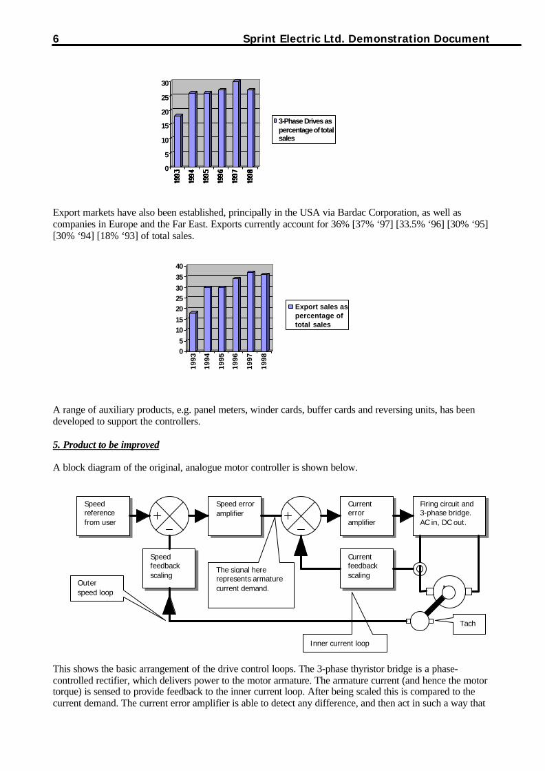
A range of three phase controllers, SL/SLX, launched in 1992, with models to 115KW added in summer ‘94along with new SLE. During ‘97 the three-phase range was extended to include drives up to 265KW. Thethree phase range now accounts for 27% [30% ‘97] [27% ‘96] [26% ‘95] [26% ‘94] [18% ‘93] of sales.Entry of a new niche market of low voltage motor control was made during ‘95 with the introduction of the200/500XLV models. The business has a growing share by volume of the UK market for the power bands inwhich it operates.
6 Sprint Electric Ltd. Demonstration Document
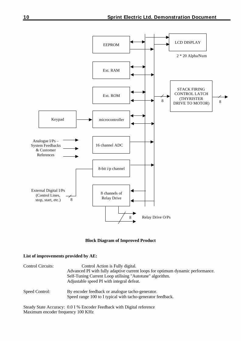
Export markets have also been established, principally in the USA via Bardac Corporation, as well ascompanies in Europe and the Far East. Exports currently account for 36% [37% ‘97] [33.5% ‘96] [30% ‘95][30% ‘94] [18% ‘93] of total sales.
A range of auxiliary products, e.g. panel meters, winder cards, buffer cards and reversing units, has beendeveloped to support the controllers.
5. Product to be improved
A block diagram of the original, analogue motor controller is shown below.
This shows the basic arrangement of the drive control loops. The 3-phase thyristor bridge is a phase-controlled rectifier, which delivers power to the motor armature. The armature current (and hence the motortorque) is sensed to provide feedback to the inner current loop. After being scaled this is compared to thecurrent demand. The current error amplifier is able to detect any difference, and then act in such a way that
Inner current loop
Speedreferencefrom user
Currenterroramplifier
Speed erroramplifier
Currentfeedbackscaling
Speedfeedbackscaling
Firing circuit and3-phase bridge.AC in, DC out.
M
Tach
The signal hererepresents armaturecurrent demand.
Outerspeed loop
0
5
10
15
20
25
30
3-Phase Drives aspercentage of totalsales
05
1015
202530
35
40
1993
1994
1995
1996
1997
1998
Export sales aspercentage oftotal sales

Sprint Electric Ltd Demonstration Document 7
the current feedback remains identical to the current demand during normal operation. This inner loop keepsa safe watch on the armature current and delivers more current or less current as required.
The outer speed loop works in the same way as the inner current loop but uses different parameters. Here thedemand is provided by the user in the form of a speed reference, and the speed feedback is derived from ashaft-mounted tachometer. Any difference is detected and translated into a new current demand level. Thislevel is arranged to demand exactly the right amount of current (and hence torque) to reduce the speed errorto zero. This new demand level is presented to the inner current loop, which obeys as rapidly as possible.
The whole process is performed on a continuous basis giving accuracy and dynamic performance. In the realworld there are numerous house keeping tasks and interface requirements.
The component costs of the product are mainly in the power assembly; therefore changing the control cardcomponents has only a marginal effect on the total component costs. What makes this applicationexperiment viable are the extra features made possible by the new technology. The impact of the newfeatures in terms of implementing system changes and commissioning precision will assist the users in themanufacture of their machines and systems. This enables the company to command a higher price for theproduct, leading to better margins and increased profitability.
All the existing products use analogue control methods. For units above 5 Kw the power components andcontrol systems are 2 assemblies. The control system sends signals to the power assembly to adjust theamount of controlled power.
The existing product uses analogue op-amps in conventional PID control loops to control the current andvoltage delivered to the user’s motor. There is also a section of alarm status detectors and logic that usesconventional discrete gates, etc. to control the safe removal of power from the motor in the event of an alarmbeing triggered.
The power is converted from the user’s incoming 3-phase supply up to 480V, and motors can be driven upto voltages of 500V and currents of 630 Amps. Various features are included in the package to assist users inthe handling of the power. Of particular interest is the regenerative option which allows the stored rotationalenergy in the motor to be returned to the supply thus saving the user considerable amounts of money overthe life of the machine, and contributing to the protection of environment by the efficient use of powersupplies.
In order to obtain optimum performance, the user needs to set various parameters. The current productallows fora maximum of 10 parameters to be adjusted, namely: maximum speed, minimum speed, forward up ramp,forward down ramp, reverse up ramp, reverse down ramp, stability, zero speed, maximum current positive,and maximum current negative.
Market information
Information is available on industry sector usage to identify target industries:

8 Sprint Electric Ltd. Demonstration Document
0 5 10 15 20 25 30
Machine Tools
Textile m/c
Food/Beverage
Other
Pulp/Paper
% share
As can be seen, the major industry sectors are Rubber / Plastics, Pulp / Paper and Metal industries. There arealso markets in, food and chemical / pharmaceuticals.
Photograph of Original Analogue Control Board

Sprint Electric Ltd Demonstration Document 9
6. Description of technical product improvements
By implementing the control loops in the microcontroller, the customer-pre-set values can be numericallyentered. The analogue summing junctions are replaced by mathematical computation, allowing configurablesignal processing and complex functions e.g. winding control. The setting menus for a particular system canbe transported to other drive units and the setting status can be transmitted to and from remote locations.Data logging functions are possible, allowing ‘black box’ analysis of machine faults.
A summary of the more important new features that are made possible by using the proposed digital solutionis given below.
1. Precise parameter setting.Instead of using analogue pre-set trimmers, the user can now enter values using menu driven keys.
2. Multiple setting menus.The user is able to store tables of settings for use with different processes.
3. Remote monitoring.The live motion parameters are available by serial link for host processing.
4. Better diagnostics.The machine and drive parameters are available for fault diagnosis.
5. Integrated winder control.The drive is able to compute reel diameters for tension control systems.
6. Position control.The drive is able to control position angles of motor shafts.
7. Encoder feedback.High accuracy feedback is possible through the use of digital speed transducers.
8. Serial communications.User operating parameters may be input from a remote computing device.
9. Data logging.The drive is able to record machine events over a period of time for performance analysis.
10. Portable personality.The drive set up parameters are easily portable to other drives in new machines.
10 Sprint Electric Ltd. Demonstration Document
STACK FIRINGCONTROL LATCH
(THYRISTERDRIVE TO MOTOR)
Keypad
LCD DISPLAYEEPROM
Ext. RAM
Ext. ROM
microcontroller
16 channel ADC
8 channels ofRelay Drive
8-bit i/p channel
Analogue I/Ps –System Feedbacks
& CustomerReferences
External Digital I/Ps(Control Lines,stop, start, etc.)
2 * 20 Alpha/Num
8 8
8
8
Relay Drive O/Ps
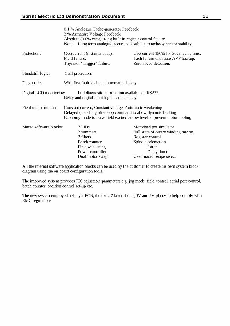
Block Diagram of Improved Product
List of improvements provided by AE:
Control Circuits: Control Action is Fully digital.Advanced PI with fully adaptive current loops for optimum dynamic performance.Self-Tuning Current Loop utilising "Autotune" algorithm.Adjustable speed PI with integral defeat.
Speed Control: By encoder feedback or analogue tacho-generator.Speed range 100 to I typical with tacho-generator feedback.
Steady State Accuracy: 0.0 I % Encoder Feedback with Digital referenceMaximum encoder frequency 100 KHz
Sprint Electric Ltd Demonstration Document 11
0.1 % Analogue Tacho-generator Feedback2 % Armature Voltage FeedbackAbsolute (0.0% error) using built in register control feature.Note: Long term analogue accuracy is subject to tacho-generator stability.
Protection: Overcurrent (instantaneous). Overcurrent 150% for 30s inverse time.Field failure. Tach failure with auto AVF backup.Thyristor "Trigger" failure. Zero-speed detection.
Standstill logic: Stall protection.
Diagnostics: With first fault latch and automatic display.
Digital LCD monitoring: Full diagnostic information available on RS232.Relay and digital input logic status display
Field output modes: Constant current, Constant voltage, Automatic weakeningDelayed quenching after stop command to allow dynamic brakingEconomy mode to leave field excited at low level to prevent motor cooling
Macro software blocks: 2 PIDs Motorised pot simulator2 summers Full suite of centre winding macros2 filters Register controlBatch counter Spindle orientationField weakening LatchPower controller Delay timerDual motor swap User macro recipe select
All the internal software application blocks can be used by the customer to create his own system blockdiagram using the on board configuration tools.
The improved system provides 720 adjustable parameters e.g. jog mode, field control, serial port control,batch counter, position control set-up etc.
The new system employed a 4-layer PCB, the extra 2 layers being 0V and 5V planes to help comply withEMC regulations.
12 Sprint Electric Ltd. Demonstration Document
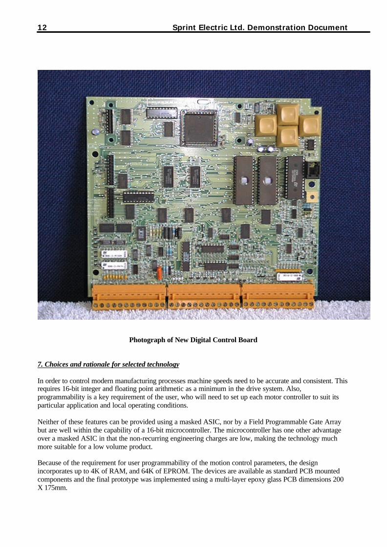
Photograph of New Digital Control Board
7. Choices and rationale for selected technology
In order to control modern manufacturing processes machine speeds need to be accurate and consistent. Thisrequires 16-bit integer and floating point arithmetic as a minimum in the drive system. Also,programmability is a key requirement of the user, who will need to set up each motor controller to suit itsparticular application and local operating conditions.
Neither of these features can be provided using a masked ASIC, nor by a Field Programmable Gate Arraybut are well within the capability of a 16-bit microcontroller. The microcontroller has one other advantageover a masked ASIC in that the non-recurring engineering charges are low, making the technology muchmore suitable for a low volume product.
Because of the requirement for user programmability of the motion control parameters, the designincorporates up to 4K of RAM, and 64K of EPROM. The devices are available as standard PCB mountedcomponents and the final prototype was implemented using a multi-layer epoxy glass PCB dimensions 200X 175mm.

Sprint Electric Ltd Demonstration Document 13
Software Structure
The drive is based on a hierarchical interrupt-driven operating system.There are three distinct hierarchical levels with level 1 being the lowest priority task.
a) Level 1 is the background task, i.e. the micro is executing this task when no interrupts are present in thesystem.This task mainly consists of servicing the human interface (keypad and LCD display unit) and somehousekeeping and calibration functions.
b) Level 2 is the main drive block diagram, which runs on a “5ms tick” interrupt.Each function of the block diagram is represented by a task which is executed in a predetermined sequence.The overall program flow consists of three main parts, namely:i)Sampling of the inputs (analogue and digital)ii)Processing of the transfer functionsiii)Updating of the outputs (analogue and digital)
c) Level 3 as a whole consists of a cluster of “asynchronous” real-time interrupts. These constitute the“core” of the drive activity in controlling the power semiconductor devices and also communicating viaserial links with a host computer.
They are also prioritised in a certain manner, typically mains thyristor stack synchronisation (coding),encoder inputs, armature current control, field current control, serial link interface (U.A.R.T.), etc.
Levels 1 and 2 are written in language C, whereas Level 3 is almost exclusively in 80C196 Assembler due toits critical speed of execution requirements. The C compiler chosen was produced by Tasking Ltd. and is theonly compiler for this microcontroller family in the market. This tool set was originally made by Intel butTasking Ltd. took it over.
The whole system was designed using a “bottom-up” approach with software version control ensuring safeand smooth transition from the lower levels to the higher ones as software was added in stages.
The use of an Emulator was periodically required to facilitate the software development and it also provedinvaluable, mainly in debugging the real-time interrupt driven tasks. This was achieved in spite of the manyproblems encountered regarding the reliability and integrity of both hardware and software content of theemulator.
Microcontroller specification
The chosen microcontroller had to be capable of working fast enough to perform all the closed loop controlalgorithms as well as displaying and accepting operator instructions. It also had to be able to undertake serialcommunications and perform various industry standard type applications e.g. winding control. The chosenmicrocontroller was the Intel 8XC196NT a CHMOS Microcontroller with 1 MBYTE of linear addressspace.
The 8XC196NT 16-bit microcontroller is a high performance member of the 96 microcontroller familyThe 8XC196NT is an enhanced 8XC196KR device with 1 Mbyte of linear address space, 1000 bytes ofregister RAM, 512 bytes of internal RAM, 20 MHz operation and an optional 32 Kbytes of OTPROM.lntel's CHMOS III-E process provides a high performance processor along with low power consumption.Ten high-speed capture/compare modules are provided. As capture modules, event times with 200 ns resolu-tion can be recorded and generate interrupts. As compare modules, events such as toggling of a port pin,starting an A/D conversion, pulse width modulation, and software timers can be generated. Events can bebased on the timer or up/down counter.
The 8XC196NT supports the following:

14 Sprint Electric Ltd. Demonstration Document
High Performance CHMOS 16-Bit CPUHigh Speed Peripheral Transaction Server (PTS)4 Channel/10-Bit A/D with Sample/Hold37 Prioritized Interrupt SourcesQuadrature Counting Inputs1.4uS 16 x 16 Multiply
These features provided the right mix of functions coupled with sufficient speed and processing power toaccommodate the majority of functions required. Further I/O requirements were provided by adding input oroutput latches. The 1MB linear address space provides the capability of future expansion of the applicationssoftware for specialist user motion control functions.
8. Expertise and experience of the company
The First User has experience in the following areas of engineering
Power electronic engineering.Thermal management of high power solid state switchesProtection of power semiconductor junctions from fault conditionsGalvanic monitoring of high voltages and currentsAnalogue closed loop control systemsEMC engineering of power productsCE, CSA, UL approvals compliancePCB designing and layoutUsing Surface Mount Components
The company is a first user of microcontroller and other digital VLSI components. This experiment was thefirst time use of the new technology within the company. The acquisition of expertise in usingmicrocontroller represents a logical addition to the company’s current capability. This is because theproducts are all industrial control products which are made more competitive from the extra features madepossible with this new technology. By completing this experiment, all aspects of control, interfacing, andcommunications design have been undertaken using the new technology and hence the company hasacquired sufficient expertise to repeat the process unaided on the rest of the product range.
9. Workplan and RationaleBoth panned and actual schedules for the project are shown below. The development work was preceded bytraining in microcontroller and programming and by the development of the specification. This was intendedto be a description of the new product using the microcontroller detailing all the requirements. The next partof the plan was the design of the hardware and software. This was to be followed by test and evaluation ofthe design.
Activities Month1 2 3 4 5 6 7 8 9 10 11 12
Management X X X X X X XSpecification X XTraining X XDesign X X X X X X X X XEvaluation X X
Planned Schedule
Sprint Electric Ltd Demonstration Document 15
Activities Month1 2 3 4 5 6 7 8 9 10 11 12
ManagementX X X X X X X
Specification(e.g. system blockdiagram)
X X
Training(e.g. microcontroller,design)
X X
Design(e.g. peripheralinterfaces)
X X X X X X X X X
Evaluation(e.g. prototypetesting)
X X
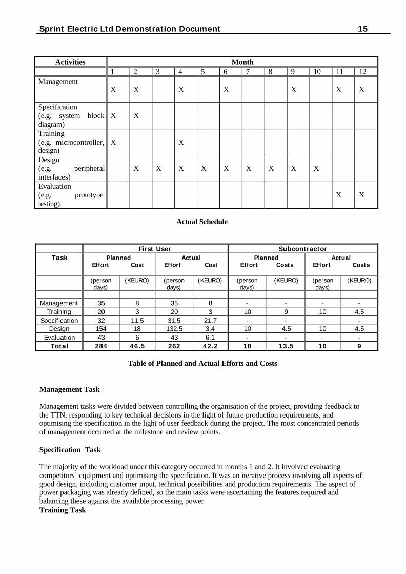
Actual Schedule
First User SubcontractorTask Planned
Effort CostActual
Effort CostPlanned
Effort CostsActual
Effort Costs
(persondays)
(KEURO) (persondays)
(KEURO) (persondays)
(KEURO) (persondays)
(KEURO)
Management 35 8 35 8 - - - -Training 20 3 20 3 10 9 10 4.5
Specification 32 11.5 31.5 21.7 - - - -Design 154 18 132.5 3.4 10 4.5 10 4.5
Evaluation 43 6 43 6.1 - - - -Total 284 46.5 262 42.2 10 13.5 10 9
Table of Planned and Actual Efforts and Costs
Management Task
Management tasks were divided between controlling the organisation of the project, providing feedback tothe TTN, responding to key technical decisions in the light of future production requirements, andoptimising the specification in the light of user feedback during the project. The most concentrated periodsof management occurred at the milestone and review points.
Specification Task
The majority of the workload under this category occurred in months 1 and 2. It involved evaluatingcompetitors’ equipment and optimising the specification. It was an iterative process involving all aspects ofgood design, including customer input, technical possibilities and production requirements. The aspect ofpower packaging was already defined, so the main tasks were ascertaining the features required andbalancing these against the available processing power.Training Task

16 Sprint Electric Ltd. Demonstration Document
The initial training covered the structure of microcontroller, the programming of microcontroller inAssembler and in a high level programming language (in this case C) and the implementation of hardwarefunctions in software. Also covered was the implementation of real time control functions in software. Lattertraining needed to concentrate on all aspects of using the chosen microprocessor in relation to the tasksrequired of it. Being a real time closed loop application, it was anticipated that skills in implementinginterrupt driven control loops would be acquired from the experiment. The second tranche of trainingconcentrated C programming. The mathematics of the control loops are well understood in the analogueproduct and intensive training in the digital implementation of these classical methods was not required.
Design Task
The main design tasks included selection of the microcontroller devices, including display drivers, serialcomms ports, A/Ds and supply budgeting. The customer survey provided the information required todetermine the amount of analogue and digital inputs and outputs. This in turn defined the amount of inputoutput latches that would need to be addressed.
The emulator was initially used to get the system core running on a laboratory rig enabling the handling ofthe peripheral interfaces and coding of the control loops. Working on the internal loops was completed bymonth 6. This enabled the rotation of a motor shaft to be achieved to prove the closed loop.
The next stage in month 7 was to start work on the customer display and comms functions. The design of theadditional customer maths functions then commenced (e.g. material winding, batch counting). Thesefunctions were not too difficult to implement because we already have equivalent analogue functions andhence did not need to re-invent the physics. Finally in months 9 and 10 the physical tracking and designingof the glue electronics was completed ready for production of working prototypes in month 11. This wasachieved by using a very high performance autorouter that was already in use within the company.
Evaluation Task
The in house evaluation of the prototype took place in month 12. Existing test resources were used toevaluate the control loop bandwidth performance relative to the analogue product. At this stageruggedisation of design techniques was used to prepare the product for the real world.
Risk assessment
After discussions with our TTN (UKC) the risk assessment was considered. Together we concluded that thiswas a low risk project because of the choice of using a microcontroller. These devices are well establishedand proven in use in similar areas of application. They are well documented and there is an excellent supplychain for the devices and the support technology. The project did not involve the generation of exclusivedevices or other special parts. The bandwidth requirements were also well within the processing speeds ofthe chosen microcontroller. The use of a microcontroller reduced the design risks as errors revealed duringthe development cycle could be corrected by modifications to the code, and the use of an In-CircuitEmulator allowed detailed debugging of hardware and software to be separated.
The company was determined not to allow the application experiment timetable to drift. Extra resourceswere redirected by the company to overcome unforeseen problems (e.g. bugs in the development tools) so asto ensure the experiment progressed as intended. Thus the actual project timescales agreed with the plannedproject timescales shown in the Gantt Chart above. There was however a cost penalty of approx. 15KEUROS caused by the problems with the development tools.
Problems encountered during the project
The main problems were caused by the failure of tools. The emulator kept failing, and the emulatorspecification proved to be incorrect. The supplier eventually replaced the power supply. The tasking Ccompiler had some serious bugs. The first problem cost 4 weeks development time and the second cost 3weeks. Our advice to other ‘First User’ companies in a similar position would be to maintain a good, close

Sprint Electric Ltd Demonstration Document 17
relationship with their suppliers, so that when problems do occur, technical support can be obtained quickly.It is a good idea to get the names of the technical support staff, so that help can be obtained easily over thephone, fax or email. It is also helpful to remember that when a problem does occur, it isn’t always the faultof the First User, it may well be a known bug, so technical support should be obtained sooner rather thanlater.
Despite the shortcomings in the Compiler and Emulator, the Intel microcontroller proved to be an excellentchoice.
One of the most difficult parts of the design was the analogue to digital converter section. There areapproximately 15 different external signals to be converted with high precision and as fast as possible. Ittook some very careful analysis of millivolt signals in a noisy digital environment to achieve the desiredreadings.
10. Subcontractor information
Name: University Of Kent at CanterburySize: 50 Technical Staff (In Electronic Engineering Labs.)
Relevant Expertise & ExperienceElectronic Design, Microcontroller Design, Software Design, Mask and Field programmable ASIC Design,Full custom Analogue and Digital IC Design.Wide experience in all fields mentioned above at the research, Consultancy and Educational levels.
The subcontractor that was chosen for the project was also the TTN. This choice was made as an existingrelationship was in place with the University and the location was relatively close. In addition it was thoughtthat the joint role of subcontractor and TTN would simplify the communications and the management of theproject.
In general it was found that this scheme worked well and the project proceeded without major problems.
With hindsight the most important qualities required for a subcontractor are:
Technical competenceCommitment to and interest in the ProjectCommercial understanding of the business (SME etc)Project Management skillsRelationship with first user
The last area is difficult to assess in advance unless the relationship exists before the project starts. But it isimportant that the staff can work together and have or can develop an understanding of each other.
The subcontractor provided training and this work was carried out in accordance with the terms of thesubcontractor’s standard contract. Sprint remained in control of the project, with the subcontractor providingtraining and support as required. The IPR for all the design work carried out during the ApplicationExperiment belongs to Sprint.
11. Description of perceived barriers to the first use of technology
Knowledge Barriers
SPRINT knew that the existing analogue control loop technology was not "state of the art" but the companyhas been using analogue techniques in its products since 1987, and no radically new technologies, apart fromthe introduction of surface mount fabrication for the product hardware, had been used. Consequently therewas unfamiliarity with the different types and families of microcontrollers and their capabilities. This is abig problem for the newcomer when trying to determine whether it is feasible to use a microcontroller in a

18 Sprint Electric Ltd. Demonstration Document
product. Until one has had some experience of the different types of microcontroller available and thenumber of peripheral latches etc. needed to perform a particular function, it is difficult to know what the costwill be of using such technology. This knowledge only comes with experience giving one a "feel" for whatis and is not achievable.
Once C PROGRAMMING training was given, the move from the basic C PROGRAMMING concepts to CPROGRAMMING-based design of functional blocks was also a barrier that had to be overcome.
Psychological Barriers
With any new technology, there is a fear associated with making a commitment to using it. It is alwayseasier to continue to use existing technologies already present within the company. In SPRINT's case thishas happened with the application of digital technology in general, which although considered on severalprior occasions, it had been ruled out as it was thought to be too complex and difficult to learn for a smallcompany such as SPRINT.
Standards Related Barriers
One of the problems facing manufacturers of industrial control equipment is compliance with the relevantworld standards e.g. standards for safety and for EMC.
Financial Barriers
Financial barriers are not the biggest barriers for SPRINT. The company has always spent money ondevelopment tools and equipment. However, in the past little has been spent on engineering training. It hasalways been assumed that the design team will be able to cope with anything related to microelectronics andproduct design without the need for additional training.
Now that we have experience in the microelectronics and software methods, it will be easier in the future forus to employ the techniques acquired.
12. Steps taken to overcome barriers
Knowledge Barriers
To overcome the knowledge barriers to using digital technology required intensive training inmicrocontrollers and programming for the engineers involved in the application experiment. Although theywere all graduates of science and were familiar with the concepts, it was the rate at which the technologyhad advanced since their student days that had to be addressed.
Psychological Barriers
In order to overcome the psychological barriers, the TTN was involved throughout the project in an advisoryrole, helping to identify common problems, such as problems with CAD tools.
In addition the TTN provided much needed assistance in training the designers to address the problems ofcommunication protocols that are required by industrial controllers. Because the communications protocolsare numerous it is necessary to provide a platform that can be used to support any existing or future protocol.This has been achieved in the new prototype by providing an on board connector with all the appropriate busconnections. This connector allows provision for an option card that will be designed in the future toaccommodate existing or new industrial protocols. This would have been a difficult area to approach withoutthe assistance of the TTN.
Standards related barriers

Sprint Electric Ltd Demonstration Document 19
To comply with the relevant world standards when using microprocessor-based systems, certain rules haveto be applied at the design stage. For the product of this AE the data transfer in the microprocessor-basedsystem is constantly checksum tested such that if a memory location should fail, it would be detected.Similarly the EEPROM, which holds the system data while the unit is turned off, is also tested by readingback from it after writing to it in order to check the validity of the write operation. A retrospective redesignto implement these features at a later date would have required much more effort. In order to comply withEMC regulations, the unit was implemented using a 4-layer PCB, with 2 layers being used for power andground planes, and the product has been successfully tested for compliance with CE EMC standards.
13. Knowledge and experience acquired
The key areas where knowledge was gained are as follows:
Programming in C
Use of development tools for writing C code
Use of emulator for the INTEL microcontroller
PCB layout techniques for digital systems
Designing multilayered PCBs
Serial communications
The training was provided by the TTN and the suppliers of the emulator and PCB autorouting tools.
During the application experiment, SPRINT acquired a wide range of knowledge, covering bothmanagement and design skills. Sprint is now experienced in the hardware design of systems usingmicrocontrollers and support chips. They are also experienced in the use of C and Assembler, in the use ofsupport tools such as In-Circuit Emulators and are now experienced in the field of digital control.
Prior to the application experiment it had not been realised that training is readily available fromuniversities. This will now be considered in future should the need arise for directed training on any aspectof microelectronics. In the past any training received by SPRINT has been negligible.
At the end of the application experiment experience shows that there were few really significant barriers tothe introduction of Microcontrollers into the company. Perceived barriers often turn out not to be as big asoriginally thought. For SPRINT, a company with knowledgeable design engineers experienced in industrialelectronics,acquiring skills in using digital techniques was in fact relatively easy. The greatest overall barrier was lackof up to date technical knowledge, which was addressed by attending suitable training courses.
14. Lessons Learned
Compiler
The “Warnings” message reported by a high-level compiler can and should sometimes be ignored when theyhave no material influence on the code produced. However, in other instances it can be fatal if they areignored.
A good example of the latter is a comparison of two variables, one of them being defined as signed and theother as an unsigned quantity.
a) A less strict compiler might not even give any warning, in which case the possibility of spotting the bug issubstantially reduced.

20 Sprint Electric Ltd. Demonstration Document
b) A stricter compiler will give the Warning “comparison is always true (or false)”, which must not beignored. By close examination of the assembler code output of the compiler it can be observed that thecomparison has been removed altogether (!), thereby prompting the programmer to look at the variablesmore carefully and thereby apply the fix.
c) A more correct compiler would have given an Error instead of the Warning, thereby guaranteeing theresponse of the programmer.
Digital Output Multiplexing
If various digital output bits representing different functionalities are combined for convenience typically inthe same hardware latch (either byte or word), extreme care should be taken when writing to the latch from aparticular software task (especially when interrupt driven) not to corrupt the rest of the bits that are notrelated to this particular task. This is an “easy” trap to fall into, although it might even be known inprinciple.
Microcontroller and emulator
The microcontroller chosen has various addressing modes that may be selected by writing a word to aninternal register. The modes available determine hold times and set-up times for the address and data bussignals. Although having this ability provides flexibility, we determined that only one mode was suitable forall the easily available peripheral chips. The design was at a late stage before it was discovered that theemulator that had been purchased only supported one of the available modes, and as usual with mothernature it wasn’t the mode we had designed for. This was a serious omission on the part of the emulatorsuppliers who had assumed the emulator was capable of emulating all modes. It took several weeks for themto actually get confirmation from the emulator manufacturers in the US to confirm that only one mode wassupported. We then had to redesign our circuits using devices that were more costly in order to emulate inthe supported mode. This will have added costs in production unless the emulator can be upgraded.
Power Supply Requirements
At the design stage, we overlooked the power requirements of the Display and High Speed Processor. Theexisting linear power supply on the power board provided only 12Va, and the new control card turned out torequire 50Va. This was a surprise as generally, replacement of analogue circuitry by digital circuitry isaccompanied by a reduction in power consumption. To overcome this we had to employ additional resourcesto design a switch mode power supply and redesign the power board incorporating the new supply.
Subcontractors and training
Before this application experiment, SPRINT's experience of using subcontractors had been for specificmanufacturing or installation jobs, never training. There existed in the company a certain reluctance toreturning to school and the attitude that it was too costly to receive external training. This is the first timeSPRINT has used a subcontractor for assistance in the design and development process and has shown howimportant in-depth technical training is to the success of the project.
Design approach
Designing Power controllers using microcontrollers requires an entirely different approach from thatemployed for design using analogue circuitry. The training provided by the TTN highlighted thefundamental design techniques of this approach at the early stages of this AE and later consultations allowedfor the transition from theory to practice to take place.
15. Resulting Product, Industrialisation and internal replication
There were many other tasks to be done to complete the project which were not directly related to the firstuse of digital techniques. These include EMC pre-compliance design, and product approvals engineering for

Sprint Electric Ltd Demonstration Document 21
UL, CSA, CE. These approvals are essential because the company is shipping an increasing proportion tothe USA. The Low Voltage Directive requires a considerable amount of environmental testing, thermal runs,drop tests etc. The UL and CSA approvals require witness tests for thermal and safety. There is also therequirement to ensure that the product is compatible with the Machinery Directive because the units areprime movers of industrial machinery.
Also we were engaged in modelling the external carcass of the controllers to incorporate the display andcustomer keys. This task was undertaken by an outside design firm with the assistance of the local BusinessLink organisation.
The working prototype has been tested in the laboratory and performs to specification.
The next stage is to manufacture 10 units for beta site testing. This serves several purposes: -
1) Subjects the design to various environments in different parts of the world.2) Provides customer feedback on suitability of specification for their market.3) Enables our manufacturing facility to dry run the production and buying process.4) Ensures that when the full product launch takes place, the product is reliable.5) Introduces key users to the product
This process will be complete by November 99. Full production should then be able to commence in Jan2000 to coincide with a full product launch in March 2000.
While the beta site testing is being performed, the 145 Kw and 250 Kw models will be developed to ensurethat the launch of the product will cover the entire power range required.
We anticipate that a further 300K Euros will be required to bring the product range to market by March2000. This will comprise 80K Euros for Beta Site engineering and production, 100K Euros for tooling of theCarcass, 20k Euros for the production of technical literature, 50K Euros for production tooling and 50KEuros for training the sales and production staff.
The result of this AE will generate an internal replication through the development of smaller single-phaseproducts using a microcontroller which will commence at the beginning of 2000.
22 Sprint Electric Ltd. Demonstration Document
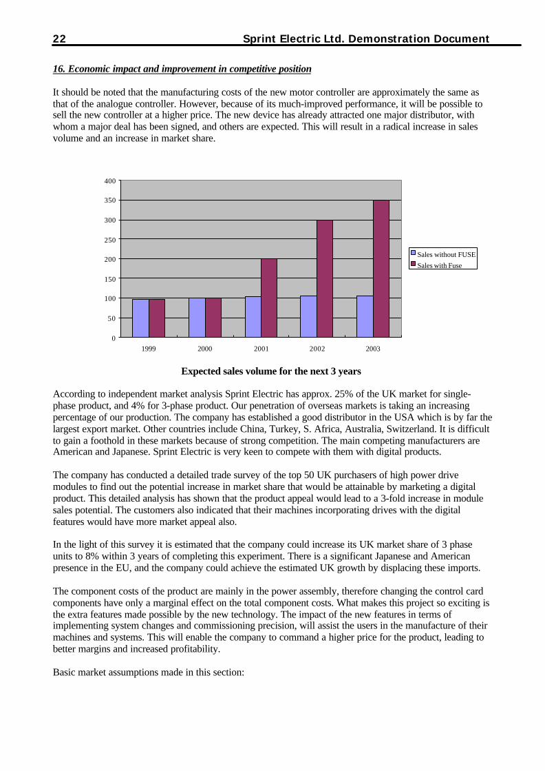
16. Economic impact and improvement in competitive position
It should be noted that the manufacturing costs of the new motor controller are approximately the same asthat of the analogue controller. However, because of its much-improved performance, it will be possible tosell the new controller at a higher price. The new device has already attracted one major distributor, withwhom a major deal has been signed, and others are expected. This will result in a radical increase in salesvolume and an increase in market share.
Expected sales volume for the next 3 years
According to independent market analysis Sprint Electric has approx. 25% of the UK market for single-phase product, and 4% for 3-phase product. Our penetration of overseas markets is taking an increasingpercentage of our production. The company has established a good distributor in the USA which is by far thelargest export market. Other countries include China, Turkey, S. Africa, Australia, Switzerland. It is difficultto gain a foothold in these markets because of strong competition. The main competing manufacturers areAmerican and Japanese. Sprint Electric is very keen to compete with them with digital products.
The company has conducted a detailed trade survey of the top 50 UK purchasers of high power drivemodules to find out the potential increase in market share that would be attainable by marketing a digitalproduct. This detailed analysis has shown that the product appeal would lead to a 3-fold increase in modulesales potential. The customers also indicated that their machines incorporating drives with the digitalfeatures would have more market appeal also.
In the light of this survey it is estimated that the company could increase its UK market share of 3 phaseunits to 8% within 3 years of completing this experiment. There is a significant Japanese and Americanpresence in the EU, and the company could achieve the estimated UK growth by displacing these imports.
The component costs of the product are mainly in the power assembly, therefore changing the control cardcomponents have only a marginal effect on the total component costs. What makes this project so exciting isthe extra features made possible by the new technology. The impact of the new features in terms ofimplementing system changes and commissioning precision, will assist the users in the manufacture of theirmachines and systems. This will enable the company to command a higher price for the product, leading tobetter margins and increased profitability.
Basic market assumptions made in this section:
0
50
100
150
200
250
300
350
400
1999 2000 2001 2002 2003
Sales without FUSESales with Fuse

Sprint Electric Ltd Demonstration Document 23
In order to assess market share the total market for three phase DC drives has to be defined in terms ofoverall value, total quantity of units and market growth. This information has been based on a number ofexternal sources, all reputable marketing organisations with particular skill in researching this particularindustry sector. No attempt has been made to allow for major economic events, which inevitably havesignificant effect on such forecasts.
The information is drawn from surveys of the European market. As the “home” market for Sprint Electric,having accurate information on this geographical area was felt to be the priority. Worldwide market surveysare generally less specific in their information detailing the drives market as a whole rather than sectorswithin it, i.e. DC Drives.
In order to assess the worldwide market a basic assumption of 2.5 times European market size has beenmade. This represents the main consumption areas of North America and the Pacific rim countries.
Note All currency conversion has been performed at EURO = 0.8 £
The Application Experiment cost 60K Euro with a further 300K Euro to take the product on to the market.The project is expected to have a payback period of approximately 18 months. The expected return over theproduct lifetime of 10 years is 6M Euro, an ROI figure of 1600% over this period.
17. Target audience for dissemination
This application experiment is targeted at SMEs in the industrial control industry, which are currently usingstandard components and analogue control loops to achieve the system functionality. The control industriesserviced by the targeted SMEs are those which use electronic motor controllers but do not have a strongpresence in the technology, thus menu-driven setups, self-calibration and configuration are a definiteadvantage. The target audience industries would include power engineering, automation, process control,metal processing, paper, rubber and plastics. Production volumes would be in the range of tens to the lowthousands.
The relevant Prodcom codes are: 3110, 3120, 3330, 28, 29, 25, 21.


![jeanpaulva.files.wordpress.com file · Web viewFOSTER – DETAILED DESIGN [Demonstration Document]. . Foster. DETAILED DESIGN](https://img.pdfslide.us/doc/110x75/5c8cec2909d3f2a01c8c4a6c/-web-viewfoster-detailed-design-demonstration-document-foster-detailed.jpg)