Embed Size (px)
Citation preview
www.intorq.de
setting the standard
Spring-applied brake BFK459The basic module
2 – 125 Nm
The INTORQ brand stands for reliable brake solutions of the highest standard. Whether in cranes, wind turbines or lift systems – INTORQ products are used in the most diverse of applica-tions. Rely on us to create the right solution for your drive – individually and reliably.
With its broad scope of different versions, the modular range of INTORQ products is used in many motors and geared motors and has set standards worldwide. With the establishment of facilities in Shanghai and Atlanta, we have also consistently expanded our international presence. So wherever you are in the world, our network of sales and service staff is always close at hand to support you.
We set the standards
INTORQ at a glance
❙ Electromagnetic brakes and clutches ❙ Configurable standard solutions and
custom-made solutions❙ Development and production centred in Aerzen❙ Fast delivery times worldwide thanks to
production sites in Shanghai und Atlanta❙ 45 million euros a year sales volume❙ 800,000 units a year ❙ 10,000 square metres production area❙ 220 employees❙ Market leader with 63 sales partners in 49
countries
INTORQ I Spring-applied brake INTORQ BFK459
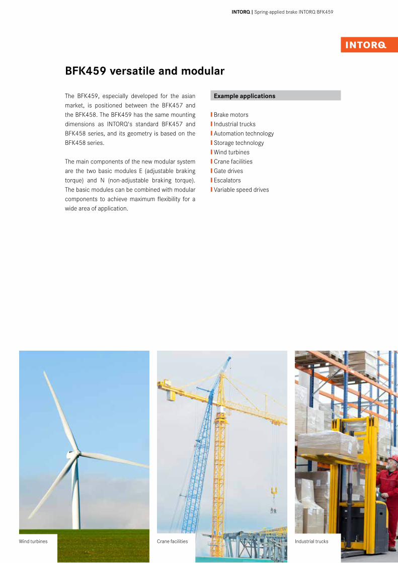
The BFK459, especially developed for the asian market, is positioned between the BFK457 and the BFK458. The BFK459 has the same mounting dimensions as INTORQ's standard BFK457 and BFK458 series, and its geometry is based on the BFK458 series.
The main components of the new modular system are the two basic modules E (adjustable braking torque) and N (non-adjustable braking torque). The basic modules can be combined with modular components to achieve maximum flexibility for a wide area of application.
Example applications
❙ Brake motors❙ Industrial trucks❙ Automation technology❙ Storage technology❙ Wind turbines❙ Crane facilities❙ Gate drives❙ Escalators❙ Variable speed drives
BFK459 versatile and modular
Crane facilities Industrial trucksWind turbines
4I5 INTORQ I Spring-applied brake INTORQ BFK459
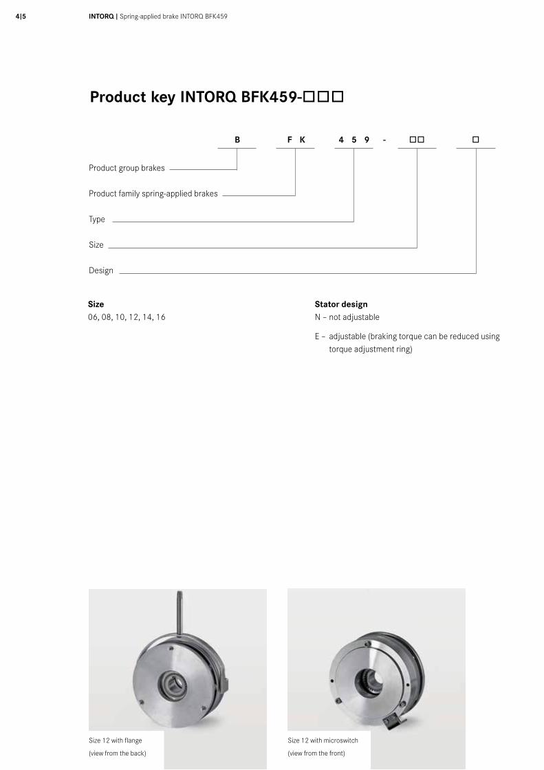
Product key INTORQ BFK459-òòò
Size06, 08, 10, 12, 14, 16
Stator designN – not adjustable
E – adjustable (braking torque can be reduced using torque adjustment ring)
B F K 4 5 9 - òò ò
Product group brakes
Product family spring-applied brakes
Type
Size
Design
Size 12 with flange
(view from the back)
Size 12 with microswitch
(view from the front)
Contents
Product key 4
List of abbreviations 5
Product information 6
Functional principle 7
Technical dataAdjustable torque design 8Non-adjustable torque design 10 Braking torques 12Rated data/Operating times 13Service life and wear/ 14torques Thermal load limits/ 15wear values
AccessoriesRotor with plastic sleeve/ 16manual release Flange/Friction plate/ 18microswitch
Seal 18Bridge rectifiers and 19half-wave rectifiers (BEG) Connection plans 22 Spark suppressor/Selection table 23for supply voltages
DimensioningBasics 24Example calculation 25
Version overview 26
Sales and service 27around the world
List of abbreviations
PN [W] Rated coil power at rated voltage and 20°CUN [V DC] Rated coil voltageMK [Nm] Rated torque of the brake at a relative speed of 100 r/min∆n0 [r/min] Initial relative speed of the brakeQ [J] Heat/energyQE [J] Maximum permissible friction work per switching cycle, thermal rating of the brakeQsmax [J] maximum permissible friction work during cyclic switching, depending on the operating frequencySh [1/h] Operating frequency, the number of repeated operations per unit timeShmax [1/h] Maximum permissible operating frequency, depending on the friction work per operationsL [mm] Air gap
sLN [mm] Rated air gapsHL [mm] Hand-release air gap, setting dimension of hand-releaset1 [s] Engagement time, the total of the reaction delay and torque rise time t1 = t11 + t12
t2 [s] Disengagement time, time from switching the stator until the torque has reduced to 0.1 MK
t3 [s] Slipping time to standstill (after t11)t11 [s] Delay time when connecting,
time from disconnecting the voltage until the torque begins to riset12 [s] Rise time of braking torque, time from
beginning of rise of torque until braking torque is reached
6I7 INTORQ I Spring-applied brake INTORQ BFK459
Produktinformationen
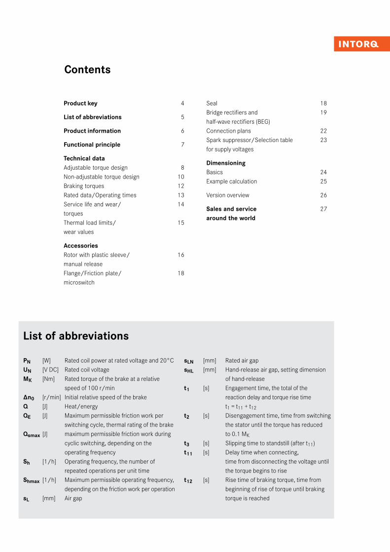
A powerful and complete range❙ 6 sizes❙ Standard voltages 20 V, 24 V, 42 V, 103 V, 180 V, 205 V❙ Graded torque range from 2 - 125 Nm❙ Customised logistics enabling short delivery times to be achieved despite wide product variety❙ Degree of protection up to IP55 equivalent, dependent on the brake equipment and the installation conditions
Versatile❙ Modular structure for virtually any area of application❙ Can replace BFK457 and BFK458 brake series
Torque transmission❙ Designed for dry running
Quick and easy installation❙ Preset air gap❙ No fixed bearing is required on the brake
Durable❙ The insulation system to temperature class F (155°C) ensures that the winding has a long service life.❙ The brakes are designed for 100% operating time (current applied to the brake).
Low maintenance❙ Long rotor/hub connection with low rate of wear and a tried-and-tested involute gear❙ Solvent-free fiction linings with low rate of wear as a standard design feature
Options❙ Manual release for all sizes❙ Various types of corrosion protection and enclosure❙ Microswitch for function monitoring (size 12 and above)
CCV (Cold Climate Version), temperature-resistant up to -40˚C ❙ CCV design configurable for all sizes in the modular system
❙ Use of chrome-plated friction surfaces (armature plate and flange)❙ Use of temperature-resistant fixing screws
up to -40˚C
Size 12 12 with
friction plate
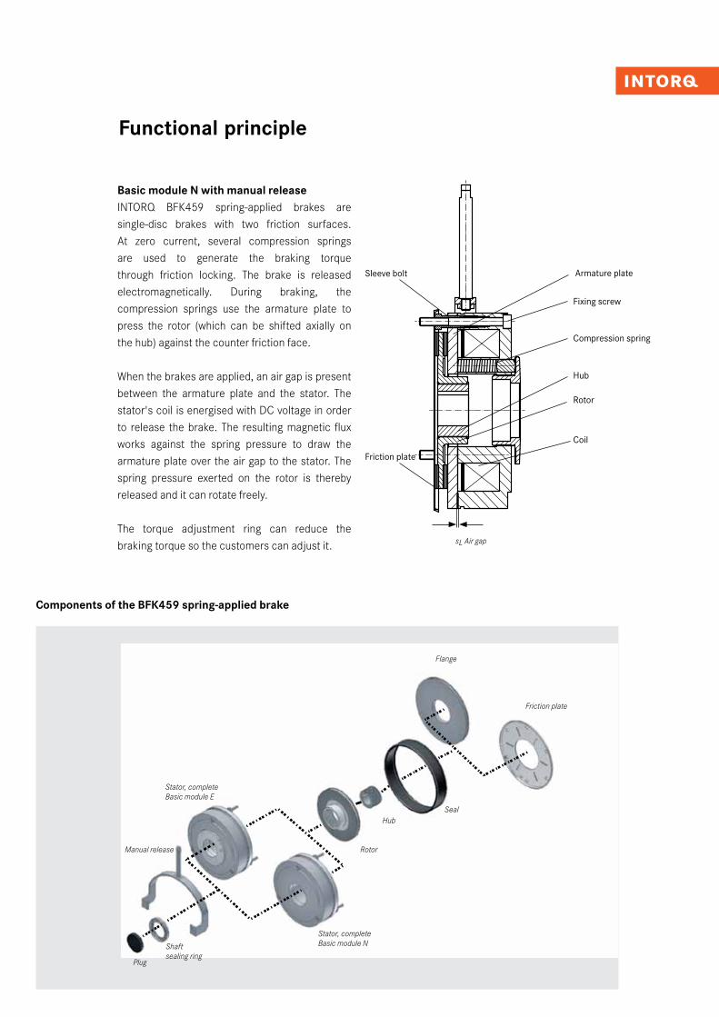
Basic module N with manual releaseINTORQ BFK459 spring-applied brakes are single-disc brakes with two friction surfaces. At zero current, several compression springs are used to generate the braking torque through friction locking. The brake is released electromagnetically. During braking, the compression springs use the armature plate to press the rotor (which can be shifted axially on the hub) against the counter friction face. When the brakes are applied, an air gap is present between the armature plate and the stator. The stator's coil is energised with DC voltage in order to release the brake. The resulting magnetic flux works against the spring pressure to draw the armature plate over the air gap to the stator. The spring pressure exerted on the rotor is thereby released and it can rotate freely.
The torque adjustment ring can reduce the braking torque so the customers can adjust it.
Functional principle
Components of the BFK459 spring-applied brake
Sleeve bolt
sL Air gap
Armature plate
Compression spring
Hub
Rotor
Coil
Friction plate
Fixing screw
Friction plate
Flange
Hub
Rotor
Stator, completeBasic module N
Plug
Shaft sealing ring
Stator, completeBasic module E
Manual release
Seal
Gr. /size b d J7 vorg. d H7 Standard d1 d2 d4 d5 d6 d7 d8 d9 H9 d10 d11 d17 d18 di da h h1 h1 min h1max h2 h3 h4 h5 h9 h10 h11 h12 h13 l l1 l2 l3 l4 SLN a a a a
β β β β
+5° +5° +5° +5°
06 90 10 10/11/12/14/15 3xM4 72 64 87 83 83 52 24 31 8 86 36 40 60 35,7 40,2 38,7 43 1 5 16 104 49 52,4 1,5 37,2 40,4 18 400 6,8 5,3 6,8 0,2 25° 10°08 109 10 11/12/14/15/20 3xM5 90 80 106 102 102 60 26 41 10 106 45 56 77 40,2 45,4 44,2 48,7 1 6 16 132 59 64 1,5 40,7 45,2 20 400 9,3 7,8 8,3 0,2 25° 10°10 137 10 11/12/14/15/20 3xM6 112 100 131 127 127 68 35 45 10 132 52 66 95 49,7 55,5 53,5 58,4 2 8 28 147 74 77,3 1,5 50,7 1) 56,6 20 400 13,3 11,8 10,3 0,2 25° 10°12 157 14 20/25 3xM6 132 121 152 147 147 82 40 52 10 153 68 70 115 54,8 59,8 58,8 64 2 8 30 157 84 88,3 1,5 54,8 2) 58 25 400 14,2 12,7 11,2 0,3 25° 10°14 174 14 20/25/30 3xM8 145 131 168 163 163 92 52 55 12 169 78 80 124 66,3 73,3 71,3 76,8 2 10 33 174 93 99,7 1,5 65,3 73,5 30 400 12,7 11,2 12,7 0,3 25° 10°16 203 15 25/30/35 3xM8 170 156 193 187 188 102 52 70 12 194 90 104 149 73,3 81,8 78,3 84,8 2,25 10 38 216 108 114,8 1,5 72,8 82,5 30 600 15,2 13,7 15,2 0,3 25° 10°
Für CCV / for CCV:1) 52,72) 56,8
Ind./ Anz./ind. quan.
Änder-Nr./revision no.
Datum/date
Name/name
Datum/date Name/name
Bea/drn
Gepr/chkd
Norm/appr
Datei/file
Benennung/name of drawing
Zeichnungsnummer/drawing no.
Ersatz fuer/back-up for
Blatt/sheetCAD
M14.0293.iami
StrateDüning
10.08.200928.08.2009
Massblatt / dimension sheet Federkraftbremse / spring operated brake BFK459-06...16E
M14.02931 - 601235 15.10.2014 STR
5020
1030
40m
m0
Schu
tzve
rmer
k IS
O 1
6016
bea
chte
n. C
opyr
ight
rese
rved
.
1 2 3 4 5 6 7 8 9 10 11 12
A
B
C
D
E
F
G
H
1 2 3 4 5 6 7 8 9 10 11 12
A
B
C
D
E
F
G
H
h4d9 d8 d4
SLN aaaa
h9h5
d11b
lda di d
l4
h3
d7
l2
h2
l1 hh1
d6 d10
h10
h12
h13
d5
-Maße in mm -Änderungen vorbehalten!
-dimensions in mm -changes reserved!
β
d2
d1
Gr. /size b d J7 vorg. d H7 Standard d1 d2 d4 d5 d6 d7 d8 d9 H9 d10 d11 d17 d18 di da h h1 h1 min h1max h2 h3 h4 h5 h9 h10 h11 h12 h13 l l1 l2 l3 l4 SLN a a a a
β β β β
+5° +5° +5° +5°
06 90 10 10/11/12/14/15 3xM4 72 64 87 83 83 52 24 31 8 86 36 40 60 35,7 40,2 38,7 43 1 5 16 104 49 52,4 1,5 37,2 40,4 18 400 6,8 5,3 6,8 0,2 25° 10°08 109 10 11/12/14/15/20 3xM5 90 80 106 102 102 60 26 41 10 106 45 56 77 40,2 45,4 44,2 48,7 1 6 16 132 59 64 1,5 40,7 45,2 20 400 9,3 7,8 8,3 0,2 25° 10°10 137 10 11/12/14/15/20 3xM6 112 100 131 127 127 68 35 45 10 132 52 66 95 49,7 55,5 53,5 58,4 2 8 28 147 74 77,3 1,5 50,7 1) 56,6 20 400 13,3 11,8 10,3 0,2 25° 10°12 157 14 20/25 3xM6 132 121 152 147 147 82 40 52 10 153 68 70 115 54,8 59,8 58,8 64 2 8 30 157 84 88,3 1,5 54,8 2) 58 25 400 14,2 12,7 11,2 0,3 25° 10°14 174 14 20/25/30 3xM8 145 131 168 163 163 92 52 55 12 169 78 80 124 66,3 73,3 71,3 76,8 2 10 33 174 93 99,7 1,5 65,3 73,5 30 400 12,7 11,2 12,7 0,3 25° 10°16 203 15 25/30/35 3xM8 170 156 193 187 188 102 52 70 12 194 90 104 149 73,3 81,8 78,3 84,8 2,25 10 38 216 108 114,8 1,5 72,8 82,5 30 600 15,2 13,7 15,2 0,3 25° 10°
Für CCV / for CCV:1) 52,72) 56,8
Ind./ Anz./ind. quan.
Änder-Nr./revision no.
Datum/date
Name/name
Datum/date Name/name
Bea/drn
Gepr/chkd
Norm/appr
Datei/file
Benennung/name of drawing
Zeichnungsnummer/drawing no.
Ersatz fuer/back-up for
Blatt/sheetCAD
M14.0293.iami
StrateDüning
10.08.200928.08.2009
Massblatt / dimension sheet Federkraftbremse / spring operated brake BFK459-06...16E
M14.02931 - 601235 15.10.2014 STR
5020
1030
40m
m0
Schu
tzve
rmer
k IS
O 1
6016
bea
chte
n. C
opyr
ight
rese
rved
.
1 2 3 4 5 6 7 8 9 10 11 12
A
B
C
D
E
F
G
H
1 2 3 4 5 6 7 8 9 10 11 12
A
B
C
D
E
F
G
H
h4
d9 d8 d4
SLN aaaa
h9h5
d11b
lda di d
l3 l4
h3h11
d17 d7
l2
h2
l1 hh1
d6 d10
h10
d18
h12
h13
d5
-Maße in mm -Änderungen vorbehalten! -dimensions in mm -changes reserved!
β
d2
d1
INTORQ I Spring-applied brake INTORQ BFK4598I9
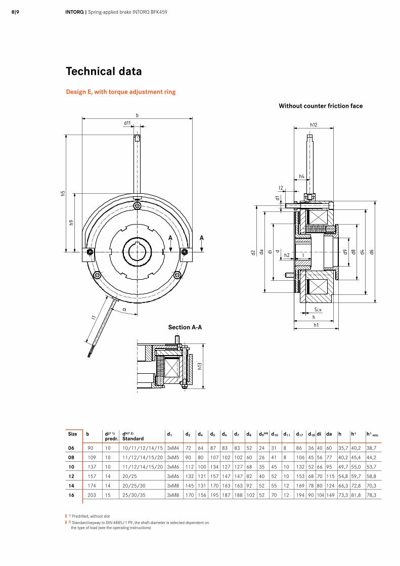
Technical data
Design E, with torque adjustment ring
Section A-A
Without counter friction face
❙ 1) Predrilled, without slot
❙ 2) Standard keyway to DIN 6885/1 P9, the shaft diameter is selected dependent on the type of load (see the operating instructions)
Size b dJ7 1) dH7 2) d1 d2 d4 d5 d6 d7 d8 d9H9 d10 d11 d17 d18 di da h h1 h1 min. predr. Standard
06 90 10 10/11/12/14/15 3xM4 72 64 87 83 83 52 24 31 8 86 36 40 60 35,7 40,2 38,7
08 109 10 11/12/14/15/20 3xM5 90 80 107 102 102 60 26 41 8 106 45 56 77 40,2 45,4 44,2
10 137 10 11/12/14/15/20 3xM6 112 100 134 127 127 68 35 45 10 132 52 66 95 49,7 55,0 53,7
12 157 14 20/25 3xM6 132 121 157 147 147 82 40 52 10 153 68 70 115 54,8 59,7 58,8
14 174 14 20/25/30 3xM8 145 131 170 163 163 92 52 55 12 169 78 80 124 66,3 72,8 70,3
16 203 15 25/30/35 3xM8 170 156 195 187 188 102 52 70 12 194 90 104 149 73,3 81,8 78,3
A A
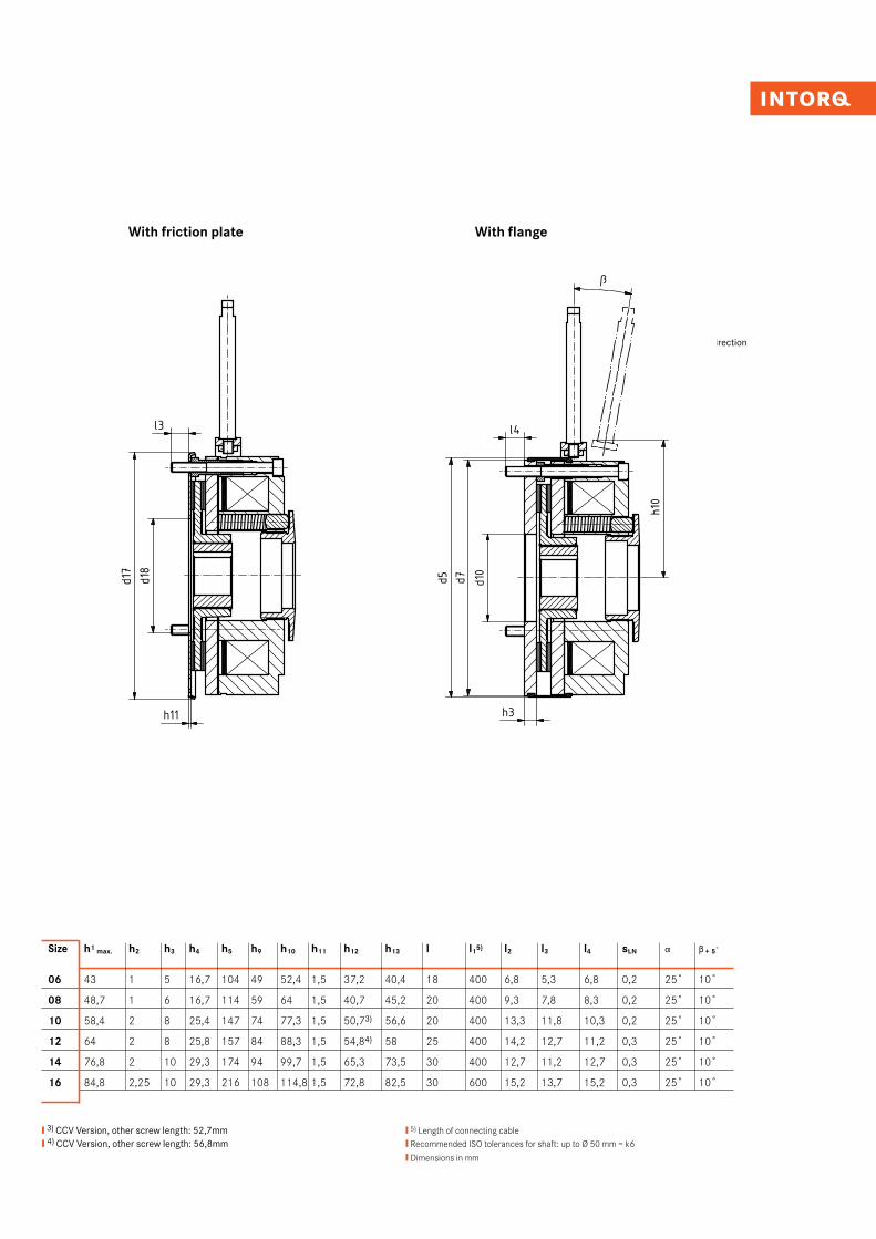
With friction plate With flange
Release direction
❙ 3) CCV Version, other screw length: 52,7mm❙ 4) CCV Version, other screw length: 56,8mm
❙ 5) Length of connecting cable❙ Recommended ISO tolerances for shaft: up to Ø 50 mm = k6
❙ Dimensions in mm
Gr. /size b d J7 vorg. d H7 Standard d1 d2 d4 d5 d6 d7 d8 d9 H9 d10 d11 d17 d18 di da h h1 h1 min h1max h2 h3 h4 h5 h9 h10 h11 h12 h13 l l1 l2 l3 l4 SLN a a a a
β β β β
+5° +5° +5° +5°
06 90 10 10/11/12/14/15 3xM4 72 64 87 83 83 52 24 31 8 86 36 40 60 35,7 40,2 38,7 43 1 5 16 104 49 52,4 1,5 37,2 40,4 18 400 6,8 5,3 6,8 0,2 25° 10°08 109 10 11/12/14/15/20 3xM5 90 80 106 102 102 60 26 41 10 106 45 56 77 40,2 45,4 44,2 48,7 1 6 16 132 59 64 1,5 40,7 45,2 20 400 9,3 7,8 8,3 0,2 25° 10°10 137 10 11/12/14/15/20 3xM6 112 100 131 127 127 68 35 45 10 132 52 66 95 49,7 55,5 53,5 58,4 2 8 28 147 74 77,3 1,5 50,7 1) 56,6 20 400 13,3 11,8 10,3 0,2 25° 10°12 157 14 20/25 3xM6 132 121 152 147 147 82 40 52 10 153 68 70 115 54,8 59,8 58,8 64 2 8 30 157 84 88,3 1,5 54,8 2) 58 25 400 14,2 12,7 11,2 0,3 25° 10°14 174 14 20/25/30 3xM8 145 131 168 163 163 92 52 55 12 169 78 80 124 66,3 73,3 71,3 76,8 2 10 33 174 93 99,7 1,5 65,3 73,5 30 400 12,7 11,2 12,7 0,3 25° 10°16 203 15 25/30/35 3xM8 170 156 193 187 188 102 52 70 12 194 90 104 149 73,3 81,8 78,3 84,8 2,25 10 38 216 108 114,8 1,5 72,8 82,5 30 600 15,2 13,7 15,2 0,3 25° 10°
Für CCV / for CCV:1) 52,72) 56,8
Ind./ Anz./ind. quan.
Änder-Nr./revision no.
Datum/date
Name/name
Datum/date Name/name
Bea/drn
Gepr/chkd
Norm/appr
Datei/file
Benennung/name of drawing
Zeichnungsnummer/drawing no.
Ersatz fuer/back-up for
Blatt/sheetCAD
M14.0293.iami
StrateDüning
10.08.200928.08.2009
Massblatt / dimension sheet Federkraftbremse / spring operated brake BFK459-06...16E
M14.02931 - 601235 15.10.2014 STR
5020
1030
40m
m0
Schu
tzve
rmer
k IS
O 1
6016
bea
chte
n. C
opyr
ight
rese
rved
.
1 2 3 4 5 6 7 8 9 10 11 12
A
B
C
D
E
F
G
H
1 2 3 4 5 6 7 8 9 10 11 12
A
B
C
D
E
F
G
H
h4
d9 d8 d4
SLN aaaa
h9h5
d11b
lda di d
l3 l4
h3h11
d17 d7
l2
h2
l1 hh1
d6 d10
h10
d18
h12
h13
d5
-Maße in mm -Änderungen vorbehalten! -dimensions in mm -changes reserved!
β
d2
d1
Size h1 max. h2 h3 h4 h5 h9 h10 h11 h12 h13 l l15) l2 l3 l4 sLN a b + 5˚
06 43 1 5 16,7 104 49 52,4 1,5 37,2 40,4 18 400 6,8 5,3 6,8 0,2 25˚ 10˚
08 48,7 1 6 16,7 114 59 64 1,5 40,7 45,2 20 400 9,3 7,8 8,3 0,2 25˚ 10˚
10 58,4 2 8 25,4 147 74 77,3 1,5 50,73) 56,6 20 400 13,3 11,8 10,3 0,2 25˚ 10˚
12 64 2 8 25,8 157 84 88,3 1,5 54,84) 58 25 400 14,2 12,7 11,2 0,3 25˚ 10˚
14 76,8 2 10 29,3 174 94 99,7 1,5 65,3 73,5 30 400 12,7 11,2 12,7 0,3 25˚ 10˚
16 84,8 2,25 10 29,3 216 108 114,8 1,5 72,8 82,5 30 600 15,2 13,7 15,2 0,3 25˚ 10˚

Gr. /size b d J7 vorg. d H7 Standard d1 d2 d3 H8 d4 d5 d6 d7 d10 d11 d17 d18 di da h h2 h3 h4 h5 h9 h10 h11 h12 h13 l l1 l2 l3 l4 SLN aaaa
β β β β
+5+5+5+5
06 90 10 10/11/12/14/15 3xM4 72 25 64 87 83 83 31 8 86 36 40 60 35,7 1 5 16 104 49 52,4 1,5 37,2 40,4 18 400 6,8 5,3 6,8 0,2 25° 10°08 109 10 11/12/14/15/20 3xM5 90 32 80 106 102 102 41 10 106 45 56 77 40,2 1 6 16 132 59 64 1,5 40,7 45,2 20 400 9,3 7,8 8,3 0,2 25° 10°10 137 10 11/12/14/15/20 3xM6 112 42 100 131 127 127 45 10 132 52 66 95 49,7 2 8 28 147 74 77,3 1,5 50,7 1) 56,6 20 400 13,3 11,8 10,3 0,2 25° 10°12 157 14 20/25 3xM6 132 50 121 152 147 147 52 10 153 68 70 115 54,8 2 8 30 157 84 88,3 1,5 54,8 2) 58 25 400 14,2 12,7 11,2 0,3 25° 10°14 174 14 20/25/30 3xM8 145 60 131 168 163 163 55 12 169 78 80 124 66,3 2 10 33 174 93 99,7 1,5 65,3 73,5 30 400 12,7 11,2 12,7 0,3 25° 10°16 203 15 25/30/35 3xM8 170 68 156 193 187 188 70 12 194 90 104 149 73,3 2,25 10 38 216 108 114,8 1,5 72,8 82,5 30 600 15,2 13,7 15,2 0,3 25° 10°
Für CCV / for CCV:1) 52,72) 56,8
Ind./ Anz./ind. quan.
Änder-Nr./revision no.
Datum/date
Name/name
Datum/date Name/name
Bea/drn
Gepr/chkd
Norm/appr
Datei/file
Benennung/name of drawing
Zeichnungsnummer/drawing no.
Ersatz fuer/back-up for
Blatt/sheetCAD
M14.0294.iami
StrateDüning
10.08.200928.08.2009
Massblatt / dimension sheetFederkraftbremse / spring operated brake BFK459-06...16N
M14.02941 - 601235 15.10.2014 STR
5020
1030
40m
m0
Schu
tzve
rmer
k IS
O 1
6016
bea
chte
n. C
opyr
ight
rese
rved
.
1 2 3 4 5 6 7 8 9 10 11 12
A
B
C
D
E
F
G
H
1 2 3 4 5 6 7 8 9 10 11 12
A
B
C
D
E
F
G
H
h4
d4
SLN aaaa
h9h5
d11b
lda di d
l3 l4
h3h11
d17 d7
l2
h2
l1 h
d6 d10
h10
d18
h12
h13
d5
-Maße in mm -Änderungen vorbehalten! -dimensions in mm -changes reserved!
(h13)
β
d2
d1
d3
INTORQ I Spring-applied brake INTORQ BFK45910I11
Technical data
Design N, without torque adjustment ring
Without counter friction face
Section A-A
❙ 1) Predrilled, without slot
❙ 2) Standard keyway to DIN 6885/1 P9, the shaft diameter is selected dependent on the type of load (see the operating instructions)
Size b dJ7 1) dH7 2) d1 d2 d3H8 d4 d5 d6 d7 d10 d11 d17 d18 di da h predr. Standard
06 90 10 10/11/12/14/15 3xM4 72 25 64 87 83 83 31 8 86 36 40 60 35,7
08 109 10 11/12/14/15/20 3xM5 90 32 80 106 102 102 41 8 106 45 56 77 40,2
10 137 10 11/12/14/15/20 3xM6 112 42 100 134 127 127 45 10 132 52 66 95 49,7
12 157 14 20/25 3xM6 132 50 121 157 147 147 52 10 153 68 70 115 54,8
14 174 14 20/25/30 3xM8 145 60 131 170 163 163 55 12 169 78 80 124 66,3
16 203 15 25/30/35 3xM8 170 68 156 195 187 188 70 12 194 90 104 149 73,3
A A
Gr. /size b d J7 vorg. d H7 Standard d1 d2 d3 H8 d4 d5 d6 d7 d10 d11 d17 d18 di da h h2 h3 h4 h5 h9 h10 h11 h12 h13 l l1 l2 l3 l4 SLN aaaa
β β β β
+5+5+5+5
06 90 10 10/11/12/14/15 3xM4 72 25 64 87 83 83 31 8 86 36 40 60 35,7 1 5 16 104 49 52,4 1,5 37,2 40,4 18 400 6,8 5,3 6,8 0,2 25° 10°08 109 10 11/12/14/15/20 3xM5 90 32 80 106 102 102 41 10 106 45 56 77 40,2 1 6 16 132 59 64 1,5 40,7 45,2 20 400 9,3 7,8 8,3 0,2 25° 10°10 137 10 11/12/14/15/20 3xM6 112 42 100 131 127 127 45 10 132 52 66 95 49,7 2 8 28 147 74 77,3 1,5 50,7 1) 56,6 20 400 13,3 11,8 10,3 0,2 25° 10°12 157 14 20/25 3xM6 132 50 121 152 147 147 52 10 153 68 70 115 54,8 2 8 30 157 84 88,3 1,5 54,8 2) 58 25 400 14,2 12,7 11,2 0,3 25° 10°14 174 14 20/25/30 3xM8 145 60 131 168 163 163 55 12 169 78 80 124 66,3 2 10 33 174 93 99,7 1,5 65,3 73,5 30 400 12,7 11,2 12,7 0,3 25° 10°16 203 15 25/30/35 3xM8 170 68 156 193 187 188 70 12 194 90 104 149 73,3 2,25 10 38 216 108 114,8 1,5 72,8 82,5 30 600 15,2 13,7 15,2 0,3 25° 10°
Für CCV / for CCV:1) 52,72) 56,8
Ind./ Anz./ind. quan.
Änder-Nr./revision no.
Datum/date
Name/name
Datum/date Name/name
Bea/drn
Gepr/chkd
Norm/appr
Datei/file
Benennung/name of drawing
Zeichnungsnummer/drawing no.
Ersatz fuer/back-up for
Blatt/sheetCAD
M14.0294.iami
StrateDüning
10.08.200928.08.2009
Massblatt / dimension sheetFederkraftbremse / spring operated brake BFK459-06...16N
M14.02941 - 601235 15.10.2014 STR
5020
1030
40m
m0
Schu
tzve
rmer
k IS
O 1
6016
bea
chte
n. C
opyr
ight
rese
rved
.
1 2 3 4 5 6 7 8 9 10 11 12
A
B
C
D
E
F
G
H
1 2 3 4 5 6 7 8 9 10 11 12
A
B
C
D
E
F
G
H
h4
d4
SLN aaaa
h9h5
d11b
lda di d
l3 l4
h3h11
d17 d7
l2
h2
l1 h
d6 d10
h10
d18
h12
h13
d5
-Maße in mm -Änderungen vorbehalten! -dimensions in mm -changes reserved!
(h13)
β
d2
d1
d3
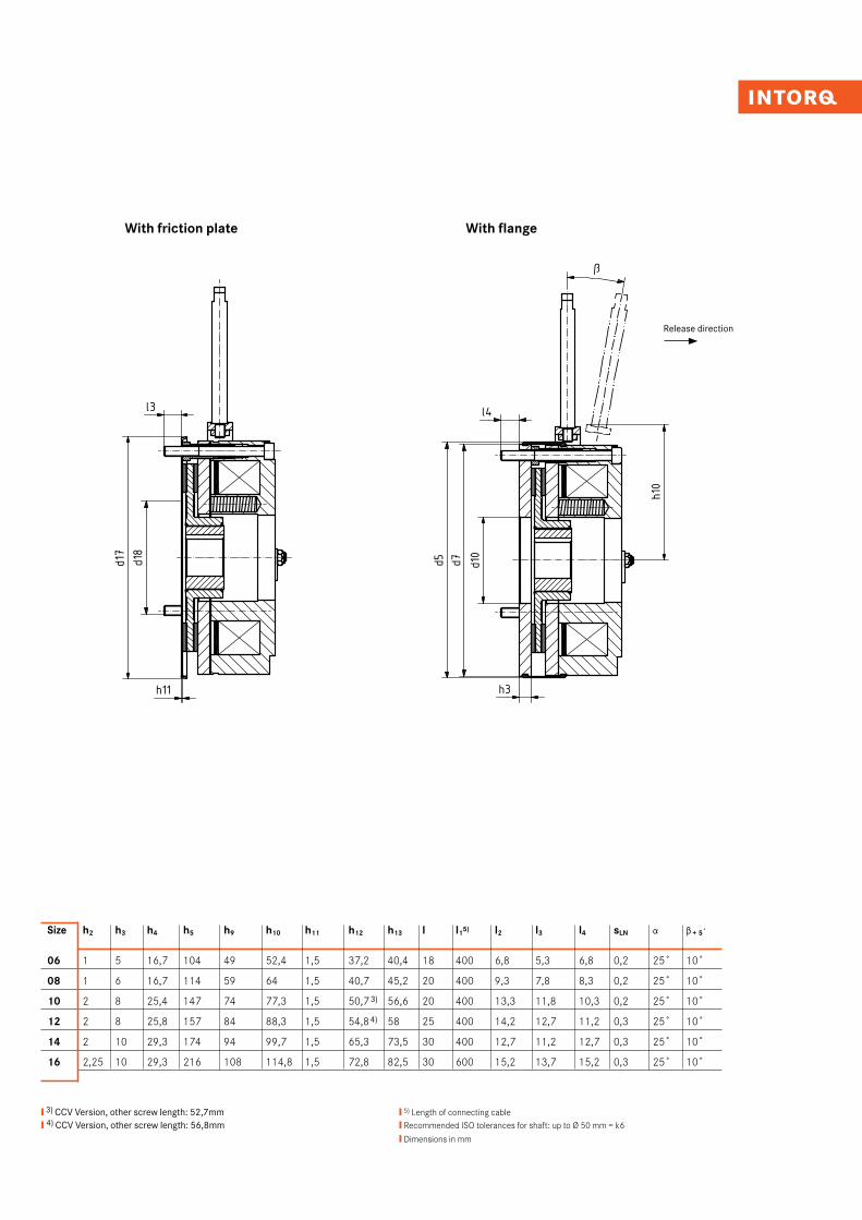
With friction plate With flange
Release direction
❙ 3) CCV Version, other screw length: 52,7mm❙ 4) CCV Version, other screw length: 56,8mm
❙ 5) Length of connecting cable❙ Recommended ISO tolerances for shaft: up to Ø 50 mm = k6
❙ Dimensions in mm
Size h2 h3 h4 h5 h9 h10 h11 h12 h13 l l15) l2 l3 l4 sLN a b + 5˚
06 1 5 16,7 104 49 52,4 1,5 37,2 40,4 18 400 6,8 5,3 6,8 0,2 25˚ 10˚
08 1 6 16,7 114 59 64 1,5 40,7 45,2 20 400 9,3 7,8 8,3 0,2 25˚ 10˚
10 2 8 25,4 147 74 77,3 1,5 50,7 3) 56,6 20 400 13,3 11,8 10,3 0,2 25˚ 10˚
12 2 8 25,8 157 84 88,3 1,5 54,84) 58 25 400 14,2 12,7 11,2 0,3 25˚ 10˚
14 2 10 29,3 174 94 99,7 1,5 65,3 73,5 30 400 12,7 11,2 12,7 0,3 25˚ 10˚
16 2,25 10 29,3 216 108 114,8 1,5 72,8 82,5 30 600 15,2 13,7 15,2 0,3 25˚ 10˚
INTORQ I Spring-applied brake INTORQ BFK45912I13
Technical data
Braking torques
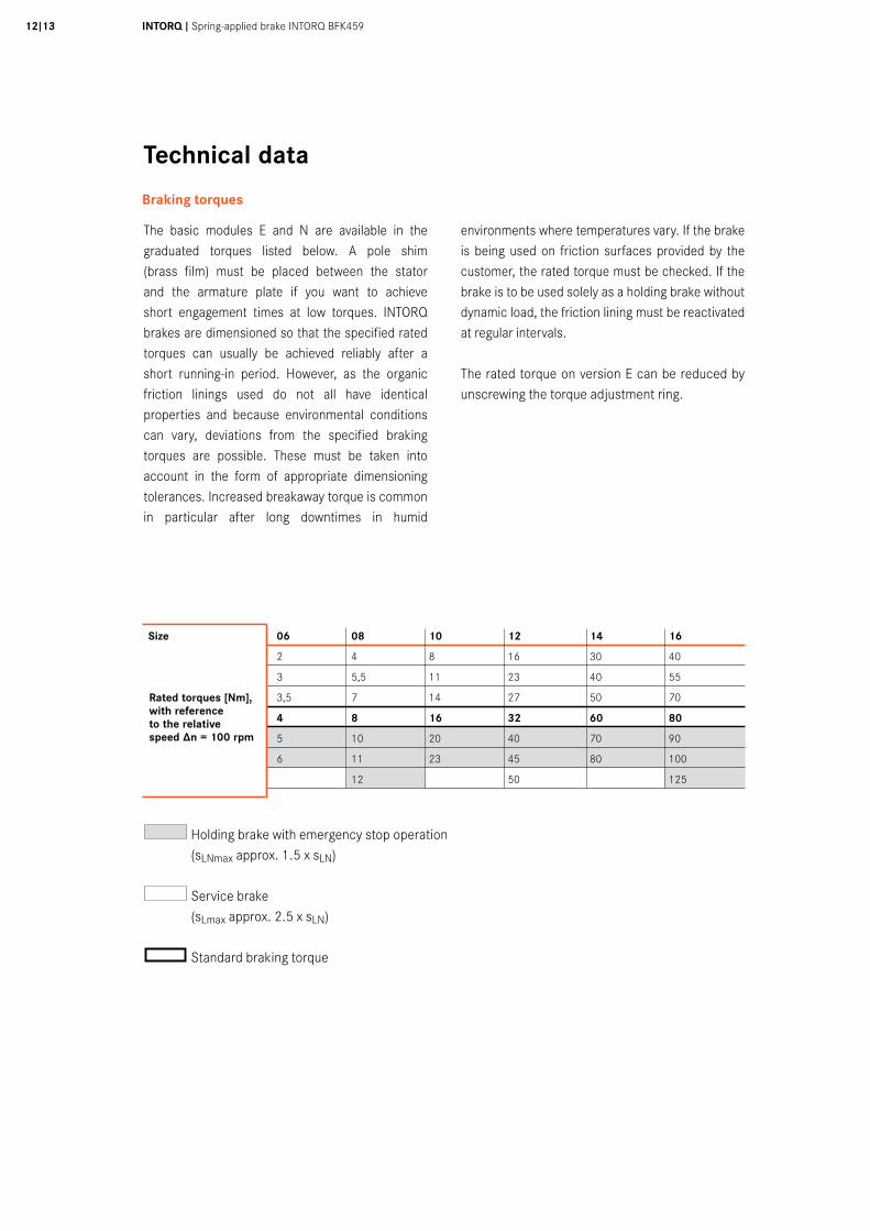
The basic modules E and N are available in the graduated torques listed below. A pole shim (brass film) must be placed between the stator and the armature plate if you want to achieve short engagement times at low torques. INTORQ brakes are dimensioned so that the specified rated torques can usually be achieved reliably after a short running-in period. However, as the organic friction linings used do not all have identical properties and because environmental conditions can vary, deviations from the specified braking torques are possible. These must be taken into account in the form of appropriate dimensioning tolerances. Increased breakaway torque is common in particular after long downtimes in humid
environments where temperatures vary. If the brake is being used on friction surfaces provided by the customer, the rated torque must be checked. If the brake is to be used solely as a holding brake without dynamic load, the friction lining must be reactivated at regular intervals.
The rated torque on version E can be reduced by unscrewing the torque adjustment ring.
Holding brake with emergency stop operation (sLNmax approx. 1.5 x sLN)
Service brake (sLmax approx. 2.5 x sLN)
Standard braking torque
Rated torques [Nm], with referenceto the relative speed ∆n = 100 rpm
Size 06 08 10 12 14 16
2 4 8 16 30 40
3 5,5 11 23 40 55
3,5 7 14 27 50 70
4 8 16 32 60 80
5 10 20 40 70 90
6 11 23 45 80 100
12 50 125
Technical data
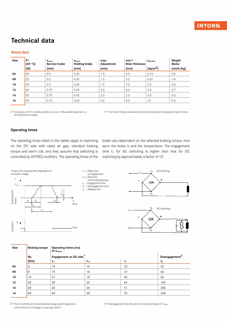
Rated data
Size P1) sLmax sLmax max. min.2) JAlurotor Weight [20 °C] Service brake Holding brake Adjustment Rotor thickness Stator
[W] [mm] [mm] [mm] [mm] [kgcm2] clutch [kg]
06 20 0.5 0.35 1.5 4.5 0.15 0.9
08 25 0.5 0.35 1.5 5.5 0.61 1.4
10 30 0.5 0.35 1.5 7.5 2.0 3.0
12 40 0.75 0.45 2.0 8.0 4.5 3.7
14 50 0.75 0.45 2.5 7.5 6.3 6.5
16 55 0.75 0.45 3.5 8.0 15 9.4
❙ 1) Coil power at 20˚C in watts, deviation of up to ±10% possible dependent on the selected coil voltage.
❙ 2) The friction lining is dimensioned so that the brake can be adjusted at least 5 times.
The operating times listed in the tables apply to switching on the DC side with rated air gap, standard braking torque and warm coil, and they assume that switching is controlled by INTORQ rectifiers. The operating times of the
brake vary dependent on the selected braking torque, how worn the brake is and the temperature. The engagement time t1 for AC switching is higher than that for DC switching by approximately a factor of 10.
❙ 1) The DC switching times were obtained using a spark suppressor,
which limits the coil voltage on opening to 800 V.
❙ 2) Disengagement time with warm coil corresponding to 0.7·lNenn
AC switching
DC switching
t11 = Delay time on engagement
t12 = Rise time of the braking torque
t1 = Engagement time t2 = Disengagement timet3 = Slipping time
Torque time characteristic dependent on excitation voltage
Cha
ract
eris
tic
torq
ueEx
cita
tion
Time
Time
Size Braking torque Operating times [ms] at sLNenn MK Engagement on DC side1) Disengagement2)
[Nm] t11 t12 t1 t2
06 4 10 13 23 52
08 8 15 16 31 60
10 16 31 19 50 65
12 32 39 25 64 145
14 60 26 25 51 205
16 80 40 30 70 258
Operating times
INTORQ I Spring-applied brake INTORQ BFK45914I15
Technical data
Service life and wear
The amount of friction energy to be withstood until sLmax (maximum permissible working air gap) is reached and the brake is adjusted depends on various factors. These include in particular the mass to be decelerated, the differential speed, the operating frequency and the resulting temperature at the friction surfaces. Therefore, it is not possible to specify a friction energy value until readjustment that is universally valid for all operating conditions.
In addition, increased wear should be expected with vertical mounting.
The BFK459 can be adjusted when sLmax is reached. The way in which the friction lining is dimensioned allows the brake to be adjusted at least 5 times.
Where the amount of friction energy per switching operation is low, the brake's mechanical components can impose limitations in terms of service life. The rotor/hub connection, springs, armature plate and sleeves are particularly vulnerable to operational wear. The expected service life of the standard design is around 1 million load alternations. Solutions that are optimised in terms of service life are available in cases where a longer service life is required (consult the supplier).
MaintenanceBrakes are components that are subject to wear. Easy access for inspection and maintenance work must be ensured. Intervals between inspections should be set in accordance with the expected service life and load. For more information, please see the operating instructions.
Torques dependent on speed
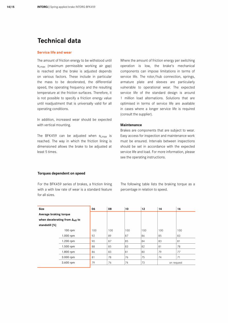
For the BFK459 series of brakes, a friction lining with a with low rate of wear is a standard feature for all sizes.
The following table lists the braking torque as a percentage in relation to speed.
Size 06 08 10 12 14 16
Average braking torque
when decelerating from ∆n0 to
standstill [%]
100 100 100 100 100 100
92 89 87 86 85 83
90 87 85 84 83 81
88 85 83 82 81 78
86 83 81 80 79 77
81 78 76 75 74 71
79 76 74 73 on request
100 rpm
1.000 rpm
1.200 rpm
1.500 rpm
1.800 rpm
3.000 rpm
3.600 rpm
Technical data
Thermal load limits
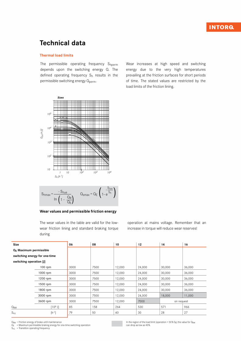
The permissible operating frequency Shperm depends upon the switching energy Q. The defined operating frequency Sh results in the permissible switching energy Qperm.
Wear increases at high speed and switching energy due to the very high temperatures prevailing at the friction surfaces for short periods of time. The stated values are restricted by the load limits of the friction lining.
Wear values and permissible friction energy
The wear values in the table are valid for the low-wear friction lining and standard braking torque during
operation at mains voltage. Remember that an increase in torque will reduce wear reserves!
Size 06 08 10 12 14 16
QE Maximum permissible
switching energy for one-time
switching operation [J]
3000 7500 12,000 24,000 30,000 36,000
3000 7500 12,000 24,000 30,000 36,000
3000 7500 12,000 24,000 30,000 36,000
3000 7500 12,000 24,000 30,000 36,000
3000 7500 12,000 24,000 30,000 36,000
3000 7500 12,000 24,000 18,000 11,000
3000 7500 12,000 7000 on request
QBW [106 J] 85 158 264 530 571 966
Shü [h-1] 79 50 40 30 28 27
100 rpm
1000 rpm
1200 rpm
1500 rpm
1800 rpm
3000 rpm
3600 rpm
QBW = Friction energy of brake until maintenanceQE = Maximum permissible braking energy for one-time switching operationShü = Transition operating frequency
In the region of the load limit (operation > 50 % QE) the value for QBW
can drop as low as 40%.
10
100
1.000
10.000
100.000
1.000.000
1 10 100 1.000 10.000
Schalthäufigkeit Sh [h-1]
Scha
ltarb
eit Q
[J]
16 14 12
1008
06
Sh [h-1]
105
104
103
102
Qzu
l in
[J]
Sizes
1 10 102 103 10410
Shmax = - Shue Qsmax = QE
(1- e-Shue )
In (1 - QR)
Sh
QE
INTORQ I Spring-applied brake INTORQ BFK45916I17
Accessories
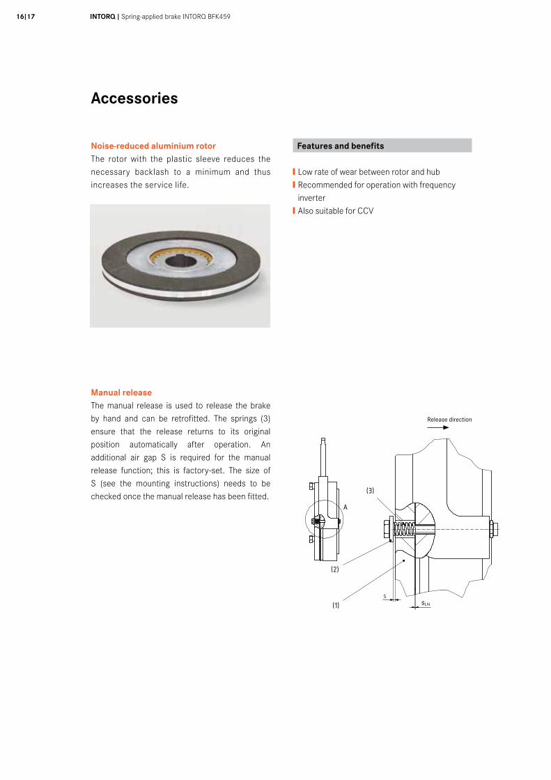
Noise-reduced aluminium rotorThe rotor with the plastic sleeve reduces the necessary backlash to a minimum and thus increases the service life.
Manual release The manual release is used to release the brake by hand and can be retrofitted. The springs (3) ensure that the release returns to its original position automatically after operation. An additional air gap S is required for the manual release function; this is factory-set. The size of S (see the mounting instructions) needs to be checked once the manual release has been fitted.
A ( 2 : 1 )
Sch
utzv
erm
erk
ISO
160
16 b
each
ten.
Cop
yrig
ht re
serv
ed.
5010
mm
3040
200
1 2 3 4 5 6 7 8
A
B
C
D
E
F
1 2 3 4 5 6 7 8
A
B
C
D
E
F
Tol.Maß/
tol. size
Abmaß/
deviation
Tol.Maß/
tol. size
Abmaß/
deviation
Ind./ Anz./ind. quan.
Änder-Nr./revision no.
Datum/date
Name/name
Datum/date Name/name
Bea/drn
Gepr/chkd
Norm/appr
Datei/file
Benennung/name of drawing
Zeichnungsnummer/drawing no.
Ersatz fuer/back-up for
Werkstoff/material
Maßstab/scale Gewicht/weight
Blatt/sheet
Allgemeintoleranzen/general tolerance
Oberflächen/surface
DIN ISO 1302
X
Y
Z
Rz25
Rz6,3
Rz1
CAD
BFK45912-001.iam
Düning HandlüftungsdarstellungBFK459-XX
A
SSlü(1)
(2)
(3)
sLN
Release direction
Features and benefits
❙ Low rate of wear between rotor and hub❙ Recommended for operation with frequency inverter ❙ Also suitable for CCV
Accessories
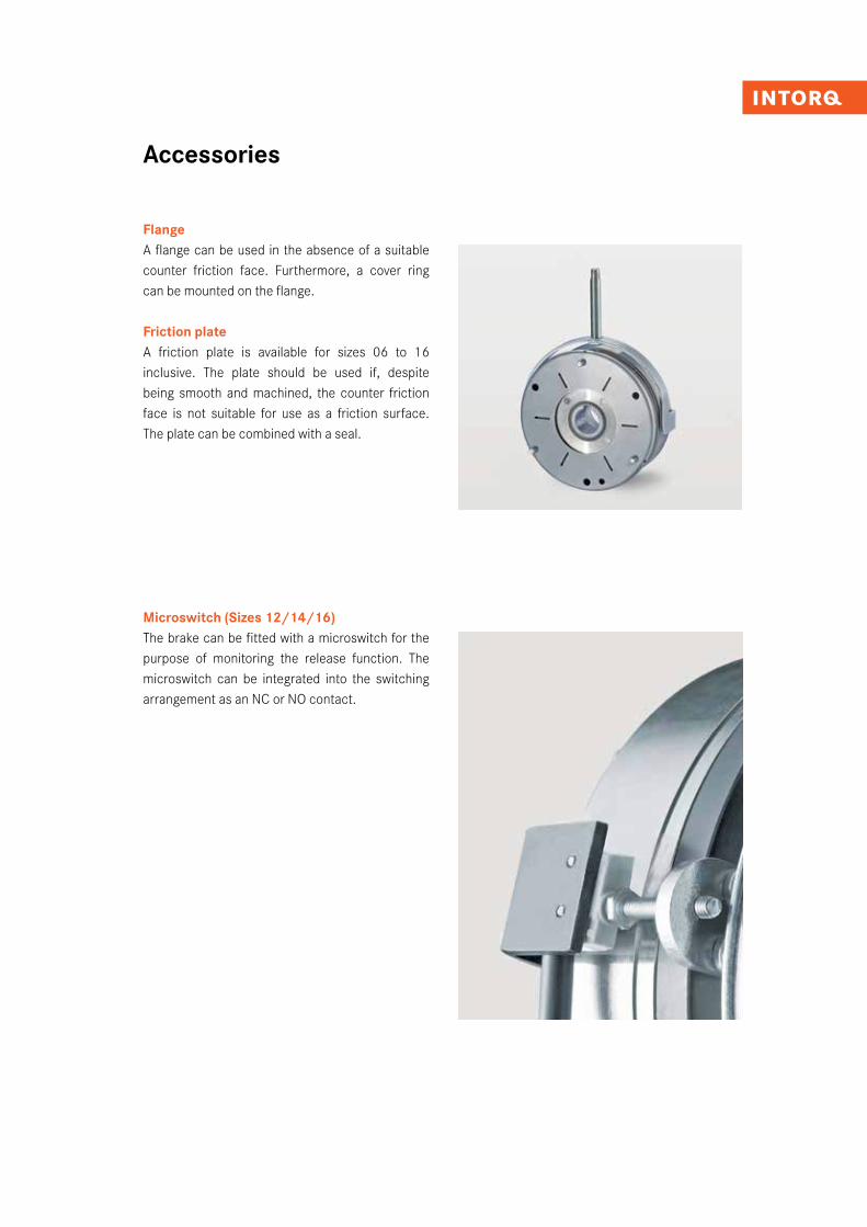
FlangeA flange can be used in the absence of a suitable counter friction face. Furthermore, a cover ring can be mounted on the flange.
Friction plateA friction plate is available for sizes 06 to 16 inclusive. The plate should be used if, despite being smooth and machined, the counter friction face is not suitable for use as a friction surface. The plate can be combined with a seal.
Microswitch (Sizes 12/14/16)The brake can be fitted with a microswitch for the purpose of monitoring the release function. The microswitch can be integrated into the switching arrangement as an NC or NO contact.
INTORQ I Spring-applied brake INTORQ BFK45918I19
Accessories
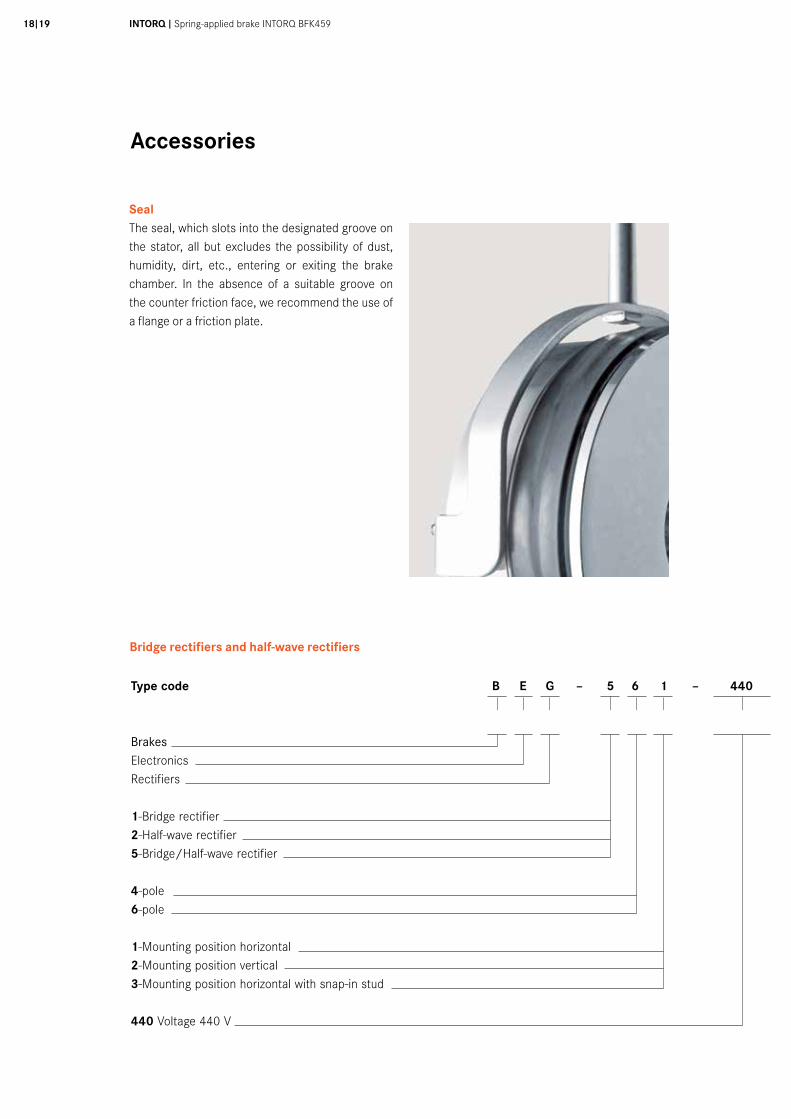
SealThe seal, which slots into the designated groove on the stator, all but excludes the possibility of dust, humidity, dirt, etc., entering or exiting the brake chamber. In the absence of a suitable groove on the counter friction face, we recommend the use of a flange or a friction plate.
Type code B E G – 5 6 1 – 440
BrakesElectronicsRectifiers
1-Bridge rectifier2-Half-wave rectifier5-Bridge/Half-wave rectifier
4-pole6-pole
1-Mounting position horizontal2-Mounting position vertical3-Mounting position horizontal with snap-in stud
440 Voltage 440 V
Bridge rectifiers and half-wave rectifiers
Accessories
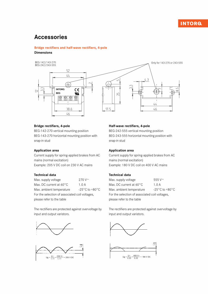
Bridge rectifiers and half-wave rectifiers, 4-poleDimensions
Bridge rectifiers, 4-poleBEG-142-270 vertical mounting position BEG-143-270 horizontal mounting position with snap-in stud
Application areaCurrent supply for spring-applied brakes from AC mains (normal excitation)Example: 205 V DC coil on 230 V AC mains
Technical dataMax. supply voltage 270 V~Max. DC current at 60°C 1.0 AMax. ambient temperature -25°C to +80°CFor the selection of associated coil voltages, please refer to the table
The rectifiers are protected against overvoltage by input and output varistors.
BEG-142/143-270
Ug = U~
= 230 V~
= 205 V DC 1.11 1.11
Ug = U~
= 400 V~
= 180 V DC 2.22 2.22
Half-wave rectifiers, 4-poleBEG-242-555 vertical mounting positionBEG-243-555 horizontal mounting position with snap-in stud
Application areaCurrent supply for spring-applied brakes from AC mains (normal excitation)Example: 180 V DC coil on 400 V AC mains
Technical dataMax. supply voltage 555 V~Max. DC current at 60°C 1.0 AMax. ambient temperature -25°C to +80°CFor the selection of associated coil voltages, please refer to the table
The rectifiers are protected against overvoltage by input and output varistors.
BEG-142/143-270BEG-242/243-555
Only for 143-270 or 243-555
INTORQ
BEG
INTORQ I Spring-applied brake INTORQ BFK45920I21
Accessories
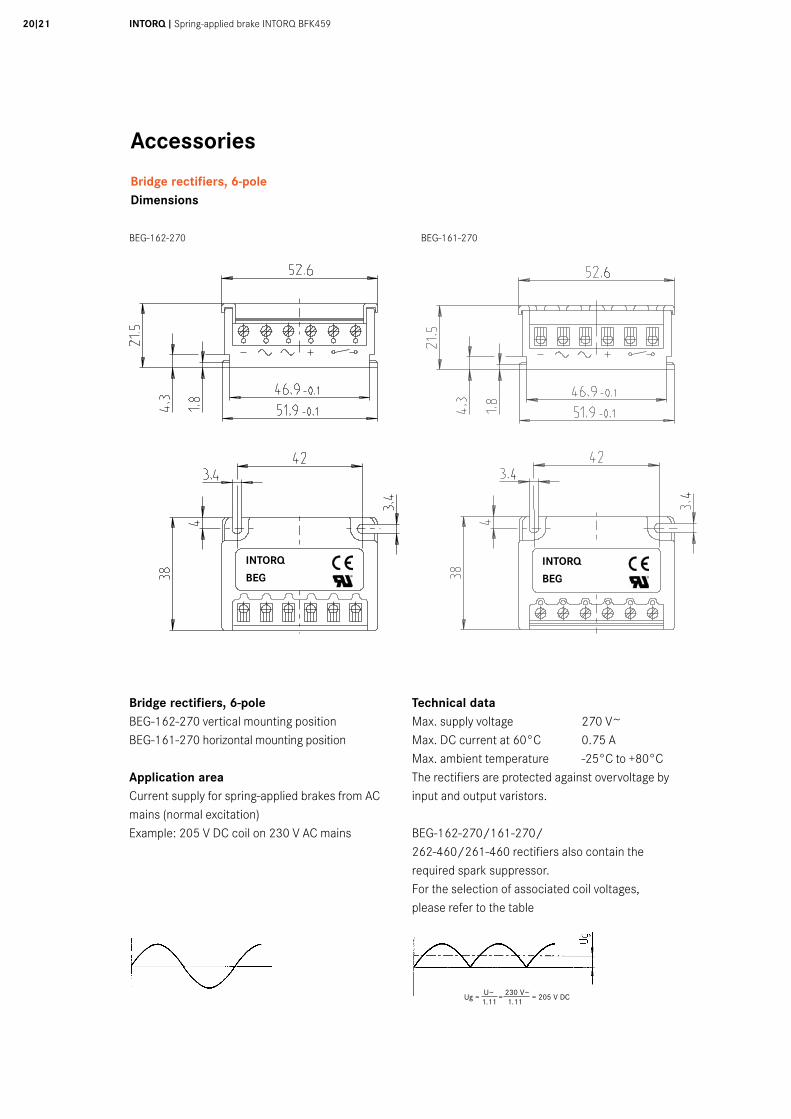
Bridge rectifiers, 6-poleDimensions
BEG-162-270 BEG-161-270
Bridge rectifiers, 6-poleBEG-162-270 vertical mounting positionBEG-161-270 horizontal mounting position
Application areaCurrent supply for spring-applied brakes from AC mains (normal excitation)Example: 205 V DC coil on 230 V AC mains
Technical dataMax. supply voltage 270 V~Max. DC current at 60°C 0.75 AMax. ambient temperature -25°C to +80°CThe rectifiers are protected against overvoltage by input and output varistors.
BEG-162-270/161-270/ 262-460/261-460 rectifiers also contain the required spark suppressor.For the selection of associated coil voltages, please refer to the table
Ug = U~
= 230 V~
= 205 V DC 1.11 1.11
BEG-162-270 BEG-161-270BEG-162-270 BEG-161-270INTORQ
BEGINTORQ
BEG
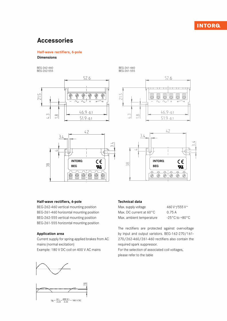
Accessories
Half-wave rectifiers, 6-poleDimensions
Half-wave rectifiers, 6-poleBEG-262-460 vertical mounting positionBEG-261-460 horizontal mounting positionBEG-262-555 vertical mounting positionBEG-261-555 horizontal mounting position
Application areaCurrent supply for spring-applied brakes from AC mains (normal excitation)Example: 180 V DC coil on 400 V AC mains
Technical dataMax. supply voltage 460 V~/555 V~Max. DC current at 60°C 0.75 AMax. ambient temperature -25°C to +80°C
The rectifiers are protected against overvoltage by input and output varistors. BEG-162-270/161-270/262-460/261-460 rectifiers also contain the required spark suppressor.For the selection of associated coil voltages, please refer to the table
Ug = U~
= 400 V~
= 180 V DC 2.22 2.22
BEG-262-460 BEG-261-460BEG-262-460 BEG-261-460
BEG-262-460 BEG-261-460BEG-262-555 BEG-261-555
INTORQ
BEG
INTORQ
BEG
INTORQ I Spring-applied brake INTORQ BFK45922I23
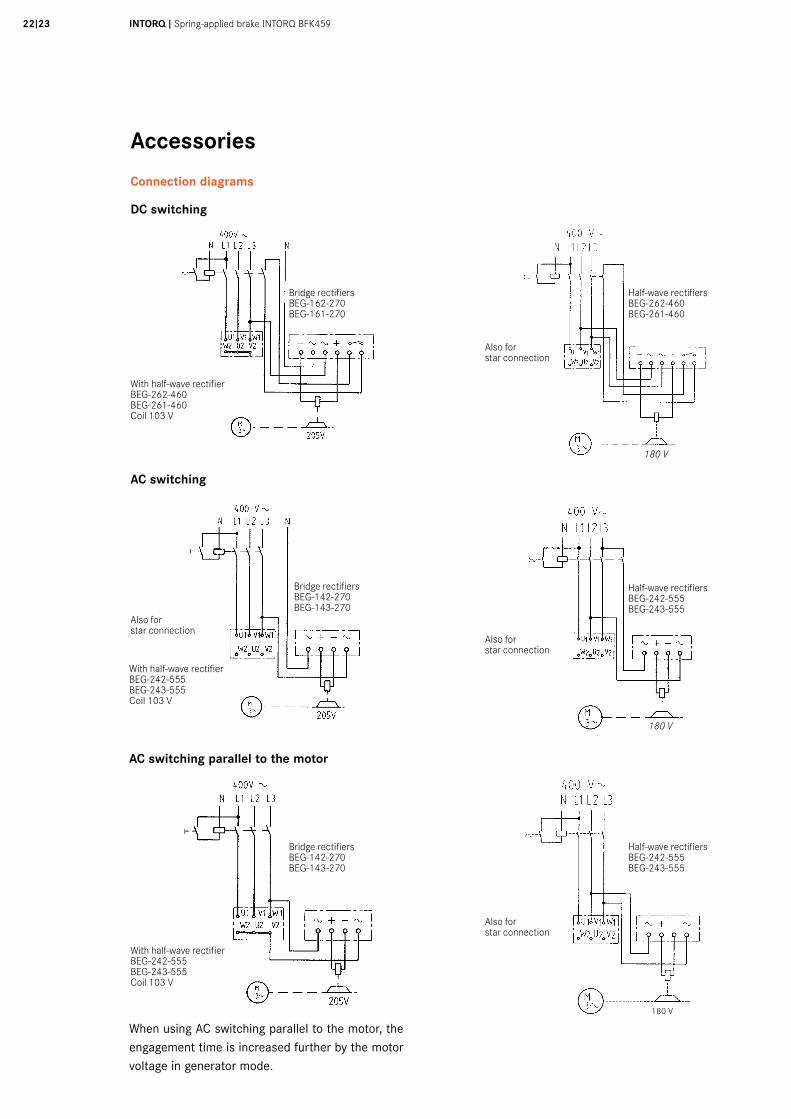
Accessories
Connection diagrams
DC switching
AC switching
Bridge rectifiersBEG-162-270BEG-161-270
Bridge rectifiersBEG-142-270BEG-143-270
Bridge rectifiersBEG-142-270BEG-143-270
Half-wave rectifiersBEG-262-460BEG-261-460
Half-wave rectifiersBEG-242-555BEG-243-555
Half-wave rectifiersBEG-242-555BEG-243-555
With half-wave rectifier BEG-262-460BEG-261-460Coil 103 V
180 V
180 V
With half-wave rectifier BEG-242-555BEG-243-555Coil 103 V
With half-wave rectifier BEG-242-555BEG-243-555Coil 103 V
Also for star connection
Also for star connection
Also for star connection
Also for star connection
180 V
AC switching parallel to the motor
When using AC switching parallel to the motor, the engagement time is increased further by the motor voltage in generator mode.
Accessories
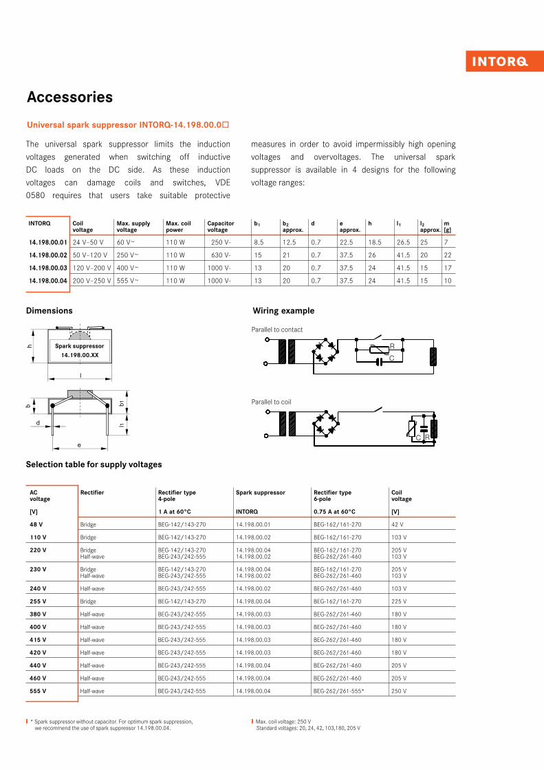
Universal spark suppressor INTORQ-14.198.00.0ò
The universal spark suppressor limits the induction voltages generated when switching off inductive DC loads on the DC side. As these induction voltages can damage coils and switches, VDE 0580 requires that users take suitable protective
measures in order to avoid impermissibly high opening voltages and overvoltages. The universal spark suppressor is available in 4 designs for the following voltage ranges:
AC Rectifier Rectifier type Spark suppressor Rectifier type Coil voltage 4-pole 6-pole voltage
[V] 1 A at 60°C INTORQ 0.75 A at 60°C [V]
48 V Bridge BEG-142/143-270 14.198.00.01 BEG-162/161-270 42 V
110 V Bridge BEG-142/143-270 14.198.00.02 BEG-162/161-270 103 V
220 V Bridge BEG-142/143-270 14.198.00.04 BEG-162/161-270 205 V Half-wave BEG-243/242-555 14.198.00.02 BEG-262/261-460 103 V
230 V Bridge BEG-142/143-270 14.198.00.04 BEG-162/161-270 205 V Half-wave BEG-243/242-555 14.198.00.02 BEG-262/261-460 103 V
240 V Half-wave BEG-243/242-555 14.198.00.02 BEG-262/261-460 103 V
255 V Bridge BEG-142/143-270 14.198.00.04 BEG-162/161-270 225 V
380 V Half-wave BEG-243/242-555 14.198.00.03 BEG-262/261-460 180 V
400 V Half-wave BEG-243/242-555 14.198.00.03 BEG-262/261-460 180 V
415 V Half-wave BEG-243/242-555 14.198.00.03 BEG-262/261-460 180 V
420 V Half-wave BEG-243/242-555 14.198.00.03 BEG-262/261-460 180 V
440 V Half-wave BEG-243/242-555 14.198.00.04 BEG-262/261-460 205 V
460 V Half-wave BEG-243/242-555 14.198.00.04 BEG-262/261-460 205 V
555 V Half-wave BEG-243/242-555 14.198.00.04 BEG-262/261-555* 250 V
Selection table for supply voltages
❙ * Spark suppressor without capacitor. For optimum spark suppression, we recommend the use of spark suppressor 14.198.00.04.
INTORQ Coil Max. supply Max. coil Capacitor b1 b2 d e h l1 l2 m voltage voltage power voltage approx. approx. approx. [g]
14.198.00.01 24 V–50 V 60 V~ 110 W 250 V- 8.5 12.5 0.7 22.5 18.5 26.5 25 7
14.198.00.02 50 V–120 V 250 V~ 110 W 630 V- 15 21 0.7 37.5 26 41.5 20 22
14.198.00.03 120 V–200 V 400 V~ 110 W 1000 V- 13 20 0.7 37.5 24 41.5 15 17
14.198.00.04 200 V–250 V 555 V~ 110 W 1000 V- 13 20 0.7 37.5 24 41.5 15 10
❙ Max. coil voltage: 250 V Standard voltages: 20, 24, 42, 103,180, 205 V
Half-wave rectifiersBEG-242-555BEG-243-555
Half-wave rectifiersBEG-242-555BEG-243-555
Dimensions Wiring example
Parallel to contact
Parallel to coil
Spark suppressor14.198.00.XX
INTORQ I Federkraftbremse INTORQ BFK45924I25
Dimensioning
Basics
+ ML = To be used when lowering a load, for example
– ML = For normal braking operation
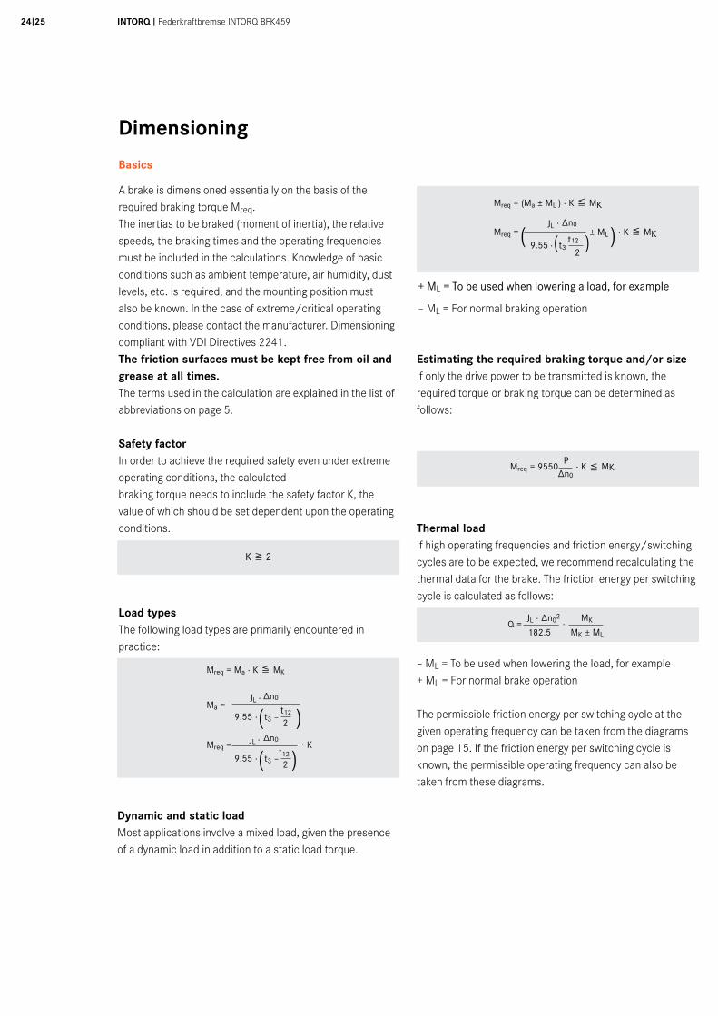
A brake is dimensioned essentially on the basis of the required braking torque Mreq.The inertias to be braked (moment of inertia), the relative speeds, the braking times and the operating frequencies must be included in the calculations. Knowledge of basic conditions such as ambient temperature, air humidity, dust levels, etc. is required, and the mounting position must also be known. In the case of extreme/critical operating conditions, please contact the manufacturer. Dimensioning compliant with VDI Directives 2241.The friction surfaces must be kept free from oil and grease at all times. The terms used in the calculation are explained in the list of abbreviations on page 5.
Safety factorIn order to achieve the required safety even under extreme operating conditions, the calculated braking torque needs to include the safety factor K, the value of which should be set dependent upon the operating conditions.
Load typesThe following load types are primarily encountered in practice:
Mreq = Ma · K & MK
Mreq = (Ma ± ML ) · K & MK
Mreq = JL
· ∆n0 ± ML · K & MK
9.55 · t3
t12
( 2
)
Dynamic and static loadMost applications involve a mixed load, given the presence of a dynamic load in addition to a static load torque.
Mreq
= 9550
P · K & MK ∆n0
Estimating the required braking torque and/or sizeIf only the drive power to be transmitted is known, the required torque or braking torque can be determined as follows:
Thermal loadIf high operating frequencies and friction energy/switching cycles are to be expected, we recommend recalculating the thermal data for the brake. The friction energy per switching cycle is calculated as follows:
– ML = To be used when lowering the load, for example+ ML = For normal brake operation
The permissible friction energy per switching cycle at the given operating frequency can be taken from the diagrams on page 15. If the friction energy per switching cycle is known, the permissible operating frequency can also be taken from these diagrams.
K 7 2
Q = JL · ∆n02
· MK
Mreq = · Kt3 –
t12
2
∆n0JL ·
( )9.55 ·
Ma = t3 –
t12
2
∆n0JL ·
( )9.55 ·
182.5 MK ± ML
( )
Dimensioning
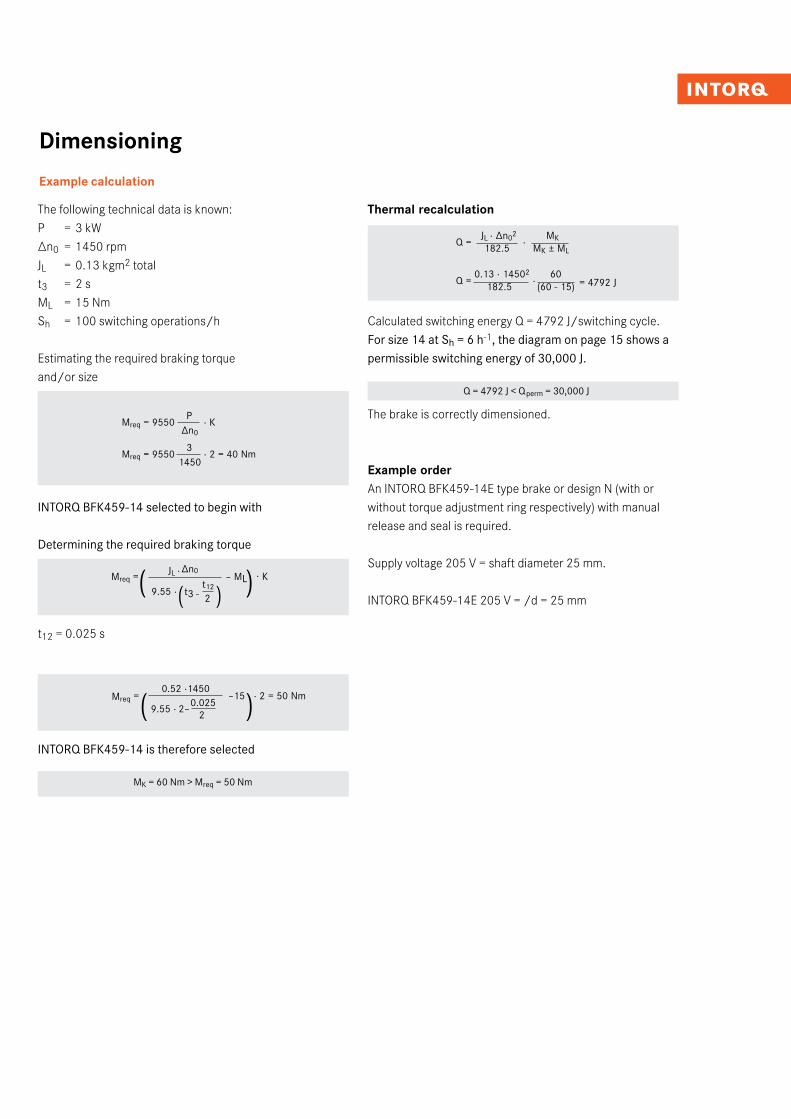
Example calculation
Mreq = –15 · 2 = 50 Nm
The following technical data is known:P = 3 kW∆n0 = 1450 rpmJL = 0.13 kgm2 totalt3 = 2 sML = 15 NmSh = 100 switching operations/h
Estimating the required braking torque and/or size
Mreq = 9550 P
· K ∆n0
Mreq = 9550 3
· 2 = 40 Nm 1450
INTORQ BFK459-14 selected to begin with
Determining the required braking torque
t12 = 0.025 s
INTORQ BFK459-14 is therefore selected
MK = 60 Nm > Mreq = 50 Nm
( )
Thermal recalculation
Calculated switching energy Q = 4792 J/switching cycle.For size 14 at Sh = 6 h-1, the diagram on page 15 shows a permissible switching energy of 30,000 J.
Q = 4792 J < Qperm = 30,000 J
The brake is correctly dimensioned.
Example orderAn INTORQ BFK459-14E type brake or design N (with or without torque adjustment ring respectively) with manual release and seal is required.
Supply voltage 205 V = shaft diameter 25 mm.
INTORQ BFK459-14E 205 V = /d = 25 mm
Q = 0.13 · 14502
· 60
182.5 (60 - 15)
0.52 ·1450
9.55 · 2–0.025
2
Q = JL · ∆n02
· MK
182.5 MK ± ML
= 4792 J
(� )Mreq = – MLt3 -
t12
2
∆n0JL ·
( )9.55 ·
· K
INTORQ I Federkraftbremse INTORQ BFK45926I27
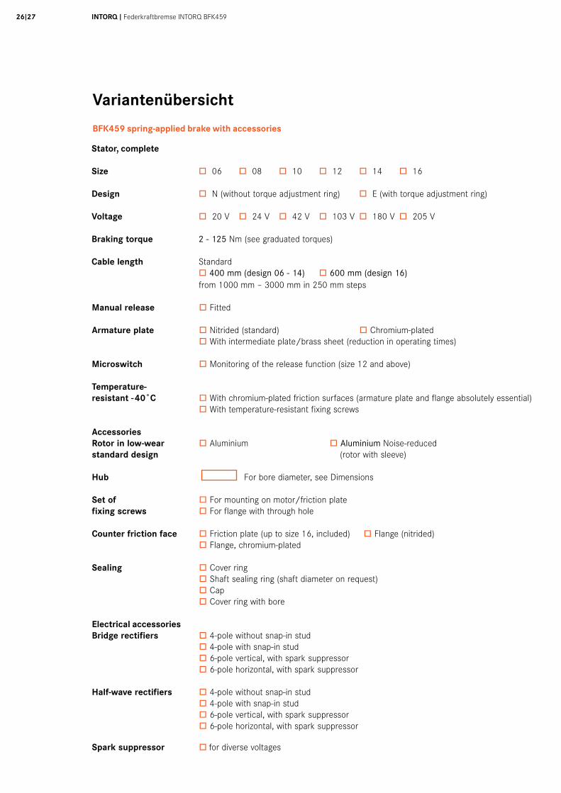
Variantenübersicht
BFK459 spring-applied brake with accessories
from 1000 mm – 3000 mm in 250 mm steps
Manual release ò Fitted
Armature plate ò Nitrided (standard) ò Chromium-plated ò With intermediate plate/brass sheet (reduction in operating times)
Microswitch ò Monitoring of the release function (size 12 and above)
Temperature-resistant -40˚C ò With chromium-plated friction surfaces (armature plate and flange absolutely essential) ò With temperature-resistant fixing screws
Accessories Rotor in low-wear ò Aluminium ò Aluminium Noise-reducedstandard design (rotor with sleeve)
Hub For bore diameter, see Dimensions
Set of ò For mounting on motor/friction platefixing screws ò For flange with through hole
Counter friction face ò Friction plate (up to size 16, included) ò Flange (nitrided) ò Flange, chromium-plated
Sealing ò Cover ring ò Shaft sealing ring (shaft diameter on request) ò Cap ò Cover ring with bore
Electrical accessoriesBridge rectifiers ò 4-pole without snap-in stud ò 4-pole with snap-in stud ò 6-pole vertical, with spark suppressor ò 6-pole horizontal, with spark suppressor
Half-wave rectifiers ò 4-pole without snap-in stud ò 4-pole with snap-in stud ò 6-pole vertical, with spark suppressor ò 6-pole horizontal, with spark suppressor
Spark suppressor ò for diverse voltages
Stator, complete
Size ò 06 ò 08 ò 10 ò 12 ò 14 ò 16
Design ò N (without torque adjustment ring) ò E (with torque adjustment ring)
Voltage ò 20 V ò 24 V ò 42 V ò 103 V ò 180 V ò 205 V
Braking torque 2 - 125 Nm (see graduated torques)
Cable length Standard ò 400 mm (design 06 - 14) ò 600 mm (design 16)

We are available to our customers at all times and in all locations. Major customers and projects are supported directly by our Key Account Sales Team at our HQ in Aerzen (Germany) or by our locations in Shanghai (China) and Atlanta (USA).
In addition to this, we work with a global network of local trading partners and cooperate with Lenze's global sales organisation.
Please send service requests directly to your local sales partner or to our HQ in Aerzen, Germany:E-mail [email protected]: +49 5154 70534-444Fax: +49 5154 70534-200
You can find more information on our products, as well as catalogues and operating instructions available for download, on our website at www.intorq.de
Setting standards in the market, worldwide
INTORQ GmbH & Co. KG
Postfach 1103D-31849 Aerzen, Germany
Wülmser Weg 5D-31855 Aerzen, Germany
Tel: +49 (0)5154 705 34-0Fax: +49 (0)5154 705 34-200E-mail [email protected]
INTORQ (Shanghai) CO., LTDChina
No. 600, Xin Yuan RoadBuilding No. 6 / Zone BNan Hui District, LingangShanghai, China 201306
Tel: +86 (0)21 20363-810Fax +86 (0)21 20363-805E-mail [email protected]
INTORQ US INC.USA
300 Lake Ridge Drive SESmyrna, GA 30082, USA
Tel: +1 (0)678 309 1155Fax: +1 (0)678 309 1157E-mail [email protected]
www.intorq.de1331
6859
Su
bjec
t to
tech
nica
l alte
ratio
ns ❚
Prin
ted
in G
erm
any
11.2
014
en ❚
2.0


![INTORQ BFK458 Spring-applied brake · 2015. 7. 22. · 1 [s] Engagement time, t 1 = t 11 + t 12 t 2 [s] Disengagement time (time from the beginning of the torque reduction until 0.1](https://img.pdfslide.us/doc/110x75/60ec2a6a0c631d665a65ea6b/intorq-bfk458-spring-applied-brake-2015-7-22-1-s-engagement-time-t-1-t.jpg)
![BFK 470 spring-applied brake - Industrial Clutch Parts · INTORQ 155-1 E318895. A powerful and complete range 3 sizes Standard voltages [V DC] 24, 103, 180, 205 Graduated torque range](https://img.pdfslide.us/doc/110x75/6133165fdfd10f4dd73adcba/bfk-470-spring-applied-brake-industrial-clutch-parts-intorq-155-1-e318895-a-powerful.jpg)


![BFK 470 spring-applied brake212.113.105.12/library/INTORQ/INTORQ_BFK470_2_370Nm_en_0... · INTORQ 155-1 E318895 Armature plate List of abbreviations PN [W] Rated coil power at rated](https://img.pdfslide.us/doc/110x75/61331667dfd10f4dd73adcbf/bfk-470-spring-applied-brake21211310512libraryintorqintorqbfk4702370nmen0.jpg)