Embed Size (px)
Citation preview

8/12/2019 Combistop - Spring Applied Brake
http://slidepdf.com/reader/full/combistop-spring-applied-brake 1/8
COMBISTOP
NE WNE W
Spring applied brakes
8/12/2019 Combistop - Spring Applied Brake
http://slidepdf.com/reader/full/combistop-spring-applied-brake 2/8
2
General
KEB COMBISTOP is an electromagnetic-actuated dual-surface spring-applied brake for dry operation. The braking force isapplied by the springs and neutralized through the electromagnetic force. For more than 30 years KEB spring appliedbrakes have a proven track record in a wide variety of applications e. g.
crane systems, driver-free transport and stacking systems, door and gate drives, vehicles for handicapped persons,brake motors/ geared motors or stage and warehouse technique
In a nutshell, KEB spring applied brakes can be found where shafts need to be held in position or rotating inertias need tobe stopped.
Premium quality materials and the latest manufacturing techniques combined with the highest standards of precision engi-
neering ensure safety and reliability.
KEB’s international product specialist would be pleased to advise how KEB COMBISTOP 38 can be applied to satisfy yourapplication requirements.
Design Features 3Functional Description 3Technical data 4Accessories, Technical data 5Accessories, Description 6
Rectifiers 6Powerbox 6Permissible friction / switching frequency 7Operation 7
Contents
With manufacturing sites on three continents and a global sales network KEB ensures world-
wide availability and support of the KEB COMBISTOP 38. This latest generation of spring applied brakes for dynamic and static applications stands out due to its enhanced design and high
performance.
8/12/2019 Combistop - Spring Applied Brake
http://slidepdf.com/reader/full/combistop-spring-applied-brake 3/8
3
COMBISTOP 38
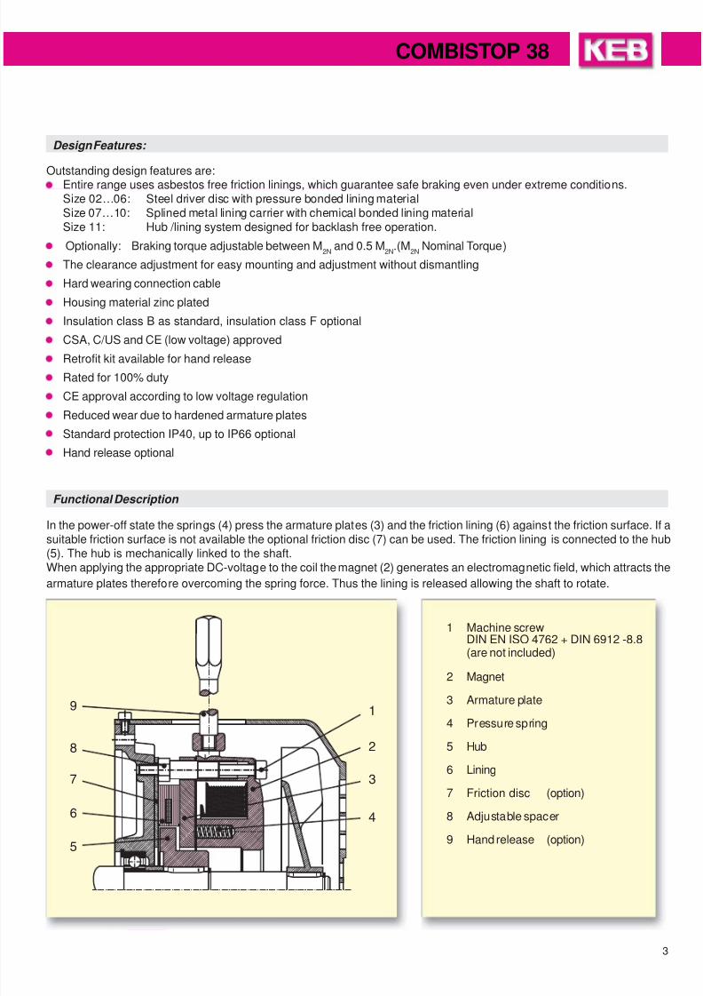
Design Features:
Outstanding design features are:Entire range uses asbestos free friction linings, which guarantee safe braking even under extreme conditions.Size 02…06: Steel driver disc with pressure bonded lining materialSize 07…10: Splined metal lining carrier with chemical bonded lining materialSize 11: Hub /lining system designed for backlash free operation.
Optionally: Braking torque adjustable between M2N
and 0.5 M2N
.(M2N
Nominal Torque)
The clearance adjustment for easy mounting and adjustment without dismantling
Hard wearing connection cable
Housing material zinc plated
Insulation class B as standard, insulation class F optional
CSA, C/US and CE (low voltage) approved
Retrofit kit available for hand release
Rated for 100% duty
CE approval according to low voltage regulation
Reduced wear due to hardened armature plates
Standard protection IP40, up to IP66 optional
Hand release optional
Functional Description
In the power-off state the springs (4) press the armature plates (3) and the friction lining (6) against the friction surface. If asuitable friction surface is not available the optional friction disc (7) can be used. The friction lining is connected to the hub(5). The hub is mechanically linked to the shaft.When applying the appropriate DC-voltage to the coil the magnet (2) generates an electromagnetic field, which attracts the
armature plates therefore overcoming the spring force. Thus the lining is released allowing the shaft to rotate.
1 Machine screwDIN EN ISO 4762 + DIN 6912 -8.8(are not included)
2 Magnet
3 Armature plate
4 Pressure spring
5 Hub
6 Lining
7 Friction disc (option)
8 Adjustable spacer
9 Hand release (option)
8/12/2019 Combistop - Spring Applied Brake
http://slidepdf.com/reader/full/combistop-spring-applied-brake 4/8
4
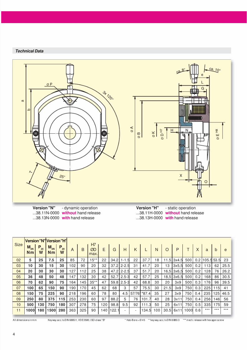
Technical Data
Version "N" - dynamic operation...38.11N-0000 without hand release...38.13N-0000 with hand release
Version "H" - static operation...38.11H-0000 without hand release...38.13H-0000 with hand release
Version "N" Version "H"
Size M2N
P20
M2N
P20
H7A B ØD E G H K L N O P T X a b e
Nm W Nm W max.
02 5 25 7.5 25 85 72 15** 22 34.2 1-1.5 22 37.7 18 11.5 3x4.5 500 0.2 105.5 53.5 23
03 10 30 15 30 102 90 20 32 37.2 2-2.5 31 41.7 20 13 3x5,5 500 0.2 113 62 25.5
04 20 30 30 30 127 112 25 38 47.2 2-2.5 37 51.7 20 16,5 3x6,5 500 0.2 128 76 26.2
05 36 48 50 48 147 132 30 42 52.7 2.5-3 42 57.7 25 18,5 3x6,5 500 0.2 168 86 30.5
06 70 62 90 75 164 145 35** 47 59.8 2.5-3 42 68.8 30 20 3x9 500 0.3 176 96 39.5
07 100 65 150 90 190 170 45 62 68 3 57 75.5 30 21.5 3x9 750 0.3 225 115 41
08 150 75 225 90 218 196 60 78 80 4.5 57/76* *87.4 35 27 3x9 750 0.4 235 125 46.5
09 250 80 375 115 253 230 60 97 88.2 5 76 101.7 40 28 3x11 750 0.4 256 146 56
10500 130 750 180
307 278 75 120 98.8 9.5 92 111.3 50 25 6x11 750 0.5 335 175 5911 1000 180 1500 280 363 325 90 140 122.1 - - 134.5 100 30.5 6x11 1000 0.6 *** *** ***
All dimensions in mm Keyway acc. to DIN 6885/1, VDE 0580, ISO-class "B" * Hub-Bore > Ø 45 ** keyway acc. to DIN 6885/3 *** mech. release with hexagon screw
8/12/2019 Combistop - Spring Applied Brake
http://slidepdf.com/reader/full/combistop-spring-applied-brake 5/8
5
COMBISTOP 38
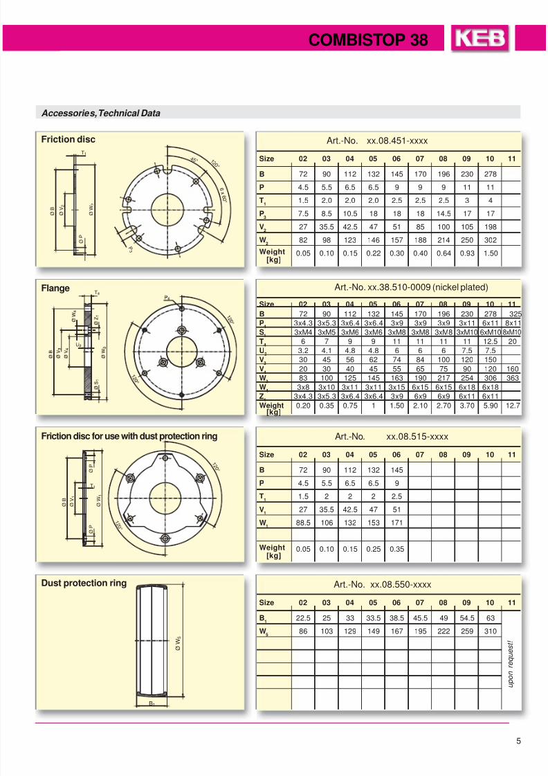
Art.-No. xx.08.451-xxxx
Size 02 03 04 05 06 07 08 09 10 11
B 72 90 112 132 145 170 196 230 278
P 4.5 5.5 6.5 6.5 9 9 9 11 11
T1
1.5 2.0 2.0 2.0 2.5 2.5 2.5 3 4
P3
7.5 8.5 10.5 18 18 18 14.5 17 17
V2
27 35.5 42.5 47 51 85 100 105 198
W2
82 98 123 146 157 188 214 250 302
Weight 0.05 0.10 0.15 0.22 0.30 0.40 0.64 0.93 1.50[kg]
Art.-No. xx.08.515-xxxx
Size 02 03 04 05 06 07 08 09 10 11
B 72 90 112 132 145
P 4.5 5.5 6.5 6.5 9
T1
1.5 2 2 2 2.5
V1
27 35.5 42.5 47 51
W1
88.5 106 132 153 171
Weight 0.05 0.10 0.15 0.25 0.35[kg]
Art.-No. xx.08.550-xxxx
Size 02 03 04 05 06 07 08 09 10 11
B1
22.5 25 33 33.5 38.5 45.5 49 54.5 63
W5
86 103 129 149 167 195 222 259 310
Accessories, Technical Data
Dust protection ring
Friction disc for use with dust protection ring
Flange
Friction disc
u p o n
r e q u e s t !
Art.-No. xx.38.510-0009 (nickel plated)
Size 02 03 04 05 06 07 08 09 10 11
B 72 90 112 132 145 170 196 230 278 325
P4
3x4.3 3x5.3 3x6.4 3x6.4 3x9 3x9 3x9 3x11 6x11 8x11
S1
3xM4 3xM5 3xM6 3xM6 3xM8 3xM8 3xM8 3xM10 6xM10 8xM10
T4
6 7 9 9 11 11 11 11 12.5 20
U2
3.2 4.1 4.8 4.8 6 6 6 7.5 7.5
V3
30 45 56 62 74 84 100 120 150
V4
20 30 40 45 55 65 75 90 120 160
W3
83 100 125 145 163 190 217 254 306 363
W4
3x8 3x10 3x11 3x11 3x15 6x15 6x15 6x18 6x18
Z1
3x4.3 3x5.3 3x6.4 3x6.4 3x9 6x9 6x9 6x11 6x11
Weight 0.20 0.35 0.75 1 1.50 2.10 2.70 3.70 5.90 12.7[kg]
8/12/2019 Combistop - Spring Applied Brake
http://slidepdf.com/reader/full/combistop-spring-applied-brake 6/8
6
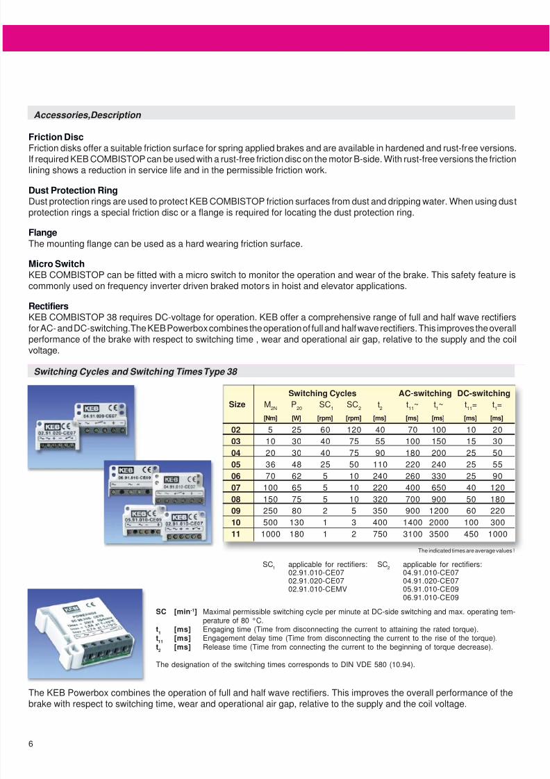
Switching Cycles and Switching Times Type 38
Switching Cycles AC-switching DC-switching
Size M2N
P20
SC1
SC2
t2
t11
~ t1~ t
11= t
1=
[Nm] [W] [rpm] [rpm] [ms] [ms] [ms] [ms] [ms]
02 5 25 60 120 40 70 100 10 20
03 10 30 40 75 55 100 150 15 30
04 20 30 40 75 90 180 200 25 50
05 36 48 25 50 110 220 240 25 55
06 70 62 5 10 240 260 330 25 90
07 100 65 5 10 220 400 650 40 120
08 150 75 5 10 320 700 900 50 180
09 250 80 2 5 350 900 1200 60 220
10 500 130 1 3 400 1400 2000 100 300
11 1000 180 1 2 750 3100 3500 450 1000
SC [min-1] Maximal permissible switching cycle per minute at DC-side switching and max. operating tem-perature of 80 °C.
t1
[ms] Engaging time (Time from disconnecting the current to attaining the rated torque).t11
[ms] Engagement delay time (Time from disconnecting the current to the rise of the torque).t2
[ms] Release time (Time from connecting the current to the beginning of torque decrease).
The designation of the switching times corresponds to DIN VDE 580 (10.94).
SC2
applicable for rectifiers:04.91.010-CE0704.91.020-CE0705.91.010-CE0906.91.010-CE09
The KEB Powerbox combines the operation of full and half wave rectifiers. This improves the overall performance of thebrake with respect to switching time, wear and operational air gap, relative to the supply and the coil voltage.
Accessories, Description
SC1
applicable for rectifiers:02.91.010-CE0702.91.020-CE0702.91.010-CEMV
Friction DiscFriction disks offer a suitable friction surface for spring applied brakes and are available in hardened and rust-free versions.If required KEB COMBISTOP can be used with a rust-free friction disc on the motor B-side. With rust-free versions the frictionlining shows a reduction in service life and in the permissible friction work.
Dust Protection RingDust protection rings are used to protect KEB COMBISTOP friction surfaces from dust and dripping water. When using dustprotection rings a special friction disc or a flange is required for locating the dust protection ring.
FlangeThe mounting flange can be used as a hard wearing friction surface.
Micro Switch
KEB COMBISTOP can be fitted with a micro switch to monitor the operation and wear of the brake. This safety feature iscommonly used on frequency inverter driven braked motors in hoist and elevator applications.
RectifiersKEB COMBISTOP 38 requires DC-voltage for operation. KEB offer a comprehensive range of full and half wave rectifiersfor AC- and DC-switching.The KEB Powerbox combines the operation of full and half wave rectifiers. This improves the overallperformance of the brake with respect to switching time , wear and operational air gap, relative to the supply and the coilvoltage.
The indicated times are average values !
8/12/2019 Combistop - Spring Applied Brake
http://slidepdf.com/reader/full/combistop-spring-applied-brake 7/8
7
COMBISTOP 38
WRmax
[J]
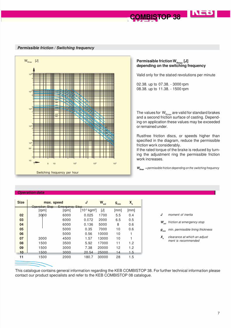
Permissible friction WRmax
[J]depending on the switching frequency
Valid only for the stated revolutions per minute
02.38. up to 07.38. - 3000 rpm08.38. up to 11.38. - 1500 rpm
The values for WRmax
are valid for standard brakesand a second friction surface of casting. Depend-ing on application these values may be exceededor remained under.
Rustfree friction discs, or speeds higher thanspecified in the diagram, reduce the permissiblefriction work considerably.If the rated torque of the brake is reduced by turn-ing the adjustment ring the permissible frictionwork increases.
W Rmax
= permissible friction depending on the switching frequency
Permissible friction / Switching frequency
Switching frequency per hour
Size max. speed J Wzul
gmin
Xn
Operation Stop Emergency Stop[rpm] [rpm] [10-3 kgm2] [J] [mm] [mm]
02 3000 6000 0.025 1700 5.5 0.4
03 6000 0.072 2000 6.5 0.5
04 6000 0.136 5000 8 0.6
05 5000 0.35 7000 10 0.606 5000 0.56 10000 10 1
07 3000 4500 1.57 13000 10 1
08 1500 3500 5.92 17000 11 1.2
09 1500 3000 7.38 20000 12 1.2
10 1500 3000 20.54 25000 14 1.5
11 1500 2000 180.7 30000 28 1.5
This catalogue contains general information regarding the KEB COMBISTOP 38. For further technical information pleasecontact our product specialists and refer to the KEB COMBISTOP 08 catalogue.
Operation data
J moment of inertia
W zul
friction at emergency stop
g min min. permissible lining thickness
X n
clearance at which an adjust
ment is recommended
8/12/2019 Combistop - Spring Applied Brake
http://slidepdf.com/reader/full/combistop-spring-applied-brake 8/8
©
K E B
0 0
. 0 0 . 0
0 0 - 5 0 3 8
0 5 / 2 0 0 2 - S u b j e c t t o
t e c h n i c a l c h a n g e s ! -
Karl E. Brinkmann GmbH
Försterweg 36 - 38 • D - 32683 Barntrup
Telefon 0 52 63 / 4 01 - 0 • Telefax 4 01 - 116
Internet: www.keb.de • E-mail: [email protected]


![COMBISTOP - Industrial Clutch Parts Ltd7 COMBISTOP 38 W Rmax [J] and a second friction surface of casting. Depend-Permissible friction W Rmax [J] depending on the switching frequency](https://img.pdfslide.us/doc/110x75/5ea4f550099f4a2e255da6c9/combistop-industrial-clutch-parts-ltd-7-combistop-38-w-rmax-j-and-a-second-friction.jpg)