Embed Size (px)
Citation preview

Spring 2005 Parallel Processing, Implementation Aspects Slide 1
Part VIImplementation Aspects
Spring 2005 Parallel Processing, Implementation Aspects Slide 2
About This Presentation
Edition Released Revised Revised
First Spring 2005
This presentation is intended to support the use of the textbook Introduction to Parallel Processing: Algorithms and Architectures (Plenum Press, 1999, ISBN 0-306-45970-1). It was prepared by the author in connection with teaching the graduate-level course ECE 254B: Advanced Computer Architecture: Parallel Processing, at the University of California, Santa Barbara. Instructors can use these slides in classroom teaching and for other educational purposes. Any other use is strictly prohibited. © Behrooz Parhami

Spring 2005 Parallel Processing, Implementation Aspects Slide 3
VI Implementation Aspects Study real parallel machines in MIMD and SIMD classes:
• Examine parallel computers of historical significance• Learn from modern systems and implementation ideas• Bracket our knowledge with history and forecasts
Topics in This Part
Chapter 21 Shared-Memory MIMD Machines
Chapter 22 Message-Passing MIMD Machines
Chapter 23 Data-Parallel SIMD Machines
Chapter 24 Past, Present, and Future

Spring 2005 Parallel Processing, Implementation Aspects Slide 4
21 Shared-Memory MIMD Machines
Learn about practical shared-variable parallel architectures:• Contrast centralized and distributed shared memories• Examine research prototypes and production machines
Topics in This Chapter
21.1 Variations in Shared Memory
21.2 MIN-Based BBN Butterfly
21.3 Vector-Parallel Cray Y-MP
21.4 Latency-Tolerant Tera MTA
21.5 CC-NUMA Stanford DASH
21.6 SCI-Based Sequent NUMA-Q

Spring 2005 Parallel Processing, Implementation Aspects Slide 5
21.1 Variations in Shared Memory
Fig. 21.1 Classification of shared-memory hardware architectures and example systems that will be studied in the rest of this chapter.
Central Main Memory
Distributed Main Memory
Single Copy of Modifiable Data
UMA
BBN Butterfly Cray Y-MP
COMACC-NUMA
Tera MTA
NUMA
Stanford DASH Sequent NUMA-Q
CC-UMA
Multiple Copies of Modifiable Data

Spring 2005 Parallel Processing, Implementation Aspects Slide 6
C.mmp: A Multiprocessor of Historical Significance
Fig. 21.2 Organization of the C.mmp multiprocessor.
16 16 crossbar
Mem 0
Memory modules
.
.
.
Mem 1
Mem 15
.
.
.
Cache
Cache
Cache
Proc 0
Proc 1
Proc 15
Clock
Bus control
BI
BI
BI
Map
Map
Map
Bus interface

Spring 2005 Parallel Processing, Implementation Aspects Slide 7
Shared Memory Consistency Models
Sequential consistency (strictest and most intuitive); mandates that the interleaving of reads and writes be the same from the viewpoint of all processors. This provides the illusion of a FCFS single-port memory.
Processor consistency (laxer); only mandates that writes be observed in the same order by all processors. This allows reads to overtake writes, providing better performance due to out-of-order execution.
Weak consistency separates ordinary memory accesses from synch accesses that require memory to become consistent. Ordinary read and write accesses can proceed as long as there is no pending synch access, but the latter must wait for all preceding accesses to complete.
Release consistency is similar to weak consistency, but recognizes two synch accesses, called “acquire” and “release”, that sandwich protected shared accesses. Ordinary read / write accesses can proceed only when there is no pending acquire access from the same processor and a release access must wait for all reads and writes to be completed.
Varying latencies makes each processor’s view of the memory different

Spring 2005 Parallel Processing, Implementation Aspects Slide 8
21.2 MIN-Based BBN Butterfly
Fig. 21.3 Structure of a processing node in the BBN Butterfly.
MC 68000 Processor
Processor Node Controller
Memory Manager
EPROM
1 MB Memory
Daughter Board Connection for Memory Expansion (3 MB)
Switch Interface
To I/O Boards
Fig. 21.4 A small 16-node version of the multistage interconnection network of the BBN Butterfly.
4 4
4 4
4 4
4 4
Processing Node 0
Processing Node 15
4 4
4 4
4 4
4 4

Spring 2005 Parallel Processing, Implementation Aspects Slide 9
21.3 Vector-Parallel Cray Y-MP
Fig. 21.5 Key elements of the Cray Y-MP processor. Address registers, address function units, instruction buffers, and control not shown.
V0
V7V6
V5V4
V3V2
V1 0 1 2 3 . . . 62 63
Vector Registers
Vector Integer Units Shift
Add
Logic
Weight/ Parity
Floating- Point Units Multiply
Add
Reciprocal Approx.
Scalar Integer Units Shift
Add
Logic
Weight/ Parity
T Registers (8 64-bit) S Registers
(8 64-bit)
From address registers/units
Central Memory
Inter- Processor Commun.
CPU
64 bit
64 bit
32 bit
Input/Output

Spring 2005 Parallel Processing, Implementation Aspects Slide 10
Cray Y-MP’s Interconnection Network
Fig. 21.6 The processor-to-memory interconnection network of Cray Y-MP.
P0
P1
P2
P3
P4
P5
P6
P7
4 4
8 8
1 8
8 8
8 8
8 8
4 4
4 4
4 4
4 4
4 4
4 4
4 4
Sections Subsections 0, 4, 8, ... , 28 32, 36, 40, ... , 92 1, 5, 9, ... , 29 2, 6, 10, ... , 30 3, 7, 11, ... , 31 227, 231, ... , 255
Memory Banks

Spring 2005 Parallel Processing, Implementation Aspects Slide 11
21.4 Latency-Tolerant Tera MTA
Fig. 21.7 The instruction execution pipelines of Tera MTA.
Memory Internal Pipeline
M A C
Instr. Fetch
Interconnection Network
Issue Pool
Retry Pool

Spring 2005 Parallel Processing, Implementation Aspects Slide 12
21.5 CC-NUMA Stanford DASH
Fig. 21.8 The architecture of Stanford DASH.
Processor cluster
Processor cluster
Processor cluster
Main memory
Reply mesh
Request mesh
Processor cluster
Directory & network interface
Level-2 cache
Processor
I-cache D-cache
Wormhole routers

Spring 2005 Parallel Processing, Implementation Aspects Slide 13
21.6 SCI-Based Sequent NUMA-Q
Fig. 21.9 The physical placement of Sequent’s quad components on a rackmount baseboard (not to scale)
IQ-link
P6
P6
P6
P6 OPB
OPB
Memory
IQ-Link
PCI/FC
PCI/LAN
MDP
Console Bridge
Bridge
Quad
Quad
Quad
SCSI
SCSI
Peripheral bay
Peripheral bay
Private Ethernet
IQ-Plus (SCI ring)
. . .
Public LAN
100 MB/s Fibre Channel
1 GB/s Interquad SCI link
Orion PCI bridge
4 x 33 MB/s PCI buses
533 MB/s local bus (64 bits, 66 MHz)
Pentium Pro (P6) proc’s
Fig. 21.10 The architecture of Sequent NUMA-Q 2000.

Spring 2005 Parallel Processing, Implementation Aspects Slide 14
Details of the IQ-Link in Sequent NUMA-Q
Fig. 21.11 Block diagram of the IQ-Link board.
P6 bus
SCI in
SCI out
Bus interface controller
Directory controller
Interconnect controller
Remote cache data
Local directory
Remote tags
Local directory
Remote tags
Bus-side snooping tags
Network-side tags
32 MB
Fig. 21.12 Block diagram of IQ-Link’s interconnect controller.
SCI in
SCI out
Stripper Assemble Elastic buffer
Request receive Q
Response receive Q
Request send Q
Response send Q
Bypass FIFO
Disassemble
Spring 2005 Parallel Processing, Implementation Aspects Slide 15
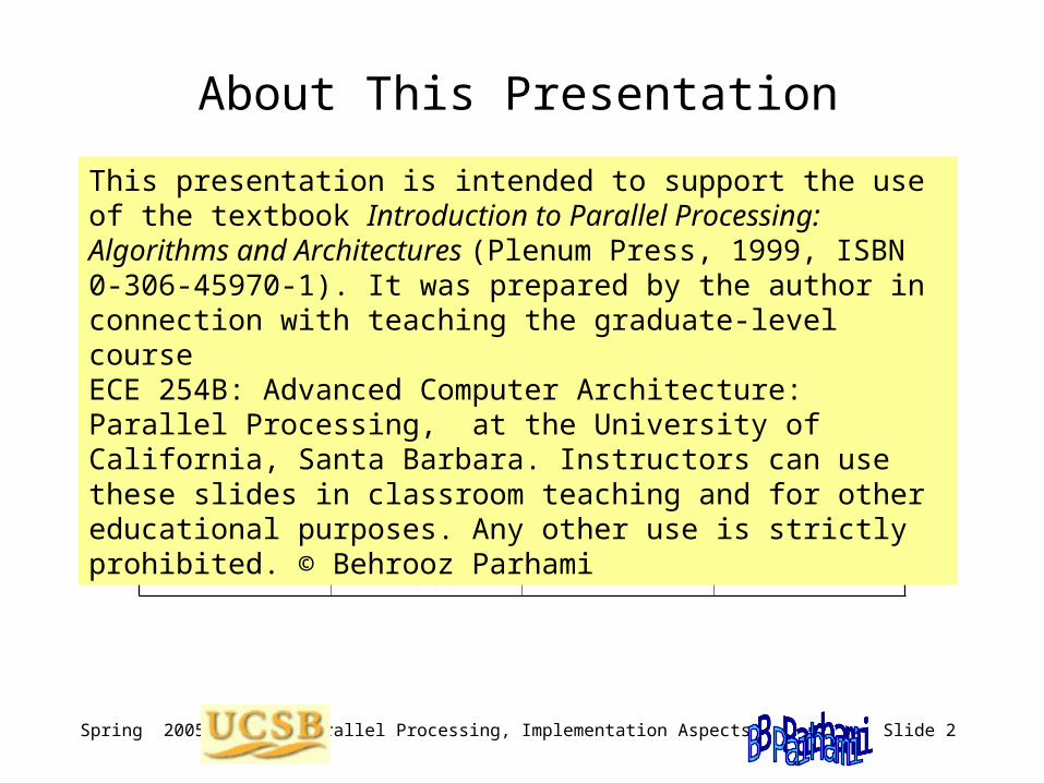
22 Message-Passing MIMD Machines
Topics in This Chapter
22.1 Mechanisms for Message Passing
22.2 Reliable Bus-Based Tandem NonStop
22.3 Hypercube-Based nCUBE3
22.4 Fat-Tree-Based Connection Machine 5
22.5 Omega-Network-Based IBM SP2
22.6 Commodity-Driven Berkeley NOW
Learn about practical message-passing parallel architectures:• Study mechanisms that support message passing• Examine research prototypes and production machines

Spring 2005 Parallel Processing, Implementation Aspects Slide 16
22.1 Mechanisms for Message Passing
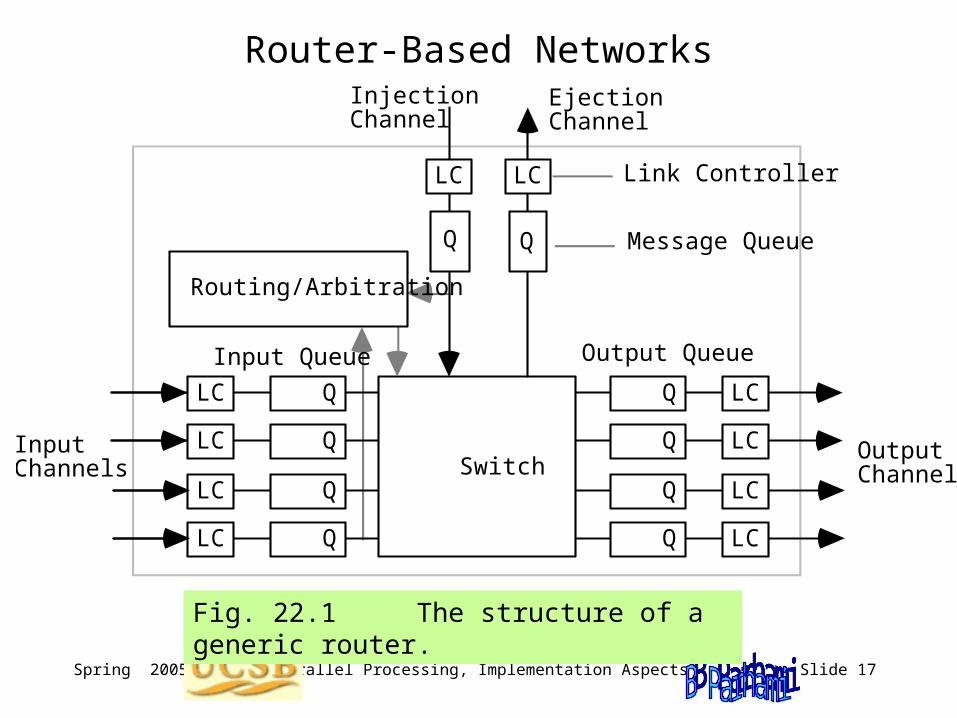
Fig. 22.1 The structure of a generic router.
Inputs
Outputs
Crosspoint switch
Through (straight)
Crossed (exchange)
Lower broadcast
Upper broadcast
1. Shared-Medium networks (buses, LANs; e.g., Ethernet, token-based)
2. Router-based networks (aka direct networks; e.g., Cray T3E, Chaos)
3. Switch-based networks (crossbars, MINs; e.g., Myrinet, IBM SP2)
Fig. 22.2 Example 4 4 and 2 2 switches used as building blocks for larger networks.
Spring 2005 Parallel Processing, Implementation Aspects Slide 17
Router-Based Networks
Q
Q
Q
Q
LC
LC
LC
LC
QLC
QLC
QLC
QLC
Switch
LC LC
Routing/Arbitration
Q Q
Link Controller
Message Queue
Input Channels
Output Channels
Output QueueInput Queue
Injection Channel
Ejection Channel
Fig. 22.1 The structure of a generic router.

Spring 2005 Parallel Processing, Implementation Aspects Slide 18
Case Studies of Message-Passing Machines
Coarse- Grain
Medium- Grain
Shared-Medium Network
Tandem NonStop (Bus)
Berkeley NOW (LAN)
nCUBE3
Router-Based Network
TMC CM-5 IBM SP2
Switch-Based Network
Fine- Grain
Fig. 22.3 Classification of message-passing hardware architectures and example systems that will be studied in this chapter.

Spring 2005 Parallel Processing, Implementation Aspects Slide 19
22.2 Reliable Bus-Based Tandem NonStop
I/O I/O
Processor and Memory
I/O I/O I/O I/O I/O I/O
Dynabus
Controller
Processor and Memory
Processor and Memory
Processor and Memory
I/O
Fig. 22.4 One section of the Tandem NonStop Cyclone system.

Spring 2005 Parallel Processing, Implementation Aspects Slide 20
High-Level Structure of the Tandem NonStop
Four-processor sections
Dynabus +
Fig. 22.5 Four four-processor sections interconnected by Dynabus+.

Spring 2005 Parallel Processing, Implementation Aspects Slide 21
22.3 Hypercube-Based nCUBE3
Fig. 22.6 An eight-node nCUBE architecture.
Host
Host
I/O
I/O
I/O
I/O

Spring 2005 Parallel Processing, Implementation Aspects Slide 22
22.4 Fat-Tree-Based Connection Machine 5
P
M
P
M
P
M
P
M
P
M
CP
M
CP
M
CP
MI/O I/O
Control Network
Diagnostic Network
Data Network
Up to 16K Processing Nodes
One or more Control Processors
. . . ...
Graphics Output
HIPPI or VME Interface
Data Vault
Fig. 22.7 The overall structure of CM-5.

Spring 2005 Parallel Processing, Implementation Aspects Slide 23
Processing Nodes in CM-5
Control Network
Data Network
Network Interface
SPARC Processor
MemoryMemory MemoryMemory
Vector Unit
Vector Unit
Vector Unit
Vector Unit
Instr. Decode
Bus Interface
Memory Control
Pipelined ALU
64 64 Register File
64-Bit Bus
Fig. 22.8 The components of a processing node in CM-5.

Spring 2005 Parallel Processing, Implementation Aspects Slide 24
The Interconnection Network in CM-5
Fig. 22.9 The fat-tree (hyper-tree) data network of CM-5.
Processors and I/O Nodes
Data Routers (4 2 Switches)
01 2 3
63
Spring 2005 Parallel Processing, Implementation Aspects Slide 25
22.5 Omega-Network-Based IBM SP2
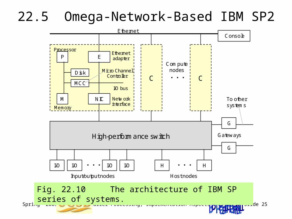
Fig. 22.10 The architecture of IBM SP series of systems.
High-performance switch
E
Ethernet
. . .
I/O bus
P
M
Disk
MCC
NIC Netw ork interface
Micro Channel Controller
Ethernet adapter
C
Console
C
Compute nodes
Memory
Processor
I/O I/O I/O I/O . . . H H . . .
G
G
Gateways
To other systems
Input/output nodes Host nodes

Spring 2005 Parallel Processing, Implementation Aspects Slide 26
The IBM SP2 Network Interface
Fig. 22.11 The network interface controller of IBM SP2.
Micro Channel interface
2 x 2 KB FIFO
buffers
Left DMA
Micro Channel
Right DMA
40 MHz i860
processor
8-MB DRAM
Input FIFO
Output FIFO
Memory and switch management unit
160 MB/s i860 bus

Spring 2005 Parallel Processing, Implementation Aspects Slide 27
The Interconnection Network of IBM SP2
Fig. 22.12 A section of the high-performance switch network of IBM SP2.
4 x 4 crossbars
Only 1/4 of links at this level are shown
0 1 2 3 . . . . 63

Spring 2005 Parallel Processing, Implementation Aspects Slide 28
22.6 Commodity-Driven Berkeley NOWNOW aims for building a distributed supercomputer from commercial workstations (high end PCs), linked via switch-based networks
Components and challenges for successful deployment of NOWs (aka clusters of workstations, or COWs)
Network interface hardware: System-area network (SAN), middle ground between LANs and specialized interconnections
Fast communication protocols: Must provide competitive parameters for the parameters in the LogP model (see Section 4.5)
Distributed file systems: Data files must be distributed among nodes, with no central warehouse or arbitration authority
Global resource management: Berkeley uses GLUnix (global-layer Unix); other systems of comparable functionalities include Argonne Globus, NSCP metacomputing system, Princeton SHRIMP, Rice TreadMarks, Syracuse WWVM, Virginia Legion, Wisconsin Wind Tunnel

Spring 2005 Parallel Processing, Implementation Aspects Slide 29
23 Data-Parallel SIMD Machines
Topics in This Chapter
23.1 Where Have All the SIMDs Gone?
23.2 The First Supercomputer: ILLIAC IV
23.3 Massively Parallel Goodyear MPP
23.4 Distributed Array Processor (DAP)
23.5 Hypercubic Connection Machine 2
23.6 Multiconnected MasPar MP-2
Learn about practical implementation of SIMD architectures:• Assess the successes, failures, and potentials of SIMD• Examine various SIMD parallel computers, old and new

Spring 2005 Parallel Processing, Implementation Aspects Slide 30
23.1 Where Have All the SIMDs Gone?
Fig. 23.1 Functional view of an associative memory/processor.
.
.
.
Global Operations Control & Response
Cell 0
Cell 1
Cell 2
Cell m–1
Data and Commands Broadcast
Read Lines Response
Store (Tags)
Global Tag Operations Unit
Control Unit
Comparand
Mask
tm–1
t2
t1
t 0
.
.
.
.
.
.
Associative or content-addressable memories/processors constituted early forms of SIMD parallel processing

Spring 2005 Parallel Processing, Implementation Aspects Slide 31
Search Functions in Associative Devices
Exact match: Locating data based on partial knowledge of contents
Inexact match: Finding numerically or logically proximate values
Membership: Identifying all members of a specified set
Relational: Determining values that are less than, less than or equal, etc.
Interval: Marking items that are between or outside given limits
Extrema: Finding the maximum, minimum, next higher, or next lower
Rank-based: Selecting kth or k largest/smallest elements
Ordered retrieval: Repeated max- or min-finding with elimination (sorting)
Spring 2005 Parallel Processing, Implementation Aspects Slide 32
Mixed-Mode SIMD / MIMD Parallelism
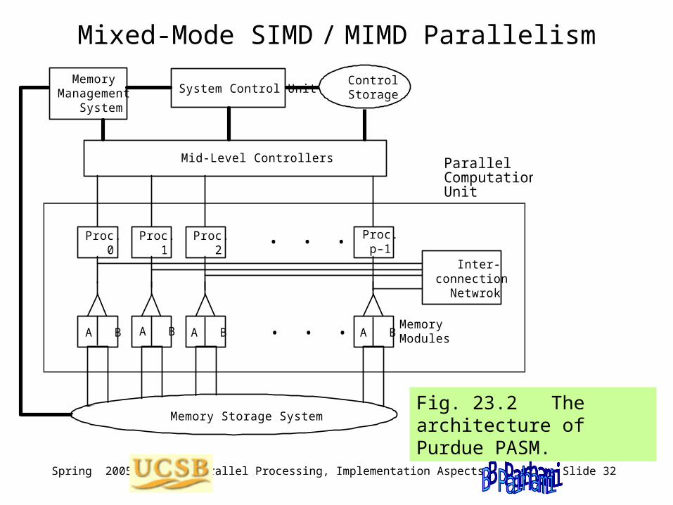
Fig. 23.2 The architecture of Purdue PASM.
System Control Unit
Mid-Level Controllers
. . .A B A B A B A BMemory Modules
Proc. 0
Proc. 1
Proc. p–1
Proc. 2
. . . Inter- connection Netwrok
Memory Management System
Control Storage
Parallel Computation Unit
Memory Storage System
Spring 2005 Parallel Processing, Implementation Aspects Slide 33
23.2 The First Supercomputer: ILLIAC IV
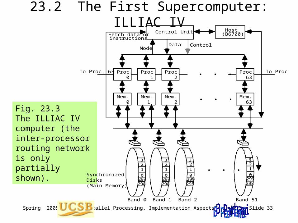
Fig. 23.3 The ILLIAC IV computer (the inter-processor routing network is only partially shown).
0
123
299298
0
123
299298
0
123
299298
0
123
299298
Mem. 0
Mem. 1
Mem. 63
Mem. 2
Control Unit Host(B6700)
. . .
ModeData Control
Fetch data or instructions
Proc. 0
Proc. 1
Proc. 63
Proc. 2
. . . To Proc. 0To Proc. 63
. . .Synchronized Disks (Main Memory)
Band 0 Band 1 Band 2 Band 51

Spring 2005 Parallel Processing, Implementation Aspects Slide 34
23.3 Massively Parallel Goodyear MPP
Fig. 23.4 The architecture of Goodyear MPP.
Tape Disk Printer Terminal Network
Host processor (VAX 11/780)
Program and data management unit
Array control Staging memory
Staging memory
Array unit
128 128 processors
128-bit output
interface
128-bit input
interface
Status Control
Switches

Spring 2005 Parallel Processing, Implementation Aspects Slide 35
Processing Elements in the Goodyear MPP
Fig. 23.5 The single-bit processor of MPP.
C
A
G
S
Sum
CarryFull adder
Data bus
P
Logic
B
Variable- length shift register
ComparatorTo/from neighbors
NEWS
Mask
Memory
Address
From left processor
To right processor
To global OR tree

Spring 2005 Parallel Processing, Implementation Aspects Slide 36
23.4 Distributed Array Processor (DAP)
Fig. 23.6 The bit-serial processor of DAP.
{N E S W
From neighboring processors
C
Q
Mux
N
S
EW
To neighboring processors
A
D
S
MuxSum
CarryFull adder
Row Col{
From control unit
Memory
From south neighbor To north neighbor
To row/col responses
Condition
N E S W

Spring 2005 Parallel Processing, Implementation Aspects Slide 37
DAP’s High-Level Structure
Fig. 23.7 The high-level architecture of DAP system.
Program memory
Master control
unit
Host interface
unit
Host work- station
Array memory (at least
32K planes) Local memory for processor ij
Q plane
C plane
A plane
D plane
Row i
Column j
Processors Fast I/O
Register Q in processor ij
One plane of memory
W
S
E
N

Spring 2005 Parallel Processing, Implementation Aspects Slide 38
23.5 Hypercubic Connection Machine 2
Fig. 23.8 The architecture of CM-2. Data Vault
Sequencer 0
16K Processors
Bus Inter- face
Front End 0
Nexus
12
3
Data Vault Data Vault
Graphic Display
12
3
I/O System

Spring 2005 Parallel Processing, Implementation Aspects Slide 39
The Simple Processing Elements of CM-2
Fig. 23.9 The bit-serial ALU of CM-2.
ab c
f op- code
g op- code
f(a, b, c)
g(a, b, c)
From Memory
0 1 2 3 4 5 6 7
Mux
0 1 2 3 4 5 6 7
Mux
Flags
To Memory

Spring 2005 Parallel Processing, Implementation Aspects Slide 40
23.6 Multiconnected MasPar MP-2
Fig. 23.10 The architecture of MasPar MP-2.
Processor Array (X-net connected)
Array Control Unit
I/O Channel Controller & Memory
Disk Array
Front EndEthernet
Global Router

Spring 2005 Parallel Processing, Implementation Aspects Slide 41
The Interconnection Network of MasPar MP-2
Fig. 23.11 The physical packaging of processor clusters and the 3-stage global router in MasPar MP-2 .
. . .
.
.
.
.
.
.
.
.
.
.
.
.
. . .
. . .
. . .
Processor cluster
Stage 1
Stage 3
Stage 2

Spring 2005 Parallel Processing, Implementation Aspects Slide 42
The Processing Nodes of MasPar MP-2
Fig. 23.12 Processor architecture in MasPar MP-2.
Word Bus
Bit Bus
32 bits
Flags
ALU LogicBarrel Shifter
Significand Unit
Exponent Unit
To Router Stage 3
To Router Stage 1
X-net In
X-net Out
Comm. Input
Comm. Output
External Memory
Memory Address Unit
Memory Data/ECC Unit
Register File
Control
Instruction Broadcast
Reduction

Spring 2005 Parallel Processing, Implementation Aspects Slide 43
24 Past, Present, and Future
Put the state of the art in context of history and future trends:• Quest for higher performance, and where it is leading us• Interplay between technology progress and architecture
Topics in This Chapter
24.1 Milestones in Parallel Processing
24.2 Current Status, Issues, and Debates
24.3 TFLOPS, PFLOPS, and Beyond
24.4 Processor and Memory Technologies
24.5 Interconnection Technologies
24.6 The Future of Parallel Processing

Spring 2005 Parallel Processing, Implementation Aspects Slide 44
24.1 Milestones in Parallel Processing
1840s Desirability of computing multiple values at the same time was noted in connection with Babbage’s Analytical Engine
1950s von Neumann’s and Holland’s cellular computers were proposed
1960s The ILLIAC IV SIMD machine was designed at U Illinois based on the earlier SOLOMON computer
1970s Vector machines, with deeply pipelined function units, emerged and quickly dominated the supercomputer market; early experiments with shared memory multiprocessors, message-passing multicomputers, and gracefully degrading systems paved the way for further progress
1980s Fairly low-cost and massively parallel supercomputers, using hypercube and related interconnection schemes, became available
1990s Massively parallel computers with mesh or torus interconnection, and using wormhole routing, became dominant
2000s Commodity and network-based parallel computing took hold, offering speed, flexibility, and reliability for server farms and other areas

Spring 2005 Parallel Processing, Implementation Aspects Slide 45
24.2 Current Status, Issues, and Debates
Design choices and key debates:
Architecture General- or special-purpose system?SIMD, MIMD, or hybrid?
Interconnection Shared-medium, direct, or multistage?Custom or commodity?
Routing Oblivious or adaptive?Wormhole, packet, or virtual cut-through?
Programming Shared memory or message passing?New languages or libraries?
Related user concerns:
Cost per MIPS Scalability, longevity
Cost per MB/sExpandability, reliability
Speed, efficiencyOverhead, saturation limit
Ease of programmingSoftware portability

Spring 2005 Parallel Processing, Implementation Aspects Slide 46
24.3 TFLOPS, PFLOPS, and Beyond
Fig. 24.1 Milestones in the Accelerated Strategic Computing Initiative (ASCI) program, sponsored by the US Department of Energy, with extrapolation up to the PFLOPS level.
2000 1995 2005 2010
Pe
rfo
rma
nce
(T
FL
OP
S)
Calendar year
ASCI Red
ASCI Blue
ASCI White
1+ TFLOPS, 0.5 TB
3+ TFLOPS, 1.5 TB
10+ TFLOPS, 5 TB
30+ TFLOPS, 10 TB
100+ TFLOPS, 20 TB
1
10
100
1000 Plan Develop Use
ASCI
ASCI Purple
ASCI Q

Spring 2005 Parallel Processing, Implementation Aspects Slide 47
24.4 Processor and Memory Technologies
Fig. 24.2 Key parts of the CPU in the Intel Pentium Pro microprocessor.
Integer Execution Unit 0
86
86
86
Port-0 Units
Port-1 Units
Port 0
Port 1
Port 2Dedicated to memory access (address generation units, etc)
Port 3
Port 4
Reservation Station
Reorder Buffer and Retirement Register File
FLP Add
Integer DivFLP Div
FLP Mult
Shift
Integer Execution Unit 1
Jump Exec Unit

Spring 2005 Parallel Processing, Implementation Aspects Slide 48
24.5 Interconnection Technologies
Continued use of Al/Oxide
Changeover to lower-resistivity wires & low-dielectric-constant insulator; e.g., Cu/Polyimide
Feature size (m) 0.5 0.35 0.25 0.18 0.13
Rat
io o
f wir
e de
lay
to s
witc
hing
tim
e
4
5
6
7
8
Fig. 24.3 Changes in the ratio of a 1-cm wire delay to device switching time as the feature size is reduced.

Spring 2005 Parallel Processing, Implementation Aspects Slide 49
Intermodule and Intersystem Connection Options
Fig. 24.4 Various types of intermodule and intersystem connections.
3
6
9
12
9 6 3 3
Ba
ndw
idth
(b
/s)
Latency (s)
10
10
10
10
10 10 10 1 10
Processor
bus
I/O
network
System-area
network (SAN)
Local-area
network (LAN)
Metro-area
network (MAN)
Wide-area
network (WAN)
Geographically distributed
Same geographic location
(ns) (s) (ms) (min) (h)

Spring 2005 Parallel Processing, Implementation Aspects Slide 50
System Interconnection Media
Fig. 24.5 The three commonly used media for computer and network connections.
Coaxial cable
Outer conductor
Copper core
Insulator
Plastic
Twisted pair
Optical fiber
Light source
Reflection Silica

Spring 2005 Parallel Processing, Implementation Aspects Slide 51
24.6 The Future of Parallel Processing
Asynchronous design for its speed and greater energy economy: Because pure asynchronous circuits create some difficulties, designs that are locally synchronous and globally asynchronous are flourishing
Intelligent memories to help remove the memory wall:Memory chips have high internal bandwidths, but are limited by pins in how much data they can handle per clock cycle
Reconfigurable systems for adapting hardware to application needs:Raw hardware that can be configured via “programming” to adapt to application needs may offer the benefits of special-purpose processing
Network and grid computing to allow flexible, ubiquitous access:Resource of many small and large computers can be pooled together via a network, offering supercomputing capability to anyone
In the early 1990s, it was unclear whether the TFLOPS performance milestone would be reached with a thousand or so GFLOPS nodes or with a million or so simpler MFLOPS processors
Now, a similar question is in front of us for PFLOPS performance

Spring 2005 Parallel Processing, Implementation Aspects Slide 52
Parallel Processing for Low-Power Systems
Figure 25.1 of Parhami’s computer architecture textbook.
1990 1980 2000 2010 kIPS
MIPS
GIPS
TIPS P
erf
orm
anc
e
Calendar year
Absolute processor
performance
GP processor performance
per watt
DSP performance per watt

Spring 2005 Parallel Processing, Implementation Aspects Slide 53
Peak Performance of Supercomputers
PFLOPS
TFLOPS
GFLOPS1980 20001990 2010
Earth Simulator
ASCI White Pacific
ASCI Red
Cray T3DTMC CM-5
TMC CM-2Cray X-MP
Cray 2
10 / 5 years
Dongarra, J., “Trends in High Performance Computing,”Computer J., Vol. 47, No. 4, pp. 399-403, 2004. [Dong04]

Spring 2005 Parallel Processing, Implementation Aspects Slide 54
From: “Robots After All,”
by H. Moravec, CACM, pp. 90-97,
October 2003.
Mental power in four scales
Evolution of Computer Performance/Cost

Spring 2005 Parallel Processing, Implementation Aspects Slide 55
ABCs of Parallel Processing in One Slide
A Amdahl’s Law (Speedup Formula)Bad news – Sequential overhead will kill you, because: Speedup = T1/Tp 1/[f + (1 – f)/p] min(1/f, p)Morale: For f = 0.1, speedup is at best 10, regardless of peak OPS.
B Brent’s Scheduling TheoremGood news – Optimal scheduling is very difficult, but even a naivescheduling algorithm can ensure: T1/p Tp T1/p + T = (T1/p)[1 + p/(T1/T)]Result: For a reasonably parallel task (large T1/T), or for a suitablysmall p (say, p T1/T), good speedup and efficiency are possible.
C Cost-Effectiveness AdageReal news – The most cost-effective parallel solution may not bethe one with highest peak OPS (communication?), greatest speed-up (at what cost?), or best utilization (hardware busy doing what?).Analogy: Mass transit might be more cost-effective than private carseven if it is slower and leads to many empty seats.

Spring 2005 Parallel Processing, Implementation Aspects Slide 56
Gordon Bell Prize for High-Performance Computing
Different hardware/software combinations have won the competition
Supercomputer performance improvement has outpaced Moore’s law; however, progress shows signs of slowing down due to lack of funding
In past few years, improvements have been due to faster uniprocessors (2004 NRC Report Getting up to Speed: The Future of Supercompuing)
Established in 1988 by Gordon Bell, one of the pioneers in the field
Awards are given annually in several categories (there are small cash awards, but the prestige of winning is the main motivator)
The two key categories are as follows; others have varied over time
Peak performance: The entrant must convince the judges that the submitted program runs faster than any other comparable application
Price/Performance: The entrant must show that performance of the application divided by the list price of the smallest system needed to achieve the reported performance is better than that of any other entry