Embed Size (px)
Citation preview

SPRAY FORMING OF THIN WALLED NET-SHAPED
COMPONENTS OF HARD MATERIALS BY HIGH
VELOCITY OXY-FUEL THERMAL SPRAYING PROCESS
BYMD. MAKSUD HELALI B.Sc., M.Sc. Eng.
SCHOOL OF MECHANICAL AND MANUFACTURING ENGINEERING
This thesis is submitted as the fulfilment of the requirement for the award of Doctor of Philosophy by research to :
D U B LIN C IT Y U N IV E R S IT Y
RESEARCH SUPERVISOR PROFESSOR M.S.J. HASHMI
SEPTEMBER 1994

DEDICATED TO
MY PARENT, WIFE & SONS

D E C LA R A T IO N
I hereby declare that this material, which I now submit for the assessment on the programme of study leading to the award of Ph.D. is entirely my own work. To the best of my knowledge, the results presented in this thesis originated from the presented study, except where references have been made. No part o f this thesis has been submitted for a degree at any other institution.
MD. MAKSUD HELALI ID. No. 91700558 September 1994.

A C K N O W LE D G E M E N TS
I am greatly indebted to Prof. M .SJ. Hashmi, head of the school of mechanical and
manufacturing engineering for his supervision, guidance and his constructive suggestions
and comments during the course of this investigation.
I am especially grateful to Martin Johnson, Michael Murphy for their technical support
and inspirational discussions throughout this work. I am grateful to Dr. David Cameron
of school of electronic engineering and to Martin Fleming of Forbairt for their assistance
in characterisation some of the samples.
I am grateful to Liam Domican of school of the mechanical and manufacturing
engineering and to all staff of the Mechanical Workshop of Dublin City University for
iheir effort to install the experimental setup, My sincere thanks to Shahida Begum,
Prashanthi Kola and Mahiuddin Ahamed for their assistance at different occasions during
the course of this investigation.
SPRAY FO RM ING OF TH IN W A LLED N E T -SH A PE D C O M PO N EN TS
OF HARD M A TER IA LS BY HIG H V ELO C ITY O X Y -FU E L TH ER M A L
SPR A Y IN G PR O C ESS
MD .MAKSUD HELALI B.Sc. M.Sc
A BSTR AC T
Spray forming is a near-net shape fabrication process in which a spray of finely divided
molten particles of metallic material is deposited onto a suitably shaped substrate to
form a coherent solid. This technology offers unique opportunity for simplifying material
processing by elimination of a number of unit operations and can be an alternative to
conventional metal working technology for the production of certain type of
components. The components thus formed may have some properties viz. hardness and
wear resistance, surpassing those of their cast and wrought counter parts.
Cemented carbide belongs to a class of hard wear resistant refractory materials
which are very difficult to process. This material can be used to make thin-walled inserts
which can be utilised to improve the surface property of the engineering components.
A high velocity oxy-fuel thermal spraying system has been installed. This coating
process has been employed to spray form thin walled near net shaped components.
Materials used to fabricate components were tungsten carbide/cobalt, nickel chromium
alloy and stainless steel. Special attention was given to determine the processing
parameters of tungsten carbide/cobalt components.
Forming cores of different sizes, shapes were made from different materials.
Materials in the form of powder were deposited by spraying with the HVOF thermal
spray gun on the forming core surface after applying a releasing layer on the forming
core. The releasing layer was so chosen that it facilitated deposition without fracture and
after deposition it can be debonded easily from the forming core such that the deposited
layer can be separated without fracture. Heating and cooling of the forming core-deposit
assembly at different stages of spray forming process have profound effect on the
success in obtaining the component without fracturing. Optimum ranges of values of the
processing variables for different types of material were determined.
The effects of the processing parameters on the properties of the components
were also investigated. The density of the spray formed components vary between 96-
99.5% of the theoretical values. The other properties of the components such as
hardness, roughness and composition were also measured and compared with the
standard values.
The components thus formed were found to be brittle. To improve the toughness
of tungsten carbide/cobalt components, multi-layer components were fabricated. The
toughness of the multi-layer component was found to be higher than the single layer
tungsten carbide/cobalt, component. Components of materials with gradual change in
composition were also fabricated to improve the toughness of tungsten carbide/cobalt
components.
Depending upon the processing variables, the spray formed components contain
residual stress. For tungsten carbide/cobalt component the amount of residual stress was
measured and the effect of processing variables on the level of residual stress was
investigated. An optimum condition was established to obtain stress free tungsten
carbide/cobalt component.
These spray formed components were found to be suitable as replaceable insert
in a nozzle or cylinder for low stress application. These replaceable inserts can be fitted
with adhesives or can be shrink fit with then* counter parts. The cost analysis of
fabricating tungsten carbide/cobalt component shows that spray forming might be a
viable alternative route for the production of carbide components.
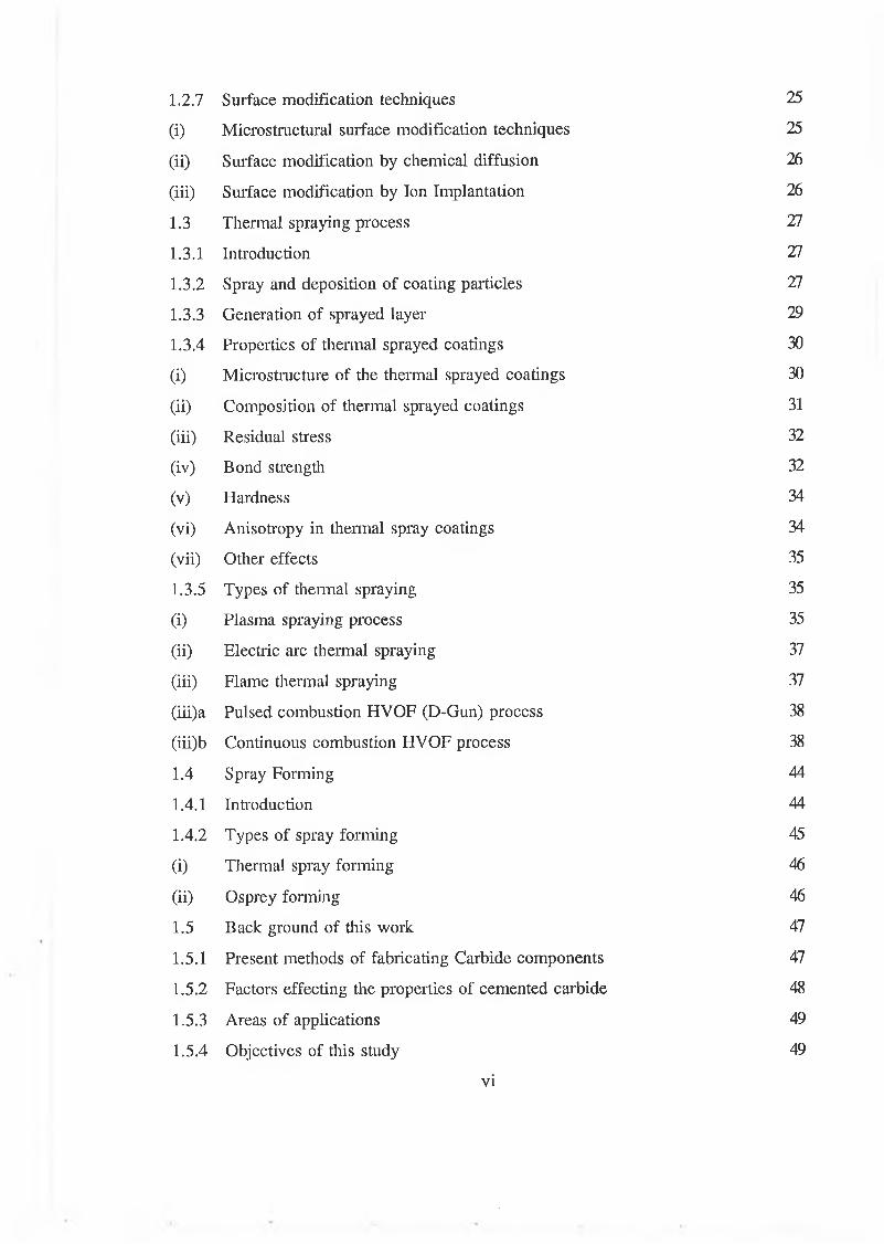
CONTENTS
PAGE
ACKNOWLEDGEMENTS iiABSTRACT iiiLIST OF FIGURES xüLIST OF TABLES xvi
CHAPTER 1 INTRODUCTION
1.1 Introduction 1
1.1.1 Organisation of the thesis 2
1.2 Literature survey on Surface Engineering 2
1.2.1 Objectives of Surface Engineering 3
1.2.2 Surface properties those are relevant to the behaviour ofengineering materials 4
1.2.3 Surface interaction with the environment 5
1.2.4 Friction and Wear 6
1.2.5 Reduction of surface deterioration in service 10
1.2.6 Coating processes 10
(i) Coating-Substrate system 11
(ii) Classification of coating processes 12
(ii)a Thermal spraying 12
(ii)b Welding 12
(ii)c Cladding 13
(ii)d Vapour Deposition 13
(ii)e Miscellaneous Techniques 18
(iii) Properties of the coating 19
(iii)a Bonding 20
(iii)b Composition of the coating 22
(iii)c Residual stresses 22
(iii)d Hardness of coating 23
(iv) Application areas of coatings 23
1.2.7 Surface modification techniques 25
(i) Micro structural surface modification techniques 25
(ü) Surface modification by chemical diffusion 26
(iii) Surface modification by Ion Implantation 26
1.3 Thermal spraying process 27
1.3.1 Introduction 27
1.3.2 Spray and deposition of coating particles 27
1.3.3 Generation of sprayed layer 29
1.3.4 Properties of thermal sprayed coatings 30
(i) Microstructure of the thermal sprayed coatings 30
(ii) Composition of thermal sprayed coatings 31
(iii) Residual stress 32
(iv) Bond strength 32
(V) Hardness 34
(vi) Anisotropy in thermal spray coatings 34
(vii) Other effects 35
1.3.5 Types of thermal spraying 35
(i) Plasma spraying process 35
(ii) Electric arc thermal spraying 37
(iii) Flame thermal spraying 37
(iii)a Pulsed combustion HVOF (D-Gun) process 38
(iii)b Continuous combustion HVOF process 38
1.4 Spray Forming 44
1.4.1 Introduction 44
1.4.2 Types of spray forming 45
(i) Thermal spray forming 46
(ii) Osprey forming 46
1.5 Back ground of this work 47
1.5.1 Present methods of fabricating Carbide components 47
1.5.2 Factors effecting the properties of cemented carbide 48
1.5.3 Areas of applications 49
1.5.4 Objectives of this study 49
vi
CHAPTER 2 EXPERIMENTAL EQUIPMENT
2.1 Introduction 85
2.2 Spraying system 85
2.2.1 Spraying equipment 85
(i) Diamond Jet Gun 86
(i)a Front end assembly 87
(ii) Powder feed unit 88
(ii)a Working principle of the powder feed unit 89
(iii) Gas flow meter unit 90
(iv) Gas regulators and manifolds 90
(v) Air control unit 90
2.3 Support system 91
2.3.1 Electric supply and gases supply units 92
2.3.2 Isolated room and spray booth 92
(i) Construction of sound proof spray room 93
2.3.3 Grit blasting apparatus 94
2.3.4 Exhaust system 95
2.3.5 Mechanical handling units 95
2.3.6 Furnace 96
2.3.7 Temperature measuring instrument 96
2.3.8 Coating thickness measuring instrument 97
CHAPTER 3 EXPERIMENTAL PROCEDURE
3.1 Procedure for thermal sprayed coating deposition 114
3.1.1 Surface preparation process 114
3.1.2 Spraying process 115
3.1.3 Post treatment process 116
3.2 Installation of the spray system and test run 117
3.3 Problem encountered with the spray gun 119
vii
3.3.1 Causes of back fire and remedy measures 119
3.4 Deposition and characterisation of coatings deposited on mild steel substrate 121
3.5 Property characterisation equipments and methods 122
3.5.1 Thickness measurement 122
3.5.2 Hardness measurement 123
3.5.3 Roughness measurement 124
3.5.4 Porosity measurement 124
3.5.5 Wear rate measurement 126
3.5.6 Adhesive bond strength measurement 126
3.6 Test run with industrial component 127
3.7 Test run to make free standing component 128
3.7.1 Trial to make free standing component by destroying the forming core 129
3.7.2 Trial to make free standing component without destroying the forming core 130
(i) Separation of the deposit from the forming core by preheating the core 130
(ü) Separation of the deposit from the forming core by putting epoxy releasing layer 131
(iii) Separation of the deposit from the forming core by putting metallic releasing layer 133
3.8 Procedure for fabricating free standing component m
3.8.1 Materials used for fabricating components 134
3.8.2 Material, size and shape of forming core 135
3.8.3 Measurement and control of process variables 135
3.8.4 Calibration procedure of the pyrometer 137
3.8.5 Selection of rotating speed and traversing speed 139
3.8.6 Fabrication of components of different size and shape 139
(i) Conical shaped components with built-in hole/holes 139
(ii) Complex shaped components 140
(iii) Smaller diameter components 141
(iv) Multi-layer components 141
v iii
(iv)a Multi-layer component with harder inner layer m
(iv)b Multi-layer component with harder outer layer 144
3.8.7 Property measurement of spray formed component 145
(i) Measurement of properties of single layered component 145
(i)a Method used for measuring ductility of sprayed material 145
(i)b Method to measure the residual stress 146
(i)c Method used to measure the composition of the WC/Co component 147
(ii) Measurement of properties of multi-layered component 149
(ii)a Test for adhesion between different layers 149
(ii)b Determination of depth of penetration of sprayed particle into aluminium substrate at different substrate temperature 15)
0')c Measurement of toughness of the component 150
CHAPTER 4 RESULTS AND DISCUSSION
4.1 Introduction 181
4.2 Initial tests to deposit coatings and their properties 181
4.3 Initial tests to fabricate free standing components 183
4.3.1 Separation of the deposited layer by destroying forming core 184
4.3.2 Separation of the deposited layer without destroying forming core m
(i) Preheating the forming core m(ii) Separation of the deposit by applying
releasing layer 187
(ii)a Separation by applying epoxy releasing layer 188
(ii)b Separation by applying metallic releasing layer 191
4.4 Property characterisation of formed components 194
4.5 Fabrication of spray formed component and identification of processing variables 196
4.6 Effect of processing variables 197
4.6.1 Effect of the forming core material 197
ix
4.6.2 Effect of size and shape of the forming core 198
4.6.3 Effect of the roughness of the forming core surface 199
4.6.4 Effect of preheating temperature of the forming core 200
4.6.5 Effect of temperature of the forming coreduring spraying 201
4.6.6 Effect of air cooling to control the temperatureof the forming core during spraying 202
4.6.7 Effect of temperature on the colour of the WC/Co deposit 208
4.6.8 Effect of post heating rate, temperature and time 203
4.6.9 Effect of cooling rate 204
4.6.10 Effect of releasing layer thickness 205
4.6.11 Effect of dimension of the fabricated componenton the processing parameters 205
4.6.12 Effect of traversing velocity on forming component 206
4.6.13 Other effects 207
(i) Fabrication of component with built-in hole/holes 207
(ii) Fabrication of complex shaped component 208
4.7 Fabrication of multi-layer component 208
4.7.1 Multi-layer component with harder inner layer 209
4.7.2 Multi-layer component with harder outer layer 212
4.8 Measurement of different properties ofmulti-layer component 213
4.9 Measurement of toughness 215
4.10 Measurement and control of residual stress inWC/Co component 216
4.11 Effect of spraying parameters on the propertiesof the WC/Co components 218
4.12 Composition of the deposited WC/Co material 220
4.13 Cost analysis of the formed component 222
4.14 Typical use of thin-walled WC/Co component 223
x
Chapter 5 CONCLUSIONS
5.1 Conclusions
5.2 Recommendations for future work 291
288
REFERENCES R1
APPENDIX A Calculation of thermal residual stress inthe deposited layer induced during coolingof the forming core-deposited layer assembly A1
APPENDIX B Calculation of residual stress A4
APPENDIX C Publications on this work A6
xi
LIST OF FIG U R ES
PACE
Figure 1.1 Various surface properties relevant to engineering components. 51
Figure 1.2 Schematic representation of a metal surface. 51
Figure 1.3 Surface asperities of a nominal smooth surface. 52
Figure 1.4 The three components of surface profile. 52
Figure 1.5 Schematic diagrams of various surface interactions. 53
Figure 1.6 Schematic diagrams of ploughing of softer surface. 53
Figure 1.7 Contact between two mating surfaces showing real area of contact. 53
Figure 1.8 Schematic of adhesive wear mechanism. 54
Figure 1.9 Schematic of fatigue wear mechanism. 54
Figure 1.10 Typical events in erosive wear. 55
Figure 1.11 Schematic illustration of the diffused coating and overlay coating. 55
Figure 1.12 Interrelated properties of coating substrate system. 56
Figure 1.13 The inter-relationship of coating, substrate,process and application. 56
Figure 1.14 Classification of various coating techniques. 57
Figure 1.15 Schematic of vacuum evaporation process. 58
Figure 1.16 Schematic of a glow discharge sputtering coating system. 59
Figure 1.17 Schematic of conventional CVD system. 60
Figure 1.18 Schematic cross-section of the model of a thin film on a substrate. 60
Figure 1.19 Schematic of spray pattern of thermal spray system. 61
Figure 1.20 Schematic of the deposition of particle and the planarmorphology of a solidified particle. 62
Figure 1.21 Lamellar structure of a thermal sprayed coating showingthe voids and pores. 63
Figure 1.22 Schematic of cracking and spalling of thermal spraycoating due to residual stress. 63
Figure 1.23 Schematic of plasma spray gun. 64
Figure 1.24 Schematic of a low pressure and controlled atmosphereplasma spraying system. 65
xii
Figure 1.25 Schematic of electric arc spray gun. 65
Figure 1.26 Schematic of flame spray gun. 66
Figure 1.27 Schematic of detonation-gun spray process. 67
Figure 1.28 Variation of theoretical flame temperature and exhausttemperature with chamber pressure. 68
Figure 1.29 Schematic of jet-kote HVOF thermal spray gun. 68
Figure 1.30 Schematic of diamond je t HVOF thermal spraying gun. 69
Figure 1.31 Schematic of CDS HVOF thermal spraying gun. 70
Figure 1.32 Gas velocity in HVOF system vs gun chamber pressure. 71
Figure 1.33 Variation of theoretical flame temperature with oxygen/fuel ratio. 71
Figure 1.34 Shock formation of an under expanded jet. 72
Figure 1.35 Variation of Mach number, temperature and pressure in atypical HVOF gas stream. 72
Figure 1.36 Laser Velocimeter 2-D particle velocity distribution. 73
Figure 1.37 Centreline alumina particle distribution measuredby Laser Velocimeter. 73
Figure 1.38 Centreline WC/12%Co particle distribution measuredby Laser Velocimeter. 74
Figure 1.39 Projected gas and particle temperature for 6 inch barrel. 74
Figure 1.40 Different design of combustion chamber of HVOF systems. 75
Figure 1.41 Graphical illustration showing the improvement ofquality of coating with velocity 76
Figure 1.42 Schematic diagram of a spray forming process. 76
Figure 1.43 Schematic of an Osprey forming system. 77
Figure 1.44 Schematic of a spray forming system with co-spray nozzle. 78
Figure 2.1 Picture of a Diamond Jet Gun. 98
Figure 2.2 Schematic showing the different assemblies of the gun. 98
Figure 2.3 Schematic of the front end parts and cross section ofthe front end assembly. 99
Figure 2.4 Schematic top cross sectional view of the gun. 100
Figure 2.5 Schematic of side cross sectional view of the gun. 101
Figure 2.6 Picture of the powder feed unit. 102
Figure 2.7 Schematic diagram of the powder feed unit. 103
x iii
Figure 2.8 Picture of the gas flow meter. 104
Figure 2,9 Picture of the Air control unit. 105
Figure 2.10 Schematic of spray booth. 105
Figure 2.11 Schematic diagram of the spray room showing thearrangement of the equipment. 106
Figure 2.12 Front sectional view of the sound proof wallsof sound proof room. 107
Figure 2.13 Diagram of the frame structure made for sound proof room. 108
Figure 2.14 A cut out cross section of the wet collector. 109
Figure 2.15 Photograph of the furnace with the cylindrical boxconnected with nitrogen cylinder. 110
Figure 2.16 Picture of the optical pyrometer. 110
Figure 2.17 Picture of the coating thickness measuring instruments. I l l
Figure 2.18 Operating principle of thickness measurement by eddy-current. I l l
Figure 2.19 Operating principle of thickness measurement bymagnetic induction. 112
Figure 3.1 Schematic of samples used for calibrating coatingthickness measuring instrument. 152
Figure 3.2 Schematic of tensile bond strength measuring sampleand the fixture. 152
Figure 3.3 Schematic of the printing roll showing the dimension. 153
Figure 3.4 Photograph of the printing roll. 153
Figure 3.5 Shape and size of the conical forming core. 154
Figure 3.6 Cooling rate of the forming core placed in ambient atmosphere. 155
Figure 3.7 Cooling rate of the forming core in furnace at different condition. 156
Figure 3.8 Photograph showing the arrangement of the sampleand the pyrometer on the lathe. 157
Figure 3.9 Particle size distribution of tungsten carbidecobalt material powder. 158
Figure 3.10 Particle size distribution of nickel chromium alloy powder. 159
Figure 3.11 Particle size distribution of stainless steel material powder. 160
Figure 3.12 Forming cores of different size and shape. 161
Figure 3.13 Schematic of the cross section of the tubeholding pyrometer sensor. 162
xiv
Figure 3. L4
Figure 3.15
Figure 3.16
Figure 3.17
Figure 3.18
Figure 3.19
Figure 3.20
Figure 3.21
Figure 3.22
Figure 3.23
Figure 3.24
Figure 4.1
Figure 4,2
Figure 4.3
Figure 4.4
Figure 4.5
Figure 4.6
Curve showing the rise of temperature of the forming core per pass of spray at different temperature range for different traversing speed of the gun.
Curve showing the rise of temperature of the forming core per pass of spray at different distance of the substrate from the gun at different traversing speed of the gun.
Curve showing the rise of temperature of the fonning core per pass of spray for different size (average diameter) at different range of temperature.
Curve showing the distribution of the particle in the spray stream for tungsten carbide cobalt material.
Curve showing the distribution of the particle in the spray stream for nickel chromium alloy.
Schematic of bend test sample and three point bend test mechanism.
Schematic of cylindrical forming core with slit used for the residual stress measurement.
Picture showing the components made for the measurement residual stress.
Schematically shows the orientation of stress measuring sample as curved beam.
Schematic of toughness test sample showing the size and shape.
Curve showing the gap that will form between the sprayed deposit layer and the fonning core surface upon cooling the forming core from preheating temperature.
Photograph showing the mode of fracture of the WC/Co component.
Schematic of deposit-forming core assembly showing the location through which molten releasing layer was coming out.
Photograph of the double cone shaped component made from different materials, a) WC/Co, b) Nickel chromium alloy and c) Stainless steel.
Time-temperature curve showing the fabrication process of spray formed component from nickel chromium alloy material.
Time-temperature curve showing the fabrication process of spray formed component from WC/Co material.
Calibration curve for pyrometer.
Figure 4.7a
Figure 4.7b
Figure 4.7c
Figure 4.8
Figure 4.9
Figure 4.10
Figure 4.11
Figure 4.12
Figure 4.13
Figure 4.14
Figure 4.15
Figure 4.16
Figure 4.17
Figure 4.18
Figure 4.19
Micrograph showing the porosity of the componentsmade from WC/Co material. 229
Micrograph showing the porosity of the componentsmade from nickel chromium alloy material. 229
Micrograph showing the porosity of the componentsmade from stainless steel material. 230
Photograph of nickel chromium alloy component of different sizes and shapes, a) conical shape of larger diameter,b) cylindrical shape, c) conical shape of smaller diameter,d) complex shape and e) conical shape of medium diameter. 231
Photograph of stainless steel component of different sizesand shapes, a) conical shape of larger diameter, b) cylindricalshape, c) conical shape of smaller diameter, d) complexshape and e) conical shape of medium diameter. 231
Photograph of WC/Co component of different sizes and shapes, a) cylindrical shape b) conical shape of larger diameter andc) conical shape of medium diameter. 232
Curve showing the variation of preheating temperaturewith the coefficient of thermal expansion of the materialby which the forming core were made. 233
Bar graph showing the safe range of preheating temperature for different type of material of the forming core. 234
Diagram showing the safe zone of preheating temperature for different size of conical shaped component of WC/Co material. 235
Photograph of WC/Co component of different sizes and shapes. 236
Diagram showing the safe zone of preheating temperature formaking free-standing component from different materialsusing 33.5 mm diameter (average) forming core. 237
Diagram showing the change of colour of the WC/Co deposit at different temperature. 238
Heating rate of the forming core during post heatingfrom 400°C temperature. 239
Heating rate of the forming core during post heatingfrom 500°C temperature. 240
Diagram showing the relation between releasing agent thicknessand the post heating temperature for separation of the depositfrom the forming core. 241
xiv
Figure 4.21
Figure 4.22
Figure 4.23
Figure 4.24
Figure 4.25
Figure 4.26
Figure 4.27
Figure 4.28
Figure 4.29
Figure 4.30
Figure 4.31
Figure 4.32
Figure 4.33
Figure 4.34
Figure 4.35
Figure 4.20 Curve showing the relation of post heating time and temperatureat different releasing layer thickness for proper separationof the deposit from the forming core. 242
Photograph of WC/Co component having localised fracture. 243
Curve showing the allowance which is to be subtracted fromthe diameter of the stainless steel forming core to make aspray formed component of WC/Co material of specifiedinner diameter, 244
Photograph of WC/Co components with single and multiplebuilt-in hole/holes. 245
Photograph of complex shaped components ofdifferent materials. 245
Photograph showing the mode of fracture ofmulti-layered component. 246
Photograph of multi-layered componentmade from WC/Co and aluminium. 246
Micrograph showing the poor bonding betweenWC/Co and aluminium layer. 247
Photograph showing the peeling of nickel chromium alloylayer from WC/Co component due to weak bonding. 248
Photograph showing the peeling of nickel chromium alloylayer from WC/Co component which was post heated innitrogen atmosphere, due to weak bonding. 248
Photograph of the component with partially deposited nickel chromium alloy layer on WC/Co component. 249
Photograph of the multi-layered component made from WC/Coand nickel chromium alloy material. 249
Photograph of fractured multi-layered component made from WC/Co and nickel chromium alloy material. 250
Micrograph of the component made from WC/Co andnickel chromium alloy mixed material (40 % nickelalloy and 60 % WC/Co). 250
Photograph of WC/Co component with mixed materialon the top layer. 251
Photograph of the multi-layered component withaluminium inner layer and nickel chromium alloyouter layer of 0.5 mm thick. 252
xvii
Figure 4.37
Figure 4.38
Figure 4.39
Figure 4.40
Figure 4.41
Figure 4.42
Figure 4.43
Figure 4.44
Figure 4.45
Figure 4.46
Figure 4.47
Figure 4.48
Figure 4.49
Figure 4.50
Figure 4.51
Figure 4.52
Figure 4.53
Figure 4.54
Figure 4.36 Adhesive bond strength of deposited material at different substrate preheating temperature.
Photograph showing the mode of failure of coating during pull test.
Photograph showing the depth of penetration of the sprayed particle into the aluminium substrate.
Ductility of different deposited material sprayed at different substrate preheating temperatures.
Variation of ductility of the deposited material with thickness of the deposited layer.
Hardness of deposited material sprayed at different substrate preheating temperature.
Load-elongation curves of different depositing materials.
Stress-strain curves for nickel chromium alloy deposited material.
Stress-strain curves for mixed ( 40% by volume nickel chromium alloy and 60% WC/Co) deposited material.
Stress-strain curves for WC/Co deposited material.
Photograph of the cracked components showing the effect of residual stress by open up and closed up of the crack.
Curve showing the relation between residual stress and post heating time.
Curve showing the relation between residual stress and post heating temperature.
Micrograph showing 0.8% porosity in WC/Co component.
Micrograph showing 1.0% porosity in WC/Co component.
Micrograph showing 2% porosity in WC/Co component.
Micrograph showing 3% porosity in WC/Co component.
Curve showing the variation of hardness and porosity with the change of flow rate of oxygen during spraying WC/Co material.
Curve showing the variation of hardness and porosity with the change of flow rate of propylene during spraying WC/Co material.
xv iii

Figure 4.55
Figure 4.56
Figure 4.57
Figure 4.58
Figure 4.59
Figure 4.60
Figure 4.61
Figure 4.62
Figure 4.63
Figure 4.64
Figure 4.65
Figure 4.66
Figure 4.67
Figure 4.68
Curve showing the variation of hardness and porosity with the change of flow rate of ah' during spraying WC/Co material.
Curve showing the variation of hardness and porosity with the change of distance of the spray gun from the forming core during spraying WC/Co material.
Curve showing the variation of hardness and porosity with the change of flow rate of powder material during spraying WC/Co material.
X-Ray diffraction pattern for WC/Co deposits without preheating condition.
X-Ray diffraction pattern for WC/Co component before post heating.
X-Ray diffraction pattern for WC/Co free-standing component after post heating.
X-Ray diffraction pattern for WC/Co free-standing component after post heating and after cleaning.
Energy dispersive analysis pattern of WC/Co coating (about 0.5 mm thick) at within 50 pm of the outer surface of the cross-section.
Energy dispersive analysis pattern of WC/Co coating (about 0.5 mm thick) at central region of the cross-section.
Energy dispersive analysis pattern of WC/Co coating (about 0.5 mm thick) at within 50 pm of the inner surface of the cross-section.
Energy dispersive analysis pattern of WC/Co free-standing cleaned component (about 0.7 mm thick) at within 50 pm of the outer surface of the cross-section.
Energy dispersive analysis pattern of WC/Co free-standing cleaned component (about 0.7 mm thick) at central region of the cross-section.
Energy dispersive analysis pattern of WC/Co free-standing cleaned component (about 0.7 mm thick) at within 50 pm of the inner surface of the cross-section.
Photograph showing the application of thin-walled WC/Co component, (a) WC/Co component is fixed with aluminium nozzle with adhesive, (b) WC/Co component is shrunk fit with aluminium nozzle.
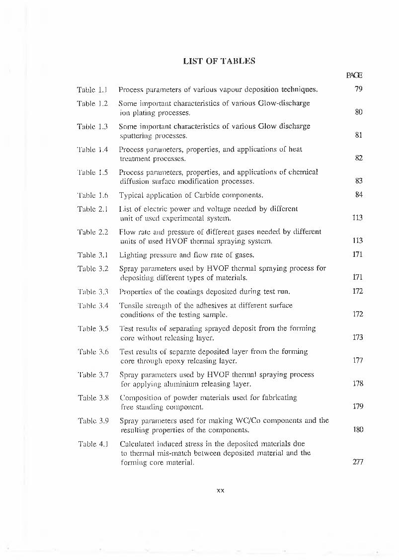
LIST OF TA BL E S
P K E
Table 1.1 Process parameters of various vapour deposition techniques. 79
Table 1.2 Some important characteristics of various Glow-discharge ion plating processes. 80
Table 1.3 Some important characteristics of various Glow discharge sputtering processes. 81
Table 1.4 Process parameters, properties, and applications of heat treatment processes. 82
Table 1.5 Process parameters, properties, and applications of chemical diffusion surface modification processes. 83
Table 1.6 Typical application of Carbide components. 84
Table 2.1 List of electric power and voltage needed by different unit of used experimental system. 113
Table 2.2 Flow rate and pressure of different gases needed by different units of used HYOF thermal spraying system. 113
Table 3.1 Lighting pressure and flow rate of gases. 171
Table 3.2 Spray parameters used by HVOF thermal spraying process for depositing different types of materials. 171
Table 3.3 Properties of the coatings deposited during test run. 172
Table 3.4 Tensile strength of the adhesives at different surface conditions of the testing sample. 172
Table 3.5 Test results of separating sprayed deposit from the forming core without releasing layer. 173
Table 3.6 Test results of separate deposited layer from the forming core through epoxy releasing layer. 177
Table 3.7 Spray parameters used by HVOF thermal spraying process for applying aluminium releasing layer. 178
Table 3.8 Composition of powder materials used for fabricating free standing component. 179
Table 3.9 Spray parameters used for making WC/Co components and the resulting properties of the components. 180
Table 4.1 Calculated induced stress in the deposited materials due to thermal mis-match between deposited material and the forming core material. 277
xx

Table 4.2 Test results to separate deposited layer from the forming core through aluminium releasing layer. 278
Table 4.3 Different properties of the spray formed components. 279
Table 4.4 Typical values of processing variables for fabricating free-standing component of different materials. 280
Table 4.5 Sizes and thicknesses of different WC/Co components as shown in Figure 4.14. 281
Table 4.6 Results showing the effect of surface roughness of the forming core on the fabrication of components. 282
Table 4.7 Effect of surface roughness and cleanliness of the forming core on the fabrication of WC/Co components. 283
Table 4.8 Bond strength and ductility of coating at different aluminium substrate surface condition. 284
Table 4.9 Effect of fabrication parameters on the residual stress of the WC/Co component. 285
Table 4.10 Conditions to make stress free spray formed WC/Co component. 286
Table 4.11 Composition in the powder and sprayed WC/Co material obtained from the relative intensities of XRD traces. 286
Table 4.12 Counts to determine relative carbon quantity in WC/Co coating and in free-standing component. 287
XX i

CHAPTER 1
INTRODUCTION
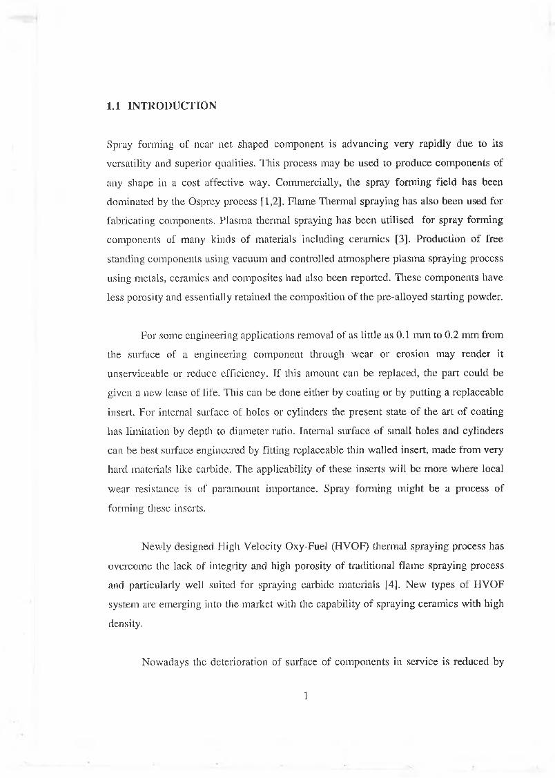
1.1 INTRODUCTION
Spray forming of near net shaped component is advancing very rapidly due to its
versatility and superior qualities. This process may be used to produce components of
any shape in a cost affective way. Commercially, the spray forming field has been
dominated by the Osprey process [1,2]. Flame Thermal spraying has also been used for
fabricating components. Plasma thermal spraying has been utilised for spray forming
components of many kinds of materials including ceramics [3]. Production of free
standing components using vacuum and controlled atmosphere plasma spraying process
using metals, ceramics and composites had also been reported. These components have
less porosity and essentially retained the composition of the pre-alloyed starting powder.
For some engineering applications removal of as little as 0.1 mm to 0.2 mm from
the surface of a engineering component through wear or erosion may render it
unserviceable or reduce efficiency. If this amount can be replaced, the part could be
given a new lease of life. This can be done either by coating or by putting a replaceable
insert. For internal surface of holes or cylinders the present state of the art of coating
has limitation by depth to diameter ratio. Internal surface of small holes and cylinders
can be best surface engineered by fitting replaceable thin walled insert, made from very
hard materials like carbide. The applicability of these inserts will be more where local
wear resistance is of paramount importance. Spray forming might be a process of
forming these inserts.
Newly designed High Velocity Oxy-Fuel (HVOF) thermal spraying process has
overcome the lack of integrity and high porosity of traditional flame spraying process
and particularly well suited for spraying carbide materials [4], New types of HVOF
system are emerging into the market with the capability of spraying ceramics with high
density.
Nowadays the deterioration of surface of components in service is reduced by
1
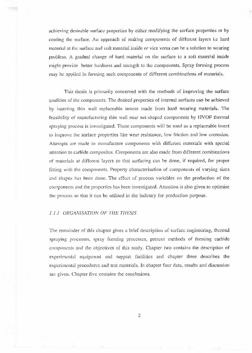
achieving desirable surface properties by either modifying the surface properties or by
coating the surface. An approach of making components of different layers i.e hard
material at the surface and soft material inside or vice versa can be a solution to wearing
problem. A gradual change of hard material on the surface to a soft material inside
might provide better hardness and strength to the components. Spray forming process
may be applied in forming such components of different combinations of materials.
This thesis is primarily concerned with the methods of improving the surface
qualities of the components. The desired properties of internal surfaces can be achieved
by inserting thin wall replaceable inserts made from hard wearing materials. The
feasibility of manufacturing thin wall near net-shaped components by HVOF thermal
spraying process is investigated. These components will be used as a replaceable insert
to improve the surface properties like wear resistance, low friction and low corrosion.
Attempts are made to manufacture components with different materials with special
attention to carbide composites. Components are also made from different combinations
of materials at different layers so that surfacing can be done, if required, for proper
fitting with the components. Property characterisation of components of varying sizes
and shapes has been done. The effect of process variables on the production of the
components and the properties has been investigated. Attention is also given to optimise
the process so that it can be utilised in the industry for production purpose.
1.1.1 ORGANISATION OF THE THESIS
The remainder of this chapter gives a brief description of surface engineering, thermal
spraying processes, spray forming processes, present methods of forming carbide
components and the objectives of this study. Chapter two contains the description of
experimental equipment and support facilities and chapter three describes the
experimental procedures and test materials. In chapter four data, results and discussion
are given. Chapter five contains the conclusions.
2
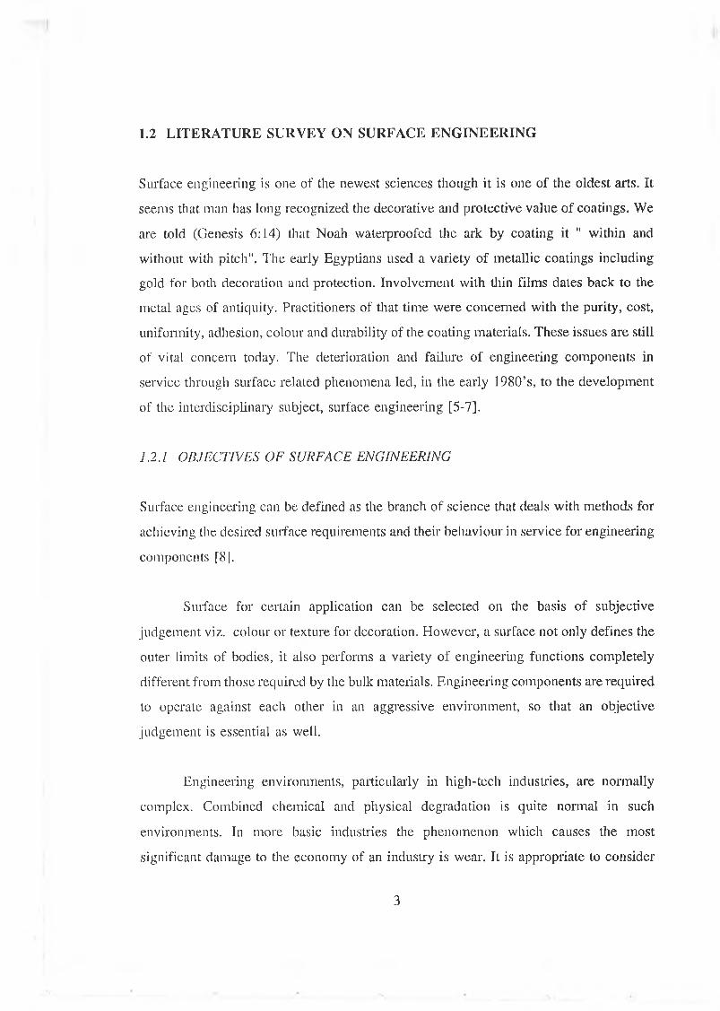
1.2 LITERATURE SURVEY ON SURFACE ENGINEERING
Surface engineering is one of the newest sciences though it is one of the oldest arts. It
seems that man lias long recognized the decorative and protective value of coatings. We
are told (Genesis 6:14) that Noah waterproofed the ark by coating it " within and
without with pitch". The early Egyptians used a variety of metallic coatings including
gold for both decoration and protection. Involvement with thin films dates back to the
metal ages of antiquity. Practitioners of that time were concerned with the purity, cost,
uniformity, adhesion, colour and durability of the coating materials. These issues are still
of vital concern today. The deterioration and failure of engineering components in
service through surface related phenomena led, in the early 1980’s, to the development
of the interdisciplinary subject, surface engineering [5-7].
1.2.1 OBJECTIVES OF SURFACE ENGINEERING
Surface engineering can be defined as the branch of science that deals with methods for
achieving the desired surface requirements and their behaviour in service for engineering
components [8].
Surface for certain application can be selected on the basis of subjective
judgement viz. colour or texture for decoration. However, a surface not only defines the
outer limits of bodies, it also performs a variety of engineering functions completely
different from those required by the bulk materials. Engineering components are required
to operate against each other in an aggressive environment, so that an objective
judgement is essential as well.
Engineering environments, particularly in high-tech industries, are normally
complex. Combined chemical and physical degradation is quite normal in such
environments. In more basic industries the phenomenon which causes the most
significant damage to the economy of an industry is wear. It is appropriate to consider
3
the mode of component degradation and failure in service and to combine the result of
both analyses in order to design better surfaces. For example, in machining process as
the loads, speeds and operative temperatures of the cutting tools continue to increase,
attention has been increasingly focused on to materials such as ceramics. Such materials
are difficult to shape into the complex geometries of many cutting tools but they can be
readily deposited as coating onto traditional materials shaped by the established cutting
and forming processes. Although ceramics are brittle in a solid form, when deposited
as coating they loose their brittleness and conform to the toughness of the base
materials. Improved surfaces of tools not only improve the life of the tools but also
improve the finish of the machined parts.
Similarly in tribological application, effective lubrication reduces friction and
wear between moving surfaces.Conventional liquid lubricants fail under extreme
conditions such as low pressure, corrosive or oxidative environment, high load and high
speed. Very often bulk materials are either incapable of satisfying design requirements
or are too expensive. Surface coating can satisfy requirements, such as hard surface with
a ductile core at minimal cost. Ceramics, cermets and self-lubricating solids may appear
to be ideal wear resistant materials that suit many tribological applications provided that
their strength and toughness are acceptable.
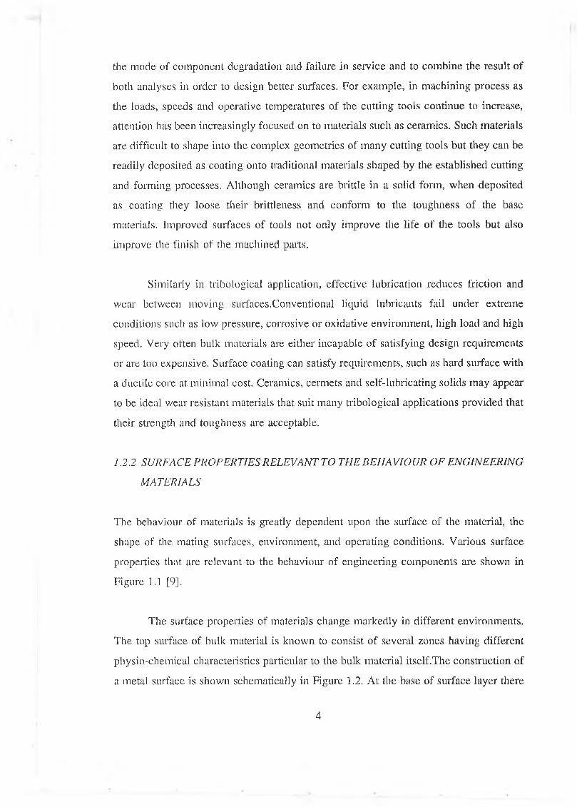
1.2.2 SURFACE PROPERTIES RELEVANTTO THE BEHAVIOUR OF ENGINEERING
MATERIALS
The behaviour of materials is greatly dependent upon the surface of the material, the
shape of the mating surfaces, environment, and operating conditions. Various surface
properties that are relevant to the behaviour of engineering components are shown in
Figure 1.1 [9].
The surface properties of materials change markedly in different environments.
The top surface of bulk material is known to consist of several zones having different
physio-chemical characteristics particular to the bulk material itself.The construction of
a metal surface is shown schematically in Figure 1.2. At the base of surface layer there
4
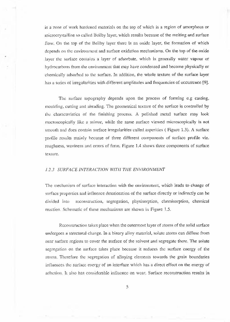
is a zone of work hardened materials on the top of which is a region of amorphous or
microcrystalline so called Beilby layer, which results because of the melting and surface
flow. On the top of the Beilby layer there is an oxide layer, the formation of which
depends on the environment and surface oxidation mechanisms. On the top of the oxide
layer the surface contains a layer of adsórbate, which is generally water vapour or
hydrocarbons from the environment that may have condensed and become physically or
chemically adsorbed to the surface. In addition, the whole texture of the surface layer
has a series of irregularities with different amplitudes and frequencies of occurrence [9].
The surface topography depends upon the process of forming e.g casting,
moulding, cutting and abrading. The geometrical texture of the surface is controlled by
the characteristics of the finishing process. A polished metal surface may look
macroscopically like a mirror, while the same surface viewed microscopically is not
smooth and does contain surface irregularities called asperities ( Figure 1.3). A surface
profile results mainly because of three different components of surface profile viz.
roughness, waviness and errors of form. Figure 1.4 shows three components of surface
texture.
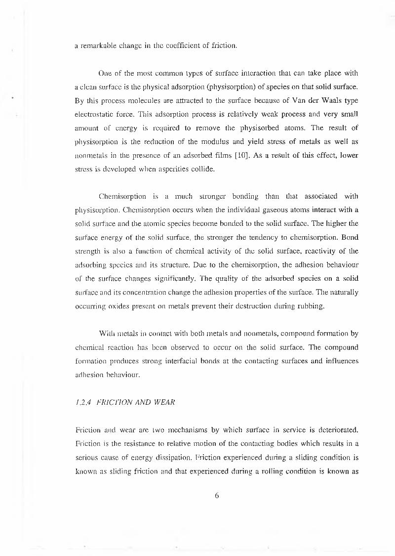
1.2.3 SURFACE INTERACTION W ITH THE ENVIRONMENT
The mechanism of surface interaction with the environment, which leads to change of
surface properties and influence deterioration of the surface directly or indirectly can be
divided into reconstruction, segregation, physisorption, chemisorption, chemical
reaction. Schematic of these mechanisms are shown in Figure 1.5.
Reconstruction takes place when the outermost layer of atoms of the solid surface
undergoes a structural change. In a binary alloy material, solute atoms can diffuse from
near surface regions to cover the surface of the solvent and segregate there. The solute
segregation on the surface takes place because it reduces the surface energy of the
atoms. Therefore the segregation of alloying elements towards the grain boundaries
influences the surface energy of an interface which has a direct effect on the energy of
adhesion. It also has considerable influence on wear. Surface reconstruction results in
5
a remarkable change in the coefficient of friction,
One of the most common types of surface interaction that can take place with
a clean surface is the physical adsorption (physisorption) of species on that solid surface.
By this process molecules are attracted to the surface because of Van der Waals type
electrostatic force. This adsorption process is relatively weak process and very small
amount of energy is required to remove the physisorbed atoms. The result of
physisorption is the reduction of the modulus and yield stress of metals as well as
nonmetals in the presence of an adsorbed films [10]. As a result of this effect, lower
stress is developed when asperities collide.
Chemisorption is a much stronger bonding than that associated with
physisorption. Chemisorption occurs when the individual gaseous atoms interact with a
solid surface and the atomic species become bonded to the solid surface. The higher the
surface energy of the solid surface, the stronger the tendency to chemisorption. Bond
strength is also a function of chemical activity of the solid surface, reactivity of the
adsorbing species and its structure. Due to the chemisorption, the adhesion behaviour
of the surface changes significantly. The quality of the adsorbed species on a solid
surface and its concentration change the adhesion properties of the surface. The naturally
occurring oxides present on metals prevent their destruction during rubbing.
With metals in contact with both metals and nonmetals, compound formation by
chemical reaction has been observed to occur on the solid surface. The compound
formation produces strong interfacial bonds at the contacting surfaces and influences
adhesion behaviour.
1.2.4 FRICTION AND WEAR
Friction and wear are two mechanisms by which surface in service is deteriorated.
Friction is the resistance to relative motion of the contacting bodies which results in a
serious cause of energy dissipation. Friction experienced during a sliding condition is
known as sliding friction and that experienced during a rolling condition is known as
6
rolling friction. The degree of friction is expressed as the coefficient of friction. Despite
extensive research on the subject, no simple model could be developed so far to predict
or calculate the coefficient of friction for a given pair of materials [9]. Friction
originates from complicated molecular-mechanical interactions between contacting
bodies and these interactions differ from one application to another.
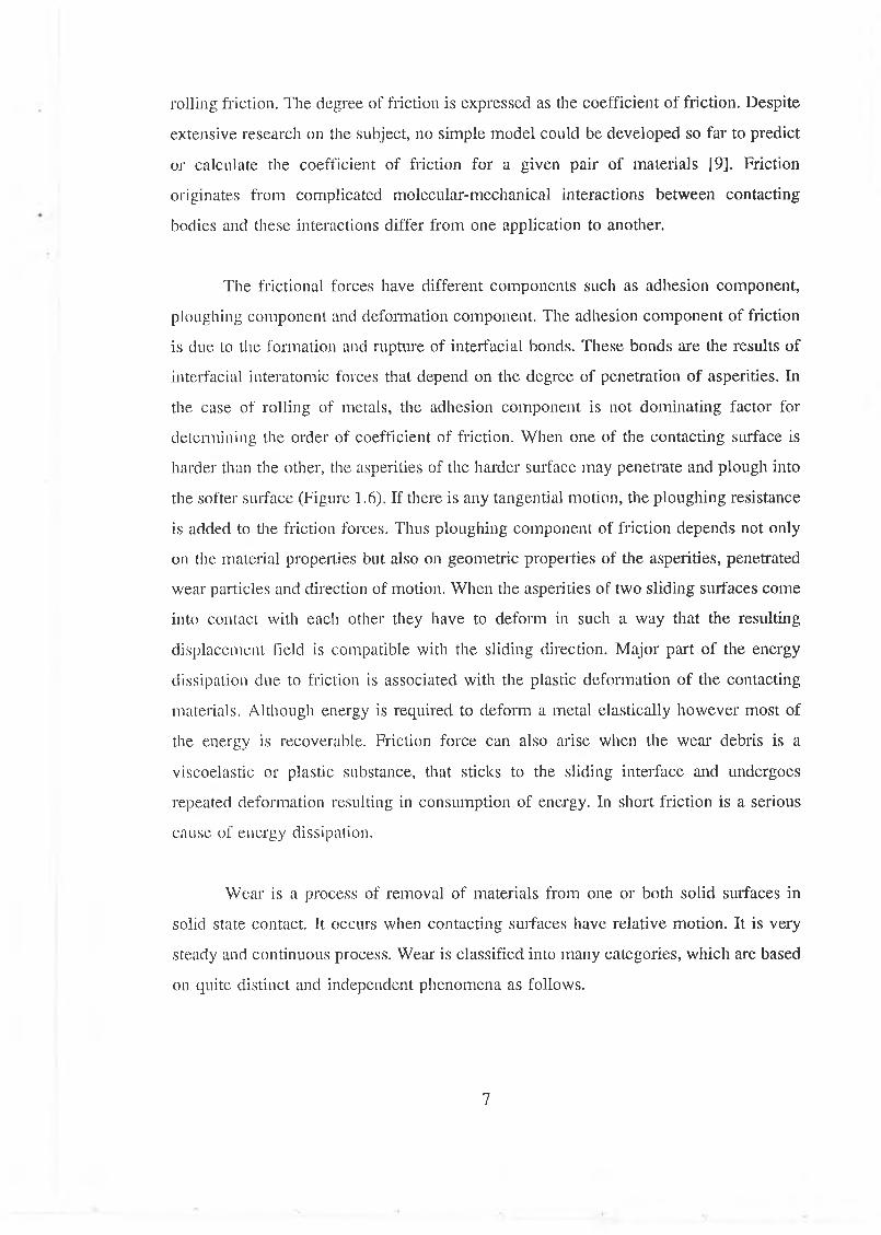
The frictional forces have different components such as adhesion component,
ploughing component and deformation component. The adhesion component of friction
is due to the formation and rupture of interfacial bonds. These bonds are the results of
interfacial interatomic forces that depend on the degree of penetration of asperities. In
the case of rolling of metals, the adhesion component is not dominating factor for
determining the order of coefficient of friction. When one of the contacting surface is
harder than the other, the asperities of the harder surface may penetrate and plough into
the softer surface (Figure 1.6). If there is any tangential motion, the ploughing resistance
is added to the friction forces. Thus ploughing component of friction depends not only
on the material properties but also on geometric properties of the asperities, penetrated
wear particles and direction of motion. When the asperities of two sliding surfaces come
into contact with each other they have to deform in such a way that the resulting
displacement field is compatible with the sliding direction. Major part of the energy
dissipation due to friction is associated with the plastic deformation of the contacting
materials. Although energy is required to deform a metal elastically however most of
the energy is recoverable. Friction force can also arise when the wear debris is a
viscoelastic or plastic substance, that sticks to the sliding interface and undergoes
repeated deformation resulting in consumption of energy. In short friction is a serious
cause of energy dissipation.
Wear is a process of removal of materials from one or both solid surfaces in
solid state contact. It occurs when contacting surfaces have relative motion. It is very
steady and continuous process. Wear- is classified into many categories, which are based
on quite distinct and independent phenomena as follows.
7
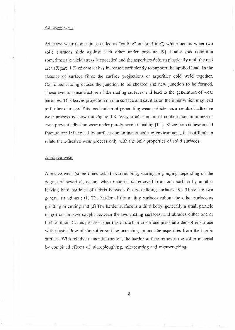
Adhesive wear
Adhesive wear (some times called as "galling" or "scuffing") which occurs when two
solid surfaces slide against each other under pressure [9]. Under this condition
sometimes the yield stress is exceeded and the asperities deform plastically until the real
area (Figure 1.7) of contact has increased sufficiently to support the applied load. In the
absence of surface films the surface projections or asperities cold weld together.
Continued sliding causes the junction to be sheared and new junction to be formed.
These events cause fracture of the mating surfaces and lead to the generation of wear
particles. This leaves pro jection on one surface and cavities on the other which may lead
to further damage. This mechanism of generating wear particles as a result of adhesive
wear process is shown in Figure 1.8. Very small amount of contaminant minimize or
even prevent adhesion wear under purely normal loading [11]. Since both adhesion and
fracture are influenced by surface contaminants and the environment, it is difficult to
relate the adhesive wear process only with the bulk properties of solid surfaces.
Abrasive wear
Abrasive wear (some times called as scratching, scoring or gouging depending on the
degree of severity), occurs when material is removed from one surface by another
leaving hard particles of debris between the two sliding surfaces [9J. There are two
general situations : (1) The harder of the mating surfaces rubout the other surface as
grinding or cutting and (2) The harder surface is a third body, generally a small particle
of grit or abrasive caught between the two mating surfaces, and abrades either one or
both of them. In this process asperities of the harder surface press into the softer surface
with plastic flow of the softer surface occurring around the asperities from the harder
surface. With relative tangential motion, the harder surface removes the softer material
by combined effects of microploughing, microcutting and microcracking.
8

Fatigue wear
A surface of a component, subjected to repeated load experiences continual application
and release of stress. These repeating stresses in a rolling or sliding contact might cause
fatigue failure. These effects are mainly based on the action of stresses in or below the
surfaces without need of direct physical contact of the surfaces under consideration. The
shear stress is maximum some distance below the surface in a pure rolling contact.
Crack for failure of the component will initiate from the point where shear stress is
maximum and the crack will move nearer to the surface (Figure 1.9). Therefore
subsurface and surface fatigue wear are the dominant failure modes in rolling element
bearing [9], Any imperfection of the material also influences this failure.
Erosive wear
Erosive wear is a life limiting phenomenon for components working in an erosive
environment. This is caused by the impingement of solid particles or small drops of
liquid or gas. The impact of these particles on moving or static surfaces of components
results in severe erosion. The basic mechanism of erosive wear is shown in Figure 1.10.
Movement of the particle stream relative to the surface is a vital feature of erosion and
the angle of impingement has significant effect on the rate of material removal. The
response of engineering materials to the impingement of solid particles or liquid drops
varies greatly depending on the type and state of materials to which these engineering
materials are exposed.
Fretting wear
When components are subjected to very small relative vibratory movements at high
frequency a type of interactive wear takes place, called "fretting". This mode of wear
is initiated by adhesion and is amplified by corrosion. However the main effect is caused
by abrasion. Fretting wear normally occurs between components which are not intended
to move e.g. press fit components. It is observed that the environment plays a strong
role in the wear of surface that undergo fretting.
9
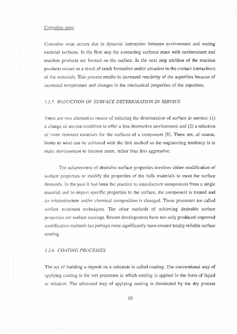
Corrosive wear
Corrosive wear occurs due to dynamic interaction between environment and mating
material surfaces. In the first step the contacting surfaces react with environment and
reaction products are formed on the surface. In the next step attrition of the reaction
products occurs as a result of crack formation and/or abrasion in the contact interactions
of the materials. This process results in increased reactivity of the asperities because of
increased temperature and changes in the mechanical properties of the asperities.
1.2.5 REDUCTION OF SURFACE DETERIORATION IN SERVICE
There are two alternative means of reducing the deterioration of surface in service: (1)
a change of service condition to offer a less destructive environment and (2) a selection
of more resistant materials for the surfaces of a component [8]. There are, of course,
limits to what can be achieved with the first method as the engineering tendency is to
make environment to become more, rather than less aggressive.
The achievement of desirable surface properties involves either modification of
surface properties or modify the properties of the bulk materials to meet the surface
demands. In the past it had been the practice to manufacture components from a single
material and to impart specific properties to the surface, the component is treated and
its microstructure and/or chemical composition is changed. These processes are called
surface treatment techniques. The other methods of achieving desirable surface
properties are surface coatings. Recent developments have not only produced improved
modification methods but perhaps more significantly have created totally reliable surface
coating.
1.2.6 COATING PROCESSES
The act of building a deposit on a substrate is called coating. The conventional way of
applying coating is the wet processes in which coating is applied in the form of liquid
or solution. The advanced way of applying coating is dominated by the dry process
10
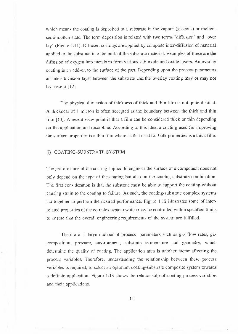
which means the coating is deposited to a substrate in the vapour (gaseous) or molten-
semi-molten state. The term deposition is related with two terms "diffusion" and "over
lay" (Figure 1.11). Diffused coatings are applied by complete inter-diffusion of material
applied to the substrate into the bulk of the substrate material. Examples of these are the
diffusion of oxygen into metals to form various sub-oxide and oxide layers. An overlay
coating is an add-on to the surface of the part. Depending upon the process parameters
an inter-diffusion layer between the substrate and the overlay coating may or may not
be present [12],
The physical dimension of thickness of thick and thin film is not quite distinct.
A thickness of 1 micron is often accepted as the boundary between the thick and thin
film [13]. A recent view point is that a film can be considered thick or thin depending
on the application and discipline. According to this idea, a coating used for improving
the surface properties is a thin film where as that used for bulk properties is a thick film.
(i) COATING-SUBSTRATE SYSTEM
The performance of the coating applied to engineer the surface of a component does not
only depend on the type of the coating but also on the coating-substrate combination.
The first consideration is that the substrate must be able to support the coating without
causing strain to the coating to failure. As such, the coating-substrate complex systems
act together to perform the desired performance. Figure 1.12 illustrates some of inter
related properties of the complex system which may be controlled within specified limits
to ensure that the overall engineering requirements of the system are fulfilled.
There are a large number of process parameters such as gas flow rates, gas
composition, pressure, environment, substrate temperature and geometry, which
determine the quality of coating. The application area is another factor affecting the
process variables. Therefore, understanding the relationship between these process
variables is required, to select an optimum coating-substrate composite system towards
a definite application. Figure 1.13 shows the relationship of coating process variables
and their applications.
11
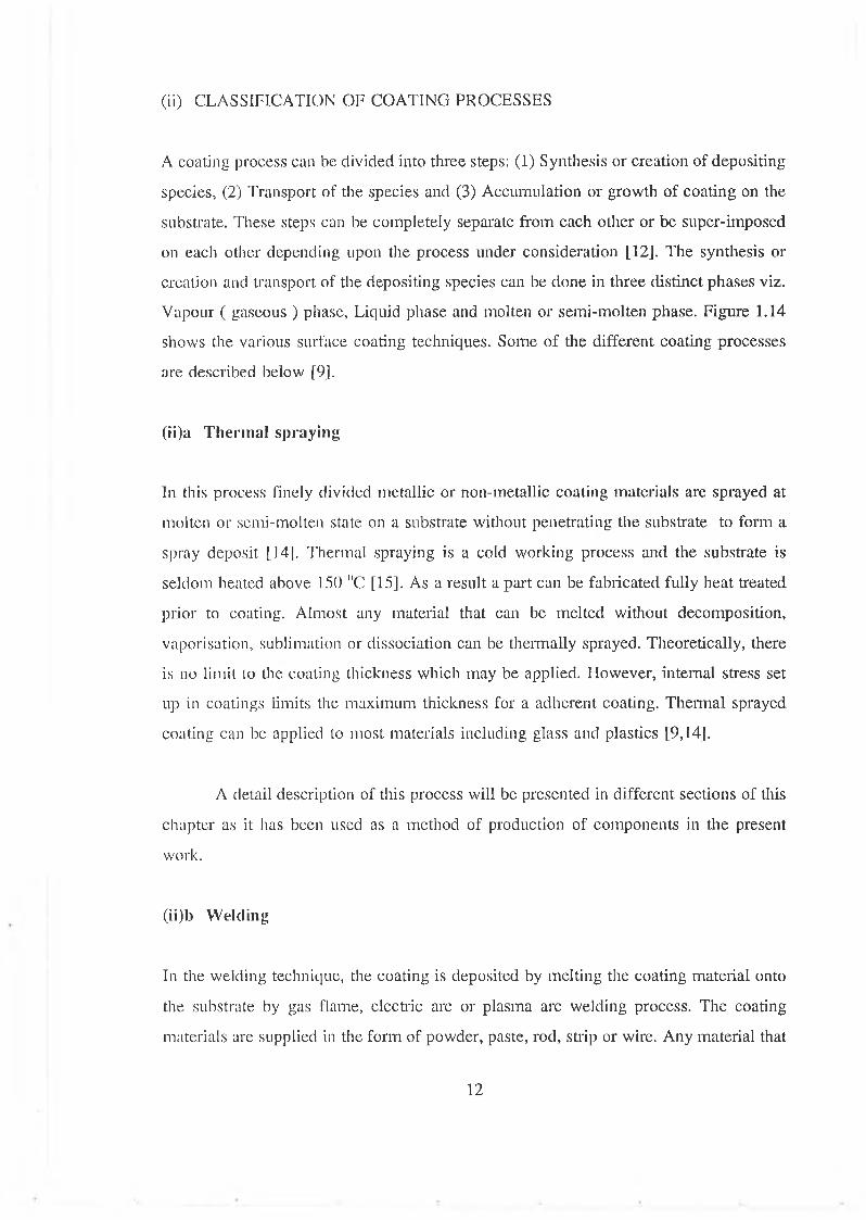
(ii) CLASSIFICATION OF COATING PROCESSES
A coating process can be divided into three steps: (1) Synthesis or creation of depositing
species, (2) Transport of the species and (3) Accumulation or growth of coating on the
substrate. These steps can be completely separate from each other or be super-imposed
on each other depending upon the process under consideration [12]. The synthesis or
creation and transport of the depositing species can be done in three distinct phases viz.
Vapour ( gaseous ) phase, Liquid phase and molten or semi-molten phase. Figure 1.14
shows the various surface coating techniques. Some of the different coating processes
are described below [9].
(ii)a T h erm a l sp ra y in g
In this process finely divided metallic or non-metallic coating materials are sprayed at
molten or semi-molten state on a substrate without penetrating the substrate to form a
spray deposit [14]. Thermal spraying is a cold working process and the substrate is
seldom heated above 150 "C [15]. As a result a part can be fabricated fully heat treated
prior to coating. Almost any material that can be melted without decomposition,
vaporisation, sublimation or dissociation can be thermally sprayed. Theoretically, there
is no limit to the coating thickness which may be applied. However, internal stress set
up in coatings limits the maximum thickness for a adherent coating. Thermal sprayed
coating can be applied to most materials including glass and plastics [9,14].
A detail description of this process will be presented in different sections of this
chapter as it has been used as a method of production of components in the present
work.
(ii)b W eld in g
In the welding technique, the coating is deposited by melting the coating material onto
the substrate by gas flame, electric arc or plasma arc welding process. The coating
materials are supplied in the form of powder, paste, rod, strip or wire. Any material that
12
can be melted and cast may be utilised in the form of welding. In contrast to the thermal
spraying process which does not penetrate the substrate metal, welding process melts a
portion of the surface. Mixing of a proportion of substrate metal can affect the
composition and the microstructure and hence the wear resistance. Only very thick
coating can be deposited by this process. The deposition rates of this process are very
high and control of uniformity of coating thickness is difficult. However, the process is
expensive and is used only for specialised applications.
(ii)c C lad d in g
In the cladding process, a metallic foil or sheet is metallurgically bonded to a metallic
substrate to produce a composite structure. The metallic powders or other fillers can also
be clad to the metallic substrate. Metals and alloys are clad by deformation cladding,
diffusion bonding, braze cladding, and laser cladding. Clad surface produced by cladding
with wrought material experiences no problems of porosity and nonstoichiometry.
Cladding usually denotes the application of a relatively high thickness ( typically 1 mm
or more ) of clad metal whereas a coating is usually thinner [9]. Limitations of this
process arc that cladding materials in many cladding processes must be available in
sheet form, and it is difficult to clad parts having complex and large shapes.
(ii)d V a p o u r d eposit ion
This is one of the oldest techniques used for depositing thin films. In this process a
vapour is generated by boiling or subliming a source material then the vapour is
transported from the source to the substrate where it condenses to a solid film. Vapour
deposition process has the ability to produce thin coatings with high purity, high
adhesion, and unusual microstructure at high deposition rates. Most nongassing substrate
materials which can withstand the deposition temperature can be coated by this process.
Coatings deposited by this method generally do not require post finishing. A major
disadvantage of vapour deposition process is the high capital cost and processing cost
associated with vacuum system.
13

There are three classes of vapour deposition techniques, physical vapour
deposition (PVD), chemical vapour deposition (CVD), and physical chemical vapour
deposition (P-CVD). Typical particle kinetic energy range for various vapour deposition
processes are presented in Table 1.1 [9].
Physical Vapour Deposition (PVD)
Physical vapour deposition is used to apply coatings by condensation of vapours in
vacuum (10 '’ to 10 Pa) atomistically at the substrate surface. This technology is
versatile, enabling one to deposit virtually every type of inorganic materials (metals,
alloys, compounds and mixtures) as well as some organic materials. The deposition rates
can be varied from 10 - 750,000 A per minute. The thickness of the deposits can vary
from a few angstroms to a few micro-metres [9,12,13,16,17]. There are three physical
deposition processes namely evaporation, ion plating and sputtering.
Evaporation PVD Process
In the evaporation process, vapour is produced from a material located in a source which
is heated by direct resistance, radiation, eddy current, electron beam, leaser beam or an
arc discharge. The process is usually carried out in vacuum so that the evaporated atoms
undergo an essentially collisionless line-of-sight transport prior to condensation on the
substrate. The substrate is usually at ground potential i.e. not biased. A schematic of a
vacuum evaporation system illustrating electron beam heating is shown in Figure 1.15.
In this process the deposit, thickness is the greatest directly above the centre-line of the
source and decreases away from it. This problem is overcome by imparting a complex
motion to the substrate or by introducing a gas at a low pressure into the chamber so
that the vapour species undergo multiple collisions during transport from the source to
substrate. The latter technique is called gas-scattering evaporation or pressure plating.
Most pure metals, many alloys and compounds that do not undergo dissociation
can be directly evaporated in vacuum. In the more general sense, when a compound is
evaporated or sputtered, the material is not transformed to the vapour state as a
14
compound state but as fragments there of. The fragments have to recombine on the
substrate to reconstitute the compound. Satisfactory methods of preparing alloys and
compounds with proper stoichiometric coatings include reactive evaporation, multiple-
source evaporation, and flash evaporation. A plasma is some times included in the
reactive evaporation to enhance the reaction between the reactants and to cause the
generation of ions and energetic neutrals. This process is known as activated reactive
evaporation.
The source material is normally in the form of powder, wire, or rod. Typically
coating thickness ranges from 0.1-100 pm [13]. Most substrate materials can be coated
by this process. The major advantages of evaporation are that it is simpler and cheaper
compared to other vacuum deposition processes and it gives high deposition rates. The
direct evaporation process is incapable of providing precise control of the stoichiometry
of compound coatings. Many of the shortcomings of evaporation have been overcome
by introducing the reactive gas deposition, ionizing the evaporant atoms, and biasing the
substrate.
Ion Plat ing
Ion plating is a generic term applied to atomistic film deposition processes in which the
substrate surface and/or the depositing film is subjected to a flux of high energy
particles sufficient to cause changes in the interfacial region or film properties compared
to the nonbombarded deposition. Ion plating processes can be classified into two broad
categories: glow-discharge (plasma) ion plating performed in low vacuum (0.5-10 Pa)
and ion beam ion plating performed in high vacuum (10'5 to 102 Pa) [12,13,18].
In the glow discharge ion plating processes, the material to be deposited is
evaporated through ordinary evaporation, but it passes through a gaseous glow discharge
on its way to the substrate, thus ionizing the evaporated atoms in the plasma.
Condensation of the vapour takes place under the action of ions from either a carrier gas
or the vapour itself. The glow discharge techniques can be classified based on the
deposition system configuration, mode of production of vapour species, and method of
15
enhancement of ionization of vapour species. Some important characteristics of various
glow discharge ion plating process are presented in Table 1.2.
In ion beam ion plating processes, the ion bombardment source is an external
ionization source (gun). These guns utilize various ion beams -single or cluster ion
beams. Ion beams can be of inert gas ions or ionized species of coating material beams,
and sputtering. By using a beam of desired ionized species, alloys or compounds can be
formed. Ion beam plating is performed at high vacuum. A wide variety of metallic and
nonmetallic coatings have been applied onto metallic and nonmetallic substrate by ion
plating processes.
Sput ter ing
Sputtering is a process whereby the coating material is dislodged and ejected from the
solid surface due to the momentum exchange associated with surface bombardment by
energetic particles. The sputtered material is ejected primarily in atomic form from the
source of the coating materials, called the target. The substrate is positioned in front of
the target so as to intercept the flux of sputtered atoms. Thus, the atoms of coating
material deposited on the substrate give rise to a coating. The ability to control coating
composition makes sputtering useful in the electronic industries. Sputtered coatings are
used for various metrological applications. The combination of hardness and corrosion
resistance of various sputtered coatings make them suitable for many decorative and
tribological applications. The sputtering process can be classified on the basis of the
means of producing high energy ions: glow-discharge sputtering process and ion beams
sputtering process.
A glow-discharge sputtering system is shown in Figure 1.16. The target is
connected to a negative voltage and faces the substrate to be coated. A gas is introduced
to provide a medium in which a glow discharge can be initiated and maintained. When
the glow discharge is started, positive ions from the plasma strike the target with
sufficient, energy to dislodge the atoms by momentum transfer. The flux of sputtered
atoms collides repeatedly with the working gas atoms before reaching the
16
substrate,where it condenses to form a coating of the target material. By biasing the
substrate to a negative potential as an electrode prior to coating, conductive
contamination is removed by sputtering and coating nucleation sites are generated on the
surface. There are different glow-discharge sputtering techniques. Some important
characteristics of various glow discharge sputtering techniques are shown in Table 1.3
19,13],
In ion beam sputtering processes, the ion bombardment source is an external
ionization source used to sputter away the coating material from a target. Ion beams can
be inert-gas ions or ionised species of coating materials. The coatings applied by ion
beam sputtering at relatively low pressure in the range of 10 5-10'2 Pa are very pure and
the resulting coatings are very hard with excellent adhesion [18].
Chemical Vapour Deposition (CVD)
Chemical vapour deposition (CVD) is the process in which a volatile component of
coating material is thermally decomposed or chemically reacts with other gases or
vapours to produce a nonvolatile solid that deposits atomistically on a suitably placed
hot substrate surface. The CVD reactions generally take place in the temperature range
of 150 °C to 2200 11 C at a pressure varying from 60 Pa to atmospheric [9]. The coating
quality depends on the substrate cleanliness, compatibility of coating and substrate
materials, thermodynamics, and kinetics of the reaction involved. A schematic of
conventional CVD process is shown in Figure 1.17.
CVD is a versatile and flexible technique to produce a wide range of metallic
and nonmetallic coatings on any nongassing substrate. The coating deposition rates are
very high, and processing cost is generally relatively low. CVD coatings generally
exhibit near theoretical density, controlled grain size and excellent adhesion but the
requirement of high substrate temperature limits their application. Sometimes CVD
processes are carried out at reduced pressure to make the process more
thermodynamically favourable. In conventional or low-pressure CVD processes
sometimes it is required to limit the growth to a very small portion of the substrate.
17

Then a laser beam is used to heat the limited area of the substrate.
Physical-Chemical Vapour Deposition
Physieal-Chemical vapour deposition (P-CVD) processes are the hybrid processes which
use glow discharge to activate CVD processes. These are broadly referred to as plasma-
enhanced CVD (PECVD) or plasma-assisted CVD (PACVD) processes. This process
involves the techniques of forming solid deposits by initiating chemical reactions in a
gas with an electric discharge. Instead of requiring thermal energy as in CVD, the
energetic electrons in the plasma can activate almost any chemical reaction. The
reactions proceed at high rate in a system at low processing temperature. Practically any
gas or vapour including polymers can be used as a precursor material. Because of the
relatively low deposition temperature PECVD techniques are suitable for the coating
deposition on a variety of substrate. Coatings produced by this process are pin hole free,
hard and have excellent adhesion [9,12,13].
(ii)e M isce l la n eo u s T ech n iq u es
Wetting process
The is a process in which the coating material is applied in the liquid form and then
becomes solid by solvent evaporation, drying, or cooling. Atomized liquid spray,
dipping, spin-on coating, and brushing are included in this process.
Atomized liquid spray process are widely used for paint application of organic
and inorganic solid lubricants. Several types of liquid spray equipment are available. All
the spray techniques atomize the fluid into tiny droplets and propel them to the
substrate. After spraying the coating is air-cured or heat cured and burnished.
In dip coating the substrate is dipped into a liquid bath. After immersion the
substrate is withdrawn and the excess coating materials are removed. The metal coatings
applied by the dipping process include zinc, aluminium, tin and lead. The thickness,
18

uniformity, and adhesion of the coating depend on the viscosity of the bath, rate of
immersion and withdrawal, temperature and the number of dips. The well-known
galvanizing, babbitting are all hot dipping processes. These techniques are used for
coatings applicable for low friction, corrosion resistant, decoration.
Brush, pad, and roller coating processes are the mechanical processes commonly
used in many industries. Most coating suspensions which can be applied by spray
coating process can also be applied by brush, pad, and roller coating processes.
Electrochemical deposition
In electrochemical deposition process metallic coatings are deposited on solid surfaces
by the action of electric current. ElecU'odeposition of metal from aqueous solution is
mainly limited by the decomposition potentials of the metals to be deposited. The
system consists essentially of an electrolytic bath, a dc power source and two electrodes
connected with anode and cathode. An electric potential is applied to the cell and metal
is deposited on the cathode by electrochemical dissolution from the donor metal. This
is the most convenient method of applying coatings with high melting points, such as
chromium, nickel, copper, iron, silver, gold, and platinum.
Chem icat Deposition
Metal coatings are produced by chemical reduction with the necessary electrons supplied
by a reducing agent present in the solution. Almost any metallic or nonmetallic,
nonconducting surfaces including polymers, ceramics, and glasses can be plated. Coating
deposited by this process can be hard and more wear resistant than electroplated
deposits.
(hi) PROPERTIES OF THE COATING
Physical properties of the coating vary widely depending on the coating processes and
the process parameters. The large number of variables involved have limited the number
19
of fundamental investigations of the process property relationship. The micro structure
of coating dictates many of the physical properties of the coating. Some of the important
properties of the coating and their probable variation are highlighted below.
(iii)a B o n d in g
Adhesion and adhesive strength are macroscopic properties that depend on the bonding
within the deposited particles or atoms and bonding across the interfacial region and the
local stresses generated during deposition. The bonding and local stresses are determined
by the environment, the chemical and thermal properties of the coating and the substrate
materials, coating morphology, mechanical property, defected morphology of the
interfacial region and external stresses [19]. Bonding depends on the processes and their
mode of growth of coating from source material.
In the case of atomistically deposited coating, the nature and condition of the
substrate surface determine many of the factors which control nucleation, interface
formation and film growth. These in turn control the interfacial properties. When atoms
impinge on a surface, they lose energy to the surface and finally condense by forming
stable nuclei. A strong surface atom interaction will give a high density of nuclei and
a weak interaction will result in widely spaced nuclei and nucleate by collision with
absorbed atoms or other atoms migrate on the surface. It has been proposed that the
nuclei density and the nuclei growth mode determine the effective interfacial contact
area and the development of voids in the interfacial region (Figure 1.18) [20]. Nuclei
density and orientation formed during deposition can be affected by ion bombardment,
electric fields, gaseous environment, contaminant layers, surface impurities, surface
defects and deposition techniques. In addition to the effective contact area the mode of
growth of the nuclei will determine the defect morphology in the interfacial region and
the amount of diffusion and reaction between the depositing atoms and the substrate
material [21].
Interface may be classified into different types viz mechanical, monolayer-to-
monolayer (abrupt), compound, diffusion or pseudo-diffusion and combinations thereof.
20
Formation of different types of interface depends on the substrate surface morphology,
contamination, chemical interactions, the energy available during interface formation and
the nucleation behaviour of the depositing atoms.
The mechanical interface is characterized by mechanical interlocking and the
strength of this interface will depend on the mechanical properties of the materials and
surface roughness. The monolayer to monolayer type interface is characterised by an
abrupt change of coating material to substrate material. This type of interface may be
formed because of no diffusion, lack of solubility between materials, little reaction
energy available, or the presence of contaminant layers.
A compound interface may be formed either by an intermetallic compound or
some other chemical compound such as an oxide. In this type of interface, there may
be abrupt physical and chemical discontinuities associated with the abrupt phase
boundaries. Often during compound formation there is segregation of impurities at the
phase boundaries and stress could be generated due to lattice mismatching. Porosity may
develop in the interfacial region [13].
In the diffusion type of interface there is gradual change in composition, intrinsic
stress and lattice parameters across the interface region. Due to the diffusion rates
"Kirkendell" porosity may be formed [13]. Diffusion process may be important in the
defect structure of the interface region.
A combination of several types of interfacial regions is possible by controlling
the environment, or film composition during the initial phase of the film deposition as
well as heating during and after film deposition.
As the nuclei join together the film begins to form. The properties of the coating
are determined by the manner in which a film develops. In the vapour deposited process
spit or small droplets of source material may be ejected with the vapour which land on
the substrate and incorporated with the coating [13]. The composition of the droplet is
different and therefore can be the initiator of corrosion. The spit may also fall leaving
21
the pinhole behind which can be stress raiser and sit for fatigue crack initiation. Spit and
foreign particle can induce preferential growth of the deposit termed as flake which can
lead to crack formation or nucleation of corrosive attack.
(iii)b C o m p o s it io n o f th e co a t in g
The composition and the stoichiometry of the compound of the deposit in different
coating processes is controlled by deposition parameter. For some alloys and composites
some times the constituents segregate out in patches. The more volatile components of
the film may affect the film stoichiometry. Impurities may arise from a number of
sources. In vacuum process oxygen, nitrogen, hydrogen and carbon are common from
residual gases, vacuum leaks and out gassing [19]. In sputter deposition, the implantation
of several atom of the sputtering gas is not at all unusual, particularly when a substrate
bias is used.
(iii)c R esid u a l stresses
Deposited coatings almost always contain residual stress [13]. It appears at the
interfacia] region in a very complex manner due to geometric effects, variation in the
physical properties of the material and the usually non homogeneous nature of the film
and interfacial material. The presence of pores and voids in the interfacial region will
give stress concentration and alter the value of the tensile and shear components of the
interfacial stress. The total stresses are composed of a thermal stress due to the
difference in the coefficient of thermal expansion of the coating and substrate materials
and an intrinsic stress arises from the accumulation effect of crystallographic flaws
which are incorporated into the film during deposition. The intrinsic stress is a function
of the deposition process. It may be affected by a number of processing and growth
parameters, film deposition rate, angle of incidence, presence of residual gas, deposition
temperature and gas incorporation [22]. Residual stress in evaporated metal films is
tensile and on the other hand residual stress in the sputtered metal films can be either
tensile or compressive depending on the deposition parameters [23].
22
(iii)d Hardness of coating
The process parameters such as deposition rate, pressure, temperature and ion
bombardment can cause considerable change in microstructure resulting in change of
hardness. An increase in substrate temperature commonly increases the coating hardness
for refractory compounds in contrast to the behaviour of the metal films. Other factors
affecting the hardness value are interatomic forces, stress level, adhesion of the coating,
impurity content and film texture [12,13],
(iv) A p p lica t ions o f coa t in gs
The performance and life of a component that is subjected to friction, wear, high
temperature and corrosion can be considerably improved by selection of suitable
materials with a suitable coating. Such coating provides a greater flexibility in the design
and selection of materials for a particular component. For giving protection and
providing decoration, the majority of manufactured goods and architectural and industrial
structures are coated. A few uses of coating are described below.
Coatings for tribologieal applications
In general, the standard requirements for multifunctional optimization of tribological
surfaces are score resistance, conformability, embeddability, compressive strength,
fatigue strength, thermal conductivity, wear resistance, corrosion resistance and cost.
Hard coatings of oxides, carbides, nitrides, borides and silicides deposited by
thermal spraying, vacuum and other deposition processes are successfully used in
various bearing applications. Various coatings have been developed for application in
high vacuum and high temperature especially in application with no external lubrication.
23
Coatings for gears, cams lappets and piston rings
Gears, cams and tappets are extensively employed in machines to transform motion.
Wear of these components can be reduced by applying a coating. The types of coating
include chemically deposited oxide coatings on ferrous metal, electrochemically
deposited Sn and Al, and TiN and TiC coatings applied by PVD and CVD. Several
plasma-sprayed coatings of composites such as WC/Co, Q ^C /N i-C r, Mo-Cr-Ni alloy
etc. have been developed for achieving improved scuffing resistance under conditions
of marginal lubrication for piston rings [24].
Coatings for cutting tools
Coatings of various ceramic materials, such as TiC, TiN, A120 3, ZrC, HfN on high speed
steel and cemented-carbide substrate have been deposited by various deposition
techniques. The low deposition temperatures of evaporation, ion plating, and sputtering
are well suited for coating tools. Coating shows an improvement in tool life by a factor
of 2 to 10 depending on the type of cutting tool and the coating. HSS tools and drills
coated with TiN by magnetron sputtering to a thickness of 2 to 5 pm are most
commonly used commercially.
Coatings for architectural and industrial structures and products
For protection and decoration, majority of architectural and industrial structures are
coated by paints. Paint coatings are very diversified. These coatings include varnishes,
paints, and enamels for both interior and exterior use. Coatings are also used on a very
wide range of materials including metal, wood, paper, textiles, leather, glass, and
plastics. These coatings are essential to the efficient functioning of many industrial
operations.
24
Oilier applications of coatings
Abradable coatings are used as rub-tolerant seals in the compressor and turbine section
of aircraft gas turbine engines. Thermal-barrier coatings of zirconia, which has insulating
properties and hot corrosion resistance are used in hot sections of turbine engines. These
coatings are applied by plasma spraying. Hard coatings of TiC-N deposited by CVD,
SiC deposited by sputtering have been found to enhance resistance to erosion of gas
turbine blades. The performance of various forming dies, punches and moulds can be
improved by putting hard coating on the surfaces. It has been reported [25,26] that an
improvement in useful life upto a factor of 10 to 200 has been obtained.
1.2.7 SURFACE M O D IFICATIO N TECHNIQUES
This thesis is mostly concerned with surface coating but for completeness a brief
discussion is included about surface modification.
Surface modification processes are in daily use for improving hardness and wear
resistance. These processes do not build a coating over a surface, rather modify the
surface itself and impart hardness, corrosion and chemical resistance to a surface and
sometimes lower friction. These processes may be classified into three categories, (i)
microstructural, (ii) chemical diffusion and (iii) ion implantation [9,27].
(i) MICROSTRUCTURAL SURFACE MODIFICATION TECHNIQUES
By only heating and cooling the microstructure of the components can be changed and
these processes are known as heat treatment. In these processes heating rate and cooling
rate are controlled in such a way that the specific properties of the solid can be obtained.
These processes can be divided into two groups. Firstly, there are some heat treatment
processes by which the whole component changes its properties such as Normalizing,
Annealing, Austenitizing, Quenching, Tempering. Secondly, there are some heat
treatments by which only the surface properties of the component are changed such as
induction hardening, laser hardening and electron beam hardening. These processes are
25
known as surface hardening processes. Process parameters of some surface hardening
processes and their applications are given in Table 1.4. The basic principles of heat
treatment as stated above are almost the same for the old and the new methods but the
improvements are only in the process control, time of processing and scale of
production. The basic idea of new developments is to heat the specific area or surface
of the component to a precisely controlled temperature and cool it at different rates as
per requirements.
(ii) SURFACE MODIFICATION BY CHEMICAL DIFFUSION
Surface hardness and the wear resistance properties of engineering components can be
improved without affecting the bulk properties by some chemical changes of the surface
material involved. By this method some chemical species are allowed to diffuse into the
surface of the bulk material. High hardness is obtained through the formation of
compounds and quenching is not required. The core remains comparatively soft and
tough. The basic process used is thermochemical, because some heat is required to
enhance the diffusion of hardening species into the surface and subsurface region of a
part. The typical elements diffused in the surface include nonmetal (e.g. carbon and
nitrogen), metalloids (e.g. boron and silicon) and metals (e.g. chromium and aluminium)
[271. The depth of diffusion depends on the temperature, the chemical composition and
the concentration gradient of a given hardening species. Hardening species used in the
processes may be in the form of gas, liquid or ions. Process parameters of some
commonly used diffusion treatments are given in Table 1.5.
(iii) SURFACE MODIFICATION BY ION IMPLANTATION
Ion implantation involves the production of ionized species from gas, vapour, or a
sputtered surface and acceleration of the ions by an electric field towards the component
surface to be treated. Energies required are usually between about 10 kev and 200 kev
1271. A limit is set to the lowest energy which can be used by the fact that the ions must
penetrate the thin oxide films normally present on metallic surfaces. The process is
carried out in a moderate vacuum, so that undue scattering or neutralization of the
26
charged particles should not occur. The depths (0.01-1.0 pm, typically 0.1 pm) to which
the composition is modified are still very small compared with those normally
encountered in surface coating and surface treatments. Whereas in the case of carbon
and nitrogen in steel, secondary effects may occur which carry the implanted material
to a greater depth. This process is mainly used in semiconductor industries.
1.3 T H E R M A L S P R A Y I N G P R O C E S S
1.3.1 INTRODUCTION
Thermal spraying was originally invented by Schoop in 1910 [15,28]. He developed a
crude spraying gun using Oxygen and acetylene as the heat source and compressed air
to project the molten materials. By this process almost any material that melts without
decomposition, vaporisation, sublimation or dissociation can be deposited. Non metallic
materials like hard ceramics, cermets, and some polymers can be sprayed by this
technique. Theoretically there is no limit to the thickness of coating. However, internal
stress set up in coatings limits the maximum thickness for an adherent coating [29-31].
Thermal spray coatings with compressive stress have been reported which claims that
there is no thickness limit of depositing these coatings [32], Thermal sprayed coating
can be applied on most materials including glass and plastic [33].
1.3.2 SPRAY AND DEPOSITION OF COATING PARTICLES
Thermal spraying is the process by which finely divided metals or non-metallic materials
are deposited in a molten or semi-molten state on a substrate to form a sprayed deposit.
So, the aim of the spraying apparatus is to spray the particle in the direction of the
substrate and to condition the particles so that when they strike the substrate they are
prone to adhere, The spraying device must produce a hot zone containing so much
enthalpy that the spraying particle melt or soften in the hot zone. Moreover in the hot
zone a gas flow must exist exerting such a drag that the particles arrive at the substrate
having the required momentum.
27
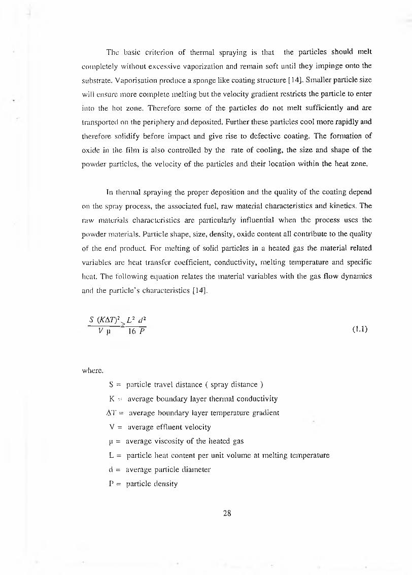
The basic criterion of thermal spraying is that the particles should melt
completely without excessive vaporization and remain soft until they impinge onto the
substrate. Vaporisation produce a sponge like coating structure [14]. Smaller particle size
will ensure more complete melting but the velocity gradient restricts the particle to enter
into the hot zone. Therefore some of the particles do not melt sufficiently and are
transported on the periphery and deposited. Further these particles cool more rapidly and
therefore solidify before impact and give rise to defective coating. The formation of
oxide in the film is also controlled by the rate of cooling, the size and shape of the
powder particles, the velocity of the particles and their location within the heat zone.
In thermal spraying the proper deposition and the quality of the coating depend
on the spray process, the associated fuel, raw material characteristics and kinetics. The
raw materials characteristics are particularly influential when the process uses the
powder materials. Particle shape, size, density, oxide content all contribute to the quality
of the end product. For melting of solid particles in a heated gas the material related
variables are heat transfer coefficient, conductivity, melting temperature and specific
heat. The following equation relates the material variables with the gas flow dynamics
and the particle’s characteristics [14],
5 (K A T ) \ L 2 d 2V p " 1 6 P (u )
where,
S = particle travel distance ( spray distance )
K = average boundary layer thermal conductivity
AT = average boundary layer temperature gradient
V = average effluent velocity
p = average viscosity of the heated gas
L = particle heat content per unit volume at melting temperature
d = average particle diameter
P = particle density
28
According to equation 1.1 there is a critical particle residence time and a critical
particle size for which complete melting could be achieved. The residence time is
determined mainly by gas velocity and spray distance.
1.3.3 GENERATION OF SPRAYED LAYER
The exiting stream of a thermal spray gun during spraying coating material reveals a
conical shape. In the stream, the coating material particles remain concentrated in the
central zone and are sparse in the outer portions (Figure 1.19) [34], The particle in the
outer periphery of the deposit are widely spaced and poorly adhered to the substrate.
The spray deposit density ratio is largely dependent on the particles within the peripheral
region. The final sprayed coating contains a mixture of material from each zone, because
the gun and the substrate moves relative to each other during coating application.
During the spraying process, particles are heated and transported with different
velocities and flatten on the substrate or on the previously deposited layers. The
substrate surface or the previously deposited layer influences the formation of metastable
phase in the fluid particle, resulting from rapid solidification of the molten particles. As
the freezing time of a particle is about 0.1-1 p second it does not influence the heat
transfer of the next particle arriving at the same point [35,36]. Because of the high
kinetic energy of the molten particles considerable liquid flow and radial sliding occur
upon particle impact. This spreading depends on substrate surface topography and on the
surface tension of the liquid particles. In the Figure 1.20 [14] a schematic of the planar
morphology of a solidifying particle is shown. From the central zone where the particle
first comes into contact with the substrate, heat is extracted through the substrate and
the solid-liquid interface moves away from the substrate and a thin extended area with
a peripheral rim is formed. This thin region may not be in full contact with the
substrate.
The particle solidifies and cools at the same time. All the particles have the same
mean direction when arriving at the substrate. Consequently a shadow effect occurs,
causing porosity (Figure 1.21). The molten particles could cover up certain amount of
29

irregularities of the surface. Narrow holes can not be filled up. The valleys in the surface
of a substrate or the lamellae can include some air or gas which causes pores and
adherence failure. With the increase of velocity and momentum of the impacting
particles this problem could be reduced. During impact and flattening process the
particle may burst. This phenomenon is governed by the mechanics of the impact, the
energy of the particles and the movement of the fluid still present in the particle.
The proper splash or wetting of the particle depends on the proper stand off
distance. When the standoff distance is too short the particle does not become
completely molten and the solid centre core can rebound away from the surface resulting
in a void. If the standoff distance is too long the molten particle may solidify before the
impact and may rebound or stick to the surface resulting in less deposition efficiency
or higher porosity. The extent of flattening depends on factors such as degree of melting,
viscosity of the liquid and wetting of the surface. Coating may contain voids arising
from outgassing, shrinkage or topographical effects (e.g. shadowing) and if it is a metal
processed in air would probably include oxide.
1.3.4 PROPERTIES OF THERMAL SPRAYED COATINGS
(i) MICROSTRUCTURE OF THE THERMAL SPRAYED COATINGS
A thermal sprayed coating applied in an air environment is a heterogeneous mixture of
sprayed material, oxide inclusion and porosity [3,9]. During the flight the particles
interact in some way chemically and physically with the environment. A thermal spray
coating consists of lenticular splats whose boundaries are parallel to the substrate surface
(Fig 1.21). This structure is due to the impact of the molten or semi-molten powder
particles. As a result of rapid cooling, some coatings may have no crystalline structure,
and some have a thin amorphous layer next to the substrate followed by crystalline
structure. Thick sprayed deposits reveal directionally oriented columnar grains near the
interface where rapid cooling occurs through the substrate. The columnar orientation
gradually decreases as the thickness of the coating increases. The change from columnar
to random grain morphology is believed to be produced by the effective lowering of the
30
cooling rate, because of the generation of heat of fusion, which gives time to reform and
change structure [13]. Radially elongated grains are rarely observed in thick coatings.
This is due to the high thermal conductivity of metals. Thin regions under the impact
of the subsequently arriving molten droplets probably recrystallize into randomly
oriented grains [14]. Another feature of the rapid solidification in thermal spraying is
the formation of structural defects such as vacancy, coagulation and dislocation.
However the structure depends heavily on quench rate.
(ii) COMPOSITION OF THERMAL SPRAYED COATINGS
The composition of the coatings may vary from the composition of the sprayed material
in thermal spraying due to the reaction of the molten particle with the gaseous
environment. Particularly the extent of their oxidation is very important to the properties
of the coating. In a study of the effect of oxidation on aluminium and bronze, it was
found that even minor oxidation during deposition is detrimental to compressive strength
both parallel and perpendicular to the surface. However discrete oxide particles on the
other hand not only strengthen the coating but also add wear resistance [37].
The loss of carbon from tungsten carbide coating through oxidation has been
reported [38-41], Metallic or cermet coating may also react with air forming oxide scales
on the particle and dissolving the gases in the molten droplet. The extent of these
reactions varies with the process parameters. As a result of rapid quenching a non
equilibrium phase may be present. In alumina coating, slightly superheated particle on
impact on high thermal conductive substtate gives delta and theta phase in addition to
gamma wilh alpha suppressed. Due to super heating selective evaporation of one
component in an alloy or decomposition to a gas or reaction with the atmosphere may
happen. The loss of compounds will be more rapid in case of a fine powder than a
coarse powder.
31
(iii) RE SID U A L STRESS
In thermal spraying, residual stress develops as a result of cooling of individual powder
particles on splat from above their melting point to the room temperature. The total
stress is composed of a thermal stress and an intrinsic stress. The magnitude of the
thermal stress is a function of spray gun parameters, deposition rate, the thermal
properties of both the coating and substrate materials and the amount of auxiliary
cooling used [42-44], The intrinsic stress arises from the accumulation of splats of the
molten particles and inclusion of impurities in the deposited coating. Use of finer
powder also leads to higher residual stress [13]. In thick sprayed coating residual stress
increases linearly with coating thickness after some critical thickness [14]. Residual
stress causes the interface to experience shearing stress which can cause cracking and
spalling (Figure 1.22).
Normally coatings suffer tension as a result of residual stress [22,45]. Methods
which reduce tensile stress in the coating and hence reduce shear stress at the interface
are a) expanding the substrate before spraying by preheating, b) selecting a coating
material with low shrinkage properties and c) building up part way with a low shrinkage
material [9,13,14],
(iv) BOND STRENGTH
Adhesion and cohesion are of paramount importance for spray coating. The mechanism
of bonding of thermally sprayed coating in many respects is still not well defined [46].
The mechanical interlocking has been considered the most important mechanism by
many investigators [47], The main conditions for physical adherence are an intensive
and permanent contact and a decrease in the Gibbs free energy of the system consisting
of the substrate and the lamellae. To ensure an intensive contact the surface has to be
clean and moreover approach each other to within the field of attraction of the atoms
of the surface i.e within 5 A. The approach of two very clean surface without any
mechanical stress to within the field of attraction of the atoms decreases the Gibbs free
energy and thereby enhances adhesion. In principle the total decrease of the Gibbs free
32
energy as contact occurs, is given by [36]
AG = A G. T com A Ss + A Hs (1.2)
where,
A G Slllf represents the decrease of the Gibbs free surface energy due to the
reduction of the state of energy of the atoms of the surface by means of the total
or partial recovery of the free bonds of the surfaces atoms.
The term ASs represents the production of entropy in the contacts as a
consequence of the diffusion of atoms in the surface zone.
The enthalpy of solution AHS is the change of the minimum of the potential curve
because of solution of a particular material’s atom in a lattice of other atoms,
when both of these materials are coming in contact.
Iji short, in a contact interface the tendency toward adhesion is raised as AG becomes
more negative i.e
1) if A G surf has a more negative value when both contacting surface are cleaner;
2) if the contact temperature has a higher value. In that case - T cont ASs has a more
negative value;
3) if atoms of both materials making contact form a state of ordering or an
intermetallic compound. In that case AHS has a more negative value.
Other mechanisms have been suggested as contributing to the bond strength
which include inter-diffusion or alloying, epitaxy, partial welding and chemical
absorption. Chemical absorption occurs when there is great affinity of the sprayed metal
33
to the base material. The mechanism is one of exchange of electron valency. Epitaxy
means a controlled and similar growth on the basic structure of a foreign substance
which is similar in structure. The super active state of the highly energized area of the
surfaces aids the development of epitaxial layers. There are some micro structural
evidences that when the refractory metal is sprayed on steel or nickel or chromium on
aluminium, there is some inter-diffusion i.e a metallurgical bond is formed [47]. Partial
welding between particles is always found in the transition zone as well as in the
sprayed layers themselves. Oxide cementing was cited as important in bonding metals
or cermets to metals [30]. In general oxides on the surface of the substrate or oxidation
that occurs during spraying decrease bond strength.
(v) HARDNESS
Thermal sprayed coatings possess a heterogenous structure consisting of the coating
material, oxide and voids. As a result the macrohardness values are less than those of
equivalent material in either a cast or a wrought form. Hardness is usually less for a
given material if the coating is applied in an inert atmosphere as compared to spraying
in air [48,49]. Although oxidation may increase the hardness of the coating, it reduces
internal strength of the coating and thus may be detrimental to the coating performance.
Hardness in thermal sprayed coating is normally measured on a test specimen which
may differ from those on actual parts due to difference in angle of deposition and stand
off distance and in some cases due to difference in residual stress.
(vi) ANISOTROPY IN THERMAL SPRAY COATINGS
Succeeding particles in thermal spraying acquire the same lenticular shape over the
material already deposited, As a result the coating develops an anisotropic lamellar
structure parallel to the interface. The mechanical as well as other properties of thermal
sprayed coating are anisotropic for its structure and directional solidification. This
anisotropy is probably more pronounced for cermets and metallic coating [50],
34
(vii) OTHER EFFECTS
The mechanical properties of thermal sprayed coatings are sensitive to the deposition
parameters used. As such any general tabulation of properties would be misleading
[13,14], The ductility of metallic thermal spray coating is slightly better than cast iron
but less than most cast metals. The ductility of sprayed coating rarely exceeds 2 % [ 15].
Surface finish of a coated surface is extremely important. The smooth finish that can be
obtained on a given coating is a function of its composition and the method of
deposition. Normally most of the coatings deposited by thermal spray need surface
finishing.
Corrosion resistance of a deposited coating is different than its cast or sintered
composition. For example alpha alumina is very corrosive resistant, but when it is
sprayed, alumina is a mixture of phases all of which are not corrosive resistance [45],
Most thermal sprayed coating have varying degrees of inter connected porosity that
allow attack of the substrate in corrosive environments. Galvanic corrosion can occur
in some environments when improper selection of coating composition is made.
1.3.5 TYPES OF THERMAL SPRAYING
Thermal spraying can be of different types depending on the type of heat source it uses.
When thermal energy of oxygen-fuel is used by a thermal spraying process, the process
is known as thermal flame spraying. When thermal energy generated from electricity is
utilised then the process is called as arc spraying and in plasma thermal spraying process
the thermal energy generated from electricity combined with a gas injection is used.
(i) PLASMA SPRAYING PROCESS
In plasma spraying the thermal energy of an electric arc and its associated plasma is
utilised for melting and projecting the coating materials [9,12,13,14]. Figure 1.23 shows
a plasma spray system which consists of a circular orifice anode and an inner cathode
enclosed in a chamber and positioned in line with the nozzle. The gas flow in the region
35
of the arc column is heated, expanded and accelerated during the production of plasma.
Coating materials in powder form are introduced into the plasma, melted and propelled
onto the workpiece. The heat content, temperature and the velocity of the plasma jet are
controlled by the nozzle type, the arc current, the mixture ratio of gases and the gas flow
rate. The high temperature of the plasma flame which can be upto 20,000 °C is enough
to melt any material whether metal, alloy or ceramics. Standard plasma guns are rated
up to 40 kW with powder particle velocity of about 120 to 400 m/s. The latest high
energy guns are rated uplo 80 kW to produce high kinetic energy by the high enthalpies.
The average powder particle velocities can be over 600 m/s for the high power gun [51].
The adhesion of the plasma sprayed coating materials depends on the preparation of the
substrate, the spraying distance, fluidity, momentum of the composition of the particle,
the inclusion of contaminant during the flight and the spraying process.
For proper adhesion, cohesion and no vaporisation of the coating materials,
dwell time of the coating material in the hot zone should be decreased, spraying distance
relative to the length of the hot zone should be increased or enthalpy of the hot gas
should be decreased. To maintain the above conditions a new plasma spraying process
was designed which is the low pressure controlled atmosphere plasma spraying process
also referred to as vacuum plasma spraying process [52-55]. Figure 1.24 shows a low
pressure and controlled atmosphere plasma spraying system. In this process the plasma
gun and the work piece are enclosed in a vacuum tank. This increases the velocity and
length of plasma jet and decreases the power density. All operations (pretreatment,
spraying, post heat treatment if required) are carried out in an inert low pressure
(typically 7 kp or 50 torr) atmosphere. This development permits the application of
complex coating system with proper stoichiometry and structure, high coating adhesion
and low porosity [56-58],
Plasma spraying is the most widely used thermal spraying process which can be
used to spray all materials on almost all substrates and it is favourable for mass
production. However, the deposition efficiency of plasma spraying process is lower than
other thermal spraying process. The flexibility of this process in terms of spray distance
and spray direction is less and the investment and the energy expense are high
36
comparing with other thermal spraying processes [9].
(ii) ELECTRIC ARC THERMAL SPRAYING
In electric arc thermal spraying, an electric arc is struck between two converging wires
close to their intersection point, as shown in Figure 1.25. The high temperature arc melts
the wire electrodes which are formed into high-velocity molten particles by an atomizing
gas flow. The wires are continuously fed to balance the loss. The molten particles are
then deposited onto a substrate. By this process only relatively ductile and electrically
conductive materials which can be drawn in the wire form can be deposited [9,14],
(iii) FLAME THERMAL SPRAYING
In the flame spraying process, fine powder or wire is carried in a gas stream and is
passed through an intense combustion flame, where it melts. The gas stream, expanding
rapidly because of the heating, sprays the molten powder onto the substrate, where it
solidifies. A schematic diagram of a flame spraying gun is shown in the Figure 1.26.
Flame spraying equipment is transportable for in situ work and is widely used by
industries for the reclamation of worn or out-of-tolerance parts. However, coatings
produced by the flame spraying process are relatively porous and have low adhesive
bond strength [9|. The flame spraying processes are widely used for corrosion resistance
and reclamation of worn or out of tolerance parts.
To improve the coating qualities of the flame spraying process a new spraying
process was developed which is known as High Velocity Oxy- Fuel (HVOF) thermal
spraying process. There are two types of HVOF processes, pulsed combustion HVOF
process and continuous combustion HVOF process.
37
(iii)a Pulsed combustion HVOF (D-Gun) process
This process was developed by Union Carbide Corporation Limited during the middle
of 1950’s and is only available through their coating service department [59]. A
schematic view of the detonation gun is shown in Figure 1.27. In this process oxygen
and fuel gas with uniformly dispersed fine powder are repetitively injected into a
shotgun-like barrel at a pressure of one atmosphere. A timed spark ignites the mixture
and hence the pressure inside the barrel rises. Because of the geometry the flame front
accelerates to a detonation wave which is supersonic. This detonation wave propagates
and ignites the mixture so rapidly that the pressure in the barrel cannot be relieved
because pressure is relieved at or below the speed of sound. Due to the detonation
phenomenon a significant rise in pressure and temperature is observed. Figure 1.28
shows the variation of theoretical flame temperature and exhaust temperature with
chamber pressure. The combustion gas instantly heats the particles to a molten state and
hurls them at supersonic speed from the gun to the substrate surface. The velocity of the
particle leaving the gun barrel varies as the pressure in the barrel decays. After the
powder has exited the barrel, a pulse of Nitrogen gas purges the barrel. The cycle is
repeated about 4 to 8 times per second. The quality of the coating sprayed by this
process is superior to traditional flame spraying and plasma spraying processes. The
better quality is mostly due to more kinetic energy of the powder particle [59-61].
(iii)b Continuous combustion HVOF process
A rapid development of HVOF system took place since the introduction of Jet-kote as
the first continuous combustion HVOF system . This thermal spraying is the most
significant development in the thermal spraying industries since the development of
plasma spraying process. These systems evolved during the last nine years. The
advanced HVOF systems are now challenging the coating qualities of most successful
coatings produced by detonation gun spraying process [62-69]. There are different types
of continuous combustion HVOF system developed by different manufacturers, namely
Jet Kote, Diamond Jet, CDS Gun. The schematic diagrams of these HVOF thermal
spraying processes are given in Figures 1.29-1.31 respectively. The working principles
38
of these spraying systems are more or less the same [70], The gun consists of three
sections, mixing zone, combustion zone and the nozzle. During operation the body is
cooled by air or by water. The fuel and oxygen are mixed by means of co-axial jets and
guided to the combustion zone where a pilot flame or external igniter initiates the
combustion. During the combustion the gas is allowed to expand in the nozzle where
it is accelerated. The powder is accelerated by the carrier gas and injected into the
flame. The powder has the same direction of flow as the direction of surrounding
expanded gas. As the combustion continues, the gas achieves supersonic velocity. On
the way from the combustion zone through the nozzle the powder particles are heated
and are further accelerated. Due to the high velocity and high impact the coating is less
porous, highly dense and has higher bond strength [71-78],
Combustion and gas dynamics o f HVOF systems
Oxygen and fuel gas at high pressure are mixed in the mixing zone of the gun and then
directed towards the combustion zone. After ignition a chemical reaction takes place and
releases heat energy from combustion process. As combustion continues the pressure
inside the combustion chamber increases and the hot gas flows with high velocity.
Propylene, propane or acetylene and oxygen are used for combustion. The simple
chemical reaction of the gases at stoichiometry in terms of mass is as follows [79].
C,H6 + 3.43 0 2 + X N2 = 1.29 H20 + 3.14 C 0 2 + X N2
The stoichiometric oxygen fuel ratio is 4.5 to 1. The energy released by the
chemical reaction of the combustible gases is used to heat and accelerate both the
emerging gases and the entrained powder. The gas velocity is a function of variables
such as gas composition, pressure, temperature, density and the area through which the
gas travels. However, the maximum obtainable gas velocity through the minimum cross
sectional area is limited to the local sound velocity [79].
39

The local velocity of sound in a perfect gas is defined by:
C = sjK R T (1.3)
where,
C = the sound velocity.
K = ratio of specific heats
R = gas constant
T = local temperature
The condition in which the gas velocity is equal to the sonic velocity is called
the critical state. At critical state a nozzle can discharge the maximum mass flow rate
say m. The critical mass flow rate can be defined as:
m = p V A (1.4)
p = critical density
V = critical gas velocity
A = critical area
This equation can be rewritten in terms of total pressure and total temperature as:
where,
(1.5)
40

where,
P„ = total pressure at critical state
T„ = total temperature at critical state
When the critical flow condition is reached, the flow is said to be choked. From
these equations it can be seen that by increasing the pressure the mass flow rate
increases and by increasing the temperature the mass flow decreases. Figure 1.32 shows
the variation of gas velocity with the chamber pressure. The chamber is maintained at
a certain pressure which differs for different design of the HVOF system.
The combustion gases are expanded in a converging diverging nozzle to achieve
supersonic speed. The adiabatic flame temperature of the stoichiometric combustion
gases is about 2900 °C (assuming propylene as fuel gas). Flame and je t temperature also
vary with oxygen/fuel ratio as shown in Figure 1.33. Within the HVOF device, both heat
addition due to combustion and friction along the nozzle surface tend to choke the flow
at the nozzle exit. As the combustion products exit the nozzle, the jet expands because
the static pressure in the nozzle is greater than the ambient pressure and expansion and
compression waves occur in the free jet (Figure 1.34). The intersections of these waves
form the bright regions in the effluent stream are commonly known as shock diamonds
[59,80-82],
Figure 1.35 shows the temperature, pressure and velocity variation in the flow
with oblique shocks. The cyclic change of the flow will extend to infinity in the absence
of friction and air entrainment. In fact the oblique shock pattern reduces in the diameter
and continues only until enough out side air is entering into the je t to substantially
reduce the temperature and velocity.
Effect on particles
During combustion, powder particles are injected in to the centre of the combustion
chamber with a carrier gas. Other designs of HVOF are also available in which powder
particles are injected radially into the gas stream at the converging diverging throat area
41
of the nozzle. This powder is turbulently mixed and accelerated to high speed and
heated within the hot gases. The gas-powder mixture leaves the barrel as a high velocity
jet and is pointed towards the surface to be coated. Since the particles are injected into
the supersonic flow, each particle will pass through the shock waves. From the
measurement of velocity of powder particles of different size and different materials
(Figure 1.36) it is evident that the particle velocities are highest on the central axis and
decrease radially outward. This is caused by the viscous shear forces acting between
the jet and the ambient air. The particles decelerate due to the viscous shear effects and
exhibit slower velocities near the outer boundary of the flame than near centre of the
flame. The centreline mean velocity measurements of 5 pm alumina and 11-45 pm
WC/Co are shown in Figure 1.37 and 1.38 respectively. As the alumina particles exit
the nozzle, they rapidly accelerate until approaching the average gas velocity which
occurs approximately 5 cm away from the nozzle exit and then the particles decelerate
as the average gas velocity decreases. The WC/Co particles of larger size do not attain
gas velocities at the nozzle exit. As the particles exit the nozzle they accelerate until
they achieve the local average gas velocity which occurs near 15 cm away from the
nozzle exit.
As no exact heat transfer correlation to calculate the temperature of the particles
exposed to supersonic flow was available, the temperature of the particle leaving the
barrel were calculated (Figure 1.39) assuming some of the parameters as it varies with
so many factors [59].
Design to increase the velocity o f the flam e
The basic requirement of an HVOF system is to burn fuel and oxidant in an enclosed
volume or chamber and build up a pressure so that the gases expand through an orifice
as they exhaust and accelerate to the atmosphere. A number of burner designs can be
used to accomplish this. These designs can be classified in to two groups, viz. throat
combustion burners and chamber burners [59],
42

In throat combustion burner (Figure 1.40) the fuel and oxidant are mixed and
injected at a pressure into a combustion region. A higher pressure is maintained at the
back of the burner. Powder is injected axially and the flow stream and the particles
accelerate in normal HVOF fashion. Compressed air is used for cooling internally and
externally. A guided flow of air between the chamber walls and the flame contains and
constricts the flow and reduces wall heating. This design increases air dilution of the
combustion stream and reduces the flame temperature and therefore is not suitable with
long barrel spray gun. Advantages of the design are its simplicity, less weight and the
possibility of manual operation.
Different types of chamber burners are evolved. These are right angle/central
injection, straight through/axial injection and straight through/radial injection (Figure
1.40). These systems are water cooled and machine mounted. The incorporation of a
longer barrel makes it possible to have a longer high temperature zone.
Advantages and. disadvantages o f HVOF systems
Particle velocity is a critical factor in all thermal spraying processes. Quality of the
coating improves with the velocity of the sprayed particle as shown in Figure 1.41.
HVOF guns can produce particle velocities that are considerably higher than the other
currently available commercial thermal spray processes. Additional benefits of HVOF
processes are as follows.
(a) More favourable environment due to less oxidizing atmosphere.
(b) More uniform and efficient particle heating due to high turbulence.
(c) Much shorter exposure time in flight due to high particle velocity.
(d) Reduced mixing with ambient air once jet and particle leave the gun.
(f) lower ultimate particle temperatures compared to plasma or arc guns.
43
For the above mentioned advantages, the coating benefits are higher density,
improved corrosion resistance, higher hardness, better wear resistance, higher bond and
cohesive strengths, lower oxide content, fewer unmelted particle content, better
chemistry and phase retention, thicker coating and smoother as-sprayed surfaces.
The main disadvantages are:
(1) The heat content in the HVOF stream is very high. Therefore over heating of the
substrates are quite likely. Therefore extra cooling of the substrate is necessary.
(2) Masking of the part is still a great problem as only mechanical masking is effective
[83],
1.4 SPRAY FORMING
1.4.1 INTRODUCTION
The earliest concept of spray forming process was described by Brennan in 1958 [82]
for the production of strip but was never used in practice. Since 1960 spray forming has
been used for fabricating components. The principal developer of the spray forming
process is Singer [85,86]. Fie developed a variant forming process applied to strip. Spray
forming is a logical development of the atomization process for the generation of
powder having a consistent and well defined size [1,2,87]. Following this early
development the preform process has been applied to the preparation of a variety of
near-net shapes. A schematic of this process is shown in Figure 1.42. Materials to be
spray formed are heated to their melting temperature and atomized by spray nozzle.
These atomized particles impinge on the flat bed substrate and solidify as individual
particle in intimate contact with the neighbours. The atomized droplets are partially
cooled in flight, depositing on the substrate surface and freezing progressively to form
sheet, strip or thicker section deposits. Different treatment such as hot rolling, hipping
or any other methods may be used to improve the bonding of the particle [86,90,91].
44
The main objectives of spray forming were to reduce the steps for production of
engineering products at lower cost and eliminate or reduce substantially the
contamination and to improve the quality of the products. Another benefit of spray
forming is the significant reduction in the as-cast grain size. This grain refinement is
desirable for improvement of both the strength and the fracture toughness. The
combination of under cooling and high solidification rate provides a basis for obtaining
unique properties in conventional or specific composition. These are distinct advantages
for a number of aerospace structural applications.
Since the spray forming produces a near net shape, very little machining is
necessary. The mandrel can be reused for many times so the cost of mandrel is
insignificant in the overall cost. The major expenditure is involved in installing and
operating the equipment. For these reasons spray forming is rapidly gaining much
attention world wide.
1.4.2 TYPES OF SPRAY FORMING
Spray forming is one of the several forming processes applied for the production of
engineering components. There may be two different ways of spray forming.
Firstly, the common type of spray deposition involves the feeding of material
in the form of wire or powder into a gun where it is heated to its melting or softening
temperature and breaks up into a stream of spray droplets and allowed to deposit on to
the preforms. This process is known as thermal spraying. Heat needed for melting the
material can be generated from electrical resistance, radiative heat from plasma or from
combustion of fuel and oxygen. By this method a small quantity of the material can be
heated uniformly, thus the deposition rate is low [84].
Secondly, the entire amount of materials to be spray formed is heated above the
melting temperature before the atomization process is performed. This process allows
high deposition rate and the ability to achieve a dynamic heat balance. This process is
commercially known as Osprey forming [84,85].
45
(i) THERMAL SPRAY FORMING
Thermal spraying is one of the numerous well known coating processes. If a coating can
be removed without unacceptable damage or distortion from the substrate, the discrete
free-standing body remains which reproduces the shape of the surface of the substrate.
To be of practical value the coating process should be rapid, giving a coating of
acceptable thickness and strength, be applicable to a variety of coating and substrate
materials and yield components that need little post fabrication treatment.
Traditionally, the flame spraying process lacked sufficient thermal and kinetic
energy to yield highly densed coating for various materials particularly for refractory and
ceramic materials. Plasma spraying, however, does not suffer from such limitations. So
this process has been used for a long time for the production of free standing objects
[92], But the porosity level of these components produced by air plasma spraying is high
(5-16 %) and often it is contaminated by the oxide. So vacuum plasma and controlled
atmosphere plasma spraying have earned much more attention among the researchers
[92-99]. Equally components can be built up with different materials at different layer
or as composite. New developments in thermal spraying technology offer exciting
possibility for extending the potential of spray forming.
(ii) OSPREY FORMING
In the osprey process as shown in Figure 1.43 a material is melted and subjected to gas
atomization under inert conditions. Nitrogen and argon gases are commonly used for
production of inert atmosphere. The atomized droplets are collected in a mould or group
of moulds in which final solidification occurs. A key part of this process is the
achievement of partial solidification before impingement. The liquid droplet size, the
droplet velocity, metal flow rate, gas-to-metal flow rate ratio and flight distance are
carefully controlled to achieve certain degree of under cooling of the liquid. Upon
impingement on the deposition surface, the viscous semisolid droplets spread laterally
by a rather high velocity shearing process. This shearing process breaks up any dendrites
formed in the droplets before impact and thereby supplying many new nucléation spots
46
in the under cooled liquid. Ideally the material then solidifies at a high velocity by
heterogeneous nucleation followed by formation of equiaxed grains. This spray forming
can achieve quite high deposition rates of 15 and 100 kg/min for aluminium and steel
respectively [100,101].
Osprey forming of thick section of stainless steel followed by hipping and heat
treatment results in an excellent combination of properties. These properties are isotropic
due to preservation of hipping of the equiaxed as-cast grain structure. The tensile
strength, ductility and toughness of the spray formed and hipped material appear to be
as good or better than those of high strength aluminium alloy cast strip. Alloys that have
been processed by the osprey process include stainless steels, high speed steels, nickel
based superalloys.
Experiments to co-spray aluminium atomized droplets with SiC particles to form
an in situ metal matrix composite were reported [84]. A schematic of the co-spray
nozzle configuration is shown in Figure 1.44.
1.5 BACKGROUND OF THIS WORK
1.5.1 PRESENT METHODS OF FABRICATING CARBIDE COMPONENTS
Cemented carbides belong to a class of hard, wear-resistant refractory materials in which
the hard carbide particles are bonded together or cemented by a soft and ductile metal
binder. Although the term cemented carbide is widely used in the United States, these
materials are better known as hard materials internationally. Among these hard materials
WC is the most popular.
WC was first synthesized by the French chemist Henri Moissan in the 1890’s.
The first cemented carbide produced was tungsten carbide with a cobalt binder. The use
of powder metallurgy techniques by Schrocter in 1923 provided the way for obtaining
a fully consolidated product [102],
47
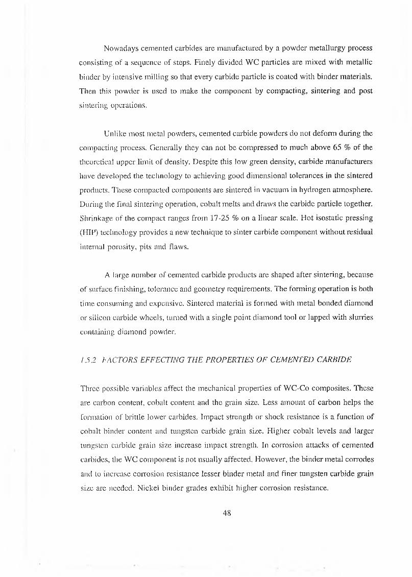
Nowadays cemented carbides are manufactured by a powder metallurgy process
consisting of a sequence of steps. Finely divided WC particles are mixed with metallic
binder by intensive milling so that every carbide particle is coated with binder materials.
Then this powder is used to make the component by compacting, sintering and post
sintering operations.
Unlike most metal powders, cemented carbide powders do not deform during the
compacting process. Generally they can not be compressed to much above 65 % of the
theoretical upper limit of density. Despite this low green density, carbide manufacturers
have developed the technology to achieving good dimensional tolerances in the sintered
products. These compacted components are sintered in vacuum in hydrogen atmosphere.
During the final sintering operation, cobalt melts and draws the carbide particle together.
Shrinkage of the compact ranges from 17-25 % on a linear scale. Hot isostatic pressing
(HIP) technology provides a new technique to sinter carbide component without residual
internal porosity, pits and flaws.
A large number of cemented carbide products are shaped after sintering, because
of surface finishing, tolerance and geometry requirements. The forming operation is both
time consuming and expensive. Sintered material is formed with metal bonded diamond
or silicon carbide wheels, turned with a single point diamond tool or lapped with slurries
containing diamond powder.
7.5.2 FACTORS EFFECTING THE PROPERTIES OF CEMENTED CARBIDE
Three possible variables affect the mechanical properties of WC-Co composites. These
are carbon content, cobalt content and the grain size. Less amount of carbon helps the
formation of brittle lower carbides. Impact strength or shock resistance is a function of
cobalt binder content and tungsten carbide grain size. Higher cobalt levels and larger
tungsten carbide grain size increase impact strength, In corrosion attacks of cemented
carbides, the WC component is not usually affected. However, the binder metal corrodes
and to increase corrosion resistance lesser binder metal and finer tungsten carbide grain
size are needed. Nickel binder grades exhibit higher corrosion resistance.
48
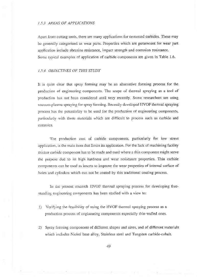
1.5.3 AREAS OF APPLICATIONS
Apart from cutting tools, there are many applications for cemented carbides. These may
be generally categorized as wear parts. Properties which are paramount for wear part
application include abrasion resistance, impact strength and corrosion resistance.
Some typical examples of application of carbide components are given in Table 1.6.
1.5.4 OBJECTIVES OF THIS STUDY
It is quite clear that spray forming may be an alternative forming process for the
production of engineering components. The scope of thermal spraying as a tool of
production has not been considered until very recently. Some researchers are using
vacuum plasma spraying for spray forming. Recently developed HVOF thermal spraying
process has the potentiality to be used for the production of engineering components,
particularly with those materials which are difficult to process such as carbide and
ceramics.
The production cost of carbide components, particularly for low stress
application, is the main item that limits its application. For the lack of machining facility
thicker carbide component has to be made and used where a thin component might serve
the purpose due to its high hardness and wear resistance properties. Thin carbide
components can be used as inserts to improve the wear properties of internal surface of
holes and cylinders which can not be coated by this traditional coating process.
In the present research HVOF thermal spraying process for developing free
standing engineering components has been studied with a view to:
1) Verifying the feasibility of using the HVOF thermal spraying process as a
production process of engineering components especially thin-walled ones.
2) Spray forming components of different shapes and sizes, and of different materials
which includes Nickel base alloy, Stainless steel and Tungsten carbide-cobalt.
49
3) Standardizing the spray forming process for the production of carbide components
and determination the process variables which have an effect on the production of
these components.
4) Characterising the properties of the components made by this process.
5) Making components by multi-layers of different material to increase the toughness
of carbide components and to facilitate the fixation of carbide components with
other components.
fi) Measuring the stresses in the component formed by this process and finding a way
of producing stress-free components.
50

Surface
VNature
Colour C lean liness Contamination W ork H ardening
Shape
RoughnessW aviness
▼Interaction With Environmentp
ReconstructionSegregationphysisorptionChem isorptionCompound FormationCorrosion
O thers
S urface Energy C ohesive Energy Point Im perfections D islocations G rain Boundaries Conductivity H a rd n ess
Figure 1.1 Various surface properties relevant to engineering components (9).
Adsorbed Gases and Water Vapour
O x Id *
t Bilby Layer
Worked Layer
Bulk Material
Figure 1.2 Schematic representation of a metal surface (9).
51
Figure 1.3 Surface asperities of a nominal smooth surface (9).
PROFILE - (SUM OF ABOVE THREE COMPONENTS)
Figure 1.4 The three components o f surface profile (9).
52
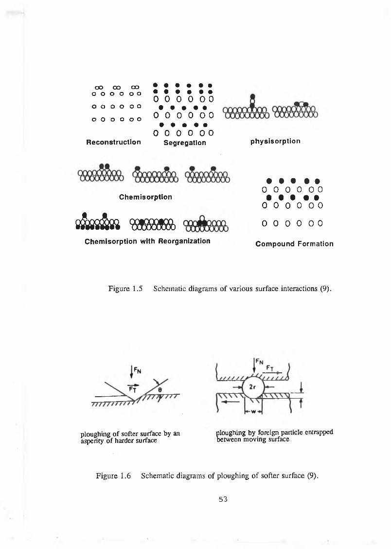
OO OO COo o o o o o
o o o o o o
O O o o o o
Reconstruction
• • • • • •• • • • • •0 0 0 0 0 0
• • • • •0 0 0 0 0 0
• • • • •0 0 0 0 0 0
Segregation physisorption
Chemisorptfon
s f o i & j m mChemisorption with Reorganization
• • • • •0 0 0 0 0 0
• • t • •0 0 0 0 0 0
0 0 0 0 0 0
Compound Formation
Figure 1.5 Schematic diagrams of various surface interactions (9).
ploughing of softer surface by an asperity of harder surface
ploughing by foreign particle entrapped between moving surface
Figure 1.6 Schematic diagrams of ploughing of softer surface (9).
53

r r r r r r / / ■ / / / / / \SOLID ( I )
S0LI0(2) „REAL
■AREA OF CONTACT
Figure 1.7 Contact between two mating surfaces showing real area of contact (9).
K S S * » » _\
Figure 1.8 Schematic of adhesive wear mechanism (9).
Figure 1.9 Schematic of fatigue wear mechanism (9).
54
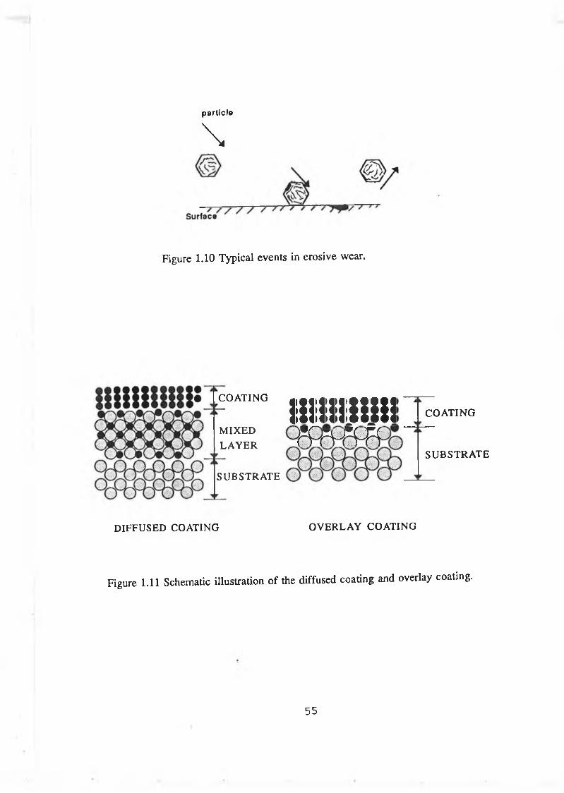
partic le
\
Figure 1.10 Typical events in erosive wear.
i n i i i m
m r n m
COATING
SUBSTRATE
DIFFUSED COATING OVERLAY COATING
Figure 1.11 Schematic illustration of the diffused coating and overlay coating.
COATING
MIXEDLAYER
SUBSTRATE
55
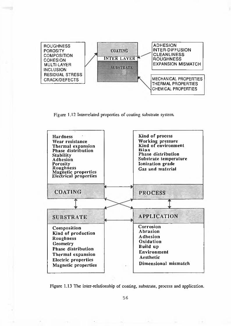
ROUGHNESSPOROSITYCOMPOSITIONCOHESIONMULTI-LAYERINCLUSIONRESIDUAL STRESSCRACK/DEFECTS
COATING_________________INTER LAYER
' V 'J "•. -
■ . :
ADHESION INTER-DIFFUSION CLEANLINESS ROUGHNESS EXPANSION MISMATCH
MECHANICAL PROPERTIES THERMAL PROPERTIES CHEMICAL PROPERTIES
Figure 1.12 Interrelated properties o f coating substrate system.
Hardness Wear resistance Therm al expansion Phase d istribution S tab ility A dhesion Porosity R oughness M agnetic properties Electrical properties
Kind o f process W orking pressure Kind o f environm ent B ia sPhase distribution Substrate temperature Ionization grade Gas and material
C O A T IN GA v
A -----------------
PROCESS..... v .; .v . . \ . .
S U B S T R A T E';X: ' \ y. : " :' • : • 4 k: V
A P P L IC A T IO N• ’■ ,
C om position Kind o f production R oughness Geometry Phase d istribution Therm al expansion Electric properties M agnetic properties
C orrosionA brasionA d h esionO xidationB uild upE nvironm entA estheticD im ensional m ism atch
Figure 1.13 The inter-relationship o f coating, substrate, process and application.
56
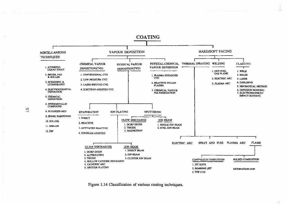
<J1
m i s c e l l a n e o u s
TECHNIQUES
1. ATOMIZED LIQUID SPRAY
2. BRUSH, PAD & ROLLER
3. SCREENING & LITHOGRAPHY
4. ELECTROCHEMICAL DEPOSITION
5. CHEMICAL DEPOSITION
6. INTERMETALUC COMPOUND
». FLUIDEZED BED
9. SPARK HARDENING
10. SOL-GEL
11. SPIN-ON
11 DIP
1VAPOUR DEPOSITION
COATING ~ 1
I-------------------CHEMICAL VAPOUR
DEPOSITION (CVD)
1. CONVENSIONAL CVD
2. LOW PRESSURE CVD
3. LASER INDUCED CVD
4. ELECTRON-ASSISTED CVD
PHYSICAL VAPOUR DEPOSITION (PVD)
PHYSICAL-CHEMICAL VAPOUR DEPOSITION
1. PLASMA ENHANCED CVD
2. REACTIVE PULSED PLASMA
3. CHEMICAL VAPOUR POLYMERIZATION
1HARD/SOFT FACING
ITHERMAL SPRAYING WELDING
EVAPORATION
1. DIRECT
2. REACTIVE
3. ACTIVATED REACTIVE
4. ION-BEAM ASSISTED
ION PLATING SPUTTERINGI
GLOW DISCHARGE
1.DC/RF DIODE2. TRIODE3. MAGNETRON
ION BEAM
1. SINGLE ION BEAM2. DUEL ION BEAM
1. OXY-FUEL GAS FLAME
2. ELECTRIC ARC
3. PLASMA ARC
CLADDING 1----1. WELD2. BRAZE
3. LASER
4. EXPLOSIVE
5. MECHANICAL METHOD6. DIFFUSION BONDING7. ELECTROMAGNETIC
IMPACT BONDING
T 1
GLO'V DISCHARGEE
1.DC/RF DIODE2. ALTERNATING3. TRIODE4. HOLLOW CATHODE DISCHARGE5. CATHODIC ARC6. SPUTTER PLATING
1ION BEAM1. DIRECT BEAM
2. ION BEAM
3. CLUSTER ION BEAM
ELECTRIC ARC SPRAY AND FUSE PLASMA ARC FLAME
j-------------------------CONTINUOUS COMBUSTION
1. JET KOTE
2. DIAMOND JET3. TOP GUN
1------PULSED COMBUSTION
DETONATION GUN
Figure 1.14 Classification of various coating techniques.

Figure 1.15 Schematic o f vacuum evaporation process (13).
58
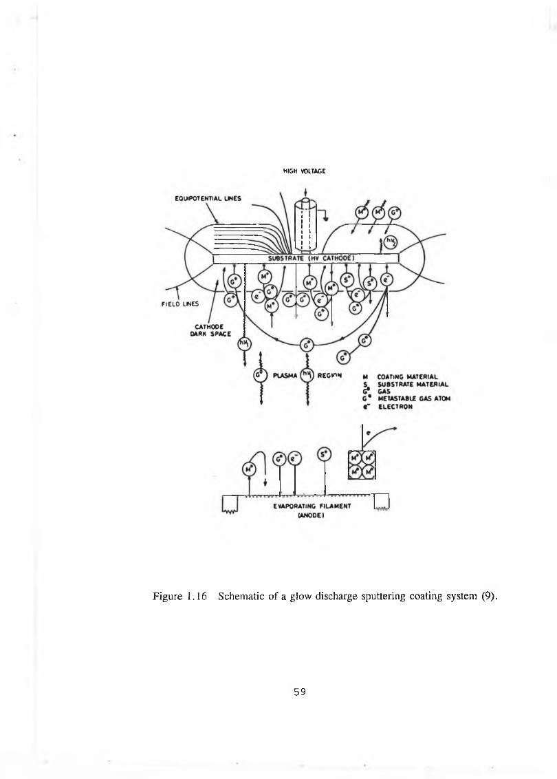
HIGH VOLTAGE
Figure 1.16 Schematic of a glow discharge sputtering coating system (9).
59
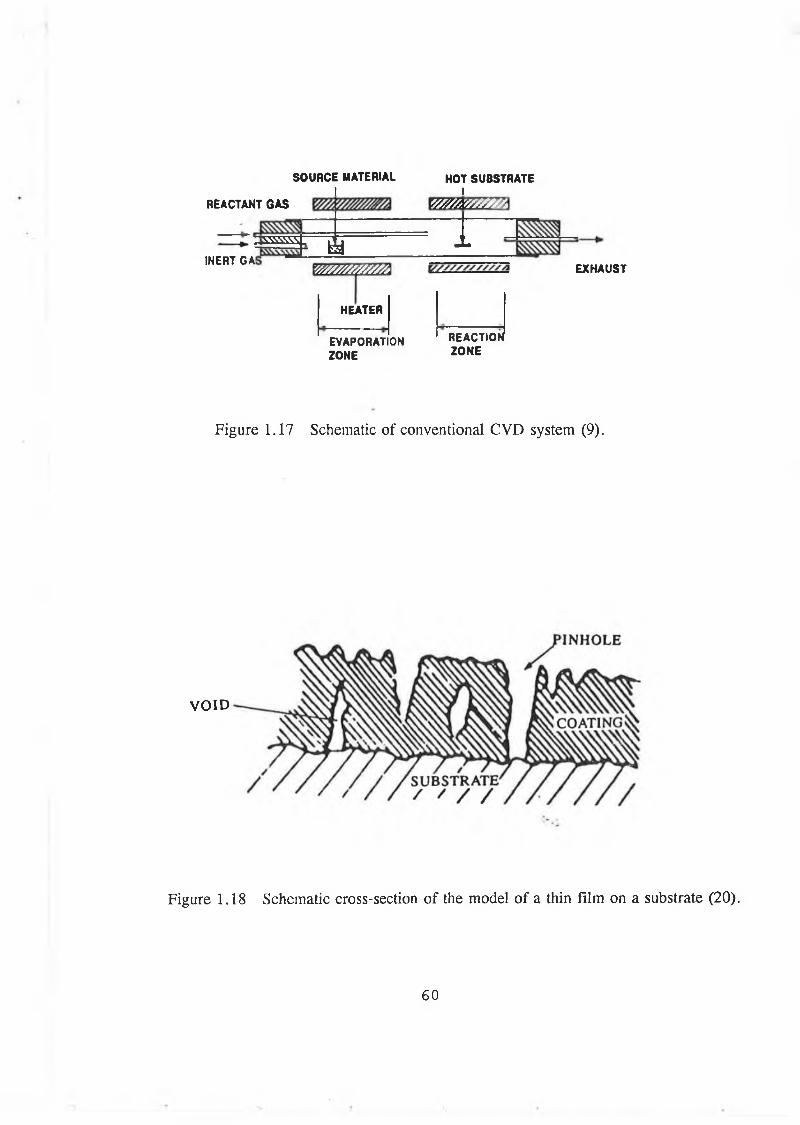
SOURCE MATERIAL
REACTANT GASI
INERT GA!
xww^; ÏV /////////////s
HOT SUBSTRATEI
'//////////S /A
t
EXHAUST
HEATER
EVAPORATIONZONE
REACTION ZONE
Figure 1.17 Schematic of conventional CVD system (9).
VOID
Figure 1.18 Schematic cross-section of the model of a thin film on a substrate (20).
60
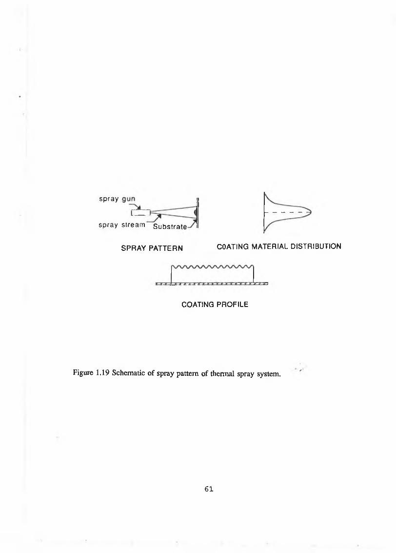
spray
spray
SPRAY PATTERN COATING MATERIAL DISTRIBUTION
COATING PROFILE
Figure 1.19 Schematic of spray pattern of thermal spray system.
stream Substra
6 1
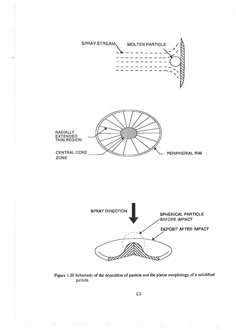
SPRAY DIRECTION
i
SPHERICAL PARTICLE 'BEFORE IMPACT
DEPOSIT AFTER IMPACT
Figure 1.20 Schematic of the deposition of particle and the planar morphology of a solidifiedparticle.

Oxide inclusions Pores/voids Cohesive strength Particle Substrate
Figure 1.21 Lamellar structure of a thermal sprayed coating showing the voids and pores (14).
THERMAL EFFECT GIVING RISE TO CRACK FORMATION
COATING
S X \ \ \ \ \ ^ S 5 3
'SUBSTRATE
THERMAL EFFECT CAUSING RESIDUAL STRESS
THERMAL EFFECT CAUSING ADHESION FAILURE
Figure 1.22 Schematic of cracking and spalling of thermal spray coating due to residual stress.
63

OS
SPRAY POWDER SUSPENDED IN CARRIER GAS
PLASMAFLAME
PO W ER T O A R C
PLASMAGAS
SEMI MOLTEN y SPRAY STREAM
NO ZZLE
ELECTRODE
Figure 1.23 Schematic o f plasma spray gun (9)
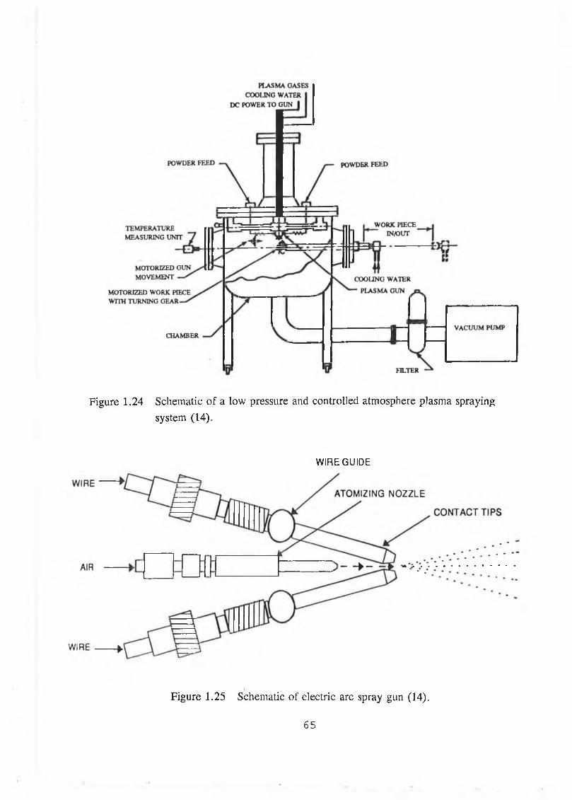
Figure 1.24 Schematic of a low pressure and controlled atmosphere plasma spraying system (14).
WIRE GUIDE
Figure 1.25 Schematic o f electric arc spray gun (14).
65

POWDER
Figure 1.26 Schematic o f flame spray gun (14).
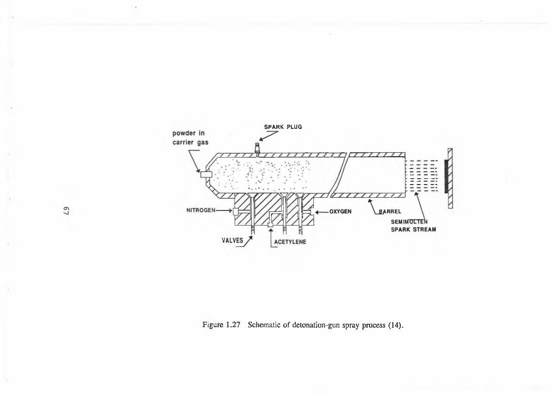
SPARK PLUG
Figure 1.27 Schematic o f detonation-gun spray process (14).
111

STOICHIOMETRIC RATIO - HEPTANE/OXYGEN
CHAMBER PRESSURE-psia
Figure 1.28 Variation of theoretical flame temperature and exhaust temperature with chamber pressure [59].
Figure 1.29 Schematic o f jet-kote HVOF thermal spray gun (65).
68
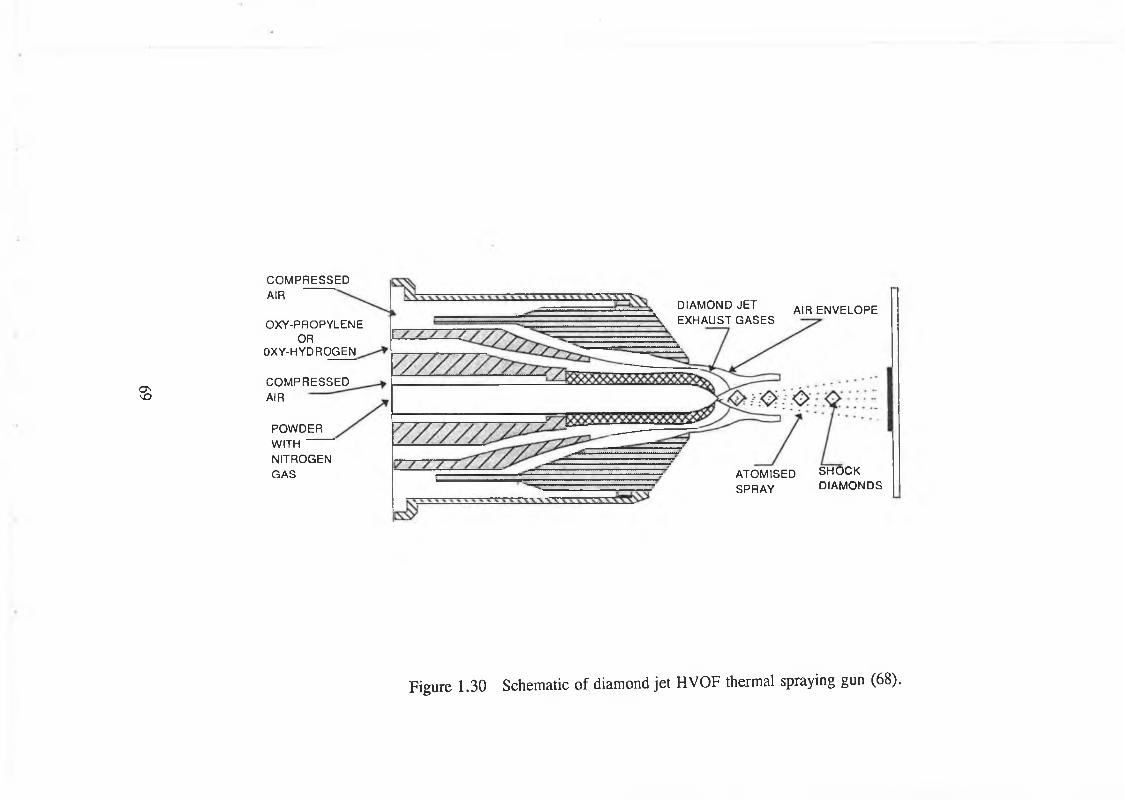
ONVO
C O M P R E S S E D
A IR
O X Y -P R O P Y L E N EO R
O X Y -H Y D R O G E N
C O M P R E S S E D
A IR
P O W D E R
W IT H
N IT R O G E N
G A S
D IA M O N D J E T A IR E N V E L O P E K E X H A U S T G A S E S
A T O M IS E D S H O C K S P R A Y D IA M O N D S
Figure 1.30 Schematic o f diamond jet HVOF thermal spraying gun (68).
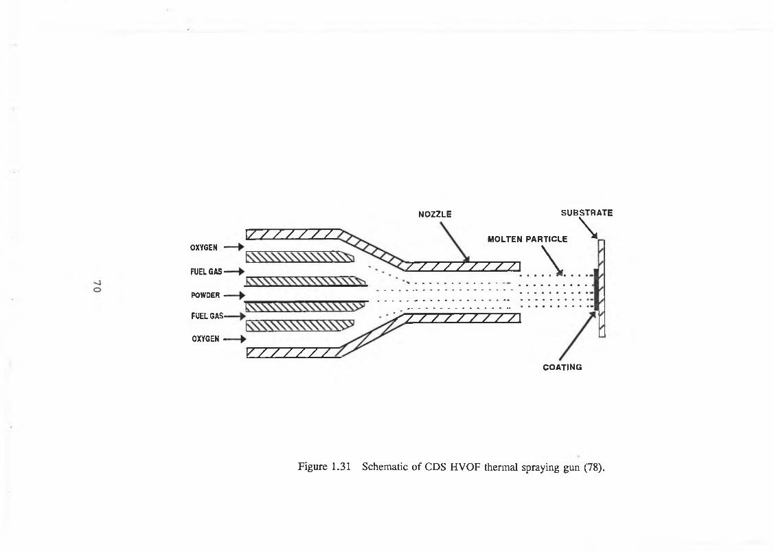
NOZZLE SU B S TR A TE
OXYGEN -
FUEL G AS-
POWDER -
FUEL GAS-
OXYGEN -
1/ / / / / / - 7-
V / / / / / /
MOLTEN PARTICLE \/ / / / Z V ZT^Z] \
s / / / / / / / / / \
COATING
Figure 1.31 Schematic o f CDS HVOF thermal spraying gun (78).

THEO
RET
ICA
L T
EM
PER
AT
UR
E-F
8000
o ------------------------- 1-------------------1------------------------ *----------------- 1-------------•-----------------—20 30 40 60 80 100 140CHAMBER PRESSURE (log)-psig
Figure 1.32 Gas velocity in HVOF system vs gun chamber pressure [59].
Figure 1.33 Variation of theoretical flame temperature with oxygen/fuel ratio [59].
7 1
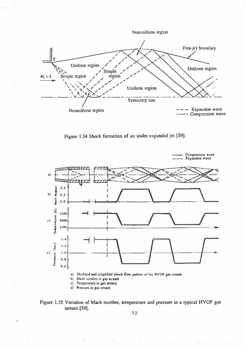
Nonuni form region
Free-jet boundary
Simple region
\ . V / y ' /\ \ V / /V X <4 A* s v Vi X i iw ;_______
Uniform region
Symmetiy line
Nonuniform region
Uniform region
Expansion wave Compression wave
Figure 1.34 Shock formation of an under expanded jet [59].
Compression wave Expansion wave
«)
b)
“ 2500 «Uc) 5 2400.•»
£ 2300
<*>
a) Idealized and simplified shock flow pattern o f the HVOF gas streamb) Mach number in gas streamc) Temperature in gas streamd) Pressure in gas stream
Figure 1.35 Variation of Mach number, temperature and pressure in a typical HVOF gas stream [59].
72
V77TA
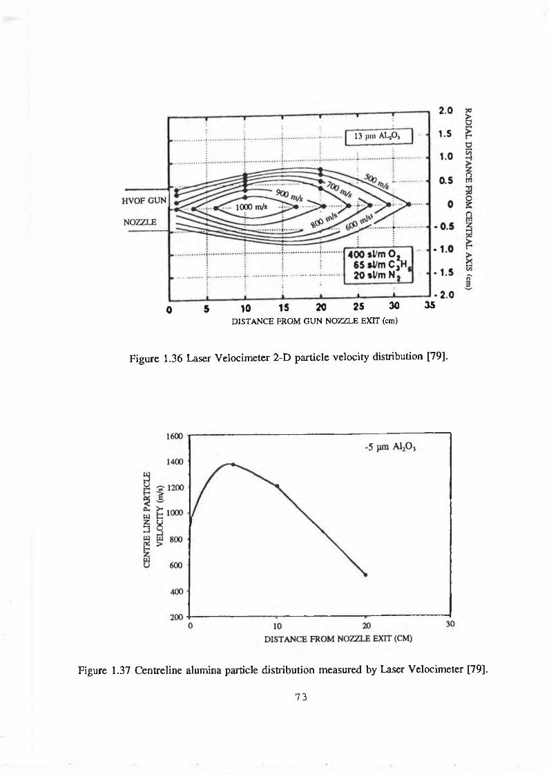
0 5 10 15 20 25 30DISTANCE FROM GUN NOZZLE EXIT (cm)
35
Figure 1.36 Laser Velocimeter 2-D particle velocity distribution [79].
Figure 1.37 Centreline alumina particle distribution measured by Laser Velocimeter [79].
73
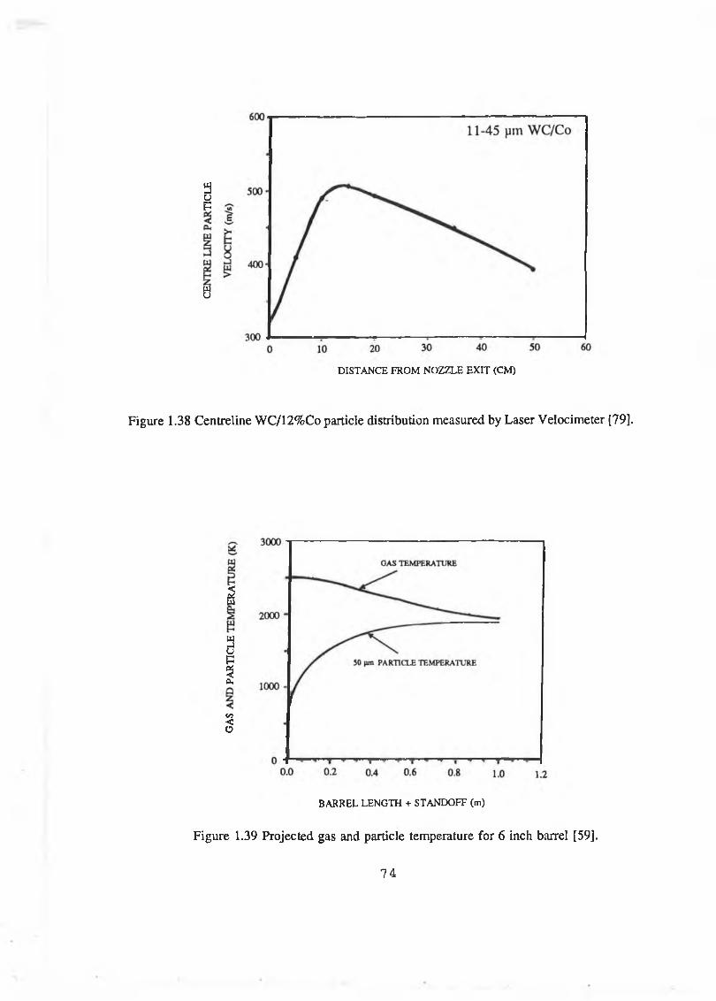
aup
wu
DISTANCE FROM NOZZLE EXIT (CM)
Figure 1.38 Centreline WC/12%Co particle distribution measured by Laser Velocimeter [79].
<piw
3up%Oh
C/J<O
BARREL LENGTH + STANDOFF (m)
Figure 1.39 Projected gas and particle temperature for 6 inch barrel [59].
74
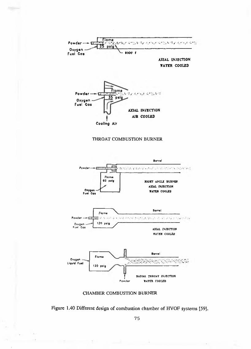
P o w d t r — - tZlAO xygen \ _
r rra¿¿----------------------------------------------------------'* » ^ #• * ;* - *■ -• •••■ ». t j ' .• ■' V •? j- ' * • •'' ' i k c •« • • J - i • •» • * * ’ < • ■' <•
F u ti C o t « » f f rAXIAL INJECTION
WATER COOLED
P o w d e r
O xygen Fuel C os
C ooling Air
AXIAL INJECTION
AIS COOLED
THROAT COMBUSTION BURNER
B o rr t l
Pow d«f •
Ovygan - Fu»l C at
Flam « 6 0 p ilg RIGHT ANCLE BURNER
AXIAL INJECTION
VATER COOLED
Powdtr ——Oxygen —
fu t i C oi
Flam *
120 psig
~ v B a rrtl
. XAXIAL INJECTION
WATER COOLED
Oxygen — Liquid F u ti
Ti am# x J i Barrai
'»•Li1 20 psig — l ì
f RADIAL THROAT INJECTION
P ow d tr WATER COOLED
CHAMBER COMBUSTION BURNER
Figure 1.40 Different design o f combustion chamber o f HVOF systems [59].
75
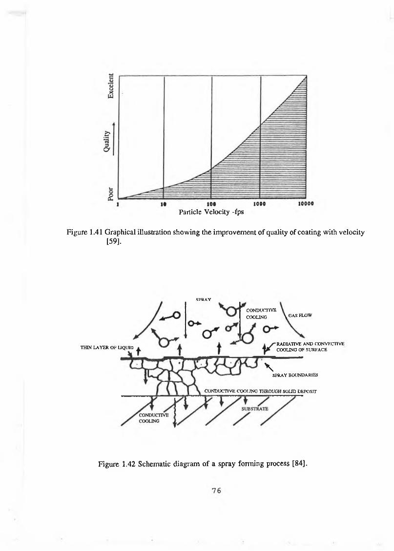
Particle Velocity -fps
Figure 1.41 Graphical illustration showing the improvement of quality of coating with velocity [59].
THIN LAYER OF LIQUID
\SPRAY BOUNDARIES
CONDUCTIVE COOLING THROUGH SOLID DEPOSIT
SPR A Y
CONDUCTIVE COOLING \ GAS FLOW
RADIATIVE AND CONVECTIVE COOLING OF SURFACE
Figure 1.42 Schematic diagram of a spray forming process [84].

Segregated scrap or cast stock
Recirculated scrap
Induction melt
Nitrogen
^Temperature qualifying furnace
Tundish
Spray
Preform
Preform die
Overspray-4 ---------- -----------------------------------------------------
Flash ^-4 a o -4 --------------------------------
Scrap forgings ___— -------------------------------------- rrea -*-------------
Clipping S a les press
Forging press
Figure 1.43 Schematic o f an Osprey forming system [102].
77
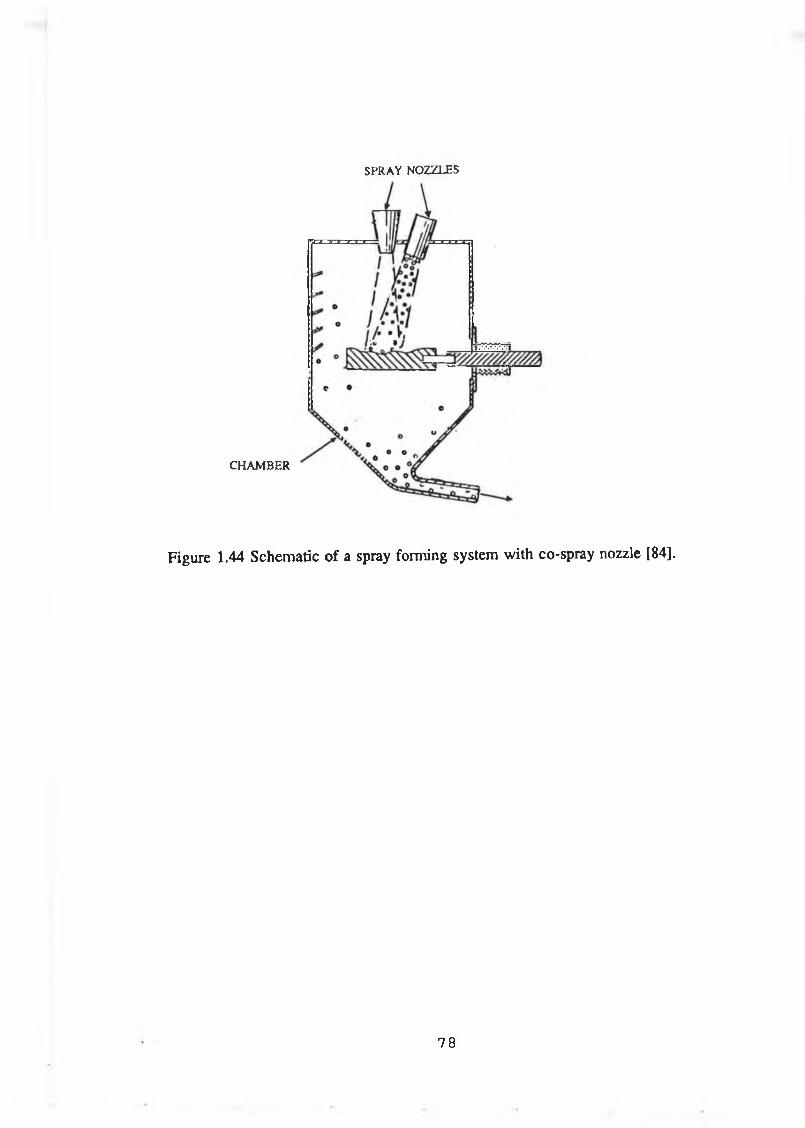
CHAMBER
Figure 1.44 Schematic of a spray forming system with co-spray nozzle [84].
SPRAY NOZZLES
78
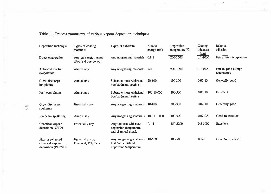
Table 1.1 Process parameters of various vapour deposition techniques.
Deposition technique
Direct evaporation
Activated reactive evaporation
Glow discharge ion plating
Ion beam plating
Glow discharge sputtering
Ion beam sputtering
Chemical vapour deposition (CVD)
Plasma enhanced chemical vapour deposition (PECVD)
Types of coating materials
Any pure metal, many alloy and compound
Almost any
Almost any
Almost any
Essentially any
Almost any
Essentially any
Essentially any, Diamond, Polymers
Types of substrate Kinetic Depositionenergy (eV) temperature °C
Any nongassing materials 0.1-1
Any nongassing materials 5-20
Substrate must withstand 10-100 bombardment heating
Substrate must withstand 100-10,000 bombardment heating
Any nongassing materials 10-100
Any nongassing materials 100-110,000
Any that can withstand 0.1-1 deposition temperature and chemical attack
Any nongassing materials 10-500 that can withstand deposition temperature
200-1600
200-1600
100-300
100-500
100-300
100-500
150-2200
100-500
Coating Relativethickness adhesion
(ym) _______0.1-1000 Fair at high temperature
0.1-1000 Fair to good at high temperature
0.02-10 Generally good
0.02-10 Excellent
0.02-10 Generally good
0.02-0.5 Good to excellent
0.5-1000 Excellent
0.1-2 Good to excellent
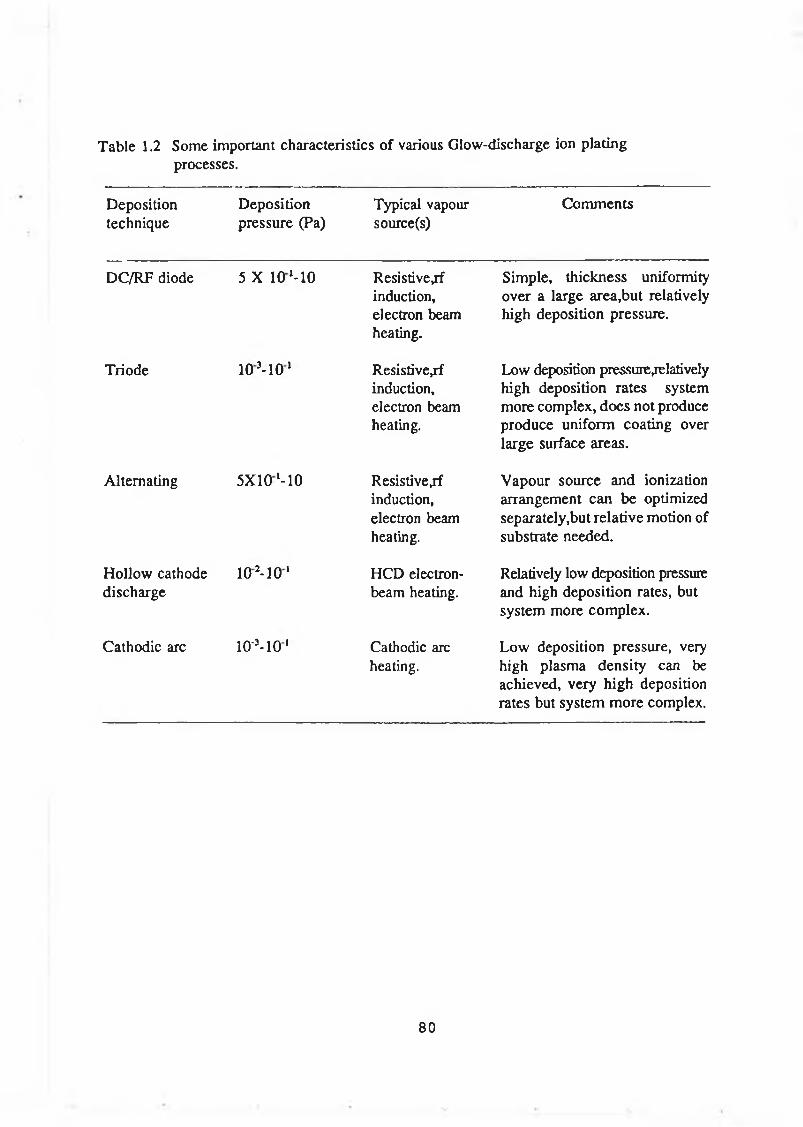
Table 1.2 Some important characteristics o f various Glow-discharge ion platingprocesses.
Depositiontechnique
Deposition pressure (Pa)
Typical vapour source(s)
Comments
DC/RF diode 5 X 1 0 M 0 Resistive^f induction, electron beam heating.
Simple, thickness uniformity over a large area,but relatively high deposition pressure.
Triode 1 0 M 0 1 Resistivejf induction, electron beam heating.
Low deposition pressure relatively high deposition rates system more complex, does not produce produce uniform coating over large surface areas.
Alternating 5X 10M 0 Resistivejf induction, electron beam heating.
Vapour source and ionization arrangement can be optimized separately,but relative motion of substrate needed.
Hollow cathode discharge
102-10 1 HCD electron- beam heating.
Relatively low deposition pressure and high deposition rates, but system more complex.
Cathodic arc 10°-101 Cathodic arc heating.
Low deposition pressure, very high plasma density can be achieved, very high deposition rates but system more complex.
80
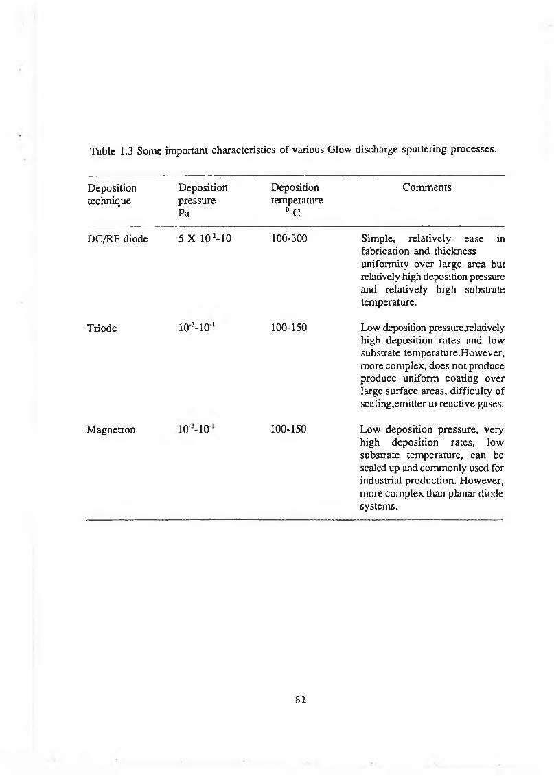
Table 1.3 Some important characteristics of various Glow discharge sputtering processes.
Depositiontechnique
DepositionpressurePa
Deposition temperature
0 C
Comments
DC/RF diode 5 X lOM O 100-300 Simple, relatively ease in fabrication and thickness uniformity over large area but relatively high deposition pressure and relatively high substrate temperature.
Triode lO M O 1 100-150 Low deposition pressure^elatively high deposition rates and low substrate temperature.However, more complex, does not produce produce uniform coating over large surface areas, difficulty of scaling,emitter to reactive gases.
Magnetron
Ö1-H1Ö
100-150 Low deposition pressure, very high deposition rates, low substrate temperature, can be scaled up and commonly used for industrial production. However, more complex than planar diode systems.
81

Table 1.4 Process parameters, properties and applications o f heat treatment processes.
Treatments Treatment temp. °C
Case dept, micron
Advantages/disadvantages
Applications
Induction 850-1100 250-5000 Fast, large case depth,high capital cost and cannot treat certain shapes.
Camyotaling shafisjnachine ways,swivel pins,steering joints, gears, valves and bearing surfaces.
Flame 750-1000 250-5000 Simple, cheap,flexible However, lack of process control.
Large sections, eg , nails, machine beds,dices, track rails.
Laser 1000-1300 1-100 Local heating allows shallow case depth for less component distortion can treat complex shapes.
C y l in d e r liners, gear, crankshafts.
Electron beam 1200-1300 1000-3000 Fast,large case depth, However, expensive.
Automobile transmission clutch cams.
Work hardening 20°C or low Metal working
A supplemental hardening process, Expensive and time consuming.
Wear plates earthmoving equipment, chute liners, piston bars.
Shot peening 100°C or lower 100-500 A supplemental hardening process,Time consuming.
Large ring gear, shaft, structural component of aircraft.
82
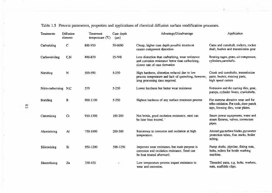
Table 1.5 Process parameters, properties and applications o f chemical diffusion surface modification processes.
Treatments Diffusion element
Carburizing C
Carboni triding C,N
Treatment Case depth temperature (°C) (pm)
Nitriding N
Nitro-carburizing N,C
Bonding B
Chromizing Cr
Aluminizing A1
Siliconizing Si
800-950
800-870
500-590
570
900-1100
950-1300
750-1000
950-1200
50-6000
25-500
5-250
5-250
5-250
100-200
200-500
500-1250
Advantage/Disadvantage
Cheap, higher case depth possible treatment causes component distortion
Less distortion than carburizing, wear resistance and corrosion resistance better than carburizing, slower rate of case formation
High hardness, distortion reduced due to low process temperature and lack of quenching, however, long processing time required.
Lower hardness but better wear resistance
Highest hardness of any surface treatment process
Not brittle, good oxidation resistance, steel can be later heat treated."
Resistance to corrosion and oxidation at high temperature.
Improves wear resistance, but main purpose is corrosion and oxidation resistance. Steel can be heat treated afterward.
Application
Cams and camshaft, rockers, rocker shaft, bushes and transmission gear
Bearing cages, gears, air compressor, cylinders,camshafts.
Crank and camshafts, transmission parts, bushes, rotating parts, high speed cutters
Extrusion and die casting dies, gear, pumps, cylinder liners, crankshafts.
For extreme abrasive wear and for tribo-oxidation. For tools, draw punch taps, forming dies, wear plates.
Steam power equipments, water and steam fixtures, valves, connectors pipes.
Aircraft gas turbine blades, pyrometer protection tubes, flue stacks, boiler tubing.
Pump shafts, pipeline, fitting nuts, bolts, rollers for bottle washing machine.
Sherardizing Zn 350-450 Low temperature process impart resistance to wear and corrosion.
Threaded parts, e.g. bolts, washers, nuts, scaffolds clips.
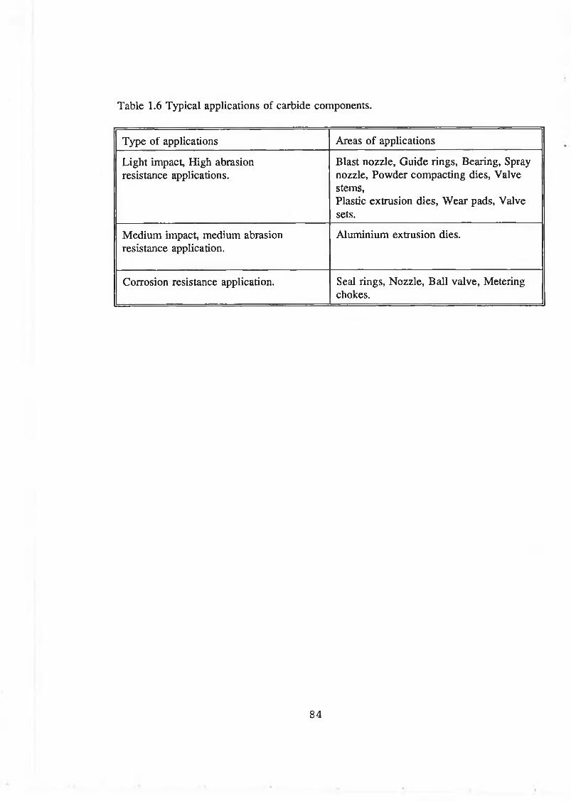
Table 1.6 Typical applications o f carbide components.
Type of applications Areas of applications
Light impact, High abrasion resistance applications.
Blast nozzle, Guide rings, Bearing, Spray nozzle, Powder compacting dies, Valve stems,Plastic extrusion dies, W ear pads, Valve sets.
Medium impact, medium abrasion resistance application.
Aluminium extrusion dies.
Corrosion resistance application. Seal rings, Nozzle, Ball valve, Metering chokes.
84

CHAPTER 2
EXPERIMENTAL EQUIPMENT
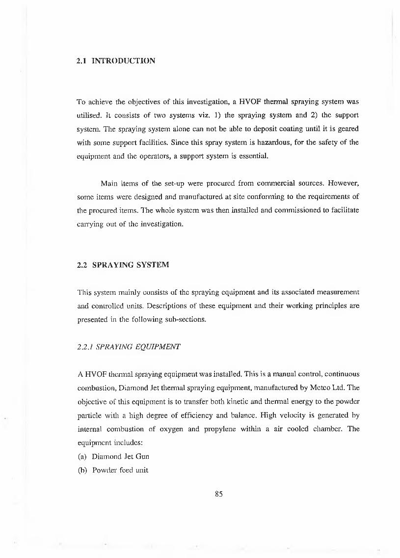
2.1 IN TR O D U C TIO N
To achieve the objectives of this investigation, a HVOF thermal spraying system was
utilised. It consists of two systems viz. 1) the spraying system and 2) the support
system. The spraying system alone can not be able to deposit coating until it is geared
with some support facilities. Since this spray system is hazardous, for the safety of the
equipment and the operators, a support system is essential.
Main items of the set-up were procured from commercial sources. However,
some items were designed and manufactured at site conforming to the requirements of
the procured items. The whole system was then installed and commissioned to facilitate
carrying out of the investigation.
2.2 SPRAYING SYSTEM
This system mainly consists of the spraying equipment and its associated measurement
and controlled units. Descriptions of these equipment and their working principles are
presented in the following sub-sections.
2.2.1 SPRAYING EQUIPMENT
A HVOF thermal spraying equipment was installed. This is a manual control, continuous
combustion, Diamond Jet thermal spraying equipment, manufactured by Metco Ltd. The
objective of this equipment is to transfer both kinetic and thermal energy to the powder
particle with a high degree of efficiency and balance. High velocity is generated by
internal combustion of oxygen and propylene within a air cooled chamber. The
equipment includes:
(a) Diamond Jet Gun
(b) Powder feed unit
85
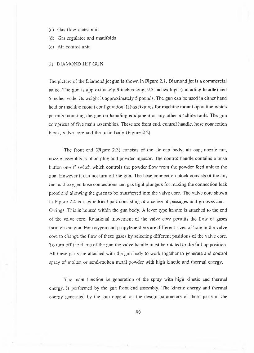
(c) Gas flow meter unit
(d) Gas regulator and manifolds
(e) Air control unit
(i) DIAMOND JET GUN
The picture of the Diamond je t gun is shown in Figure 2.1. Diamond je t is a commercial
name. The gun is approximately 9 inches long, 9.5 inches high (including handle) and
5 inches wide. Its weight is approximately 5 pounds. The gun can be used in either hand
held or machine mount configuration. It has fixtures for machine mount operation which
permits mounting the gun on handling equipment or any other machine tools. The gun
comprises of five main assemblies. These are front end, control handle, hose connection
block, valve core and the main body (Figure 2.2).
The front end (Figure 2.3) consists of the air cap body, air cap, nozzle nut,
nozzle assembly, siphon plug and powder injector. The control handle contains a push
button on-off switch which controls the powder flow from the powder feed unit to the
gun. However it can not turn off the gun. The hose connection block consists of the air,
fuel and oxygen hose connections and gas tight plungers for making the connection leak
proof and allowing the gases to be transferred into the valve core. The valve core shown
in Figure 2.4 is a cylindrical part consisting of a series of passages and grooves and
O-rings. This is housed within the gun body. A lever type handle is attached to die end
of the valve core. Rotational movement of the valve core permits the flow of gases
through the gun. For oxygen and propylene there are different sizes of hole in the valve
core to change the flow of these gases by selecting different positions of the valve core.
To turn off the flame of the gun the valve handle must be rotated to the full up position.
All these parts are attached with the gun body to work together to generate and control
spray of molten or semi-molten metal powder with high kinetic and thermal energy.
'The main function i.e generation of the spray with high kinetic and thermal
energy, is performed by the gun front end assembly. The kinetic energy and thermal
energy generated by the gun depend on the design parameters of these parts of the
86
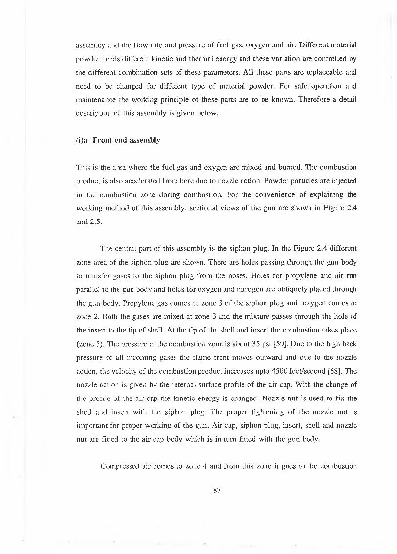
assembly and the flow rate and pressure of fuel gas, oxygen and air. Different material
powder needs different kinetic and thermal energy and these variation are controlled by
the different combination sets of these parameters. All these parts are replaceable and
need to be changed for different type of material powder. For safe operation and
maintenance the working principle of these parts are to be known. Therefore a detail
description of this assembly is given below.
(i)a F ro n t end a ssem b ly
This is the area where the fuel gas and oxygen are mixed and burned. The combustion
product is also accelerated from here due to nozzle action. Powder particles are injected
in the combustion zone during combustion. For the convenience of explaining the
working method of this assembly, sectional views of the gun are shown in Figure 2.4
and 2.5.
The central part of this assembly is the siphon plug. In the Figure 2.4 different
zone area of the siphon plug are shown. There are holes passing through the gun body
to transfer gases to the siphon plug from the hoses. Holes for propylene and air run
parallel to the gun body and holes for oxygen and nitrogen are obliquely placed through
the gun body. Propylene gas comes to zone 3 of the siphon plug and oxygen comes to
zone 2. Both the gases are mixed at zone 3 and the mixture passes through the hole of
the insert to the tip of shell. At the tip of the shell and insert the combustion takes place
(zone 5). The pressure at the combustion zone is about 35 psi [59]. Due to the high back
pressure of all incoming gases the flame front moves outward and due to the nozzle
action, the velocity of the combustion product increases upto 4500 feet/second [68]. The
nozzle action is given by the internal surface profile of the air cap. With the change of
the profile of the ah cap the kinetic energy is changed. Nozzle nut is used to fix the
shell and insert with the siphon plug. The proper tightening of the nozzle nut is
important for proper working of the gun. Ah' cap, siphon plug, insert, shell and nozzle
nut are fitted to the air cap body which is in turn fitted with the gun body.
Compressed air comes to zone 4 and from this zone it goes to the combustion
87
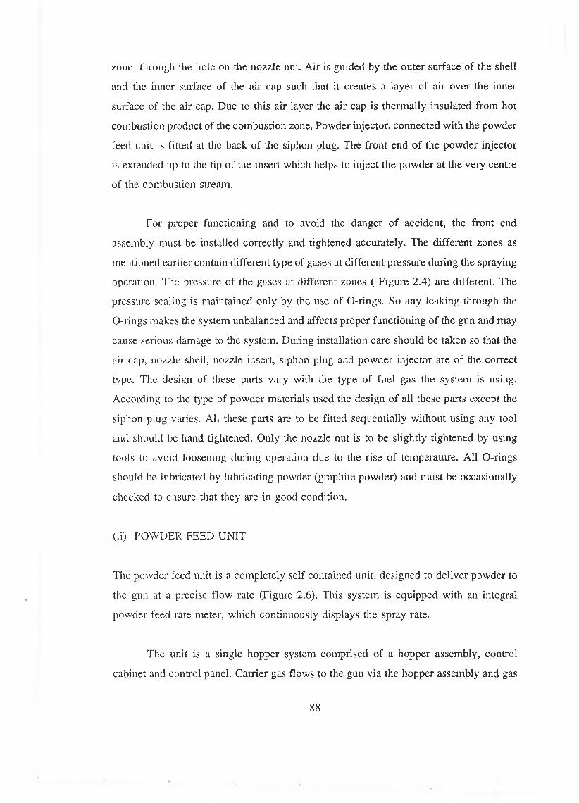
zone through the hole on the nozzle nut. Air is guided by the outer surface of the shell
and the inner surface of the air cap such that it creates a layer of air over the inner
surface of the air cap. Due to this air layer the air cap is thermally insulated from hot
combustion product of the combustion zone. Powder injector, connected with the powder
feed unit is fitted at the back of the siphon plug. The front end of the powder injector
is extended up to the tip of the insert which helps to inject the powder at the very centre
of the combustion stream.
For proper functioning and to avoid the danger of accident, the front end
assembly must be installed correctly and tightened accurately. The different zones as
mentioned earlier contain different type of gases at different pressure during the spraying
operation. The pressure of the gases at different zones ( Figure 2.4) are different. The
pressure sealing is maintained only by the use of O-rings. So any leaking through the
O-rings makes the system unbalanced and affects proper functioning of the gun and may
cause serious damage to the system. During installation care should be taken so that the
air cap, nozzle shell, nozzle insert, siphon plug and powder injector are of the correct
type. The design of these parts vary with the type of fuel gas the system is using.
According to the type of powder materials used the design of all these parts except the
siphon plug varies. All these parts are to be fitted sequentially without using any tool
and should be hand tightened. Only the nozzle nut is to be slightly tightened by using
tools to avoid loosening during operation due to the rise of temperature. All O-rings
should be lubricated by lubricating powder (graphite powder) and must be occasionally
checked to ensure that they are in good condition.
(ii) POWDER FEED UNIT
The powder feed unit is a completely self contained unit, designed to deliver powder to
the gun at a precise flow rate (Figure 2.6). This system is equipped with an integral
powder feed rate meter, which continuously displays the spray rate.
The unit is a single hopper system comprised of a hopper assembly, control
cabinet and control panel. Carrier gas flows to the gun via the hopper assembly and gas
88
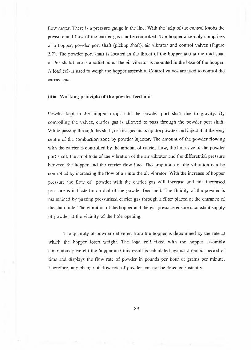
flow meter. There is a pressure gauge in the line. With the help of the control knobs the
pressure and flow of the earner gas can be controlled. The hopper assembly comprises
of a hopper, powder port shaft (pickup shaft), air vibrator and control valves (Figure
2.7). The powder port shaft is located in the throat of the hopper and at the mid span
of this shaft there is a radial hole. The air vibrator is mounted in the base of the hopper.
A load cell is used to weigh the hopper assembly. Control valves are used to control the
carrier gas.
(ii)a Working principle of the powder feed unit
Powder kept in the hopper, drops into the powder port shaft due to gravity. By
controlling the valves, carrier gas is allowed to pass through the powder port shaft.
While passing through the shaft, earner gas picks up the powder and inject it at the very
centre of the combustion zone by powder injector. The amount of the powder flowing
with the carrier is controlled by the amount of carrier flow, the hole size of the powder
port shaft, the amplitude of the vibration of the air vibrator and the differential pressure
between the hopper and the carrier flow line. The amplitude of the vibration can be
controlled by increasing the flow of air into the air vibrator. With the increase of hopper
pressure the flow of powder with the carrier gas will increase and this increased
pressure is indicated on a dial of the powder feed unit. The fluidity of the powder is
maintained by passing pressurised earner gas through a filter placed at the entrance of
the shaft hole. The vibration of the hopper and the gas pressure ensure a constant supply
of powder at the vicinity of the hole opening.
The quantity of powder delivered from the hopper is determined by the rate at
which the hopper loses weight. The load cell fixed with the hopper assembly
continuously weight the hopper and this result is calculated against a certain period of
time and displays the flow rate of powder in pounds per hour or grams per minute.
Therefore, any change of flow rate of powder can not be detected instantly.
89
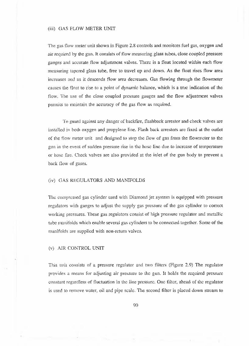
(iii) GAS FLO W M E T E R U N IT
The gas flow meter unit shown in Figure 2.8 controls and monitors fuel gas, oxygen and
air required by the gun. It consists of flow measuring glass tubes, close coupled pressure
gauges and accurate flow adjustment valves. There is a float located within each flow
measuring tapered glass tube, free to travel up and down. As the float rises flow area
increases and as it descends flow area decreases. Gas flowing through the flowmeter
causes the float to rise to a point of dynamic balance, which is a true indication of the
flow. The use of the close coupled pressure gauges and the flow adjustment valves
permits to maintain the accuracy of the gas flow as required.
To guard against any danger of backfire, flashback arrestor and check valves are
installed in both oxygen and propylene line. Flash back arrestors are fixed at the outlet
of the flow meter unit and designed to stop the flow of gas from the flowmeter to the
gun in the event of sudden pressure rise in the hose line due to increase of temperature
or hose fire. Check valves are also provided at the inlet of the gun body to prevent a
back flow of gases.
(iv) GAS REGULATORS AND MANIFOLDS
The compressed gas cylinder used with Diamond je t system is equipped with pressure
regulators with gauges to adjust the supply gas pressure of the gas cylinder to correct
working pressures. These gas regulators consist of high pressure regulator and metallic
tube manifolds which enable several gas cylinders to be connected together. Some of the
manifolds are supplied with non-return valves.
(v) AIR CONTROL UNIT
This unit consists of a pressure regulator and two filters (Figure 2.9) The regulator
provides a means for adjusting air pressure to the gun. It holds the required pressure
constant regardless of fluctuation in the line pressure. One filter, ahead of the regulator
is used to remove water, oil and pipe scale. The second filter is placed down stream to
90
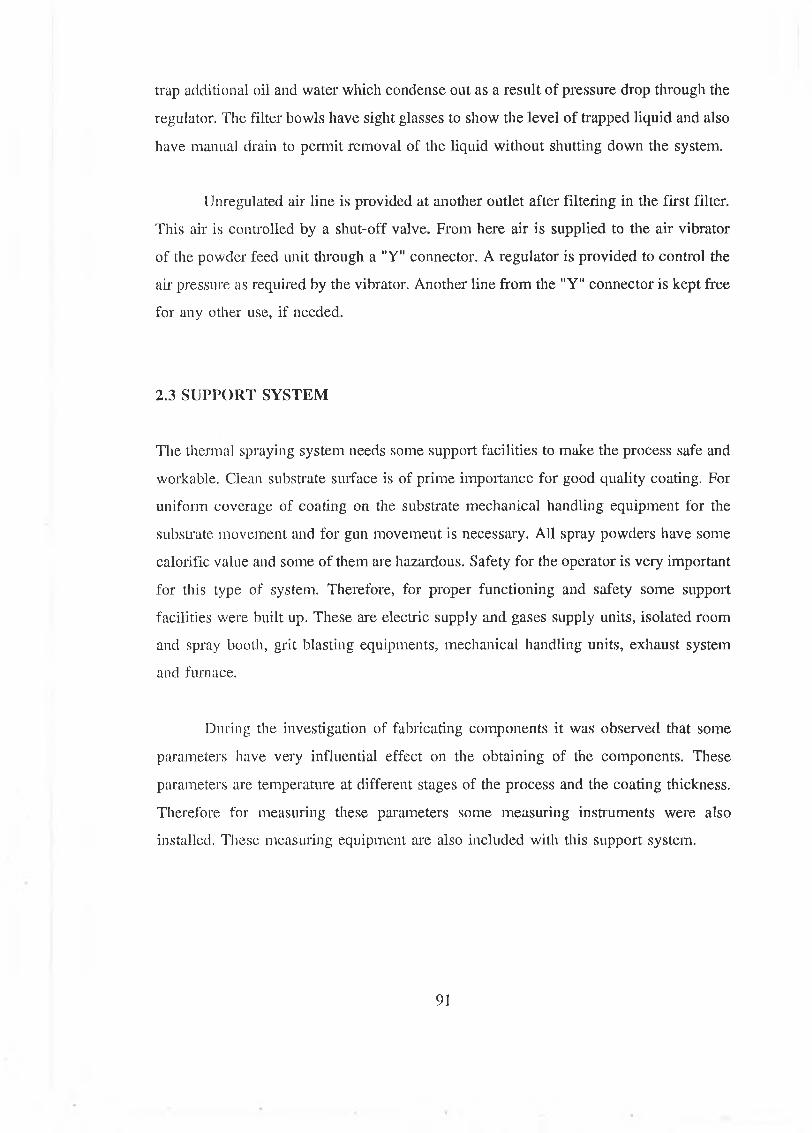
trap additional oil and water which condense out as a result of pressure drop through the
regulator. The filter bowls have sight glasses to show the level of trapped liquid and also
have manual drain to permit removal of the liquid without shutting down the system.
Unregulated air line is provided at another outlet after filtering in the first filter.
This air is controlled by a shut-off valve. From here air is supplied to the air vibrator
of the powder feed unit through a "Y" connector. A regulator is provided to control the
air pressure as required by the vibrator. Another line from the "Y" connector is kept free
for any other use, if needed.
2.3 SUPPORT SYSTEM
The thermal spraying system needs some support facilities to make the process safe and
workable. Clean substrate surface is of prime importance for good quality coating. For
uniform coverage of coating on the substrate mechanical handling equipment for the
substrate movement and for gun movement is necessary. All spray powders have some
calorific value and some of them are hazardous. Safety for the operator is very important
for this type of system. Therefore, for proper functioning and safety some support
facilities were built up. These are electric supply and gases supply units, isolated room
and spray booth, grit blasting equipments, mechanical handling units, exhaust system
and furnace.
During the investigation of fabricating components it was observed that some
parameters have very influential effect on the obtaining of the components. These
parameters are temperature at different stages of the process and the coating thickness.
Therefore for measuring these parameters some measuring instruments were also
installed. These measuring equipment are also included with this support system.
91
2.3.1 ELECTRIC SUPPLY AND GASES SUPPLY UNITS
Powder feed unit, air compressor, dust collector of the grit blasting equipment and wet
collector unit need electric power supply at different voltage at different amount. Table
2.1 lists the type and amount of power needed by different units of the spraying system.
The HVOF system needs different types of gases to operate the system. The type
of gases and their quantities and pressure are listed in Table 2.2. Nitrogen is required
for powder feeding as a carrier gas. To maintain the required consumption one nitrogen
gas cylinder with commercial grade purity is enough for the proper operation of this
system.
Oxygen is used as oxidant for combustion. To maintain the huge flow rate of this
gas, at least four cylinder of oxygen with commercial grade purity should be connected
together.
Propylene is used as a fuel for combustion.lt is recommended that at least three
45 kg cylinders are to be connected together. The purity of the propylene should be 99
% as suggested by the manufacturer. However during this investigation 96 % pure
propylene were used and this reduced purity of the gas was within the acceptable range
as per manufacturer recommendation, though it might reduce the life of the nozzle.
A supply of clean, dry compressed air is required for the use of the gun. A
compressor is installed to compress air with the range of pressure 6.8 bar to 10.2 bar at
a flow rate of 1500 standard litre per minute (SLPM). An air reservoir of capacity 300
litre was installed to store air to ensure a constant supply of air to the gun.
2.3.2 ISOLATED ROOM AND SPRAY BOOTH
The potential hazards associated with thermal spraying are toxic materials that may
generate in the thermal spraying process, airborne metal dust and fumes, and the noise
level. The probable adverse environmental conditions of thermal spraying operation
92
require a well protected area where the spraying operation can be done. Dust , fumes
and overspray must be removed from the work area as rapidly as possible. The most
effective way of achieving these objectives is through the use of spray enclosures. A
spray booth (Figure 2.10) was installed to guide and contain all airborne dust, fume and
over spray so that they can be properly extracted by the wet collector. The spray booth
helps to minimize danger from dust explosions and adequate ventilation. The operator
is supplied with equipment for protection against noise, dust, fumes and rays. For the
protection of personnel working in the vicinity of the spray room, the room was
isolated. It is always preferable to keep the oxygen and propylene cylinder outside the
spray room. From this consideration, in the present installation a room is divided into
two part: the front room and the spray room. The compressor and the gas cylinders are
put into the front room and the spray room is isolated by a sound proof wall. The design
considerations of the sound proof room are given below.
(i) CONSTRUCTION OF SOUND PROOF SPRAY ROOM
A plan of the spray room is shown in Figure 2.11. Three sides of the room were built
up with double layered sound absorbent walls, in addition to the brick walls. The roof
of the room was also protected with double layer sound absorbent ceiling (Figure 2.12).
Each layer of the sound proof wall is made up of different layers of sound absorbing
materials. For the side walls, frame structures (Figure 2.13) of 1.22 X 2.64 metres
rectangular shape were made from 44 X 44 X 3 mm box sectioned steel bar. Both the
sides of the frame were covered by peg boards and the space within was filled up with
tightly packed glass wool. These frames were placed side by side to cover the total side
wall. Frame structures made for roof were made of 1.22 X 3.91 metres size and these
frames were also covered by peg board and glass wool as the side wall frames. These
frames were placed on the side wall frames in two layers. Between the layers wooden
blocks were positioned for strong support. At the entrance of the room two doors (one
opening inside and another opening out side) were made in a similar pattern as the side
wall frame. An extra outer layer of aluminium sheet of 3 mm thickness was given to
the doors. The outside area of the sound absorbent side walls, facing the brick walls,
was also covered widi aluminium sheet. During suction of the exhaust fan, the door
93
which opens out side closes tightly and prevents sound to go outside. For ventilation air
ducts were made passing through a side wall. The air ducts were fitted with silencers
to absorb sound such that the sound can not propagate through the duct.
The noise level at any location depends on factors such as equipment operating
parameters, back ground noise, room size and wall, floor and ceiling material. Therefore
to determine the exact noise level of any room, it is necessary to measure the sound
level. To check the effectiveness of the sound proof walls the noise level of the spray
room was measured by a db meter putting it at the location where normally an operator
will stand during spraying. It was found that the noise level was 126 db. The noise level
at the front room ( outside the spray room) was 96 db when the gun was on and the
compressor was on. When only the compressor was on the noise level of the front room
was 89 db. Therefore it is quite obvious that with the addition of the sound proof wall
the noise level of the spray room is reasonably protected.
2 .3.3 GRIT BLASTING APPARATUS
The adhesion of the coating is directly related with the cleanliness of the substrate
surface and the total surface area of the substrate. Increase of effective substrate surface
by roughening is a well known method. The function of abrasive blasting equipment is
cleaning and roughening the substrate surface. Therefore a grit blasting equipment
supplied by Metco Ltd was installed. The commercial name of this unit is Ventublast
Mammoth. It has a large capacity grit blasting cabinet with 42 by 32 inches internal
dimension of the work area. An eye level visor gives visibility over the entire work area.
The system also includes a hand-held blasting gun and dust collector. The abrasive
medium is dispensed from a hopper at the cabinet base. The blasting gun is of the
suction type with a straight nozzle made of ceramic material. When air is flowing
through the nozzle at some section of the nozzle a vacuum is generated due to the
increase of velocity of air. Due to the vacuum grit is drawn from the base of the cabinet
to that section of the nozzle and propelled by the air to the substrate. The grit drops
through a grate, returns to the hopper and is recycled. Clean dry air from the compressor
is used for grit blasting. A pressure controller is used to change the supply pressure of
94
the compressed air used by the blasting equipment. The roughness of the substrate is
controlled by controlling the air pressure, grit size and spray distance. The best way of
doing this is by changing the grit size. For thermal spraying normally three grade size
grit are used viz. coarse, fine and very fine. Broken down abrasives and dust are
exhausted into a series of filter bags in a separate collector.
2.3.4 EXHAUST SYSTEM
To minimize the danger of dust explosion and prevention of fumes and dust
accumulation resulting from spraying, adequate ventilation must be provided for spray
booths and other confined spaces. The velocity of air in the gun area sweeping fumes
into the exhaust system should be at least 300 linear feet per minute. To clean the dust
from the air it is better to be wetted down and keep in water. Therefore a metro type
4CW wet collector was installed for the HVOF spray system.
Figure 2.14 shows a cut away cross section drawing of the wet collector showing
how the scrubbing activity is produced. The dust laden air is drawn through the inlet and
passes under the scroll, picks up and mixes with water. The turbulence of this mixture
of water, dust and air is intensified by directional change of the air flow. Finally the air
flows through the moisture eliminator where water and dust drops out and air escapes
upward. The cleaned air is extracted through a centrifugal fan housed in the upper
section of the wet collector and exhausted to the atmosphere. A door is provided to
scrape out the wet dust in the form of sludge. The water level of the wet collector is
designed to work automatically but due to faulty design it does not work automatically.
So occasionally water is to be fed to maintain the designed level. The unit is rated to
exhaust water wash and scrub 2000 to 2500 cfm of air when ideal condition of water
level is maintained.
2.3.5 MECHANICAL HANDLING UNITS
For better coating quality and uniform coverage of the coating on the substrate a
continuous movement of the substrate and the gun is essential. For a cylindrical
95
substrate a rotary motion can be given by a variable speed motor through a chuck of a
lathe. The traversing unit of the lathe carriage can be used for to and fro motion of the
gun. Therefore a semi automatic lathe was installed having rotational speed 40 to 2500
rpm and traversing speed 0.05 mm per rotation to 3.5 mm per rotation. The size of the
chuck was 200 mm and the height of the centre of the chuck from the bed is 200 mm
and the length of the bed was about 1 metre.
2.3.6 FURNACE
A furnace made by Lenton thermal designs of the type EF 10/8 was used to heat the
sample during experiments (Figure 2.15). The furnace is equipped with the analogue
temperature controller which can control the temperature within ±3 °C. The range of
temperature between which the furnace can be used is 0 to 1000 °C. A cylindrical box
was made inside the furnace. This box was connected with a nitrogen gas cylinder
through a flexible tube. A flow meter was also provided to control the flow rate of
nitrogen in to the box. This box was used to heat the object in a nitrogen atmosphere.
2.3.7 TEMPERATURE MEASURING INSTRUMENT
To measure the temperature of the static body thermocouples of type K were used.
When the body is rotating at high speed it was not possible to measure the temperature
by any device which needs physical contact. Therefore for non-contact temperature
measurement a pyrometer was installed. This is an optical fibre thermometer made by
Accufiber of the type Model 10 (modified low temperature), which can measure the
temperature between the range of 200-1000 °C. A picture of the used optical pyrometer
is shown in Figure 2.16.
The pyrometer works on the principle that all substances at temperature above
absolute zero emit radiant energy as the result of the atomic and molecular agitation that
is associated with the temperature of the substances. The rate of emission of the
radiation per unit area increases with increase in temperature. Accordingly, the
96
temperature of a substance can be measured by means of a suitable device responsive
to such radiation energy. An optical pyrometer can collect the radiant energy from the
work piece at a distance of a few inches to many feet (upto 16 feet). This type of sensor
is used when direct contact or close proximity sensors are impractical.
2.3.8 COATING THICKNESS MEASURING INSTRUMENT
A coating thickness measuring instrument known as Fisherscope Multi of the type 760
C (Figure 2.17) was installed to measure the thickness of the coating. This instrument
uses the eddy-current method and the magnetic induction method.
A schematic of the eddy-current thickness gauge is shown in Figure 2.18. When
high frequency current is passed through the exciter/sensing coil and the coil is brought
near an electrically conductive material, then eddy current is induced in the material.
This current, in turn, reacts with the sensing coil, causing back emf energy loss and a
change in coil impedance. It is the impedance change that the instrument measures and
converts into a thickness proportional signal. By calibrating the gauge with standard
coating of known thickness, the meter can be directly used to measure the unknown
thickness of the coating provided that the substrate coating combination is same. In
magnetic induction type instruments, the non-magnetic coating on a magnetic substrate
forms the nonmagnetic gap in the circuit and the inductance of the coil is diminished
as the air gap is increased. If a magnetic coating on a nonmagnetic substrate is
measured, the inductance increases with coating thickness. Figure 2.19 shows
schematically the essential elements of this type of thickness measuring instrument.
These methods can measure the coating thickness with a uncertainty of less then 10 %
or 0.5 pm which ever is the greater [101], provided that they are properly calibrated.
97

HANDLE
Figure 2.1
FRONT END
Picture of a Diamond Jet Gun.
HOSE CONNECTION BLOCK
GUN BODY
VALVE CORE
Figure 2.2 Schematic showing the different assemblies o f the gun.
98

INJECTOR
AIR CAP NOZZLE NUT SHELLINSERT
Figure 2.3 Schematic of the front end parts and cross section of the front end assembly.
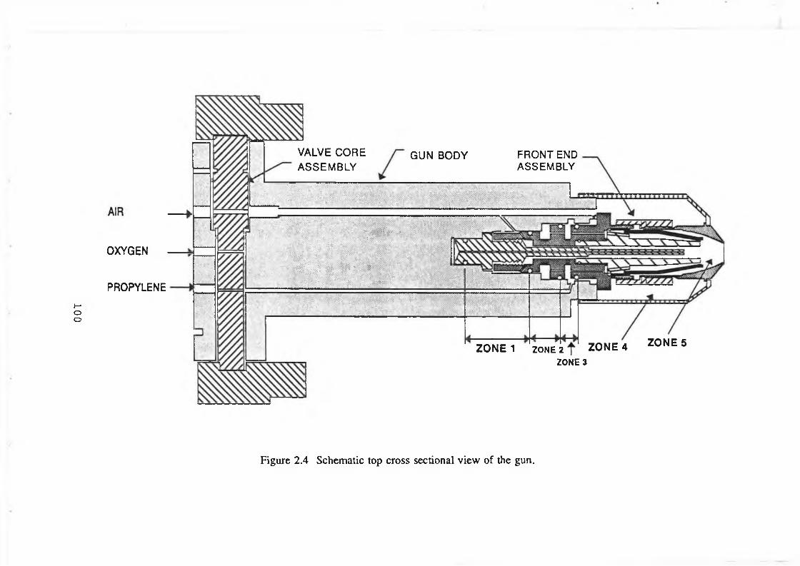
100
OXYGEN
PROPYLENE
VALVE CORE ASSEMBLY
GUN BODY FRONT END ASSEMBLY
•' •
< . v!- - i i f 1 ; - -
: -v •
;; ■ ; :A■ • ■ yX :>■ :¥
-... ... . - f o i - V , ; ;;
* ■ 4 i i f e l g | Ip ' i
'■■■-v- v y : ; .
--- ----------------- ------------ ------------------------i -!■: . : . -... .. .... W:;*-;:-:1: •
ZONE 1 ZONE 2 ZONE 4 ZONE 3
ZONE 5
Figure 2.4 Schematic top cross sectional view of the gun.

101
POWDER WITH NITROGEN “
FRONT END
OXYGEN
VALVECORE
Figure 2.5 Schematic o f side cross sectional view o f the gun.
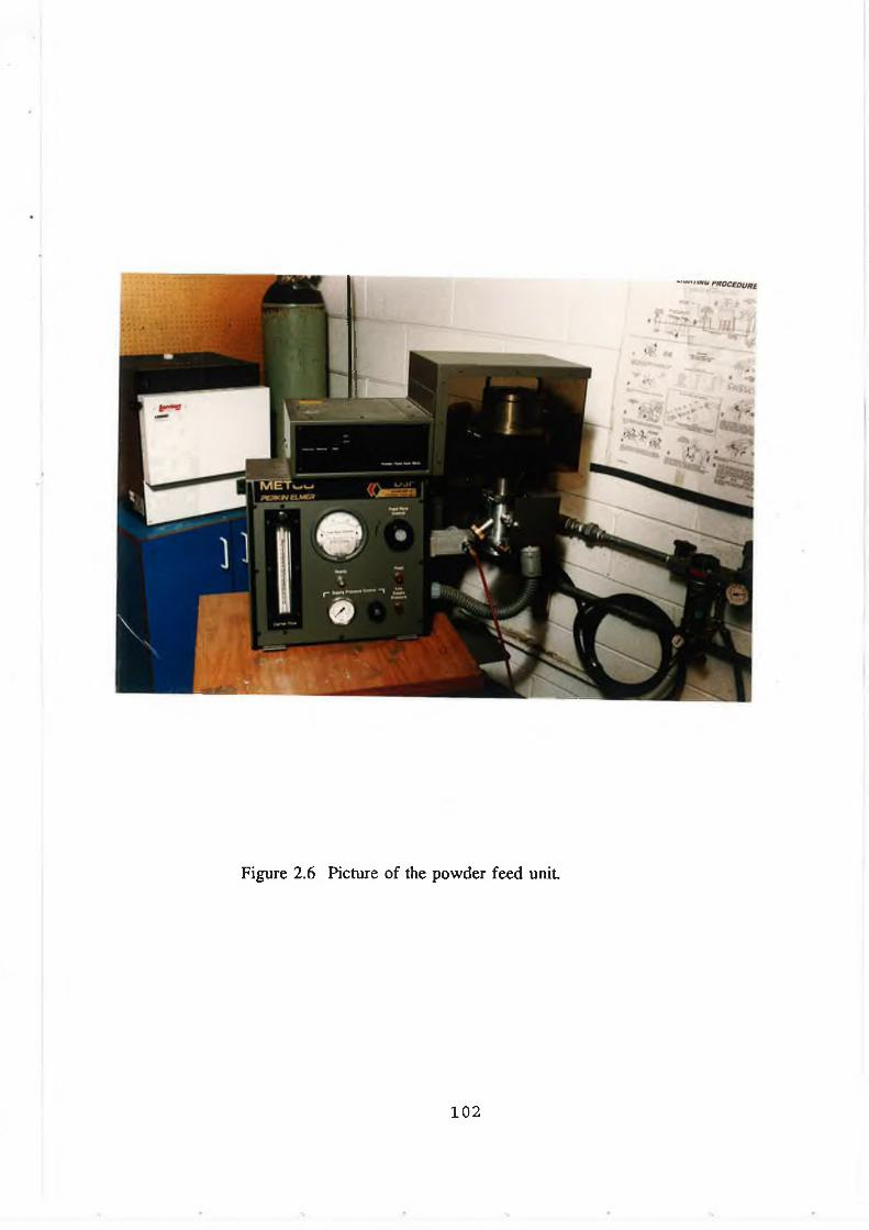
Figure 2.6 Picture of the powder feed unit
102

HOPPER
Figure 2.7 Schematic diagram of the powder feed unit
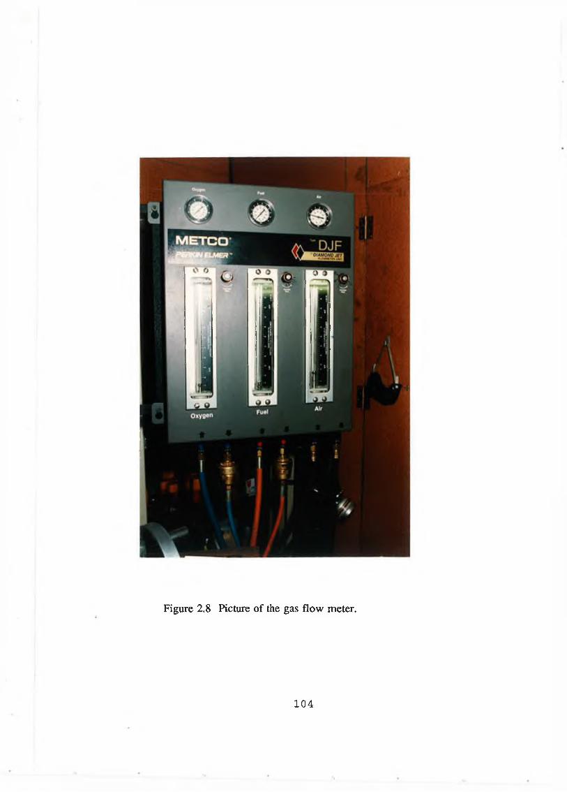
Figure 2.8 Picture o f the gas flow meter.
1 0 4
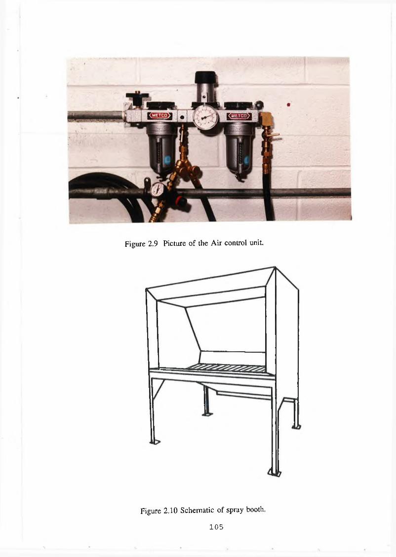
I
KBB>3
Figure 2.9 Picture of the Air control unit.
Figure 2.10 Schematic o f spray booth.
1 0 5
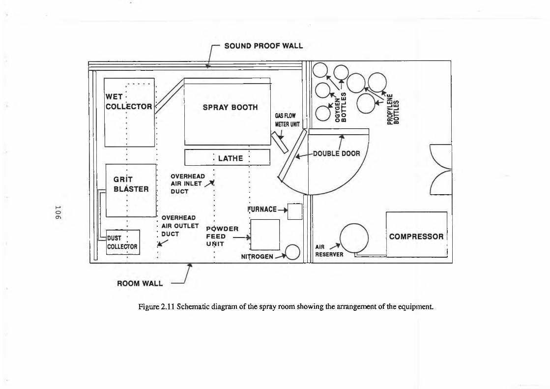
Figure 2.11 Schematic diagram of the spray room showing the arrangement of the equipment.
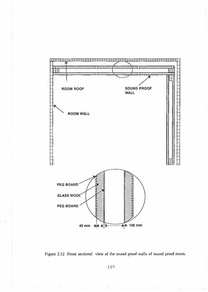
Figure 2.12 Front sectional view of the sound proof walls o f sound proof room.
1 0 7
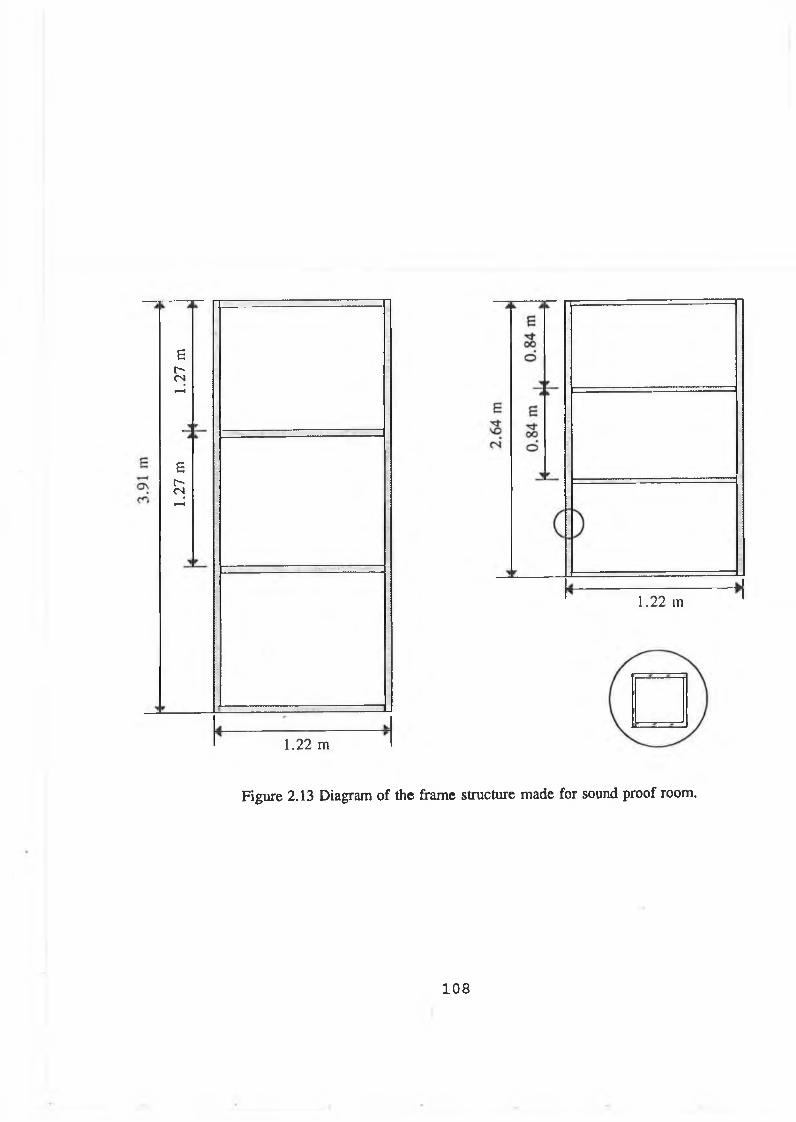
1.27
m .
1.27
m
1.22 m
1.22 m
Figure 2.13 Diagram of the frame structure made for sound proof room.
1 0 8
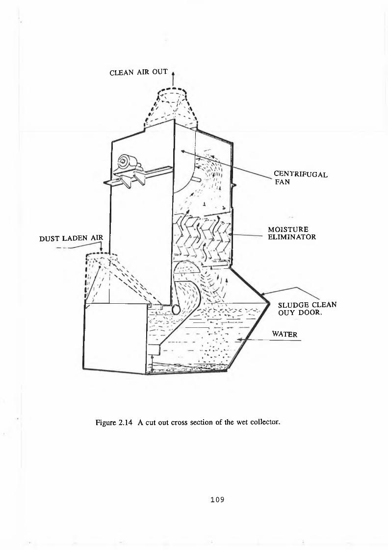
CLEAN AIR OUT
DUST LADEN AIR
CENTRIFUGALFAN
MOISTUREELIMINATOR
SLUDGE CLEAN OUY DOOR.
WATER
Figure 2.14 A cut out cross section of the wet collector.
109
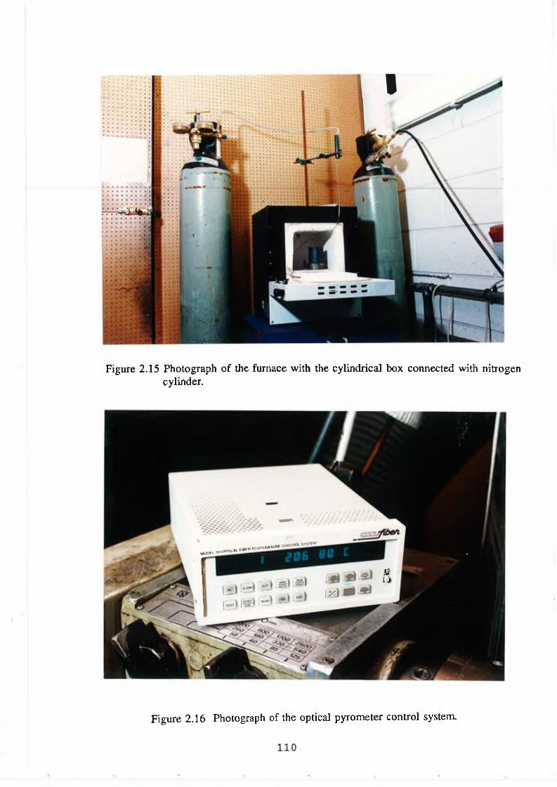
Figure 2.15 Photograph of the furnace with the cylindrical box connected with nitrogen cylinder.
Figure 2.16 Photograph of the optical pyrometer control system.
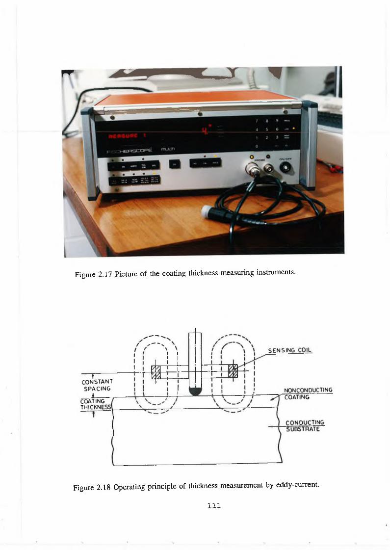
Figure 2.17 Picture of the coating thickness measuring instruments.
Figure 2.18 Operating principle o f thickness measurement by eddy-current.
I l l
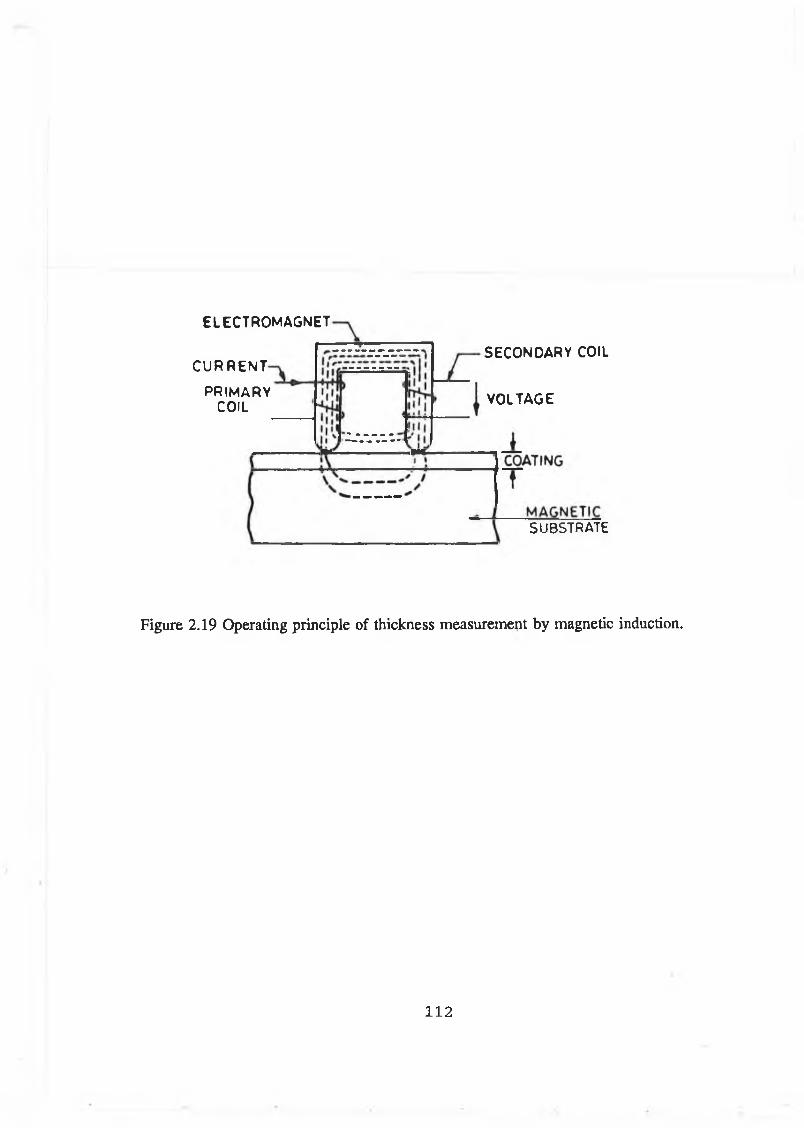
ELECTROMAGNET
C U R R E N T
PRIMARYCOIL
SECONDARY COIL
VOLTAGE
SUBSTRATE
Figure 2.19 Operating principle of thickness measurement by magnetic induction.
112
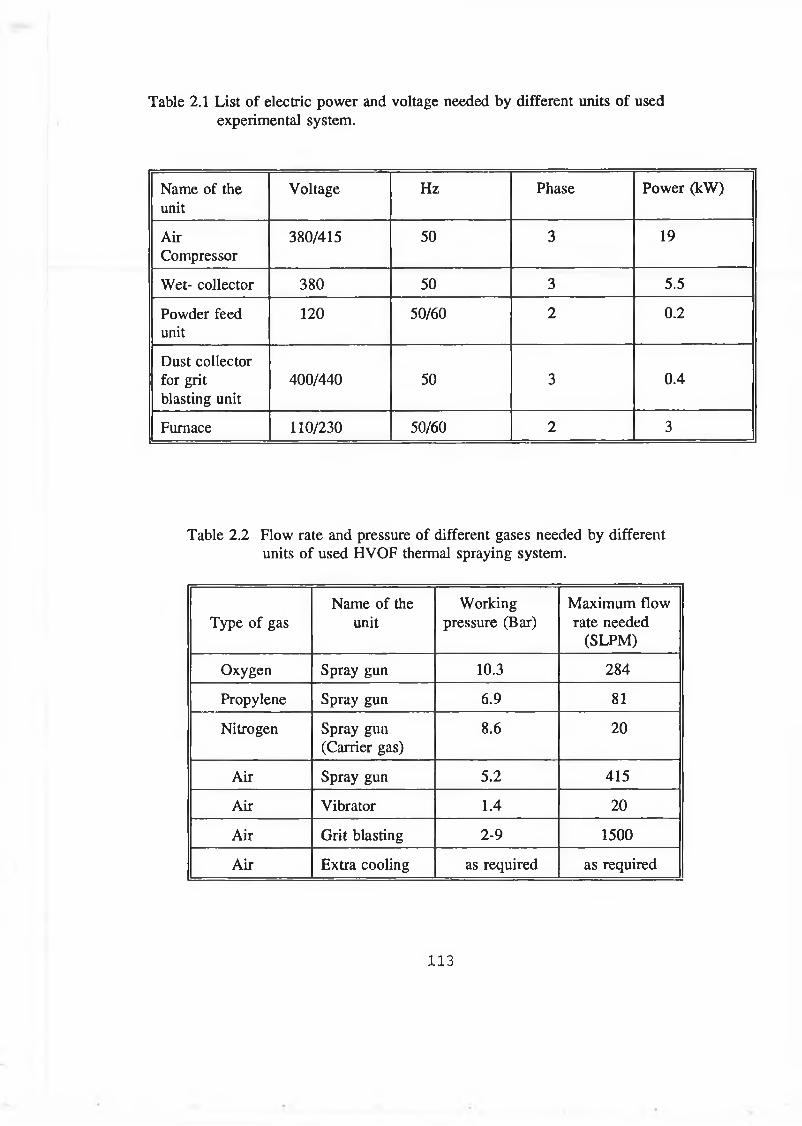
Table 2.1 List of electric power and voltage needed by different units of used experimental system.
Name of the unit
Voltage Hz Phase Power (kW)
AirCompressor
380/415 50 3 19
Wet- collector 380 50 3 5.5
Powder feed unit
120 50/60 2 0.2
Dust collector for grit blasting unit
400/440 50 3 0.4
Furnace 110/230 50/60 2 3
Table 2.2 Flow rate and pressure of different gases needed by different units of used HVOF thermal spraying system.
Type of gasName of the
unitWorking
pressure (Bar)Maximum flow rate needed
(SLPM)
Oxygen Spray gun 10.3 284
Propylene Spray gun 6.9 81
Nitrogen Spray gun (Carrier gas)
8.6 20
Air Spray gun 5.2 415
Air Vibrator 1.4 20
Air Grit blasting 2-9 1500
Air Extra cooling as required as required
113

CHAPTER 3
EXPERIMENTAL PROCEDURE
3.1 PROCEDURE FOR COATING BY THERMAL SPRAY PROCESS
Coating by thermal spray process with acceptable qualities needs very careful attention
to every step in the total process. Every coating-substrate combination has to be treated
differently to achieve proper qualities. The entire thermal spray coating process can be
divided mainly into three steps: surface preparation process, spraying process and post
spray process.
3.1.1 SURFACE PREPARATION PROCESS
Any substrate to be coated must be clean from oxide scales, oils, machining lubricants
and other foreign materials like dusts. The steps followed for surface preparation are:
degreasing, removal of oxides or other foreign materials, masking for roughening,
roughening, masking for spraying and putting bond coat.
Degreasing is required to removal oil and grease from the substrate surface as well
as from the pores of the substrate surface. This is especially important if the component
has been in service. For degreasing, the substrate is to be flooded with cold solvent.
Trichloroethylene is used as a solvent for degreasing. A porous substrate which absorbs
oil in service has to be preheated to remove absorbed oil. After degreasing it is
important that the area to be sprayed is not touched by hand or any other means that
may spoil the surface.
Oxide layer and other contaminant materials are generally removed by grit blasting.
Grit blasting should not be relied upon to remove heavy scale, since it may simply
embed scales inside the surface. These embedded scales create an area where the
sprayed coating is weakly bonded. Prior to grit blasting the components should be
degreased to prevent contamination of grit blasting media. Masking is required to protect
areas not to be sprayed from grit during blasting. Commercially aluminium oxide,
chilled iron, sand, crushed steel and silicon carbide are used as abrasive grit. Most
114
commonly used abrasive grit is aluminium oxide. Three different sizes of grit are used
to make different type of roughness. These types are designated as coarse, fine and very
fine. Coarse grit is used to roughen the surface when the coating thickness will be more
than 250 pm [9]. Finer grit is used to roughen the surface when thin coating is to be
deposited. Air pressure required for grit blasting varies from 200-600 kPa. Clean and dry
air should be used to avoid contamination of the grit and substrate. Nozzle to substrate
distance should be between 50-150 mm. Variation of distance within this range appears
to have very little effect on the roughness. It is always preferable to control roughness
by changing grit size rather than changing pressure or distance [102]. The angle of
impact should be less than 90° to avoid embedding grit into the substrate surface.
Masking used for grit blasting might not be suitable for subsequent thermal
spraying due to the temperature and kinetic energy of the sprayed particle. For HVOF
process, only mechanical masking is effective. During masking care should be taken not
to contaminate the spray area.
Certain materials can bond with clean surfaces that have not subsequently been
prepared by roughening. These materials contain certain percentages of Nickel and
Aluminium which metallurgically bond with the substrate. This types of coating is
known as bond coat. By applying a initial coating of these materials the bond strength
of the final coatings can be improved.
3.1.2 SPRAYING PROCESS
Depending on the type of application, the coating material to be deposited on the
substrate is to be decided. Considering the coating material and the shape, size and
material of the substrate, the rotational speed and the traverse speed of the spray gun are
to be decided. The rotational speed of the substrate and traversing speed of the gun
should be such that the deposition rate of the coating per spray is less than 75 pm for
general metallic material and for carbide it should be about 15 pm. In general it is good
practice to traverse the gun as fast as possible. However, any sign of spiral deposition
on the substrate should be avoided.
115
Before commencing spraying, the substrate is to be preheated to remove moisture
and condensation from the surface. Preheating also reduce thermal stress that may arise
due to difference in the coefficient of thermal expansion between the substrate material
and the coating material. Flame of the gun should not be used directly to preheat the
substrate. However, its flame may be used indirectly to preheat the substrate. The
preheating temperature of steel substrate should be 90-150 °C and should never cross
200 °C. For aluminium the preheating temperature should be 50 °C. Copper and
magnesium substrate should not be preheated [15].
Before spraying, the process parameters are to be adjusted. The process parameter
includes pressure and flow of gases, air pressure and flow, spray rate, spray distance and
spray gun parameter. The process variables depend on the type of coating material to
be deposited.
During spraying, cooling may be required to prevent the coating and the substrate
from overheating and to allow continuous spraying, especially when applying a thicker
coating. Large components are unlikely to need additional cooling, but for smaller
components cooling is essential. Clean and dry air is suitable for cooling. If air cooling
is not sufficient to control the temperature of the substrate, interruption of spray is
essential.
3.1.3 POST TREATMENT PROCESS
Thermal spray coatings usually exhibit two common features in the as-deposited
condition. Firstly, the surface finish of the coated surfaces is such that they look like a
sand paper and secondly they are porous. Typical surface roughness of a sprayed coating
ranges from 5-15 pm [9], which is too rough for most tribological application. Grinding
is the preferred method for finishing the coating. W et grinding with a wheel of medium
hardness is recommended. The wheel should be dressed frequently to avoid glazing
which is a very common problem with sprayed coating.Over spray should be removed
first by grinding outwards from the sprayed area. Certain coating materials can be
finished by turning with carbide tools.
116
In some applications the porous nature of the coating is advantageous as its porosity
helps to retain lubricants. However, there are some cases where it needs sealing up the
pores in the sprayed coating, particularly when the coating is exposed to harsher
environments. Sealing is the process by which the pores of a coating are filled to
eliminate the possibility of infiltt'ation of fluids or corrosive media that can contribute
to premature failure. Epoxy and resin seals are effective in highly porous coating. All
sealers should be applied after spraying and before any finishing. After finishing a light
coat of seal material should be reapplied to ensure optimum sealing. Coating sprayed
by HVOF thermal spraying process has low porosity and therefore normally HVOF
thermal spray coating does not need sealing.
3.2 INSTALLATION OF THE SPRAY SYSTEM AND TEST RUN
The spray equipment and most of the support facilities used for this investigation were
supplied by Metco Ltd. The sound proof room was built and the spray system with its
support facilities were installed by technical staff of the workshop. Test runs were
earned out by depositing coatings of nickel chromium alloy, WC/Co and stainless steel
materials on substi'ates made from mild steel plate. These tests were undertaken to gain
experience 011 how to use the equipment and how to control the spray parameters. For
spraying with the spray gun the following steps are to be taken.
(1) After setting all the equipment in their proper location the gun is ready for lighting
and spraying. If there is any part missing, particularly the gun front end assembly,
bodily injury or equipment damage is quite likely to occur.
(2) The gun is to be pointed to the spray booth and exhaust unit is to be switched on.
(3) Gas bottles of all types are to be opened and set to the required pressure as shown
in Table 3.1.
(4) Powder feed unit is to be switched on and the pressure and flow of the carrier gas
are to be set to the required values.
117
(5) Air control and regulator unit are to be adjusted for requisite pressure and flow of
air for the flow meter unit and the air vibrator unit.
(6) The pressure and flow of air, oxygen and propylene are to be finally adjusted by
the knob of gas flow meter unit.
(7) To purge out any dust in the gun holes and to ensure proper adjustment of pressure
and flow of gases the valve of the gun is to be turned full on for a few seconds and
closed immediately. Any change of pressure and flow indicated by the flow meter
unit is to be adjusted.
(8) For lighting the gun, the valve of the gun is to be opened upto lighting position
(marked by a dent on the valve handle) and lighter is to be struck very near to the
tip of the gun. As soon as the gun lights, immediately the gun valve is to be
opened gradually to full open position.
(9) After lighting, a certain time has to be allowed to pressurise the powder feed unit
which is indicated by zero reading of the feed rate meter.
(10) For spraying different type of powder materials, the flow of gases is to be adjusted
accordingly after lighting and spraying can be commenced. The value of flow rate
for individual powders are available from the manufacturer with the application
data for the powders.
If there is some interruption of spraying i.e if the gun is off for some time, there
is no need to go back to the lighting pressure and flow setting. With the changed setting
if it is not possible to light the gun then it is advisable to set the pressure and flow for
lighting.
118

3.3 PRO BLEM ENCOUNTERED W ITH TH E SPRAY GUN
During the initial test run of the spray gun it was found that the gun back fired quite
frequently. By back fire it is meant that momentarily the flame of the gun goes inside
the siphon plug of the gun with a "pop" and bums inside the gun. During back firing
any delay to stop the flow of fuel gas to the gun will cause melting of the component
of the gun and even more dangerous problem may happen. Frequent backfire or
permitting the gases to burn in the siphon plug too long makes it necessary to clean the
holes in the siphon plug. It may also cause the nozzle nut to loosen. According to the
suppliers recommendation, the gun will not back fire unless something is definitely
wrong. The cause of the backfire should be found and corrected before commencing
coating operation.
3.3.1 CAUSES OF BACK FIRE AND REMEDY MEASURES
At the time of backfire the valve of the spray gun to control the flow of gases was
closed immediately. After dis-assembling the front end components it was found that
carbon soot was deposited 011 some area of the siphon plug. This soot was deposited as
a result of burning of gases at the area where fuel and oxygen are mixed. The causes
of backfire as explained in the manual of the spray gun are as follows:
■ A leak at the nozzle assembly O-rings.
■ Dirt or damaged nozzle shell O-rings.
■ A leak at the siphon plug O-rings.
■ Dirt in the siphon plug holes.
■ Improper lighting pressure.
All the above causes of backfire were checked thoroughly. It is quite unusual to
have such problems with a new system. It was observed that there was no such problem
as explained in the manual to cause backfire. Therefore spraying with the gun was tried
again and again, and found that there was backfire. Sometimes it was at the start of
lighting the gun and sometimes it was after few seconds. Very occasionally spraying
119
could be started but could not be continued due to backfire. In the manual the causes
of backfire were not well explained and even during further correspondence and
discussion with the manufacturer the exact causes of backfire was not properly
explained. They orally suggested that the temperature of the spray room should be kept
about 15 °C during spraying and that might help to avoid the backfire problem. Spraying
with room temperature about 15 °C was tried and found that the gun still backfires.
Therefore a detailed investigations were carried out to find the exact cause of backfire.
During the investigation spraying was tried with different sets of front end
assembly. The flow rates and pressures of different gases were varied during spraying.
The effect of room temperature was also investigated.
It was observed that some nozzle inserts and shells were causing backfire whereas
some were not causing backfire though both were new and not damaged. Therefore it
was concluded that some O-rings of the nozzle inserts and shells can seal the gases and
some can not. This may be due to their improper dimension or hardness or both.
The variation of supply pressure of gases within 10 % of the standard pressure has
no effect on backfire. Investigations were only carried out with 10 % variation of
pressure.
The moisture content in the air has no effect on the cause of backfire. The moisture
of air was varied by using the unfiltered air for spraying.
Moisture in the fuel gas may be the most deciding factor to cause backfire. The
fuel gas used for the system is propylene and this gas is supplied in the liquid form in
a cylinder which has to vaporise continuously to maintain the continuous flow. The
supply pressure of the propylene is 100 psi. At this pressure a room temperature of upto
15 °C is not sufficient to maintain a continuous flow of propylene at dry condition at
the specified rate even though the vapour pressure of propylene is about 100 psi at a
temperature of 5.6 °C. It was found that one of the criteria to avoid the backfire is to
keep the room temperature above 20 °C.
120
With proper O-rings on the front end assembly of the gun and 20 °C room
temperature the problem of backfiring was almost solved. With these setting there was
backfire at very few occasions. Some incidents might be due to the fluctuation of flow
of gases or any other reasons. For this system the flow rate of gases are very high and
for the safety of the system a lot of valves at different locations on the flow path are
installed which caused the fluctuation of flow and it was not possible to avoid such
fluctuation. This problem might be an inherent problem of the system itself. Therefore,
careful attention while spraying is a must for this spraying process.
3.4 DEPOSITION AND CHARACTERISATION OF COATINGS DEPOSITED
ON MILD STEEL SUBSTRATE
On test runs, coatings of different materials were deposited on a mild steel substrate.
The materials used were Tungsten carbide/Cobalt, Nickel chromium alloy and Stainless
steel commercially designated as Diamalloy 2003, 2001 and 1003 respectively. Three
millimetre thick mild steel plates of circular shape were used as substrate. The substrates
were degreased by trichloroethylene and roughened by grit blasting. Coarse size grit was
used for blasting and the air pressure was maintained at 300 kPa. The substrate was
clamped in a vice and the gun was positioned at some standard distance according to
the type of coating material used (Table 3.2). As the HVOF thermal spraying process
can deposit coating with high bond strength, the bond coat was not used for depositing
coating. The spray parameters used are shown in Table 3.2. These standard values were
supplied by the manufacturer of the spray system. Before spraying the substrate was
preheated to a temperature of about 100 °C and this temperature was measured by fixing
a thermocouple at the back of the sample. The traversing speed of the gun was
maintained by hand such that the temperature of the substrate did not rise above 150 °C.
During traversing care was taken to cover the whole surface area of the substrate with
an equal thickness of coating. The coating characterisation was performed on the coated
sample. Properties measured were hardness, thickness, roughness and porosity for all the
deposited coating materials. The relative wear and bond strength were measured only
for WC/Co coating deposited on different size and shape of samples. The results of
characterisation of these coating are furnished in Table 3.3.
121
3.5 PROPERTY CHARACTERISATION EQUIPMENTS AND METHODS
The properties of the deposited coating measured includes thickness, hardness,
roughness, porosity, wear and adhesive bond sti'ength. The methods of measuring these
properties and the instruments are described below.
3.5.1 THICKNESS MEASUREMENT
Thermal spraying process is normally used to deposit coating of thickness from 50 pm
to more than 1000 pm. Eddy current and magnetic induction type coating thickness
measurement methods are very effective to measure the coating thickness within this
thickness range. By these methods the thickness of the coating can be measured without
destroying the coating on substrates. A instrument known as Fisherscope Multi of the
type 760 C was used for this investigation (2.3.8).
This instrument has to be calibrated with same coating-substrate combination before
use. Therefore, samples of different coating thickness were deposited with the same
coating and substrate material combination for calibration . For this purpose a mild steel
rod of 17 mm diameter was used as substrate. Coatings of different material were
deposited on this substrate by rotating it at 800 rpm and traversing the spray gun at a
constant speed of 3 mm per rotation. The thickness of the coating was varied by varying
the number of spray. After spraying small pieces of sample were cut from the coated
substrate (Figure 3.1). The two ends of the cylindrical sample were grounded and
polished to measure the coating thickness by optical microscope. Readings of coating
thickness were taken at two end surfaces of the samples. Four readings at each surface
were taken and averaged to have an average coating thickness of the samples. These
samples were used as the standard sample of known coating thickness to calibrate the
thickness measuring instrument. A few samples were also made of known coating
thickness to check the accuracy of the thickness measurement. As this instrument is
standardised with samples of known coating thicknesses, further calibration of this
instrument is not needed. The thicknesses of these samples were measured by the
instrument and found that the variation of the measured thicknesses were within 5 % of
122

the known thicknesses. With the help of this calibrated instrument the coating
thicknesses of the samples made during test run were measured and these are presented
in Table 3.3.
3.5.2 HARDNESS MEASUREMENT
Hardness is usually measured in three different methods. These are static indentation,
rebound or dynamic and scratch method. In the static indentation method a ball or a
diamond cone or a pyramid is forced into the material being tested. The relationship of
total load to the area or depth of indentation provides the measurement of hardness. This
method has served quite well for hardness tests performed using loads of 200 gm and
higher. However, hardness tests performed at lower loads called microhardness test,
depend on applied load. Hardness tests with the load range less than 200 gm gives wide
scattered value and the scattering increases as load deceases. The scatter is due to real
error involved in making load, dimension measurement and used hardness definition
[105].
Though microhardness measurement suffers from scatter value for low load, still
it is widely used for measuring hardness of coating. In this study hardness was measured
at a load of 300 gm to avoid scattering due to load. The instrument used was Leitz
miniload 2 Vickers, Knoop and scratch hardness tester. The range of test loads that can
be used by this instrument is 5 gm to 2000 gm. Hardness of thermally sprayed coating
are normally measured along the cross-section of the coating. Therefore coated samples
were sectioned and mounted for grinding and polishing. Polished samples were
positioned on the platform of the hardness tester and indented with a load of 300 gm.
By focusing the microscope the width of the indentation were measured at a
magnification of 500 X. The values of hardness of the coatings are presented in Table
3.3.
123
3.5.3 ROUGHNESS M EASUREMENT
The roughness of any surface is most commonly measured along a single line profile
and is characterised as arithmetic average of the heights of the peaks and troughs of the
surface. This can be defined as the arithmetic height of the roughness component
irregularities from the mean line measured within the sample length. The mean line can
be defined as a line such that the area between the surface profile and the mean line,
above the mean line is equal to that below the mean line. Various contact type and non-
contact type instruments are available to measure roughness. A contact-type stylus
instrument is most popular to measure roughness. The stylus instrument amplifies and
records the vertical motion of a stylus while moving at a constant velocity relative to
the surface to be measured.
The roughness of as sprayed coating of different materials was measured by a
stylus type instrument known as Surftest-402/Mitutoyo. The average roughness of the
deposited coatings are given in Table 3.3.
3.5.4 POROSITY MEASUREMENT
The common techniques used to measure porosity are, direct observation methods and
indirect detection methods. Direct observation methods allow observation of both
isolated voids (closed porosity) and through pores (open porosity). Indirect detection
methods includes mercury porosimeter, optical dielectric constant test, pore corrosion
test, radiography method and density measurement. Direct observation technique uses
optical microscopy, scanning electron microscopy, transmission electron microscopy and
x-ray scattering.
By using optical microscope porosity of coating can be measured by comparing
micro-photograph of the sample taken by a microscope with another micro-photograph
of sample of known porosity. Porosity can be measured by optical microscope by
directly measuring the pore area on the view field of a microscope and comparing this
area with the total viewing area. A microscope equipped with computerised analysis
124
system is available to determine the area of the pore on any specified size of field
within the focusing area of the microscope. This instrument works on the principle that
the focusing area of the microscope is directed to a video camera, which converts the
visible light image into an electronic signal. These electronic signals then represents the
image. A computer then processes the signal by digitizing the electronic signals. On the
computer screen the image focused by the microscope can be seen. The pores on the
sample are seen as darker area while other area is bright. Computer program can
calculate the darker area by assigning different colour to the different brightness area.
This method of measuring pores or voids which are darker might suffer from some error
if the colour of the matrix of the sample contains some black component like carbide.
For this type of measurement metallographic preparation of the coating is required.
This is often difficult because a coating sample is the combination of hard and soft
materials, which normally require different polishing technique. Pullout is a common
problem that can substantially increase the apparent porosity in brittle coatings, such as
carbide and ceramics. Conversely, for coating that contain soft and ductile phases
smearing of these ductile materials can produce artificially low apparent porosity values
[106]. Metallographic preparation consists of cutting the specimen, mounting them
within epoxy, grinding and polishing. Cutting and mounting are normally done manually
by high speed saw made of abrasive. Grinding and polishing can be done manually or
by automatic equipment. For reproducibility it is better to use automatic system,
particularly for hard material where pull out is a common problem.
In this investigation cutting and mounting of WC/Co coating samples were done
manually. Grinding and polishing were done by two methods. During the
characterisation of a coating deposited for initial test, grinding and polishing of WC/Co
sample were done by manually operated ’Struer’ polishing instrument. During
characterisation of spray formed component of WC/Co material, grinding and polishing
were done by an automatic system known as Motopol 12 polishing machine. All
metallographic preparation of coatings deposited from nickel alloy and stainless steel
material were done by using Struer polishing instruments. Porosity measurements were
taken using Reichert MEF3 optical microscope and a Quantimet 570 image analysis
125
system. The measured porosity values of these coatings are presented in Table 3.3.
3.5.5 WEAR RATE MEASUREMENT
The relative abrasion wear test of WC/Co coating was done by grinding the coating and
stainless steel 316L sample together. Two samples of tungsten carbide/cobalt coating and
one stainless steel sample of same size were mounted with same load on Struer
polishing instrument system. Silicon carbide paper was used to grind them for a definite
period. The weight loss per unit time was recorded and this gives the relative wear of
the WC/Co coatings. The result of the wear test is presented in Table 3.3.
3.5.6 ADHESION BOND STRENGTH MEASUREMENT
Adhesion strength is the stress required to remove a coating from a substrate. Many
techniques have been developed to measure coating adhesion. Most of them are
qualitative. The quantitative measurement of adhesion can be done for thermal spray
coating in a simple way by pull test as most of the thermal spray coating have adhesion
strength below 100 kPa. In this method a force of increasing magnitude is applied in a
direction normal to the interface until the interface is disrupted. Coatings on metal
substrates are tested in this manner and this method is described by ASTM C633-79. In
this test the coating is deposited on one face of the cylindrical substrate. This coating
is bonded by suitable adhesive with the face of another cylindrical component. To
ensure proper alignment, these two parts were positioned on a V-block. A small blob
of the adhesive (Permabond ESP) was applied on the mating surfaces of the coated and
uncoated parts and was spread over the surfaces as evenly as possible. A clamp was
then used to press the two parts together to remove any entrapped air bubbles which
might be present within the adhesive. The clamped sample with the V-block were put
inside the oven to heat cure the adhesive at a temperature of 150 °C for an hour. The
size and shape of the adhesive strength test sample is shown in Figure 3.2. After proper
bonding the coating is to be grounded around the base so that extra load due to excess
adhesive and shear stresses can be avoided during the tensile test. A loading fixture is
to be used to pull the component of the test sample upto failure. Flexible pin joint
126

(Figure 3.2) is recommended for the loading fixture to take care of the slight
misalignment. This test is performed at room temperature. As per given standard the
thermal spray coating thickness should be greater than 0.38 mm because the adhesive
might penetrate through the pores of the coating. The speed of loading should be about
0.1 mm per minute.
The strength of the adhesive is the main limiting factor during testing adhesive
bond strength of coating by this method. Adhesive Manufacturer generally does not
supply the tensile bond strength of the adhesives. They often supply the shear strength.
Therefore to select adhesive of proper tensile strength two types of commercially
available adhesive were tested. These adhesives were Araldite 2005 made by Ciba-Geigy
and Permabond ESP 109. Two end surfaces of two cylinder specimens, similar to tensile
bond strength test sample without coating were bonded and pull tested. Different
conditions were maintained during sample preparation and it was found that the tensile
strength of the adhesives were quite different. Table 3.4 shows the test results of the
adhesives. It was found that Permabond ESP 109 adhesive give maximum tensile
strength which is 80 kPa when the bonded surfaces were roughened and heat cured at
150 °C for one hour. Therefore, for subsequent tests this adhesive with other conditions
for best strength was used.
During the test run of the HVOF system the adhesive bond strength of deposited
coating was measured only for WC/Co coating and this value is shown in Table 3.3.
3.6 TEST RUN W ITH INDUSTRIAL COM PONENT
A printing roll which was in service, made of aluminium and coated with chrome
plating was used to investigate whether this component can be recoated by HVOF
thermal spray coating. During service this component worn out at different locations and
the depth of wearing was less than 0.5 mm. The size and shape of the printing roll are
shown in Figure 3.3. To coat this component, nickel chromium alloy material was
selected considering the hardness required by the customer and the availability of the
grinding facility.
127
First try was performed to coat only the womout areas by masking the other areas
of the roll. As only mechanical masking is effective for HVOF system, the roll was
covered with metallic sheet exposing only the worn out area. After degreasing and grit
blasting the coating was deposited maintaining standard spray parameters for this coating
material. The preheating temperature was about 50 °C. During spraying it was found that
deposited coating was spalling off from some edges of the grit blasted area. It was
observed that those areas were not perfectly cleaned and at some minute locations
previous chrome plating material were present. Therefore, the same areas of the printing
roll were again grit blasted to clean the deposited coating and previous chrome coating.
The roll was recoated with the same method and with the same material. This time the
coating did not spall off. After grinding the excess deposited coating material it was
found that at some locations the edges of the applied coating fractured and peeled off.
This might be due to weaker bond strength at the edges due to improper cleaning or lack
of matching with the previous chrome coating or improper method of grinding.
Second try to coat the worn out roll was performed after completely cleaning the
chrome coating by grinding. After grinding the two ends of the roll were masked and
the surface of the roll was degreased, grit blasted and coated with nickel chromium alloy
up to thickness of 0.5 mm. During grinding the coating was locally peeled off. The
cause of peeling off the coating was investigated and it was found that the methods
followed during grinding was wrong. During grinding the coating, frequent redressing
of the grinder is needed and this was not maintained at the time of grinding. Therefore,
the same roll was recoated with the similar procedure after cleaning all the previous
coating. This time after grinding the coating on the roll was found quite perfect. The
photograph of the coated printing roll is given in Figure 3.4. Therefore, it was concluded
that the proper grinding of coating is one of the essential process parameter, that has to
be carefully controlled for proper application of coating.
3.7 TEST RUN TO MAKE FREE STANDING COMPONENT
Initial trials to make free standing thin wall component were carried out using nickel
chromium alloy material because the coating of this material is tougher than WC/Co
material. The procedure followed to make thermal spray free standing object was as
128
follows:
1) Forming cores are to be made from any suitable material.
2) The shape of the forming core should be simple and size should be convenient to
spray.
3) The material of free standing components are to be sprayed on the surface of the
forming core to a suitable thickness such that it can be separated.
4) Separation of the deposit from the core former by any suitable means without
fracture.
The separation of the deposit from the core former can be done by two ways:
1) By destroying the core former after deposition of spray materials.
2) Without destroying the core former.
3.7.1 TRIAL TO M AKE FREE STANDING COMPONENT BY DESTROYING
FORMING CORE
Separation of the deposit by destroying the core former can be done in many ways. This
includes melting, machining and selective leaching or oxidation of the core material.
Though separating by destroying the forming core is not a suitable method for mass
production yet separation by melting was tried by making the forming core from Lead
as it has low melting point. Conical core formers were made from this material. This
forming core was positioned on the lathe through a mandrel which was held in the
chuck. Nickel chromium alloy material was sprayed on the forming core while the
forming core was rotating at 540 rpm. The traversing speed of the gun was maintained
by hand. Standard spray parameters (Table 3.2) were used during spraying. The
component thus formed was deformed and fractured.
129
3.7.2 TRIAL TO M AKE FREE STANDING COMPONENT W ITHOUT DESTROYING
FORMING CORE
To separate the deposit easily a conical shaped core with a taper angle 10 degree was
made. Two forming cores were positioned side by side to have a double cone shape such
that after deposition these cores can be pulled outward to separate the deposit from the
substrate. A through hole along the axis of each conical forming core was made and
threaded. These holes were used to fix two samples together by a mandrel. During
pulling for separation these threaded holes can be utilised to fix some fixture needed for
applying the load. On one side surface of each forming core, three holes of diameter 1.2
mm and depth of 5 mm were made at different distance from the centre of the forming
core. These holes were used to position thermocouples to measure the temperature of
the forming core. The shapes and sizes of the forming core are presented in Figure 3.5.
(i) SEPARATION OF THE DEPOSIT FROM THE FORMING CORE BY
PREHEATING THE CORE
Two conical forming cores were fixed with the lathe chuck with the help of threaded
rod and the gun was positioned in front of the forming core. The forming core was
allowed to rotate at 800 rpm. Before spraying the powder material, the flame of the gun
was used to heat up the substrate to different temperature. The traverse of the gun was
controlled manually. During preheating, the gun was kept at a distance about 200-250
mm from the core to heat it uniformly. The temperature of the forming core was
measured by putting a thermocouple into the hole drilled in the side surface of the
forming core. During measuring the temperature, the gun was put off and the rotation
of the forming core was stopped. After preheating, the powder material of nickel
chromium alloy and WC/Co were sprayed on the core former. During spraying, standard
spray parameters for these materials were used (Table 3.2). The average temperature of
the core during spraying was maintained within ± 100 °C of preheating temperature. The
control of core temperature during spraying was maintained manually by interruption of
spraying. During spraying the material, occasionally temperature was measured by
interruption of spray.
130
Similar trials were performed with different preheating temperatures, thicknesses
of the deposit and cooling rates. The preheating temperature was varied from 150-450°C
for aluminium forming cores and 300-600 °C for stainless steel forming cores (Table
3.5). The thickness was varied between 0.1-1 mm for both forming cores. The deposit
with the core was cooled at different cooling rates in atmosphere without any flow of
air and with a slow cooling rate in preheated furnace (Figures 3.6 and 3.7). However,
it was not possible to obtain proper free standing objects.
(ii) SEPARATION OF THE DEPOSIT FROM THE FORMING CORE BY
PUTTING EPOXY RELEASING LAYER
The next trial was done by putting a layer (releasing layer) of epoxy on the surface of
the forming core which might help deposition and after deposition it can be leached or
burnt out easily for the separation of the deposit from the forming core [93,94].
Therefore, a toughened single part epoxy adhesive (Permabond ESP 109) with higher
bond strength was used to put an inter-layer on the forming core. This epoxy adhesive
can withstand temperatures of about 300 °C with proper bond strength. After putting the
epoxy adhesive as a releasing layer on the forming core of double conical shaped, it was
heat cured at 200 °C in an oven for 15 minutes. After curing, the thickness of the
releasing layer was measured by a micrometer. Then the forming core was fixed in the
chuck of a lathe. The spray gun was positioned at a distance of about 200 mm and the
spraying parameters were maintained as standard for nickel chromium alloy coating
material. During spraying the core former was allowed to rotate at 800 rpm and the
traverse speed of the gun was maintained by hand such that the temperature of the
substrate did not rise above 150 °C. During this process, spraying was interrupted to
measure the temperature of the substrate by putting the thermocouple into the hole of
the forming core. Though, during spraying the subsU'ate temperature did not rise above
150 °C, the consolidation of deposit as a continuous layer was not achieved.
The thickness of the releasing layer of epoxy material was varied between 0.1-0.4
mm (Table 3.6) by increasing the number of application and was measured by a
micrometer. The coating material was sprayed exactly the same way but formation of
131
a component was not possible.
To absorb the impact of the sprayed particle and to reduce penetration of the hot
particles into the epoxy layer, an aluminium foil was fixed on the forming core surface
over the releasing layer. The epoxy adhesive acts as an adhesive to bond the aluminium
foil with the releasing layer. After that, the coating material was sprayed similarly as
before. The formation of the component by this process was also not possible.
A releasing layer of epoxy and metal powder mixture was applied on the forming
core surface such that the adhesive will provide bonding strength and the metal powder
will provide thermal conductivity and resist the spray particle from embedding into the
epoxy-metal powder layer. Aluminium metal powder of 75 pm average particle size was
mixed with the epoxy. The proportion of metallic material in the mixture was 10 % by
weight. The metal powder and the epoxy were mixed and then applied on the forming
core surface. After applying this layer the forming core with the applied layer was kept
in a furnace at a temperature of 200 °C for 15 minutes for curing. Nickel chromium
alloy material was sprayed as before and it was observed that the deposition of sprayed
material was better than before. But with increased thickness the deposit spalled off.
Subsequently different thickness of the releasing layer made from aluminium
powder and epoxy mixture were applied on the forming core. The thickness varied
between 0.2 to 0.3 mm. The proportion of aluminium in the metal-epoxy mixture was
varied from 10-60 % by weight. In place of aluminium, nickel chromium alloy material
(Diamalloy 2001) was also used with similar proportion. The thickness of the releasing
layer made by using nickel chromium alloy was also varied from 0.2 mm to 0.3 mm.
Spraying to deposit nickel chromium alloy was performed with same method. However
the result of forming free standing component was almost same i.e, no success.
132
(iii) SEPARATION OF THE DEPOSIT FROM THE FORMING CORE BY
PUTTING METALLIC RELEASING LAYER
Low melting metal like tin and aluminium can be used as an releasing layer. Due to the
availability of aluminium metal powder for conventional flame thermal spray coating,
it was thought as a better choice to try with this powder. In addition to this the cost of
aluminum powder is less then other low melting metal powders. Therefore, a
commercially available aluminium powder designated as Metco 54 N -l was used to
spray as a releasing layer. The HVOF thermal spraying system was used to spray this
layer on the core surface.
The spray of inter layer on the core substrate was done in the similar way as
spraying nickel chromium alloy material. Two forming cores of conical shape were
positioned on the lathe chuck through a mandrel as before. The aluminium releasing
layer was sprayed on the forming core without preheating the forming core. During
spraying the releasing layer, the gun parameters were selected arbitrarily and the spray
parameters (Table 3.7) such as flow rates of gases were selected from the application
data table of HVOF process. The lowest value of flow rate of the application data table
was selected as the melting temperature of aluminium is the lowest, compared to all the
material present in the application data table. At the time of spraying the releasing layer,
the temperature of the forming core rises upto 70-80 °C. Some time was allowed to cool
down the forming core. After that, the forming core with the releasing layer was
preheated to different temperature ranging from 300-500 nC and then the nickel
chromium alloy material was sprayed on the forming core. After cooling, the deposit and
the forming core assembly was transferred to a furnace. In the furnace it was heated
upto 700 °C to melt the aluminium releasing layer such that during melting the
aluminium comes out and creates a gap between deposited layer and the forming core.
Therefore after cooling, the deposited component might separate from the forming core
after cooling. By this method, free-standing components made from nickel chromium
alloy were obtained. A number of trials were performed in similar way to see the exact
effect of the process variables on the ease of separation of the deposit.
133

3.8 PROCEDURE FOR FABRICATING FREE STANDING COMPONENT
For a given shape of product the forming core was held by the lathe chuck through a
mandrel and was allowed to rotate at a certain speed. A pyrometer (Figure 3.8) was
focused onto the side surface of the forming core such that it can measure its average
temperature all the time during the spraying process. Aluminium material was applied
as a releasing layer, by spraying with HVOF thermal spraying process upto certain
thickness. The thickness was measured by a coating thickness measuring instrument. The
forming core was preheated by the flame of the gun to a certain predetermined
temperature and after that the material to be deposited was sprayed. While spraying, the
temperature of the core was monitored continuously and the temperature was maintained
within certain limits. The forming core temperature during spraying was controlled by
supplying extra cooling air, by increasing the distance of the gun from the core, by
putting more than one sample at a time and/or by interrupting the spray process. The
thickness of the free-standing components was controlled by controlling the flow rate
of the powder and/or the time of spraying. Immediately after spraying, the forming core
with the deposit was transferred to the preheated furnace to heat the assembly to a
certain temperature for a predetermined time. Then the core-deposit assembly was
cooled at different conditions and at different cooling rates. After cooling the free
standing component was separated easily.
3.8.1 MATERIALS USED FOR FABRICATING COMPONENTS
For fabricating the free standing component, three types of commercially available
material powder were used. These were chosen so that they covers a wider range of
hardness, thermal expansion and strength. These are Tungsten Carbide/Cobalt, Nickel
Chromium alloy and Stainless Steel similar to AISI 306, commercially known as
Diamalloy 2003, 2001 and 1003 respectively. The particle size distribution of these
powders are shown in Figures 3.9-3.11. The composition of these powder materials are
presented in Table 3.8. The main attention was given to fabricating Tungsten
carbide/cobalt component.
134
3.8.2 MATERIAL, SIZE AND SHAPE OF THE FORM ING CORE
The materials used for making the forming core were aluminium, copper, mild steel,
stainless steel 316L, D2 steel. The size and shape were varied which includes
cylindrical, conical ( single cone and double cone), complex with convex and concave
surface. Figure 3.12 shows the size and shape of the forming core. To obtain
components with built-in holes conical shaped core formers were also made from
stainless steel 316L with single or multiple holes. A collapsible core was made from
stainless steel 316L to make component with convex and concave surface. This forming
core was made such that it can collapse internally releasing the deposit from the forming
core surface. After collapsing it can be removed easily without causing any damage to
the free standing objects. The surface of the forming cores was fine machine finished.
The effects of process variables were measured only for conical shaped forming
core. The shape and size of this core is shown in Figure 3.5.
3.8.3 MEASUREMENT AND CONTROL OF PROCESS VARIABLES
To observe the effect of the releasing layer thickness on the ease of separation of the
deposit, it was required to deposit the releasing layer thickness to a predetermined
thickness and to measure the thickness. The average particle size of the aluminium
powder (Metco 54NS-1) used during the test run was 75 pm which was too large to
deposit uniformly as a releasing layer of thickness less then 60 pm. Therefore, in some
initial tests the releasing layer was deposited using this aluminium powder and after
putting this layer, the thickness was reduced by nibbing uniformly with sand paper. With
this releasing layer formation and separation of component was possible. However, the
thickness of the releasing layer, thus formed was not sufficiently uniform and therefore
another commercially available aluminium powder was used ( Good fellow) having
average particle size 50 pm. This powder was not a standard one for thermal spraying
yet it was used for HVOF thermal spraying with some difficulty. The main problem
with this powder was that it was not flowing properly with the carrier gas of this system
and some times blocking of the powder feed unit line was observed. Therefore, after
135
every spray of this powder the cleaning of the powder feed unit and the total flow path
of this powder was necessary. Therefore, to ease the process of applying releasing layer
on the forming core, 10 to 15 forming cores were positioned through a long mandrel
with the lathe chuck. Spraying of the releasing layer on the forming core was done
simultaneously on these forming cores. After applying the releasing layer the thickness
of this layer was measured by using coating thickness measuring instrument (section
2.3.8).
The roughness of the forming core was controlled by grinding with sand paper and
by roughening with grit blasting. The roughness was measured by a stylus type
roughness tester (3.5.3).
The forming core was preheated by the flame of the spray gun before commencing
spraying material. During preheating, the temperature of the surface of the forming core
may vary from the body temperature of the forming core and therefore a ceitain time
was allowed before spraying such that the temperature of the whole forming core
became uniform. The temperature of the forming core was monitored continuously by
the pyrometer and during spraying the temperature of the forming core was controlled
by shifting the gun to a different distance from the forming core, by extra cooling air,
by interruption of spray or by using more than one forming core to deposit material
simultaneously.
Post heating of the deposit and the forming core assembly was done in a furnace
(2.3.6). The heating rate was controlled by preheating the furnace at different
temperatures. The cooling rate was controlled by putting the sample into the furnace at
closed position and also at partial open position, and in atmosphere with no air flow and
with forced air flow. The cooling rates used at different conditions arc shown in Figure
Throughout the whole fabricating process the temperature of the forming core at
different stages of the process has been found to have a profound effect on the
production of the free standing thin wall components. Therefore, a continuous
temperature measuring equipment is necessary to monitor the temperature of the forming
136
core while preheating, spraying and subsequent releasing. Since the forming core is
rotating at high rpm, a non-contact type of temperature measurement is necessary.
A pyrometer ( 2.3.7) was installed on the tail stock of the lathe focusing the side
surface of the forming core which is held in the chuck of the lathe as shown in Figure
3.8. This equipment can measure the temperature of the fanning core while spraying
continues. The radiation coining from the hot forming core is sensed by the pyrometer
sensor and the temperature is displayed. While spraying continues, the radiation from
the molten hot particles and from the flame influence the measurement of temperature
of the forming core. To avoid this influence, the pyrometer was housed in a metallic
tube (Figure 3.13). The tube was fitted with two shields with a small hole at the centre
of each shield. The distance of the pyrometer sensor and the two shields are so adjusted
that the radiation from only the hot fonning core can reach the sensor. In addition, the
internal surface of the tube, the total surface of the shields and the total surrounding area
were painted black to absorb the radiation from the sprayed materials and the flame.
With this arrangement the pyrometer was calibrated by a thermocouple.
3.HA CALIBRATION PROCEDURE OF THE PYROMETER
A cone shaped forming core was placed on a mandrel and fixed with the chuck of the
lathe. The pyrometer was focused to the side surface of the forming core. This
calibrating core has three holes of 1.5 mm diameter and 5 mm depth on the focused
surface. The positions of the holes were at a distance 3 mm, 6 mm and 9 mm from the
outer edge of the focused surface of the forming core. The HVOF thermal spraying gun
was used to heat the forming core while the core was rotating at 800 rpm. The traverse
of the gun was controlled by hand such that the total surface could be heated uniformly.
When the temperature of the forming core was above 200 (IC the pyrometer was showing
the average temperature of the forming core. Only when the flame of the gun was
passing through the space between the forming core and the pyrometer sensor the
readings shown by the pyrometer fluctuated. However, when the flame of the gun was
shifted from the focusing area of the pyrometer the reading of the pyrometer quickly
settled down and showed the average temperature of the forming core. To measure the
137
actual temperature of the forming core the flame of the gun was put off and the rotation
of the forming core was stopped. Very quickly three thermocouple were positioned into
the three holes of the forming core and the temperature shown by the thermocouples and
the pyrometer were recorded. It was observed that all three thermocouple showed very
little variation of temperature. For a stainless steel forming core the variation of
temperature was less than 2 %. The time required for positioning the thermocouples into
the holes of the forming core after heating by flame of the HVOF thermal spray gun,
might be sufficient to minimize the variation of temperature at different distances from
the outer surface. The inconsistency of variation might arise due to improper contact of
the thermocouples with the surface of the hole. The temperature of the forming core,
obtained by averaging the three temperatures shown by three thermocouples, was
assumed to be the true temperature of the forming core. During measuring the
temperature with the pyrometer the emissivity value of the surface whose temperature
is to be measured, is to be given. Emissivity of any surface depends on its cleanliness,
brightness and temperature. During this investigation it was observed that the cleanliness
of the forming core surface could not be maintained and with the temperature increase,
the colour of the stainless steel subsU'ate surface changes. Therefore the difference
between the true temperature and the pyrometer reading was found less at lower
temperature of the forming core and higher at higher temperature of the forming core.
This tendency of different deviation was reduced by heating the forming core to 500 °C
temperature and then with this colour the emissivity value for this material and surface
was adjusted by trial and error, such that the deviation was less within the used range
of temperature. This is because the changed colour of the stainless steel surface at higher
temperature did not change when it was cooled. Ultimately the variation of the true
temperature and the temperature measured by pyrometer was reduced as shown in Figure
3.14. This curve was used as the calibration curve of pyrometer for stainless steel
substrate for the rest of the experiment. The selected average emissivity value for
stainless steel was 0.3. The change of colour with aluminium forming core was also
present. As the temperature rises the brightness of the aluminium surface become dull.
For this material, emissivity value was selected by trial and error method, and found that
the same calibration curve (Figure 3.14) can be used to measure the temperature of
aluminium forming core. For the forming core made from copper, the change of colour
138
and oxidation on the surface was such that the calibration was not possible and
measurement of temperature of this forming core by using the pyrometer was not
possible. Therefore, the temperature of this forming core was measured by
thermocouples at some discrete points during preheating and spraying.
3.8.5 SELECTION OF ROTATING SPEED AND TRAVERSING SPEED
The rotation of the forming core and the traversing speed of the gun have a profound
effect on the uniformity of thickness of deposition and on the uniformity of temperature
of the forming core during preheating and spraying. To fixup these values the rise of
temperature of the forming core at different traversing speeds at different distances
between the forming core and the gun was measured. These are presented in Figures
3.15 - 3.17. For uniform thickness of the deposit, the distribution of the spray particle
in the spray stream of the gun was measured and the pattern of distribution for different
material is shown in Figures 3.18.and 3.19. During the initial tests traversing speed of
the gun was maintained by positioning the gun on the traversing unit of the lathe. For
further tests the similar traversing speed was imitated by traversing the gun with hand
for ease of control.
3.8.6 FABRICATION OF COMPONENTS OF D IFFERENT SIZE AND SHAPE
Though the main attention was focused on the fabrication of conical shaped components,
other different shapes were also fabricated during this study. Almost every shape has its
own difficulty to fabricate and some extra care was needed during the fabrication of
other shapes. The fabricating processes for these shapes are discussed under this
headings.
(i) CONICAL SHAPED COMPONENTS WITH BUILT-IN HOLE/HOLES
Free standing component of tungsten carbide/cobalt material were also fabricated with
built in holes. To make these type of components the forming core was made from
stainless steel containing single and multiple holes (Figure 3.12). The depth of holes on
139
the forming core was about half the diameter of the forming core. This was done such
that while spraying the material on the forming core the sprayed material on the hole
area could not build up as a continuous layer with the rest of the deposited material on
the forming core surface. Two methods were used to make built-in hole/holes of the
formed component. In the first method, a cylindrical rod was positioned in the hole of
the forming core such that one end of the cylinder remain protruding by about 1.5 mm
above the curved surface of the forming core. Therefore, the material sprayed during
fabrication of the component on the hole area was deposited on the end surface of the
cylinder. After spraying and post heating the deposit and forming core, the cylinder was
removed and thus a hole was created in the fabricated component. In the second method,
the hole was kept uncovered such that the sprayed material on the hole area was
deposited inside the hole, leaving a hole on the sprayed component. During separation
of the deposit from the forming core it was found that some material also deposited on
the inside edge of the hole as a continuous layer with the formed component. However,
this extra material inside the hole area was weakly bonded with the formed component.
Therefore, before separation of the component from the forming core, this material was
easily removed by filing. To mask the end of the hole in the mandrel some asbestos
cotton was put in the hole/holes. During spraying, sprayed deposit accumulated on the
asbestos cotton. After spraying and separation of the free standing object, the deposited
material inside the hole/holes of the forming core was cleaned very easily.
(ii) COMPLEX SHAPED COMPONENTS
A collapsible forming core shown in Figure 3.12 was made from six small pieces. These
pieces are joined together with two end plates by screws. A mandrel was passed through
the hole of the die to fix this forming core with the chuck of the lathe. This forming
core is designed such that if the mandrel is removed and when the small parts are not
screwed with the end plates, all the small parts will collapse inwards. While spraying
on the collapsible forming core, sprayed material may also be deposited on the end plate
as a continuous layer. In that case the component formed may not be the true shape as
wanted. Therefore to keep a gap between the deposited material on end support and on
the surface of the die, a gap was created by putting an extra collar between the end plate
140

and the main body of the collapsible forming core. The gap created was about 0.5 mm.
After fixing all parts of the collapsible die, the releasing layer of aluminium was applied
using the similar procedure as before. Method of fabricating a component by collapsible
die is the same as the method of fabricating other components of conical shape. During
separation of the forming core, care should be taken during unscrewing of the small
parts of the die. Gripping load of the forming core might cause fracture of the deposited
layer during unscrewing. Initially the deposited layer remain attached with the forming
core and can withstand higher gripping load. When it is just unscrewed the formed layer
loses it support as it become separated from the core. After unscrewing all small pieces
can be removed one after another.
(iii) SMALLER DIAMETER COMPONENTS
During fabricating components of smaller size the traversing speed of the spray gun was
controlled by hand because the traversing unit used during this study has the maximum
value of 3.5 mm per rotation which is not sufficient for maintaining the uniformity of
temperature of the forming core. In this case the traversing speed could not be measured.
The temperature was controlled by counting the number of passes per minute which was
maintained about 100 to 120 passes per minute. For making components of smaller
diameter and longer length, higher traversing speed was used. This higher speed was
managed by traversing the spray gun by hand at higher speed. In that case the number
of passes per minute was about 200 or more.
(iv) MULTI-LAYER COMPONENTS
Spray formed components can be made by putting different types of material in different
layers of the component. By putting different types of material at different layers, the
toughness of the component can be improved. The combination of harder layer and
softer layer in a multi-layer component can be arranged in two ways. The hard layer
may be the inner most layer or it may be the outer most layer. When the inner layer is
the hard layer, then the total component should be spray formed. When the outer layer
is the hard layer then the inner layer may be made from any of low cost materials and
141
then thick or thin layer can be applied as required and the combined layer will act as
a component. In that case it should be assured that the bonding between the layers
should be such that, both layers will act together to withstand the external load.
(iv)a Mulli-layer component with harder inner layer
To manufacture the multi-layer component with a hard inner layer, different methods
were used. In the first method, the WC/Co material was sprayed as the first layer onto
the surface of the forming core to different thickness after preheating the forming core.
The thickness of the first layer was varied between about 0.1-0.4 mm. Spraying of the
first material was stopped when the temperature of the forming core was about 100 °C
above the preheating temperature of the forming core. After spraying the first layer, the
forming core was covered with asbestos cloth to reduce the rate of cooling of the
forming. The WC/Co powder material of the powder feeder was changed with nickel
chromium alloy material very quickly such that the temperature of the forming core
could not fall below the preheating temperature of the forming core. The second layer
with nickel chromium alloy material was sprayed before post heating the forming core.
The thickness of this second layer was varied between 0.1 mm to 1.0 mm. During the
spraying and post heating the sprayed deposit did not fracture but during cooling the
formed component fractured.
In the second method a thin-walled component was made from WC/Co material.
The formed component was then reassembled on to the forming core and positioned on
the chuck of the lathe through mandrel for respray. Then a second material was sprayed
to obtain thicker coating on the formed WC/Co spray formed component after cleaning
by sand paper and by grit blasting. The material used to put the extra layer was
aluminium and nickel chromium alloy. The spray parameter used for aluminium material
is shown in Table 3.7 and for nickel chromium alloy is shown in Table 3.2. During
spraying the second layer, care was taken such that the temperature of the forming core
did not rise above 100 °C. The thermal expansion of the fonning core was higher as it
was made from steel and thermal expansion of the component was lower as it was made
from WC/Co. Therefore, at higher temperature the forming core over which the
142
component is positioned might cause fracture due to the higher thermal expansion. The
rise in temperature was controlled by extra cooling and/or by interruption of spray.
Due to post heating, the surface of the WC/Co component contains oxide on its
surface which reduces the adhesion of the resprayed material with the surface of the
component. For improved adhesion of the second layer material with the surface of the
previously formed component, a third method was used in which different steps were
used to improve the adhesion. These steps are 1) post heating while making a
component was performed in a nitrogen atmosphere 2) during spraying for fabrication
of WC/Co component a layer of mixed material (nickel chromium alloy and WC/Co )
was sprayed as the top layer of component. Tiie combination of steps 1 and 2 was also
performed.
To do the above tests after spraying WC/Co material the powder from the powder
feeder was changed with a mixed powder made from mixing the WC/Co and nickel
chromium alloy and sprayed using the spray parameters as of WC/Co material. After
spraying this material as a top layer on the WC/Co layer, the component was separated
from the forming core after post heating. The post heating and cooling was performed
in the furnace with air environment and in nitrogen environment. The next layer was
sprayed on this component after fixing it with the forming core on the lathe chuck.
During spraying the last layer, conditions for spraying were maintained as those for the
second method.
Mixed powder material was prepared from WC/Co and nickel chromium alloy. A
certain amount of WC/Co material was mixed with a certain amount of nickel chromium
alloy and both the powders were put in a can. The can with the powder was fixed with
the chuck of the lathe by griping the can at its side through a G-clamp. The can was
rotated at a rpm of 40 for 10 minutes. The proportion of the nickel chromium alloy
material in the mixture was varied from 10-40 % by volume to achieve satisfactory
adhesion between the two layers.
Multi-layer components were also made from graded material, the first layer was
143
sprayed with WC/Co composite and gradually this material was substituted with Nickel
Chromium alloy. During milking these components, WC/Co material was sprayed on the
forming core to a thickness of about 0.2 mm ( this thickness was assumed from the time
of spray and flow rate of the powder material ). After that a mixed powder material
made from WC/Co and nickel chromium alloy material was used to spray on the
previously sprayed material. After spraying this material to a certain thickness the mixed
powder material was changed with another mixed powder material which contains higher
proportion of nickel chromium alloy. In this way three to four layers of different
proportion of mixed material were sprayed. The sprayed deposit with the forming core
was post heated to separate the deposit from the forming core. The method used for post
heating is similar to forming conical WC/Co component. The total thickness of the
component was varied from 0.6-1.2 mm. The thickness of the individual layers made
from mixed material could neither be measured nor assumed as during spraying the flow
rates of mixed powder were not uniform.
(iv)b Multi-layer component with harder outer layer
As thermal spray can be used to almost any substrate therefore to make a component
with outer surface of hard material, an inner core of conical shape was made from low
cost material like aluminium. The thickness of this aluminium forming core was about
2 mm. After that the core was fixed with the chuck of the lathe with suitable fixture i.e
by a mandrel. While the core was rotating the spray gun was used to preheat the core
at different temperature and then the depositing material was sprayed continuously upto
the required thickness. The preheating temperature was maintained from 200-400 °C. For
the outer layer, two types of materials were used; these were tungsten carbide cobalt and
nickel chromium alloy. During spraying, standard spray parameters were used except for
the preheating temperature. To check the bonding of the spray deposit with the forming
core substrate tensile bond strength and ductility tests were performed.
144
3.8.7 PROPERTY M EASU REM ENT OF SPRAY FORM ED CO M PONENT
During the fabrication of spray formed component, the spray conditions used were
different from those used for coating. Therefore, measurement of properties of the spray
formed component was essential. The measurements taken can be classified into two
types viz. 1) measurement taken for single layer components, 2) measurement taken for
multi-layer components.
(i) MEASUREMENT OF PROPERTIES OF SINGLE LAYERED COMPONENT
The properties, measured for single layered component were hardness, porosity, ductility,
residual stress and composition. The effects of spray parameters on the hardness and
porosity of the sprayed WC/Co material were investigated. During these investigations
the spray parameters varied were 1) flow rate of oxygen, 2) flow rate of propylene, 3)
flow rate of air, 4) spray rate of powder material and 5) distance between the spray gun
and the forming core. The values of these spray parameters and the resulting hardness
and porosity of the deposits are presented in Table 3.9. The hardness and porosity of
the components were measured using the method described in section 3.5.2 and 3.5.4.
The method of measuring ductility, residual stress and composition are described below.
(i)a Method used for measuring ductility of sprayed material
To determine ductility of the sprayed material a standard bend test method was used
[103]. For the bend tests, specimens were made from aluminium sheet as shown in
Figure 3.20. The dimensions of the specimens were 70 x 10 x 1.9 mm. Since the
samples were thin and not strong enough to withstand the flow force of the spray stream
of the gun at higher temperatures, these were held against a mild steel plate and the
thermocouple was placed between the sample and the supporting plate to measure the
temperature of the sample while spraying. WC/Co and nickel chromium alloy materials
were deposited on one surface of the sample upto a thickness ranging from 150 pm to
350 pm. The thickness was calculated from the measurement of thickness of the
substrate before and after depositing the materials by using a micrometer. Before
145
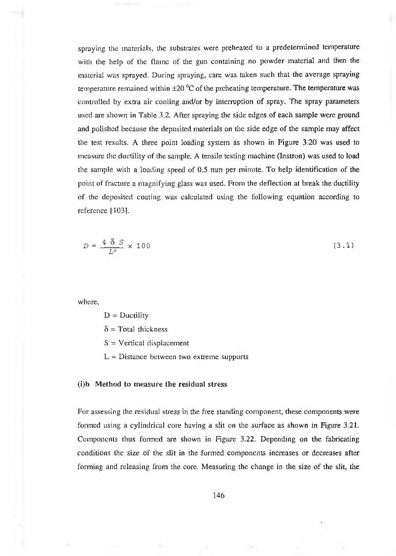
spraying the materials, the substrates were preheated to a predetermined temperature
with the help of the flame of the gun containing no powder material and then the
material was sprayed. During spraying, care was taken such that the average spraying
temperature remained within ±20 °C of the preheating temperature. The temperature was
controlled by extra air cooling and/or by interruption of spray. The spray parameters
used are shown in Table 3.2. After spraying the side edges of each sample were ground
and polished because the deposited materials on the side edge of the sample may affect
the test results. A three point loading system as shown in Figure 3.20 was used to
measure the ductility of the sample. A tensile testing machine (Instron) was used to load
the sample with a loading speed of 0.5 mm per minute. To help identification of the
point of fracture a magnifying glass was used. From the deflection at break the ductility
of the deposited coating was calculated using the following equation according to
reference [103].
D = 4 5 S x 1 0 0 ( 3 . 1 )L ‘L
where,
D = Ductility
5 = Total thickness
S = Vertical displacement
L = Distance between two extreme supports
(i)b Method to measure the residual stress
For assessing the residual stress in the free standing component, these components were
formed using a cylindrical core having a slit on the surface as shown in Figure 3.21.
Components thus formed are shown in Figure 3.22. Depending on the fabricating
conditions the size of the slit in the formed components increases or decreases after
forming and releasing from the core. Measuring the change in the size of the slit, the
146
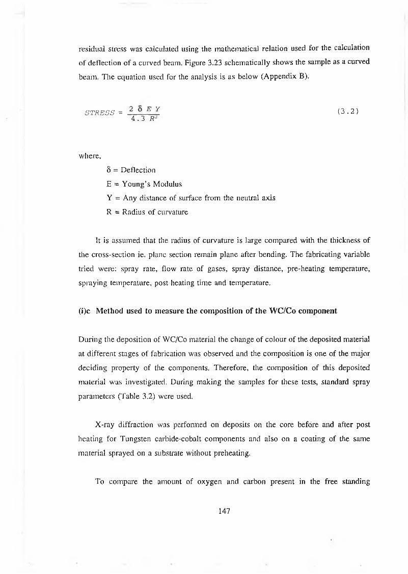
residual stress was calculated using the mathematical relation used for the calculation
of deflection of a curved beam. Figure 3.23 schematically shows the sample as a curved
beam. The equation used for the analysis is as below (Appendix B).
STRESS = 2 _ E 7 ( 3 . 2 )4 . 3 R-
where,
8 = Deflection
E = Young’s Modulus
Y = Any distance of surface from the neutral axis
R = Radius of curvature
It is assumed that the radius of curvature is large compared with the thickness of
the cross-section ie. plane section remain plane after bending. The fabricating variable
tried were: spray rate, flow rate of gases, spray distance, pre-heating temperature,
spraying temperature, post heating time and temperature.
(i)c Method used to measure the composition of the WC/Co component
During the deposition of WC/Co material the change of colour of the deposited material
at different stages of fabrication was observed and the composition is one of the major
deciding property of the components. Therefore, the composition of this deposited
material was investigated. During making the samples for these tests, standard spray
parameters (Table 3.2) were used.
X-ray diffraction was performed on deposits on the core before and after post
heating for Tungsten carbide-cobalt components and also on a coating of the same
material sprayed on a substrate without preheating.
To compare the amount of oxygen and carbon present in the free standing
147
component and in the deposited coating, relative quantitative measurement were done.
The carbon and oxygen contents of the cleaned free-standing object and coating
deposited from WC/Co materials were analyzed by using wave length spectrometry. At
the same time to ascertain the variation of the elements along the cross-section of the
free standing component, relative quantitative measurements for different element
present, were done. Three locations were chosen for each component such that it covers
the total cross-sectional area. A Joel 8600 ’Superprobe’ SEM fitted with both the wave
length and energy dispersive analysis facilities was used to measure these quantities.
Principle o f SEM
The process used in SEM principally involves the generation of a primary beam of
electrons from an emission source which are then accelerated by a voltage of between
1-30 keV and directed down the centre of an election optical column consisting of two
or three magnetic lenses. These lenses cause a fine electron beam to be focused onto the
specimen surface. Scanning coils made to pass through the corresponding deflection
coils of a cathode ray tube so as to produce a similar but larger raster on the viewing
screen in a synchronous fashion.
Various phenomena occur at the surface of the sample including secondary electron
emission which in this case is used to form the image. There is one-to-one
correspondence between the number of secondary electrons collected from any particular
point on the specimen surface and the brightness of the analogous point on the cathode
ray tube screen. Consequently, an image of the surface is progressively built up on the
screen. Some of the electrons are inelastically scattered by the K, L, or N electrons shell
in the atom losing their energy in the form of x-rays and it is these which are detected
in energy dispersive x-ray analysis (EDAX). The energy lost is characteristic of the
scattering atom and intensity is used to establish the concentration of the element.
EDAX utilises a solid state detector to measure the x-ray radiation which is more
sensitive to elements of higher atomic mass. ED analyzers have been used to detect
elements above fluorine (atomic number 9). Problems are encountered when elements
whose x-ray energies are too close together coexist in a sample. Other factors limiting
148

light element detection are window thickness and electronic noise.
Wavelength diffractometers (WD) are also available as an accessory on some
SEMs. In the WD method, a crystal of known spacing d separates x-rays according to
Bragg’s law, nA, = 2dsin0 so that at a diffraction angle of 0 (collection angle of 20), x-
rays of specific wavelengths are detected. To cover the whole range, the diffractometers
are usually equipped with many crystals.
(ii) MEASUREMENT OF PROPERTIES OF MULTI-LAYERED COMPONENT
The properties, measured for multi-layered component were toughness, adhesion between
the layers and penetration of the sprayed material into softer substrates. The method of
measuring these properties are described below.
(ii)a Test for adhesion between different layers
The multi-layer components comprises the layers of 1) WC/Co and aluminium, 2)
Nickel chromium alloy and aluminium and 3) WC/Co and nickel chromium alloy.
For adhesion bond strength, tests were carried out according to ASTM C633-79.
The shape and dimensions of the sample are shown in Figure 3.2. Since the density of
the coating deposited by HVOF thermal spraying process is high, lower thickness than
the standard was used to determine the bond strength. The range of coating thickness
used was 200 to 300 pm as measured by an optical microscope at different locations of
a sample. To measure the bond strength of the sprayed material on aluminium substrate,
samples with aluminium substrate were made for bond strength test. The test sample was
composed of two parts, one was coated and another was uncoated. The coated sample
was made after spraying on one end surface of the cylindrical surface. Materials used
for coating were WC/Co and nickel chromium alloy. Standard spray parameters (Table
3.2) were used to deposit these material. To investigate the effect of roughness on bond
strength, some of the sample surfaces were roughened and some others were polished
before spraying material on sample surface. The uncoated part was roughened to ensure
149
proper bonding with adhesive. Two cylindrical parts of the sample were attached
together by adhesive and the method used for this was described in section 3.5.6. After
bonding and cooling the excess adhesive was polished off. A Instron tensile testing
machine was used to pull the sample at a cross head speed 0.1 mm per minute.
To investigate the bond strength between different layers of multi-layer component,
tensile testing specimens were also made by spraying WC/Co and nickel chromium alloy
materials. The end surface of the cylindrical sample made from stainless steel was
coated with different layers of the sprayed materials. During spraying these materials
standard spray conditions (Table 3.2) were used. The initial layer on the sample
substrate was sprayed by WC/Co material and the second layer was sprayed from nickel
chromium alloy material. These test samples were fixed by adhesive with another
cylindrical specimen as stated before and pull tests were done in similar way as before.
(ii)b Determination of depth of penetration of sprayed particle into aluminium
substrate at different substrate temperature
Some of the polished samples were used to determine the depth of penetration of the
sprayed particles. These samples are preheated at a set preheating temperature and then
the powder material was sprayed. An optical microscope was used to measure the depth
of penetration of the spray particle by observing the cross section of the sample.
(ii)c Measurement of toughness of the component
To compare the qualitative toughness of the component formed by WC/Co material and
by multi-layer, these components were dropped from different heights on the floor of
the laboratory. The component which did not fracture was dropped thrice.
To measure the toughness of the sprayed material of different powders, the
toughness was measured on the sample made from these materials by tension test. It is
known that the area under the stress strain curve for a material is the toughness of that
material. Therefore specimens for tensile test were made from the sprayed material. The
150
shape and size of the specimen are shown in Figure 3.24. This testing of specimen
comprised of aluminium substrate of the same shape and size made from aluminium
sheet of thickness 1.90 mm. These specimens were machined and positioned on a vice
with a support of steel plate at the back. Thermocouples were positioned at the back of
the aluminium substrate. Different material were sprayed on different aluminium
substrate after preheating the substrate to 450 °C temperature. Material used to spray on
the substrate were 1) WC/Co, 2) nickel chromium alloy and 3) a mixed material, made
from WC/Co and 40 % by volume nickel chromium alloy. The thickness of the sprayed
material on aluminium substrate was varied from 0.3-1.8 mm for nickel chromium alloy
material and 0.3-0.5 mm for other two materials. During spraying the WC/Co and nickel
chromium alloy material, standard spray parameters (Table 3.2) were used. The mixed
materials were sprayed using the spray parameters as of WC/Co material. After spraying,
the samples were cooled in atmosphere. Aluminium layer on the gauge length area of
the specimen were ground by filing, leaving only with sprayed materials. The shape of
the specimen thus formed is shown in Figure 3.24. To avoid a bending effect during
tensile loading and to facilitate gripping during loading, a small piece of aluminium of
1.9 mm thick was fixed on the gripping area of the specimen such that the sprayed layer
remains between the aluminium layers.
The tension test were preformed on a tensile testing machine (Instron) and with
the help of a chart recorder the load-deflection curve was obtained. The cross-head
speed maintained was 0.5 mm per minute and the load range was varied for different
thickness of the sample, to obtain the accuracy of the measured load. From these
measured load- deflection curves the stress-strain curves were plotted. The areas under
the curves were calculated by counting the squares of the graph under the curves.
151
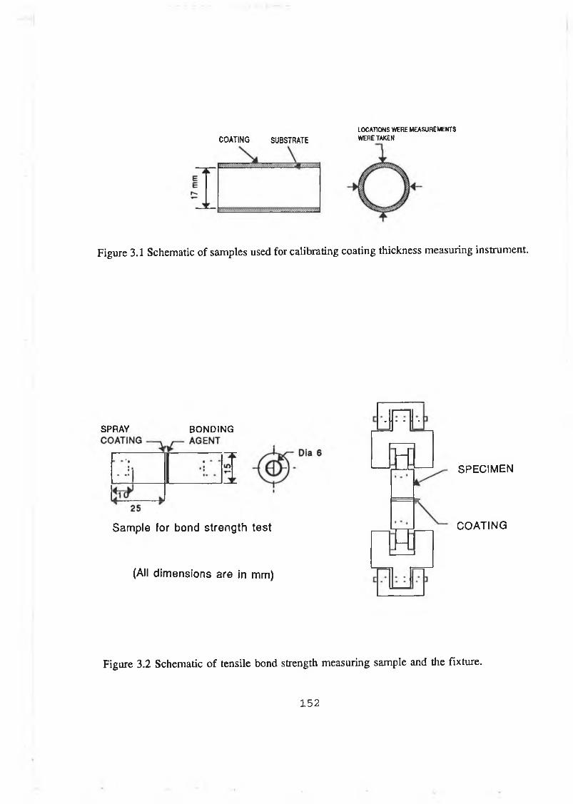
LOCATIONS WERE MEASUREMENTS COATING SUBSTRATE WERE TAKEN
Figure 3.1 Schematic of samples used for calibrating coating thickness measuring instrument.
SPRAY BONDING
Sample for bond strength test
(All dim ensions are in mm)
SPECIM EN
COATING
Figure 3.2 Schematic o f tensile bond strength measuring sample and the fixture.
1 5 2
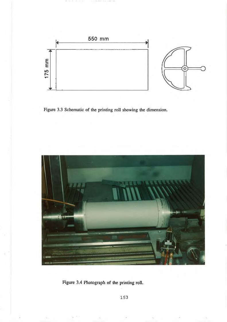
175
mm
550 mm
Figure 3.4 Photograph o f the printing ro ll.
1 5 3
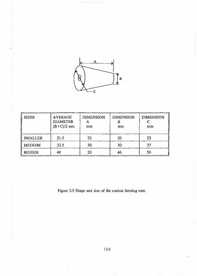
SIZES AVERAGE DIMENSION DIMENSION DIMENSIONDIAMETER A B C(B+C)/2 mm mm mm mm
SMALLER 21.5 25 20 23
MEDIUM 33.5 30 30 37
BIGGER 48 20 46 50
Figure 3.5 Shape and size of the conical forming core.
1 5 4

TEM
PERA
TURE
OF
TH
E FO
RMIN
G CO
RE
IN°C
8 0 0
TIME IN MINUTE
Figure 3.6 Cooling rate of the forming core placed in ambient atmosphere.
1 5 5
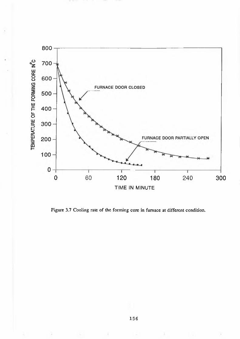
TEM
PERA
TURE
OF
TH
E FO
RMIN
G CO
RE
IN°C
8 0 0
0 60 120 180 TIME IN MINUTE
240
Figure 3.7 Cooling rate of the forming core in furnace at different condition.
300
156
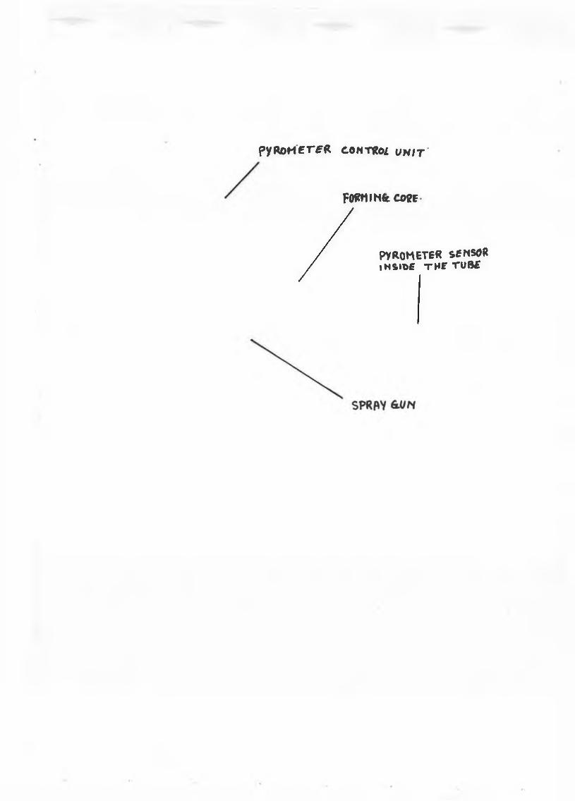
p y R O M E T f R CONTRòi U N I T
FOffMIHét COŸB
/PYROMETER SENSOR iNS»T>£ THF Tü8£
I
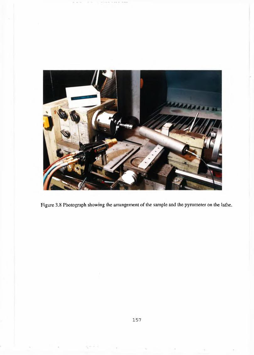
Figure 3.8 Photograph showing the arrangement of the sample and the pyrometer on the lathe.
1 5 7

High Under Size X
High Under S ize Z
High Under Size X
High Under Size X
High Under Size Z
High Under Size X
Span1.63
564 100 254 100 114 100 51.3 96.5 23.1 70.6 10.4 20.4 D[4,3]524 100 236 100 106 100 47.7 95.5 21.4 65.9 9.64 16.9 19.94pm488 100 219 100 98.6 100 44.4 94.4 19.9 61.1 8.97 13.8454 100 204 100 91.7 99.9 41.2 93.1 18.5 56.3 8.34 11.1 D[3,2]422 100 190 100 85.3 99.9 38.4 91.7 17.2 51.7 7.76 8.9 13.53pm392 100 176 100 79.3 99.7 35.7 90.2 16.0 47.2 7.21 7.0365 100 164 100 73.8 99.5 33.2 88.3 14.9 42.6 6.71 5.4 D[v,0.9]339 100 153 100 68.6 99.1 30.8 85.9 13.9 38.0 6.24 4.1 35.39pm315 100 142 100 63.8 98.7 28.7 82.9 12.9 33.3 5.80 3.1293 100 132 100 59.3 98.1 26.7 79.2 12.0 28.7 D[v,0.1]273 100 123 100 55.2 97.3 24.8 75.1 11.2 24.3 8.06pm
Source ¡Sample Beam length = 14.3 mm Mode' indpLog. D iff. = 3.790 Otv.O.5]
Focal length = 300 mm Obscuration = 0.7069 Volume Cone. = ( .0387* 16.78pmPresentation = p il Volume d istribu tion Sp.S.A 0.4434 m’ /cc.
Particle size (un).
Figure 3.9 Particle size distribution of tungsten carbide cobalt material powder.
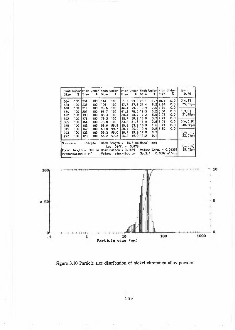
High Under High Under High Under High Under High Under High Under SpanSize X Size * Size X Size X Size X Size X 0.76
564 100 254 100 114 100 51.3 93.6 23.1 11.7 10.4 0.0 D[4,3]524 100 236 100 106 100 47.7 87.8 21.4 9.2 9.64 0.0 35. 51pm468 100 219 100 98.6 100 44.4 79.9 19.9 7.6 8.97 0.0454 100 204 100 91.7 100 41.2 70.6 18.5 6.2 8.34 0.0 D[3.2]422 100 190 100 85.3 100 38.4 60.7 17.2 5.0 7.76 0.0 31 .SSjjffl392 100 176 100 79.3 100 35.7 50.9 16.0 3.7 7.21 0.0365 100 164 100 73.8 100 33.2 41.6 14.9 2.6 6.71 0.0 D[v,0.9]339 100 153 100 68.6 99.9 30.8 33.2 13.9 1.6 6.24 0.0 48.88nm315 100 142 100 63.8 99.7 28.7 25.9 12.9 0.8 5.80 0.0293 100 132 100 59.3 99.0 26.7 19.9 12.0 0.3 D[v ,0 .1]273 100 123 100 55.2 97.3 24.8 15.2 11.2 0.1 22. Olpjn
Source = :Sample Beam length = 14.3 mm Model indpLog. D iff. = 3.678 D[v,0.5]
Focal length = 300 mm Obscuration = 0.1659 Volume Cone. = 0.0135% 35.42pmPresentation = pi 1 Volume d istr ib u tion Sp.S.A 0.1882 m /cc.
Particle size (un).
Figure 3.10 Particle size distribution o f nickel chromium alloy powder.
1 5 9

1G0
X 5 0
0L-.1
High Under High Under High Under High Under High Under High Under SpanSize % Size X Size X Size X Size % Size % 0.37
564 100 254 100 114 100 51.3 100 23.1 37.3 10.4 0.0 D[4,3]524 100 236 100 106 100 47.7 100 21.4 22.0 9.64 0.0 24.49pm488 100 219 100 98.6 100 44.4 99.9 19.9 9.9 8.97 0.0454 100 204 100 91.7 100 41.2 99.8 18.5 2.4 8.34 0.0 D[3,2]422 100 190 100 85.3 100 38.4 99.8 17.2 0.1 7.76 0.0 23.95pm392 100 176 100 79.3 100 35.7 99.8 16.0 0.0 7.21 0.0365 100 164 100 73.8 100 33.2 99.4 14.9 0.0 6.71 0.0 D[v,0.9]339 100 153 100 68.6 100 30.8 96.8 13.9 0.0 6.24 0.0 29. Oljj/n315 100 142 100 63.8 100 28.7 88.0 12.9 0.0 5.80 0.0293 100 132 100 59.3 100 26.7 72.6 12.0 0.0 D[v,0.1 ]273 100 123 100 55.2 100 24.8 54.6 11.2 0.0 19.96pm
Source s :Sample Beam length = 14.3 mm Model indpLog. D iff. = 4.376 D[v, 0.5]
Focal length = 300 mm Obscuration = 0.0307 Volume Cone. = 0.0017% 24.34pmPresentation = pi 1 Volume d istribu tion Sp.S.A 0.2505 m*/cc.
1000Particle size (un).
Figure 3.11 Particle size distribution of stainless steel material powder.
160
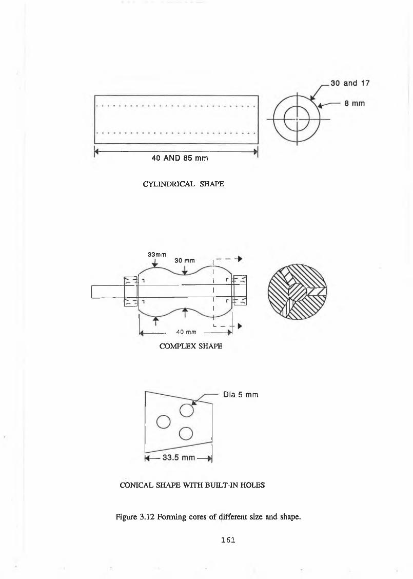
40 AND 85 mm
CYLINDRICAL SHAPE
40 mm
COMPLEX SHAPE
33mm
Dia 5 mm
CONICAL SHAPE WITH BUILT-IN HOLES
Figure 3.12 Forming cores o f different size and shape.
1 6 1

Figure 3.13 Schematic of the cross section of the tube holding pyrometer sensor.
ACTUAL TEMPERATURE MEASURED BY THERMOCOUPLE fC )
Figure 3.14 Calibration curve fo r pyrometer.
1 6 2
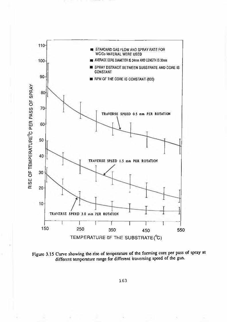
RISE
OF
TE
MP
ERA
TUR
E°C
PE
R PA
SS
OF
SP
RA
Y
■ STANDARD GAS FLOW AND SPRAY RATE FOR WC/Co MATERIAL WERE USED
■ AVERAGE CORE DIAMETER IS 34mm AND LENGTH IS 30mm
■ SPRAY DISTANCE BETWEEN SUBSTRATE AND CORE IS CONSTANT
■ RPM OF THE CORE IS CONSTANT (800)
TRAVERSE SPEED 0.5 mm PER ROTATION
TRAVERSE SPEED 1.5 mm PER ROTATION
TRAVERSE SPEED 3.0 mm PER ROTATION
n i i i 1-------1------- 1------- ,150 250 350 450 550
TEM PER A TU R E OF THE SU B S TR A TE(°C )
Figure 3.15 Curve showing the rise of temperature o f the forming core per pass of spray at different temperature range for different traversing speed of the gun.
1 6 3
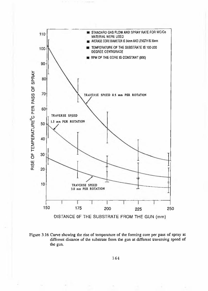
RISE
OF
TE
MPE
RAT
UR
E C
PER
PASS
OF
S
PR
AY
1 1 0 -
100 -
STANDARD GAS FLOW AND SPRAY RATE FOR WC/Co
MATERIAL WERE USEDAVERAGE CORE DIAMETER IS 34mm AND LENGTH IS 30mm
TEMPERATURE OF THE SUBSTRATE IS 100-200
DEGREE CENTIGRADE
RPM OF THE CORE IS CONSTANT (800)
TRAVERSE SPEED 0.5 mm PER ROTATION
150 175 200 225 250
DISTANCE OF THE SUBSTRATE FROM THE GUN (mm)
Figure 3.16 Curve showing the rise of temperature of the forming core per pass of spray at different distance of the substrate from the gun at different traversing speed of the gun.
1 6 4

RISE
OF
TE
MPE
RAT
UR
E C
PER
PASS
OF
S
PR
AY
5 0 -
STANDARD GAS FLOW AND SPRAY RATE FOR WC/Co MATERIAL WERE USED
GUN TRAVERSE SPEED IS 3 mm PER ROTATION
GUN DISTANCE FROM THE SUBSTRATE IS 200 mm
RPM OF THE CORE IS CONSTANT (800)
LENGTH OF THE CORE IS CONSTANT (30 mm)
4 0 -
30
20
1 0 -
1-------1-------1 r n20 30 40 50
AVERAGE DIAMETER OF THE CORE (mm)
Figure 3.17 Curve showing the rise of temperature of the forming core per pass of spray for different size (average diameter) at different range of temperature.
1 6 5
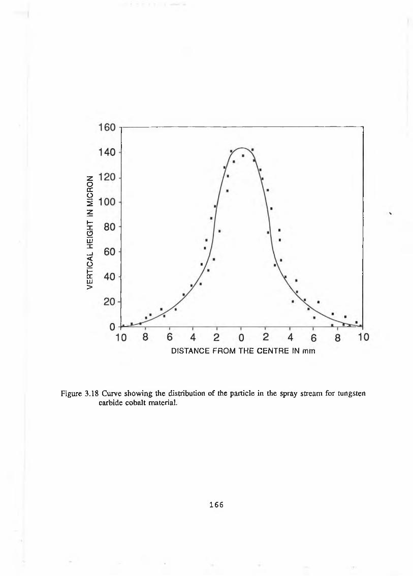
VERT
ICAL
HE
IGHT
IN
MIC
RO
N
DISTANCE FROM THE CENTRE IN mm
Figure 3.18 Curve showing the distribution of the particle in the spray stream for tungsten carbide cobalt material.
1 6 6
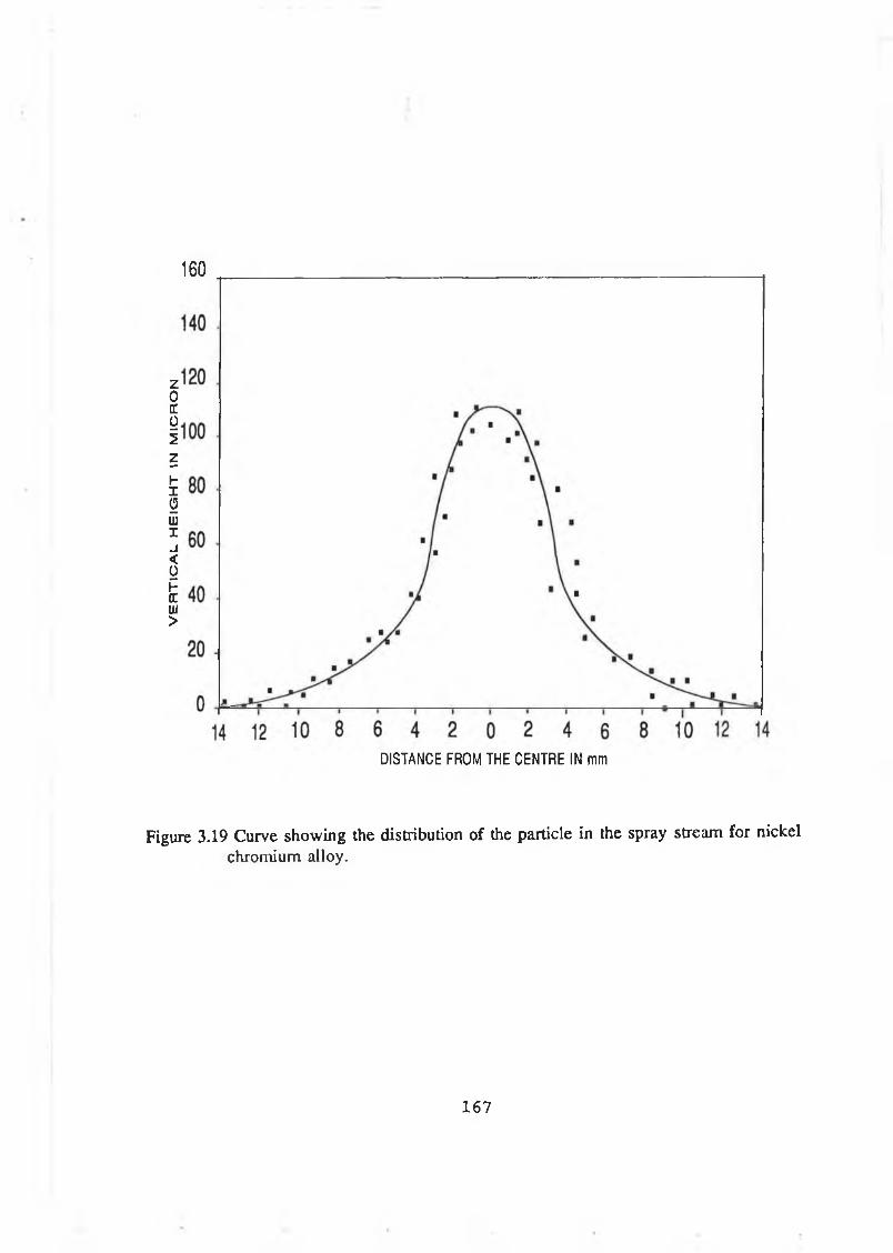
VE
RT
ICA
L
HE
IGH
T
IN M
ICR
ON
1 6 0
DISTANCE FROM THE CENTRE IN mm
Figure 3.19 Curve sh o w in g the distribution o f the particle in the spray stream for n ickelchromium alloy.
1 6 7
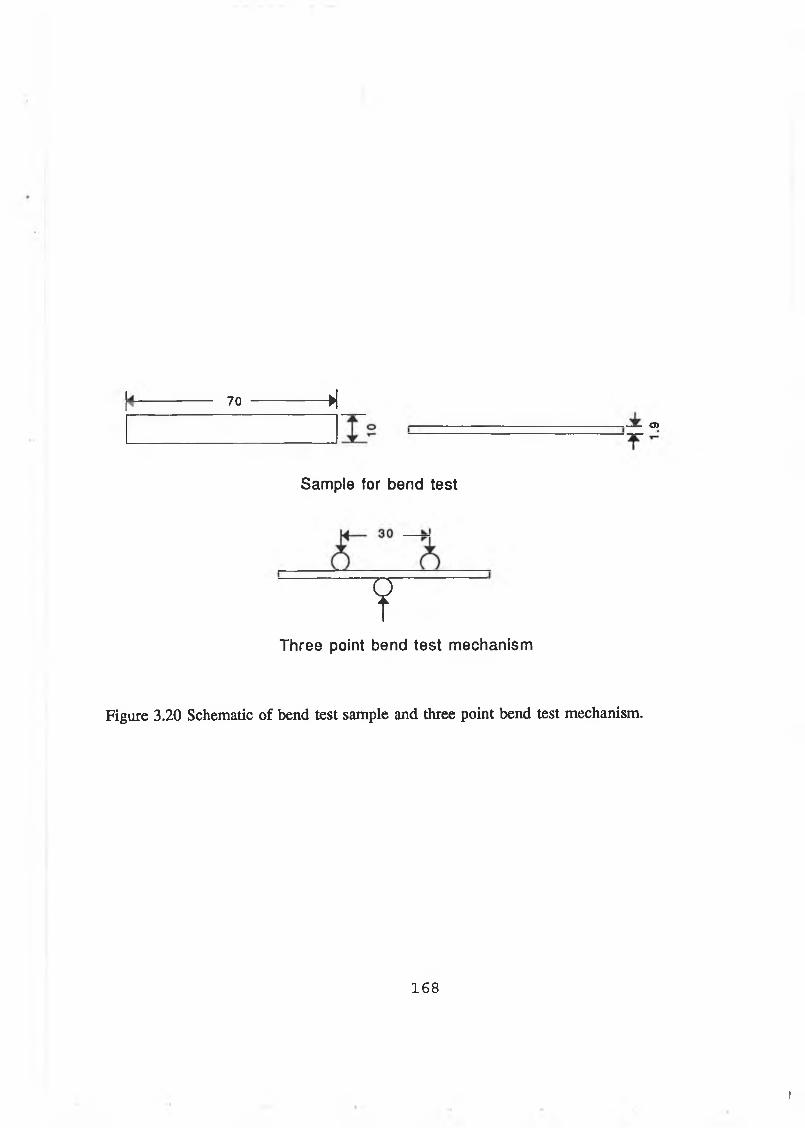
70 ->1
Sam ple for bend test
YT h re e point bend test m echanism
O)
Figure 3 .20 Schem atic o f bend test sam ple and three point bend test m echanism .
1 6 8
I
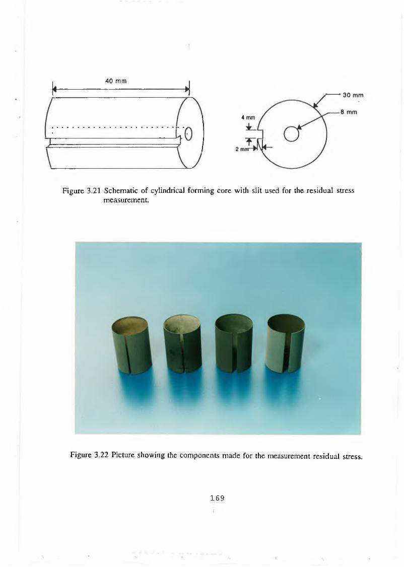
k 4 0 m m A
Figure 3.21 Schematic of cylindrical forming core with slit used for the residual stress measurement.
Figure 3.22 Picture showing the components made for the measurement residual stress.
169
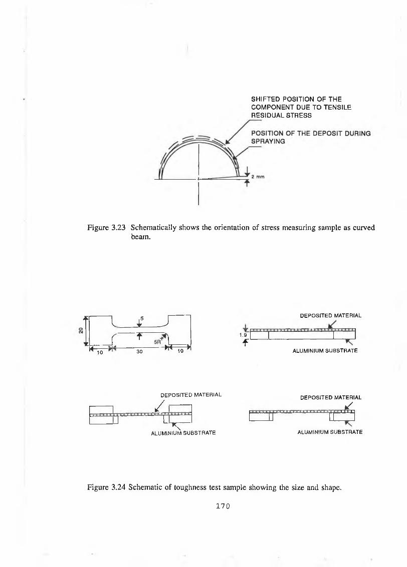
SHIFTED POSITION OF THE COMPONENT DUE TO TENSILE RESIDUAL STRESS
Figure 3.23 Schematically shows the orientation of stress measuring sample as curved beam.
AI 4? J
V rt
M 10 ~ 30 -------- M - ^ l1.9
f
D E P O S IT E D M A T E R IA L
A LU M IN IU M S U B S T R A T E
D E P O S IT E D M A T E R IA L
/
■ * TA LU M IN IU M S U B S T R A T E
D E P O S IT E D M A T E R IA L
jL
A LU M IN IU M S U B S T R A T E
Figure 3.24 Schematic of toughness test sample showing the size and shape.
170

Table 3.1 Lighting pressure and flow rate o f gases.
Types ofgases
Pressure(Bar)
Flow meter reading
Flow rate (SLPM)
Oxygen 10.3 40-44 252-278
Propylene 6.9 35-40 67-77
Gun air 5.2 60-65 415-449
Carrier gas (Nitrogen)
8.6 55 14
Table 3.2 Spray parameters used by HVOF thermal spraying process for depositing different types of materials.
Types of material
Stainless steel Nickel chromium alloy
WC/Co
Gun parameters
Siphon plug 2 2 2Shell A A AGun Insert 3 3 Jetted 2Injector 3 3 2Air cap 2 2 3
Spray parameters
Oxygen pressure(Bar) 10.3 10.3 10.3Oxygen Flow (SLPM*) 265.0 278.0 265.0Propylene pressure (Bar) 6.9 6.9 6.9; Propylene Flow (SLPM) 71.0 74.0 73.0Air pressure (Bar) 5.2 5.2 5.2Air Flow (SLPM) 318.0 338.0 325.0, Spray Distance (mm) 200.0 150.0 200.0Spray rate (gm/min) 45.0 38.0 38.0
(*SLPM) = Standard litre per minute)
1 7 1
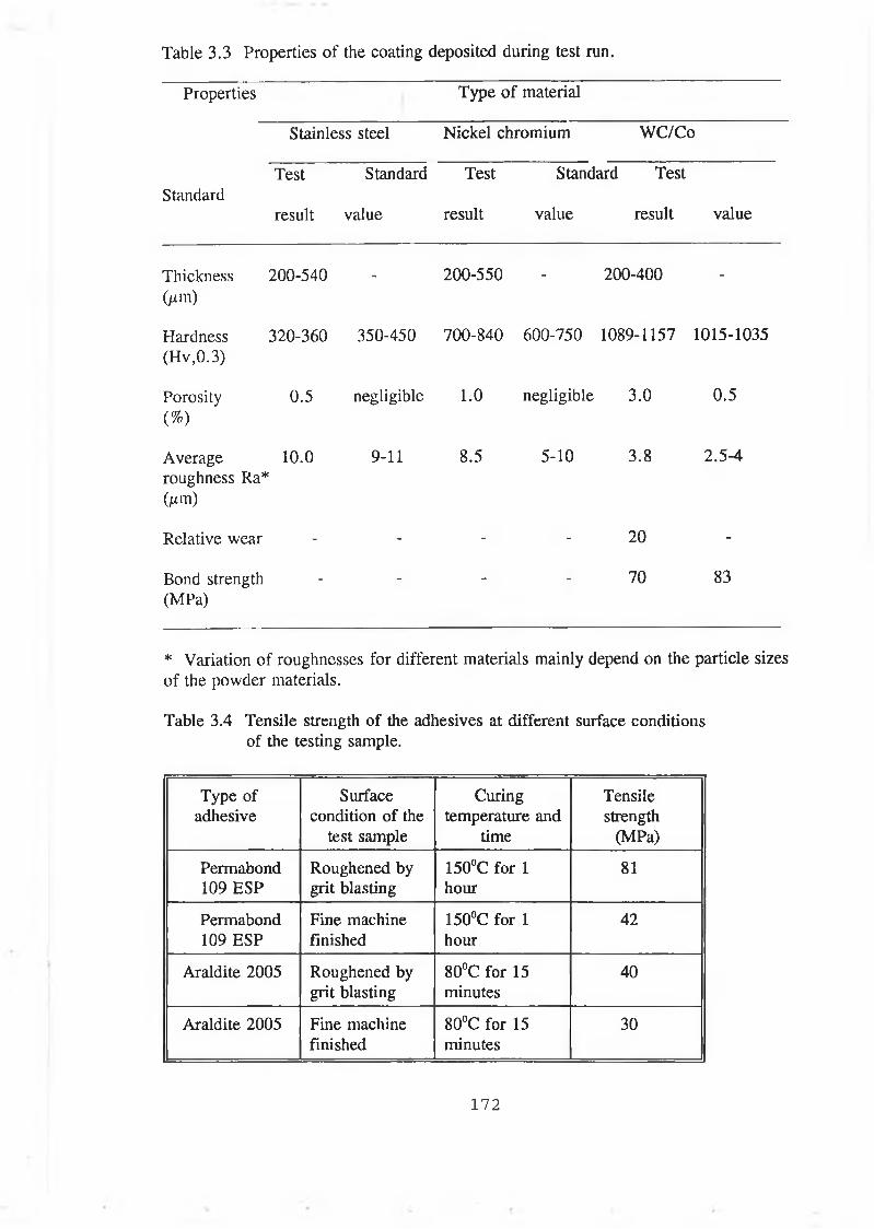
Table 3.3 Properties o f the coating deposited during test run.
Properties Type of material
Stainless steel Nickel chromium WC/Co
StandardTest
result
Standard
value
Test
result
Standard Test
value result value
Thickness (ji m)
200-540 - 200-550 - 200-400 -
Hardness(Hv,0.3)
320-360 350-450 700-840 600-750 1089-1157 1015-1035
Porosity(%)
0.5 negligible 1.0 negligible 3.0 0.5
Average 10.0 roughness Ra*Om)
9-11 8.5 5-10 3.8 2.5-4
Relative wear - - - - 20 -
Bond strength (MPa)
- - “ - 70 83
* Variation of roughnesses for different materials mainly depend on the particle sizesof the powder materials.
Table 3.4 Tensile strength of the adhesives at different surface conditions of the testing sample.
Type of adhesive
Surface condition of the
test sample
Curing temperature and
time
Tensilestrength
(MPa)
Permabond 109 ESP
Roughened by grit blasting
150°C for 1 hour
81
Permabond 109 ESP
Fine machine finished
150°C for 1 hour
42
Araldite 2005 Roughened by grit blasting
80°C for 15 minutes
40
Araldite 2005 Fine machine finished
80°C for 15 minutes
30
172
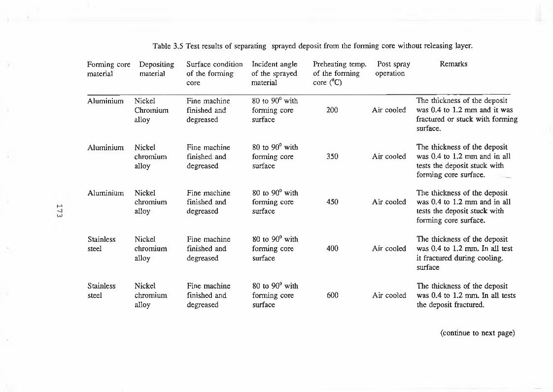
Forming core material
Aluminium
Aluminium
Aluminium
Stainlesssteel
Stainlesssteel
Depositing Surface condition Incident angle Preheating temp. Post spray Remarksmaterial of the forming of the sprayed of the forming operation
core material core (°C)
Table 3.5 Test results o f separating sprayed deposit from the forming core without releasing layer.
NickelChromiumalloy
Fine machine finished and degreased
80 to 90° with forming core surface
200The thickness of the deposit
Air cooled was 0.4 to 1.2 mm and it was fractured or stuck with forming surface.
Nickelchromiumalloy
Nickelchromiumalloy
Nickelchromiumalloy
Fine machine finished and degreased
Fine machine finished and degreased
Fine machine finished and degreased
80 to 90° with forming core surface
80 to 90° with forming core surface
80 to 90° with forming core surface
350
450
400
The thickness of the deposit Air cooled was 0.4 to 1.2 mm and in all
tests the deposit stuck with forming core surface.
The thickness of the deposit Air cooled was 0.4 to 1.2 mm and in all
tests the deposit stuck with forming core surface.
The thickness of the deposit Air cooled was 0.4 to 1.2 mm. In all test
it fractured during cooling, surface
Nickelchromiumalloy
Fine machine finished and degreased
80 to 90° with forming core surface
600The thickness of the deposit
Air cooled was 0.4 to 1.2 mm. In all tests the deposit fractured.
(continue to next page)
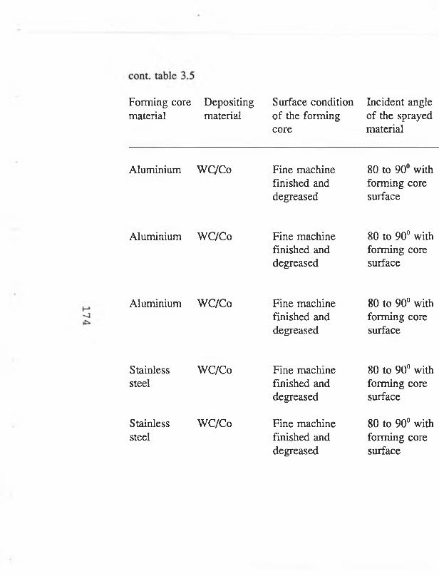
Forming core Depositing Surface condition Incident anglematerial material o f the form ing o f the sprayed
core material
Aluminium WC/Co
Aluminium WC/Co
Aluminium WC/Co
Stainless WC/Costeel
Stainless WC/Costeel
Fine machine finished and degreased
Fine machine finished and degreased
Fine machine finished and degreased
Fine machine finished and degreased
Fine machine finished and degreased
80 to 90° with forming core surface
80 to 90° with forming core surface
80 to 90° with forming core surface
80 to 90° with forming core surface
80 to 90° with forming core surface
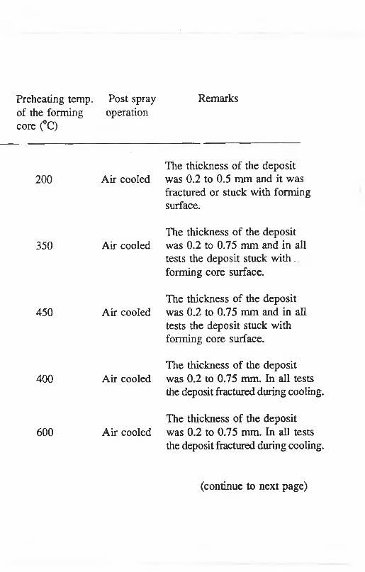
Preheating temp, of the forming core (°C)
200
350
450
400
600
Post spray Remarksoperation
The thickness of the deposit Air cooled was 0.2 to 0.5 mm and it was
fractured or stuck with forming surface.
The thickness of the deposit Air cooled was 0.2 to 0.75 mm and in all
tests the deposit stuck with ... forming core surface.
The thickness of the deposit Air cooled was 0.2 to 0.75 mm and in all
tests the deposit stuck with forming core surface.
The thickness of the deposit Air cooled was 0.2 to 0.75 mm. In all tests
the deposit fractured during cooling.
The thickness of the deposit Air cooled was 0.2 to 0.75 mm. In all tests
the deposit fractured during cooling.
(continue to next page)
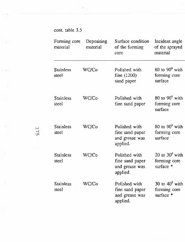
cont. table 3.5
Forming core material
Stainlesssteel
Stainlesssteel
Stainlesssteel
Stainlesssteel
Stainlesssteel
Depositing Surface condition Incident anglematerial o f the form ing o f the sprayed
core material
WC/Co Polished with 80 to 90° withfine (1200) forming coresand paper surface
WC/Co Polished with 80 to 90° withfine sand paper forming core
surface
WC/Co
WC/Co
WC/Co
Polished with fine sand paper and grease was applied.
Polished with fine sand paper and grease was applied.
Polished with fine sand paper and grease was applied.
80 to 90° with forming core surface
20 to 30° with forming core surface *
30 to 40° with forming core surface *
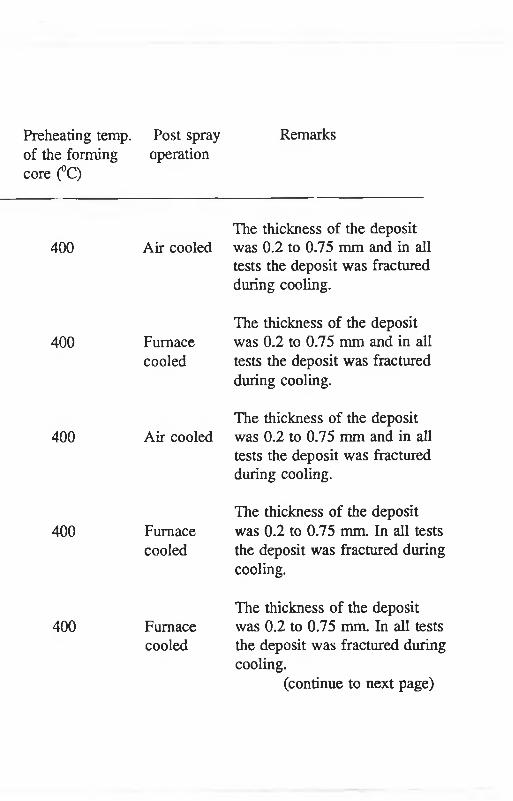
Preheating temp. Post spray Remarksof the forming operation core (°C)
400 Air cooled
400 Furnacecooled
400 Air cooled
400 Furnacecooled
400 Furnacecooled
The thickness of the deposit was 0.2 to 0.75 mm and in all tests the deposit was fractured during cooling.
The thickness of the deposit was 0.2 to 0.75 mm and in all tests the deposit was fractured during cooling.
The thickness of the deposit was 0.2 to 0.75 mm and in all tests the deposit was fractured during cooling.
The thickness of the deposit was 0.2 to 0.75 mm. In all tests the deposit was fractured during cooling.
The thickness of the deposit was 0.2 to 0.75 mm. In all tests the deposit was fractured during cooling.
(continue to next page)
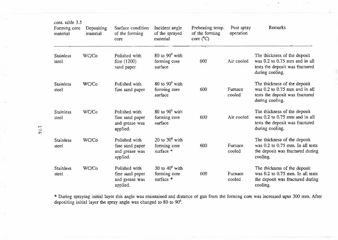
17
6
cont. table 3.5 Forming core material
Stainlesssteel
Stainlesssteel
Stainlesssteel
Stainlesssteel
Stainlesssteel
Depositing Surface condition Incident angle Preheating temp. Post spray Remarksmaterial o f the form ing o f the sprayed o f the form ing operation
core material core (°C)
WC/Co
WC/Co
WC/Co
WC/Co
WC/Co
Polished with fine (1200) sand paper
Polished with fine sand paper
Polished with fine sand paper and grease was applied.
Polished with fine sand paper and grease was applied.
Polished with fine sand paper and grease was applied.
80 to 90° with forming core surface
80 to 90° with forming core surface
80 to 90° with forming core surface
20 to 30° with forming core surface *
30 to 40° with forming core surface *
600
600
600
600
600
The thickness of the deposit Air cooled was 0.2 to 0.75 mm and in all
tests the deposit was fractured during cooling.
Furnacecooled
Air cooled
The thickness of the deposit was 0.2 to 0.75 mm and in all tests the deposit was fractured during cooling.
The thickness of the deposit was 0.2 to 0.75 mm and in all tests the deposit was fractured during cooling.
The thickness of the deposit Furnace was 0.2 to 0.75 mm. In all testscooled the deposit was fractured during
cooling.
The thickness of the deposit Furnace was 0.2 to 0.75 mm. In all testscooled the deposit was fractured during
cooling.
* During spraying initial layer this angle was maintained and distance of gun from the forming core was increased upto 300 mm. After depositing initial layer the spray angle was changed to 80 to 90°.
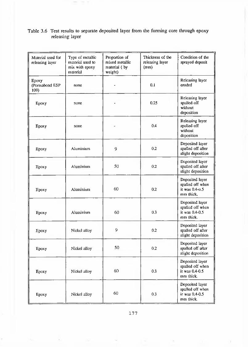
Table 3.6 Test results to separate deposited layer from the forming core through epoxy releasing layer
Material used for releasing layer
Type of metallic material used to mix with epoxy material
Proportion of mixed metallic material ( by weight)
Thickness of the releasing layer (mm)
Condition of the sprayed deposit
Epoxy(Permabond ESP 109)
none - 0.1Releasing layer eroded
Epoxy none - 0.25Releasing layer spalled off without deposition
Epoxy none - 0.4Releasing layer spalled off without deposition
Epoxy Aluminium 9 0.2Deposited layer spalled off after slight deposition
Epoxy Aluminium 50 0.2Deposited layer spalled off after slight deposition
Epoxy Aluminium 60 0.2
Deposited layer spalled off when it was 0.4-O.5 mm thick.
Epoxy Aluminium 60 0.3
Deposited layer spalled off when it was 0.4-0.5 mm thick.
Epoxy Nickel alloy 9 0.2Deposited layer spalled off after slight deposition
Epoxy Nickel alloy 50 0.2Deposited layer spalled off after slight deposition
Epoxy Nickel alloy 60 0.3
Deposited layer spalled off when it was 0.4-0.5 mm thick.
Epoxy Nickel alloy 60 0.3
Deposited layer spalled off when ir was 0.4-0.5 mm thick.
1 7 7
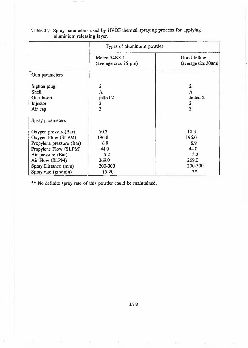
Table 3.7 Spray parameters used by HVOF thermal spraying process for applying aluminium releasing layer.
Types of aluminium powder
Metco 54NS-1 (average size 75 pm)
Good fellow (average size 50pm)
Gun parameters
Siphon plug 2 2Shell A AGun Insert jetted 2 Jetted 2Injector 2 2Air cap 3 3
Spray parameters
Oxygen pressure(Bar) 10.3 10.3Oxygen Flow (SLPM) 196.0 196.0Propylene pressure (Bar) 6.9 6.9Propylene Flow (SLPM) 44.0 44.0Air pressure (Bar) 5.2 5.2Air Flow (SLPM) 269.0 269.0Spray Distance (mm) 200-300 200-300Spray rate (gm/min) 15-20 **
* * No definite spray rate of this powder could be maintained.
1 7 8

Table 3.8 Composition of powder materials used for fabricating free standing components.
Type of material Ingridients of the material
Tungsten Carbide/Cobalt (WC/Co)
Tungsten Carbide - 88.5 % Cobalt - 11.5 %
Nickel chromium alloy Nickel - 72.0 %
Chromium - 17.o %
Silicon - 4.0 %
Boron - 3.5 % Iron - 1.0 % Cobalt - 1.0 %
Stainless steel * (similar to type 316 stainless steel)
Manganese, Silicon, Molybdenum, Iron, Nickel, Chromium.
* The percentage of the ingredients are not known.
1 7 9
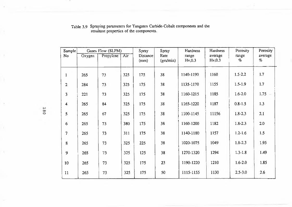
Table 3.9 Spraying parameters for Tungsten Carbide-Cobalt components and the resultant properties of the components.
SampleNo
Gases Flow (SLPM) SprayDistance(mm)
SprayRate(gm/min)
HardnessrangeHv,0.3
HardnessaverageHv,0.3
Porosityrange
%
Porosityaverage%
Oxygen Propylene Air
1 265 73 325 175 38 1140-1190 1160 1.5-2.2 1.7
2 284 73 325 175 38 1135-1170 1155 1.5-1.9 1.7
3 221 73 325 175 38 1160-1215 1185 1.6-2.0 1.75
4 265 84 325 175 38 1165-1220 1187 0.8-1.5 1.3
5 265 67 325 175 38 1100-1145 11156 1.8-2.3 2.1
6 265 73 380 175 38 1160-1200 1182 1.8-2.3 2.0
7 265 73 311 175 38 1140-1180 1157 1.2-1.6 1.5
8 265 73 325 225 38 1020-1075 1049 1.8-2.3 1.95
9 265 73 325 125 38 1270-1320 1294 1.3-1.8 1.49
10 265 73 325 175 23 1190-1220 1210 1.6-2.0 1.85
11 265 73 325 175 50 1115-1155 1130 2.6

CHAPTER 4
RESULTS AND DISCUSSION
4.1 IN TR O D U C TIO N
This study is mainly concerned with the fabrication of components by spray forming
using HVOF thermal spraying process. However, in the course of establishing the
correct method to form these components, a large variety of other experiments were
carried out to become familiar with the HVOF thermal spraying process and to know
the processing variables that may affect the qualities of the deposited coating. These
initial experiments include depositing coatings on mild steel substrates, coating an
industrial component (printing roll) made from aluminium and the characterisation of
coatings deposited by HVOF thermal spraying process. For these experiments different
types of coating materials were used. In this section results of test runs of the spray
facilities to deposit coating on different substrate surfaces and the results of tests to
fabricate components by spray forming will be presented.
4.2 INITIAL TESTS TO DEPOSIT COATINGS AND THEIR PROPERTIES
Initial tests were performed with three types of coating materials mentioned in section
3.4. The spraying parameters used to deposit these coating were standard values as
supplied by the manufacturer (Table 3.2) [68]. The property characterisation of these
deposited coatings was performed and the results are presented in Table 3.3. From these
results it can be observed that the values of Vicker hardness (300 gm load) were 320-
360, 700-840 and 1089-1157 for coatings deposited using stainless steel, nickel
chromium alloy and WC/Co materials respectively. The average roughness of coatings
deposited by stainless steel, nickel chromium alloy and WC/Co materials were 10, 8.5
and 3.8 respectively. These values of hardness and roughness are in good agreement
with the results supplied by the manufacturer [68], The wear rate of the WC/Co coating
was measured ( section 3.5.5 ) and was found to be 20 time less than that of the
stainless steel. This result of relative wear test could not be compared with any
previously published result because the result of this type of wear test for these coating
materials was not available in the literature. However, it can be observed that the wear
rate of this coating material is very low as compared with stainless steel. The porosity
181
levels for all these coating materials were measured on the ground and polished cross
sections (section 3.5.4). The porosities for stainless steel, nickel chromium alloy and
WC/Co coating materials were about 0.5, 1.0 and 3 % respectively. The porosity levels
of stainless steel and nickel alloy were in good agreement with die standard values [68],
but the porosity level of WC/Co coating was higher than the given standard value. This
might be due to the wrong method of metallographic preparation. Use of silicon carbide
paper for grinding the WC/Co specimen might have caused some pull-outs resulting in
the development of some artificial porosity of the polished surface [106].
The bond strength of the coatings deposited using WC/Co material has lower than
the specified value [68]. The reasons for this lower bond strength value might be due
to the difficulty of maintaining the standard conditions during sample preparation. While
preparing the tensile test samples, the gun was traversed by hand and the sample
remained static. The gun was traversed manually because it has to be traversed at high
speed which the installed mechanical handling equipment (lathe) could not do. Yet the
traversing speeds maintained by hand during spraying on the tensile test specimens were
not sufficient to control the temperature of the substrate during preheating and spraying.
For thermal spray process, it is recommended that preheating temperature of the
substrate should be about 150 °C. The temperature of the substrate should not rise above
200 °C during spraying. In addition, the temperature of the substrate during spraying
should not differ much from the substrate preheating temperature. Due to the small size
of the tensile testing specimen (substrate), and the high temperature and heat content of
the HVOF thermal spray stream, the temperature of the substrate rises more than 50 °C
for every pass of the spray stream. Therefore it was quite impossible to keep the
temperature uniform throughout the total spraying operation on the test sample.
Moreover, proper positioning of the thermocouple, very near to the substrate surface of
tensile testing specimen on which the spray material was deposited, was not possible.
Though the standard procedure was followed during cleaning the substrate, yet the
cleanliness of the surface might not be perfect which also affected the tensile bond
strength of the WC/Co coating. The cause of the lower tensile bond strength of WC/Co
coating deposited on mild steel substrate was not investigated thoroughly, because that
182
was not an objective of this investigation.
4.3 INITIAL TESTS TO FABRICATE FREE STANDING COMPONENTS
Initial trial for fabricating free standing components was performed by making a forming
core of a conical shape ( section 3.7.1 and 3.7.2 ). The powder material of nickel
chromium alloy was sprayed on the substrate by using HVOF thermal spraying process.
The standard spraying parameters (Table 3.2) were used during spraying this material.
The fabrication process of a free standing component by HVOF thermal spraying
can be divided into two steps: 1) deposition of the sprayed materials on any suitable
forming core and 2) separation of the deposited layer from the forming core.
During the investigation it was observed that, as long as the temperature of the
substrate during spraying remained within some range of the substrate preheating
temperature, the deposition of sprayed material on any substrate can be done without
causing any fracture of the deposits. For deposition of a thick layer which is required
to fabricate components, it is always better that the preheating temperature of the
substrate is higher. This is because, during spraying on a substrate by HVOF thermal
spraying process, the temperature of the substrate rises upto a certain steady state
temperature. This steady state temperature depends on the size and the material of the
substrate and on the spray parameters. Therefore, if the substrate preheating temperature
is closer to the steady state temperature, the control of temperature of the substrate
during spraying is easier. If the substrate preheating temperature is low then interruption
of spray during deposition of a thicker layer is essential. This interruption of spraying
makes the forming process uneconomical. Therefore, during this investigation more
attention was given to form the component by continuous spraying.
For making free-standing components the forming core must be separated from the
deposited material after spraying. Separation of the deposits could be done in two ways:
1) by destroying the forming core after deposition by machining or by melting and 2)
by putting a releasing layer which can be leached and/or debonded after deposition.
183
4.3.1 SEPARATION OF THE DEPOSITED LAYER BY DESTROYING FORMING
CORE
Destroying the forming core by machining could cause fracture of the deposit due to the
force needed during machining and therefore was not tried as a method of separation.
Separation by melting the forming core was performed by making the forming core with
lead ( section 3.7.1 ). During spraying the powder material of nickel chromium alloy,
the edge of the forming core was deformed due to its low melting temperature and high
impact of the sprayed particles. At the same time the impacted particles also penetrated
into the core surface and thus the shape of the forming core was deformed. As a result
after melting the forming core, the free standing object formed by the deposits collapsed
due to non-uniformity of the shape and thickness.
Since repeated use of the forming core should be a criterion for mass production
process, separation of the deposits by melting the forming core was not tried with any
other material having a low melting temperature like aluminium.
4.3.2 SEPARATION OF THE DEPOSITED LAYER W ITHOUT DESTROYING
FORMING CORE
Separation of the sprayed deposit from the forming core (without destroying forming
core) can be done in two different ways. These are: 1) preheating the forming core and
2) putting a releasing layer between the forming core and the deposit.
(i) PREHEATING THE FORMING CORE
The utilisation of the difference between the coefficient of thermal expansion of the
coating material and forming core material is reported [93] for spray forming of
cylindrical components by using vacuum plasma thermal spraying. In this work the
authors preheated the substrate before spraying the material and, after spraying, the
substrate was cooled and then the free standing components were separated. A similar
method for separating the deposit from the forming core was investigated in this work
184
to fabricate components. In this method forming cores of double conical shape, made
from aluminium and stainless steel materials were preheated and after that powder
materials of nickel chromium alloy and WC/Co were sprayed by using the HVOF
thermal spraying process (section 3.7.2).
The preheating temperatures of the substrates were selected from the calculation of
the difference in the coefficient of linear thermal expansion of the depositing materials
and the core materials. During calculation the average diameter of the core was
considered. The curve in Figure 4.1 shows the gap that might be created between the
outer surface of the forming core and the inner surface of the deposit upon cooling the
core-deposit assembly from different preheating temperatures. The minimum preheating
temperature selected for the aluminium forming core during depositing nickel alloy
material was 200 °C and, upon cooling, this preheating temperature should create a gap
of about 70 pm that might be sufficient to separate the deposit from the core. For
WC/Co depositing material and forming core made from aluminium, the minimum
preheating temperature of the substrate was selected as 150 °C.
During the tests with the aluminium forming core, it was observed that after
spraying and cooling, the deposited layer from the aluminium forming core did not
separate and was rather stuck with the forming core. Due to the thermal mis-match the
deposited layer for some of the samples were cracked but did not peel off. This may be
due to the diffusion of the spray particles with the aluminium core substrate. The
preheating temperature of the aluminium forming core was varied from 200-450 °C for
nickel chromium alloy material and 150-450 °C for WC/Co material and even then it
was found that the deposits did not separate from the aluminium forming core. The
thickness of the spray deposited layer were varied from 0.4-12 mm for nickel chromium
alloy and 0.2-0.75 mm for WC/Co materials but the separation of the deposited layer
from the forming core was not possible. The preheating temperatures, thicknesses of the
deposit and their conditions for different forming core material are presented in
Table 3.5.
A similar trial of depositing both materials on a preheated stainless steel forming
185
core was also performed. This time the minimum preheating temperatures of the forming
core were selected from the Figure 4.1 as 400 HC and 300 °C for nickel alloy and
WC/Co material respectively. After spraying the deposit-forming core assembly was
cooled in ambient air. The rate of cooling is shown in Figure 3.6. After cooling it was
observed that the deposited layer fractured during cooling. This might be due to the
strong adherence of the deposited material with the core surface. During cooling the
induced thermal stress causes fracture of the deposited layer. The thickness of the
deposited layer was varied. When the thickness is less, the deposited layer was fractured
into small pieces. With the increase of thickness the pattern of fracture was changed.
Figure 4.2 shows a fractured nickel chromium deposited component. The thickness of
this fractured component is about 1.1 mm and it was deposited at the preheating
temperature of 400 °C on stainless steel forming core.
To reduce the bond strength of the sprayed material with the forming core, the
angle of incidence during the spray to form the initial layer on the forming core, was
varied. It was reported that the bond strength of the sprayed material reduces with the
decrease of the incident angle [107]. After preheating the forming core, the material was
sprayed on the forming core with different angles of incidence.The value of the incident
angle was varied from 30-45°. In all these experiments the deposited material fractured
during cooling. The localised adherence of the deposited material could not be avoided
by decreasing the angle of incidence. In addition to the decrease of the angle of
incidence of the sprayed material, the surface of the forming core was made non
adherent by putting oily material like grease. A silicone grease whose working
temperature is about 300 °C, was applied to make the surface of the forming core non
adherent. However, even the use of both the grease and the variation of angle of
incidence could not reduce the adhesion of the sprayed deposit to a value such that the
sprayed deposit could be separated without fracture from the forming core with or
without preheating.
The rate of cooling might also have an effect on the fracture of the deposit. To
investigate the effect of rate of cooling on the separation of the sprayed deposit, the
deposit with the forming core was cooled at different cooling rates as shown in Figures
186
3.6 and 3.7. It was observed that reduced cooling rate did not improve the ease of
separation of the deposit from the forming core and it was found that in all these tests,
the deposited layer fractured during cooling.
The cause of fracture might be due to the induced thermal stress which developed
during cooling the deposit and the forming core. The stress developed during cooling
was calculated and presented in Table 4.1. During calculation (shown in appendix A)
the inner surface of the deposit was assumed in proper bonding with the outer surface
of the core. From Table 4.1 it can be seen that the change of temperature of 100 °C
from the equilibrium temperature is sufficient to cause fracture of the WC/Co deposit
layer since at this change of temperature the induced stress is sufficient to cause fracture
of the deposited layer. From the calculation it is seen that for nickel chromium alloy the
change of temperature from equilibrium temperature should be about 300 °C to initiate
cracking. However in actual test with nickel chromium alloy the deposited layer was
fractured when the temperature difference is about 400 "C. For the above calculation the
tensile strength and Young’s modulus of the sprayed material were assumed to be one
third of the standard value for these materials [50]. Due to the anisotropy of the
deposited material the induced stress might differ from the calculated value.
4.3.2.2 SEPARATION OF THE DEPOSIT BY APPLYING RELEASING LAYER
HVOF thermal spraying process is designed for higher density and higher bond strength
of the coating. This quality is achieved by increasing the kinetic energy of the spray
particle. To achieve this high kinetic energy it needs a huge amount of heat energy
which causes the rise of temperature of the substrate very quickly. Higher density of the
coating is preferable but for spray forming the bond strength should only be sufficient
to let the coating consolidate without cracking. A reduced level of bonding might result
in poor thermal contact between the substrate and the coating and hence during the
deposition and separation cracking of the deposit is quite likely to occur. From the
above it was concluded that the method of separating the deposit from the substrate
sprayed by HVOF thermal spraying process might be different from the method of
separating the deposit from the substrate sprayed by plasma process [93,94],
187
Therefore, to separate the HVOF thermal sprayed deposit after spraying on any
substrate, a releasing layer might be applied between the deposited layer and the
substrate which has the following properties.
1) The releasing layer has to withstand the thermal energy of the impacted particle.
2) The releasing layer material should be compatible with the depositing material and
forming core material.
3) The releasing layer must have good adherence with the forming core surface such
that proper bonding of the deposit with the forming core is achieved during
deposition.
4) The releasing layer should be easily leachable or can be de-bonded after deposition.
5) The application of the releasing layer on the forming core surface should be easy and
the cost of the releasing layer material should be reasonably low.
(ii)a Separation by applying epoxy releasing layer
Considering the above points an epoxy was selected (section 3.7.2) to act as an releasing
layer material. After putting a releasing layer of 0.1 mm thickness the material to be
deposited was sprayed on the forming core. It was found that build up of deposit, as a
continuous layer was not possible. At some locations on the forming core surface, the
sprayed material was deposited but over most of the area the releasing layer was eroded.
The same test was repeated several times and similar results were obtained. This erosion
of the releasing layer by the impact of the sprayed particle might be due to the lower
thickness of the releasing layer [92].
Therefore, similar tests were performed with different releasing layer thickness. The
result of these tests are tabulated in Table 3.6. From this table it can be observed that
at higher thickness of the releasing layer, the formation of the deposit as a continuous
188
layer was possible. However, after depositing upto certain thickness the formed layer
peeled off due to the poor cohesive bonding among the sprayed deposit. Though the
applied epoxy can withstand 300 °C temperature and the average temperature of the
forming core during spraying was less than 150 °C yet the epoxy might burn out and
remain attached with the deposited particle. The deposited material mixed with the burnt
epoxy might cause the weaker cohesive strength within the particle of the deposited
layer. During spraying, the molten particle with a temperature of about 1300 °C (melting
point temperature of nickel) impacts on the epoxy releasing layer surface and penetrates
into the epoxy layer. After penetration the particle dissipate heat to the surrounding. Due
to the low thermal conductivity of the epoxy the dissipation rate of heat is less and
hence the rise of local temperature was such that the epoxy close to the impacted
particle burnt out and remained attached with the deposited particle. Therefore cohesive
bonding within the sprayed nickel chromium alloy particle was not strong enough to
form a component.
To reduce the erosion of the releasing layer and to reduce the penetration of the hot
particle into the epoxy layer, an extra aluminium layer on the epoxy releasing layer was
made by putting an aluminium foil on the releasing layer surface. It was thought that
due to the high bonding strength of the epoxy the aluminium foil should remain bonded
with the forming core surface and might reduce the penetration and erosion of the
releasing layer. During spraying nickel chromium alloy material on the forming core,
the aluminium foil helped to reduce the penetration of hot particle into the epoxy layer
and initiated deposition of sprayed material as a continuous layer. However, the rise of
temperature of the foil was so quick and so high that the epoxy lost its bonding with the
aluminium foil. Due to the impact of the deposited particle and the high velocity force
of the HVOF spray stream, the deposited layer fractured and spalled off along with the
aluminium foil.
To improve the cohesion between the sprayed deposit and to increase the
dissipation of heat of the sprayed particle, a mixture of metallic powder and epoxy was
used to put a releasing layer. The methods of applying this mixed layer were described
in section 3.7.2. After applying about 0.2 mm thick releasing layer, nickel chromium
189
alloy material was sprayed on the forming core and it was found that the deposition and
growth of a continuous layer of the deposit was better than before. However, when the
thickness of the deposited layer reached about 0.4-0.5 mm, the layer spalled off.
Different thicknesses of the mixed releasing layer were applied on the forming core to
see its effect on the separation of the deposited layer from the substrate. The results of
these tests are tabulated in Table 3.6. The increased thickness of the mixed releasing
layer did not provide sufficient cohesive bonding within the deposited material particles
and therefore ultimately the deposited layer spalled off.
It was observed that the mixed releasing layer could only reduce the penetration of
the sprayed particle but could not prevent the burning of the epoxy material surrounded
by the sprayed molten particle. The heat transfer rate from the sprayed particle was not
sufficient to prevent burning of the epoxy materials. Therefore increased amount of
metallic material was mixed with the epoxy and applied as a releasing layer on the
forming core surface. Similar tests were carried out. The proportion of the metallic
material in the epoxy mixture was varied from 9-60 % (by weight) of the total. The
nickel chromium alloy material was also used to mix with epoxy such that the sprayed
nickel chromium alloy might get bonded easily with the same material present in the
releasing layer. The increased amount of metallic material could only delay the fracture
of the spray deposit during spraying but did not assist in forming a free standing object.
The addition of nickel chromium alloy with the releasing layer epoxy did not improve
the situation. This might be due to the formation of a thin boundary layer of the epoxy
between the mixed releasing layer and the surface of the forming core during curing of
the releasing layer. Due to this thin epoxy layer the conduction of heat from the
deposited material to the forming core body was not sufficient as the releasing layer acts
as an insulator to heat conduction. It was observed that powder of metallic material
mixed with the epoxy was not in good contact with the forming core surface.
Therefore it was concluded that the releasing layer should also have the following
properties in addition to the properties stated before.
190
1) The releasing layer should dissipate heat from the sprayed particle very quickly such
that the local rise of temperature can not cause burning or vaporising of the
releasing layer material.
2) The layer should have proper bonding with the substrate throughout the whole
spraying operation and at elevated temperature the bonding should be sufficient to
absorb impact of the sprayed material.
(ii)b S ep a ra tio n by a p p ly in g m eta llic re lea sin g la y er
Considering the above properties of the releasing layer it was concluded that
a metal to metal contact between the releasing layer material and the forming core is
required for proper conduction of heat from the sprayed particle to the forming core.
Metal powder of lower melting temperature may act as a releasing layer if that can be
applied on the forming core with proper adhesion. After spraying the material with
which the component will be made, the releasing layer might be melted out or debonded
by some means to separate the deposit from the forming core.
The probable low melting temperature metal powders are tin and aluminium.
Considering the availability, ease of application and economy, aluminium was selected
to be used as a releasing layer. Commercially available aluminium powder (section
3.7.2) for thermal spraying was procured and used for putting the releasing layer by
spraying with HVOF thermal spraying process though it is not recommended by the
vendor to spray by this thermal spraying process.
Aluminium powder was sprayed on double cone shaped forming core to a thickness
of about 0.15 mm (section 3.7.2). Nickel chromium alloy material was then sprayed on
the aluminium coated forming core after preheating it. The preheating temperature of
the forming core was about 100 °C. During spraying it was observed that there was no
problem of formation of the deposited layer. After spraying, the deposit-forming core
assembly was cooled in air and then transferred to the furnace to heat the assembly for
melting the aluminium releasing layer. During heating, when the temperature of the
191
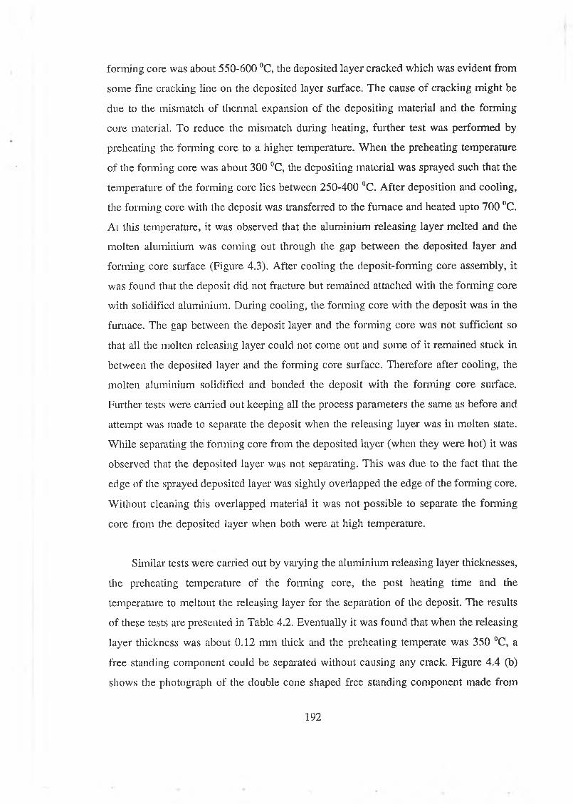
forming core was about 550-600 °C, the deposited layer cracked which was evident from
some fine cracking line on the deposited layer surface. The cause of cracking might be
due to the mismatch of thermal expansion of the depositing material and the forming
core material. To reduce the mismatch during heating, further test was performed by
preheating the forming core to a higher temperature. When the preheating temperature
of the forming core was about 300 °C, the depositing material was sprayed such that the
temperature of the forming core lies between 250-400 °C. After deposition and cooling,
the forming core with the deposit was transferred to the furnace and heated upto 700 °C.
At this temperature, it was observed that the aluminium releasing layer melted and the
molten aluminium was coming out through the gap between the deposited layer and
forming core surface (Figure 4.3). After cooling the deposit-forming core assembly, it
was found that the deposit did not fracture but remained attached with the forming core
with solidified aluminium. During cooling, the forming core with the deposit was in the
furnace. The gap between the deposit layer and the forming core was not sufficient so
that all the molten releasing layer could not come out and some of it remained stuck in
between the deposited layer and the forming core surface. Therefore after cooling, the
molten aluminium solidified and bonded the deposit with the forming core surface.
Further tests were carried out keeping all the process parameters the same as before and
attempt was made to separate the deposit when the releasing layer was in molten state.
While separating the forming core from the deposited layer (when they were hot) it was
observed that the deposited layer was not separating. This was due to the fact that the
edge of the sprayed deposited layer was sightly overlapped the edge of the forming core.
Without cleaning this overlapped material it was not possible to separate the forming
core from the deposited layer when both were at high temperature.
Similar tests were earned out by varying the aluminium releasing layer thicknesses,
the preheating temperature of the forming core, the post heating time and the
temperature to meltout the releasing layer for the separation of the deposit. The results
of these tests are presented in Table 4.2. Eventually it was found that when the releasing
layer thickness was about 0.12 mm thick and the preheating temperate was 350 °C, a
free standing component could be separated without causing any crack. Figure 4.4 (b)
shows the photograph of the double cone shaped free standing component made from
192
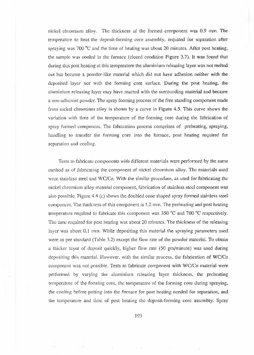
nickel chromium alloy. The thickness of the formed component was 0.9 mm. The
temperature to heat the deposit-forming core assembly, required for separation after
spraying was 700 °C and the time of heating was about 20 minutes. After post heating,
the sample was cooled in the furnace (closed condition Figure 3.7). It was found that
during this post heating at this temperature the aluminium releasing layer was not melted
out but became a powder-like material which did not have adhesion neither with the
deposited layer nor with the forming core surface. During the post heating, the
aluminium releasing layer may have reacted with the surrounding material and became
a non-adherent powder. The spray forming process of the free standing component made
from nickel chromium alloy is shown by a curve in Figure 4.5. This curve shows the
variation with time of the temperature of the forming core during the fabrication of
spray formed component. The fabrication process comprises of preheating, spraying,
handling to transfer the forming core into the furnace, post heating required for
separation and cooling.
Tests to fabricate components with different materials were performed by the same
method as of fabricating the component of nickel chromium alloy. The materials used
were stainless steel and WC/Co. With the similar procedure, as used for fabricating the
nickel chromium alloy material component, fabrication of stainless steel component was
also possible. Figure 4.4 (c) shows the doubled cone shaped spray formed stainless steel
component. The thickness of this component is 1.2 mm. The preheating and post heating
temperature required to fabricate this component was 350 ()C and 700 °C respectively.
The time required for post heating was about 20 minutes. The thickness of the releasing
layer was about 0.1 mm. While depositing this material the spraying parameters used
were as per standard (Table 3.2) except the flow rate of the powder material. To obtain
a thicker layer of deposit quickly, higher flow rate (50 gm/minute) was used during
depositing this material. However, with the similar process, the fabrication of WC/Co
component was not possible. Tests to fabricate component with WC/Co material were
performed by varying the aluminium releasing layer thickness, the preheating
temperature of the forming core, the temperature of the forming core during spraying,
the cooling before putting into the furnace for post heating needed for separation, and
the temperature and time of post heating the deposit-forming core assembly. Spray
193
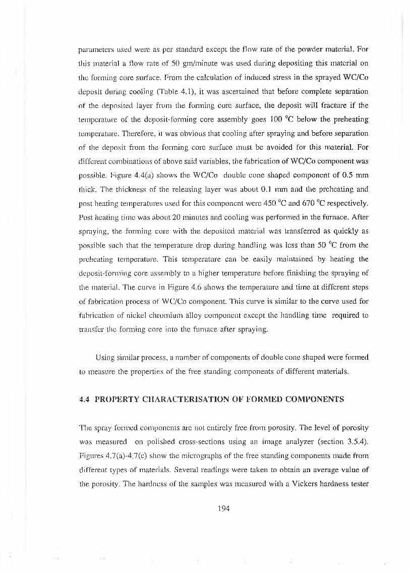
parameters used were as per standard except the flow rate of the powder material. For
this material a flow rate of 50 gm/minute was used during depositing this material on
the forming core surface. From the calculation of induced stress in the sprayed WC/Co
deposit during cooling (Table 4.1), it was ascertained that before complete separation
of the deposited layer from the forming core surface, the deposit will fracture if the
temperature of the deposit-forming core assembly goes 100 °C below the preheating
temperature. Therefore, it was obvious that cooling after spraying and before separation
of the deposit from the forming core surface must be avoided for this material. For
different combinations of above said variables, the fabrication of WC/Co component was
possible. Figure 4.4(a) shows the WC/Co double cone shaped component of 0.5 mm
thick. The thickness of the releasing layer was about 0.1 mm and the preheating and
post heating temperatures used for this component were 450 °C and 670 °C respectively.
Post heating time was about 20 minutes and cooling was performed in the furnace. After
spraying, the forming core with the deposited material was transferred as quickly as
possible such that the temperature drop during handling was less than 50 °C from the
preheating temperature. This temperature can be easily maintained by heating the
deposit-forming core assembly to a higher temperature before finishing the spraying of
the material. The curve in Figure 4.6 shows the temperature and time at different steps
of fabrication process of WC/Co component. This curve is similar to the curve used for
fabrication of nickel chromium alloy component except the handling time required to
transfer the forming core into the furnace after spraying.
Using similar process, a number of components of double cone shaped were formed
to measure the properties of the free standing components of different materials.
4.4 PROPERTY CHARACTERISATION OF FORMED COMPONENTS
The spray formed components are not entirely free from porosity. The level of porosity
was measured on polished cross-sections using an image analyzer (section 3.5.4).
Figures 4.7(a)-4.7(c) show the micrographs of the free standing components made from
different types of materials. Several readings were taken to obtain an average value of
the porosity. The hardness of the samples was measured with a Vickers hardness tester
194
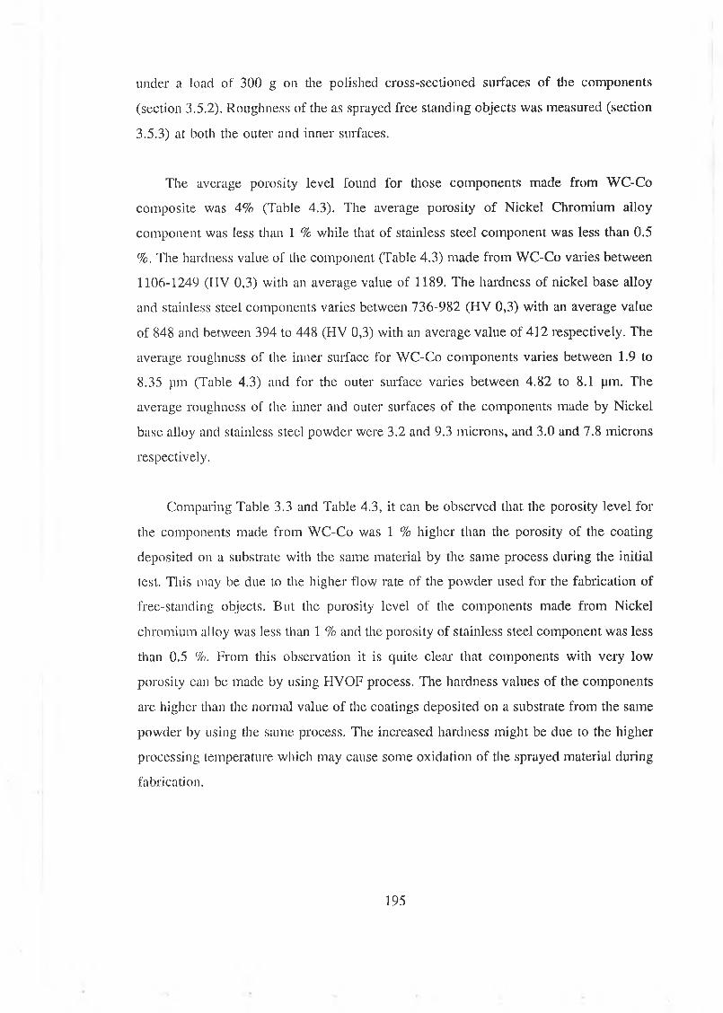
under a load of 300 g on the polished cross-sectioned surfaces of the components
(section 3.5.2). Roughness of the as sprayed free standing objects was measured (section
3.5.3) at both the outer and inner surfaces.
The average porosity level found for those components made from WC-Co
composite was 4% (Table 4.3). The average porosity of Nickel Chromium alloy
component was less than 1 % while that of stainless steel component was less than 0.5
%. The hardness value of the component (Table 4.3) made from WC-Co varies between
1106-1249 (HV 0,3) with an average value of 1189. The hardness of nickel base alloy
and stainless steel components varies between 736-982 (HV 0,3) with an average value
of 848 and between 394 to 448 (HV 0,3) with an average value of 412 respectively. The
average roughness of the inner surface for WC-Co components varies between 1.9 to
8.35 pm (Table 4.3) and for the outer surface varies between 4.82 to 8.1 pm. The
average roughness of the inner and outer surfaces of the components made by Nickel
base alloy and stainless steel powder were 3.2 and 9.3 microns, and 3.0 and 7.8 microns
respectively.
Comparing Table 3.3 and Table 4.3, it can be observed that the porosity level for
the components made from WC-Co was 1 % higher than the porosity of the coating
deposited on a substrate with the same material by the same process during the initial
test. This may be due to the higher flow rate of the powder used for the fabrication of
free-standing objects. But the porosity level of the components made from Nickel
chromium alloy was less than 1 % and the porosity of stainless steel component was less
than 0.5 %. From this observation it is quite clear that components with very low
porosity can be made by using HVOF process. The hardness values of the components
are higher than the normal value of the coatings deposited on a substrate from the same
powder by using the same process. The increased hardness might be due to the higher
processing temperature which may cause some oxidation of the sprayed material during
fabrication.
195
4.5 FABRICATION OF SPRAY FORMED COMPONENTS AND
IDENTIFICATION OF PROCESSING VARIABLES
The HVOF thermal spraying process was used to fabricate components of different size
and shape. Three types of material were used to fabricate these components. The process
variables were as described earlier. The components thus formed are presented in
Figures 4.8-4.10. In Figure 4.8 components made from nickel chromium alloy are
presented. In this Figure three conical components of differing size and one cylindrical
shape are shown. In Figure 4.9 three conical components of different size and of
cylindrical shape component made from stainless steel are shown. In Figure 4.10
similarly shaped components made of WC/Co material are presented. The processing
variables used in the manufacture of all these components are presented Table 4.4.
From these figures it is clear that thin walled near net-shaped free standing
components of different sizes can be made by using HVOF thermal spraying process.
The processing variables for different material are different. The processing variables
which might affect ease of fabrication are as follows.
1) The material of the forming core.
2) The size of the forming core.
3) The roughness of the forming core surface.
4) The preheating temperature of the forming core.
5) The equilibrium of the temperature of the forming core during deposition.
6) The thickness of the inter-layer.
7) The post heating temperature, time and rate of the deposit-forming core assembly
after deposition for the separation of the deposit.
196
8) The cooling rate of the deposit-forming core assembly after post heating.
9) The variation of the properties of the component made from WC/Co material with
the spraying parameters.
4.6 EFFECT OF PROCESSING VARIABLES
To determined the effect of process variables on the manufacturability of the
components a particular shape of the forming core was selected to measure all the
processing variables. The conical forming core of average diameter 33.5 mm shown in
Figure 3.5 was selected. This was chosen because of the ease of separation of the
deposit from the forming core. Special attention was given to the processing variables
for fabricating component from WC/Co material.
4.6.1 EFFECT OF THE FORMING CORE MATERIAL
Conical forming cores of average diameter 33.5 mm (Figure 3.5) were made from D2
steel, stainless steel 316L, copper, mild steel and aluminium. These forming cores were
used to investigate the effect of the forming core material on the fabrication process. It
was found that the forming cores made from aluminium were unsuitable due to the fact
that for the pre-heating and post heating temperatures the aluminium based releasing
agent gets bonded with the core and causes fracture of the deposited components. The
copper made cores were found to be satisfactory for the production of components.
However, a problem was encountered in measuring and hence controlling the
temperature while spraying. With the rise of temperature, copper oxidised and changed
its surface colour so rapidly that it was very difficult to measure the temperature using
the pyrometer. Therefore, continuous measurement of temperature was not possible.
From time to time during the fabrication of the components, the temperature of the
forming core was measured with the help of a thermocouple by interrupting the spraying
operation. Between these intervals the temperature of the forming core was assumed to
remain within the measured values. Cores made from D2 steel, stainless steel and mild
steel were also found to be satisfactory except that due to the oxidation, the life of mild
197
steel core was found to be short. The property of the forming core material which most
affects the fabrication of the spray formed objects is the coefficient of thermal
expansion. The preheating temperature of the forming core depends on the coefficient
of thermal expansion of the material of the forming core ( Figure 4.11). The curve in
Figure 4.11 shows that with the increase of the coefficient of linear thermal expansion
the minimum preheating temperature increases. The range of preheating temperature for
these forming core materials is shown in Figure 4.12 . From the graph it is shown that
for every forming core material of a definite size, there are three different zones of the
preheating temperature. When the preheating temperature lies within the lower zone of
the bar graph the deposit will fracture during the post heating needed for the separation
of the deposit. When the preheating temperature lies within the middle zone of the bar
graph there is some chance of fracturing of the deposited material during post heating.
This may be due to the directional inhomogeneity resulting anisotropy within the
deposited material. This inhomogeneity of the deposited material is a characteristic of
the sprayed deposit and might be due to the inclusion of porosity, foreign impurities and
oxides. When the preheating temperature of the forming core lies within the upper zone,
it is quite likely that free standing components will be formed successfully unless other
factors cause fracture of the deposited components.
4.6.2 EFFECT OF SIZE AND SHAPE OF THE FORMING CORE
Figure 4 .13 shows the effect of the size of the forming core on the preheating
temperature of the forming core. These results are for a forming core made from
stainless steel 316L and for making of WC/Co component. From Figure 4.13 it is seen
that the minimum preheating temperature for obtaining WC/Co component decreases
linearly with the average diameter of the forming core. In this Figure, two zones are
shown, one indicates the safe operation zone i.e zone 1. When the preheating
temperature lies within the other zone (zone 2), it is uncertain whether a component will
be formed successfully or not. When preheating temperature lies below the temperature
indicated by zone 2, fracture of the deposited layer during post heating is likely to occur.
198
Figure 4.14 shows a photograph of different sizes and shapes of some components
made from WC/Co material. The sizes, thickness and spray parameters for fabrication
of these component are presented in Table 4.5.
4.6.3 EFFECT OF THE ROUGHNESS OF THE FORMING CORE SURFACE
The roughness of the forming cores was varied by grinding the surface using sand paper
and by grit blasting. Table 4.6 shows the effect of surface roughness of the forming core
on the roughness of the spray formed component. From Table 4.6 it is observed that
though the average roughness of the forming core is 0.83 and 4.7 pm due to grinding
and grit blasting respectively, after applying a releasing layer the average roughness
changes to 4.2 and 4.0 pm for ground and grit blasted surface respectively. The average
roughness of the inner surface of the formed components using these two forming cores
was 2.92 and 3.16 pm, and for outer surface was 3.98 and 3.72 pm. During deposition,
due to the preheat temperature of the forming core and the impact of the deposited
material, the sprayed material penetrates into the interlayer and therefore the roughness
of the inner surface does not depend on the roughness of the surface of the forming
core. The roughness of the outer surface is mostly governed by the size of the sprayed
powder particles, and is unlikely to depend on the roughness of the forming core
surface.
However, the roughness of the forming core surface does have some effect on the
fabrication process of the component. The releasing layer, which was deposited by
thermal spraying using HVOF thermal spraying process should have proper adhesion
witli the forming core surface. Roughening and cleaning the forming core surface
increases the bond strength of the sprayed releasing layer which helps the deposition of
spray formed object during spraying. It was observed that a smooth surface and
improper cleaning of the forming core resulted in the fracturing of the spray formed
component during spraying. This might be due to the improper bonding of the releasing
layer with the forming core. This test was performed using a cleaned and roughened
forming core as follows (Table 4.7). The average roughness of the roughened forming
core surface was about 4.7 pm. During fabrication of the first component, using this
199
forming core, the deposited layer was not fractured. During making a second component
with the same forming core, the forming core was not cleaned. Keeping all the
fabricating conditions constant it was not possible to obtain a component as during
spraying the deposited layer was fractured. The same forming core was used for a third
time. This time the forming core was cleaned by only sand paper which cleaned the
surface but reduced the roughness. This time the roughness of the forming core surface
was about 1.9 pm and the formation of a component without fracture was possible.
When the same forming core surface was polished to a surface average roughness of less
than 1.0 pm the deposited layer fractured during spraying. During the deposition all
other parameters were identical. Similar results were obtained after repeating the same
procedure thrice.
4.6.4 EFFECT OF PREHEATING TEMPERATURE OF THE FORMING CORE
The preheating temperature of the forming core is one of the critical factors which
influences the ease with which the component may be released from the preform as
illustrated in the Figure 4.15. When stainless steel material was sprayed on to a stainless
steel core a preheating temperature of less than 200 HC ( for a core with 33.5 mm
average diameter) led to high releasing load to separate the components from the core
and as a result fracture of the deposits occurred during separation. The separation load
increases with the decrease of preheating temperature and the core size ( average
diameter). When the preheating temperature is more than 300 °C, the deposition and
releasing of the component made from stainless steel with a stainless steel or mild steel
core can be achieved witli ease. The maximum preheating temperature attempted was
600 "C, beyond that, the releasing agent applied is dispersed from the surface of the
core during spraying due to the high velocity of the flame. The safe range of the
preheating temperature for a nickel chromium alloy component (for 33.5 mm diameter
core size) is 350 °C to 600 nC. For the preheating temperature lower than 250 °C there
is every chance of fracture of the component occurring during either the deposition or
the post heating stages. The preheating temperature of between 350-250 °C is an
overlapping zone where a component may or may not be formed. For Tungsten carbide
components of similar size, the safe preheating temperature range is 425-550 UC. Above
200

this temperature there is evidence of fracture which may be attributed to oxidation and
formation of very brittle tungsten oxides during spraying and/or reduction of bond
strength of the releasing agent with the core. With the increase of the preheating
temperature for WC/Co deposits, the chance of oxidation increases and this could be
observed by the colour change of the deposits on the core. At temperatures lower than
400 °C the deposits fracture during post heating. This may be due to the lower
coefficient of thermal expansion of tungsten carbide composite in relation to the
coefficient of thermal expansion of the core material. The preheating temperature range
of 400-425°C for stainless steel cores sometimes leads to fracturing of the deposits.
4.6.5 EFFECT OF TEMPERATURE OF THE FORMING CORE DURING SPRAYING
The temperature of the forming core during spraying has a significant effect on the
manufacture of the free-standing components made from WC/Co material. However, for
the other two materials it has almost no effect as long as it is maintained at or above
300 °C of the preheating temperature before releasing from the core. For the carbide
components large deviation of the spraying temperature from the mean spraying
temperature during spraying causes fracture of the free-standing component. During
spraying the WC/Co material, if the temperature of the forming core rises about 425 °C,
a light brown colour appears on the surface of the deposit which shows the formation
of lower carbides such as W3C, which is very brittle and has higher hardness than WC.
With increasing temperature of the forming core this light brown colour changes to deep
brown and after that into pink. This change of colour shows the increasing amount of
lower carbide in the sprayed deposit. With the increased amount of lower carbide the
chance of fracturing the deposited layer increases. A careful control of the temperature
of the forming core during spraying to around 425 l1C reduces the amount of lower
carbide formation.
Therefore, during spraying of carbide material, the distance of the gun and the
traverse of the gun need to be adjusted such that the temperature rise (Figures 3.15-3.17)
during spraying can be better controlled. Otherwise during deposition the deposited
layer might fracture. If the size of the component is small the adjustment of the distance
201
of the gun from the core and the gun traverse is not sufficient to control the spray
temperature. In that case the equilibrium of temperature is maintained by interruption
of spray or by forming more than one component during a given spraying operation.
Depending on the size and material of the component there are some optimum
ranges for gun traverse, gun distance from the core and the number of the components
being formed at a time, provided that the spray condition such as the flow of different
gases to the gun remains the same. It is preferable that the spraying temperature is kept
within ± 50 °C of the preheating temperature for carbide component. For other materials
it can be widely varied. From Figures 3.15-3.17 it is seen that at a traverse speed of 3
mm per rotation the rise of temperature for one pass of spray is fairly uniform at higher
temperature. The distance of the core from the gun should be maximum, however,
higher distances might reduce spraying efficiency and hardness, and increase porosity
for WC/Co material. As such a traverse speed of 3 mm per rotation was chosen for all
the materials and the spray temperature was controlled by forming two samples for each
of the smaller and medium size cores and one sample for the bigger size core for single
spraying operation.
4.6.6 EFFECT OF AIR COOLING TO CONTROL THE TEMPERATURE OF THE
FORMING CORE DURING SPRAYING
Extra air cooling can be used to cool the forming core in order to control the
temperature to within reasonable limits dnring spraying. However, it was observed that
due to the increased flow of cooling air the amount of formation of lower carbide on the
deposited material increases and the increased amount is seen by the change of colour
of the deposits. Increased amount of cooling air also causes the fracture of the deposited
component. The cause of fracture may be due to the increased amount of brittle lower
carbides or due to the thermal mismatch of the deposit and the forming core. The
cooling air can cool the outer surface of the deposit rapidly but not the forming core.
Therefore due to air cooling, the thermal mismatch between the deposit and the forming
core is more which might cause fracture of the sprayed deposit.
202

4.6.7 EFFECT OF TEMPERATURE ON THE COLOUR OF THE WCICo DEPOSIT
The change of colour of the sprayed WC/Co deposit can be used as an indication of the
temperature of the deposit-forming core assembly and thus supplies a means to control
the temperature of the forming core during fabrication. Figure 4.16 shows the
temperature of the sprayed deposit and the colour of the deposit. With the increase of
temperature the colour of the deposit changes from grey to light brown, brown, pink,
bluish grey and then light blue. This change of colour is very distinct and can easily be
recognised during spraying.
4.6.8 EFFECT OF POST HEATING RATE, TEMPERATURE AND TIM E
The post heating temperature and soaking time of the core together with the deposit are
very critical on the ease of separation of the component from the core. The rate of
heating of the deposit-forming core assembly was varied and this is shown in Figures
4.17 and 4.18. From Figure 4.17 it is shown that the tíme of heating of the deposit-
forming core assembly from temperature 400 °C to 680 °C varies from 5-27 minutes.
Figure 4.18 shows that the time required to heat the deposit-forming core assembly from
temperature 500 °C to 680 °C varies from 3-24 minutes. It was found that the heating
rate does not have significant effect on the ease of separation of the free-standing
component from the core. Figure 4.19 shows the effect of forming core temperature on
the ease of separation of the deposit. This Figure, drawn on the basis of about 100 tests
on the carbide components, shows that for post heating temperatures below about 600
°C the deposit can not be separated without causing fracture. Also, if the temperature is
higher than about 675 °C there is every possibility that the deposit will crack due to
excessive oxidation and thermal expansion mismatch during post heating. It is also true
that with increasing temperature the amount of oxidation for the carbide component
increases but it is reasonably low at about 600 °C. For the other two materials the post
heating temperature is between 625 HC to 750 °C.
The effect of post heating at different temperatures can be increased by increasing
the heating time. Figure 4.20 shows the effect of time and temperature of the post
203

heating on the separation of deposits with different releasing layer thickness. If the
releasing layer has a higher thickness the separation of the deposit from the forming core
can be performed by heating the deposit-forming core assembly at a given temperature
for a longer time. If the thickness of the releasing layer is 60 pm and the post heating
temperature is 670 °C the time required for separation of the deposit is about 3 minute.
With the same releasing layer thickness if the post heating temperature is 600 °C the
time required to separate the deposit is about 15 minute.
4.6.9 EFFECT OF COOLING RATE
The cooling rate of the deposit-forming core assembly also has significant effect on the
process, particularly for the carbide components. Figures 3.6 and 3.7 show four different
cooling rates used to fabricate components. Figure 3.6 shows the cooling rate of the
forming core when it is placed in air with and without forced flow of air. Figure 3.7
shows the cooling rate of the forming core when it is placed in the furnace with the door
closed and when partially opened. When the core deposit assembly was cooled by forced
air, in all tests the deposited layer of WC/Co material fractured due to higher
temperature difference between the deposited layer and the inner core. Components of
the other two materials also could not be cooled with forced air but they are not as
sensitive as the carbide components as some times these components were formed
successfully after cooling with forced flow of air. Slower rates of cooling are preferable
for the successful manufacture of the component but longer time in hot environment
increases the chance of oxidation and formation of lower carbides for the carbide
components. Therefore, it is better to cool in the air without any forced flow. To avoid
oxidation or formation of lower carbide, a controlled atmosphere post heating and
cooling is advisable for the carbide component.
A nitrogen atmosphere post heating was attempted to reduce the oxidation and
formation of lower carbide of the carbide components. However, the nitrogen
atmosphere could only reduce the amount of formation of lower oxide but could not stop
the formation of lower carbides. The reduction in the amount of carbide formation was
identified by the change of colour of the formed components.
204
4.6.10 EFFECT OF RELEASING LAYER THICKNESS
The thickness of the releasing agent has no significant effect on the deposition of the
component materials on the surface of the core as long as it has proper bonding with the
forming core surface. However, it influences the ease of separation of the component
from the core. Figures 4.19 and 4.20 show the effect of the releasing agent thickness for
WC/Co components. If the thickness of the releasing agent is too low the deposit will
stick with the core at some places and when attempting to separate the component, the
stuck area will cause fracture of the total component due to residual stress generated for
thermal mismatch and for partial releasing of the component. If the releasing agent is
not uniformly applied some local area may also get bonded causing localised fracture
( Figure 4.21) or complete fracture of the component. This was prominent when the
releasing agent thickness was less then about 55 micron. If the releasing agent is too
thick the deposit will crack for all materials. This releasing agent works on the principle
that at a certain temperature it oxidises and/or reacts with the surrounding materials and
becomes non-sticking interlayer and thus allows the deposit to separate from the core.
It was also found that the longer the post heating duration the surer is the safe separation
of the deposit from the core. Thus, the critical range of the thickness of the releasing
agent can be widened by adjusting the post heating temperature and the soaking time.
But too thick a releasing agent can not be made fully non-sticking. In that case the
releasing agent sticks with both the preform and the component surfaces causing fracture
of the components.
4.6.11 EFFECT OF DIM ENSION OF THE FABRICATED COMPONENT ON THE
PROCESSING PARAMETERS
During the fabrication of the component the sprayed layer of the deposit is in close
contact witli the outer surface of the forming core, so that the inner diameter of the
formed component should be equal to the outer diameter of the forming core during
spraying at high temperature. After cooling the deposit-forming core assembly and due
to the releasing layer, a gap is created between the inner surface of the formed
component and the forming core. Therefore, the inner diameter of the cooled spray
205
formed component is a little greater than the outer diameter of the forming core. While
making a forming core for fabricating a component of certain specified inner diameter,
an allowance for this dimensional change during fabrication is to be subtracted from the
outer diameter of the forming core. This correction for diameter of the forming core
depends on the material and the dimension of the forming core, and the releasing layer
thickness. Figure 4.22 shows the diametral allowance that should to be subtracted from
the diameter of the forming core during fabrication of the forming core for forming a
component of specified inner diameter. The effect of the releasing layer thickness on the
gap created upon cooling the deposit and forming core could not be measured due to the
lack of proper control of the thickness of tire releasing layer and the absence of exact
coefficient of thermal expansion of the sprayed material.
4.6.12 EFFECT OF TRAVERSING VELOCITY ON FORMING COMPONENT
During the fabrication of components of longer length, the control of the uniformity of
temperature during spraying is very important. This is because during spraying at one
end of the forming core, the other end cools down due to the induced flow of the spray
stream and hence fracturing of the sprayed deposit is quite likely. This problem of the
difference in temperature along the length of the forming core can be reduced by
traversing the gun very fast. Figure 4.14 (g) shows a component of cylindrical shape of
85 mm length and 0.92 mm thick. The number of passes per minute of spray used was
about 200 or more.
The resulting thickness of the component made following this procedure was found
to be non-uniform. The formed component has higher thickness at the two ends than that
at the middle. This variation of thickness is about 0.1 mm for the component shown in
Figure 4.14 (g). This arises due to the non-uniform velocity of traverse of the spray gun.
For a lateral to and fro motion, the velocity of the traversing unit at the two extreme
points of traversing length is zero and at the middle it has the maximum velocity. As
the spray gun has a lateral to and fro motion during deposition, it deposits less material
at the middle portion of the forming core and deposits more material at the two ends.
This is more prominent when the motion of the spray gun was controlled by hand.
206

When the motion of the spray gun was controlled by the traversing unit of the lathe, the
variation of the thickness was less and this is due to the manner in which the direction
of motion of the traversing unit of the lathe was changed. As the lathe is semi
automatic, the change of direction of motion is done manually. This non-uniformity of
thickness can be controlled by traversing the spray gun even at greater length then the
forming core such that when changing the direction of the traversing unit the spray is
directed out beyond the forming core. Note that spraying beyond the forming core will
reduce the efficiency of deposition of spraying materials.
4.6.13 OTHER EFFECTS
During fabricating components of different shape and size it was observed that every
individual shape and size has some aspects which need careful attention while making
these components. Some of these aspects are described below.
(i) FABRICATION OF COMPONENT WITH BUILT-IN HOLE/HOLES
Two methods were used to fabricate the components with built-in hole/holes (section
3.8.6). In the first method, where a cylindrical insert (plug) was used to create a hole,
the extended portion of the rod creates a shadowing effect such that the sprayed material
could not deposit on some areas very near to the edge of the hole. Therefore the shape
of the hole was not uniform. This non-uniformity and sticking of the deposit to the
surface of the cylindrical insert causes fracture of the formed component during
separation. In the second method, when the sprayed material was allowed to pass into
the hole and deposit inside the hole, the fabrication of the components with built-in
hole/holes was possible. However, in this method the edges of the holes were overlapped
by the sprayed deposit which created a problem in separating the deposit from the
forming core. After post heating and cooling, the edges of the holes should be cleared
before complete separation of the components from the forming core. Figure 4.23 shows
two components made from WC/Co materials having single and multiple hole. All holes
are 5 mm diameter.
207
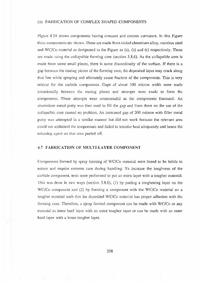
(ii) FA B R IC A TIO N O F C O M PLEX SH A PED C O M PO N EN T S
Figure 4.24 shows components having concave and convex curvature. In this Figure
three components are shown. These are made from nickel chromium alloy, stainless steel
and WC/Co material as designated in the Figure as (a), (b) and (c) respectively. These
are made using the collapsible forming core (section 3.8.6). As the collapsible core is
made from some small pieces, there is some discontinuity of the surface. If there is a
gap between the mating pieces of the forming core, the deposited layer may crack along
that line while spraying and ultimately cause fracture of the components. This is very
critical for the carbide components. Gaps of about 100 micron width were made
intentionally between the mating pieces and attempts were made to form the
components. These attempts were unsuccessful as the components fractured. An
aluminium metal putty was then used to fill the gap and from there on the use of the
collapsible core caused no problem. An increased gap of 200 micron with filler metal
putty was attempted in a similar manner but did not work because the relevant area
could not withstand the temperature and failed to transfer heat adequately and hence the
releasing agent on that area peeled off.
4.7 FABRICATION OF MULTI-LAYER COMPONENT
Components formed by spray forming of WC/Co material were found to be brittle in
nature and require extreme care during handling. To increase the toughness of the
carbide component, tests were performed to put an extra layer with a tougher material.
This was done in two ways (section 3.8.6), (1) by putting a toughening layer on the
WC/Co component and (2) by forming a component with the WC/Co material on a
tougher material such that the deposited WC/Co material has proper adhesion with the
forming core. Therefore, a spray formed component can be made with WC/Co or any
material as inner hard layer with an outer tougher layer or can be made with an outer
hard layer with a inner tougher layer.
208
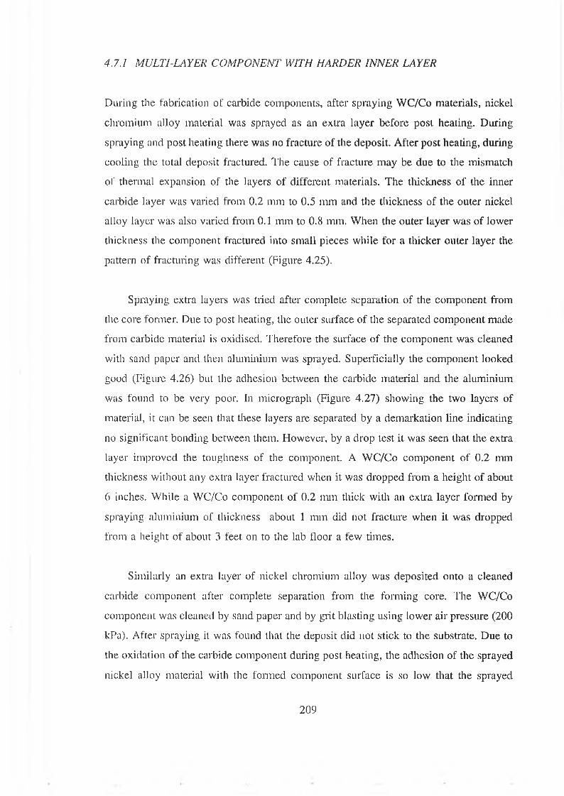
4.7.1 MULTI-LAYER COMPONENT WITH HARDER INNER LAYER
During the fabrication of carbide components, after spraying WC/Co materials, nickel
chromium alloy material was sprayed as an extra layer before post heating. During
spraying and post heating there was no fracture of the deposit. After post heating, during
cooling the total deposit fractured. The cause of fracture may be due to the mismatch
of thermal expansion of the layers of different materials. The thickness of the inner
carbide layer was varied from 0.2 mm to 0.5 mm and the thickness of the outer nickel
alloy layer was also varied from 0.1 mm to 0.8 mm. When the outer layer was of lower
thickness the component fractured into small pieces while for a thicker outer layer the
pattern of fracturing was different (Figure 4.25).
Spraying extra layers was tried after complete separation of the component from
the core former. Due to post heating, the outer surface of the separated component made
from carbide material is oxidised. Therefore the surface of the component was cleaned
with sand paper and then aluminium was sprayed. Superficially the component looked
good (Figure 4.26) but the adhesion between the carbide material and the aluminium
was found to be very poor. In micrograph (Figure 4.27) showing the two layers of
material, it can be seen that these layers are separated by a demarkation line indicating
no significant bonding between them. However, by a drop test it was seen that the extra
layer improved the toughness of the component. A WC/Co component of 0.2 mm
thickness without any extra layer fractured when it was dropped from a height of about
6 inches. While a WC/Co component of 0.2 mm thick with an extra layer formed by
spraying aluminium of thickness about 1 mm did not fracture when it was dropped
from a height of about 3 feet on to the lab floor a few times.
Similarly an extra layer of nickel chromium alloy was deposited onto a cleaned
carbide component after complete separation from the forming core. The WC/Co
component was cleaned by sand paper and by grit blasting using lower air pressure (200
kPa). After spraying it was found that the deposit did not stick to the substrate. Due to
the oxidation of the carbide component during post heating, the adhesion of the sprayed
nickel alloy material with the formed component surface is so low that the sprayed
209

nickel alloy material could not be deposited as a continuous layer and after deposition
on some areas the deposited layer peeled off (Figure 4.28). Therefore, to keep the outer
surface of the carbide component oxide free, carbide component was fabricated by post
heating in nitrogen atmosphere. This modification of post heating improved the surface
quality but could not completely stop the oxidation of the component. With this reduced
oxide surface, spraying of nickel alloy was tried and it was found that initially the spray
material was deposited but after certain thickness (about 0.2 mm) the layer peeled off
(Figure 4.29).
Therefore when fabricating components with WC/Co material a top layer was given
with a mixed powder (section 3.8.6). The mixture material was made from the
combination of WC/Co and nickel chromium alloy in different proportions. When the
mixed layer was made from 10 % (by volume) nickel chromium alloy material and 90
% (by volume) WC/Co material, during deposition of the extra layer from nickel alloy
the formation of continuous layer was not possible because this amount of nickel
chromium alloy material in the top layer of the formed component is not sufficient to
provide proper bonding with the sprayed material. Figure 4.30 shows the component
with mixed layer (10 % nickel chromium alloy) on the top surface and while respraying
with nickel chromium alloy material for extra layer, the sprayed material adhered at
some areas of the surface and in some areas the deposited layer spalled off. When the
mixed layer was made from 40 % (by volume) nickel chromium alloy and 60 % (by
volume) WC/Co material, this mixed layer has sufficient bonding to allow deposition
of the nickel chromium alloy material as an extra layer. Figure 4.31 shows a component
made from WC/Co material of thickness about 0.4 mm and then a mixed layer of 40 %
nickel chromium alloy and 60 % WC/Co material was applied as a very thin layer such
that the mixed layer barely covered the whole surface. Then the component was
separated from the core by post heating in nitrogen atmosphere. After post heating,
nickel chromium alloy was applied such that the total thickness of the component was
about 1.0 mm. The adhesion of the extra layer to the mixed layer is sufficient because
the nickel material within the mixed layer did not oxidise during post heating and it
helped bonding the deposited nickel alloy material. The thickness of the extra layer
made from nickel chromium alloy was varied and it was found that for upto about 0.6
210
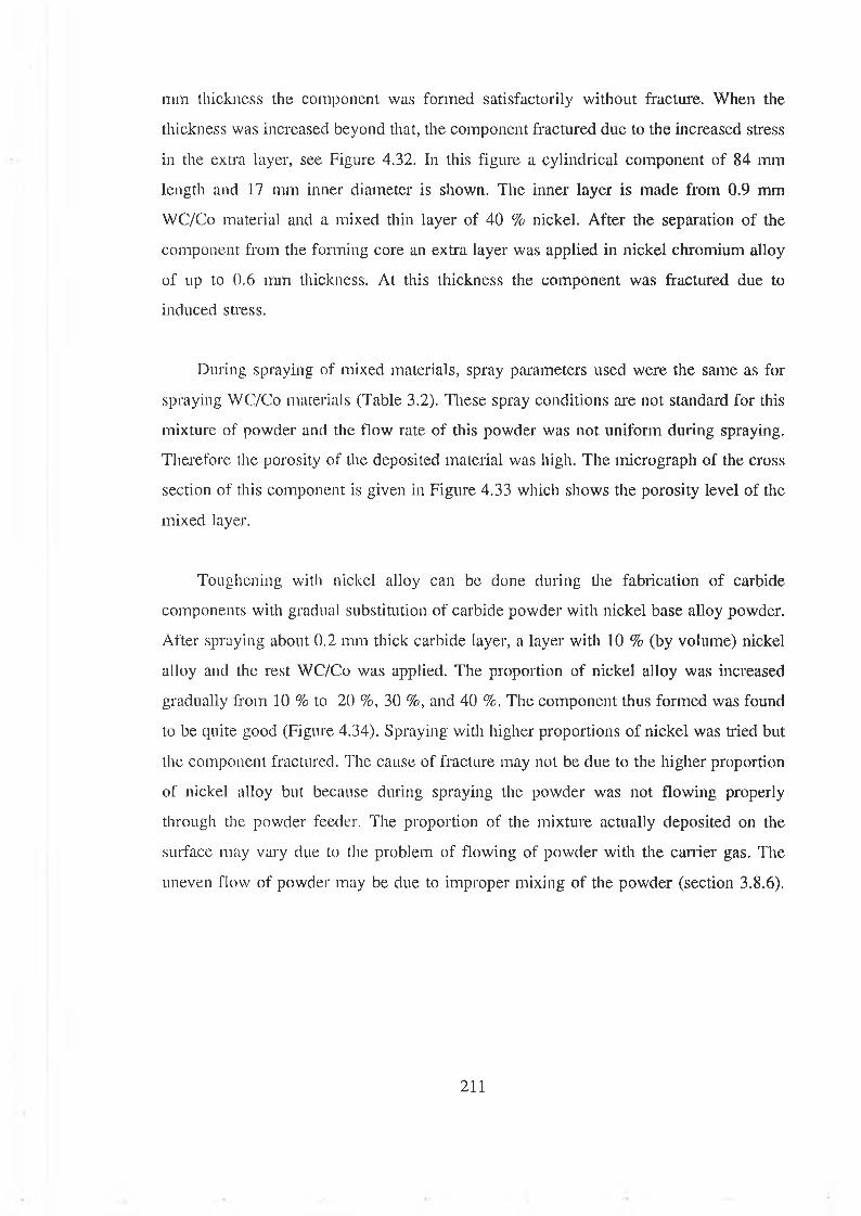
mm thickness the component was formed satisfactorily without fracture. When the
thickness was increased beyond that, the component fractured due to the increased stress
in the extra layer, see Figure 4.32. In this figure a cylindrical component of 84 mm
length and 17 mm inner diameter is shown. The inner layer is made from 0.9 mm
WC/Co material and a mixed thin layer of 40 % nickel. After the separation of the
component from the forming core an extra layer was applied in nickel chromium alloy
of up to 0.6 mm thickness. At this thickness the component was fractured due to
induced stress.
During spraying of mixed materials, spray parameters used were the same as for
spraying WC/Co materials (Table 3.2). These spray conditions are not standard for this
mixture of powder and the flow rate of this powder was not uniform during spraying.
Therefore the porosity of the deposited material was high. The micrograph of the cross
section of this component is given in Figure 4.33 which shows the porosity level of the
mixed layer.
Toughening with nickel alloy can be done during the fabrication of carbide
components with gradual substitution of carbide powder with nickel base alloy powder.
After spraying about 0.2 mm thick carbide layer, a layer with 10 % (by volume) nickel
alloy and the rest WC/Co was applied. The proportion of nickel alloy was increased
gradually from 10 % to 20 %, 30 %, and 40 %. The component thus formed was found
to be quite good (Figure 4.34). Spraying with higher proportions of nickel was tried but
the component fractured. The cause of fracture may not be due to the higher proportion
of nickel alloy but because during spraying the powder was not flowing properly
through the powder feeder. The proportion of the mixture actually deposited on the
surface may vary due to the problem of flowing of powder with the carrier gas. The
uneven flow of powder may be due to improper mixing of the powder (section 3.8.6).
211
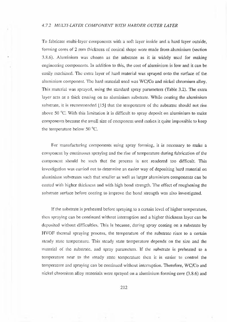
4.7.2 MULTI-LAYER COM PONENT WITH HARDER OUTER LAYER
To fabricate multi-layer components with a soft layer inside and a hard layer outside,
forming cores of 2 mm thickness of conical shape were made from aluminium (section
3.8.6). Aluminium was chosen as the substrate as it is widely used for making
engineering components. In addition to this, the cost of aluminium is low and it can be
easily machined. The extra layer of hard material was sprayed onto the surface of the
aluminium component. The hard material used was WC/Co and nickel chromium alloy.
This material was sprayed, using the standard spray parameters (Table 3.2). The extra
layer acts as a thick coating on an aluminium substrate. While coating the aluminium
substrate, it is recommended [15] that the temperature of the subsU'ate should not rise
above 50 °C. With this limitation it is difficult to spray deposit on aluminium to make
components because the small size of component used makes it quite impossible to keep
the temperature below 50 °C.
For manufacturing components using spray forming, it is necessary to make a
component by continuous spraying and the rise of temperature during fabrication of the
component should be such that the process is not rendered too difficult. This
investigation was carried out to determine an easier way of depositing hard material on
aluminium substrates such that smaller as well as larger aluminium components can be
coated with higher thickness and with high bond strength. The effect of roughening the
substrate surface before coating to improve the bond strength was also investigated.
If the substrate is preheated before spraying to a certain level of higher temperature,
then spraying can be continued without interruption and a higher thickness layer can be
deposited without difficulties. This is because, during spray coating on a substrate by
HVOF thermal spraying process, the temperature of the substrate rises to a certain
steady state temperature. This steady state temperature depends on the size and the
material of the substrate, and spray parameters. If the substrate is preheated to a
temperature near to the steady state temperature then it is easier to control the
temperature and spraying can be continued without interruption. Therefore, WC/Co and
nickel chromium alloy materials were sprayed on a aluminium forming core (3.8.6) and
212
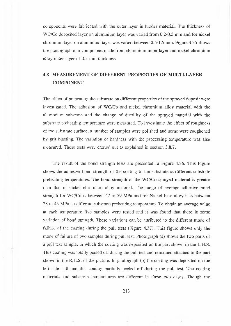
components were fabricated with the outer layer in harder material. The thickness of
WC/Co deposited layer on aluminium layer was varied from 0.2-0.5 mm and for nickel
chromium layer on aluminium layer was varied between 0.5-1.5 mm. Figure 4.35 shows
the photograph of a component made from aluminium inner layer and nickel chromium
alloy outer layer of 0.5 mm thickness.
4.8 MEASUREMENT OF DIFFERENT PROPERTIES OF MULTI-LAYER
COMPONENT
The effect of preheating the substrate on different properties of the sprayed deposit were
investigated. The adhesion of WC/Co and nickel chromium alloy material with the
aluminium substrate and the change of ductility of the sprayed material with the
substrate preheating temperature were measured. To investigate the effect of roughness
of the substrate surface, a number of samples were polished and some were roughened
by grit blasting. The variation of hardness with the processing temperature was also
measured. These tests were carried out as explained in section 3.8.7.
The result of the bond strength tests are presented in Figure 4.36. This Figure
shows the adhesive bond strength of the coating to the substrate at different substrate
preheating temperatures. The bond strength of the WC/Co sprayed material is greater
than that of nickel chromium alloy material. The range of average adhesive bond
strength for WC/Co is between 47 to 59 MPa and for Nickel base alloy it is between
28 to 43 MPa, at different substrate preheating temperature. To obtain an average value
at each temperature five samples were tested and it was found that there is some
variation of bond strength. These variations can be attributed to the different mode of
failure of the coating during the pull tests (Figure 4.37). This figure shows only the
mode of failure of two samples during pull test. Photograph (a) shows the two parts of
a pull test sample, in which the coating was deposited on the part shown in the L.H.S.
This coating was totally peeled off during the pull test and remained attached to the part
shown in the R.H.S. of the picture. In photograph (b) the coating was deposited on the
left side half and this coating partially peeled off during the pull test. The coating
materials and substrate temperatures are different in these two cases. Though the
213

variation of bond strength was found to be different at any particular preheating
temperature for each material, it is evident that the average bond strength of these
materials to an aluminium substrate increases at higher substrate preheating
temperatures. With the higher substrate temperature the thermal mismatch is greater, but
better diffusion of the coating particles increases the bond strength so much that it
nullifies the effect of increased thermal stress and increases the bond strength of the
coating. Figure 4.38 shows the penetration of a sprayed particle into the aluminium
substrate to a depth of 30-35 jim at preheating temperature 400 °C and 15-20 pm at
substrate preheating temperature 50 °C. This penetration of the sprayed particle increased
the diffusion and thus increase the bond strength of the deposited material. The curve
in Figure 4.36 shows that the bond strength has less increasing trend at lower substrate
preheating temperature and have higher increasing trend at higher temperature. This may
be due to insufficient diffusion of the sprayed particles at that temperature. This trend
is similar for both the materials used. The bond strength test results could not be
compared with results obtained by other investigators because the bond strength of
coatings on aluminium substrates is not available in the literature.
Adhesion between the layers of WC/Co and Nickel chromium alloy was measured
by pull test (section 3.5.6). The tensile bond strength was found to be more than 70
MPa. At this strength always the adhesive failed. The bond strength between the WC/Co
layer and the mixed material (WC/Co and 40 % nickel chromium alloy) was also tested
and the tensile bond strength was also found to be more than 70 Mpa.
The results of the ductility test are presented in Figure 4.39. From the bend test the
ductility of the spray coating was found to be very low, which is to be expected because
the thermally sprayed coatings have low ductility [12]. Curves in Figure 4.39 show the
variation of ductility of the coatings at different temperatures. The ductility of the
coatings at higher temperatures increased slightly for Nickel base alloy. The ductility of
tungsten carbide did not change due to the change in substrate temperatures. The curve
in Figure 4.40 shows the variation of ductility of the nickel alloy coating with thickness
at a certain substrate preheating temperature and it is evident that with increasing
thickness there is only marginal increase in ductility of this material.
214
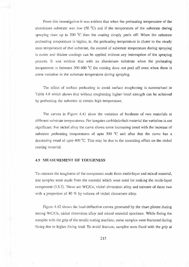
From this investigation it was evident that when the preheating temperature of the
aluminium substrate was low (50 °C) and if the temperature of the substrate during
spraying rises up to 200 UC then the coating simply peels off. When the substrate
preheating temperature is higher, ie. the preheating temperature is closer to the steady
state temperature of that substrate, the control of substrate temperature during spraying
is easier and thicker coatings can be applied without any interruption of the spraying
process. It was evident that with an aluminium substrate when the preheating
temperature is between 300-400 °C the coating does not peel off even when there is
some variation in the substrate temperature during spraying.
The effect of surface preheating to avoid surface roughening is summarised in
Table 4.8 which shows that without roughening higher bond strength can be achieved
by preheating the substrate at certain high temperature.
The curves in Figure 4.41 show the variation of hardness of two materials at
different substrate temperatures. For tungsten carbide/cobalt material the variation is not
significant. For nickel alloy the curve shows some increasing trend with the increase of
substrate preheating temperatures of upto 300 °C and after that the curve has a
decreasing trend of upto 400 °C. This may be due to the annealing effect on the nickel
coating material.
4.9 MEASUREMENT OF TOUGHNESS
To measure the toughness of the component made from multi-layer and mixed material,
test samples were made from the material which were used for making the multi-layer
component (3.8.7). These are WC/Co, nickel chromium alloy and mixture of these two
with a proportion of 40 % by volume of nickel chromium alloy.
Figure 4.42 shows the load-deflection curves generated by the chart plotter during
testing WC/Co, nickel chromium alloy and mixed material specimen. While fixing the
samples with the grip of the tensile testing machine, some samples were fractured during
fixing due to higher fixing load. To avoid fracture, samples were fixed with the grip at
215
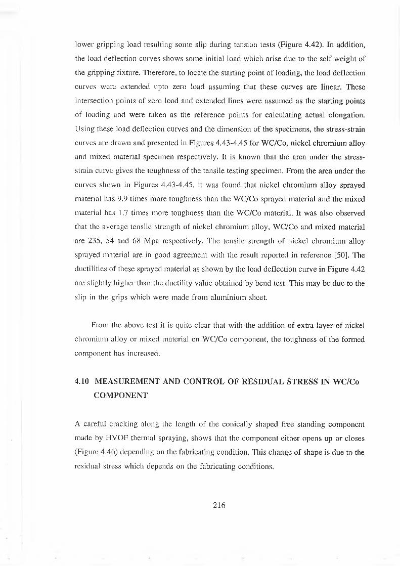
lower gripping load resulting some slip during tension tests (Figure 4.42). In addition,
the load deflection curves shows some initial load which arise due to the self weight of
the gripping fixture. Therefore, to locate the starting point of loading, the load deflection
curves were extended upto zero load assuming that these curves are linear. These
intersection points of zero load and extended lines were assumed as the starting points
of loading and were taken as the reference points for calculating actual elongation.
Using these load deflection curves and the dimension of the specimens, the stress-strain
curves are drawn and presented in Figures 4.43-4.45 for WC/Co, nickel chromium alloy
and mixed material specimen respectively. It is known that the area under the stress-
strain curve gives the toughness of the tensile testing specimen. From the area under the
curves shown in Figures 4.43-4.45, it was found that nickel chromium alloy sprayed
material has 9.9 times more toughness than the WC/Co sprayed material and the mixed
material has 1.7 times more toughness than the WC/Co material. It was also observed
that the average tensile strength of nickel chromium alloy, WC/Co and mixed material
are 235, 54 and 68 Mpa respectively. The tensile strength of nickel chromium alloy
sprayed material are in good agreement with the result reported in reference [50]. The
ductilities of these sprayed material as shown by the load deflection curve in Figure 4.42
are slightly higher than the ductility value obtained by bend test. This may be due to the
slip in the grips which were made from aluminium sheet.
From the above test it is quite clear that with the addition of extra layer of nickel
chromium alloy or mixed material on WC/Co component, the toughness of the formed
component has increased.
4.10 MEASUREMENT AND CONTROL OF RESIDUAL STRESS IN WC/Co
COMPONENT
A careful cracking along the length of the conically shaped free standing component
made by HVOF thermal spraying, shows that the component either opens up or closes
(Figure 4.46) depending on the fabricating condition. This change of shape is due to the
residual stress which depends on the fabricating conditions.
216
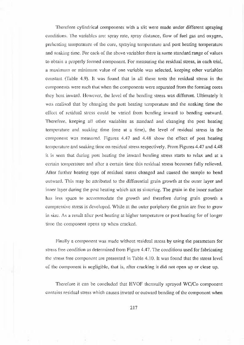
Therefore cylindrical components with a slit were made under different spraying
conditions. The variables are: spray rate, spray distance, flow of fuel gas and oxygen,
preheating temperature of the core, spraying temperature and post heating temperature
and soaking time. For each of the above variables there is some standard range of values
to obtain a properly formed component. For measuring the residual stress, in each trial,
a maximum or minimum value of one variable was selected, keeping other variables
constant (Table 4.9). It was found that in all these tests the residual stress in the
components were such that when the components were separated from the forming cores
they bent inward. However, the level of the bending stress was different. Ultimately it
was realised that by changing the post heating temperature and the soaking time the
effect of residual stress could be varied from bending inward to bending outward.
Therefore, keeping all other variables as standard and changing the post heating
temperature and soaking time (one at a time), the level of residual stress in the
component was measured. Figures 4.47 and 4.48 show the effect of post heating
temperature and soaking time on residual stress respectively. From Figures 4.47 and 4.48
it is seen that during post heating the inward bending stress starts to relax and at a
certain temperature and after a certain time this residual stress becomes fully relieved.
After further heating type of residual stress changed and caused the sample to bend
outward. This may be attributed to the differential grain growth at the outer layer and
inner layer during the post heating which act as sintering. The grain in the inner surface
has less space to accommodate the growth and therefore during grain growth a
compressive stress is developed. While at the outer periphery the grain are free to grow
in size. As a result after post heating at higher temperature or post heating for of longer
time the component opens up when cracked.
Finally a component was made without residual stress by using the parameters for
stress free condition as determined from Figure 4.47. The conditions used for fabricating
the stress free component are presented in Table 4.10. It was found that the stress level
of the component is negligible, that is, after cracking it did not open up or close up.
Therefore it can be concluded that HVOF thermally sprayed WC/Co component
contains residual stress which causes inward or outward bending of the component when
217
cracked. However, the level of bending stress might be different with different spray
parameters. This bending stress can be controlled by controlling post-heating the sprayed
deposit at specified temperature and time.
4.11 EFFECT OF SPRAYING PARAMETERS ON THE PROPERTIES OF THE
WC/Co COMPONENT
The WC/Co components were made under different spray conditions and the resulting
properties in terms of the hardness and porosity are given in Table 3.9. The spray
parameters varied were: 1) flow rate of oxygen, 2) flow rate of propylene, 3) flow rate
of air, 4) spray distance and 5) spray rate of depositing material. The standard values
of these variables for depositing coatings using this material were supplied by the
equipment manufacturer. The standard values given by the manufacturer were concerned
with the properties of the coating such as hardness, porosity and bond strength. The
bond strength of the coating with the substrate is a very crucial property. For spray
forming, bonding of the depositing material with the substrate is not required. Therefore
the standard values of spray parameters set by the manufacturer are not valid for spray
forming operation. Hardness and porosity are the main concern of this investigation.
Therefore tests were carried out to evaluate the effect of the spray parameters on the
hardness and porosity of the sprayed WC/Co materials. During this test, values of the
spray parameters were selected around the standard values set by the manufacturer
because too wide a variation of the spray parameters might have a detrimental effect on
the hardware of the HVOF thermal spraying system.
The properties required for the component depends on the type of application. As
this study is not restricted to any definite application, optimization of the spraying
parameters towards a definite optimum property (hardness and porosity) of the deposited
free standing component was not carried out. Therefore, the effect of the individual
spraying parameter only is of interest here. During these tests one variable was varied
while keeping all other variables constant and the effect of this variable on hardness and
porosity are presented graphically in different figures.
218
To measure these properties, samples were sectioned, mounted, ground and
polished. A fully automatic Motopol 12 polishing machine was used to polish the
sample to a surface finish of 0.5 micron. Porosity measurements were taken by using
a Reichert MEF3 optical microscope and a Quantiment 570 image analysis system. The
results are average values based on measurements taken at randomly selected locations
for each sample. Hardness was measured with a Vickers hardness tester under a load of
0.3 kg on the polished cross section. Micrographs showing the porosity in the deposited
materials are presented in Figures 4.49-4.52. The level of porosity in the deposited
materials is 0.8 %, 1.0 %, 2 % and 3 % as shown in Figures 4.49-4.52 respectively.
Curves in Figure 4.53 shows the variation of hardness and porosity of the deposited
material for the variation in flow rate of oxygen between 284-221 standard litre per
minute (SLPM). The average hardness and porosity values change from 1155-1185
Hv,0.3 and 1.7-1.75 % respectively. Figure 4.54 shows that the variation of the flow rate
of propylene between 84-67 SLPM causes the variation of average hardness and porosity
1187-1115 Hv,0.3 and 1.3-2.1 %. Figure 4.55 shows that the variation of the flow rate
of air between 380-311 SLPM causes the variation of average hardness and porosity
1182-1157 Hv,0.3 and 2.0-1.5 %. Figure 4.56 shows that the variation of the spray
distance between 225-125 mm causes the variation of average hardness and porosity
1049-1294 Hv,0.3 and 1.95-1.49 %. Figure 4.57 shows that the variation of flow rate
of powder material between 50-23 gm per minute causes the variation of average
hardness and porosity 1130-1210 Hv,0.3 and 2.6-1.85 %.
Therefore, it can be observed that the spray distance is the dominant factor
influencing the hardness of the depositing material. Both the higher spray and air flow
rates produce higher porosity in the deposited material. Increased flow rate of propylene
increases the hardness but has little effect on the porosity of the deposit. Flow rate of
oxygen has little effect on both the hardness and porosity compared to other variables.
During making a sample using the shortest spray distance the rise in temperature
was so quick that a change of colour of the depositing material was observed and that
might produce some amount of lower carbide which is harder and hence high hardness
219
results were obtained.
4.12 COMPOSITION OF THE DEPOSITED WC/Co MATERIAL
During the deposition of the WC/Co material, the change of colour of the deposited
material at different stages of fabrication was observed. In addition, the composition of
the sprayed material is one of the major deciding property of the components. Therefore
the composition of this deposited material was investigated.
X-ray diffraction was performed on the deposits on the core before and after post
heating for Tungsten carbide-cobalt components and also on a coating of the same
material sprayed on a substrate without preheating. The typical XRD spectra are given
in Figures 4.58-4.61. The XRD spectra of the coating shown in Figure 4.58, shows WC
phase in the deposit with some proportion of decomposed W2C and M6C (Co3W3C-eta)
phases. These phases are quite likely in the coatings deposited by HVOF process [105].
Figure 4.59 shows the XRD traces for the deposited material on the core before post
heating. These two traces give almost identical peaks for different phases of WC-Co
materials. Fig. 4.60 is the XRD spectra of the outer surface of the as obtained free
standing component after post heating. This trace is quite different and shows the
different phases of oxides of WC and the colour of the surface is bluish. After cleaning
the outer surface by sand paper, XRD was performed and the spectra is shown in
Figure 4.61. Analysis of all these traces shows that after cleaning, the compositional
phases of the free standing object is similar with small proportion of oxide phases in the
component. Therefore, it is clear that post heating makes the outer layer of the
component oxidised and this oxidised layer can be removed by easy rubbing with sand
paper.
The percentage of the amount of each composition in the formed component are
calculated from the ratio of intensity of the peaks in the XRD trace for the composition
and is presented in Table 4.11. This table also shows the percentage of composition for
this powder material and the deposited coating reported in reference [105], From Table
4.11 it can be seen that the percentage of WC in the deposited coating is about 57 %
220
which is 12 % less than the amount of WC, present in the starting powder. However the
amount of WC in the deposited coating is 11 % higher than that of the reported value.
The percentage of WC in the formed component is about 53 %. During the fabrication
of the component some amount of WC might lose its carbon and formed lower carbide
due to higher temperature of the fabricating process. During the fabrication the
formation of lower carbide was observed by the change of colours. Due to the higher
percentage of W2C the hardness of the deposited material is higher and the brittleness
of the formed component is also higher.
To compare the amount of oxygen and carbon present in the free standing
component and in the deposited coating, relative quantitative measurements were
performed. At the same time to ascertain the variation of the elements along the cross-
section of the free standing component, relative quantitative measurements for different
element present, were performed. A Joel 8600 ’Superprobe’ SEM fitted with both the
wave length and energy dispersive analysis facilities were used to measure these
quantities.
To compare the carbon and oxygen contents of the cleaned free-standing object and
coating deposited from WC-Co materials were analyzed by using wave length
spectrometry. The count rates obtained for carbon over 100 second in central region of
both samples are given in Table 4.12. It was found that the variation of the count is less
than 500, which is considered to be very small in terms of the wave length spectrometry.
Extremely low oxygen count rates were measured indicating that no substantial amount
of oxygen was present in either sample.
To compare the compositional variation along the cross-section of the free standing
component and deposited coating, the energy dispersive analysis was done as shown in
Figure 4.62-4.67. Three locations were chosen for each component such that it covers
the total cross-sectional area. This analysis indicates that no significant compositional
( W and Co) variation was present between the samples.
221
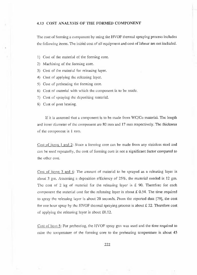
I
The cost of forming a component by using the HVOF thermal spraying process includes
the following items. The initial cost of all equipment and cost of labour are not included.
1) Cost of the material of the forming core.
2) Machining of the forming core.
3) Cost of the material for releasing layer.
4) Cost of applying the releasing layer.
5) Cost of preheating the forming core.
6) Cost of material with which the component is to be made.
7) Cost of spraying the depositing material.
8) Cost of post heating.
If it is assumed that a component is to be made from WC/Co material. The length
and inner diameter of the component are 80 mm and 17 mm respectively. The thickness
of the component is 1 mm.
Cost of items 1 and 2 : Since a forming core can be made from any stainless steel and
can be used repeatedly, the cost of forming core is not a significant factor compared to
the other cost.
Cost of items 3 and 4: The amount of material to be sprayed as a releasing layer is
about 3 gm. Assuming a deposition efficiency of 25%, the material needed is 12 gm.
The cost of 2 kg of material for the releasing layer is £ 90. Therefore for each
component the material cost for the releasing layer is about £ 0.54. The time required
to spray the releasing layer is about 20 seconds. From the reported data [79], the cost
for one hour spray by the HVOF thermal spraying process is about £ 22. Therefore cost
of applying the releasing layer is about £0.12.
Cost of item 5: For preheating, the HVOF spray gun was used and the time required to
raise the temperature of the forming core to the preheating temperature is about 45
4.13 COST ANALYSIS OF TH E FORMED COM PONENT
222
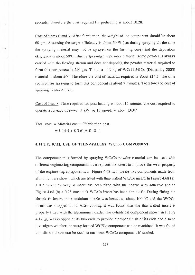
seconds. Therefore the cost required for preheating is about £0.28.
Cost of items 6 and 7 : After fabrication, the weight of the component should be about
60 gm. Assuming the target efficiency is about 50 % ( as during spraying all the time
the spraying material may not be sprayed on the forming core) and the deposition
efficiency is about 50% ( during spraying the powder material, some powder is always
carried with the flowing stream and does not deposit), the powder material required to
form this component is 240 gm. The cost of 1 kg of WC/11.5%Co (Diamalloy 2003)
material is about £60. Therefore the cost of material required is about £14.5. The time
required for spraying to form this component is about 7 minutes. Therefore the cost of
spraying is about £ 2.6.
Cost of item 8: Time required for post heating is about 15 minute. The cost required to
operate a furnace of power 3 kW for 15 minute is about £0.07.
Total cost = Materia] cost + Fabrication cost.
= £ 14.5 + £ 3.61 = £ 18.11
4.14 TYPICAL USE OF THIN-WALLED WC/Co COMPONENT
The component thus formed by spraying WC/Co powder material can be used with
different engineering components as a replaceable insert to improve the wear property
of the engineering components. In Figure 4.68 two nozzle like components made from
aluminium are shown which are fitted with thin-walled WC/Co insert. In Figure 4.68 (a),
a 0.2 mm thick WC/Co insert has been fixed with the nozzle with adhesive and in
Figure 4.68 (b) a 0.25 mm thick WC/Co insert has been shrunk fit. During fitting the
shrunk fit insert, the aluminium nozzle was heated to about 100 °C and the WC/Co
insert was dropped in it. After cooling it was found that the thin-walled insert is
properly fitted with the aluminium nozzle. The cylindrical component shown in Figure
4.14 (g) was chopped at its two ends to provide a proper finish of its ends and also to
investigate whether the spray formed WC/Co component can be machined. It was found
that diamond saw can be used to cut these WC/Co component if needed.
223

TEMP
ERAT
URE
DIFF
EREN
CE
IN C
DIFFERENCE IN THERMAL EXPANSION BETWEEN FORMING CORE AND SPRAYED DEPOSIT IN MICRON
( Curves 1,2 and 3 are drawn for aluminium forming core and stainless steel, nickel chromium alloy and WC/Co depositing materials respectively. Cuives 4 and 5 are drawn for stainless steel forming core and nickel chromium alloy and WC/Co depositing materials respectively.)
Figure 4.1 Curve showing the gap that will form between the sprayed deposit layer and the forming core surface upon cooling the forming core from preheating temperature.
224
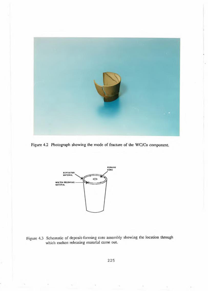
Figure 4.2 Photograph showing the mode of fracture o f the WC/Co component.
FORMINGCO R E
D E P O S ITE DMATERIAL
M OLTEN RELEASING M ATERIAL
Figure 4.3 Schematic of deposit-forming core assembly showing the location through which molten releasing material came out.
225
(a) (b) (c)
Figure 4.4 Photograph of the double cone shaped component made from different materials, a) WC/Co, b) Nickel chromium alloy and c) Stainless steel.
226

TEM
PER
ATU
RE
IN C
700
toto<1
PREHEATING THE\ FORMING C O R E \ COATED WITH INTER LAYER
6 0 0 -
500
400
300
HEATING F O R SEPARATION
S O A KING
SPRAYING O F DEPOSITING MATERIAL
TRANSFERING THE DEPOSIT-FORMING CORE ASSEMBLY IN THE FURNACE
C O OLING
80 100 120 TIME IN M INUTE
Figure 4.5 Time-temperature curve showing the fabrication process of spray formed component from nickel chromium alloy material.
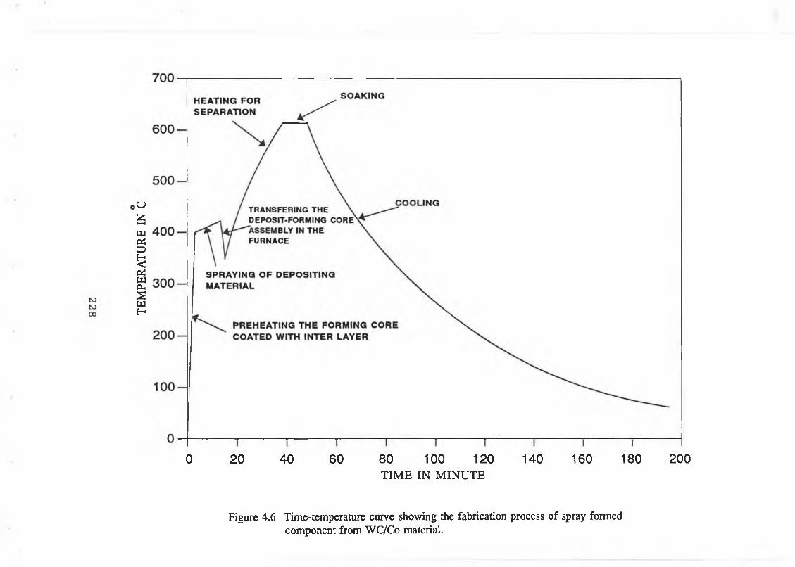
TEM
PER
ATU
RE
IN C
0 20 40 60 80 100 120 140 160 180 200TIME IN M INUTE
Figure 4.6 Time-temperature curve showing the fabrication process of spray formed component from WC/Co material.

Figure 4.7a Micrograph showing the porosity of the components made from WC/Co material (maginfication 380 X).
Figure 4.7b Micrograph showing the porosity of the components made from Nickel chromium alloy material (maginfication 380 X).
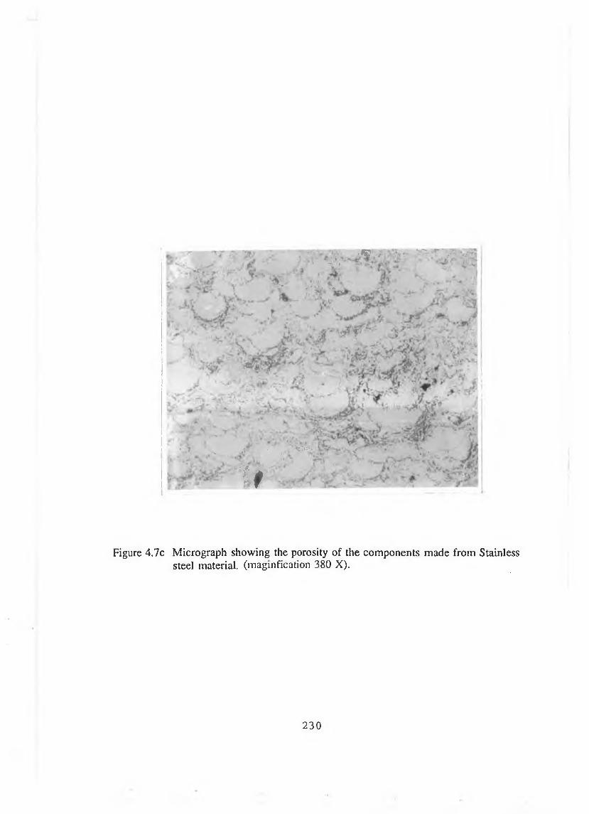
’ . 1 ® >•; f S& f" ’ fV ! "
\ > »?>)* tv. v .***
• ,T __ ^ • _ , V * = S V - ? * > <» J v .
> * f
Figure 4.7c Micrograph showing the porosity of the components made from Stainless steel material, (magnification 380 X).
230
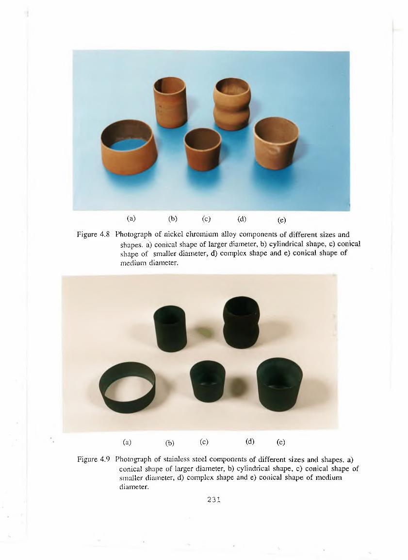
(a) (b) (c) (d) (e)
Figure 4.8 Photograph of nickel chromium alloy components of different sizes andshapes, a) conical shape of larger diameter, b) cylindrical shape, c) conical shape of smaller diameter, d) complex shape and e) conical shape of medium diameter.
(a) (b) (c) (d) (e)
Figure 4.9 Photograph of stainless steel components of different sizes and shapes, a)1 conical shape of larger diameter, b) cylindrical shape, c) conical shape of smaller diameter, d) complex shape and e) conical shape of medium diameter.
2 3 1

(a) (b) (c)
Figure 4.10 Photograph of WC/Co components of different sizes and shapes, (a) cylindrical shape, (b) conical shape of large diameter and (c) conical shape of medium diameter.
232

C O E FF IC IE N T O F T H E R M A L E X P A N SIO N ( x 10? K ')
Figure 4.11 Curve showing the variation of preheating temperature with the coefficient of thermal expansion of the material by which the forming core were made.
233
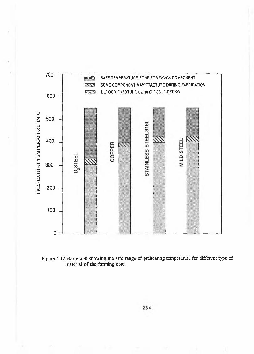
PREH
EAT
ING
T
EM
PER
AT
UR
E
IN C
700 -
600 -
500 -
400 _
300 -
200 -
100 -
0 -
mm SAFE TEMPERATURE ZONE FOR WC/Co COMPONENT
c w q SOME COMPONENT MAY FRACTURE DURING FABRICATION
H DEPOSIT FRACTURE DURING POST HEATING
Figure 4.12 Bar graph showing the safe range of preheating temperature for different type of material of the forming core.
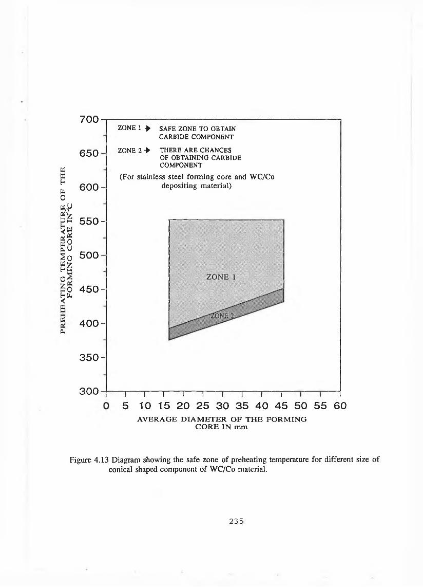
700
0
ZONE 1 *
650 ZONE 2 *
y
w K Hb 0
&l-l
¡aSBS o 5 0 0S zh m
SAFE ZONE TO OBTAIN CARBIDE COM PONENT
THERE A R E CHANCES OF OBTAINING C AR BIDE CO M PO NENT
6 0 0 -
5 5 0 -
(For stainless steel forming core and WC/Co depositing material)
M 0h Pk<n
M0,
4 5 0 -
4 0 0 -
3 5 0 -
300 i i 1 i i i i i r
5 10 15 20 25 30 35 40 45 50 55 60AVER AG E D IA M E T E R OF T H E FO R M IN G
C O R E IN mm
Figure 4.13 Diagram showing the safe zone of preheating temperature for different size of conical shaped component of WC/Co material.
235

(c) (d) (e) (f) (g) (h)
Figure 4.14 Photograph of WC/Co components of different sizes and shapes.(dimensions of these components are presented in Table 4.5)
2 36
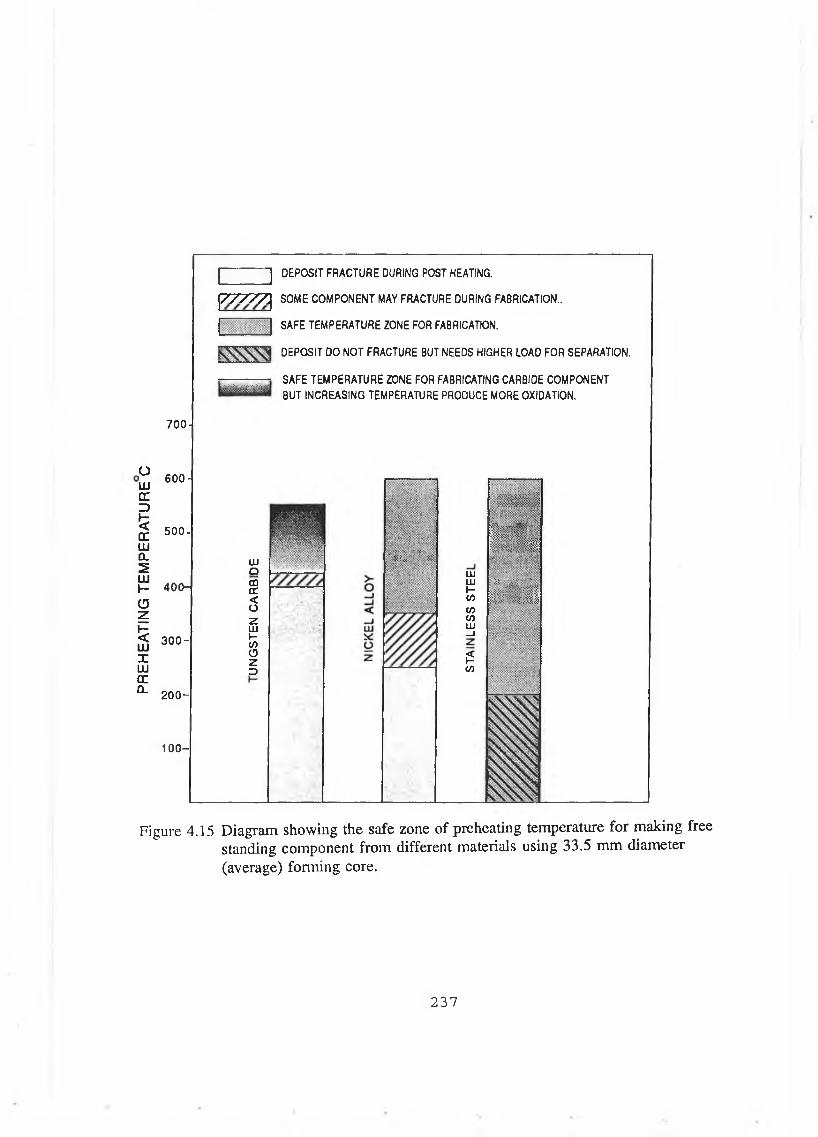
PREH
EATI
NG
TE
MPE
RA
TUR
E C
DEPOSIT FRACTURE DURING POST HEATING.
700-
600-
500-
400-
3 0 0 -
2 0 0 -
100-
Z / V V Z j SOME COMPONENT MAY FRACTURE DURING FABRICATION..
SAFE TEMPERATURE ZONE FOR FABRICATION.
DEPOSIT DO NOT FRACTURE BUT NEEDS HIGHER LOAD FOR SEPARATION.
SAFE TEMPERATURE ZONE FOR FABRICATING CARBIDE COMPONENT
BUT INCREASING TEMPERATURE PRODUCE MORE OXIDATION.
UJQCDcc<oHU JHCOuzo
: ::x‘ " v:-.y v
; •
LU UJ I— C/5
COGOUJ—I
ÉCO
¡ S Ü
I « 1M U l .
i? . 'PfRXIi
Figure 4.15 Diagram showing the safe zone of preheating temperature for making free standing component from different materials using 33.5 mm diameter (average) forming core.
2 3 7
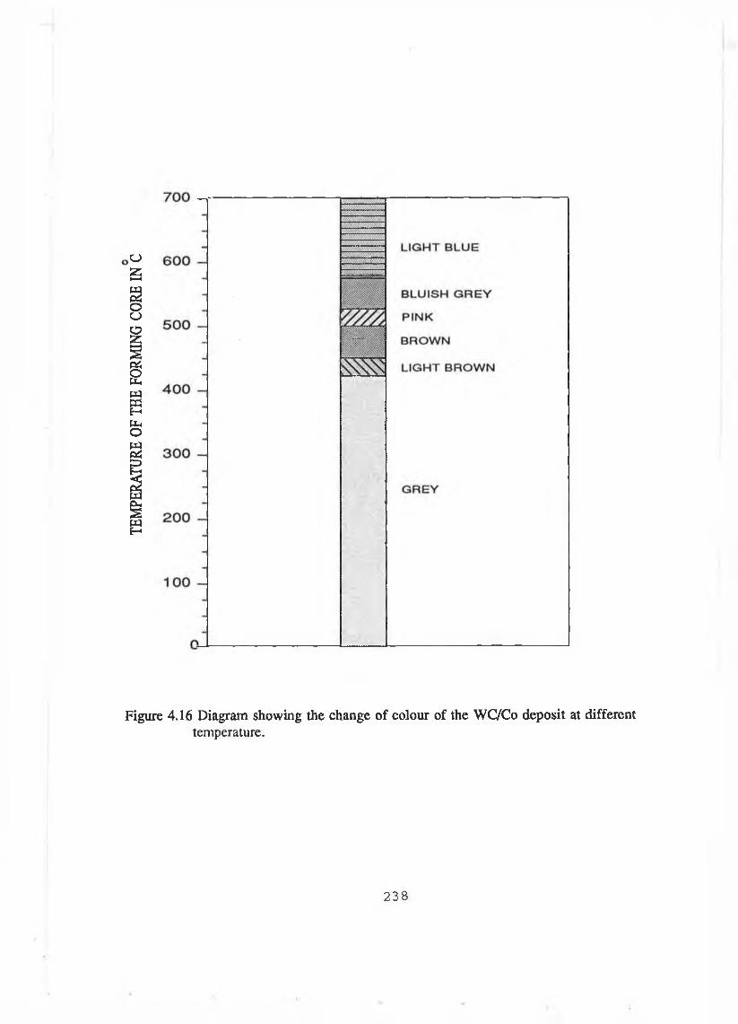
TEM
PERA
TURE
OF
TH
E FO
RMIN
G CO
RE
IN C
Figure 4.16 Diagram showing the change of colour of the WC/Co deposit at different temperature.
238
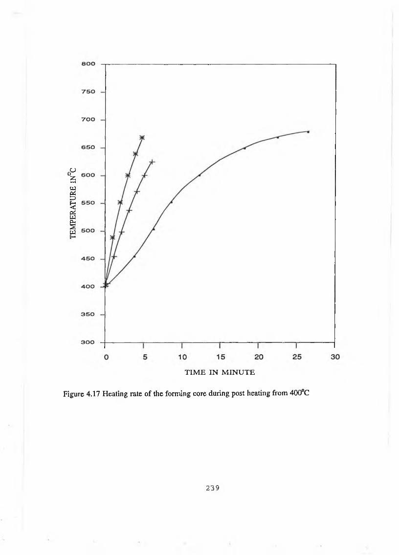
TEM
PERA
TURE
IN
C
TIM E IN M IN U TE
Figure 4.17 Heating rate of the forming core during post heating from 400°C
239
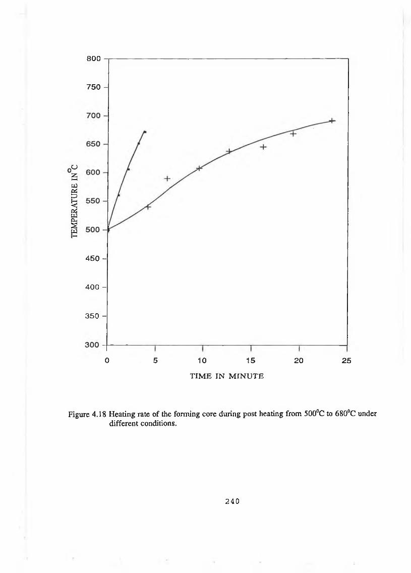
TEM
PERA
TURE
IN
C
800
750 -
4 50 -
400 -
350 -
0 5 10 15 20 25
T IM E IN M IN U T E
Figure 4.18 Heating rate of the forming core during post heating from 500°C to 680°C under different conditions.
240
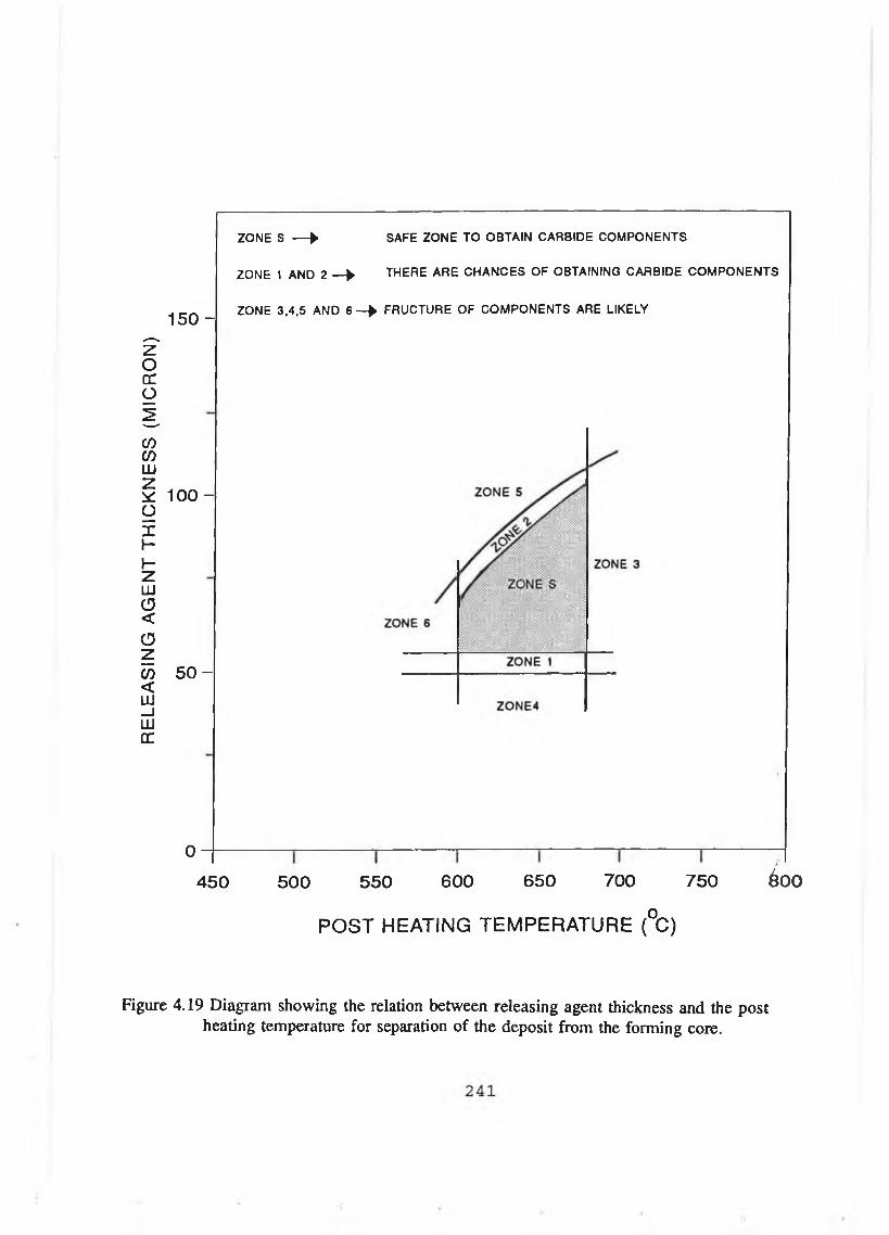
RE
LE
ASI
NG
A
GEN
T T
HIC
KN
ESS
(M
ICR
ON
)
1 5 0 -
100 -
5 0 -
0 -----
4 5 0
ZONE S — ► SAFE ZONE TO OBTAIN CARBIDE COMPONENTS
ZONE 1 AND 2 — ► THERE ARE CHANCES OF OBTAINING CARBIDE COMPONENTS
ZONE 3,4,5 AND 6 - > FRUCTURE OF COMPONENTS ARE LIKELY
5 0 0 5 5 0 6 0 0 6 5 0 7 0 0 7 5 0 ÓOO
P O S T H E A T IN G T E M P E R A T U R E (°C )
Figure 4.19 Diagram showing the relation between releasing agent thickness and the post heating temperature for separation of the deposit from the forming core.
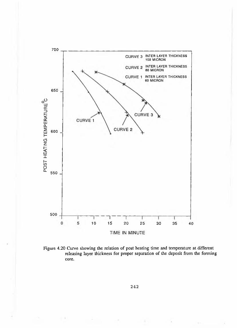
POST
HE
ATIN
G TE
MPE
RA
TUR
E C
7 0 0
650 _
CURVE 3 IN T E R LA V E R T H IC K N E S S 1 0 0 M IC R O N
600 _
550 _
500
10715
T20 25
TIME IN MINUTE
30 35 40
Figure 4.20 Curve showing the relation of post heating time and temperature at different releasing layer thickness for proper separation of the deposit from the forming core.
242

Figure 4.21 Photograph of WC/Co component having localised fracture.
243
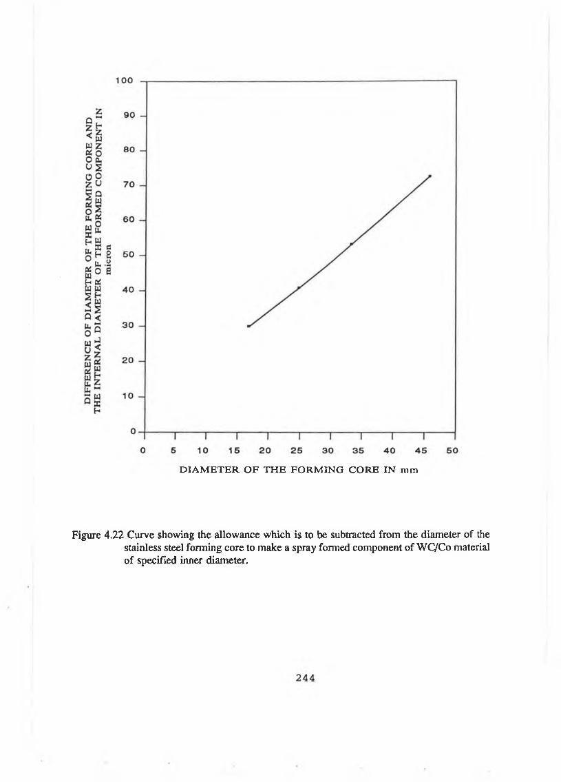
D IA M E TE R OF TH E FORM ING CORE IN mm
Figure 4.22 Curve showing the allowance which is to be subtracted from the diameter of the stainless steel forming core to make a spray formed component of WC/Co material of specified inner diameter.
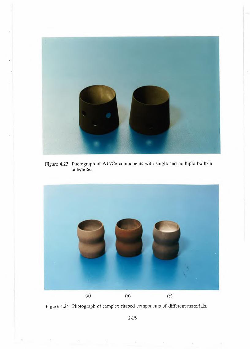
Figure 4.23 Photograph of WC/Co components with single and multiple built-in hole/holes.
Figure 4.24 Photograph of
2 4 5
(b) (c)
complex shaped components of different materials.
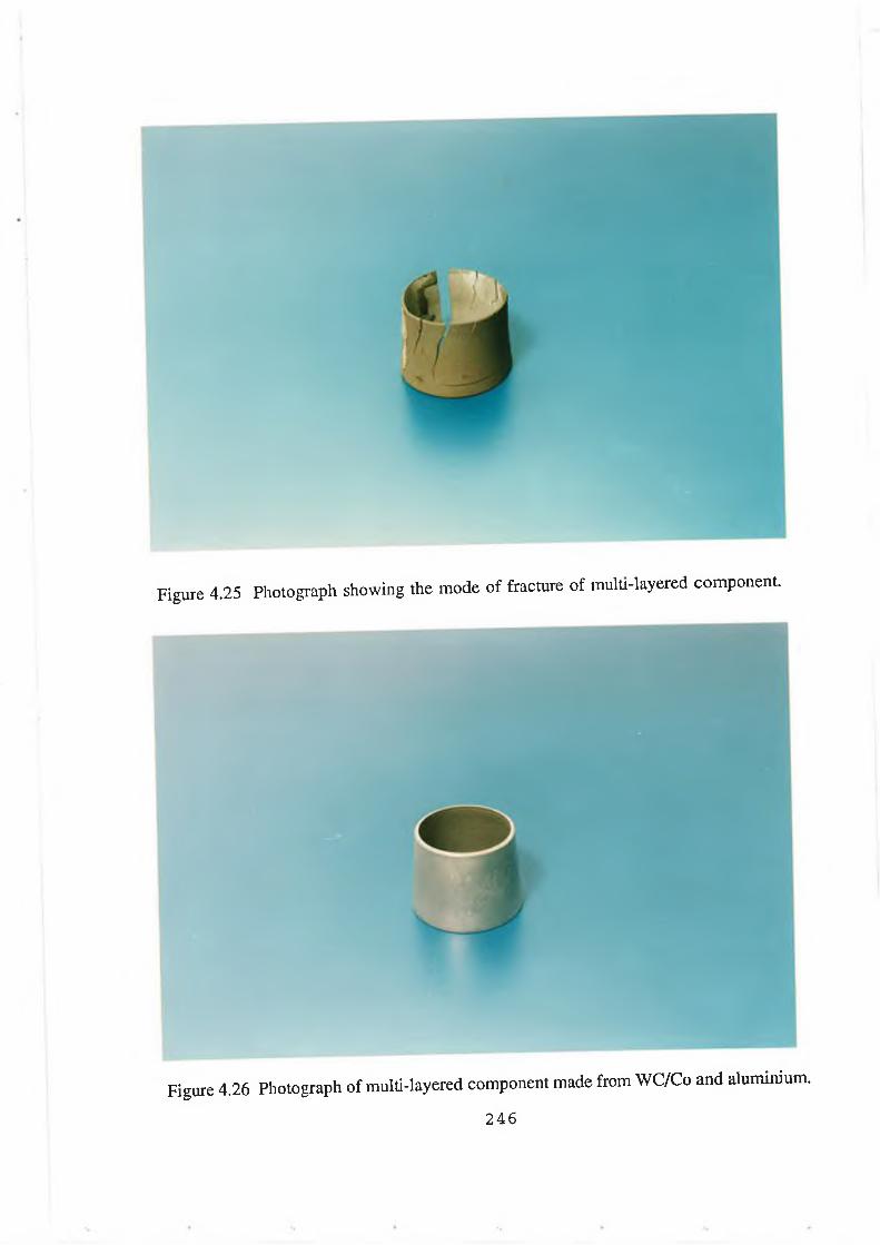
Figure 4.25 Photograph showing the mode of fracture of multi-layered component.
Figure 4.26 Photograph of multi-layered component made from WC/Co and aluminium.
246
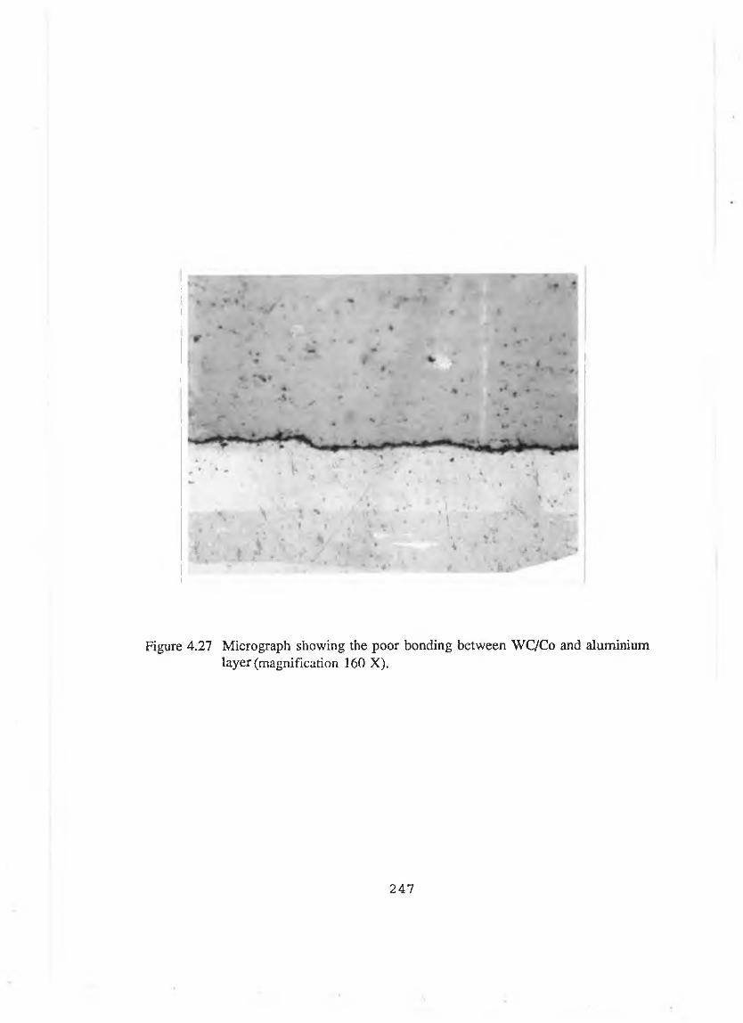
Figure 4.27 Micrograph showing the poor bonding between WC/Co and aluminium layer (magnification 160 X).
247
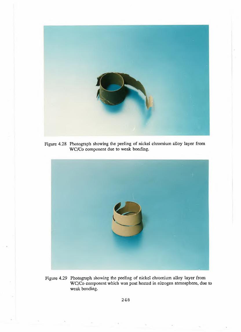
Figure 4.28 Photograph showing the peeling of nickel chromium alloy layer from WC/Co component due to weak bonding.
Figure 4.29 Photograph showing the peeling of nickel chromium alloy layer fromWC/Co component which was post heated in nitrogen atmosphere, due to weak bonding.
248

Figure 4.30 Photograph of the component with partially deposited nickel chromium alloy layer on WC/Co component.
Figure 4.31 Photograph of the multi-layered component made from WC/Co and nickel chromium alloy material.
2 4 9
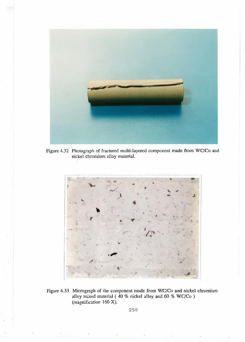
Figure 4.32 Photograph of fractured multi-layered component made from WC/Co and nickel chromium alloy material.
fiTr " ’w > ■ *" ' m
r v
Ak.
V /- - «»
4¥
1 ; r • ,t v . .
l f « '*•' * >
i- •. V ; '
* 'to• f
* , * *
‘ t *
• >
Figure 4.33 Micrograph of the component made from WC/Co and nickel chromium alloy mixed material ( 40 % nickel alloy and 60 % WC/Co ) (magnification 160 X).
250

Figure 4.34 Photograph of WC/Co component with mixed material on the top layer.
2 5 1
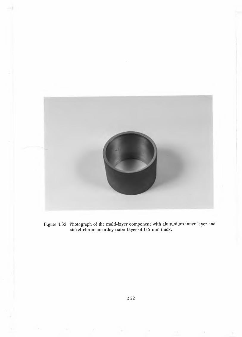
Figure 4.35 Photograph of the multi-layer component with aluminium inner layer and nickel chromium alloy outer layer of 0.5 mm thick.
252

7 0
Figure 4.36 Adhesive bond strength of deposited material at different substrate preheating temperature.
253
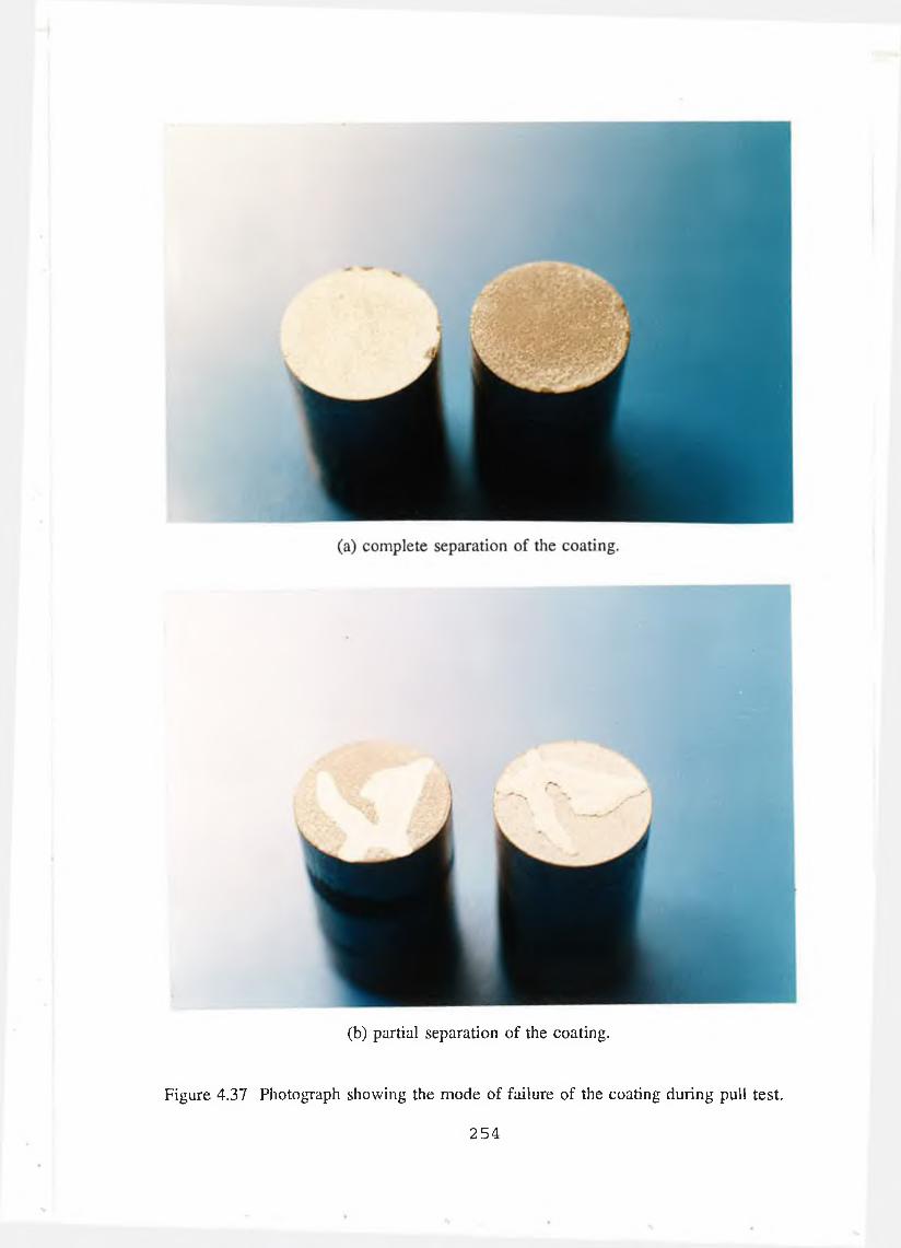
(b) partial separation of the coating.
Figure 4.37 Photograph showing the mode o f failure o f the coating during pull test.
254
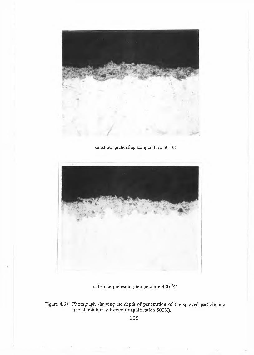
substrate preheating temperature 50 °C
substrate preheating temperature 400 °C
Figure 4.38 Photograph showing the depth of penetration of the sprayed particle into the aluminium substrate, (magnification 500X).
255
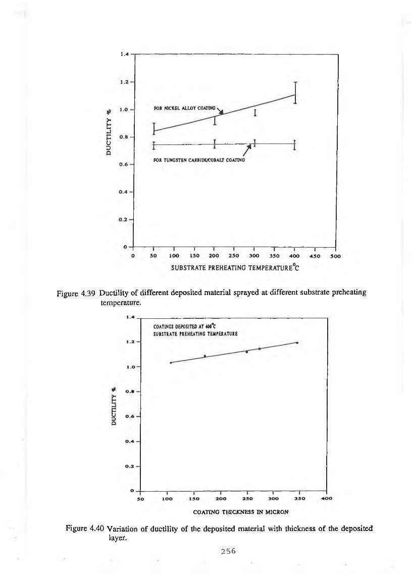
1.4
Figure 4.39 Ductility of different deposited material sprayed at different substrate preheating temperature.
COATING THICKNESS IN MICRON
Figure 4.40 Variation of ductility of the deposited material with thickness of the deposited layer.
256
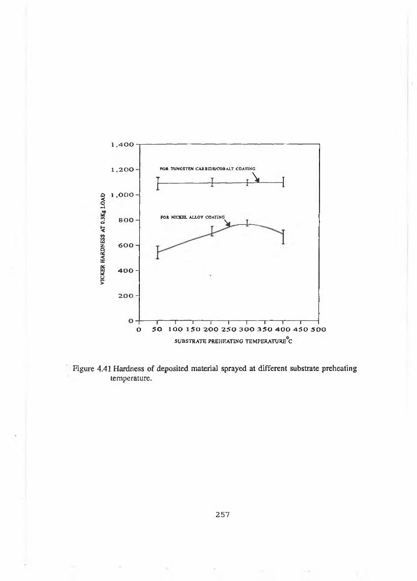
1 . 4 0 0
1 ,200
Q 1 .O O O <S
o
¡Ctn232QP i<aaisu>
800
600 -
400 -
200 -
}
FOR TUNGSTEN CAR BIDE/COB ALT COATING
Í -------
FOR NICKEL ALLOY COATING
I in vi
A 1
1 1 1--------1-1 1 1-----------------1--------1-----O 50 100 150 200 250 300 350 400 450 500
SUBSTRATE PREHEATING TEMPERATURE C
Figure 4.41 Hardness of deposited material sprayed at different substrate preheatingtemperature.
257
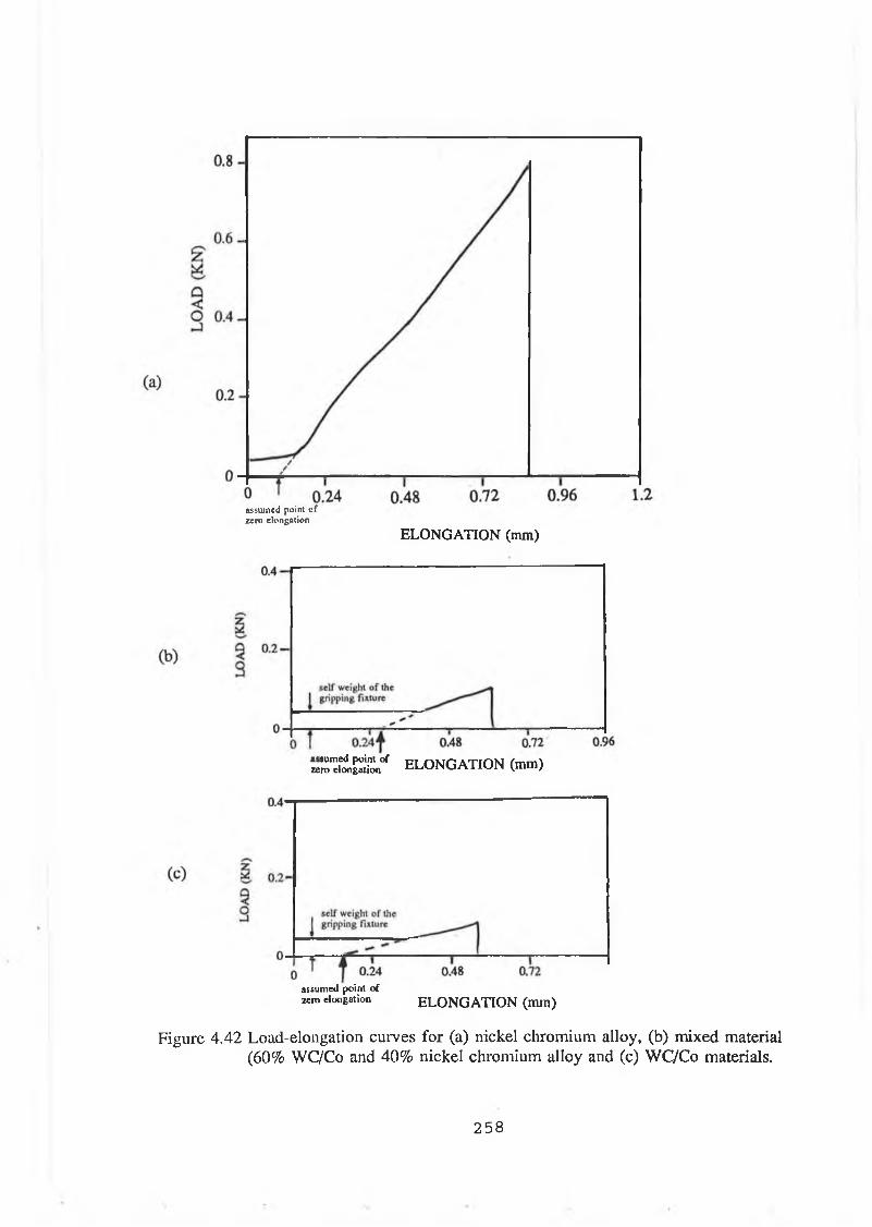
assum ed point o f zero elongation
ELONGATION (mm)
« T e it £ ! ° f ELONGATION (mm)
assum ed point ofzero elongation E L O N G A T IO N (mm)
Figure 4 .4 2 Load-elongation curves for (a) n ickel chrom ium a lloy , (b) m ixed material (60% W C/Co and 40% n ick e l chrom ium alloy and (c) W C /C o materials.
258
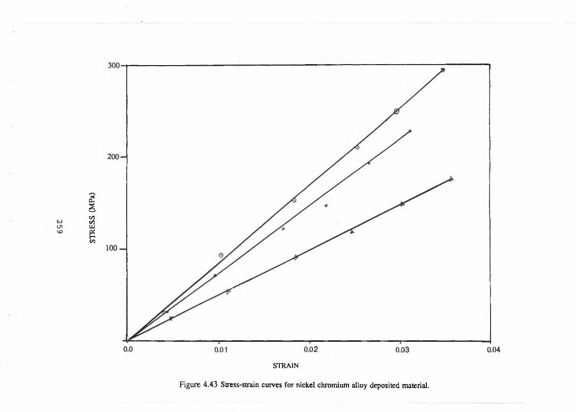
STR
ESS
(MPa
)
STRAIN
Figure 4.43 Stress-strain curves for nickel chromium alloy deposited material.
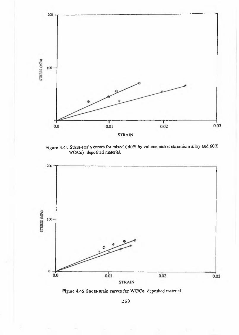
STRAIN
Figure 4 .4 4 Stress-strain curves for mixed ( 40% by volum e nickel chromium alloy and 60% WCVCo) deposited material.
Figure 4.45 Stress-strain curves for WC/Co deposited material.
260
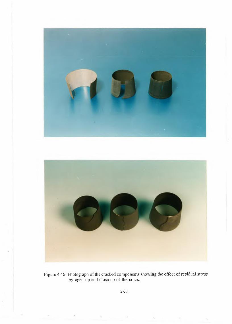
Figure 4.46 Photograph of the cracked com ponents showing the effect o f residual stressby open up and close up of the crack.
261
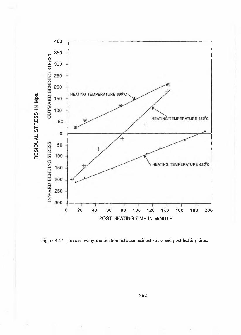
400
(0CL
C/D0 )LUCCf-w
<DqcoU JDC
350C/3t/3
Sg 300 00
20 40 60 80 100 120 140 160
POST HEATING TIME IN MINUTE
180 200
Figure 4 .47 Curve show ing the relation betw een residual stress and p ost heating time.
262
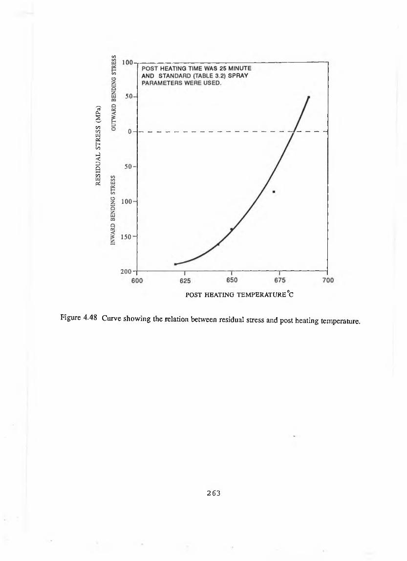
RESI
DUAL
ST
RESS
(M
Pa)
CO
POST HEATING TEMPERATURE °C
Figure 4.48 Curve showing the relation between residual stress and post heating temperature.
263
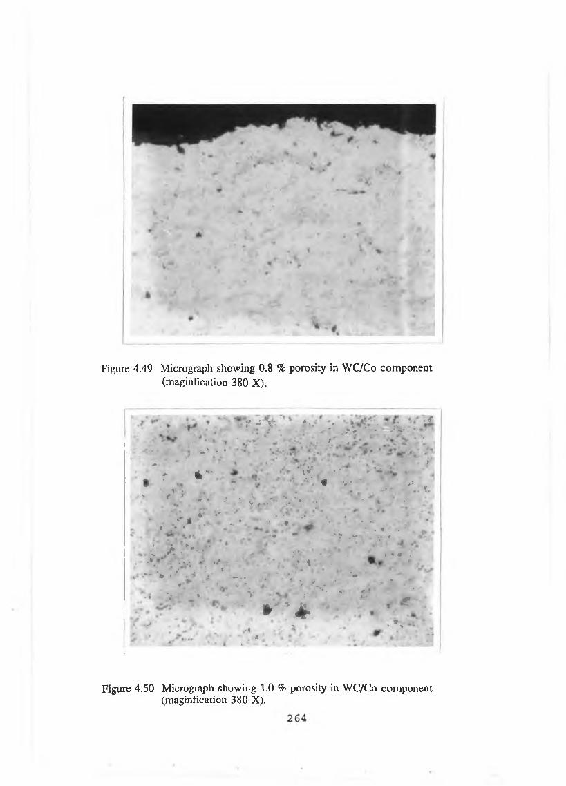
Figure 4.49 Micrograph showing 0.8 % porosity in WC/Co component(maginfication 380 X).
f A » i * ' • * * • • i ‘■ ' , y * ■' \ - v *
a
' / ' . **
, .* < f - ^ — V % •
JP, - ,* * L ? * • i * it
; r * s * *.r . * •§ • ■ - 1 ♦ > * * • . . . > n1 .
, % f t i . • , . t . * i - *. r " , .■ * * . • > f - * > * * ■: * * *•
• . ■>" d * * ri , * • ; ■
* * ■ * ' * ’ r f * ** ' # h 44:' • . - » >* J
" \ ■’ .* - • - ■ .
¿ * ^ / • - • ’
* ' ? - * - • * - v *
• ■* JrV. * V . _ / * » • ' #, . . * . . . . . * / - , . • i • . > t i • * ,
• . .• , . *. i . M * r #•
* ■ " . * ■ ‘ *, # • ■ ^ »* 'v •
. i V • .* ■ . • .*»,* . . -
• v r \ : * * ; £ ^
: • r - * *f s . . * V . • » * ' ^ * ' 1 V ' .% , Ip .» * % ' %"
■ ■ ; > ; 5 • / • *
i
Figure 4.50 Micrograph showing 1.0 % porosity in WC/Co component(maginfication 380 X).

Figure 4.51 Micrograph showing 2.0 % porosity in WC/Co component(maginfication 380 X).
* mi
■ \ 4 <•
j * *
i
k
' ' ** t
9' » . ' V
V ,' .
> f
T
■ r r n
• > + f(■ (
Figure 4.52 Micrograph showing 3.0 % porosity in WC/Co component (magnification 380X).
265

VIC
KER
H
AR
DN
ESS
(Hv
0.3)
1350
1300 -
1250
1200 -
1150 -
1 1 0 0 -
1050 -
1000
200
- 2 .5
- 2
- 1.5
- 1
- 0.5
225 250 275F L O W R A T E O F O X Y G E N (SL P M )
300
Figure 4.53 Curve showing the variation of hardness and porosity with the change offlow rate of oxygen during spraying WC/Co material.
266
PO
RO
SIT
Y
%

VICK
ER
HAR
DNES
S (H
v 0.
3)
1350
1300 -
1250 -
1 2 0 0 -
1150 -
1100 -
1050 -
1000
- 2.5
~ 1.5
- 0.5
65 70 75 80 85FLOW RATE OF PROPYLENE (SLPM )
Figure 4.54 Curve showing the variation of hardness and porosity with the change of flow rate of propylene during spraying WC/Co material.
267
PORO
SITY
%

VICK
ER
HARD
NESS
(Hv
0.
3)1350
1300 -
1 2 5 0 -
1200 -
1150 -
1 1 0 0 -
1050 -
1000
- 2.5
h 1.5
- 0.5
300 325 350 375
FLOW RATE OF AIR (SLPM )
400
Figure 4.55 Curve showing the variation of hardness and porosity with the change offlow rate of air during spraying WC/Co material.
268
PO
RO
SIT
Y
%

1400
1350
1300
1250
1200
1150
1100
1050
1000
95C
ire 4.'
1 1 1 1
>0 125 1 50 175 200
SPRAY DISTANCE IN mm
225 25
Curve showing the variation of hardness and porosity with thedistance o f the spray gun from the forming core during sprayimaterial.

VICK
ER
HARD
NESS
(H
v 0.
3)1300
1250 -
1200 -
1150 -
1100 -
1050 -
1000 -
950
- 4.5
3.5
- 3
- 2.5
- 2
- 1.5
- 0.5
10 15 20 25 30 35 40 45 50 55 60
SPRAY RATE OF WC/Co MATERIAL (gm/min)
Figure 4.57 Curve showing the variation of hardness and porosity with the change offlow rate of powder material during spraying WC/Co material.
270
PO
RO
SITY
%

INTE
NSIT
Y (a
rbit
rary
un
it)
Figure 4.58 X-Ray diffraction pattern for WC/Co coating deposited without preheating condition.
Figure 4.59 X-Ray diffraction pattern for WC/Co component before post heating.
2 7 1

50 45 4ft 35 30 25 20
Figure 4.60 X-Ray diffraction pattern for WC/Co free-standing component after post heating.
Figure 4.61 X-Ray diffraction pattern for WC/Co free-standing component after post heating and cleaning.
272

COUN
TS
FULL
SC
ALE
= 80
00
§ CO
UNTS
FU
LL
SCAL
E =
8000
4.62 Energy dispersive analysis pattern of WC/Co coating (about 0.5 mm thick) at within 50 pm of the outer surface of the cross-section.
Figure 4.63 Energy dispersive analysis pattern o f WC/Co coating (about 0.5 mm thick) atcentral region o f the cross-section.
273

Figure 4.64 Energy dispersive analysis pattern of WC/Co coating (about 0.5 mm thick) at within 50 pm of the inner surface of the cross-section.
Figure 4.65 Energy dispersive analysis pattern of WC/Co free-standing cleaned component(about 0.7 mm thick) at within 50 pm of the outer.surface of the cross-section.
274

Figure 4.66 Energy dispersive analysis pattern of WC/Co free-standing cleaned component (about 0.7 mm thick) at central region of the cross-section.
Figure 4.67 Energy dispersive analysis pattern of WC/Co free-standing cleaned component(about 0.7 mm thick) at within 50 pm of the inner surface of the cross-section.
275

Figure 4.68 Photograph showing the application of thin-walled WC/Co component(a) WC/Co component is fixed with the aluminium nozzle with adhesive,(b) WC/Co component is shrunk fit with aluminium nozzle.
2 7 6

Table 4.1 Calculated induced stress in the deposited materials due to thermal mis-match between deposited material and the forming core material.
(Stainless steel was used as forming core material. Estee,= 193 GPa, a itec)= 18 x 10 */K)
Depositingmaterial
Young’s modulus of depositing material (GPa)
Coefficient of thermal expansion of depositing material x 106/K
Equilibrium temperature (°C) *
Change of temp, from equilibrium temp. (°C)
Induced hoop stress (MPa)
WC/Co 193 7 500 10 0 20 0
WC/Co 193 7 500 2 0 0 400
Nickelchromiumalloy
67 13 500 10 0 95
Nickelchromiumalloy
67 13 500 2 0 0 189
Nickelchromiumalloy
67 13 500 300 284
Nickelchromiumalloy
67 13 500 400 378
* The temperature at which sprayed material were deposited and it is assumed that at this temperature there is no stress within the deposited material.
277

Table 4.2 Test results to separate deposited layer from theforming core through aluminium releasing layer.
Depositing materialReleasing layer thickness (pm)
Remarks
Nickel chromium alloy 213
Molten releasing layer stuck with the deposit and separation of the deposit from the forming core was not possible
Nickel chromium alloy 196
Molten releasing layer stuck with the deposit and separation of the deposit from the forming core was not possible
Nickel chromium alloy 173
Molten releasing layer stuck with the deposit and separation of the deposit from the forming core was not possible
Nickel chromium alloy 154
Molten releasing layer stuck with the deposit and separation of the deposit from the forming core was not possible
Nickel chromium alloy 138Molten releasing layer stuck with deposit, but fabrication was possible
Nickel chromium alloy 122 Fabrication of component was possible
Nickel chromium alloy 115 Fabrication of component was possible
Nickel chromium alloy 93 Fabrication of component was possible
Nickel chromium alloy 76 Fabrication of component was possible
278

Table 4.3 Different properties o f the spray formed components.
Materials Porosity Hardness Roughness (Ra)% Range Average Inner surface Outer Surface
(HV 0.3) (HV 0.3) (pm) (pm)
WC/Co ” 4 1106-1249 1189 1.9-8.33 4.82-8.1
Nickel 1 736-982 848 3.2 9.3ChromiumAlloy
Stainless 0.5 394-448 412 3.0 7.8Steel
279

280
Table 4.4 Typical values of processing variables for fabricating free-standing components of different materials.
Type of material
Thickness of thereleasing layer (pm)
Preheating temp. (°C)
Spraying temp.(°C)
Spraying time (min)
Post heating temp. (°C)
Post heating time (min)
Coolingcondition
Thickness of the component
(pm)
WC/Co 60-110 425-550 425-600 3-10 600-680 3-30
Cooled in atmosphere or in furnace 100-1200
Nickelchromiumalloy
60-110 350-550 350-650 3-10 650-700 10-30Cooled in atmosphere 200-1500
Stainless steel 60-110 200-550 200-650 3-10 650-700 10-30 Cooled in atmosphere
200-1500

Table 4.5 Sizes and thicknesses of different WC/Co components as shown in Figure 4.14.
Sampleidentification
Shape of the component
Averagediameter(mm)
Length (mm) Thickness(mm)
(a) Conical 33.5 30 0.96
(b) Conical 33.5 30 1.2
(c) Conical 48.0 20 0.26
(d) Cylindrical 40.0 40 0.42
(e) Conical 21.5 25 0.45
(f) Complex 31.5 40 0.41
(g) Cylindrical 17.0 85 0.98
00 Complex 46.0 50 0.38
2 8 1

282
Table 4.6 Results showing the effect o f surface roughness o f the forming core on the fabrication o f WC/Cocomponents.
Forming core surfaceForming core surface after applying releasing layer
Component surface Component surface
inner surface outer surface inner surface outer surface
Roughness Polished by sand paper
Roughened by grit (C grade) blasting
Polishedformingcore
Roughenedformingcore
Made from polished forming core
Made from roughened forming core
Made from polished forming core
Made from roughened forming core
Ra (pm) 0.83 4.7 4.2 4.0 2.92 3.16 3.98 3.72
Rmax (pm) 8.1 37.0 40.5 27.0 22.4 27.0 28.4 37.0

Table 4.7 Effect of surface roughness and cleanliness of the forming core on thefabrication of WC/Co components.
No. of sampleAverage Roughness in micron
Cleanliness Remarks
1 4.7Cleaned by sand blasting
Fabrication of component was possible
2 4.7Forming core reused without cleaning
Deposit fractured during spraying
3 1.9Forming core reused after cleaning by sand paper
Fabrication of component was possible
4 1.9Forming core reused without cleaning
Deposit fractured during spraying
5 < 1 .0
Forming core reused after cleaning and polishing
Deposit fractured during spraying
283

Table 4.8 Bond strength and ductility of coating at different aluminium substrate surface condition.
Roughen substrate Surface at 50°C substrate preheating temperature.
Smooth substrate Surface at 400°C substrate preheating temperature.
WC/Co Nickel chromium alloy
WC/Co Nickel chromium Alloy
Bond strength (MPa)
47 28 63 46
Ductility % 0.76 0.86 0.76 1.08
284

285
Table 4.9 Effect o f fabrication parameters on the residual stress o f the WC/Co component
SampleNo
Spray rate (gm/min)
Spraydistance(mm)
Flow rate of gases (SLPMJ
Oxygen Propylene Air
Preheating; temp. ( Q
Temp, during spraying ( C).
Post heating temp. f C )
Post heating time (min).
Type of bending stress.
1 45 2 0 0 265 73 325 450 450-500 650 30 bending inward
2 30 2 0 0 265 73 325 450 450-500 650 30 bending inwand
3 38 2 0 0 265 73 325 450 450-500 650 30 bending inward
4 38 225 265 73 325 450 450-500 650 30 bending in ward
5 38 150 265 73 325 450 450-500 650 30 bending inward
6 38 2 0 0 284 73 325 450 450-500 650 30 bending inward
7 38 2 0 0 2 2 1 73 325 450 450-500 650 30 bending inward
8 38 2 0 0 265 84 325 450 450-500 650 30 bending inward
9 38 2 0 0 265 67 325 450 450-500 650 30 bending inward
1 0 38 2 0 0 265 73 380 450 450-500 650 30 bending inwaid
1 1 38 2 0 0 265 73 311 450 450-500 650 30 bending inwaid
1 2 38 2 0 0 265 73 325 550 550-600 650 30 bending inward
13 38 2 0 0 265 73 325 425 425-475 650 30 bending inwaid
14 38 2 0 0 265 73 325 450 450-650 650 30 bending inwaid
15 38 2 0 0 265 73 325 450 450-475 650 30 balding inwaid
16 38 2 0 0 265 73 325 450 450-500 690 30 bending outwaid
17 38 2 0 0 265 73 325 450 450-500 620 30 balding inward
18 38 2 0 0 265 73 325 450 450-500 650 10 0 bending outwaid
19 38 2 0 0 265 73 325 450 450-500 650 15 bending inward

Table 4.10 Conditions to make stress free spray formed WC/Co component.
Spray parameters
Flow of Oxygen (SLPM) - 265
Flow of propylene (SLPM) - 73
Flow of air (SLPM) - 325
Spray rate (gm/inin) - 38
Spray distance (mm) - 200
Conditions of the forming core
Preheating temperature (°C) - 450
Temperature (°C) during spraying - 450-500
Post heating temperature (°C) - 650
Post heating time (min) - 80
Table 4.11 Composition in the powder and sprayed WC/Co material obtained from the relative intensities of XRD traces.
Sample Phase relative intensity
WC W2C W WCO C03W 3C
Starting 62 23 5 -powder [42]
44 35 17Coating deposited by HVOF [42]
Coating 67 33(Fig. 4.58)
Component 61 36before post heating (Fig.4.59)
Component 121 69afterfabrication(Fig.4.61)
10
12
13
Percent of phase present
W C W 2C W W CO C03W 3C
69 25.5 5.5
46 36 18 -
57 3 2
53 37
53 37
11
286

Table 4.12 Counts to determine relative carbon quantity in WC/Co coating and in free standing components.
Sample identification Counts
WC-Co Coating deposited without preheating.
Location 1 Location 2
14661 14334
WC-Co Cleaned free-standing component
14259 14527
2 8 7

CHAPTER 5
CONCLUSIONS

5.1 CONCLUSIONS
Spray forming of near net shaped thin walled hollow components using HVOF thermal
spraying process has been investigated. Components have been successfully formed in
tungsten carbide/cobalt, nickel chromium alloy and stainless steel materials. Component
formed are of cylindrical, conical with or without holes and complex shaped. This
method should provide a cost effective way of making carbide components of a variety
of sizes and shapes.
While fabricating spray formed components, material is to be sprayed on a
forming core which is subsequently separated from the forming core. Proper separation
of the sprayed layer from the forming core can not be achieved by preheating the
forming core or by increasing the spray distance or by decreasing the angle of incidence
of the sprayed particle or by applying high temperature grease. During the deposition
of spray materials the adhesion of the sprayed material with the substrate should be
sufficient such that the spray layer does not fracture during spraying. After spraying the
adhesion of the sprayed layer with the forming core surface has to be poor such that the
sprayed layer can be separated without fracture. These conditions of sprayed deposit can
be maintained by putting a releasing inter layer.
An epoxy layer whose working temperature is about 300 °C, is not suitable to
withstand the high temperature and high heat content of the spray stream and the high
impact of the sprayed particle of the HVOF gun. A mixture of metallic material with
the epoxy adhesive is not a solution to protect the epoxy releasing layer against the
erosion and burning of epoxy material. The releasing layer which is to be applied on the
forming core surface should have a proper thermal conductivity to allow transfer of the
heat of the sprayed material to the forming core and to the environment very effectively.
Aluminium of 99 % purity and with certain range of particle sizes has been
identified to act as a releasing layer which had sufficient bonding with the forming core
288

surface up to the temperature at which deposition takes place. This releasing layer can
also be made non-adherent through some post treatment after spraying. The thickness
of the releasing agent has profound effect on the ease with which the free standing
components can be released form the forming core. During the forming operation the
forming core surface remains unaffected allowing the same forming core to be used
repeatedly. This reduces the production cost and makes the process very suitable for
mass production.
The forming core can be made from different types of materials such as mild
steel, stainless steel, D2 steel and copper. The coefficient of thermal expansion of the
forming core material has some effect on a number of processing parameters, such as
types of the depositing material, preheating temperature and size of the forming core.
The difference between the dimensions of the inner diameter of the component and the
outer diameter of the forming core also depends on the coefficient of thermal expansion
of the forming core material and its dimension. The roughness and cleanliness of the
forming core surface have some effect on the occurrence of fracture of the sprayed layer
during spraying.
The process of heating and cooling of the forming core at different stages of the
spray forming process has the influential effect in obtaining the component in proper
condition. The preheating temperature of the forming core is one of the critical factors
which influences the ease with which the component may be released. For every
combination of the depositing and forming core materials there is some definite range
of preheating temperature. The temperature of the forming core during spraying affects
fracture of the WC/Co deposited layer during spraying. A large deviation from the
preheating temperature during spraying might cause fracture of any of the depositing
material used. Variation of temperature during spraying along the length of the forming
core might cause fracture of the deposited layer and it is more critical in a forming core
of higher length and smaller diameter. Variation of temperature of the forming core
during spraying is more critical for WC/Co material than for other two materials used
for fabricating components. Extra cooling air should not be used to control the
temperature of the forming core during spraying. Spray distance or number of samples
289

or traversing speed of the gun should be adjusted to control the temperature of the
forming core during spraying.
Before the separation of the sprayed deposit from the forming core, the forming
core-deposit assembly should not be allowed to cool down to a much lower temperature.
Therefore, after deposition of the material the forming core-deposit assembly should be
transferred to a preheated furnace as quickly as possible to avoid much cooling of the
forming core. This is more critical for a WC/Co component than for the other two
materials. Post heating of the forming core is essential to separate the deposit from the
forming core surface. The temperature and soaking time of post heating are crucial to
make the releasing layer non-adherent with the forming core surface. The post heating
temperature and soaking time are also depend on the releasing layer thickness. The
heating rate during post heating has no significant effect on the ease of separation of the
free standing component. The cooling rate of the forming core-deposit assembly should
not be very fast. Forced air cooling might cause fracture of the free standing component.
Very slow cooling might cause more oxidation of the free standing component,
particularly for WC/Co component. Otherwise slower cooling is preferable for obtaining
components without fracture.
Measurement and control of temperature during preheating and spraying
operation are essential. This is more true for WC/Co components. During spraying a
WC/Co component, the sprayed surface changes colour with temperature which is very
distinctive. This can be utilised to control and monitor the temperature of the WC/Co
deposit while spraying.
The hardnesses of the spray formed components are found to be higher than the
cast and wrought materials. The porosity levels of WC/Co components are found to be
0.8-3.0 %. By choosing the processing variables the porosity and hardness of the WC/Co
components can be adjusted upto certain limits. For nickel chromium alloy and for
stainless steel the porosity levels are less than 1 % and 0.5 % respectively. The
compositional analysis of WC/Co components shows that there is no significant
compositional variation present within the samples.
290

The components formed by this process are found to be brittle. However the
toughness of a WC/Co component can be increased by putting multi-layers with other
materials such as aluminium and nickel chromium alloy. It is found that this extra layer
increases the toughness and may provide a means of attaching these components with
some other components. However, there is some limitation to the thickness of this extra
layer beyond which the stress set up in the layer may induce cracking of the component.
Toughening of the component can be achieved by fabricating the component initially
with a hard material and finally with the mixed material. In the mixed material, the
harder material is gradually substituted with a tougher material. The proportion of the
mixture can be varied upto a certain limit. However, complete substitution of the harder
material by a tougher material may cause fracture of the component. Multi-layer
components can also be made with an aluminium inner layer and harder material outer
layer. The adhesion of these harder sprayed materials deposited at higher preheating
temperatures of aluminium substrate are found to be satisfactory to act as multi-layer
components.
The spray formed components made from WC/Co contain residual stresses. The
amount of residual stress depends on the values of processing parameters. Parameters
can be selected to obtain a component with the desired type of residual stress.
Thin-walled spray formed WC/Co components can be fitted as replaceable inserts
in a nozzle or in a cylinder with adhesive or can be shrunk fit. The edges of the formed
component can be chopped by diamond cutter if needed to fix it properly.
5.2 RECOM M ENDATIONS FO R FUTURE W O RK
During this investigation it was found that with the decrease of coefficient of thermal
expansion of the forming core material the preheating temperature decreases. Therefore
further investigation can be carried out to make free standing components by WC/Co
material using a forming core which is made of a material such that the thermal
expansion of the forming core material is almost equal to the thermal expansion of the
sprayed deposit. In that case preheating might be avoided and at the same time the
291

control of temperature during spraying might be easier.
The material of the releasing layer has been chosen from commercially available
material which is not standard for use by a HVOF process, caused problem of flow
during the tests. An alternative powder of the same composition can be selected which
can flow with the carrier gas of the powder feeder or a method is to be developed to
maintain the proper flow of the powder used.
During the investigation it was found that the residual stress within the spray
formed WC/Co components is always compressive when the post heating temperature
and time are less. Variation of other processing parameters resulted in compressive
residual stress within the formed component. However, it was also found that the level
of the compressive residual stress varied with the change of the values of processing
parameters. The effect of the processing parameters on the residual stress can be
investigated in detail to determine the overall effect of the processing variables on the
residual stress of the component.
The application of multi-layer to improve the toughness can be investigated in
more detail to determine the maximum thickness of the extra layer. The residual stress
within the component might have some effect on the thickness of the extra layer.
Manufacturing of components with a harder initial layer and gradually
substituting the harder material with tougher material by mixing the tougher and harder
material at different proportions might be worthwhile to investigate to make tougher
components with WC/Co material. In that case WC/Co materials with different
proportion of cobalt can be used to make a tougher and thicker component.
During the tests of fabricating WC/Co components, it was found that at higher
preheating temperatures, formation of lower carbide in WC/Co material produces higher
hardness. This can be done intentionally to create a harder surface layer of WC/Co
material which contains lower carbide and the rest of the layer of the component can be
made of WC/Co of higher cobalt content. This component might have both higher
292

hardness layer and higher toughness layer. For other materials also the same procedure
can be investigated by spraying an initial layer with a controlled amount of oxidation
and the rest of the deposition could be done without oxidation. This process might help
to obtain a component of any material with higher wear resisting surface property.
During the investigation it was not possible to maintain the uniformity of
thickness of the component due to the lack of proper control of the traversing unit and
the flow rate of the powder. A traversing unit which has higher traversing speed and
better control can be designed to obtain component of uniform thickness. A fully
automatic traversing unit would be preferable. To make a component with different
combination of powders, a powder feeder with the facility of using more than one
powder is needed.
293

REFERENCE
1. Moran.A.L., at el, " Spray fonning technology for military applications" Proceedings of the fourth National thermal spray conference, Pittsburgh, PA, USA, 4-10 May 1991.
2. Moran.A.L." Large scale production of spray deposition tubes in alloy 625" Powder production and spray forming. Volume-1 Proceedings of the 1992 powder metallurgy world congress. 21-26 June, San Francisco, California, USA.
3. Scott.K.T., Kingswell.R., "Thermal spraying" Advanced Surface Coating: a Handbook of surface engineering. Published by Chapman and Hall, New York.
4. Kubel,E.J.(1987), "Thermal Spraying Technology:From Alt to Science," Advanced materials and Precesses. 12. 69-87.
5. Bell.T., Bloyce.A and Lanagon.J. "Surface engineering of light metals" Proc. 6 th Int. Conf. on heat treatment and materials, Chicago, Illinois, 28-30 sept. 1988.pp 1 -8 .
6 . Vento.P.R., " The focus and direction of surface modification technology". Proc. 6 th Int. Conf. on heat treatment and materials, Chicago, Illinois, 28-30 sept. 1988. pp 29- 36.
7. Chapman.B.N.and Anderson.T.C., Science and technology of surface coating, Academic, New York.
8 . Hailing,J. (1985) " Introduction" Recent developments in surface coating and modification processes.MEP ,london.l-2.
9. Bluishan,B., Gupta,B.K. (1991), Handbook of Tribology,Mcgraw Hill,New York.
10. Rehbinder.P.A. and Likhtman.V.I., (1957), "Effects of surface active media on strains and rupture in solids", Proceedings of second international congress on surface activity, vol-3, London, 563-580.
11. Kinloch. A.J, (1980), " The science of adhesion", Journal Material science, Vol- 15, pp.2141-2166.
12. Rickerby D.S. and Matthews.A. Advanced surface coating: a hand book of surface engineering. Blackie and Son Ltd. London. 1991
13. Bmishah,R.F. (1982), Deposition technologies for Films and Coatings, Noyes publications, New Jersey U.S.A.
R1

14. Anonymous (l985)"Coating Characteristics," Thermal Spraying:Practice,Theory, and Application. American Welding Society, Inc.Miami, Florida.
15. Metco/Perkin-Elmer,(1989),"Hand note"
16. Vossen.L.J. and Kern.W. Thin film process, Academic press. Inc, San Diego, California. 1978
17. Vossen.L.J. and Kern.W. Thin film process II, Academic press. Inc, San Diego, California. 1991.
18. Cuomo.J. and Rossnagel.S., Hand book of Ion beam processing technology, Noyes Publication.
19. Sundgren.J.E. and Hentzrll.T.G., " A review of the present state of art in hard coatings grown from the vapour phase", J.Vac.Sci. Technol. A.4(5), 1986.
20. Kola etal ." Magnetron sputtering of TiN protective coatings" Proc. of the Int. Conf. on Advances in Materials and Processing Technologies. 1993. pp 1323- 1332.
21. Nakahara.S., "Microporosity induced by nucleation and growth process in crystalline and non-crystalline films". Thin solid films, Vol-45, pp 421-432.
22. Kawan etal" Study on elastic contact and residual stress measurements during ceramic coatings" Proc. Third National thermal spray conf. Long beach. CA. May1990. pp. 339-342.
23. Pan.A. and Greene. J.E. " Residual compressive stress in sputter-deposited TiC films on steel substrate", Thin solid films, Vol-78, pp 25-34.
24. Scott,D. etal (1975), "Metals and Metallurgical Aspects of Piston Ring Scuffing - A Literature Survey," Wear, Vol.33, 293-315.
25. Hintermann, H.E. (1980), " Exploitation of Wear and Corrosion resistant CVD Coatings," Tribol. Int. Vol. 13, 267-277.
26. Boving, H., Hintermann, H.E., and Stehle,G. (1983), TiC Coated Cemented Carbide Balls in Gyro-Application Balls Bearings. Lubrication Engineering, Vol.39, 209-215.
27. ASM Hand book "Heat treatment. Volume-4, 1991.
28. Kraak, Herlaar,W., Wolke,J., etal.(1992)," Influence of Different Gases on the Mechanical and Physical Properties on HVOF Sprayed Tungsten Carbide Cobalt,"Proceedings, Int.Thermal Spray Conference, Orlando, Florida. 153-158.
R2

29. Antony,K.C., Bhansali.K.J., Messier,R.W.(1983)," Hard Facing," Metals Hand Book, vol 6 . Welding, Brazing and Soldering. 9 th. ed., ASM Metals Park Ohio, pp 771-803.
30. Ingham,H.S.(1969),"Flame Sprayed Coatings,"Composite Engineering Laminates. (A.G.H.Deetz, ed ), MIT Press, Cambridge. 304-322.
31. Fisher,I.A.(1972),"Variables Influencing the Characteristics of Plasma- Sprayed Coatings,"International Metal Review, vol-17. 117-129.
32. Morishita.T, Whitfield.R.W, Kuramochi.E, Tanabe.S, " Coatings with compressive stress" Proceedings of the international thermal spray conference & exposition, Orlando, Florida, USA, 28 May - 5 June, 1992
33. Clare,J.H., Crawmer,D.E. (1982), "Thermal Spray Coatings," Metals Hand Book, Vol.5. Surface Cleaning, Finishing and Coating, 9th ed.ASM, Metal Park, Ohio, pp. 361-374.
34. Figueroa. H. and Diaz. O., " Thermal spray modelling of flat surfaces and cylinders", Proc. of the fourth National thermal spray conf. Pittsburgh, PA,USA, may 1991. pp 549-556
35. Wilms.V. and Herman.H.,"Plasma spraying of Al2Oa and A120 3-Y20 3" Thin solid films. Vol-39 1970. pp 251-262.
36. Zaat,H.J.(1987),"A Quarter of a Century of Plasma Spraying," Annual Review of Material Science, 13. 9-42.
37. Datta.P.K. and Gray.J.S. Surface engineering Volume III: Fundamentals of coatings. Published by the Royal Society of Chemistry, Science Park, Cambridge. Great Britain.
38. Levinstein.M.A, Eisenlohr.A. and Rramer.B.T. "Properties of plasma-sprayed materials", Welding Journal, Vol-40, 1961.pp 234-245.
39. Ault.N.N, "Some characteristics of composite tungsten carbide weld deposits". Welding Journal, Vol-30, pp 144-160.
40. Berger.L.M. eta I,"Influence of carbide powder composition on decarburization and properties of air plasma sprayed coatings" Proceedings, International Thermal Spray Conference, Oriando,Florida, 1992, pp. 375-380.
41. BeczlcowiakJ., Schwier,G., "Tailoring Carbides and Oxides for HVOF" Proceedings of the Fourth National Thermal Spray Conference, Pittsburgh, Pennsylvania, 1991, pp. 121-126.
R3

42. Kaufold,R., Rotolico,A., Nerz,J„ etal.(1990),"Deposition of Coatings Using a MHigh Velocity Combustion Spray Gun," Proceedings, Third National Thermal Spray Conference, Long Beach, CA. 561-569.
43. Stover.D, Jager.D.A and Schutz.H.G., " Residual stress in low pressure plasma sprayed chromia coatings" Proc. of the fourth National thermal spray conf. Pittsburgh, PA,USA. 1991.
44. Takuichi.S, Ito.M and Talceda. " Modelling of residual stress in plasma sprayed coatings: Effect of substrate temperature", Surface and coating technology. Vol- 42 1990.
45. Anlt.N.N " Characteristics of refractory oxide coatings produced by flame- spraying", Journal of the American ceramic society. Vol-40, no 3. 1957.
46. Tucker,R.C.Jr."Structure/property relationships in deposits produced by plasma spray and detonation gun techniques" J.Vac. Sci. Tech. 11. 1973. pp. 725-734.
47. Kitahara.S and Hasui.A, " A study of the bonding mechanism of sprayed coatings". Journal .Vac. Sci. Technol. 11 1974. pp 747-754.
48. Gruner,H.(l984),"Vacuum Plasma Spray Quality Control," Thin Solid Films. 118. 409-420.
49. Henne,R., Schnurenberger,W., Weber,W. (1984), "Low Pressure Plasma Spraying -Properties and Potential for Manufacturing Improved Electrolysis," Thin Solid Film s,119. 141-152.
50. Nakahira etal." Anisottopy of thermally sprayed coating" Proc. of the Int. Thermal spray conf. and exposition. Orlando, Florida. USA. 1992. pp. 1011- 1018.
51. Bergder,M.E., Kermith,R."New Sonic and Supersonic 80 KW Plasma spray system" Proc. 9th airlines plating forum. Montreal, Canada. 1973.
52. Steffens,H.D., Hohle,H.M., Erturk,E.(1980)," Low Pressure Plasma Spraying of Reactive Materials," Thin Solid Films, 73. 19-29.
53. Steffens,H.D., Hohle,H.M.,(1980),"Further Development of the Thermal Spraying Technique by Low Pressure Plasma Spraying," Proceedings, Ninth International Thermal Spraying Conference, May, The Hogue, Netherlands.
54. James,D.H., (1983),"Progress in Thermal Spraying for Corrosion Protection," Anti-corrosion, July. 11- 15.
R4

55. Weglowski,S. and Pawlowski,L. " A study of residual stress in plasma sprayed alumina coatings"Proc. of the 5th International Symp. on plasma chemistry. Edinburgh, 1981, pp. 592-601.
56. Wolf,P.C. and Longo,F.N. "Vacuum plasma spray process and coatings", Proc.9th Int. Thermal spraying conf. 1980.
57. Smith.R.W, Schilling.W.F and Fox.H,"Low pressure plasma spray coatings for hot corrosion resistance", Proc.9th Int. Thermal spraying conf. 1980.
58. Eschnauer,H., Lugscheider,E. (1984),"Metallic and Ceramic Powders For Vacuum Plasma Spraying," Thin Solid Films. 118. 421-435.
59. Thorpe,M.L., Rich ter,H.S. "Pragmatic Analysis and Comparison of the HVOF process, " Proceedings. International Thermal Spray Conference, Oriando, Florida. 1992, pp. 137-148.
60. Vuoristo.P.M.J.,Niemi.K.J. and Mantyla.T.A. " On the properties of detonation gun sprayed and plasma sprayed ceramic coatings" Proceedings, International Thermal Spray Conference, Oriando,Florida. 1992. pp. 171-178.
61. Vuoristo.P, etal," Spray parameter effects on structure and wear properties of detonation gun sprayed WC + 17% Co coatings" Proceedings, 5th National Thermal Spray Conference, Anaheim, California, USA, 1993, pp. 173-178
62. Kreye.H and Blume.D, " High velocity oxy-fuel flame spraying of molybdenum" Proceedings, International Thermal Spray Conference, Or i an do, Florida. 1992. pp. 177-180.
63. Moskowitz.L.N, " Application of HVOF thermal spraying to solve corrosion problems in the petroleum industry", Proceedings, International Thermal Spray Conference, Oriando,Florida. 1992. pp. 611-618.
64. K notek.O ," Process modeling of HVOF thermal spraying systems", Proceedings, International Thermal Spray Conference, Oriando,Florida,1992, pp. 811-816.
65. Knotek.O."Simulation of the Jet-kote process", Proceedings of the Fouith National Thermal Spray Conference, Pittsburgh, Pennsylvania, USA, 1991, pp.269-272.
6 6 . Dorfman.M. etal,"R VOF materials for internal diameter applications" Proceedings Fifth National Thermal Spray Conference, Anaheim, California, USA, 1993, pp. 145-152.
R5

67. Nicoll,A.R., BachmannJ.R., Moens,J.R., etal.,"The application of High Velocity Combustion Spraying,'"Proceedings. International Thermal Spray conf., Oriando, Florida, 1992, pp 149-152.
6 8 . Metco/Perkin-Elmer,(1989),"Diamond jet System and Gun Manual"
69. Gansert,D.J., H erm an ,H .(1 9 8 8 )Je t Kote Sprayed Machine Element Coatings," Proceedings, National Thermal Spray Conference. Cincinnati,Ohio. 139-145.
70. Knight,R., Smith,R.W.(1992)," HVOF sprayed 80/20 NiCr. Coatings - Process Influence Trends," Proceedings. International Thermal Spray Conference, Oriando, Florida. 159-164.
71. Chon.T, etal," Taguchi analysis of high velocity oxy-fuel sprayed abradable coatings" Proceedings of the Third National Thermal Spray Conference. Long Beach. CA.1990, pp.691-692.
72. Crawmer.D.C, Krebsbach.J.D. and Riggs.W.L, "Coating developed for HVOF process using design of experiments" Proceedings. International Thermal Spray Conference, Oriando,Florida.l992. pp. 127-136.
73. Guo.X. and Zhang.H, "HVOF-Sprayed tribaloy (T-800): Microstructure and particle-erosion behaviour" Proceedings, International Thermal Spray Conference, Oriando,Florida. 1992. pp. 729-734.
74. Jarosinski.W.J., Gruinger.M.F. and Londry.C.H. "Characterization of tungsten carbide cobalt powders and HVOF coatings" Proceedings Fifth National Thermal Spray Conference, Anaheim, California, USA, 1993, pp.153-158.
75. N usum .P," Application in thermal spraying" Proc. of NTSC 1988. Cincinati. OH. Oct. pp 449-454.
76. Rao,K.V., Somerville,D.A., Lee,D.(1986) /'Properties and Characterization of coatings Made Using Jet Kote Thermal Spray Technique,"Proceedings, 11th international Thermal Spray Conference, Montreal, Canada. 873-882.
77. Provot.X, etal, "Comparative studies of microstructures, residual stress distributions and wear properties for HVOF and APS WC-Co coatings of Ti6A14V" Proceedings Fifth National Thermal Spray Conference, Anaheim, California, USA, 1993, pp.159-166.
78. Miller Thermal,Inc Broceure on HVOF spray system.
R6

79. Kowaisky,K.B., Marantz,D.R., Smith,K.F., etal.(1990)," HVOF- Particle, Flame Diagnostics and Coating Characteristics," Proceedings of the Third National Thermal Spray Conference. Long Beach. CA. 587-596.
80. Thorpe.R.J. and Thorpe.M.C.,"High pressure HVOF - An Update", Proceedings of the 5th National Thermal Spray Conference 7-11 June 1993. Anaheim, California, pp 199-204.
81. Wagner, etal , " Particle velocity in Hypersonic ñam e spraying of WC-Co.
82. Hackett.C.M, Settles.G.S. and Miller.J.D. " On the gas dynamics of HVOF thermal sprays" Proceedings Fifth National Thermal Spray Conference, Anaheim, California, USA, 1993, pp.167-172.
83. Parker.D.W. and Kutner.G.L., "HVOF -Spray technology - poised for growth"Advanced Materials & processes, 4, 1991. pp 68-74.
84. Lewis.R.E.,Lawley.A, " Spray forming of metallic materials: An overview Proceedings of 1991 P/M Aerospace and Defence Technologies Symposium" Publ by Metal powder industries federation, Princetron, NJ,USA. pp 173-184,1991.
85. Lewis.R.E and Davinroy.A.T, " Microstructural and property improvements in 7075 and 8090 aluminium alloys by spray forming", Proceedings of 1991 P/M Aerospace and Defence Technologies Symposium" Publ by Metal powder industries federation, Princetron, NJ,USA. pp 185-192, 1991.
8 6 . Medwell.J.O., Gethin.D.T. and Muhamad.N." Analysis of the Osprey preform deposition process" Powder production and spray forming. Volume-1 Proceedings of the 1992 powder metallurgy world congress. 21-26 June, San Francisco, California, USA.
87. Davies.D.R.G. and Singer.A.R.E, " Spray Forming by Centrifugal Spray Deposition" Powder production and spray forming. Volume-1 Proceedings of the 1992 powder metallurgy world congress. 21-26 June, San Francisco, California, USA.
8 8 . Bewlay.B.P. and Cantor.B., " The spray deposition of a stainless steel" Rapidly solidified materials, P.W.Lee and R.S. Carbonara, editors, ASM, 1985. pp. 15-21.
89. McKechnie.T.N. etal, " Metallurgy and properties of plasma spray formed materials" Proceedings, International Thermal Spray Conference, Oriando,Florida,1992, pp. 839-846.
R7

90. Mallener.W, etal, "VPS fabrication of electro-active solid oxide fuel cell membranes", Proceedings, International Thermal Spray Conference, Oriando,Florida, 1992, pp. 835-838.
91. Tiwari. etal , " Thermal spray forming of particulate composites." Proceedings of the Third National Thermal Spray Conference. Long Beach. CA.1990, pp.393-399.
92. Scott.K.T. and Cross.A.G., "Near-Net shaped fabrication by thermal spraying" British Ceramic Proceedings. 38 1986 pp 203-211.
93. Geibel.A„Verstreken.P., Delaey.L., and Froyen.L, "Production of free standing plasma sprayed NiAl components". Proceeding of the International thermal spray conference and exposition, Orlando, Florida, U.S.A. 28 May - 5 June 1992, p.363.
94. Jager.D.A., Stover.D, and Schutz.H.G.," Plasma spraying of graded composites", proceedings of the fourth National Thermal spraying conference, Pittsburg, PA, U.S.A. 4-10 May 1991, p. 323.
95. Scholl.M. and Clayton.P., Elmore.E. and Wooten.J., " Spraying forming by High- power High-Velocity plasma spraying" Proceedings of the fourth National thermal spray conference, Pittsburgh, PA, USA, 4-10 May 1991.
96. Holmen.R.R, Burns.D.H. and Mckechnie.T.N., " Vacuum plasma spray forming, NARloy-Z and Inconel 718 components for liquid rocket engines", Proceedings of the Third National Thermal Spray Conference. Long Beach. CA. 1990, pp.363-367.
97. Murakami.K, etal," Thermal spraying as a method of producing rapidly solidified materials" Proceedings of the Third National Thermal Spray Conference. Long Beach. CA.1990, pp.351-355.
98. Weiss.L.E., Prinz.F. and Adams.D, " Solid freeform fabrication by thermal spray shape deposition" Proceedings, International Thermal Spray Conference, Oriando,Florida,1992, pp. 847-853.
99. Tsantrizos.P.G. " The reactive spray forming production of titanium aluminides in the tail flame of a D.C. plasma torch" Proceedings, International Thermal Spray Conference, Oriando,Florida, 1992, pp. 839-846.
100. Mchugh.K.M. and Key.J.F., " Recent inel spray forming developments" Proceedings of the 3rd international conference on powder Metallurgy in Aerospace, Defence and Demand and application, pp (177-184) 1990.
R8

101. Mchugh.K.M. and Key.J.F., " Use of Delaval Nozzles in spray forming"Proceeding of the 1993 National Thermal spraying conference. Anaheim, CA. 7-11 June 1993.
102. Metal Handbook, ASM, Ninth edition, Vol-16, "Machining".
103. BS standard 5411 1989.
104. Wigren,J. " Grit-Blasting as surface preparation before plasma spraying" Proc. 6 th Int. Conf. on heat treatment and materials, Chicago, Illinois, 28-30 sept. 1988. pp 99-104.
105. Yost, F.G. " On the definition of microhardness" Metallurgical transaction Vol- 14 A, 1983. pp 947-952.
106. Smith, etal ."A comparison of techniques for the metal]ographic preparation of thermal sprayed samples", Proc. of the fourth NTSC. Pittsburg, PA, USA. 1991. pp 97-105.
107. DaJlaire.S and Arsenault.B, "Investigation of selected plasma sprayed coatings for bonding glass to metal in hermetic seal applications". Proc. of the fourth NTSC. Pittsburg, PA, USA. 1991.
108. Slavin.T.P. and Nerz.J, " Material characteristics and performance of WC-Co wear-resistance coatings". Proc. of the third national thermal spray conference, Long Beach, CA,USA. 1990. pp 159-164.222
R9


APPENDIX A
CALCULATION OF THERMAL STRESS IN THE DEPOSITED LAYER INDUCED
DURING COOLING OF THE FORMING CORE-DEPOSITED LAYER ASSEMBLY
If an unstressed compound cylinder constructed from two tubes of different materials
is heated or cooled uniformly, all parts of the compound cylinder will change its
dimensions at different ratio and differential thermal stress will be set up. If the two
tubes of the compound cylinder are bonded together, one will restrict the change of
dimension of the other and a compromise situation will be reached ( if either of the two
does not fracture). The situation is illustrated in Figure A -l.
During spray forming, let us assume that the forming core and the deposited layer act
as two tubes of different materials. The inner tube ( forming core) is made of steel and
the outer deposited layer is made of WC/Co or nickel. The sprayed deposit is properly
bonded with the forming core surface when being deposited. The temperature of the
deposit and the forming core during spraying is T2. It is assumed that at this temperature
the thermal stresses within the forming core and the deposited layer are zero. As the
inner cylinder of mild steel has a higher coefficient of thermal expansion than that of
the outer cylinder of the deposited material, a radial tensile pressure ( P ) will develop
at the common interface by virtue of the differential contraction of the tubes during
cooling. As a result a tensile hoop stress will be generated in the inner core and a
compressive hoop stress will be generated in the outer shell.
A1

POSITION OF THE FORMING CORE DURING SPRAYING WHEN IT IS AT HIGER TEMPERATURE
FREE POSITION OF THE OUTER SURFACE OF THE CORE AFTER COOLING
FINAL POSITION OF THE INTERFACE BOUNDARY LAYER
POSITION OF THE DEPOSIT DURING SPRAYING WHEN IT IS AT HIGHER TEMPERATURE
POSITION OF THE INTERFACE BOUNDARY LAYER DURING SPRAYING
FREE POSITION OF THE INNER SURFACE OF THE OUTER LAYER AFTER COOLING
Figure A -l. Schematic of the forming core with the deposit during spraying and after cooling.
From the Figure A -l,
Total diametral gap between the free positions of the surfaces of the inner core and outer
deposited layer = 25 core + 25 deposit
The change in diameter, 2Score, of the forming core = e core . d
The change in diameter, 25deposit, of the deposited layer = - e deposit. d
(negative since it is a decrease in diameter)
A2

where,
d = Interface diameter after cooling
e corc = Diametral strain of the forming core
e deposit = Diametral strain of the deposited layer
So that,
2 ( ^ c o r c ^ d e p o s i t) ~ ( ^ c o r c ” ^ d e p o s i t ) ^ — ( ® c o r e " ^ d e p o s i t ) C ^ 2 ” ^ l ) ^
Therefore,
E corc " e deposit = (& c o r c * ^ d c |> o s it ) 0 * 2 _ ^ l ) ( A . l )
where,
a = Coefficient of thermal expansion
T, = Temperature of the compound cylinder during spraying
T, = Temperature of the compound cylinder after cooling
Since diametral strain = circumferential strain, it can written that
® core ~ir ®r. cor# ^ core ® r core. ” c o r « cor-- ‘core
and
® d e p o s it ~p------------ f ^ t fit*posiC ^ d e p o s i t deposit. "^tler*isic ^1 d e p o s i t ^deposic
where,
a, is the hoop stress
a r is the radial stress
a, is the longitudinal stress and
x/ is the Poisson’s ratio
A3

For simplicity, it is assumed that longitudinal stress is zero.
Therefore,
The diametral strains can be written as follows,
® core — ~ S core ^core core ^ ( A . 2 )c o re
and
1® d e p o s i C -j=7 d e p o s i t ^deposi t d e p o s i t ( A . 3 )F7deposi t
As stated earlier, due to the differential thermal contraction the radial stress induced at
the common interface will be, a r = + P (tensile).
Combining equations A .l, A.2 and A.3 the following equation can be obtained,
1 1 core ^ccire * ” i d e p o s i t d e p o s it . * ^771 u c core core J p
core deposit
- ( a core ^ d e p o s i t ) ( 2 ^1 ) ( A . 4 )
Now, using Lamé equations for the common interface, the equation for the hoop stress
can be obtained as follows;
i t = P ^ + ^ 1 ( A. 5)tcore ~( 1----------------1— 7 W . ~W[ "______ — J 2 c o r e o cotfe
td2 td2i core o core
and
--------- ! - ! --------- [-5 7 -^ ------ + -5 5 -^ -------1 U - 6)( j_________ — __________ ) o depos ¿ t i d e p o s i t
R¿ d 2o d e p o s it . i d e p o s it
A4

Substituting for a (core and a, deposit in equation A.4 the expression for determining the
interface pressure (radial stress) is obtained as follows,
p r I ^ w ^ 1 - 11 ]"B 1 ^ T---------------1 ~r Z------- ~r ! corecore ( - ) K i core K o corep2 rt,i
i core. o core
P r t ^ w 1 j. l~K _ T T “Ô5 deposi t J
deposit. { _____________ — ) o deposit i depositR Ro d e p o s it i d e p o s it
= («core - «deposit) ( ^ ) ( A . 7)
where,D
core = Inner radius of the forming core ( 4 mm)D
core = Outer radius of the forming core (1 7 mm)D‘ N deposit = Inner radius of the deposited layer (17 mm)D■o deposit = Outer radius of the deposited layer (18 mm)
F core = Young’s modulus of steel ( 200 GPa)
F deposit = Young’s modulus of WC/Co ( 193 Gpa)*, or nickel chromium
alloy (67 Gpa)*
Once the interface pressure is determined using equation A.7, the hoop stresses at the
common interface can be calculated using equations A.5 and A.6 .
* For deposited material Young’s modulus is assumed to be one third o f the standard
value of the matrix material [50].
A5

APPENDIX B
CALCULATION OF RESIDUAL STRESS
To calculate the residual stress the spray form ed com ponent was form ed w ith a slit. T he sam ple thus formed is show n below . T he residual stress was calculated assu m ing the sam ple as a curved beam.
SHIFTED POSITION OF THE COMPONENT DUE TO TENSILE RESIDUAL STRESS
From the figure
V e r t i c a l d e f l e c t i o n : 5 =: 5 = f _ Ll E I
( R - R c o s Q) ( R - i ? c o s 0 ) RdQ ( A . 8 )
w here ,
L = Load needed to cause the d eflection E = Y ou n g’s m odulus1 = M om ent o f inertia about centroidal axis R = Radius o f curvature o f the curved beam 0, = 7.64°0 2 = K
A fter integration and rearranging,
L = 5 E I4 . 3 R*
(A. 9)
A6

W hen the radius o f curvature is large com pared w ith the d im ension o f the cross-section then it can be assum ed that p lane section rem ain p lan e after bending. The thickness o f the sam ple form ed during this investigation is about 1 m m w h ich is sm all com pared to the radius o f curvature (17 mm ).
The bending stress is g iven by,
S t r e s s = G = — X. ( A . 10)
where,M = M om ent at any point Y = D istan ce o f any surface from the neutral axis
U sin g equations A .9 and A . 10 the equation for the residual stress can be obtained as,
R e s i d u a l s t r e s s - P E ¥ . {A. 11)4 . 3 R 2
where, E = Y o u n g ’s m odulus o f W C /C o material (1 9 3 GPa, as appendix A )
A7

APPENDIX C
P U B LIC A TIO N S ON TH IS W O R K
1. Helali.M.M. and Hashmi.M .SJ. "A comparative study of plasma spraying and high velocity oxy-fuel (HVOF) thermal spraying", Proc. of the 10th conf. of the Irish Manufacturing committee (IMC-10),pp. 377-387, Galway, 8-10th Sept. 1992.
2. Helali.M.M. and Hashmi.M .SJ. "Production of free standing objects by high velocity oxy-fuel (HVOF) thermal spraying process", Journal of Materials Processing Technology (in Press), 1994.
3. Helali.M.M., Begum.S. and Hashmi.M.SJ. "Improving adhesion bond strength of high velocity oxy-fuel (HVOF) thermal spraying coatings on aluminium substrate", Accepted for proc. 11th conf. of the Irish Manufacturing committee (IMC-11), 31 Aug.-2 Sept.,Belfast, 1994.
4. Helali.M.M. and Hashmi.M.SJ. "To coat or not to coat engineering components", Transaction of the IEI. Vol-18, (in Press), 1994.
5. Helali.M.M. and Hashmi.M.SJ. "A technique of fabrication of complex shaped thin walled components in hard materials using high velocity oxy-fuel (HVOF) thermal spraying process", Submitted for publication in the International Journal of Machine tools and Manufacturing.
A8