Embed Size (px)
Citation preview
M ic rocont ro l le rs
SPOC PWM SPI Dr iver P W M G e n e r a t i o n t h r o u g h S P I u s i n g S P O C d e v i c e s o n X C 2 0 0 0 F a m i l y ( F o r i n t e r n a l u s e o n l y )
App l i ca t i on No te , V1 .0 , May 2008
AP16143

Edition 2008-05-21 Published by Infineon Technologies AG 81726 München, Germany © Infineon Technologies AG 2008. All Rights Reserved.
LEGAL DISCLAIMER THE INFORMATION GIVEN IN THIS APPLICATION NOTE IS GIVEN AS A HINT FOR THE IMPLEMENTATION OF THE INFINEON TECHNOLOGIES COMPONENT ONLY AND SHALL NOT BE REGARDED AS ANY DESCRIPTION OR WARRANTY OF A CERTAIN FUNCTIONALITY, CONDITION OR QUALITY OF THE INFINEON TECHNOLOGIES COMPONENT. THE RECIPIENT OF THIS APPLICATION NOTE MUST VERIFY ANY FUNCTION DESCRIBED HEREIN IN THE REAL APPLICATION. INFINEON TECHNOLOGIES HEREBY DISCLAIMS ANY AND ALL WARRANTIES AND LIABILITIES OF ANY KIND (INCLUDING WITHOUT LIMITATION WARRANTIES OF NON-INFRINGEMENT OF INTELLECTUAL PROPERTY RIGHTS OF ANY THIRD PARTY) WITH RESPECT TO ANY AND ALL INFORMATION GIVEN IN THIS APPLICATION NOTE.
Information For further information on technology, delivery terms and conditions and prices please contact your nearest Infineon Technologies Office (www.infineon.com).
Warnings Due to technical requirements components may contain dangerous substances. For information on the types in question please contact your nearest Infineon Technologies Office. Infineon Technologies Components may only be used in life-support devices or systems with the express written approval of Infineon Technologies, if a failure of such components can reasonably be expected to cause the failure of that life-support device or system, or to affect the safety or effectiveness of that device or system. Life support devices or systems are intended to be implanted in the human body, or to support and/or maintain and sustain and/or protect human life. If they fail, it is reasonable to assume that the health of the user or other persons may be endangered.

AP16143 Driver API for PWM Generation over SPI
Application Note 3 V1.0, 2008-05
AP16143 Revision History: 2008-05 V1.0 Previous Version: none Page Subjects (major changes since last revision) 1.0 * Accept review from Fabian Gressel
* Cross-references to document “PWM operation using the SPI for SPOC product family” (Olivier Ploix)
0.2 Second draft version * Replaced: time unit us with us, and other typos * Updated: Motivation and Requirements (Chapter 3) * Updated: SPOC PWM Driver API (Chapter 6) * Added: Sample Project #2 with XC2287 Power EasyKit (Chapter 9) * Added: API function execution time (Chapter 10) * Added: Brightness Control use case (Chapter 11)
0.1 Initial draft version
We Listen to Your Comments Any information within this document that you feel is wrong, unclear or missing at all? Your feedback will help us to continuously improve the quality of this document. Please send your proposal (including a reference to this document) to: [email protected]
AP16143 Driver API for PWM Generation over SPI
Table of Contents Page
Application Note (For internal use only) 4 V1.0, 2008-05
1 Scope...........................................................................................................................................6 2 References ..................................................................................................................................7 3 Motivation and Requirements....................................................................................................8 3.1 Motivations ...................................................................................................................................8 3.2 Requirements ...............................................................................................................................8 4 Infineon’s SPOC Family Devices...............................................................................................9 4.1 Controlling Mechanisms .............................................................................................................11 4.2 Daisy-chain SPOC......................................................................................................................12 5 PWM Generation over SPI for SPOC-Family...........................................................................13 5.1 Device Organization ...................................................................................................................13 5.2 PWM Generation Limits..............................................................................................................13 5.3 Generation Method.....................................................................................................................14 5.4 Generation of PWM with fixed-time SPI commands ...................................................................15 5.5 ADC Multiplexer command insertion...........................................................................................16 5.6 General Architecture for PWM generation with fixed-time SPI ....................................................17 5.7 Method to avoid PWM Jitter........................................................................................................18 6 SPOC PWM Driver API .............................................................................................................19 6.1 Limitations ..................................................................................................................................19 6.2 User-defined properties ..............................................................................................................19 6.3 Group Period and Period Divider ................................................................................................20 6.4 A/D conversion result..................................................................................................................21 6.5 SPI Standard Diagnostic Data ....................................................................................................21 6.6 State Machine.............................................................................................................................21 6.7 Data Structure ............................................................................................................................21 6.8 File descriptions and dependencies............................................................................................22 6.9 Pre-compile Configuration ..........................................................................................................23 6.9.1 TSpocConfig structure ................................................................................................................24 6.10 Type definitions ..........................................................................................................................24 6.10.1 TSpocGroup ...............................................................................................................................24 6.10.2 TSpocChannel............................................................................................................................25 6.10.3 TSpocPeriod...............................................................................................................................25 6.10.4 TSpocChannelDef ......................................................................................................................25 6.10.5 TSpocDelayData ........................................................................................................................25 6.10.6 TSpocGroupConfig .....................................................................................................................26 6.10.7 TSpocConfig...............................................................................................................................26 6.10.8 TSpocCommandBuffer ...............................................................................................................26 6.10.9 TSpocDiagnosticData .................................................................................................................27 6.10.10 TSpocChannelData ....................................................................................................................27 6.10.11 TSpocGroupData........................................................................................................................27 6.10.12 TSpocGroupDuty........................................................................................................................28 6.11 Exported Variables .....................................................................................................................28 6.11.1 SpocGroupCount ........................................................................................................................28 6.11.2 SpocGroups................................................................................................................................28 6.12 Public function prototypes...........................................................................................................28 6.12.1 Spoc_Init.....................................................................................................................................28 6.12.2 Spoc_SetDutyCycle....................................................................................................................29 6.12.3 Spoc_SetDutyCycleAll................................................................................................................29 6.12.4 Spoc_SetGroupPeriod................................................................................................................30 6.12.5 Spoc_IsBusy...............................................................................................................................30 6.12.6 Spoc_GetAdcValue ....................................................................................................................30 6.13 Interrupt Service Routines ..........................................................................................................31 7 Implementation in XC2000 Microcontroller Family ................................................................32 7.1 Unique hardware features ..........................................................................................................32
AP16143 Driver API for PWM Generation over SPI
Table of Contents Page
Application Note (For internal use only) 5 V1.0, 2008-05
7.2 Hardware Resource Mapping .....................................................................................................32 8 Sample Project #1 with XC2286M EasyKit ..............................................................................35 8.1 Required Equipments .................................................................................................................35 8.2 Required PC Software ................................................................................................................35 8.3 Pin Assignment...........................................................................................................................35 8.4 Project Files................................................................................................................................36 8.5 SPOC Driver Configuration.........................................................................................................37 8.5.1 Pre-compile parameters .............................................................................................................37 8.5.2 TSpocConfig structure values.....................................................................................................38 8.6 Shell operation............................................................................................................................39 9 Sample Project #2 with XC2287 Power EasyKit .....................................................................41 9.1 Required Equipments and Software ...........................................................................................41 9.2 Pin Assignment...........................................................................................................................41 10 XC2000 CPU Performance .......................................................................................................42 10.1 TX-FIFO Interrupt .......................................................................................................................42 10.2 SPI-RX and ADC Diagnostic Interrupts.......................................................................................43 10.3 API Functions Execution Time....................................................................................................43 11 Brightness Control (use case).................................................................................................45 11.1 Lookup Table..............................................................................................................................45 11.2 Control Routine...........................................................................................................................47 11.3 CPU Load...................................................................................................................................47
AP16143 Driver API for PWM Generation over SPI
Scope
Application Note (For internal use only) 6 V1.0, 2008-05
1 Scope
Dear Reader,
Thanks for your interest to the PWM generation over SPI system using SPOC devices! Almost all car OEM’s require PWM-control for lighting applications today. PWM control ensures constant brightness for loads like LEDs or bulbs with voltage range from 9 to 16 Volts.
This document focuses mainly on software driver API and implementation example in XC2000 microcontroller family, i.e XC2287 and the new middle-range device XC2286M.
Chapters 3 until 5 contain of the motivation and principles of described in the reference document [2] “PWM operation using the SPI for SPOC product family”. For those readers who are already familiar with it may jump directly into chapter 6 SPOC PWM Driver API.
Have fun with Infineon’s SPOC Driver and Devices!
AP16143 Driver API for PWM Generation over SPI
References
Application Note (For internal use only) 7 V1.0, 2008-05
2 References [1] SPOC Product Information Page, http://www.infineon.com/spoc
[2] Olivier Ploix. “PWM operation using the SPI for SPOC product family” (Spoc PWM Rev 1.0.pdf). Automotive Power. Infineon Technologies. September 2007.
[3] XC2000 Device Family User Manual. XC2200_um_v2.0_2007_12_vol1_sys/per.pdf
AP16143 Driver API for PWM Generation over SPI
Motivation and Requirements
Application Note (For internal use only) 8 V1.0, 2008-05
3 Motivation and Requirements
3.1 Motivations
Almost all car manufacturers today require PWM-control for lighting application, e.g. driving bulbs or LEDs. The reasons for using PWM are: • Increased bulb lifetime, e.g. 5% over voltage leads to 50% less lifetime for the bulb. • Constant brightness • CO2 reduction • Optimized EMC behavior. Every channel can be started at dedicated time (PWM phase shift)
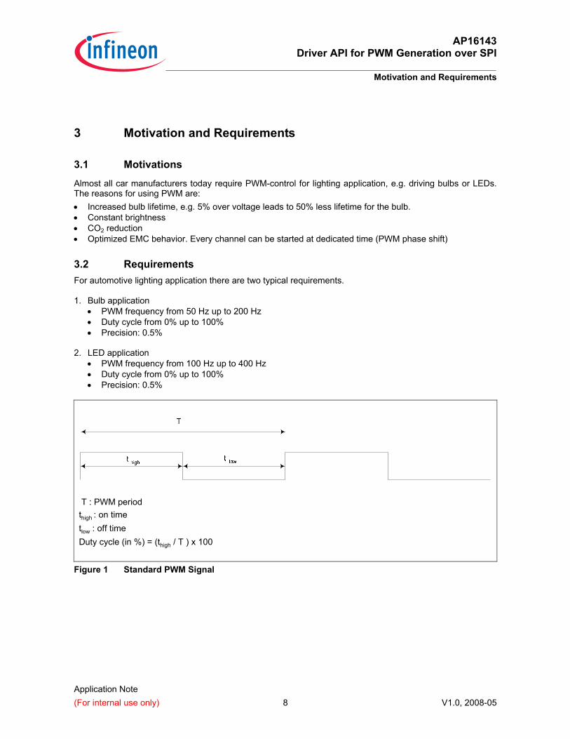
3.2 Requirements For automotive lighting application there are two typical requirements. 1. Bulb application
• PWM frequency from 50 Hz up to 200 Hz • Duty cycle from 0% up to 100% • Precision: 0.5%
2. LED application
• PWM frequency from 100 Hz up to 400 Hz • Duty cycle from 0% up to 100% • Precision: 0.5%
T : PWM period thigh : on time tlow : off time Duty cycle (in %) = (thigh / T ) x 100
Figure 1 Standard PWM Signal
AP16143 Driver API for PWM Generation over SPI
Infineon’s SPOC Family Devices
Application Note (For internal use only) 9 V1.0, 2008-05
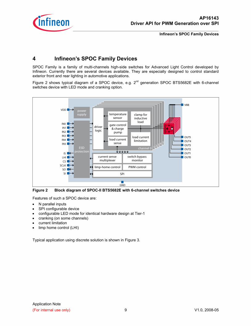
4 Infineon’s SPOC Family Devices SPOC Family is a family of multi-channels high-side switches for Advanced Light Control developed by Infineon. Currently there are several devices available. They are especially designed to control standard exterior front and rear lighting in automotive applications.
Figure 2 shows typical diagram of a SPOC device, e.g. 2nd generation SPOC BTS5682E with 6-channel switches device with LED mode and cranking option.
Figure 2 Block diagram of SPOC-II BTS5682E with 6-channel switches device
Features of such a SPOC device are: • N parallel inputs • SPI configurable device • configurable LED mode for identical hardware design at Tier-1 • cranking (on some channels) • current limitation • limp home control (LHI)
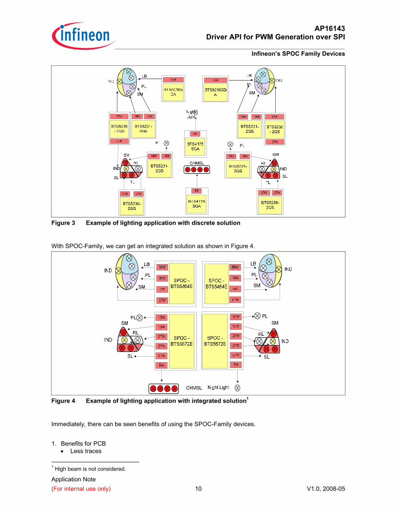
Typical application using discrete solution is shown in Figure 3.
AP16143 Driver API for PWM Generation over SPI
Infineon’s SPOC Family Devices
Application Note (For internal use only) 10 V1.0, 2008-05
Figure 3 Example of lighting application with discrete solution
With SPOC-Family, we can get an integrated solution as shown in Figure 4.
Figure 4 Example of lighting application with integrated solution1
Immediately, there can be seen benefits of using the SPOC-Family devices.
1. Benefits for PCB
• Less traces
1 High beam is not considered.
AP16143 Driver API for PWM Generation over SPI
Infineon’s SPOC Family Devices
Application Note (For internal use only) 11 V1.0, 2008-05
• Less parts • Less area
2. Benefits for Microcontroller
• Less IO pins • Less AD channels (due to multiplexed sense output of SPOC devices) • Diagnostics through SPI reception.
3. Scalability with one PCB design
• LED or Bulbs application with the same device (differs only at the PWM duty-cycle strategy) • Pins, functions, and package compatibility within SPOC family • watchdog option
4. Assembly cost and quality
• Less part reference management • Less pick and place • Less testing • Less parts decreases the risk of reliability issues linked to soldering
4.1 Controlling Mechanisms
A SPOC device can be driven either by: • Direct inputs (IN0...INx) • SPI input.
In direct inputs method, the inputs shall be connected to PWM generator of the microcontroller, e.g. digital-level PWM signal generated by CAPCOM peripherals. The output will have the similar PWM pattern raised to the battery voltage level, plus with additional switching on/off time and delay.
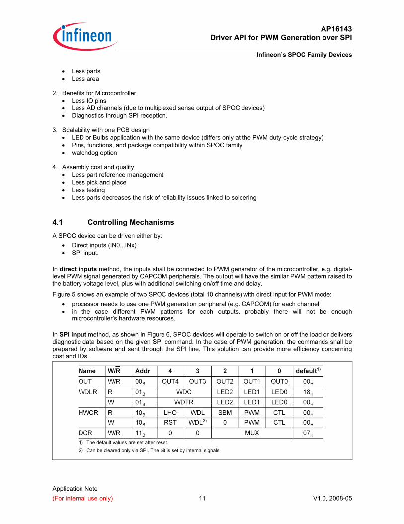
Figure 5 shows an example of two SPOC devices (total 10 channels) with direct input for PWM mode: • processor needs to use one PWM generation peripheral (e.g. CAPCOM) for each channel • in the case different PWM patterns for each outputs, probably there will not be enough
microcontroller’s hardware resources. In SPI input method, as shown in Figure 6, SPOC devices will operate to switch on or off the load or delivers diagnostic data based on the given SPI command. In the case of PWM generation, the commands shall be prepared by software and sent through the SPI line. This solution can provide more efficiency concerning cost and IOs.
AP16143 Driver API for PWM Generation over SPI
Infineon’s SPOC Family Devices
Application Note (For internal use only) 12 V1.0, 2008-05
Two most used SPI commands for controlling SPOC devices are the OUT and DCR commands. OUT command has the bitfield control of the output. Writing a ‘0’ value at the channel’s bit switches off the output and writing ‘1’ otherwise. DCR command contains bitfield to select the output of ISense signal from SPOC device, which can be sampled by A/D converter of the microcontroller to represent the status of output current of a channel.
Figure 5 Controlling SPOC devices with direct input
Figure 6 Controlling SPOC devices with SPI input
4.2 Daisy-chain SPOC The SPOC-Family allows also daisy-chaining of several devices in one SPI line, as shown in Figure 6. With this feature, more channels can be controlled by one SPI line.
AP16143 Driver API for PWM Generation over SPI
PWM Generation over SPI for SPOC-Family
Application Note (For internal use only) 13 V1.0, 2008-05
5 PWM Generation over SPI for SPOC-Family
5.1 Device Organization
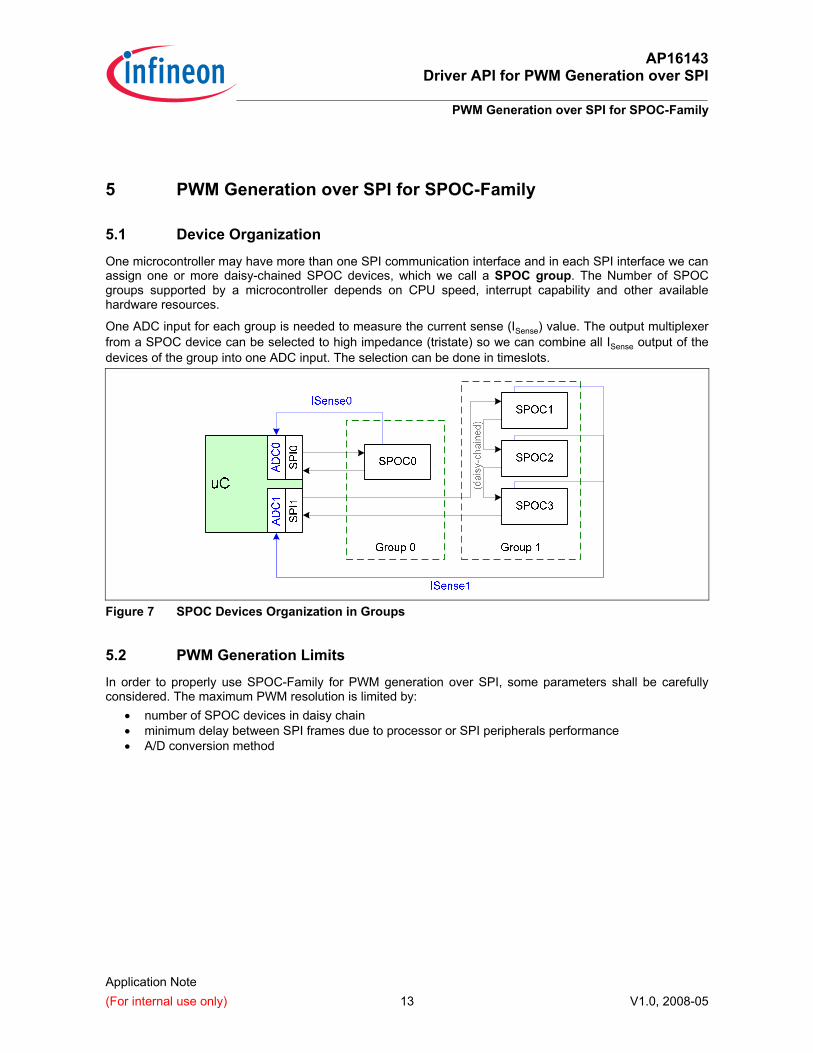
One microcontroller may have more than one SPI communication interface and in each SPI interface we can assign one or more daisy-chained SPOC devices, which we call a SPOC group. The Number of SPOC groups supported by a microcontroller depends on CPU speed, interrupt capability and other available hardware resources.
One ADC input for each group is needed to measure the current sense (ISense) value. The output multiplexer from a SPOC device can be selected to high impedance (tristate) so we can combine all ISense output of the devices of the group into one ADC input. The selection can be done in timeslots.
Figure 7 SPOC Devices Organization in Groups
5.2 PWM Generation Limits
In order to properly use SPOC-Family for PWM generation over SPI, some parameters shall be carefully considered. The maximum PWM resolution is limited by:
• number of SPOC devices in daisy chain • minimum delay between SPI frames due to processor or SPI peripherals performance • A/D conversion method
AP16143 Driver API for PWM Generation over SPI
PWM Generation over SPI for SPOC-Family
Application Note (For internal use only) 14 V1.0, 2008-05
CS
SCLK
SI
tCS(lead) tCS(td)tCS(lag)
tSCLK(H) tSCLK(L)
tSCLK(P)
tSI(su) tSI(h)
SO
tSO(v)tSO(en) tSO(dis)
0.7Vdd
0.2Vdd
0.7Vdd
0.2Vdd
0.7Vdd
0.2Vdd
0.7Vdd
0.2Vdd
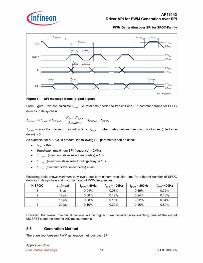
SPI Timing.emf Figure 8 SPI message frame (digital signal)
From Figure 8 we can calculate framet , i.e. total time needed to transmit one SPI command frame for SPOC devices in daisy-chain:
)()()((max) ldCSlagCSSPOCbit
leadCSframeres ttBaudrate
NNttt ++
×+==
framet is also the maximum resolution time, (max)rest , when delay between sending two frames (interframe delay) is 0.
As example, for a SPOC II product, the following SPI parameters can be used:
• bitN = 8-bit
• Baudrate (maximum SPI frequency) = 2MHz • )(leadCSt (minimum slave select lead-delay) = 1us
• )(lagCSt (minimum slave select trailing-delay) = 1us
• )(ldCSt (minimum slave select delay) = 2us Following table shows minimum duty cycle due to minimum resolution time for different number of SPOC devices in daisy-chain and maximum output PWM frequencies.
N SPOC tres(max) fpwm = 50Hz fpwm = 100Hz fpwm = 200Hz fpwm=400Hz 1 8 µs 0.04% 0.08% 0.16% 0.32% 2 12 µs 0.06% 0.12% 0.24% 0.48% 3 16 µs 0.08% 0.16% 0.32% 0.64% 4 20 µs 0.10% 0.20% 0.40% 0.80%
However, the overall minimal duty-cycle will be higher if we consider also switching time of the output MOSFET’s and the time for A/D measurements.
5.3 Generation Method
There are two foreseen PWM generation methods over SPI:
AP16143 Driver API for PWM Generation over SPI
PWM Generation over SPI for SPOC-Family
Application Note (For internal use only) 15 V1.0, 2008-05
1. Sending SPI commands at every expected edge of PWM signal.
2. Sending SPI commands at every fixed time, i.e. equals to PWM resolution time.
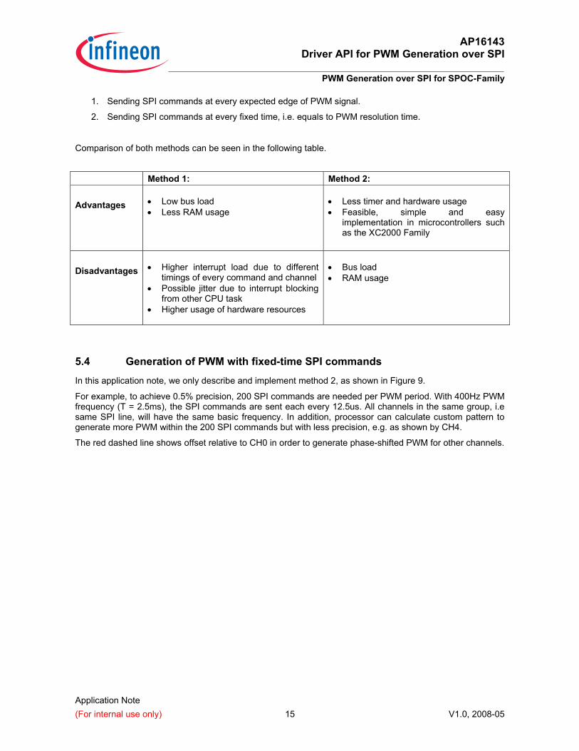
Comparison of both methods can be seen in the following table.
Method 1: Method 2: Advantages
• Low bus load • Less RAM usage
• Less timer and hardware usage • Feasible, simple and easy
implementation in microcontrollers such as the XC2000 Family
Disadvantages
• Higher interrupt load due to different
timings of every command and channel • Possible jitter due to interrupt blocking
from other CPU task • Higher usage of hardware resources
• Bus load • RAM usage
5.4 Generation of PWM with fixed-time SPI commands
In this application note, we only describe and implement method 2, as shown in Figure 9.
For example, to achieve 0.5% precision, 200 SPI commands are needed per PWM period. With 400Hz PWM frequency (T = 2.5ms), the SPI commands are sent each every 12.5us. All channels in the same group, i.e same SPI line, will have the same basic frequency. In addition, processor can calculate custom pattern to generate more PWM within the 200 SPI commands but with less precision, e.g. as shown by CH4.
The red dashed line shows offset relative to CH0 in order to generate phase-shifted PWM for other channels.

AP16143 Driver API for PWM Generation over SPI
PWM Generation over SPI for SPOC-Family
Application Note (For internal use only) 16 V1.0, 2008-05
Figure 9 PWM generation by sending SPI frames at fixed-time
5.5 ADC Multiplexer command insertion
In this application PWM signals are generated with different frequency and starting point. A user-defined phase-shift is applied to every next channel. A/D measurement is needed to monitor whether the load is switched properly. Two different A/D measurement approaches can be done: 1. At specific time after active level 2. At specific time before passive level
Because of simplicity, the first approach will be used.
Figure 10 PWM generation by sending SPI frames at fixed-time
AP16143 Driver API for PWM Generation over SPI
PWM Generation over SPI for SPOC-Family
Application Note (For internal use only) 17 V1.0, 2008-05
Here the ADC multiplexer command for a PWM channel is inserted right after the “ON” time of that channel. In some cases, we can also delay the ADC mux command to a later time due to rise time of the high-side switch and multiplexer switching delay, but this will increase the minimum duty cycle, e.g. from 0.5% to 1%.
In Figure 10 example, ADC is triggered every fifth SPI commands to wait the stable output of PWM signal. But this also will increase the minimum duty cycle, traded with less RAM required to store the A/D conversion results.
Given we have a number of SPI command buffer (SPOC_BUFFER_LENGTH) and the timer tick period (K) to trigger the ADC, then A/D conversion result buffer size is:
The minimum duty cycle will be increased by K times the original PWM resolution1 because we can not switch off the PWM output before the A/D conversion is done.
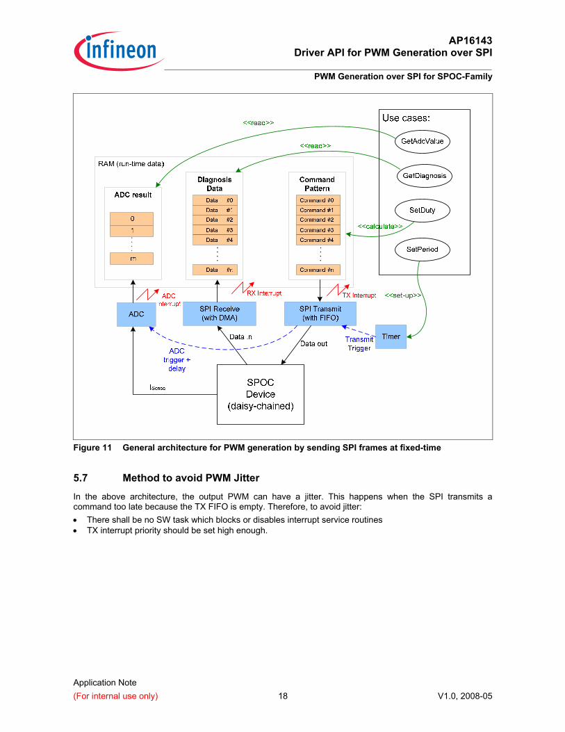
5.6 General Architecture for PWM generation with fixed-time SPI The architecture for generation of PWM with fixed-time SPI commands is shown in Figure 11. The use-cases represent the typical cases needed from the SPOC’s user point of view: • SetDutyCycle: to change duty cycle of output PWM signal of specific channel. This is done by
calculating SPI command pattern to be transmitted in the command buffer (RAM). • SetGroupPeriod: to change or to set the period of all PWM signals. This is done by changing the timer to
trigger transmission of each SPI command. • GetDiagnostic: to read diagnostic data from SPOC device • GetAdcValue: to read A/D conversion values which represent the ISense of the PWM channels Operation of the SPOC can be fully independent from the User Actions. For each SPOC group, there are common hardware and software requirements:
1. Three buffer areas needed:
• For calculated PWM and diagnostic MUX pattern • For SPI-received diagnostic data • For AD conversion results
2. Three interrupt handlers: • For handling sending of commands (TX) • For handling reception of diagnostic data (RX) • For handling AD result
3. One timer for fixed-time triggering SPI transmission 4. One timer for triggering AD conversion based on SPI transmission The timer periodically triggers at fixed-time the transmission of each SPI command. The SPI transmitter circularly reads the command patterns from command buffer in the RAM. At the same time, the trigger is forwarded to start A/D conversion. With the normal behavior of SPI communication and SPOC device, each transmitted command is exchanged with a diagnostic data sent by the SPOC device which can be stored by the SPI receiver into the RAM.
1 Calculation of PWM resolution is explained in Section 5.2 “PWM Generation Limits"
AP16143 Driver API for PWM Generation over SPI
PWM Generation over SPI for SPOC-Family
Application Note (For internal use only) 18 V1.0, 2008-05
Figure 11 General architecture for PWM generation by sending SPI frames at fixed-time
5.7 Method to avoid PWM Jitter
In the above architecture, the output PWM can have a jitter. This happens when the SPI transmits a command too late because the TX FIFO is empty. Therefore, to avoid jitter: • There shall be no SW task which blocks or disables interrupt service routines • TX interrupt priority should be set high enough.
AP16143 Driver API for PWM Generation over SPI
SPOC PWM Driver API
Application Note (For internal use only) 19 V1.0, 2008-05
6 SPOC PWM Driver API
6.1 Limitations
This specification is based on requirements described in document [2] (explained also in chapters 3 until 5), but with the following limitations: 1. Maximum only two daisy-chained devices allowed in one SPOC group. This implies:
• usage of 16-bit SPI frame to control two daisy-chained group devices, or 8-bit SPI frame to control one
• usage of 16-bit data element for the SPI command buffer 2. The focus is on PWM generation over SPI, ADC diagnostic, and receiving of SPOC standard diagnostic
data. Other SPOC control and diagnostic command is not yet supported. On the other hand, there is no API limitation on the number of groups controlled by one microcontroller because it purely depends on the capacity of microcontroller.
6.2 User-defined properties
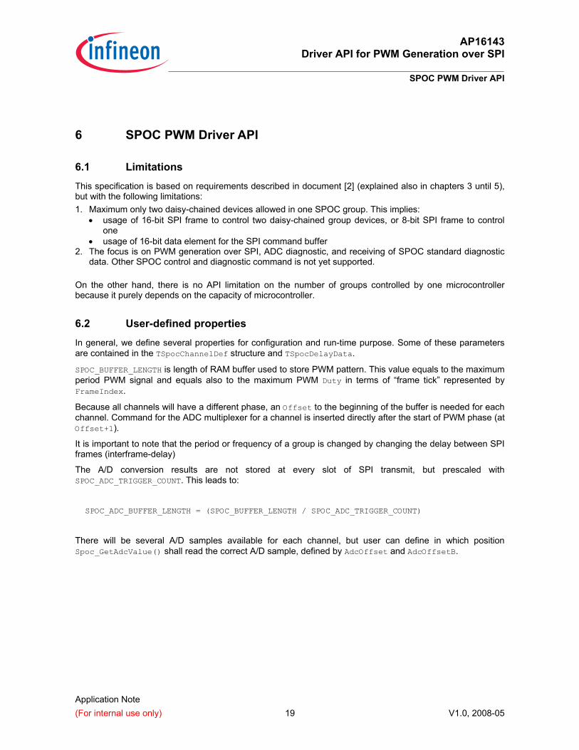
In general, we define several properties for configuration and run-time purpose. Some of these parameters are contained in the TSpocChannelDef structure and TSpocDelayData.
SPOC_BUFFER_LENGTH is length of RAM buffer used to store PWM pattern. This value equals to the maximum period PWM signal and equals also to the maximum PWM Duty in terms of “frame tick” represented by FrameIndex.
Because all channels will have a different phase, an Offset to the beginning of the buffer is needed for each channel. Command for the ADC multiplexer for a channel is inserted directly after the start of PWM phase (at Offset+1).
It is important to note that the period or frequency of a group is changed by changing the delay between SPI frames (interframe-delay)
The A/D conversion results are not stored at every slot of SPI transmit, but prescaled with SPOC_ADC_TRIGGER_COUNT. This leads to:
SPOC_ADC_BUFFER_LENGTH = (SPOC_BUFFER_LENGTH / SPOC_ADC_TRIGGER_COUNT)
There will be several A/D samples available for each channel, but user can define in which position Spoc_GetAdcValue() shall read the correct A/D sample, defined by AdcOffset and AdcOffsetB.
AP16143 Driver API for PWM Generation over SPI
SPOC PWM Driver API
Application Note (For internal use only) 20 V1.0, 2008-05
Figure 12 Properties of PWM Generation
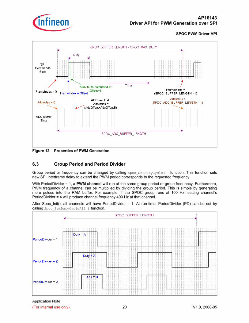
6.3 Group Period and Period Divider
Group period or frequency can be changed by calling Spoc_SetDutyCycle() function. This function sets new SPI interframe delay to extend the PWM period corresponds to the requested frequency.
With PeriodDivider = 1, a PWM channel will run at the same group period or group frequency. Furthermore, PWM frequency of a channel can be multiplied by dividing the group period. This is simple by generating more pulses into the RAM buffer. For example, if the SPOC group runs at 100 Hz, setting channel’s PeriodDivider = 4 will produce channel frequency 400 Hz at that channel.
After Spoc_Init(), all channels will have PeriodDivider = 1. At run-time, PeriodDivider (PD) can be set by calling Spoc_SetDutyCycleAll() function.
AP16143 Driver API for PWM Generation over SPI
SPOC PWM Driver API
Application Note (For internal use only) 21 V1.0, 2008-05
Figure 13 Channels with different duty and period
6.4 A/D conversion result
It is up to the user how the data is going to be read. User can directly read the ADC data by Spoc_GetAdcValue() function, which contains value of the ADC result buffer at index = AdcOffset + AdcOffsetB.
Alternatively, direct access to the ADC result buffer is possible by using exported variable SpocAdcResults.
For the case of XC2000 Family device, SpocAdcResults is copied directly from ADC result register. In this register, only 10-bit contains the conversion value (bit 11… 2), therefore: AdcValue = (SpocAdcResults[GroupNr][index] >> 2) & 0x3FF
6.5 SPI Standard Diagnostic Data
The SPOC standard diagnostic data can be accessed directly through the exported variable SpocGroups, e.g. SpocGroups[GroupNr].Diagnostic.Data[RxIndex]
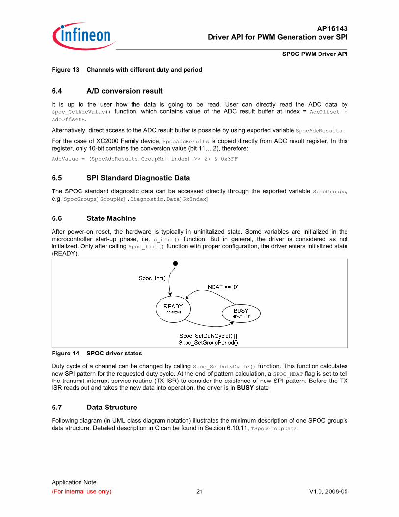
6.6 State Machine
After power-on reset, the hardware is typically in uninitalized state. Some variables are initialized in the microcontroller start-up phase, i.e. c_init() function. But in general, the driver is considered as not initialized. Only after calling Spoc_Init() function with proper configuration, the driver enters initialized state (READY).
Figure 14 SPOC driver states
Duty cycle of a channel can be changed by calling Spoc_SetDutyCycle() function. This function calculates new SPI pattern for the requested duty cycle. At the end of pattern calculation, a SPOC_NDAT flag is set to tell the transmit interrupt service routine (TX ISR) to consider the existence of new SPI pattern. Before the TX ISR reads out and takes the new data into operation, the driver is in BUSY state
6.7 Data Structure
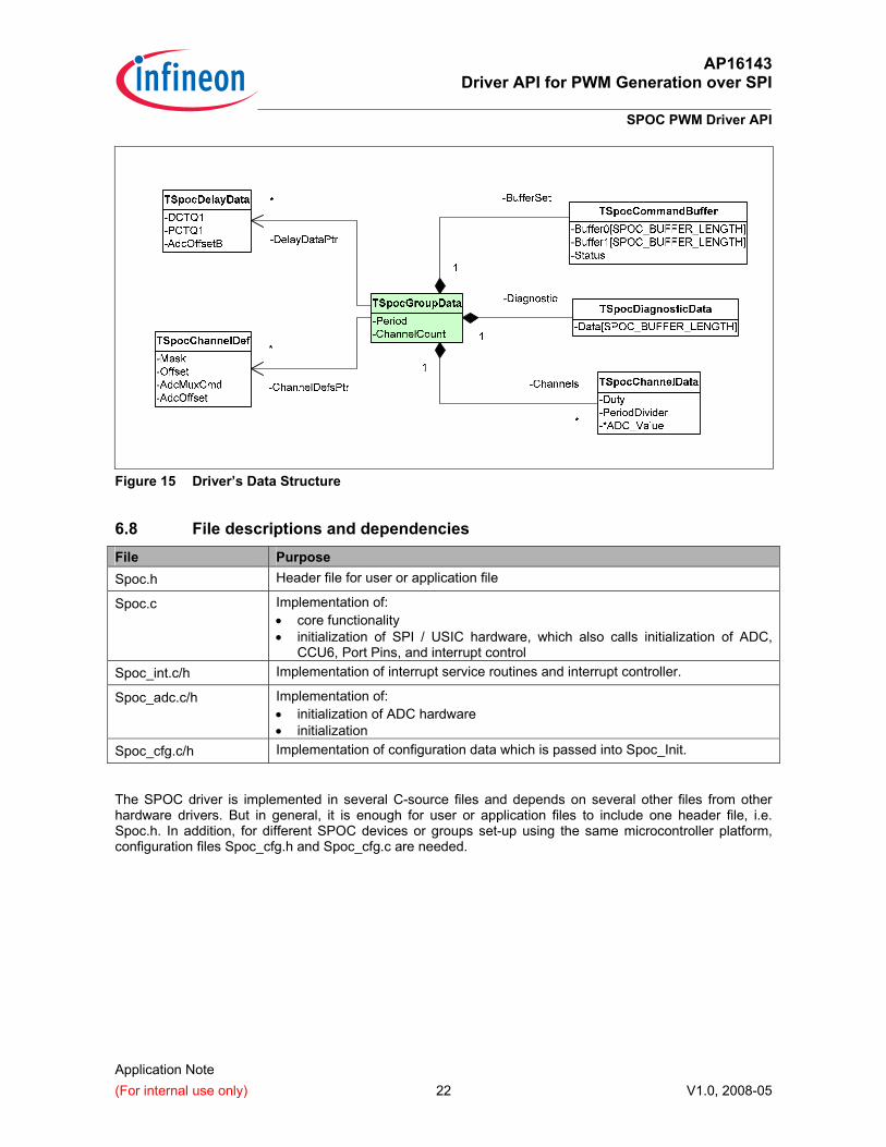
Following diagram (in UML class diagram notation) illustrates the minimum description of one SPOC group’s data structure. Detailed description in C can be found in Section 6.10.11, TSpocGroupData.
AP16143 Driver API for PWM Generation over SPI
SPOC PWM Driver API
Application Note (For internal use only) 22 V1.0, 2008-05
Figure 15 Driver’s Data Structure
6.8 File descriptions and dependencies File Purpose Spoc.h Header file for user or application file
Spoc.c Implementation of: • core functionality • initialization of SPI / USIC hardware, which also calls initialization of ADC,
CCU6, Port Pins, and interrupt control Spoc_int.c/h Implementation of interrupt service routines and interrupt controller.
Spoc_adc.c/h Implementation of: • initialization of ADC hardware • initialization
Spoc_cfg.c/h Implementation of configuration data which is passed into Spoc_Init.
The SPOC driver is implemented in several C-source files and depends on several other files from other hardware drivers. But in general, it is enough for user or application files to include one header file, i.e. Spoc.h. In addition, for different SPOC devices or groups set-up using the same microcontroller platform, configuration files Spoc_cfg.h and Spoc_cfg.c are needed.
AP16143 Driver API for PWM Generation over SPI
SPOC PWM Driver API
Application Note (For internal use only) 23 V1.0, 2008-05
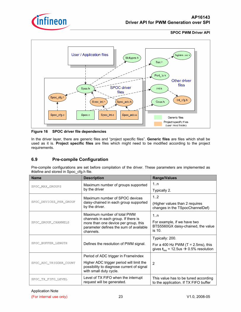
Figure 16 SPOC driver file dependencies
In the driver layer, there are generic files and “project specific files”. Generic files are files which shall be used as it is. Project specific files are files which might need to be modified according to the project requirements.
6.9 Pre-compile Configuration
Pre-compile configurations are set before compilation of the driver. These parameters are implemented as #define and stored in Spoc_cfg.h file.
Name Description Range/Values
SPOC_MAX_GROUPS Maximum number of groups supported by the driver
1..n
Typically 2.
SPOC_DEVICES_PER_GROUP Maximum number of SPOC devices daisy-chained in each group supported by the driver.
1..2
(Higher values than 2 requires changes in the TSpocChannelDef)
SPOC_GROUP_CHANNELS
Maximum number of total PWM channels in each group. If there is more than one device per group, this parameter defines the sum of available channels.
1..n
For example, if we have two BTS5560GX daisy-chained, the value is 10.
SPOC_BUFFER_LENGTH Defines the resolution of PWM signal. Typically: 200.
For a 400 Hz PWM (T = 2.5ms), this gives tres = 12.5us 0.5% resolution
SPOC_ADC_TRIGGER_COUNT
Period of ADC trigger in FrameIndex
Higher ADC trigger period will limit the possibility to diagnose current of signal with small duty cycle.
2
SPOC_TX_FIFO_LEVEL Level of TX FIFO when the interrupt request will be generated.
This value has to be tuned according to the application. If TX FIFO buffer
AP16143 Driver API for PWM Generation over SPI
SPOC PWM Driver API
Application Note (For internal use only) 24 V1.0, 2008-05
length is 64, 50 is a ‘good’ value.
Two other parameters, SPOC_DUTY_MAX and SPOC_ADC_BUFFER_LENGTH, are calculated in the Spoc.h as follows: #define SPOC_DUTY_MAX (SPOC_BUFFER_LENGTH)
#define SPOC_ADC_BUFFER_LENGTH (SPOC_BUFFER_LENGTH / SPOC_ADC_TRIGGER_COUNT)
6.9.1 TSpocConfig structure
In addition to pre-compile configuration, there is TSpocConfig structure which defines the values to be passed through a pointer into the Spoc_Init() function.
6.10 Type definitions
The API imports some standard types previously defined in the file dependencies. • integer types, e.g. uint8, uint16, from StdTypes.h • boolean type and constants, from StdTypes.h • return type (TStdReturn) and constant, from StdTypes.h • usic_t, from registers_usic.h • TUsicIoSet, from port_io.h • TSscSlaveSelectOutput, from Ssc.h
In addition, SPOC driver defines its own types:
Identifier-type definitions: • TSpocGroup • TSpocChannel • TSpocPeriod
Configuration data type definitions: • TSpocChannelDef • TSpocDelayData • TSpocGroupConfig • TSpocConfig
Run-time data type definitions: • TSpocCommandBuffer • TSpocDiagnosticData • TSpocChannelData • TSpocGroupData • TSpocGroupDuty
6.10.1 TSpocGroup Type: Enumeration
Range: SPOC_GROUP_0 As reference for SPOC group 0 SPOC_GROUP_1 As reference for SPOC group 1 ... SPOC_GROUP_N As reference for SPOC group (SPOC_MAX_GROUPS-1)
Description: These constants are used as reference for specific SPOC group.
AP16143 Driver API for PWM Generation over SPI
SPOC PWM Driver API
Application Note (For internal use only) 25 V1.0, 2008-05
6.10.2 TSpocChannel Type: uint8 or Enumeration
Range: 0..(SPOC_GROUP_CHANNELS-1)
Description: These constants are used as reference for a SPOC channel.
6.10.3 TSpocPeriod Type: uint8 or Enumeration
Range: 0..(SPOC_NUM_SUPPORTED_PERIODS-1)
Description: These constants are used as reference for a SPOC PWM period.
6.10.4 TSpocChannelDef
Type: struct
Elements: uint16 Mask Mask for bit position of in the SPI command to control the output of a channel in a SPOC device.
This position is device-specific. uint16 Offset Offset (=Phase) of PWM signal with respect to the beginning of
SPI command buffer. uint16 AdcMuxCmd Command to select ISense output of this channel
This position is device-specific. uint16 AdcOffset Base offset in the SpocAdcResults buffer where the earliest
ADC result for this channel can be found. Description: Values in this structure are used for:
• calculating the pattern of SPI commands for a SPOC channel. • inserting ADC multiplexer command into correct command slot calculated based on
TSpocChannelDef.AdcOffset plus the TSpocDelayData.AdcOffsetB based on active group period.
6.10.5 TSpocDelayData Type: struct
Elements: bool Usable marker whether this delay information will be used or not uint8 DCTQ1 DCTQ1 parameter of usic’s SSC uint8 PCTQ1 PCTQ1 parameter of usic’s SSC uint16 AdcOffsetB Additional offset to retrieve ADC command from the duty-on
frame. Description: Values in this structure are used for:
• calculating the interframe delay of SPI commands for a SPOC group • calculating the total offset of the ADC result
AP16143 Driver API for PWM Generation over SPI
SPOC PWM Driver API
Application Note (For internal use only) 26 V1.0, 2008-05
Note: Actual elements are hardware-dependent. Above elements might be only specific to microcontroller with USIC peripheral, e.g. XC2000 Family.
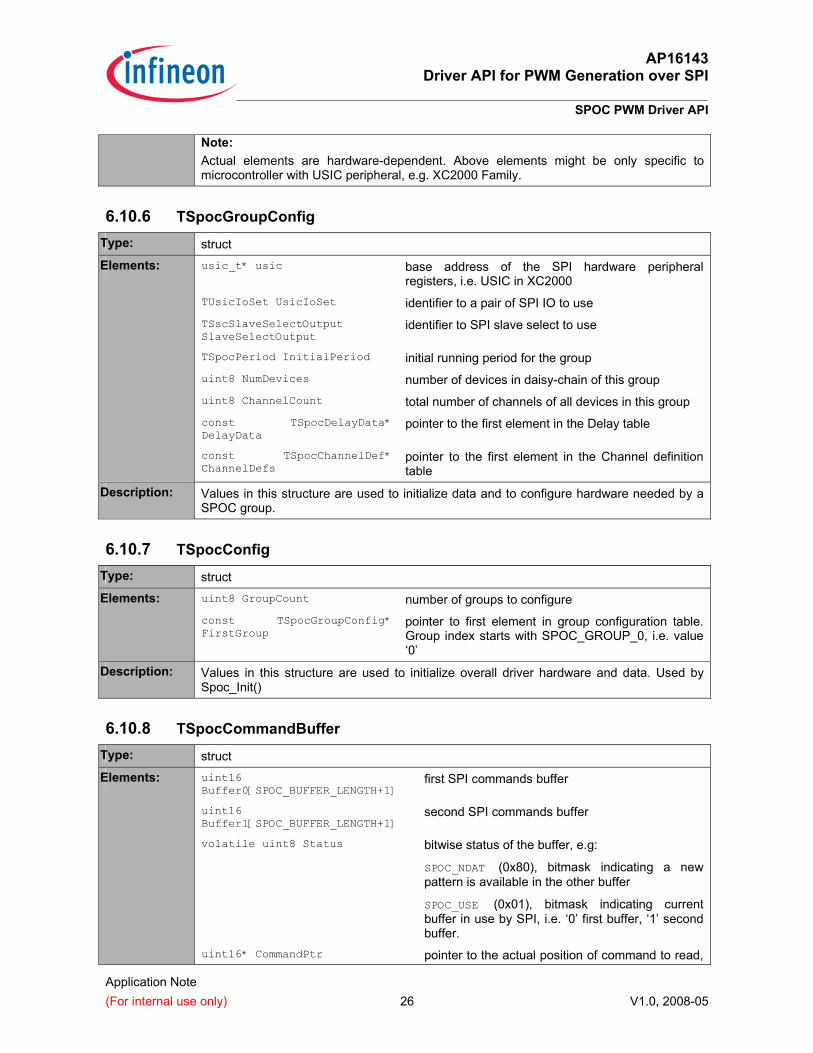
6.10.6 TSpocGroupConfig Type: struct
Elements: usic_t* usic base address of the SPI hardware peripheral registers, i.e. USIC in XC2000
TUsicIoSet UsicIoSet identifier to a pair of SPI IO to use TSscSlaveSelectOutput SlaveSelectOutput
identifier to SPI slave select to use
TSpocPeriod InitialPeriod initial running period for the group uint8 NumDevices number of devices in daisy-chain of this group uint8 ChannelCount total number of channels of all devices in this group const TSpocDelayData* DelayData
pointer to the first element in the Delay table
const TSpocChannelDef* ChannelDefs
pointer to the first element in the Channel definition table
Description: Values in this structure are used to initialize data and to configure hardware needed by a SPOC group.
6.10.7 TSpocConfig Type: struct
Elements: uint8 GroupCount number of groups to configure const TSpocGroupConfig* FirstGroup
pointer to first element in group configuration table. Group index starts with SPOC_GROUP_0, i.e. value ‘0’
Description: Values in this structure are used to initialize overall driver hardware and data. Used by Spoc_Init()
6.10.8 TSpocCommandBuffer Type: struct
Elements: uint16 Buffer0[SPOC_BUFFER_LENGTH+1]
first SPI commands buffer
uint16 Buffer1[SPOC_BUFFER_LENGTH+1]
second SPI commands buffer
volatile uint8 Status bitwise status of the buffer, e.g:
SPOC_NDAT (0x80), bitmask indicating a new pattern is available in the other buffer
SPOC_USE (0x01), bitmask indicating current buffer in use by SPI, i.e. ‘0’ first buffer, ‘1’ second buffer.
uint16* CommandPtr pointer to the actual position of command to read,
AP16143 Driver API for PWM Generation over SPI
SPOC PWM Driver API
Application Note (For internal use only) 27 V1.0, 2008-05
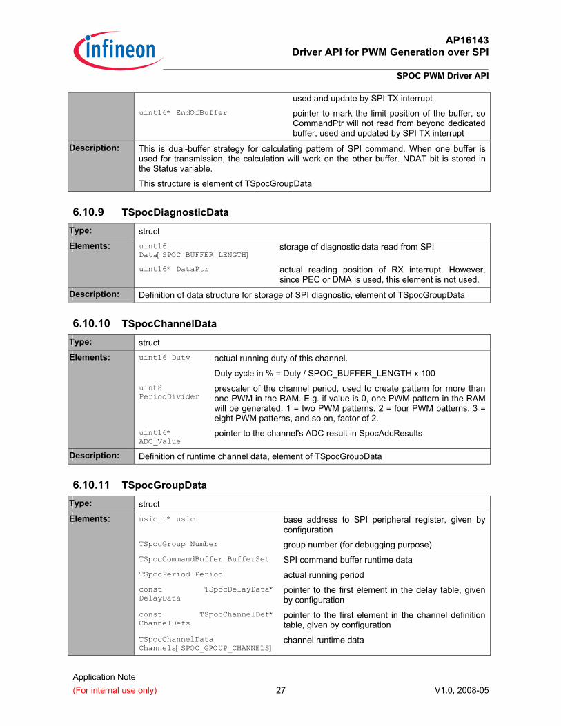
used and update by SPI TX interrupt uint16* EndOfBuffer pointer to mark the limit position of the buffer, so
CommandPtr will not read from beyond dedicated buffer, used and updated by SPI TX interrupt
Description: This is dual-buffer strategy for calculating pattern of SPI command. When one buffer is used for transmission, the calculation will work on the other buffer. NDAT bit is stored in the Status variable.
This structure is element of TSpocGroupData
6.10.9 TSpocDiagnosticData Type: struct
Elements: uint16 Data[SPOC_BUFFER_LENGTH]
storage of diagnostic data read from SPI
uint16* DataPtr actual reading position of RX interrupt. However, since PEC or DMA is used, this element is not used.
Description: Definition of data structure for storage of SPI diagnostic, element of TSpocGroupData
6.10.10 TSpocChannelData Type: struct
Elements: uint16 Duty actual running duty of this channel.
Duty cycle in % = Duty / SPOC_BUFFER_LENGTH x 100 uint8 PeriodDivider
prescaler of the channel period, used to create pattern for more than one PWM in the RAM. E.g. if value is 0, one PWM pattern in the RAM will be generated. 1 = two PWM patterns. 2 = four PWM patterns, 3 = eight PWM patterns, and so on, factor of 2.
uint16* ADC_Value
pointer to the channel's ADC result in SpocAdcResults
Description: Definition of runtime channel data, element of TSpocGroupData
6.10.11 TSpocGroupData Type: struct
Elements: usic_t* usic base address to SPI peripheral register, given by configuration
TSpocGroup Number group number (for debugging purpose) TSpocCommandBuffer BufferSet SPI command buffer runtime data TSpocPeriod Period actual running period const TSpocDelayData* DelayData
pointer to the first element in the delay table, given by configuration
const TSpocChannelDef* ChannelDefs
pointer to the first element in the channel definition table, given by configuration
TSpocChannelData Channels[SPOC_GROUP_CHANNELS]
channel runtime data
AP16143 Driver API for PWM Generation over SPI
SPOC PWM Driver API
Application Note (For internal use only) 28 V1.0, 2008-05
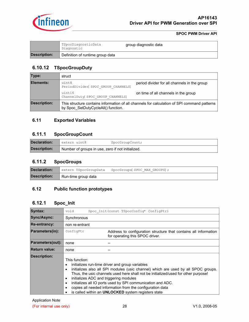
TSpocDiagnosticData Diagnostic
group diagnostic data
Description: Definition of runtime group data
6.10.12 TSpocGroupDuty Type: struct
Elements: uint8 PeriodDivider[SPOC_GROUP_CHANNELS]
period divider for all channels in the group
uint16 ChannelDuty[SPOC_GROUP_CHANNELS]
on time of all channels in the group
Description: This structure contains information of all channels for calculation of SPI command patterns by Spoc_SetDutyCycleAll() function.
6.11 Exported Variables
6.11.1 SpocGroupCount Declaration: extern uint8 SpocGroupCount;
Description: Number of groups in use, zero if not initialized.
6.11.2 SpocGroups Declaration: extern TSpocGroupData SpocGroups[SPOC_MAX_GROUPS];
Description: Run-time group data
6.12 Public function prototypes
6.12.1 Spoc_Init Syntax: void Spoc_Init(const TSpocConfig* ConfigPtr)
Sync/Async: Synchronous
Re-entrancy: non re-entrant
Parameters(in): ConfigPtr Address to configuration structure that contains all information for operating this SPOC driver.
Parameters(out): none -- Return value: none -- Description:
This function: • initializes run-time driver and group variables • initializes also all SPI modules (usic channel) which are used by all SPOC groups.
Thus, the usic channels used here shall not be initialized/used for other purpose! • initializes ADC and triggering modules • initializes all IO ports used by SPI communication and ADC. • copies all needed information from the configuration data • is called within an UNLOCKED system registers state
AP16143 Driver API for PWM Generation over SPI
SPOC PWM Driver API
Application Note (For internal use only) 29 V1.0, 2008-05
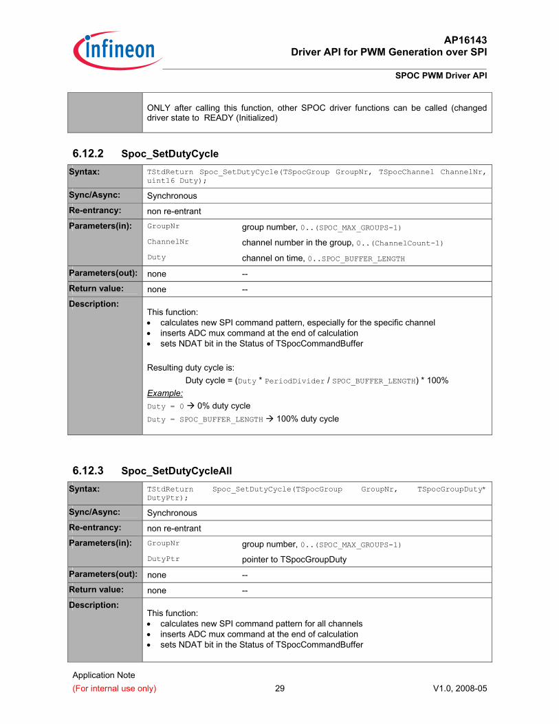
ONLY after calling this function, other SPOC driver functions can be called (changed driver state to READY (Initialized)
6.12.2 Spoc_SetDutyCycle Syntax: TStdReturn Spoc_SetDutyCycle(TSpocGroup GroupNr, TSpocChannel ChannelNr,
uint16 Duty);
Sync/Async: Synchronous
Re-entrancy: non re-entrant
Parameters(in): GroupNr group number, 0..(SPOC_MAX_GROUPS-1) ChannelNr channel number in the group, 0..(ChannelCount-1) Duty channel on time, 0..SPOC_BUFFER_LENGTH
Parameters(out): none -- Return value: none -- Description:
This function: • calculates new SPI command pattern, especially for the specific channel • inserts ADC mux command at the end of calculation • sets NDAT bit in the Status of TSpocCommandBuffer Resulting duty cycle is:
Duty cycle = (Duty * PeriodDivider / SPOC_BUFFER_LENGTH) * 100% Example: Duty = 0 0% duty cycle Duty = SPOC_BUFFER_LENGTH 100% duty cycle
6.12.3 Spoc_SetDutyCycleAll Syntax: TStdReturn Spoc_SetDutyCycle(TSpocGroup GroupNr, TSpocGroupDuty*
DutyPtr);
Sync/Async: Synchronous
Re-entrancy: non re-entrant
Parameters(in): GroupNr group number, 0..(SPOC_MAX_GROUPS-1) DutyPtr pointer to TSpocGroupDuty
Parameters(out): none -- Return value: none -- Description:
This function: • calculates new SPI command pattern for all channels • inserts ADC mux command at the end of calculation • sets NDAT bit in the Status of TSpocCommandBuffer
AP16143 Driver API for PWM Generation over SPI
SPOC PWM Driver API
Application Note (For internal use only) 30 V1.0, 2008-05
6.12.4 Spoc_SetGroupPeriod Syntax: TStdReturn Spoc_SetGroupPeriod(TSpocGroup GroupNr, TSpocPeriod Period);
Sync/Async: Synchronous
Re-entrancy: non re-entrant
Parameters(in): GroupNr group number, 0..(SPOC_MAX_GROUPS-1) Period identifier to the expected period, see TSpocPeriod
Parameters(out): none -- Return value: E_OK when group period can be set succesfully
E_INVALID_PARAM when one of the parameter is not valid Description:
This function sets the group period, i.e. running frequency, of a SPOC group. This function takes effect only if the SPOC is not busy (query by Spoc_IsBusy() function). The group frequency can be changed using the DCTQ1 and PCTQ1 information in the TSpocDelayData.
6.12.5 Spoc_IsBusy Syntax: bool Spoc_IsBusy(TSpocGroup GroupNr)
Sync/Async: Synchronous
Re-entrancy: non re-entrant
Parameters(in): GroupNr group number, 0..(SPOC_MAX_GROUPS-1) Parameters(out): none -- Return value: TRUE the SPOC group is busy, e.g. due to SPI command buffer has
been modified but has not been taken by the TX interrupt service routine
FALSE the SPOC group is ready to receive new duty cycle or frequency setting.
Description: This function retrieves the status of the SPI buffer and communication, whether it is ready to receive duty-cycle or period modification. Due to availability of exported SpocGroups variable, this function can be made as inline.
6.12.6 Spoc_GetAdcValue Syntax: uint16 Spoc_GetAdcValue(TSpocGroup GroupNr, TSpocChannel ChannelNr)
Sync/Async: Synchronous
Re-entrancy: non re-entrant
Parameters(in): GroupNr group number, 0..(SPOC_MAX_GROUPS-1)
AP16143 Driver API for PWM Generation over SPI
SPOC PWM Driver API
Application Note (For internal use only) 31 V1.0, 2008-05
ChannelNr channel number in the group, 0..(SPOC_GROUP_CHANNELS-1) Parameters(out): none -- Return value: uint16 Value of channel’s ISense read by ADC hardware. Description:
This function retrieves the latest read value of ISense output of a specific SPOC channel in a group. Due to availability of exported SpocGroups variable, this function can be made as inline.
6.13 Interrupt Service Routines
The driver implements the service routines for handling several requests: 1. Transmit interrupt of SPI communication 2. Receive interrupt of SPI communication 3. End of ADC conversion Those service routines are implementation specific and are called from hardware specific interrupt frames (vectors).
AP16143 Driver API for PWM Generation over SPI
Implementation in XC2000 Microcontroller Family
Application Note (For internal use only) 32 V1.0, 2008-05
7 Implementation in XC2000 Microcontroller Family
7.1 Unique hardware features
XC2000 Family is 16-bit microcontroller which has several unique hardware features which improves a lot the performance in par with a 32-bit microcontroller. Key features used in this application notes are:
USIC (Universal Serial Interface Channel) • Data-FIFO with 64 entries (16 bit) • Time triggered FIFO entry transmission • Huge frame delay possible • Using transmit slave select event for triggering AD conversions
Analog to Digital Converter • Very fast conversion: 1,5 µs @ 10 bit • High accuracy: 2 LSB @ 10 bit • Hardware conversion trigger from various sources • Data reduction mode • Alias mode
Capture-Compare Unit 6 • Two 16 bit timer with hardware connectivity to USIC and ADC • Trigger on compare and period match
PEC (DMA-like) transfer • Direct memory access between memories and registers
7.2 Hardware Resource Mapping
In XC2000 Microcontroller Family, we can assign above requirements to the following hardware resources, thus implements a near complete solution. Availability of SPI FIFO and DMA-like feature reduces the CPU load a lot.
HW Requirement Fulfillment TX, RX, and ADC Buffer
Internal RAM
TX interrupt Number of interrupts is reduced due to availability of SPI transmit FIFO. RX interrupt Handled by PEC (DMA-like feature).
CPU interruption only occurs once every end of receive buffer for updating PEC pointer and counter
ADC interrupt Handled by PEC. CPU interruption only occurs once every end of A/D results buffer for updating PEC pointer and counter
Fixed-time SPI trigger
Interframe delay parameter. Directly supported by USIC (serial controller interface in XC2000)
ADC trigger/counter Direct connection from CCU6 timer to trigger ADC. In some XC2000 devices such as XC2000M (M-Step device and above), there’s a
AP16143 Driver API for PWM Generation over SPI
Implementation in XC2000 Microcontroller Family
Application Note (For internal use only) 33 V1.0, 2008-05
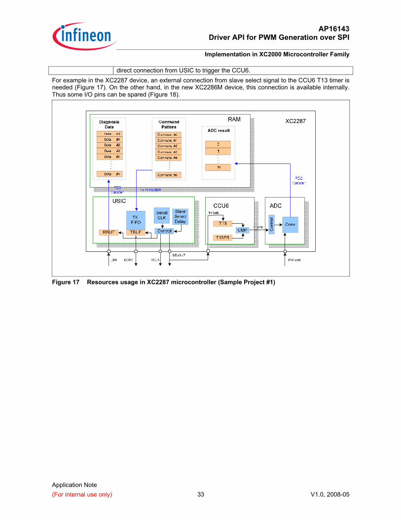
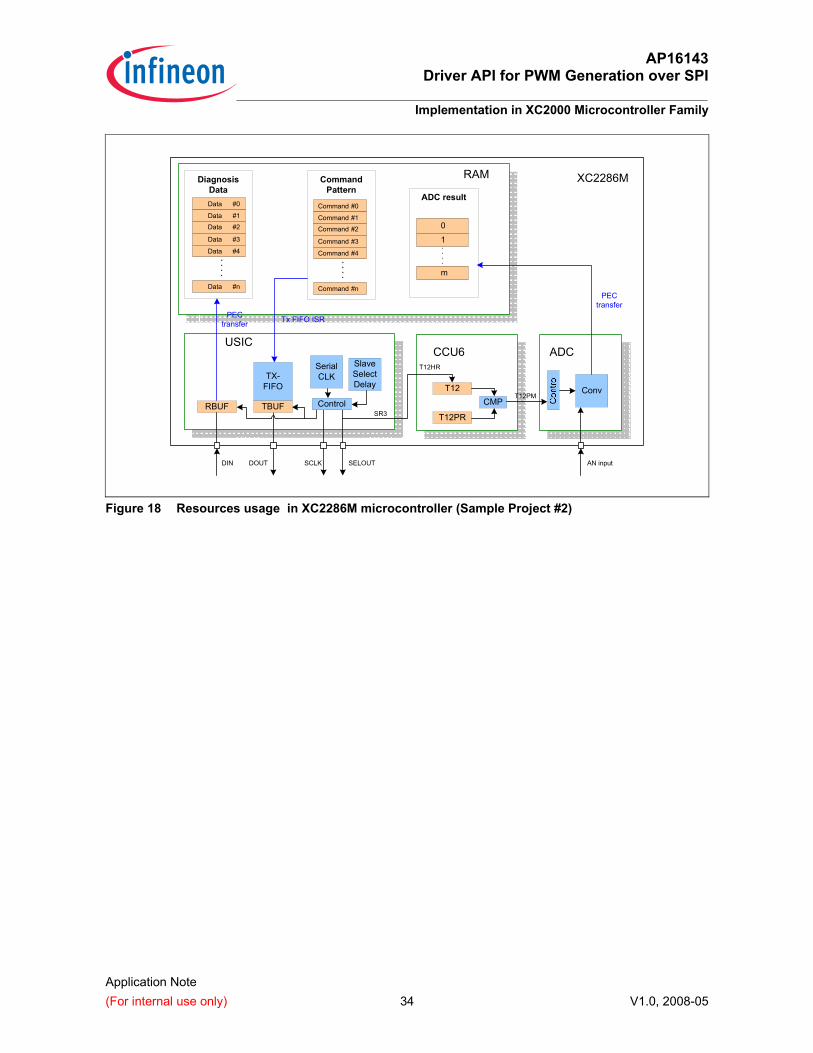
direct connection from USIC to trigger the CCU6. For example in the XC2287 device, an external connection from slave select signal to the CCU6 T13 timer is needed ( Figure 17). On the other hand, in the new XC2286M device, this connection is available internally. Thus some I/O pins can be spared ( Figure 18).
Figure 17 Resources usage in XC2287 microcontroller (Sample Project #1)
AP16143 Driver API for PWM Generation over SPI
Implementation in XC2000 Microcontroller Family
Application Note (For internal use only) 34 V1.0, 2008-05
DiagnosisData
CommandPattern
Command #0
Command #1
Command #2
Command #3
Command #4
Command #n
Data #0
Data #1
Data #2
Data #3
Data #4
Data #n
0
1
m
ADC result
RBUF
TX-FIFO
SlaveSelectDelay
SerialCLK
ControlTBUF
SELOUTSCLKDOUTDIN
USIC
PECtransfer Tx FIFO ISR
CCU6
T12
T12PR
CMP
T12HR
SR3
ADC
AN input
ConvT12PM
PECtransfer
XC2286MRAM
Figure 18 Resources usage in XC2286M microcontroller (Sample Project #2)
AP16143 Driver API for PWM Generation over SPI
Sample Project #1 with XC2286M EasyKit
Application Note (For internal use only) 35 V1.0, 2008-05
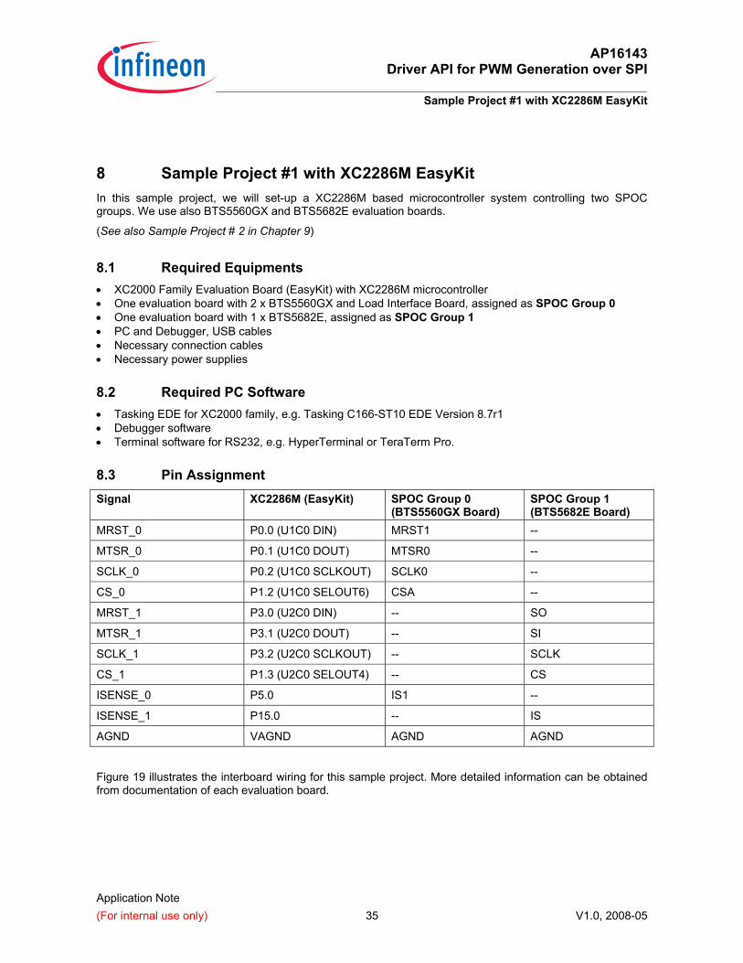
8 Sample Project #1 with XC2286M EasyKit In this sample project, we will set-up a XC2286M based microcontroller system controlling two SPOC groups. We use also BTS5560GX and BTS5682E evaluation boards.
(See also Sample Project # 2 in Chapter 9)
8.1 Required Equipments • XC2000 Family Evaluation Board (EasyKit) with XC2286M microcontroller • One evaluation board with 2 x BTS5560GX and Load Interface Board, assigned as SPOC Group 0 • One evaluation board with 1 x BTS5682E, assigned as SPOC Group 1 • PC and Debugger, USB cables • Necessary connection cables • Necessary power supplies
8.2 Required PC Software • Tasking EDE for XC2000 family, e.g. Tasking C166-ST10 EDE Version 8.7r1 • Debugger software • Terminal software for RS232, e.g. HyperTerminal or TeraTerm Pro.
8.3 Pin Assignment Signal XC2286M (EasyKit) SPOC Group 0
(BTS5560GX Board) SPOC Group 1 (BTS5682E Board)
MRST_0 P0.0 (U1C0 DIN) MRST1 --
MTSR_0 P0.1 (U1C0 DOUT) MTSR0 --
SCLK_0 P0.2 (U1C0 SCLKOUT) SCLK0 --
CS_0 P1.2 (U1C0 SELOUT6) CSA --
MRST_1 P3.0 (U2C0 DIN) -- SO
MTSR_1 P3.1 (U2C0 DOUT) -- SI
SCLK_1 P3.2 (U2C0 SCLKOUT) -- SCLK
CS_1 P1.3 (U2C0 SELOUT4) -- CS
ISENSE_0 P5.0 IS1 --
ISENSE_1 P15.0 -- IS
AGND VAGND AGND AGND
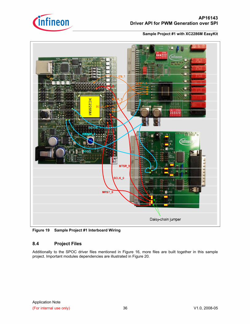
Figure 19 illustrates the interboard wiring for this sample project. More detailed information can be obtained from documentation of each evaluation board.
AP16143 Driver API for PWM Generation over SPI
Sample Project #1 with XC2286M EasyKit
Application Note (For internal use only) 36 V1.0, 2008-05
Figure 19 Sample Project #1 Interboard Wiring
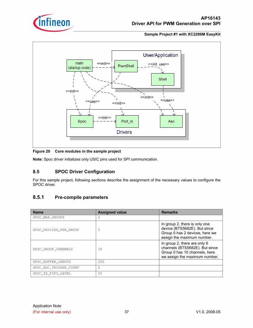
8.4 Project Files Additionally to the SPOC driver files mentioned in Figure 16, more files are built together in this sample project. Important modules dependencies are illustrated in Figure 20.
AP16143 Driver API for PWM Generation over SPI
Sample Project #1 with XC2286M EasyKit
Application Note (For internal use only) 37 V1.0, 2008-05
Figure 20 Core modules in the sample project
Note: Spoc driver initializes only USIC pins used for SPI communication.
8.5 SPOC Driver Configuration
For this sample project, following sections describe the assignment of the necessary values to configure the SPOC driver.
8.5.1 Pre-compile parameters Name Assigned value Remarks SPOC_MAX_GROUPS 2
SPOC_DEVICES_PER_GROUP 2
In group 2, there is only one device (BTS5682E). But since Group 0 has 2 devices, here we assign the maximum number.
SPOC_GROUP_CHANNELS 10
In group 2, there are only 6 channels (BTS5682E). But since Group 0 has 10 channels, here we assign the maximum number.
SPOC_BUFFER_LENGTH 200 SPOC_ADC_TRIGGER_COUNT 2 SPOC_TX_FIFO_LEVEL 50
AP16143 Driver API for PWM Generation over SPI
Sample Project #1 with XC2286M EasyKit
Application Note (For internal use only) 38 V1.0, 2008-05
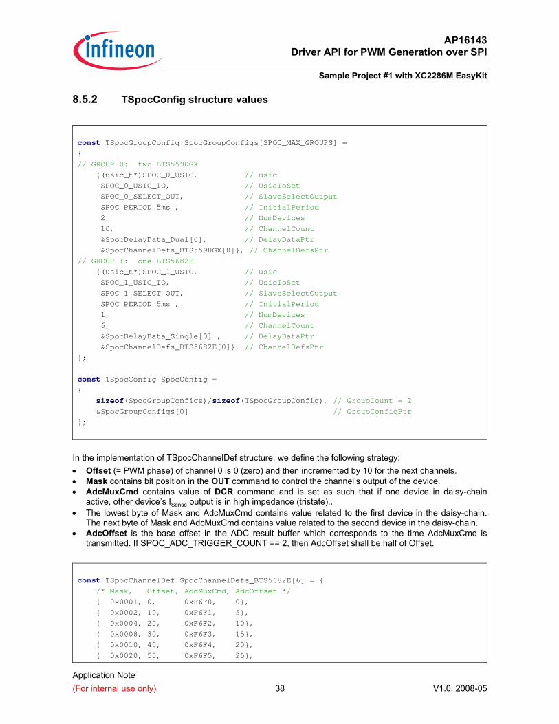
8.5.2 TSpocConfig structure values
const TSpocGroupConfig SpocGroupConfigs[SPOC_MAX_GROUPS] =
{
// GROUP 0: two BTS5590GX
{(usic_t*)SPOC_0_USIC, // usic
SPOC_0_USIC_IO, // UsicIoSet
SPOC_0_SELECT_OUT, // SlaveSelectOutput
SPOC_PERIOD_5ms , // InitialPeriod
2, // NumDevices
10, // ChannelCount
&SpocDelayData_Dual[0], // DelayDataPtr
&SpocChannelDefs_BTS5590GX[0]}, // ChannelDefsPtr
// GROUP 1: one BTS5682E
{(usic_t*)SPOC_1_USIC, // usic
SPOC_1_USIC_IO, // UsicIoSet
SPOC_1_SELECT_OUT, // SlaveSelectOutput
SPOC_PERIOD_5ms , // InitialPeriod
1, // NumDevices
6, // ChannelCount
&SpocDelayData_Single[0] , // DelayDataPtr
&SpocChannelDefs_BTS5682E[0]}, // ChannelDefsPtr
};
const TSpocConfig SpocConfig =
{
sizeof(SpocGroupConfigs)/sizeof(TSpocGroupConfig), // GroupCount = 2
&SpocGroupConfigs[0] // GroupConfigPtr
};
In the implementation of TSpocChannelDef structure, we define the following strategy: • Offset (= PWM phase) of channel 0 is 0 (zero) and then incremented by 10 for the next channels. • Mask contains bit position in the OUT command to control the channel’s output of the device. • AdcMuxCmd contains value of DCR command and is set as such that if one device in daisy-chain
active, other device’s ISense output is in high impedance (tristate).. • The lowest byte of Mask and AdcMuxCmd contains value related to the first device in the daisy-chain.
The next byte of Mask and AdcMuxCmd contains value related to the second device in the daisy-chain. • AdcOffset is the base offset in the ADC result buffer which corresponds to the time AdcMuxCmd is
transmitted. If SPOC_ADC_TRIGGER_COUNT == 2, then AdcOffset shall be half of Offset.
const TSpocChannelDef SpocChannelDefs_BTS5682E[6] = {
/* Mask, Offset, AdcMuxCmd, AdcOffset */
{ 0x0001, 0, 0xF6F0, 0},
{ 0x0002, 10, 0xF6F1, 5},
{ 0x0004, 20, 0xF6F2, 10},
{ 0x0008, 30, 0xF6F3, 15},
{ 0x0010, 40, 0xF6F4, 20},
{ 0x0020, 50, 0xF6F5, 25},
AP16143 Driver API for PWM Generation over SPI
Sample Project #1 with XC2286M EasyKit
Application Note (For internal use only) 39 V1.0, 2008-05
};
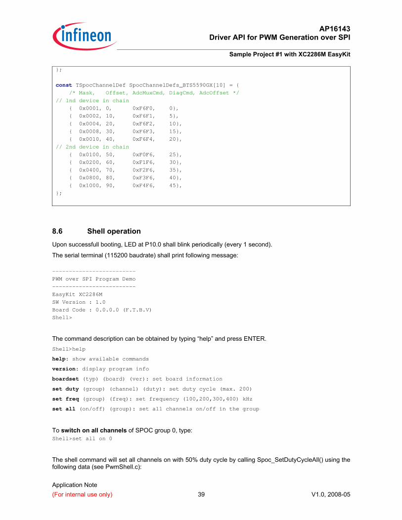
const TSpocChannelDef SpocChannelDefs_BTS5590GX[10] = {
/* Mask, Offset, AdcMuxCmd, DiagCmd, AdcOffset */
// 1nd device in chain
{ 0x0001, 0, 0xF6F0, 0},
{ 0x0002, 10, 0xF6F1, 5},
{ 0x0004, 20, 0xF6F2, 10},
{ 0x0008, 30, 0xF6F3, 15},
{ 0x0010, 40, 0xF6F4, 20},
// 2nd device in chain
{ 0x0100, 50, 0xF0F6, 25},
{ 0x0200, 60, 0xF1F6, 30},
{ 0x0400, 70, 0xF2F6, 35},
{ 0x0800, 80, 0xF3F6, 40},
{ 0x1000, 90, 0xF4F6, 45},
};
8.6 Shell operation Upon successfull booting, LED at P10.0 shall blink periodically (every 1 second).
The serial terminal (115200 baudrate) shall print following message:
-------------------------
PWM over SPI Program Demo
-------------------------
EasyKit XC2286M
SW Version : 1.0
Board Code : 0.0.0.0 (F.T.B.V)
Shell>
The command description can be obtained by typing “help” and press ENTER. Shell>help
help: show available commands version: display program info boardset (typ) (board) (ver): set board information set duty (group) (channel) (duty): set duty cycle (max. 200) set freq (group) (freq): set frequency (100,200,300,400) kHz set all (on/off) (group): set all channels on/off in the group
To switch on all channels of SPOC group 0, type: Shell>set all on 0
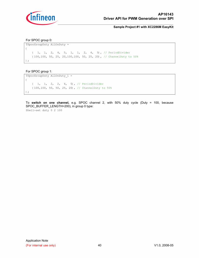
The shell command will set all channels on with 50% duty cycle by calling Spoc_SetDutyCycleAll() using the following data (see PwmShell.c):
AP16143 Driver API for PWM Generation over SPI
Sample Project #1 with XC2286M EasyKit
Application Note (For internal use only) 40 V1.0, 2008-05
For SPOC group 0: TSpocGroupDuty AllOnDuty =
{
{ 1, 1, 2, 4, 5, 1, 1, 2, 4, 5}, // PeriodDivider
{100,100, 50, 25, 20,100,100, 50, 25, 20}, // ChannelDuty to 50%
};
For SPOC group 1: TSpocGroupDuty AllOnDuty_1 =
{
{ 1, 1, 2, 2, 4, 5}, // PeriodDivider
{100,100, 50, 50, 25, 20}, // ChannelDuty to 50%
};
To switch on one channel, e.g. SPOC channel 2, with 50% duty cycle (Duty = 100, because SPOC_BUFFER_LENGTH=200), in group 0 type: Shell>set duty 0 2 100
AP16143 Driver API for PWM Generation over SPI
Sample Project #2 with XC2287 Power EasyKit
Application Note (For internal use only) 41 V1.0, 2008-05
9 Sample Project #2 with XC2287 Power EasyKit In this sample project, we will set-up a XC2287 Power EasyKit based microcontroller system controlling two SPOC groups.
9.1 Required Equipments and Software
The required equipments and PC software are similar to those of Sample Project #1 with the exception that here we use a XC2287 Power EasyKit.
9.2 Pin Assignment Signal XC2287 Power EasyKit SPOC Group 0 (BTS5560GX Board) MRST_0 P0.0 (U1C0 DIN) MRST1
MTSR_0 P0.1 (U1C0 DOUT) MTSR0
SCLK_0 P0.2 (U1C0 SCLKOUT) SCLK0
CS_0 P1.1 (U1C0 SELOUT5)
P5.8 (CCU60), important for triggering ADC!!
CSA
ISENSE_0 P5.0 IS1
AGND VAGND AGND
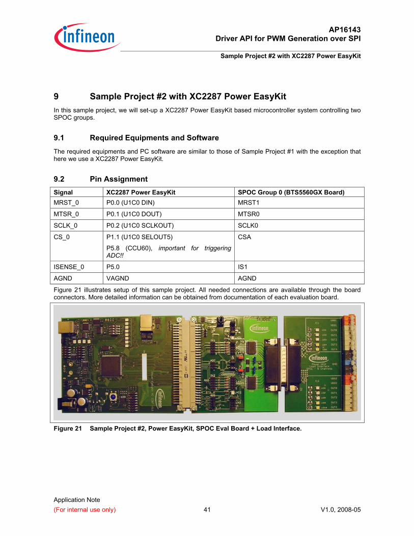
Figure 21 illustrates setup of this sample project. All needed connections are available through the board connectors. More detailed information can be obtained from documentation of each evaluation board.
Figure 21 Sample Project #2, Power EasyKit, SPOC Eval Board + Load Interface.
AP16143 Driver API for PWM Generation over SPI
XC2000 CPU Performance
Application Note (For internal use only) 42 V1.0, 2008-05
10 XC2000 CPU Performance
10.1 TX-FIFO Interrupt
Among the three interrupts (TX-FIFO, RX, and ADC), the most exhausting one is TX-FIFO interrupt where CPU needs to transfer SPI command from Group’s CommandBuffer into USIC Transmit FIFO buffer.
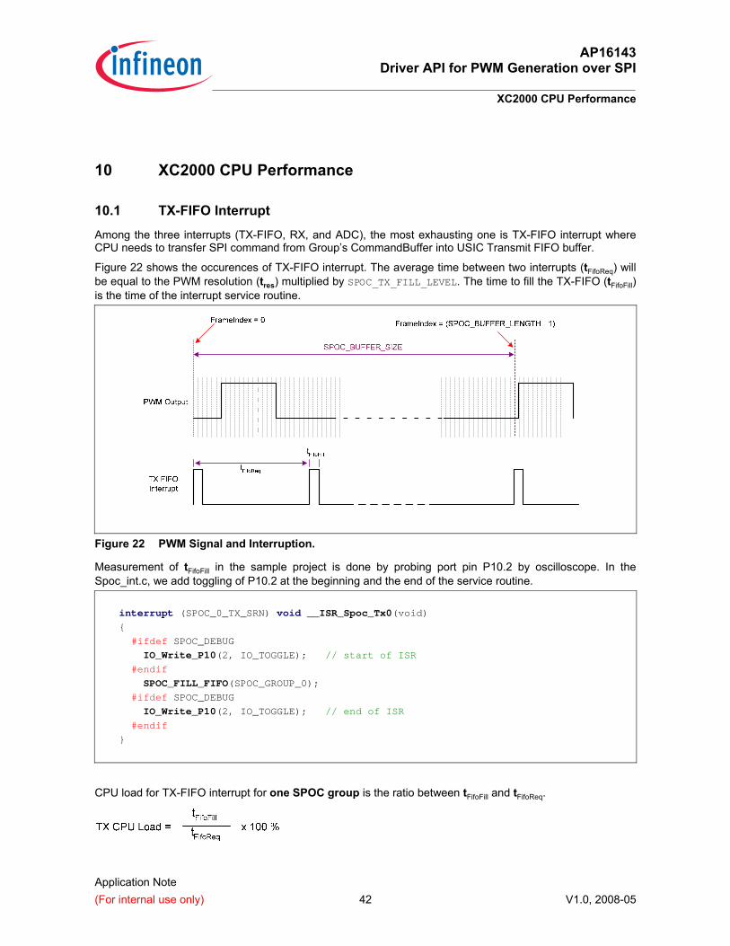
Figure 22 shows the occurences of TX-FIFO interrupt. The average time between two interrupts (tFifoReq) will be equal to the PWM resolution (tres) multiplied by SPOC_TX_FILL_LEVEL. The time to fill the TX-FIFO (tFifoFill) is the time of the interrupt service routine.
Figure 22 PWM Signal and Interruption.
Measurement of tFifoFill in the sample project is done by probing port pin P10.2 by oscilloscope. In the Spoc_int.c, we add toggling of P10.2 at the beginning and the end of the service routine.
interrupt (SPOC_0_TX_SRN) void __ISR_Spoc_Tx0(void)
{
#ifdef SPOC_DEBUG
IO_Write_P10(2, IO_TOGGLE); // start of ISR
#endif
SPOC_FILL_FIFO(SPOC_GROUP_0);
#ifdef SPOC_DEBUG
IO_Write_P10(2, IO_TOGGLE); // end of ISR
#endif
}
CPU load for TX-FIFO interrupt for one SPOC group is the ratio between tFifoFill and tFifoReq.
AP16143 Driver API for PWM Generation over SPI
XC2000 CPU Performance
Application Note (For internal use only) 43 V1.0, 2008-05
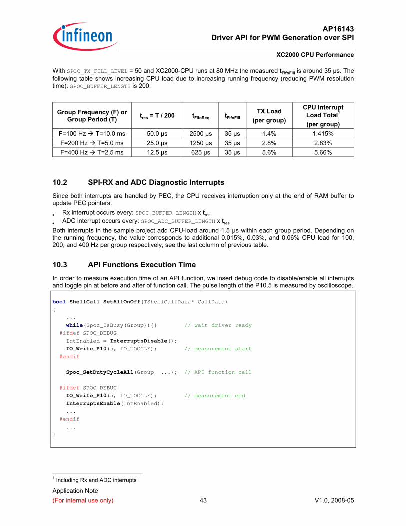
With SPOC_TX_FILL_LEVEL = 50 and XC2000-CPU runs at 80 MHz the measured tFifoFill is around 35 µs. The following table shows increasing CPU load due to increasing running frequency (reducing PWM resolution time). SPOC_BUFFER_LENGTH is 200.
Group Frequency (F) or Group Period (T) tres = T / 200 tFifoReq tFifoFill
TX Load (per group)
CPU Interrupt Load Total1 (per group)
F=100 Hz T=10.0 ms 50.0 µs 2500 µs 35 µs 1.4% 1.415% F=200 Hz T=5.0 ms 25.0 µs 1250 µs 35 µs 2.8% 2.83% F=400 Hz T=2.5 ms 12.5 µs 625 µs 35 µs 5.6% 5.66%
10.2 SPI-RX and ADC Diagnostic Interrupts
Since both interrupts are handled by PEC, the CPU receives interruption only at the end of RAM buffer to update PEC pointers.
• Rx interrupt occurs every: SPOC_BUFFER_LENGTH x tres
• ADC interrupt occurs every: SPOC_ADC_BUFFER_LENGTH x tres
Both interrupts in the sample project add CPU-load around 1.5 µs within each group period. Depending on the running frequency, the value corresponds to additional 0.015%, 0.03%, and 0.06% CPU load for 100, 200, and 400 Hz per group respectively; see the last column of previous table.
10.3 API Functions Execution Time
In order to measure execution time of an API function, we insert debug code to disable/enable all interrupts and toggle pin at before and after of function call. The pulse length of the P10.5 is measured by oscilloscope.
bool ShellCall_SetAllOnOff(TShellCallData* CallData)
{
...
while(Spoc_IsBusy(Group)){} // wait driver ready
#ifdef SPOC_DEBUG
IntEnabled = InterruptsDisable();
IO_Write_P10(5, IO_TOGGLE); // measurement start
#endif
Spoc_SetDutyCycleAll(Group, ...); // API function call
#ifdef SPOC_DEBUG
IO_Write_P10(5, IO_TOGGLE); // measurement end
InterruptsEnable(IntEnabled);
...
#endif
...
}
1 Including Rx and ADC interrupts
AP16143 Driver API for PWM Generation over SPI
XC2000 CPU Performance
Application Note (For internal use only) 44 V1.0, 2008-05
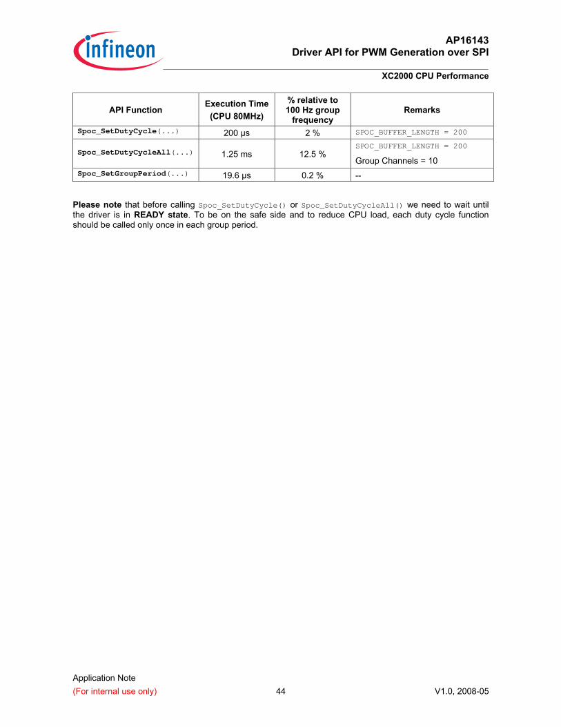
API Function Execution Time
(CPU 80MHz)
% relative to 100 Hz group
frequency Remarks
Spoc_SetDutyCycle(...) 200 µs 2 % SPOC_BUFFER_LENGTH = 200
Spoc_SetDutyCycleAll(...) 1.25 ms 12.5 % SPOC_BUFFER_LENGTH = 200
Group Channels = 10 Spoc_SetGroupPeriod(...) 19.6 µs 0.2 % --
Please note that before calling Spoc_SetDutyCycle() or Spoc_SetDutyCycleAll() we need to wait until the driver is in READY state. To be on the safe side and to reduce CPU load, each duty cycle function should be called only once in each group period.
AP16143 Driver API for PWM Generation over SPI
Brightness Control (use case)
Application Note (For internal use only) 45 V1.0, 2008-05
11 Brightness Control (use case) An additional aspect which is discussed here, but not included in the sample project, is PWM control in the case of variation of battery voltage (VBATT). The PWM controller takes VRMS as reference to maintain constant brightness of the bulb or LED and sets the correct duty cycle for each channel by using the following relation:
2
2
BATT
RMS
VV
DC =
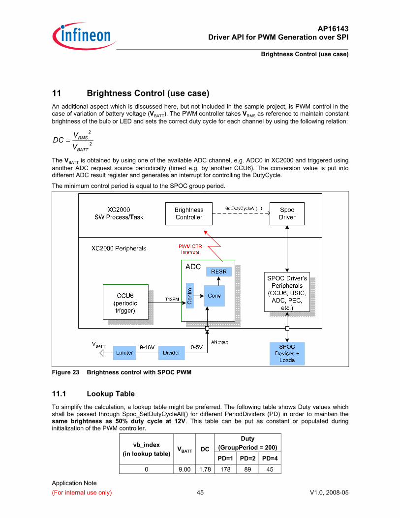
The VBATT is obtained by using one of the available ADC channel, e.g. ADC0 in XC2000 and triggered using another ADC request source periodically (timed e.g. by another CCU6). The conversion value is put into different ADC result register and generates an interrupt for controlling the DutyCycle.
The minimum control period is equal to the SPOC group period.
Figure 23 Brightness control with SPOC PWM
11.1 Lookup Table
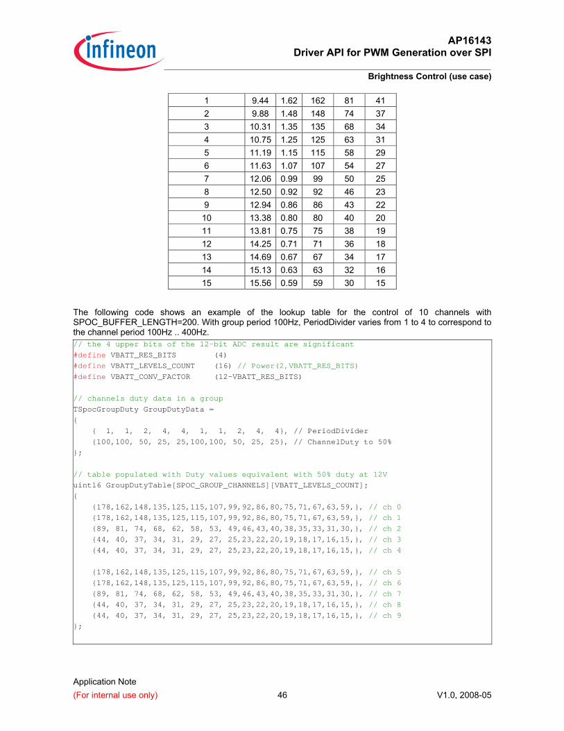
To simplify the calculation, a lookup table might be preferred. The following table shows Duty values which shall be passed through Spoc_SetDutyCycleAll() for different PeriodDividers (PD) in order to maintain the same brightness as 50% duty cycle at 12V. This table can be put as constant or populated during initialization of the PWM controller.
Duty (GroupPeriod = 200) vb_index
(in lookup table)VBATT DC
PD=1 PD=2 PD=4
0 9.00 1.78 178 89 45
AP16143 Driver API for PWM Generation over SPI
Brightness Control (use case)
Application Note (For internal use only) 46 V1.0, 2008-05
1 9.44 1.62 162 81 41 2 9.88 1.48 148 74 37 3 10.31 1.35 135 68 34 4 10.75 1.25 125 63 31 5 11.19 1.15 115 58 29 6 11.63 1.07 107 54 27 7 12.06 0.99 99 50 25 8 12.50 0.92 92 46 23 9 12.94 0.86 86 43 22 10 13.38 0.80 80 40 20 11 13.81 0.75 75 38 19 12 14.25 0.71 71 36 18 13 14.69 0.67 67 34 17 14 15.13 0.63 63 32 16 15 15.56 0.59 59 30 15
The following code shows an example of the lookup table for the control of 10 channels with SPOC_BUFFER_LENGTH=200. With group period 100Hz, PeriodDivider varies from 1 to 4 to correspond to the channel period 100Hz .. 400Hz. // the 4 upper bits of the 12-bit ADC result are significant
#define VBATT_RES_BITS (4)
#define VBATT_LEVELS_COUNT (16) // Power(2,VBATT_RES_BITS)
#define VBATT_CONV_FACTOR (12-VBATT_RES_BITS)
// channels duty data in a group
TSpocGroupDuty GroupDutyData =
{
{ 1, 1, 2, 4, 4, 1, 1, 2, 4, 4}, // PeriodDivider
{100,100, 50, 25, 25,100,100, 50, 25, 25}, // ChannelDuty to 50%
};
// table populated with Duty values equivalent with 50% duty at 12V
uint16 GroupDutyTable[SPOC_GROUP_CHANNELS][VBATT_LEVELS_COUNT];
{
{178,162,148,135,125,115,107,99,92,86,80,75,71,67,63,59,}, // ch 0
{178,162,148,135,125,115,107,99,92,86,80,75,71,67,63,59,}, // ch 1
{89, 81, 74, 68, 62, 58, 53, 49,46,43,40,38,35,33,31,30,}, // ch 2
{44, 40, 37, 34, 31, 29, 27, 25,23,22,20,19,18,17,16,15,}, // ch 3
{44, 40, 37, 34, 31, 29, 27, 25,23,22,20,19,18,17,16,15,}, // ch 4
{178,162,148,135,125,115,107,99,92,86,80,75,71,67,63,59,}, // ch 5
{178,162,148,135,125,115,107,99,92,86,80,75,71,67,63,59,}, // ch 6
{89, 81, 74, 68, 62, 58, 53, 49,46,43,40,38,35,33,31,30,}, // ch 7
{44, 40, 37, 34, 31, 29, 27, 25,23,22,20,19,18,17,16,15,}, // ch 8
{44, 40, 37, 34, 31, 29, 27, 25,23,22,20,19,18,17,16,15,}, // ch 9
};
AP16143 Driver API for PWM Generation over SPI
Brightness Control (use case)
Application Note (For internal use only) 47 V1.0, 2008-05
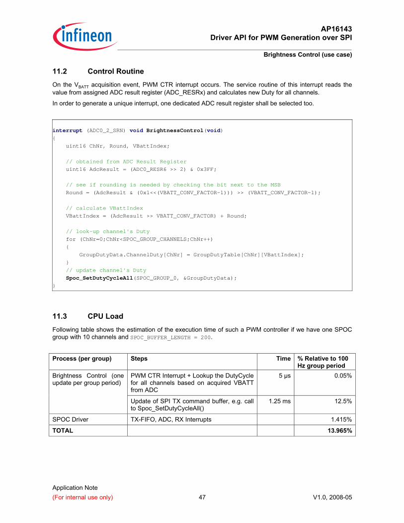
11.2 Control Routine
On the VBATT acquisition event, PWM CTR interrupt occurs. The service routine of this interrupt reads the value from assigned ADC result register (ADC_RESRx) and calculates new Duty for all channels.
In order to generate a unique interrupt, one dedicated ADC result register shall be selected too.
interrupt (ADC0_2_SRN) void BrightnessControl(void)
{
uint16 ChNr, Round, VBattIndex;
// obtained from ADC Result Register
uint16 AdcResult = (ADC0_RESR6 >> 2) & 0x3FF;
// see if rounding is needed by checking the bit next to the MSB
Round = (AdcResult & (0x1<<(VBATT_CONV_FACTOR-1))) >> (VBATT_CONV_FACTOR-1);
// calculate VBattIndex
VBattIndex = (AdcResult >> VBATT_CONV_FACTOR) + Round;
// look-up channel's Duty
for (ChNr=0;ChNr<SPOC_GROUP_CHANNELS;ChNr++)
{
GroupDutyData.ChannelDuty[ChNr] = GroupDutyTable[ChNr][VBattIndex];
}
// update channel's Duty
Spoc_SetDutyCycleAll(SPOC_GROUP_0, &GroupDutyData);
}
11.3 CPU Load
Following table shows the estimation of the execution time of such a PWM controller if we have one SPOC group with 10 channels and SPOC_BUFFER_LENGTH = 200.
Process (per group) Steps Time % Relative to 100 Hz group period
PWM CTR Interrupt + Lookup the DutyCycle for all channels based on acquired VBATT from ADC
5 µs 0.05%Brightness Control (one update per group period)
Update of SPI TX command buffer, e.g. call to Spoc_SetDutyCycleAll()
1.25 ms 12.5%
SPOC Driver TX-FIFO, ADC, RX Interrupts 1.415%
TOTAL 13.965%

ht tp://www.inf ineon.com
Published by Infineon Technologies AG