Embed Size (px)
Citation preview

\
SBUS & PWM
Adapters
V1.6
This document is the property of Sierra Pacific Innovations Corp (“SPI Corp”). SPI Corp reserves all rights to this document, data, invention, and content herein described. This document is confidential, including the fact of its existence and is not to be disclosed, in whole or in part, to any other party and it shall not be duplicated, used, transmitted or copied in any form without the express prior written permission of SPI Corp. Acceptance of this document will be construed as acceptance of the foregoing conditions.

SBUS & PWM Adapters Ver : 1.6
- Page 2 of 28 – - SPI Corp Proprietary and Confidential Information -
Compilation and Publication Notice
This manual is covering the latest product descriptions and specifications.
The contents of this manual and the specifications of this product are subject to change without notice.
SPI Corp reserves the right to make changes without notice in the specifications and materials contained herein and shall not be responsible for any damages (including consequential) caused by reliance on the materials presented, including but not limited to typographical and other errors relating to the publication.
For Further information please contact
Sierra Pacific Innovations Corp

SBUS & PWM Adapters Ver : 1.6
- Page 3 of 28 – - SPI Corp Proprietary and Confidential Information -
Table of Content
1 Introduction .................................................................................... 5
2 Architecture .................................................................................... 7
3 Legacy Control Mode ..................................................................... 8
4 SingleYAW – Auto ROLL Mode .................................................. 9
5 SBUS-Adapter .............................................................................. 11
5.1 Interfaces ..................................................................................................11
5.2 Wire Harness .............................................................................................12
5.3 CAMERA Pinout .........................................................................................12
5.4 POWER pinout ...........................................................................................13
5.5 USB pinout ................................................................................................13
5.6 SBUS - IN pinout .........................................................................................13
5.7 SBUS OUT pinout........................................................................................14
5.8 VIDEO pinout .............................................................................................14
5.9 SBUS Channels ...........................................................................................15
6 Lightbridge ................................................................................... 16
6.1 Connecting SBUS Adapter to Lightbridge.......................................................17
6.2 Lightbridge & Remote control configuration .................................................18
7 PWM-Adapter .............................................................................. 22
7.1 Interfaces ..................................................................................................22
7.2 Wire Harness .............................................................................................23
7.3 CAMERA Pinout .........................................................................................23
7.4 POWER pinout ...........................................................................................24
7.5 USB pinout ................................................................................................24

SBUS & PWM Adapters Ver : 1.6
- Page 4 of 28 – - SPI Corp Proprietary and Confidential Information -
7.6 VIDEO1 & VIDEO2 pinout ............................................................................24
7.7 PWM signals ..............................................................................................25
7.8 PWM Channels ..........................................................................................26
8 Ordering Information.................................................................... 27
8.1 Adapters ...................................................................................................27
8.2 Wire Harness .............................................................................................28

SBUS & PWM Adapters Ver : 1.6
- Page 5 of 28 – - SPI Corp Proprietary and Confidential Information -
1 Introduction
The document describes SBUS Adapter and PWM Adapter. The functionality of both adapters is similar. The only difference is with the interface.
Both adapters support two different modes of control:
• Legacy Control Mode – user controls both camera pitch and roll
Vertical Mount
Legacy Mode - Camera Controls
Mandatory
Optional
• Yaw • Pitch • Zoom • DAY / IR / NUC
• Freeze • Sensitivity • Go to Center

SBUS & PWM Adapters Ver : 1.6
- Page 6 of 28 – - SPI Corp Proprietary and Confidential Information -
• SingleYAW – AutoROLL Mode – user controls only camera pitch
M2-D H Mount
Legacy Mode - Camera Controls
Mandatory Optional

SBUS & PWM Adapters Ver : 1.6
- Page 7 of 28 – - SPI Corp Proprietary and Confidential Information -
PWM
2 Architecture
The PWM architecture is depicted in the following:
PWM
Platform PWM-Adapter M2-D
The SBUS architecture is depicted in the following:
S.bus
SBUS-Adapter M2-D
Platform

SBUS & PWM Adapters Ver : 1.6
- Page 8 of 28 – - SPI Corp Proprietary and Confidential Information -
3 Legacy Control Mode
In Legacy control mode the user controls both pitch and roll of the camera. The camera can be mounted horizontally, vertically-up or vertically-down.
The following table holds the channels from the remote control to the remote control adapter:
Channel Description Pitch Pitch rate
Pitch Down Rate No Change Pitch Up Rate Recommended switch - Dual direction proportional switch with distinctive zero position
Roll Roll Rate Roll Left Rate No Change Roll Right Rate
Recommended switch - Dual direction proportional switch with distinctive zero position Zoom Zoom IN/Out
Zoom IN No Change Zoom OUT Recommended switch - 3 positional dual direction spring return
Selection between visible and IR channels, switching between black and white hot and performing non-uniformity correction. Recommended switch - 3 positions toggle where one of the position is spring return
Up position fixed EO (DAY) Video Channel activated
Middle position fixed IR (Thermal) Video Channel activated
DAY/IR/ POLARITY/ NUC
Down position SPRING momentary push (<1sec) B/W Hot toggle Long push (>3sec) Execute NUC (Non uniformity correction)
Optional Sensitivity Pitch/Yaw Sticks sensitivity
Thermal Gain Thermal Channel Gain (increment / decrement) Thermal Level Thermal Channel Level (increment / decrement)

SBUS & PWM Adapters Ver : 1.6
- Page 9 of 28 – - SPI Corp Proprietary and Confidential Information -
4 SingleYAW – Auto ROLL Mode
In SingleYAW-AutoRoll mode the user controls only the pitch of the camera. The roll of the camera is not controlled by the user. The roll of the camera is set automatically. The camera should be mounted horizontally where the roll axis of the camera aligned with the roll axis of the platform.
The following table holds the list of channels from the remote control to the remote control adapter:
Channel Description Selection between visible and IR channels switching between black hot, white hot and Pseudo-Color Performing non-uniformity correction. Recommended switch - 3 positions toggle where one of the position is spring return
Up position fixed EO (DAY) Video Channel activated
Middle position fixed IR (Thermal) Video Channel activated
DAY/IR/ POLARITY/ NUC
Down position SPRING momentary push (<1sec) B Hot/W Hot/Pseudo Color toggle Long push (>3sec) Execute NUC (Non uniformity correction)
Pitch Pitch Rate Pitch Down Rate No Change Pitch Up Rate
Recommended switch - Dual direction proportional switch with distinctive zero position Zoom Zoom IN/Out
Zoom IN No Change Zoom OUT Recommended switch - 3 positional dual direction spring return
YAW-IN YAW Command Input (from Receiver) When left unconnected the roll automatically switched to Standalone operation, fast motion damping
Optional Sensitivity Pitch/Yaw Sticks sensitivity
Thermal Gain Thermal Channel Gain (increment / decrement) Thermal Level Thermal Channel Level (increment / decrement)
Pilot / YAW- Bypass
When SET the adapter bypasses yaw commands directly to the platform without any processing, camera switch to roll=0° Pitch=70° and maximum zoom out

SBUS & PWM Adapters Ver : 1.6
- Page 10 of 28 – - SPI Corp Proprietary and Confidential Information -
The following table holds the description of the channel from the remote control adapter to the platform:
Channel Description YAW-OUT YAW Command output (to platform)
SBUS & PWM Adapters Ver : 1.6
- Page 11 of 28 – - SPI Corp Proprietary and Confidential Information -
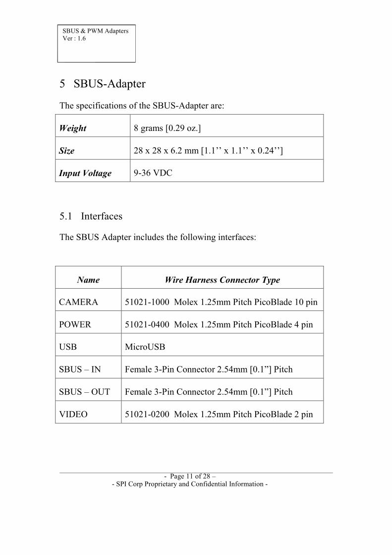
5 SBUS-Adapter
The specifications of the SBUS-Adapter are:
Weight
8 grams [0.29 oz.]
Size
28 x 28 x 6.2 mm [1.1’’ x 1.1’’ x 0.24’’]
Input Voltage
9-36 VDC
5.1 Interfaces
The SBUS Adapter includes the following interfaces:
Name
Wire Harness Connector Type CAMERA
51021-1000 Molex 1.25mm Pitch PicoBlade 10 pin
POWER
51021-0400 Molex 1.25mm Pitch PicoBlade 4 pin
USB
MicroUSB
SBUS – IN
Female 3-Pin Connector 2.54mm [0.1”] Pitch
SBUS – OUT
Female 3-Pin Connector 2.54mm [0.1”] Pitch
VIDEO
51021-0200 Molex 1.25mm Pitch PicoBlade 2 pin

SBUS & PWM Adapters Ver : 1.6
- Page 12 of 28 – - SPI Corp Proprietary and Confidential Information -
5.2 Wire Harness
The following wire harness can be sourced from SPI Corp: Interface Description
CAMERA
Wire harness 2x10pin (SPI 51021-1000) L=½m [19.7”] 7 wires color coded
POWER
Wire harness 1x4pin (SPI 51021-0400 ) L=25cm [9.8”] pig tail 4-wires red & black color coded
VIDEO
Wire harness 1x2pin (51021-0200 ) L=25cm [9.8”] pig tail 2-wires yellow & black color coded
5.3 CAMERA Pinout
Pin
NAME
Description
1
SYS_PWR
System Power Input
2
GND
System Ground
3
RS232_IN
RS232 Receive Input (12V level)
4
RS232_OUT
RS232 Transmitter Output (12V level)
5
RS_232 GND
RS232 Ground
6
Reserved
Do not connect
7
Reserved
Do not connect
8
Reserved
Do not connect
9
VIDEO_OUT
Video Out (PAL or NTSC)
SBUS & PWM Adapters Ver : 1.6
- Page 13 of 28 – - SPI Corp Proprietary and Confidential Information -
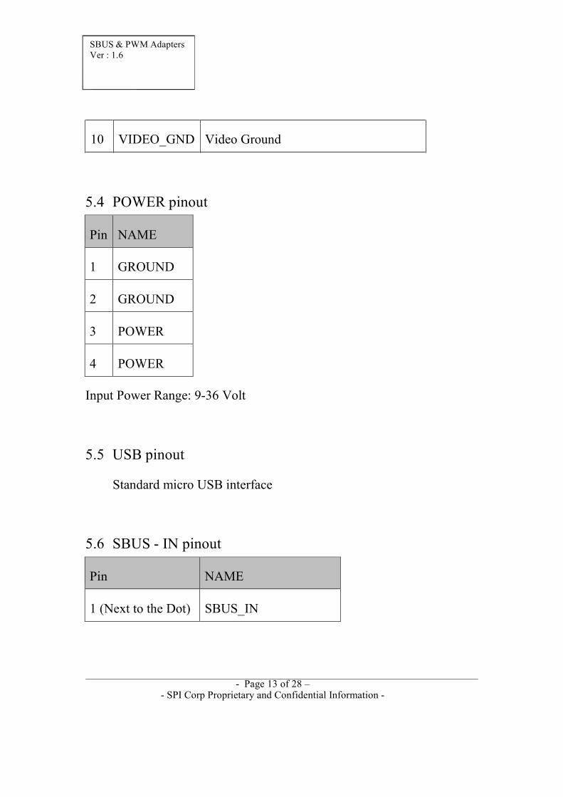
10 VIDEO_GND Video Ground
5.4 POWER pinout
Pin
NAME
1
GROUND
2
GROUND
3
POWER
4
POWER
Input Power Range: 9-36 Volt
5.5 USB pinout
Standard micro USB interface
5.6 SBUS - IN pinout
Pin
NAME
1 (Next to the Dot)
SBUS_IN

SBUS & PWM Adapters Ver : 1.6
- Page 14 of 28 – - SPI Corp Proprietary and Confidential Information -
2
-----
3
GND
5.7 SBUS OUT pinout
5.8 VIDEO pinout
Pin
NAME
1
Video
2
GND
Pin
NAME
1 (next to the dot)
SBUS_OUT
2
-----
3
GND

SBUS & PWM Adapters Ver : 1.6
- Page 15 of 28 – - SPI Corp Proprietary and Confidential Information -
5.9 SBUS Channels
The SBUS Adapter is shipped (factory default) with the following configuration:
SBUS Channel
Description
1
ROLL
2
PITCH
4
ZOOM
11
DAY / IR / POLARITY / NUC
12
Sensitivity
The rest of the channels are unprocessed.
Using the Configuration Application, one can determine
• which SBUS channels are bypassed from input to output • the allocation of SBUS channel to camera functionality

SBUS & PWM Adapters Ver : 1.6
- Page 16 of 28 – - SPI Corp Proprietary and Confidential Information -
6 Lightbridge
This section describes the connection and configuration of Lightbridge and a Remote Control when connected to the SBUS- Adapter. The architecture is depicted in the following:

SBUS & PWM Adapters Ver : 1.6
- Page 17 of 28 – - SPI Corp Proprietary and Confidential Information -
6.1 Connecting SBUS Adapter to Lightbridge
The following image describes the cabling orientation when connecting to the S-BUS Adapter. The cable connecting to the S- BUS IN is supplied with the Lightbridge.

SBUS & PWM Adapters Ver : 1.6
- Page 18 of 28 – - SPI Corp Proprietary and Confidential Information -
6.2 Lightbridge & Remote control configuration
Follow the following steps when connecting to SBUS-Adapter with factory defaults.
Control verification:
a. The Control led green led should illuminate when the Lightbridge air station connects to Lightbridge base station
Video verification:
b. Connect SBUS adapter to camera and to Lightbridge air station. The VIDEO green led should illuminate when the SBUS adapter provides video to Lightbridge air station:

SBUS & PWM Adapters Ver : 1.6
- Page 19 of 28 – - SPI Corp Proprietary and Confidential Information -
Remote Control Configuration
c. Set Remote Control channel in accordance with the following table:
Description Channel
Camera roll
1
Camera pitch
2
Zoom channel
4
Day/IR/NUC/POLARITY
11
Camera roll & pitch sensitivity
12
d. Connect the LightBridge to Remote control

SBUS & PWM Adapters Ver : 1.6
- Page 20 of 28 – - SPI Corp Proprietary and Confidential Information -
Lightbridge configuration
e. Download and install DJI Lightbridge Assistant_1.3 application
f. Connect the LightBridge Ground sytem to Your PC using micro USB
g. Execute LightBridge Application
SBUS & PWM Adapters Ver : 1.6
- Page 21 of 28 – - SPI Corp Proprietary and Confidential Information -
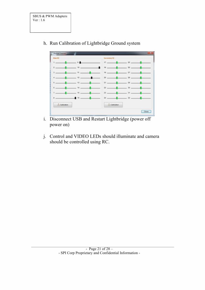
h. Run Calibration of Lightbridge Ground system
i. Disconnect USB and Restart Lightbridge (power off power on)
j. Control and VIDEO LEDs should illuminate and camera should be controlled using RC.

SBUS & PWM Adapters Ver : 1.6
- Page 22 of 28 – - SPI Corp Proprietary and Confidential Information -
7 PWM-Adapter
The specifications of the SBUS-Adapter are:
Weight
14 grams [0.49 oz.]
Size
33 x 31 x 11 mm [1.3’’ x 1.3’’ x 0.43’’]
Input Voltage
9-36 VDC
7.1 Interfaces
The PWM-Adapter includes the following interfaces:
Interface
Wire Harness Connector Type CAMERA
51021-1000 Molex 1.25mm Pitch PicoBlade 10 pin
POWER
51021-0400 Molex 1.25mm Pitch PicoBlade 4 pin
USB
MicroUSB
PWM
Female 3-Pin Connector 2.54mm [0.1”] Pitch
VIDEO1
51021-0200 Molex 1.25mm Pitch PicoBlade 2 pin
VIDEO2
51021-0200 Molex 1.25mm Pitch PicoBlade 2 pin
VIDEO1 & VIDEO2 are two identical output video ports.

SBUS & PWM Adapters Ver : 1.6
- Page 23 of 28 – - SPI Corp Proprietary and Confidential Information -
7.2 Wire Harness
The following wire harness can be sourced from SPI Corp: Interface Description
CAMERA
Wire harness 2x10pin (SPI 51021-1000) L=½m 7 wires color coded
POWER
Wire harness 1x4pin (SPI 51021-0400 ) L=25cm [9.8”] pig tail 4-wires red&black color coded
VIDEO1 / VIDEO2
Wire harness 1x2pin (SPI 51021-0200 ) L=25cm [9.8”] pig tail 2-wires yellow&black color coded
7.3 CAMERA Pinout
Pin
NAME
Description
1
SYS_PWR
System Power Input
2
GND
System Ground
3
RS232_IN
RS232 Receive Input (12V level)
4
RS232_OUT
RS232 Transmitter Output (12V level)
5
RS_232 GND
RS232 Ground
6
Reserved
Do not connect
7
Reserved
Do not connect
8
Reserved
Do not connect
9
VIDEO_OUT
Video Out (PAL or NTSC)

SBUS & PWM Adapters Ver : 1.6
- Page 24 of 28 – - SPI Corp Proprietary and Confidential Information -
10 VIDEO_GND Video Ground
7.4 POWER pinout
Pin
NAME
1
GROUND
2
GROUND
3
POWER
4
POWER
Input Power Range: 9-36 Volt DC
7.5 USB pinout
Standard micro USB interface
7.6 VIDEO1 & VIDEO2 pinout
Pin
NAME
1
Video
2
GND

SBUS & PWM Adapters Ver : 1.6
- Page 25 of 28 – - SPI Corp Proprietary and Confidential Information -
7.7 PWM signals
5V is not outputted from PWM adapter.
A shortcut connects all 5V pins. The user can connects 5V to one of the pins and have this signal on all pins.

SBUS & PWM Adapters Ver : 1.6
- Page 26 of 28 - - SPI Corp Proprietary and Confidential Information -
7.8 PWM Channels
The following table includes the description of the PWM Adapter channels:
Channel
NAME
S1
ROLL
S2
PITCH
S3
ZOOM
S4
DAY / IR / NUC / BLACK HOT-WHITE HOT-PSEUDO COLOR
S5
IR GAIN
S6
IR LEVEL
S7
SENSITIVITY
S8
YAW – IN
S9
YAW – OUT

SBUS & PWM Adapters Ver : 1.6
- Page 27 of 28 – - SPI Corp Proprietary and Confidential Information -
8 Ordering Information
8.1 Adapters
Description
P/N
PWM Adapter.
Dimensions: 33 x 31 x 11 mm [1.3’’ x 1.3’’ x 0.43’’]
Weight: 14 grams [0.49 oz.]
2054
SBUS Adapter.
Dimensions: 28 x 28 x 6.2 mm [1.1’’ x 1.1’’ x 0.24’’]
Weight: 8 grams [0.29 oz.]
2055

SBUS & PWM Adapters Ver : 1.6
- Page 28 of 28 – - SPI Corp Proprietary and Confidential Information -
8.2 Wire Harness
Description
Connecting Harness for connecting SBUS/PWM Adapters to power.
The wire harness includes single 4pin connector connected with 30cm [11.8”] long AWG26 wires. The wires are color coded in red & black.
Connecting Harness for connecting SBUS/PWM Adapters video output.
The wire harness includes single 2 pin connector connected with L = 30cm [11.8”] long AWG26 wires. The wires are color coded in yellow & black.
Connecting Harness for connecting SBUS/PWM Adapters to Camera.
Wire harness 2x10pin L=1/2m 7 ultra-flexible wires