Embed Size (px)
DESCRIPTION
SPL Integration Layout Impact on cryo and vacuum sectorisation. ◊ Underground obstacles, constraints on slope and length of the SPL. ◊ Continuous cryostat and warm magnet options. ◊ Location of the surface buildings and of the main service shaft. - PowerPoint PPT Presentation
Citation preview

SPL Integration LayoutImpact on cryo and vacuum sectorisation
◊ Underground obstacles, constraints on slope and length of the SPL
◊ Continuous cryostat and warm magnet options
◊ Location of the surface buildings and of the main service shaft
◊ Preliminary integration, impact of the position of the couplers
Sylvain Weisz – SPL Cryogenic and vacuum sectorisation – 9 Nov 2009

Linac 4
SPL tunnel
Material access and services shaftPersonnel and material access shaft
Klystron gallery
Emergency exit shaft
Transfert line to PS2
Personnel passage
Emergency exit shaft
Personnel passage
Personnel passage

Computer Center
n_TOF target
TI2 injection line
Underground obstacles

Computer Center
RP requires a shielding of 6.9m of earth to keep Bld 513 a non designated area sets the altitude of Linac4
A. Kosmicki & M. Poehler

n_TOF target area
160µSr/h in Klystron gallerie for 7 1012 ppp on n_TOF target
(20 GeV, 0.33Hz)
A. Kosmicki & M. Poehler

TI2 injection line to LHC
SPL tunnel or SPL to PS2 transfert line crosses TI2 from above
A. Kosmicki & M. Poehler

Linac 4
Computer Center
n_TOF target area
TI2 injection lineSPL tunnel – slope = 1.7%
Transfert line to PS2 – slope = 8.4%
~550m
Constraints on slope and length of the SPL

10 x β=.65 moduleslength = 121 m
4 Gev version (LP): 18 x β=1 modules + 2 de-modulator modules
extraction regions to Isolde and Eurisol
5 Gev version (HP): 23 x β=1 modules + 2 de-modulator modules
extraction regions to Isolde and Eurisol SPL length = 527.38 m
SPL length = 452.58 m
SPL "baseline" layout
Cold continuous cryostat
T. Renaglia

"Compact" version (gain on interconnections):
5 Gev version (HP): SPL length = 485.14 m (-42.24 m with respect to "baseline")
"Warm quadrupole" version (with separate cryoline):
5 Gev version (HP): SPL length = 535.92 m (+8.54 m with respect to "baseline")
Continuous cryostat and warm magnet options

SPL tunnel
Material access and services shaftPersonnel and material access shaft
Klystron gallery
~150m
~170m
Location of the surface buildings and of the main service shaft

Downstream limit ofmain service shaft
A. Kosmicki & M. Poehler
Too far, assume 320m max.

SPLTunnel Machine & Tunnel Services
JMB 03-07-2009
Very preliminary integration issue: Position of the power couplers
Preferred to initial model if we have many waveguide between the two tunnels
J-M. Bianco
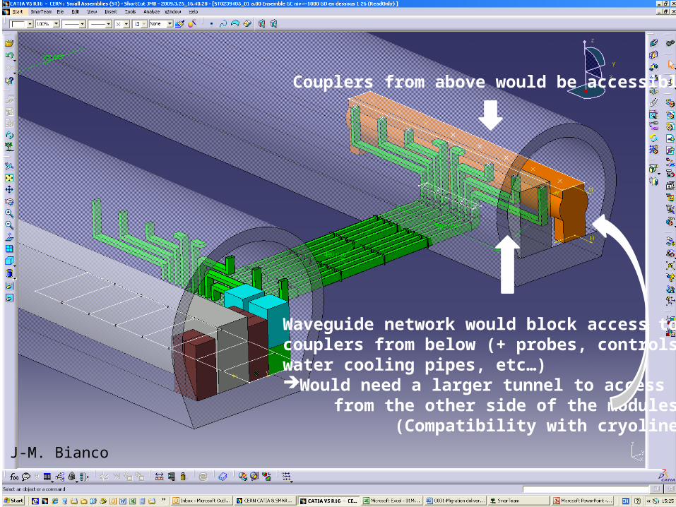
Couplers from above would be accessible
Waveguide network would block access to couplers from below (+ probes, controls,water cooling pipes, etc…)Would need a larger tunnel to access from the other side of the modules (Compatibility with cryoline?)
J-M. Bianco

Summary◊ SPL would have a 1.7% slope ◊ 550m should be considered as a maximum length
(including debuncher and vertical bend to PS2)
◊ A warm magnet option just fits in the footprint◊ Surface buildings and main shafts can be located
around the mid-point of the SPL◊ It would be a big advantage to install the power
couplers from above