Embed Size (px)
Citation preview

Spiral Heat Exchanger

3
HES Heat Exchanger Systems GmbH originated in 1997 from the companyKapp Apparatebau and is now a world-wide operating enterprise with more than30-years experience in the design andmanufacture of spiral heat exchangers(SHE).
HES is located in Schopfheim in the south of Baden-Württemberg, Germany,about 20 km north-east of Basel,Switzerland.
We develop, design, manufacture andmarket heat exchangers for a wide rangeof applications.Our customers include well-known plantbuilders, engineering firms, the chemicaland pharmaceutical industries, the miningand paper industries, steel works, refine-ries, water treatment facilities and manyothers.
The spiral heat exchanger was developed in the twenties for use in thepaper industry by the Swedish engineerMr Rosenblad. For the first time, a heatexchanger became available, that allowedtrouble-free heat transfer between particle-loaded process streams.
In the beginning of the seventies, Kapp Apparatebau started manufacturingspiral heat exchangers on the basis of an own design that has distinct advan-tages over the Rosenblad-design whichhad been exclusively employed until then.
Nowadays, HES is the only company capable of manufacturing spiral heatexchangers both to its own design and to the Rosenblad concept in almost any size from any cold-workable and weldablematerial.
HES GmbH Heat Exchanger Systems

The concept of a spiral heat exchanger is as simple asit is sophisticated. Two or four long metal strips, onto which spacer studs are welded, are wound arounda core, thus creating two or four equally spaced single-passage channels.
The concentric shape of the flow-passages and thestuds yield turbulence already at low Reynolds numbers.By optimising the flow pattern heat transfer is en-hanced, whilst fouling is reduced. This yields a compactand space-saving construction that can be readily integrated in any plant and reduces installation costs.
Because of the all-welded androbust designand the lowfouling proper-ties, maintenan-ce costs arereduced to a mini-mum. From theviewpoint of TotalCost ofOwnership, thespiral heatexchanger is frequently the mostcost-effective solution.
Tailored to the requirements
As the channel geometry can be varied with great flexibility, a spiral heat exchanger can be adapted ideallyto the existing requirements and desires.Notwithstanding varying mass flows and desired tempe-rature differences, a spiral heat exchanger often enables heat transfer in a single unit and offers anexcellent turn-down ratio. The long single-flow passagechannels offer almost any desirable thermal length bywhich difficult process flows can be heated or cooled ina single device, while avoiding any sharp turns of flowthat so often cause blockages.
4
The spiral heat exchanger – a solution for a wide range of applications
HES have developed a wide range of cores, each ofwhich is tailored to accomplish specific tasks, which enables us to choose the right solution for anyapplication.
An important feature of our design is the use of continuous strips from core to shell that enables internal and almost unreachable welding seams to be avoided entirely.
The execution of a unit can be chosen freely to our, or to the Rosenblad-design, which enables us to offerreplacements units for all applications without the need of costly piping adjustments.
Different types for different tasks
Type A: ● COUNTER- OR CO-CURRENT-FLOW● Both covers closing
the spiral body ● Liquid/liquid as well as
vapour/liquid-applications
Type B: ● CROSS-FLOW● Both covers at a distance
from the spiral body● (Overhead) condensation
and evaporation applications
Type C: ● CROSS-/COUNTER- OR CO-CURRENT-FLOW
● One cover closes the spiral body;the other is at a distance
● Condensation applications with the possibility of condensatesub-cooling

5
APPLICATIONSFluids Liquids, suspensions,
fibre- and particle-loaded liquids,(highly) viscous fluids, non-Newtonian fluids including slurries and sludges,vapour with and without inert gases
Tasks Cooling, heating, heat recovery, (near-vacuum) condensation, evaporation, thermosyphon, reboiler
Application (Petro-) chemical, food, in the pharma, vegetable oil, following water treatment, industries paper, steel and mining industries
CAPABILITIESfrom to
Channel spacings 5 mm 70 mmChannel widths 50 mm 2000 mmSurface per unit 0.1 m2 to 800 m2
Design pressure Vacuum 45 bar and above
Design temperature -100°C 450°Cand above
Materials Carbon steel, (super-) austeniticstainless steel, duplex, Nickel and Nickel alloys, Titanium,Zirconium and others
PV Codes AD-2000, PED, ASME, AS1210, etc.
Quality ISO 9001:2000, SQLCertification for Europe, China, USA, Australia
CAPABILITIES AND APPLICATIONS
Manufacturing capabilities:
Design and fabrication are executed in accordance with international pressure-vessel codes including PED (CE-Stamp), AD-Merkblätter, ASME (U-Stamp),AS1210 etc.; Quality is ensured by maintaining ownwritten practises from proposal to delivery.Corresponding certifications to ISO 9001:2000 andSafety Quality License (SQL) are a matter of course.
Leakage is practically excluded by the all-welded channel construction. For this reason the spiral heatexchanger is ideal in the case of sensible, dangerous and/or aggressive fluids.
Because of the single-flow passage, chemical cleaning is extremely effective.
The covers are mounted with hook-bolts to enable easyaccess to the channels, which can also be readily cleaned mechanically. In particular for sludge or slurryapplications, covers can be executed with hinges ordavits, thus enabling very fast access that reducesdown-time.
6
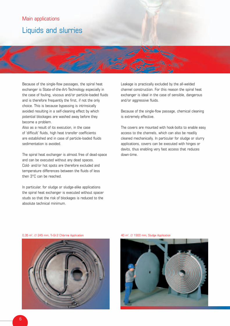
Because of the single-flow passages, the spiral heatexchanger is State-of-the-Art-Technology especially inthe case of fouling, viscous and/or particle-loaded fluidsand is therefore frequently the first, if not the only choice. This is because bypassing is intrinsically avoided resulting in a self-cleaning effect by whichpotential blockages are washed away before they become a problem. Also as a result of its execution, in the case of ‘difficult’ fluids, high heat transfer coefficients are established and in case of particle-loaded fluidssedimentation is avoided.
The spiral heat exchanger is almost free of dead-spaceand can be executed without any dead spaces. Cold- and/or hot spots are therefore excluded and temperature differences between the fluids of less then 3°C can be reached.
In particular, for sludge or sludge-alike applications the spiral heat exchanger is executed without spacerstuds so that the risk of blockages is reduced to theabsolute technical minimum.
Main applications
Liquids and slurries
0,35 m2, ∅ 245 mm, Ti-Gr.2 Chlorine Application 40 m2, ∅ 1900 mm, Sludge Application

7
HotFluidIn
In
Hot Fluid
Out
ColdFluid
Out
Cold Fluid
Hinges Re-inforced covers Body flange Frame
8
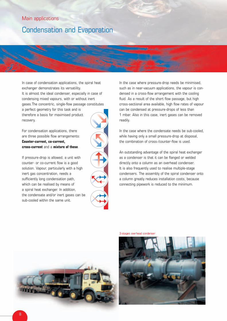
In case of condensation applications, the spiral heatexchanger demonstrates its versatility. It is almost the ideal condenser, especially in case ofcondensing mixed vapours, with or without inertgases.The concentric, single-flow passage constitutes a perfect geometry for this task and is therefore a basis for maximised product recovery.
For condensation applications, there are three possible flow arrangements:Counter-current, co-current,cross-current and a mixture of these.
If pressure-drop is allowed, a unit with counter- or co-current flow is a good solution. Vapour, particularly with a high inert gas concentration, needs a sufficiently long condensation path, which can be realised by means of a spiral heat exchanger. In addition, the condensate and/or inert gases can besub-cooled within the same unit.
In the case where pressure-drop needs be minimised,such as in near-vacuum applications, the vapour is con-densed in a cross-flow arrangement with the coolingfluid. As a result of the short flow passage, but highcross-sectional area available, high flow rates of vapourcan be condensed at pressure-drops of less than 1 mbar. Also in this case, inert gases can be removedreadily.
In the case where the condensate needs be sub-cooled, while having only a small pressure-drop at disposal, the combination of cross-/counter-flow is used.
An outstanding advantage of the spiral heat exchangeras a condenser is that it can be flanged or weldeddirectly onto a column as an overhead condenser. It is also frequently used to realise multiple-stage condensers. The assembly of the spiral condenser ontoa column greatly reduces installation costs, becauseconnecting pipework is reduced to the minimum.
Main applications
Condensation and Evaporation
3-stages overhead condenser

9
Standard condenserSteam/vapour
Condensate
CoolingFluid
CoolingFluid
Outlet uncondensed vapours
CoolingFluidstage II
CoolingFluid stage I
CoolingFluidstage II
CoolingFluidstage I
Condensateoutlet stage Il
Condensateoutlet stage I
In
Out
In
Out
Out
Vapour inlet
In
Overhead Condenser
Bottom condenser
With our experience in all applications ofthe spiral heat exchanger, we can assistour customers in many ways. As a resultof development, design, engineering andfabrication all being carried out by us inour facilities at one single location, we can quickly respond to customerrequirements and wishes. The excellentteam-work with our worldwide network of representatives and co-operation partners provides local and directaccess.Apart from the high standards of ourengineering work and fabrication, exemplary quality management and fulltechnical documentation belong to everyunit we deliver.Customer feedback and the resultingexperience play a vital role. Our customers contribute importantly tothe development of our company, which is required in a rapidly changing world,and ensures the continuous improvement process within our company.By our development and manufacturing of ever more mechanically sophisticatedunits and prototypes, we have repeatedlyset new standards and technical possibili-ties for the spiral heat exchanger.For new applications, test units are available that enable a co-operative elaboration of solutions that respond togiven process heat transfer challenges.Repairs and overhauls of existing units ofall brands can be executed effectively andefficiently both in the plant and in ourshop.
Always prepared to take new challenges,we look forward to receiving your nextinquiry.
Know-how, flexibility and service
11
Hohe-Flum-Straße 3179650 Schopfheim, GermanyTelefon +49 (0) 7622/6 66 89-0Telefax +49 (0) 7622/6 66 89-30E-mail [email protected] www.hes-kapp.de
Ausg
abe
06/2
004
The right partnerfor heat-transfer solutions