Embed Size (px)
Citation preview

October 2017, Volume 4, Issue 10 JETIR (ISSN-2349-5162)
JETIR1710010 Journal of Emerging Technologies and Innovative Research (JETIR) www.jetir.org 67
COMPARATIVE ANALYSIS OF SPIRAL HEAT
EXCHANGER AND GASKETED PLATE TYPE HEAT
EXCHANGER 1NIKHIL LOKHANDE
*, Dr. S. R. NIKAM
2, Dr. K.N. PATIL
3
1Student,
2Assist. Professor
3Professor, Department of Mechanical Engineering, K.J. Somaiya College of Engineering,
Vidyavihar, Mumbai, India
Abstract: Present paper reports theoretical analysis of Spiral heat exchanger(SPHE) and Gasketed plate heat exchanger (PHE), to
investigate its efficacy of heat transfer. Experimental investigation of effect of chevron angle of plate in Gasketed PHE on thermal and
hydraulic performance is carried out. The Spiral heat exchanger when compared with Gasketed plate heat exchanger (PHE), the
performance of PHE is found better than SPHE. Overall heat transfer coefficient (U) is increased by 86.8% by GPHE over SPHE.
Performance of PHE is investigated for two different plate chevron angles, 65° and 30°. Overall heat transfer coefficient is increased by 26%
for chevron angle 65° as compared to 30°. Also, pressure drop is increased by 12.77% when chevron angle increased from 65° to 30°.
Keywords: Spiral Heat Exchanger, Plate Heat Exchanger, Chevron angle.
1. INTRODUCTION
The Spiral Heat Exchangers (SHE), which has a helical (coiled) tube configuration and a pair of flat surfaces that are coiled to form two
channels in a counter-flow direction. M. P. Nueza et al. [1] studied the design of the spiral heat exchangers. They made it clear that the heat
transfer rate of the spiral heat exchanger is more than that of the other exchangers (Double Pipe Heat Exchanger, Tubular Heat Exchanger, Shell
and Tube Heat Exchanger). The Spiral Heat Exchanger used in the industry has a limitation because of its limited temperature and pressure of
500°C and 25 bar, the cleaning of this type of heat exchanger is difficult whereas its maximum flow rate is limited up to 350 m3/hr [2].
Considering these limitations of Spiral type heat exchanger, some other type of HE is to be suggested. Plate type Heat Exchanger is
advantageous considering its compact size, high efficiency, easy for cleaning, requires less heat transfer area (less than 20-30%). Various
experimental and computational investigations are carried out to analyse performance of Gasketed plate type heat exchanger [1,2,3,4,5,6]. Khan
et al. [3] have experimentally investigated effect of Reynolds number, Prandtl number and Chevron angle on heat transfer coefficient and
pressure drop. They reported the effect of the above factors on heat transfer coefficient and proposed new correlation as a function of Nusselt
number, Reynolds number, Prandtl number and chevron angle. Xiao-Hong Han et al. [4] experimentally and numerically investigated the
temperature, pressure, and velocity in the different regions of the flow in chevron corrugated plate heat exchanger. Paisarn Naphon et al. [5]
observed the effect of constant heat flux on heat transfer coefficient and pressure drop in a corrugated channel. A significant effect was observed
due to the recirculation zones formed due to the corrugated surface. Ting Chen [6] observed the variation in heat transfer coefficient and
effectiveness using two chevron angles of different angle with water and also with Nano fluid. Nano fluid technology has been rapidly
developing over the last two decades. In this paper, the performance of a lithium bromide (Li-Br) solution with and without nanoparticles in plate
heat exchanger (PHE) for various chevron angles and mass flow rates was investigated. The results showed that 60°chevron angle plate has
100% higher heat transfer coefficient than 30° corrugated plates and 60°plate has 70% higher effectiveness than 30° corrugated plates. Abdullah
Yildiza & Mustafa Ali Ersözb [7] compared the theoretical results of Energy and Exergy analyses of a plate type heat exchanger
experimentally. Hot mass flow rate was kept constant and the cold mass flow rate was varied during experimental investigation. Naphon [8]
discussed effect of varying cold and hot fluid mass with shell and helically coiled tube unit with two different coil diameters. As the hot mass
flow rates of water increases the cold-water outlet temperature increases. The friction factor decreases when hot mass flow rates increases. A
significant effect of inlet and outlet mass flow rates and hot water temperature is observed on the effectiveness. The heat transfers by analytical
and experimental method had a difference of 12%. ZhenHua Jin et al. [9] designed and estimated the pressure drop of PHE. The investigation
concluded that the pressure drop in PHE is comparatively lesser than the shell and tube heat exchanger. Aydın Durmus et al. [10] he
investigated the heat transfer in plate heat exchanger and he found that the heat transfer rate in plate heat exchanger is much more than that of
conventional heat exchangers.
Considering advantages of plate type heat exchanger present work is focused on theoretical analysis of spiral and Gasketed plate type heat
exchanger in view of possible replacement of spiral heat exchanger by Gasketed plate type heat exchanger. For this analysis, spiral heat
exchanger presently used in Jindal South West (JSW) Pvt. Ltd. Dolvi Works, Maharashtra is considered. Also, experimental investigation of
effect of chevron angle on thermal and hydraulic performance is carried out. For this study two chevron angles selected are 65° and 30°.
2. METHODOLOGY
2.1 Theoretical Analysis
The Spiral Heat Exchanger in used in the JSW Steel and Power Dolvi Works in ammonia decomposition system. The Spiral HE uses
Ammonia liquor for its hot and cold fluid side at different concentrations i.e. Rich ammonia liquor and Lean ammonia liquor. The ammonia
which is the working fluid contains various particles such as dust, dirt and contaminants, when gets deposited inside the HE reduces the rate of
heat exchanger. Performance of Spiral heat exchanger and Gasketed plate type heat exchanger is analyzed theoretically for the actual data of HE
October 2017, Volume 4, Issue 10 JETIR (ISSN-2349-5162)
JETIR1710010 Journal of Emerging Technologies and Innovative Research (JETIR) www.jetir.org 68
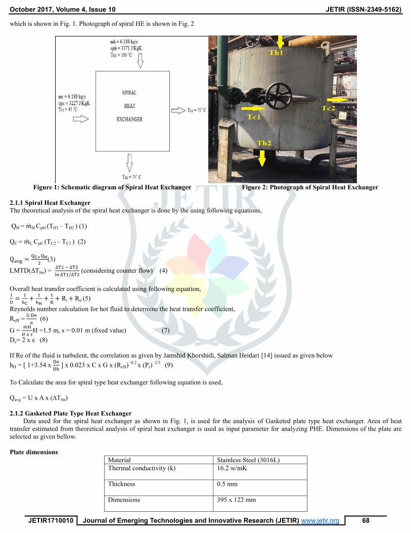
which is shown in Fig. 1. Photograph of spiral HE is shown in Fig. 2
Figure 1: Schematic diagram of Spiral Heat Exchanger Figure 2: Photograph of Spiral Heat Exchanger
2.1.1 Spiral Heat Exchanger
The theoretical analysis of the spiral heat exchanger is done by the using following equations,
QH = �̇�H CpH (TH1 – TH2 ) (1)
QC = �̇�C CpC (TC2 – TC1 ) (2)
Qavg =QC+QH
2(3)
LMTD(∆Tlm) = ∆T1 − ∆T2
ln ∆T1/∆T2 (considering counter flow) (4)
Overall heat transfer coefficient is calculated using following equation, 1
U=
1
hC+
1
hH+
t
K+ Ri + Ro (5)
Reynolds number calculation for hot fluid to determine the heat transfer coefficient,
ReH = G De
𝑢 (6)
G = �̇�H
𝐻 𝑥 𝑠H =1.5 m, s = 0.01 m (fixed value) (7)
De= 2 x s (8)
If Re of the fluid is turbulent, the correlation as given by Jamshid Khorshidi, Salman Heidari [14] issued as given below
hH = [ 1+3.54 x De
Dh ] x 0.023 x C x G x (ReH)
−0.2 x (Pr)
−2/3 (9)
To Calculate the area for spiral type heat exchanger following equation is used,
Qavg = U x A x (∆Tlm)
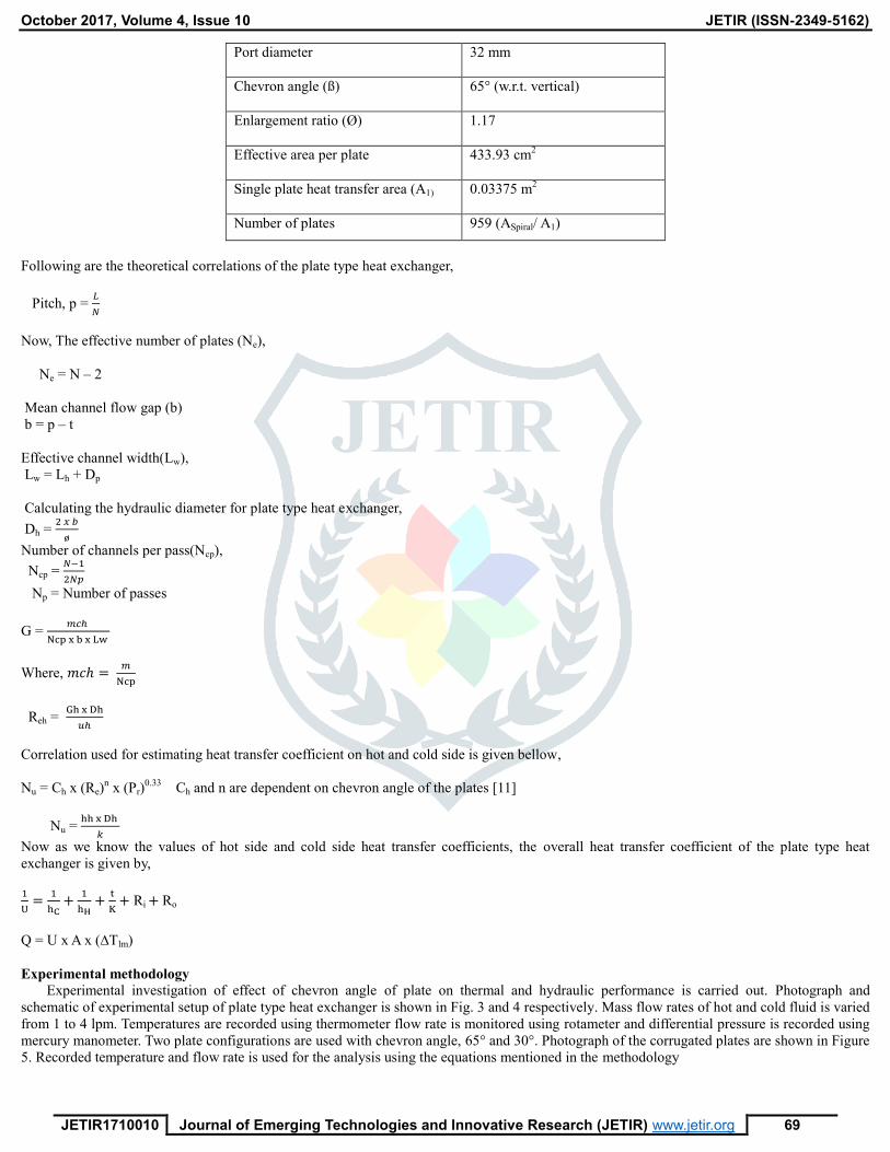
2.1.2 Gasketed Plate Type Heat Exchanger
Data used for the spiral heat exchanger as shown in Fig. 1, is used for the analysis of Gasketed plate type heat exchanger. Area of heat
transfer estimated from theoretical analysis of spiral heat exchanger is used as input parameter for analyzing PHE. Dimensions of the plate are
selected as given bellow.
Plate dimensions
Material Stainless Steel (3016L)
Thermal conductivity (k)
16.2 w/mK
Thickness
0.5 mm
Dimensions
395 x 122 mm
October 2017, Volume 4, Issue 10 JETIR (ISSN-2349-5162)
JETIR1710010 Journal of Emerging Technologies and Innovative Research (JETIR) www.jetir.org 69
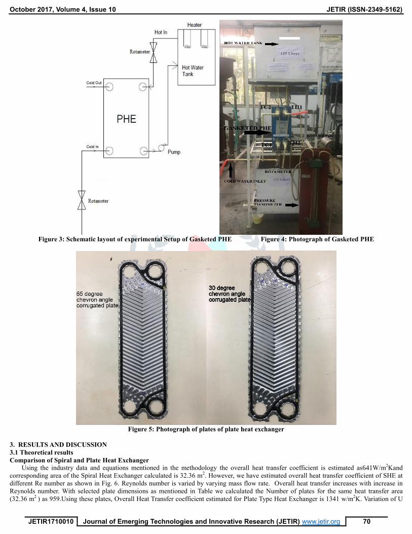
Port diameter
32 mm
Chevron angle (ß)
65° (w.r.t. vertical)
Enlargement ratio (Ø)
1.17
Effective area per plate
433.93 cm2
Single plate heat transfer area (A1)
0.03375 m2
Number of plates 959 (ASpiral/ A1)
Following are the theoretical correlations of the plate type heat exchanger,
Pitch, p = 𝐿
𝑁
Now, The effective number of plates (Ne),
Ne = N – 2
Mean channel flow gap (b)
b = p – t
Effective channel width(Lw),
Lw = Lh + Dp
Calculating the hydraulic diameter for plate type heat exchanger,
Dh = 2 𝑥 𝑏
ø
Number of channels per pass(Ncp),
Ncp = 𝑁−1
2𝑁𝑝
Np = Number of passes
G = 𝑚𝑐ℎ
Ncp x b x Lw
Where, 𝑚𝑐ℎ = 𝑚
Ncp
Reh = Gh x Dh
𝑢ℎ
Correlation used for estimating heat transfer coefficient on hot and cold side is given bellow,
Nu = Ch x (Re)n x (Pr)
0.33 Ch and n are dependent on chevron angle of the plates [11]
Nu = hh x Dh
𝑘
Now as we know the values of hot side and cold side heat transfer coefficients, the overall heat transfer coefficient of the plate type heat
exchanger is given by,
1
U=
1
hC+
1
hH+
t
K+ Ri + Ro
Q = U x A x (∆Tlm)
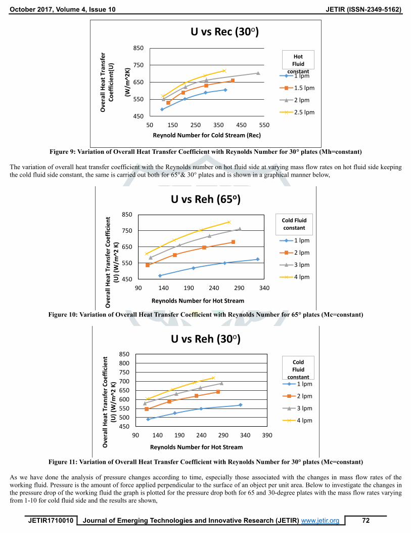
Experimental methodology
Experimental investigation of effect of chevron angle of plate on thermal and hydraulic performance is carried out. Photograph and
schematic of experimental setup of plate type heat exchanger is shown in Fig. 3 and 4 respectively. Mass flow rates of hot and cold fluid is varied
from 1 to 4 lpm. Temperatures are recorded using thermometer flow rate is monitored using rotameter and differential pressure is recorded using
mercury manometer. Two plate configurations are used with chevron angle, 65° and 30°. Photograph of the corrugated plates are shown in Figure
5. Recorded temperature and flow rate is used for the analysis using the equations mentioned in the methodology
October 2017, Volume 4, Issue 10 JETIR (ISSN-2349-5162)
JETIR1710010 Journal of Emerging Technologies and Innovative Research (JETIR) www.jetir.org 70
Figure 3: Schematic layout of experimental Setup of Gasketed PHE Figure 4: Photograph of Gasketed PHE
Figure 5: Photograph of plates of plate heat exchanger
3. RESULTS AND DISCUSSION
3.1 Theoretical results
Comparison of Spiral and Plate Heat Exchanger
Using the industry data and equations mentioned in the methodology the overall heat transfer coefficient is estimated as641W/m2Kand
corresponding area of the Spiral Heat Exchanger calculated is 32.36 m2. However, we have estimated overall heat transfer coefficient of SHE at
different Re number as shown in Fig. 6. Reynolds number is varied by varying mass flow rate. Overall heat transfer increases with increase in
Reynolds number. With selected plate dimensions as mentioned in Table we calculated the Number of plates for the same heat transfer area
(32.36 m2
) as 959.Using these plates, Overall Heat Transfer coefficient estimated for Plate Type Heat Exchanger is 1341 w/m2K. Variation of U

October 2017, Volume 4, Issue 10 JETIR (ISSN-2349-5162)
JETIR1710010 Journal of Emerging Technologies and Innovative Research (JETIR) www.jetir.org 71
with Reynolds number for PHE is shown in Fig. 7. Thus, comparison of U for spiral and PHE shows that performance of PHE is better than the
SPHE as the Overall heat transfer coefficient is higher for lower value of Reynolds number in GPHE.
Figure 6: Variation of Overall Heat Transfer Coefficient with Reynolds Number for Spiral HE
Figure 7: Variation of Overall Heat Transfer Coefficient with Reynolds Number for Plate HE
Observations were taken by varying the hot mass flow rates and the cold mass flow rates at 5 minutes 10 minutes and 15 minutes so as to
ensure continuous flow of the fluid through the heat exchanger and its plates and throughout
the system.
The variation of overall heat transfer coefficient with the Reynolds number on cold fluid side at varying mass flow rates on cold fluid side
keeping the hot fluid side constant, the same is carried out both for 65°& 30° plates and is shown in a graphical manner below,
Figure 8: Variation of Overall Heat Transfer Coefficient with Reynolds Number for 65°plates (Mh=constant)
350
400
450
500
550
600
650
700
200000 300000 400000 500000 600000 700000
Ove
rall
HTC
(W/m
2K
)
Reynolds Number
U vs Re
Spiral HE
1325
1330
1335
1340
1345
5000 7000 9000 11000 13000 15000 17000 19000
Ove
rall
HTC
(W
/m2K
)
Reynolds Number
U vs Re
Plate HE
450
550
650
750
850
50 150 250 350 450
Ove
rall
He
at T
ran
sfe
r C
oe
ffic
ien
t(U
)
(W
/m^2
K)
Reynolds Number for Cold Stream (Rec)
U vs Rec (65o)
1 lpm
1.5 lpm
2 lpm
2.5 lpm
Hot Fluid
constant
October 2017, Volume 4, Issue 10 JETIR (ISSN-2349-5162)
JETIR1710010 Journal of Emerging Technologies and Innovative Research (JETIR) www.jetir.org 72
Figure 9: Variation of Overall Heat Transfer Coefficient with Reynolds Number for 30° plates (Mh=constant)
The variation of overall heat transfer coefficient with the Reynolds number on hot fluid side at varying mass flow rates on hot fluid side keeping
the cold fluid side constant, the same is carried out both for 65°& 30° plates and is shown in a graphical manner below,
Figure 10: Variation of Overall Heat Transfer Coefficient with Reynolds Number for 65° plates (Mc=constant)
Figure 11: Variation of Overall Heat Transfer Coefficient with Reynolds Number for 30° plates (Mc=constant)
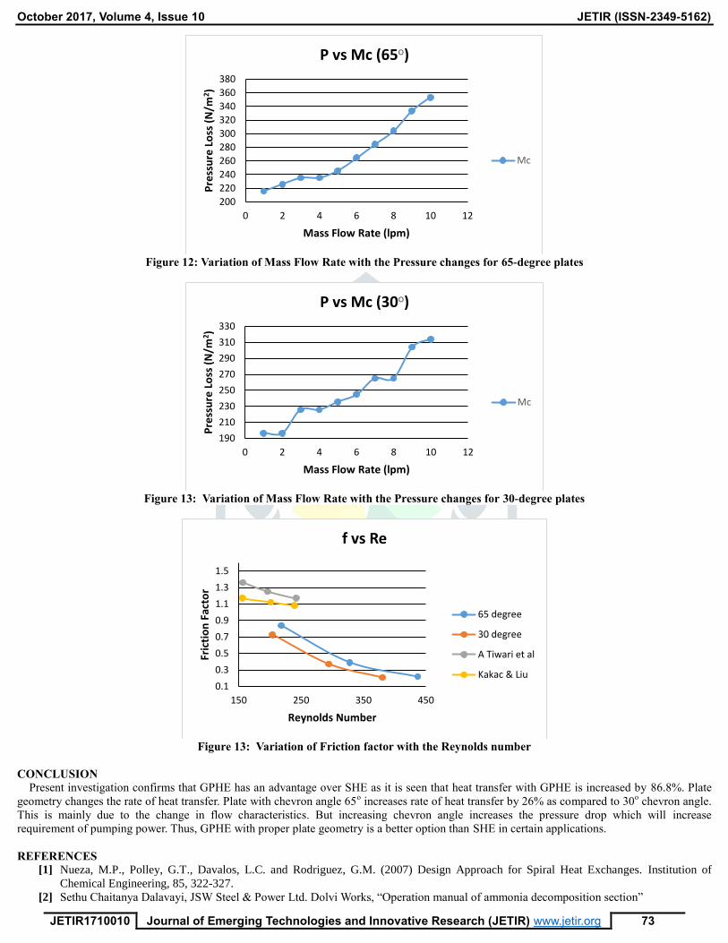
As we have done the analysis of pressure changes according to time, especially those associated with the changes in mass flow rates of the
working fluid. Pressure is the amount of force applied perpendicular to the surface of an object per unit area. Below to investigate the changes in
the pressure drop of the working fluid the graph is plotted for the pressure drop both for 65 and 30-degree plates with the mass flow rates varying
from 1-10 for cold fluid side and the results are shown,
450
550
650
750
850
50 150 250 350 450 550
Ove
rall
He
at T
ran
sfe
r C
oe
ffic
ien
t(U
)
(W
/m^2
K)
Reynold Number for Cold Stream (Rec)
U vs Rec (30o)
1 lpm
1.5 lpm
2 lpm
2.5 lpm
Hot Fluid
constant
450
550
650
750
850
90 140 190 240 290 340
Ove
rall
He
at T
ran
sfe
r C
oe
ffic
ien
t (U
) (W
/m^2
K)
Reynolds Number for Hot Stream
U vs Reh (65o)
1 lpm
2 lpm
3 lpm
4 lpm
Cold Fluid constant
450
500
550
600
650
700
750
800
850
90 140 190 240 290 340 390
Ove
rall
He
at T
ran
sfe
r C
oe
ffic
ien
t (U
) (W
/m^2
K)
Reynolds Number for Hot Stream
U vs Reh (30o)
1 lpm
2 lpm
3 lpm
4 lpm
Cold Fluid
constant
October 2017, Volume 4, Issue 10 JETIR (ISSN-2349-5162)
JETIR1710010 Journal of Emerging Technologies and Innovative Research (JETIR) www.jetir.org 73
Figure 12: Variation of Mass Flow Rate with the Pressure changes for 65-degree plates
Figure 13: Variation of Mass Flow Rate with the Pressure changes for 30-degree plates
Figure 13: Variation of Friction factor with the Reynolds number
CONCLUSION
Present investigation confirms that GPHE has an advantage over SHE as it is seen that heat transfer with GPHE is increased by 86.8%. Plate
geometry changes the rate of heat transfer. Plate with chevron angle 65o increases rate of heat transfer by 26% as compared to 30
o chevron angle.
This is mainly due to the change in flow characteristics. But increasing chevron angle increases the pressure drop which will increase
requirement of pumping power. Thus, GPHE with proper plate geometry is a better option than SHE in certain applications.
REFERENCES
[1] Nueza, M.P., Polley, G.T., Davalos, L.C. and Rodriguez, G.M. (2007) Design Approach for Spiral Heat Exchanges. Institution of
Chemical Engineering, 85, 322-327.
[2] Sethu Chaitanya Dalavayi, JSW Steel & Power Ltd. Dolvi Works, “Operation manual of ammonia decomposition section”
200
220
240
260
280
300
320
340
360
380
0 2 4 6 8 10 12P
ress
ure
Lo
ss (
N/m
2)
Mass Flow Rate (lpm)
P vs Mc (65o)
Mc
190
210
230
250
270
290
310
330
0 2 4 6 8 10 12
Pre
ssu
re L
oss
(N
/m2 )
Mass Flow Rate (lpm)
P vs Mc (30o)
Mc
0.1
0.3
0.5
0.7
0.9
1.1
1.3
1.5
150 250 350 450
Fric
tio
n F
acto
r
Reynolds Number
f vs Re
65 degree
30 degree
A Tiwari et al
Kakac & Liu

October 2017, Volume 4, Issue 10 JETIR (ISSN-2349-5162)
JETIR1710010 Journal of Emerging Technologies and Innovative Research (JETIR) www.jetir.org 74
[3] “Experimental investigation of single phase convective heat transfer coefficient in a corrugated plate heat exchanger for multiple plate
configurations” by, T.S. Khan, M.S. Khan, Ming-C. Chyu, Z.H. Ayub.
[4] “A numerical and experimental study of chevron, corrugated-plate heat exchangers” by, Xiao-Hong Han, Li-Qi Cui, Shao-Jie Chen,
Guang-Ming Chen, Qin Wang.
[5] “Laminar convective heat transfers and pressure drop in the corrugated channels” by, Paisarn Naphon. Article in international
communications in heat and mass transfer January 2007.
[6] “Theoretical analysis of the thermal performance of a plate heat exchanger at various chevron angles using lithium bromide solution
with nanofluid” by, Ting Chen, Jinhyun Kim , Honghyun Cho. International journal of refrigeration 48 (2014) 233-244.
[7] “Theoretical and experimental thermodynamic analyses of a chevron type heat exchanger” by, Abdullah Yildiz, Mustafa Ali Ersöz.
[8] P. Naphon, “Thermal performance and pressure drop of the helical–coil heat exchangers with and without helically crimped fins.”
International Communications in Heat and Mass Transfer, vol.34, PP – 321 – 330, 2007.
[9] ZhenHu11a Jin, GiTae Park, YongHun Lee, SoonHo Choi, HanShik Chung, HyoMin Jeong, “Design and Performance of Flow
Distribution to the Channel in Plate Heat Exchanger”, International Conference onEngineering Optimization, Rio de Janeiro, Brazil, 01
- 05 June 2008.
[10] Aydin Durmus, Huseyin Benli, Irfan Kurtbas, Hasan Gul, “Investigation of heat transfer in plate heat exchangers having different
surface profiles”, International Journal of Heat and Mass Transfer 52 (2009) 1451–1457.
[11] Sadik Kakac & Hongton Liu (2002), Heat Exchangers: Selection,Rating and Thermal Design,Department of Mechanical Engineering
University of Miami.
[12] P.M. Deshpande & Dr. S. Dawande, “Study of Hydrodynamics of Horizontal Spiral Coil Tube.” International Journal of Advanced
Engineering Research and Studies, Vol. 1, Issue. 3, PP – 112 – 114, ISSN No. 2249 – 8974, Apr – June 2012.
[13] Kondahkar, G.E. and Kapatkat, V.N. (2012) Performance Analysis of Spiral Tube Heat Exchanger Used in Oil Extraction System.
International Journal of Modern Engineering Research, 2, 930-936.
[14] Jamshid Khorshidi, Salman Heidari (2016) Design and Construction of a Spiral Heat ExchangerDepartment of Engineering, Hormozgan
University, Bandar Abbas, IranAdvances in Chemical Engineering and Science, 2016, 6, 201-208.
NOMENCLATURE
mh = Mass flow rate of hot fluid, (kg/s)
mc = Mass flow rate of cold fluid, kg/s
Cph = Specific heat of hot fluid, J/KgK
Cpc = Specific heat of cold fluid, J/KgK
De = Equivalent diameter of flow channel, m
Dh = Hydraulic diameter, m
hh = Heat transfer coefficient on hot fluid side, W/m2K
hc = Heat transfer coefficient on cold fluid side, W/m2K
Q = Heat transfer, W
K = Thermal conductivity of the material, W/mK
Th1 = Inlet temperature of hot fluid, ˚C
Th2 = Outlet temperature of hot fluid, ˚C
Tc1 = Inlet temperature of cold fluid, ˚C
Tc2 = Outlet temperature of cold fluid, ˚C
tw= Wall thickeness of spiral, m
Reh = Reynolds number of hot fluid side
Rec = Reynolds number of cold fluid side
∆Tlm = Log Mean Temperature Difference, ˚C
Qh = Hot fluid side heat transfer, W
Qc = Cold fluid side heat transfer, W
A = Area of heat exchanger, m2
s = Thickness of the duct, m
ƍ = Density (Kg/m3)
v = Velocity (m/s)
d = Diameter (m)
u = Dynamic viscosity (Ns/m2)
G = Mass velocity (Kg/m2s)
m = Mass flow rate (Kg/s)
H = Hieght of spiral heat exchanger (m)
uf = Dynamic viscosity at Tavg (Ns/m2)
uw = Dynamic viscosity at wall temperature (Ns/m2)
Pr = Prandtl number
Ne = Effective number of plates
Leff = Effective flow length (m)
b = Mean channel flow gap (m)
Lw = Effective channel width (m)
Ncp = Number of channels per pass
p = Plate pitch (m)

October 2017, Volume 4, Issue 10 JETIR (ISSN-2349-5162)
JETIR1710010 Journal of Emerging Technologies and Innovative Research (JETIR) www.jetir.org 75
Dp = Diameter of the port on the plate (m)
Ri = Internal fouling resistance (m2K/W )
Ro = External fouling resistance (m2K/W)
∆Eh = Exergy loss at hot fluid side (KW)
∆Eh = Exergy loss at hot fluid side (KW)
Shi = Entropy of hot water inlet temperature, (J/K)
Sho = Entropy of hot water outlet temperature, (J/K)
Sci = Entropy of cold water inlet temperature, (J/K)
Sco = Entropy of cold water outet temperature, (J/K)