Embed Size (px)
Citation preview
Philips tech: Rev. 35,137-141,1975, No. 5 137
Spiral-groove bearing systems with grease
J. G. G. Bos
If bearings are filled with grease, it is almost inevitable that a certain amount of air willbecome entrapped. In combinations of two or more spiral-groove [*1 bearings, whichshould be considered as a single grease-circulation system, this can have very seriousconsequences when air accumulates at a place where it cannot escape. By analysing thepressure distribution in the grease of such a bearing system, a design can be producedin which this dijJiculty is avoided.
Lubrication 'for life'
Spiral-groovejournal and thrust bearings have a num-ber of attractivefeatures, These include great rigidity,a pumping action that permits self-sealing, and a long-term performance better than that of porous bearingsmade of sintered and oil-impregnated metal [11 [21 [31.
Moreover, a journal bearing with grooves is morestable in operation than one with no grooves in thebearing surfaces [41. For smooth journal bearings, it isknown that when the load is zero or almost zero, thenotorious (half-speed) whirl appears, unless specialprecautions are taken, such as the addition of twoeccentric cylindrical surfaces. Preventive measures ofthis type are expensive or technically difficult.The promising results with spiral-groove patterns
encouraged us to apply them in a variety of com-plicated bearings developed at Philips Research Labor-atories in recent years, and built up from combina-tions of simple bearings with different functions.Grease was chosen as the lubricant because greasesleak away much less than oils, especially when thebearing is stationary. In some recent applications it isparticularly important to prevent leakage of the lu-bricant. The addition of lubricant afterwards is some-times completely impossible, for example in unmannedspacecraft, or is inconvenient and expensive - as indomestic equipment. The rate of leakage may thendetermine the appliance's useful life.
A grease may be considered as a Bingham fluid, i.e. a mediumthat has a yield point. When the shear stresses are below thislimit, it behaves as a solid, and if they are higher, it flows andbehaves more or less like an oil (i.e. a Newtonian fluid). For thesevalues ofthe shear stress, there is an approximately linear relationwith the shear rate; the magnitude of the viscosity need not thendiffer very greatly from that of an oil.
J. G. G. Bosç formerly with Philips Research Laboratories, Eind-hoven, is now with N. V. Pope, Venlo, the Netherlands.
While investigating these compound bearings. weencountered a particular difficulty not found in singlespiral- or helical-groove bearings: the local accumula-tion of air in the grease. This forms the subject of thisarticle. When the bearing is filled with grease duringassembly it is almost impossible to prevent some airfrom being trapped. Also, air can sometimes enter thebearing while it is running. Generally the air in a singlespiral- or helical-groove bearing can be readily elim-inated by the pumping action and will not cause diffi-culties. However, in compound bearings, trapped aircan easily accumulate somewhere inside the bearing,for example at places where there is a local minimumin the pressure of the grease. The air cannot escapefrom such a 'pressure dip'. If the pressure outside thesystem falls - as in a spacecraft directly after launch-ing - or the temperature of the grease increases, theexpansion of the air can force grease out of the bear-ing, with all the consequences for the life. In designinga system of grooved bearings it is therefore importantto ensure - while taking the other requirements intoaccount, of course - that any pressure dips occur atplaces that incoming air can escape from.
[1) For a general treatment see E. A. Muijderman, New bearingtypes: the gas and the spiral groove bearing, Philips tech.Rev. 25, 296, 1963 and E. A. Muijderman, New possibilitiesfor the solution of bearing problems by means of the spiralgroove principle, in: Lubrication and Wear 4th Conv. (proc.Inst. Mech. Eng. 180, part 3K), 174-183, 1966. The name'greaseber' has since been proposed for spiral-groove bearingscontaining grease (grease-lubricated, self-acting and self con-tained bearing).
[2) G. Remmers, Grease-lubricated spiral groove bearings fora straight-through shaft, Philips tech. Rev. 27, 107, 1966.
[3) G. Remmers, Grease-lubricated helical-groove bearings ofplastic, Philips tech. Rev. 34, 103, 1974 (No. 4).
[4) G. G. Hirs, The load capacity and stability characteristics ofhydrodynamic grooved journal bearings, ASLE Trans. 8,296-305, 1965.
["') In this article the term 'spiral' also refers to three-dimensionalcurves such as the helix.
138 J. G. G. BOS Philips tech. Rev. 35, No. 5
There are further reasons why the presence of air bubbles mustbe considered undesirable. Air in the grease will diminish theload-bearing capacity of the compound bearing. It has also beenfound that a spiral-groove bearing becomes unstable rather easilywhen the grease does not fill the grooves right to the outer edgeof the bearing surface [5]. A compound bearing could thusbecome unstable due to the presence of air/grease interfaces, andstart whirling. The bearing surfaces then come into direct contactand rapid wear will occur.
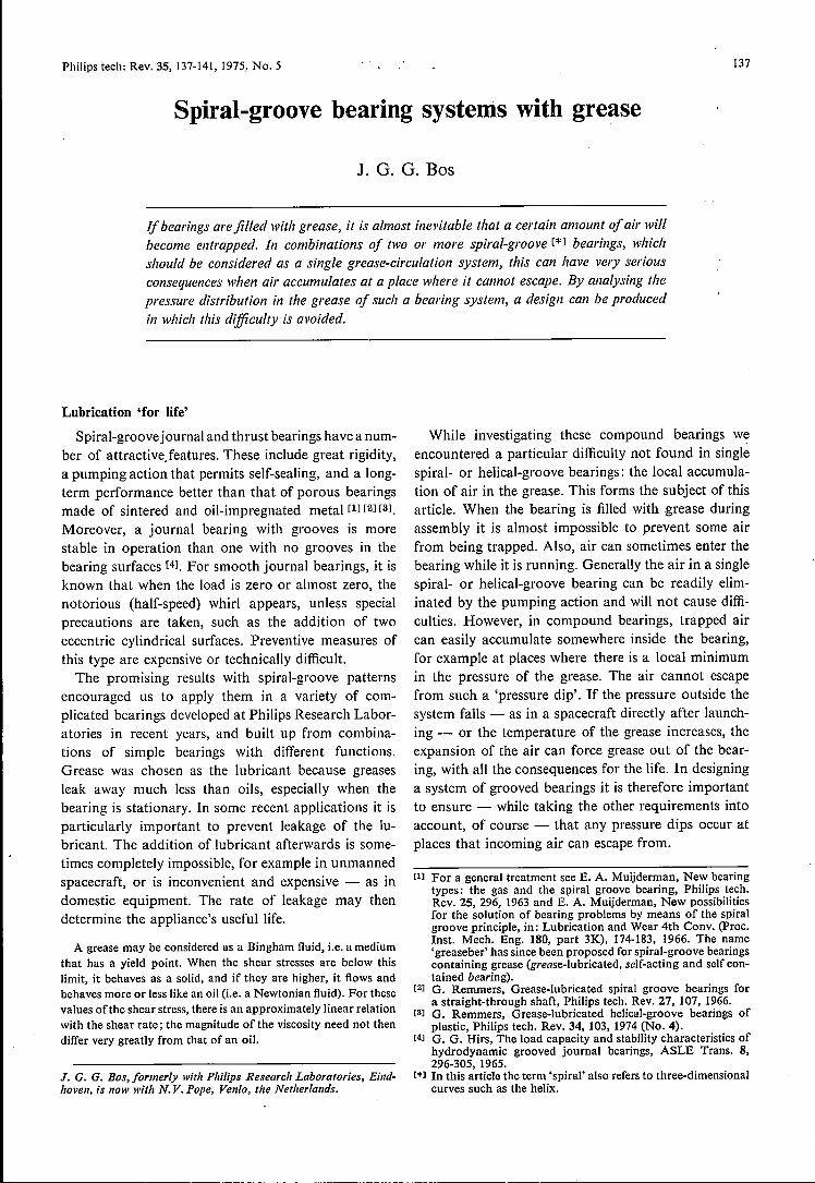
A pressure dip of the type described above arises be-cause the effect of the system of bearings on the greaseflow and pressure is that of a system of interconnectedpumps and flow resistances. We have now been ableto produce equivalent circuits for such systems. Oncesuch a circuit has been set up, it can be analysed in thesame way as an electrical network by applying Kirch-hoff's first and second laws [61. Fig. 1 shows theelements needed to represent a groove pattern in suchan equivalent circuit; further details will be consideredin the example which follows.
This method of analysis can be applied during thedesign phase to predict approximately where thetrapped air will collect. Systematic modification of thedesign based on the circuit and on practical experiencewill then give an arrangement in which the air canescape and no grease need be lost.
w
Fig. I. The groove pattern in a spiral-groove journal bearing(schematic) and the equivalent circuit of such a bearing in rela-tion to its pumping action. The circuit consists of a pressuresource (pump coefficient #) and a restrietion (resistance coef-ficient (j», connected in series. If the bearing surfaces rotate witha relative angular velocity w, the bearing produces a pressuredifference P2 - PI, which causes a mass flow S of the lubricant.The relation between these quantities is: uco - os = j)2 - Pl.
Air bubbles in grease
Before dealing with the example just mentioned, alittle more should be said about the behaviour of airbubbles in the grease of a bearing. We have investigatedthis effect with transparent models of bearings. Some-times very many small air bubbles appear in the grease;these bubbles are so small that they are carried alongby the flows in the system. To eliminate these bubbles,it is sufficient to design the bearing in such a way thatthe flow - or some of it - crosses a point where the
system is open. These very small air bubbles can thenescape there without much leakage of the grease,provided that there is a physical mechanisrn for separat-ing the air from the grease, such as a centrifugal force.
The grease can also contain air bubbles that are suf-ficiently large that they 'roll down' a pressure gradient(like the rising bubbles in a glass of beer) while the flowitself has little effect. These air bubbles are the onesmost likely to accumulate at the pressure dip and causethe difficulties previously mentioned.
Apart from these two extremes there are of coursemany different types of air-bubble behaviour. Never-theless grease leakage from a compound bearing canbe almost totally eliminated by taking care that nopressure minima can occur in the system.
Bearing systems for 'flywheel' for attitude stabilizationof space vehicles
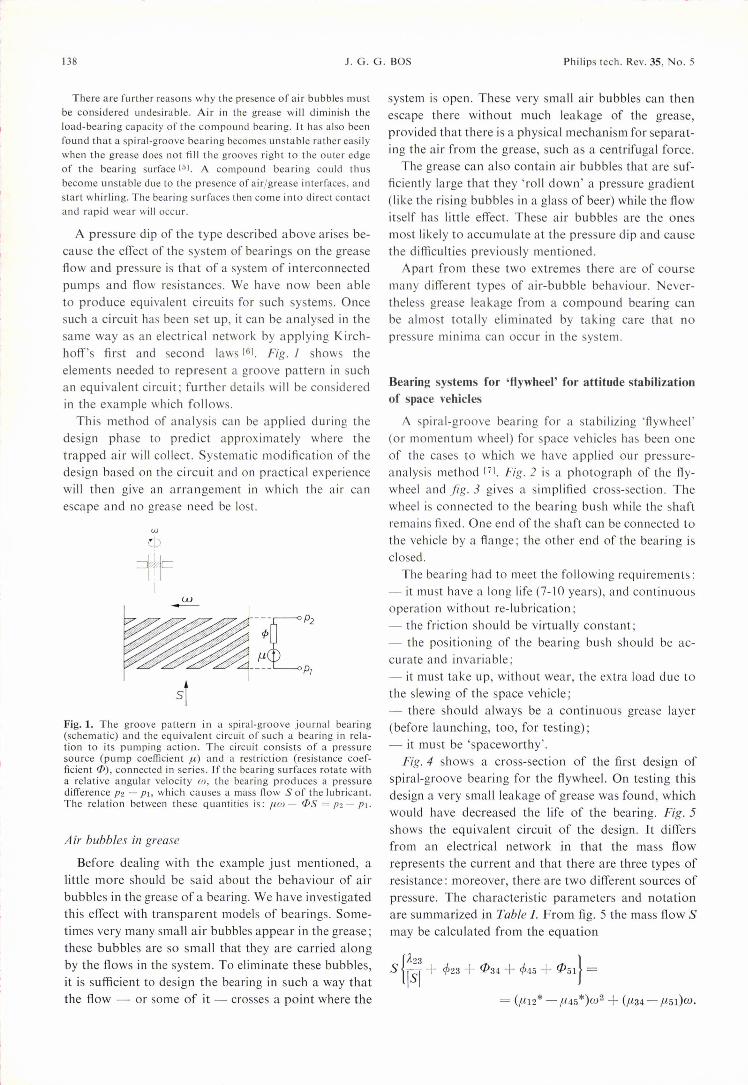
A spiral-groove bearing for a stabilizing 'flywheel'(or momentum wheel) for space vehicles has been oneof the cases to which we have applied our pressure-analysis method [71. Fig. 2 is a photograph of the fly-wheel and fig. 3 gives a simplified cross-section. Thewheel is connected to the bearing bush while the shaftremains fixed. One end of the shaft can be connected tothe vehicle by a flange; the other end of the bearing isclosed.
The bearing had to meet the following requirements:- it must have a long life (7-10 years), and continuousoperation without re-lubrication;- the friction should be virtually constant;- the positioning of the bearing bush should be ac-curate and invariable;- it must take up, without wear, the extra load due tothe slewing of the space vehicle;- there should always be a continuous grease layer(before launching, too, for testing);- it must be 'spaceworthy'.
Fig. 4 shows a cross-section of the first design ofspiral-groove bearing for the flywheel. On testing thisdesign a very small leakage of grease was found, whichwould have decreased the life of the bearing. Fig. 5shows the equivalent circuit of the design. It differsfrom an electrical network in that the mass flowrepresents the current and that there are three types ofresistance: moreover, there are two different sources ofpressure. The characteristic parameters and notationare summarized in Table I. From fig. 5 the mass flow Smay be calculated from the equation
{À23 }S 181+ cP23 + c[J34 + cP45+ c[J51 =
= (,L1l2* - ,u45*)W2 + (,u34 - ,u51)W.
Philips tech. Rev. 35, No. 5 SPIRAL-GROOVE BEARING SYSTEMS WITH GREASE 139
Fig. 2. A 'flywheel' for attitude stabilization ora space vehicle. The shaft is fixed to the vehicleand the bearing bush supports the wheel. The drive motor is not illustrated.
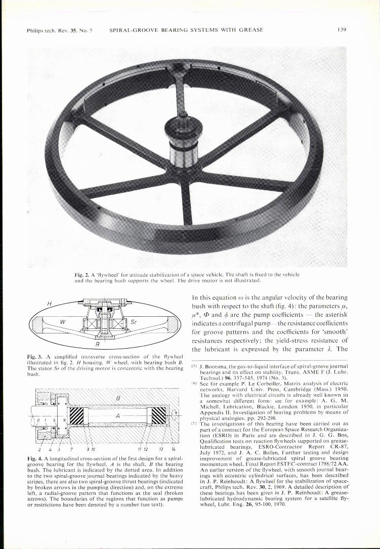
Fig.3. A simplified transverse cross-section of the flywheelillustrated in fig. 2. H housing. W wheel, with bearing bush B.The statal' Sr of the driving motor is concentric with the bearingbush.
2 4 3 7 9 10 11 12 13 14
Fig. 4. A longitudinal cross-section of the first design for a spi ral-groove bearing for the flywheel. A is the shaft, B the bearingbush. The lubricant is indicated by the dotted area. In additionto the two spiral-groove journal bearings indicated by the heavystripes, there are also two spiral-groove thrust bearings (indicatedby broken arrows in the pumping direction) and, on the extremeleft, a radial-groove pattern that functions as the seal (brokenarrows). The boundaries of the regions that function as pumpsor restrictions have been denoted by a number (see text).
r n this equation co is the angular velocity of the bearingbush with respect to the shaft (fig. 4): the parameters u,/h*, (jj and ~ are the pump coefficients - the asteriskindicates a centrifugal pump- the resistance coefficientsfor groove patterns and the coefficients for 'smooth'resistances respectively; the yield-stress resistance ofthe lubricant is expressed by the parameter Je. The
[5] J. Bootsma, the gas-to-liquid interface of spiral-groove journalbearings and its effect on stability, Trans. ASME F (J. Lubr.Techno!.) 96, 337-345, 1974 (No. 3).
[6] See for example P. Le Corbeiller, Matrix analysis of electricnetworks, Harvard Univ. Press, Cambridge (Mass.) 1950.The analogy with electrical circuits is already well known ina somewhat different form: see for example: A. G. M.M ichell, Lubrication, Blackie, London 1950, in particularAppendix 11, Investigation of bearing problems by means ofphysical analogies, pp. 292-298.
[7] The investigations of this bearing have been carried out aspart of a contract for the European Space Research Organiza-tion (ESRO) in Paris and are described in J. G. G. Bos,Qua lification tests on reaction flywheels supported on grease-lubricated bearings, ESRO-Contractor Report CR-87,July 1972, and J. A. C. Bollen, Further testing and designimprovement of grease-lubricated spiral groove bearingmomentum wheel, Final Report ESTEC-contract 1798/72 AA.An earlier version of the flywheel, with smooth journal bear-ings with eccentric cylindrical surfaces, has been describedin J. P. Reinhoudt : A flywheel for the stabilization of space-craft, Philips tech. Rev. 30, 2, 1969. A detailed description ofthese bearings has been given in J. P. Reinhoudt: A grease-lubricated hydrodynamic bearing system for a satellite fly-wheel, Lubr. Eng. 26, 95-100, 1970.

140 J. G. G. BOS Philips tech. Rev. 35, No. 5
Fig.5. The network of pressure sources and flow resistances forming the equivalent circuitof the bearing system shown in fig. 4; the numbers 0-14 in the squares correspond to theequivalent positions in fig. 4. Further details of the notation are given in Table I. In the branchbetween 3 and 14, no yield-stress resistance has been included; this is permissible because itsvalue is negligible compared with the flow resistance present there. Lubricant only flows in thering part of the network, with a mass flow S; in the branch between 3 and 14 a static pres-sure distribution is established with zero mass flow. In the branches 3-5 and 3-8 there is somecentrifugal pumping action besides the pumping action of the spiral grooves. The circuit hasbeen modified to take account ofthis by including an extra pump in the branches 4-5 and 7-8.
double indices give the positions (fig.4) between whichthe elements may be localized for the computation ofthe parameters. Once the resulting mass flow is knownat a given shaft speed, it is easy to determine the pres-sure as a function of position in the system. The massflow is zero in the branch between positions 3 and 14and the resulting (static) pressure distribution thereshould be considered as the analogue of the potentiallevels of a number of batteries in series but not deliver-ing a current. The pressure distribution determined inthis way for the system is shown infig. 6. This pressure
Table I. The active and passive components that can appear in agrease-lubricated spiral-groove bearing; the active componentscause a pressure (pressure sources) and the passive ones arestrietion (flow resistance). The arrow in the pressure sourcegives the direction in which the source pumps. S mass flow.00 the relative angular velocity of the bearing surfaces. The pumpcoefficients p, and ft* and the resistance coefficients cp and r/> canbe calculated for all components as a function of their dimen-sions and the viscosity of the grease. (These calculations, whichwere performed in part by G. Remmers, of these laboratories,were mainly based on the theoretical treatment in E. A. Muijder-man, Spiral groove bearings, Philips Technical Library, Eind-hoven, 1966.)
Symbol Name Equation [a) Bearingcomponent
Active
-e- ; .ft hydrodynamic ó.p = [u» groovepump pattern
-8-' ; p,. centrifugal ó.p = ft*w2' centrifugalpump seal
Passive
-=-. ; cp groove ó.p = -SCP grooveresistance pattern
r/> 'smooth' 'smooth'--- ; ó.p = -Sr/> part ofresistance bearing--E3- ; Ä flow-point S
resistance ó.p =-,S' Ä grease
[a) the pressure difference /lp =Pright - Piert
distribution indicates directly why the compoundbearing of fig. 4 presented problems. Large air bubblesthat have formed in the region 9-12 during assemblyare quite likely to 'roll down' the right-hand side of thegraph and arrive at the blind end of the bearing.
This fault has been corrected by the construction ofa return channel that runs from 13-14 back to thevicinity of 5, so that the air can escape from the blindend. A new analysis of the pressure distribution, withthe return channel now taken into account, gave thedimensions of the channel.
A number of other necessary modifications werealso made: point 8 was connected to the return channeljust described, the pump region 1-5 was replaced by a
Fig. 6. The distribution ofthe pressure P in the bearing system offig.4, calculated with the aid of'the equivalent circuit of fig. 5.The figures in squares correspond to the same locations (Iöc) infig. 5. The pressure at position 0 is set equal to zero. In theregions where the air can accumulate from the grease, the pressuredistribution is indicated by a dashed line. Separation of air andgrease in the pump regions 8-9 and 12-13 can lead to the develop-ment of free edges (i.e. strips with no grease), with the risk thatthe 'half-speed whirl' will appear. In particular, the pressuredrop at the closed end of the bearing (region 13-14) is extremelyundesirable.

Philips teel). Rev. 35, No. 5 SPIRAL-GROOVE BEARING SYSTEMS WITH GREASE 141
Fig.7. Cross-section of the improved spiral-groove bearingsystem. It differs from the bearing illustrated in fig. 4 by thepresence of a connection that allows the air that collects at 13-]4to escape to 5.
gradient should occur not only at the nominal speed,but also at much lower speeds. If this is not the case,then eventually after each start and before each stop asituation will arise for some time in which the greasewill behave locally as a solid; there will be no flow, andthe consequences can be disastrous.Fig. 7 shows a cross-section of the modified bearing
and its equivalent circuit is given in fig. 8. The threemass flows SI, S2 and S3 can be calculated using knownmethods with the aid of a 3X 3 matrix [6l. The pres-sure distribution can again be determined from the
L_----~ .. ~~--~6~------------------------------~Fig. 8. Equivalent circuit of the bearing system of fig. 7.
smooth restriction, and finally the length of the pumpregion 8-9 was made larger than that of 12-13, so thatthe first region receives the stronger pumping actiononce the flow pattern is defined.These changes were necessary because the lubricant
did not behave as a Newtonian fluid under all cir-cumstances. In a grease-lubricated system of spiral-groove bearings, a suitable pressure distribution and
Fig.9. Pressure distribution in the bearing system of fig. 7, cal-culated from the equivalent circuit of fig. 8. There is now nopressure drop at 13-14, as there was in fig. 6. The slight drop at3 does not present much of a problem, since the.air will not bevery likely to collect there because of the strong local flow.
flows in a straightforward way. This pressure distri-bution, which is given infig. 9, approximates to theideal situation. The only feature that might be ques-tioned is the weak dip at point 3. The flows there areso strong, however, that an accumulation of air at thatpoint seems most unlikely.To recapitulate the essentials briefly, the pumping
action of a spiral-groove bearing in a properly designedcompound bearing can simultaneously deliver therequired load-bearing ability, rigidity and stability,with minimal wear (owing to the presence of the con-tinuous lubricant layer), and provide an effective sealfor the lubricant.
Summary. A method of analysis has been developed that enablesthe pressure distribution - and consequently the air-removingcharacteristics - of a system of coupled, grease-lubricatedspiral-groove bearings to be predicted. The system is consideredas a number of pressure sources, connected by flow resistances.The mass flow and the pressure distribution may be calculated inthe same way as the currents and potential differences in anelectrical network. Even at the design stage, successive applica-tions of the method yield improvements that ensure that any airin the lubricant can escape during operation without much lossof grease. Compound bearings designed in this way have a verylong life and require no maintenance. As an example, a hydro-dynamic bearing for a flywheel in a space vehicle (a project forESRO) is described.