Embed Size (px)
Citation preview
Grease-lubricated spiral-groove 'bearings
E. A. Muijderman, G. Remmers and L. P. M. Tielemans
Since the start of the sixties Philips Research Laboratories have been doing research on spiral-groove bearings [*1. The articles on this subject that have appeared in this journal havedescribed the excellent characteristics of these bearings, especially when grease is used as thelubricant. Some successful professional applications have also been described. Large-scaleapplication in consumer articles was not possible until quite recently, however, partly because ofa large number of theoretical and practical aspects of spiral-groove bearings and the long timenecessary for the development of an inexpensive method of manufacture and for testingimportant characteristics such as reliability and life and other special features. The use ofthese bearings in the recently introduced VR 2020 video cassette recorder, based on the new'Video 2000' system, can therefore be considered as something of a landmark in the work ongrease-lubricated spiral-groove bearings.
184 Philips tech. Rev. 39, 184-198, 1980, No. 6/7
Introduetion
A spiral-groove bearing is a self-acting bearing witha repetitive pattern of grooves in one of its two bear-ing surfaces. When these surfaces move in the rightdirection in relation to one another, the pumpingaction of the grooves produces an overpressure in thelubricant between them. Because of this overpressurethe lubricant keeps the moving surfaces apart and aforce is transferred. The first article on this subject inthis journal [1] explained the principle of operation ofthe bearing and drew attention to its low friction andthe possibility of making bearings with very smalldimensions (e.g. with a diameter of only 3 mm).
In many applications in professional equipment thespiral-groove bearings are often lubricated with air.This does not contaminate the immediate surround-ings of the bearing, it can operate at extremes of tem-perature and the speed of the shaft can be very high.In Britain and America gyrocompasses, flywheels,fans, small electric motors and gas circulators havebeen fitted with air-lubricated spiral-groove thrustand journal bearings. A number of interesting pos-sible applications have also been investigated atPhilips Research Laboratories; one of these is the'push-pull' bearing, a thrust bearing with self-adjust-ing internal preloading [2] .
. Prof. Dr Ir E. A. Muijderman, Ing. G. Remmers and Ing. L. P. M.Tielemans are with Philips Research Laboratories, Eindhoven.
For many applications, and here we include almostall consumer articles, air lubrication is unsuitable,however, because the load-carrying capacity of theair-lubricated bearing is usually too small for thedimensions and speeds normally used in this equip-ment. To obtain bearings with sufficient load-carryingcapacity we need a lubricant that has a much higherviscosity, such as oil or grease. Oillubrication is usedfor example in the bearing system we have developedfor ultracentrifuges; grease lubrication is used in thebearing system of the flywheel for stabilizing spacevehicles described previously in this journal [3]. Anadvantage of greases that became clear at an earlystage [1,4] is that they do not leak out of a bearing asreadily as do oils. And even after long periods of usesome greases retain their excellent lubricating proper-ties so that the life of grease-lubricated spiral-groovebearings can be very long [4,5]. All ten of the fly-wheels are still operating perfectly after running formore than ten years in laboratory tests although theirbearings have never been re-lubricated.The potential advantages of grease lubrication and
our favourable experience in professional applica-tions led us ~o a study of grease-lubricated spiral-groove bearings for applications in consumer articles.This work has resulted in a number of suitable bear-ing designs. Further studies made in cooperation withgrease manufacturers' laboratories have led to the
Philips tech. Rev. 39, No. 6/7 GREASE-LUBRICATED SPIRAL-GROOVE BEARINGS 185
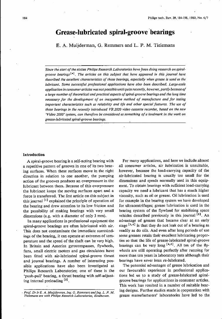
Fig. 1. The VR 2020, the new Philips video cassette recorder.
development of greases with appropriate propertiesfor the special conditions in spiral-groove bearings.From the results obtained we conclude that thesebearings now operate more reliably and more pre-dictably than the porous oil-impregnated bearings ofsintered metal ('sintered bearings') that are widelyused in consumer products.
A very interesting application for spiral-groovebearings was found when a new generation of videocassette recorders (VCR) based on the 'Video 2000'system was being developed for domestic use. Thedesired playing time of 2 x 4 hours per cassette placedsuch exacting requirements on the running accuracyof the head disc that the sintered-bronze bearingsystem used in earlier types was no longer adequatefor the head-disc motor. Working together with tech-nologists and motor and VCR designers from theAudio and Video Divisions we have developed grease-lubricated spiral-groove bearings that do meet therequirements. These bearings are highly suitable forthis particular consumer product because they com-bine excellent technical and practical features: theywill locate the shaft very accurately, they will handlehigh loads, they are stable, have a constant frictionand a long life, they are silent, they are lubricated forlife, and they are very reliable and reasonably inex-pensive. They are used with success in the VR 2020,the new recorder that has been on the market sincelast year (jig. 1).
In this article we shall describe first of all thegeneral operation of spiral-groove bearings, including
the choice of groove pattern and lubricant. Thisdescription will include results obtained from theresearch of the past few years [6-9]. We shall thencover in somewhat greater detail the use of greasesand show that the exacting requirements for viscosity,rheological behaviour and stability over longoperating periods can, to some extent, be met by
making a correct selection of lubricant composition.We shall then discuss manufacture of spiral-groovejournal bearings, with emphasis on the selection ofthe bearing material and the way in which it ismachined. Finally, we shalliook at the application ofgrease-lubricated spiral-groove journal bearings in thehead-disc motor of the VR 2020.
[.] The term 'spiral-groove bearing' in this article is used both forspiral-groove thrust bearings and for helical-groove journalbearings.
[1] E. A. Muijderman, Philips tech. Rev. 25, 253, 1963/64.See also by the same author:Polytech. T. A 20, 154A, 1965 (in Dutch);Proc. Instn Mech. Engrs 180, 174, 1965/66;Scientific American 214, March 1966, page 60.
[2] H. J. W. M. Volman, Philips tech. Rev. 35,1],1975.[3] J. P. Reinhoudt, Philips tech. Rev. 30, 2,1969.[4] G. Remmers, Philips tech. Rev. 27, 107, 1966.[5] G. Remmers, Philips tech. Rev. 34, 103, 1974.[6] G. Remmers, in: Advances in tribology (papers, 1976 Conven-
tion, Durham), page 13; Instn Mech. Engrs, London 1978.[7] J. Bootsma and L. P. M. Tielemans, Trans. ASME F (J. Lubr.
Techno!.) 99, 215, 1977.[8] J. P. Reinhoudt, On the stability of rotor-and-bearing systems
and on the calculation of sliding bearings, Thesis, Eindhoven1972; also published as Philips Res. Repts. Supp!. 1972, No. 1.
[9] J. Bootsma, Liquid-lubricated spiral-groove bearings, Thesis,Delft 1975; also published as Philips Res. Repts. Suppl. 1975,No.7.

186 E. A. MUIJDERMAN el al. Philips tech. Rev. 39, No. 6/7
Operation of spiral-groove bearings
To illustrate the operation of the bearing let us firstexamine a simple model consisting of a plain bearingsurface in motion and, parallel to it and underneathit, a stationary bearing surface with a pattern ofparallel grooves at an angle a to the velocity vector;see fig. 2. The presence of the grooves produces anoverpressure between the bearing surfaces because thelubricant, the 'viscous medium', is 'dragged' throughnarrowing gaps (the 'wedge effect'). Because thegrooves are at an acute angle, lubricant is alsopumped along the grooves so that the pressure in-creases in this direction. The mean pressure differenceSp between the two ends of the groove pattern (y == dand y = 0) depends on a number of quantities
I]vdg!lP=7
where I] is the viscosity of the lubricant, v the velocityof the upper bearing surface, h, the distance betweenthe upper bearing surface and the ridges in the lowerbearing surface, and g is a function of the grooveangle a, the ratio fJ of the ridge width b, to the groovewidth bg, and the ratio b of n, to the groove depth hg•
Calculations show that for grooves of rectangularcross-section the function g has a maximum value(about 0.09) when a = 16°, B == I and b = 0.4.
In most cases both theory and practical applica-tions relate to grooves of rectangular cross-section.This is not essential for the bearing action: any cross-section is in principle possible and can be used inpractice provided it has been dimensioned correctly.In fig. 3 the function g is plotted against 0 fora triangular groove cross-section for different valuesof a. The envelope curves have also been drawn forrectangular, circular and triangular cross-sections.These curves show that the greatest pressure is pro-duced with a rectangular cross-section and also thatthe pressure is not much lower for the other twocross-sections.
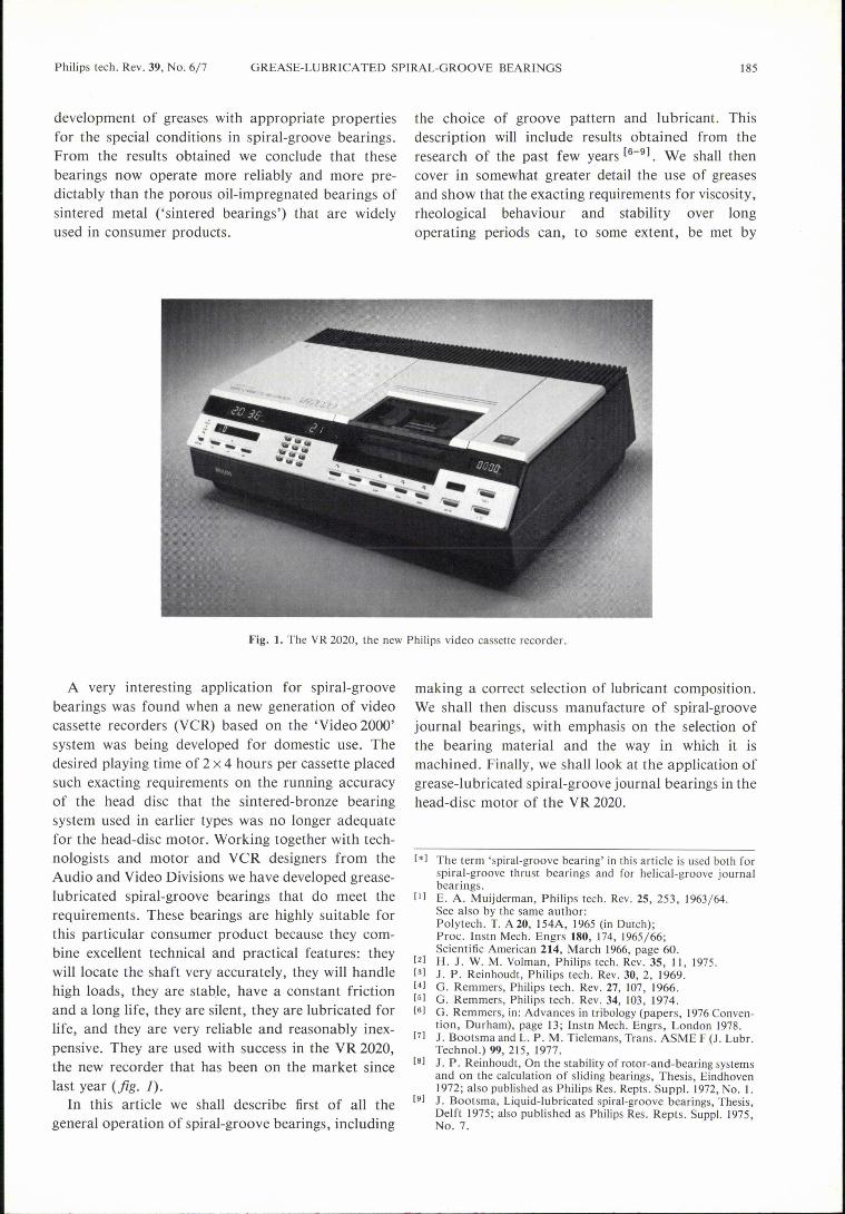
The results of the simple model with parallelgrooves can be used to determine the best shape ofgroove for a thrust bearing [10]. When the shaft isrotating in the correct direction with respect to thegroove pattern the grooves pump lubricant towardsthe centre of the bearing. This bearing can be thoughtof as being split up into a large number of elementseach resembling the model described above; seefig. 4.Each 'ring' at an arbitrary distance r from the centrewith a radial width Sr functions as a pump. Thepumping action developing the pressure is at its mosteffective when the pressure difference across !lris aslarge as possible. This means that all the groovesshould be at the same angle to the local velocity
vector. This requirement is satisfied if the grooveshave the shape of a logarithmic spiral. Similarly itmay be deduced that in journal bearings the groovesshould take the form of a helix.Itwill be clear that these pumps will produce a pres-
sure in the lubricant between the rotating and station-ary bearing surfaces. The load-carrying capacity ofthe bearing can be calculated by integrating thepressure over the entire bearing surface. Allowancemust be made here for the finite number of grooves.
Fig. 2. A diagram showing the distribution of the pressure p in thelubricant, the 'viscous medium', between a plain bearing surfacemoving at a velocity v and a stationary bearing surface parallel toit, with grooves that have a rectangular cross-section and are at anangle a to the velocity vector. h, height of gap above the ridges, hggroove depth, b, ridge width, bg groove width. There is a constantpressure gradient in the direction of the grooves.
0.10,------------------,
0089
t 0.06
0.04
002
02 04 08 1006-ö
Fig. 3. The function g for f3 = 1 plotted against 0 for differentvalues of a. The solid lines refer to grooves of triangular cross-section. The dashed lines represent the envelope curves for rectan-gular, circular and triangular groove cross-sections. The highestvalue (about 0.09) is obtained for grooves of rectangular cross-section when a = 16° and 0 = 0.4.
Philips tech. Rev. 39, No. 6/7 GREASE-LUBRICATED SPIRAL-GROOVE BEARINGS 187
The three-dimensional representation of the pressuredistribution in a spiral-groove thrust bearing that wegave in an earlier issue of this journal [11] applies onlyto a model with an infinite number of grooves. In anactual practical bearing the pressure ripples that wehave shown in fig. 2 appear on the outside of this'pressure hill' as a kind of modulation. The pattern ofthe pressure distribution in a thrust bearing with kgrooves is shaped like an inverted pudding basin withk ribs on its surface.
Fig. 4. Part of a spiral-groove pattern for a thrust bearing. Each'ring' of width Sr, at a distance r from the centre, pumps lubricanttowards the centre. The pumping action is strongest when thegrooves have the shape of a logarithmic spiral, so that the angle abetween the local velocity vector v and the tangent to the groove isconstant over the entire grooved surface.
Fig. 5. Diagram of the distribution of the pressure p in a spiral-groove journal bearing in which the shaft runs eccentrically becauseof the load. L load vector. Only the overpressure in the constrictedpart of the bearing gap gives the bearing a radial load-carryingcapacity. The detailed effects of the grooves on the pressure dis-tribution are not shown.
The grooves in a spiral-groove journal bearing alsobuild up a pressure between the bearing surfaces.However, when the shaft is concentric with the bear-ing bush this does not produce a radial load-carryingcapacity. Only if the shaft is in an eccentric position isa radialload-carrying capacity produced by the over-pressure created in the narrowing part of the bearinggap; seefig. 5. The grooves ensure that the lubricant iskept inside the bearing.
The groove pattern
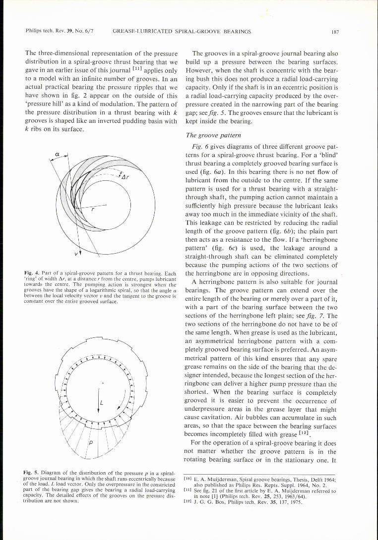
Fig. 6 gives diagrams of three different groove pat-terns for a spiral-groove thrust bearing. For a 'blind'thrust bearing a completely grooved bearing surface isused (fig. 6a). In this bearing there is no net flow oflubricant from the outside to the centre. If the samepattern is used for a thrust bearing with a straight-through shaft, the pumping action cannot maintain asufficiently high pressure because the lubricant leaksaway too much in the immediate vicinity of the shaft.This leakage can be restricted by reducing the radiallength of the groove pattern (fig. 6b); the plain partthen acts as a resistance to the flow. If a 'herringbonepattern' (fig. 6c) is used, the leakage around astraight-through shaft can be eliminated completelybecause the pumping actions of the two sections ofthe herringbone are in opposing directions.
A herringbone pattern is also suitable for journalbearings. The groove pattern can extend over theentire length of the bearing or merely over a part of it,with a part of the bearing surface between the twosections of the herringbone left plain; see fig. 7. Thetwo sections of the herringbone do not have to be ofthe same length. When grease is used as the lubricant,an asymmetrical herringbone pattern with a com-pletely grooved bearing surface is preferred. An asym-metrical pattern of this kind ensures that any sparegrease remains on the side of the bearing that the de-signer intended, because the longest section of the her-ringbone can deliver a higher pump pressure than theshortest. When the bearing surface is completelygrooved it is easier to prevent the occurrence ofunderpressure areas in the grease layer that mightcause cavitation. Air bubbles can accumulate in suchareas, so that the space between the bearing surfacesbecomes incompletely filled with grease [12].
For the operation of a spiral-groove bearing it doesnot matter whether the groove pattern is in therotating bearing surface or in the stationary one. It
[10] E. A. Muijderman, Spiral groove bearings, Thesis, Delft 1964;also published as Philips Res. Repts. Suppl. 1964, No. 2.
[11] See fig. 21 of the first article by E. A. Muijderman referred toin note [I] (Philips tech. Rev. 25, 253, 1963/64).
[12] J. G. G. Bos, Philips tech. Rev. 35,137,1975.
188 E. A. MUIJDERMAN et al. Phi1ips tech. Rev. 39, No. 6/7
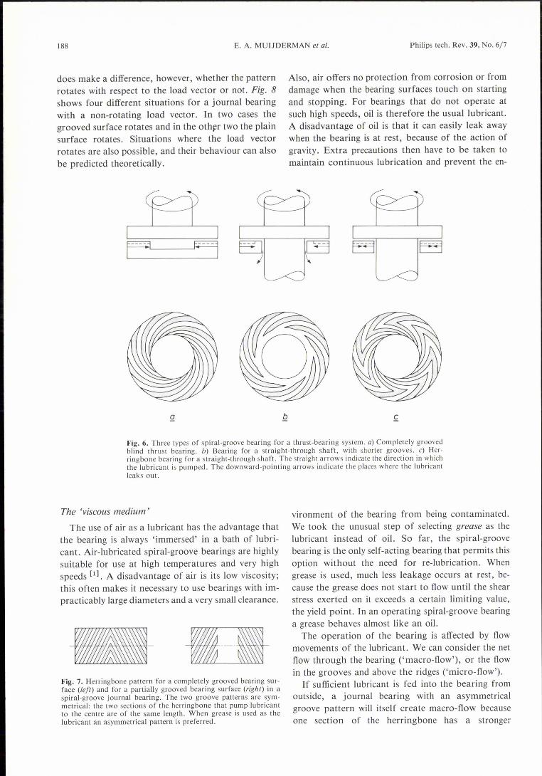
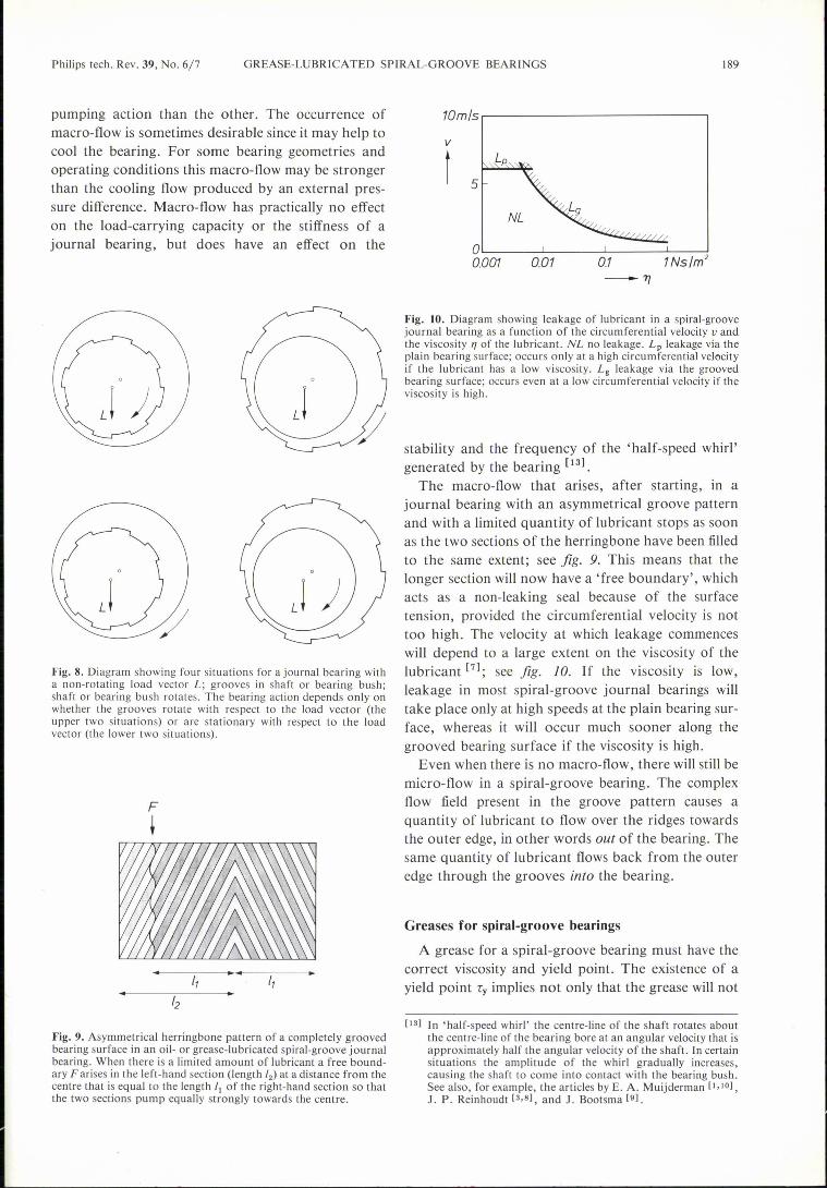
does make a difference, however, whether the patternrotates with respect to the load vector or not. Fig. 8shows four different situations for a journal bearingwith a non-rotating load vector. In two cases thegrooved surface rotates and in the other two the plainsurface rotates. Situations where the load vectorrotates are also possible, and their behaviour can alsobe predicted theoretically.
Also, air offers no proteetion from corrosion or fromdamage when the bearing surfaces touch on startingand stopping. For bearings that do not operate atsuch high speeds, oil is therefore the usual lubricant.A disadvantage of oil is that it can easily leak awaywhen the bearing is at rest, because of the action ofgravity. Extra precautions then have to be taken tomaintain continuous lubrication and prevent the en-
cL___-9 EJ)
Fig. 6. Three types of spiral-groove bearing for a thrust-bearing system. a) Completely groovedblind thrust bearing. b) Bearing for a straight-through shaft, with shorter grooves. c) Her-ringbone bearing for a straight-through shaft. The straight arrows indicate the direction in whichthe lubricant is pumped. The downward-pointing arrows indicate the places where the lubricantleaks out.
Q
The 'viscous medium'The use of air as a lubricant has the advantage that
the bearing is always 'immersed' in a bath of lubri-cant. Air-lubricated spiral-groove bearings are highlysuitable for use at high temperatures and very highspeeds [1). A disadvantage of air is its low viscosity;this often makes it necessary to use bearings with im-practicably large diameters and a very small clearance.
Fig. 7. Herringbone pattern for a completely grooved bearing sur-face (left) and for a partially grooved bearing surface (right) in aspiral-groove journal bearing. The two groove patterns are sym-metrical: the two sections of the herringbone that pump lubricantto the centre are of the same length. When grease is used as thelubricant an asymmetrical pattern is preferred.
f.
vironment of the bearing from being contaminated.We took the unusual step of selecting grease as thelubricant instead of oil. So far, the spiral-groovebearing is the only self-acting bearing that permits thisoption without the need for re-lubrication. Whengrease is used, much less leakage occurs at rest, be-cause the grease does not start to flow until the shearstress exerted on it exceeds a certain limiting value,the yield point. In an operating spiral-groove bearinga grease behaves almost like an oil.
The operation of the bearing is affected by flowmovements of the lubricant. We can consider the netflow through the bearing ('macro-flow'), or the flowin the grooves and above the ridges ('micro-flow').If sufficient lubricant is fed into the bearing from
outside, a journal bearing with an asymmetricalgroove pattern will itself create macro-flow becauseone section of the herringbone has a stronger
Philips tech. Rev. 39, No. 6/7 GREASE-LUBRICA TED SPIRAL-GROOVE BEARINGS 189
pumping action than the other. The occurrence ofmacro-flow is sometimes desirable since it may help tocool the bearing. For some bearing geometries andoperating conditions this macro-flow may be strongerthan the cooling flow produced by an external pres-sure difference. Macro-flow has practically no effecton the load-carrying capacity or the stiffness of ajournal bearing, but does have an effect on the
Fig. 8. Diagram showing four situations for a journal bearing witha non-rotating load vector L; grooves in shaft or bearing bush;shaft or bearing bush rotates. The bearing action depends only onwhether the grooves rotate with respect to the load vector (theupper two situations) or are stationary with respect to the loadvector (the lower two situations).
F
t
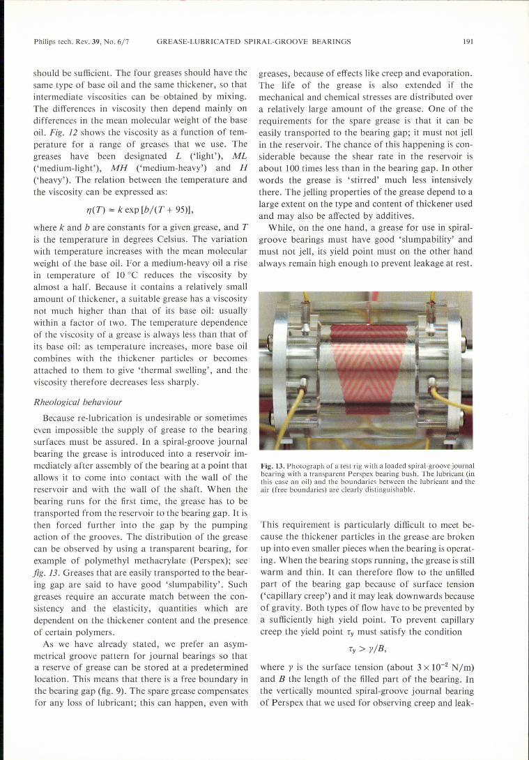
Fig. 9. Asymmetrical herringbone pattern of a completely groovedbearing surface in an oil- or grease-lubricated spiral-groove journalbearing. When there is a limited amount of lubricant a free bound-ary F arises in the left-hand section (length '2) at a distance from thecentre that is equal to the length 'I of the right-hand section so thatthe two sections pump equally strongly towards the centre.
I
10m~r------------------------'v
t 5
NL
OL_ J_ ~ ~~~
0.001 0.01 0.1 1Ns lm'-7]
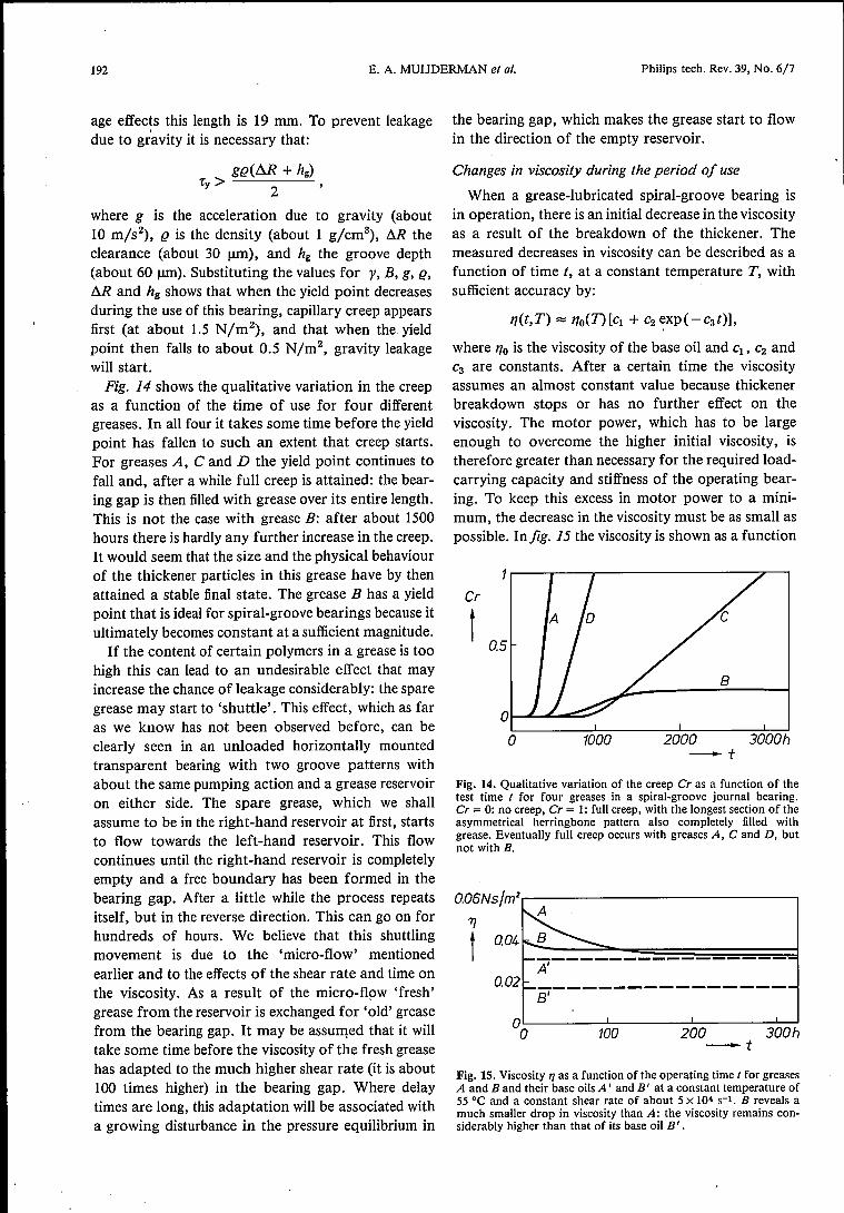
Fig. 10. Diagram showing leakage of lubricant in a spiral-groovejournal bearing as a function of the circumferential velocity vandthe viscosity 17of the lubricant. NL no leakage. Lp leakage via theplain bearing surface; occurs only at a high circumferential velocityif the lubricant has a low viscosity. Lg leakage via the groovedbearing surface; occurs even at a low circumferential velocity if theviscosity is high.
stability and the frequency of the 'half-speed whirl'generated by the bearing [13].
The macro-flow that arises, after starting, in ajournal bearing with an asymmetrical groove patternand with a limited quantity of lubricant stops as soonas the two sections of the herringbone have been filledto the same extent; see fig. 9. This means that thelonger section will now have a 'free boundary', whichacts as a non-leaking seal because of the surfacetension, provided the circumferential velocity is nottoo high. The velocity at which leakage commenceswill depend to a large extent on the viscosity of thelubricant [7]; see fig. la. If the viscosity is low,leakage in most spiral-groove journal bearings willtake place only at high speeds at the plain bearing sur-face, whereas it will occur much sooner along thegrooved bearing surface if the viscosity is high.
Even when there is no macro-flow, there will still bemicro-flow in a spiral-groove bearing. The complexflow field present in the groove pattern causes aquantity of lubricant to flow over the ridges towardsthe outer edge, in other words out of the bearing. Thesame quantity of lubricant flows back from the outeredge through the grooves into the bearing.
Greases for spiral-groove bearings
A grease for a spiral-groove bearing must have thecorrect viscosity and yield point. The existence of ayield point Ty implies not only that the grease will not
[13] In 'half-speed whirl' the centre-line of the shaft rotates aboutthe centre-line of the bearing bore at an angular velocity that isapproximately half the angular velocity of the shaft. In certainsituations the amplitude of the whirl gradually increases,causing the shaft to come into contact with the bearing bush.See also, for example, the articles by E. A. Muijderman [1,10],
J. P. Reinhoudt [3,8], and J. Bootsma [9].

190 E. A. MUIJDERMAN et al. Philips tech. Rev. 39, No. 6/7
begin to flow until the shear stress. exerted upon it isgreater than 'y, but also that the dynamic viscosity 1'/depends on the shear rate s:
1'/ = ./s = 'y/s + 1'/00'
The viscosity only approaches a constant value 1'/00 athigh shear rates. Strictly speaking it would be moreappropriate here to speak of 'the apparent dynamicviscosity', but for convenience we shall continue totalk about 'the viscosity'. The diagram of fig. 11illustrates the difference between a fluid with a yieldpoint (a Bingham fluid) and a Newtonian fluid, whichdoes not have a yield point and has a viscosity inde-pendent of the shear rate.As well as meeting the requirements for viscosity
and yield point a suitable grease must also satisfysome 'other general requirements. Itmust, for instance,
7J
t
N
-sFig. 11. Viscosity Tl as a function of the shear rate s. For a New-tonian fluid N, Tl is constant; for a Bingham fluid-B, Tl is a decreas-ing function of s, which only tends to a constant value Tl cc when theshear rate is high.
7J
t
0.1
Q01~----~-----L---L~.~~~o 20 40 60 80 100°C-T
Fig. 12. Viscosity Tl of four basic greases that we used, as a functionof temperature T. The designations L, ML, MH and H stand for'light', 'medium-light', 'medium-heavy' and 'heavy' . This series ofgreases will cover a wide viscosity range.'
protect the bearing surfaces from any damage thatmight occur when they are in contact with, one an-other, even during rotation, and from corrosion fromoutside, but it must not attack the bearing surfaces orother structural materials. In many consumer articlesit is extremely difficult or even impossible to re-lubricate the bearing once it has been assembled. Thègrease must therefore have a long life. This meansthat it must be mechanically and chemically stable,must not oxidize, and that the base oil must notevaporate or leak away from the grease.
Because of the special conditions in spiral-groovebearings it is difficult for a grease to meet all the above -requirements in full. It must, for instance, have asufficiently high yield point to prevent leakage when atrest, yet all of the grease must start to flow as soon asrotation starts. The amount of grease used in a spiral-groove bearing is usually very small, only a few tensof mm" per bearing. The grease is continuously sub-ject to shear; the shear rate in the bearing gap is about104 to 105 S-1. We should remember here that arequired life of several thousand hours is more therule than the exception. There is also an intensive cir-culation of grease (micro-flow) in the bearing so thatthere is always 'fresh grease' arriving at the edges ofthe bearing and being exposed to oxygen there. Be-cause of these special circumstances greases for spiral-groove bearings should generally be quite different incomposition from greases used in ball bearings, forexample.
Composition
A grease consists mainly of a base oil and athickener; the first functions as the fluid lubricant,and the second determines the consistency.
In simple terms we could say that the thickener retains the liquidlubricant like a sponge. Another concept is to imagine the thickeneras a three-dimensional network resembling a bundle of sticks towhich the base oil is attached by physical and chemical bonds.When the shear stresses are small, the 'sticks' of the thickenerdeform elastically; the grease behaves like an elastic solid. Whenthe stresses exceed the yield point, the 'sticks' slide about on oneanother; the grease then behaves like a plastic material. The slidingsticks break and begin to line up with the direction of flow so thatthe mixture of sticks and oil begins to behave more and more like afluid. As the shear stress increases, the pieces of broken stickbecome smaller, until equilibrium is reached. The grease thenbegins to approximate more closely to a real fluid containing solidround particles. If the shear is stopped after a while, the thickenerparticles start to reorientate themselves somewhat and to recrystal-Iize, but the yield point now has a considerably lower value than inthe unworked grease.
To cover a sufficiently large range of viscosity it isnot in fact necessary to stock greases of many dif-ferent viscosities; in our view a range of at least four
Philips tech. Rev. 39, No. 6/7 GREASE-LUBRICATED SPIRAL-GROOVE BEARINGS 191
should be sufficient. The four greases should have thesame type of base oil and the same thickener, so thatintermediate viscosities can be obtained by mixing.The differences in viscosity then depend mainly ondifferences in the mean molecular weight of the baseoil. Fig. 12 shows the viscosity as a function of tem-perature for a range of greases that we use. Thegreases have been designated L ('light'), ML('medium-light'), MH ('medium-heavy') and H('heavy'). The relation between the temperature andthe viscosity can be expressed as:
1](T) "'" k exp [bl(T + 95»),
where k and b are constants for a given grease, and Tis the temperature in degrees Celsius. The variationwith temperature increases with the mean molecularweight of the base oil. For a medium-heavy oil a risein temperature of 10 °C reduces the viscosity byalmost a half. Because it contains a relatively smallamount of thickener, a suitable grease has a viscositynot much higher than that of its base oil: usuallywithin a factor of two. The temperature dependenceof the viscosity of a grease is always less than that ofits base oil: as temperature increases, more base oilcombines with the thickener particles or becomesattached to them to give 'thermal swelling', and theviscosity therefore decreases less sharply.
Rheological behaviour
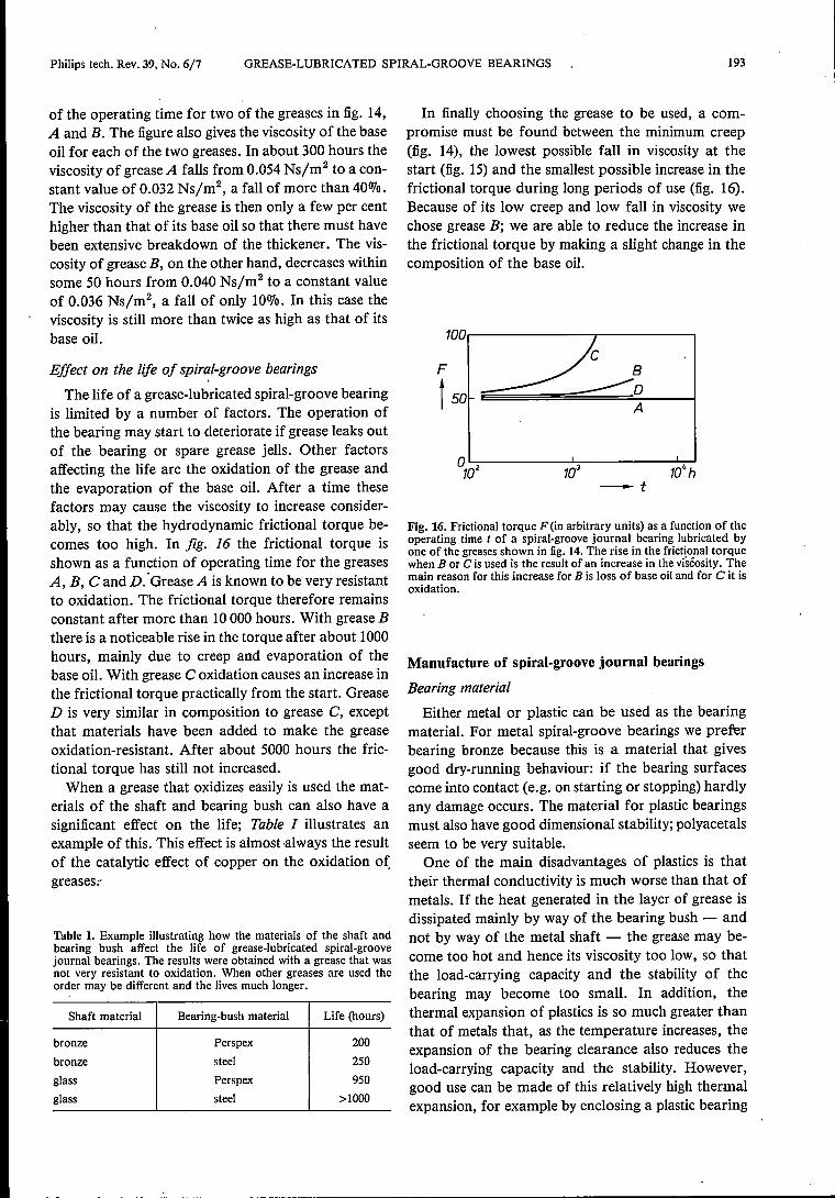
Because re-lubrication is undesirable or sometimeseven impossible the supply of grease to the bearingsurfaces must be assured. In a spiral-groove journalbearing the grease is introduced into a reservoir im-mediately after assembly of the bearing at a point thatallows it to come into contact with the wall of thereservoir and with the wall of the shaft. When thebearing runs for the first time, the grease has to betransported from the reservoir to the bearing gap. It isthen forced further into the gap by the pumpingaction of the grooves. The distribution of the greasecan be observed by using a transparent bearing, forexample of polymethyl methacrylate (Perspex); seefig. 13. Greases that are easily transported to the bear-ing gap are said to have good 'slumpability'. Suchgreases require an accurate match between the con-sistency and the elasticity, quantities which aredependent on the thickener content and the presenceof certain polymers.
As we have already stated, we prefer an asym-metrical groove pattern for journal bearings so thata reserve of grease can be stored at a predeterminedlocation. This means that there is a free boundary inthe bearing gap (fig. 9). The spare grease compensatesfor any loss of lubricant; this can happen, even with
greases, because of effects like creep and evaporation.The life of the grease is also extended if themechanical and chemical stresses are distributed overa relatively large amount of the grease. One of therequirements for the spare grease is that it can beeasily transported to the bearing gap; it must not jellin the reservoir. The chance of this happening is con-siderable because the shear rate in the reservoir isabout 100 times less than in the bearing gap. In otherwords the grease is 'stirred' much less intensivelythere. The jelling properties of the grease depend to alarge extent on the type and content of thickener usedand mayalso be affected by additives.
While, on the one hand, a grease for use in spiral-groove bearings must have good 'slumpability' andmust not jell, its yield point must on the other handalways remain high enough to prevent leakage at rest.
Fig. 13. Photograph of a test rig with a loaded spiral-groove journalbearing with a transparent Perspex bearing bush. The lubricant (inthis case an oil) and the boundaries between the lubricant and theair (free boundaries) are clearly distinguishable.
This requirement is particularly difficult to meet be-cause the thickener particles in the grease are brokenup into even smaller pieces when the bearing is operat-ing. When the bearing stops running, the grease is stillwarm and thin. It can therefore flow to the unfilledpart of the bearing gap because of surface tension('capillary creep') and it may leak downwards becauseof gravity. Both types of flow have to be prevented bya sufficiently high yield point. To prevent capillarycreep the yield point Ty must satisfy the condition
Ty> ylB,
where y is the surface tension (about 3 x 10⁻² Nyrn)and B the length of the filled part of the bearing. Inthe vertically mounted spiral-groove journal bearingof Perspex that we used for observing creep and leak-
192 E. A. MUIJDERMAN et al. Philips tech. Rev. 39, No. 6/7
age effects this length is 19 mm. To prevent leakagedue to gravity it is necessary that:
gg(M + hg)Ty> 2 '
where g is the acceleration due to gravity (about10 m/s''), g is the density (about 1 g/cm"), M theclearance (about 30 urn), and hg the groove depth(about 60 urn). Substituting the values for y, B, g, g,M and hg shows that when the yield point decreasesduring the use of this bearing, capillary creep appearsfirst (at about 1.5 N/m2), and that when the yieldpoint then falls to about 0.5 N/m2, gravity leakagewill start.Fig. 14 shows the qualitative variation in the creep
as a function of the time of use for four differentgreases. In all four it takes some time before the yieldpoint has fallen to such an extent that creep starts.For greases A, C and D the yield point continues tofall and, after a while full creep is attained: the bear-ing gap is then filledwith grease over its entire length.This is not the case with grease B: after about 1500hours there is hardly any further increase in the creep.Itwould seem that the size and the physical behaviourof the thickener particles in this grease have by thenattained a stable final state. The grease B has a yieldpoint that is ideal for spiral-groove bearings because itultimately becomes constant at a sufficient magnitude.If the content of certain polymers in a grease is too
high this can lead to an undesirable effect that mayincrease the chance of leakage considerably: the sparegrease may start to 'shuttle'. This effect, which as faras we know has not been observed before, can beclearly seen in an unloaded horizontally mountedtransparent bearing with two groove patterns withabout the same pumping action and a grease reservoiron either side. The spare grease, which we shallassume to be in the right-hand reservoir at first, startsto flow towards the left-hand reservoir. This flowcontinues until the right-hand reservoir is completelyempty and a free boundary has been formed in thebearing gap. After a little while the process repeatsitself, but in the reverse direction. This can go on forhundreds of hours. We believe that this shuttlingmovement is due to the 'micro-flow' mentionedearlier and to the effects of the shear rate and time onthe viscosity. As a result of the micro-flow 'fresh'grease from the reservoir is exchanged for 'old' greasefrom the bearing gap. It may be assumed that it willtake some time before the viscosity of the fresh greasehas adapted to the much higher shear rate (it is about100 times higher) in the bearing gap. Where delaytimes are long, this adaptation will be associated witha growing disturbance in the pressure equilibrium in
the bearing gap, which makes the grease start to flowin the direction of the empty reservoir.
Changes in viscosity during the period of use
When a grease-lubricated spiral-groove bearing isin operation, there is an initial decrease in the viscosityas a result of the breakdown of the thickener. Themeasured decreases in viscosity can be described as afunction of time t, at a constant temperature T, withsufficient accuracy by:
where 170 is the viscosity of the base oil and Cl, C2andC3 are constants. After a certain time the viscosityassumes an almost constant value because thickenerbreakdown stops or has no further effect on theviscosity. The motor power, which has to be largeenough to overcome the higher initial viscosity, istherefore greater than necessary for the required load-carrying capacity and stiffness of the operating bear-ing. To keep this excess in motor power to a mini-mum, the decrease in the viscosity must be as small aspossible. Infig. 15 the viscosity is shown as a function
Cr
t 0.5
o 1000 2000-t
3000h
Fig. 14. Qualitative variation of the creep Cr as a function of thetest time t for four greases in a spiral-groove journal bearing.Cr = 0: no creep, Cr = 1: full creep, with the longest section of theasymmetrical herringbone pattern also completely filled withgrease. Eventually full creep occurs with greases A, C and D, butnot with B.
a06Ns/m2,--------------------------.7]
t----------------B'
100 200 300h-t
Fig. IS. Viscosity 1/ as a function of the operating time t for greasesA and B and their base oils A' and B' at a constant temperature of55 oe and a constant shear rate of about 5 x 10⁴ S-I. B reveals amuch smaller drop in viscosity than A: the viscosity remains con-siderably higher than that of its base oil B' .
Philips tech. Rev. 39, No. 6/7 GREASE-LUBRICATED SPIRAL-GROOVE BEARINGS 193
of the operating time for two of the greases in fig. 14,A and B. The figure also gives the viscosity of the baseoil for each of the two greases. In about 300 hours theviscosity of grease A falls from 0.054 Ns/m2 to a con-stant value of 0.032 Ns/m", a fall of more than 40070.The viscosity of the grease is then only a few per centhigher than that of its base oil so that there must havebeen extensive breakdown of the thickener. The vis-cosity of grease B, on the other hand, decreases withinsome 50 hours from 0.040 Ns/m'' to a constant valueof 0.036 Ns/m", a fall of only 10%. In this case theviscosity is still more than twice as high as that of itsbase oil.
Effect on the life of spiral-groove bearings
The life of a grease-lubricated spiral-groove bearingis limited by a number of factors. The operation ofthe bearing may start to deteriorate if grease leaks outof the bearing or spare grease jells. Other factorsaffecting the life are the oxidation of the grease andthe evaporation of the base oil. After a time thesefactors may cause the viscosity to increase consider-ably, so that the hydrodynamic frictional torque be-comes too high. In fig. 16 the frictional torque isshown as a function of operating time for the greasesA, B, C and D:GreaseA is known to be very resistantto oxidation. The frictional torque therefore remainsconstant after more than 10000 hours. With grease Bthere is a noticeable rise in the torque after about 1000hours, mainly due to creep and evaporation of thebase oil. With grease C oxidation causes an increase inthe frictional torque practically from the start. GreaseD is very similar in composition to grease C, exceptthat materials have been added to make the greaseoxidation-resistant. After about 5000 hours the fric-tional torque has still not increased.When a grease that oxidizes easily is used the mat-
erials of the shaft and bearing bush can also have asignificant effect on the life; Table I illustrates anexample of this. This effect is almost always the resultof the catalytic effect of copper on the oxidation ofgreases:-
Table I. Example illustrating how the materials of the shaft andbearing bush affect the life of grease-lubricated spiral-groovejournal bearings. The results were obtained with a grease that wasnot very resistant to oxidation. When other greases are used theorder may be different and the lives much longer.
Shaft material Bearing-bush material Life (hours)
bronze Perspex 200
bronze steel 250
glass Perspex 950
glass steel >1000
In finally choosing the grease to be used, a com-promise must be found between the minimum creep(fig. 14), the lowest possible fall in viscosity at thestart (fig. 15) and the smallest possible increase in thefrictional torque during long periods of use (fig. 16).Because of its low creep and low fall in viscosity wechose grease B; we are able to reduce the increase inthe frictional torque by making a slight change in thecomposition of the base oil.
100..---------.-------,
F
t 50 oA
o~------~----------~d d dh-t
Fig. 16. Frictional torque F (in arbitrary units) as a function of theoperating time ( of a spiral-groove journal bearing lubricated byone of the greases shown in fig. 14. The rise in the frictional torquewhen B or C is used is the result of an increase in the viséosity. Themain reason for this increase for B is loss of base oil and for C it isoxidation.
Manufacture of spiral-groove journal bearings
Bearing material
Either metal or plastic can be used as the bearingmaterial. For metal spiral-groove bearings we preferbearing bronze because this is a material that givesgood dry-running behaviour: if the bearing surfacescome into contact (e.g. on starting or stopping) hardlyany damage occurs. The material for plastic bearingsmust also have good dimensional stability; polyacetalsseem to be very suitable.
One of the main disadvantages of plastics is thattheir thermal conductivity is much worse than that ofmetals. If the heat generated in the layer of grease isdissipated mainly by way of the bearing bush - andnot by way of the metal shaft - the grease may be-come too hot and hence its viscosity too low, so thatthe load-carrying capacity and the stability of thebearing may become too small. In addition, thethermal expansion of plastics is so much greater thanthat of metals that, as the temperature increases, theexpansion of the bearing clearance also reduces theload-carrying capacity and the stability. However,good use can be made of this relatively high thermalexpansion, for example by enclosing a plastic bearing
194 E. A. MUIJDERMAN et al. Philips tech. Rev. 39, No. 6/7
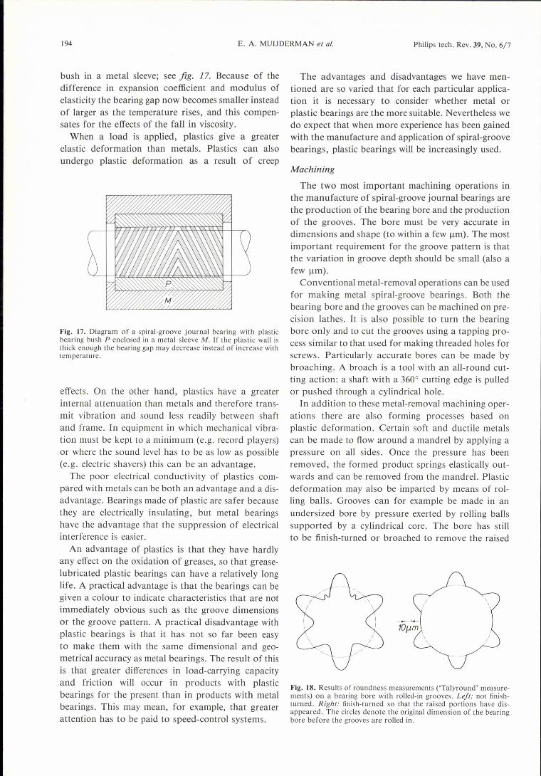
bush in a metal sleeve; see fig. 17. Because of thedifference in expansion coefficient and modulus ofelasticity the bearing gap now becomes smaller insteadof larger as the temperature rises, and this compen-sates for the effects of the fall in viscosity.
When a load is applied, plastics give a greaterelastic deformation than metals. Plastics can alsoundergo plastic deformation as a result of creep
Fig. 17. Diagram of a spiral-groove journal bearing with plasticbearing bush P enclosed in a metal sleeve M. If the plastic wall isthick enough the bearing gap may decrease instead of increase withtemperature.
effects. On the other hand, plastics have a greaterinternal attenuation than metals and therefore trans-mit vibration and sound less readily between shaftand frame. In equipment in which mechanical vibra-tion must be kept to a minimum (e.g. record players)or where the sound level has to be as low as possible(e.g. electric shavers) this can be an advantage.
The poor electrical conductivity of plastics com-pared with metals can be both an advantage and a dis-advantage. Bearings made of plastic are safer becausethey are electrically insulating, but metal bearingshave the advantage that the suppression of electricalinterference is easier.
An advantage of plastics is that they have hardlyany effect on the oxidation of greases, so that grease-lubricated plastic bearings can have a relatively longlife. A practical advantage is that the bearings can begiven a colour to indicate characteristics that are notimmediately obvious such as the groove dimensionsor the groove pattern. A practical disadvantage withplastic bearings is that it has not so far been easyto make them with the same dimensional and geo-metrical accuracy as metal bearings. The result of thisis that greater differences in load-carrying capacityand friction will occur in products with plasticbearings for the present than in products with metalbearings. This may mean, for example, that greaterattention has to be paid to speed-control systems.
The advantages and disadvantages we have men-tioned are so varied that for each particular applica-tion it is necessary to consider whether metal orplastic bearings are the more suitable. Nevertheless wedo expect that when more experience has been gainedwith the manufacture and application of spiral-groovebearings, plastic bearings will be increasingly used.
Machining
The two most important machining operations inthe manufacture of spiral-groove journal bearings arethe production of the bearing bore and the productionof the grooves. The bore must be very accurate indimensions and shape (to within a few urn). The mostimportant requirement for the groove pattern is thatthe variation in groove depth should be small (also afew urn).
Conventional metal-removal operations can be usedfor making metal spiral-groove bearings. Both thebearing bore and the grooves can be machined on pre-cision lathes. It is also possible to turn the bearingbore only and to cut the grooves using a tapping pro-cess similar to that used for making threaded holes forscrews. Particularly accurate bores can be made bybroaching. A broach is a tool with an all-round cut-ting action: a shaft with a 3600 cutting edge is pulledor pushed through a cylindrical hole.
In addition to these metal-removal machining oper-ations there are also forming processes based onplastic deformation. Certain soft and ductile metalscan be made to flow around a mandrel by applying apressure on all sides. Once the pressure has beenremoved, the formed product springs elastically out-wards and can be removed from the mandrel. Plasticdeformation mayalso be imparted by means of rol-ling balls. Grooves can for example be made in anundersized bore by pressure exerted by rolling ballssupported by a cylindrical core. The bore has stillto be finish-turned or broached to remove the raised
\\
//
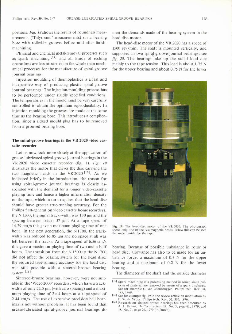
Fig. 18. Results of roundness measurements ('Talyround' measure-ments) on a bearing bore with rolled-in grooves. Left: not finish-turned. Right: finish-turned so that the raised portions have dis-appeared. The circles denote the original dimension of the bearingbore before the grooves are rolled in.
Philips tech. Rev. 39, No. 6/7 GREASE-LUBRICATED SPIRAL-GROOVE BEARINGS 195
portions. Fig. 18 shows the results of roundness meas-urements ('Talyround' measurements) on a bearingbore with rolled-in grooves before and after finish-machining.
Physical and chemical metal-removal processes suchas spark machining [14] and all kinds of etchingoperations are less attractive on the whole than mech-anical processes for the manufacture of spiral-groovejournal bearings.
Injection moulding of thermoplastics is a fast andinexpensive way of producing plastic spiral-groovejournal bearings. The injection-moulding process hasto be performed under rigidly specified conditions.The temperatures in the mould must be very carefullycontrolled to obtain the optimum reproducibility. Ininjection moulding the grooves are made at the sametime as the bearing bore. This introduces a complica-tion, since a ridged mould plug has to be removedfrom a grooved bearing bore.
The spiral-groove bearings in the VR 2020 video cas-sette recorder
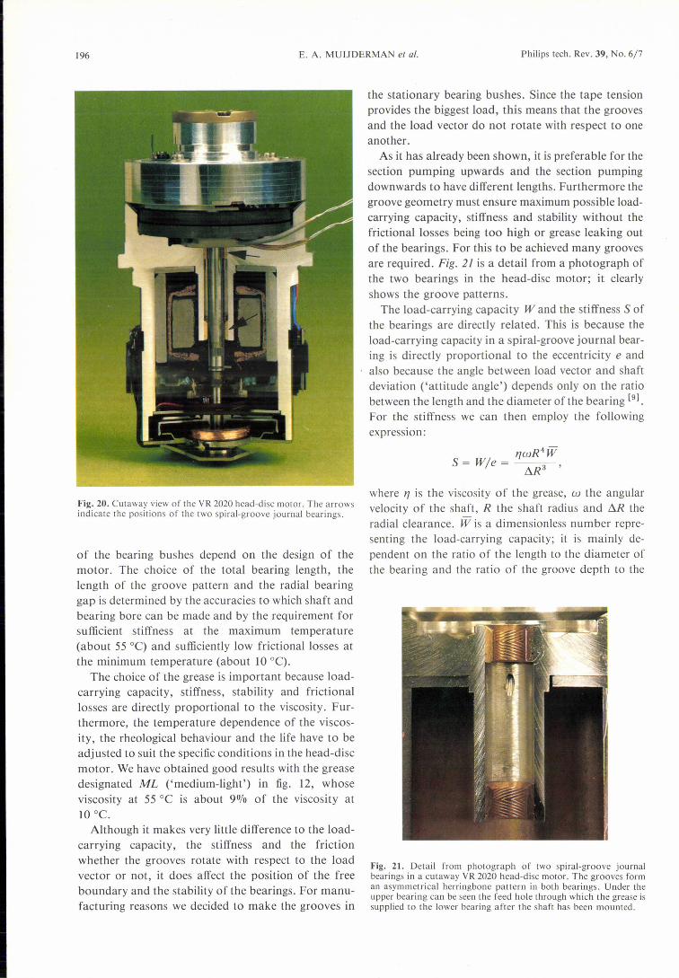
Let us now look more closely at the application ofgrease-lubricated spiral-groove journal bearings in theVR 2020 video cassette recorder (fig. I). Fig. 19illustrates the motor that drives the disc carrying thetwo magnetic heads in the VR 2020 [15]. As weindicated briefly in the introduction, the reason forusing spiral-groove journal bearings is closely as-sociated with the demand for a longer video-cassetteplaying time and hence a higher information densityon the tape, which in turn requires that the head discshould have greater true-running accuracy. For thePhilips first-generation video cassette home recorders,the N 1500, the signal track-width was l30 urn and thespacing between tracks 57 urn, At a tape speed of14.29 crrr/s this gave a maximum playing time of onehour. In the next generation, the N 1700, the track-width was reduced to 85 urn and no space at all wasleft between the tracks. At a tape speed of 6.56 cm/sthis gave a maximum playing time of two and a halfhours. The transition from the N 1500 to the N 1700did not affect the bearing system for the head disc:the required true-running accuracy for the head discwas still possible with a sintered-bronze bearingsystem [16].
Sintered-bronze bearings, however, were not suit-able in the 'Video 2000' recorders, which have a track-width of only 22.5 urn (with zero spacing) and a maxi-mum playing time of 2 x 4 hours at a tape speed of2.44 cmys. The use of expensive precision ball bear-ings is not without problems. It has been found thatgrease-lubricated spiral-groove journal bearings do
meet the demands made of the bearing system in thehead-disc motor.
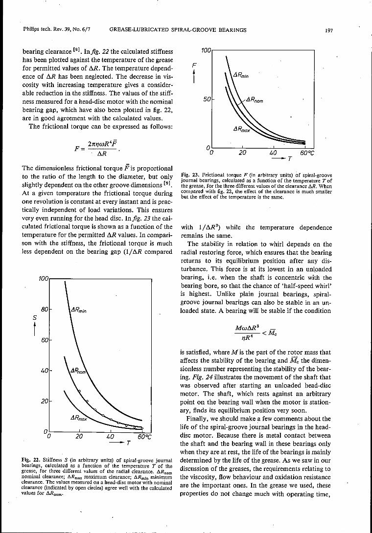
The head-disc motor of the VR 2020 has a speed of1500 rev Imin. The shaft is mounted vertically, andsupported in two spiraJ-groove journal bearings; seejig. 20. The bearings take up the radial load duemainly to the tape tension. This load is about 1.75 Nfor the upper bearing and about 0.75 N for the lower
Fig. 19. The head-disc motor of the VR 2020. The photographshows only one of the two magnetic heads. Below this can be seenthe angled guide for the tape.
bearing. Because of possible unbalance in rotor orhead disc, allowance has also to be made for an un-balance force: a maximum of 0.3 N for the upperbearing and a maximum of 0.2 N for the lowerbearing.
The diameter of the shaft and the outside diameter
[141 Spark machining is a processing method in which small par-ticles of material are removed by means of a spark discharge.See for example C. van Osenbruggen, Philips tech. Rev. 30,195, 1969.
[151 See for example fig. 39 in the review article on modulation byF. W. de Vrijer, Phi1ips tech. Rev. 36, 305, 1976.
[161 Research on sintered-bronze bearings has been described byA. L. Braun, De Constructeur 18, No. 5, page 61, 1979, and18, No. 7, page 20, 1979 (in Dutch).
196 E. A. MUIJDERMAN el al. Philips tech. Rev. 39, No. 6/7
Fig. 20. Cutaway view of the VR 2020 head-disc motor. The arrowsindicate the positions of the two spiral-groove journal bearings.
of the bearing bushes depend on the design of themotor. The choice of the total bearing length, thelength of the groove pattern and the radial bearinggap is determined by the accuracies to which shaft andbearing bore can be made and by the requirement forsufficient stiffness at the maximum temperature(about 55°C) and sufficiently low frictional losses atthe minimum temperature (about 10 0C).
The choice of the grease is important because load-carrying capacity, stiffness, stability and frictionallosses are directly proportional to the viscosity. Fur-thermore, the temperature dependence of the viscos-ity, the rheological behaviour and the life have to beadjusted to suit the specific conditions in the head-discmotor. We have obtained good results with the greasedesignated ML ('medium-light') in fig. 12, whoseviscosity at 55 oe is about 9070 of the viscosity at10 oe.
Although it makes very little difference to the load-carrying capacity, the stiffness and the frictionwhether the grooves rotate with respect to the loadvector or not, it does affect the position of the freeboundary and the stability of the bearings. For manu-facturing reasons we decided to make the grooves in
the stationary bearing bushes. Since the tape tensionprovides the biggest load, this means that the groovesand the load vector do not rotate with respect to oneanother.
As it has already been shown, it is preferable for thesection pumping upwards and the section pumpingdownwards to have different lengths. Furthermore thegroove geometry must ensure maximum possible load-carrying capacity, stiffness and stability without thefrictional losses being too high or grease leaking outof the bearings. For this to be achieved many groovesare required. Fig. 21 is a detail from a photograph ofthe two bearings in the head-disc motor; it clearlyshows the groove patterns.
The load-carrying capacity Wand the stiffness S ofthe bearings are directly related. This is because theload-carrying capacity in a spiral-groove journal bear-ing is directly proportional to the eccentricity e andalso because the angle between load vector and shaftdeviation ('attitude angle') depends only on the ratiobetween the length and the diameter of the bearing [9].
For the stiffness we can then employ the followingexpression:
where 17is the viscosity of the grease, co the angularvelocity of the shaft, R the shaft radius and Ó.R theradial clearance. W is a dimensionless number repre-senting the load-carrying capacity; it is mainly de-pendent on the ratio of the length to the diameter ofthe bearing and the ratio of the groove depth to the
Fig. 21. Detail from photograph of two spiral-groove journalbearings in a cutaway VR 2020 head-disc motor. The grooves forman asymmetrical herringbone pattern in both bearings. Under theupper bearing can be seen the Feed hole through which the grease issupplied to the lower bearing after the shaft has been mounted.
Philips tech. Rev. 39, No. 6/7 GREASE-LUBRICATED SPIRAL-GROOVE BEARINGS 197
bearing clearance [91. Infig. 22 the calculated stiffnesshas been plotted against the temperature of the greasefor permitted values of M. The temperature depend-ence of M has been neglected. The decrease in vis-cosity with increasing temperature gives a consider-able reduction in the stiffness. The values of the stiff-ness measured for a head-disc motor with the nominalbearing gap, which have also been plotted in fig. 22,are in good agreement with the calculated values.The frictional torque can be expressed as follows:
The dimensionless frictional torque F is proportionalto the ratio of the length to the diameter, but onlyslightly dependent on the other groove dimensions [91.
At a given temperature the frictional torque duringone revolution is constant at every instant and is prae-tically independent of load variations. This ensuresvery even running for the head disc. Infig. 23 the cal-culated frictional torque is shown as a function of thetemperature for the permitted M values. In compari-son with the stiffness, the frictional torque is muchless dependent on the bearing gap (1/ M compared
1oo.---------------------~
805
t50
40
20
°0~----~2~0------4LO------5~0-joC-T
Fig. 22. Stiffness S (in arbitrary units) of spiral-groove journalbearings, calculated as a function of the temperature T of thegrease, for three different values of the radial clearance. t.Rnomnominal clearance; Mmax maximum clearance; Mmin minimumclearance. The values measured on a head-disc motor with nominalclearance (indicated by open circles) agree well with the calculatedvalues for Mnom•
100.-----------------------,
F
t50
-T
Fig. 23. Frictional torque F (in arbitrary units) of spiral-groovejournal bearings, calculated as a function of the temperature Tofthe grease, for the three different values of the clearance t.R. Whencompared with fig. 22, the effect of the clearance is much smallerbut the effect of the temperature is the same.
with 1/ M3) while the temperature dependence
remains the same.The stability in relation to whirl depends on the
radial restoring force, which ensures that the bearingreturns to its equilibrium position after any dis-turbance. This force is at its lowest in an unloadedbearing, i.e. when the shaft is concentric with thebearing bore, so that the chance of 'half-speed whirl'is highest. Unlike plain journal bearings, spiral-groove journal bearings can also be stable in an un-loaded state. A bearing will be stable if the condition
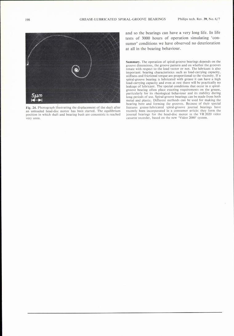
is satisfied, where M is the part of the rotor mass thataffects the stability of the bearing and Mc the dimen-sionless number representing the stability of the bear-ing. Fig. 24 illustrates the movement of the shaft thatwas observed after starting an unloaded head-discmotor. The shaft, which rests against an arbitrarypoint on the bearing wall when the motor is station-ary, finds its equilibrium position very soon.Finally, we should make a few comments about the
life of the spiral-groove journal bearings in the head-disc motor. Because there is metal contact betweenthe shaft and the bearing wall in these bearings onlywhen they are at rest, the life of the bearings is mainlydetermined by the life of the grease. As we saw in ourdiscussion of the greases, the requirements relating tothe viscosity, flow behaviour and oxidation resistanceare the important ones. In the grease we used, theseproperties do not change much with operating time,
198 GREASE-LUBRICATED SPIRAL-GROOVE BEARINGS Philips tech. Re.v. 39, No. 6/7
Fig. 24. Photograph illustrating the displacement of the shaft afteran unloaded head-disc motor has been started. The equilibriumposition in which shaft and bearing bush are concentric is reachedvery soon.
and so the bearings can have a very long life. In lifetests of 3000 hours of operation simulating 'con-sumer' conditions we have observed no deteriorationat all in the bearing behaviour.
Summary. The operation of spiral-groove bearings depends on thegroove dimensions, the groove pattern and on whether the groovesrotate with respect to the load vector or not. The lubricant is alsoimportant: bearing characteristics such as load-carrying capacity,stiffness and frictional torque are proportional to the viscosity. If aspiral-groove bearing is lubricated with grease it can have a highload-carrying capacity and even at rest there will be practically noleakage of lubricant. The special conditions that occur in a spi ral-groove bearing often place exacting requirements on the grease,particularly for its rheoIogical behaviour and its stability duringlong periods of use. Spiral-groove bearings can be made from bothmetal and plastic. Different methods can be used for making thebearing bore and forming the grooves. Because of their specialfeatures grease-lubricated spiral-groove journal bearings haverecently been incorporated in a consumer article: they form thejournal bearings for the head-disc motor in the VR 2020 videocassette recorder, based on the new 'Video 2000' system.
Scientific publicationsThese publications are contributed by staff of laboratories and plants which form part ofor cooperate with enterprises of the Philips group of companies, particularly by staff ofthe following research laboratories:
Philips Research Laboratories, Eindhoven, The Netherlands EPhilips Research Laboratories, Redhill, Surrey RH1 5HA, England RLaboratoires d'Electronique et de Physique Appliquée, 3 avenue Descartes,94450 Limeil-Brévannes, France L
Philips GmbH Forschungslaboratorium Aachen, Wei13hausstra13e,51Aachen,Germany A
Philips GmbH Forschungslaboratorium Hamburg, Vogt-Kölln-StraBe 30,2000 Hamburg 54, Germany H
Philips Research Laboratory Brussels, 2 avenue Van Becelaere, 1170Brussels(Boitsfort), Belgium B
Philips Laboratories, N.A.P.C., 345 Scarborough Road, Briarcliff Manor,N.Y. 10510, U.S.A. N
Philips tech. Rev. 39, No. 6/7
B. Aldefeld: A numerical solution of transient non-linear eddy-current problems including moving ironparts.IEEE Trans. MAG-14, 371-373, 1978(No. 5).
S. Askienazy (Hêpital Ste Anne, Paris), R. Genève &M. Jatteau: Les tendances de Ia médecine nucléaire.Acta Electronica 22, 79-90, 1979 (No. 2). L
M. Auphan: Les transducteurs à réseau annulaire foca-lisant en poursuite d'échos.Acta Electronica 22, 119-127, 1979(No. 2).
C. I. M. Beenakker, B. Bosman & P. W. J. M.Boumans: An assessment of a microwave-inducedplasma generated in argon with a cylindrical TMolOcavity as an excitation source for emission spectro-metric analysis of solutions.Spectrochim. Acta 33B, 373-381,1978 (No. 7).
A. J. van Bommel & J. E. Crombeen: The GaP(OOl)surface and the adsorption of Cs.Surface Sci. 76,499-508, 1978 (No. 2). E
A. H. Boonstra & C. A. H. A. Mutsaers: Small valuesof the temperature coefficient of resistance in leadrhodate thick films ascribed to a compensation mech-anism.Thin Solid Films 51,287-296, 1978 (No. 3). E
G. Bouwhuis & J. J. M. Braat: Video disk playeroptics.Appl. Optics 17, 1993-~900,1978 (No. 13). E
J. J. M. Braat & G. Bouwhuis: Position sensing invideo disk readout.Appl. Optics 17, 2013-2021, 1978 (No. 13). E
J. J. M. Braat & G. Bouwhuis: Optical video disks withundulating tracks.Appl. Optics 17, 2022-2028, !9,18(No. 13). E
J. C. Brice: Crystal growth from liquids at high tem-peratures.Progress in Crystal Growth and Characterization 1,255-288, 1978 (No. 3). R
199
J. W. Broer: Linking while writing - do you or don'tyou?J. tech. Writ. Comm. 8,217-225,1978 (No. 3). E
HR. Bruno, W. Hermann, H. Hörster, R ..Kersten, K.Klinkenberg & F. Mahdjuri: The Philips experimentalhouse: results and experience.Energy use management, Proc. int. Conf., Tucson1977, pp. 299-304. A
LR. Bruno & R. Kersten: Models and methods for theanalysis and optimization of solar energy systems.Energy use management, Proc. int. Conf., Tucson .1977, pp. 643-651. A
E
A. L. J. Burgmans & M. F. H. Schuurmans: Spectro-scopie aan atomen nabij een wand.Ned. T. Natuurk. A 44,62-64, 1978(No. 2). E
T. A. C. M. Claasen: Warum Digitaltechnik bei derÜbertragung und Speicherung von Bild- und Ton-signalen?Fernseh- u. Kino-T. 32, 245-250,1978 (No. 7). E
P. S. Clarke, J. W. Orton & A. J. Guest: Electrical-conductivity and Hall-effect measurements in semicon-ducting powders. Study of percolation effects.Phys. Rev. B 18, 1813-1817,1978 (No. 4). R
R. H. Coursant: Les transducteurs ultrasonores.Acta Electronica 22,129-141,1979 (No. 2). L
P.-J. Courtois: Exact aggregation in queueing net-works.First Meeting AFCET-SMF on Applied Math., Palai-seau 1978, Vol. I, pp. 35-51. B
P. A. Devijver: A generalized divergence measure forsignal selection.First Meeting AFCET-SMF on Applied Math., Palai-seau 1978, Vol. I, pp. 315-324. B
H. Dötsch: Investigation of magnetic bubble filmsusing spin wave and magnetoelastic resonances.IEEE Trans. MAG-14, 692-694, 1978 (No. 5). H
200 SCIENTIFIC PUBLICATIONS Philips tech. Rev. 39, No. 6/7
A. Dumont: Les techniques Doppler en échographie.Acta Electronica 22, 143-148, 1979(No. 2). LR. C. French: Error rate predictions and measurementsin the mobile radio data channel.IEEE Trans. VT-27, 110-116, 1978 (No. 3). RR. Genève: Introduetion to medical imaging techniques.Acta Electronica 22, 7-17, 1979 (No. I). (Also inFrench.) LJ. P. Hazan, J. P. Cabaniê & J. J. Bernard: Method ofassessing index profile data.Electronics Letters 14, 416-418, 1978(No. 14). LJ. P. J. Heemskerk: Noise in a video disk system:experiments with an (AlGa)As laser.Appl. Optics 17, 2007-2012, 1978 (No. 13).
B. A. J. Jacobs: Laser beam recording of video masterdisks.Appl. Optics 17, 2001-2006, 1978 (No. 13).M. Jatteau, P. Lelong, G. Normand, J. Ott, J. Pauvert& J. Pergrale: Pour une optimisation des caméras degammagraphie de type Anger.Acta Electronica 22,91-117, 1979 (No. 2).W. H. de Jeu & F. Leenhouts (University of Gronin-gen): Physical properties of nematic p,p' -diheptylazo-benzene.J. Physique 39,869-872,1978 (No. 8).H.-G. Junginger, R. F. Schmidt & R. Stronk: Exper-iments on latent electrostatic images and electropho-retic development comparison with model calculations.Photogr. Sci. Engng. 22, 213-218, 1978(No. 4). AJ. J. Kelly & G. J. Koel: Electrochemical aspects of thebeveling of sputtered Permalloy films.J. Electrochem. Soc. 125, 860-865,1978 (No. 6).
G. Kowalski, R. Rieckeheer &W. Wagner: New meansfor picture formation in computer tomography.Acta Electronica 22,51-63, 1979 (No. I).C. Kramer (Philips Medical Systems Division, Best):Developments in medical imaging techniques.Acta Electronica 22, 19-39, 1979 (No. I). (Also inFrench.)S. Leblanc, M. Bristica (La Radio-technique, Suresnes)& V. Evers: Experience with an undergraduate levelCAI-course for electronic engineers in industry.Computers &Education 2, 221-226, 1978(No. 3). L, E
K.-M. Luedeke, J. Koehier & J. Kanzenbach: A radia-tion balance microwave thermograph for medical ap-plications.Acta Electronica 22,65-69, 1979 (No. I). H
P. J. Mabey: Mobile radio data transmission - codingfor error control.IEEE Trans. VT-27, 99-109,1978 (No. 3). R
A. E. Morgan & H. W. Werner: Semiquantitative anal-yses by secondary ion mass speetrometry using onefitting parameter.Mikrochim. Acta 1978Il, 31-50 (No. 1/2). E
A. Nicia: Practical low-loss lens connector for opticalfibres.Electronics Letters 14,511-512, 1978(No. 16). E
A. Pirotte: Criteria for comparing the linguistic struc-ture of non-procedural relational languages.Proc. Workshop 'Modèles relationnels - Langages demanipulation de données', Paris 1978, pp. 228-249. B
J. Polman, A. K. de Jonge & A. Castelijns: Free pistonelectrodynamic gas compressor.Proc. 1978 Purdue Compressor Technology Conf.,West Lafayette (Indiana), pp. 241-245. E
H. Ran: Nonstoichiometry of ZnSe and CdSe.J. Phys. Chem. Solids 39,879-882,1978 (No. 8). A
E N. V. Smith (Bell Laboratories, Murray Hill, N.J.) &P. K. Larsen: Directional photoemission from two-dimensional systems.Photoemission and the electronic properties of sur-faces, ed. B. Feuerbacher, B. Fitton &-R. F. Willis, pp.409-436; Wiley, New York 1978. E
E
LW. T. Stacy & B. J. Fitzpatrick: Electron-beam-induced dislocation climb in ZnSe.J. appl. Phys. 49, 4765-4769,1978 (No. 9). E,N
E
T. Thalhammer, G. Prast, J. Langerhorst & W. Floor(Ministry of Foreign Affairs, The Hague): Develop-ment co-operation and solar energy.Int. J. Energy Res. 2, 211-228, 1978 (No. 3). E
J. C. Tranchart, L. HoHan & R. Memming: Localizedavalanche breakdown on GaAs electrodes in aqueouselectrolytes.J. Electrochem. Soc. 125, 1185-1187, 1978 (No. 7). L
C. H. F. Velzei:Laser beam reading of video records.E Appl. Optics 17, 2029-2036, 1978(No. 13). E
J. Verhoeven: A vapor collect method applied to themeasurement of magnesium diffusion in tungstened
H nickel.Appl. Phys. Letters 33, 16-18,1978 (No. I). E
J. H. Waszink & H. J. Flinsenberg: Determination ofthe electron density in a high-pressure Na-Xe dischargefrom the profile of a Stark-broadened spectralline.J. appl. Phys. 49, 3792-3795,1978 (No. 7). E
H. Weiss, E. Klotz & R. Linde: Flashing tomosyn-thesis: three-dimensional X-ray imaging.Acta Electronica 22,41-50, 1979(No. I). H
J. Wilson, D. C. Brown (both with University of Roch-ester, N.Y.) & W. K. Zwicker: XeF excimer pumpingof Nd:P6014•
Appl. Phys. Letters 33, 614-616, 1978 (No. 7). N
J. P. Woerdman: Laser-excited broadband violet emis-sion from sodium molecules.Optics Comm. 26, 216-218, 1978(No. 2). E
C. E. C. Wood & B. A. Joyce: Tin-doping effects inGaAs films grown by molecular beam epitaxy.J. appl. Phys. 49, 4854-4861,1978 (No. 9). R
Volume 39, 1980, No. 6/7 Published 12th May 1981pages 153-200
Recent United States PatentsAbstracts from patents that describe inventions from the following research laboratoriesthat form part of or cooperate with the Philips group of companies:
Philips Research Laboratories, Eindhoven, The Netherlands EPhilips Research Laboratories, RedhilI, Surrey RHI 5HA, England RLaboratoires d'Electronique et de Physique Appliquée, 3 avenue Descartes,
94450 Limeil-Brévannes, France LPhilips GmbH Forschungslaboratorium Aachen, WeiJ3hausstraJ3e, 51 Aachen,
Germany APhilips GmbH Forschungslaboratorium Hamburg, Vogt-Kölln-StraJ3e 30,
2000 Hamburg 54, Germany HPhilips Research Laboratory Brussels, 2 avenue Van Becelaere, 1170 Brussels
(Boitsfort), Belgium BPhilips Laboratories, N.A.P.C., 345 Scarborough Road, Briarclitf Manor,
N.Y. 10510, USA N
Supplement to Philips Technical ReviewBeilage der Philips Technischen RundschauBijlage van Philips Technisch Tijdschrift
4207 595Apparatus for making laminar radiogramsJ. DittrichJ. HeinzerlingP. LuxIn tomosynthesis distortions are produced owing to the curvatureof the image intensifier input screen and other non-linearities of thetransmission system, which in particular affect the synthesis of thelaminar image when the individual images should be shifted relativeto each other for this purpose. These distortions depend on theangle which the central ray makes with the laminar plane during theindividual exposures and therefore they can hardly be compensatedfor. The invention now proposes that when the individual imagesare taken the image intensifier is steered so that the optical axisalways remains parallel to the central ray. The distortions producedby the curvature of the input screen of the image intensifier etc. arethen independent of the angle between the central ray and thelaminar plane, and can be compensated for by known commerciallyavailable correction devices. However, additional geometric distor-tion is then produced because the plane of the input screen isinclined relative to the laminar plane. These geometric distortionsdepend on the orbit angle. By a rotation of the deflection field inaccordance with the orbit angle, it is then achieved that trapeziumdistortions are produced which are independent of the orbit angle.These trapezium distortions are compensated for in known man-ner, and subsequently the position of the deflection field is restored.
4207614Magnetic bubble shift register storeG. FrensA magnetic bubble shift register store having a plate of magneticmaterial whose preferred magnetization direction extends trans-verse to the plane of the plate and in which bubbles are situated,said plate having two separate, elongated generally parallel extend-ing continuous bubble paths, of lower bubble energy in comparisonwith the vicinity; the center lines of said paths being situated at adistance from each other which is at least equal to the mean bubblediameter. The O-bits of written information to be transported andstored are represented by bubbles in the one path, while the I-bitsthereof are represented by bubbles in the other path. Theinteraction between the bubbles ensures that bubbles in the twopaths cannot pass each other, with the result that the informationrepresented by the bubbles can be unambiguously transported andmaintained in the path direction.
PHILIPS
February 1981
4207656Color television display tube and method of manu-
H facturing sameJ. van Esdonk EP. F. A. HaansIn an assembly of at least two electrodes which are connectedtogether in an insulating manner, said electrodes are kept at a givendistance from each other by at least one member of an electricallyinsulating material situated between the electrodes which comprisesa core which determines the distance between the electrodes and ajacket which directly adheres to the electrode material by heating.The materialof the core has a higher melting point than the mate-rial of the jacket so that the core during effecting a connectionbetween the jacket and the electrode material maintains its shape.
4208449Method of making an electric resistor having a resist-ance body consisting of silicon carbide having anegative temperature coefficient~R~~M~~ EG. VerspuiS. H. HagenA method of making an electric resistor having a negative tem-perature coefficient of resistance whose resistance body consists ofP-type doped pyrolytic polycrystalline cubic silicon carbide.
E4208 607Electric lamp with tin or lead alloy plug for lead-inP. Hokkeling ER. J. Q van den PlasThe invention relates to an electric lamp having a pinch seal inwhich a molybdenum foil is incorporated as a current leadthroughconductor. An external current conductor is connected to the foil.As a result of differences in coefficients of expansion, a capillaryspace is present around the external current conductor, throughwhich space oxidizing gas can reach the molybdenum foil. Oxida-tion of the foil involves an increase of its volume and results incrack of the pinch seal. In lamps according to the fnvention a metal

plug is provided around the external current conductor, said plugbeing sealed to said current conductor and to the glass of the pinchseal and sealing the capillary space in a vacuum-tight manner.
4208634Circuit for suppressing noise caused by scratches on aphonograph recordJ. B. H. Peek EJ. M. SchmidtA circuit for suppressing pulse-shaped interferences in an audiosignal caused by scratches on a phonograph disc, comprising asignal processing section connected between an audio frequencyinput and an audio frequency output, comprising a noise sup-pressor having a control input; as well as a control signal sectionconnected between the audio frequency input and the control input,said control signal section comprising a first threshold selectioncircuit connected to the audio frequency input for selecting pulse-shaped signals from the audio signal, followed by a second thresh-old selection circuit for distinguishing the pulse-shaped signalsoriginating from noise signals from those originating from musicalsignals.
4209804Record carrier containing information in an opticallyreadable radiation reflecting information structureJ. G. Dil EA record carrier is described having an optically readable radiation-reflecting information structure, comprising information areasarranged in information tracks, which areas are spaced from eachother by intermediate areas, the information areas having obliquewalls. It is demonstrated that a suitable information signal and asuitable positional error signal are obtained if the angle of inclina-tion of the walls of the information area lies between 65° and 85°and the phase depth of the information areas lies between 95° and140°.
4210 371Rotary-anode X-ray tubeJ. GerkemaE. A. MuijdermanA rotary-anode X-ray tube, comprising a rotary anode which isjournalled in a vacuum-tight housing by means of at least onesleeve bearing whose mutually co-operating bearing surfaces aremade of W or Mo or of an alloy of Wand Mo. The bearing islubricated by Ga or a Ga alloy having a melting point below 25°C.The Ga or Ga alloy lubricant is in molecular welting contact withthe bearing surfaces so that the bearing surfaces are completelyseparated from each other in the loaded condition. During stand-still, as well as during rotation, the lubricant is not forced out of thebearing, so that the bearing surfaces cannot become fused. Thewear and the bearing noise are therefore extremely low. Thedesired, thorough wetting is obtained by making the bearing sur-faces, as well as the Ga alloy, oxide-free before they are broughtinto contact with each other.
4210 882Delay network comprising a chain of all-pass sectionsE. Roza EJ. O. VoormanA delay network, having a chain of all-pass sections, each com-prising two separate branches, a resistive and a capacitive branch,which terminate in amplifiers with negligible signal consumptionwhose output signals are combined. This enables an analog delaynetwork to be realized in integrated circuit technology.
4213 100Gas discharge laserR. A. J. KeijserG. A. WesselinkB. J. DerksemaJ. A. T. Verhoeven
E
A gas discharge laser in which at least the inner wall of the lasertube is manufactured for the greater part from a gehleniteglassthereby providing a laser having a long life. The gehlenite glass canbetter withstand the eroding effect of the gas discharge so that therate at which the optical elements are contaminated is greatlyreduced.
4213 144Method of modulating a composite color televisionsigna I on a carrier signal and device for carrying outsaid methodE. de Boer EA method of modulating a composite color television signa I on acarrier wave. The luminance signal is frequency-modulated on thecarrier wave. The chrominance signal is translated to a subcarrierwave frequency either by mixing the modulated carrier wave orfrequency modulating the carrier wave with said chrominancesignal. Subsequently, the carrier wave is pulse-width modulatedwith said subcarrier wave. In this way a signal is obtained fromwhich the original color television signal can be recovered by asingle frequency demodulation operation, while the normallyoccurring undesired interference components can be reducedsubstantially.
4213311SuperleakA. P. SeverijnsF. A. Staas
E
A superleak in which a heat exchanger having a superleak structureis included in order to drastically reduce heat leak in the flow direc-tion during operation.
E4213659Connecting rod bearing arràngementL. P. M. TielemansJ. A. G. de DeugdA bearing arrangement for a connecting rod big end journalled on acrankshaft pin, for lubrication by splash or mist. Adjoining thecylindrical journalon the crankshaft pin and the rod big end,facing generally planar surfaces on the crankshaft and the rod bigend have a pattern of shallow lubricant pumping grooves to providea constant, reliable flow of oil through the bearing. At the oppositeend of the connecting rod plain bearing, other plane surfaces mayprovide either draining grooves or grooves which pump oil outwardto an axial bearing surface.
E
4216004Method of breaking optical 6bersR. BrehmA. J. J. FrankenA method of breaking optical fibers, a fiber being scored over theentire circumference in a plane perpendicular to the fiber axis. Bysubsequently applying a predetermined axial tensile force to thefiber, fracture is initiated over the entire circumference of the fiber.As a result of this, fibers with a comparatively large diameter can bebroken in such a way that a mirror zone is obtained across theentire fracture area. Circumferential scoring also ensures therequired accuracy in respect of the perpendicular orientation of thefracture plane relative to the fiber axis.
E

4216274Battery with hydrogen absorbing materialof the for-mula LnM5H. A. C. M. Bruning EJ. H. N. van VuchtF. F. WestendorpH. Zij/straAn electrochemical energy conversion device, i.e. a galvanic cellusing a hydrogen absorbing material to provide either a source ofenergy, or to absorb hydrogen to avoid overpressure in the cell.This hydrogen absorbing material is a compound of the formulaL"Ms in which L" represents a lanthanide metal and M is eithercobalt or nickel.
4 216 419Tachometer systemR. A. A. F. van DamK. A. IntminkA tachometer system for supplying a control signal indicative ofpositional and/or speed errors of a rotatable element comprises atachometer on which marks are arranged in a closed track and adetector responsive thereto to produce n tache-pulses per revolu-tion of the tachometer. The tachometer system further comprises amemory device with n locations in which n correction signals arestored. The correction signals are obtained by driving the tacho-meter at an accurately constant speed, measuring the phase dif-ference between the tache-pulses and the reference signal, and stor-ing the phase-error signals related to the consecutive tache-pulses inseparate location of the memory device. When the tachometersystem is used in a se rvo control loop these correction signals areused to correct the' phase-error signals then measured, yielding acorrection in respect of the deviations in these phase-error signalsowing to positional tolerances of the marks on the tachometer.
4217489Device for location-sensitive detection of photonand/or particle radiationJ.-C. Rosier LAn electron multiplier which is formed by at least two microchannelplates which are arranged one above the other and which operate inthe saturation mode. The second microchannel plate produces anoutput charge for each incident electron which depends on theelectrical field in the vicinity of the input surface of said secondplate. By suitable geometrical structure in the plate or by shapingthe potential applied thereto, an electrical field is produced whichvaries from point to point on its input surface. The charge outputthus contains information regarding the location of the incidentelectron.
4218269Method for the epitaxial deposition of several layersT. G. J. van Oirschot EW J. LeswinP. J. A. ThijsW NijmanA method of manufacturing a semiconductor device having amonocrystalline substrate and.a plurality of epitaxiallayers succes-sively deposited on the substrate is disclosed. The device is manu-factured by successively contacting the substrate with solutionswhich are previously saturated by contact with a plurality of aux-iliary substrates, in a process in which the monocrystalline sub-strate, the auxiliary substrates and the solutions are cooled beforethe layers are deposited. The method includes the steps of contact-ing a first auxiliary substrate with a first solution, contacting asecond auxiliary substrate with this first solution while simultane-ously contacting the first auxiliary substrate with a second solution,contacting the rnonocrystalline substrate with the first solution todeposit a first layer thereon while simultaneously contacting asecond auxiliary substrate with the second solution, and thencontacting the rnonocrystalline substrate with the second solutionto deposit a second layer thereon. The total contact time of each
solution with the auxiliary substrates is not limited to the time of asingle contact of the monocrystalline substrate with any solution.In this manner, the solubility times for the auxiliary substrates neednot be limited to the epitaxiallayer growth time of the monocrystal-line substrate, thus resulting in an improved and more flexiblemanufacturing process. .4218762Device for close-packed magnetic domainsJ. Haisma EK. L. L. van Mierloo
E
A device for storing digital information in the form of magneticdomains including at least two ferrimagnetic layers on a substrate.The ferrimagnetic layers are separated by a compensation wall andin the presence of a bias magnetic field single magnetic domains andsuperposed magnetic domain pairs, the superposed domains beingseparated by a compensation wall, are generated. All single andsuperposed domains are mutually repulsive. The domains within asuperposed pair are attracted to each other. The generated domainsare propagated to a shift register ànd when the register is filled arow of domains is coincidentally propagated, transversely out ofthe register, to a domain array region adjacent the register. Rowsare then propagated through the array region to a second shiftregister where they are individually detected and annihilated. Acontrol device assures the proper working relationship between allelements.
4219321Device for making discsP. L. HolsterA. Ooms
E
A device for making discs, comprising a press which includes atleast one hydraulic pressure chamber, one wall of which is formedduring operation by a flexible, thermally conductive plate whichcan be pressed against a thermoplastic substrate. The device com-prises a first system of ducts which includes a pump whereby a hotliquid can be supplied to and discharged from the pressure cham-ber, and a second system of ducts which includes a pump wherebycold liquid can be supplied to the pressure chamber. The liquid inthe systems of ducts and the pressure chamber is pressurized bymeans of an expansion vessel, the liquid part of which communi-cates with the pressure chamber as well as with both systems ofducts, its gas part communicating with a pressure control device.
4220844Method of and device for plasma-MIG weldingW. G. Essers EA plasma-MIG welding system includes establishing a plasma arebetween a primary non-consumable electrode and an auxiliary non-consumable nozzle electrode to provide a plasma flow downstreamof the primary non-consumable electrode and out through suchnozzle electrode. A consumable electrode is fed through the plasmaflow out through the nozzle electrode, a MIG-arc being establishedbetween the consumable electrode and a workpiece. A gas streamconsisting of an inert gas and an oxidizing gas is flowed past theconsumable electrode in a manner to completely envelope the sameand into admixture with the plasma flow without coming intocontact with the non-consumable electrode. A separate gas streamprovides a sheath for the resulting plasma flow after its passagethrough the nozzle electrode.
4 221 928Noise reduction circuit for stereo signalsN. V. FranssenM. H. Geelen
E
Noise reduction circuit for stereo signals comprising a control inputterminal, first and second outputs as well as a controllable couplingcircuit for a controllable mutual signal coupling between the twooutputs, the two outputs being decoupled from one another onlyduring those sound passages wherein an effective after-effect of astereo impression is produced to obtain an optimal combination ofnoise level and stereo effect.
4 221 988Low pressure gas discharge lamp having fibers evenlydistributed between the electrodesJ. Hasker EP. R. van IJzendoornH. RoelofsA low pressure gas discharge lamp having a body present in thedischarge vessel which consists of a longitudinal support whichextends into the longitudinal direction of the vessel, the supportbeing provided with fibers which are distributed over the spacewithin the discharge vessel and extend substantially transverselyfrom the support.
4222 102Data buffer memory of the 'first-in, first-out' type,comprising a variable input and a variable outputP. G. Jansen EJ. L. W. KesselsB. L. A. WaumansA data buffer memory of the 'first-in, first-out' type, having aninput bus by which data are applied to the buffer and an output busby which data are taken up from the buffer. The buffer includeslogic means whereby a variable input location and a variable outputlocation can be selected. The logic means are provided for eachsection of the buffer and use status signals in co-operation withsignals applied from outside the buffer, to determine where data areto be written in the buffer and where data are to be read from thebuffer.
4222 159Method of manufacturing a color display tubeshadow maskJ. Koorneef EA method of manufacturing a col or display tube of the refocusingtype in which supports of insulation material are secured against anapertured metal plate. The supports are provided with a conductorat least on the side remote from the plate, so that the plate con-stitutes a first set of lens electrodes and the conductors eenstinne asecond set of lens electrodes. The two sets of lens electrodes form aquadrupole lens in each aperture in the metal plate when a voltagedifference is applied between the first set and the second set. Thedefocusing direction of the quadrupole lens is parallel to the phos-phor strips of the display screen.
4222791Method of making heterojunction devices by accuratecontrol of gold pattern mask and proton bombard-mentR.~ Tijburg ET. van DongenA method of manufacturing a device in which a surface of a body isprovided with a gold layer masking against a proton bombardment,in which the gold pattern is formed by means of a photoetchingprocess, the gold pattern is removed after the subsequent proton
. bombardment of the body. The masking gold layer is obtained byproviding on the body a quantity of gold simultaneously with aquantity of an addition which is small as compared with the quan-tity of gold.
4222827Electroplating solution for the electrodeposition ofaluminiumT. E. G. Daenen EElectrolyte liquid for electrodepositing ductile aluminium. Theliquid comprises, dissolved in an aprotic liquid, an alkali alum-inium hydride and aluminum hydride coordinatively bound to atertiary amine, a tertiary diamine or an arylphosphine.
4223 282Method of reducing interference components in a fre-quency modulated signal and device for carrying outsaid methodE. de Boer EA method of reducing interference components in a frequency-modulated carrier signal in which the modulating signal contains acomposite color television signal with a chrominance signal mod-ulated on a chrominance .subcarrier wave. In addition to the fre-quency modulation, the carrier signal is pulse-width modulated bythe first-order lower side-band component of the frequency-mod-ulated signal produced by the modulated chrominance subcarriersignal.
4223 347Videodisc with undulating nested tracksG. BouwhuisP. Kramer
E
A record carrier is described on which information is stored in anoptically readable structure of trackwise arranged areas and inter-mediate areas. By giving the information tracks periodic excursionstowards and away from adjacent tracks, in a direction transverse tothe direction of reading, the period of the excursions being sub-stantially greater than the average period of the areas and theamplitude of the excursions being smaller than the width of thetracks, a control signal for eentering the read beam of radiation onan information track can be obtained without the use of additional.optical means. The excursions of the tracks have such relative phasethat the tracks are in nested concentric relation and one componentof the stored information represents the phase of the undulations.
4225 885Method and apparatus for adaptive transform codingof picture signals~L~ HJ. PetzoldA method and apparatus to reduce the redundancy for the trans-mission or storage of picture signals using transforms. The basiscoefficients are arranged in a sequence and thereafter quantized inthe customary manner. The basis coefficients obtained from the
. transformation are sequentially examined to see if they exceed apredetermined value, for example the average value across theentire picture. The number of times the value is exceeded is coun-ted. I f, in a sequence class, the number of coefficients exceedingthe predetermined value is more than half the total number in thesequence class then the associated sequences are quantized with alarger number of bits. For this purpose, activity classes are formedwhich indicate which sequences in the picture are active and thecharacteristic of the quantizer is controlled by this class informa-tion.
4226227Solar collectorG..Harupa AThere is provided a solar collector including a sealed and evacuatedtransparent cover tube that forms a wall of a heating duct throughwhich a heat transport medium is fed during operation. Specialconnections are provided at the ends of the heating duct for theintroduetion of the heat transport medium thereinto and the dis-charge of the same therefrom.
4226509Display device comprising a liquid display medium~ H. Jacobs EIn a display device having a liquid display medium, for exampleliquid crystal, the filling apertures have to be readily sealed. In aseal which is very suitable for mass production a piece of elasticmaterial is drawn through two oppositely located filling aperturesor between a brace .across the filling aperture and the filling aper-ture.


![STUDY OF GREASE BEHAVIOUR IN A STARVED - MM …1).pdf · STUDY OF GREASE BEHAVIOUR IN A STARVED ELASTOHYDRODYNAMICALLY LUBRICATED CONTACT ... [Cann 2007], the properties of ... The](https://img.pdfslide.us/doc/110x75/5b5a19de7f8b9a4e1b8e305d/study-of-grease-behaviour-in-a-starved-mm-1pdf-study-of-grease-behaviour.jpg)