Embed Size (px)
Citation preview

Spintronic Devices and Spin Physics in Bulk Semiconductors
Marta Luengo-KovacJune 10, 2015

Outline
• Motivation
• Basic spin dynamics• Precession• Dephasing
• Spin-based devices• Datta-Das Spin Modulator• Magnetic Tunnel Junctions• MRAM
• My own research• Measurement techniques• Current-induced spin polarization
2

Computers - The Past
• Moore’s law has held for the past 50 years
• But a limit is being reached• Photolithography limit• Features smaller than the wavelength of light
• Quantum limit• Tunneling causes gate leakage
• Huge power dissipation• Overheating and low energy efficiency
3

Spintronics - The Future?
• Why spins?• Exploit quantum features• Additional degree of freedom• Spin current doesn’t need electrical current –
less power dissipation
• Non-volatile – “normally off” computers• Ando et al., J.A.P. 115, 172607 (2014)
4
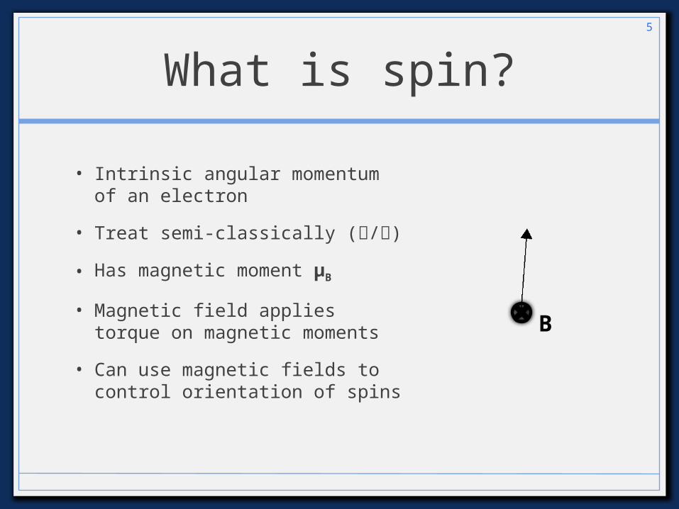
• Intrinsic angular momentum of an electron
• Treat semi-classically (/)
• Has magnetic moment μB
• Magnetic field applies torque on magnetic moments
• Can use magnetic fields to control orientation of spins
What is spin?5
B

But it’s not that simple - spin orbit effects
• Due to spin-orbit effects – an electron moving through an electric field sees an effective magnetic field
• Electrons are moving
• at different speeds
• in different directions
• Every spin sees a slightly different magnetic field
6
GaAs crystal structureBtotal = Bexternal + Bspin-
orbit

This leads to dephasing
7
Total spin polarizatio
n
Projection of S on horizontal axis
Spin Polarization
Time

Devices and their Spintronic Counterparts
• Metal-Oxide-Semiconductor Field-Effect Transistor (MOSFET)
• Datta-Das Spin Modulator
• Dynamic Random Access Memory (DRAM)
• Magnetic tunnel junctions (MTJs)
• Magnetoresistive Random Access Memory (MRAM)
8

Metal-oxide-semiconductor field-effect transistors (MOSFETs)
9
Source DrainGate (off)
n-doped n-doped
p-doped
V
No current - 0
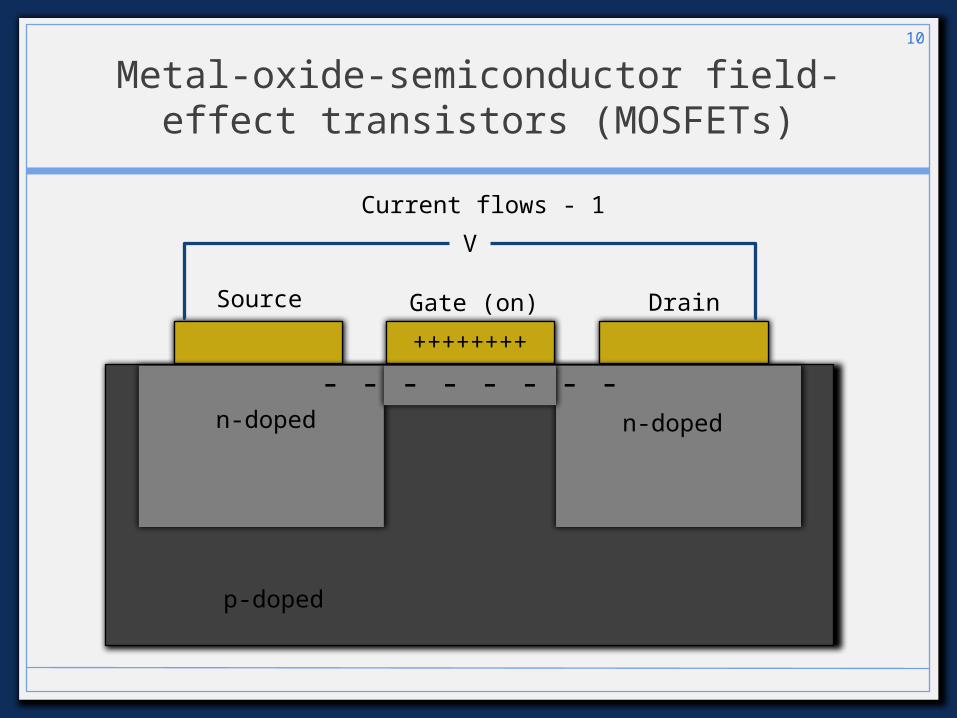
Metal-oxide-semiconductor field-effect transistors (MOSFETs)
10
Source DrainGate (on)
n-doped n-doped
p-doped
V
Current flows - 1
++++++++
- - - - - - - -
Yes measured currentNo measured current
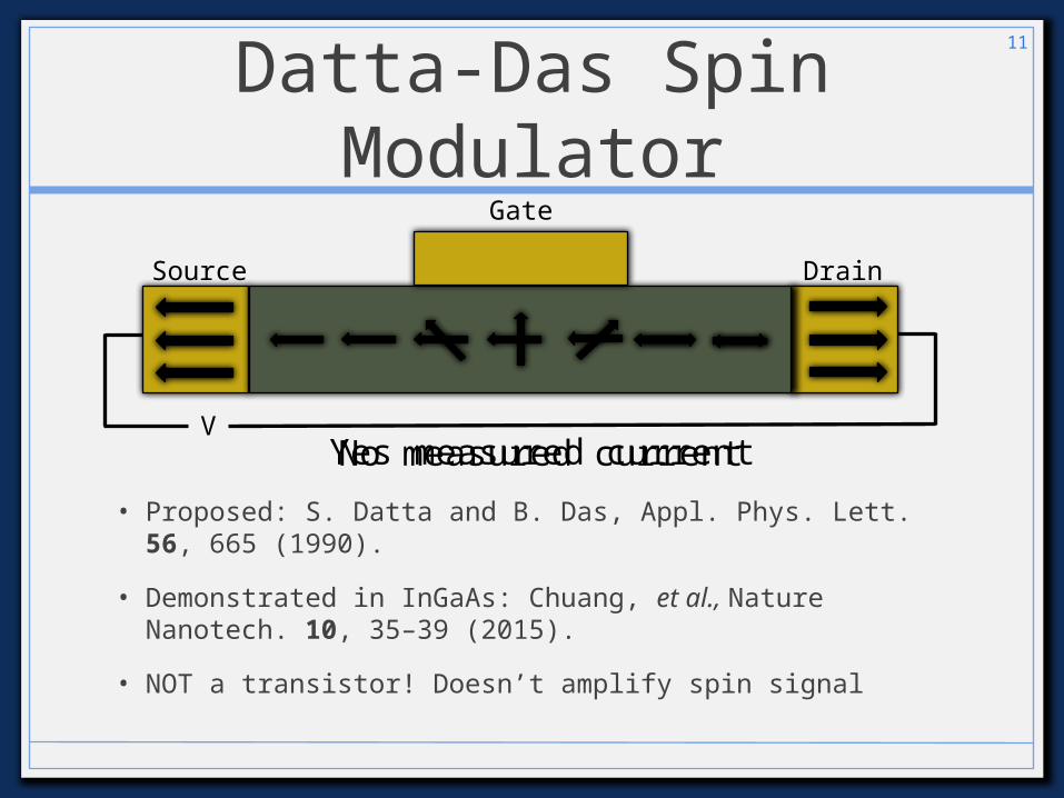
Datta-Das Spin Modulator
• Proposed: S. Datta and B. Das, Appl. Phys. Lett. 56, 665 (1990).
• Demonstrated in InGaAs: Chuang, et al., Nature Nanotech. 10, 35–39 (2015).
• NOT a transistor! Doesn’t amplify spin signal
11
Source Drain
Gate
V

Dynamic Random Access Memory (DRAM)
• Main type of RAM used in computers nowadays
• Uses a capacitor to store a bit• Charged – 1• Discharged – 0
• Due to capacitor discharging, must be periodically refreshed• Every 64 ms
12

Magnetic Tunnel Junctions
13
VInsulator
Current flows - 1
Pinned Magnetic Layer
Free Magnetic Layer
electrons tunnel

Magnetic Tunnel Junctions
14
V
No current - 0
Insulator
Pinned Magnetic Layer
Free Magnetic Layer

Magnetoresistive Random Access Memory (MRAM)
15
Albert Fert, Nobel Lecture; Sbiaa et al., PSS RRL 5, 413 (2011)
Writing (flipping the top layer): • Run current through one Bit and one Word line• Induced magnetic field only exerts enough torque to flip the
magnetization where the Bit and Word lines overlap

My Research
• Optical measurements of spins• Creating a spin polarization• Measuring a spin polarization (Faraday
rotation)
• Measuring spin-orbit fields
• Current-induced spin polarization
16
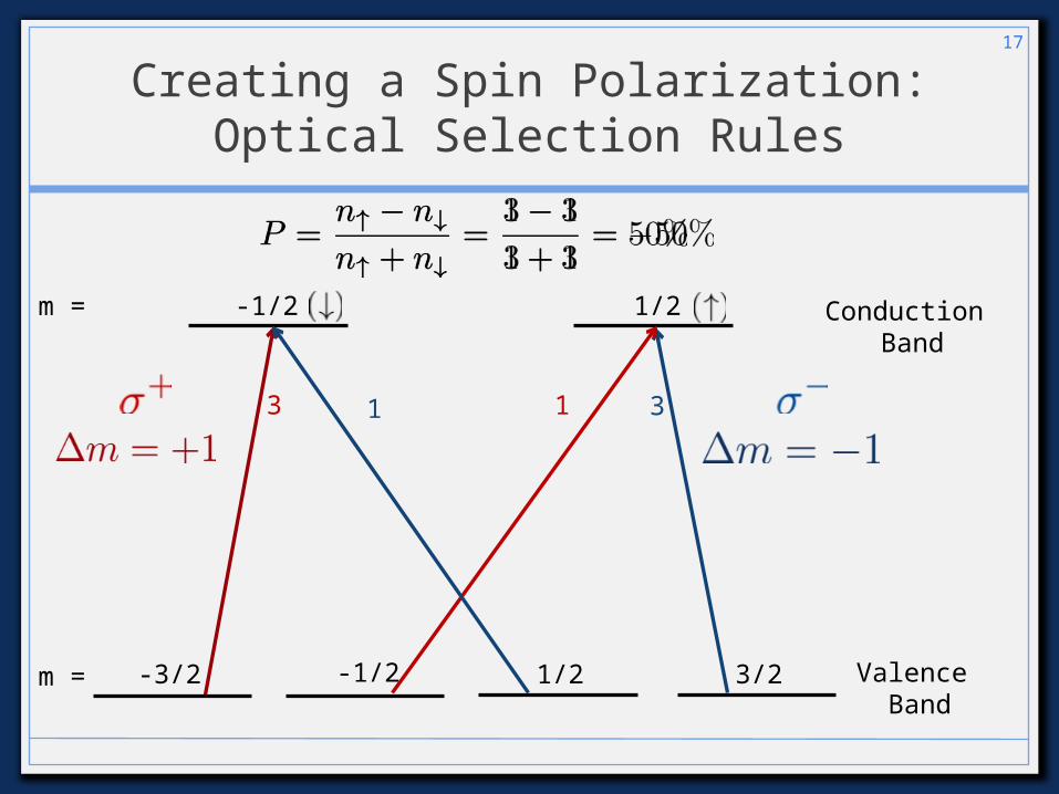
Creating a Spin Polarization:Optical Selection Rules
17
Valence Band
Conduction Band
-1/2 1/2
-3/2 -1/2 1/2 3/2
3 11 3
m =
m =

Measuring a Spin Polarization:
Faraday Rotation
18
Conduction Band
-1/2 1/2m =
Valence Band
-3/2 3/2m =

Measuring a Spin Polarization:
Faraday Rotation• σ+ and σ - absorbed at slightly different energies
• Different absorption Different index of refraction (n)
• Different n for σ+ and σ - (“circular birefringence”)
19
Kramers-Kronig
Relations
Angle of rotation (“Faraday angle”) Spin Polarization

Pump-Probe Setup
• Pump laser pulse• Circularly polarized• Optically injects a spin polarization
• Probe laser pulse• Linearly polarized• Measure Faraday rotation after transmission• Faraday rotation proportional to spin
polarization
20

Cold Finger
Pump-Probe Setup21
Lase
r
Pump
ProbeWollasto
nPrism
Linear
Pola
riz
er
Half Wave Plate
PEM
Chopper

Time-Resolved Faraday Rotation
22
Fara
day R
ota
tion
(a.u
.)

Magnetic Field Scans(Resonant Spin Amplification)
Fara
day R
ota
tion
(a.u
.)
J. M. Kikkawa and D.D. Awschalom, PRL 80, 4313 (1997)
23

Spatial measurements map out the spin packet
24
0 V + 2 V

Fitting the spin-orbit fields
25
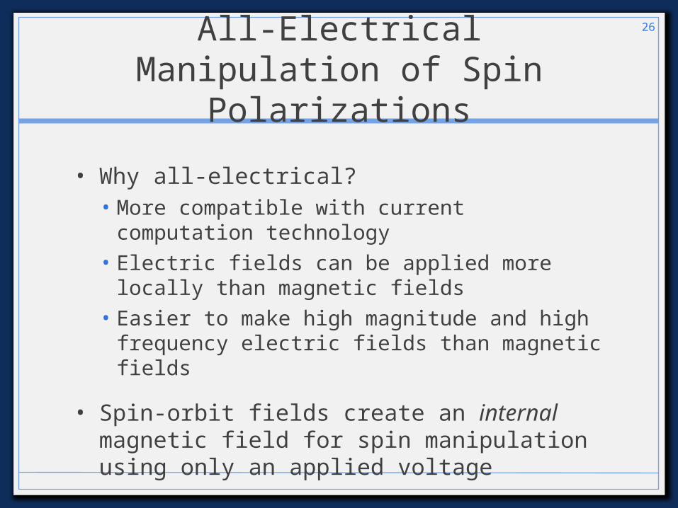
All-Electrical Manipulation of Spin Polarizations
• Why all-electrical?• More compatible with current computation
technology• Electric fields can be applied more locally than
magnetic fields• Easier to make high magnitude and high
frequency electric fields than magnetic fields
• Spin-orbit fields create an internal magnetic field for spin manipulation using only an applied voltage
26

All-Electrical Creation of Spin Polarizations
• Why all-electrical?• Alternatives:• Laser light – complicates device design• Injection from a ferromagnet – complicates
sample design• Large external magnetic field – difficult and
expensive
• All-electrical more compatible with current technology
• Current-induced spin polarization
27

Measuring current-induced spin polarization
• “CISP”
• Block the pump (no optical injection of spins)
• Apply an electric field
• Measured spin polarization is due to the electric field
28

Measuring current-induced spin polarization
29
MeasurementProjection Axis
• Current-induced: P ~ 0.1%• Optical injection: P ~ 50%

Understanding current-induced spin polarization
• To maximize CISP, we must understand CISP
• “Common sense” explanation• CISP is due to the spin-orbit
effect – coupling of an electron’s motion to its spin
• Therefore, larger spin-orbit field should mean larger CISP – right?
• Measurement doesn’t match theory!
30
B. M. Norman, et al. PRL 112, 056601 (2014)
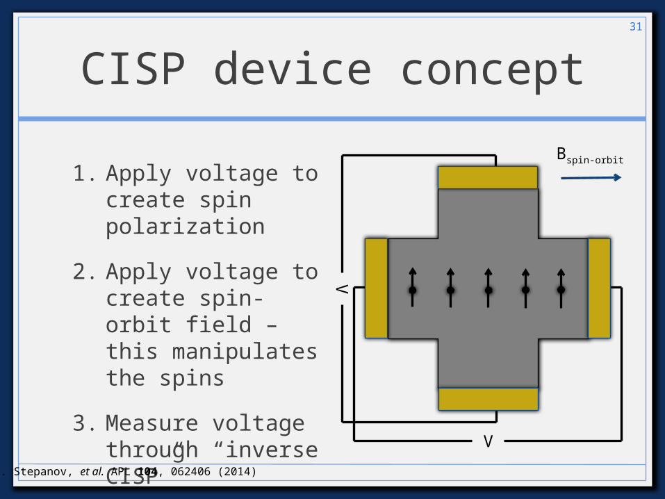
CISP device concept
1. Apply voltage to create spin polarization
2. Apply voltage to create spin-orbit field – this manipulates the spins
3. Measure voltage through “inverse CISP”
31
I. Stepanov, et al. APL 104, 062406 (2014)
V
V
Bspin-orbit

Conclusion
• Spintronic devices offer several advantages, e.g.• Information density• Power consumption
• Current-induced spin polarization could be used for all-electrical, all-semiconductor spintronic devices
• However, we need to understand it first (no theory yet)
32