Embed Size (px)
Citation preview
Revision 3.0 2013-09-11 www.impinj.com
Copyright © 2011-2013, Impinj, Inc.
Impinj, Octane, Powered by Impinj and Speedway are either registered trademarks or trademarks of Impinj, Inc. For more information, contact [email protected]
Low Level User Data Support
Speedway® Revolution Reader Application Note
This application note provides the operator of a Speedway Revolution reader with the necessary
information to utilize the Radio Frequency (RF) phase and Received Signal Strength Indication (RSSI)
low level user data.
The target audience is any party interested in using the RF phase and RSSI reporting features.
Note that the low level user data feature requires a Speedway Revolution reader with at least Octane 4.4
firmware to receive any low level tag metrics, however the latest optimizations to these tag reports,
including the Doppler effects described here, are available beginning with Octane 4.8.
Speedway Revolution Reader—Low Level User Data Support
ii Revision 3.0, Copyright © 2011-2013, Impinj, Inc.
Table of Contents
1 Introduction ............................................................................................................................................. 3 1.1 Terminology...................................................................................................................................... 3
2 Configuration ........................................................................................................................................... 4 2.1 Example LLRP ROSpec ................................................................................................................... 4 2.2 Example RO_ACCESS_REPORT ................................................................................................... 6
3 Low Level User Data .............................................................................................................................. 8 3.1 Backscatter Power............................................................................................................................. 8
3.1.1 Theory ........................................................................................................................................ 8 3.1.2 Environmental and Other Effects ............................................................................................... 9
3.1.3 Speedway Revolution Reader RSSI Reporting .......................................................................... 9 3.2 RF Phase ......................................................................................................................................... 10
3.2.1 Theory ...................................................................................................................................... 10 3.2.2 Environmental and Other Effects ............................................................................................. 10
3.2.3 Inventory, Antenna Switching, and Frequency Hopping Effects ............................................ 11 3.2.4 Speedway Revolution Reader RF Phase Reporting ................................................................. 11
3.2.5 Computing Velocity from RF Phase ........................................................................................ 12 3.3 Doppler Frequency Shift ................................................................................................................. 13
3.3.1 Theory ...................................................................................................................................... 13
3.3.2 Speedway Revolution Reader Doppler Frequency Shift Reporting ........................................ 14 3.3.3 Accuracy of Doppler Frequency Shift Reporting .................................................................... 15
3.3.4 Calculation of Velocity from Doppler Frequency Shift Reporting .......................................... 15 4 Revision History .................................................................................................................................... 16
Notices: ..................................................................................................................................................... 16
Speedway Revolution Reader—Low Level User Data Support
Revision 3.0, Copyright © 2011-2013, Impinj, Inc. 3
1 Introduction This application note provides the operator of a Speedway Revolution reader with the necessary
information to utilize the Radio Frequency (RF) phase and Received Signal Strength Indication (RSSI)
low level user data.
The target audience is any party interested in using the RF phase and RSSI reporting features.
Note that the low level user data feature requires a Speedway Revolution reader with at least Octane 4.4
firmware to receive any low level tag metrics; however the latest optimizations to these tag reports,
including the Doppler effects described here, are available beginning with Octane 4.8.
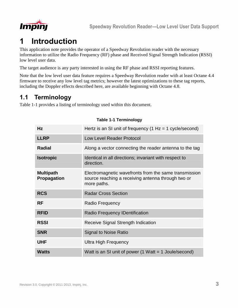
1.1 Terminology Table 1-1 provides a listing of terminology used within this document.
Table 1-1 Terminology
Hz Hertz is an SI unit of frequency (1 Hz = 1 cycle/second)
LLRP Low Level Reader Protocol
Radial Along a vector connecting the reader antenna to the tag
Isotropic Identical in all directions; invariant with respect to direction.
Multipath Propagation
Electromagnetic wavefronts from the same transmission source reaching a receiving antenna through two or more paths.
RCS Radar Cross Section
RF Radio Frequency
RFID Radio Frequency IDentification
RSSI Receive Signal Strength Indication
SNR Signal to Noise Ratio
UHF Ultra High Frequency
Watts Watt is an SI unit of power (1 Watt = 1 Joule/second)
Speedway Revolution Reader—Low Level User Data Support
4 Revision 3.0, Copyright © 2011-2013, Impinj, Inc.
2 Configuration When loaded with the Octane 4.4, or newer versions of software, the Speedway Revolution reader
supports RF phase and RSSI reporting through custom extensions of the Low Level Reader Protocol
(LLRP). The ImpinjTagReportContentSelector parameter allows the operator to configure additional
parameters to be reported via the TagReportData parameter including the ImpinjRFPhaseAngle,
ImpinjPeakRSSI and ImpinjRFDoppler parameters. For a complete description of how to enable the low
level user data feature for the Speedway Revolution reader please refer to the Octane LLRP Version 4.8
documentation.
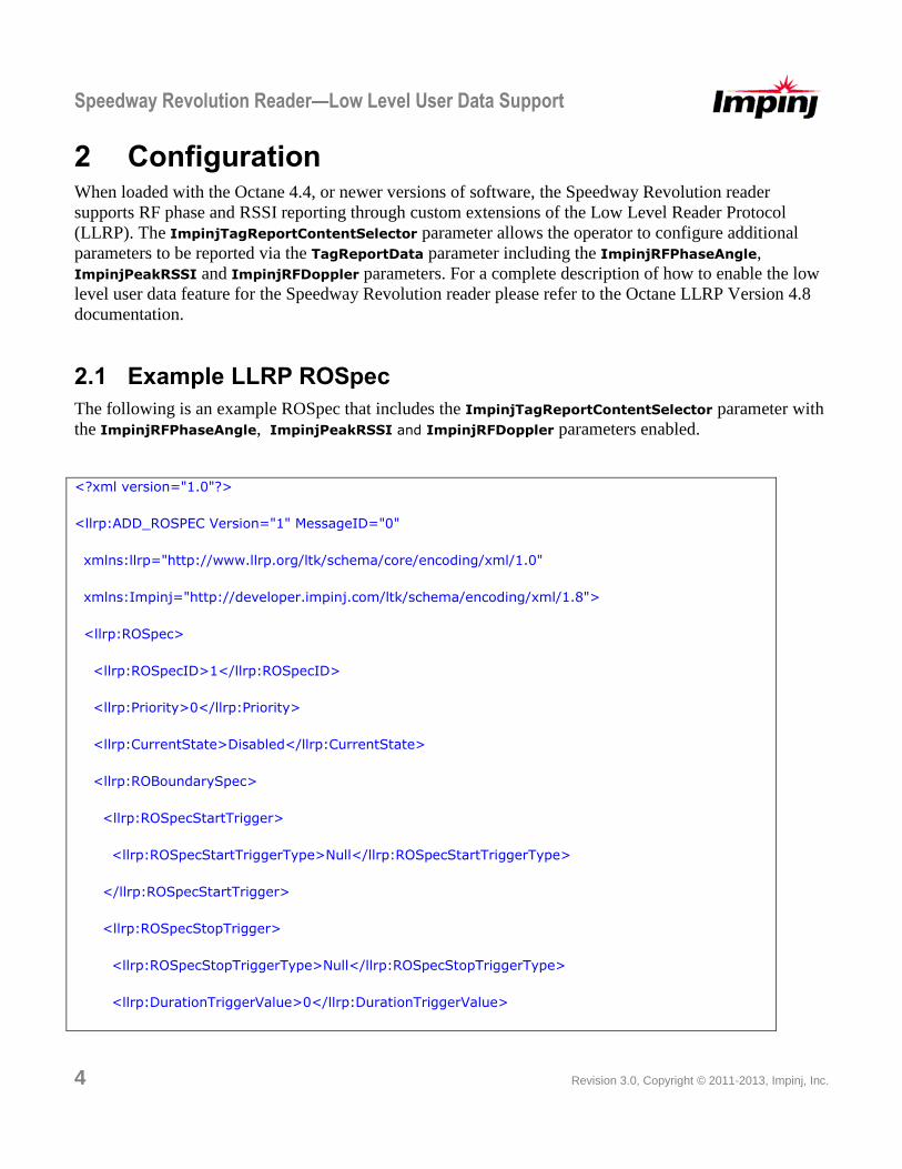
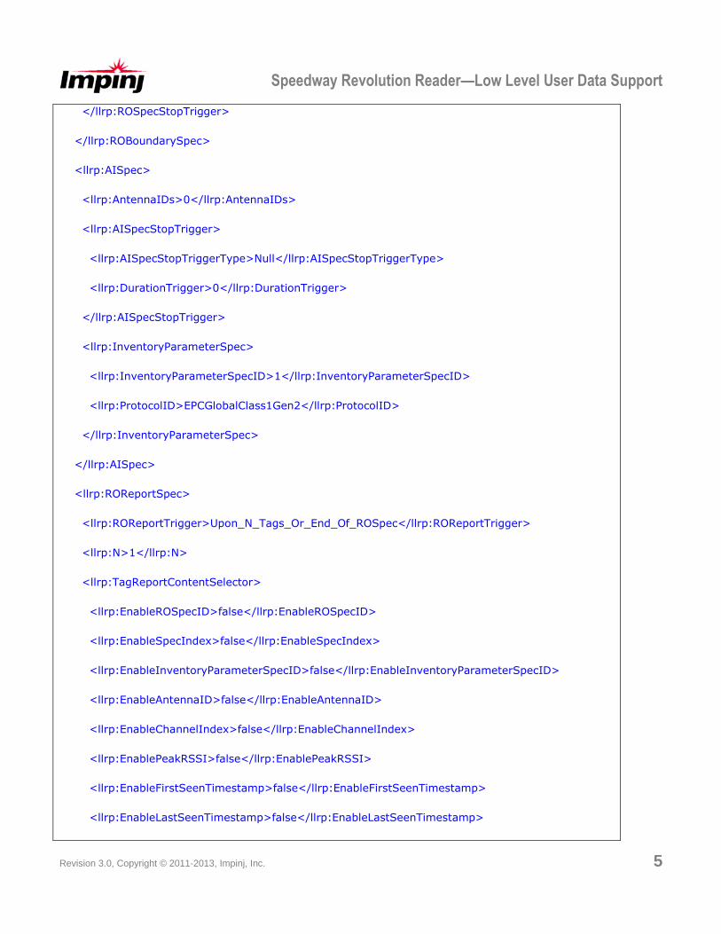
2.1 Example LLRP ROSpec
The following is an example ROSpec that includes the ImpinjTagReportContentSelector parameter with
the ImpinjRFPhaseAngle, ImpinjPeakRSSI and ImpinjRFDoppler parameters enabled.
<?xml version="1.0"?>
<llrp:ADD_ROSPEC Version="1" MessageID="0"
xmlns:llrp="http://www.llrp.org/ltk/schema/core/encoding/xml/1.0"
xmlns:Impinj="http://developer.impinj.com/ltk/schema/encoding/xml/1.8">
<llrp:ROSpec>
<llrp:ROSpecID>1</llrp:ROSpecID>
<llrp:Priority>0</llrp:Priority>
<llrp:CurrentState>Disabled</llrp:CurrentState>
<llrp:ROBoundarySpec>
<llrp:ROSpecStartTrigger>
<llrp:ROSpecStartTriggerType>Null</llrp:ROSpecStartTriggerType>
</llrp:ROSpecStartTrigger>
<llrp:ROSpecStopTrigger>
<llrp:ROSpecStopTriggerType>Null</llrp:ROSpecStopTriggerType>
<llrp:DurationTriggerValue>0</llrp:DurationTriggerValue>
Speedway Revolution Reader—Low Level User Data Support
Revision 3.0, Copyright © 2011-2013, Impinj, Inc. 5
</llrp:ROSpecStopTrigger>
</llrp:ROBoundarySpec>
<llrp:AISpec>
<llrp:AntennaIDs>0</llrp:AntennaIDs>
<llrp:AISpecStopTrigger>
<llrp:AISpecStopTriggerType>Null</llrp:AISpecStopTriggerType>
<llrp:DurationTrigger>0</llrp:DurationTrigger>
</llrp:AISpecStopTrigger>
<llrp:InventoryParameterSpec>
<llrp:InventoryParameterSpecID>1</llrp:InventoryParameterSpecID>
<llrp:ProtocolID>EPCGlobalClass1Gen2</llrp:ProtocolID>
</llrp:InventoryParameterSpec>
</llrp:AISpec>
<llrp:ROReportSpec>
<llrp:ROReportTrigger>Upon_N_Tags_Or_End_Of_ROSpec</llrp:ROReportTrigger>
<llrp:N>1</llrp:N>
<llrp:TagReportContentSelector>
<llrp:EnableROSpecID>false</llrp:EnableROSpecID>
<llrp:EnableSpecIndex>false</llrp:EnableSpecIndex>
<llrp:EnableInventoryParameterSpecID>false</llrp:EnableInventoryParameterSpecID>
<llrp:EnableAntennaID>false</llrp:EnableAntennaID>
<llrp:EnableChannelIndex>false</llrp:EnableChannelIndex>
<llrp:EnablePeakRSSI>false</llrp:EnablePeakRSSI>
<llrp:EnableFirstSeenTimestamp>false</llrp:EnableFirstSeenTimestamp>
<llrp:EnableLastSeenTimestamp>false</llrp:EnableLastSeenTimestamp>
Speedway Revolution Reader—Low Level User Data Support
6 Revision 3.0, Copyright © 2011-2013, Impinj, Inc.
<llrp:EnableTagSeenCount>false</llrp:EnableTagSeenCount>
<llrp:EnableAccessSpecID>false</llrp:EnableAccessSpecID>
<llrp:C1G2EPCMemorySelector>
<llrp:EnableCRC>false</llrp:EnableCRC>
<llrp:EnablePCBits>false</llrp:EnablePCBits>
</llrp:C1G2EPCMemorySelector>
</llrp:TagReportContentSelector>
<Impinj:ImpinjTagReportContentSelector>
<Impinj:ImpinjEnableSerializedTID>false</Impinj:ImpinjEnableSerializedTID>
<Impinj:ImpinjEnableRFPhaseAngle>true</Impinj:ImpinjEnableRFPhaseAngle>
<Impinj:ImpinjEnablePeakRSSI>true</Impinj:ImpinjEnablePeakRSSI>
<Impinj:ImpinjEnableRFDopplerFrequency>true</Impinj:ImpinjEnableRFDopplerFrequency>
</Impinj:ImpinjTagReportContentSelector>
</llrp:ROReportSpec>
</llrp:ROSpec>
</llrp:ADD_ROSPEC>
Figure 2-1: Sample LLRP ROSpec
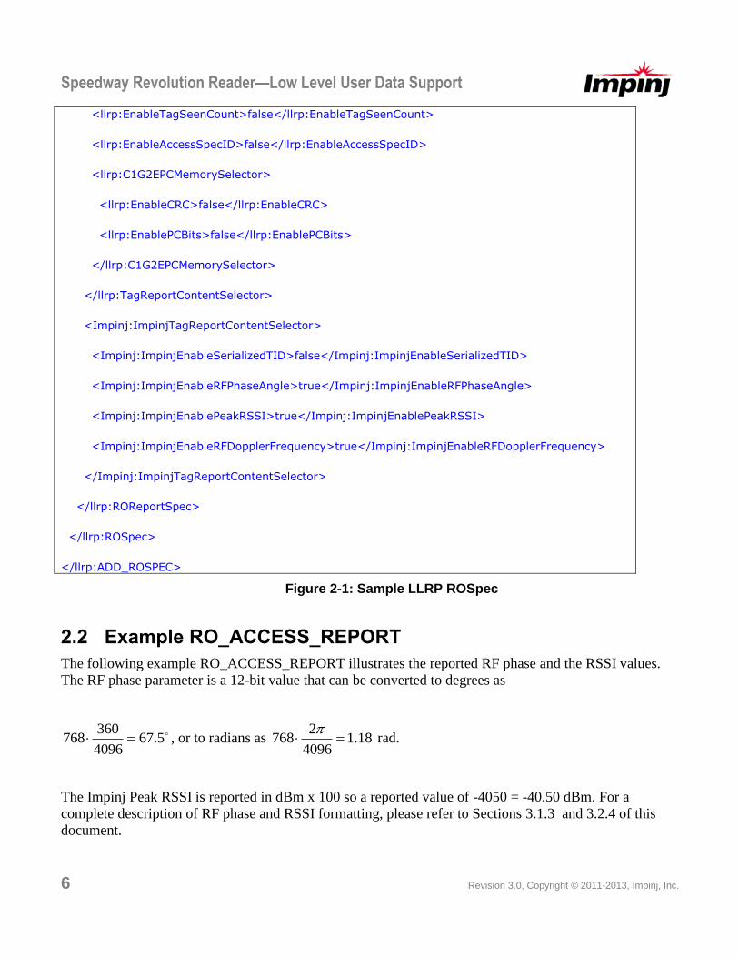
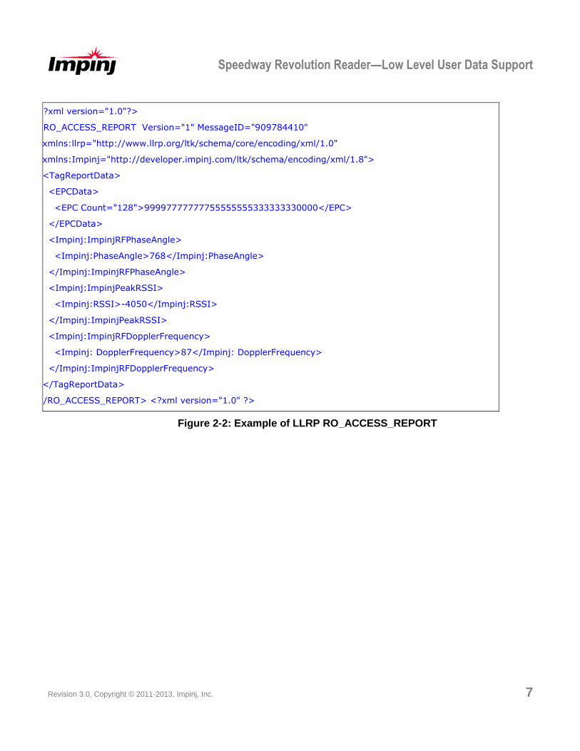
2.2 Example RO_ACCESS_REPORT
The following example RO_ACCESS_REPORT illustrates the reported RF phase and the RSSI values.
The RF phase parameter is a 12-bit value that can be converted to degrees as
5.674096
360768 , or to radians as 18.1
4096
2768
rad.
The Impinj Peak RSSI is reported in dBm x 100 so a reported value of -4050 = -40.50 dBm. For a
complete description of RF phase and RSSI formatting, please refer to Sections 3.1.3 and 3.2.4 of this
document.
Speedway Revolution Reader—Low Level User Data Support
Revision 3.0, Copyright © 2011-2013, Impinj, Inc. 7
<?xml version="1.0"?>
<RO_ACCESS_REPORT Version="1" MessageID="909784410"
xmlns:llrp="http://www.llrp.org/ltk/schema/core/encoding/xml/1.0"
xmlns:Impinj="http://developer.impinj.com/ltk/schema/encoding/xml/1.8">
<TagReportData>
<EPCData>
<EPC Count="128">99997777777755555555333333330000</EPC>
</EPCData>
<Impinj:ImpinjRFPhaseAngle>
<Impinj:PhaseAngle>768</Impinj:PhaseAngle>
</Impinj:ImpinjRFPhaseAngle>
<Impinj:ImpinjPeakRSSI>
<Impinj:RSSI>-4050</Impinj:RSSI>
</Impinj:ImpinjPeakRSSI>
<Impinj:ImpinjRFDopplerFrequency>
<Impinj: DopplerFrequency>87</Impinj: DopplerFrequency>
</Impinj:ImpinjRFDopplerFrequency>
</TagReportData>
</RO_ACCESS_REPORT> <?xml version="1.0" ?>
Figure 2-2: Example of LLRP RO_ACCESS_REPORT
Speedway Revolution Reader—Low Level User Data Support
8 Revision 3.0, Copyright © 2011-2013, Impinj, Inc.
3 Low Level User Data This application note provides a cursory introduction to those radio propagation topics immediately
relevant to the Speedway Revolution reader RSSI and RF phase user data. A comprehensive description
of radar techniques and electromagnetic wave propagation are beyond the scope of this paper. The
operator is encouraged to reference one of the many texts available on those subjects.
3.1 Backscatter Power
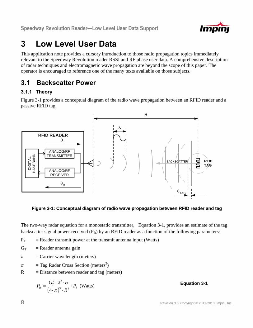
3.1.1 Theory
Figure 3-1 provides a conceptual diagram of the radio wave propagation between an RFID reader and a
passive RFID tag.
ANALOG/RF
TRANSMITTER
ANALOG/RF
RECEIVER
DIG
ITA
L
BA
SE
BA
ND
R
RFID
TAG
T
R
BACKSCATTER
RFID READER
TAG
Figure 3-1: Conceptual diagram of radio wave propagation between RFID reader and tag
The two-way radar equation for a monostatic transmitter, Equation 3-1, provides an estimate of the tag
backscatter signal power received (PR) by an RFID reader as a function of the following parameters:
PT = Reader transmit power at the transmit antenna input (Watts)
GT = Reader antenna gain
= Carrier wavelength (meters)
= Tag Radar Cross Section (meters2)
R = Distance between reader and tag (meters)
T
T PR
GP
43
22
R4
(Watts)
Equation 3-1
Speedway Revolution Reader—Low Level User Data Support
Revision 3.0, Copyright © 2011-2013, Impinj, Inc. 9
The two-way radar equation is a form of the well-known Friis equation applied to both directions of the
radar link (reader-to-tag and tag-to-reader). The receiver antenna gain term (GR) in the standard Friis
equation is replaced by a factor comprehending the target’s Radar Cross Section (RCS), GR = 4/2. An
object’s RCS is a measure of the effective area for capturing incident energy and isotropically scattering it
back to the source. The RCS for a passive RFID tag depends on antenna design, impedance matching, and
the changes in reflection coefficient as a function of tag modulator state.
The received signal power decays as 1/R4 due to the product of the two free-space loss factors, 1/R
2, for
each link direction (reader-to-tag and tag-to-reader).
3.1.2 Environmental and Other Effects
Many factors can affect the received power, causing it to be different than predicted by the two-way radar
equation. Propagation effects such as absorption and scattering as well as antenna effects such as
impedance mismatch and polarization mismatch can reduce the power observed at the reader receiver.
Multipath propagation and undesired signals in the environment can combine with the primary
backscatter, thereby increasing or decreasing the received signal power at the reader receiver.
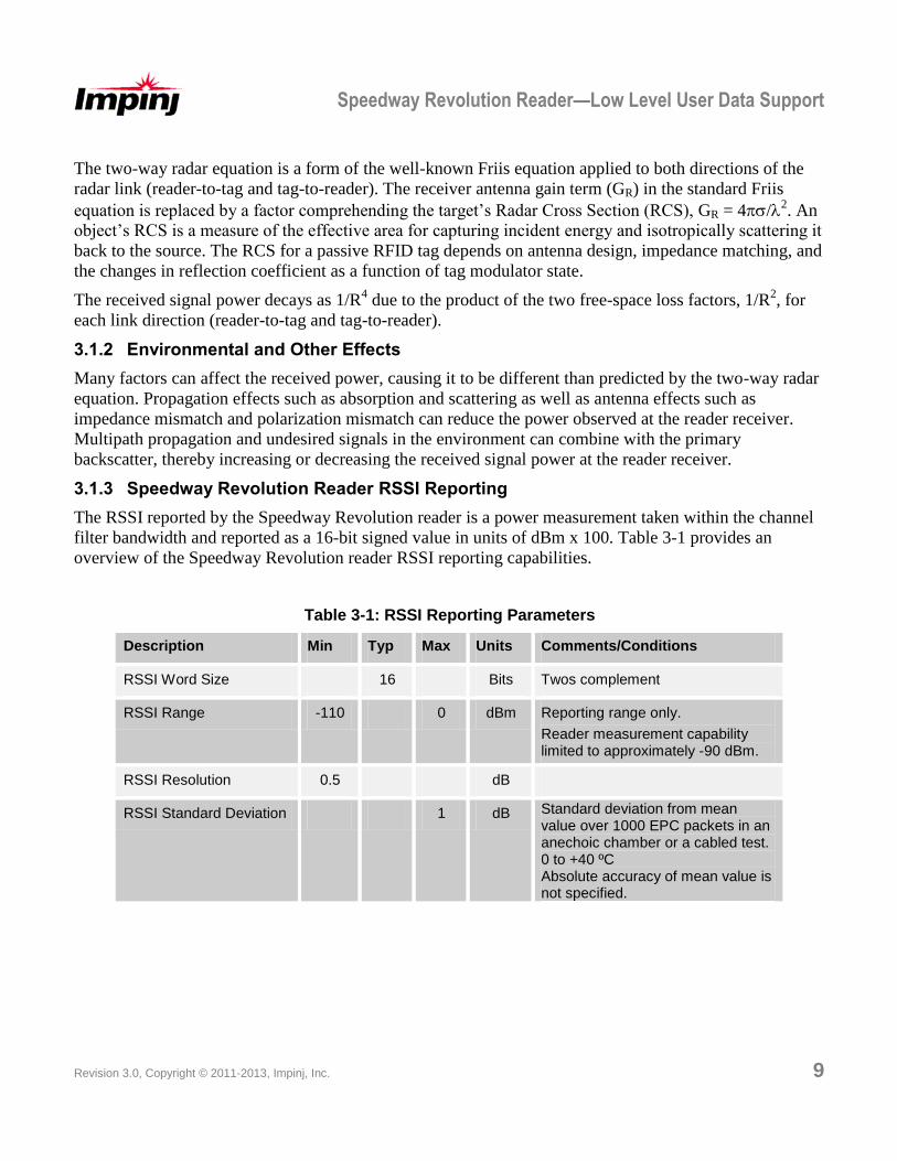
3.1.3 Speedway Revolution Reader RSSI Reporting
The RSSI reported by the Speedway Revolution reader is a power measurement taken within the channel
filter bandwidth and reported as a 16-bit signed value in units of dBm x 100. Table 3-1 provides an
overview of the Speedway Revolution reader RSSI reporting capabilities.
Table 3-1: RSSI Reporting Parameters
Description Min Typ Max Units Comments/Conditions
RSSI Word Size 16 Bits Twos complement
RSSI Range -110 0 dBm Reporting range only.
Reader measurement capability limited to approximately -90 dBm.
RSSI Resolution 0.5 dB
RSSI Standard Deviation 1 dB Standard deviation from mean value over 1000 EPC packets in an anechoic chamber or a cabled test.
0 to +40 ºC Absolute accuracy of mean value is
not specified.
Speedway Revolution Reader—Low Level User Data Support
10 Revision 3.0, Copyright © 2011-2013, Impinj, Inc.
3.2 RF Phase
3.2.1 Theory
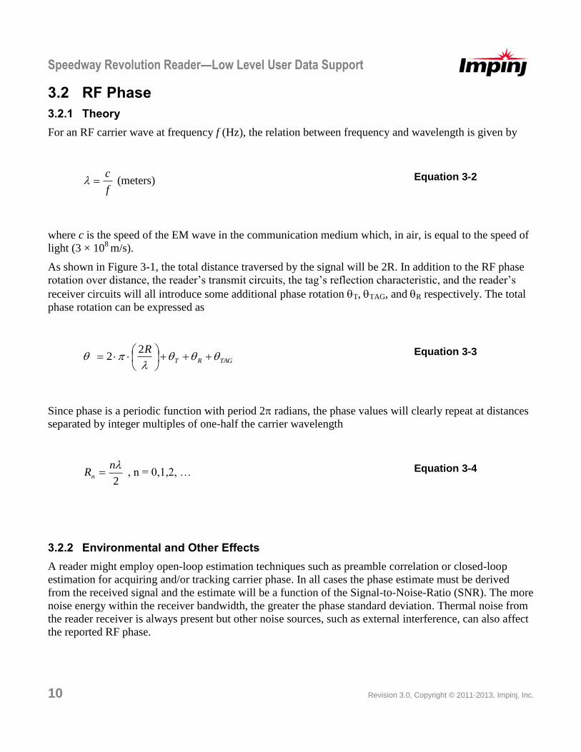
For an RF carrier wave at frequency f (Hz), the relation between frequency and wavelength is given by
f
c (meters) Equation 3-2
where c is the speed of the EM wave in the communication medium which, in air, is equal to the speed of
light (3 × 10⁸
m/s).
As shown in Figure 3-1, the total distance traversed by the signal will be 2R. In addition to the RF phase
rotation over distance, the reader’s transmit circuits, the tag’s reflection characteristic, and the reader’s
receiver circuits will all introduce some additional phase rotation T, TAG, and R respectively. The total
phase rotation can be expressed as
TAGRT
R
22 Equation 3-3
Since phase is a periodic function with period 2radians, the phase values will clearly repeat at distances
separated by integer multiples of one-half the carrier wavelength
2
nRn , n = 0,1,2, … Equation 3-4
3.2.2 Environmental and Other Effects
A reader might employ open-loop estimation techniques such as preamble correlation or closed-loop
estimation for acquiring and/or tracking carrier phase. In all cases the phase estimate must be derived
from the received signal and the estimate will be a function of the Signal-to-Noise-Ratio (SNR). The more
noise energy within the receiver bandwidth, the greater the phase standard deviation. Thermal noise from
the reader receiver is always present but other noise sources, such as external interference, can also affect
the reported RF phase.
Speedway Revolution Reader—Low Level User Data Support
Revision 3.0, Copyright © 2011-2013, Impinj, Inc. 11
As mentioned in 3.1.1 the RF phase is a periodic function and will be estimated modulo-2. In addition,
the Speedway Revolution reader receive signal processing introduces radians of ambiguity such that the
reported phase can be the true phase () or the true phase plus radians (+).
3.2.3 Inventory, Antenna Switching, and Frequency Hopping Effects
The Speedway Revolution reader provides one RF phase estimate each time a tag is successfully
inventoried. If an application employs multiple samples of the RF phase from a single tag, the application
must comprehend the following:
1. Phase estimates should only be compared on a single antenna and channel. RF phase is a function of
frequency and antenna path as shown by Equation 3-3.
2. Gen2 UHF RFID employs a slotted-aloha media access scheme, which means that the order in which
tags are inventoried will be random. The time between successive inventories of the same tag will depend
on reader mode, tag population size, and environmental conditions (e.g. interference levels). Since RF
phase is a function of radial distance between reader and tag, the phase difference between successive
inventories of the same tag will depend on the elapsed time between the two inventories and the tag’s
radial velocity.
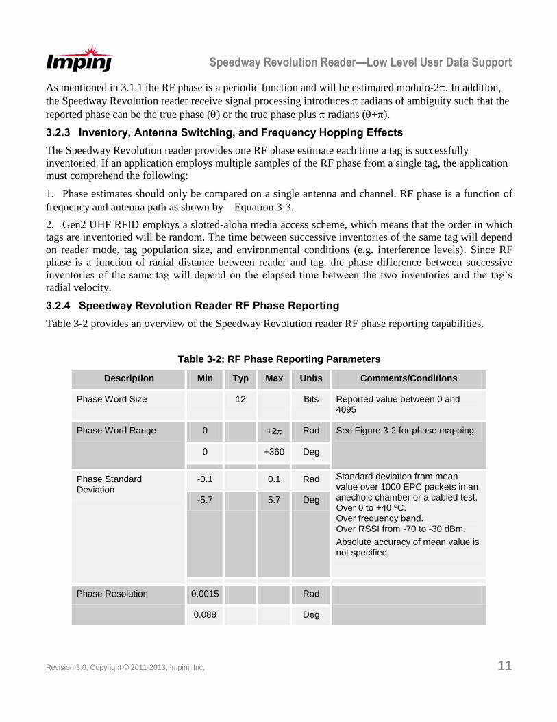
3.2.4 Speedway Revolution Reader RF Phase Reporting
Table 3-2 provides an overview of the Speedway Revolution reader RF phase reporting capabilities.
Table 3-2: RF Phase Reporting Parameters
Description Min Typ Max Units Comments/Conditions
Phase Word Size 12 Bits Reported value between 0 and 4095
Phase Word Range 0 +2 Rad See Figure 3-2 for phase mapping
0 +360 Deg
Phase Standard Deviation
-0.1 0.1 Rad Standard deviation from mean value over 1000 EPC packets in an anechoic chamber or a cabled test.
Over 0 to +40 ºC. Over frequency band. Over RSSI from -70 to -30 dBm.
Absolute accuracy of mean value is not specified.
-5.7 5.7 Deg
Phase Resolution 0.0015 Rad
0.088 Deg
Speedway Revolution Reader—Low Level User Data Support
12 Revision 3.0, Copyright © 2011-2013, Impinj, Inc.
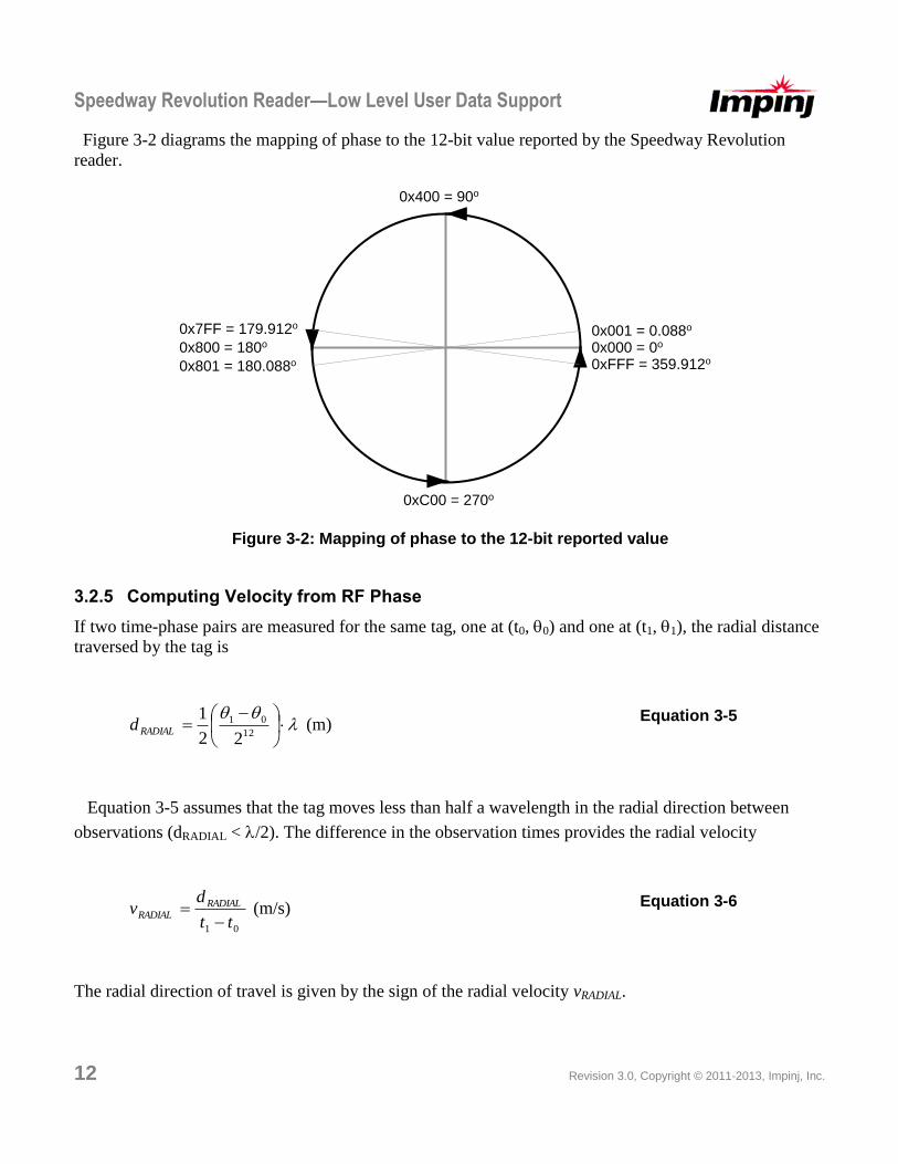
Figure 3-2 diagrams the mapping of phase to the 12-bit value reported by the Speedway Revolution
reader.
0x000 = 0o0x800 = 180o
0x001 = 0.088o
0xFFF = 359.912o
0x7FF = 179.912o
0x801 = 180.088o
0x400 = 90o
0xC00 = 270o
Figure 3-2: Mapping of phase to the 12-bit reported value
3.2.5 Computing Velocity from RF Phase
If two time-phase pairs are measured for the same tag, one at (t0, 0) and one at (t1, 1), the radial distance
traversed by the tag is
12
01
22
1RADIALd (m)
Equation 3-5
Equation 3-5 assumes that the tag moves less than half a wavelength in the radial direction between
observations (dRADIAL < /2). The difference in the observation times provides the radial velocity
01 tt
dv RADIAL
RADIAL
(m/s) Equation 3-6
The radial direction of travel is given by the sign of the radial velocity vRADIAL.
Speedway Revolution Reader—Low Level Data Support
Revision 3.0, Copyright © 2011, Impinj, Inc. 13
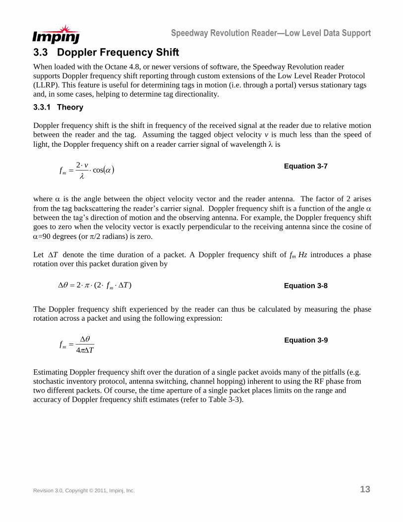
3.3 Doppler Frequency Shift
When loaded with the Octane 4.8, or newer versions of software, the Speedway Revolution reader
supports Doppler frequency shift reporting through custom extensions of the Low Level Reader Protocol
(LLRP). This feature is useful for determining tags in motion (i.e. through a portal) versus stationary tags
and, in some cases, helping to determine tag directionality.
3.3.1 Theory
Doppler frequency shift is the shift in frequency of the received signal at the reader due to relative motion
between the reader and the tag. Assuming the tagged object velocity v is much less than the speed of
light, the Doppler frequency shift on a reader carrier signal of wavelength is
cos2
v
fm Equation 3-7
where is the angle between the object velocity vector and the reader antenna. The factor of 2 arises
from the tag backscattering the reader’s carrier signal. Doppler frequency shift is a function of the angle
between the tag’s direction of motion and the observing antenna. For example, the Doppler frequency shift
goes to zero when the velocity vector is exactly perpendicular to the receiving antenna since the cosine of
=90 degrees (or /2 radians) is zero.
Let T denote the time duration of a packet. A Doppler frequency shift of fm Hz introduces a phase
rotation over this packet duration given by
)2(2 Tfm Equation 3-8
The Doppler frequency shift experienced by the reader can thus be calculated by measuring the phase
rotation across a packet and using the following expression:
Tfm
4
Equation 3-9
Estimating Doppler frequency shift over the duration of a single packet avoids many of the pitfalls (e.g.
stochastic inventory protocol, antenna switching, channel hopping) inherent to using the RF phase from
two different packets. Of course, the time aperture of a single packet places limits on the range and
accuracy of Doppler frequency shift estimates (refer to Table 3-3).
Speedway Revolution Reader—Low Level User Data Support
14 Revision 3.0, Copyright © 2011-2013, Impinj, Inc.
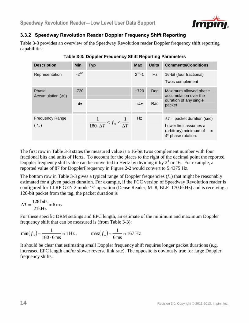
3.3.2 Speedway Revolution Reader Doppler Frequency Shift Reporting
Table 3-3 provides an overview of the Speedway Revolution reader Doppler frequency shift reporting
capabilities.
Table 3-3: Doppler Frequency Shift Reporting Parameters
Description Min Typ Max Units Comments/Conditions
Representation -212
212
-1 Hz 16-bit (four fractional)
Twos complement
Phase
Accumulation ()
-720 +720 Deg Maximum allowed phase accumulation over the duration of any single packet -4 +4 Rad
Frequency Range
( fm )
Tf
Tm
1
180
1
Hz T = packet duration (sec)
Lower limit assumes a
(arbitrary) minimum of
4 phase rotation.
The first row in Table 3-3 states the measured value is a 16-bit twos complement number with four
fractional bits and units of Hertz. To account for the places to the right of the decimal point the reported
Doppler frequency shift value can be converted to Hertz by dividing it by 24 or 16. For example, a
reported value of 87 for DopplerFrequency in Figure 2-2 would convert to 5.4375 Hz.
The bottom row in Table 3-3 gives a typical range of Doppler frequencies (fm) that might be reasonably
estimated for a given packet duration. For example, if the FCC version of Speedway Revolution reader is
configured for LLRP GEN 2 mode ‘3’ operation (Dense Reader, M=8, BLF=170.6kHz) and is receiving a
128-bit packet from the tag, the packet duration is
ms 621kHz
bits 128T
For these specific DRM settings and EPC length, an estimate of the minimum and maximum Doppler
frequency shift that can be measured is (from Table 3-3):
Hz 1ms 6180
1min
mf , Hz 167
ms 6
1max mf
It should be clear that estimating small Doppler frequency shift requires longer packet durations (e.g.
increased EPC length and/or slower reverse link rate). The opposite is obviously true for large Doppler
frequency shifts.
Speedway Revolution Reader—Low Level Data Support
Revision 3.0, Copyright © 2011, Impinj, Inc. 15
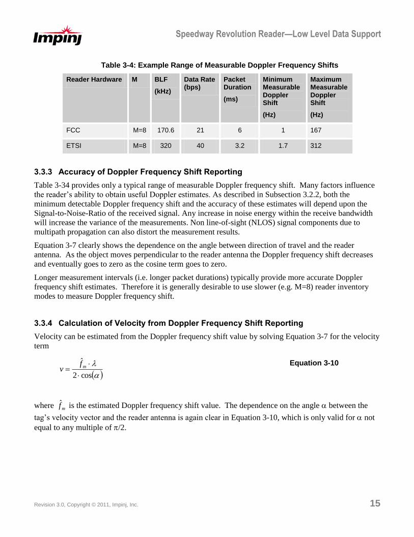
Table 3-4: Example Range of Measurable Doppler Frequency Shifts
Reader Hardware M BLF
(kHz)
Data Rate (bps)
Packet Duration
(ms)
Minimum Measurable Doppler Shift
(Hz)
Maximum Measurable Doppler Shift
(Hz)
FCC M=8 170.6 21 6 1 167
ETSI M=8 320 40 3.2 1.7 312
3.3.3 Accuracy of Doppler Frequency Shift Reporting
Table 3-34 provides only a typical range of measurable Doppler frequency shift. Many factors influence
the reader’s ability to obtain useful Doppler estimates. As described in Subsection 3.2.2, both the
minimum detectable Doppler frequency shift and the accuracy of these estimates will depend upon the
Signal-to-Noise-Ratio of the received signal. Any increase in noise energy within the receive bandwidth
will increase the variance of the measurements. Non line-of-sight (NLOS) signal components due to
multipath propagation can also distort the measurement results.
Equation 3-7 clearly shows the dependence on the angle between direction of travel and the reader
antenna. As the object moves perpendicular to the reader antenna the Doppler frequency shift decreases
and eventually goes to zero as the cosine term goes to zero.
Longer measurement intervals (i.e. longer packet durations) typically provide more accurate Doppler
frequency shift estimates. Therefore it is generally desirable to use slower (e.g. M=8) reader inventory
modes to measure Doppler frequency shift.
3.3.4 Calculation of Velocity from Doppler Frequency Shift Reporting
Velocity can be estimated from the Doppler frequency shift value by solving Equation 3-7 for the velocity
term
cos2
ˆ
mf
v Equation 3-10
where mf̂ is the estimated Doppler frequency shift value. The dependence on the angle between the
tag’s velocity vector and the reader antenna is again clear in Equation 3-10, which is only valid for not
equal to any multiple of /2.
Speedway Revolution Reader—Low Level User Data Support
16 Revision 3.0, Copyright © 2011-2013, Impinj, Inc.
4 Revision History Date Revision Comments
08/12/2010 1.0 Original release
05/26/2011 2.0 Updated for Doppler Frequency in Octane 4.8
07/05/2012 3.0 Expanded Doppler Frequency reporting, section 3.3
Notices:
Copyright © 2012, Impinj, Inc. All rights reserved.
This document is conditionally issued, and neither receipt nor possession hereof confers or transfers any
right in, or license to, use the subject matter of any drawings, design, or technical information contained
herein, nor any right to reproduce or disclose any part of the contents hereof, without the prior written
consent of Impinj and the authorized recipient hereof.
Impinj reserves the right to change its products and services at any time without notice.
Impinj assumes no responsibility for customer product design or for infringement of patents and/or the
rights of third parties, which may result from assistance provided by Impinj. No representation of warranty
is given and no liability is assumed by Impinj with respect to accuracy or use of such information.
These products are not designed for use in life support appliances, devices, or systems where malfunction
can reasonably be expected to result in personal injury.
This product is covered by one or more of the following U.S. patents. Other patents pending. 7283037,
7026935, 7049964, 7501953, 7030786, 7246751, 7245213, 7408466, 7187290, 7304579, 7510117,
7107022, 7419096, 7382257, 7405660, 7436308, 7417548, 7391329, 7391329, 7592897, 7589618,
7633376, 7696882, 7830262