Embed Size (px)
Citation preview
®
SpeedScrub Rider
331140Rev. 01
Operator Manual
*331140*
t
Hygenic Fully Cleanable TankstThe safe scrubbing alternative
R
R
®
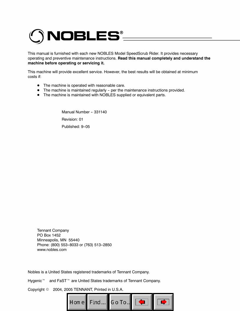
This manual is furnished with each new NOBLES Model SpeedScrub Rider. It provides necessaryoperating and preventive maintenance instructions. Read this manual completely and understand themachine before operating or servicing it.
This machine will provide excellent service. However, the best results will be obtained at minimumcosts if:
D The machine is operated with reasonable care.D The machine is maintained regularly -- per the maintenance instructions provided.D The machine is maintained with NOBLES supplied or equivalent parts.
Manual Number -- 331140
Revision: 01
Published: 9--05
Tennant CompanyPO Box 1452Minneapolis, MN 55440Phone: (800) 553--8033 or (763) 513--2850www.nobles.com
Nobles is a United States registered trademarks of Tennant Company.
Hygenict and FaSTt are United States trademarks of Tennant Company.
Copyright E 2004, 2005 TENNANT, Printed in U.S.A.

CONTENTS
1SpeedScrub Rider 331140 (9--05)
CONTENTS
PageSAFETY PRECAUTIONS 2. . . . . . . . . . . . . . . . . . .OPERATION 4. . . . . . . . . . . . . . . . . . . . . . . . . . . . . .
MACHINE COMPONENTS 4. . . . . . . . . . . . . . .CONTROLS AND INSTRUMENTS 5. . . . . . . .HOW THE MACHINE WORKS 6. . . . . . . . . . . .
FOAM SCRUBBING SYSTEM(FaST MoDE) 6. . . . . . . . . . . . . . . . . . . . .
BRUSH INFORMATION 7. . . . . . . . . . . . . . . . . .MACHINE SETUP 7. . . . . . . . . . . . . . . . . . . . . . .
ATTACHING SQUEEGEE ASSEMBLY 7. .INSTALLING BRUSHES/PADS 7. . . . . . . . .FILLING THE SOLUTION TANK 8. . . . . . . .
MACHINE OPERATION 8. . . . . . . . . . . . . . . . . .PRE--OPERATION CHECKLIST 8. . . . . . . .BEFORE OPERATING 8. . . . . . . . . . . . . . . .SETTING SCRUB MODES 9. . . . . . . . . . . .
SETTING FaST BUTTON 9. . . . . . . . . .SETTING BRUSH PRESSURE 9. . . . . .SETTING SOLUTION FLOW LEVEL
(CONVENTIONAL SCRUBBINGONLY) 9. . . . . . . . . . . . . . . . . . . . . .
ECONOMY SETTING 9. . . . . . . . . . . . . .SCRUBBING 10. . . . . . . . . . . . . . . . . . . . . . .DOUBLE SCRUBBING 11. . . . . . . . . . . . . . .WATER PICKUP MODE
(NO SCRUBBING) 12. . . . . . . . . . . . . . . .WHILE OPERATING THE MACHINE 13. .EMERGENCY STOP BUTTON 13. . . . . . . .HOUR METER 13. . . . . . . . . . . . . . . . . . . . . .SOLUTION TANK EMPTY INDICATOR 14RECOVERY TANK FULL INDICATOR 14. .BATTERY DISCHARGE INDICATOR 14. .FAULT INDICATOR 15. . . . . . . . . . . . . . . . . .CIRCUIT BREAKERS 16. . . . . . . . . . . . . . . .FUSES 16. . . . . . . . . . . . . . . . . . . . . . . . . . . . .HAZARD LIGHT SWITCH (OPTION) 16. . .
DRAINING AND CLEANING THE TANKS 17.PROPEL SYSTEM TROUBLESHOOTING 19.MACHINE TROUBLESHOOTING 20. . . . . . . .
PageMAINTENANCE 22. . . . . . . . . . . . . . . . . . . . . . . . . .
MAINTENANCE CHART 23. . . . . . . . . . . . . . . .BATTERIES 24. . . . . . . . . . . . . . . . . . . . . . . . . . .
CHARGING THE BATTERIES 25. . . . . . . .ELECTRIC MOTORS 26. . . . . . . . . . . . . . . . . . .SCRUB BRUSHES AND PADS 27. . . . . . . . . .
REPLACING SCRUB BRUSHES ORPAD DRIVER 27. . . . . . . . . . . . . . . . . . . .
REPLACING SCRUB PADS 28. . . . . . . . . .REPLACING THE FaST--PAK
(FaST Model) 29. . . . . . . . . . . . . . . . . . . . . . .FaST SUPPLY HOSE CONNECTOR 29. .
SQUEEGEE BLADES 30. . . . . . . . . . . . . . . . . .REPLACING (OR ROTATING) THE
REAR SQUEEGEE BLADES 30. . . . . . .REPLACING SIDE SQUEEGEE
BLADES 32. . . . . . . . . . . . . . . . . . . . . . . . .ADJUSTING THE SQUEEGEE GUIDE
ROLLER 32. . . . . . . . . . . . . . . . . . . . . . . .LEVELING THE REAR SQUEEGEE 32. . .ADJUSTING REAR SQUEEGEE
BLADE DEFLECTION 33. . . . . . . . . . . . .SKIRTS AND SEALS 34. . . . . . . . . . . . . . . . . . .
SCRUB HEAD FLOOR SKIRT 34. . . . . . . .RECOVERY TANK SEAL 34. . . . . . . . . . . . .SOLUTION TANK SEALS 34. . . . . . . . . . . .
TIRES 34. . . . . . . . . . . . . . . . . . . . . . . . . . . . . . . .PUSHING, TOWING, AND
TRANSPORTING THE MACHINE 35. . . . .PUSHING OR TOWING THE
MACHINE 35. . . . . . . . . . . . . . . . . . . . . . .TRANSPORTING THE MACHINE 35. . . . .
MACHINE JACKING 36. . . . . . . . . . . . . . . . . . . .STORAGE INFORMATION 36. . . . . . . . . . . . . .FREEZE PROTECTION 36. . . . . . . . . . . . . . . . .
SPECIFICATIONS 37. . . . . . . . . . . . . . . . . . . . . . . .GENERAL MACHINE
DIMENSIONS/CAPACITIES 37. . . . . . . . . .GENERAL MACHINE
PERFORMANCE 37. . . . . . . . . . . . . . . . .POWER TYPE 38. . . . . . . . . . . . . . . . . . . . . . . . .TIRES 38. . . . . . . . . . . . . . . . . . . . . . . . . . . . . . . .FaST SYSTEM (OPTION) 38. . . . . . . . . . . . . . .MACHINE DIMENSIONS 39. . . . . . . . . . . . . . . .
INDEX 40. . . . . . . . . . . . . . . . . . . . . . . . . . . . . . . . . . .

SAFETY PRECAUTIONS
SpeedScrub Rider 331140 (9--05)2
SAFETY PRECAUTIONS
The following symbols are used throughout thismanual as indicated in the descriptions:
WARNING: To warn of hazards orunsafe practices that could result insevere personal injury or death.
FOR SAFETY: To identify actions thatmust be followed for safe operation ofequipment.
This machine is designed solely for cleaningsmooth flooring in an indoor environment. Tennantdoes not recommend using this machine in anyother environment.
The following information signals potentiallydangerous conditions to the operator orequipment. Read this manual carefully. Knowwhen these conditions can exist. Locate all safetydevices on the machine. Then, take necessarysteps to train machine operating personnel.Report machine damage or faulty operationimmediately. Do not use the machine if it is not inproper operating condition.
WARNING: Batteries emit hydrogen gas.Explosion or fire can result. Keepsparks and open flame away. Keepcovers open when charging.
WARNING: Flammable materials cancause an explosion or fire. Do not useflammable materials in tank(s).
WARNING: Flammable materials orreactive metals can cause an explosionor fire. Do not pick up.
FOR SAFETY:
1. Do not operate machine:-- Unless trained and authorized.-- With brake disabled.-- Unless operation manual is read andunderstood.
-- In flammable or explosive areas.-- In areas with possible falling objects.
2. Before starting machine:-- Make sure all safety devices are inplace and operate properly.
-- Check brakes and steering for properoperation.
3. When using machine:-- Go slow on inclines and slipperysurfaces.
-- Use care when backing machine.-- Report machine damage or faultyoperation immediately.
-- Follow mixing and handlinginstructions on chemical containers.
4. Before leaving or servicing machine:-- Stop on level surface.-- Turn off machine and remove key.
5. When servicing machine:-- Do not push or tow the machine oninclines with the brake disabled.
-- Avoid moving parts. Do not wear loosejackets, shirts, or sleeves whenworking on machine.
-- Block machine tires before jackingmachine up.
-- Jack machine up at designatedlocations only. Block machine up withjack stands.
-- Use hoist or jack that will support theweight of the machine.
-- Wear eye and ear protection whenusing pressurized air or water.
-- Wear protective gloves when handlingbatteries or battery cables.
-- Disconnect battery connections beforeworking on machine.
-- Avoid contact with battery acid.-- Do not power spray or hose offmachine. Electrical malfunction mayoccur.
-- Use Tennant supplied or equivalentreplacement parts.
6. When loading/unloading machineonto/off truck or trailer:-- Drain tanks before loading machine.-- Turn off machine.-- Use truck or trailer that will supportthe weight of the machine.
-- Block machine tires.-- Lower scrub head and squeegeebefore tying down machine.
-- Tie machine down to truck or trailer.

SAFETY PRECAUTIONS
3SpeedScrub Rider 331140 (11--04)
The safety labels appear on the machine in thelocations indicated. If these or any label becomesdamaged or illegible, install a new label in itsplace.
BATTERY CHARGING LABEL --LOCATED ON THE SEAT PANEL
FLAMMABLE SPILLS LABEL --LOCATED ON THE SEAT PANEL
FOR SAFETY LABEL --LOCATED ON THESEAT PANEL
FLAMMABLE MATERIALS LABEL --LOCATED UNDER THE SOLUTION FILLPORT AND NEXT TO FOOT PEDALS
ELECTRICAL COMPONENTS, USEGROUNDING STRAP BEFOREOPENING PANEL LABEL --LOCATED ON ELECTRICAL PANELUNDER THE SEAT
OPERATION
4 SpeedScrub Rider 331140 (11--04)
OPERATION
MACHINE COMPONENTS
A
B D
C
H
I
J
G
E
L
M
N
F
K
O
S
R
Q
P
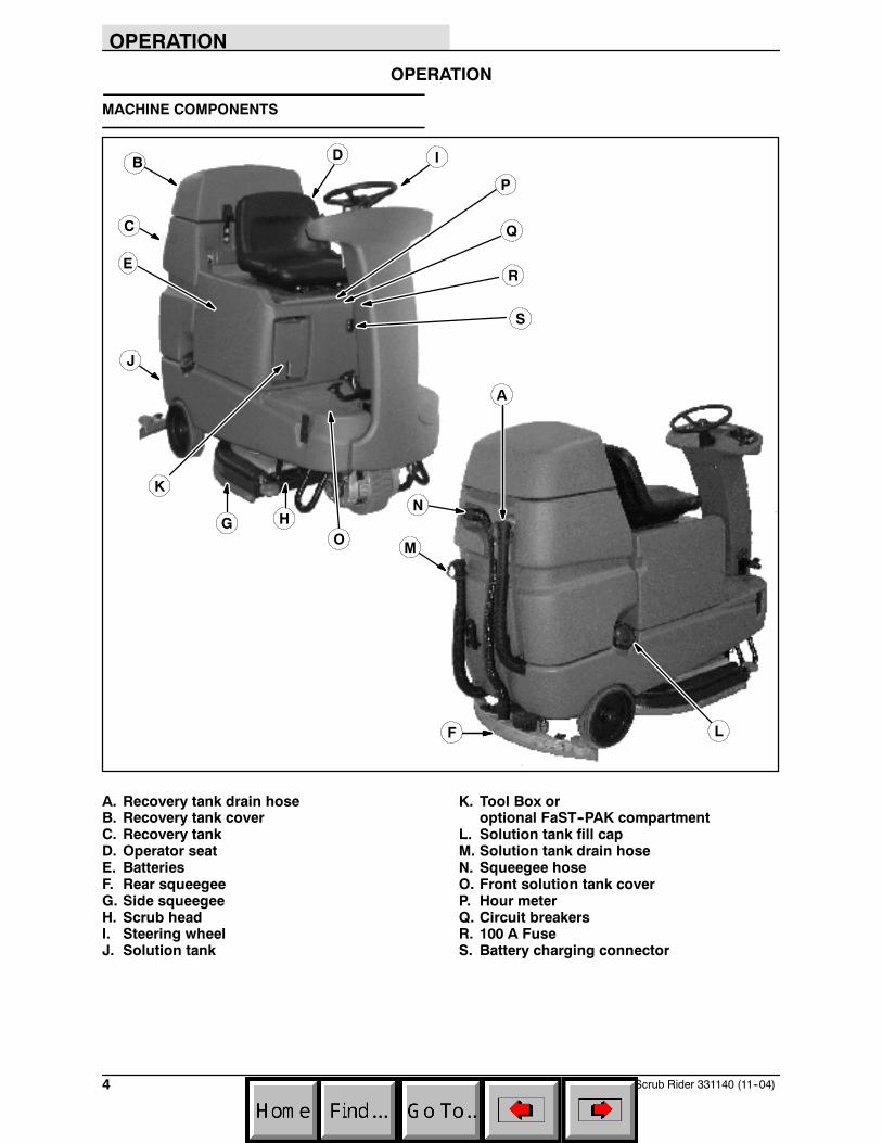
A. Recovery tank drain hoseB. Recovery tank coverC. Recovery tankD. Operator seatE. BatteriesF. Rear squeegeeG. Side squeegeeH. Scrub headI. Steering wheelJ. Solution tank
K. Tool Box oroptional FaST--PAK compartment
L. Solution tank fill capM. Solution tank drain hoseN. Squeegee hoseO. Front solution tank coverP. Hour meterQ. Circuit breakersR. 100 A FuseS. Battery charging connector

OPERATION
5SpeedScrub Rider 331140 (11--04)
CONTROLS AND INSTRUMENTS
A
F
J
E
BC D
G
H
I
K
L
M
N
0
P
Q
R
A. Solution tank empty indicatorB. Recovery tank full indicatorC. Battery charge level indicatorsD. Fault indicatorE. Emergency Stop ButtonF. Directional switchG. Horn buttonH. On/Off key switchI. One Step scrub buttonJ. FaST button (option)K. Vacuum fan / squeegee buttonL. Brush Pressure increase button (+)M. Brush Pressure decrease button (--)N. Solution increase button (+)O. Solution decrease button (--)P. Brake pedalQ. Propel pedalR. Control panel cover
OPERATION
6 SpeedScrub Rider 331140 (11--04)
HOW THE MACHINE WORKS
The machine solution tank, scrub brushes,squeegee, vacuum fan, and recovery tank worktogether to effectively clean dirty floors.
Water and detergent from the solution tank flow tothe floor through a solution valve. The brushesuse the detergent and water solution to scrub thefloor clean. As the machine propels forward, thesqueegee wipes the dirty solution from the floor.The suction created by the vacuum fan thendraws the dirty solution from the squeegee intothe recovery tank.
The steering wheel controls the path of themachine travel. The directional switch controls theforward or reverse direction of the machine. Thepropel pedal controls the speed of the machine.The brake pedal slows and stops the machine.
The buttons on the control panel control themachine scrubbing functions. The One StepScrub button turns the preset scrub functions onand off. The FaST button controls use of theFoam scrubbing system. The vacuum fan /squeegee button turns the vacuum fan on/off andraises and lowers the squeegee. The brushpressure buttons control the scrub brushpressure, and the solution buttons control thesolution flow.
The two available scrub head widths use diskbrushes. One of the scrub heads is 650 mm (26 in)wide, the other is 800 mm (32 in) wide.
NOTE: The amount and type of soilage play animportant role in determining the type of brushesor pads to use. For specific recommendations,see the BRUSH INFORMATION section of thismanual or contact a Tennant representative.
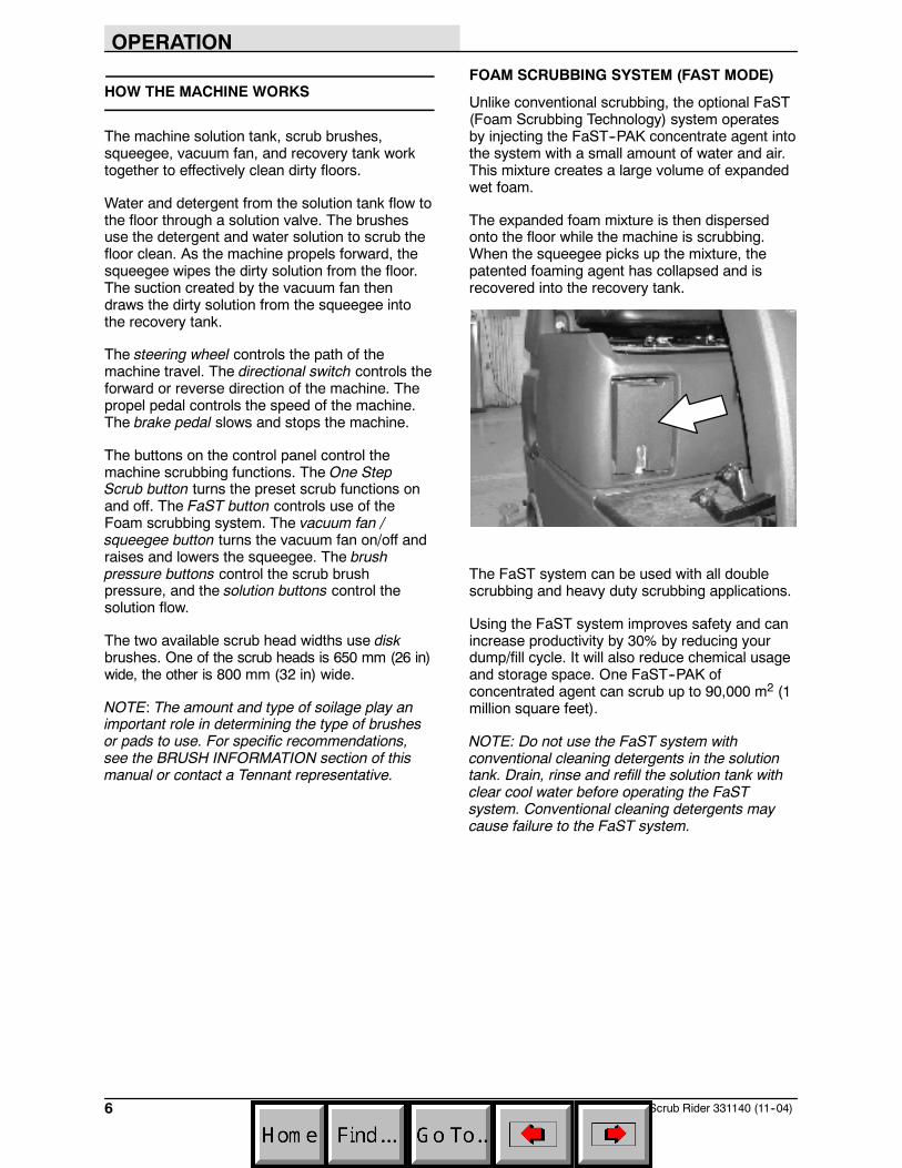
FOAM SCRUBBING SYSTEM (FAST MODE)
Unlike conventional scrubbing, the optional FaST(Foam Scrubbing Technology) system operatesby injecting the FaST--PAK concentrate agent intothe system with a small amount of water and air.This mixture creates a large volume of expandedwet foam.
The expanded foam mixture is then dispersedonto the floor while the machine is scrubbing.When the squeegee picks up the mixture, thepatented foaming agent has collapsed and isrecovered into the recovery tank.
The FaST system can be used with all doublescrubbing and heavy duty scrubbing applications.
Using the FaST system improves safety and canincrease productivity by 30% by reducing yourdump/fill cycle. It will also reduce chemical usageand storage space. One FaST--PAK ofconcentrated agent can scrub up to 90,000 m2 (1million square feet).
NOTE: Do not use the FaST system withconventional cleaning detergents in the solutiontank. Drain, rinse and refill the solution tank withclear cool water before operating the FaSTsystem. Conventional cleaning detergents maycause failure to the FaST system.

OPERATION
7SpeedScrub Rider 331140 (11--04)
BRUSH INFORMATION
For best results, use the correct brush type for thecleaning application. The following arerecommended brush applications.
Non-scuff polypropylene scrub brush -- Thisbrush uses a softer, general purposepolypropylene bristle to lift lightly compactedsoilage without scuffing high-gloss coated floors.
Nylon scrub brush -- Recommended forscrubbing coated floors. Cleans without scuffing
Super abrasive bristle scrub brush -- Nylonfiber impregnated with abrasive grit to removestains and soilage. Strong action on any surface.Performs well on buildup, grease, or tire marks.
Stripping pad -- This brown pad is for strippingfloors. Quickly and easily cuts through old finish toprepare the floor for recoating.
Scrubbing pad -- This blue pad is for scrubbingfloors. Removes dirt, spills, and scuffs. Leaves aclean surface ready for re-coating.
Buffing pad -- This red pad is for buffing floors.Quickly cleans and removes scuff marks whilepolishing the floor to a high gloss.
Polishing pad -- This white pad is for polishingfloors. Maintains a high gloss. Use for buffing verysoft finishes and lower traffic areas, and polishingsoft waxes on wood floors.
MACHINE SETUP
ATTACHING SQUEEGEE ASSEMBLY
1. Stop machine on a level surface.
2. Turn the machine ON/OFF key switch off.
FOR SAFETY: Before leaving or servicingmachine, stop on level surface, and turn offmachine.
3. Place the rear squeegee under the squeegeemount bracket and fasten with the two knobs.
The squeegee deflection is set at the factory.If the squeegee blade needs adjustments, seeADJUSTING REAR SQUEEGEE BLADEDEFLECTION section of this manual.
INSTALLING BRUSHES/PADS
To install the brushes or pad, see REPLACINGSCRUB BRUSHES OR PAD DRIVER section ofthis manual.
OPERATION
8 SpeedScrub Rider 331140 (11--04)
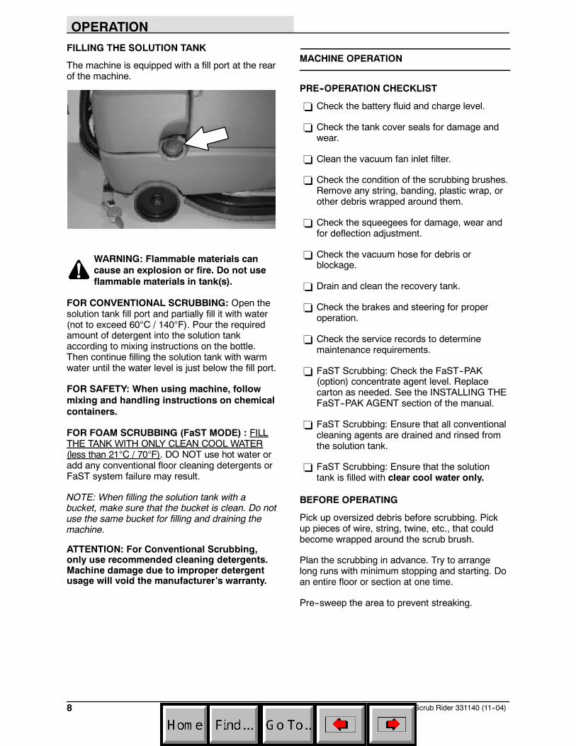
FILLING THE SOLUTION TANK
The machine is equipped with a fill port at the rearof the machine.
WARNING: Flammable materials cancause an explosion or fire. Do not useflammable materials in tank(s).
FOR CONVENTIONAL SCRUBBING: Open thesolution tank fill port and partially fill it with water(not to exceed 60°C / 140°F). Pour the requiredamount of detergent into the solution tankaccording to mixing instructions on the bottle.Then continue filling the solution tank with warmwater until the water level is just below the fill port.
FOR SAFETY: When using machine, followmixing and handling instructions on chemicalcontainers.
FOR FOAM SCRUBBING (FaST MODE) : FILLTHE TANK WITH ONLY CLEAN COOL WATER(less than 21°C / 70°F). DO NOT use hot water oradd any conventional floor cleaning detergents orFaST system failure may result.
NOTE: When filling the solution tank with abucket, make sure that the bucket is clean. Do notuse the same bucket for filling and draining themachine.
ATTENTION: For Conventional Scrubbing,only use recommended cleaning detergents.Machine damage due to improper detergentusage will void the manufacturer’s warranty.
MACHINE OPERATION
PRE--OPERATION CHECKLIST
- Check the battery fluid and charge level.
- Check the tank cover seals for damage andwear.
- Clean the vacuum fan inlet filter.
- Check the condition of the scrubbing brushes.Remove any string, banding, plastic wrap, orother debris wrapped around them.
- Check the squeegees for damage, wear andfor deflection adjustment.
- Check the vacuum hose for debris orblockage.
- Drain and clean the recovery tank.
- Check the brakes and steering for properoperation.
- Check the service records to determinemaintenance requirements.
- FaST Scrubbing: Check the FaST--PAK(option) concentrate agent level. Replacecarton as needed. See the INSTALLING THEFaST--PAK AGENT section of the manual.
- FaST Scrubbing: Ensure that all conventionalcleaning agents are drained and rinsed fromthe solution tank.
- FaST Scrubbing: Ensure that the solutiontank is filled with clear cool water only.
BEFORE OPERATING
Pick up oversized debris before scrubbing. Pickup pieces of wire, string, twine, etc., that couldbecome wrapped around the scrub brush.
Plan the scrubbing in advance. Try to arrangelong runs with minimum stopping and starting. Doan entire floor or section at one time.
Pre--sweep the area to prevent streaking.
OPERATION
9SpeedScrub Rider 331140 (11--04)
SETTING SCRUB MODES
Before scrubbing, determine which scrub modewill be used (FaST or conventional). Then set thescrub brush pressure and if conventionalscrubbing, adjust the solution flow levels.
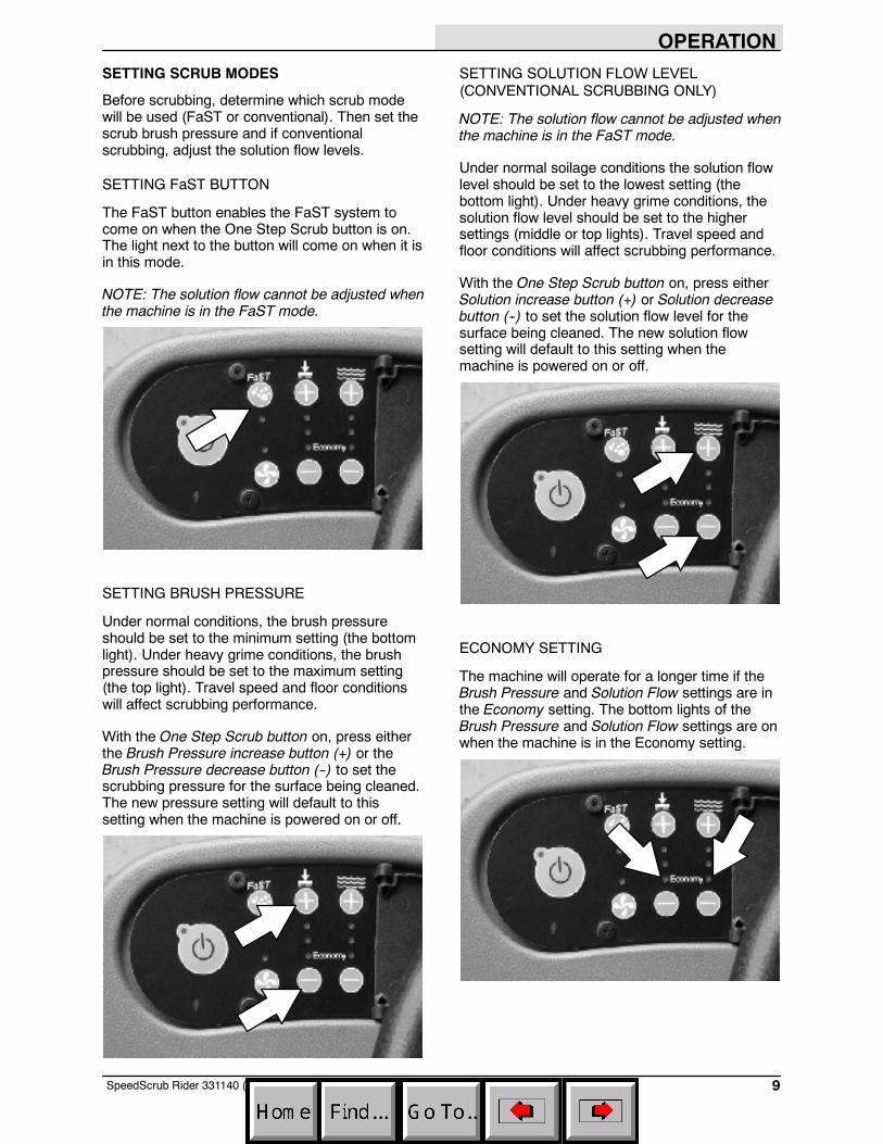
SETTING FaST BUTTON
The FaST button enables the FaST system tocome on when the One Step Scrub button is on.The light next to the button will come on when it isin this mode.
NOTE: The solution flow cannot be adjusted whenthe machine is in the FaST mode.
SETTING BRUSH PRESSURE
Under normal conditions, the brush pressureshould be set to the minimum setting (the bottomlight). Under heavy grime conditions, the brushpressure should be set to the maximum setting(the top light). Travel speed and floor conditionswill affect scrubbing performance.
With the One Step Scrub button on, press eitherthe Brush Pressure increase button (+) or theBrush Pressure decrease button (--) to set thescrubbing pressure for the surface being cleaned.The new pressure setting will default to thissetting when the machine is powered on or off.
SETTING SOLUTION FLOW LEVEL(CONVENTIONAL SCRUBBING ONLY)
NOTE: The solution flow cannot be adjusted whenthe machine is in the FaST mode.
Under normal soilage conditions the solution flowlevel should be set to the lowest setting (thebottom light). Under heavy grime conditions, thesolution flow level should be set to the highersettings (middle or top lights). Travel speed andfloor conditions will affect scrubbing performance.
With the One Step Scrub button on, press eitherSolution increase button (+) or Solution decreasebutton (--) to set the solution flow level for thesurface being cleaned. The new solution flowsetting will default to this setting when themachine is powered on or off.
ECONOMY SETTING
The machine will operate for a longer time if theBrush Pressure and Solution Flow settings are inthe Economy setting. The bottom lights of theBrush Pressure and Solution Flow settings are onwhen the machine is in the Economy setting.

OPERATION
10 SpeedScrub Rider 331140 (NIL)
SCRUBBING
FOR SAFETY: Do not operate machine, unlessoperator manual is read and understood.
1. Turn the On/Off key switch on.
NOTE: Make sure the scrub modes / settings areset before scrubbing.
2. Press the One Step Scrub button. The lighton the button is illuminated. All the presetscrubbing functions will turn on.
NOTE: Open the control panel cover to adjust theBrush Pressure and Solution Flow Setting whilescrubbing if necessary.
NOTE: DO NOT turn the FaST system on duringconventional scrubbing. Conventional cleaningdetergents may cause the FaST injection systemto fail. Drain, rinse, and refill solution tank withcool clean water before operating the FaSTsystem.
3. Place the directional switch in the directionthe machine is to be moved (forward orreverse).
NOTE: The machine can scrub in both forward orreverse. The horn will sound when in reverse.
NOTE: The squeegee automatically raises whenthe machine is driven backwards. This preventsdamaging the squeegee. When the machine isplaced in reverse, the vacuum fan will shut offafter a short delay.
4. Press the propel pedal to begin scrubbing.
WARNING: Flammable materials orreactive metals can cause an explosionor fire. Do not pick up.
5. Release the propel pedal to stop the machine.Scrubbing functions stop and the automaticpark brake will engage when the machinestops.
OPERATION
11SpeedScrub Rider 331140 (11--04)
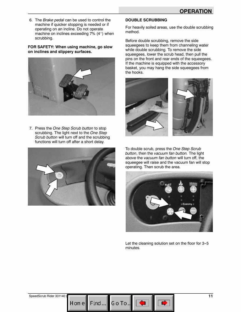
6. The Brake pedal can be used to control themachine if quicker stopping is needed or ifoperating on an incline. Do not operatemachine on inclines exceeding 7% (4_) whenscrubbing.
FOR SAFETY: When using machine, go slowon inclines and slippery surfaces.
7. Press the One Step Scrub button to stopscrubbing. The light next to the One StepScrub button will turn off and the scrubbingfunctions will turn off after a short delay.
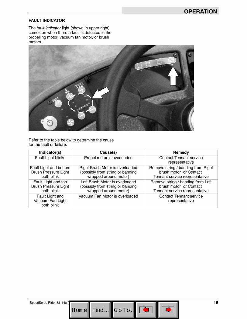
DOUBLE SCRUBBING
For heavily soiled areas, use the double scrubbingmethod.
Before double scrubbing, remove the sidesqueegees to keep them from channeling waterwhile double scrubbing. To remove the sidesqueegees, lower the scrub head, then pull thepins on the front and rear ends of the squeegees.If the machine is equipped with the accessorybasket, you may hang the side squeegees fromthe hooks.
To double scrub, press the One Step Scrubbutton, then the vacuum fan button. The lightabove the vacuum fan button will turn off, thesqueegee will raise and the vacuum fan will stopoperating. Then scrub the area.
Let the cleaning solution set on the floor for 3--5minutes.

OPERATION
12 SpeedScrub Rider 331140 (11--04)
Place the side squeegees back on to the machinebefore scrubbing the floor the second time.
NOTE: It is easier to put the side squeegeesback on to the machine with the scrub headpartially lowered. This allows clearance to installthe pins.
Press the vacuum fan button again to lower thesqueegee and to turn on the vacuum fan. Thelight above the vacuum fan button will come on.Then scrub the floor a second time picking up thecleaning solution.
WARNING: Flammable materials orreactive metals can cause an explosionor fire. Do not pick up.
NOTE: When scrubbing the area a second time,you can turn off the solution flow by pressing theSolution decrease button (--) repeatedly until alllights above the button are off.
WATER PICKUP MODE (NO SCRUBBING)
The machine can be used to pick up water ornon--flammable liquid spills without scrubbing.
To pick up water or non--flammable liquid spills,check to make sure that the One Step Scrubbutton is not activated. The light next to the OneStep Scrub button must be off.
WARNING: Flammable materials orreactive metals can cause an explosionor fire. Do not pick up.
Then press the vacuum fan button. The lightabove the vacuum fan button will turn on, thesqueegee will lower and the vacuum fan will startoperating. Then pick up the water ornon--flammable liquid spill.

OPERATION
13SpeedScrub Rider 331140 (11--04)
WHILE OPERATING THE MACHINE
Drive as straight a path as possible. Avoidbumping into posts or scraping the sides of themachine. Overlap the scrub paths by severalcentimeters (a few inches).
Avoid turning the steering wheel too sharply whenthe machine is in motion. The machine is veryresponsive to the movement of the steering wheel.Avoid sudden turns, except in emergencies.
When scrubbing dead end aisles, start at theclosed end of the aisle and scrub out towards theopening.
Adjust the machine speed, brush pressure, andsolution flow as required when scrubbing. Use theminimal brush pressure and solution flow settingsas possible. Use the FaST system for the bestresults.
Keep the machine moving to prevent damagingfloor finishes.
If poor scrubbing performance is observed, stopscrubbing and refer to MACHINETROUBLESHOOTING.
Conventional Scrubbing: Pour a recommendedfoam control solution into the recovery tank ifexcessive foam appears.
Change or rotate pads as necessary.
Observe the battery discharge indicator to ensurethere is adaquate charge for machine operation.
Observe the solution tank indicator to ensure thesolution tank is not empty. Always empty recoverytank before refilling the solution tank.
Observe the recovery tank indicator to ensure therecovery is not full.
Remove the key when leaving the machineunattended.
Perform the Daily Maintenance Procedures afterscrubbing (see MACHINE MAINTENANCE).
EMERGENCY STOP BUTTON
The Emergency Stop Button halts all power to themachine in case of an emergency. Press thebutton to halt the machine power. To restart themachine, turn the Emergency Stop Button to theright. Then turn the on/off switch to the off positionand then to the on position.
NOTE: This button should not be used for normalstopping as premature wear to the parking brakemay occur.
HOUR METER
The hour meter records the number of hours themachine has been powered on. This informationis useful for servicing the machine. It is locatedunder the seat.

OPERATION
14 SpeedScrub Rider 331140 (11--04)
SOLUTION TANK EMPTY INDICATOR
The solution tank empty indicator comes on whenthe solution tank is empty. When this happens,the scrub functions are disabled. If necessary,press the ONE STEP Scrub button for anadditional minute of operation to pick up standingwater or solution.
RECOVERY TANK FULL INDICATOR
The recovery tank full indicator comes on whenthe recovery tank is full. When this happens, thescrub functions are disabled. If necessary, pressthe ONE STEP Scrub button for an additionalminute of operation to pick up standing water orsolution.
BATTERY DISCHARGE INDICATOR
The battery discharge indicator shows the chargelevel of the batteries.
When the batteries are fully charged, all five lightsare lit. As the batteries discharge, the lights go outuntil only the left light is blinking.
When the left light blinks, the scrubbing functionswill shut off to alert the operator of the batterycondition. The machine will still propel when thelight is blinking. Recharge the batteries when thelight blinks. If necessary, press the ONE STEPScrub button for an additional minute of operationto pick up standing water or solution.
NOTE: Do not charge batteries more often thannecessary. Excessive charging could reduce thelife of the batteries. It is best to charge thebatteries only when the left light indicates that thebattery needs charging. See BATTERIES in theMAINTENANCE section.
NOTE: The blinking left battery discharge light willnot reset from blinking until the batteries are fullycharged.
OPERATION
15SpeedScrub Rider 331140 (11--04)
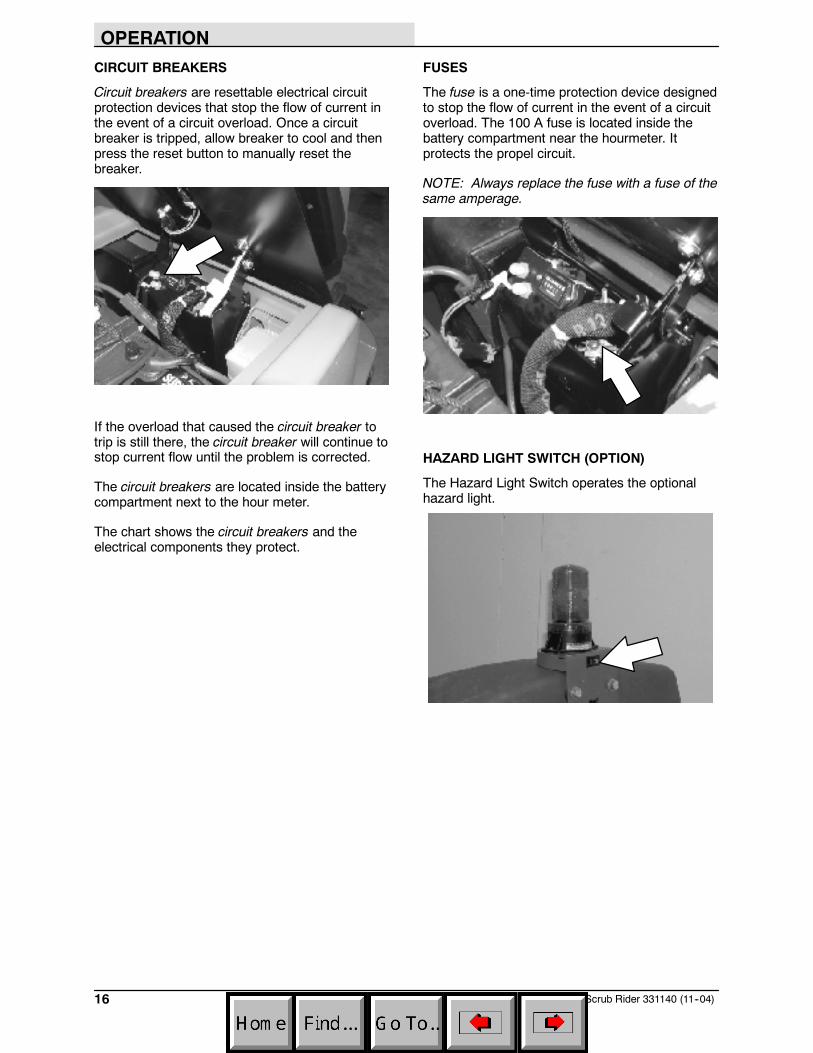
FAULT INDICATOR
The fault indicator light (shown in upper right)comes on when there a fault is detected in thepropelling motor, vacuum fan motor, or brushmotors.
Refer to the table below to determine the causefor the fault or failure.
Indicator(s) Cause(s) RemedyFault Light blinks Propel motor is overloaded Contact Tennant service
representativeFault Light and bottomBrush Pressure Light
both blink
Right Brush Motor is overloaded(possibly from string or banding
wrapped around motor)
Remove string / banding from Rightbrush motor or Contact
Tennant service representativeFault Light and topBrush Pressure Light
both blink
Left Brush Motor is overloaded(possibly from string or banding
wrapped around motor)
Remove string / banding from Leftbrush motor or Contact
Tennant service representativeFault Light and
Vacuum Fan Lightboth blink
Vacuum Fan Motor is overloaded Contact Tennant servicerepresentative
OPERATION
16 SpeedScrub Rider 331140 (11--04)
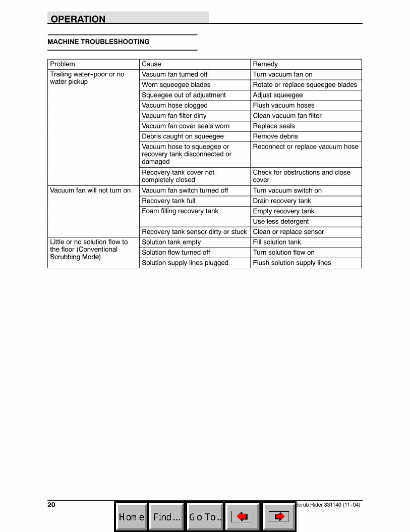
CIRCUIT BREAKERS
Circuit breakers are resettable electrical circuitprotection devices that stop the flow of current inthe event of a circuit overload. Once a circuitbreaker is tripped, allow breaker to cool and thenpress the reset button to manually reset thebreaker.
If the overload that caused the circuit breaker totrip is still there, the circuit breaker will continue tostop current flow until the problem is corrected.
The circuit breakers are located inside the batterycompartment next to the hour meter.
The chart shows the circuit breakers and theelectrical components they protect.
FUSES
The fuse is a one-time protection device designedto stop the flow of current in the event of a circuitoverload. The 100 A fuse is located inside thebattery compartment near the hourmeter. Itprotects the propel circuit.
NOTE: Always replace the fuse with a fuse of thesame amperage.
HAZARD LIGHT SWITCH (OPTION)
The Hazard Light Switch operates the optionalhazard light.

OPERATION
17SpeedScrub Rider 331140 (11--04)
DRAINING AND CLEANING THE TANKS
When cleaning is finished, or when the recoverytank full indicator comes on, the recovery tankshould be drained and cleaned. The solution tankthen can be filled again for additional cleaning.
1. Drive the machine to a solution disposal drain.
2. Turn the machine ON/OFF key switch off.
FOR SAFETY: Before leaving or servicingmachine, stop on level surface, and turn offmachine.
3. Tilt the operator seat forward and hook theseat latch into place to hold up the seat.
4. Remove the recovery tank drain hose. Whileholding the hose up, remove the plug, thenslowly lower the drain hose to the floor drainor sink.
5. Lift the recovery tank cover. Flush the insideof the recovery tank with clean water.
WARNING: Flammable materials cancause an explosion or fire. Do not useflammable materials in tank(s).
NOTE: DO NOT use steam to clean tanks.Excessive heat can damage tanks andcomponents.
6. Rinse the float sensor located inside therecovery tank.
7. Replace the recovery tank drain hose cap andmount the drain hose back onto the mountingclip after the tank is drained.
8. Remove and clean the vacuum fan filter.Clean the filter with a damp cloth or lowpressure water hose if dirty. Allow the vacuumfan filter to dry completely before reinstalling itin the machine.

OPERATION
18 SpeedScrub Rider 331140 (11--04)
9. Close the recovery tank cover.
10.Remove the solution tank drain hose. Whileholding the hose up, remove the plug, thenslowly lower the drain hose to the floor drainor sink.
11. Tilt the recovery tank back to access thesolution tank. Make sure the recovery tank isempty before tilting.
12. Flush the solution tank and rinse the floatsensor located inside the back part of thesolution tank. Rinse the screen filter on thebottom of the tank.
13. Carefully push the recovery tank forward toclose the solution tank.
14. Unhook the seat latch and lower the operatorseat.
15. Clean the front of the solution tank throughthe front access port located under the frontsolution tank cover. Wipe the bottom of thecover and the tank seal before replacing thecover.
16. Replace the solution tank drain hose cap andmount the drain hose back onto the mountingclip after after the tank is drained.

OPERATION
19SpeedScrub Rider 331140 (11--04)
PROPEL SYSTEM TROUBLESHOOTING
The audio alarm (horn) will sound and/or warninglights will come on when a propelling system faultor failure is detected. The machine will stoppropelling when this happens. Refer to the tablebelow to determine the cause for the fault orfailure.
Indicator(s) Cause(s) RemedyHorn repeatedlybeeps 2 times
Propel pedal depressed withoutoperator in seat
Sit in seat when operating machine
Horn repeatedlybeeps 4 times
ON/OFF key switch is turned on whilepropel pedal is engaged
Release the propel pedal beforeturning key on
Horn repeatedlybeeps 5 times
Failure in the Throttle system hasoccurred
Contact Tennant servicerepresentative
Horn repeatedlybeeps 6 times
Failure in the Brake system hasoccurred
Contact Tennant servicerepresentative
Horn repeatedlybeeps 7 times
Failure in the Parking Brake systemhas occurred
Contact Tennant servicerepresentative
Horn repeatedlybeeps 8 times
Emergency Stop Button is engaged Reset Emergency Stop Button
Horn repeatedlybeeps 9 times
ON/OFF key switch is turned on whilebattery charger is plugged into
machine
Unplug battery charger before startingmachine
Fault Light blinks Propel motor is overloaded Contact Tennant servicerepresentative
OPERATION
20 SpeedScrub Rider 331140 (11--04)
MACHINE TROUBLESHOOTING
Problem Cause RemedyTrailing water--poor or no
t i kVacuum fan turned off Turn vacuum fan ong p
water pickup Worn squeegee blades Rotate or replace squeegee blades
Squeegee out of adjustment Adjust squeegee
Vacuum hose clogged Flush vacuum hoses
Vacuum fan filter dirty Clean vacuum fan filter
Vacuum fan cover seals worn Replace seals
Debris caught on squeegee Remove debris
Vacuum hose to squeegee orrecovery tank disconnected ordamaged
Reconnect or replace vacuum hose
Recovery tank cover notcompletely closed
Check for obstructions and closecover
Vacuum fan will not turn on Vacuum fan switch turned off Turn vacuum switch on
Recovery tank full Drain recovery tankFoam filling recovery tank Empty recovery tankg y
Use less detergent
Recovery tank sensor dirty or stuck Clean or replace sensorLittle or no solution flow toth fl (C ti l
Solution tank empty Fill solution tankthe floor (ConventionalScrubbing Mode)
Solution flow turned off Turn solution flow onScrubbing Mode)
Solution supply lines plugged Flush solution supply lines

OPERATION
21SpeedScrub Rider 331140 (11--04)
Problem Cause RemedyPoor scrubbing performance One Step Scrub button not on Turn One Step Scrub button ong p
Improper detergent or brushesused
Contact Tennant servicerepresentative
Recovery tank full Empty recovery tank
Solution tank empty Fill solution tank
Debris caught on scrub brushes orpads
Remove debris
Worn scrub brush Replace scrub brush
Brush pressure set too light Increase brush pressure
Low battery charge Charge batteries until the chargerautomatically turns off
FaST System does nott
FaST switch is turned off Turn on the FaST swiitchoperate
Accessory circuit breaker tripped Reset circuit breaker
Clogged FaST--PAK supply hoseand/or connector
Soak connector and hose in warmwater and clean
FaST--PAK carton is empty or notconnected
Replace FaST--PAK carton and/orconnect supply hose
FaST system is not primed To prime, operate the FaST solu-tion system for a few minutes
Clogged filter screen Drain solution tank, remove andclean filter screen
Faulty solution pump Replace solution pump
MAINTENANCE
22 SpeedScrub Rider 331140 (11--04)
MAINTENANCE
1
1
2
8
3
9
11
5
4
3
6
310
7
10
3

MAINTENANCE
23SpeedScrub Rider 331140 (11--04)
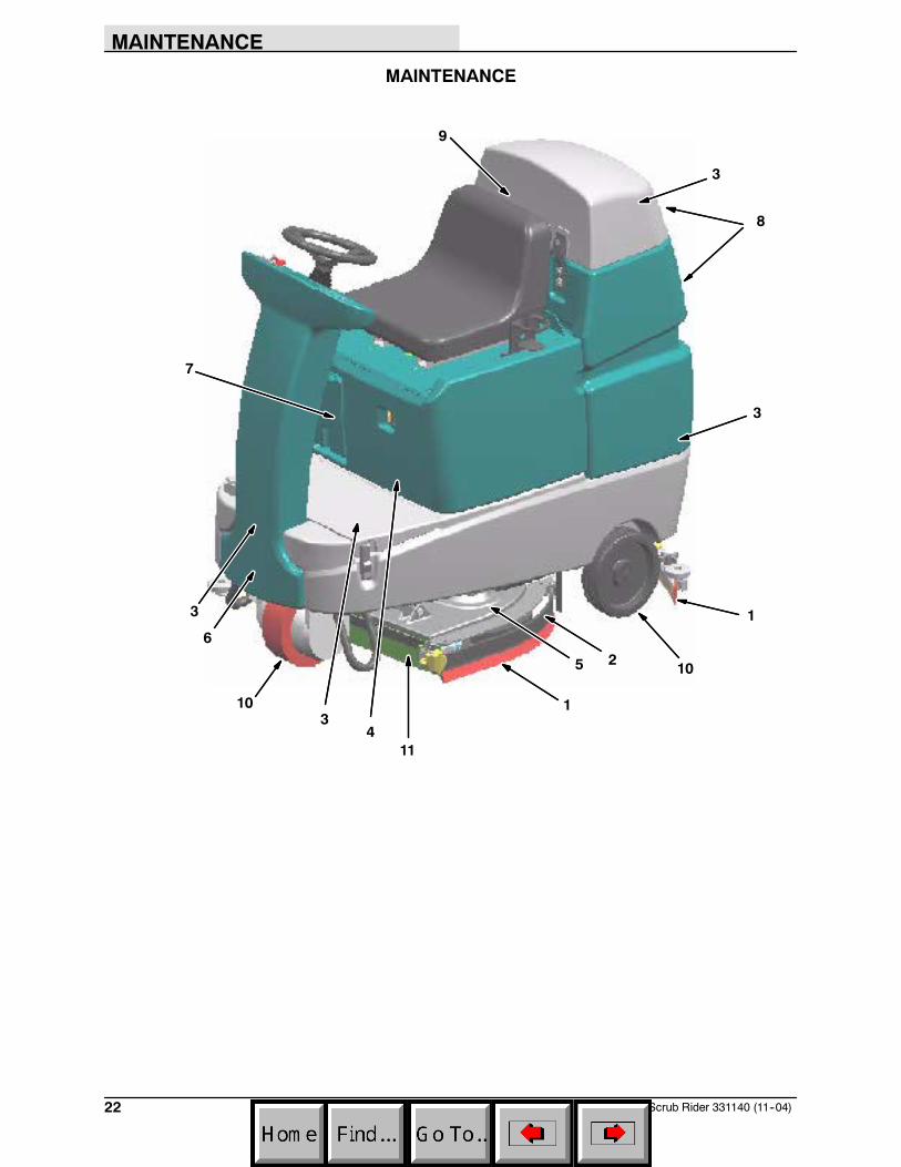
MAINTENANCE CHART
Interval Key Description ProcedureLubricant/
Fluid
No. ofServicePoints
Daily 1 Side and rear squeegees Check for damage and wear -- 3y q gCheck deflection and leveling -- 6
2 Scrub brushes / pads Check for damage, wear, debris -- 28 Recovery tank Clean tank, screen filter, and float
sensor-- 1
9 Vacuum fan filter Clean -- 17 FaST--PAK supply hose
and connector (option)Clean and connect hose to stor-ing plug when not in use
-- 1
50 Hours 4 Battery cells(Lead acid batteries)
Check electrolyte level DW 3
11 Scrub head floor skirt Check for damage and wear -- 2100 Hours 3 Vacuum Fan and tank
sealsCheck for damage and wear -- 3
200 Hours 4 Battery terminals andcables
Check and clean -- 12
500 Hours 9 Vacuum fan motor(s) Check motor brushes -- 15 Scrub brush motors Check motor brushes -- 26 Propelling motor Check motor brushes -- 110 Tires Check for damage and wear -- 3
LUBRICANT/FLUID
DW Distilled water. . . .

MAINTENANCE
24 SpeedScrub Rider 331140 (11--04)
BATTERIES
The batteries are designed to hold their power forlong periods of time. The lifetime of the batteriesis limited to number of charges the batteriesreceive. To get the most life from the batteries,recharge them immediately when the batterydischarge indicator begins to blink.
After every 200 hours of use check for loosebattery connections and clean the surface of thebatteries, including terminals and cable clamps,using a strong solution of baking soda and water.Brush the solution sparingly over the battery tops.Do not allow any baking soda solution to enter thebatteries. Use a wire brush to clean the terminalposts and the cable connectors. Wipe off allcleaning solution residue. After cleaning, apply acoating of clear battery post protectant to theterminals and the cable connectors. Keep the topsof the batteries clean and dry.
Objects made of metal can potentially short circuitthe batteries. Keep all metallic objects off thebatteries. Replace any worn or damaged wires.Replace any defective batteries. To dispose ofbatteries, contact a battery dealer or your TennantService representative.
Check the electrolyte level in each battery cellbefore and after charging, and after every 50hours of operation. Never add acid to thebatteries. Add distilled water only. Always keepthe battery caps on, except when adding water ortaking hydrometer readings.
Using a hydrometer, measure the specific gravityto determine the charge level and condition of thebatteries. If one or more of the battery cells testlower than the other battery cells (0.050 or more),the cell is damaged, shorted, or is near failure.Completely recharge the batteries and then retest.
04380

MAINTENANCE
25SpeedScrub Rider 331140 (11--04)
NOTE: Do not take readings immediately afteradding distilled water. If the water and acid are notthoroughly mixed, the readings may not beaccurate. Check the hydrometer readings againstthe following chart to determine the remainingbattery charge level:
SPECIFIC GRAVITY BATTERYat 27_ C (80_F) CHARGE
1.265 100% Charged
1.223 75% Charged
1.185 50% Charged
1.148 25% Charged
1.110 Discharged
NOTE: If the readings are taken when the batteryelectrolyte is any temperature other than 27_ C(80_ F), the reading must be temperaturecorrected. Add or subtract to the specific gravityreading 0.004, 4 points, for each 6_ C(10_ F)above or below 27_C(80_ F).
CHARGING THE BATTERIES
1. Drive the machine to a flat, dry surface.
NOTE: Make sure the area is well ventilated.
2. Turn the machine ON/OFF key switch off.
FOR SAFETY: Before leaving or servicingmachine, stop on level surface, and turn offmachine.
3. Tilt the operator seat forward and hook theseat latch into place to hold up the seat
4. Lead acid batteries: Check the water level inall battery cells. If the level is low, add justenough distilled water to cover the plates. DONOT OVERFILL. The batteries can overflowduring charging due to expansion.
NOTE: Make sure the battery caps are in placewhile charging.
FOR SAFETY: When maintaining or servicingmachine, avoid contact with battery acid.
5. Plug the charger connector into the machinebattery charging connector.
WARNING: Batteries emit hydrogen gas.Explosion or fire can result. Keepsparks and open flame away. Keepcovers open when charging.

MAINTENANCE
26 SpeedScrub Rider 331140 (9--05)
6. Plug the battery charger into the wall outlet.
NOTE: If the red “ABNORMAL CYCLE” lamplights when the TENNANT charger is plugged intoa wall outlet, the charger cannot charge thebattery and there is something wrong with thebattery.
07224
7. The TENNANT charger will startautomatically. When the batteries are fullycharged, the TENNANT charger willautomatically turn off.
8. After the charger has turned off, unplug thecharger from the machine battery chargingconnector.
9. Lead acid batteries: Check the electrolytelevel in each battery cell after charging. Ifneeded, add distilled water to raise theelectrolyte level to about 12 mm (0.4 in) belowthe bottom of the sight tubes.
10. Unhook the seat latch and lower the operatorseat.
ELECTRIC MOTORS
The carbon brushes on the vacuum fan motor, thepropelling motor, and the scrub brush motorsshould be inspected after the initial 500 hours ofmachine operation and then every 100 hours afterthe initial 500 hours.

MAINTENANCE
27SpeedScrub Rider 331140 (11--04)
SCRUB BRUSHES AND PADS
The machine can be equipped with scrub brushesor cleaning pads. Check scrub brushes daily forwire or string tangled around the brush or brushdrive hub. Also check for brushes damage andwear.
The scrub brushes should be replaced if a largenumber of bristles are missing or if bristle length isless than 10 mm (0.38 in).
Cleaning pads must be placed on pad drivesbefore they are ready to use. The cleaning pad isheld in place by a pad holder.
Cleaning pads need to be cleaned immediatelyafter use with soap and water. Do not wash thepads with a pressure washer. Hang pads, or liepads flat to dry.
NOTE: Always replace brushes and pads in sets.Otherwise one brush or pad will be moreaggressive than the other.
REPLACING SCRUB BRUSHES OR PADDRIVER
1. Stop machine on a level surface. Make surethe scrub head is in the raised position.
2. Turn the machine ON/OFF key switch off.
FOR SAFETY: Before leaving or servicingmachine, stop on level surface, and turn offmachine.
3. Pull the pin from the side squeegee retainerpivot.
4. Open the side squeegee retainer pivot towardthe front of the machine, then pull the sidesqueegee toward the rear of the machine toaccess the scrub brushes or pads.

MAINTENANCE
28 SpeedScrub Rider 331140 (11--04)
5. Pull the scrub brush/pad driver downward toremove it from the drive hub.
6. Place the new scrub brush/pad driver onto thedrive hub. Ensure that it is securely mountedonto the brush drive hub.
7. Close the side squeegee and the retainerpivot, then insert the pin.
NOTE: Be sure the pin is inserted completelythrough the bottom.
REPLACING SCRUB PADS
1. Remove the pad driver from the machine.
2. Squeeze the spring clip together to removethe center disk.
3. Flip or replace the scrub pad, center the scrubpad on the pad driver. Then reinstall thecenter disk to secure the pad in place on thepad driver.
4. Reinsert the pad driver into the machine.

MAINTENANCE
29SpeedScrub Rider 331140 (11--04)
REPLACING THE FaST--PAK (FaST Model)
1. Stop machine on a level surface.
2. Turn off the machine ON/OFF key switch.
FOR SAFETY: Before leaving or servicingmachine, stop on level surface, and turn offmachine.
3. Open the FaST--PAK compartment door andslide the empty FaST--PAK approximately halfway out from the FaST--PAK compartmentdoor.
4. Squeeze the button on the FaST supply hoseconnector, then pull the empty FaST--PAK outfrom the compartment.
5. Remove the perforated knock outs from thenew FaST--PAK carton. Do Not remove thebag from the carton. Pull out the hoseconnector located on the bottom of the bagand remove the hose cap from the connector.
NOTE: The FaST--PAK Floor CleaningConcentrate is specially designed for use with theFaST system scrubbing application. NEVER usea substitute. Other cleaning solutions may causeFaST system failure.
6. Insert the new FaST--PAK approximately halfway into the FaST--PAK compartment.
7. Connect the FaST--PAK hose connector tothe FaST supply hose connector, slide theFaST--PAK the rest of the way into theFaST--PAK compartment, and close theFaST--PAK compartment door.
8. When replacing an empty FaST--PAK carton,you must scrub with the FaST system for afew minutes before the detergent will reach itsmaximum foaming.
FaST SUPPLY HOSE CONNECTOR
The FaST supply hose connector is located belowthe FaST--PAK holder. Soak the connector inwarm water if detergent buildup is visible. When aFaST--PAK carton is not installed, store thesupply hose connector on the storing plug toprevent the hose from clogging.

MAINTENANCE
30 SpeedScrub Rider 331140 (11--04)
SQUEEGEE BLADES
The side squeegees control water spray andchannel water into the path of the rear squeegee.The side squeegee blades are not adjustable.
The rear squeegee assembly channels water intothe vacuum fan suction. The front blade channelsthe water and the rear blade wipes the floor.
Check the squeegee blades daily for damage andwear. Rotate or replace the squeegee blades ifthe leading edge is torn or worn half-way throughthe thickness of the blade. Replace the sidesqueegee deflectors if they become worn.
The rear squeegee can be adjusted for levelingand deflection. The deflection and leveling of thesqueegee blades should be checked daily, orwhen scrubbing a different type of floor.
The rear squeegee assembly can be removedfrom the squeegee pivot to prevent damageduring transport of the machine.
REPLACING (OR ROTATING) THE REARSQUEEGEE BLADES
1. Stop machine on a level surface. Make surethe scrub head is in the raised position.
2. Turn the machine ON/OFF key switch off.
FOR SAFETY: Before leaving or servicingmachine, stop on level surface, and turn offmachine.
3. Remove the squeegee suction hose from therear squeegee assembly. Then loosen bothrear squeegee assembly mounting knobs.
4. Pull the rear squeegee assembly from themachine.
5. Loosen the rear squeegee retaining bandtension latch and remove the retaining band.
6. Remove rear squeegee blade from the rearsqueegee assembly.
7. Loosen the two outer knobs on the rearsqueegee assembly. Remove the frontsqueegee blade from the squeegee assembly.

MAINTENANCE
31SpeedScrub Rider 331140 (11--04)
8. Install the new front squeegee blade or rotatethe existing blade to the new edge. Be surethe holes in the front squeegee blade arehooked onto the tabs on the front bladeclamp.
9. Lightly tighten the two outer knobs.
10. Install the new rear squeegee blade or rotatethe existing blade to the new edge. Be surethe holes in the squeegee blade are hookedonto the tabs on the squeegee assembly.
11. Reinstall the rear squeegee retaining bandonto the squeegee assembly. Be sure each ofthe flanges on the retaining band are seatedin the cut outs in the rear squeegee assembly.
12. Tighten the rear squeegee retaining bandtension latch.
13.Reinstall the rear squeegee under thesqueegee mount bracket and tighten all fourknobs.
14. Reinstall the squeegee suction hose onto therear squeegee assembly.

MAINTENANCE
32 SpeedScrub Rider 331140 (11--04)
REPLACING SIDE SQUEEGEE BLADES
1. Open the side squeegee as described inREPLACING SCRUB BRUSHES OR PADDRIVER section of this manual.
2. Pull the old side squeegee blade from theside squeegee retainer. Slide the new bladeonto the retainer.
3. Close the side squeegee and replace the pin.
NOTE: Be sure the pin is inserted completelythrough the bottom.
ADJUSTING THE SQUEEGEE GUIDE ROLLER
The squeegee guide rollers are located on bothends of the rear squeegee. The rollers guide thesqueegee blade end along a wall. Loosen the nutlocated at the top of the guide roller and move theroller in or out to adjust how close the end of thesqueegee blade is to the wall. The squeegeeblade end should be further away from the wallwhen the floor curves up into the wall.
LEVELING THE REAR SQUEEGEE
Leveling of the squeegee assures the entirelength of the squeegee is in even contact with thesurface being scrubbed. Perform this adjustmenton an even and level floor.
1. Lower the squeegee and drive the machineforward a few feet.
2. Turn off the machine ON/OFF key switch.
FOR SAFETY: Before leaving or servicingmachine, stop on level surface, and turn offmachine.
3. Look at the deflection of the squeegee overthe full length of the squeegee blade.
4. If the deflection is not the same over the fulllength of the blade, turn the squeegeeleveling bolt to make adjustments.
The squeegee leveling bolt is located directlybehind the squeegee suction hose. DO NOTdisconnect the suction hose from thesqueegee frame when leveling squeegee.
Turn the squeegee leveling boltcounter-clockwise to increase the deflection atthe ends of the squeegee.
Turn the squeegee leveling bolt clockwise todecrease the deflection at the ends of thesqueegee blade.
5. Drive the machine forward with the squeegeedown to recheck the squeegee bladedeflection if adjustments were made.
6. Readjust the squeegee blade deflection ifnecessary.

MAINTENANCE
33SpeedScrub Rider 331140 (11--04)
ADJUSTING REAR SQUEEGEE BLADEDEFLECTION
Deflection is the amount of curl the overallsqueegee blade has when the machine movesforward. The best deflection is when thesqueegee wipes the floor dry with a minimalamount of deflection.
1. Lower the squeegee and drive the machineforward a few meters (feet).
2. Turn off the machine ON/OFF key switch.
FOR SAFETY: Before leaving or servicingmachine, stop on level surface, and turn offmachine.
3. Look at the amount of deflection or “curl” ofthe squeegee blade. The correct amount ofdeflection is 12 mm (0.50 in) for scrubbingsmooth floors and 15 mm (0.62 in) for roughfloors.
03719
12 mm(0.50 in)
4. If the overall squeegee blade deflection needsto be adjusted, loosen the jam nuts on thesqueegee casters and adjust the height.
5. Drive the machine forward again to recheckthe squeegee blade deflection afteradjustments are made.
6. Readjust the squeegee blade deflection ifnecessary.

MAINTENANCE
34 SpeedScrub Rider 331140 (11--04)
SKIRTS AND SEALS
SCRUB HEAD FLOOR SKIRT
The skirt is located in front of the disc brush scrubheads. Check the skirt for damage and wear afterevery 50 hours of operation.
The skirts should clear the floor by 0 to 6 mm(0 to .25 in) when the scrub brushes are new andthe scrub head is down.
RECOVERY TANK SEAL
The recovery tank seal is located on the bottom ofthe recovery tank cover. Check the seal fordamage and wear after every 100 hours ofoperation.
SOLUTION TANK SEALS
There are two solution tank seals. Check the sealfor damage and wear after every 100 hours ofoperation.
A front seal is located on the bottom of thesolution tank cover. A rear seal is located on thebottom of the recovery tank.
TIRES
The machine has three solid rubber tires: one tireis front and two are in the rear. Check the tires fordamage and wear after every 500 hours ofoperation.

MAINTENANCE
35SpeedScrub Rider 331140 (9--05)
PUSHING, TOWING, AND TRANSPORTINGTHE MACHINE
PUSHING OR TOWING THE MACHINE
If the machine becomes disabled, it can bepushed from the front or rear, but only tow it fromthe front.
FOR SAFETY: When servicing machine, donot push or tow the machine on inclines withthe brake disabled.
Before attempting to push or tow the machine,disconnect the propel motor harness anddisengage the brake.
ATTENTION! Do not push or tow machinewith the motor harness connected or thecontrol board may fail.
To disengage the brake, insert the tip of a smallscrew driver between the electronic brake leverand the hub.
Only push or tow the machine on a level surface.Do not exceed 3.2 kp/h (2 mph). It is NOTintended to be pushed or towed at a high speed.
Immediately after pushing the machine, removethe screw driver to enable the parking brake andreconnect the propel motor harness. Neveroperate the machine with the brake disabled.
FOR SAFETY: Do not operate machine withthe brake disabled.
TRANSPORTING THE MACHINEWhen transporting the machine by trailer or truck,be certain to follow the tie--down procedure below:
1. Raise the squeegee and scrub head.
2. Load the machine using a recommendedloading ramp.
FOR SAFETY: When transporting machine,use a recommended ramp when loading/unloading into/off truck or trailer.
3. Position the front of machine against the frontof the trailer or truck.
4. Lower the scrub head and squeegee after themachine is positioned on the trailer or truck.
5. Place a block behind each wheel to preventthe machine from rolling.
6. Route the front tie--down straps through thestabilizer arms and then secure the tie--downsto the trailer or truck to prevent the machinefrom tipping.
NOTE: It may be necessary to install tie-downbrackets to the floor of the trailer or truck.
FOR SAFETY: When transporting machine,use tie--down straps to secure machine totruck or trailer.
7. Route the rear tie--down straps through theopening at the center part of the rear axle.

MAINTENANCE
36 SpeedScrub Rider 331140 (11--04)
MACHINE JACKING
Empty the recovery and solution tanks beforejacking the machine. Jack up the machine forservice at the designated locations. Use a hoist orjack capable of supporting the weight of themachine. Always stop the machine on a flat, levelsurface and block the tires before jacking up themachine.
Front jacking locations are located on both sidesof the machine.
Rear jacking locations are located on both sidesof the machine at the axles.
FOR SAFETY: Before leaving or servicingmachine, stop on level surface.
FOR SAFETY: When servicing machine, blockmachine tires before jacking machine up. Usea hoist or jack that will support the weight ofthe machine. Jack machine up at designatedlocations only. Block machine up with jackstands.
STORAGE INFORMATION
The following steps should be taken when storingthe machine for extended periods of time.
1. Drain and clean the solution and recoverytanks. Open the recovery tank cover topromote air circulation.
2. Park the machine in a cool, dry area. Do notexpose the machine to rain. Store indoors.
3. Remove the batteries, or charge them everythree months.
FREEZE PROTECTION
1. Be sure the solution tank is empty.
2. Pour 3.8 L (1 gal) of pre-mixedautomotive-type windshield washer solutioninto the solution tank.
3. FaST models: Remove the FaST--PAK andstore in temperatures above freezing.
4. Turn the machine power on.
5. Run the solution flow for about 15 seconds inthe conventional mode and about 30 secondsin the FaST mode.
6. The washer solution does not need to bedrained from the solution tank.

SPECIFICATIONS
37SpeedScrub Rider 331140 (9--05)
SPECIFICATIONS
GENERAL MACHINE DIMENSIONS/CAPACITIES
Item Dimension/capacity
Length 1520 mm (60 in)
Height 1270 mm (50 in)
Width/frame (roller to roller) 740 mm (29 in)
Width/scrub head for 650 mm (26 in) scrub head 800 mm (31.5 in)
Width/scrub head for 800 mm (32 in) scrub head 910 mm (36 in)
Width/rear squeegee (roller to roller) for 650 mm (26 in) scrub head 850 mm (33.25 in)
Width/rear squeegee (roller to roller) for 800 mm (32 in) scrub head 1000 mm (39.25 in)
Brush diameter for 650 mm (26 in) scrub head 330 mm (13 in)
Brush diameter for 800 mm (32 in) scrub head 410 mm (16 in)
Scrubbing path width for 650 mm (26 in) scrub head 650 mm (26 in)
Scrubbing path width for 800 mm (32 in) scrub head 800 mm (32 in)
Solution tank capacity 110 L (29 gallons)
Recovery tank capacity 110 L (29 gallons)
Weight/net less batteries 265 Kg (585 lbs)
Weight/with standard battery package 386 Kg (850 lbs)
Weight/with heavy duty battery package 443 Kg (975 lbs)
GVWR 725.75 Kg (1600 lbs)
Operating Sound Level At Operator Ear 67 dB(A)
Vibration level at steering wheel 0.2 m/s@
GENERAL MACHINE PERFORMANCE
Item Measure
Aisle turnaround width for 650 mm (26 in) scrub head 1730 mm (68.5 in)
Aisle turnaround width for 800 mm (32 in) scrub head 1840 mm (72.5 in)
Travel Speed (maximum) 6.4 Km/h (4 mph)
Maximum rated climb and descent angle with full tanks 6_/10.5%
Maximum rated climb and descent angle with empty tanks 11_/19.25%
Maximum rated climb and descent angle when scrubbing 4_/7%

SPECIFICATIONS
SpeedScrub Rider 331140 (11--04)38
POWER TYPE
Type Quantity Volts Ah Rating Weight (Each)
Batteries (standard) 4 6 235 @ 20 hr rate 30.25 kg (66.25 lb)
Batteries (heavy duty) 4 6 335 @ 20 hr rate 44.5 kg (97.5 lb)
Type Use VDC kW (hp)
Electric Motors Scrub brush 24 0 45 kW (0 6 hp)Electric Motors Scrub brush 24 0.45 kW (0.6 hp)
Vacuum fan 24 0 45 kW (0 6 hp)Vacuum fan 24 0.45 kW (0.6 hp)
Propelling 24 0 85 kW (1 1 hp)Propelling 24 0.85 kW (1.1 hp)
Type VDC amp Hz Phase VAC
Chargers (Smart) 24 20 60 1 120
24 25 60 1 120
TIRES
Location Type Size
Front (1) Solid 90 mm wide x 260 mm OD (3.5 in wide x 10 in OD)
Rear (2) Solid 80 mm wide x 260 mm OD (3.0 in wide x 10 in OD)
FaST SYSTEM (OPTION)
Item Measure
Solution pump 24 Volt DC, 5A, 5.7 LPM (1.5 GPM) open flow,70 psi bypass setting
Solution flow rate 1.1 LPM (0.30 GPM)
Detergent to water dilution ratio 1:1000
Detergent flow rate 1.35 CC/Minute (0.046 Ounces/Minute)

SPECIFICATIONS
39SpeedScrub Rider 331140 (11--04)
Frame(roller to roller)740 mm (29 in)
1270 mm(50 in)
1520 mm(60 in)
For 650 mm (26 in) scrub head800 mm (33.25 in)
For 800 mm (32 in) scrub head1000 mm (39.25 in)
1014751
MACHINE DIMENSIONS
INDEX
SpeedScrub Rider 331140 (9--05)40
INDEX
A
Adjusting Rear Squeegee Blade Deflection, 33
Adjusting the Squeegee Guide Roller, 32
Attaching the Squeegee Assembly, 7
Audio Alarms (Horn), 19
B
Batteries, 24Charging the Batteries, 25Check Electrolyte Level, 24Clean Batteries, 24Disposing Batteries, 24Measure Specific Gravity, 24Specifications, 38
Battery Discharge Indicator, 14
Before Operating, 8
Brush Information, 7Available Scrub Head Widths, 6
Brush, Replacing, 27
C
Capacities, 37
Charging the Batteries, 25
Check Electrolyte Level (Batteries), 24
Check Specific Gravity (Batteries), 24
Circuit Breakers, 16
Clean Batteries, 24
Contents, 1
Controls and Instruments, 5
D
Dimensions, 37
Double Scrubbing, 11
Draining and Cleaning the Tanks, 17
E
Economy Setting, 9
Electric Motors, 26Inspect Electric Motors, 26
Emergency Stop Button, 13
F
FaST Supply Hose Connector, 29
FaST System, Specifications, 38
Fault Indicator, 15
Filling the Solution Tank, 8For Conventional Scrubbing, 8For Foam Scrubbing (FaST Mode), 8
Foam Scrubbing System (Fast Mode), 6Replacing the FaST--PAK (FaST Model), 29
Freeze Protection, 36
Fuses, 16
H
Hazard Light Switch (Option), 16
Hour Meter, 13
How the Machine Works, 6
I
Indicators, 14Battery Discharge Indicator, 14Fault Indicator, 15Recovery Tank Full Indicator, 14Solution Tank Empty Indicator, 14
L
Labels, 3
Leveling the Rear Squeegee, 32
M
Machine components, 4
Machine Dimensions, 39
Machine Jacking, 36
Machine Operation, 8Battery Discharge Indicator, 14Before Operating, 8Circuit Breakers, 16Double Scrubbing, 11Emergency Stop Button, 13Fault Indicator, 15Fuses, 16Hazard Light Switch (Option), 16Hour Meter, 13Pre--Operation Checklist, 8Recovery Tank Full Indicator, 14Scrubbing, 10

INDEX
41SpeedScrub Rider 331140 (9--05)
Setting Scrub Modes, 9Economy Setting, 9Setting Brush Pressure, 9Setting FaST Button, 9Setting Solution Flow Level (Conventional
Scrubbing Only), 9Solution Tank Empty Indicator, 14Water Pickup Mode (No Scrubbing), 12While Operating the Machine, 13
Machine PerformanceAisle Turnaround width, 37Climb and Descent Angles, 37Travel Speed (Maximum), 37
Machine Setup, 7Attaching Squeegee Assembly, 7Filling the Solution Tank, 8For Conventional Scrubbing, 8For Foam Scrubbing (FaST Mode), 8
Machine Specifications, 37–40
Machine Troubleshooting, 20
Maintenance, 22–46
Maintenance Chart, 23
O
Operating Sound Level, 37
Operation, 4–28
Options, FaST System Specifications, 38
P
Pad Driver, Replacing, 27
Pad, Replace, 28
Pre--Operation Checklist, 8
Propel System Troubleshooting, 19
Pushing or Towing the Machine, 35
Pushing, Towing, and Transporting the Machine,35
Pushing or Towing the Machine, 35Transporting the Machine, 35
R
Rear Squeegee Blade, 30Adjusting Rear Squeegee Deflection, 33Leveling the Rear Squeegee, 32Replacing (or Rotating) the Rear Squeegee
Blade, 30
Rear Squeegee Blade, Adjusting the SqueegeeGuide Roller, 32
Recovery Tank Full Indicator, 14
Recovery Tank Seal, 34
Replacing (or Rotating) the Rear SqueegeeBlades, 30
Replacing the FaST--PAK (FaST Model), 29FaST Supply Hose Connector, 29
Replacing the Side Squeegee Blades, 32
S
SafetyLabels, 3Precautions, 2
Scrub Brushes and Pads, 27Replacing Scrub Brushes or Pad Driver, 27Replacing Scrub Pads, 28
Scrub Brushes, Replacing, 27
Scrub Head Floor Skirt, 34
Scrub Pads, Replace, 28
Scrubbing, 10
Setting Brush Pressure, 9
Setting FaST Button, 9
Setting Scrub Modes, 9
Setting Solution Flow Level (ConventionalScrubbing Only), 9
Side Squeegee Blades, 32Replacing Side Squeegee Blades, 32
Skirts and Seals, 34Recovery Tank Seal, 34Scrub Head Floor Skirt, 34Solution Tank Seals, 34
Solution Tank Empty Indicator, 14
Solution Tank Seals, 34
Specifications, 37–40Battery Chargers, 38Electric Motors, 38FaST System, 38Machine Capacities, 37Machine Dimensions, 37Machine Performance, 37Operating Sound Level, 37Power Type, 38Tires, 38
Squeegee Blades, 30Adjusting the Rear Squeegee Blade Deflection,
33Adjusting the Squeegee Guide Roller, 32Leveling the Rear Squeegee, 32Replacing (or Rotating) the Rear Squeegee
Blades, 30Replacing Side Squeegee Blades, 32

INDEX
SpeedScrub Rider 331140 (9--05)42
Squeegee, Attaching, 30Rear Squeegee, 30Side Squeegee, 32
Storage Information, 36Freeze Protection, 36Storing the Machine, 36
T
Tires, 34Specifications, 38
Transporting the Machine, 35
W
Water Pickup Mode (No Scrubbing), 12
While Operating the Machine, 13