Embed Size (px)
Citation preview
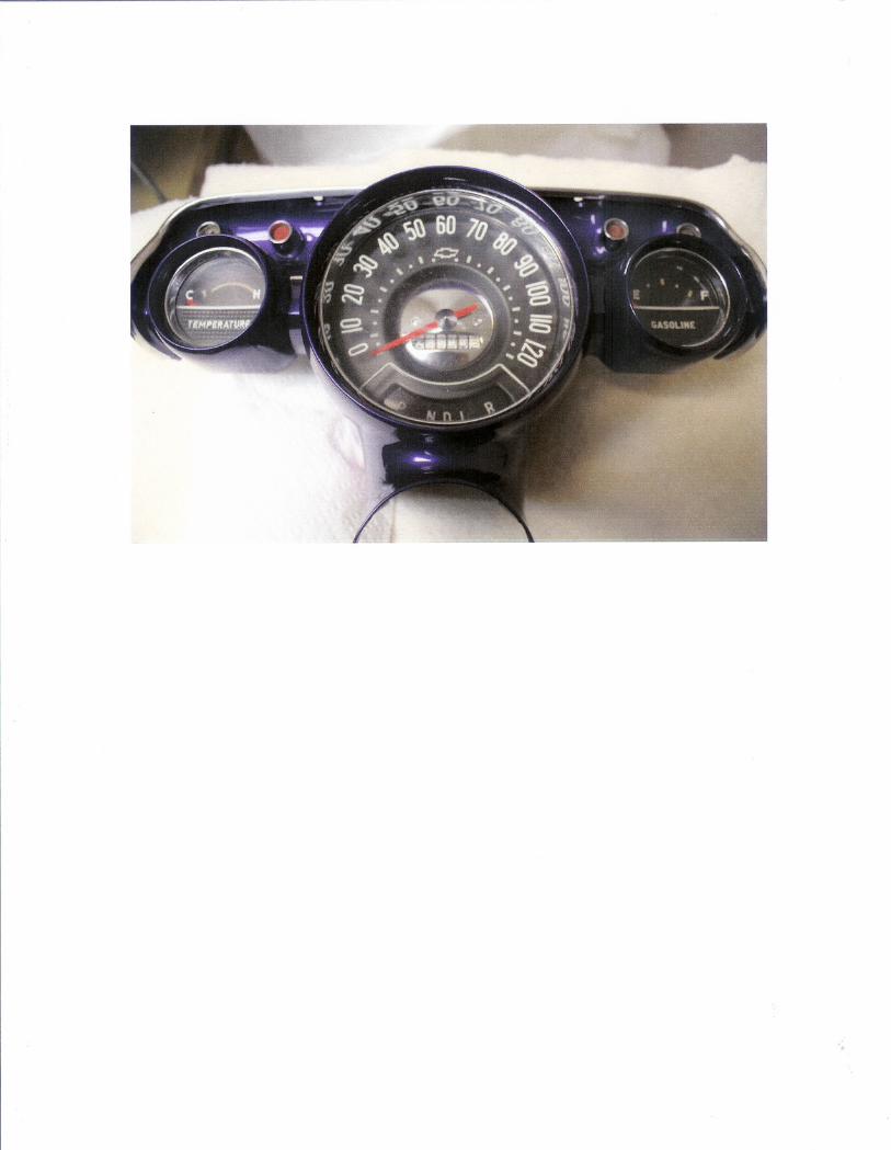
Speedometer Repair & Lube Pt.1
1. Begin disassembly on a clean area approximately 2' by 3' so you have plentyof room to layout parts as you disassemble them. I use a piece of white orlight colored paper to do this on so no parts get lost. If you do this where
.there might be a chance of a breeze, TAPE DOWN the paper or apply weightsto keep from losing parts. Lay all parts aside in the order you remove them.
2. Take note of where the needle is pointing when the face is in a verticalposition. It should be covering.the long white line at the bottom of the face.Tum the Brass drive assembly a couple oftimes COUNTERCLOCKWISE asview from the back to make sure the needle drops back to the lower long line.Remove the needle by carefully pulling and turning the needle to the LEFT atthe same time. Be sure to hold onto the chrome center of the needle as theneedle portion is very fragile. It should come off fairly easy. If it doesn'tcome off right away STOP and turn the unit face down. Take a small amountofPB Blaster or some other penetrating lube and carefully apply a couple ofdrops to the needle shaft visible behind the black face and let it run down theshaft to the needle. If you have to do this take a 10 minute break to let it soakthen try again. When the needle is off you have what looks like this:
r-
t.,,:rj
~\
3.
4. If you need to paint the needle do it now so it has time to dry beforereassembly.
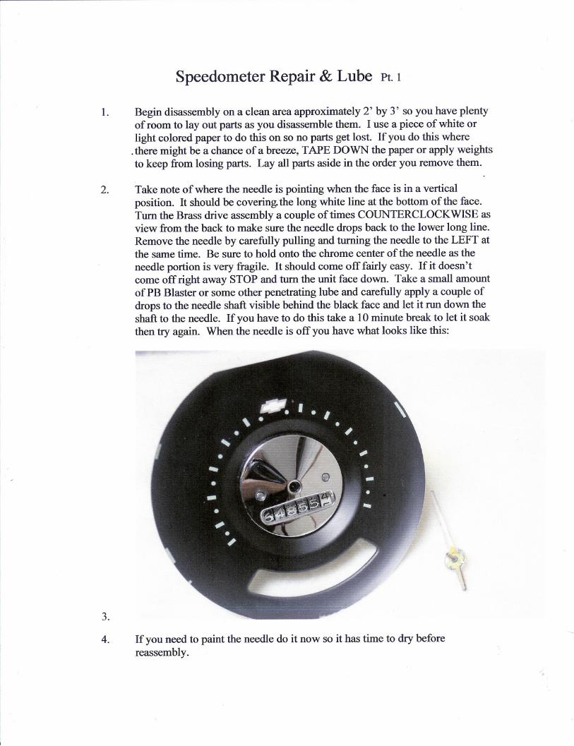
5. Using a small flat screwdriver, remove the screws holding the chrome centerand the black face.
.--,..- "
6.
/l
7. Turn the main head over to match the next picture.
8.
m
'ilm illS
p~£-
Speedometer
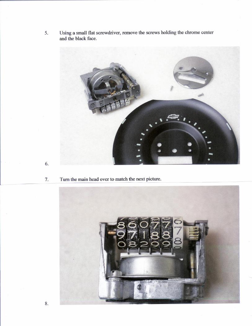
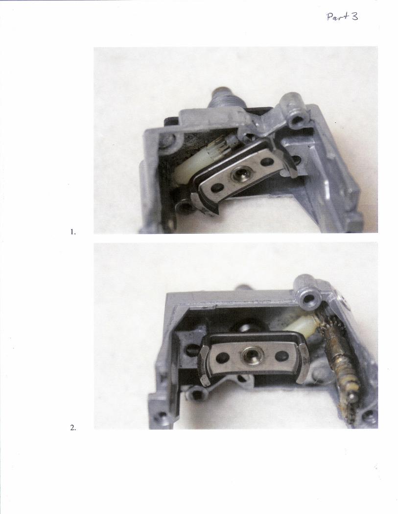
1. In this picture you will notice the small brass clip in the upper left comer. Itholds the odometer assembly to the head. Also take note of the 5 forks at thebottom of the odometer assembly and how they are slipped over the smallflange. Remove the clip carefully as it may want to fly off somewhere, thenslide the odometer assembly to the left releasing the shaft on the right andlifting slightly slide back to the right releasing the assembly. Set asidecarefully so as not to disturb the mileage. I forgot to check the depth of fieldon the next photo but it sort of shows the forks that slip over the flange.
2.
3. Position the head as in the next picture and remove the two screws in thelower comers holding the front bearing assembly. There should be a VERYsmall washer on the front side of the shaft that fits down in the well of thebearing.
..-!It'
"
..
I
,:
4.
- --Ii
IIIt'f ,f
- j
0
5.

6.
7.
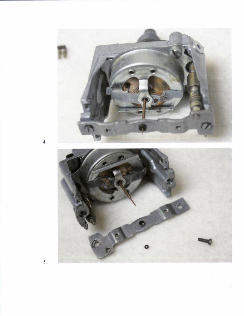
From this point on you must treat the needle armature and the shell it fits intoas one unit or you could ruin the return spring. This spring is carefullycalibrated when manufactured to apply tynsion to the armature as the rotatingmagnets work against it.
Remove the two screws holding the shell to the head and remove the assemblyfrom the head by GRASPING THE NEEDLE SHAFT RIGHT NEXT TOTHE SHELL so they do not separate. After you get the shell assembly offyou can lay it down as in the next picture.
8.
9.
..
In the above picture you will see the rear bearing that is usually the culprit forcausing a buzzing or otherwise noisy speedometer. Also shown is the drivingmagnet that spins with the cable.
10. In the next picture you can see the rest of the odometer drive mechanismwhich is a series of worm gear drives. These can be taken out, cleaned andlubed with light grease and reassembled. You can also put a couple of dropsof light oil on the inside of the main bearing at the base of the magnet whilespinning the shaft. Also with a pry out the brass cup on the back by thethreaded fitting and remove the wick and add a couple of drops of oil thenreassemble.
'Pew-+- "3
1.
",., 01' ...
1:.;. II.
..
2.
. ;;11...
-.
5.
3. Now it's time to final lube and reassembly. I usually turn the head unit withthe magnet shaft up and put a drop of light oil in the bearing cup. It is really Aar-dto get a small amount in there so I take the comer of a paper towel and blot itto get most back out just so when it is spinning it isn't slinging oil all overeverything.
4. After lubing the rear bearing it's time to reassemble. Make sure the firstodometer gear is in place, carefully set the needle and shell assembly in placerememberingto keepthe parts fromseparating. Tightenthe two screws. I .like to spin the rear shaft counterclockwise after every step just to make surethe previous step didn't cause any binding. Also before going any furthermake sure the needle armature stop is on the correct side of the shell stop.(refer to the picture in step 11)midway between the edge of the shell and thecenter shaft.
You will notice the shaft is very loose in the shell center as there is not abearing at this location. Apply a small drop of oil to the needle shaft right atthe shoulder where the needle attaches. Make sure the odometer shaft is inplace and attach the front bearing plate. It will only fit one way.
6. If you have new decals to refresh the numbers on the odometer this is the timeto do it before reassembly of the odometer.
7. Now take the odometer assembly and line up all the forked pieces andassemble to the head making sure all the forks are fitted to the flange. Slidethe shaft to engage the gear and attach the brass clip. If you had the tinywasher that fits on the front of the needle shaft install it now.
8. You may want to dust the black face before installing and also polish thechrome center cap. Attach with the two screws.
9. Very carefully set the needle on the shaft at about the second long bar up fromthe lower left position. Before pushing it all the way on, turn the shaft fromthe back to verify it moves up when you turn the shaft. (If it doesn't, you areturning the wrong way or you missed a step somewhere. Back up until itworks.) As you push on the needle from the center, carefully twist left untilthe needle lines up with the fust long white line on the face. Keep spinningthe shaft after every adjustment just to make sure it drops back to the line.You can now make sure the needle doesn't hit the face by carefully movingthe needle by pushing on the shorter bottom part. If it touches the faceanywhere you can gently lift on the end of the needle with the blade of a flatscrewdriver. JUST DON"T BREAK IT OFF. I don't know ifthey arereproduced or not.
to. You should now have a silent speedometer when reinstalled. Don't forget tolube the cable before you attach it to the back of the head.