Embed Size (px)
Citation preview
Avalanche Speedometer Repair
Replacing the stepper motors on my 2005 Avalanche 2500. Much thanks to Kevenand David who provided great advice on this task as noted below.
This set of instructions combines:§ information from David ([email protected]) who will repair the cluster for
you and return it to you fixed, or sell you the stepper motors for a reasonableprice so you can do it yourself.
§ instrumctions from Kevin via the Avalanche Fan Club site athttp://www.chevyavalanchefanclub.com who provided instructions andencouragement to do it myself.
§ my personal experience along with photos.
Tools needed:§ Fingers (they did not get damaged in my case)§ Small set of 1/4" drive sockets or a small set of the screwdriver type socket
drivers. I found that a socket extension helped out some.§ Soldering iron with a fine tip§ Solder-sucker tool (blue one in the solder picture) I recommend the spring-
loaded type with the button release (Radio Shack variety works but get thebutton release, not the squzee bulb type)
§ Small screw driver and a very small needle-nose pliers are very useful too
Skills needed:§ Soldering skills, but it wasn't a high degree of difficulty§ Nerve to do it yourself

The process:1. The dash panel and instrument cluster are very easy to remove and replace. The
outer dash ring or panel is just clipped on. It comes off by just pulling on itstarting on the lower right corner and working your way around. There are noscrews, just snap clips. You have to turn on your ignition and put your gear-shifter into the lowest drive position to get it out of the way. If you have anadjustable steering column you will want to lower it as well. Then the panelring comes off easily.
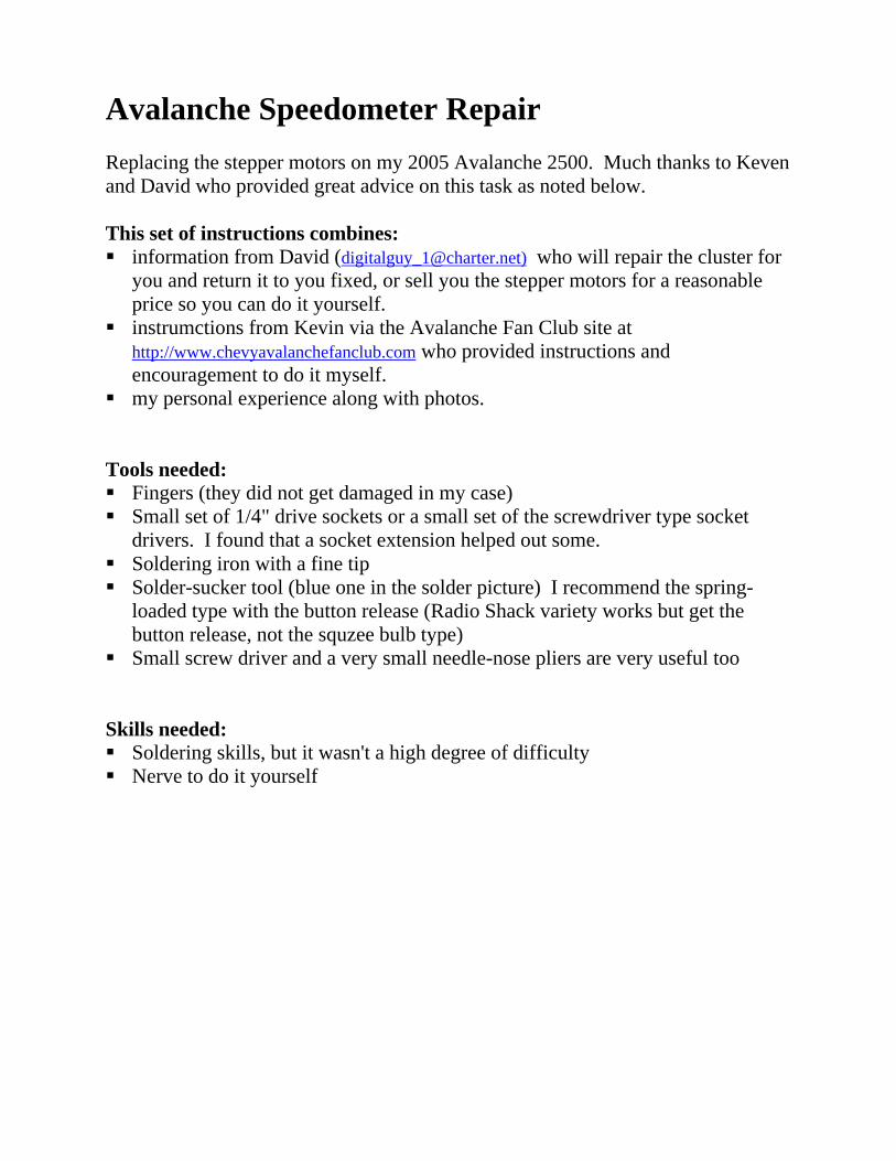
2. The instrument cluster is removed by unscrewing the four screws, one on eachcorner.
Screws4 Screws
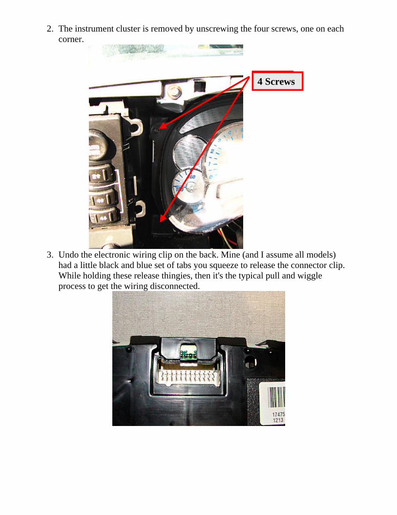
3. Undo the electronic wiring clip on the back. Mine (and I assume all models)had a little black and blue set of tabs you squeeze to release the connector clip.While holding these release thingies, then it's the typical pull and wiggleprocess to get the wiring disconnected.
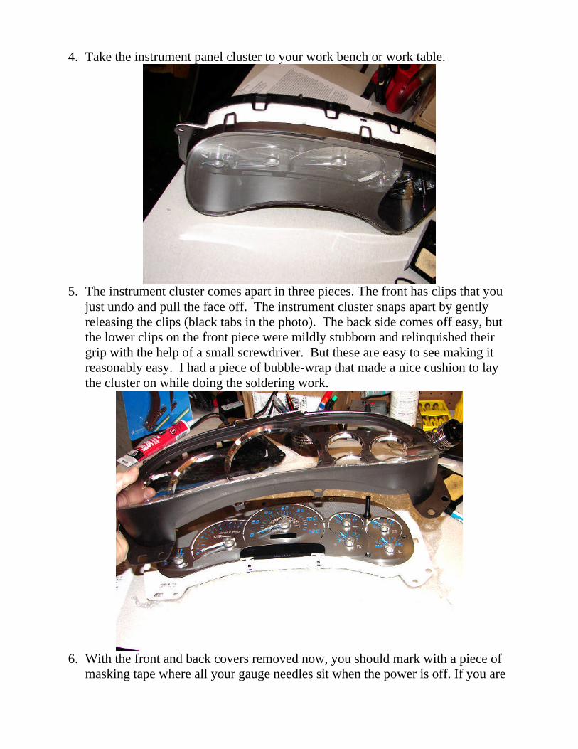
4. Take the instrument panel cluster to your work bench or work table.
5. The instrument cluster comes apart in three pieces. The front has clips that youjust undo and pull the face off. The instrument cluster snaps apart by gentlyreleasing the clips (black tabs in the photo). The back side comes off easy, butthe lower clips on the front piece were mildly stubborn and relinquished theirgrip with the help of a small screwdriver. But these are easy to see making itreasonably easy. I had a piece of bubble-wrap that made a nice cushion to laythe cluster on while doing the soldering work.
6. With the front and back covers removed now, you should mark with a piece ofmasking tape where all your gauge needles sit when the power is off. If you are
only replacing several, you still must take ALL the gage needles off. The tapehelps you get them in the correct place again when you put them back on.
7. To remove the gauge needles, I followed the advice of Kevin and Dave and.used a kitchen fork using the needle between the tines and pry up. Beforeprying them up, it helps to gently move them a bit to the left (counter-clockwise) to break them loose from the stem. You feel this happen with a littlesnap sound. It can take a little bit of force but they do lift up. Make sure youare prying/lifting strait up to avoid potential damage.
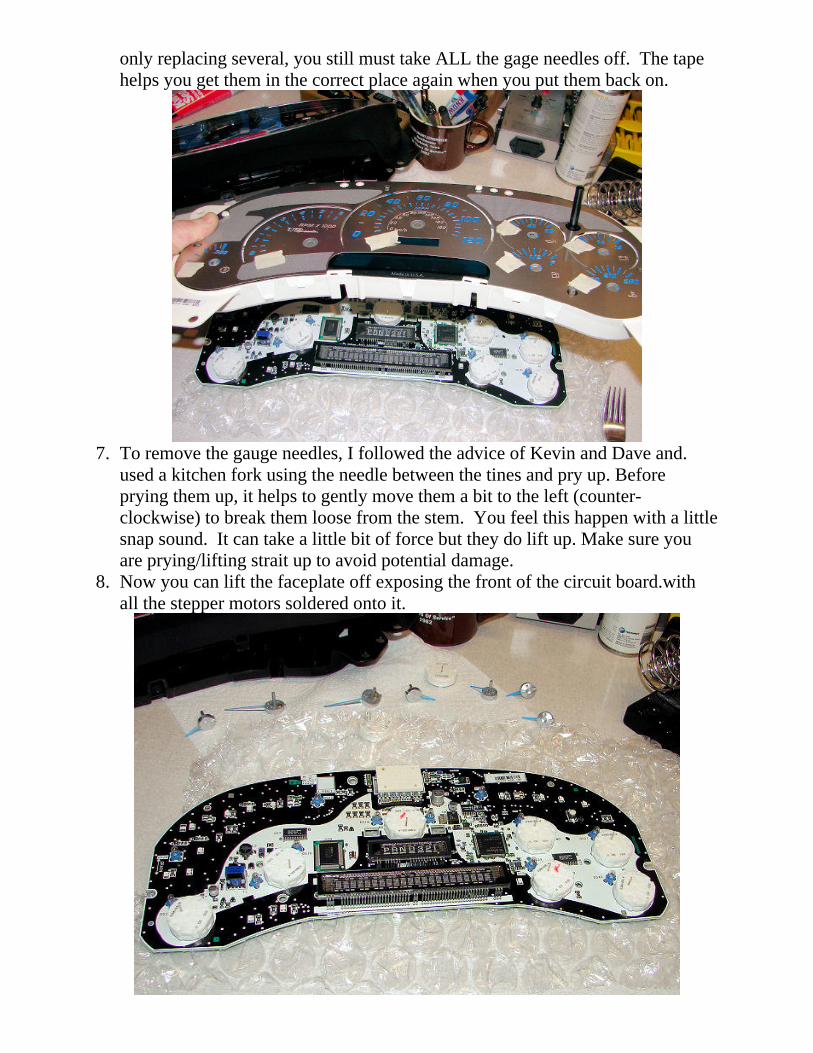
8. Now you can lift the faceplate off exposing the front of the circuit board.withall the stepper motors soldered onto it.

9. If you have any electronic/soldering experience this isn't too hard either, just alittle delicate. You have to unsolder the 4 pins on each of the old steppermotors. Be very careful not to use too much heat. I highly recommend using adesoldering sucker tool. If you use too much heat you will burn the circuit onthe board and have to make a jumper to the next available spot in the circuit.Use a very small soldering point/tip and be careful to only heat up the desiredpins.
10. From the back side of the circuit board, identify the 4 pins of the stepper motoryou are going to unsolder. I cocked the desoldering sucker tool, then appliedheat to the pins for probably about 3 seconds, then quickly put the desolderingtool down on the hot solder and fired the trigger. One shot per pin did it for me.This went much better than I feared.
11. Once you have the 4 pins for one stepper motor unsoldered, if the pins aren'tstrait, take a small needle-nose pliers and make each desoldered pinperpendicular (sticking strait up) from the circuit board.
12. At this point I turned the circuit board over and was able to pull the old steppermotor off easily.

13. Now insert the new stepper motor being careful to guide the 4 pins into the oldholes.
14. Turn the board back over and solder the 4 connectors again. You probably don'twant to apply heat for more than about 3 seconds to avoid damage to the board.I press the soldering tip so it touches the pins and the tiny metal connector plateon the circuit board for a few seconds then apply some solder before removingthe soldering iron. It takes only a little bit of solder.
15. When you are done replacing the stepper motor/motors put the back of thecluster back on. Set the front panel with all the markings back on being carefulto guide the motor shafts through the correct holes. Then you are ready to putyour needles back on.
16. Here I had several approaches suggested. Here is what worked for me. Tryingto put it needle on right where the tape was seemed less accurate than what Idesired. So I put them on a bit to the clockwise side of where the tape was.Then you can turn them back to the correct place rotating the needle on theshaft. One suggestion, from David, was to just put them on in the 12 O'clockposition, then turn them back to the tape. This will turn the motor to the zeroposition, then rotate the needle on the shaft to it's final zero position. I didn'tpush them quite all the way down on the motor shaft until I had them in thefinal position. Then a final little push and they were in place.
17. I only put the back cover piece onto the circuit board at this point (per Kevin'ssuggestion). Then I reattached the wiring harness on the back and just sat itinto place leaving the dash apart. I have a handheld GPS so I drove down theroad comparing the GPS speed with the speedo speed. If they are different, Icould have adjusted. But in my case they were fine. However, the RPMappeared a bit high on the tach so I adjusted it just a bit and also for the gasgage (I don't want it showing above E when I run out!).
18. Now I was able to snap the front (the glass/plastic window) on withoutdisconnecting the instrument cluster again.

19. Then put in the 4 screws in to hold the cluster in place.20. Put the gearshift lever down into low and snap the frame back on.
It was great to fix this problem without paying the high cost of a new cluster orhaving the dealer charge their prices to do it. I appreciate the help I got on-line andwanted to give these instructions and photos for the benefit of others. I hope thishelps someone else attempting this electronic repair task.
Cheers,[email protected]