Embed Size (px)
Citation preview

Abstract—This paper proposes a speed load control of
induction motor using immune algorithm (IA) and fuzzy phase
plane controller. Fuzzy membership functions, phase plane
theory and the IA are employed to design the proposed
controller (FPPC) for controlling the speed of an induction
motor with loading, based on the desired specifications. The
proposed FPPC has merits of rapid response, simply designed
fuzzy logic control and an explicitly designed phase plane theory.
Simulations and experimental results reveal that the proposed
FPPC is superior in optimal speed and load control to
conventional PI controller.
Index Terms—Fuzzy phase plane, immune algorithm, speed
load control.
I. INTRODUCTION
Conventional proportional integral (PI) dynamic controls
for speed and the load have drawbacks [1]. Although fuzzy
logic is commonly applied to the field oriented control of
induction motors, the fuzzification, defuzzification, and
decision procedures that establish a knowledge base are more
complicated, difficult and time-consuming. Moreover,
although some studies [2]-[6] have been performed in this
area, most, if not all, are based on conventional trial-and-error
techniques. However, optimal performance may not be
achieved. The phase plane technique [7]-[9] is now widely
used to enhance the control performance in the transient and
steady states. This paper describes a new method for
advancing the indirect oriented field control (IFOC) [3], [4]
technique for controlling the speed load of an induction motor.
The proposed controller (FPPC) speeds up the response
because the defuzzification procedure and the fuzzy rules
derived from expert experiences (knowledge bases) are no
longer required. The block diagram of the proposed controller
design has shown in Fig. 1 for controlling speed load of an
induction motor.
Fig. 1. The block diagram for controlling the induction motor speed.
Manuscript received October 15, 2013
work was supported by the National Science Council, Taiwan, ROC. Under
Grant No. NSC100-2632-E-252-001-MY3.
C. L. Chiang is with the Nan Kai University of Technology, Nan-Tou,
Taiwan, ROC (e-mail: t129@ nkut.edu.tw).
IA [10] is inspired by immunology, immune function and
principles observed in nature. IA is a very intricate biological
system which accounts for resistance of a living body against
harmful foreign entities. It is now interest of many researchers
and has been successfully used in various areas of research
[10]-[12].
Fuzzy membership functions, phase plane theory and the
IA are used to design the proposed controller (FPPC) for the
IFOC of an induction motor, based on the desired
specifications. The proposed FPPC has rapid response,
simply designed fuzzy logic control and an explicitly
designed phase plane theory. The simulated and experimental
results indicate that the proposed FPPC outperforms the
conventional PI controllers in the optimal speed control and
loading controls.
II. SYSTEM FORMULATION
By assuming a linear magnetic circuit and neglecting the
iron losses, the dynamic equations for an induction motor can
be expressed in a de-q
e rotating two-axis coordinate frame [13]
as,
*
*2
2 2
0 0
10
0
0
s
ee eqsqs qs
e e es m r m rds ds ds
r re e
dr dr
m r r
r r
R
Li i
R L R L Rp i i
L L L L L L
L R R
L L
(1)
where
*
/e e e e
qs qs e ds m r e drL i L L (2)
*e e e
ds ds e qsL i (3)
Rs, Rr = stator resistance and rotor resistance referred to the
Stator
voltagesstatoraxisande
qs
e
ds
ee qd,
linkagesfluxrotoraxisand
currentsstatoraxisand
e
qr
e
dr
e
qs
e
ds
ee
ee
qd,
qdi,i
Lσ = Ls –Lm2 /Lr , total leakage inductance
Lm, Lr = mutual inductance and rotor inductance referred
to the stator
Te = electromagnetic torque
ωe = synchronous rotating frame angular speed
ωm = rotor mechanical speed (rad/s)
p = differential operator ( p ≡d / dt )
Speed Load Control of Induction Motor Using Immune
Algorithm and Fuzzy Phase Plane Controller
Chao-Lung Chiang
299
IACSIT International Journal of Engineering and Technology, Vol. 6, No. 4, August 2014
DOI: 10.7763/IJET.2014.V6.716
; revised December 18, 2013.

By applying (1) and letting e
dr be a constant,
e
drcan be
expressed in terms of e
dsi as,
(4)
1
ee ds mdr
r
r
i L
Ls
R
Once the de-axis position is determined, the magnetizing
current component, or equivalently, the de-axis current
component can be easily determined:
)5(*
m
e
dre
dsL
i
where *
mL is the unsaturated nominal mutual inductance.
After decoupling, the stator current command (*e
qsi ) can be
controlled by motor torque generation. Two command values
(*
sl and*e
qsi ) are obtained from the vector controllers. The
slip command (*
sl ) satisfies,
)6(*
*
e
drr
e
qs
*
m
*
r*
sl
L
iLR
where *
rR represents the nominal rotor resistance.
Substituting (6) into (1) enables the stator current command
(*e
qsi ) to be written as,
)7(3
4*
*
e
dr
*
e
*
m
re
qs
T
L
L
Pi
The torque current command (*e
qsi ) is generated primarily
from the output of the proposed FPPC.
III. THE DESIGN OF CONTROLLERS
A. The Proposed Controller (FPPC)
The output signal u (t) of the proposed FPPC shown in Fig.
1 is given by,
( ) ( )u t U n , for ( 1)ndT t n dT (8)
where dT indicates the sampling period and n is an integer.
The value of U (n) is determined using the following steps.
Step 1. Sample the error (E) and compute the scaled
variation of error (dEscale) by,
( ) ( ) ( 1)dE n E n E n (9)
( ) ( )scale odE n k dE n (10)
where dE(n) is the variation of error at nth
sampling time;
dEscale is the scaled dE and ko is the scaling factor.
Step 2. Compute θ(n) and Ri(n), which are shown in Fig.
2.
Fig. 2. Induction motor condition on the phase plane.
Step 3. Define the membership function, which contains
sigmoid functions that determine the angle-direction gain is
presented. The bell-shaped membership function of P(θ),
which has a positive gain, is illustrated as,
36090901
1
1
1180)(
ii ee
eeP (11)
Fig. 3 shows the corresponding waveform to (11). This
figure presents N ( ), which is the negation of P ( ), is
equal to 1-P ( ). If the <α- 90 condition occurs, plus
360 results (11). We set ei and α to 100.0 and 135o
respectively, and expect to obtain a rapid response and
simplified design.
Fig. 3. The bell-shaped membership function for angle-direction gain
distribution.
Step 4. Determine the radius-direction gain function G
(Ri(n)), and is defined in (12). Where the fi is an adjustable
centripetal gain; Ri(n) is the length between the dynamic and
original points , (Ri(n) =∣(k0*dE i(n) , E i(n) )∣).
)12(11
2
)n(Rfiiie
nRG
Step 5. Compute the output of the proposed controller
( ( )U n ), represented as,
MAXi UnPnRGnU 1)(2)( (13)
where UMAX is the maximum output of ( )U n for a practical
hardware system.
Step 6. Increase n by 1, and repeat steps 1 to 5.
Some parameters regarding the proposed controller must
be optimized to improve the performance of the proposed
FPPC. Equation (14) defines the index for optimizing the
aforementioned parameters. The performance index is
defined as the sum of absolute errors with constraints
(SAEC).
300
IACSIT International Journal of Engineering and Technology, Vol. 6, No. 4, August 2014

M
n
M
n
k
L
k
k gnerrorJ1 1 1
)(minSAECmin (14)
where M denotes the total number of data sampled. λk is the
penalty factor associated with the constraint gk, and L is the
total number of constraints.
B. The Field-Weaken Control, the Flux Controller and Two
Current Controllers
The conventional PI controller has been extensively used
for controlling the speed of induction motor drives. The major
feature of the PI controller is its capability to maintain a zero
steady state error within a step change. The controller has the
merits of simplicity and stability. However, a PI controller has
some disadvantages, such as undesirable speed overshoot and
oscillation, a sluggish response to a sudden change in load
torque, a long settling time, and sensitivity to controller gains
kP and ki. Hence, the proposed FPPC is used as the primary
controller, which can overcome the disadvantages in the PI
controller. Three PI controllers are employed as subordinate
controllers [14] in the IFOC drive system design, including
the flux controller and two current controllers of iqs and ids.
The determination of *e
dr requires fairly complicated
computations because the solution of *e
dr is based on an
eighth-order polynomial equation [15]. Let *
eT = 0;
then*e
dr can be approximated by,
rs
sme
drL
VL
max* (15)
where max
sV and r are the maximum stator voltage and the
electrical angular speed, respectively. To keep *e
dsi constant,
the flux controller uses the PI control expressed as,
e
dr
e
dr
if
pf
e
dss
kki
** (16)
To eliminate variant values *e
qs and *e
ds in (2) and (3),
two PI controllers are used in the current decoupling
controllers of the de and q
e axes, defined as (17) and (18).
e
qs
e
qs
ic
pc
e
qs iis
kk
*1
1
*
(17)
e
ds
e
ds
ic
pc
e
ds iis
kk
*2
2
*
(18)
Thus, the two decoupled stator voltages can be rewritten as,
e
drerm
e
dse
e
qs
decouple
qs LLiL / (19)
e
qse
e
ds
decouple
ds iL (20)
MAX
nRf
Uee
enU
oo
ii
11
2
1
2
11
2)(
3150.1001350.100
)(
(21)
The parameters of the flux controller and the two current
controllers (kpf, kif, kpc1, kic1, kpc2 and kic2) slightly influence the
performance of motor controls because the principal
controller (FPPC) performs most of this work.
IV. THE OPTIMAL ALGORITHM
In IA [12], mimics these biological principles of clone
generation, proliferation and maturation. The main steps of IA
based on clonal selection principle are activation of
antibodies, proliferation and differentiation on the encounter
of cells with antigens, maturation by carrying out affinity
maturation process, eliminating old antibodies to maintain the
diversity of antibodies and to avoid premature convergence,
selection of those antibodies whose affinities with the antigen
are greater. In order to emulate IA in optimization, the
antibodies and affinity are taken as the feasible solutions and
the objective function respectively.
V. RESULTS OF THE SIMULATIONS AND EXPERIMENTS
A. Setups of the Proposed Controller
The proposed controller (FPPC) was implemented using
fuzzy membership functions, the phase plane theory and the
IA. Fig. 1 shows the block diagram for controlling the speed
of an induction motor using the IFOC. The proposed FPPC
has one output ( ( )U n , the torque *
eT ) and two input state
variables (the state E(n) and the variation of the error state dE
(n)). Substituting (11) and (12) into (13) yields the output
( )U n shown as (21).
In (21), fi is an adjustable parameter related to G (Ri (n)),
and the scaling factor ko of (10) is an adjustable parameter on
the phase plane. For optimal control, the parameters fi and ko
must be optimized. The maximum output UMAX was set to 3
for the practical hardware system. Matlab /Simulink software
was employed on a P-IV 2.0GHz CPU to perform the
simulations and experiments. The sampling interval was
chosen as 0.1ms. Table I lists the parameters for the induction
motor.
TABLE I: THE PARAMETERS OF THE INDUCTION MOTOR
Rs = 2.85Ω,Ls = 0.19667H
Rr = 2.34Ω,Lr = 0.19667H
Lm = 0.1886H
Jm = 0.002 kg·m2
Bm = 0.003 N·m/rad/s
4-pole, 220V Δ-connected,1 hp
B. Optimal Parameters of the Proposed Controller
In practice, the desired performance of a control system is
specified in terms of time-domain quantities. An induction
motor drive must usually meet the following specifications [5],
[14], [16];
1) Delay time (td), td < 0.15s. 2) Rise time (tr), tr < 0.1s. 3)
Settling time (ts), ts < 0.2s. 4) Maximum step response
overshoot (mp), mp < 0.3%. 5) Step response steady state error
(ess), ess ~ 0.
The IA was used to find the optimal parameters, fi and ko for
301
IACSIT International Journal of Engineering and Technology, Vol. 6, No. 4, August 2014

controlling speed of an induction motor. The fitness function
can be calculated using (14). In light of aforementioned
specifications, the penalty factors and constraints of (14) are
defined as follows;
5110 ,kfork
00
0
300
30
200
20
100
10
1500
150
5
4
3
2
1
ss
ss
p
p
s
s
r
r
d
d
eif,
eif,)n(Eg
%.mif,
%.mif,)n(Eg
s.tif,
s.tif,)n(Eg
s.tif,
s.tif,)n(Eg
s.tif,
s.tif,)n(Eg
C. Responses of the Proposed FPPC and Conventional PI
Controllers
Fig. 4. The optimal speed control responses of the proposed FPPC and
conventional PI controllers.
TABLE II: THE OPTIMAL PARAMETERS OF THE PROPOSED FPPC AND
CONVENTIONAL PI CONTROLLERS, USING THE IA.
IA Controller Optimal parameters
SPEED CONTROL
(ω*d =1000 rpm)
FPPC fi
ko
30.2618
1.2818
PI Kp2
Ki2
45.4267
0.0184
TABLE III: THE CHARACTERISTICS OF THE TRANSIENT AND STEADY STATES
FOR THE PROPOSED FPPC AND CONVENTIONAL PI CONTROLLERS
Simulation td (ms) tr
(ms) ts (ms)
mp
(%) ess (rpm)
Speed FPPC 70 109-32=77 120 0.0750 -0.00033
PI 93 141-47=94 152 0.0246 0.01430
Experiment td
(ms)
tr
(ms)
ts
(ms)
mp
(%) ess (rpm)
Speed FPPC 83 130-33=97 140 0.2853 1.0387
PI 95 153-47=106 166 0.3021 2.0010
The simulated and experimental results for a step command
input are given here to demonstrate the effectiveness of the
proposed controller (FPPC). The IA was applied ten times,
considering the desired specifications. Table II lists the
optimal parameters yielding the minimum SAEC using ten
runs with the proposed FPPC and conventional PI controllers.
Fig. 4 shows the simulated and experimental results using the
proposed FPPC and conventional PI controllers to optimally
control the speed of an induction motor. Moreover, Table III
summarizes the characteristics of the transient and steady
states (td, tr, ts, mp and ess), during applications using the
proposed FPPC and conventional PI controllers to control the
speed of an induction motor. Fig. 4 and Table III indicate that
the proposed FPPC not only has a smaller SAEC than the
conventional PI controllers in speed control, but also
completely satisfies the desired specifications. However, the
conventional PI controllers violate most of the desired
specifications.
Fig. 5 shows a three-dimensional plot using (ko*dE(n), E(n),
U(n)) as (x, y, z) variables. This figure indicates that the
output of the proposed FPPC, (U(n)), is a functional designing
controller on the phase plane, obtained using (22). The figure
also shows that the switch line nearly cuts the phase plane into
two semi-planes at 135˚ . The proposed FPPC accelerates
the response because defuzzification and the knowledge base
are no longer required. Therefore, the proposed FPPC has the
merits of rapid response, simply designed fuzzy logic control
and an explicitly designed phase plane theory.
Fig. 5. 3D phase plane diagram of the optimal speed control using the
proposed FPPC.
TABLE IV: THREE CASES OF DIFFERENT PARAMETERS FOR THE FLUX
CONTROLLER AND TWO CURRENT CONTROLLERS
Case A Case B Case C
Flux Controller
Eq. (16)
kpf 20.0 20.0×0.7 20.0×1.3
kif 351.2 351.2×1.3 351.2×0.7
qe-Current
controller
Eq.(17)
kpc1 20.0 20.0×1.3 20.0×0.7
kic1 200.0 200.0×.7 200.0×1.3
de-Current
controller
Eq.(18)
kpc2 20.0 20.0×0.7 20.0×1.3
kic2 200.0 200.0×1.3 200.0×0.7
D. Parameters of the Three Subordinate Controllers
This paper used (15) to compensate for the field-weaken
control of an induction motor, and employed three PI
controllers as the subordinate controllers for the IFOC. Table
IV lists the computational results from three cases involving
different parameters for these PI controllers. This table
explains that the flux controller and two current controller
parameters (kpf, kif, kpc1, kic1, kpc2 and kic2) could be roughly
chosen, because this task was performed by the proposed
FPPC.
E. Responses of the Load Control of the FPPC and PI
Controllers
Fig. 6 presents the simulated and experimental speed
302
IACSIT International Journal of Engineering and Technology, Vol. 6, No. 4, August 2014
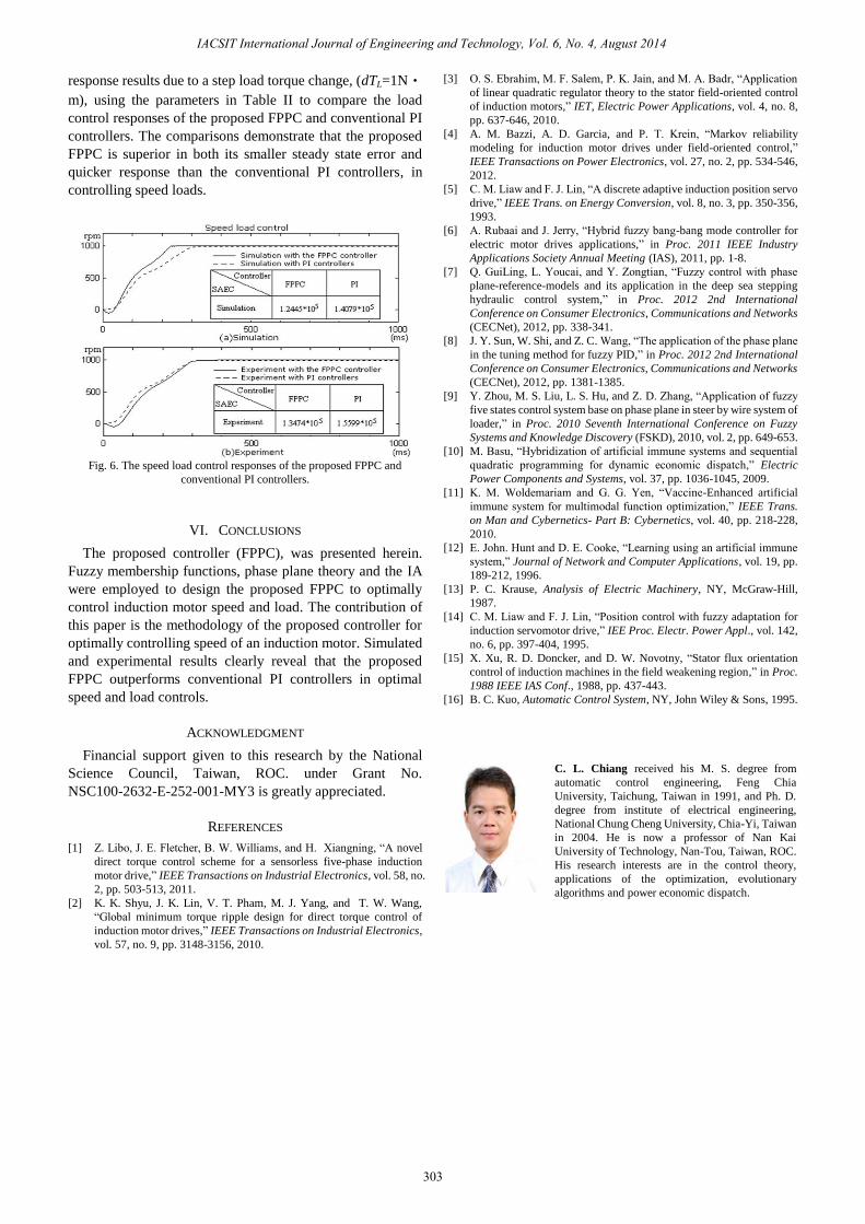
response results due to a step load torque change, (dTL=1N•
m), using the parameters in Table II to compare the load
control responses of the proposed FPPC and conventional PI
controllers. The comparisons demonstrate that the proposed
FPPC is superior in both its smaller steady state error and
quicker response than the conventional PI controllers, in
controlling speed loads.
Fig. 6. The speed load control responses of the proposed FPPC and
conventional PI controllers.
VI. CONCLUSIONS
The proposed controller (FPPC), was presented herein.
Fuzzy membership functions, phase plane theory and the IA
were employed to design the proposed FPPC to optimally
control induction motor speed and load. The contribution of
this paper is the methodology of the proposed controller for
optimally controlling speed of an induction motor. Simulated
and experimental results clearly reveal that the proposed
FPPC outperforms conventional PI controllers in optimal
speed and load controls.
ACKNOWLEDGMENT
Financial support given to this research by the National
Science Council, Taiwan, ROC. under Grant No.
NSC100-2632-E-252-001-MY3 is greatly appreciated.
REFERENCES
[1] Z. Libo, J. E. Fletcher, B. W. Williams, and H. Xiangning, “A novel
direct torque control scheme for a sensorless five-phase induction
motor drive,” IEEE Transactions on Industrial Electronics, vol. 58, no.
2, pp. 503-513, 2011.
[2] K. K. Shyu, J. K. Lin, V. T. Pham, M. J. Yang, and T. W. Wang,
“Global minimum torque ripple design for direct torque control of
induction motor drives,” IEEE Transactions on Industrial Electronics,
vol. 57, no. 9, pp. 3148-3156, 2010.
[3] O. S. Ebrahim, M. F. Salem, P. K. Jain, and M. A. Badr, “Application
of linear quadratic regulator theory to the stator field-oriented control
of induction motors,” IET, Electric Power Applications, vol. 4, no. 8,
pp. 637-646, 2010.
[4] A. M. Bazzi, A. D. Garcia, and P. T. Krein, “Markov reliability
modeling for induction motor drives under field-oriented control,”
IEEE Transactions on Power Electronics, vol. 27, no. 2, pp. 534-546,
2012.
[5] C. M. Liaw and F. J. Lin, “A discrete adaptive induction position servo
drive,” IEEE Trans. on Energy Conversion, vol. 8, no. 3, pp. 350-356,
1993.
[6] A. Rubaai and J. Jerry, “Hybrid fuzzy bang-bang mode controller for
electric motor drives applications,” in Proc. 2011 IEEE Industry
Applications Society Annual Meeting (IAS), 2011, pp. 1-8.
[7] Q. GuiLing, L. Youcai, and Y. Zongtian, “Fuzzy control with phase
plane-reference-models and its application in the deep sea stepping
hydraulic control system,” in Proc. 2012 2nd International
Conference on Consumer Electronics, Communications and Networks
(CECNet), 2012, pp. 338-341.
[8] J. Y. Sun, W. Shi, and Z. C. Wang, “The application of the phase plane
in the tuning method for fuzzy PID,” in Proc. 2012 2nd International
Conference on Consumer Electronics, Communications and Networks
(CECNet), 2012, pp. 1381-1385.
[9] Y. Zhou, M. S. Liu, L. S. Hu, and Z. D. Zhang, “Application of fuzzy
five states control system base on phase plane in steer by wire system of
loader,” in Proc. 2010 Seventh International Conference on Fuzzy
Systems and Knowledge Discovery (FSKD), 2010, vol. 2, pp. 649-653.
[10] M. Basu, “Hybridization of artificial immune systems and sequential
quadratic programming for dynamic economic dispatch,” Electric
Power Components and Systems, vol. 37, pp. 1036-1045, 2009.
[11] K. M. Woldemariam and G. G. Yen, “Vaccine-Enhanced artificial
immune system for multimodal function optimization,” IEEE Trans.
on Man and Cybernetics- Part B: Cybernetics, vol. 40, pp. 218-228,
2010.
[12] E. John. Hunt and D. E. Cooke, “Learning using an artificial immune
system,” Journal of Network and Computer Applications, vol. 19, pp.
189-212, 1996.
[13] P. C. Krause, Analysis of Electric Machinery, NY, McGraw-Hill,
1987.
[14] C. M. Liaw and F. J. Lin, “Position control with fuzzy adaptation for
induction servomotor drive,” IEE Proc. Electr. Power Appl., vol. 142,
no. 6, pp. 397-404, 1995.
[15] X. Xu, R. D. Doncker, and D. W. Novotny, “Stator flux orientation
control of induction machines in the field weakening region,” in Proc.
1988 IEEE IAS Conf., 1988, pp. 437-443.
[16] B. C. Kuo, Automatic Control System, NY, John Wiley & Sons, 1995.
C. L. Chiang received his M. S. degree from
automatic control engineering, Feng Chia
University, Taichung, Taiwan in 1991, and Ph. D.
degree from institute of electrical engineering,
National Chung Cheng University, Chia-Yi, Taiwan
in 2004. He is now a professor of Nan Kai
University of Technology, Nan-Tou, Taiwan, ROC.
His research interests are in the control theory,
applications of the optimization, evolutionary
algorithms and power economic dispatch.
303
IACSIT International Journal of Engineering and Technology, Vol. 6, No. 4, August 2014