Embed Size (px)
Citation preview

L. Tlustos, CERNICFTD, Nov. 2009
Spectroscopic X-ray imaging
Lukas Tlustos
Medipix Collaboration, CERN

L. Tlustos, CERNICFTD, Nov. 2009
MEDIPIX2 Collaboration
- U INFN Cagliari
- CEA-LIST Saclay
- CERN Genève
- U d'Auvergne Clermont
- U Erlangen
- ESRF Grenoble
- U Freiburg
- U Glasgow
- IFAE Barcelona
- Mit t hoegskolan
- MRC-LMB Cambridge
- U INFN Napoli
- NIKHEF Amst erdam
- U INFN Pisa
- FZU CAS Prague
- IEAP CTU in Prague
- SSL Berkeley http:/ / medipix.web.cern.ch/ MEDIPIX/

L. Tlustos, CERNICFTD, Nov. 2009
• University of Canterbury, Christchurch, New Zealand
• DRT/LIST/DeTeCS/SSTM, CEA, Paris, France
• CERN, Geneva, Switzerland,
• DESY-Hamburg, Germany
• The Diamond Light Source, Diamond House, Didcot, UK
• Freiburger Materialforschungszentrum, Albert-Ludwigs-Universität Freiburg, Germany
• University of Glasgow, Scotland, UK
• Institute for Synchrotron Radiation, ISS, Forschungszentrum Karlsruhe, Germany
• Biophysical Structural Chemistry, Leiden Univ., The Netherlands
• NIKHEF, Amsterdam, The Netherlands
• Mid Sweden University, Sundsvall, Sweden
• IEAP, Czech Technical University, Prague, Czech Republic
• ESRF, Grenoble, France
• Universität Erlangen-Nurnberg, Erlangen, Germany
• Space Sciences Laboratory, University of California, Berkeley, USA
• VTT Microsystems, Espoo, Finland
• ITER
MEDIPIX3 Collaboration

L. Tlustos, CERNICFTD, Nov. 2009
Hybrid-Pixel Detector
p+
n-
ASICn-well
p-substrate
Semiconductor
detector
Bump-bond
contact
Charged particle
gm
Iin Vout

L. Tlustos, CERNICFTD, Nov. 2009
Medipix2
(Current) RO systems
•Standard readout: MUROS2 + NI-DIO32
•Fastest readout: PRIAM (ESRF)
1.5 kHz frame rate
•Most compact, portable: USB1.0 based
4Hz frame rate
ASIC
•0.25 mm CMOS
•55 μm Pixel, 256 x 256
•Sensitive area ~2 cm2
•3 side buttable
•Serial RO ~ 9.2ms @100MHz Clock
•32bit CMOS Parallel RO ~300μs Port
Largest assemblies
2x2 and 1x5

L. Tlustos, CERNICFTD, Nov. 2009
Medipix2 Pixel
Analogue Digital
Preamp
Disc1
Disc2
Double Disc logic
Vth Low
Vth High
13 bits
Shift
Register
Input
Ctest
Testbit
Test Input
Maskbit
Maskbit
3 bits
threshold
3 bits
threshold
Shutter
Mux
Mux
ClockOut
Previous Pixel
Next Pixel
Conf
8 bits configuration
Polarity
• Positive und negative input signals→ alternative detector materials (GaAs, CdTe …)
• Charge sensitive preamplifier with leakage current compensation per pixel
• 2 Discriminators with globally adjustable threshold
• 3-bit threshold adjustment per pixel
• Counter activation via external shutter signal
• 1 test-bit and 1 mask-bit per pixel
• 13-bit Pseudo-random counter

L. Tlustos, CERNICFTD, Nov. 2009
Medipix Signal Processing
N+ P+Si
Counter:
+
Amplifier
Comparator
000001
Threshold level >>
electronic noise
No noise counts
Digital integration
(counting)
No dark current.
Unlimited dynamic range
and exposure time.
Bia
s V
olta
ge
Com
mo
n
ba
ck-s
ide
ele
ctr
od
e
Pix
ella
ted
fron
t-sid
e
ele
ctr
od
e
Pixel electronics
Thresholdlevel
Particle count

L. Tlustos, CERNICFTD, Nov. 2009
• Use as much information contained in the X-ray beam as possible
• Noise reduction, Energy weighting, …
• Material reconstruction
• “Energy-selective reconstructions
in X-ray computerised tomography”,
R. Alvarez and A. Macovski
1976 Phys. Med. Biol. 21 733-744
• Particle recognition → Quantum dosimetry
• Autoradiography - Discrimination of cosmics
• ….
• (Neuron imaging)
Motivation for Spectroscopic Imaging

L. Tlustos, CERNICFTD, Nov. 2009
Energy Window Medipix216.1-19.6 keV 21.6-25.1 keV 29-33.5 keV
36.9-40.4 keV 43.1-46.6
W-Tube 50 kV
2.5 mm Al
E=3.5 keV

L. Tlustos, CERNICFTD, Nov. 2009
K-edge Imaging - Simulation
CT g/cm3
M Firsching et al. Nuclear Science Symposium Conf. Rec., 2006
• 20 cm water phantom• W-tube 120kV, 0.6 mm Ti filter• Ideal detector w=40 cm, 256 pixels• Contrast agents
– Iodine
– Gadolinium
• Matrix inversion

L. Tlustos, CERNICFTD, Nov. 2009
Butzer, J. et al., Image and Vision
Computing New Zealand,
2008. IVCNZ 2008. 23rd
International Conference
Statistical Material Recognition
Principal
Components
Analysis
•Material reconstruction using matrix inversion not always possible, matrix to be inverted tends to be
close to singular
•Alternatives: Iterative methods, Statistical methods

L. Tlustos, CERNICFTD, Nov. 2009
K-edge imaging
•Iodine: Pulmonary circulation
•Barium: Lung
•Bone: normal structure
Univ. Canterbury, NZ
Mars bio-imaging
Small animal CT

L. Tlustos, CERNICFTD, Nov. 2009
4 energy CT
4 low thresholds chosen
(15, 23, 30, 35 keV)

L. Tlustos, CERNICFTD, Nov. 2009
4 energy CT

L. Tlustos, CERNICFTD, Nov. 2009
PCA
-1 1
Bone =
Iodine =
Barium =
1
1
1
-1
1
1
0
-1
1

L. Tlustos, CERNICFTD, Nov. 2009
Colourise
+
X
)( +
Spectral information
“conventional” information

L. Tlustos, CERNICFTD, Nov. 2009
Spectral enhancement
Butler, A., et al., Processing of
spectral X-ray data with
principal components Analysis,
IWORID 2009, Prague
Iodine: Pulmonary circulation
Barium: Lung
Bone

L. Tlustos, CERNICFTD, Nov. 2009
• Eventually humans
• Improved material recognition
– Ca-Phosphate vs. Ca-Oxylate
– Fat vs. glandular tissue
– Micro-CT in industrial context
• Nanoparticles
– E.g. Contrast agent loaded
Lipoproteines
– Antibody labeled Lipoproteines →
“functional” CT
Possible Future Applications

L. Tlustos, CERNICFTD, Nov. 2009
1) Energy dispersion due to charge sharing
– Double counted / not counted photons, depending on threshold
– Can be corrected for (De-convolution, Spectrum stripping), but
introduces additional noise to the spectral dataset due to
uncorrelated datasets - see above
– Further amplification of noise when using matrix inversion to
reconstruct mean Z and mean
2) Only one energy window
– Uncorrelated datasets for different energy bins
– Reduced quantum efficiency
3) Fluorescence within detector (GaAs, CdTe, …)
– Additional distortion of the recorded spectrum
Limiting Factors

L. Tlustos, CERNICFTD, Nov. 2009
Charge Transport in Planar Si Sensor
20 keV Photons
300 m Si Sensor
55 m Pixel Pitch
120 V sensor bias
• Mono-energetic Photon spectrum
continuous spectrum with constant
background and strong contribution of low
pulse heights
• Even when using energy window
spectroscopic information degraded
Mono-energetic Photons 20 keV

L. Tlustos, CERNICFTD, Nov. 2009
Charge Summing Implementation
• Off chip: Timepix like architecture
– Digitization of energy deposited in pixel →TOT
– Sparse data, no overlaps → limited particle flux
– Fast readout necessary
• On chip: Medipix3
– Communicating pixels
• Dead time/pileup limit given by shaping time
– Summing of 4 adjacent pixels
– 2, 4 (8) Energy bins

L. Tlustos, CERNICFTD, Nov. 2009
TimePix
N+ P+Si
Counter:
+
Amplifier
Comparator
000001
Continuous clock signal on
whole chip 100 MHz
3 Modes:
1. Counting = Medipix2
2. Time over Threshold
clock pulses counted
when discriminator high.
Measure for energy
deposited in pixel.
3. Time of Arrival
all clock pulses from first
hit until end of shutter
signal counted. Time of
arrival of first particle per
pixel.
Bia
s V
olta
ge
Com
mo
n
ba
ck-s
ide
ele
ctr
od
e
Pix
ella
ted
fron
t-sid
e
ele
ctr
od
e
Pixel electronics
Thresholdlevel 007003
Particle countEnergy
Courtesy J. Jakubek, CTU/IEAP

L. Tlustos, CERNICFTD, Nov. 2009
11B HIMAC, 290 MeV/nucleon
@ 0 @ 60 @ ~90
Charge deposition studies with various Isotopes → Space Dosimetry
Courtesy L. Pinsky, Univ. Houston

L. Tlustos, CERNICFTD, Nov. 2009
90Sr
1 256
256
1
X (column number)
Y
1 2951 5901 88511.18e+004
• 90Sr 11 μs exposure time and Clk_Ref=6.27 MHz (159.3ns)
• Maximum acquisition time dynamic range of 1.88 ms

L. Tlustos, CERNICFTD, Nov. 2009
Timepix with 3-GEM detector
• DESY testbeam in November 2006 (A.Bamberger, M.Titov)
• 5 GeV e-

L. Tlustos, CERNICFTD, Nov. 2009
55 m
The winner takes all • Charge is summed in
every 4 pixel cluster on
an event-by-event basis
Medipix3 - Charge Summing Architecture
• The incoming
quantum is assigned as
a single hit

L. Tlustos, CERNICFTD, Nov. 2009
Medipix2/3 - 300 m GaAs, 650 V
e e 650V/300 m 1.7 cm
h h 650V/300 m ~ 0.086 cm
Ga K = 9.2 keV → 40 m mean free path
As K = 10.5 keV → 15 m mean free path
(still simulations)

L. Tlustos, CERNICFTD, Nov. 2009
System Configuration Pixel Operating Modes # Thresholds
Fine Pitch Mode → 55 µm x 55 µm
Single Pixel Mode
2Charge Summing Mode
Spectroscopic Mode → 110 µm x 110 µmSingle Cluster Mode
8Charge Summing Mode
Front-end Gain Modes Linearity # Thresholds/Pix
High Gain Mode ~10 ke-
2Low Gain Mode ~20 ke-
Pixel Counter Modes Dynamic range # Counters/Pix
1-bit 1 2
4-bit 15 2
12-bit 4095 2
24-bit 16777215 1
Pixel Readout Modes # Active Counters Dead Time
Sequential Read-Write 2 Yes
Continuous Read-Write 1 No
Medipix3 Modes of Operation

L. Tlustos, CERNICFTD, Nov. 2009
First Medipix3 Assemblies @
CERN• First 20 300 µm Si detectors bonded to single Medipix3 readout chips (VTT) arrived at
CERN ~ one month ago.
• 5 assemblies have been mounted
• Extensive testing going on
– + HW integration …
– + Software debugging ….
Images courtesy Gädda Akiko (VTT, Finland)

L. Tlustos, CERNICFTD, Nov. 2009
corrected
50 100 150 200 250
50
100
150
200
2500
200
400
600
800
1000
1200
Charge Summing vs. Single Pixel
corrected
50 100 150 200 250
50
100
150
200
2500
200
400
600
800
1000
1200
Charge Summing Mode Single Pixel Mode
Very first images, preliminary.

L. Tlustos, CERNICFTD, Nov. 2009
Spectroscopic behavior (CSM and SPM) Am241
0 50 100 150 200 250 300 350 4000
5000
10000
15000241Am, 2s acquisition, CSM
Threshold (DAC steps)
Tota
l chip
counts
0 50 100 150 200 250 300 350 4000
50
100
150
200
Threshold (DAC steps)
Derivative c
ounts
SPM
CSM
SPM
CSM
keV %
13.9 9.6
17.7 5.7
17.9 1.4
20.8 1.4
59.5 35.9
• Again, very first
measurements
• Low statistics
0.1 count/pixel
•Charge summing
works !

L. Tlustos, CERNICFTD, Nov. 2009
MPX3 2nd threshold
• Preliminary
• best guess
working point

L. Tlustos, CERNICFTD, Nov. 2009
• Spectroscopic imaging has a wide range of applications
• High resolution spectroscopic X-ray imaging entered pre-clinical
context
– For the moment limited to low energies ~ 40 keV (Si de facto
standard sensor material)
• First Medipix3 production run
– Working!
– Verification/characterisation under way (16 modes!)
– High Z materials
– …..
• Timepix2, first discussions
– ToA and ToT simultaneously per pixel
– ….
Conclusions & Outlook

L. Tlustos, CERNICFTD, Nov. 2009
Description of the detector
Medipix2 ASIC with 300µm Si sensor + USB interface
Neutron conversion structures:
1) LiF+50µm Al foil area
2) 100µm Al foil area
3) PE area
4) PE+50µm Al foil area
5) Uncovered area
6Li +n → + 3H
28Si +n → + 25Mg
28Si +n → p + 28Al

L. Tlustos, CERNICFTD, Nov. 2009
Neutron efficiency calibrationFixed HIGH threshold (~200keV)
Calibrated efficiency:
Thermal: 1.41E-2 7.11E-4 cm-2s-1
252Cf: 1.19E-3 1.89E-5 cm-2s-1
AmBe: 2.86E-3 5.46E-5 cm-2s-1
VDG: 7.23E-3 5.81E-4 cm-2s-1
Thermal neutrons – 500s, 25meV (mean)
252Cf – 2000s, 2 MeV (mean) AmBe – 2000s, 4 MeV (mean)
PE
PE + Al
Al
Uncovered
LiF
X-ray image of conversion layers
Van de Graaff – 1000s, 14 MeV
PE / PE+Al cluster count ratio:
252Cf: 10.70 0.04
AmBe: 5.18 0.03
VDG: 2.51 0.03
NIMA607 (2009) 35–37, NIMA 607 (2009) 38–40

L. Tlustos, CERNICFTD, Nov. 2009
Pulse processing (= energy sensitive) imaging ROCs
( tentative & incomplete listing)
MEDIPIX2 MPX3 (design) XPAD3 Pilatus II (single) Eiger PIXIE (4th
, 2007) Timepix
Technology CMOS 0.25 m CMOS 0.13 m CMOS 0.25 m CMOS 0.25 m CMOS 0.25 m CMOS 0.18 m CMOS 0.25 m
Type counting counting counting counting counting counting counting
ToT ToT
timestamp timestamp
Pixel size [um] 55 55/110 130 172 75 27.7 hexagonal 55
Matrix 256 x 256 256 x 256 80 x 120 60 x 97 256x256 600 x 800 256x256
Pixel no. 65536 65536 9600 5820 65536 480000 65536
Area mm2
196 196 162 172 369 672 196
Max. tiled Area [cm2] 1.4 x 7 6.8 x 6.5 43 x 44 big 3 x 3
Pixel density [mm-2 ]
330 330 60 33 177 720 330
Pixel noise ENC [e-] 140 75e / 150 160 65 135 (design) 50 90
Threshold dispersion [e-] 100 55 / 100 adj. 50 85 unadj <200 unadj 30 60
Global threshold [e-] 1000 adj 1000 adj 1000 adj 730 unadj <1250 unadj 200 auto-adj 650 adj
Counter depth 13 1/2/4/8//11/22 12 20 4/8/2012 15 13
No threshold2 1/2/2008 2 1 1 1 1
Read-out scheme synchronous synchronous synchronous synchronous synchronous synchronous synchronous
Read-out mode full frame full frame/ROI full frame full frame full frame/ROI full frame/ROI full frame
continous continous continous up to 200 nodes
Read-out time 10 ms, 300 s <10 ms 2 ms (continous) 3.6 ms 41/82/123 s ? 10 ms, 300 s
Frame rate [Hz] 103 100… 500 100 8/12/24 kHz 5 kHz 103
Event rate/pixel [Hz] ~ 106
~ 106
~ 106
~ 106
~ 5 106
> 105
~ 106
Poisson event rate
[Hz/cm2]
~ 109
~108
/ 109
~ 109

L. Tlustos, CERNICFTD, Nov. 2009
XPAD2, XPAD3, Large surface X-Ray PixelDetector
XPAD2
•Pixels 330 x 330 µm2
•15-bit Counter
•linear until 2. 106 ph/sec/pixel
•8 modules tiled
•6,8 x 6,5 cm2 HPS Detector
•Pixels size: 330 x 330 µm2
•400 frames, 2 ms between frames
XPAD3
• IBM 0,25 µm
•Pixels 130 µm, 120 x 80 pixels
•Radiation hard
•13-bit counter/pixel
•Continuous readout during DAQ
•Chip size: 1 x 1.7 cm2
Courtesy Pierre Delpierre, CPPM
L. Tlustos, CERNICFTD, Nov. 2009
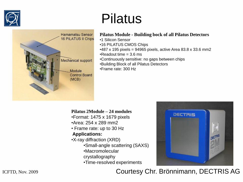
PilatusPilatus Module - Building bock of all Pilatus Detectors•1 Silicon Sensor
•16 PILATUS CMOS Chips
•487 x 195 pixels = 94965 pixels, active Area 83.8 x 33.6 mm2
•Readout time = 3.6 ms
•Continuously sensitive: no gaps between chips
•Building Block of all Pilatus Detectors
•Frame rate: 300 Hz
Pilatus 2Module – 24 modules
•Format: 1475 x 1679 pixels
•Area: 254 x 289 mm2
• Frame rate: up to 30 Hz
Applications:
•X-ray diffraction (XRD)
•Small-angle scattering (SAXS)
•Macromolecular
crystallography
•Time-resolved experiments
Courtesy Chr. Brönnimann, DECTRIS AG

L. Tlustos, CERNICFTD, Nov. 2009
EIGER (preliminary)
~very first image, preliminary – definitely working!
Courtesy R. Dinapoli, PSI
Technological process UMC 0.25 µm
Analog Parameters 30 ns peaking time
~150 ns ret. Zero
8.8uW/pixel
Gain: 44.6 μV/e-
Chip size 19.3 x 20.1 mm2 (active 19.2x19.2mm
2)
Pixel array 256 x 256 = 65536
Pixel size 75 x 75 µm2
Transistors, Matrix: 28.44M
Periphery: >120 000
Transistors density: 430/pixel
Detector readout speed ~12.5 KHz @ 8 bit mode (Detector size
doesn’t matter)
Radiation tolerance Full radiation tolerant design (>4Mrad)
Nominal power supplies 1.1 V (analog), 2V (digital), 1.8V (I/O)
Counter 12 bits, binary, configurable (4,8,12 bit
mode)
Continuous readout yes
Threshold adjustment 6 bit DAC
Overflow control yes
2 cm
2 cm

L. Tlustos, CERNICFTD, Nov. 2009
The CMOS counting ASICThe chip integrates more than 259 million
transistors.
It has 480k pixels organized in a honeycomb
matrix of 600 columns 800 lines corresponding
to an active area of
24mm (600x40 m) 27.7mm (800x34.64 m)
Each pixel is connected to a charge-sensitive
shaping amplifier followed by a discriminator and
a 15-bit shift register.
A self-calibration circuit is implemented in each
pixel to reduce unavoidable DC offset variations
from pixel to pixel →
a global threshold can be applied to the whole
matrix.
722 pixels/mm2
Each pixel column can be individually
configured for:
• counting the number of events during a given time slot or
• providing, with an external clock, a timestamp to the event or the time over threshold
See talk 24th Nov: R. Bellazini, X Ray Polarimetry: a new window on the high energy sky
Courtesy R.Bellazzini, INFN Pisa

L. Tlustos, CERNICFTD, Nov. 200917 October 2006 Michael Campbell
Acknowledgements
Fellow members of the Medipix Consortium www.cern.ch/medipix
Rafael Ballabriga, Michael Campbell, Erik Heijne, Xavier Llopart, Winnie Wong, CERN
And especially
Ronaldo Bellazzini, INFN Pisa
Christian Brönnimann, Dectris
Roberto Dinapoli, PSI
Anthony Butler, Univ. Canterbury, MARS
Pierre Delpierre, CPPM

L. Tlustos, CERNICFTD, Nov. 2009
Acknowledgements…
![111 NIST Calibration of a Neutron Spectrometer ROSPEC · 252Cf sources [4,5], a thermal-neutron beam, and 2.5 MeV and 14 MeV sources. The 2.5 MeV and 14 MeV sources are of known energy,](https://img.pdfslide.us/doc/110x75/5ebad920c3c33b6ef9254a6b/111-nist-calibration-of-a-neutron-spectrometer-rospec-252cf-sources-45-a-thermal-neutron.jpg)