Embed Size (px)
Citation preview

SPECTRA-TEKSpectra-Tek
Mercury 2e TerminalUser Manual

Layout Design by Ambrit Ltd, Northchurch, Herts.Tel: 01442 866294 Email: [email protected]
All trademarks are acknowledged as the property of their respective owners.
This document shall not form part of any contract. Specifications are subject to changewithout notice, and Daniel Europe accepts no liability of any kind for errors or omissions.
161198
Contents
PageIntroduction 5
Nomenclature & Conventions 6INSTALLATION 7
Sitting the Mercury Terminal 8Mounting procedure 10
CONNECTIONSIntrinsically Safe Connections 11Connecting a Terminal in a Safe Area 14Connecting the Card Reader 14Connecting the Bar-code System 14
Cleaning the Mercury Terminal 15POWERING UP 17Setup 18OPERATION 21Receiving Data 23Character Display mode 23
User Definable Characters and Keys 28Messages & Blocks 29Point-to-Point Transmission 30 Multi-Drop Telemetry 31
Graphics Display Mode 33Line and Box Drawing 35
Optional Equipment 36TECHNICAL SPECIFICATION
Mercury 2e Terminal 37Non IS Mercury 2e Terminal 39Security card reader 39Bar code Interface 39Bar code wand 40IS Interface Module 41
Appendix A - Certificates of Conformity 43Declaration of Conformity 58
Appendix B - References 61Appendix C - Using Mercury 2e in Multi-drop mode 63Appendix D - Terminal Wiring Schedule 67Appendix E - IS Interface Module Wiring Schedule 69Appendix F - Communications with interface module 71Appendix G - Wiring Drawings 75Appendix H - Modbus option operation 80Parts Ordering Codes 90More Information 91Index 92
3
4 161198
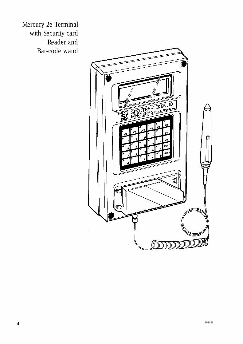
Mercury 2e Terminalwith Security card
Reader and Bar-code wand
5161198
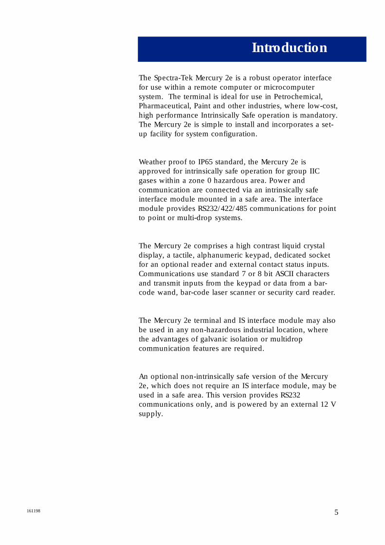
The Spectra-Tek Mercury 2e is a robust operator interfacefor use within a remote computer or microcomputersystem. The terminal is ideal for use in Petrochemical,Pharmaceutical, Paint and other industries, where low-cost,high performance Intrinsically Safe operation is mandatory.The Mercury 2e is simple to install and incorporates a set-up facility for system configuration.
Weather proof to IP65 standard, the Mercury 2e isapproved for intrinsically safe operation for group IICgases within a zone 0 hazardous area. Power andcommunication are connected via an intrinsically safeinterface module mounted in a safe area. The interfacemodule provides RS232/422/485 communications for pointto point or multi-drop systems.
The Mercury 2e comprises a high contrast liquid crystaldisplay, a tactile, alphanumeric keypad, dedicated socketfor an optional reader and external contact status inputs.Communications use standard 7 or 8 bit ASCII charactersand transmit inputs from the keypad or data from a bar-code wand, bar-code laser scanner or security card reader.
The Mercury 2e terminal and IS interface module may alsobe used in any non-hazardous industrial location, wherethe advantages of galvanic isolation or multidropcommunication features are required.
An optional non-intrinsically safe version of the Mercury2e, which does not require an IS interface module, may beused in a safe area. This version provides RS232communications only, and is powered by an external 12 Vsupply.
Introduction

6 161198
Nomenclature andConventions
In this manual, ASCII single characters which are eithercontrol or non-visible codes (Hexadecimal 00 - 1F, 20 and7F) are indicated by enclosure in < >, for example, <ESC>.
Character strings which are indivisible sequences areshown between quotation marks, for example, “<ESC> [ 2 J”.
In the ASCII 7 and 8 bit code sets used by Mercury 2e, acharacter is represented by two digits, each in the rangehexadecimal 0 to F. For example, <SP>, the space characteris defined (20H).
7161198
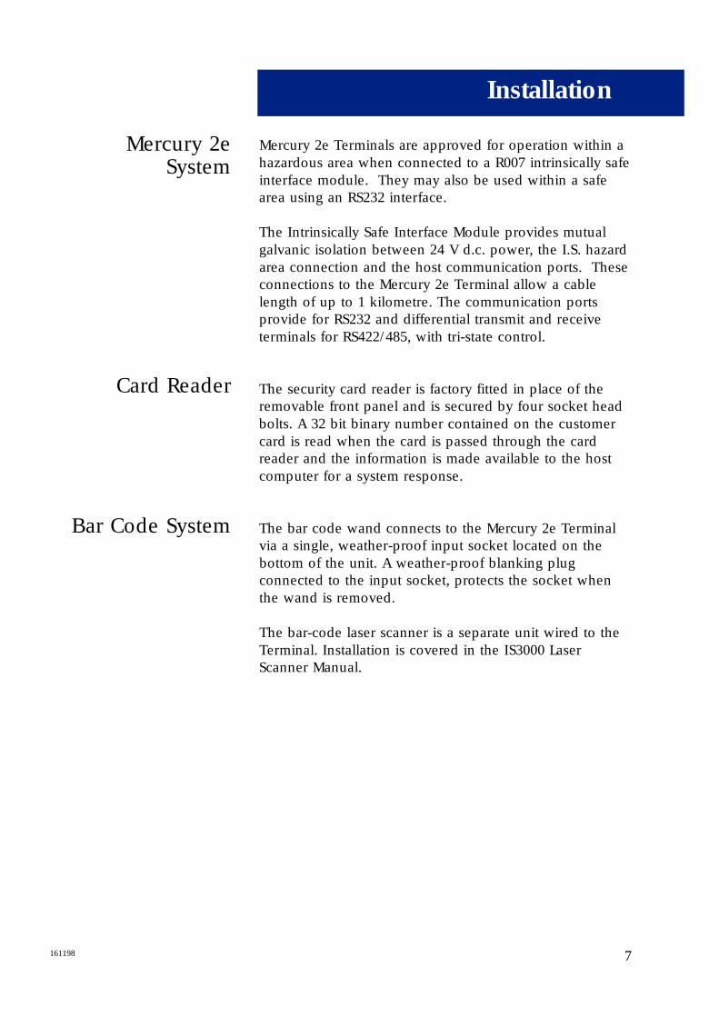
Mercury 2eSystem
Card Reader
Bar Code System
Mercury 2e Terminals are approved for operation within ahazardous area when connected to a R007 intrinsically safeinterface module. They may also be used within a safearea using an RS232 interface.
The Intrinsically Safe Interface Module provides mutualgalvanic isolation between 24 V d.c. power, the I.S. hazardarea connection and the host communication ports. Theseconnections to the Mercury 2e Terminal allow a cablelength of up to 1 kilometre. The communication portsprovide for RS232 and differential transmit and receiveterminals for RS422/485, with tri-state control.
The security card reader is factory fitted in place of theremovable front panel and is secured by four socket headbolts. A 32 bit binary number contained on the customercard is read when the card is passed through the cardreader and the information is made available to the hostcomputer for a system response.
The bar code wand connects to the Mercury 2e Terminalvia a single, weather-proof input socket located on thebottom of the unit. A weather-proof blanking plugconnected to the input socket, protects the socket whenthe wand is removed.
The bar-code laser scanner is a separate unit wired to theTerminal. Installation is covered in the IS3000 LaserScanner Manual.
Installation

8 161198
Sitting the MercuryTerminal
For your safety remember to implement all relevant
precautions and procedures. In the United Kingdom
installations must comply with BS5345, part 4.
The Mercury terminal is weather-proof to IP65, so it can beinstalled outside as well as under shelter or indoors.
Mount the terminal in a vertical position on an evensurface, strong enough to support its weight of 5.5 kg.
Position the unit so that the LCD and Keypad areconvenient for the operator, usually at eye level. Notethat, in strong direct sunlight, display clarity and servicelife may be reduced.
9161198
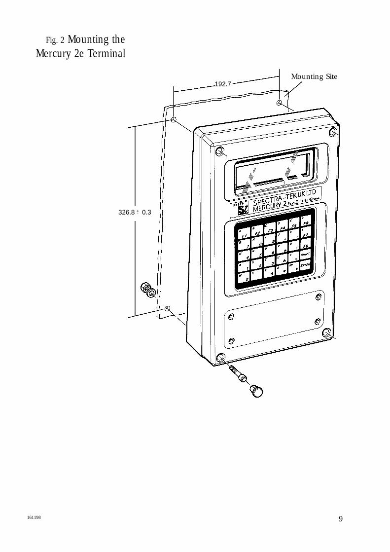
Fig. 2 Mounting theMercury 2e Terminal
192.7
326.8 0.3+-
Mounting Site

MountingProcedure
1. Check that the connection panel cover or security card reader is secured to the face of the Terminal; thisprevents any dust or water from entering the unit. Unplug the bar-code wand and make sure the protective cap is fitted on to the bar code reader inputsocket on the underside of the unit.
2. Remove the plastic protective plugs covering the four corner mounting holes by pushing the plugs from behind. Retain the plugs in a safe place. It is not necessary to remove the back of the terminal.
3. Place the Terminal against the surface on which it is to be mounted at the correct position and height for operator use and mark the position of the four mounting holes using the dimensions given (see Fig 2). Drill, and plug if necessary, the mounting holeson the mounting surface.
4. Place the Terminal against the mounting surface and secure the Terminal using 4 off M5 cap head screws (26 mm shank) or similar.
5. To avoid electro-chemical corrosion of the aluminium case, the fixing bolts and nuts should be thoroughly greased.
6. Check that the Terminal is securely fastened to the mounting surface and re-insert the plastic protective plugs into the four corner holes.
10 161198
11161198
Intrinsically Safe Connections
Connecting the I.S.Interface Module
Power and communication connections to the Mercury 2eTerminal are made via the R007 intrinsically safe interfacemodule. The IS interface module should be installed in asafe area. The cable screen should be connected to J5 pin 5 within the Mercury 2e
WARNING Power must be disconnected before
connecting or inspecting the IS interface module.
No intrinsically safe earth is required as the unit isgalvanically isolated.
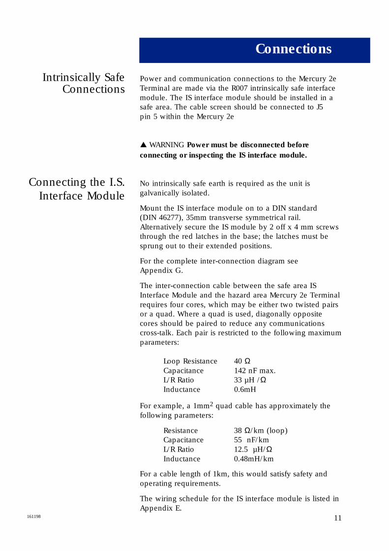
Mount the IS interface module on to a DIN standard (DIN 46277), 35mm transverse symmetrical rail.Alternatively secure the IS module by 2 off x 4 mm screwsthrough the red latches in the base; the latches must besprung out to their extended positions.
For the complete inter-connection diagram see Appendix G.
The inter-connection cable between the safe area ISInterface Module and the hazard area Mercury 2e Terminalrequires four cores, which may be either two twisted pairsor a quad. Where a quad is used, diagonally oppositecores should be paired to reduce any communicationscross-talk. Each pair is restricted to the following maximumparameters:
Loop Resistance 40 ΩCapacitance 142 nF max.L/R Ratio 33 µH /ΩInductance 0.6mH
For example, a 1mm2 quad cable has approximately thefollowing parameters:
Resistance 38 Ω/km (loop)Capacitance 55 nF/kmL/R Ratio 12.5 µH/ΩInductance 0.48mH/km
For a cable length of 1km, this would satisfy safety andoperating requirements.
The wiring schedule for the IS interface module is listed inAppendix E.
Connections
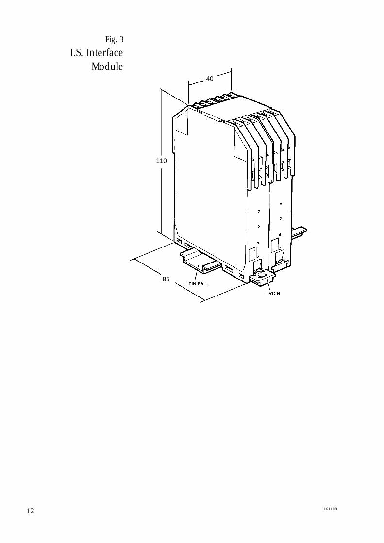
Fig. 3
I.S. Interface Module
12 161198
40
110
85
13161198
Connecting theMercury Terminal
Connecting to theTerminal Blocks
After installing the intrinsically safe interface module, youcan proceed to connect power and communication wiringto the Mercury Terminal.
For the cable entry into the Mercury Terminal, fit a suitableinsulated cable gland (M20) on the four core or twintwisted pair cable.
The terminal connection blocks are protected by a cover,or the card reader if fitted. Remove the cover byunscrewing the four retaining screws.
Power and communication connections are made toterminal block J5, pins 1 to 4 . The cable screen isconnected to pin 5.
“Simple Equipment Interface” (Digital Inputs) connectionsare located at J1, pins 1 to 5. When the host computerqueries the digital input status, a short duration 5V 1 KΩsource whetting signal senses whether an external contactis open or closed.
The Simple Equipment Interface digital inputs areintrinsically safe and have the following safety description.
Vout = 29.4 V Iout = 66.4mAWout = 0.262WCext = 0.11µF Lext = 8.4mHL/Rext =135µH/ΩCeq = 0 Leq = 0
The common connection J1 pin 5 is at a logic 0 V. Onlyvolt free contacts are permitted for use with these digitalinputs.
Connecting aTerminal in a Safe
Area
Connecting the Card Reader
Connecting the Bar Code System
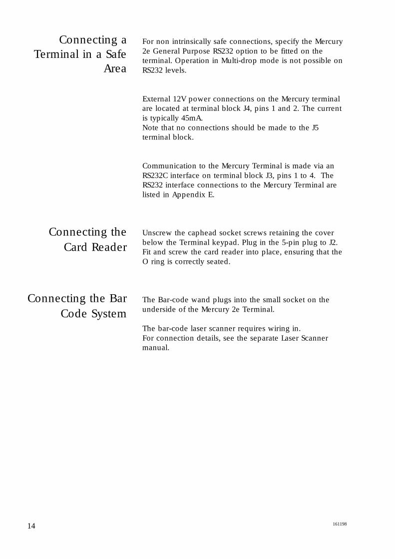
For non intrinsically safe connections, specify the Mercury2e General Purpose RS232 option to be fitted on theterminal. Operation in Multi-drop mode is not possible onRS232 levels.
External 12V power connections on the Mercury terminalare located at terminal block J4, pins 1 and 2. The currentis typically 45mA.Note that no connections should be made to the J5terminal block.
Communication to the Mercury Terminal is made via anRS232C interface on terminal block J3, pins 1 to 4. TheRS232 interface connections to the Mercury Terminal arelisted in Appendix E.
Unscrew the caphead socket screws retaining the coverbelow the Terminal keypad. Plug in the 5-pin plug to J2.Fit and screw the card reader into place, ensuring that theO ring is correctly seated.
The Bar-code wand plugs into the small socket on theunderside of the Mercury 2e Terminal.
The bar-code laser scanner requires wiring in. For connection details, see the separate Laser Scannermanual.
14 161198

15161198
Cleaning theMercury Terminal
The body of the terminal is finished in epoxy paint. Thedisplay window is polycarbonate and the keypad surfaceis polyester. These may be cleaned with soapy water.Difficult grease deposits may be treated with mostsolvents.
In a hazardous area, avoid rubbing dry plastic surfaceswith cleaning cloths, as there is a small spark hazard bytriboelectric charge generation. This risk can be overcomeby using moist cleaning processes. The keypad carries areminder of this risk.

16 161198
17161198
With no local switch, the Mercury terminal receives powerwhen the IS interface module in the safe area is connected.On connection, a beep sounds and the initialisation routinestarts. Model number and software version are detailed onthe LCD, then the cursor appears and the keyboard modeis indicated in the bottom right corner.
Automatic Message Recall
A feature of the Mercury 2e terminal is the automaticMessage Recall. Immediately after powering up and theSpectra-Tek version message has been displayed, theTerminal automatically recalls Message No. 1. For example,this may be a string of text or an escape sequence to setkeyboard mode.
Point-to-Point Mode
The single Terminal dumb mode is the default mode ofoperation, with simple transmission of characters to thehost computer on keypress, and display of receivedcharacters.
Multi-drop Mode
Up to fifteen Mercury terminals can be installed a singlemulti-drop operation. The multi-drop system uses the ISInterface Module as the tri-state controlled communicationport.
Communications
Configurable in set-up mode, selected communicationoptions are held in non-volatile RAM. Set-up mode may bepassword protected.
Powering Up
Set up
Setting options
Cold Start
In Set-up mode, the Mercury 2e is configurable for systemoperation and communication with the host computer.Setup is selected from the keypad only and, while in setupmode, no characters are transmitted by the terminal.Parameters and options are listed on the Setup menu.
Access Setup by pressing Shift four times, then Enter . (On the S500 keyboard. the Shift key is invisible and islocated below the ‘F4’ key and to the left of the ‘4’ key.)The first parameter and variable of the Setup menu isdisplayed on the bottom line of the LCD. If no securitycode has been enabled, options can be selected and set. Ifthe Security Code has been enabled, the prompt on theLCD asks for a six figure security code. If no code isentered, the options menu can be viewed but notconfigured (V3.1 and above).
Use the and keys to move the cursor to the requiredparameter, and the keys to select an option. (On the terminal automation keyboard, the keys are not indicated. The user must use H,T,M,O
instead.)
Continue selecting parameters and options until theconfiguration of the terminal is complete. Press Enter ,and the selected options are entered into NVRAM.
Parameters and options available are listed in Table 1 anddescribed below. Default settings on cold start appear inbold.
Performing a cold start will restore all default settings anderase any stored messages. A Cold Start can be performedin one of three ways:-
1. Power on with link 4 on PCB set to left hand position (ie ‘1’)
2. Power on holding down the two leftmost and two rightmost keys on the bottom row.
3. In Setup mode,, press the bottom left key (ie ‘O‘, STOP, VIEW ALARM). This will display the message “Cold Start? NO”. Pressing the same key will toggle between “Cold Start? NO” and “Cold Start? YES”. If “YES” is shown, pressing Enter will cause the machine to pause and then perform a cold start. To return to setup mode, press Enter when “NO” is displayed.
18 161198
19161198
Table 1
Set-Up Mode Menu
Parameters &Options Explained
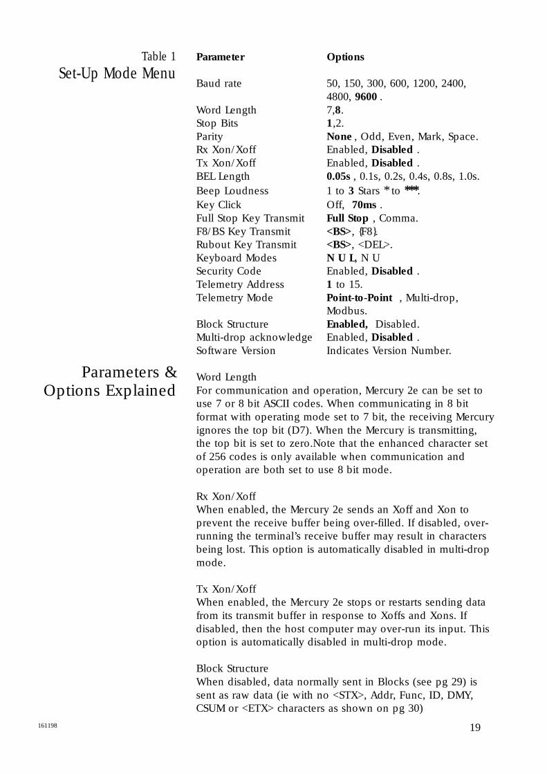
Parameter Options
Baud rate 50, 150, 300, 600, 1200, 2400, 4800, 9600 .
Word Length 7,8.Stop Bits 1,2.Parity None , Odd, Even, Mark, Space.Rx Xon/Xoff Enabled, Disabled .Tx Xon/Xoff Enabled, Disabled .BEL Length 0.05s , 0.1s, 0.2s, 0.4s, 0.8s, 1.0s.Beep Loudness 1 to 3 Stars * to ***.Key Click Off, 70ms .Full Stop Key Transmit Full Stop , Comma.F8/BS Key Transmit <BS>, F8.Rubout Key Transmit <BS>, <DEL>.Keyboard Modes N U L, N USecurity Code Enabled, Disabled .Telemetry Address 1 to 15.Telemetry Mode Point-to-Point , Multi-drop,
Modbus.Block Structure Enabled, Disabled.Multi-drop acknowledge Enabled, Disabled .Software Version Indicates Version Number.
Word LengthFor communication and operation, Mercury 2e can be set touse 7 or 8 bit ASCII codes. When communicating in 8 bitformat with operating mode set to 7 bit, the receiving Mercuryignores the top bit (D7). When the Mercury is transmitting,the top bit is set to zero.Note that the enhanced character setof 256 codes is only available when communication andoperation are both set to use 8 bit mode.
Rx Xon/XoffWhen enabled, the Mercury 2e sends an Xoff and Xon toprevent the receive buffer being over-filled. If disabled, over-running the terminal’s receive buffer may result in charactersbeing lost. This option is automatically disabled in multi-dropmode.
Tx Xon/XoffWhen enabled, the Mercury 2e stops or restarts sending datafrom its transmit buffer in response to Xoffs and Xons. Ifdisabled, then the host computer may over-run its input. Thisoption is automatically disabled in multi-drop mode.
Block StructureWhen disabled, data normally sent in Blocks (see pg 29) issent as raw data (ie with no <STX>, Addr, Func, ID, DMY,CSUM or <ETX> characters as shown on pg 30)
Local Echo
Digital Inputs
Display Test
20 161198
Security CodeThe default security code is 000000. The six digit securitycode is programmed into the Mercury terminal from thehost computer. If the security code option is enabled, theoperator has to enter a matching code at the keypad toaccess Set-up configuration.
Multi-drop / Modbus ModesIn multi-drop mode the host computer (the master device)transmits strings and commands to its population ofMercury 2e Terminals (slave devices) with an address, dataand message terminator structure. The Modbus optiononly appears if a Modbus upgrade code has beenpurchased.
Telemetry AddressWhen Multi-drop Mode is enabled, a unique TelemetryAddress must be set for each Mercury 2e Terminal. FifteenUnique addresses, 1 to 15, are available. Address “0” isreserved for broadcast operation when the same messageis sent to all slave devices simultaneously.
Multi-drop AcknowledgeWhen Enabled, an acknowledgement reply is sent inresponse to every valid received message of matchingaddress except a broadcast.
Local Echo mode is a facility to help in checking that thekeyboard, barcode or card reader is functioning correctly.When set, all keypresses, readings or swipes echo thetransmitted characters to the screen. The characters aredisplayed in current screen mode, and at current cursorcoordinates, so the screen display should be set to theappropriate mode before Local Echo is set. Local Echotoggles on and off by pressing F1 (or START BATCH 1 onthe terminal automation keyboard), when in Setup. In Local Echo mode, the terminal continues tocommunicate with the host. Press Enter to return tonormal set-up mode.
Pressing F6 (or START BATCH 6 on the terminalautomation Keyboard), while in the set-up mode gives asingle line display showing the state of the digital inputs inreal time. Press Enter to return to normal set-up mode.
Pressing F3 (or START BATCH 3 on the terminalautomation Keyboard), while in setup mode, performs adisplay test. The screen will go black, then white, and theterminal will automatically exit setup mode and return tonormal operation.
21161198
Liquid Crystal Display
Keypad
Fig 4
Standard KeypadLayout
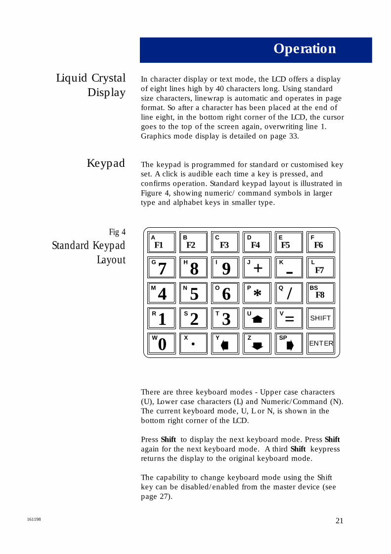
In character display or text mode, the LCD offers a displayof eight lines high by 40 characters long. Using standardsize characters, linewrap is automatic and operates in pageformat. So after a character has been placed at the end ofline eight, in the bottom right corner of the LCD, the cursorgoes to the top of the screen again, overwriting line 1.Graphics mode display is detailed on page 33.
The keypad is programmed for standard or customised keyset. A click is audible each time a key is pressed, andconfirms operation. Standard keypad layout is illustrated inFigure 4, showing numeric/ command symbols in largertype and alphabet keys in smaller type.
There are three keyboard modes - Upper case characters(U), Lower case characters (L) and Numeric/Command (N).The current keyboard mode, U, L or N, is shown in thebottom right corner of the LCD.
Press Shift to display the next keyboard mode. Press Shift
again for the next keyboard mode. A third Shift keypressreturns the display to the original keyboard mode.
The capability to change keyboard mode using the Shiftkey can be disabled/enabled from the master device (seepage 27).
Operation
F1A
G
7M 4R 1W
0
F2B
H
8N 5S 2X .
F3C
I
9O 6T 3Y
F4D
J +P
*U
Z
F5E
K
-Q /V=SP
F6F
F7L
SHIFT
ENTER
F8BS
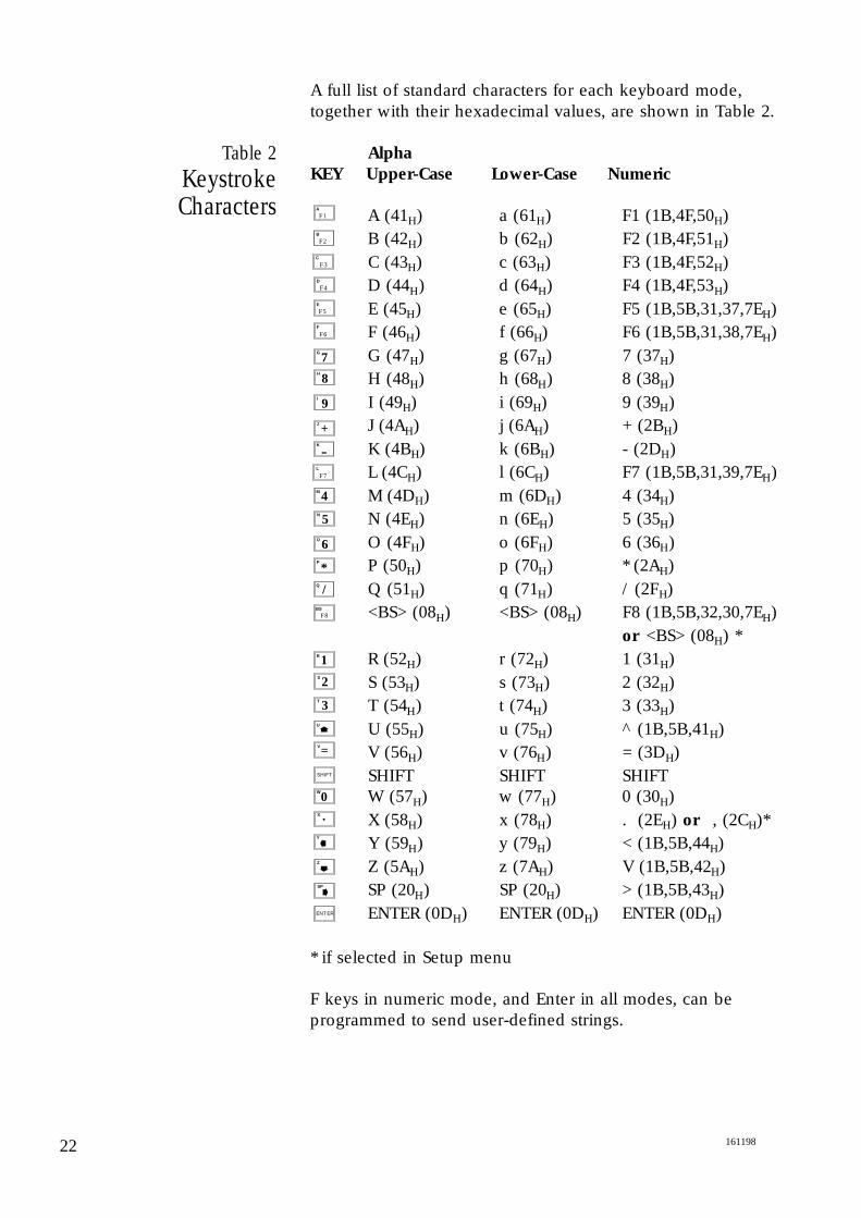
A full list of standard characters for each keyboard mode,together with their hexadecimal values, are shown in Table 2.
Alpha
KEY Upper-Case Lower-Case Numeric
A (41H) a (61H) F1 (1B,4F,50H)B (42H) b (62H) F2 (1B,4F,51H)C (43H) c (63H) F3 (1B,4F,52H)D (44H) d (64H) F4 (1B,4F,53H)E (45H) e (65H) F5 (1B,5B,31,37,7EH)F (46H) f (66H) F6 (1B,5B,31,38,7EH)G (47H) g (67H) 7 (37H)H (48H) h (68H) 8 (38H)I (49H) i (69H) 9 (39H)J (4AH) j (6AH) + (2BH)K (4BH) k (6BH) - (2DH)L (4CH) l (6CH) F7 (1B,5B,31,39,7EH)M (4DH) m (6DH) 4 (34H)N (4EH) n (6EH) 5 (35H)O (4FH) o (6FH) 6 (36H)P (50H) p (70H) * (2AH)Q (51H) q (71H) / (2FH)<BS> (08H) <BS> (08H) F8 (1B,5B,32,30,7EH)
or <BS> (08H) *R (52H) r (72H) 1 (31H)S (53H) s (73H) 2 (32H)T (54H) t (74H) 3 (33H)U (55H) u (75H) ^ (1B,5B,41H)V (56H) v (76H) = (3DH)SHIFT SHIFT SHIFT W (57H) w (77H) 0 (30H)X (58H) x (78H) . (2EH) or , (2CH)*Y (59H) y (79H) < (1B,5B,44H)Z (5AH) z (7AH) V (1B,5B,42H)SP (20H) SP (20H) > (1B,5B,43H)ENTER (0DH) ENTER (0DH) ENTER (0DH)
* if selected in Setup menu
F keys in numeric mode, and Enter in all modes, can beprogrammed to send user-defined strings.
22 161198
Table 2Keystroke Characters F1
A
F2B
F3C
F4D
F5E
F6F
G
7H
8I
9J +K
- F7L
M 4N 5O 6P
*Q /
R 1
F8BS
V=
SHIFT
W
0X .
Y
Z
SP
ENTER
S 2T 3U
23161198
Receiving Data
Character DisplayMode
Table 3
Standard ASCII Namesof Control Codes
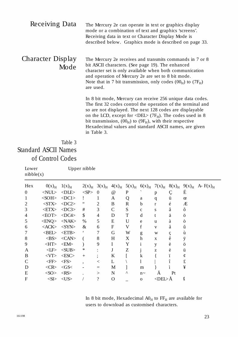
The Mercury 2e can operate in text or graphics displaymode or a combination of text and graphics ‘screens’.Receiving data in text or Character Display Mode isdescribed below. Graphics mode is described on page 33.
The Mercury 2e receives and transmits commands in 7 or 8bit ASCII characters. (See page 19). The enhancedcharacter set is only available when both communicationand operation of Mercury 2e are set to 8 bit mode. Note that in 7 bit transmission, only codes (00H) to (7FH)are used.
In 8 bit mode, Mercury can receive 256 unique data codes.The first 32 codes control the operation of the terminal andso are not displayed. The next 128 codes are displayableon the LCD, except for <DEL> (7FH). The codes used in 8bit transmission, (00H) to (9FH), with their respectiveHexadecimal values and standard ASCII names, are givenin Table 3.
In 8 bit mode, Hexadecimal A0H to FFH are available forusers to download as customised characters.
Lower Upper nibblenibble(x)
Hex 0(x)H 1(x)H 2(x)H 3(x)H 4(x)H 5(x)H 6(x)H 7(x)H 8(x)H 9(x)H A- F(x)H
0 <NUL> <DLE> <SP> 0 @ P ` p Ç É1 <SOH> <DC1> ! 1 A Q a q ü œ2 <STX> <DC2> “ 2 B R b r é Æ3 <ETX> <DC3> # 3 C S c s â ô4 <EOT> <DC4> $ 4 D T d t ä ö5 <ENQ> <NAK> % 5 E U e u à ò6 <ACK> <SYN> & 6 F V f v å û7 <BEL> <ETB> ‘ 7 G W g w ç ù8 <BS> <CAN> ( 8 H X h x ê ÿ9 <HT> <EM> ) 9 I Y i y ë öA <LF> <SUB> * : J Z j z è üB <VT> <ESC> + ; K [ k ï ¢C <FF> <FS> , < L \ l | î £D <CR> <GS< - = M ] m ì ¥E <SO> <RS> . > N ^ n ~ Ä PtF <SI> <US> / ? O _ o <DEL>Å f
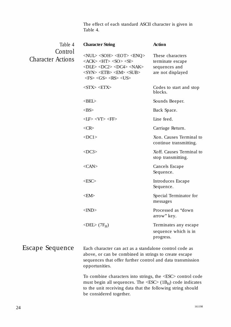
Table 4Control
Character Actions
Escape Sequence
The effect of each standard ASCII character is given inTable 4.
Character String Action
<NUL> <SOH> <EOT> <ENQ> These characters <ACK> <HT> <SO> <SI> terminate escape <DLE> <DC2> <DC4> <NAK> sequences and<SYN> <ETB> <EM> <SUB> are not displayed<FS> <GS> <RS> <US>
<STX> <ETX> Codes to start and stop blocks.
<BEL> Sounds Beeper.
<BS> Back Space.
<LF> <VT> <FF> Line feed.
<CR> Carriage Return.
<DC1> Xon. Causes Terminal tocontinue transmitting.
<DC3> Xoff. Causes Terminal tostop transmitting.
<CAN> Cancels Escape Sequence.
<ESC> Introduces Escape Sequence.
<EM> Special Terminator for messages
<IND> Processed as “down arrow” key.
<DEL> (7FH) Terminates any escape
sequence which is in progress.
Each character can act as a standalone control code asabove, or can be combined in strings to create escapesequences that offer further control and data transmissionopportunities.
To combine characters into strings, the <ESC> control codemust begin all sequences. The <ESC> (1BH) code indicatesto the unit receiving data that the following string should be considered together.
24 161198
25161198
Table 5
Cursor/Screen Control Strings in
Text Mode
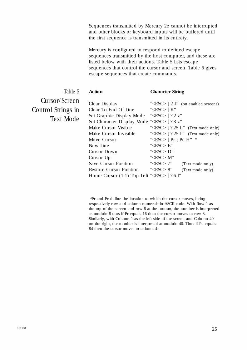
Sequences transmitted by Mercury 2e cannot be interruptedand other blocks or keyboard inputs will be buffered untilthe first sequence is transmitted in its entirety.
Mercury is configured to respond to defined escapesequences transmitted by the host computer, and these arelisted below with their actions. Table 5 lists escapesequences that control the cursor and screen. Table 6 givesescape sequences that create commands.
Action Character String
Clear Display “<ESC> [ 2 J” (on enabled screens)
Clear To End Of Line “<ESC> [ K”Set Graphic Display Mode “<ESC> [ ? 2 z”Set Character Display Mode “<ESC> [ ? 3 z”Make Cursor Visible “<ESC> [ ? 25 h” (Text mode only)
Make Cursor Invisible “<ESC> [ ? 25 l” (Text mode only)
Move Cursor “<ESC> [ Pr ; Pc H” *New Line “<ESC> E”Cursor Down “<ESC> D”Cursor Up “<ESC> M”Save Cursor Position “<ESC> 7” (Text mode only)
Restore Cursor Position “<ESC> 8” (Text mode only)
Home Cursor (1,1) Top Left “<ESC> [ ? 6 l”
*Pr and Pc define the location to which the cursor moves, beingrespectively row and column numerals in ASCII code. With Row 1 asthe top of the screen and row 8 at the bottom, the number is interpretedas modulo 8 thus if Pr equals 16 then the cursor moves to row 8.Similarly, with Column 1 as the left side of the screen and Column 40on the right, the number is interpreted at modulo 40. Thus if Pc equals84 then the cursor moves to column 4.
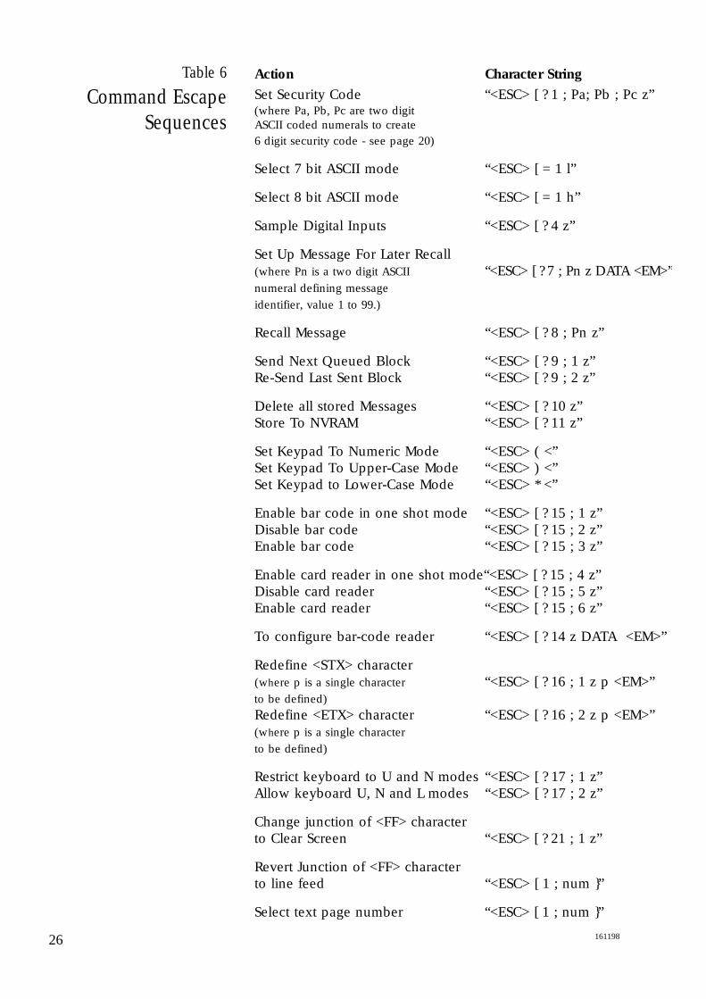
Table 6
Command EscapeSequences
Action Character String
Set Security Code “<ESC> [ ? 1 ; Pa; Pb ; Pc z”(where Pa, Pb, Pc are two digitASCII coded numerals to create 6 digit security code - see page 20)
Select 7 bit ASCII mode “<ESC> [ = 1 l”
Select 8 bit ASCII mode “<ESC> [ = 1 h”
Sample Digital Inputs “<ESC> [ ? 4 z”
Set Up Message For Later Recall(where Pn is a two digit ASCII “<ESC> [ ? 7 ; Pn z DATA <EM>”numeral defining message
identifier, value 1 to 99.)
Recall Message “<ESC> [ ? 8 ; Pn z”
Send Next Queued Block “<ESC> [ ? 9 ; 1 z”Re-Send Last Sent Block “<ESC> [ ? 9 ; 2 z”
Delete all stored Messages “<ESC> [ ? 10 z”Store To NVRAM “<ESC> [ ? 11 z”
Set Keypad To Numeric Mode “<ESC> ( <”Set Keypad To Upper-Case Mode “<ESC> ) <”Set Keypad to Lower-Case Mode “<ESC> * <”
Enable bar code in one shot mode “<ESC> [ ? 15 ; 1 z”Disable bar code “<ESC> [ ? 15 ; 2 z”Enable bar code “<ESC> [ ? 15 ; 3 z”
Enable card reader in one shot mode“<ESC> [ ? 15 ; 4 z”Disable card reader “<ESC> [ ? 15 ; 5 z”Enable card reader “<ESC> [ ? 15 ; 6 z”
To configure bar-code reader “<ESC> [ ? 14 z DATA <EM>”
Redefine <STX> character(where p is a single character “<ESC> [ ? 16 ; 1 z p <EM>”to be defined)
Redefine <ETX> character “<ESC> [ ? 16 ; 2 z p <EM>”(where p is a single character
to be defined)
Restrict keyboard to U and N modes “<ESC> [ ? 17 ; 1 z”Allow keyboard U, N and L modes “<ESC> [ ? 17 ; 2 z”
Change junction of <FF> characterto Clear Screen “<ESC> [ ? 21 ; 1 z”
Revert Junction of <FF> character to line feed “<ESC> [ 1 ; num ”
Select text page number “<ESC> [ 1 ; num ”
26 161198
27161198
Specifying ScreenMode
DisablingKeyboard or
Keyboard ModeSelection
Pin Number
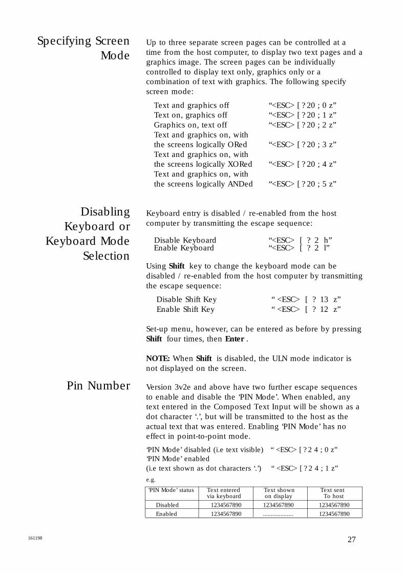
Up to three separate screen pages can be controlled at atime from the host computer, to display two text pages and agraphics image. The screen pages can be individuallycontrolled to display text only, graphics only or acombination of text with graphics. The following specifyscreen mode:
Text and graphics off “<ESC> [ ? 20 ; 0 z”Text on, graphics off “<ESC> [ ? 20 ; 1 z”Graphics on, text off “<ESC> [ ? 20 ; 2 z”Text and graphics on, with the screens logically ORed “<ESC> [ ? 20 ; 3 z”Text and graphics on, with the screens logically XORed “<ESC> [ ? 20 ; 4 z”Text and graphics on, with the screens logically ANDed “<ESC> [ ? 20 ; 5 z”
Keyboard entry is disabled / re-enabled from the hostcomputer by transmitting the escape sequence:
Disable Keyboard “<ESC> [ ? 2 h” Enable Keyboard “<ESC> [ ? 2 l”
Using Shift key to change the keyboard mode can bedisabled / re-enabled from the host computer by transmittingthe escape sequence:
Disable Shift Key “ <ESC> [ ? 13 z”Enable Shift Key “ <ESC> [ ? 12 z”
Set-up menu, however, can be entered as before by pressingShift four times, then Enter .
NOTE: When Shift is disabled, the ULN mode indicator isnot displayed on the screen.
Version 3v2e and above have two further escape sequencesto enable and disable the ‘PIN Mode’. When enabled, anytext entered in the Composed Text Input will be shown as adot character ‘.’, but will be transmitted to the host as theactual text that was entered. Enabling ‘PIN Mode’ has noeffect in point-to-point mode.
‘PIN Mode’ disabled (i.e text visible) “ <ESC> [ ? 2 4 ; 0 z”‘PIN Mode’ enabled (i.e text shown as dot characters ‘.’) “ <ESC> [ ? 2 4 ; 1 z”
e.g.
‘PIN Mode’ status Text entered Text shown Text sent via keyboard on display To host
Disabled 1234567890 1234567890 1234567890
Enabled 1234567890 ................... 1234567890
User-DefinableCharacters
User-Definable Keys
There are 96 ASCII two-digit codes available for users toassign to escape sequences that are frequently required.These are hexadecimal A0H to FFH (see Table 3) andavailable in 8 bit mode only. The sequence to define acharacter is as follows:
“<ESC> [ ? 19 ; num z data ”
num is ASCII number of the character being defined(between 160 and 255). data gives 8 bytes of data whichmust be supplied as ASCII characters. For Pixel to ASCIIcharacter conversion table, see page 33.
Redefine a Function key or Enter with up to 8 ASCIIcharacters, placed in the following sequence at data .
“<ESC> [ ? 23; Pn z data <EM>”
Pn is the number of the key being redefined. Numbers 1to 8 redefine F1 to F8 respectively, and 9 redefines Enter .
28 161198
29161198
Messages
Storing Messages
Blocks
Messages, in the form of characters or escape sequencesthat are sent to the Mercury, can be recalled for displaymany times (see Table 6).
A total of 7,000 characters may be stored as messages inRAM. Each message is assigned an identifying valuebetween 1 and 99. A message should not be allocated toan identifier already in use.
The codes in the message can be any visible or controlcharacter, except <STX>, <ETX> and <EM>, or the escapesequence for “Set Up Message for Later Recall”. It ispossible to create a message string to recall othermessages.
On transmission to the Mercury, messages are storedtemporarily in Static Random Access Memory (SRAM). Amessage may be recalled as often as required, but it is lostif the power is removed from the Mercury 2e Terminal. Ifthe command “Store to NVRAM” is sent after the message,then the contents of the SRAM are copied to the Non-Volatile RAM (NVRAM) to ensure preservation in case ofpower failure.
If the Mercury 2e Terminal is turned off and subsequentlyturned on, it copies the contents of NVRAM into SRAM,restoring any messages down-loaded up to the time thelast “Store to NVRAM” command was sent. If the set-upmode is entered and left, the contents of SRAM are copiedto NVRAM automatically.
Blocks are strings of data in a fixed format which cannotbe interrupted, obtained from a read of digital inputs, orfrom a bar code read or a card swipe. The formatdistinguishes the data string from keypad-entered data.
Point to PointTransmission
Transmission of messages in point-to-point configuration isimmediate, i.e. at every key stroke, or promptly after acard-read or bar-code swipe. The control codes andescape sequences described in this section are available,with the exceptions noted.
Transmitted messages follow the format:
<STX> ADDR FUNC ID DATA DMY CSUM <ETX>
<STX> Start Transmission (02H)
ADDR A two byte address field, set up in Telemetry Address with value 1 to 15. For multi-drop mode see page 32. This is always 01 in point topoint mode.
FUNC Determines type of information being transmitted with a single byte character. For messages transmitted from the Mercury 2e terminal this is always “D” (44H), and “R” (52H) for messages received by the Mercury 2e terminal.
ID Identifies source of data from a single byte:
“B” (42H) data from Security Card swipe“C” (43H) data from Bar Code Reader“E” (45H) data from digital input read.
Other ID codes are available in Multi-drop mode. (see page 32)
DATA Information being sent from the identified source:
data from Security Card swipe as 32 bits, encoded into 8 bytes of ASCII hexadecimal;
data from Bar Code Reader, printable as it stands;
data for Digital input reader as a single byte.
DMY Single character, usually (00H); but if this wouldresult in the following CSUM byte being a control character, the DMY is set to (20H).
CSUM A single byte checksum character, which is the 7 bit negated algebraic sum of all the charactersin the string from <STX> to DMY inclusive.
<ETX> End Transmission character (03H) (see Table 4)
Examples of messages are given in Appendix C.30 161198
31161198
Multi-DropTelemetry
Multi-Drop ModeScreen
In multi-drop mode the master device polls the slaveMercury 2e Terminals. Up to 15 Terminal systems cantransmit to a single host computer via a single twisted paircable utilising RS485 levels (two pairs if RS422 is used).The Multi-drop master initiates all communications and theslaves can only reply when requested.
Multi-drop operation is supported over the RS485 and tri-state controlled RS422 communications link between I.SInterface Modules. So these must be installed even ifoperation is in non-hazardous areas.
The Mercury 2e LCD screen in multi-drop mode operatesin the standard page format, with the exception that theeighth line is used as the editing area for composingblocks. To avoid deletion of data being composed on Line8, host operators should use lines 1 to 7.
In the case of the host computer transmitting a ClearScreen escape sequence, in Multi-drop mode, lines 1 to 7of the Screen are cleared. Line 8 is not affected.
On Line 8, an alpha-numeric keypress causes the characterto appear on the bottom line of the screen at column 6. Upto 30 characters can be composed into a message. To edituse the back space key, <BS> (F8 in N mode). Whencomplete, press Enter to queue the message fortransmission.
If a function key is activated while a message is beingcomposed, the function code is added to the block bufferahead of the message, without affecting the composition ofthe message.
Messages are block-based and therefore indivisible. So thesoftware handshaking facility Xon/Xoff is automaticallydisabled if Multi-drop Operation is selected in the Setupmenu (see Table 1).
The Mercury terminal does not inhibit received charactersbeing displayed on the 8th line of the screen. So amessage being composed may be overwritten on thescreen, although it will still be composed correctly into ablock.
Block Format
Sending Block
The block format for messages in multi-drop are similar tothat for Point-to-Point mode, and are received as well astransmitted:
<STX> ADDR FUNC ID DATA DMY CSUM <ETX>
These fields are described on page 30. The following fieldshave additional options in multi-drop mode as follows:
ADDR Mercury 2e Terminal can be set to respond to any address in range 1 to 15 in the Setup menu. Address 00 is reserved for broadcast to all slave terminals.
ID In addition to the codes B, C and E described in Point-to-Point Mode, a single byte defines the block source as follows:
“A” (41H) block from operator keyboard entry
“D” (44H) block from keyboard function key (F1 to F8)
DATA Format differs slightly for sending or receiving data blocks. Block data received by the Mercury 2e can be up to 128 bytes long, containing visible characters and escape sequences.Block data transmitted by the Mercury 2e includes one of the above ID bytes or the “Multi-drop Acknowledge” block (see Setup menu on page 19). No acknowledgement is sent if the received block was a broadcast.
A key or series of keys pressed on the terminal are storedinto an output buffer on the keypress Enter . The masterunit reads the output buffer on a FIRST-IN, FIRST-OUTbasis. The escape sequence to send the next buffer isdefined in Table 6 on page 26.
Examples of typical sequences and how they arecomposed are given in Appendix C.
32 161198
33161198
Graphics DisplayMode
Graphics Display
Table 7
GraphicsMode Pixel Data
To select Graphics with Text or Graphics alone, see page 27.Note that on Mercury terminals with text only, the enhancedsoftware described below is not available.
In Graphics mode, display is made up of 64 rows of 40columns. Each column position is a ‘tile’ made up of 6 pixelsacross by 1 pixel in height.
No cursor is visible in graphics mode. As a tile is written, avirtual cursor is incremented. The virtual cursor has its own setof coordinates allowing access to graphics without corruptingtext currently displayed.
Coordinates are defined by the byte number and row number,calculated from the top left corner of the display. With one byteequating to 6 pixels, simple or bitmap images are positionedhorizontally from the 6 pixel boundaries.
Graphics may be downloaded as a bit-map image from off-lineGraphics Converter Software, available from Daniel Europe Ltd,or designed directly on the display. See page 35 for examples ofsimple graphics and their design.
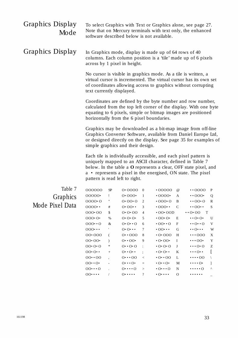
Each tile is individually accessible, and each pixel pattern isuniquely mapped to an ASCII character, defined in Table 7below. In the table a O represents a clear, OFF state pixel, anda • represents a pixel in the energised, ON state. The pixelpattern is read left to right.
OOOOOO SP O•OOOO 0 •OOOOO @ ••OOOO P
OOOOO• ! O•OOO• 1 •OOOO• A ••OOO• Q
OOOO•O " O•OO•O 2 •OOO•O B ••OO•O R
OOOO•• # O•OO•• 3 •OOO•• C ••OO•• S
OOO•OO $ O•O•OO 4 •OO•OO D ••O•OO T
OOO•O• % O•O•O• 5 •OO•O• E ••O•O• U
OOO••O & O•O••O 6 •OO••O F ••O••O V
OOO••• ' O•O••• 7 •OO••• G ••O••• W
OO•OOO ( O••OOO 8 •O•OOO H •••OOO X
OO•OO• ) O••OO• 9 •O•OO• I •••OO• Y
OO•O•O * O••O•O : •O•O•O J •••O•O Z
OO•O•• + O••O•• ; •O•O•• K •••O•• [OO••OO , O•••OO < •O••OO L ••••OO \
OO••O• - O•••O• = •O••O• M ••••O• ]
OO•••O . O••••O > •O•••O N •••••O ^
OO•••• / O••••• ? •O•••• O •••••• _
Cursor and ScreenControl Codes
Table 8Cursor/Screen
Control in GraphicsMode
Control Codes
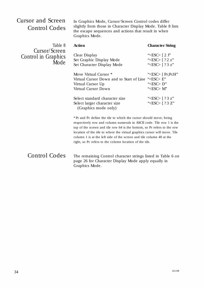
In Graphics Mode, Cursor/Screen Control codes differslightly from those in Character Display Mode. Table 8 liststhe escape sequences and actions that result in whenGraphics Mode.
Action Character String
Clear Display “<ESC> [ 2 J”Set Graphic Display Mode “<ESC> [ ? 2 z”Set Character Display Mode “<ESC> [ ? 3 z”
Move Virtual Cursor * “<ESC> [ Pr;PcH”Virtual Cursor Down and to Start of Line “<ESC> E”Virtual Cursor Up “<ESC> D”Virtual Cursor Down “<ESC> M”
Select standard character size “<ESC> [ ? 3 z”Select larger character size “<ESC> [ ? 3 Z”
(Graphics mode only)
* Pr and Pc define the tile to which the cursor should move, being
respectively row and column numerals in ASCII code. Tile row 1 is the
top of the screen and tile row 64 is the bottom, so Pr refers to the row
location of the tile to where the virtual graphics cursor will move. Tile
column 1 is at the left side of the screen and tile column 40 at the
right, so Pc refers to the column location of the tile.
The remaining Control character strings listed in Table 6 onpage 26 for Character Display Mode apply equally inGraphics Mode.
34 161198

35161198
Draw Line
Draw a Solid Box
Downloading aGraphic BitmapImage to Screen
The facility to draw a line or box is not available in thetext-only version of Mercury 2e. The fully enhancedMercury 2e is capable of handling downloaded bitmapimages generated off-line, as well as these simple line andbox drawings.
A line can be drawn at any angle using the followingsequence:
<ESC> [ ? 18 ; 4 ; x1 ; y1 ; x2 ; y2
where x1 (pixel number) and y1 (row number) give thepixel coordinates of the start of the line, and x2 , y2 givethe pixel coordinates of the end of the line.
To draw a solid box, use one of the following sequences.
Solid black box <ESC> [ ? 18 ; 2 ; x1 ; y1 ; x2 ; y2 z
Solid white box <ESC> [ ? 18 ; 3 ; x1 ; y1 ; x2 ; y2 z
where x1 (pixel number) and y1 (row number) give thepixel coordinates of the top, left corner, and x2 , y2 givethe pixel coordinates of the bottom, right corner of thebox.
When downloading a graphics bitmap image, enter theposition and size of the image in the following sequence.
<ESC> [ ? 18 ; 1 ; x1 ; y1 ; wdth ; hgt z data
where x1 (byte number) and y1 (row number) are thecoordinates of the top left corner, and wdth and hgt givethe width (in bytes) and height (in rows) of the image.
OptionalEquipment
Card Reader
Operated by passing a customer card through the reader, asuccessful read is indicated by a beep. In point-to-pointmode, transmission to the host computer is immediate. Inmulti-drop mode the data is stored in the output buffer. The message format is determined by the byte structuresetting, selected during set-up, and comprises an escapeprefix, function code, data and return. For sequencescontrolling the card reader, see page 26.
Bar Code Wand Reader
The bar code reader is operated by wiping the head of thewand over the item bar code. The tip should be in contactwith the bar-code surface and the wand may be wiped ineither direction. A successful read of the bar code isindicated by a beep. For escape sequences controlling thebar-code reader see page 26.
Laser Scanner
Installation and operation of the Bar-code laser scanner iscovered in a separate manual. Operation results in thesame action as described for the Bar Code Wand.
36 161198
37161198
Mercury 2e Terminal
(Part No.R004/e-IS.)
Physical Data
Overall Dimensions:Height 370 mm.Width 227 mm.Depth: (with card reader) 97 mm.
(without card reader) 67 mm.Weight 5.5Kg.Colour Cobalt Blue.Paint type Epoxy.
Performance Data
DISPLAYType Supertwist, Liquid Crystal.
Reflective filters.Colour Black on silverCharacter Mode: 40 characters, 8 lines
6 x 8 dot character cell ; 128 pre-defined and 96 downloadable ASCII characters in 8 bit mode; 96 ASCII character set in 7 bit mode.Character height 4.2 mm.
Graphics Mode 240 x 64 graphic pixels, forming 2560 tiles.Character cell height 4.2 mm or 12.7 mm.
Keypad Sealed membrane switches. Polyester outer layer, with tactile response. Damp wipeable for clean/sterile environments.30 keys including 8 functions. Option for Audible sounder via membrane selected in Setup.
Keyboard modes Upper Case (U), Lower case (L), Numeric/Command (N).
Digital Inputs 4 whetted inputs for external contacts or I.S. “simple apparatus”.
Protocol Based on VT 100.Communication To and from the host computer
in full or half duplex, using standard asynchronous 7 bit or 8 bit ASCII characters.
Communications speed 50 – 9600 baud.
Specification
Buffers Incoming buffer 2048 characters long. Xon-Xoff control selected in Setup. Xoff sent to host computer when buffer is within 10 bytes of being full. Xon sent when Terminalbuffer is within 5 characters of being empty. In multi-drop mode, Xon-Xoff control is disabled.
User Memory 8K NVRAM for rapid recall of user graphics or characters.
Data is the binary value of the 5 readable inputs biased by 20H.
Digital Inputs D7 Always a zero.D6 Always a zero.D5 Always a one.D4 Card presence indicator.
Bit is a “1” if card in slotD3 Digital input 4. This bit is
a “1” if a contact is closed.D2 Digital input 3. This bit is
a “1” if a contact is closed.D1 Digital input 2. This bit is
a “1” if a contact is closed.D0 Digital input 1. This bit is
a “1” if a contact is closed.
Inputs identified by ID “A” (41H) Operator keypress“B” (42H) Security Card“C” (43H) Bar Code reader“D” (44H) Function key“E” (45H) Digital Input
Multi-Drop Mode Maximum of 15 terminals may be multidropped via IS interface modules.
Multi-Drop Protocol Spectra-Tek proprietary, based on ANSI-X3.
Environmental Conditions
Operating Temperature -20 to 50°CStorage -20 to 60°CProtection IP65 Standard. (Ingress protection:
6 dust, 5 water-jet).Certification EEx ia IIC T4.Sira Safety Services Ltd. SCS No Ex90C2016 X.Quality Assurance BS5750 Part I.P
38 161198
39161198
Non-I.S. Mercury2e Terminal
Security CardReader
Bar Code Interface
(Part No. R004/e-GP)
The non-IS terminal has similar specifications to ISTerminal. Unit may be used as a stand alone safe areaTerminal powered by a 12 V, 1 Watt supply, with an RS232port. Not intrinsically safe because of the voltages usedwith the RS232 port.
(R005-CR)
Performance Data
Principle of Operation Wiegand Effect. Comprises permanent magnets and sensing coil.
Card Code 32 bit binary plus start and stop bits (16 bit customer location plus 16 bit card number).
Intrinsic Safety Card reader is certified for use with Mercury 2e Terminal (see Appendix A.)
Environmental Conditions
Operating Temperature -20 to 50° C.Storage -20 to 60° C.Protection IP65 Standard. (Ingress
protection: 6 dust, 5 water-jet).
(Part No. R008-WO) Installed with Mercury 2e
Readable Codes (automatic) Code 39 (3 of 9)Extended code 39Code 128UPC/EAN/ JANInterleaved 2 of 5Codabar (NW7).
Decode Direction Interface interprets codes read in either direction.
40 161198
(Part No. R008-WAND)
Performance Data
Cable 1m coiled cable with waterproof connection.
Optical Resolution 0.19 mm.Tip Material Replaceable Sapphire.Intrinsic Safety The bar code wand is certified
for use with the Mercury 2e Terminal as an associated apparatus, EEx ia IIC T4 SCS No.Ex90C2016X (see Appendix A).
Scan Speed 10 to 120 cm per second.
Environmental Conditions
Operating Temperature -20 to 50° C.Storage -40 to 75° C.Protection IP64 Standard.
Bar Code Wand

41161198
I.S. InterfaceModule
(Part No. R007-IS) Installed in Safe Area
Physical Data
Overall DimensionsHeight 110 mm.Width 85 mm.Depth 40 mm.Weight 250 grams (approx.).Material PlasticColour Green.IS Terminals 20 V, 100 ohm nominal, galvanically
isolated.IS Cabling See page 10Mounting 35mm transverse rail DIN 46277 or by
screws on 90 mm centres.Power 20-32 V d.c. 2W maximum. Nominal
80mA at 24V.IS Earth Not Required.Isolation 3 mutually galvanically isolated ports.Communications RS232, RS422 and RS485 (see
Appendix F).Intrinsic Safety Mounted in safe area, SCS No.
Ex90C2017
Environmental Conditions
Operating Temperature 0 to 40° C.Storage -20 to 60°C.Humidity 95% non-condensing.Protection IP 20.Location Safe Area.

42 161198

43161198
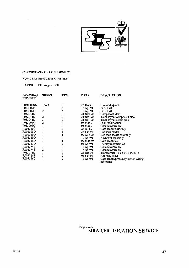
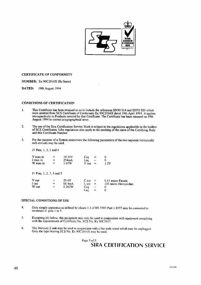
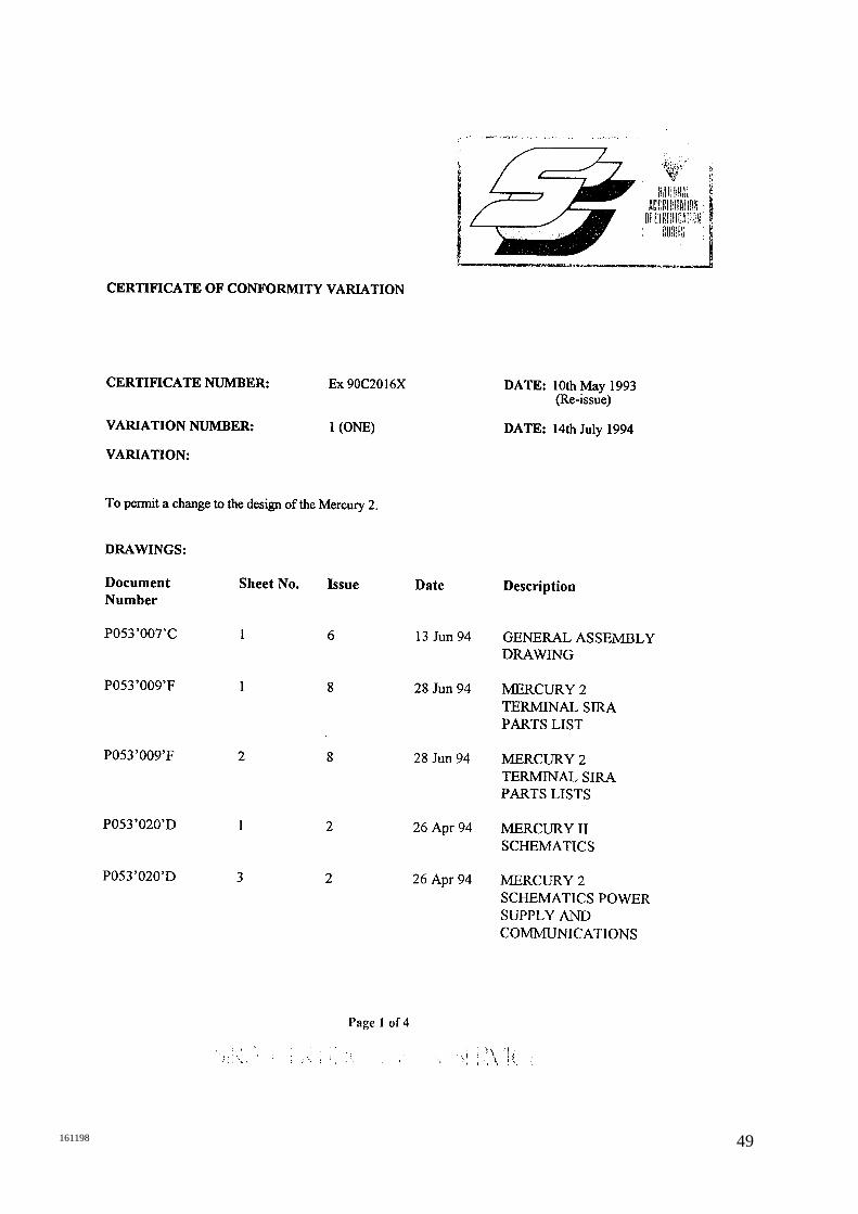
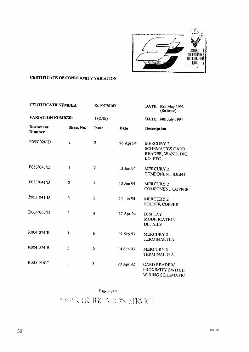
Appendix A
Certificates of Conformity for the Spectra-Tek UK LimitedMercury 2e and R007 Intrinsically Safe Interface Module are given overleaf.

44 161198

45161198

46 161198
47161198
48 161198
49161198
50 161198
51161198

52 161198

53161198

54 161198

55161198
56 161198
57161198

58 161198

59161198

60 161198

61161198
References 1 Hand Book of Reliability Data (4), British Telecom.
2 BS5501 Equipment for potentially explosive atmospheres.
Appendix B

62 161198

63161198
Using Mercury 2e in Multi-drop
Mode
Text Transmission
Examples of how to use the Mercury 2e escape codes tocomplete actions are given below. Take a few minutes tofamiliarise yourself with the method for designing blocksand messages, or graphic images.
This example runs through the method to send a textmessage to a Mercury’s display. The text used in thisexample is the word “TEST”.Using the format of a block, we can examine how it iscomposed:
“<STX> ADDR FUNC DATA DMY CSUM <ETX>”
<STX> character always starts a block and is sometimesknown as the Control B character. The terminal needs toreceive the character Hex value (02H).
ADDR Before any transmission is made, determine the destinationterminal address. This address is set manually in the Set-upmode on the terminal and is a number between 1 and 15.The ADDR field is a two byte field. So if the destinationterminal address is 1, then the field must contain 01.
FUNC The FUNC byte is a “D” (44H) for messages transmitted fromthe Mercury 2e terminal and “R” (52H) for messages receivedby the Mercury 2e terminal. In this example this byte mustbe “R”.
DATAA field of variable length, this contains the “message” to betransmitted whether it is text or a control character string. Inthis example the word “TEST” is being transmitted.
Appendix C
64 161198
CSUM
Read the BlockBuffer
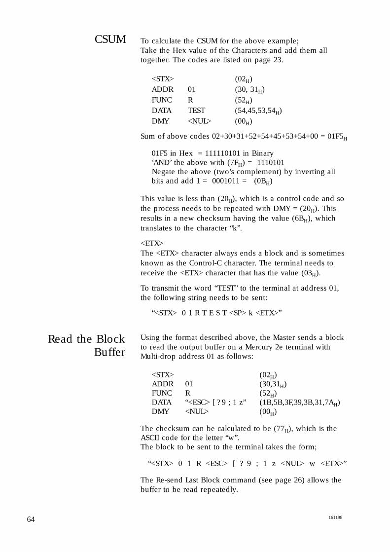
To calculate the CSUM for the above example;Take the Hex value of the Characters and add them alltogether. The codes are listed on page 23.
<STX> (02H)ADDR 01 (30, 31H)FUNC R (52H)DATA TEST (54,45,53,54H)DMY <NUL> (00H)
Sum of above codes 02+30+31+52+54+45+53+54+00 = 01F5H
01F5 in Hex = 111110101 in Binary‘AND’ the above with (7FH) = 1110101Negate the above (two’s complement) by inverting all bits and add 1 = 0001011 = (0BH)
This value is less than (20H), which is a control code and sothe process needs to be repeated with DMY = (20H). Thisresults in a new checksum having the value (6BH), whichtranslates to the character “k”.
<ETX>The <ETX> character always ends a block and is sometimesknown as the Control-C character. The terminal needs toreceive the <ETX> character that has the value (03H).
To transmit the word “TEST” to the terminal at address 01,the following string needs to be sent:
“<STX> 0 1 R T E S T <SP> k <ETX>”
Using the format described above, the Master sends a blockto read the output buffer on a Mercury 2e terminal withMulti-drop address 01 as follows:
<STX> (02H)ADDR 01 (30,31H)FUNC R (52H)DATA “<ESC> [ ? 9 ; 1 z” (1B,5B,3F,39,3B,31,7AH)DMY <NUL> (00H)
The checksum can be calculated to be (77H), which is theASCII code for the letter “w”.The block to be sent to the terminal takes the form;
“<STX> 0 1 R <ESC> [ ? 9 ; 1 z <NUL> w <ETX>”
The Re-send Last Block command (see page 26) allows thebuffer to be read repeatedly.
65161198
Read Digital Inputs
Multi-Drop Acknowledge
Mode
The Control Character String to read the Digital Inputs inMulti-drop mode is:
“<ESC> [ ? 4 z”
Using the method demonstrated above, the block to besent in multi-drop mode becomes;
“<STX> 0 1 R <ESC> [ ? 4 z <NUL> h <ETX>”
This action causes the status of the external contacts to becopied into the output buffer. It is possible to incorporatea Block Read instruction into a single block command byputting into the DATA field both the Control String to readthe digital inputs and the Control String to read the blockbuffer.
If the destination terminal is set up with Multi-dropAcknowledge Enabled then the Mercury 2e terminal sendsan Acknowledge Block back to the master. It does this onreceipt of a valid Block of matching address (i.e the Multi-drop Protocol is correct) and takes the form:
“<STX> 0 1 D <NUL> Y <ETX>”
This string acknowledges that a message with the correctprotocol, ie FUNC, CSUM, etc. has been received, not thatthe message data is recognised. So if a message isconstructed with a non-existent Escape sequence in DATAyet with the correct protocol, then a Multi-dropAcknowledge is transmitted but the Mercury 2e ignores theinstruction.
When the Digital Inputs are read to the block, noinformation is relayed back to the Master. If Multi-dropAcknowledge is enabled, however, then the acknowledgewould confirm that the message was received correctly.

66 161198
67161198
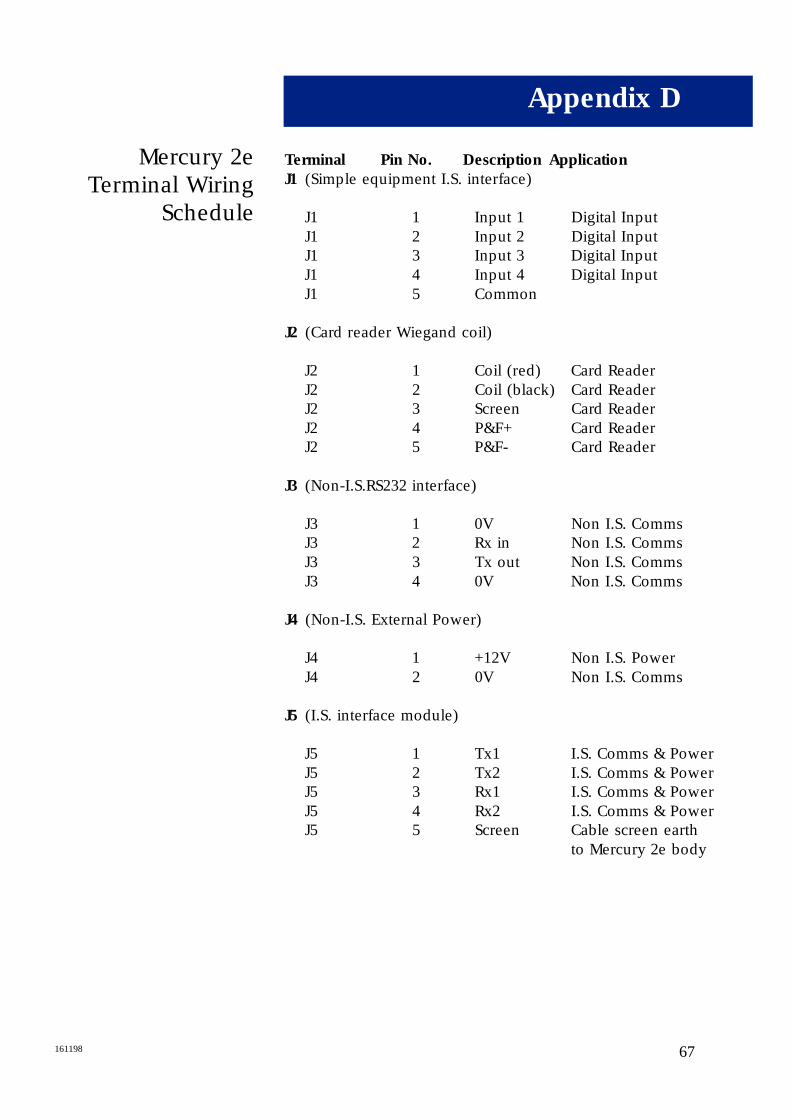
Mercury 2eTerminal Wiring
Schedule
Terminal Pin No. Description Application
J1 (Simple equipment I.S. interface)
J1 1 Input 1 Digital InputJ1 2 Input 2 Digital InputJ1 3 Input 3 Digital InputJ1 4 Input 4 Digital InputJ1 5 Common
J2 (Card reader Wiegand coil)
J2 1 Coil (red) Card ReaderJ2 2 Coil (black) Card ReaderJ2 3 Screen Card ReaderJ2 4 P&F+ Card ReaderJ2 5 P&F- Card Reader
J3 (Non-I.S.RS232 interface)
J3 1 0V Non I.S. CommsJ3 2 Rx in Non I.S. CommsJ3 3 Tx out Non I.S. CommsJ3 4 0V Non I.S. Comms
J4 (Non-I.S. External Power)
J4 1 +12V Non I.S. PowerJ4 2 0V Non I.S. Comms
J5 (I.S. interface module)
J5 1 Tx1 I.S. Comms & PowerJ5 2 Tx2 I.S. Comms & PowerJ5 3 Rx1 I.S. Comms & PowerJ5 4 Rx2 I.S. Comms & PowerJ5 5 Screen Cable screen earth
to Mercury 2e body
Appendix D

68 161198
69161198
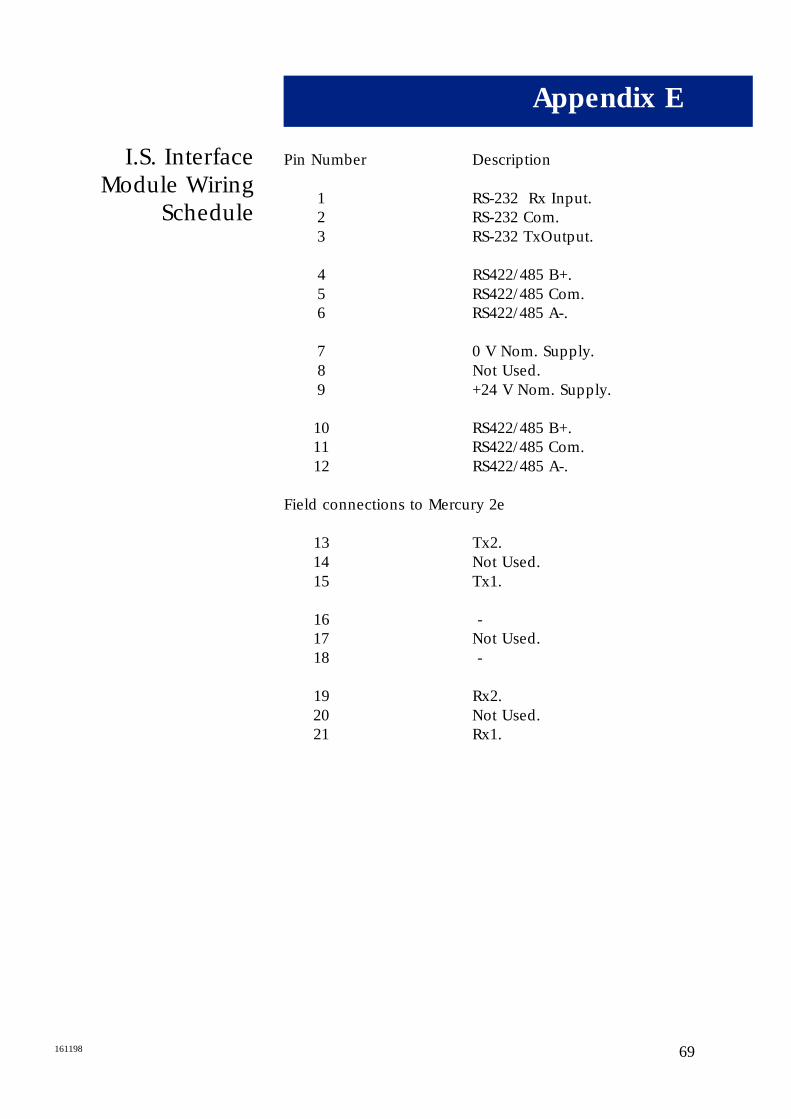
I.S. InterfaceModule Wiring
Schedule
Pin Number Description
1 RS-232 Rx Input.2 RS-232 Com.3 RS-232 TxOutput.
4 RS422/485 B+.5 RS422/485 Com.6 RS422/485 A-.
7 0 V Nom. Supply.8 Not Used.9 +24 V Nom. Supply.
10 RS422/485 B+.11 RS422/485 Com.12 RS422/485 A-.
Field connections to Mercury 2e
13 Tx2.14 Not Used.15 Tx1.
16 -17 Not Used.18 -
19 Rx2.20 Not Used.21 Rx1.
Appendix E

70 161198
71161198
Communicationswith the R007
Interface Module
RS422/485 and RS232 ports share a common 0V rail whichis totally floating.
RS422 Tx drivers are tri-state devices which remain in astate of high impedance until data transmission, when theyare asserted; this allows multi-drop operation. In point-to-point mode, RS422 drivers are constantly active, i.e. neverin Hi-Z state.
Multi-drop communications are provided via RS422 orRS485. To connect RS485 to the Interface Module, the Tx+and the Tx- terminals should be paralleled with the Rx+and Rx- terminals respectively. See Appendix E.
The IS Interface Module R007-IS is used as the tri-statecommunication port. See Appendix E for the wiringschedule.
The transmitters require a high impedance state and aprotocol to ensure that only one transmitter is allowed todrive the ‘bus’ at any one time. To avoid contention, thetransmitter is enabled in the marking state (see Fig. 5).
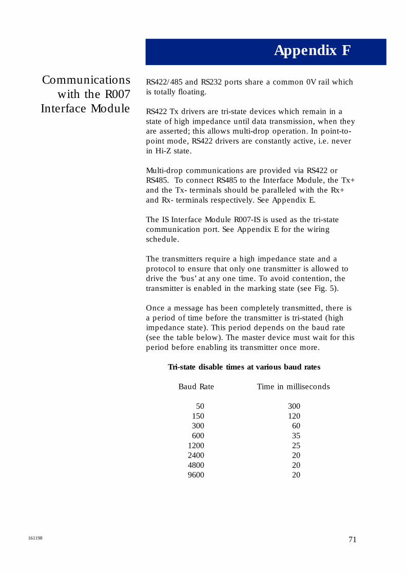
Once a message has been completely transmitted, there isa period of time before the transmitter is tri-stated (highimpedance state). This period depends on the baud rate(see the table below). The master device must wait for thisperiod before enabling its transmitter once more.
Tri-state disable times at various baud rates
Baud Rate Time in milliseconds
50 300150 120300 60600 35
1200 252400 204800 209600 20
Appendix F
RS485 SignalLevels
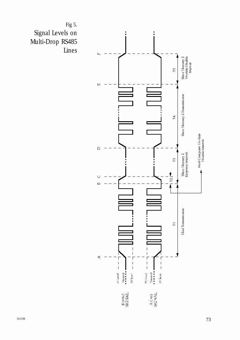
Fig. 5 illustrates signal levels on Multi-drop RS 485 lines.
At time A, the Host computer has determined that theRS485 link is not being used (previous polled message hasbeen received) and enables its transmitter. The B signalthen moves from its Hi-Z state to the marking level, a highlevel. At the same time the A signal moves from its Hi-Zstate to the marking level, a low level. The Host thensends out its message. This occupies the time interval T1. At time B, the Host has sent the stop bit for the finalcharacter, <ETX>. The Host can now disable itstransmitter and at time C the line returns to its Hi-Z state.The interval T2 is determined by the Host, but it should beshort enough to ensure that the bus is tri-stated before theslave replies.The interval T3 is the response time of the slave Mercury2e, which has a typical time of 20ms, an absolutemaximum time of 50ms and and a minimum time of 10ms.At time D, the slave Mercury 2e has enabled its transmitterand started to transmit the message requested by the Host.Interval T4 depends upon the message length and baudrate. At time E the slave Mercury 2e has transmitted the stop bitof the final character, <ETX>. At time F the slave disablesits transmitter to the Hi-Z state. The interval T5 isdetermined by the Mercury 2e system, and its maximumtime is shown in the table on page 83.
72 161198
73161198
Fig 5.
Signal Levels on Multi-Drop RS485
Lines

74 161198

75161198
Please select fromthe list to viewthese drawings
INTRINSICALLY SAFE INSTALLATION
1. Typical Wiring, Mercury 2e System (P053’120’D)
2. Full-Duplex, Multi-drop RS422 Master-Slave Wiring (P053’127’D)
3. Half-Duplex, Multi-drop RS485 Master-Slave Wiring(P053’128’D)
4. F.M. Control Drawing (P053’121’D)
Appendix G

76 161198
80161198
Modbus OptionOperation
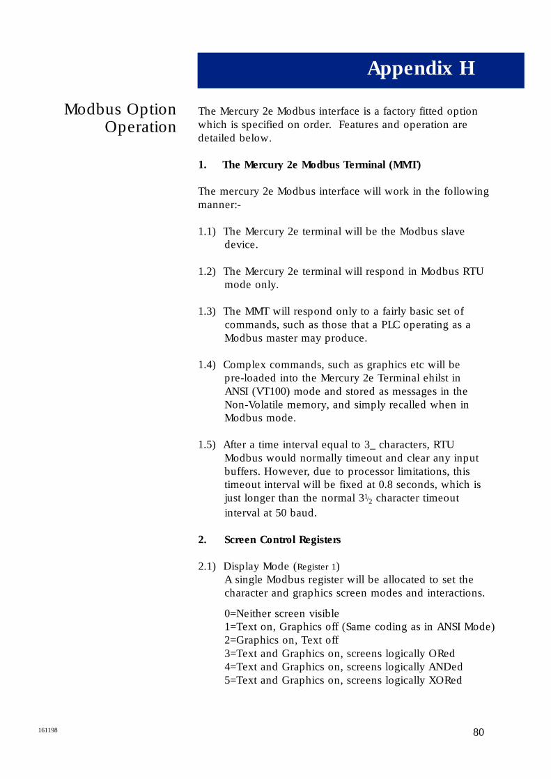
The Mercury 2e Modbus interface is a factory fitted optionwhich is specified on order. Features and operation aredetailed below.
1. The Mercury 2e Modbus Terminal (MMT)
The mercury 2e Modbus interface will work in the followingmanner:-
1.1) The Mercury 2e terminal will be the Modbus slave device.
1.2) The Mercury 2e terminal will respond in Modbus RTU mode only.
1.3) The MMT will respond only to a fairly basic set of commands, such as those that a PLC operating as a Modbus master may produce.
1.4) Complex commands, such as graphics etc will be pre-loaded into the Mercury 2e Terminal ehilst in ANSI (VT100) mode and stored as messages in the Non-Volatile memory, and simply recalled when in Modbus mode.
1.5) After a time interval equal to 3_ characters, RTU Modbus would normally timeout and clear any input buffers. However, due to processor limitations, this timeout interval will be fixed at 0.8 seconds, which is just longer than the normal 31/2 character timeout interval at 50 baud.
2. Screen Control Registers
2.1) Display Mode (Register 1)A single Modbus register will be allocated to set the character and graphics screen modes and interactions.
0=Neither screen visible1=Text on, Graphics off (Same coding as in ANSI Mode)2=Graphics on, Text off3=Text and Graphics on, screens logically ORed4=Text and Graphics on, screens logically ANDed5=Text and Graphics on, screens logically XORed
Appendix H
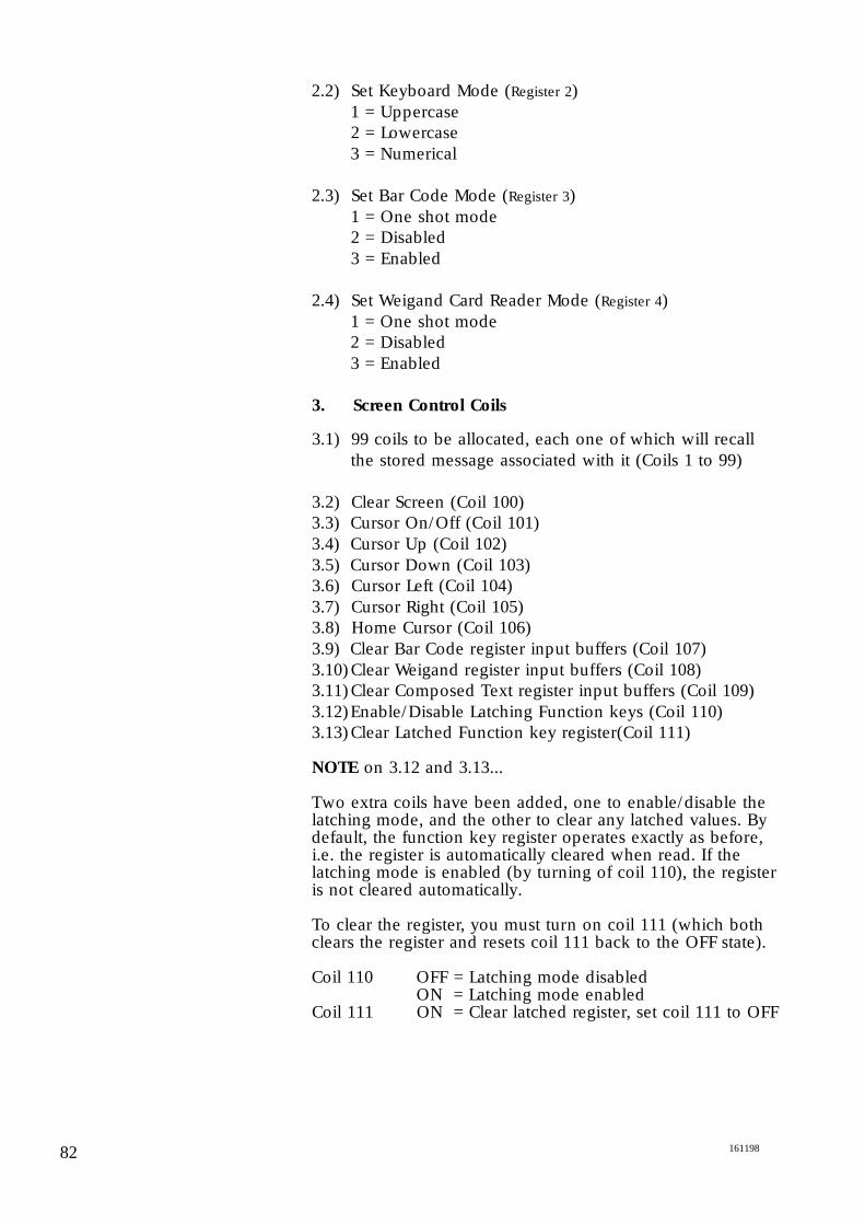
2.2) Set Keyboard Mode (Register 2)1 = Uppercase2 = Lowercase3 = Numerical
2.3) Set Bar Code Mode (Register 3)1 = One shot mode2 = Disabled3 = Enabled
2.4) Set Weigand Card Reader Mode (Register 4)1 = One shot mode2 = Disabled3 = Enabled
3. Screen Control Coils
3.1) 99 coils to be allocated, each one of which will recall the stored message associated with it (Coils 1 to 99)
3.2) Clear Screen (Coil 100)3.3) Cursor On/Off (Coil 101)3.4) Cursor Up (Coil 102)3.5) Cursor Down (Coil 103)3.6) Cursor Left (Coil 104)3.7) Cursor Right (Coil 105)3.8) Home Cursor (Coil 106)3.9) Clear Bar Code register input buffers (Coil 107)3.10)Clear Weigand register input buffers (Coil 108)3.11)Clear Composed Text register input buffers (Coil 109)3.12)Enable/Disable Latching Function keys (Coil 110)3.13)Clear Latched Function key register(Coil 111)
NOTE on 3.12 and 3.13...
Two extra coils have been added, one to enable/disable thelatching mode, and the other to clear any latched values. Bydefault, the function key register operates exactly as before,i.e. the register is automatically cleared when read. If thelatching mode is enabled (by turning of coil 110), the registeris not cleared automatically.
To clear the register, you must turn on coil 111 (which bothclears the register and resets coil 111 back to the OFF state).
Coil 110 OFF = Latching mode disabledON = Latching mode enabled
Coil 111 ON = Clear latched register, set coil 111 to OFF
82 161198
83 161198
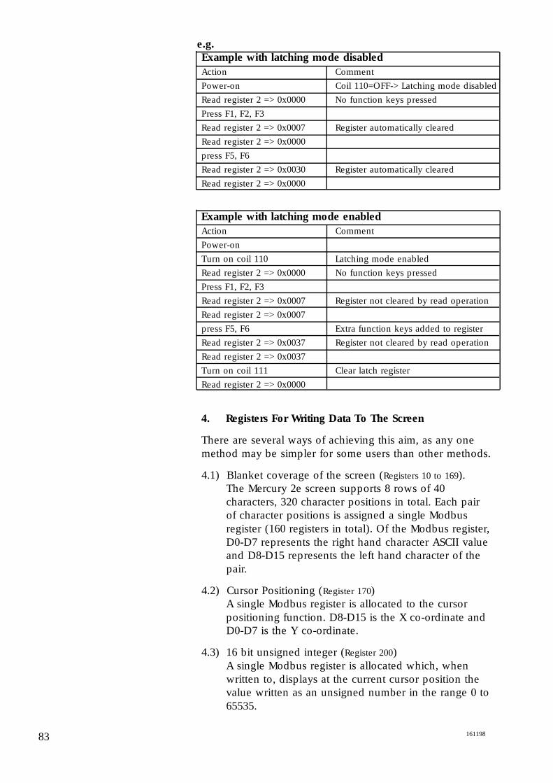
Example with latching mode disabled
Action Comment
Power-on Coil 110=OFF-> Latching mode disabled
Read register 2 => 0x0000 No function keys pressed
Press F1, F2, F3
Read register 2 => 0x0007 Register automatically cleared
Read register 2 => 0x0000
press F5, F6
Read register 2 => 0x0030 Register automatically cleared
Read register 2 => 0x0000
Example with latching mode enabled
Action Comment
Power-on
Turn on coil 110 Latching mode enabled
Read register 2 => 0x0000 No function keys pressed
Press F1, F2, F3
Read register 2 => 0x0007 Register not cleared by read operation
Read register 2 => 0x0007
press F5, F6 Extra function keys added to register
Read register 2 => 0x0037 Register not cleared by read operation
Read register 2 => 0x0037
Turn on coil 111 Clear latch register
Read register 2 => 0x0000
4. Registers For Writing Data To The Screen
There are several ways of achieving this aim, as any onemethod may be simpler for some users than other methods.
4.1) Blanket coverage of the screen (Registers 10 to 169). The Mercury 2e screen supports 8 rows of 40 characters, 320 character positions in total. Each pair of character positions is assigned a single Modbus register (160 registers in total). Of the Modbus register, D0-D7 represents the right hand character ASCII value and D8-D15 represents the left hand character of the pair.
4.2) Cursor Positioning (Register 170)A single Modbus register is allocated to the cursor positioning function. D8-D15 is the X co-ordinate and D0-D7 is the Y co-ordinate.
4.3) 16 bit unsigned integer (Register 200)A single Modbus register is allocated which, when written to, displays at the current cursor position the value written as an unsigned number in the range 0 to 65535.
e.g.
84161198
4.4) 16 bit signed integer (Register 201)A single Modbus register is allocated which, when written to, displays at the current cursor position the value written as a signed number in the range -32768 to 32767. Note that positive numbers have no leading plus sign, whereas negative numbers have a preceding minus sign.
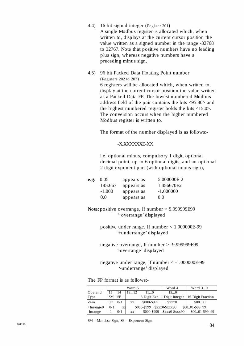
4.5) 96 bit Packed Data Floating Point number (Registers 202 to 207)6 registers will be allocated which, when written to, display at the current cursor position the value written as a Packed Data FP. The lowest numbered Modbus address field of the pair contains the bits <95:80> and the highest numbered register holds the bits <15:0>. The conversion occurs when the higher numbered Modbus register is written to.
The format of the number displayed is as follows:-
-X.XXXXXXE-XX
i.e. optional minus, compulsory 1 digit, optional decimal point, up to 6 optional digits, and an optional 2 digit exponent part (with optional minus sign),
e.g: 0.05 appears as 5.000000E-2145.667 appears as 1.456670E2-1.000 appears as -1.0000000.0 appears as 0.0
Note:positive overrange, If number > 9.999999E99‘+overrange’ displayed
positive under range, If number < 1.000000E-99 ‘+underrange’ displayed
negative overrange, If number > -9.999999E99‘-overrange’ displayed
negative under range, If number < -1.000000E-99 ‘-underrange’ displayed
The FP format is as follows:-
Word 5 Word 4 Word 3...0Operand 15 14 13...12 11...0 15...0Type SM SE 3 Digit Exp 1 Digit Integer 16 Digit Fraction
Zero 0/1 0/1 xx $000-$999 $xxx0 $00..00+Inrange 0 0/1 xx $000-$999 $xxx0-$xxx90 $00..01-$99..99-Inrange 1 0/1 xx $000-$999 $xxx0-$xxx90 $00..01-$99..99
SM = Mantissa Sign, SE = Exponent Sign
4.6) 16 bit unsigned integer in 10mm high characters (Register 208)As paragraph 3 above, but 10mm high text characters (displayed on the graphics screen) are used.
4.7) 16 Bit signed integer in 10mm high characters (Register 209)As paragraph 4 above, but 10mm high text characters (displayed on the graphics screen) are used.
4.8) 96 bit Packed Data Floating Point number in 10mm high characters (Registers 210 to 215)As paragraph 5 above, but 10mm high text characters (displayed on the graphics screen) are used.
(Note that in paragraphs 9-12 : the characters sent willoverwrite the current screen data, all control characters will be ignored and after a control character all subsequent data in the Modbus registers will also be ignored. This applies to all characters, and thus any string may be shortened by putting (for example) a null character after the last character to be displayed. The screen will wrap if the character stringexceeds column 40 of the display. Valid character data is sent to the display when data is written to bits D0-D7 of the highest relevant Modbus register.)
4.9) A two character string without auto increment (Register 171)A single Modbus register is used which, when writtento, puts two characters on the screen at the current cursor position. The cursor position is not moved. Of the Modbus register, the high order (D8-D15) represents the left hand character ASCII value and low order (D0-D7) represents the right hand characterof the pair.
4.10) An 8 character string without auto increment (Registers 172 to 175)A quad set of Modbus registers puts 8 characters on the screen at the current cursor position when the lastof the 4 register quads is written. The cursor position is not moved. Of the Modbus register, the high order (D8-D15) represents the left hand character ASCII value and the low order (D0-D7) represents the right hand character of the pair. The next Modbus register represents the next pair of character positions.
85 161198
86161198
4.11) A 40 character string without auto increment (Registers 176 to 195)This is similar to paragraph 12 but, by reserving 20 registers, allows a complete line of 40 characters to be written in one go.
4.12) A two character string with auto increment (Register 196)A single Modbus register is used which, when written to, puts two characters on the screen at the current cursor position, and then moves the cursor position along two character positions. Of the Modbus register, the high order (D8-D15) represents the left hand character ASCII value and the low order (D0-D7) represents the right hand character of the pair.
5. Registers For Receiving Data From the Mercury 2e
5.1) Data Pending input register (Register 1)A single resister can be read to determine if there is any valid data in the Bar Code, Card Reader or Text input registers. This single register contains 3 separate numbers, each corresponding to the number of relevant readings that are currently buffered in the Mercury 2e, waiting to be read.
D0-D3 = number of buffered text messagesD4-D7 = number of buffered Weigand card readingsD8-D11= number of buffered Bar Code readings
5.2) Function Key register (Register 2)D0-D7 = 1 means Function Keys F1 to F8 have been pressed. Note there is no time stamping.
5.3) Bar Code input registers (Registers 3 to 18)A set of 16 Modbus registers are used to hold the barcode reading.Up to 5 barcode readings may be buffered, waiting to be read. If further barcode readings are made without the buffer being read, the subsequent data is lost.For each Modbus register, the high order (D8-D15) represents the left hand character ASCII value and the low order (D0-D7) represents the right hand character of the pair. If the barcode is less than 32 characters long, then the Modbus register “half” following the last valid character will have the value 00 Hex, as will all the other Modbus registers in the rest of the register set.
5.4) Weigand Security card input registers (Registers 19 and 20)A pair of Modbus registers are used to hold the Weigand card reading.Up to 5 Weigand card readings may be buffered waiting to be read. If further Weigand card readings are made without the buffer being read, the subsequent data is lost.The Modbus input registers are used together to hold the 32 bit value read from the Weigand card. The lower Modbus register of the pair contains the bits <31:16> and the higher order register holds the bits <15:0>.
5.5) Composed Text Modbus input registers (Registers 21 to 35)A set of 15 Modbus registers are used to hold the Composed Text readings.Up to 5 Composed Text readings may be buffered waiting to be read. If further text is entered without the buffer being read, the subsequent data is lost.For each Modbus register, the high order (D8-D15) holds the left hand character ASCII value and the loworder (D0-D7) holds the left hand character ASCII value. If the Composed Text is less than 30 characterslong, then the Modbus register “half” following the last valid character will have the value 00 Hex, as willall the other Modbus registers in the rest of the register set.
5.6) Modbus Inputs (single bit reads) (Coils 1 to 5)5 off single bit Modbus inputs that reflect the digital input status of the Mercury 2e.
87 161198
88161198
Mercury 2eExample Modbus
Messages
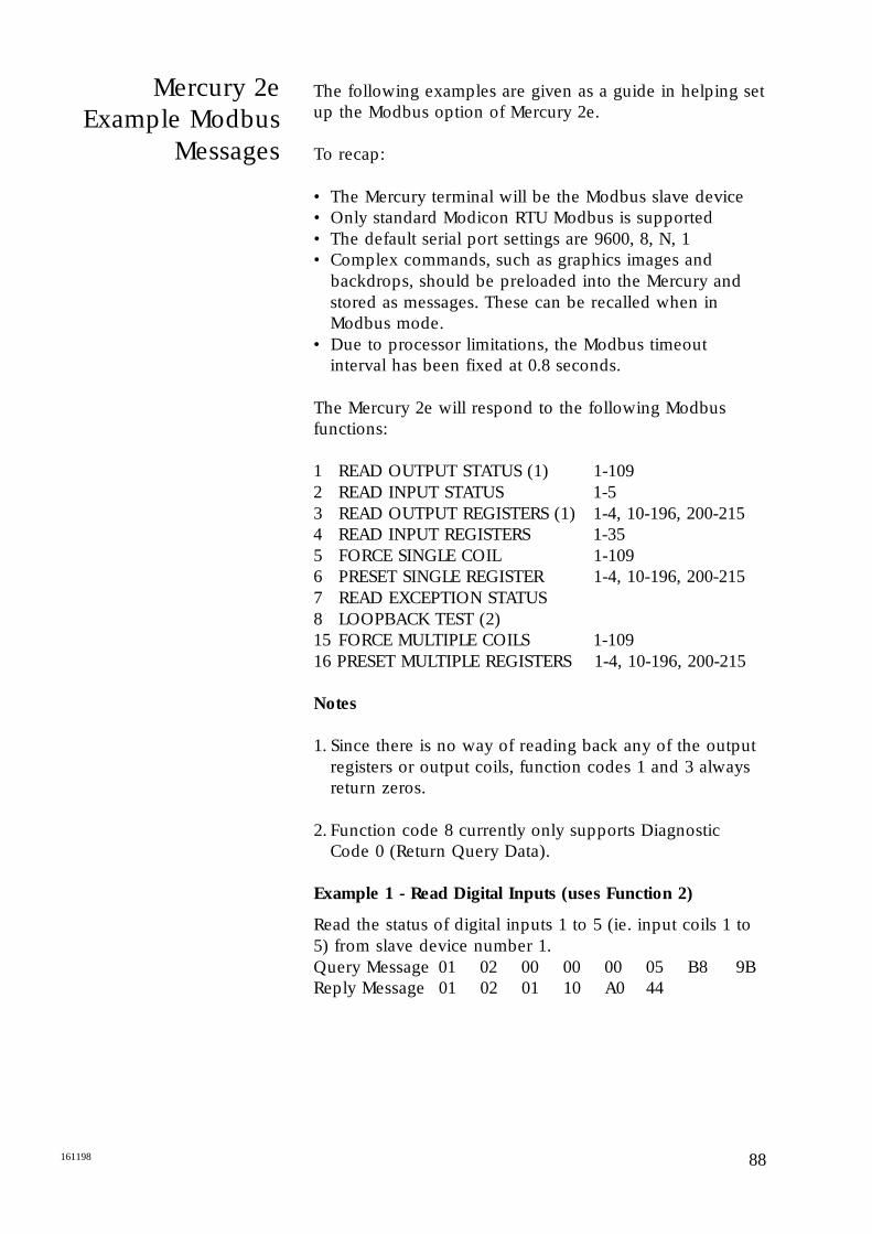
The following examples are given as a guide in helping setup the Modbus option of Mercury 2e.
To recap:
• The Mercury terminal will be the Modbus slave device• Only standard Modicon RTU Modbus is supported• The default serial port settings are 9600, 8, N, 1• Complex commands, such as graphics images and
backdrops, should be preloaded into the Mercury and stored as messages. These can be recalled when in Modbus mode.
• Due to processor limitations, the Modbus timeout interval has been fixed at 0.8 seconds.
The Mercury 2e will respond to the following Modbusfunctions:
1 READ OUTPUT STATUS (1) 1-1092 READ INPUT STATUS 1-53 READ OUTPUT REGISTERS (1) 1-4, 10-196, 200-2154 READ INPUT REGISTERS 1-355 FORCE SINGLE COIL 1-1096 PRESET SINGLE REGISTER 1-4, 10-196, 200-2157 READ EXCEPTION STATUS8 LOOPBACK TEST (2)15 FORCE MULTIPLE COILS 1-10916 PRESET MULTIPLE REGISTERS 1-4, 10-196, 200-215
Notes
1. Since there is no way of reading back any of the output registers or output coils, function codes 1 and 3 always return zeros.
2. Function code 8 currently only supports Diagnostic Code 0 (Return Query Data).
Example 1 - Read Digital Inputs (uses Function 2)
Read the status of digital inputs 1 to 5 (ie. input coils 1 to5) from slave device number 1.Query Message 01 02 00 00 00 05 B8 9BReply Message 01 02 01 10 A0 44
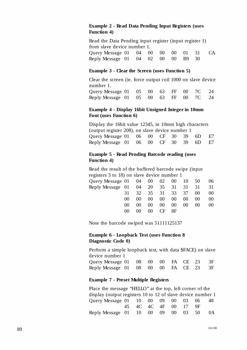
Example 2 - Read Data Pending Input Registers (uses
Function 4)
Read the Data Pending input register (input register 1)from slave device number 1.Query Message 01 04 00 00 00 01 31 CAReply Message 01 04 02 00 00 B9 30
Example 3 - Clear the Screen (uses Function 5)
Clear the screen (ie. force output coil 1000 on slave devicenumber 1.Query Message 01 05 00 63 FF 00 7C 24Reply Message 01 05 00 63 FF 00 7C 24
Example 4 - Display 16bit Unsigned Integer in 10mm
Font (uses Function 6)
Display the 16bit value 12345, in 10mm high characters(output register 208), on slave device number 1Query Message 01 06 00 CF 30 39 6D E7Reply Message 01 06 00 CF 30 39 6D E7
Example 5 - Read Pending Barcode reading (uses
Function 4)
Read the result of the buffered barcode swipe (inputregisters 3 to 18) on slave device number 1Query Message 01 04 00 02 00 10 50 06Reply Message 01 04 20 35 31 31 31 31
31 32 35 31 33 37 00 0000 00 00 00 00 00 00 0000 00 00 00 00 00 00 0000 00 00 CF 8F
Note the barcode swiped was 51111125137
Example 6 - Loopback Test (uses Function 8
Diagnostic Code 0)
Perform a simple loopback test, with data $FACE) on slavedevice number 1Query Message 01 08 00 00 FA CE 23 3FReply Message 01 08 00 00 FA CE 23 3F
Example 7 - Preset Multiple Registers
Place the message “HELLO” at the top, left corner of thedisplay (output registers 10 to 12 of slave device number 1Query Message 01 10 00 09 00 03 06 48
45 4C 4C 4F 00 17 9FReply Message 01 10 00 09 00 03 50 0A
89 161198

90161198
Parts OrderingCodes
Part No
IS Mercury 2e Terminal R004/e-ISNon IS Mercury 2e R004/e-GPIS Mercury 2e (text only) R004/e-TO/ISNon IS Mercury 2e (text only) R004/e-TO/GPIS Interface Module R007-ISWiegand Card Reader R005-CRBar Code Interface Kit (exc. wand) R008-WOBar Code Wand R008-WAND

More Information
Other Spectra-Tek Products
Contact
Information on Spectra-Tek products is available from themain Sales Office.
IS3000 Laser Scanner
ISP3000 Laser Scanner
Sentinel 500 - Liquid Turbine Flowcomputer
- Gas Orifice Flowcomputer
- Bi-directional Prover
Autoload II - integrated terminal automation system
Pipeline Automation Systems
Headquarters and Main Sales Office
Daniel Europe Limited
Swinton Grange,Malton,North Yorkshire YO17 6QR.
Tel: +44 0 1653 695 551Fax +44 0 1653 600 425Email: [email protected]
Far East
Daniel Asia Pacific Pte Ltd .Singapore Branch,171, Chin Swee Road,07-09 San Centre,Singapore 169877.
Tel: (65) 538 0498Fax (65) 538 6210Email: [email protected]
91 161198
92161198
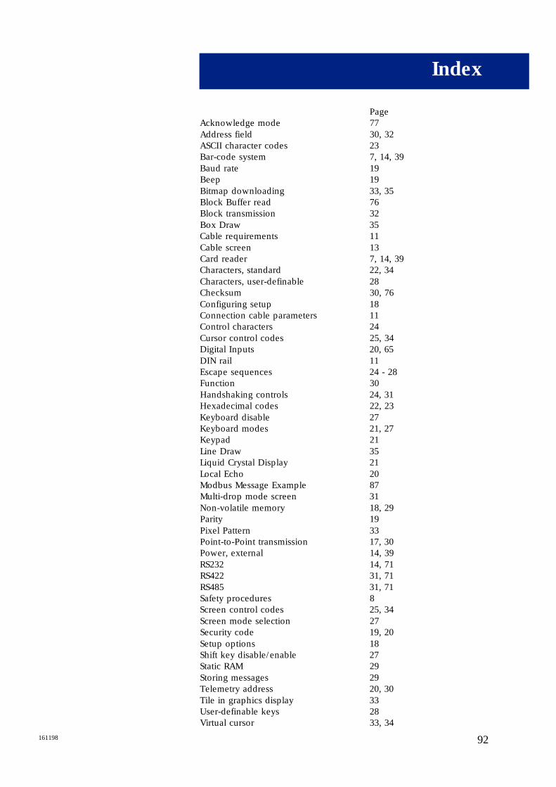
PageAcknowledge mode 77Address field 30, 32ASCII character codes 23Bar-code system 7, 14, 39Baud rate 19Beep 19Bitmap downloading 33, 35Block Buffer read 76Block transmission 32Box Draw 35Cable requirements 11Cable screen 13Card reader 7, 14, 39Characters, standard 22, 34Characters, user-definable 28Checksum 30, 76Configuring setup 18Connection cable parameters 11Control characters 24Cursor control codes 25, 34Digital Inputs 20, 65DIN rail 11Escape sequences 24 - 28Function 30Handshaking controls 24, 31Hexadecimal codes 22, 23Keyboard disable 27Keyboard modes 21, 27Keypad 21Line Draw 35Liquid Crystal Display 21Local Echo 20Modbus Message Example 87Multi-drop mode screen 31Non-volatile memory 18, 29Parity 19Pixel Pattern 33Point-to-Point transmission 17, 30Power, external 14, 39RS232 14, 71RS422 31, 71RS485 31, 71Safety procedures 8Screen control codes 25, 34Screen mode selection 27Security code 19, 20Setup options 18Shift key disable/enable 27Static RAM 29Storing messages 29Telemetry address 20, 30Tile in graphics display 33User-definable keys 28Virtual cursor 33, 34
Index