Embed Size (px)
Citation preview
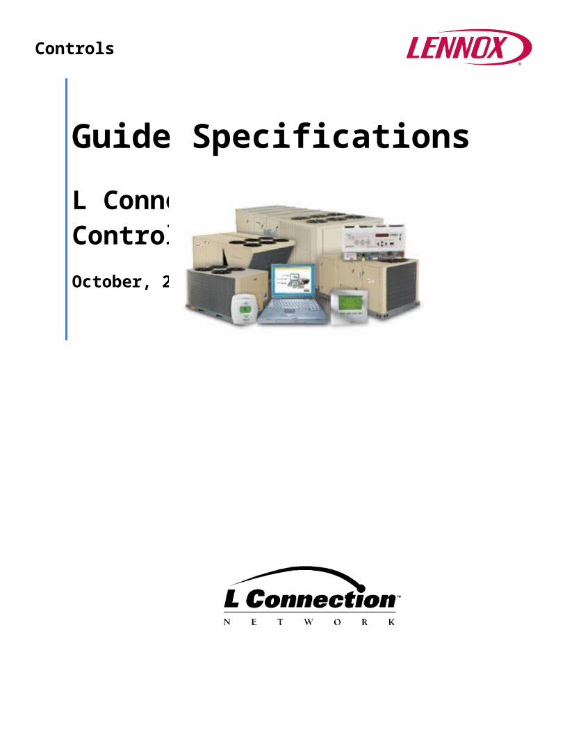
Guide Specifications
L Connection® Network Control SystemOctober, 2013
Controls
2
Table of ContentsNetwork Control Panel (NCP) Network Manager....................................................................3Prodigy® Unit Controller.......................................................................................................5Network Thermostat Control DDC Module (NTC1-1)............................................................12Building Controller Module (BC1-1)....................................................................................16Electrical Demand Controller.............................................................................................17Comfort Sensors………………………………………………………………………………………………………………………18Zoning.......................................................................................................................................... 19
Zone Link......................................................................................................................19Comfort Sensor – Zoning................................................................................................21Damper Actuator 12W98...............................................................................................24
Zone Temperature Sensors................................................................................................25Wall Mount 56L80.........................................................................................................25Wall Mount 76M32.......................................................................................................25Wall Mount 94L60.........................................................................................................25Wall Mount 94L61.........................................................................................................25Wall Mount Sensor for Building Controller 59M04...........................................................26Duct Mount 56L81........................................................................................................26Averaging Kit 23M20.....................................................................................................26
Outdoor Air Temperature Sensors......................................................................................26Outdoor Air Sensor for Building Controller 59M05...........................................................26Wall Mount 17M50.......................................................................................................27Duct Mount 76M31.......................................................................................................27
CO2 Sensors......................................................................................................................27Wall Mount 77N39, 87N54, 87N52.................................................................................27
L Connection® Network Control System
3
CO2 Sensors Duct Mount Aspiration Box 90N43...............................................................27Pressure Sensors..............................................................................................................28
Supply Static Differential Pressure Sensor 78M19.............................................................28Return (Building) Static Differential Pressure Sensor 78M20..............................................28
Miscellaneous Sensors......................................................................................................29Remote Discharge Temperature Sensor Kit 45L78............................................................29Outdoor Air Control Sensor Kit 98M61............................................................................29Duct Temperature Sensor 99K64....................................................................................29Temperature Sensor Probe 14K92..................................................................................29Ambient Light Sensor 34M67.........................................................................................30
Network Control Panel PC Interface Software......................................................................31Network Control Panel PC Software 96L82......................................................................31Unit Controller PC Software 96L80..................................................................................32
L Connection® Network Control System
4
Network Control Panel (NCP) Network Manager(NCP1-1 software version 1.13)
HVAC Scheduling Panel should have the ability to perform all of the following Energy Management routines:
Store up to 99 different Day Schedules with up to six setpoint changes per day. Store up to 26 different programs. (seven day + holiday) Store up to 50 holidays. Adjust relative humidity setpoint per program for Lennox Humiditrol® units or units running
in the Supermarket reheat mode. Store one override heating and one override cooling setpoint per program. User selected temperature override limit range between 0-10°F. User selected override time limit range between 0-8 hours. Panel shall provide a user adjustable setpoint recovery stagger delay of between 0-4
minutes that will stagger each HVAC unit’s setpoint change in order to help control peak power loading.
Building Controller Scheduling Panel shall also have the ability to perform all of the following Energy Management routines:
Store up to 50 different Day Schedules with up to four changes per day. Store up to 26 different programs. (seven day + holiday). Use the same holidays as defined in the HVAC scheduling. A different schedule program may be used for each Building Controller output. User selected override time limit range between 0-8 hours.
HVAC Status Display Data Panel shall display the following information on the Zone Status Screen:
o Zone number, address number, zone description, zone temperature, zone setpoints, outdoor temperature, date/time/day of week, unit mode of operation, unit alarm indication, filter reminder, zone CO2 level when optional CO2 sensor is connected to the unit controller and zone relative humidity % when optional relative humidity sensor is connected to the unit controller.
Panel shall display the following information on the Unit Data Screen: For Energence® Rooftop Units:
o Unit number, unit type, Prodigy® mode, return air temperature, supply air temperature, outdoor temperature, CO2 level when optional CO2 sensor is connected to unit, zone relative humidity % when optional relative humidity sensor is connected to the unit, economizer mode, damper position when optional economizer is used, most recent alarm, blower status, number of heating and cooling stages operating and number of condenser fans operating.
Building Controller Status Display Data Panel shall display the following information on the Zone Status Screen:
o Address number, date/time/day of week, page number, BC description, name of each output (8), and program assigned to output, output status that includes, on or off, in override mode or in local override mode and override timer. Override mode means override by NCP and local override means the output is overridden by control function programmed in Building Controller by user.
o Description of each analog input (3) and value of each input in volts.o Description of each temperature input (4) and value of each input in degrees F or C.
L Connection® Network Control System
5
o Description of the ambient light sensor and indication of light or dark. Panel shall display the following information on the Unit Data Screen:
o Status of each digital input, digital output, temperature input and analog input. o Most recent alarm.
Controllers Panel shall monitor and/or control up to 31 total of the following L Connection controllers: Prodigy ®,
the standard unit controller in the Energence® rooftop equipment, is a microprocessor-based control board that provides flexible control of all unit function.
The NTC1-1 DDC module used for non-Energence equipment and the Building Controller (BC) used for controlling non-HVAC equipment such as lights, exhaust fans, etc. and for reading additional analog and temperature sensors.
Diagnostics Panel shall display “alarm” on zone status screen to indicate that a new alarm has occurred in the
unit controller. Panel shall display all unit controller alarm codes with date/time stamp on the alarm list screen. Panel shall display a full description of the unit alarm and action taken by unit controller on the
alarm description screen. Panel shall have a panel test function that allows the user to test the panel’s LCD display, buttons,
network communications, speaker (beeper), clock and memory.
PC Access The module may be accessed locally by using a PC running the optional Network Control Panel
Software and the optional L Connection Network PC Converter. The module may be accessed remotely by using the optional L Connection Network Modem (on
site), and a PC with modem running the optional Network Control Panel Software. The module may be accessed through an Ethernet local area network using the optional Ethernet
Converter Kit and a PC with the optional Network Control Panel software. This can also be used for remote access through the Internet if the user has access to their local area network from outside that network’s firewall on a PC with the Network Control Panel software.
Real Time Clock The panel shall have an internal real time clock with a 10-year life back-up battery.
Panel shall have a user selectable Daylight Savings Auto set function that will automatically set the internal clock for daylight saving time.
Password Option Panel shall have 1 to 6 character alphanumeric user selected password option. If password is enabled, user must enter password to change programs, control settings and to
delete the alarm list both at the panel and via the NCP PC software. If password is enabled, user can override the schedule program setpoints within the override
setpoint range for the override time.
Control Options Panel shall have a user adjustable program override timer that will allow a person at panel to
temporarily change the setpoints for specific time when panel is controlling the space temperature based on a program.
L Connection® Network Control System
6
Panel shall have a user adjustable program override temperature range that will allow a person at panel to temporarily change the setpoint within a specific range when the panel is controlling the space temperature based on a program.
Panel shall have an audible beeper option that will beep once every 10 seconds if a unit connected to the network is in a lockout condition.
Panel shall have a filter timer that will keep the blower run time of each unit connected to the network and indicate on the zone status screen when to check filter based on the filter time selected by the user of between 0-60 days.
Panel shall have the option to return to factory settings. Panel shall have user adjustable display options to adjust the contrast, backlight and brightness. Panel shall have a user selected Fahrenheit or Celsius temperature display option.
Electrical/Environmental Panel shall consist of a microprocessor-based digital panel with large LCD display and power supply. Panel shall have one RS-232 serial data communication port for connection to personal computer
for uploading new software versions. Panel shall have one L Connection Network serial data communication port for communicating with
unit controllers connected to the network. Panel’s software version shall be capable of being upgraded without removing or replacing the panel
by using PC connected to the RS-232 serial data port. Panel shall have a user adjustable backlighted graphical LCD display. Panel shall operate safely over a temperature range from 0 to 125F. Panel shall operate safely from 18 to 30VAC. Panel’s programs shall be stored in non-volatile flash memory. Panel shall be connected to the L Connection network via 2 conductor twisted pair, shielded, 22
gauge communication cables. Belden type 8761 or 88761. Panel may be connected to a unit’s 24VAC supply via 2 conductor, 18 gauge standard thermostat
wire for power or with an optional wall plug 115VAC transformer,
Prodigy® Unit Controller The Prodigy Unit Controller is a microprocessor-based control board that provides flexible control of all unit functions.All control voltage is provided via a 24V (secondary) transformer with built-in circuit breaker protection.
Features Scrolling Display - Display scrolls full text instead of numerical codes to help simplify diagnosing
and troubleshooting. The high contrast display makes it easy to read in various lighting and ambient conditions.
Push Buttons - Offer simplified navigation during setup and diagnostics. Arrow buttons (no DIP switches) simplify setup and installation by making menu navigation very intuitive
Guided Setup - The Prodigy Unit Controller features a guided setup procedure that speeds up and helps insure proper installation and setup of the rooftop unit.
USB Port - Allows a technician or user to easily download and transfer unit information (With a time/date stamp and unit serial number) via a USB flash drive to help verify service was
performed. A second USB port also offers an easy interface with a PC and the Lennox Unit Controller Software.
Unit Profile - A Unit Profile can also be saved to a USB flash drive and then uploaded to an identical unit, instantly copying all setpoints.
L Connection® Network Control System
7
Self-Test - Unit Controller performs self-test to verify individual critical component and system performance. Included is an economizer test function that helps assure the economizer is operating correctly.
Time Clock with Run-time Information - Internal time clock with runtime information on these key components: Power Applied, Filter, Blower Belt, UV Lamp, Blower, Compressor(s), Condenser Fan(s), Heat Stage(s), Free Cooling, Exhaust Fan and Dehumidification.
Built-in functions include Blower On/Off Delay - Adjustable time delay between blower on and off. Built-in Control Parameter Defaults – No programming required. Compressor Time-Off Delay - Adjustable time delay between compressor shutoff and start up. DDC Compatible - Various third party DDC controllers can be factory or field installed. Dirty Filter Switch Input - When a Dirty Filter Switch is installed, the control will signal when the
indoor blower static pressure increases. Switch is optional and can be factory or field installed. Discharge Air Temperature Control – The controller will cycle up to 4 stages of heating or
cooling to maintain the discharge air setpoints for heating or cooling. Optional sensor for remote field installation in the supply duct.
Display/Sensor Readout - Displays control parameters, text status messages, and sensor readings. The unit controller displays temperature readings from return air, supply air, and outdoor air sensors that are furnished as standard on all Energence® units. Controller will also display readings from optional sensors such as zone sensors, CO2 sensors or relative humidity sensors.
Economizer Control Choice - The economizer is controlled by the Prodigy Unit Controller. The control has several options for controlling the economizer.
Operation Modes The module shall be capable of stand-alone operation with either a standard room thermostat
or zone sensor without the use of an interface board. The module shall control the stages of heating and cooling as well as directly control the
optional economizer via analog output.
Extensive Unit Diagnostics The Prodigy Unit Controller monitors all sensors and functions related to unit operation to
provide critical information. The controller will display detailed diagnostic information with over 100 diagnostic and status messages to pinpoint any problems and reduce troubleshooting time. All diagnostic messages and status alarms are displayed in plain English
The module shall indicate the unit’s problem with up to 107 different alarm codes, depending on the size and type of unit.
The module shall keep a permanent history of the last 84 diagnostic codes stored in non-volatile EEPROM memory. User can view and erase the history at any time either by using the on-board pushbutton, using a PC running Unit Controller software, or at the Network Control Panel.
Stage Control The module shall be capable of controlling up to 2 stages of heating and 2 stages of cooling by
means of the standard thermostat inputs. The module shall be capable of controlling up to 4 stages of cooling, 2 stages of gas or resistive
heating and 4 stages of electric heating when using an optional zone sensor or third party DDC control system.
When using an optional zone sensor, the module shall provide user adjustable default cooling stage differentials of 0.5 degrees F for each cooling stage available in unit.
L Connection® Network Control System
8
When using an optional zone sensor, the module shall provide user adjustable default heating stage differentials of 0.5 degrees F for each heating stage available in unit except the supplemental heat pump heat stages which defaults are 1 degrees F.
With the addition of one control relay, the module can control 3 stages of cooling by means of the standard thermostat inputs.
Network Manager The module shall communicate with the optional Network Control Panel network manager.
PC Access The module may be accessed locally by using a PC running the optional Unit Controller Software
and the L Connection PC Converter. The module may be accessed remotely by using the optional L Connection Network Modem (on
site) and a PC with modem running the optional Unit Controller Expanded Software. The module may be accessed through an Ethernet local area network using the optional
Ethernet Converter Kit and a PC with the optional Unit Controller software. This can also be used for remote access through the Internet if the user has access to their local area network from outside that network’s firewall on a PC with the Unit Controller software.
Sensor/Switch Inputs The module shall be factory installed and wired complete with Return Air Sensor, Discharge Air
Sensor, Outdoor Air Sensor and Zone, a high pressure, low pressure, and freezestat switch on each refrigeration circuit (up to 4); a primary heat limit, secondary heat limit, and a roll-out switch on each gas heat section (up to 2); and defrost control switches on heat pump models. Optional blower proving switches, dirty filter switches and zone sensors are available.
The module shall have a 0-10 VDC (0-100% RH) input used for displaying the relative humidity (RH) of an optional RH sensor and controlling the indoor relative humidity on gas-electric Energence units if the Supermarket reheat option is selected and on gas-electric and electric-electric Energence units with the Humiditrol® option
The module shall have a 0-10VDC (0-2000ppm) input for a CO2 sensor used for demand control ventilation.
On Board User Interface The module shall have a scrolling display and a user interface that consists of dip switches and a
push button that will allow the user to display control information and change options without any additional equipment. The display will show the temperature reading (in Fahrenheit or Celsius) of the outdoor temperature sensor, return air temperature sensor, discharge air sensor, and optional zone temperature sensor. In addition, the display will display the CO 2 reading of an optional CO2
sensor, relative humidity of an optional RH sensor, and damper position for demand control ventilation and free cooling operation.
The module shall have a DIP switch for setting the unit network address when using the L Connection® Network.
The module shall have a DIP switch used for selecting the unit type (gas-electric, electric-electric, heat pump, single/three phase) and the number of compressors and condenser fans.
The module shall have LED lights that indicate room thermostat demands. The module shall provide an LED “heartbeat” light on each board that indicates that the control is
operating normally. Each input and output on the module shall be clearly marked with the wiring diagram key number.
L Connection® Network Control System
9
The module shall provide a means to reset the control by pressing and holding the on-board pushbutton for 5 seconds.
Adjustable Control Parameters The module shall provide up to 115 user adjustable control parameters (options) that can be
changed by using the on-board push-button and display or by PC. The module shall provide backup factory default control parameters that the user may restore if
desired. The module shall ship from the factory with the default program and control parameters built in so
that installer does not have to program control for unit operation.Backup Modes The module shall provide 2 automatic backup options, while operating in the zone sensor mode, in
the event that the zone sensor fails or becomes disconnected. One option will automatically switch over to the return air sensor and one will automatically switch over to an optional room thermostat.
The module shall have automatic backup setpoint temperatures while operating in the zone sensor mode in the event of a network failure. These backup setpoints shall be adjustable by the user.
Economizer Control Modes The module shall control the economizer’s minimum position and proportional free cooling with
user selected control modes of differential temperature, single enthalpy (with optional sensor), differential enthalpy (with optional sensors) and global when a third party DDC module is used.
The damper minimum position shall be adjustable between 0-100% travel. It may be set at the module or by PC running the interface software either locally or remotely.
Exhaust Fan Control The module shall provide user adjustable control of the optional exhaust fan based on the damper
position.
Fresh Air Tempering Module shall have user selected fresh air tempering mode that monitors the supply air temperature
and activates the heat section to control the temperature of the supply air to a minimum of 65 °F. Temperature control point can be adjusted.
Demand Control Ventilation The module shall be capable of accepting a CO2 sensor input to control the opening of outdoor air
dampers. Either a two position or modulating control algorithm shall be available for user selection. The damper opening CO2 ppm setpoint shall be adjustable from 0 to 2000 ppm.
Humidity Control The module shall have a default user adjustable internal relative humidity setpoint of 60 % that is
used to control gas-electric Energence units if the Supermarket reheat option is selected and on gas-electric and electric-electric units if the Humiditrol® option is selected.
The humidity setpoint shall be adjustable from 0 to 100% at the module or by using optional PC interface software.
When operating in the zone sensor mode the humidity setpoint is adjustable at the Network Control Panel.
The module shall have a relative humidity sensor analog input. The input range shall be 0-10VDC (0-100%RH)
L Connection® Network Control System
10
The relative humidity sensor may be used to control the unit operating the Supermarket option (LGx only), control Humiditrol® units or for displaying relative humidity (all units) on the optional Network Control Panel and/or PC interface software.
Smoke Detector Inputs/Modes The module shall have a normally open 24VAC input for an optional smoke detector. The module shall have four selectable smoke alarm modes: unit off, purge, positive pressure, and negative pressure with blower.
Occupied Mode The module shall be capable of controlling the unit in the occupied and unoccupied modes.
Time Delays The module shall provide a default minimum run time of four minutes for each compressor when
used on three phase units. (user adjustable) The module shall provide a default minimum off delay of five minutes for each compressor when
used on single-phase units. (user adjustable) The module shall have a 3 second thermostat bounce delay. The module shall have a 1 second delay between starting each compressor stage to prevent current
surges. The module shall provide user selected blower on delay for cooling operation. The module shall provide user selected blower off delay for cooling operation. The module shall provide user selected blower on delay for heating operation. The module shall provide user selected blower off delay for heating operation. The module shall provide a means to bypass times delays during testing operation by pressing the
on-board push button. The module shall provide a user adjustable default auto-changeover delay of 5 minutes between
heating and cooling. The module shall provide a user adjustable default start-up demand delay of 2 minutes. This delay
may be adjusted to stagger unit demands when units are powered on by setting different time delays for each unit.
Return Air Limits The module shall have user selected return air limits that interrupt the heating or cooling demands if
limits are exceeded.
Low Ambient Control The module shall provide user selected independent low ambient lockout control for each
compressor. The module shall provide user adjustable low ambient control so that the unit can operate down to
0F as standard by staging the condenser fan(s).
On-Board Test Modes The module shall provide test mode to simulate room thermostat demands for testing heating and
cooling operation of unit. The module shall provide test mode to independently energize the blower, each condenser fan,
each reversing valve, each reheat solenoid, service relay and exhaust fan output for testing the operation of the unit.
L Connection® Network Control System
11
Service Relay The module shall provide a service relay output that turns on if the unit is in a lockout condition.
Electrical/Environmental The module shall be microprocessor based with core software stored in non-volatile flash memory
and adjustable control parameters values stored in non-volatile EEPROM memory. The module core software may be field upgradeable with a PC without changing hardware. The module shall operate safely over a temperature range from -40F to 155F. The module shall operate safely from 18 to 30VAC. The module printed circuit boards shall be conformal coated to protect critical components.
Gas-Electric Units Only The module shall have a default blower on delay of 40 seconds. (user adjustable) The module shall have a default delay of 30 seconds between the first and second stages of heat.
(user adjustable) The module shall have a default minimum timed off delay of 100 seconds. (user adjustable). The module shall have user selected reheat operation that may be used on process air applications
such as supermarkets to reduce the indoor humidity. Optional de-humidistat switch or humidity sensor required
Electric-Electric Units Only The module shall provide user selected blower on delay during heating. The module shall provide a default blower off delay of 20 seconds during heating. (user adjustable)
Energence units with Humiditrol® Option Module shall provide the outputs for controlling up to two solenoid reheat valves. The control will provide an LED display that indicates the status of each reheat valve solenoid
output. The module can operate Humiditrol reheat in two control modes: thermostat and zone sensor. In
the thermostat mode the module allows up to two stages of cooling. In the zone sensor mode the module allows up to four stages of cooling.
When operating in the thermostat control mode the humidity setpoint is set in the module at a default of 60%. This setpoint is adjustable between 0 to 100% at the module or by using optional PC interface software.
When operating in the zone sensor mode the humidity setpoint is adjustable at the Network Control Panel.
Module shall start condenser reheat circuits if the humidity exceeds the humidity set point. Module shall prioritize heat demand over dehumidification demands. Module shall turn off the compressors if a heat demand occurs during a dehumidification demand. Module shall prioritize cooling demands over dehumidification demands. If the space humidity is greater than the humidity setpoint, the module will not use outside air for
free cooling. On two compressor units, if both a dehumidification and first stage cooling demands occur, the
module will operate one compressor in reheat and one in cooling. If a second stage cooling demand occurs, the module will de-energize the reheat valve and operate both compressors in cooling.
On three compressor units, if both a dehumidification and a first stage cooling demand occurs, the module will operate compressors one and two in reheat and compressor three in cooling. In the thermostat control mode, if a second stage cooling demand occurs, the module will de-energize the reheat valves and operate compressors one, two, and three in cooling. In the zone sensor control mode, if a second stage cooling demand occurs, the module will de-energize the reheat valves and
L Connection® Network Control System
12
operate compressors one and two in cooling. In the zone sensor control mode, if a third or fourth stage cooling demand occurs, the module will de-energize the reheat valves and operate compressor one, two and three in cooling.
On four compressor units operating in the thermostat control mode: If both a dehumidification and first stage cooling demand occurs, the module will operate compressors one and two in reheat and compressors three and four in cooling. If a second cooling demand occurs the module will de-energize the reheat valves and operate all four compressors in cooling.
On four compressor units operating in the zone sensor control mode: If both a dehumidification and first stage cooling demand occurs, the module will operate compressors one and two in reheat and compressor three in cooling. If a second cooling stage demand occurs, the module keeps compressors one and two in reheat and operates compressors three and four in cooling. If a third cooling stage demand occurs the module will de-energize the reheat valves and operate compressors one, two and three in cooling. If a fourth cooling stage demand occurs the module will de-energize the reheat valves and operate all four compressors in cooling.
L Connection® Network Control System
13
Network Thermostat Control DDC Module (NTC1-1)(Software version 1.00) Stage Control Each module shall control up to 2 stages of heating and 3 stages of cooling, blower operation, unit
economizer and heat pump reversing valve. The module shall provide user adjustable default cooling stage differentials of 0.5 degrees F for each
cooling stage available in unit. The module shall provide user adjustable default heating stage differentials of 0.5 degrees F for each
heating stage available in unit.
Unit Type The module shall have user selectable options for controlling packaged or split system gas/electric,
electric/electric and heat pump units. The option is set by on-board DIP switches.
Network Manager The module shall communicate with the optional Network Control Panel network manager.
PC Access The module may be accessed locally by using a PC running the optional Unit Controller Software and
the optional L Connection Network PC Converter. The module may be accessed remotely by using the optional L Connection Network Modem (on site)
and a PC with modem running the optional Unit Controller Software.
Temperature Inputs The module shall have a zone sensor input that uses the standard L Connection Network thermistor
type zone sensors. The module shall provide a user adjustable zone sensor calibration option for adjusting the zone
sensor temperature +/-5 degrees F. The module shall have a return air, discharge air and outdoor air sensor input that uses the optional
standard L Connection Network thermistor type sensors.
Analog Inputs The module shall have a 0-10 VDC (0-2000ppm) input to display information from an optional CO2
sensor.
The module shall have a 0-10 VDC (0-100% RH) input to display information from an optional RH sensor.
The module shall have a 2-10 VDC (0-100% travel) input to display the damper position on an optional damper or economizer.
Digital Inputs The module shall provide a normally closed user selectable 24VAC digital input that may be used for
either an optional shut off relay or smoke detector that can shut off the unit and issue either a service or smoke alarm.
The module shall provide a user selectable input that may be used for either an optional service relay or dirty filter switch used to issue an alarm.
The module shall provide a user selectable input that may be used for either an optional blower overload relay or loss of phase protector that can shut off the unit and issue an alarm.
L Connection® Network Control System
14
Outputs/Inputs Each output shall be a relay dry contact and have an LED indicator fuse and be rated at 2 Amps.
Occupied Mode, Warm-up and Cool Down Operation The module shall be capable of controlling the unit’s occupied and unoccupied modes by controlling
the occupied output. The module shall provide user adjustable default warm-up delay of 30 minutes that keeps the
occupied output off for that time or until the first heating demand is met. The module shall provide user adjustable default cool-down delay of 30 minutes that keeps the
occupied output off for that time or until the first cooling demand is met.
Time Delays The module shall provide a user adjustable default minimum off delay of five minutes for each
compressor. The module shall have a 3 second de-bounce delay in all digital inputs except when configured as a
smoke alarm input. In that case, the input has a 1 second delay. The module shall have a 1 second delay between starting each compressor stage to prevent current
surges. The module shall provide a user adjustable default auto-changeover delay of 5 minutes between
heating and cooling. The module shall provide a user adjustable default time delay of 20 seconds for the air flow proving
switch input. The module shall provide a user adjustable default start-up demand delay of 2 minutes. This delay
may be adjusted to stagger unit demands when units are powered on by setting different time delays for each unit.
The module shall provide user-selected blower on delay for cooling operation. The module shall provide user-selected blower off delay for cooling operation. The module shall provide user-selected blower on delay for heating operation. The module shall provide user-selected blower off delay for heating operation.
Adjustable Control Parameters The module shall provide up to 50 optional control parameters (ECTOs) that can be changed by
using a PC running Unit Controller software version 2.02 or greater. The module shall provide backup factory default control parameters that the user may restore if
desired. The module shall ship from the factory with the default program and control parameters built in so
that the installer does not have to program control for unit operation.
Unit Diagnostics The module shall provide diagnostic alarms for optional switch and sensor inputs that are displayed
on the Network Control Panel or a PC running Unit Controller software version 2.02 or greater. The module shall provide up to 25 different alarm codes. The module shall keep a permanent history of the last 84 diagnostic codes stored in non-volatile
EEPROM memory. User can view and erase the history at any time by using a PC running Unit Controller software version 2.02 or greater.
Backup Modes The module shall provide a backup option to operate on an optional return air sensor in the event
that the zone sensor fails or becomes disconnected.
L Connection® Network Control System
15
The module shall have user adjustable default back-up set points of 70° F for heating and 75 ° F for cooling that are automatically used in the event of a network failure or disconnect.
Return air Limits The module shall have user selected return air limits that can interrupt the heating or cooling
demands if limits are exceeded. This function will only work if the optional return air sensor is used.
Low Ambient Control The module shall provide a user adjustable heat pump compressor lockout setpoint of –30°
degree F if optional outdoor temperature sensor is used. The module shall provide a user adjustable cooling compressor lockout setpoint of 0° F if optional
outdoor temperature sensor is used.
Heat Pump Supplemental Heat Lockout The module shall provide a user adjustable default heat pump supplemental heat lockout setpoint
of 40 ° degrees F if optional outdoor temperature sensor is used.
Blower Control Options The module shall provide a user selectable option for setting the blower to cycle with the demand or
run continuously during occupied time periods.
On-Board User Interface The module shall provide a means to bypass time delays during testing operation by pressing the on-
board pushbutton. The module shall provide a means to reset the control by pressing and holding the on-board
pushbutton for 5 seconds. The module shall have dipswitches for setting the type of unit and number of stages of heating and
cooling. The module shall have dipswitches for setting the network address (1-31). The module shall have LED lights that indicate each digital input and output. The module shall provide a two color LED “heartbeat” light on each board that indicates that the
control is operating normally or in a lockout condition. Each input and output on the module shall be clearly marked. The module shall have pluggable screw terminal blocks to provide convenient connection points. Each digital output shall have a manual slide switch used for overriding the control in order to test
the unit operation.
Electrical/ Environmental The module shall be microprocessor based with core software stored in non-volatile flash memory
and adjustable control parameters values stored in non-volatile EEPROM memory. The module core software may be field upgradeable with a PC without changing hardware. The module shall operate safely over a temperature range from -40F to 155F. The module shall operate safely from 18 to 30VAC. The module shall have a fuse rated at 2Amp on the power input (24VAC). The module may be mounted in the unit’s control box but not directly adjacent to a gas ignition
module. The module may be mounted in a dry location within 100 feet of the unit. If required, anAn optional NEMA 4 or NEMA 1 enclosure shall be available. The module shall have solid-state circuit protection on the L Connection Network RS-485 bus port to
protect the circuit from inadvertently being connected to 24VAC.
L Connection® Network Control System
16
The module shall have solid-state circuit protection on the voltage analog inputs to protect the circuit from inadvertently being connected to 24VAC.
The module printed circuit boards shall be conformal coated to protect surface mount components on the bottom of the control.
The module shall be mounted on an aluminum base to protect the surface mount components used for mounting.
L Connection® Network Control System
17
Building Controller Module (BC1-1)(Software version 1.00)
Digital Outputs The module shall have 8 dry contact outputs rated at 24VAC, 2Amps that may be used for
controlling building lights, vent hoods, exhaust fans, etc. Each output has an individual fuse, an LED indicator and a manual override switch.
Network Manager The module shall communicate with the optional Network Control Panel network manager.
PC Access The module may be accessed locally by using a PC running the optional Unit Controller Software and
the optional L Connection Network PC Converter. The module may be accessed remotely by using the optional L Connection Network Modem (on site)
and a PC with modem running the optional Unit Controller Software. The module may be accessed through an Ethernet local area network using the optional Ethernet
Converter Kit and a PC with the optional Unit Controller software. This can also be used for remote access through the Internet if the user has access to their local area network from outside that network’s firewall on a PC with the Unit Controller software.
Digital Inputs The module shall have four 24VAC digital inputs. Each input may be used for monitoring purposes only or for overriding any module output, forcing
selected HVAC units to shift setpoints, operate on their override setpoints or go to standby (off). Each input may be read on the Network Control Panel or with PC running the optional L Connection
software.
Sensor Analog Inputs The module shall have three 0-10VDC analog inputs. Each input may be used for monitoring purposes only or for overriding any module output, forcing
selected HVAC units to shift setpoints, operate on their override setpoints or go to standby (off). Each input voltage reading may be read on the Network Control Panel or with PC running the
optional L Connection software.
Temperature Inputs The module shall have four temperature inputs that use the standard L Connection Network
thermistor type sensors. The range of each input is –40F to 130F. Each input may be used for monitoring purposes only or for overriding any module output, forcing
selected HVAC units to shift setpoints, operate on their override setpoints or got to standby (off). Each input temperature reading may be read on the Network Control Panel or with PC running the
optional L Connection software.
L Connection® Network Control System
18
Electrical Demand Controller
Demand Monitor and Controller for Building Controller 76M33 Controller shall be a hardware device that allows the L Connection Network to perform load
shedding to limit electrical demand in a facility Controller shall act as an interface between utility meters with KYZ pulse initiators and the Building
Controller. Controller shall have three buttons for simple programming Controller shall have setting for pulse rate and duration information provided by user-supplied KW
meter. Controller shall provide sliding window average options to match utility rate structures. Controller shall have terminal block for wiring connections. Controller shall have an LED display. Controller shall be connected to the building controller via two SPDT dry contact outputs using 20
gauge twisted pair shielded cable, not to exceed 100ft. Controller shall be connected to the KW meter using 20 gauge twisted pair shielded cable, not to
exceed 1000ft. Controller shall be (H x W x D): 9 in. x 4 in. x 3.40 in (228x 121 x 86 mm) in size.
Comfort Sensor
It is a communicating, single zone unit room temperature sensor that is available with optional built-in relative humidity and CO2 sensors.
It is also available with LCD display with setpoint and fan control. Each model of the Comfort Sensor has an input for up to four additional optional remote room
temperature sensors. These sensors may be used for applications that require remote temperature sensing or temperature averaging.
Each version also has an input for optional occupancy switch that could be used for controlling the occupied status of the unit as well as the occupied/unoccupied temperature setpoints.
Each model can be used with the Network Control Panel for scheduling setpoints or in a stand-alone mode without the Network Control Panel.
No setpoint scheduling is available when used in the stand-alone mode.Main Features of the Comfort Sensor
Single unit temperature setpoint control. Available with zone RH and/or zone CO2 sensors. CO2 self calibration system eliminates the need for manual calibration in most applications. Available with or without display and setpoint adjustment. Easy user interface on models with setpoint control. Field upgradeable flash memory. Display in degrees °F or °C. May use up to four additional averaging sensors (optional). May use remote sensor (optional). May use optional field provided occupancy sensor. Screw terminals for field wiring. Off-white plastic enclosure. 8 Electronic Configure-To-Order (ECTO) parameters. All models have after-hours override push-button. All models have convenient phone jack for configuration with L Connection Unit Controller PC
software.
L Connection® Network Control System
19
Models with Display and Setpoint Adjustment C0SNAJ02AE1L (18W68) - Temperature, Display, Setpoint/Fan Control, After-Hours Override
Button C0SNMT10AE1L (18W66) - Temperature, Relative Humidity, Display, Setpoint/Fan Control, After-
Hours Override Button C0SNMT20AE1L (18W67) - Temperature, CO2, Display, Setpoint/Fan Control, After-Hours
Override Button C0SNMT30AE1L (18W65) - Temperature, Relative Humidity, CO2, Display, Setpoint/Fan Control,
After- Hours Override Button
User Interfaceo Display/Setpoint Adjustable Models have a user interface, consisting of an LCD display
and three push buttons with following functions: Adjusting zone temperature setpoints. Changing zone occupied mode. Resuming a scheduled program. Viewing zone data, zone temperature (°F or °C), relative humidity (%), carbon
dioxide level (PPM) and outdoor temperature (°F or °C). Controlling unit blower.
o All models have an after-hours override button on the right side.
Models Without Display or Setpoint Adjustment• C0SNZN09AE1 (18W72) Temperature, After-Hours Override Button. C0SNMT11AE1 (18W69) Temperature, Relative Humidity, After- Hours Override Button. C0SNMT21AE1L (18W70) - Temperature, CO2, After-Hours Override Button. C0SNMT31AE1L (18W71) - Temperature, Relative Humidity, CO2, After-Hours Override Button.
Temperature Setpoint and Occupancy Operation with Network Control PanelThe Comfort Sensor operates to maintain the zone temperature setpoint. The heating and cooling setpoints originate from a Zone Link running in Time Clock mode, a Network Control Panel or the Comfort Sensor. In applications using the Network Control Panel operating in manual mode, a Comfort Sensor with display can fully adjust the setpoints between a minimum of 40°F and the maximum of 95°F. The system maintains two sets of setpoints, Occupied and Unoccupied. If the zone is currently unoccupied, the zone may be overridden into the occupied state by:
1. Pressing the UP/DOWN buttons to change the current setpoints, in a display version of Comfort Sensor.
2. Pressing the OVERRIDE button on the side of the Comfort Sensor.3. Applying an occupied signal to the Comfort Sensor Occupancy Input.4. Changing the occupied state of the zone, at the Network Control Panel or using the Network
Control Panel Software.The Comfort Sensor with display can be used to override the current setpoints within a specified range.This range is set in an internal ECTO parameter.A setting of zero disables this feature. Pressing the UP or DOWN buttons will change the current (most recently serviced) heating or cooling setpoint. Pressing the SELECT button will highlight the other heating or cooling setpoint, allowing adjustment of this setpoint.These override setpoints will be active for the time specified in the Override Timer ECTO parameter that is set in the Network Control Panel. Pressing the side OVERRIDE button will initiate the override timer. The zone will go into the occupied state and use the override setpoints for the time set in the Override Timer ECTO parameter that is in the Network Control Panel.
L Connection® Network Control System
20
The override operation may be disabled by setting the Network Control Panel override timer ECTO parameter to zero.
Temperature Setpoint and Occupancy Operation without Network Control PanelThe Comfort Sensor operates to maintain the zone temperature setpoint. In applications without a Network Control Panel, the heating and cooling setpoints originate from the Prodigy® Unit Controller ECTO parameters. A Comfort Sensor model with display can be used to adjust the setpoints within its allowable range. The allowable range can be set from ± 0 to 10°F. Relative Humidity Operation The Comfort Sensor models with built-in RH sensor can be used to control Humiditrol™ units based on the RH setpoint and conditions stored in the Prodigy Unit Controller unit controller ECTO parameters. The Comfort Sensor with RH sensor option can also be used to control any premium Lennox rooftop unit configured in supermarket reheat mode, which uses gas heat for reheat. Like Humiditrol operation, the RH setpoint and conditions for supermarket reheat are stored in the Prodigy Unit Controller ECTO parameters. CO2 Operation The Comfort Sensor models with built-in CO2 sensor can be used to control Lennox’ premium rooftop unit Demand Control Ventilation features based on CO2 setpoints and conditions stored in the Prodigy Unit Controller ECTO parameter.
Zoning
Zone Link
It controls the unit for zoning applications based on the demands of up to 31 zones. It also can be used as a network expander, which expands the L Connection Network up to 93
units on one Network Control Panel. Zone Link has a heartbeat LED and transmits LEDs on both communication ports for quick
operation indication. It has two air balance modes that are set by a DIP switch that makes zoning air balance simple. It also has 2 multifunctional digital inputs and 2 multi-functional outputs. It is designed so that it can be mounted either inside a rooftop unit or inside the conditioned
space. Power is provided from an external 24VAC transformer
Main Features of the Zone Link Automatically self configures for either zoning mode or single zone expander mode. 181 optional control parameters (ECTOs).
o Capable of controlling up to 31 zones/units.o Variable Air Volume Bypass (VAV) units.o Constant Air Volume Bypass units (CAVB) w/bypass damper.
Capable of adding up to 36 additional devices to network in bus expander mode. Built-in zoning air balance test mode. 2 multi-functional 24VAC digital inputs.
o Time Clock Option.o Global Smoke Alarm for all units under Zone Linko Purge (Zoning only).o Global shutdown (Zoning only).
L Connection® Network Control System
21
2 multi-functional digital (relay) outputs based on one of following conditions when used for zoning:
o CO2 above setpoint.o RH above setpoint.o RH below setpoint.o Unit lockout condition.o Unit in occupied mode.
3 options for zoning demand control ventilationo Maximum occupied zone.o Average of all occupied zones.o Average of all zones.
3 zoning morning ventilation modeso Air Mix.o Fresh Air.o Purge.
Sequence of OperationMultiple Zones (Zone Link Zoning Mode)After power up, the Zone Link begins automatically polling from address 1 to 31 and searching for unitsAs soon as a unit controller (Prodigy® Unit Controller or Network Thermostat Controller) replies, the Zone Link checks the unit controller’s system mode.
If the system mode is set to Remote Demand Mode, the Zone Link knows it’s a zoning application. Next, the Zone Link polls for Comfort Sensor-Zoning units. Now the Zone Link knows the application is zoning and how many zones are in use.
If a Network Control Panel is connected to the network, the setpoints for each zone are sent from the Panel.
If the Zone Link is setup in the time clock mode, the built-in default setpoints in the Zone Link will be sent to each Comfort Sensor-Zoning.
Each Comfort Sensor-Zoning generates a vote for heating, cooling or no vote. The Zone Link adds up the votes of all zones, considering the zone weights and zone wait time of each zone and sends the appropriate heat/cool demand to the unit controller (Prodigy® Unit Controller or Network Thermostat Controller). The demand is maintained as long as the voting result maintains the majority or the maximum changeover time is reached.
Single Zone (Zone Link Network Expander Mode)Zone Link powers up and begins automatically polling addresses 1 to 31, searching for units (devices). As soon as a unit controller (Prodigy® Unit Controller or Network Thermostat Controller) replies, the Zone Link checks the unit controller’s system mode.
If the system mode is anything except Remote Demand Mode, the Zone Link knows its application is not for zoning, but for single zone operation. Next, the Zone Link polls for a Comfort Sensor with the same address as the Prodigy® Unit Controller or Network Thermostat Controller.
If found, that Comfort Sensor is assigned to that particular unit. The Zone Link repeats this polling process until all units (devices) are found. The Zone Link can support up to 31 units without Comfort Sensors or 16 units paired with Comfort Sensors.
If a Network Control Panel is connected to the network, the setpoints for each zone are sent from the Panel.
If the Zone Link is setup in the time clock mode, the builtin default setpoints in the Zone Link will be sent to each Comfort Sensor-Zoning.
L Connection® Network Control System
22
There is no voting with single zone operation. The setpoints of the Comfort Sensor match the unit controller (Prodigy® Unit Controller or Network Thermostat Controller) and Network Control Panel (or time clock).
Comfort Sensor – Zoning
The Comfort Sensor-Zoning is a communicating zone temperature sensor and controller that isavailable with a variety of features including built-in relative humidity and CO2 sensors. It is alsoavailable with or without LCD display and setpoint adjustment. Each model of the Comfort Sensor-Zoning also has outputs necessary to control either a zone damper or a fan powered VAV terminal with electric heat.Each model has an input for up to four additional optional remote room temperature sensors. Thesesensors may be used for applications that require remote temperature or temperature averaging. Inaddition, each model has an input for an optional occupancy switch that can be used for controlling theoccupied status of the zone as well as the occupied/ unoccupied temperature setpoints.The Comfort Sensor-Zoning must be used in conjunction with a Zone Link for controlling the unit inzoning applications. In addition, the Network Control Panel can be used for scheduling up to six setpointchanges per day for each zone. A time clock may be used for controlling the occupied status of the zones as well as the occupied/unoccupied temperature setpoints.Main Features of the Comfort Sensor-Zoning Zone sensor and zoning controller for damper, fan and zone heat. Compatible with Damper Actuator C0MISC21AE1L (12W98). Available with zone RH and/or zone CO2 sensors. Available with or without display. Units with display have setpoint control. Easy user interface on models with setpoint control Field upgradeable flash memory. Display in degrees °F or °C. May use up to four additional averaging sensors (optional). May use remote sensor (optional). May use optional field provided occupancy sensor. 28 Electronic Configure To Order (ECTO) parameters Screw terminals for field wiring. Off-white plastic enclosure. All models have after-hours override push-button. All models have convenient phone jack for configuration with L Connection Unit Controller PC
software.
Models With Display and Setpoint Adjustment C0SNCT01AE1L (18W58) - Temperature, Display, Setpoint/Fan Control, After-Hours Override Button,
Zone Damper, Fan and Heat Control. C0SNCT10AE1L (18W56) - Temperature, Relative Humidity, Display, Setpoint/Fan Control, After-
Hours Override Button, Zone Damper, Fan and Heat Control. C0SNCT20AE1L (18W57) - Temperature, CO2, Display, Setpoint/Fan Control, After-Hours Override
Button, Zone Damper, Fan and Heat Control. C0SNCT30AE1L (18W55) - Temperature, Relative Humidity, CO2, Display, Setpoint/Fan Control, After-
Hours Override Button, Zone Damper, Fan and Heat Control.
Models Without Display or Setpoint Adjustment C0SNCT00AE1L (18W59) - Temperature, After-Hours Override Button, Zone Damper, Fan and Heat
Control
L Connection® Network Control System
23
C0SNCT11AE1L (18W60) - Temperature, Relative Humidity, After-Hours Override Button, Zone Damper, Fan and Heat Control
C0SNCT21AE1L (18W61) - Temperature, CO2, After- Hours Override Button, Zone Damper, Fan and Heat Control
C0SNCT31AE1L (18W62) - Temperature, Relative Humidity, CO2, After-Hours Override Button, Zone Damper, Fan and Heat Control COMFORT SENSOR-ZONING
Sequence of Operation Setpoint and Occupancy Operation The Comfort Sensor-Zoning operates to maintain the zone temperature setpoint. The heating and cooling setpoints originate from the Zone Link operating in time clock mode, or a Network Control Panel running a time schedule program. In a Network Control Panel application operating in manual mode, a Comfort Sensor-Zoning with a display can be used to fully adjust the setpoints between a minimum of 40°F and the maximum of 95°F. The system maintains two sets of setpoints, Occupied and Unoccupied.If the zone is currently unoccupied, the zone may be overridden into the occupied state by:
1. Pressing the UP/DOWN buttons to change the current setpoints, in a display version of the Comfort Sensor-Zoning
2. Pressing the OVERRIDE button on the side of the Comfort Sensor-Zoning.3. Applying an occupied signal to the Comfort Sensor-Zoning occupancy input.4. Changing the occupied state of the zone, at the Network Control Panel or using the Network
Control Panel Software.The Comfort Sensor-Zoning with display can be used to override current setpoints within a specified range. This range is set using an ECTO parameter. A setting of zero disables this feature. Pressing the UP or DOWN buttons will change the current (most-recently serviced) heating or cooling setpoint. Pressing the SELECT button will highlight the other setpoint, allowing the adjustment of this setpoint. These override setpoints will be active for the time specified in the Override Timer ECTO parameter that is set in the Network Control Panel.Pressing the OVERRIDE button on the right side of the case will initiate the override timer. The zone will go into the occupied state, and use the override setpoints for the time set in the Override Timer ECTO parameter that is in the Zone Link.The override operation may be disabled by setting the Zone Link Override Timer ECTO parameter to zero.The application of 24 volts AC to the occupancy sensor input of the Comfort Sensor-Zoning will force the zone into the occupied state. The Comfort Sensor-Zoning will operate with occupied setpoints as long as this signal is applied. Heating and Cooling Demands and Zone Damper OperationThe Comfort Sensor-Zoning will generate a cooling demand if the zone temperature is a specified amount above the cooling setpoint. This amount is set in the ECTO parameter, COOLING DIFFERENTIAL 1. The default is 0.5 °F. The cooling demand will remain until the zone temperature drops below the temperature defined by: COOLING SETPOINT plus COOLING DIFFERENTIAL 1, minus ECTO parameter COOLING DEADBAND (default 1.5°F).A high demand cooling state is entered if the zone temperature exceeds the setpoint plus ECTO parameter, COOLING DIFFERENTIAL 2. This higher demand state will, by default, double the weight of the cooling demand to the Zone Link in determining the operating state of the HVAC unit.Similarly, the Comfort Sensor -Zoning will generate a heating demand if the zone temperature is a specified amount below the heating setpoint. This amount is set in the ECTO parameter, HEATING DIFFERENTIAL 1. The default is 0.5 °F. The heating demand will remain until the zone temperature rises above the temperature defined by: HEATING SETPOINT minus HEATING DIFFERENTIAL 1, plus ECTO parameter HEATING DEADBAND (default 1.5°F).
L Connection® Network Control System
24
A high demand heating state is entered if the zone temperature is lower than the setpoint minus ECTO parameter, HEATING DIFFERENTIAL 2. This higher demand state will, by default, double the weight of the heating demand to the Zone Link in determining the operating state of the HVAC unit.If the zone is in a heating or cooling demand and the supply air is not suitable for this demand, the zone damper will be at its minimum position if the zone is occupied, or closed if the zone is unoccupied.If there is no demand but the supply air temperature is above the cooling setpoint or below the heating setpoint, the zone damper will be at its minimum position if the zone is occupied, or closed if the zone is unoccupied.If the supply air is suitable for the demand, the Comfort Sensor-Zoning will modulate the damper according to a proportional-integral (PI) control algorithm, the zone temperature and the temperature setpoint. There is an ECTO parameter for the proportional constant and for the integral constant for each of the heating and cooling demands.If the zone temperature is between the heating and cooling setpoints, the supply air is between the setpoints and the zone is occupied, the damper will open to the ECTO parameter ventilation position.
Zone Terminal Box OperationThe Comfort Sensor-Zoning can optionally control a zone terminal box. It has one relay output for controlling either a series or parallel fan, and one relay output to control either electric reheat, auxiliary heat, or peripheral heat.With a zone terminal box, the zone has the opportunity for local heat operation, while the HVAC unit is either idle or is in cooling.A series fan pulls air from both the supply air duct and the return air plenum. It is on whenever the zone is occupied, or is in either heating, local heating, cooling or ventilation states.A parallel fan pulls air from the return air plenum. It is on only during the local heating state.Electric reheat is on with either a low or high demand, during a local heat state. It requires air flow from either the terminal box fan, or the HVAC unit blower with the zone damper set to the ventilation position.Auxiliary heat is on with a high demand, during a local heat state. It requires either the terminal box fan or the HVAC unit blower to be on.Peripheral heat is on with any heat demand - either a local heat state or when the HVAC unit is heating. Zone High CO2 Operation The Comfort Sensor-Zoning may be configured to open the zone damper to the ventilation position and turn on the zone terminal box fan if the zone carbon dioxide level exceeds a specified CO2 setpoint. The zone will stay in this state until the CO2 level is 100 ppm lower than the CO2 setpoint.The Comfort Sensor-Zoning default setting for this feature is disabled. When the Comfort Sensor-Zoning is in the High CO2 state, the zone quits voting to determine the demands to the HVAC unit. The zone temperature is still used in determining the discharge air temperature reset, if enabled.The Comfort Sensor-Zoning CO2 setpoint must be set higher than the HVAC unit IAQ setpoint. Other Modes of Operation Smoke Mode - The Comfort Sensor-Zoning monitors the status of the HVAC unit. If the HVAC unit is in smoke mode, then the Comfort Sensor-Zoning will also go to smoke mode. If the unit’s blower is running in smoke mode, Comfort Sensor-Zoning will turn on its series fan and open the zone damper to ventilation position. Otherwise the Comfort Sensor-Zoning will close the zone damper and turn off the terminal box fan.The zone damper and terminal box fan may be controlled remotely by the Zone Link or though the Unit Controller Software when the system is in a special mode such as air balance or building air purge.
Damper Actuator 12W98
The Damper Actuator is used for zone damper and bypass damper control.
L Connection® Network Control System
25
The modulating actuator is controlled by a 2-10VDC or 4-20mA input. The actuator requires 24VAC for power.
Main Features of the Damper Actuator Used for all damper sizes, both zone and unit bypass dampers.• Used for all bypass dampers.• Mounts to Lennox dampers with one screw.• Provided with 2-10VDC and 4-20mA control inputs.• Screw field wiring terminal block.
Zone Temperature Sensors
Wall Mount 56L80 Sensor shall be compact wall sensor complete with optional after-hours override button, warm/cool
offset adjustment. Sensor shall have an L Connection Network convenience phone jack that may be used for connecting
a PC converter to a PC with L Connection Network software. Sensor shall have terminal block for wiring connections. Sensor shall be connected to the unit controller via 2 conductor, 22 gauge twisted pair shielded
cable. The sensor shall have an accuracy of +/-0.4°.F. Sensor shall not be located in direct sunlight or close to supply air diffuser or any other heat source. Sensor shall be mounted about 5 ft above finished floor (refer to local codes for height
requirements). Sensor shall be mounted on the zone wall at a distance not exceeding 100 ft from the unit
controller.
Wall Mount 76M32 Sensor shall be stainless steel flush mount wall sensor complete with optional after-hours override
button. Sensor shall be miniature wall sensor. Sensor shall be 2.75 x 4.50 inches in size. Sensor shall stripped wires. Sensor shall be connected to the unit controller via 2 conductor, 22 gauge twisted pair shielded
cable. The sensor shall have an accuracy of +/-0.4°.F. Sensor shall not be located in direct sunlight or close to supply air diffuser or any other heat source. Sensor shall be mounted about 5 ft above finished floor (refer to local codes for height
requirements).
Wall Mount 94L60 Sensor shall be compact wall sensor complete with optional after-hours override button. Sensor shall have an L Connection Network convenience phone jack that may be used for connecting
a PC converter to a PC with L Connection Network software. Sensor shall have terminal block for wiring connections. Sensor shall be connected to the unit controller via 2 conductor, 22 gauge twisted pair shielded
cable.
L Connection® Network Control System
26
The sensor shall have an accuracy of +/-0.4°F. Sensor shall not be located in direct sunlight or close to supply air diffuser or any other heat source. Sensor shall be mounted about 5 ft above finished floor (refer to local codes for height
requirements). Sensor shall be mounted on the zone wall at a distance not exceeding 100 ft from the unit
controller.
Wall Mount 94L61 Sensor shall be miniature wall sensor. Sensor shall be 2 x 1 ½ inches in size. Sensor shall have terminal block for wiring connections. Sensor shall be connected to the unit controller via 2 conductor, 22 gauge twisted pair shielded
cable. The sensor shall have an accuracy of +/-0.4°.F. Sensor shall not be located in direct sunlight or close to supply air diffuser or any other heat source. Sensor shall be mounted about 5 ft above finished floor (refer to local codes for height
requirements).
Wall Mount Sensor for Building Controller 59M04 Sensor shall be miniature wall sensor. Sensor shall be 2 x 1 ½ inches in size. Sensor shall have terminal block for wiring connections. Sensor shall be connected to the unit controller via 2 conductor, 22 gauge twisted pair shielded
cable. The sensor shall have an accuracy of +/-0.4°.F. Sensor shall not be located in direct sunlight or close to supply air diffuser or any other heat source. Sensor shall be mounted about 5 ft above finished floor (refer to local codes for height
requirements).
Duct Mount 56L81 Sensor shall be duct mount probe used in place of wall mount sensor. Sensor shall be 12in. probe with mounting plate. Sensor probe shall be constructed of stainless steel. The sensor shall have an accuracy of +/-0.4°F. Sensor shall be mounted in the return air duct at a distance not exceeding 100 ft from the unit
controller.
Averaging Kit 23M20 Sensor shall be two-sensor averaging kit. Kit shall include two sensors that are 2 x 1 ½ inches each in size. Sensor shall have terminal block for wiring connections. Sensor shall be connected to the unit controller via 2 conductor, 22 gauge twisted pair shielded
cable. Each sensor shall have an accuracy of +/-0.4°.F. Sensor shall not be located in direct sunlight or close to supply air diffuser or any other heat source. Sensor shall be mounted about 5 ft above finished floor (refer to local codes for height
requirements). Sensor shall be mounted on the zone wall at a distance not exceeding 100 ft from the unit
controller.
Outdoor Air Temperature Sensors
L Connection® Network Control System
27
Outdoor Air Sensor for Building Controller 59M05 Sensor shall be compact watertight outdoor sensor to provide outdoor air temperature input to the
building controller Sensor shall have terminal block for wiring connections. Sensor shall be connected to the unit controller via 2 conductor, 22 gauge twisted pair shielded
cable. The sensor shall have an accuracy of +/-0.4°.F. Sensor shall not be located in direct sunlight or close to exhaust air louver or any other heat source. Sensor shall be mounted at a distance not exceeding 100 ft from the unit controller.
L Connection® Network Control System

28
Zone Relative Humidity Sensors
Wall Mount 17M50 Sensor shall have terminal block for wiring connections. Sensor shall be connected to the unit controller via 2- 2 conductor, 22 gauge twisted pair shielded
cable. The sensor shall have an accuracy of +/-3%RH from 20 to 95%RH. Sensor shall not be located in direct sunlight or close to supply air diffuser or any other heat source. Sensor shall be mounted about 5 ft above finished floor (refer to local codes for height
requirements). Sensor shall be mounted on the zone wall at a distance not exceeding 100 ft from the unit
controller. Sensor shall have a long-term stability of less than 2% RH drift/5 years.
Duct Mount 76M31 Sensor shall be duct mount probe used in place of wall mount sensor. Sensor shall be 7.85 in. probe with mounting plate. Sensor shall have terminal block for wiring connections. Sensor probe shall be constructed of stainless steel. The sensor shall have an accuracy of +/-3% from 20 to 95% RH. Sensor shall be mounted in the final branch of the return air duct at a distance not exceeding 100 ft
from the unit controller.
CO2 Sensors
Wall Mount 77N39, 87N54, 87N52 Sensor shall have terminal block for wiring connections. Sensor shall include self-calibration that may eliminate the need for manual calibration. Optional black case is UL94-V5 rated which makes it suitable for duct mounting. Sensor shall provide for proportional or exponential output signal. Sensor shall have conformal coated electronic to resist airborne contaminants. Sensor shall have an accuracy of +/-100ppm or 7% whichever is greater. Sensor shall have response time of less than 1 minute at 25°C. Sensor shall have a warm-up time of less than 2 minutes at 25°C. Sensor temperature operating range shall be 60 to 90°F. (0-95%RH, non-condensing) Sensor shall operate safety over a voltage range of 18-30 VAC, 50/60Hz. Optional LCD display will indicate the CO2 ppm level.
L Connection® Network Control System
29
CO2 Sensors Duct Mount Aspiration Box 90N43
Converts standard wall mount CO2 sensors to duct mount applications. The custom internal mounting bracket secures the base of the sensor inside the aspiration box. Power is applied by running conduit through a knockout and wiring to the terminal blocks located
on the sensor mounting bracket. The enclosure is lightweight, durable, and can be installed in minutes. Main Features of CO2 Sensor Duct Mount Aspiration Box:
• See-through cover.• Custom mounting bracket.• Duct sample tube.• Choice of knockouts.
Pressure Sensors
Supply Static Differential Pressure Sensor 78M19
The Supply Static Differential Pressure Sensor has three operating ranges and three output options. Main Features of Supply Static Pressure Sensor
• Pre-set to 0 - 5.0 in. w.c. range and 0-10VDC output.• Additional ranges and outputs are available by hanging mini-jumpers.• NIST traceable calibration.• Compatible with Prodigy® Unit Controller and Network Thermostat Controller Bypass
Controller.
Return (Building) Static Differential Pressure Sensor 78M20
The Return (Building) Static Differential Pressure Sensor has three operating ranges and three output options.
It is used with optional power exhaust fans to control building static pressure on Lennox’ premium rooftop units.
Main Features of Building Static Pressure Sensor• Pre-set to -0.5 to 0.5 in. w.c. range and 0 to 10VDC output for Prodigy® Unit Controller.• Additional ranges and outputs are available by changing mini-jumpers.• Compatible with Prodigy® Unit Controller.• C0SNSR22AE1- (79M21) Outdoor Air Weather Head required for reducing outdoor static
pressure fluctuations
L Connection® Network Control System
30
Miscellaneous Sensors
Remote Discharge Temperature Sensor Kit 45L78
For applications that use the Discharge Air Control or Fresh Air Tempering feature available in all Lennox’ premium rooftop units
This kit replaces the discharge air temperature sensor that is standard in these units. The kit includes a Duct Temperature Sensor C0SNDC04AE1- (99K64) and 15 ft. of cable
Outdoor Air Control Sensor Kit 98M61
The Outdoor Air Control Sensor Kit is an air velocity sensor that can be used on Lennox’ premium rooftop units
The kit also includes a wiring harness, mounting bracket and includes an I/O Module Kit C0CTRL01AE1L (86M39).
Main Features of Outdoor Air Control Sensor Kit• Three field selectable air velocity ranges.• Includes I/O Module Kit C0CTRL01AE1L (86M39).• Innovative hot film anemometer principle
The sensor is used for modulating the economizer (outdoor air damper) to hold the outside air flow rate constant.
The sensor may also be used with the Building Controller for monitoring air flow and setting alarms or controlling digital outputs.
Duct Temperature Sensor 99K64
When used with Network Thermostat Controller applications, the Duct Temperature Sensor displays the return air temperature on the Network Control Panel and software program display screens.
This sensor will act as a backup in case the zone sensor has a wiring problem or malfunctions. It will also allow the use of the return air limit option. When used with Building Controller applications, the sensor can be used to display the temperature
at the Network Control Panel and software program display screens. It can also be used to override an output.
Temperature Sensor Probe 14K92
When used with Network Thermostat Controller applications, the Temperature Sensor Probe displays the return air temperature on the Network Control
Panel and software program display screens. It can also be used as a general purpose sensor to monitor refrigerated coolers, ice makers, etc. The sensor also allows the low ambient compressor control option and allows use of the heat pump
supplemental heat lockout option that keeps the supplemental heat off if outside air temperature is above the selected set-point.
When used with Building Controller applications, the sensor can be used to display the temperature at the Network Control Panel and software program display screens
L Connection® Network Control System
31
Ambient Light Sensor 34M67
Outdoor ambient light sensor for use with the Building Controller and Network Control Panel for automatic lighting control.
Main Features of Ambient Light Sensor• Monitors wide range of light.• Linear output voltage.• Electronics encased in a clear epoxy and sealed with an electronic grade non-corrosive
urethane resin.
L Connection® Network Control System
32
Network Control Panel PC Interface Software
Network Control Panel PC Software 96L82
The Network Control Panel PC Software is a Microsoft® Windows® based program for interfacing directly with the Network Control Panel through a personal computer.Features and benefits:
• Local access through a computer that is tied in directly to an L Connection Network via a serial COM port.
• Remotely access the Network Control Panel through an L Connection Network Modem or Ethernet Converter.
• Set-up the Network Control Panel settings and programs from a PC.• Can be used to set-up building schedules “off-line”.• Easily and quickly upload saved schedules at a later date.• Modify setpoints and monitor the status of each controller connected to the Network
Control Panel.• View controller alarms stored in the Network Control Panel.• Displays unit operating mode including current zone temperature, heating and cooling
setpoints, CO2 levels (optional CO2 sensor required), humidity levels (optional sensor required), number of compressors, blower status, economizer status, filter status, and the number of heating and cooling stages.
• Displays status of the Building Controller including current status of each output, temperature sensor, digital inputs and analog inputs.
• Print and save reports that include schedules, controller alarms and status.• Alarm e-mail notification (Requires Network Control Panel PC Software to be running
and connected to a network and Microsoft Outlook installed and setup for e-mail).• Data logging and graphing (Requires Network Control Panel PC Software to be running
and connected to a network and Microsoft Excel to view data logging reports).Additional Equipment:
• Network Bus to PC Converter Kit C0MISC47AE1- (96L78) for direct (local) serial COM port connections.
• Network Modem Kit C0MISC46AE1- (94L62) for remote dial-up connections.• Ethernet Converter Kit C0MISC43AE1L (76M77) for TCP/IP connections.• CD-ROM includes software and L Connection Network controls manuals.• Computer system requirements:
IBM compatible PC with Pentium® or higher processor Microsoft® Windows® 7, 8, 95, 98, ME, 2000, XP, or NT® 256 MB RAM (more memory may be required to run additional applications
simultaneously) Requires at least 20 MB of free hard drive space VGA or higher resolution monitor (screen resolution must be 800 X 600 or
higher and 256 colors) CD-ROM drive, mouse or compatible pointing device Serial COM port, PC modem for remote connections
Unit Controller PC Software 96L80
L Connection® Network Control System
33
The Unit Controller Software is a Microsoft® Windows® based PC program for interfacing directly with HVAC equipment.
For Lennox’ premium rooftop units, the software will interface with the Prodigy® Unit Controller.
For non-Prodigy Lennox units or third-party equipment including rooftop units and split systems, the software will interface with the Network Thermostat Controller DDC module.
This software is required for the following:• Changes to the control parameters in the Network Thermostat Controller.• Changes to the control parameters in the Zone Link and Comfort Sensor.• This software will also interface to the Building Controller for configuring building
functions and interfacing with the zoning network with Zone Link and Comfort Sensors.Features and Benefits:
• Allows user the option to set-up, monitor, and diagnose rooftop units from their PC.• Allows the user to set-up or change the Electronic Configure to Order (ECTO)
parameters, view alarm codes, view unit status, test unit and print/save reports.Additional Equipment:
• Network Bus to PC Converter Kit C0MISC47AE1- (96L78) for direct (local) serial COM port connections.
• Network Modem Kit C0MISC46AE1- (94L62) for remote dial-up connections.• Ethernet Converter Kit C0MISC43AE1L (76M77) for TCP/IP connections.• CD-ROM includes software and L Connection Network controls manuals.• Computer system requirements:
IBM compatible PC with Pentium® or higher processor, Microsoft®
Windows® 7, 8, 95, 98, Me, 2000, XP, or NT®. 256 MB RAM (more memory may be required to run additional applications
simultaneously) Requires at least 20 MB of free hard drive space VGA or higher resolution monitor(screen resolution must be 800 X 600 or higher
and 256 colors) CD-ROM drive, mouse or compatible pointing device Serial COM Port, PC modem for remote connections
Bulletin No. 000361 (October 2013)
L Connection® Network Control System