Embed Size (px)
Citation preview

220 – 12 WATER ST
VANCOUVER BC V6B 1A5
t 604.736.5581
f 604.736.5585
www.iredale.ca
SPECIFICATIONS
Issued for Tender
Environment Canada PWRC Multi-Purpose Building
5421 Robertson Road, Westham Island, Delta, BC
Project No: 16063
19th July, 2017


PWRC Multi-Purpose Building & Picnic Shelter Section 00 01 07 February 2017 Seals Page Page 1
Iredale Architecture – Project #16063
Wicke Herfst Maver Consulting (Structural)
Signature and Seal Brian P. Maver (P.Eng., LEED AP)
END OF SECTION

PWRC Multi-Purpose Building & Picnic Shelter Section 00 01 07
February 2017 Seals Page
Page 1
Iredale Architecture Project #16063
Prism Engineering Ltd.
(Mechanical Engineering)
Signature and Seal
Branislav Cvijetinovic (Engineer P.Eng, LEED AP BD+C)
END OF SECTION

PWRC Multi-Purpose Building & Picnic Shelter Section 00 01 07 February 2017 Seals Page Page 1
Iredale Architecture – Project #16063
Prism Engineering Ltd. (Electrical Engineering)
Signature and Seal Duane Mattson (Engineer, P.Eng)
END OF SECTION

PWRC Multi-Purpose Building & Picnic Shelter Section 00 01 15 February 2017 List of Drawing Sheets
Page 1
Iredale Architecture – Project #16063
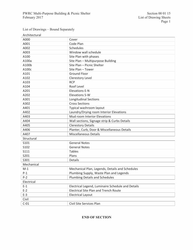
List of Drawings – Bound Separately
END OF SECTION
Architectural A000 Cover A001 Code Plan A002 Schedules A003 Window wall schedule A100 Site Plan with phases A100a Site Plan – Multipurpose Building A100b Site Plan – Picnic Shelter A100c Site Plan – Tower A101 Ground Floor A102 Clerestory Level A103 RCP A104 Roof Level A201 Elevations E-N A202 Elevations S-W A301 Longitudinal Sections A302 Cross Sections A401 Typical washroom layout A402 Laundry/Drying room Interior Elevations A403 Mud room Interior Elevations A404 Wall sections, Signage strip & Curbs Details A405 Clerestory Details A406 Planter, Curb, Door & Miscellaneous Details A407 Miscellaneous Details Structural S101 General Notes S102 General Notes S111 Tables S201 Plans S301 Details Mechanical M-1 Mechanical Plan, Legends, Details and Schedules P-1 Plumbing Supply, Waste Plan and Legends P-2 Plumbing Details and Schedules Electrical E-1 Electrical Legend, Luminaire Schedule and Details E-2 Electrical Site Plan and Trench Route E-3 Electrical Layout Civil C-01 Civil Site Services Plan

PWRC Multi-Purpose Building & Picnic Shelter Section 00 01 10 February 2017 TABLE OF CONTENTS
Page 1
Iredale Architecture – Project #16063
Section Number Section Title No. of Pages 00 01 15 List of Drawing Sheets 1 00 01 10 Table of Contents 3 01 11 00 Summary of Work 4 01 14 00 Work Restrictions 2 01 29 00 Payment Procedures 3 01 31 19 Project Meetings 3 01 32 16.07 Construction Progress Schedules – Bar (GANTT) Chart 3 01 33 00 Submittal Procedures 5 01 35 29.06 Health and Safety Requirements 4 01 35 43 Environmental Procedures 4 01 41 00 Regulatory Requirements 2 01 45 00 Quality Control 3 01 51 00 Temporary Utilities 3 01 52 00 Construction Facilities 4 01 56 00 Temporary Barriers and Closures 2 01 61 00 Common Product Requirements 4 01 71 00 Examination and Preparation 2 01 73 00 Execution 3 01 74 11 Cleaning 3 01 74 21 Construction/Demolition Waste Management And Disposal 11 01 77 00 Closeout Procedures 2 01 78 00 Closeout Submittals 8 01 79 00 Demonstration and Training 2 01 91 13 General Commissioning (Cx) Requirements 10 01 91 31 Commissioning (Cx) Plan 10 01 91 33 Commissioning Forms 4 01 91 41 Commissioning Training 4 01 91 51 Building Management Manual (BMM) 4 02 65 00 Underground Storage Tank Removal 5 03 10 00 Concrete Forming and Accessories 4 03 20 00 Concrete Reinforcing 5 03 30 00 Cast-In-Place Concrete 5 03 35 00 Concrete Finishing 4 04 04 99 Masonry for Minor Works 6 05 50 00 Metal Fabrications 6 06 08 99 Rough Carpentry for Minor Works 5 06 17 53 Shop-Fabricated Wood Trusses 5 06 20 00 Finish Carpentry 6 06 40 00 Architectural Woodwork 7 07 11 13 Bituminous Dampproofing 5 07 21 13 Board Insulation 4 07 21 16 Blanket Insulation 3 07 26 00 Vapour Retarders 4 07 44 56 Mineral Fiber Reinforced Cementitious Siding 4

PWRC Multi-Purpose Building & Picnic Shelter Section 00 01 10 February 2017 TABLE OF CONTENTS
Page 2
Iredale Architecture – Project #16063
07 46 23 Wood Siding 4 07 61 00 Sheet Metal Roofing 6 07 62 00 Sheet Metal Flashing and Trim 6 07 92 00 Joint Sealants 6 08 11 00 Metal Doors and Frames 8 08 14 13 Window Wall 4 08 33 23.01 Overhead Coiling Doors and Grilles 5 08 41 13 Glazed Aluminum Storefront 7 08 71 00 Door Hardware 6 08 80 50 Glazing 6 08 90 00 Louvres and Vents 4 09 21 16 Gypsum Board Assemblies 7 09 91 99 Painting for Minor Works 7 10 28 10 Toilet and Bath Accessories 4 10 56 13 Metal Storage Shelving 3 11 41 10 Walk-in Freezers and Coolers 8 12 35 53.13 Steel Casework 5 13 34 23 Prefabricated Structure 4 21 05 01 Mechanical General Requirements 13 22 05 00 Common Work Results for Plumbing 7 22 06 01 Plumbing Equipment Manufacturers 2 22 11 16 Domestic Water Piping 7 22 13 17 Drainage Waste and Vent Piping – Cast Iron and Copper 4 22 30 05 Domestic Water Heaters 2 23 05 29 Hangers and Supports for Piping and Equipment 5 23 05 93 Testing, Adjusting and Balancing for HVAC 5 23 06 01 HVAC Equipment Manufacturers 2 23 06 02 HVAC Subtrades 1 23 07 13 Duct Insulation 6 23 07 15 Thermal Insulation for Piping 7 23 33 00 Air Duct Accessories 4 23 33 14 Dampers – Balancing 3 25 05 01 EMCS General Requirements 6 25 05 02 EMCS Summary of Work 1 25 08 20 EMCS Installation and Wiring 5 25 10 02 EMCS Software Requirements 3 25 30 01 EMCS Hardware Requirements 1 25 30 02 EMCS Field Control Devices 3 25 30 03 EMCS Points List 1 25 90 01 EMCS Sequences of Operation 3 26 05 00 Common Work Results for Electrical 14 26 05 20 Wire and Box Connectors (0-1000 V) 2 26 05 21 Wires and Cables (0-1000 V) 6 26 05 32 Outlet Boxes, Conduit Boxes and Fittings 2 26 05 34 Conduits, Conduit Fastenings and Conduit Fittings 3 26 05 43.01 Installation of Cables in Trenches and in Ducts 4

PWRC Multi-Purpose Building & Picnic Shelter Section 00 01 10 February 2017 TABLE OF CONTENTS
Page 3
Iredale Architecture – Project #16063
26 24 16.01 Panelboards Breaker Type 5 26 27 26 Wiring Devices 5 26 28 16.02 Moulded Case Circuit Breakers 2 26 50 00 Lighting 8 26 56 00 Exterior Lighting 11 31 00 99 Earthwork for Minor Works 6 31 05 16 Aggregate Materials 4 31 11 00 Clearing and Grubbing 5 31 22 13 Rough Grading 3 31 23 33.01 Excavating, Trenching and Backfilling 8 32 12 16.02 Asphalt Paving for Building Sites 10 32 13 13.01 Concrete Paving for Building Site 7 32 15 40 Crushed Stone Surfacing 4 32 16 15 Concrete Walks, Curbs and Gutters 5 32 31 13 Chain Link Fences and Gates 5 32 37 00 Exterior Site Furnishings 3 32 91 19.13 Topsoil Placement and Grading 6 32 92 23 Sodding 6 33 31 13 Public Sanitary Utility Sewerage Piping 6 33 34 00 Sanitary Utility Sewerage Force Mains 9 33 41 00 Storm Utility Drainage Piping 5 Appendix A 32
END OF SECTION

PWRC Multi-Purpose Building & Picnic Shelter Section 01 11 00 February 2017 SUMMARY OF WORK
Page 1
Iredale Group Architecture – Project #16063
Part 1 General
1.1 RELATED REQUIREMENTS
.1 All Sections.
1.2 WORK COVERED BY CONTRACT DOCUMENTS
.1 Work of this Contract comprises the construction of a new multi-purpose building, the installation of a package picnic shelter, and the repair of an existing wood frame tower, located at 5421 Robertson Road, Westham Island.
1.3 CONTRACT METHOD
.1 Construct Work under single contract.
.2 Not used.
1.4 WORK SEQUENCE
.1 Co-ordinate Progress Schedule and co-ordinate with Owner occupancy during construction.
.2 Maintain fire access/control.
.3 Work to be completed within 24 weeks of award.
1.5 CONTRACTOR USE OF PREMISES
.1 Limit use of premises for Work, to allow:
.1 Owner occupancy.
.2 Work by other contractors.
.3 Building operation.
.2 Co-ordinate use of premises under direction of the Owner's Representative.
.3 Obtain and pay for use of additional storage or work areas needed for operations under this Contract.
.4 Remove or alter existing work to prevent injury or damage to portions of existing work which remain.
.5 Repair or replace portions of existing work which have been altered during construction operations to match existing or adjoining work, as directed by Owner's Representative.
.6 At completion of operations condition of existing work: equal to or better than that which existed before new work started.
1.6 OWNER OCCUPANCY
.1 Owner will occupy the site during entire construction period for execution of normal operations.
.2 Co-operate with Owner in scheduling operations to minimize conflict and to facilitate Owner usage.

PWRC Multi-Purpose Building & Picnic Shelter Section 01 11 00 February 2017 SUMMARY OF WORK
Page 2
Iredale Group Architecture – Project #16063
1.7 ALTERATIONS, ADDITIONS OR REPAIRS TO EXISTING BUILDING
.1 Execute work with least possible interference or disturbance to building operations and occupants, and the normal use of premises. Arrange with the Owner's Representative to facilitate execution of work.
1.8 EXISTING SERVICES
.1 Notify the Departmental Representative, Project Manager and utility companies of intended interruption of services and obtain required permission.
.2 Where Work involves breaking into or connecting to existing services, give the Departmental Representative and Project Manager minimum 48 hours notice for necessary interruption of mechanical or electrical service throughout course of work. Minimize duration of interruptions. Carry out work at times as directed by the Departmental Representative and Project Manager with minimum disturbance to the Owner, other Contractors and Building occupants.
.3 Provide alternative routes for the Owner, other Contractors and Building occupants and vehicular traffic.
.4 Establish location and extent of service lines in area of work before starting Work. Notify the Departmental Representative and Project Manager of findings.

PWRC Multi-Purpose Building & Picnic Shelter Section 01 11 00 February 2017 SUMMARY OF WORK
Page 3
Iredale Group Architecture – Project #16063
.5 Submit schedule to and obtain approval from the Departmental Representative and Project Manager for any shut-down or closure of active service or facility including power and communications services. Adhere to approved schedule and provide notice to affected parties.
.6 Provide temporary services as required by the Architectural drawing set and Project Manager's Schedule, or when directed by the Departmental Representative and Project Manager, to maintain critical building and tenant systems.
.7 Provide adequate bridging over trenches which cross sidewalks or roads to permit normal traffic.
.8 Where unknown services are encountered, immediately advise the Owner's Representative and confirm findings in writing.
.9 Protect, relocate or maintain existing active services. When inactive services are encountered, cap off in manner approved by authorities having jurisdiction.
.10 Record locations of maintained, re-routed and abandoned service lines.
.11 Construct barriers in accordance with Section 01 56 00 - Temporary Barriers and Enclosures.
1.9 DOCUMENTS REQUIRED
.1 Maintain at job site, one copy each document as follows:
.1 Contract Drawings.
.2 Specifications.
.3 Addenda.
.4 Reviewed Shop Drawings.
.5 List of Outstanding Shop Drawings.
.6 Change Orders.
.7 Other Modifications to Contract.
.8 Field Test Reports.
.9 Copy of Approved Work Schedule.
.10 Health and Safety Plan and Other Safety Related Documents.
.11 Security Clearance, see 01 14 00 Work Restrictions.
.12 Other documents as specified.
Part 2 Products
2.1 NOT USED
.1 Not used.
Part 3 Execution
3.1 NOT USED
.1 Not used.

PWRC Multi-Purpose Building & Picnic Shelter Section 01 11 00 February 2017 SUMMARY OF WORK
Page 4
Iredale Group Architecture – Project #16063
END OF SECTION
PWRC Multi-Purpose Building & Picnic Shelter Section 01 14 00 February 2017 WORK RESTRICTIONS
Page 1
Iredale Group Architecture – Project #16063
Approved: 2010-12-31
Part 1 General
1.1 RELATED REQUIREMENTS
.1 All Sections.
1.2 ACCESS AND EGRESS
.1 Design, construct and maintain temporary "access to" and "egress from" work areas, including stairs, runways, ramps or ladders, scaffolding, independent of finished surfaces and in accordance with relevant municipal, provincial and other regulations.
1.3 USE OF SITE AND FACILITIES
.1 Execute work with least possible interference or disturbance to normal use of premises. Make arrangements with the Owner's Representative to facilitate work as stated.
.2 Maintain existing services to building and provide for personnel and vehicle access.
.3 Where security is reduced by work provide temporary measures to maintain security. All measures must be submitted to the Departmental Representative, Project Manager and Consultant for approval in writing prior to the start of the Work.
.4 The contractor to provide their own sanitary facilities.
.5 Closures: protect work temporarily until permanent enclosures are completed.
1.4 ALTERATIONS, ADDITIONS OR REPAIRS TO EXISTING BUILDING
.1 Execute work with least possible interference or disturbance to building operations and occupants, and the normal use of premises. Arrange with the Departmental Representative and Project Manager to facilitate execution of work.
1.5 EXISTING SERVICES
.1 Notify the Departmental Representative, Project Manager, Consultant and utility companies of intended interruption of services and obtain required permission.
.2 Where Work involves breaking into or connecting to existing services, give the the Departmental Representative, Project Manager and Consultant minimum 48 hours notice for necessary interruption of mechanical or electrical service throughout course of work. Minimize duration of interruptions. Carry out work at times as directed by the Departmental Representative and Project Manager with minimum disturbance to the Owner, other Contractors and Building occupants.
.3 Provide alternative routes for the Owner, other Contractors and Building occupants and vehicular traffic.
.4 Construct barriers in accordance with Section 01 56 00 - Temporary Barriers and Enclosures.

PWRC Multi-Purpose Building & Picnic Shelter Section 01 14 00 February 2017 WORK RESTRICTIONS
Page 2
Iredale Group Architecture – Project #16063
1.6 SPECIAL REQUIREMENTS
.1 Submit schedule in accordance with Section 01 32 16.06 - Construction Progress Schedule - Critical Path Method (CPM).
.2 Ensure Contractor's personnel employed on site become familiar with and obey regulations including safety, fire, traffic and security regulations.
.3 Keep within limits of work and avenues of access.
1.7 SECURITY
.1 Where security has been reduced by Work of Contract, provide temporary means to maintain security.
.2 Security escort:
.1 Personnel employed on this project must sign in and out every day with the Facility Manager.
1.8 BUILDING SMOKING ENVIRONMENT
.1 Comply with smoking restrictions. Smoking is not permitted within 20m of building openings and air intake locations.
Part 2 Products
2.1 NOT USED
.1 Not Used.
Part 3 Execution
3.1 NOT USED
.1 Not Used.
END OF SECTION

PWRC Multi-Purpose Building & Picnic Shelter Section 01 29 00 February 2017 PAYMENT PROCEDURES
Page 1
Iredale Group Architecture – Project #16063
Approved: 2006-03-31
Part 1 General
1.1 REFERENCE STANDARDS
.1 Owner/Contractor Agreement.
.1 Not used.
1.2 APPLICATIONS FOR PROGRESS PAYMENT
.1 Make applications for payment on account as monthly as Work progresses.
.2 Date applications for payment last day of agreed monthly payment period and ensure amount claimed is for value, proportionate to amount of Contract, of Work performed and Products delivered to Place of Work at that date.
.3 Submit to Consultant, at least 14 days before first application for payment. Schedule of values for parts of Work, aggregating total amount of Contract Price, to facilitate evaluation of applications for payment.
1.3 SCHEDULE OF VALUES
.1 Provide schedule of values supported by evidence as Consultant may reasonably direct and when accepted by Consultant, be used as basis for applications for payment.
.2 Include statement based on schedule of values with each application for payment.
.3 Support claims for products delivered to Place of Work but not yet incorporated into Work by such evidence as Consultant may reasonably require to establish value and delivery of products.
1.4 PREPARING SCHEDULE OF UNIT PRICE TABLE ITEMS
.1 Submit separate schedule of unit price items of Work if requested in Bid form.
.2 Make form of submittal parallel to Schedule of Values, with each line item identified same as line item in Schedule of Values. Include in unit prices only:
.1 Cost of material.
.2 Delivery and unloading at site.
.3 Sales taxes.
.4 Installation, overhead and profit.
.3 Ensure unit prices multiplied by quantities given equal material cost of that item in Schedule of Values.
1.5 PROGRESS PAYMENT
.1 Not used.
.2 Consultant will issue to Owner, no later than 10 days after receipt of an application for payment, certificate for payment in amount applied for or in such other amount as Consultant determines to be due. If Consultant amends application, Consultant will give notification in writing giving reasons for amendment.

PWRC Multi-Purpose Building & Picnic Shelter Section 01 29 00 February 2017 PAYMENT PROCEDURES
Page 2
Iredale Group Architecture – Project #16063
1.6 SUBSTANTIAL PERFORMANCE OF WORK
.1 Prepare and submit to Consultant comprehensive list of items to be completed or corrected and apply for a review by Consultant to establish Substantial Performance of Work or substantial performance of designated portion of Work when Work is substantially performed if permitted by lien legislation applicable to Place of Work designated portion which Owner agrees to accept separately is substantially performed. Failure to include items on list does not alter responsibility to complete Contract.
.2 No later than 10 days after receipt of list and application, Consultant will review Work to verify validity of application, and no later than 7 days after completing review, will notify Contractor if Work or designated portion of Work is substantially performed.
.3 Consultant: state date of Substantial Performance of Work or designated portion of Work in certificate.
.4 Immediately following issuance of certificate of Substantial Performance of Work, in consultation with Consultant, establish reasonable date for finishing Work.
1.7 PAYMENT OF HOLDBACK UPON SUBSTANTIAL PERFORMANCE OF WORK
.1 After issuance of certificate of Substantial Performance of Work:
.1 Submit application for payment of holdback amount.
.2 Submit sworn statement that accounts for labour, subcontracts, products, construction machinery and equipment, and other indebtedness which may have been incurred in Substantial Performance of Work and for which Owner might in be held responsible have been paid in full, except for amounts properly retained as holdback or as identified amount in dispute.
.2 After receipt of application for payment and sworn statement, Consultant will issue certificate for payment of holdback amount.
.3 Where holdback amount has not been placed in a separate holdback account, Owner shall, 10 days prior to expiry of holdback period stipulated in lien legislation applicable to Place of Work, place holdback amount in bank account in joint names of Owner and Contractor.
.4 Amount authorized by certificate for payment of holdback amount is due and payable on day following expiration of holdback period stipulated in lien legislation applicable to Place of Work. Where lien legislation does not exist or apply, holdback amount is due and payable in accordance with other legislation, industry practice, or provisions which may be agreed to between parties. Owner may retain out of holdback amount sums required by law to satisfy liens against Work or, if permitted by lien legislation applicable to Place of Work, other third party monetary claims against Contractor which are enforceable against Owner.
1.8 PROGRESSIVE RELEASE OF HOLDBACK
.1 Where legislation permits, if Consultant has certified that Work of subcontractor or supplier has been performed prior to Substantial Performance of Work, Owner shall pay holdback amount retained for such subcontract Work, or products supplied by such supplier, on day following expiration of holdback period for such Work stipulated in lien legislation applicable to Place of Work.

PWRC Multi-Purpose Building & Picnic Shelter Section 01 29 00 February 2017 PAYMENT PROCEDURES
Page 3
Iredale Group Architecture – Project #16063
.2 In addition to provisions of preceding paragraph, and certificate wording, ensure that such subcontract Work or products is protected pending issuance of final certificate for payment and be responsible for correction of defects or Work not performed regardless of whether or not such was apparent when such certificates were issued.
1.9 FINAL PAYMENT
.1 Submit application for final payment when Work is completed.
.2 Consultant will, no later than 10 days after receipt of application for final payment, review Work to verify validity of application. Consultant will give notification that application is valid or give reasons why it is not valid, no later than 7 days after reviewing Work.
.3 Consultant will issue final certificate for payment when application for final payment is found valid.
Part 2 Products
2.1 NOT USED
.1 Not Used.
Part 3 Execution
3.1 NOT USED
.1 Not Used.
END OF SECTION

PWRC Multi-Purpose Building & Picnic Shelter Section 01 31 19 February 2017 PROJECT MEETINGS
Page 1
Iredale Group Architecture – Project #16063
Part 1 General
1.1 RELATED REQUIREMENTS
.1 All Sections.
1.2 ADMINISTRATIVE
.1 Schedule and administer regular project meetings throughout the progress of the work.
.2 Prepare agenda for meetings.
.3 Distribute written notice of each meeting four days in advance of meeting date to the Owner's Representative.
.4 Progress meetings may be conducted by phone or on site as agreed to by the Departmental Representative and Consultant.
.5 Record the meeting minutes. Include significant proceedings and decisions. Identify actions by parties.
.6 Reproduce and distribute copies of minutes within 3 days after meetings and transmit to meeting participants and affected parties not in attendance.
.7 Representative of Contractor, Subcontractor and suppliers attending meetings will be qualified and authorized to act on behalf of party each represents.
1.3 PRECONSTRUCTION MEETING
.1 Within 15 days after award of Contract, request a meeting of parties in contract to discuss and resolve administrative procedures and responsibilities.
.2 Establish time and location of meeting and notify parties concerned minimum 5 days before meeting.
.3 Incorporate mutually agreed variations to Contract Documents into Agreement, prior to signing.
.4 Agenda to include:
.1 Appointment of official representative of participants in the Work.
.2 Schedule of Work: in accordance with Section 01 32 16.06 - Construction Progress Schedule - Critical Path Method (CPM).
.3 Schedule of submission of shop drawings, samples, colour chips. Submit submittals in accordance with Section 01 33 00 - Submittal Procedures.
.4 Requirements for temporary facilities, site sign, offices, storage sheds, utilities, fences in accordance with Section 01 52 00 - Construction Facilities.
.5 Delivery schedule of specified equipment in accordance with Section 14 20 06 Passenger Elevators and Section 14 31 00 Escalators.
.6 Site security in accordance with Section 01 14 00 Work Restrictions and Section 01 56 00 - Temporary Barriers and Enclosures.
.7 Proposed changes, change orders, procedures, approvals required, mark-up percentages permitted, time extensions, overtime, administrative requirements.

PWRC Multi-Purpose Building & Picnic Shelter Section 01 31 19 February 2017 PROJECT MEETINGS
Page 2
Iredale Group Architecture – Project #16063
.8 Owner provided products, if required.
.9 Record drawings in accordance with Section 01 33 00 - Submittal Procedures.
.10 Maintenance manuals in accordance with Section 01 78 00 - Closeout Submittals.
.11 Take-over procedures, acceptance, warranties in accordance with Section 01 78 00 - Closeout Submittals.
.12 Monthly progress claims, administrative procedures, photographs, hold backs.
.13 Appointment of inspection and testing agencies or firms.
.14 Insurances, transcript of policies.
1.4 PROGRESS MEETINGS
.1 During course of Work and 2 weeks prior to project completion, schedule progress meetings bi-weekly.
.2 Contractor, major Subcontractors involved in Work, Departmental Representative (as required), Project Manager and Consultants (as required) are to be in attendance.
.3 Notify parties minimum 5 days prior to meetings.
.4 Record minutes of meetings and circulate to attending parties and affected parties not in attendance within 3 days after meeting.
.5 Agenda to include the following:
.1 Review, approval of minutes of previous meeting.
.2 Review of Work progress since previous meeting.
.3 Field observations, problems, conflicts.
.4 Problems which impede construction schedule.
.5 Review of off-site fabrication delivery schedules.
.6 Corrective measures and procedures to regain projected schedule.
.7 Revision to construction schedule.
.8 Progress schedule, during succeeding work period.
.9 Review submittal schedules: expedite as required.
.10 Maintenance of quality standards.
.11 Review proposed changes for affect on construction schedule and on completion date.
.12 Other business.
Part 2 Products
2.1 NOT USED
.1 Not Used.

PWRC Multi-Purpose Building & Picnic Shelter Section 01 31 19 February 2017 PROJECT MEETINGS
Page 3
Iredale Group Architecture – Project #16063
Part 3 Execution
3.1 NOT USED
.1 Not Used.
END OF SECTION

PWRC Multi-Purpose Building & Picnic Shelter Section 01 32 16.07 February 2017 CONSTRUCTION PROGRESS SCHEDULE - BAR (GANTT) CHART Publisher: Spex.ca Page 1
Approved: 2006-06-30
Part 1 General
1.1 RELATED REQUIREMENTS
.1 Section [_____]
1.2 DEFINITIONS
.1 Activity: element of Work performed during course of Project. Activity normally has expected duration, and expected cost and expected resource requirements. Activities can be subdivided into tasks.
.2 Bar Chart (GANTT Chart): graphic display of schedule-related information. In typical bar chart, activities or other Project elements are listed down left side of chart, dates are shown across top, and activity durations are shown as date-placed horizontal bars. Generally Bar Chart should be derived from commercially available computerized project management system.
.3 Baseline: original approved plan (for project, work package, or activity), plus or minus approved scope changes.
.4 Construction Work Week: Monday to Friday, inclusive, will provide five day work week and define schedule calendar working days as part of Bar (GANTT) Chart submission.
.5 Duration: number of work periods (not including holidays or other nonworking periods) required to complete activity or other project element. Usually expressed as workdays or workweeks.
.6 Master Plan: summary-level schedule that identifies major activities and key milestones.
.7 Milestone: significant event in project, usually completion of major deliverable.
.8 Project Schedule: planned dates for performing activities and the planned dates for meeting milestones. Dynamic, detailed record of tasks or activities that must be accomplished to satisfy Project objectives. Monitoring and control process involves using Project Schedule in executing and controlling activities and is used as basis for decision making throughout project life cycle.
.9 Project Planning, Monitoring and Control System: overall system operated by Departmental Representative to enable monitoring of project work in relation to established milestones.
1.3 REQUIREMENTS
.1 Ensure Master Plan and Detail Schedules are practical and remain within specified Contract duration.
.2 Plan to complete Work in accordance with prescribed milestones and time frame.
.3 Limit activity durations to maximum of approximately 10 working days, to allow for progress reporting.

PWRC Multi-Purpose Building & Picnic Shelter Section 01 32 16.07 February 2017 CONSTRUCTION PROGRESS SCHEDULE - BAR (GANTT) CHART Publisher: Spex.ca Page 2
.4 Ensure that it is understood that Award of Contract or time of beginning, rate of progress, Interim Certificate and Final Certificate as defined times of completion are of essence of this contract.
1.4 ACTION AND INFORMATIONAL SUBMITTALS
.1 Provide submittals in accordance with Section 01 33 00- Submittal Procedures.
.2 Submit to Department Representative
.3 Submit Project Schedule to Departmental Representative within 5 working days of receipt of acceptance of Master Plan.
1.5 PROJECT MILESTONES
.1 Project milestones form interim targets for Project Schedule.
.1 Excavation complete
.2 Substructure complete
.3 Superstructure complete
.4 Building closed-in and weatherproofed
.5 Interior finishing and fitting, mechanical, and electrical work
.6 Interim Certificate (Substantial Completion)
1.6 MASTER PLAN
.1 Structure schedule to allow orderly planning, organizing and execution of Work as Bar Chart (GANTT).
.2 Departmental Representative and Consultant will review and return revised schedules within 5 working days.
.3 Revise schedule as required and resubmit within 5 working days.
.4 Accepted revised schedule will become Master Plan and be used as baseline for updates.
1.7 PROJECT SCHEDULE
.1 Develop detailed Project Schedule derived from Master Plan.
.2 Ensure detailed Project Schedule includes as minimum milestone and activity types as follows:
.1 Award.
.2 Shop Drawings, Samples.
.3 Permits.
.4 Mobilization.
.5 Excavation.
.6 Backfill.
.7 Building footings.
.8 Slab on grade.
.9 Structural Steel.
.10 Siding and Roofing.

PWRC Multi-Purpose Building & Picnic Shelter Section 01 32 16.07 February 2017 CONSTRUCTION PROGRESS SCHEDULE - BAR (GANTT) CHART Publisher: Spex.ca Page 3
.11 Interior Architecture (Walls, Floors and Ceiling).
.12 Plumbing.
.13 Lighting.
.14 Electrical.
.15 Piping.
.16 Controls.
.17 Heating, Ventilating, and Air Conditioning.
.18 Millwork.
.19 Fire Systems.
.20 Testing and Commissioning.
.21 Supplied equipment long delivery items.
.22 Engineer supplied equipment required dates.
1.8 PROJECT SCHEDULE REPORTING
.1 Update Project Schedule on weekly basis reflecting activity changes and completions, as well as activities in progress.
.2 Include as part of Project Schedule, narrative report identifying Work status to date, comparing current progress to baseline, presenting current forecasts, defining problem areas, anticipated delays and impact with possible mitigation.
1.9 PROJECT MEETINGS
.1 Discuss Project Schedule at regular site meetings, identify activities that are behind schedule and provide measures to regain slippage. Activities considered behind schedule are those with projected start or completion dates later than current approved dates shown on baseline schedule.
.2 Weather related delays with their remedial measures will be discussed and negotiated.
Part 2 Products
2.1 NOT USED
.1 Not used.
Part 3 Execution
3.1 NOT USED
.1 Not used.
END OF SECTION

PWRC Multi-Purpose Building & Picnic Shelter Section 01 33 00 February 2017 SUBMITTAL PROCEDURES
Page 1
Iredale Group Architecture – Project #16063
Part 1 General
1.1 RELATED REQUIREMENTS
.1 All Sections.
1.2 REFERENCES
.1 Comply with Municipal, Provincial and Federal requirements.
.2 Refer to Section 01 41 00 Regulatory Requirements and the specific References, Codes and Standards of each individual Specification Section.
1.3 ADMINISTRATIVE
.1 Submit to the Consultant and Project Manager submittals listed for review. Submit promptly and in orderly sequence to not cause delay in Work. Failure to submit in ample time is not considered sufficient reason for extension of Contract Time and no claim for extension by reason of such default will be allowed.
.2 Do not proceed with Work affected by submittal until review is complete.
.3 Present shop drawings, product data, samples and mock-ups in SI Metric units.
.4 Where items or information is not produced in SI Metric units converted values are acceptable.
.5 Review submittals prior to submission. This review represents that necessary requirements have been determined and verified, or will be, and that each submittal has been checked and co-ordinated with requirements of Work and Contract Documents. Submittals not stamped, signed, dated and identified as to specific project will be returned without being examined and considered rejected.
.6 Notify the Project Manager and Consultant, in writing at time of submission, identifying deviations from requirements of Contract Documents stating reasons for deviations.
.7 Verify field measurements and affected adjacent Work are co-ordinated.
.8 Contractor's responsibility for errors and omissions in submission is not relieved by the Project Manager and Consultant review of submittals.
.9 Contractor's responsibility for deviations in submission from requirements of Contract Documents is not relieved by the Project Manager and Consultant review.
.10 Keep one reviewed copy of each submission on site.
1.4 SHOP DRAWINGS AND PRODUCT DATA
.1 The term "shop drawings" means drawings, diagrams, illustrations, schedules, performance charts, brochures and other data which are to be provided by Contractor to illustrate details of a portion of Work.
.2 Submit drawings stamped and signed by professional engineer registered or licensed in the Province of British Columbia, Canada.

PWRC Multi-Purpose Building & Picnic Shelter Section 01 33 00 February 2017 SUBMITTAL PROCEDURES
Page 2
Iredale Group Architecture – Project #16063
.3 Indicate materials, methods of construction and attachment or anchorage, erection diagrams, connections, explanatory notes and other information necessary for completion of Work. Where articles or equipment attach or connect to other articles or equipment, indicate that such items have been co-ordinated, regardless of Section under which adjacent items will be supplied and installed. Indicate cross references to design drawings and specifications.
.4 Allow 3 days for the Project Manager and Consultant review of each submission.
.5 Adjustments made on shop drawings by the Consultant and Project Manager are not intended to change Contract Price. If adjustments affect value of Work, state such in writing to Consultant and Project Manager prior to proceeding with Work.
.6 Make changes in shop drawings as Consultant and Project Manager may require, consistent with Contract Documents. When resubmitting, notify Consultant and Owner's Representative in writing of revisions other than those requested.
.7 Accompany submissions with transmittal letter, in [duplicate], containing:
.1 Date.
.2 Project title and number.
.3 Contractor's name and address.
.4 Identification and quantity of each shop drawing, product data and sample.
.5 Other pertinent data.
.8 Submissions include:
.1 Date and revision dates.
.2 Project title and number.
.3 Name and address of:
.1 Subcontractor.
.2 Supplier.
.3 Manufacturer.
.4 Contractor's stamp, signed by Contractor's authorized representative certifying approval of submissions, verification of field measurements and compliance with Contract Documents.
.5 Details of appropriate portions of Work as applicable:
.1 Fabrication.
.2 Layout, showing dimensions, including identified field dimensions, and clearances.
.3 Setting or erection details.
.4 Capacities.
.5 Performance characteristics.
.6 Standards.
.7 Operating weight.
.8 Wiring diagrams.
.9 Single line and schematic diagrams.
.10 Relationship to adjacent work.
PWRC Multi-Purpose Building & Picnic Shelter Section 01 33 00 February 2017 SUBMITTAL PROCEDURES
Page 3
Iredale Group Architecture – Project #16063
.9 After the Project Manager and Consultant review, distribute copies to all affected parties.
.10 Submit an electronic copy (in PDF form, of a quality suitable for printing) of shop drawings for each requirement requested in specification Sections and as the Project Manager and Consultant may reasonably request.
.11 Submit electronic copy (in PDF form, of a quality suitable for printing) of product data sheets or brochures for requirements requested in specification Sections and as requested by the Project Manager and Consultant where shop drawings will not be prepared due to standardized manufacture of product.
.12 Submit electronic copy (in PDF form, of a quality suitable for printing) of test reports for requirements requested in specification Sections and as requested by the Project Manager and Consultant:
.1 Report signed by authorized official of testing laboratory that material, product or system identical to material, product or system to be provided has been tested in accord with specified requirements.
.2 Testing must have been within 3 years of date of contract award for project.
.13 Submit electronic copy (in PDF form, of a quality suitable for printing) of certificates for requirements requested in specification Sections and as requested by the Project Manager and Consultant.
.1 Statements printed on manufacturer's letterhead and signed by responsible officials of manufacturer of product, system or material attesting that product, system or material meets specification requirements.
.2 Certificates must be dated after award of project contract complete with project name.
.14 Submit electronic copies of manufacturer's instructions for requirements requested in specification Sections and as requested by the Project Manager and Consultant.
.1 Pre-printed material describing installation of product, system or material, including special notices and Material Safety Data Sheets concerning impedances, hazards and safety precautions.
.15 Submit electronic copies of Manufacturer's Field Reports for requirements requested in specification Sections and as requested by the Project Manager and Consultant.
.16 Documentation of the testing and verification actions taken by manufacturer's representative to confirm compliance with manufacturer's standards or instructions.
.17 Submit electronic copy (in PDF form, of a quality suitable for printing) of Operation and Maintenance Data for requirements requested in specification Sections and as requested by the Project Manager and Consultant.
.18 Delete information not applicable to project.
.19 Supplement standard information to provide details applicable to project.
.20 If upon review by the Project Manager and Consultant, no errors or omissions are discovered or if only minor corrections are made, the Electronic copy will be returned and fabrication and installation of Work may proceed. If shop drawings are rejected, noted copy will be returned and resubmission of corrected shop drawings, through same

PWRC Multi-Purpose Building & Picnic Shelter Section 01 33 00 February 2017 SUBMITTAL PROCEDURES
Page 4
Iredale Group Architecture – Project #16063
procedure indicated above, must be performed before fabrication and installation of Work may proceed.
.21 The review of shop drawings by Public Works and Procurement Canada is for sole purpose of ascertaining conformance with general concept.
.1 This review shall not mean that Public Works and Procurement Canada approves detail design inherent in shop drawings, responsibility for which shall remain with Contractor submitting same, and such review shall not relieve Contractor of responsibility for errors or omissions in shop drawings or of responsibility for meeting requirements of construction and Contract Documents.
.2 Without restricting generality of foregoing, Contractor is responsible for dimensions to be confirmed and correlated at job site, for information that pertains solely to fabrication processes or to techniques of construction and installation and for co-ordination of Work of sub-trades.
1.5 SAMPLES
.1 Submit for review samples in duplicate as requested in respective specification Sections. Label samples with origin and intended use.
.2 Deliver samples prepaid to the Consultant's business address.
.3 Notify the Project Manager and Consultant in writing, at time of submission of deviations in samples from requirements of Contract Documents.
.4 Where colour, pattern or texture is criterion, submit full range of samples.
.5 Adjustments made on samples by the Project Manager and Consultant are not intended to change Contract Price. If adjustments affect value of Work, state such in writing to the Project Manager and Consultant prior to proceeding with Work.
.6 Make changes in samples which the Project Manager and Consultant may require, consistent with Contract Documents.
.7 Reviewed and accepted samples will become standard of workmanship and material against which installed Work will be verified.
1.6 MOCK-UPS
.1 Erect mock-ups in accordance with 01 45 00 - Quality Control.
1.7 PHOTOGRAPHIC DOCUMENTATION
.1 Submit electronic digital photography in jpg format, in a fine resolution, bi-weekly with progress statement as directed by the Consultant.
.2 Project identification: name and number of project and date of exposure indicated.
.3 Number of viewpoints: 4 locations.
.1 Viewpoints and their location as determined by the Consultant.
.4 Frequency of photographic documentation: bi-weekly, or as directed by the Project Manager and Consultant. Additional photo documentation to include:
.1 All found or unexpected conditions encountered as part of the work.

PWRC Multi-Purpose Building & Picnic Shelter Section 01 33 00 February 2017 SUBMITTAL PROCEDURES
Page 5
Iredale Group Architecture – Project #16063
1.8 CERTIFICATES AND TRANSCRIPTS
.1 Immediately after award of Contract, submit Workers' Compensation Board status.
.2 Submit transcription of insurance immediately after award of Contract.
Part 2 Products
2.1 NOT USED
.1 Not Used.
Part 3 Execution
3.1 NOT USED
.1 Not Used.
END OF SECTION

PWRC Multi-Purpose Building & Picnic Shelter Section 01 35 29.06 February 2017 HEALTH AND SAFETY REQUIREMENTS
Page 1
Iredale Group Architecture – Project # 16063
Approved: 2013-06-30
Part 1 General
1.1 RELATED REQUIREMENTS
.1 All Sections.
1.2 REFERENCES
.1 Canada Labour Code, Part 2, Canada Occupational Safety and Health Regulations
.2 Province of British Columbia
.1 Workers Compensation Act, RSBC 1996 - Updated 2012.
1.3 ACTION AND INFORMATIONAL SUBMITTALS
.1 Submit in accordance with Section 01 33 00 - Submittal Procedures.
.2 Submit site-specific Health and Safety Plan: Within [7] days after date of Notice to Proceed and prior to commencement of Work. Health and Safety Plan must include:
.1 Results of site specific safety hazard assessment.
.2 Results of safety and health risk or hazard analysis for site tasks and operation found in work plan.
.3 Submit copies of Contractor's authorized representative's work site health and safety inspection reports to the Project Manager weekly.
.4 Submit copies of reports or directions issued by Federal, Provincial and Territorial health and safety inspectors.
.5 Submit copies of incident and accident reports.
.6 Submit WHMIS MSDS - Material Safety Data Sheets in accordance with Section [01 47 15 - Sustainable Requirements: Construction].
.7 Project Manager will review Contractor's site-specific Health and Safety Plan and provide comments to Contractor within 5 days after receipt of plan. Revise plan as appropriate and resubmit plan to the Project Manager within 5 days after receipt of comments from the Project Manager.
.8 The Project Manager review of Contractor's final Health and Safety plan should not be construed as approval and does not reduce the Contractor's overall responsibility for construction Health and Safety.
.9 Medical Surveillance: where prescribed by legislation, regulation or safety program, submit certification of medical surveillance for site personnel prior to commencement of Work, and submit additional certifications for any new site personnel to the Project Manager.
.10 On-site Contingency and Emergency Response Plan: address standard operating procedures to be implemented during emergency situations. Co-ordinate with the Owner's building operations and site security. Plan shall include:
.1 Medical emergencies.

PWRC Multi-Purpose Building & Picnic Shelter Section 01 35 29.06 February 2017 HEALTH AND SAFETY REQUIREMENTS
Page 2
Iredale Group Architecture – Project # 16063
.2 Fire.
1.4 FILING OF NOTICE
.1 File Notice of Project with Provincial authorities prior to beginning of Work.
.2 Contractor shall be responsible and assume the Principal Contractor role for each work zone location and not the entire complex. Contractor shall provide a written acknowledgement of this responsibility with 3 weeks of contract award. Contractor to submit written acknowledgement to CSST along with Ouverture de Chantier Notice.
.3 Work zone locations include:
.1 See Phasing Plan in the Architectural drawing set.
.4 Contractor shall agree to install proper site separation and identification in order to maintain time and space at all times throughout life of project.
1.5 SAFETY ASSESSMENT
.1 Perform site specific safety hazard assessment related to project.
1.6 MEETINGS
.1 Schedule and administer Health and Safety meeting with the Project Manager prior to commencement of Work.
1.7 REGULATORY REQUIREMENTS
.1 Do Work in accordance with Section 01 41 00 - Regulatory Requirements.
1.8 PROJECT/SITE CONDITIONS
.1 Work at site will involve contact with:
.1 To be confirmed.
1.9 GENERAL REQUIREMENTS
.1 Develop written site-specific Health and Safety Plan based on hazard assessment prior to beginning site Work and continue to implement, maintain, and enforce plan until final demobilization from site. Health and Safety Plan must address project specifications.
.2 Project Manager may respond in writing, where deficiencies or concerns are noted and may request re-submission with correction of deficiencies or concerns.
1.10 RESPONSIBILITY
.1 Be responsible for health and safety of persons on site, safety of property on site and for protection of persons adjacent to site and environment to extent that they may be affected by conduct of Work.
.2 Contractor will be responsible and assume the role Prime Contractor as described in the WorksafeBC Occupational Health and Safety Act and Regulations for Construction Projects.

PWRC Multi-Purpose Building & Picnic Shelter Section 01 35 29.06 February 2017 HEALTH AND SAFETY REQUIREMENTS
Page 3
Iredale Group Architecture – Project # 16063
.3 Comply with and enforce compliance by employees with safety requirements of Contract Documents, applicable federal, provincial, territorial and local statutes, regulations, and ordinances, and with site-specific Health and Safety Plan.
1.11 COMPLIANCE REQUIREMENTS
.1 Comply with Workers Compensation Act, RSBC 1996 - Updated [2012]
.2 Comply with Canada Labour Code, Canada Occupational Safety and Health Regulations.
1.12 UNFORSEEN HAZARDS
.1 When unforeseen or peculiar safety-related factor, hazard, or condition occur during performance of Work, follow procedures in place for Employee's Right to Refuse Work in accordance with Acts and Regulations of the Province having jurisdiction and advise the Project Manager verbally and in writing.
.2 When unforeseen or peculiar safety-related factor, hazard, or condition occur during performance of Work, advise the Health and Safety co-ordinator, Owner's Safety Officer and follow procedures in accordance with Acts and Regulations of the Province having jurisdiction and advise the Project Manager verbally and in writing.
1.13 HEALTH AND SAFETY CO-ORDINATOR
.1 Employ and assign to Work, competent and authorized representative as Health and Safety Co-ordinator. Health and Safety Co-ordinator must:
.1 Have site-related working experience specific to activities associated with Building Construction and Tenant Improvement work.
.2 Have working knowledge of occupational safety and health regulations.
.3 Be responsible for completing Contractor's Health and Safety Training Sessions and ensuring that personnel not successfully completing required training are not permitted to enter site to perform Work.
.4 Be responsible for implementing, enforcing daily and monitoring site-specific Contractor's Health and Safety Plan.
.5 Be on site during execution of Work and report directly to and be under direction of the site supervisor.
1.14 POSTING OF DOCUMENTS
.1 Ensure applicable items, articles, notices and orders are posted in conspicuous location on site in accordance with Acts and Regulations of the Province having jurisdiction, and in consultation with the Project Manager.
1.15 CORRECTION OF NON-COMPLIANCE
.1 Immediately address health and safety non-compliance issues identified by authority having jurisdiction or by the Project Manager.
.2 Provide the Project Manager with written report of action taken to correct non-compliance of health and safety issues identified.
.3 The Project Manager may stop Work if non-compliance of health and safety regulations is not corrected.

PWRC Multi-Purpose Building & Picnic Shelter Section 01 35 29.06 February 2017 HEALTH AND SAFETY REQUIREMENTS
Page 4
Iredale Group Architecture – Project # 16063
1.16 POWDER ACTUATED DEVICES
.1 Use powder actuated devices only after receipt of written permission from the Project Manager.
1.17 WORK STOPPAGE
.1 Give precedence to safety and health of public and site personnel and protection of environment over cost and schedule considerations for Work.
Part 2 Products
2.1 NOT USED
.1 Not used.
Part 3 Execution
3.1 NOT USED
.1 Not used.
END OF SECTION
PWRC Multi-Purpose Building & Picnic Shelter Section 01 35 43 February 2017 ENVIRONMENTAL PROCEDURES
Page 1
Iredale Group Architecture – Project #16063
Part 1 General
1.1 RELATED REQUIREMENTS
.1 All Sections.
1.2 REFERENCES
.1 Definitions:
.1 Environmental Pollution and Damage: presence of chemical, physical, biological elements or agents which adversely affect human health and welfare; unfavourably alter ecological balances of importance to human life; affect other species of importance to humans; or degrade environment aesthetically, culturally and/or historically.
.2 Environmental Protection: prevention/control of pollution and habitat or environment disruption during construction.
.2 Reference Standards:
.1 U.S. Environmental Protection Agency (EPA)/Office of Water
.1 EPA 832/R-92-005-92, Storm Water Management for Construction Activities, Chapter 3.
.2 EPA General Construction Permit (GCP) 2012.
1.3 ACTION AND INFORMATIONAL SUBMITTALS
.1 Submit in accordance with Section 01 33 00 - Submittal Procedures.
.2 Product Data:
.1 Submit manufacturer's instructions, printed product literature and data sheets for all products, and include product characteristics, performance criteria, physical size, finish and limitations.
.2 Submit 2 copies of WHMIS MSDS in accordance with Section 01 35 29.06 - Health and Safety Requirements and this Section.
.3 Before commencing construction activities or delivery of materials to site, submit Environmental Protection Plan for review and approval by the Architect and Owner's Representative.
.4 Environmental Protection Plan must include comprehensive overview of known or potential environmental issues to be addressed during construction.
.5 Address topics at level of detail commensurate with environmental issue and required construction tasks.
.6 Include in Environmental Protection Plan:
.1 Name of person responsible for ensuring adherence to Environmental Protection Plan.
.2 Name and qualifications of person responsible for manifesting hazardous waste to be removed from site.

PWRC Multi-Purpose Building & Picnic Shelter Section 01 35 43 February 2017 ENVIRONMENTAL PROCEDURES
Page 2
Iredale Group Architecture – Project #16063
.3 Name and qualifications of person responsible for training site personnel.
.4 Descriptions of environmental protection personnel training program.
.5 Erosion and sediment control plan identifying type and location of erosion and sediment controls to be provided including monitoring and reporting requirements to assure that control measures are in compliance with erosion and sediment control plan, Federal, Provincial, and Municipal laws and regulations.
.6 Drawings indicating locations of proposed temporary excavations or embankments for haul roads, stream crossings, material storage areas, structures, sanitary facilities, and stockpiles of excess or spoil materials including methods to control runoff and to contain materials on site.
.7 Traffic Control Plans including measures to reduce erosion of temporary roadbeds by construction traffic, especially during wet weather.
.1 Plans to include measures to minimize amount of material transported onto paved public roads by vehicles or runoff.
.8 Work area plan showing proposed activity in each portion of area and identifying areas of limited use or non-use.
.1 Plan to include measures for marking limits of use areas and methods for protection of features to be preserved within authorized work areas.
.9 Spill Control Plan to include procedures, instructions, and reports to be used in event of unforeseen spill of regulated substance.
.10 Non-Hazardous solid waste disposal plan identifying methods and locations for solid waste disposal including clearing debris.
.11 Air pollution control plan detailing provisions to assure that dust, debris, materials, and trash, are contained on project site.
.12 Contaminant Prevention Plan identifying potentially hazardous substances to be used on job site; intended actions to prevent introduction of such materials into air, water, or ground; and detailing provisions for compliance with Federal, Provincial, and Municipal laws and regulations for storage and handling of these materials.
.13 Waste Water Management Plan identifying methods and procedures for management of discharge of waste waters which are directly derived from construction activities, such as concrete curing water, clean-up water, dewatering of ground water, disinfection water, hydrostatic test water, and water used in flushing of lines.
.14 Historical, archaeological, cultural resources biological resources and wetlands plan that defines procedures for identifying and protecting historical, archaeological, cultural resources, biological resources and wetlands.
.15 Pesticide treatment plan to be included and updated, as required.
1.4 FIRES
.1 Fires and burning of rubbish on site is not permitted.
1.5 DRAINAGE
.1 Develop and submit erosion and Sediment Control Plan (ESC) identifying type and location of erosion and sediment controls provided. Plan to include monitoring and

PWRC Multi-Purpose Building & Picnic Shelter Section 01 35 43 February 2017 ENVIRONMENTAL PROCEDURES
Page 3
Iredale Group Architecture – Project #16063
reporting requirements to assure that control measures are in compliance with erosion and sediment control plan, Federal, Provincial, and Municipal laws and regulations.
.2 Storm Water Pollution Prevention Plan (SWPPP) to be substituted for erosion and sediment control plan.
.3 Provide temporary drainage and pumping required to keep excavations and site free from water.
.4 Ensure pumped water into waterways, sewer or drainage systems is free of suspended materials.
.5 Control disposal or runoff of water containing suspended materials or other harmful substances in accordance with local authority requirements.
1.6 SITE CLEARING AND PLANT PROTECTION
.1 Protect trees and plants on site and adjacent properties as indicated.
.2 Protect trees and shrubs adjacent to construction work, storage areas and trucking lanes, and encase with protective wood framework from grade level to height of 1.2 m minimum.
.3 Protect roots of designated trees to dripline during excavation and site grading to prevent disturbance or damage.
.1 Avoid unnecessary traffic, dumping and storage of materials over root zones.
.4 Minimize stripping of topsoil and vegetation to what is required for the Work.
.5 No tree removal is allowed.
1.7 WORK ADJACENT TO WATERWAYS
.1 Construction equipment to be operated on land only.
.2 Waterways to be kept free of excavated fill, waste material and debris.
.3 Design and construct temporary crossings to minimize erosion to waterways.
.4 Do not skid logs or construction materials across waterways.
.5 Avoid contaminating any spawning beds that may be on-site.
1.8 POLLUTION CONTROL
.1 Maintain temporary erosion and pollution control features installed under this Contract.
.2 Control emissions from equipment and plant in accordance with local authorities' emission requirements.
.3 Prevent sandblasting and other extraneous materials from contaminating air and waterways beyond application area.
.1 Provide temporary enclosures where indicated or directed by the Project Manager and Consultant.
.4 Cover or wet down dry materials and rubbish to prevent blowing dust and debris. Provide dust control for temporary roads.

PWRC Multi-Purpose Building & Picnic Shelter Section 01 35 43 February 2017 ENVIRONMENTAL PROCEDURES
Page 4
Iredale Group Architecture – Project #16063
1.9 NOTIFICATION
.1 The Project Manager and Consultant will notify Contractor in writing of observed noncompliance with Federal, Provincial or Municipal environmental laws or regulations, permits, and other elements of Contractor's Environmental Protection plan.
.2 Contractor: after receipt of such notice, inform the Project Manager and Consultant of proposed corrective action and take such action for approval by the Project Manager and Consultant.
.1 Take action only after receipt of written approval by The Project Manager and Consultant.
.3 The Project Manager and Consultant will issue stop order of work until satisfactory corrective action has been taken.
.4 No time extensions granted or equitable adjustments allowed to Contractor for such suspensions.
Part 2 Products
2.1 NOT USED
.1 Not Used.
Part 3 Execution
3.1 CLEANING
.1 Progress Cleaning: clean in accordance with Section 01 74 11 - Cleaning.
.1 Leave Work area clean at end of each day.
.2 Burying rubbish and waste materials on site is not permitted.
.3 Ensure public waterways, storm and sanitary sewers remain free of waste and volatile materials disposal.
.4 Final Cleaning: upon completion remove surplus materials, rubbish, tools and equipment in accordance with Section 01 74 11 - Cleaning.
.5 Waste Management: separate waste materials for in accordance with Section 01 74 21 - Construction/Demolition Waste Management and Disposal.
.1 Remove recycling containers and bins from site and dispose of materials at appropriate facility, conforming to all Municipal, Provincial and Federal requirements.
END OF SECTION
PWRC Multi-Purpose Building & Picnic Shelter Section 01 41 00 February 2017 REGULATORY REQUIREMENTS
Page 1
Iredale Group Architecture – Project #16063
Part 1 General
1.1 RELATED REQUIREMENTS
.1 Section All Sections.
1.2 REFERENCES AND CODES
.1 Perform Work in accordance with the 2012 British Columbia Building Code of Canada (BCBC), all Municipal, Provincial and Federal requirements including amendments up to tender closing date and other codes of provincial or local application provided that in case of conflict or discrepancy, more stringent requirements apply.
.2 Meet or exceed requirements of:
.1 Contract documents.
.2 Specified standards, codes and referenced documents.
1.3 HAZARDOUS MATERIAL DISCOVERY
.1 Asbestos: demolition of spray or trowel-applied asbestos is hazardous to health. Stop work immediately when material resembling spray or trowel-applied asbestos is encountered during demolition work. Notify the Architect and Owner's Representative immediately.
.2 PCB: Polychlorinated Biphenyl: stop work immediately when material resembling Polychlorinated Biphenyl is encountered during demolition work. Notify the Architect and Owner's Representative immediately.
.3 Mould: stop work immediately when material resembling mould is encountered during demolition work. Notify the Architect and Owner's Representative immediately.
1.4 BUILDING SMOKING ENVIRONMENT
.1 Comply with smoking restrictions and municipal by-laws.
1.5 NATIONAL PARKS ACT
.1 Perform Work in accordance with National Parks Act when projects are located within boundaries of National Park.
Part 2 Products
2.1 NOT USED
.1 Not Used.
Part 3 Execution
3.1 NOT USED
.1 Not Used.

PWRC Multi-Purpose Building & Picnic Shelter Section 01 41 00 February 2017 REGULATORY REQUIREMENTS
Page 2
Iredale Group Architecture – Project #16063
END OF SECTION

PWRC Multi-Purpose Building & Picnic Shelter Section 01 45 00 February 2017 QUALITY CONTROL
Page 1
Iredale Group Architecture – Project #16063
Part 1 General
1.1 RELATED REQUIREMENTS
.1 All Sections.
1.2 NOT USED .1 Not used
1.3 INSPECTION
.1 Allow Architect/Consultants and the Project Manager access to Work. If part of Work is in preparation at locations other than Place of Work, allow access to such Work whenever it is in progress.
.2 Give timely notice requesting inspection if Work is designated for special tests, inspections or approvals by the Architect/Consultants and the Project Manager instructions, or law of Place of Work.
.3 If Contractor covers or permits to be covered Work that has been designated for special tests, inspections or approvals before such is made, uncover such Work, have inspections or tests satisfactorily completed and make good such Work.
.4 The Project Manager or Consultant will order part of Work to be examined if Work is suspected to be not in accordance with Contract Documents. If, upon examination such work is found not in accordance with Contract Documents, correct such Work and pay cost of examination and correction. If such Work is found in accordance with Contract Documents, the Owner shall pay cost of examination and replacement.
1.4 INDEPENDENT INSPECTION AGENCIES
.1 Unless note otherwise, independent Inspection/Testing Agencies will be engaged by the Architect/Consultants and the Project Manager for purpose of inspecting and/or testing portions of Work. Cost of such services will be borne by the Owner.
.2 Provide equipment required for executing inspection and testing by appointed agencies.
.3 Employment of inspection/testing agencies does not relax responsibility to perform Work in accordance with Contract Documents.
.4 If defects are revealed during inspection and/or testing, appointed agency will request additional inspection and/or testing to ascertain full degree of defect. Correct defect and irregularities as advised by Architect/Consultants and the Project Manager at no cost to the Owner. Pay costs for retesting and re-inspection.
1.5 ACCESS TO WORK
.1 Allow inspection/testing agencies access to Work, off site manufacturing and fabrication plants.
.2 Co-operate to provide reasonable facilities for such access.

PWRC Multi-Purpose Building & Picnic Shelter Section 01 45 00 February 2017 QUALITY CONTROL
Page 2
Iredale Group Architecture – Project #16063
1.6 PROCEDURES
.1 Notify appropriate agency, the Architect and the Project Manager in advance of requirement for tests, in order that attendance arrangements can be made.
.2 Submit samples and/or materials required for testing, as specifically requested in specifications. Submit with reasonable promptness and in orderly sequence to not cause delays in Work.
.3 Provide labour and facilities to obtain and handle samples and materials on site. Provide sufficient space to store and cure test samples.
1.7 REJECTED WORK
.1 Remove defective Work, whether result of poor workmanship, use of defective products or damage and whether incorporated in Work or not, which has been rejected by the Architect/Consultants and the Project Manager as failing to conform to Contract Documents. Replace or re-execute in accordance with Contract Documents.
.2 Make good other Contractor's work damaged by such removals or replacements promptly.
.3 If in opinion of the Architect/Consultant and the Project Manager it is not expedient to correct defective Work or Work not performed in accordance with Contract Documents, Owner will deduct from Contract Price difference in value between Work performed and that called for by Contract Documents.
1.8 REPORTS
.1 Submit electronic copy (in PDF form, of a quality suitable for printing), followed by the original hard-copy, of inspection and test reports to the Architect/Consultant and the Project Manager.
.2 Provide copies to the subcontractor of work being inspected or tested and the manufacturer or fabricator of material being inspected or tested as required.
1.9 TESTS AND MIX DESIGNS
.1 Furnish test results and mix designs as requested.
.2 Cost of tests and mix designs beyond those called for in Contract Documents or beyond those required by law of Place of Work will be appraised by the Consultant and the Project Manager and may be authorized as recoverable.
1.10 MOCK-UPS
.1 Prepare mock-ups for Work specifically requested in specifications. Include for Work of Sections required to provide mock-ups.
.2 Construct in locations as specified in specific Sections, or acceptable to the Project Manager and Consultant.
.3 Prepare mock-ups for the Project Manager and Consultant to review with reasonable promptness and in orderly sequence, to not cause delays in Work.

PWRC Multi-Purpose Building & Picnic Shelter Section 01 45 00 February 2017 QUALITY CONTROL
Page 3
Iredale Group Architecture – Project #16063
.4 Failure to prepare mock-ups in ample time is not considered sufficient reason for extension of Contract Time and no claim for extension by reason of such default will be allowed.
.5 If requested, the Project Manager and Consultant will assist in preparing schedule fixing dates for preparation.
.6 Remove mock-up at conclusion of Work or when acceptable to the Project Manager and Consultant.
.7 Mock-ups may remain as part of Work.
.8 Specification section identifies whether mock-up may remain as part of Work or if it is to be removed and when.
1.11 MILL TESTS
.1 Submit mill test certificates as requested.
1.12 EQUIPMENT AND SYSTEMS
.1 Submit adjustment and balancing reports for mechanical, electrical and building equipment systems.
Part 2 Products
2.1 NOT USED
.1 Not Used.
Part 3 Execution
3.1 NOT USED
.1 Not Used.
END OF SECTION

PWRC Multi-Purpose Building & Picnic Shelter Section 01 51 00 February 2017 TEMPORARY UTILITIES
Page 1
Iredale Group Architecture – Project # 16063
Approved: 2006-06-30
Part 1 General
1.1 RELATED REQUIREMENTS
.1 All Sections.
1.2 REFERENCES
.1 Municipal, Provincial and Federal regulations and by-laws.
1.3 ACTION AND INFORMATIONAL SUBMITTALS
.1 Provide submittals in accordance with Section 01 33 00 - Submittal Procedures.
1.4 INSTALLATION AND REMOVAL
.1 Provide temporary utilities controls in order to execute work expeditiously.
.2 Remove from site all such work after use.
1.5 DEWATERING
.1 Provide temporary drainage and pumping facilities to keep excavations and site free from standing water.
1.6 TEMPORARY HEATING AND VENTILATION
.1 Provide temporary heating required during construction period, including attendance, maintenance and fuel.
.2 Construction heaters used inside building must be vented to outside or be non-flameless type. Solid fuel salamanders are not permitted.
.3 Provide temporary heat and ventilation in enclosed areas as required to:
.1 Facilitate progress of Work.
.2 Protect Work and products against dampness and cold.
.3 Prevent moisture condensation on surfaces.
.4 Provide ambient temperatures and humidity levels for storage, installation and curing of materials.
.5 Provide adequate ventilation to meet health regulations for safe working environment.
.4 Maintain temperatures of minimum 10 degrees C in areas where construction is in progress.
.5 Permanent heating system of building, to be used when permitted in writing and available. Be responsible for damage to heating system if use is permitted.
.6 On completion of Work for which permanent heating system is used, replace filters as directed by the Project Manager and Consultant.

PWRC Multi-Purpose Building & Picnic Shelter Section 01 51 00 February 2017 TEMPORARY UTILITIES
Page 2
Iredale Group Architecture – Project # 16063
.7 Maintain strict supervision of operation of temporary heating and ventilating equipment to:
.1 Conform with applicable codes and standards.
.2 Enforce safe practices.
.3 Prevent abuse of services.
.4 Prevent damage to finishes.
.5 Vent direct-fired combustion units to outside.
.8 Be responsible for damage to Work due to failure in providing adequate heat and protection during construction.
1.7 TEMPORARY POWER AND LIGHT
.1 Provide and pay for temporary power during construction for temporary lighting and operating of power tools, to a maximum supply of 230 volts 30 amps.
.2 Arrange for connection with appropriate utility company. Pay costs for installation, maintenance and removal.
.3 Temporary power for electric cranes and other equipment requiring in excess of above is responsibility of the Contractor, only with the approval of the Project Manager and Consultant.
.4 Provide and maintain temporary lighting throughout project. Ensure level of illumination on all floors and stairs is not less than 162 lx.
.5 Electrical power and lighting systems installed under this Contract may be used for construction requirements only with prior written approval of the Owner provided that guarantees are not affected. Make good damage to electrical system caused by use under this Contract. Replace lamps which have been used for more than 3 months.
1.8 TEMPORARY COMMUNICATION FACILITIES
.1 Provide and pay for temporary telephone or data necessary for own use, as required for the execution of the work.
1.9 FIRE PROTECTION
.1 Provide and maintain temporary fire protection equipment during performance of Work required by insurance companies having jurisdiction governing codes, regulations and bylaws.
.2 Burning rubbish and construction waste materials is not permitted on site.
Part 2 Products
2.1 NOT USED
.1 Not Used.

PWRC Multi-Purpose Building & Picnic Shelter Section 01 51 00 February 2017 TEMPORARY UTILITIES
Page 3
Iredale Group Architecture – Project # 16063
Part 3 Execution
3.1 NOT USED
END OF SECTION

PWRC Multi-Purpose Building & Picnic Shelter Section 01 52 00 February 2017 CONSTRUCTION FACILITIES
Page 1
Iredale Group Architecture – Project # 16063
Approved: 2006-06-30
Part 1 General
1.1 RELATED REQUIREMENTS
.1 All Sections.
1.2 REFERENCES
.1 Canadian General Standards Board (CGSB)
.1 CAN/CGSB 1.189-00, Exterior Alkyd Primer for Wood.
.2 CGSB 1.59-97, Alkyd Exterior Gloss Enamel.
.2 Canadian Standards Association (CSA International)
.1 CSA-A23.1/A23.2-04, Concrete Materials and Methods of Concrete Construction/Methods of Test and Standard Practices for Concrete.
.2 CSA-0121-M1978(R2003), Douglas Fir Plywood.
.3 CAN/CSA-S269.2-M1987(R2003), Access Scaffolding for Construction Purposes.
.4 CAN/CSA-Z321-96(R2001), Signs and Symbols for the Occupational Environment.
.3 Public Works Government Services Canada (PWGSC) Standard Acquisition Clauses and Conditions (SACC)-ID: R0202D, Title: General Conditions 'C', In Effect as of: May 14, 2004.
.4 U.S. Environmental Protection Agency (EPA) / Office of Water
.1 EPA 832R92005, Storm Water Management for Construction Activities: Developing Pollution Prevention Plans and Best Management Practices.
1.3 ACTION AND INFORMATIONAL SUBMITTALS
.1 Provide submittals in accordance with Section 01 33 00 - Submittal Procedures.
1.4 INSTALLATION AND REMOVAL
.1 Prepare site plan indicating proposed location and dimensions of area to be fenced and used by Contractor, number of trailers to be used, avenues of ingress/egress to fenced area and details of fence installation.
.2 Identify areas which have to be gravelled to prevent tracking of mud.
.3 Indicate use of supplemental or other staging area.
.4 Provide construction facilities in order to execute work expeditiously.
.5 Remove from site all such work after use.
1.5 SCAFFOLDING
.1 Scaffolding in accordance with CAN/CSA-S269.2.
PWRC Multi-Purpose Building & Picnic Shelter Section 01 52 00 February 2017 CONSTRUCTION FACILITIES
Page 2
Iredale Group Architecture – Project # 16063
.2 Provide and maintain scaffolding, ramps, ladders, swing staging, platforms, and/or temporary stairs.
1.6 HOISTING
.1 Provide, operate and maintain hoists or cranes required for moving materials and equipment. Make financial arrangements with Subcontractors for their use of hoists.
.2 Hoists or cranes to be operated by qualified operator.
1.7 SITE STORAGE/LOADING
.1 Confine work and operations of employees by Contract Documents. Do not unreasonably encumber premises with products.
.2 Do not load or permit to load any part of Work with weight or force that will endanger Work.
1.8 CONSTRUCTION PARKING
.1 Parking will be permitted on site only in designated areas, provided it does not disrupt performance of Work or the operation of the building.
.2 Provide and maintain adequate access to project site.
.3 Clean runways and taxi areas where used by Contractor's equipment.
1.9 SECURITY
.1 Provide and pay for responsible security personnel to guard site and contents of site after working hours and during holidays.
1.10 EQUIPMENT, TOOL AND MATERIALS STORAGE
.1 No equipment or tools are permitted to be stored on-site.
.2 Locate materials on site only in designated areas, in manner to cause least interference with work activities. Co-ordinate with the Owner.
1.11 SANITARY FACILITIES
.1 Provide sanitary facilities for work force in accordance with governing regulations and ordinances.
.2 Permanent facilities will be designated for Contractor use; co-ordinate with the Owner.
.3 Post notices and take precautions as required by local health authorities. Keep area and premises in sanitary condition.
1.12 CONSTRUCTION SIGNAGE
.1 Provide and erect project signage as directed by the Owner's Representative.
.2 Construction signage shall be professionally constructed and installed.
.3 Direct requests for approval to erect Consultant/Contractor signboard to the Owner's Representative. For consideration general appearance of Consultant/Contractor signboard must conform to project identification site sign. Wording in both official languages.

PWRC Multi-Purpose Building & Picnic Shelter Section 01 52 00 February 2017 CONSTRUCTION FACILITIES
Page 3
Iredale Group Architecture – Project # 16063
.4 Signs and notices for safety and instruction in both official languages Graphic symbols to CAN/CSA-Z321.
.5 Maintain approved signs and notices in good condition for duration of project, and dispose of off site on completion of project or earlier if directed by the Owner's Representative.
1.13 PROTECTION AND MAINTENANCE OF TRAFFIC
.1 Maintain and protect traffic on affected roads during construction period except as otherwise specifically directed by the Owner's Representative.
.2 Provide measures for protection and diversion of traffic, including provision of watch-persons and flag-persons, erection of barricades, placing of lights around and in front of equipment and work, and erection and maintenance of adequate warning, danger, and direction signs.
.3 Protect travelling public from damage to person and property.
.4 Contractor's traffic on roads selected for hauling material to and from site to interfere as little as possible with public traffic.
.5 Verify adequacy of existing roads and allowable load limit on these roads. Contractor: responsible for repair of damage to roads caused by construction operations.
.6 Construct access and haul roads necessary.
.7 Haul roads: constructed with suitable grades and widths; sharp curves, blind corners, and dangerous cross traffic shall be avoided.
.8 Provide necessary lighting, signs, barricades, and distinctive markings for safe movement of traffic.
.9 Dust control: adequate to ensure safe operation at all times.
.10 Location, grade, width, and alignment of construction and hauling roads: subject to approval by the Owner.
.11 Lighting: to assure full and clear visibility for full width of haul road and work areas during night work operations.
.12 Provide snow removal during period of Work.
.13 Remove, upon completion of work, haul roads designated by the Owner's Representative.
1.14 CLEAN-UP
.1 Remove construction debris, waste materials, packaging material from work site daily.
.2 Clean dirt or mud tracked onto paved or surfaced roadways.
.3 Store materials resulting from demolition activities that are salvageable.
.4 Stack stored new or salvaged material not in construction facilities.

PWRC Multi-Purpose Building & Picnic Shelter Section 01 52 00 February 2017 CONSTRUCTION FACILITIES
Page 4
Iredale Group Architecture – Project # 16063
Part 2 Products
2.1 NOT USED
.1 Not Used.
Part 3 Execution
3.1 TEMPORARY EROSION AND SEDIMENTATION CONTROL
.1 Provide temporary erosion and sedimentation control measures to prevent soil erosion and discharge of soil-bearing water runoff or airborne dust to adjacent properties and walkways, according to requirements of authorities having jurisdiction or as directed by the Project Manager and Consultant.
.2 Inspect, repair, and maintain erosion and sedimentation control measures during construction until permanent vegetation has been established.
.3 Remove erosion and sedimentation controls and restore and stabilize areas disturbed during removal.
END OF SECTION

PWRC Multi-Purpose Building & Picnic Shelter Section 01 56 00 February 2017 TEMPORARY BARRIERS AND ENCLOSURES
Page 1
Iredale Group Architecture – Project # 16067
Approved: 2006-03-31
Part 1 General
1.1 RELATED REQUIREMENTS
.1 All Sections.
1.2 REFERENCES
.1 Canadian General Standards Board (CGSB)
.1 CGSB 1.59-97, Alkyd Exterior Gloss Enamel.
.2 CAN/CGSB 1.189-00, Exterior Alkyd Primer for Wood.
.2 Canadian Standards Association (CSA International)
.1 CSA-O121-M1978(R2003), Douglas Fir Plywood.
.3 Public Works Government Services Canada (PWGSC) Standard Acquisition Clauses and Conditions (SACC)-ID: R0202D, Title: General Conditions 'C', In Effect as Of: May 14, 2004.
1.3 INSTALLATION AND REMOVAL
.1 Provide temporary controls in order to execute Work expeditiously.
.2 Remove from site all such work after use.
1.4 HOARDING
.1 Provide site Hoarding to protect trees and shrubs as directed by the Project Manager
1.5 GUARD RAILS AND BARRICADES
.1 Provide secure, rigid guard rails and barricades around deep excavations, open shafts, open stair wells, open edges of floors and roofs.
.2 Provide as required by governing authorities or as indicated.
1.6 WEATHER ENCLOSURES
.1 Provide weather tight closures to unfinished door and window openings, tops of shafts and other openings in floors and roofs.
.2 Close off floor areas where walls are not finished; seal off other openings; enclose building interior work for temporary heat.
.3 Design enclosures to withstand wind pressure and snow loading.
1.7 DUST TIGHT SCREENS
.1 Provide dust tight screens or partitions to localize dust generating activities, and for protection of workers, finished areas of Work and public.
.2 Maintain and relocate protection until such work is complete.
PWRC Multi-Purpose Building & Picnic Shelter Section 01 56 00 February 2017 TEMPORARY BARRIERS AND ENCLOSURES
Page 2
Iredale Group Architecture – Project # 16067
1.8 ACCESS TO SITE
.1 Provide and maintain access roads, sidewalk crossings, ramps and construction runways as may be required for access to Work.
1.9 PUBLIC TRAFFIC FLOW
.1 Provide and maintain competent signal flag operators, traffic signals, barricades and flares, lights, or lanterns as required to perform Work and protect public.
1.10 FIRE ROUTES
.1 Maintain access to property including overhead clearances for use by emergency response vehicles.
1.11 PROTECTION FOR OFF-SITE AND PUBLIC PROPERTY
.1 Protect surrounding private and public property from damage during performance of Work.
.2 Be responsible for damage incurred.
1.12 PROTECTION OF BUILDING FINISHES
.1 Provide protection for finished and partially finished building finishes and equipment during performance of Work.
.2 Provide necessary screens, covers, and hoardings.
.3 Be responsible for damage incurred due to lack of or improper protection.
1.13 WASTE MANAGEMENT AND DISPOSAL
.1 Separate waste materials for [reuse] [recycling] in accordance with Section 01 74 21 - Construction/Demolition Waste Management And Disposal.
Part 2 Products
2.1 NOT USED
.1 Not Used.
Part 3 Execution
3.1 NOT USED
.1 Not Used.
END OF SECTION

PWRC Multi-Purpose Building & Picnic Shelter Section 01 61 00 February 2017 COMMON PRODUCT REQUIREMENTS
Page 1
Iredale Group Architecture – Project # 16063
Approved: 2006-03-31
Part 1 General
1.1 RELATED REQUIREMENTS
.1 All Sections.
1.2 REFERENCES
.1 Within text of each specifications section, reference may be made to reference standards.
.2 Conform to these reference standards, in whole or in part as specifically requested in specifications.
.3 If there is question as to whether products or systems are in conformance with applicable standards, the Project Manager and Consultant reserves right to have such products or systems tested to prove or disprove conformance.
.4 Cost for such testing will be born by the Owner in event of conformance with Contract Documents or by Contractor in event of non-conformance.
1.3 QUALITY
.1 Products, materials, equipment and articles incorporated in Work shall be new, not damaged or defective, and of best quality for purpose intended. If requested, furnish evidence as to type, source and quality of products provided.
.2 Procurement policy is to acquire, in cost effective manner, items containing highest percentage of recycled and recovered materials practicable consistent with maintaining satisfactory levels of competition. Make reasonable efforts to use recycled and recovered materials and in otherwise utilizing recycled and recovered materials in execution of work.
.3 Defective products, whenever identified prior to completion of Work, will be rejected, regardless of previous inspections. Inspection does not relieve responsibility, but is precaution against oversight or error. Remove and replace defective products at own expense and be responsible for delays and expenses caused by rejection.
.4 Should disputes arise as to quality or fitness of products, decision rests strictly with the Project Manager and Consultant based upon requirements of Contract Documents.
.5 Unless otherwise indicated in specifications, maintain uniformity of manufacture for any particular or like item throughout building.
.6 Permanent labels, trademarks and nameplates on products are not acceptable in prominent locations, except where required for operating instructions, or when located in mechanical or electrical rooms.
1.4 AVAILABILITY
.1 Immediately upon signing Contract, review product delivery requirements and anticipate foreseeable supply delays for items. If delays in supply of products are foreseeable, notify the Project Manager and Consultant of such, in order that substitutions or other remedial action may be authorized in ample time to prevent delay in performance of Work.

PWRC Multi-Purpose Building & Picnic Shelter Section 01 61 00 February 2017 COMMON PRODUCT REQUIREMENTS
Page 2
Iredale Group Architecture – Project # 16063
.2 In event of failure to notify the Project Manager and Consultant at commencement of Work and should it subsequently appear that Work may be delayed for such reason, the Project Manager and Consultant reserves right to substitute more readily available products of similar character, at no increase in Contract Price or Contract Time.
1.5 STORAGE, HANDLING AND PROTECTION
.1 Handle and store products in manner to prevent damage, adulteration, deterioration and soiling and in accordance with manufacturer's instructions when applicable.
.2 Store packaged or bundled products in original and undamaged condition with manufacturer's seal and labels intact. Do not remove from packaging or bundling until required in Work.
.3 Store products subject to damage from weather in weatherproof enclosures.
.4 Store cementitious products clear of earth or concrete floors, and away from walls.
.5 Keep sand, when used for grout or mortar materials, clean and dry. Store sand on wooden platforms and cover with waterproof tarpaulins during inclement weather.
.6 Store sheet materials and lumber on flat, solid supports and keep clear of ground. Slope to shed moisture.
.7 Store and mix paints in heated and ventilated room. Remove oily rags and other combustible debris from site daily. Take every precaution necessary to prevent spontaneous combustion.
.8 Remove and replace damaged products at own expense and to satisfaction of the Project Manager and Consultant.
.9 Touch-up damaged factory finished surfaces to the Project Manager and Consultant satisfaction. Use touch-up materials to match original. Do not paint over name plates.
1.6 TRANSPORTATION
.1 Pay costs of transportation of products required in performance of Work.
.2 Transportation cost of products supplied by Owner will be paid for by Owner. Schedule for delivery, unload, handle and store such products as required for the Work.
1.7 MANUFACTURER'S INSTRUCTIONS
.1 Unless otherwise indicated in specifications, install or erect products in accordance with manufacturer's instructions. Do not rely on labels or enclosures provided with products. Obtain written instructions directly from manufacturers.
.2 Notify the Project Manager and Consultant in writing, of conflicts between specifications and manufacturer's instructions, so that the Project Manager and Consultant will establish course of action.
.3 Improper installation or erection of products, due to failure in complying with these requirements, authorizes the Project Manager and Consultant to require removal and re-installation at no increase in Contract Price or Contract Time.

PWRC Multi-Purpose Building & Picnic Shelter Section 01 61 00 February 2017 COMMON PRODUCT REQUIREMENTS
Page 3
Iredale Group Architecture – Project # 16063
1.8 QUALITY OF WORK
.1 Ensure Quality of Work is of highest standard, executed by workers experienced and skilled in respective duties for which they are employed. Immediately notify the Project Manager and Consultant if required Work is such as to make it impractical to produce required results.
.2 Do not employ anyone unskilled in their required duties. The Project Manager and Consultant reserves right to require dismissal from site, workers deemed incompetent or careless.
.3 Decisions as to standard or fitness of Quality of Work in cases of dispute rest solely with the Project Manager and Consultant, whose decision is final.
1.9 CO-ORDINATION
.1 Ensure co-operation of workers in laying out Work. Maintain efficient and continuous supervision.
.2 Be responsible for coordination and placement of openings, sleeves and accessories.
1.10 CONCEALMENT
.1 In finished areas conceal pipes, ducts and wiring in floors, walls and ceilings, except where indicated otherwise.
.2 Before installation inform the Project Manager and Consultant if there is interference. Install as directed by the Project Manager and Consultant.
1.11 REMEDIAL WORK
.1 Perform remedial work required to repair or replace parts or portions of Work identified as defective or unacceptable. Co-ordinate adjacent affected Work as required.
.2 Perform remedial work by specialists familiar with materials affected. Perform in a manner to neither damage nor put at risk any portion of Work.
1.12 LOCATION OF FIXTURES
.1 Consider location of fixtures, outlets, and mechanical and electrical items indicated as approximate.
.2 Inform the Project Manager and Consultant of conflicting installation. Install as directed.
1.13 FASTENINGS
.1 Provide metal fastenings and accessories in same texture, colour and finish as adjacent materials, unless indicated otherwise.
.2 Prevent electrolytic action between dissimilar metals and materials.
.3 Use non-corrosive hot dip galvanized steel fasteners and anchors for securing exterior work, unless stainless steel or other material is specifically requested in affected specification Section.
.4 Space anchors within individual load limit or shear capacity and ensure they provide positive permanent anchorage. Wood, or any other organic material plugs are not acceptable.

PWRC Multi-Purpose Building & Picnic Shelter Section 01 61 00 February 2017 COMMON PRODUCT REQUIREMENTS
Page 4
Iredale Group Architecture – Project # 16063
.5 Keep exposed fastenings to a minimum, space evenly and install neatly.
.6 Fastenings which cause spalling or cracking of material to which anchorage is made are not acceptable.
1.14 FASTENINGS - EQUIPMENT
.1 Use fastenings of standard commercial sizes and patterns with material and finish suitable for service.
.2 Use heavy hexagon heads, semi-finished unless otherwise specified. Use No. 304 stainless steel for exterior areas.
.3 Bolts may not project more than one diameter beyond nuts.
.4 Use plain type washers on equipment, sheet metal and soft gasket lock type washers where vibrations occur. Use resilient washers with stainless steel.
1.15 PROTECTION OF WORK IN PROGRESS
.1 Prevent overloading of parts of building. Do not cut, drill or sleeve load bearing structural member, unless specifically indicated without written approval of the Project Manager and Consultant.
1.16 EXISTING UTILITIES
.1 When breaking into or connecting to existing services or utilities, execute Work at times directed by local governing authorities, with minimum of disturbance to Work, building occupants and pedestrian and vehicular traffic.
.2 Protect, relocate or maintain existing active services. When services are encountered, cap off in manner approved by authority having jurisdiction. Stake and record location of capped service.
Part 2 Products
2.1 NOT USED
.1 Not Used.
Part 3 Execution
3.1 NOT USED
.1 Not Used.
END OF SECTION

PWRC Multi-Purpose Building & Picnic Shelter Section 01 71 00 February 2017 EXAMINATION AND PREPARATION
Page 1
Iredale Group Architecture – Project # 16063
Approved: 2006-06-30
Part 1 General
1.1 RELATED REQUIREMENTS
.1 All Sections.
1.2 REFERENCES
.1 Owner's identification of existing survey control points and property limits.
1.3 QUALIFICATIONS OF SURVEYOR
.1 Qualified registered land surveyor, licensed to practice in Place of Work, acceptable to the Consultant and Owner's Representative.
1.4 SURVEY REFERENCE POINTS
.1 Locate and protect control points prior to starting site work described in the Contract Documents. Preserve permanent reference points during construction.
.2 Make no changes or relocations without prior written notice to the Project Manager and Consultant.
.3 Report to the Project Manager and Consultant when reference point is lost or destroyed, or requires relocation because of necessary changes in grades or locations.
.4 Require surveyor to replace control points in accordance with original survey control.
1.5 SURVEY REQUIREMENTS
.1 Establish permanent bench marks on site, referenced to established bench marks by survey control points. Record locations, with horizontal and vertical data in Project Record Documents.
.2 Establish lines and levels, locate and lay out, by instrumentation.
.3 Stake for grading, fill and topsoil placement and landscaping features.
.4 Stake slopes.
.5 Establish pipe invert elevations if applicable.
.6 Establish lines and levels for concrete walkways as described in the Contract Documents.
1.6 EXISTING CONDITIONS AND SERVICES
.1 Before commencing work, establish the location and extent of service lines in area of Work and notify the Project Manager and Consultant of findings.
.2 Note found or abandoned service lines in area of Work and notify the Project Manager and Consultant of findings.
PWRC Multi-Purpose Building & Picnic Shelter Section 01 71 00 February 2017 EXAMINATION AND PREPARATION
Page 2
Iredale Group Architecture – Project # 16063
1.7 RECORDS
.1 On completion of construction, prepare a certified survey showing dimensions, locations, angles and elevations of Work.
.2 Record locations of found service lines and/or abandoned service lines.
1.8 ACTION AND INFORMATIONAL SUBMITTALS
.1 Submit name and address of Surveyor to the Project Manager and Consultant.
.2 On request of the Project Manager and Consultant, submit documentation to verify accuracy of field engineering work.
.3 Submit certificate signed by surveyor certifying those elevations and locations of completed Work that conform with Contract Documents.
1.9 SUBSURFACE CONDITIONS
.1 Promptly notify Consultant in writing if subsurface conditions at Place of Work differ materially from those indicated in Contract Documents, or a reasonable assumption of probable conditions based thereon.
.2 After prompt investigation, should Consultant determine that conditions do differ materially, instructions will be issued for changes in Work as provided in Changes and Change Orders.
Part 2 Products
2.1 NOT USED
.1 Not Used.
Part 3 Execution
3.1 NOT USED
.1 Not Used.
END OF SECTION

PWRC Multi-Purpose Building & Picnic Shelter Section 01 73 00 February 2017 EXECUTION
Page 1
Iredale Group Architecture – Project # 16063
Approved: 2006-03-31
Part 1 General
1.1 RELATED REQUIREMENTS
.1 All Sections.
1.2 ACTION AND INFORMATIONAL SUBMITTALS
.1 Submittals: in accordance with Section 01 33 00 - Submittal Procedures.
.2 Submit written request in advance of cutting or alteration which affects:
.1 Structural integrity of elements of project.
.2 Integrity of weather-exposed or moisture-resistant elements.
.3 Efficiency, maintenance, or safety of operational elements.
.4 Visual qualities of sight-exposed elements.
.5 Work of Owner or separate contractor.
.3 Include in request:
.1 Identification of project.
.2 Location and description of affected Work.
.3 Statement on necessity for cutting or alteration.
.4 Description of proposed Work, and products to be used.
.5 Alternatives to cutting and patching.
.6 Effect on Work of Owner or separate contractor.
.7 Written permission of affected separate contractor.
.8 Date and time work will be executed.
1.3 MATERIALS
.1 Required for original installation.
.2 Change in Materials: Submit request for substitution in accordance with Section 01 33 00 - Submittal Procedures.
1.4 PREPARATION
.1 Inspect existing conditions, including elements subject to damage or movement during cutting and patching.
.2 After uncovering, inspect conditions affecting performance of Work.
.3 Beginning of cutting or patching means acceptance of existing conditions.
.4 Provide supports to assure structural integrity of surroundings; provide devices and methods to protect other portions of project from damage.
.5 Provide protection from elements for areas which are to be exposed by uncovering work; maintain excavations free of water.

PWRC Multi-Purpose Building & Picnic Shelter Section 01 73 00 February 2017 EXECUTION
Page 2
Iredale Group Architecture – Project # 16063
1.5 INDOOR AIR QUALITY
.1 The Contractor shall supply all equipment necessary to maintain Indoor Air Quality per WorksafeBC. All equipment will be maintained per manufacturer's instructions, such as filter exchanges or daily equipment cleaning. Use high-efficiency particulate air (HEPA) filters.
1.6 EXECUTION
.1 Execute cutting, fitting, and patching including excavation and fill, to complete Work.
.2 Fit several parts together, to integrate with other Work.
.3 Uncover Work to install ill-timed Work.
.4 Remove and replace defective and non-conforming Work.
.5 Provide openings in non-structural elements of Work for penetrations of mechanical and electrical Work.
.6 Execute Work by methods to avoid damage to other Work, and which will provide proper surfaces to receive patching and finishing.
.7 Employ original installer to perform cutting and patching for weather-exposed and moisture-resistant elements, and sight-exposed surfaces.
.8 Cut rigid materials using masonry saw or core drill. Pneumatic or impact tools not allowed on masonry work without prior approval.
.9 Restore work with new products in accordance with requirements of Contract Documents.
.10 Fit Work airtight to pipes, sleeves, ducts, conduit, and other penetrations through surfaces.
.11 Refinish surfaces to match adjacent finishes: Refinish continuous surfaces to nearest intersection. Refinish assemblies by refinishing entire unit.
.12 Conceal pipes, ducts and wiring in floor, wall and ceiling construction of finished areas except where indicated otherwise.
1.7 WASTE MANAGEMENT AND DISPOSAL
.1 Separate waste materials for recycling in accordance with Section 01 74 21 - Construction/Demolition Waste Management And Disposal.
Part 2 Products
2.1 NOT USED
.1 Not Used.

PWRC Multi-Purpose Building & Picnic Shelter Section 01 73 00 February 2017 EXECUTION
Page 3
Iredale Group Architecture – Project # 16063
Part 3 Execution
3.1 NOT USED
.1 Not Used.
END OF SECTION

PWRC Multi-Purpose Building & Picnic Shelter Section 01 74 11 February 2017 CLEANING
Page 1
Iredale Group Architecture – Project # 16063
Part 1 General
1.1 RELATED REQUIREMENTS
.1 All Sections.
1.2 NOT USED .1 Not used
1.3 PROJECT CLEANLINESS
.1 Maintain Work in tidy condition, free from accumulation of waste products and debris.
.2 Remove waste materials from site at daily regularly scheduled times or dispose of as directed by the Project Manager or Consultant. Do not burn waste materials as a means of disposal.
.3 Clear snow and ice from access to building, bank/pile snow in designated areas only.
.4 Make arrangements with and obtain permits from authorities having jurisdiction for disposal of waste and debris.
.5 Provide on-site containers for collection of waste materials and debris.
.6 Provide and use marked separate bins for recycling. Refer to Section 01 74 21 - Construction/Demolition Waste Management and Disposal.
.7 Dispose of waste materials and debris at designated facilities off site as required by Municipal, Provincial and Federal regulations and by-laws.
.8 Clean interior areas prior to start of finishing work, and maintain areas free of dust and other contaminants during finishing operations.
.9 Store volatile waste in covered metal containers, and remove from premises at end of each working day.
.10 Provide adequate ventilation during use of volatile or noxious substances. Use of building ventilation systems is not permitted for this purpose.
.11 Use only cleaning materials recommended by manufacturer of surface to be cleaned, and as recommended by cleaning material manufacturer.
.12 Schedule cleaning operations so that resulting dust, debris and other contaminants will not fall on wet, newly painted surfaces nor contaminate building systems.
1.4 FINAL CLEANING
.1 When Work is Substantially Performed remove surplus products, tools, construction machinery and equipment not required for performance of remaining Work.
.2 Remove waste products and debris other than that caused by others, and leave Work clean and suitable for occupancy.
.3 Prior to final review remove surplus products, tools, construction machinery and equipment.
.4 Remove waste products and debris.
PWRC Multi-Purpose Building & Picnic Shelter Section 01 74 11 February 2017 CLEANING
Page 2
Iredale Group Architecture – Project # 16063
.5 Make arrangements with and obtain permits from authorities having jurisdiction for disposal of waste and debris.
.6 Clean and polish glass, mirrors, hardware, wall tile, stainless steel, chrome, porcelain enamel, baked enamel, plastic laminate, and mechanical and electrical fixtures. Replace broken, scratched or disfigured glass.
.7 Remove stains, spots, marks and dirt from decorative work, electrical and mechanical fixtures, furniture fitments, walls, carpets, floors, escalators and elevators.
.8 Clean lighting reflectors, lenses, and other lighting surfaces.
.9 Vacuum clean and dust building interiors, behind grilles, louvres and screens.
.10 Wax, seal, shampoo or prepare floor finishes, as recommended by manufacturer.
.11 Inspect finishes, fitments and equipment and ensure specified workmanship and operation.
.12 Broom clean and wash exterior walks, steps and surfaces; rake clean other surfaces of grounds.
.13 Remove dirt and other disfiguration from exterior surfaces.
.14 Clean and sweep roofs, gutters, areaways, and sunken wells.
.15 Sweep and wash clean paved areas.
.16 Clean equipment and fixtures to sanitary condition; clean or replace filters of mechanical equipment.
.17 Clean roofs, downspouts, and drainage systems.
.18 Remove debris and surplus materials from crawl areas and other accessible concealed spaces.
.19 Remove snow and ice from access to building.
1.5 WASTE MANAGEMENT AND DISPOSAL
.1 Separate waste materials for recycling in accordance with Section 01 74 21 - Construction/Demolition Waste Management And Disposal.
Part 2 Products
2.1 NOT USED
.1 Not Used.
Part 3 Execution
3.1 NOT USED
.1 Not Used.

PWRC Multi-Purpose Building & Picnic Shelter Section 01 74 11 February 2017 CLEANING
Page 3
Iredale Group Architecture – Project # 16063
END OF SECTION

PWRC Multi-Purpose Building & Picnic Shelter Section 01 74 21 February 2017 CONSTRUCTION/DEMOLITION WASTE MANAGEMENT AND DISPOSAL
Page 1
Iredale Group Architecture – Project # 16063
Part 1 General
1.1 WASTE MANAGEMENT GOALS
.1 Prior to start of Work conduct meeting with the Project Manager and Consultant to review and discuss Public Services and Procurement Canada (PSPC) waste management goal and Contractor's proposed Waste Reduction Workplan for Construction, Renovation and /or Demolition (CRD) waste to be project generated.
.2 PSPC 's waste management goal: to divert a minimum 75 percent of total Project Waste from landfill sites. Prior to project completion provide the Project Manager and Consultant documentation certifying that waste management, recycling, reuse of recyclable and reusable materials have been extensively practiced.
.3 Target percentage goals are achievable for waste diversion. Contractor to review and confirm the Owner's Waste Audit acceptable values.
.4 Minimize amount of non-hazardous solid waste generated by project and accomplish maximum source reduction, reuse and recycling of solid waste produced by CRD activities.
.5 Prevent contamination of materials to be salvaged and recycled and handle materials in accordance with requirements for acceptance by approved facilities.
.6 Protect environment and prevent environmental pollution damage.
1.2 RELATED REQUIREMENTS
.1 All Sections.
1.3 REFERENCES
.1 Definitions:
.1 Approved/Authorized recycling facility: a local waste recycler approved by applicable provincial authority or other users of material for recycling approved by the Project Manager and Consultant.
.2 Class III: non-hazardous waste - construction renovation and demolition waste.
.3 Construction, Renovation and/or Demolition (CRD) Waste: Class III solid, non-hazardous waste materials generated during construction, demolition, and/or renovation activities
.4 Cost/Revenue Analysis Workplan (CRAW): based on information from Waste Reduction Workplan, and intended as financial tracking tool for determining economic status of waste management practices (Schedule E).
.5 Inert Fill: inert waste - exclusively asphalt and concrete.
.6 Waste Source Separation Program (WSSP): implementation and co-ordination of ongoing activities to ensure designated waste materials will be sorted into pre-defined categories and sent for recycling and reuse, maximizing diversion and potential to reduce disposal costs.

PWRC Multi-Purpose Building & Picnic Shelter Section 01 74 21 February 2017 CONSTRUCTION/DEMOLITION WASTE MANAGEMENT AND DISPOSAL
Page 2
Iredale Group Architecture – Project # 16063
.7 Recyclable: ability of product or material to be recovered at end of its life cycle and re-manufactured into new product for reuse.
.8 Recycle: process by which waste and recyclable materials are transformed or collected for purpose of being transferred into new products.
.9 Recycling: process of sorting, cleansing, treating and reconstituting solid waste and other discarded materials for purpose of using in altered form. Recycling does not include burning, incinerating, or thermally destroying waste.
.10 Reuse: repeated use of product in same form but not necessarily for same purpose. Reuse includes:
.1 Salvaging reusable materials from re-modelling projects, before demolition stage, for resale, reuse on current project or for storage for use on future projects.
.2 Returning reusable items including pallets or unused products to vendors.
.11 Salvage: removal of structural and non-structural materials from deconstruction/disassembly projects for purpose of reuse or recycling.
.12 Separate Condition: refers to waste sorted into individual types.
.13 Source Separation: act of keeping different types of waste materials separate beginning from the point they became waste.
.14 Waste Audit (WA): detailed inventory of estimated quantities of waste materials that will be generated during construction, demolition, deconstruction and/or renovation. Involves quantifying by volume/weight amounts of materials and wastes that will be reused, recycled or landfilled. Refer to Schedule A.
.15 Waste Diversion Report: detailed report of final results, quantifying cumulative weights and percentages of waste materials reused, recycled and landfilled over course of project. Measures success against Waste Reduction Workplan (WRW) goals and identifies lessons learned.
.16 Waste Management Co-ordinator (WMC): contractor representative responsible for supervising waste management activities as well as co-ordinating required submittal and reporting requirements.
.17 Waste Reduction Workplan (WRW): written report which addresses opportunities for reduction, reuse, or recycling of materials generated by project. Specifies diversion goals, implementation and reporting procedures, anticipated results and responsibilities. Waste Reduction Workplan (Schedule B) information acquired from Waste Audit.
.2 Reference Standards:
.1 Canadian Construction Association (CCA)
.1 CCA 81-2001: A Best Practices Guide to Solid Waste Reduction.
.2 Public Services and Procurement Canada (PSPC)
.1 2002 National Construction, Renovation and Demolition Non-Hazardous Solid Waste Management Protocol.
.2 CRD Waste Management Market Research Report (available from PSPC 's Environmental Services).

PWRC Multi-Purpose Building & Picnic Shelter Section 01 74 21 February 2017 CONSTRUCTION/DEMOLITION WASTE MANAGEMENT AND DISPOSAL
Page 3
Iredale Group Architecture – Project # 16063
.3 Sustainable Development Strategy 2007-2009: Target 2.1 Environmentally Sustainable Use of Natural Resources.
.1 Real Property projects over $1 million and in communities where industrial recycling is supported, implementation of CRD waste management practices will be completed, with waste materials being reused or recycled.
.2 Contractually ensure resources used in construction or maintenance are consumed and recovered in a sustainable manner.
1.4 DOCUMENTS
.1 Post and maintain in visible and accessible area at job site, one copy of following documents:
.1 Waste Audit (Schedule A).
.2 Waste Reduction Workplan (Schedule B).
.3 Waste Source Separation Program.
.4 Schedules A and B completed for project.
1.5 ACTION AND INFORMATIONAL SUBMITTALS
.1 Submit in accordance with Section 01 33 00 - Submittal Procedures.
.2 Prepare and submit following prior to project start-up:
.1 2 copy and 1 electronic copy of completed Waste Audit (WA): Schedule A.
.2 2 copy and 1 electronic copy of completed Waste Reduction Workplan (WRW): Schedule B.
.3 2 copy and 1 electronic copy of Cost/Revenue Analysis Workplan (CRAW): Schedule E.
.4 2 copy and 1 electronic copy of Waste Source Separation Program (WSSP).
.3 Prepare and submit on monthly basis, throughout project or at intervals agreed to by the Project Manager and Consultant the following:
.1 Receipts, scale tickets, waybills, and/or waste disposal receipts that show quantities and types of materials reused, recycled, or disposed of.
.2 Updated Waste Materials Tracking form (Schedule D).
.3 Written monthly summary report detailing cumulative amounts of waste materials reused, recycled and landfilled, and brief status of ongoing waste management activities.
.4 Submit prior to final payment the following:
.1 Waste Diversion Report, indicating final quantities [in tones] by material types salvaged for reuse, recycling or disposal in landfill and recycling centres, re-use depots, landfills and other waste processors that received waste materials (See Schedule C).

PWRC Multi-Purpose Building & Picnic Shelter Section 01 74 21 February 2017 CONSTRUCTION/DEMOLITION WASTE MANAGEMENT AND DISPOSAL
Page 4
Iredale Group Architecture – Project # 16063
.2 Provide receipts, scale tickets, waybills, waste disposal receipts that confirm quantities and types of materials reused, recycled or disposed of and destination.
1.6 WASTE AUDIT (WA)
.1 WA provides detailed inventory, estimated quantities and types of waste materials that will be generated as well as their potential to be reused and/or recycled and project's waste diversion goals and objectives.
.2 After award of contract, contractor to review WA and confirm that anticipated quantities of waste generated are accurate and goals achievable.
.3 If after review, contractor determines that indicated quantities or opportunities in WA are not accurate or achievable, contractor to provide written details of discrepancies and revised quantities for areas of concern. Contractor to meet with the Project Manager and Consultant.
.4 Post on-site WA where contractor and sub-contractors are able to review content.
1.7 WASTE REDUCTION WORKPLAN (WRW)
.1 Prepare and submit WRW (Schedule B) at least 10 days prior to project start-up.
.2 WRW identifies strategies to optimize diversion through reduction, reuse, and recycling of materials and comply with applicable regulations, based on information acquired from WA.
.3 WRW should include but not limited to:
.1 Applicable regulations.
.2 Specific goals for waste reduction, identify existing barriers and develop strategies to overcome them.
.3 Destination of materials identified.
.4 Deconstruction/disassembly techniques and schedules.
.5 Methods to collect, separate, and reduce generated wastes.
.6 Location of waste bins on-site.
.7 Security of on-site stock piles and waste bins.
.8 Protection of personnel, sub-contractors.
.9 Clear labelling of storage areas.
.10 Training plan for contractor and sub-contractors.
.11 Methods to track and report results reliably (Schedule D).
.12 Details on materials handling and removal procedures.
.13 Recycler and reclaimer requirements.
.14 Quantities of materials to be salvaged for reuse or recycled and materials sent to landfill.
.15 Requirements for monitoring on-site wastes management activities.
.4 Structure WRW to prioritize actions and follow 3R's hierarchy, with Reduction as first priority, followed by Reuse, then Recycle.
.5 Post WRW or summary where workers at site are able to review content.
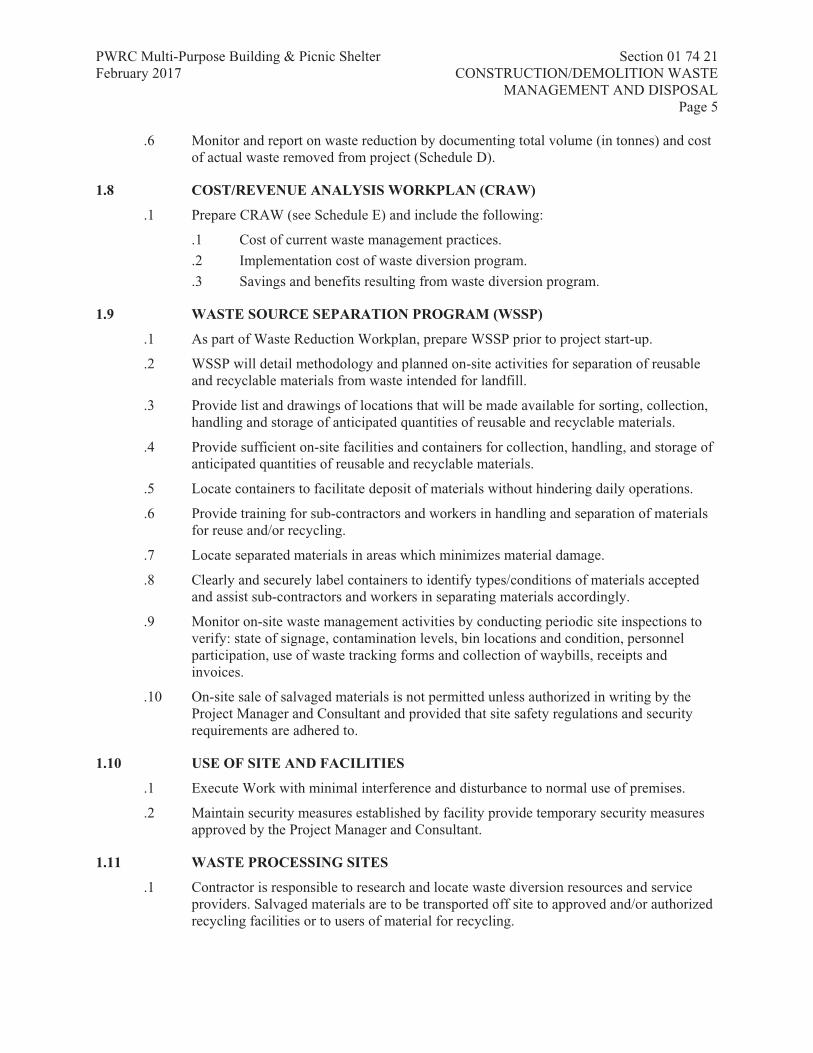
PWRC Multi-Purpose Building & Picnic Shelter Section 01 74 21 February 2017 CONSTRUCTION/DEMOLITION WASTE MANAGEMENT AND DISPOSAL
Page 5
Iredale Group Architecture – Project # 16063
.6 Monitor and report on waste reduction by documenting total volume (in tonnes) and cost of actual waste removed from project (Schedule D).
1.8 COST/REVENUE ANALYSIS WORKPLAN (CRAW)
.1 Prepare CRAW (see Schedule E) and include the following:
.1 Cost of current waste management practices.
.2 Implementation cost of waste diversion program.
.3 Savings and benefits resulting from waste diversion program.
1.9 WASTE SOURCE SEPARATION PROGRAM (WSSP)
.1 As part of Waste Reduction Workplan, prepare WSSP prior to project start-up.
.2 WSSP will detail methodology and planned on-site activities for separation of reusable and recyclable materials from waste intended for landfill.
.3 Provide list and drawings of locations that will be made available for sorting, collection, handling and storage of anticipated quantities of reusable and recyclable materials.
.4 Provide sufficient on-site facilities and containers for collection, handling, and storage of anticipated quantities of reusable and recyclable materials.
.5 Locate containers to facilitate deposit of materials without hindering daily operations.
.6 Provide training for sub-contractors and workers in handling and separation of materials for reuse and/or recycling.
.7 Locate separated materials in areas which minimizes material damage.
.8 Clearly and securely label containers to identify types/conditions of materials accepted and assist sub-contractors and workers in separating materials accordingly.
.9 Monitor on-site waste management activities by conducting periodic site inspections to verify: state of signage, contamination levels, bin locations and condition, personnel participation, use of waste tracking forms and collection of waybills, receipts and invoices.
.10 On-site sale of salvaged materials is not permitted unless authorized in writing by the Project Manager and Consultant and provided that site safety regulations and security requirements are adhered to.
1.10 USE OF SITE AND FACILITIES
.1 Execute Work with minimal interference and disturbance to normal use of premises.
.2 Maintain security measures established by facility provide temporary security measures approved by the Project Manager and Consultant.
1.11 WASTE PROCESSING SITES
.1 Contractor is responsible to research and locate waste diversion resources and service providers. Salvaged materials are to be transported off site to approved and/or authorized recycling facilities or to users of material for recycling.

PWRC Multi-Purpose Building & Picnic Shelter Section 01 74 21 February 2017 CONSTRUCTION/DEMOLITION WASTE MANAGEMENT AND DISPOSAL
Page 6
Iredale Group Architecture – Project # 16063
1.12 QUALITY ASSURANCE
.1 After award of Contract, a mandatory site examination will be held for this Project for the Contractor responsible for construction, renovation demolition/deconstruction waste management.
.1 Date, time and location will be arranged by the Project Manager and Consultant.
.2 Waste Management Meeting: Waste Management Co-ordinator is to provide an update on status of waste diversion and management activities at each meeting. Written monthly Waste Diversion Report summary to be provided by Waste Management Coordinator (refer to the Waste Diversion Report form in Schedule C and Waste Materials Tracking form in Schedule D).
1.13 STORAGE, HANDLING AND PROTECTION
.1 Store, materials to be reused, recycled and salvaged in locations as directed by the Project Manager and Consultant.
.2 Unless specified otherwise, materials for removal do not become Contractor's property.
.3 Protect, stockpile, store and catalogue salvaged items.
.4 Separate non-salvageable materials from salvaged items. Transport and deliver non-salvageable items to licensed disposal facility.
.5 Protect structural components not removed and salvaged materials from movement or damage.
.6 Support affected structures. If safety of building is endangered, cease operations and immediately notify the Project Manager and Consultant.
.7 Protect surface drainage, mechanical and electrical from damage and blockage.
.8 Provide on-site facilities and containers for collection and storage of reusable and recyclable materials.
.9 Separate and store materials produced during project in designated areas.
.10 Prevent contamination of materials to be salvaged and recycled and handle materials in accordance with requirements for acceptance by designated processing facilities.
.1 On-site source separation is recommended.
.2 Remove co-mingled materials to off-site processing facility for separation.
.3 Obtain waybills, receipts and/or scale tickets for separated materials removed from site.
.4 Materials reused on-site are considered to be diverted from landfill and as such are to be included in all reporting.
1.14 DISPOSAL OF WASTES
.1 Do not bury rubbish or waste materials.
.2 Do not dispose of any waste into waterways, storm, or sanitary sewers.
.3 Keep records of construction waste including:

PWRC Multi-Purpose Building & Picnic Shelter Section 01 74 21 February 2017 CONSTRUCTION/DEMOLITION WASTE MANAGEMENT AND DISPOSAL
Page 7
Iredale Group Architecture – Project # 16063
.1 Number and size of bins.
.2 Waste type of each bin.
.3 Total tonnage generated.
.4 Tonnage reused or recycled.
.5 Reused or recycled waste destination.
.4 Remove materials on-site as Work progresses.
.5 Prepare project summary to verify destination and quantities on a material-by-material basis as identified in the waste audit.
1.15 SCHEDULING
.1 Co-ordinate Work with other activities at site to ensure timely and orderly progress of Work.
Part 2 Products
2.1 NOT USED
.1 Not Used.
Part 3 Execution
3.1 APPLICATION
.1 Do Work in compliance with WRW and WSSP.
.2 Handle waste materials not reused, salvaged, or recycled in accordance with appropriate regulations and codes.
3.2 CLEANING
.1 Progress Cleaning: clean in accordance with Section 01 74 11 - Cleaning.
.1 Leave Work area clean at end of each day.
.2 Final Cleaning: upon completion remove surplus materials, rubbish, tools and equipment in accordance with Section 01 74 11 - Cleaning.
.3 Waste Management: separate waste materials for recycling in accordance with Section 01 74 21 - Construction/Demolition Waste Management and Disposal.
.1 Remove recycling containers and bins from site and dispose of materials at appropriate facility.
.2 Source separate materials to be reused/recycled into specified sort areas.
3.3 WASTE DIVERSION REPORT
.1 At completion of Project, prepare written Waste Diversion Report indicating quantities of materials reused, recycled or disposed of as well as the following:
PWRC Multi-Purpose Building & Picnic Shelter Section 01 74 21 February 2017 CONSTRUCTION/DEMOLITION WASTE MANAGEMENT AND DISPOSAL
Page 8
Iredale Group Architecture – Project # 16063
.1 Identify final diversion results and measure success against goals from Waste Reduction Workplan.
.2 Compare final quantities/percentages diverted with initial projections in Waste Audit and Waste Reduction Workplan and explain variances.
.1 Supporting documentation.
.2 Waybills and tracking forms.
.3 Description of issues, resolutions and lessons learned.

PWRC Multi-Purpose Building & Picnic Shelter Section 01 74 21 February 2017 CONSTRUCTION/DEMOLITION WASTE MANAGEMENT AND DISPOSAL
Page 9
Iredale Group Architecture – Project # 16063
3.4 WASTE AUDIT (WA)
.1 Schedule A - Waste Audit (WA)
(1) Material Category
(2) Material QuantityUnit
(3)Estimated Waste %
(4) Total Quantity of Waste (unit)
(5)GenerationPoint
(6) % Recycled
(7) % Reused
Concrete cu.m 100 GranularBase
cu.m 90
Sod cu.m 100 Wood and PlasticsMaterialDescription
Off-cuts WarpedPallet Forms
PlasticPackaging
CardboardPackaging
Other Doors and WindowsMaterialDescription
PaintedFrames
Glass Wood Metal Other
3.5 WASTE REDUCTION WORKPLAN (WRW)
.1 Schedule B
(1)MaterialCategory
(2)Person(s)Respon-sible
(3) Total Quantityof Waste (unit)
(4)ReusedAmount (units)Projected
Actual (5) Recycled Amount (unit)Projected
Actual (6) Material(s)Destina-tion
Concrete GranularBase
Sod WarpedPallet
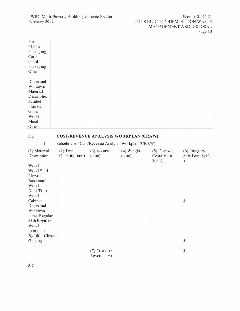
PWRC Multi-Purpose Building & Picnic Shelter Section 01 74 21 February 2017 CONSTRUCTION/DEMOLITION WASTE MANAGEMENT AND DISPOSAL
Page 10
Iredale Group Architecture – Project # 16063
FormsPlasticPackaging
Card-boardPackaging
Other Doors and WindowsMaterialDescription
PaintedFrames
Glass Wood Metal Other
3.6 COST/REVENUE ANALYSIS WORKPLAN (CRAW)
.1 Schedule E - Cost/Revenue Analysis Workplan (CRAW)
(1) Material Description
(2) Total Quantity (unit)
(3) Volume (cum)
(4) Weight (cum)
(5) Disposal Cost/Credit$(+/-)
(6) Category Sub-Total $(+/-)
Wood Wood Stud Plywood Baseboard - Wood
Door Trim - Wood
Cabinet $ Doors and Windows
Panel Regular Slab Regular WoodLaminate
Byfold - Closet Glazing $ (7) Cost (-) /
Revenue (+) $
3.7
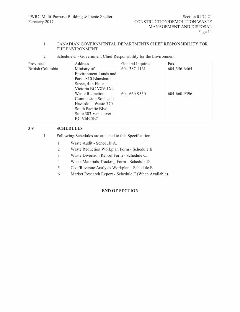
PWRC Multi-Purpose Building & Picnic Shelter Section 01 74 21 February 2017 CONSTRUCTION/DEMOLITION WASTE MANAGEMENT AND DISPOSAL
Page 11
Iredale Group Architecture – Project # 16063
.1 CANADIAN GOVERNMENTAL DEPARTMENTS CHIEF RESPONSIBILITY FOR THE ENVIRONMENT
.2 Schedule G - Government Chief Responsibility for the Environment:
Province Address General Inquires Fax British Columbia Ministry of
Environment Lands and Parks 810 Blanshard Street, 4 th Floor Victoria BC V8V 1X4
604-387-1161 604-356-6464
Waste Reduction Commission Soils and Hazardous Waste 770 South Pacific Blvd, Suite 303 Vancouver BC V6B 5E7
604-660-9550 604-660-9596
3.8 SCHEDULES
.1 Following Schedules are attached to this Specification:
.1 Waste Audit - Schedule A.
.2 Waste Reduction Workplan Form - Schedule B.
.3 Waste Diversion Report Form - Schedule C.
.4 Waste Materials Tracking Form - Schedule D.
.5 Cost/Revenue Analysis Workplan - Schedule E.
.6 Market Research Report - Schedule F (When Available).
END OF SECTION

PWRC Multi-Purpose Building & Picnic Shelter Section 01 77 00 February 2017 CLOSEOUT PROCEDURES
Page 1
Iredale Group Architecture – Project # 16063
Approved: 2009-06-30
Part 1 General
1.1 RELATED REQUIREMENTS
.1 All Sections.
1.2 NOT USED .1 Not used
1.3 ADMINISTRATIVE REQUIREMENTS
.1 Acceptance of Work Procedures:
.1 Contractor's Inspection: conduct inspection of Work, identify deficiencies and defects, and repair as required to conform to Contract Documents.
.1 Notify the Project Manager and Consultant in writing of satisfactory completion of Contractor's inspection and submit verification that corrections have been made.
.2 Request the Project Manager and Consultant inspection.
.2 The Project Manager and Consultant Inspection:
.1 The Project Manager and Consultant and Contractor to inspect Work and identify defects and deficiencies.
.2 Contractor to correct Work as directed.
.3 Completion Tasks: submit written certificates in English that tasks have been performed as follows:
.1 Work: completed and inspected for compliance with Contract Documents.
.2 Defects: corrected and deficiencies completed.
.3 Equipment and systems: tested, balanced and fully operational.
.4 Certificates required by Fire Commissioner: submitted.
.5 Operation of systems: demonstrated to Owner's personnel.
.6 Commissioning of mechanical systems: completed in accordance with 01 91 13 - General Commissioning (Cx) Requirements copies of final Commissioning Report submitted to the Project Manager and Consultant.
.7 Work: complete and ready for final inspection.
.4 Final Inspection:
.1 When completion tasks are done, request final inspection of Work by the Project Manager and Consultant, and Contractor.
.2 When Work incomplete according to the Project Manager and Consultant, complete outstanding items and request re-inspection.
.5 Declaration of Substantial Performance: when the Project Manager and Consultant considers deficiencies and defects corrected and requirements of Contract substantially performed, make application for Certificate of Substantial Performance.

PWRC Multi-Purpose Building & Picnic Shelter Section 01 77 00 February 2017 CLOSEOUT PROCEDURES
Page 2
Iredale Group Architecture – Project # 16063
.6 Commencement of Lien and Warranty Periods: date of Owner's acceptance of submitted declaration of Substantial Performance to be date for commencement for warranty period and commencement of lien period unless required otherwise by lien statute of Place of Work.
.7 Final Payment:
.1 When the Project Manager and Consultant considers final deficiencies and defects corrected and requirements of Contract met, make application for final payment.
.8 Payment of Holdback: after issuance of Certificate of Substantial Performance of Work, submit application for payment of holdback amount in accordance with contractual agreement.
1.4 FINAL CLEANING
.1 Clean in accordance with Section 01 74 11 - Cleaning.
.1 Remove surplus materials, excess materials, rubbish, tools and equipment.
.2 Waste Management: separate waste materials for recycling in accordance with Section 01 74 21 - Construction/Demolition Waste Management and Disposal.
Part 2 Products
2.1 NOT USED
.1 Not Used.
Part 3 Execution
3.1 NOT USED
.1 Not Used.
END OF SECTION

PWRC Multi-Purpose Building & Picnic Shelter Section 01 78 00 February 2017 CLOSEOUT SUBMITTALS
Page 1
Iredale Group Architecture – Project # 16063
Approved: 2009-06-30
Part 1 General
1.1 RELATED REQUIREMENTS
.1 All Sections.
1.2 ADMINISTRATIVE REQUIREMENTS
.1 Pre-warranty Meeting:
.1 Convene meeting one week prior to contract completion with the Project Manager and Consultant, in accordance with Section 01 31 19 - Project Meetings to:
.1 Verify Project requirements.
.2 Review warranty requirements and manufacturer's installation instructions.
.2 The Project Manager and Consultant to establish communication procedures for:
.1 Notifying construction warranty defects.
.2 Determine priorities for type of defects.
.3 Determine reasonable response time.
.3 Contact information for bonded and licensed company for warranty work action: provide name, telephone number and address of company authorized for construction warranty work action.
.4 Ensure contact is located within local service area of warranted construction, is continuously available, and is responsive to inquiries for warranty work action.
1.3 ACTION AND INFORMATIONAL SUBMITTALS
.1 Provide submittals in accordance with Section 01 33 00 - Submittal Procedures.
.2 Two weeks prior to Substantial Performance of the Work, submit to the Project Manager and Consultant, four final copies of operating and maintenance manuals in English.
.3 Provide spare parts, maintenance materials and special tools of same quality and manufacture as products provided in Work.
.4 Provide evidence, if requested, for type, source and quality of products supplied.
1.4 FORMAT
.1 Organize data as instructional manual.
.2 Binders: vinyl, hard covered, 3 'D' ring, loose leaf 219 x 279 mm with spine and face pockets.
.3 When multiple binders are used correlate data into related consistent groupings.
.1 Identify contents of each binder on spine.
.4 Cover: identify each binder with type or printed title 'Project Record Documents'; list title of project and identify subject matter of contents.
PWRC Multi-Purpose Building & Picnic Shelter Section 01 78 00 February 2017 CLOSEOUT SUBMITTALS
Page 2
Iredale Group Architecture – Project # 16063
.5 Arrange content by systems, under Section numbers and sequence of Table of Contents.
.6 Provide tabbed fly leaf for each separate product and system, with typed description of product and major component parts of equipment.
.7 Text: manufacturer's printed data, or typewritten data.
.8 Drawings: provide with reinforced punched binder tab.
.1 Bind in with text; fold larger drawings to size of text pages.
.9 Provide 1:1 scaled CAD files in dwg format on CD.
1.5 CONTENTS - PROJECT RECORD DOCUMENTS
.1 Table of Contents for Each Volume: provide title of project;
.1 Date of submission; names.
.2 Addresses, and telephone numbers of Consultant and Contractor with name of responsible parties.
.3 Schedule of products and systems, indexed to content of volume.
.2 For each product or system:
.1 List names, addresses and telephone numbers of subcontractors and suppliers, including local source of supplies and replacement parts.
.3 Product Data: mark each sheet to identify specific products and component parts, and data applicable to installation; delete inapplicable information.
.4 Drawings: supplement product data to illustrate relations of component parts of equipment and systems, to show control and flow diagrams.
.5 Typewritten Text: as required to supplement product data.
.1 Provide logical sequence of instructions for each procedure, incorporating manufacturer's instructions specified in Section 01 45 00 - Quality Control.
.6 Training: refer to Section 01 79 00 - Demonstration and Training.
1.6 AS -BUILT DOCUMENTS AND SAMPLES
.1 Maintain, in addition to requirements in General Conditions, at site for the Project Manager and Consultant one record copy of:
.1 Contract Drawings.
.2 Specifications.
.3 Addenda.
.4 Change Orders and other modifications to Contract.
.5 Reviewed shop drawings, product data, and samples.
.6 Field test records.
.7 Inspection certificates.
.8 Manufacturer's certificates.
.2 Store record documents and samples in field office apart from documents used for construction.

PWRC Multi-Purpose Building & Picnic Shelter Section 01 78 00 February 2017 CLOSEOUT SUBMITTALS
Page 3
Iredale Group Architecture – Project # 16063
.1 Provide files, racks, and secure storage.
.3 Label record documents and file in accordance with Section number listings in List of Contents of this Project Manual.
.1 Label each document "PROJECT RECORD" in neat, large, printed letters.
.4 Maintain record documents in clean, dry and legible condition.
.1 Do not use record documents for construction purposes.
.5 Keep record documents and samples available for inspection by the Project Manager and Consultant.
1.7 RECORDING INFORMATION ON PROJECT RECORD DOCUMENTS
.1 Record information on set of black line opaque drawings, and in copy of Project Manual, provided by the Consultant.
.2 Use felt tip marking pens, maintaining separate colours for each major system, for recording information.
.3 Record information concurrently with construction progress.
.1 Do not conceal Work until required information is recorded.
.4 Contract Drawings and shop drawings: mark each item to record actual construction, including:
.1 Measured depths of elements of foundation in relation to finish first floor datum.
.2 Measured horizontal and vertical locations of underground utilities and appurtenances, referenced to permanent surface improvements.
.3 Measured locations of internal utilities and appurtenances, referenced to visible and accessible features of construction.
.4 Field changes of dimension and detail.
.5 Changes made by change orders.
.6 Details not on original Contract Drawings.
.7 References to related shop drawings and modifications.
.5 Specifications: mark each item to record actual construction, including:
.1 Manufacturer, trade name, and catalogue number of each product actually installed, particularly optional items and substitute items.
.2 Changes made by Addenda and change orders.
.6 Other Documents: maintain manufacturer's certifications, inspection certifications, field test records, required by individual specifications sections.
.7 Provide digital photos, if requested, for site records.
1.8 FINAL SURVEY
.1 Submit final site survey certificate in accordance with Section 01 71 00 - Examination and Preparation, certifying that elevations and locations of completed Work are in conformance, or non-conformance with Contract Documents.

PWRC Multi-Purpose Building & Picnic Shelter Section 01 78 00 February 2017 CLOSEOUT SUBMITTALS
Page 4
Iredale Group Architecture – Project # 16063
1.9 EQUIPMENT AND SYSTEMS
.1 For each item of equipment and each system include description of unit or system, and component parts.
.1 Give function, normal operation characteristics and limiting conditions.
.2 Include performance curves, with engineering data and tests, and complete nomenclature and commercial number of replaceable parts.
.2 Panel board circuit directories: provide electrical service characteristics, controls, and communications.
.3 Include installed colour coded wiring diagrams.
.4 Operating Procedures: include start-up, break-in, and routine normal operating instructions and sequences.
.1 Include regulation, control, stopping, shut-down, and emergency instructions.
.2 Include summer, winter, and any special operating instructions.
.5 Maintenance Requirements: include routine procedures and guide for trouble-shooting; disassembly, repair, and reassembly instructions; and alignment, adjusting, balancing, and checking instructions.
.6 Provide servicing and lubrication schedule, and list of lubricants required.
.7 Include manufacturer's printed operation and maintenance instructions.
.8 Include sequence of operation by controls manufacturer.
.9 Provide original manufacturer's parts list, illustrations, assembly drawings, and diagrams required for maintenance.
.10 Provide installed control diagrams by controls manufacturer.
.11 Provide Contractor's co-ordination drawings, with installed colour coded piping diagrams.
.12 Provide charts of valve tag numbers, with location and function of each valve, keyed to flow and control diagrams.
.13 Provide list of original manufacturer's spare parts, current prices, and recommended quantities to be maintained in storage.
.14 Include test and balancing reports as specified in Section 01 45 00 - Quality Control 01 91 13 - General Commissioning (Cx) Requirements.
.15 Additional requirements: as specified in individual specification sections.
1.10 MATERIALS AND FINISHES
.1 Building products, applied materials, and finishes: include product data, with catalogue number, size, composition, and colour and texture designations.
.2 Instructions for cleaning agents and methods, precautions against detrimental agents and methods, and recommended schedule for cleaning and maintenance.
.3 Moisture-protection and weather-exposed products: include manufacturer's recommendations for cleaning agents and methods, precautions against detrimental agents and methods, and recommended schedule for cleaning and maintenance.

PWRC Multi-Purpose Building & Picnic Shelter Section 01 78 00 February 2017 CLOSEOUT SUBMITTALS
Page 5
Iredale Group Architecture – Project # 16063
.4 Additional requirements: as specified in individual specifications sections.
1.11 MAINTENANCE MATERIALS
.1 Spare Parts:
.1 Provide spare parts, in quantities specified in individual specification sections.
.2 Provide items of same manufacture and quality as items in Work.
.3 Deliver to location as directed; place and store.
.4 Receive and catalogue items.
.1 Submit inventory listing to the Project Manager and Consultant.
.2 Include approved listings in Maintenance Manual.
.5 Obtain receipt for delivered products and submit prior to final payment.
.2 Extra Stock Materials:
.1 Provide maintenance and extra materials, in quantities specified in individual specification sections.
.2 Provide items of same manufacture and quality as items in Work.
.3 Deliver to location as directed; place and store.
.4 Receive and catalogue items.
.1 Submit inventory listing to the Project Manager and Consultant.
.2 Include approved listings in Maintenance Manual.
.5 Obtain receipt for delivered products and submit prior to final payment.
.3 Special Tools:
.1 Provide special tools, in quantities specified in individual specification section.
.2 Provide items with tags identifying their associated function and equipment.
.3 Deliver to location as directed; place and store.
.4 Receive and catalogue items.
.1 Submit inventory listing to the Project Manager and Consultant.
.2 Include approved listings in Maintenance Manual.
1.12 DELIVERY, STORAGE AND HANDLING
.1 Store spare parts, maintenance materials, and special tools in manner to prevent damage or deterioration.
.2 Store in original and undamaged condition with manufacturer's seal and labels intact.
.3 Store components subject to damage from weather in weatherproof enclosures.
.4 Store paints and freezable materials in a heated and ventilated room.
.5 Remove and replace damaged products at own expense and for review by the Project Manager and Consultant.
1.13 WARRANTIES AND BONDS
.1 Develop warranty management plan to contain information relevant to Warranties.

PWRC Multi-Purpose Building & Picnic Shelter Section 01 78 00 February 2017 CLOSEOUT SUBMITTALS
Page 6
Iredale Group Architecture – Project # 16063
.2 Submit warranty management plan, 30 days before planned pre-warranty conference, to the Project Manager and Consultant approval.
.3 Warranty management plan to include required actions and documents to assure that Owner receives warranties to which it is entitled.
.4 Provide plan in narrative form and contain sufficient detail to make it suitable for use by future maintenance and repair personnel.
.5 Submit, warranty information made available during construction phase, to the Project Manager and Consultant for approval prior to each monthly pay estimate.
.6 Assemble approved information in binder, submit upon acceptance of work and organize binder as follows:
.1 Separate each warranty or bond with index tab sheets keyed to Table of Contents listing.
.2 List subcontractor, supplier, and manufacturer, with name, address, and telephone number of responsible principal.
.3 Obtain warranties and bonds, executed in duplicate by subcontractors, suppliers, and manufacturers, within [ten] days after completion of applicable item of work.
.4 Verify that documents are in proper form, contain full information, and are notarized.
.5 Co-execute submittals when required.
.6 Retain warranties and bonds until time specified for submittal.
.7 Except for items put into use with Owner's permission, leave date of beginning of time of warranty until Date of Substantial Performance is determined.
.8 Conduct joint 12 month warranty inspection, measured from time of Substantial Completion, by the Project Manager and Consultant.
.9 Include information contained in warranty management plan as follows:
.1 Roles and responsibilities of personnel associated with warranty process, including points of contact and telephone numbers within the organizations of Contractors, subcontractors, manufacturers or suppliers involved.
.2 Listing and status of delivery of Certificates of Warranty for extended warranty items, to include roofs, HVAC balancing, pumps, motors, transformers, commissioned systems, fire protection, alarm systems, sprinkler systems, and lightning protection systems.
.3 Provide list for each warranted equipment, item, feature of construction or system indicating:
.1 Name of item.
.2 Model and serial numbers.
.3 Location where installed.
.4 Name and phone numbers of manufacturers or suppliers.
.5 Names, addresses and telephone numbers of sources of spare parts.
.6 Warranties and terms of warranty: include one-year overall warranty of construction. Indicate items that have extended warranties and show separate warranty expiration dates.

PWRC Multi-Purpose Building & Picnic Shelter Section 01 78 00 February 2017 CLOSEOUT SUBMITTALS
Page 7
Iredale Group Architecture – Project # 16063
.7 Cross-reference to warranty certificates as applicable.
.8 Starting point and duration of warranty period.
.9 Summary of maintenance procedures required to continue warranty in force.
.10 Cross-Reference to specific pertinent Operation and Maintenance manuals.
.11 Organization, names and phone numbers of persons to call for warranty service.
.12 Typical response time and repair time expected for various warranted equipment.
.4 Contractor's plans for attendance at 12 month post-construction warranty inspections.
.5 Procedure and status of tagging of equipment covered by extended warranties.
.6 Post copies of instructions near selected pieces of equipment where operation is critical for warranty and/or safety reasons.
.10 Respond in timely manner to oral or written notification of required construction warranty repair work.
.11 Written verification to follow oral instructions.
.1 Failure to respond will be cause for the Project Manager and Consultant to proceed with action against Contractor.
1.14 WARRANTY TAGS
.1 Tag, at time of installation, each warranted item. Provide durable, oil and water resistant tag approved by the Project Manager.
.2 Attach tags with copper wire and spray with waterproof silicone coating.
.3 Leave date of acceptance until project is accepted for occupancy.
.4 Indicate following information on tag:
.1 Type of product/material.
.2 Model number.
.3 Serial number.
.4 Contract number.
.5 Warranty period.
.6 Inspector's signature.
.7 Construction Contractor.
Part 2 Products
2.1 NOT USED
.1 Not Used.

PWRC Multi-Purpose Building & Picnic Shelter Section 01 78 00 February 2017 CLOSEOUT SUBMITTALS
Page 8
Iredale Group Architecture – Project # 16063
Part 3 Execution
3.1 NOT USED
.1 Not Used.
END OF SECTION

PWRC Multi-Purpose Building & Picnic Shelter Section 01 79 00 February 2017 DEMONSTRATION AND TRAINING
Page 1
Iredale Group Architecture – Project # 16063
Approved: 2009-06-30
Part 1 General
1.1 RELATED REQUIREMENTS
.1 All Sections.
1.2 ADMINISTRATIVE REQUIREMENTS
.1 Demonstrate operation and maintenance of equipment and systems to Owner's personnel two weeks prior to date of substantial performance.
.2 Owner: provide list of personnel to receive instructions, and co-ordinate their attendance at agreed-upon times.
.3 Preparation:
.1 Verify conditions for demonstration and instructions comply with requirements.
.2 Verify designated personnel are present.
.3 Ensure equipment has been inspected and put into operation.
.4 Ensure testing, adjusting, and balancing has been performed [in accordance with Section 01 91 13 - General Commissioning (Cx) Requirements and equipment and systems are fully operational.
.4 Demonstration and Instructions:
.1 Demonstrate start-up, operation, control, adjustment, trouble-shooting, servicing, and maintenance of each item of equipment at agreed upon times, at the designated location.
.2 Instruct personnel in phases of operation and maintenance using operation and maintenance manuals as basis of instruction.
.3 Review contents of manual in detail to explain aspects of operation and maintenance.
.4 Prepare and insert additional data in operations and maintenance manuals when needed during instructions.
.5 Time Allocated for Instructions: ensure amount of time required for instruction of each item of equipment or system as noted in the following Sections:
1.3 ACTION AND INFORMATIONAL SUBMITTALS
.1 Provide submittals in accordance with Section 01 33 00 - Submittal Procedures.
.2 Submit schedule of time and date for demonstration of each item of equipment and each system two weeks prior to designated dates, for the Project Manager and Consultant'sapproval.
.3 Submit reports within one week after completion of demonstration, that demonstration and instructions have been satisfactorily completed.
.4 Give time and date of each demonstration, with list of persons present.

PWRC Multi-Purpose Building & Picnic Shelter Section 01 79 00 February 2017 DEMONSTRATION AND TRAINING
Page 2
Iredale Group Architecture – Project # 16063
.5 Provide copies of completed operation and maintenance manuals for use in demonstrations and instructions.
1.4 QUALITY ASSURANCE
.1 When specified in individual Sections requiring manufacturer to provide authorized representative to demonstrate operation of equipment and systems:
.1 Instruct Owner's personnel.
.2 Provide written report that demonstration and instructions have been completed.
Part 2 Products
2.1 NOT USED
.1 Not Used.
Part 3 Execution
3.1 NOT USED
.1 Not Used.
END OF SECTION
PWRC Multi-Purpose Building & Picnic Shelter Section 01 91 13 February 2017 GENERAL COMMISSIONING (CX) REQUIREMENTS
Page 1
Iredale Architecture – Project #16063
Part 1 General
1.1 SUMMARY
.1 Section Includes:
.1 General requirements relating to commissioning of project's components and systems, specifying general requirements to PV of components, equipment, sub-systems, systems, and integrated systems.
.2 Related Requirements
.1 Section 07 62 00 Sheet Metal Flashing and Trim.
.2 Section 07 92 00 Joint Sealing.
.3 Section 21 05 01 Mechanical General Requiremen
.4 Section 22 05 00 Common Work Results for Plumbing
.5 Section 22 06 01 Plumbing Equipment Manufacturers
.6 Section 22 11 16 Domestic Water Piping
.7 Section 22 13 17 Drainage Waste and Vent Piping – Cast Iron and Copper
.8 Section 22 30 05 Domestic Water Heaters
.9 Section 23 05 29 Hangers and Supports for Piping and Equipment
.10 Section 23 05 93 Testing, Adjusting and Balancing for HVAC
.11 Section 23 06 01 HVAC Equipment Manufacturers
.12 Section 23 06 02 HVAC Subtrades
.13 Section 23 07 13 Duct Insulation
.14 Section 23 07 15 Thermal Insulation for Piping
.15 Section 23 33 00 Air Duct Accessories
.16 Section 23 33 14 Dampers – Balancing
.17 Section 26 05 00 Common Work Results for Electrical
.18 Section 26 05 20 Wire And Box Connectors (0-1000 V)
.19 Section 26 05 21 Wires And Cables (0-1000 V)
.20 Section 26 05 32 Outlet Boxes, Conduit Boxes And Fittings
.21 Section 26 05 34 Conduits, Conduit Fastenings And Conduit Fittings
.22 Section 26 05 43.01 Installation Of Cables In Trenches And In Ducts
.23 Section 26 24 16.01 Panelboards Breaker Type
.24 Section 26 27 26 Wiring Devices
.25 Section 26 28 16.02 Moulded Case Circuit Breakers
.26 Section 26 50 00 Lighting.

PWRC Multi-Purpose Building & Picnic Shelter Section 01 91 13 February 2017 GENERAL COMMISSIONING (CX) REQUIREMENTS
Page 2
Iredale Architecture – Project #16063
.27 Section 26 56 00 Exterior Lighting
.28 Acronyms:
.1 AFD - Alternate Forms of Delivery, service provider.
.2 BMM - Building Management Manual.
.3 Cx - Commissioning.
.4 EMCS - Energy Monitoring and Control Systems.
.5 O M - Operation and Maintenance.
.6 PI - Product Information.
.7 PV - Performance Verification.
.8 TAB - Testing, Adjusting and Balancing.
1.2 GENERAL
.1 Cx is a planned program of tests, procedures and checks carried out systematically on systems and integrated systems of the finished Project. Cx is performed after systems and integrated systems are completely installed, functional and Contractor's Performance Verification responsibilities have been completed and approved. Objectives:
.1 Verify installed equipment, systems and integrated systems operate in accordance with contract documents and design criteria and intent.
.2 Ensure appropriate documentation is compiled into the BMM.
.3 Effectively train OM staff.
.2 Contractor assists in Cx process, operating equipment and systems, troubleshooting and making adjustments as required.
.1 Systems to be operated at full capacity under various modes to determine if they function correctly and consistently at peak efficiency. Systems to be interactively with each other as intended in accordance with Contract Documents and design criteria.
.2 During these checks, adjustments to be made to enhance performance to meet environmental or user requirements.
.3 Design Criteria: as per client's requirements or determined by designer. To meet Project functional and operational requirements.
.4 AFD managed projects the term Consultant in Cx specifications to be interpreted as AFD Service Provider.
1.3 COMMISSIONING OVERVIEW
.1 Section 01 91 31 - Commissioning (Cx) Plan.
.2 For Cx responsibilities refer to Section 01 91 31 - Commissioning (Cx) Plan.
.3 Cx to be a line item of Contractor's cost breakdown.
.4 Cx activities supplement field quality and testing procedures described in relevant technical sections.
.5 Cx is conducted in concert with activities performed during stage of project delivery. Cx identifies issues in Planning and Design stages which are addressed during Construction
PWRC Multi-Purpose Building & Picnic Shelter Section 01 91 13 February 2017 GENERAL COMMISSIONING (CX) REQUIREMENTS
Page 3
Iredale Architecture – Project #16063
and Cx stages to ensure the Work is constructed and proven to operate satisfactorily under weather, environmental and occupancy conditions to meet functional and operational requirements. Cx activities includes transfer of critical knowledge to facility operational personnel.
.6 Consultant will issue Interim Acceptance Certificate when:
.1 Completed Cx documentation has been received, reviewed for suitability and approved by Consultant.
.2 Equipment, components and systems have been commissioned.
.3 O M training has been completed.
1.4 NON-CONFORMANCE TO PERFORMANCE VERIFICATION REQUIREMENTS
.1 Should equipment, system components, and associated controls be incorrectly installed or malfunction during Cx, correct deficiencies, re-verify equipment and components within the unfunctional system, including related systems as deemed required by Consultant, to ensure effective performance.
.2 Costs for corrective work, additional tests, inspections, to determine acceptability and proper performance of such items to be borne by Contractor. Above costs to be in form of progress payment reductions or hold-back assessments.
1.5 PRE-CX REVIEW
.1 Before Construction:
.1 Review contract documents, confirm by writing to Consultant.
.1 Adequacy of provisions for Cx.
.2 Aspects of design and installation pertinent to success of Cx.
.2 During Construction:
.1 Co-ordinate provision, location and installation of provisions for Cx.
.3 Before start of Cx:
.1 Have completed Cx Plan up-to-date.
.2 Ensure installation of related components, equipment, sub-systems, systems is complete.
.3 Fully understand Cx requirements and procedures.
.4 Have Cx documentation shelf-ready.
.5 Understand completely design criteria and intent and special features.
.6 Submit complete start-up documentation to Consultant.
.7 Have Cx schedules up-to-date.
.8 Ensure systems have been cleaned thoroughly.
.9 Complete TAB procedures on systems, submit TAB reports to Consultant for review and approval.
.10 Ensure "As-Built" system schematics are available.
.4 Inform Consultant in writing of discrepancies and deficiencies on finished works.

PWRC Multi-Purpose Building & Picnic Shelter Section 01 91 13 February 2017 GENERAL COMMISSIONING (CX) REQUIREMENTS
Page 4
Iredale Architecture – Project #16063
1.6 CONFLICTS
.1 Report conflicts between requirements of this section and other sections to Consultant before start-up and obtain clarification.
.2 Failure to report conflict and obtain clarification will result in application of most stringent requirement.
1.7 ACTION AND INFORMATIONAL SUBMITTALS
.1 Submittals: in accordance with Section 01 33 00 - Submittal Procedures.
.1 Submit no later than 4 weeks after award of Contract:
.1 Name of Contractor's Cx agent.
.2 Draft Cx documentation.
.3 Preliminary Cx schedule.
.2 Request in writing to Consultant for changes to submittals and obtain written approval at least 8 weeks prior to start of Cx.
.3 Submit proposed Cx procedures to Consultant where not specified and obtain written approval at least 8 weeks prior to start of Cx.
.4 Provide additional documentation relating to Cx process required by Consultant.
1.8 COMMISSIONING DOCUMENTATION
.1 Refer to Section 01 91 33 - Commissioning (Cx) Forms: Installation Check Lists and Product Information (PI) / Performance Verification (PV) Forms for requirements and instructions for use.
.2 Consultant to review and approve Cx documentation.
.3 Provide completed and approved Cx documentation to Consultant.
1.9 COMMISSIONING SCHEDULE
.1 Provide detailed Cx schedule as part of construction schedule in accordance with Section 01 32 16.06 - Construction Progress Schedule - Critical Path Method (CPM).
.2 Provide adequate time for Cx activities prescribed in technical sections and commissioning sections including:
.1 Approval of Cx reports.
.2 Verification of reported results.
.3 Repairs, retesting, re-commissioning, re-verification.
.4 Training.
1.10 COMMISSIONING MEETINGS
.1 Convene Cx meetings following project meetings: Section 01 32 16.06 - Construction Progress Schedule - Critical Path Method (CPM) and as specified herein.
.2 Purpose: to resolve issues, monitor progress, identify deficiencies, relating to Cx.
.3 Continue Cx meetings on regular basis until commissioning deliverables have been addressed.

PWRC Multi-Purpose Building & Picnic Shelter Section 01 91 13 February 2017 GENERAL COMMISSIONING (CX) REQUIREMENTS
Page 5
Iredale Architecture – Project #16063
.4 At 60% construction completion stage. Section 01 32 16.06 - Construction Progress Schedule - Critical Path Method (CPM). Consultant to call a separate Cx scope meeting to review progress, discuss schedule of equipment start-up activities and prepare for Cx. Issues at meeting to include:
.1 Review duties and responsibilities of Contractor and subcontractors, addressing delays and potential problems.
.2 Determine the degree of involvement of trades and manufacturer's representatives in the commissioning process.
.5 Thereafter Cx meetings to be held until project completion and as required during equipment start-up and functional testing period.
.6 Meeting will be chaired by Cx Agent, who will record and distribute minutes.
.7 Ensure subcontractors and relevant manufacturer representatives are present at 60% and subsequent Cx meetings and as required.
1.11 STARTING AND TESTING
.1 Contractor assumes liabilities and costs for inspections. Including disassembly and re-assembly after approval, starting, testing and adjusting, including supply of testing equipment.
1.12 WITNESSING OF STARTING AND TESTING
.1 Provide 14 days notice prior to commencement.
.2 Consultant to witness of start-up and testing.
.3 Contractor's Cx Agent to be present at tests performed and documented by sub-trades, suppliers and equipment manufacturers.
1.13 MANUFACTURER'S INVOLVEMENT
.1 Factory testing: manufacturer to:
.1 Coordinate time and location of testing.
.2 Provide testing documentation for approval by Consultant.
.3 Arrange for Consultant to witness tests.
.4 Obtain written approval of test results and documentation from Consultant before delivery to site.
.2 Obtain manufacturers installation, start-up and operations instructions prior to start-up of components, equipment and systems and review with Consultant.
.1 Compare completed installation with manufacturer's published data, record discrepancies, and review with manufacturer.
.2 Modify procedures detrimental to equipment performance and review same with manufacturer before start-up.
.3 Integrity of warranties:
.1 Use manufacturer's trained start-up personnel where specified elsewhere in other divisions or required to maintain integrity of warranty.
.2 Verify with manufacturer that testing as specified will not void warranties.

PWRC Multi-Purpose Building & Picnic Shelter Section 01 91 13 February 2017 GENERAL COMMISSIONING (CX) REQUIREMENTS
Page 6
Iredale Architecture – Project #16063
.4 Qualifications of manufacturer's personnel:
.1 Experienced in design, installation and operation of equipment and systems.
.2 Ability to interpret test results accurately.
.3 To report results in clear, concise, logical manner.
1.14 PROCEDURES
.1 Verify that equipment and systems are complete, clean, and operating in normal and safe manner prior to conducting start-up, testing and Cx.
.2 Conduct start-up and testing in following distinct phases:
.1 Included in delivery and installation:
.1 Verification of conformity to specification, approved shop drawings and completion of PI report forms.
.2 Visual inspection of quality of installation.
.2 Start-up: follow accepted start-up procedures.
.3 Operational testing: document equipment performance.
.4 System PV: include repetition of tests after correcting deficiencies.
.5 Post-substantial performance verification: to include fine-tuning.
.3 Correct deficiencies and obtain approval from Consultant after distinct phases have been completed and before commencing next phase.
.4 Document require tests on approved PV forms.
.5 Failure to follow accepted start-up procedures will result in re-evaluation of equipment by an independent testing agency selected by Consultant. If results reveal that equipment start-up was not in accordance with requirements, and resulted in damage to equipment, implement following:
.1 Minor equipment/systems: implement corrective measures approved by Consultant.
.2 Major equipment/systems: if evaluation report concludes that damage is minor, implement corrective measures approved by Consultant.
.3 If evaluation report concludes that major damage has occurred, Consultant shall reject equipment.
.1 Rejected equipment to be remove from site and replace with new.
.2 Subject new equipment/systems to specified start-up procedures.
1.15 START-UP DOCUMENTATION
.1 Assemble start-up documentation and submit to Consultant for approval before commencement of commissioning.
.2 Start-up documentation to include:
.1 Factory and on-site test certificates for specified equipment.
.2 Pre-start-up inspection reports.
.3 Signed installation/start-up check lists.
.4 Start-up reports,

PWRC Multi-Purpose Building & Picnic Shelter Section 01 91 13 February 2017 GENERAL COMMISSIONING (CX) REQUIREMENTS
Page 7
Iredale Architecture – Project #16063
.5 Step-by-step description of complete start-up procedures, to permit the Building Property Manager to repeat start-up at any time.
1.16 OPERATION AND MAINTENANCE OF EQUIPMENT AND SYSTEMS
.1 After start-up, operate and maintain equipment and systems as directed by equipment/system manufacturer.
.2 With assistance of manufacturer develop written maintenance program and submit Consultant for approval before implementation.
.3 Operate and maintain systems for length of time required for commissioning to be completed.
.4 After completion of commissioning, operate and maintain systems until issuance of certificate of interim acceptance.
1.17 TEST RESULTS
.1 If start-up, testing and/or PV produce unacceptable results, repair, replace or repeat specified starting and/or PV procedures until acceptable results are achieved.
.2 Provide manpower and materials, assume costs for re-commissioning.
1.18 START OF COMMISSIONING
.1 Notify Consultant at least 21 days prior to start of Cx.
.2 Start Cx after elements of building affecting start-up and performance verification of systems have been completed.
1.19 INSTRUMENTS / EQUIPMENT
.1 Submit to Consultant for review and approval:
.1 Complete list of instruments proposed to be used.
.2 Listed data including, serial number, current calibration certificate, calibration date, calibration expiry date and calibration accuracy.
.2 Provide the following equipment as required:
.1 2-way radios.
.2 Ladders.
.3 Equipment as required to complete work.
1.20 COMMISSIONING PERFORMANCE VERIFICATION
.1 Carry out Cx:
.1 Under actual operating conditions, over entire operating range, in all modes.
.2 On independent systems and interacting systems.
.2 Cx procedures to be repeatable and reported results are to be verifiable.
.3 Follow equipment manufacturer's operating instructions.
.4 EMCS trending to be available as supporting documentation for performance verification.
PWRC Multi-Purpose Building & Picnic Shelter Section 01 91 13 February 2017 GENERAL COMMISSIONING (CX) REQUIREMENTS
Page 8
Iredale Architecture – Project #16063
1.21 WITNESSING COMMISSIONING
.1 Building Property Manager to witness activities and verify results.
1.22 AUTHORITIES HAVING JURISDICTION
.1 Where specified start-up, testing or commissioning procedures duplicate verification requirements of authority having jurisdiction, arrange for authority to witness procedures so as to avoid duplication of tests and to facilitate expedient acceptance of facility.
.2 Obtain certificates of approval, acceptance and compliance with rules and regulation of authority having jurisdiction.
.3 Provide copies to Consultant within 5 days of test and with Cx report.
1.23 COMMISSIONING CONSTRAINTS
.1 Not Used
1.24 EXTRAPOLATION OF RESULTS
.1 Where Cx of weather, occupancy, or seasonal-sensitive equipment or systems cannot be conducted under near-rated or near-design conditions, extrapolate part-load results to design conditions when approved by Consultant in accordance with equipment manufacturer's instructions, using manufacturer's data, with manufacturer's assistance and using approved formulae.
1.25 EXTENT OF VERIFICATION
.1 Laboratory areas:
.1 Provide manpower and instrumentation to verify up to 100 % of reported results.
.2 Elsewhere:
.1 Provide manpower and instrumentation to verify up to 30 % of reported results, unless specified otherwise in other sections.
.3 Number and location to be at discretion of Consultant.
.4 Conduct tests repeated during verification under same conditions as original tests, using same test equipment, instrumentation.
.5 Review and repeat commissioning of systems if inconsistencies found in more than 20% of reported results.
.6 Perform additional commissioning until results are acceptable to Consultant.
1.26 REPEAT VERIFICATIONS
.1 Assume costs incurred by Consultant for third and subsequent verifications where:
.1 Verification of reported results fail to receive Consultant's approval.
.2 Repetition of second verification again fails to receive approval.
.3 Consultant deems Contractor's request for second verification was premature.

PWRC Multi-Purpose Building & Picnic Shelter Section 01 91 13 February 2017 GENERAL COMMISSIONING (CX) REQUIREMENTS
Page 9
Iredale Architecture – Project #16063
1.27 SUNDRY CHECKS AND ADJUSTMENTS
.1 Make adjustments and changes which become apparent as Cx proceeds.
.2 Perform static and operational checks as applicable and as required.
1.28 DEFICIENCIES, FAULTS, DEFECTS
.1 Correct deficiencies found during start-up and Cx to satisfaction of Consultant.
.2 Report problems, faults or defects affecting Cx to Consultant in writing. Stop Cx until problems are rectified. Proceed with written approval from Consultant.
1.29 COMPLETION OF COMMISSIONING
.1 Upon completion of Cx leave systems in normal operating mode.
.2 Except for warranty and seasonal verification activities specified in Cx specifications, complete Cx prior to issuance of Interim Certificate of Completion.
.3 Cx to be considered complete when contract Cx deliverables have been submitted and accepted by Consultant.
1.30 ACTIVITIES UPON COMPLETION OF COMMISSIONING
.1 When changes are made to baseline components or system settings established during Cx process, provide updated Cx form for affected item.
1.31 TRAINING
.1 In accordance with Section 01 91 41 - Commissioning (Cx) - Training.
1.32 MAINTENANCE MATERIALS, SPARE PARTS, SPECIAL TOOLS
.1 Supply, deliver, and document maintenance materials, spare parts, and special tools as specified in contract.
1.33 OCCUPANCY
.1 Cooperate fully with Consultant during stages of acceptance and occupancy of facility.
1.34 INSTALLED INSTRUMENTATION
.1 Use instruments installed under Contract for TAB and PV if:
.1 Accuracy complies with these specifications.
.2 Calibration certificates have been deposited with Consultant.
.2 Calibrated EMCS sensors may be used to obtain performance data provided that sensor calibration has been completed and accepted.
1.35 PERFORMANCE VERIFICATION TOLERANCES
.1 Application tolerances:
.1 Specified range of acceptable deviations of measured values from specified values or specified design criteria. Except for special areas, to be within +/- 10% of specified values.

PWRC Multi-Purpose Building & Picnic Shelter Section 01 91 13 February 2017 GENERAL COMMISSIONING (CX) REQUIREMENTS
Page 10
Iredale Architecture – Project #16063
.2 Instrument accuracy tolerances:
.1 To be of higher order of magnitude than equipment or system being tested.
.3 Measurement tolerances during verification:
.1 Unless otherwise specified actual values to be within +/- 2 % of recorded values.
1.36 OWNER'S PERFORMANCE TESTING
.1 Performance testing of equipment or system by Owner will not relieve Contractor from compliance with specified start-up and testing procedures.
Part 2 Products
2.1 NOT USED
.1 Not Used.
Part 3 Execution
3.1 NOT USED
.1 Not Used.
END OF SECTION

PWRC Multi-Purpose Building & Picnic Shelter Section 01 91 31 February 2017 COMMISSIONING (CX) PLAN
Page 1
Iredale Architecture – Project #16063
Approved: 2006-03-31
Part 1 General
1.1 SUMMARY
.1 Section Includes:
.1 Description of overall structure of Cx Plan and roles and responsibilities of Cx team.
.2 Related Requirements
.1 Section 07 62 00 Sheet Metal Flashing and Trim.
.2 Section 07 92 00 Joint Sealing.
.3 Section 21 05 01 Mechanical General Requiremen
.4 Section 22 05 00 Common Work Results for Plumbing
.5 Section 22 06 01 Plumbing Equipment Manufacturers
.6 Section 22 11 16 Domestic Water Piping
.7 Section 22 13 17 Drainage Waste and Vent Piping – Cast Iron and Copper
.8 Section 22 30 05 Domestic Water Heaters
.9 Section 23 05 29 Hangers and Supports for Piping and Equipment
.10 Section 23 05 93 Testing, Adjusting and Balancing for HVAC
.11 Section 23 06 01 HVAC Equipment Manufacturers
.12 Section 23 06 02 HVAC Subtrades
.13 Section 23 07 13 Duct Insulation
.14 Section 23 07 15 Thermal Insulation for Piping
.15 Section 23 33 00 Air Duct Accessories
.16 Section 23 33 14 Dampers – Balancing
.17 Section 26 05 00 Common Work Results for Electrical
.18 Section 26 05 20 Wire And Box Connectors (0-1000 V)
.19 Section 26 05 21 Wires And Cables (0-1000 V)
.20 Section 26 05 32 Outlet Boxes, Conduit Boxes And Fittings
.21 Section 26 05 34 Conduits, Conduit Fastenings And Conduit Fittings
.22 Section 26 05 43.01 Installation Of Cables In Trenches And In Ducts
.23 Section 26 24 16.01 Panelboards Breaker Type
.24 Section 26 27 26 Wiring Devices
.25 Section 26 28 16.02 Moulded Case Circuit Breakers
.26 Section 26 50 00 Lighting.

PWRC Multi-Purpose Building & Picnic Shelter Section 01 91 31 February 2017 COMMISSIONING (CX) PLAN
Page 2
Iredale Architecture – Project #16063
.27 Section 26 56 00 Exterior Lighting
1.2 REFERENCES
.1 American Water Works Association (AWWA)
.2 Public Works and Government Services Canada (PWGSC)
.1 PWGSC - Commissioning Guidelines CP.4 -3rd edition-03.
.3 Underwriters' Laboratories of Canada (ULC)
1.3 GENERAL
.1 Provide a fully functional facility:
.1 Systems, equipment and components meet user's functional requirements before date of acceptance, and operate consistently at peak efficiencies and within specified energy budgets under normal loads.
.2 Facility user and O M personnel have been fully trained in aspects of installed systems.
.3 Optimized life cycle costs.
.4 Complete documentation relating to installed equipment and systems.
.2 Term "Cx" in this section means "Commissioning".
.3 Use this Cx Plan as master planning document for Cx:
.1 Outlines organization, scheduling, allocation of resources, documentation, pertaining to implementation of Cx.
.2 Communicates responsibilities of team members involved in Cx Scheduling, documentation requirements, and verification procedures.
.3 Sets out deliverables relating to O M, process and administration of Cx.
.4 Describes process of verification of how built works meet design requirements.
.5 Produces a complete functional system prior to issuance of Certificate of Occupancy.
.6 Management tool that sets out scope, standards, roles and responsibilities, expectations, deliverables, and provides:
.1 Overview of Cx.
.2 General description of elements that make up Cx Plan.
.3 Process and methodology for successful Cx.
.4 Acronyms:
.1 Cx - Commissioning.
.2 BMM - Building Management Manual.
.3 EMCS - Energy Monitoring and Control Systems.
.4 MSDS - Material Safety Data Sheets.
.5 PI - Product Information.
.6 PV - Performance Verification.
.7 TAB - Testing, Adjusting and Balancing.

PWRC Multi-Purpose Building & Picnic Shelter Section 01 91 31 February 2017 COMMISSIONING (CX) PLAN
Page 3
Iredale Architecture – Project #16063
.8 WHMIS - Workplace Hazardous Materials Information System.
.5 Commissioning terms used in this Section:
.1 Bumping: short term start-up to prove ability to start and prove correct rotation.
.2 Deferred Cx - Cx activities delayed for reasons beyond Contractor's control due to lack of occupancy, weather conditions, need for heating/cooling loads.
1.4 DEVELOPMENT OF 100% CX PLAN
.1 Cx Plan to be 95% completed before added into Project Specifications.
.2 Cx Plan to be 100% completed within 8weeks of award of contract to take into account:
.1 Approved shop drawings and product data.
.2 Approved changes to contract.
.3 Contractor's project schedule.
.4 Cx schedule.
.5 Contractor's, sub-contractor's, suppliers' requirements.
.6 Project construction team's and Cx team's requirements.
.3 Submit completed Cx Plan to Consultant and obtain written approval.
1.5 REFINEMENT OF CX PLAN
.1 During construction phase, revise, refine and update Cx Plan to include:
.1 Changes resulting from Client program modifications.
.2 Approved design and construction changes.
.2 Revise, refine and update every 4 months during construction phase. At each revision, indicate revision number and date.
.3 Submit each revised Cx Plan to Consultant for review and obtain written approval.
.4 Include testing parameters at full range of operating conditions and check responses of equipment and systems.
1.6 COMPOSITION, ROLES AND RESPONSIBILITIES OF CX TEAM
.1 Project Manager to maintain overall responsibility for project and is sole point of contact between members of commissioning team.
.2 Project Manager will select Cx Team consisting of following members:
.1 PWGSC Design Quality Review Team: during construction, will conduct periodic site reviews to observe general progress.
.2 PWGSC Quality Assurance Commissioning Manager: ensures Cx activities are carried out to ensure delivery of a fully operational project including:
.1 Review of Cx documentation from operational perspective.
.2 Review for performance, reliability, durability of operation, accessibility, maintainability, operational efficiency under conditions of operation.
.3 Protection of health, safety and comfort of occupants and O M personnel.
.4 Monitoring of Cx activities, training, development of Cx documentation.

PWRC Multi-Purpose Building & Picnic Shelter Section 01 91 31 February 2017 COMMISSIONING (CX) PLAN
Page 4
Iredale Architecture – Project #16063
.5 Work closely with members of Cx Team.
.3 Cx Agent is responsible for:
.1 Provide Commissioning forms.
.2 Provide Construction Commissioning Plan.
.3 Coordinate Commissioning activities with the Construction Schedule.
.4 Organizing Cx.
.5 Monitoring operations Cx activities.
.6 Witnessing, certifying accuracy of reported results.
.7 Witnessing and certifying TAB and other tests.
.8 Developing BMM.
.9 Ensuring implementation of final Cx Plan.
.10 Performing verification of performance of installed systems and equipment.
.11 Implementation of Training Plan.
.4 Construction Team: contractor, sub-contractors, suppliers and support disciplines, is responsible for construction/installation in accordance with contract documents, including:
.1 Testing.
.2 TAB.
.3 Performance of Cx activities.
.4 Delivery of training and Cx documentation.
.5 Assigning one person as point of contact with Consultant and PWGSC Cx Manager for administrative and coordination purposes.
.5 Contractor's Cx agent implements specified Cx activities including:
.1 Demonstrations.
.2 Training.
.3 Testing.
.4 Preparation, submission of test reports.
.6 Property Manager: represents lead role in Operation Phase and onwards and is responsible for:
.1 Receiving facility.
.2 Day-To-Day operation and maintenance of facility.
1.7 CX PARTICIPANTS
.1 Employ the following Cx participants to verify performance of equipment and systems:
.1 Installation contractor/subcontractor:
.1 Equipment and systems except as noted.
.2 Equipment manufacturer: equipment specified to be installed and started by manufacturer.
.1 To include performance verification.
PWRC Multi-Purpose Building & Picnic Shelter Section 01 91 31 February 2017 COMMISSIONING (CX) PLAN
Page 5
Iredale Architecture – Project #16063
.3 Specialist subcontractor: equipment and systems supplied and installed by specialist subcontractor.
.4 Specialist Cx agency:
.1 Possessing specialist qualifications and installations providing environments essential to client's program but are outside scope or expertise of Cx specialists on this project.
.5 Client: responsible for intrusion and access security systems.
.6 Ensure that Cx participant:
.1 Could complete work within scheduled time frame.
.2 Available for emergency and troubleshooting service during first year of occupancy by user for adjustments and modifications outside responsibility of O M personnel, including:
.1 Modify ventilation rates to meet changes in off-gassing.
.2 Changes to heating or cooling loads beyond scope of EMCS.
.3 Changes to EMCS control strategies beyond level of training provided to O M personnel.
.4 Redistribution of electrical services.
.5 Modifications of fire alarm systems.
.6 Modifications to voice communications systems.
.7 Provide names of participants to [Departmental Representative] [DCC Representative] [Consultant] and details of instruments and procedures to be followed for Cx [3] months prior to starting date of Cx for review and approval.
1.8 EXTENT OF CX
.1 Cx Architectural Systems:
.1 Metal Roof:
.1 Sheet Metal.
.2 Flashing & Trim
.3 Joints.
.4 Construction and assembly.
.2 Wall Envelope System
.1 Cladding
.2 Joints
.3 Construction & Assembly
.3 Window Wall System
.1 Construction and Assembly
.4 Man Doors & Garage Doors
.1 Closers
.2 Auto operators
.3 Electric Strikes
.4 Construction and Assembly

PWRC Multi-Purpose Building & Picnic Shelter Section 01 91 31 February 2017 COMMISSIONING (CX) PLAN
Page 6
Iredale Architecture – Project #16063
.5 Freezer
.1 Construction and Assembly
.2 Cooling System
.6 Appliances
.1 Washer
.2 Dryer
.2 HVAC and Plumbing systems
.1 Force Flow Heaters
.1 Heating operation
.2 HRV Unit Ventilators
.1 Core heat transfer efficiency
.2 Defrost mode
.3 Operation
.3 Plumbing Fixtures
.1 Operation
.4 Domestic Hot Water Tanks
.1 Operation
.3 Commission electrical systems and equipment:
.1 Lighting systems
.1 Lighting equipment.
.2 Lighting control (automatic shutoff, occupancy sensor)
.2 Power
.1 Electrical Panels
.2 Power distribution
.3 Generator full building load testing
1.9 DELIVERABLES RELATING TO OM PERSPECTIVES
.1 General requirements:
.1 Compile in English documentation.
.2 Documentation to be computer-compatible format ready for inputting for data management.
.2 Provide deliverables:
.1 Warranties.
.2 Project record documentation.
.3 Inventory of spare parts, special tools and maintenance materials.
.4 Maintenance Management System (MMS) identification system used.
.5 WHMIS information.
.6 MSDS data sheets.

PWRC Multi-Purpose Building & Picnic Shelter Section 01 91 31 February 2017 COMMISSIONING (CX) PLAN
Page 7
Iredale Architecture – Project #16063
.7 Electrical Panel inventory containing detailed inventory of electrical circuitry for each panel board. Duplicate of inventory inside each panel.
1.10 DELIVERABLES RELATING TO THE CX PROCESS
.1 General:
.1 Start-up, testing and Cx requirements, conditions for acceptance and specifications form part of relevant technical sections of these specifications.
.2 Definitions:
.1 Cx as used in this section includes:
.1 Cx of components, equipment, systems, subsystems, and integrated systems.
.2 Factory inspections and performance verification tests.
.3 Deliverables: provide:
.1 Cx Specifications.
.2 Startup, pre-Cx activities and documentation for systems, and equipment.
.3 Completed installation checklists (ICL).
.4 Completed product information (PI) report forms.
.5 Completed performance verification (PV) report forms.
.6 Results of Performance Verification Tests and Inspections.
.7 Description of Cx activities and documentation.
.8 Description of Cx of integrated systems and documentation.
.9 Tests of following witnessed by PWGSC Design Quality Review Team:
.1 Door operators
.2 Freezer
.3 HVAC Equipment
.4 Plumbing fixtures
.5 Power Systems
.6 Lights.
.10 Tests performed by User.
.11 Training Plans.
.12 Cx Reports.
.13 Prescribed activities during warranty period.
.4 Consultant to witness and certify tests and reports of results provided to Consultant.
.5 Consultant to participate.
1.11 PRE-CX ACTIVITIES AND RELATED DOCUMENTATION
.1 Items listed in this Cx Plan include the following:
.1 Pre-Start-Up inspections: by Consultant prior to permission to start up and rectification of deficiencies to Consultant's satisfaction.
.2 Consultant to use approved check lists.

PWRC Multi-Purpose Building & Picnic Shelter Section 01 91 31 February 2017 COMMISSIONING (CX) PLAN
Page 8
Iredale Architecture – Project #16063
.3 Consultant will monitor all of these pre-start-up inspections.
.4 Include completed documentation with Cx report.
.5 Conduct pre-start-up tests: conduct pressure, static, flushing, cleaning, and "bumping" during construction as specified in technical sections. To be witnessed and certified by Consultant and does not form part of Cx specifications.
.6 Consultant will monitor some of these inspections and tests.
.7 Include completed documentation in Cx report.
.2 Pre-Cx activities - ARCHITECTURAL:
.1 Doors operators
.2 Appliances
.3 Freezer
.3 Pre-Cx activities – MECHANICAL AND ELECTRICAL:
.1 HVAC
.2 Plumbing
.3 Lighting systems.
.1 Lighting.
.4 Power Systems
.1 Power Distribution
1.12 START-UP
.1 Start up components, equipment and systems.
.2 Equipment manufacturer, supplier, installing specialist sub-contractor, as appropriate, to start-up, under Contractor's direction, following equipment, systems:
.1 HVAC equipment
.2 Freezer
.3 Consultant to monitor all of these start-up activities.
.1 Rectify start-up deficiencies to satisfaction of Consultant.
.4 Performance Verification (PV):
.1 Approved Cx Agent to perform.
.1 Repeat when necessary until results are acceptable to Consultant.
.2 Use procedures modified generic procedures to suit project requirements.
.3 Consultant to witness and certify reported results using approved PI and PV forms.
.4 Consultant to approve completed PV reports and provide to the Owner.
.5 Consultant reserves right to verify up to 30% of reported results at random.
.6 Failure of randomly selected item shall result in rejection of PV report or report of system startup and testing.

PWRC Multi-Purpose Building & Picnic Shelter Section 01 91 31 February 2017 COMMISSIONING (CX) PLAN
Page 9
Iredale Architecture – Project #16063
1.13 CX ACTIVITIES AND RELATED DOCUMENTATION
.1 Perform Cx by specified Cx agency using procedures developed by Consultant and approved by Owner.
.2 Consultant to monitor Cx activities.
.3 Upon satisfactory completion, Cx agency performing tests to prepare Cx Report using approved PV forms.
.4 Consultant to witness, certify reported results of, Cx activities and forward to the Owner.
.5 Consultant reserves right to verify a percentage of reported results at no cost to contract.
1.14 INSTALLATION CHECK LISTS (ICL)
.1 Refer to Section 01 91 33 - Commissioning (Cx) Forms: Installation Check Lists and Product Information (PI) / Performance Verification (PV) Forms.
1.15 PRODUCT INFORMATION (PI) REPORT FORMS
.1 Refer to Section 01 91 33 - Commissioning (Cx) Forms: Installation Check Lists and Product Information (PI) / Performance Verification (PV) Forms.
1.16 PERFORMANCE VERIFICATION (PV) REPORT
.1 Refer to Section 01 91 33 - Commissioning (Cx) Forms: Installation Check Lists and Product Information (PI) / Performance Verification (PV) Forms.
1.17 DELIVERABLES RELATING TO ADMINISTRATION OF CX
.1 General:
.1 Because of risk assessment, complete Cx of occupancy, weather and seasonal-sensitive equipment and systems in these areas before building is occupied.
1.18 CX SCHEDULES
.1 Prepare detailed Cx Schedule and submit to Consultant for review and approval same time as project Construction Schedule. Include:
.1 Milestones, testing, documentation, training and Cx activities of components, equipment, subsystems, systems and integrated systems, including:
.1 Design criteria, design intents.
.2 Pre-TAB review.
.3 Cx agents' credentials.
.4 Cx procedures.
.5 Cx Report format.
.6 Submission of list of instrumentation with relevant certificates.
.7 Notification of intention to start TAB.
.8 TAB.
.9 Notification of intention to start Cx.
.10 Identification of deferred Cx.
.11 Implementation of training plans.

PWRC Multi-Purpose Building & Picnic Shelter Section 01 91 31 February 2017 COMMISSIONING (CX) PLAN
Page 10
Iredale Architecture – Project #16063
.12 Cx reports: immediately upon successful completion of Cx.
.2 Detailed training schedule to demonstrate no conflicts with testing, completion of project and hand-over to the Property Manager and Consultant.
.2 After approval, incorporate Cx Schedule into Construction Schedule.
.3 Consultant, Contractor, Contractor's Cx agent, and Owner will monitor progress of Cx against this schedule.
1.19 CX REPORTS
.1 Submit reports of tests, witnessed and certified by Consultant to Owner, who will verify reported results.
.2 Include completed and certified PV reports in properly formatted Cx Reports.
.3 Before reports are accepted, reported results to be subject to verification by Consultant.
1.20 ACTIVITIES DURING WARRANTY PERIOD
.1 Cx activities must be completed before issuance of Interim Certificate.
1.21 TESTS TO BE PERFORMED BY OWNER/USER
.1 None is anticipated on this project.
1.22 TRAINING PLANS
.1 Refer to Section 01 91 41 - Commissioning (Cx) - Training.
1.23 FINAL SETTINGS
.1 Upon completion of Cx to satisfaction of Consultant lock control devices in their final positions, indelibly mark settings marked and include in Cx Reports.
Part 2 Products
2.1 NOT USED
.1 Not Used.
Part 3 Execution
3.1 NOT USED
.1 Not Used.
END OF SECTION

PWRC Multi-Purpose Building & Picnic Shelter Section 01 91 33 February 2017 COMMISSIONING FORMS
Page 1
Iredale Architecture – Project #16063
Approved: 2005-09-30
Part 1 General
1.1 SUMMARY
.1 Section Includes:
.1 Commissioning forms to be completed for equipment, system and integrated system.
.2 Related Requirements
.1 Section 07 62 00 Sheet Metal Flashing and Trim.
.2 Section 07 92 00 Joint Sealing.
.3 Section 21 05 01 Mechanical General Requiremen
.4 Section 22 05 00 Common Work Results for Plumbing
.5 Section 22 06 01 Plumbing Equipment Manufacturers
.6 Section 22 11 16 Domestic Water Piping
.7 Section 22 13 17 Drainage Waste and Vent Piping – Cast Iron and Copper
.8 Section 22 30 05 Domestic Water Heaters
.9 Section 23 05 29 Hangers and Supports for Piping and Equipment
.10 Section 23 05 93 Testing, Adjusting and Balancing for HVAC
.11 Section 23 06 01 HVAC Equipment Manufacturers
.12 Section 23 06 02 HVAC Subtrades
.13 Section 23 07 13 Duct Insulation
.14 Section 23 07 15 Thermal Insulation for Piping
.15 Section 23 33 00 Air Duct Accessories
.16 Section 23 33 14 Dampers – Balancing
.17 Section 26 05 00 Common Work Results for Electrical
.18 Section 26 05 20 Wire And Box Connectors (0-1000 V)
.19 Section 26 05 21 Wires And Cables (0-1000 V)
.20 Section 26 05 32 Outlet Boxes, Conduit Boxes And Fittings
.21 Section 26 05 34 Conduits, Conduit Fastenings And Conduit Fittings
.22 Section 26 05 43.01 Installation Of Cables In Trenches And In Ducts
.23 Section 26 24 16.01 Panelboards Breaker Type
.24 Section 26 27 26 Wiring Devices
.25 Section 26 28 16.02 Moulded Case Circuit Breakers
.26 Section 26 50 00 Lighting.

PWRC Multi-Purpose Building & Picnic Shelter Section 01 91 33 February 2017 COMMISSIONING FORMS
Page 2
Iredale Architecture – Project #16063
.27 Section 26 56 00 Exterior Lighting
1.2 INSTALLATION/START-UP CHECK LISTS
.1 Include the following data:
.1 Product manufacturer's installation instructions and recommended checks.
.2 Special procedures as specified in relevant technical sections.
.3 Items considered good installation and engineering industry practices deemed appropriate for proper and efficient operation.
.2 Equipment manufacturer's installation/start-up check lists are acceptable for use. As deemed necessary by Consultant supplemental additional data lists will be required for specific project conditions.
.3 Use check lists for equipment installation. Document check list verifying checks have been made, indicate deficiencies and corrective action taken.
.4 Installer to sign check lists upon completion, certifying stated checks and inspections have been performed. Return completed check lists to Consultant. Check lists will be required during Commissioning and will be included in Building Maintenance Manual (BMM) at completion of project.
.5 Use of check lists will not be considered part of commissioning process but will be stringently used for equipment pre-start and start-up procedures.
1.3 PRODUCT INFORMATION (PI) REPORT FORMS
.1 Product Information (PI) forms compiles gathered data on items of equipment produced by equipment manufacturer, includes nameplate information, parts list, operating instructions, maintenance guidelines and pertinent technical data and recommended checks that is necessary to prepare for start-up and functional testing and used during operation and maintenance of equipment. This documentation is included in the BMM at completion of work.
.2 Prior to Performance Verification (PV) of systems complete items on PI forms related to systems and obtain Consultant's approval.
1.4 PERFORMANCE VERIFICATION (PV) FORMS
.1 PV forms to be used for checks, running dynamic tests and adjustments carried out on equipment and systems to ensure correct operation, efficiently and function independently and interactively with other systems as intended with project requirements.
.2 PV report forms include those developed by Contractor records measured data and readings taken during functional testing and Performance Verification procedures.
.3 Prior to PV of integrated system, complete PV forms of related systems and obtain Consultant's approval.
1.5 SAMPLES OF COMMISSIONING FORMS
.1 Consultant will develop and provide to Contractor required project-specific Commissioning forms in electronic format complete with specification data.
.1 Roofing System

PWRC Multi-Purpose Building & Picnic Shelter Section 01 91 33 February 2017 COMMISSIONING FORMS
Page 3
Iredale Architecture – Project #16063
.2 Wall Systems
.3 Window Wall Systems
.4 Door operators
.5 Freezer
.6 HVAC Systems
.7 Plumbing Systems
.8 Power Distribution
.9 Lighting
.2 Revise items on Commissioning forms to suit project requirements.
.3 Samples of Commissioning forms and a complete index of produced to date will be attached to this section.
1.6 CHANGES AND DEVELOPMENT OF NEW REPORT FORMS
.1 When additional forms are required, but are not available from Consultant develop appropriate verification forms and submit to Consultant for approval prior to use.
.1 Additional commissioning forms to be in same format as provided by Consultant.
1.7 COMMISSIONING FORMS
.1 Use Commissioning forms to verify installation and record performance when starting equipment and systems.
.2 3rd Party Commissioning Agent to provide Commissioning forms.
.3 Strategy for Use:
.1 Consultant provides Contractor project-specific Commissioning forms with Specification data included.
.2 Contractor will provide required shop drawings information and verify correct installation and operation of items indicated on these forms.
.3 Confirm operation as per design criteria and intent.
.4 Identify variances between design and operation and reasons for variances.
.5 Verify operation in specified normal and emergency modes and under specified load conditions.
.6 Record analytical and substantiating data.
.7 Verify reported results.
.8 Form to bear signatures of recording technician and reviewed and signed off by Consultant.
.9 Submit immediately after tests are performed.
.10 Reported results in true measured SI unit values.
.11 Provide Consultant with originals of completed forms.
.12 Maintain copy on site during start-up, testing and commissioning period.
.13 Forms to be both hard copy and electronic format with typed written results in Building Management Manual in accordance with Section 01 91 51 - Building Management Manual (BMM).

PWRC Multi-Purpose Building & Picnic Shelter Section 01 91 33 February 2017 COMMISSIONING FORMS
Page 4
Iredale Architecture – Project #16063
1.8 LANGUAGE
.1 To suit the language profile of the awarded contract.
Part 2 Products
2.1 NOT USED
.1 Not Used.
Part 3 Execution
3.1 NOT USED
.1 Not Used.
END OF SECTION

PWRC Multi-Purpose Building & Picnic Shelter Section 01 91 41 February 2017 COMMISSIONING: TRAINING
Page 1
Iredale Architecture – Project #16063
Approved: 2005-09-30
Part 1 General
1.1 SUMMARY
.1 Section Includes:
.1 This Section specifies roles and responsibilities of Commissioning Training.
.2 Related Requirements
.1 Section 07 62 00 Sheet Metal Flashing and Trim.
.2 Section 07 92 00 Joint Sealing.
.3 Section 21 05 01 Mechanical General Requiremen
.4 Section 22 05 00 Common Work Results for Plumbing
.5 Section 22 06 01 Plumbing Equipment Manufacturers
.6 Section 22 11 16 Domestic Water Piping
.7 Section 22 13 17 Drainage Waste and Vent Piping – Cast Iron and Copper
.8 Section 22 30 05 Domestic Water Heaters
.9 Section 23 05 29 Hangers and Supports for Piping and Equipment
.10 Section 23 05 93 Testing, Adjusting and Balancing for HVAC
.11 Section 23 06 01 HVAC Equipment Manufacturers
.12 Section 23 06 02 HVAC Subtrades
.13 Section 23 07 13 Duct Insulation
.14 Section 23 07 15 Thermal Insulation for Piping
.15 Section 23 33 00 Air Duct Accessories
.16 Section 23 33 14 Dampers – Balancing
.17 Section 26 05 00 Common Work Results for Electrical
.18 Section 26 05 20 Wire And Box Connectors (0-1000 V)
.19 Section 26 05 21 Wires And Cables (0-1000 V)
.20 Section 26 05 32 Outlet Boxes, Conduit Boxes And Fittings
.21 Section 26 05 34 Conduits, Conduit Fastenings And Conduit Fittings
.22 Section 26 05 43.01 Installation Of Cables In Trenches And In Ducts
.23 Section 26 24 16.01 Panelboards Breaker Type
.24 Section 26 27 26 Wiring Devices
.25 Section 26 28 16.02 Moulded Case Circuit Breakers
.26 Section 26 50 00 Lighting.

PWRC Multi-Purpose Building & Picnic Shelter Section 01 91 41 February 2017 COMMISSIONING: TRAINING
Page 2
Iredale Architecture – Project #16063
.27 Section 26 56 00 Exterior Lighting
1.2 TRAINEES
.1 Trainees: personnel selected for operating and maintaining this facility. Includes Facility Manager, building operators, maintenance staff, security staff, and technical specialists as required.
.2 Trainees will be available for training during later stages of construction for purposes of familiarization with systems.
1.3 INSTRUCTORS
.1 Consultant will provide:
.1 Descriptions of systems.
.2 Instruction on design philosophy, design criteria, and design intent.
.2 Contractor and certified factory-trained manufacturers' personnel: to provide instruction on the following:
.1 Start-Up, operation, shut-down of equipment, components and systems.
.2 Control features, reasons for, results of, implications on associated systems of, adjustment of set points of control and safety devices.
.3 Instructions on servicing, maintenance and adjustment of systems, equipment and components.
.3 Contractor and equipment manufacturer to provide instruction on:
.1 Start-up, operation, maintenance and shut-down of equipment they have certified installation, started up and carried out PV tests.
1.4 TRAINING OBJECTIVES
.1 Training to be detailed and duration to ensure:
.1 Safe, reliable, cost-effective, energy-efficient operation of systems in normal and emergency modes under all conditions.
.2 Effective on-going inspection, measurements of system performance.
.3 Proper preventive maintenance, diagnosis and trouble-shooting.
.4 Ability to update documentation.
.5 Ability to operate equipment and systems under emergency conditions until appropriate qualified assistance arrives.
1.5 TRAINING MATERIALS
.1 Instructors to be responsible for content and quality.
.2 Training materials to include:
.1 "As-Built" Contract Documents.
.2 Operating Manual.
.3 Maintenance Manual.
.4 Management Manual.

PWRC Multi-Purpose Building & Picnic Shelter Section 01 91 41 February 2017 COMMISSIONING: TRAINING
Page 3
Iredale Architecture – Project #16063
.5 TAB and PV Reports.
.3 Project Manager, Commissioning Manager and Facility Manager will review training manuals.
.4 Training materials to be in a format that permits future training procedures to same degree of detail.
.5 Supplement training materials:
.1 Transparencies for overhead projectors.
.2 Multimedia presentations.
.3 Manufacturer's training videos.
.4 Equipment models.
1.6 SCHEDULING
.1 Include in Commissioning Schedule time for training.
.2 Deliver training during regular working hours.
.3 Training to be completed prior to acceptance of facility.
1.7 RESPONSIBILITIES
.1 Be responsible for:
.1 Implementation of training activities,
.2 Coordination among instructors,
.3 Quality of training, training materials,
.2 Consultant will evaluate training and materials.
.3 Upon completion of training, provide written report, signed by Instructors, witnessed by Consultant.
1.8 TRAINING CONTENT
.1 Training to include demonstrations by Instructors using the installed equipment and systems.
.2 Content includes:
.1 Review of facility and occupancy profile.
.2 Functional requirements.
.3 System philosophy, limitations of systems and emergency procedures.
.4 Review of system layout, equipment, components and controls.
.5 Equipment and system start-up, operation, monitoring, servicing, maintenance and shut-down procedures.
.6 System operating sequences, including step-by-step directions for starting up, shut-down, operation of valves, dampers, switches, adjustment of control settings and emergency procedures.
.7 Maintenance and servicing.
.8 Trouble-shooting diagnosis.

PWRC Multi-Purpose Building & Picnic Shelter Section 01 91 41 February 2017 COMMISSIONING: TRAINING
Page 4
Iredale Architecture – Project #16063
.9 Inter-Action among systems during integrated operation.
.10 Review of O M documentation.
.3 Provide specialized training as specified in relevant Technical Sections of the construction specifications.
1.9 VIDEO-BASED TRAINING
.1 Manufacturer's videotapes to be used as training tool with Consultant's review and written approval.
.2 On-Site training videos:
.1 Videotape training sessions for use during future training.
.2 To be performed after systems are fully commissioned.
.3 Organize into several short modules to permit incorporation of changes.
.3 Production methods to be high quality.
Part 2 Products
2.1 NOT USED
.1 Not Used.
Part 3 Execution
3.1 NOT USED
.1 Not Used.
END OF SECTION

PWRC Multi-Purpose Building & Picnic Shelter Section 01 91 51 February 2017 BUILDING MANAGEMENT MANUAL (BMM)
Page 1
Iredale Architecture – Project #16063
Approved: 2005-09-30
Part 1 General
1.1 SUMMARY
.1 Section Includes:
.1 This section is limited to portions of the Building Management Manual (BMM) provided to Consultant by Contractor.
.2 Related Requirements
.1 Section 07 62 00 Sheet Metal Flashing and Trim.
.2 Section 07 92 00 Joint Sealing.
.3 Section 21 05 01 Mechanical General Requiremen
.4 Section 22 05 00 Common Work Results for Plumbing
.5 Section 22 06 01 Plumbing Equipment Manufacturers
.6 Section 22 11 16 Domestic Water Piping
.7 Section 22 13 17 Drainage Waste and Vent Piping – Cast Iron and Copper
.8 Section 22 30 05 Domestic Water Heaters
.9 Section 23 05 29 Hangers and Supports for Piping and Equipment
.10 Section 23 05 93 Testing, Adjusting and Balancing for HVAC
.11 Section 23 06 01 HVAC Equipment Manufacturers
.12 Section 23 06 02 HVAC Subtrades
.13 Section 23 07 13 Duct Insulation
.14 Section 23 07 15 Thermal Insulation for Piping
.15 Section 23 33 00 Air Duct Accessories
.16 Section 23 33 14 Dampers – Balancing
.17 Section 26 05 00 Common Work Results for Electrical
.18 Section 26 05 20 Wire And Box Connectors (0-1000 V)
.19 Section 26 05 21 Wires And Cables (0-1000 V)
.20 Section 26 05 32 Outlet Boxes, Conduit Boxes And Fittings
.21 Section 26 05 34 Conduits, Conduit Fastenings And Conduit Fittings
.22 Section 26 05 43.01 Installation Of Cables In Trenches And In Ducts
.23 Section 26 24 16.01 Panelboards Breaker Type
.24 Section 26 27 26 Wiring Devices
.25 Section 26 28 16.02 Moulded Case Circuit Breakers
.26 Section 26 50 00 Lighting.

PWRC Multi-Purpose Building & Picnic Shelter Section 01 91 51 February 2017 BUILDING MANAGEMENT MANUAL (BMM)
Page 2
Iredale Architecture – Project #16063
.27 Section 26 56 00 Exterior Lighting
.28 Acronyms:
.1 BMM - Building Management Manual.
.2 Cx - Commissioning.
.3 HVAC - Heating, Ventilation and Air Conditioning.
.4 PI - Product Information.
.5 PV - Performance Verification.
.6 TAB - Testing, Adjusting and Balancing.
.7 WHMIS - Workplace Hazardous Materials Information System.
1.2 GENERAL REQUIREMENTS
.1 Standard letter size paper 8.5" x 11".
.2 Methodology used to facilitate updating.
.3 Drawings, diagrams and schematics to be professionally developed.
.4 Electronic copy of data to be in a format accepted and approved by Consultant.
1.3 APPROVALS
.1 Prior to commencement, co-ordinate requirements for preparation, submission and approval with Consultant.
1.4 GENERAL INFORMATION
.1 Provide Consultant the following for insertion into appropriate Part and Section of BMM:
.1 Complete list of names, addresses, telephone and fax numbers of contractor, sub-contractors that participated in delivery of project - as indicated in Section 1.2 of BMM.
.2 Summary of architectural, and electrical systems installed and commissioned - as indicated in Section 1.4 of BMM.
.1 Including sequence of operation as finalized after commissioning is complete as indicated in Section 2.0 of BMM.
.3 System, equipment and components Maintenance Management System (MMS) identification - Section 2.1 of BMM..
.4 Information on operation and maintenance of architectural systems and equipment installed and commissioned - Section 2.0 of BMM.
.5 Information on operation and maintenance of mechanical systems and equipment installed and commissioned - Section 2.0 of BMM.
.6 Operating and maintenance manual - Section 3.2 of BMM.
.7 Final commissioning plan as actually implemented.
.8 Completed commissioning checklists.
.9 Commissioning test procedures employed.
.10 Completed Product Information (PI) and Performance Verification (PV) report forms, approved and accepted by Consultant.

PWRC Multi-Purpose Building & Picnic Shelter Section 01 91 51 February 2017 BUILDING MANAGEMENT MANUAL (BMM)
Page 3
Iredale Architecture – Project #16063
.11 Commissioning reports.
1.5 CONTENTS OF OPERATING AND MAINTENANCE MANUAL
.1 For detailed requirements refer to Section [01 78 00 - Closeout Submittals].
.2 Consultant to review and approve format and organization within 12 weeks of award of contract.
.3 Include original manufactures brochures and written information on products and equipment installed on this project.
.4 Record and organize for easy access and retrieval of information contained in BMM.
.5 Include completed PI report forms, data and information from other sources as required.
.6 Inventory directory relating to information on installed systems, equipment and components.
.7 Approved project shop-drawings, product and maintenance data.
.8 Manufacturer's data and recommendations relating: manufacturing process, installation, commissioning, start-up, O M, shutdown and training materials.
.9 Inventory and location of spare parts, special tools and maintenance materials.
.10 Warranty information.
.11 Inspection certificates with expiration dates, which require on-going re-certification inspections.
.12 Maintenance program supporting information including:
.1 Recommended maintenance procedures and schedule.
.2 Information to removal and replacement of equipment including, required equipment, points of lift and means of entry and egress.
1.6 SUPPORTING DOCUMENTATION FOR INSERTION INTO SUPPORTING APPENDICES
.1 Provide Consultant supporting documentation relating to installed equipment and system, including:
.1 General:
.1 Finalized commissioning plan.
.2 WHMIS information manual.
.3 Approved "as-built" drawings and specifications.
.4 Procedures used during commissioning.
.5 Cross-Reference to specification sections.
.2 Architectural:
.1 Inspection certificates, construction permits.
.2 PV reports.
.3 Mechanical
.1 Installation permits, inspection certificates.
.2 TAB and PV reports

PWRC Multi-Purpose Building & Picnic Shelter Section 01 91 51 February 2017 BUILDING MANAGEMENT MANUAL (BMM)
Page 4
Iredale Architecture – Project #16063
.3 Mechanical work log book.
.4 Charts and Schedules
.5 Locations of ducting, piping, and components
.6 Copies of posted instructions
.4 Electrical:
.1 Installation permits, inspection certificates.
.2 TAB and PV reports.
.3 Electrical work log book.
.4 Charts and schedules.
.5 Locations of cables and components.
.6 Copies of posted instructions.
.2 Assist Consultant with preparation of BMM.
1.7 NOT USED
1.8 IDENTIFICATION OF FACILITY
.1 When submitting information to Consultant for incorporation into BMM, use following system for identification of documentation:
.1 TBD per Owner's requirements.
1.9 USE OF CURRENT TECHNOLOGY
.1 Use current technology for production of documentation. Emphasis on ease of accessibility at all times, maintain in up-to-date state, compatibility with user's requirements.
.2 Obtain Consultant's approval before starting Work.
Part 2 Products
2.1 NOT USED
.1 Not used.
Part 3 Execution
3.1 NOT USED
.1 Not used.
END OF SECTION

Pacific Wildlife Research Centre Section 02 65 00 Multi-Purpose Building Project UNDERGROUND STORAGE TANK REMOVAL Project: PWRC-012-1000534 Page 1
Approved: 2008-06-30
Part 1 General
1.1 RELATED REQUIREMENTS
.1 This section of the Specification forms parts of the Contract Documents and is to be read, interpreted and coordinated with all other parts.
1.2 REFERENCE STANDARDS
.1 Canadian Council of Ministers of the Environment (CCME)
.1 CCME PN 1326-[2003], Environmental Code of Practice for Underground Storage Tank Systems Containing Petroleum Products and Allied Petroleum Products.
.2 CCME PN 1299-[2006], Canadian Environmental Quality Guidelines.
.1 Chapter 7-[2006], Canadian Soil Quality Guidelines for the Protection of Environmental and Human Health.
.2 Canadian Federal Legislation
.1 Canadian Environmental Protection Act (CEPA), 1999, c. 33.
.2 Canadian Environmental Assessment Act (CEAA), 1995, c. 37.
.3 Canada Labour Code (R.S. 1985, c. L-2).
.1 Part II (September 2000) - Occupational Health and Safety.
.4 Transportation of Dangerous Goods Act (TDGA), 1992, c. 34.
.3 Underwriters' Laboratories of Canada (ULC)
.1 ULC-S603-[2000], Standard for Steel Underground Tanks for Flammable and Combustible Liquids.
.2 ULC-S615-[1998], Standard for Reinforced Plastic Underground Tanks for Flammable and Combustible Liquids.
1.3 ACTION AND INFORMATIONAL SUBMITTALS
.1 Provide submittals in accordance with Section [01 33 00- Submittal Procedures].
.2 Provide written storage tank description in accordance with Section [01 33 00- Submittal Procedures].
.3 Provide the following information on storage tank:
.1 Former contents.
.2 Location.
.3 Reason for removal.
.4 Provide Departmental Representative with copy of vapour removal test results.
.5 Forward affidavit of destruction of underground storage tank[s]to authority having jurisdiction.

Pacific Wildlife Research Centre Section 02 65 00 Multi-Purpose Building Project UNDERGROUND STORAGE TANK REMOVAL Project: PWRC-012-1000534 Page 2
1.4 QUALITY ASSURANCE
.1 Contractor must be licensed/certified by Province/Territorial authorities having jurisdiction for removal of underground storage tanks.
.1 License/certificate, title and number must accompany tender document.
.2 Regulatory Requirements: ensure Work is performed in compliance with applicable Provincial/Territorial regulations.
1.5 DELIVERY, STORAGE AND HANDLING
.1 Waste Management and Disposal:
.1 Separate waste materials for recycling in accordance with Section [01 74 21- Construction/Demolition Waste Management and Disposal].
.2 Divert metal materials from landfill to metal recycling facility approved by Departmental Representative.
.3 Segregate and deliver non-salvageable or non-recyclable materials, including waste liquids and sludges to Provincially/Territorially licensed waste facility.
Part 2 Products
2.1 NOT USED
.1 Not Used.
Part 3 Execution
3.1 PREPARATION SAFETY AND SECURITY
.1 Conform to or exceed Federal, Provincial and Territorial codes, local municipal by-laws, by-laws, and codes and regulations of utility authorities having jurisdiction.
.2 Do construction occupational health and safety in accordance with Section [01 35 29.06- Health and Safety Requirements].
.3 Protection:
.1 Meet safety requirements of Occupational Safety and Health, Canada Labour Code Part II and Regulations for Construction Projects.
.2 Disconnect or remove source of ignition from vicinity of tank.
.3 Provide temporary protection for safe movement of personnel and vehicle traffic.
.4 Cut, braze or weld metal only in monitored areas established to be free of ignitable vapour concentrations.
.5 Ground and bond metal equipment, including tanks and transfer pipes, before operating equipment or transferring flammable materials.
.6 Use non-sparking tools and intrinsically safe electrical equipment.
.7 Smoking is not permitted.
Pacific Wildlife Research Centre Section 02 65 00 Multi-Purpose Building Project UNDERGROUND STORAGE TANK REMOVAL Project: PWRC-012-1000534 Page 3
3.2 DRAINING
.1 Drain and flush piping into tank.
.2 Pump out liquid from tank
.1 Use explosion proof, air driven or hand pump.
.3 Remove sludge from tank bottom.
.1 Dispose of product and sludge in accordance with local, Provincial and Territorial regulations using waste disposal carrier licensed by Provincial/Territorial Environmental Agency having jurisdiction.
3.3 EXCAVATION TRENCHING AND BACKFILL
.1 Do work in accordance with Section 31 23 10- Excavation, Trenching and Backfilling.
.2 Provide protective material around excavation.
.3 Provide constant supervision during excavation and backfilling.
.4 Excavation:
.1 Excavate until top of tank and connections and openings are exposed.
.2 Disconnect piping:
.1 Remove fill tube.
.2 Disconnect fill gauge, product and vent lines.
.3 Cap or plug open ends of lines that are not to be used further.
.4 Remove piping from ground.
.3 Temporarily plug tank openings.
.4 Continue excavation until tank is completely exposed.
.5 Temporarily stockpile on site soil in vicinity of tank, until waste classification can be established prior to final disposal.
.5 Prevent movement, settlement or damage of adjacent grades, services, and trees. Provide shoring as required.
3.4 TANK REMOVAL
.1 Remove tank in accordance with CCME Code of Practice PN 1326 and/or applicable provincial standards and regulations, and place in secure location.
.2 Block tank to prevent movement.
.3 Contact Departmental Representative immediately if there is evidence of contamination in tank excavation, stop Work until further notice.
.4 Remove and replace contaminated soil and accumulated flammable or combustible liquid with clean fill common to local area in accordance with Section 31 23 10- Excavating, Trenching and Backfilling.
3.5 VAPOUR REMOVAL
.1 Purging:
.1 Purge vapours to less than 10% of lower explosive limit (LEL).

Pacific Wildlife Research Centre Section 02 65 00 Multi-Purpose Building Project UNDERGROUND STORAGE TANK REMOVAL Project: PWRC-012-1000534 Page 4
.2 Verify with combustible gas metre.
.2 Inverting:
.1 Displace oxygen to levels below necessary to sustain combustion.
.2 Verify with combustible gas metre.
.3 Water Method:
.1 Fill tank with water to expel vapours.
.2 Remove and dispose of contaminated water in accordance with regulations after tank is removed from site.
.3 Verify with combustible gas metre.
.4 Dry Ice Method:
.1 Add [1.85]gm of solid carbon dioxide (dry ice) for each 100 litre capacity.
.2 Crush and distribute ice evenly over greatest area to secure rapid evaporation. Avoid skin contact.
.3 Verify dry ice has vapourized.
.5 Air Method:
.1 Ventilate tank with air using small gas exhauster operated with compressed air.
.2 Air to enter opening at one end and to exit opening at other end to quickly remove vapour.
.3 Test interior of tank to determine when tank is free of vapour.
3.6 CAPPING
.1 Plug holes after tank has been freed of vapours and before tank is moved from site.
.1 Leave vent open.
.2 Plug corrosion leak holes using screwed (boiler) plugs.
.3 Leave 3mm vent hole in one plug to prevent tank from being subjected to excessive pressure differential caused by extreme temperature change.
3.7 SECURING AND REMOVAL FROM SITE
.1 Check vapour levels prior to transport:
.1 Remove vapour if required.
.2 Dispose of tank in accordance with local, Provincial, Federal or Territorial regulations.
.3 Truck removal:
.1 Secure tank on truck for transport to disposal site.
.2 Cut suitable openings in tank sides to render tank unusable.
.3 Ensure 3mm vent hole located at uppermost point on tank.
3.8 SITE REMEDIATION
.1 To CCME PN 1299.
Pacific Wildlife Research Centre Section 02 65 00 Multi-Purpose Building Project UNDERGROUND STORAGE TANK REMOVAL Project: PWRC-012-1000534 Page 5
.2 Repair/replace finish grade to match surrounding area, including but not limited to sods as specified in Section 31 22 13- Rough Grading.
.3 Prepare tank closure report containing results of soil sampling analysis to determine level and extent of hydrocarbon contamination.
.4 In event of required site remediation, refer to Section 02 61 00.01- Soil Remediation.
3.9 WORKMANSHIP AND DISPOSAL
.1 Tanks destined for disposal:
.1 Dismantle, cut sufficient openings or otherwise render unusable.
.2 Tanks for reuse:
.1 Refurbish to: ULC-S615.
END OF SECTION

PWRC Multi-Purpose Building & Picnic Shelter Section 03 10 00 February 2017 CONCRETE FORMING AND ACCESSORIES Publisher: Spex.ca Page 1
Approved: 2006-09-30
Part 1 General
1.1 RELATED REQUIREMENTS
.1 Section [_____]
1.2 REFERENCE STANDARDS
.1 Canadian Standards Association (CSA International)
.1 CSA-A23.1-[04]/A23.2-[04], Concrete Materials and Methods of Concrete Construction/Methods of Test and Standard Practices for Concrete.
.2 CSA-O86S1-[05], Supplement No. 1 to CAN/CSA-O86-01, Engineering Design in Wood.
.3 CSA O121-[M1978(R2003)], Douglas Fir Plywood.
.4 CSA O151-[04], Canadian Softwood Plywood.
.5 CSA O153-[M1980(R2003)], Poplar Plywood.
.6 CAN/CSA-O325.0-[92(R2003)], Construction Sheathing.
.7 CSA O437 Series-[93(R2006)], Standards for OSB and Waferboard.
.8 CSA S269.1-[1975(R2003)], Falsework for Construction Purposes.
.9 CAN/CSA-S269.3-[M92(R2003)], Concrete Formwork, National Standard of Canada
.2 Underwriters' Laboratories of Canada (ULC)
.1 CAN/ULC-S701-[05], Standard for Thermal Insulation, Polystyrene, Boards and Pipe Covering.
1.3 ACTION AND INFORMATIONAL SUBMITTALS
.1 Submittals in accordance with Section 01 33 00- Submittal Procedures.
.2 Submit shop drawings for formwork and falsework.
.1 Submit drawings stamped and signed by professional engineer registered or licensed in Province, Canada.
.3 Submit WHMIS MSDS - Material Safety Data Sheets
.4 Co-ordinate submittal requirements and provide submittals as per 01 33 00 Submittal Procedures.
.5 Indicate method and schedule of construction, shoring, stripping and re-shoring procedures, materials, arrangement of joints, special architectural exposed finishes, ties, liners, and locations of temporary embedded parts. Comply with CAN/CSA-S269.3 for formwork drawings.
.6 Indicate formwork design data: permissible rate of concrete placement, and temperature of concrete, in forms.
.7 Indicate sequence of erection and removal of formwork/falsework as directed by [DCC Representative] [Consultant] [Departmental Representative].

PWRC Multi-Purpose Building & Picnic Shelter Section 03 10 00 February 2017 CONCRETE FORMING AND ACCESSORIES Publisher: Spex.ca Page 2
.8 When [slip forming] [flying forms]are used, submit details of equipment and procedures for review by [DCC Representative] [Departmental Representative] [Consultant].
.9 Sustainable Design Submittals:
.1 Construction Waste Management:
.1 Refer to 01 74 21 Construction Waste Management for required submittals.
.2 Recycled Content:
.1 Submit listing of post-industrial and post-consumer recycled content indicating percentages of each in the products used and include total cost of these products.
.3 Regional Materials (not applicable to equipment, non-permanent elements, mechanical, plumbing, and electrical systems):
.1 Submit information that products incorporate regional materials defined as materials or products that have been extracted, harvested, recovered, and processed within 800kms (or 2400km if shipped by rail or boat) of the final manufacturing site, and the final manufacturing site is within 800km (or 2400km as above) of the project site.
.4 Low-Emitting Materials (where applicable):
.1 Submit listing of paints and coatings and/or adhesives and sealants used in the installation of and on site finishing of the products, showing compliance with VOC SCAQMD and GreenSeal requirements.
.2 Submit evidence that composite wood and agrifibre products used on the interior of the building do not contain added urea-formaldehyde resins.
1.4 DELIVERY, STORAGE AND HANDLING
.1 Deliver, store and handle materials in accordance with Section with manufacturer's written instructions and 01 61 00- Common Product Requirements.
.2 Delivery and Acceptance Requirements: deliver materials to site in original factory packaging, labelled with manufacturer's name and address.
.3 Storage and Handling Requirements:
.1 Store materials in accordance with manufacturer's recommendations in clean, dry, well-ventilated area.
.2 Store and protect specified materials from damage.
.3 Replace defective or damaged materials with new.
.4 Develop Construction Waste Management Plan related to Work of this Section.
.5 Packaging Waste Management: remove and reuse or recycle in accordance with Section 01 74 21- Construction/Demolition Waste Management and Disposal.

PWRC Multi-Purpose Building & Picnic Shelter Section 03 10 00 February 2017 CONCRETE FORMING AND ACCESSORIES Publisher: Spex.ca Page 3
Part 2 Products
2.1 MATERIALS
.1 Formwork materials:
.1 For concrete without special architectural features, use wood and wood product formwork materials to CAN/CSA-O86.
.2 For concrete with special architectural features, use formwork materials to CSA-
.3 Rigid insulation board: to Section 07 21 13.
.2 Form ties:
.1 For concrete not designated 'Architectural', use removable or snap-off metal ties, fixed or adjustable length, free of devices leaving holes larger than 25 mm diameter in concrete surface.
.2 For Architectural concrete, use snap ties complete with plastic cones and light grey concrete plugs.
.3 Form liner:
.1 Plywood: Douglas Fir to CSA O121
.2 Waferboard: to CAN/CSA-O325.0
.4 Form release agent: biodegradable and non-toxic.
.5 Form stripping agent: colourless mineral oil, free of kerosene
.6 Falsework materials: to CSA-S269.1.
.7 Sealant: to Section 07 92 00- Joint Sealants.
Part 3 Execution
3.1 FABRICATION AND ERECTION
.1 Verify lines, levels and centres before proceeding with formwork/falsework and ensure dimensions agree with drawings.
.2 Obtain Consultant’s approval for use of earth forms framing openings not indicated on drawings.
.3 Hand trim sides and bottoms and remove loose earth from earth forms before placing concrete.
.4 Refer to architectural drawings for concrete members requiring architectural exposed finishes.
.5 Do not place shores and mud sills on frozen ground.
.6 Provide site drainage to prevent washout of soil supporting mud sills and shores.
.7 Fabricate and erect formwork in accordance with CAN/CSA-S269.3 to produce finished concrete conforming to shape, dimensions, locations and levels indicated within tolerances required by CSA-A23.1/A23.2.
.8 Align form joints and make watertight.

PWRC Multi-Purpose Building & Picnic Shelter Section 03 10 00 February 2017 CONCRETE FORMING AND ACCESSORIES Publisher: Spex.ca Page 4
.1 Keep form joints to minimum.
.9 Use 25mm chamfer strips on external corners and/or 25mm fillets at interior corners, joints, unless specified otherwise.
.10 Form chases, slots, openings, drips, recesses, expansion and control joints as indicated.
.11 Construct forms for architectural concrete, and place ties as directed.
.1 Joint pattern not necessarily based on using standard size panels or maximum permissible spacing of ties.
.12 Build in anchors, sleeves, and other inserts required to accommodate Work specified in other sections.
.1 Ensure that anchors and inserts will not protrude beyond surfaces designated to receive applied finishes, including painting.
.13 Clean formwork in accordance with CSA-A23.1/A23.2, before placing concrete.
3.2 REMOVAL AND RESHORING
.1 Leave formwork in place for following minimum periods of time after placing concrete.
.1 4 days
.2 Re-use formwork and falsework subject to requirements of CSA-A23.1/A23.2.
3.3 CLEANING
.1 Waste Management: separate waste materials in accordance with Section 01 74 21- Construction/Demolition Waste Management and Disposal
.1 Remove recycling containers and bins from site and dispose of materials at appropriate facility.
END OF SECTION
Pacific Wildlife Research Centre Section 03 20 00 Multi-Purpose Building Project CONCRETE REINFORCING Project: PWRC-012-1000534 Page 1
Approved: 2009-12-31
Part 1 General
1.1 RELATED REQUIREMENTS
.1 This section of the Specification forms parts of the Contract Documents and is to be read, interpreted and coordinated with all other parts.
1.2 PRICE AND PAYMENT PROCEDURES
.1 Measurement and Payment:
.1 No measurement will be made under this Section.
.1 Include reinforcement costs in items of concrete work in Section 03 30 00- Cast-In-Place Concrete.
1.3 REFERENCE STANDARDS
.1 American Concrete Institute (ACI)
.1 SP-66-[04], ACI Detailing Manual 2004.
.2 ASTM International
.1 ASTM A82/A82M-[07], Standard Specification for Steel Wire, Plain, for Concrete Reinforcement.
.2 ASTM A143/A143M-[07], Standard Practice for Safeguarding Against Embrittlement of Hot-Dip Galvanized Structural Steel Products and Procedure for Detecting Embrittlement.
.3 ASTM A185/A185M-[07], Standard Specification for Steel Welded Wire Reinforcement, Plain, for Concrete.
.4 ASTM A775/A775M-[07b], Standard Specification for Epoxy-Coated Reinforcing Steel Bars.
.3 CSA International
.1 CSA-A23.1-[09]/A23.2-[09], Concrete Materials and Methods of Concrete Construction/Test Methods and Standard Practices for Concrete.
.2 CAN/CSA-A23.3-[04(R2010)], Design of Concrete Structures.
.3 CSA-G30.18-[09], Carbon Steel Bars for Concrete Reinforcement.
.4 CSA-G40.20/G40.21-[04(R2009)], General Requirements for Rolled or Welded Structural Quality Steel/Structural Quality Steel.
.5 CAN/CSA-G164-[M92(R2003)], Hot Dip Galvanizing of Irregularly Shaped Articles.
.6 CSA W186-[M1990(R2007)], Welding of Reinforcing Bars in Reinforced Concrete Construction.
.4 Reinforcing Steel Institute of Canada (RSIC)
.1 RSIC-[2004], Reinforcing Steel Manual of Standard Practice.

Pacific Wildlife Research Centre Section 03 20 00 Multi-Purpose Building Project CONCRETE REINFORCING Project: PWRC-012-1000534 Page 2
1.4 ACTION AND INFORMATIONAL SUBMITTALS
.1 Submit in accordance with Section 01 33 00- Submittal Procedures.
.2 Prepare reinforcement drawings in accordance with RSIC Manual of Standard Practice SP-66.
.3 Shop Drawings:
.1 Submit drawings stamped and signed by professional engineer registered or licensed in a Province of Canada.
.1 Indicate placing of reinforcement and:
.1 Bar bending details.
.2 Lists.
.3 Quantities of reinforcement.
.4 Sizes, spacings, locations of reinforcement and mechanical splices if approved by Departmental Representative, with identifying code marks to permit correct placement without reference to structural drawings.
.5 Indicate sizes, spacings and locations of chairs, spacers and hangers.
.2 Detail lap lengths and bar development lengths to CAN/CSA-A23.3, unless otherwise indicated.
.1 Provide type where indicated.
.4 When Chromate solution is used as replacement for galvanizing non-prestressed reinforcement, provide product description for review by Departmental Representative prior to its use.
1.5 QUALITY ASSURANCE
.1 Submit in accordance with Section 01 45 00- Quality Control and as described in PART 2 - SOURCE QUALITY CONTROL.
.1 Mill Test Report: upon request, provide Departmental Representative with certified copy of mill test report of reinforcing steel.
.2 Upon request submit in writing to Departmental Representative proposed source of reinforcement material to be supplied.
1.6 DELIVERY, STORAGE AND HANDLING
.1 Deliver, store and handle materials in accordance with Section with manufacturer's written instructions and 01 61 00- Common Product Requirements.
.2 Delivery and Acceptance Requirements: deliver materials to site in original factory packaging, labelled with manufacturer's name and address.
.3 Storage and Handling Requirements:
.1 Store materials in dry location and in accordance with manufacturer's recommendations in clean, dry, well-ventilated area.
.2 Replace defective or damaged materials with new.

Pacific Wildlife Research Centre Section 03 20 00 Multi-Purpose Building Project CONCRETE REINFORCING Project: PWRC-012-1000534 Page 3
.4 Develop Construction Waste Management Plan related to Work of this Section and in accordance with Section 01 35 21- LEED Requirements as applicable.
Part 2 Products
2.1 MATERIALS
.1 Substitute different size bars only if permitted in writing by Departmental Representative.
.2 Reinforcing steel: billet steel, grade 350, deformed bars to CSA-G30.18, unless indicated otherwise.
.3 Reinforcing steel: weldable low alloy steel deformed bars to CSA-G30.18.
.4 Cold-drawn annealed steel wire ties: to [ASTM A82/A82M].
.5 Deformed steel wire for concrete reinforcement: to [ASTM A82/A82M].
.6 Welded steel wire fabric: to [ASTM A185/A185M].
.1 [Provide in flat sheets only].
.7 Welded deformed steel wire fabric: to [ASTM A82/A82M].
.1 [Provide in flat sheets only].
.8 Epoxy Coating of non-prestressed reinforcement: to ASTM A775/A775M.
.9 Galvanizing of non-prestressed reinforcement: to CAN/CSA-G164, minimum zinc coating [610]g/m2.
.1 Protect galvanized reinforcing steel with chromate treatment to prevent reaction with Portland cement paste.
.2 If chromate treatment is carried out immediately after galvanizing, soak steel in aqueous solution containing minimum 0.2% by weight sodium dichromate or 0.2% chromic acid.
.1 Temperature of solution equal to or greater than 32 degrees and galvanized steels immersed for minimum 20 seconds.
.3 If galvanized steels are at ambient temperature, add sulphuric acid as bonding agent at concentration of 0.5% to 1%.
.1 In this case, no restriction applies to temperature of solution.
.4 Chromate solution sold for this purpose may replace solution described above, provided it is of equivalent effectiveness.
.1 Provide product description as described in PART 1 - ACTION AND INFORMATIONAL SUBMITTALS.
.10 Chairs, bolsters, bar supports, spacers: to CSA-A23.1/A23.2.
.11 Mechanical splices: subject to approval of Departmental Representative.
.12 Plain round bars: to CSA-G40.20/G40.21.
2.2 FABRICATION
.1 Fabricate reinforcing steel in accordance with [CSA-A23.1/A23.2] [Reinforcing Steel Manual of Standard Practice by the Reinforcing Steel Institute of Canada] [SP-66].

Pacific Wildlife Research Centre Section 03 20 00 Multi-Purpose Building Project CONCRETE REINFORCING Project: PWRC-012-1000534 Page 4
.1 [SP-66]unless indicated otherwise.
.2 Obtain Departmental Representative's written approval for locations of reinforcement splices other than those shown on placing drawings.
.3 Upon approval of Departmental Representative, weld reinforcement in accordance with CSA W186.
.4 Ship bundles of bar reinforcement, clearly identified in accordance with bar bending details and lists.
.1 Ship epoxy coated bars in accordance with ASTM A775A/A775M.
2.3 SOURCE QUALITY CONTROL
.1 Upon request, provide Departmental Representative with certified copy of mill test report of reinforcing steel, showing physical and chemical analysis.
.2 Upon request inform Departmental Representative of proposed source of material to be supplied.
Part 3 Execution
3.1 PREPARATION
.1 Galvanizing to include chromate treatment.
.1 Duration of treatment to be 1 hour per 25 mm of bar diameter.
.2 Conduct bending tests to verify galvanized bar fragility in accordance with ASTM A143/A143M.
3.2 FIELD BENDING
.1 Do not field bend or field weld reinforcement except where indicated or authorized by Departmental Representative.
.2 When field bending is authorized, bend without heat, applying slow and steady pressure.
.3 Replace bars, which develop cracks or splits.
3.3 PLACING REINFORCEMENT
.1 Place reinforcing steel as indicated on placing drawings in accordance with CSA-A23.1/A23.2.
.2 Use plain round bars as slip dowels in concrete.
.1 Paint portion of dowel intended to move within hardened concrete with [one coat of asphalt paint].
.2 When paint is dry, apply thick even film of mineral lubricating grease.
.3 Prior to placing concrete, obtain Departmental Representative's approval of reinforcing material and placement.
.4 Ensure cover to reinforcement is maintained during concrete pour.
.5 Protect epoxy coated portions of bars with covering during transportation and handling.

Pacific Wildlife Research Centre Section 03 20 00 Multi-Purpose Building Project CONCRETE REINFORCING Project: PWRC-012-1000534 Page 5
3.4 FIELD TOUCH-UP
.1 Touch up damaged and cut ends of epoxy coated or galvanized reinforcing steel with compatible finish to provide continuous coating.
3.5 CLEANING
.1 Progress Cleaning: clean in accordance with Section 01 74 11- Cleaning.
.1 Leave Work area clean at end of each day.
.2 Final Cleaning: upon completion remove surplus materials, rubbish, tools and equipment in accordance with Section 01 74 11- Cleaning.
.3 Waste Management: separate waste materials for recycling in accordance with Section 01 74 21- Construction/Demolition Waste Management and Disposal and 01 35 21- LEED Requirements as required.
END OF SECTION

National Master Specification Section 03 30 00 October 2016 CAST-IN-PLACE CONCRETE Publisher: Spex.ca Page 1
Approved: 2011-06-30
Part 1 General
1.1 RELATED REQUIREMENTS
.1 Section [_____]
1.2 Not Used
1.3 REFERENCE STANDARDS
.1 ASTM International
.1 ASTM C260/C260M-[10a], Standard Specification for Air-Entraining Admixtures for Concrete.
.2 ASTM C309-[07], Standard Specification for Liquid Membrane-Forming Compounds for Curing Concrete.
.3 ASTM C494/C494M-[10a], Standard Specification for Chemical Admixtures for Concrete.
.4 ASTM C1017/C1017M-[07], Standard Specification for Chemical Admixtures for Use in Producing Flowing Concrete.
.5 ASTM D412-[06ae2], Standard Test Methods for Vulcanized Rubber and Thermoplastic Elastomers-Tension.
.6 ASTM D624-[00(2007)], Standard Test Method for Tear Strength of Conventional Vulcanized Rubber and Thermoplastic Elastomer.
.7 ASTM D1751-[04(2008)], Standard Specification for Preformed Expansion Joint Filler for Concrete Paving and Structural Construction (Nonextruding and Resilient Bituminous Types).
.8 ASTM D1752-[04a(2008)], Standard Specification for Preformed Sponge Rubber Cork and Recycled PVC Expansion Joint Fillers for Concrete Paving and Structural Construction.
.2 Canadian General Standards Board (CGSB)
.1 CAN/CGSB-37.2-[M88], Emulsified Asphalt, Mineral Colloid-Type, Unfilled, for Dampproofing and Waterproofing and for Roof Coatings.
.2 CAN/CGSB-51.34-[M86(R1988)], Vapour Barrier, Polyethylene Sheet for Use in Building Construction.
.3 CSA International
.1 CSA A23.1/A23.2-[09], Concrete Materials and Methods of Concrete Construction/Methods of Test and Standard Practices for Concrete.
.2 CSA A283-[06], Qualification Code for Concrete Testing Laboratories.
.3 CSA A3000-[08], Cementitious Materials Compendium (Consists of A3001, A3002, A3003, A3004 and A3005).

National Master Specification Section 03 30 00 October 2016 CAST-IN-PLACE CONCRETE Publisher: Spex.ca Page 2
1.4 ABBREVIATIONS AND ACRONYMS
.1 Portland Cement: hydraulic cement, blended hydraulic cement (XXb - b denotes blended) and Portland-limestone cement.
.1 Type GU, GUb and GUL - General use cement.
.2 Type MS and MSb - Moderate sulphate-resistant cement.
.3 Type MH, MHb and MHL - Moderate heat of hydration cement.
.4 Type HE, HEb and HEL - High early-strength cement.
.5 Type LH, LHb and LHL - Low heat of hydration cement.
.6 Type HS and HSb - High sulphate-resistant cement.
.2 Fly ash:
.1 Type F - with CaO content less than 15%.
.2 Type CI - with CaO content ranging from 15 to 20%.
.3 Type CH - with CaO greater than 20%.
.3 GGBFS - Ground, granulated blast-furnace slag.
1.5 Not Used
1.6 ACTION AND INFORMATIONAL SUBMITTALS
.1 Provide submittals in accordance with Section 01 33 00- Submittal Procedures.
.2 Provide testing results for review by Consultant and do not proceed without written approval when deviations from mix design or parameters are found.
.3 Concrete pours: provide accurate records of poured concrete items indicating date and location of pour, quality, air temperature and test samples taken as described in PART 3 - FIELD QUALITY CONTROL.
.4 Provide digital copy of WHMIS MSDS in accordance with Section 01 35 43- Environmental Procedures and 01 35 29.06- Health and Safety Requirements.
1.7 QUALITY ASSURANCE
.1 Quality Assurance: in accordance with Section 01 45 00- Quality Control.
1.8 DELIVERY, STORAGE AND HANDLING
.1 Deliver, store and handle materials in accordance with Section with manufacturer's written instructions and 01 61 00- Common Product Requirements.
.2 Delivery and Acceptance Requirements: deliver materials to site in original factory packaging, labelled with manufacturer's name and address.
.3 Storage and Handling Requirements:
.1 Store materials in accordance with manufacturer's recommendations in clean, dry, well-ventilated area.
.2 Store and protect specified materials from damage.
.3 Replace defective or damaged materials with new.
.4 Develop Construction Waste Management Plan related to Work of this Section.

National Master Specification Section 03 30 00 October 2016 CAST-IN-PLACE CONCRETE Publisher: Spex.ca Page 3
.5 Packaging Waste Management: remove and reuse or recycle in accordance with Section 01 74 21- Construction/Demolition Waste Management and Disposal.
Part 2 Products
2.1 MATERIALS
.1 Portland Cement: to CSA A3001, Type GU.
.2 Water: to [CSA A23.1].
.3 Aggregates: to [CSA A23.1/A23.2].
.4 Admixtures:
.1 Air entraining admixture: to ASTM C260.
.2 Chemical admixture: to ASTM C494. Consultant to approve accelerating or set retarding admixtures during cold and hot weather placing.
.5 Shrinkage compensating grout: premixed compound consisting of non-metallic aggregate, Portland cement, water reducing and plasticizing agents to CSA A23.1/A23.2.
.6 Non premixed dry pack grout: composition of non metallic aggregate Portlandcement with sufficient water for mixture to retain its shape when made into ball by hand and capable of developing compressive strength of 35 MPa.
.7 Curing compound: to CSA A23.1/A23.2.
.8 Premoulded joint fillers:
.1 Bituminous impregnated fibre board: to ASTM D1751.
.9 Weep hole tubes: plastic.
2.2 MIXES
.1 As per drawings.
Part 3 Execution
3.1 PREPARATION
.1 Obtain Consultant's written approval before placing concrete.
.1 Provide 48 hours minimum notice prior to placing of concrete.
.2 Place concrete reinforcing in accordance with Section 03 20 00- Concrete Reinforcing.
.3 During concreting operations:
.1 Development of cold joints not allowed.
.2 Ensure concrete delivery and handling facilitates placing with minimum of re-handling, and without damage to existing structure or Work.
.4 Pumping of concrete is permitted only after approval of equipment and mix.
.5 Ensure reinforcement and inserts are not disturbed during concrete placement.

National Master Specification Section 03 30 00 October 2016 CAST-IN-PLACE CONCRETE Publisher: Spex.ca Page 4
.6 Prior to placing of concrete obtain Consultant's approval of proposed method for protection of concrete during placing and curing in adverse weather.
.7 Protect previous Work from staining.
.8 Clean and remove stains prior to application for concrete finishes.
.9 Maintain accurate records of poured concrete items to indicate date, location of pour, quality, air temperature and test samples taken.
.10 Do not place load upon new concrete until authorized by Consultant.
3.2 INSTALLATION/APPLICATION
.1 Do cast-in-place concrete work to CSA A23.1/A23.2.
.2 Sleeves and inserts:
.1 Do not permit penetrations, sleeves, ducts, pipes or other openings to pass through joists, beams, column capitals or columns, except where indicated or approved by Consultant.
.2 Where approved by Consultant set sleeves, ties, pipe hangers and other inserts and openings as indicated or specified elsewhere.
.3 Sleeves and openings greater than 100 x 100 mm not indicated, must be reviewed by Consultant.
.4 Do not eliminate or displace reinforcement to accommodate hardware. If inserts cannot be located as specified, obtain written approval of modifications from Consultant before placing of concrete.
.5 Confirm locations and sizes of sleeves and openings shown on drawings.
.3 Anchor bolts:
.1 Set anchor bolts to templates in co-ordination with appropriate trade prior to placing concrete.
.2 Protect anchor bolt holes from water accumulations, snow and ice build-ups.
.3 Set bolts and fill holes with epoxy grout.
.4 Drainage holes and weep holes:
.1 Form weep holes and drainage holes in accordance with Section 03 10 00- Concrete Forming and Accessories. If wood forms are used, remove them after concrete has set.
.2 Install weep hole tubes and drains as indicated.
.5 Grout under base plates using procedures in accordance with manufacturer's recommendations which result in 100% contact over grouted area.
.6 Finishing and curing:
.1 Finish concrete to CSA A23.1/A23.2.
.2 Provide trowelled finish unless otherwise indicated.
.3 Rub exposed sharp edges of concrete with carborundum to produce 3 mm minimum radius edges unless otherwise indicated.

National Master Specification Section 03 30 00 October 2016 CAST-IN-PLACE CONCRETE Publisher: Spex.ca Page 5
.7 Joint fillers:
.1 Furnish filler for each joint in single piece for depth and width required for joint, unless otherwise authorized by Consultant.
.2 When more than one piece is required for joint, fasten abutting ends and hold securely to shape by stapling or other positive fastening.
.3 Locate and form construction and expansion joints as indicated.
.4 Install joint filler.
.5 Use 12mm thick joint filler to separate slabs-on-grade from vertical surfaces and extend joint filler from bottom of slab to within 12 mm of finished slab surface unless indicated otherwise.
3.3 SURFACE TOLERANCE
.1 Concrete tolerance to CSA A23.1
3.4 FIELD QUALITY CONTROL
.1 Site tests: conduct tests as follows in accordance with Section 01 45 00- Quality Control] and submit report as described in PART 1 - ACTION AND INFORMATIONAL SUBMITTALS.
.1 Concrete pours.
.2 Slump.
.3 Air content.
.4 Compressive strength at 7 and 28 days.
.5 Air and concrete temperature.
.2 Inspection and testing of concrete and concrete materials will be carried out by a certified testing laboratory for review to CSA A23.1/A23.2.
.1 Ensure testing laboratory is certified to CSA A283.
3.5 CLEANING
.1 Progress Cleaning: clean in accordance with Section 01 74 11- Cleaning.
.1 Leave Work area clean at end of each day.
.2 Final Cleaning: upon completion remove surplus materials, rubbish, tools and equipment in accordance with Section 01 74 11- Cleaning.
.3 Waste Management: separate waste materials in accordance with 74 21- Construction/Demolition Waste Management and Disposal.
.1 Remove recycling containers and bins from site and dispose of materials at appropriate facility.
.2
END OF SECTION

PWRC Multi-Purpose Building & Picnic Shelter Section 03 35 00 February 2017 CONCRETE FINISHING Publisher: Spex.ca Page 1
Iredale Architecture – Project #16063
Approved: 2009-12-31
Part 1 General
1.1 RELATED REQUIREMENTS
.1 Section [_____]
1.2 REFERENCE STANDARDS
.1 Canadian General Standards Board (CGSB)
.1 CAN/CGSB-25.20-[95], Surface Sealer for Floors.
.2 CSA International
.1 CAN/CSA-A23.1-[09]/A23.2-[09], Concrete Materials and Methods of Concrete Construction//Methods of Test for Concrete.
.3 South Coast Air Quality Management District (SCAQMD), California State
.1 SCAQMD Rule 1168-A2005(June 2006), Adhesives and Sealants Applications.
1.3 ACTION AND INFORMATIONAL SUBMITTALS
.1 Submit submittals in accordance with Section [01 33 00- Submittal Procedures].
.2 Product Data:
.1 Provide manufacturer's printed product literature and data sheets for concrete finishes and include product characteristics, performance criteria, physical size, finish and limitations.
.1 Provide an electronic copy of WHMIS MSDS in accordance with Section 01 35 43- Environmental Procedures and 01 35 29.06- Health and Safety Requirements. WHMIS MSDS acceptable to Labour Canada and Health and Welfare Canada for concrete floor treatment materials. Indicate VOC content in g/L.
.2 Include application instructions for concrete floor treatments.
.1 Sustainable Design Submittals:
.1 Construction Waste Management:
.1 Refer to 01 74 21 Construction Waste Management for required submittals.
.2 Recycled Content:
.1 Submit listing of post-industrial and post-consumer recycled content indicating percentages of each in the products used and include total cost of these products.
.3 Regional Materials (not applicable to equipment, non-permanent elements, mechanical, plumbing, and electrical systems):
.1 Submit information that products incorporate regional materials defined as materials or products that have been extracted, harvested, recovered, and processed within 800kms (or 2400km if shipped by rail or boat) of

PWRC Multi-Purpose Building & Picnic Shelter Section 03 35 00 February 2017 CONCRETE FINISHING Publisher: Spex.ca Page 2
Iredale Architecture – Project #16063
the final manufacturing site, and the final manufacturing site is within 800km (or 2400km as above) of the project site.
.4 Low-Emitting Materials (where applicable):
.1 Submit listing of paints and coatings and/or adhesives and sealants used in the installation of and on site finishing of the products, showing compliance with VOC SCAQMD and GreenSeal requirements.
.2 Submit evidence that composite wood and agrifibre products used on the interior of the building do not contain added urea-formaldehyde resins.
1.4 ENVIRONMENTAL REQUIREMENTS
.1 Temporary lighting:
.1 Minimum 1200 W light source, placed 2.5 m above floor surface, for each 40 sq m of floor being treated.
.2 Electrical power:
.1 Provide sufficient electrical power to operate equipment normally used during construction.
.3 Work area:
.1 Make work area water tight protected against rain and detrimental weather conditions.
.4 Temperature:
.1 Maintain ambient temperature of not less than 10 degrees C from 7 days before installation to at least 48 hours after completion of work and maintain relative humidity not higher than 40% during same period.
.5 Not used
.6 Safety:
.1 Comply with requirements of Workplace Hazardous Materials Information System (WHMIS) regarding use, handling, storage, and disposal of hazardous materials.
.7 Ventilation:
.1 Ventilate enclosed spaces in accordance with Section 01 51 00- Temporary Utilities.
.2 Provide continuous ventilation during and after coating application.
1.5 DELIVERY, STORAGE AND HANDLING
.1 Deliver, store and handle materials in accordance with Section with manufacturer's written instructions and 01 61 00- Common Product Requirements.
.2 Delivery and Acceptance Requirements: deliver materials to site in original factory packaging, labelled with manufacturer's name and address.
.3 Storage and Handling Requirements:
.1 Store materials in accordance with manufacturer's recommendations in clean, dry, well-ventilated area.

PWRC Multi-Purpose Building & Picnic Shelter Section 03 35 00 February 2017 CONCRETE FINISHING Publisher: Spex.ca Page 3
Iredale Architecture – Project #16063
.2 Store and protect specified materials from damage.
.3 Replace defective or damaged materials with new.
.4 Develop Construction Waste Management Plan related to Work of this Section.
.5 Packaging Waste Management: remove and reuse or recycle in accordance with Section 01 74 21- Construction/Demolition Waste Management and Disposal.
Part 2 Products
2.1 NOT USED
2.2 PERFORMANCE REQUIREMENTS
.1 Product quality and quality of work in accordance with Section 01 61 00- Common Product Requirements.
2.3 NOT USED
2.4 SEALING COMPOUNDS
.1 Surface sealer: to CAN/CGSB-25.20, Type 2 - water based clear.
.2 Sealants: maximum VOC limit 250]g/L to SCAQMD Rule 1168.
.3 Surface sealer: acrylic carnuba wax, colour clear
.4 Surface sealers are not manufactured or formulated with mercury, lead, aromatic solvents, formaldehyde, halogenated solvents, cadmium, hexavalent chromium and their compounds.
2.5 CURING COMPOUNDS
.1 Select water-based, low VOC, curing compounds.
2.6 NOT USED
2.7 MIXES
.1 Mixing ratios in accordance with manufacturer's written instructions.
Part 3 Execution
3.1 EXAMINATION
.1 Verify that slab surfaces are ready to receive work.
3.2 NOT USED
3.3 APPLICATION
.1 Apply floor treatment in accordance with Sealer manufacturer's written instructions.
.2 Clean over spray. Clean sealant from adjacent surfaces.

PWRC Multi-Purpose Building & Picnic Shelter Section 03 35 00 February 2017 CONCRETE FINISHING Publisher: Spex.ca Page 4
Iredale Architecture – Project #16063
3.4 CLEANING
.1 Progress Cleaning: clean in accordance with Section 01 74 11- Cleaning.
.1 Leave Work area clean at end of each day.
.2 Final Cleaning: upon completion remove surplus materials, rubbish, tools and equipment in accordance with Section 01 74 11- Cleaning.
.3 Waste Management: separate waste materials in accordance with Section 01 74 21- Construction/Demolition Waste Management and Disposal
.1 Remove recycling containers and bins from site and dispose of materials at appropriate facility.
3.5 PROTECTION
.1 Protect finished installation in accordance with manufacturer's instructions.
3.6 SCHEDULE
.1 Table:
Sealer Location CAN/CGSB-25.20, Type 1 - waterbased Exposed concrete, Garage Light Grey Epoxy Coating with non-slip additive Washrooms/Laundry Room, Mud Room, Freezer
END OF SECTION

PWRC Multi-Purpose Building & Picnic Shelter Section 04 04 99 February 2017 MASONRY FOR MINOR WORKS Publisher: Spex.ca Page 1
Iredale Architecture – Project #16063
Approved: 2010-12-31
Part 1 General
1.1 RELATED REQUIREMENTS
.1 Section [_____]
1.2 REFERENCE STANDARDS
.1 ASTM International
.1 ASTM A496/A496M-[07], Standard Specification for Steel Wire, Deformed, for Concrete Reinforcement.
.2 CSA International
.1 CAN/CSA-A82-[06], Fired Masonry Brick Made From Clay or Shale.
.2 CAN/CSA-A165 SERIES-[04(R2009)], CSA Standards on Concrete Masonry Units [covers: A165.1, A165.2, A165.3].
.3 CAN/CSA-A179-[04(R2009)], Mortar and Grout for Unit Masonry.
.4 CAN/CSA-A370-[04(R2009)], Connectors for Masonry.
.5 CAN/CSA A371-[04(R2009)], Masonry Construction for Buildings.
.6 CSA G30.18-[09], Carbon Steel Bars for Concrete Reinforcement.
.7 CSA S304.1-[04(R2009)], Design of Masonry Structures.
.3 Green Seal Environmental Standards (GS)
.1 GS-11-[2008, 2nd Edition], Paints and Coatings.
.4 Health Canada / Workplace Hazardous Materials Information System (WHMIS)
.1 Material Safety Data Sheets (MSDS).
.5 National Research Council Canada (NRC)
.1 National Building Code of Canada [2015](NBC).
.2 National Fire Code of Canada [2015](NFC).
.6 South Coast Air Quality Management District (SCAQMD), California State, Regulation XI. Source Specific Standards
.1 SCAQMD Rule 1113-[A2007], Architectural Coatings.
1.3 ACTION AND INFORMATIONAL SUBMITTALS
.1 Submit in accordance with Section [01 33 00- Submittal Procedures].
.2 Product Data:
.1 Submit manufacturer's instructions, printed product literature and data sheets for masonry products and include product characteristics, performance criteria, physical size, finish and limitations.

PWRC Multi-Purpose Building & Picnic Shelter Section 04 04 99 February 2017 MASONRY FOR MINOR WORKS Publisher: Spex.ca Page 2
Iredale Architecture – Project #16063
.2 Submit electronic copies of WHMIS MSDS in accordance with Section 01 35 43- Environmental Procedures and 01 35 29.06- Health and Safety Requirements.
.1 Indicate VOC's in g/L for epoxy coatings and galvanized protective coatings and touch-up products to be applied within building envelope.
.3 Shop Drawings:
.1 Submit drawings stamped and signed by professional engineer registered or licensed in Province, Canada for supplier designed components.
.4 Samples:
.1 Submit for review and acceptance of each unit.
.2 Samples will be returned for inclusion into work.
.3 Submit duplicate full size samples of each type masonry units.
.1 Sustainable Design Submittals:
.1 Construction Waste Management:
.1 Refer to 01 74 21 Construction Waste Management for required submittals.
.2 Recycled Content:
.1 Submit listing of post-industrial and post-consumer recycled content indicating percentages of each in the products used and include total cost of these products.
.3 Regional Materials (not applicable to equipment, non-permanent elements, mechanical, plumbing, and electrical systems):
.1 Submit information that products incorporate regional materials defined as materials or products that have been extracted, harvested, recovered, and processed within 800kms (or 2400km if shipped by rail or boat) of the final manufacturing site, and the final manufacturing site is within 800km (or 2400km as above) of the project site.
.4 Low-Emitting Materials (where applicable):
.1 Submit listing of paints and coatings and/or adhesives and sealants used in the installation of and on site finishing of the products, showing compliance with VOC SCAQMD and GreenSeal requirements.
.2 Submit evidence that composite wood and agrifibre products used on the interior of the building do not contain added urea-formaldehyde resins.
1.4 DELIVERY, STORAGE AND HANDLING
.1 Deliver, store and handle materials in accordance with Section with manufacturer's written instructions and 01 61 00- Common Product Requirements.
.2 Delivery and Acceptance Requirements: deliver materials to site in original factory packaging, labelled with manufacturer's name and address.
.3 Storage and Handling Requirements:
.1 Store materials in accordance with manufacturer's recommendations in clean, dry, well-ventilated area.

PWRC Multi-Purpose Building & Picnic Shelter Section 04 04 99 February 2017 MASONRY FOR MINOR WORKS Publisher: Spex.ca Page 3
Iredale Architecture – Project #16063
.2 Store and protect specified materials from damage.
.3 Replace defective or damaged materials with new.
.4 Develop Construction Waste Management Plan related to Work of this Section.
.5 Packaging Waste Management: remove and reuse or recycle in accordance with Section 01 74 21- Construction/Demolition Waste Management and Disposal.
Part 2 Products
2.1 MASONRY UNITS
.1 Standard concrete block units: to CAN/CSA-A165 Series (CAN/CSA-A165.1).
.1 Classification: [_____][_____]
.2 Size: modular.
.3 Special shapes: provide square units for exposed corners. Provide purpose-made shapes for lintels and bond beams. Provide additional special shapes as indicated.
2.2 REINFORCEMENT AND CONNECTORS
.1 Bar reinforcement: to CSA G30.18, Grade 400.
.2 Wire reinforcement: to ASTM A496/A496M, truss type.
.3 Connectors shall be corrosion resistant: to CSA S304.1.
2.3 MORTAR AND GROUT
.1 Mortar: to CAN/CSA-A179.
.1 Use aggregate passing 1.18 mm sieve where 6 mm thick joints are indicated.
.2 Colour: ground coloured natural aggregates or metallic oxide pigments.
.2 Mortar Type: S based on specifications,
.3 Mortar for foundation walls, manholes, sewers, pavements, walks, patios and other exterior masonry at or below grade: type M based on specifications.
.4 Following applies regardless of mortar types and uses specified above:
.1 Mortar for grouted reinforced masonry: type S
.5 Grout: to [CAN/CSA-A179], Table 3.
2.4 ACCESSORIES
.1 Nailing Inserts: 0.5 mm minimum thickness, galvanized.
.2 Bolts: 12 mm diameter x 150 mm long with ends bent 50 mm at 90 degrees.
.3 Flashings: copper sheet, [600]g/m2, asphalt laminated to two layers of creped kraft paper, reinforced with [12.7 x 12.7]mm fibreglass scrim.
.4 Primers and Paints: to SCAQMD Rule 1113.
.5 Coatings: to SCAQMD Rule 1113.

PWRC Multi-Purpose Building & Picnic Shelter Section 04 04 99 February 2017 MASONRY FOR MINOR WORKS Publisher: Spex.ca Page 4
Iredale Architecture – Project #16063
Part 3 Execution
3.1 EXAMINATION
.1 Verification of Conditions: verify conditions of substrates previously installed under other Sections or Contracts are acceptable for product installation in accordance with manufacturer's written instructions.
.1 Visually inspect substrate in presence of Consultant
.2 Inform Consultant of unacceptable conditions immediately upon discovery.
.3 Proceed with installation only after unacceptable conditions have been remedied.
3.2 INSTALLATION
.1 Do masonry work in accordance with CAN/CSA-A371 except where specified otherwise.
.1 Bond: running stretcher bond with vertical joints in perpendicular alignment and centred on adjacent stretchers above and below.
.2 Coursing height: 200 mm for one block and one joint.
.3 Jointing: tool where exposed or where paint or other finish coating is specified to provide smooth compressed concave surface.
.2 Build masonry plumb, level, and true to line, with vertical joints in alignment.
.3 Layout coursing and bond to achieve correct coursing heights, and continuity of bond above and below openings, with minimum of cutting.
3.3 CONSTRUCTION
.1 Exposed masonry:
.1 Remove chipped, cracked, and otherwise damaged units, in exposed masonry and replace with undamaged units.
.2 Cut out for electrical switches, outlet boxes, and other recessed or built-in objects. Make cuts straight, clean, and free from uneven edges.
.2 Building-in:
.1 Install masonry connectors and reinforcement where indicated on drawings.
.2 Build in items required to be built into masonry.
.3 Prevent displacement of built-in items during construction. Check plumb, location and alignment frequently, as work progresses.
.4 Brace door jambs to maintain plumb. Fill spaces between jambs and masonry with mortar.
.5 Install loose steel lintels over openings where indicated.
.3 Concrete block lintels:
.1 Install reinforced concrete block lintels over openings in masonry where steel or reinforced concrete lintels are not indicated.
.2 End bearing: not less than 200mm or as indicated on drawings.
.4 Provision for movement:
.1 Leave 3mm space below shelf angles.

PWRC Multi-Purpose Building & Picnic Shelter Section 04 04 99 February 2017 MASONRY FOR MINOR WORKS Publisher: Spex.ca Page 5
Iredale Architecture – Project #16063
.2 Leave 6mm space between top of non-load bearing walls and partitions and structural elements. Do not use wedges.
.3 Built masonry to tie in with stabilizers, with provision for vertical movement.
.5 Interface with other work:
.1 Cut openings in existing work as indicated.
.2 Openings in walls: approved by Consultant
.3 Make good existing work. Use materials to match existing.
.6 Build in flashings in masonry in accordance with CAN/CSA-A371.
.1 Install flashings under exterior masonry bearing on foundation walls, slabs, shelf angles, and steel angles over openings or as indicated.
.2 Lap joints 150 mm and seal with adhesive.
3.4 REINFORCING AND CONNECTING
.1 Install masonry connectors and reinforcement in accordance with CAN/CSA-A370, CAN/CSA-A371 and CSA S304.1 unless indicated otherwise.
.2 Prior to placing grout or concrete, obtain Consultant's approval of placement of reinforcement and connectors.
3.5 NOT USED
3.6 REINFORCED LINTELS AND BOND BEAMS
.1 Reinforce masonry lintels and bond beams as indicated.
.2 Place and grout reinforcement in accordance with CAN/CSA-A179, CAN/CSA-A371 and CSA S304.1.
3.7 GROUTING
.1 Grout masonry in accordance with CAN/CSA-A179, CAN/CSA-A371 and CSA S304.1 and as indicated.
3.8 ANCHORS
.1 Supply and install metal anchors as indicated.
3.9 LATERAL SUPPORT AND ANCHORAGE
.1 Supply and install lateral support and anchorage in accordance with CSA S304.1 and as indicated.
3.10 SITE TOLERANCES
.1 Tolerances of CAN/CSA-A371 apply.
3.11 FIELD QUALITY CONTROL
.1 Inspection and testing will be carried out by Testing Laboratory designated by Consultant.
PWRC Multi-Purpose Building & Picnic Shelter Section 04 04 99 February 2017 MASONRY FOR MINOR WORKS Publisher: Spex.ca Page 6
Iredale Architecture – Project #16063
3.12 CLEANING
.1 Progress Cleaning: clean in accordance with Section 01 74 11- Cleaning.
.1 Leave Work area clean at end of each day.
.2 Final Cleaning: upon completion remove surplus materials, rubbish, tools and equipment in accordance with Section 01 74 11- Cleaning.
.3 Waste Management: separate waste materials in accordance with Section 01 74 21- Construction/Demolition Waste Management and Disposal
.1 Remove recycling containers and bins from site and dispose of materials at appropriate facility.
3.13 PROTECTION
.1 Protect masonry and other work from marking and other damage. Protect completed work from mortar droppings. Use non-staining coverings.
.2 Repair damage to adjacent materials caused by masonry products installation.
END OF SECTION

PWRC Multi-Purpose Building & Picnic Shelter Section 05 50 00 February 2017 METAL FABRICATIONS Publisher: Spex.ca Page 1
Iredale Architecture – Project #16063
Approved: 2010-06-30
Part 1 General
1.1 RELATED REQUIREMENTS
.1 [_____]
1.2 REFERENCE STANDARDS
.1 ASTM International
.1 ASTM A53/A53M-[07], Standard Specification for Pipe, Steel, Black and Hot-Dipped, Zinc-Coated Welded and Seamless.
.2 ASTM A269-[08], Standard Specification for Seamless and Welded Austenitic Stainless Steel Tubing for General Service.
.3 ASTM A307-[07b], Standard Specification for Carbon Steel Bolts and Studs, 60,000 PSI Tensile Strength.
.2 CSA International
.1 CSA G40.20/G40.21-[04(R2009)], General Requirements for Rolled or Welded Structural Quality Steel/Structural Quality Steel.
.2 CAN/CSA G164-[M92(R2003)], Hot Dip Galvanizing of Irregularly Shaped Articles.
.3 CSA S16-[09], Design of Steel Structures.
.4 CSA W48-[06], Filler Metals and Allied Materials for Metal Arc Welding (Developed in co-operation with the Canadian Welding Bureau).
.5 CSA W59-[M03(R2008)], Welded Steel Construction (Metal Arc Welding) [Metric].
.3 Environmental Choice Program
.1 CCD-047-[98(R2005)], Architectural Surface Coatings.
.2 CCD-048-[98(R2006)], Surface Coatings - Recycled Water-borne.
.4 Green Seal Environmental Standards (GS)
.1 GS-11-[2008, 2nd Edition], Paints and Coatings.
.5 Health Canada / Workplace Hazardous Materials Information System (WHMIS)
.1 Material Safety Data Sheets (MSDS).
.6 The Master Painters Institute (MPI)
.1 Architectural Painting Specification Manual - [current edition].
1.3 ACTION AND INFORMATIONAL SUBMITTALS
.1 Submit in accordance with Section 01 33 00- Submittal Procedures.
.2 Product Data:

PWRC Multi-Purpose Building & Picnic Shelter Section 05 50 00 February 2017 METAL FABRICATIONS Publisher: Spex.ca Page 2
Iredale Architecture – Project #16063
.1 Submit manufacturer's instructions, printed product literature and data sheets for metal fabrications, include product characteristics, performance criteria, physical size, finish and limitations.
.2 Submit electronic copies of WHMIS MSDS in accordance with Section 01 35 43- Environmental Procedures and 01 35 29.06- Health and Safety Requirements.
.1 For finishes, coatings, primers, and paints applied on site: indicate VOC concentration in g/L.
.3 Shop Drawings:
.1 Submit drawings stamped and signed by professional engineer registered or licensed in British Columbia, Canada.
.2 Indicate materials, core thicknesses, finishes, connections, joints, method of anchorage, number of anchors, supports, reinforcement, details, and accessories.
.4 Sustainable Design Submittals:
.1 Construction Waste Management:
.1 Refer to 01 74 21 Construction Waste Management for required submittals.
.2 Recycled Content:
.1 Submit listing of post-industrial and post-consumer recycled content indicating percentages of each in the products used and include total cost of these products.
.3 Regional Materials (not applicable to equipment, non-permanent elements, mechanical, plumbing, and electrical systems):
.1 Submit information that products incorporate regional materials defined as materials or products that have been extracted, harvested, recovered, and processed within 800kms (or 2400km if shipped by rail or boat) of the final manufacturing site, and the final manufacturing site is within 800km (or 2400km as above) of the project site.
.4 Low-Emitting Materials (where applicable):
.1 Submit listing of paints and coatings and/or adhesives and sealants used in the installation of and on site finishing of the products, showing compliance with VOC SCAQMD and GreenSeal requirements.
.2 Submit evidence that composite wood and agrifibre products used on the interior of the building do not contain added urea-formaldehyde resins.
1.4 DELIVERY, STORAGE AND HANDLING
.1 Deliver, store and handle materials in accordance with Section with manufacturer's written instructions and 01 61 00- Common Product Requirements.
.2 Delivery and Acceptance Requirements: deliver materials to site in original factory packaging, labelled with manufacturer's name and address.
.3 Storage and Handling Requirements:
.1 Store materials in accordance with manufacturer's recommendations in clean, dry, well-ventilated area.

PWRC Multi-Purpose Building & Picnic Shelter Section 05 50 00 February 2017 METAL FABRICATIONS Publisher: Spex.ca Page 3
Iredale Architecture – Project #16063
.2 Store and protect specified materials from damage.
.3 Replace defective or damaged materials with new.
.4 Develop Construction Waste Management Plan related to Work of this Section.
.5 Packaging Waste Management: remove and reuse or recycle in accordance with Section 01 74 21- Construction/Demolition Waste Management and Disposal.
1.5 QUALITY ASSURANCE
.1 Test Reports: submit certified test reports showing compliance with specified performance characteristics and physical properties.
.2 Certifications: submit product certificates signed by manufacturer certifying materials comply with specified performance characteristics and criteria and physical requirements.
Part 2 Products
2.1 MATERIALS
.1 Steel sections and plates: to CSA G40.20/G40.21, Grade 350W and 300W.
.2 Steel pipe: to ASTM A53/A53M
.3 Welding materials: to CSA W59.
.4 Welding electrodes: to CSA W48 Series.
.5 Bolts and anchor bolts: to ASTM A307.
.6 Aluminum sheet: plain
.7 Stainless steel tubing: to ASTM A269
.8 Grout: non-shrink, non-metallic, flowable, 15 MPa at 24 hours.
2.2 FABRICATION
.1 Fabricate work square, true, straight and accurate to required size, with joints closely fitted and properly secured.
.2 Use self-tapping shake-proof round headed screws on items requiring assembly by screws or as indicated.
.3 Where possible, fit and shop assemble work, ready for erection.
.4 Ensure exposed welds are continuous for length of each joint. File or grind exposed welds smooth and flush.
2.3 FINISHES
.1 Galvanizing: hot dipped galvanizing with zinc coating 600g/m2to CAN/CSA-G164.
.2 Chromium plating: chrome on steel with plating sequence of 0.009mm thickness of copper 0.010mm thickness of nickel and 0.0025mm thickness of chromium.
.3 Shop coat primer: VOC to GC-11, to MPI- INT and EXT 5.1B or MPI- EXT and INT 5.1A.

PWRC Multi-Purpose Building & Picnic Shelter Section 05 50 00 February 2017 METAL FABRICATIONS Publisher: Spex.ca Page 4
Iredale Architecture – Project #16063
.4 Zinc primer: zinc rich, ready mix to MPI-INT or EXT 5.2C , VOC to GC-11.
2.4 ISOLATION COATING
.1 Isolate aluminum from following components, by means of bituminous paint:
.1 Dissimilar metals except stainless steel, zinc, or white bronze of small area.
.2 Concrete, mortar and masonry.
.3 Wood.
2.5 SHOP PAINTING
.1 Primer: VOC to GS-11.
.2 Apply one shop coat of primer to metal items, with exception of galvanized or concrete encased items.
.3 Use primer unadulterated, as prepared by manufacturer. Paint on dry surfaces, free from rust, scale, grease. Do not paint when temperature is lower than 7 degrees C.
.4 Clean surfaces to be field welded; do not paint.
2.6 ANGLE LINTELS AND CLADDING SUPPORTS
.1 Steel angles: prime painted, sizes indicated.
.2 Weld or bolt back-to-back angles to profiles as indicated.
.3 Finish: [shop painted].
.1 Primer: VOC to GS-11when applied onsite.
2.7 NOT USED
2.8 NOT USED
2.9 NOT USED
2.10 NOT USED
2.11 NOT USED
Part 3 Execution
3.1 EXAMINATION
.1 Verification of Conditions: verify conditions of substrates previously installed under other Sections or Contracts are acceptable for metal fabrications installation in accordance with manufacturer's written instructions.
.1 Visually inspect substrate.
.2 Inform Consultant of unacceptable conditions immediately upon discovery.

PWRC Multi-Purpose Building & Picnic Shelter Section 05 50 00 February 2017 METAL FABRICATIONS Publisher: Spex.ca Page 5
Iredale Architecture – Project #16063
.3 Proceed with installation only after unacceptable conditions have been remedied [and after receipt of written approval to proceed from [DCC Representative] [Consultant] [Departmental Representative]].
3.2 ERECTION
.1 Do welding work in accordance with CSA W59 unless specified otherwise.
.2 Erect metalwork square, plumb, straight, and true, accurately fitted, with tight joints and intersections.
.3 Provide suitable means of anchorage acceptable to Consultant such as dowels, anchor clips, bar anchors, expansion bolts and shields, and toggles.
.4 Exposed fastening devices to match finish and be compatible with material through which they pass.
.5 Supply components for work by other trades in accordance with shop drawings and schedule.
.6 Field weld connections.
.7 Deliver items over for casting into concrete and building into masonry together with setting templates to appropriate location and construction personnel.
.8 Touch-up rivets, field welds, bolts and burnt or scratched surfaces with primer after completion of:
.1 Primer: maximum VOC limit to GS-11.
.9 Touch-up galvanized surfaces with zinc rich primer where burned by field welding.
.1 Primer: maximum VOC limit to GS-11.
3.3 NOT USED
3.4 NOT USED
3.5 NOT USED
3.6 NOT USED
3.7 NOT USED
3.8 CLEANING
.1 Progress Cleaning: clean in accordance with Section 01 74 11- Cleaning.
.1 Leave Work area clean at end of each day.
.2 Final Cleaning: upon completion remove surplus materials, rubbish, tools and equipment in accordance with Section 01 74 11- Cleaning.
.3 Waste Management: separate waste materials in accordance with 74 21- Construction/Demolition Waste Management and Disposal.
.1 Remove recycling containers and bins from site and dispose of materials at appropriate facility.

PWRC Multi-Purpose Building & Picnic Shelter Section 05 50 00 February 2017 METAL FABRICATIONS Publisher: Spex.ca Page 6
Iredale Architecture – Project #16063
3.9 PROTECTION
.1 Protect installed products and components from damage during construction.
.2 Repair damage to adjacent materials caused by metal fabrications installation.
END OF SECTION
PWRC Multi-Purpose Building & Picnic Shelter Section 06 08 99 February 2017 ROUGH CARPENTRY FOR MINOR WORKS Publisher: Spex.ca Page 1
Iredale Architecture – Project #16063
Approved: 2010-12-31
Part 1 General
1.1 RELATED REQUIREMENTS
.1 Section [_____]
1.2 REFERENCE STANDARDS
.1 CSA International
.1 CSA B111-[1974(R2003)], Wire Nails, Spikes and Staples.
.2 CSA O121-[08], Douglas Fir Plywood.
.3 CSA O141-[05(R2009)], Softwood Lumber.
.4 CSA O151-[09], Canadian Softwood Plywood.
.5 CAN/CSA-O325.0-[07], Construction Sheathing.
.6 CAN/CSA-Z809-[08], Sustainable Forest Management.
.2 National Research Council Canada (NRC)
.1 National Building Code of Canada [2015](NBC).
.3 Forest Stewardship Council (FSC)
.1 FSC-STD-01-001-[2004], FSC Principle and Criteria for Forest Stewardship.
.4 Green Seal Environmental Standards (GS)
.1 GS-11-[11], Paints and Coatings.
.5 National Lumber Grades Authority (NLGA)
.1 Standard Grading Rules for Canadian Lumber [2010].
.6 South Coast Air Quality Management District (SCAQMD), California State, Regulation XI. Source Specific Standards
.1 SCAQMD Rule 1113-[A2011], Architectural Coatings.
.7 Sustainable Forestry Initiative (SFI)
.1 SFI-[2010-2014]Standard.
1.3 ACTION AND INFORMATIONAL SUBMITTALS
.1 Submit in accordance with Section 01 33 00- Submittal Procedures.
.2 Product Data:
.1 Submit manufacturer's instructions, printed product literature and data sheets for rough carpentry work and include product characteristics, performance criteria, physical size, finish and limitations.
.3 Sustainable Design Submittals:
.1 Construction Waste Management:

PWRC Multi-Purpose Building & Picnic Shelter Section 06 08 99 February 2017 ROUGH CARPENTRY FOR MINOR WORKS Publisher: Spex.ca Page 2
Iredale Architecture – Project #16063
.1 Refer to 01 74 21 Construction Waste Management for required submittals.
.2 Recycled Content:
.1 Submit listing of post-industrial and post-consumer recycled content indicating percentages of each in the products used and include total cost of these products.
.3 Regional Materials (not applicable to equipment, non-permanent elements, mechanical, plumbing, and electrical systems):
.1 Submit information that products incorporate regional materials defined as materials or products that have been extracted, harvested, recovered, and processed within 800kms (or 2400km if shipped by rail or boat) of the final manufacturing site, and the final manufacturing site is within 800km (or 2400km as above) of the project site.
.4 Low-Emitting Materials (where applicable):
.1 Submit listing of paints and coatings and/or adhesives and sealants used in the installation of and on site finishing of the products, showing compliance with VOC SCAQMD and GreenSeal requirements.
.2 Submit evidence that composite wood and agrifibre products used on the interior of the building do not contain added urea-formaldehyde resins.
1.4 DELIVERY, STORAGE AND HANDLING
.1 Deliver, store and handle materials in accordance with Section with manufacturer's written instructions and 01 61 00- Common Product Requirements.
.2 Delivery and Acceptance Requirements: deliver materials to site in original factory packaging, labelled with manufacturer's name and address.
.3 Storage and Handling Requirements:
.1 Store materials in accordance with manufacturer's recommendations in clean, dry, well-ventilated area.
.2 Store and protect specified materials from damage.
.3 Replace defective or damaged materials with new.
.4 Develop Construction Waste Management Plan related to Work of this Section.
.5 Packaging Waste Management: remove and reuse or recycle in accordance with Section 01 74 21- Construction/Demolition Waste Management and Disposal.
.1
1.5 MAINTENANCE MATERIAL SUBMITTALS
.1 Extra Stock Materials:
.1 Provide electrical equipment backboards for mounting electrical equipment as indicated. Use 19mm thick plywood on 19 x 38 mm furring around spacing, perimeter and at maximum 300 mm intermediate

PWRC Multi-Purpose Building & Picnic Shelter Section 06 08 99 February 2017 ROUGH CARPENTRY FOR MINOR WORKS Publisher: Spex.ca Page 3
Iredale Architecture – Project #16063
1.6 QUALITY ASSURANCE
.1 Lumber identification: by grade stamp of an agency certified by Canadian Lumber Standards Accreditation Board.
.2 Plywood identification: by grade mark in accordance with applicable CSA standards.
.3 Plywood, OSB and wood based composite panel construction sheathing identification: by grademark in accordance with applicable CSA standards.
.4 Sustainable Standards Certification:
.1 Certified Wood: submit listing of wood products and materials used in accordance with CAN/CSA-Z809 or FSC or SFI.
Part 2 Products
2.1 MATERIALS
.1 Lumber: unless specified otherwise, softwood, S4S, moisture content 19% or less in accordance with following standards:
.1 CAN/CSA-O141.
.2 NLGA Standard Grading Rules for Canadian Lumber.
.3 CAN/CSA-Z809 or FSC or SFI certified.
.2 Furring, blocking, nailing strips, grounds, rough bucks, cants, curbs, fascia backing and sleepers:
.1 Board sizes: "Standard" or better grade.
.2 Dimension sizes: "Standard" light framing or better grade.
.3 Post and timbers sizes: "Standard" or better grade.
.3 Panel Materials:
.1 Douglas fir plywood (DFP): to CSA O121, standard construction.
.1 Urea-formaldehyde free.
.2 Canadian softwood plywood (CSP): to CSA O151, standard construction.
.1 Urea-formaldehyde free.
.3 Plywood, OSB and wood based composite panels: to CAN/CSA-O325.
.1 Urea-formaldehyde free.
.4 CAN/CSA-Z809 or FSC or SFI certified.
.4 Wood Preservative:
.1 Surface-applied wood preservative: coloured, copper naphthenate or 5% pentachlorophenol solution, water repellent preservative.
.2 Pentachlorophenol use is restricted to building components that are in ground contact and subject to decay or insect attack only. Where used, pentachlorophenol-treated wood must be covered with two coats of an appropriate sealer.

PWRC Multi-Purpose Building & Picnic Shelter Section 06 08 99 February 2017 ROUGH CARPENTRY FOR MINOR WORKS Publisher: Spex.ca Page 4
Iredale Architecture – Project #16063
.3 Structures built with wood treated with pentachlorophenol and inorganic arsenicals must not be used for storing food nor should the wood come in contact with drinking water.
.5 Primers, Coatings, and Paints: in accordance with manufacturer's recommendations for surface conditions:
.1 Primer: VOC limit to GS-11.
.2 Paint: VOC limit to SCAQMD Rule 1113.
.3 Coating: VOC limit SCAQMD Rule 1113 and GS-11.
2.2 ACCESSORIES
.1 Fasteners: to CAN/CSA-G164, for exterior work, interior highly humid areas, and pressure- preservative treated lumber.
.2 Nails, spikes and staples: to CSA B111.
.3 Bolts: 12.5mm diameter unless indicated otherwise, complete with nuts and washers.
.4 Proprietary fasteners: toggle bolts, expansion shields and lag bolts, screws and lead or inorganic fibre plugs, explosive actuated fastening devices, recommended for purpose by manufacturer.
Part 3 Execution
3.1 EXAMINATION
.1 Verification of Conditions: verify conditions of substrates previously installed under other Sections or Contracts are acceptable for rough carpentry installation in accordance with manufacturer's written instructions.
.1 Visually inspect substrate.
.2 Inform Consultant of unacceptable conditions immediately upon discovery.
.3 Proceed with installation only after unacceptable conditions have been remedied.
3.2 PREPARATION
.1 Treat surfaces of material with wood preservative where applicable, before installation.
.2 Apply preservative by dipping, or by brush to completely saturate and maintain wet film on surface for minimum 3 minute soak on lumber and 1 minute soak on plywood.
.3 Re-treat surfaces exposed by cutting, trimming or boring with liberal brush application of preservative before installation.
3.3 INSTALLATION
.1 Comply with requirements of National Building Code of Canada (NBC), supplemented by the following paragraphs.
.2 Install furring and blocking as required to space-out and support casework, cabinets, wall and ceiling finishes, facings, fascia, soffit, siding and other work as required.
.3 Align and plumb faces of furring and blocking to tolerance of 1:600.

PWRC Multi-Purpose Building & Picnic Shelter Section 06 08 99 February 2017 ROUGH CARPENTRY FOR MINOR WORKS Publisher: Spex.ca Page 5
Iredale Architecture – Project #16063
.4 Install rough bucks, nailers and linings to rough openings as required to provide backing for frames and other work.
.5 Install wood cants, fascia backing, nailers, curbs and other wood supports as required and secure using galvanized steel fasteners.
.6 Use caution when working with particle board. Use dust collectors and high quality respirator masks.
.7 Frame, anchor, fasten, tie and brace members to provide necessary strength and rigidity.
.8 Countersink bolts where necessary to provide clearance for other work.
3.4 CLEANING
.1 Progress Cleaning: clean in accordance with Section 01 74 11- Cleaning.
.1 Leave Work area clean at end of each day.
.2 Final Cleaning: upon completion remove surplus materials, rubbish, tools and equipment in accordance with Section 01 74 11- Cleaning.
.3 Waste Management: separate waste materials in accordance with Section 01 74 21- Construction/Demolition Waste Management and Disposal.
.1 Remove recycling containers and bins from site and dispose of materials at appropriate facility.
END OF SECTION

PWRC Multi-Purpose Building & Picnic Shelter Section 06 17 53 February 2017 SHOP-FABRICATED WOOD TRUSSES Publisher: Spex.ca Page 1
Approved: 2005-06-30
Part 1 General
1.1 RELATED REQUIREMENTS
.1 [_____]
1.2 REFERENCE STANDARDS
.1 CSA International
.1 CAN/CSA O80 Series-[08], Wood Preservation.
.2 CSA O86 Consolidation-[09], Engineering Design in Wood.
.3 CSA O141-[05(R2009)], Softwood Lumber.
.4 CSA S307-[M1980(R2001)], Load Test Procedure for Wood Roof Trusses for Houses and Small Buildings.
.5 CSA S347-[99(R2009)], Method of Test for Evaluation of Truss Plates Used in Lumber Joints.
.6 CSA W47.1-[09], Certification of Companies for Fusion Welding of Steel.
.7 CAN/CSA-Z809-[08], Sustainable Forest Management.
.2 National Lumber Grades Authority (NLGA)
.1 Standard Grading Rules for Canadian Lumber [2010].
.3 National Research Council Canada (NRC)
.1 National Building Code of Canada [2015](NBC).
.2 Canadian Construction Materials Centre (CCMC)-[on-line edition], Registry of Product Evaluations.
.4 Truss Plate Institute of Canada (TPIC)
.1 TPIC - [2007], Truss Design Procedures and Specifications for Light Metal Plate Connected Wood Trusses (Limit States Design).
1.3 ACTION AND INFORMATIONAL SUBMITTALS
.1 Submit in accordance with Section [01 33 00- Submittal Procedures].
.2 Product Data:
.1 Submit manufacturer's instructions, printed product literature and data sheets for wood trusses and include product characteristics, performance criteria, physical size, finish and limitations.
.3 Shop Drawings:
.1 Submit drawings stamped and signed by professional engineer registered or licensed in British Columbia, Canada.
.2 Include on drawings:
.1 Each shop]drawing submission showing connection details.

PWRC Multi-Purpose Building & Picnic Shelter Section 06 17 53 February 2017 SHOP-FABRICATED WOOD TRUSSES Publisher: Spex.ca Page 2
.2 Indicate special structural application and specification as according to local authorities having jurisdiction.
.3 Indicate TPIC Truss Design Procedure and CSA O86 Engineering Design in Wood and specific CCMC Product Registry number of the truss plates
.4 Indicate species, sizes, and stress grades of lumber used as truss members. Show pitch, span, camber, configuration and spacing of trusses. Indicate connector types, thicknesses, sizes, locations and design value. Show bearing details. Indicate design load for members.
.5 Submit stress diagram or print-out of computer design indicating design load for truss members. Indicate allowable load and stress increase.
.6 Indicate arrangement of webs or other members to accommodate ducts and other specialties.
.7 Show location of lateral bracing for compression members.
.8 Test reports: submit certified test reports for prefabricated wood trusses from approved independent testing laboratories, indicating compliance with specifications for specified performance characteristics and physical properties.
.9 Certificates: submit certificates signed by manufacturer certifying that materials comply with specified performance characteristics and physical properties.
.10 Instructions: submit manufacturer's installation instructions.
.4 Sustainable Design Submittals:
.1 Construction Waste Management:
.1 Refer to 01 74 21 Construction Waste Management for required submittals.
.2 Recycled Content:
.1 Submit listing of post-industrial and post-consumer recycled content indicating percentages of each in the products used and include total cost of these products.
.3 Regional Materials (not applicable to equipment, non-permanent elements, mechanical, plumbing, and electrical systems):
.1 Submit information that products incorporate regional materials defined as materials or products that have been extracted, harvested, recovered, and processed within 800kms (or 2400km if shipped by rail or boat) of the final manufacturing site, and the final manufacturing site is within 800km (or 2400km as above) of the project site.
.4 Low-Emitting Materials (where applicable):
.1 Submit listing of paints and coatings and/or adhesives and sealants used in the installation of and on site finishing of the products, showing compliance with VOC SCAQMD and GreenSeal requirements.
.2 Submit evidence that composite wood and agrifibre products used on the interior of the building do not contain added urea-formaldehyde resins.

PWRC Multi-Purpose Building & Picnic Shelter Section 06 17 53 February 2017 SHOP-FABRICATED WOOD TRUSSES Publisher: Spex.ca Page 3
1.4 QUALITY ASSURANCE
.1 Qualifications:
.1 Fabricator for trusses to show evidence of quality control program such as provided by regional wood truss associations, or equivalent.
.2 Fabricator for welded steel connections to be certified in accordance with CSA W47.1.
1.5 DELIVERY, STORAGE AND HANDLING
.1 Deliver, store and handle materials in accordance with Section with manufacturer's written instructions and 01 61 00- Common Product Requirements.
.2 Delivery and Acceptance Requirements: deliver materials to site in original factory packaging, labelled with manufacturer's name and address.
.3 Storage and Handling Requirements:
.1 Store materials in accordance with manufacturer's recommendations in clean, dry, well-ventilated area.
.2 Store and protect specified materials from damage.
.3 Replace defective or damaged materials with new.
.4 Develop Construction Waste Management Plan related to Work of this Section.
.5 Packaging Waste Management: remove and reuse or recycle in accordance with Section 01 74 21- Construction/Demolition Waste Management and Disposal.
Part 2 Products
2.1 DESIGN REQUIREMENTS
.1 Design light metal plate connected wood trusses in accordance with TPIC truss design procedures for wood truss chords and webs in accordance with engineering properties in CSA O86.
.2 Design light metal plate connected wood trusses in accordance with TPIC truss design procedures for truss joint designs to test engineering properties in accordance with CSA S347 and listed in CCMC Registry of Product Evaluations.
.3 Design trusses, bridging in accordance with CSA O86.1 and minimum uniform and minimum concentrated loadings stipulated in NBC commentary for building locality as ascertained by National Building Code of Canada (NBC), Climatic Information for Building Design in Canada and for loads indicated.
.4 Limit live load deflection to 1/360th of span where gypsum board ceilings are hung directly from trusses.
.5 Limit live load deflections to 1/240th of span unless otherwise specified or indicated.
.6 Provide camber for trusses as indicated.
2.2 MATERIALS

PWRC Multi-Purpose Building & Picnic Shelter Section 06 17 53 February 2017 SHOP-FABRICATED WOOD TRUSSES Publisher: Spex.ca Page 4
.1 Lumber: spf or hem-fir, to following standards:
.1 CSA O141.
.2 NLGA (National Lumber Grading Association), Standard Grading Rules for Canadian Lumber.
.3 CAN/CSA-Z809 or FSC or SFI certified.
.2 Fastenings: to CSA O86.
2.3 FABRICATION
.1 Fabricate wood trusses in accordance reviewed shop drawings.
.2 Provide for design camber and roof slopes when positioning truss members.
.3 Connect members using connectors suitable for application.
.4 Apply preservative where required in accordance with CAN/CSA O80 Series.
2.4 SOURCE QUALITY CONTROL
.1 Identify lumber by grade stamp of an agency certified by Canadian Lumber Standards Administration Board.
.2 Certify by agency accredited by Standards Council of Canada that treated wood in accordance with CAN/CSA O80 Series.
Part 3 Execution
3.1 EXAMINATION
.1 Verification of Conditions: verify conditions of substrates previously installed under other Sections or Contracts are acceptable for product installation in accordance with manufacturer's written instructions.
3.2 MANUFACTURER'S INSTRUCTIONS
.1 Compliance: comply with manufacturer's written recommendations or specifications, including product technical bulletins, handling, storage and installation instructions, and datasheet.
3.3 ERECTION
.1 Handling, installation, erection, bracing and lifting in accordance with manufacturers instructions.
.2 Make adequate provisions for handling and erection stresses.
.3 Exercise care to prevent out-of-plane bending of trusses.
.4 Install temporary horizontal and cross bracing to hold trusses plumb and in safe condition until permanent bracing and decking are installed.
.5 Install permanent bracing in accordance with reviewed shop drawings, prior to application of loads to trusses.
PWRC Multi-Purpose Building & Picnic Shelter Section 06 17 53 February 2017 SHOP-FABRICATED WOOD TRUSSES Publisher: Spex.ca Page 5
.6 Do not cut or remove any truss material without approval of Consultant.
.7 Remove chemical and other surface deposits on treated wood, in preparation for applied finishes.
3.4 FIELD QUALITY CONTROL
.1 Manufacturer's Field Services:
.1 Have manufacturer of products supplied under this Section review work involved in handling, installation/application, protection and cleaning of its product[s], and submit written reports, in acceptable format, to verify compliance of work with Contract.
.2 Manufacturer's field services: provide manufacturer's field services, consisting of product use recommendations and periodic site visits for inspection of product installation, in accordance with manufacturer's instructions.
.3 Schedule site visits to review work at stages listed:
.1 After delivery and storage of products, and when preparatory work on which work of this Section depends is complete, but before installation begins.
.2 Once during progress of work at 60%complete.
.2 Upon completion of work, after cleaning is carried out.
.3 Obtain reports within three days of review and submit immediately to .Consultant.
3.5 CLEANING
.1 Progress Cleaning: clean in accordance with Section 01 74 11- Cleaning.
.1 Leave Work area clean at end of each day.
.2 Final Cleaning: upon completion remove surplus materials, rubbish, tools and equipment in accordance with Section 01 74 11- Cleaning.
.3 Waste Management: separate waste materials in accordance with 74 21- Construction/Demolition Waste Management and Disposal.
.1 Remove recycling containers and bins from site and dispose of materials at appropriate facility.
END OF SECTION

PWRC Multi-Purpose Building & Picnic Shelter Section 06 20 00 February 2017 FINISH CARPENTRY Publisher: Spex.ca Page 1
Iredale Architecture – Project #16063
Approved: 2010-06-30
Part 1 General
1.1 RELATED REQUIREMENTS
.1 [_____]
1.2 REFERENCE STANDARDS
.1 American National Standards Institute (ANSI)
.1 ANSI A208.1-[09], Particleboard.
.2 ANSI A208.2-[09], Medium Density Fibreboard (MDF) for Interior Applications.
.3 ANSI/HPVA HP-1-[10], American National Standard for Hardwood and Decorative Plywood.
.2 Architectural Woodwork Manufacturers Association of Canada (AWMAC) and Architectural Woodwork Institute (AWI)
.1 Architectural Woodwork Quality Standards, 1st edition, [2009].
.3 ASTM International
.1 ASTM A123/A123M-[09], Standard Specification for Zinc (Hot-Dip Galvanized) Coatings on Iron and Steel Products.
.4 Canadian General Standards Board (CGSB)
.1 CAN/CGSB-11.3-[M87], Hardboard.
.5 CSA International
.1 CSA B111-[74(R2003)], Wire Nails, Spikes and Staples.
.2 CSA O121-[08], Douglas Fir Plywood.
.3 CSA O141-[05(R2009)], Softwood Lumber.
.4 CSA O151-[09], Canadian Softwood Plywood.
.5 CSA O153-[M1980(R2008)], Poplar Plywood.
.6 CAN/CSA-Z809-[08], Sustainable Forest Management.
.6 Forest Stewardship Council (FSC)
.1 FSC-STD-01-001-[2004], FSC Principle and Criteria for Forest Stewardship.
.7 National Lumber Grades Authority (NLGA)
.1 Standard Grading Rules for Canadian Lumber [2010].
.8 South Coast Air Quality Management District (SCAQMD), California State, Regulation XI. Source Specific Standards
.1 SCAQMD Rule 1168-[A2005], Adhesives and Sealants Applications.
.9 Sustainable Forestry Initiative (SFI)
.1 SFI-[2010-2014]Standard.

PWRC Multi-Purpose Building & Picnic Shelter Section 06 20 00 February 2017 FINISH CARPENTRY Publisher: Spex.ca Page 2
Iredale Architecture – Project #16063
.10 Underwriters Laboratories of Canada (ULC)
.1 CAN/ULC-S104-[10], Standard Method for Fire Tests of Door Assemblies.
.2 CAN/ULC-S105-[09], Standard Specification for Fire Door Frames.
1.3 ACTION AND INFORMATIONAL SUBMITTALS
.1 Submit in accordance with Section [01 33 00- Submittal Procedures].
.2 Product Data:
.1 Submit manufacturer's instructions, printed product literature and data sheets for MDF, OSB, Plywood and particle board and include product characteristics, performance criteria, physical size, finish and limitations.
.2 Submit electronic copies of WHMIS MSDS in accordance with Section 01 35 29.06- Health and Safety Requirements and 01 35 43- Environmental Procedures.
.3 Shop Drawings:
.1 Submit drawings stamped and signed by professional engineer registered or licensed in British Columbia, Canada.
.2 Indicate details of construction, profiles, jointing, fastening and other related details.
.3 Indicate materials, thicknesses, finishes and hardware.
.4 Samples:
.1 Submit for review and acceptance of each unit.
.2 Samples will be returned for inclusion into work.
.3 Submit duplicate 300 x 300 mm samples of cabinetry finishes
.5 Certifications: submit certificates signed by manufacturer certifying materials comply with specified performance characteristics and physical properties.
.6 Sustainable Design Submittals:
.1 Construction Waste Management:
.1 Refer to 01 74 21 Construction Waste Management for required submittals.
.2 Recycled Content:
.1 Submit listing of post-industrial and post-consumer recycled content indicating percentages of each in the products used and include total cost of these products.
.3 Regional Materials (not applicable to equipment, non-permanent elements, mechanical, plumbing, and electrical systems):
.1 Submit information that products incorporate regional materials defined as materials or products that have been extracted, harvested, recovered, and processed within 800kms (or 2400km if shipped by rail or boat) of the final manufacturing site, and the final manufacturing site is within 800km (or 2400km as above) of the project site.
.4 Low-Emitting Materials (where applicable):

PWRC Multi-Purpose Building & Picnic Shelter Section 06 20 00 February 2017 FINISH CARPENTRY Publisher: Spex.ca Page 3
Iredale Architecture – Project #16063
.1 Submit listing of paints and coatings and/or adhesives and sealants used in the installation of and on site finishing of the products, showing compliance with VOC SCAQMD and GreenSeal requirements.
.2 Submit evidence that composite wood and agrifibre products used on the interior of the building do not contain added urea-formaldehyde resins.
.5 Wood Certification: submit Chain-of-Custody Certificate number for CAN/CSA-Z809 or FSC or SFI certified wood.
1.4 DELIVERY, STORAGE AND HANDLING
.1 Deliver, store and handle materials in accordance with Section with manufacturer's written instructions and 01 61 00- Common Product Requirements.
.2 Delivery and Acceptance Requirements: deliver materials to site in original factory packaging, labelled with manufacturer's name and address.
.3 Storage and Handling Requirements:
.1 Store materials in accordance with manufacturer's recommendations in clean, dry, well-ventilated area.
.2 Store and protect specified materials from damage.
.3 Replace defective or damaged materials with new.
.4 Develop Construction Waste Management Plan related to Work of this Section.
.5 Packaging Waste Management: remove and reuse or recycle in accordance with Section 01 74 21- Construction/Demolition Waste Management and Disposal.
1.5 QUALITY ASSURANCE
.1 Lumber by grade stamp of agency certified by Canadian Lumber Standards Accreditation Board (CLSAB).
.2 Sustainable Standards Certification:
.1 Certified Wood: submit listing of wood products and materials used in accordance with CAN/CSA-Z809 or FSC or SFI.
.3 Plywood, particleboard, OSB and wood based composite panels to CSA and ANSI standards.
1.6 DELIVERY, STORAGE AND HANDLING
.1 Deliver, store and handle materials in accordance with Section with manufacturer's written instructions and 01 61 00- Common Product Requirements.
.2 Delivery and Acceptance Requirements: deliver materials to site in original factory packaging, labelled with manufacturer's name and address.
.3 Storage and Handling Requirements:
.1 Store materials in dry location and off ground and in accordance with manufacturer's recommendations in clean, dry, well-ventilated area.
.2 Store and protect wood products from damage.
.3 Replace defective or damaged materials with new.

PWRC Multi-Purpose Building & Picnic Shelter Section 06 20 00 February 2017 FINISH CARPENTRY Publisher: Spex.ca Page 4
Iredale Architecture – Project #16063
.4 Develop Construction Waste Management Plan related to Work of this Section.
.5 Packaging Waste Management: remove in accordance 01 74 21- Construction/Demolition Waste Management and Disposal.
Part 2 Products
2.1 MATERIALS
.1 Softwood lumber: S4S, moisture content 19% or less in accordance with following standards:
.1 CSA O141.
.2 CAN/CSA-Z809 or FSC or SFI certified.
.3 NLGA Standard Grading Rules for Canadian Lumber.
.4 AWMAC custom grade, moisture content as specified.
.5 Machine stress-rated lumber is acceptable.
.6 Hardwood lumber:
.1 National Hardwood Lumber Association (NHLA).
.2 AWMAC custom grade
.3 CAN/CSA-Z809 or FSC or SFI certified.
.2 Panel Material: urea-formaldehyde free
.1 CAN/CSA-Z809 or FSC or SFI certified.
.2 Douglas fir plywood (DFP): to [CSA O121], standard construction.
.3 Canadian softwood plywood (CSP): to [CSA O151], standard construction.
.4 Hardwood plywood: to [ANSI/HPVA HP-1].
.5 Poplar plywood (PP): to [CSA O153], standard construction.
.6 Particleboard: to [ANSI A208.1].
.7 Hardboard: to [CAN/CGSB-11.3].
.8 Medium density fibreboard (MDF): to [ANSI A208.2], density 640-800 kg/m3.
.9 Low density fibreboard: to [CSA-A247M].
.10 Decorative overlaid composite panels.
.1 Decorative overlay, heat and pressure laminated with suitable resin to thickness indicated urea-formaldehyde free plywood core.
.2 Overlay bonded to both faces where exposed two sides, and when panel material require surface on one side only, reverse side to be overlaid with a plain (buff) balancing sheet.
.3 Furniture finish: selected by Consultant
.4 Edge finishing: matching melamine and polyester overlay edge strip with self-adhesive.
2.2 ACCESSORIES
.1 Nails and staples: to CSA B111; galvanized to ASTM A123/A123M for exterior work, interior humid areas and for treated lumber; stainless steel, plain finish elsewhere.
PWRC Multi-Purpose Building & Picnic Shelter Section 06 20 00 February 2017 FINISH CARPENTRY Publisher: Spex.ca Page 5
Iredale Architecture – Project #16063
.2 Wood screws: type and size to suit application.
.3 Splines: wood.
.4 Adhesive and Sealants: in accordance with Section 07 92 00- Joint Sealants.
.1 VOC limit to SCAQMD Rule 1168.
Part 3 Execution
3.1 EXAMINATION
.1 Verification of Conditions: verify conditions of substrates previously installed under other Sections or Contracts are acceptable for wood products installation in accordance with manufacturer's written instructions.
3.2 INSTALLATION
.1 Do finish carpentry to Quality Standards of (AWMAC).
.2 Scribe and cut as required, fit to abutting walls, and surfaces, fit properly into recesses and to accommodate piping, columns, fixtures, outlets, or other projecting, intersecting or penetrating objects.
.3 Form joints to conceal shrinkage.
3.3 CONSTRUCTION
.1 Fastening:
.1 Position items of finished carpentry work accurately, level, plumb, true and fasten or anchor securely.
.2 Design and select fasteners to suit size and nature of components being joined. Use proprietary devices as recommended by manufacturer.
.3 Set finishing nails to receive filler. Where screws are used to secure members, countersink screw in round smooth cut hole and plug with wood plug to match material being secured.
.4 Replace items of finish carpentry with damage to wood surfaces including hammer and other bruises.
.2 Standing and running trim:
.1 Install door and window trim in single lengths without splicing.
3.4 INSTALLATION OF TRIM
.1 Standing and running trim:
.1 Exterior:
.1 Grade: paint
.2 Solid stock: cedar
.2 Interior:
.1 Grade: paint
.2 Solid stock: spruce/pine/fir
PWRC Multi-Purpose Building & Picnic Shelter Section 06 20 00 February 2017 FINISH CARPENTRY Publisher: Spex.ca Page 6
Iredale Architecture – Project #16063
.2 Soffit:
.1 Grade: stain
.2 Solid Stock: cedar
3.5 NOT USED
3.6 NOT USED
3.7 NOT USED
3.8 NOT USED
3.9 CLEANING
.1 Progress Cleaning: clean in accordance with Section 01 74 11- Cleaning.
.1 Leave Work area clean at end of each day.
.2 Final Cleaning: upon completion remove surplus materials, rubbish, tools and equipment in accordance with Section 01 74 11- Cleaning.
.3 Waste Management: separate waste materials fin accordance with Section 01 74 21- Construction/Demolition Waste Management and Disposal
.1 Remove recycling containers and bins from site and dispose of materials at appropriate facility.
3.10 PROTECTION
.1 Protect installed products and components from damage during construction.
.2 Repair damage to adjacent materials caused by finish carpentry installation.
END OF SECTION
PWRC Multi-Purpose Building & Picnic Shelter Section 06 40 00 February 2017 ARCHITECTURAL WOODWORK Publisher: Spex.ca Page 1
Iredale Architecture – Project #16063
Approved: 2016-07-22
Part 1 General
1.1 RELATED REQUIREMENTS
.1 [_____]
1.2 REFERENCE STANDARDS
.1 American National Standards Institute (ANSI)
.1 ANSI A208.1-[09], Particleboard.
.2 ANSI A208.2-[09], Medium Density Fiberboard (MDF) for Interior Applications.
.3 ANSI/HPVA HP-1-[10], Standard for Hardwood and Decorative Plywood.
.2 ASTM International
.1 ASTM E1333-[10], Standard Test Method for Determining Formaldehyde Concentrations in Air and Emission Rates From Wood Products Using a Large Chamber.
.2 ASTM D2832-[92(R2011)], Standard Guide for Determining Volatile and Nonvolatile Content of Paint and Related Coatings.
.3 ASTM D5116-[10], Standard Guide For Small-Scale Environmental Chamber Determinations of Organic Emissions From Indoor Materials/Products.
.3 Architectural Woodwork Manufacturers Association of Canada (AWMAC)
.1 Architectural Woodwork Standards (AWS).
.1 AWS Manual - (2014)
.4 Canadian General Standards Board (CGSB)
.1 CAN/CGSB-71.20-[M88], Adhesive, Contact, Brushable.
.5 CSA International
.1 CSA B111-[74(R2003)], Wire Nails, Spikes and Staples.
.2 CSA O112.10-[08], Evaluation of Adhesives for Structural Wood Products (Limited Moisture Exposure).
.3 CSA O121-[08], Douglas Fir Plywood.
.4 CSA O141-[05 (R2009)], Softwood Lumber.
.5 CSA O151-[09], Canadian Softwood Plywood.
.6 CSA O153-[M1980 (R2008)], Poplar Plywood.
.7 CAN/CSA-Z809-[08], Sustainable Forest Management.
.6 Forest Stewardship Council (FSC)
.1 FSC-STD-01-001-[2004], FSC Principle and Criteria for Forest Stewardship.
.7 Green Seal Environmental Standards (GS)
.1 GS-11-[11], Paints and Coatings.

PWRC Multi-Purpose Building & Picnic Shelter Section 06 40 00 February 2017 ARCHITECTURAL WOODWORK Publisher: Spex.ca Page 2
Iredale Architecture – Project #16063
.2 GS-36-[11], Commercial Adhesives.
.8 Health Canada/Workplace Hazardous Materials Information System (WHMIS)
.1 Material Safety Data Sheets (MSDS).
.9 International Organization for Standardization (ISO)
.1 ISO 14040-[2006], Environmental Management-Life Cycle Assessment - Principles and Framework.
.2 ISO 14041-[98], Environmental Management-Life Cycle Assessment - Goal and Scope Definition and Inventory Analysis.
.10 National Electrical Manufacturers Association (NEMA)
.1 ANSI/NEMA LD-3-[05], High-Pressure Decorative Laminates (HPDL).
.11 South Coast Air Quality Management District (SCAQMD), California State, Regulation XI. Source Specific Standards
.1 SCAQMD Rule 1113-[A2011], Architectural Coatings.
.2 SCAQMD Rule 1168-[A2005], Adhesives and Sealants Applications.
.12 Sustainable Forestry Initiative (SFI)
.1 SFI-[2010-2014]Standard.
1.3 ACTION AND INFORMATIONAL SUBMITTALS
.1 Submit in accordance with Section 01 33 00- Submittal Procedures.
.2 Product Data:
.1 Submit manufacturer's instructions, printed product literature and data sheets for architectural woodwork and include product characteristics, performance criteria, physical size, finish and limitations.
.2 Submit electronic copies of WHMIS MSDS in accordance with Section 01 35 29.06- Health and Safety Requirements and 01 35 43- Environmental Procedures.
.3 Shop Drawings:
.1 Submit shop drawings in accordance with AWS requirements.
.2 Submit two copies.
.1 One will be returned with reviewed notations.
.2 Make corrections noted and distribute required copies prior to start of work
.3 Indicate on casework and counter top elevations location of backing required for attachment within walls.
.4 Samples:
.1 Submit finished sample of each type of finish to be used.
.1 Veneer samples minimum 304 mm x 304 mm.
.5 Certifications: submit certificates signed by manufacturer certifying that materials comply with specified performance characteristics and physical properties
.6 Sustainable Design Submittals:

PWRC Multi-Purpose Building & Picnic Shelter Section 06 40 00 February 2017 ARCHITECTURAL WOODWORK Publisher: Spex.ca Page 3
Iredale Architecture – Project #16063
.1 Construction Waste Management:
.1 Refer to 01 74 21 Construction Waste Management for required submittals.
.2 Recycled Content:
.1 Submit listing of post-industrial and post-consumer recycled content indicating percentages of each in the products used and include total cost of these products.
.3 Regional Materials (not applicable to equipment, non-permanent elements, mechanical, plumbing, and electrical systems):
.1 Submit information that products incorporate regional materials defined as materials or products that have been extracted, harvested, recovered, and processed within 800kms (or 2400km if shipped by rail or boat) of the final manufacturing site, and the final manufacturing site is within 800km (or 2400km as above) of the project site.
.4 Low-Emitting Materials (where applicable):
.1 Submit listing of paints and coatings and/or adhesives and sealants used in the installation of and on site finishing of the products, showing compliance with VOC SCAQMD and GreenSeal requirements.
.2 Submit evidence that composite wood and agrifibre products used on the interior of the building do not contain added urea-formaldehyde resins.
1.4 DELIVERY, STORAGE AND HANDLING
.1 Deliver, store and handle materials in accordance with Section with manufacturer's written instructions and 01 61 00- Common Product Requirements.
.2 Delivery and Acceptance Requirements: deliver materials to site in original factory packaging, labelled with manufacturer's name and address.
.3 Storage and Handling Requirements:
.1 Store materials in accordance with manufacturer's recommendations in clean, dry, well-ventilated area.
.2 Store and protect specified materials from damage.
.3 Replace defective or damaged materials with new.
.4 Develop Construction Waste Management Plan related to Work of this Section.
.5 Packaging Waste Management: remove and reuse or recycle in accordance with Section 01 74 21- Construction/Demolition Waste Management and Disposal.
1.5 QUALITY ASSURANCE
.1 Work in accordance with Grade or Grades specified of the AWS.
.2 Guarantee and Inspection Service:
.1 Architectural woodwork shall be manufactured and installed to the current AWMAC Architectural Woodwork Standards.
.2 If the woodwork contractor is an AWMAC manufacturer member in good standing, a two (2) year AWMAC Guarantee Certificate will be issued. The AWMAC Guarantee shall cover replacing, reworking and/or refinishing deficient

PWRC Multi-Purpose Building & Picnic Shelter Section 06 40 00 February 2017 ARCHITECTURAL WOODWORK Publisher: Spex.ca Page 4
Iredale Architecture – Project #16063
architectural woodwork due to faulty workmanship or defective materials supplied [and/or]installed by the woodwork contractor, which may appear during two (2) year period following the date of issuance.
.3 If the woodwork contractor is not an AWMAC Manufacturer member they shall provide the owner with a two (2) year maintenance bond, in lieu of the AWMAC Guarantee Certificate, to the full value of architectural woodwork contract. For more information about AWMAC and the GIS Program visit its website at
.3 Woodwork Manufacturer Qualifications:
.1 Member in Good Standing of AWMAC.
.2 Minimum 5 years of production experience similar to this project, whose qualifications indicate ability to comply with requirements of this Section.
.4 Lumber by grade stamp of an agency certified by Canadian Lumber Standards Accreditation Board.
.5 Sustainable Standards Certification:
.1 Certified Wood: submit listing of wood products and materials used in accordance with CAN/CSA-Z809 or FSC or SFI.
.6 Plywood, particleboard, OSB and wood based composite panels to CSA and ANSI standards.
Part 2 Products
2.1 MATERIALS
.1 Softwood lumber: unless specified otherwise, S4S, moisture content in accordance with following standards:
.1 CAN/CSA-Z809 or FSC or SFI certified.
.2 AWMAC custom grade, moisture content as specified.
.2 Douglas fir plywood (DFP): to CSA O121, standard construction, CAN/CSA-Z809 or FSC or SFI certified.
.1 Plywood resin to contain no added urea-formaldehyde.
.3 Canadian softwood plywood (CSP): to CSA O151, standard construction, CAN/CSA-Z809 or FSC or SFI certified.
.1 Plywood resin to contain no added urea-formaldehyde.
.4 Laminated plastic for flatwork: to NEMA LD3, Grade HGL or VGL, Type HD, colour and finish per manufacturer’s standard range.
.5 Laminated plastic for postforming work: to NEMA LD3, Grade VGP, Type HD colour and finish per manufacturer’s standard range.
.6 Laminated plastic backing sheet: Grade BKL, Type HD minimum of 0.5 mm thick or same thickness as face laminate.
.7 Laminated plastic liner sheet: Grade CLS, Type HD, white
.8 Edgeband

PWRC Multi-Purpose Building & Picnic Shelter Section 06 40 00 February 2017 ARCHITECTURAL WOODWORK Publisher: Spex.ca Page 5
Iredale Architecture – Project #16063
.1 For Plastic Laminate Casework: PVC
.9 Nails and staples: to CSA B111.
.10 Wood screws: type and size to suit application.
.11 Splines: wood
.12 Sealant: in accordance with Section 07 92 00- Joint Sealants
.1 Sealants: VOC limit to SCAQMD Rule 1168.
.13 Laminated plastic adhesive:
.1 Adhesive: appropriate for application
.2 Adhesives: VOC limit to SCAQMD Rule 1168.
.3 Paints: VOC limit to SCAQMD Rule 1113
.14 Hardware:
.1 Unless otherwise specified: Meeting requirements of AWS for grade specified
.2 Finish:
.1 Exposed hardware: brushed nickel
.2 Semi exposed hardware: Manufacturer’s standard finish.
.3 Pulls: D pull
.4 Hinges: concealed European style Grade II hinges minimum 120º opening
.5 Door Catches: manufacturer’s standard
.6 Shelf Supports: Bored hole system
2.2 MANUFACTURED UNITS
.1 General:
.1 Materials and methods of construction to meet requirements of AWS for grade or grades specified.
.1 If there is conflict between plans and/or specifications and AWS, plans and specifications shall govern.
.2 Plastic Laminate Casework:
.1 Grade: AWS Custom Grade.
.2 Construction Type: AWS construction type, Frameless.
.3 Cabinet and door interface: flush overlay.
.4 Exposed Exterior Surfaces Pressure Decorative Laminate (HPDL), color, finish and pattern direction meeting requirements of AWS for Grade specified.
.5 Exposed interior surfaces: HPDL matching exposed surfaces
.6 Semi-exposed surfaces: vertical grade laminate
.7 Edgeband: PVC
.1 Edgeband at doors, and false fronts: 0.5 mm thick.
2.3 FABRICATION
.1 Set nails and countersink screws.

PWRC Multi-Purpose Building & Picnic Shelter Section 06 40 00 February 2017 ARCHITECTURAL WOODWORK Publisher: Spex.ca Page 6
Iredale Architecture – Project #16063
.2 Shop install cabinet hardware for doors and shelves. Recess shelf standards unless noted otherwise.
.3 Shelving to cabinetwork to be adjustable unless otherwise noted.
.4 Provide cutouts for plumbing fixtures, inserts, appliances, outlet boxes and other fixtures.
.5 Shop assemble work for delivery to site in size easily handled and to ensure passage through building openings.
.6 Obtain governing dimensions before fabricating items which are to accommodate or abut appliances, equipment and other materials.
.7 Ensure adjacent parts of continuous laminate work match in colour and pattern.
.8 Adhere laminated plastic to core material in accordance with adhesive manufacturer's instructions. Ensure core and laminate profiles coincide to provide continuous support and bond over entire surface. Use continuous lengths up.
.9 Form shaped profiles and bends as indicated, using postforming grade laminate to laminate manufacturer's instructions.
.10 Use straight self-edging laminate strip for flatwork to cover exposed edge of core material. Chamfer exposed edges uniformly at approximately 20 degrees. Do not mitre laminate edges.
.11 Apply laminate backing sheet to reverse side of core of plastic laminate work.
2.4 FINISHING
.1 Factory Finishing
Part 3 Execution
3.1 EXAMINATION
.1 Verification of Conditions: verify conditions of substrates previously installed under other Sections or Contracts are acceptable for architectural woodwork installation in accordance with manufacturer's instructions.
3.2 INSTALLATION
.1 Install work in conformance with the AWS.
.2 Conform to AWS Grade(s).
.3 Fasten and anchor millwork securely.
.1 Supply and install heavy duty fixture attachments for wall mounted cabinets.
.4 Scribe and cut as required to fit abutting walls and to fit properly into recesses and to accommodate piping, columns, fixtures, outlets or other projecting, intersecting or penetrating objects.
.5 Apply water resistant building paper over wood framing members in contact with masonry or cementitious construction.

PWRC Multi-Purpose Building & Picnic Shelter Section 06 40 00 February 2017 ARCHITECTURAL WOODWORK Publisher: Spex.ca Page 7
Iredale Architecture – Project #16063
.6 Fit hardware accurately and securely in accordance with manufacturer's written instructions.
3.3 CLEANING
.1 Progress Cleaning: clean in accordance with Section 01 74 11- Cleaning.
.1 Leave Work area clean at end of each day.
.2 Final Cleaning: upon completion remove surplus materials, rubbish, tools and equipment in accordance with Section 01 74 11- Cleaning.
.1 Remove excess glue from surfaces.
.3 Waste Management: separate waste materials in accordance with Section 01 74 21- Construction/Demolition Waste Management and Disposal
.1 Remove recycling containers and bins from site and dispose of materials at appropriate facility.
3.4 PROTECTION
.1 Protect installed products and components from damage during construction.
.2 Repair damage to adjacent materials caused by architectural woodwork installation.
3.5 NOT USED
END OF SECTION

PWRC Multi-Purpose Building & Picnic Shelter Section 07 11 13 February 2017 BITUMINOUS DAMPPROOFING Publisher: Spex.ca Page 1
Iredale Architecture – Project #16063
Approved: 2012-06-30
Part 1 General
1.1 RELATED REQUIREMENTS
.1 Section [_____]
1.2 REFERENCE STANDARDS
.1 Canadian General Standards Board (CGSB)
.1 CAN/CGSB-37.2-[M88], Emulsified Asphalt, Mineral-Colloid Type, Unfilled, for Dampproofing and Waterproofing and for Roof Coatings.
.2 CAN/CGSB-37.3-[M89], Application of Emulsified Asphalts for Dampproofing or Waterproofing.
.3 CAN/CGSB-37.5-[M89], Cutback Asphalt Plastic Cement.
.4 CGSB 37-GP-6Ma-[83], Asphalt, Cutback, Unfilled, for Dampproofing.
.5 CGSB 37-GP-9Ma-[83], Primer, Asphalt, Unfilled, for Asphalt Roofing, Dampproofing and Waterproofing.
.6 CGSB 37-GP-11M-[76(R1984)], Application of Cutback Asphalt Plastic Cement.
.7 CGSB 37-GP-12Ma-[84], Application of Unfilled Cutback Asphalt for Dampproofing.
.8 CGSB 37-GP-15M-[76(R1984)], Application of Asphalt Primer for Asphalt Roofing, Dampproofing and Waterproofing.
.9 CAN/CGSB-37.16-[M89], Filled, Cutback, Asphalt for Dampproofing and Waterproofing.
.10 CAN/CGSB-37.28-[M89], Reinforced Mineral Colloid Type, Emulsified Asphalt for Roof Coatings and for Waterproofing.
.11 CGSB 37-GP-36M-[76], Application of Filled Cutback Asphalts for Dampproofing and Waterproofing.
.12 CGSB 37-GP-37M-[77], Application of Hot Asphalt for Dampproofing or Waterproofing.
.2 CSA International
.1 CAN/CSA-A123.4-[04(R2008)], Asphalt for Construction of Built-Up Roof Coverings and Waterproofing Systems.
.3 Health Canada
.1 Workplace Hazardous Materials Information System (WHMIS)
.1 Material Safety Data Sheets (MSDS).
1.3 ACTION AND INFORMATIONAL SUBMITTALS
.1 Submit in accordance with Section 01 33 00- Submittal Procedures.
.2 Product Data:

PWRC Multi-Purpose Building & Picnic Shelter Section 07 11 13 February 2017 BITUMINOUS DAMPPROOFING Publisher: Spex.ca Page 2
Iredale Architecture – Project #16063
.1 Submit manufacturer's instructions, printed product literature and data sheets for bituminous dampproofing application and include product characteristics, performance criteria, physical size, finish and limitations.
.2 Submit electronic copy of WHMIS MSDS in accordance with Section 01 35 43- Environmental Procedures and 01 35 29.06- Health and Safety Requirements.
.3 Manufacturer's Instructions: provide to indicate special handling criteria, installation sequence, and cleaning procedures.
.4 Sustainable Design Submittals:
.1 Construction Waste Management:
.1 Refer to 01 74 21 Construction Waste Management for required submittals.
.2 Recycled Content:
.1 Submit listing of post-industrial and post-consumer recycled content indicating percentages of each in the products used and include total cost of these products.
.3 Regional Materials (not applicable to equipment, non-permanent elements, mechanical, plumbing, and electrical systems):
.1 Submit information that products incorporate regional materials defined as materials or products that have been extracted, harvested, recovered, and processed within 800kms (or 2400km if shipped by rail or boat) of the final manufacturing site, and the final manufacturing site is within 800km (or 2400km as above) of the project site.
.4 Low-Emitting Materials (where applicable):
.1 Submit listing of paints and coatings and/or adhesives and sealants used in the installation of and on site finishing of the products, showing compliance with VOC SCAQMD and GreenSeal requirements.
.2 Submit evidence that composite wood and agrifibre products used on the interior of the building do not contain added urea-formaldehyde resins.
1.4 DELIVERY, STORAGE AND HANDLING
.1 Deliver, store and handle materials in accordance with Section with manufacturer's written instructions and 01 61 00- Common Product Requirements.
.2 Delivery and Acceptance Requirements: deliver materials to site in original factory packaging, labelled with manufacturer's name and address.
.3 Storage and Handling Requirements:
.1 Store materials in accordance with manufacturer's recommendations in clean, dry, well-ventilated area.
.2 Store and protect specified materials from damage.
.3 Replace defective or damaged materials with new.
.4 Develop Construction Waste Management Plan related to Work of this Section.
.5 Packaging Waste Management: remove and reuse or recycle in accordance with Section 01 74 21- Construction/Demolition Waste Management and Disposal.

PWRC Multi-Purpose Building & Picnic Shelter Section 07 11 13 February 2017 BITUMINOUS DAMPPROOFING Publisher: Spex.ca Page 3
Iredale Architecture – Project #16063
1.5 SITE CONDITIONS
.1 Ambient Conditions: temperature, relative humidity, moisture content.
.1 Apply dampproofing materials only when surfaces and ambient temperatures are within manufacturers' prescribed limits.
.2 Do not proceed with Work when wind chill effect would tend to set bitumen before proper curing takes place.
.3 Maintain air temperature and substrate temperature at dampproofing installation area above 5 degrees C for 24 hours before, during and 24 hours after installation.
.4 Do not apply dampproofing in wet weather.
.2 Safety: comply with requirements of Workplace Hazardous Materials Information System (WHMIS) regarding use, handling, storage, and disposal of asphalt, sealing compounds, primers and caulking materials.
.3 Ventilation:
.1 Ventilate enclosed spaces in accordance with Section 01 51 00- Temporary Utilities.
.2 Provide continuous ventilation during and after dampproofing application. Run ventilation system 24 hours per daynduring installation; provide continuous ventilation for 7 days after completion of dampproofing installation.
Part 2 Products
2.1 MATERIALS
.1 For typical foundation dampproofing, for Concrete cured a minimum of 28 days. .1 For application/curing at temperatures above 5 degrees C: TREMproof 201/60
(Low VOC), roller grade as manufactured by Tremco, or alternate as approved by the Consultant.
.2 For application/curing at temperatures above 0 degrees C but below 5 deg C: Bakor – 910-01 primer and Bakor 710-11 Premium grade foundation coating, or alternate as approved by the Consultant.
.2 For typical foundation dampproofing, for green Concrete. .1 For application/curing at temperatures above 5 degrees C: TREMproof 250 (Low
VOC), roller grade as manufactured by Tremco, or alternate as approved by the Consultant.
.2 Primer: Compatible primer, as manufactured by Tremco, or alternate as approved by the Consultant.
.3 Sealing compound: Dymonic FC, as manufactured by Tremco, or alternate as approved by the Consultant.

PWRC Multi-Purpose Building & Picnic Shelter Section 07 11 13 February 2017 BITUMINOUS DAMPPROOFING Publisher: Spex.ca Page 4
Iredale Architecture – Project #16063
Part 3 Execution
3.1 EXAMINATION
.1 Verification of Conditions: verify that conditions of substrate previously installed under other Sections or Contracts are acceptable for bituminous dampproofing application installation in accordance with manufacturer's written instructions.
3.2 WORKMANSHIP
.1 Per manufacturer’s written instructions.
3.3 PREPARATION
.1 Before applying dampproofing:
.1 Seal exterior joints between foundation walls and footings, joints between concrete floor slab and foundation and around penetrations through dampproofing with sealing compound.
3.4 APPLICATION
.1 Do dampproofing in accordance with CAN/CGSB-37.3 and manufacturer’s written instructions.
.2 Do sealing work in accordance with CGSB 37-GP-11M.
.3 Do priming of surface in accordance with CGSB 37-GP-15M.
.4 Apply primer to CGSB primer standard.
.5 Apply dampproofing in accordance with applicable CGSB application standard.
3.5 SCHEDULE
.1 Apply continuous, uniform coating to entire exterior faces of foundation walls from 50mm below finished grade level to and including tops of foundation wall footings.
.2 Apply continuous, uniform coating to exterior side of foundation walls enclosing rooms below finished grade. Include exterior portion of interior walls where floors in adjacent rooms are at different elevations.
.3 Apply two additional coats of dampproofing to vertical corners and construction joints for a minimum width of 230 mm on each side, and all around and for 230 mm along pipes passing through walls.
3.6 CLEANING
.1 Progress Cleaning: clean in accordance with Section 01 74 11- Cleaning.
.1 Leave Work area clean at end of each day.
.2 Final Cleaning: upon completion remove surplus materials, rubbish, tools and equipment in accordance with Section 01 74 11- Cleaning.
.3 Waste Management: separate waste materials in accordance with Section 74 21- Construction/Demolition Waste Management and Disposal.

PWRC Multi-Purpose Building & Picnic Shelter Section 07 11 13 February 2017 BITUMINOUS DAMPPROOFING Publisher: Spex.ca Page 5
Iredale Architecture – Project #16063
.1 Remove recycling containers and bins from site and dispose of materials at appropriate facility.
3.7 PROTECTION
.1 Protect installed products and components from damage during construction.
.2 Repair damage to adjacent materials caused by dampproofing application.
END OF SECTION

PWRC Multi-Purpose Building & Picnic Shelter Section 07 21 13 February 2017 BOARD INSULATION Publisher: Spex.ca Page 1
Iredale Architecture – Project #16063
Approved: 2014-12-31
Part 1 General
1.1 RELATED REQUIREMENTS
.1 Section [_____]
1.2 REFERENCE STANDARDS
.1 ASTM International
.1 ASTM C612-[14], Standard Specification for Mineral Fibre Block and Board Thermal Insulation.
.2 ASTM E96/E96M-[13], Standard Test Methods for Water Vapour Transmission of Materials.
.2 Health Canada/Workplace Hazardous Materials Information System (WHMIS)
.1 Material Safety Data Sheets (MSDS).
.3 Underwriters Laboratories of Canada (ULC)
.1 CAN/ULC-S604-[2012], Standard for Factory-Built Type A Chimneys.
.2 CAN/ULC-S701-[11], Standard for Thermal Insulation, Polystyrene, Boards and Pipe Coverings.
.3 CAN/ULC-S702-[2012 ], Standard for Mineral Fibre Insulation for Buildings.
1.3 ACTION AND INFORMATIONAL SUBMITTALS
.1 Submit in accordance with Section 01 33 00- Submittal Procedures.
.2 Product Data:
.1 Submit manufacturer's instructions, printed product literature and data sheets for board insulation and include product characteristics, performance criteria, physical size, finish and limitations.
.2 Submit electronic copy of WHMIS MSDS in accordance with Section 01 35 43- Environmental Procedures and 01 35 29.06- Health and Safety Requirements. Indicate VOC's during application and curing.
.3 Shop Drawings:
.1 Submit shop drawings per 01 33 00 Submittal Procedures.
.4 Certificates:
.1 Submit product certificates signed by manufacturer certifying materials comply with specified performance characteristics and criteria and physical requirements.
.5 Test Reports:
.1 Submit certified test reports showing compliance with specified performance characteristics and physical properties.
.6 Manufacturer's Instructions:

PWRC Multi-Purpose Building & Picnic Shelter Section 07 21 13 February 2017 BOARD INSULATION Publisher: Spex.ca Page 2
Iredale Architecture – Project #16063
.1 Submit manufacturer's installation instructions.
.7 Sustainable Design Submittals:
.1 Construction Waste Management:
.1 Refer to 01 74 21 Construction Waste Management for required submittals.
.2 Recycled Content:
.1 Submit listing of post-industrial and post-consumer recycled content indicating percentages of each in the products used and include total cost of these products.
.3 Regional Materials (not applicable to equipment, non-permanent elements, mechanical, plumbing, and electrical systems):
.1 Submit information that products incorporate regional materials defined as materials or products that have been extracted, harvested, recovered, and processed within 800kms (or 2400km if shipped by rail or boat) of the final manufacturing site, and the final manufacturing site is within 800km (or 2400km as above) of the project site.
.4 Low-Emitting Materials (where applicable):
.1 Submit listing of paints and coatings and/or adhesives and sealants used in the installation of and on site finishing of the products, showing compliance with VOC SCAQMD and GreenSeal requirements.
.2 Submit evidence that composite wood and agrifibre products used on the interior of the building do not contain added urea-formaldehyde resins.
1.4 DELIVERY, STORAGE AND HANDLING
.1 Deliver, store and handle materials in accordance with Section with manufacturer's written instructions and 01 61 00- Common Product Requirements.
.2 Delivery and Acceptance Requirements: deliver materials to site in original factory packaging, labelled with manufacturer's name and address.
.3 Storage and Handling Requirements:
.1 Store materials in accordance with manufacturer's recommendations in clean, dry, well-ventilated area.
.2 Store and protect specified materials from damage.
.3 Replace defective or damaged materials with new.
.4 Develop Construction Waste Management Plan related to Work of this Section.
.5 Packaging Waste Management: remove and reuse or recycle in accordance with Section 01 74 21- Construction/Demolition Waste Management and Disposal.
Part 2 Products
2.1 INSULATION
.1 Roxul Comfortboard 80 for vertical and horizontal applications above grade and not subject to load.

PWRC Multi-Purpose Building & Picnic Shelter Section 07 21 13 February 2017 BOARD INSULATION Publisher: Spex.ca Page 3
Iredale Architecture – Project #16063
.2 Roxul Comfortboard 110 for vertical and horizontal applications below grade and subject to load.
.3 Roxul ProRox PS960 Pipe Insulation
2.2 NOT USED
2.3 ACCESSORIES
.1 Fasteners as required for temporary installation on vertical surfaces prior to installation of strapping.
.1 Screw and washer
.2 Insulation fastener
.3 Plastic cap nails
.4 Impaling pins
Part 3 Execution
3.1 EXAMINATION
.1 Verification of Conditions: verify that conditions of substrate previously installed under other Sections or Contracts are acceptable for board insulation application in accordance with manufacturer's written instructions.
3.2 INSTALLATION
.1 Install insulation after building substrate materials are dry.
.2 Install insulation to maintain continuity of thermal protection to building elements and spaces.
.3 Fit insulation tight around electrical boxes, plumbing and heating pipes and ducts, around exterior doors and windows and other protrusions.
.4 Keep insulation minimum 75mm from heat emitting devices such as recessed light fixtures.
.5 Cut and trim insulation neatly to fit spaces. Butt joints tightly, offset vertical joints. Use only undamaged insulation boards. Use largest possible dimensions to reduce number of joints.
.6 Offset both vertical and horizontal joints in multiple layer applications.
.7 Do not enclose insulation until it has been inspected and approved by Consultant.
3.3 RIGID INSULATION INSTALLATION
.1 Apply mineral fibre board insulation in accordance with manufacturer's recommendations to perimeter foundation walls, under slab, vertical wall faces, and piping (refer to mechanical) as indicated.

PWRC Multi-Purpose Building & Picnic Shelter Section 07 21 13 February 2017 BOARD INSULATION Publisher: Spex.ca Page 4
Iredale Architecture – Project #16063
3.4 NOT USED
3.5 NOT USED
3.6 NOT USED
3.7 CLEANING
.1 Progress Cleaning: clean in accordance with Section 01 74 11- Cleaning.
.1 Leave Work area clean at end of each day.
.2 Final Cleaning: upon completion remove surplus materials, rubbish, tools and equipment in accordance with Section 01 74 11- Cleaning.
.3 Waste Management: separate waste materials in accordance with 74 21- Construction/Demolition Waste Management and Disposal.
.1 Remove recycling containers and bins from site and dispose of materials at appropriate facility.
END OF SECTION

PWRC Multi-Purpose Building & Picnic Shelter Section 07 21 16 February 2017 BLANKET INSULATION Publisher: Spex.ca Page 1
Iredale Architecture – Project #16063
Approved: 2014-12-31
Part 1 General
1.1 RELATED REQUIREMENTS
.1 Section [_____]
1.2 REFERENCE STANDARDS
.1 ASTM International
.1 ASTM C553-[13], Standard Specification for Mineral Fibre Blanket Thermal Insulation for Commercial and Industrial Applications.
.2 ASTM C665-[12], Standard Specification for Mineral-Fiber Blanket Thermal Insulation for Light Frame Construction and Manufactured Housing.
.3 ASTM C1320-[10], Standard Practice for Installation of Mineral Fiber Batt and Blanket Thermal Insulation for Light Frame Construction.
.2 CSA Group
.1 CSA B111-[1974(R2003)], Wire Nails, Spikes and Staples.
.3 Underwriters Laboratories of Canada (ULC)
.1 CAN/ULC-S702-[2012 ], Standard for Mineral Fibre Insulation for Buildings.
1.3 ACTION AND INFORMATIONAL SUBMITTALS
.1 Submit in accordance with Section 01 33 00- Submittal Procedures.
.2 Product Data:
.1 Submit manufacturer's instructions, printed product literature and data sheets for blanket insulation and include product characteristics, performance criteria, physical size, finish and limitations.
.3 Certificates:
.1 Submit product certificates signed by manufacturer certifying materials comply with specified performance characteristics and criteria and physical requirements.
.4 Test Reports:
.1 Submit certified test reports showing compliance with specified performance characteristics and physical properties.
.5 Sustainable Design Submittals:
.1 Construction Waste Management:
.1 Refer to 01 74 21 Construction Waste Management for required submittals.
.2 Recycled Content:
.1 Submit listing of post-industrial and post-consumer recycled content indicating percentages of each in the products used and include total cost of these products.

PWRC Multi-Purpose Building & Picnic Shelter Section 07 21 16 February 2017 BLANKET INSULATION Publisher: Spex.ca Page 2
Iredale Architecture – Project #16063
.3 Regional Materials (not applicable to equipment, non-permanent elements, mechanical, plumbing, and electrical systems):
.1 Submit information that products incorporate regional materials defined as materials or products that have been extracted, harvested, recovered, and processed within 800kms (or 2400km if shipped by rail or boat) of the final manufacturing site, and the final manufacturing site is within 800km (or 2400km as above) of the project site.
.4 Low-Emitting Materials (where applicable):
.1 Submit listing of paints and coatings and/or adhesives and sealants used in the installation of and on site finishing of the products, showing compliance with VOC SCAQMD and GreenSeal requirements.
.2 Submit evidence that composite wood and agrifibre products used on the interior of the building do not contain added urea-formaldehyde resins.
1.4 DELIVERY, STORAGE AND HANDLING
.1 Deliver, store and handle materials in accordance with Section with manufacturer's written instructions and 01 61 00- Common Product Requirements.
.2 Delivery and Acceptance Requirements: deliver materials to site in original factory packaging, labelled with manufacturer's name and address.
.3 Storage and Handling Requirements:
.1 Store materials in accordance with manufacturer's recommendations in clean, dry, well-ventilated area.
.2 Store and protect specified materials from damage.
.3 Replace defective or damaged materials with new.
.4 Develop Construction Waste Management Plan related to Work of this Section.
.5 Packaging Waste Management: remove and reuse or recycle in accordance with Section 01 74 21- Construction/Demolition Waste Management and Disposal.
Part 2 Products
2.1 INSULATION
.1 Roxul ComfortBatt
2.2 NOT USED
Part 3 Execution
3.1 EXAMINATION
.1 Verification of Conditions: verify that conditions of substrate previously installed under other Sections or Contracts are acceptable for blanket insulation application in accordance with manufacturer's written instructions.

PWRC Multi-Purpose Building & Picnic Shelter Section 07 21 16 February 2017 BLANKET INSULATION Publisher: Spex.ca Page 3
Iredale Architecture – Project #16063
3.2 INSULATION INSTALLATION
.1 Install insulation to maintain continuity of thermal protection to building elements and spaces.
.2 Fit insulation closely around electrical boxes, pipes, ducts, frames and other objects in or passing through insulation.
.3 Do not compress insulation to fit into spaces.
.4 Keep insulation minimum 75mm from heat emitting devices such as recessed light fixtures.
.5 Do not enclose insulation until it has been inspected and approved by Consultant
3.3 CLEANING
.1 Progress Cleaning: clean in accordance with Section 01 74 11- Cleaning.
.1 Leave Work area clean at end of each day.
.2 Final Cleaning: upon completion remove surplus materials, rubbish, tools and equipment in accordance with Section 01 74 11- Cleaning.
.3 Waste Management: separate waste materials in accordance with 74 21- Construction/Demolition Waste Management and Disposal.
.1 Remove recycling containers and bins from site and dispose of materials at appropriate facility.
END OF SECTION
PWRC Multi-Purpose Building & Picnic Shelter Section 07 26 00 February 2017 VAPOUR RETARDERS Publisher: Spex.ca Page 1
Iredale Architecture – Project #16063
Approved: 2014-12-18
Part 1 General
1.1 RELATED REQUIREMENTS
.1 Section [_____]
1.2 REFERENCE STANDARDS
.1 Canadian General Standards Board (CGSB)
.1 CAN/CGSB-51.33-[M89], Vapour Barrier Sheet, Excluding Polyethylene, for Use in Building Construction.
.2 CAN/CGSB-51.34-[M86], Vapour Barrier, Polyethylene Sheet, for Use in Building Construction.
1.3 ACTION AND INFORMATIONAL SUBMITTALS
.1 Submit in accordance with Section 01 33 00- Submittal Procedures.
.2 Product Data:
.1 Submit manufacturer's instructions, printed product literature and data sheets for vapour retarders and include product characteristics, performance criteria, physical size, finish and limitations.
.2 Submit electronic copy of WHMIS MSDS in accordance with Section 01 35 29.06- Health and Safety Requirements and 01 35 43- Environmental Procedures.
.3 Certificates:
.1 Submit product certificates signed by manufacturer certifying materials comply with specified performance characteristics and criteria and physical requirements.
.4 Sustainable Design Submittals:
.1 Construction Waste Management:
.1 Refer to 01 74 21 Construction Waste Management for required submittals.
.2 Recycled Content:
.1 Submit listing of post-industrial and post-consumer recycled content indicating percentages of each in the products used and include total cost of these products.
.3 Regional Materials (not applicable to equipment, non-permanent elements, mechanical, plumbing, and electrical systems):
.1 Submit information that products incorporate regional materials defined as materials or products that have been extracted, harvested, recovered, and processed within 800kms (or 2400km if shipped by rail or boat) of the final manufacturing site, and the final manufacturing site is within 800km (or 2400km as above) of the project site.
.4 Low-Emitting Materials (where applicable):

PWRC Multi-Purpose Building & Picnic Shelter Section 07 26 00 February 2017 VAPOUR RETARDERS Publisher: Spex.ca Page 2
Iredale Architecture – Project #16063
.1 Submit listing of paints and coatings and/or adhesives and sealants used in the installation of and on site finishing of the products, showing compliance with VOC SCAQMD and GreenSeal requirements.
.2 Submit evidence that composite wood and agrifibre products used on the interior of the building do not contain added urea-formaldehyde resins.
1.4 DELIVERY, STORAGE AND HANDLING
.1 Deliver, store and handle materials in accordance with Section with manufacturer's written instructions and 01 61 00- Common Product Requirements.
.2 Delivery and Acceptance Requirements: deliver materials to site in original factory packaging, labelled with manufacturer's name and address.
.3 Storage and Handling Requirements:
.1 Store materials in accordance with manufacturer's recommendations in clean, dry, well-ventilated area.
.2 Store and protect specified materials from damage.
.3 Replace defective or damaged materials with new.
.4 Develop Construction Waste Management Plan related to Work of this Section.
.5 Packaging Waste Management: remove and reuse or recycle in accordance with Section 01 74 21- Construction/Demolition Waste Management and Disposal.
Part 2 Products
2.1 SHEET VAPOUR BARRIER
.1 Polyethylene film: to CAN/CGSB-51.34, 0.10 mm thick.
2.2 ACCESSORIES
.1 Joint sealing tape: air resistant pressure sensitive adhesive tape, cloth fabric duct tape or type recommended by vapour barrier manufacturer, 50 mm wide for lap joints and perimeter seals, 25 mm wide elsewhere.
.2 Sealant: compatible with vapour retarder materials, recommended by vapour retarder manufacturer to Section 07 92 00- Joint Sealants.
.3 Staples: minimum 6 mm leg.
.4 Moulded box vapour barrier: factory-moulded polyethylene box for use with recessed electric switch and outlet device boxes.
Part 3 Execution
3.1 EXAMINATION
.1 Verification of Conditions: verify that conditions of substrate previously installed under other Sections or Contracts are acceptable for vapour retarder installation in accordance with manufacturer's written instructions.

PWRC Multi-Purpose Building & Picnic Shelter Section 07 26 00 February 2017 VAPOUR RETARDERS Publisher: Spex.ca Page 3
Iredale Architecture – Project #16063
3.2 INSTALLATION
.1 Ensure services are installed and inspected prior to installation of retarder.
.2 Install sheet vapour retarder on warm side of exterior wall and ceiling assemblies prior to installation of finishing materials to form continuous retarder.
.3 Use sheets of largest practical size to minimize joints.
.4 Inspect for continuity. Repair punctures and tears with sealing tape before work is concealed.
3.3 EXTERIOR SURFACE OPENINGS
.1 Cut sheet vapour retarder to form openings and ensure material is lapped and sealed to frame.
3.4 PERIMETER SEALS
.1 Seal perimeter of sheet vapour barrier as follows:
.1 Apply continuous bead of sealant to substrate at perimeter of sheets.
.2 Lap sheet over sealant and press into sealant bead.
.3 Install staples through lapped sheets at sealant bead into wood substrate.
.4 Ensure that no gaps exist in sealant bead. Smooth out folds and ripples occurring in sheet over sealant.
3.5 LAP JOINT SEALS
.1 Seal lap joints of sheet vapour barrier as follows:
.1 Attach first sheet to substrate.
.2 Apply continuous bead of sealant over solid backing at joint.
.3 Lap adjoining sheet minimum 150 mm and press into sealant bead.
.4 Install staples through lapped sheets at sealant bead into wood substrate.
.5 Ensure that no gaps exist in sealant bead. Smooth out folds and ripples occurring in sheet over sealant.
3.6 ELECTRICAL BOXES
.1 Seal electrical switch and outlet device boxes that penetrate vapour barrier as follows:
.1 Install moulded box vapour barrier.
.2 Apply sealant to seal edges of flange to main vapour barrier and seal wiring penetrations through box cover.
3.7 CLEANING
.1 Progress Cleaning: clean in accordance with Section 01 74 11- Cleaning.
.1 Leave Work area clean at end of each day.
.2 Final Cleaning: upon completion remove surplus materials, rubbish, tools and equipment in accordance with Section 01 74 11- Cleaning.

PWRC Multi-Purpose Building & Picnic Shelter Section 07 26 00 February 2017 VAPOUR RETARDERS Publisher: Spex.ca Page 4
Iredale Architecture – Project #16063
.1 Remove insulation material spilled during installation and leave work area ready for application of wall board.
.3 Waste Management: separate waste materials in accordance with 01 74 21- Construction/Demolition Waste Management and Disposal.
.1 Remove recycling containers and bins from site and dispose of materials at appropriate facility.
END OF SECTION

PWRC Multi-Purpose Building & Picnic Shelter Section 07 44 56 February 2017 MINERAL FIBER REINFORCED CEMENTITIOUS SIDING Publisher: Spex.ca Page 1
Iredale Architecture – Project #16063
Approved: 2012-12-31
Part 1 General
1.1 RELATED REQUIREMENTS
.1 Section [_____]
1.2 REFERENCE STANDARDS
.1 Aluminum Association (AA)
.1 AA-DAF-45-[03], Designation System for Aluminum Finishes.
.2 ASTM International
.1 ASTM A653/A653M-[11], Standard Specification for Steel Sheet, Zinc-Coated (Galvanized) or Zinc-Iron Alloy-Coated (Galvannealed) by the Hot-Dip Process.
.2 ASTM E96/E96M-[10], Standard Test Methods for Water Vapor Transmission of Materials.
.3 Canadian General Standards Board (CGSB)
.1 CGSB 41-GP-6M-[83], Sheets, Thermosetting Polyester Plastics, Glass Fibre Reinforced.
.4 Green Seal Environmental Standards (GS)
.1 GS-11-[11], Standard for Paints and Coatings.
.2 GS-36-[11], Standard for Commercial Adhesives.
.5 Health Canada/Workplace Hazardous Materials Information System (WHMIS)
.1 Material Safety Data Sheets (MSDS).
.6 Department of Justice Canada (Jus)
.1 Canadian Environmental Protection Act (CEPA), 1999 (R2008)
.7 The Master Painters Institute (MPI)
.1 Architectural Painting Specification Manual - [current edition].
.1 MPI EXT 5.1C.
.8 National Research Council Canada (NRC)
.1 National Building Code of Canada [2015](NBC).
.9 South Coast Air Quality Management District (SCAQMD), California State, Regulation XI. Source Specific Standards
.1 SCAQMD Rule 1113-[A2011], Architectural Coatings.
.2 SCAQMD Rule 1168-[A2005], Adhesives and Sealants Applications.
.10 Transport Canada (TC)
.1 Transportation of Dangerous Goods Act (TDGA), 1992.
.11 Underwriters Laboratories' of Canada (ULC)

PWRC Multi-Purpose Building & Picnic Shelter Section 07 44 56 February 2017 MINERAL FIBER REINFORCED CEMENTITIOUS SIDING Publisher: Spex.ca Page 2
Iredale Architecture – Project #16063
1.3 ACTION AND INFORMATIONAL SUBMITTALS
.1 Submit in accordance with Section 01 33 00- Submittal Procedures.
.2 Product Data:
.1 Submit manufacturer's instructions, printed product literature and data sheets for cementitious materials and include product characteristics, performance criteria, physical size, finish and limitations.
.2 Submit electronic copies of WHMIS MSDS in accordance with Section 01 35 43- Environmental Procedures and 01 35 29.06- Health and Safety Requirements. Indicate VOC's for cementitious materials.
.3 Samples:
.1 Submit duplicate 300mm samples of siding to indicated texture, thickness, and colour.
.4 Sustainable Design Submittals:
.1 Construction Waste Management:
.1 Refer to 01 74 21 Construction Waste Management for required submittals.
.2 Recycled Content:
.1 Submit listing of post-industrial and post-consumer recycled content indicating percentages of each in the products used and include total cost of these products.
.3 Regional Materials (not applicable to equipment, non-permanent elements, mechanical, plumbing, and electrical systems):
.1 Submit information that products incorporate regional materials defined as materials or products that have been extracted, harvested, recovered, and processed within 800kms (or 2400km if shipped by rail or boat) of the final manufacturing site, and the final manufacturing site is within 800km (or 2400km as above) of the project site.
.4 Low-Emitting Materials (where applicable):
.1 Submit listing of paints and coatings and/or adhesives and sealants used in the installation of and on site finishing of the products, showing compliance with VOC SCAQMD and GreenSeal requirements.
.2 Submit evidence that composite wood and agrifibre products used on the interior of the building do not contain added urea-formaldehyde resins.
1.4 DELIVERY, STORAGE AND HANDLING
.1 Deliver, store and handle materials in accordance with Section with manufacturer's written instructions and 01 61 00- Common Product Requirements.
.2 Delivery and Acceptance Requirements: deliver materials to site in original factory packaging, labelled with manufacturer's name and address.
.3 Storage and Handling Requirements:
.1 Store materials in accordance with manufacturer's recommendations in clean, dry, well-ventilated area.
PWRC Multi-Purpose Building & Picnic Shelter Section 07 44 56 February 2017 MINERAL FIBER REINFORCED CEMENTITIOUS SIDING Publisher: Spex.ca Page 3
Iredale Architecture – Project #16063
.2 Store and protect specified materials from damage.
.3 Replace defective or damaged materials with new.
.4 Develop Construction Waste Management Plan related to Work of this Section.
.5 Packaging Waste Management: remove and reuse or recycle in accordance with Section 01 74 21- Construction/Demolition Waste Management and Disposal.
1.5 ENVIRONMENTAL REQUIREMENTS
.1 Comply with requirements of Workplace Hazardous Materials Information System (WHMIS) regarding use, handling, storage, and disposal of hazardous materials; and regarding labelling and provision of material safety data sheets (MSDS) acceptable to Labour Canada.
Part 2 Products
2.1 DESIGN REQUIREMENTS
.1 Design composite building panel wall to provide for thermal movement of component materials caused by ambient temperature range of [_____]
.2 Include expansion joints to accommodate movement in wall system and between wall system and building structure, caused by structural movements, without permanent distortion, damage to infills, racking of joints, breakage of seals, or water penetration.
.3 Design members to withstand dead load and wind loads as calculated in accordance with National Building Code of Canada (NBC) and applicable Municipal/Territorial regulations, to maximum allowable deflection of 1/180 of span.
.4 Provide for positive drainage of condensation occurring within wall construction and water entering at joints, to exterior face of wall in accordance with NRC "Rain Screen Principles".
.5 Design wall system to accommodate specified erection tolerances of structure.
.6 Maintain following installation tolerances:
.1 Maximum variation from plane or location shown on approved shop drawings: 10 mm/m of length and up to 20 mm/100 m maximum.
.2 Maximum offset from true alignment between two adjacent members abutting end to end, in line: 0.75 mm.
2.2 MATERIALS
.1 Cementitious Siding: HardiShingle or approved equal. Paintable.
.2 Sealants:
.1 Sealants: VOC limit to SCAQMD Rule 1168.
.3 Fasteners: stainless steel, purpose made, self tapping.
.4 Adhesive: purpose made, waterproof, contact type, cured resilient without final set.
.1 Adhesives: VOC limit to SCAQMD Rule 1168.
PWRC Multi-Purpose Building & Picnic Shelter Section 07 44 56 February 2017 MINERAL FIBER REINFORCED CEMENTITIOUS SIDING Publisher: Spex.ca Page 4
Iredale Architecture – Project #16063
2.3 NOT USED
2.4 NOT USED
2.5 NOT USED
2.6 NOT USED
Part 3 Execution
3.1 EXAMINATION
.1 Verification of Conditions: verify that conditions of substrate previously installed under other Sections or Contracts are acceptable in accordance with manufacturer's written instructions.
3.2 INSTALLATION
.1 Install as per manufacturer’s written instructions.
3.3 CLEANING
.1 Progress Cleaning: clean in accordance with Section 01 74 11- Cleaning.
.2 Final Cleaning: upon completion remove surplus materials, rubbish, tools and equipment in accordance with Section 01 74 11- Cleaning.
.3 Waste Management: separate waste materials in accordance with Section 01 74 21- Construction/Demolition Waste Management and Disposal
.1 Remove recycling containers and bins from site and dispose of materials at appropriate facility.
3.4 PROTECTION
.1 Protect installed products and components from damage during construction.
.2 Repair damage to adjacent materials caused by mineral fibre reinforced panel installation.
END OF SECTION
PWRC Multi-Purpose Building & Picnic Shelter Section 07 46 23 February 2017 WOOD SIDING Publisher: Spex.ca Page 1
Iredale Architecture – Project #16063
Approved: 2012-12-31
Part 1 General
1.1 RELATED REQUIREMENTS
.1 Section [_____]
1.2 REFERENCE STANDARDS
.1 American National Standards Institute (ANSI)
.1 ANSI A135.6-[06], Hardboard Siding Standard.
.2 ASTM International
.1 ASTM D5116-[10], Standard Guide For Small-Scale Environmental Chamber Determinations of Organic Emissions From Indoor Materials/Products..
.3 Canadian General Standards Board (CGSB)
.1 CAN/CGSB-51.32-[M77], Sheathing, Membrane, Breather Type.
.4 CSA International
.1 CSA B111-[1974(R2003)], Wire Nails, Spikes and Staples.
.2 CSA O121-[08], Douglas Fir Plywood.
.3 CSA O151-[09], Canadian Softwood Plywood.
.4 CAN/CSA-Z809-[08], Sustainable Forest Management.
.5 Environmental Choice Program (ECP)
.1 CCD-045-[95], Sealants and Caulking Compounds.
.6 Forest Stewardship Council (FSC)
.1 FSC-STD-01-001-[2004], FSC Principle and Criteria for Forest Stewardship.
.7 National Lumber Grading Authority (NLGA)
.1 NLGA Standard Grading Rules for Canadian Lumber [2010].
.8 Sustainable Forestry Initiative (SFI)
.1 SFI-[2010-2014]Standard.
1.3 ACTION AND INFORMATIONAL SUBMITTALS
.1 Submit in accordance with Section [01 33 00- Submittal Procedures].
.2 Product Data:
.1 Submit manufacturer's instructions, printed product literature and data sheets for [wood siding]and include product characteristics, performance criteria, physical size, finish and limitations.
.2 Submit [2]copies of WHMIS MSDS in accordance with Section [01 35 43- Environmental Procedures] [01 35 29.06- Health and Safety Requirements]. Indicate VOC's for caulking materials during application [and curing].

PWRC Multi-Purpose Building & Picnic Shelter Section 07 46 23 February 2017 WOOD SIDING Publisher: Spex.ca Page 2
Iredale Architecture – Project #16063
.3 Samples:
.1 Submit duplicate 300mm samples of wood siding showing variation in colour and grain and finish.
.4 Sustainable Design Submittals:
.1 Construction Waste Management:
.1 Refer to 01 74 21 Construction Waste Management for required submittals.
.2 Recycled Content:
.1 Submit listing of post-industrial and post-consumer recycled content indicating percentages of each in the products used and include total cost of these products.
.3 Regional Materials (not applicable to equipment, non-permanent elements, mechanical, plumbing, and electrical systems):
.1 Submit information that products incorporate regional materials defined as materials or products that have been extracted, harvested, recovered, and processed within 800kms (or 2400km if shipped by rail or boat) of the final manufacturing site, and the final manufacturing site is within 800km (or 2400km as above) of the project site.
.4 Low-Emitting Materials (where applicable):
.1 Submit listing of paints and coatings and/or adhesives and sealants used in the installation of and on site finishing of the products, showing compliance with VOC SCAQMD and GreenSeal requirements.
.2 Submit evidence that composite wood and agrifibre products used on the interior of the building do not contain added urea-formaldehyde resins.
.5 Wood: Submit Chain of Custody Certification for Can/CSA-Z809 or FSC or SRI certified wood.
1.4 DELIVERY, STORAGE AND HANDLING
.1 Deliver, store and handle materials in accordance with Section with manufacturer's written instructions and 01 61 00- Common Product Requirements.
.2 Delivery and Acceptance Requirements: deliver materials to site in original factory packaging, labelled with manufacturer's name and address.
.3 Storage and Handling Requirements:
.1 Store materials in accordance with manufacturer's recommendations in clean, dry, well-ventilated area.
.2 Store and protect specified materials from damage.
.3 Replace defective or damaged materials with new.
.4 Develop Construction Waste Management Plan related to Work of this Section.
.5 Packaging Waste Management: remove and reuse or recycle in accordance with Section 01 74 21- Construction/Demolition Waste Management and Disposal.

PWRC Multi-Purpose Building & Picnic Shelter Section 07 46 23 February 2017 WOOD SIDING Publisher: Spex.ca Page 3
Iredale Architecture – Project #16063
1.5 QUALITY ASSURANCE
.1 Test Reports: submit certified test reports showing compliance with specified performance characteristics and physical properties.
.2 Certificates: submit product certificates signed by manufacturer certifying materials comply with specified performance characteristics and criteria and physical requirements.
Part 2 Products
2.1 MATERIALS
.1 Lumber siding: to NLGA Standard Grading Rules for Canadian Lumber.
.1 Shake siding stain grade, western red cedar,
.2 CAN/CSA-Z809 or FSC or SFI certified.
.2 Accessories: exposed trim, closures, cap pieces of manufacturer's standard
.3 Fasteners: nails to CSA B111, stainless steel,, sized as required.
.4 Sealants: refer to section 07 92 00 Joint Sealants
Part 3 Execution
3.1 EXAMINATION
.1 Verification of Conditions: verify that conditions of substrate previously installed under other Sections or Contracts are acceptable in accordance with manufacturer's written instructions.
3.2 MANUFACTURER'S INSTRUCTIONS
.1 Compliance: comply with manufacturer's written data, including product technical bulletins, product catalogue installation instructions, product carton installation instructions, and data sheets.
3.3 INSTALLATION
.1 Install shakes to manufacturers' written instructions.
.2 Install sill flashings, wood starter strips, inside corner flashings, edgings and flashings over openings.
.3 Fasten wood siding in straight, aligned lengths as indicated.
3.4 CLEANING
.1 Progress Cleaning: clean in accordance with Section [01 74 11- Cleaning].
.1 Leave Work area clean at end of each day.
.2 Final Cleaning: upon completion remove surplus materials, rubbish, tools and equipment in accordance with Section [01 74 11- Cleaning].

PWRC Multi-Purpose Building & Picnic Shelter Section 07 46 23 February 2017 WOOD SIDING Publisher: Spex.ca Page 4
Iredale Architecture – Project #16063
.3 Waste Management: separate waste materials for recycling or reuse in accordance with Section 01 74 21- Construction/Demolition Waste Management and Disposal]
.1 Remove recycling containers and bins from site and dispose of materials at appropriate facility.
3.5 PROTECTION
.1 Protect installed products and components from damage during construction.
.2 Repair damage to adjacent materials caused by wood siding installation.
END OF SECTION
PWRC Multi-Purpose Building & Picnic Shelter Section 07 61 00 February 2017 SHEET METAL ROOFING Publisher: Spex.ca Page 1
Iredale Architecture – Project #16063
Approved: 2011-12-31
Part 1 General
1.1 RELATED REQUIREMENTS
.1 Section [_____]
1.2 REFERENCE STANDARDS
.1 Aluminum Association (AA)
.1 DAF-45-[R03], Designation System for Aluminum Finishes - 9th Edition.
.2 ASM-35-[October 2000], Specifications for Aluminum Sheet Metal Work in Building Construction, Section 5.
.2 ASTM International
.1 ASTM A167-[99(2009)], Standard Specification for Stainless and Heat-Resisting Chromium-Nickel Steel Plate, Sheet, and Strip.
.2 ASTM A240/A240M-[11a], Standard Specification for Chromium and Chromium-Nickel Stainless Steel Plate, Sheet, and Strip for Pressure Vessels and for General Applications.
.3 ASTM A653/A653M-[10], Standard Specification for Steel Sheet, Zinc-Coated (Galvanized) or Zinc-Iron Alloy-Coated (Galvannealed) by the Hot-Dip Process.
.4 ASTM A792/A792M-[10], Standard Specification for Steel Sheet, 55% Aluminum-Zinc Alloy-Coated by the Hot Dip Process.
.5 ASTM B32-[08], Standard Specification for Solder Metal.
.6 ASTM B370-[11], Standard Specification for Copper Sheet and Strip for Building Construction.
.7 ASTM D523-[89(2008)], Standard Test Method for Specular Gloss.
.8 ASTM D822-[01(R2006)], Standard Practice for Filtered Open-Flame Carbon-Arc Exposures of Paint and Related Coatings.
.3 Canadian General Standards Board (CGSB)
.1 CAN/CGSB-37.5-[M89], Cutback Asphalt Plastic Cement.
.2 CAN/CGSB-37.29-[M89], Rubber-Asphalt Sealing Compound.
.3 CAN/CGSB-51.32- [M77], Sheathing, Membrane, Breather Type.
.4 CAN/CGSB-93.1-[M85], Sheet Aluminum Alloy, Prefinished, Residential.
.4 CSA International
.1 CSA A123.3-[05(2010)], Asphalt Saturated Organic Roofing Felt.
.5 Department of Justice Canada (Jus)
.1 Canadian Environmental Protection Act (CEPA), 1999.
.6 Health Canada/Workplace Hazardous Materials Information System (WHMIS)
.1 Material Safety Data Sheets (MSDS).
.7 National Building Code of Canada [2015](NBC).
PWRC Multi-Purpose Building & Picnic Shelter Section 07 61 00 February 2017 SHEET METAL ROOFING Publisher: Spex.ca Page 2
Iredale Architecture – Project #16063
.1 CCMC- Registry of Product Evaluations.
.8 Transport Canada (TC)
.1 Transportation of Dangerous Goods Act (TDGA), 1992.
1.3 ACTION AND INFORMATIONAL SUBMITTALS
.1 Submit in accordance with Section 01 33 00- Submittal Procedures.
.2 Product Data:
.1 Submit manufacturer's instructions, printed product literature and data sheets for sheet metal roofing and include product characteristics, performance criteria, physical size, finish and limitations.
.2 Proof of manufacturer's CCMC listing and listing number.
.3 Submit electronic copies of WHMIS MSDS in accordance with Section 01 35 29.06- Health and Safety Requirements and 01 35 43- Environmental Procedures.
.3 Shop Drawings:
.1 Submit drawings stamped and signed by professional engineer registered or licensed in British Columbia, Canada.
.4 Samples:
.1 Submit 300 x 300 mm duplicate samples of each sheet metal material.
.5 Sustainable Design Submittals:
.1 Construction Waste Management:
.1 Refer to 01 74 21 Construction Waste Management for required submittals.
.2 Recycled Content:
.1 Submit listing of post-industrial and post-consumer recycled content indicating percentages of each in the products used and include total cost of these products.
.3 Regional Materials (not applicable to equipment, non-permanent elements, mechanical, plumbing, and electrical systems):
.1 Submit information that products incorporate regional materials defined as materials or products that have been extracted, harvested, recovered, and processed within 800kms (or 2400km if shipped by rail or boat) of the final manufacturing site, and the final manufacturing site is within 800km (or 2400km as above) of the project site.
.4 Low-Emitting Materials (where applicable):
.1 Submit listing of paints and coatings and/or adhesives and sealants used in the installation of and on site finishing of the products, showing compliance with VOC SCAQMD and GreenSeal requirements.
.2 Submit evidence that composite wood and agrifibre products used on the interior of the building do not contain added urea-formaldehyde resins.

PWRC Multi-Purpose Building & Picnic Shelter Section 07 61 00 February 2017 SHEET METAL ROOFING Publisher: Spex.ca Page 3
Iredale Architecture – Project #16063
1.4 DELIVERY, STORAGE AND HANDLING
.1 Deliver, store and handle materials in accordance with Section with manufacturer's written instructions and 01 61 00- Common Product Requirements.
.2 Delivery and Acceptance Requirements: deliver materials to site in original factory packaging, labelled with manufacturer's name and address.
.3 Storage and Handling Requirements:
.1 Store materials in accordance with manufacturer's recommendations in clean, dry, well-ventilated area.
.2 Store and protect specified materials from damage.
.3 Replace defective or damaged materials with new.
.4 Develop Construction Waste Management Plan related to Work of this Section.
.5 Packaging Waste Management: remove and reuse or recycle in accordance with Section 01 74 21- Construction/Demolition Waste Management and Disposal.
1.5 QUALITY ASSURANCE
.1 Mock-ups:
.1 Submit mock-ups in accordance with Section 01 45 00- Quality Control.
.2 Mock-up will be used:
.1 To judge workmanship, substrate preparation, operation of equipment and material application.
.3 Locate where directed.
.4 Allow [24]hours for inspection of mock-up by Consultant before proceeding with sheet metal flashing work.
.5 When accepted, mock-up will demonstrate minimum standard of quality required for this Work.
.6 Approved mock-up may remain as part of finished Work.
Part 2 Products
2.1 NOT USED
2.2 PREFINISHED STEEL STANDING SEAM ROOFING .1 Sheet Steel 22g, 22mm deep corrugated profile based on the following Vic – West
Systems (or pre-approved alternatives). .1 Prestige: 20” (straight slope), colour from manufacturer’s standard range.
2.3 NOT USED
2.4 NOT USED
2.5 ACCESSORIES

PWRC Multi-Purpose Building & Picnic Shelter Section 07 61 00 February 2017 SHEET METAL ROOFING Publisher: Spex.ca Page 4
Iredale Architecture – Project #16063
.1 Isolation coating: alkali resistant bituminous paint.
.2 Plastic cement: to CAN/CGSB 37.5.
.3 Underlay: dry sheathing to CAN/CGSB-51.32 asphalt laminated 3.6 to 4.5 kg kraft paper or No.15 perforated asphalt felt to CSA A123.3.
.4 Slip sheet: reinforced sisal paper or a heavy felt kraft paper.
.5 Sealants (Asbestos free sealant compatible with systems material.): in accordance with Section 07 92 00, paragraph 2.1.4 matching colour selected by Architect.
.6 Rubber-asphalt sealing compound: to CAN/CGSB 37.29.
.7 Cleats: of same material, and temper as sheet metal, minimum 75 mm wide at spacing to match furring spacing. Thickness same as sheet metal being secured - 2 screws per clip anchoring.
.8 Fasteners: self-tapping hot dipped galvanized to CSA B111-1974, flat head screws of length and thickness suitable for sheet metal roofing application and anchorage to substrate.
.9 Washers: of same material as sheet metal, 1 mm thick with rubber packings.
.10 Touch-up paint: as recommended by sheet metal roofing manufacturer.
.11 Fasteners: FM approved plates and fasteners, galvanized and stainless steel fasteners. Acceptable to Manufacturers Product and RCABC requirements and details.
.12 Insulation: Polar Foam spray foam insulation
.13 Vapour Retarder: Vapour Barrier: Sopravap’r self-adhered.
.14 Thermal Membrane: Dens Deck ¼” thick.
.15 Roof Deck, Building Structure.
2.6 FABRICATION
.1 Fabricate aluminum sheet metal in accordance with AA ASM-35.
.2 Form individual pieces in 2400 mm maximum lengths. Make allowances for expansion at joints.
.3 Hem exposed edges on underside 12 mm, mitre and seal.
.4 Form sections square, true and accurate to size, free from distortion and other defects detrimental to appearance or performance.
.5 Apply minimum 0.2 mm dry film thickness coat of plastic cement to both faces of dissimilar metals in contact.
.6 Tin edges of copper sheets to be soldered for width of 40 mm both sides with solder.
Part 3 Execution
3.1 EXAMINATION
.1 Verification of Conditions: verify that conditions of substrate previously installed under other Sections or Contracts are acceptable for sheet metal roofing installation in accordance with manufacturer's written instructions.
3.2 INSTALLATION
.1 Use concealed fastenings.
.2 Include underlay under sheet metal roofing.

PWRC Multi-Purpose Building & Picnic Shelter Section 07 61 00 February 2017 SHEET METAL ROOFING Publisher: Spex.ca Page 5
Iredale Architecture – Project #16063
.1 Secure in place and lap joints 100 mm minimum.
.3 Apply slip sheet over asphalt felt underlay to prevent bonding between sheet metal and felt.
.1 Secure with anchorage and lap joints 50 mm minimum in direction of waterflow.
.4 Install sheet metal roof panels using cleats. Secure cleats with 2 fasteners each and cover with cleat tabs.
.5 Align transverse seams in adjacent panels.
.6 Flash roof penetrations with material matching roof panels, and make watertight.
.7 Form seams in direction of water-flow and make watertight.
.8 Perform soldering with well heated coppers, heat seam thoroughly and sweat solder through its full width.
.9 Clean and flux metals before soldering.
.10 Follow sheet metal manufacturer's recommendations for soldering procedures.
.11 As work progresses, neutralize excess flux with 5% to 10% washing soda solution, and thoroughly rinse. Leave work clean and free of stains.
3.3 NOT USED
3.4 NOT USED
3.5 NOT USED
3.6 NOT USED
3.7 NOT USED
3.8 CLEANING
.1 Progress Cleaning: clean in accordance with Section 01 74 11- Cleaning.
.1 Leave Work area clean at end of each day.
.2 Final Cleaning: upon completion remove surplus materials, rubbish, tools and equipment in accordance with Section 01 74 11- Cleaning.
.3 Waste Management: separate waste materials in accordance with Section 01 74 21- Construction/Demolition Waste Management and Disposal
.1 Remove recycling containers and bins from site and dispose of materials at appropriate facility.
3.9 PROTECTION
.1 Protect installed products and components from damage during construction.
.2 Repair damage to adjacent materials caused by sheet metal roofing installation.

PWRC Multi-Purpose Building & Picnic Shelter Section 07 61 00 February 2017 SHEET METAL ROOFING Publisher: Spex.ca Page 6
Iredale Architecture – Project #16063
END OF SECTION

PWRC Multi-Purpose Building & Picnic Shelter Section 07 62 00 February 2017 SHEET METAL FLASHING AND TRIM Publisher: Spex.ca Page 1
Iredale Architecture – Project #16063
Approved: 2008-06-30
Part 1 General
1.1 RELATED REQUIREMENTS
.1 Section [_____]
1.2 REFERENCE STANDARDS
.1 The Aluminum Association Inc. (AAI)
.1 AAI-Aluminum Sheet Metal Work in Building Construction-[2002].
.2 AAI DAF45-[03], Designation System for Aluminum Finishes.
.2 American Society for Testing and Materials International (ASTM)
.1 ASTM A167-[99(2004)], Specification for Stainless and Heat-Resisting Chromium-Nickel Steel Plate, Sheet, and Strip.
.2 ASTM A240/A240M-[07e1], Standard Specification for Chromium and Chromium-Nickel Stainless Steel Plate, Sheet, and Strip for Pressure Vessels and for General Applications.
.3 ASTM A606-[04], Standard Specification for Steel, Sheet and Strip, High-Strength, Low-Alloy, Hot-Rolled and Cold-Rolled, with Improved Atmospheric Corrosion Resistance.
.4 ASTM A653/A653M-[07], Standard Specification for Steel Sheet, Zinc-Coated (Galvanized) or Zinc-Iron Alloy-Coated (Galvannealed) by the Hot-Dip Process.
.5 ASTM A792/A792M-[06a], Standard Specification for Steel Sheet, 55% Aluminum-Zinc Alloy-Coated by the Hot-Dip Process.
.6 ASTM B32-[04], Standard Specification for Solder Metal.
.7 ASTM B370-[03], Standard Specification for Copper Sheet and Strip for Building Construction.
.8 ASTM D523-[89(1999)], Standard Test Method for Specular Gloss.
.9 ASTM D822-[01(2006)], Standard Practice for Filtered Open-Flame Carbon-Arc Exposures of Paint and Related Coatings.
.3 Canadian Roofing Contractors Association (CRCA)
.1 Roofing Specifications Manual [1997].
.4 Canadian General Standards Board (CGSB)
.1 CAN/CGSB-51.32-[M77], Sheathing, Membrane, Breather Type.
.2 CAN/CGSB-93.1-[M85], Sheet Aluminum Alloy, Prefinished, Residential.
.5 Canadian Standards Association (CSA International)
.1 CSA A123.3-[05], Asphalt Saturated Organic Roofing Felt.
.2 AAMA/WDMA/CSA 101/I.S.2/A440-[2008], Standard/Specification for Windows, Doors, and Unit Skylights.
.3 CSA B111-[1974(R2003)], Wire Nails, Spikes and Staples.

PWRC Multi-Purpose Building & Picnic Shelter Section 07 62 00 February 2017 SHEET METAL FLASHING AND TRIM Publisher: Spex.ca Page 2
Iredale Architecture – Project #16063
.6 Green Seal Environmental Standards
.1 Standard GS-03-[93], Anti-Corrosive Paints.
.2 Standard GS-11-[97], Architectural Paints.
.3 Standard GS-36-[00], Commercial Adhesives.
.7 Health Canada/Workplace Hazardous Materials Information System (WHMIS)
.1 Material Safety Data Sheets (MSDS).
.8 South Coast Air Quality Management District (SCAQMD), California State
.1 SCAQMD Rule #1113-[04], Architectural Coatings.
.2 SCAQMD Rule #1168-[05], Adhesives and Sealants.
1.3 ACTION AND INFORMATIONAL SUBMITTALS
.1 Provide submittals in accordance with Section [01 33 00- Submittal Procedures].
.2 Product Data:
.1 Submit manufacturer's printed product literature for sheet metal flashing systems materials, specifications and datasheet and include product characteristics, performance criteria, physical size, finish and limitations.
.2 Submit electronic copy of WHMIS MSDS - Material Safety Data Sheets in accordance with Section 01 35 29.06- Health and Safety Requirements and 01 35 43- Environmental Procedures.
.3 Shop Drawings:
.1 Shop drawings: Submit drawings stamped and signed by professional engineer registered or licensed in British Columbia, Canada.
.4 Samples:
.1 Submit 50 x 50mm samples of each type of sheet metal material, finishes and colours.
.5 Sustainable Design Submittals:
.1 Construction Waste Management:
.1 Refer to 01 74 21 Construction Waste Management for required submittals.
.2 Recycled Content:
.1 Submit listing of post-industrial and post-consumer recycled content indicating percentages of each in the products used and include total cost of these products.
.3 Regional Materials (not applicable to equipment, non-permanent elements, mechanical, plumbing, and electrical systems):
.1 Submit information that products incorporate regional materials defined as materials or products that have been extracted, harvested, recovered, and processed within 800kms (or 2400km if shipped by rail or boat) of the final manufacturing site, and the final manufacturing site is within 800km (or 2400km as above) of the project site.
.4 Low-Emitting Materials (where applicable):

PWRC Multi-Purpose Building & Picnic Shelter Section 07 62 00 February 2017 SHEET METAL FLASHING AND TRIM Publisher: Spex.ca Page 3
Iredale Architecture – Project #16063
.1 Submit listing of paints and coatings and/or adhesives and sealants used in the installation of and on site finishing of the products, showing compliance with VOC SCAQMD and GreenSeal requirements.
.2 Submit evidence that composite wood and agrifibre products used on the interior of the building do not contain added urea-formaldehyde resins.
1.4 DELIVERY, STORAGE AND HANDLING
.1 Deliver, store and handle materials in accordance with Section with manufacturer's written instructions and 01 61 00- Common Product Requirements.
.2 Delivery and Acceptance Requirements: deliver materials to site in original factory packaging, labelled with manufacturer's name and address.
.3 Storage and Handling Requirements:
.1 Store materials in accordance with manufacturer's recommendations in clean, dry, well-ventilated area.
.2 Store and protect specified materials from damage.
.3 Replace defective or damaged materials with new.
.4 Develop Construction Waste Management Plan related to Work of this Section.
.5 Packaging Waste Management: remove and reuse or recycle in accordance with Section 01 74 21- Construction/Demolition Waste Management and Disposal.
1.5 QUALITY CONTROL
.1 Company specializing in performing work of this section with minimum 3 years documented experience. .1 Comply with ASTM and RCABC standards, detail and specifications and with
membrane and steel roof manufacturer's recommendations, unless detailed/indicated or stated otherwise. Comply with more stringent requirements of these 2 provisions.
.2 Do work in accordance with RGC Guarantee Standards, unless stated otherwise.
.3 Engage competent, qualified trade workers, using adequate plant and equipment to perform work.
.4 Provide Roofing Contractors Association of British Columbia (RGC) 5 Year Guarantee for metal roof flashings of this Section.
.2 Mock-Ups: Construct mock-up in accordance with Section 01 45 00 Quality Control, in a location selected by the Consultant. .1 Include all Products and Details of an Assembly. .2 Call for review and allow 48 hours for inspection of mock-up by the Consultant
before proceeding with the work. .3 When accepted, mock-up will demonstrate minimum standard of quality required
for the Work. Approved mock-up may remain as part of the finished Work.
.3
.

PWRC Multi-Purpose Building & Picnic Shelter Section 07 62 00 February 2017 SHEET METAL FLASHING AND TRIM Publisher: Spex.ca Page 4
Iredale Architecture – Project #16063
Part 2 Products
2.1 SHEET METAL MATERIALS
.1 Metal Flashing. .1 Minimum (22g) thick steel sheet pre-finished, Grade 33 by Vic West, Cascadia or
pre-acceptable Suppliers or minimum 22 gauge anodized aluminum. Refer to drawings for locations of metal and aluminum flashings. Colours: selected by Consultant..
.2 Perforated metal (insect screen) (24g) thick steel sheet, pre-finished to size, profile and locations indicated on the drawings.
.3 Flashing screws: adequate size to provide permanent anchorage, stainless steel alloy, complete with neoprene washers and to match finish of flashing material in exposed locations, pan head.
2.2 NOT USED
2.3 ACCESSORIES
.1 Isolation coating: alkali resistant bituminous paint.
.2 Plastic cement: to CAN/CGSB 37.5.
.1 Maximum VOC limit to GSES GS-36 or to SCAQMD Rule 1168.
.3 Underlay for metal flashing: No. 15 perforated asphalt felt to CSA A123.3
.4 Sealants:
.1 Maximum VOC limit to SCAQMD Rule 1168.
.5 Cleats: of same material, and temper as sheet metal, minimum 50mm wide. Thickness same as sheet metal being secured.
.6 Fasteners: of same material as sheet metal, to CSA B111, flat head roofing nails of length and thickness suitable for metal flashing application.
.7 Washers: of same material as sheet metal, 1 mm thick with rubber packings.
.8 Solder: to ASTM B32
.9 Flux: rosin, cut hydrochloric acid, or commercial preparation suitable for materials to be soldered.
.10 Touch-up paint: as recommended by prefinished material manufacturer.
.1 Maximum VOC limit to SCAQMD Rule 1113.
2.4 FABRICATION
.1 Use commercial sheet metal and or aluminum (as indicated) forming equipment to fabricate accurate flashings with true crisp lines and quality metalwork joinery suitable for exposed installation, to profiles detailed and required.
.2 Pre-fabricate corners with mitred joints. Form watertight lock-seams set in sealant for all mitred corner joints.
PWRC Multi-Purpose Building & Picnic Shelter Section 07 62 00 February 2017 SHEET METAL FLASHING AND TRIM Publisher: Spex.ca Page 5
Iredale Architecture – Project #16063
.3 Use standing seams S Lock/Folded joints for parapet flashings and all joints.
.4 Hem exposed edges. Fold under minimum 10 mm.
.5 Form sections square, true and accurate to size, free from distortion and other defects detrimental to appearance or performance. Butt Joints, exposed or separated joints are not acceptable for any flashing condition or detail.
2.5 METAL FLASHINGS
.1 Form flashings, copings and fascias to profiles indicated of prefinished aluminum or steel.
2.6 NOT USED
2.7 REGLETS AND CAP FLASHINGS
.1 Form metal cap flashing inset and surface mounted reglets sheet metal to be built-in concrete and masonry work for base flashings in accordance with CRCA FL series details.
.1 Provide slotted fixing holes and steel/plastic washer fasteners.
2.8 NOT USED
2.9 NOT USED
2.10 NOT USED
Part 3 Execution
3.1 MANUFACTURER'S INSTRUCTIONS
.1 Compliance: comply with manufacturer's written recommendations, including product technical bulletins, handling, storage and installation instructions, and datasheets.
3.2 INSTALLATION
.1 Install sheet metal work CRCA FL series details, and as detailed.
.2 Use concealed fastenings except where approved before installation.
.3 Provide underlay under sheet metal.
.1 Secure in place and lap joints 100 mm.
.4 Counterflash bituminous flashings at intersections of roof with vertical surfaces and curbs.
.1 Flash joints using standing seams forming tight fit over hook strips.
.5 Lock end joints and caulk with sealant.
.6 Install surface mounted reglets true and level, and caulk top of reglet with sealant.
.7 Insert metal flashing into reglets or under cap flashing to form weather tight junction.

PWRC Multi-Purpose Building & Picnic Shelter Section 07 62 00 February 2017 SHEET METAL FLASHING AND TRIM Publisher: Spex.ca Page 6
Iredale Architecture – Project #16063
.8 Turn top edge of flashing into recessed reglet or mortar joint minimum of 25 mm. Lead wedge flashing securely into joint.
.9 Caulk flashing at cap flashing and reglets with sealant.
.10 Install pans, where shown around items projecting through roof membrane.
3.3 NOT USED
3.4 NOT USED
3.5 NOT USED
3.6 CLEANING
.1 Proceed in accordance with Section 01 74 11- Cleaning.
.2 On completion and verification of performance of installation, remove surplus materials, excess materials, rubbish, tools and equipment.
.3 Leave work areas clean, free from grease, finger marks and stains.
.4 Waste Management: separate waste materials in accordance with Section 01 74 21- Construction/Demolition Waste Management and Disposal
.1 Remove recycling containers and bins from site and dispose of materials at appropriate facility.
END OF SECTION

PWRC Multi-Purpose Building & Picnic Shelter Section 07 92 00 February 2017 JOINT SEALANTS Publisher: Spex.ca Page 1
Iredale Architecture – Project #16063
Approved: 2011-12-31
Part 1 General
1.1 RELATED REQUIREMENTS
.1 Section [_____]
1.2 REFERENCE STANDARDS
.1 ASTM International
.1 ASTM C919-[08], Standard Practice for Use of Sealants in Acoustical Applications.
.2 Canadian General Standards Board (CGSB)
.1 CGSB 19-GP-5M-[1984], Sealing Compound, One Component, Acrylic Base, Solvent Curing (Issue of 1976 reaffirmed, incorporating Amendment No. 1).
.2 CAN/CGSB-19.13-[M87], Sealing Compound, One-component, Elastomeric, Chemical Curing.
.3 CGSB 19-GP-14M-[1984], Sealing Compound, One Component, Butyl-Polyisobutylene Polymer Base, Solvent Curing (Reaffirmation of April 1976).
.4 CAN/CGSB-19.17-[M90], One-Component Acrylic Emulsion Base Sealing Compound.
.5 CAN/CGSB-19.24-[M90], Multi-component, Chemical Curing Sealing Compound.
.3 General Services Administration (GSA) - Federal Specifications (FS)
.1 FS-SS-S-200-[E(2)1993], Sealants, Joint, Two-Component, Jet-Blast-Resistant, Cold Applied, for Portland Cement Concrete Pavement.
.4 Health Canada/Workplace Hazardous Materials Information System (WHMIS)
.1 Material Safety Data Sheets (MSDS).
.5 South Coast Air Quality Management District (SCAQMD), California State, Regulation XI. Source Specific Standards
.1 SCAQMD Rule 1168-[A2005], Adhesives and Sealants Applications.
1.3 ACTION AND INFORMATIONAL SUBMITTALS
.1 Submit in accordance with Section 01 33 00- Submittal Procedures.
.2 Product Data:
.1 Submit manufacturer's instructions, printed product literature and data sheets for joint sealants and include product characteristics, performance criteria, physical size, finish and limitations.
.2 Manufacturer's product to describe:
.1 Caulking compound.
.2 Primers.

PWRC Multi-Purpose Building & Picnic Shelter Section 07 92 00 February 2017 JOINT SEALANTS Publisher: Spex.ca Page 2
Iredale Architecture – Project #16063
.3 Sealing compound, each type, including compatibility when different sealants are in contact with each other.
.3 Submit electronic copy of WHMIS MSDS in accordance with Section 01 35 43- Environmental Procedures and 01 35 29.06- Health and Safety Requirements.
.3 Samples:
.1 Submit sample of each type of material and colour.
.2 Cured samples of exposed sealants for each colour where required to match adjacent material.
.4 Manufacturer's Instructions:
.1 Submit instructions to include installation instructions for each product used.
.5 Sustainable Design Submittals:
.1 Construction Waste Management:
.1 Refer to 01 74 21 Construction Waste Management for required submittals.
.2 Recycled Content:
.1 Submit listing of post-industrial and post-consumer recycled content indicating percentages of each in the products used and include total cost of these products.
.3 Regional Materials (not applicable to equipment, non-permanent elements, mechanical, plumbing, and electrical systems):
.1 Submit information that products incorporate regional materials defined as materials or products that have been extracted, harvested, recovered, and processed within 800kms (or 2400km if shipped by rail or boat) of the final manufacturing site, and the final manufacturing site is within 800km (or 2400km as above) of the project site.
.4 Low-Emitting Materials (where applicable):
.1 Submit listing of paints and coatings and/or adhesives and sealants used in the installation of and on site finishing of the products, showing compliance with VOC SCAQMD and GreenSeal requirements.
.2 Submit evidence that composite wood and agrifibre products used on the interior of the building do not contain added urea-formaldehyde resins.
1.4 DELIVERY, STORAGE AND HANDLING
.1 Deliver, store and handle materials in accordance with Section with manufacturer's written instructions and 01 61 00- Common Product Requirements.
.2 Delivery and Acceptance Requirements: deliver materials to site in original factory packaging, labelled with manufacturer's name and address.
.3 Storage and Handling Requirements:
.1 Store materials in accordance with manufacturer's recommendations in clean, dry, well-ventilated area.
.2 Store and protect specified materials from damage.
.3 Replace defective or damaged materials with new.

PWRC Multi-Purpose Building & Picnic Shelter Section 07 92 00 February 2017 JOINT SEALANTS Publisher: Spex.ca Page 3
Iredale Architecture – Project #16063
.4 Develop Construction Waste Management Plan related to Work of this Section.
.5 Packaging Waste Management: remove and reuse or recycle in accordance with Section 01 74 21- Construction/Demolition Waste Management and Disposal.
1.5 CLOSEOUT SUBMITTALS
.1 Submit in accordance with Section 01 78 00- Closeout Submittals.
.2 Operation and Maintenance Data: submit operation and maintenance data for incorporation into manual.
1.6 SITE CONDITIONS
.1 Ambient Conditions:
.1 Proceed with installation of joint sealants only when:
.1 Ambient and substrate temperature conditions are within limits permitted by joint sealant manufacturer or are above 4.4 degrees C.
.2 Joint substrates are dry.
.3 Conform to manufacturer's recommended temperatures, relative humidity, and substrate moisture content for application and curing of sealants including special conditions governing use.
.2 Joint-Width Conditions:
.1 Proceed with installation of joint sealants only where joint widths are more than those allowed by joint sealant manufacturer for applications indicated.
.3 Joint-Substrate Conditions:
.1 Proceed with installation of joint sealants only after contaminants capable of interfering with adhesion are removed from joint substrates.
1.7 ENVIRONMENTAL REQUIREMENTS
.1 Comply with requirements of Workplace Hazardous Materials Information System (WHMIS) regarding use, handling, storage, and disposal of hazardous materials; and regarding labelling and provision of Material Safety Data Sheets (MSDS) acceptable to Health Canada.
Part 2 Products
2.1 SEALANT MATERIALS
.1 Do not use caulking that emits strong odours, contains toxic chemicals or is not certified as mould resistant in air handling units.
.2 When low toxicity caulks are not possible, confine usage to areas which off gas to exterior, are contained behind air barriers, or are applied several months before occupancy to maximize off gas time.
.3 Where sealants are qualified with primers use only these primers.

PWRC Multi-Purpose Building & Picnic Shelter Section 07 92 00 February 2017 JOINT SEALANTS Publisher: Spex.ca Page 4
Iredale Architecture – Project #16063
2.2 SEALANT MATERIAL DESIGNATIONS
.1 Exposed Exterior Sealants TYPE 1: .1 One component Dymonic FC as manufactured by Tremco. .2 Multi-component Dymeric 240FC as manufactured by Tremco.
.2 Concealed Sealants (Interior and Exterior) TYPE 2: .1 CWS by Dow.
.3 Interior Paintable Sealant TYPE 3: .1 At typical conditions: Alex Painters Caulking by DAP. .2 Mildew Resistant at washrooms and kitchens: Kwik Seal Tub & Tile caulk by
DAP.
.4 Acoustic Sealant TYPE 4: .1 1-part formulation, non-paintable, non-hardening, non-bleeding compound.
Acoustical sealant as manufactured by Tremco. Colour: As selected by Consultant from manufacturer’s standard range.
2.3 SEALANT SELECTION
.1 Perimeters of exterior openings where frames meet exterior facade of building (i.e. brick, block, precast masonry): sealant type: TYPE 1
.2 Expansion and control joints in exterior surfaces of poured-in-place concrete walls: sealant type: TYPE 1
.3 Control and expansion joints in exterior surfaces of unit masonry walls: sealant type: TYPE 1 exposed, TYPE 2 concealed.
.4 Coping joints and coping-to facade joints: sealant type: TYPE 1
.5 Cornice and wash (or horizontal surface joints): sealant type: TYPE 1
.6 Exterior joints in horizontal wearing surfaces (as itemized): sealant type: TYPE 1
.7 Seal interior perimeters of exterior openings as detailed on drawings: sealant type: TYPE 2 concealed, TYPE 3 exposed
.8 Control and expansion joints on the interior of exterior poured-in place concrete walls: sealant type: TYPE 2 concealed, TYPE 3 exposed
.9 Control and expansion joints on the interior of exterior surfaces of unit masonry walls: sealant type: TYPE 2 concealed, TYPE 3 exposed
.10 Interior control and expansion joints in floor surfaces: sealant type: TYPE 3.
.11 Perimeters of interior frames, as detailed and itemized: sealant type: TYPE 2 concealed, TYPE 3 exposed
.12 Interior masonry vertical control joints (block-to-block, block-to-concrete, and intersecting masonry walls): sealant type: TYPE 2 concealed, TYPE 3 exposed
.13 Perimeter of plumbing fixtures (e.g. sinks, tubs, urinals, stools, water closets, basins, vanities): sealant type: TYPE 3

PWRC Multi-Purpose Building & Picnic Shelter Section 07 92 00 February 2017 JOINT SEALANTS Publisher: Spex.ca Page 5
Iredale Architecture – Project #16063
.14 Exposed interior control joints in drywall: sealant type: TYPE 3
2.4 JOINT CLEANER
.1 Non-corrosive and non-staining type, compatible with joint forming materials and sealant in accordance with sealant manufacturer's written recommendations.
.2 Primer: in accordance with sealant manufacturer's written recommendations.
Part 3 Execution
3.1 EXAMINATION
.1 Verification of Conditions: verify that conditions of substrate previously installed under other Sections or Contracts are acceptable for joint sealants installation in accordance with manufacturer's written instructions.
3.2 SURFACE PREPARATION
.1 Examine joint sizes and conditions to establish correct depth to width relationship for installation of backup materials and sealants.
.2 Clean bonding joint surfaces of harmful matter substances including dust, rust, oil grease, and other matter which may impair Work.
.3 Do not apply sealants to joint surfaces treated with sealer, curing compound, water repellent, or other coatings unless tests have been performed to ensure compatibility of materials. Remove coatings as required.
.4 Ensure joint surfaces are dry and frost free.
.5 Prepare surfaces in accordance with manufacturer's directions.
3.3 PRIMING
.1 Where necessary to prevent staining, mask adjacent surfaces prior to priming and caulking.
.2 Prime sides of joints in accordance with sealant manufacturer's instructions immediately prior to caulking.
3.4 BACKUP MATERIAL
.1 Apply bond breaker tape where required to manufacturer's instructions.
.2 Install joint filler to achieve correct joint depth and shape, with approximately 30% compression.
3.5 MIXING
.1 Mix materials in strict accordance with sealant manufacturer's instructions.
3.6 APPLICATION
.1 Sealant:
.1 Apply sealant in accordance with manufacturer's written instructions.

PWRC Multi-Purpose Building & Picnic Shelter Section 07 92 00 February 2017 JOINT SEALANTS Publisher: Spex.ca Page 6
Iredale Architecture – Project #16063
.2 Mask edges of joint where irregular surface or sensitive joint border exists to provide neat joint.
.3 Apply sealant in continuous beads.
.4 Apply sealant using gun with proper size nozzle.
.5 Use sufficient pressure to fill voids and joints solid.
.6 Form surface of sealant with full bead, smooth, free from ridges, wrinkles, sags, air pockets, embedded impurities.
.7 Tool exposed surfaces before skinning begins to give slightly concave shape.
.8 Remove excess compound promptly as work progresses and upon completion.
.2 Curing:
.1 Cure sealants in accordance with sealant manufacturer's instructions.
.2 Do not cover up sealants until proper curing has taken place.
3.7 CLEANING
.1 Progress Cleaning: clean in accordance with Section 01 74 11- Cleaning.
.1 Leave Work area clean at end of each day.
.2 Clean adjacent surfaces immediately.
.3 Remove excess and droppings, using recommended cleaners as work progresses.
.4 Remove masking tape after initial set of sealant.
.2 Final Cleaning: upon completion remove surplus materials, rubbish, tools and equipment in accordance with Section 01 74 11- Cleaning.
.3 Waste Management: separate waste materials in accordance with Section 01 74 21- Construction/Demolition Waste Management and Disposal
.1 Remove recycling containers and bins from site and dispose of materials at appropriate facility.
3.8 PROTECTION
.1 Protect installed products and components from damage during construction.
.2 Repair damage to adjacent materials caused by joint sealants installation.
END OF SECTION

Issued: June 30, 2014 Section 08 14 13 IREDALE MASTER SPECIFICATION WINDOW WALL[Project Address] Page 1 of 4
Project #16063 IREDALE GROUP ARCHITECTURE
PART 1 GENERAL
1.1 SECTION INCLUDES
.1 Supply and install window wall, and related components as indicated on the drawings and as specified herein.
1.2 SYSTEM DESCRIPTION and DESIGN REQUIREMENTS
.1 Design and size components to withstand wind, seismic loads and sway displacement as calculated in accordance with Applicable Building Code / Building Bylaw.
.2 Limit mullion deflection to flexure limit of glass 12 mm L/240; with full recovery of glazing materials.
.3 Ensure no vibration harmonics, wind whistles, noises caused by thermal movement, thermal movement transmitted to other building elements, loosening, weakening, or fracturing of attachments or components of system occur.
1.3 BID and CONTRACT DOCUMENTS
.1 All Bid Documents (drawings and specifications) prepared by the Architect and the Consultants form an integral part of this Section and are to be read as one. Any required Clarifications or Changes are to be issued to the Contractor by the Coordinating Registered Professional via Addenda.
.2 Bid Documents, including any issued Addenda become the Contract Documents, after signing of the Contract between the Owner and the Contractor.
1.4 RELATED SECTIONS
.1 Section 00 00 02 Reference Abbreviations.
.2 Section 01 11 00 Summary of the Work.
.3 Section 01 33 00 Pre-Construction Submittals.
.4 Section 01 35 43 Environmental Protection.
.5 Section 01 41 00 Regulatory Requirements.
.6 Section 01 45 00 Quality Control.
.7 Section 01 60 00 Product Requirements.
.8 Section 01 71 00 Examination and Preparation.
.9 Section 01 73 03 Execution Requirements.
.10 Section 01 74 11 Cleaning.
.11 Section 01 74 19 Waste Management and Disposal.
.12 Section 01 78 00 Closeout Submittals.

Section 08 14 13 Issued: June 30, 2014 WINDOW WALL IREDALE MASTER SPECIFICATIONPage 2 of 4
[Project Address]
IREDALE GROUP ARCHITECTURE
1.5 CODES, REFERENCES and STANDARDS
.1 American Architectural Manufacturers Association (AAMA)..1 AAMA 611 - “Voluntary Specifications for Anodized Architectural Aluminum” Specification
describes test procedures and requirements for high performance (Class I) and commercial (Class II) architectural quality anodized coatings.
.2 Canadian General Standards Board (CAN/CGSB). .1 CAN/CGSB-12.8 - “Insulating Glass Units” The Canadian standard for insulating glass
construction. .2 CAN/CGSB-12.20-M - “Structural Design of Glass for Buildings” The Canadian standard
for structural design of glass.
.3 Canadian Standards Association (CAN/CSA). .1 CAN/CSA-S157 - “Strength Design in Aluminum” The Canadian standard for structural
design of aluminum.
1.6 PRE-CONSTRUCTION SUBMITTALS
.1 Make submissions in accordance with Section 01 33 00 Pre-Construction Submittals, Including: .1 Manufacturers Product Data and Installation Instructions. .2 Shop Drawings:
.1 Prepare shop drawings specifically for this Project. Show the complete scope of work via, plans, elevations, details, finishes and other methods necessary to demonstrate the intent. Show any other interfacing materials or components being supplied and or installed by other disciplines.
.2 Submit Schedule S-B by a Professional Engineer (P. Eng.) with submission of sealed and signed shop drawings by the same Engineer.
.3 Sustainable Design Submittals: .1 Construction Waste Management:
.1 Refer to 01 74 21 Construction Waste Management for required submittals. .2 Recycled Content:
.1 Submit listing of post-industrial and post-consumer recycled content indicating percentages of each in the products used and include total cost of these products.
.3 Regional Materials (not applicable to equipment, non-permanent elements, mechanical, plumbing, and electrical systems): .1 Submit information that products incorporate regional materials defined as
materials or products that have been extracted, harvested, recovered, and processed within 800kms (or 2400km if shipped by rail or boat) of the final manufacturing site, and the final manufacturing site is within 800km (or 2400km as above) of the project site.
.4 Low-Emitting Materials (where applicable): .1 Submit listing of paints and coatings and/or adhesives and sealants used in
the installation of and on site finishing of the products, showing compliance with VOC SCAQMD and GreenSeal requirements.
.2 Submit evidence that composite wood and agrifibre products used on the interior of the building do not contain added urea-formaldehyde resins.
1.7 QUALITY ASSURANCE
.1 Company specializing in performing work of this section with minimum 3 years documented experience.
.2 Mock-Ups: Construct mock-up in accordance with Section 01 45 00 Quality Control, in a location selected by the CRP-Architect.

Issued: June 30, 2014 Section 08 14 13 IREDALE MASTER SPECIFICATION WINDOW WALL[Project Address] Page 3 of 4
Project #16063 IREDALE GROUP ARCHITECTURE
.1 Include all Products and Details of an Assembly.
.2 Call for review and allow 24 hours for inspection of mock-up by the CRP-Architect before proceeding with the work.
.3 When accepted, mock-up will demonstrate minimum standard of quality required for the Work. Approved mock-up may remain as part of the finished Work.
1.8 DELIVERY, STORAGE AND HANDLING
.1 Deliver, store and handle materials in accordance with Section with manufacturer's written instructions and 01 61 00- Common Product Requirements.
.2 Delivery and Acceptance Requirements: deliver materials to site in original factory packaging, labelled with manufacturer's name and address.
.3 Storage and Handling Requirements:
.1 Store materials in accordance with manufacturer's recommendations in clean, dry, well-ventilated area.
.2 Store and protect specified materials from damage.
.3 Replace defective or damaged materials with new.
.4 Develop Construction Waste Management Plan related to Work of this Section.
.5 Packaging Waste Management: remove and reuse or recycle in accordance with Section 01 74 21- Construction/Demolition Waste Management and Disposal.
1.9 WASTE MANAGEMENT AND DISPOSAL
.1 Separate and recycle waste materials in accordance with Section 01 74 19 Waste Management and Disposal.
1.10 WARRANTY
.1 Provide a One Year Warranty for Labour and Material, to repair any items that become defective from date of Substantial Completion of the Project.
1.11 CLOSEOUT SUBMITTALS
.1 Make submissions in accordance with Section 01 78 00 Closeout Submittals, Including: .1 Schedule: S-C after completion of installations (or when requested en-route by the CRP -
Coordinating Registered Professional) and before the established date of Substantial Performance for the Project.
PART 2 PRODUCTS
2.1 SYSTEMS
.1 Glazed interior structurally silicon glazed window wall, based on 1600 Wall System 2 by Kawneer as supporting back up. .1 Finish: light satin finish to AAMA 611, class 1.
.2 Glass: Structural silicone glazed, single glazed, clear (tempered and laminated), thickness to be engineered based on size of panels.
.3 Bolts, screws, nuts, washers and other fasteners: Stainless steel of austenitic grade, 300 series for all connections.
Section 08 14 13 Issued: June 30, 2014 WINDOW WALL IREDALE MASTER SPECIFICATIONPage 4 of 4
[Project Address]
IREDALE GROUP ARCHITECTURE
.4 38 mm diam, stainless steel rail on inside face from mullion to mullion at max 3’-6” above finished floor.
2.2 FABRICATION
.1 Fabricate system components with minimum clearances and shim spacing around perimeter of assembly, yet enabling installation and dynamic movement.
.2 Accurately fit and secure joints and corners.
.3 Arrange fasteners and attachments to ensure concealment from view.
PART 3 EXECUTION
3.1 INSTALLATION
.1 Install system in accordance with manufacturer's instructions.
.2 Attach to structure to permit sufficient adjustment to accommodate construction tolerances and other irregularities.
.3 Align assembly plumb and level, free of warp or twist. Maintain assembly dimensional tolerances and align with adjacent work. .1 Maximum variation from plumb: 1.5 mm/m non-cumulative or 12mm/30 m, whichever is
less..2 Maximum misalignment of two adjoining members abutting in plane: 0.8mm. .3 Maximum sealant space between storefront and adjacent construction: 13mm.
3.2 REVIEW
.1 Contractor to notify Architect-CRP at least 24 hours in advance of any necessary reviews of the work.
3.3 CLEANING
.1 Waste Management: separate waste materials in accordance with Section 01 74 21- Construction/Demolition Waste Management and Disposal
.1 Remove recycling containers and bins from site and dispose of materials at appropriate facility.
END OF SECTION

PWRC Multi-Purpose Building & Picnic Shelter Section 08 11 00 February 2017 METAL DOORS AND FRAMES Publisher: Spex.ca Page 1
Iredale Architecture – Project #16063
Approved: 2007-12-31
Part 1 General
1.1 RELATED REQUIREMENTS
.1 Section 088050-Glazing
1.2 REFERENCE STANDARDS
.1 American Society for Testing and Materials International (ASTM)
.1 ASTM A653/A653M-[06a], Specification for Steel Sheet, Zinc-Coated (Galvanized) or Zinc-Iron Alloy-Coated (Galvannealed) by the Hot-Dip Process.
.2 ASTM B29-[03], Standard Specification for Refined Lead.
.3 ASTM B749-[03], Standard Specification for Lead and Lead Alloy Strip, Sheet and Plate Products.
.2 Canadian General Standards Board (CGSB)
.1 CAN/CGSB-1.181-[99], Ready-Mixed Organic Zinc-Rich Coating.
.3 Canadian Standards Association (CSA International)
.1 CSA-G40.20-[04]/G40.21-[04], General Requirements for Rolled or Welded Structural Quality Steel/Structural Quality Steel.
.2 CSA W59-[03], Welded Steel Construction (Metal Arc Welding).
.4 Canadian Steel Door Manufacturers' Association (CSDMA)
.1 CSDMA, Recommended Specifications for Commercial Steel Doors and Frames, [2000].
.2 CSDMA, Selection and Usage Guide for Commercial Steel Doors, [1990].
.5 South Coast Air Quality Management District (SCAQMD), California State
.1 SCAQMD Rule 1113-[04], Architectural Coatings.
.2 SCAQMD Rule 1168-[05], Adhesives and Sealants Applications.
.6 Underwriters' Laboratories of Canada (ULC)
.1 CAN/ULC-S701-[01], Standard for Thermal Insulation, Polystyrene, Boards and Pipe Covering.
.2 CAN/ULC-S702-[97], Standard for Thermal Insulation, Mineral Fibre, for Buildings.
.3 CAN/ULC-S704-[03], Standard for Thermal Insulation, Polyurethane and Polyisocyanurate Boards, Faced.
.4 CAN4-S104-[M80], Standard Method for Fire Tests of Door Assemblies.
.5 CAN4-S105-[M85], Standard Specification for Fire Door Frames Meeting the Performance Required by CAN4-S104.
1.3 SYSTEM DESCRIPTION
.1 Design Requirements:

PWRC Multi-Purpose Building & Picnic Shelter Section 08 11 00 February 2017 METAL DOORS AND FRAMES Publisher: Spex.ca Page 2
Iredale Architecture – Project #16063
.1 Design exterior frame assembly to accommodate to expansion and contraction when subjected to minimum and maximum surface temperature of -35 degrees C to 35 degrees C.
.2 Maximum deflection for exterior steel entrance screens under wind load of 1.2 kPa not to exceed 1/175th of span.
.3 Steel fire rated doors and frames: labelled and listed by an organization accredited by Standards Council of Canada in conformance with CAN4-S104 NFPA 252 for ratings specified or indicated.
1.4 ACTION AND INFORMATIONAL SUBMITTALS
.1 Provide submittals in accordance with Section 01 33 00- Submittal Procedures.
.2 Provide product data: in accordance with Section 01 33 00- Submittal Procedures.
.3 Provide shop drawings: in accordance with Section 01 33 00- Submittal Procedures.
.1 Submit drawings stamped and signed by professional engineer registered or licensed in British Columbia, Canada.
.2 Indicate each type of door, material, steel core thicknesses, mortises, reinforcements, location of exposed fasteners, openings, glazed, arrangement of hardware fire rating and finishes.
.3 Indicate each type frame material, core thickness, reinforcements, glazing stops, location of anchors and exposed fastenings finishes.
.4 Include schedule identifying each unit, with door marks and numbers relating to numbering on drawings and door schedule.
.5 Submit test and engineering data, and installation instructions.
.4 Provide samples in accordance with Section 01 33 00- Submittal Procedures.
.5 Submit one [300 x 300]mm corner sample of each type of frame.
.1 Show glazing stops.
1.5 SUSTAINABLE REQUIREMENTS
.1 Sustainable Design Submittals:
.1 Construction Waste Management:
.1 Refer to 01 74 21 Construction Waste Management for required submittals.
.2 Recycled Content:
.1 Submit listing of post-industrial and post-consumer recycled content indicating percentages of each in the products used and include total cost of these products.
.3 Regional Materials (not applicable to equipment, non-permanent elements, mechanical, plumbing, and electrical systems):
.1 Submit information that products incorporate regional materials defined as materials or products that have been extracted, harvested, recovered, and processed within 800kms (or 2400km if shipped by rail or boat) of the final manufacturing site, and the final manufacturing site is within 800km (or 2400km as above) of the project site.

PWRC Multi-Purpose Building & Picnic Shelter Section 08 11 00 February 2017 METAL DOORS AND FRAMES Publisher: Spex.ca Page 3
Iredale Architecture – Project #16063
.4 Low-Emitting Materials (where applicable):
.1 Submit listing of paints and coatings and/or adhesives and sealants used in the installation of and on site finishing of the products, showing compliance with VOC SCAQMD and GreenSeal requirements.
.2 Submit evidence that composite wood and agrifibre products used on the interior of the building do not contain added urea-formaldehyde resins.
1.6 DELIVERY, STORAGE AND HANDLING
.1 Deliver, store and handle materials in accordance with Section with manufacturer's written instructions and 01 61 00- Common Product Requirements.
.2 Delivery and Acceptance Requirements: deliver materials to site in original factory packaging, labelled with manufacturer's name and address.
.3 Storage and Handling Requirements:
.1 Store materials in accordance with manufacturer's recommendations in clean, dry, well-ventilated area.
.2 Store and protect specified materials from damage.
.3 Replace defective or damaged materials with new.
.4 Develop Construction Waste Management Plan related to Work of this Section.
.5 Packaging Waste Management: remove and reuse or recycle in accordance with Section 01 74 21- Construction/Demolition Waste Management and Disposal.
Part 2 Products
2.1 MATERIALS
.1 Sheet steel:
.1 Door faces: 1.22 mm (18 gauge) metal thickness.
.2 Ratings: Non rated, 20 min and 45 min, refer to door schedule and wall for applicable door rating. Rated frames to have ULC Labels.
.3 Refer to Door Schedule on Architectural Drawings for location of rated walls and doors (One hour assembly rating = 45min door/hatch/closure assembly c/w 45min rated hardware, 45min assembly rating = 20min rated door/hatch/closure assembly c/w 20min rated hardware).
.4 Finish:
.1 ZF75 zinc coat designation (paintable Galvaneal), paint finish per Finishes Schedule.
.2 Steel shapes, plates and bars: structural quality Type 300W; free of scale, pitting and other surface blemishes.
.3 Door cores:
.1 Insulated doors: 16 to 32 kg/m3 density expanded polystyrene slab.
.4 Adhesives:

PWRC Multi-Purpose Building & Picnic Shelter Section 08 11 00 February 2017 METAL DOORS AND FRAMES Publisher: Spex.ca Page 4
Iredale Architecture – Project #16063
.1 Heat resistant, spray grade, resin reinforced neoprene/rubber based, low viscosity, contact cement compatible with respective core material. Adhesives to meet SCAQMD Rule #1168 for VOC limits.
.5 Zinc primer:
.1 Zinc rich, ready mix. All paints and sealers to meet low VOC requirements, refer to section 09 91 99 Painting for Minor Works
.6 Filler:
.1 Polyester type automotive body spot filler compound.
.7 Isolation coating:
.1 Bituminous paint.
.8 Kickplates:
.1 Provide 300mm high 20g stainless steel kick plates (#4 brushed finish to both sides of all doors).
2.2 NOT USED
2.3 NOT USED
2.4 NOT USED
2.5 NOT USED
2.6 ACCESSORIES
.1 Door silencers: single stud rubber/neoprene type.
.2 Top and bottom caps: steel
.3 Fabricate glazing stops as formed channel, minimum 16 mm height, accurately fitted, butted at corners and fastened to frame sections with counter-sunk oval head sheet metal screws.
.4 Metallic paste filler: to manufacturer's standard.
.5 Fire labels: metal riveted.
.6 Sealant: TYPE 1 or TYPE 2, or TYPE 3 depending on application. See 07 92 00 Joint Sealants
.7 Make provisions for glazing as indicated and provide necessary glazing stops.
.1 Provide removable stainless steel glazing beads for use with glazing tapes and compounds and secured with countersunk stainless steel screws.
.2 Design exterior glazing stops to be tamperproof.
2.7 FRAMES FABRICATION GENERAL
.1 Fabricate frames in accordance with CSDMA specifications.
.2 Fabricate frames to profiles and maximum face sizes as indicated.
.3 Exterior frames: 1.6mm welded thermally broken type construction.

PWRC Multi-Purpose Building & Picnic Shelter Section 08 11 00 February 2017 METAL DOORS AND FRAMES Publisher: Spex.ca Page 5
Iredale Architecture – Project #16063
.4 Blank, reinforce, drill and tap frames for mortised, templated hardware, electronic hardware using templates provided by finish hardware supplier. Reinforce frames for surface mounted hardware.
.5 Protect mortised cutouts with steel guard boxes.
.6 Prepare frame for door silencers, 3 for single door, 2 at head for double door.
.7 Manufacturer's nameplates on frames and screens are not permitted.
.8 Conceal fastenings except where exposed fastenings are indicated.
.9 Provide factory-applied touch up primer at areas where zinc coating has been removed during fabrication.
.10 Insulate exterior frame components with polyurethane insulation.
2.8 FRAME ANCHORAGE
.1 Provide appropriate anchorage to floor and wall construction.
.2 Locate each wall anchor immediately above or below each hinge reinforcement on hinge jamb and directly opposite on strike jamb.
.3 Provide 2 anchors for rebate opening heights up to 1520 mm and 1 additional anchor for each additional 760 mm of height or fraction thereof.
.4 Locate anchors for frames in existing openings not more than 150 mm from top and bottom of each jambs and intermediate at 660 mm on centre maximum.
2.9 FRAMES: WELDED TYPE
.1 Welding in accordance with CSA W59.
.2 Accurately mitre or mechanically joint frame product and securely weld on inside of profile.
.3 Cope accurately and securely weld butt joints of mullions, transom bars, centre rails and sills.
.4 Grind welded joints and corners to a flat plane, fill with metallic paste and sand to uniform smooth finish.
.5 Securely attach floor anchors to inside of each jamb profile.
.6 Weld in 2 temporary jamb spreaders per frame to maintain proper alignment during shipment.
.7 Securely attach lead to inside of frame profile from return to jamb soffit (inclusive) on door side of frame only.
.8 Fabricate frame thermally broken, separating exterior parts from interior parts with continuous interlocking thermal break. Use rigid polyvinylchloride extrusion conforming to CGSB 41-GP-19Ma to form the interlocking thermal break.
PWRC Multi-Purpose Building & Picnic Shelter Section 08 11 00 February 2017 METAL DOORS AND FRAMES Publisher: Spex.ca Page 6
Iredale Architecture – Project #16063
2.10 NOT USED
2.11 NOT USED
2.12 DOOR FABRICATION GENERAL
.1 Doors: swing type, flush, with provision for glass and/or louvre openings as indicated.
.2 Exterior doors: rigid insulation core construction. Interior doors:
.3 Fabricate doors with longitudinal edges welded. Seams: grind welded joints to a flat plane, fill with metallic paste filler and sand to a uniform smooth finish.
.4 Doors: manufacturers' proprietary construction, tested and/or engineered as part of a fully operable assembly, including door, frame, gasketing and hardware in accordance with ASTM E330
.5 Blank, reinforce, drill doors and tap for mortised, templated hardware electronic hardware.
.6 Factory prepare holes 12.7 mm diameter and larger except mounting and through-bolt holes, on site, at time of hardware installation.
.7 Reinforce doors where required, for surface mounted hardware. Provide flush steel top caps to exterior doors. Provide inverted, recessed, spot welded channels to top and bottom of interior doors.
.8 Provide factory-applied touch-up primer at areas where zinc coating has been removed during fabrication.
.9 Provide fire labelled doors for those openings requiring fire protection ratings, as scheduled. Test such products in conformance with NFPA 252 list by nationally recognized agency having factory inspection service and construct as detailed in Follow-Up Service Procedures/Factory Inspection Manuals issued by listing agency to individual manufacturers.
.10 Manufacturer's nameplates on doors are not permitted.
2.13 DOORS: HONEYCOMB CORE CONSTRUCTION
.1 Form face sheets for exterior doors from 1.6mm sheet steel with polystyrene core laminated under pressure to face sheets.
2.14 NOT USED
2.15 NOT USED
Part 3 Execution
3.1 MANUFACTURER'S INSTRUCTIONS
.1 Compliance: comply with manufacturer's written recommendations or specifications, including product technical bulletins, handling, storage and installation instructions, and datasheets.

PWRC Multi-Purpose Building & Picnic Shelter Section 08 11 00 February 2017 METAL DOORS AND FRAMES Publisher: Spex.ca Page 7
Iredale Architecture – Project #16063
3.2 INSTALLATION GENERAL
.1 Install labelled steel fire rated doors and frames to NFPA 80 except where specified otherwise.
.2 Install doors and frames to CSDMA Installation Guide.
3.3 FRAME INSTALLATION
.1 Set frames plumb, square, level and at correct elevation.
.2 Secure anchorages and connections to adjacent construction.
.3 Brace frames rigidly in position while building-in. Install temporary horizontal wood spreader at third points of door opening to maintain frame width. Provide vertical support at centre of head for openings over 1200 mm wide. Remove temporary spreaders after frames are built-in.
.4 Make allowances for deflection of structure to ensure structural loads are not transmitted to frames.
.5 Caulk perimeter of frames between frame and adjacent material.
.6 Maintain continuity of vapour retarder and air barrier.
3.4 DOOR INSTALLATION
.1 Install doors and hardware in accordance with hardware templates and manufacturer's instructions and Section 08 71 00- Door Hardware.
.2 Provide even margins between doors and jambs and doors and finished floor and thresholds as follows.
.1 Hinge side: 1.0 mm.
.2 Latchside and head: 1.5 mm.
.3 Finished floor, and thresholds: 13 mm.
.3 Adjust operable parts for correct function.
.4 Install louvres.
3.5 FINISH REPAIRS
.1 Touch up with primer finishes damaged during installation.
.2 Fill exposed frame anchors surfaces with imperfections with metallic paste filler and sand to a uniform smooth finish.
3.6 GLAZING
.1 Install glazing for doors and sidelites in accordance with Section 08 80 50- Glazing.
3.7 CLEANING
.1 Waste Management: separate waste materials in accordance with Section 01 74 21- Construction/Demolition Waste Management and Disposal
.1 Remove recycling containers and bins from site and dispose of materials at appropriate facility.

PWRC Multi-Purpose Building & Picnic Shelter Section 08 11 00 February 2017 METAL DOORS AND FRAMES Publisher: Spex.ca Page 8
Iredale Architecture – Project #16063
END OF SECTION
PWRC Multi-Purpose Building & Picnic Shelter Section 08 33 23.01 February 2017 OVERHEAD COILING DOORS AND GRILLES Publisher: Spex.ca Page 1
Approved: 2010-12-31
Part 1 General
1.1 RELATED REQUIREMENTS
.1 [_____]
1.2 REFERENCE STANDARDS
.1 Aluminum Association (AA)
.1 AA DAF 45-[03(R2009)], Designation System for Aluminum Finishes.
.2 American Architectural Manufacturers Association (AAMA)
.1 AAMA 609/610-[09], Cleaning and Maintenance Guide for Architecturally Finished Aluminum.
.3 ASTM International
.1 ASTM A167-[99(2009)], Specification for Stainless and Heat-Resisting Chromium-Nickel Steel Plate, Sheet, and Strip.
.2 ASTM A276-[10], Standard Specification for Stainless Steel Bars and Shapes.
.3 ASTM A480/A480M-[11], Standard Specification for General Requirements for Flat Rolled Stainless Steel and Heat-Resisting Steel Plate, Sheet and Strip.
.4 ASTM A653/A653M-[11], Standard Specification for Steel Sheet, Zinc-Coated (Galvanized) or Zinc-Iron Alloy-Coated (Galvannealed) by the Hot-Dip Process.
.4 Electrical and Electronic Manufacturers' Association of Canada (EEMAC)
.5 Green Seal Environmental Standards (GS)
.1 GS-11-[11], Paints and Coatings.
.2 GS-36-[11], Commercial Adhesives.
.6 South Coast Air Quality Management District (SCAQMD), California State, Regulation XI. Source Specific Standards
.1 SCAQMD Rule 1113-[A2011], Architectural Coatings.
.2 SCAQMD Rule 1168-[A2005], Adhesives and Sealants Applications.
.7 The Master Painters Institute (MPI)
.1 Architectural Painting Specification Manual - [current edition].
.1 MPI #76 Primer, Alkyd, Quick Dry, for Metal.
.2 MPI #95 Primer, Quick Dry, for Aluminum.
1.3 NOT USED
.1
1.4 ACTION AND INFORMATIONAL SUBMITTALS
.1 Submit in accordance with Section 01 33 00- Submittal Procedures.
PWRC Multi-Purpose Building & Picnic Shelter Section 08 33 23.01 February 2017 OVERHEAD COILING DOORS AND GRILLES Publisher: Spex.ca Page 2
.2 Product Data:
.1 Submit manufacturer's instructions, printed product literature and data sheets for door components and include product characteristics, performance criteria, physical size, finish and limitations.
.3 Shop Drawings:
.1 Submit drawings stamped and signed by professional engineer registered or licensed IN British Columbia, Canada.
.2 Indicate each type of door, arrangement of hardware, required clearances, electrical characteristics including voltage, size of motors, auxiliary controls and wiring diagrams.
.3 Indicate assembly details and dimensions of fabrication, required clearances and electrical connections.
.4 Samples:
.1 Submit duplicate [300]mm long pieces door finish
.5 Test Reports: certified test reports showing compliance with specified performance characteristics and physical properties.
.6 Manufacturers Reports:
.1 Manufacturer's Field Reports: submit manufacturer's written reports within 3 days of review, verifying compliance of Work, as described in PART 3 - FIELD QUALITY CONTROL.
.7 Sustainable Design Submittals:
.1 Construction Waste Management:
.1 Submit project Waste Management Plan highlighting recycling and salvage requirements.
.2 Submit calculations on end-of-project recycling rates, salvage rates, and landfill rates demonstrating that 75% of construction wastes were recycled or salvaged.
.2 Recycled Content:
.1 Submit listing of recycled content products used, including details of required percentages or recycled content materials and products, showing their costs and percentages of post-consumer and post-industrial content, and total cost of materials for project.
.3 Regional Materials: submit evidence that product incorporates regional materials and products, showing their cost, distance from project to furthest site of extraction or manufacture, and total cost of materials for project.
.4 Low-Emitting Materials:
.1 Submit listing of adhesives and sealants, paints and coatings used in product that is site applied, showing compliance with VOC and chemical component limits or restriction requirements.
1.5 CLOSEOUT SUBMITTALS
.1 Submit in accordance with Section 01 78 00- Closeout Submittals.

PWRC Multi-Purpose Building & Picnic Shelter Section 08 33 23.01 February 2017 OVERHEAD COILING DOORS AND GRILLES Publisher: Spex.ca Page 3
.2 Operation and Maintenance Data: submit operation and maintenance data for [overhead coiling [grilles] [doors] , and hardware]for incorporation into manual.
1.6 QUALITY ASSURANCE
.1 Certifications: product certificates signed by manufacturer certifying materials comply with specified performance characteristics and criteria and physical requirements.
1.7 DELIVERY, STORAGE AND HANDLING
.1 Deliver, store and handle materials in accordance with Section 01 61 00- Common Product Requirements and with manufacturer's written instructions.
.2 Delivery and Acceptance Requirements: deliver materials to site in original factory packaging, labelled with manufacturer's name and address.
.3 Storage and Handling Requirements:
.1 Store materials in accordance with manufacturer's recommendations in clean, dry, well-ventilated area.
.2 Replace defective or damaged materials with new.
.4 Develop Construction Waste Management Plan related to Work of this Section.
.5 Packaging Waste Management: remove in accordance with Section 01 74 21- Construction/Demolition Waste Management and Disposal.
Part 2 Products
2.1 DESIGN CRITERIA
.1 Design door curtain and assembly to withstand wind load.
2.2 PRODUCTS
.1 Overhead Door Company, Rolling Shutters Allura Shutter Model 653, standard slat or approved equal. Comes with electric tube motor with crank, cylinder lock, Powder Guard Premium powder coat finish (colour as per drawings), weather stripping. No fenestration.
.2 Adhesives and Sealants: VOC limit to SCAQMD Rule 1168.
2.3 DOOR FABRICATION
.1 Equip door for locking from outside with lockset.
2.4 NOT USED
2.5 NOT USED
2.6 OPERATION
.1 Equip for operation by:
.1 Electric motor operator, with hand override.

PWRC Multi-Purpose Building & Picnic Shelter Section 08 33 23.01 February 2017 OVERHEAD COILING DOORS AND GRILLES Publisher: Spex.ca Page 4
2.7 ELECTRICAL OPERATOR
.1 Electrical motors, controller units, remote pushbutton stations, relays and other electrical components: to CSA approval.
.2 Operation:
.1 Key operated.
.3 Design brake to stop and hold doors in any position.
.4 Include hand chain interlocked auxiliary operator to disconnect motor mechanically and electrically when engaged and allow manual operation of door.
.5 Safety switch: electro mechanical or electro pneumatic device full length of bottom rail of bottom section of door, to reverse door to open position when coming in contact with object on closing cycle.
Part 3 Execution
3.1 EXAMINATION
.1 Verification of Conditions: verify conditions of substrates previously installed under other Sections or Contracts are acceptable for overhead coiling doors installation in accordance with manufacturer's written instructions.
3.2 INSTALLATION
.1 Manufacturer's Instructions: comply with manufacturer's written recommendations, including product technical bulletins, product catalogue installation instructions, product carton installation instructions, and data sheets.
3.3 FIELD QUALITY CONTROL
.1 Have manufacturer of products supplied under this Section review Work involved in handling, installation, protection and cleaning of its products, and submit written reports in acceptable format to verify compliance of Work with Contract.
.2 Manufacturer's Field Services:
.1 Obtain written reports from manufacturer verifying compliance of Work, in handling, installing, applying, protecting and cleaning of product within 3 days.
.3 Submit manufacturer's field services consisting of product use recommendations and periodic site visits for inspection of product installation in accordance with manufacturer's instructions.
.4 Schedule site visits to review Work as required for the satisfactory installation of the doors.
3.4 CLEANING
.1 Perform cleaning of aluminum components in accordance with: AAMA 609.
.2 Progress Cleaning: clean in accordance with Section 01 74 11- Cleaning.
.1 Leave Work area clean at end of each day.
PWRC Multi-Purpose Building & Picnic Shelter Section 08 33 23.01 February 2017 OVERHEAD COILING DOORS AND GRILLES Publisher: Spex.ca Page 5
.3 Final Cleaning: upon completion remove surplus materials, rubbish, tools and equipment in accordance with Section 01 74 11- Cleaning.
.4 Waste Management: separate waste materials for in accordance with Section 01 74 21- Construction/Demolition Waste Management and Disposal.
.1 Remove recycling containers and bins from site and dispose of materials at appropriate facility.
3.5 PROTECTION
.1 Protect installed products and components from damage during construction.
.2 Repair damage to adjacent materials caused by overhead coiling door installation.
END OF SECTION

PWRC Multi-Purpose Building & Picnic Shelter Section 08 41 13February 2017 GLAZED ALUMINUM STOREFRONT
Page 1
Project #16063 IREDALE ARCHITECTURE
PART 1 GENERAL
1.1 SECTION INCLUDES
.1 Supply and Install glazed Aluminum Storefront and related components as indicated on the drawings and as specified herein.
1.2 SYSTEM DESCRIPTION and DESIGN REQUIREMENTS
.1 Design and size components to withstand dead and live loads caused by pressure and suction of wind, snow and hail for sloped glazing, acting normal to plane of system as calculated in accordance with the British Columbia Building Code and Engineered Shop Drawings.
.2 Design and size components to withstand seismic loads and sway displacement as calculated in accordance with Applicable Building Code.
.3 Limit mullion deflection to flexure limit of glass 12 mm L/240; with full recovery of glazing materials.
.4 Maintain continuous air and vapour retardation throughout assembly.
.5 Ensure no vibration harmonics, wind whistles, noises caused by thermal movement, thermal movement transmitted to other building elements, loosening, weakening, or fracturing of attachments or components of system occur.
1.3 RELATED SECTIONS
.1 [ ]
1.4 CODES, REFERENCES and STANDARDS
.1 Lab Testing Standards: .1 ASTM E283-04(2012), Test Method for Determining Rate of Air Leakage Through Exterior
Windows, Curtain Walls, and Doors Under Specified Pressure Differences Across the Specimen, as referenced by NAFS.
.2 ASTM E330/E330M-14, Standard Test Method for Structural Performance of Exterior Windows, Doors, Skylights and Curtain Walls by Uniform Static Air Pressure Difference, as referenced by NAFS.
.3 ASTM E547-00(2009), Standard Test Method for Water Penetration of Exterior Windows, Skylights, Doors, and Curtain Walls by Cyclic Static Air Pressure Difference, as referenced by NAFS.
.4 AAMA 1503-09, Test Method for Thermal Transmittance and Condensation Resistance of Windows, Doors and Glazed Wall Sections.
.5 CAN/CSA A440.2/A440.3-14, Fenestration Energy Performance, and user guide.
.6 NFRC 100-2014, Procedure for Determining Fenestration Product U-factors.
.7 ASTM E90-09, Standard Test Method for Laboratory Measurement of Airborne Sound Transmission Loss of Building Partitions and Elements.
.8 ASTM E1425-07, Standard Practice for Determining the Acoustical Performance of Windows, Doors, Skylight, and Glazed Wall Systems.
.9 CAN/CGSB-12.3-M91, Flat, Clear Float Glass.
.10 CAN/CGSB-12.8-97, Insulating Glass Units.
.11 CAN/CGSB-12.10-M89, Light and Heat Reflecting Glass.
.12 CAN/CGSB-12.20-M89, Structural Design of Glass for Buildings.
.2 Site Testing Standards:

PWRC Multi-Purpose Building & Picnic Shelter Section 08 41 13February 2017 GLAZED ALUMINUM STOREFRONT
Page 2
IREDALE GROUP ARCHITECTURE
.1 CAN/CGSB 149.10-M89, Determination of the Airtightness of Building Envelopes by the Fan Depressurization Method.
.2 ASTM-E1105-00(2008), Standard Test Method for Field Determination of Water Penetration of Installed Exterior Windows, Curtain Walls and Doors by Uniform or Cyclic Static Air Pressure Difference.
.3 Associations: .1 Fenestration Association of BC (FEN-BC). .2 Insulating Glass Manufacturer’s Association of Canada (IGMAC).
.4 Refer to Section 01 41 00 Regulatory Requirements and the specific References, Codes and Standards of each individual Specification Section.
1.5 PRE-CONSTRUCTION SUBMITTALS
.1 Make submissions in accordance with Section 01 33 00 Submittals, Including: .1 Manufacturers Product Data and Installation Instructions. .2 Samples: Provide 2 x 12” long section of Storefront framing. One approved sample to be
retained by the Architect, one approved sample to be returned to the Contractor. (Sample(s) to be labeled with Product name/number, colour and any other specific characteristics.) .1 Submit 300 x 300mm (12” x 12”) ‘L’ corner sample of Assembly.
.3 Shop Drawings: .1 Prepare shop drawings specifically for this Project. Show the complete scope of
work via, plans, elevations, details, finishes and other methods necessary to demonstrate the intent. Show any other interfacing materials or components being supplied and or installed by other disciplines.
.2 Submit seismic calculations. Calculations shall be performed using a current seismic program and submitted to a local structural engineer licensed in the Province where the project is located. A signed copy of these calculations must be given to the architect and local building department as required.
.3 Submit Schedule S-B by a Professional Engineer (P. Eng.) with submission of sealed and signed shop drawings by the same Engineer.
.4 Indicate system dimensions, framed opening requirements and tolerances, adjacent construction, anchor details anticipated deflection under load, affected related Work, weep drainage network, expansion and contraction joint location and details, and field welding required.
.5 Provide component dimensions; describe components within assembly, anchorage and fasteners, glass and infill and internal drainage details.
.4 Sustainable Design Submittals: .1 Construction Waste Management:
.1 Refer to 01 74 21 Construction Waste Management for required submittals. .2 Recycled Content:
.1 Submit listing of post-industrial and post-consumer recycled content indicating percentages of each in the products used and include total cost of these products.
.3 Regional Materials (not applicable to equipment, non-permanent elements, mechanical, plumbing, and electrical systems): .1 Submit information that products incorporate regional materials defined as
materials or products that have been extracted, harvested, recovered, and processed within 800kms (or 2400km if shipped by rail or boat) of the final manufacturing site, and the final manufacturing site is within 800km (or 2400km as above) of the project site.
.4 Low-Emitting Materials (where applicable): .1 Submit listing of paints and coatings and/or adhesives and sealants used in
the installation of and on site finishing of the products, showing compliance with VOC SCAQMD and GreenSeal requirements.

PWRC Multi-Purpose Building & Picnic Shelter Section 08 41 13February 2017 GLAZED ALUMINUM STOREFRONT
Page 3
Project #16063 IREDALE ARCHITECTURE
.2 Submit evidence that composite wood and agrifibre products used on the interior of the building do not contain added urea-formaldehyde resins.
1.6 DELIVERY, STORAGE AND HANDLING .1 Deliver, store and handle materials in accordance with Section with manufacturer's written
instructions and 01 61 00- Common Product Requirements. .2 Delivery and Acceptance Requirements: deliver materials to site in original factory packaging,
labelled with manufacturer's name and address. .3 Storage and Handling Requirements:
.1 Store materials in accordance with manufacturer's recommendations in clean, dry, well-ventilated area.
.2 Store and protect specified materials from damage.
.3 Replace defective or damaged materials with new. .4 Develop Construction Waste Management Plan related to Work of this Section. .5 Packaging Waste Management: remove and reuse or recycle in accordance with Section
01 74 21- Construction/Demolition Waste Management and Disposal. .1
1.7 QUALITY ASSURANCE
.1 Company specializing in performing work of this section with minimum 3 years documented experience.
.2 Manufacturing company specializing in manufacturing products of this Section to have a minimum of 5 years of proven experience.
.3 Mock-Ups: Construct mock-up in accordance with Section 01 45 00 Quality Control, in a location selected by the Consultant. .1 Construct mock-ups for connection of air barrier around perimeter of following wall
penetration conditions, in locations directed by Consultant. .1 A portion of the assembly as designated or in the case of a single door and window
the complete assembly. .2 Co-ordinate mock-ups with respective trades for timely installation of penetration items. .3 Notify Consultant at least 48 hours in advance to review mock-ups. .4 Approved mock-ups will establish minimum acceptable standard for remaining work. .5 Approved mock-ups may remain part of Work.
1.8 TESTING
.1 Contractor will appoint and pay costs for inspection/testing agency to carry out water testing of windows in accordance with Section 01 45 00 Quality Control.
1.9 DELIVERY, STORAGE AND HANDLING
.1 Deliver, store and handle materials in accordance with Section 01 60 00 Common Product Requirements.
.2 Protect prefinished aluminum surfaces with strippable coating. Do not use adhesive papers or sprayed coatings, which bond when exposed to sunlight or weather.
.3 Ship components and materials in manner to prevent twisting, bending and rubbing.
.4 Protect pre-finished surfaces from damage.
.5 Prevent contact of dissimilar metals during storage. Protect from corrosive materials and elements.
1.10 WASTE MANAGEMENT AND DISPOSAL
PWRC Multi-Purpose Building & Picnic Shelter Section 08 41 13February 2017 GLAZED ALUMINUM STOREFRONT
Page 4
IREDALE GROUP ARCHITECTURE
.1 Develop Construction Waste Management Plan related to Work of this Section.
.2 Packaging Waste Management: remove and reuse or recycle in accordance with Section 01 74 21- Construction/Demolition Waste Management and Disposal.
1.11 WARRANTY
.1 Storefront to be free from defects in material and will continue to perform satisfactorily for a period of 5 years from the date of Substantial Performance of the Work. Provide a 5 year Materials and Labour Bonded Warranty.
.2 Provide IGU manufacturer’s standard warranty stating that the insulating glass units will be free from material defects obstructing vision for a period of 10 years from the date of substantial completion.
.3 Warrant all structural silicone sealant work against defects for a period of 20 years. Warrant that the sealant shall remain free from cohesive or adhesive failure, surface crazing or discolouration.
1.12 CLOSEOUT SUBMITTALS
.1 Make submissions in accordance with Section 01 78 00 Closeout Submittals.
.2 Schedule: S-C after completion of installations (or when requested en-route by the Consultant) and before the established date of Substantial Performance for the Project.
PART 2 PRODUCTS
2.1 SYSTEMS
.1 Vertical glazed aluminum storefront system, including swing doors (c/w hardware per hardware schedule). Storefront assembled with aluminum sections, vision glass, related flashings, 3-way adjustable anchorage and attachment devices. Stainless steel fasteners.
.2 System Based on Kawneer Tri-Fab 450 and Door Systems thermally broken double-glazed (black spacers), c/w weather-stripping: .1 Painted Aluminum: to be Factory finished with three coats, thermo-setting, high
performance Kynar Paint (fluoropolymer finish coating, minimum 1.6 mils dry film thickness) conforming AAMA 2605.
.2 Colour: to be chosen by Consultant from standard range or as specified herein, (minimum Gloss Level 80).
.3 Refer to Architectural Drawings for location of finishes.
.3 Glass Unit Types: double units to CAN/CGSB-12.8 utilizing a high performance thermally broken (black) edge spacer, double sealed. Heat strengthened glass to be used where wind or thermal loads require. Fully tempered glass to be used only where safety glazing is specifically required for code compliance and where specifically indicated. Edges of glass shall be stainless steel straight cut, free from nicks and other imperfections conducive to breakage, arrissed where visible, without metal edge banding. Double seal to be PIB primary seal and silicone secondary seal.
.4 Edge spacer core shall be stainless steel (pre-finished black), straight and evenly set into glass units with a maximum variation in line of spacer core of plus or minus 2 mm and the primary seal shall not extend past the inside edge of spacer core by more than 1.5 mm. All units to have IGMAC certification.
2.2 PERFORMANCE REQUIREMENTS

PWRC Multi-Purpose Building & Picnic Shelter Section 08 41 13February 2017 GLAZED ALUMINUM STOREFRONT
Page 5
Project #16063 IREDALE ARCHITECTURE
.1 Performance Requirements: .1 Air Tightness, (ASTM E283 @ 75 Pa): 1.5 L/s/sq.m (A2) max. .2 Water Resistance (ASTM E547 @ 260 Pa): No leakage as defined in the test method. .3 Uniform Load Deflection Test (ASTM E330 @ 1680 Pa, applied in both positive and
negative directions): L/175 of span, max. .4 Uniform Load Structural Test (ASTM E330 @ 2520 Pa): no glass breakage, permanent
deformation of less than 0.4% of span. .5 Thermal Transmittance (CAN/CSA A440.2 or NFRC 100): U = 1.60 W/sq.m/°C max. .6 Solar Heat Gain Coefficient (AAMA 1503): 0.5 max. .7 Condensation Resistance Factor (frame, CSA A440.2): 58, min. .8 Sound Transmission Loss (ASTM E90 and E1425): STC 35 min. .9 Conforming to Energy Star requirements for Zone 1.
2.3 SEALANTS
.1 One-Part Silicone Sealant: Neutral cure, high performance complying with ASTM C920, Type S, Grade NS, Class 50, capable of sustaining dynamic movements; .1 Tremco Spectrem 2 or Dow Corning 795.
.2 Two-Part Sealant for in factory structural glazing. .1 Tremco Proglaze 11 or Dow Corning 983.
.3 All structural sealants shall comply with ASTM C1184 and use a design strength of 138 kPa or 20 psi as measured by ASTM C1135.
PART 3 EXECUTION
3.1 SITE - EXAMINATION
.1 Before commencing installation, examine the work of other Sections to which work of this Section will be attached.
.2 Report immediately in writing to the Building Envelope Consultant all discrepancies in accuracy and suitability, which will adversely affect the work of this Section. Report surfaces left unacceptable by other trades to the Building Envelope Consultant before commencing installation.
.3 Verify that openings and support structure are dimensionally within allowable tolerances, in accordance with reviewed shop drawings, plumb, level, clean, and provide a solid anchoring surface.
.4 Take site dimensions before fabrication. Ensure fabricated work will fit openings and that allowance is made for deflection of structure and specified building movements, and that required clearances to other work will be maintained.
.5 Ensure all flashings built-in or provided by other contractors interfacing with the Storefront System will integrate with the work of this section to divert all moisture to the exterior.
.6 Do not begin to install Storefront until all conditions are satisfactory.
3.2 FABRICATION
.1 Fabricate system components with minimum clearances and shim spacing around perimeter of assembly, yet enabling installation and dynamic movement of perimeter seal.
.2 Accurately fit and secure joints and corners.

PWRC Multi-Purpose Building & Picnic Shelter Section 08 41 13February 2017 GLAZED ALUMINUM STOREFRONT
Page 6
IREDALE GROUP ARCHITECTURE
.3 Arrange fasteners and attachments to ensure concealment from view.
3.3 INSTALLATION
.1 Install storefront system in accordance with manufacturer's instructions and reviewed shop drawings.
.2 Attach to structure to permit sufficient adjustment to accommodate construction tolerances and other irregularities.
.3 Provide alignment attachments and shims to permanently fasten system to building structure. Clean weld surfaces; apply protective primer to field welds and adjacent surfaces.
.4 Align assembly plumb and level, free of warp or twist. Maintain assembly dimensional tolerances and align with adjacent work. .1 Maximum variation from plumb: 1.5 mm/m non-cumulative or 12mm/30 m, Whichever is
less..2 Maximum misalignment of two adjoining members abutting in plane: 0.8mm. .3 Maximum sealant space between storefront and adjacent construction: 13mm.
.5 Coordinate installation of fire stop insulation.
.6 Co-ordinate attachment and seal of perimeter air barrier and vapour retarder materials.
.7 Install glass panels.
.8 Apply one coat of bituminous paint to concealed aluminum and steel surfaces in contact with cementitious surfaces or other dissimilar materials and metals.
3.4 SITE - QUALITY MONITORING and TESTING
.1 Consultant shall select areas/details of Storefront to be tested as soon as a representative portion of the project has been installed, glazed, perimeter caulked and cured. Conduct tests for air infiltration and water penetration with manufacturer’s representative present. Tests not meeting specified performance requirements and units having deficiencies shall be corrected. Refer to Part 1 for testing requirements.
.2 Cost for successful tests will by paid by the Owner. Cost for all unsuccessful tests and any required re-testing to be paid by the Storefront Contractor.
3.5 SITE - INSTALLATION of INSULATION AND AIR/VAPOUR BARRIERS
.1 Provide and maintain the continuity of the rain screen air/vapour barrier and insulation integrity of the building envelope.
.2 All sheet metal and membrane air/vapour barriers attached to and occurring behind work of this Section are part of the work of this Section.
.3 Form edges of sheet metal air/vapour barriers to permit perimeter and joint sealing at concealed locations where indicated and required.
.4 Cut, fit and form metal air/vapour barriers as required to accommodate conflicting framing, anchor, connections, mechanical and electrical appurtenances and other obstructions.

PWRC Multi-Purpose Building & Picnic Shelter Section 08 41 13February 2017 GLAZED ALUMINUM STOREFRONT
Page 7
Project #16063 IREDALE ARCHITECTURE
.5 Provide sheet steel and/or flexible, continuous membrane and gasket air/vapour arrier seals for installation between work of this Section and adjacent construction where shown, and at expansion and deflection joints within framing members.
.6 Provide continuous thermal insulation in a large a piece as practical.
3.6 REVIEW
.1 Contractor to notify Consultant at least 24 hours in advance of any necessary reviews of the work.
3.7 CLEANING
.1 Clean up in accordance with Section 01 74 11 Cleaning.
.2 Remove protective film material from pre-finished aluminum surfaces.
.3 Remove excess sealant by moderate use of mineral spirits, isopropyl or other solvent acceptable to sealant manufacturer. Wash down surfaces with a solution of mild detergent in warm water, applied with soft, clean wiping cloths. Take care to remove dirt from corners. Wipe surfaces clean.
.4 Waste Management: separate waste materials in accordance with Section 01 74 21- Construction/Demolition Waste Management and Disposal .1 Remove recycling containers and bins from site and dispose of materials at
appropriate facility.
END OF SECTION

PWRC Multi-Purpose Building & Picnic Shelter Section 08 71 00 February 2017 DOOR HARDWARE Publisher: Spex.ca Page 1
Iredale Architecture – Project #16063
Approved: 2010-06-30
Part 1 General
1.1 RELATED REQUIREMENTS
.1 [_____]
1.2 REFERENCE STANDARDS
.1 American National Standards Institute (ANSI) / Builders Hardware Manufacturers Association (BHMA)
.1 ANSI/BHMA A156.1-[2000], American National Standard for Butts and Hinges.
.2 ANSI/BHMA A156.2-[2003], Bored and Preassembled Locks and Latches.
.3 ANSI/BHMA A156.3-[2001], Exit Devices.
.4 ANSI/BHMA A156.4-[2000], Door Controls - Closers.
.5 ANSI/BHMA A156.5-[2001], Auxiliary Locks and Associated Products.
.6 ANSI/BHMA A156.6-[2005], Architectural Door Trim.
.7 ANSI/BHMA A156.8-[2005], Door Controls - Overhead Stops and Holders.
.8 ANSI/BHMA A156.10-[1999], Power Operated Pedestrian Doors.
.9 ANSI/BHMA A156.12-[2005], Interconnected Locks and Latches.
.10 ANSI/BHMA A156.13-[2002], Mortise Locks and Latches Series 1000.
.11 ANSI/BHMA A156.14-[2002], Sliding and Folding Door Hardware.
.12 ANSI/BHMA A156.15-[2006], Release Devices - Closer Holder, Electromagnetic and Electromechanical.
.13 ANSI/BHMA A156.16-[2002], Auxiliary Hardware.
.14 ANSI/BHMA A156.17-[2004], Self-closing Hinges and Pivots.
.15 ANSI/BHMA A156.18-[2006], Materials and Finishes.
.16 ANSI/BHMA A156.19-[2002], Power Assist and Low Energy Power - Operated Doors.
.17 ANSI/BHMA A156.20-[2006], Strap and Tee Hinges and Hasps.
.2 Canadian Steel Door and Frame Manufacturers' Association (CSDMA)
.1 CSDMA Recommended Dimensional Standards for Commercial Steel Doors and Frames - 2009.
1.3 ACTION AND INFORMATIONAL SUBMITTALS
.1 Submit in accordance with Section [01 33 00- Submittal Procedures].
.2 Product Data:
.1 Submit manufacturer's instructions, printed product literature and data sheets for door hardware and include product characteristics, performance criteria, physical size, finish and limitations.
.3 Samples:

PWRC Multi-Purpose Building & Picnic Shelter Section 08 71 00 February 2017 DOOR HARDWARE Publisher: Spex.ca Page 2
Iredale Architecture – Project #16063
.1 Submit for review and acceptance of each unit.
.2 Samples will be returned for inclusion into work.
.3 Identify each sample by label indicating applicable specification paragraph number, brand name and number, finish and hardware package number.
.4 After approval samples will be returned for incorporation in Work.
.4 Hardware List:
.1 Submit contract hardware list.
.2 Indicate specified hardware, including make, model, material, function, size, finish and other pertinent information.
.5 Test Reports: certified test reports showing compliance with specified performance characteristics and physical properties.
.6 Manufacturer's Instructions: submit manufacturer's installation instructions.
.7 Sustainable Design Submittals:
.1 Construction Waste Management:
.1 Refer to 01 74 21 Construction Waste Management for required submittals.
.2 Recycled Content:
.1 Submit listing of post-industrial and post-consumer recycled content indicating percentages of each in the products used and include total cost of these products.
.3 Regional Materials (not applicable to equipment, non-permanent elements, mechanical, plumbing, and electrical systems):
.1 Submit information that products incorporate regional materials defined as materials or products that have been extracted, harvested, recovered, and processed within 800kms (or 2400km if shipped by rail or boat) of the final manufacturing site, and the final manufacturing site is within 800km (or 2400km as above) of the project site.
.4 Low-Emitting Materials (where applicable):
.1 Submit listing of paints and coatings and/or adhesives and sealants used in the installation of and on site finishing of the products, showing compliance with VOC SCAQMD and GreenSeal requirements.
.2 Submit evidence that composite wood and agrifibre products used on the interior of the building do not contain added urea-formaldehyde resins.
1.4 DELIVERY, STORAGE AND HANDLING
.1 Deliver, store and handle materials in accordance with Section with manufacturer's written instructions and 01 61 00- Common Product Requirements.
.2 Delivery and Acceptance Requirements: deliver materials to site in original factory packaging, labelled with manufacturer's name and address.
.3 Storage and Handling Requirements:
.1 Store materials in accordance with manufacturer's recommendations in clean, dry, well-ventilated area.

PWRC Multi-Purpose Building & Picnic Shelter Section 08 71 00 February 2017 DOOR HARDWARE Publisher: Spex.ca Page 3
Iredale Architecture – Project #16063
.2 Store and protect specified materials from damage.
.3 Replace defective or damaged materials with new.
.4 Develop Construction Waste Management Plan related to Work of this Section.
.5 Packaging Waste Management: remove and reuse or recycle in accordance with Section 01 74 21- Construction/Demolition Waste Management and Disposal.
1.5 CLOSEOUT SUBMITTALS
.1 Submit in accordance with Section 01 78 00- Closeout Submittals.
.2 Operation and Maintenance Data: submit operation and maintenance data for door hardware for incorporation into manual.
1.6 MAINTENANCE MATERIAL SUBMITTALS
.1 Extra Stock Materials:
.1 Supply maintenance materials in accordance with Section 01 78 00- Closeout Submittals.
.2 Tools:
.1 Supply 2 sets of wrenches for locksets and door closers.
1.7 QUALITY ASSURANCE
.1 Regulatory Requirements:
.1 Hardware for doors in fire separations and exit doors certified by a Canadian Certification Organization accredited by Standards Council of Canada.
.2 Certificates: product certificates signed by manufacturer certifying materials comply with specified performance characteristics and criteria and physical requirements.
Part 2 Products
2.1 HARDWARE ITEMS
.1 Use one manufacturer's products only for similar items.
2.2 DOOR HARDWARE
.1 Locks and latches:
.1 Mortise locks and latches: to ANSI/BHMA A156.13, designed for function and keyed as stated in Hardware Schedule.
.2 Lever handles: Schlage “Rhodes” or equal.
.3 Escutcheons: round.
.4 Normal strikes: box type, lip projection not beyond jamb.
.5 Electric Strikes: box type, lip projection not beyond jamb.
.6 Cylinders: key into keying system as directed.
.7 Finish: #626 satin chromium plated.
.2 Butts and hinges:

PWRC Multi-Purpose Building & Picnic Shelter Section 08 71 00 February 2017 DOOR HARDWARE Publisher: Spex.ca Page 4
Iredale Architecture – Project #16063
.1 Butts and hinges: to ANSI/BHMA A156.1, suitable for application listed in Hardware Schedule.
.3 Door Closers and Accessories:
.1 Door closers: to ANSI/BHMA A156.4.
.4 Door Operators:
.1 Horton series 4000 or equivalent: satin stainless finish
.5 Auxiliary locks and associated products: to ANSI/BHMA A156.5, finished to #626 satin chromium plated.
.1 Latch bolt or Dead bolt, type as suited for application. Key into keying system as directed.
.6 Architectural door trim: to ANSI/BHMA A156.6, as listed below:
.1 Door protection plates: kick plate, 1.27 mm thick stainless steel, brushed finish.
.7 Door bottom seal: door seal of extruded aluminum frame and closed cell neoprene weather seal, recessed in door bottom, closed ends, with automatic retract mechanism when door is open, clear anodized finish.
.8 Thresholds: low rise extruded aluminum surface, serrated, with thermal break of rigid PVC.
.9 Weatherstripping:
.1 Head and jamb seal:
.1 Adhesive backed neoprene material.
.10 Astragal: extruded aluminum frame with pile insert, finished to match doors.
.11 Door Operator Actuator:
.1 Control boxes: complete with electric strike relay.
.2 Mount operators on either push or pull sides of doors as required to place them inside rooms.
.3 Electrical box and actuator: Hardwired low voltage actuator with stainless steel 114 mm round plate, engraved blue filled with handicap symbol. Box 51 mm wide x 102 mm high x 50 mm deep single gang electrical box, flush mounted in wall, locations indicated.
2.3 NOT USED
2.4 FASTENINGS
.1 Use only fasteners provided by manufacturer. Failure to comply may void warranties and applicable licensed labels.
.2 Supply screws, bolts, expansion shields and other fastening devices required for satisfactory installation and operation of hardware.
.3 Exposed fastening devices to match finish of hardware.

PWRC Multi-Purpose Building & Picnic Shelter Section 08 71 00 February 2017 DOOR HARDWARE Publisher: Spex.ca Page 5
Iredale Architecture – Project #16063
.4 Where pull is scheduled on one side of door and push plate on other side, supply fastening devices, and install so pull can be secured through door from reverse side. Install push plate to cover fasteners.
.5 Use fasteners compatible with material through which they pass.
2.5 KEYING
.1 Doors, to be keyed as directed.
.2 Supply keys in duplicate for every lock in this Contract.
.3 Supply 3 master keys for each master key or grand master key group.
.4 Stamp keying code numbers on keys and cylinders.
.5 Supply construction cores.
.6 Hand over permanent cores and keys to Departmental Representative.
Part 3 Execution
3.1 INSTALLATION
.1 Manufacturer's Instructions: comply with manufacturer's written recommendations, including product technical bulletins, product catalogue installation instructions, product carton installation instructions, and data sheets.
.2 Supply metal door and frame manufacturers with complete instructions and templates for preparation of their work to receive hardware.
.3 Supply manufacturers' instructions for proper installation of each hardware component.
.4 Install hardware to standard hardware location dimensions in accordance with CSDFMA Canadian Metric Guide for Steel Doors and Frames (Modular Construction).
.5 Where door stop contacts door pulls, mount stop to strike bottom of pull.
.6 Use only manufacturer's supplied fasteners.
.1 Use of "quick" type fasteners, unless specifically supplied by manufacturer, is unacceptable.
.7 Remove construction cores when directed by Departmental Representative.
.1 Install permanent cores and ensure locks operate correctly.
3.2 ADJUSTING
.1 Adjust door hardware, operators, closures and controls for optimum, smooth operating condition, safety and for weather tight closure.
.2 Lubricate hardware, operating equipment and other moving parts.
.3 Adjust door hardware to ensure tight fit at contact points with frames.
3.3 CLEANING
.1 Progress Cleaning: clean in accordance with Section 01 74 11- Cleaning.

PWRC Multi-Purpose Building & Picnic Shelter Section 08 71 00 February 2017 DOOR HARDWARE Publisher: Spex.ca Page 6
Iredale Architecture – Project #16063
.1 Leave Work area clean at end of each day.
.2 Clean hardware with damp rag and approved non-abrasive cleaner, and polish hardware in accordance with manufacturer's instructions.
.3 Remove protective material from hardware items where present.
.4 Final Cleaning: upon completion remove surplus materials, rubbish, tools and equipment in accordance with Section 01 74 11- Cleaning.
.2 Waste Management: separate waste materials in accordance with Section 01 74 21- Construction/Demolition Waste Management and Disposal.
.1 Remove recycling containers and bins from site and dispose of materials at appropriate facility.
3.4 DEMONSTRATION
.1 Keying System Setup and Cabinet:
.1 Set up key control system with file key tags, duplicate key tags, numerical index, alphabetical index and key change index, label shields, control book and key receipt cards and turn over to Departmental Representative.
.2 Maintenance Staff Briefing:
.1 Brief maintenance staff regarding:
.1 Proper care, cleaning, and general maintenance of projects complete hardware.
.2 Description, use, handling, and storage of keys.
.3 Use, application and storage of wrenches for locksets and door closers.
.3 Demonstrate operation, operating components, adjustment features, and lubrication requirements.
3.5 PROTECTION
.1 Protect installed products and components from damage during construction.
.2 Repair damage to adjacent materials caused by door hardware installation.
3.6 NOT USED
.1
END OF SECTION

PWRC Multi-Purpose Building & Picnic Shelter Section 08 80 50 February 2017 GLAZING Publisher: Spex.ca Page 1
Iredale Architecture – Project #16063
Approved: 2010-06-30
Part 1 General
1.1 RELATED REQUIREMENTS
.1 08 11 00-Metal Doors and Frames
.2 08 41 13 – Glazed Aluminum Storefront
1.2 REFERENCE STANDARDS
.1 ASTM International
.1 ASTM C542-[05], Standard Specification for Lock-Strip Gaskets.
.2 ASTM D790-[07e1], Standard Test Methods for Flexural Properties of Unreinforced and Reinforced Plastics and Electrical Insulating Materials.
.3 ASTM D1003-[07e1], Standard Test Method for Haze and Luminous Transmittance of Plastics.
.4 ASTM D1929-[96(R2001)e1], Standard Test Method for Determining Ignition Temperature of Plastics.
.5 ASTM D2240-[05], Standard Test Method for Rubber Property - Durometer Hardness.
.6 ASTM E84-[10], Standard Test Method for Surface Burning Characteristics of Building Materials.
.7 ASTM E330-[02], Standard Test Method for Structural Performance of Exterior Windows, Doors, Skylights and Curtain Walls by Uniform Static Air Pressure Difference.
.8 ASTM F1233-[08], Standard Test Method for Security Glazing Materials and Systems.
.2 Canadian General Standards Board (CGSB)
.1 CAN/CGSB-12.1-[M90], Tempered or Laminated Safety Glass.
.2 CAN/CGSB-12.2-[M91], Flat, Clear Sheet Glass.
.3 CAN/CGSB-12.3-[M91], Flat, Clear Float Glass.
.4 CAN/CGSB-12.8-[97], Insulating Glass Units.
.5 CAN/CGSB-12.8-[97](Amendment), Insulating Glass Units.
.6 CAN/CGSB-12.9-[M91], Spandrel Glass.
.7 CAN/CGSB-12.10-[M76], Glass, Light and Heat Reflecting.
.3 Environmental Choice Program (ECP)
.1 CCD-045-[95(R2005)], Sealants and Caulking Compounds.
.4 Glass Association of North American (GANA)
.1 GANA Glazing Manual - [2008].
.2 GANA Laminated Glazing Reference Manual - [2009].

PWRC Multi-Purpose Building & Picnic Shelter Section 08 80 50 February 2017 GLAZING Publisher: Spex.ca Page 2
Iredale Architecture – Project #16063
.5 South Coast Air Quality Management District (SCAQMD), California State, Regulation XI. Source Specific Standards
.1 SCAQMD Rule 1168-[A2005], Adhesives and Sealants Applications.
1.3 NOT USED
1.4 ACTION AND INFORMATIONAL SUBMITTALS
.1 Submit in accordance with Section 01 33 00- Submittal Procedures.
.2 Product Data:
.1 Submit manufacturer's instructions, printed product literature and data sheets for glass, sealants, and glazing accessories and include product characteristics, performance criteria, physical size, finish and limitations.
.3 Shop Drawings:
.1 Submit drawings stamped and signed by professional engineer registered or licensed in British Columbia, Canada.
.4 Samples:
.1 Submit for review and acceptance of each unit.
.2 Samples will be returned for inclusion into work.
.5 Certificates: submit product certificates signed by manufacturer certifying materials comply with specified performance characteristics and criteria and physical requirements.
.6 Test Reports: certified test reports showing compliance with specified performance characteristics and physical properties.
.1 Submit analysis of glass under provisions of Section 01 45 00- Quality Control.
.7 Sustainable Design Submittals:
.1 Construction Waste Management:
.1 Refer to 01 74 21 Construction Waste Management for required submittals.
.2 Recycled Content:
.1 Submit listing of post-industrial and post-consumer recycled content indicating percentages of each in the products used and include total cost of these products.
.3 Regional Materials (not applicable to equipment, non-permanent elements, mechanical, plumbing, and electrical systems):
.1 Submit information that products incorporate regional materials defined as materials or products that have been extracted, harvested, recovered, and processed within 800kms (or 2400km if shipped by rail or boat) of the final manufacturing site, and the final manufacturing site is within 800km (or 2400km as above) of the project site.
.4 Low-Emitting Materials (where applicable):
.1 Submit listing of paints and coatings and/or adhesives and sealants used in the installation of and on site finishing of the products, showing compliance with VOC SCAQMD and GreenSeal requirements.

PWRC Multi-Purpose Building & Picnic Shelter Section 08 80 50 February 2017 GLAZING Publisher: Spex.ca Page 3
Iredale Architecture – Project #16063
.2 Submit evidence that composite wood and agrifibre products used on the interior of the building do not contain added urea-formaldehyde resins.
1.5 DELIVERY, STORAGE AND HANDLING
.1 Deliver, store and handle materials in accordance with Section with manufacturer's written instructions and 01 61 00- Common Product Requirements.
.2 Delivery and Acceptance Requirements: deliver materials to site in original factory packaging, labelled with manufacturer's name and address.
.3 Storage and Handling Requirements:
.1 Store materials in accordance with manufacturer's recommendations in clean, dry, well-ventilated area.
.2 Store and protect specified materials from damage.
.3 Replace defective or damaged materials with new.
.4 Develop Construction Waste Management Plan related to Work of this Section.
.5 Packaging Waste Management: remove and reuse or recycle in accordance with Section 01 74 21- Construction/Demolition Waste Management and Disposal.
1.6 CLOSEOUT SUBMITTALS
.1 Submit in accordance with Section 01 78 00- Closeout Submittals.
.2 Operation and Maintenance Data: submit operation and maintenance data for glazing for incorporation into manual.
1.7 QUALITY ASSURANCE
.1 Certificates: product certificates signed by manufacturer certifying materials comply with specified performance characteristics and criteria and physical requirements.
.2 Mock-ups:
.1 Construct mock-ups in accordance with Section 01 45 00- Quality Control.
.2 Construct mock-up to include glazing, and perimeter air barrier and vapour retarder seal.
.3 Mock-up will be used:
.1 To judge quality of work, substrate preparation, operation of equipment and material application.
.2 For testing to determine compliance with performance requirements.
.4 Locate where directed.
.5 Allow 24 hours for inspection of mock-up before proceeding with work.
.6 When accepted, mock-up will demonstrate minimum standard of quality required for this work. Approved mock-up may remain as part of finished work.
1.8 AMBIENT CONDITIONS
.1 Ambient Requirements:

PWRC Multi-Purpose Building & Picnic Shelter Section 08 80 50 February 2017 GLAZING Publisher: Spex.ca Page 4
Iredale Architecture – Project #16063
.1 Install glazing when ambient temperature is 10 degrees C minimum. Maintain ventilated environment for 24 hours after application.
.2 Maintain minimum ambient temperature before, during and 24 hours after installation of glazing compounds.
Part 2 Products
2.1 MATERIALS
.1 Design Criteria:
.1 Ensure continuity of building enclosure vapour and air barrier using glass and glazing materials as follow:
.1 Utilize inner light of multiple light sealed units for continuity of air and vapour seal.
.2 Size glass to withstand wind loads, dead loads and positive and negative live loads acting normal to plane of glass.
.3 Limit glass deflection to 1/200 with full recovery of glazing materials.
.2 Insulating Glass Units:
.1 Insulating glass units: to CAN/CGSB-12.8, double
.1 Glass: to CAN/CGSB-12.3
.2 Glass thickness: 6 mm each light
.2 Performance Requirements
.1 Thermal Transmittance (CAN/CSA A440.2 or NFRC 100): U = 1.60 W/sq.m/°C max.
.2 Solar Heat Gain Coefficient (AAMA 1503): 0.5 max.
.3 Conforming to Energy Star requirements for Zone 1.
.3 Inert gas fill: argon.
.3 Plastic Film: 3M Milky Milky or equal.
.4 Sealant: in accordance with Section 07 92 00- Joint Sealants.
.1 VOC limit to SCAQMD Rule 1168
.5 Glass finish: provide AviProtek Bird Friendly Acid-etched Glass (Walker Textures) for the clear glass glazing.
2.2 ACCESSORIES
.1 Setting blocks: EPDM, silicone or neoprene, to suit glazing method, glass light weight and area.
.2 Spacer shims: silicone or neoprene], to suit application. Self-adhesive on one face.
.3 Glazing tape:
.1 Preformed butyl compound, hardness to ASTM D2240; coiled on release paper.
.4 Glazing splines: resilient silicone, extruded shape to suit glazing channel retaining slot.
PWRC Multi-Purpose Building & Picnic Shelter Section 08 80 50 February 2017 GLAZING Publisher: Spex.ca Page 5
Iredale Architecture – Project #16063
.5 Glazing clips: manufacturer's standard type as required.
.6 Lock-strip gaskets: to ASTM C542.
Part 3 Execution
3.1 EXAMINATION
.1 Verification of Conditions: verify conditions of substrates previously installed under other Sections or Contracts are acceptable for glazing installation in accordance with manufacturer's written instructions.
.1 Verify that openings for glazing are correctly sized and within tolerance.
.2 Verify that surfaces of glazing channels or recesses are clean, free of obstructions, and ready to receive glazing.
.3 Visually inspect substrate
.4 Inform Consultant of unacceptable conditions immediately upon discovery.
.5 Proceed with installation only after unacceptable conditions have been remedied.
3.2 PREPARATION
.1 Clean contact surfaces with solvent and wipe dry.
.2 Seal porous glazing channels or recesses with substrate compatible primer or sealer.
.3 Prime surfaces scheduled to receive sealant.
3.3 INSTALLATION
.1 Manufacturer's Instructions: comply with manufacturer's written data, including product technical bulletins, product catalogue installation instructions, product carton installation instructions, and data sheets.
.2 Perform work in accordance with GANA Glazing Manual for glazing installation methods.
3.4 NOT USED
3.5 NOT USED
3.6 NOT USED
3.7 NOT USED
3.8 NOT USED
3.9 NOT USED
3.10 INSTALLATION: PLASTIC FILM
.1 Install plastic film with adhesive, applied in accordance with film manufacturer's instructions.

PWRC Multi-Purpose Building & Picnic Shelter Section 08 80 50 February 2017 GLAZING Publisher: Spex.ca Page 6
Iredale Architecture – Project #16063
.2 Place without air bubbles, creases or visible distortion.
.3 Fit tight to glass perimeter with razor cut edge.
3.11 CLEANING
.1 Progress Cleaning: clean in accordance with Section 01 74 11- Cleaning.
.1 Leave Work area clean at end of each day.
.1 Remove traces of primer, caulking.
.2 Remove glazing materials from finish surfaces.
.3 Remove labels.
.4 Clean glass using approved non-abrasive cleaner in accordance with manufacturer's instructions.
.2 Final Cleaning: upon completion remove surplus materials, rubbish, tools and equipment in accordance with Section 01 74 11- Cleaning.
.2 Waste Management: separate waste materials in accordance with Section 01 74 21- Construction/Demolition Waste Management and Disposal
.1 Remove recycling containers and bins from site and dispose of materials at appropriate facility.
3.12 PROTECTION
.1 Protect installed products and components from damage during construction.
.2 After installation, mark each light with an "X" by using removable plastic tape or paste.
.1 Do not mark heat absorbing or reflective glass units.
.3 Repair damage to adjacent materials caused by glazing installation.
3.13 NOT USED
END OF SECTION

PWRC Multi-Purpose Building & Picnic Shelter Section 08 90 00 February 2017 LOUVRES AND VENTS Publisher: Spex.ca Page 1
Iredale Architecture – Project #16063
Approved: 2006-12-31
Part 1 General
1.1 RELATED REQUIREMENTS
.1 Section [_____]
1.2 REFERENCE STANDARDS
.1 The Aluminum Association Inc. (AAI)
.1 AAI DAF-45-[2003], Designation System for Aluminum Finishes - 9th Edition.
.2 Air Movement and Control Association International (AMCA)
.1 AMCA 500-D-[98], Laboratory Methods of Testing Dampers for Rating.
.2 AMCA 500-L-[99], Laboratory Methods of Testing Louvers for Rating.
.3 AMCA 501-[03], Application Manual for Air Louvers.
.4 AMCA 511-[99(R2004)], Certified Ratings Program for Air Control Devices.
.3 American National Standards Institute (ANSI)
.1 ANSI H35.1/H35.1M-[06], Alloy and Temper Designation Systems for Aluminum.
.4 American Society for Testing and Materials International (ASTM)
.1 ASTM B209-[04], Standard Specification for Aluminum and Aluminum-Alloy Sheet and Plate.
.2 ASTM B221-[05a], Standard Specification for Aluminum and Aluminum-Alloy Extruded Bars, Rods, Wire, Profiles, and Tubes.
.3 ASTM D822-[01], Standard Practice for Filtered Open-Flame Carbon-Arc Exposure of Paint and Related Coatings.
.5 Canadian General Standards Board (CGSB)
.1 CAN/CGSB-1.213-[2004], Etch Primer (Pretreatment Coating of Tie Coat) for Steel and Aluminum.
.2 CAN2-93.1-[M85], Sheet Aluminum Alloy, Prefinished, Residential.
1.3 ACTION AND INFORMATIONAL SUBMITTALS
.1 Provide submittals in accordance with Section 01 33 00- Submittal Procedures.
.2 Product Data:
.1 Submit manufacturer's printed product literature, specifications and datasheet and include product characteristics, performance criteria, physical size, finish and limitations.
.2 Submit WHMIS MSDS - Material Safety Data Sheets in accordance with Section 02 81 01- Hazardous Materials.
.3 Shop Drawings:

PWRC Multi-Purpose Building & Picnic Shelter Section 08 90 00 February 2017 LOUVRES AND VENTS Publisher: Spex.ca Page 2
Iredale Architecture – Project #16063
.1 Submit drawings stamped and signed by professional engineer registered or licensed in British Columbia Canada.
.2 Indicate fabrication and erection details, including anchorage, accessories, and finishes.
.4 Samples:
.1 Submit duplicate samples of each type of louvre showing colour and finish.
.2 Show frame detail, screening and finish.
.3 Where colour is not indicated, submit manufacturer's standard colours to Consultant for selection.
.5 Quality Assurance Submittals: submit following in accordance with Section 01 45 00- Quality Control.
.1 Sustainable Design Submittals:
.1 Construction Waste Management:
.1 Refer to 01 74 21 Construction Waste Management for required submittals.
.2 Recycled Content:
.1 Submit listing of post-industrial and post-consumer recycled content indicating percentages of each in the products used and include total cost of these products.
.3 Regional Materials (not applicable to equipment, non-permanent elements, mechanical, plumbing, and electrical systems):
.1 Submit information that products incorporate regional materials defined as materials or products that have been extracted, harvested, recovered, and processed within 800kms (or 2400km if shipped by rail or boat) of the final manufacturing site, and the final manufacturing site is within 800km (or 2400km as above) of the project site.
.4 Low-Emitting Materials (where applicable):
.1 Submit listing of paints and coatings and/or adhesives and sealants used in the installation of and on site finishing of the products, showing compliance with VOC SCAQMD and GreenSeal requirements.
1.4 STORAGE AND HANDLING
.1 Deliver, store and handle materials in accordance with Section with manufacturer's written instructions and 01 61 00- Common Product Requirements.
.2 Delivery and Acceptance Requirements: deliver materials to site in original factory packaging, labelled with manufacturer's name and address.
.3 Storage and Handling Requirements:
.1 Store materials in accordance with manufacturer's recommendations in clean, dry, well-ventilated area.
.2 Store and protect specified materials from damage.
.3 Replace defective or damaged materials with new.
.4 Develop Construction Waste Management Plan related to Work of this Section.

PWRC Multi-Purpose Building & Picnic Shelter Section 08 90 00 February 2017 LOUVRES AND VENTS Publisher: Spex.ca Page 3
Iredale Architecture – Project #16063
.5 Packaging Waste Management: remove and reuse or recycle in accordance with Section 01 74 21- Construction/Demolition Waste Management and Disposal.
Part 2 Products
2.1 MATERIALS
.1 Weather resistant louvres, made to withstand a prescribed wind loads.
.2 Aluminum extrusions: to ASTM B221 alloy 6063.
.3 Nails and fasteners: same material as fabricated items.
.4 Gaskets: vinyl.
.5 Screens:
.1 Insect screens: 0.3 mm diameter aluminum wire 18 x 14 mesh with 60% free area, secured to aluminum frame.
.6 Extruded aluminum louvres:
.1 Construct louvres from aluminum extrusions of minimum 3 mm thickness to sizes and shapes indicated.
.2 Arrange blades, mullions and frame extrusions as indicated.
.3 Install concealed vertical stiffeners spaced to meet required loads.
2.2 FINISHES
.1 Finish exposed surfaces of aluminum components in accordance with ANSI H35.1/H35.1M for Aluminum Finishes. Clear anodized finish or to match surrounding finish.
.2 Appearance and properties of anodized finishes designated by the Aluminum Association as Architectural Class 1, Architectural Class 2, and Protective and Decorative.
Part 3 Execution
3.1 MANUFACTURER'S INSTRUCTIONS
.1 Compliance: comply with manufacturer's written recommendations or specifications, including product technical bulletins, handling, storage and installation instructions, and datasheets.
3.2 INSTALLATION
.1 Install louvres and vents where indicated.
.2 Set adjustable louvre blades for uniform alignment in open and closed positions.
.3 Adjust louvres so moving parts operate smoothly.
.4 Attach insect screen to inside face of louvre or vent.
.5 Repair damage to louvres and vents to match original finish.

PWRC Multi-Purpose Building & Picnic Shelter Section 08 90 00 February 2017 LOUVRES AND VENTS Publisher: Spex.ca Page 4
Iredale Architecture – Project #16063
.6 Install wall louvers using as appropriate for wall construction and in accordance with manufacturer's recommendations.
3.3 CLEANING
.1 Progress Cleaning: clean in accordance with Section 01 74 11- Cleaning.
.1 Leave Work area clean at end of each day.
.2 Final Cleaning: upon completion remove surplus materials, rubbish, tools and equipment in accordance with Section 01 74 11- Cleaning.
.3 Waste Management: separate waste materials in accordance with 74 21- Construction/Demolition Waste Management and Disposal.
.1 Remove recycling containers and bins from site and dispose of materials at appropriate facility.
3.4 PROTECTION
.1 Where aluminum contacts metal other than zinc, paint dissimilar metal with primer and two coats of aluminum paint.
.2 Paint metal in contact with mortar, concrete, or other masonry materials with alkali-resistant coatings such as heavy-bodied bituminous paint.
.3 Paint wood or other absorptive materials that may become repeatedly wet and in contact with metal with two coats of aluminum paint or coat of heavy-bodied bituminous paint.
END OF SECTION

PWRC Multi-Purpose Building & Picnic Shelter Section 09 21 16 February 2017 GYPSUM BOARD ASSEMBLIES Publisher: Spex.ca Page 1
Iredale Architecture – Project #16063
Approved: 2010-06-30
Part 1 General
1.1 RELATED REQUIREMENTS
.1 [_____]
1.2 REFERENCE STANDARDS
.1 Aluminum Association (AA)
.1 AA DAF 45-[03(R2009)], Designation System for Aluminum Finishes.
.2 ASTM International
.1 ASTM C475-[02(2007)], Standard Specification for Joint Compound and Joint Tape for Finishing Gypsum Board.
.2 ASTM C514-[04(2009e1)], Standard Specification for Nails for the Application of Gypsum Board.
.3 ASTM C557-[03(2009)e1], Standard Specification for Adhesives for Fastening Gypsum Wallboard to Wood Framing.
.4 ASTM C840-[08], Standard Specification for Application and Finishing of Gypsum Board.
.5 ASTM C954-[07], Standard Specification for Steel Drill Screws for the Application of Gypsum Panel Products or Metal Plaster Bases to Steel Studs From 0.033 in. (0.84 mm) to 0.112 in. (2.84 mm) in Thickness.
.6 ASTM C1002-[07], Standard Specification for Steel Self-Piercing Tapping Screws for the Application of Gypsum Panel Products or Metal Plaster Bases to Wood Studs or Steel Studs.
.7 ASTM C1047-[09], Standard Specification for Accessories for Gypsum Wallboard and Gypsum Veneer Base.
.8 ASTM C1280-[99], Standard Specification for Application of Gypsum Sheathing.
.9 ASTM C1177/C1177M-[08], Standard Specification for Glass Mat Gypsum Substrate for Use as Sheathing.
.10 ASTM C1178/C1178M-[08], Standard Specification for Glass Mat Water-Resistant Gypsum Backing Board.
.11 ASTM C1396/C1396M-[09a], Standard Specification for Gypsum Wallboard.
.12 ASTM E 119 - Fire-Test.
.13 ASTM C645-09 - Steel Studs, Runners, Framing Members.
.14 ASTM C 1002 - Standard Specification for Steel Self Piercing Tapping Screws for the Application of Gypsum Panel Products or Metal Plaster Bases to Wood Studs or Steel Studs.
.15 ASTM C 754-00 - Installation of Steel Framing Members to Receive Screw-Attached Gypsum Panel Products.
.16 ASTM C645-09 - Steel Studs, Runners, Framing Members.

PWRC Multi-Purpose Building & Picnic Shelter Section 09 21 16 February 2017 GYPSUM BOARD ASSEMBLIES Publisher: Spex.ca Page 2
Iredale Architecture – Project #16063
.3 Association of the Wall and Ceilings Industries International (AWCI)
.1 AWCI Levels of Gypsum Board Finish-[97].
.4 Canadian General Standards Board (CGSB)
.1 CAN/CGSB-51.34-[M86(R1988)], Vapour Barrier, Polyethylene Sheet for Use in Building Construction.
.2 CAN/CGSB-71.25-[M88], Adhesive, for Bonding Drywall to Wood Framing and Metal Studs.
.5 Green Seal Environmental Standards (GS)
.1 GS-11-[2008, 2nd Edition], Paints and Coatings.
.6 South Coast Air Quality Management District (SCAQMD), California State, Regulation XI. Source Specific Standards
.1 SCAQMD Rule 1113-[A2007], Architectural Coatings.
.2 SCAQMD Rule 1168-[A2005], Adhesives and Sealants Applications.
.7 Underwriters' Laboratories of Canada (ULC)
.1 CAN/ULC-S102-[07], Standard Method of Test of Surface Burning Characteristics of Building Materials and Assemblies.
1.3 ACTION AND INFORMATIONAL SUBMITTALS
.1 Submit in accordance with Section 01 33 00- Submittal Procedures.
.2 Product Data:
.1 Submit manufacturer's instructions, printed product literature and data sheets for gypsum board assemblies and include product characteristics, performance criteria, physical size, finish and limitations.
.3 Sustainable Design Submittals:
.1 Construction Waste Management:
.1 Refer to 01 74 21 Construction Waste Management for required submittals.
.2 Recycled Content:
.1 Submit listing of post-industrial and post-consumer recycled content indicating percentages of each in the products used and include total cost of these products.
.3 Regional Materials (not applicable to equipment, non-permanent elements, mechanical, plumbing, and electrical systems):
.1 Submit information that products incorporate regional materials defined as materials or products that have been extracted, harvested, recovered, and processed within 800kms (or 2400km if shipped by rail or boat) of the final manufacturing site, and the final manufacturing site is within 800km (or 2400km as above) of the project site.
.4 Low-Emitting Materials (where applicable):

PWRC Multi-Purpose Building & Picnic Shelter Section 09 21 16 February 2017 GYPSUM BOARD ASSEMBLIES Publisher: Spex.ca Page 3
Iredale Architecture – Project #16063
.1 Submit listing of paints and coatings and/or adhesives and sealants used in the installation of and on site finishing of the products, showing compliance with VOC SCAQMD and GreenSeal requirements.
.2 Submit evidence that composite wood and agrifibre products used on the interior of the building do not contain added urea-formaldehyde resins.
1.4 DELIVERY, STORAGE AND HANDLING
.1 Deliver, store and handle materials in accordance with Section with manufacturer's written instructions and 01 61 00- Common Product Requirements.
.2 Delivery and Acceptance Requirements: deliver materials to site in original factory packaging, labelled with manufacturer's name and address.
.3 Storage and Handling Requirements:
.1 Store materials in accordance with manufacturer's recommendations in clean, dry, well-ventilated area.
.2 Store and protect specified materials from damage.
.3 Replace defective or damaged materials with new.
.4 Develop Construction Waste Management Plan related to Work of this Section.
.5 Packaging Waste Management: remove and reuse or recycle in accordance with Section 01 74 21- Construction/Demolition Waste Management and Disposal.
1.5 AMBIENT CONDITIONS
.1 Maintain temperature 10 degrees C minimum, 21 degrees C maximum for 48 hours prior to and during application of gypsum boards and joint treatment, and for 48 hours minimum after completion of joint treatment.
.2 Apply board and joint treatment to dry, frost free surfaces.
.3 Ventilation: ventilate building spaces as required to remove excess moisture that would prevent drying of joint treatment material immediately after its application.
Part 2 Products
2.1 MATERIALS
.1 Standard board: to ASTM C1396/C1396M
.2 Glass mat water-resistant gypsum board: to ASTM C1178/C1178M,
.1 ToughRock DensArmor Plus or approved equal
.3 Metal furring runners, hangers, tie wires, inserts, anchors
.4 Nails: to ASTM C514.
.5 Steel drill screws: to ASTM C1002.
.6 Casing beads, corner beads, control joints and edge trim: to ASTM C1047, perforated flanges, one piece length per location.
.7 Sealants: in accordance with Section 07 92 00- Joint Sealants.

PWRC Multi-Purpose Building & Picnic Shelter Section 09 21 16 February 2017 GYPSUM BOARD ASSEMBLIES Publisher: Spex.ca Page 4
Iredale Architecture – Project #16063
.1 VOC limit to SCAQMD Rule 1168.
.2 Acoustic sealant: in accordance with Section 07 92 00- Joint Sealants.
.8 Polyethylene: to CAN/CGSB-51.34, Type 2.
.9 Insulating strip: rubberized, moisture resistant, closed cell neoprene strip with self sticking permanent adhesive on one face, lengths as required.
.10 Joint compound: to ASTM C475, asbestos-fre
.11 Steel Studs:
.1 Flange (32mm) Web width (92 mm) 20ga stud, 0.5893mm base-metal thickness at 406mm o.c., refer to drawings for locations and shop drawings for additional engineered design requirements.
.12 Headers and Jambs:
.1 Manufacturer’s proprietary shape used to form header beams, of web depths indicated, un-punched, with stiffened flanges and as follows. Minimum Base Metal Thickness 2.45 mm.
.13 Hat-Shaped Steel Sections:
.1 Minimum Base-Metal Thickness: 0.75 mm, depth 22 mm.
.14 Carrying Channels:
.1 0.75 mm uncoated-steel thickness, 64 x 38 mm.
.15 Tie Wire:
.1 Class 1 zinc coating, soft temper1.59-mm diameter wire, or double strand of 1.21-mm diameter wire.
.16 Fasteners:
.1 Type, material, size, corrosion resistance, holding power, and other properties to comply with Engineering requirements.
.17 Isolation Strip to Masonry/Concrete:
.1 Foam Gasket, adhesive-backed, closed-cell vinyl foam strips that allow fastener penetration without foam displacement, 1/8 inch (3.2 mm) thick, in width to suit steel stud size.
2.2 FINISHES .1 Primer: VOC limit to GS-11 or SCAQMD Rule 1113 as applicable for
application.
Part 3 Execution
3.1 EXAMINATION
.1 Verification of Conditions: verify conditions of substrates previously installed under other Sections or Contracts are acceptable for gypsum board assemblies installation in accordance with manufacturer's written instructions.
PWRC Multi-Purpose Building & Picnic Shelter Section 09 21 16 February 2017 GYPSUM BOARD ASSEMBLIES Publisher: Spex.ca Page 5
Iredale Architecture – Project #16063
3.2 ERECTION
.1 Install framing system components according to spacings indicated, but not greater than spacings required by referenced installation standards for assembly types, 16 inches (406 mm) o.c. unless otherwise indicated. Framing for all areas with Level 5 drywall finish to be at 12” (304 mm o.c).
.2 Where studs are installed directly against concrete or masonry walls or dissimilar metals at exterior walls, install isolation strip between studs and exterior wall.
.3 Install studs so flanges within framing system point in same direction.
.4 Install tracks (runners) at floors and overhead supports.
.5 Extend framing full height to structural supports or substrates above suspended ceilings except where partitions are indicated to terminate at suspended ceilings.
.6 Continue framing around ducts penetrating partitions above ceiling.
.7 Slip-Type Head Joints: Where framing extends to overhead structural supports, install to produce joints at tops of framing systems that prevent axial loading of finished assemblies.
.8 Other Framed Openings: Frame openings other than door openings the same as required for door openings unless otherwise indicated. Install framing below sills of openings to match framing required above door heads.
.9 Apply gypsum board after bucks, anchors, blocking, sound attenuation, electrical and mechanical work have been approved.
.10 Do application and finishing of gypsum board to ASTM C840 except where specified otherwise.
.11 Erect hangers and runner channels for suspended gypsum board ceilings to ASTM C840 except where specified otherwise.
.12 Install work level to tolerance of 1:1200.
.13 Erect accessories straight, plumb or level, rigid and at proper plane. Use full length pieces where practical. Make joints tight, accurately aligned and rigidly secured. Mitre and fit corners accurately, free from rough edges.
.14 Install casing beads around perimeter of suspended ceilings.
.15 Install casing beads where gypsum board butts against surfaces having no trim concealing junction and where indicated. Seal joints with sealant.
.16 Install insulating strips continuously at edges of gypsum board and casing beads abutting metal window and exterior door frames, to provide thermal break.
.17 Install access doors to electrical and mechanical fixtures specified in respective sections.
.1 Rigidly secure frames to furring or framing systems.
.18 Finish face panel joints and internal angles with joint system consisting of joint compound, joint tape and taping compound installed according to manufacturer's directions and feathered out onto panel faces.
.19 Gypsum Board Finish: finish gypsum board walls and ceilings to following levels in accordance with AWCI Levels of Gypsum Board Finish:

PWRC Multi-Purpose Building & Picnic Shelter Section 09 21 16 February 2017 GYPSUM BOARD ASSEMBLIES Publisher: Spex.ca Page 6
Iredale Architecture – Project #16063
.1 Levels of finish:
.1 Level 0: no taping, finishing or accessories required.
.2 Level 1: embed tape for joints and interior angles in joint compound. Surfaces to be free of excess joint compound; tool marks and ridges are acceptable.
.3 Level 2: embed tape for joints and interior angles in joint compound and apply one separate coat of joint compound over joints, angles, fastener heads and accessories; surfaces free of excess joint compound; tool marks and ridges are acceptable.
.4 Level 3: embed tape for joints and interior angles in joint compound and apply two separate coats of joint compound over joints, angles, fastener heads and accessories; surfaces smooth and free of tool marks and ridges.
.5 Level 4: embed tape for joints and interior angles in joint compound and apply three separate coats of joint compound over joints, angles, fastener heads and accessories; surfaces smooth and free of tool marks and ridges.
.6 Level 5: embed tape for joints and interior angles in joint compound and apply three separate coats of joint compound over joints, angles, fastener heads and accessories; apply a thin skim coat of joint compound to entire surface; surfaces smooth and free of tool marks and ridges.
.20 Finish corner beads, control joints and trim as required with two coats of joint compound and one coat of taping compound, feathered out onto panel faces.
.21 Fill screw head depressions with joint and taping compounds to bring flush with adjacent surface of gypsum board so as to be invisible after surface finish is completed.
.22 Sand lightly to remove burred edges and other imperfections. Avoid sanding adjacent surface of board.
.23 Completed installation to be smooth, level or plumb, free from waves and other defects and ready for surface finish.
.24 Mix joint compound slightly thinner than for joint taping.
.25 Apply thin coat to entire surface using trowel or drywall broad knife to fill surface texture differences, variations or tool marks.
.26 Allow skim coat to dry completely.
.27 Remove ridges by light sanding or wiping with damp cloth.
3.3 CLEANING
.1 Progress Cleaning: clean in accordance with Section 01 74 11- Cleaning.
.1 Leave Work area clean at end of each day.
.2 Final Cleaning: upon completion remove surplus materials, rubbish, tools and equipment in accordance with Section 01 74 11- Cleaning.
.2 Waste Management: separate waste materials in accordance with Section 01 74 21- Construction/Demolition Waste Management and Disposal.
.1 Remove recycling containers and bins from site and dispose of materials at appropriate facility.

PWRC Multi-Purpose Building & Picnic Shelter Section 09 21 16 February 2017 GYPSUM BOARD ASSEMBLIES Publisher: Spex.ca Page 7
Iredale Architecture – Project #16063
3.4 PROTECTION
.1 Protect installed products and components from damage during construction.
.2 Repair damage to adjacent materials caused by gypsum board assembly installation.
3.5 NOT USED
END OF SECTION

PWRC Multi-Purpose Building & Picnic Shelter Section 09 91 99 February 2017 PAINTING FOR MINOR WORKS Publisher: Spex.ca Page 1
Iredale Architecture – Project #16063
Approved: 2010-12-31
Part 1 General
1.1 RELATED REQUIREMENTS
.1 Section [_____]
1.2 REFERENCE STANDARDS
.1 Green Seal Environmental Standards (GS)
.1 GS-11-[2008, 2nd Edition], Paints and Coatings.
.2 Health Canada/Workplace Hazardous Materials Information System (WHMIS)
.1 Material Safety Data Sheets (MSDS).
.3 The Master Painters Institute (MPI)
.1 Architectural Painting Specification Manual - [current edition].
.2 Maintenance Repainting Manual - [current edition].
.4 National Research Council Canada (NRC)
.1 National Building Code of Canada [2015](NBC).
.5 South Coast Air Quality Management District (SCAQMD), California State, Regulation XI. Source Specific Standards
.1 SCAQMD Rule 1113-[A2007], Architectural Coatings.
1.3 ACTION AND INFORMATIONAL SUBMITTALS
.1 Submit in accordance with Section 01 33 00- Submittal Procedures.
.2 Product Data:
.1 Submit manufacturer's instructions, printed product literature and data sheets for paint and coating products and include product characteristics, performance criteria, physical size, finish and limitations.
.2 Submit electronic copy of WHMIS MSDS in accordance with Section 01 35 29.06- Health and Safety Requirements and 01 35 43- Environmental Procedures].
.3 Samples:
.1 Submit paint drawdowns for approval indicating colour, gloss/sheen and textures to MPI Painting Specifications Manual Standards.
.4 Certificates: submit product certificates signed by manufacturer certifying materials comply with specified performance characteristics and criteria and physical requirements.
.5 Sustainable Design Submittals:
.1 Construction Waste Management:
.1 Refer to 01 74 21 Construction Waste Management for required submittals.

PWRC Multi-Purpose Building & Picnic Shelter Section 09 91 99 February 2017 PAINTING FOR MINOR WORKS Publisher: Spex.ca Page 2
Iredale Architecture – Project #16063
.2 Recycled Content:
.1 Submit listing of post-industrial and post-consumer recycled content indicating percentages of each in the products used and include total cost of these products.
.3 Regional Materials (not applicable to equipment, non-permanent elements, mechanical, plumbing, and electrical systems):
.1 Submit information that products incorporate regional materials defined as materials or products that have been extracted, harvested, recovered, and processed within 800kms (or 2400km if shipped by rail or boat) of the final manufacturing site, and the final manufacturing site is within 800km (or 2400km as above) of the project site.
.4 Low-Emitting Materials (where applicable):
.1 Submit listing of paints and coatings and/or adhesives and sealants used in the installation of and on site finishing of the products, showing compliance with VOC SCAQMD and GreenSeal requirements.
.2 Submit evidence that composite wood and agrifibre products used on the interior of the building do not contain added urea-formaldehyde resins.
1.4 DELIVERY, STORAGE AND HANDLING
.1 Deliver, store and handle materials in accordance with Section with manufacturer's written instructions and 01 61 00- Common Product Requirements.
.2 Delivery and Acceptance Requirements: deliver materials to site in original factory packaging, labelled with manufacturer's name and address.
.3 Storage and Handling Requirements:
.1 Store materials in accordance with manufacturer's recommendations in clean, dry, well-ventilated area.
.2 Store and protect specified materials from damage.
.3 Replace defective or damaged materials with new.
.4 Develop Construction Waste Management Plan related to Work of this Section.
.5 Packaging Waste Management: remove and reuse or recycle in accordance with Section 01 74 21- Construction/Demolition Waste Management and Disposal.
1.5 SITE CONDITIONS
.1 Heating, Ventilation and Lighting:
.1 Ventilate enclosed spaces in accordance with Section 01 51 00- Temporary Utilities.
.2 Provide minimum lighting level of 323 Lux on surfaces to be painted.
.2 Temperature, Humidity and Substrate Moisture Content Levels:
.1 Apply paint finishes when ambient air and substrate temperatures at location of installation can be satisfactorily maintained during application and drying process, within MPI and paint manufacturer's prescribed limits.
.2 Test concrete, masonry and plaster surfaces for alkalinity as required.

PWRC Multi-Purpose Building & Picnic Shelter Section 09 91 99 February 2017 PAINTING FOR MINOR WORKS Publisher: Spex.ca Page 3
Iredale Architecture – Project #16063
.3 Apply paint to adequately prepared surfaces, when moisture content is below paint manufacturer's prescribed limits.
.3 Additional application requirements:
.1 Apply paint finish in areas where dust is no longer being generated by related construction operations or when wind or ventilation conditions are such that airborne particles will not affect quality of finished surface.
Part 2 Products
2.1 MATERIALS
.1 Supply paint materials for paint systems from single manufacturer.
.2 Conform to latest MPI requirements for painting work including preparation and priming.
.3 Materials in accordance with MPI - Architectural Painting Specification Manual"Approved Product" listing.
.1 Primer: VOC limit to SCAQMD Rule 1113 or GS-11 as applicable.
.2 Paint: VOC limit to SCAQMD Rule 1113 or GS-11 as applicable.
.4 Colours:
.1 Colours as indicated.
.5 Mixing and tinting:
.1 Perform colour tinting operations prior to delivery of paint to site, in accordance with manufacturer's written recommendations.
.2 Use and add thinner in accordance with paint manufacturer's recommendations.
.1 Do not use kerosene or similar organic solvents to thin water-based paints.
.3 Thin paint for spraying in accordance with paint manufacturer's written recommendations.
.4 Re-mix paint in containers prior to and during application to ensure break-up of lumps, complete dispersion of settled pigment, and colour and gloss uniformity.
.6 Gloss/sheen ratings:
.1 Paint gloss is defined as sheen rating of applied paint, in accordance with following values:
Gloss Level-Category Gloss @ 60 degrees Sheen @ 85 degrees Gloss Level 1 - Matte Finish Max. 5 Max. 10 Gloss Level 2 - Velvet Max.10 10 to 35 Gloss Level 3 - Eggshell 10 to 25 10 to 35 Gloss Level 4 - Satin 20 to 35 min. 35 Gloss Level 5 - Semi-Gloss 35 to 70 Gloss Level 6 - Gloss 70 to 85 Gloss Level 7 - High Gloss More than 85
.2 Gloss level ratings of painted surfaces as noted on Finish Schedule.
.7 Exterior painting:

PWRC Multi-Purpose Building & Picnic Shelter Section 09 91 99 February 2017 PAINTING FOR MINOR WORKS Publisher: Spex.ca Page 4
Iredale Architecture – Project #16063
.1 Concrete Vertical Surfaces: (including horizontal soffits)
.1 EXT 3.1A - Latex [insert gloss level]finish.
.2 Concrete Masonry Units: smooth and split face block and brick
.1 EXT 4.2A - Latex Gloss Level 5 finish.
.3 Structural Steel and Metal Fabrications: columns, beams, joists and miscellaneous metal.
.1 EXT 5.1D - Alkyd Gloss Level 5 finish.
.4 Galvanized Metal: high contact/high traffic areas (doors, frames, railings and handrails, etc.).
.1 EXT 5.3B - Alkyd Gloss Level 5 finish.
.5 Dimension Lumber: columns, beams, exposed joists, underside of decking, siding, fencing, etc.
.1 EXT 6.2B - Waterborne solid colour stain finish.
.2 EXT 6.2C - Alkyd Gloss Level 5 finish.
.3 EXT 6.2L - Semi-transparent stain finish.
.6 Dressed Lumber: doors, door and window frames, casings, battens, smooth facias, etc.
.1 EXT 6.3B - Alkyd Gloss Level 5 finish [do not use flat finish on doors].
.2 EXT 6.3C - Solid colour stain finish [do not use in high contact areas or on doors].
.3 EXT 6.3D - Semi-transparent stain finish [do not use on doors].
.8 Interior painting:
.1 Concrete horizontal surfaces: floors.
.1 INT 3.2C - Epoxy
.2 Structural Steel and Metal Fabrications: columns, beams, joists and miscellaneous metal.
.1 INT 5.1E Alkyd - Gloss Level 5 finish.
.3 Galvanized Metal: high contact/high traffic areas (doors, frames, railings and handrails, etc.).
.1 INT 5.3C – Alkyd Gloss Level 5 finish (over cementitious primer).
.4 Dressed Lumber: doors, door and window frames, casings, mouldings, etc.:
.1 INT 6.3A - Latex Gloss Level 5 finish.
.2 INT 6.3B - Alkyd Gloss Level 5 finish.
.5 Plaster and gypsum board: gypsum wallboard, drywall, "sheet rock" type material, etc.
.1 INT 9.2A - Latex Gloss Level 4finish (over latex sealer).
.2 INT 9.2C - Alkyd Gloss Level 4 finish (over latex sealer).
.3 INT 9.2M - Institutional low odour/low VOC Gloss Level 4finish.

PWRC Multi-Purpose Building & Picnic Shelter Section 09 91 99 February 2017 PAINTING FOR MINOR WORKS Publisher: Spex.ca Page 5
Iredale Architecture – Project #16063
2.2 GENERAL
.1 Compliance: comply with manufacturer's written recommendations or specifications, including product technical bulletins, handling, storage and installation instructions, and data sheets.
.2 Perform preparation and operations for interior painting in accordance with MPI - Architectural Painting Specifications Manual except where specified otherwise.
2.3 EXAMINATION
.1 Investigate existing substrates for problems related to proper and complete preparation of surfaces to be painted.
.2 Conduct moisture testing of surfaces to be painted using properly calibrated electronic moisture meter, except test concrete floors for moisture using simple "cover patch test". Do not proceed with work until conditions fall within acceptable range as recommended by manufacturer.
2.4 PREPARATION
.1 Protection of in-place conditions:
.1 Protect items that are permanently attached such as Fire Labels on doors and frames.
.2 Protect factory finished products and equipment.
.2 Surface Preparation:
.1 Remove electrical cover plates, light fixtures, surface hardware on doors, bath accessories and other surface mounted equipment, fittings and fastenings prior to undertaking painting operations. Identify and store items in secure location and re-installed after painting is completed.
.2 Move and cover furniture and portable equipment as necessary to carry out painting operations. Replace as painting operations progress.
.3 Place "WET PAINT" signs in occupied areas as painting operations progress.
.4 Clean and prepare surfaces in accordance with MPI - Architectural Painting Specification Manual specific requirements and coating manufacturer's recommendations.
.5 Prevent contamination of cleaned surfaces by salts, acids, alkalis, other corrosive chemicals, grease, oil and solvents before prime coat is applied and between applications of remaining coats. Apply primer, paint, or pretreatment as soon as possible after cleaning and before deterioration occurs.
.6 Where possible, prime non-exposed surfaces of new wood surfaces before installation. Use same primers as specified for exposed surfaces.
.1 Apply vinyl sealer to MPI #36 over knots, pitch, sap and resinous areas.
.2 Apply wood filler to nail holes and cracks.
.3 Tint filler to match stains for stained woodwork.
.7 Sand and dust between coats as required to provide adequate adhesion for next coat and to remove defects visible from a distance up to 1000 mm.

PWRC Multi-Purpose Building & Picnic Shelter Section 09 91 99 February 2017 PAINTING FOR MINOR WORKS Publisher: Spex.ca Page 6
Iredale Architecture – Project #16063
.8 Clean metal surfaces to be painted by removing rust, loose mill scale, welding slag, dirt, oil, grease and other foreign substances in accordance with MPI requirements.
.9 Touch up of shop primers with primer as specified.
2.5 APPLICATION
.1 Conform to manufacturer's application recommendations.
.2 Apply coats of paint in continuous film of uniform thickness.
.1 Repaint thin spots or bare areas before next coat of paint is applied.
.3 Allow surfaces to dry and properly cure after cleaning and between subsequent coats for minimum time period as recommended by manufacturer.
.4 Sand and dust between coats to remove visible defects.
.5 Finish surfaces both above and below sight lines as specified for surrounding surfaces, including such surfaces as tops of interior cupboards and cabinets and projecting ledges.
.6 Finish inside of cupboards and cabinets as specified for outside surfaces.
.7 Finish closets and alcoves as specified for adjoining rooms.
.8 Finish top, bottom, edges and cutouts of doors after fitting as specified for door surfaces.
.9 Mechanical/Electrical Equipment:
.1 Paint conduits, piping, hangers, ductwork and other mechanical and electrical equipment exposed in finished areas, to match adjacent surfaces, except as indicated.
.2 Do not paint over nameplates.
.3 Keep sprinkler heads free of paint.
.4 Paint fire protection piping [red].
.5 Paint disconnect switches for fire alarm system and exit light systems in red enamel.
.6 Paint natural gas piping [yellow].
.7 Paint both sides and edges of backboards for telephone and electrical equipment before installation.
.1 Leave equipment in original finish except for touch-up as required, and paint conduits, mounting accessories and other unfinished items.
2.6 CLEANING
.1 Progress Cleaning: clean in accordance with Section 01 74 11- Cleaning.
.1 Leave Work area clean at end of each day.
.2 Final Cleaning: upon completion remove surplus materials, rubbish, tools and equipment in accordance with Section 01 74 11- Cleaning.
.3 Waste Management: separate waste materials in accordance with Section 01 74 21- Construction/Demolition Waste Management and Disposal.

PWRC Multi-Purpose Building & Picnic Shelter Section 09 91 99 February 2017 PAINTING FOR MINOR WORKS Publisher: Spex.ca Page 7
Iredale Architecture – Project #16063
.1 Remove recycling containers and bins from site and dispose of materials at appropriate facility.
.4 Place materials defined as hazardous or toxic waste, including tubes and containers, in containers or areas designated for hazardous waste.
END OF SECTION

PWRC Multi-Purpose Building & Picnic Shelter Section 10 28 10 February 2017 TOILET AND BATH ACCESSORIES Publisher: Spex.ca Page 1
Iredale Architecture – Project #16063
Approved: 2009-12-31
Part 1 General
1.1 RELATED REQUIREMENTS
.1 Section [_____]
1.2 REFERENCE STANDARDS
.1 ASTM International
.1 ASTM A167-[99(2009)], Standard Specification for Stainless and Heat-Resisting Chromium-Nickel Steel Plate, Sheet, and Strip.
.2 ASTM B456-[03], Standard Specification for Electrodeposited Coatings of Copper Plus Nickel Plus Chromium and Nickel Plus Chromium.
.3 ASTM A653/A653M-[09], Standard Specification for Steel Sheet, Zinc-Coated (Galvanized) or Zinc-Iron Alloy-Coated (Galvannealed) by the Hot-Dip Process.
.4 ASTM A924/A924M-[09], Standard Specification for General Requirements for Steel Sheet, Metallic-Coated by the Hot-Dip Process.
.2 Canadian General Standards Board (CGSB)
.1 CAN/CGSB-1.81-[M90], Air Drying and Baking Alkyd Primer for Vehicles and Equipment.
.2 CAN/CGSB-1.88-[92], Gloss Alkyd Enamel, Air Drying and Baking.
.3 CGSB 31-GP-107MA-[90], Non-inhibited Phosphoric Acid Base Metal Conditioner and Rust Remover.
.3 CSA International
.1 CAN/CSA-B651-04, Accessible Design for the Built Environment.
.2 CAN/CSA-G164-M92(R2003), Hot Dip Galvanizing of Irregularly Shaped Articles.
1.3 ACTION AND INFORMATIONAL SUBMITTALS
.1 Provide submittals in accordance with Section 01 33 00- Submittal Procedures.
.2 Product Data:
.1 Provide manufacturer's printed product literature and data sheets and include product characteristics, performance criteria, physical size, finish and limitations.
.3 Shop Drawings:
.1 Indicate size and description of components, base material, surface finish inside and out, hardware and locks, attachment devices, description of rough-in-frame, building-in details of anchors for grab bars.
.4 Sustainable Design Submittals:
.1 Construction Waste Management:
.1 Refer to 01 74 21 Construction Waste Management for required submittals.
PWRC Multi-Purpose Building & Picnic Shelter Section 10 28 10 February 2017 TOILET AND BATH ACCESSORIES Publisher: Spex.ca Page 2
Iredale Architecture – Project #16063
.2 Recycled Content:
.1 Submit listing of post-industrial and post-consumer recycled content indicating percentages of each in the products used and include total cost of these products.
.3 Regional Materials (not applicable to equipment, non-permanent elements, mechanical, plumbing, and electrical systems):
.1 Submit information that products incorporate regional materials defined as materials or products that have been extracted, harvested, recovered, and processed within 800kms (or 2400km if shipped by rail or boat) of the final manufacturing site, and the final manufacturing site is within 800km (or 2400km as above) of the project site.
.4 Low-Emitting Materials (where applicable):
.1 Submit listing of paints and coatings and/or adhesives and sealants used in the installation of and on site finishing of the products, showing compliance with VOC SCAQMD and GreenSeal requirements.
.2 Submit evidence that composite wood and agrifibre products used on the interior of the building do not contain added urea-formaldehyde resins.
1.4 CLOSEOUT SUBMITTALS
.1 Provide maintenance data for toilet and bath accessories for incorporation into manual specified in Section 01 78 00- Closeout Submittals.
1.5 MAINTENANCE MATERIAL SUBMITTALS
.1 Tools:
.1 Provide special tools required for assembly, disassembly or removal for toilet and bath accessories in accordance with requirements specified in Section 01 78 00- Closeout Submittals.
.2 Deliver special tools to Departmental Representative.
1.6 DELIVERY, STORAGE AND HANDLING
.1 Deliver, store and handle materials in accordance with Section with manufacturer's written instructions and 01 61 00- Common Product Requirements.
.2 Delivery and Acceptance Requirements: deliver materials to site in original factory packaging, labelled with manufacturer's name and address.
.3 Storage and Handling Requirements:
.1 Store materials in accordance with manufacturer's recommendations in clean, dry, well-ventilated area.
.2 Store and protect specified materials from damage.
.3 Replace defective or damaged materials with new.
.4 Develop Construction Waste Management Plan related to Work of this Section.
.5 Packaging Waste Management: remove and reuse or recycle in accordance with Section 01 74 21- Construction/Demolition Waste Management and Disposal.

PWRC Multi-Purpose Building & Picnic Shelter Section 10 28 10 February 2017 TOILET AND BATH ACCESSORIES Publisher: Spex.ca Page 3
Iredale Architecture – Project #16063
Part 2 Products
2.1 MATERIALS
.1 Sheet steel: to ASTM A653/A653M with ZF001 designation zinc coating.
.2 Stainless steel sheet metal: to ASTM A167, Type 304
.3 Stainless steel tubing: Type 304
.4 Fasteners: concealed screws and bolts hot dip galvanized, exposed fasteners to match face of unit. Expansion shields fibre, lead or rubber as recommended by accessory manufacturer for component and its intended use.
2.2 COMPONENTS
.1 Washroom accessories as indicated on drawings by Frost (or Bobrick or Bradley equivalent):
.1 Grab Bar – 1-1/4 inch diameter.
.2 Standard Fixed Tilt Vandal Resistant Mirror.
.3 Surface-Mounted Multi-Roll Toilet Tissue Dispenser.
.4 Wall-mounted waste receptacle
.5 Wall-Mounted Soap Dispenser.
.6 Hands Free Napkin Disposal
.7 Diaper Changing Station
.8 Surface mounted paper towel dispenser
2.3 FABRICATION
.1 Back paint components where contact is made with building finishes to prevent electrolysis.
.2 Hot dip galvanize concealed ferrous metal anchors and fastening devices to CAN/CSA-G164.
.3 Shop assemble components and package complete with anchors and fittings.
.4 Deliver inserts and rough-in frames to job site at appropriate time for building-in. Provide templates, details and instructions for building in anchors and inserts.
.5 Provide steel anchor plates and components for installation on studding and building framing.
2.4 FINISHES
.1 Chrome and nickel plating: to ASTM B456, satin finish.
Part 3 Execution
3.1 EXAMINATION
.1 Verification of Conditions: verify that conditions of substrates and surfaces to receive toilet and bathroom accessories previously installed under other Sections or Contracts are
PWRC Multi-Purpose Building & Picnic Shelter Section 10 28 10 February 2017 TOILET AND BATH ACCESSORIES Publisher: Spex.ca Page 4
Iredale Architecture – Project #16063
acceptable for product installation in accordance with manufacturer's instructions prior to toilet and bathroom accessories installation.
3.2 INSTALLATION
.1 Install and secure accessories rigidly in place as follows:
.1 Stud walls: install steel back-plate to stud prior to plaster or drywall finish. Provide plate with threaded studs or plugs.
.2 Hollow masonry units, existing plaster or drywall: use toggle bolts drilled into cell or wall cavity.
.3 Solid masonry, marble, stone or concrete: use bolt with lead expansion sleeve set into drilled hole.
.4 Toilet and shower compartments: use male to female through bolts.
.2 Install grab bars on built-in anchors.
.3 Use tamper proof screws/bolts for fasteners.
.4 Fill units with necessary supplies shortly before final acceptance of building.
3.3 ADJUSTING
.1 Adjust toilet and bathroom accessories components and systems for correct function and operation in accordance with manufacturer's written instructions.
.2 Lubricate moving parts to operate smoothly and fit accurately.
3.4 CLEANING
.1 Progress Cleaning: clean in accordance with Section 01 74 11- Cleaning.
.1 Leave Work area clean at end of each day.
.2 Final Cleaning: upon completion remove surplus materials, rubbish, tools and equipment in accordance with Section 01 74 11- Cleaning.
.3 Waste Management: separate waste materials in accordance with Section 01 74 21- Construction/Demolition Waste Management and Disposal.
.1 Remove recycling containers and bins from site and dispose of materials at appropriate facility.
3.5 PROTECTION
.1 Protect installed products and components from damage during construction.
.2 Repair damage to adjacent materials caused by toilet and bathroom accessories installation.
3.6 NOT USED
END OF SECTION

PWRC Multi-Purpose Building & Picnic Shelter Section 10 56 13 February 2017 METAL STORAGE SHELVING Publisher: Spex.ca Page 1
Iredale Architecture – Project #16063
Approved: 2014-12-31
Part 1 General
1.1 RELATED REQUIREMENTS
.1 Section [_____]
1.2 REFERENCE STANDARDS
.1 Aluminum Association (AA)
.1 AA DAF 45-[03(R2009)], Designation System for Aluminum Finishes.
.2 ASTM International
.1 ASTM A490M-[12], Standard Specification for High-Strength Steel Bolts, Classes 10.9 and 10.9.3, for Structural Steel Joints [Metric].
.2 ASTM A653/A653M-[13], Standard Specification for Sheet, Zinc-Coated (Galvanized) or Zinc-Iron Alloy-Coated (Galvannealed) by Hot-Dip Process.
.3 Canadian General Standards Board (CGSB)
.1 CAN/CGSB-1.81-[M90(R1990)], Air Drying and Baking Alkyd Primer for Vehicles and Equipment.
.2 CAN/CGSB-1.88-[92], Gloss Alkyd Enamel, Air Drying and Baking.
.3 CGSB 31-GP-107Ma-[90], Non-inhibited Phosphoric Acid Base Metal Conditioner and Rust Remover.
.4 CSA Group
.1 CSA G40.20/G40.21-[13], General Requirements for Rolled or Welded Structural Quality Steel/Structural Quality Steel.
.2 CSA W59-[13], Welded Steel Construction (Metal Arc Welding).
.5 Green Seal (GS)
.1 GS-11-[2013], Standard for Paints and Coatings.
.6 Master Painters Institute (MPI)
.1 Architectural Painting Specification Manual - current edition.
.1 MPI #76, Quick Dry Alkyd Metal Primer.
.2 MPI #96, Quick Dry Enamel Gloss.
.7 South Coast Air Quality Management District (SCAQMD)
.1 SCAQMD Rule 1113-[13], Architectural Coatings.
1.3 ACTION AND INFORMATIONAL SUBMITTALS
.1 Submit in accordance with Section 01 33 00- Submittal Procedures.
.2 Product Data:

PWRC Multi-Purpose Building & Picnic Shelter Section 10 56 13 February 2017 METAL STORAGE SHELVING Publisher: Spex.ca Page 2
Iredale Architecture – Project #16063
.1 Submit manufacturer's instructions, printed product literature and data sheets for metal shelving and include product characteristics, performance criteria, physical size, finish and limitations.
.3 Shop Drawings:
.1 Indicate shelving unit layouts, number of units, number of shelves, support system.
.4 Sustainable Design Submittals:
.1 Construction Waste Management:
.1 Refer to 01 74 21 Construction Waste Management for required submittals.
.2 Recycled Content:
.1 Submit listing of post-industrial and post-consumer recycled content indicating percentages of each in the products used and include total cost of these products.
.3 Regional Materials (not applicable to equipment, non-permanent elements, mechanical, plumbing, and electrical systems):
.1 Submit information that products incorporate regional materials defined as materials or products that have been extracted, harvested, recovered, and processed within 800kms (or 2400km if shipped by rail or boat) of the final manufacturing site, and the final manufacturing site is within 800km (or 2400km as above) of the project site.
.4 Low-Emitting Materials (where applicable):
.1 Submit listing of paints and coatings and/or adhesives and sealants used in the installation of and on site finishing of the products, showing compliance with VOC SCAQMD and GreenSeal requirements.
.2 Submit evidence that composite wood and agrifibre products used on the interior of the building do not contain added urea-formaldehyde resins.
1.4 DELIVERY, STORAGE AND HANDLING
.1 Deliver, store and handle materials in accordance with Section with manufacturer's written instructions and 01 61 00- Common Product Requirements.
.2 Delivery and Acceptance Requirements: deliver materials to site in original factory packaging, labelled with manufacturer's name and address.
.3 Storage and Handling Requirements:
.1 Store materials in accordance with manufacturer's recommendations in clean, dry, well-ventilated area.
.2 Store and protect specified materials from damage.
.3 Replace defective or damaged materials with new.
.4 Develop Construction Waste Management Plan related to Work of this Section.
.5 Packaging Waste Management: remove and reuse or recycle in accordance with Section 01 74 21- Construction/Demolition Waste Management and Disposal.

PWRC Multi-Purpose Building & Picnic Shelter Section 10 56 13 February 2017 METAL STORAGE SHELVING Publisher: Spex.ca Page 3
Iredale Architecture – Project #16063
Part 2 Products
2.1 DESIGN REQUIREMENTS
.1 Metal storage shelving to support a load of 800lbs per shelf.
.2 Shelving to accommodate vertical adjustment of shelves in 25 mm increments and to permit easy assembly, expansion, dismantling and re-use of shelving component parts.
2.2 MATERIALS
.1 Stainless Steel Type 304.
.2 Steel bolts, nuts and washers: to ASTM A490M.
.3 Welding materials: to CSA W59.
2.3 COMPONENTS
.1 Tarrison shelving units or approved equal as indicated on drawings.
2.4 NOT USED
Part 3 Execution
3.1 EXAMINATION
.1 Verification of Conditions: verify that conditions of substrate previously installed under other Sections or Contracts are acceptable for metal shelving installation in accordance with manufacturer's written instructions.
3.2 INSTALLATION
.1 Install metal storage shelving in accordance with reviewed layout.
3.3 CLEANING
.1 Progress Cleaning: clean in accordance with Section 01 74 11- Cleaning.
.1 Leave Work area clean at end of each day.
.2 Final Cleaning: upon completion remove surplus materials, rubbish, tools and equipment in accordance with Section 01 74 11- Cleaning.
.3 Waste Management: separate waste materials for reuse or recycling in accordance with Section 01 74 21- Construction/Demolition Waste Management and Disposal.
.1 Remove recycling containers and bins from site and dispose of materials at appropriate facility.
END OF SECTION
PWRC Multi-Purpose Building & Picnic Shelter Section 11 41 10 February 2017 WALK-IN FREEZERS AND COOLERS Publisher: Spex.ca Page 1
Iredale Architecture – Project #16063
Approved: 2011-12-31
Part 1 General
1.1 RELATED REQUIREMENTS
.1 Section [_____]
1.2 PRODUCTS FURNISHED BUT NOT INSTALLED UNDER THIS SECTION
.1 Insulation for floor depressions at "walk-in" type refrigerated boxes.
.2 Electrical disconnect boxes and electrical breaker panels.
1.3 REFERENCE STANDARDS
.1 American National Standards Institute/American Society of Mechanical Engineers (ANSI/ASME)
.1 ANSI/ASME B16.26-[2006], Cast Copper Alloy Fittings for Flared Copper Tubes.
.2 ANSI/ASME B16.29-[2007], Wrought Copper and Wrought Copper Alloy Solder Joint Drainage Fittings-DWV.
.2 American National Standards Institute/National Fire Protection Association (ANSI/NFPA)
.1 ANSI/NFPA 255-[2006], Standard Method of Test of Surface Burning Characteristics of Building Materials.
.3 ASTM International
.1 ASTM A167-[99(2009)], Standard Specification for Stainless and Heat-Resisting Chromium-Nickel Steel Plate, Sheet, and Strip.
.2 ASTM A240/A240M-[11a], Standard Specification for Chromium and Chromium-Nickel Stainless Steel Plate, Sheet, and Strip for Pressure Vessels and for General Applications.
.3 ASTM A480/A480M-[11a], Specification for General Requirements for Flat-Rolled Stainless and Heat-Resisting Steel Plate, Sheet and Strip.
.1 Finish for sheet: No. 4 Finish-General purpose polished finish, one or both sides.
.4 ASTM A653/A653M-[10], Standard Specification for Steel Sheet, Zinc-Coated (Galvanized) or Zinc-Iron Alloy-Coated (Galvannealed) by the Hot-Dip Process.
.5 ASTM B88M-[09], Standard Specification for Seamless Copper Water Tube [Metric].
.6 ASTM B280-[08], Standard Specification for Seamless Copper Tube for Air Conditioning and Refrigeration Field Service.
.7 ASTM E84-[11a], Standard Test Method for Surface Burning Characteristics of Building Materials.
.8 ASTM E162-[11a], Standard Test Method for Surface Flammability of Materials Using a Radiant Heat Energy Source.
PWRC Multi-Purpose Building & Picnic Shelter Section 11 41 10 February 2017 WALK-IN FREEZERS AND COOLERS Publisher: Spex.ca Page 2
Iredale Architecture – Project #16063
.4 ASHRAE: Advanced Energy Design Guide for Grocery Stores
.5 Canadian General Standards Board (CGSB)
.1 CAN/CGSB-19.13-[M87], Sealing Compound, One-Component, Elastomeric, Chemical Curing.
.6 CSA International
.1 CSA C22.2 No.137-[M1981(R2004)], Electric Luminaires for Use in Hazardous Locations.
.7 Society of Automotive Engineers (SAE)
.8 Underwriters' Laboratories of Canada
.1 CAN/ULC-S704-[11], Thermal Insulation, Polyurethane and Polyisocyanurate Boards, Faced.
.2 CAN/ULC-S705.1-[2001], Thermal Insulation - Spray Applied Rigid Polyurethane Foam, Medium Density, Material Specification.
1.4 ACTION AND INFORMATIONAL SUBMITTALS
.1 Submit in accordance with Section 01 33 00- Submittal Procedures.
.2 Product Data:
.1 Submit manufacturer's instructions, printed product literature and data sheets for walk-in freezer and include product characteristics, performance criteria, physical size, finish and limitations.
.3 Shop Drawings:
.1 Submit drawings stamped and signed by professional engineer registered or licensed in British Columbia Canada.
.2 Indicate on drawings:
.1 Profile
.2 Gauge of both exterior and interior sheet
.3 Location, layout and dimensions of panels
.4 Location and type of fasteners
.5 Shape and method of attachment of all trim
.6 Locations and type of sealants
.7 Installation sequence
.8 Coordination Drawings: Provide elevation drawings and building sections which show panels in relationship to required locations for structural support. Include panel details and details showing attachment to structural support.
.9 Other details as may be required for a weathertight installation
.4 Samples:
.1 Samples: Provide nominal 3 x 5 inch of each color indicated.
.5 Quality Control:

PWRC Multi-Purpose Building & Picnic Shelter Section 11 41 10 February 2017 WALK-IN FREEZERS AND COOLERS Publisher: Spex.ca Page 3
Iredale Architecture – Project #16063
.1 Design Data, Test Reports: Provide manufacturer test reports indicating product compliance with requirements.
.2 Manufacturer Erection Instructions: Provide manufacturer’s written installation instructions including proper material storage, material handling, installation sequence, panel location(s), and attachment methods, details and required trim and accessories.
.2
.6 Sustainable Design Submittals:
.1 Construction Waste Management:
.1 Refer to 01 74 21 Construction Waste Management for required submittals.
.2 Recycled Content:
.1 Submit listing of post-industrial and post-consumer recycled content indicating percentages of each in the products used and include total cost of these products.
.3 Regional Materials (not applicable to equipment, non-permanent elements, mechanical, plumbing, and electrical systems):
.1 Submit information that products incorporate regional materials defined as materials or products that have been extracted, harvested, recovered, and processed within 800kms (or 2400km if shipped by rail or boat) of the final manufacturing site, and the final manufacturing site is within 800km (or 2400km as above) of the project site.
.4 Low-Emitting Materials (where applicable):
.1 Submit listing of paints and coatings and/or adhesives and sealants used in the installation of and on site finishing of the products, showing compliance with VOC SCAQMD and GreenSeal requirements.
.2 Submit evidence that composite wood and agrifibre products used on the interior of the building do not contain added urea-formaldehyde resins.
1.5 DELIVERY, STORAGE AND HANDLING
.1 Deliver, store and handle materials in accordance with Section with manufacturer's written instructions and 01 61 00- Common Product Requirements.
.2 Delivery and Acceptance Requirements: deliver materials to site in original factory packaging, labelled with manufacturer's name and address.
.3 Storage and Handling Requirements:
.1 Store materials in accordance with manufacturer's recommendations in clean, dry, well-ventilated area.
.2 Store and protect specified materials from damage.
.3 Replace defective or damaged materials with new.
.4 Develop Construction Waste Management Plan related to Work of this Section.
.5 Packaging Waste Management: remove and reuse or recycle in accordance with Section 01 74 21- Construction/Demolition Waste Management and Disposal.

PWRC Multi-Purpose Building & Picnic Shelter Section 11 41 10 February 2017 WALK-IN FREEZERS AND COOLERS Publisher: Spex.ca Page 4
Iredale Architecture – Project #16063
1.6 CLOSEOUT SUBMITTALS
.1 Submit in accordance with Section 01 78 00- Closeout Submittals.
.2 Operation and Maintenance Data: submit operation and maintenance data for walk-in freezer for incorporation into manual.
Part 2 Products
2.1 MATERIALS
.1 Reference Product: Kingspan KS45 FRP or approved equal
.1 Freezer to maintain constant -20C.
.2 Required Thermal resistance rating of panels – R40
.3 Heatcraft Refrigeration Products
.1 Split system controller
.2 Bohn scroll Air-cooled condensing unit
.3 Defrost kit with 2 contactors
.4 Suction accumulator
.5 Insulated and heated receiver
.6 Bohn Low profile electric defrost walk-in unit cooler
.2 Stainless steel sheet: to A240/A240M type 304 with No. 4 finish.
.3 Galvanized steel sheet: commercial grade to ASTM A653/A653M
.4 Mild steel sheet: cold rolled to Society of Automotive Engineers (SAE) 1010 to 1020 suitably prepared for specified finish.
.5 Aluminum sheet: utility sheet with "stucco" pattern finish on exterior panels and smooth finish on interior panels.
.6 Galvalume: steel sheet with aluminum zinc alloy coating with baked on polyester finish.
.7 Sealant: to CAN/CGSB-19.13, colour to match panel.
.8 Isolating coating: to manufacturer's recommendations.
.9 Insulation for panels and screeds: to CAN/ULC-S705.1, Class 3, poured type foamed-in-place polyurethane (urethane) or mineral wool to ASTM D1622/D1622M and CAN/ULC-S102, or Polyisocyanurate (ISO) core to ASTM C591.
2.2 FABRICATION
.1 Overall dimensions: as indicated.
.2 Panel sections: precision die formed metal pans accurately spaced and insulated. Panel edges and corners to have tongue and grooves, formed-in-place, to assure airtight, vapour proof joints using gaskets or sealants.
.3 Wall, ceiling and floor panels: nominal 300, 600 and 1200 mm widths.
.4 Corner panels: 300 x 300 mm wide externally.
PWRC Multi-Purpose Building & Picnic Shelter Section 11 41 10 February 2017 WALK-IN FREEZERS AND COOLERS Publisher: Spex.ca Page 5
Iredale Architecture – Project #16063
.5 Door panels: insulated and finished as per exterior and interior panels with 865 x 1980 mm clear door opening, reinforced to prevent door panels from twisting, racking or warping. Ensure that doors will close and seal opening. Equip each door panel with.
.1 One, in fitting flush mounted type, door (swing as indicated) to fit door opening, insulated and finished same as panels, having 1220 high x 1.6 mm thick stainless steel push/kick-plates on both exterior and interior and having soft thermoplastic gasket with magnetic steel core at top and both sides, adjustable rubber wiper gasket at bottom.
.1 Gaskets to be oil, fat, water and sunlight resistant and be replaceable.
.2 Hinges, spring loaded, self-closing type, with stainless steel pin and nylon cam-type bearing, of bright polished finished aluminum.
.3 One latch, to match hinges, for opening door by breaking force of trigger-action door closer and magnetic gasket.
.1 Latch to have cylinder type lock and have inside safety release handle capable of opening door from within regardless of whether door is padlocked or not.
.4 One door hook with eye connected to wall for holding door open.
.5 One trigger-action positive door closer, located on interior, to assist in positive closing of door.
.6 Built-in thermostatically controlled heater cables inside perimeter of door and beneath sill plate and jambs of door opening. Heaters to have fused protection within panels.
.7 Threshold plates: 2.0 mm stainless steel and removable.
.8 One 50 mm diameter flush-face dial-type thermometer to provide temperature readings from -51 degrees C to 27 degrees C and mounted on hinge side of panel approximately 1525 mm from floor.
.1 Cover sensing bulb with protective stainless steel moulding.
.9 Two LED vapour-tight luminaires, with guard, mounted not less than 1980 mm from floor on interior of panel, operated from toggle switch with pilot light, mounted 1372 mm from floor on exterior of panel, adjacent to latch.
.1 Factory pre-wired and terminating in vapour-tight junction box that light is mounted on.
.6 Ceiling panels: reinforced internally or externally as required, to support evaporator. Where external reinforcement is needed and through fasteners are used, fasteners to be of low heat conducting material such as teflon.
.1 Insert fasteners in teflon sleeves to prevent compressing of insulation.
.7 Screeds: same construction materials and finish as wall panels. Length and configuration to match wall and corner panels.
.1 Reinforce screeds internally at 584 mm minimum centres to accommodate fastening to building wearing floor.
.2 Reinforcing and floor fastenings to form an integral part of panel locking devices system.

PWRC Multi-Purpose Building & Picnic Shelter Section 11 41 10 February 2017 WALK-IN FREEZERS AND COOLERS Publisher: Spex.ca Page 6
Iredale Architecture – Project #16063
.8 Panel thickness and finish for exterior and interior panels exposed to normal view except floor panels: 1.0 mm plain or stucco patterned aluminum or 0.8 mm core galvanized steel, factory painted, colour white.
.9 Locking devices: panel sections to have cam-action locking devices, spaced at maximum 950 mm vertically, 600 mm horizontally. Male and female lock pockets.
.10 LED lights:
.1 Satin anodized aluminum housing.
.2 Completely gasketted enclosure.
.3 High impact opal acrylic lenses.
.4 Pressure locking devices.
.5 White baked-on acrylic finishes.
.6 Lamps: 1220 mm long LED strip light colour corrected, full spectrum, rapid start.
.7 Energy efficient ballasts.
.11 Removable closure panels: extend from lower edge of erected prefabricated ceiling panels to finished building ceiling.
.1 Extend cover strips or angles from building floor to ceiling closure panels between exposed ends of walk-in boxes and building wall.
.2 Closure panels, cover strips or angles to match exposed exterior wall panels.
.12 Two-way pressure relief port: in freezer wall panel away from direct air stream flowing from coil.
.1 Embed anti-sweat heater cables in frame of port so intake and exhaust ports will not freeze.
.2 Terminate wiring in junction box on interior panel over top of port.
.13 Temperature alarm system: self-contained with visual and audible alarm. Include following:
.1 Power source failure alarm with adjustable set point for temperature.
.2 Jack for remote alarm telephone dialer and enunciator panel.
.3 Digital thermometer with minus 15 degrees C to plus 30 degrees C range.
.4 Built-in battery and charger.
2.3 PRE-ASSEMBLED REMOTE REFRIGERATION SYSTEMS
.1 Provide pre-assembled remote refrigeration equipment complete with electrical and refrigeration connections including necessary components factory-installed on both evaporator and condensing unit assemblies, prewired, ready for site connections.
.2 Design refrigerator equipment per applicable codes and the ASHRAE document “Advanced Energy Design Guide for Grocery Stores”.
.3 Evaporator assembly in addition to evaporator, to include heat exchanger, temperature control and expansion valve.
.4 Condensing unit assembly, in addition to condensing unit, to include sight glass, drier, time clock and vibration eliminator and suction accumulator.

PWRC Multi-Purpose Building & Picnic Shelter Section 11 41 10 February 2017 WALK-IN FREEZERS AND COOLERS Publisher: Spex.ca Page 7
Iredale Architecture – Project #16063
2.4 DRAIN LINES AND HEATER CABLES
.1 Provide necessary drain lines to funnel drains and heater cables as required.
2.5 SOURCE QUALITY CONTROL
.1 Ensure equipment is manufactured and installed by company having personnel skilled in manufacturing and installing of prefabricated walk-in freezers and coolers and has continuous proven experience within last five years.
.2 Departmental Representative and Consultant will conduct shop inspection of equipment fabrication prior to delivery to site in accordance with Section 01 45 00- Quality Control.
Part 3 Execution
3.1 EXAMINATION
.1 Verification of Conditions: verify that conditions of substrate previously installed under other Sections or Contracts are acceptable for walk-in freezers and coolers installation in accordance with manufacturer's written instructions.
.1 Visually inspect substrate.
.2 Inform Consultant of unacceptable conditions immediately upon discovery.
.3 Proceed with installation only after unacceptable conditions have been remedied.
3.2 INSTALLATION
.1 Supply appropriate protection apparatus.
.2 Install in accordance with manufacturer's written recommendations.
.3 Erect work true-to-line, plumb, square and level with joints aligned. Fit joints and intersecting members accurately and in true planes adequately fastened.
.4 Clear drain holes in floor, in freezer area, and ensure that underslab vapour barrier is punctured to allow drainage to drains and vent pipes.
.5 Insulate to prevent electrolysis between metal and concrete by applying coating of asphaltic paint to metal surface, applied in accordance with manufacturer's instructions.
.6 Unless otherwise indicated, install units within 25 mm of building walls, with 25 mm minimum clearance between top of unit and room ceiling.
.1 Fasten screeds to building and/or wearing floor in accordance with manufacturer's instructions.
.7 Caulk around perimeter of screeds after installation on floor slab.
.8 Cut or drill holes in panels, as required, to accommodate electrical and mechanical services, runs or connections.
.1 Insert teflon sleeves into holes and seal.
.2 After installation of services, fill remaining space with insulation.
.9 Cap wrench access holes with an in-fitting, flush, stainless steel removable plug.
.10 Install removable closure panels, cover strips, and angles.
PWRC Multi-Purpose Building & Picnic Shelter Section 11 41 10 February 2017 WALK-IN FREEZERS AND COOLERS Publisher: Spex.ca Page 8
Iredale Architecture – Project #16063
3.3 ADJUSTING
.1 Remove protective coverings and test and adjust operating equipment.
3.4 CLEANING
.1 Progress Cleaning: clean in accordance with Section 01 74 11- Cleaning.
.1 Leave Work area clean at end of each day.
.2 Clean equipment and apparatus in accordance with Section 01 45 00- Quality Control.
.3 Re-finish damaged coatings and finishes.
.2 Final Cleaning: upon completion remove surplus materials, rubbish, tools and equipment in accordance with Section 01 74 11- Cleaning.
.3 Waste Management: separate waste materials for reuse and recycling in accordance with Section 01 74 21- Construction/Demolition Waste Management and Disposal.
.1 Remove recycling containers and bins from site and dispose of materials at appropriate facility.
3.5 PROTECTION
.1 Protect installed products and components from damage during construction.
.2 Repair damage to adjacent materials caused by walk-in freezer and cooler installation.
END OF SECTION

PWRC Multi-Purpose Building & Picnic Shelter Section 12 35 53.13 February 2017 STEEL CASEWORK Publisher: Spex.ca Page 1
Iredale Group Architecture – Project #16063
Approved: 2012-06-30
Part 1 General
1.1 PRODUCTS SUPPLIED BUT NOT INSTALLED UNDER THIS SECTION
.1 Gas, air and vacuum cocks, faucets, tail pieces, strainers, traps, electrical outlets, non-integral sinks and drains.
1.2 RELATED REQUIREMENTS
.1 Section [_____]
1.3 REFERENCE STANDARDS
.1 American National Standards Institute (ANSI)
.1 ANSI A208.1-[2009], Particleboard.
.2 ASTM International
.1 ASTM A167-[99(2009)], Standard Specification for Stainless and Heat-Resisting Chromium-Nickel Steel Plate, Sheet, and Strip.
.2 ASTM A240/A240M-[11b], Standard Specification for Heat-Resisting Chromium and Chromium-Nickel Stainless Steel Plate, Sheet, and Strip for Pressure Vessels.
.3 ASTM A653/A653M-[11], Standard Specification for Steel Sheet, Zinc-Coated (Galvanized) or Zinc-Iron Alloy-Coated (Galvannealed) by the Hot-Dip Process.
.4 ASTM B456-[11e1], Standard Specification for Electrodeposited Coatings of Copper Plus Nickel Plus Chromium and Nickel Plus Chromium.
.5 ASTM E478-[08], Standard Test Methods for Chemical Analysis of Copper Alloys.
.3 South Coast Air Quality Management District (SCAQMD), California State, Regulation XI. Source Specific Standards.
.1 SCAQMD Rule 1113-[A2011], Architectural Coatings.
.2 SCAQMD Rule 1168-[A2005], Adhesives and Sealants Applications.
1.4 ACTION AND INFORMATIONAL SUBMITTALS
.1 Submit in accordance with Section 01 33 00- Submittal Procedures.
.2 Product Data:
.1 Submit manufacturer's instructions, printed product literature and data sheets for stainless steel casework and include product characteristics, performance criteria, physical size, finish and limitations.
.3 Shop Drawings:
.1 Submit drawings stamped and signed by professional engineer registered or licensed in British Columbia, Canada.
.2 Indicate on drawings:
PWRC Multi-Purpose Building & Picnic Shelter Section 12 35 53.13 February 2017 STEEL CASEWORK Publisher: Spex.ca Page 2
Iredale Group Architecture – Project #16063
.1 Details of casework construction and related and dimensional position, with sections.
.2 Location of each casework unit.
.3 Location for roughing-in of plumbing, including sinks, faucets, strainers and cocks.
.4 Samples:
.1 Submit duplicate samples of:
.1 Casework material, 300 x 300 mm including external corner.
.5 Sustainable Design Submittals
.1 Construction Waste Management:
.1 Submit project Waste Management Plan highlighting recycling and salvage requirements.
.2 Submit calculations on end-of-project recycling rates, salvage rates, and landfill rates demonstrating that 75% of construction wastes were recycled or salvaged.
.3 Recycled Content:
.1 Submit listing of recycled content products used, including details of required percentages of recycled content materials and products, showing their costs and percentages of [post-industrial] [post-consumer] content, and total cost of materials for project.
.4 Regional Materials: submit evidence that project incorporates regional materials and products, showing their cost, distance from project to furthest site of extraction or manufacture, and total cost of materials for project.
.5 Low-Emitting Materials:
.1 Submit listing of adhesives and sealants used in building, showing compliance with VOC and chemical component limits or restriction requirements.
1.5 DELIVERY, STORAGE AND HANDLING
.1 Deliver, store and handle materials in accordance with Section 01 61 00- Common Product Requirements and with manufacturer's written instructions.
.2 Delivery and Acceptance Requirements: deliver materials to site in original factory packaging, labelled with manufacturer's name and address.
.3 Develop Construction Waste Management Plan related to Work of this Section.
.4 Packaging Waste Management: remove for reuse or recycling packaging material in accordance with Section 01 74 21- Construction/Demolition Waste Management and Disposal.

PWRC Multi-Purpose Building & Picnic Shelter Section 12 35 53.13 February 2017 STEEL CASEWORK Publisher: Spex.ca Page 3
Iredale Group Architecture – Project #16063
Part 2 Products
2.1 MATERIALS
.1 Stainless steel sheet: 16 gauge, AISI Type 316 to ASTM A240/A240M
.2 Stainless steel tubing: 40mm dia, AISI Type 304, commercial grade, seamless welded, 1.5 mm wall thickness.
.3 Sealants: to SCAQMD Rule 1168.
2.2 COUNTERTOP MATERIALS
.1 Stainless steel sheet: to ASTM A240/A240M
2.3 COUNTERTOP FABRICATION
.1 Fabricate counter tops as indicated and with:
.1 Positive slope to sink for drainboard counter
.2 Fabricate counter top in stainless steel.
.3 Cut holes for fittings, accessories, and equipment.
.4 Round or chamfer exposed edges and corners of cutouts.
.5 Form counter tops and work surfaces of sheets with edges returned.
.6 Reinforce sheet metal tops.
.7 Connect steel reinforced tops to cabinets or supports with bolts.
.8 Cove internal corners of sheet metal to 12 mm radius.
.9 Finish exposed edges and surfaces in same manner as specified for working surface of counter top material.
.10 Make allowances around periphery and where fixed objects pass through or project into counter top material to permit normal movement without restriction.
.11 Joints: field welded or mechanical watertight.
2.4 NOT USED
2.5 SINKS
.1 Equip sinks with tailpieces, cross strainer, plug and overflow unless otherwise indicated.
.2 Provide standing overflow, when in position, 25 mm below flood level of sink. Include perforated over-flow guard with top 12 mm below flood level.
.3 Stainless steel sinks: to ASTM E54 and ASTM E478, 1.4 mm, type 316 stainless steel, welded construction without solder or fill, exposed surface polished No. 4 finish.
.1 Make sink integral in stainless steel top and provide drain board on both sides, same width as sink as indicated. Form smooth drainboard sloped to sink.
.2 Apply sound deadening material undercoating to sinks and drainboards.
.3 Include stainless steel waste fittings.

PWRC Multi-Purpose Building & Picnic Shelter Section 12 35 53.13 February 2017 STEEL CASEWORK Publisher: Spex.ca Page 4
Iredale Group Architecture – Project #16063
2.6 NOT USED
2.7 FABRICATION
.1 Align end panels, top rails, bottoms and vertical posts, at intersections in same plane, without overlap.
.2 Grind exposed welds flush and smooth, burnish to match adjacent surfaces.
2.8 NOT USED
2.9 NOT USED
2.10 NOT USED
2.11 SHELVES
.1 Form shelves of steel sheet with exposed front, side, and rear edges flanged down 19 mm and hemmed back at 30 degrees to underside of shelf.
.2 Support shelves per manufacturer’s standard to support legs.
2.12 NOT USED
2.13 NOT USED
Part 3 Execution
3.1 EXAMINATION
3.2 INSTALLATION
.1 Install fixed drain table, and counters plumb with counter tops level to 1.5 mm in 3 m.
3.3 CLEANING
.1 Progress Cleaning: clean in accordance with Section 01 74 11- Cleaning.
.1 Leave Work area clean at end of each day.
.2 Final Cleaning: upon completion remove surplus materials, rubbish, tools and equipment in accordance with Section 01 74 11- Cleaning.
.1 Touch up marred or abraded finished surfaces.
.2 Wipe down surfaces to remove fingerprints and markings.
.3 Waste Management: separate waste materials for recycling and reuse in accordance with Section 01 74 21- Construction/Demolition Waste Management and Disposal
.1 Remove recycling containers and bins from site and dispose of materials at appropriate facility.
3.4 PROTECTION
.1 Protect installed products and components from damage during construction.

PWRC Multi-Purpose Building & Picnic Shelter Section 12 35 53.13 February 2017 STEEL CASEWORK Publisher: Spex.ca Page 5
Iredale Group Architecture – Project #16063
.2 Repair damage to adjacent materials caused by steel casework installation.
END OF SECTION

PWRC Multi-Purpose Building & Picnic Shelter Section 13 34 23 February 2017 PREFABRICATED STRUCTURE Publisher: Spex.ca Page 1
Iredale Group Architecture – Project #16063
Approved: 2011-06-30
Part 1 General
1.1 RELATED REQUIREMENTS
.1 Section [_____]
1.2 REFERENCE STANDARDS
.1 Canada Green Building Council (CaGBC)
.1 LEED Canada-NC Version 1.0-[2004], LEED (Leadership in Energy and Environmental Design): Green Building Rating System Reference Package For New Construction and Major Renovations (including Addendum [2007]).
.2 Canadian Sheet Steel Building Institute (CSSBI)
.1 CSSBI 30M-[06], Standard for Steel Building Systems.
.3 South Coast Air Quality Management District (SCAQMD), California State, Regulation XI. Source Specific Standards
.1 SCAQMD Rule 1168-[A2005], Adhesives and Sealants Applications.
1.3 ADMINISTRATIVE REQUIREMENTS
1.4 ACTION AND INFORMATIONAL SUBMITTALS
.1 Submit in accordance with Section [01 33 00- Submittal Procedures].
.2 Product Data:
.1 Submit manufacturer's instructions, printed product literature and data sheets and include product characteristics, performance criteria, physical size, finish and limitations.
.3 Shop Drawings:
.1 Submit drawings stamped and signed by professional engineer registered or licensed in British Columbia, Canada.
.1 Submit drawings for fabricator designed assemblies, components and connections.
.4 Manufacturer's Field Reports: submit to [Consultant], manufacturer's written report, within 3 days of review, verifying compliance of Work.
.5 Sustainable Design Submittals:
.1 Construction Waste Management:
.1 Refer to 01 74 21 Construction Waste Management for required submittals.
.2 Recycled Content:
.1 Submit listing of post-industrial and post-consumer recycled content indicating percentages of each in the products used and include total cost of these products.
PWRC Multi-Purpose Building & Picnic Shelter Section 13 34 23 February 2017 PREFABRICATED STRUCTURE Publisher: Spex.ca Page 2
Iredale Group Architecture – Project #16063
.3 Regional Materials (not applicable to equipment, non-permanent elements, mechanical, plumbing, and electrical systems):
.1 Submit information that products incorporate regional materials defined as materials or products that have been extracted, harvested, recovered, and processed within 800kms (or 2400km if shipped by rail or boat) of the final manufacturing site, and the final manufacturing site is within 800km (or 2400km as above) of the project site.
.4 Low-Emitting Materials (where applicable):
.1 Submit listing of paints and coatings and/or adhesives and sealants used in the installation of and on site finishing of the products, showing compliance with VOC SCAQMD and GreenSeal requirements.
.2 Submit evidence that composite wood and agrifibre products used on the interior of the building do not contain added urea-formaldehyde resins.
1.5 DELIVERY, STORAGE AND HANDLING
.1 Deliver, store and handle materials in accordance with Section with manufacturer's written instructions and 01 61 00- Common Product Requirements.
.2 Delivery and Acceptance Requirements: deliver materials to site in original factory packaging, labelled with manufacturer's name and address.
.3 Storage and Handling Requirements:
.1 Store materials in accordance with manufacturer's recommendations in clean, dry, well-ventilated area.
.2 Store and protect specified materials from damage.
.3 Replace defective or damaged materials with new.
.4 Develop Construction Waste Management Plan related to Work of this Section.
.5 Packaging Waste Management: remove and reuse or recycle in accordance with Section 01 74 21- Construction/Demolition Waste Management and Disposal.
1.6 WARRANTY
.1 Contractor warrants Work of this section is in accordance with General Conditions (GC) , but for 10 years.
Part 2 Products
2.1 MATERIALS
.1 RAM 16’ x 24’ picnic shelter by Poligon or approved equal.
2.2 SYSTEM DESCRIPTION
.1 Provide picnic structure and enclosure as indicated on the drawings.:
2.3 DESIGN CRITERIA
.1 Design picnic structure to meet the requirements of the NBC and NBC Supplement latest editions.
PWRC Multi-Purpose Building & Picnic Shelter Section 13 34 23 February 2017 PREFABRICATED STRUCTURE Publisher: Spex.ca Page 3
Iredale Group Architecture – Project #16063
.2 Design structure assembly to permit easy disassembly of components.
.1 Use non-welded construction.
2.4 PERFORMANCE CRITERIA
2.5 FABRICATION
.1 Accurately fit and rigidly frame together joints, corners and mitres.
.1 Match components carefully to produce continuity of line and design.
.2 Provide hairline joints for materials in contact.
.3 Co-ordinate location of visible joints.
2.6 FINISHES
.1 Roof: profiled sheet metal pre-finished per manufacturer’s standard. Colour to match colour of metal roof at Multi-purpose building.
.2 Framing and connectors: powder coated steel. Colour to match pre-finished metal element colour for Multi-Purpose building.
Part 3 Execution
3.1 EXAMINATION
.1 Verification of Conditions: verify that conditions of existing concrete slab are adequate for the connection of the structure posts. Inform Consultant of unacceptable conditions immediately upon discovery. Proceed with installation only after unacceptable conditions have been remedied.
3.2 ERECTION
.1 Erect per manufacturer’s written instruction.
3.3 FIELD QUALITY CONTROL
.1 Manufacturer's Field Services:
.1 Obtain written report from manufacturer's verifying compliance of Work, in handling, installing, applying, protecting and cleaning of product and submit Manufacturer's Field Reports as described in PART 1 - ACTION AND INFORMATIONAL SUBMITTALS.
.2 Provide manufacturer's field services consisting of product use recommendations and periodic site visits for inspection of product installation in accordance with manufacturer's instructions.
.3 Ensure manufacturer's representative is present before and during critical periods of installation.
.4 Schedule site visits:
.1 After delivery and storage of products, and when preparatory Work is complete but before installation begins.
.2 Upon completion of Work, after cleaning is carried out.

PWRC Multi-Purpose Building & Picnic Shelter Section 13 34 23 February 2017 PREFABRICATED STRUCTURE Publisher: Spex.ca Page 4
Iredale Group Architecture – Project #16063
3.4 CLEANING
.1 Progress Cleaning: clean in accordance with Section 01 74 11- Cleaning.
.1 Leave Work area clean at end of each day.
.2 Final Cleaning: upon completion remove surplus materials, rubbish, tools and equipment in accordance with Section 01 74 11- Cleaning.
.3 Waste Management: separate waste materials for recycling and reuse in accordance with Section 01 74 21- Construction/Demolition Waste Management and Disposal.
.1 Remove recycling containers and bins from site and dispose of materials at appropriate facility.
3.5 PROTECTION
.1 Protect finished surfaces with strippable coatings, strippable wrappers, plywood or sheet materials as required before acceptance of Work.
.2 Protect installed products and components from damage during construction.
.3 Repair damage to adjacent materials caused by sealants, insulation, and building materials installation.
END OF SECTION
PWRC Multi-Purpose Building & Picnic Shelter Section 21 05 01 February 2017 MECHANICAL GENERAL REQUIREMENTS Page 1
Prism Engineering Ltd. Approved 2015
Part 1 PART 1 GENERAL
1.1 SCOPE
.1 This specification, together with the other Contract Documents, describes the requirements and quality of work for the design, supply and installation of new mechanical systems, Plumbing and HVAC equipment required to turn over complete operating systems as shown on the drawings and called for in these specifications.
.2 The Work shall include but not be limited to the supply of all labour, materials, equipment and supervision to complete the Work as shown on the Drawings and as required by the Contract Documents.
.3 Carefully examine any existing buildings, local conditions affecting the Work and building site, together with all other trades to make sure that Work under Specification and as shown on Drawings can be satisfactorily carried out without changes. Work of all trade Divisions shall be examined, before commencing Work, and any defect or interference affecting Work shall be reported at once.
.4 No allowance will be made for any expense incurred through failure to make these examinations or on account of any condition on site or item existing thereon which was visible or known to exist at the time Tender for Work was submitted.
.5 Drawings as provided, showing the Work, do not show every structural and architectural detail and are diagrammatic only. Take any information involving accurate measurements of the building.
1.2 DEFINITIONS
.1 Where the works “indicated”, “designated”, “shown”, “noted”, “listed”, or similar words or phrases are used in the Specification they shall be understood, unless the context otherwise provides, to mean that material or item referred to is “indicated”, “designated”, “shown”, “listed” or “noted” in the Specifications or on the Drawings.
.2 Wherever the words “approved”, “satisfactory”, “as directed”, “submit”, “permitted”, “inspected” or similar words or phases are used in the Specification they shall be understood, unless the context otherwise provides, to mean that material or item referred to shall be “approved by”, “satisfactory to”, “as directed by”, “submitted to”, “permitted by” or “inspected by” the Owners Representative.
.3 The term “provide” where used, shall be understood to include labour, materials and services necessary to supply and install the item or work referred to.
.4 In the Contract Documents the following definitions apply:
.1 “Work” includes the whole of the works, materials, matters and things required to be done, furnished and performed by the Contractor under the Contract Documents.
.2 “Substantial Performance” means the work is ready for use or is being used for the purpose intended and has passed the test procedure in accordance with the Project Specification and is so certified by the Owner’s Representative.

PWRC Multi-Purpose Building & Picnic Shelter Section 21 05 01 February 2017 MECHANICAL GENERAL REQUIREMENTS Page 2
Prism Engineering Ltd. Approved 2015
.3 “Total Performance” shall mean that the entire work has been performed to the requirements of the Contract Documents and is so certified by the Owner’s Representative.
1.3 EXAMINATION OF SITE
.1 Visit the site before tendering and examine all local and existing conditions on which the work is dependent.
.2 No consideration will be granted for any misunderstanding of work to be done resulting from failure to visit the site.
.3 When the contract documents do not contain sufficient information for the proper selection of equipment for bidding, notify the design authority during the tendering period. If clarification is not obtained, allow for the most expensive arrangement. Failure to do this shall not relieve the contractor of responsibility to supply the intended equipment.
.4 Check drawings of all trades and survey the site to verify space availability for the installation. Co-ordinate work with all trades and make changes to facilitate a satisfactory installation. Make no deviations to the design intent without written approval.
.5 The dimensions of existing work shown on the drawings are approximate and the Contractor must take actual measurements before ordering materials, equipment and the like. Failure to comply with this requirement will make the Contractor fully responsible for replacing such material or equipment at no extra cost to the contract.
1.4 LIABILITY
.1 Assume responsibility for laying out work and for damage caused by improper execution of work.
.2 Protect finished and unfinished work fillings and occupants furniture and equipment from damage.
.3 Take responsibility for condition of materials and equipment supplied and protect until work is completed and accepted.
.4 The Owner shall have recourse in tort for any negligent action by the contractor or his representatives.
.5 Contractor to make good all damage, painting, flooring, concrete anchors, etc.
1.5 AWARD
.1 Upon written contract award the successful contractor shall provide but not limited to the following:
.1 Contractors appointed responsible supervisor;
.2 Submittal of three copies of workshop drawings of equipment to the consultant for review within two weeks of contract award. Allowance shall be made in the contractors schedule for at least one week turnaround time of consultants review of the submittals;

PWRC Multi-Purpose Building & Picnic Shelter Section 21 05 01 February 2017 MECHANICAL GENERAL REQUIREMENTS Page 3
Prism Engineering Ltd. Approved 2015
.3 Construction schedule including after-hours work. The construction schedule shall also include testing, commissioning and operational demonstration of the works as specified.
1.6 DRAWINGS
.1 The drawings which accompany this specification shall be read in conjunction with all architectural, electrical, sprinkler and structural drawings. The Contractor will be required to make, without charge, any necessary modifications in the arrangement of piping, ductwork, or electrical service and wiring, to accommodate structural conditions or the work of the trades.
.2 The drawings are generally diagrammatic and are intended to indicate the scope and general arrangement of work. Do not scale the drawings. All services to be concealed unless otherwise noted.
.3 The Contractor, when estimating, shall visit the site and make himself familiar with all existing conditions and allow for same in his tender.
.4 The contract drawings shall not be used for the prefabrication of piping, ductwork, plenum work, etc. Where the Contractor prefabricates certain sections of the work, he shall be responsible for taking all required field measurements and surveys, to check out and make due allowance for the work of other trades, structure, and available space, and be fully responsible for his work.
.5 The Contractor shall be responsible for the detailed layout of all equipment, bases, ductwork and piping, etc. He shall take all required field measurements and surveys and lay out all equipment, bases, piping and duct runs accurately. Equipment locations and piping and duct runs shall generally conform to the contract drawings. Where required, he shall produce field shop drawings to show the positions of all equipment, bases and runs with detailed dimensions of equipment, bases, anchor bolts, etc.
1.7 PERMITS CODES AND APPROVALS
.1 The Contractor shall obtain all permits, pay fees therefore that are required by local municipal, provincial and federal authorities. Do Work in compliance with all laws, rules, ordinances and regulations having jurisdiction.
.2 Provide certificates, inspection reports for inclusion in the maintenance manuals, as evidence that the Work conforms with the laws and regulations of the authorities having jurisdiction.
.3 Engage and pay for the services of a structural seismic Engineer registered in the Province of BC to design seismic supports for all mechanical equipment, piping and ductwork and provide stamped Engineering Schedules at the end of the project to the Consultant.
1.8 CODES GOVERNING REGULATIONS
.1 The Work under this contract shall conform to but not be limited to the requirements of the following codes, regulations and standards:
.2 Bylaws
PWRC Multi-Purpose Building & Picnic Shelter Section 21 05 01 February 2017 MECHANICAL GENERAL REQUIREMENTS Page 4
Prism Engineering Ltd. Approved 2015
.1 Local Building Bylaws. .3 Canadian Standards Association
.1 CSA Standard C22.1-1998, Canadian Electrical Code.
.2 CSA Standard B51-97, Boiler, Pressure Vessel and Pressure Piping Code. .4 Province of British Columbia
.1 B.C. Safety Authority Power Engineers, Boiler, Pressure Vessel and Refrigeration Safety Regulation.
.2 B.C. Building Code (2012) Parts 1 to 10 inclusive.
.3 B.C. Industrial Health & Safety Regulations, Workers' Compensation Board of British Columbia.
.5 SMACNA Publications
.1 H.V.A.C. Duct Construction Standards, Third Edition 2005.
.2 Fire, Smoke and Radiation Damper Installation Guide, Fifth Edition 2002.
.3 Guidelines for seismic restraints of mechanical systems.
.6 Where these specifications specifically indicate requirements more onerous than the aforementioned codes, these specifically indicated requirements shall be incorporated into the work.
1.9 ASHRAE 90.1
.1 All mechanical equipment shall comply with the minimum efficiency standards set out in ASHRAE 90.1 and the Model National Energy Code of Canada for Buildings. Submit all necessary information to substantiate conformance.
1.10 SITE CO-OPERATION
.1 Co-operate at all times with the Owner’s Representative in all matters concerning scheduling of work, necessary interference with normal working routine, access to work areas, placing and removing of temporary barricades, and protection.
.2 All work in office space shall be undertaken outside of regular business hours unless otherwise approved in advance (minimum 24 hours) by the Owner’s Representative.
.3 Electrical power shutdown to facilitate connection of equipment shall be done in co-operation with the Owner’s Representative during off hours or during weekends.
.4 The Contractor shall at all times during performance of the Work keep the Site reasonably clean and presentable and for that purpose shall from time to time, remove from the Site all rubbish and debris accumulating from the Work, and upon completion of the Work shall leave the Site in a clean and presentable condition.
.5 Each trade shall protect its own and other trade’s finished and unfinished work from damage, due to the carrying out of its work. Cover floors, office furnishings and other work with tarpaulins, if required, for this purpose. Each trade shall assume responsibility for repairing damage to floor and wall surfaces and office equipment resulting from its failure to provide such protection. Carry out such repairs in a satisfactory manner without expense to the Owner.
PWRC Multi-Purpose Building & Picnic Shelter Section 21 05 01 February 2017 MECHANICAL GENERAL REQUIREMENTS Page 5
Prism Engineering Ltd. Approved 2015
.6 Work of each trade shall be laid out so that it does not conflict with Work under other related contracts. Make good damage to the Owner’s property or other trade’s work, caused by improper locating or carrying out of Work.
.7 Install services and equipment which are to be concealed, as close as possible to building structure for accessibility and so that necessary furring if required can be kept to minimum dimensions.
1.11 RECORDS TO BE KEPT BY CONTRACTOR
.1 The Contractor shall, for a period of two years from the date of Total Performance, maintain and keep full records, vouchers, other writings and information in respect of his estimates and actual cost of the work, and shall make them available for copy, audit or inspection by the Owner’s Representative.
1.12 MATERIALS
.1 All materials furnished and entering into the installation shall be new and of the best quality. Where two or more units of the same type of equipment are required, they shall be the product of the same manufacturer. All equipment and materials shall be installed in accordance with the manufacturer's recommendations.
.2 Preference shall be given to products from BC for all materials and supplies used in or on the construction of the building or site where price, quality and service are equal. Decision as to the equality of materials or supplies shall be made by the Owner, based on the recommendations of the Consultant.
1.13 SUBSTITUTION OF EQUIPMENT
.1 The Contractor shall base his tender on the goods specified or he may submit a tender using alternative material, provided such alternative material receives the written approval of the consultant prior to closing of tenders. Requests must be submitted at least five full working days prior to the closing of tenders for this trade.
.2 Where the Contractor proposes to use alternative material which requires any redesign, changes, or additions to the structure, piping, ductwork, wiring, etc., the cost of all such redesign, new drawings, changes, and additions required shall be borne by the Contractor.
1.14 FIRE STOPPING
.1 It shall be the responsibility of the Contractor to provide fire stopping at all duct, pipe, wiring and conduit penetrations of fire rated walls and floors where such penetrations are the result of the work of this Division. Use Dow Corning FS 2000 silicone and Dow Corning FS 2001 RTV Foam applied in accordance with the manufacturer's printed instructions. All materials must meet the smoke and flame spread requirements of the current edition of the BC Building Code and ULC approved for this application.
1.15 MECHANICAL APPROVAL LIST
.1 Tenders for the mechanical work shall be based on equipment, materials, firms, etc., as specified or scheduled, or on those named as acceptable alternatives on the mechanical Approval List or in the specification.

PWRC Multi-Purpose Building & Picnic Shelter Section 21 05 01 February 2017 MECHANICAL GENERAL REQUIREMENTS Page 6
Prism Engineering Ltd. Approved 2015
.2 To receive approval for other alternate material or equipment, refer to clause “Substitution of Equipment”. Substitute materials and equipment will be deemed as acceptable providing such material is of the same type, quality, capacity, performance rating, size, construction, and characteristics which, in the opinion of the Consultant, are equal to that specified.
.3 It is the responsibility of those suppliers who are not specified or scheduled, but who are named as acceptable alternatives in the mechanical Approval List or the specification to check and assure that their equipment meets all the requirements of the specifications and is of a size to fit into the allocated space without hindering access for operation and maintenance. Where the Contractor proposes to use alternative material or equipment which requires any redesign, changes, or additions to the structure, piping, ductwork, wiring, equipment layout, etc., the cost of all such redesign, new drawings, changes, and additions that are required shall be borne by the Contractor.
.4 Where, in the opinion of the Consultant, any alternative equipment or materials proposed do not meet the requirements of the specification, are of inadequate capacity, or are too large or are of a size unsuitable to the space allocated, such equipment and material will be rejected for use on this project.
.5 Suppliers shall not group or bulk different types of equipment or materials together and quote lump sum prices.
.6 Within 15 days of award of contract, the Contractor shall furnish to the Consultant for approval three (3) copies of a complete list of suppliers, equipment, materials, and sub-trades he intends to employ on the job. One name shall be submitted for each item listed on the mechanical Approval List. If any equipment or materials are not that specified or an approved alternative, or in the opinion of the Consultant are not suitable for the project, it shall be rejected, and the Contractor shall replace it with approved acceptable products.
.7 If the above list is not received by the Consultant within the stated time, the Contractor shall supply all equipment and materials exactly as specified or scheduled.
1.16 MECHANICAL EQUIPMENT SCHEDULES
.1 The equipment schedules are to be read in conjunction with the pertinent sections of the specification. The specification sections and the schedules are complimentary to one another.
.2 The equipment make and size shown in the schedules is that which the project design and drawings are based on and for which space in the building design has been allocated.
.3 Where alternative equipment makes have been shown in the specification equipment sections, the Mechanical Approval List, or are approved during the tender process, it shall be the Contractor’s and equipment suppliers’ responsibility to assure that the alternate equipment meets all the requirements of the specification, is of adequate size and capacity, has similar electrical characteristics, is suitable for the duty intended, and is of a physical size and shape to fit into the space which has been allocated in the system design. Where any alternate equipment fails to meet any of the criteria for the use of alternate equipment spelled out in this specification, it shall be rejected for use in the project.

PWRC Multi-Purpose Building & Picnic Shelter Section 21 05 01 February 2017 MECHANICAL GENERAL REQUIREMENTS Page 7
Prism Engineering Ltd. Approved 2015
1.17 PROJECT RECORD DRAWINGS
.1 The Contractor shall maintain on-site, one complete set of white prints of the mechanical, plumbing, sprinkler and site service drawings. These drawings shall be maintained on-site, in good condition, to record all changes, revisions, addenda, etc. They shall not be used for any other purpose. This site record set of drawings shall be kept up to date and shall be available on-site at all times for review by the Consultant.
.2 The Contractor shall neatly record, on the site record set of drawings, all revisions, changes and addenda to the original contract drawings. All revisions shall be neatly drawn in red pencil. All changes in invert elevations shall be noted and recorded.
.3 The location and identification number of all concealed mechanical equipment controls, instruments, switches, transducers, etc., shall be recorded on the site record drawings.
.4 Maintain one contract drawing white print on site, solely for the purpose of recording, in red, any change and/or deviation from the contract drawing as it occurs.
.5 Submit a copy of as-installed drawings to the Consultant upon substantial completion of this contract.
.6 Mechanical contractor shall submit mechanical record drawings (“as-builts”) markups to prism engineering ltd. Prism engineering will then transfer all changes to amend the original cad files. Fee for this service will be $800.
.7 Include all details and revisions reflecting As-Built conditions to the Mechanical System. Label each
.8 The piping colour code and identification schedule.
(a) Chemical cleaning and water treatment report. Instruction for the future care and water treatment of all systems.
(b) Provide list of equipment suppliers and contractors, including address and telephone number. Outline procedures for purchasing parts and equipment.
(c) Hydrostatic or air tests performed on piping systems, equipment alignment certificates, copy of balancing data for air and water systems, copy of valve tag identification and pipe colour code, inspection approval certificates for plumbing system, heating and ventilation systems and operational tests on gas-fired equipment.
(d) Provide materials received in compliance with clause “Shop Drawings”.
(e) The divider tabs shall be laminated mylar plastic and coloured according to Section. Plastic tabs with typewritten card insertions will not be accepted.
1.18 MAINTENANCE MANUALS
.1 The Contractor shall furnish and pay for three (3) complete sets of operating and maintenance manuals for the installation. The manuals shall be prepared by a specialized company or approved agency. The Contractor shall also provide a scanned copy of the O & M manual (soft copy) on a computer disk(s) or on a thumb drive memory stick. The Cost of the manuals shall be included in the contract price.

PWRC Multi-Purpose Building & Picnic Shelter Section 21 05 01 February 2017 MECHANICAL GENERAL REQUIREMENTS Page 8
Prism Engineering Ltd. Approved 2015
.2 The manual sections shall be separated by tabs and shall consist of the following documents/information:
Description of systems and operation
Reviewed shop drawings of all equipment
One year parts and labour warranty and extended warranties
Maintenance and operation instructions
List of manufacturer and trade names
List of supply sources for maintenance
Air balancing report
Commissioning reports
Name of architect, engineers and contractors
Copies of record drawings
Letters of assurance for seismic restraints
Duct cleaning report/letter
Pipe cleaning and chemical treatment reports
Pressure test reports
Safety branch permits and inspection reports
1.19 GUARANTEE
.1 The Contractor shall guarantee that all apparatus shall develop the capacities and characteristics specified. The guarantee period shall be 12 months from the date of substantial completion of the general contract for the project as established by the owner.
.2 During this period, any defects in materials, workmanship, or performance shall, without cost to the owner, be remedied within a reasonable length of time of notice being received from the owner. The Contractor shall undertake all service or adjustment required to the equipment during this period as part of the guarantee.
.3 The guarantee period shall not be shortened, or the terms altered, due to the use of the owner's equipment before substantial performance is accepted.
1.20 ACCESSIBILITY, ACCESS PANELS AND DOORS
.1 The Contractor shall install all equipment and systems so that they are readily accessible for adjustment, operation and maintenance. The Contractor shall provide access panels, and/or doors, where required, in building surfaces and equipment areas.

PWRC Multi-Purpose Building & Picnic Shelter Section 21 05 01 February 2017 MECHANICAL GENERAL REQUIREMENTS Page 9
Prism Engineering Ltd. Approved 2015
.2 The Contractor shall locate access panels in service areas, wherever possible, and shall not locate them in panelled or special finish walls without prior acceptance by the Owner’s Representative.
.3 Access panels, accepted for and compatible with the structure in which they are mounted, shall be flush type of 14 gauge steel having mounting flange, concealed hinges and screwdriver cam locks. Access panels in fire separations and fire walls shall have a compatible fire rating and ULC label.
.4 Access doors shall be heavy duty steel construction complete with flush mounting frame, access door with continuous concealed hinge, and screwdriver operated cam lock. Access doors shall be furnished in prime coat finish unless specifically noted otherwise. Access doors and panels shall be Milcor, Acudor, Maxam, LeHage, or approved. Confirm all model numbers prior to ordering.
.5 Provide and install access panels as necessary to make all valves, dampers, equipment, etc., accessible for servicing or balancing. They shall be a minimum of 18" x 18".
.6 Access panels shall be installed at all drain valves, control valves, expansion joints, air vents, and where unions are installed in any main or branch main.
.7 Provide and install new access panels in new construction as required to provide access to existing valves, dampers, controls, equipment, etc., that may become covered up in new alterations.
.8 Access doors in plastered walls and ceilings shall be flush type made of 14 gauge steel with perforated anchor flange and plaster key and screwdriver cam locks.
.9 Access doors in tile, brick, or masonry finish walls shall be flush type made of 14 gauge steel having mounting flange, adjustable anchor straps, concealed hinges, and screwdriver cam locks.
.10 Access doors in fire rated walls and partitions shall be rated and ULC labelled for closure rating required.
1.21 INSERTS
.1 Supply and install all inserts, including sleeves and fastenings as required, to support piping, ducts, and miscellaneous equipment supplied under the Mechanical Contract.
.2 All inserts required to be encased in concrete and inserted in walls and floors shall be supplied in place in a manner so as not to be disturbed during construction and in no way to interfere with the structure.
.3 Supply all templates, special frame inserts, etc., as required to accommodate equipment supplied under this contract to other Divisions whose work is associated with its installation. It shall be the responsibility of the Mechanical Contractor to ensure the correct placement and mounting of these items.
.4 Extreme care must be taken when placing drilled-in type inserts. Ensure Structural Engineer's approval is obtained before proceeding. Use HKD drop-in anchors or Hilti Kwik-bolt stud anchors designed for a safety load factor of 4.
PWRC Multi-Purpose Building & Picnic Shelter Section 21 05 01 February 2017 MECHANICAL GENERAL REQUIREMENTS Page 10
Prism Engineering Ltd. Approved 2015
1.22 SCAFFOLDING, RIGGING AND HOISTING
.1 The Contractor shall furnish scaffolding, rigging, hoisting and services necessary for erection and delivery into the premises of any equipment and apparatus removed or furnished.
.2 Remove same from premises when no longer required. Contractor to obtain the necessary permits and insurance for this work.
1.23 NAMEPLATES, LABELLING AND IDENTIFICATION
.1 All mechanical equipment, control equipment, instruments, fans, heater units, equipment, etc., shall be labelled, numbered, and indexed. Labels and tags shall be lamicoid plates, white writing on black background.
.2 The size and location of labels and tags and the size of lettering shall suit the area and installation and shall be as directed. Valve tags shall be minimum 1-1/2 inch diameter. Tags and labels shall be secured on or adjacent to equipment. Valve and instrument tags shall be secured to the equipment with brass chains.
.3 All piping systems shall be identified and colour coded. Arrows shall indicate the direction of flow. Colour coding shall be 2 inch wide bands of pressure sensitive colour code tape applied around the pipe with a 50% overlap. Identification legends and arrows shall be pressure sensitive tape and shall be secured with colour coded bands. Coding, identification, and arrows shall be applied to pipe at 20 foot intervals, at all access panels, and at all equipment. Colour coding tape, identification legends, and directional arrows shall be Brady, or approved.
1.24 WIRING
.1 All control wiring shall be the responsibility of the Mechanical Contractor, regardless of voltage, unless specifically noted otherwise. All power wiring shall be by the Electrical Contractor. All wiring shall conform to the Canadian Electrical Code and all local codes. All circuits shall be protected regardless of voltage.
.2 All line voltage wiring shall be run in EMT conduit. Where the code requires wiring to be run in conduit, or where control wiring is run exposed or in mechanical rooms, it shall be run in EMT conduit.
.3 All electrical connections to isolated or moving equipment shall be made with approved flexible connections. Flexible connections shall be liquid tight flexible conduit and shall contain a minimum of one 90o angle bend in the connector.
.4 All conductors shall be coded and each wire and cable shall be identified at each termination point.
.5 All wiring shall be run concealed and shall be installed in a neat and workmanlike manner. All wiring shall be run parallel or perpendicular to building planes and shall be secured to building wall, roof or ceiling structure. Wiring shall not be run on suspended ceiling surfaces or be secured to piping, ductwork, pipe or duct hangers, or ceiling hangers. Wiring shall be secured to surfaces using wire clips or wire ties that have been positively secured to the building structure. Taping is not acceptable.

PWRC Multi-Purpose Building & Picnic Shelter Section 21 05 01 February 2017 MECHANICAL GENERAL REQUIREMENTS Page 11
Prism Engineering Ltd. Approved 2015
.6 All switches, relays, transformers and other interconnecting devices shall be supplied, installed and wired in place by the Contractor.
.7 The size of wiring conduit and the size and type of wire shall be the design responsibility of the controls contractor. Minimum low voltage wire size shall be 18 AWG.
1.25 SHOP DRAWINGS
.1 The Contractor shall email one set of shop drawings in PDF format to the Consultant for review prior to ordering.
.2 Note each shop drawing with the following information:
.3 Manufacturers and Suppliers name
.4 Catalogue Model Number
.5 Name and Trade supplying item
.6 Project Identification Number
.7 Number identifying item on Contract Drawing and/or in Specification
.8 Each shop drawing shall be checked and stamped as being correct by the trade purchasing the item and by the Contractor before the drawing is submitted. If the above requirements are not complied with, shop drawings will be rejected and returned forthwith.
.9 When drawings are accepted, the said acceptance does not in any way relieve the Contractor of his responsibility or the necessity of furnishing materials or performing work as required by the drawings and Project Specification.
.10 No factory or field fabrication shall commence nor shall any materials be delivered to the site before the drawings are accepted by the Owner’s Representative.
1.26 CONNECTIONS TO OTHER EQUIPMENT
.1 The Contractor shall examine on site the details for connections to other equipment. The Contractor shall make all such connections as required by his trade complete with all materials etc., required for the proper operation of the equipment, and as required by codes and inspection having jurisdiction.
1.27 CLEANING
.1 The Contractor shall be responsible to keep the building, site, and premises clean and tidy with respect to his work at all times.
.2 On completion, all dirt and rubbish for which the Contractor is responsible, shall be removed from the site and premises and the whole left clean and tidy. All soiling of finished walls, floors, ceilings, carpets, or other surfaces, caused by the Contractor shall be cleaned up or made good by the Contractor.
.3 All mechanical equipment, air handling apparatus, ductwork etc., shall be thoroughly cleaned of dust, dirt, and debris before start-up and hand-over.
PWRC Multi-Purpose Building & Picnic Shelter Section 21 05 01 February 2017 MECHANICAL GENERAL REQUIREMENTS Page 12
Prism Engineering Ltd. Approved 2015
1.28 PAINTING
.1 All machinery shall be cleaned and touched up on completion by the Contractor.
.2 All non-coated steel surfaces, hangers, supports, stands, brackets, etc., shall be cleaned of all dirt, dust, grease, and mill scale, and then given one heavy coat of Rustoleum No. 796 damp-proof red primer.
.3 Equipment to be finish painted shall match existing unless otherwise directed.
1.29 EQUIPMENT AND OPERATION
.1 All equipment operated by the Contractor prior to final acceptance of the building shall be maintained by the Contractor. All equipment shall be lubricated by the Contractor using correct lubricant at regular intervals.
.2 All lubricating positions on equipment shall be arranged or extended to accessible locations by the Contractor.
.3 All air filters shall be fitted with new filter media at the time the job is turned over to the Owner’s Representative.
.4 Three sets of any keys, operators, special tools, etc., required for the operation and maintenance of the systems shall be turned over to the Owner’s Representative.
1.30 STARTING UP
.1 Provide services of a skilled mechanic as required to start in its proper sequence, and to thoroughly explain the operation and maintenance of each system provided to the full satisfaction of the Owner if so required. In addition, provide specialized instructions by the respective manufacturers as described under the appropriate clauses of this Specification. Arrange with the Owner the most suitable time for instructions to their operating and maintenance personnel. Keep a record of dates and duration of each instruction period together with the names of persons to whom the instructions were given. Submit one signed copy of such record.
.2 Where the Owner wishes to take over certain areas ahead of project completion date and these areas are intended to be fed from the new distribution systems, make temporary connections to such areas using services existing in these areas. Re-connect these areas to the permanent services, as shown, at a later date when new distribution systems are available in the areas concerned.
1.31 SUBSTANTIAL PERFORMANCE
.1 The Owner’s Representative shall, within ten working days of receipt of a written application from the Contractor for a Substantial Performance, make an inspection and assessment of the work to verify the validity of the application according to the following details.
.2 Before Substantial Performance will be granted, an acceptance testing period of seven calendar days will begin. All features of the contracted system will be shown to be operational to the Owner’s Representative.
.3 Documentation must be in place before Substantial Performance is granted.

PWRC Multi-Purpose Building & Picnic Shelter Section 21 05 01 February 2017 MECHANICAL GENERAL REQUIREMENTS Page 13
Prism Engineering Ltd. Approved 2015
.4 Once the basic requirements are met and all other features of the system are complete and acceptable, Substantial Performance shall be granted. A deficiency list shall be prepared and holdbacks applied. All deficiencies shall be corrected prior to Total Performance.
.5 The Owner’s Representative shall, within seven days of its acceptance test, notify the Contractor of its approval or disapproval of the application. When the Owner’s Representative finds the work to be substantially performed, a letter to that effect will be issued.
1.32 TOTAL PERFORMANCE
.1 The Owner’s Representative shall, within ten days of receipt of an application from the Contractor for certificate of Total Performance, make an inspection and assessment of work to verify the validity of the application. The Owner’s Representative shall, within seven days of its inspection, notify the Contractor of its approval or disapproval of the application. When the Owner’s Representative finds the work to be totally performed, it shall issue a letter of Total Performance and the date of this letter shall be the date of Total Performance of the Contract. Warranty shall start from the date of Total Performance of the work.
.2 Inspection certificates, as follows, shall be submitted before final acceptance will be issued:
Electrical and Mechanical inspection reports Record Drawings Maintenance Manuals
END OF SECTION

PWRC Multi-Purpose Building & Picnic Shelter Section 22 05 00 February 2017 COMMON WORK RESULTS FOR PLUMBING Page 1
Prism Engineering Ltd.
Part 1 General
1.1 MATERIALS
.1 Where two or more items of equipment and/or material of the same type, are required, they shall be the products of a single manufacturer.
.2 Material considered to satisfy the specification, but of a manufacturer other than those listed, may be submitted to the Consultant for consideration.
Part 2 Execution
2.1 CONCEALED SUPPLY PIPING
.1 Concealed water supply piping to plumbing fixtures, trim items, equipment, hose bibbs, etc., shall be installed using cast brass 90 degree drop ear elbow or drop ear tees as the piping design dictates.
.2 Blocking shall be provided within the concealed space and the elbows and tees shall be secured to the blocking using brass screws to provide a rigid installation.
2.2 CLEANING
.1 Clean interior and exterior of all systems including strainers.
2.3 VALVE INSTALLATION
.1 Disassemble solder end joint valves before soldering.
.2 Install shut-off or isolation valves whether shown on the drawings or not at the following locations:
.1 At each main branch supply point; provide a valve on each outlet leg from the tee or cross;
.2 At each single plumbing fixture (i.e. normally this requirement is satisfied by the provision of the angle valve specified with the specific fixture);
.3 At each single piece of equipment;
.4 At all points as indicated on the drawings;
.5 At all points where the plumbing code requires same;
.3 All cross connection control devices shall be installed, tested and maintained in accordance with the current BCBC and CAN/CSA-B64.10.01 requirements.
.4 All piping on the discharge side of a testable cross connection control device to be labelled to CAN/CGSB-24.3-92 Standard for Identification Piping Systems.
.5 Testable cross connection control device requires permanent lamacoid identification tag.
.6 Installation of an in line strainer shall be required where water may contain foreign material that could lodge on or erode the seating surfaces.
.7 All double detector check valves to be USC approved.

PWRC Multi-Purpose Building & Picnic Shelter Section 22 05 00 February 2017 COMMON WORK RESULTS FOR PLUMBING Page 2
Prism Engineering Ltd.
.8 Testable cross connection control device to have an isolation valve in the water supply.
.9 Pipe testable cross connection control device indirectly to drain.
.10 Install strainer blow-off connections. Connections shall be full drain connection size and shall include:
.1 Up to 50mm (2”) – nipple and cap (hot services)
.2 65mm (2 ½”) and larger – nipple, globe valve and nipple (hot services)
.3 All sizes (cold services) – plug the blow-off connection only
.11 Install unions or flanges on all connections to pumps, reducing valves, control valves, fixtures and equipment.
.12 Unless otherwise noted, union connections up to and including 50mm (2”) size shall be all bronze union, 1035kPa (150psi) rating with ground seat.
.13 Union connections larger than 50mm (2”) size shall be flanged.
.14 Install water hammer arrestor on all branch lines to flush valves, solenoid valves, self closing faucets, quick closing valves and on refrigeration, kitchen and laundry equipment incorporating solenoid valves.
.15 Pipe temperature and pressure relief valve full outlet size to floor drain and arrange to prevent splash-over.
.16 Install dielectric type couplings where copper piping and accessories connect to plumbing equipment such as steel storage tanks or pressure reducing stations.
.17 Install air vent on tees and not on horizontal piping or radiused elbows.
.18 Install 12mm (1/2”) minimum isolating gate valve ahead of each air vent.
.19 Pipe all air vent discharge connections separately to nearest building drain using 6mm (1/4”) hard drawn copper.
.20 Provide trap seal primer valves for floor drain traps in public washrooms and other areas requiring priming according to plumbing code.
.21 Locate trap primer valves in locations that are readily accessible by the building maintenance staff c/w access panel where required.
2.4 PIPING INSTALLATION
.1 Install piping straight, parallel and close to walls and ceiling, with a fall of not less than 1:50 for gravity piping and with a slope to drain cocks, fixtures or equipment for all pressure piping unless otherwise indicated on drawings. Use standard fittings for direction changes. Provide drain cocks as required.
.2 Install groups of piping parallel to each other; spaced to permit application of insulation, identification, and service access, on trapeze hangers.
.3 Where pipe size differs from connection size to equipment, install reducing fitting close to equipment. Reducing bushing are not permitted.
.4 Brass and copper pipe and tubing shall be free from surface damage. Replace damaged pipe or tubing.
.5 Ream ends of pipe and tubes before installation.

PWRC Multi-Purpose Building & Picnic Shelter Section 22 05 00 February 2017 COMMON WORK RESULTS FOR PLUMBING Page 3
Prism Engineering Ltd.
.6 Lay copper pipe so that it is not in contact with dissimilar metal and will not be crimped or collapsed. All joints on cast or ductile iron pressure service piping shall be made electrically conductive.
.7 Install flanges or unions to permit removal of equipment without disturbing piping systems.
.8 Clean ends of pipes or tubing and recesses of fittings to be jointed. Assemble joints without binding.
.9 Install piping to connections at fixtures, equipment, outlets and all other appurtenances requiring service. Trap and vent waste connections to fixtures. Grade all vents to drain back to waste piping.
.10 Plug or cap pipe and fittings to keep out debris during construction.
.11 Jointing of pipe shall be compatible with type of pipe used.
.12 Non-corrosive lubricant or teflon tape shall be applied to the male thread of threaded joints.
.13 Flush and clean out piping systems after testing.
.14 Install drain valves at low points.
.15 Extend equipment drain piping to discharge indirectly to floor or hub drain.
.16 Install adequate support to piping to prevent any stress or strain.
.17 Install pressure piping with loops and offsets which will permit expansion and contraction to occur without damaging the pressure piping system.
2.5 CLEANOUTS
.1 Install cleanouts at the following locations:
.1 Changes of direction of more than 45 degrees in drainage piping.
.2 Nominally horizontal branch or building drain at intervals of not more than 15 metres (50’) for 100mm (4”) and smaller and 30 metres (100’) for 150mm (6”) and larger.
.3 Fixture drain of a sink, kitchen piping or grease waste piping at intervals not exceeding 7.5 metres (25’) for pipe all sizes.
.4 Base of soil or waste stacks and rainwater leaders.
.5 As called for by the Province of British Columbia Plumbing Code.
.2 Cleanouts which are located low on walls shall be located 75mm (3”) minimum above the top of the baseboard or minimum 200mm (8”) above finished floor level where there is no baseboard.
.3 Cleanouts shall be co-ordinated with all millwork and with all other obstructions, shall be placed in readily accessible locations and shall have sufficient clearance for rodding and cleaning.
.4 Extend cleanouts to the finished floor or wall unless exposed in a basement room, pipe tunnel or accessible crawlspace.

PWRC Multi-Purpose Building & Picnic Shelter Section 22 05 00 February 2017 COMMON WORK RESULTS FOR PLUMBING Page 4
Prism Engineering Ltd.
.5 Cleanouts in wet floor areas shall extend above the floor in walls or be provided with gasketted waterproofed tops.
.6 Cleanouts passing through a waterproofed floor or a slab on grade shall possess a clamping collar which shall be clamped to the floor membrane or lead flashing.
.7 Cleanouts on outside drains shall be brought to grade and anchored in a concrete collar.
.8 Cleanouts in inside finished areas shall all be of the same shape either square or round.
2.6 HANGERS AND SUPPORTS
.1 On insulated piping larger than 25mm (1”) diameter where the insulation possesses a continuous vapour barrier, install oversized hangers and insulation protection shields of gauge and length as recommended by the manufacturer. On insulated piping 25mm (1”) diameter and less protect contact between pipe and hanger (Ref. 2.3.1.4.3) and fit insulation tightly around hanger and penetration through insulation.
.2 Maximum hanger spacing: (maximum spacing for cast iron is 1.5 meters [5’]).
Pipe Size mm (in.)
Rod Diameter mm (in.)
Steel m (ft.)
Copper m (ft.)
to 18 (¾) 9 (3/8) 1.5 (5) 1.5 (5) 25 - 30 (1 - 1½) 9 (3/8) 2.1 (7) 1.8 (6) 40 - 50 (1½ - 2) 9 (3/8) 2.7 (9) 2.4 (8) 65 - 75 (2½ - 3) 12 (½) 3.3 (11) 3.0 (10) 100 - 125 (4 - 5) 15 (5/8) 4.2 (14) 3.6 (12)
150 (6) 20 (¾) 5.2 (17) 1.2 (4) 200 - 250 (8 1- 10) 22 (7/8) 5.8 (19) 1.2 (4)
.3 Do not support horizontal piping runs from the floor unless specifically indicated.
.4 Hangers and supports for natural gas piping shall be in accordance with the National Standard of Canada. CAN/CGA -B149.1-M86, Natural Gas Installation Code and the British Columbia Gas Safety Branch Bulletins.
2.7 PIPE SLEEVES AND ESCUTCHEONS
.1 Supply and installation of pipe sleeves is included in this section of the work. Install chrome plated escutcheon plates on exposed piping passing through walls, floors and ceilings in finished areas. Sleeves shall be through walls, floors and ceiling in finished areas. Sleeves shall be concentric with pipe and/ except at fire separations, shall be sized to allow for the continuity of insulation.
.2 Extend sleeves 50mm (2”) above floor slabs in wet areas. Wet areas include equipment rooms, janitor’s rooms, kitchen areas, utility rooms, bath areas and washrooms.
.3 Extend sleeves through outside walls to 25mm (1”) beyond the exterior face and caulk with flexible caulking compound.
.4 Where removable plastic sleeves are used they shall be removed prior to pipe penetration and the resulting hole shall be then classified as the sleeve.
.5 Extra high vertical risers for cold water and hot water systems with many horizontal branch take offs passing through sleeves set in rigid structure adjacent to the main risers,

PWRC Multi-Purpose Building & Picnic Shelter Section 22 05 00 February 2017 COMMON WORK RESULTS FOR PLUMBING Page 5
Prism Engineering Ltd.
sleeves shall be set to accommodate long term structural movement to avoid imposing stress on these systems.
2.8 CORE DRILLING AND CUTTING
.1 Arrange and pay for all core drilling and cutting for plumbing system in this section of the work.
.2 Verify the location of existing service runs and structural reinforcement within existing concrete floors and walls prior to core drilling and cutting. Coring and cutting of structural building components shall only take place upon the receipt of specific written approval of the structural engineer. Repairs to existing services damaged as a result of core drilling is included in this section of the work.
.3 Mechanical contractor to coordinate with the General Contractor coring of all penetrations and openings in the building structure.
2.9 MISCELLANEOUS METALS RELATING TO PLUMBING SYSTEMS
.1 All miscellaneous metal related to the plumbing systems including, all mild steel checker plate sumps covers and frames, all metal back up plates and supports or wall supported equipment or plumbing fixtures is part of this section.
.2 Frames which are out of level of cover plates which are warped are unacceptable.
.3 Prime coat after fabrication with two coats of red lead primer.
.4 See separate division of specification for finish painting requirements.
2.10 PIPING EXPANSION
.1 All piping systems, including all take-offs shall be so installed within the building that the piping and connected equipment will in no way be distorted by expansion, contraction or settling.
.2 If circumstances on the job require additional changes in direction from those shown on the drawings, the configuration shall be adjusted to suit at no extra cost.
.3 Anchors shall be installed where necessary to control expansion. Expansion joints or loops shall be installed on hot water piping where required.
2.11 SEISMIC RESTRAINT
.1 Supply and install sway-bracing hangers on the following systems:
.1 All plumbing services NPS 2½ and larger.
.2 All piping NPS 1¼ and larger in Equipment Rooms
2.12 ACCESS DOOR REQUIREMENTS
.1 All access doors shall, in any event, be sized to satisfy minimum access requirements as required by plumbing code requirements but shall be increased in size wherever necessary to suit architectural block or other construction modules to provide a complete modular finished appearance.
PWRC Multi-Purpose Building & Picnic Shelter Section 22 05 00 February 2017 COMMON WORK RESULTS FOR PLUMBING Page 6
Prism Engineering Ltd.
.2 Install access doors at all concealed cleanouts, traps, unions, expansion joints, valves, control valves, air vents, water hammer arrestors, special equipment, trap primers, vacuum breakers and any other equipment for which subsequent periodic access will be required during the life of said equipment.
.3 Locate access doors so that all concealed items are readily accessible for adjustment, operation, maintenance and replacement.
.4 Do not locate access doors in feature walls or ceilings without the prior approval of the Consultant. Locate in service areas and storage rooms wherever possible.
.5 Plaster or wet wall construction: 14 gauge bonderized steel flush with wall or ceiling type with concealed flange.
.6 Masonry or drywall construction: 16 gauge for 400mm x 400mm and smaller, 14 gauge for 450mm x 450mm and larger. Bonderized steel face of wall type with exposed flange.
2.13 FIELD QUALITY CONTROL
.1 Manufacturer's Field Services:
.1 Obtain written report from manufacturer verifying compliance of Work, in handling, installing, applying, protecting and cleaning of product and submit Manufacturer's Field Reports.
.2 Provide manufacturer's field services consisting of product use recommendations and periodic site visits for inspection of product installation in accordance with manufacturer's instructions.
2.14 TESTING AND INSPECTION
.1 Tests on the domestic water systems shall consist of hydraulic pressure testing of 1,400 kPa (200 psi) for 8 hours.
.2 Furnish all labour, materials, instruments, etc., necessary for all required tests. All work shall be subject to inspection by local plumbing inspector and design authority. At least forty-eight (48) hour’s notice shall be given in advance of making the required tests.
.3 All leaks shall be corrected by remaking the joints. The systems shall be retested until no leaks are observed.
.4 No plumbing system or part thereof shall be covered until it has been inspected and approved by the Plumbing Inspector. If any plumbing system or part thereof is covered before being inspected or approved, it shall be uncovered upon the direction of the Plumbing Inspector or Consultant.
2.15 DEMONSTRATION
.1 Consultant will use equipment and systems for test purposes prior to acceptance. Supply labour, material, and instruments required for testing.
.2 Use operation and maintenance manual, as-built drawings, and audio visual aids as part of instruction materials.

PWRC Multi-Purpose Building & Picnic Shelter Section 22 05 00 February 2017 COMMON WORK RESULTS FOR PLUMBING Page 7
Prism Engineering Ltd.
2.16 PROTECTION
.1 Protect equipment and system openings from dirt, dust, and other foreign materials with temporary sealing products appropriate to prevent the contamination of the system.
END OF SECTION

PWRC Multi-Purpose Building & Picnic Shelter Section 22 06 01 February 2017 PLUMBING EQUIPMENT MANUFACTURERS Page 1
Prism Engineering Ltd.
Part 1 General
1.1 REQUIREMENTS
.1 The following listed manufacturers are acceptable for their ability to meet the general design intent, quality and performance characteristics of the specified product. The list does not endorse the acceptability of all products available from the listed manufacturers/suppliers.
.2 It remains the responsibility of the contractor to ensure the products supplied are equal to the specified products in every respect, operate as intended, and meet the performance specifications and physical dimensions of the specified product.
.3 The contractor shall be fully responsible for any additional work or materials, to accommodate the use of equipment from the acceptable manufacturers and suppliers list.
.4 Submit within 14 days of contract award a copy of the list underlining the name of the manufacturer whose price was carried in the tender. If no manufacturers’ names are submitted, it will be assumed that the price carried in the tender was that of the specified manufacturer or where the specified product is generic, the first acceptable manufacturer listed for each item and equipment.
.5 Submit shop drawings on all items marked with an asterisk (*) within 30 days of award of contract.
Part 2 Products
2.1 EQUIPMENT & ACCESSORIES
BACKFLOW PREVENTERS
Watts, Zurn
DRAINAGE PRODUCTS cleanouts, drains, hose bibs, water hammer arrestors
Jay R.Smith, Watts, Zurn, Wade
HEAT TRACING
freeze protection Raychem XL-Trace, 3M, Nu Heat, Chromalox
INSULATION
piping & equipment REFER TO DIVISION 23
PIPE & FITTINGS
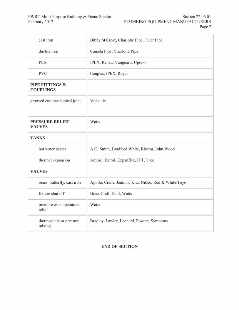
PWRC Multi-Purpose Building & Picnic Shelter Section 22 06 01 February 2017 PLUMBING EQUIPMENT MANUFACTURERS Page 2
Prism Engineering Ltd.
cast iron Bibby St Croix, Charlotte Pipe, Tyler Pipe
ductile iron Canada Pipe, Charlotte Pipe
PEX IPEX, Rehau, Vanguard, Uponor
PVC Canplas, IPEX, Royal
PIPE FITTINGS & COUPLINGS
grooved end mechanical joint Victaulic
PRESSURE RELIEF VALVES
Watts
TANKS
hot water heater A.O. Smith, Bradford White, Rheem, John Wood
thermal expansion Amtrol, Extrol, Expanflex, ITT, Taco
VALVES
brass, butterfly, cast iron Apollo, Crane, Jenkins, Kitz, Nibco, Red & White/Toyo
fixture shut off Brass Craft, Dahl, Watts
pressure & temperature relief
Watts
thermostatic or pressure mixing
Bradley, Lawler, Leonard, Powers, Symmons
END OF SECTION

PWRC Multi-Purpose Building & Picnic Shelter Section 22 11 16 February 2017 DOMESTIC WATER PIPING Page 1
Prism Engineering Ltd.
Part 1 General
1.1 REFERENCES
.1 American National Standards Institute (ANSI)/American Society of Mechanical Engineers International (ASME).
.1 ANSI/ASME B16.15-06, Cast Bronze Threaded Fittings, Classes 125 and 250.
.2 ANSI/ASME B16.18-01, Cast Copper Alloy Solder Joint Pressure Fittings.
.3 ANSI/ASME B16.22-01, Wrought Copper and Copper Alloy Solder Joint Pressure Fittings.
.4 ANSI/ASME B16.24-01, Cast Copper Alloy Pipe Flanges and Flanged Fittings, Class 150, 300, 400, 600, 900, 1500 and 2500.
.2 ASTM International Inc.
.1 ASTM A307-07b, Standard Specification for Carbon Steel Bolts and Studs, 60,000 PSI Tensile Strength.
.2 ASTM A536-84(2004)e1, Standard Specification for Ductile Iron Castings.
.3 ASTM B88M-05, Standard Specification for Seamless Copper Water Tube (Metric).
.3 Canadian Standards Association (CSA International)
.1 CSA B242-05, Groove and Shoulder Type Mechanical Pipe Couplings.
.2 CSA B137.5, Crosslinked polyethylene (PEX) tubing systems for pressure applications.
.4 Health Canada/Workplace Hazardous Materials Information System (WHMIS)
.1 Material Safety Data Sheets (MSDS).
.5 Manufacturer's Standardization Society of the Valve and Fittings Industry (MSS).
.1 MSS-SP-80-03, Bronze Gate, Globe, Angle and Check Valves.
.6 National Research Council (NRC)/Institute for Research in Construction
.1 NRCC 38728, National Plumbing Code of Canada (NPC) - 2010.
1.2 ACTION AND INFORMATIONAL SUBMITTALS
.1 Product Data:
.1 Provide manufacturer's printed product literature and datasheets for insulation and adhesives, and include product characteristics, performance criteria, physical size, finish and limitations.
.2 Closeout Submittals:
.1 Provide maintenance data for incorporation into manual.

PWRC Multi-Purpose Building & Picnic Shelter Section 22 11 16 February 2017 DOMESTIC WATER PIPING Page 2
Prism Engineering Ltd.
Part 2 Products
2.1 PIPING
.1 Domestic cold water systems within building:
.1 Copper tube, hard drawn, type L: to ASTM B88M.
.2 Domestic hot water systems, within building:
.1 Copper tube, hard drawn, type K: to ASTM B88M.
2.2 FITTINGS
.1 Bronze pipe flanges and flanged fittings: to ANSI/ASME B16.24.
.2 Cast bronze threaded fittings: to ANSI/ASME B16.15.
.3 Cast copper, solder type: to ANSI/ASME B16.18.
.4 Wrought copper and copper alloy, solder type: to ANSI/ASME B16.22.
.5 NPS 2 and larger: ANSI/ASME B16.18 or ANSI/ASME B16.22 roll grooved to CSA B242.
.6 NPS 1 1/2 and smaller: wrought copper to ANSI/ASME B16.22 cast copper to ANSI/ASME B16.18; Suitable for operating pressure to 1400 kPa.
.7 Above ground: Cast or ductile iron, roll grooved fittings with grooved mechanical connector couplings: to AWWA C151.
2.3 JOINTS
.1 Rubber gaskets: to AWWA C111.
.2 Bolts, nuts, hex head and washers: to ASTM A307, heavy series.
.3 Solder: Cast Copper Alloy: to ANSI B16.18
.4 Solder: Wrought Copper and Copper Alloy: to ANSI/ASME B16.22.
.5 Flared joint: to ANSI/ASME B16.26.
.6 Teflon tape: for threaded joints.
.7 Grooved couplings: designed with angle bolt pads to provide rigid joint, complete with EPDM gasket.
.8 Dielectric connections between dissimilar metals: dielectric fitting, complete with thermoplastic liner.
2.4 SWING CHECK VALVES
.1 NPS 2” and smaller, screwed:
.1 Screwed joint type, bronze body, bronze or stainless steel swing disc, 860 kPa (125 psi) rating.
.2 Acceptable products: i) Crane 37, Grinnell 3300, Jenkins 4092, Kitz 22, Lunkenheimer 2144, Neuman-Hattersley A60AT, Red & White/Toyo 236.

PWRC Multi-Purpose Building & Picnic Shelter Section 22 11 16 February 2017 DOMESTIC WATER PIPING Page 3
Prism Engineering Ltd.
2.5 BALL VALVES
.1 NPS 2” and smaller, screwed:
.1 Brass two piece body, blow-out proof stem, PTFE seats, brass chrome plate ball, lever handle operator, 1035 kPa (150 spi) rating.
.2 Acceptable products:
.1 Solder joint type: Red & Whitre/Toyo 5049A, Apollo, Crane, Jenkins, Kitz, Lunkenheimer 746FS or 747FS, Neuman-hattersley 1969AT, Nippco, Watts, Worcester.
.2 Screwed joint type: Red & White/Toyo 5044A, Apollo-70 Series, Crane 93-TF, Grinnell 3700 full port, Jenkins-1101-T, Kitz 58, Lunkenheimer 746F or 747F, Neuman-Hattersley 1969AT, Nippco T-580-BR, Watts B-6000, Worcester 4211-RT.
.2 NPS 2” and smaller, soldered:
.1 To ANSI/ASME B16.18, Class 150.
.2 Bronze body, stainless steel ball, PTFE adjustable packing, brass gland and PTFE seat, steel lever handle, with NPT to copper adaptors
2.6 STRAINERS
.1 Sized on a 4 to 1 ratio of basket open area to connecting pipe cross-sectional area, ‘Y’ pattern, 304 stainless steel screen.
.2 6 mm (¼”) to 50 mm (2”), screwed ends, bronze body, 1400 kPa (200 psi) rating. Acceptable products: Red & White/Toyo 380, Crane 988-½, Armstrong, Muessco, Sarco (Canada), Kitz.
.3 65 mm (2½”) and larger, flanged ends, cast iron body, 1400 kPa rating. Acceptable products: Red & White/Toyo 381A, Crane 989-½, Armstrong, Muessco, Sarco (Canada), Kitz.
2.7 WATER HAMMER ARRESTORS
.1 Bellows or piston style with stainless steel casing and welded stainless steel nesting bellows if of the bellows style.
.2 Acceptable products:
.1 Zurn Z-1700 Series bellows style, R.T.S., Enpoco, Ancon, Amtrol, Watts; Precision Plumbing Products Inc. piston style.
2.8 PRESSURE GAUGES
.1 Design Basis:
.1 Pipe mounting type, plain case style, bottom connection.
.2 Wall or panel surface mounting type, flanged style.
.3 Flush panel mounting type, flush mount case style.
.2 Minimum Requirements:

PWRC Multi-Purpose Building & Picnic Shelter Section 22 11 16 February 2017 DOMESTIC WATER PIPING Page 4
Prism Engineering Ltd.
.1 Seamless phosphor bronze Bourdon tube type, with minimum 115 mm (4½”) diameter dial, unless otherwise indicated.
.2 Cast aluminium, black steel or stainless steel case, with stainless steel or chrome plated face ring.
.3 White background with pressure range in black.
.4 Accuracy - 2% of scale range.
.5 Scales to be calibrated in both psig and kilopascals.
.6 Scale range.
Operating Pressure Scale Range kPa (psig) kPa (psig)
-50 - 100 (-15”Hg - 15) -100 - 100 (-30”Hg - 15) 0 - 150 (0 - 22) 0 - 200 (0 - 30)
150 - 310 (22 - 45) 0 - 400 (0 - 60) 310 - 520 (45 - 75) 0 - 700 (0 - 100) 520 - 690 (75 - 100) 0 - 1500 (0 - 200)
690 - 1035 (100 - 150) 0 - 2000 (0 - 300) 1035 - 1380 (150 - 200) 0 - 3000 (0 - 400)
.3 Install a needle valve ahead of each gauge.
.4 Acceptable products: Lunkenheimer, Moeller, Terice, Weiss, Weksler.
2.9 TEMPERATURE AND PRESSURE RELIEF VALVES
.1 Watts A.S.M.E. rated.
.2 Acceptable products: Cash Acme.
2.10 AIR VENTS
.1 Automatic float type.
.2 Acceptable products:
.1 242 kPa (35 psi) max. operating pressure - Armstrong 11-AV, Dole 200, Maid-o-Mist 67 or 68, Barukman EA122, Amtrol;
.2 345 kPa a(50 psi) max. operating pressure - Armstrong 11-AV, Dole 75, Taco 423, Maid-o-Mist 7, Braukman EA122, Amtrol;
.3 517 kPa (75 psi) max. operating pressure - Armstrong 11-AV, Dole 75, Taco 426, Maid-o-Mist 7, Braukman EA122, Amtrol;
.4 1035 kPa (150 psi) max. operating pressure - Armstrong 11-Av, Maid-o-Mist 71, Taco 426, Amtrol.
2.11 BACK FLOW PREVENTERS
.1 Preventers: to CSA-B64 Series, application as indicated, reduced pressure principle type, double check valve assembly back flow preventer with intermediate atmospheric vent and drain connection.
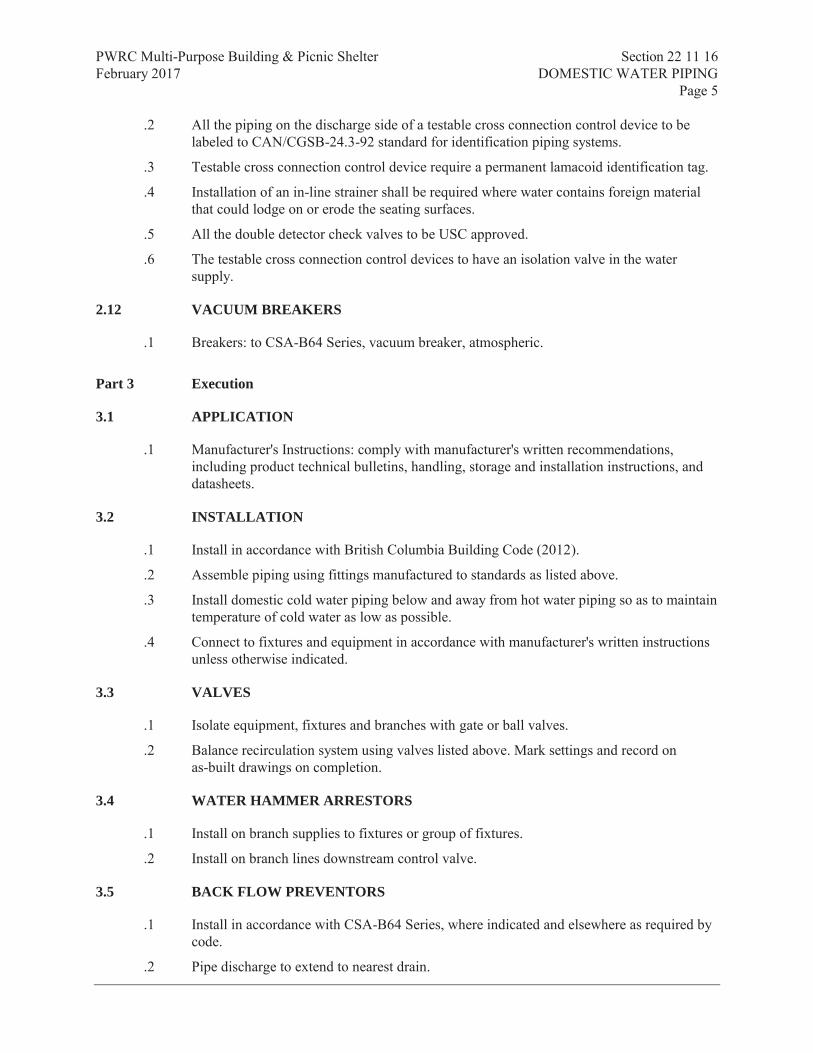
PWRC Multi-Purpose Building & Picnic Shelter Section 22 11 16 February 2017 DOMESTIC WATER PIPING Page 5
Prism Engineering Ltd.
.2 All the piping on the discharge side of a testable cross connection control device to be labeled to CAN/CGSB-24.3-92 standard for identification piping systems.
.3 Testable cross connection control device require a permanent lamacoid identification tag.
.4 Installation of an in-line strainer shall be required where water contains foreign material that could lodge on or erode the seating surfaces.
.5 All the double detector check valves to be USC approved.
.6 The testable cross connection control devices to have an isolation valve in the water supply.
2.12 VACUUM BREAKERS
.1 Breakers: to CSA-B64 Series, vacuum breaker, atmospheric.
Part 3 Execution
3.1 APPLICATION
.1 Manufacturer's Instructions: comply with manufacturer's written recommendations, including product technical bulletins, handling, storage and installation instructions, and datasheets.
3.2 INSTALLATION
.1 Install in accordance with British Columbia Building Code (2012).
.2 Assemble piping using fittings manufactured to standards as listed above.
.3 Install domestic cold water piping below and away from hot water piping so as to maintain temperature of cold water as low as possible.
.4 Connect to fixtures and equipment in accordance with manufacturer's written instructions unless otherwise indicated.
3.3 VALVES
.1 Isolate equipment, fixtures and branches with gate or ball valves.
.2 Balance recirculation system using valves listed above. Mark settings and record on as-built drawings on completion.
3.4 WATER HAMMER ARRESTORS
.1 Install on branch supplies to fixtures or group of fixtures.
.2 Install on branch lines downstream control valve.
3.5 BACK FLOW PREVENTORS
.1 Install in accordance with CSA-B64 Series, where indicated and elsewhere as required by code.
.2 Pipe discharge to extend to nearest drain.

PWRC Multi-Purpose Building & Picnic Shelter Section 22 11 16 February 2017 DOMESTIC WATER PIPING Page 6
Prism Engineering Ltd.
.3 All the piping on the discharge side of a testable cross connection control device to be labeled to CAN/CGSB-24.3-92 standard for identification piping systems.
.4 The testable cross connection control devices to have an isolation valve in the water supply.
3.6 PRESSURE TESTS
.1 Conform to requirements of Section 21 05 01 - Common Work Results for Mechanical.
.2 Test pressure: greater of 1 times maximum system operating pressure or 860 kPa.
3.7 STRAINERS
.1 Install with sufficient room to remove basket.
3.8 FLUSHING AND CLEANING
.1 Flush entire system for 8 h. Ensure outlets flushed for 2 hours. Let stand for 24 hours, then draw sample off longest run. Submit to testing laboratory to verify that system is clean to local potable water guidelines. Let system flush for additional 2 hours, then draw off another sample for testing.
3.9 PRE-START-UP INSPECTIONS
.1 Systems to be complete, prior to flushing, testing and start-up.
.2 Verify that system can be completely drained.
.3 Ensure that pressure booster systems are operating properly.
.4 Ensure that air chambers, expansion compensators are installed properly.
3.10 DISINFECTION
.1 Flush out, disinfect and rinse system to requirements of authority having jurisdiction and approval of Consultant.
.2 Upon completion, provide laboratory test reports on water quality for Consultant approval.
3.11 START-UP
.1 Timing: start up after:
.1 Pressure tests have been completed.
.2 Disinfection procedures have been completed.
.3 Certificate of static completion has been issued.
.4 Water treatment systems operational.
.2 Provide continuous supervision during start-up.
.3 Start-up procedures:
.1 Establish circulation and ensure that air is eliminated.

PWRC Multi-Purpose Building & Picnic Shelter Section 22 11 16 February 2017 DOMESTIC WATER PIPING Page 7
Prism Engineering Ltd.
.2 Check pressurization to ensure proper operation and to prevent water hammer, flashing and/or cavitation.
.3 Bring HWS storage tank up to design temperature slowly.
.4 Monitor piping HWS and HWC piping systems for freedom of movement, pipe expansion as designed.
.5 Check control, limit, and safety devices for normal and safe operation.
.4 Rectify start-up deficiencies.
.5 Vacuum breakers, backflow preventers, backwater valves:
.1 Test tightness, accessibility for O&M of cover and of valve.
.2 Simulate reverse flow and back-pressure conditions to test operation of vacuum breakers, backflow preventers.
.3 Verify visibility of discharge from open ports.
.6 Water hammer arrestors:
.1 Verify proper installation of correct type of water hammer arrester.
.7 Strainers:
.1 Clean out repeatedly until clear.
.2 Verify accessibility of cleanout plug and basket.
.3 Verify that cleanout plug does not leak.
.8 Hose bibbs, sediment faucets:
.1 Verify operation.
3.12 OPERATION REQUIREMENTS
.1 Co-ordinate operation and maintenance requirements including, cleaning and maintenance of specified materials and products with Section 23 05 05 - Installation of Pipework.
END OF SECTION
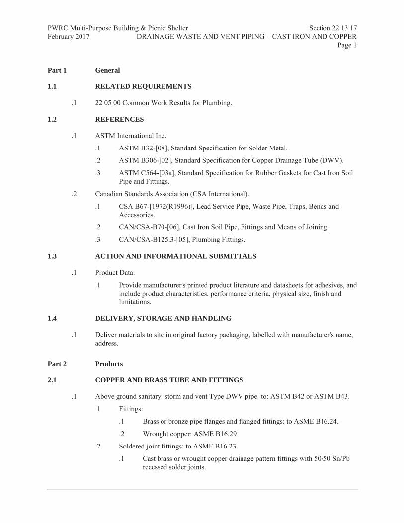
PWRC Multi-Purpose Building & Picnic Shelter Section 22 13 17 February 2017 DRAINAGE WASTE AND VENT PIPING – CAST IRON AND COPPER Page 1
Prism Engineering Ltd.
Part 1 General
1.1 RELATED REQUIREMENTS
.1 22 05 00 Common Work Results for Plumbing.
1.2 REFERENCES
.1 ASTM International Inc.
.1 ASTM B32-[08], Standard Specification for Solder Metal.
.2 ASTM B306-[02], Standard Specification for Copper Drainage Tube (DWV).
.3 ASTM C564-[03a], Standard Specification for Rubber Gaskets for Cast Iron Soil Pipe and Fittings.
.2 Canadian Standards Association (CSA International).
.1 CSA B67-[1972(R1996)], Lead Service Pipe, Waste Pipe, Traps, Bends and Accessories.
.2 CAN/CSA-B70-[06], Cast Iron Soil Pipe, Fittings and Means of Joining.
.3 CAN/CSA-B125.3-[05], Plumbing Fittings.
1.3 ACTION AND INFORMATIONAL SUBMITTALS
.1 Product Data:
.1 Provide manufacturer's printed product literature and datasheets for adhesives, and include product characteristics, performance criteria, physical size, finish and limitations.
1.4 DELIVERY, STORAGE AND HANDLING
.1 Deliver materials to site in original factory packaging, labelled with manufacturer's name, address.
Part 2 Products
2.1 COPPER AND BRASS TUBE AND FITTINGS
.1 Above ground sanitary, storm and vent Type DWV pipe to: ASTM B42 or ASTM B43.
.1 Fittings:
.1 Brass or bronze pipe flanges and flanged fittings: to ASME B16.24.
.2 Wrought copper: ASME B16.29
.2 Soldered joint fittings: to ASME B16.23.
.1 Cast brass or wrought copper drainage pattern fittings with 50/50 Sn/Pb recessed solder joints.

PWRC Multi-Purpose Building & Picnic Shelter Section 22 13 17 February 2017 DRAINAGE WASTE AND VENT PIPING – CAST IRON AND COPPER Page 2
Prism Engineering Ltd.
2.2 CAST IRON PIPING AND FITTINGS
.1 Buried sanitary, storm and vent minimum NPS 75mm (3”), to: CAN/CSA-B70..
.1 Joints:
.1 Mechanical joints:
.1 Neoprene or butyl rubber compression gaskets: to ASTM C564 or CAN/CSA-B70.
.2 Stainless steel couplings
.2 Hub and spigot:
.1 Caulking lead: to CSA B67.
.2 Cold caulking compounds.
.2 Above ground sanitary, storm and vent: to CAN/CSA-B70.
.1 Joints:
.1 Mechanical joints:
.1 Neoprene or butyl rubber compression gaskets with stainless steel clamps.
.2 Hub and spigot:
.1 Caulking lead: to CSA B67.
Part 3 Execution
3.1 APPLICATION
.1 Manufacturer's Instructions: comply with manufacturer's written recommendations, including product technical bulletins, handling, storage and installation instructions, and datasheets.
3.2 SAFES, FLASHING AND VENT TERMINALS
.1 Supply and fix 25 kb/m2 (5 lb/ft2) sheet lead flashings to all cleanouts and floor drains. Securely fix to flashing clamps and extend 300 mm (12”) beyond edge of cast iron fittings.
.2 All cleanouts passing through walls or floors subject to hydrostatic pressure and waterproofed by means other than a membrane shall be provided with clamping collars and flashings of 25 kg/m2 (5 lb/ft2) lead.
.3 Vent flashing minimum 450 mm x 450 mm (18” x 18”) base dimension shall terminate flush with the top of 300 mm (12”0 high vent pipe and the gap between the flashing and pipe shall be closed to a 25 kb/m2 (5 lb/ft2) separate lead cap 75 mm (3”) high. The main flashing shall not be turned over the pipe.

PWRC Multi-Purpose Building & Picnic Shelter Section 22 13 17 February 2017 DRAINAGE WASTE AND VENT PIPING – CAST IRON AND COPPER Page 3
Prism Engineering Ltd.
3.3 INSTALLATION
.1 Install of drainage and venting shall be in accordance with National Plumbing Code, Provincial Plumbing Code and Vancouver Building ByLaw.
.2 Install floor drains set low to provide proper drainage.
.3 Water piping from trap primer to floor drain to be protected in polyethylene sleeve where buried below slab.
.4 A cleanout shall be provided to permit the cleaning of the piping downstream of an interceptor.
.5 Cleanouts shall be installed so that the cumulative change in direction is not more than 90º.
.6 Copper to Cast Iron joints shall be male brass adaptors to tapped fittings.
.7 Nipples shall be cast iron or heavy brass.
.8 Combustible and Non-Combustible piping that penetrates a fire separation shall be sealed at the penetration by a fire stop system that, when subjected to the fire test method in ULC-S115, “Fire Tests of Firestop Systems”, has an FT rating not less than the fire resistance rating of the fire separation.
.9 Manufacturer to provide on site inspection during installation ensuring proper installation and procedures are followed.
3.4 TESTING
.1 After a section of drainage or venting has been roughed in, and before any fixture is installed, a water pressure test or an air pressure test shall be conducted.
.2 Water pressure test on drainage and vent piping must maintain a minimum of 30kPa and maximum 75kPa for a minimum of 8 hours. Check for proper grade and obstruction with ball test.
.3 Air pressure test on drainage and vent piping must maintain a minimum pressure of 35kPa for a minimum of 8 hours.
.4 Hydraulically test to verify grades and freedom from obstructions.
3.5 PERFORMANCE VERIFICATION
.1 Cleanouts:
.1 Ensure accessible and that access doors are correctly located.
.2 Open, cover with linseed oil and re-seal.
.3 Verify that cleanout rods can probe as far as the next cleanout, at least.
.2 Test to ensure traps are fully and permanently primed.
.3 Storm water drainage:
.1 Verify domes are secure.
.2 Ensure weirs are correctly sized and installed correctly.
.3 Verify provisions for movement of roof system.

PWRC Multi-Purpose Building & Picnic Shelter Section 22 13 17 February 2017 DRAINAGE WASTE AND VENT PIPING – CAST IRON AND COPPER Page 4
Prism Engineering Ltd.
.4 Ensure that fixtures are properly anchored, connected to system and effectively vented.
.5 Affix applicable label (storm, sanitary, vent, pump discharge etc.) c/w directional arrows every floor or 4.5 m (whichever is less).
3.6 CLEANING
.1 Remove surplus materials, excess materials, rubbish, tools and equipment.
END OF SECTION
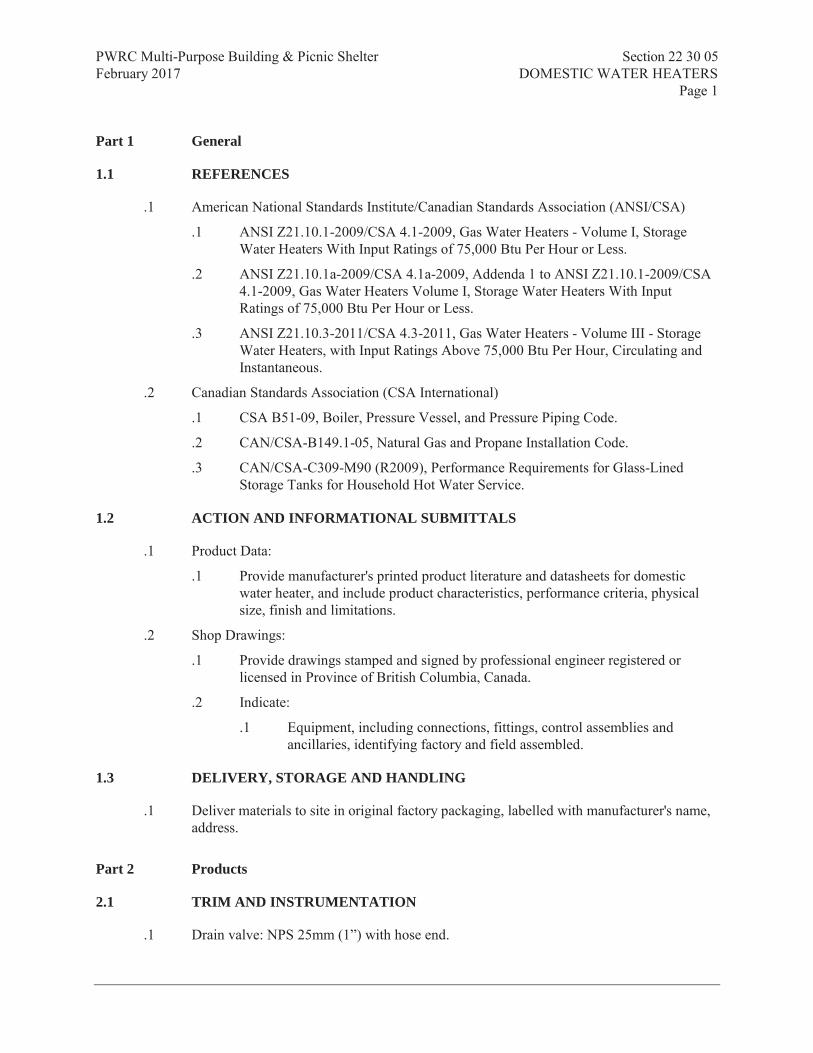
PWRC Multi-Purpose Building & Picnic Shelter Section 22 30 05 February 2017 DOMESTIC WATER HEATERS Page 1
Prism Engineering Ltd.
Part 1 General
1.1 REFERENCES
.1 American National Standards Institute/Canadian Standards Association (ANSI/CSA)
.1 ANSI Z21.10.1-2009/CSA 4.1-2009, Gas Water Heaters - Volume I, Storage Water Heaters With Input Ratings of 75,000 Btu Per Hour or Less.
.2 ANSI Z21.10.1a-2009/CSA 4.1a-2009, Addenda 1 to ANSI Z21.10.1-2009/CSA 4.1-2009, Gas Water Heaters Volume I, Storage Water Heaters With Input Ratings of 75,000 Btu Per Hour or Less.
.3 ANSI Z21.10.3-2011/CSA 4.3-2011, Gas Water Heaters - Volume III - Storage Water Heaters, with Input Ratings Above 75,000 Btu Per Hour, Circulating and Instantaneous.
.2 Canadian Standards Association (CSA International)
.1 CSA B51-09, Boiler, Pressure Vessel, and Pressure Piping Code.
.2 CAN/CSA-B149.1-05, Natural Gas and Propane Installation Code.
.3 CAN/CSA-C309-M90 (R2009), Performance Requirements for Glass-Lined Storage Tanks for Household Hot Water Service.
1.2 ACTION AND INFORMATIONAL SUBMITTALS
.1 Product Data:
.1 Provide manufacturer's printed product literature and datasheets for domestic water heater, and include product characteristics, performance criteria, physical size, finish and limitations.
.2 Shop Drawings:
.1 Provide drawings stamped and signed by professional engineer registered or licensed in Province of British Columbia, Canada.
.2 Indicate:
.1 Equipment, including connections, fittings, control assemblies and ancillaries, identifying factory and field assembled.
1.3 DELIVERY, STORAGE AND HANDLING
.1 Deliver materials to site in original factory packaging, labelled with manufacturer's name, address.
Part 2 Products
2.1 TRIM AND INSTRUMENTATION
.1 Drain valve: NPS 25mm (1”) with hose end.

PWRC Multi-Purpose Building & Picnic Shelter Section 22 30 05 February 2017 DOMESTIC WATER HEATERS Page 2
Prism Engineering Ltd.
.2 Thermometer: 100 mm dial type with red pointer and thermowell filled with conductive paste.
.3 Pressure gauge: 75 mm dial type with red pointer, syphon and shut-off cock.
.4 Thermowell filled with conductive paste for control valve temperature sensor.
.5 ASME rated temperature and pressure relief valve sized for full capacity of heater having discharge terminating over floor drain and visible to operators.
2.2 ANCHOR BOLTS AND TEMPLATES
.1 Supply anchor bolts and templates for installation in concrete support pad.
.2 Size anchor bolts to withstand seismic zone 4 acceleration and velocity forces.
Part 3 Execution
3.1 APPLICATION
.1 Manufacturer's Instructions: comply with manufacturer's written recommendations, including product technical bulletins, handling, storage and installation instructions, and datasheets.
3.2 INSTALLATION
.1 Install in accordance with manufacturer's recommendations and authority having jurisdiction.
.2 Provide insulation between tank and supports.
.3 Install natural gas fired domestic water heaters in accordance with CAN/CSA-B149.1.
3.3 FIELD QUALITY CONTROL
.1 Manufacturer's factory trained, certified Engineer to start up and commission DHW heating system.
3.4 CLEANING
.1 Remove surplus materials, excess materials, rubbish, tools and equipment.
END OF SECTION

PWRC Multi-Purpose Building & Picnic Shelter Section 23 05 29 February 2017 HANGERS AND SUPPORTS FOR PIPING AND EQUIPMENT Page 1
Prism Engineering Ltd.
Part 1 General
1.1 REFERENCES
.1 American Society of Mechanical Engineers (ASME)
.1 ASME B31.1-07, Power Piping.
.2 ASTM International
.1 ASTM A125-1996 (2007), Standard Specification for Steel Springs, Helical, Heat-Treated.
.2 ASTM A307-07b, Standard Specification for Carbon Steel Bolts and Studs, 60,000 PSI Tensile Strength.
.3 ASTM A563-07a, Standard Specification for Carbon and Alloy Steel Nuts.
.3 Factory Mutual (FM)
.4 Manufacturer's Standardization Society of the Valves and Fittings Industry (MSS)
.1 MSS SP58-2002, Pipe Hangers and Supports - Materials, Design and Manufacture.
.2 MSS SP69-2003, Pipe Hangers and Supports - Selection and Application.
.3 MSS SP89-2003, Pipe Hangers and Supports - Fabrication and Installation Practices.
.5 Underwriter's Laboratories of Canada (ULC)
Part 2 Products
2.1 SYSTEM DESCRIPTION
.1 Design Requirements:
.1 Construct pipe hanger and support to manufacturer's recommendations utilizing manufacturer's regular production components, parts and assemblies.
.2 Base maximum load ratings on allowable stresses prescribed by ASME B31.1 or MSS SP58.
.3 Ensure that supports, guides, anchors do not transmit excessive quantities of heat to building structure.
.4 Design hangers and supports to support systems under conditions of operation, allow free expansion and contraction, prevent excessive stresses from being introduced into pipework or connected equipment.
.5 Provide for vertical adjustments after erection and during commissioning. Amount of adjustment in accordance with MSS SP58.
2.2 GENERAL
.1 Fabricate hangers, supports and sway braces in accordance with ANSI B31.1 and MSS SP58.

PWRC Multi-Purpose Building & Picnic Shelter Section 23 05 29 February 2017 HANGERS AND SUPPORTS FOR PIPING AND EQUIPMENT Page 2
Prism Engineering Ltd.
.2 Use components for intended design purpose only. Do not use for rigging or erection purposes.
2.3 PIPE HANGERS
.1 Finishes:
.1 Pipe hangers and supports: galvanized painted with zinc-rich paint after manufacture.
.2 Ensure steel hangers in contact with copper piping are copper plated.
.2 Upper attachment structural: suspension from lower flange of I-Beam:
.1 Cold piping NPS 2 maximum: malleable iron C-clamp with hardened steel cup point setscrew, locknut and carbon steel retaining clip.
.1 Rod: 9 mm UL listed13 mm FM approved.
.2 Cold piping NPS 2 1/2 or greater, hot piping: malleable iron beam clamp, eye rod, jaws and extension with carbon steel retaining clip, tie rod, nuts and washers, UL listed to MSS-SP58 and MSS-SP69.
.3 Upper attachment structural: suspension from upper flange of I-Beam:
.1 Cold piping NPS 2 maximum: ductile iron top-of-beam C-clamp with hardened steel cup point setscrew, locknut and carbon steel retaining clip, UL listed to MSS SP69.
.2 Cold piping NPS 2 1/2 or greater, hot piping: malleable iron top-of-beam jaw-clamp with hooked rod, spring washer, plain washer and nut UL listed, FM approved.
.4 Upper attachment to concrete:
.1 Ceiling: carbon steel welded eye rod, clevis plate, clevis pin and cotters with weldless forged steel eye nut. Ensure eye 6 mm minimum greater than rod diameter.
.2 Concrete inserts: wedge shaped body with knockout protector plate UL listed [FM approved to MSS SP69.
.5 Shop and field-fabricated assemblies:
.1 Trapeze hanger assemblies:
.2 Steel brackets: Sway braces for seismic restraint systems:
.6 Hanger rods: threaded rod material to MSS SP58:
.1 Ensure that hanger rods are subject to tensile loading only.
.2 Provide linkages where lateral or axial movement of pipework is anticipated.
.3 Do not use 22 mm rod.
.7 Pipe attachments: material to MSS SP58:
.1 Attachments for steel piping: carbon steel black......
.2 Attachments for copper piping: copper plated black steel.
.3 Use insulation shields for hot pipework.

PWRC Multi-Purpose Building & Picnic Shelter Section 23 05 29 February 2017 HANGERS AND SUPPORTS FOR PIPING AND EQUIPMENT Page 3
Prism Engineering Ltd.
.4 Oversize pipe hangers and supports.
.8 Adjustable clevis: material to MSS SP69 UL listed FM approved, clevis bolt with nipple spacer and vertical adjustment nuts above and below clevis.
.9 Yoke style pipe roll: carbon steel yoke, rod and nuts with cast iron roll, to MSS SP69.
.10 U-bolts: carbon steel to MSS SP69 with 2 nuts at each end to ASTM A563.
.1 Finishes for steel pipework: black.
.11 Pipe rollers: cast iron roll and roll stand with carbon steel rod to MSS SP69.
2.4 INSULATION PROTECTION SHIELDS
.1 Insulated hot piping:
.1 Curved plate 300 mm long, with edges turned up, welded-in centre plate for pipe sizes NPS 12 and over, carbon steel to comply with MSS SP69.
2.5 CONSTANT SUPPORT SPRING HANGERS
.1 Springs: alloy steel to ASTM A125, shot peened, magnetic particle inspected, with +/-5% spring rate tolerance, tested for free height, spring rate, loaded height and provided with Certified Mill Test Report (CMTR).
.2 Load adjustability: 10% minimum adjustability each side of calibrated load. Adjustment without special tools. Adjustments not to affect travel capabilities.
.3 Provide upper and lower factory set travel stops.
.4 Provide load adjustment scale for field adjustments.
.5 Total travel to be actual travel + 20%. Difference between total travel and actual travel 25 mm minimum.
.6 Individually calibrated scales on each side of support calibrated prior to shipment, complete with calibration record.
2.6 VARIABLE SUPPORT SPRING HANGERS
.1 Vertical movement: 13 mm minimum, 50 mm maximum, use single spring pre-compressed variable spring hangers.
.2 Vertical movement greater than 50 mm: use double spring pre-compressed variable spring hanger with [2] springs in series in single casing.
.3 Variable spring hanger complete with factory calibrated travel stops. Provide certificate of calibration for each hanger.
.4 Steel alloy springs: to ASTM A125, shot peened, magnetic particle inspected, with +/-5 % spring rate tolerance, tested for free height, spring rate, loaded height and provided with CMTR.
2.7 EQUIPMENT SUPPORTS
.1 Fabricate equipment supports not provided by equipment manufacturer from structural grade steel. Submit calculations with shop drawings.

PWRC Multi-Purpose Building & Picnic Shelter Section 23 05 29 February 2017 HANGERS AND SUPPORTS FOR PIPING AND EQUIPMENT Page 4
Prism Engineering Ltd.
2.8 EQUIPMENT ANCHOR BOLTS AND TEMPLATES
.1 Provide templates to ensure accurate location of anchor bolts.
Part 3 Execution
3.1 MANUFACTURER'S INSTRUCTIONS
.1 Compliance: comply with manufacturer's written recommendations or specifications, including product technical bulletins, handling, storage and installation instructions, and datasheet.
3.2 INSTALLATION
.1 Install in accordance with:
.1 Manufacturer's instructions and recommendations.
.2 Vibration Control Devices:
.1 Install on piping systems at pumps, boilers, chillers, cooling towers, and as indicated.
.3 Clevis Plates:
.1 Attach to concrete with 4 minimum concrete inserts, one at each corner.
.4 Provide supplementary structural steelwork where structural bearings do not exist or where concrete inserts are not in correct locations.
.5 Use approved constant support type hangers where:
.1 Vertical movement of pipework is 13 mm or more,
.2 Transfer of load to adjacent hangers or connected equipment is not permitted.
.6 Use variable support spring hangers where:
.1 Transfer of load to adjacent piping or to connected equipment is not critical.
.2 Variation in supporting effect does not exceed 25 % of total load.
3.3 HANGER SPACING
.1 Plumbing piping: to BC Plumbing Code authority having jurisdiction.
.2 Copper piping: up to NPS 1/2: every 1.5 m.
.3 Flexible joint roll groove pipe: in accordance with table below for steel, but not less than one hanger at joints. Table listings for straight runs without concentrated loads and where full linear movement is not required.
.4 Within 300 mm of each elbow.
.5 Per the following table:
Maximum Pipe Size : NPS Maximum Spacing Steel Maximum Spacing Copper up to 1-1/4 2.4 m 1.8 m 1-1/2 3.0 m 2.4 m

PWRC Multi-Purpose Building & Picnic Shelter Section 23 05 29 February 2017 HANGERS AND SUPPORTS FOR PIPING AND EQUIPMENT Page 5
Prism Engineering Ltd.
Maximum Pipe Size : NPS Maximum Spacing Steel Maximum Spacing Copper 2 3.0 m 2.4 m 2-1/2 3.7 m 3.0 m 3 3.7 m 3.0 m 3-1/2 3.7 m 3.3 m 4 3.7 m 3.6 m 5 4.3 m 6 4.3 m 8 4.3 m 10 4.9 m 12 4.9 m
3.4 HANGER INSTALLATION
.1 Install hanger so that rod is vertical under operating conditions.
.2 Adjust hangers to equalize load.
.3 Support from structural members. Where structural bearing does not exist or inserts are not in suitable locations, provide supplementary structural steel members.
3.5 HORIZONTAL MOVEMENT
.1 Angularity of rod hanger resulting from horizontal movement of pipework from cold to hot position not to exceed 4 degrees from vertical.
.2 Where horizontal pipe movement is less than 13 mm, offset pipe hanger and support so that rod hanger is vertical in the hot position.
3.6 FINAL ADJUSTMENT
.1 Adjust hangers and supports:
.1 Ensure that rod is vertical under operating conditions.
.2 Equalize loads.
.2 Adjustable clevis:
.1 Tighten hanger load nut securely to ensure proper hanger performance.
.2 Tighten upper nut after adjustment.
.3 C-clamps:
.1 Follow manufacturer's recommended written instructions and torque values when tightening C-clamps to bottom flange of beam.
.4 Beam clamps:
.1 Hammer jaw firmly against underside of beam.
END OF SECTION

PWRC Multi-Purpose Building & Picnic Shelter Section 23 05 93 February 2017 TESTING, ADJUSTING AND BALANCING FOR HVAC Page 1
Prism Engineering Ltd.
Part 1 General
1.1 SUMMARY
.1 TAB is used throughout this Section to describe the process, methods and requirements of testing, adjusting and balancing for HVAC.
.2 TAB means to test, adjust and balance to perform in accordance with requirements of Contract Documents and to do other work as specified in this section.
1.2 SCOPE OF WORK
.1 Conduct the following system measurement and balancing as indicated on the drawings across the following systems:
.1 Air Balancing
.1 Air intake into each forced flow unit
1.3 QUALIFICATIONS OF TAB PERSONNEL
.1 Submit names of personnel to perform TAB to Consultant within 30 days of award of contract.
.2 Provide documentation confirming qualifications, successful experience.
.3 TAB: performed in accordance with the requirements of standard under which TAB Firm's qualifications are approved:
.1 Associated Air Balance Council, (AABC) National Standards for Total System Balance, MN-1-2002.
.2 National Environmental Balancing Bureau (NEBB) TABES, Procedural Standards for Testing, Adjusting, Balancing of Environmental Systems-1998 Sheet Metal and Air Conditioning Contractors' National Association (SMACNA), HVAC TAB HVAC Systems - Testing, Adjusting and Balancing-2002.
.4 Recommendations and suggested practices contained in the TAB Standard: mandatory.
.5 Use TAB Standard provisions, including checklists, and report forms to satisfy Contract requirements.
.6 Use TAB Standard for TAB, including qualifications for TAB Firm and Specialist and calibration of TAB instruments.
.7 Where instrument manufacturer calibration recommendations are more stringent than those listed in TAB Standard, use manufacturer's recommendations.
.8 TAB Standard quality assurance provisions such as performance guarantees form part of this contract.
.1 For systems or system components not covered in TAB Standard, use TAB procedures developed by TAB Specialist.
.2 Where new procedures, and requirements, are applicable to Contract requirements have been published or adopted by body responsible for TAB Standard used
PWRC Multi-Purpose Building & Picnic Shelter Section 23 05 93 February 2017 TESTING, ADJUSTING AND BALANCING FOR HVAC Page 2
Prism Engineering Ltd.
(AABC, NEBB, or TABB), requirements and recommendations contained in these procedures and requirements are mandatory.
1.4 PURPOSE OF TAB
.1 Test to verify proper and safe operation, determine actual point of performance, evaluate qualitative and quantitative performance of equipment, systems and controls at design, average and low loads using actual or simulated loads
.2 Adjust and regulate equipment and systems to meet specified performance requirements and to achieve specified interaction with other related systems under normal and emergency loads and operating conditions.
.3 Balance systems and equipment to regulate flow rates to match load requirements over full operating ranges.
1.5 EXCEPTIONS
.1 TAB of systems and equipment regulated by codes, standards to satisfaction of authority having jurisdiction.
1.6 CO-ORDINATION
.1 Schedule time required for TAB (including repairs, re-testing) into project construction and completion schedule to ensure completion before acceptance of project.
.2 Do TAB of each system independently and subsequently, where interlocked with other systems, in unison with those systems.
1.7 PRE-TAB REVIEW
.1 Review contract documents before project construction is started and confirm in writing to Consultant adequacy of provisions for TAB and other aspects of design and installation pertinent to success of TAB.
.2 Review specified standards and report to Consultant in writing proposed procedures which vary from standard.
.3 During construction, co-ordinate location and installation of TAB devices, equipment, accessories, measurement ports and fittings.
1.8 START-UP
.1 Follow start-up procedures as recommended by equipment manufacturer unless specified otherwise.
.2 Follow special start-up procedures specified elsewhere in Division 23.
1.9 OPERATION OF SYSTEMS DURING TAB
.1 Operate systems for length of time required for TAB and as required by Consultant for verification of TAB reports.

PWRC Multi-Purpose Building & Picnic Shelter Section 23 05 93 February 2017 TESTING, ADJUSTING AND BALANCING FOR HVAC Page 3
Prism Engineering Ltd.
1.10 START OF TAB
.1 Notify Consultant 7 days prior to start of TAB.
.2 Start TAB when building is essentially completed, including:
.3 Installation of ceilings, doors, windows, other construction affecting TAB.
.4 Application of weatherstripping, sealing, and caulking.
.5 Pressure, leakage, other tests specified elsewhere Division 23.
.6 Provisions for TAB installed and operational.
.7 Start-up, verification for proper, normal and safe operation of mechanical and associated electrical and control systems affecting TAB including but not limited to:
.1 Proper thermal overload protection in place for electrical equipment.
.2 Air systems:
.1 Filters in place, clean.
.2 Duct systems clean.
.3 Ducts, air shafts, ceiling plenums are airtight to within specified tolerances.
.4 Correct fan rotation.
.5 Fire, volume control dampers installed and open.
.6 Coil fins combed, clean.
.7 Access doors, installed, closed.
.8 Outlets installed, volume control dampers open.
1.11 APPLICATION TOLERANCES
.1 Do TAB to following tolerances of design values:
.1 All HVAC systems: plus 5%, minus 5%.
.2 Hydronic systems: plus or minus 10%.
1.12 ACCURACY TOLERANCES
.1 Measured values accurate to within plus or minus 2 % of actual values.
1.13 INSTRUMENTS
.1 Prior to TAB, submit to Consultant list of instruments used together with serial numbers.
.2 Calibrate in accordance with requirements of most stringent of referenced standard for either applicable system or HVAC system.
.3 Calibrate within 3 months of TAB. Provide certificate of calibration to Consultant.
1.14 SUBMITTALS
.1 Submit, prior to commencement of TAB:

PWRC Multi-Purpose Building & Picnic Shelter Section 23 05 93 February 2017 TESTING, ADJUSTING AND BALANCING FOR HVAC Page 4
Prism Engineering Ltd.
.2 Proposed methodology and procedures for performing TAB if different from referenced standard.
1.15 PRELIMINARY TAB REPORT
.1 Submit for checking and approval of Consultant, prior to submission of formal TAB report, sample of rough TAB sheets. Include:
.1 Details of instruments used.
.2 Details of TAB procedures employed.
.3 Calculations procedures.
.4 Summaries.
1.16 TAB REPORT
.1 Format in accordance with referenced standard.
.2 TAB report to show results in SI & IP units and to include:
.1 Project record drawings.
.2 System schematics.
.3 Submit 6 copies of TAB Report to Consultant for verification and approval, in English in D-ring binders, complete with index tabs.
1.17 VERIFICATION
.1 Reported results subject to verification by Consultant.
.2 Pay costs to repeat TAB as required to satisfaction of Consultant.
1.18 SETTINGS
.1 After TAB is completed to satisfaction of Consultant, replace drive guards, close access doors, lock devices in set positions, ensure sensors are at required settings.
.2 Permanently mark settings to allow restoration at any time during life of facility. Do not eradicate or cover markings.
1.19 COMPLETION OF TAB
.1 TAB considered complete when final TAB Report received and approved by Consultant.
1.20 AIR SYSTEMS
.1 Standard: TAB to most stringent of this section or TAB standards of AABC. TAB current member in good standing of AABC qualified to standards of AABC.
.2 Quality assurance: perform TAB under direction of supervisor qualified to standards of AABC.
.3 Measurements: to include as appropriate for systems, equipment, components, controls: air velocity, static pressure, flow rate, pressure drop (or loss), temperatures (dry bulb, wet
PWRC Multi-Purpose Building & Picnic Shelter Section 23 05 93 February 2017 TESTING, ADJUSTING AND BALANCING FOR HVAC Page 5
Prism Engineering Ltd.
bulb, dewpoint), duct cross-sectional area, RPM, electrical power, voltage, noise, vibration.
.4 Locations of equipment measurements: to include as appropriate:
.1 Inlet and outlet of dampers, filter, coil, fan, other equipment causing changes in conditions.
.2 At controllers, controlled device.
.5 Locations of systems measurements to include as appropriate: main ducts, main branch, sub-branch, run-out (or grille, register or diffuser).
1.21 OTHER TAB REQUIREMENTS
.1 General requirements applicable to work specified this paragraph:
.1 Qualifications of TAB personnel: as for air systems specified this section.
.2 Quality assurance: as for air systems specified this section.
Part 2 Products
2.1 NOT USED
Part 3 Execution
3.1 NOT USED
END OF SECTION

PWRC Multi-Purpose Building & Picnic Shelter Section 23 06 01 February 2017 HVAC EQUIPMENT MANUFACTURERS Page 1
Prism Engineering Ltd.
Part 1 General
1.1 REQUIREMENTS
.1 The following listed manufacturers are acceptable for their ability to meet the general design intent, quality and performance characteristics of the specified product. The list does not endorse the acceptability of all products available from the listed manufacturers/suppliers.
.2 It remains the responsibility of the contractor to ensure the products supplied are equal to the specified products in every respect, operate as intended, and meet the performance specifications and physical dimensions of the specified product.
.3 The contractor shall be fully responsible for any additional work or materials, to accommodate the use of equipment from the acceptable manufacturers and suppliers list.
.4 Submit within 14 days of contract award a copy of the list underlining the name of the manufacturer whose price was carried in the tender. If no manufacturers’ names are submitted, it will be assumed that the price carried in the tender was that of the specified manufacturer or where the specified product is generic, the first acceptable manufacturer listed for each item and equipment.
.5 Submit shop drawings on all items marked with an asterisk (*) within 30 days of award of contract.
Part 2 Products
2.1 EQUIPMENT & ACCESSORIES
EQUIPMENT/ACCESSORIES SUPPLIERS / MANUFACTURERS (APPROVED EQUALS)
ACCESS DOORS / PANELS
Building Surfaces Acudor, Cendrex, E.H. Price, Maxam, Milcor, Mifab, Steel Brothers
Ducts Nailor, Ventlok
BACKDRAFT DAMPERS
Light Duty E.H. Price CBD, Ruskin B02/A1, Nailor
DUCT CONNECTORS FLEXIBLE
Duro Dyne "Durolon", Ventfabrics - "Ventlon", Dynair Hypalon
FIRE STOPPING Hilti Canada Ph. 1-800-363-4458 JV Firestop Inc. Ph. 1-416-356-7102 Fire Stop Systems Ph. 1-647-288-1326
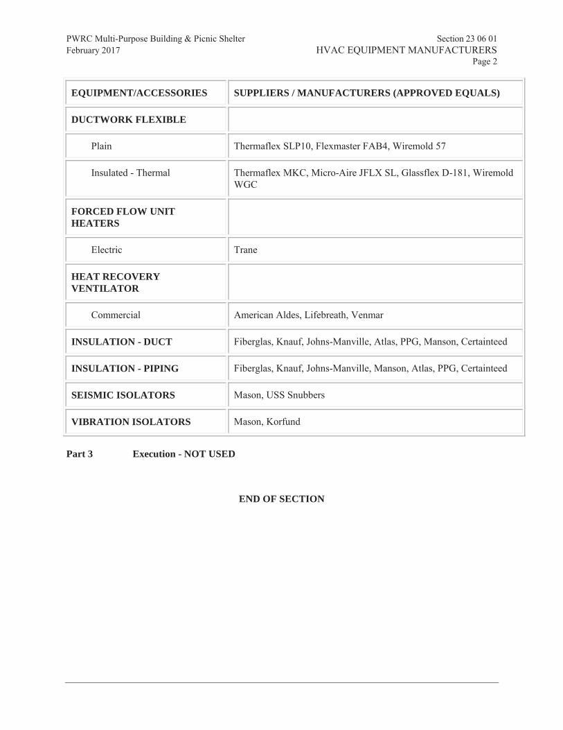
PWRC Multi-Purpose Building & Picnic Shelter Section 23 06 01 February 2017 HVAC EQUIPMENT MANUFACTURERS Page 2
Prism Engineering Ltd.
EQUIPMENT/ACCESSORIES SUPPLIERS / MANUFACTURERS (APPROVED EQUALS)
DUCTWORK FLEXIBLE
Plain Thermaflex SLP10, Flexmaster FAB4, Wiremold 57
Insulated - Thermal Thermaflex MKC, Micro-Aire JFLX SL, Glassflex D-181, Wiremold WGC
FORCED FLOW UNIT HEATERS
Electric Trane
HEAT RECOVERY VENTILATOR
Commercial American Aldes, Lifebreath, Venmar
INSULATION - DUCT Fiberglas, Knauf, Johns-Manville, Atlas, PPG, Manson, Certainteed
INSULATION - PIPING Fiberglas, Knauf, Johns-Manville, Manson, Atlas, PPG, Certainteed
SEISMIC ISOLATORS Mason, USS Snubbers
VIBRATION ISOLATORS Mason, Korfund
Part 3 Execution - NOT USED
END OF SECTION

PWRC Multi-Purpose Building & Picnic Shelter Section 23 06 02 February 2017 HVAC SUBTRADES Page 1
Prism Engineering Ltd.
BALANCING: K.D. ENGINEERING CO.
WESTERN MECHANICAL SERVICES
COMMISSIONING: K.D. ENGINEERING CO.
WESTERN MECHANICAL SERVICES
DUCT AND FAN SYSTEM CLEANING:
ACE MOBILE
ENVIRO-VAC
NALCO
POWER SUCTION SERVICES
OPERATING & MAINTENANCE MANUALS:
K.D. ENGINEERING
WESTERN MECHANICAL SERVICES
END OF SECTION

PWRC Multi-Purpose Building & Picnic Shelter Section 23 07 13 February 2017 DUCT INSULATION Page 1
Prism Engineering Ltd.
Part 1 General
1.1 RELATED DOCUMENTS
.1 Drawings and general provisions of the Contract, including General and Supplementary Conditions and Division 01 Specification Sections, apply to this Section.
.2 Specifications throughout all Divisions of the Project Manual are directly applicable to this Section, and this Section is directly applicable to them.
1.2 SUMMARY
.1 Perform all Work required to provide and install ductwork insulation and jackets indicated by the Contract Documents with supplementary items necessary for proper installation.
1.3 REFERENCE STANDARDS
.1 The latest published edition of a reference shall be applicable to this Project unless identified by a specific edition date.
.2 All reference amendments adopted prior to the effective date of this Contract shall be applicable to this Project
.3 All materials, installation and workmanship shall comply with the applicable requirements and standards addressed within the following references.
.1 ASTM B209 - Aluminum and Aluminum-Alloy Sheet and Plate.
.2 ASTM C168 - Terminology Relating to Thermal Insulation Materials.
.3 ASTM C518 - Steady-State Thermal Transmission Properties by Means of the Heat Flow Meter Apparatus.
.4 ASTM C553 - Mineral Fiber Blanket Thermal Insulation for Commercial and Industrial Applications.
.5 ASTM C612 - Mineral Fiber Block and Board Thermal Insulation.
.6 ASTM C1071 - Standard Specification for Fibrous Glass Duct Lining Insulation (Thermal and Sound Absorbing Material).
.7 ASTM C1104 - Standard Test Method for Determining the Water Vapor Sorption of Unfaced Mineral Fiber Insulation.
.8 ASTM C1290 - Standard Specification for Flexible Fibrous Glass Blanket Insulation Used to Externally Insulate HVAC Ducts.
.9 ASTM C1136 - Standard Specification for Flexible, Low Permeance Vapor Retarders for Thermal Insulation.
.10 ASTM C1338 - Standard Test Method for Determining Fungi Resistance of Insulation Materials and Facings.
.11 ASTM E84 - Surface Burning Characteristics of Building Materials.
.12 ASTM E96 - Water Vapor Transmission of Materials.

PWRC Multi-Purpose Building & Picnic Shelter Section 23 07 13 February 2017 DUCT INSULATION Page 2
Prism Engineering Ltd.
.13 ASTM E119 - Standard Test Methods for Fire Tests of Building Construction and Materials.
.14 ASTM G21 - Standard Practice for Determining Resistance of Synthetic Polymeric Materials to Fungi.
.15 NFPA 255 - Surface Burning Characteristics of Building Materials.
.16 SMACNA - HVAC Duct Construction Standards - Metal and Flexible.
.17 UL 181 - Standard for Factory-Made Air Ducts and Air Connectors.
.18 UL 723 - Surface Burning Characteristics of Building Materials.
.19 ASTM E2336 - Standard for Grease Ducts.
.20 ASTM D5590 - - Standard Test Method for Determining the Resistance of Paint Films and Related Coatings to Fungal Defacement by Accelerated Four-Week Agar Plate Assay
1.4 QUALITY ASSURANCE
.1 All ductwork requiring insulation shall be insulated as specified herein and as required for a complete system. In each case, the insulation shall be equivalent to that specified and materials applied and finished as described in these Specifications.
.2 All insulation, jacket, adhesives, mastics, sealers, etc., utilized in the fabrication of these systems shall meet NFPA for fire resistant ratings (maximum of 25 flame spread and 50 smoke developed ratings) and shall be approved by the insulation manufacturer for guaranteed performances when incorporated into their insulation system, unless a specific product is specified for a specific application and is stated as an exception to this requirement. Certificates to this effect shall be submitted along with Contractor’s submittal data for this Section of the Specifications. No material may be used that, when tested by the ASTM E84-89 test method, is found to melt, drip or delaminate to such a degree that the continuity of the flame front is destroyed, thereby resulting in an artificially low flame spread rating.
.3 Application Company Qualifications: Company performing the Work of this Section must have minimum three (3) years experience specializing in the trade.
.4 All insulation shall be applied by mechanics skilled in this particular Work and regularly engaged in such occupation.
.5 All insulation shall be applied in strict accordance with these Specifications and with factory printed recommendations on items not herein mentioned. Unsightly, inadequate, or sloppy Work will not be acceptable.
1.5 SUBMITTALS
.1 Product Data
.1 Provide product description, list of materials, “k” value, “R” value, mean temperature range, and thickness for each service and location
.2 Record Documents
.1 Submit under provisions of Division 01
PWRC Multi-Purpose Building & Picnic Shelter Section 23 07 13 February 2017 DUCT INSULATION Page 3
Prism Engineering Ltd.
.3 Operation and Maintenance Data
.1 Samples: When requested, submit three (3) samples of any representative size illustrating each insulation type.
.2 Manufacturer’s Installation Instructions: Indicate procedures that ensure acceptable standards will be achieved. Submit certificates to this effect.
1.6 DELIVERY, STORAGE AND HANDLING
.1 Deliver materials to Site in original factory packaging, labeled with manufacturer’s identification including product thermal ratings and thickness.
.2 Store insulation in original wrapping and protect from weather and construction traffic. Protect insulation against dirt, water, chemical, and mechanical damage.
.3 Maintain ambient temperatures and conditions required by manufacturers of adhesives, mastics and insulation cements.
Part 2 Products
2.1 GENERAL
.1 All materials shall meet or exceed all applicable referenced standards, federal, state and local requirements, and conform to codes and ordinances of authorities having jurisdiction.
2.2 INSULATION MATERIALS
.1 Type D1: Flexible glass fiber; ASTM C553 and ASTM C1290; commercial grade; 'k' value of 0.25 at 75 degrees F; 1.5 lb/cu ft minimum density; 0.002 inch foil scrim kraft facing for air ducts.
.2 Type D2: Rigid glass fiber; ASTM C612, Class 1; 'k' value of 0.23 at 75 degrees F; 3.0 lb/cu ft minimum density; 0.002 inch foil scrim kraft facing for air ducts.
2.3 INSULATION ACCESSORIES
.1 Adhesives: Waterproof vapor barrier type, meeting requirements of ASTM C916; Childers CP-82 or Foster 85-20.
.2 Weather Barrier: Breather Mastic:, Childers CP-10/CP-11 or Foster 46-50 White..
.3 Vapor Barrier Coating: Permeance - ASTM E 96, Procedure B, 0.08 perm or less at 45-mil dry film thickness, tested at 100F and 50%RH; Foster 30-65 or Childers CP-34
.1 When higher humidity levels may be of concern, only specify the following fungus/mold resistant coating: Foster 30-80 AF (anti fungal). Coating must meet ASTM D 5590 with 0 growth rating**
.4 Reinforcing Mesh: 10x10 or 9x8 glass mesh; Foster Mast a Fab or Childers #10
.5 Jacket: Pre-sized glass cloth, minimum 7.8 oz/sq yd.
.6 Type D4 Insulation Adhesive: Fire resistive to ASTM E84, Childers CP-82 or Foster 85-20.
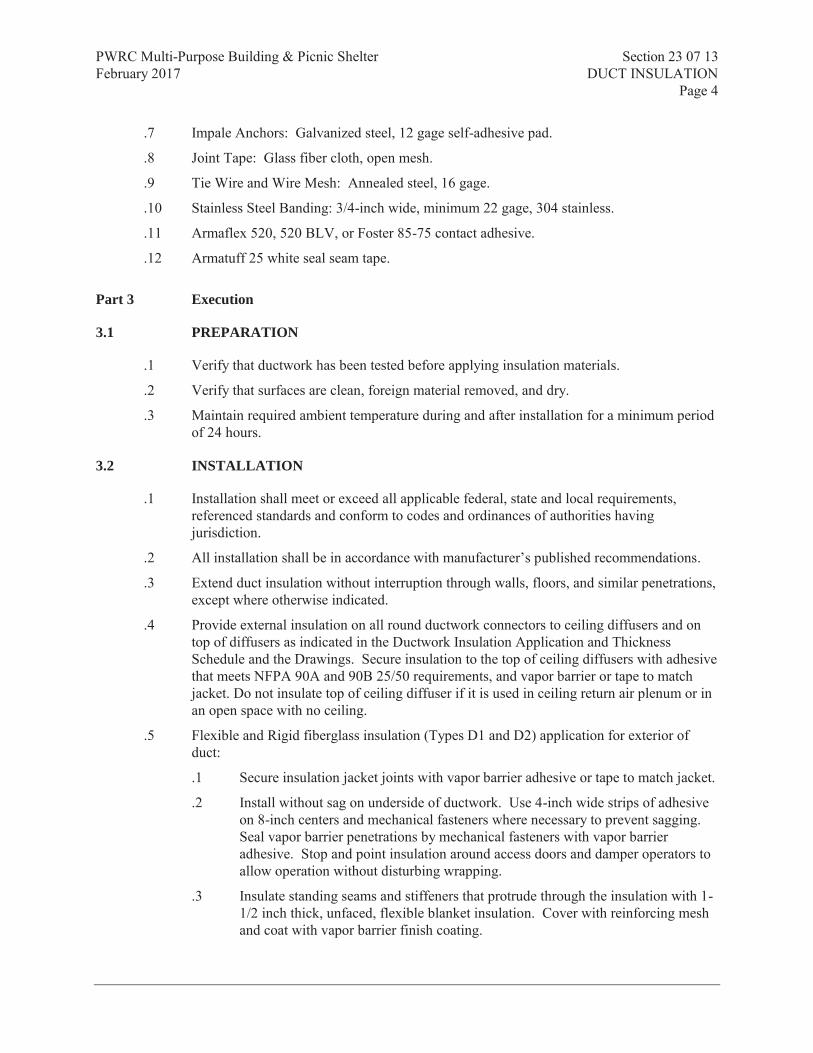
PWRC Multi-Purpose Building & Picnic Shelter Section 23 07 13 February 2017 DUCT INSULATION Page 4
Prism Engineering Ltd.
.7 Impale Anchors: Galvanized steel, 12 gage self-adhesive pad.
.8 Joint Tape: Glass fiber cloth, open mesh.
.9 Tie Wire and Wire Mesh: Annealed steel, 16 gage.
.10 Stainless Steel Banding: 3/4-inch wide, minimum 22 gage, 304 stainless.
.11 Armaflex 520, 520 BLV, or Foster 85-75 contact adhesive.
.12 Armatuff 25 white seal seam tape.
Part 3 Execution
3.1 PREPARATION
.1 Verify that ductwork has been tested before applying insulation materials.
.2 Verify that surfaces are clean, foreign material removed, and dry.
.3 Maintain required ambient temperature during and after installation for a minimum period of 24 hours.
3.2 INSTALLATION
.1 Installation shall meet or exceed all applicable federal, state and local requirements, referenced standards and conform to codes and ordinances of authorities having jurisdiction.
.2 All installation shall be in accordance with manufacturer’s published recommendations.
.3 Extend duct insulation without interruption through walls, floors, and similar penetrations, except where otherwise indicated.
.4 Provide external insulation on all round ductwork connectors to ceiling diffusers and on top of diffusers as indicated in the Ductwork Insulation Application and Thickness Schedule and the Drawings. Secure insulation to the top of ceiling diffusers with adhesive that meets NFPA 90A and 90B 25/50 requirements, and vapor barrier or tape to match jacket. Do not insulate top of ceiling diffuser if it is used in ceiling return air plenum or in an open space with no ceiling.
.5 Flexible and Rigid fiberglass insulation (Types D1 and D2) application for exterior of duct:
.1 Secure insulation jacket joints with vapor barrier adhesive or tape to match jacket.
.2 Install without sag on underside of ductwork. Use 4-inch wide strips of adhesive on 8-inch centers and mechanical fasteners where necessary to prevent sagging. Seal vapor barrier penetrations by mechanical fasteners with vapor barrier adhesive. Stop and point insulation around access doors and damper operators to allow operation without disturbing wrapping.
.3 Insulate standing seams and stiffeners that protrude through the insulation with 1-1/2 inch thick, unfaced, flexible blanket insulation. Cover with reinforcing mesh and coat with vapor barrier finish coating.

PWRC Multi-Purpose Building & Picnic Shelter Section 23 07 13 February 2017 DUCT INSULATION Page 5
Prism Engineering Ltd.
.4 On circumferential joints, the 2-inch flange on the facing shall be secured with 9/16 inch outward clinch steel staples on 2-inch centers, and taped with minimum 3-inch wide strip of glass fabric and finish coating.
.5 Vapor seal all seams, joints, pin penetrations and other breaks with vapor barrier coating reinforced with reinforcing mesh.
.6 All ductwork, accessories, and all plenums including metal and masonry construction, etc., shall be insulated as indicated on the Drawings, as specified herein and as required for a complete system. In each case, the insulation shall be equal to that specified and materials applied and finished as described in these Specifications.
.7 Flexible ductwork connections to equipment shall not be insulated.
.8 Where vapor barriers are required, the vapor barrier shall be on the outside. Extreme care shall be taken that the vapor barrier is unbroken. Joints, etc., shall all be sealed. Where insulation with a vapor barrier terminates, it shall be sealed off with the vapor barrier being continuous to the surface being insulated. Ends shall not be left raw.
.9 Extreme care shall be taken in insulating high and medium pressure ductwork including all ductwork between the fan discharge and all mixing boxes to ensure the duct is not pierced with sheet metal screws or other fasteners. All high and medium pressure ducts in these Specifications are classified as high velocity ductwork.
.10 Where canvas finish is specified use lagging adhesive/coating to prevent mildew in securing canvas. Do not use wheat paste.Use only anti fungal lagging adhesive that adheres to ASTM D 5590 with 0 growth rating. (Foster 30-60, Childers CP-137AF). In addition, cover all exterior canvas-covered insulation with a fire retardant weather barrier mastic.
.11 All supply ductwork in the Project shall be insulated; all exhaust and fume hood exhaust ductwork shall not be insulated, unless used for energy recovery purposes or noted on drawings.
.12 Flexible round ducts shall be factory insulated.
3.3 INSPECTION
.1 Visually inspect the completed insulation installation per manufacturers recommended materials, procedures and repair or replace any improperly sealed joints.
.2 Where there is evidence of vapor barrier failure or “wet” insulation after installation, the damaged insulation shall be removed, duct surface shall be cleaned and dried and new insulation shall be installed
3.4 DUCTWORK INSULATION APPLICATION AND THICKNESS SCHEDULE
Ductwork System Application Insulation
Type Insulation Thickness
Supply Air (Hot, Cold, Combination)
Outside of Mechanical Rooms D1 2"

PWRC Multi-Purpose Building & Picnic Shelter Section 23 07 13 February 2017 DUCT INSULATION Page 6
Prism Engineering Ltd.
Ductwork System Application Insulation
Type Insulation Thickness
Inside of Mechanical Rooms D2 1-1/2"
Return Air, Relief Air, and Exhaust Air All D1 1"
Outside Air Treated and Untreated D1 2"
END OF SECTION

PWRC Multi-Purpose Building & Picnic Shelter Section 23 07 15 February 2017 THERMAL INSULATION FOR PIPING Page 1
Prism Engineering Ltd.
Part 1 General
1.1 SUMMARY
.1 Section Includes:
.1 Thermal insulation for piping and piping accessories in commercial type applications.
1.2 REFERENCES
.1 American Society of Heating, Refrigeration and Air Conditioning Engineers (ASHRAE)
.1 ASHRAE Standard 90.1-10, Energy Standard for Buildings Except Low-Rise Residential Buildings.
.2 American Society for Testing and Materials International (ASTM)
.1 ASTM B209M-04, Standard Specification for Aluminum and Aluminum Alloy Sheet and Plate.
.2 ASTM C335-04, Standard Test Method for Steady State Heat Transfer Properties of Horizontal Pipe Insulation.
.3 ASTM C411-04, Standard Test Method for Hot-Surface Performance of High-Temperature Thermal Insulation.
.4 ASTM C449/C449M-00, Standard Specification for Mineral Fiber-Hydraulic-Setting Thermal Insulating and Finishing Cement.
.5 ASTM C533-2004, Calcium Silicate Block and Pipe Thermal Insulation.
.6 ASTM C547-2003, Mineral Fiber Pipe Insulation.
.7 ASTM C795-03, Standard Specification for Thermal Insulation for Use in Contact with Austenitic Stainless Steel.
.8 ASTM C921-03a, Standard Practice for Determining the Properties of Jacketing Materials for Thermal Insulation.
.3 Canadian General Standards Board (CGSB)
.1 CGSB 51-GP-52Ma-89, Vapour Barrier, Jacket and Facing Material for Pipe, Duct and Equipment Thermal Insulation.
.2 CAN/CGSB-51.53-95, Poly (Vinyl Chloride) Jacketting Sheet, for Insulated Pipes, Vessels and Round Ducts
.4 Health Canada/Workplace Hazardous Materials Information System (WHMIS)
.1 Material Safety Data Sheets (MSDS).
.5 Manufacturer's Trade Associations
.1 Thermal Insulation Association of Canada (TIAC): National Insulation Standards (Revised 2004).
.6 Underwriters' Laboratories of Canada (ULC)

PWRC Multi-Purpose Building & Picnic Shelter Section 23 07 15 February 2017 THERMAL INSULATION FOR PIPING Page 2
Prism Engineering Ltd.
.1 CAN/ULC-S102-03, Surface Burning Characteristics of Building Materials and Assemblies.
.2 CAN/ULC-S701-01, Thermal Insulation, Polystyrene, Boards and Pipe Covering.
.3 CAN/ULC-S702-1997, Thermal Insulation, Mineral Fibre, for Buildings
.4 CAN/ULC-S702.2-03, Thermal Insulation, Mineral Fibre, for Buildings, Part 2: Application Guidelines.
1.3 DEFINITIONS
.1 For purposes of this section:
.1 "CONCEALED" - insulated mechanical services in suspended ceilings and non-accessible chases and furred-in spaces.
.2 "EXPOSED" - will mean "not concealed" as specified.
.2 TIAC:
.1 CRF: Code Rectangular Finish.
.2 CPF: Code Piping Finish.
1.4 SUBMITTALS
.1 Quality assurance submittals:
.1 Certificates: submit certificates signed by manufacturer certifying that materials comply with specified performance characteristics and physical properties.
1.5 QUALITY ASSURANCE
.1 Installer: specialist in performing work of this Section, and have at least 3 years successful experience in this size and type of project, qualified to standards or a member of TIAC.
.2 Health and Safety:
.1 Do construction occupational health and safety in accordance with WBC requirements.
1.6 DELIVERY, STORAGE AND HANDLING
.1 Packing, shipping, handling and unloading:
.1 Deliver, store and handle materials in accordance with manufacturer's written instructions.
.2 Deliver materials to site in original factory packaging, labelled with manufacturer's name, address.
.2 Storage and Protection:
.1 Protect from weather, construction traffic.
.2 Protect against damage.
.3 Store at temperatures and conditions required by manufacturer.

PWRC Multi-Purpose Building & Picnic Shelter Section 23 07 15 February 2017 THERMAL INSULATION FOR PIPING Page 3
Prism Engineering Ltd.
Part 2 Products
2.1 FIRE AND SMOKE RATING
.1 In accordance with CAN/ULC-S102.
.1 Maximum flame spread rating: 25.
.2 Maximum smoke developed rating: 50.
2.2 INSULATION
.1 Mineral fibre specified includes glass fibre, rock wool, slag wool.
.2 Thermal conductivity ("k" factor) not to exceed specified values at 24 degrees C mean temperature when tested in accordance with ASTM C335.
.3 TIAC Code A-1: rigid moulded mineral fibre without factory applied vapour retarder jacket.
.1 Mineral fibre: to CAN/ULC-S702.
.2 Maximum "k" factor: to CAN/ULC-S702.
.4 TIAC Code A-3: rigid moulded mineral fibre with factory applied vapour retarder jacket.
.1 Mineral fibre: to CAN/ULC-S702.
.2 Jacket: to CGSB 51-GP-52Ma.
.3 Maximum "k" factor: to CAN/ULC-S702.
.5 TIAC Code C-2: mineral fibre blanket faced with factory applied vapour retarder jacket (as scheduled in PART 3 of this section).
.1 Mineral fibre: to CAN/ULC-S702, ASTM C547.
.2 Jacket: to CGSB 51-GP-52Ma.
.3 Maximum "k" factor: to CAN/ULC-S702
2.3 HOT WATER HEATING PIPING
.1 All hot water heating piping shall be insulated with 2.5 kg/m3 (5-1/2 lb.) density molded preformed fiberglass pipe insulation with integral all-service jacket.
.2 All Chilled water piping shall be insulated with 2.5 kg/m3 (5-1/2 lb.) density molded preformed fiberglass pipe insulation with integral vapour retarder jacket.
2.4 INSULATION SECUREMENT
.1 Tape: self-adhesive, aluminum, plain or reinforced, 50 mm wide minimum.
.2 Contact adhesive: quick setting.
.3 Canvas adhesive: washable.
.4 Tie wire: 1.5 mm diameter stainless steel.
.5 Bands: stainless steel, 19mm wide, 0.5 mm thick.

PWRC Multi-Purpose Building & Picnic Shelter Section 23 07 15 February 2017 THERMAL INSULATION FOR PIPING Page 4
Prism Engineering Ltd.
2.5 CEMENT
.1 Thermal insulating and finishing cement:
.1 Hydraulic setting or air drying on mineral wool, to ASTM C449/C449M.
2.6 VAPOUR RETARDER LAP ADHESIVE
.1 Water based, fire retardant type, compatible with insulation.
2.7 INDOOR VAPOUR RETARDER FINISH
.1 Vinyl emulsion type acrylic, compatible with insulation.
2.8 OUTDOOR VAPOUR RETARDER FINISH
.1 Vinyl emulsion type acrylic, compatible with insulation.
.2 Reinforcing fabric: fibrous glass, untreated 305 g/m2.
2.9 JACKETS
.1 Polyvinyl Chloride (PVC):
.1 One-piece moulded type and sheet to CAN/CGSB-51.53 with pre-formed shapes as required.
.2 Colours: to match adjacent finish paint or by Consultant.
.3 Minimum service temperatures: -20 degrees C.
.4 Maximum service temperature: 65 degrees C.
.5 Moisture vapour transmission: 0.02 perm.
.6 Thickness: 0.75mm.
.7 Fastenings:
.1 Use solvent weld adhesive compatible with insulation to seal laps and joints.
.2 Tacks.
.3 Pressure sensitive vinyl tape of matching colour.
.2 Canvas:
.1 220 gm/m2 cotton, plain weave, treated with dilute fire retardant lagging adhesive to ASTM C921.
.2 Lagging adhesive: compatible with insulation.
.3 Aluminum:
.1 To ASTM B209.
.2 Thickness: 0.50 mm sheet.
.3 Finish: smooth.
.4 Joining: longitudinal and circumferential slip joints with 50 mm laps.

PWRC Multi-Purpose Building & Picnic Shelter Section 23 07 15 February 2017 THERMAL INSULATION FOR PIPING Page 5
Prism Engineering Ltd.
.5 Fittings: 0.5 mm thick die-shaped fitting covers with factory-attached protective liner.
.6 Metal jacket banding and mechanical seals: stainless steel, 19 mm wide, 0.5mm thick at 300mm spacing.
Part 3 Execution
3.1 MANUFACTURER'S INSTRUCTIONS
.1 Compliance: comply with manufacturer's written recommendations or specifications, including product technical bulletins, handling, storage and installation instructions, and datasheet.
3.2 PRE-INSTALLATION REQUIREMENT
.1 Pressure testing of piping systems and adjacent equipment to be complete, witnessed and certified.
.2 Surfaces clean, dry, free from foreign material.
3.3 INSTALLATION
.1 Install in accordance with TIAC National Standards.
.2 Apply materials in accordance with manufacturers instructions and this specification.
.3 Use two layers with staggered joints when required nominal wall thickness exceeds 75 mm.
.4 Maintain uninterrupted continuity and integrity of vapour retarder jacket and finishes.
.1 Install hangers, supports outside vapour retarder jacket.
.5 Supports, Hangers:
.1 Apply high compressive strength insulation, suitable for service, at oversized saddles and shoes where insulation saddles have not been provided.
3.4 REMOVABLE, PRE-FABRICATED, INSULATION AND ENCLOSURES
.1 Application: at expansion joints, valves, primary flow measuring elements, flanges and unions at equipment.
.2 Design: to permit movement of expansion joint and to permit periodic removal and replacement without damage to adjacent insulation.
.3 Insulation:
.1 Insulation, fastenings and finishes: same as system.
.2 Jacket: aluminum high temperature fabric.
3.5 INSTALLATION OF ELASTOMERIC INSULATION
.1 Insulation to remain dry. Overlaps to manufacturer's instructions. Ensure tight joints.
.2 Provide vapour retarder as recommended by manufacturer.

PWRC Multi-Purpose Building & Picnic Shelter Section 23 07 15 February 2017 THERMAL INSULATION FOR PIPING Page 6
Prism Engineering Ltd.
3.6 PIPING INSULATION SCHEDULES
.1 Includes valves, valve bonnets, strainers, flanges and fittings unless otherwise specified.
.2 TIAC Code: A-1.
.1 Securements: SS wire bands
.2 Tape at 300 mm on centre.
.3 Seals: lap seal adhesive, lagging adhesive.
.4 Installation: TIAC Code 1501-H.
.3 TIAC Code: A-3.
.1 Securements: SS wire bands
.2 Tape at 300 mm on centre.
.3 Seals: VR lap seal adhesive, VR lagging adhesive.
.4 Installation: TIAC Code: 1501-C.
.4 TIAC Code: C-2 with vapour retarder jacket.
.1 Insulation securements:
.2 Seals: lap seal adhesive, lagging adhesive.
.3 Installation: TIAC Code: 1501-C.
.5 Thickness of insulation as listed in following table.
.1 Run-outs to individual units and equipment not exceeding 4000 mm long.
.2 Do not insulate exposed runouts to plumbing fixtures, chrome plated piping, valves, fittings.
Application Temp degrees C
TIAC code
Pipe sizes (NPS) and insulation thickness (mm)
Run out to 1 1 to <1 ½
1 ½ to < 4
4 to < 8 8 & over
Domestic HWS
[A-1] 25 25 25 38 38 38
Domestic CWS
[A-3] 25 25 25 25 25 25
RWL and RWP
[C-2] 25 25 25 25 25 25
.6 Finishes:
.1 Exposed indoors: canvas or PVC jacket.
.2 Exposed in mechanical rooms: canvas or PVC jacket.
.3 Concealed, indoors: canvas on valves, fittings. No further finish.
.4 On TIAC code A-3 insulation, use vapour retarder jacket compatible with insulation.

PWRC Multi-Purpose Building & Picnic Shelter Section 23 07 15 February 2017 THERMAL INSULATION FOR PIPING Page 7
Prism Engineering Ltd.
.5 Outdoors: water-proof aluminum jacket, silicone seal all joints.
.6 Finish attachments: SS bands, at 300 mm on centre. Seals: closed.
.7 Installation: to appropriate TIAC code CRF/1 through CPF/5.
END OF SECTION

PWRC Multi-Purpose Building & Picnic Shelter Section 23 33 00 February 2017 AIR DUCT ACCESSORIES Page 1
Prism Engineering Ltd.
Part 1 General
1.1 SUMMARY
.1 Section Includes:
.1 Materials and installation for duct accessories including flexible connections, access doors, vanes and collars.
.2 Sustainable requirements for construction and verification.
1.2 REFERENCES
.1 Health Canada/Workplace Hazardous Materials Information System (WHMIS).
.1 Material Safety Data Sheets (MSDS).
.2 Sheet Metal and Air Conditioning Contractors' National Association (SMACNA).
.1 SMACNA - HVAC Duct Construction Standards - Metal and Flexible, 95.
1.3 SUBMITTALS
.1 Product Data:
.1 Submit manufacturer's printed product literature, specifications and data sheet. Indicate the following:
.1 Flexible connections.
.2 Duct access doors.
.3 Turning vanes.
.4 Instrument test ports.
.2 Test Reports: submit certified test reports from approved independent testing laboratories indicating compliance with specifications for specified performance characteristics and physical properties.
.1 Certification of ratings: catalogue or published ratings to be those obtained from tests carried out by manufacturer or independent testing agency signifying adherence to codes and standards.
.3 Certificates: submit certificates signed by manufacturer certifying that materials comply with specified performance characteristics and physical properties.
.4 Instructions: submit manufacturer's installation instructions.
.5 Manufacturer's Field Reports: manufacturer's field reports specified.
1.4 DELIVERY, STORAGE AND HANDLING
.1 Waste Management and Disposal:
.1 Remove from site and dispose of packaging materials at appropriate recycling facilities.

PWRC Multi-Purpose Building & Picnic Shelter Section 23 33 00 February 2017 AIR DUCT ACCESSORIES Page 2
Prism Engineering Ltd.
.2 Divert unused metal materials from landfill to metal recycling facility as approved by Consultant.
Part 2 Products
2.1 GENERAL
.1 Manufacture in accordance with SMACNA - HVAC Duct Construction Standards.
2.2 FLEXIBLE CONNECTIONS
.1 Frame: galvanized sheet metal frame 2 mm thick with fabric clenched by means of double locked seams.
.2 Material:
.1 Fire resistant, self extinguishing, neoprene coated glass fabric, temperature rated at minus 40 degrees C to plus 90 degrees C, density of 1.3 kg/m2.
2.3 ACCESS DOORS IN DUCTS
.1 Non-Insulated Ducts: sandwich construction of same material as duct, one sheet metal thickness heavier, minimum 0.6 mm thick complete with sheet metal angle frame.
.2 Insulated Ducts: sandwich construction of same material as duct, one sheet metal thickness heavier, minimum 0.6 mm thick complete with sheet metal angle frame and 25 mm thick rigid glass fibre insulation.
.3 Gaskets: neoprene.
.4 Hardware:
.1 Up to 300 x 300 mm: two sash locks [complete with safety chain.
.2 301 to 450 mm: four sash locks [complete with safety chain.
.3 451 to 1000 mm: piano hinge and minimum two sash locks.
.4 Doors over 1000 mm: piano hinge and two handles operable from both sides.
.5 Hold open devices.
.6 300 x 300 mm glass viewing panels.
2.4 TURNING VANES
.1 Factory or shop fabricated double thickness with trailing edge, to recommendations of SMACNA.
2.5 INSTRUMENT TEST
.1 1.6 mm thick steel zinc plated after manufacture.
.2 Cam lock handles with neoprene expansion plug and handle chain.
.3 28 mm minimum inside diameter. Length to suit insulation thickness.

PWRC Multi-Purpose Building & Picnic Shelter Section 23 33 00 February 2017 AIR DUCT ACCESSORIES Page 3
Prism Engineering Ltd.
.4 Neoprene mounting gasket.
Part 3 Execution
3.1 MANUFACTURER'S INSTRUCTIONS
.1 Compliance: comply with manufacturer's written recommendations or specifications, including product technical bulletins, handling, storage and installation instructions, and data sheet.
3.2 INSTALLATION
.1 Flexible Connections:
.1 Install in following locations:
.1 Inlets and outlets to supply air units and fans.
.2 Inlets and outlets of exhaust and return air fans.
.3 As indicated.
.2 Length of connection: 100 mm.
.3 Minimum distance between metal parts when system in operation: 75 mm.
.4 Install in accordance with recommendations of SMACNA.
.5 When fan is running:
.1 Ducting on sides of flexible connection to be in alignment.
.2 Ensure slack material in flexible connection.
.2 Access Doors and Viewing Panels:
.1 Size:
.1 600 x 1200 mm for person size entry.
.2 600 x 600 mm for servicing entry.
.3 300x 300 mm for viewing.
.4 As indicated for kitchen exhaust duct.
.2 Locations:
.1 Fire and smoke dampers.
.2 Control dampers.
.3 Devices and ducts requiring maintenance.
.4 Required by code.
.5 Reheat coils.
.3 Instrument Test Ports:
.1 General:

PWRC Multi-Purpose Building & Picnic Shelter Section 23 33 00 February 2017 AIR DUCT ACCESSORIES Page 4
Prism Engineering Ltd.
.1 Install in accordance with recommendations of SMACNA and in accordance with manufacturer's instructions.
.2 Locate to permit easy manipulation of instruments.
.3 Install insulation port extensions as required.
.4 Locations:
.1 For traverse readings:
.1 Ducted inlets to roof and wall exhausters.
.2 Inlets and outlets of other fan systems.
.3 Main and sub-main ducts.
.4 And as indicated.
.2 For temperature readings:
.1 At outside air intakes.
.2 In mixed air applications in locations as approved by Consultant
.3 At inlet and outlet of coils.
.4 Downstream of junctions of two converging air streams of different temperatures.
.4 Turning vanes:
.1 Install in accordance with recommendations of SMACNA and as indicated.
3.3 CLEANING
.1 Perform cleaning operations in accordance with manufacturer's recommendations.
.2 Upon completion and verification of performance of installation, remove surplus materials, excess materials, rubbish, tools and equipment.
END OF SECTION

PWRC Multi-Purpose Building & Picnic Shelter Section 23 33 14 February 2017 DAMPERS – BALANCING Page 1
Prism Engineering Ltd.
Part 1 General
1.1 SUMMARY
.1 Section Includes:
.1 Balancing dampers for mechanical forced air ventilation and air conditioning systems.
.2 Sustainable requirements for construction and verification.
1.2 REFERENCES
.1 Sheet Metal and Air Conditioning National Association (SMACNA)
.1 SMACNA HVAC Duct Construction Standards, Metal and Flexible-1985.
.2 Health Canada/Workplace Hazardous Materials Information System (WHMIS)
.1 Material Safety Data Sheets (MSDS).
1.3 SUBMITTALS
.1 Product Data:
.1 Submit manufacturer's printed product literature, specifications and datasheet in accordance with Section 01 33 00 - Submittal Procedures. Include product characteristics, performance criteria, and limitations.
.1 Submit two copies of Workplace Hazardous Materials Information System (WHMIS) Material Safety Data Sheets (MSDS) in accordance with Section 01 33 00 - Submittal Procedures
.2 Quality assurance submittals: submit following in accordance with Section 01 33 00 - Submittal Procedures.
.1 Certificates: submit certificates signed by manufacturer certifying that materials comply with specified performance characteristics and physical properties.
.2 Instructions: submit manufacturer's installation instructions.
.1 Consultant will make available 1 copy of systems supplier's installation instructions.
Part 2 Products
2.1 GENERAL
.1 Manufacture to SMACNA standards.
2.2 SPLITTER DAMPERS
.1 Fabricate from same material as duct but one sheet metal thickness heavier, with appropriate stiffening.
.2 Single thickness construction.

PWRC Multi-Purpose Building & Picnic Shelter Section 23 33 14 February 2017 DAMPERS – BALANCING Page 2
Prism Engineering Ltd.
.3 Control rod with locking device and position indicator.
.4 Rod configuration to prevent end from entering duct.
.5 Pivot: piano hinge.
.6 Folded leading edge.
2.3 SINGLE BLADE DAMPERS
.1 Fabricate from same material as duct, but one sheet metal thickness heavier. V-groove stiffened.
.2 Size and configuration to recommendations of SMACNA, except maximum height 100 mm or as indicated.
.3 Locking quadrant with shaft extension to accommodate insulation thickness.
.4 Inside and outside nylon or bronze end bearings.
.5 Channel frame of same material as adjacent duct, complete with angle stop.
2.4 MULTI-BLADED DAMPERS
.1 Factory manufactured of material compatible with duct.
.2 Opposed blade: configuration, metal thickness and construction to recommendations of SMACNA.
.3 Maximum blade height: 100 mm and as indicated.
.4 Bearings: pin in bronze bushings self-lubricating nylon .
.5 Linkage: shaft extension with locking quadrant.
.6 Channel frame of same material as adjacent duct, complete with angle stop.
.7 Maximum leakage: 5 % at 500 Pa.
Part 3 Execution
3.1 MANUFACTURER'S INSTRUCTIONS
.1 Compliance: comply with manufacturer's written recommendations or specifications, including product technical bulletins, handling, storage and installation instructions, and datasheet.
3.2 INSTALLATION
.1 Install where indicated.
.2 Install in accordance with recommendations of SMACNA and in accordance with manufacturer's instructions.
.3 Locate balancing dampers in each branch duct, for supply, return and exhaust systems.
.4 Runouts to registers and diffusers: install single blade damper located as close as possible to main ducts.

PWRC Multi-Purpose Building & Picnic Shelter Section 23 33 14 February 2017 DAMPERS – BALANCING Page 3
Prism Engineering Ltd.
.5 Dampers: vibration free.
.6 Ensure damper operators are observable and accessible.
.7 Corrections and adjustments conducted by Engineer.
END OF SECTION

PWRC Multi-Purpose Building & Picnic Shelter Section 25 05 01 May 2017 EMCS General Requirements
Page 1
1. GENERAL
1.1. This Project Specification, including all appendices, shall be deemed to cover the complete installation ready for operation. Consequently, minor details not necessarily shown or specified but necessary for the proper functioning of the installation, including equipment serviceability, shall be included in the Work, the same as if shown in the Project Specification.
2. INTENT
2.1. Work shall be in accordance with the specifications and their intent, complete with all necessary components, including those not normally shown or called for, and shall be ready for operation before acceptance.
2.2. Any reference to the “design authority” or "consultant" shall mean Prism Engineering Ltd.
2.3. The work "provide" shall mean "supply and install" unless otherwise indicated.
2.4. The new installation shall meet the existing building standards in all aspects.
3. CODES AND STANDARDS AND PERMITS
3.1. Obtain all required permits and pay all fees therefore and comply with all provincial, municipal and other legal regulations, codes and by-laws applicable to the work.
3.2. General contractor and all sub-contractors shall obtain security clearance as per owner requirements before perform any work inside the building.
3.3. The work under this Contract shall conform, but not be limited to, the requirements of the following codes, regulations and standards:
the local Building Code; the B.C. Building Code; the Workers' Compensation Act; the Canadian Electrical Code; the Canadian Standards Association; the National Fire Protection Association.
3.4. Electric equipment shall bear CSA labels and, where applicable, ULC label certifying compliance with test standards of these agencies.
4. EXAMINATION OF SITE
4.1. A site visit is recommended for all the contractors before pricing the project. Examine all local and existing conditions on which the work is dependent. Site visit should be coordinated with the owner.
4.2. No consideration will be granted for any misunderstanding of work to be done resulting from failure to visit the site.
4.3. When the contract documents do not contain sufficient information for the proper selection of equipment for bidding, notify the design authority during the tendering period. If clarification is not obtainable, allow for the most expensive arrangement. Failure to do this shall not relieve the contractor of responsibility to supply the intended equipment.
4.4. Check drawings of all trades and survey the site to verify space availability for the installation. Coordinate work with all trades and make changes to facilitate a satisfactory installation. Make no deviations to the design intent without written approval.
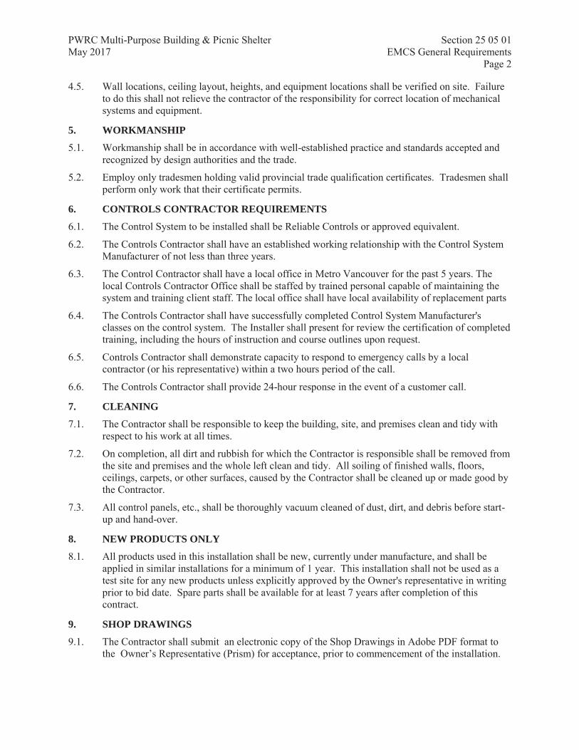
PWRC Multi-Purpose Building & Picnic Shelter Section 25 05 01 May 2017 EMCS General Requirements
Page 2
4.5. Wall locations, ceiling layout, heights, and equipment locations shall be verified on site. Failure to do this shall not relieve the contractor of the responsibility for correct location of mechanical systems and equipment.
5. WORKMANSHIP
5.1. Workmanship shall be in accordance with well-established practice and standards accepted and recognized by design authorities and the trade.
5.2. Employ only tradesmen holding valid provincial trade qualification certificates. Tradesmen shall perform only work that their certificate permits.
6. CONTROLS CONTRACTOR REQUIREMENTS
6.1. The Control System to be installed shall be Reliable Controls or approved equivalent.
6.2. The Controls Contractor shall have an established working relationship with the Control System Manufacturer of not less than three years.
6.3. The Control Contractor shall have a local office in Metro Vancouver for the past 5 years. The local Controls Contractor Office shall be staffed by trained personal capable of maintaining the system and training client staff. The local office shall have local availability of replacement parts
6.4. The Controls Contractor shall have successfully completed Control System Manufacturer's classes on the control system. The Installer shall present for review the certification of completed training, including the hours of instruction and course outlines upon request.
6.5. Controls Contractor shall demonstrate capacity to respond to emergency calls by a local contractor (or his representative) within a two hours period of the call.
6.6. The Controls Contractor shall provide 24-hour response in the event of a customer call.
7. CLEANING
7.1. The Contractor shall be responsible to keep the building, site, and premises clean and tidy with respect to his work at all times.
7.2. On completion, all dirt and rubbish for which the Contractor is responsible shall be removed from the site and premises and the whole left clean and tidy. All soiling of finished walls, floors, ceilings, carpets, or other surfaces, caused by the Contractor shall be cleaned up or made good by the Contractor.
7.3. All control panels, etc., shall be thoroughly vacuum cleaned of dust, dirt, and debris before start-up and hand-over.
8. NEW PRODUCTS ONLY
8.1. All products used in this installation shall be new, currently under manufacture, and shall be applied in similar installations for a minimum of 1 year. This installation shall not be used as a test site for any new products unless explicitly approved by the Owner's representative in writing prior to bid date. Spare parts shall be available for at least 7 years after completion of this contract.
9. SHOP DRAWINGS
9.1. The Contractor shall submit an electronic copy of the Shop Drawings in Adobe PDF format to the Owner’s Representative (Prism) for acceptance, prior to commencement of the installation.

PWRC Multi-Purpose Building & Picnic Shelter Section 25 05 01 May 2017 EMCS General Requirements
Page 3
9.2. When Shop Drawings are accepted, the said acceptance does not in any way relieve the Contractor of his responsibility or the necessity of furnishing materials and software or performing work as required by the Contract Documents.
9.3. No factory or field fabrication work shall commence, nor shall any materials be delivered to the site(s) until the Shop Drawings have been reviewed by the Owner’s Representative for conformity with the plan and specifications.
9.4. Note each shop drawing with the following information:
Manufacturer’s and Supplier’s name Catalogue model number Project identification number Number identifying item on Contract Drawings and/or in Specifications
9.5. The location of all devices shall be reviewed with the Owner’s Representative prior to installation.
9.6. Shop Drawings for each controlled system shall consist of detailed descriptions of the system(s) including:
Points Lists including, system name, point name, point description, point type (AI, AO, DI, DO), device type and part number. Spare points shall be shown.
Schematic diagrams containing the system name, description and location; name and panel/point address of all monitored and controlled devices; all required field and factory terminations and cable/wire identifiers.
Sequence of operation. The written sequence shall be specific for the use of the Control System being provided for this project.
Complete bill of materials of equipment to be used indicating quantity, manufacturer and model number.
System capacity and expansion limits including the type and size of memory 9.7. Provide manufacturers cut sheets for all system components including controllers, sensors,
valves, dampers, actuators, relays and auxiliary control devices. When manufacturer's cut sheets apply to a product series rather than a specific product, the data specifically applicable to the project shall be highlighted or clearly indicated by other means.
9.8. Each shop drawing shall be checked and stamped as being correct by the Contractor, before drawing is submitted.
9.9. Provide the Owner’s Representative and Owner, with any additional information or data that is deemed necessary to determine compliance with these specifications or which is deemed valuable in documenting the system to be installed.
9.10. Wiring diagrams with cable type and identification including terminal numbers shall be included in the as built drawings.
10. AS-BUILT DRAWINGS
10.1. Changes made to the Work during installation and before completion of the Work shall be documented by the Contractor to ensure that the changes are recorded as they occur.
10.2. The Contractor shall submit for review, an electronic version of the as-built set of drawings to the Owner’s Representative after completely incorporating the revisions as above. These drawings shall be clearly identified with the notation "Revised As-built" imprinted adjacent to the title block.

PWRC Multi-Purpose Building & Picnic Shelter Section 25 05 01 May 2017 EMCS General Requirements
Page 4
10.3. A copy of the as-built drawings shall be saved on the Operator Workstation and be accessible via an icon on the main graphic screen.
11. COMMISSIONING
11.1. The control system must be commissioned and tested at the end of the work to be completely operational including the following:
every point shall be end to end checked to ensure accuracy and integrity of systems. Provide check-out data sheet signed off by the DDC Contractor.
DDC Program Code shall successfully control the systems. time schedules shall be built and in control of time-controlled equipment. graphic displays must be installed and each graphic screen shall be fully operational. all specified trends covering a Seventy-Two (72) hour continuous period to confirm system
operation must be created and operational. all features of system shall have been exercised. operator shall have been briefed on operation of system. all sensors shall have been calibrated. results of all tests shall be documented by the Contractor and a signed hard copy of the
commissioning sheets, sensors calibration, and trends submitted to the Owner’s Representative (Prism) for review.
12. DEMONSTRATION
12.1. A complete demonstration and readout of the capabilities of the monitoring and control system shall be performed. The contractor shall dedicate a minimum of 4 hours on-site with the Owner and his representatives for a complete functional demonstration of all the system requirements.
12.2. This demonstration constitutes a joint acceptance inspection, and acceptance of the delivered system for on-line operation.
13. TRAINING
13.1. Train the designated staff of Owner's representative and Owner to enable them to proficiently operate the system.
13.2. The training shall be divided into two logical groupings; participants may attend one or more of these, depending on level of knowledge required:
Day-to-day Operators System Manager
13.3. Provide a minimum of 2 training sessions of 2 hours each, throughout the contract period for personnel designated by the Owner.
13.4. The instructor(s) shall be factory-trained instructors experienced in presenting this material.
14. WARRANTY
14.1. Labour & materials for control system specified shall be warranted free from defects for a period of twelve (12) months, exclusive of building controllers (B-BC) which shall have a five-year warranty, after final completion acceptance by the Owner. Control System failures of upgrade components during the warranty period shall be adjusted, repaired, or replaced at no charge or reduction in service to the Owner. The Contractor shall respond to the Owner's request for warranty service within 24 hours during customary business hours.

PWRC Multi-Purpose Building & Picnic Shelter Section 25 05 01 May 2017 EMCS General Requirements
Page 5
14.2. At the end of the final start-up/testing and commissioning, if equipment and systems are operating satisfactorily to the Owner and Engineer, the Owner shall sign certificates certifying that the control system's operation has been tested and accepted in accordance with the terms of this specification. The date of Owner's acceptance shall be the start of warranty.
14.3. Operator workstation software, project specific software, graphics, database, and firmware updates shall be provided to the Owner at no charge during the warranty period, other than those items that are specifically exempted. Written authorization by Owner must, however, be granted prior to the installation of such changes.
14.4. The warranty shall provide all material, parts and labour, including labour provided on an emergency response basis outside of normal working hours. Labour shall include any related travel time and other related costs associated with providing the warranty service.
14.5. The warranty shall cover all aspects of the control system upgrade provided under this contract, including: transmission equipment and links, all DDC panels and micro panel chip upgrades, and devices, transducers, and software.
14.6. A detailed service report must be filed with the Owner after each warranty visit, detailing the work performed, time spent, devices replaced or repaired, and the personnel involved.
14.7. Emergency calls during the warranty period shall be addressed by the Contractor within four (4) hours of notification. Service shall be available 24 hours per day, seven days a week. The Owner shall be provided an emergency phone number for contacting service personnel. The service call shall only be chargeable if inspection reveals any defect not directly covered under the terms of the specification.
15. OWNERSHIP OF PROPRIETARY MATERIAL
15.1. All project developed hardware and software shall become the property of the Owner. These include but are not limited to:
record drawings project database job-specific application programming code all documentation
16. ACCEPTANCE
16.1. The control systems will not be accepted as meeting the requirements of completion until all tests and documentation described in this specification have been provided to the satisfaction of both the Owner’s Representative and Owner.
16.2. Any tests that cannot be performed due to circumstances beyond the control of the Contractor may be exempt from the completion requirements if stated as such in writing by the Owner's representative. Such tests shall then be performed as part of the warranty.
17. SUBSTANTIAL PERFORMANCE
17.1. Once the above basic requirements are met and all other features of the system are complete and acceptable, Substantial Performance shall be granted. A deficiency list shall be prepared and holdbacks applied. All deficiencies shall be corrected prior to Total Performance.
18. TOTAL PERFORMANCE
18.1. The Owner’s Representative shall issue a letter of Total Performance when all of the deficiencies have been rectified.

PWRC Multi-Purpose Building & Picnic Shelter Section 25 05 01 May 2017 EMCS General Requirements
Page 6
18.2. The date of this letter shall be the date of Total Performance of the Contract. Warranty shall start from the date of Total Performance of the work.
18.3. The following shall be submitted before final acceptance will be issued:
Electrical permit and inspectors report As Built Drawings O & M Manuals Commissioning Report Controls Verification and documentation
END OF SECTION

PWRC Multi-Purpose Building & Picnic Shelter Section 25 05 02 May 2017 EMCS Summary of Work
Page 1
Prism Engineering Ltd.
1. OBJECTIVE
1.1. The objective of the work is to provide a DDC control system for the HVAC system installed in the PWRC Multi-Purpose Building.
2. SCOPE OF WORK
2.1. Major items of Work shall consist of but shall not be limited to the following:
Controls Provide a new DDC system for the monitoring and control of the HVAC system. DDC
system shall be designed as per this specification including schematic drawings, sequences of operation and points list;
Provide four occupancy sensors (grouped in two zones) in the building, as indicated in drawing M-1, to control the HVAC in the building;
Provide four space temperature sensors and one outdoor temperature, as indicated in drawing M-1, to control Forced Flow heaters FFH-1 to FFH-4;
Provide a BACnet controller (B-BC) with a BACNnet Operator Display (B-OD); Provide all engineering and documentation necessary to define details of the contractor’s
system for both shop drawing review and the Contractor’s installation; Provide all computerised and electronic hardware, including network, communications
devices and building controller; Provide all required hardware components necessary for a complete system, including
field devices of all types (e.g. sensors, relays, contractors), transformers, wiring, conduit, raceways, and piping.);
Provide application programming, databases, graphics and other activities related to computer software or firmware, required to implement the defined sequences of operation, trends, logs and the graphics screens defined in this specification;
Provide and coordinate the work of all associated trades necessary to install the system; Provide labour and supervision for the installation, calibration, adjustments, checkouts,
commissioning of all components and devices provided; Commission the control system to prove point functionality and communication; Provide complete documentation of the installed system with commissioning reports and
Operations and Maintenance manuals; Provide a complete demonstration of the control system capabilities as per this
specification; Provide training on the system for the building operation and maintenance personnel; Provide one year warranty as per this specification
END OF SECTION

PWRC Multi-Purpose Building & Picnic Shelter Section 25 08 20 May 2017 EMCS Installation and Wiring
Page 1
Prism Engineering Ltd.
1. INSTALLATION STANDARDS
1.1. The intention of this clause is to guide the Contractor as to the required quality of installation.
1.2. All installations to be performed by skilled and certified technicians and trades people.
1.3. Contractor shall continually monitor the installation for code compliance and quality of workmanship.
1.4. Contractor shall arrange for all field inspections required by local and/or provincial authorities having jurisdiction over the Work.
1.5. All equipment installed shall be mechanically stable and, as necessary, fixed to wall or floor. Anti-vibration mounts to be provided, if required, for the proper isolation of the equipment.
1.6. Equipment shall be installed to allow for easy maintenance access. Equipment shall be installed such that it does not interfere in any way with access to adjacent equipment and personnel traffic in the surrounding space.
1.7. Equipment shall be installed in locations providing adequate ambient conditions for its specified functioning, allowing for adequate ventilation and with no condensate traps.
2. ELECTRICAL WORK BY THE CONTROLS CONTRACTOR
2.1. Controls contractor shall act as the prime contractor - direct and schedule the work.
2.2. All wiring required for devices supplied under this Specification, regardless of the voltage, shall be the responsibility of the Controls Contractor.
2.3. Provision of control panels, pilot lights, selectors, relays, etc., required for the proper operation of the control systems.
2.4. Conduit and wiring from the starter control circuits to the mechanical system control panels including 110 V wiring.
2.5. Conduit and wiring required for the interlocking of mechanical system motor starters as required for the proper operation of the control system.
2.6. Wiring from pilot devices, relays, contactors, or other control interface devices required for the proper operation of the control system.
2.7. Wiring from spare 15 amp circuit breakers in power panels for line voltage power sources where required by control system. Circuit breakers shall be locking type.
2.8. Controls Contractor shall confirm all wiring connections between controllers and field devices and provide a copy of the End-to-End Checkout Sheet for every control panel.
2.9. This Contractor shall terminate all control and/or interlock wiring and shall maintain updated (as-built) wiring diagrams with termination identified at the job site.
2.10. Power wiring to line voltage thermostats controlling force flow units and unit heaters, and wiring to float devices for sump pumps, etc.
3. CONTROL AND INTERLOCK WIRING
3.1. Maximum allowable voltage for control wiring shall be 120V. If only higher voltages are available, the Control System Contractor shall provide step down transformers.
3.2. All control and interlock wiring shall comply with the national and local electrical codes as well as the following clauses.

PWRC Multi-Purpose Building & Picnic Shelter Section 25 08 20 May 2017 EMCS Installation and Wiring
Page 2
Prism Engineering Ltd.
3.3. All wiring shall be installed as continuous lengths, where possible. Any required splices shall be made only within an approved junction box or other approved protective device.
3.4. Install plenum wiring in sleeves where it passes through walls and floors. Maintain fire rating at all penetrations in accordance with local codes.
3.5. Maximum allowable voltage for control wiring shall be 120V. If only higher voltages are available, the Control System Contractor shall provide step down transformers.
3.6. Adhere to Division 16 requirements for installation in raceways.
3.7. This Contractor shall terminate all control and/or interlock wiring and shall maintain updated (as-built) wiring diagrams with terminations identified at the job site.
3.8. Flexible metal conduits and liquid-tight, flexible metal conduits shall not exceed 3' in length and shall be supported at each end. Flexible metal conduit less than 1/2" electrical trade size shall not be used. In areas exposed to moisture, including chiller and boiler rooms, liquid-tight, flexible metal conduits shall be used.
3.9. Where there is no alternative to supplying equipment, which is not CSA certified, submit such equipment to Inspection Authorities for special inspection and obtains approval before delivery of equipment to site. Such equipment must be individually identified in the Contractor's proposal.
3.10. Use coded conductors throughout with different coloured conductors for each phase and white wire for neutral.
3.11. Low Voltage Wiring - Size and type of low voltage control signal wiring shall be suitable for the service for which it will be put to use and be the responsibility of this Contractor; minimum wire size #18 AWG.
3.12. Identify each wire and cable at every termination point. Identify all conduits with “neat” colour bands at no more than 7.5 m intervals and on both sides of walls and floors.
3.13. All wiring in mechanical rooms and service rooms shall be in conduit or raceway. Provide 600 mm, B-X flexible connection to input and output devices where required for servicing or to accommodate vibration.
3.14. Low voltage wiring to input and output devices from Building Controller and Application Specific Controllers is not required to be installed in conduit except as noted. Use plenum rated wire in areas used as return air plenums. Provide sleeves where wires pass through walls and floors. Support wires from structure or fixed equipment in ceiling spaces at minimum 2 m intervals.
3.15. Junction and Pull boxes shall be adequate tagged to indicate its use for DDC system. Self sticker labels with controls company logo could be used for that purpose.
4. COMMUNICATION WIRING
4.1. Follow manufacturer's installation recommendations for all communication and network cabling. Network or communication cabling shall be run inside conduit and separately from other wiring.
5. CLASS 1 WIRING
5.1. 120 V circuits shall be, at a minimum, of #12 AWG RW-90 copper. For runs over 50 m in length, use #10 AWG-RW90 copper.
5.2. All 120 V interlock wiring and power supplies for panels to be installed in conduit.

PWRC Multi-Purpose Building & Picnic Shelter Section 25 08 20 May 2017 EMCS Installation and Wiring
Page 3
Prism Engineering Ltd.
5.3. Provide 120VAC power supplies to all main DDC panels, separately circuited from all other loads.
5.4. Several Application Specific or Advanced Application Controllers may be supplied from one 120/24VAC transformer in accordance with the manufacturer’s design. Only Application Specific or Advanced Application Controllers connected to the same Building Controller may be connected to a common power supply.
6. CLASS 2 WIRING
6.1. 24 VAC power to controllers shall be separated from field devices transformer.
6.2. Where Class 2 wires are in concealed and accessible locations including ceiling return air plenums, approved cables not in raceway may be used provided that:
circuits meet NEC Class 2 (current-limited) requirements. (Low-voltage power circuits shall be sub-fused when required to meet Class 2 current-limit.) all cables shall be UL listed for application, i.e. cables used in ceiling plenums shall be UL listed specifically for that purpose.
6.3. Any existing wiring considered for re-use (i.e. thermostat wiring re-use for temperature sensor) must be fully tested and verified prior to connection to new system. Any wiring deemed to not meet the project requirements must be replaced at the cost of the contractor.
6.4. Do not install Class 2 wiring in conduit containing Class 1 wiring. Boxes and panels containing high voltage may not be used for low voltage wiring except for the purpose of interfacing the two (e.g. relays and transformers).
6.5. Where class 2 wiring is run exposed, wiring shall be run parallel along a surface or perpendicular to it, and bundled, using approved wire ties at no greater than 3 m [10 ft] intervals. Such bundled cable shall be fastened to the structure, using specified fasteners, at 1.5 m [5 ft] intervals or more often to achieve a neat and workmanlike result.
6.6. All wire-to-device connections shall be made at a terminal blocks or terminal strip. All wire-to-wire connections shall be at a terminal block. All wiring within enclosures shall be neatly bundled and anchored to permit access and prevent restriction to devices and terminals.
6.7. Junction and Pull boxes shall be adequate tagged to indicate its use for DDC system. Self sticker labels with controls company logo could be used for that purpose.
7. INSTALLATION OF SENSORS
7.1. Install sensors in accordance with the manufacturer's recommendations.
7.2. Mount sensors rigidly and adequate for the environment within which the sensor operates.
7.3. All wires attached to sensors shall be air sealed in their conduits or in the wall to stop air transmitted from other areas affecting sensor readings.
7.4. Room temperature sensors shall be installed on concealed junction boxes properly supported by the wall framing.
7.5. Install outdoor air temperature sensors on north wall complete with sun shield at designated location.
7.6. Wiring for space sensors shall be concealed in building walls. EMT conduit is acceptable within mechanical and service rooms.

PWRC Multi-Purpose Building & Picnic Shelter Section 25 08 20 May 2017 EMCS Installation and Wiring
Page 4
Prism Engineering Ltd.
7.7. All wires attached to sensors shall be air sealed in their conduits or in the wall to stop air transmitted from other areas affecting sensor readings.
7.8. Install labels on the inside covers of all room sensors identifying the point name using peel and stick labels such as the Brother labelling system.
8. INSTALLATION OF RELAYS
8.1. Control and status relays are to be located in designated enclosures only. These relays may also be located within packaged equipment control panel enclosures. These relays shall not be located within Class 1 starter enclosures.
8.2. Control Relays shall be identified with permanent labels. Identifiers shall match record documents. All plug-in components shall be labelled such that removal of the component does not remove the label.
9. INSTALLATION OF OCCUPANCY SENSORS
9.1. Provide sufficient quantity of controls to ensure full coverage of detection area. Sensor installation shall leave no gaps in detection area or “dead zones” in coverage where occupancy is not detected.
9.2. In multiple sensor applications, sensors shall be placed so that detection zones of the sensors overlap in the major motion area of the forward or side-to-side throw of the sensor detection zone. Distance between sensors to achieve adequate overlap shall be based on maximum distance of the detection zone forward or side-to-side throw (as applicable to facing and mounting of sensors) as detailed in manufactures literature, with sensors mounting spaced as to have overlapping detection zones approximate to half the distance differential between the minor movement and major movement coverage areas of the detection zones.
9.3. Provide 24 VDC power to all sensors, with a maximum deviation of +/- 5% (22.8 to 25.2 VDC), at the device terminals when at full operation. Operating power for control devices is to be provided either by power supplies as made by the control device manufacturer or provided through DDC system supply. If provided by DDC supply, voltage must be within parameters outlined and system must provide current in milliamps (ma) as described in the manufactures product data sheets. No more than three devices may be powered from the same power feed.
9.4. Contractor is to adjust settings to disable “learn mode” options for auto sensitivity and auto time delay functions. Settings to mask out resonant frequencies of mechanical or other systems shall remain active.
9.5. Mount all sensors to be clear of obstructions. Passive Infrared (PIR) sensors must be mounted with unobstructed “view” of line-of-sight of detection zone.
9.6. For varying mounting heights, adjust sensor minor and major detection to increase or decrease range as per manufacturers literature to ensure proper detection zone coverage and overlap
10. INSTALLATION OF CONTROLLERS
10.1. Controllers and devices shall be conveniently spaced and neatly wired. Cables shall be accommodated inside slotted plastic wiring duct (Panduit or equivalent).
11. IDENTIFICATION OF HARDWARE AND WIRING
11.1. All wiring and cabling, including that within factory-fabricated panels, shall be labelled at each end within 2" of termination with a cable identifier. Cable identifier shall be shown on and match record documents.

PWRC Multi-Purpose Building & Picnic Shelter Section 25 08 20 May 2017 EMCS Installation and Wiring
Page 5
Prism Engineering Ltd.
11.2. Permanently label or code each point of field terminal strips to show the instrument or item served.
11.3. Identify all control panels, including interface panels (relay boxes, etc.) with minimum 1 cm letters on laminated plastic nameplates. Panel identifiers shall be shown on the record drawings indicating each contained device (controllers, relays, transducers, current sensors etc.)
11.4. Identify all other control components including control relays with permanent labels. Identifiers shall match record documents. All plug-in components shall be labelled such that removal of the component does not remove the label.
END OF SECTION

PWRC Multi-Purpose Building & Picnic Shelter Section 25 10 02 May 2017 EMCS Software Requirements
Page 1
Prism Engineering Ltd.
1. COMMUNICATIONS
1.1. The data communication protocol for the project shall comprise a BACnet inter-network.
1.2. All BACnet MS/TP networks shall communicate error free at a baud rate of 76,800 bps.
1.3. Low capacitance cable with less than 15 Pico farads per foot shall be provided for MS/TP networks to for stable and less network communication errors.
2. INPUT/OUTPUT INTERFACE
2.1. All input points and output points shall be protected such that shorting of the point to itself, another point, or ground will cause no damage to the controller. All input and output points shall be protected from voltage up to 24V of any duration, such that contact with this voltage will cause no damage to the controller.
2.2. Binary inputs shall allow the monitoring of on/off signals from remote devices. The binary inputs shall provide a wetting current of at least 12 mA to be compatible with commonly available control devices.
2.3. Pulse accumulation input points. This type of point shall conform to all the requirements of Binary Input points, and also accept up to 2 pulses per second for pulse accumulation, and shall be protected against effects of contact bounce and noise.
2.4. Analog inputs shall allow the monitoring of low voltage (0-10 VDC), current (4-20 mA), or resistance signals (thermistor, RTD). Analog inputs shall be compatible with, and field configurable to commonly available sensing devices.
2.5. Binary outputs shall provide for on/off operation, or a pulsed low voltage signal for pulse width modulation control. Outputs shall be selectable for either normally open or normally closed operation.
2.6. Analog outputs shall provide a modulating signal for the control of end devices. Outputs shall provide either a 0-10 VDC or a 4-20 mA signal as required to provide proper control of the output device.
3. SYSTEM GRAPHICS
3.1. The system shall allow display of multiple graphic screens for comparison and monitoring of system status. Provide a method for the operator to easily move between graphic displays.
3.2. An operator with the proper password level shall be able to add, delete, or change dynamic points on a graphic.
3.3. Graphic screens shall be created for main menu, schedules and for each system schematics.
3.4. Minimum Requirements - Graphics text font shall be reasonable sized for easy reading with a pleasing color contrast between lettering and background.
A point value or status shall be located as close as possible to the graphical representation of the actual physical location. If the point has an associated setpoint this point will be located directly below the actual point and be in a different colour.
Status of equipment shall be displayed as ON or OFF and located on top of commanded points.
Command points shall be defined as Start/Stop or Enable/Disable, etc, but not as ON/OFF.
Graphic screens shall include trend /multi-trend icons for each specified multiple point trends directing to the specific trend graphic screen.

PWRC Multi-Purpose Building & Picnic Shelter Section 25 10 02 May 2017 EMCS Software Requirements
Page 2
Prism Engineering Ltd.
Runtime hours icons shall be placed as close as possible to the actual point or value being totalized. The icon shall provide access to the totalizer configuration data.
4. ENGINEERING UNITS
4.1. Engineering units on this project shall be SI
5. POINT NAMING CONVENTION
5.1. Create and name all points indicated in the points lists. Software points (variable) shall have the same characteristics on the graphic screens as the real or hardware points. A few additional points may be required to comply with the intent of the generic logic, depending on the vendors system.
5.2. System point names as point, variable, trend, schedule, calendar and other names shall be modular in design, allowing easy operator interface without the use of a written point index.
5.3. Point naming shall be composed as follows:
SYS_POINT_FUNC Where:
SYS is the system identifier POINT is the point identifier(s) FUNC is the point function
6. PROGRAMMING
6.1. Provide programming for the system as per specifications and adhere to the control sequences provided. All other system programming necessary for the operation of the system but not specified in this document shall also be provided by the Control System Contractor.
6.2. Provide a description for each analog and binary variable created. The description property shall include application and scope of the variable.
6.3. The controls contractor shall provide all the labour necessary to install, initialize, start-up, and trouble-shoot all operator interface software and their functions as described in this section. This includes any operating system software, the operator interface database, and any third party software installation and integration required for successful operation of the operator interface.
6.4. Variable names shall be as defined as an acronym that represents the application of the variable. All variable description fields shall provide information as to the variable application. (ie. Upper range limit for static pressure reset, Outside air temperature below which maximum supply water temperature setpoint is applied, boiler is disabled above this temperature)
7. SCHEDULING
7.1. Provide the capability to schedule (including statutory holidays calendar) and control each object or group of objects in the system. The contractor is responsible for making adjustments in point names, day type numbers, and program logic such that the system operates according to the intent of previous control strategies.
8. ALARM
8.1. Any object in the system shall be configurable to alarm in and out of normal state.
8.2. Alarms should be set with sufficient time delay, software interlocks and adequate range to avoid nuisance alarms.
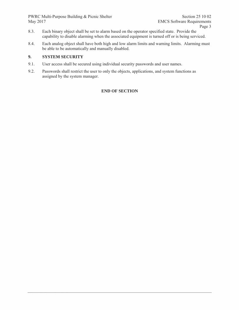
PWRC Multi-Purpose Building & Picnic Shelter Section 25 10 02 May 2017 EMCS Software Requirements
Page 3
Prism Engineering Ltd.
8.3. Each binary object shall be set to alarm based on the operator specified state. Provide the capability to disable alarming when the associated equipment is turned off or is being serviced.
8.4. Each analog object shall have both high and low alarm limits and warning limits. Alarming must be able to be automatically and manually disabled.
9. SYSTEM SECURITY
9.1. User access shall be secured using individual security passwords and user names.
9.2. Passwords shall restrict the user to only the objects, applications, and system functions as assigned by the system manager.
END OF SECTION

PWRC Multi-Purpose Building & Picnic Shelter Section 25 30 01 May 2017 EMCS Hardware Requirements
Page 1
Prism Engineering Ltd.
1. BUILDING CONTROLLERS (B-BC)
1.1. Reference: Reliable MACH-ProView LCD
1.2. Controllers shall be BACnet Testing Laboratories (BTL) marked. No translation software shall be used internal to the controller to convert from a proprietary protocol to BACnet Standard Object Types, Standard Application Services and Devices.
1.3. Effective Panel Processing Speed - Maximum permissible execution time is half a second. Execution time is defined as the time it takes the controller to execute all application software from some point in the software back to the same point while simultaneously responding to operator or terminal display requests and carrying out normal inter-panel communications. Set up an analog variable counter in each panel, incremented and reset by program code, to allow for verification of the processing speed.
1.4. Controller shall have sufficient memory to support its operating system, database, programming and trending requirements.
1.5. Controller shall maintain all BIOS and programming information in the event of a power loss for at least 72 hours.
1.6. Controller shall be able to operate at 90% to 110% of nominal voltage rating and shall perform an orderly shutdown below 80% nominal voltage.
1.7. Controller operation shall be protected against electrical noise of 5 to 120 Hz and from keyed radios up to 5 W at 1 m.
1.8. Controller hardware shall be suitable for the anticipated ambient conditions.
1.9. Controller shall have a real time clock.
1.10. The Building Automation System shall be composed of one independent, stand-alone, microprocessor based Building Controller to manage the global control strategies specified in the Sequences of Operation section of the Specifications
1.11. Each Building Controller shall reside on a BACnet inter-network using the ISO 8802-3 (Ethernet) Physical/Data Link layer protocol. Each Building Controller shall also perform routing to a network of Advanced Application and Application Specific Controllers.
1.12. The Building Controller shall use the Read (Initiate) and Write (Execute) Services as defined in Clauses 15.5 and 15.8, respectively, of ASHRAE Standard 135-2004, to communicate with BACnet objects in the inter-network.
1.13. The operating system of the Controller shall manage the input and output communications signals to allow distributed controllers to share real and virtual point information and allow central monitoring and alarms.
END OF SECTION

PWRC Multi-Purpose Building & Picnic Shelter Section 25 30 02 May 2017 EMCS Field Control Devices
Page 1
Prism Engineering Ltd.
1. TEMPERATURE SENSORS
1.1. Provide one of the following temperature sensor types throughout:
10,000 Ohm at 25°C thermister 1000 Ohm at 0°C (±0.2 ohm) thin film platinum with coefficient of resistivity of 0.000385 ohms/ohm/°C 100 Ohm at 0°C (±0.2 ohm) platinum with coefficient of resistivity of 0.00385 ohms/ohm/°C
1.2. Sensors shall have an accuracy of ±0.3°C or better.
1.3. All temperature sensors provided shall be constructed as follows:
integral anchored lead wires; strain minimizing construction.
1.4. Outside Temperature Sensors (TSO) Outside air temperature sensors shall be as follows:
weather proof enclosure complete with on-corroding outdoor shield designed to minimize the effect of solar heating on the sensing element; threaded fittings for mating to 12 mm conduit or as applicable; total probe length of 50 mm; stainless steel sheath; operating range: -35°C to +50°C.
1.5. Room Temperature sensors (TSR) Room temperature sensors shall be as follows:
the sensing element shall be installed in a vented wall mounted protective enclosure;
2. CONTROL RELAYS (CR1, 2 & 3, CRS)
Control relays shall be as follows: control relays shall be UL listed plug-in type with dust cover. Contact rating, configuration, and coil voltage suitable for application; electro mechanical relays shall have integral override switch to allow local override in event of DDC control failure; motor rated relays shall be provided in DDC enable control application for small motors (pumps, fans, etc) equipped with manual starters.
3. CURRENT TRANSDUCERS (CS1)
Current transducers shall be as follows: range selected to match the current of the application; output to match the requirements of the DDC System; accuracy of ± 2% full scale or better; repeatability of ±2% full scale or better; over-current and over-voltage protection as applicable; shock and vibration protection as necessary.
4. OCCUPANCY SENSORS - GENERAL (OS1)
Sensors shall be low voltage type, with no minimum load required for proper operation.

PWRC Multi-Purpose Building & Picnic Shelter Section 25 30 02 May 2017 EMCS Field Control Devices
Page 2
Prism Engineering Ltd.
Sensors shall be complete with two isolated low voltage 500 ma auxiliary contacts; one “normally open” (NO) type and one “normally closed” (NC) type. DDC interface connection shall be made to the NO auxiliary contact. All sensors must have non-volatile memory so as to retain settings in the event of power outage. Ultrasonic and dual technology sensors are not to be utilized at mounting heights above 14’ or in applications where the room ceiling height is greater than 15’. All occupancy sensor controls shall have a no minimum load requirement to allow for future connection of lighting loads to the sensors and for lighting DDC interface. Wall mounted sensors shall be complete with swivel base and mounting bracket. Ceiling mounted sensors shall be complete with surface mounting plate. Sensors to be installed in areas where impact with equipment or where airborne objects may contact the sensor shall be complete with painted wireguard. All sensors shall be located to sense the occupant as they enter the room or are within the room. Sensors shall be located and installed as per manufacturer’s guidelines.
4.1. Wall Mounted Wide View Dual Technology Occupancy Sensors Wall mounted wide view dual technology occupancy sensors shall have coverage of minimum of 1,600 square feet when mounted at 8’ AFF. Wide view dual technology occupancy sensors shall have passive infrared and Doppler ultrasonic sensors combined in one unit. Sensors shall have a minimum detection zone of 110 to 150 degrees side-to-side, with a forward throw minor movement detection zone of a minimum of 20’ and a major movement detection zone of 40’. Dual technology occupancy sensors shall have a no minimum load rating for potential future connection of lighting loads within area.
5. TRANSFORMERS AND POWER SUPPLIES
5.1. Control transformers shall be UL listed, Class 2 current-limiting type, or shall be furnished with over-current protection in both primary and secondary circuits for Class 2 service.
5.2. Unit output shall match the required output current and voltage requirements. Current output shall allow for a 50% safety factor. Unit shall have built-in over-voltage protection.
6. FIELD DEVICE TYPES
6.1. Field devices, specifications and standard of acceptance shall be based on the following device types as noted in points lists and/or drawings.
Table 1: Control Device Types
Device Type
Description Technical Performance Standard of Acceptance
CR2 Control relay (Dry contact electro-mechanical relay)
240V, 10A to suit application IDEC - RH Series Carlo Gavazzi - RCP8 Functional Devices RIB Series
CR4 Control relay (Dry contact electro-mechanical with HOA)
240V, 10A to suit application Veris Victory Series Functional Devices RIB Series
CS1 Current Transducer Greystone CS-450.

PWRC Multi-Purpose Building & Picnic Shelter Section 25 30 02 May 2017 EMCS Field Control Devices
Page 3
Prism Engineering Ltd.
Device Type
Description Technical Performance Standard of Acceptance
Enercorp Sentry 100 TSR Room temperature
sensor Greystone TE-200-AE
Enercorp TS-S-E Delta RTS400
TSO Outside air temperature sensor
Greystone TE-200-F Enercorp TS-O
OS1 Wall Mounted Wide View Dual Technology Occupancy Sensors
Hubbell Building Automation LODT-RP c/w LV controls Leviton OSW12-M0W c/w LV controls Watt Stopper DT-200 c/w LV controls
END OF SECTION
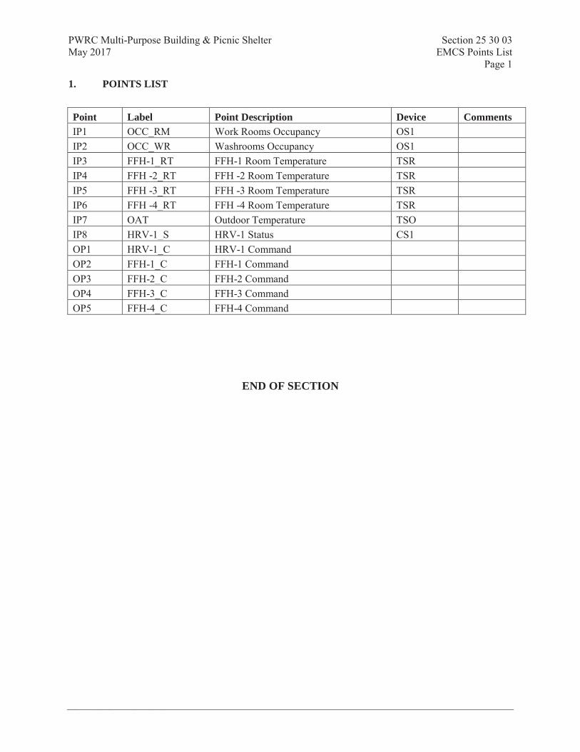
PWRC Multi-Purpose Building & Picnic Shelter Section 25 30 03 May 2017 EMCS Points List
Page 1
Prism Engineering Ltd.
1. POINTS LIST
Point Label Point Description Device Comments IP1 OCC_RM Work Rooms Occupancy OS1 IP2 OCC_WR Washrooms Occupancy OS1 IP3 FFH-1_RT FFH-1 Room Temperature TSR IP4 FFH -2_RT FFH -2 Room Temperature TSR IP5 FFH -3_RT FFH -3 Room Temperature TSR IP6 FFH -4_RT FFH -4 Room Temperature TSR IP7 OAT Outdoor Temperature TSO IP8 HRV-1_S HRV-1 Status CS1 OP1 HRV-1_C HRV-1 Command OP2 FFH-1_C FFH-1 Command OP3 FFH-2_C FFH-2 Command OP4 FFH-3_C FFH-3 Command OP5 FFH-4_C FFH-4 Command
END OF SECTION

PWRC Multi-Purpose Building & Picnic Shelter Section 25 90 01 May 2017 EMCS Sequences of Operation
Page 1
Prism Engineering Ltd.
1. FORCED FLOW UNITS FFH-1, FFH-2, FFH-3 AND FFH-4
1.1. General
Heating for the building is provided by four forced flow units: FFH-1 to FFH-4.
1.2. Four occupancy sensors shall be installed, as indicated in drawing M-1, to control the forced flow units.
1.3. The occupancy sensors shall be grouped in two zones: washrooms and work rooms (mud room and laundry room). Each zone comprises two sensors. Sensors in the same zone shall be wired in parallel and connected to an input to the controller. In case occupancy is detected by any of the sensors of the same zone, the forced flow heaters in the zone shall be enabled as indicated below.
1.4. Variables
Adjustable variable shall signify that the object present value is displayed and can be modified on graphic screens whereas configurable signifies that the object present value can only be modified from within the object properties definition. All variables specified as fixed shall be imbedded in control programs.
1.5. 1.6. Start-Up and Operation
1.7. The forced flow units shall be operated according to the weekly schedule and annual calendar.
1.8. Forced flow heaters shall cycle to meet setpoint. Occupied setpoint shall be initially set to 20°C (adjustable); unoccupied setpoint shall be initially set to 14°C (adjustable).
1.9. Forced flow units shall be disabled when the outdoor temperature is higher than 16°C (configurable).
1.10. During unoccupied periods, forced flow heaters operation shall revert to occupied mode after occupancy has been detected for two minutes continuous. Units shall revert to unoccupied mode after occupancy has not been detected for ten minutes continuous.
1.11. Alarms
Provide the following alarms: Alarm Alarm Source High Limit Low Limit Space Temperature Extreme* Space Temp Sensor SP + 3oC SP - 3oC
*. Alarm shall be inhibited upon change of space temperature setpoint
1.12. System Graphics
System graphic screen shall indicate the complete equipment layout with all inputs, outputs, setpoints, and alarms. Provide navigation buttons to main menu, associated trends and associated screens. All setpoints shall be adjustable at graphic screen.
1.13. Trends
Provide four-300 sample trends, at 15-minute intervals as applicable, for the following points/variables:
FFH-x (per unit) Point Trend Type Outdoor Air Temperature Polling

PWRC Multi-Purpose Building & Picnic Shelter Section 25 90 01 May 2017 EMCS Sequences of Operation
Page 2
Prism Engineering Ltd.
Room Temperature Polling Room Setpoint Polling FFH-x Command Polling
1.14. Run Time Logs Run time totalizers shall be provided as follows: FFH-x Command
Totalizers shall be reset on an annual basis or by command by the building operator from the graphic screen.
2. HEAT RECOVERY VENTILATOR (HRV-1)
2.1. General
Ventilation to the building is provided by a Heat Recovery Ventilation unit HRV-1.
2.2. Operation:
2.3. HRV-1 shall be operated according to the weekly schedule and annual calendar.
2.4. During unoccupied periods, HRV-1 shall be enabled after occupancy has been detected in any zonefor two minutes continuous. Once the HRV-1 is enabled, the system shall be disabled after occupancy has not been detected for ten minutes continuous, subject to a minimum run time of 20 minutes.
2.5. Alarms
Provide the following alarms: Alarm Alarm Source High Limit Low Limit Supply Fan failure Fan Motor status - -
2.6. System Graphics
2.7. System graphic screen shall indicate the complete equipment layout with all inputs, outputs, setpoints, and alarms. Provide navigation buttons to main menu, associated trends and associated screens. All room temperature setpoints shall be adjustable at graphic screen.
2.8. Trends
Provide 300 sample trends, at 15-minute intervals as applicable, for the following points/variables:
Trend 1: Point Trend Type Occupancy Polling HRV-1 Command Polling HRV-1 Status Polling
2.9. Run Time Logs Run time totalizers shall be provided as follows:

PWRC Multi-Purpose Building & Picnic Shelter Section 25 90 01 May 2017 EMCS Sequences of Operation
Page 3
Prism Engineering Ltd.
HRV-1 Command HRV-1 Status
Totalizers shall be reset on an annual basis or by command by the building operator from the graphic screen.
END OF SECTION

PWRC Multi-Purpose Building & Picnic Shelter Section 26 05 00May 2017 COMMON WORK RESULTS FOR ELECTRICAL
Page 1
Prism Project #2016368 Page 1
Part 1 General
1.1 RELATED SECTIONS
.1 Section 01 33 00 – Submittal Procedures.
.2 Section 01 45 00 – Quality Control.
.3 Section 01 35 29.06 – Health and Safety Requirements.
.4 Section 01 74 21 – Construction/Demolition Waste Management and Disposal.
1.2 REFERENCES
.1 Canadian Standards Association (CSA International)
.1 CSA C22.1-12, Canadian Electrical Code, Part 1 (22nd Edition), Safety Standardfor Electrical Installations.
.2 CSA C22.2
.3 CAN/CSA-C22.3 No. 1-01(current version), Overhead Systems.
.4 CAN3-C235-83(R2010), Preferred Voltage Levels for AC Systems, 0 to 50,000V.
.2 Institute of Electrical and Electronics Engineers (IEEE)/National Electrical Safety CodeProduct Line (NESC)
.1 IEEE SP1122-2000, The Authoritative Dictionary of IEEE Standards Terms, 7thEdition.
1.3 DEFINITIONS
.1 Electrical and electronic terms: unless otherwise specified or indicated, terms used in thesespecifications, and on drawings, are those defined by IEEE SP1122.
1.4 REGULATORY REQUIREMENTS
.1 Execution of all Work shall be performed to comply with and conform to the followingrequirements:
2012 Canadian Electrical Code C22.1-12 (or current version);
2012 BC Building Code (or current version);
2010 National Building Code (or current version);
2010 National Fire Code (or current version).
Work shall be performed to meet the above mentioned codes and, where applicable, to thesatisfaction of all applicable provincial, city, municipal and / or district bylaws andauthorities having jurisdiction of the place of Work.

PWRC Multi-Purpose Building & Picnic Shelter Section 26 05 00May 2017 COMMON WORK RESULTS FOR ELECTRICAL
Page 2
Prism Project #2016368 Page 2
.2 Where requirements detailed in these specifications exceed code requirements or are morestringent than code requirements, the specification requirements shall take precedence andshall be adhered to.
.3 In the event of a conflict between code requirements and those detailed in thesespecifications, the former shall prevail. Note that requirements within the specificationthat are more stringent requirements than codes do not constitute a conflict.
.4 All retrofitted luminaires shall comply with the requirements of the Electrical SafetyBranch Directive 02/96, dated May 14, 1996 or current revision.
.5 Submit certification report(s) for all luminaire retrofits that require recertification, toConsultant prior to commencement of installation and include copy in Data Book atcompletion of project.
.6 The Contractor shall ensure that all seismic restraint requirements, as directed by buildingor electrical codes for the city, municipality or district where each facility is located, fornew or relocated luminaires are met and adhered to.
.7 The installation of new must be supported independently of the drywall ceiling inaccordance with construction and local seismic requirements.
1.5 DESIGN REQUIREMENTS
.1 Operating voltages: to CAN3-C235.
.2 Motors, electric heating, control and distribution devices and equipment to operatesatisfactorily at 60 Hz within normal operating limits established by above standard.
.1 Equipment to operate in extreme operating conditions established in abovestandard without damage to equipment.
.3 Language operating requirements: provide identification nameplates and labels for controlitems in English.
1.6 SUBMITTALS
.1 Submittals: in accordance with Section 01 33 00 - Submittal Procedures.
.2 Shop drawings:
.1 Submit wiring diagrams and installation details of equipment indicating proposedlocation, layout and arrangement, control panels, accessories, piping, ductwork,and other items that must be shown to ensure co-ordinated installation.
.2 Identify on wiring diagrams circuit terminals and indicate internal wiring for eachitem of equipment and interconnection between each item of equipment.
.3 Indicate of drawings clearances for operation, maintenance, and replacement ofoperating equipment devices.
.4 If changes are required, notify Owner’s Representative of these changes beforethey are made.
.3 Record Drawings
.1 After completion of the work, provide the building owner with a set of RecordDrawings (“As-Builts”) on a set of clean blackline prints as updated with
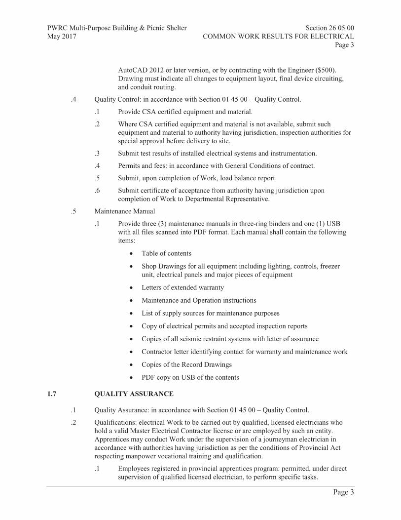
PWRC Multi-Purpose Building & Picnic Shelter Section 26 05 00May 2017 COMMON WORK RESULTS FOR ELECTRICAL
Page 3
Prism Project #2016368 Page 3
AutoCAD 2012 or later version, or by contracting with the Engineer ($500).Drawing must indicate all changes to equipment layout, final device circuiting,and conduit routing.
.4 Quality Control: in accordance with Section 01 45 00 – Quality Control.
.1 Provide CSA certified equipment and material.
.2 Where CSA certified equipment and material is not available, submit suchequipment and material to authority having jurisdiction, inspection authorities forspecial approval before delivery to site.
.3 Submit test results of installed electrical systems and instrumentation.
.4 Permits and fees: in accordance with General Conditions of contract.
.5 Submit, upon completion of Work, load balance report
.6 Submit certificate of acceptance from authority having jurisdiction uponcompletion of Work to Departmental Representative.
.5 Maintenance Manual
.1 Provide three (3) maintenance manuals in three-ring binders and one (1) USBwith all files scanned into PDF format. Each manual shall contain the followingitems:
Table of contents
Shop Drawings for all equipment including lighting, controls, freezerunit, electrical panels and major pieces of equipment
Letters of extended warranty
Maintenance and Operation instructions
List of supply sources for maintenance purposes
Copy of electrical permits and accepted inspection reports
Copies of all seismic restraint systems with letter of assurance
Contractor letter identifying contact for warranty and maintenance work
Copies of the Record Drawings
PDF copy on USB of the contents
1.7 QUALITY ASSURANCE
.1 Quality Assurance: in accordance with Section 01 45 00 – Quality Control.
.2 Qualifications: electrical Work to be carried out by qualified, licensed electricians whohold a valid Master Electrical Contractor license or are employed by such an entity.Apprentices may conduct Work under the supervision of a journeyman electrician inaccordance with authorities having jurisdiction as per the conditions of Provincial Actrespecting manpower vocational training and qualification.
.1 Employees registered in provincial apprentices program: permitted, under directsupervision of qualified licensed electrician, to perform specific tasks.

PWRC Multi-Purpose Building & Picnic Shelter Section 26 05 00May 2017 COMMON WORK RESULTS FOR ELECTRICAL
Page 4
Prism Project #2016368 Page 4
.2 Permitted activities: determined based on training level attained anddemonstration of ability to perform specific duties.
.3 Health and Safety Requirements: do construction occupational health and safety inaccordance with Section 01 35 29.06 – Health and Safety Requirements.
1.8 DELIVERY, STORAGE AND HANDLING
.1 Material Delivery Schedule: provide Owner’s Representative with a material deliveryschedule within two (2) weeks after award of Contract.
.2 Construction/Demolition Waste Management and Disposal: separate waste materials forreuse and recycling in accordance with Section 01 74 21 – Construction/Demolition WasteManagement and Disposal.
.3 Where the Contractor arranges for product to be delivered to site by third party carrier, theContractor is to arrange for Contractor staff to meet the carrier, unload all materials andproducts, move immediately to storage and sign for all deliveries.
.4 Owner, Owner’s Representative or Consultant will not sign for or accept delivery of anymaterials for the project, with the exception of spare materials for maintenance beingsupplied to the Owner as part of the contract.
.5 Contractor is not to use Owner’s staff, equipment or shipping / receiving areas for deliveryof materials and products; unless prior agreement and arrangement has been made with theOwner or Owner’s Representative.
1.9 SYSTEM STARTUP
.1 Instruct Owner’s Representative and operating personnel in operation, care andmaintenance of systems, system equipment and components.
.2 Arrange and pay for services of manufacturer’s factory service engineer to supervise start-up of installation, check, adjust, balance and calibrate components and instruct operatingpersonnel.
.3 Provide these services for such period, and for as many visits as necessary to putequipment in operation, and ensure that operating personnel are conversant with aspects ofits care and operation.
1.10 OPERATING INSTRUCTIONS
.1 Provide for each system and principal item of equipment as specified in technical sectionsfor use by operation and maintenance personnel.
.2 Operating instructions to include following:
.1 Wiring diagrams, control diagrams, and control sequence for each principalsystem and item of equipment.
.2 Start up, proper adjustment, operating, lubrication, and shutdown procedures.
.3 Safety precautions.
.4 Procedures to be followed in event of equipment failure.

PWRC Multi-Purpose Building & Picnic Shelter Section 26 05 00May 2017 COMMON WORK RESULTS FOR ELECTRICAL
Page 5
Prism Project #2016368 Page 5
.5 Other items of instruction as recommended by manufacturer of each system oritem of equipment.
.3 Print or engrave operating instructions and frame under glass or in approved laminatedplastic.
.4 Post instructions where directed.
.5 For operating instructions exposed to weather, provide weather-resistant materials orweatherproof enclosures.
.6 Ensure operating instructions will not fade when exposed to sunlight and are secured toprevent easy removal or peeling.
Part 2 Products
2.1 STANDARD OF MATERIALS
.1 Materials and equipment are specifically described and named in this Specification inorder to establish a standard of material and workmanship.
.2 Materials required for performance of work to be new and the best of their respectivekinds and of uniform pattern throughout work.
.3 Materials to be of Canadian manufacture where obtainable. Materials of foreignmanufacture, unless specified are to be approved before being ordered. Products are to bepurchased through manufacturer’s Canadian Distributors or Wholesalers, or directly fromthe manufacturer, when obtainable.
.4 Equipment items are to be standard products of approved manufacture. Identical units ofequipment are to be of same manufacture. In any unit of equipment, identical componentparts to be of same manufacture, but the various component parts comprising the unit neednot be of one manufacture.
.5 Chemical and physical properties of materials and design performance characteristics andmethods of construction and installation of items of equipment, specified herein, to be inaccordance with latest issue of applicable Standards or Authorities when such are eithermentioned herein, or have jurisdiction over such materials or items of equipment.
.6 Materials to bear approval labels as required by Code and / or Local Inspection Authoritiesand be eligible for sale and installation in Canada. All equipment to be approved by acertification agency listed in BC Electrical Bulletin 0-7-0. Where it is stated within thisspecification that equipment “must be CSA approved”, or similar wording, it is to be takenthat equipment bearing an appropriate certification label from any certificationorganizations listed in federal, provincial or territorial bulletins is acceptable.
.7 Install materials in strict accordance with manufacturer’s recommendations.
.8 Include items of material and equipment not specifically noted on drawings, provided oninformational bills of material, or mentioned in specifications but which are necessary tomake a complete and operating installation.
.9 Confirm capacity or ratings of equipment being provided, when based on ratings ofequipment being provided under other trade Section, before such items are purchased.

PWRC Multi-Purpose Building & Picnic Shelter Section 26 05 00May 2017 COMMON WORK RESULTS FOR ELECTRICAL
Page 6
Prism Project #2016368 Page 6
.10 Remove materials, condemned as not approved for use, from job site and deliver andinstall suitable approved materials in their place.
.11 Where requirements of this Specification exceed those of applicable standards, thisSpecification governs.
2.2 WARNING SIGNS
.1 Warning Signs: in accordance with requirements of authority having jurisdiction.
.2 Decal signs, minimum size 175 x 250 mm.
2.3 BARRIERS AND WARNING AIDS
.1 Barriers and warning aids shall be used to protect those who access or traverse near thespace or areas of Work in both interior and exterior areas where the Work could pose ahazard to the passersby. The intent is to cordon off hazard areas and warn of a hazard.
.2 Where required for safety and security of the construction zones and to avoid potentialhazards to occupants and users of the space or site, areas of Work that are accessible to thepublic or unauthorized occupants entering a Work location are to be barriered from publicor occupant access with Owner approved barriers and / or fencing.
.3 In locked rooms only accessible by authorized personnel or users, barriers and warningaids are required around Work if there is a potential for tripping hazard, accidental contactwith temporary structures, access to scaffolding or lifts, open electrical that could allow forcontact with live electrical conductors, buss bars or other components, or open mechanicalequipment with rotary component or operable devices, anywhere there is potential foraccess and contact by occupants not associated with the Work and could present a dangerfor the unaware.
.4 Where available, follow and adhere to Owner or Owner’s Representative site constructionguidelines for public safety and barriers in construction areas. Request suchdocumentation from the Owner or Owner’s Representative.
.5 In the absence of such documentation, adhere to WorkSafe BC (WCB) guidelines for suchsafety equipment and procedures.
.6 Minimally, the Contractor shall provide protection and warning as detailed in thefollowing articles:
.7 During times of construction when contractor personnel are actively working on site andin an area, high visibility cones, barriers and tape shall be utilized to surround areas ofWork as warning to staff, the general public and any other occupants / users of the facility,grounds and site that there is construction underway.
.8 Contractor personnel shall actively guard against unauthorized persons entering the areasof work during active construction.
.9 During times where no construction is happening, for example at the end of the work shift,any exposed Work or equipment shall be barriered off with fencing, high visibility tapeand, where applicable, safety cones. These barriers must be structured or affixed such thatthey cannot easily be removed without use of tools, and wherever possible must be lockedin position.

PWRC Multi-Purpose Building & Picnic Shelter Section 26 05 00May 2017 COMMON WORK RESULTS FOR ELECTRICAL
Page 7
Prism Project #2016368 Page 7
.10 Security or facilities staff must have copies of keys for any locks used for barriers andfences. Keys shall be colour coded or otherwise have indicators as to which key workswhich lock; for quick and easy access to the barriered area.
Barriers, safety cones, and fencing shall NOT impinge or restrict walkways, doorways, orany other commonly used routes of building access or egress. Do not block or restrict useof entire walkways or passageways
2.4 WIRING TERMINATIONS
.1 Ensure lugs, terminals, screws used for termination of wiring are suitable for either copperor aluminum conductors.
.2 Apply anti-oxidization compounds as required for connections made between dissimilarmetals.
2.5 EQUIPMENT IDENTIFICATION
.1 Labels for feeder conduits, cables and bus ducts to indicate their content are to comprisepressure sensitive tape. Print labels on plastic coated tape, 50.8 mm x 152.4 mm (2” x 6”)size with black printing on yellow background indicating applicable voltage, i.e. 600 volts.
.2 Provide name plates on each piece of electrical equipment, namely power panels,distribution panels, lighting panels, transformers, disconnect switches, contactors,telephone panels, miscellaneous systems panels, double throw switches and automatictransfer switches.
.3 Indicate panel designation, mains voltage and panel and circuit number from which thispanel is fed on nameplates for each electrical panel.
.4 Indicate transformer primary and secondary voltage and transformer name and designationon nameplates for transformers.
.5 Indicate equipment being controlled and voltage on nameplates for disconnects andcontractors.
.6 Indicate system, and voltage and load of area served on nameplates for terminal cabinets.
.7 Nameplates are to be black-white-black lamicoid with bevelled edges and white engravedletters. Fasten or cement nameplates to equipment in a conspicuous location. Locatenameplate on flush mounted panels on front of panel behind hinged door.
.8 Typical Identification Standards.
.9 Lighting, Receptacle and Power panels shall each be identified with an engraved lamicoidplate secured to top interior trim as:
.1 RP-14RA 12.7 mm (1/2”) high lettering
.2 120/208 volts 4.8 mm (3/16”) high lettering
.3 Fed from PP-14AA 4.8 mm (3/16”) high lettering
.10 Supply each panel with a directory card holder welded to inside of door, complete with aneatly typewritten list showing information as follows:
.1 Panelboard Name -

PWRC Multi-Purpose Building & Picnic Shelter Section 26 05 00May 2017 COMMON WORK RESULTS FOR ELECTRICAL
Page 8
Prism Project #2016368 Page 8
.2 Panel Voltage - 120/240 volts
.3 Circuit Number Description
.1 Panel A
.2 Panel E2
.11 Cover list with a 0.8 mm (1/32”) minimum thick clear plastic sheet to protect it.
.12 Identify other cabinets for low voltage systems, such as signals and communications, asfor panelboards with a directory showing circuit numbers and room locations plus a blankfor “Remarks”, as well as a lamicoid plate designating panel name.
.1 EXAMPLE: If cabinet is for telephone - TP-C-A
.13 Identify equipment not listed above, such as incoming service cables, communicatingcables, switchgear, transformers, disconnects, contactor motors, instruments, fire alarm,clock program equipment and control panels, in a similar manner showing name andnumber of the equipment, voltage and load information.
.14 Identify feeder pull boxes and junction boxes with lettering stamped on brass oraluminium tags showing feeder or system concerned, voltage involved and data for bothtermination points whether equipment or panel. Tag to be held to boxes under lid screwsusing steel wire.
.15 Apply a small dab of paint to inside of each outlet box, pull box and panel as it isinstalled, using base building standards or colour code as follows:
.1 Red - Fire Alarm System
.2 Yellow - Alarm Systems
.3 Grey - Low Voltage Lighting Control System
.16 No colour code is required for regular lighting and power circuits.
.17 Ensure that colour identification is on both inside and outside of junction boxes in furredceiling.
.18 Connections in equipment to be Phase A, B, C, from left to right when viewing wiringfrom front or accessible direction.
.19 Band main bus on lighting and power panels with tape as follows, to confirm to theCanadian Electrical Code.
.1 Red - Phase A White - Neutral
.2 Black - Phase B Green - Ground
.3 Blue - Phase C Orange - Control
.20 Identify control conductors for motors and equipment by pressure sensitive tape markers ateach main terminal point and wherever they are introduced into ducts or equipment.Schedule and chart marker numbers with corresponding machine numbers and locationsand include with Record Drawings.
.21 Label feeder conduits, cables.
.22 Locate labels as follows:
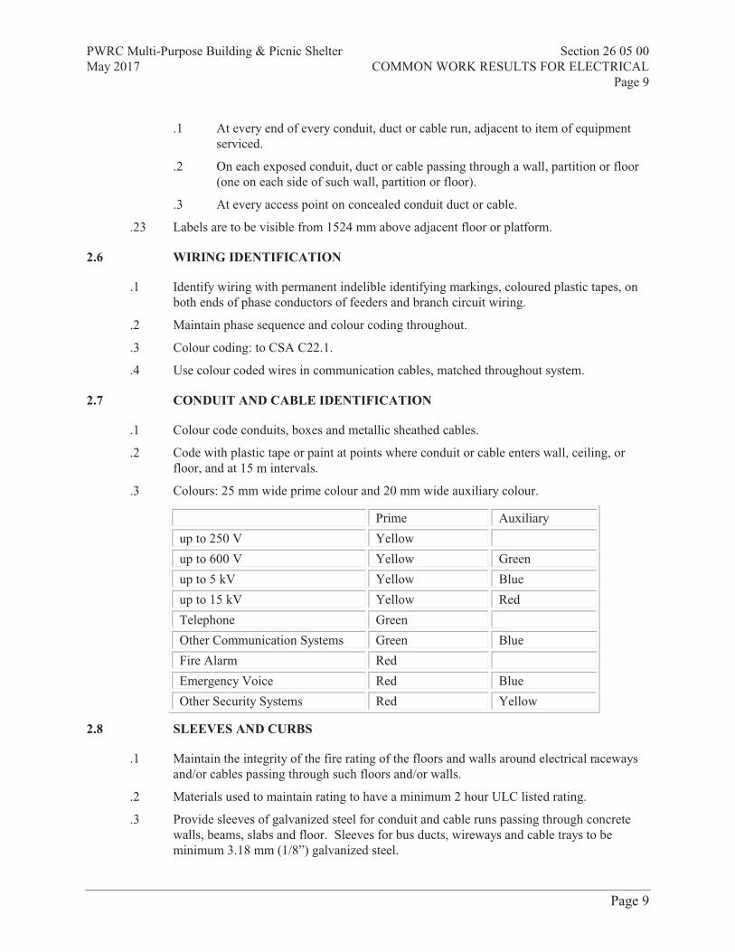
PWRC Multi-Purpose Building & Picnic Shelter Section 26 05 00May 2017 COMMON WORK RESULTS FOR ELECTRICAL
Page 9
Prism Project #2016368 Page 9
.1 At every end of every conduit, duct or cable run, adjacent to item of equipmentserviced.
.2 On each exposed conduit, duct or cable passing through a wall, partition or floor(one on each side of such wall, partition or floor).
.3 At every access point on concealed conduit duct or cable.
.23 Labels are to be visible from 1524 mm above adjacent floor or platform.
2.6 WIRING IDENTIFICATION
.1 Identify wiring with permanent indelible identifying markings, coloured plastic tapes, onboth ends of phase conductors of feeders and branch circuit wiring.
.2 Maintain phase sequence and colour coding throughout.
.3 Colour coding: to CSA C22.1.
.4 Use colour coded wires in communication cables, matched throughout system.
2.7 CONDUIT AND CABLE IDENTIFICATION
.1 Colour code conduits, boxes and metallic sheathed cables.
.2 Code with plastic tape or paint at points where conduit or cable enters wall, ceiling, orfloor, and at 15 m intervals.
.3 Colours: 25 mm wide prime colour and 20 mm wide auxiliary colour.
Prime Auxiliary
up to 250 V Yellow
up to 600 V Yellow Green
up to 5 kV Yellow Blue
up to 15 kV Yellow Red
Telephone Green
Other Communication Systems Green Blue
Fire Alarm Red
Emergency Voice Red Blue
Other Security Systems Red Yellow
2.8 SLEEVES AND CURBS
.1 Maintain the integrity of the fire rating of the floors and walls around electrical racewaysand/or cables passing through such floors and/or walls.
.2 Materials used to maintain rating to have a minimum 2 hour ULC listed rating.
.3 Provide sleeves of galvanized steel for conduit and cable runs passing through concretewalls, beams, slabs and floor. Sleeves for bus ducts, wireways and cable trays to beminimum 3.18 mm (1/8”) galvanized steel.

PWRC Multi-Purpose Building & Picnic Shelter Section 26 05 00May 2017 COMMON WORK RESULTS FOR ELECTRICAL
Page 10
Prism Project #2016368 Page 10
.4 Provide concrete curbs, minimum 101.6 mm (4”) high above finished floor surroundingopenings where bus ducts, wireways and cable trays rise through slabs above grade toprevent debris and water from falling to floor below. Concrete curb are to have sufficientarea to adequately carry bus duct support brackets.
.5 Provide concrete curbs, minimum 101.6 mm (4”) high above finished floor for telephonecable risers and other openings intended for electrical use in slabs above grade.
.6 Extend galvanized sleeves for conduit rising through slabs 101.6 mm (4”) minimum abovefinished floors. Provide sleeves, passing through floors having a waterproof membrane,with an integral flashing clamp.
.7 Install fire stop or sealant material between opening or sleeve and raceway or cable inaccordance with the recommendations of the manufacture to achieve a minimum 2 hourrating, unless otherwise noted.
2.9 FINISHES
.1 Shop finish metal enclosure surfaces by application of rust resistant primer inside andoutside, and at least two coats of finish enamel.
.1 Paint outdoor electrical equipment "equipment green" finish.
2.10 ACCESS DOORS
.1 Provide access doors in non-accessible ceilings.
.2 Provide a set of prints of the reflected ceiling plan and indicate required access doorlocations and proposed size prior to installation.
.3 Co-ordinate location of equipment in non-accessible ceiling with all other trades, as toutilize minimum quantities of access doors prior to installation of equipment.
2.11 ELECTRICAL PLATE FINISHES
.1 If no other cover plates are presently installed in the area, new plates to be stainless steel18-8 chrome metal alloy, type 302, non-magnetic in finished areas and pressed steel inunfinished areas. Finish brush marks to be run in a vertical direction. For single gangplates, brush marks to be run in long direction of plate.
.2 Switch, receptacle and other plates to be stainless steel 18-8 chrome metal alloy, type 302,non-magnetic in finished areas and pressed steel in unfinished areas. Finish brush marksto be run in a vertical direction. For single gang plates, brush marks to be run in longdirection of plate.
.3 Cover plates to be manufactured by:
.1 Arrow Hart Wiring Devices
.2 Bryant Electric Inc.
.3 Harvey Hubbell of Canada Ltd.
.4 Leviton
.5 Pass & Seymour Inc.

PWRC Multi-Purpose Building & Picnic Shelter Section 26 05 00May 2017 COMMON WORK RESULTS FOR ELECTRICAL
Page 11
Prism Project #2016368 Page 11
.6 Westinghouse Canada Ltd.
.7 Or Accepted Equivalent.
.4 Switch, receptacle, telephone and other plates to be Decorator Series Thermoplastic.
.5 Coverplates to be pressed steel in unfinished areas. Finish brush marks to be run in avertical direction. For single gang plates, brush marks to be run in long direction of plate.
.6 Cover plates to be as manufactured by:
.1 Spider Manufacturing Inc. (SMI)
.2 Leviton
.3 Pass & Seymour Canada Inc.
.4 Or Accepted Equivalent.
.7 Cover plates to be finished in White
.8 Provide blank inserts in unused portions of coverplates as required, colour to matchdevices.
.9 Provide circuit number identification on all receptacle coverplates. Lettering to be 3mm(1/8”) high with black lettering utilizing clear adhesive tape.
.10 Where coverplates are indicated to be engraved, letters to be 6mm (1/4”) high filled withred paint where engraving is indicated. Engraving to be parallel to finished floor line.
.11 Where outlets are shown grouped together e.g.: power, telephone, signal, etc., they are tobe mounted in a common outlet box with suitable barrier between power and signalsections. Provide common cover plate over all devices. Do not install plates until finalpainting of room or area is completed. Remove protective covering.
2.12 SAFETY SWITCHES
.1 Provide engraved nameplates on each switch in accordance with details specified inArticle “Equipment Identification”.
.2 Fused or unfused disconnect or safety switches to be Type “A”, quick-make, quick-breakconstruction with provision for padlocking switches in either “ON” or “OFF” position.
.3 Fused switches to have fuse clips designed for NEMA Class “J” HRC fuses and designedto reject standard N.E.C. fuses.
.4 Switches throughout job are to be of same manufacture and to match base buildingstandards.
.5 Provide fused or unfused safety or disconnect switches as shown and as required.
Part 3 Execution
3.1 INSTALLATION
.1 Do complete installation in accordance with CSA C22.1 except where specified otherwise.
.2 Do overhead and underground systems in accordance with CSA C22.3 No.1 except wherespecified otherwise.

PWRC Multi-Purpose Building & Picnic Shelter Section 26 05 00May 2017 COMMON WORK RESULTS FOR ELECTRICAL
Page 12
Prism Project #2016368 Page 12
3.2 NAMEPLATES AND LABELS
.1 Ensure manufacturer’s nameplates, CSA labels and identification nameplates are visibleand legible after equipment is installed.
3.3 CONDUIT AND CABLE INSTALLATION
.1 Install conduit and sleeves prior to pouring of concrete.
.1 Sleeves through concrete: schedule 40 steel pipe, sized for free passage ofconduit, and protruding 50mm from poured surface.
.2 If plastic sleeves are used in fire rated walls or floors, remove before conduit installation.
.3 Install cables, conduits and fittings embedded or plastered over, close to building structureso furring can be kept to minimum.
3.4 LOCATION OF OUTLETS
.1 Locate outlets in accordance with Section 26 05 32 – Outlet Boxes, Conduit Boxes andFittings.
.2 Do not install outlets back-to-back in wall; allow minimum 150m horizontal clearancebetween boxes.
.3 Change location of outlets at no extra cost or credit, providing distance does not exceed3000 mm, and information is given before installation.
.4 Locate light switches on latch side of doors.
.1 Locate disconnect devices in mechanical and elevator machine rooms on latchside of door.
.2 Under no circumstances is a switch to be located behind a door or out of sight andeasy reach of a person entering a room or space.
3.5 MOUNTING HEIGHTS
.1 Mounting height of equipment is from finished floor to centreline of equipment unlessspecified or indicated otherwise.
.2 If mounting height of equipment is not specified or indicated, verify before proceedingwith installation.
.3 Install electrical equipment at following heights unless indicated otherwise.
.1 Local switches: 1400mm.
.2 Wall receptacles:
.1 General: 300mm.
.2 Above top of counters or counter splash backs: 175mm..3 Panelboards: as required by Code or as indicated.
.4 Fire alarm stations: 1500mm.
.5 Fire alarm bells: 2100mm.

PWRC Multi-Purpose Building & Picnic Shelter Section 26 05 00May 2017 COMMON WORK RESULTS FOR ELECTRICAL
Page 13
Prism Project #2016368 Page 13
3.6 CO-ORDINATION OF PROTECTIVE DEVICES
.1 Ensure circuit protective devices such as overcurrent trips, relays and fuses are installed torequired values and settings.
3.7 TEMPORARY LIGHTING AND POWER SERVICES
.1 Provide temporary general lighting throughout construction site; existing luminaires maybe utilized for this task, where possible. In areas where lighting has been removed to suitconstruction, provide lighting strings with incandescent, compact fluorescent, or solid-state light emitting diode lamps, to approximate the equivalent lumen output equivalent ofincandescent 150W I.F. lamps mounted on 10 foot centres, or through use of highpowered portable work lights. Lamp placement on lighting strings is variable dependingupon light source and lumen output of lamps utilized to meet equivalency and minimumfootcandle illumination levels as detailed in this section.
.2 Lighting levels in work areas shall conform to WorkSafe BC’s (WCB) OccupationalHealth and Safety Regulations. For work sites not under WorkSafe BC jurisdiction, obtainand adhere to regulations of the jurisdiction having authority for the site type and location.
.3 Where no defined illumination levels are detailed in regulations, provide a minimum 50footcandles of illumination across the work area.
.4 Relocate temporary lighting throughout construction site as often as necessary, such thattemporary lighting is provided in all areas where work is being performed.
.5 Provide additional task lighting for specific working conditions where higher lightinglevels are required.
.6 Provide temporary power supplies with receptacles and extension cords from existingbuilding services, for construction equipment, e.g.: drills, saws, etc. Locate, relocate andremove services as necessary.
.7 Maintain the temporary facilities in good repair and in safe working condition throughoutthe duration of the construction project.
.8 Remove, at the end of project, the above noted temporary systems.
3.8 FIELD QUALITY CONTROL
.1 Load Balance:
.1 Measure phase current to panelboards with normal loads (lighting) operating attime of acceptance; adjust branch circuit connections as required to obtain bestbalance of current between phases and record changes.
.2 Measure phase voltages at loads and adjust transformer taps to within 2% of ratedvoltage of equipment.
.3 For affected lighting circuits only, provide upon completion of work, load balancereport as directed in PART 1 - SUBMITTALS: phase and neutral currents onpanelboards, dry-core transformers and motor control centres, operating undernormal load, as well as hour and date on which each load was measured, andvoltage at time of test.
.2 Conduct following tests in accordance with Section 01 45 00 – Quality Control.

PWRC Multi-Purpose Building & Picnic Shelter Section 26 05 00May 2017 COMMON WORK RESULTS FOR ELECTRICAL
Page 14
Prism Project #2016368 Page 14
.1 Power distribution system including phasing, voltage, grounding and loadbalancing. For services to modified lighting and control systems only. Do pre andpost installation testing and verification of loads, grounding and harmonics.
.2 Circuits originating from branch distribution panels.
.3 Lighting and its control.
.4 Motors, heaters and associated control equipment including sequenced operationof systems where applicable.
.5 Fire alarm system if applicable.
.6 Communications system if applicable.
.7 Insulation resistance testing:
.1 Megger circuits, feeders and equipment up to 350 V with a 500 Vinstrument.
.2 Megger 350-600 V circuits, feeders and equipment with a 1000 Vinstrument.
.3 Check resistance to ground before energizing..3 Carry out tests in presence of Owner’s Representative.
.4 Provide instruments, meters, equipment and personnel required to conduct tests duringand at conclusion of project.
.5 Manufacturer’s Field Services:
.1 Obtain written report from manufacturer verifying compliance of Work, inhandling, installing, applying, protecting and cleaning of product and submitManufacturer’s Field Reports as described in PART 1- SUBMITTALS.
.2 Provide manufacturer’s field services consisting of product use recommendationsand periodic site visits for inspection of product installation in accordance withmanufacturer’s instructions.
.3 Schedule site visits, to review Work, as directed in PART 1 - QUALITYASSURANCE.
3.9 CLEANING
.1 Refer to 01 74 11 - CLEANING
.2 Clean and touch up surfaces of shop-painted equipment scratched or marred duringshipment or installation, to match original paint.
.3 Clean and prime exposed non-galvanized hangers, racks and fastenings to prevent rusting.
END OF SECTION

PWRC Multi-Purpose Building & Picnic Shelter Section 26 05 20May 2017 WIRE AND BOX CONNECTORS 0-1000V
Page 1
Prism Project #2016368 Page 1
Part 1 General
1.1 SECTION INCLUDES
.1 Materials and installation for wire and box connectors.
1.2 RELATED SECTIONS
.1 Section 01 74 21 - Construction/Demolition Waste Management and Disposal.
1.3 REFERENCES
.1 Canadian Standards Association (CSA International)
.1 CAN/CSA-C22.2 No.18.2-06, Outlet Boxes, Conduit Boxes, Fittings andAssociated Hardware.
.2 CSA C22.2 No.65-13, Wire Connectors.
.2 Electrical and Electronic Manufacturers’ Association of Canada (EEMAC)
.1 EEMAC 1Y-2, 1979 Bushing Stud Connectors and Aluminum Adapters (1200Ampere Maximum Rating).
.3 National Electrical Manufacturers Association (NEMA)
1.4 WASTE MANAGEMENT AND DISPOSAL
.1 Separate and recycle waste materials in accordance with Section 01 74 21 -Construction/Demolition Waste Management and Disposal.
.2 Remove from site and dispose of all packaging materials at appropriate recycling facilities.
.3 Collect and separate for disposal all packaging material for recycling in accordance withWaste Management Plan.
.4 Divert unused wiring materials from landfill to metal recycling facility as approved byappropriate government agency as a waste disposal and recycling facility.
Part 2 Products
2.1 MATERIALS
.1 Pressure type wire connectors to: CSA C22.2 No.65, with current carrying parts of coppersized to fit copper conductors as required.
.2 Luminaire type splicing connectors to: CSA C22.2 No.65, with current carrying parts ofcopper sized to fit copper conductors 10 AWG or less.

PWRC Multi-Purpose Building & Picnic Shelter Section 26 05 20May 2017 WIRE AND BOX CONNECTORS 0-1000V
Page 2
Prism Project #2016368 Page 2
.3 Bushing stud connectors: to EEMAC 1Y-2 to consist of:
.1 Connector body and stud clamp for stranded or round copper conductors.
.2 Clamp for stranded or round copper.
.3 Not used.
.4 Stud clamp bolts.
.5 Bolts for copper conductors.
.6 Not used.
.7 Sized for conductors as indicated.
.4 Clamps or connectors for armoured cable as required to: CAN/CSA-C22.2 No.18.2.
Part 3 Execution
3.1 INSTALLATION
.1 Remove insulation carefully from ends of conductors and:
.1 Apply coat of zinc joint compound on aluminum conductors prior to installationof connectors.
.2 Install mechanical pressure type connectors and tighten screws, with appropriatecompression tool where recommended by manufacturer. Installation shall meetsecureness tests in accordance with CSA C22.2 No.65.
.3 Install fixture type connectors and tighten. Replace insulating cap.
.4 Install bushing stud connectors in accordance with NEMA.
END OF SECTION

PWRC Multi-Purpose Building & Picnic Shelter Section 26 05 21May 2017 WIRES AND CABLES (0-1000V)
Page 1
Prism Engineering Ltd. Page 1
Part 1 General
1.1 RELATED SECTIONS
.1 Section 01 33 00 – Submittal Procedures.
.2 Section 01 74 21 – Construction/Demolition Waste Management and Disposal.
.3 Section 26 05 00 – Common Work Results for Electrical.
1.2 PRODUCT DATA
.1 Provide product data in accordance with Section 01 33 00 – Submittal Procedures.
.2 CSA C22.2 No. 0.3-09 Test Methods for Electrical Wires and Cables.
1.3 DELIVERY, STORAGE AND HANDLING
.1 Packaging Waste Management: remove for reuse and recycle in accordance with Section01 74 21 – Construction/Demolition Waste Management and Disposal.
Part 2 Products
2.1 BUILDING WIRES
.1 Conductors: stranded for 10 AWG and larger. Minimum size: 12 AWG.
.2 Copper conductors: size as indicated, with 600 V insulation of cross-linked thermosettingpolyethylene material rated RW90 XLPE, Jacketted.
.3 Copper conductors: size as indicated, with thermoplastic insulation type TWU rated at600 V.
.4 Neutral supported cable: 3 phase insulated conductors of Copper and one neutralconductor of Copper steel reinforced, size as indicated. Type: NS75 Insulation: Type NS-1rated 300 V.
2.2 CONDUCTORS, WIRES AND CABLES
.1 All conductors are to be copper conductors. All AWG sizes given in this specificationrefer to the copper AWG size.
.2 Wiring installed in conduit, unless otherwise noted, to be 600 volt RW-90 X-Link.Wiring in channel back of fluorescent luminaires to be 600 volt type GTF or TEW.
.3 Use copper wiring, minimum No. 12 gauge for lighting and power wiring. Size wires for2% maximum voltage drop to farthest outlet on a loaded circuit.
.4 Home runs to 120 volt lighting and receptacle panels, which exceed 75 feet (23 m) inlength, to be minimum No. 10 gauge. Home runs which exceed 38mm (125’-0”) in lengthto be minimum No. 8 gauge.

PWRC Multi-Purpose Building & Picnic Shelter Section 26 05 21May 2017 WIRES AND CABLES (0-1000V)
Page 2
Prism Engineering Ltd. Page 2
2.3 TECK 90 CABLE
.1 Cable: in accordance with Section 26 05 00 – Common Work Results for Electrical.
.2 Conductors:
.1 Grounding conductor: copper as indicated.
.2 Circuit conductors: copper as indicated, size as indicated.
.3 Insulation:
.1 Ethylene propylene rubber EP.
.2 Cross-linked polyethylene XLPE.
.3 Rating: 600.
.4 Inner jacket: polyvinyl chloride material.
.5 Armour: aluminum.
.6 Overall covering: thermoplastic polyvinyl chloride.
.7 Fastenings:
.1 One hole steel straps to secure surface cables 50 mm and smaller. Two hole steelstraps for cables larger than 50 mm.
.2 Channel type supports for two or more cables at 1200mm centers.
.3 Threaded rods: 6 mm diameter to support suspended channels.
.8 Connectors:
.1 Watertight approved for TECK cable.
2.4 ARMOURED CABLES
.1 Conductors: insulated, copper, size as indicated.
.2 Type: AC90
.3 Armour: interlocking type fabricated from galvanized steel strip.
.4 Type: ACWU90 jacket over armour and compliant to applicable Building Codeclassification for this project.
.5 Connectors: anti short connectors.
2.5 CONTROL CABLES
.1 Type: LVT: 2 soft annealed copper conductors, sized as indicated:
.1 Insulation: thermoplastic.
.2 Sheath : thermoplastic jacket
.2 Type: low energy 300 V control cable: solid annealed copper conductors sized asindicated LVT: 2 soft annealed copper conductors, sized as indicated:

PWRC Multi-Purpose Building & Picnic Shelter Section 26 05 21May 2017 WIRES AND CABLES (0-1000V)
Page 3
Prism Engineering Ltd. Page 3
.1 Insulation: PVC
.2 Shielding: tape coated with paramagnetic material over each conductor.
.3 Overall covering: PVC jackets.
.3 Type: 600 V stranded annealed copper
.4 conductors, sizes as indicated:
.1 Insulation: PVC
.2 Shielding: magnetic tape
.3 Overall covering: thermoplastic jacket
Part 3 Execution
3.1 FIELD QUALITY CONTROL
.1 Perform tests in accordance with Section 26 05 00 – Common Work Results for Electrical.
.2 Perform tests using method appropriate to site conditions and to approval of Owner’sRepresentative and local authority having jurisdiction over installation.
.3 Perform tests before energizing electrical system.
3.2 WIRING METHODS
.1 Install wiring in conduit unless otherwise specified.
.2 Use thin wall conduit for branch circuit and signal wiring in ceilings, and furred spaces.Use rigid galvanized steel conduit for wiring in poured concrete, or where conduit couldbe exposed to mechanical injury.
.3 Enclose all visible surface conduits in public areas in surface raceway: Wiremold V2000Series or Accepted Equivalent.
.4 Conduit is to be of sufficient size to permit easy removal of conductors at any time.Conduit sizes, where shown, are minimum and shall not be reduced. Do not bend conduitover sharp objects. Improperly formed bends and running threads will not be accepted.Do not use bends and fittings together.
.5 Run conduits and cables in finished areas concealed, above finished ceilings, under floors,in walls and in partitions. Run conduit and cables in unfinished areas, such as fan roomsand penthouses, exposed and install at right angles or parallel to building lines, accurate inline and level.
.6 Runs of conduit and cables, where shown are indicated only by general location androuting. Install conduits and cables to provide maximum head room and to interfere aslittle as possible with free use of spaces through which they pass. Install as close tobuilding structure as possible, so that, where concealed, necessary furring can be kept to aminimum. Arrange conduits, installed in suspended ceilings, to provide minimuminterference with removal of tiles.

PWRC Multi-Purpose Building & Picnic Shelter Section 26 05 21May 2017 WIRES AND CABLES (0-1000V)
Page 4
Prism Engineering Ltd. Page 4
.7 Wiring and conduit for wall devices etc., to be routed in ceiling space of floor they areserving.
.8 Install conduit and cables to avoid proximity to water and heating pipes. They are not berun within 152.4 mm (6”) of such pipes except where crossings are unavoidable, in whichcase they are to be kept at least 25 mm (1”) from covering of pipe crossed.
.9 Provide expansion joint sleeves with ground jumpers in conduit runs where they crossbuilding expansion joints.
.10 Provide a minimum of one (1) hour fire protection around all emergency service feedersrouted through non fire rated rooms in accordance with CAN/CSA – C282-M89.
3.3 GROUNDING
.1 Ground electrical equipment and wiring in accordance with Canadian Electrical Code andLocal Inspection Authority’s Rules and Regulations.
.2 Condition or existence of grounding of existing luminaries must be reviewed and propergrounding confirmed. Inform Consultant if ungrounded luminaries or service feeder toluminaires are identified.
3.4 CIRCUITING REQUIREMENTS
.1 Circuitry as indicated is diagrammatic only.
.2 Where new lighting or additional luminaires are to be installed, extend the existing serviceto suit and connect to spare/new breakers in existing panelboards. Loading of lightingcircuits is not to exceed 70% of breaker rating.
.3 Where new lighting installation or revisions to lighting load will result in a significantreduction, resulting in less than 50% loading in the load on any circuits, Contractors are toconsolidate like loads, (example; indoor LED loads or exterior LED loads with like orsimilar loads) and recover redundant breakers as spares. Cap unused feeds in an approvedor existing junction outlet box or remove back to the panelboard providing the localservice. Update panelboard directories to reflect changes.
3.5 CONDUCTORS, WIRES AND CABLES
.1 Colour code all conductors. Conductors No. 2 gauge and smaller to have colourimpregnated into insulation at time of manufacture. Conductors size larger than No. 2gauge may be colour coded with adhesive colour coding tape but only black insulatedconductors are to be employed in this case, except for neutrals which are to be whitewhenever possible. Conductors of No. 8 gauge and larger must be stranded.
.2 Colour code as follows:
Phase “A” Red Ground GreenPhase “B” Black Neutral White
Phase “C” Blue Control Orange

PWRC Multi-Purpose Building & Picnic Shelter Section 26 05 21May 2017 WIRES AND CABLES (0-1000V)
Page 5
Prism Engineering Ltd. Page 5
.3 Neutral conductors may be identified by a coloured insulation with three or more extrudedlongitudinal white stripes along the insulation, and will be deemed to have a white ornatural covering. All neutral conductors used in the Work must match building standard.
.4 Neatly train circuit wiring in cabinets, panels, pull boxes and junction boxes and hold withnylon cable ties.
.5 Splice wire, up to and including No. 6 gauge, with twist-on style connections ratedminimum 600 volts (1000 volts in luminaires). Connection body to be moulded ofthermoplastic. Spring insert to have an expandable square-edge. Splice large conductorsusing split-bolt or compression type connections wrapped with PVC tape.
.6 Where colour coding tape is utilized, it is to be applied for a minimum of 50.8 mm (2”) atterminations, junction and pull boxes and condulet fittings. Do not paint conductors underany circumstances. Colour coding also applies to bussing in panels.
3.6 EQUIPMENT AND WIRING TESTING
.1 Make tests of equipment and wiring at time requested.
.2 Tests are to include measured insulation values, voltage and current readings to determinebalance of panels and feeders under full load, and operation of each piece of equipmentfor correct operation.
.3 Supply meters, materials and personnel as required, to carry out these tests.
.4 Test electrical work to standards and function of Specification and applicable codes in anapproved manner. Replace defective equipment and wiring with new material and leaveentire system in complete first class operating condition.
.5 Connect single phase loads so that there is the least possible unbalance of the supplyphases.
.6 Where specialized equipment or controls systems requiring commissioning are installed aspart of Work, arrange and pay for services of manufacturer’s factory service engineer /technician to supervise initial start-up or calibration of such equipment or controls.Engineer / technician shall check systems installation and verify operation is correct orshall adjust, balance and calibrate components, or direct installer to perform these tasks,including installation related wiring and operation of controls, to the satisfaction of theengineer / technician and the Consultant.
.7 Instruct Owner’s operating personnel in the operation of the installations. Provide theseservices for such periods, and for as many visits as may be necessary to put applicableportion of installation in complete working order, and to ensure that Owner’s operatingpersonnel are fully conversant with every aspect of the operation, care and maintenancethereof.
3.7 GENERAL CABLE INSTALLATION
.1 Install cable in trenches in accordance with Section 33 71 73.02 - Underground ElectricalService.
.2 Terminate cables in accordance with Section 26 05 20 - Wire and Box Connectors - (0-1000 V).
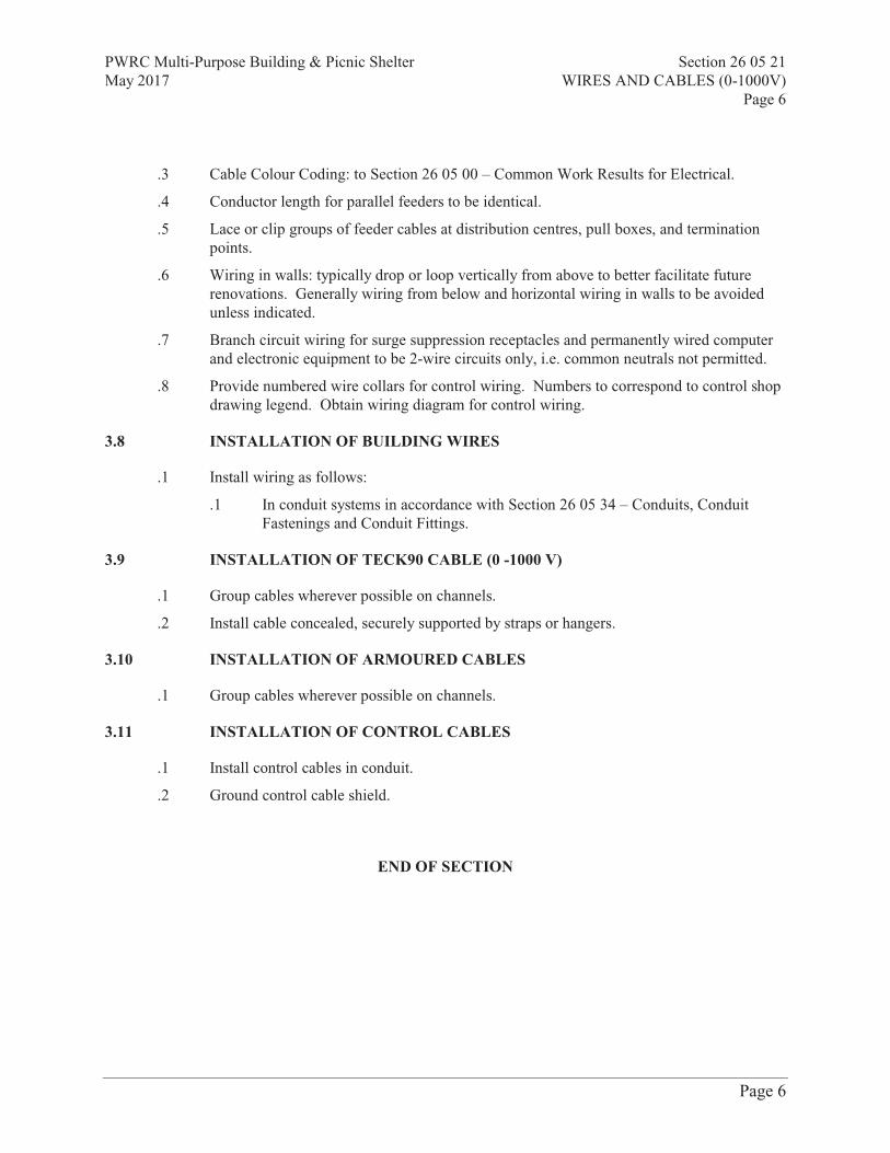
PWRC Multi-Purpose Building & Picnic Shelter Section 26 05 21May 2017 WIRES AND CABLES (0-1000V)
Page 6
Prism Engineering Ltd. Page 6
.3 Cable Colour Coding: to Section 26 05 00 – Common Work Results for Electrical.
.4 Conductor length for parallel feeders to be identical.
.5 Lace or clip groups of feeder cables at distribution centres, pull boxes, and terminationpoints.
.6 Wiring in walls: typically drop or loop vertically from above to better facilitate futurerenovations. Generally wiring from below and horizontal wiring in walls to be avoidedunless indicated.
.7 Branch circuit wiring for surge suppression receptacles and permanently wired computerand electronic equipment to be 2-wire circuits only, i.e. common neutrals not permitted.
.8 Provide numbered wire collars for control wiring. Numbers to correspond to control shopdrawing legend. Obtain wiring diagram for control wiring.
3.8 INSTALLATION OF BUILDING WIRES
.1 Install wiring as follows:
.1 In conduit systems in accordance with Section 26 05 34 – Conduits, ConduitFastenings and Conduit Fittings.
3.9 INSTALLATION OF TECK90 CABLE (0 -1000 V)
.1 Group cables wherever possible on channels.
.2 Install cable concealed, securely supported by straps or hangers.
3.10 INSTALLATION OF ARMOURED CABLES
.1 Group cables wherever possible on channels.
3.11 INSTALLATION OF CONTROL CABLES
.1 Install control cables in conduit.
.2 Ground control cable shield.
END OF SECTION

PWRC Multi-Purpose Building & Picnic Shelter Section 26 05 32May 2017 OUTLET BOXES, CONDUIT BOXES AND FITTINGS
Page 1
Prism Project #2016368 Page 1
Part 1 General
1.1 RELATED SECTIONS
.1 Section 01 33 00 - Submittal Procedures.
.2 Section 01 61 00 – Common Product Requirements.
.3 Section 01 74 21 – Construction/Demolition Waste Management and Disposal.
.4 Section 26 05 00 – Common Work Results – Electrical.
1.2 REFERENCES
.1 Canadian Standards Association (CSA International)
.1 CSA C22.1-09, Canadian Electrical Code, Part 1, 21st Edition.
1.3 SUBMITTALS
.1 Provide submittals in accordance with Section 01 33 00 - Submittal Procedures.
1.4 DELIVERY, STORAGE AND HANDLING
.1 Deliver, store and handle materials in accordance with Section 01 61 00 – CommonProduct Requirements.
.2 Waste Management and Disposal:
.1 Separate waste materials for reuse and recycling in accordance with Section01 74 21 – Construction/Demolition Waste Management and Disposal.
Part 2 Products
2.1 OUTLET BOXES
.1 Conform to CSA Standard C22.2 No. 18.
.2 Ceiling boxes are to be 101.6 mm (4”) octagon or square, complete with fittings, whererequired to support luminaires.
.3 Switch and receptacles boxes to be:
.1 No. 1104, where flush mounted in wood or drywall, with stud fasteners asrequired.
.2 Boxes for 347 volt switches are to be similar but sized as per Code with barriersbetween switches.
.4 Where boxes are surface mounted in unfinished areas, they are to be FS condulets.
.5 Standard outlet boxes are to be manufactured from code gauge galvanized steel.

PWRC Multi-Purpose Building & Picnic Shelter Section 26 05 32May 2017 OUTLET BOXES, CONDUIT BOXES AND FITTINGS
Page 2
Prism Project #2016368 Page 2
.6 Ensure outlet boxes installed outside building and/or in damp locations are FSweatherproof type. If in direct contact with the ground, they are to be made of cast iron.
.7 Provide a suitable outlet box for each luminaire, switch, receptacle or other outlet,approved for the particular area in which it is to be installed.
2.2 CONDUIT BOXES
.1 Cast FS boxes with factory-threaded hubs and mounting feet for surface wiring of devices.
2.3 FITTINGS - GENERAL
.1 Bushing and connectors with nylon insulated throats.
.2 Knock-out fillers to prevent entry of debris.
.3 Conduit outlet bodies for conduit up to 35 mm and pull boxes for larger conduits.
.4 Double locknuts and insulated bushings on sheet metal boxes.
Part 3 Execution
3.1 INSTALLATION
.1 Support outlet boxes independently of conduit and cable.
.2 Locate outlet boxes, mounted in hung ceiling space, so they do not obstruct or interferewith the removal of lay-in ceiling tiles.
.3 Offset outlet boxes, shown back to back in partitions, horizontally to minimize noisetransmission between adjacent rooms.
.4 Use gang boxes at locations where more than one device is to be mounted. Usecombination boxes with suitable barriers where outlets for more than one system areshown.
.5 Flush mount boxes, panels, cabinets and electrical devices, which are installed in finishedareas, and fit with suitable flush trims and doors or covers, unless specifically notedotherwise.
END OF SECTION

PWRC Multi-Purpose Building & Picnic Shelter Section 26 05 34May 2017 CONDUITS, CONDUIT FASTENINGS AND CONDUIT FITTINGS
Page 1
Prism Project #2016368 Page 1
Part 1 General
1.1 RELATED SECTIONS
.1 Section 01 33 00 – Submittal Procedures.
.2 Section 01 74 11 – Cleaning.
.3 Section 01 74 21 – Construction/Demolition Waste Management and Disposal.
.4 Section 26 05 32 – Outlet Boxes, Conduit Boxes and Fittings.
1.2 REFERENCES
.1 Canadian Standards Association (CSA International)
.1 CAN/CSA C22.2 No. 1-04(R2009), Outlet Boxes, Conduit Boxes, Fittings andAssociated Hardware, A National Standard of Canada.
.2 CSA C22.2 No. 45-M1981(R2007), Rigid Metal Conduit.
.3 CSA C22.2 No. 56-04(R2009), Flexible Metal Conduit and Liquid-Tight FlexibleMetal Conduit.
.4 CSA C22.2 No. 83-M1985(R2008), Electrical Metallic Tubing.
1.3 SUBMITTALS
.1 Provide submittals in accordance with Section 01 33 00 – Submittal Procedures.
1.4 WASTE MANAGEMENT AND DISPOSAL
.1 Separate waste materials for reuse and recycling in accordance with Section 01 74 21 –Construction/Demolition Waste Management and Disposal.
Part 2 Products
2.1 CONDUITS
.1 Rigid metal conduit: to CSA C22.2 No. 45, galvanized steel threaded.
.2 Electrical metallic tubing (EMT): to CSA C22.2 No. 83, with couplings.
.3 Flexible metal conduit: to CSA C22.2 No. 56, steel.
2.2 CONDUIT FASTENINGS
.1 One hole steel straps to secure surface conduits 50 mm and smaller.
.1 Two hole steel straps for conduits larger than 50 mm.
.2 Beam clamps to secure conduits to exposed steel work.
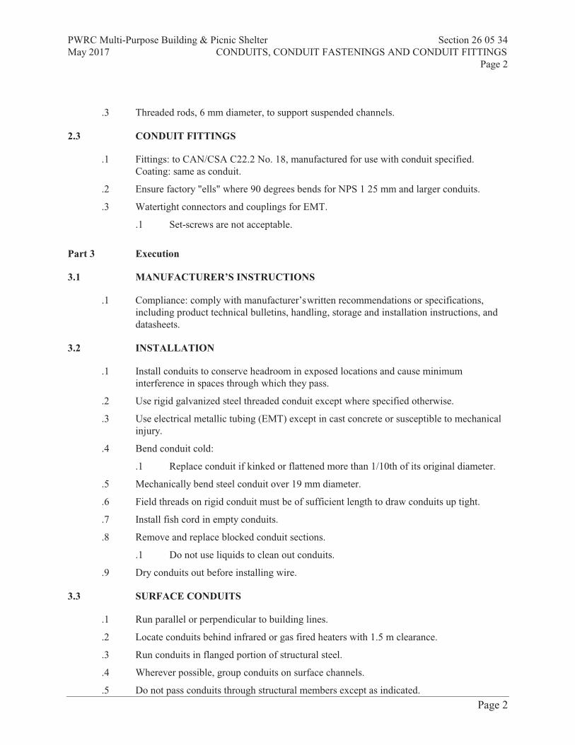
PWRC Multi-Purpose Building & Picnic Shelter Section 26 05 34May 2017 CONDUITS, CONDUIT FASTENINGS AND CONDUIT FITTINGS
Page 2
Prism Project #2016368 Page 2
.3 Threaded rods, 6 mm diameter, to support suspended channels.
2.3 CONDUIT FITTINGS
.1 Fittings: to CAN/CSA C22.2 No. 18, manufactured for use with conduit specified.Coating: same as conduit.
.2 Ensure factory "ells" where 90 degrees bends for NPS 1 25 mm and larger conduits.
.3 Watertight connectors and couplings for EMT.
.1 Set-screws are not acceptable.
Part 3 Execution
3.1 MANUFACTURER’S INSTRUCTIONS
.1 Compliance: comply with manufacturer’swritten recommendations or specifications,including product technical bulletins, handling, storage and installation instructions, anddatasheets.
3.2 INSTALLATION
.1 Install conduits to conserve headroom in exposed locations and cause minimuminterference in spaces through which they pass.
.2 Use rigid galvanized steel threaded conduit except where specified otherwise.
.3 Use electrical metallic tubing (EMT) except in cast concrete or susceptible to mechanicalinjury.
.4 Bend conduit cold:
.1 Replace conduit if kinked or flattened more than 1/10th of its original diameter.
.5 Mechanically bend steel conduit over 19 mm diameter.
.6 Field threads on rigid conduit must be of sufficient length to draw conduits up tight.
.7 Install fish cord in empty conduits.
.8 Remove and replace blocked conduit sections.
.1 Do not use liquids to clean out conduits.
.9 Dry conduits out before installing wire.
3.3 SURFACE CONDUITS
.1 Run parallel or perpendicular to building lines.
.2 Locate conduits behind infrared or gas fired heaters with 1.5 m clearance.
.3 Run conduits in flanged portion of structural steel.
.4 Wherever possible, group conduits on surface channels.
.5 Do not pass conduits through structural members except as indicated.
PWRC Multi-Purpose Building & Picnic Shelter Section 26 05 34May 2017 CONDUITS, CONDUIT FASTENINGS AND CONDUIT FITTINGS
Page 3
Prism Project #2016368 Page 3
.6 Do not locate conduits less than 75 mm parallel to steam or hot water lines with minimumof 25 mm at crossovers.
3.4 CONCEALED CONDUITS
.1 Run parallel or perpendicular to building lines.
.2 Do not install horizontal runs in masonry walls.
.3 Do not install conduits in terrazzo or concrete toppings.
3.5 CLEANING
.1 Proceed in accordance with Section 01 74 11 – Cleaning.
.2 On completion and verification of performance of installation, remove surplus materials,excess materials, rubbish, tools and equipment.
END OF SECTION

PWRC Multi-Purpose Building & Picnic Shelter Section 26 05 43.01 May 2017 INSTALLATION OF CABLES IN TRENCHES AND IN DUCTS Page 1
Prism Project #2016368
Part 1 GENERAL
1.1 RELATED SECTIONS
.1 Section 01 74 21 - Construction/Demolition Waste Management And Disposal.
.2 Section 31 23 33.01 - Excavating, Trenching and Backfilling.
.3 Section 26 05 00 - Common Work Results - Electrical.
1.2 REFERENCES
.1 Canadian Standards Association, (CSA International)
.2 Insulated Cable Engineers Association, Inc. (ICEA)
1.3 WASTE MANAGEMENT AND DISPOSAL
.1 Separate and recycle waste materials in accordance with Section 01 74 21 - Construction/Demolition Waste Management And Disposal.
.2 Remove from site and dispose of all packaging materials at appropriate recycling facilities.
.3 Collect and separate for disposal packaging material in appropriate on-site bins for recycling in accordance with Waste Management Plan.
.4 Unused material must not be disposed of into sewer system, into streams, lakes, onto ground or in other location where it will pose health or environmental hazard.
.5 Divert unused metal and wiring materials from landfill to metal recycling facility as approved by Consultant.
.6 Do not dispose of preservative treated wood through incineration.
.7 Do not dispose of preservative treated wood with other materials destined for recycling or reuse.
.8 Dispose of treated wood, end pieces, wood scraps and sawdust at sanitary landfill approved by Consultant.
.9 Fold up metal banding, flatten and place in designated area for recycling.

PWRC Multi-Purpose Building & Picnic Shelter Section 26 05 43.01 May 2017 INSTALLATION OF CABLES IN TRENCHES AND IN DUCTS Page 2
Prism Project #2016368
Part 2 Products
2.1 CABLE PROTECTION
.1 38 x 140 mm planks treated with clear or copper napthenate or 5% pentachlorophenol solution, water repellent preservative.
2.2 MARKERS
.1 Concrete type cable markers: 600 x 600 x 100 mm with words: cable, joint or conduit impressed in top surface, with arrows to indicate change in direction of cable and duct runs.
.2 Cedar post type markers: 89 x 89 mm, 1.5 m long, pressure treated with clear or copper napthenate or 5% pentachlorophenol solution, water repellent preservative, with nameplate fastened near post top, on side facing cable or conduit to indicate depth and direction of duct and cable runs.
.1 Nameplate: aluminum anodized 89 x 125 mm, 1.5 mm thick mounted on cedar post with mylar label 0.125 mm thick with words Cable, Joint or Conduit with arrows to indicate change in direction.
Part 3 Execution
3.1 CABLE INSTALLATION IN DUCTS
.1 Install cables as indicated in ducts.
.1 Do not pull spliced cables inside ducts.
.2 Install multiple cables in duct simultaneously.
.3 Use CSA approved lubricants of type compatible with cable jacket to reduce pulling tension.
.4 To facilitate matching of colour coded multiconductor control cables reel off in same direction during installation.
.5 Before pulling cable into ducts and until cables are properly terminated, seal ends of lead covered cables with wiping solder; seal ends of non-leaded cables with moisture seal tape.
.6 After installation of cables, seal duct ends with duct sealing compound.
3.2 MARKERS
.1 Mark cable every 20 m along duct runs and changes in direction.

PWRC Multi-Purpose Building & Picnic Shelter Section 26 05 43.01 May 2017 INSTALLATION OF CABLES IN TRENCHES AND IN DUCTS Page 3
Prism Project #2016368
.2 Mark underground splices.
.3 Where markers are removed to permit installation of additional cables, reinstall existing markers.
.4 Install concrete cable markers within 180 m from each side of runway centreline; 45 m from each side of taxi way centreline; 50 m from edge of taxi ramps or aprons.
.5 Install cedar post type markers.
.6 Lay concrete markers flat and centred over cable with top flush with finish grade.
3.3 FIELD QUALITY CONTROL
.1 Perform tests in accordance with Section 26 05 00 - Common Work Results - Electrical.
.2 Perform tests using qualified personnel. Provide necessary instruments and equipment.
.3 Check phase rotation and identify each phase conductor of each feeder.
.4 Check each feeder for continuity, short circuits and grounds. Ensure resistance to ground of circuits is not less than 50 megohms.
.5 Pre-acceptance tests.
.1 After installing cable but before splicing and terminating, perform insulation resistance test with 1000 V megger on each phase conductor.
.2 Check insulation resistance after each splice and/or termination to ensure that cable system is ready for acceptance testing.
.6 Acceptance Tests
.1 Ensure that terminations and accessory equipment are disconnected.
.2 Ground shields, ground wires, metallic armour and conductors not under test.
.3 High Potential (Hipot) Testing. .1 Conduct hipot testing of original factory test voltage in accordance with
manufacturer's recommendations. .4 Leakage Current Testing.
.1 Raise voltage in steps from zero to maximum values as specified by manufacturer for type of cable being tested.
.2 Hold maximum voltage for specified time period by manufacturer
.3 Record leakage current at each step.
.7 Provide Consultant with list of test results showing location at which each test was made, circuit tested and result of each test.
.8 Remove and replace entire length of cable if cable fails to meet any of test criteria.

PWRC Multi-Purpose Building & Picnic Shelter Section 26 05 43.01 May 2017 INSTALLATION OF CABLES IN TRENCHES AND IN DUCTS Page 4
Prism Project #2016368
END OF SECTION

PWRC Multi-Purpose Building & Picnic Shelter Section 26 24 16.01 May 2017 PANELBOARDS BREAKER TYPE Page 1
Prism Project #2016368 Page 1
Part 1 General
1.1 RELATED SECTIONS
.1 Section 01 33 00 – Submittal Procedures.
.2 Section 01 74 21 – Construction/Demolition Waste Management And Disposal.
.3 Section 26 05 00 – Common Work Results – Electrical.
1.2 REFERENCES
.1 Canadian Standards Association (CSA International)
.1 CSA C22.2No.29-M1989(R2000), Panelboards and enclosed Panelboards.
1.3 SHOP DRAWINGS
.1 Submit shop drawings in accordance with Section 01 33 00 – Submittal Procedures.
.2 Drawings to include electrical detail of panel, branch breaker type, quantity, ampacity and enclosure dimension.
1.4 WASTE MANAGEMENT AND DISPOSAL
.1 Separate and recycle waste materials in accordance with Section 01 74 21 – Construction/Demolition Waste Management And Disposal.
.2 Remove from site and dispose of packaging materials at appropriate recycling facilities.
.3 Collect and separate for disposal for recycling in accordance with Waste Management Plan.
.4 Divert unused metal and wiring materials from landfill to metal recycling facility approved by Departmental Representative.
Part 2 Products
2.1 PANELBOARDS
.1 Panelboards: to CSA C22.2No.29 and product of one manufacturer.
.1 Install circuit breakers in panelboards before shipment.
.2 In addition to CSA requirements manufacturer's nameplate must show fault current that panel including breakers has been built to withstand.
.2 240V panelboards: bus and breakers rated for 100A (symmetrical) interrupting capacity or as indicated.
.3 Sequence phase bussing with odd numbered breakers on left and even on right, with each breaker identified by permanent number identification as to circuit number and phase.

PWRC Multi-Purpose Building & Picnic Shelter Section 26 24 16.01 May 2017 PANELBOARDS BREAKER TYPE Page 2
Prism Project #2016368 Page 2
.4 Panelboards: mains, number of circuits, and number and size of branch circuit breakers as indicated.
.5 Two keys for each panelboard and key panelboards alike.
.6 Copper bus with neutral of same ampere rating as mains.
.7 Mains: suitable for bolt-on breakers.
.8 Trim with concealed front bolts and hinges.
.9 Trim and door finish: baked grey enamel.
2.2 LIGHTING AND RECEPTACLES PANELS
.1 Provide engraved nameplates, after completion of wiring, in accordance with details
specified in Article “Equipment Identification”.
.2 Panels to be constructed and finished in accordance with details specified in Article “Panel Trim”.
.3 After completion of wiring, type directory showing a clear description of each circuit being controlled from panel and place in metal frame inside door.
.4 In panelboards where changes to circuiting have occurred, replace the existing directory with new typed directory updated to reflect changes that have occurred.
.5 Panels to be constructed and finished in accordance with details specified in Article “Panel Trim” and “Sprinkler Protection”.
.6 Lighting and receptacle panels are to be surface mounting type, as shown.
.7 Panels to be dead front type in code gauge steel enclosures.
.8 Each panel is to be dead front type in code gauge steel enclosures.
.9 Panels are to have mains of voltage and capacity, and main and branch breakers and contractors, as shown on the “Lighting and Receptacle Panel Schedule”. Spaces to include necessary bus work such that the Owner, at a later date, need buy only the breakers.
.10 Contactors in panel mains to be electrically operated, mechanically held and rated to lighting and other loads as shown. Contactors to be mounted within panel and to be open type. Contactors to be complete with fuse and fuse adapter mounted and connected to line side of contactor and to be connected to supply power to operating coil. Coil clearing contacts shall be included in contactor where a contactor is controlled by a time switch, photo switch or similar device.
.11 Contactors to be as manufactured by:
.1 Ascoelectric Ltd. – Bulletin 920 Series
.2 Or Accepted Equivalent.
.12 Provide isolated grounding bar in all new and existing panelboards mounted on insulators for connection from isolated ground type receptacles.
.13 Connect ground bar in each panel with minimum #1/0 green insulated ground conductors to ground bar on existing bus duct riser.

PWRC Multi-Purpose Building & Picnic Shelter Section 26 24 16.01 May 2017 PANELBOARDS BREAKER TYPE Page 3
Prism Project #2016368 Page 3
.14 Breakers to have bolted type connections. Two and three pole breakers to be common trip type with a single handle, suitable for voltage applied and of same manufacture as single pole breakers.
.15 Breakers servicing bedrooms shall be Arc-Fault type.
.16 Panels for 120/240 volt, 1 phase, 3 wire systems to be complete with full size breakers with a symmetrical interrupting capacity of 10,000 A.
.17 Panels to be factory assembled of the same manufacture as existing building panelboards.
.18 Panels to be factory assembled, of the same manufacture and shall be as manufactured by one of the following:
.1 Federal Pioneer Ltd.
.2 Siemens Canada Ltd.
.3 Square “D” Company (Canada) Ltd.
.4 Westinghouse Canada Ltd.
.5 Or Accepted Equivalent.
.19 Provide lighting and receptacle panels, surface or flush-mounting type, as shown.
.20 Provide locking bars on non-switched circuits where panels are used for switching lighting circuits.
2.3 BREAKERS
.1 Breakers: to Section 26 28 21 - Moulded Case Circuit Breakers.
.2 Breakers with thermal and magnetic tripping in panelboards except as indicated otherwise.
.3 Main breaker: separately mounted on top or bottom of panel to suit cable entry. When mounted vertically, down position should open breaker.
.4 Lock-on devices for 10% of 15 to 30A breakers installed as indicated. Turn over unused lock-on devices to Departmental Representative.
.5 Lock-on devices for receptacles, fire alarm, emergency, door supervisory circuits.
2.4 EQUIPMENT IDENTIFICATION
.1 Provide equipment identification in accordance with Section 26 05 00 – Common Work Results - Electrical.
Part 3 Execution
3.1 INSTALLATION
.1 Locate panelboards as indicated and mount securely, plumb, true and square, to adjoining surfaces.
.2 Install surface mounted panelboards on plywood backboards. Where practical, group panelboards on common backboard.

PWRC Multi-Purpose Building & Picnic Shelter Section 26 24 16.01 May 2017 PANELBOARDS BREAKER TYPE Page 4
Prism Project #2016368 Page 4
.3 Mount panelboards to height specified in Section 26 05 00 – Common Work Results – Electrical or as indicated.
.4 Connect loads to circuits.
.5 Connect neutral conductors to common neutral bus with respective neutral identified.
3.2 PANEL TRIM
.1 Panels to be given a rust-resistant treatment to both tub and trim.
.2 Flush panels to have concealed hinges and flush type combination lock latch. Locks to be chrome plated. Doors are to open minimum 235 degrees. Trims to have fasteners concealed and shall be prime coated to receive room finish paint.
.3 Surface mounted panels to:
.1 Have manufacturer’s standard trim complete with lock and latch.
.2 Be finished with two coats of grey ASA No. 61.
.4 Surface mounted panels to be finished as follows, based on Bapco colours:
.1 Normal power - Pale Blue
.2 Emergency power - 28031 (International Orange)
.5 Panel locks to be common to one key throughout project, except that main fire alarm control panel to be keyed differently. Locks are to be those used by Lighting Panel Manufacturer.
.6 Locks are to match those used in most recent renovation or addition to project.
.7 Recessed panels to have standard flush trims.
.8 Co-ordinate panel finish with Room finish Schedule.
.9 Deliver two (2) duplicate keys for panel locks to Departmental Representative.
3.3 PANEL MOUNTING HEIGHT
.1 Mount electrical panels, where possible, with top of trim at uniform height of 1900 mm (6’-6”) or to match door heads or to suit tile layout.
.2 Provide three 25 mm (1”) empty conduits from top and from bottom, of lighting, receptacle, telephone, signal and communication panels recessed in walls.
.3 Provide three 50 mm (2”) empty conduits from top and from bottom, of recessed power panels.
.4 Cap ends of conduits in accessible locations in ceiling spaces above and below panels, to allow for future wiring.
.5 Cap ends of conduits for panels located in areas with raised floors, in raised floor area to allow for future wiring.

PWRC Multi-Purpose Building & Picnic Shelter Section 26 24 16.01 May 2017 PANELBOARDS BREAKER TYPE Page 5
Prism Project #2016368 Page 5
END OF SECTION

PWRC Multi-Purpose Building & Picnic Shelter Section 26 27 26May 2017 WIRING DEVICES
Page 1
Prism Project #2016368 Page 1
Part 1 General
1.1 RELATED SECTIONS
.1 Section 01 33 00 – Submittal Procedures.
.2 Section 01 74 21 – Construction/Demolition Waste Management and Disposal.
.3 Section 26 05 00 – Common Work Results – Electrical.
1.2 REFERENCES
.1 Canadian Standards Association (CSA International)
.1 CSA-C22.2 No.42-99(R2002), General Use Receptacles, Attachment Plugs andSimilar Devices.
.2 CSA-C22.2 No.42.1-00, Cover Plates for Flush-Mounted Wiring Devices(Bi-national standard, with UL 514D).
.3 CSA-C22.2 No.55-M1986(July 2001), Special Use Switches.
.4 CSA-C22.2 No.111-00, General-Use Snap Switches (Bi-national standard, withUL 20, twelfth edition).
1.3 SHOP DRAWINGS AND PRODUCT DATA
.1 Submit shop drawings and product data in accordance with Section 01 33 00 – SubmittalProcedures.
1.4 WASTE MANAGEMENT AND DISPOSAL
.1 Separate and recycle waste materials in accordance with Section 01 74 21 –Construction/Demolition Waste Management and Disposal.
.2 Remove from site and dispose of all packaging materials at appropriate recycling facilities.
.3 Collect and separate for disposal all packaging material in appropriate on-site bins forrecycling in accordance with Waste Management Plan.
.4 Divert unused metal and wiring materials from landfill to metal recycling facility asapproved by Consultant.

PWRC Multi-Purpose Building & Picnic Shelter Section 26 27 26May 2017 WIRING DEVICES
Page 2
Prism Project #2016368 Page 2
Part 2 Products
2.1 SWITCHES
.1 Specifications presented below are to set out a minimum standard for switching devices.
.2 15A, 120 V, single pole, three-way switches to: CSA-C22.2 No.55 and CSA-C22.2No.111.
.3 Manually-operated general purpose ac switches with following features:
.1 Terminal holes approved for No. 10 AWG wire.
.2 Silver alloy contacts.
.3 Urea or melamine moulding for parts subject to carbon tracking.
.4 Suitable for back and side wiring.
.5 Ivory toggle
.4 Switches of one manufacturer throughout project.
2.2 COVER PLATES
.1 Cover plates for wiring devices to: CSA-C22.2 No.42.1.
.2 Cover plates from one manufacturer throughout project.
.3 Sheet steel utility box cover for wiring devices installed in surface-mounted utility boxes.
.4 ivory cover plates, thickness 2.5 mm for wiring devices mounted in flush-mounted outletbox.
.5 Cast cover plates for wiring devices mounted in surface-mounted FS or FD type conduitboxes.
.6 Weatherproof double lift spring-loaded cast aluminum cover plates, complete with gasketsfor duplex receptacles as indicated.
.7 Weatherproof spring-loaded cast aluminum cover plates complete with gaskets for singlereceptacles or switches.
2.3 RECEPTACLES
.1 Receptacles are to be as shown and as specified.
.2 Receptacles to be colour-coded as follows:
.1 Normal power: White, Ivory, Brown, Black, Grey
.2 Emergency power: Red
.3 Isolated ground: Orange
.3 The receptacles listed below represent the most common configurations used on thisproject. Refer to Drawings for additional types used.

PWRC Multi-Purpose Building & Picnic Shelter Section 26 27 26May 2017 WIRING DEVICES
Page 3
Prism Project #2016368 Page 3
.1 15 ampere, 120 volt, single phase grounded duplex receptacles shall be NEMA-U-ground type CSA Configuration 5-15R, as manufactured by:
.1 Decorator Series
Pass & Seymour – No. 26252
.2 Regular Type:
Arrow Hart No. 5262
Bryant No. 5262
Hubbell – Cat. No. 5262
Pass & Seymour – No. 5262.4 Verify exact position of service fittings to suit layout. Obtain approval from Owner’s
Representative prior to drilling. Assume complete responsibility for the repair of anyservices within or below the slab, which may be damaged by these penetrations.
.5 Do not mount receptacles directly on a column, unless column has been furred, to avoidbreaking fire barrier.
.6 Mount receptacles vertically, 300 mm (12”) to centre above finished floor, or 150 mm (6”)horizontally above counter top where shown at counters or benches, unless notedotherwise.
.7 Vertically mount receptacles in fan rooms, mechanical and electrical equipment rooms900 mm (36”) to centre above floor.
.8 Connect receptacle grounding terminal to the outlet box with an insulated green groundstrap.
.9 Provide for each wall or floor receptacle one (1) insulated green ground wire, sized as perCode, per three phase. Run back to ground bar in new or existing panelboards.
.10 Clean and remove dirt, plaster and excess paint from receptacles prior to installation ofcover plates.
2.4 ISOLATED GROUND RECEPTACLES
.1 Provide all materials as shown in accordance with specification.
.2 Isolated ground receptacles are to be provided as shown on Drawings.
.3 15 ampere, 120 volt, single phase isolated ground duplex receptacles to be NEMA-U-ground type CSA Configuration 5 -15R, as manufactured by:
.1 Decorator Series
Pass & Seymour IG-26262-HG
.2 Regular Type
Arrow Hart No. IG5262
Bryant No. 5262IG
Hubbell No. IG-5262
PWRC Multi-Purpose Building & Picnic Shelter Section 26 27 26May 2017 WIRING DEVICES
Page 4
Prism Project #2016368 Page 4
Pass & Seymour IG-6200
.4 Provide conduit and wire runs to isolated ground receptacles as detailed.
.5 Ground all raceways, boxes and covers to normal building ground.
.6 Provide for each wall or floor receptacle one (1) insulated green ground wire, sized as perCode, per three phases. Run back to groundbar in new or existing panelboards.
.7 Receptacles to be colour coded orange for isolated ground power.
2.5 FINISHES
.1 Shop finish metal enclosure surfaces by application of rust resistant primer inside andoutside, and at least two coats of finish enamel.
.1 Not used.
.2 Paint indoor switchgear and distribution enclosures light gray to EEMAC 2Y-1.
2.6 ELECTRICAL PLATE FINISHES
.1 Switch and other plates to match existing plates installed in the area.
.2 If no other cover plates are presently installed in the area, new plates to be stainless steel18-8 chrome metal alloy, type 302, non-magnetic in finished areas and pressed steel inunfinished areas. Finish brush marks to be run in a vertical direction. For single gangplates, brush marks to be run in long direction of plate.
.3 Switch, receptacle, telephone and other plates to be Decorator Series.
.4 Coverplates to be pressed steel in unfinished areas. Finish brush marks to be run in avertical direction. For single gang plates, brush marks to be run in long direction of plate.
.5 Cover plates to be as manufactured by:
.1 Spider Manufacturing Inc. (SMI)
.2 Leviton
.3 Pass & Seymour Canada Inc.
.4 Or Accepted Equivalent.
.6 Provide blank inserts in unused portions of coverplates as required, colour to matchdevices.
.7 Provide circuit number identification on all receptacle coverplates. Lettering to be 3mm(1/8”) high with black lettering utilizing clear adhesive tape.
.8 Where coverplates are indicated to be engraved, letters to be 6mm (1/4”) high filled withred paint where engraving is indicated. Engraving to be parallel to finished floor line.
.9 Where outlets are shown grouped together e.g.: power, telephone, signal, etc., they are tobe mounted in a common outlet box with suitable barrier between power and signalsections. Provide common cover plate over all devices. Do not install plates until finalpainting of room or area is completed. Remove protective covering.
PWRC Multi-Purpose Building & Picnic Shelter Section 26 27 26May 2017 WIRING DEVICES
Page 5
Prism Project #2016368 Page 5
Part 3 Execution
3.1 INSTALLATION
.1 Switches:
.1 Install single throw switches with handle in "UP" position when switch closed.
.2 Install switches in gang type outlet box when more than one switch is required inone location.
.3 Mount toggle switches at height in accordance with Section 26 05 00 - CommonWork Results – Electrical.
.2 Cover plates:
.1 Protect stainless steel cover plate finish with paper or plastic film until paintingand other work is finished.
.2 Install suitable common cover plates where wiring devices are grouped.
.3 Do not use cover plates meant for flush outlet boxes on surface-mounted boxes.
END OF SECTION

PWRC Multi-Purpose Building & Picnic Shelter Section 26 28 16.02 May 2017 MOULDED CASE CIRCUIT BREAKERS Page 1
Prism Project #2016368
Part 1 GENERAL
1.1 SECTION INCLUDES
.1 Materials for moulded-case circuit breakers.
1.2 RELATED SECTIONS
.1 Section 01 33 00 - Submittal Procedures.
1.3 REFERENCES
.1 Canadian Standards Association (CSA International).
.1 CSA-C22.2 No. 5-[02], Moulded-Case Circuit Breakers, Molded-Case Switches and Circuit-Breaker Enclosures (Tri-national standard with UL 489, tenth edition, and the second edition of NMX-J-266-ANCE).
1.4 SUBMITTALS
.1 Submit product data in accordance with Section 01 33 00 - Submittal Procedures.
Part 2 PRODUCTS
2.1 BREAKERS GENERAL
.1 Moulded-case circuit breakers: to CSA C22.2 No. 5
.2 Bolt-on moulded case circuit breaker: quick- make, quick-break type, for manual and automatic operation with temperature compensation for 40 degrees C ambient.
.3 Common-trip breakers: with single handle for multi-pole applications.
.4 Circuit breakers shall have a minimum interrupting capacity of 50,000 AIC at 120/240V.
.5 Moulded case circuit breaker to operate automatically by means of thermal and magnetic tripping devices to provide inverse time current tripping and instantaneous tripping for short circuit protection.
.6 Moulded-case circuit breakers shall match base building standards.

PWRC Multi-Purpose Building & Picnic Shelter Section 26 28 16.02 May 2017 MOULDED CASE CIRCUIT BREAKERS Page 2
Prism Project #2016368
Part 3 EXECUTION
3.1 INSTALLATION
.1 Install circuit breakers in accordance with manufacturer’s instructions.
.2 Provide new doors and panels as required.
.3 Test, Commission and place into working order.
.4 Provide all Lamacoid Name Plates and permanently fix to the Distribution Board.
***END OF SECTION***
PWRC Multi-Purpose Building & Picnic Shelter Section 26 50 00May 2017 LIGHTING
Page 1
Prism Project #2016368 Page 1
Part 1 General
1.1 RELATED SECTIONS
.1 Section 01 33 00 – Submittal Procedures
.2 Section 01 45 00 – Quality Control
.3 Section 01 61 00 – Common Product Requirements
.4 Section 01 74 21 – Construction/Demolition Waste Management and Disposal
.5 Section 01 74 11 – Cleaning
1.2 REFERENCES
.1 American National Standards Institute (ANSI)
.1 ANSI C82.1-04, Lamp Ballasts-Line Frequency Fluorescent Lamp Ballast.
.2 ANSI C82.4-02(R2007), Ballasts for High-Intensity-Discharge and Low-PressureSodium Lamps Multi Supply Type.
.2 American National Standards Institute/Institute of Electrical and Electronics Engineers(ANSI/IEEE)
.1 ANSI/IEEE C62.41-1991, Recommended Practice for Surge Voltages in Low-Voltage AC Power Circuits.
.3 ASTM International Inc.
.1 ASTM F1137-[00(2006)], Standard Specification for Phosphate/Oil andPhosphate/Organic Corrosion Protective Coatings for Fasteners.
.4 Canadian Standards Association (CSA International)
.5 ICES-005-07, Radio Frequency Lighting Devices.
.6 Underwriters’Laboratories of Canada (ULC)
1.3 RELATED REQUIREMENTS
.1 The Contractor to ensure that all seismic restraint requirements, as directed by building orelectrical codes for the city, municipality or district where each facility is located, for newor relocated luminaires are met and adhered to.
.2 The installation of new luminaires must be supported independently of the drywall ceilingin accordance with construction and local seismic requirements.
1.4 ACTION AND INFORMATIONAL SUBMITTALS
.1 Provide submittals in accordance with Section 01 33 00 - Submittal Procedures.
.2 Product Data:

PWRC Multi-Purpose Building & Picnic Shelter Section 26 50 00May 2017 LIGHTING
Page 2
Prism Project #2016368 Page 2
.1 Provide manufacturer’s printed product literature, specifications and datasheet andinclude product characteristics, performance criteria, physical size, finish andlimitations.
.2 Provide complete photometric data prepared by independent testing laboratory forluminaires where specified, for review by Owner’s Representative.
.3 Photometric data to include: VCP Table where applicable and spacing criterion.
.3 Samples:
.1 Provide samples as indicated, locations as indicated on drawings or as directed byDepartmental Representative. Install sample fixtures.
.4 Quality assurance submittals: provide following in accordance with Section 01 45 00 –Quality Control.
.1 Manufacturer’s instructions: provide manufacturer’s written installationinstructions and special handling criteria, installation sequence, cleaning andprocedures.
.5 Provide certification report(s) for all luminaire retrofits that require recertification, toConsultant prior to commencement of installation and include copy in Data Book atcompletion of project.
1.5 QUALITY ASSURANCE
.1 Provide mock-ups in accordance with Section 01 45 00 – Quality Control.
1.6 DELIVERY, STORAGE AND HANDLING
.1 Deliver, store and handle materials in accordance with Section 01 61 00 – CommonProduct Requirements.
.2 Deliver materials to site in original factory packaging, labelled with manufacturer’s name,address.
.3 Packaging Waste Management: remove for reuse and recycling in accordance with Section01 74 21 – Construction/Demolition Waste Management and Disposal.
.4 Divert unused metal materials from landfill to metal recycling facility.
Part 2 Products
2.1 GENERAL LAMP REQUIREMENTS
.1 All LED luminaires located on the premises, indoor or outdoor, and energized from theclients power supplies, including those not affected by this lighting system upgrade, aresubject to this tender and must be fully functional at the completion of the Work.

PWRC Multi-Purpose Building & Picnic Shelter Section 26 50 00May 2017 LIGHTING
Page 3
Prism Project #2016368 Page 3
2.2 SOLID-STATE DOWNLIGHTS (NEW)
.1 Solid-state, Light Emitting Diode (LED) downlights shall be purpose-built downlightluminaires with LED light engines and electronic drivers.
.2 Downlights shall be suitable for operation in any mounting position.
.3 LED light sources utilized in downlights shall utilize high brightness diodes and shallhave a minimum CRI of 80.
.4 Systems shall have a CCT of 3,500 verify lamp colour temperature with Owner’sRepresentative before ordering. Colour consistency of LED chipset shall maintainchromaticity within four steps as defined on the MacAdam ellipse.
.5 Light engine drivers shall be a constant current type providing nominal 525 MA currentand be high power factor with less than 20% THD.
.6 Wattages and luminous output values listed in specification documentation for solid-statedownlights are nominal values; variances of 2 to 5% for equivalent performing productsare allowed.
.7 LED light engines shall be mercury free. LED chipset shall emit no ultraviolet or infraredwavelengths that could damage objects illuminated by these light sources.
.8 Sound emission under normal and dimmed operation shall be less than 25 decibels.
.9 LED light engines shall be dimmable on and be compatible with magnetic or electronicdimmers; both residential and commercial grade. Dimming ranges shall be to a minimumof 5% light output on electronic dimmers and a minimum of 10% light output on magneticdimmers. LED downlights light engines should not flicker during dimmed operation.
.10 LED life expectancy to “half-life” shall be minimum 50,000 hours for all solid-statepurpose build downlights. Life expectancy shall be based on testing and constructionstandards L70 and IESNA LM-79.
.11 Luminous efficacy of solid-state, light emitting diodes shall be 65 lumens per watt orgreater.
.12 Downlights shall be complete with a multi-groove baffle and reflector cones. Baffles shallbe at least 1½” deep and have sufficient depth to cover all mounting screws or openings.Downlight reflector cones finishes shall be as detailed in specifications or as advised byOwner or Owner’s Representative.
.13 Baffles and reflectors for downlight conversion modules shall be of sufficient depth anddesign so that the direct lamp cut off angles shall be a minimum of 30 degrees abovehorizontal. Lamp image in the reflector shall be a minimum of 20 degrees.
.14 Downlight cones shall be complete with a minimum 1/2” wide, white trim ring.
.15 Solid-state LED downlights shall have a minimum manufacturer warranty of 5 years.
.16 Solid-state LED downlights shall be manufactured by:
.1 Cooper Industries
.2 CREE Lighting
.3 Halo Lighting

PWRC Multi-Purpose Building & Picnic Shelter Section 26 50 00May 2017 LIGHTING
Page 4
Prism Project #2016368 Page 4
.4 Juno Lighting
.5 Lithonia Lighting
.6 Prescolite / Hubbell Lighting
.7 Philips Lighting Inc.
.8 Or Accepted Equivalent
2.3 SOLID-STATE NEW LUMINAIRES
.1 Solid-state, Light Emitting Diode (LED) luminaires light engines shall be suitable foroperation in any mounting position.
.2 LED modules / light engines utilized in new luminaires shall utilize high brightness diodesand shall have a minimum CRI of 80 for indoor applications and minimum CRI of 70 forexterior applications. Diodes shall be mounted in modular strips that allow forreplacement of individual modules upon failure of individual diodes, instead of requiringreplacement of entire light engine.
.3 LED modules / light engines shall have a CCT of 3,500K unless otherwise stated inspecifications; verify lamp colour before ordering.
.4 Light engine drivers shall be a constant current type providing nominal 525 MA current.
.5 Wattages and luminous output values listed in specification documentation for solid-stateluminaires are nominal values; variances of 2 to 5% for equivalent performing productsare allowed.
.6 LED modules / light engine drivers shall be dimmable to minimum 5% light output on andbe compatible with magnetic or electronic dimmers. LED modules / light engine driversshould not emit high pitched sounds during dimmed operation.
.7 LED life expectancy to “half life” shall be minimum 50,000 hours for all solid-stateluminaires. Life expectancy shall be based on testing and construction standards L70 andIESNA LM-79.
.8 LED modules shall be mercury free. Lamps shall emit no ultraviolet or infraredwavelengths that could damage objects illuminated by these lamps.
.9 Luminaires to be used in damp, dusty, wet or exterior areas shall conform to and becertified per IP66 rating standard.
.10 Luminous efficacy of solid-state, light emitting diodes shall be 65 lumens per watt orgreater.
.11 Solid-state light engines shall have a power factor greater than 90%.
.12 Indoor downlight new luminaires shall be complete with frosted, spread diffuser forpixilation and glare control. Diffusers shall blend LED light output so as to not showvisible hot spots.
.13 Roadway and area new luminaires shall have all solid-state LED modules in one opticchamber and be complete with tempered glass diffuser covering the optic chamber.
.14 All exterior application luminaires shall have full cut-off optics; unless otherwise stated innew luminaire schedule description.

PWRC Multi-Purpose Building & Picnic Shelter Section 26 50 00May 2017 LIGHTING
Page 5
Prism Project #2016368 Page 5
.15 Exterior luminaires shall have NEMA Type distribution pattern as stated in new luminaireschedule description.
.16 Light standard mounted exterior luminaires shall have an effective EPA of 1.2 square feetor less; for both the luminaire housing and mounting arm.
.17 All new solid-state luminaires shall be complete with a five-year manufacturer’s warranty.
.18 Solid-state, light emitting diode light engines in new luminaires shall have LED modulesmanufactured by:
.1 Cree
.2 Lumiled
.3 Nichia
.4 Osram Sylvania
.5 Philips
.6 Samsung
.7 Or Accepted Equivalent
2.4 LUMINAIRE DISCONNECT
.1 All new luminaires with designated voltage ballasts or drivers rated at above 150 volts orwith multi-voltage ballasts or drivers where at least one of the rated voltages exceeds 150volts are to be complete with a disconnect on the incoming line voltage power side of theballast or driver that is rated for live make and break.
.2 For luminaire retrofits or ballast changes utilizing designated voltage ballasts or driversrated at above 150 volts or with multi-voltage ballasts or drivers where at least one of thevoltages exceeds 150 volts are to be complete with a disconnect on the incoming linevoltage power side of the ballast or driver that is rated for live make and break.
.3 Fluorescent luminaire disconnects to be manufactured by:
.1 Ideal Manufacturing
.2 Standard Products
.3 Thomas and Betts
.4 Wago Corporation
.5 Or Accepted Equivalent
2.5 GENERAL REQUIREMENTS FOR NEW LUMINAIRES
.1 End caps are to be of metal construction unless otherwise noted in specifications.
.2 Catalogue reference numbers given for individual luminaire types may not necessarily becorrect, but are intended as a guide when read, in conjunction with the description of theluminaires.

PWRC Multi-Purpose Building & Picnic Shelter Section 26 50 00May 2017 LIGHTING
Page 6
Prism Project #2016368 Page 6
.3 The catalogue reference is to be verified with the description and coordinated with theinstallation conditions, with particular regard to ceiling construction details, type andfinish, before ordering the luminaires.
.4 Lenses, louvres, cones, baffles and trims are to be easily removable, but positively held.
.5 Construct luminaires so that electrical components are readily accessible and replaceablewithout removing adjacent finishes or the luminaire.
.6 Finishes of luminaires, as specified in the “Luminaire Schedule” must be maintained.Where the description of the luminaire directs a “colour/finish to suit Owner’sRepresentative” it is to be understood that during construction the final colour/finish willbe selected. The Owner’s Representative must be permitted to make his choice from astandard colour/finish range but the selected colour will apply to all of the particular typeof luminaire unless otherwise specified.
.7 Luminaires not be delivered to building or stored therein until dry and protected space isavailable for proper storage of luminaires.
.8 Submit samples of luminaires that are not standard catalogue items for approval.Additional luminaires are not to be manufactured until the submitted sample has beenapproved. Each approved sample will be retained on job site until final completion ofproject. Luminaires that do not match quality and workmanship of sample will beremoved and replaced.
.9 Submit shop drawings for all luminaires. Submission to include photometric test report asprepared by an independent testing laboratory, in accordance with the recommendedpractices of the Illumination Society (IES). Information submitted to include:
.1 Manufacturers printed material.
.2 Luminaires physical characteristics.
.3 Candela distribution table.
.4 Luminaire luminance table.
2.6 LUMINAIRES
.1 As indicated in luminaire schedule.
.2 All new, exterior luminaires that have a flat surface area that is greater than two (2) squarefeet are to be complete with bird spikes mounted to the top of the luminaire housing.This is critical for luminaires mounted on light standards or that have a projectionmounting arm.
Part 3 Execution
3.1 INSTALLATION
.1 Locate and install luminaires as indicated.
.2 Install luminaries accurately and carefully aligned, complete with all mounting hardware.
PWRC Multi-Purpose Building & Picnic Shelter Section 26 50 00May 2017 LIGHTING
Page 7
Prism Project #2016368 Page 7
.3 Install new or relocated luminaries so that recessed portions of the luminaires enclosureare a minimum of 12 mm (1/2”) from combustible materials at every point other than at apoint of support.
.4 Install all lamps in accordance with luminaire and lamp manufacturer’s instructions so asnot to void any warranties.
.5 All lighting luminaires to be supplied with accessory items such as yoked, plaster rings,frames, supports, etc., where required for proper installation of luminaires.
.6 The Contractor to confirm the compatibility of lighting luminaires specified with ceilingtypes throughout the project.
.7 Lighting drawings as provided are diagrammatic only and do not indicate exact mountinglocations. Refer to architectural reflected ceiling drawings and details.
.8 Install luminaires in service areas, to be clear of obstruction. Provide additionalmiscellaneous metal supports to clear ductwork where practical.
.9 Mount luminaires located where insulation or sound barrier material is being applied, onappropriate spaces, e.g. “Unistrut” to suit thickness of insulation or sound barrier.
.10 Light leaks around trims of recessed luminaires will not be accepted. Remove and replacewith acceptable products.
.11 Lighting strips shown in coves or valences on drawings are for tendering purposes only.Site measure exact dimensions for louvres, lenses and strip lengths. Where fluorescentstriplights are mounted continuously, single bodies with tandem lamps may be used.
.12 For locations that utilize a shared ballast, provide identification of ballast locations.Provide colour coded 80 mm (5/16”) diameter stickers, yellow for 120 V, red for 277 Vand blue for 347 V. For luminaires located in T-bar ceilings, locate sticker on T-baradjacent to ballast locations. For surface mounted striplights, industrials, etc. locatestickers as to be visible from floor level.
3.2 WIRING
.1 Connect luminaires to lighting circuits:
.1 Install flexible or rigid conduit for luminaires as indicated.
3.3 LUMINAIRE SUPPORTS
.1 For suspended ceiling installations support luminaires independently of ceiling.
3.4 LUMINAIRE ALIGNMENT
.1 Align luminaires mounted in continuous rows to form straight uninterrupted line. Ensuresuspension rods are vertical.
.2 Align luminaires mounted individually parallel or perpendicular to building grid lines.

PWRC Multi-Purpose Building & Picnic Shelter Section 26 50 00May 2017 LIGHTING
Page 8
Prism Project #2016368 Page 8
3.5 LUMINAIRE AIMING
.1 Aim, focus, lock, etc. all adjustable lighting luminaries under the supervision of theOwner’s Representative. All aiming and adjusting to be carried out after the entireinstallation is complete. Furnish all ladders, scaffolds, etc. as required. Once aiming andadjusting are complete locking set screws and bolt and nuts to be tightened securely.Aiming to be done at night whenever daylight interferes with seeing.
3.6 PROTECTION OF EQUIPMENT
.1 The Contractor is responsible for protection of all lighting elements during construction.Replace all elements blemished, scratched or damaged at no additional cost.
.2 Install luminaire trims, baffles, cones, lenses, louvres and aperture plates after all thepainting and cleaning has been completed.
3.7 CLEANING
.1 Clean in accordance with Section 01 74 11 – Cleaning.
.1 Remove surplus materials, excess materials, rubbish, tools and equipment.
.2 Waste Management: separate waste materials for reuse and recycling in accordance withSection 01 74 21 – Construction/Demolition Waste Management and Disposal.
END OF SECTION

PWRC Multi-Purpose Building & Picnic Shelter Section 26 56 00May 2017 EXTERIOR LIGHTING
Page 1
Prism Project #2016368 Page 1
Part 1 General
1.1 RELATED SECTIONS
.1 Section 01 33 00 – Submittal Procedures
.2 Section 01 45 00 – Quality Control
.3 Section 01 61 00 – Common Product Requirements
.4 Section 01 74 21 – Construction/Demolition Waste Management and Disposal
.5 Section 26 50 00 - Lighting
.6 Section 01 74 11 – Cleaning
1.2 REFERENCES
.1 American National Standards Institute (ANSI)
.1 ANSI C82.1-04, Lamp Ballasts-Line Frequency Fluorescent Lamp Ballast.
.2 ANSI C82.4-02(R2007), Ballasts for High-Intensity-Discharge and Low-PressureSodium Lamps Multi Supply Type.
.2 American National Standards Institute/Institute of Electrical and Electronics Engineers(ANSI/IEEE)
.1 ANSI/IEEE C62.41-1991, Recommended Practice for Surge Voltages in Low-Voltage AC Power Circuits.
.3 ASTM International Inc.
.1 ASTM F1137-[00(2006)], Standard Specification for Phosphate/Oil andPhosphate/Organic Corrosion Protective Coatings for Fasteners.
.4 Canadian Standards Association (CSA International)
.5 ICES-005-07, Radio Frequency Lighting Devices.
.6 Underwriters’Laboratories of Canada (ULC)
1.3 RELATED REQUIREMENTS
.1 The Contractor to ensure that all seismic restraint requirements, as directed by building orelectrical codes for the city, municipality or district where each facility is located, for newor relocated luminaires are met and adhered to.
.2 The installation of new luminaires or the relocation of existing luminaires must be inaccordance with construction and local seismic requirements.
.3 All exterior luminaires that exposed to the elements (rain, water spray, snow, dust,etcetera) shall be suitably Ingress Protection (IP rated) as defined by InternationalStandard EN 60529.

PWRC Multi-Purpose Building & Picnic Shelter Section 26 56 00May 2017 EXTERIOR LIGHTING
Page 2
Prism Project #2016368 Page 2
1.4 ACTION AND INFORMATIONAL SUBMITTALS
.1 Provide submittals in accordance with Section 01 33 00 - Submittal Procedures.
.2 Product Data:
.1 Provide manufacturer’s printed product literature, specifications and datasheet andinclude product characteristics, performance criteria, physical size, finish andlimitations.
.2 Provide complete photometric data prepared by independent testing laboratory forluminaires where specified, for review by Owner’s Representative.
.3 Photometric data to include: candela trace, zonal lumen table and spacingcriterion. Exterior luminaires data to include backlight, uplight, glare values andeffective projected area.
.3 Samples:
.1 Provide samples as indicated, locations as indicated on drawings or as directed byOwner’s Representative. Install sample fixtures.
.4 Quality assurance submittals: provide following in accordance with Section 01 45 00 –Quality Control.
.1 Manufacturer’s instructions: provide manufacturer’s written installationinstructions and special handling criteria, installation sequence, cleaning andprocedures.
.5 Provide certification report(s) for all luminaire retrofits that require recertification, toConsultant prior to commencement of installation and include copy in Data Book atcompletion of project.
1.5 QUALITY ASSURANCE
.1 Provide mock-ups in accordance with Section 01 45 00 – Quality Control.
1.6 DELIVERY, STORAGE AND HANDLING
.1 Deliver, store and handle materials in accordance with Section 01 61 00 – CommonProduct Requirements.
.2 Deliver materials to site in original factory packaging, labelled with manufacturer’s name,address.
.3 Packaging Waste Management: remove for reuse and recycling in accordance with Section01 74 21 – Construction/Demolition Waste Management and Disposal.
.4 Divert unused metal materials from landfill to metal recycling facility.
PWRC Multi-Purpose Building & Picnic Shelter Section 26 56 00May 2017 EXTERIOR LIGHTING
Page 3
Prism Project #2016368 Page 3
Part 2 Products
2.1 GENERAL LAMP REQUIREMENTS
.1 All luminaires located on the exterior, outdoors, perimeter, walkways, and energized fromthe clients power supplies, listed as being affected by this lighting system upgrade, thatnoted as being subject to this tender and must be fully functional at the completion of theWork.
2.2 SOLID-STATE LAMPS
.1 Solid-state, Light Emitting Diode (LED) lamps shall be suitable for operation in anymounting position.
.2 LED lamps shall utilize high brightness diodes and shall have a minimum CRI of 80.
.3 LED lamps shall have a CCT of 3,000 K; verify lamp colour before ordering. Where ‘A’-line lamps do not have a 3,000 K CCT, provide lamps with 2,700 K CCT.
.4 Screw-based LED lamps shall match existing lamp base and be medium Edison base usein standard incandescent lampholders or candelabra base for reduced size bases.
.5 Lamps for use in luminaires with GU24 based lamps shall match existing lamp base.
.6 Bi-pin and GU10 base MR16 style LED lamps shall be compatible with all manufacturerslamp mounting bases and transformers for direct incandescent lamp replacement.Replacement MR16 style LED lamps shall match existing incandescent MR16 lamps interms of beam spread and distribution type (flood or spot).
.7 ‘PAR’ and ‘R’ reflector flood and spot LED lamps shall utilize integral finned heatsink forconductive cooling.
.8 LED lamps shall be mercury free. Lamps shall emit no ultraviolet or infrared wavelengthsthat could damage objects illuminated by these lamps.
.9 LED lamps shall be dimmable to minimum 5% light output on and be compatible withmagnetic or electronic dimmers; both residential and commercial grade. LED lampsshould not emit high pitched sounds during dimmed operation.
.10 LED life expectancy to “half-life” shall be minimum 25,000 hours for ‘A’ line lamps andfor MR16 style lamps, and a minimum of 45,000 for PAR and R reflector lamps. Lifeexpectancy shall be based on standards IESNA LM-79.
.11 Luminous efficacy of solid-state, light emitting diodes shall be 50 lumens per watt orgreater.
.12 Solid-state lamps shall be as manufactured by:
.1 Canadian General Electric
.2 Osram Sylvania Ltd.
.3 Philips Lighting Electronics Corp.
.4 Or Accepted Equivalent

PWRC Multi-Purpose Building & Picnic Shelter Section 26 56 00May 2017 EXTERIOR LIGHTING
Page 4
Prism Project #2016368 Page 4
2.3 SOLID-STATE DOWNLIGHTS (NEW)
.1 Solid-state, Light Emitting Diode (LED) downlights shall be purpose-built downlightluminaires with LED light engines and electronic drivers.
.2 Downlights shall be suitable for operation in any mounting position.
.3 LED light sources utilized in downlights shall utilize high brightness diodes and shall havea minimum CRI of 80.
.4 Systems shall have a CCT of 3,000K; verify lamp colour temperature with Owner’sRepresentative before ordering. Colour consistency of LED chipset shall maintainchromaticity within three steps as defined on the MacAdam ellipse.
.5 Light engine drivers shall be a constant current type providing nominal 525 MA currentand be high power factor with less than 20% THD.
.6 Wattages and luminous output values listed in specification documentation for solid-statedownlights are nominal values; variances of 2 to 5% for equivalent performing productsare allowed.
.7 LED light engines shall be mercury free. LED chipset shall emit no ultraviolet or infraredwavelengths that could damage objects illuminated by these light sources.
.8 Sound emission under normal and dimmed operation shall be less than 25 decibels.
.9 LED light engines shall be dimmable on and be compatible with magnetic or electronicdimmers; both residential and commercial grade. Dimming ranges shall be to a minimumof 5% light output on electronic dimmers and a minimum of 10% light output on magneticdimmers. LED downlights light engines should not flicker during dimmed operation.
.10 LED life expectancy to “half-life” shall be minimum 50,000 hours for all solid-statepurpose build downlights. Life expectancy shall be based on testing and constructionstandards L70 and IESNA LM-79.
.11 Luminous efficacy of solid-state, light emitting diodes shall be 75 lumens per watt orgreater.
.12 Downlights shall be complete with a multi-groove baffle and reflector cones. Baffles shallbe at least 1½” deep and have sufficient depth to cover all mounting screws or openings.Downlight reflector cones finishes shall be as detailed in specifications or as advised byOwner or Owner’s Representative.
.13 Baffles and reflectors for downlight conversion modules shall be of sufficient depth anddesign so that the direct lamp cut off angles shall be a minimum of 30 degrees abovehorizontal. Lamp image in the reflector shall be a minimum of 20 degrees.
.14 Downlight cones shall be complete with a minimum 1/2” wide, white trim ring.
.15 Solid-state LED downlights shall have a minimum manufacturer warranty of 5 years.
.16 Solid-state LED downlights shall be manufactured by:
.1 Cooper Industries
.2 CREE Lighting
.3 Halo Lighting

PWRC Multi-Purpose Building & Picnic Shelter Section 26 56 00May 2017 EXTERIOR LIGHTING
Page 5
Prism Project #2016368 Page 5
.4 Juno Lighting
.5 Lithonia Lighting
.6 Prescolite / Hubbell Lighting
.7 Philips Lighting Inc.
.8 Or Accepted Equivalent
2.4 SOLID-STATE NEW LUMINAIRES (EXTERIOR)
.1 Solid-state, Light Emitting Diode (LED) luminaires light engines shall be suitable foroperation in any mounting position.
.2 LED modules / light engines utilized in new luminaires shall utilize high brightness diodesand shall have a minimum CRI of 70 for exterior applications. Diodes shall be mountedin modular strips that allow for replacement of individual modules upon failure ofindividual diodes, instead of requiring replacement of entire light engine.
.3 LED modules / light engines shall have a CCT of 3,000K unless otherwise stated inspecifications; verify lamp colour before ordering.
.4 Light engine drivers shall be electronic, high power factor, a constant current typeproviding maximum nominal drive current of 700 mA, with 525 mA being preferred.
.5 Wattages and luminous output values listed in specification documentation for solid-stateluminaires are nominal values; variances of 2 to 5% for equivalent performing productsare allowed.
.6 New luminaire LED electronic drivers for exterior applications shall be a bi-level / step-dimming type to provide option of high / low sensor control or dynamic dimming throughlighting control system or wireless interface.
.7 LED modules / light engine drivers shall be dimmable to minimum 5% light output on andbe compatible with magnetic or electronic dimmers. LED modules / light engine driversshould not emit high pitched sounds during dimmed operation.
.8 In bi-level switching configuration, the minimum and maximum light output ranges for theluminaires shall be field adjustable in 5% or 10% increments. Presets for minimum andmaximum light output ranges shall be factory set to minimum 30% light output in low-mode and maximum 100% light output in full-mode operation.
.9 Solid-state new luminaires shall be complete with localized, luminaire integrated or multi-luminaire occupancy controls if no identified zone controls or connection to existinglighting control systems are identified. Local controls and zone controls may not bedetailed in the Bill of Materials or Controls Report; allowances for such controls are to beincluded in costing. Connections to system or zone photocell control or automated controlthat provide ‘On’ / ‘Off’ control are not to be considered nullification of this local bi-levelcontrol supply requirement.
.10 Where controls are not an integral component of or supplied by luminaire manufacturer,Contractor to provide all controls for the installation.

PWRC Multi-Purpose Building & Picnic Shelter Section 26 56 00May 2017 EXTERIOR LIGHTING
Page 6
Prism Project #2016368 Page 6
.11 L70 rating shall be minimum 100,000 hours for all new LED luminaires. Life expectancyshall be based on IESNA light measurement methods and technical memorandums LM-79, LM-80, and TM-21.
.12 LED modules shall be mercury free. Lamps shall emit no ultraviolet or infraredwavelengths that could damage objects illuminated by these lamps.
.13 Luminaires to be used in damp, dusty, wet or exterior areas shall conform to and becertified per minimally IP66 rating standard, with IP67 preferred for direct exposure andin-ground applications.
.14 Luminous efficacy of solid-state, light emitting diodes shall be 75 lumens per watt orgreater.
.15 Solid-state light engines shall have a power factor greater than 90%.
.16 Outdoor downlight new luminaires shall be complete with frosted, spread diffuser forpixilation and glare control. Diffusers shall blend LED light output so as to not showvisible hot spots.
.17 Roadway and area type new luminaires shall have all solid-state LED modules in one opticchamber and be complete with tempered glass diffuser covering the optic chamber.
.18 All exterior application luminaires shall have full cut-off optics; unless otherwise stated innew luminaire schedule description.
.19 Exterior luminaires shall have NEMA Type distribution pattern as stated in new luminaireschedule description.
.20 Exterior luminaires without noted NEMA Type distribution or with Type V distributionthat is general and not specific as to short, medium or other throw and wall mountedgeneral distribution (not type specific) luminaires shall be complete with diffused glasslensing.
.21 Light standard mounted exterior luminaires shall have an effective EPA of 1.2 square feetor less; for both the luminaire housing and mounting arm.
.22 Where new LED luminaires are to be installed on existing light standards, colour ofluminaire housing shall match the colour of the light standard. Confirm colour prior toordering.
.23 All new solid-state luminaires shall be complete with a five-year manufacturer’s warranty.
.24 Solid-state, light emitting diode light engines in new luminaires shall have LED modulesmanufactured by:
.1 Cree
.2 Lumiled
.3 Nichia
.4 Osram Sylvania
.5 Philips
.6 Samsung
.7 Or Accepted Equivalent
PWRC Multi-Purpose Building & Picnic Shelter Section 26 56 00May 2017 EXTERIOR LIGHTING
Page 7
Prism Project #2016368 Page 7
2.5 LUMINAIRE DISCONNECT
.1 All new luminaires with designated voltage ballasts or drivers rated at above 150 volts orwith multi-voltage ballasts or drivers where at least one of the rated voltages exceeds 150volts are to be complete with a disconnect on the incoming line voltage power side of theballast or driver that is rated for live make and break.
.2 For luminaire retrofits or ballast changes utilizing designated voltage ballasts or driversrated at above 150 volts or with multi-voltage ballasts or drivers where at least one of thevoltages exceeds 150 volts are to be complete with a disconnect on the incoming linevoltage power side of the ballast or driver that is rated for live make and break.
.3 Fluorescent luminaire disconnects to be manufactured by:
.1 Ideal Manufacturing
.2 Standard Products
.3 Thomas and Betts
.4 Wago Corporation
.5 Or Accepted Equivalent
2.6 LIGHT STANDARD
.1 All new light standards shall be of painted steel construction to NEMA SH5 designed forunderground wiring.
.2 10’ to 12’ light standards shall have a minimum cross-section of 3.5”, 15’ to 20’ lightstandards shall have a minimum cross-section of 4" for single head light standards and 5"for the double head standards. Light standards of greater than 20’ but less than 30’ shallhave a minimum cross-section of 5” for single head light standards and 5.5” for doublehead standards.
.3 Light standards are to be complete with grounding lug and lockable access hand hole.Light standards shall be complete with post-top fitters, mounting arms, mounting bracketsor tenons as required for the luminaires and mounting configuration to be installed.
.4 Light standards shall be as manufactured by:
.1 Fox Fab
.2 Nova Pole
.3 Valmont / West Coast Engineering
.4 Or Accepted Equivalent
2.7 WIRING ANTI-THEFT DEVICE
.1 Light standards are to be complete with an internal wiring anti-theft device mountedbehind the lockable access hand-hole.
.2 The anti-theft device shall shield wiring, connection lugs, contactors and groundingconductors from access through the hand-hole without removal of an internal lockedaccess panel or raising the light standard to clear the anti-theft device.

PWRC Multi-Purpose Building & Picnic Shelter Section 26 56 00May 2017 EXTERIOR LIGHTING
Page 8
Prism Project #2016368 Page 8
.3 Light standards shall be as manufactured by:
.1 Trans Canada Traffic Wire Sentry series
.2 Or Accepted Equivalent
2.8 LIGHT STANDARD BASE
.1 All light standards shall be mounted on and fastened to square or pyramid shaped concretebases via an integral light standard mounting plate welded to and part of the lightingstandard. Mounting system shall consist of threaded, galvanized steel "J" bolts, asprovided by light standard manufacturer, imbedded into the concrete base.
.2 Mounting plates and mounting bolts shall be covered by a removable, painted steel basecover. Base covers shall have gasketting or seals to prevent water infiltration to the baseand “J” bolts
.3 Employ the services of a structural engineer for the design of a suitable concrete lightingstandard base. Lighting standard bury depth, mounting plate bolt circle, anchor boltlength and cross-section / diameter to be as determined and specified by structuralengineer. Provide drawings of base with all details prior to ordering or installation oflighting standard bases.
.4 Bases shall be suitably sized to withstand wind-loading of 120 km/h using a square lightstandard.
.5 Where a location is designed for multiple luminaires, wind-loading shall be based on asuitably sized square light standards complete with two or more luminaires as per thedesign, where each luminaire is anticipated to have an EPA of 1.2 - 1.4 and each luminairehas a mounting arm with an EPA of 1. Confirm with base manufacturer or structuralengineer for base sizing and all requirements.
.6 Bases shall be complete with inset conduits for electrical services. Conduits per base shallbe two, three or four as determined by the electrical service runs for the services and bydrawings (if any) for the project. Example: For single direction, daisy-chain service runinstallation, two conduits should suffice; for bi-directional or multi-directional service runinstallations, three or four conduits would be required.
.7 Concrete bases shall be pre-cast concrete as manufactured by:
.1 AE Concrete
.2 Langley Concrete
.3 Or Accepted Equivalent
2.9 GENERAL REQUIREMENTS FOR NEW LUMINAIRES
.1 On projects with multiple sites, or buildings or area on one site, involved: all luminaires ofany particular body style shall be consistent at any site. For example, at a site wheremultiple wattages and mounting of shoebox luminaires are to be replaced, the newshoebox luminaires shall be the same manufacturer, model series and style. Mixing ofmanufactures and styles at any one site is not acceptable. Luminaires for multiple sitescan be different from site to site, provided that the luminaires installed at any particularsite are consistent as detailed.

PWRC Multi-Purpose Building & Picnic Shelter Section 26 56 00May 2017 EXTERIOR LIGHTING
Page 9
Prism Project #2016368 Page 9
.2 Housings, including end caps, are to be of metal construction unless otherwise noted inspecifications.
.3 Catalogue reference numbers given for individual luminaire types may not necessarily becorrect, due to modifications or changes in manufacturer nomenclature of which theconsultant may not be apprised, but are intended as a guide when read in conjunction withthe description of the luminaires.
.4 The catalogue reference shall be verified with the description and coordinated with theinstallation conditions, with particular regard to surfaces construction details, type andfinish, before ordering the luminaires.
.5 Lenses, reflectors, louvres, cones, baffles and trims shall be easily removable, butpositively held.
.6 Luminaires shall be constructed so that electrical components are readily accessible andreplaceable without removing adjacent finishes or the luminaire.
.7 Finishes of luminaires where noted, as specified in the “Luminaire Schedule” or “NewLuminaire Report”, must be maintained. Where the description of the luminaire directs a“colour/finish to suit Owner’s Representative” it is to be understood that duringconstruction the final colour/finish will be selected. The Owner’s Representative must bepermitted to make his choice from a standard colour/finish range but the selected colourwill apply to all of the particular type of luminaire unless otherwise specified.
.8 Luminaires not be delivered to building or stored therein until dry and protected space isavailable for proper storage of luminaires.
.9 Submit samples of luminaires that are not standard catalogue items for approval.Additional luminaires are not to be manufactured until the submitted sample has beenapproved. Each approved sample will be retained on job site until final completion ofproject. Luminaires that do not match quality and workmanship of sample will beremoved and replaced.
.10 Submit shop drawings for all luminaires. Submission to include photometric test report asprepared by an independent testing laboratory, in accordance with the recommendedpractices of the Illumination Society (IES). Information submitted to include:
.1 Manufacturers printed material.
.2 Luminaires physical characteristics.
.3 Candela distribution table.
.4 Luminaire luminance table
2.10 LUMINAIRES
.1 As indicated in luminaire schedule or new luminaire report.
.2 All new, exterior luminaires that have a flat or concave surface area that is greater than 1.0square feet are to be complete with bird spikes mounted to the top of the luminairehousing. This is critical for wall-mount luminaires or luminaires mounted on lightstandards or that have a projection mounting arm.
PWRC Multi-Purpose Building & Picnic Shelter Section 26 56 00May 2017 EXTERIOR LIGHTING
Page 10
Prism Project #2016368 Page 10
Part 3 Execution
3.1 INSTALLATION
.1 Locate and install luminaires as indicated.
.2 Install luminaries accurately and carefully aligned, complete with all mounting hardware.
.3 Install new or relocated luminaries so that recessed portions of the luminaries enclosure area minimum of 12 mm (1/2”) from combustible materials at every point other than at apoint of support.
.4 Install all ballasts/drivers in accordance with manufacturer’s instructions so as not to voidany ballasts or lamp warranties. Ballasts/drivers are to be installed and wired to conformto the manufacturer’s wiring diagram for the ballast type being installed.
.5 Install all lamps in accordance with luminaire and lamp manufacturer’s instructions so asnot to void any warranties.
.6 All lighting luminaires to be supplied with accessory items such as yoked, plaster rings,frames, supports, etc., where required for proper installation of luminaires.
.7 The Contractor to confirm the compatibility of lighting luminaires specified with ceilingtypes throughout the project.
.8 Lighting drawings as provided are diagrammatic only and do not indicate exact mountinglocations. Refer to architectural reflected ceiling drawings and details.
.9 Install luminaires in service areas, such as Mechanical or Electrical rooms, to be clear ofobstruction. Provide additional miscellaneous metal supports to clear ductwork wherepractical.
.10 Mount luminaires located where insulation or sound barrier material is being applied, onappropriate spaces, e.g. “Unistrut” to suit thickness of insulation or sound barrier.
.11 Light leaks around trims of recessed luminaires will not be accepted. Remove and replacewith acceptable products.
3.2 WIRING
.1 Connect luminaires to lighting circuits.
3.3 LUMINAIRE SUPPORTS
.1 For luminaires mounted on walls, light standards or other structures, contractor is to ensureluminaires are seismically supported and installations are in accordance to seismic andconstruction requirements.
3.4 LUMINAIRE ALIGNMENT
.1 Align luminaires mounted in continuous rows to form straight uninterrupted line. Ensuresuspension rods are vertical.
.2 Align luminaires mounted individually parallel or perpendicular to building grid lines.

PWRC Multi-Purpose Building & Picnic Shelter Section 26 56 00May 2017 EXTERIOR LIGHTING
Page 11
Prism Project #2016368 Page 11
3.5 LUMINAIRE AIMING
.1 Aim, focus, lock, etc. all adjustable lighting luminaries under the supervision of theOwner’s Representative. All aiming and adjusting to be carried out after the entireinstallation is complete. Furnish all ladders, scaffolds, etc. as required. Once aiming andadjusting are complete locking set screws and bolt and nuts to be tightened securely.Aiming to be done at night whenever daylight interferes with seeing.
3.6 PROTECTION OF EQUIPMENT
.1 The Contractor is responsible for protection of all lighting elements during construction.Replace all elements blemished, scratched or damaged at no additional cost.
.2 Install luminaire trims, baffles, cones, lenses, louvres and aperture plates after all thepainting and cleaning has been completed.
3.7 CLEANING
.1 Clean in accordance with Section 01 74 11 – Cleaning.
.1 Remove surplus materials, excess materials, rubbish, tools and equipment.
.2 Waste Management: separate waste materials for reuse and recycling in accordance withSection 01 74 21 – Construction/Demolition Waste Management and Disposal.
END OF SECTION

Pacific Wildlife Research Centre Section 31 00 99 Multi-Purpose Builidng Project EARTHWORK FOR MINOR WORKS Project: PWRC-012-1000534 Page 1
Approved: 2010-12-31
Part 1 General
1.1 RELATED REQUIREMENTS
.1 This section of the specification forms parts of the Contract Documents and is to be read, interpreted and coordinated with all other parts.
1.2 REFERENCE STANDARDS
.1 ASTM International
.1 ASTM D698-[07e1], Standard Test Methods for Laboratory Compaction Characteristics of Soil Using Standard Effort (12,400 ft-lbf/ft3) (600kN-m/m3).
.2 Canada Green Building Council (CaGBC)
.1 LEED Canada-NC Version 1.0-[2004], LEED (Leadership in Energy and Environmental Design): Green Building Rating System Reference Package For New Construction and Major Renovations (including Addendum [2007]).
.3 CSA International
.1 CSA A23.1/A23.2-[09], Concrete Materials and Methods of Concrete Construction/Test Methods and Standard Practices for Concrete.
.4 Ontario Provincial Standard Specifications (OPSS)
.1 OPSS 1004-[05], Material Specification for Aggregates-Miscellaneous.
.2 OPSS SP 110F13-[03], Material Specification for Aggregates - Base, Subbase, Select Subgrade, and Backfill Material.
.5 Ministère des Transports du Québec
.1 Cahier des charges et devis généraux (CCDG) : infrastructures routières, Édition 2010.
.6 U.S. Environmental Protection Agency (EPA)/Office of Water
.1 EPA 832/R-92-005, Storm Water Management for Construction Activities: Developing Pollution Prevention Plans and Best Management Practices.
1.3 ACTION AND INFORMATIONAL SUBMITTALS
.1 Submit in accordance with Section 01 33 00- Submittal Procedures.
.2 Sustainable Design Submittals:

Pacific Wildlife Research Centre Section 31 00 99 Multi-Purpose Builidng Project EARTHWORK FOR MINOR WORKS Project: PWRC-012-1000534 Page 2
.1 LEED Canada-[NC Version 1.0]Submittals: in accordance with Section 01 35 21- LEED Requirements.
.2 Erosion and Sedimentation Control: submit erosion and sedimentation control plan in accordance with authorities having jurisdiction, Section 01 35 21- LEED Requirements.
.3 Construction Waste Management:
.1 Submit project Waste Management Plan highlighting recycling and salvage requirements.
.2 Submit calculations on end-of-project recycling rates, salvage rates, and landfill rates demonstrating that 50% of construction wastes were recycled or salvaged.
.4 Regional Materials: submit evidence that project incorporates required percentage 10% of regional materials and products, showing their cost, distance from project to furthest site of extraction or manufacture, and total cost of materials for project.
Part 2 Products
2.1 MATERIALS
.1 Granular Select Subgrade.
.2 Gravel and sand, Crushed Granular
.3 Unshrinkable fill: concrete to CSA A23.1/A23.2.
Part 3 Execution
3.1 EXAMINATION
.1 Verification of Conditions:
.1 Examine soil report available at EXP Services Inc. dated February 16, 2017.
.2 Before commencing work verify locations of buried services on and adjacent to site.
.2 Evaluation and Assessment:
.1 Arrange with appropriate authority for relocation of buried services that interfere with execution of work. Pay costs of relocating services.
.2 Testing of materials and compaction of backfill and fill will be carried out by testing laboratory designated by Departmental Representative.

Pacific Wildlife Research Centre Section 31 00 99 Multi-Purpose Builidng Project EARTHWORK FOR MINOR WORKS Project: PWRC-012-1000534 Page 3
.3 Not later than 1 week before backfilling or filling, provide to designated testing agency, sieve analysis of fill materials proposed for use.
.4 Not later than 48 hours before backfilling or filling with approved material, notify Departmental Representative so that compaction tests can be carried out by designated testing agency.
.5 Before commencing work, conduct, with Departmental Representative, condition survey of existing structures, trees and plants, lawns, fencing, service poles, wires, rail tracks and paving, survey bench marks and monuments which may be affected by work.
3.2 PREPARATION
.1 Temporary Erosion and Sedimentation Control:
.1 Use temporary erosion and sedimentation control measures to prevent soil erosion and discharge of soil-bearing water runoff or airborne dust to adjacent properties and walkways, in accordance with sediment and erosion control drawings and requirements of authorities having jurisdiction.
.2 Inspect, repair, and maintain erosion and sedimentation control measures during construction until permanent vegetation has been established.
.3 Remove erosion and sedimentation controls and restore and stabilize areas disturbed during removal.
.2 Protection of in-place conditions:
.1 Protect excavations from freezing.
.2 Keep excavations clean, free of standing water, and loose soil.
.3 Where soil is subject to significant volume change due to change in moisture content, cover and protect to Departmental Representative's approval.
.4 Protect natural and man-made features required to remain undisturbed. Unless otherwise indicated or located in an area to be occupied by new construction, protect existing trees from damage.
.5 Protect buried services that are to remain undisturbed.
.3 Removal:
.1 Remove obsolete buried services within 2 m of foundations. Cap cut-offs.
.2 Remove obstructions, ice and snow, from surfaces to be excavated within limits indicated.
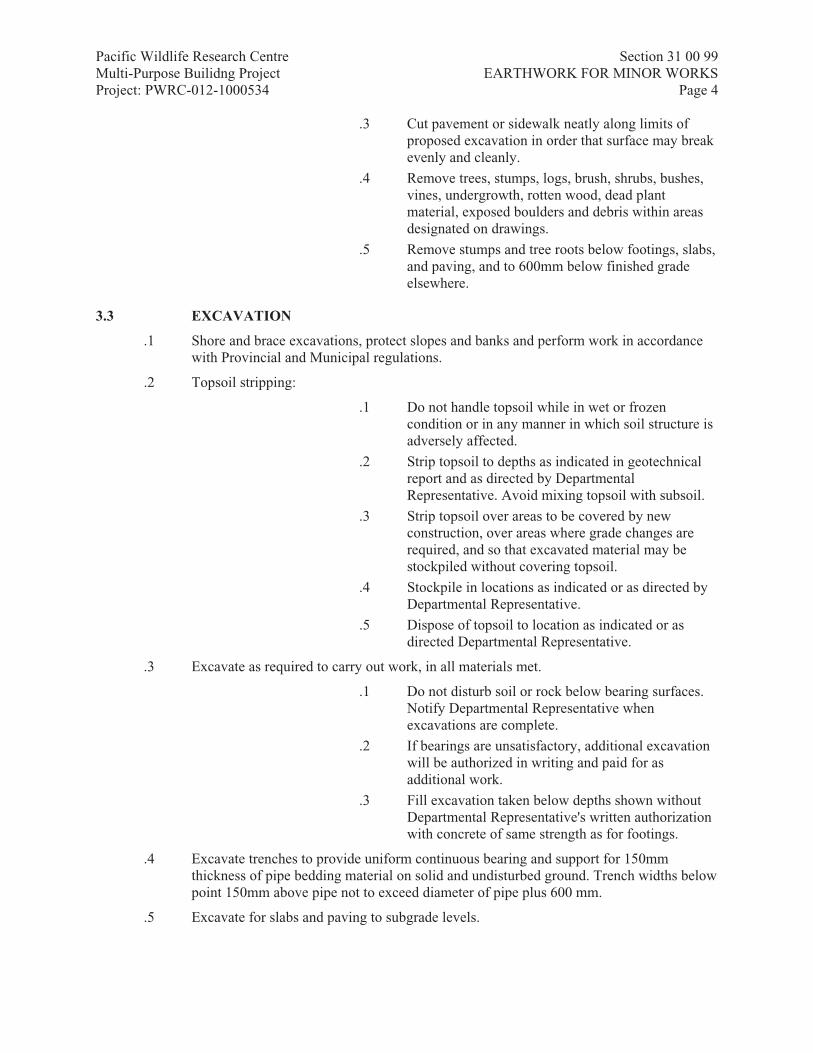
Pacific Wildlife Research Centre Section 31 00 99 Multi-Purpose Builidng Project EARTHWORK FOR MINOR WORKS Project: PWRC-012-1000534 Page 4
.3 Cut pavement or sidewalk neatly along limits of proposed excavation in order that surface may break evenly and cleanly.
.4 Remove trees, stumps, logs, brush, shrubs, bushes, vines, undergrowth, rotten wood, dead plant material, exposed boulders and debris within areas designated on drawings.
.5 Remove stumps and tree roots below footings, slabs, and paving, and to 600mm below finished grade elsewhere.
3.3 EXCAVATION
.1 Shore and brace excavations, protect slopes and banks and perform work in accordance with Provincial and Municipal regulations.
.2 Topsoil stripping:
.1 Do not handle topsoil while in wet or frozen condition or in any manner in which soil structure is adversely affected.
.2 Strip topsoil to depths as indicated in geotechnical report and as directed by Departmental Representative. Avoid mixing topsoil with subsoil.
.3 Strip topsoil over areas to be covered by new construction, over areas where grade changes are required, and so that excavated material may be stockpiled without covering topsoil.
.4 Stockpile in locations as indicated or as directed by Departmental Representative.
.5 Dispose of topsoil to location as indicated or as directed Departmental Representative.
.3 Excavate as required to carry out work, in all materials met.
.1 Do not disturb soil or rock below bearing surfaces. Notify Departmental Representative when excavations are complete.
.2 If bearings are unsatisfactory, additional excavation will be authorized in writing and paid for as additional work.
.3 Fill excavation taken below depths shown without Departmental Representative's written authorization with concrete of same strength as for footings.
.4 Excavate trenches to provide uniform continuous bearing and support for 150mm thickness of pipe bedding material on solid and undisturbed ground. Trench widths below point 150mm above pipe not to exceed diameter of pipe plus 600 mm.
.5 Excavate for slabs and paving to subgrade levels.

Pacific Wildlife Research Centre Section 31 00 99 Multi-Purpose Builidng Project EARTHWORK FOR MINOR WORKS Project: PWRC-012-1000534 Page 5
.1 Remove topsoil, organic matter, debris and other loose and harmful matter encountered at subgrade level.
3.4 SITE QUALITY CONTROL
.1 Fill material and spaces to be filled to be inspected and approved by Departmental Representative.
3.5 BACKFILLING
.1 Start backfilling only after inspection and receipt of written approval of fill material and spaces to be filled from Departmental Representative.
.2 Remove snow, ice, construction debris, organic soil and standing water from spaces to be filled.
.3 Lateral support: maintain even levels of backfill around structures as work progresses, to equalize earth pressures.
.4 Compaction of subgrade: compact existing subgrade under walks, paving, and slabs on grade, to same compaction as specified for fill. Fill excavated areas with selected subgrade material, gravel and sand compacted as specified for fill.
.5 Placing:
.1 Place backfill, fill and basecourse material in 150 mm lifts. Add water as required to achieve specified density.
.2 Place unshrinkable fill in areas as indicated. Consolidate and level unshrinkable fill with internal vibrators.
.6 Compaction: compact each layer of material to following densities for material to [ASTM D698]:
.1 To underside of basecourses: 95%.
.2 Basecourses: 100%.
.3 Elsewhere: 90%.
.7 Under slabs and paving:
.1 Use 19mm minus crushed gravel
.2 Use 75mm minus subbase gravel
.8 In trenches:
.1 Up to 300 mm above pipe or conduit: 19mm minus crushed gravel.
.2 Over 300 mm above pipe or conduit: 19mm minus crushed gravel.
.9 Under seeded and sodded areas: use site excavated material to bottom of topsoil except in trenches and within 600 mm of foundations.

Pacific Wildlife Research Centre Section 31 00 99 Multi-Purpose Builidng Project EARTHWORK FOR MINOR WORKS Project: PWRC-012-1000534 Page 6
.10 Blown rock material, not capable of fine grading, is not acceptable, imported material must be placed on this type of material.
.11 Against foundations (except as applicable to trenches and under slabs and paving): excavated material or imported material with no stones larger than 100 mm diameter within 600 mm of structures.
.12 Underground tanks: use 19mm minus crushed gravel to bottom of granular base courses or to bottom of topsoil, as applicable.
3.6 GRADING
.1 Grade to ensure that water will drain away from buildings, walls and paved areas, to catch basins and other disposal areas approved by Departmental Representative. Grade to be gradual between finished spot elevations as indicated.
3.7 CLEANING
.1 Progress Cleaning: clean in accordance with Section 01 74 11- Cleaning.
.1 Dispose of cleared and grubbed material off site daily.
.2 Final Cleaning: upon completion remove surplus materials, rubbish, tools and equipment in accordance with Section 01 74 11- Cleaning.
.3 Waste Management: separate waste materials for recycling in accordance with Section 01 74 21- Construction/Demolition Waste Management and Disposal 01 35 21- LEED Requirements.
END OF SECTION

Pacific Wildlife Research Centre Section 31 05 16 Multi-Purpose Building Project AGGREGATE MATERIALS Project: PWRC-012-1000534 Page 1
Part 1 General
1.1 RELATED REQUIREMENTS
.1 This Section of the Specification forms parts of the Contract Documents and is to be read, interpreted and coordinated with all other parts.
1.2 REFERENCE STANDARDS
.1 ASTM International
.1 ASTM D4791-10, Standard Test Method for Flat Particles, Elongated Particles, or Flat and Elongated Particles in Coarse Aggregate.
1.3 ACTION AND INFORMATIONAL SUBMITTALS
.1 Submit in accordance with Section 01 33 00- Submittal Procedures.
.2 Product Data:
.1 Submit manufacturer's instructions, printed product literature and data sheets for aggregate materials and include product characteristics, performance criteria, physical size, finish and limitations.
.3 Samples:
.1 Allow continual sampling by Departmental Representative during production.
.2 Provide Departmental Representative with access to source and processed material for sampling.
.3 Provide front end loader or other suitable equipment including trained operator for stockpile sampling as necessary. Move samples to storage place as directed by Departmental Representative.
.4 Supply new or clean sample bags or containers according appropriate to aggregate materials.
.5 Pay cost of sampling and testing of aggregates which fail to meet specified requirements.
.4 Sustainable Design Submittals:
.1 Construction Waste Management:
.1 Submit project Waste Management Plan highlighting recycling and salvage requirements.
.2 Erosion and Sedimentation Control: submit copy of erosion and sedimentation control plan.
1.4 DELIVERY, STORAGE AND HANDLING
.1 Deliver, store and handle materials in accordance with Section with manufacturer's written instructions.
.2 Transportation and Handling: handle and transport aggregates to avoid segregation, contamination and degradation.

Pacific Wildlife Research Centre Section 31 05 16 Multi-Purpose Building Project AGGREGATE MATERIALS Project: PWRC-012-1000534 Page 2
.3 Storage: store washed materials or materials excavated from underwater 24 hours minimum to allow free water to drain and for materials to attain uniform water content.
Part 2 Products
2.1 MATERIALS
.1 Aggregate quality: sound, hard, durable material free from soft, thin, elongated or laminated particles, organic material, clay lumps or minerals, free from adherent coatings and injurious amounts of disintegrated pieces or other deleterious substances.
.2 Flat and elongated particles of coarse aggregate: to ASTM D4791.
.1 Greatest dimension to exceed 5 times least dimension.
.3 Fine aggregates satisfying requirements of applicable section to be following:
.1 Screenings produced in crushing of quarried rock, boulders, gravel or slag.
.4 Coarse aggregates satisfying requirements of applicable section to be one of or blend of following:
.1 Crushed rock.
.2 Gravel and crushed gravel composed of naturally formed particles of stone.
.3 Light weight aggregate, including slag and expanded shale.
2.2 SOURCE QUALITY CONTROL
.1 Inform Departmental Representative of proposed source of aggregates and provide access for sampling 4 weeks minimum before starting production.
.2 If materials from proposed source do not meet, or cannot reasonably be processed to meet, specified requirements, locate alternative source.
.3 Advise Departmental Representative 4 weeks minimum in advance of proposed change of material source.
.4 Acceptance of material at source does not preclude future rejection if it fails to conform to requirements specified, lacks uniformity, or if its field performance is found to be unsatisfactory.
Part 3 Execution
3.1 EXAMINATION
.1 Verification of Conditions: verify that conditions are acceptable for topsoil stripping.
.1 Visually inspect substrate in presence of Departmental Representative.
.2 Inform Departmental Representative of unacceptable conditions immediately upon discovery.
.3 Proceed with topsoil stripping only after unacceptable conditions have been remedied and after receipt of written approval to proceed from Departmental Representative.

Pacific Wildlife Research Centre Section 31 05 16 Multi-Purpose Building Project AGGREGATE MATERIALS Project: PWRC-012-1000534 Page 3
3.2 PREPARATION
.1 Topsoil stripping:
.1 Do not handle topsoil while in wet or frozen condition or in any manner in which soil structure is adversely affected.
.2 Begin topsoil stripping of areas as directed by Departmental Representative after area has been cleared of grasses and removed from site.
.3 Strip topsoil to depths as directed by Departmental Representative. Avoid mixing topsoil with subsoil.
.4 Stockpile in locations as directed by Departmental Representative. Stockpile height not to exceed 2m.
.5 Dispose of topsoil off site.
.2 Aggregate source preparation:
.1 Prior to excavating materials for aggregate production, clear and grub area to be worked, and strip unsuitable surface materials. Dispose of cleared, grubbed and unsuitable materials as directed by Departmental Representative.
.2 Where clearing is required, leave screen of trees between cleared area and roadways as directed.
.3 Clear, grub and strip area ahead of quarrying or excavating operation sufficient to prevent contamination of aggregate by deleterious materials.
.4 When excavation is completed dress sides of excavation to nominal 1.5:1 slope, and provide drains or ditches as required to prevent surface standing water.
.5 Trim off and dress slopes of waste material piles and leave site in neat condition.
.6 Provide silt fence or other means to prevent contamination of existing watercourse or natural wetland features.
.3 Processing:
.1 Process aggregate uniformly using methods that prevent contamination, segregation and degradation.
.2 Blend aggregates, as required, including reclaimed materials that meet physical requirements of specification is permitted in order to satisfy gradation requirements for material and, percentage of crushed particles, or particle shapes specified.
.1 Use methods and equipment approved in writing by Departmental Representative.
.4 When operating in stratified deposits use excavation equipment and methods that produce uniform, homogeneous aggregate gradation.
.5 Where necessary, screen, crush, wash, classify and process aggregates with suitable equipment to meet requirements.
.1 Use only equipment approved in writing by Departmental Representative.
.6 Stockpiling:
.1 Stockpile aggregates on site in locations as indicated unless directed otherwise by Departmental Representative. Do not stockpile on completed pavement surfaces.
.2 Stockpile aggregates in sufficient quantities to meet project schedules.

Pacific Wildlife Research Centre Section 31 05 16 Multi-Purpose Building Project AGGREGATE MATERIALS Project: PWRC-012-1000534 Page 4
.3 Stockpiling sites to be level, well drained, and of adequate bearing capacity and stability to support stockpiled materials and handling equipment.
.4 Except where stockpiled on acceptably stabilized areas, provide compacted sand base not less than 300mm in depth to prevent contamination of aggregate. Stockpile aggregates on ground but do not incorporate bottom 300mm of pile into Work.
.5 Separate different aggregates by strong, full depth bulkheads, or stockpile far enough apart to prevent intermixing.
.6 Do not use intermixed or contaminated materials. Remove and dispose of rejected materials as directed by Departmental Representative within 48 hours of rejection.
.7 Stockpile materials in uniform layers of thickness as follows:
.1 Maximum 1.0m for coarse aggregate and base course materials.
.2 Maximum 1.0m for fine aggregate and sub-base materials.
.3 Maximum 1.0m for other materials.
.8 Uniformly spot-dump aggregates delivered to stockpile in trucks and build up stockpile as specified.
.9 Do not cone piles or spill material over edges of piles.
.10 Do not use conveying stackers.
.11 During winter operations, prevent ice and snow from becoming mixed into stockpile or in material being removed from stockpile.
3.3 CLEANING
.1 Progress Cleaning: Leave Work area clean at end of each day.
.2 Final Cleaning: upon completion remove surplus materials, rubbish, tools and equipment.
.3 Leave aggregate stockpile site in tidy, well drained condition, free of standing surface water.
.4 Leave any unused aggregates in neat compact stockpiles as directed by Departmental Representative.
.5 For temporary or permanent abandonment of aggregate source, restore source to condition meeting requirements of authority having jurisdiction.
.6 Restrict public access to temporary or permanently abandoned stockpiles by means acceptable to Departmental Representative.
END OF SECTION

Pacific Wildlife Research Centre Section 31 11 00 Multi-Purpose Building Project CLEARING AND GRUBBING Project: PWRC-012-1000534 Page 1
Approved: 2016-04-18
Part 1 General
1.1 RELATED REQUIREMENTS
.1 This section of the Specification forms parts of the Contract Documents and is to be read, interpreted and coordinated with all other parts.
1.2 MEASUREMENT PROCEDURES
.1 Measure following items in hectares within limits as indicated:
.1 Clearing.
.2 Grubbing.
.3 Close cut clearing.
.4 Underbrush clearing.
.2 Measure clearing isolated trees and grubbing isolated tree stumps as number of isolated trees cleared and number of isolated stumps grubbed.
.3 Fixed price payment will be made for:
.1 Clearing.
.2 Close cut clearing.
.3 Clearing isolated trees.
.4 Grubbing.
1.3 REFERENCE STANDARDS
.1 U.S. Environmental Protection Agency (EPA)/Office of Water
.1 EPA 832R92005, Storm Water Management for Construction Activities: Developing Pollution Prevention Plans and Best Management Practices.
1.4 DEFINITIONS
.1 Clearing consists of cutting off trees and brush vegetative growth to not more than specified height above ground and disposing of felled trees, previously uprooted trees and stumps, and surface debris.
.2 Close-cut clearing consists of cutting off standing trees, brush, scrub, roots, stumps and embedded logs, removing at, or close to, existing grade and disposing of fallen timber and surface debris.
.3 Clearing isolated trees consists of cutting off to not more than specified height above ground of designated trees, and disposing of felled trees and debris.
.4 Underbrush clearing consists of removal from treed areas of undergrowth, deadwood, and trees smaller than 50 mm trunk diameter and disposing of fallen timber and surface debris.
.5 Grubbing consists of excavation and disposal of stumps and roots to not less than specified depth below existing ground surface.

Pacific Wildlife Research Centre Section 31 11 00 Multi-Purpose Building Project CLEARING AND GRUBBING Project: PWRC-012-1000534 Page 2
.6 EAB refers to Emerald Ash Borer a non-native, invasive beetle that is highly destructive to ash trees where it occurs.
.1 Woodchips in the context of EAB consist of untreated, raw bark and wood fragments broken or shredded from logs or branches. Woodchips are to be less than 2.5 cm in at least any two dimensions.
.2 Firewood in the context of EAB consists of non-manufactured, solid wood material, with or without bark, cut into sizes less than 1.2 metres long and less than 25 cm in diameter which may be handled manually.
.3 Logs in the context of EAB consist of untreated, raw wood greater than 1.2 metres in length and greater than 25 cm diameter.
.4 Enclosed vehicle in the context of EAB consist of any vehicle transporting regulated wood material that is equipped to prelude the loss of materials or the escape of EAB while in transit.
1.5 ACTION AND INFORMATIONAL SUBMITTALS
.1 Provide submittals in accordance with Section 01 33 00- Submittal Procedures.
.2 Samples:
.1 Upon request submit 2 samples of each material listed below for approval prior to delivery of materials to project site.
.2 Tree wound paint: one litre can with manufacturer's label.
.3 Herbicide: one litre can with manufacturer's label.
.3 Submit certificates signed by manufacturer certifying that materials comply with specified performance characteristics and physical properties.
.4 Provide manufacturer's installation instructions.
1.6 QUALITY ASSURANCE
.1 Do construction occupational health and safety in accordance with Section 01 35 29.06- Health and Safety Requirements.
.2 Safety Requirements: worker protection.
.1 Workers must wear long sleeved clothing, gloves, eye protection, respirators protective clothing when applying herbicide materials.
.2 Workers must wear long sleeved clothing, gloves, safety boots, protective clothing, eye protection, safety vests when clearing and grubbing.
.3 Workers must not eat, drink or smoke while applying herbicide material.
.4 Clean up spills of preservative materials immediately with absorbent material and safely discard to landfill.
1.7 STORAGE AND PROTECTION
.1 Prevent damage to existing buildings, natural features, root systems of trees, site appurtenances, fencing, water courses, existing pavement, utility lines, bench marks, trees, landscaping, shrubs which are to remain.
.1 Repair damaged items to approval of Departmental Representative.

Pacific Wildlife Research Centre Section 31 11 00 Multi-Purpose Building Project CLEARING AND GRUBBING Project: PWRC-012-1000534 Page 3
.2 Replace trees designated to remain, if damaged, as directed DCC Representative.
1.8 WASTE MANAGEMENT AND DISPOSAL
.1 Separate waste materials for recycling in accordance with Section 01 74 21- Construction/Demolition Waste Management and Disposal.
.2 Ash wood mixed with the wood of other species is to all be managed and disposed of as ash wood.
Part 2 Products
2.1 MATERIALS
.1 Bituminous based paint of standard manufacture specially formulated for tree wounds.
.2 Soil Material for Fill:
.1 Excavated soil material: free of debris, roots, wood, scrap material, vegetable matter, refuse, soft unsound particles, deleterious, or objectionable materials.
.2 Remove and store soil material for reuse.
Part 3 Execution
3.1 TEMPORARY EROSION AND SEDIMENTATION CONTROL
.1 Provide temporary erosion and sedimentation control measures to prevent soil erosion and discharge of soil-bearing water runoff or airborne dust to adjacent properties and walkways, according to requirements of authorities having jurisdiction, sediment and erosion control drawings.
.2 Inspect, repair, and maintain erosion and sedimentation control measures during construction until permanent vegetation has been established.
.3 Remove erosion and sedimentation controls and restore and stabilize areas disturbed during removal.
3.2 PREPARATION
.1 Inspect site and verify with Departmental Representative, items designated to remain.
.2 Locate and protect utility lines: preserve in operating condition active utilities traversing site.
.1 Notify Departmental Representative immediately of damage to or when unknown existing utility lines are encountered.
.2 When utility lines which are to be removed are encountered within area of operations, notify Departmental Representative in ample time to minimize interruption of service.
.3 Notify utility authorities before starting clearing.
.4 Keep roads and walks free of dirt and debris.

Pacific Wildlife Research Centre Section 31 11 00 Multi-Purpose Building Project CLEARING AND GRUBBING Project: PWRC-012-1000534 Page 4
3.3 APPLICATION
.1 Manufacturer's instructions: comply with manufacturer's written recommendations or specifications, including product technical bulletins, handling, storage and installation instructions, and datasheet.
3.4 CLEARING
.1 Clearing includes cutting, felling, trimming, of trees into sections and satisfactory disposal of trees and other vegetation designated for removal, including snags, brush, rubbish downed timber, occurring within cleared areas.
.2 Clear as directed by Departmental Representative, by cutting at height of not more than 300mm above ground. In areas to be subsequently grubbed, height of stumps left from clearing operations to be not more than 1000mm above ground surface.
.3 Cut off branches overhanging area cleared as directed by Departmental Representative.
.4 Cut off unsound branches on trees designated to remain as directed by Departmental Representative.
3.5 CLOSE CUT CLEARING
.1 Close cut clearing to ground level.
.2 Cut off branches overhanging area cleared as directed by Departmental Representative.
.3 Cut off unsound branches on trees designated to remain as directed by Departmental Representative.
3.6 ISOLATED TREES
.1 Cut off isolated trees as directed by Departmental Representativeat height of not more than 300mm above ground surface.
.2 Grub out isolated tree stumps.
.3 Prune individual trees as indicated.
.4 Trim trees designated to be left standing within cleared areas of dead branches 4cm or more in diameter; and trim branches to heights as indicated.
.5 Cut limbs and branches to be trimmed close to bole of tree or main branches.
.6 Paint cuts more than 3cm in diameter with approved tree wound paint.
3.7 UNDERBRUSH CLEARING
.1 Clear underbrush from areas as indicated at ground level.
3.8 GRUBBING
.1 Remove and dispose of roots larger than 7.5cm in diameter, matted roots, and designated stumps from indicated grubbing areas.
.2 Grub out stumps and roots to not less than 200mm below ground surface.
.3 Grub out visible rock fragments and boulders, greater than 300mm in greatest dimension, but less than 0.25m3.

Pacific Wildlife Research Centre Section 31 11 00 Multi-Purpose Building Project CLEARING AND GRUBBING Project: PWRC-012-1000534 Page 5
.4 Fill depressions made by grubbing with suitable material and to make new surface conform with existing adjacent surface of ground.
3.9 REMOVAL AND DISPOSAL
.1 Remove grubbed, cleared materials off site designated by Departmental Representative to disposal area.
.2 Cut timber greater than 125mm diameter to 450mm lengths and stockpile as indicated. Stockpiled timber becomes property of Departmental Representative.
.3 Remove diseased trees identified by Departmental Representative and dispose of this material to approval of Departmental Representative.
.4 Any ash wood materials or firewood which is removed from the site is to be transported in an enclosed vehicle and disposed of at an authorized disposal facility.
.5 The Contractor is responsible for monitoring all cut ash wood and firewood until it is properly disposed of as determined by Departmental Representative.
3.10 FINISHED SURFACE
.1 Leave ground surface in condition suitable for immediate grading operations stripping of topsoil to approval of Departmental Representative.
3.11 CLEANING
.1 Proceed in accordance with Section 01 74 11- Cleaning.
.2 On completion and verification of performance of installation, remove surplus materials, excess materials, rubbish, flagging tape, tools and equipment.
END OF SECTION

Pacific Wildlife Research Centre Section 31 22 13 Multi-Purpose Building Project ROUGH GRADING Project: PWRC-012-1000534 Page 1
Approved: 2012-06-30
Part 1 General
1.1 RELATED REQUIREMENTS
.1 This section of the specification forms parts of the Contract Documents and is to be read, interpreted and coordinated with all other parts.
1.2 REFERENCE STANDARDS
.1 ASTM International
.1 ASTM D698-[07e1], Test Method for Laboratory Compaction Characteristics of Soil Using Standard Effort (600 kN-m/m3).
.2 Canada Green Building Council (CaGBC)
.1 LEED Canada-NC Version 1.0-[2004], LEED (Leadership in Energy and Environmental Design): Green Building Rating System for New Construction and Major Renovations (including Addendum [2007]).
.2 LEED Canada-NC-[2009], LEED (Leadership in Energy and Environmental Design): Green Building Rating System for New Construction and Major Renovations 2009.
.3 LEED Canada-CI Version 1.0-[2007], LEED (Leadership in Energy and Environmental Design): Green Building Rating System for Commercial Interiors.
.4 LEED Canada-EB: O&M-[2009], LEED (Leadership in Energy and Environmental Design): Green Building Rating System for Existing Buildings: Operations and Maintenance 2009.
.3 Underwriters' Laboratories of Canada (ULC)
1.3 ACTION AND INFORMATIONAL SUBMITTALS
.1 Submit in accordance with Section 01 33 00- Submittal Procedures.
.2 Sustainable Design Submittals:
.1 LEED Canada submittals: in accordance with Section 01 35 21- LEED Requirements.
.2 Construction Waste Management:
.1 Submit project Waste Management Plan highlighting recycling and salvage requirements.
.2 Submit calculations on end-of-project recycling rates, salvage rates, and landfill rates demonstrating that 50% of construction wastes were recycled or salvaged.
.3 Erosion and Sedimentation Control: submit copy of erosion and sedimentation control plan in accordance with authorities having jurisdiction Section 01 35 21- LEED Requirements.

Pacific Wildlife Research Centre Section 31 22 13 Multi-Purpose Building Project ROUGH GRADING Project: PWRC-012-1000534 Page 2
1.4 EXISTING CONDITIONS
.1 Examine subsurface investigation report by EXP Services Inc. dated February 16, 2017.
.2 Known underground and surface utility lines and buried objects are as indicated on site plan.
.3 Refer to dewatering in Section 31 23 33.01- Excavating, Trenching and Backfilling.
Part 2 Products
2.1 MATERIALS
.1 Fill material: 31 23 33.01- Excavating, Trenching and Backfilling
.2 Excavated or graded material existing on site suitable to use as fill for grading work if approved by Departmental Representative.
Part 3 Execution
3.1 EXAMINATION
.1 Verification of Conditions: verify that conditions of substrate previously installed under other Sections or Contracts are acceptable for rough grading installation in accordance with manufacturer's written instructions.
.1 Visually inspect substrate in presence of Departmental Representative.
.2 Inform Departmental Representative of unacceptable conditions immediately upon discovery.
.3 Proceed with installation only after unacceptable conditions have been remedied and after receipt of written approval to proceed from Departmental Representative.
3.2 STRIPPING OF TOPSOIL
.1 Do not handle topsoil while in wet or frozen condition or in any manner in which soil structure is adversely affected as determined by Departmental Representative.
.2 Commence topsoil stripping of areas as indicated after area has been cleared of brush, weeds and removed from site.
.3 Strip topsoil to depths as indicated or as directed by Departmental Representative. Rototill grasses and retain as topsoil on site. Avoid mixing topsoil with subsoil.
.4 Stockpile in locations as indicated or directed by Departmental. Stockpile height not to exceed 2 m.
.5 Dispose of unused topsoil to location as directed by Departmental Representative.
3.3 GRADING
.1 Rough grade to levels, profiles, and contours allowing for surface treatment as indicated.
.2 Rough grade to following minimum depths below finish grades:

Pacific Wildlife Research Centre Section 31 22 13 Multi-Purpose Building Project ROUGH GRADING Project: PWRC-012-1000534 Page 3
.1 300mm – asphalt paving.
.2 400mm – concrete walkways
.3 300mm – asphalt walkways
.4 300mm – crushed gravel surface
.3 Slope rough grade away from building as indicated 1:50 minimum.
.4 Grade ditches to depth as indicated.
.5 Prior to placing fill over existing ground, scarify surface to depth of 150 mm minimum before placing fill over existing ground. Maintain fill and existing surface at approximately same moisture content to facilitate bonding.
.6 Compact filled and disturbed areas to maximum dry density to ASTM D698, as follows:
.1 85% under landscaped areas.
.2 100% under paved and walk areas.
.7 Do not disturb soil within branch spread of trees or shrubs to remain.
3.4 TESTING
.1 Inspection and testing of soil compaction will be carried out by testing laboratory designated by ULC. Costs of tests will be paid by Owner in accordance with Sections 01 29 83- Payment Procedures for Testing Laboratory Services and 01 45 00- Quality Control.
.2 Submit testing procedure, frequency of tests, to Departmental Representative for review.
3.5 CLEANING
.1 Progress Cleaning: clean in accordance with Section 01 74 11- Cleaning.
.1 Leave Work area clean at end of each day.
.2 Final Cleaning: upon completion remove surplus materials, rubbish, tools and equipment in accordance with Section 01 74 11- Cleaning.
.3 Waste Management: separate waste materials for reuse in accordance with Section 01 74 21- Construction/Demolition Waste Management and Disposal 01 35 21- LEED Requirements.
.1 Remove recycling containers and bins from site and dispose of materials at appropriate facility.
3.6 PROTECTION
.1 Protect existing trees, fencing, landscaping, natural features, bench marks, buildings, pavement, surface or underground utility lines which are to remain as directed by Departmental Representative. If damaged, restore to original or better condition unless directed otherwise.
.2 Maintain access roads to prevent accumulation of construction related debris on roads.
END OF SECTION

Pacific Wildlife Research Centre Section 31 23 33.01 Multi Purpose Building Project EXCAVATING, TRENCHING AND BACKFILLING Project: PWRC-012-1000534 Page 1
Part 1 General
1.1 RELATED REQUIREMENTS
.1 This Section of the Specification forms parts of the Contract Documents and is to be read, interpreted and coordinated with all other parts.
1.2 MEASUREMENT PROCEDURES
.1 Excavated materials will be measured in cubic metres in their original location.
.1 Common excavation quantities measured will be actual volume removed within following limits:
.1 Width for trench excavation as indicated.
.2 Sheeting and bracing left in place on direction of Departmental Representative will be measured in square metres of surface area of plane surface of sheeting.
.3 Shoring, bracing, cofferdams, underpinning and de-watering of excavation will not be measured separately for payment.
.4 Backfilling to authorized excavation limits will be measured in cubic metres compacted in place for each type of material specified.
.5 Placing and spreading of topsoil will be measured for payment in cubic metres calculated from cross sections taken in area of excavation from original location.
.1 If double handling of topsoil is directed Departmental Representative (stockpiling and later placing), then quantities will be measured twice; on excavation from original location and on excavation from stockpile.
1.3 REFERENCE STANDARDS
.1 American Society for Testing and Materials International (ASTM)
.1 ASTM C117-13, Standard Test Method for Material Finer than 0.075 mm (No.200) Sieve in Mineral Aggregates by Washing.
.2 ASTM C136-05, Standard Test Method for Sieve Analysis of Fine and Coarse Aggregates.
.3 ASTM D422-63-2007, Standard Test Method for Particle-Size Analysis of Soils.
.4 ASTM D698-12e2, Standard Test Methods for Laboratory Compaction Characteristics of Soil Using Standard Effort (12,400 ft-lbf/ft3) (600 kN-m/m3).
.5 ASTM D1557-12e1, Standard Test Methods for Laboratory Compaction Characteristics of Soil Using Modified Effort (56,000 ft-lbf/ft3) (2,700 kN-m/m3).
.6 ASTM D4318-05, Standard Test Methods for Liquid Limit, Plastic Limit, and Plasticity Index of Soils.
.2 Canadian General Standards Board (CGSB)
.1 CAN/CGSB-8.2-M88, Sieves, Testing, Woven Wire, Metric.
.3 Canadian Standards Association (CSA International)

Pacific Wildlife Research Centre Section 31 23 33.01 Multi Purpose Building Project EXCAVATING, TRENCHING AND BACKFILLING Project: PWRC-012-1000534 Page 2
.1 CAN/CSA-A3000-03, Cementitious Materials Compendium (Consists of A3001, A3002, A3003, A3004 and A3005).
.1 CSA-A3001-03, Cementitious Materials for Use in Concrete.
.2 CSA-A23.1/A23.2-04, Concrete Materials and Methods of Concrete Construction/Methods of Test and Standard Practices for Concrete.
1.4 DEFINITIONS
.1 Excavation classes: one classes of excavation will be recognized; common excavation.
.1 Common excavation: excavation of materials of whatever nature, which are not included under definitions of rock excavation.
.2 Unclassified excavation: excavation of deposits of whatever character encountered in Work.
.3 Topsoil:
.1 Material capable of supporting good vegetative growth and suitable for use in top dressing, landscaping and seeding.
.2 Material reasonably free from subsoil, clay lumps, brush, objectionable weeds, and other litter, and free from cobbles, stumps, roots, and other objectionable material larger than 25 millimeters in any dimension.
.4 Waste material: excavated material unsuitable for use in Work or surplus to requirements.
.5 Borrow material: material obtained from locations outside area to be graded, and required for construction of fill areas or for other portions of Work.
.6 Recycled fill material: material, considered inert, obtained from alternate sources and engineered to meet requirements of fill areas.
.7 Unsuitable materials:
.1 Weak, chemically unstable, and compressible materials.
.2 Frost susceptible materials:
.1 Fine grained soils with plasticity index less than 10 when tested to ASTM D4318. Sieve sizes to CAN/CGSB-8.2-M88.
.2 Table:Sieve Designation % Passing 2.00 mm [100] 0.10 mm [45 - 100] 0.02 mm [10 - 80] 0.005 mm [0 - 45]
.3 Coarse grained soils containing more than [20]% by mass passing 0.075 mm sieve.
.8 Unshrinkable fill: very weak mixture of cement, concrete aggregates and water that resists settlement when placed in utility trenches, and capable of being readily excavated.
1.5 ACTION AND INFORMATIONAL SUBMITTALS
.1 Make submittals in accordance with Section 01 33 00- Submittal Procedures.
.2 Quality Control: in accordance with Section 01 45 00- Quality Control:

Pacific Wildlife Research Centre Section 31 23 33.01 Multi Purpose Building Project EXCAVATING, TRENCHING AND BACKFILLING Project: PWRC-012-1000534 Page 3
.1 Submit condition survey of existing conditions as described in EXISTING CONDITIONS article of this Section.
.2 Submit to Departmental Representative written notice at least 7 days prior to excavation work, to ensure cross sections are taken.
.3 Submit to Departmental Representative written notice when bottom of excavation is reached.
.4 Submit to Departmental Representative results as described in PART 3 of this Section.
.3 Preconstruction Submittals:
.1 Submit construction equipment list for major equipment to be used in this section prior to start of Work.
.2 Submit records of underground utility locates, indicating: location plan of existing utilities as found in field.
.4 Samples:
.1 Submit samples in accordance with Section 01 33 00- Submittal Procedures.
.2 Inform Departmental Representative at least 4 weeks prior to beginning Work, of proposed source of fill materials and provide access for sampling.
.3 Ship samples to Departmental Representative, in tightly closed containers to prevent contamination and exposure to elements.
.4 At least 4 weeks prior to beginning Work, inform Departmental Representative source of fly ash and submit samples to Departmental Representative.
.1 Do not change source of Fly Ash without written approval of Departmental Representative.
1.6 QUALITY ASSURANCE
.1 Qualification Statement: submit proof of insurance coverage for professional liability.
.2 Where Departmental Representative is employee of Contractor, submit proof that Work by Departmental Representative is included in Contractor's insurance coverage.
.3 Submit design and supporting data at least 2 weeks prior to beginning Work.
.4 Design and supporting data submitted to bear stamp and signature of qualified professional engineer registered or licensed in British Columbia, Canada.
.5 Keep design and supporting data on site.
.6 Engage services of qualified professional Engineer who is registered or licensed in British Columbia, Canada in which Work is to be carried out to design and inspect cofferdams, shoring, bracing and underpinning required for Work.
.7 Do not use soil material until written report of soil test results are approved by Departmental Representative.
1.7 WASTE MANAGEMENT AND DISPOSAL
.1 Divert excess materials from landfill to local facility for reuse as directed by Departmental Representative.

Pacific Wildlife Research Centre Section 31 23 33.01 Multi Purpose Building Project EXCAVATING, TRENCHING AND BACKFILLING Project: PWRC-012-1000534 Page 4
1.8 EXISTING CONDITIONS
.1 Buried services:
.1 Before commencing work verify location of buried services on and adjacent to site.
.2 Arrange with appropriate authority for relocation of buried services that interfere with execution of work: pay costs of relocating services.
.3 Remove obsolete buried services within 2 m of foundations: cap cut-offs.
.4 Size, depth and location of existing utilities and structures as indicated are for guidance only. Completeness and accuracy are not guaranteed.
.5 Prior to beginning excavation Work, notify applicable Departmental Representative establish location and state of use of buried utilities and structures. Departmental Representative to clearly mark such locations to prevent disturbance during Work.
.6 Confirm locations of buried utilities by careful test excavations.
.7 Maintain and protect from damage, water, sewer, gas, electric, telephone and other utilities and structures encountered.
.8 Where utility lines or structures exist in area of excavation, obtain direction of Departmental Representative before re-routing. Costs for such Work to be paid by Departmental Representative.
.9 Record location of maintained, re-routed and abandoned underground lines.
.10 Confirm locations of recent excavations adjacent to area of excavation.
.2 Existing buildings and surface features:
.1 Conduct, with Departmental Representative, condition survey of existing buildings, trees and other plants, lawns, fencing, service poles, wires, rail tracks, pavement, survey bench marks and monuments which may be affected by Work.
.2 Protect existing buildings and surface features from damage while Work is in progress. In event of damage, immediately make repair as directed Departmental Representative.
.3 Where required for excavation, cut roots or branches as directed by Departmental Representative.
Part 2 Products
2.1 MATERIALS
.1 Type 1 and Type 2 fill: properties to Section 31 05 16- Aggregate Materials and the following requirements:
.1 Crushed, pit run or screened stone, gravel or sand.
.2 Gradations to be within limits specified when tested to ASTM C117 and ASTM C136. Sieve sizes to CAN/CGSB-8.2.

Pacific Wildlife Research Centre Section 31 23 33.01 Multi Purpose Building Project EXCAVATING, TRENCHING AND BACKFILLING Project: PWRC-012-1000534 Page 5
.3 Table:Sieve Designation % Passing Type 1 Type 2 75 mm - [100] 50 mm - - 37.5 mm - - 25 mm [100] - 19 mm [75-100] - 12.5 mm - - 9.5 mm [50-100] - 4.75 mm [30-70] [22-85] 2.00 mm [20-45] - 0.425 mm [10-25] [5-30] 0.180 mm - - 0.075 mm [3-8] [0-10]
.2 Type 3 fill: selected material from excavation or other sources, approved by Departmental Representative for use intended, unfrozen and free from rocks larger than 75mm, cinders, ashes, sods, refuse or other deleterious materials.
Part 3 Execution
3.1 TEMPORARY EROSION AND SEDIMENTATION CONTROL
.1 Provide temporary erosion and sedimentation control measures to prevent soil erosion and discharge of soil-bearing water runoff or airborne dust to adjacent properties and walkways.
.2 Inspect, repair, and maintain erosion and sedimentation control measures during construction until permanent vegetation has been established.
.3 Remove erosion and sedimentation controls and restore and stabilize areas disturbed during removal.
3.2 SITE PREPARATION
.1 Remove obstructions, ice and snow, from surfaces to be excavated within limits indicated.
.2 Cut pavement or sidewalk neatly along limits of proposed excavation in order that surface may break evenly and cleanly.
3.3 PREPARATION/PROTECTION
.1 Keep excavations clean, free of standing water, and loose soil.
.2 Where soil is subject to significant volume change due to change in moisture content, cover and protect to Departmental Representative approval.
.3 Protect natural and man-made features required to remain undisturbed. Unless otherwise indicated or located in an area to be occupied by new construction, protect existing trees from damage.

Pacific Wildlife Research Centre Section 31 23 33.01 Multi Purpose Building Project EXCAVATING, TRENCHING AND BACKFILLING Project: PWRC-012-1000534 Page 6
.4 Protect buried services that are required to remain undisturbed.
3.4 STRIPPING OF TOPSOIL
.1 Begin topsoil stripping of areas as directed by Departmental Representative after area has been cleared of grasses and removed from site.
.2 Strip topsoil to depths as directed by Departmental Representative.
.1 Do not mix topsoil with subsoil.
.3 Stockpile in locations as directed by Departmental Representative.
.1 Stockpile height not to exceed 2 m and should be protected from erosion.
.4 Dispose of unused topsoil off site.
3.5 STOCKPILING
.1 Stockpile fill materials in areas designated by Departmental Representative.
.1 Stockpile granular materials in manner to prevent segregation.
.2 Protect fill materials from contamination.
.3 Implement sufficient erosion and sediment control measures to prevent sediment release off construction boundaries and into water bodies.
3.6 EXCAVATION
.1 Advise Departmental Representative at least 7 days in advance of excavation operations for initial cross sections to be taken.
.2 Excavate to lines, grades, elevations and dimensions as directed by Departmental Representative.
.3 Remove obstructions encountered during.
.4 Excavation must not interfere with bearing capacity of adjacent foundations.
.5 Do not disturb soil within branch spread of trees or shrubs that are to remain.
.1 If excavating through roots, excavate by hand and cut roots with sharp axe or saw.
.6 For trench excavation, unless otherwise authorized by Departmental Representative in writing, do not excavate more than 30m of trench in advance of installation operations and do not leave open more than 15m at end of day's operation.
.7 Keep excavated and stockpiled materials safe distance away from edge of trench as directed by Departmental Representative.
.8 Restrict vehicle operations directly adjacent to open trenches.
.9 Dispose of surplus and unsuitable excavated material off site.
.10 Do not obstruct flow of surface drainage or natural watercourses.
.11 Earth bottoms of excavations to be undisturbed soil, level, free from loose, soft or organic matter.
.12 Notify Departmental Representative when bottom of excavation is reached.

Pacific Wildlife Research Centre Section 31 23 33.01 Multi Purpose Building Project EXCAVATING, TRENCHING AND BACKFILLING Project: PWRC-012-1000534 Page 7
.13 Obtain Departmental Representative approval of completed excavation.
.14 Remove unsuitable material from trench bottom including those that extend below required elevations to extent and depth as directed by Departmental Representative.
.15 Hand trim, make firm and remove loose material and debris from excavations.
.1 Where material at bottom of excavation is disturbed, compact foundation soil to density at least equal to undisturbed soil.
3.7 FILL TYPES AND COMPACTION
.1 Use types of fill as indicated or specified below. Compaction densities are percentages of maximum densities obtained from ASTM D698.
.1 Exterior side of perimeter walls: use Type 3 fill to subgrade level. Compact to 95% of corrected maximum dry density.
3.8 BEDDING AND SURROUND OF UNDERGROUND SERVICES
.1 Place and compact granular material for bedding and surround of underground services Section 33 41 00- Storm Utility Drainage Piping, Section 33 11 16- Site Water Utility Distribution Piping, Section 33 31 13- Public Sanitary Utility Sewerage Piping as specified.
.2 Place bedding and surround material in unfrozen condition.
3.9 BACKFILLING
.1 Do not proceed with backfilling operations until completion of following:
.1 Departmental Representative has inspected and approved installations.
.2 Departmental Representative has inspected and approved of construction below finish grade.
.3 Inspection, testing, approval, and recording location of underground utilities.
.4 Removal of concrete formwork.
.2 Areas to be backfilled to be free from debris, snow, ice, water and frozen ground.
.3 Do not use backfill material which is frozen or contains ice, snow or debris.
.4 Place backfill material in uniform layers not exceeding 150mm compacted thickness up to grades indicated. Compact each layer before placing succeeding layer.
.5 Backfilling around installations:
.1 Place bedding and surround material as specified elsewhere.
.2 Do not backfill around or over cast-in-place concrete within 24 hours after placing of concrete.
.3 Place layers simultaneously on both sides of installed Work to equalize loading.
.6 Place fill in areas as indicated.
.7 Consolidate and level unshrinkable fill with internal vibrators.

Pacific Wildlife Research Centre Section 31 23 33.01 Multi Purpose Building Project EXCAVATING, TRENCHING AND BACKFILLING Project: PWRC-012-1000534 Page 8
3.10 RESTORATION
.1 Upon completion of Work, remove waste materials and debris, trim slopes, and correct defects as directed by Departmental Representative.
.2 Replace topsoil as directed by Departmental Representative.
.3 Reinstate lawns to elevation which existed before excavation.
.4 Reinstate pavements and sidewalks disturbed by excavation to thickness, structure and elevation which existed before excavation.
.5 Clean and reinstate areas affected by Work as directed by Departmental Representative.
.6 Use temporary plating to support traffic loads over unshrinkable fill for initial 24 hours.
.7 Protect newly graded areas from traffic and erosion and maintain free of trash or debris.
END OF SECTION

Pacific Wildlife Research Centre SECT 32 12 16.02 Multi-Purpose Building Project ASPHALT PAVING FOR BUILDING SITES Project: PWRC-012-1000534 PAGE 1 2011-06-30
1 GENERAL
1.01 RELATED REQUIREMENTS
.1 This section of the specification forms parts of the Contract Documents and is to be read, interpreted and coordinated with all other parts.
1.02 MEASUREMENT AND PAYMENT
.1 Asphalt concrete pavement including granular base and sub-base will be measured in square metres of asphalt surface in place.
1.03 REFERENCE STANDARDS
.1 ASTM International .1 ASTM C 88-[05], Standard Test Method for Soundness of Aggregates by
Use of Sodium Sulphate or Magnesium Sulphate..2 ASTM C 117-[04], Standard Test Method for Material Finer Than 0.075
(No. 200) mm Sieve in Mineral Aggregates by Washing..3 ASTM C 123-[04], Standard Test Method for Lightweight Particles in
Aggregate..4 ASTM C 127-[07], Standard Test Method for Density, Relative Density
(Specific Gravity), and Absorption of Coarse Aggregate..5 ASTM C 128-[07a], Standard Test Method for Density, Relative Density
(Specific Gravity), and Absorption of Fine Aggregate..6 ASTM C 131-[06], Standard Test Method for Resistance to Degradation
of Small-Size Coarse Aggregate by Abrasion and Impact in the Los Angeles Machine.
.7 ASTM C 136-[06], Standard Method for Sieve Analysis of Fine and CoarseAggregates.
.8 ASTM D 698-[07e1], Standard Test Method for Laboratory Compaction Characteristics of Soil Using Standard Effort (12,400 ft-lbf/ftü) (600 kN-m/mü).
.9 ASTM D 995-[95b(2002)], Standard Specification for Mixing Plants for Hot-Mixed, Hot-Laid Bituminous Paving Mixtures.
.10 ASTM D 1557-[09], Standard Test Method for Laboratory Compaction Characteristics of Soil Using Modified Effort (56,000 ft-lbf/ftü) (2,700 kN-m/mü).
.11 ASTM D 1559-[89], Test Method for Resistance to Plastic Flow of Bituminous Mixtures Using Marshall Apparatus.
.12 ASTM D 2419-[09], Standard Test Method for Sand Equivalent Value of Soils and Fine Aggregate.
.13 ASTM D 3203-[05], Standard Test Method for Percent Air Voids in Compacted Dense and Open Bituminous Paving Mixtures.
.14 ASTM D 4318-[10], Standard Test Method for Liquid Limit, Plastic Limit and Plasticity Index of Soils.
.15 ASTM D 4791-[10], Standard Test Method for Flat Particles, Elongated Particles, or Flat and Elongated Particles in Coarse Aggregate.
.2 Asphalt Institute (AI) .1 AI MS-2-[94], Mix Design Methods for Asphalt Concrete and Other

Pacific Wildlife Research Centre SECT 32 12 16.02 Multi-Purpose Building Project ASPHALT PAVING FOR BUILDING SITES Project: PWRC-012-1000534 PAGE 2 2011-06-30
Hot-Mix Types.
.3 Canada Green Building Council (CaGBC) .1 LEED Canada-NC Version 1.0-[2004], LEED (Leadership in Energy and
Environmental Design): Green Building Rating System Reference Package For New Construction and Major Renovations (including Addendum [2007]).
.4 Canadian General Standards Board (CGSB) .1 CAN/CGSB-8.1-[88], Sieves Testing, Woven Wire, Inch Series. .2 CAN/CGSB-8.2-[M88], Sieves Testing, Woven Wire, Metric.
.5 U.S. Environmental Protection Agency (EPA) / Office of Water .1 EPA 832/R-92-005, Storm Water Management for Construction Activities:
Developing Pollution Prevention Plans and Best Management Practices.
1.04 ACTION AND INFORMATIONAL SUBMITTALS
.1 Submit in accordance with Section 01 33 00 - Submittal Procedures.
.2 Product Data: .1 Submit manufacturer's instructions, printed product literature and
data sheets for [asphalt paving mix, aggregate, and coatings] and include product characteristics, performance criteria, physical size, finish and limitations.
.3 Samples: .1 Submit asphalt concrete mix design for review. .2 Inform Departmental Representative of proposed source of aggregates
and provide access for sampling at least 2 weeks prior to commencing work.
.3 Submit samples of following materials proposed for use at least 2 weeks prior to commencing work:
.4 Test and Evaluation Reports: .1 Materials to be tested by accredited testing laboratory approved by
Departmental Representative..2 Submit test certificates showing suitability of materials at least
4 weeks prior to commencing work.
.5 Sustainable Design Submittals: .1 LEED Canada-[NC Version 1.0] Submittals: in accordance with Section
01 35 21 - LEED Requirements..2 Erosion and Sedimentation Control: submit copy of erosion and
sedimentation control plan in accordance with authorities having jurisdiction and Section 01 35 21 - LEED Requirements.
.3 Construction Waste Management: .1 Submit project Waste Management Plan highlighting recycling
and salvage requirements..2 Submit calculations on end-of-project recycling rates, salvage
rates, and landfill rates demonstrating that 50% of construction wastes were recycled or salvaged.
.4 Regional Materials: submit evidence that project incorporates required percentage 10% of regional materials and products, showing

Pacific Wildlife Research Centre SECT 32 12 16.02 Multi-Purpose Building Project ASPHALT PAVING FOR BUILDING SITES Project: PWRC-012-1000534 PAGE 3 2011-06-30
their cost, distance from project to furthest site of extraction or manufacture, and total cost of materials for project.
1.05 DELIVERY, STORAGE AND HANDLING
.1 Deliver, store and handle materials in accordance with Section 01 61 00 - Common Product Requirements and with manufacturer's written instructions.
.2 Storage and Handling Requirements: .1 Store materials in accordance with manufacturer's recommendations. .2 Store and protect aggregate. .3 Replace defective or damaged materials with new.
.3 Develop construction Waste Management Plan related to Work of this Section and in accordance with Section 01 35 21 - LEED Requirements.
.4 Packaging Waste Management: remove for reuse by manufacturer of packaging materials as specified in Construction Waste Management Plan in accordance with Section 01 74 21 - Construction/Demolition Waste Management and Disposal and Section 01 35 21 - LEED Requirements.
2 PRODUCTS
2.01 MATERIALS
.1 Granular base and sub-base material: to Section 31 05 16 - Aggregate Materials and following requirements:.1 Crushed or screened stone, gravel or sand. .2 Gradations: within limits specified when tested to [ASTM C 136] and
[ASTM C 117]. Sieve sizes to [CAN/CGSB-8.1] [CAN/CGSB-8.2]..3 Table:
Sieve Granular Base Granular Designation Sub-Base 200 mm - - - - 75 mm - - 100 - 50 mm - - - - 38.1 m - - 60-100 -
25 mm - - - -
19 mm - 100 35-80 - ] 12.5 mm - 75-10 - -
9.5 mm - 60-90 26-60 -
4.75 mm - 40-70 20-40 -
2.00 mm - 27-55 15-30 -
0.425 mm - 7-25 3-15 - ] 0.180 mm - - - -
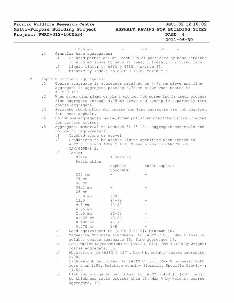
Pacific Wildlife Research Centre SECT 32 12 16.02 Multi-Purpose Building Project ASPHALT PAVING FOR BUILDING SITES Project: PWRC-012-1000534 PAGE 4 2011-06-30
0.075 mm - 3-8 0-5 -.4 Granular base aggregates:
.1 Crushed particles: at least 60% of particles by mass retained on 4.75 mm sieve to have at least 1 freshly fractured face.
.2 Liquid limit: to ASTM D 4318, maximum 25.
.3 Plasticity index: to ASTM D 4318, maximum 6.
.2 Asphalt concrete aggregates: .1 Coarse aggregate is aggregate retained on 4.75 mm sieve and fine
aggregate is aggregate passing 4.75 mm sieve when tested to ASTM C 117.
.2 When dryer drum plant or plant without hot screening is used, process fine aggregate through 4.75 mm sieve and stockpile separately from coarse aggregate.
.3 Separate stock piles for coarse and fine aggregate are not required for sheet asphalt.
.4 Do not use aggregates having known polishing characteristics in mixes for surface courses.
.5 Aggregate: material to Section 31 05 16 - Aggregate Materials and following requirements:.1 Crushed stone or gravel. .2 Gradations to be within limits specified when tested to
ASTM C 136 and ASTM C 117. Sieve sizes to CAN/CGSB-8.1 CAN/CGSB-8.2.
.3 Table: Sieve % Passing Designation Asphalt Sheet Asphalt Concrete 200 mm - - 75 mm - - 50 mm - - 38.1 mm - - 25 mm - - 19.0 mm 100 - 12.5 84-99 - 9.5 mm 73-88 - 4.75 mm 50-68 - 2.00 mm 35-55 - 0.425 mm 10-26 - 0.180 mm 4-17 - 0.075 mm 3-8 -
.4 Sand equivalent: to [ASTM D 2419], Minimum 40.
.5 Magnesium Sulphate soundness: to [ASTM C 88]. Max % loss by weight: coarse aggregate 15, fine aggregate 18.
.6 Los Angeles Degradation: to [ASTM C 131]. Max % loss by weight: coarse aggregate, 35.
.7 Absorption: to [ASTM C 127]. Max % by weight: coarse aggregate, 2.00.
.8 Lightweight particles: to [ASTM C 123]. Max % by mass, with less than 1.95. Relative density (formally Specific Gravity): [1.5].
.9 Flat and elongated particles: to [ASTM D 4791], (with length to thickness ratio greater than 5): Max % by weight: coarse aggregate, 10.
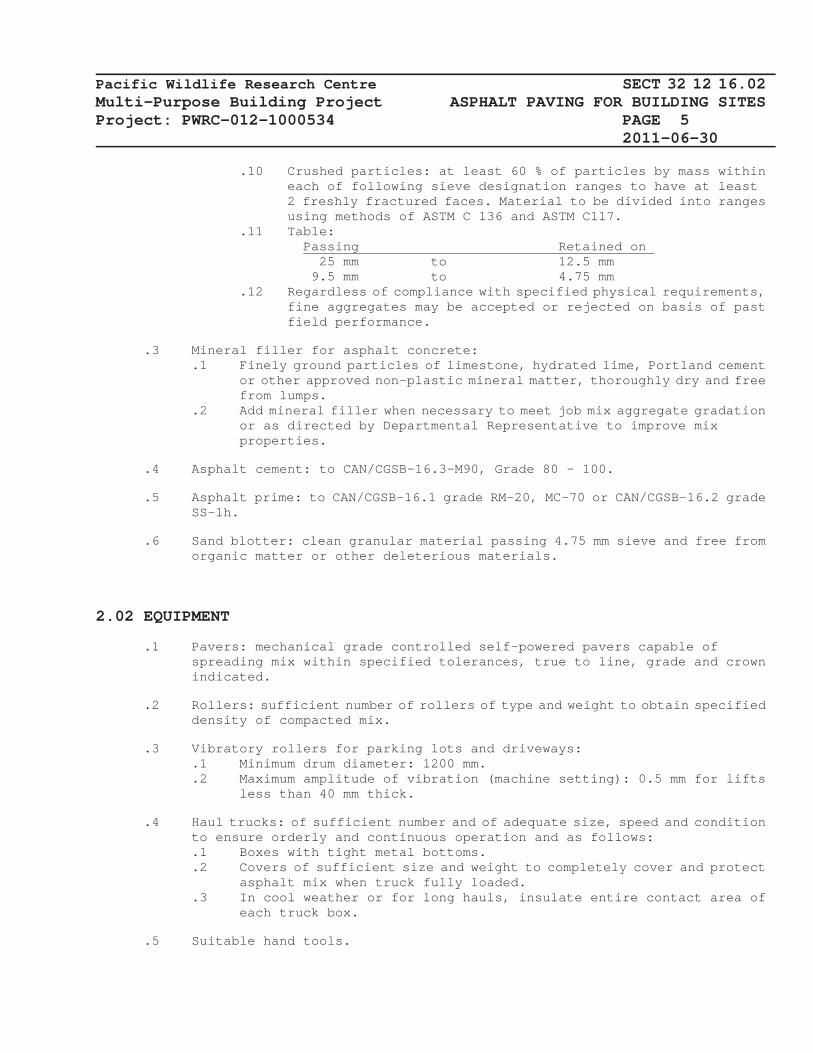
Pacific Wildlife Research Centre SECT 32 12 16.02 Multi-Purpose Building Project ASPHALT PAVING FOR BUILDING SITES Project: PWRC-012-1000534 PAGE 5 2011-06-30
.10 Crushed particles: at least 60 % of particles by mass within each of following sieve designation ranges to have at least 2 freshly fractured faces. Material to be divided into ranges using methods of ASTM C 136 and ASTM C117.
.11 Table: Passing Retained on 25 mm to 12.5 mm 9.5 mm to 4.75 mm
.12 Regardless of compliance with specified physical requirements, fine aggregates may be accepted or rejected on basis of past field performance.
.3 Mineral filler for asphalt concrete: .1 Finely ground particles of limestone, hydrated lime, Portland cement
or other approved non-plastic mineral matter, thoroughly dry and free from lumps.
.2 Add mineral filler when necessary to meet job mix aggregate gradation or as directed by Departmental Representative to improve mix properties.
.4 Asphalt cement: to CAN/CGSB-16.3-M90, Grade 80 - 100.
.5 Asphalt prime: to CAN/CGSB-16.1 grade RM-20, MC-70 or CAN/CGSB-16.2 grade SS-1h.
.6 Sand blotter: clean granular material passing 4.75 mm sieve and free from organic matter or other deleterious materials.
2.02 EQUIPMENT
.1 Pavers: mechanical grade controlled self-powered pavers capable of spreading mix within specified tolerances, true to line, grade and crown indicated.
.2 Rollers: sufficient number of rollers of type and weight to obtain specified density of compacted mix.
.3 Vibratory rollers for parking lots and driveways: .1 Minimum drum diameter: 1200 mm. .2 Maximum amplitude of vibration (machine setting): 0.5 mm for lifts
less than 40 mm thick.
.4 Haul trucks: of sufficient number and of adequate size, speed and condition to ensure orderly and continuous operation and as follows:.1 Boxes with tight metal bottoms. .2 Covers of sufficient size and weight to completely cover and protect
asphalt mix when truck fully loaded..3 In cool weather or for long hauls, insulate entire contact area of
each truck box.
.5 Suitable hand tools.

Pacific Wildlife Research Centre SECT 32 12 16.02 Multi-Purpose Building Project ASPHALT PAVING FOR BUILDING SITES Project: PWRC-012-1000534 PAGE 6 2011-06-30
2.03 MIX DESIGN
.1 Mix design to [AI MS-2].
.2 Job mix formula to be approved by Departmental Representative.
.3 Design of mix: by Marshall method to requirements below: .1 Compaction blows on each face of test specimens: 75. .2 Mix physical requirements:
Property Sheet Asphalt Concrete Marshall 6.4 Stability at 60 degrees C, kN minimum. Flow Value, 2-4 mm. Air Voids in 3-6 Mixture, % Voids in 14 Mineral Aggregate, % minimum Index of 75 Retained Stability, % minimum
.3 Measure physical requirements as follows: .1 Marshall load and flow value: to ASTM D 1559. .2 Compute void properties on basis of bulk specific gravity of
aggregate to ASTM C 127 and ASTM C 128. Make allowance for volume of asphalt absorbed into pores of aggregate.
.3 Air voids: to ASTM D 3203.
.4 Voids in mineral aggregate: to AI MS-2, chapter 4.
.5 Index of Retained Stability: measure in accordance with Section 32 12 10 - Marshall Immersion Test for Bitumen.
.4 Do not change job-mix without prior approval of Departmental Representative. When change in material source proposed, new job-mix formula to be reviewed by Departmental Representative.
.5 Return plant dust collected during processing to mix in quantities acceptable to Departmental Representative.
3 EXECUTION
3.01 EXAMINATION
.1 Verification of Conditions: verify that conditions of substrate previously installed under other Sections or Contracts are acceptable for asphalt paving installation in accordance with manufacturer's written instructions. .1 Visually inspect substrate in presence of Departmental
Representative..2 Inform Departmental Representative of unacceptable conditions
immediately upon discovery..3 Proceed with installation only after unacceptable conditions have

Pacific Wildlife Research Centre SECT 32 12 16.02 Multi-Purpose Building Project ASPHALT PAVING FOR BUILDING SITES Project: PWRC-012-1000534 PAGE 7 2011-06-30
been remedied [and after receipt of written approval to proceed from Departmental Representative.
3.02 (SUBGRADE) (SURFACE) PREPARATION AND INSPECTION
.1 Temporary Erosion and Sedimentation Control: .1 Provide temporary erosion and sedimentation control measures to
prevent soil erosion and discharge of soil-bearing water runoff or airborne dust to adjacent properties and walkways, according to [requirements of authorities having jurisdiction] [sediment and erosion control drawings] [sediment and erosion control plan, specific to site, that complies with EPA 832/R-92-005 or requirements of authorities having jurisdiction, whichever is more stringent].
.2 Inspect, repair, and maintain erosion and sedimentation control measures during construction until permanent vegetation has been established.
.3 Remove erosion and sedimentation controls and restore and stabilize areas disturbed during removal.
.2 Verify grades of items set in paving area for conformity with elevations and sections before placing granular base and sub-base material.
.3 Obtain written approval of subgrade by Departmental Representative before placing granular sub-base and base.
3.03 GRANULAR SUB-BASE AND GRANULAR BASE
.1 Place granular base and sub-base material on clean unfrozen surface, free from snow and ice.
.2 Place granular base and sub-base to compacted thicknesses as indicated. Do not place frozen material.
.3 Place in layers not exceeding 150 mm compacted thickness. Compact to density not less than 95 % maximum dry density in accordance with ASTM D 1557.
.4 Finished base surface to be within 10 mm of specified grade, but not uniformlyhigh or low.
3.04 ASPHALT PRIME
.1 Cutback asphalt: .1 Heat asphalt prime to 60 to 70 degrees C for pumping and spraying
in accordance with manufacturer’s instructions..2 Apply cutback asphalt prime to granular base, at rate directed by
[Departmental Representative] [DCC Representative] [Consultant], but do not exceed [2.0] L/m2.
.3 Apply on damp surface, unless otherwise directed by Departmental Representative.
.2 Emulsified asphalt: .1 Dilute asphalt emulsion with clean water at 1:1 ratio for application.
Mix thoroughly by pumping or other method approved in writing by Departmental Representative.
.2 Apply diluted asphalt emulsion at rate directed by Departmental

Pacific Wildlife Research Centre SECT 32 12 16.02 Multi-Purpose Building Project ASPHALT PAVING FOR BUILDING SITES Project: PWRC-012-1000534 PAGE 8 2011-06-30
Representative but do not exceed 5 L/m2..3 Apply on damp surface unless directed by Departmental Representative.
.3 Do not apply primer when air temperature is below 5 degrees C or when rain is forecast within 2 hours.
.4 If asphalt prime fails to penetrate within 24 hours, spread sand blotter material in amounts required to absorb excess material. Sweep and remove excess blotter material.
3.05 ASPHALT TACK COAT
.1 In accordance with Section 32 12 13.16 - Asphalt Tack Coats.
3.06 PLANT AND MIXING REQUIREMENTS
.1 In accordance with ASTM D 995.
3.07 ASPHALT CONCRETE PAVING
.1 Obtain written approval of base and primer from Departmental Representative before placing asphalt mix.
.2 Place asphalt mix only when base or previous course is dry and air temperature is above 5 degrees C.
.3 Place asphalt concrete in [compacted layers not exceeding 60 mm one lift.
.4 Minimum 135 degrees C mix temperature required when spreading.
.5 Maximum 160 degrees C mix temperature permitted at any time.
.6 Compact each course with roller as soon as it can support roller weight without undue cracking or displacement.
.7 Compact [parking lot and driveway asphalt concrete] to density not less than 97 % of density obtained with Marshall specimens prepared in accordance with ASTM D 1559 from samples of mix being used. Roll until roller marks are eliminated.
.8 Keep roller speed slow enough to avoid mix displacement and do not stop roller on fresh pavement.
.9 Moisten roller wheels with water to prevent pick up of material.
.10 Compact mix with hot tampers or other equipment approved in writing by Departmental Representative, in areas inaccessible to roller.
.11 Finish surface to be within 10 mm of design elevation and with no irregularities greater than 10 mm in 4.5 m.
.12 Repair areas showing checking, rippling or segregation as directed by Departmental Representative.

Pacific Wildlife Research Centre SECT 32 12 16.02 Multi-Purpose Building Project ASPHALT PAVING FOR BUILDING SITES Project: PWRC-012-1000534 PAGE 9 2011-06-30
3.08 JOINTS
.1 Remove surplus material from surface of previously laid strip. Do not deposit on surface of freshly laid strip.
.2 Paint contact surfaces of existing structures such as manholes, curbs or gutters with bituminous material prior to placing adjacent pavement.
.3 For cold joints, cut back to full depth vertical face and tack face with hot asphalt.
.4 For longitudinal joints, overlap previously laid strip with spreader by 25 to 50 mm.
3.09 ASPHALTIC CURBS
.1 Form asphalt curbs by machine to profiles as indicated. Curve curbs uniformly.
3.10 SPEED BUMPS
.1 Form speed-limiting bumps as indicated. Stop bumps 300 mm short of edge of driveway.
3.11 NOT USED
3.12 TESTING
.1 Inspection and testing of asphalt pavement will be carried out by designated testing laboratory in accordance with Section 01 45 00 - Quality Control.
.2 Costs of tests will be paid by owner.
3.13 CLEANING
.1 Progress Cleaning: clean in accordance with Section 01 74 11 - Cleaning. .1 Leave Work area clean at end of each day.
.2 Final Cleaning: upon completion remove surplus materials, rubbish, tools and equipment in accordance with Section 01 74 11 - Cleaning.
.3 Waste Management: separate waste materials for recycling in accordance with Section 01 74 21 - Construction/Demolition Waste Management and Disposal 01 35 21 - LEED Requirements..1 Remove recycling containers and bins from site and dispose of
materials at appropriate facility.
3.14 PROTECTION
.1 Keep vehicular traffic off newly paved areas until paving surface temperature has cooled below 38 degrees C..1 Do not permit stationary loads on pavement until 24 hours after

Pacific Wildlife Research Centre SECT 32 12 16.02 Multi-Purpose Building Project ASPHALT PAVING FOR BUILDING SITES Project: PWRC-012-1000534 PAGE 10 2011-06-30
placement.
.2 Provide access to buildings as required. .1 Arrange paving schedule so as not to interfere with normal use of
premises.
END OF SECTION

Pacific Wildlife Research Centre SECT 32 13 13.01 Multi-Purpose Building Project CONCRETE PAVING FOR BUILDING SITE Project: PWRC-012-1000534 PAGE 1
2007-12-31
1 GENERAL
1.01 RELATED REQUIREMENTS
.1 This section of the specification forms parts of the Contract Documents and is to be read, interpreted and coordinated with all other parts.
1.02 MEASUREMENT PROCEDURES
.1 Measure cement concrete pavement in square metres of indicated thickness in place.
1.03 REFERENCE STANDARDS
.1 American Society for Testing and Materials International (ASTM) .1 ASTM C 117-[04], Standard Test Method for Materials Finer Than 0.075
mm (No. 200) Sieve in Mineral Aggregates by Washing..2 ASTM C 136-[05], Standard Test Method for Sieve Analysis of Fine and
Coarse Aggregates..3 ASTM C 260-[01], Standard Specification for Air-Entraining
Admixtures for Concrete..4 ASTM C 309-[03], Standard Specification for Liquid Membrane-Forming
Compounds for Curing Concrete..5 ASTM C 330-[04], Standard Specification for Lightweight Aggregates
for Structural Concrete..6 ASTM C 494/C 494M-[05a], Standard Specification for Chemical
Admixtures for Concrete..7 ASTM D 698-[00ae1], Standard Test Methods for Laboratory Compaction
Characteristics of Soil Using Standard Effort (12,400ft-lbf/ftü) (600kN-m/mü).
.8 ASTM D 1751-[04], Standard Specification for Preformed Expansion Joint Fillers for Concrete Paving and Structural Construction (Nonextruding and Resilient Bituminous Types).
.9 ASTM D 3406-[95(2000)], Standard Specification for Joint Sealant, Hot-Applied, Elastomeric-Type, for Portland Cement Concrete Pavements.
.10 ASTM D 6690-[01], Standard Specification for Joint and Crack Sealants, Hot Applied, for Concrete and Asphalt Pavements.
.2 Canadian General Standards Board (CGSB) .1 CAN/CGSB-8.1-[88], Sieves Testing, Woven Wire, Inch Series. .2 CAN/CGSB-8.2-[M88], Sieves Testing, Woven Wire, Metric.
.3 Canadian Standards Association (CSA International) .1 CAN/CSA A23.1-[04]/A23.2-[04], Concrete Materials and Methods of
Concrete Construction/Methods of Test and Standard Practices For Concrete.
.2 CAN/CSA-A3000 -[03(Updated December 2005)], Cementitious Materials Compendium (Consists of A3001, A3002, A3003, A3004 and A3005)..1 CSA A3001-[03], Cementitious Materials for Use in Concrete.

Pacific Wildlife Research Centre SECT 32 13 13.01 Multi-Purpose Building Project CONCRETE PAVING FOR BUILDING SITE Project: PWRC-012-1000534 PAGE 2
2007-12-311.04 ACTION AND INFORMATIONAL SUBMITTALS
.1 Submittals in accordance with Section 01 33 00 - Submittal Procedures.
.2 Product Data: submit WHMIS MSDS in accordance with Section 01 47 15 - Sustainable Requirements: Construction and Section 02 81 01 - Hazardous Materials.
.3 Inform Departmental Representative of proposed source of materials and provide access for sampling at least 2 weeks prior to beginning work.
.4 Submit test certificates from testing laboratory showing suitability of materials for this project, when materials have been tested by accredited testing laboratory within previous 2 months and have passed tests equal to requirements of this specification.
.5 Submit to Departmental Representative manufacturer's test data and certification that following material meets requirements of this section prior to starting concrete work..1 Cement. .2 Blended hydraulic cement. .3 Supplementary cementing material. .4 Admixtures. .5 Joint sealants. .6 Curing materials. .7 Joint filler.
.6 Provide certification that plant, equipment, and materials to be used in concrete production comply with requirements of CSA-A23.1/A23.2, and that concrete mix is designed to prevent alkali aggregate reactivity problems in accordance with CSA-A23.1/A23.2 Appendix B.
.7 At least 2 weeks prior to beginning Work, inform Departmental Representative source of fly ash and submit samples to Departmental Representative..1 Do not change source of Fly Ash without written approval of
Departmental Representative.
1.05 DELIVERY, STORAGE AND HANDLING .1 Waste Management and Disposal: .1 Separate waste materials for recycling in accordance with Section
01 74 21 - Construction/Demolition Waste Management and Disposal..2 Use excess concrete for: additional paving. .3 Divert unused aggregate materials from landfill to local facility
as directed by Departmental Representative..4 Divert unused concrete materials from landfill to local facility as
directed by Departmental Representative..5 Unused plasticizers, water reducing agent materials must not be
disposed of into sewer systems, into lakes, streams, onto ground or in location where it will pose health or environmental hazard.
2 PRODUCTS
2.01 SUSTAINABLE REQUIREMENTS
.1 Materials and products in accordance with Section 01 47 15 - Sustainable

Pacific Wildlife Research Centre SECT 32 13 13.01 Multi-Purpose Building Project CONCRETE PAVING FOR BUILDING SITE Project: PWRC-012-1000534 PAGE 3
2007-12-31Requirements: Construction.
.2 Do verification requirements in accordance with Section 01 47 17 - Sustainable Requirements: Contractor's Verification.
2.02 MATERIALS
.1 Granular base: material to Section 31 05 16 - Aggregate Materials and following requirements..1 Crushed stone or gravel. .2 Gradations: within limits specified when tested to ASTM C 136 and
ASTM C 117. Sieve sizes to CAN/CGSB-8.1.
.2 Table: Sieve Designation % Passing 200 mm - 75 mm - 50 mm - 38.1 mm - 25 mm - 19 mm 100 12.5 mm 75-100 9.5 mm 60-90 4.75 mm 40- 70 2.00 mm 27- 55 0.425 mm 7- 25 0.180 mm - 0.075 mm 2- 8
.3 Cement: to CAN/CSA-A5.
.4 Hydraulic cement: type GU to CAN/CSA-A3001.
.5 Supplementary cementing materials: to CAN/CSA A23.5.
.6 Water: to CSA-A23.1.
.7 Aggregates: to CAN/CSA A23.1.
.8 Admixtures: .1 Air entraining admixture: to CAN/CSA–A266.1. .2 Chemical admixture: to CAN/CSA A266.2. Departmental Representative
to approve accelerating or set retarding admixtures during cold and hot weather placing.
.9 Reinforcing Steel: to Section 03 20 00 - Concrete Reinforcing.
.10 Preformed joint fillers: .1 Bituminous impregnated fibre board: to ASTM D 1751.
.11 Curing compound: to ASTM C 309.
.12 Joint sealant, hot poured: to ASTM D 6690 ASTM D 3406.
2.03 MIXES
.1 Concrete mixes: to CSA-A23.1/A23.2, Alternative 2 - Prescriptive Method
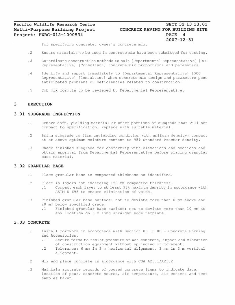
Pacific Wildlife Research Centre SECT 32 13 13.01 Multi-Purpose Building Project CONCRETE PAVING FOR BUILDING SITE Project: PWRC-012-1000534 PAGE 4
2007-12-31for specifying concrete: owner's concrete mix.
.2 Ensure materials to be used in concrete mix have been submitted for testing.
.3 Co-ordinate construction methods to suit [Departmental Representative] [DCC Representative] [Consultant] concrete mix proportions and parameters.
.4 Identify and report immediately to [Departmental Representative] [DCC Representative] [Consultant] when concrete mix design and parameters pose anticipated problems or deficiencies related to construction.
.5 Job mix formula to be reviewed by Departmental Representative.
3 EXECUTION
3.01 SUBGRADE INSPECTION
.1 Remove soft, yielding material or other portions of subgrade that will not compact to specification; replace with suitable material.
.2 Bring subgrade to firm unyielding condition with uniform density; compact at or above optimum moisture content to 95% Standard Proctor density.
.3 Check finished subgrade for conformity with elevations and sections and obtain approval from Departmental Representative before placing granular base material.
3.02 GRANULAR BASE
.1 Place granular base to compacted thickness as identified.
.2 Place in layers not exceeding 150 mm compacted thickness. .1 Compact each layer to at least 98% maximum density in accordance with
ASTM D 698 to ensure elimination of voids.
.3 Finished granular base surface: not to deviate more than 0 mm above and 20 mm below specified grade..1 Finished granular base surface: not to deviate more than 10 mm at
any location on 3 m long straight edge template.
3.03 CONCRETE
.1 Install formwork in accordance with Section 03 10 00 - Concrete Forming and Accessories..1 Secure forms to resist pressure of wet concrete, impact and vibration
of construction equipment without springing or movement..2 Tolerance: 6 mm in 3 m horizontal alignment, 3 mm in 3 m vertical
alignment.
.2 Mix and place concrete in accordance with CSA-A23.1/A23.2.
.3 Maintain accurate records of poured concrete items to indicate date, location of pour, concrete source, air temperature, air content and test samples taken.

Pacific Wildlife Research Centre SECT 32 13 13.01 Multi-Purpose Building Project CONCRETE PAVING FOR BUILDING SITE Project: PWRC-012-1000534 PAGE 5
2007-12-31.4 For ready-mix concrete, provide duplicate delivery slips listing following
with each load delivered to site:.1 Name of ready-mix batch plant. .2 Serial number of ticket. .3 Date and truck number. .4 Name or number of project. .5 Class of concrete or mix. .6 Amount of concrete in cubic metres. .7 Time of loading or first mixing of aggregate, cement and water. .8 Arrival and waiting time at site. .9 Air content.
.5 Ensure that reinforcement and inserts are not disturbed during concrete placement.
.6 Provide access and assistance for concrete sampling by Departmental Representative.
.7 Apply curing compound in accordance with manufacturer's instructions.
.8 Cure and protect concrete in accordance with CSA-A23.1/A23.2.
.9 Departmental Representative to prepare 2 extra test cylinders per test during cold weather concreting and cure test cylinders at job site under same conditions as concrete which it represents..1 Removal of heating and protection as directed by Departmental
Representative.
3.04 CONCRETE TOLERANCE
.1 Finish concrete to required elevation, in accordance with Section 22 of CSA-A23.1/A23.2, to tolerance of 10 mm of required elevation, with no irregularities exceeding 5 mm in 2 m.
3.05 STRAIGHT EDGING
.1 Following strike-off and consolidation, scrape concrete with aluminum or magnesium straight edge..1 Straightedge: 3 m long and equipped with handle to permit use from
side of concrete..2 Prior to scraping concrete, remove excess water of laitance from
surface of concrete..3 Draw straightedge, perpendicular to centerline of pavement, forward
in direction of paving, one-half its length after each pass..4 Correct irregularities in surface with addition or removal of
concrete, and resurface with straightedge.
3.06 EDGING
.1 Finish concrete with edges radius, 5 mm, before final finishing, and before concrete has taken its initial set.
3.07 CONCRETE FINISHING
.1 Finish concrete paving with non-skid finish as indicated.

Pacific Wildlife Research Centre SECT 32 13 13.01 Multi-Purpose Building Project CONCRETE PAVING FOR BUILDING SITE Project: PWRC-012-1000534 PAGE 6
2007-12-31.2 If burlap drag is specified burlap drag to be wide enough to cover entire
width of slab, minimum 1 m long with minimum of 500 mm in continuous contact with concrete surface..1 Keep burlap clean, damp, and free from encrusted mortar. .2 Drag burlap in direction of paving. .3 Do not rest burlap drag on fresh concrete surface. .4 Prepare test section of sample of final surface texture for review
by Departmental Representative.
.3 If broom finish specified use stiff coarse fibre broom to obtain desired texture..1 Prepare test section of sample of final surface texture for review
by Departmental Representative.
.4 If tined finish is specified use device having randomly spaced wire tines, varying from 10 to 40 mm with 50% of spacings less than 25 mm..1 Drag tines transversely across pavement to form grooves. .2 Width of Grooves to be between 2 to 3 mm and depth to be from 3 to
5 mm..3 Texture only when concrete is sufficiently hard to retain ridges. .4 Prepare test section of sample of final surface texture for review
by Departmental Representative.
3.08 CONTRACTION JOINTS
.1 Saw cut contraction joints at spacing as indicated to 6 mm width and to one quarter thickness of slab as soon as concrete can be sawn without dislodging aggregate particles..1 Insert fibre strips in uncured concrete at spacing as indicated. .2 Remove strips as soon as initial set of concrete has taken place.
.2 Fill with sealant in accordance with manufacturer's recommendations.
3.09 CONSTRUCTION JOINTS
.1 Provide full depth joint at end of each day's construction or when concrete placement is interrupted for more than 30 minutes..1 Construct keyed joints as indicated. Dimensions not to vary by more
than 2 mm from indicated dimensions, and not more than 4 mm from mid-depth of pavement.
.2 Edge and texture joints to match adjacent surface.
3.10 EXPANSION JOINTS
.1 Tool transverse expansion joints at intervals of 1.5 m after floating, when concrete is stiff, but still plastic.
.2 Provide expansion joints with clean break throughout depth of slab with clear distance across joint of 18 mm.
.3 Fill expansion joints with preformed joint filler.
3.11 ISOLATION JOINTS
.1 Make isolation joint filler continuous from edge to edge. .1 Extend joint material full depth of concrete, and finished joint not

Pacific Wildlife Research Centre SECT 32 13 13.01 Multi-Purpose Building Project CONCRETE PAVING FOR BUILDING SITE Project: PWRC-012-1000534 PAGE 7
2007-12-31to deviate in horizontal alignment more than 6 mm from straight line.
.2 Match edge and texture joint to adjacent surface.
.2 Install isolation joints as indicated by Departmental Representative.
.3 Install isolation joints around manholes and catch basins and along length adjacent to concrete curbs, building, or permanent structure.
.4 Install joint filler in isolation joints as indicated.
.5 When sidewalk is adjacent to curb, make joints of curb, gutters and sidewalk coincide.
3.12 JOINT SEALING
.1 Seal isolation joints with sealant as directed by Departmental Representative.
.2 Prepare and clean joint in accordance with manufacturer's recommendations.
.3 Complete joint sealing prior to opening pavement to traffic and allow sufficient time for curing, in accordance with manufacturer's recommendations.
3.13 PROTECTION
.1 Keep vehicular traffic off newly paved areas until pavement has properly cured and joints have been sealed until minimum strength of 26 Mpa has been attained.
3.14 CLEANING
.1 Proceed in accordance with Section 01 74 11 - Cleaning.
.2 On completion and verification of performance of installation, remove surplus materials, excess materials, rubbish, tools and equipment.
END OF SECTION
Pacific Wildlife Research Centre Section 32 15 40 Multi-Purpose Building Project CRUSHED STONE SURFACING Project: PWRC-012-1000534 Page 1
Approved: 2009-12-31
Part 1 General
1.1 RELATED REQUIREMENTS
.1 This section of the specification forms parts of the Contract Documents and is to be read, interpreted and coordinated with all other parts.
1.2 MEASUREMENT AND PAYMENT
.1 Measure granular sub-base in measured in place square metres of material incorporated into Work and accepted by Departmental Representative.
.2 Measure granular base in measured in place square metres of material incorporated into Work and accepted by Departmental Representative.
.3 Measure granular topping in square metres measured in place of material incorporated into Work and accepted by Departmental Representative.
1.3 REFERENCE STANDARDS
.1 ASTM International
.1 ASTM C136-[06], Standard Test Method for Sieve Analysis of Fine and Coarse Aggregates.
.2 ASTM C117-[04], Standard Test Method for Material Finer Than 0.075 mm (No. 200) Sieve in Mineral Aggregates by Washing.
.3 ASTM D4318-[05], Standard Test Method for Liquid Limit, Plastic Limit and Plasticity Index of Soils.
.4 ASTM D698-[07e1], Standard Test Methods for Laboratory Compaction Characteristics of Soil Using Standard Effort (12,400 ft-lbf/ft3(600 kN-m/m3).
.2 Canada Green Building Council (CaGBC)
.1 LEED Canada-NC Version 1.0-[2004], LEED (Leadership in Energy and Environmental Design): Green Building Rating System Reference Package For New Construction and Major Renovations (including Addendum [2007]).
.2 LEED Canada-CI Version 1.0-[2007], LEED (Leadership in Energy and Environmental Design): Green Building Rating System Reference Guide For Commercial Interiors.
.3 Canadian General Standards Board (CGSB)
.1 CAN/CGSB-8.1-[88], Sieves, Testing, Woven Wire, Inch Series.
.2 CAN/CGSB-8.2-[M88], Sieves, Testing, Woven Wire, Metric.
1.4 ADMINISTRATIVE REQUIREMENTS
.1 Access: allow access to building at all times.
.2 Scheduling: co-ordinate paving schedule to minimize interference with normal use of premises.

Pacific Wildlife Research Centre Section 32 15 40 Multi-Purpose Building Project CRUSHED STONE SURFACING Project: PWRC-012-1000534 Page 2
1.5 ACTION AND INFORMATIONAL SUBMITTALS
.1 Submit submittals in accordance with Section 01 33 00- Submittal Procedures.
.2 Sustainable Design Submittals:
.1 LEED Canada-[NC Version 1.0] [CI Version 1.0]Submittals: in accordance with Section 01 35 21- LEED Requirements.
.2 Construction Waste Management:
.1 Submit project Waste Management Plan highlighting recycling and salvage requirements.
.2 Submit calculations on end-of-project recycling rates, salvage rates, and landfill rates demonstrating that 50% of construction wastes were recycled or salvaged.
1.6 DELIVERY, STORAGE AND HANDLING
.1 Deliver, store and handle materials in accordance with Section 01 61 00- Common Product Requirements.
.2 Store crushed stone as and where directed by Departmental Representative.
.3 Packaging Waste Management: remove for reuse packaging materials as specified in Construction Waste Management Plan in accordance with Section 01 74 21- Construction/Demolition Waste Management and Disposal Section 01 35 21- LEED Requirements.
Part 2 Products
2.1 MATERIALS
.1 Granular sub-base: in accordance with Section 32 12 16.02- Asphalt Paving For Building Sites
.2 Granular base: in accordance with Section 32 12 16.02- Asphalt Paving For Building Sites
.3 Granular topping - 19mm minus clear crushed gravel:
.1 Screenings: hard, durable, crushed stone particles, free from clay lumps, cementation, organic material, frozen material and other deleterious materials.
.2 Gradations: within limits specified when tested to [ASTM C136] [ASTM C117]. Sieve Designation % Passing 25.0 mm 100 19.0 mm 0-100 9.50 mm 0-5 4.75 mm 0

Pacific Wildlife Research Centre Section 32 15 40 Multi-Purpose Building Project CRUSHED STONE SURFACING Project: PWRC-012-1000534 Page 3
Part 3 Execution
3.1 SUBGRADE
.1 Ensure subgrade preparation conforms to levels and compaction required, to allow for installation of granular base.
3.2 GEOTEXTILE FILTER
.1 Install geotextile filter as indicated
3.3 GRANULAR SUB-BASE
.1 Granular sub-base material minimum thickness: as indicated.
.2 Place material in uniform layers not to exceed 150mm compacted thickness.
.1 Compact layer to 100% Standard Density in accordance with ASTM D698.
3.4 GRANULAR BASE
.1 Granular base material thickness: as indicated.
.2 Spread and compact granular base material in uniform layers not exceeding 150mm compacted thickness.
.3 Compact to a density of not less than 100% Standard Density in accordance with ASTM D698.
3.5 EDGING
.1 Install edging true to grade, in location, layout as indicated.
3.6 GRANULAR TOPPING
.1 Place granular topping to compacted thickness as indicated.
.2 Place material in uniform layers not to exceed 150mm compacted thickness.
.1 Compact layer to 100% Standard Density in accordance with ASTM D698.
3.7 FIELD QUALITY CONTROL
.1 Inspection and testing of crushed stone paving: carried out by designated testing laboratory.
.2 Costs of tests: paid by Owner.
3.8 CLEANING
.1 Progress Cleaning: clean in accordance with Section 01 74 11- Cleaning.
.1 Leave Work area clean at end of each day.
.2 Final Cleaning: upon completion remove surplus materials, rubbish, tools and equipment in accordance with Section 01 74 11- Cleaning.

Pacific Wildlife Research Centre Section 32 15 40 Multi-Purpose Building Project CRUSHED STONE SURFACING Project: PWRC-012-1000534 Page 4
.3 Waste Management: separate waste materials for recycling in accordance with Section 01 74 21- Construction/Demolition Waste Management and Disposal 01 35 21- LEED Requirements.
.1 Remove recycling containers and bins from site and dispose of materials at appropriate facility.
3.9 PROTECTION
.1 Prevent damage to remaining roads, buildings, curbs, sidewalks, trees, fences, and landscaping
.1 Repair damages incurred.
.2 Provide access to buildings at all times. Co-ordinate paving schedule to minimize interference with normal use of premises.
END OF SECTION

PWRC Multi-Purpose Building & Picnic Shelter Section 32 16 15 February 2017 CONCRETE WALKS, CURBS AND GUTTERS Publisher: Spex.ca Page 1
Iredale Architecture – Project #16063
Approved: 2006-12-31
Part 1 General
1.1 RELATED REQUIREMENTS
.1 Section [_____]
1.2 REFERENCE STANDARDS
.1 American Society for Testing and Materials International (ASTM)
.1 ASTM C117-[04], Standard Test Method for Materials Finer than 0.075 mm (No. 200) Sieve in Mineral Aggregates by Washing.
.2 ASTM C136-[05], Standard Test Method for Sieve Analysis of Fine and Coarse Aggregates.
.3 ASTM D260-[86(2001)], Standard Specification for Boiled Linseed Oil.
.4 ASTM D698-[00ae1], Standard Test Method for Laboratory Compaction Characteristics of Soil Using Standard Effort (12,400ft-lbf/ft3) (600 kN-m/m3).
.2 Canadian General Standards Board (CGSB)
.1 CAN/CGSB-3.3-[99(March 2004)], Kerosene, Amend. No. 1, National Standard of Canada.
.2 CAN/CGSB-8.1-[88], Sieves, Testing, Woven Wire, Inch Series.
.3 Canadian Standards Association (CSA International)
.1 CSA-A23.1-[04]/A23.2-[04], Concrete Materials and Methods of Concrete Construction/Methods of Test and Standard Practices for Concrete.
1.3 ACTION AND INFORMATIONAL SUBMITTALS
.1 Submittals in accordance with Section [01 33 00- Submittal Procedures].
.2 Product Data: submit WHMIS MSDS in accordance with Section [01 47 15- Sustainable Requirements: Construction]and [02 81 01- Hazardous Materials].
.3 Inform [Departmental Representative] [Consultant] [DCC Representative]of proposed source of materials and provide access for sampling at least [4]weeks prior to commencing work.
.4 If materials have been tested by [independent testing laboratory] [accredited testing laboratory testing laboratory approved by [DCC Representative] [Departmental Representative] [Consultant]]within previous [2]months and have passed tests equal to requirements of this specification, submit test certificates from testing laboratory showing suitability of materials for this project.
.5 Sustainable Design Submittals:
.1 Construction Waste Management:
.1 Refer to 01 74 21 Construction Waste Management for required submittals.
.2 Recycled Content:

PWRC Multi-Purpose Building & Picnic Shelter Section 32 16 15 February 2017 CONCRETE WALKS, CURBS AND GUTTERS Publisher: Spex.ca Page 2
Iredale Architecture – Project #16063
.1 Submit listing of post-industrial and post-consumer recycled content indicating percentages of each in the products used and include total cost of these products.
.3 Regional Materials (not applicable to equipment, non-permanent elements, mechanical, plumbing, and electrical systems):
.1 Submit information that products incorporate regional materials defined as materials or products that have been extracted, harvested, recovered, and processed within 800kms (or 2400km if shipped by rail or boat) of the final manufacturing site, and the final manufacturing site is within 800km (or 2400km as above) of the project site.
.4 Low-Emitting Materials (where applicable):
.1 Submit listing of paints and coatings and/or adhesives and sealants used in the installation of and on site finishing of the products, showing compliance with VOC SCAQMD and GreenSeal requirements.
.2 Submit evidence that composite wood and agrifibre products used on the interior of the building do not contain added urea-formaldehyde resins.
1.4 DELIVERY, STORAGE AND HANDLING
.1 Deliver, store and handle materials in accordance with Section with manufacturer's written instructions and 01 61 00- Common Product Requirements.
.2 Delivery and Acceptance Requirements: deliver materials to site in original factory packaging, labelled with manufacturer's name and address.
.3 Storage and Handling Requirements:
.1 Store materials in accordance with manufacturer's recommendations in clean, dry, well-ventilated area.
.2 Store and protect specified materials from damage.
.3 Replace defective or damaged materials with new.
.4 Develop Construction Waste Management Plan related to Work of this Section.
.5 Packaging Waste Management: remove and reuse or recycle in accordance with Section 01 74 21- Construction/Demolition Waste Management and Disposal.
Part 2 Products
2.1 SUSTAINABLE REQUIREMENTS
.1 Materials and products in accordance with Section [01 47 15- Sustainable Requirements: Construction].
.2 Do verification requirements in accordance with Section [01 47 17- Sustainable Requirements: Contractor's Verification].
2.2 MATERIALS
.1 Concrete mixes and materials: in accordance with Section [03 30 00- Cast-in-Place Concrete].
PWRC Multi-Purpose Building & Picnic Shelter Section 32 16 15 February 2017 CONCRETE WALKS, CURBS AND GUTTERS Publisher: Spex.ca Page 3
Iredale Architecture – Project #16063
.2 Reinforcing steel: in accordance with Section [03 20 00- Concrete Reinforcing].
.3 [Joint filler] [Curing Compound]: in accordance with Section [03 30 00- Cast-in-Place Concrete].
.4 Granular base: material to [Section 31 05 16- Aggregate Materials]following requirements:
.1 Type [1, 2 or 3 fill].
.2 Crushed stone or gravel.
.3 Gradations: within limits specified when tested to [ASTM C136] [ASTM C117]. Sieve sizes to CAN/CGSB-8.1.
.5 Non-staining mineral type form release agent: chemically active release agents containing compounds that react with free lime to provide water-soluble soap.
.6 Fill material: to [Section 31 05 16- Aggregate Materials]following requirements:
.1 Type [1, 2 or 3 fill].
.2 Crushed stone or gravel.
.3 Gradations: within limits specified when tested to [ASTM C117] [ASTM C136]. Sieve sizes to CAN/CGSB-8.1.
.7 Boiled linseed oil: to [ASTM D260].
.8 Kerosene: to CAN/CGSB-3.3.
Part 3 Execution
3.1 GRADE PREPARATION
.1 Do grade preparation work in accordance with Section [31 23 33.01- Excavating, Trenching and Backfilling].
.2 Construct embankments using excavated material free from organic matter or other objectionable materials.
.1 Dispose of surplus and unsuitable excavated material [off site] [in approved location on site].
.3 When constructing embankment provide for minimum [_____]
.4 Place fill in maximum [150]mm layers and compact to at least [95]% of maximum dry density to ASTM D698.
3.2 GRANULAR BASE
.1 Obtain [Consultant's] [Departmental Representative's] [DCC Representative's]approval of subgrade before placing granular base.
.2 Place granular base material to lines, widths, and depths as indicated.
.3 Compact granular base in maximum [150 mm]layers to at least [95]% of maximum density to ASTM D698.

PWRC Multi-Purpose Building & Picnic Shelter Section 32 16 15 February 2017 CONCRETE WALKS, CURBS AND GUTTERS Publisher: Spex.ca Page 4
Iredale Architecture – Project #16063
3.3 CONCRETE
.1 Obtain [DCC Representative's] [Departmental Representative] [Consultant's]approval of granular base[and reinforcing steel]prior to placing concrete.
.2 Do concrete work in accordance with Section [03 30 00- Cast-in-Place Concrete].
.3 Immediately after floating, give sidewalk surface uniform broom finish to produce regular corrugations not exceeding [2]mm deep, by drawing broom in direction normal to centre line.
.4 Provide edging as indicated with [10]mm radius edging tool.
.5 Slip-form pavers equipped with string line system for line and grade control may be used if quality of work acceptable to [Departmental Representative] [Consultant] [DCC Representative]can be demonstrated. Hand finish surfaces when directed by [DCC Representative] [Departmental Representative] [Consultant].
3.4 TOLERANCES
.1 Finish surfaces to within [3]mm in [3]m as measured with [3]m straightedge placed on surface.
3.5 EXPANSION AND CONTRACTION JOINTS
.1 Install tooled transverse contraction joints after floating, when concrete is stiff, but still plastic, at intervals of [_____]
.2 Install expansion joints [as indicated] [as directed by [DCC Representative] [Consultant] [Departmental Representative]] [at intervals of [6] m].
.3 When sidewalk is adjacent to curb, make joints of curb, gutters and sidewalk coincide.
3.6 ISOLATION JOINTS
.1 Install isolation joints around manholes and catch basins and along length adjacent to concrete curbs, catch basins, buildings, or permanent structure.
.2 Install joint filler in isolation joints [as indicated] [in accordance with Section [03 30 00- Cast-in-Place Concrete]].
.3 Seal isolation joints with sealant approved by [DCC Representative] [Departmental Representative] [Consultant].
3.7 CURING
.1 Cure concrete by adding moisture continuously in accordance with CSA-A23.1/A23.2 to exposed finished surfaces for at least [1]day after placing, or sealing moisture in by curing compound as directed by [DCC Representative] [Consultant] [Departmental Representative].
.2 Where burlap is used for moist curing, place two prewetted layers on concrete surface and keep continuously wet during curing period.
.3 Apply curing compound evenly to form continuous film, in accordance with manufacturer's requirements.

PWRC Multi-Purpose Building & Picnic Shelter Section 32 16 15 February 2017 CONCRETE WALKS, CURBS AND GUTTERS Publisher: Spex.ca Page 5
Iredale Architecture – Project #16063
3.8 BACKFILL
.1 Allow concrete to cure for [7]days prior to backfilling.
.2 Backfill to designated elevations with material as directed by [Departmental Representative] [Consultant] [DCC Representative].
.1 Compact and shape to required contours [as indicated] [as directed by [Consultant] [DCC Representative] [Departmental Representative]].
3.9 LINSEED OIL TREATMENT
.1 Apply two coats of linseed oil mixture uniformly to surfaces of curbs, walks and gutters, after concrete has cured for specified curing time and when surface of concrete is clean and dry.
.2 Linseed oil mixture to consist of 50% boiled linseed oil and 50% mineral spirits by volume.
.3 Apply treatment when air temperature above 10 degrees C.
.4 Apply first coat at [135]mL/m2.
.5 Apply second coat at [90]mL/m2when first coat has dried.
3.10 CLEANING
.1 Proceed in accordance with Section [01 74 11- Cleaning].
.2 On completion and verification of performance of installation, remove surplus materials, excess materials, rubbish, tools and equipment.
.3 Waste Management: separate waste materials in accordance with Section 01 74 21- Construction/Demolition Waste Management and Disposal
.1 Remove recycling containers and bins from site and dispose of materials at appropriate facility.
END OF SECTION

PWRC Multi-Purpose Building & Picnic Shelter Section 32 31 13 February 2017 CHAIN LINK FENCES AND GATES Publisher: Spex.ca Page 1
Iredale Architecture – Project #16063
Approved: 2011-06-30
Part 1 General
1.1 RELATED REQUIREMENTS
.1 Section [_____]
1.2 MEASUREMENT AND PAYMENT
.1 Measure supply and erection of chain link fence in metres erected [including gates].
.2 Measure supply and erection of chain link fence gates as units of each size erected.
1.3 REFERENCE STANDARDS
.1 ASTM International
.1 ASTM A53/A53M-[10], Standard Specification for Pipe, Steel, Black and Hot-Dipped, Zinc-Coated Welded and Seamless.
.2 ASTM A90/A90M-[09], Standard Test Method for Weight [Mass]of Coating on Iron and Steel Articles with Zinc or Zinc-Alloy Coatings.
.3 ASTM A121-[07], Standard Specification for Zinc-Coated (Galvanized) Steel Barbed Wire.
.4 A653/A653M-[10], Standard Specification for Steel Sheet, Zinc-Coated (Galvanized) or Zinc-Iron Alloy-Coated (Galvannealed) by the Hot-Dip Process.
.5 ASTM C618-[08a], Standard Specification for Coal Fly Ash and Raw or Calcined Natural Pozzolan for Use as a Mineral Admixture in Concrete.
.6 ASTM F1664-[08], Standard Specification for Poly(Vinyl Chloride) (PVC)-Coated Steel Tension Wire Used with Chain-Link Fence.
.7 ASTM A123/A123M-[09], Standard Specification for Zinc (Hot Dip Galvanized) coatings on Iron and Steel Products.
.2 Canada Green Building Council (CaGBC)
.1 LEED Canada-NC Version 1.0-[2004], LEED (Leadership in Energy and Environmental Design): Green Building Rating System Reference Package For New Construction and Major Renovations (including Addendum [2007]).
.3 Canadian General Standards Board (CGSB)
.1 CAN/CGSB-138.1-[96], Fabric for Chain Link Fence.
.2 CAN/CGSB-138.2-[96], Steel Framework for Chain Link Fence.
.3 CAN/CGSB-138.3-[96], Installation of Chain Link Fence.
.4 CAN/CGSB-138.4-[96], Gates for Chain Link Fence.
.5 CAN/CGSB-1.181-[99], Ready-Mixed Organic Zinc-Rich Coating.
.4 CSA International
.1 CSA A23.1/A23.2-[09], Concrete Materials and Methods of Concrete Construction/Test Methods and Standard Practices for Concrete.
.2 CAN/CSA-A3000-[08], Cementitious Materials Compendium.

PWRC Multi-Purpose Building & Picnic Shelter Section 32 31 13 February 2017 CHAIN LINK FENCES AND GATES Publisher: Spex.ca Page 2
Iredale Architecture – Project #16063
.5 Master Painters Institute (MPI)
.1 Architectural Painting Specification Manual - [current edition].
.6 U.S. Environmental Protection Agency (EPA) / Office of Water
.1 EPA 832/R-92-005, Storm Water Management for Construction Activities: Developing Pollution Prevention Plans and Best Management Practices.
1.4 ACTION AND INFORMATIONAL SUBMITTALS
.1 Submit in accordance with Section [01 33 00- Submittal Procedures].
.2 Product Data:
.1 Submit manufacturer's instructions, printed product literature and data sheets for [concrete mixes, fences, posts and gates]and include product characteristics, performance criteria, physical size, finish and limitations.
.3 Sustainable Design Submittals:
.1 Construction Waste Management:
.1 Refer to 01 74 21 Construction Waste Management for required submittals.
.2 Recycled Content:
.1 Submit listing of post-industrial and post-consumer recycled content indicating percentages of each in the products used and include total cost of these products.
.3 Regional Materials (not applicable to equipment, non-permanent elements, mechanical, plumbing, and electrical systems):
.1 Submit information that products incorporate regional materials defined as materials or products that have been extracted, harvested, recovered, and processed within 800kms (or 2400km if shipped by rail or boat) of the final manufacturing site, and the final manufacturing site is within 800km (or 2400km as above) of the project site.
.4 Low-Emitting Materials (where applicable):
.1 Submit listing of paints and coatings and/or adhesives and sealants used in the installation of and on site finishing of the products, showing compliance with VOC SCAQMD and GreenSeal requirements.
.2 Submit evidence that composite wood and agrifibre products used on the interior of the building do not contain added urea-formaldehyde resins.
1.5 DELIVERY, STORAGE AND HANDLING
.1 Deliver, store and handle materials in accordance with Section with manufacturer's written instructions and 01 61 00- Common Product Requirements.
.2 Delivery and Acceptance Requirements: deliver materials to site in original factory packaging, labelled with manufacturer's name and address.
.3 Storage and Handling Requirements:
.1 Store materials in accordance with manufacturer's recommendations in clean, dry, well-ventilated area.

PWRC Multi-Purpose Building & Picnic Shelter Section 32 31 13 February 2017 CHAIN LINK FENCES AND GATES Publisher: Spex.ca Page 3
Iredale Architecture – Project #16063
.2 Store and protect specified materials from damage.
.3 Replace defective or damaged materials with new.
.4 Develop Construction Waste Management Plan related to Work of this Section.
.5 Packaging Waste Management: remove and reuse or recycle in accordance with Section 01 74 21- Construction/Demolition Waste Management and Disposal.
Part 2 Products
2.1 MATERIALS
.1 Chain-link fence fabric: to CAN/CGSB-138.1.
.1 Type 1, Class A, medium style, Grade [3] [1] [2].
.2 Height of fabric: as indicate on drawings.
.2 Posts, braces and rails: to CAN/CGSB-138.2, galvanized steel pipe. Dimensions as indicated.
.3 Tension wire: to CAN/CGSB-138.2, single strand, galvanized steel wire.
.4 Tie wire fasteners: steel wire
.5 Tension bar: to ASTM A653/A653M, 5 x 20 mm minimum galvanized steel.
.6 Gates: to CAN/CGSB-138.4.
.7 Gate frames: to ASTM A53/A53M galvanized steel pipe, standard weight 45mm outside diameter pipe for outside frame, 35mm outside diameter pipe for interior bracing.
.1 Fabricate gates as indicated with electrically welded joints, and hot-dip galvanized after welding.
.2 Fasten fence fabric to gate with twisted selvage at top.
.3 Furnish gates with galvanized malleable iron hinges, lockset that can be operated by card reader.
.8 Fittings and hardware: to CAN/CGSB-138.2, galvanized steel
.1 Tension bar bands: 3 x 20 mm minimum galvanized steel or 5 x 20 mm minimum aluminum.
.2 Post caps to provide waterproof fit, to fasten securely over posts and to carry top rail.
.9 Organic zinc rich coating: to MPI #18, CAN/CGSB-1.181.
2.2 FINISHES
.1 Galvanizing:
.1 For chain link fabric: to CAN/CGSB-138.1Grade [2].
.2 For pipe: to ASTM A90.
.3 For other fittings: to ASTM A123/A123M.

PWRC Multi-Purpose Building & Picnic Shelter Section 32 31 13 February 2017 CHAIN LINK FENCES AND GATES Publisher: Spex.ca Page 4
Iredale Architecture – Project #16063
Part 3 Execution
3.1 EXAMINATION
.1 Verification of Conditions: verify conditions of substrate previously installed under other Sections or Contracts are acceptable for fence and gate installation in accordance with manufacturer's written instructions.
3.2 PREPARATION
.1 Temporary Erosion and Sedimentation Control:
.1 Provide temporary erosion and sedimentation control measures to prevent soil erosion and discharge of soil-bearing water runoff or airborne dust to adjacent properties and walkways, according to [sediment and erosion control plan, specific to site, that complies with EPA 832/R-92-005 or requirements of authorities having jurisdiction, whichever is more stringent] [sediment and erosion control drawings] [requirements of authorities having jurisdiction].
.2 Inspect, repair, and maintain erosion and sedimentation control measures during construction until permanent vegetation has been established.
.3 Remove erosion and sedimentation controls and restore and stabilize areas disturbed during removal.
.2 Grading:
.1 Remove debris and correct ground undulations along fence line to obtain smooth uniform gradient between posts.
.1 Provide clearance between bottom of fence and ground surface of 50mm.
3.3 ERECTION OF FENCE
.1 Erect fence along lines as indicated to CAN/CGSB-138.3.
.2 Provide base plates for posts to attach to the concrete walkway
.3 Space line posts as indicated, measured parallel to ground surface.
.4 Install corner post where change in alignment exceeds 10 degrees.
.5 Install end posts at end of fence and at buildings.
.1 Install gate posts on both sides of gate openings.
.6 Place concrete in post holes then embed posts into concrete to minimum depths indicate.
.1 Slope concrete to drain away from posts.
.2 Brace to hold posts in plumb position and true to alignment and elevation until concrete has set.
.7 Install fence fabric after concrete has cured, minimum of 5 days.
.8 Install brace between end and gate posts and nearest line post, placed d in centre of panel and parallel to ground surface].
.1 Install braces on both sides of corner anmm above ground surface.
.9 Determine position of centre gate rest for double gate.

PWRC Multi-Purpose Building & Picnic Shelter Section 32 31 13 February 2017 CHAIN LINK FENCES AND GATES Publisher: Spex.ca Page 5
Iredale Architecture – Project #16063
.1 Cast gate rest in concrete as directed.
.2 Dome concrete above ground level to shed water.
.10 Install gate stops where indicated.
3.4 TOUCH UP
.1 Clean damaged surfaces with wire brush removing loose and cracked coatings. Apply two coats of organic zinc-rich paint to damaged areas as indicated.
.1 Pre-treat damaged surfaces according to manufacturers' instructions for zinc-rich paint.
3.5 CLEANING
.1 Progress Cleaning: clean in accordance with Section 01 74 11- Cleaning.
.1 Leave Work area clean at end of each day.
.2 Final Cleaning: upon completion remove surplus materials, rubbish, tools and equipment in accordance with Section 01 74 11- Cleaning.
.3 Waste Management: separate waste materials for reuse and recycling in accordance with Section 01 74 21- Construction/Demolition Waste Management and Disposal
.1 Remove recycling containers and bins from site and dispose of materials at appropriate facility.
END OF SECTION
PWRC Multi-Purpose Building & Picnic Shelter (NMS) Section 32 37 00 July 2013 EXTERIOR SITE FURNISHINGS Publisher: Spex.ca Page 1
Approved: 2011-06-30
Part 1 General
1.1 RELATED REQUIREMENTS
.1 Section [_____].
1.2 REFERENCES
.1 CSA International
.1 CAN/CSA-Z809-[08], Sustainable Forest Management.
.2 Forest Stewardship Council (FSC)
.1 FSC-STD-01-001-[2004], FSC Principle and Criteria for Forest Stewardship.
.3 Sustainable Forestry Initiative (SFI)
.1 SFI-[2010-2014] Standard.
1.3 ACTION AND INFORMATIONAL SUBMITTALS
.1 Submit in accordance with Section [01 33 00 - Submittal Procedures].
.2 Product Data:
.1 Submit manufacturer's instructions, printed product literature and data sheets for [furniture] and include product characteristics, performance criteria, physical size, finish and limitations.
.3 Shop Drawings:
.1 Submit shop drawings indicating dimensions, sizes, assembly, anchorage and installation details for each furnishing specified.
.4 Sustainable Design Submittals:
.1 Construction Waste Management:
.1 Refer to 01 74 21 Construction Waste Management for required submittals.
.2 Recycled Content:
.1 Submit listing of post-industrial and post-consumer recycled content indicating percentages of each in the products used and include total cost of these products.
.3 Regional Materials (not applicable to equipment, non-permanent elements, mechanical, plumbing, and electrical systems):
.1 Submit information that products incorporate regional materials defined as materials or products that have been extracted, harvested, recovered, and processed within 800kms (or 2400km if shipped by rail or boat) of the final manufacturing site, and the final manufacturing site is within 800km (or 2400km as above) of the project site.
.4 Low-Emitting Materials (where applicable):

PWRC Multi-Purpose Building & Picnic Shelter (NMS) Section 32 37 00 July 2013 EXTERIOR SITE FURNISHINGS Publisher: Spex.ca Page 2
.1 Submit listing of paints and coatings and/or adhesives and sealants used in the installation of and on site finishing of the products, showing compliance with VOC SCAQMD and GreenSeal requirements.
.2 Submit evidence that composite wood and agrifibre products used on the interior of the building do not contain added urea-formaldehyde resins.
1.4 DELIVERY, STORAGE AND HANDLING
.1 Deliver, store and handle materials in accordance with Section with manufacturer's written instructions and 01 61 00- Common Product Requirements.
.2 Delivery and Acceptance Requirements: deliver materials to site in original factory packaging, labelled with manufacturer's name and address.
.3 Storage and Handling Requirements:
.1 Store materials in accordance with manufacturer's recommendations in clean, dry, well-ventilated area.
.2 Store and protect specified materials from damage.
.3 Replace defective or damaged materials with new.
.4 Develop Construction Waste Management Plan related to Work of this Section.
.5 Packaging Waste Management: remove and reuse or recycle in accordance with Section 01 74 21- Construction/Demolition Waste Management and Disposal.
1.5 CLOSEOUT SUBMITTALS
.1 Submit maintenance data for care and cleaning of site furnishings for incorporation into manual specified in Section [01 78 00 - Closeout Submittals].
1.6 QUALITY ASSURANCE
.1 Sustainable Standards Certification:
.1 Certified Wood: submit listing of wood products and materials used in accordance with CAN/CSA-Z809 or FSC or SFI.
Part 2 Products
2.1 BENCH
.1 Seat: wood constructed from western red cedar. Dimension, attachment, and finish as per drawings.
.1 CAN/CSA-Z809 or FSC or SFI certified.
2.2 BICYCLE RACK
.1 Stainless Steel bike rack: CAH205 by Canaan or equal. For public access bike rack by washrooms
.2 Stainless Steel bike rack: CAH205 by Canaan or equal. For secured bicycle parking

PWRC Multi-Purpose Building & Picnic Shelter (NMS) Section 32 37 00 July 2013 EXTERIOR SITE FURNISHINGS Publisher: Spex.ca Page 3
Part 3 Execution
3.1 EXAMINATION
.1 Verification of Conditions: verify that conditions of substrate previously installed under other Sections or Contracts are acceptable for exterior site furnishing installation in accordance with manufacturer's written instructions.
3.2 PREPARATION
.1 Locate and protect utility lines.
.2 Notify and acquire written acknowledgment from utility authorities before beginning installation Work
3.3 INSTALLATION
.1 Assemble furnishings in accordance with manufacturer's written recommendations.
.2 Install as indicated.
.3 Touch-up damaged finishes to approval of Consultant.
3.4 CLEANING
.1 Progress Cleaning: clean in accordance with Section 01 74 11 - Cleaning.
.1 Leave Work area clean at end of each day.
.2 Final Cleaning: upon completion remove surplus materials, rubbish, tools and equipment in accordance with Section 01 74 11 - Cleaning.
.3 Waste Management: separate waste materials for reuse and recycling in accordance with Section 01 74 21 - Construction/Demolition Waste Management and Disposal.
.1 Remove recycling containers and bins from site and dispose of materials at appropriate facility.
3.5 PROTECTION
.1 Protect installed products and components from damage during construction.
.2 Repair damage to adjacent materials caused by site furnishings installation.
END OF SECTION

Pacific Wildlife Research Centre SECT 32 91 19.13 Multi-Purpose Building Project TOPSOIL PLACEMENT AND GRADING Project: PWRC-012-1000534 PAGE 1 2011-06-30
1 GENERAL
1.01 NOT USED
1.02 RELATED REQUIREMENTS
.1 This section of the specification forms parts of the Contract Documents and is to be read, interpreted and coordinated with all other parts.
1.03 MEASUREMENT PROCEDURES
.1 Preparation of sub-grade for placing of topsoil will not be measured for payment.
.2 Topsoil stripping will not be measured.
.3 Measure supplying, placing and spreading topsoil in cubic metres as determined from actual surface area covered and depth of topsoil specified. .1 Specified depth of topsoil: measured and approved by Departmental
Representative after settlement and consolidation as specified.
.4 Measure finish grading in square metres from actual surface measurements as determined by Departmental Representative.
1.04 PAYMENT
.1 Testing of topsoil: Owner will pay for cost of tests as specified in Section 01 29 83 - Payment Procedures for Testing Laboratory Services.
1.05 REFERENCE STANDARDS
.1 Agriculture and Agri-Food Canada .1 The Canadian System of Soil Classification, Third Edition, 1998.
.2 Canadian Council of Ministers of the Environment .1 PN1340-[2005], Guidelines for Compost Quality.
.3 Canada Green Building Council (CaGBC) .1 LEED Canada-NC Version 1.0-[2004], LEED (Leadership in Energy and
Environmental Design): Green Building Rating System Reference Package For New Construction and Major Renovations (including Addendum [2007]).
.2 LEED Canada-CI Version 1.0-[2007], LEED (Leadership in Energy and Environmental Design): Green Building Rating System Reference Guide For Commercial Interiors.
.4 U.S. Environmental Protection Agency (EPA)/Office of Water .1 EPA 832R92005, Storm Water Management for Construction Activities:
Developing Pollution Prevention Plans and Best Management Practices.

Pacific Wildlife Research Centre SECT 32 91 19.13 Multi-Purpose Building Project TOPSOIL PLACEMENT AND GRADING Project: PWRC-012-1000534 PAGE 2 2011-06-30
1.06 DEFINITIONS
.1 Compost: .1 Mixture of soil and decomposing organic matter used as fertilizer,
mulch, or soil conditioner..2 Compost is processed organic matter containing 40% or more organic
matter as determined by Walkley-Black or Loss On Ignition (LOI) test. .3 Product must be sufficiently decomposed (i.e. stable) so that any
further decomposition does not adversely affect plant growth (C:N ratio below (25) (50)), and contain no toxic or growth inhibiting contaminates.
.4 Composed bio-solids to: CCME Guidelines for Compost Quality, Category (A) (B).
1.07 ACTION AND INFORMATIONAL SUBMITTALS
.1 Provide submittals in accordance with Section 01 33 00 - Submittal Procedures.
.2 LEED Submittals: .1 Submit erosion and sedimentation control plan for Credit SSp1 in
accordance with LEED Canada-NC.
.3 Quality control submittals: .1 Soil testing: submit certified test reports showing compliance with
specified performance characteristics and physical properties as described in PART 2 - SOURCE QUALITY CONTROL.
.2 Certificates: submit product certificates signed by manufacturer certifying materials comply with specified performance characteristics and criteria and physical requirements.
1.08 QUALITY ASSURANCE
.1 Pre-installation meetings: conduct pre-installation meeting to verify project requirements, installation instructions and warranty requirements in accordance with Section 01 32 16.06 - Construction Progress Schedule - Critical Path Method (CPM).
1.09 WASTE MANAGEMENT AND DISPOSAL
.1 Separate waste materials for recycling in accordance with Section 01 74 21 - Construction/Demolition Waste Management and Disposal.
.2 Divert unused soil amendments from landfill to official hazardous material collections site approved by Departmental Representative.
.3 Do not dispose of unused soil amendments into sewer systems, into lakes, streams, onto ground or in locations where it will pose health or environmental hazard.

Pacific Wildlife Research Centre SECT 32 91 19.13 Multi-Purpose Building Project TOPSOIL PLACEMENT AND GRADING Project: PWRC-012-1000534 PAGE 3 2011-06-30
2 PRODUCTS
2.01 TOPSOIL
.1 Topsoil for seeded areas: mixture of particulates, micro organisms and organic matter which provides suitable medium for supporting intended plant growth..1 Soil texture based on The Canadian System of Soil Classification,
to consist of 20 to 70 % sand, minimum 7 % clay, and contain 2 to 10 % organic matter by weight.
.2 Contain no toxic elements or growth inhibiting materials.
.3 Finished surface free from: .1 Debris and stones over 50 mm diameter. .2 Course vegetative material, 10 mm diameter and 100 mm length,
occupying more than 2% of soil volume..4 Consistence: friable when moist.
2.02 SOIL AMENDMENTS
.1 Fertilizer: .1 Fertility: major soil nutrients present in following amounts: .2 Nitrogen (N): 20 to 40 micrograms of available N per gram of topsoil. .3 Phosphorus (P): 40 to 50 micrograms of phosphate per gram of topsoil. .4 Potassium (K): 75 to 110 micrograms of potassium per gram of topsoil. .5 Calcium, magnesium, sulphur and micro-nutrients present in balanced
ratios to support germination and/or establishment of intended vegetation.
.6 Ph value: 6.5 to 8.0.
.2 Peatmoss: .1 Derived from partially decomposed species of Sphagnum Mosses. .2 Elastic and homogeneous, brown in colour. .3 Free of wood and deleterious material which could prohibit growth. .4 Shredded particle minimum size: 5 mm.
.3 Sand: washed coarse silica sand, medium to course textured.
.4 Organic matter: compost Category A, in accordance with CCME PN1340, unprocessed organic matter, such as rotted manure, hay, straw, bark residue or sawdust, meeting the organic matter, stability and contaminant requirements.
.5 Use composts meeting Category B requirements for land fill reclamation and large scale industrial applications.
.6 Limestone: .1 Ground agricultural limestone. .2 Gradation requirements: percentage passing by weight, 90% passing
1.0 mm sieve, 50% passing 0.125 mm sieve.
.7 Fertilizer: industry accepted standard medium containing nitrogen, phosphorous, potassium and other micro-nutrients suitable to specific plant species or application or defined by soil test.
Pacific Wildlife Research Centre SECT 32 91 19.13 Multi-Purpose Building Project TOPSOIL PLACEMENT AND GRADING Project: PWRC-012-1000534 PAGE 4 2011-06-30
2.03 SOURCE QUALITY CONTROL
.1 Advise Departmental Representative of sources of topsoil and manufactured topsoil to be utilized with sufficient lead time for testing.
.2 Contractor is responsible for amendments to supply topsoil as specified.
.3 Soil testing by recognized testing facility for PH, P and K, and organic matter.
.4 Testing of topsoil will be carried out by testing laboratory designated by Departmental Representative..1 Soil sampling, testing and analysis to be in accordance with
Provincial standards.
3 EXECUTION
3.01 TEMPORARY EROSION AND SEDIMENTATION CONTROL
.1 Provide temporary erosion and sedimentation control measures to prevent soil erosion and discharge of soil-bearing water runoff or airborne dust to adjacent properties and walkways, according to requirements of sediment and erosion control drawings or requirements of authorities having jurisdiction, whichever is more stringent.
.2 Inspect, repair, and maintain erosion and sedimentation control measures during construction until permanent vegetation has been established.
.3 Remove erosion and sedimentation controls and restore and stabilize areas disturbed during removal.
3.02 STRIPPING OF TOPSOIL
.1 Begin topsoil stripping of areas as indicated after area has been cleared of brush weeds and grasses and removed from site.
.2 Strip topsoil to depths as indicated. .1 Avoid mixing topsoil with subsoil where textural quality will be moved
outside acceptable range of intended application.
.3 Stockpile in locations as directed by Departmental Representative. .1 Stockpile height not to exceed 2 m.
.4 Disposal of unused topsoil is to be in an environmentally responsible manner but not used as landfill.
.5 Protect stockpiles from contamination and compaction.
3.03 PREPARATION OF EXISTING GRADE
.1 Verify that grades are correct. .1 If discrepancies occur, notify Departmental Representative and do
not commence work until instructed by Departmental Representative.
Pacific Wildlife Research Centre SECT 32 91 19.13 Multi-Purpose Building Project TOPSOIL PLACEMENT AND GRADING Project: PWRC-012-1000534 PAGE 5 2011-06-30
.2 Grade soil, eliminating uneven areas and low spots, ensuring positive drainage.
.3 Remove debris, roots, branches, stones in excess of 50 mm diameter and other deleterious materials..1 Remove soil contaminated with calcium chloride, toxic materials and
petroleum products..2 Remove debris which protrudes more than 75 mm above surface. .3 Dispose of removed material off site.
.4 Cultivate entire area which is to receive topsoil to minimum depth of 100 mm..1 Cross cultivate those areas where equipment used for hauling and
spreading has compacted soil.
3.04 PLACING AND SPREADING OF TOPSOIL/PLANTING SOIL
.1 Place topsoil after Departmental Representative has accepted subgrade.
.2 Spread topsoil in uniform layers not exceeding 150 mm.
.3 For sodded areas keep topsoil 15 mm below finished grade.
.4 Spread topsoil as indicated to following minimum depths after settlement. .1 150 mm for seeded areas. .2 135 mm for sodded areas. .3 300 mm for flower beds. .4 500 mm for shrub beds.
.5 Manually spread topsoil/planting soil around trees, shrubs and obstacles.
3.05 NOT USED
3.06 FINISH GRADING
.1 Grade to eliminate rough spots and low areas and ensure positive drainage. .1 Prepare loose friable bed by means of cultivation and subsequent
raking.
.2 Consolidate topsoil to required bulk density using equipment approved by Departmental Representative..1 Leave surfaces smooth, uniform and firm against deep footprinting.
3.07 ACCEPTANCE
.1 Departmental Representative will inspect and test topsoil in place and determine acceptance of material, depth of topsoil and finish grading.
3.08 SURPLUS MATERIAL
.1 Dispose of materials except topsoil not required where directed by Departmental Representative off site.

Pacific Wildlife Research Centre SECT 32 91 19.13 Multi-Purpose Building Project TOPSOIL PLACEMENT AND GRADING Project: PWRC-012-1000534 PAGE 6 2011-06-30
3.09 CLEANING
.1 Proceed in accordance with Section 01 74 11 - Cleaning.
.2 Upon completion of installation, remove surplus materials, rubbish, tools and equipment barriers.
END OF SECTION

Pacific Wildlife Research Centre Section 32 92 23 Multi-Purpose Building Project SODDING Project: PWRC-012-1000534 Page 1
Approved: 2011-06-30
Part 1 General
1.1 RELATED REQUIREMENTS
.1 This section of the specification forms parts of the Contract Documents and is to be read, interpreted and coordinated with all other parts.
1.2 MEASUREMENT AND PAYMENT
.1 Payment for sodding will be made at unit price bid of actual area surface measurements taken and computed by Departmental Representative for:
.1 Commercial Grade Turf Grass Nursery Sod per square metre.
1.3 REFERENCE STANDARDS
.1 Canada Green Building Council (CaGBC)
.1 LEED Canada-NC Version 1.0-[2004], LEED (Leadership in Energy and Environmental Design): Green Building Rating System Reference Package For New Construction and Major Renovations (including Addendum [2007]).
1.4 ADMINISTRATIVE REQUIREMENTS
.1 Scheduling:
.1 Schedule sod laying to coincide with preparation of soil surface.
.2 Schedule sod installation when frost is not present in ground.
.3 Pre-Installation Meetings: conduct pre-installation meeting to verify project requirements, installation instructions and warranty requirements in accordance with Section 01 31 19- Project Meetings.
1.5 ACTION AND INFORMATIONAL SUBMITTALS
.1 Submit in accordance with Section 01 33 00- Submittal Procedures.
.2 Product Data:
.1 Submit manufacturer's instructions, printed product literature and data sheets for sod, and fertilizer and include product characteristics, performance criteria, physical size, finish and limitations.
.2 Submit 2 copies of WHMIS MSDS in accordance with Section 01 35 43- Environmental Procedures 01 35 29.06- Health and Safety Requirements.
.3 Samples.
.1 Submit:
.1 Sod for each type specified.
.2 Obtain approval of samples by Departmental Representative.
1.6 QUALITY ASSURANCE
.1 Qualifications:

Pacific Wildlife Research Centre Section 32 92 23 Multi-Purpose Building Project SODDING Project: PWRC-012-1000534 Page 2
.1 Landscape Contractor: to be a Member in Good Standing of The BC Nursery Trades Association.
.2 Landscape Planting Supervisor: Landscape Industry Certified Technician with Softscape Installation designation.
.3 Landscape Maintenance Supervisor: Landscape Industry Certified Technician with Turf Maintenance designation.
1.7 DELIVERY, STORAGE AND HANDLING
.1 Deliver, store and handle materials in accordance with Section 01 61 00- Common Product Requirements with manufacturer's written instructions.
.2 Delivery and Acceptance Requirements: deliver materials to site in original factory packaging, labelled with manufacturer's name and address.
.3 Storage and Handling Requirements:
.1 Store materials in accordance with supplier's recommendations.
.2 Replace defective or damaged materials with new.
.4 Develop Construction Waste Management Plan related to Work of this Section and in accordance with Section 01 35 21- LEED Requirements.
.5 Packaging Waste Management: remove for reuse by manufacturer and returnof pallets, as specified in Construction Waste Management Plan in accordance with Section 01 74 21- Construction/Demolition Waste Management and Disposal Section 01 35 21- LEED Requirements.
Part 2 Products
2.1 MATERIALS
.1 Number One Turf Grass Nursery Sod: sod that has been especially sown and cultivated in nursery fields as turf grass crop.
.1 Turf Grass Nursery Sod types:
.1 Number One Kentucky Bluegrass Sod: Nursery Sod grown solely from seed of cultivars of Kentucky Bluegrass, containing not less than 50% Kentucky Bluegrass cultivars.
.2 Number One Kentucky Bluegrass Sod - Fescue Sod: Nursery Sod grown solely from seed mixture of cultivars of Kentucky Bluegrass and Chewing Fescue or Creeping Red Fescue, containing not less than 40% Kentucky Bluegrass cultivars and 30% Chewing Fescue or Creeping Red Fescue cultivar[s].
.3 Number One Named Cultivars: Nursery Sod grown from certified seed.
.2 Turf Grass Nursery Sod quality:
.1 Not more than 1 broadleaf weed and up to 1% native grasses per 40 square metres.
.2 Density of sod sufficient so that no soil is visible from height of 1500 mm when mown to height of 50 mm.
.3 Mowing height limit: 35 to 65 mm.

Pacific Wildlife Research Centre Section 32 92 23 Multi-Purpose Building Project SODDING Project: PWRC-012-1000534 Page 3
.4 Soil portion of sod: 6 to 15 mm in thickness.
.2 Commercial Grade Turf Grass Nursery:
.1 Mow sod at height directed by Departmental Representative within 36 hours prior to lifting, and remove clippings.
.2 Not more than 5 broadleaf weeds and up to 20% native grasses per 40 square metres.
.3 Water:
.1 Supplied by Departmental Representative at designated source.
.4 Fertilizer:
.1 To Canada "Fertilizers Act" and Fertilizers Regulations.
.2 Complete, synthetic, slow release with 65% of nitrogen content in water-insoluble form.
2.2 SOURCE QUALITY CONTROL
.1 Obtain written approval from Departmental Representative of sod at source.
.2 When proposed source of sod is approved, use no other source without written authorization from Departmental Representative.
Part 3 Execution
3.1 INSTALLERS
.1 Use installers who are Member in Good Standing of The BC Nursery Trades Association.
3.2 EXAMINATION
.1 Verification of Conditions: verify that conditions of substrate previously installed under other Sections or Contracts are acceptable for sod installation in accordance with manufacturer's written instructions.
.1 Visually inspect substrate in presence of Departmental Representative.
.2 Inform Departmental Representative of unacceptable conditions immediately upon discovery.
.3 Proceed with installation only after unacceptable conditions have been remedied and after receipt of written approval to proceed from Departmental Representative.
3.3 PREPARATION
.1 Verify that grades are correct and prepared in accordance with Section 32 91 19.13- Topsoil Placement and Grading. If discrepancies occur, notify Departmental Representative and commence work when instructed by Departmental Representative.
.2 Do not perform work under adverse field conditions such as frozen soil, excessively wet soil or soil covered with snow, ice, or standing water.

Pacific Wildlife Research Centre Section 32 92 23 Multi-Purpose Building Project SODDING Project: PWRC-012-1000534 Page 4
.3 Fine grade surface free of humps and hollows to smooth, even grade, to elevations indicated, to tolerance of plus or minus 50 mm for Commercial Grade Turf Grass Nursery, surface to drain naturally.
.4 Remove and dispose of weeds; debris; stones 50mm in diameter and larger; soil contaminated by oil, gasoline and other deleterious materials; off site in accordance with Section 01 74 21- Construction/Demolition Waste Management And Disposal.
3.4 SOD PLACEMENT
.1 Ensure sod placement is done under supervision of certified Landscape Planting Supervisor.
.2 Lay sod within 24hours of being lifted if air temperature exceeds 20 degrees C.
.3 Lay sod sections in rows, joints staggered. Butt sections closely without overlapping or leaving gaps between sections. Cut out irregular or thin sections with sharp implements.
.4 Roll sod as directed by Departmental Representative. Provide close contact between sod and soil by light rolling. Use of heavy roller to correct irregularities in grade is not permitted.
3.5 SOD PLACEMENT ON SLOPES AND PEGGING
.1 Install and secure geotextile fabric in areas indicated, in accordance with manufacturer's instructions.
.2 Start laying sod at bottom of slopes.
3.6 FERTILIZING PROGRAM
.1 Fertilize during establishment and warranty periods to section 32 91 19.13 Topsoil Placement and Grading.
3.7 CLEANING
.1 Progress Cleaning: clean in accordance with Section 01 74 11- Cleaning.
.1 Leave Work area clean at end of each day.
.2 Keep pavement and area adjacent to site clean and free from mud, dirt, and debris at all times.
.2 Final Cleaning: upon completion remove surplus materials, rubbish, tools and equipment in accordance with Section 01 74 11- Cleaning.
.1 Clean and reinstate areas affected by Work.
.3 Waste Management: separate waste materials for reuse in accordance with Section 01 35 21- LEED Requirements 01 74 21- Construction/Demolition Waste Management and Disposal.
.1 Remove recycling and compost containers and bins from site and dispose of materials at appropriate facility.
.2 Divert unused fertilizer from landfill to official hazardous material collections site approved by Departmental Representative.

Pacific Wildlife Research Centre Section 32 92 23 Multi-Purpose Building Project SODDING Project: PWRC-012-1000534 Page 5
3.8 PROTECTION BARRIERS
.1 Protect newly sodded areas from deterioration as directed by Departmental Representative.
.2 Remove protection after inspection as directed by Departmental Representative.
3.9 MAINTENANCE DURING ESTABLISHMENT PERIOD
.1 Perform following operations from time of installation until acceptance.
.1 Water sodded areas in sufficient quantities and at frequency required to maintain optimum soil moisture condition to depth of 75 to 100mm.
.2 Cut grass to 50mm when or prior to it reaching height of 75mm.
.3 Maintain sodded areas weed free 95%.
.4 Fertilize areas in accordance with fertilizing program. Spread half of required amount of fertilizer in one direction and remainder at right angles and water in well.
.5 Temporary barriers or signage to be maintained where required to protect newly established sod.
3.10 ACCEPTANCE
.1 Turf Grass Nursery Sod areas will be accepted by Departmental Representative provided that:
.1 Sodded areas are properly established.
.2 Sod is free of bare and dead spots.
.3 No surface soil is visible from height of 1500 mm when grass has been cut to height of 50mm.
.4 Sodded areas have been cut minimum 2 times prior to acceptance.
.2 Sodded Commercial Grade Turf Grass Nursery Sod areas will be accepted by Departmental Representative provided that:
.1 Sodded areas are properly established.
.2 Extent of surface soil visible when grass has been cut to height of 60mm is acceptable.
.3 Sod is free of bare or dead spots and extent of weeds apparent in grass is acceptable.
.4 Sodded areas have been cut minimum 2 times prior to acceptance.
.5 Fertilizing in accordance with fertilizer program has been carried out at least once.
.3 Areas sodded in fall will be accepted in following spring one month after start of growing season provided acceptance conditions are fulfilled.
.4 When environmental conditions allow, all sodded areas showing shrinkage cracks shall be top-dressed and seeded with a seed mix matching the original.
.5 Areas sodded in fall will be accepted in following spring one month after start of growing season provided acceptance conditions are fulfilled.

Pacific Wildlife Research Centre Section 32 92 23 Multi-Purpose Building Project SODDING Project: PWRC-012-1000534 Page 6
3.11 MAINTENANCE DURING WARRANTY PERIOD
.1 Perform following operations from time of acceptance until end of warranty period:
.1 Water sodded Commercial Grade Turf Grass Nursery Sod areas at weekly intervals to obtain optimum soil moisture conditions to depth of 100mm.
.2 Repair and resod dead or bare spots to satisfaction of Departmental Representative.
.3 Cut grass and remove clippings as directed by Departmental Representative to height as follows:
.1 Turf Grass Nursery Sod:
.1 50mm during normal growing conditions.
.2 Commercial Grade Turf Grass Nursery Sod:
.1 60mm during normal growing conditions.
.3 Cut grass at 2 week intervals or as directed by Departmental Representative, but at intervals so that approximately one third of growth is removed in single cut.
.4 Fertilize areas in accordance with fertilizing program. Spread half of required amount of fertilizer in one direction and remainder at right angles and water in well.
.5 Eliminate weeds by mechanical means to extent acceptable to Departmental Representative.
END OF SECTION

Pacific Wildlife Research Centre Section 33 31 13 Multi-Purpose Building Project PUBLIC SANITARY UTILITY SEWERAGE PIPING Project: PWRC-012-1000534 Page 1
Part 1 General
1.1 GENERAL
.1 This Section of the Specification forms parts of the Contract Documents and is to be read, interpreted and coordinated with all other parts.
1.2 MEASUREMENT AND PAYMENT
.1 Measure excavation and backfill under Section 31 23 33.01- Excavating Trenching and Backfilling.
.2 Measure granular bedding and surround in cubic metres compacted in place.
.3 After video and photographic pipe inspections:
.1 If no defective work is found, Departmental Representative will pay costs for inspectors, trained operators, equipment rental and materials.
1.3 REFERENCE STANDARDS
.1 American National Standards Institute/American Water Works Association (ANSI/AWWA)
.1 ANSI/AWWA C111/A21.11-07, Rubber-Gasket Joints for Ductile-Iron Pressure Pipe and Fittings.
.2 ASTM International
.1 ASTM C828-06, Standard Test Method for Low-pressure Air Test of Vitrified Clay Pipe Lines.
.2 ASTM D2680-01(2009), Standard Specification for Acrylonitrile-Butadiene-Styrene (ABS) and Poly (Vinyl Chloride) (PVC) Composite Sewer Piping.
.3 ASTM D3034-08, Standard Specification for Type PSM Poly (Vinyl Chloride) (PVC) Sewer Pipe and Fittings.
.4 ASTM D3350-10, Standard Specification for Polyethylene Plastics Pipe and Fittings Materials.
.3 CSA International
.1 CSA B1800-11, Thermoplastic Non-pressure Pipe Compendium.
.1 CSA B182.1-11, Plastic Drain and Sewer Pipe and Pipe Fittings.
.2 CSA B182.2-11, PSM Type Polyvinylchloride PVC Sewer Pipe and Fittings.
.3 CSA B182.6-11, Profile Polyethylene (PE) Sewer Pipe and Fittings for Leak-Proof Sewer Applications.
.4 CSA B182.11-11, Standard Practice for the Installation of Thermoplastic Drain, Storm, and Sewer Pipe and Fittings.
1.4 ADMINISTRATIVE REQUIREMENTS
.1 Scheduling:

Pacific Wildlife Research Centre Section 33 31 13 Multi-Purpose Building Project PUBLIC SANITARY UTILITY SEWERAGE PIPING Project: PWRC-012-1000534 Page 2
.1 Schedule Work to minimize interruptions to existing services and maintain existing sewage flows during construction.
1.5 ACTION AND INFORMATIONAL SUBMITTALS
.1 Submit in accordance with Section 01 33 00- Submittal Procedures.
.2 Certificates:
.1 Certification to be marked on pipe.
.3 Test and Evaluation Reports:
.1 Submit manufacturer's test data and certification 2 weeks minimum before beginning Work.
1.6 DELIVERY, STORAGE AND HANDLING
.1 Deliver, store and handle materials in accordance with manufacturer's written instructions.
.2 Delivery and Acceptance Requirements: deliver materials to site in original factory packaging, labelled with manufacturer's name and address.
.3 Storage and Handling Requirements:
.1 Store materials in accordance with manufacturer's recommendations.
.2 Store and protect pipes from damage.
.3 Replace defective or damaged materials with new.
Part 2 Products
2.1 PLASTIC PIPE
.1 Type PSM Polyvinyl Chloride (PVC): to CSA B182.2.
.1 Standard Dimensional Ratio (SDR): 35.
.2 Locked-in gasket and integral bell system.
.3 Nominal lengths: 6m.
2.2 PIPE BEDDING AND SURROUND MATERIALS
.1 Granular material to Section 31 05 16- Aggregate Materials.
2.3 BACKFILL MATERIAL
.1 In accordance with Section 31 23 33.01- Excavating, Trenching and Backfilling.

Pacific Wildlife Research Centre Section 33 31 13 Multi-Purpose Building Project PUBLIC SANITARY UTILITY SEWERAGE PIPING Project: PWRC-012-1000534 Page 3
Part 3 Execution
3.1 EXAMINATION
.1 Verification of Conditions: verify that conditions of substrate previously installed under other Sections or Contracts are acceptable for sewer pipe installation in accordance with manufacturer's written instructions.
.1 Visually inspect substrate in presence of Departmental Representative.
.2 Proceed with installation only after unacceptable conditions have been remedied and after receipt of written approval to proceed from Departmental Representative.
3.2 PREPARATION
.1 Temporary Erosion and Sedimentation Control:
.1 Inspect, repair, and maintain erosion and sedimentation control measures during construction until permanent vegetation has been established.
.2 Remove erosion and sedimentation controls and restore and stabilize areas disturbed during removal.
.2 Clean pipes and fittings of debris and water before installation, and remove defective materials from site to approval of Departmental Representative.
.3 Clean and dry pipes and fittings before installation.
.4 Obtain Departmental Representative's approval of pipes and fittings prior to installation.
3.3 TRENCHING
.1 Do trenching Work in accordance with Section 31 23 33.01- Excavating, Trenching and Backfilling.
.2 Protect trench from contents of sewer or sewer connection.
.3 Trench alignment and depth require approval of Departmental Representative prior to placing bedding material and pipe.
3.4 GRANULAR BEDDING
.1 Place bedding in unfrozen condition.
.2 Place granular bedding materials in uniform layers not exceeding 150mm compacted thickness as indicated.
.3 Shape bed true to grade and to provide continuous, uniform bearing surface for pipe.
.1 Do not use blocks when bedding pipe.
.4 Shape transverse depressions as required to suit joints.
.5 Compact each layer full width of bed to at least 95% corrected maximum dry density.
3.5 INSTALLATION
.1 Lay and join pipes in accordance with manufacturer's recommendations and to approval of Departmental Representative.

Pacific Wildlife Research Centre Section 33 31 13 Multi-Purpose Building Project PUBLIC SANITARY UTILITY SEWERAGE PIPING Project: PWRC-012-1000534 Page 4
.2 Handle pipe using methods approved by Departmental Representative.
.1 Do not use chains or cables passed through rigid pipe bore so that weight of pipe bears upon pipe ends.
.3 Begin laying at outlet and proceed in upstream direction with socket ends of pipe facing upgrade.
.4 Joint deflection permitted within limits recommended by pipe manufacturer.
.5 Water to flow through pipe during construction, only as permitted by Departmental Representative.
.6 Whenever Work is suspended, install removable watertight bulkhead at open end of last pipe laid to prevent entry of foreign materials.
.7 Install plastic pipe and fittings in accordance with CSA B182.11.
.8 Pipe jointing:
.1 Install gaskets in accordance with manufacturer's written recommendations.
.2 Support pipes with hand slings or crane as required to minimize lateral pressure on gasket and maintain concentricity until gasket is properly positioned.
.3 Align pipes before joining.
.4 Maintain pipe joints free from mud, silt, gravel and foreign material.
.5 Avoid displacing gasket or contaminating with dirt or foreign material. Gaskets so disturbed to be removed, cleaned and lubricated and replaced before joining is attempted.
.6 Complete each joint before laying next length of pipe.
.7 Minimize joint deflection after joint has been made to avoid joint damage.
.8 At rigid structures, install pipe joints not more than 1.2m from side of structure.
.9 Apply sufficient pressure in making joints to ensure that joint is complete as outlined in manufacturer's recommendations.
.9 When stoppage of Work occurs, block pipes as directed by Departmental Representative to prevent creep during down time.
.10 Plug lifting holes with pre-fabricated plugs approved by Departmental Representative, set in shrinkage compensating grout.
.11 Cut pipes as required for special inserts, fittings or closure pieces as recommended by pipe manufacturer, without damaging pipe or its coating and to leave smooth end at right angles to axis of pipe.
.12 Make watertight connections to manholes.
.1 Use shrinkage compensating grout when suitable gaskets are not available.
.13 Use prefabricated saddles or field connections approved by Representative, for connecting pipes to existing sewer pipes.
.1 Joints to be structurally sound and watertight.
3.6 BACKFILL
.1 Place backfill material in unfrozen condition.
Pacific Wildlife Research Centre Section 33 31 13 Multi-Purpose Building Project PUBLIC SANITARY UTILITY SEWERAGE PIPING Project: PWRC-012-1000534 Page 5
.2 Place backfill material, above pipe surround in uniform layers not exceeding 150mm compacted thickness up to grades as indicated.
.3 Under paving and walks, compact backfill to at least 95% corrected maximum dry density.
.4 Place unshrinkable fill in accordance with Section 31 23 33.01- Excavating, Trenching and Backfilling.
3.7 FIELD TESTING
.1 Repair or replace pipe, pipe joint or bedding found defective.
.2 When directed by Departmental Representative, draw tapered wooden plug with diameter of 50mm less than nominal pipe diameter through sewer to ensure that pipe is free of obstruction.
.3 Remove foreign material from sewers and related appurtenances by flushing with water.
.4 Perform infiltration and exfiltration testing as soon as practicable after jointing and bedding are complete, and service connections have been installed.
.5 Do infiltration and exfiltration test to ASTM C828.
.6 Do infiltration and exfiltration testing as specified herein and as directed by Departmental Representative.
.1 Perform tests in presence of Departmental Representative.
.2 Notify Departmental Representative 24 hours minimum in advance of proposed tests.
.7 Carry out tests on each section of sewer between successive manholes including service connections.
.8 Install watertight bulkheads in suitable manner to isolate test section from rest of pipeline.
.9 Exfiltration test:
.1 Fill test section with water to displace air in line. Maintain under nominal head for 24 hours to ensure absorption in pipe wall is complete before test measurements are begun.
.2 Immediately prior to test period add water to pipeline until there is head of 1m over interior crown of pipe measured at highest point of test section or water in manhole is 1m above static ground water level, whichever is greater.
.3 Duration of exfiltration test: 2 hours.
.4 Water loss at end of test period: not to exceed maximum allowable exfiltration over any section of pipe between manholes.
.10 Leakage: not to exceed following limits in litres per hour per mm of diameter per 100m of sewer including service connections:
.1 Exfiltration, based on 600mm head: 0.175L.
.11 Repair and retest sewer line as required, until test results are within limits specified.
.12 Repair visible leaks regardless of test results.

Pacific Wildlife Research Centre Section 33 31 13 Multi-Purpose Building Project PUBLIC SANITARY UTILITY SEWERAGE PIPING Project: PWRC-012-1000534 Page 6
.13 Television and photographic inspections:
.1 Carry out inspection of installed sewers by video camera, digital camera or by other related means.
.2 Provide means of access to permit Departmental Representative
END OF SECTION

Pacific Wildlife Research Centre Section 33 34 00 Multi-Purpose Building Project SANITARY UTILITY SEWERAGE FORCE MAINS Project: PWRC-012-1000534 Page 1
Approved: 2011-06-30
Part 1 General
1.1 RELATED REQUIREMENTS
.1 This section of the specification forms parts of the Contract Documents and is to be read, interpreted and coordinated with all other parts.
1.2 PRODUCTS INSTALLED BUT NOT SUPPLIED UNDER THIS SECTION
.1 Departmental Representative will supply materials as follows:
1.3 MEASUREMENT AND PAYMENT
.1 Measure trenching and backfilling under Section 31 23 33.01- Excavating, Trenching and Backfilling.
.2 Measure supply and installation of sewage force main and granular bedding and surround including excavating and backfilling in metres of each type and size of pipe installed and tie-in to existing forcemain.
.1 Measurement will be made of actual length in place, through valves and fittings, after work has been completed.
.3 Measure granular bedding and surround material in cubic metres compacted in place.
.4 Measure concrete thrust blocks in units in place, concrete for thrust blocks in cubic metres in place, concrete and rebar for lift station anti-floatation slab in cubic metres in place
.5 Measure supply and installation of sanitary sewage package lift station including excavation and backfilling, power supply, pump controls, and connection to sanitary forcemain.
.1 Measurement will be made of fully installed sanitary sewage package lift station after work has been completed
1.4 REFERENCE STANDARDS
.1 American National Standards Institute/American Water Works Association (ANSI/AWWA)
.1 ANSI/AWWA C104/A21.4-[08], Standard for Cement-Mortar Lining for Ductile-Iron Pipe and Fittings for Water.
.2 ANSI/AWWA C111/A21.11-[06], Standard for Rubber Gasket Joints for Ductile-Iron Pressure Pipe and Fittings.
.3 ANSI/AWWA C151/A21.51-[09], Standard for Ductile-Iron Pipe, Centrifugally Cast.
.4 ANSI/AWWA C207-[07], Standard for Steel Pipe Flanges for Waterworks Service, Sizes 4 Inch Through 144 Inch (100 mm Through 3,600 mm).
.5 ANSI/AWWA C600-[10], Standard for Installation of Ductile-Iron Water Mains and Their Appurtenances.
Pacific Wildlife Research Centre Section 33 34 00 Multi-Purpose Building Project SANITARY UTILITY SEWERAGE FORCE MAINS Project: PWRC-012-1000534 Page 2
.6 ANSI/AWWA C900-[07], Standard for Polyvinyl Chloride (PVC) Pressure Pipe and Fabricated Fittings, 4 Inch Through-12 Inch (100 mm-300 mm), for Water Transmission and Distribution.
.2 ASTM International
.1 ASTM C136-[06], Standard Test Method for Sieve Analysis of Fine and Coarse Aggregates.
.2 ASTM C117-[04], Standard Test Method for Material Finer Than 0.075 mm (No. 200) Sieve in Mineral Aggregates by Washing.
.3 ASTM D698-[07e1], Standard Test Method for Laboratory Compaction Characteristics of Soil Using Standard Effort ((12,400 ft-lbf/ft3) (600kN-m/m3)).
.4 ASTM D2241-[09], Standard Specification for Poly(Vinyl Chloride) (PVC) Pressure-Rated Pipe (SDR Series).
.5 ASTM D2310-[06], Standard Classification for Machine-Made "Fiberglass" (Glass-Fiber-Reinforced Thermosetting-Resin) Pipe.
.6 ASTM D2992-[06], Standard Practice for Obtaining Hydrostatic or Pressure Design Basis for "Fiberglass" (Glass-Fiber-Reinforced Thermosetting Resin) Pipe and Fitting.
.7 ASTM D2996-[01(07)e1], Standard Specification for Filament-Wound "Fiberglass" (Glass-Fiber- Reinforced Thermosetting Resin Pipe).
.8 ASTM D3034-[08], Standard Specification for Type PSM Poly(Vinyl Chloride) (PVC) Sewer Pipe and Fittings.
.3 Canada Green Building Council (CaGBC)
.1 LEED Canada-NC Version 1.0-[2004], LEED (Leadership in Energy and Environmental Design): Green Building Rating System Reference Package For New Construction and Major Renovations (including Addendum [2007]).
.4 Canadian General Standards Board (CGSB)
.1 CAN/CGSB-8.1-[88], Sieves, Testing, Woven Wire, Inch Series.
.2 CAN/CGSB-8.2-[M88], Sieves Testing, Woven Wire, Metric.
.3 CAN/CGSB-34.1-[M94], Asbestos-Cement Pressure Pipe.
.4 CGSB 41-GP-25M-[77], Pipe, Polyethylene, for the Transport of Liquids.
.5 CSA International
.1 CAN/CSA-B70-[06], Cast Iron Soil Pipe, Fittings, and Means of Joining.
.2 CSA B137 Series-[09], Thermoplastic Pressure Piping Compendium.
.6 U.S. Environmental Protection Agency (EPA) / Office of Water
.1 EPA 832/R-92-005, Storm Water Management for Construction Activities: Developing Pollution Prevention Plans and Best Management Practices.
1.5 ADMINISTRATIVE REQUIREMENTS
.1 Scheduling:
.1 Schedule Work to minimize interruptions to existing services.

Pacific Wildlife Research Centre Section 33 34 00 Multi-Purpose Building Project SANITARY UTILITY SEWERAGE FORCE MAINS Project: PWRC-012-1000534 Page 3
.2 Submit schedule of expected interruptions and adhere to schedule approved by Departmental Representative.
.3 Notify Departmental Representative and building superintendent a minimum of 24 hours in advance of interruption in service.
1.6 ACTION AND INFORMATIONAL SUBMITTALS
.1 Submit in accordance with Section [01 33 00- Submittal Procedures].
.2 Product Data:
.1 Manufacturer's instructions, printed product literature and data sheets for pipes and backfill and product characteristics, performance criteria, physical size, finish and limitations are appended to this section of the specifications.
.3 Shop Drawings:
.1 Submit drawings stamped and signed by professional engineer registered or licensed in the Province of BC, Canada.
.2 Submit shop drawings showing proposed method of installation for sewage force main in undercrossing.
.4 Samples:
.1 Submit 2 weeks minimum before beginning Work, with proposed source of bedding materials and provide access for sampling.
.2 Submit for testing 2 weeks before beginning Work, samples of materials proposed for use as follows:
.5 Certification to be marked on pipe.
.6 Test and Evaluation Reports: submit manufacturer's test data and certification at least 2 weeks prior to beginning Work.
.7 Manufacturer's Instructions: submit to Departmental Representative 1 copy of manufacturer's installation instructions.
.8 Sustainable Design Submittals:
.1 LEED Canada-NC Version 1.0Submittals: in accordance with Section 01 35 21- LEED Requirements.
.2 Erosion and Sedimentation Control: submit copy of erosion and sedimentation control plan in accordance with Section 01 35 21- LEED Requirements authorities having jurisdiction.
.3 Construction Waste Management:
.1 Submit project Waste Reduction Workplan highlighting recycling and salvage requirements.
.2 Submit calculations on end-of-project recycling rates, salvage rates, and landfill rates demonstrating that 50% of construction wastes were recycled or salvaged.
.4 Recycled Content:
.1 Submit listing of recycled content products used, including details of required percentages of recycled content materials and products, showing
Pacific Wildlife Research Centre Section 33 34 00 Multi-Purpose Building Project SANITARY UTILITY SEWERAGE FORCE MAINS Project: PWRC-012-1000534 Page 4
their costs and percentages of post-industrial content, and total cost of materials for project.
.2 Submit evidence, when Supplementary Cementing Materials (SCMs) are used, to certify reduction in cement from Base Mix to Actual SCMs Mix, as percentage.
.5 Regional Materials: submit evidence that project incorporates required percentage 10% of regional materials and products, showing their cost, distance from project to furthest site of extraction or manufacture, and total cost of materials for project.
1.7 DELIVERY, STORAGE AND HANDLING
.1 Deliver, store and handle materials in accordance with Section 01 61 00- Common Product Requirements with manufacturer's written instructions.
.2 Delivery and Acceptance Requirements: deliver materials to site in original factory packaging, labelled with manufacturer's name and address.
.3 Storage and Handling Requirements:
.1 Store materials in accordance with manufacturer's recommendations.
.2 Store and protect pipes from damage.
.3 Replace defective or damaged materials with new.
.4 Develop Construction Waste Management Plan related to Work of this Section and in accordance with Section 01 35 21- LEED Requirements.
.5 Packaging Waste Management: remove for reuse by manufacturer of pallets, crates, as specified in Construction Waste Management Planin accordance with Section 01 35 21- LEED Requirements 01 74 21- Construction/Demolition Waste Management and Disposal.
Part 2 Products
2.1 MATERIALS
.1 Iron pipe:
.1 Ductile Iron Pipe: to ANSI/AWWA C151/A21.51.
.2 Cast iron pipe: to CAN/CSA-B70 Class150
.3 Pipe and fittings: cement-mortar lined to ANSI/AWWA C104/A21.4.
.4 Pipe joints: to ANSI/AWWA C111/A21.11, mechanical joint type.
.5 Rubber gaskets: to ANSI/AWWA C111/A21.11, lead tipped for mechanical joints.
.2 Polyvinyl chloride (PVC) pipe: to ANSI/AWWA C900 ASTM D2241 CSA B137.
.1 SDR: 13.
.2 Pressure Class: 1 MPa.
.3 Gasket bell end.

Pacific Wildlife Research Centre Section 33 34 00 Multi-Purpose Building Project SANITARY UTILITY SEWERAGE FORCE MAINS Project: PWRC-012-1000534 Page 5
.4 Pipe joints: bell and spigot with rubber gaskets solvent welded joints or mechanical joints to ANSI/AWWA C111/A21.11, with transition gaskets to pipe manufacturers specifications.
.5 Rubber gaskets: to ANSI/AWWA C111/A21.11. Gaskets for mechanical joints to be duck-tipped transition gaskets for PVC.
2.2 PIPE BEDDING AND SURROUND MATERIALS
.1 Granular material to Section 31 05 16- Aggregate Materials and following requirements:
.1 Crushed or screened stone, gravel or sand.
.2 Gradations within limits specified when tested to [ASTM C136] [ASTM C117]. Sieve sizes to [CAN/CGSB-8.1] [CAN/CGSB-8.2].
.2 Table:
Sieve Designation % Passing Stone/Gravel 200 mm - 75 mm - 50 mm - 38.1 mm - 25 mm 100 19 mm 90 – 100 12.5 mm 65 - 85 9.5 mm 50 - 75 4.75 mm 25 - 50 2.00 mm 10 – 35 0.425 mm 3 - 17 0.180 mm - 0.075 mm 0 - 5
.3 Concrete mixes and materials for thrust blocks and uplift slabs to Section 03 30 00- Cast-in-Place Concrete.
2.3 BACKFILL MATERIAL
.1 As indicated.
.2 Type 1 , in accordance with Section 31 23 33.01- Excavating, Trenching and Backfilling.
Part 3 Execution
3.1 EXAMINATION
.1 Verification of Conditions: verify conditions of substrate previously installed under other Sections or Contracts are acceptable for pipe installation in accordance with manufacturer's written instructions.
.1 Visually inspect substrate in presence of Departmental Representative.
.2 Inform Departmental Representative of unacceptable conditions immediately upon discovery.

Pacific Wildlife Research Centre Section 33 34 00 Multi-Purpose Building Project SANITARY UTILITY SEWERAGE FORCE MAINS Project: PWRC-012-1000534 Page 6
.3 Proceed with installation only after unacceptable conditions have been remedied and after receipt of written approval to proceed from Departmental Representative.
3.2 PREPARATION
.1 Temporary Erosion and Sedimentation Control:
.1 Provide temporary erosion and sedimentation control measures to prevent soil erosion and discharge of soil-bearing water runoff or airborne dust to adjacent properties and walkways, according sediment and erosion control drawings or requirements of authorities having jurisdiction, whichever is more stringent.
.2 Inspect, repair, and maintain erosion and sedimentation control measures during construction until permanent vegetation has been established.
.3 Remove erosion and sedimentation controls and restore and stabilize areas disturbed during removal.
.2 Pipes and fittings to be clean and dry.
.3 Prior to installation, obtain Departmental Representative's approval of pipes and fittings.
3.3 TRENCHING
.1 Do trenching Work, in accordance with Section 31 23 33.01- Excavating, Trenching and Backfilling.
.2 Trench alignment and depth require approval from Departmental Representative prior to placing bedding material or pipe.
3.4 GRANULAR BEDDING
.1 Place granular bedding in unfrozen condition.
.2 Place granular bedding material in uniform layer not exceeding 150mm compacted thickness to depth as indicated.
.3 Shape bed true to grade and to provide continuous, uniform bearing surface for pipe.
.4 Shape transverse depressions as required to suit joints.
.5 Compact each layer full width of bed to at least 95% corrected maximum dry density.
.6 Fill excavation below design elevation of bottom of specified bedding with compacted bedding material.
3.5 INSTALLATION
.1 Lay pipes in accordance with ANSI/AWWA C600, for ductile iron pipe manufacturer's recommendations.
.2 Join pipes in accordance with manufacturer's recommendations ANSI/AWWA C600, for ductile iron pipe.
.3 Avoid damage to machined ends of pipes in handling and moving pipe.
.4 Maintain grade and alignment of pipes.
.5 Align pipes carefully before jointing.

Pacific Wildlife Research Centre Section 33 34 00 Multi-Purpose Building Project SANITARY UTILITY SEWERAGE FORCE MAINS Project: PWRC-012-1000534 Page 7
.6 Joint deflection permitted within limits in accordance with pipe manufacturer's written recommendations.
.7 Support pipe firmly over entire length, except for clearance necessary at couplings.
.1 Do not use blocks to support pipe.
.8 Keep pipe and pipe joints free from foreign material.
.9 Avoid bumping gasket and knocking it out of position, or contaminating with dirt or other foreign material. Remove disturbed gaskets clean, lubricate and replace before jointing is attempted.
.10 Support pipes using hand slings or crane as required to minimize lateral pressure on gasket and maintain concentricity until gasket is properly positioned.
.11 Apply sufficient pressure in making joint to ensure that joint is complete to manufacturer's recommendations.
.12 Apply restraint to pipe to ensure that joints when completed are held in place, by tamping fill material under and alongside pipe, or otherwise as approved by Departmental Representative.
.13 When stoppage of Work occurs, block pipe as directed by Departmental Representative to prevent creep during downtime.
3.6 THRUST BLOCKS
.1 Restrain bends, tees and fittings using concrete thrust blocks as indicated.
.2 Keep pipe couplings free of concrete.
.3 Bearing area of thrust blocks to be as indicated.
3.7 PIPE SURROUND
.1 Place surround material in unfrozen condition.
.2 Upon completion of pipe laying, and after Departmental Representative has inspected pipe joints, surround and cover pipes as indicated. Leave joints and fittings exposed until field testing is completed.
.3 Hand place surround material in uniform layers simultaneously on each side of pipe not exceeding 150mm compacted thickness as indicated.
.1 Do not dump material within tench
.4 Compact each layer from pipe invert to mid height of pipe to at least 95% corrected maximum dry density.
.5 Compact each layer from mid height of pipe to underside of backfill to at least 90% corrected maximum dry density.
.6 When field test results are acceptable to Departmental Representative, place surround material at pipe joints.
3.8 BACKFILL
.1 Place backfill material in unfrozen condition.

Pacific Wildlife Research Centre Section 33 34 00 Multi-Purpose Building Project SANITARY UTILITY SEWERAGE FORCE MAINS Project: PWRC-012-1000534 Page 8
.2 Place backfill material, above pipe surround in uniform layers not exceeding 300mm compacted thickness up to grades as indicated.
.3 Under paving and walks, compact backfill to at least 95% corrected maximum dry density. In other areas, compact to at least 90% corrected maximum dry density.
3.9 NOT USED
3.10 FIELD TESTING OF FORCE MAIN
.1 Testing of force main to be carried out in presence of Departmental Representative.
.2 Strut and brace caps, bends and tees, to prevent movement when test pressure is applied.
.3 Expel air from force main, by slowly filling main with water.
.1 Drill and tap high points and install suitable cocks to vent air and to be shut when pressure is applied.
.2 Remove cocks after satisfactory completion of test and seal holes with tight fitting plugs.
.4 Apply hydrostatic test pressure of 200 Psi
.5 Apply pressure for 1 hour for pressure test and 2 hours for leakage test.
.6 Examine exposed pipe, joints and fittings while system is under pressure.
.7 Remove defective joints, pipe and fittings and replace with new sound material.
.8 Define leakage as amount of water supplied from water storage tank in order to maintain test pressure for 2 hours.
.9 Do not exceed allowable leakage as defined in ANSI/AWWA C600.
.10 Locate and repair defects if leakage is greater than amount specified.
.11 Repeat test until leakage is within specified allowance for full length of force main.
.12 Complete backfill.
.13 Repeat test after completing backfill. Locate and repair defects and backfill. Repeat tests, repairs and backfills as needed until leakage is less than amount specified.
3.11 CLEANING
.1 Progress Cleaning: clean in accordance with Section 01 74 11- Cleaning.
.1 Leave Work area clean at end of each day.
.2 Final Cleaning: upon completion remove surplus materials, rubbish, tools and equipment in accordance with Section 01 74 11- Cleaning.
.3 Waste Management: separate waste materials for recycling in accordance with Section 01 74 21- Construction/Demolition Waste Management and Disposal 01 35 21- LEED Requirements.
.1 Remove recycling containers and bins from site and dispose of materials at appropriate facility.

Pacific Wildlife Research Centre Section 33 34 00 Multi-Purpose Building Project SANITARY UTILITY SEWERAGE FORCE MAINS Project: PWRC-012-1000534 Page 9
END OF SECTION

Pacific Wildlife Research Centre Section 33 41 00 Multi-Purpose Building Project STORM UTILITY DRAINAGE PIPING Project: PWRC-012-1000534 Page 1
Part 1 General
1.1 GENERAL
.1 This Section of the Specification forms parts of the Contract Documents and is to be read, interpreted and coordinated with all other parts.
1.2 REFERENCE STANDARDS
.1 ASTM International
.1 ASTM D2680-01(2009), Standard Specification for Acrylonitrile-Butadiene-Styrene (ABS) and Poly (Vinyl Chloride) (PVC) Composite Sewer Piping.
.2 ASTM C76M-10a, Standard Specification for Reinforced Concrete Culvert, Storm Drain and Sewer Pipe (Metric).
.3 ASTM D3034-08, Standard Specification for Type PSM Poly (Vinyl Chloride) (PVC) Sewer Pipe and Fittings.
.2 CSA International
.1 CAN/CSA-A3000-08, Cementitious Materials Compendium.
.2 CSA A257 Series-M92(R2009), Standards for Concrete Pipe.
.3 CAN/CSA-B1800-06, Thermoplastic Non-pressure Pipe Compendium - B1800 Series.
.4 CSA G401-07, Corrugated Steel Pipe Products.
1.3 SCHEDULING
.1 Schedule Work to minimize interruptions to existing services and to maintain existing flow during construction.
1.4 ACTION AND INFORMATIONAL SUBMITTALS
.1 Submit in accordance with Section 01 33 00- Submittal Procedures.
.2 Product Data:
.1 Submit manufacturer's instructions, printed product literature and data sheets for pipes and include product characteristics, performance criteria, physical size, finish and limitations.
.3 Certification to be marked on pipe.
.4 Test and Evaluation Reports: submit manufacturer's test data and certification at least 2 weeks prior to beginning Work.
.5 Manufacturer's Instructions: submit to Departmental Representative 1copy of manufacturer's installation instructions.
1.5 DELIVERY, STORAGE AND HANDLING
.1 Deliver, store and handle materials in accordance with Section with manufacturer's written instructions.

Pacific Wildlife Research Centre Section 33 41 00 Multi-Purpose Building Project STORM UTILITY DRAINAGE PIPING Project: PWRC-012-1000534 Page 2
.2 Delivery and Acceptance Requirements: deliver materials to site in original factory packaging, labelled with manufacturer's name and address.
.3 Storage and Handling Requirements:
.1 Store materials in accordance with manufacturer's recommendations.
.2 Store and protect pipes from damage.
.3 Replace defective or damaged materials with new.
Part 2 Products
2.1 CONCRETE PIPE
.1 Reinforced circular concrete pipe and fittings: to CSA A257, 450 mm diameter, strength classification IV ASTM C76M as indicated, designed for flexible rubber gasket joints to CSA A257.
2.2 PLASTIC PIPE
.1 Type PSM Poly Vinyl Chloride (PVC): to CAN/CSA-B1800.
.1 Standard Dimensional Ratio (SDR): 35.
.2 Locked-in gasket and integral bell system.
.3 Nominal lengths: 6m.
2.3 PIPE BEDDING AND SURROUND MATERIAL
.1 Granular material in accordance with Section 31 05 16- Aggregate Materials.
2.4 BACKFILL MATERIAL
.1 In accordance with Section 31 23 33.01 – Excavating, Trenching and Backfilling.
Part 3 Execution
3.1 PREPARATION
.1 Temporary Erosion and Sedimentation Control:
.1 Inspect, repair, and maintain erosion and sedimentation control measures during construction until permanent vegetation has been established.
.2 Remove erosion and sedimentation controls and restore and stabilize areas disturbed during removal.
.2 Clean pipes and fittings of debris and water before installation, and remove defective materials from site to approval of Departmental Representative.
3.2 TRENCHING
.1 Do trenching Work in accordance with Section 31 23 33.01- Excavating, Trenching and Backfilling.
.2 Protect trench from contents of sewer.

Pacific Wildlife Research Centre Section 33 41 00 Multi-Purpose Building Project STORM UTILITY DRAINAGE PIPING Project: PWRC-012-1000534 Page 3
.3 Trench alignment and depth to approval of Departmental Representative prior to placing bedding material and pipe.
3.3 GRANULAR BEDDING
.1 Place bedding in unfrozen condition.
.2 Place granular bedding material in uniform layer not exceeding 150mm compacted thickness to depth as indicated.
.3 Shape bed true to grade and to provide continuous, uniform bearing surface for pipe.
.1 Do not use blocks when bedding pipes.
.4 Shape transverse depressions as required to suit joints.
.5 Compact each layer full width of bed to at least 95% corrected maximum dry density.
.6 Fill excavation below bottom of specified bedding adjacent to manholes or catch basins with compacted bedding material.
3.4 INSTALLATION
.1 Lay and join pipe in accordance with manufacturer's recommendations and to approval of Departmental Representative.
.2 Handle pipe using methods approved by Departmental Representative.
.1 Do not use chains or cables passed through rigid pipe bore so that weight of pipe bears upon pipe ends.
.3 Lay pipes on prepared bed, true to line and grade with pipe inverts smooth and free of sags or high points.
.1 Ensure barrel of each pipe is in contact with shaped bed throughout its full length.
.4 Begin laying at outlet and proceed in upstream direction with socket ends of pipe facing upgrade.
.5 Joint deflection permitted within limits recommended by pipe manufacturer.
.6 Water to flow through pipes during construction only as permitted by Departmental Representative.
.7 Whenever Work is suspended, install removable watertight bulkhead at open end of last pipe laid to prevent entry of foreign materials.
.8 Install plastic pipe and fittings in accordance with CAN/CSA-B1800.
.9 When any stoppage of Work occurs, restrain pipes as directed by Departmental Representative, to prevent "creep" during down time.
.10 Joints:
.1 Concrete, clay and asbestos cement pipe:
.1 Install gaskets as recommended by manufacturer.
.2 Support pipes with hand slings or crane as required to minimize lateral pressure on gasket and maintain concentricity until gasket is properly positioned.
Pacific Wildlife Research Centre Section 33 41 00 Multi-Purpose Building Project STORM UTILITY DRAINAGE PIPING Project: PWRC-012-1000534 Page 4
.3 Align pipes before joining.
.4 Maintain pipe joints free from mud, silt, gravel and other foreign material.
.5 Avoid displacing gasket or contaminating with dirt or other foreign material. Remove disturbed or dirty gaskets; clean, lubricate and replace before joining is attempted.
.6 Complete each joint before laying next length of pipe.
.7 Minimize joint deflection after joint has been made to avoid joint damage.
.8 Apply sufficient pressure in making joints to ensure that joint is complete as outlined in manufacturer's recommendations.
.11 Cut pipes as required for special inserts, fittings or closure pieces, as recommended by pipe manufacturer, without damaging pipe or its coating and to leave smooth end at right angles to axis of pipe.
.12 Make watertight connections to manholes and catch basins.
.1 Use shrinkage compensating grout when suitable gaskets are not available.
.13 Use prefabricated saddles or approved field connections for connecting pipes to existing sewer pipes.
.1 Joint to be structurally sound and watertight.
.14 Temporarily plug open upstream ends of pipes with removable watertight concrete, steel or plastic bulkheads.
3.5 BACKFILL
.1 Place backfill material in unfrozen condition.
.2 Place backfill material, above pipe surround, in uniform layers not exceeding 150mm compacted thickness up to grades as indicated.
.3 Compact backfill to at least 95% corrected maximum dry.
3.6 FIELD TESTS AND INSPECTIONS
.1 Repair or replace pipe, pipe joint or bedding found defective.
.2 Draw tapered wooden plug with diameter of 50mm less than nominal pipe diameter through sewer to ensure that pipe is free of obstruction directed by Departmental Representative.
.3 Remove foreign material from sewers and related appurtenances by flushing with water.
.4 Television and photographic inspections:
.1 Carry out inspection of installed sewers by television camera, photographic camera or by other related means.
.2 Provide means of access to permit Departmental Representative to do inspections.

Pacific Wildlife Research Centre Section 33 41 00 Multi-Purpose Building Project STORM UTILITY DRAINAGE PIPING Project: PWRC-012-1000534 Page 5
END OF SECTION

AAppendix A

General FeaturesThe model DH152 or DR152 grinder pump station is a complete unit that includes: two grinder pumps, check valve, HDPE (high density polyethylene) tank, controls, and alarm panel. A single DH152 or DR152 is ideal for up to four, average single-family homes and can also be used for up to 12 average single-family homes where codes allow and with consent of the factory.
The DH152 is the “hardwired,” or “wired,” model where a cable connects the motor controls to the level controls through watertight penetrations.
that uses wireless technology to communicate between the level controls and the motor controls.
Operational InformationMotor
Hz, 1 phase
Inlet Connections
from the factory.
Discharge ConnectionsPump discharge terminates in 1.25-inch NPT female thread. Can easily be
Discharge
Accessories
be installed between the grinder pump station and the street main for added
Alarm panels are available with a variety of options, from basic monitoring to advanced notice of service requirements.
from view.
DH152/DR152

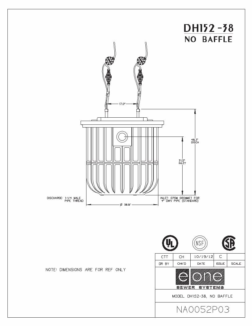


2
1. GRINDER PUMP BASIN – High density polyethylene (HDPE)
2. ACCESSWAY COVER – HDPE
3. ELECTRICAL QUICK DISCONNECT (EQD) – Cable from pump core terminates here.
4. POWER AND ALARM CABLE – Circuits to be installed in accordance with local codes.
5. ALARM PANEL – NEMA 4X enclosure. Equipped with circuit breakers. Locate according to local codes.
6. ALARM DEVICE – Every installation is to have an alarm device to alert the homeowner of a potential malfunction. Visual devices should be placed in very conspicuous locations.
7. INLET – EPDM grommet (4.5” ID). For 4.5” OD DWV pipe.
8. WET WELL VENT – 2.0” tank vent, supplied by factory in units with accessways.
9. GRAVITY SERVICE LINE – 4” DWV, (4.5” OD). Supplied by others.
9a. STUB-OUT – 4” X 5’ Long watertight stub-out, to be installed at time of burial unless the gravity service line is connected during installation. Supplied by others.
10. DISCHARGE VALVE – 1-1/4” Female pipe thread.
11. DISCHARGE LINE – 1-1/4” Nominal pipe size. Supplied by others.
12. CONCRETE ANCHORSupplied by others.
13. BEDDING MATERIAL – 6” minimum depth, round aggregate (gravel). Supplied by others.
14. FINISHED GRADE – Grade line to be 1 to 4 inches below removable lid and slope away from the station.
15. VENT – Indoor installation. See section 6, Venting, on page 6.
16. VALVE – Full ported ball valve. Recommended option, for use during service operations. Supplied by others.
17. CONDUIT – 1” or 1-1/4”, material and burial depth as required per national and local codes. Conduit must enter panel from bottom and be sealed per NEC section 300.5 & 300.7. Supplied by others.
18. UNION – 1-1/4” or compression type coupling. Supplied by others. (Do not use rubber sleeve and hose clamp type coupling.)
19. VALVE – Ball valve, must provide a full-ported 1-1/4” round passage when open. Supplied by others.
20. REBAR – Required to lift tank after ballast (concrete anchor) has been attached, 4 places, evenly spaced around tank.

3
FAILURE TO COMPLY WITH INSTALLATION INSTRUCTIONS WILL
VOID WARRANTY
SEAL CONDUIT PER NEC SECTION
300.5 & 300.7
Figure 1b
Figure 1a
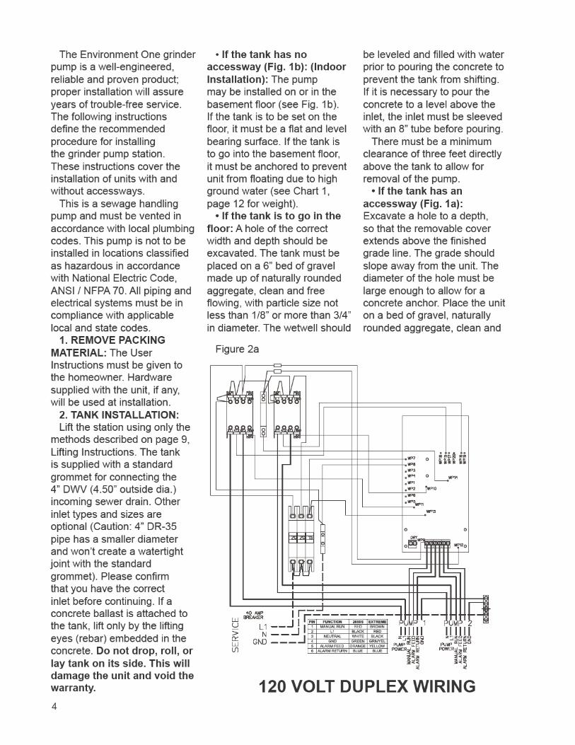


6
underground structure.
available to produce favorable results with different native soil conditions.
The recommended method
the unit to grade using Class
Class 1A and Class 1B are recommended where frost heave is a concern; Class 1B is a better choice when the native soil is sand or if a
is expected. Class I, angular crushed stone, offers an added
compaction. Class II, naturally rounded stone, may require more compactive effort, or tamping, to achieve the proper density.
If the native soil condition consists of clean, compactible
free of ice, rocks, roots, and organic material, it may be
soil must be compacted in lifts not to exceed one foot to
between 85% and 90%. Non-compactible clays and silts are notor any underground structure such as inlet or discharge lines. If you are unsure of the consistency of the native soil, it is recommended that a geotechnical evaluation of the material be obtained before
Another option is the use of
concrete). This is particularly attractive when installing grinder pump stations in augured holes where tight
compaction with dry materials.
dropped with more than 4 feet between the discharge nozzle and the bottom of the hole because this can cause separation of the constituent materials.
6. VENTING: The unit must be properly vented to assure correct operation of the pump. If you have an indoor unit, it can be vented through the 2” port supplied at the top of the wetwell or through the incoming sewer line with a 2” pipe (the vent must be within 4 feet of the grinder pump,
The outdoor units are supplied with a vent pipe from the wetwell to the top of the accessway. Failure to properly vent the tank will result in faulty operation and will void the warranty.
7. ELECTRICAL CONNECTION: (Supply panel to E/One Alarm Panel)
Before proceeding, verify that the service voltage is the same as the motor voltage shown on the name plate. An alarm device is to be installed in a conspicuous location where it can be readily seen by the homeowner. An alarm device is required on every installation. There shall be no exceptions.
Wiring of supply panel and alarm panel shall be per Figures 2a and 2b, alarm panel wiring diagrams and local codes. A dedicated 30 amp breaker is required before a 240V duplex alarm panel, and a dedicated 40 amp breaker is required before a 120V duplex alarm panel.
8. ELECTRICAL CONNECTION: (Pump to Panel) (Fig. 4) The grinder pump station is provided with a cable for connection between the station and the alarm panel (supply cable). The supply cable is shipped inside the station with a small portion fed through the cable
TYPICAL IN-GROUND SECTION VIEW
Figure 3

7
TYPICAL SUPPLY CABLE CONFIGURATION
Figure 4
connector mounted on the
The supply cable, a six conductor tray cable, meets NEC requirements for direct burial as long as a minimum of 24” burial depth is maintained. Those portions of the cable which have less than 24” of cover must be contained in suitable conduit. This includes the vertical portion dropping to a 24” depth at the station and the length rising out of the ground at the control panel. NOTE: Wiring must be installed per national and local codes. Conduit must enter panel from bottom and be sealed per NEC section 300.5 & 300.7.
8a. Installing E/One supply cable:
1) Open the lid of the station. Locate the cable and the feed-thru connector on the wall of the shroud. If the
was delivered in two pieces, be sure both halves of the EQD are securely assembled
together. Loosen the nut on the connector and pull the supply cable out through the connector until it hits the crimped-on stop feature on the cable, approximately 24” from the EQD. **IMPORTANT: All but 24” of the cable must be pulled out of the station, and the EQD and Equalizer should be hung as high in the station as possible to ensure that the pump functions properly. Do not leave the excess cable in the station.
2) Retighten the nut. This connection must be tight or ground water will enter the station.
3) Feed the wire through the length of conduit (contractor provided), which will protect it until it is below the 24” burial depth.
4) Position the conduit vertically below the cable connector along side of the station reaching down into the burial depth. Attach the small guard (protective shroud)
provided with the station to protect the exposed cable where it enters the station. Four self-tapping screws are provided.
5) Run the cable under-ground, in a trench or tunnel, to the location of the alarm panel. Leave a 6- to 12-inch loop of cable at each end to allow for shifting and settling. Connections made at the panel are shown in Figures 2a and 2b.
9. DEBRIS REMOVAL: Prior to start-up test procedure, the core must be removed and the
force all miscellaneous debris into the tank. Next, all liquid and debris must be removed. Once tank is clean, reinstall the pump and proceed with the test.
10. TEST PROCEDURE: When the system is complete and ready for use, the following steps should be taken to verify proper pump and high level alarm operation:
a) Make sure that the discharge shutoff valve is fully open. This valve must not be closed when the pump is operating. In some installations there may be a valve, or valves, at the street main that must also be open.
(Ignore all Trouble indications, LEDs and/or messages until the panel is reset at the end of this procedure.)
For model DH152:b) Turn on the alarm breaker.c) Fill tank with water until the
high level alarm turns on. Shut off water.
d) Turn on pump breaker; the pump should turn on immediately. Verify that the high level alarm turns off
Power at the station must not drop below 10% of nameplate voltage. Maximum Recommended Length:120 Volt 60’ (min. voltage at pump — 108V)240 Volt 150’ (min. voltage at pump — 216V)
Consult factory for longer lengths

8
and then the pump turns off. Proceed to Step E.
For model DR152:b) Fill tank with 100 gallons of
water.c) Turn on pump and alarm
breakers; the pump and high level alarm should turn on immediately.
d) Verify that the high level alarm turns off and then the pump turns off.
e) Clear/Reset the alarm panel:
Sentry and T260 panels: Reset is not required.
Protect Panel: Turn pump and alarm breakers off and back on simultaneously.
Protect Plus Panels: Perform a “cold start” from the Initialize System menu. Any user setting that were previously chosen will not be reset.
f) If any Trouble or alarm conditions are indicated after the panel is reset, contact your local service provider.

9
Field Joint Assembly Instructions
Parts included in Field Joint Kit: Identify all parts before proceeding with installation.
(16) 3/8-16 x 1-1/2 long screws(16) 3/8-16 Elastic Stop Nuts(32) Flat Washers(1) Length Sealant (Sika) Tape (1) Hole Punch(1) Vent Pipe Extension
1) Carefully clean and dry both
IMPORTANT: Sealing surfaces must be dry to ensure the sealant adheres correctly.
2) Starting at one hole of tank
Tape around the inside half of the
the tape with the bolt circle. Move to the adjacent hole and apply one layer of Sika Tape around
inside of tape with the bolt circle. Remove the backing paper as you
Do not stretch Sika tape during application; it may result in a leak. The tape should overlap at the end by approximately 1/2 inch, as shown in Fig. 5a. If a section of Sika Tape is misapplied, the bad section may be cut out and replaced. Cut away the poorly laid portion cleanly with a knife and be sure to over lap the tape at each end about 1/2 inch.
3) Using the tool provided, punch a hole through the tape at each of the 16 existing bolt holes
Be careful to keep the exposed sealant clean and dry.
4) Insert three of the sixteen 3/8-
the upper part of the accessway. These will act as guides while
aligning the bolt pattern of the two
5) Support the upper accessway section a few inches over the tank, making sure to align the vent port in the lid with the vent pipe in the tank. Once aligned, lower the upper section onto the mating
guide it to the proper position. See Fig. 5b.
6) Insert the remaining 13 bolts
stop nut on the end of each bolt, turning the nut on just enough to hold the washer in place.
7) Tighten the bolts until the sealant begins to squeeze out
ensure a consistent, sturdy seal, tighten them in the following sequence: 1, 9; 5, 13; 3, 11; 7, 15; 2, 10; 4, 12; 6, 14; 8, 16. Always be sure to tighten one bolt and then the bolt at the position 180° from it; see Fig. 1 for position
numbers.8) Using the same sequence as
in Step 7, tighten each bolt to 60 in-lbs. Visually inspect the joint, each bolt and each nut should
of sealant should be protruding from the seam along the entire perimeter.
In the event that there are any voids in the sealant, the joint may leak. Take corrective actions if necessary and be sure that the joint is leak free before continuing.
9) Install the vent pipe extension piece, which was shipped inside the upper piece of the accessway. Push the extension pipe into
installed in the wet well tank. Be sure the pipe is seated correctly. Slide the top end of the extension pipe into the receptacle on the bottom of the lid.
IT IS EXTREMELY IMPORTANT THAT THE JOINT IS SEALED PROPERLY BEFORE BACKFILLING. EXCAVATING A UNIT FOR REPAIR IS VERY EXPENSIVE AND CAN BE EASILY
AVOIDED BY USING PROPER CAUTION DURING THE FOLLOWING PROCEDURE.
Figure 5a Figure 5b

10
Lifting Instructions
FAILURE TO FOLLOW THESE INSTRUCTIONS COMPLETELY WILL VOID WARRANTY.
* Transporting unit to installation site: Always lift a unit from the bottom for the purpose of transportation. The station should be received attached to a pallet for this purpose. Never roll a station or move it on its side.
1. No Ballast, No Eye bolts (Ballast to be poured in place): If the concrete anchor is to be poured while the station is in place and it has no eye bolts, lift the
or round eye slings around the station. Loop the slings around the station and use an appropriate lifting beam or tie-down strap to ensure the safety of the station and people close to the unit. (see below)
2. No Ballast, Factory- Installed Eye Bolts (Ballast to be poured in place): If the concrete anchor is to be poured while the station is in place lift the unit by securing straps to the eyebolts supplied on
Keep station oriented vertically to avoid any damage. Only lift from the eyebolts to put unit in hole, not for moving any distance. (see below)
3. Precast Ballast: Never lift a station that has a ballast attached by any means except the rebar hooks. The weight of the concrete will damage the station if you attempt to lift it from any part of the station. (see below)

11
E/One Grinder Pump Station Ballast CalculationsAny buried vessel that is submerged, or partially submerged, in water will be acted on by an upward
buoyant force that attempts to return the vessel to a non-submerged state. The magnitude of this buoyant force is equal to the volume of the vessel that is submerged multiplied by the density of water. On most in-ground installations a ballast, or concrete anchor, of proper volume and weight is required to resist the buoyant force. The amount of ballast required for a given set of installation site conditions may be calculated as follows.
Installation Site Assumptions
of the E/One grinder pump stations will be submerged.
3. The consulting engineer should perform a soil test to determine if the assumptions that have been made are valid. If the site conditions differ from these assumptions, then the consulting engineer must revise the calculations as shown in this document.
Physical Constants
1. Density of Water = 62.4 lb/cu ft 2. Density of Concrete = 150 lb/cu ft (in air) 3. Density of Concrete = 87.6 lb/cu ft (in water)
Procedure
A. Determine the buoyant force exerted on the station.
1. Determine the buoyant force that acts on the grinder pump station when the wet well is submerged in water.
2. Subtract the weight of the station from the buoyant force due to the submerged wet well to determine the net buoyant force acting on the station.
B. Determine the ballast force exerted on the station.
1. Determine the ballast force applied to the station from the concrete, saturated soil and dry soil.
C. Subtract the ballast force from the buoyant force.
1. If the installation site conditions are different from those listed above, the consulting engineer should recalculate the concrete ballast.
Ballast Calculations
The following calculations are to outline the areas used to determine the volumes of the different materials for the ballast. All sections referred to in the calculations are marked on the accompanying drawing.

12
E/One Grinder Pump Station Ballast CalculationsSample Calculation
Volume of Station Wet Well = 22.0 cu ft Station Weight = 470 lb Station Height = 93.5”
A. Buoyant Force
1. The buoyant force acting on the submerged DH152-93 is equal to the weight of the displaced water for the section of the tank that is submerged (wet well).
Fbuoyant = (density of water)(volume of DH152-93 wet well) = (62.4 lb/cu. ft)(22.0 cu. ft) = 1372.8 lb
2. The net buoyant force acting on the station (Fnet-buoyant) is equal to the buoyant force (Fbuoyant) minus the weight of the grinder pump station.
Fnet-buoyant= 1372.8 lb – 470 lb = 902.8 lb
B. Ballast Force
1. Determine the volume of concrete (if applicable) and soil (saturated and dry).
Section I: Used to determine the volume of concrete
Area = (Height)(Width) + (Triangular Area) = (20”)(3.1”) + (1/2)(7”)(5.5”) = 81.3in2
Volume = (Area)(Average Perimeter of the cylinder) = (81.3in2)(2 )(20.95”) = 10701.74 = (10701.74 in3 )(1/1728 ft3/in3) = 6.2 ft3
Section II: Used to determine the volume of saturated soil
Area = (Height)(Width) = (16.5”)(3.1”) = 51.2in2
Volume = (Area)(Average Perimeter of the cylinder) = (51.2in2)(2 )(21.0”) = (6755.7 in3 )(1/1728 ft3/in3) = 3.9 ft3

13
E/One Grinder Pump Station Ballast CalculationsSample Calculation, Continued
Section III: Used To Determine The Volume Of Dry Soil
Area = (Height)(Width) + (Top Area) = (36.5”)(3.1”) + (17.5”)(9.3”) = 275.9in2
Volume = (Area)(Average Perimeter of the cylinder) = (275.9in2)(2 )(17.9”) = (31030.2 in3 )(1/1728 ft3/in3) = 18.0 ft3
2. Determine the combined ballast
Ballast (total) = Ballast (concrete) + Ballast (saturated soil) + Ballast (dry soil) = (Vconcrete)(density concrete in water) + (Vsoil)(density wet soil) + (Vsoil)(density dry soil)
= (6.2 cu ft)(87.6 lb/ft3) + (3.9 cu ft)(70 lb/ft3) + (18.0 cu ft)(110 lb/ft3)
= 543.12 lb + 273 lb + 1980 lb
= 2796.12 lb
Final Condition = Ballast Force – Buoyant Force = 2796.12 lb – 902.8 lb = 1893.3 lb
The approach outlined above may be used to calculate the ballast requirements listed below.
Chart 1
Station Height (in)
Wetwell Volume (cu ft)
FNet-Buoyant
(lb)
Station Weight
(lb)
Fballast (lb)
Volume Concrete
(cu ft)
Weight Concrete in Air (lb)
93 inches 22 902.8 470 2787.4 6.1 915129 inches 22 863.8 509 5174.4 6.1 915160 inches 22 833.8 539 7253.4 6.1 915

14

15
Adjusting the Height of the Grinder Pump StationTO INCREASE STATION HEIGHT 6 INCHES1. Increasing station height can be done without cutting the station. Use the E/One Extender cover shroud
kit (ND0082G01) and follow the instructions that are included with the kit.
TO INCREASE STATION HEIGHT MORE THAN 6 INCHES or TO REDUCE THE STATION HEIGHT:
REMOVE EXISTING COVER ASSEMBLY (Fig. 6)If your existing station has a welded-on cover shroud you will need the
appropriate replacement cover kit (see Table 2, page 15).1. Turn off all power to the grinder pump station.2. Remove the tank lid and the electrical shroud.3. Unplug the electrical quick disconnect (EQD) and remove the EQD
from the supply cable. Note: DO NOT CUT CABLE. Loosen liquid tight cable connector and pull the supply cable out through the connector on the side of tank.
4. Tape the pump breather cable to the vent pipe in the tank.5. Remove the soil around the tank, exposing three of
the tank corrugations below grade. Use caution not to damage buried cable.
6. Remove existing cover shroud.6a. Welded-on shroud (standard) - Using a hand saw,
cut the tank in the valley between the two corrugations at grade, discard existing welded-on shroud and attached corrugations (shroud is not to be reused). Caution: Be careful not to cut either the vent pipe or the pump breather cable.
6b. Clamped-on shroud - Remove band clamp and cover shroud.
REDUCING STATION HEIGHT (Fig. 7)7. Using a hand saw, cut the tank in the valley
between the two corrugations at grade.8. Cut vent pipe 4 ¾” above the cut made on the
tank. Proceed to step 16.
INCREASING STATION HEIGHT (Fig. 8 and Fig. 9)9. Remove the soil around the tank exposing it
18” deeper than the extension being installed. For example, if you have a 2’ extension (not including the coupler) you must dig down 3’6” minimum from grade; if you have a 4’ extension (not including the coupler) you must dig down 5’6” minimum from grade. Use caution not to damage buried cable.
10. Measure from grade down 2’ (for a 2’ extension) or 4’ (for a 4’ extension) and mark accessway. Using a hand saw, cut the tank in the valley between the two corrugations that are closest to your mark. Note: Make sure the welded-on shroud of the extension will be at grade level. Be sure you are not cutting into the wet well and you must have two corrugations below your cut, if there are less than two corrugations, this extension kit can not be used.
Caution: Be careful not to cut either the vent pipe or the pump breather cable.
Figure 6
Figure 7
Figure 8
Figure 9

16
11. Attach the vent pipe extension with the 2” vent coupling, bringing the vent well above grade.12. Clean all dirt and debris from top four corrugations on tank. Install the 24” coupler O-ring on the tank
between the top two corrugations with the white or yellow line facing out and on top.13. Lube extension coupler and coupler O-ring with pipe lube or dish soap.14. Manually press coupling evenly over lubricated O-ring. If additional force is needed, place a plywood
cover over the accessway and apply gentle mechanical pressure to the coupler. Note: Care must be used when pushing down on the coupler. Excessive force or impact may result in damage and leakage.
15. Frequent visual inspections during installation must be performed to determine when the tank has fully engage the coupler.
INSTALL REPLACEMENT COVER ASSEMBLY (Fig. 10)16. Clean top corrugation on accessway extension and
mating surface of replacement shroud with acetone. 17. Liberally apply the silicone sealer provided to the
under side of the replacement shroud where it will come in contact with the accessway extension.
18. Lube wet well vent grommet and vent pipe extension with pipe lube, non-grit hand cleaner or dish soap and slide vent pipe through grommet until tank shroud seats to accessway.
19. Place SS band clamp around top corrugation and the replacement shroud. Tap with a mallet around clamp to help seat the clamp. Torque stud assembly on band clamp to a maximum 125 inlb.
20. Reinstall the supply cable, EQD**, tank lid and electrical shroud and tighten cable connector. (**See “EQD wiring order,” Table 1)
21. Follow start-up procedures to ensure proper pump operation (you will
instruction guide). PIN # COLOR 1 Brown 2 Red 3 Black 4 Grn/Yellow 5 Yellow 6 Blue
**EQD wiring order
Table 1
NOTE: IF EXISTING ACCESSWAY HAS ONLY 2 CORRUGATIONS (Fig. 11)
- If the coupler will not engage completely because the discharge piping is in the way, and it doesn’t have a cut out, you will need to cut a slot in the coupler.
- Using a hand, reciprocating or hole saw, cut an arch in the coupler; the cut-out is not to exceed 5.50” tall or 5.00” wide.Figure 11 Figure 12
Table 2
Figure 10
NC0028
DESCRIPTION PART NO.Simplex station NC0022G15
Duplex station NC0022G17

17

18
Environment One Corporation2773 Balltown RoadNiskayuna, New York 12309–1090
Voice: (01) 518.346.6161Fax: 518.346.6188
www.eone.com NA0063P01 Rev H5/16
A Precision Castparts Company

19
User Instructions for the Environment One Grinder PumpGeneral InformationYour home is served by a low pressure sewer system; the key element is an Environment One grinder pump. The tank collects all solid materials and wastewater from the house. The solid materials are then ground to a
to pump this slurry from your home to the wastewater treatment receiving line and/or disposal plant.
This device complies with Part 15 of the FCC rules. Operation is subject to the following two conditions: 1) this device may not cause harmful interference; and 2) this device must accept any interference received, including
party responsible for compliance could void the user’s authority to operate this equipment.
Care and Use of your Grinder PumpThe Environment One grinder pump is capable of accepting and pumping a wide range of materials, and an extensive grind test is required in order to obtain NSF approval. However, regulatory agencies advise that the following items should not be introduced into any sewer, either directly or through a kitchen waste disposal unit:
Glass Seafood shells Diapers, socks, rags or cloth Syringes
Cotton swabs Personal/cleaning wipes & sponges Disposable toothbrushes Latex/vinyl items
Aquarium gravel Sanitary napkins or tampons Cigarette butts
Caution: Kitchen garbage disposals do not keep grease/oil out of the plumbing system
In addition, you must never introduce into any sewer:
Explosives Strong chemicals Lubricating oil and/or grease
Flammable material Gasoline
Items introduced into the sewer system from your home can potentially impact the water environment. Proper disposal of household wastes such as window cleaners, unused/expired pharmaceuticals, paint thinners, fats, fruit labels, etc. is important. For more information, visit http://www.wef.org.
Periods of DisuseIf your home or building is left unoccupied for longer than a couple of weeks, perform the following procedure:
Purge the System. Run clean water into the unit until the pump activates. Immediately turn off the water and allow the grinder pump to run until it shuts off automatically.
Duplex Units. Special attention must be taken to ensure that both pumps turn on when clean water is added to the tank.
Caution: Do not disconnect power to the unit
Power FailureYour grinder pump cannot dispose of wastewater without electrical power. If electrical power service is interrupted, keep water usage to a minimum.
Pump Failure AlarmYour Environment One grinder pump has been manufactured to produce an alarm signal (120 volt) in the event of a high water level in the basin. The installer must see that the alarm signal provided is connected to an audible and/or visual alarm in such a manner as to provide adequate warning to the user that service is required. During the interim prior to the arrival of an authorized service technician, water usage must be limited to the reserve capacity of the tank.
For service, please call your local distributor:
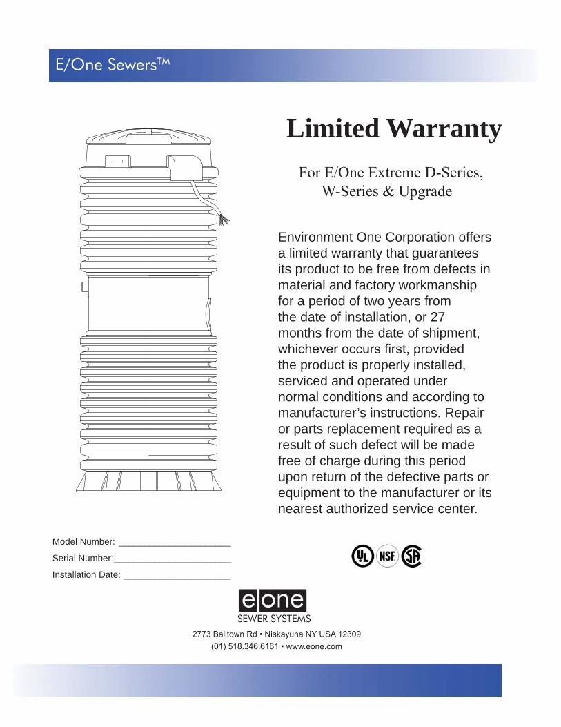
SEWER SYSTEMS
Environment One Corporation offers a limited warranty that guarantees its product to be free from defects in material and factory workmanship for a period of two years from the date of installation, or 27 months from the date of shipment,
the product is properly installed, serviced and operated under normal conditions and according to manufacturer’s instructions. Repair or parts replacement required as a result of such defect will be made free of charge during this period upon return of the defective parts or equipment to the manufacturer or its nearest authorized service center.
Limited WarrantyFor E/One Extreme D-Series,
W-Series & Upgrade
Model Number: ______________________
Serial Number: _______________________
Installation Date: _____________________
E/One SewersTM

DescriptionThe E/One Sentry Protect Plus panels are custom designed for use with
meet the needs of your application, from basic alarm indication to advanced warning of pending service requirements.
E/One Sentry Protect Plus panels are supplied with audible and visual high level alarms. They are easily installed in accordance with relevant national and local codes. Standard panels are approved by UL, CSA, CE and NSF to ensure high quality and safety.
The panel features a corrosion-proof, NEMA 4X-rated, thermoplastic enclosure. A padlock is provided to prevent unauthorized entry (safety front).
Features
panel, including circuit breakers, 240 or 120 VAC service, terminal blocks and ground lugs, audible alarm with manual silence, manual run feature and run indicator, safety front, conformal-coated board and overload protection.
Includes all features of the E/One Sentry Simplex Protect package, including a Trouble indication that shuts down the pumps temporarily in the event of an unacceptable operating condition (brownout, system over-pressure, run-dry), as well as:
Predictive status display modulePre-alarm indication for major operating parametersAlarm indications for major operating parametersHour meter, cycle counter and alarm delayLCD display and user-friendly interfaceInner cover (dead front)Contact group — dry contacts and Remote Sentry contactsProgrammable User Settings
Please consult factory for special applications.
E/One SentryTM
Alarm Panel — Duplex Protect Plus Package
NA0344P01 Rev. –

PIN FUNCTION 2000S EXTREME1 MANUAL RUN RED BROWN2 L1 BLACK RED3 L2 WHITE BLACK4 GND GREEN GRN/YEL5 ALARM FEED ORANGE YELLOW6 ALARM RETURN BLUE BLUE
OLD / NEW WIRE COLOR MAPPIN FUNCTION 2000S EXTREME
1 MANUAL RUN RED BROWN2 L1 BLACK RED3 L2 WHITE BLACK4 GND GREEN GRN/YEL5 ALARM FEED ORANGE YELLOW6 ALARM RETURN BLUE BLUE
OLD / NEW WIRE COLOR MAPPIN FUNCTION 2000S EXTREME
1 MANUAL RUN RED BROWN2 L1 BLACK RED3 L2 WHITE BLACK4 GND GREEN GRN/YEL5 ALARM FEED ORANGE YELLOW6 ALARM RETURN BLUE BLUE
OLD / NEW WIRE COLOR MAP

PIN FUNCTION 2000S EXTREME1 MANUAL RUN RED BROWN2 L1 BLACK RED3 N WHITE BLACK4 GND GREEN GRN/YEL5 ALARM FEED ORANGE YELLOW6 ALARM RETURN BLUE BLUE
OLD / NEW WIRE COLOR MAPPIN FUNCTION 2000S EXTREME
1 MANUAL RUN RED BROWN2 L1 BLACK RED3 N WHITE BLACK4 GND GREEN GRN/YEL5 ALARM FEED ORANGE YELLOW6 ALARM RETURN BLUE BLUE
OLD / NEW WIRE COLOR MAPPIN FUNCTION 2000S EXTREME
1 MANUAL RUN RED BROWN2 L1 BLACK RED3 N WHITE BLACK4 GND GREEN GRN/YEL5 ALARM FEED ORANGE YELLOW6 ALARM RETURN BLUE BLUE
OLD / NEW WIRE COLOR MAP


![MODEL TENDER DOCUMENT Issued to [Name of the Bidder ... june.pdfMODEL TENDER DOCUMENT. GOVERNMENT OF [STATE] Issued to [Name of the Bidder] [Address] This Tender Document is non-transferable](https://img.pdfslide.us/doc/110x75/6131b8741ecc51586944e9ea/model-tender-document-issued-to-name-of-the-bidder-junepdf-model-tender-document.jpg)


![MODEL TENDER DOCUMENT Issued to [Name of …...MODEL TENDER DOCUMENT GOVERNMENT OF [STATE] Issued to [Name of the Bidder] [Address] This Tender Document is non-transferable. The Price](https://img.pdfslide.us/doc/110x75/5f1414421830ce42287623e2/model-tender-document-issued-to-name-of-model-tender-document-government-of.jpg)