Embed Size (px)
Citation preview

SPECIFICATIONS
FOR
FLINT WATER POLLUTION CONTROL FACILITYULTRAVIOLET DISINFECTION PROJECT
SRF PROJECT NUMBER 5696-01
CITY OF FLINTFLINT, MICHIGAN
ISSUED FOR BIDSMAY 15, 2020
HRC JOB NO. 20190265
555 Hulet Drive PO Box 824Bloomfield Hills, Michigan 48303-0824


FLINT WPCF TABLE OF CONTENTSUV DISINFECTION PROJECT 00010/ 1
Hubbell, Roth & Clark, Inc.Job Number 20190265
TABLE OF CONTENTS
NUMBER SECTION NAME PAGE NUMBER
BIDDING REQUIREMENTS - CONTRACT PROVISIONS
00001 Title Page ........................................................................................................1 only00010 Table of Contents .........................................................................................1 thru 400030 Invitation to Bid ............................................................................................1 and 200100 Instructions to Bidders................................................................................1 thru 1000300 Bid Form.......................................................................................................1 thru 600430 Bid Bond Penal Sum Form ...........................................................................1 and 200500 Agreement ....................................................................................................1 thru 700510 Notice of Award .............................................................................................1 only00520 Notice to Proceed............................................................................................1 only00610 Performance Bond........................................................................................1 thru 500615 Construction Payment Bond.........................................................................1 thru 400620 Contractor’s Application for Payment............................................................1 only00625 Certificate of Substantial Completion...........................................................1 and 200700 Standard General Conditions......................................................................1 thru 6400702 Enrolled HB5541..........................................................................................1 thru 400706 EGLE SFR Boilerplate...............................................................................1 thru 3100800 General Supplementary Conditions..............................................................1 thru 900940 Work Change Directive ................................................................................1 and 200941 Change Order ................................................................................................1 and 2
DIVISION 1 - GENERAL REQUIREMENTS
01000 General Specifications................................................................................1 thru 1101039 Coordination and Meetings ..........................................................................1 thru 401210 Allowances....................................................................................................1 and 201300 Submittals.....................................................................................................1 thru 701310 Progress Schedules........................................................................................1 and 201400 Quality Control.............................................................................................1 thru 301500 Construction Facilities..................................................................................1 thru 601590 Field Offices and Sheds................................................................................1 thru 301600 Material and Equipment ...............................................................................1 thru 601700 Contract Closeout .........................................................................................1 thru 601730 Operation and Maintenance Data .................................................................1 thru 401800 Training ........................................................................................................1 thru 3
DIVISION 2 - SITE WORK
02030 Sequence of Construction and Special Project Requirements......................1 thru 402050 Demolition Work..........................................................................................1 thru 702200 Earthwork .....................................................................................................1 thru 902990 Permits ............................................................................................................1 only

TABLE OF CONTENTS FLINT WPCF00010 / 2 UV DISINFECTION PROJECT
NUMBER SECTION NAME PAGE NUMBER
Hubbell, Roth & Clark, Inc.Job Number 20190265
DIVISION 3 - CONCRETE
03110 Concrete Forming.........................................................................................1 thru 503150 Concrete Accessories ...................................................................................1 thru 403200 Concrete Reinforcing ...................................................................................1 thru 603300 Cast-In-Place Concrete...............................................................................1 thru 17
DIVISION 4 - MASONRY
04100 Mortaring and Grouting................................................................................1 thru 504270 Glass Unit Masonry......................................................................................1 thru 604300 Unit Masonry System.................................................................................1 thru 14
DIVISION 5 - METALS
05120 Structural Steel Framing...............................................................................1 thru 805500 Metal Fabrications........................................................................................1 thru 705530 Gratings ........................................................................................................1 thru 7
DIVISION 6 - WOOD AND PLASTICS
06114 Wood Blocking and Curbing ........................................................................1 and 206600 Fiberglass Reinforced Polymer Products .....................................................1 thru 4
DIVISION 7 - THERMAL AND MOISTURE PROTECTION
07181 Water Repellent Coating ..............................................................................1 thru 307531 Single Ply Roofing - Fully Adhered - Conventional....................................1 thru 707620 Sheet Metal Flashing and Trim ....................................................................1 thru 407920 Joint Sealants................................................................................................1 thru 9
DIVISION 8 - DOORS AND WINDOWS
08114 Custom Steel Doors......................................................................................1 thru 508115 Custom Steel Frames....................................................................................1 thru 508710 Door Hardware .............................................................................................1 thru 7
DIVISION 9 - FINISHES
09900 Painting.......................................................................................................1 thru 15
DIVISION 10 -SPECIALTIES
10441 Signs .............................................................................................................1 thru 3

FLINT WPCF TABLE OF CONTENTSUV DISINFECTION PROJECT 00010 / 3
NUMBER SECTION NAME PAGE NUMBER
Hubbell, Roth & Clark, Inc.Job Number 20190265
DIVISION 11 - EQUIPMENT
11282 Gates & Stop Plates......................................................................................1 thru 711380 Ultraviolet Disinfection Equipment ...........................................................1 thru 10
DIVISION 15 - MECHANICAL
15000 Equipment, General......................................................................................1 thru 715010 HVAC & Plumbing General Provisions ......................................................1 thru 815030 Piping Installation, General ..........................................................................1 thru 815060 Pipe and Pipe Fittings.................................................................................1 thru 1115100 Valves and Actuators....................................................................................1 thru 415110 Plumbing & HVAC Materials and Methods ................................................1 thru 615170 Motors ..........................................................................................................1 thru 515250 Plumbing Insulation .....................................................................................1 thru 315622 Direct Fired Makeup Air Units ....................................................................1 thru 715810 Ductwork & Ductwork Accessories.............................................................1 thru 315860 Exhaust Fans .................................................................................................1 and 215940 Air Inlets and Outlets ....................................................................................1 and 2 15960 HVAC Controls and Sequences of Operation..............................................1 thru 415970 Testing Adjusting and Balancing .................................................................1 thru 3
DIVISION 16 - ELECTRICAL
16010 General Electrical, Instrument, and Control Requirements .........................1 thru 616050 Basic Electrical Materials and Methods.......................................................1 thru 516055 Basic I & C Materials and Methods .............................................................1 thru 316110 Raceways......................................................................................................1 thru 916118 Underground Conduit System......................................................................1 thru 416123 Wire and Cable...........................................................................................1 thru 1016130 Boxes ............................................................................................................1 thru 616140 Wiring Devices.............................................................................................1 thru 516160 Cabinets and Enclosures...............................................................................1 thru 516170 Grounding and Bonding ...............................................................................1 thru 516190 Supporting Devices ......................................................................................1 thru 316195 Electrical Identification ................................................................................1 thru 416461 Dry Type Transformers ................................................................................1 thru 416470 Panelboards ..................................................................................................1 thru 416477 Fuses.............................................................................................................1 thru 316482 Motor Control Centers..................................................................................1 thru 516510 Lighting Fixtures and Luminaires ................................................................1 thru 616810 Analysis Instruments ....................................................................................1 thru 416820 Flow Instruments..........................................................................................1 thru 516960 Electrical Testing and Equipment ................................................................1 thru 316970 Calibration and Start-up of Systems.............................................................1 thru 516980 Demonstration and Training.........................................................................1 thru 3

TABLE OF CONTENTS FLINT WPCF00010 / 4 UV DISINFECTION PROJECT
NUMBER SECTION NAME PAGE NUMBER
Hubbell, Roth & Clark, Inc.Job Number 20190265
Appendix A SCADA Work UV Disinfection MAK-2004
END OF SECTION

INVITATION TO BID 00 1116-1 COF106401F
CITY OF FLINTDepartment of Purchases &
Supplies
Sheldon A. NeeleyMayor
Joyce A. McClanePurchasing Manager
INVITATION TO BIDOWNER:THE CITY OF FLINTDEPARTMENT OF PURCHASES AND SUPPLIES 1101 S. SAGINAW STREET, ROOM 203FLINT, MI, 48502
Project Name: WPC Ultraviolet Disinfection Project Proposal No.:
SCOPE OF WORK:The City of Flint, Department of Purchases & Supplies, is soliciting sealed bids for providing:
Work shall include the Conversion of the existing chlorine contact tank to an ultraviolet disinfection system including UV disinfection equipment rated for 80 MGD, new building and associated concrete, demolition, mechanical and electrical work.
If your firm is interested in providing the requested services, please submit one (1) original, one (1) electronic copy, one (1) unbound copy of your bid in a sealed envelope to the City of Flint, Department of Purchases by on a date and time to be announced, but not before May 21, 2020. The outside of the envelope should clearly identify the project name and number, and the name and address of the Bidder. Please note: all bids received after 1:00 PM (EST) will not be considered. Faxed bids to the Purchasing Department will not be accepted. Bidding Documents shall meet requirements set forth in Specification Section 00100, Instructions to Bidders.
A mandatory pre-bid meeting will be held on a date and time to be announced, but not before May 7, 2020, at the City of Flint’s Water Pollution Control (WPC) Facility located at 4652 Beecher Road, Flint, Michigan 48532. This will be the only venue that potential contractors will be able to have a face-to-face conversation with both the Purchasing Department and WPC staff. This venue will also allow contractors to ask any questions concerning this Project.
Each bid proposal shall be submitted on the proposal forms provided and shall be accompanied by a certified check, cashier's check or bid bond, executed by the bidder and Surety Company, payable to Treasurer, City of Flint in the amount of five percent (5%) of the accompanying bid. Proposal Guarantee shall provide assurance that the bidder will, upon acceptance of the bid, execute the necessary Contract with the City. No bid may be withdrawn for one hundred twenty (120) days after scheduled closing time for receiving bids.
Proposals submitted by Bidders who have been debarred, suspended, or made ineligible by any Federal Agency will be rejected. The project is funded through the State Clean Water Revolving Loan program, requirements of the program are included in the Contract Documents.

INVITATION TO BID 00 1116-2 COF106401F
Each bidder agrees to waive any claim it has or may have against the Owner, the Architect/Engineer, and their respective employees, arising out of or in connection with the administration, evaluation, or recommendation of any bid.
The City of Flint reserves the right to reject all bids and to waive irregularities in bidding.
All additional bid documents, requirements, addendums, specifications and plans/drawings (if utilized) are available on the Purchasing page of the City of Flint's web site at https://www.cityofflint.com/finance/purchasing/ under "open bids" and the specific bid or proposal number assigned to this notice.
Anticipated Bid Submission Schedule:
Date Released/Bid Posted to City’s Website: Monday, May 18, 2020Bid Advertisement: Monday, May 18, 2020Mandatory Pre-bid Meeting: To Be AnnouncedFinal Date for Questions: To Be AnnouncedFinal Addendum: To Be AnnouncedBid Due Date: To Be Announced
The dates provided above are estimated dates only and may be subject to change.
Submit to City: One (1) printed, signed, original proposal and addendaOne (1) electronic copy of the proposal and addenda on flash driveOne (1) printed, signed, copy of the proposal and addenda (unbound)
Send to: The City of FlintDepartment of Purchases and Supplies 1101 S. Saginaw Street, Room 203 Flint, MI 48502
Effective immediately upon release of these Bidding Documents, and until notice of contract award, all official communications from proposers regarding the requirements of this Bid shall be directed to:
Joyce A. McClane [email protected]
The City, or designee, shall distribute all official changes, modifications, responses to questions or notices relating to the requirements of this Bid. Addendum to this Bid may be developed and shared with all Vendors. Any other information of any kind from any other source shall not be considered official, and proposers relying on other information do so at their own risk.
Sincerely,
Joyce A. McClane, Purchasing Manager

FLINT WPCF INSTRUCTIONS TO BIDDERS
UV DISINFECTION PROJECT 00100/ 1
EJCDC C-200 Suggested Instructions to Bidders for Construction Contracts
Copyright © 2007 National Society of Professional Engineers for EJCDC. All rights reserved.
Page 1 of 10
SECTION 00100
INSTRUCTIONS TO BIDDERS
ARTICLE 1 – DEFINED TERMS
1.01 Terms used in these Instructions to Bidders have the meanings indicated in the General Conditions
and Supplementary Conditions. Additional terms used in these Instructions to Bidders have the
meanings indicated below:
A. Issuing Office – The office from which the Bidding Documents are to be issued and where the
bidding procedures are to be administered.
ARTICLE 2 – COPIES OF BIDDING DOCUMENTS
2.01 Complete sets of the Bidding Documents in the number and for the deposit sum, if any, stated in
the advertisement or invitation to bid may be obtained from the Issuing Office. The deposit will
be refunded to each document holder of record who returns a complete set of Bidding Documents
in good condition within 30 days after opening of Bids.
2.02 Complete sets of Bidding Documents shall be used in preparing Bids; neither Owner nor Engineer
assumes any responsibility for errors or misinterpretations resulting from the use of incomplete
sets of Bidding Documents.
2.03 Owner and Engineer, in making copies of Bidding Documents available on the above terms, do so
only for the purpose of obtaining Bids for the Work and do not authorize or confer a license for
any other use.
ARTICLE 3 – QUALIFICATIONS OF BIDDERS
3.01 To demonstrate Bidder’s qualifications to perform the Work, within 3 days of Owner’s request,
Bidder shall submit written evidence such as financial data, previous experience, present
commitments, and such other data as may be called for below.
3.02 Bidder is advised to carefully review those portions of the Bid Form requiring Bidder’s
representations and certifications.
FLINT WPCF INSTRUCTIONS TO BIDDERS
UV DISINFECTION PROJECT 00100/ 2
EJCDC C-200 Suggested Instructions to Bidders for Construction Contracts
Copyright © 2007 National Society of Professional Engineers for EJCDC. All rights reserved.
Page 2 of 10
ARTICLE 4 – EXAMINATION OF BIDDING DOCUMENTS, OTHER RELATED DATA, AND
SITE
4.01 Subsurface and Physical Conditions
A. The Supplementary Conditions identify:
1. Those reports known to Owner of explorations and tests of subsurface conditions at or
contiguous to the Site.
2. Those drawings known to Owner of physical conditions relating to existing surface or
subsurface structures at the Site (except Underground Facilities).
B. Copies of reports and drawings referenced in Paragraph 4.01.A will be made available by Owner
to any Bidder on request. Those reports and drawings are not part of the Contract Documents,
but the “technical data” contained therein upon which Bidder is entitled to rely as provided in
Paragraph 4.02 of the General Conditions has been identified and established in Paragraph 4.02
of the Supplementary Conditions. Bidder is responsible for any interpretation or conclusion
Bidder draws from any “technical data” or any other data, interpretations, opinions, or
information contained in such reports or shown or indicated in such drawings.
4.02 Underground Facilities
A. Information and data shown or indicated in the Bidding Documents with respect to existing
Underground Facilities at or contiguous to the Site is based upon information and data furnished
to Owner and Engineer by owners of such Underground Facilities, including Owner, or others.
4.03 Hazardous Environmental Condition
A. The Supplementary Conditions identify any reports and drawings known to Owner relating to a
Hazardous Environmental Condition identified at the Site.
B. Copies of reports and drawings referenced in Paragraph 4.03.A will be made available by Owner
to any Bidder on request. Those reports and drawings are not part of the Contract Documents,
but the “technical data” contained therein upon which Bidder is entitled to rely as provided in
Paragraph 4.06 of the General Conditions has been identified and established in Paragraph 4.06
of the Supplementary Conditions. Bidder is responsible for any interpretation or conclusion
Bidder draws from any “technical data” or any other data, interpretations, opinions, or
information contained in such reports or shown or indicated in such drawings.
4.04 Provisions concerning responsibilities for the adequacy of data furnished to prospective Bidders
with respect to subsurface conditions, other physical conditions, and Underground Facilities, and
possible changes in the Bidding Documents due to differing or unanticipated subsurface or
physical conditions appear in Paragraphs 4.02, 4.03, and 4.04 of the General Conditions.
Provisions concerning responsibilities for the adequacy of data furnished to prospective Bidders

FLINT WPCF INSTRUCTIONS TO BIDDERS
UV DISINFECTION PROJECT 00100/ 3
EJCDC C-200 Suggested Instructions to Bidders for Construction Contracts
Copyright © 2007 National Society of Professional Engineers for EJCDC. All rights reserved.
Page 3 of 10
with respect to a Hazardous Environmental Condition at the Site, if any, and possible changes in
the Contract Documents due to any Hazardous Environmental Condition uncovered or revealed at
the Site which was not shown or indicated in the Drawings or Specifications or identified in the
Contract Documents to be within the scope of the Work, appear in Paragraph 4.06 of the General
Conditions.
4.05 On request, Owner will provide Bidder access to the Site to conduct such examinations,
investigations, explorations, tests, and studies as Bidder deems necessary for submission of a Bid.
Bidder shall fill all holes and clean up and restore the Site to its former condition upon completion
of such explorations, investigations, tests, and studies. Bidder shall comply with all applicable
Laws and Regulations relative to excavation and utility locates.
4.06 A. Reference is made to Article 7 of the Supplementary Conditions for the identification of the
general nature of other work that is to be performed at the Site by Owner or others (such as
utilities and other prime contractors) that relates to the Work contemplated by these Bidding
Documents. On request, Owner will provide to each Bidder for examination access to or copies
of contract documents (other than portions thereof related to price) for such other work.
B. Paragraph 6.13.C of the General Conditions indicates that if an Owner safety
program exists, it will be noted in the Supplementary Conditions.
4.07 It is the responsibility of each Bidder before submitting a Bid to:
A. examine and carefully study the Bidding Documents, and the other related data identified in the
Bidding Documents;
B. visit the Site and become familiar with and satisfy Bidder as to the general, local, and Site
conditions that may affect cost, progress, and performance of the Work;
C. become familiar with and satisfy Bidder as to all federal, state, and local Laws and Regulations
that may affect cost, progress, and performance of the Work;
D. carefully study all: (1) reports of explorations and tests of subsurface conditions at or contiguous
to the Site and all drawings of physical conditions relating to existing surface or subsurface
structures at the Site (except Underground Facilities) that have been identified in Paragraph 4.02
of the Supplementary Conditions as containing reliable "technical data," and (2) reports and
drawings of Hazardous Environmental Conditions, if any, at the Site that have been identified in
the Paragraph 4.06 of the Supplementary Conditions as containing reliable "technical data";
E. consider the information known to Bidder; information commonly known to contractors doing
business in the locality of the Site; information and observations obtained from visits to the Site;
the Bidding Documents; and the Site-related reports and drawings identified in the Bidding
Documents, with respect to the effect of such information, observations, and documents on (1)
the cost, progress, and performance of the Work; (2) the means, methods, techniques, sequences,

FLINT WPCF INSTRUCTIONS TO BIDDERS
UV DISINFECTION PROJECT 00100/ 4
EJCDC C-200 Suggested Instructions to Bidders for Construction Contracts
Copyright © 2007 National Society of Professional Engineers for EJCDC. All rights reserved.
Page 4 of 10
and procedures of construction to be employed by Bidder, including applying any specific
means, methods, techniques, sequences, and procedures of construction expressly required by
the Bidding Documents; and (3) Bidder’s safety precautions and programs;
F. agree at the time of submitting its Bid that no further examinations, investigations, explorations,
tests, studies, or data are necessary for the determination of its Bid for performance of the Work
at the price(s) bid and within the times required, and in accordance with the other terms and
conditions of the Bidding Documents;
G. become aware of the general nature of the work to be performed by Owner and others at the Site
that relates to the Work as indicated in the Bidding Documents;
H. promptly give Engineer written notice of all conflicts, errors, ambiguities, or discrepancies that
Bidder discovers in the Bidding Documents and confirm that the written resolution thereof by
Engineer is acceptable to Bidder; and
I. determine that the Bidding Documents are generally sufficient to indicate and convey
understanding of all terms and conditions for the performance of the Work.
4.08 The submission of a Bid will constitute an incontrovertible representation by Bidder that Bidder
has complied with every requirement of this Article 4, that without exception the Bid is premised
upon performing and furnishing the Work required by the Bidding Documents and applying any
specific means, methods, techniques, sequences, and procedures of construction that may be
shown or indicated or expressly required by the Bidding Documents, that Bidder has given
Engineer written notice of all conflicts, errors, ambiguities, and discrepancies that Bidder has
discovered in the Bidding Documents and the written resolutions thereof by Engineer are
acceptable to Bidder, and that the Bidding Documents are generally sufficient to indicate and
convey understanding of all terms and conditions for performing and furnishing the Work.
ARTICLE 5 – PRE-BID CONFERENCE
5.01 A Mandatory Pre-Bid conference will be held at 10:00 a.m. local time on May 19, 2020 at the Flint
Water Pollution Control Facility, 4652 Beecher Road, Flint, MI. Representatives of Owner and
Engineer will be present to discuss the Project. Bidders are required to attend and participate in
the conference. Engineer will transmit to all prospective Bidders of record such Addenda as
Engineer considers necessary in response to questions arising at the conference. Oral statements
may not be relied upon and will not be binding or legally effective. Attendance at this meeting is
required to submit a bid on the project.
ARTICLE 6 – SITE AND OTHER AREAS
6.01 The Site is identified in the Bidding Documents. Easements for permanent structures or permanent
changes in existing facilities are to be obtained and paid for by Owner unless otherwise provided
in the Bidding Documents. All additional lands and access thereto required for temporary

FLINT WPCF INSTRUCTIONS TO BIDDERS
UV DISINFECTION PROJECT 00100/ 5
EJCDC C-200 Suggested Instructions to Bidders for Construction Contracts
Copyright © 2007 National Society of Professional Engineers for EJCDC. All rights reserved.
Page 5 of 10
construction facilities, construction equipment, or storage of materials and equipment to be
incorporated in the Work are to be obtained and paid for by Contractor.
ARTICLE 7 – INTERPRETATIONS AND ADDENDA
7.01 All questions about the meaning or intent of the Bidding Documents are to be submitted to
Engineer in writing. Interpretations or clarifications considered necessary by Engineer in response
to such questions will be issued by Addenda mailed or delivered to all parties recorded by Engineer
as having received the Bidding Documents. Questions received less than ten days prior to the date
for opening of Bids may not be answered. Only questions answered by Addenda will be binding.
Oral and other interpretations or clarifications will be without legal effect.
7.02 Addenda may be issued to clarify, correct, or change the Bidding Documents as deemed advisable
by Owner or Engineer.
ARTICLE 8 – BID SECURITY
8.01 A Bid must be accompanied by Bid security made payable to Owner in an amount of 5 percent of
Bidder’s maximum Bid price and in the form of a certified check, bank money order, or a Bid bond
(on the form attached) issued by a surety meeting the requirements of Paragraphs 5.01 and 5.02 of
the General Conditions.
8.02 The Bid security of the Successful Bidder will be retained until such Bidder has executed the
Contract Documents, furnished the required contract security and met the other conditions of the
Notice of Award, whereupon the Bid security will be returned. If the Successful Bidder fails to
execute and deliver the Contract Documents and furnish the required contract security within 15
days after the Notice of Award, Owner may consider Bidder to be in default, annul the Notice of
Award, and the Bid security of that Bidder will be forfeited. Such forfeiture shall be Owner’s
exclusive remedy if Bidder defaults. The Bid security of other Bidders whom Owner believes to
have a reasonable chance of receiving the award may be retained by Owner until the earlier of
seven days after the Effective Date of the Agreement or 61 days after the Bid opening, whereupon
Bid security furnished by such Bidders will be returned.
8.03 Bid security of other Bidders whom Owner believes do not have a reasonable chance of receiving
the award will be returned within seven days after the Bid opening.
ARTICLE 9 – CONTRACT TIMES
9.01 The number of days within which, or the dates by which, the Work is to be substantially completed
and ready for final payment are set forth in the Agreement.
ARTICLE 10 – LIQUIDATED DAMAGES
10.01 Provisions for liquidated damages, if any, are set forth in the Agreement.

FLINT WPCF INSTRUCTIONS TO BIDDERS
UV DISINFECTION PROJECT 00100/ 6
EJCDC C-200 Suggested Instructions to Bidders for Construction Contracts
Copyright © 2007 National Society of Professional Engineers for EJCDC. All rights reserved.
Page 6 of 10
ARTICLE 11 – SUBSTITUTE AND “OR-EQUAL” ITEMS
11.01 The Contract, if awarded, will be on the basis of materials and equipment specified or described
in the Bidding Documents without consideration of possible substitute or “or-equal” items.
Whenever it is specified or described in the Bidding Documents that a substitute or “or-equal”
item of material or equipment may be furnished or used by Contractor if acceptable to Engineer,
application for such acceptance will not be considered by Engineer until after the Effective Date
of the Agreement.
ARTICLE 12 – SUBCONTRACTORS, SUPPLIERS AND OTHERS
12.01 If the Supplementary Conditions require the identity of certain Subcontractors, Suppliers,
individuals, or entities to be submitted to Owner in advance of a specified date prior to the Effective
Date of the Agreement, the apparent Successful Bidder, and any other Bidder so requested, shall
within five days after Bid opening, submit to Owner a list of all such Subcontractors, Suppliers,
individuals, or entities proposed for those portions of the Work for which such identification is
required. Such list shall be accompanied by an experience statement with pertinent information
regarding similar projects and other evidence of qualification for each such Subcontractor,
Supplier, individual, or entity if requested by Owner. If Owner or Engineer, after due investigation,
has reasonable objection to any proposed Subcontractor, Supplier, individual, or entity, Owner
may, before the Notice of Award is given, request apparent Successful Bidder to submit a
substitute,
[in which case apparent Successful Bidder shall submit an acceptable substitute, Bidder’s Bid price
will be increased (or decreased) by the difference in cost occasioned by such substitution, and
Owner may consider such price adjustment in evaluating Bids and making the Contract award.]
12.02 If apparent Successful Bidder declines to make any such substitution, Owner may award the
Contract to the next lowest Bidder that proposes to use acceptable Subcontractors, Suppliers,
individuals, or entities. Declining to make requested substitutions will not constitute grounds for
forfeiture of the Bid security of any Bidder. Any Subcontractor, Supplier, individual, or entity so
listed and against which Owner or Engineer makes no written objection prior to the giving of the
Notice of Award will be deemed acceptable to Owner and Engineer subject to revocation of such
acceptance after the Effective Date of the Agreement as provided in Paragraph 6.06 of the General
Conditions.
12.03 Contractor shall not be required to employ any Subcontractor, Supplier, individual, or entity
against whom Contractor has reasonable objection.
ARTICLE 13 – PREPARATION OF BID
13.01 The Bid Form is included with the Bidding Documents. Additional copies may be obtained from
Engineer.

FLINT WPCF INSTRUCTIONS TO BIDDERS
UV DISINFECTION PROJECT 00100/ 7
EJCDC C-200 Suggested Instructions to Bidders for Construction Contracts
Copyright © 2007 National Society of Professional Engineers for EJCDC. All rights reserved.
Page 7 of 10
13.02 All blanks on the Bid Form shall be completed in ink and the Bid Form signed in ink. Erasures or
alterations shall be initialed in ink by the person signing the Bid Form. A Bid price shall be
indicated for each [section, Bid item, alternative, adjustment unit price item, and unit price item]
listed therein. In the case of optional alternatives the words “No Bid,” “No Change,” or “Not
Applicable” may be entered.
13.03 A Bid by a corporation shall be executed in the corporate name by the president or a vice-president
or other corporate officer accompanied by evidence of authority to sign. The corporate seal shall
be affixed and attested by the secretary or an assistant secretary. The corporate address and state
of incorporation shall be shown.
13.04 A Bid by a partnership shall be executed in the partnership name and signed by a partner (whose
title must appear under the signature), accompanied by evidence of authority to sign. The official
address of the partnership shall be shown.
13.05 A Bid by a limited liability company shall be executed in the name of the firm by a member and
accompanied by evidence of authority to sign. The state of formation of the firm and the official
address of the firm shall be shown.
13.06 A Bid by an individual shall show the Bidder’s name and official address.
13.07 A Bid by a joint venture shall be executed by each joint venturer in the manner indicated on the
Bid Form. The official address of the joint venture shall be shown.
13.08 All names shall be printed in ink below the signatures.
13.09 The Bid shall contain an acknowledgment of receipt of all Addenda, the numbers of which shall
be filled in on the Bid Form.
13.10 Postal and e-mail addresses and telephone number for communications regarding the Bid shall be
shown.
13.11 The Bid shall contain evidence of Bidder’s authority and qualification to do business in the state
where the Project is located, or Bidder shall covenant in writing to obtain such authority and
qualification prior to award of the Contract and attach such covenant to the Bid. Bidder’s state
contractor license number, if any, shall also be shown on the Bid Form.

FLINT WPCF INSTRUCTIONS TO BIDDERS
UV DISINFECTION PROJECT 00100/ 8
EJCDC C-200 Suggested Instructions to Bidders for Construction Contracts
Copyright © 2007 National Society of Professional Engineers for EJCDC. All rights reserved.
Page 8 of 10
ARTICLE 14 – BASIS OF BID; COMPARISON OF BIDS
14.01 Lump Sum& Alternates
A. Bidders shall submit a Bid on a lump sum basis for the base Bid and include a separate price for
each alternate described in the Bidding Documents as provided for in the Bid Form. The price
for each alternate will be the amount added to or deleted from the base Bid if Owner selects the
alternate. Bidders are encouraged to fill in any Alternates which are listed as “Voluntary,” but
need not do so. In the comparison of Bids, alternates may be applied in any order with all or
none of them selected as determined solely by the OWNER.
14.02 Allowances
A. For cash allowances the Bid price shall include such amounts as the Bidder deems proper for
Contractor's overhead, costs, profit, and other expenses on account of cash allowances, if any,
named in the Contract Documents, in accordance with Paragraph 11.02.B of the General
Conditions.
ARTICLE 15 – SUBMITTAL OF BID
15.01 With each copy of the Bidding Documents, a Bidder is furnished one separate unbound copy of
the Bid Form, and, if required, the Bid Bond Form. The unbound copy of the Bid Form is to be
completed and submitted with the Bid security and the following documents:
15.02 A Bid shall be submitted no later than the date and time prescribed and at the place indicated in
the advertisement or invitation to bid and shall be enclosed in a plainly marked package with the
Project title (and, if applicable, the designated portion of the Project for which the Bid is
submitted), the name and address of Bidder, and shall be accompanied by the Bid security and
other required documents. If a Bid is sent by mail or other delivery system, the sealed envelope
containing the Bid shall be enclosed in a separate package plainly marked on the outside with the
notation “BID ENCLOSED.” A mailed Bid shall be addressed to the entity provided in the Bid
Advertisement.
ARTICLE 16 – MODIFICATION AND WITHDRAWAL OF BID
16.01 A Bid may be modified or withdrawn by an appropriate document duly executed in the same
manner that a Bid must be executed and delivered to the place where Bids are to be submitted prior
to the date and time for the opening of Bids.
16.02 If within 24 hours after Bids are opened any Bidder files a duly signed written notice with Owner
and promptly thereafter demonstrates to the reasonable satisfaction of Owner that there was a
material and substantial mistake in the preparation of its Bid, that Bidder may withdraw its Bid,
and the Bid security will be returned. Thereafter, if the Work is rebid, that Bidder will be
disqualified from further bidding on the Work.

FLINT WPCF INSTRUCTIONS TO BIDDERS
UV DISINFECTION PROJECT 00100/ 9
EJCDC C-200 Suggested Instructions to Bidders for Construction Contracts
Copyright © 2007 National Society of Professional Engineers for EJCDC. All rights reserved.
Page 9 of 10
ARTICLE 17 – OPENING OF BIDS
17.01 Bids will be opened at the time and place indicated in the Advertisement or Invitation to Bid and,
unless obviously non-responsive, read aloud publicly. An abstract of the amounts of the base Bids
and major alternates, if any, will be made available to Bidders after the opening of Bids.
ARTICLE 18 – BIDS TO REMAIN SUBJECT TO ACCEPTANCE
18.01 All Bids will remain subject to acceptance for the period of time stated in the Bid Form, but Owner
may, in its sole discretion, release any Bid and return the Bid security prior to the end of this period.
ARTICLE 19 – EVALUATION OF BIDS AND AWARD OF CONTRACT
19.01 Owner reserves the right to reject any or all Bids, including without limitation, nonconforming,
nonresponsive, unbalanced, or conditional Bids. Owner further reserves the right to reject the Bid
of any Bidder whom it finds, after reasonable inquiry and evaluation, to not be responsible. Owner
may also reject the Bid of any Bidder if Owner believes that it would not be in the best interest of
the Project to make an award to that Bidder. Owner also reserves the right to waive all informalities
not involving price, time, or changes in the Work and to negotiate contract terms with the
Successful Bidder.
19.02 More than one Bid for the same Work from an individual or entity under the same or different
names will not be considered. Reasonable grounds for believing that any Bidder has an interest in
more than one Bid for the Work may be cause for disqualification of that Bidder and the rejection
of all Bids in which that Bidder has an interest.
19.03 In evaluating Bids, Owner will consider whether or not the Bids comply with the prescribed
requirements, and such alternates, unit prices and other data, as may be requested in the Bid Form
or prior to the Notice of Award.
19.04 In evaluating Bidders, Owner will consider the qualifications of Bidders and may consider the
qualifications and experience of Subcontractors, Suppliers, and other individuals or entities
proposed for those portions of the Work for which the identity of Subcontractors, Suppliers, and
other individuals or entities must be submitted as provided in the Supplementary Conditions.
19.05 Owner may conduct such investigations as Owner deems necessary to establish the responsibility,
qualifications, and financial ability of Bidders, proposed Subcontractors, Suppliers, individuals, or
entities proposed for those portions of the Work in accordance with the Contract Documents.
19.06 If the Contract is to be awarded, Owner will award the Contract to the Bidder whose Bid is in the
best interests of the Project.

FLINT WPCF INSTRUCTIONS TO BIDDERS
UV DISINFECTION PROJECT 00100/ 10
EJCDC C-200 Suggested Instructions to Bidders for Construction Contracts
Copyright © 2007 National Society of Professional Engineers for EJCDC. All rights reserved.
Page 10 of 10
ARTICLE 20 – CONTRACT SECURITY AND INSURANCE
20.01 Article 5 of the General Conditions, as may be modified by the Supplementary Conditions, sets
forth Owner’s requirements as to performance and payment bonds and insurance. When the
Successful Bidder delivers the executed Agreement to Owner, it shall be accompanied by such
bonds.
ARTICLE 21 – SIGNING OF AGREEMENT
21.01 When Owner issues a Notice of Award to the Successful Bidder, it shall be accompanied by the
required number of unsigned counterparts of the Agreement along with the other Contract
Documents which are identified in the Agreement as attached thereto. Within 15 days thereafter,
Successful Bidder shall sign and deliver the required number of counterparts of the Agreement
and attached documents to Owner. Within ten days thereafter, Owner shall deliver one fully signed
counterpart to Successful Bidder with a complete set of the Drawings with appropriate
identification.
ARTICLE 22 – SALES AND USE TAXES
22.01 The Contractor is responsible for payment of all State of Michigan sales and use tax on this project.
Said taxes shall not be included in the Bid. Refer to Paragraph 6.10 of the Supplementary
Conditions for additional information.
ARTICLE 23 – RETAINAGE
23.01 Provisions concerning Contractor’s rights to deposit securities in lieu of retainage are set forth in
the Agreement.

FLINT WPCF BID FORM
UV DISINFECTION PROJECT 00300/ 1
EJCDC C-410 Suggested Bid Form for Construction Contracts
Copyright © 2007 National Society of Professional Engineers for EJCDC. All rights reserved.
Page 1 of 6
SECTION 00300
BID FORM
ARTICLE 1 – BID RECIPIENT
1.01 This Bid is submitted to:
City of Flint, Michigan
1.02 The undersigned Bidder proposes and agrees, if this Bid is accepted, to enter into an Agreement with
Owner in the form included in the Bidding Documents to perform all Work as specified or indicated
in the Bidding Documents for the prices and within the times indicated in this Bid and in accordance
with the other terms and conditions of the Bidding Documents.
ARTICLE 2 – BIDDER’S ACKNOWLEDGEMENTS
2.01 Bidder accepts all of the terms and conditions of the Instructions to Bidders, including without
limitation, those dealing with the disposition of Bid security. This Bid will remain subject to
acceptance for 120 days after the Bid opening, or for such longer period of time that Bidder may
agree to in writing upon request of Owner.
ARTICLE 3 – BIDDER’S REPRESENTATIONS
3.01 In submitting this Bid, Bidder represents that:
A. Bidder has examined and carefully studied the Bidding Documents, other related data identified
in the Bidding Documents, and the following Addenda, receipt of which is hereby
acknowledged:
Addendum No. Addendum Date
B. Bidder has visited the Site and become familiar with and is satisfied as to the general, local, and
Site conditions that may affect cost, progress, and performance of the Work.
C. Bidder is familiar with and is satisfied as to all Laws and Regulations that may affect cost,
progress, and performance of the Work.
D. Bidder has carefully studied all: (1) reports of explorations and tests of subsurface conditions at
or contiguous to the Site and all drawings of physical conditions relating to existing surface or

FLINT WPCF BID FORM
UV DISINFECTION PROJECT 00300/ 2
EJCDC C-410 Suggested Bid Form for Construction Contracts
Copyright © 2007 National Society of Professional Engineers for EJCDC. All rights reserved.
Page 2 of 6
subsurface structures at the Site (except Underground Facilities) that have been identified in SC-
4.02 as containing reliable "technical data," and (2) reports and drawings of Hazardous
Environmental Conditions, if any, at the Site that have been identified in SC-4.06 as containing
reliable "technical data."
E. Bidder has considered the information known to Bidder; information commonly known to
contractors doing business in the locality of the Site; information and observations obtained from
visits to the Site; the Bidding Documents; and the Site-related reports and drawings identified in
the Bidding Documents, with respect to the effect of such information, observations, and
documents on (1) the cost, progress, and performance of the Work; (2) the means, methods,
techniques, sequences, and procedures of construction to be employed by Bidder, including
applying the specific means, methods, techniques, sequences, and procedures of construction
expressly required by the Bidding Documents; and (3) Bidder’s safety precautions and programs.
F. Based on the information and observations referred to in Paragraph 3.01.E above, Bidder does
not consider that further examinations, investigations, explorations, tests, studies, or data are
necessary for the determination of this Bid for performance of the Work at the price(s) bid and
within the times required, and in accordance with the other terms and conditions of the Bidding
Documents.
G. Bidder is aware of the general nature of work to be performed by Owner and others at the Site
that relates to the Work as indicated in the Bidding Documents.
H. Bidder has given Engineer written notice of all conflicts, errors, ambiguities, or discrepancies
that Bidder has discovered in the Bidding Documents, and the written resolution thereof by
Engineer is acceptable to Bidder.
1. The Bidding Documents are generally sufficient to indicate and convey understanding of all
terms and conditions for the performance of the Work for which this Bid is submitted.
ARTICLE 4 – BIDDER’S CERTIFICATION
4.01 Bidder certifies that:
A. This Bid is genuine and not made in the interest of or on behalf of any undisclosed individual or
entity and is not submitted in conformity with any collusive agreement or rules of any group,
association, organization, or corporation;
B. Bidder has not directly or indirectly induced or solicited any other Bidder to submit a false or
sham Bid;
C. Bidder has not solicited or induced any individual or entity to refrain from bidding; and
D. Bidder has not engaged in corrupt, fraudulent, collusive, or coercive practices in competing for
the Contract. For the purposes of this Paragraph 4.01.D:

FLINT WPCF BID FORM
UV DISINFECTION PROJECT 00300/ 3
EJCDC C-410 Suggested Bid Form for Construction Contracts
Copyright © 2007 National Society of Professional Engineers for EJCDC. All rights reserved.
Page 3 of 6
1. “corrupt practice” means the offering, giving, receiving, or soliciting of any thing of value
likely to influence the action of a public official in the bidding process;
2. “fraudulent practice” means an intentional misrepresentation of facts made (a) to influence
the bidding process to the detriment of Owner, (b) to establish bid prices at artificial non-
competitive levels, or (c) to deprive Owner of the benefits of free and open competition;
3. “collusive practice” means a scheme or arrangement between two or more Bidders, with or
without the knowledge of Owner, a purpose of which is to establish bid prices at artificial,
non-competitive levels; and
4. “coercive practice” means harming or threatening to harm, directly or indirectly, persons or
their property to influence their participation in the bidding process or affect the execution
of the Contract.
ARTICLE 5 – BASIS OF BID
5.01 Bidder will complete the Work in accordance with the Contract Documents for the following
price(s):
_________________________________________________________________ ($_______________)
Use Words Use Figures
All specified cash allowances are included in the price(s) set forth above, and have been computed in
accordance with Paragraph 11.02 of the General Conditions.
1. Included in the Bid Price is an Allowance for SCADA programming and PLC panel in the
amount of $17,000.00.
2. Included in the Bid Price is an Allowance for security camera in the amount of $13,000.00
3. Included in the Bid Price is an Owner Controlled Contingency Allowance in the amount of
$250,000.00.
5.02 Bidder proposes the following subcontractors for this contract:
A. Concrete _________________________________________
B. Mechanical _______________________________________
C. Electrical ________________________________________
FLINT WPCF BID FORM
UV DISINFECTION PROJECT 00300/ 4
EJCDC C-410 Suggested Bid Form for Construction Contracts
Copyright © 2007 National Society of Professional Engineers for EJCDC. All rights reserved.
Page 4 of 6
ARTICLE 6 – TIME OF COMPLETION
6.01 Bidder agrees that the Work will be substantially complete and will be completed and ready for final
payment in accordance with Paragraph 14.07 of the General Conditions on or before the dates or
within the number of calendar days indicated in the Agreement.
6.02 Bidder accepts the provisions of the Agreement as to liquidated damages.
ARTICLE 7 – ATTACHMENTS TO THIS BID
7.01 The following documents are submitted with and made a condition of this Bid:
A. Required Bid security in the form of ;
ARTICLE 8 – DEFINED TERMS
8.01 The terms used in this Bid with initial capital letters have the meanings stated in the Instructions to
Bidders, the General Conditions, and the Supplementary Conditions.

FLINT WPCF BID FORM
UV DISINFECTION PROJECT 00300/ 5
EJCDC C-410 Suggested Bid Form for Construction Contracts
Copyright © 2007 National Society of Professional Engineers for EJCDC. All rights reserved.
Page 5 of 6
ARTICLE 9 – BID SUBMITTAL
9.01 This Bid is submitted by:
If Bidder is:
An Individual
Name (typed or printed):
By:
(Individual’s signature)
Doing business as:
A Partnership
Partnership Name:
By:
(Signature of general partner -- attach evidence of authority to sign)
Name (typed or printed):
A Corporation
Corporation Name: (SEAL)
State of Incorporation:
Type (General Business, Professional, Service, Limited Liability):_______
By:
(Signature -- attach evidence of authority to sign)
Name (typed or printed):
Title:
(CORPORATE SEAL)
Attest

FLINT WPCF BID FORM
UV DISINFECTION PROJECT 00300/ 6
EJCDC C-410 Suggested Bid Form for Construction Contracts
Copyright © 2007 National Society of Professional Engineers for EJCDC. All rights reserved.
Page 6 of 6
Date of Qualification to do business in [State where Project is located] is
____/____/____.
A Joint Venture
Name of Joint Venture:
First Joint Venturer Name: (SEAL)
By:
(Signature of first joint venture partner -- attach evidence of authority to sign)
Name (typed or printed):
Title:
Second Joint Venturer Name: (SEAL)
By:
(Signature of second joint venture partner -- attach evidence of authority to sign)
Name (typed or printed):
Title:
(Each joint venturer must sign. The manner of signing for each individual, partnership,
and corporation that is a party to the joint venture should be in the manner indicated
above.)
Bidder's Business Address
Phone No. _____________________________________ Fax No.
E-mail ______________________________ _______
SUBMITTED on , 20____.

FLINT WPCF BID BOND PENAL SUM FORM
UV DISINFECTION PROJECT 00430/ 1
EJCDC C-430 Bid Bond (Penal Sum Form)
Prepared by the Engineers Joint Contract Documents Committee.
Page 1 of 2
BID BOND
Any singular reference to Bidder, Surety, Owner or other party shall be considered plural where applicable.
BIDDER (Name and Address):
SURETY (Name and Address of Principal Place of Business):
OWNER (Name and Address):
BID
Bid Due Date:
Description (Project Name and Include Location):
BOND
Bond Number:
Date (Not earlier than Bid due date):
Penal sum $
(Words) (Figures)
Surety and Bidder, intending to be legally bound hereby, subject to the terms set forth below, do each cause this
Bid Bond to be duly executed by an authorized officer, agent, or representative.
BIDDER SURETY
(Seal) (Seal)
Bidder’s Name and Corporate Seal Surety’s Name and Corporate Seal
By: By:
Signature Signature (Attach Power of Attorney)
Print Name Print Name
Title Title
Attest: Attest:
Signature Signature
Title Title
Note: Above addresses are to be used for giving any required notice. Provide execution by any additional
parties, such as joint venturers, if necessary.

FLINT WPCF BID BOND PENAL SUM FORM
UV DISINFECTION PROJECT 00430/ 2
EJCDC C-430 Bid Bond (Penal Sum Form)
Prepared by the Engineers Joint Contract Documents Committee.
Page 2 of 2
1. Bidder and Surety, jointly and severally, bind themselves, their heirs, executors, administrators, successors, and
assigns to pay to Owner upon default of Bidder the penal sum set forth on the face of this Bond. Payment of the
penal sum is the extent of Bidder’s and Surety’s liability. Recovery of such penal sum under the terms of this Bond
shall be Owner’s sole and exclusive remedy upon default of Bidder.
2. Default of Bidder shall occur upon the failure of Bidder to deliver within the time required by the Bidding
Documents (or any extension thereof agreed to in writing by Owner) the executed Agreement required by the
Bidding Documents and any performance and payment bonds required by the Bidding Documents.
3. This obligation shall be null and void if:
3.1 Owner accepts Bidder’s Bid and Bidder delivers within the time required by the Bidding Documents (or
any extension thereof agreed to in writing by Owner) the executed Agreement required by the Bidding
Documents and any performance and payment bonds required by the Bidding Documents, or
3.2 All Bids are rejected by Owner, or
3.3 Owner fails to issue a Notice of Award to Bidder within the time specified in the Bidding Documents (or
any extension thereof agreed to in writing by Bidder and, if applicable, consented to by Surety when
required by Paragraph 5 hereof).
4. Payment under this Bond will be due and payable upon default of Bidder and within 30 calendar days after
receipt by Bidder and Surety of written notice of default from Owner, which notice will be given with reasonable
promptness, identifying this Bond and the Project and including a statement of the amount due.
5. Surety waives notice of any and all defenses based on or arising out of any time extension to issue Notice of
Award agreed to in writing by Owner and Bidder, provided that the total time for issuing Notice of Award including
extensions shall not in the aggregate exceed 120 days from Bid due date without Surety’s written consent.
6. No suit or action shall be commenced under this Bond prior to 30 calendar days after the notice of default
required in Paragraph 4 above is received by Bidder and Surety and in no case later than one year after Bid due
date.
7. Any suit or action under this Bond shall be commenced only in a court of competent jurisdiction located in the
state in which the Project is located.
8. Notices required hereunder shall be in writing and sent to Bidder and Surety at their respective addresses shown
on the face of this Bond. Such notices may be sent by personal delivery, commercial courier, or by United States
Registered or Certified Mail, return receipt requested, postage pre-paid, and shall be deemed to be effective upon
receipt by the party concerned.
9. Surety shall cause to be attached to this Bond a current and effective Power of Attorney evidencing the authority
of the officer, agent, or representative who executed this Bond on behalf of Surety to execute, seal, and deliver such
Bond and bind the Surety thereby.
10. This Bond is intended to conform to all applicable statutory requirements. Any applicable requirement of any
applicable statute that has been omitted from this Bond shall be deemed to be included herein as if set forth at
length. If any provision of this Bond conflicts with any applicable statute, then the provision of said statute shall
govern and the remainder of this Bond that is not in conflict therewith shall continue in full force and effect.
11. The term “Bid” as used herein includes a Bid, offer, or proposal as applicable.

FLINT WPCF AGREEMENT
UV DISINFECTION PROJECT 00500/ 1
EJCDC C-520 Suggested Form of Agreement Between Owner and Contractor for Construction Contract (Stipulated Price)
Copyright © 2007 National Society of Professional Engineers for EJCDC. All rights reserved.
Page 1 of 7
SUGGESTED FORM OF AGREEMENT
BETWEEN OWNER AND CONTRACTOR
FOR CONSTRUCTION CONTRACT (STIPULATED PRICE)
THIS AGREEMENT is by and between City of Flint (“Owner”) and
(“Contractor”).
Owner and Contractor hereby agree as follows:
ARTICLE 1 – WORK
Contractor shall complete all Work as specified or indicated in the Contract Documents. The Work
is generally described as follows: Conversion of the existing chlorine contact tank to an ultraviolet
disinfection system including UV disinfection equipment rated for 80 MGD, new building and
associated concrete, demolition, mechanical and electrical work.
ARTICLE 2 – THE PROJECT
2.01 The Project for which the Work under the Contract Documents may be the whole or only a part is
generally described as follows: UV Disinfection Project.
ARTICLE 3 – ENGINEER
3.01 The Project has been designed by Hubbell, Roth & Clark, Inc. (Engineer), which is to act as
Owner’s representative, assume all duties and responsibilities, and have the rights and authority
assigned to Engineer in the Contract Documents in connection with the completion of the Work in
accordance with the Contract Documents.
ARTICLE 4 – CONTRACT TIMES
4.01 Time of the Essence
A. All time limits for Milestones, if any, Substantial Completion, and completion and readiness for
final payment as stated in the Contract Documents are of the essence of the Contract.
4.02 Days to Achieve Substantial Completion and Final Payment
A. The Work will be substantially completed within 420 days after the date when the Contract
Times commence to run as provided in Paragraph 2.03 of the General Conditions, and completed
and ready for final payment in accordance with Paragraph 14.07 of the General Conditions within
460 days after the date when the Contract Times commence to run.

FLINT WPCF AGREEMENT
UV DISINFECTION PROJECT 00500/ 2
EJCDC C-520 Suggested Form of Agreement Between Owner and Contractor for Construction Contract (Stipulated Price)
Copyright © 2007 National Society of Professional Engineers for EJCDC. All rights reserved.
Page 2 of 7
4.03 Liquidated Damages
A. Contractor and Owner recognize that time is of the essence as stated in Paragraph 4.01 above
and that Owner will suffer financial loss if the Work is not completed within the times specified
in Paragraph 4.02 above, plus any extensions thereof allowed in accordance with Article 12 of
the General Conditions. The parties also recognize the delays, expense, and difficulties involved
in proving in a legal or arbitration proceeding the actual loss suffered by Owner if the Work is
not completed on time. Accordingly, instead of requiring any such proof, Owner and Contractor
agree that as liquidated damages for delay (but not as a penalty), Contractor shall pay Owner
$1,500.00 for each day that expires after the time specified in Paragraph 4.02 above for
Substantial Completion until the Work is substantially complete. After Substantial Completion,
if Contractor shall neglect, refuse, or fail to complete the remaining Work within the Contract
Time or any proper extension thereof granted by Owner, Contractor shall pay Owner $1,500.00
for each day that expires after the time specified in Paragraph 4.02 above for completion and
readiness for final payment until the Work is completed and ready for final payment.
ARTICLE 5 – CONTRACT PRICE
5.01 Owner shall pay Contractor for completion of the Work in accordance with the Contract
Documents an amount in current funds equal to the sum of the amounts determined pursuant to
Paragraphs 5.01.A below:
A. For all Work other than Unit Price Work, a lump sum of: $
All specific cash allowances are included in the above price in accordance with Paragraph 11.02
of the General Conditions.
ARTICLE 6 – PAYMENT PROCEDURES
6.01 Submittal and Processing of Payments
A. Contractor shall submit Applications for Payment in accordance with Article 14 of the General
Conditions. Applications for Payment will be processed by Engineer as provided in the General
Conditions.
6.02 Progress Payments; Retainage
A. Owner shall make progress payments on account of the Contract Price on the basis of
Contractor’s Applications for Payment on or about the 7th day of each month during
performance of the Work as provided in Paragraph 6.02.A.1 below. All such payments will be
measured by the schedule of values established as provided in Paragraph 2.07.A of the General
Conditions (and in the case of Unit Price Work based on the number of units completed) or, in
the event there is no schedule of values, as provided in the General Requirements.

FLINT WPCF AGREEMENT
UV DISINFECTION PROJECT 00500/ 3
EJCDC C-520 Suggested Form of Agreement Between Owner and Contractor for Construction Contract (Stipulated Price)
Copyright © 2007 National Society of Professional Engineers for EJCDC. All rights reserved.
Page 3 of 7
1. Prior to Substantial Completion, progress payments will be made in an amount equal to the
percentage indicated below but, in each case, less the aggregate of payments previously made
and less such amounts as Engineer may determine or Owner may withhold, including but not
limited to liquidated damages, in accordance with Paragraph 14.02 of the General
Conditions.
a. The provisions set forth in Michigan Public Acts of 1980, Act No. 524, shall be adhered
to by OWNER and CONTRACTOR for retainage. A copy of the Act is included in
Section 00702, Act. No. 524, Michigan P.A. 1980.
6.03 Final Payment
A. Upon final completion and acceptance of the Work in accordance with Paragraph 14.07 of the
General Conditions, Owner shall pay the remainder of the Contract Price as recommended by
Engineer as provided in said Paragraph 14.07.
ARTICLE 7 – INTEREST
7.01 All moneys not paid when due as provided in Article 14 of the General Conditions shall bear
interest at the passbook savings rate.
ARTICLE 8 – CONTRACTOR’S REPRESENTATIONS
8.01 In order to induce Owner to enter into this Agreement, Contractor makes the following
representations:
A. Contractor has examined and carefully studied the Contract Documents and the other related
data identified in the Bidding Documents.
B. Contractor has visited the Site and become familiar with and is satisfied as to the general, local,
and Site conditions that may affect cost, progress, and performance of the Work.
C. Contractor is familiar with and is satisfied as to all federal, state, and local Laws and Regulations
that may affect cost, progress, and performance of the Work.
D. Contractor has carefully studied all: (1) reports of explorations and tests of subsurface conditions
at or contiguous to the Site and all drawings of physical conditions relating to existing surface or
subsurface structures at the Site (except Underground Facilities), if any, that have been identified
in Paragraph SC-4.02 of the Supplementary Conditions as containing reliable "technical data,"
and (2) reports and drawings of Hazardous Environmental Conditions, if any, at the Site that
have been identified in Paragraph SC-4.06 of the Supplementary Conditions as containing
reliable "technical data."
E. Contractor has considered the information known to Contractor; information commonly known
to contractors doing business in the locality of the Site; information and observations obtained

FLINT WPCF AGREEMENT
UV DISINFECTION PROJECT 00500/ 4
EJCDC C-520 Suggested Form of Agreement Between Owner and Contractor for Construction Contract (Stipulated Price)
Copyright © 2007 National Society of Professional Engineers for EJCDC. All rights reserved.
Page 4 of 7
from visits to the Site; the Contract Documents; and the Site-related reports and drawings
identified in the Contract Documents, with respect to the effect of such information,
observations, and documents on (1) the cost, progress, and performance of the Work; (2) the
means, methods, techniques, sequences, and procedures of construction to be employed by
Contractor, including any specific means, methods, techniques, sequences, and procedures of
construction expressly required by the Contract Documents; and (3) Contractor’s safety
precautions and programs.
F. Based on the information and observations referred to in Paragraph 8.01.E above, Contractor
does not consider that further examinations, investigations, explorations, tests, studies, or data
are necessary for the performance of the Work at the Contract Price, within the Contract Times,
and in accordance with the other terms and conditions of the Contract Documents.
G. Contractor is aware of the general nature of work to be performed by Owner and others at the
Site that relates to the Work as indicated in the Contract Documents.
H. Contractor has given Engineer written notice of all conflicts, errors, ambiguities, or discrepancies
that Contractor has discovered in the Contract Documents, and the written resolution thereof by
Engineer is acceptable to Contractor.
I. The Contract Documents are generally sufficient to indicate and convey understanding of all
terms and conditions for performance and furnishing of the Work.
ARTICLE 9 – CONTRACT DOCUMENTS
9.01 Contents
A. The Contract Documents consist of the following:
1. This Agreement.
2. Performance bond.
3. Payment bond.
4. Other bonds __________________.
5. General Conditions.
6. Supplementary Conditions.
7. Specifications as listed in the table of contents of the Project Manual.
8. Drawings as listed on attached sheet index.
FLINT WPCF AGREEMENT
UV DISINFECTION PROJECT 00500/ 5
EJCDC C-520 Suggested Form of Agreement Between Owner and Contractor for Construction Contract (Stipulated Price)
Copyright © 2007 National Society of Professional Engineers for EJCDC. All rights reserved.
Page 5 of 7
9. Addenda (numbers 1, inclusive).
10. Exhibits to this Agreement (enumerated as follows):
a. Contractor’s Bid.
b. Documentation submitted by Contractor prior to Notice of Award.
11. The following which may be delivered or issued on or after the Effective Date of the
Agreement and are not attached hereto:
a. Notice to Proceed.
b. Work Change Directives.
c. Change Orders.
B. The documents listed in Paragraph 9.01.A are attached to this Agreement (except as expressly
noted otherwise above).
C. There are no Contract Documents other than those listed above in this Article 9.
D. The Contract Documents may only be amended, modified, or supplemented as provided in
Paragraph 3.04 of the General Conditions.
ARTICLE 10 – MISCELLANEOUS
10.01 Terms
A. Terms used in this Agreement will have the meanings stated in the General Conditions and the
Supplementary Conditions.
10.02 Assignment of Contract
A. No assignment by a party hereto of any rights under or interests in the Contract will be binding
on another party hereto without the written consent of the party sought to be bound; and,
specifically but without limitation, moneys that may become due and moneys that are due may
not be assigned without such consent (except to the extent that the effect of this restriction may
be limited by law), and unless specifically stated to the contrary in any written consent to an
assignment, no assignment will release or discharge the assignor from any duty or responsibility
under the Contract Documents.

FLINT WPCF AGREEMENT
UV DISINFECTION PROJECT 00500/ 6
EJCDC C-520 Suggested Form of Agreement Between Owner and Contractor for Construction Contract (Stipulated Price)
Copyright © 2007 National Society of Professional Engineers for EJCDC. All rights reserved.
Page 6 of 7
10.03 Successors and Assigns
A. Owner and Contractor each binds itself, its partners, successors, assigns, and legal
representatives to the other party hereto, its partners, successors, assigns, and legal
representatives in respect to all covenants, agreements, and obligations contained in the Contract
Documents.
10.04 Severability
A. Any provision or part of the Contract Documents held to be void or unenforceable under any
Law or Regulation shall be deemed stricken, and all remaining provisions shall continue to be
valid and binding upon Owner and Contractor, who agree that the Contract Documents shall be
reformed to replace such stricken provision or part thereof with a valid and enforceable provision
that comes as close as possible to expressing the intention of the stricken provision.
10.05 Contractor’s Certifications
A. Contractor certifies that it has not engaged in corrupt, fraudulent, collusive, or coercive practices
in competing for or in executing the Contract. For the purposes of this Paragraph 10.05:
1. “corrupt practice” means the offering, giving, receiving, or soliciting of any thing of value
likely to influence the action of a public official in the bidding process or in the Contract
execution;
2. “fraudulent practice” means an intentional misrepresentation of facts made (a) to influence
the bidding process or the execution of the Contract to the detriment of Owner, (b) to
establish Bid or Contract prices at artificial non-competitive levels, or (c) to deprive Owner
of the benefits of free and open competition;
3. “collusive practice” means a scheme or arrangement between two or more Bidders, with or
without the knowledge of Owner, a purpose of which is to establish Bid prices at artificial,
non-competitive levels; and
4. “coercive practice” means harming or threatening to harm, directly or indirectly, persons or
their property to influence their participation in the bidding process or affect the execution
of the Contract.
10.06 Other Provisions

EJCDC C-520 Suggested Form of Agreement Between Owner and Contractor for Construction Contract (Stipulated Price)
Copyright © 2007 National Society of Professional Engineers for EJCDC. All rights reserved.
Page 7 of 7
IN WITNESS WHEREOF, Owner and Contractor have signed this Agreement. Counterparts have been
delivered to Owner and Contractor. All portions of the Contract Documents have been signed or have been
identified by Owner and Contractor or on their behalf.
This Agreement will be effective on (which is the Effective Date
of the Agreement).
OWNER: CONTRACTOR
City of Flint
By: By:
Title: Title:
(If Contractor is a corporation, a partnership,
or a joint venture, attach evidence of authority
to sign.)
Attest: Attest:
Title: Title:
Address for giving notices: Address for giving notices:
(If Owner is a corporation, attach evidence
of authority to sign. If Owner is a public body, attach
evidence of authority to sign and resolution or other
documents authorizing execution
of this Agreement.)
Agent for service of process:


FLINT WPCF NOTICE OF AWARD
UV DISINFECTION PROJECT 00510/ 1
EJCDC C-510 Notice of Award
Prepared by the Engineers Joint Contract Documents Committee and endorsed by the Construction Specifications Institute.
Page 1 of 1
Notice of Award
Date: _________
Project:
Owner: Owner's Contract No.: n/a
Contract: Engineer's Project No.:
Bidder:
Bidder's Address:
You are notified that your Bid dated ____________ for the above Contract has been considered. You are
the Successful Bidder and are awarded a Contract for construction of _____________.
The Contract Price of your Contract is __________________($_________). This reflects the base bid total.
6 copies of the proposed Contract Documents (except Drawings) accompany this Notice of Award.
10 sets of the Drawings will be delivered separately or otherwise made available to you immediately.
You must comply with the following conditions precedent within [30] days of the date you receive this
Notice of Award.
1. Deliver to the Owner [6] fully executed counterparts of the Contract Documents.
2. Deliver with the executed Contract Documents the Contract security [Bonds] as specified.
3. Deliver with the executed Contract Documents the Insurance Certificates as specified.
Failure to comply with these conditions within the time specified will entitle Owner to consider you in
default, annul this Notice of Award, and declare your Bid security forfeited.
Within thirty days after you comply with the above conditions and funding has been secured, Owner will
return to you one fully executed counterpart of the Contract Documents.
By:
Authorized Signature
Title Copy to Engineer


FLINT WPCF NOTICE TO PROCEED
UV DISINFECTION PROJECT 00520/ 1
EJCDC C-550 Notice to Proceed
Prepared by the Engineers Joint Contract Documents Committee and endorsed by the Construction Specifications Institute.
Page 1 of 1
Notice to Proceed
Date: _________________
Project:
Owner: Owner's Contract No.:
Contract: Engineer's Project No.
Contractor:
Contractor's Address: [send Certified Mail, Return Receipt Requested]
You are notified that the Contract Times under the above Contract will commence to run
on . On or before that date, you are to start performing your obligations under the Contract
Documents. In accordance with Article 4 of the Agreement, the date of Substantial Completion
is , and the date of readiness for final payment is [(or) the number of days to achieve
Substantial Completion is , and the number of days to achieve readiness for final payment is
].
Before you may start any Work at the Site, Paragraph 2.01.B of the General Conditions
provides that you and Owner must each deliver to the other (with copies to Engineer and other
identified additional insureds and loss payees) certificates of insurance which each is required to
purchase and maintain in accordance with the Contract Documents.
Also, before you may start any Work at the Site, you must:
__________________________________ [add other requirements].
Owner
Given by:
Authorized Signature
Title
Date
Copy to Engineer


FLINT WPCF PERFORMANCE BOND
UV DISINFECTION PROJECT 00610/ 1
EJCDC C-610 Performance Bond
Prepared by the Engineers Joint Contract Documents Committee.
Page 1 of 5
PERFORMANCE BOND
Any singular reference to Contractor, Surety, Owner, or other party shall be considered plural where applicable.
CONTRACTOR (Name and Address): SURETY (Name, and Address of Principal Place of Business):
OWNER (Name and Address):
CONTRACT
Effective Date of Agreement:
Amount:
Description (Name and Location):
BOND
Bond Number:
Date (Not earlier than Effective Date of
Agreement):
Amount:
Modifications to this Bond Form:
Surety and Contractor, intending to be legally bound hereby, subject to the terms set forth below, do each cause
this Performance Bond to be duly executed by an authorized officer, agent, or representative.
CONTRACTOR AS PRINCIPAL SURETY
(Seal) (Seal)
Contractor's Name and Corporate Seal Surety’s Name and Corporate Seal
By: By:
Signature Signature (Attach Power of Attorney)
Print Name Print Name
Title Title
Attest: Attest:
Signature Signature

FLINT WPCF PERFORMANCE BOND
UV DISINFECTION PROJECT 00610/ 2
EJCDC C-610 Performance Bond
Prepared by the Engineers Joint Contract Documents Committee.
Page 2 of 5
Title Title
Note: Provide execution by additional parties, such as joint venturers, if necessary.

FLINT WPCF PERFORMANCE BOND
UV DISINFECTION PROJECT 00610/ 3
EJCDC C-610 Performance Bond
Prepared by the Engineers Joint Contract Documents Committee.
Page 3 of 5
Contractor and Surety, jointly and severally, bind themselves, their heirs, executors, administrators, successors,
and assigns to Owner for the performance of the Contract, which is incorporated herein by reference.
1. If Contractor performs the Contract, Surety and Contractor have no obligation under this Bond, except to
participate in conferences as provided in Paragraph 2.1.
2. If there is no Owner Default, Surety’s obligation under this Bond shall arise after:
2.1 Owner has notified Contractor and Surety, at the addresses described in Paragraph 9 below, that
Owner is considering declaring a Contractor Default and has requested and attempted to arrange a
conference with Contractor and Surety to be held not later than 15 days after receipt of such notice
to discuss methods of performing the Contract. If Owner, Contractor, and Surety agree, Contractor
shall be allowed a reasonable time to perform the Contract, but such an agreement shall not waive
Owner’s right, if any, subsequently to declare a Contractor Default; and
2.2 Owner has declared a Contractor Default and formally terminated Contractor’s right to complete the
Contract. Such Contractor Default shall not be declared earlier than 20 days after Contractor and
Surety have received notice as provided in Paragraph 2.1; and
2.3 Owner has agreed to pay the Balance of the Contract Price to:
1. Surety in accordance with the terms of the Contract; or
2. Another contractor selected pursuant to Paragraph 3.3 to perform the Contract.
3. When Owner has satisfied the conditions of Paragraph 2, Surety shall promptly, and at Surety’s expense,
take one of the following actions:
3.1 Arrange for Contractor, with consent of Owner, to perform and complete the Contract; or
3.2 Undertake to perform and complete the Contract itself, through its agents or through independent
contractors; or
3.3 Obtain bids or negotiated proposals from qualified contractors acceptable to Owner for a contract for
performance and completion of the Contract, arrange for a contract to be prepared for execution by
Owner and contractor selected with Owner’s concurrence, to be secured with performance and
payment bonds executed by a qualified surety equivalent to the bonds issued on the Contract, and
pay to Owner the amount of damages as described in Paragraph 5 in excess of the Balance of the
Contract Price incurred by Owner resulting from Contractor Default; or
3.4 Waive its right to perform and complete, arrange for completion, or obtain a new contractor, and with
reasonable promptness under the circumstances:
1. After investigation, determine the amount for which it may be liable to Owner and, as soon as
practicable after the amount is determined, tender payment therefor to Owner; or
2. Deny liability in whole or in part and notify Owner citing reasons therefor.
4. If Surety does not proceed as provided in Paragraph 3 with reasonable promptness, Surety shall be deemed
to be in default on this Bond 15 days after receipt of an additional written notice from Owner to Surety
demanding that Surety perform its obligations under this Bond, and Owner shall be entitled to enforce any
remedy available to Owner. If Surety proceeds as provided in Paragraph 3.4, and Owner refuses the payment
tendered or Surety has denied liability, in whole or in part, without further notice Owner shall be entitled to
enforce any remedy available to Owner.

FLINT WPCF PERFORMANCE BOND
UV DISINFECTION PROJECT 00610/ 4
EJCDC C-610 Performance Bond
Prepared by the Engineers Joint Contract Documents Committee.
Page 4 of 5
5. After Owner has terminated Contractor’s right to complete the Contract, and if Surety elects to act under
Paragraph 3.1, 3.2, or 3.3 above, then the responsibilities of Surety to Owner shall not be greater than those of
Contractor under the Contract, and the responsibilities of Owner to Surety shall not be greater than those of
Owner under the Contract. To the limit of the amount of this Bond, but subject to commitment by Owner of
the Balance of the Contract Price to mitigation of costs and damages on the Contract, Surety is obligated
without duplication for:
5.1 The responsibilities of Contractor for correction of defective Work and completion of the Contract;
5.2 Additional legal, design professional, and delay costs resulting from Contractor’s Default, and
resulting from the actions of or failure to act of Surety under Paragraph 3; and
5.3 Liquidated damages, or if no liquidated damages are specified in the Contract, actual damages caused
by delayed performance or non-performance of Contractor.
6. Surety shall not be liable to Owner or others for obligations of Contractor that are unrelated to the Contract,
and the Balance of the Contract Price shall not be reduced or set off on account of any such unrelated
obligations. No right of action shall accrue on this Bond to any person or entity other than Owner or its heirs,
executors, administrators, or successors.
7. Surety hereby waives notice of any change, including changes of time, to Contract or to related
subcontracts, purchase orders, and other obligations.
8. Any proceeding, legal or equitable, under this Bond may be instituted in any court of competent jurisdiction
in the location in which the Work or part of the Work is located, and shall be instituted within two years after
Contractor Default or within two years after Contractor ceased working or within two years after Surety refuses
or fails to perform its obligations under this Bond, whichever occurs first. If the provisions of this paragraph
are void or prohibited by law, the minimum period of limitation available to sureties as a defense in the
jurisdiction of the suit shall be applicable.
9. Notice to Surety, Owner, or Contractor shall be mailed or delivered to the address shown on the signature
page.
10. When this Bond has been furnished to comply with a statutory requirement in the location where the
Contract was to be performed, any provision in this Bond conflicting with said statutory requirement shall be
deemed deleted herefrom and provisions conforming to such statutory requirement shall be deemed
incorporated herein. The intent is that this Bond shall be construed as a statutory bond and not as a common
law bond.
11. Definitions.
11.1 Balance of the Contract Price: The total amount payable by Owner to Contractor under the Contract
after all proper adjustments have been made, including allowance to Contractor of any amounts
received or to be received by Owner in settlement of insurance or other Claims for damages to which
Contractor is entitled, reduced by all valid and proper payments made to or on behalf of Contractor
under the Contract.
11.2 Contract: The agreement between Owner and Contractor identified on the signature page, including
all Contract Documents and changes thereto.

FLINT WPCF PERFORMANCE BOND
UV DISINFECTION PROJECT 00610/ 5
EJCDC C-610 Performance Bond
Prepared by the Engineers Joint Contract Documents Committee.
Page 5 of 5
11.3 Contractor Default: Failure of Contractor, which has neither been remedied nor waived, to perform
or otherwise to comply with the terms of the Contract.
11.4 Owner Default: Failure of Owner, which has neither been remedied nor waived, to pay Contractor
as required by the Contract or to perform and complete or otherwise comply with the other terms
thereof.
FOR INFORMATION ONLY – (Name, Address and Telephone)
Surety Agency or Broker:
Owner’s Representative (Engineer or other party):


FLINT WPCF CONSTRUCTION PAYMENT BOND
UV DISINFECTION PROJECT 00615/ 1
{MW001504;1} EJCDC C-615(A) Payment Bond March 2008
Prepared by the Engineers Joint Contract Documents Committee.
Page 1 of 4
PAYMENT BOND
Any singular reference to Contractor, Surety, Owner, or other party shall be considered plural where applicable.
CONTRACTOR (Name and Address): SURETY (Name, and Address of Principal Place of
Business):
OWNER (Name and Address):
CONTRACT
Effective Date of Agreement:
Amount:
Description (Name and Location):
BOND
Bond Number:
Date (Not earlier than Effective Date of
Agreement):
Amount:
Modifications to this Bond Form:
Surety and Contractor, intending to be legally bound hereby, subject to the terms set forth below, do each
cause this Payment Bond to be duly executed by an authorized officer, agent, or representative.
CONTRACTOR AS PRINCIPAL SURETY
(Seal) (Seal)
Contractor's Name and Corporate Seal Surety’s Name and Corporate Seal
By: By:
Signature Signature (Attach Power of Attorney)
Print Name Print Name
Title Title
Attest: Attest:
Signature Signature
Title Title

FLINT WPCF CONSTRUCTION PAYMENT BOND
UV DISINFECTION PROJECT 00615/ 2
{MW001504;1} EJCDC C-615(A) Payment Bond March 2008
Prepared by the Engineers Joint Contract Documents Committee.
Page 2 of 4
Note: Provide execution by additional parties, such as joint venturers, if necessary.

FLINT WPCF CONSTRUCTION PAYMENT BOND
UV DISINFECTION PROJECT 00615/ 3
{MW001504;1} EJCDC C-615(A) Payment Bond March 2008
Prepared by the Engineers Joint Contract Documents Committee.
Page 3 of 4
1. Contractor and Surety, jointly and severally, bind themselves, their heirs, executors, administrators,
successors, and assigns to Owner to pay for labor, materials, and equipment furnished by Claimants for use in
the performance of the Contract, which is incorporated herein by reference.
2. With respect to Owner, this obligation shall be null and void if Contractor:
2.1 Promptly makes payment, directly or indirectly, for all sums due Claimants, and
2.2 Defends, indemnifies, and holds harmless Owner from all claims, demands, liens, or suits alleging
non-payment by Contractor by any person or entity who furnished labor, materials, or equipment for
use in the performance of the Contract, provided Owner has promptly notified Contractor and Surety
(at the addresses described in Paragraph 12) of any claims, demands, liens, or suits and tendered
defense of such claims, demands, liens, or suits to Contractor and Surety, and provided there is no
Owner Default.
3. With respect to Claimants, this obligation shall be null and void if Contractor promptly makes payment,
directly or indirectly, for all sums due.
4. Surety shall have no obligation to Claimants under this Bond until:
4.1 Claimants who are employed by or have a direct contract with Contractor have given notice to Surety
(at the address described in Paragraph 12) and sent a copy, or notice thereof, to Owner, stating that a
claim is being made under this Bond and, with substantial accuracy, the amount of the claim.
4.2 Claimants who do not have a direct contract with Contractor:
1. Have furnished written notice to Contractor and sent a copy, or notice thereof, to Owner, within
90 days after having last performed labor or last furnished materials or equipment included in the
claim stating, with substantial accuracy, the amount of the claim and the name of the party to whom
the materials or equipment were furnished or supplied, or for whom the labor was done or
performed; and
2. Have either received a rejection in whole or in part from Contractor, or not received within 30 days
of furnishing the above notice any communication from Contractor by which Contractor had
indicated the claim will be paid directly or indirectly; and
3. Not having been paid within the above 30 days, have sent a written notice to Surety (at the address
described in Paragraph 12) and sent a copy, or notice thereof, to Owner, stating that a claim is
being made under this Bond and enclosing a copy of the previous written notice furnished to
Contractor.
5. If a notice by a Claimant required by Paragraph 4 is provided by Owner to Contractor or to Surety, that is
sufficient compliance.
6. Reserved.
7. Surety’s total obligation shall not exceed the amount of this Bond, and the amount of this Bond shall be
credited for any payments made in good faith by Surety.
8. Amounts owed by Owner to Contractor under the Contract shall be used for the performance of the
Contract and to satisfy claims, if any, under any performance bond. By Contractor furnishing and Owner
accepting this Bond, they agree that all funds earned by Contractor in the performance of the Contract are
dedicated to satisfy obligations of Contractor and Surety under this Bond, subject to Owner’s priority to use
the funds for the completion of the Work.

FLINT WPCF CONSTRUCTION PAYMENT BOND
UV DISINFECTION PROJECT 00615/ 4
{MW001504;1} EJCDC C-615(A) Payment Bond March 2008
Prepared by the Engineers Joint Contract Documents Committee.
Page 4 of 4
9. Surety shall not be liable to Owner, Claimants, or others for obligations of Contractor that are unrelated to
the Contract. Owner shall not be liable for payment of any costs or expenses of any Claimant under this Bond,
and shall have under this Bond no obligations to make payments to, give notices on behalf of, or otherwise
have obligations to Claimants under this Bond.
10. Surety hereby waives notice of any change, including changes of time, to the Contract or to related
subcontracts, purchase orders, and other obligations.
11. No suit or action shall be commenced by a Claimant under this Bond other than in a court of competent
jurisdiction in the location in which the Work or part of the Work is located or after the expiration of one year
from the date (1) on which the Claimant gave the notice required by Paragraph 4.1 or Paragraph 4.2.3, or (2)
on which the last labor or service was performed by anyone or the last materials or equipment were furnished
by anyone under the Contract, whichever of (1) or (2) first occurs. If the provisions of this paragraph are void
or prohibited by law, the minimum period of limitation available to sureties as a defense in the jurisdiction of
the suit shall be applicable.
12. Notice to Surety, Owner, or Contractor shall be mailed or delivered to the addresses shown on the signature
page. Actual receipt of notice by Surety, Owner, or Contractor, however accomplished, shall be sufficient
compliance as of the date received at the address shown on the signature page.
13. When this Bond has been furnished to comply with a statutory requirement in the location where the
Contract was to be performed, any provision in this Bond conflicting with said statutory requirement shall be
deemed deleted herefrom and provisions conforming to such statutory requirement shall be deemed
incorporated herein. The intent is that this Bond shall be construed as a statutory Bond and not as a common
law bond.
14. Upon request of any person or entity appearing to be a potential beneficiary of this Bond, Contractor shall
promptly furnish a copy of this Bond or shall permit a copy to be made.
15. Definitions
15.1 Claimant: An individual or entity having a direct contract with Contractor, or with a first-tier
subcontractor of Contractor, to furnish labor, materials, or equipment for use in the performance of
the Contract. The intent of this Bond shall be to include without limitation in the terms “labor,
materials or equipment” that part of water, gas, power, light, heat, oil, gasoline, telephone service, or
rental equipment used in the Contract, architectural and engineering services required for
performance of the Work of Contractor and Contractor’s subcontractors, and all other items for which
a mechanic’s lien may be asserted in the jurisdiction where the labor, materials, or equipment were
furnished.
15.2 Contract: The agreement between Owner and Contractor identified on the signature page, including
all Contract Documents and changes thereto.
15.3 Owner Default: Failure of Owner, which has neither been remedied nor waived, to pay Contractor
as required by the Contract, or to perform and complete or otherwise comply with the other terms
thereof.
FOR INFORMATION ONLY – (Name, Address, and Telephone)
Surety Agency or Broker:
Owner’s Representative (Engineer or other):

Con
trac
tor'
s App
licat
ion
for
Paym
ent N
o.A
pplic
atio
n Pe
riod:
App
licat
ion
Dat
e:
To (O
wne
r):Fr
om (C
ontra
ctor
):V
ia (E
ngin
eer):
Proj
ect:
Con
tract
:
Ow
ner's
Con
tract
No.
:C
ontra
ctor
's Pr
ojec
t No.
:En
gine
er's
Proj
ect N
o.:
1. O
RIG
INA
L C
ON
TR
AC
T P
RIC
E...
......
......
......
......
......
......
......
......
......
.$
2. N
et c
hang
e by
Cha
nge
Ord
ers..
......
......
......
......
......
......
......
......
......
......
...$
3. C
urre
nt C
ontr
act P
rice
(Lin
e 1
± 2)
......
......
......
......
......
......
......
......
......
..$
4. T
OT
AL
CO
MPL
ET
ED
AN
D S
TO
RE
D T
O D
AT
E
(C
olum
n F
on P
rogr
ess E
stim
ate)
......
......
......
......
......
......
......
......
......
.....
$5.
RE
TA
INA
GE
:a.
XW
ork
Com
plet
ed...
......
.$
b.X
Stor
ed M
ater
ial..
......
....
$c.
Tot
al R
etai
nage
(Lin
e 5a
+ L
ine
5b)..
......
......
......
......
.....
$6.
AM
OU
NT
EL
IGIB
LE
TO
DA
TE
(Lin
e 4
- Lin
e 5c
).....
......
......
......
......
$7.
LE
SS P
RE
VIO
US
PAY
ME
NT
S (L
ine
6 fr
om p
rior
App
licat
ion)
......
..$
8. A
MO
UN
T D
UE
TH
IS A
PPL
ICA
TIO
N...
......
......
......
......
......
......
......
....
$9.
BA
LA
NC
E T
O F
INIS
H, P
LU
S R
ET
AIN
AG
E
(Col
umn
G o
n Pr
ogre
ss E
stim
ate
+ L
ine
5 ab
ove)
......
......
......
......
......
.....
$
Con
trac
tor'
s Cer
tific
atio
n
Paym
ent o
f:$
is
reco
mm
ende
d by
:
Pa
ymen
t of:
$
is
appr
oved
by:
By:
Dat
e:
App
rove
d by
:
Add
ition
s
NET
CH
AN
GE
BY
App
rove
d C
hang
e O
rder
s
TOTA
LS
CH
AN
GE
OR
DER
S
Cha
nge
Ord
er S
umm
ary
Num
ber
Ded
uctio
ns
App
licat
ion
For
Paym
ent
(Dat
e)
(Eng
inee
r)
(Ow
ner)
Endo
rsed
by
the
Con
stru
ctio
n Sp
ecifi
catio
ns In
stitu
te.
(Lin
e 8
or o
ther
- at
tach
exp
lana
tion
of th
e ot
her a
mou
nt)
(Dat
e)
Fund
ing
Age
ncy
(if a
pplic
able
)
(Dat
e)
(Lin
e 8
or o
ther
- at
tach
exp
lana
tion
of th
e ot
her a
mou
nt)
The
unde
rsig
ned
Con
tract
or c
ertif
ies t
hat t
o th
e be
st o
f its
kno
wle
dge:
(1) a
ll pr
evio
us p
rogr
ess
paym
ents
rece
ived
from
Ow
ner o
n ac
coun
t of W
ork
done
und
er th
e C
ontra
ct h
ave
been
app
lied
on
acco
unt t
o di
scha
rge
Con
tract
or's
legi
timat
e ob
ligat
ions
incu
rred
in c
onne
ctio
n w
ith W
ork
cove
red
by
prio
r App
licat
ions
for P
aym
ent;
(2) t
itle
of a
ll W
ork,
mat
eria
ls a
nd e
quip
men
t inc
orpo
rate
d in
said
Wor
k or
oth
erw
ise
liste
d in
or c
over
ed b
y th
is A
pplic
atio
n fo
r Pay
men
t will
pas
s to
Ow
ner a
t tim
e of
pay
men
t fr
ee a
nd c
lear
of a
ll Li
ens,
secu
rity
inte
rest
s an
d en
cum
bran
ces
(exc
ept s
uch
as a
re c
over
ed b
y a
Bon
d ac
cept
able
to O
wne
r ind
emni
fyin
g O
wne
r aga
inst
any
suc
h Li
ens,
secu
rity
inte
rest
or e
ncum
bran
ces)
; an
d (3
) all
Wor
k co
vere
d by
this
App
licat
ion
for P
aym
ent i
s in
acco
rdan
ce w
ith th
e C
ontra
ct D
ocum
ents
an
d is
not
def
ectiv
e.
EJC
DC
C-6
20 C
ontra
ctor
's A
pplic
atio
n fo
r Pay
men
t©
200
7 N
atio
nal S
ocie
ty o
f Pro
fess
iona
l Eng
inee
rs fo
r EJC
DC
. A
ll rig
hts r
eser
ved.
Page
1 o
f 4


FLINT WPCF CERTIFICATE OF SUBSTANTIAL COMPLETION
UV DISINFECTION PROJECT 00625/ 1
EJCDC C-625 Certificate of Substantial Completion
Prepared by the Engineers Joint Contract Documents Committee and endorsed by the Construction Specifications Institute.
Page 1 of 2
Certificate of Substantial Completion
Project:
Owner: Owner's Contract No.:
Contract: Engineer's Project No.:
This [tentative] [definitive] Certificate of Substantial Completion applies to:
All Work under the Contract Documents: The following specified portions of the Work:
Date of Substantial Completion
The Work to which this Certificate applies has been inspected by authorized representatives of Owner,
Contractor, and Engineer, and found to be substantially complete. The Date of Substantial Completion
of the Project or portion thereof designated above is hereby declared and is also the date of
commencement of applicable warranties required by the Contract Documents, except as stated below.
A [tentative] [definitive] list of items to be completed or corrected is attached hereto. This list may not
be all-inclusive, and the failure to include any items on such list does not alter the responsibility of the
Contractor to complete all Work in accordance with the Contract Documents.
The responsibilities between Owner and Contractor for security, operation, safety, maintenance,
heat, utilities, insurance and warranties shall be as provided in the Contract Documents except as
amended as follows:
Amended Responsibilities Not Amended
Owner's Amended Responsibilities:
Contractor's Amended Responsibilities:

FLINT WPCF CERTIFICATE OF SUBSTANTIAL COMPLETION
UV DISINFECTION PROJECT 00625/ 2
EJCDC C-625 Certificate of Substantial Completion
Prepared by the Engineers Joint Contract Documents Committee and endorsed by the Construction Specifications Institute.
Page 2 of 2
The following documents are attached to and made part of this Certificate:
This Certificate does not constitute an acceptance of Work not in accordance with the Contract
Documents nor is it a release of Contractor's obligation to complete the Work in accordance with the
Contract Documents.
Executed by Engineer Date
Accepted by Contractor Date
Accepted by Owner Date

FLINT WPCF STANDARD GENERAL CONDITIONS
UV DISINFECTION PROJECT 00100/ i
EJCDC C-700 Standard General Conditions of the Construction Contract
Copyright © 2007 National Society of Professional Engineers for EJCDC. All rights reserved.
Page i
STANDARD GENERAL CONDITIONS OF THE
CONSTRUCTION CONTRACT
TABLE OF CONTENTS
Page
Article 1 – Definitions and Terminology .......................................................................................................... 1
1.01 Defined Terms............................................................................................................................... 1
1.02 Terminology .................................................................................................................................. 5
Article 2 – Preliminary Matters ......................................................................................................................... 6
2.01 Delivery of Bonds and Evidence of Insurance ............................................................................. 6
2.02 Copies of Documents .................................................................................................................... 6
2.03 Commencement of Contract Times; Notice to Proceed .............................................................. 6
2.04 Starting the Work .......................................................................................................................... 6
2.05 Before Starting Construction ........................................................................................................ 7
2.06 Preconstruction Conference; Designation of Authorized Representatives ................................. 7
2.07 Initial Acceptance of Schedules ................................................................................................... 7
Article 3 – Contract Documents: Intent, Amending, Reuse ............................................................................ 8
3.01 Intent .............................................................................................................................................. 8
3.02 Reference Standards ..................................................................................................................... 8
3.03 Reporting and Resolving Discrepancies ...................................................................................... 8
3.04 Amending and Supplementing Contract Documents .................................................................. 9
3.05 Reuse of Documents ..................................................................................................................... 9
3.06 Electronic Data ............................................................................................................................ 10
Article 4 – Availability of Lands; Subsurface and Physical Conditions; Hazardous Environmental
Conditions; Reference Points .......................................................................................................... 10
4.01 Availability of Lands .................................................................................................................. 10
4.02 Subsurface and Physical Conditions .......................................................................................... 11
4.03 Differing Subsurface or Physical Conditions ............................................................................. 11
4.04 Underground Facilities ............................................................................................................... 12
4.05 Reference Points ......................................................................................................................... 13
4.06 Hazardous Environmental Condition at Site .............................................................................. 14
Article 5 – Bonds and Insurance ..................................................................................................................... 15
5.01 Performance, Payment, and Other Bonds .................................................................................. 15
5.02 Licensed Sureties and Insurers ................................................................................................... 16
5.03 Certificates of Insurance ............................................................................................................. 16
5.04 Contractor’s Insurance ................................................................................................................ 16
5.05 Owner’s Liability Insurance ....................................................................................................... 18
5.06 Property Insurance ...................................................................................................................... 18

FLINT WPCF STANDARD GENERAL CONDITIONS
UV DISINFECTION PROJECT 00100/ ii
EJCDC C-700 Standard General Conditions of the Construction Contract
Copyright © 2007 National Society of Professional Engineers for EJCDC. All rights reserved.
Page ii
5.07 Waiver of Rights ......................................................................................................................... 19
5.08 Receipt and Application of Insurance Proceeds ........................................................................ 20
5.09 Acceptance of Bonds and Insurance; Option to Replace........................................................... 20
5.10 Partial Utilization, Acknowledgment of Property Insurer ......................................................... 21
Article 6 – Contractor’s Responsibilities ........................................................................................................ 21
6.01 Supervision and Superintendence .............................................................................................. 21
6.02 Labor; Working Hours ................................................................................................................ 21
6.03 Services, Materials, and Equipment ........................................................................................... 22
6.04 Progress Schedule ....................................................................................................................... 22
6.05 Substitutes and “Or-Equals” ....................................................................................................... 22
6.06 Concerning Subcontractors, Suppliers, and Others ................................................................... 25
6.07 Patent Fees and Royalties ........................................................................................................... 26
6.08 Permits ......................................................................................................................................... 26
6.09 Laws and Regulations ................................................................................................................. 27
6.10 Taxes ........................................................................................................................................... 27
6.11 Use of Site and Other Areas ....................................................................................................... 27
6.12 Record Documents ...................................................................................................................... 28
6.13 Safety and Protection .................................................................................................................. 28
6.14 Safety Representative ................................................................................................................. 29
6.15 Hazard Communication Programs ............................................................................................. 29
6.16 Emergencies ................................................................................................................................ 29
6.17 Shop Drawings and Samples ...................................................................................................... 30
6.18 Continuing the Work .................................................................................................................. 31
6.19 Contractor’s General Warranty and Guarantee .......................................................................... 31
6.20 Indemnification ........................................................................................................................... 32
6.21 Delegation of Professional Design Services .............................................................................. 33
Article 7 – Other Work at the Site ................................................................................................................... 34
7.01 Related Work at Site ................................................................................................................... 34
7.02 Coordination ................................................................................................................................ 34
7.03 Legal Relationships ..................................................................................................................... 35
Article 8 – Owner’s Responsibilities .............................................................................................................. 35
8.01 Communications to Contractor................................................................................................... 35
8.02 Replacement of Engineer ............................................................................................................ 35
8.03 Furnish Data ................................................................................................................................ 35
8.04 Pay When Due ............................................................................................................................ 35
8.05 Lands and Easements; Reports and Tests .................................................................................. 35
8.06 Insurance ..................................................................................................................................... 35
8.07 Change Orders............................................................................................................................. 35
8.08 Inspections, Tests, and Approvals .............................................................................................. 36
8.09 Limitations on Owner’s Responsibilities ................................................................................... 36
8.10 Undisclosed Hazardous Environmental Condition .................................................................... 36
8.11 Evidence of Financial Arrangements ......................................................................................... 36

FLINT WPCF STANDARD GENERAL CONDITIONS
UV DISINFECTION PROJECT 00100/ iii
EJCDC C-700 Standard General Conditions of the Construction Contract
Copyright © 2007 National Society of Professional Engineers for EJCDC. All rights reserved.
Page iii
8.12 Compliance with Safety Program ............................................................................................... 36
Article 9 – Engineer’s Status During Construction ........................................................................................ 36
9.01 Owner’s Representative .............................................................................................................. 36
9.02 Visits to Site ................................................................................................................................ 36
9.03 Project Representative ................................................................................................................ 37
9.04 Authorized Variations in Work .................................................................................................. 37
9.05 Rejecting Defective Work .......................................................................................................... 37
9.06 Shop Drawings, Change Orders and Payments ......................................................................... 37
9.07 Determinations for Unit Price Work .......................................................................................... 38
9.08 Decisions on Requirements of Contract Documents and Acceptability of Work .................... 38
9.09 Limitations on Engineer’s Authority and Responsibilities ........................................................ 38
9.10 Compliance with Safety Program ............................................................................................... 39
Article 10 – Changes in the Work; Claims ..................................................................................................... 39
10.01 Authorized Changes in the Work ............................................................................................... 39
10.02 Unauthorized Changes in the Work ........................................................................................... 39
10.03 Execution of Change Orders....................................................................................................... 39
10.04 Notification to Surety .................................................................................................................. 40
10.05 Claims .......................................................................................................................................... 40
Article 11 – Cost of the Work; Allowances; Unit Price Work ....................................................................... 41
11.01 Cost of the Work ......................................................................................................................... 41
11.02 Allowances .................................................................................................................................. 43
11.03 Unit Price Work .......................................................................................................................... 44
Article 12 – Change of Contract Price; Change of Contract Times ............................................................... 45
12.01 Change of Contract Price ............................................................................................................ 45
12.02 Change of Contract Times .......................................................................................................... 46
12.03 Delays .......................................................................................................................................... 46
Article 13 – Tests and Inspections; Correction, Removal or Acceptance of Defective Work ...................... 47
13.01 Notice of Defects ........................................................................................................................ 47
13.02 Access to Work ........................................................................................................................... 47
13.03 Tests and Inspections .................................................................................................................. 47
13.04 Uncovering Work........................................................................................................................ 48
13.05 Owner May Stop the Work ......................................................................................................... 48
13.06 Correction or Removal of Defective Work ................................................................................ 48
13.07 Correction Period ........................................................................................................................ 49
13.08 Acceptance of Defective Work .................................................................................................. 50
13.09 Owner May Correct Defective Work ......................................................................................... 50
Article 14 – Payments to Contractor and Completion .................................................................................... 51
14.01 Schedule of Values ..................................................................................................................... 51
14.02 Progress Payments ...................................................................................................................... 51
14.03 Contractor’s Warranty of Title ................................................................................................... 53

FLINT WPCF STANDARD GENERAL CONDITIONS
UV DISINFECTION PROJECT 00100/ iv
EJCDC C-700 Standard General Conditions of the Construction Contract
Copyright © 2007 National Society of Professional Engineers for EJCDC. All rights reserved.
Page iv
14.04 Substantial Completion ............................................................................................................... 53
14.05 Partial Utilization ........................................................................................................................ 54
14.06 Final Inspection ........................................................................................................................... 55
14.07 Final Payment ............................................................................................................................. 55
14.08 Final Completion Delayed .......................................................................................................... 56
14.09 Waiver of Claims ........................................................................................................................ 56
Article 15 – Suspension of Work and Termination ........................................................................................ 57
15.01 Owner May Suspend Work ........................................................................................................ 57
15.02 Owner May Terminate for Cause ............................................................................................... 57
15.03 Owner May Terminate For Convenience ................................................................................... 58
15.04 Contractor May Stop Work or Terminate .................................................................................. 58
Article 16 – Dispute Resolution ...................................................................................................................... 59
16.01 Methods and Procedures ............................................................................................................. 59
Article 17 – Miscellaneous .............................................................................................................................. 59
17.01 Giving Notice .............................................................................................................................. 59
17.02 Computation of Times ................................................................................................................ 60
17.03 Cumulative Remedies ................................................................................................................. 60
17.04 Survival of Obligations ............................................................................................................... 60
17.05 Controlling Law .......................................................................................................................... 60
17.06 Headings ...................................................................................................................................... 60

EJCDC C-700 Standard General Conditions of the Construction Contract
Copyright © 2007 National Society of Professional Engineers for EJCDC. All rights reserved.
Page 1 of 62
ARTICLE 1 – DEFINITIONS AND TERMINOLOGY
1.01 Defined Terms
A. Wherever used in the Bidding Requirements or Contract Documents and printed with initial capital
letters, the terms listed below will have the meanings indicated which are applicable to both the
singular and plural thereof. In addition to terms specifically defined, terms with initial capital
letters in the Contract Documents include references to identified articles and paragraphs, and the
titles of other documents or forms.
1. Addenda—Written or graphic instruments issued prior to the opening of Bids which clarify,
correct, or change the Bidding Requirements or the proposed Contract Documents.
2. Agreement—The written instrument which is evidence of the agreement between Owner and
Contractor covering the Work.
3. Application for Payment—The form acceptable to Engineer which is to be used by Contractor
during the course of the Work in requesting progress or final payments and which is to be
accompanied by such supporting documentation as is required by the Contract Documents.
4. Asbestos—Any material that contains more than one percent asbestos and is friable or is
releasing asbestos fibers into the air above current action levels established by the United
States Occupational Safety and Health Administration.
5. Bid—The offer or proposal of a Bidder submitted on the prescribed form setting forth the
prices for the Work to be performed.
6. Bidder—The individual or entity who submits a Bid directly to Owner.
7. Bidding Documents—The Bidding Requirements and the proposed Contract Documents
(including all Addenda).
8. Bidding Requirements—The advertisement or invitation to bid, Instructions to Bidders, Bid
security of acceptable form, if any, and the Bid Form with any supplements.
9. Change Order—A document recommended by Engineer which is signed by Contractor and
Owner and authorizes an addition, deletion, or revision in the Work or an adjustment in the
Contract Price or the Contract Times, issued on or after the Effective Date of the Agreement.
10. Claim—A demand or assertion by Owner or Contractor seeking an adjustment of Contract
Price or Contract Times, or both, or other relief with respect to the terms of the Contract. A
demand for money or services by a third party is not a Claim.
11. Contract—The entire and integrated written agreement between the Owner and Contractor
concerning the Work. The Contract supersedes prior negotiations, representations, or
agreements, whether written or oral.

EJCDC C-700 Standard General Conditions of the Construction Contract
Copyright © 2007 National Society of Professional Engineers for EJCDC. All rights reserved.
Page 2 of 62
12. Contract Documents—Those items so designated in the Agreement. Only printed or hard
copies of the items listed in the Agreement are Contract Documents. Approved Shop
Drawings, other Contractor submittals, and the reports and drawings of subsurface and
physical conditions are not Contract Documents.
13. Contract Price—The moneys payable by Owner to Contractor for completion of the Work in
accordance with the Contract Documents as stated in the Agreement (subject to the provisions
of Paragraph 11.03 in the case of Unit Price Work).
14. Contract Times—The number of days or the dates stated in the Agreement to: (i) achieve
Milestones, if any; (ii) achieve Substantial Completion; and (iii) complete the Work so that it
is ready for final payment as evidenced by Engineer’s written recommendation of final
payment.
15. Contractor—The individual or entity with whom Owner has entered into the Agreement.
16. Cost of the Work—See Paragraph 11.01 for definition.
17. Drawings—That part of the Contract Documents prepared or approved by Engineer which
graphically shows the scope, extent, and character of the Work to be performed by Contractor.
Shop Drawings and other Contractor submittals are not Drawings as so defined.
18. Effective Date of the Agreement—The date indicated in the Agreement on which it becomes
effective, but if no such date is indicated, it means the date on which the Agreement is signed
and delivered by the last of the two parties to sign and deliver.
19. Engineer—The individual or entity named as such in the Agreement.
20. Field Order—A written order issued by Engineer which requires minor changes in the Work
but which does not involve a change in the Contract Price or the Contract Times.
21. General Requirements—Sections of Division 1 of the Specifications.
22. Hazardous Environmental Condition—The presence at the Site of Asbestos, PCBs, Petroleum,
Hazardous Waste, or Radioactive Material in such quantities or circumstances that may
present a substantial danger to persons or property exposed thereto.
23. Hazardous Waste—The term Hazardous Waste shall have the meaning provided in Section
1004 of the Solid Waste Disposal Act (42 USC Section 6903) as amended from time to time.
24. Laws and Regulations; Laws or Regulations—Any and all applicable laws, rules, regulations,
ordinances, codes, and orders of any and all governmental bodies, agencies, authorities, and
courts having jurisdiction.
25. Liens—Charges, security interests, or encumbrances upon Project funds, real property, or
personal property.
26. Milestone—A principal event specified in the Contract Documents relating to an intermediate
completion date or time prior to Substantial Completion of all the Work.

EJCDC C-700 Standard General Conditions of the Construction Contract
Copyright © 2007 National Society of Professional Engineers for EJCDC. All rights reserved.
Page 3 of 62
27. Notice of Award—The written notice by Owner to the Successful Bidder stating that upon
timely compliance by the Successful Bidder with the conditions precedent listed therein,
Owner will sign and deliver the Agreement.
28. Notice to Proceed—A written notice given by Owner to Contractor fixing the date on which
the Contract Times will commence to run and on which Contractor shall start to perform the
Work under the Contract Documents.
29. Owner—The individual or entity with whom Contractor has entered into the Agreement and
for whom the Work is to be performed.
30. PCBs—Polychlorinated biphenyls.
31. Petroleum—Petroleum, including crude oil or any fraction thereof which is liquid at standard
conditions of temperature and pressure (60 degrees Fahrenheit and 14.7 pounds per square
inch absolute), such as oil, petroleum, fuel oil, oil sludge, oil refuse, gasoline, kerosene, and
oil mixed with other non-Hazardous Waste and crude oils.
32. Progress Schedule—A schedule, prepared and maintained by Contractor, describing the
sequence and duration of the activities comprising the Contractor’s plan to accomplish the
Work within the Contract Times.
33. Project—The total construction of which the Work to be performed under the Contract
Documents may be the whole, or a part.
34. Project Manual—The bound documentary information prepared for bidding and constructing
the Work. A listing of the contents of the Project Manual, which may be bound in one or more
volumes, is contained in the table(s) of contents.
35. Radioactive Material—Source, special nuclear, or byproduct material as defined by the
Atomic Energy Act of 1954 (42 USC Section 2011 et seq.) as amended from time to time.
36. Resident Project Representative—The authorized representative of Engineer who may be
assigned to the Site or any part thereof.
37. Samples—Physical examples of materials, equipment, or workmanship that are representative
of some portion of the Work and which establish the standards by which such portion of the
Work will be judged.
38. Schedule of Submittals—A schedule, prepared and maintained by Contractor, of required
submittals and the time requirements to support scheduled performance of related construction
activities.
39. Schedule of Values—A schedule, prepared and maintained by Contractor, allocating portions
of the Contract Price to various portions of the Work and used as the basis for reviewing
Contractor’s Applications for Payment.
EJCDC C-700 Standard General Conditions of the Construction Contract
Copyright © 2007 National Society of Professional Engineers for EJCDC. All rights reserved.
Page 4 of 62
40. Shop Drawings—All drawings, diagrams, illustrations, schedules, and other data or
information which are specifically prepared or assembled by or for Contractor and submitted
by Contractor to illustrate some portion of the Work.
41. Site—Lands or areas indicated in the Contract Documents as being furnished by Owner upon
which the Work is to be performed, including rights-of-way and easements for access thereto,
and such other lands furnished by Owner which are designated for the use of Contractor.
42. Specifications—That part of the Contract Documents consisting of written requirements for
materials, equipment, systems, standards and workmanship as applied to the Work, and certain
administrative requirements and procedural matters applicable thereto.
43. Subcontractor—An individual or entity having a direct contract with Contractor or with any
other Subcontractor for the performance of a part of the Work at the Site.
44. Substantial Completion—The time at which the Work (or a specified part thereof) has
progressed to the point where, in the opinion of Engineer, the Work (or a specified part thereof)
is sufficiently complete, in accordance with the Contract Documents, so that the Work (or a
specified part thereof) can be utilized for the purposes for which it is intended. The terms
“substantially complete” and “substantially completed” as applied to all or part of the Work
refer to Substantial Completion thereof.
45. Successful Bidder—The Bidder submitting a responsive Bid to whom Owner makes an award.
46. Supplementary Conditions—That part of the Contract Documents which amends or
supplements these General Conditions.
47. Supplier—A manufacturer, fabricator, supplier, distributor, materialman, or vendor having a
direct contract with Contractor or with any Subcontractor to furnish materials or equipment to
be incorporated in the Work by Contractor or Subcontractor.
48. Underground Facilities—All underground pipelines, conduits, ducts, cables, wires, manholes,
vaults, tanks, tunnels, or other such facilities or attachments, and any encasements containing
such facilities, including those that convey electricity, gases, steam, liquid petroleum products,
telephone or other communications, cable television, water, wastewater, storm water, other
liquids or chemicals, or traffic or other control systems.
49. Unit Price Work—Work to be paid for on the basis of unit prices.
50. Work—The entire construction or the various separately identifiable parts thereof required to
be provided under the Contract Documents. Work includes and is the result of performing or
providing all labor, services, and documentation necessary to produce such construction, and
furnishing, installing, and incorporating all materials and equipment into such construction, all
as required by the Contract Documents.
51. Work Change Directive—A written statement to Contractor issued on or after the Effective
Date of the Agreement and signed by Owner and recommended by Engineer ordering an
addition, deletion, or revision in the Work, or responding to differing or unforeseen subsurface
or physical conditions under which the Work is to be performed or to emergencies. A Work

EJCDC C-700 Standard General Conditions of the Construction Contract
Copyright © 2007 National Society of Professional Engineers for EJCDC. All rights reserved.
Page 5 of 62
Change Directive will not change the Contract Price or the Contract Times but is evidence that
the parties expect that the change ordered or documented by a Work Change Directive will be
incorporated in a subsequently issued Change Order following negotiations by the parties as
to its effect, if any, on the Contract Price or Contract Times.
1.02 Terminology
A. The words and terms discussed in Paragraph 1.02.B through F are not defined but, when used in
the Bidding Requirements or Contract Documents, have the indicated meaning.
B. Intent of Certain Terms or Adjectives:
1. The Contract Documents include the terms “as allowed,” “as approved,” “as ordered,” “as
directed” or terms of like effect or import to authorize an exercise of professional judgment by
Engineer. In addition, the adjectives “reasonable,” “suitable,” “acceptable,” “proper,”
“satisfactory,” or adjectives of like effect or import are used to describe an action or
determination of Engineer as to the Work. It is intended that such exercise of professional
judgment, action, or determination will be solely to evaluate, in general, the Work for
compliance with the information in the Contract Documents and with the design concept of
the Project as a functioning whole as shown or indicated in the Contract Documents (unless
there is a specific statement indicating otherwise). The use of any such term or adjective is not
intended to and shall not be effective to assign to Engineer any duty or authority to supervise
or direct the performance of the Work, or any duty or authority to undertake responsibility
contrary to the provisions of Paragraph 9.09 or any other provision of the Contract Documents.
C. Day:
1. The word “day” means a calendar day of 24 hours measured from midnight to the next
midnight.
D. Defective:
1. The word “defective,” when modifying the word “Work,” refers to Work that is unsatisfactory,
faulty, or deficient in that it:
a. does not conform to the Contract Documents; or
b. does not meet the requirements of any applicable inspection, reference standard, test, or
approval referred to in the Contract Documents; or
c. has been damaged prior to Engineer’s recommendation of final payment (unless
responsibility for the protection thereof has been assumed by Owner at Substantial
Completion in accordance with Paragraph 14.04 or 14.05).
E. Furnish, Install, Perform, Provide:
1. The word “furnish,” when used in connection with services, materials, or equipment, shall
mean to supply and deliver said services, materials, or equipment to the Site (or some other
specified location) ready for use or installation and in usable or operable condition.

EJCDC C-700 Standard General Conditions of the Construction Contract
Copyright © 2007 National Society of Professional Engineers for EJCDC. All rights reserved.
Page 6 of 62
2. The word “install,” when used in connection with services, materials, or equipment, shall mean
to put into use or place in final position said services, materials, or equipment complete and
ready for intended use.
3. The words “perform” or “provide,” when used in connection with services, materials, or
equipment, shall mean to furnish and install said services, materials, or equipment complete
and ready for intended use.
4. When “furnish,” “install,” “perform,” or “provide” is not used in connection with services,
materials, or equipment in a context clearly requiring an obligation of Contractor, “provide”
is implied.
F. Unless stated otherwise in the Contract Documents, words or phrases that have a well-known
technical or construction industry or trade meaning are used in the Contract Documents in
accordance with such recognized meaning.
ARTICLE 2 – PRELIMINARY MATTERS
2.01 Delivery of Bonds and Evidence of Insurance
A. When Contractor delivers the executed counterparts of the Agreement to Owner, Contractor shall
also deliver to Owner such bonds as Contractor may be required to furnish.
B. Evidence of Insurance: Before any Work at the Site is started, Contractor and Owner shall each
deliver to the other, with copies to each additional insured identified in the Supplementary
Conditions, certificates of insurance (and other evidence of insurance which either of them or any
additional insured may reasonably request) which Contractor and Owner respectively are required
to purchase and maintain in accordance with Article 5.
2.02 Copies of Documents
A. Owner shall furnish to Contractor up to ten printed or hard copies of the Drawings and Project
Manual. Additional copies will be furnished upon request at the cost of reproduction.
2.03 Commencement of Contract Times; Notice to Proceed
A. The Contract Times will commence to run on the thirtieth day after the Effective Date of the
Agreement or, if a Notice to Proceed is given, on the day indicated in the Notice to Proceed. A
Notice to Proceed may be given at any time within 30 days after the Effective Date of the
Agreement. In no event will the Contract Times commence to run later than the sixtieth day after
the day of Bid opening or the thirtieth day after the Effective Date of the Agreement, whichever
date is earlier.
2.04 Starting the Work
A. Contractor shall start to perform the Work on the date when the Contract Times commence to run.
No Work shall be done at the Site prior to the date on which the Contract Times commence to run.

EJCDC C-700 Standard General Conditions of the Construction Contract
Copyright © 2007 National Society of Professional Engineers for EJCDC. All rights reserved.
Page 7 of 62
2.05 Before Starting Construction
A. Preliminary Schedules: Within 10 days after the Effective Date of the Agreement (unless
otherwise specified in the General Requirements), Contractor shall submit to Engineer for timely
review:
1. a preliminary Progress Schedule indicating the times (numbers of days or dates) for starting
and completing the various stages of the Work, including any Milestones specified in the
Contract Documents;
2. a preliminary Schedule of Submittals; and
3. a preliminary Schedule of Values for all of the Work which includes quantities and prices of
items which when added together equal the Contract Price and subdivides the Work into
component parts in sufficient detail to serve as the basis for progress payments during
performance of the Work. Such prices will include an appropriate amount of overhead and
profit applicable to each item of Work.
2.06 Preconstruction Conference; Designation of Authorized Representatives
A. Before any Work at the Site is started, a conference attended by Owner, Contractor, Engineer, and
others as appropriate will be held to establish a working understanding among the parties as to the
Work and to discuss the schedules referred to in Paragraph 2.05.A, procedures for handling Shop
Drawings and other submittals, processing Applications for Payment, and maintaining required
records.
B. At this conference Owner and Contractor each shall designate, in writing, a specific individual to
act as its authorized representative with respect to the services and responsibilities under the
Contract. Such individuals shall have the authority to transmit instructions, receive information,
render decisions relative to the Contract, and otherwise act on behalf of each respective party.
2.07 Initial Acceptance of Schedules
A. At least 10 days before submission of the first Application for Payment a conference attended by
Contractor, Engineer, and others as appropriate will be held to review for acceptability to Engineer
as provided below the schedules submitted in accordance with Paragraph 2.05.A. Contractor shall
have an additional 10 days to make corrections and adjustments and to complete and resubmit the
schedules. No progress payment shall be made to Contractor until acceptable schedules are
submitted to Engineer.
1. The Progress Schedule will be acceptable to Engineer if it provides an orderly progression of
the Work to completion within the Contract Times. Such acceptance will not impose on
Engineer responsibility for the Progress Schedule, for sequencing, scheduling, or progress of
the Work, nor interfere with or relieve Contractor from Contractor’s full responsibility
therefor.
2. Contractor’s Schedule of Submittals will be acceptable to Engineer if it provides a workable
arrangement for reviewing and processing the required submittals.

EJCDC C-700 Standard General Conditions of the Construction Contract
Copyright © 2007 National Society of Professional Engineers for EJCDC. All rights reserved.
Page 8 of 62
3. Contractor’s Schedule of Values will be acceptable to Engineer as to form and substance if it
provides a reasonable allocation of the Contract Price to component parts of the Work.
ARTICLE 3 – CONTRACT DOCUMENTS: INTENT, AMENDING, REUSE
3.01 Intent
A. The Contract Documents are complementary; what is required by one is as binding as if required
by all.
B. It is the intent of the Contract Documents to describe a functionally complete project (or part
thereof) to be constructed in accordance with the Contract Documents. Any labor, documentation,
services, materials, or equipment that reasonably may be inferred from the Contract Documents
or from prevailing custom or trade usage as being required to produce the indicated result will be
provided whether or not specifically called for, at no additional cost to Owner.
C. Clarifications and interpretations of the Contract Documents shall be issued by Engineer as
provided in Article 9.
3.02 Reference Standards
A. Standards, Specifications, Codes, Laws, and Regulations
1. Reference to standards, specifications, manuals, or codes of any technical society,
organization, or association, or to Laws or Regulations, whether such reference be specific or
by implication, shall mean the standard, specification, manual, code, or Laws or Regulations
in effect at the time of opening of Bids (or on the Effective Date of the Agreement if there
were no Bids), except as may be otherwise specifically stated in the Contract Documents.
2. No provision of any such standard, specification, manual, or code, or any instruction of a
Supplier, shall be effective to change the duties or responsibilities of Owner, Contractor, or
Engineer, or any of their subcontractors, consultants, agents, or employees, from those set forth
in the Contract Documents. No such provision or instruction shall be effective to assign to
Owner, Engineer, or any of their officers, directors, members, partners, employees, agents,
consultants, or subcontractors, any duty or authority to supervise or direct the performance of
the Work or any duty or authority to undertake responsibility inconsistent with the provisions
of the Contract Documents.
3.03 Reporting and Resolving Discrepancies
A. Reporting Discrepancies:
1. Contractor’s Review of Contract Documents Before Starting Work: Before undertaking each
part of the Work, Contractor shall carefully study and compare the Contract Documents and
check and verify pertinent figures therein and all applicable field measurements. Contractor
shall promptly report in writing to Engineer any conflict, error, ambiguity, or discrepancy
which Contractor discovers, or has actual knowledge of, and shall obtain a written
interpretation or clarification from Engineer before proceeding with any Work affected
thereby.

EJCDC C-700 Standard General Conditions of the Construction Contract
Copyright © 2007 National Society of Professional Engineers for EJCDC. All rights reserved.
Page 9 of 62
2. Contractor’s Review of Contract Documents During Performance of Work: If, during the
performance of the Work, Contractor discovers any conflict, error, ambiguity, or discrepancy
within the Contract Documents, or between the Contract Documents and (a) any applicable
Law or Regulation , (b) any standard, specification, manual, or code, or (c) any instruction of
any Supplier, then Contractor shall promptly report it to Engineer in writing. Contractor shall
not proceed with the Work affected thereby (except in an emergency as required by Paragraph
6.16.A) until an amendment or supplement to the Contract Documents has been issued by one
of the methods indicated in Paragraph 3.04.
3. Contractor shall not be liable to Owner or Engineer for failure to report any conflict, error,
ambiguity, or discrepancy in the Contract Documents unless Contractor had actual knowledge
thereof.
B. Resolving Discrepancies:
1. Except as may be otherwise specifically stated in the Contract Documents, the provisions of
the Contract Documents shall take precedence in resolving any conflict, error, ambiguity, or
discrepancy between the provisions of the Contract Documents and:
a. the provisions of any standard, specification, manual, or code, or the instruction of any
Supplier (whether or not specifically incorporated by reference in the Contract
Documents); or
b. the provisions of any Laws or Regulations applicable to the performance of the Work
(unless such an interpretation of the provisions of the Contract Documents would result in
violation of such Law or Regulation).
3.04 Amending and Supplementing Contract Documents
A. The Contract Documents may be amended to provide for additions, deletions, and revisions in the
Work or to modify the terms and conditions thereof by either a Change Order or a Work Change
Directive.
B. The requirements of the Contract Documents may be supplemented, and minor variations and
deviations in the Work may be authorized, by one or more of the following ways:
1. A Field Order;
2. Engineer’s approval of a Shop Drawing or Sample (subject to the provisions of Paragraph
6.17.D.3); or
3. Engineer’s written interpretation or clarification.
3.05 Reuse of Documents
A. Contractor and any Subcontractor or Supplier shall not:
1. have or acquire any title to or ownership rights in any of the Drawings, Specifications, or other
documents (or copies of any thereof) prepared by or bearing the seal of Engineer or its
consultants, including electronic media editions; or

EJCDC C-700 Standard General Conditions of the Construction Contract
Copyright © 2007 National Society of Professional Engineers for EJCDC. All rights reserved.
Page 10 of 62
2. reuse any such Drawings, Specifications, other documents, or copies thereof on extensions of
the Project or any other project without written consent of Owner and Engineer and specific
written verification or adaptation by Engineer.
B. The prohibitions of this Paragraph 3.05 will survive final payment, or termination of the Contract.
Nothing herein shall preclude Contractor from retaining copies of the Contract Documents for
record purposes.
3.06 Electronic Data
A. Unless otherwise stated in the Supplementary Conditions, the data furnished by Owner or
Engineer to Contractor, or by Contractor to Owner or Engineer, that may be relied upon are limited
to the printed copies (also known as hard copies). Files in electronic media format of text, data,
graphics, or other types are furnished only for the convenience of the receiving party. Any
conclusion or information obtained or derived from such electronic files will be at the user’s sole
risk. If there is a discrepancy between the electronic files and the hard copies, the hard copies
govern.
B. Because data stored in electronic media format can deteriorate or be modified inadvertently or
otherwise without authorization of the data’s creator, the party receiving electronic files agrees
that it will perform acceptance tests or procedures within 60 days, after which the receiving party
shall be deemed to have accepted the data thus transferred. Any errors detected within the 60-day
acceptance period will be corrected by the transferring party.
C. When transferring documents in electronic media format, the transferring party makes no
representations as to long term compatibility, usability, or readability of documents resulting from
the use of software application packages, operating systems, or computer hardware differing from
those used by the data’s creator.
ARTICLE 4 – AVAILABILITY OF LANDS; SUBSURFACE AND PHYSICAL CONDITIONS;
HAZARDOUS ENVIRONMENTAL CONDITIONS; REFERENCE POINTS
4.01 Availability of Lands
A. Owner shall furnish the Site. Owner shall notify Contractor of any encumbrances or restrictions
not of general application but specifically related to use of the Site with which Contractor must
comply in performing the Work. Owner will obtain in a timely manner and pay for easements for
permanent structures or permanent changes in existing facilities. If Contractor and Owner are
unable to agree on entitlement to or on the amount or extent, if any, of any adjustment in the
Contract Price or Contract Times, or both, as a result of any delay in Owner’s furnishing the Site
or a part thereof, Contractor may make a Claim therefor as provided in Paragraph 10.05.
B. Upon reasonable written request, Owner shall furnish Contractor with a current statement of
record legal title and legal description of the lands upon which the Work is to be performed and
Owner’s interest therein as necessary for giving notice of or filing a mechanic’s or construction
lien against such lands in accordance with applicable Laws and Regulations.
C. Contractor shall provide for all additional lands and access thereto that may be required for
temporary construction facilities or storage of materials and equipment.

EJCDC C-700 Standard General Conditions of the Construction Contract
Copyright © 2007 National Society of Professional Engineers for EJCDC. All rights reserved.
Page 11 of 62
4.02 Subsurface and Physical Conditions
A. Reports and Drawings: The Supplementary Conditions identify:
1. those reports known to Owner of explorations and tests of subsurface conditions at or
contiguous to the Site; and
2. those drawings known to Owner of physical conditions relating to existing surface or
subsurface structures at the Site (except Underground Facilities).
B. Limited Reliance by Contractor on Technical Data Authorized: Contractor may rely upon the
accuracy of the “technical data” contained in such reports and drawings, but such reports and
drawings are not Contract Documents. Such “technical data” is identified in the Supplementary
Conditions. Except for such reliance on such “technical data,” Contractor may not rely upon or
make any claim against Owner or Engineer, or any of their officers, directors, members, partners,
employees, agents, consultants, or subcontractors with respect to:
1. the completeness of such reports and drawings for Contractor’s purposes, including, but not
limited to, any aspects of the means, methods, techniques, sequences, and procedures of
construction to be employed by Contractor, and safety precautions and programs incident
thereto; or
2. other data, interpretations, opinions, and information contained in such reports or shown or
indicated in such drawings; or
3. any Contractor interpretation of or conclusion drawn from any “technical data” or any such
other data, interpretations, opinions, or information.
4.03 Differing Subsurface or Physical Conditions
A. Notice: If Contractor believes that any subsurface or physical condition that is uncovered or
revealed either:
1. is of such a nature as to establish that any “technical data” on which Contractor is entitled to
rely as provided in Paragraph 4.02 is materially inaccurate; or
2. is of such a nature as to require a change in the Contract Documents; or
3. differs materially from that shown or indicated in the Contract Documents; or
4. is of an unusual nature, and differs materially from conditions ordinarily encountered and
generally recognized as inherent in work of the character provided for in the Contract
Documents;
then Contractor shall, promptly after becoming aware thereof and before further disturbing the
subsurface or physical conditions or performing any Work in connection therewith (except in an
emergency as required by Paragraph 6.16.A), notify Owner and Engineer in writing about such
condition. Contractor shall not further disturb such condition or perform any Work in connection
therewith (except as aforesaid) until receipt of written order to do so.

EJCDC C-700 Standard General Conditions of the Construction Contract
Copyright © 2007 National Society of Professional Engineers for EJCDC. All rights reserved.
Page 12 of 62
B. Engineer’s Review: After receipt of written notice as required by Paragraph 4.03.A, Engineer will
promptly review the pertinent condition, determine the necessity of Owner’s obtaining additional
exploration or tests with respect thereto, and advise Owner in writing (with a copy to Contractor)
of Engineer’s findings and conclusions.
C. Possible Price and Times Adjustments:
1. The Contract Price or the Contract Times, or both, will be equitably adjusted to the extent that
the existence of such differing subsurface or physical condition causes an increase or decrease
in Contractor’s cost of, or time required for, performance of the Work; subject, however, to
the following:
a. such condition must meet any one or more of the categories described in Paragraph 4.03.A;
and
b. with respect to Work that is paid for on a unit price basis, any adjustment in Contract Price
will be subject to the provisions of Paragraphs 9.07 and 11.03.
2. Contractor shall not be entitled to any adjustment in the Contract Price or Contract Times if:
a. Contractor knew of the existence of such conditions at the time Contractor made a final
commitment to Owner with respect to Contract Price and Contract Times by the
submission of a Bid or becoming bound under a negotiated contract; or
b. the existence of such condition could reasonably have been discovered or revealed as a
result of any examination, investigation, exploration, test, or study of the Site and
contiguous areas required by the Bidding Requirements or Contract Documents to be
conducted by or for Contractor prior to Contractor’s making such final commitment; or
c. Contractor failed to give the written notice as required by Paragraph 4.03.A.
3. If Owner and Contractor are unable to agree on entitlement to or on the amount or extent, if
any, of any adjustment in the Contract Price or Contract Times, or both, a Claim may be made
therefor as provided in Paragraph 10.05. However, neither Owner or Engineer, or any of their
officers, directors, members, partners, employees, agents, consultants, or subcontractors shall
be liable to Contractor for any claims, costs, losses, or damages (including but not limited to
all fees and charges of engineers, architects, attorneys, and other professionals and all court or
arbitration or other dispute resolution costs) sustained by Contractor on or in connection with
any other project or anticipated project.
4.04 Underground Facilities
A. Shown or Indicated: The information and data shown or indicated in the Contract Documents
with respect to existing Underground Facilities at or contiguous to the Site is based on information
and data furnished to Owner or Engineer by the owners of such Underground Facilities, including
Owner, or by others. Unless it is otherwise expressly provided in the Supplementary Conditions:
1. Owner and Engineer shall not be responsible for the accuracy or completeness of any such
information or data provided by others; and

EJCDC C-700 Standard General Conditions of the Construction Contract
Copyright © 2007 National Society of Professional Engineers for EJCDC. All rights reserved.
Page 13 of 62
2. the cost of all of the following will be included in the Contract Price, and Contractor shall have
full responsibility for:
a. reviewing and checking all such information and data;
b. locating all Underground Facilities shown or indicated in the Contract Documents;
c. coordination of the Work with the owners of such Underground Facilities, including
Owner, during construction; and
d. the safety and protection of all such Underground Facilities and repairing any damage
thereto resulting from the Work.
B. Not Shown or Indicated:
1. If an Underground Facility is uncovered or revealed at or contiguous to the Site which was not
shown or indicated, or not shown or indicated with reasonable accuracy in the Contract
Documents, Contractor shall, promptly after becoming aware thereof and before further
disturbing conditions affected thereby or performing any Work in connection therewith
(except in an emergency as required by Paragraph 6.16.A), identify the owner of such
Underground Facility and give written notice to that owner and to Owner and Engineer.
Engineer will promptly review the Underground Facility and determine the extent, if any, to
which a change is required in the Contract Documents to reflect and document the
consequences of the existence or location of the Underground Facility. During such time,
Contractor shall be responsible for the safety and protection of such Underground Facility.
2. If Engineer concludes that a change in the Contract Documents is required, a Work Change
Directive or a Change Order will be issued to reflect and document such consequences. An
equitable adjustment shall be made in the Contract Price or Contract Times, or both, to the
extent that they are attributable to the existence or location of any Underground Facility that
was not shown or indicated or not shown or indicated with reasonable accuracy in the Contract
Documents and that Contractor did not know of and could not reasonably have been expected
to be aware of or to have anticipated. If Owner and Contractor are unable to agree on
entitlement to or on the amount or extent, if any, of any such adjustment in Contract Price or
Contract Times, Owner or Contractor may make a Claim therefor as provided in Paragraph
10.05.
4.05 Reference Points
A. Owner shall provide engineering surveys to establish reference points for construction which in
Engineer’s judgment are necessary to enable Contractor to proceed with the Work. Contractor
shall be responsible for laying out the Work, shall protect and preserve the established reference
points and property monuments, and shall make no changes or relocations without the prior written
approval of Owner. Contractor shall report to Engineer whenever any reference point or property
monument is lost or destroyed or requires relocation because of necessary changes in grades or
locations, and shall be responsible for the accurate replacement or relocation of such reference
points or property monuments by professionally qualified personnel.

EJCDC C-700 Standard General Conditions of the Construction Contract
Copyright © 2007 National Society of Professional Engineers for EJCDC. All rights reserved.
Page 14 of 62
4.06 Hazardous Environmental Condition at Site
A. Reports and Drawings: The Supplementary Conditions identify those reports and drawings
known to Owner relating to Hazardous Environmental Conditions that have been identified at the
Site.
B. Limited Reliance by Contractor on Technical Data Authorized: Contractor may rely upon the
accuracy of the “technical data” contained in such reports and drawings, but such reports and
drawings are not Contract Documents. Such “technical data” is identified in the Supplementary
Conditions. Except for such reliance on such “technical data,” Contractor may not rely upon or
make any claim against Owner or Engineer, or any of their officers, directors, members, partners,
employees, agents, consultants, or subcontractors with respect to:
1. the completeness of such reports and drawings for Contractor’s purposes, including, but not
limited to, any aspects of the means, methods, techniques, sequences and procedures of
construction to be employed by Contractor and safety precautions and programs incident
thereto; or
2. other data, interpretations, opinions and information contained in such reports or shown or
indicated in such drawings; or
3. any Contractor interpretation of or conclusion drawn from any “technical data” or any such
other data, interpretations, opinions or information.
C. Contractor shall not be responsible for any Hazardous Environmental Condition uncovered or
revealed at the Site which was not shown or indicated in Drawings or Specifications or identified
in the Contract Documents to be within the scope of the Work. Contractor shall be responsible for
a Hazardous Environmental Condition created with any materials brought to the Site by
Contractor, Subcontractors, Suppliers, or anyone else for whom Contractor is responsible.
D. If Contractor encounters a Hazardous Environmental Condition or if Contractor or anyone for
whom Contractor is responsible creates a Hazardous Environmental Condition, Contractor shall
immediately: (i) secure or otherwise isolate such condition; (ii) stop all Work in connection with
such condition and in any area affected thereby (except in an emergency as required by Paragraph
6.16.A); and (iii) notify Owner and Engineer (and promptly thereafter confirm such notice in
writing). Owner shall promptly consult with Engineer concerning the necessity for Owner to retain
a qualified expert to evaluate such condition or take corrective action, if any. Promptly after
consulting with Engineer, Owner shall take such actions as are necessary to permit Owner to
timely obtain required permits and provide Contractor the written notice required by Paragraph
4.06.E.
E. Contractor shall not be required to resume Work in connection with such condition or in any
affected area until after Owner has obtained any required permits related thereto and delivered
written notice to Contractor: (i) specifying that such condition and any affected area is or has been
rendered safe for the resumption of Work; or (ii) specifying any special conditions under which
such Work may be resumed safely. If Owner and Contractor cannot agree as to entitlement to or
on the amount or extent, if any, of any adjustment in Contract Price or Contract Times, or both, as
a result of such Work stoppage or such special conditions under which Work is agreed to be
resumed by Contractor, either party may make a Claim therefor as provided in Paragraph 10.05.

EJCDC C-700 Standard General Conditions of the Construction Contract
Copyright © 2007 National Society of Professional Engineers for EJCDC. All rights reserved.
Page 15 of 62
F. If after receipt of such written notice Contractor does not agree to resume such Work based on a
reasonable belief it is unsafe, or does not agree to resume such Work under such special conditions,
then Owner may order the portion of the Work that is in the area affected by such condition to be
deleted from the Work. If Owner and Contractor cannot agree as to entitlement to or on the amount
or extent, if any, of an adjustment in Contract Price or Contract Times as a result of deleting such
portion of the Work, then either party may make a Claim therefor as provided in Paragraph 10.05.
Owner may have such deleted portion of the Work performed by Owner’s own forces or others in
accordance with Article 7.
G. To the fullest extent permitted by Laws and Regulations, Owner shall indemnify and hold harmless
Contractor, Subcontractors, and Engineer, and the officers, directors, members, partners,
employees, agents, consultants, and subcontractors of each and any of them from and against all
claims, costs, losses, and damages (including but not limited to all fees and charges of engineers,
architects, attorneys, and other professionals and all court or arbitration or other dispute resolution
costs) arising out of or relating to a Hazardous Environmental Condition, provided that such
Hazardous Environmental Condition: (i) was not shown or indicated in the Drawings or
Specifications or identified in the Contract Documents to be included within the scope of the
Work, and (ii) was not created by Contractor or by anyone for whom Contractor is responsible.
Nothing in this Paragraph 4.06.G shall obligate Owner to indemnify any individual or entity from
and against the consequences of that individual’s or entity’s own negligence.
H. To the fullest extent permitted by Laws and Regulations, Contractor shall indemnify and hold
harmless Owner and Engineer, and the officers, directors, members, partners, employees, agents,
consultants, and subcontractors of each and any of them from and against all claims, costs, losses,
and damages (including but not limited to all fees and charges of engineers, architects, attorneys,
and other professionals and all court or arbitration or other dispute resolution costs) arising out of
or relating to a Hazardous Environmental Condition created by Contractor or by anyone for whom
Contractor is responsible. Nothing in this Paragraph 4.06.H shall obligate Contractor to indemnify
any individual or entity from and against the consequences of that individual’s or entity’s own
negligence.
I. The provisions of Paragraphs 4.02, 4.03, and 4.04 do not apply to a Hazardous Environmental
Condition uncovered or revealed at the Site.
ARTICLE 5 – BONDS AND INSURANCE
5.01 Performance, Payment, and Other Bonds
A. Contractor shall furnish performance and payment bonds, each in an amount at least equal to the
Contract Price as security for the faithful performance and payment of all of Contractor’s
obligations under the Contract Documents. These bonds shall remain in effect until one year after
the date when final payment becomes due or until completion of the correction period specified in
Paragraph 13.07, whichever is later, except as provided otherwise by Laws or Regulations or by
the Contract Documents. Contractor shall also furnish such other bonds as are required by the
Contract Documents.
B. All bonds shall be in the form prescribed by the Contract Documents except as provided otherwise
by Laws or Regulations, and shall be executed by such sureties as are named in the list of
“Companies Holding Certificates of Authority as Acceptable Sureties on Federal Bonds and as

EJCDC C-700 Standard General Conditions of the Construction Contract
Copyright © 2007 National Society of Professional Engineers for EJCDC. All rights reserved.
Page 16 of 62
Acceptable Reinsuring Companies” as published in Circular 570 (amended) by the Financial
Management Service, Surety Bond Branch, U.S. Department of the Treasury. All bonds signed by
an agent or attorney-in-fact must be accompanied by a certified copy of that individual’s authority
to bind the surety. The evidence of authority shall show that it is effective on the date the agent
or attorney-in-fact signed each bond.
C. If the surety on any bond furnished by Contractor is declared bankrupt or becomes insolvent or its
right to do business is terminated in any state where any part of the Project is located or it ceases
to meet the requirements of Paragraph 5.01.B, Contractor shall promptly notify Owner and
Engineer and shall, within 20 days after the event giving rise to such notification, provide another
bond and surety, both of which shall comply with the requirements of Paragraphs 5.01.B and 5.02.
5.02 Licensed Sureties and Insurers
A. All bonds and insurance required by the Contract Documents to be purchased and maintained by
Owner or Contractor shall be obtained from surety or insurance companies that are duly licensed
or authorized in the jurisdiction in which the Project is located to issue bonds or insurance policies
for the limits and coverages so required. Such surety and insurance companies shall also meet such
additional requirements and qualifications as may be provided in the Supplementary Conditions.
5.03 Certificates of Insurance
A. Contractor shall deliver to Owner, with copies to each additional insured and loss payee identified
in the Supplementary Conditions, certificates of insurance (and other evidence of insurance
requested by Owner or any other additional insured) which Contractor is required to purchase and
maintain.
B. Owner shall deliver to Contractor, with copies to each additional insured and loss payee identified
in the Supplementary Conditions, certificates of insurance (and other evidence of insurance
requested by Contractor or any other additional insured) which Owner is required to purchase and
maintain.
C. Failure of Owner to demand such certificates or other evidence of Contractor's full compliance
with these insurance requirements or failure of Owner to identify a deficiency in compliance from
the evidence provided shall not be construed as a waiver of Contractor’s obligation to maintain
such insurance.
D. Owner does not represent that insurance coverage and limits established in this Contract
necessarily will be adequate to protect Contractor.
E. The insurance and insurance limits required herein shall not be deemed as a limitation on
Contractor’s liability under the indemnities granted to Owner in the Contract Documents.
5.04 Contractor’s Insurance
A. Contractor shall purchase and maintain such insurance as is appropriate for the Work being
performed and as will provide protection from claims set forth below which may arise out of or
result from Contractor’s performance of the Work and Contractor’s other obligations under the
Contract Documents, whether it is to be performed by Contractor, any Subcontractor or Supplier,

EJCDC C-700 Standard General Conditions of the Construction Contract
Copyright © 2007 National Society of Professional Engineers for EJCDC. All rights reserved.
Page 17 of 62
or by anyone directly or indirectly employed by any of them to perform any of the Work, or by
anyone for whose acts any of them may be liable:
1. claims under workers’ compensation, disability benefits, and other similar employee benefit
acts;
2. claims for damages because of bodily injury, occupational sickness or disease, or death of
Contractor’s employees;
3. claims for damages because of bodily injury, sickness or disease, or death of any person other
than Contractor’s employees;
4. claims for damages insured by reasonably available personal injury liability coverage which
are sustained:
a. by any person as a result of an offense directly or indirectly related to the employment of
such person by Contractor, or
b. by any other person for any other reason;
5. claims for damages, other than to the Work itself, because of injury to or destruction of tangible
property wherever located, including loss of use resulting therefrom; and
6. claims for damages because of bodily injury or death of any person or property damage arising
out of the ownership, maintenance or use of any motor vehicle.
B. The policies of insurance required by this Paragraph 5.04 shall:
1. with respect to insurance required by Paragraphs 5.04.A.3 through 5.04.A.6 inclusive, be
written on an occurrence basis, include as additional insureds (subject to any customary
exclusion regarding professional liability) Owner and Engineer, and any other individuals or
entities identified in the Supplementary Conditions, all of whom shall be listed as additional
insureds, and include coverage for the respective officers, directors, members, partners,
employees, agents, consultants, and subcontractors of each and any of all such additional
insureds, and the insurance afforded to these additional insureds shall provide primary
coverage for all claims covered thereby;
2. include at least the specific coverages and be written for not less than the limits of liability
provided in the Supplementary Conditions or required by Laws or Regulations, whichever is
greater;
3. include contractual liability insurance covering Contractor’s indemnity obligations under
Paragraphs 6.11 and 6.20;
4. contain a provision or endorsement that the coverage afforded will not be canceled, materially
changed or renewal refused until at least 30 days prior written notice has been given to Owner
and Contractor and to each other additional insured identified in the Supplementary Conditions
to whom a certificate of insurance has been issued (and the certificates of insurance furnished
by the Contractor pursuant to Paragraph 5.03 will so provide);

EJCDC C-700 Standard General Conditions of the Construction Contract
Copyright © 2007 National Society of Professional Engineers for EJCDC. All rights reserved.
Page 18 of 62
5. remain in effect at least until final payment and at all times thereafter when Contractor may be
correcting, removing, or replacing defective Work in accordance with Paragraph 13.07; and
6. include completed operations coverage:
a. Such insurance shall remain in effect for two years after final payment.
b. Contractor shall furnish Owner and each other additional insured identified in the
Supplementary Conditions, to whom a certificate of insurance has been issued, evidence
satisfactory to Owner and any such additional insured of continuation of such insurance at
final payment and one year thereafter.
5.05 Owner’s Liability Insurance
A. In addition to the insurance required to be provided by Contractor under Paragraph 5.04, Owner,
at Owner’s option, may purchase and maintain at Owner’s expense Owner’s own liability
insurance as will protect Owner against claims which may arise from operations under the
Contract Documents.
5.06 Property Insurance
A. Unless otherwise provided in the Supplementary Conditions, Owner shall purchase and maintain
property insurance upon the Work at the Site in the amount of the full replacement cost thereof
(subject to such deductible amounts as may be provided in the Supplementary Conditions or
required by Laws and Regulations). This insurance shall:
1. include the interests of Owner, Contractor, Subcontractors, and Engineer, and any other
individuals or entities identified in the Supplementary Conditions, and the officers, directors,
members, partners, employees, agents, consultants, and subcontractors of each and any of
them, each of whom is deemed to have an insurable interest and shall be listed as a loss payee;
2. be written on a Builder’s Risk “all-risk” policy form that shall at least include insurance for
physical loss or damage to the Work, temporary buildings, falsework, and materials and
equipment in transit, and shall insure against at least the following perils or causes of loss:
fire, lightning, extended coverage, theft, vandalism and malicious mischief, earthquake,
collapse, debris removal, demolition occasioned by enforcement of Laws and Regulations,
water damage (other than that caused by flood), and such other perils or causes of loss as may
be specifically required by the Supplementary Conditions.
3. include expenses incurred in the repair or replacement of any insured property (including but
not limited to fees and charges of engineers and architects);
4. cover materials and equipment stored at the Site or at another location that was agreed to in
writing by Owner prior to being incorporated in the Work, provided that such materials and
equipment have been included in an Application for Payment recommended by Engineer;
5. allow for partial utilization of the Work by Owner;
6. include testing and startup; and

EJCDC C-700 Standard General Conditions of the Construction Contract
Copyright © 2007 National Society of Professional Engineers for EJCDC. All rights reserved.
Page 19 of 62
7. be maintained in effect until final payment is made unless otherwise agreed to in writing by
Owner, Contractor, and Engineer with 30 days written notice to each other loss payee to whom
a certificate of insurance has been issued.
B. Owner shall purchase and maintain such equipment breakdown insurance or additional property
insurance as may be required by the Supplementary Conditions or Laws and Regulations which
will include the interests of Owner, Contractor, Subcontractors, and Engineer, and any other
individuals or entities identified in the Supplementary Conditions, and the officers, directors,
members, partners, employees, agents, consultants and subcontractors of each and any of them,
each of whom is deemed to have an insurable interest and shall be listed as a loss payee.
C. All the policies of insurance (and the certificates or other evidence thereof) required to be
purchased and maintained in accordance with this Paragraph 5.06 will contain a provision or
endorsement that the coverage afforded will not be canceled or materially changed or renewal
refused until at least 30 days prior written notice has been given to Owner and Contractor and to
each other loss payee to whom a certificate of insurance has been issued and will contain waiver
provisions in accordance with Paragraph 5.07.
D. Owner shall not be responsible for purchasing and maintaining any property insurance specified
in this Paragraph 5.06 to protect the interests of Contractor, Subcontractors, or others in the Work
to the extent of any deductible amounts that are identified in the Supplementary Conditions. The
risk of loss within such identified deductible amount will be borne by Contractor, Subcontractors,
or others suffering any such loss, and if any of them wishes property insurance coverage within
the limits of such amounts, each may purchase and maintain it at the purchaser’s own expense.
E. If Contractor requests in writing that other special insurance be included in the property insurance
policies provided under this Paragraph 5.06, Owner shall, if possible, include such insurance, and
the cost thereof will be charged to Contractor by appropriate Change Order. Prior to
commencement of the Work at the Site, Owner shall in writing advise Contractor whether or not
such other insurance has been procured by Owner.
5.07 Waiver of Rights
A. Owner and Contractor intend that all policies purchased in accordance with Paragraph 5.06 will
protect Owner, Contractor, Subcontractors, and Engineer, and all other individuals or entities
identified in the Supplementary Conditions as loss payees (and the officers, directors, members,
partners, employees, agents, consultants, and subcontractors of each and any of them) in such
policies and will provide primary coverage for all losses and damages caused by the perils or
causes of loss covered thereby. All such policies shall contain provisions to the effect that in the
event of payment of any loss or damage the insurers will have no rights of recovery against any of
the insureds or loss payees thereunder. Owner and Contractor waive all rights against each other
and their respective officers, directors, members, partners, employees, agents, consultants and
subcontractors of each and any of them for all losses and damages caused by, arising out of or
resulting from any of the perils or causes of loss covered by such policies and any other property
insurance applicable to the Work; and, in addition, waive all such rights against Subcontractors
and Engineer, and all other individuals or entities identified in the Supplementary Conditions as
loss payees (and the officers, directors, members, partners, employees, agents, consultants, and
subcontractors of each and any of them) under such policies for losses and damages so caused.
None of the above waivers shall extend to the rights that any party making such waiver may have

EJCDC C-700 Standard General Conditions of the Construction Contract
Copyright © 2007 National Society of Professional Engineers for EJCDC. All rights reserved.
Page 20 of 62
to the proceeds of insurance held by Owner as trustee or otherwise payable under any policy so
issued.
B. Owner waives all rights against Contractor, Subcontractors, and Engineer, and the officers,
directors, members, partners, employees, agents, consultants and subcontractors of each and any
of them for:
1. loss due to business interruption, loss of use, or other consequential loss extending beyond
direct physical loss or damage to Owner’s property or the Work caused by, arising out of, or
resulting from fire or other perils whether or not insured by Owner; and
2. loss or damage to the completed Project or part thereof caused by, arising out of, or resulting
from fire or other insured peril or cause of loss covered by any property insurance maintained
on the completed Project or part thereof by Owner during partial utilization pursuant to
Paragraph 14.05, after Substantial Completion pursuant to Paragraph 14.04, or after final
payment pursuant to Paragraph 14.07.
C. Any insurance policy maintained by Owner covering any loss, damage or consequential loss
referred to in Paragraph 5.07.B shall contain provisions to the effect that in the event of payment
of any such loss, damage, or consequential loss, the insurers will have no rights of recovery against
Contractor, Subcontractors, or Engineer, and the officers, directors, members, partners,
employees, agents, consultants and subcontractors of each and any of them.
5.08 Receipt and Application of Insurance Proceeds
A. Any insured loss under the policies of insurance required by Paragraph 5.06 will be adjusted with
Owner and made payable to Owner as fiduciary for the loss payees, as their interests may appear,
subject to the requirements of any applicable mortgage clause and of Paragraph 5.08.B. Owner
shall deposit in a separate account any money so received and shall distribute it in accordance with
such agreement as the parties in interest may reach. If no other special agreement is reached, the
damaged Work shall be repaired or replaced, the moneys so received applied on account thereof,
and the Work and the cost thereof covered by an appropriate Change Order.
B. Owner as fiduciary shall have power to adjust and settle any loss with the insurers unless one of
the parties in interest shall object in writing within 15 days after the occurrence of loss to Owner’s
exercise of this power. If such objection be made, Owner as fiduciary shall make settlement with
the insurers in accordance with such agreement as the parties in interest may reach. If no such
agreement among the parties in interest is reached, Owner as fiduciary shall adjust and settle the
loss with the insurers and, if required in writing by any party in interest, Owner as fiduciary shall
give bond for the proper performance of such duties.
5.09 Acceptance of Bonds and Insurance; Option to Replace
A. If either Owner or Contractor has any objection to the coverage afforded by or other provisions of
the bonds or insurance required to be purchased and maintained by the other party in accordance
with Article 5 on the basis of non-conformance with the Contract Documents, the objecting party
shall so notify the other party in writing within 10 days after receipt of the certificates (or other
evidence requested) required by Paragraph 2.01.B. Owner and Contractor shall each provide to
the other such additional information in respect of insurance provided as the other may reasonably

EJCDC C-700 Standard General Conditions of the Construction Contract
Copyright © 2007 National Society of Professional Engineers for EJCDC. All rights reserved.
Page 21 of 62
request. If either party does not purchase or maintain all of the bonds and insurance required of
such party by the Contract Documents, such party shall notify the other party in writing of such
failure to purchase prior to the start of the Work, or of such failure to maintain prior to any change
in the required coverage. Without prejudice to any other right or remedy, the other party may elect
to obtain equivalent bonds or insurance to protect such other party’s interests at the expense of the
party who was required to provide such coverage, and a Change Order shall be issued to adjust
the Contract Price accordingly.
5.10 Partial Utilization, Acknowledgment of Property Insurer
A. If Owner finds it necessary to occupy or use a portion or portions of the Work prior to Substantial
Completion of all the Work as provided in Paragraph 14.05, no such use or occupancy shall
commence before the insurers providing the property insurance pursuant to Paragraph 5.06 have
acknowledged notice thereof and in writing effected any changes in coverage necessitated thereby.
The insurers providing the property insurance shall consent by endorsement on the policy or
policies, but the property insurance shall not be canceled or permitted to lapse on account of any
such partial use or occupancy.
ARTICLE 6 – CONTRACTOR’S RESPONSIBILITIES
6.01 Supervision and Superintendence
A. Contractor shall supervise, inspect, and direct the Work competently and efficiently, devoting such
attention thereto and applying such skills and expertise as may be necessary to perform the Work
in accordance with the Contract Documents. Contractor shall be solely responsible for the means,
methods, techniques, sequences, and procedures of construction. Contractor shall not be
responsible for the negligence of Owner or Engineer in the design or specification of a specific
means, method, technique, sequence, or procedure of construction which is shown or indicated in
and expressly required by the Contract Documents.
B. At all times during the progress of the Work, Contractor shall assign a competent resident
superintendent who shall not be replaced without written notice to Owner and Engineer except
under extraordinary circumstances.
6.02 Labor; Working Hours
A. Contractor shall provide competent, suitably qualified personnel to survey and lay out the Work
and perform construction as required by the Contract Documents. Contractor shall at all times
maintain good discipline and order at the Site.
B. Except as otherwise required for the safety or protection of persons or the Work or property at the
Site or adjacent thereto, and except as otherwise stated in the Contract Documents, all Work at the
Site shall be performed during regular working hours. Contractor will not permit the performance
of Work on a Saturday, Sunday, or any legal holiday without Owner’s written consent (which will
not be unreasonably withheld) given after prior written notice to Engineer.

EJCDC C-700 Standard General Conditions of the Construction Contract
Copyright © 2007 National Society of Professional Engineers for EJCDC. All rights reserved.
Page 22 of 62
6.03 Services, Materials, and Equipment
A. Unless otherwise specified in the Contract Documents, Contractor shall provide and assume full
responsibility for all services, materials, equipment, labor, transportation, construction equipment
and machinery, tools, appliances, fuel, power, light, heat, telephone, water, sanitary facilities,
temporary facilities, and all other facilities and incidentals necessary for the performance, testing,
start-up, and completion of the Work.
B. All materials and equipment incorporated into the Work shall be as specified or, if not specified,
shall be of good quality and new, except as otherwise provided in the Contract Documents. All
special warranties and guarantees required by the Specifications shall expressly run to the benefit
of Owner. If required by Engineer, Contractor shall furnish satisfactory evidence (including
reports of required tests) as to the source, kind, and quality of materials and equipment.
C. All materials and equipment shall be stored, applied, installed, connected, erected, protected, used,
cleaned, and conditioned in accordance with instructions of the applicable Supplier, except as
otherwise may be provided in the Contract Documents.
6.04 Progress Schedule
A. Contractor shall adhere to the Progress Schedule established in accordance with Paragraph 2.07
as it may be adjusted from time to time as provided below.
1. Contractor shall submit to Engineer for acceptance (to the extent indicated in Paragraph 2.07)
proposed adjustments in the Progress Schedule that will not result in changing the Contract
Times. Such adjustments will comply with any provisions of the General Requirements
applicable thereto.
2. Proposed adjustments in the Progress Schedule that will change the Contract Times shall be
submitted in accordance with the requirements of Article 12. Adjustments in Contract Times
may only be made by a Change Order.
6.05 Substitutes and “Or-Equals”
A. Whenever an item of material or equipment is specified or described in the Contract Documents
by using the name of a proprietary item or the name of a particular Supplier, the specification or
description is intended to establish the type, function, appearance, and quality required. Unless the
specification or description contains or is followed by words reading that no like, equivalent, or
“or-equal” item or no substitution is permitted, other items of material or equipment or material
or equipment of other Suppliers may be submitted to Engineer for review under the circumstances
described below.
1. “Or-Equal” Items: If in Engineer’s sole discretion an item of material or equipment proposed
by Contractor is functionally equal to that named and sufficiently similar so that no change in
related Work will be required, it may be considered by Engineer as an “or-equal” item, in
which case review and approval of the proposed item may, in Engineer’s sole discretion, be
accomplished without compliance with some or all of the requirements for approval of
proposed substitute items. For the purposes of this Paragraph 6.05.A.1, a proposed item of
material or equipment will be considered functionally equal to an item so named if:

EJCDC C-700 Standard General Conditions of the Construction Contract
Copyright © 2007 National Society of Professional Engineers for EJCDC. All rights reserved.
Page 23 of 62
a. in the exercise of reasonable judgment Engineer determines that:
1) it is at least equal in materials of construction, quality, durability, appearance, strength,
and design characteristics;
2) it will reliably perform at least equally well the function and achieve the results
imposed by the design concept of the completed Project as a functioning whole; and
3) it has a proven record of performance and availability of responsive service.
b. Contractor certifies that, if approved and incorporated into the Work:
1) there will be no increase in cost to the Owner or increase in Contract Times; and
2) it will conform substantially to the detailed requirements of the item named in the
Contract Documents.
2. Substitute Items:
a. If in Engineer’s sole discretion an item of material or equipment proposed by Contractor
does not qualify as an “or-equal” item under Paragraph 6.05.A.1, it will be considered a
proposed substitute item.
b. Contractor shall submit sufficient information as provided below to allow Engineer to
determine if the item of material or equipment proposed is essentially equivalent to that
named and an acceptable substitute therefor. Requests for review of proposed substitute
items of material or equipment will not be accepted by Engineer from anyone other than
Contractor.
c. The requirements for review by Engineer will be as set forth in Paragraph 6.05.A.2.d, as
supplemented by the General Requirements, and as Engineer may decide is appropriate
under the circumstances.
d. Contractor shall make written application to Engineer for review of a proposed substitute
item of material or equipment that Contractor seeks to furnish or use. The application:
1) shall certify that the proposed substitute item will:
a) perform adequately the functions and achieve the results called for by the general
design,
b) be similar in substance to that specified, and
c) be suited to the same use as that specified;
2) will state:
a) the extent, if any, to which the use of the proposed substitute item will prejudice
Contractor’s achievement of Substantial Completion on time,

EJCDC C-700 Standard General Conditions of the Construction Contract
Copyright © 2007 National Society of Professional Engineers for EJCDC. All rights reserved.
Page 24 of 62
b) whether use of the proposed substitute item in the Work will require a change in
any of the Contract Documents (or in the provisions of any other direct contract
with Owner for other work on the Project) to adapt the design to the proposed
substitute item, and
c) whether incorporation or use of the proposed substitute item in connection with the
Work is subject to payment of any license fee or royalty;
3) will identify:
a) all variations of the proposed substitute item from that specified, and
b) available engineering, sales, maintenance, repair, and replacement services; and
4) shall contain an itemized estimate of all costs or credits that will result directly or
indirectly from use of such substitute item, including costs of redesign and claims of
other contractors affected by any resulting change.
B. Substitute Construction Methods or Procedures: If a specific means, method, technique,
sequence, or procedure of construction is expressly required by the Contract Documents,
Contractor may furnish or utilize a substitute means, method, technique, sequence, or procedure
of construction approved by Engineer. Contractor shall submit sufficient information to allow
Engineer, in Engineer’s sole discretion, to determine that the substitute proposed is equivalent to
that expressly called for by the Contract Documents. The requirements for review by Engineer
will be similar to those provided in Paragraph 6.05.A.2.
C. Engineer’s Evaluation: Engineer will be allowed a reasonable time within which to evaluate each
proposal or submittal made pursuant to Paragraphs 6.05.A and 6.05.B. Engineer may require
Contractor to furnish additional data about the proposed substitute item. Engineer will be the sole
judge of acceptability. No “or equal” or substitute will be ordered, installed or utilized until
Engineer’s review is complete, which will be evidenced by a Change Order in the case of a
substitute and an approved Shop Drawing for an “or equal.” Engineer will advise Contractor in
writing of any negative determination.
D. Special Guarantee: Owner may require Contractor to furnish at Contractor’s expense a special
performance guarantee or other surety with respect to any substitute.
E. Engineer’s Cost Reimbursement: Engineer will record Engineer’s costs in evaluating a substitute
proposed or submitted by Contractor pursuant to Paragraphs 6.05.A.2 and 6.05.B. Whether or not
Engineer approves a substitute so proposed or submitted by Contractor, Contractor shall reimburse
Owner for the reasonable charges of Engineer for evaluating each such proposed substitute.
Contractor shall also reimburse Owner for the reasonable charges of Engineer for making changes
in the Contract Documents (or in the provisions of any other direct contract with Owner) resulting
from the acceptance of each proposed substitute.
F. Contractor’s Expense: Contractor shall provide all data in support of any proposed substitute or
“or-equal” at Contractor’s expense.

EJCDC C-700 Standard General Conditions of the Construction Contract
Copyright © 2007 National Society of Professional Engineers for EJCDC. All rights reserved.
Page 25 of 62
6.06 Concerning Subcontractors, Suppliers, and Others
A. Contractor shall not employ any Subcontractor, Supplier, or other individual or entity (including
those acceptable to Owner as indicated in Paragraph 6.06.B), whether initially or as a replacement,
against whom Owner may have reasonable objection. Contractor shall not be required to employ
any Subcontractor, Supplier, or other individual or entity to furnish or perform any of the Work
against whom Contractor has reasonable objection.
B. If the Supplementary Conditions require the identity of certain Subcontractors, Suppliers, or other
individuals or entities to be submitted to Owner in advance for acceptance by Owner by a specified
date prior to the Effective Date of the Agreement, and if Contractor has submitted a list thereof in
accordance with the Supplementary Conditions, Owner’s acceptance (either in writing or by
failing to make written objection thereto by the date indicated for acceptance or objection in the
Bidding Documents or the Contract Documents) of any such Subcontractor, Supplier, or other
individual or entity so identified may be revoked on the basis of reasonable objection after due
investigation. Contractor shall submit an acceptable replacement for the rejected Subcontractor,
Supplier, or other individual or entity, and the Contract Price will be adjusted by the difference in
the cost occasioned by such replacement, and an appropriate Change Order will be issued. No
acceptance by Owner of any such Subcontractor, Supplier, or other individual or entity, whether
initially or as a replacement, shall constitute a waiver of any right of Owner or Engineer to reject
defective Work.
C. Contractor shall be fully responsible to Owner and Engineer for all acts and omissions of the
Subcontractors, Suppliers, and other individuals or entities performing or furnishing any of the
Work just as Contractor is responsible for Contractor’s own acts and omissions. Nothing in the
Contract Documents:
1. shall create for the benefit of any such Subcontractor, Supplier, or other individual or entity
any contractual relationship between Owner or Engineer and any such Subcontractor, Supplier
or other individual or entity; nor
2. shall create any obligation on the part of Owner or Engineer to pay or to see to the payment of
any moneys due any such Subcontractor, Supplier, or other individual or entity except as may
otherwise be required by Laws and Regulations.
D. Contractor shall be solely responsible for scheduling and coordinating the Work of Subcontractors,
Suppliers, and other individuals or entities performing or furnishing any of the Work under a direct
or indirect contract with Contractor.
E. Contractor shall require all Subcontractors, Suppliers, and such other individuals or entities
performing or furnishing any of the Work to communicate with Engineer through Contractor.
F. The divisions and sections of the Specifications and the identifications of any Drawings shall not
control Contractor in dividing the Work among Subcontractors or Suppliers or delineating the
Work to be performed by any specific trade.
G. All Work performed for Contractor by a Subcontractor or Supplier will be pursuant to an
appropriate agreement between Contractor and the Subcontractor or Supplier which specifically
binds the Subcontractor or Supplier to the applicable terms and conditions of the Contract

EJCDC C-700 Standard General Conditions of the Construction Contract
Copyright © 2007 National Society of Professional Engineers for EJCDC. All rights reserved.
Page 26 of 62
Documents for the benefit of Owner and Engineer. Whenever any such agreement is with a
Subcontractor or Supplier who is listed as a loss payee on the property insurance provided in
Paragraph 5.06, the agreement between the Contractor and the Subcontractor or Supplier will
contain provisions whereby the Subcontractor or Supplier waives all rights against Owner,
Contractor, Engineer, and all other individuals or entities identified in the Supplementary
Conditions to be listed as insureds or loss payees (and the officers, directors, members, partners,
employees, agents, consultants, and subcontractors of each and any of them) for all losses and
damages caused by, arising out of, relating to, or resulting from any of the perils or causes of loss
covered by such policies and any other property insurance applicable to the Work. If the insurers
on any such policies require separate waiver forms to be signed by any Subcontractor or Supplier,
Contractor will obtain the same.
6.07 Patent Fees and Royalties
A. Contractor shall pay all license fees and royalties and assume all costs incident to the use in the
performance of the Work or the incorporation in the Work of any invention, design, process,
product, or device which is the subject of patent rights or copyrights held by others. If a particular
invention, design, process, product, or device is specified in the Contract Documents for use in the
performance of the Work and if, to the actual knowledge of Owner or Engineer, its use is subject
to patent rights or copyrights calling for the payment of any license fee or royalty to others, the
existence of such rights shall be disclosed by Owner in the Contract Documents.
B. To the fullest extent permitted by Laws and Regulations, Owner shall indemnify and hold harmless
Contractor, and its officers, directors, members, partners, employees, agents, consultants, and
subcontractors from and against all claims, costs, losses, and damages (including but not limited
to all fees and charges of engineers, architects, attorneys, and other professionals, and all court or
arbitration or other dispute resolution costs) arising out of or relating to any infringement of patent
rights or copyrights incident to the use in the performance of the Work or resulting from the
incorporation in the Work of any invention, design, process, product, or device specified in the
Contract Documents, but not identified as being subject to payment of any license fee or royalty
to others required by patent rights or copyrights.
C. To the fullest extent permitted by Laws and Regulations, Contractor shall indemnify and hold
harmless Owner and Engineer, and the officers, directors, members, partners, employees, agents,
consultants and subcontractors of each and any of them from and against all claims, costs, losses,
and damages (including but not limited to all fees and charges of engineers, architects, attorneys,
and other professionals and all court or arbitration or other dispute resolution costs) arising out of
or relating to any infringement of patent rights or copyrights incident to the use in the performance
of the Work or resulting from the incorporation in the Work of any invention, design, process,
product, or device not specified in the Contract Documents.
6.08 Permits
A. Unless otherwise provided in the Supplementary Conditions, Contractor shall obtain and pay for
all construction permits and licenses. Owner shall assist Contractor, when necessary, in obtaining
such permits and licenses. Contractor shall pay all governmental charges and inspection fees
necessary for the prosecution of the Work which are applicable at the time of opening of Bids, or,
if there are no Bids, on the Effective Date of the Agreement. Owner shall pay all charges of utility
owners for connections for providing permanent service to the Work.

EJCDC C-700 Standard General Conditions of the Construction Contract
Copyright © 2007 National Society of Professional Engineers for EJCDC. All rights reserved.
Page 27 of 62
6.09 Laws and Regulations
A. Contractor shall give all notices required by and shall comply with all Laws and Regulations
applicable to the performance of the Work. Except where otherwise expressly required by
applicable Laws and Regulations, neither Owner nor Engineer shall be responsible for monitoring
Contractor’s compliance with any Laws or Regulations.
B. If Contractor performs any Work knowing or having reason to know that it is contrary to Laws or
Regulations, Contractor shall bear all claims, costs, losses, and damages (including but not limited
to all fees and charges of engineers, architects, attorneys, and other professionals and all court or
arbitration or other dispute resolution costs) arising out of or relating to such Work. However, it
shall not be Contractor’s responsibility to make certain that the Specifications and Drawings are
in accordance with Laws and Regulations, but this shall not relieve Contractor of Contractor’s
obligations under Paragraph 3.03.
C. Changes in Laws or Regulations not known at the time of opening of Bids (or, on the Effective
Date of the Agreement if there were no Bids) having an effect on the cost or time of performance
of the Work shall be the subject of an adjustment in Contract Price or Contract Times. If Owner
and Contractor are unable to agree on entitlement to or on the amount or extent, if any, of any such
adjustment, a Claim may be made therefor as provided in Paragraph 10.05.
6.10 Taxes
A. Contractor shall pay all sales, consumer, use, and other similar taxes required to be paid by
Contractor in accordance with the Laws and Regulations of the place of the Project which are
applicable during the performance of the Work.
6.11 Use of Site and Other Areas
A. Limitation on Use of Site and Other Areas:
1. Contractor shall confine construction equipment, the storage of materials and equipment, and
the operations of workers to the Site and other areas permitted by Laws and Regulations, and
shall not unreasonably encumber the Site and other areas with construction equipment or other
materials or equipment. Contractor shall assume full responsibility for any damage to any such
land or area, or to the owner or occupant thereof, or of any adjacent land or areas resulting
from the performance of the Work.
2. Should any claim be made by any such owner or occupant because of the performance of the
Work, Contractor shall promptly settle with such other party by negotiation or otherwise
resolve the claim by arbitration or other dispute resolution proceeding or at law.
3. To the fullest extent permitted by Laws and Regulations, Contractor shall indemnify and hold
harmless Owner and Engineer, and the officers, directors, members, partners, employees,
agents, consultants and subcontractors of each and any of them from and against all claims,
costs, losses, and damages (including but not limited to all fees and charges of engineers,
architects, attorneys, and other professionals and all court or arbitration or other dispute
resolution costs) arising out of or relating to any claim or action, legal or equitable, brought by
EJCDC C-700 Standard General Conditions of the Construction Contract
Copyright © 2007 National Society of Professional Engineers for EJCDC. All rights reserved.
Page 28 of 62
any such owner or occupant against Owner, Engineer, or any other party indemnified
hereunder to the extent caused by or based upon Contractor’s performance of the Work.
B. Removal of Debris During Performance of the Work: During the progress of the Work Contractor
shall keep the Site and other areas free from accumulations of waste materials, rubbish, and other
debris. Removal and disposal of such waste materials, rubbish, and other debris shall conform to
applicable Laws and Regulations.
C. Cleaning: Prior to Substantial Completion of the Work Contractor shall clean the Site and the
Work and make it ready for utilization by Owner. At the completion of the Work Contractor shall
remove from the Site all tools, appliances, construction equipment and machinery, and surplus
materials and shall restore to original condition all property not designated for alteration by the
Contract Documents.
D. Loading Structures: Contractor shall not load nor permit any part of any structure to be loaded in
any manner that will endanger the structure, nor shall Contractor subject any part of the Work or
adjacent property to stresses or pressures that will endanger it.
6.12 Record Documents
A. Contractor shall maintain in a safe place at the Site one record copy of all Drawings,
Specifications, Addenda, Change Orders, Work Change Directives, Field Orders, and written
interpretations and clarifications in good order and annotated to show changes made during
construction. These record documents together with all approved Samples and a counterpart of all
approved Shop Drawings will be available to Engineer for reference. Upon completion of the
Work, these record documents, Samples, and Shop Drawings will be delivered to Engineer for
Owner.
6.13 Safety and Protection
A. Contractor shall be solely responsible for initiating, maintaining and supervising all safety
precautions and programs in connection with the Work. Such responsibility does not relieve
Subcontractors of their responsibility for the safety of persons or property in the performance of
their work, nor for compliance with applicable safety Laws and Regulations. Contractor shall take
all necessary precautions for the safety of, and shall provide the necessary protection to prevent
damage, injury or loss to:
1. all persons on the Site or who may be affected by the Work;
2. all the Work and materials and equipment to be incorporated therein, whether in storage on or
off the Site; and
3. other property at the Site or adjacent thereto, including trees, shrubs, lawns, walks, pavements,
roadways, structures, utilities, and Underground Facilities not designated for removal,
relocation, or replacement in the course of construction.
B. Contractor shall comply with all applicable Laws and Regulations relating to the safety of persons
or property, or to the protection of persons or property from damage, injury, or loss; and shall erect
and maintain all necessary safeguards for such safety and protection. Contractor shall notify

EJCDC C-700 Standard General Conditions of the Construction Contract
Copyright © 2007 National Society of Professional Engineers for EJCDC. All rights reserved.
Page 29 of 62
owners of adjacent property and of Underground Facilities and other utility owners when
prosecution of the Work may affect them, and shall cooperate with them in the protection, removal,
relocation, and replacement of their property.
C. Contractor shall comply with the applicable requirements of Owner’s safety programs, if any. The
Supplementary Conditions identify any Owner’s safety programs that are applicable to the Work.
D. Contractor shall inform Owner and Engineer of the specific requirements of Contractor’s safety
program with which Owner’s and Engineer’s employees and representatives must comply while
at the Site.
E. All damage, injury, or loss to any property referred to in Paragraph 6.13.A.2 or 6.13.A.3 caused,
directly or indirectly, in whole or in part, by Contractor, any Subcontractor, Supplier, or any other
individual or entity directly or indirectly employed by any of them to perform any of the Work, or
anyone for whose acts any of them may be liable, shall be remedied by Contractor (except damage
or loss attributable to the fault of Drawings or Specifications or to the acts or omissions of Owner
or Engineer or anyone employed by any of them, or anyone for whose acts any of them may be
liable, and not attributable, directly or indirectly, in whole or in part, to the fault or negligence of
Contractor or any Subcontractor, Supplier, or other individual or entity directly or indirectly
employed by any of them).
F. Contractor’s duties and responsibilities for safety and for protection of the Work shall continue
until such time as all the Work is completed and Engineer has issued a notice to Owner and
Contractor in accordance with Paragraph 14.07.B that the Work is acceptable (except as otherwise
expressly provided in connection with Substantial Completion).
6.14 Safety Representative
A. Contractor shall designate a qualified and experienced safety representative at the Site whose
duties and responsibilities shall be the prevention of accidents and the maintaining and supervising
of safety precautions and programs.
6.15 Hazard Communication Programs
A. Contractor shall be responsible for coordinating any exchange of material safety data sheets or
other hazard communication information required to be made available to or exchanged between
or among employers at the Site in accordance with Laws or Regulations.
6.16 Emergencies
A. In emergencies affecting the safety or protection of persons or the Work or property at the Site or
adjacent thereto, Contractor is obligated to act to prevent threatened damage, injury, or loss.
Contractor shall give Engineer prompt written notice if Contractor believes that any significant
changes in the Work or variations from the Contract Documents have been caused thereby or are
required as a result thereof. If Engineer determines that a change in the Contract Documents is
required because of the action taken by Contractor in response to such an emergency, a Work
Change Directive or Change Order will be issued.

EJCDC C-700 Standard General Conditions of the Construction Contract
Copyright © 2007 National Society of Professional Engineers for EJCDC. All rights reserved.
Page 30 of 62
6.17 Shop Drawings and Samples
A. Contractor shall submit Shop Drawings and Samples to Engineer for review and approval in
accordance with the accepted Schedule of Submittals (as required by Paragraph 2.07). Each
submittal will be identified as Engineer may require.
1. Shop Drawings:
a. Submit number of copies specified in the General Requirements.
b. Data shown on the Shop Drawings will be complete with respect to quantities, dimensions,
specified performance and design criteria, materials, and similar data to show Engineer the
services, materials, and equipment Contractor proposes to provide and to enable Engineer
to review the information for the limited purposes required by Paragraph 6.17.D.
2. Samples:
a. Submit number of Samples specified in the Specifications.
b. Clearly identify each Sample as to material, Supplier, pertinent data such as catalog
numbers, the use for which intended and other data as Engineer may require to enable
Engineer to review the submittal for the limited purposes required by Paragraph 6.17.D.
B. Where a Shop Drawing or Sample is required by the Contract Documents or the Schedule of
Submittals, any related Work performed prior to Engineer’s review and approval of the pertinent
submittal will be at the sole expense and responsibility of Contractor.
C. Submittal Procedures:
1. Before submitting each Shop Drawing or Sample, Contractor shall have:
a. reviewed and coordinated each Shop Drawing or Sample with other Shop Drawings and
Samples and with the requirements of the Work and the Contract Documents;
b. determined and verified all field measurements, quantities, dimensions, specified
performance and design criteria, installation requirements, materials, catalog numbers, and
similar information with respect thereto;
c. determined and verified the suitability of all materials offered with respect to the indicated
application, fabrication, shipping, handling, storage, assembly, and installation pertaining
to the performance of the Work; and
d. determined and verified all information relative to Contractor’s responsibilities for means,
methods, techniques, sequences, and procedures of construction, and safety precautions
and programs incident thereto.
2. Each submittal shall bear a stamp or specific written certification that Contractor has satisfied
Contractor’s obligations under the Contract Documents with respect to Contractor’s review
and approval of that submittal.

EJCDC C-700 Standard General Conditions of the Construction Contract
Copyright © 2007 National Society of Professional Engineers for EJCDC. All rights reserved.
Page 31 of 62
3. With each submittal, Contractor shall give Engineer specific written notice of any variations
that the Shop Drawing or Sample may have from the requirements of the Contract Documents.
This notice shall be both a written communication separate from the Shop Drawings or Sample
submittal; and, in addition, by a specific notation made on each Shop Drawing or Sample
submitted to Engineer for review and approval of each such variation.
D. Engineer’s Review:
1. Engineer will provide timely review of Shop Drawings and Samples in accordance with the
Schedule of Submittals acceptable to Engineer. Engineer’s review and approval will be only
to determine if the items covered by the submittals will, after installation or incorporation in
the Work, conform to the information given in the Contract Documents and be compatible
with the design concept of the completed Project as a functioning whole as indicated by the
Contract Documents.
2. Engineer’s review and approval will not extend to means, methods, techniques, sequences, or
procedures of construction (except where a particular means, method, technique, sequence, or
procedure of construction is specifically and expressly called for by the Contract Documents)
or to safety precautions or programs incident thereto. The review and approval of a separate
item as such will not indicate approval of the assembly in which the item functions.
3. Engineer’s review and approval shall not relieve Contractor from responsibility for any
variation from the requirements of the Contract Documents unless Contractor has complied
with the requirements of Paragraph 6.17.C.3 and Engineer has given written approval of each
such variation by specific written notation thereof incorporated in or accompanying the Shop
Drawing or Sample. Engineer’s review and approval shall not relieve Contractor from
responsibility for complying with the requirements of Paragraph 6.17.C.1.
E. Resubmittal Procedures:
1. Contractor shall make corrections required by Engineer and shall return the required number
of corrected copies of Shop Drawings and submit, as required, new Samples for review and
approval. Contractor shall direct specific attention in writing to revisions other than the
corrections called for by Engineer on previous submittals.
6.18 Continuing the Work
A. Contractor shall carry on the Work and adhere to the Progress Schedule during all disputes or
disagreements with Owner. No Work shall be delayed or postponed pending resolution of any
disputes or disagreements, except as permitted by Paragraph 15.04 or as Owner and Contractor
may otherwise agree in writing.
6.19 Contractor’s General Warranty and Guarantee
A. Contractor warrants and guarantees to Owner that all Work will be in accordance with the Contract
Documents and will not be defective. Engineer and its officers, directors, members, partners,
employees, agents, consultants, and subcontractors shall be entitled to rely on representation of
Contractor’s warranty and guarantee.

EJCDC C-700 Standard General Conditions of the Construction Contract
Copyright © 2007 National Society of Professional Engineers for EJCDC. All rights reserved.
Page 32 of 62
B. Contractor’s warranty and guarantee hereunder excludes defects or damage caused by:
1. abuse, modification, or improper maintenance or operation by persons other than Contractor,
Subcontractors, Suppliers, or any other individual or entity for whom Contractor is
responsible; or
2. normal wear and tear under normal usage.
C. Contractor’s obligation to perform and complete the Work in accordance with the Contract
Documents shall be absolute. None of the following will constitute an acceptance of Work that is
not in accordance with the Contract Documents or a release of Contractor’s obligation to perform
the Work in accordance with the Contract Documents:
1. observations by Engineer;
2. recommendation by Engineer or payment by Owner of any progress or final payment;
3. the issuance of a certificate of Substantial Completion by Engineer or any payment related
thereto by Owner;
4. use or occupancy of the Work or any part thereof by Owner;
5. any review and approval of a Shop Drawing or Sample submittal or the issuance of a notice
of acceptability by Engineer;
6. any inspection, test, or approval by others; or
7. any correction of defective Work by Owner.
6.20 Indemnification
A. To the fullest extent permitted by Laws and Regulations, Contractor shall indemnify and hold
harmless Owner and Engineer, and the officers, directors, members, partners, employees, agents,
consultants and subcontractors of each and any of them from and against all claims, costs, losses,
and damages (including but not limited to all fees and charges of engineers, architects, attorneys,
and other professionals and all court or arbitration or other dispute resolution costs) arising out of
or relating to the performance of the Work, provided that any such claim, cost, loss, or damage is
attributable to bodily injury, sickness, disease, or death, or to injury to or destruction of tangible
property (other than the Work itself), including the loss of use resulting therefrom but only to the
extent caused by any negligent act or omission of Contractor, any Subcontractor, any Supplier, or
any individual or entity directly or indirectly employed by any of them to perform any of the Work
or anyone for whose acts any of them may be liable .
B. In any and all claims against Owner or Engineer or any of their officers, directors, members,
partners, employees, agents, consultants, or subcontractors by any employee (or the survivor or
personal representative of such employee) of Contractor, any Subcontractor, any Supplier, or any
individual or entity directly or indirectly employed by any of them to perform any of the Work, or
anyone for whose acts any of them may be liable, the indemnification obligation under Paragraph
6.20.A shall not be limited in any way by any limitation on the amount or type of damages,

EJCDC C-700 Standard General Conditions of the Construction Contract
Copyright © 2007 National Society of Professional Engineers for EJCDC. All rights reserved.
Page 33 of 62
compensation, or benefits payable by or for Contractor or any such Subcontractor, Supplier, or
other individual or entity under workers’ compensation acts, disability benefit acts, or other
employee benefit acts.
C. The indemnification obligations of Contractor under Paragraph 6.20.A shall not extend to the
liability of Engineer and Engineer’s officers, directors, members, partners, employees, agents,
consultants and subcontractors arising out of:
1. the preparation or approval of, or the failure to prepare or approve maps, Drawings, opinions,
reports, surveys, Change Orders, designs, or Specifications; or
2. giving directions or instructions, or failing to give them, if that is the primary cause of the
injury or damage.
6.21 Delegation of Professional Design Services
A. Contractor will not be required to provide professional design services unless such services are
specifically required by the Contract Documents for a portion of the Work or unless such services
are required to carry out Contractor’s responsibilities for construction means, methods, techniques,
sequences and procedures. Contractor shall not be required to provide professional services in
violation of applicable law.
B. If professional design services or certifications by a design professional related to systems,
materials or equipment are specifically required of Contractor by the Contract Documents, Owner
and Engineer will specify all performance and design criteria that such services must satisfy.
Contractor shall cause such services or certifications to be provided by a properly licensed
professional, whose signature and seal shall appear on all drawings, calculations, specifications,
certifications, Shop Drawings and other submittals prepared by such professional. Shop Drawings
and other submittals related to the Work designed or certified by such professional, if prepared by
others, shall bear such professional’s written approval when submitted to Engineer.
C. Owner and Engineer shall be entitled to rely upon the adequacy, accuracy and completeness of the
services, certifications or approvals performed by such design professionals, provided Owner and
Engineer have specified to Contractor all performance and design criteria that such services must
satisfy.
D. Pursuant to this Paragraph 6.21, Engineer’s review and approval of design calculations and design
drawings will be only for the limited purpose of checking for conformance with performance and
design criteria given and the design concept expressed in the Contract Documents. Engineer’s
review and approval of Shop Drawings and other submittals (except design calculations and design
drawings) will be only for the purpose stated in Paragraph 6.17.D.1.
E. Contractor shall not be responsible for the adequacy of the performance or design criteria required
by the Contract Documents.
EJCDC C-700 Standard General Conditions of the Construction Contract
Copyright © 2007 National Society of Professional Engineers for EJCDC. All rights reserved.
Page 34 of 62
ARTICLE 7 – OTHER WORK AT THE SITE
7.01 Related Work at Site
A. Owner may perform other work related to the Project at the Site with Owner’s employees, or
through other direct contracts therefor, or have other work performed by utility owners. If such
other work is not noted in the Contract Documents, then:
1. written notice thereof will be given to Contractor prior to starting any such other work; and
2. if Owner and Contractor are unable to agree on entitlement to or on the amount or extent, if
any, of any adjustment in the Contract Price or Contract Times that should be allowed as a
result of such other work, a Claim may be made therefor as provided in Paragraph 10.05.
B. Contractor shall afford each other contractor who is a party to such a direct contract, each utility
owner, and Owner, if Owner is performing other work with Owner’s employees, proper and safe
access to the Site, provide a reasonable opportunity for the introduction and storage of materials
and equipment and the execution of such other work, and properly coordinate the Work with theirs.
Contractor shall do all cutting, fitting, and patching of the Work that may be required to properly
connect or otherwise make its several parts come together and properly integrate with such other
work. Contractor shall not endanger any work of others by cutting, excavating, or otherwise
altering such work; provided, however, that Contractor may cut or alter others' work with the
written consent of Engineer and the others whose work will be affected. The duties and
responsibilities of Contractor under this Paragraph are for the benefit of such utility owners and
other contractors to the extent that there are comparable provisions for the benefit of Contractor in
said direct contracts between Owner and such utility owners and other contractors.
C. If the proper execution or results of any part of Contractor’s Work depends upon work performed
by others under this Article 7, Contractor shall inspect such other work and promptly report to
Engineer in writing any delays, defects, or deficiencies in such other work that render it
unavailable or unsuitable for the proper execution and results of Contractor’s Work. Contractor’s
failure to so report will constitute an acceptance of such other work as fit and proper for integration
with Contractor’s Work except for latent defects and deficiencies in such other work.
7.02 Coordination
A. If Owner intends to contract with others for the performance of other work on the Project at the
Site, the following will be set forth in Supplementary Conditions:
1. the individual or entity who will have authority and responsibility for coordination of the
activities among the various contractors will be identified;
2. the specific matters to be covered by such authority and responsibility will be itemized; and
3. the extent of such authority and responsibilities will be provided.
B. Unless otherwise provided in the Supplementary Conditions, Owner shall have sole authority and
responsibility for such coordination.

EJCDC C-700 Standard General Conditions of the Construction Contract
Copyright © 2007 National Society of Professional Engineers for EJCDC. All rights reserved.
Page 35 of 62
7.03 Legal Relationships
A. Paragraphs 7.01.A and 7.02 are not applicable for utilities not under the control of Owner.
B. Each other direct contract of Owner under Paragraph 7.01.A shall provide that the other contractor
is liable to Owner and Contractor for the reasonable direct delay and disruption costs incurred by
Contractor as a result of the other contractor’s wrongful actions or inactions.
C. Contractor shall be liable to Owner and any other contractor under direct contract to Owner for
the reasonable direct delay and disruption costs incurred by such other contractor as a result of
Contractor’s wrongful action or inactions.
ARTICLE 8 – OWNER’S RESPONSIBILITIES
8.01 Communications to Contractor
A. Except as otherwise provided in these General Conditions, Owner shall issue all communications
to Contractor through Engineer.
8.02 Replacement of Engineer
A. In case of termination of the employment of Engineer, Owner shall appoint an engineer to whom
Contractor makes no reasonable objection, whose status under the Contract Documents shall be
that of the former Engineer.
8.03 Furnish Data
A. Owner shall promptly furnish the data required of Owner under the Contract Documents.
8.04 Pay When Due
A. Owner shall make payments to Contractor when they are due as provided in Paragraphs 14.02.C
and 14.07.C.
8.05 Lands and Easements; Reports and Tests
A. Owner’s duties with respect to providing lands and easements and providing engineering surveys
to establish reference points are set forth in Paragraphs 4.01 and 4.05. Paragraph 4.02 refers to
Owner’s identifying and making available to Contractor copies of reports of explorations and tests
of subsurface conditions and drawings of physical conditions relating to existing surface or
subsurface structures at the Site.
8.06 Insurance
A. Owner’s responsibilities, if any, with respect to purchasing and maintaining liability and property
insurance are set forth in Article 5.
8.07 Change Orders
A. Owner is obligated to execute Change Orders as indicated in Paragraph 10.03.
EJCDC C-700 Standard General Conditions of the Construction Contract
Copyright © 2007 National Society of Professional Engineers for EJCDC. All rights reserved.
Page 36 of 62
8.08 Inspections, Tests, and Approvals
A. Owner’s responsibility with respect to certain inspections, tests, and approvals is set forth in
Paragraph 13.03.B.
8.09 Limitations on Owner’s Responsibilities
A. The Owner shall not supervise, direct, or have control or authority over, nor be responsible for,
Contractor’s means, methods, techniques, sequences, or procedures of construction, or the safety
precautions and programs incident thereto, or for any failure of Contractor to comply with Laws
and Regulations applicable to the performance of the Work. Owner will not be responsible for
Contractor’s failure to perform the Work in accordance with the Contract Documents.
8.10 Undisclosed Hazardous Environmental Condition
A. Owner’s responsibility in respect to an undisclosed Hazardous Environmental Condition is set
forth in Paragraph 4.06.
8.11 Evidence of Financial Arrangements
A. Upon request of Contractor, Owner shall furnish Contractor reasonable evidence that financial
arrangements have been made to satisfy Owner’s obligations under the Contract Documents.
8.12 Compliance with Safety Program
A. While at the Site, Owner’s employees and representatives shall comply with the specific
applicable requirements of Contractor’s safety programs of which Owner has been informed
pursuant to Paragraph 6.13.D.
ARTICLE 9 – ENGINEER’S STATUS DURING CONSTRUCTION
9.01 Owner’s Representative
A. Engineer will be Owner’s representative during the construction period. The duties and
responsibilities and the limitations of authority of Engineer as Owner’s representative during
construction are set forth in the Contract Documents.
9.02 Visits to Site
A. Engineer will make visits to the Site at intervals appropriate to the various stages of construction
as Engineer deems necessary in order to observe as an experienced and qualified design
professional the progress that has been made and the quality of the various aspects of Contractor’s
executed Work. Based on information obtained during such visits and observations, Engineer, for
the benefit of Owner, will determine, in general, if the Work is proceeding in accordance with the
Contract Documents. Engineer will not be required to make exhaustive or continuous inspections
on the Site to check the quality or quantity of the Work. Engineer’s efforts will be directed toward
providing for Owner a greater degree of confidence that the completed Work will conform
generally to the Contract Documents. On the basis of such visits and observations, Engineer will
keep Owner informed of the progress of the Work and will endeavor to guard Owner against
defective Work.

EJCDC C-700 Standard General Conditions of the Construction Contract
Copyright © 2007 National Society of Professional Engineers for EJCDC. All rights reserved.
Page 37 of 62
B. Engineer’s visits and observations are subject to all the limitations on Engineer’s authority and
responsibility set forth in Paragraph 9.09. Particularly, but without limitation, during or as a result
of Engineer’s visits or observations of Contractor’s Work, Engineer will not supervise, direct,
control, or have authority over or be responsible for Contractor’s means, methods, techniques,
sequences, or procedures of construction, or the safety precautions and programs incident thereto,
or for any failure of Contractor to comply with Laws and Regulations applicable to the
performance of the Work.
9.03 Project Representative
A. If Owner and Engineer agree, Engineer will furnish a Resident Project Representative to assist
Engineer in providing more extensive observation of the Work. The authority and responsibilities
of any such Resident Project Representative and assistants will be as provided in the
Supplementary Conditions, and limitations on the responsibilities thereof will be as provided in
Paragraph 9.09. If Owner designates another representative or agent to represent Owner at the Site
who is not Engineer’s consultant, agent or employee, the responsibilities and authority and
limitations thereon of such other individual or entity will be as provided in the Supplementary
Conditions.
9.04 Authorized Variations in Work
A. Engineer may authorize minor variations in the Work from the requirements of the Contract
Documents which do not involve an adjustment in the Contract Price or the Contract Times and
are compatible with the design concept of the completed Project as a functioning whole as
indicated by the Contract Documents. These may be accomplished by a Field Order and will be
binding on Owner and also on Contractor, who shall perform the Work involved promptly. If
Owner or Contractor believes that a Field Order justifies an adjustment in the Contract Price or
Contract Times, or both, and the parties are unable to agree on entitlement to or on the amount or
extent, if any, of any such adjustment, a Claim may be made therefor as provided in
Paragraph 10.05.
9.05 Rejecting Defective Work
A. Engineer will have authority to reject Work which Engineer believes to be defective, or that
Engineer believes will not produce a completed Project that conforms to the Contract Documents
or that will prejudice the integrity of the design concept of the completed Project as a functioning
whole as indicated by the Contract Documents. Engineer will also have authority to require special
inspection or testing of the Work as provided in Paragraph 13.04, whether or not the Work is
fabricated, installed, or completed.
9.06 Shop Drawings, Change Orders and Payments
A. In connection with Engineer’s authority, and limitations thereof, as to Shop Drawings and
Samples, see Paragraph 6.17.
B. In connection with Engineer’s authority, and limitations thereof, as to design calculations and
design drawings submitted in response to a delegation of professional design services, if any, see
Paragraph 6.21.

EJCDC C-700 Standard General Conditions of the Construction Contract
Copyright © 2007 National Society of Professional Engineers for EJCDC. All rights reserved.
Page 38 of 62
C. In connection with Engineer’s authority as to Change Orders, see Articles 10, 11, and 12.
D. In connection with Engineer’s authority as to Applications for Payment, see Article 14.
9.07 Determinations for Unit Price Work
A. Engineer will determine the actual quantities and classifications of Unit Price Work performed by
Contractor. Engineer will review with Contractor the Engineer’s preliminary determinations on
such matters before rendering a written decision thereon (by recommendation of an Application
for Payment or otherwise). Engineer’s written decision thereon will be final and binding (except
as modified by Engineer to reflect changed factual conditions or more accurate data) upon Owner
and Contractor, subject to the provisions of Paragraph 10.05.
9.08 Decisions on Requirements of Contract Documents and Acceptability of Work
A. Engineer will be the initial interpreter of the requirements of the Contract Documents and judge
of the acceptability of the Work thereunder. All matters in question and other matters between
Owner and Contractor arising prior to the date final payment is due relating to the acceptability of
the Work, and the interpretation of the requirements of the Contract Documents pertaining to the
performance of the Work, will be referred initially to Engineer in writing within 30 days of the
event giving rise to the question.
B. Engineer will, with reasonable promptness, render a written decision on the issue referred. If
Owner or Contractor believes that any such decision entitles them to an adjustment in the Contract
Price or Contract Times or both, a Claim may be made under Paragraph 10.05. The date of
Engineer’s decision shall be the date of the event giving rise to the issues referenced for the
purposes of Paragraph 10.05.B.
C. Engineer’s written decision on the issue referred will be final and binding on Owner and
Contractor, subject to the provisions of Paragraph 10.05.
D. When functioning as interpreter and judge under this Paragraph 9.08, Engineer will not show
partiality to Owner or Contractor and will not be liable in connection with any interpretation or
decision rendered in good faith in such capacity.
9.09 Limitations on Engineer’s Authority and Responsibilities
A. Neither Engineer’s authority or responsibility under this Article 9 or under any other provision of
the Contract Documents nor any decision made by Engineer in good faith either to exercise or not
exercise such authority or responsibility or the undertaking, exercise, or performance of any
authority or responsibility by Engineer shall create, impose, or give rise to any duty in contract,
tort, or otherwise owed by Engineer to Contractor, any Subcontractor, any Supplier, any other
individual or entity, or to any surety for or employee or agent of any of them.
B. Engineer will not supervise, direct, control, or have authority over or be responsible for
Contractor’s means, methods, techniques, sequences, or procedures of construction, or the safety
precautions and programs incident thereto, or for any failure of Contractor to comply with Laws
and Regulations applicable to the performance of the Work. Engineer will not be responsible for
Contractor’s failure to perform the Work in accordance with the Contract Documents.

EJCDC C-700 Standard General Conditions of the Construction Contract
Copyright © 2007 National Society of Professional Engineers for EJCDC. All rights reserved.
Page 39 of 62
C. Engineer will not be responsible for the acts or omissions of Contractor or of any Subcontractor,
any Supplier, or of any other individual or entity performing any of the Work.
D. Engineer’s review of the final Application for Payment and accompanying documentation and all
maintenance and operating instructions, schedules, guarantees, bonds, certificates of inspection,
tests and approvals, and other documentation required to be delivered by Paragraph 14.07.A will
only be to determine generally that their content complies with the requirements of, and in the case
of certificates of inspections, tests, and approvals that the results certified indicate compliance
with, the Contract Documents.
E. The limitations upon authority and responsibility set forth in this Paragraph 9.09 shall also apply
to the Resident Project Representative, if any, and assistants, if any.
9.10 Compliance with Safety Program
A. While at the Site, Engineer’s employees and representatives shall comply with the specific
applicable requirements of Contractor’s safety programs of which Engineer has been informed
pursuant to Paragraph 6.13.D.
ARTICLE 10 – CHANGES IN THE WORK; CLAIMS
10.01 Authorized Changes in the Work
A. Without invalidating the Contract and without notice to any surety, Owner may, at any time or
from time to time, order additions, deletions, or revisions in the Work by a Change Order, or a
Work Change Directive. Upon receipt of any such document, Contractor shall promptly proceed
with the Work involved which will be performed under the applicable conditions of the Contract
Documents (except as otherwise specifically provided).
B. If Owner and Contractor are unable to agree on entitlement to, or on the amount or extent, if any,
of an adjustment in the Contract Price or Contract Times, or both, that should be allowed as a
result of a Work Change Directive, a Claim may be made therefor as provided in Paragraph 10.05.
10.02 Unauthorized Changes in the Work
A. Contractor shall not be entitled to an increase in the Contract Price or an extension of the Contract
Times with respect to any work performed that is not required by the Contract Documents as
amended, modified, or supplemented as provided in Paragraph 3.04, except in the case of an
emergency as provided in Paragraph 6.16 or in the case of uncovering Work as provided in
Paragraph 13.04.D.
10.03 Execution of Change Orders
A. Owner and Contractor shall execute appropriate Change Orders recommended by Engineer
covering:
1. changes in the Work which are: (i) ordered by Owner pursuant to Paragraph 10.01.A, (ii)
required because of acceptance of defective Work under Paragraph 13.08.A or Owner’s
correction of defective Work under Paragraph 13.09, or (iii) agreed to by the parties;

EJCDC C-700 Standard General Conditions of the Construction Contract
Copyright © 2007 National Society of Professional Engineers for EJCDC. All rights reserved.
Page 40 of 62
2. changes in the Contract Price or Contract Times which are agreed to by the parties, including
any undisputed sum or amount of time for Work actually performed in accordance with a
Work Change Directive; and
3. changes in the Contract Price or Contract Times which embody the substance of any written
decision rendered by Engineer pursuant to Paragraph 10.05; provided that, in lieu of executing
any such Change Order, an appeal may be taken from any such decision in accordance with
the provisions of the Contract Documents and applicable Laws and Regulations, but during
any such appeal, Contractor shall carry on the Work and adhere to the Progress Schedule as
provided in Paragraph 6.18.A.
10.04 Notification to Surety
A. If the provisions of any bond require notice to be given to a surety of any change affecting the
general scope of the Work or the provisions of the Contract Documents (including, but not limited
to, Contract Price or Contract Times), the giving of any such notice will be Contractor’s
responsibility. The amount of each applicable bond will be adjusted to reflect the effect of any
such change.
10.05 Claims
A. Engineer’s Decision Required: All Claims, except those waived pursuant to Paragraph 14.09,
shall be referred to the Engineer for decision. A decision by Engineer shall be required as a
condition precedent to any exercise by Owner or Contractor of any rights or remedies either may
otherwise have under the Contract Documents or by Laws and Regulations in respect of such
Claims.
B. Notice: Written notice stating the general nature of each Claim shall be delivered by the claimant
to Engineer and the other party to the Contract promptly (but in no event later than 30 days) after
the start of the event giving rise thereto. The responsibility to substantiate a Claim shall rest with
the party making the Claim. Notice of the amount or extent of the Claim, with supporting data
shall be delivered to the Engineer and the other party to the Contract within 60 days after the start
of such event (unless Engineer allows additional time for claimant to submit additional or more
accurate data in support of such Claim). A Claim for an adjustment in Contract Price shall be
prepared in accordance with the provisions of Paragraph 12.01.B. A Claim for an adjustment in
Contract Times shall be prepared in accordance with the provisions of Paragraph 12.02.B. Each
Claim shall be accompanied by claimant’s written statement that the adjustment claimed is the
entire adjustment to which the claimant believes it is entitled as a result of said event. The opposing
party shall submit any response to Engineer and the claimant within 30 days after receipt of the
claimant’s last submittal (unless Engineer allows additional time).
C. Engineer’s Action: Engineer will review each Claim and, within 30 days after receipt of the last
submittal of the claimant or the last submittal of the opposing party, if any, take one of the
following actions in writing:
1. deny the Claim in whole or in part;
2. approve the Claim; or

EJCDC C-700 Standard General Conditions of the Construction Contract
Copyright © 2007 National Society of Professional Engineers for EJCDC. All rights reserved.
Page 41 of 62
3. notify the parties that the Engineer is unable to resolve the Claim if, in the Engineer’s sole
discretion, it would be inappropriate for the Engineer to do so. For purposes of further
resolution of the Claim, such notice shall be deemed a denial.
D. In the event that Engineer does not take action on a Claim within said 30 days, the Claim shall be
deemed denied.
E. Engineer’s written action under Paragraph 10.05.C or denial pursuant to Paragraphs 10.05.C.3 or
10.05.D will be final and binding upon Owner and Contractor, unless Owner or Contractor invoke
the dispute resolution procedure set forth in Article 16 within 30 days of such action or denial.
F. No Claim for an adjustment in Contract Price or Contract Times will be valid if not submitted in
accordance with this Paragraph 10.05.
ARTICLE 11 – COST OF THE WORK; ALLOWANCES; UNIT PRICE WORK
11.01 Cost of the Work
A. Costs Included: The term Cost of the Work means the sum of all costs, except those excluded in
Paragraph 11.01.B, necessarily incurred and paid by Contractor in the proper performance of the
Work. When the value of any Work covered by a Change Order or when a Claim for an adjustment
in Contract Price is determined on the basis of Cost of the Work, the costs to be reimbursed to
Contractor will be only those additional or incremental costs required because of the change in the
Work or because of the event giving rise to the Claim. Except as otherwise may be agreed to in
writing by Owner, such costs shall be in amounts no higher than those prevailing in the locality of
the Project, shall not include any of the costs itemized in Paragraph 11.01.B, and shall include
only the following items:
1. Payroll costs for employees in the direct employ of Contractor in the performance of the Work
under schedules of job classifications agreed upon by Owner and Contractor. Such employees
shall include, without limitation, superintendents, foremen, and other personnel employed full
time on the Work. Payroll costs for employees not employed full time on the Work shall be
apportioned on the basis of their time spent on the Work. Payroll costs shall include, but not
be limited to, salaries and wages plus the cost of fringe benefits, which shall include social
security contributions, unemployment, excise, and payroll taxes, workers’ compensation,
health and retirement benefits, bonuses, sick leave, vacation and holiday pay applicable
thereto. The expenses of performing Work outside of regular working hours, on Saturday,
Sunday, or legal holidays, shall be included in the above to the extent authorized by Owner.
2. Cost of all materials and equipment furnished and incorporated in the Work, including costs
of transportation and storage thereof, and Suppliers’ field services required in connection
therewith. All cash discounts shall accrue to Contractor unless Owner deposits funds with
Contractor with which to make payments, in which case the cash discounts shall accrue to
Owner. All trade discounts, rebates and refunds and returns from sale of surplus materials and
equipment shall accrue to Owner, and Contractor shall make provisions so that they may be
obtained.
3. Payments made by Contractor to Subcontractors for Work performed by Subcontractors. If
required by Owner, Contractor shall obtain competitive bids from subcontractors acceptable

EJCDC C-700 Standard General Conditions of the Construction Contract
Copyright © 2007 National Society of Professional Engineers for EJCDC. All rights reserved.
Page 42 of 62
to Owner and Contractor and shall deliver such bids to Owner, who will then determine, with
the advice of Engineer, which bids, if any, will be acceptable. If any subcontract provides that
the Subcontractor is to be paid on the basis of Cost of the Work plus a fee, the Subcontractor’s
Cost of the Work and fee shall be determined in the same manner as Contractor’s Cost of the
Work and fee as provided in this Paragraph 11.01.
4. Costs of special consultants (including but not limited to engineers, architects, testing
laboratories, surveyors, attorneys, and accountants) employed for services specifically related
to the Work.
5. Supplemental costs including the following:
a. The proportion of necessary transportation, travel, and subsistence expenses of
Contractor’s employees incurred in discharge of duties connected with the Work.
b. Cost, including transportation and maintenance, of all materials, supplies, equipment,
machinery, appliances, office, and temporary facilities at the Site, and hand tools not
owned by the workers, which are consumed in the performance of the Work, and cost, less
market value, of such items used but not consumed which remain the property of
Contractor.
c. Rentals of all construction equipment and machinery, and the parts thereof whether rented
from Contractor or others in accordance with rental agreements approved by Owner with
the advice of Engineer, and the costs of transportation, loading, unloading, assembly,
dismantling, and removal thereof. All such costs shall be in accordance with the terms of
said rental agreements. The rental of any such equipment, machinery, or parts shall cease
when the use thereof is no longer necessary for the Work.
d. Sales, consumer, use, and other similar taxes related to the Work, and for which Contractor
is liable, as imposed by Laws and Regulations.
e. Deposits lost for causes other than negligence of Contractor, any Subcontractor, or anyone
directly or indirectly employed by any of them or for whose acts any of them may be liable,
and royalty payments and fees for permits and licenses.
f. Losses and damages (and related expenses) caused by damage to the Work, not
compensated by insurance or otherwise, sustained by Contractor in connection with the
performance of the Work (except losses and damages within the deductible amounts of
property insurance established in accordance with Paragraph 5.06.D), provided such losses
and damages have resulted from causes other than the negligence of Contractor, any
Subcontractor, or anyone directly or indirectly employed by any of them or for whose acts
any of them may be liable. Such losses shall include settlements made with the written
consent and approval of Owner. No such losses, damages, and expenses shall be included
in the Cost of the Work for the purpose of determining Contractor’s fee.
g. The cost of utilities, fuel, and sanitary facilities at the Site.

EJCDC C-700 Standard General Conditions of the Construction Contract
Copyright © 2007 National Society of Professional Engineers for EJCDC. All rights reserved.
Page 43 of 62
h. Minor expenses such as telegrams, long distance telephone calls, telephone service at the
Site, express and courier services, and similar petty cash items in connection with the
Work.
i. The costs of premiums for all bonds and insurance Contractor is required by the Contract
Documents to purchase and maintain.
B. Costs Excluded: The term Cost of the Work shall not include any of the following items:
1. Payroll costs and other compensation of Contractor’s officers, executives, principals (of
partnerships and sole proprietorships), general managers, safety managers, engineers,
architects, estimators, attorneys, auditors, accountants, purchasing and contracting agents,
expediters, timekeepers, clerks, and other personnel employed by Contractor, whether at the
Site or in Contractor’s principal or branch office for general administration of the Work and
not specifically included in the agreed upon schedule of job classifications referred to in
Paragraph 11.01.A.1 or specifically covered by Paragraph 11.01.A.4, all of which are to be
considered administrative costs covered by the Contractor’s fee.
2. Expenses of Contractor’s principal and branch offices other than Contractor’s office at the
Site.
3. Any part of Contractor’s capital expenses, including interest on Contractor’s capital employed
for the Work and charges against Contractor for delinquent payments.
4. Costs due to the negligence of Contractor, any Subcontractor, or anyone directly or indirectly
employed by any of them or for whose acts any of them may be liable, including but not limited
to, the correction of defective Work, disposal of materials or equipment wrongly supplied, and
making good any damage to property.
5. Other overhead or general expense costs of any kind and the costs of any item not specifically
and expressly included in Paragraphs 11.01.A.
C. Contractor’s Fee: When all the Work is performed on the basis of cost-plus, Contractor’s fee
shall be determined as set forth in the Agreement. When the value of any Work covered by a
Change Order or when a Claim for an adjustment in Contract Price is determined on the basis of
Cost of the Work, Contractor’s fee shall be determined as set forth in Paragraph 12.01.C.
D. Documentation: Whenever the Cost of the Work for any purpose is to be determined pursuant to
Paragraphs 11.01.A and 11.01.B, Contractor will establish and maintain records thereof in
accordance with generally accepted accounting practices and submit in a form acceptable to
Engineer an itemized cost breakdown together with supporting data.
11.02 Allowances
A. It is understood that Contractor has included in the Contract Price all allowances so named in the
Contract Documents and shall cause the Work so covered to be performed for such sums and by
such persons or entities as may be acceptable to Owner and Engineer.
B. Cash Allowances:

EJCDC C-700 Standard General Conditions of the Construction Contract
Copyright © 2007 National Society of Professional Engineers for EJCDC. All rights reserved.
Page 44 of 62
1. Contractor agrees that:
a. the cash allowances include the cost to Contractor (less any applicable trade discounts) of
materials and equipment required by the allowances to be delivered at the Site, and all
applicable taxes; and
b. Contractor’s costs for unloading and handling on the Site, labor, installation, overhead,
profit, and other expenses contemplated for the cash allowances have been included in the
Contract Price and not in the allowances, and no demand for additional payment on
account of any of the foregoing will be valid.
C. Contingency Allowance:
1. Contractor agrees that a contingency allowance, if any, is for the sole use of Owner to cover
unanticipated costs.
D. Prior to final payment, an appropriate Change Order will be issued as recommended by Engineer
to reflect actual amounts due Contractor on account of Work covered by allowances, and the
Contract Price shall be correspondingly adjusted.
11.03 Unit Price Work
A. Where the Contract Documents provide that all or part of the Work is to be Unit Price Work,
initially the Contract Price will be deemed to include for all Unit Price Work an amount equal to
the sum of the unit price for each separately identified item of Unit Price Work times the estimated
quantity of each item as indicated in the Agreement.
B. The estimated quantities of items of Unit Price Work are not guaranteed and are solely for the
purpose of comparison of Bids and determining an initial Contract Price. Determinations of the
actual quantities and classifications of Unit Price Work performed by Contractor will be made by
Engineer subject to the provisions of Paragraph 9.07.
C. Each unit price will be deemed to include an amount considered by Contractor to be adequate to
cover Contractor’s overhead and profit for each separately identified item.
D. Owner or Contractor may make a Claim for an adjustment in the Contract Price in accordance
with Paragraph 10.05 if:
1. the quantity of any item of Unit Price Work performed by Contractor differs materially and
significantly from the estimated quantity of such item indicated in the Agreement; and
2. there is no corresponding adjustment with respect to any other item of Work; and
3. Contractor believes that Contractor is entitled to an increase in Contract Price as a result of
having incurred additional expense or Owner believes that Owner is entitled to a decrease in
Contract Price and the parties are unable to agree as to the amount of any such increase or
decrease.

EJCDC C-700 Standard General Conditions of the Construction Contract
Copyright © 2007 National Society of Professional Engineers for EJCDC. All rights reserved.
Page 45 of 62
ARTICLE 12 – CHANGE OF CONTRACT PRICE; CHANGE OF CONTRACT TIMES
12.01 Change of Contract Price
A. The Contract Price may only be changed by a Change Order. Any Claim for an adjustment in the
Contract Price shall be based on written notice submitted by the party making the Claim to the
Engineer and the other party to the Contract in accordance with the provisions of Paragraph 10.05.
B. The value of any Work covered by a Change Order or of any Claim for an adjustment in the
Contract Price will be determined as follows:
1. where the Work involved is covered by unit prices contained in the Contract Documents, by
application of such unit prices to the quantities of the items involved (subject to the provisions
of Paragraph 11.03); or
2. where the Work involved is not covered by unit prices contained in the Contract Documents,
by a mutually agreed lump sum (which may include an allowance for overhead and profit not
necessarily in accordance with Paragraph 12.01.C.2); or
3. where the Work involved is not covered by unit prices contained in the Contract Documents
and agreement to a lump sum is not reached under Paragraph 12.01.B.2, on the basis of the
Cost of the Work (determined as provided in Paragraph 11.01) plus a Contractor’s fee for
overhead and profit (determined as provided in Paragraph 12.01.C).
C. Contractor’s Fee: The Contractor’s fee for overhead and profit shall be determined as follows:
1. a mutually acceptable fixed fee; or
2. if a fixed fee is not agreed upon, then a fee based on the following percentages of the various
portions of the Cost of the Work:
a. for costs incurred under Paragraphs 11.01.A.1 and 11.01.A.2, the Contractor’s fee shall be
15 percent;
b. for costs incurred under Paragraph 11.01.A.3, the Contractor’s fee shall be five percent;
c. where one or more tiers of subcontracts are on the basis of Cost of the Work plus a fee and
no fixed fee is agreed upon, the intent of Paragraphs 12.01.C.2.a and 12.01.C.2.b is that
the Subcontractor who actually performs the Work, at whatever tier, will be paid a fee of
15 percent of the costs incurred by such Subcontractor under Paragraphs 11.01.A.1 and
11.01.A.2 and that any higher tier Subcontractor and Contractor will each be paid a fee of
five percent of the amount paid to the next lower tier Subcontractor;
d. no fee shall be payable on the basis of costs itemized under Paragraphs 11.01.A.4,
11.01.A.5, and 11.01.B;
e. the amount of credit to be allowed by Contractor to Owner for any change which results
in a net decrease in cost will be the amount of the actual net decrease in cost plus a
deduction in Contractor’s fee by an amount equal to five percent of such net decrease; and

EJCDC C-700 Standard General Conditions of the Construction Contract
Copyright © 2007 National Society of Professional Engineers for EJCDC. All rights reserved.
Page 46 of 62
f. when both additions and credits are involved in any one change, the adjustment in
Contractor’s fee shall be computed on the basis of the net change in accordance with
Paragraphs 12.01.C.2.a through 12.01.C.2.e, inclusive.
12.02 Change of Contract Times
A. The Contract Times may only be changed by a Change Order. Any Claim for an adjustment in the
Contract Times shall be based on written notice submitted by the party making the Claim to the
Engineer and the other party to the Contract in accordance with the provisions of Paragraph 10.05.
B. Any adjustment of the Contract Times covered by a Change Order or any Claim for an adjustment
in the Contract Times will be determined in accordance with the provisions of this Article 12.
12.03 Delays
A. Where Contractor is prevented from completing any part of the Work within the Contract Times
due to delay beyond the control of Contractor, the Contract Times will be extended in an amount
equal to the time lost due to such delay if a Claim is made therefor as provided in Paragraph
12.02.A. Delays beyond the control of Contractor shall include, but not be limited to, acts or
neglect by Owner, acts or neglect of utility owners or other contractors performing other work as
contemplated by Article 7, fires, floods, epidemics, abnormal weather conditions, or acts of God.
B. If Owner, Engineer, or other contractors or utility owners performing other work for Owner as
contemplated by Article 7, or anyone for whom Owner is responsible, delays, disrupts, or
interferes with the performance or progress of the Work, then Contractor shall be entitled to an
equitable adjustment in the Contract Price or the Contract Times, or both. Contractor’s entitlement
to an adjustment of the Contract Times is conditioned on such adjustment being essential to
Contractor’s ability to complete the Work within the Contract Times.
C. If Contractor is delayed in the performance or progress of the Work by fire, flood, epidemic,
abnormal weather conditions, acts of God, acts or failures to act of utility owners not under the
control of Owner, or other causes not the fault of and beyond control of Owner and Contractor,
then Contractor shall be entitled to an equitable adjustment in Contract Times, if such adjustment
is essential to Contractor’s ability to complete the Work within the Contract Times. Such an
adjustment shall be Contractor’s sole and exclusive remedy for the delays described in this
Paragraph 12.03.C.
D. Owner, Engineer, and their officers, directors, members, partners, employees, agents, consultants,
or subcontractors shall not be liable to Contractor for any claims, costs, losses, or damages
(including but not limited to all fees and charges of engineers, architects, attorneys, and other
professionals and all court or arbitration or other dispute resolution costs) sustained by Contractor
on or in connection with any other project or anticipated project.
E. Contractor shall not be entitled to an adjustment in Contract Price or Contract Times for delays
within the control of Contractor. Delays attributable to and within the control of a Subcontractor
or Supplier shall be deemed to be delays within the control of Contractor.

EJCDC C-700 Standard General Conditions of the Construction Contract
Copyright © 2007 National Society of Professional Engineers for EJCDC. All rights reserved.
Page 47 of 62
ARTICLE 13 – TESTS AND INSPECTIONS; CORRECTION, REMOVAL OR ACCEPTANCE OF
DEFECTIVE WORK
13.01 Notice of Defects
A. Prompt notice of all defective Work of which Owner or Engineer has actual knowledge will be
given to Contractor. Defective Work may be rejected, corrected, or accepted as provided in this
Article 13.
13.02 Access to Work
A. Owner, Engineer, their consultants and other representatives and personnel of Owner, independent
testing laboratories, and governmental agencies with jurisdictional interests will have access to the
Site and the Work at reasonable times for their observation, inspection, and testing. Contractor
shall provide them proper and safe conditions for such access and advise them of Contractor’s
safety procedures and programs so that they may comply therewith as applicable.
13.03 Tests and Inspections
A. Contractor shall give Engineer timely notice of readiness of the Work for all required inspections,
tests, or approvals and shall cooperate with inspection and testing personnel to facilitate required
inspections or tests.
B. Owner shall employ and pay for the services of an independent testing laboratory to perform all
inspections, tests, or approvals required by the Contract Documents except:
1. for inspections, tests, or approvals covered by Paragraphs 13.03.C and 13.03.D below;
2. that costs incurred in connection with tests or inspections conducted pursuant to Paragraph
13.04.B shall be paid as provided in Paragraph 13.04.C; and
3. as otherwise specifically provided in the Contract Documents.
C. If Laws or Regulations of any public body having jurisdiction require any Work (or part thereof)
specifically to be inspected, tested, or approved by an employee or other representative of such
public body, Contractor shall assume full responsibility for arranging and obtaining such
inspections, tests, or approvals, pay all costs in connection therewith, and furnish Engineer the
required certificates of inspection or approval.
D. Contractor shall be responsible for arranging and obtaining and shall pay all costs in connection
with any inspections, tests, or approvals required for Owner’s and Engineer’s acceptance of
materials or equipment to be incorporated in the Work; or acceptance of materials, mix designs,
or equipment submitted for approval prior to Contractor’s purchase thereof for incorporation in
the Work. Such inspections, tests, or approvals shall be performed by organizations acceptable to
Owner and Engineer.
E. If any Work (or the work of others) that is to be inspected, tested, or approved is covered by
Contractor without written concurrence of Engineer, Contractor shall, if requested by Engineer,
uncover such Work for observation.

EJCDC C-700 Standard General Conditions of the Construction Contract
Copyright © 2007 National Society of Professional Engineers for EJCDC. All rights reserved.
Page 48 of 62
F. Uncovering Work as provided in Paragraph 13.03.E shall be at Contractor’s expense unless
Contractor has given Engineer timely notice of Contractor’s intention to cover the same and
Engineer has not acted with reasonable promptness in response to such notice.
13.04 Uncovering Work
A. If any Work is covered contrary to the written request of Engineer, it must, if requested by
Engineer, be uncovered for Engineer’s observation and replaced at Contractor’s expense.
B. If Engineer considers it necessary or advisable that covered Work be observed by Engineer or
inspected or tested by others, Contractor, at Engineer’s request, shall uncover, expose, or otherwise
make available for observation, inspection, or testing as Engineer may require, that portion of the
Work in question, furnishing all necessary labor, material, and equipment.
C. If it is found that the uncovered Work is defective, Contractor shall pay all claims, costs, losses,
and damages (including but not limited to all fees and charges of engineers, architects, attorneys,
and other professionals and all court or arbitration or other dispute resolution costs) arising out of
or relating to such uncovering, exposure, observation, inspection, and testing, and of satisfactory
replacement or reconstruction (including but not limited to all costs of repair or replacement of
work of others); and Owner shall be entitled to an appropriate decrease in the Contract Price. If
the parties are unable to agree as to the amount thereof, Owner may make a Claim therefor as
provided in Paragraph 10.05.
D. If the uncovered Work is not found to be defective, Contractor shall be allowed an increase in the
Contract Price or an extension of the Contract Times, or both, directly attributable to such
uncovering, exposure, observation, inspection, testing, replacement, and reconstruction. If the
parties are unable to agree as to the amount or extent thereof, Contractor may make a Claim
therefor as provided in Paragraph 10.05.
13.05 Owner May Stop the Work
A. If the Work is defective, or Contractor fails to supply sufficient skilled workers or suitable
materials or equipment, or fails to perform the Work in such a way that the completed Work will
conform to the Contract Documents, Owner may order Contractor to stop the Work, or any portion
thereof, until the cause for such order has been eliminated; however, this right of Owner to stop
the Work shall not give rise to any duty on the part of Owner to exercise this right for the benefit
of Contractor, any Subcontractor, any Supplier, any other individual or entity, or any surety for,
or employee or agent of any of them.
13.06 Correction or Removal of Defective Work
A. Promptly after receipt of written notice, Contractor shall correct all defective Work, whether or
not fabricated, installed, or completed, or, if the Work has been rejected by Engineer, remove it
from the Project and replace it with Work that is not defective. Contractor shall pay all claims,
costs, losses, and damages (including but not limited to all fees and charges of engineers,
architects, attorneys, and other professionals and all court or arbitration or other dispute resolution
costs) arising out of or relating to such correction or removal (including but not limited to all costs
of repair or replacement of work of others).

EJCDC C-700 Standard General Conditions of the Construction Contract
Copyright © 2007 National Society of Professional Engineers for EJCDC. All rights reserved.
Page 49 of 62
B. When correcting defective Work under the terms of this Paragraph 13.06 or Paragraph 13.07,
Contractor shall take no action that would void or otherwise impair Owner’s special warranty and
guarantee, if any, on said Work.
13.07 Correction Period
A. If within one year after the date of Substantial Completion (or such longer period of time as may
be prescribed by the terms of any applicable special guarantee required by the Contract
Documents) or by any specific provision of the Contract Documents, any Work is found to be
defective, or if the repair of any damages to the land or areas made available for Contractor’s use
by Owner or permitted by Laws and Regulations as contemplated in Paragraph 6.11.A is found to
be defective, Contractor shall promptly, without cost to Owner and in accordance with Owner’s
written instructions:
1. repair such defective land or areas; or
2. correct such defective Work; or
3. if the defective Work has been rejected by Owner, remove it from the Project and replace it
with Work that is not defective, and
4. satisfactorily correct or repair or remove and replace any damage to other Work, to the work
of others or other land or areas resulting therefrom.
B. If Contractor does not promptly comply with the terms of Owner’s written instructions, or in an
emergency where delay would cause serious risk of loss or damage, Owner may have the defective
Work corrected or repaired or may have the rejected Work removed and replaced. All claims,
costs, losses, and damages (including but not limited to all fees and charges of engineers,
architects, attorneys, and other professionals and all court or arbitration or other dispute resolution
costs) arising out of or relating to such correction or repair or such removal and replacement
(including but not limited to all costs of repair or replacement of work of others) will be paid by
Contractor.
C. In special circumstances where a particular item of equipment is placed in continuous service
before Substantial Completion of all the Work, the correction period for that item may start to run
from an earlier date if so provided in the Specifications.
D. Where defective Work (and damage to other Work resulting therefrom) has been corrected or
removed and replaced under this Paragraph 13.07, the correction period hereunder with respect to
such Work will be extended for an additional period of one year after such correction or removal
and replacement has been satisfactorily completed.
E. Contractor’s obligations under this Paragraph 13.07 are in addition to any other obligation or
warranty. The provisions of this Paragraph 13.07 shall not be construed as a substitute for, or a
waiver of, the provisions of any applicable statute of limitation or repose.

EJCDC C-700 Standard General Conditions of the Construction Contract
Copyright © 2007 National Society of Professional Engineers for EJCDC. All rights reserved.
Page 50 of 62
13.08 Acceptance of Defective Work
A. If, instead of requiring correction or removal and replacement of defective Work, Owner (and,
prior to Engineer’s recommendation of final payment, Engineer) prefers to accept it, Owner may
do so. Contractor shall pay all claims, costs, losses, and damages (including but not limited to all
fees and charges of engineers, architects, attorneys, and other professionals and all court or
arbitration or other dispute resolution costs) attributable to Owner’s evaluation of and
determination to accept such defective Work (such costs to be approved by Engineer as to
reasonableness) and for the diminished value of the Work to the extent not otherwise paid by
Contractor pursuant to this sentence. If any such acceptance occurs prior to Engineer’s
recommendation of final payment, a Change Order will be issued incorporating the necessary
revisions in the Contract Documents with respect to the Work, and Owner shall be entitled to an
appropriate decrease in the Contract Price, reflecting the diminished value of Work so accepted.
If the parties are unable to agree as to the amount thereof, Owner may make a Claim therefor as
provided in Paragraph 10.05. If the acceptance occurs after such recommendation, an appropriate
amount will be paid by Contractor to Owner.
13.09 Owner May Correct Defective Work
A. If Contractor fails within a reasonable time after written notice from Engineer to correct defective
Work, or to remove and replace rejected Work as required by Engineer in accordance with
Paragraph 13.06.A, or if Contractor fails to perform the Work in accordance with the Contract
Documents, or if Contractor fails to comply with any other provision of the Contract Documents,
Owner may, after seven days written notice to Contractor, correct, or remedy any such deficiency.
B. In exercising the rights and remedies under this Paragraph 13.09, Owner shall proceed
expeditiously. In connection with such corrective or remedial action, Owner may exclude
Contractor from all or part of the Site, take possession of all or part of the Work and suspend
Contractor’s services related thereto, take possession of Contractor’s tools, appliances,
construction equipment and machinery at the Site, and incorporate in the Work all materials and
equipment stored at the Site or for which Owner has paid Contractor but which are stored
elsewhere. Contractor shall allow Owner, Owner’s representatives, agents and employees,
Owner’s other contractors, and Engineer and Engineer’s consultants access to the Site to enable
Owner to exercise the rights and remedies under this Paragraph.
C. All claims, costs, losses, and damages (including but not limited to all fees and charges of
engineers, architects, attorneys, and other professionals and all court or arbitration or other dispute
resolution costs) incurred or sustained by Owner in exercising the rights and remedies under this
Paragraph 13.09 will be charged against Contractor, and a Change Order will be issued
incorporating the necessary revisions in the Contract Documents with respect to the Work; and
Owner shall be entitled to an appropriate decrease in the Contract Price. If the parties are unable
to agree as to the amount of the adjustment, Owner may make a Claim therefor as provided in
Paragraph 10.05. Such claims, costs, losses and damages will include but not be limited to all costs
of repair, or replacement of work of others destroyed or damaged by correction, removal, or
replacement of Contractor’s defective Work.
D. Contractor shall not be allowed an extension of the Contract Times because of any delay in the
performance of the Work attributable to the exercise by Owner of Owner’s rights and remedies
under this Paragraph 13.09.

EJCDC C-700 Standard General Conditions of the Construction Contract
Copyright © 2007 National Society of Professional Engineers for EJCDC. All rights reserved.
Page 51 of 62
ARTICLE 14 – PAYMENTS TO CONTRACTOR AND COMPLETION
14.01 Schedule of Values
A. The Schedule of Values established as provided in Paragraph 2.07.A will serve as the basis for
progress payments and will be incorporated into a form of Application for Payment acceptable to
Engineer. Progress payments on account of Unit Price Work will be based on the number of units
completed.
14.02 Progress Payments
A. Applications for Payments:
1. At least 20 days before the date established in the Agreement for each progress payment (but
not more often than once a month), Contractor shall submit to Engineer for review an
Application for Payment filled out and signed by Contractor covering the Work completed as
of the date of the Application and accompanied by such supporting documentation as is
required by the Contract Documents. If payment is requested on the basis of materials and
equipment not incorporated in the Work but delivered and suitably stored at the Site or at
another location agreed to in writing, the Application for Payment shall also be accompanied
by a bill of sale, invoice, or other documentation warranting that Owner has received the
materials and equipment free and clear of all Liens and evidence that the materials and
equipment are covered by appropriate property insurance or other arrangements to protect
Owner’s interest therein, all of which must be satisfactory to Owner.
2. Beginning with the second Application for Payment, each Application shall include an
affidavit of Contractor stating that all previous progress payments received on account of the
Work have been applied on account to discharge Contractor’s legitimate obligations associated
with prior Applications for Payment.
3. The amount of retainage with respect to progress payments will be as stipulated in the
Agreement.
B. Review of Applications:
1. Engineer will, within 10 days after receipt of each Application for Payment, either indicate in
writing a recommendation of payment and present the Application to Owner or return the
Application to Contractor indicating in writing Engineer’s reasons for refusing to recommend
payment. In the latter case, Contractor may make the necessary corrections and resubmit the
Application.
2. Engineer’s recommendation of any payment requested in an Application for Payment will
constitute a representation by Engineer to Owner, based on Engineer’s observations of the
executed Work as an experienced and qualified design professional, and on Engineer’s review
of the Application for Payment and the accompanying data and schedules, that to the best of
Engineer’s knowledge, information and belief:
a. the Work has progressed to the point indicated;

EJCDC C-700 Standard General Conditions of the Construction Contract
Copyright © 2007 National Society of Professional Engineers for EJCDC. All rights reserved.
Page 52 of 62
b. the quality of the Work is generally in accordance with the Contract Documents (subject
to an evaluation of the Work as a functioning whole prior to or upon Substantial
Completion, the results of any subsequent tests called for in the Contract Documents, a
final determination of quantities and classifications for Unit Price Work under Paragraph
9.07, and any other qualifications stated in the recommendation); and
c. the conditions precedent to Contractor’s being entitled to such payment appear to have
been fulfilled in so far as it is Engineer’s responsibility to observe the Work.
3. By recommending any such payment Engineer will not thereby be deemed to have represented
that:
a. inspections made to check the quality or the quantity of the Work as it has been performed
have been exhaustive, extended to every aspect of the Work in progress, or involved
detailed inspections of the Work beyond the responsibilities specifically assigned to
Engineer in the Contract Documents; or
b. there may not be other matters or issues between the parties that might entitle Contractor
to be paid additionally by Owner or entitle Owner to withhold payment to Contractor.
4. Neither Engineer’s review of Contractor’s Work for the purposes of recommending payments
nor Engineer’s recommendation of any payment, including final payment, will impose
responsibility on Engineer:
a. to supervise, direct, or control the Work, or
b. for the means, methods, techniques, sequences, or procedures of construction, or the safety
precautions and programs incident thereto, or
c. for Contractor’s failure to comply with Laws and Regulations applicable to Contractor’s
performance of the Work, or
d. to make any examination to ascertain how or for what purposes Contractor has used the
moneys paid on account of the Contract Price, or
e. to determine that title to any of the Work, materials, or equipment has passed to Owner
free and clear of any Liens.
5. Engineer may refuse to recommend the whole or any part of any payment if, in Engineer’s
opinion, it would be incorrect to make the representations to Owner stated in
Paragraph 14.02.B.2. Engineer may also refuse to recommend any such payment or, because
of subsequently discovered evidence or the results of subsequent inspections or tests, revise or
revoke any such payment recommendation previously made, to such extent as may be
necessary in Engineer’s opinion to protect Owner from loss because:
a. the Work is defective, or completed Work has been damaged, requiring correction or
replacement;
b. the Contract Price has been reduced by Change Orders;

EJCDC C-700 Standard General Conditions of the Construction Contract
Copyright © 2007 National Society of Professional Engineers for EJCDC. All rights reserved.
Page 53 of 62
c. Owner has been required to correct defective Work or complete Work in accordance with
Paragraph 13.09; or
d. Engineer has actual knowledge of the occurrence of any of the events enumerated in
Paragraph 15.02.A.
C. Payment Becomes Due:
1. Ten days after presentation of the Application for Payment to Owner with Engineer’s
recommendation, the amount recommended will (subject to the provisions of Paragraph
14.02.D) become due, and when due will be paid by Owner to Contractor.
D. Reduction in Payment:
1. Owner may refuse to make payment of the full amount recommended by Engineer because:
a. claims have been made against Owner on account of Contractor’s performance or
furnishing of the Work;
b. Liens have been filed in connection with the Work, except where Contractor has delivered
a specific bond satisfactory to Owner to secure the satisfaction and discharge of such Liens;
c. there are other items entitling Owner to a set-off against the amount recommended; or
d. Owner has actual knowledge of the occurrence of any of the events enumerated in
Paragraphs 14.02.B.5.a through 14.02.B.5.c or Paragraph 15.02.A.
2. If Owner refuses to make payment of the full amount recommended by Engineer, Owner will
give Contractor immediate written notice (with a copy to Engineer) stating the reasons for such
action and promptly pay Contractor any amount remaining after deduction of the amount so
withheld. Owner shall promptly pay Contractor the amount so withheld, or any adjustment
thereto agreed to by Owner and Contractor, when Contractor remedies the reasons for such
action.
3. Upon a subsequent determination that Owner’s refusal of payment was not justified, the
amount wrongfully withheld shall be treated as an amount due as determined by Paragraph
14.02.C.1 and subject to interest as provided in the Agreement.
14.03 Contractor’s Warranty of Title
A. Contractor warrants and guarantees that title to all Work, materials, and equipment covered by any
Application for Payment, whether incorporated in the Project or not, will pass to Owner no later
than the time of payment free and clear of all Liens.
14.04 Substantial Completion
A. When Contractor considers the entire Work ready for its intended use Contractor shall notify
Owner and Engineer in writing that the entire Work is substantially complete (except for items
specifically listed by Contractor as incomplete) and request that Engineer issue a certificate of
Substantial Completion.

EJCDC C-700 Standard General Conditions of the Construction Contract
Copyright © 2007 National Society of Professional Engineers for EJCDC. All rights reserved.
Page 54 of 62
B. Promptly after Contractor’s notification, Owner, Contractor, and Engineer shall make an
inspection of the Work to determine the status of completion. If Engineer does not consider the
Work substantially complete, Engineer will notify Contractor in writing giving the reasons
therefor.
C. If Engineer considers the Work substantially complete, Engineer will deliver to Owner a tentative
certificate of Substantial Completion which shall fix the date of Substantial Completion. There
shall be attached to the certificate a tentative list of items to be completed or corrected before final
payment. Owner shall have seven days after receipt of the tentative certificate during which to
make written objection to Engineer as to any provisions of the certificate or attached list. If, after
considering such objections, Engineer concludes that the Work is not substantially complete,
Engineer will, within 14 days after submission of the tentative certificate to Owner, notify
Contractor in writing, stating the reasons therefor. If, after consideration of Owner’s objections,
Engineer considers the Work substantially complete, Engineer will, within said 14 days, execute
and deliver to Owner and Contractor a definitive certificate of Substantial Completion (with a
revised tentative list of items to be completed or corrected) reflecting such changes from the
tentative certificate as Engineer believes justified after consideration of any objections from
Owner.
D. At the time of delivery of the tentative certificate of Substantial Completion, Engineer will deliver
to Owner and Contractor a written recommendation as to division of responsibilities pending final
payment between Owner and Contractor with respect to security, operation, safety, and protection
of the Work, maintenance, heat, utilities, insurance, and warranties and guarantees. Unless Owner
and Contractor agree otherwise in writing and so inform Engineer in writing prior to Engineer’s
issuing the definitive certificate of Substantial Completion, Engineer’s aforesaid recommendation
will be binding on Owner and Contractor until final payment.
E. Owner shall have the right to exclude Contractor from the Site after the date of Substantial
Completion subject to allowing Contractor reasonable access to remove its property and complete
or correct items on the tentative list.
14.05 Partial Utilization
A. Prior to Substantial Completion of all the Work, Owner may use or occupy any substantially
completed part of the Work which has specifically been identified in the Contract Documents, or
which Owner, Engineer, and Contractor agree constitutes a separately functioning and usable part
of the Work that can be used by Owner for its intended purpose without significant interference
with Contractor’s performance of the remainder of the Work, subject to the following conditions:
1. Owner at any time may request Contractor in writing to permit Owner to use or occupy any
such part of the Work which Owner believes to be ready for its intended use and substantially
complete. If and when Contractor agrees that such part of the Work is substantially complete,
Contractor, Owner, and Engineer will follow the procedures of Paragraph 14.04.A through D
for that part of the Work.
2. Contractor at any time may notify Owner and Engineer in writing that Contractor considers
any such part of the Work ready for its intended use and substantially complete and request
Engineer to issue a certificate of Substantial Completion for that part of the Work.

EJCDC C-700 Standard General Conditions of the Construction Contract
Copyright © 2007 National Society of Professional Engineers for EJCDC. All rights reserved.
Page 55 of 62
3. Within a reasonable time after either such request, Owner, Contractor, and Engineer shall
make an inspection of that part of the Work to determine its status of completion. If Engineer
does not consider that part of the Work to be substantially complete, Engineer will notify
Owner and Contractor in writing giving the reasons therefor. If Engineer considers that part of
the Work to be substantially complete, the provisions of Paragraph 14.04 will apply with
respect to certification of Substantial Completion of that part of the Work and the division of
responsibility in respect thereof and access thereto.
4. No use or occupancy or separate operation of part of the Work may occur prior to compliance
with the requirements of Paragraph 5.10 regarding property insurance.
14.06 Final Inspection
A. Upon written notice from Contractor that the entire Work or an agreed portion thereof is complete,
Engineer will promptly make a final inspection with Owner and Contractor and will notify
Contractor in writing of all particulars in which this inspection reveals that the Work is incomplete
or defective. Contractor shall immediately take such measures as are necessary to complete such
Work or remedy such deficiencies.
14.07 Final Payment
A. Application for Payment:
1. After Contractor has, in the opinion of Engineer, satisfactorily completed all corrections
identified during the final inspection and has delivered, in accordance with the Contract
Documents, all maintenance and operating instructions, schedules, guarantees, bonds,
certificates or other evidence of insurance, certificates of inspection, marked-up record
documents (as provided in Paragraph 6.12), and other documents, Contractor may make
application for final payment following the procedure for progress payments.
2. The final Application for Payment shall be accompanied (except as previously delivered) by:
a. all documentation called for in the Contract Documents, including but not limited to the
evidence of insurance required by Paragraph 5.04.B.6;
b. consent of the surety, if any, to final payment;
c. a list of all Claims against Owner that Contractor believes are unsettled; and
d. complete and legally effective releases or waivers (satisfactory to Owner) of all Lien rights
arising out of or Liens filed in connection with the Work.
3. In lieu of the releases or waivers of Liens specified in Paragraph 14.07.A.2 and as approved
by Owner, Contractor may furnish receipts or releases in full and an affidavit of Contractor
that: (i) the releases and receipts include all labor, services, material, and equipment for which
a Lien could be filed; and (ii) all payrolls, material and equipment bills, and other indebtedness
connected with the Work for which Owner might in any way be responsible, or which might
in any way result in liens or other burdens on Owner's property, have been paid or otherwise
satisfied. If any Subcontractor or Supplier fails to furnish such a release or receipt in full,

EJCDC C-700 Standard General Conditions of the Construction Contract
Copyright © 2007 National Society of Professional Engineers for EJCDC. All rights reserved.
Page 56 of 62
Contractor may furnish a bond or other collateral satisfactory to Owner to indemnify Owner
against any Lien.
B. Engineer’s Review of Application and Acceptance:
1. If, on the basis of Engineer’s observation of the Work during construction and final inspection,
and Engineer’s review of the final Application for Payment and accompanying documentation
as required by the Contract Documents, Engineer is satisfied that the Work has been completed
and Contractor’s other obligations under the Contract Documents have been fulfilled,
Engineer will, within ten days after receipt of the final Application for Payment, indicate in
writing Engineer’s recommendation of payment and present the Application for Payment to
Owner for payment. At the same time Engineer will also give written notice to Owner and
Contractor that the Work is acceptable subject to the provisions of Paragraph 14.09. Otherwise,
Engineer will return the Application for Payment to Contractor, indicating in writing the
reasons for refusing to recommend final payment, in which case Contractor shall make the
necessary corrections and resubmit the Application for Payment.
C. Payment Becomes Due:
1. Thirty days after the presentation to Owner of the Application for Payment and accompanying
documentation, the amount recommended by Engineer, less any sum Owner is entitled to set
off against Engineer’s recommendation, including but not limited to liquidated damages, will
become due and will be paid by Owner to Contractor.
14.08 Final Completion Delayed
A. If, through no fault of Contractor, final completion of the Work is significantly delayed, and if
Engineer so confirms, Owner shall, upon receipt of Contractor’s final Application for Payment
(for Work fully completed and accepted) and recommendation of Engineer, and without
terminating the Contract, make payment of the balance due for that portion of the Work fully
completed and accepted. If the remaining balance to be held by Owner for Work not fully
completed or corrected is less than the retainage stipulated in the Agreement, and if bonds have
been furnished as required in Paragraph 5.01, the written consent of the surety to the payment of
the balance due for that portion of the Work fully completed and accepted shall be submitted by
Contractor to Engineer with the Application for such payment. Such payment shall be made under
the terms and conditions governing final payment, except that it shall not constitute a waiver of
Claims.
14.09 Waiver of Claims
A. The making and acceptance of final payment will constitute:
1. a waiver of all Claims by Owner against Contractor, except Claims arising from unsettled
Liens, from defective Work appearing after final inspection pursuant to Paragraph 14.06, from
failure to comply with the Contract Documents or the terms of any special guarantees specified
therein, or from Contractor’s continuing obligations under the Contract Documents; and

EJCDC C-700 Standard General Conditions of the Construction Contract
Copyright © 2007 National Society of Professional Engineers for EJCDC. All rights reserved.
Page 57 of 62
2. a waiver of all Claims by Contractor against Owner other than those previously made in
accordance with the requirements herein and expressly acknowledged by Owner in writing as
still unsettled.
ARTICLE 15 – SUSPENSION OF WORK AND TERMINATION
15.01 Owner May Suspend Work
A. At any time and without cause, Owner may suspend the Work or any portion thereof for a period
of not more than 90 consecutive days by notice in writing to Contractor and Engineer which will
fix the date on which Work will be resumed. Contractor shall resume the Work on the date so
fixed. Contractor shall be granted an adjustment in the Contract Price or an extension of the
Contract Times, or both, directly attributable to any such suspension if Contractor makes a Claim
therefor as provided in Paragraph 10.05.
15.02 Owner May Terminate for Cause
A. The occurrence of any one or more of the following events will justify termination for cause:
1. Contractor’s persistent failure to perform the Work in accordance with the Contract
Documents (including, but not limited to, failure to supply sufficient skilled workers or
suitable materials or equipment or failure to adhere to the Progress Schedule established under
Paragraph 2.07 as adjusted from time to time pursuant to Paragraph 6.04);
2. Contractor’s disregard of Laws or Regulations of any public body having jurisdiction;
3. Contractor’s repeated disregard of the authority of Engineer; or
4. Contractor’s violation in any substantial way of any provisions of the Contract Documents.
B. If one or more of the events identified in Paragraph 15.02.A occur, Owner may, after giving
Contractor (and surety) seven days written notice of its intent to terminate the services of
Contractor:
1. exclude Contractor from the Site, and take possession of the Work and of all Contractor’s
tools, appliances, construction equipment, and machinery at the Site, and use the same to the
full extent they could be used by Contractor (without liability to Contractor for trespass or
conversion);
2. incorporate in the Work all materials and equipment stored at the Site or for which Owner has
paid Contractor but which are stored elsewhere; and
3. complete the Work as Owner may deem expedient.
C. If Owner proceeds as provided in Paragraph 15.02.B, Contractor shall not be entitled to receive
any further payment until the Work is completed. If the unpaid balance of the Contract Price
exceeds all claims, costs, losses, and damages (including but not limited to all fees and charges of
engineers, architects, attorneys, and other professionals and all court or arbitration or other dispute
resolution costs) sustained by Owner arising out of or relating to completing the Work, such excess
will be paid to Contractor. If such claims, costs, losses, and damages exceed such unpaid balance,

EJCDC C-700 Standard General Conditions of the Construction Contract
Copyright © 2007 National Society of Professional Engineers for EJCDC. All rights reserved.
Page 58 of 62
Contractor shall pay the difference to Owner. Such claims, costs, losses, and damages incurred by
Owner will be reviewed by Engineer as to their reasonableness and, when so approved by
Engineer, incorporated in a Change Order. When exercising any rights or remedies under this
Paragraph, Owner shall not be required to obtain the lowest price for the Work performed.
D. Notwithstanding Paragraphs 15.02.B and 15.02.C, Contractor’s services will not be terminated if
Contractor begins within seven days of receipt of notice of intent to terminate to correct its failure
to perform and proceeds diligently to cure such failure within no more than 30 days of receipt of
said notice.
E. Where Contractor’s services have been so terminated by Owner, the termination will not affect
any rights or remedies of Owner against Contractor then existing or which may thereafter accrue.
Any retention or payment of moneys due Contractor by Owner will not release Contractor from
liability.
F. If and to the extent that Contractor has provided a performance bond under the provisions of
Paragraph 5.01.A, the termination procedures of that bond shall supersede the provisions of
Paragraphs 15.02.B and 15.02.C.
15.03 Owner May Terminate For Convenience
A. Upon seven days written notice to Contractor and Engineer, Owner may, without cause and
without prejudice to any other right or remedy of Owner, terminate the Contract. In such case,
Contractor shall be paid for (without duplication of any items):
1. completed and acceptable Work executed in accordance with the Contract Documents prior to
the effective date of termination, including fair and reasonable sums for overhead and profit
on such Work;
2. expenses sustained prior to the effective date of termination in performing services and
furnishing labor, materials, or equipment as required by the Contract Documents in connection
with uncompleted Work, plus fair and reasonable sums for overhead and profit on such
expenses;
3. all claims, costs, losses, and damages (including but not limited to all fees and charges of
engineers, architects, attorneys, and other professionals and all court or arbitration or other
dispute resolution costs) incurred in settlement of terminated contracts with Subcontractors,
Suppliers, and others; and
4. reasonable expenses directly attributable to termination.
B. Contractor shall not be paid on account of loss of anticipated profits or revenue or other economic
loss arising out of or resulting from such termination.
15.04 Contractor May Stop Work or Terminate
A. If, through no act or fault of Contractor, (i) the Work is suspended for more than 90 consecutive
days by Owner or under an order of court or other public authority, or (ii) Engineer fails to act on
any Application for Payment within 30 days after it is submitted, or (iii) Owner fails for 30 days

EJCDC C-700 Standard General Conditions of the Construction Contract
Copyright © 2007 National Society of Professional Engineers for EJCDC. All rights reserved.
Page 59 of 62
to pay Contractor any sum finally determined to be due, then Contractor may, upon seven days
written notice to Owner and Engineer, and provided Owner or Engineer do not remedy such
suspension or failure within that time, terminate the Contract and recover from Owner payment
on the same terms as provided in Paragraph 15.03.
B. In lieu of terminating the Contract and without prejudice to any other right or remedy, if Engineer
has failed to act on an Application for Payment within 30 days after it is submitted, or Owner has
failed for 30 days to pay Contractor any sum finally determined to be due, Contractor may, seven
days after written notice to Owner and Engineer, stop the Work until payment is made of all such
amounts due Contractor, including interest thereon. The provisions of this Paragraph 15.04 are not
intended to preclude Contractor from making a Claim under Paragraph 10.05 for an adjustment in
Contract Price or Contract Times or otherwise for expenses or damage directly attributable to
Contractor’s stopping the Work as permitted by this Paragraph.
ARTICLE 16 – DISPUTE RESOLUTION
16.01 Methods and Procedures
A. Either Owner or Contractor may request mediation of any Claim submitted to Engineer for a
decision under Paragraph 10.05 before such decision becomes final and binding. The mediation
will be governed by the Construction Industry Mediation Rules of the American Arbitration
Association in effect as of the Effective Date of the Agreement. The request for mediation shall
be submitted in writing to the American Arbitration Association and the other party to the
Contract. Timely submission of the request shall stay the effect of Paragraph 10.05.E.
B. Owner and Contractor shall participate in the mediation process in good faith. The process shall
be concluded within 60 days of filing of the request. The date of termination of the mediation shall
be determined by application of the mediation rules referenced above.
C. If the Claim is not resolved by mediation, Engineer’s action under Paragraph 10.05.C or a denial
pursuant to Paragraphs 10.05.C.3 or 10.05.D shall become final and binding 30 days after
termination of the mediation unless, within that time period, Owner or Contractor:
1. elects in writing to invoke any dispute resolution process provided for in the Supplementary
Conditions; or
2. agrees with the other party to submit the Claim to another dispute resolution process; or
3. gives written notice to the other party of the intent to submit the Claim to a court of competent
jurisdiction.
ARTICLE 17 – MISCELLANEOUS
17.01 Giving Notice
A. Whenever any provision of the Contract Documents requires the giving of written notice, it will
be deemed to have been validly given if:

EJCDC C-700 Standard General Conditions of the Construction Contract
Copyright © 2007 National Society of Professional Engineers for EJCDC. All rights reserved.
Page 60 of 62
1. delivered in person to the individual or to a member of the firm or to an officer of the
corporation for whom it is intended; or
2. delivered at or sent by registered or certified mail, postage prepaid, to the last business address
known to the giver of the notice.
17.02 Computation of Times
A. When any period of time is referred to in the Contract Documents by days, it will be computed to
exclude the first and include the last day of such period. If the last day of any such period falls on
a Saturday or Sunday or on a day made a legal holiday by the law of the applicable jurisdiction,
such day will be omitted from the computation.
17.03 Cumulative Remedies
A. The duties and obligations imposed by these General Conditions and the rights and remedies
available hereunder to the parties hereto are in addition to, and are not to be construed in any way
as a limitation of, any rights and remedies available to any or all of them which are otherwise
imposed or available by Laws or Regulations, by special warranty or guarantee, or by other
provisions of the Contract Documents. The provisions of this Paragraph will be as effective as if
repeated specifically in the Contract Documents in connection with each particular duty,
obligation, right, and remedy to which they apply.
17.04 Survival of Obligations
A. All representations, indemnifications, warranties, and guarantees made in, required by, or given
in accordance with the Contract Documents, as well as all continuing obligations indicated in the
Contract Documents, will survive final payment, completion, and acceptance of the Work or
termination or completion of the Contract or termination of the services of Contractor.
17.05 Controlling Law
A. This Contract is to be governed by the law of the state in which the Project is located.
17.06 Headings
A. Article and paragraph headings are inserted for convenience only and do not constitute parts of
these General Conditions.

Hubbell, Roth & Clark, Inc.
Job Number 20190265
Act No. 524
Public Acts of 1980
Approved by Governor
January 29, 1981
STATE OF MICHIGAN
80th LEGISLATURE
REGULAR SEASON OF 1980
Introduced by Rep. Ryan
ENROLLED HOUSE BILL NO. 5541
AN ACT to provide for the terms of certain construction contracts with certain public agencies; to
regulate the payment and retainage of payments on construction contracts with certain public agencies; and to
provide for the resolution of certain disputes.
The People of the State of Michigan enact:
Sec. 1. As used in this act:
(a) “Agent’ means the person or persons agreed to or selected by the contractor and the public agency
pursuant to section 4(2).
(b) “Architect or professional engineer” means an architect or professional engineer licensed under Act
No. 299 of the Public Acts of 1980, being sections 339.101 to 339.2601 of the Michigan Compiled Laws, and
designated by a public agency in a construction contract to recommend progress payments.
(c) ”Construction contract” or “contract” means a written agreement between a contractor and a public
agency for the construction, alteration, demolition, or repair of a facility, other than a contract having a dollar
value less than $30,000.00 or a contract that provides for 3 or fewer payments.
(d) “Contract documents” means the construction contract; instructions to bidders; proposal; conditions
of the contract; performance bond; labor and material bond; drawings; specifications; all addenda issued before
execution of the construction contract and all modifications issued subsequently.
(e) “Contractor” means an individual, sole proprietorship, partnership, corporation, or joint venture,
that is a party to a construction contract with a public agency.
(f) “Facility” means a building, utility, road, street, boulevard, parkway, bridge, ditch, drain, levee, dike,
sewer, park, playground, or other structure or work that is paid for with public funds or a special assessment.
(g) “Progress payment” means a payment by a public agency to a contractor for work in place under
the terms of a construction contract.
(h) “Public agency” means this state, or a county, city township, village, assessment district, or other
political subdivision, corporation, commission, agency, or authority created by law. However, public agency
does not include the state transportation department, a school district, junior or community college, the Michigan
state housing development authority created in Act No. 346 of the Public Acts of 1966, as amended, being
sections 125.1401 to 125.1496 of the Michigan Compiled Laws, and a municipal electric utility or agency.
“Assessment district” means the real property within a district area upon which special assessments are levied
ENROLLED HOUSE BILL NO. 5541 FLINT WPCF
00702 / 2 UV DISINFECTION PROJECT
Hubbell, Roth & Clark, Inc.
Job Number 20190265
or imposed or the construction, reconstruction, betterment, replacement, or repair of a facility to be paid for by
funds derived from those special assessments imposed or levied on the benefited real property.
(i) “Retainage” or “retained funds” means the amount withheld from a progress payment to a contractor
pursuant to Section 3.
Sec. 2. (1) The construction contract shall designate a person representing the contractor who will submit
written requests for progress payments, and a person representing the public agency to whom requests for
progress payments are to be submitted. The written requests for progress payments shall be submitted to the
designated person in a manner and at such time as provided in the construction contract.
(2) The processing of progress payments by the public agency may be deferred by the public agency
until work having a prior sequence, as provided in the contract documents, is in place and is approved.
(3) Each progress payment requested, including reasonable interest if requested under subsection (4),
shall be paid within 1 of the following time periods, whichever is later:
(a) Thirty days after the architect or professional engineer has certified to the public agency that work
is in place in the portion of the facility covered by the applicable request for payment in accordance with the
contract documents.
(b) Fifteen days after the public agency has received the funds with which to make the progress payment
from a department or agency of the federal or state government, if any funds are to come from either of those
sources.
(4) Upon failure of a public agency to make a timely progress payment pursuant to this section, the
person designated to submit requests for progress payments may include reasonable interest on amounts past
due in the next request for payment.
Sec. 3. (1) To assure proper performance of a construction contract by the contractor, a public agency
may retain a portion of each progress payment otherwise due as provided in this section.
(2) The retainage shall be limited to the following:
(a) Not more than 10% of the dollar value of all work in place until work is 50% in place.
(b) After the work is 50% in place, additional retainage shall not be withheld unless the public agency
determines that the contractor is not making satisfactory progress, or for other specific cause relating to the
contractor’s performance under the contract. If the public agency so determines, the public agency may retain
not more than 10% of the dollar value of work more than 50% in place.
(3) The retained funds shall not exceed the pro rata share of the public agency’s matching requirement
under the construction contract and shall not be commingled with other funds of the public agency and shall be
deposited in an interest bearing account in a regulated financial institution in this state wherein all such retained
funds are kept by the public agency which shall account for both retainage and interest on each construction
contract separately. A public agency is not required to deposit retained funds in an interest bearing account if
the retained funds are to be provided under a state or federal grant and the retained funds have not been paid to
the public agency.
(4) Except as provided in Section 4(7) and (8), retainage and interest earned on retainage shall be
released to a contractor together with the final progress payment.
(5) At any time after 94% of work under the contract is in place and at the request of the original
contractor, the public agency shall release the retainage plus interest to the original contractor only if the original
contractor provides to the public agency an irrevocable letter of credit in the amount of the retainage plus interest,
issued by a bank authorized to do business in this state, containing terms mutually acceptable to the contractor
and the public agency.
Sec 4. (1) The construction contract shall contain an agreement to submit those matters described in
subsection (3) to the decision of an agent at the option of the public agency.

Hubbell, Roth & Clark, Inc.
Job Number 20190265
(2) If a dispute regarding a matter described in subsection (3) arises, the contractor and the public agency
shall designate an agent who has background, training, and experience in the construction of facilities similar to
that which is the subject of the contract, as follows:
(a) In an agreement reached within 10 days after a dispute arises.
(b) If an agreement cannot be reached within 10 days after a dispute arises, the public agency shall
designate an agent who has background, training, and experience in the construction of facilities similar to that
which is the subject of the contract and who is not an employee of the agency.
(3) The public agency may request dispute resolution by the agent regarding the following:
(a) At any time during the term of the contract, to determine whether there has been a delay for reasons
that were within the control of the contractor, and the period of time that delay has been caused, continued, or
aggravated by actions of the contractor.
(b) At any time after 94% of work under the contract is in place, whether there has been an unacceptable
delay by the contractor in performance of the remaining 6% of work under the contract. The agent shall consider
the terms of the contract and the procedures normally followed in the industry and shall determine whether the
delay was for failure to follow reasonable and prudent practices in the industry for completion of the project.
(4) This dispute resolution process shall be used only for the purpose of determining the rights of the
parties to retained funds and interest earned on retained funds and is not intended to alter, abrogate, or limit any
rights with respect to remedies that are available to enforce or compel performance of the terms of the contract
by either party.
(5) The agent may request and shall receive all pertinent information from the parties and shall provide
an opportunity for an informal meeting to receive comments, documents, and other relevant information in order
to resolve the dispute. The agent shall determine the time, place, and procedure for the informal meeting. A
written decision and reasons for the decision shall be given to the parties within 14 days after the meeting.
(6) The decision of the agent shall be final and binding upon all parties. Upon application of either
party, the decision of the agent may be vacated by order of the circuit court only upon a finding by the court that
the decision was procured by fraud, or other illegal means.
(7) If the dispute resolution results in a decision:
(a) That there has been a delay as described in subsection (3)(a), all interest earned on retained funds
during the period of delay shall become the property of the public agency.
(b) That there has been unacceptable delay as described in subsection (3)(b), the public agency may
contract with a subsequent contractor to complete the remaining 6% of work under the contract, and interest
earned on retained funds shall become the property of the public agency. A subsequent contractor under this
subdivision shall be paid by the public agency from the following sources until each source is depleted, in the
order listed below:
(i) The dollar value of the original contract, less the dollar value of funds already paid to the original
contractor and the dollar value of work in place for which the original contractor has not received payment.
(ii) Retainage from the original contractor, or funds made available under a letter of credit provided
under section 3(5).
(iii) Interest earned on retainage from the original contractor, or funds made available under a letter of
credit provided under section 3(5).
(8) If the public agency contracts with a subsequent contractor as provided in subsection (7)(b), the
final progress payment shall be payable to the original contractor the time period specified in section 2(3). The
amount of the final progress payment to the original contractor shall not include interest earned on retained
funds. The public agency may deduct from the final progress payment all expenses of contracting with the
subsequent contractor. This act shall not impair the right of the public agency to bring an action or to otherwise
enforce a performance bond to complete work under a construction contract.
Sec. 5. (1) Except as provided in subsection (2), this act shall apply only to a construction contract
entered into after the effective date of this act.

ENROLLED HOUSE BILL NO. 5541 FLINT WPCF
00702 / 4 UV DISINFECTION PROJECT
Hubbell, Roth & Clark, Inc.
Job Number 20190265
(2) For a construction contract entered into before the effective date of this date, the provisions of this
act may be implemented by a public agency, through a contract amendment, upon the written request of the
contractor, with such consideration as the public agency considers adequate.
Sec. 6. This act shall take effect January 1, 1983.
Rev. 3-2015
REQUIRED STANDARD CONTRACT LANGUAGE: CLEAN WATER STATE REVOLVING FUND AND DRINKING
WATER REVOLVING FUND
• Davis-Bacon/Prevailing Federal Wages, Including Labor Standards Provisions
• Disadvantaged Business Enterprise (DBE) Requirements*
• Debarment/Suspension Certification*
* Bidders should note these sections contain instructions regarding forms/information that must be completed/included with any
submitted bid.
SECTION 00706

1 Rev. 3/2015
Davis-Bacon/Prevailing Federal Wage Rates P.L. 111-88 requires compliance with the Davis Bacon Act and adherence to the current U.S. Department of Labor Wage Decision. Attention is called to the fact that not less than the minimum salaries and wages as set forth in the Contract Documents (see Wage Decision included herein) must be paid on this project. The Wage Decision, including modifications, must be posted by the Contractor on the job site. A copy of the Federal Labor Standards Provisions is included and is hereby a part of this contract.
SECTION 00706

������������������������� ������������������������������������������������������� ��������������������������� !����"����������#$����%����!��"����$����������"����$���� !��&��%'�(�� ��") �#*'"#�) �+*),-"#��.�����������������!���/���$� ����������������������������������!���������0&�� �����'�����-1���2��)�����.-)0���34�5���� ����$�������6�!���/�7��&���/�����������$����������������������������������8������� ����2�9%����:��/���6 �� ������������6������.������$����������6��������0��������/����,�����$��5����4&���/�� ������������2������$�� ��-)5�� ������������������$�����6��;��������$�����/��������������� ��6�!�����������������������7��&������� ����.���� �����������6�!����������������� ��6�!�������������5�/����� ! ��0�/������� ��������������/����!����� �������������������$��������&���/�� ������������2������$�� ��-)�����������/���������������������$�/������/��������/�6��;����� ����������������������������� ��6�!�������������5�� ������������������$�6��;������� �������/��������������� ��6�!������������������ ���! �� ����/������������������/��� ������"<*�4&4.�0.�0.0�.���� ��-)�������6�!������5/����� ! ���� ���� ����/������6�!������0&��# ��-)�������6�!�������6��������8�������������$&��+������������ ���� ��-)������������ �����2�9����������$�����/����������������������$�� ��/�������!�2��������� ����������8������� ����2�9%����:������/5��������������������$���������������8������$����� ����2�9%����*�������:��5������!�� ��������/��� �������"<*�4&�.�0.�09.3�0&�:���������/����������������������=�������������6��;�������������������� ��-)����2����������666&���&!�2�6 ��!�2�������&������/����� ����������+���������������������������������������������������������������������������������������:�%-���>9�����>��������������������������������������������*��������������<��!����:�%-�#)��?)*@-*�A-:#�B�<*)�#����� �'(:#)*&&&&&&&&&&&&&&&&&&&&&&&&7���&���������������>&���9999999999999999999999999999999999999999999999999999999999999999��%)�(��3�9��������������������������������������������������*��������������<��!����%)�(-*�:@-*&&&&&&&&&&&&&&&&&&&&&&7���&34�������������3&���9999999999999999999999999999999999999999999999999999999999999999��%*������9��������������������������������������������������*��������������<��!����%*�"@(:C-*&&&&&&&&&&&&&&&&&&&&&&&7���&����������������&���#�(-�<� ��A-*&&&&&&&&&&&&&&&&&&&&7���&����������������&���#�(-��-##-*&&&&&&&&&&&&&&&&&&&&&&7���&����������������&����
SECTION 00706

��������������������� ���������������� ����������������������� ������������������������������������������������� ������������������� ���������������������� ���������!��""""""""""""""""""""""""""""""""""""""""""""""""""""""""""""""""��#$%�&'&("&&)�&(*&)*+&),������������������������������������%����������������� ����#$%�����%��-�� �������$������� �#� � ����-���� ������.���� ������� � �������/��������0��� ����1���-���� ����!!!!!!!!!!!!!!!!2�+'!+)������������+)!34�""""""""""""""""""""""""""""""""""""""""""""""""""""""""""""""""�5��6�#&,47"&&)�))*+3*+&),������������������������������������%����������������� �����6�#�%-#-$����������8� ����6���9� �� ��/�� !2�:7!:)������������+:!&(������6���9� �� ��/�� !!!!!!!!!!2�+,!4(������������)'!)+�""""""""""""""""""""""""""""""""""""""""""""""""""""""""""""""""����;-&:+4"&))�&(*&)*+&),������������������������������������%����������������� �������%$��%����������<��������������;%�=��)!!!!!!!!!!!!!!!!!!!!!2�:,!37������������+4!:3������;%�=��+!!!!!!!!!!!!!!!!!!!!!2�:(!+7������������+4!:3������;%�=��:!!!!!!!!!!!!!!!!!!!!!2�::!(:������������+4!:3������;%�=��4!!!!!!!!!!!!!!!!!!!!!2�:)!,+������������+4!:3������;%�=��3!!!!!!!!!!!!!!!!!!!!!2�:)!,+������������+4!:3������;%�=��(!!!!!!!!!!!!!!!!!!!!!2�+(!&(������������+4!:3������;%�=��'!!!!!!!!!!!!!!!!!!!!!2�+:!37������������+4!:3����������1������#������������������������������>��:&&?���� �� ����2)!3&���������������������� �����)�����!�#��������������������������������>��4&&?���� �� ����2:!&&�������������������� �������)�����!�����$-.���6-.$@1������@���?��.����0����� �.���������������� �����6�����.���������� �� �.������#��������.��!����/�%��A=-�0�������%$��%�#6$11-�-#$�-��1��������;%�=��)��#������������������������������>��4&&?��:&&?�������++&?���� �� ��!����;%�=��+��#������������������������������>��)4&?������ �� ����������������� ���������������� ������������;%�=��:��B������*�8�������*��������C�B� �D��C�#��������������C�#����C�;����*B ��C�� � ��C�����C�6����C�%� ��C���1������C�1����6� �.�����C��������C�������������;%�=��4��B�����*1��6����C�B����*1������C������������E�������+&?� ��F��;%�=��3��B����������E���"��� � F��
SECTION 00706

������������� ����������������� ���������������������������� ��������!!!!!!!!!!!!!!!!!!!!!!!!!!!!!!!!!!!!!!!!!!!!!!!!!!!!!!!!!!!!!!!!��"��#���$!�%&���'�%'��%&������������������������������������������������������(����"��#)��*+����������+"#���,"#�-----------------.�/�-&0������������� -&&������1���,���23------------------.�/�- �������������&-�/�!!!!!!!!!!!!!!!!!!!!!!!!!!!!!!!!!!!!!!!!!!!!!!!!!!!!!!!!!!!!!!!!��324��//5!��$���'�%'��%&������������������������������������������������������(����324��+����3������6��7����"�(������������������%---------------------.���- $������������� -%��������������---------------------.�%0- $������������� -%���,3211"�",2�"�#1��������������%��3������6���6��������8����� ���(���8�(�����������������9 �6�����6���8�������6��������������8���������������9 �:�������������������3������6����;���������6������6���8������������:�8�� �����:������������6������������������������!!!!!!!!!!!!!!!!!!!!!!!!!!!!!!!!!!!!!!!!!!!!!!!!!!!!!!!!!!!!!!!!��324�%� $!������'�%'��%&������������������������������������������������������(����324��+���������,�����������<������������,=����<�>����������!�������4���',�����',�����8���������6�����<�1���;�����------.��/-��������������%/-���!!!!!!!!!!!!!!!!!!!!!!!!!!!!!!!!!!!!!!!!!!!!!!!!!!!!!!!!!!!!!!!!���2"#%�$�!��%���'�%'��%0������������������������������������������������������(�����2"#�+���������4 �=�7����---------------.��5-5�������������%�-&$������16��-----------------------.��$- $������������%�-&$�!!!!!!!!!!!!!!!!!!!!!!!!!!!!!!!!!!!!!!!!!!!!!!!!!!!!!!!!!!!!!!!!���2"#%�$�!��5���'�%'��%0������������������������������������������������������(����?�@)233��"#"1A+�'�2�+���������?������������(-------------.���-� ������������%/-$�������A������-------------------.���-� ������������%/-$�������>��=������----------------.���-� ������������%/-$��!!!!!!!!!!!!!!!!!!!!!!!!!!!!!!!!!!!!!!!!!!!!!!!!!!!!!!!!!!!!!!!!���321��%�!��$��5'�%'��%5������������������������������������������������������(����,+>+#��>21�#',�#,�+�+��"#"1A+�---.��$-$0������������%�-00�
SECTION 00706

������������������������������������������������������������������������������������� ��������������������������������������������������������������������������������� !"#������$������������%�&��'���������� !"#�()���*�����������%�+,,,,,,,,-���, ��������������,������.��/��'������� !"#���$���������������%�,,,,,,,,,,,,,,,,,,,,,-���, ��������������,���������������������������������������������������������������������00���12���3��������2�������������������������������������������������������������00���,,,,,,,,,,,,,,,,,,,,,,,,,,,-� ,3���������������,3��������������������������������������������������������������������(����2������1������2������������������������������������������������������������(���45��������������������($���6����+,,,,,,,,,,,,,,,,,,,,,,-��3,�������������,2��������������������������������������������������������������������( ��������� ��3������ ������������������������������������������������������������( �������"��70�5��/������������� !"#�8��������������������������%�,,,,,,,,,,,,,,,,,,,,,-���,1������������,���������������������������������������������������������������������(��������� �����������������������������������������������������������������������0470�5��/�0�4"��4�"�,,,,,,,,,,,-�� ,1 ��������������,2��������#5�8��!��9�������%�� �����������6,,,,,,,,,,,,,,,,,,,,,,,,,,,,-���,3���������������,� �������������������������������������������������������������������7��8��(��������:�������$������;���<%�����<��$��<%�*����%$�����%���%�=>��>�=��������������������,��????????????????????????????????????????????????????????????????���4%��9��'�����:��0�������0+�����/�����;���>���������(��6����:��<%����������#%������%����$$������%������%����������;@�����%��>��8�:���.��%��"���<%��=>��>��>���%�����������=�������������)��%��������%��=���������+�%��%���<����A�����)��/����,���<��>����%�����������%:�����;)��>���0/��>���%������%��*����$�%:�����*$�%)����=��>���>%���%<�$�������6����:��<%���:��)����>%�����>�)�=%�6/��$��%�3�>%����%<�$�������6����:�����>�)���,��*$�%)����*����;��$��*�������%�����$�������6����:��<%���>����%=���������/���@��)�%��%�>���>����>��������������/�����������$��:����:������&��%����������<�*��)�*�*;����%��$���%��=>%������6��<�*��)��%��>���*$�%)��+�=>%�������/���@����/�%��>���%�>���>����>��������������/�����������$��:����:������&�%��<%������%�������������<�%*/�%���%����������<�*��)�*�*;����%��$���%��=>%������6��<�*��)��%��>���*$�%)��+�=>%������:����*�%</��%*������:�%�����/���'�����������/�%������6���,��"�����%������<%�*���%��%���%������%����B����*���������=%�6���$�%�����%����������>���0�����:����;������===,�%�,�%:�=>���%:�%�������,��
SECTION 00706

������������������������������ ��� ���������������������������������������������������������������������� �� ���������� ����������������� ����� ������ ����������������������� �����������!!!!!!!!!!!!!!!!!!!!!!!!!!!!!!!!!!!!!!!!!!!!!!!!!!!!!!!!!!!!!!!!����"���������������#������ ���������������������������������#�� ������������������������������ ������#��� ������������������������� ������������� ����� �����������#������ ���������"��������������� ���������������������� �� ����$$��������� �$$������������������ ������ ���� � ������������� ����� ������������#������� ����� �����%���� ���� �������#������� #�� ����� ���������� #�� �������#������������� #�� ����������������&�������� ���'���� ������ �������������� ����������������� ���������������������������#�����#������� �� ������ �����$$(�$$�� �$$�')*$$������������������������������������� ����� ��� ������#��� ������������������������� �����+,����-�./�01 �2!11��1341 4�1 5��./�0�������� ����������������� �������������������� ���������������� ������ ����������������%���������������,��������������.����� ���1 �2���������������������������� �� ����� �������������� ���� ���������%�����%�.����� ��/���1 �2��"�����,������� %�11����������,����%���������� �������� ���������� ������#������#������ ���������1341 4�1 5���������������������������������� ������#������� ��%���������������,��������6���� %��1 5���������� ������#��#�� ���� ������������ ��������� �����#�������������������� #����#�# ���������7'��#��� ���#�������������������� �����(� ��������&�������� ��������������������������� �����$$(�$$���������� ������������������� ���� ��������� �������������������������� ��������������������� �������� ���������������#�����#������� #�� ������������������ ���� ��� ������������� ������ ������������������'����������#������� #�� �������������� ���� ��� ������������� ���%�������������������������������!������ �����+,����-�(�/'�1 �!113��4 84�1 5��(�������������� ���� ���� ���� ����������������#������� #������������� ������� �������9� ���� �����/'�������������(�������/���������1 ����������� ������ ��������������������������������� ���� ��������"�����,������� %�113���������,����%���������� �������� ���������� �����#������#������ ����������4 84�1 5��������������� �������������������� �������������������� �������� �������������� ���(� �����#�� ���� ���������������� ��������������������������� �����������������������'�� #������&�������� ����������������������������� ������')*���������� ������������������#����9� ���� ���� ��������� ������������������:������� %� 11;����������� ��� ������ ������������������������������+<'0./+-��')*!=>!11 1�124��4�1 5���')*����������������� ����������#�����������
SECTION 00706

������������������ ������������������������������������������������������������������������������������� ���������������������������������� ��� ��������������!� ��������������"������� ����" �������������������������������"�����#�$#%&����������������������� ����!�����������!���'�����!��"��� ��!����������"�� ���������������������"����� �����������������()#�������"������������ ����"������ ������������������������****************************************************************���������������������+#&,�-,�,./01#�0�1�#22,#34�2.�(,44����5������������������������� ����������������6����� �����7��8��������������������������������������8���������!�������!����������������������8����+������������-�������������������"����������������������������������������������8���� ��"����� ��9��������� ����" �������������5����������������!����������������������� ���� ���� ��������:������"�������������"������!���������������������+������������.��������"" ��"���������������� �����������!����� ���� ������ �����������.��������"" ������������������!�"�������-���*)� ��������!����������0"��������������"������������� ���� ������������"� ���!�������������� ������� ���������5�����;�5�����������"����������+���������������!������������������!�������"�������"��������� ������� ���������������� ���� ��������������������)��� ���"�(������ ����+����-��������������+������7��������������)��� ���"�(������ ����+����-������������������������+������������-�����������������$�4��-�����������"�3���������������������(����������#�������1�+��������������+����������-(����������5�0"�������������������:�����������5���!��������������������������!�9�������""� �����!������ ���5� �����:����������������� �����������"��������+������������#�����������94������(<.�2���������������(<.�2����=5��+������7��������������+������������#�����������������������$�4��-�����������"�3���������������������(����������#�������1�+��������������+����������-(��������������:���������������� ���������!���"���������������"�������������������!>��������������!���!��"��������9�������!��������������?� ����� ��������������� � ������������� �5������������:������� �������������������������������;�5�0"������� �����"�����#�����������������"���������������������������!���!����������� ��!��������#�����������.�����)�����9"������!�����+����#�������)����5���+������7��������������#�����������.�����)�����������������$�4��-�����������"�3���������������������(����������#�������1�+��
SECTION 00706

������������������������� � ����������������������������������������������������������� �������!!!!!!!!!!!!!!!!!!!!!!!!!!!!!!!!!!!!!!!!!!!!!!!!!!!!!!!!!!!!!!!!������������"#��$%�&"#"��'��"�()($#*����������
SECTION 00706
3 Rev. 3/2015
29 CFR Part 5 – Labor Standards Provisions for Federally Assisted Projects
§ 5.5 Contract provisions and related matters. (a) The Agency head shall cause or require the contracting officer to insert in full in any contract in excess of $2,000 which is entered into for the actual construction, alteration and/or repair, including painting and decorating, of a public building or public work, or building or work financed in whole or in part from Federal funds or in accordance with guarantees of a Federal agency or financed from funds obtained by pledge of any contract of a Federal agency to make a loan, grant or annual contribution (except where a different meaning is expressly indicated), and which is subject to the labor standards provisions of any of the acts listed in Sec. 5.1, the following clauses (or any modifications thereof to meet the particular needs of the agency, Provided, That such modifications are first approved by the Department of Labor): (1) Minimum wages. (i) All laborers and mechanics employed or working upon the site of the work (or under the United States Housing Act of 1937 or under the Housing Act of 1949 in the construction or development of the project), will be paid unconditionally and not less often than once a week, and without subsequent deduction or rebate on any account (except such payroll deductions as are permitted by regulations issued by the Secretary of Labor under the Copeland Act (29 CFR part 3)), the full amount of wages and bona fide fringe benefits (or cash equivalents thereof) due at time of payment computed at rates not less than those contained in the wage determination of the Secretary of Labor which is attached hereto and made a part hereof, regardless of any contractual relationship which may be alleged to exist between the contractor and such laborers and mechanics. Contributions made or costs reasonably anticipated for bona fide fringe benefits under section 1(b)(2) of the Davis-Bacon Act on behalf of laborers or mechanics are considered wages paid to such laborers or mechanics, subject to the provisions of paragraph (a)(1)(iv) of this section; also, regular contributions made or costs incurred for more than a weekly period (but not less often than quarterly) under plans, funds, or programs which cover the particular weekly period, are deemed to be constructively made or incurred during such weekly period. Such laborers and mechanics shall be paid the appropriate wage rate and fringe benefits on the wage determination for the classification of work actually performed, without regard to skill, except as provided in Sec. 5.5(a)(4). Laborers or mechanics performing work in more than one classification may be compensated at the rate specified for each classification for the time actually worked therein: Provided, That the employer's payroll records accurately set forth the time spent in each classification in which work is performed. The wage determination (including any additional classification and wage rates conformed under paragraph (a)(1)(ii) of this section) and the Davis-Bacon poster (WH-1321) shall be posted at all times by the contractor and its subcontractors at the site of the work in a prominent and accessible place where it can be easily seen by the workers. (ii)(A) The contracting officer shall require that any class of laborers or mechanics, including helpers, which is not listed in the wage determination and which is to be employed under the contract shall be classified in conformance with the wage determination. The contracting officer shall approve an additional classification and wage rate and fringe benefits therefore only when the following criteria have been met: (1) The work to be performed by the classification requested is not performed by a classification in the wage determination; and
SECTION 00706

4 Rev. 3/2015
(2) The classification is utilized in the area by the construction industry; and (3) The proposed wage rate, including any bona fide fringe benefits, bears a reasonable relationship to the wage rates contained in the wage determination. (B) If the contractor and the laborers and mechanics to be employed in the classification (if known), or their representatives, and the contracting officer agree on the classification and wage rate (including the amount designated for fringe benefits where appropriate), a report of the action taken shall be sent by the contracting officer to the Administrator of the Wage and Hour Division, Employment Standards Administration, U.S. Department of Labor, Washington, DC 20210. The Administrator, or an authorized representative, will approve, modify, or disapprove every additional classification action within 30 days of receipt and so advise the contracting officer or will notify the contracting officer within the 30-day period that additional time is necessary. (C) In the event the contractor, the laborers or mechanics to be employed in the classification or their representatives, and the contracting officer do not agree on the proposed classification and wage rate (including the amount designated for fringe benefits, where appropriate), the contracting officer shall refer the questions, including the views of all interested parties and the recommendation of the contracting officer, to the Administrator for determination. The Administrator, or an authorized representative, will issue a determination within 30 days of receipt and so advise the contracting officer or will notify the contracting officer within the 30-day period that additional time is necessary. (D) The wage rate (including fringe benefits where appropriate) determined pursuant to paragraphs (a)(1)(ii) (B) or (C) of this section, shall be paid to all workers performing work in the classification under this contract from the first day on which work is performed in the classification. (iii) Whenever the minimum wage rate prescribed in the contract for a class of laborers or mechanics includes a fringe benefit which is not expressed as an hourly rate, the contractor shall either pay the benefit as stated in the wage determination or shall pay another bona fide fringe benefit or an hourly cash equivalent thereof. (iv) If the contractor does not make payments to a trustee or other third person, the contractor may consider as part of the wages of any laborer or mechanic the amount of any costs reasonably anticipated in providing bona fide fringe benefits under a plan or program, Provided, That the Secretary of Labor has found, upon the written request of the contractor, that the applicable standards of the Davis-Bacon Act have been met. The Secretary of Labor may require the contractor to set aside in a separate account assets for the meeting of obligations under the plan or program. (2) Withholding. The (write in name of Federal Agency or the loan or grant recipient) shall upon its own action or upon written request of an authorized representative of the Department of Labor withhold or cause to be withheld from the contractor under this contract or any other Federal contract with the same prime contractor, or any other federally-assisted contract subject to Davis-Bacon prevailing wage requirements, which is held by the same prime contractor, so much of the accrued payments or advances as may be considered necessary to pay laborers and mechanics, including apprentices, trainees, and helpers, employed by the contractor or any subcontractor the full amount of wages required by the contract. In the event of failure to pay any laborer or mechanic, including any apprentice, trainee, or helper, employed or working on the site of the work (or under the United States Housing Act of 1937 or under the Housing Act of
SECTION 00706
5 Rev. 3/2015
1949 in the construction or development of the project), all or part of the wages required by the contract, the (Agency) may, after written notice to the contractor, sponsor, applicant, or owner, take such action as may be necessary to cause the suspension of any further payment, advance, or guarantee of funds until such violations have ceased. (3) Payrolls and basic records. (i) Payrolls and basic records relating thereto shall be maintained by the contractor during the course of the work and preserved for a period of three years thereafter for all laborers and mechanics working at the site of the work (or under the United States Housing Act of 1937, or under the Housing Act of 1949, in the construction or development of the project). Such records shall contain the name, address, and social security number of each such worker, his or her correct classification, hourly rates of wages paid (including rates of contributions or costs anticipated for bona fide fringe benefits or cash equivalents thereof of the types described in section 1(b)(2)(B) of the Davis-Bacon Act), daily and weekly number of hours worked, deductions made and actual wages paid. Whenever the Secretary of Labor has found under 29 CFR 5.5(a)(1)(iv) that the wages of any laborer or mechanic include the amount of any costs reasonably anticipated in providing benefits under a plan or program described in section 1(b)(2)(B) of the Davis-Bacon Act, the contractor shall maintain records which show that the commitment to provide such benefits is enforceable, that the plan or program is financially responsible, and that the plan or program has been communicated in writing to the laborers or mechanics affected, and records which show the costs anticipated or the actual cost incurred in providing such benefits. Contractors employing apprentices or trainees under approved programs shall maintain written evidence of the registration of apprenticeship programs and certification of trainee programs, the registration of the apprentices and trainees, and the ratios and wage rates prescribed in the applicable programs. (ii)(A) The contractor shall submit weekly for each week in which any contract work is performed a copy of all payrolls to the (write in name of appropriate federal agency) if the agency is a party to the contract, but if the agency is not such a party, the contractor will submit the payrolls to the applicant, sponsor, or owner, as the case may be, for transmission to the (write in name of agency). The payrolls submitted shall set out accurately and completely all of the information required to be maintained under 29 CFR 5.5(a)(3)(i), except that full social security numbers and home addresses shall not be included on weekly transmittals. Instead the payrolls shall only need to include an individually identifying number for each employee (e.g., the last four digits of the employee's social security number). The required weekly payroll information may be submitted in any form desired. Optional Form WH-347 is available for this purpose from the Wage and Hour Division Web site at http://www.dol.gov/whd/forms/wh347.pdf or its successor site. The prime contractor is responsible for the submission of copies of payrolls by all subcontractors. Contractors and subcontractors shall maintain the full social security number and current address of each covered worker, and shall provide them upon request to the (write in name of appropriate federal agency) if the agency is a party to the contract, but if the agency is not such a party, the contractor will submit them to the applicant, sponsor, or owner, as the case may be, for transmission to the (write in name of agency), the contractor, or the Wage and Hour Division of the Department of Labor for purposes of an investigation or audit of compliance with prevailing wage requirements. It is not a violation of this section for a prime contractor to require a subcontractor to provide addresses and social security numbers to the prime contractor for its own records, without weekly submission to the sponsoring government agency (or the applicant, sponsor, or owner). (B) Each payroll submitted shall be accompanied by a ``Statement of Compliance,'' signed by the contractor or subcontractor or his or her agent who pays or supervises the payment of the persons employed under the contract and shall certify the following:
SECTION 00706

6 Rev. 3/2015
(1) That the payroll for the payroll period contains the information required to be provided under Sec. 5.5 (a)(3)(ii) of Regulations, 29 CFR part 5, the appropriate information is being maintained under Sec. 5.5 (a)(3)(i) of Regulations, 29 CFR part 5, and that such information is correct and complete; (2) That each laborer or mechanic (including each helper, apprentice, and trainee) employed on the contract during the payroll period has been paid the full weekly wages earned, without rebate, either directly or indirectly, and that no deductions have been made either directly or indirectly from the full wages earned, other than permissible deductions as set forth in Regulations, 29 CFR part 3; (3) That each laborer or mechanic has been paid not less than the applicable wage rates and fringe benefits or cash equivalents for the classification of work performed, as specified in the applicable wage determination incorporated into the contract. (C) The weekly submission of a properly executed certification set forth on the reverse side of Optional Form WH-347 shall satisfy the requirement for submission of the ``Statement of Compliance'' required by paragraph (a)(3)(ii)(B) of this section. (D) The falsification of any of the above certifications may subject the contractor or subcontractor to civil or criminal prosecution under section 1001 of title 18 and section 231 of title 31 of the United States Code. (iii) The contractor or subcontractor shall make the records required under paragraph (a)(3)(i) of this section available for inspection, copying, or transcription by authorized representatives of the (write the name of the agency) or the Department of Labor, and shall permit such representatives to interview employees during working hours on the job. If the contractor or subcontractor fails to submit the required records or to make them available, the Federal agency may, after written notice to the contractor, sponsor, applicant, or owner, take such action as may be necessary to cause the suspension of any further payment, advance, or guarantee of funds. Furthermore, failure to submit the required records upon request or to make such records available may be grounds for debarment action pursuant to 29 CFR 5.12. (4) Apprentices and trainees--(i) Apprentices. Apprentices will be permitted to work at less than the predetermined rate for the work they performed when they are employed pursuant to and individually registered in a bona fide apprenticeship program registered with the U.S. Department of Labor, Employment and Training Administration, Office of Apprenticeship Training, Employer and Labor Services, or with a State Apprenticeship Agency recognized by the Office, or if a person is employed in his or her first 90 days of probationary employment as an apprentice in such an apprenticeship program, who is not individually registered in the program, but who has been certified by the Office of Apprenticeship Training, Employer and Labor Services or a State Apprenticeship Agency (where appropriate) to be eligible for probationary employment as an apprentice. The allowable ratio of apprentices to journeymen on the job site in any craft classification shall not be greater than the ratio permitted to the contractor as to the entire work force under the registered program. Any worker listed on a payroll at an apprentice wage rate, who is not registered or otherwise employed as stated above, shall be paid not less than the applicable wage rate on the wage determination for the classification of work actually performed. In addition, any apprentice performing work on the job site in excess of the ratio permitted under the registered program shall be paid not less than the applicable wage rate on the wage determination for the work actually performed. Where a contractor is performing construction on a project in a locality other than that in which its
SECTION 00706

7 Rev. 3/2015
program is registered, the ratios and wage rates (expressed in percentages of the journeyman's hourly rate) specified in the contractor's or subcontractor's registered program shall be observed. Every apprentice must be paid at not less than the rate specified in the registered program for the apprentice's level of progress, expressed as a percentage of the journeymen hourly rate specified in the applicable wage determination. Apprentices shall be paid fringe benefits in accordance with the provisions of the apprenticeship program. If the apprenticeship program does not specify fringe benefits, apprentices must be paid the full amount of fringe benefits listed on the wage determination for the applicable classification. If the Administrator determines that a different practice prevails for the applicable apprentice classification, fringes shall be paid in accordance with that determination. In the event the Office of Apprenticeship Training, Employer and Labor Services, or a State Apprenticeship Agency recognized by the Office, withdraws approval of an apprenticeship program, the contractor will no longer be permitted to utilize apprentices at less than the applicable predetermined rate for the work performed until an acceptable program is approved. (ii) Trainees. Except as provided in 29 CFR 5.16, trainees will not be permitted to work at less than the predetermined rate for the work performed unless they are employed pursuant to and individually registered in a program which has received prior approval, evidenced by formal certification by the U.S. Department of Labor, Employment and Training Administration. The ratio of trainees to journeymen on the job site shall not be greater than permitted under the plan approved by the Employment and Training Administration. Every trainee must be paid at not less than the rate specified in the approved program for the trainee's level of progress, expressed as a percentage of the journeyman hourly rate specified in the applicable wage determination. Trainees shall be paid fringe benefits in accordance with the provisions of the trainee program. If the trainee program does not mention fringe benefits, trainees shall be paid the full amount of fringe benefits listed on the wage determination unless the Administrator of the Wage and Hour Division determines that there is an apprenticeship program associated with the corresponding journeyman wage rate on the wage determination which provides for less than full fringe benefits for apprentices. Any employee listed on the payroll at a trainee rate who is not registered and participating in a training plan approved by the Employment and Training Administration shall be paid not less than the applicable wage rate on the wage determination for the classification of work actually performed. In addition, any trainee performing work on the job site in excess of the ratio permitted under the registered program shall be paid not less than the applicable wage rate on the wage determination for the work actually performed. In the event the Employment and Training Administration withdraws approval of a training program, the contractor will no longer be permitted to utilize trainees at less than the applicable predetermined rate for the work performed until an acceptable program is approved. (iii) Equal employment opportunity. The utilization of apprentices, trainees and journeymen under this part shall be in conformity with the equal employment opportunity requirements of Executive Order 11246, as amended, and 29 CFR part 30. (5) Compliance with Copeland Act requirements. The contractor shall comply with the requirements of 29 CFR part 3, which are incorporated by reference in this contract. (6) Subcontracts. The contractor or subcontractor shall insert in any subcontracts the clauses contained in 29 CFR 5.5(a)(1) through (10) and such other clauses as the (write in the name of the Federal agency) may by appropriate instructions require, and also a clause requiring the subcontractors to include these clauses in any lower tier subcontracts. The prime contractor shall be responsible for the compliance by any subcontractor or lower tier subcontractor with all the contract clauses in 29 CFR 5.5.
SECTION 00706

8 Rev. 3/2015
(7) Contract termination: debarment. A breach of the contract clauses in 29 CFR 5.5 may be grounds for termination of the contract, and for debarment as a contractor and a subcontractor as provided in 29 CFR 5.12. (8) Compliance with Davis-Bacon and Related Act requirements. All rulings and interpretations of the Davis-Bacon and Related Acts contained in 29 CFR parts 1, 3, and 5 are herein incorporated by reference in this contract. (9) Disputes concerning labor standards. Disputes arising out of the labor standards provisions of this contract shall not be subject to the general disputes clause of this contract. Such disputes shall be resolved in accordance with the procedures of the Department of Labor set forth in 29 CFR parts 5, 6, and 7. Disputes within the meaning of this clause include disputes between the contractor (or any of its subcontractors) and the contracting agency, the U.S. Department of Labor, or the employees or their representatives. (10) Certification of eligibility. (i) By entering into this contract, the contractor certifies that neither it (nor he or she) nor any person or firm who has an interest in the contractor's firm is a person or firm ineligible to be awarded Government contracts by virtue of section 3(a) of the Davis-Bacon Act or 29 CFR 5.12(a)(1). (ii) No part of this contract shall be subcontracted to any person or firm ineligible for award of a Government contract by virtue of section 3(a) of the Davis-Bacon Act or 29 CFR 5.12(a)(1). (iii) The penalty for making false statements is prescribed in the U.S. Criminal Code, 18 U.S.C. 1001. (b) Contract Work Hours and Safety Standards Act. The Agency Head shall cause or require the contracting officer to insert the following clauses set forth in paragraphs (b)(1), (2), (3), and (4) of this section in full in any contract in an amount in excess of $100,000 and subject to the overtime provisions of the Contract Work Hours and Safety Standards Act. These clauses shall be inserted in addition to the clauses required by Sec. 5.5(a) or 4.6 of part 4 of this title. As used in this paragraph, the terms laborers and mechanics include watchmen and guards. (1) Overtime requirements. No contractor or subcontractor contracting for any part of the contract work which may require or involve the employment of laborers or mechanics shall require or permit any such laborer or mechanic in any workweek in which he or she is employed on such work to work in excess of forty hours in such workweek unless such laborer or mechanic receives compensation at a rate not less than one and one-half times the basic rate of pay for all hours worked in excess of forty hours in such workweek. (2) Violation; liability for unpaid wages; liquidated damages. In the event of any violation of the clause set forth in paragraph (b)(1) of this section the contractor and any subcontractor responsible there for shall be liable for the unpaid wages. In addition, such contractor and subcontractor shall be liable to the United States (in the case of work done under contract for the District of Columbia or a territory, to such District or to such territory), for liquidated damages. Such liquidated damages shall be computed with respect to each individual laborer or mechanic, including watchmen and guards, employed in violation of the clause set forth in paragraph (b)(1) of this section, in the sum of $10 for each calendar day on which such individual was required or permitted to work in excess of the standard workweek of forty hours without payment of the overtime wages required by the clause set forth in paragraph (b)(1) of this section.
SECTION 00706

9 Rev. 3/2015
(3) Withholding for unpaid wages and liquidated damages. The (write in the name of the Federal agency or the loan or grant recipient) shall upon its own action or upon written request of an authorized representative of the Department of Labor withhold or cause to be withheld, from any moneys payable on account of work performed by the contractor or subcontractor under any such contract or any other Federal contract with the same prime contractor, or any other federally-assisted contract subject to the Contract Work Hours and Safety Standards Act, which is held by the same prime contractor, such sums as may be determined to be necessary to satisfy any liabilities of such contractor or subcontractor for unpaid wages and liquidated damages as provided in the clause set forth in paragraph (b)(2) of this section. (4) Subcontracts. The contractor or subcontractor shall insert in any subcontracts the clauses set forth in paragraph (b)(1) through (4) of this section and also a clause requiring the subcontractors to include these clauses in any lower tier subcontracts. The prime contractor shall be responsible for compliance by any subcontractor or lower tier subcontractor with the clauses set forth in paragraphs (b)(1) through (4) of this section. (c) In addition to the clauses contained in paragraph (b), in any contract subject only to the Contract Work Hours and Safety Standards Act and not to any of the other statutes cited in Sec. 5.1, the Agency Head shall cause or require the contracting officer to insert a clause requiring that the contractor or subcontractor shall maintain payrolls and basic payroll records during the course of the work and shall preserve them for a period of three years from the completion of the contract for all laborers and mechanics, including guards and watchmen, working on the contract. Such records shall contain the name and address of each such employee, social security number, correct classifications, hourly rates of wages paid, daily and weekly number of hours worked, deductions made, and actual wages paid. Further, the Agency Head shall cause or require the contracting officer to insert in any such contract a clause providing that the records to be maintained under this paragraph shall be made available by the contractor or subcontractor for inspection, copying, or transcription by authorized representatives of the (write the name of agency) and the Department of Labor, and the contractor or subcontractor will permit such representatives to interview employees during working hours on the job.
SECTION 00706

10 Rev. 3/2015
Disadvantaged Business Enterprises (DBE) Prime contractors bidding on this project must follow, document, and maintain documentation of their Good Faith Efforts, as listed below, to ensure that Disadvantaged Business Enterprises (DBEs) have the opportunity to participate in the project by increasing DBE awareness of procurement efforts and outreach. Bidders must make the following Good Faith Efforts for any work that will be subcontracted.
1. Ensure DBEs are made aware of contracting opportunities to the fullest extent practicable through outreach and recruitment activities. Place DBEs on solicitation lists and solicit DBEs whenever they are potential sources.
2. Make information on forthcoming opportunities available to DBEs. Arrange time-
frames for contracts and establish delivery schedules, where the requirements permit, in a way that encourages and facilitates participation by DBEs in the competitive process. Whenever possible, post solicitation for bids or proposals for a minimum of 30 calendar days before the bid or proposal closing date. The DBEs should be given a minimum of 5 days to respond to the posting.
3. Consider in the contracting process whether firms competing for large contracts can
be subcontracted with DBEs. Divide total requirements, when economically feasible, into smaller tasks or quantities to permit maximum participation by DBEs in the competitive process.
4. Encourage contracting with a consortium of DBEs when a contract is too large for
one DBE firm to handle individually.
5. Use the services and assistance of the Small Business Administration and the Minority Business Development Agency of the U.S. Department of Commerce.
Subsequent to compliance with the Good Faith Efforts, the following conditions also apply under the DBE requirements. Completed Good Faith Efforts Worksheets (Attachment 1), along with the required supporting documentation outlined in the instructions, must be submitted with your bid proposal. EPA form 6100-2 must also be provided at the pre-bid meeting. A copy of this form is available on the Forms and Guidance page of the Revolving Loan website.
1. The prime contractor must pay its subcontractor for work that has been satisfactorily completed no more than 30 days from the prime contractor’s receipt of payment from the owner.
2. The prime contractor must notify the owner in writing prior to the termination of any
DBE subcontractor for convenience by the prime contractor and employ the Good Faith Efforts if soliciting a replacement contractor.
3. If a DBE contractor fails to complete work under the subcontract for any reason, the
prime contractor must employ the Good Faith Efforts if soliciting a replacement contractor.
4. The prime contractor must employ the Good Faith Efforts.
SECTION 00706

11 Rev. 3/2015
Debarment Certification
The prime contractor must provide a completed Certification Regarding Debarment, Suspension, and Other Responsibility Matters Form with its bid or proposal package to the owner (Attachment 2).
SECTION 00706

Attachment 1
Disadvantaged Business Enterprise (DBE) Utilization GOOD FAITH EFFORTS WORKSHEET
SECTION 00706

SECTION 00706

Michigan Department of Environmental Quality Office of Drinking Water and Municipal Assistance– Revolving Loan Section
Disadvantaged Business Enterprise (DBE) Utilization State Revolving Fund/Drinking Water Revolving Fund
GOOD FAITH EFFORTS WORKSHEET
Rick Snyder, Governor Dan Wyant, Director
Authorized under Parts 53 & 54 of the Natural Resources and Environmental Protection Act, 1994 PA 451, as amended. www.michigan.gov/deq
Bidder:______________________________________________________________________ Subcontract Area of Work (one per worksheet:_______________________________________________ Outreach Goal: Solicit a minimum of three (3) DBEs via email/letter/fax. It is recommended that various sources be used to locate the minimum number of DBEs. The Michigan Department of Transportation (MDOT) website and www.sam.gov registries may be two resources used to find a minimum of three DBEs. List the DBEs contacted for the above area of work and complete the following information for each DBE.
Company Name Type of Contact
Date of Contact
Price Quote Received
Accepted/ Rejected
Please Explain if Rejected
A R
A R
A R
A R
A R
A R
Explanation for Not Achieving a Minimum of Three Contacts; you may include a printout of the MDOT and www.sam.gov search results (attach extra sheets if necessary): MITA DBE Posting Date (if applicable): _____________________________ (attach a copy of the DBE advertisement) Other Efforts (attach extra sheets if necessary):
Please include the completed worksheet and supporting documentation with the bid proposal. Rev.3-2015
SECTION 00706

Michigan Department of Environmental Quality Office of Drinking Water and Municipal Assistance– Revolving Loan Section
Disadvantaged Business Enterprise (DBE) Utilization State Revolving Fund/Drinking Water Revolving Fund
GOOD FAITH EFFORTS WORKSHEET
Rick Snyder, Governor Dan Wyant, Director
Authorized under Parts 53 & 54 of the Natural Resources and Environmental Protection Act, 1994 PA 451, as amended. www.michigan.gov/deq
Instructions to Bidders for the Completion of the Good Faith Efforts Worksheet
1. Separate worksheets must be provided for each area of work to be subcontracted out. This includes both major and minor subcontracts.
2. A minimum of three (3) DBEs must be contacted by a verifiable means of communication such as
e-mail, letter, or fax for each area of work to be subcontracted out. Copies of the solicitation letters/e-mails and fax confirmation sheets must be provided with the worksheet.
3. If less that three (3) DBEs exist statewide for the area of work, then provide documentation that
other DBE resources were consulted. This may include the MDOT and www.sam.gov registries and an advertisement is a publication. A printout of the website searched (conducted prior to the end of the bid period) must be submitted.
4. Posting solicitations for quotes/proposals from DBEs on the MITA website (www.mitadbe.com)
is highly recommended to facilitate participation in the competitive process whenever possible. The solicitation needs to identify the project and the areas of work to be subcontracted out. A copy of the MITA DBE advertisement must be submitted with the Good Faith Efforts worksheet, if used, or a printout of the resulting quotes posted to the MITA website can be submitted with this form as supporting documentation.
5. If the area of work is so specialized that no DBEs exist, then an explanation is required to support
that conclusion, including the documentation required in No. 3 above. 6. The date of the DBE contact must be identified, as it is important to document that the DBE
solicitation was made during the bid period and that sufficient time was given for the DBE to return a quote.
7. Each DBE firm’s price quote must be identified if one was received or N/A entered on the
worksheet if a quote was not received. Copies of all quotes must be submitted with the worksheet.
8. If a quote was received, indicate if it was accepted or rejected. Justification for not accepting a
quote and not using the DBE subcontractor must be provided. 9. Under Other Efforts, please indicate additional steps you have taken to obtain DBE contractors
and provide the appropriate supporting documentation such as: • Follow-up e-mails, faxes, or letters. • Copies of announcements/postings in newspapers, trade publications, or minority media that
target DBE firms.
Rev. 3-2015
SECTION 00706

Attachment 2
Certification Regarding Debarment, Suspension, and Other Responsibility Matters
SECTION 00706

SECTION 00706

Certification Regarding Debarment, Suspension, and Other Responsibility Matters
The prospective participant certifies, to the best of its knowledge and belief, that it and its principals: (1) Are not presently debarred, suspended, proposed for debarment, declared ineligible, or
voluntarily excluded from participation in transactions under federal nonprocurement programs by any federal department or agency;
(2) Have not, within the three year period preceding the proposal, had one or more public
transactions (federal, state, or local) terminated for cause or default; and (3) Are not presently indicted or otherwise criminally or civilly charged by a government entity
(federal, state, or local) and have not, within the three year period preceding the proposal, been convicted of or had a civil judgment rendered against it:
(a) For the commission of fraud or a criminal offense in connection with obtaining,
attempting to obtain, or performing a public transaction (federal, state, or local) or a procurement contract under such a public transaction;
(b) For the violation of federal or state antitrust statutes, including those proscribing
price fixing between competitors, the allocation of customers between competitors, or bid rigging; or
(c) For the commission of embezzlement, theft, forgery, bribery, falsification or
destruction of records, making false statements, or receiving stolen property. I understand that a false statement on this certification may be grounds for the rejection of this proposal or the termination of the award. In addition, under 18 U.S.C. §1001, a false statement may result in a fine of up to $10,000 or imprisonment for up to five years, or both. _____________________________________________________________________________ Name and Title of Authorized Representative _____________________________________________________________________________ Name of Participant Agency or Firm _____________________________________________________________________________ Signature of Authorized Representative Date I am unable to certify to the above statement. Attached is my explanation.
SECTION 00706

SECTION 00706

Attachment 3
Frequently Asked Questions About Disadvantaged Business Enterprise (DBE) Solicitation
SECTION 00706

SECTION 00706

Disadvantaged Business Enterprise (DBE) Requirements Frequently Asked Questions Regarding Contractor Compliance
Q: What is the Good Faith Efforts Worksheet form and how is it to be completed? A: This form captures efforts by the prime contractor to solicit DBEs for each area of work type
that will be subcontracted out. A separate Good Faith Efforts Worksheet must be provided by the prime contractor for each area of work type to be subcontracted out. There are specific instructions that accompany this form that prescribe minimum efforts which bidders must make in order to be in compliance with the DBE requirements.
Q: Can non-certified DBEs be used? A: While non-certified DBEs can be used, only DBEs, MBEs, and WBEs that are certified by
EPA, SBA, or MDOT (or by tribal, state and local governments, as long as their standards for certification meet or exceed the standards in EPA policy) can be counted toward the fair share goal. Proof of certification by one of these recognized and approved agencies should be sought from each DBE.
Q: How does a DBE get certified? A: Applications for certification under MDOT can be found at
http://mdotjboss.state.mi.us/UCP/LearnHowServlet.
Applications for certification under EPA can be found on EPA’s Small Business Programs website at http://www.epa.gov/osbp/dbe_firm.htm under Certification Forms.
Q: If a bidder follows the MDOT DBE requirements, will the bidder be in compliance with the
SRF/DWRF DBE requirements? A: No. Federally funded highway projects utilize DBE goals, which require that a certain
percentage of work be performed by DBE subcontractors. For SRF/DWRF projects, there is no financial goal. However, there is a solicitation effort goal. Bidders must use Good Faith Efforts for each and every area of work to be subcontracted out to obtain DBEs. The bidders are not required to use DBEs if the quotes are higher than non-DBE subcontractors. There is no required DBE participation percentage contract goal for the SRF/DWRF. However, if the SRF/DWRF project is part of a joint project with MDOT, the project can be excluded from SRF/DWRF DBE requirements (i.e., the Good Faith Efforts Worksheet is not required) as it would be difficult to comply with both programs’ requirements.
Q. Must the Good Faith Efforts Worksheet and supporting documentation be turned in with the
bid proposals? A: Yes. This is a requirement to document that the contractor has complied with the DBE
requirements and the Good Faith Efforts. These compliance efforts must be done during the bidding phase and not after-the-fact. It is highly recommended that the need for these efforts and the submittal of the forms with the bid proposals be emphasized at the pre-bid meetings. Failure to show that the Good Faith Efforts were complied with during the bidding process can lead to a prime contractor being found non-responsive.
Q: Does EPA form 6100-2 need to be provided at the pre-bid meeting? A: Yes. The form must be made available at the pre-bid meeting.
SECTION 00706

Q: What kinds of documentation should a contractor provide to document solicitation efforts? A: Documentation can include fax confirmation sheets, copies of solicitation letters/e-mails,
printouts of online solicitations, printouts of online search results, affidavits of publication in newspapers, etc.
Q: How much time will compliance with the Good Faith Efforts require in terms of structuring an
adequate bidding period? A: Due to the extent of the efforts required, a minimum of 30 calendar days is recommended
between bid posting and bid opening to ensure adequate time for contractors to locate certified DBEs and solicit quotes.
Q: How does a contractor locate certified DBEs? A: The Michigan Department of Transportation has a directory of all Michigan certified entities
located at http://mdotjboss.state.mi.us/UCP/. Additionally, the federal System for Award Management (SAM) is another place to search and can be found at www.sam.gov. SAM contains information from the former Central Contractor Registration (CCR) database.
Q: If the bidder does not intend to subcontract any work, what forms, if any, must be provided
with the bid proposal? A: The bidder should complete the Good Faith Efforts Worksheet with a notation that no
subcontracting will be done. However, if the bidder is awarded the contract and then decides to subcontract work at any point, then the Good Faith Efforts must be made to solicit DBEs.
Q: In the perfect world, the Good Faith Efforts Worksheet is required to be turned in with the
proposal. What if no forms are turned in with the bid proposal or forms are blank or incomplete? Should this be cause to determine that the bidder is non-responsive?
A: While the Good Faith Efforts Worksheet is important, it is more critical to confirm that the
contractor complied with the DBE requirements prior to bid opening. The owner should contact the bidder as soon as deficiencies are noted for a determination/documentation of efforts taken to comply with the DBE requirements. Immediate submittal of the completed forms will be acceptable provided the Good Faith Efforts were made and it is just a matter of transferring information to the forms.
Q: If the prime contractor is a DBE, does he have to solicit DBE subcontractors? A: Yes, the DBE requirements still apply if the prime intends to subcontract work out. Good
Faith Efforts must be used to solicit DBEs. Q: If the area of work is one where there are less than three DBE contractors, how is the
contractor to document this? A: Copies of printouts from MDOT and SAM showing no DBEs and advertisements soliciting
quotes for all subcontract areas, including the questionable areas, will be adequate if the dates on the printouts are prior to the bid or proposal closing date.
SECTION 00706


FLINT WPCF SUPPLEMENTARY CONDITIONS
UV DISINFECTION PROJECT 00800 / 1
EJCDC C-800 Guide to the Preparation of Supplementary Conditions
Copyright © 2007 National Society of Professional Engineers for EJCDC. All rights reserved.
Page 1 of 9
SECTION 00800
SUPPLEMENTARY CONDITIONS
Supplementary Conditions
These Supplementary Conditions amend or supplement the Standard General Conditions of the
Construction Contract, EJCDC C-700 (2007 Edition). All provisions which are not so amended or
supplemented remain in full force and effect.
The terms used in these Supplementary Conditions have the meanings stated in the General
Conditions. Additional terms used in these Supplementary Conditions have the meanings stated
below, which are applicable to both the singular and plural thereof.
The address system used in these Supplementary Conditions is the same as the address system used
in the General Conditions, with the prefix "SC" added thereto.
SC-2.02 Copies of Documents
SC-2.02 Delete Paragraph 2.02.A in its entirety and insert the following in its place:
A. Owner shall furnish to Contractor up to 5 printed or hard copies of the
Drawings and Project Manual and one set in electronic format (pdf).
Additional copies will be furnished upon request at the cost of
reproduction.
SC-5.04 Contractor’s Liability Insurance
SC-5.04 Add the following new paragraph immediately after Paragraph 5.04.B:
C. The limits of liability for the insurance required by Paragraph 5.04 of the
General Conditions shall provide coverage for not less than the following
amounts or greater where required by Laws and Regulations:
1. Workers’ Compensation, and related coverages under Paragraphs
5.04.A.1 and A.2 of the General Conditions:
a. State: Statutory
b. Applicable Federal
(e.g., Longshoreman’s): Statutory
c. Employer’s Liability: $500,000
2. Contractor’s General Liability under Paragraphs 5.04.A.3 through
A.6 of the General Conditions which shall include completed
operations and product liability coverages and eliminate the exclusion

FLINT WPCF SUPPLEMENTARY CONDITIONS
UV DISINFECTION PROJECT 00800 / 2
EJCDC C-800 Guide to the Preparation of Supplementary Conditions
Copyright © 2007 National Society of Professional Engineers for EJCDC. All rights reserved.
Page 2 of 9
with respect to property under the care, custody and control of
Contractor:
a. General Aggregate $2,000,000
b. Products - Completed
Operations Aggregate $2,000,000
c. Personal and Advertising
Injury $1,000,000
d. Each Occurrence
(Bodily Injury and
Property Damage) $1,000,000
e. Property Damage liability insurance will provide
Explosion, Collapse, and Under-ground coverages
where applicable.
f. Excess or Umbrella Liability
General Aggregate $2,000,000
Each Occurrence $2,000,000
3. Automobile Liability under Paragraph 5.04.A.6 of the General
Conditions:
a. Combined Single Limit of $1,000,000
4. The Contractual Liability coverage required by Paragraph 5.04.B.4 of
the General Conditions shall provide coverage for not less than the
following amounts:
a. Bodily Injury:
Each person $1,000,000
Each Accident $1,000,000
b. Property Damage:
Each Accident $1,000,000
Annual Aggregate $1,000,000
5. The policy shall include an endorsement which includes the following
as additional insured’s:
a. The Owner, their counsel, members, Board members, public
officials, consultants, agents and employees.

FLINT WPCF SUPPLEMENTARY CONDITIONS
UV DISINFECTION PROJECT 00800 / 3
EJCDC C-800 Guide to the Preparation of Supplementary Conditions
Copyright © 2007 National Society of Professional Engineers for EJCDC. All rights reserved.
Page 3 of 9
b. The “Engineer”, Hubbell, Roth & Clark, Inc., Bloomfield Hills,
Michigan, Wade Trim and Associates, Detroit, Michigan,
Century AE, Grand Rapids, Michigan; Their owners, directors,
officers, consultants, agents and employees.
SC-5.06 Property Insurance
SC-5.06.A. Delete Paragraph 5.06.A in its entirety and insert the following in its place:
A. Contractor shall purchase and maintain property insurance upon the Work
at the Site in the amount of the full replacement cost thereof. Contractor
shall be responsible for any deductible or self-insured retention. This
insurance shall:
1. include the interests of Owner, Contractor, Subcontractors, Engineer
and the officers, directors, partners, employees, agents and other
consultants and subcontractors of any of them, each of whom is
deemed to have an insurable interest and shall be listed as an insured
or loss payee;
2. be written on a Builder’s Risk “all-risk” policy form that shall at least
include insurance for physical loss and damage to the Work,
temporary buildings, falsework, and materials and equipment in
transit and shall insure against at least the following perils or causes
of loss: fire, lightning, extended coverage, theft, vandalism and
malicious mischief, earthquake, collapse, debris removal, demolition
occasioned by enforcement of Laws and Regulations, water damage
(other than that caused by flood), and such other perils or causes of
loss as may be specifically required by these Supplementary
Conditions.
3. include expenses incurred in the repair or replacement of any insured
property (including but not limited to fees and charges of engineers
and architects);
4. cover materials and equipment stored at the Site or at another location
that was agreed to in writing by Owner prior to being incorporated in
the Work, provided that such materials and equipment have been
included in an Application for Payment recommended by Engineer;
5. allow for partial utilization of the Work by Owner;
6. include testing and startup;
7. be maintained in effect until final payment is made unless otherwise
agreed to in writing by Owner, Contractor, and Engineer with 30 days

FLINT WPCF SUPPLEMENTARY CONDITIONS
UV DISINFECTION PROJECT 00800 / 4
EJCDC C-800 Guide to the Preparation of Supplementary Conditions
Copyright © 2007 National Society of Professional Engineers for EJCDC. All rights reserved.
Page 4 of 9
written notice to each other loss payee to whom a certificate of
insurance has been issued; and
8. comply with the requirements of Paragraph 5.06.C of the General
Conditions.
SC-6.17 Shop Drawings and Samples
SC-6.17 Add the following new paragraphs immediately after Paragraph 6.17.E:
F. Contractor shall furnish required submittals with sufficient information
and accuracy in order to obtain required approval of an item with no more
than three submittals. Engineer will record Engineer’s time for reviewing
subsequent submittals of Shop Drawings, samples, or other items
requiring approval and Contractor shall reimburse Owner for Engineer’s
charges for such time.
G. In the event that Contractor requests a change of a previously approved
item, Contractor shall reimburse Owner for Engineer’s charges for its
review time unless the need for such change is beyond the control of
Contractor.
SC-9.03 Project Representative
SC-9.03 Add the following new paragraphs immediately after Paragraph 9.03.A:
B. The Resident Project Representative (RPR) will be Engineer's
employee or agent at the Site, will act as directed by and under the
supervision of Engineer, and will confer with Engineer regarding RPR's
actions. RPR's dealings in matters pertaining to the Work in general
shall be with Engineer and Contractor. RPR's dealings with
Subcontractors shall be through or with the full knowledge and
approval of Contractor. The RPR shall:
1. Schedules: Review the progress schedule, schedule of Shop
Drawing and Sample submittals, and schedule of values prepared by
Contractor and consult with Engineer concerning acceptability.
2. Conferences and Meetings: Attend meetings with Contractor, such
as preconstruction conferences, progress meetings, job conferences
and other project-related meetings, and prepare and circulate copies
of minutes thereof.

FLINT WPCF SUPPLEMENTARY CONDITIONS
UV DISINFECTION PROJECT 00800 / 5
EJCDC C-800 Guide to the Preparation of Supplementary Conditions
Copyright © 2007 National Society of Professional Engineers for EJCDC. All rights reserved.
Page 5 of 9
3. Liaison:
a. Serve as Engineer’s liaison with Contractor, working principally
through Contractor’s authorized representative, assist in
providing information regarding the intent of the Contract
Documents.
b. Assist Engineer in serving as Owner’s liaison with Contractor
when Contractor’s operations affect Owner’s on-Site operations.
c. Assist in obtaining from Owner additional details or
information, when required for proper execution of the Work.
4. Interpretation of Contract Documents: Report to Engineer when
clarifications and interpretations of the Contract Documents are
needed and transmit to Contractor clarifications and interpretations
as issued by Engineer.
5. Shop Drawings and Samples:
a. Record date of receipt of Samples and approved Shop Drawings.
b. Receive Samples which are furnished at the Site by Contractor,
and notify Engineer of availability of Samples for examination.
6. Modifications: Consider and evaluate Contractor’s suggestions for
modifications in Drawings or Specifications and report such
suggestions, together with RPR’s recommendations, to Engineer.
Transmit to Contractor in writing decisions as issued by Engineer.
7. Review of Work and Rejection of Defective Work:
a. Conduct on-Site observations of Contractor’s work in progress
to assist Engineer in determining if the Work is in general
proceeding in accordance with the Contract Documents.
b. Report to Engineer whenever RPR believes that any part of
Contractor’s work in progress will not produce a completed
Project that conforms generally to the Contract Documents or
will imperil the integrity of the design concept of the completed
Project as a functioning whole as indicated in the Contract
Documents, or has been damaged, or does not meet the
requirements of any inspection, test or approval required to be
made; and advise Engineer of that part of work in progress that
RPR believes should be corrected or rejected or should be

FLINT WPCF SUPPLEMENTARY CONDITIONS
UV DISINFECTION PROJECT 00800 / 6
EJCDC C-800 Guide to the Preparation of Supplementary Conditions
Copyright © 2007 National Society of Professional Engineers for EJCDC. All rights reserved.
Page 6 of 9
uncovered for observation, or requires special testing, inspection
or approval.
8. Inspections, Tests, and System Startups:
a. Verify that tests, equipment, and systems start-ups and operating
and maintenance training are conducted in the presence of
appropriate Owner’s personnel, and that Contractor maintains
adequate records thereof.
b. Observe, record, and report to Engineer appropriate details
relative to the test procedures and systems start-ups.
9. Records:
a. Record names, addresses, fax numbers, e-mail addresses, web
site locations, and telephone numbers of all Contractors,
Subcontractors, and major Suppliers of materials and
equipment.
b. Maintain records for use in preparing Project documentation.
10. Reports:
a. Furnish to Engineer periodic reports as required of progress of
the Work and of Contractor’s compliance with the progress
schedule and schedule of Shop Drawing and Sample submittals.
b. Draft and recommend to Engineer proposed Change Orders,
Work Change Directives, and Field Orders. Obtain backup
material from Contractor.
c. Immediately notify Engineer of the occurrence of any Site
accidents, emergencies, acts of God endangering the Work,
damage to property by fire or other causes, or the discovery of
any Hazardous Environmental Condition.
11. Payment Requests: Review Applications for Payment with
Contractor for compliance with the established procedure for their
submission and forward with recommendations to Engineer, noting
particularly the relationship of the payment requested to the
schedule of values, Work completed, and materials and equipment
delivered at the Site but not incorporated in the Work.
12. Certificates, Operation and Maintenance Manuals: During the
course of the Work, verify that materials and equipment certificates,

FLINT WPCF SUPPLEMENTARY CONDITIONS
UV DISINFECTION PROJECT 00800 / 7
EJCDC C-800 Guide to the Preparation of Supplementary Conditions
Copyright © 2007 National Society of Professional Engineers for EJCDC. All rights reserved.
Page 7 of 9
operation and maintenance manuals and other data required by the
Specifications to be assembled and furnished by Contractor are
applicable to the items actually installed and in accordance with the
Contract Documents, and have these documents delivered to
Engineer for review and forwarding to Owner prior to payment for
that part of the Work.
13. Completion:
a. Participate in a Substantial Completion inspection, assist in the
determination of Substantial Completion and the preparation of
lists of items to be completed or corrected.
b. Participate in a final inspection in the company of Engineer,
Owner, and Contractor and prepare a final list of items to be
completed and deficiencies to be remedied.
c. Observe whether all items on the final list have been completed
or corrected and make recommendations to Engineer concerning
acceptance and issuance of the Notice of Acceptability of the
Work.
C. The RPR shall not:
1. Authorize any deviation from the Contract Documents or
substitution of materials or equipment (including “or-equal”
items).
2. Exceed limitations of Engineer’s authority as set forth in the
Contract Documents.
3. Undertake any of the responsibilities of Contractor,
Subcontractors, Suppliers, or Contractor’s superintendent.
4. Advise on, issue directions relative to, or assume control over
any aspect of the means, methods, techniques, sequences or
procedures of Contractor’s work unless such advice or directions
are specifically required by the Contract Documents.
5. Advise on, issue directions regarding, or assume control over
safety practices, precautions, and programs in connection with
the activities or operations of Owner or Contractor.
6. Participate in specialized field or laboratory tests or inspections
conducted off-site by others except as specifically authorized by
Engineer.

FLINT WPCF SUPPLEMENTARY CONDITIONS
UV DISINFECTION PROJECT 00800 / 8
EJCDC C-800 Guide to the Preparation of Supplementary Conditions
Copyright © 2007 National Society of Professional Engineers for EJCDC. All rights reserved.
Page 8 of 9
7. Accept Shop Drawing or Sample submittals from anyone other
than Contractor.
8. Authorize Owner to occupy the Project in whole or in part.
SC-12.01 Change of Contract Price
SC-12.01.C Contractor's Fee. Delete the semicolon at the end of GC 12.01.C.2.c, and
add the following language:
, provided, however, that on any subcontracted work the total maximum
fee to be paid by Owner under this subparagraph shall be no greater than
27 percent of the costs incurred by the Subcontractor who actually
performs the work;
SC-16.01 Methods and Procedure
SC-16.01 Delete Paragraph 16.01.C in its entirety and insert the following in its place:
C. If the Claim is not resolved by mediation, Engineer’s action under
Paragraph 10.05.C or a denial pursuant to Paragraphs 10.05.C.3 or
10.05.D shall become final and binding 30 days after termination of the
mediation unless, within that time period, Owner or Contractor:
1. elects in writing to demand arbitration of the Claim, pursuant to
Paragraph SC-16.02; or
2. agrees with the other party to submit the Claim to another dispute
resolution process.
SC-16.02 Add the following new paragraph immediately after Paragraph 16.01.
SC-16.02 Arbitration
A. All Claims or counterclaims, disputes, or other matters in question
between Owner and Contractor arising out of or relating to the Contract
Documents or the breach thereof (except for Claims which have been
waived by the making or acceptance of final payment as provided by
Paragraph 14.09) including but not limited to those not resolved under the
provisions of Paragraphs SC-16.01A and 16.01.B will be decided by
arbitration in accordance with the rules of the American Arbitration
Association, subject to the conditions and limitations of this Paragraph
SC-16.02. This agreement to arbitrate and any other agreement or consent
to arbitrate entered into will be specifically enforceable under the
prevailing law of any court having jurisdiction.

FLINT WPCF SUPPLEMENTARY CONDITIONS
UV DISINFECTION PROJECT 00800 / 9
EJCDC C-800 Guide to the Preparation of Supplementary Conditions
Copyright © 2007 National Society of Professional Engineers for EJCDC. All rights reserved.
Page 9 of 9
B. The demand for arbitration will be filed in writing with the other party to
the Contract and with the selected arbitrator or arbitration provider, and a
copy will be sent to Engineer for information. The demand for arbitration
will be made within the 30 day period specified in Paragraph SC-16.01.C,
and in all other cases within a reasonable time after the Claim or
counterclaim, dispute, or other matter in question has arisen, and in no
event shall any such demand be made after the date when institution of
legal or equitable proceedings based on such Claim or other dispute or
matter in question would be barred by the applicable statue of limitations.
C. No arbitration arising out of or relating to the Contract Documents shall
include by consolidation, joinder, or in any other manner any other
individual or entity (including Engineer, and Engineer’s consultants and
the officers, directors, partners, agents, employees or consultants of any
of them) who is not a party to this Contract unless:
1. the inclusion of such other individual or entity is necessary if
complete relief is to be afforded among those who are already parties
to the arbitration; and
2. such other individual or entity is substantially involved in a question
of law or fact which is common to those who are already parties to
the arbitration and which will arise in such proceedings.
D. The award rendered by the arbitrator(s) shall be consistent with the
agreement of the parties, in writing, and include: (i) a concise breakdown
of the award; (ii) a written explanation of the award specifically citing the
Contract Document provisions deemed applicable and relied on in
making the award.
E. The award will be final. Judgment may be entered upon it in any court
having jurisdiction thereof, and it will not be subject to modification or
appeal, subject to provisions of the Controlling Law relating to vacating
or modifying an arbitral award.
F. The fees and expenses of the arbitrators and any arbitration service shall
be shared equally by Owner and Contractor.


FLINT WPCF WORK CHANGE DIRECTIVE
UV DISINFECTION PROJECT 00940/ 1
EJCDC C-940 Work Change Directive
Prepared by the Engineers Joint Contract Documents Committee and endorsed by the Construction Specifications Institute.
Page 1 of 2
Work Change Directive
No.
Date of Issuance: Effective Date:
Project:
Owner:
Owner's Contract No.:
Contract:
Date of Contract:
Contractor:
Engineer's Project No.:
Contractor is directed to proceed promptly with the following change(s):
Item No. Description
Attachments (list documents supporting change):
Purpose for Work Change Directive:
Authorization for Work described herein to proceed on the basis of Cost of the Work due to:
Nonagreement on pricing of proposed change.
Necessity to expedite Work described herein prior to agreeing to changes on Contract
Price and Contract Time.
Estimated change in Contract Price and Contract Times:
Contract Price $ (increase/decrease) Contract Time (increase/decrease)
days
Recommended for Approval by Engineer: Date
Authorized for Owner by: Date

FLINT WPCF WORK CHANGE DIRECTIVE
UV DISINFECTION PROJECT 00940/ 2
EJCDC C-940 Work Change Directive
Prepared by the Engineers Joint Contract Documents Committee and endorsed by the Construction Specifications Institute.
Page 2 of 2
Received for Contractor by: Date
Received by Funding Agency (if applicable): Date:

FLINT WPCF CHANGE ORDER
UV DISINFECTION PROJECT 00941/ 1
EJCDC C-941 Change Order
Prepared by the Engineers Joint Contract Documents Committee and endorsed by the Construction Specifications Institute.
Page 1 of 2
Change Order
No.
Date of Issuance: Effective Date:
Project:
Owner:
Owner's Contract No.:
Contract:
Date of Contract:
Contractor:
Engineer's Project No.:
The Contract Documents are modified as follows upon execution of this Change Order:
Description:
Attachments (list documents supporting change):
CHANGE IN CONTRACT PRICE: CHANGE IN CONTRACT TIMES:
Original Contract Price: Original Contract Times: Working days
Calendar days
Substantial completion (days or date):
$ Ready for final payment (days or date): [Increase] [Decrease] from previously
approved Change Orders No. to No.
:
[Increase] [Decrease] from previously approved Change Orders
No. to No. :
Substantial completion (days):
$ Ready for final payment (days):
Contract Price prior to this Change Order: Contract Times prior to this Change Order:
Substantial completion (days or date):
$ Ready for final payment (days or date):
[Increase] [Decrease] of this Change Order: [Increase] [Decrease] of this Change Order:
Substantial completion (days or date):
$ Ready for final payment (days or date): Contract Price incorporating this Change Order:
Contract Times with all approved Change Orders:
Substantial completion (days or date):
$ Ready for final payment (days or date): RECOMMENDED: ACCEPTED: ACCEPTED:
By: By: By: Engineer (Authorized Signature) Owner (Authorized Signature) Contractor (Authorized Signature)

FLINT WPCF CHANGE ORDER
UV DISINFECTION PROJECT 00941/ 2
EJCDC C-941 Change Order
Prepared by the Engineers Joint Contract Documents Committee and endorsed by the Construction Specifications Institute.
Page 2 of 2
Date: Date: Date:
Approved by Funding Agency (if applicable):
____________________________________________________________
Date:
Change Order
Instructions
A. GENERAL INFORMATION
This document was developed to provide a uniform format for handling contract changes that affect Contract
Price or Contract Times. Changes that have been initiated by a Work Change Directive must be incorporated
into a subsequent Change Order if they affect Price or Times.
Changes that affect Contract Price or Contract Times should be promptly covered by a Change Order. The
practice of accumulating Change Orders to reduce the administrative burden may lead to unnecessary
disputes.
If Milestones have been listed in the Agreement, any effect of a Change Order thereon should be addressed.
For supplemental instructions and minor changes not involving a change in the Contract Price or Contract
Times, a Field Order should be used.
B. COMPLETING THE CHANGE ORDER FORM
Engineer normally initiates the form, including a description of the changes involved and attachments based
upon documents and proposals submitted by Contractor, or requests from Owner, or both.
Once Engineer has completed and signed the form, all copies should be sent to Owner or Contractor for
approval, depending on whether the Change Order is a true order to the Contractor or the formalization of a
negotiated agreement for a previously performed change. After approval by one contracting party, all copies
should be sent to the other party for approval. Engineer should make distribution of executed copies after
approval by both parties.
If a change only applies to price or to times, cross out the part of the tabulation that does not apply.

FLINT WPCF GENERAL SPECIFICATIONS
UV DISINFECTION PROJECT 01000 / 1
Hubbell, Roth & Clark, Inc.
Job Number 20190265
SECTION 01000
GENERAL SPECIFICATIONS
1.1 WORKING SPACE................................................................................................................................. 1 1.2 WORK WITHIN PUBLIC STREETS OR LAND .................................................................................. 2 1.3 EASEMENTS .......................................................................................................................................... 2 1.4 LOCATING WORK ................................................................................................................................ 2 1.5 SOIL CONDITIONS ............................................................................................................................... 2 1.6 SURVEY MONUMENTS ....................................................................................................................... 3 1.7 TRENCH BACKFILL ............................................................................................................................. 3 1.8 MAINTENANCE AND RESTORATION OF PAVEMENTS, ROAD
SURFACES, STRUCTURES AND TRENCH BACKFILL .................................................................. 4 1.9 ROAD PERMITS .................................................................................................................................... 4 1.10 ROAD DETOURS................................................................................................................................... 5 1.11 PROTECTION OF THE PUBLIC .......................................................................................................... 5 1.12 BARRICADES AND PROTECTION..................................................................................................... 5 1.13 MAINTENANCE OF TRAFFIC ............................................................................................................ 5 1.14 PRESERVATION OF TREES ................................................................................................................ 6 1.15 REPLACEMENT OF SHRUBBERY ..................................................................................................... 6 1.16 SODDING ............................................................................................................................................... 6 1.17 FINAL CLEANUP, GRADING, TOP SOIL AND SEEDING ............................................................... 7 1.18 EXISTING STRUCTURES AND UTILITIES ....................................................................................... 7 1.19 PUBLIC AND PRIVATE UTILITIES .................................................................................................... 8 1.20 PUMPING, BAILING AND DRAINING............................................................................................... 9 1.21 SHEETING, SHORING AND BRACING ............................................................................................. 9 1.22 DISPOSAL OF EXCAVATED MATERIAL ......................................................................................... 9 1.23 DISPOSAL OF WASTE MATERIALS.................................................................................................. 9 1.24 TUNNELING .......................................................................................................................................... 9 1.25 COMPRESSED AIR ............................................................................................................................. 10 1.26 EXPLOSIVES ....................................................................................................................................... 10 1.27 INSPECTION OF PREMISES .............................................................................................................. 10 1.28 SCHEDULE OF OPERATIONS .......................................................................................................... 10 1.29 ORDINANCES AND CODES .............................................................................................................. 10 1.30 REQUIREMENTS PERTAINING TO WORK WITHIN RAILROAD
RIGHTS-OF-WAY................................................................................................................................ 11 1.31 TRAFFIC CONTROL ........................................................................................................................... 11 1.32 DUST CONTROL ................................................................................................................................. 11 1.33 INCONVENIENCES ............................................................................................................................ 11
1.1 WORKING SPACE
A. The contractor shall interfere as little as possible with traffic and in all cases shall confine the
work operations to the minimum space possible.
B. Stockpiling of construction material and equipment will be permitted as necessary, but in no
case shall traveled roadways, driveways, or entrances be unduly obstructed.

GENERAL SPECIFICATIONS FLINT WPCF
01000 / 2 UV DISINFECTION PROJECT
Hubbell, Roth & Clark, Inc.
Job Number 20190265
C. Should storage areas be desired on private property, the Contractor may obtain such space on
privately owned property at his own expense, by agreement with the property owner thereof.
The Contractor shall provide the Owner with a copy of the written permission from the private
property owner prior to occupying the property.
D. The contractor shall be allowed to use space adjacent to the Sulfur Dioxide building near the
chlorine contact tank for office trailer or lay down area for materials.
1.2 WORK WITHIN PUBLIC STREETS OR LAND
A. Where the centerline of the proposed improvement is within the public street or land, the
contractor shall confine his operations to within the public street or land unless easements
have been acquired (See “Easements"). It shall be the contractor's responsibility to use such
methods and/or materials, including sheeting, so as to prevent any portion of the excavation
from encroaching on private property. This shall not preclude the contractor from obtaining
the right to encroach on private land in accord with the foregoing article "Working Space." All
signing and barricading shall be done in accordance with current edition of the Michigan
Manual of Uniform Traffic Control Devices (M.M.U.T.C.D.) as issued by the Michigan
Department of Transportation.
1.3 EASEMENTS
A. In certain instances the owner may have acquired certain permanent easements and
construction easements for the contractor's use in constructing the work. The contractor shall
confine work operations to these easements except as noted under the foregoing article
"Working Space."
1.4 LOCATING WORK
A. The contractor shall accurately locate the work from reference points established by the
Owner along the surface of the ground and the line of work. For sewers, "cut sheets" will be
furnished by the Owner. Reference points shall be protected and preserved by the contractor.
1.5 SOIL CONDITIONS
A. The contractor, as such and as bidder, shall make his own determination as to soil and/or rock
conditions and shall complete the work in whatever material and under whatever conditions
may be encountered or created, without extra cost to the owner. This shall apply whether or
not borings are shown on the drawings.
B. The owner does not guarantee that the ground encountered during construction will conform
with any boring information furnished herein.
C. The Owner and Engineer may have been involved in the design, construction observation,
and/or construction of other underground projects in the area of the proposed construction.
The observation field reports, soil reports, and any soil information connected with these
projects are available for review by the prospective bidders.

FLINT WPCF GENERAL SPECIFICATIONS
UV DISINFECTION PROJECT 01000 / 3
Hubbell, Roth & Clark, Inc.
Job Number 20190265
1.6 SURVEY MONUMENTS
A. Monuments or other recognized property boundary markers at street intersections, section
corners, acreage or lot corners, and right-of-way lines shall be preserved and protected.
Where such monuments or markers must be removed during construction, the Owner shall be
notified and the Contractor shall make all necessary arrangements with a land surveyor
registered in the State of Michigan to have these monuments or markers properly witnessed
prior to disturbance or removal and later reset by the registered land surveyor at no cost to the
Owner.
1.7 TRENCH BACKFILL
A. The Contractor, as such and as bidder, shall carefully review the contract drawings and
specifications and shall determine the extent of the "Special Backfill" requirements. The cost
of providing for and meeting the requirements for Special Backfill shall be included in the unit
price of the work as bid at no extra cost to the Owner.
B. Special backfill shall be used at all locations and of the type called for on the drawings, and at
other locations specified herein whether called for on the drawings or not.
C. The type and method of backfilling is dependent on its locations and function and shall
conform with the following requirements. The owner will supply field observation on the
special backfill compaction requirements.
D. Backfilling of trenches in the shoulder area and under private gravel drives shall be carried to
within 6 inches of the existing surface as specified under Trench A or Trench B as required.
The shoulder shall be defined herein as the area within ten feet of the pavement edge, or the
width of the existing graveled shoulder, whichever is the lesser. The remaining depth shall be
backfilled with 6 inches of compacted 21AA aggregate. Backfilling of trenches crossing
gravel roads or streets shall be carried to within 8 inches of the existing surface and the
remaining depth shall be backfilled with 8 inches of compacted 21AA limestone aggregate.
Compaction shall be performed by a pneumatic-tired roller or a vibratory compactor until the
compaction requirements as required for Trench A or Trench B and as detailed in the
following paragraphs are met.
E. The requirements as specified herein are in addition to the conditions provided for under
permit granted by the Board of County Road Commissioners of the County or the Michigan
Department of Transportation.
F. Trench A
1. All trenches under graveled, slag or hard surfaced roads, pavements, hard surfaced
parking lots and driveways, sidewalks, curbs and where the trench edge is within 3 feet
of a pavement shall be backfilled with bank run sand meeting the requirements of
Granular Material, MDOT Class II. The material shall be placed by the Controlled
Density Method or other effective means having the approval of the Engineer and is to
be compacted to 95 percent of maximum unit weight as determined by ASTM D-1557
Modified Proctor. Trenches under pavement to be constructed in the near future, as
noted or shown on the drawings, shall be backfilled with MDOT Class II Granular
Material, meeting the requirements of Table 902-3 Grading Requirements for Granular
Materials 1996 in the MDOT 1996 Standard Specifications for Construction.

GENERAL SPECIFICATIONS FLINT WPCF
01000 / 4 UV DISINFECTION PROJECT
Hubbell, Roth & Clark, Inc.
Job Number 20190265
G. Trench B
1. Trench B shall be used where called for on the drawings and where the trench crosses
slag or gravel drives, shoulders, or parking lots whether called for on the drawings or
not.
H. All trenches shall be backfilled with granular material, MDOT Class II to a point 12 inches
above the pipe for diameters less than 24 inches and up to the spring line with materials
meeting the requirements of the 1996 MDOT Table 902-2, Class 34R for diameters 24 inches
or larger. This portion of the backfill is to be placed in layers not exceeding 6 inches in depth,
and shall be thoroughly compacted by mechanical tamping to not less than 95% of maximum
unit weight utilizing ASTM D-1557 Modified Proctor. The remainder of the backfill shall be
made with suitable excavated material (excluding blue and gray clays, peat, muck, marl or
other organic materials) placed in one foot layers with each layer being thoroughly compacted
by approved mechanical methods, or other effective means having the approval of the
Engineer, to a density of 90% of maximum unit weight utilizing ASTM D-1557 Modified
Proctor.
1.8 MAINTENANCE AND RESTORATION OF PAVEMENTS, ROAD SURFACES, STRUCTURES
AND TRENCH BACKFILL
A. Where trenches cross existing improved roadways or drives or where the trench parallels an
existing improved roadway which is disturbed by the contractor's operations, the contractor
shall consolidate the trench backfill and shall place a temporary gravel fill, meeting 21AA
Aggregate Gradation or (County Road Specifications) at least 8" thick; and shall, during the
life of the contract, maintain the same in good condition with additional gravel as settling
takes place. All structures, including curbing, walks, paving, gravel, or street road surfaces,
etc., that may be damaged or destroyed by the contractor's operations, shall be repaired and
replaced by him at his own expense. In restoring pavement, a saw shall be used and a cut
equal to at least 3/4 of the thickness of the existing pavement shall be made on each side of the
part to be restored, with the exception of expansion joints that shall be saw cut the full depth
of the pavement. Concrete shall be 3500 psi, using six (6) sacks of cement per cubic yard of
concrete, unless otherwise required.
B. If the pavement removed had an asphaltic concrete surface, the surface shall be removed to a
distance one foot beyond the limits of the removed concrete pavement. The butt joint in
asphaltic concrete removal shall be prepared by sawing through the total depth of asphaltic
concrete. The surface shall be replaced with a nominal two inches of MDOT bituminous
surface mixture as required by the Owner and meeting the requirements of the Michigan
Department of Transportation as to materials and method of replacement at no extra cost to the
Owner.
C. Trenches shall be backfilled to the requirement of "Trench A" or "Trench B" specifications as
described in this section and as specified on plans and profiles. After completion of backfill,
the work area shall be restored as noted under "Final Cleanup - Grading, Topsoil, and Seeding
and/or Sodding".
1.9 ROAD PERMITS
A. The contractor shall obtain any necessary construction permits required of contractors for
work within public streets, highways, roads, or alleys. The cost of construction permits,

FLINT WPCF GENERAL SPECIFICATIONS
UV DISINFECTION PROJECT 01000 / 5
Hubbell, Roth & Clark, Inc.
Job Number 20190265
including, but not limited to, inspection fees, application fees, and/or review fees that may be
required in connection with such permits, shall be at the Contractor’s expense. Construction
operations shall be conducted in accordance with provisions of such permits, including
tunneling of pavements where required. The cost of any required bonds shall be included in
the cost of the work as bid.
1.10 ROAD DETOURS
A. The contractor shall provide and maintain all temporary roadways as required for work
operations or as required under "Road Permits" or otherwise specified or shown on the
drawings at no extra cost to the Owner.
1.11 PROTECTION OF THE PUBLIC
A. The contractor shall provide sufficient barricades, guard railings, fencing, advance
construction signing, coverings or other means to protect the public from injury due to the
work operations, including completed or uncompleted work, at all times until acceptance of
the work by the Owner at no extra cost to the Owner.
1.12 BARRICADES AND PROTECTION
A. The contractor shall provide and maintain in good repair, all barricades, guard railings, etc., as
required for the protection of the workers, the Owner's employees and employees of Owner’s
agent in strict compliance with state and local requirements.
B. At dangerous points throughout the work, the contractor shall provide and maintain guard
rails, colored lights, and flags. All possible precautions shall be taken to protect the workers
from injury at no extra cost to the Owner.
1.13 MAINTENANCE OF TRAFFIC
A. During the progress of the work, the contractor shall accommodate both vehicular and
pedestrian traffic as provided in these specifications and as indicated on the drawings. In the
absence of specific requirements, traffic shall be maintained in accordance with the current
edition of the Michigan Manual of Uniform Traffic Control Devices. Access to fire hydrants
and water valves shall always be maintained. The contractor's truck and equipment operations
on public streets shall be governed by County regulations, all local traffic ordinances, and
regulations of the Fire and Police Department.
B. Small street openings necessary for manholes, alignment holes, sewer connections, etc. will be
permitted. Such holes shall not be open longer than necessary and shall be protected and any
traffic detouring necessary shall be done to the satisfaction of the Owner. Wherever possible,
small openings shall be covered with steel plates at pavement level secured in place during
periods that work is not being performed at no extra cost to the Owner.
C. Where streets are partially obstructed, the contractor shall place and maintain temporary
driveways, ramps, bridges and crossings which in the opinion of the Owner are necessary to
accommodate the public at no extra cost to the Owner. In the event of the contractor's failure
to comply with the foregoing provisions, the Owner may, with or without notice, cause the
same to be done and deduct the cost of such work from any monies due or to become due the
GENERAL SPECIFICATIONS FLINT WPCF
01000 / 6 UV DISINFECTION PROJECT
Hubbell, Roth & Clark, Inc.
Job Number 20190265
contractor under this contract. However, the performance of such work by the Owner, or at
his insistence, shall serve in no way to release the contractor from his liability for the safety of
the traveling public.
D. The contractor shall provide flagmen, warning lights, signs, fencing and barricades necessary
to direct and protect vehicular and pedestrian traffic at no extra cost to the Owner.
E. The contractor shall inform the local fire department in advance of work operations of street
obstructions and detours, so that the fire department can set up plans for servicing the area in
case of an emergency. The governing police department and the owner shall be notified at
least one week prior to obstructing any street.
1.14 PRESERVATION OF TREES
A. The contractor shall protect and preserve all trees along the line of work, and will be held
responsible for any damage to trees. Where necessary to preserve a tree and its main roots, the
contractor shall tunnel under such tree. Where specifically called for on the drawings, the
contractor shall remove trees completely, including stumps and main roots.
B. Where tunneling is not required for trees close to the trench and root trimming is necessary,
the contractor shall hand trench ahead of the machine digging and cut all roots cleanly to
minimize damage to the roots.
C. Tree branches shall be tied back to protect them from the contractor's machinery.
D. When a tree is removed by the contractor for his convenience and with the permission of the
Owner and the adjacent property owner (where required), the contractor shall furnish one
three (3) inch dia. tree for every six (6) inches of diameter of the tree removed. The species
shall be as directed by the Owner. All trees installed shall be guaranteed to grow for a period
of one (1) year.
E. The contractor will receive no extra compensation for preservation of trees or for their
removal and replacement where called for, and the cost of all work involved shall be included
in the unit price bid or at no extra cost to the owner.
1.15 REPLACEMENT OF SHRUBBERY
A. The contractor shall protect and/or replace all shrubbery damaged or destroyed by operations
under this contract at no extra cost to the owner.
1.16 SODDING
A. Where called for in the specifications, or on the drawings, the contractor shall furnish all labor
and material and place Grade A sod to the finished grade shown or to conform with existing
grades and provide a smooth and uniform surface to meet existing ground surface.
B. Sod shall be densely rooted blue grass or other approved perennial grasses, free from noxious
weeds and reasonably free from other weeds. Sod shall be not less than 2 inches thick, cut in
strips not less than 10 inches wide by 18 inches long. The type of grass shall match the
adjacent lawn.

FLINT WPCF GENERAL SPECIFICATIONS
UV DISINFECTION PROJECT 01000 / 7
Hubbell, Roth & Clark, Inc.
Job Number 20190265
C. The area to be sodded shall be made smooth and shall be covered with not less than 2 inches
of approved topsoil screened to remove all debris uniformly spread over the scarified ground
surface.
D. Sod shall be moist and shall be laid in a moist earth bed. Pegs shall be used where required to
hold the sod in place.
E. Sod shall not be placed during a drought nor during the period from July 1 to August 15.
F. Sod to be kept moist by the contractor for fourteen (14) days to insure growth.
G. The cost of providing for and meeting the sodding requirements shall be included in the bid
price or at no extra cost to the owner.
1.17 FINAL CLEANUP, GRADING, TOP SOIL AND SEEDING
A. Upon completion of construction and before final payment is made, the contractor shall
restore the working area to as clean a condition as existed before construction operations
started.
B. The Contractor shall go over the entire area and regrade and fill any areas that may have
settled, including fills made from excess excavated materials and all other areas that may have
been disturbed during construction operations.
C. Where established lawn or grass areas have been disturbed by the contractor's operations, the
Contractor shall provide, unless otherwise specified or called for on the drawings or in the
specifications, not less than the minimum depth of approved top soil and shall grade, seed,
fertilize and mulch the areas as required by the Owner and per the following Table:
Location Seed Mixture Amount of Seed Fertilizer Top Soil (min.)
Lawn MDOT Class A 100 lb/Acre 400 lb/Acre 3"
Other Areas MDOT Roadside 35 lb/Acre 200 lb/Acre 2"
D. Fertilizing and sowing shall be done in an approved manner, and the seed shall be covered by
light raking or dragging, and then rolled with a light roller. Fertilizer shall be 10-6-4
commercial type.
E. Seeding areas are to be kept moist for fourteen (14) days to insure growth. The cost of
providing for and meeting these requirements shall be incidental to the project unless
otherwise provided.
1.18 EXISTING STRUCTURES AND UTILITIES
A. Certain underground structures and utilities have been shown as an aid to the contractor, but
the owner does not guarantee their location or that other underground structures or utilities
may not be encountered.

GENERAL SPECIFICATIONS FLINT WPCF
01000 / 8 UV DISINFECTION PROJECT
Hubbell, Roth & Clark, Inc.
Job Number 20190265
1.19 PUBLIC AND PRIVATE UTILITIES
A. Utilities
1. The Contractor must provide adequate protection for water, sewer, gas, telephone, TV
cable, or any other public or private utilities encountered. The Contractor will be held
responsible for any damages to such utilities arising from his operation.
2. When it is apparent that construction operations may endanger the foundations of any
utility conduit, or the support of any structure, the contractor shall notify the utility
owner of this possibility and shall take steps as may be required to provide temporary
bracing or support of conduit or structures.
3. In all cases where permits or inspection fees are required by utilities in connection with
changes to or temporary support of their conduits, the contractor shall secure such
permits and pay all inspection fees.
4. Where it is necessary in order to carry out the work, that a pole, electric or telephone,
be moved to a new location, or moved and replaced after construction , the contractor
shall arrange for the moving of such pole or poles, and the lines thereof, and shall pay
any charges therefor.
5. Where it is the policy of any utility owner to make repairs to damaged conduit or other
structures, the contractor shall cooperate to the fullest extent with the utility and shall
see that construction operations interfere as little as possible with the utilities
operations. The contractor shall pay any charges for these repairs.
B. Existing Sewer Facilities
1. Existing sewers or drains may be encountered along the line of work. In all such cases,
the contractor shall perform the work in such a manner that sewer service will not be
interrupted. and shall make all temporary provisions to maintain sewer service as
incidental to the work as bid.
2. Unless otherwise indicated on the drawings, the contractor shall replace any disturbed
sewer or drain, or relay same at a new grade and/or location to be established by the
Owner such that sufficient clearance for the sewer will be provided.
3. The contractor will receive no extra compensation for replacement or relocation of
sewers or drains encountered, or for relaying at a new grade where called for by the
drawings unless a separate bid item has been included in the proposal.
C. Existing Water Facilities
1. Where existing water mains are encountered in the work, they shall be maintained in
operation. If necessary, they shall be re-laid using ductile iron pipe of the type and with
joints as specified within the current water main specifications of the governmental
agency controlling said utility.
2. The contractor will receive no extra compensation for the relaying and/or lowering or
raising of water mains or water service leads, except where a separate bid item has been
included in the proposal.
D. Existing Gas Facilities
1. Where existing gas mains and services are encountered, the contractor shall arrange
with the gas company for any necessary relaying, and shall pay for the cost of such
work unless otherwise provided.

FLINT WPCF GENERAL SPECIFICATIONS
UV DISINFECTION PROJECT 01000 / 9
Hubbell, Roth & Clark, Inc.
Job Number 20190265
1.20 PUMPING, BAILING AND DRAINING
A. The contractor shall provide and maintain adequate pumping and drainage facilities for
removal and disposal of water from trenches or other excavations.
B. Where the work is in ground containing an excessive amount of water, the contractor shall
provide, install, maintain, and operate suitable deep wells or well points, connecting manifolds
and reliable pumping equipment to operate same to insure proper construction of the work.
Alternate dewatering methods may be implemented if approved by the Owner.
C. Drainage or discharge lines shall be connected to adjacent public storm water drains or
extended to nearby water courses wherever possible. In any event, all pumping and drainage
shall be done without damage to any highway or other property, public or private, and without
interference with the rights of the public or private property owners and in accordance with the
MDEQ and local requirements for soil erosion and sedimentation control.
D. The contractor shall receive no extra compensation for providing, maintaining or operating
any dewatering or drainage facilities.
1.21 SHEETING, SHORING AND BRACING
A. Where necessary in order to construct the work called for by the contract, to insure the safety
of the workers, or to protect other things of value, the contractor shall use and, if necessary,
leave in place, such sheeting, shoring, and bracing as is needed to carry out the work or to
adequately insure the stability of such work, or to insure the safety of the workers and/or to
protect adjoining things of value. The contractor will receive no extra compensation for
sheeting, shoring, or bracing, whether removed or left in place.
1.22 DISPOSAL OF EXCAVATED MATERIAL
A. With the exception of an amount of excavated materials sufficient for backfilling and
construction of fills, as called for on the drawings, all broken concrete, stone, and excess
excavated materials shall be disposed of from the site by the contractor. The contractor will
be required to obtain his own disposal ground and will receive no extra compensation for
disposing of any of the excess materials.
1.23 DISPOSAL OF WASTE MATERIALS
A. Unless otherwise directed by the owner, all waste materials and debris resulting from the
construction work shall be removed from the premises at no extra cost to the owner.
B. The contractor shall, at all times, keep the premises free from accumulations of waste material
or debris caused by his employees or work, and shall remove same when necessary or required
by the owner.
1.24 TUNNELING
A. The contractor shall construct the work in tunnel where shown on the drawings or required by
permits, and at other locations may, at his option, construct the work in tunnel where it crosses
existing roadways, public and private utilities, walks or other structures. Tunnel work shall be

GENERAL SPECIFICATIONS FLINT WPCF
01000 / 10 UV DISINFECTION PROJECT
Hubbell, Roth & Clark, Inc.
Job Number 20190265
constructed in accordance with the drawings and specifications, "Road Permit" requirements,
or as otherwise noted on the drawings at no extra cost to the owner.
1.25 COMPRESSED AIR
A. The contractor shall provide compressed air as required for the work at no extra cost to the
owner.
1.26 EXPLOSIVES
A. Explosives may be brought or used on the premises only with the written consent of the
owner.
B. If explosives are used, the contractor shall comply with all laws, rules, and regulations
governing their use. The contractor shall be fully responsible for the safety of all persons and
property and any approval by the owner shall not relieve the contractor of such responsibility.
C. All fees and assessments in connection therewith shall be paid for by the contractor, the cost
of which shall be included in the proposal. The contractor shall be responsible for furnishing
sufficient, properly qualified safety inspectors as required by the state and local governing
bodies. The cost of providing for and meeting the requirements for handling explosives shall
be at no extra cost to the owner.
1.27 INSPECTION OF PREMISES
A. The bidder shall visit the premises and thoroughly acquaint himself with the conditions to be
encountered in the installation of the work shown on the drawings and described in the
specifications, as no extras will be allowed to cover work which he has not included in his
tender due to his failure to inspect the premises.
1.28 SCHEDULE OF OPERATIONS
A. The contractor shall submit, for the owner's review and approval, a schedule of his proposed
operations. The contractor's schedule shall be complete and shall show in detail the manner in
which he proposed to complete the work under this contract.
1.29 ORDINANCES AND CODES
A. All work shall be executed and inspected in accordance with all local and state rules and
regulations and all established codes applicable thereto and shall conform in all respects to the
requirements of all authorities having jurisdiction thereover.
B. Should any change in the contract plans and/or specifications be required to comply with local
regulations, the contractor shall notify the owner in accordance with Specification 00120,
Instructions to Bidders. After entering into contract, the contractor will be held to complete all
work necessary to meet the local requirements without extra expense to the owner.
C. Where the work required by the drawings and specifications is above the standard required, it
shall be done as shown or specified.

FLINT WPCF GENERAL SPECIFICATIONS
UV DISINFECTION PROJECT 01000 / 11
Hubbell, Roth & Clark, Inc.
Job Number 20190265
1.30 REQUIREMENTS PERTAINING TO WORK WITHIN RAILROAD RIGHTS-OF-WAY
A. Where the contract drawings call for work within railroad rights-of-way or where the work
crosses under railroad tracks, the contractor shall secure the approval of the railroad company
of the method and schedule of operations and shall carry out the work in strict accordance
therewith, all to the satisfaction of the railroad company and at no extra cost to the owner.
B. The owner will pay the cost of all inspectors and flagmen required and furnished by the
railroad company during the construction operations.
C. The additional named insured under General Supplementary Conditions for "Owner and
Contractor's Protective Public Liability and Property Damage Insurance" shall include the
name of the railroad company.
1.31 TRAFFIC CONTROL
A. During construction the contractor shall control traffic in accordance with the current edition
of the Michigan Manual of Uniform Traffic Control Devices issued by the Michigan
Department of Transportation.
1.32 DUST CONTROL
A. The contractor shall provide adequate measures to control dust caused by his operation. The
methods employed, and frequency of application shall be as approved and directed by the
Owner.
1.33 INCONVENIENCES
A. The contractor shall at all times be aware of inconveniences caused to the abutting property
owners and general public. Where undue inconveniences are not remedied by the contractor,
the municipality, upon four hours notice, reserves the right to perform the necessary work and
to have the owner deduct the cost thereof from the money due or to become due to the
contractor.
END OF SECTION


FLINT WPCF COORDINATION AND MEETINGS
UV DISINFECTION PROJECT 01039 / 1
Hubbell, Roth & Clark, Inc.
Job Number 20190265
SECTION 01039
COORDINATION AND MEETINGS
PART 1 GENERAL
1.1 SECTION INCLUDES
A. Related Sections
B. Coordination.
C. Pre-Bid Meeting.
D. Pre-Award Meeting.
E. Preconstruction Meeting.
F. Progress Meetings.
G. Preinstallation Meetings.
1.2 RELATED SECTIONS
A. Section 00120 – Instructions for Bidders.
B. Section 00700 - General Conditions.
C. Section 00800 - General Supplementary Conditions.
D. Section 01005 - Administration Provisions.
E. Section 01300 - Submittals.
F. Section 01310 - Progress Schedules.
1.3 COORDINATION
A. Coordinate scheduling, submittals, and Work of the various sections of the Project Manual to
assure efficient and orderly sequence of installation of interdependent construction elements,
with provisions for accommodating items installed later.
B. Verify utility requirements and characteristics of operating equipment are compatible with
building utilities. Coordinate work of various sections having interdependent responsibilities
for installing, connecting to, and placing in service, such equipment.
C. Coordinate space requirements and installation of mechanical and electrical work which are
indicated diagrammatically on Drawings. Follow routing shown for pipes, ducts, and conduit,

COORDINATION AND MEETINGS FLINT WPCF
01039 / 2 UV DISINFECTION PROJECT
Hubbell, Roth & Clark, Inc.
Job Number 20190265
as closely as practicable; place runs parallel with line of building. Utilize spaces efficiently to
maximize accessibility for other installations, for maintenance, and for repairs.
D. Coordinate completion and clean up of Work of separate sections in preparation for
Substantial Completion and for portions of Work designated for Owner's occupancy.
E. After Owner occupancy of premises, coordinate access to site for correction of defective Work
and Work not in accordance with Contract Documents, to minimize disruption of Owner's
activities.
1.4 PRE-BID MEETING
A. Engineer will schedule a meeting as noted inn the Information for Bidders.
B. Attendance Required: Owner, Engineer, and Bidders.
C. Attendance Requested: Regulatory Agencies, Utility Representatives.
D. Agenda:
1. Review of Permits Required.
2. Review of Special Project Requirements.
3. Regulatory requirements affecting the project.
4. Review of Contract Documents.
5. Critical work sequencing.
6. Use of premises by Owner and Contractors
7. Construction facilities and controls provided by Owner.
8. Temporary utilities provided by Contractor and by Owner.
9. Survey and layout.
10. Security and housekeeping procedures.
11. Responsibility for testing.
E. Record minutes and distribute copies within two days after meeting to participants, with one
copy to all participants, and those affected by decisions made.
1.5 PRE-AWARD MEETING
A. Engineer will schedule a meeting prior to issuing Notice of Award.
B. Attendance Required: Owner, Engineer, and Contractor.
C. Agenda:
1. Review of Owner-Contractor Agreement.
2. Review of Submission of bonds and insurance certificates.
3. Regulatory requirements affecting the project.
4. Review of Federal, State and Local contract requirements.
5. Review of list of Subcontractors, list of Products, and schedule of values.
6. Designation of personnel representing the parties in Contract, and the Engineer.
7. Critical work sequencing.
8. Use of premises by Owner and Contractor
9. Construction facilities and controls provided by Owner.

FLINT WPCF COORDINATION AND MEETINGS
UV DISINFECTION PROJECT 01039 / 3
Hubbell, Roth & Clark, Inc.
Job Number 20190265
10. Mobilization
11. Project Coordination
D. Record minutes and distribute copies within two days after meeting to participants, with one
copy to all participants, and those affected by decisions made.
1.6 PRECONSTRUCTION MEETING
A. Engineer will schedule a meeting prior to issuing Notice of Award.
B. Attendance Required: Owner, Engineer, major subcontractors and Contractor.
C. Agenda:
1. Review of Execution of Owner-Contractor Agreement.
2. Review of Regulatory requirements affecting the project.
3. Distribution of Control Documents.
4. Submission of progress construction schedule.
5. Designation of personnel representing the parties in Contract, and the Engineer.
6. Procedures and processing of field decisions, submittals, substitutions, applications
for payments, proposal request, Change Orders, and Contract closeout procedures.
7. Critical work sequencing.
8. Use of premises by Owner and Contractor
9. Construction facilities and controls provided by Owner.
10. Mobilization
11. Project Coordination
12. Temporary utilities provided by Contractor and Owner.
13. Survey and layout.
14. Security and housekeeping procedures.
15. Procedures for testing.
16. Procedures for maintaining record documents.
D. Record minutes and distribute copies within two days after meeting to participants, with one
copy to all participants, and those affected by decisions made.
1.7 PROGRESS MEETINGS
A. The Engineer will schedule and administer meetings throughout progress of the Work at
maximum monthly intervals.
B. Engineer will make arrangements for meetings, prepare agenda with copies for participants,
and preside at meetings.
C. Attendance Required: Job superintendent, major Subcontractors and Suppliers, Owner,
Engineer, as appropriate to agenda topics for each meeting.
D. Agenda:
1. Review minutes of previous meetings.
2. Review of Work progress.
3. Field observations, problems, and decisions.
4. Identification of problems which impede planned progress.

COORDINATION AND MEETINGS FLINT WPCF
01039 / 4 UV DISINFECTION PROJECT
Hubbell, Roth & Clark, Inc.
Job Number 20190265
5. Review of submittals schedule and status of submittals.
6. Review of on-site and off-site fabrication and delivery schedules.
7. Maintenance of progress schedule.
8. Corrective measures to regain projected schedules.
9. Planned progress during succeeding work period.
10. Coordination of projected progress.
11. Maintenance of quality and work standards.
12. Effect of proposed changes on progress schedule and coordination.
1.8 PREINSTALLATION MEETING
A. When required in individual specification sections, convene a preinstallation meeting at work
site prior to commencing work of the section.
B. Require attendance of parties directly affecting, or affected by, work of the specific section.
C. Notify Engineer four days in advance of meeting date.
D. Prepare agenda and preside at meeting:
1. Review conditions of installation, preparation and installation procedures.
2. Review coordination with related work.
E. Record minutes and distribute copies within two days after meeting to participants, with
copies to Engineer, Owner, participants, and those affected by decisions made.
PART 2 PRODUCTS
Not Used.
PART 3 EXECUTION
Not Used.
END OF SECTION

FLINT WPCF ALLOWANCES
UV DISINFECTION PROJECT 01210 / 1
Hubbell, Roth & Clark, Inc.
Job Number 20190265
SECTION 01210
ALLOWANCES
PART 1 GENERAL
1.1 SUMMARY
A. This Section specifies administrative and procedural requirements for processing Allowances.
Selected materials and equipment, and in some cases their installation, are shown and
specified in the Contract Documents by Allowances. Allowances have been established in
lieu of additional requirements and to defer selection of actual materials and equipment to a
later date when additional information is available for evaluation. Additional requirements, if
necessary, will be issued by Change Order.
1.2 DEFINITIONS
A. Lump Sum Allowance: A monetary sum that includes, as part of the Contract Price, the
associated costs and requirements to complete the specified Allowance.
1.3 SUBMITTALS
A. Submit invoices or delivery slips to indicate actual quantities of materials delivered to the Site
for use in fulfillment of each Allowance.
1.4 OWNER’S INSTRUCTIONS
A. At the earliest feasible date after Contract Award, advise ENGINEER of the date when the
final selection and purchase of each product or system described by an Allowance must be
completed in order to avoid delay in performance of the work.
B. When requested by ENGINEER, obtain Bids for each Allowance for use in making final
selections; include recommendations that are relevant to performance of the Work.
C. Purchase products and systems as selected by ENGINEER from the designated supplier.
D. Use Allowances only as directed for OWNER’s purposes, and only by written directives from
the Engineer which designate amounts to be charged to the Allowance.
E. If the actual price for the specified Allowance is more or less than the stated Allowance, the
Contract Price shall be adjusted accordingly by Change Order. The adjustment in Contract
Price shall be made in accordance with Paragraph 11.02 of the General Conditions.
F. CONTRACTOR’S overhead, profit and any other costs for administering these allowances
shall be included in the Lump Sum bid price. No separate markup for these costs will be
allowed for these Allowances with the exception if there is new work authorized under the
Owner Controlled Change allowance normal O&P amounts as defined in the General
Conditions for all Sub work apply.
ALLOWANCES FLINT WPCF
01210 / 2 UV DISINFECTION PROJECT
Hubbell, Roth & Clark, Inc.
Job Number 20190265
G. At Project closeout, any amounts remaining in Allowances will be credited to OWNER by
Change Order.
PART 2 PRODUCTS
Not Used.
PART 3 EXECUTION
3.1 INSPECTION
A. Inspect products covered by an Allowance promptly upon delivery for damages or defects.
3.2 PREPARATION
A. Coordinate materials and their installation for each Allowance with related materials and
installations to ensure that each Allowance item is completely integrated and interfaced with
related construction activities.
SCHEDULE OF ALLOWANCES
1. Lump Sum Allowance for SCADA programming in the amount of $17,000.00. This
amount will be increased or decreased based on actual costs. The SCADA
programming will be done on the City’s existing control system and as described in
the Appendix. The SCADA contractor is MAK Controls, 734-770-8785,
[email protected]. The CONTRACTOR will pay for this work out of
the Allowance and coordinate it.
2. Lump Sum Allowance for Security Camera installation in the amount of $13,000.00.
This amount will be increased or decreased based on actual costs. This work will be
done by PCT . The CONTRACTOR will pay for this work out of the Allowance and
coordinate it.
3. Owner Controlled Changes Allowance in the amount of $250,000.00. This allowance
will only be used when directed by the Engineer to the Contractor for additional work
which may arise in the course of the project. Any work down under this item shall be
included in the billing cycle associated with the completed work.
END OF SECTION

FLINT WPCF SUBMITTALSUV DISINFECTION PROJECT 01300 / 1
Hubbell, Roth & Clark, Inc.Job Number 20190265
SECTION 01300
SUBMITTALS
PART 1 GENERAL
1.1 SCHEDULE FOR SUBMISSION
A. Submittal procedures
B. Submittal Review
C. Proposed Products list
D. Shop Drawings, Product Data, and Samples
E. Manufacture's installation instructions
F. Manufacture's certificates
1.2 RELATED SECTIONS
A. Standard General Conditions of the Construction Contract
B. Section 01400 - Quality Control
C. Section 01700 - Contract Closeout
1.3 SCHEDULE FOR SUBMISSION
A. Prior to submitting any shop drawings, product data, portfolios, samples, etc. the Contractor shall prepare a summary, listing all items in the project which he will submit for review by the Engineer.
B. The summary shall be submitted within twenty (20) calendar days after receipt of Notice to Proceed and shall be updated once per month thereafter.
C. The summary shall include the proposed dates for submittal for each item for control purposes. The summary shall be prepared in coordination with the Project Schedule for Construction and adequate time shall be allowed therein for review and possible resubmittal.
D. The summary and schedule for submittals shall not relieve the Contractor of his obligation to comply with specification requirements for items not listed on the schedule.
E. Nothing herein shall be construed as allowing additional time for completion of the project in the event resubmittal is required for shop drawings or the other items to be submitted.

SUBMITTALS FLINT WPCF01300 / 2 UV DISINFECTION PROJECT
Hubbell, Roth & Clark, Inc.Job Number 20190265
1.4 SUBMITTAL PROCEDURES
A. Transmit each submittal with Engineer approved transmittal form.
B. Sequentially number the transmittal form. Re-submittals shall have original number and a sequential alphabetic suffix.
C. Identify Project, Contractor, Subcontractor and supplier; pertinent drawing and detail number, and specification section number, as appropriate.
D. Apply Contractor's stamp, signed or initialed certifying that review, verification of Products required, field dimensions, adjacent construction Work, and coordination of information, is in accordance with the requirements of the Work and Contract Documents.
E. Schedule submittals to expedite the Project, and deliver to the Engineer in a manner to allow sufficient time for review and processing by the Engineer so as to not cause delays in the Work. Coordinate submission of related items.
F. All drawings, information and documentation shall be prepared and submitted with all words in the English language and dimensions in American units. No foreign language or metric units will be permitted.
G. Identify variations from Contract Documents and Products and system limitations which may be detrimental to successful performance of the completed work.
H. Provide space for Contractor and Engineer review stamps.
I. Revise and resubmit submittals as required and identify all changes made since previous submission.
J. Distribute copies of reviewed submittals to all concerned and related parties. Instruct parties to promptly report any inability to comply with provisions.
K. The Engineer reserves the right to refuse to check or review any submittal of a subcontractor or manufacturer which is not presented in compliance with the foregoing requirements.
L. Electronic Submittals:1. All electronic submittals shall follow the procedures outlined above.2. Electronic submittal procedures are only applicable to Shop Drawings and product
data submittals.3. Electronic submittals shall be made in a standard format the Engineer has agreed in
advance to accept, JPEG, TIF, DGN, DXF, DWG, or PDF.4. Reviewed submittals shall be returned in JPEG, TIF, or PDF electronic format for the
Contractor’s printing and distribution.5. Contractor to provide an electronic, internet based system for uploading, transmitting
and reviewing shop drawings and all other project correspondence between the Engineer, Contractor, Owner and other interested parties. System shall be Procore or Submittal Exchange.

FLINT WPCF SUBMITTALSUV DISINFECTION PROJECT 01300 / 3
Hubbell, Roth & Clark, Inc.Job Number 20190265
1.5 SUBMITTAL REVIEW
A. All subcontractors and manufacturers' drawings shall first be sent directly to the Contractor, who shall keep a record of the drawing numbers and the dates of receipt. The Contractor shall check thoroughly all such drawings, as regards measurements, sizes of members, materials, and all other details to assure himself that they conform to the intent of the drawings and the specification, and shall promptly return to the subcontractors and/or manufacturers for correction such drawings as are found inaccurate or otherwise in error.
B. The Engineer will review the Contractor's, subcontractors' and manufacturers' drawings within a reasonable time after receipt thereof and will return one copy endeavoring to indicate, by notation thereon or written instructions, any correction which may be necessary to meet the Contract requirements. The Contractor shall then review such notations and/or instructions and if he concurs therein, shall make or have made such required corrections, and shall, when so noted on the drawings or requested by the Engineer, resubmit corrected drawings to the Engineer as soon as possible, for final review. Such further review by the Engineer will be limited to the corrections only, and the Contractor, by such re-submission shall be held to have represented that such drawings contain no other alterations, additions or deletions, unless the Contractor (in writing) directs the Engineer's specific attention to same. Should the Contractor question, or dissent from, such notations and/or instructions, he shall so inform the Engineer and request further clarification before resubmitting the drawings.
C. The review of Contractor's, subcontractors', and manufacturers' drawings by the Engineer is for coordination and assistance, and the Engineer does not thereby assume responsibility for errors or omissions. Such errors or omissions must be made good by the Contractor, irrespective of the receipt, review of the drawings by the Engineer, and even though the work is done in accordance with such drawings.
1.6 PROPOSED PRODUCTS LIST
A. Within 15 days after date of Owner-Contractor Agreement submit list of all major products proposed for use, including those previously called for to be submitted in the Proposal, with name of manufacturer, trade name, and model number of each product.
B. For products specified only by reference standards, give manufacturer, trade name, model or catalog designation, and reference standards.
C. Substitutions: Whenever a particular brand or make or type of material, equipment, or other item is specified or is indicated on the Contract Drawings, it is for the purpose of establishing a standard of quality, design, and type desired and to supplement the detailed specifications. Any other brand or make or type which in the opinion of the Engineer is equivalent to that specified or indicated may be offered as a substitute, subject to the following provisions:1. Contractor shall submit for each proposed substitution sufficient details, complete
descriptive literature and performance data together with samples of the materials where feasible to enable the Engineer to determine if the proposed substitution is equal to that specified.
2. Contractor shall submit certified tests where applicable by an independent laboratory, acceptable to the Owner, attesting that the proposed substitution is equal.
3. A list of installations where the proposed substitution is used.

SUBMITTALS FLINT WPCF01300 / 4 UV DISINFECTION PROJECT
Hubbell, Roth & Clark, Inc.Job Number 20190265
4. Requests for substitutions shall include full information concerning differences in cost, and any savings in cost resulting from such substitutions shall be passed on to the Owner.
5. Where the review of a substitution requires revision or redesign of any part of the work, all such revision and redesign and all new drawings and details required, therefore, shall be provided by the Contractor at his own cost and expense and shall be subject to the review of the Engineer.
6. In all cases, the Engineer shall be sole judge as to whether a proposed substitution is to be incorporated into the project. The Contractor shall abide by the Engineer's decision when proposed substitute items are judged to be unacceptable and shall in such instances furnish the item specified or indicated. No substitute items shall be used in the work without review of the Engineer.
1.7 SHOP DRAWINGS, PRODUCT DATA, AND SAMPLES
A. The intent of the Contract Documents is to include in the contract price the cost of all labor and materials, water, fuel, tools, plant, equipment, light, transportation, and all other expenses as may be necessary for the proper execution and completion of the work.
B. While the contract drawings and specifications propose to be complete in all respects as to layout, type of equipment and materials, they are not intended to serve as detailed sleeve or insert drawings, and the preparation of such drawings required or necessary for this purpose, or to set equipment accurately, shall be the responsibility of the Contractor.
C. These Contract Documents shall be supplemented by other drawings, product data, samples and portfolios of all equipment, apparatus, materials, etc. furnished by the Contractor and reviewed by the Engineer. All such supplementary drawings or instructions are intended to be consistent with the Contract Documents, true developments thereof and reasonably inferable therefrom. Therefore, no extra charge will be allowed on a claim that particular supplemental drawings or instructions differed from the Contract documents, incurring extra work, unless the Contractor has first brought the matter, in writing, to the Engineer's attention for proper adjustment before starting on the work covered by such and has received from the Engineer an order in writing to so proceed.
D. These original and supplementary drawings constitute the drawings according to which the work is to be done. The Contractor shall keep at the site of the work, copies of all drawings and specifications and shall at all times give the Engineer or Owner access thereto.
E. Shop Drawings are drawings, diagrams, schedules other data specifically prepared for the Work by the Contractor or a subcontractor, Subcontractor manufacturer, supplier or distributor to illustrate some portion of the Work.
F. Shop Drawings, Product Data, Samples and similar submittals are not Contract Documents. The purpose of these submittals is to demonstrate for those portions of the Work for which submittals are required the way the Contractor proposes to conform to the information given and the design concept expressed in the Contract Documents.
G. Product Data are illustrations, standard schedules, performance charts, instructions, catalog cuts, brochures, diagrams, materials lists and other information furnished by the Contractor to illustrate materials or equipment for some portion of the Work.

FLINT WPCF SUBMITTALSUV DISINFECTION PROJECT 01300 / 5
Hubbell, Roth & Clark, Inc.Job Number 20190265
H. Samples are physical examples which illustrate materials, equipment or workmanship and establish standards by which the Work will be judged.
I. The Contractor shall review, approve, and submit to the Engineer, Shop Drawings, Product Data, Samples, and similar submittals required by the Contract Documents requested by the Engineer or Owner or otherwise necessary for the proper execution of the work, with reasonable promptness and in such sequence as to cause no delay in the Work or in the activities of the Owner or of separate contractors. Submittals made by the Contractor which are not required by the Contract Documents may be returned without action.
J. The Contractor shall perform no portion of the Work requiring submittal, resubmittal, and review of Shop Drawings, Product Data, Samples or similar submittals until the respective submittal has been reviewed by the Engineer. Such Work shall be in accordance with reviewed submittals.
K. By approving and submitting Shop Drawings, Product Data, Samples and similar submittals, the Contractor represents that the Contractor has determined and verified materials, field measurements and field construction criteria related thereto, or contained within such submittals with the requirements of the Work and of the Contract Documents.
L. The Contractor shall not be relieved of responsibility for deviations from requirements of the Contract Documents by the Engineer's review of Shop Drawings, Product Data, Samples or similar submittals unless the Contractor has specifically informed the Engineer in writing of such deviation at the time of submittal and the Engineer has given written approval to the specific deviation. The Contractor shall not be relieved of responsibility for errors or omissions in the Shop Drawings, Product Data, Samples or similar submittals by the Engineer's review thereof, as the Engineer's review in intended to cover compliance with the Contract Document and not to enter into every detail of the shop work.
M. The Contractor shall direct specific attention, in writing or on resubmitted Shop Drawings, Product Data, Samples, or similar submittals, to revisions other than those required by the Engineer on previous submittals.
N. When professional certification of performance criteria of materials systems or equipment is required by the Contract Documents, the Engineer shall be entitled to rely upon the accuracy and completeness of such calculations and certifications.
O. Shop Drawings1. Submit in the form of two legible opaque copies.2. One reviewed copy will be returned to the Contractor for his duplication and
distribution.3. After review, produce copies and distribute in accordance with the SUBMITTAL
PROCEDURES article herein and for record documents purposes described in Section 01700 - CONTRACT CLOSEOUT.
P. Product Data1. Submit two copies of the documents which the Engineer requires. One reviewed copy
will be returned to the Contractor for his duplication and distribution.

SUBMITTALS FLINT WPCF01300 / 6 UV DISINFECTION PROJECT
Hubbell, Roth & Clark, Inc.Job Number 20190265
2. Mark each copy to identify applicable products, models, options, and other data. Supplement manufacturers' standard data to provide information unique to this Project.
3. Product data shall be bound with an index sheet containing a space at least 5" x 8" for review stamps and notes.
4. After review distribute in accordance with the Submittal Procedures article above and provide copies for record documents described in Section 01700 - CONTRACT CLOSEOUT.
Q. Samples1. Submit samples to illustrate functional and aesthetic characteristics of the Product,
with integral parts and attachment devices. Coordinate sample submittals for interfacing work.
2. Submit samples of sufficient size and representative of finishes indicating textures, and patterns for Owner selection.
3. Include identification on each sample, with full Project information.4. Submit the number of samples specified in individual specification sections; two of
which will be retained by the Engineer.5. Reviewed samples which may be used in the work are indicated in individual
specification sections.
1.8 MANUFACTURER INSTALLATION INSTRUCTIONS
A. When specified in individual specification sections, submit printed instructions for delivery, storage, assembly, installation, start-up, operating, maintaining and finishing to the Engineer in quantities specified for Product Data.
B. Identify conflicts between manufacturer's instructions and contract documents.
1.9 MANUFACTURER CERTIFICATES
A. When specified in individual sections, submit certification by manufacturer to Engineer, in quantities specified for Product Data.
B. Indicate material or Product meets or exceeds specified requirements. Submit supporting reference data, affidavits, and certifications as appropriate.
C. Certificates may be recent or previous test results on material or Product, but must be acceptable to the Engineer.

FLINT WPCF SUBMITTALSUV DISINFECTION PROJECT 01300 / 7
Hubbell, Roth & Clark, Inc.Job Number 20190265
PART 2 PRODUCTS
Not Used.
PART 3 EXECUTION
Not Used.
END OF SECTION


FLINT WPCF PROGRESS SCHEDULESUV DISINFECTION PROJECT 01310 / 1
Hubbell, Roth & Clark, Inc.Job Number 20190265
SECTION 01310
PROGRESS SCHEDULES
PART 1 GENERAL
1.1 SECTION INCLUDES
A. Format.
B. Content.
C. Revisions to schedules.
D. Submittals.
1.2 RELATED SECTIONS
A. Standard General Conditions of the Construction Contract
B. Section 01000 - Specifications General
C. Section 01300 - Submittals: Shop drawings, product data, and samples
1.3 FORMAT
A. Provide a critical path method scheduling software for the project, Primavera or equivalent. Note all major tasks and sub-tasks, start date, duration, float and critical path. Show shutdowns and any interruptions to normal plant operations. Show major pieces of equipment, concrete pours and building activities. Show major electrical and mechanical tasks.
B. Sequence of Listings: The chronological order of the start of each item of Work.
C. Scale and Spacing: To provide space for notations and revisions.
D. Sheet Size: Multiples of 11 x 17 inches
1.4 CONTENT
A. Show complete sequence of construction by activity, with dates for beginning and completion of each element of construction.
B. Identify each item by specification section number.
C. Identify work of separate stages and other logically grouped activities.
D. Provide sub-schedules to define critical portions of the entire schedule.

PROGRESS SCHEDULES FLINT WPCF
01310 / 2 UV DISINFECTION PROJECT
Hubbell, Roth & Clark, Inc.
Job Number 20190265
E. Show accumulated percentage of completion of each item, and total percentage of Work
completed, as of the last day of each month.
F. Provide separate schedule of submittal dates for shop drawings, product data, and samples,
and dates reviewed submittals will be required from Architect/Engineer. Indicate decision
dates for selection of finishes.
1.5 REVISIONS TO SCHEDULES
A. Indicate progress of each activity to date of submittal, and projected completion date of each
activity.
B. Identify activities modified since previous submittal, major changes in scope, and other
identifiable changes.
C. Provide narrative report to define problem areas, anticipated delays, and impact on Schedule.
Report corrective action taken, or proposed, and its effect, on schedules of separate
contractors.
1.6 SUBMITTALS
A. Submit initial schedules within 30 days after date established in Notice to Proceed. After
review, resubmit required revised data within ten days.
B. Submit the number of opaque reproductions which Contractor requires, plus four copies which
will be retained by Engineer or, submit one opaque reproduction and one reproducible
transparency.
1.7 DISTRIBUTION
A. Distribute copies of reviewed schedules to Project site file, Subcontractors, suppliers, and
other concerned parties.
B. Instruct recipients to promptly report, in writing, problems anticipated by projections indicated
in schedules.
PART 2 PRODUCTS
Not Used.
PART 3 EXECUTION
Not Used.
END OF SECTION

FLINT WPCF QUALITY CONTROL
UV DISINFECTION PROJECT 01400 / 1
Hubbell, Roth & Clark, Inc.
Job Number 20190265
SECTION 01400
QUALITY CONTROL
PART 1 GENERAL
1.1 SECTION INCLUDES
A. Quality assurance - control of installation.
B. Tolerances
C. References.
D. Mockup.
E. Inspecting and testing laboratory services.
F. Manufacturers' field services and reports.
1.2 RELATED SECTIONS
A. Section 01300 - Submittals: Submission of manufacturers' instructions and certificates.
B. Section 01600 - Material and Equipment: Requirements for material and product quality.
1.3 QUALITY ASSURANCE - CONTROL OF INSTALLATION
A. Monitor quality control over suppliers, manufacturers, Products, services, site conditions, and
workmanship, to produce Work of specified quality.
B. Comply with manufacturers' instructions, including each step in sequence.
C. Should manufacturers' instructions conflict with Contract Documents, request clarification
from Architect/Engineer before proceeding.
D. Comply with specified standards as minimum quality for the Work except where more
stringent tolerances, codes, or specified requirements indicate higher standards or more precise
workmanship.
E. Perform work by persons qualified to produce workmanship of specified quality.
F. Secure Products in place with positive anchorage devices designed and sized to withstand
stresses, vibration, physical distortion, or disfigurement.
1.4 TOLERANCES
A. Monitor tolerance control of installed Products to produce acceptable Work. Do not permit
tolerances to accumulate.

QUALITY CONTROL FLINT WPCF
01400 / 2 UV DISINFECTION PROJECT
Hubbell, Roth & Clark, Inc.
Job Number 20190265
B. Comply with manufacturers' tolerances. Should manufacturers' tolerances conflict with
Contract Documents, request clarification from Architect/Engineer before proceeding.
C. Adjust Products to appropriate dimensions; position before securing Products in place.
1.5 REFERENCES
A. For Products or workmanship specified by association, trade, or other consensus standards,
comply with requirements of the standard, except when more rigid requirements are specified
or are required by applicable codes.
B. Conform to reference standard by date of issue current on date specified in the individual
specification sections, except where a specific date is established by code.
C. Obtain copies of standards where required by product specification sections.
D. The contractual relationship, duties, and responsibilities of the parties in Contract nor those of
the Architect/Engineer shall not be altered from the Contract Documents by mention or
inference otherwise in any reference document.
1.6 MOCK-UP
A. Tests will be performed under provisions identified in this section and identified in the
respective product specification sections.
B. Assemble and erect specified items with specified attachment and anchorage devices,
flashings, seals, and finishes.
C. Accepted mock-ups are representative of the quality required for the Work.
D. Where mock-up has been accepted by Architect/Engineer and is specified in product
specification sections to be removed; remove mock-up and clear area when directed to do so.
1.7 INSPECTING AND TESTING LABORATORY SERVICES
A. Contractor shall appoint, employ, and pay for specified services of an independent firm to
perform inspecting and testing, as required.
B. The independent firm will perform inspections, tests, and other services specified in individual
specification sections and as required by the Engineer or the Owner.
C. Inspecting, testing, and source quality control may occur on or off the project site. Perform
off-site inspecting or testing as required by the Engineer or the Owner.
D. Reports will be submitted by the independent firm to the Engineer, in duplicate, indicating
observations and results of tests and indicating compliance or non-compliance with Contract
Documents.
E. Cooperate with independent firm; furnish samples of materials, design mix, equipment, tools,
storage, safe access, and assistance by incidental labor as requested.

FLINT WPCF QUALITY CONTROL
UV DISINFECTION PROJECT 01400 / 3
Hubbell, Roth & Clark, Inc.
Job Number 20190265
1. Notify Engineer and independent firm 48 hours prior to expected time for operations
requiring services.
2. Make arrangements with independent firm and pay for additional samples and tests
required for Contractor's use.
F. Testing or inspecting does not relieve Contractor of performing Work to contract
requirements.
G. Retesting required because of non-conformance to specified requirements shall be performed
by the same independent firm on instructions by the Engineer. Payment for retesting will be
charged to the Contractor by deducting inspecting or testing charges from the Contract Sum.
1.8 MANUFACTURERS' FIELD SERVICES AND REPORTS
A. When specified in individual specification sections, require material or Product suppliers or
manufacturers to provide qualified staff personnel to observe site conditions, conditions of
surfaces and installation, quality of workmanship, start-up of equipment, test, adjust and
balance of equipment and as applicable, and to initiate instructions when necessary.
B. Report observations and site decisions or instructions given to applicators or installers that are
supplemental or contrary to manufacturers' written instructions.
C. Submit report in duplicate within 30 days of observation to Engineer for information.
PART 2 PRODUCTS
Not Used.
PART 3 EXECUTION
Not Used.
END OF SECTION


FLINT WPCF CONSTRUCTION FACILITIESUV DISINFECTION PROJECT 01500 / 1
Hubbell, Roth & Clark, Inc.Job Number 20190265
SECTION 01500
CONSTRUCTION FACILITIES
PART 1 GENERAL
1.1 SECTION INCLUDES
A. Temporary Utilities: Electricity, lighting, heat, ventilation, telephone and fax service, water supply, and sanitary facilities.
B. Temporary Controls: Fire Protection, Barriers, enclosures and fencing, protection of the Work, and ground and surface water control.
C. Construction Facilities: First Aid Facilities Access roads, parking, progress cleaning, project signage, existing utilities, structures and temporary buildings.
1.2 RELATED SECTIONS
A. Standard General Conditions of the Construction Contract
B. Section 01590 - Field Offices and Sheds.
C. Section 01700 - Contract Closeout: Final cleaning.
1.3 TEMPORARY ELECTRICITY AND LIGHTING
A. Cost: By Contractor; provide and pay for power service required from utility source.
B. The Contractor shall provide all necessary materials and equipment required for temporary service. All circuits shall be insulated, weatherproof, equipped with an equipment grounding conductor. All enclosures and devices shall be weatherproof.
C. When permanent electrical power and lighting systems are in operating condition, they may be used for temporary power and lighting for construction purposes provided that the Contractor:1. Obtains the approval of the Engineer.2. Assumes full responsibility for power and lighting system.3. Pays all costs for operation and restoration of the systems and for all electrical power
consumed.
D. Provide adequate distribution equipment, wiring, and outlets to provide single phase branch circuits for power and lighting.
E. Provide branch wiring from power source to distribution boxes with lighting conductors, pigtails, and lamps as required.
F. Maintain lighting and provide routine repairs.

CONSTRUCTION FACILITIES FLINT WPCF
01500 / 2 UV DISINFECTION PROJECT
Hubbell, Roth & Clark, Inc.
Job Number 20190265
1.4 TEMPORARY HEAT AND VENTILATION
A. The Contractor shall provide heat and ventilation as required to maintain specified conditions
for construction operations and to protect materials and finishes from damage due to
temperature or humidity.
B. The Contractor shall provide ventilation of enclosed areas to cure materials; to disperse
humidity; and to prevent accumulations of dust, fumes, vapors, or gases.
C. Permanent heating and ventilation systems may be used for temporary heating and ventilation
during construction provided the Contractor:
1. Obtains approval from the Engineer.
2. Assumes full responsibility for the entire system.
3. Pays for all costs for operation, maintenance, and restoration of the system and for
energy consumed.
D. Prior to operation of permanent equipment for temporary heating purposes, verify that
installation is approved for operation, equipment is lubricated and filters are in place. Provide
and pay for operation, maintenance, and regular replacement of filters and worn or consumed
parts.
1.5 TELEPHONE AND FACSIMILE SERVICE
A. Provide, maintain and pay for telephone service to field office and Engineer's field office at
time of project mobilization, and during the entire duration of the project.
B. Provide, maintain and pay for facsimile service and a dedicated telephone line to field office at
time of project mobilization, and for the entire duration of the project.
C. Provide for removal of these services at the culmination of the project.
1.6 TEMPORARY WATER SERVICE
A. Municipal water shall be made available for the Contractor's use provided such service is
readily accessible. Any temporary extension of the facilities shall be installed by the
Contractor and removed at the completion of his work. The construction of the temporary
facilities shall meet all state and local codes and shall include a meter with totalizer. The
discriminate use of the Municipal water for normal purposes of construction shall be at no cost
to the Contractor. Excessive or indiscriminant use of water will be cause for the Municipality
to require the Contractor to pay for the water used.
B. If connections are made to the hydrants, the Contractor shall obtain authorization from the
appropriate Fire Department. The Fire Department standard wrench shall be used for opening
and closing the fire hydrants. Fire hydrants shall be pumped out and left dry after each use
regardless of the season of the year.
1.7 TEMPORARY SANITARY FACILITIES
A. Provide and maintain adequate and required facilities and enclosures during the entire duration
of the project.

FLINT WPCF CONSTRUCTION FACILITIES
UV DISINFECTION PROJECT 01500 / 3
Hubbell, Roth & Clark, Inc.
Job Number 20190265
1.8 TEMPORARY FIRE PROTECTION
A. The Contractor shall follow the standards of the National Fire Protection Association during
torch cutting or welding on the job site.
B. The Contractor shall provide a suitable number of portable fire extinguishers (non-freeze type
in cold weather) distributed about the job site.
C. The Contractor shall store gasoline and other flammable liquids in U.L. listed safety
containers in a location away from the building and distribute the liquids directly from the
containers. Storage of flammable liquids shall not be allowed inside of any municipal or
county building or structure.
1.9 BARRIERS
A. The Contractor shall provide barricades, and adequate warning flags, signs, and lights in
accordance with governing laws and ordinances to protect construction areas, existing
facilities, and adjacent properties.
B. Provide barricades and covered walkways required by governing authorities for public
right-of-way and for public access to existing building.
C. Provide protection for plant life designated to remain. Replace damaged plant life.
D. Protect non-owned vehicular traffic, stored materials, site, and structures from damage.
1.10 FENCING
A. Provide fencing around construction sites and equip as needed with vehicular and pedestrian
gates with locks as shown on the Contract Drawings.
1.11 GROUND AND SURFACE WATER CONTROL
A. Grade site to drain. Maintain excavations free of water. Provide, operate, and maintain
pumping equipment. All water from whatever sources entering the work during any stage of
construction shall be promptly removed and disposed. All pumping and drainage shall be
done without damage to property or structures and without interference with the rights of the
public, owners of private property, pedestrians or vehicular traffic, or the work of other
contractors. Dewatering shall be done in such a manner that soil under or adjacent to existing
structures shall not be disturbed, removed, or displaced.
1.12 ENCLOSURES
A. The Contractor shall provide a construction plan layout showing the arrangement of temporary
buildings, construction equipment, and storage and work areas. The plan must be approved by
the Engineer prior to erection.
B. The Contractor shall provide temporary insulated weather tight closure of all exterior openings
to accommodate acceptable working conditions and protection for Products, to allow for
temporary heating and maintenance of required ambient temperatures identified in individual

CONSTRUCTION FACILITIES FLINT WPCF
01500 / 4 UV DISINFECTION PROJECT
Hubbell, Roth & Clark, Inc.
Job Number 20190265
specification sections, and to prevent entry of unauthorized persons. Provide access doors
with self-closing hardware and locks. All access openings shall be approved by the Engineer.
C. Provide temporary partitions and ceilings as indicated to separate work areas from Owner
occupied areas, to prevent penetration of dust and moisture into Owner occupied areas, and to
prevent damage to existing materials and equipment.
D. The construction of partitions shall be 2 x 4 framing and sheet materials with closed joints and
sealed edges at intersections with existing surfaces.
1.13 PROTECTION OF INSTALLED WORK
A. Protect installed Work and provide special protection where specified in individual
specification sections.
B. Provide temporary and removable protection for installed Products. Control activity in
immediate work area to prevent damage.
C. Provide protective coverings at walls, projections, jambs, sills, and soffits of openings.
D. Protect finished floors, stairs, and other surfaces from traffic, dirt, wear, damage, or movement
of heavy objects, by protecting with durable sheet materials.
E. Prohibit traffic or storage upon waterproofed or roofed surfaces. If traffic or activity is
necessary, obtain recommendations for protection from waterproofing or roofing material
manufacturer.
F. Prohibit traffic from landscaped areas.
G. Prohibit construction traffic from utilizing permanent site access bridge.
1.14 SECURITY
A. Provide security and facilities to protect Work, from unauthorized entry, vandalism, or theft.
1.15 FIRST AID FACILITIES
A. A completely equipped, readily accessible first-aid kit shall be provided and maintained at the
job site at all times.
B. The telephone numbers for summoning aid from outside sources (e.g., Police, Fire, EMS,
physicians) shall be conspicuously posted near each phone on the job site.
1.16 ACCESS ROADS
A. Construct and maintain temporary roads accessing public thoroughfares to serve construction
area.
B. Extend and relocate as Work progress requires. Provide detours necessary for unimpeded
traffic flow.

FLINT WPCF CONSTRUCTION FACILITIES
UV DISINFECTION PROJECT 01500 / 5
Hubbell, Roth & Clark, Inc.
Job Number 20190265
C. Provide and maintain access to fire hydrants, free of obstructions.
D. Provide means of removing mud from vehicle wheels before entering streets.
1.17 PARKING
A. Provide temporary gravel surface parking areas to accommodate construction personnel.
B. When site space is not adequate, provide additional off-site parking.
C. Do not allow vehicle parking on existing pavement.
D. Designate two parking spaces for the Owner and Engineer.
1.18 TRAFFIC REGULATION
A. The Contractor's trucks and equipment operations shall be governed by all applicable
ordinances; the rules and regulations of the Fire, Police, Transportation Departments; and the
requirements of any other authority having jurisdiction. Flagman, warning lights, traffic signs,
cones, and barricades shall be provided by the Contractor as necessary to direct and protect
vehicular and pedestrian traffic at all locations of construction operations.
B. The Contractor shall be responsible for obtaining approvals and securing permits from all
authorities having jurisdiction over work in rights-of-way.
C. The Contractor shall notify the Engineer, the local police and fire departments, all other
interested local authorities, and the residents of all affected streets five days prior to any street
closures.
D. The Contractor shall provide and maintain all temporary facilities required. These shall
include but not be limited to facilities necessary to maintain pedestrian and vehicular traffic
access through the area or to adjacent properties and to provide unobstructed access to fire
hydrants and water and gas valves. The Contractor shall provide all barriers, lights, warning
flags and signals, and the like that the Engineer or other authorities may require to
accommodate and protect the public.
E. Should the Contractor fail to promptly provide or neglect to maintain the required temporary
facilities or be dilatory in carrying out specific instruction to the Engineer, the Owner may
with or without notice to the Contractor take such remedial measures deemed necessary and
charge the Contractor with any costs incurred therefor. Any such action, however, shall in no
way serve to release the Contractor from his general or particular liability for the safety of the
traveling public or the protection of property.
1.19 PROTECTION OF PROPERTY AND SURVEY MONUMENTS
A. Before any monuments or stakes marking the boundaries of property along or near the work
are removed or disturbed, notify the Engineer in sufficient time so that they can be properly
located and reset. Contractor shall pay all costs incurred in connection therewith.

CONSTRUCTION FACILITIES FLINT WPCF
01500 / 6 UV DISINFECTION PROJECT
Hubbell, Roth & Clark, Inc.
Job Number 20190265
B. All precautions shall be taken to avoid disturbance of permanent survey monuments of any
city, county, state, or federal authority; and when any of these are disturbed or destroyed, the
Contractor shall restore them to the satisfaction of such authority and shall pay all costs
incurred by such authority in connection therewith.
1.20 PROGRESS CLEANING AND WASTE REMOVAL
A. Maintain areas free of waste materials, debris, and rubbish. Maintain site in a clean and
orderly condition.
B. Remove debris and rubbish from pipe chases, plenums, attics, crawl spaces, and other closed
or remote spaces, prior to enclosing the space.
C. Broom and vacuum clean interior areas prior to start of surface finishing, and continue
cleaning to eliminate dust.
D. Collect and remove waste materials, debris, and rubbish from site weekly and dispose off-site.
1.21 REMOVAL OF UTILITIES, FACILITIES, AND CONTROLS
A. Remove temporary utilities, equipment, facilities, materials, prior to Substantial Completion
inspection.
B. Remove underground installations to a minimum depth of 2 feet. Grade site as indicated.
C. Clean and repair damage caused by installation or use of temporary work.
D. Restore existing and permanent facilities used during construction to original condition.
Restore permanent facilities used during construction to specified condition.
PART 2 PRODUCTS
Not Used.
PART 3 EXECUTION
Not Used.
END OF SECTION

FLINT WPCF FIELD OFFICES AND SHEDS
UV DISINFECTION PROJECT 01590 / 1
Hubbell, Roth & Clark, Inc.
Job Number 20190265
SECTION 01590
FIELD OFFICES AND SHEDS
PART 1 GENERAL
1.1 SECTION INCLUDES
A. Temporary field offices and sheds.
B. Maintenance and cleaning.
C. Removal.
1.2 RELATED SECTIONS
A. Section 01500 - Construction Facilities
B. Section 01600 - Material and Equipment
1.3 USE OF EXISTING FACILITIES
A. Existing facilities shall not be used for field offices or for storage.
1.4 USE OF PERMANENT FACILITIES
A. When permanent facilities are enclosed with operable utilities, relocate offices and storage
into building, with written agreement of Owner, and remove temporary buildings.
PART 2 PRODUCTS
2.1 MATERIALS, EQUIPMENT, FURNISHINGS
A. Materials, Equipment, Furnishings: Serviceable, new or used, adequate for required purpose.
2.2 CONSTRUCTION
A. Portable or mobile buildings, or buildings constructed with floors raised above ground,
securely fixed to foundations, with steps and landings at entrance doors.
B. Construction: Structurally sound, secure, weather tight enclosures for office and storage
spaces. Maintain during progress of Work; remove at completion of Work.
C. Temperature Transmission Resistance of Floors, Walls, and Ceilings: Compatible with
occupancy and storage requirements.
D. Exterior Materials: Weather resistant, finished materials.

FIELD OFFICES AND SHEDS FLINT WPCF
01590 / 2 UV DISINFECTION PROJECT
Hubbell, Roth & Clark, Inc.
Job Number 20190265
E. Interior Materials in Offices: Sheet type materials for walls and ceilings, pre-finished or
painted; resilient floors and bases.
F. Lighting for Offices: 50 ft-C at desk top height, exterior lighting at all doors.
G. Fire Extinguishers: Appropriate type fire extinguisher at each office and each storage area.
H. Interior Materials in Storage Sheds: As required to provide specified conditions for storage of
products.
2.3 ENVIRONMENTAL CONTROL
A. Heating, Cooling, and Ventilating for Offices: Automatic equipment to maintain 68 degrees F
heating and 76 degrees F cooling.
B. Storage Spaces: Heating and ventilation as needed to maintain Products in accordance with
Contract Documents; adequate lighting for maintenance and inspection of Products.
2.4 CONTRACTOR OFFICE AND FACILITIES
A. Size: For Contractor's needs and to provide space for project meetings.
B. Telephone: As specified in Section 01500.
C. Other Furnishings: Contractor's option.
D. Miscellaneous Equipment: Six adjustable band protective helmets for visitors, one 10 inch
outdoor weather thermometer.
PART 3 EXECUTION
3.1 PREPARATION
A. Fill and grade sites for temporary structures to provide drainage away from buildings.
3.2 INSTALLATION
A. Install office spaces ready for occupancy within 15 days after date fixed in Notice to Proceed
but prior to start of any work.
B. Parking: Provide two graded and drained parking spaces for use by the Engineer, connected
to Engineer's office by a similar surfaced walk.
3.3 MAINTENANCE AND CLEANING
A. Weekly janitorial services for offices; periodic cleaning and maintenance for office and
storage areas.
B. Maintain approach walks free of mud, water, and snow.

FLINT WPCF FIELD OFFICES AND SHEDS
UV DISINFECTION PROJECT 01590 / 3
Hubbell, Roth & Clark, Inc.
Job Number 20190265
3.4 REMOVAL
A. When no longer required, remove all buildings, foundations, utility services, and debris.
B. Restore the area of its original condition or as required by the Contract Documents.
END OF SECTION


FLINT WPCF MATERIAL AND EQUIPMENT
UV DISINFECTION PROJECT 01600 / 1
Hubbell, Roth & Clark, Inc.
Job Number 20190265
SECTION 01600
MATERIAL AND EQUIPMENT
PART 1 GENERAL
1.1 SECTION INCLUDES
A. General Provisions.
B. Transportation and handling.
C. Storage and protection.
D. "Or Equal" Clause
E. Product options.
F. Substitutions.
G. Installation of Equipment.
H. Damage during tests and instruction period.
I. Services of manufacturer's engineers.
J. Equipment manufacturer certification.
1.2 RELATED SECTIONS
A. Section 00120 - Instructions to Bidders: Product options and substitution procedures.
B. Section 01400 - Quality Control: Product quality monitoring.
1.3 GENERAL PROVISIONS
A. Products (including all materials, machinery, equipment, and systems) shall be carefully
designed and installed to insure that all required functions are adequately performed within
specified degrees of precision and that each unit shall operate with every other part, furnished
or existing, to provide a complete integrated system which shall operate to the satisfaction of
the Engineer. Any changes or revisions of existing work made necessary by the type and
dimensions of furnished products shall be made at the expense of the Contractor, and he shall
furnish detail drawings showing such changes or revisions for the approval of the Engineer.
B. Submit to the Engineer ample proof that each and every part of the products to be furnished is
of a reliable make and of a type which has been in successful operation within the continental
United States. Installation of any experimental or untried type of apparatus, material, or
machinery will not be allowed.

MATERIAL AND EQUIPMENT FLINT WPCF
01600 / 2 UV DISINFECTION PROJECT
Hubbell, Roth & Clark, Inc.
Job Number 20190265
C. Each major item of equipment shall have the manufacturer's nameplate securely affixed in a
conspicuous place. The nameplate shall show the manufacturer's name, address, model
number, rating, and any other pertinent data such as speed, horsepower, etc.
D. All materials, equipment, and accessories shall be new and unused and shall be essentially the
products of a manufacturer regularly engaged in the production of such material or equipment
and shall essentially duplicate material or equipment that has been in satisfactory operation at
least 5 years.
E. The owner reserves the right to reject any material or equipment manufacturer who, although
he meets the above requirements, does not provide satisfactory evidence indicating adequate
and prompt post-installation repair and maintenance service as required to suit the operational
requirements of Owner. Items of any one type of materials or equipment shall be the product
of a single manufacturer.
F. All piping and equipment furnished under this contract shall be fabricated of such materials
that under normal operating conditions harmful substances are not imparted to the water
supply system.
G. Except as otherwise specified or required, equipment shall be primed and finish painted at the
factory in accordance with the recommendations or the approved manufacturer. All
equipment supplied under this contract shall include at least one quart of finish paint used for
touch-up at the completion of construction.
H. Necessary field painting shall be in accordance with the requirements of Section 09900 -
Painting. Any damage to shop coating shall be corrected to the satisfaction of the Engineer.
I. Certification shall be provided that all materials which may come into contact with potable
water meets the National Sanitation Foundation Standard 61 and all MDPH regulations in
force at the time of submittals.
1.4 TRANSPORTATION AND HANDLING
A. Transport and handle Products in accordance with manufacturer's instructions.
B. Transport and handle all materials in such a manner to avoid breakage, inclusion of foreign
materials, and/or damage by water or other causes.
C. Deliver packaged materials in original unopened containers. Packages or materials showing
evidence of damage or contamination regardless of cause will be rejected.
D. Promptly inspect shipments to ensure that Products comply with requirements, quantities are
correct, and Products are undamaged.
E. Repair or replace all items damaged or broken as a result of the Contractor's operation at no
cost to the Owner.
F. When specified in the individual Section, equipment shall be made available for conditional
acceptance by the Engineer at the factory prior to shipment.

FLINT WPCF MATERIAL AND EQUIPMENT
UV DISINFECTION PROJECT 01600 / 3
Hubbell, Roth & Clark, Inc.
Job Number 20190265
G. Equipment shall not be delivered unless it can be immediately incorporated into the work or
proper storage facilities are available.
H. Crate all parts of equipment carefully to facilitate shipping and handling. Crates shall
completely protect the equipment and be sufficiently strong to permit lifting and skidding
without additional bracing or reinforcement.
I. Provide equipment and personnel to handle Products by methods to prevent soiling,
disfigurement, or damage.
J. Notify the Engineer at least two days in advance of the delivery of equipment.
1.5 STORAGE AND PROTECTION
A. Store and protect Products in accordance with manufacturers' instructions, with seals and
labels intact and legible.
B. Store sensitive Products in weather tight, climate controlled enclosures.
C. For exterior storage of fabricated Products, place on sloped supports, above ground.
D. Provide bonded off-site storage and protection when site does not permit on-site storage or
protection.
E. Cover Products subject to deterioration with impervious sheet covering. Provide ventilation to
avoid condensation or potential degradation of Product.
F. Store loose granular materials on solid flat surfaces in a well-drained area. Prevent mixing
with foreign matter.
G. Provide equipment and personnel to store Products by methods to prevent soiling,
disfigurement, or damage.
H. Arrange storage of Products to permit access for inspection. Periodically inspect to verify
Products are undamaged and are maintained in acceptable condition.
1.6 PRODUCT OPTIONS
A. Products Specified by Reference Standards or by Description Only: Any Product meeting
those standards or description.
B. Products Specified by Naming One or More Manufacturers with the provision "No
Substitutions": Products of manufacturers named and meeting specifications, no options or
substitutions allowed.
C. Products Specified by Naming One or More Manufacturers with a Provision for "or Equal" or
Substitutions: Submit a request for substitution for any manufacturer not named in accordance
with the following article and Section 01300.

MATERIAL AND EQUIPMENT FLINT WPCF
01600 / 4 UV DISINFECTION PROJECT
Hubbell, Roth & Clark, Inc.
Job Number 20190265
1.7 “OR EQUAL” CLAUSE
A. Specifying an article, material, or piece of equipment by reference to a proprietary product or
by using the name of a manufacturer or vendor followed by the clause "or equal" shall be
understood to indicate the type, function, minimum standard of design, efficiency, and quality
desired and shall not be construed in such a manner as to exclude products of comparable
quality, design, and efficiency.
B. Comparable products shall be capable of performing equal function and shall be compatible
with other equipment, materials, or systems to which they connect or will become an integral
part of.
C. The clause "or approved equal" which may appear elsewhere in the documents shall mean the
same as "or equal".
D. Wherever in the documents an article, material, or piece of equipment is defined by specifying
a proprietary product or using the name of a manufacturer or vendor the term "or equal" if not
included shall be implied.
E. Substitutions of "or equal" products are subject to approval of the Engineer. Any costs for
review of products shall be borne by the Contractor.
1.8 SUBSTITUTIONS
A. Refer also to Section 01300.
B. Engineer will consider requests for Substitutions after the date established in Notice to
Proceed.
C. Document each request with complete data substantiating compliance of proposed
Substitution with Contract Documents.
D. A request constitutes a representation that the Contractor:
1. Has investigated proposed Product and determined that it meets or exceeds the quality
level of the specified Product.
2. Will provide the same warranty for the Substitution as for the specified Product.
3. Will coordinate installation and make changes to other Work which may be required
for the Work to be complete with no additional cost to Owner.
4. Waives claims for additional costs or time extension which may subsequently become
apparent.
E. Substitutions will not be considered when they are indicated or implied on shop drawing or
product data submittals, without separate written request, or when acceptance will require
revision to the Contract Documents.
F. Substitution Submittal Procedure:
1. Submit three copies of request for Substitution for consideration. Limit each request
to one proposed Substitution.
2. Submit shop drawings, product data, and certified test results attesting to the proposed
Product equivalence. Also provide information required by Section 01300 for

FLINT WPCF MATERIAL AND EQUIPMENT
UV DISINFECTION PROJECT 01600 / 5
Hubbell, Roth & Clark, Inc.
Job Number 20190265
substitutions. Burden of proof is on proposer. All costs for Engineer’s review will be
paid for by the Contractor.
3. The Engineer will notify Contractor in writing of decision to accept or reject request.
1.9 INSTALLATION OF EQUIPMENT
A. General
1. Contractor shall have on hand sufficient personnel, proper equipment, and machinery
of ample capacity to facilitate the work.
2. Contractor shall be responsible for locating, aligning, and leveling all equipment.
3. Complete manufacturer's installation instructions including permissible tolerances
shall be furnished with each unit of equipment.
4. All equipment shall be installed in accordance with the approved manufacturer's
specifications, drawings, and tolerances under the direct supervision of the required
manufacturer's engineer.
5. Equipment shall be erected in a neat and workman-like manner on the foundations at
the locations and elevations shown on the drawings unless directed otherwise by the
Engineer during installation.
B. Installation
1. Special care shall be used in locating, aligning and, leveling all equipment and parts
thereof to insure each item is in the proper position relative to other equipment and
that all parts are aligned within allowable tolerances. The Contractor shall be
responsible for this accuracy and shall notify the Engineer of any conditions in prior
work which would prevent this alignment before proceeding with the work. The
Contractor shall employ a competent surveyor to set all lines and levels of equipment
to the accuracy required.
2. All blocking and wedging required for the proper support and leveling of equipment
during installation shall be furnished by the Contractor. All temporary supports shall
be removed except steel wedges and bronze shims which may be left in place with the
approval of the Engineer.
3. Each piece of equipment or supporting base bearing on concrete foundations shall be
bedded in grout. The Contractor shall provide a minimum of 1-1/2" thick grouting or
as indicated on Contract Drawings.
1.10 DAMAGE DURING TESTS AND INSTRUCTION PERIODS
A. Contractor shall be fully responsible for the proper operation of equipment during tests and
instruction periods and he shall neither have nor make any claim for damage which may occur
to equipment prior to the time when the Owner formally takes over the operation thereof.
1.11 SERVICES OF MANUFACTURER'S ENGINEERS
A. The contract price shall include the cost of furnishing competent engineers or superintendents
from each company manufacturing equipment for the Project to:
1. Assist the Contractor to install, adjust, and test the equipment in conformity with the
Contract Documents.
2. Supervise start-up operations and adequately instruct designated employees of the
Owner in the proper operation and maintenance procedures when requested by the
MATERIAL AND EQUIPMENT FLINT WPCF
01600 / 6 UV DISINFECTION PROJECT
Hubbell, Roth & Clark, Inc.
Job Number 20190265
Owner throughout the guarantee period of the equipment. A report on each visit shall
be filed by the manufacturer's representative with the Engineer.
1.12 EQUIPMENT MANUFACTURER CERTIFICATION
A. The Contractor will provide Engineer with written certification obtained from each company
manufacturing equipment for the Project that the equipment is installed and does operate in
accordance with the manufacturer's recommendations.
PART 2 PRODUCTS
Not Used.
PART 3 EXECUTION
Not Used.
END OF SECTION
FLINT WPCF CONTRACT CLOSEOUT
UV DISINFECTION PROJECT 01700 / 1
Hubbell, Roth & Clark, Inc.
Job Number 20190265
SECTION 01700
CONTRACT CLOSEOUT
PART 1 GENERAL
1.1 SECTION INCLUDES
A. Closeout procedures.
B. Final cleaning.
C. Adjusting.
D. Project record documents.
E. Lubrication survey.
F. Spare parts and special tools.
G. Equipment startup services.
H. Substantial completion.
I. Warranties.
1.2 RELATED SECTIONS
A. Section 01300 - Submittals.
B. Section 01500 - Construction Facilities.
C. Section 01730 - Operation and Maintenance Data.
1.3 CLOSEOUT PROCEDURES
A. Submit written certification that Contract Documents have been reviewed, Work has been
inspected, and that Work is complete in accordance with Contract Documents and ready for
Engineer's review.
B. Provide submittals to Engineer that are required by governing or other authorities.
C. Submit final Application for Payment identifying total adjusted Contract Sum, previous
payments, and sum remaining due.
1.4 FINAL CLEANING
A. Complete final cleaning and restoration prior to final project inspection.

CONTRACT CLOSEOUT FLINT WPCF
01700 / 2 UV DISINFECTION PROJECT
Hubbell, Roth & Clark, Inc.
Job Number 20190265
B. Remove all temporary labels, stains and foreign substances. Wash or clean by approved
methods all surfaces on which dust and dirt has collected.
C. Clean equipment and fixtures to a sanitary condition with cleaning materials appropriate to the
surface and material being cleaned.
D. Clean debris from drainage systems.
E. Clean site; sweep paved areas, rake clean landscaped surfaces.
F. Remove waste and surplus materials, rubbish, and construction facilities from the site.
G. Restore disturbed area. Lawn area may be seeded unless otherwise noted. Paved area shall be
restored to their original condition, compatible with the surrounding area, using like materials
and workmanship.
H. Touchup painted surface. Clean and repaint with matching color all scratched, marred or
otherwise damaged painted surfaces of all equipment and enclosures.
1.5 ADJUSTING
A. Adjust operating Products and equipment to ensure smooth and unhindered operation.
1.6 PROJECT RECORD DOCUMENTS
A. Maintain on site, one set of the following record documents:
1. Drawings.
2. Specifications.
3. Addenda.
4. Change Orders and other modifications to the Contract.
5. Reviewed Shop Drawings, Product Data, and Samples.
6. Manufacturer's instruction for assembly, installation, and adjusting.
B. As the work progresses, keep a complete and accurate record of all changes in the Contract
Documents (including Drawings, Shop Drawings, Product Data, and Specifications) indicating
the work as actually installed. All changes shall be neatly shown on blueline prints of the
drawings effected or in the specifications which shall be kept at the job site for inspection by
the Owner and the Engineer.
C. Ensure entries are complete and accurate, enabling future reference by Owner.
D. Store record documents separate from documents used for construction.
E. Record information concurrent with construction progress.
F. Specifications: Legibly mark and record at each Product section description of actual
Products installed, including the following:
1. Manufacturer's name and product model and number.
2. Product substitutions or alternates utilized.
3. Changes made by Addenda, Field Modifications and Change Orders.

FLINT WPCF CONTRACT CLOSEOUT
UV DISINFECTION PROJECT 01700 / 3
Hubbell, Roth & Clark, Inc.
Job Number 20190265
G. Record Documents and Shop Drawings: Legibly mark each item to record actual construction
including:
1. Measured depths of foundations in relation to finish main floor datum.
2. Measured horizontal and vertical locations of underground utilities and appurtenances,
referenced to permanent surface improvements.
3. Measured locations of internal utilities and appurtenances concealed in construction,
referenced to visible and accessible features of the Work.
4. Field changes of dimension and detail.
5. Details not on original Contract drawings.
H. On completion of the work, prior to the Contractor's application for final payment and as a
condition to its approval by the Engineer and Owner, the Contractor shall arrange such site
records in order in accordance with the various sections of the specifications bind them
together and index them and deliver them to the Engineer. In addition, the Contractor shall
request a complete set of reproducible Contract Drawings, and transfer all as-built revisions
and changes to them and deliver them to the Engineer. These drawings shall be dated and
marked "As-Built".
I. All reproducible tracings made by the Contractor, equipment manufacturers, and/or material
suppliers shall be corrected to show the work as actually completed or installed and a
reproducible copy of these drawings shall then be turned over to the Engineer.
J. Prints in triplicate of all corrected opaque drawings shall be furnished to the Engineer prior to
the issuance of the final estimate.
K. Written approval or other evidence satisfactory to the Engineer of the final conditions of the
work shall be obtained from:
1. Macomb County
2. Detroit Edison Company
3. All public authorities or agencies having jurisdiction over any portion of the work
4. Others as requested by the Engineer in writing.
L. All public authorities or agencies having jurisdiction over any part of the work shall be
determined, and all the requirements of these authorities or agencies with respect to but not
limited to inspection, permits, fees, approval, and the like regardless of whether they are listed
above or not shall be met.
M. Submit all documents to Engineer for approval prior to submittal of final Application for
Payment.
1.7 LUBRICATION SURVEY
A. A lubrication survey, made by a lubricant supply firm, shall be provided and paid for by the
General Contractor, subject to the approval of the Engineer.
B. The lubrication survey shall list all equipment, the equipment manufacturer's lubrication
recommendations, and an interchangeable lubricants tabulation standardizing and
consolidating lubricants whenever possible.

CONTRACT CLOSEOUT FLINT WPCF
01700 / 4 UV DISINFECTION PROJECT
Hubbell, Roth & Clark, Inc.
Job Number 20190265
C. The General Contractor shall supply all lubricants, applicators and labor for lubricating the
equipment in accordance with manufacturers' recommendations, for field testing and prior to
final acceptance. A supply of required lubricants sufficient for start-up and initial operation
shall also be supplied by the General Contractor.
D. Five copies of the approved lubrication survey shall be furnished prior to final acceptance and
shall be included within O & M Manuals furnished under Section 01730.
1.8 SPARE PARTS AND SPECIAL TOOLS
A. Spare Parts
1. As soon as practicable after approval of the list of equipment, the Contractor shall
furnish spare parts data for each different item of equipment listed. The data shall
include a complete list of parts and supplies with current unit prices and source of
supply.
2. Contractor shall also furnish a list of parts and supplies that are either normally
furnished at no extra cost with the purchase of the equipment or specified to be
furnished a part of the Contract and a list of additional items recommended by the
manufacturer to assure efficient operation for a period of 1 year at the particular
installation.
3. The foregoing shall not relieve the Contractor of any responsibilities under the
guarantee provisions of these Specifications.
4. The Contractor shall deliver all spare parts required by this contract to the Engineer or
as directed by the Engineer.
B. Special Tools
1. Contractor shall furnish at no additional cost to the Owner with each piece of
equipment, one complete set of suitably marked special tools and appliances which
may be needed to adjust, operate, maintain, or repair the equipment.
2. Contractor shall submit for approval by the Engineer a complete list of the special
tools and appliances to be furnished. Such tools and appliances shall be furnished in
approved painted steel cases properly labeled and equipped with good grade cylinder
locks and duplicate keys.
3. The Contractor shall deliver all special tools required by this contract to the Engineer
or as directed by the Engineer.
C. Keys
1. The Contractor shall deliver four keys for each lockset and padlocks installed under
this Contract.
2. The keys shall be tagged with locations, room numbers, and key numbers.
3. The Contractor shall deliver all keys required by this contract to the Engineer or as
directed by the Engineer.
1.9 EQUIPMENT START-UP SERVICES
A. Equipment start-up period for the training of plant personnel shall begin after satisfactory
completion and acceptance of the field tests and coincidentally with the certified date of
substantial completion for that part of the work for which the equipment is included. If the
equipment is not covered by a certificate of substantial completion for a part of the work, the
period shall begin upon substantial completion of the project.

FLINT WPCF CONTRACT CLOSEOUT
UV DISINFECTION PROJECT 01700 / 5
Hubbell, Roth & Clark, Inc.
Job Number 20190265
B. During the equipment start-up period, the Contractor shall furnish at no additional cost to the
Owner the services of factory trained representatives of the equipment manufacturers for the
equipment designated in the Specifications to:
1. Assist in the start-up and operations of the equipment.
2. Assist in the training of facility personnel, designated by the Owner, in the proper
operation and maintenance of the equipment.
C. The Owner shall:
1. Provide the necessary personnel to be instructed in the operation and maintenance of
the equipment. The Owner's personnel shall operate all equipment.
2. Pay for all fuel, power and chemicals consumed beyond quantities specified or in the
Contract Documents or required due to Contractors fault. The Contractor shall pay
for fuel, power, and chemicals consumed up to the date of "certified substantial
completion" except as otherwise specified herein.
D. Contractor shall be available to promptly repair all work during the start-up period so as to
cause minimum disruption to the total facility operation.
E. In the event a system, equipment, or component proves defective or is unable to meet
specified performance criteria, the Contractor shall replace the defective item and the one year
guarantee period for the item shall start after satisfactory replacement and testing of the item.
1.10 SUBSTANTIAL COMPLETION
A. Substantial Completion is the stage in the progress of the Work when the Work or designated
portion thereof is sufficiently complete in accordance with the Contract Documents so the
Owner can occupy and utilize the facilities for its intended use.
B. When the Contractor considers that the Work, or portion thereof which the Owner agrees to
accept separately, is substantially complete, the Contractor shall prepare and submit to the
Engineer a comprehensive list of items to be completed or corrected. The Contractor shall
proceed promptly to complete and correct items on the list. Failure to include an item on such
list does not alter the responsibility of the Contractor to complete all Work in accordance with
the Contract Documents. Upon receipt of the Contractor's list, the Engineer will make an
inspection to determine whether the Work or designated portion thereof is substantially
complete. If the Engineers inspection discloses any item, whether or not included on the
Contractor's list, which is not in accordance with the requirements of the Contract Documents,
the Contractor shall complete or correct such item upon notification by the Engineer. The
Contractor shall then submit a request for another inspection by the Engineer to determine
Substantial Completion. When the Work or designated portion thereof is substantially
complete, the Engineer will prepare a Certificate of Substantial Completion which shall
establish responsibilities of the Owner and Contractor for security, maintenance, heat, utilities,
damage to the Work and insurance, and shall fix the time within which the Contractor shall
finish all items on the list accompanying the Certificate. Warranties required by the Contract
Documents shall commence on the date of Substantial Completion of the Work or designated
portion thereof unless otherwise provided in the Certificate of Substantial Completion. The
Certificate of Substantial Completion shall be submitted to the Owner and Contractor for their
written acceptance of responsibilities assigned to them in such Certificate.

CONTRACT CLOSEOUT FLINT WPCF
01700 / 6 UV DISINFECTION PROJECT
Hubbell, Roth & Clark, Inc.
Job Number 20190265
1.11 WARRANTIES
A. Provide duplicate copies of all warranties.
B. Execute and assemble transferable warranty documents from Subcontractors, suppliers, and
manufacturers with a Table of Contents in three D side ring binder with durable plastic cover.
C. Submit warranty documents prior to final Application for Payment.
D. For items of Work delayed beyond date of Substantial Completion, provide updated submittal
within 10 days after acceptance, listing date of acceptance as start of warranty period.
E. All parts of the work or equipment which is in the opinion of the Engineer prove defective in
material, workmanship, or operation within the warranty period shall be removed and replaced
or repaired in a manner satisfactory to the Engineer and at no cost to the Owner.
F. Any service material or equipment required because of the defect shall be supplied without
charge.
G. All work specified to be designed by the Contractor shall be guaranteed to perform as
specified.
H. The Warranty period shall be one year from the date of Substantial Completion unless:
1. A greater period is specified elsewhere.
2. Owner chooses to take over and use a portion of the Work as provided for in the
Specifications; in which case the warranty shall be one year from said takeover and
use.
I. Equipment or work replaced and/or repaired during the warranty period shall be guaranteed
for one year from the date of acceptance of the repair or replacement or until expiration of the
original warranty period whichever comes later.
PART 2 PRODUCTS
Not Used.
PART 3 EXECUTION
Not Used.
END OF SECTION

FLINT WPCF OPERATION AND MAINTENANCE DATA
UV DISINFECTION PROJECT 01730 / 1
Hubbell, Roth & Clark, Inc.
Job Number 20190265
SECTION 01730
OPERATION AND MAINTENANCE DATA
PART 1 GENERAL
1.1 SECTION INCLUDES
A. Format and content of manuals.
B. Instruction of Owner's personnel.
C. Submittals.
1.2 RELATED SECTIONS
A. Section 01300 - Submittals
B. Section 01400 - Quality Control
C. Section 01600 - Material and Equipment
D. Section 01700 - Contract Closeout
E. Individual Specifications Sections: Specific requirements for operation and maintenance data.
1.3 QUALITY ASSURANCE
A. Prepare instructions and data by personnel experienced in maintenance and operation of
described products.
1.4 FORMAT
A. Prepare data in the form of an instructional manual.
A. Binders: Commercial quality, 8-1/2 x 11 inch three D side ring binders with durable plastic
covers; 3 inch maximum ring size. When multiple binders are used, correlate data into related
consistent groupings. Fill binders to no more than 75% capacity.
B. Cover: Identify each binder with typed or printed title OPERATION AND MAINTENANCE
INSTRUCTIONS; identify title of Project; Volume number, General Contractor name and
address and Engineer name and address.
C. Provide tabbed indexes for each separate product and system, with typed description of
product and system.
D. Text: Manufacturer's printed data, or typewritten data on 20 pound paper.
E. Drawings: Provide with reinforced punched binder tab. Bind in with text; fold larger
drawings to size of text pages.

OPERATION AND MAINTENANCE DATA FLINT WPCF
01730 / 2 UV DISINFECTION PROJECT
Hubbell, Roth & Clark, Inc.
Job Number 20190265
F. Arrange content by process flow under section numbers and sequence of Table of Contents of
this Project Manual.
1.5 CONTENTS, GENERAL FOR EACH VOLUME
A. Table of Contents: Provide title of Projects and the names, addresses, and telephone numbers
of Engineer, Subconsultants, and Contractor in the heading. Next, provide a schedule of
products and systems, indexed to content of the volume.
B. For Each Product or System: List names, addresses and telephone numbers of Subcontractors
and suppliers, including local source of supplies and replacement parts.
C. Product Data: Mark each sheet to clearly identify specific products and component parts, and
data applicable to installation. Delete inapplicable information.
D. Drawings: Supplement product data to illustrate relations of component parts of equipment
and systems, to show control and flow diagrams.
E. Typed Text: As required to supplement product data. Provide logical sequence of instructions
for each procedure, incorporating manufacturer's instructions.
F. Warranties and Bonds: Bind in copy of each.
1.6 MANUFACTURERS MANUALS FOR EQUIPMENT AND SYSTEMS
A. Each Item of Equipment and Each System: Include description of unit or system, and
component parts with diagrams, charts, capabilities, etc. Identify function, normal operating
characteristics, and limiting conditions. Include performance curves, with engineering data
and tests, complete nomenclature and model number of replaceable parts, and catalog data or
literature with correct model number of equipment noted where literature covers more than
one model.
B. Panelboard Circuit Directories: Provide electrical service characteristics, controls, and
communications, either typed or by label machine.
C. Include color coded wiring diagrams as installed.
D. Operating Procedures: Include start-up, break-in, and routine normal operating instructions
and sequences. Include regulation, control, stopping, shut-down, and emergency instructions.
Include summer, winter, and any special operating instructions.
E. Maintenance Requirements: Include routine procedures and guide for trouble-shooting;
disassembly, repair, and reassembly instructions and drawings; and alignment, adjusting,
balancing, calibration and checking instructions.
F. Provide preventive maintenance recommendations servicing and lubrication schedule, and list
of lubricants required. Include manufacturer's printed storage and installation instructions
with alignment instructions and tolerances.

FLINT WPCF OPERATION AND MAINTENANCE DATA
UV DISINFECTION PROJECT 01730 / 3
Hubbell, Roth & Clark, Inc.
Job Number 20190265
G. Include manufacturer's printed operation and maintenance instructions. Provide trouble
shooting guide for equipment and system components.
H. Include sequence of operation by controls manufacturer.
I. Provide original manufacturer's detailed parts list and parts drawing, illustrations,
assembly/disassembly drawings and instructions, and diagrams required for maintenance.
Provide a cross reference to all individual component manuals for all parts lists and
illustrations provide correct parts numbers. All bearing numbers shall be listed.
J. Provide control diagrams by controls manufacturer as installed.
K. Provide Contractor's coordination drawings, with color coded piping diagrams as installed for
equipment systems.
L. Provide charts of valve tag numbers, with location and function of each valve, keyed to flow
and control diagrams for each equipment system.
M. Provide list of original manufacturer's spare parts, current prices, and recommended quantities
to be maintained in storage and how to obtain them.
N. Include test and balancing reports as specified in Section 01400.
O. Additional Requirements: As specified in individual Product specification sections.
P. Provide a listing in Table of Contents for design data, with tabbed indexed and space for
insertion of data.
1.7 INSTRUCTION OF OWNER PERSONNEL
A. Before final inspection, instruct Owner's designated personnel in operation, adjustment, and
maintenance of products, equipment, and systems, at agreed upon times.
B. For equipment requiring seasonal operation, perform instructions for other seasons.
C. Use operation and maintenance manuals as basis for instruction. Review contents of manual
with personnel in detail to explain all aspects of operation and maintenance.
D. Prepare and insert additional data in Operation and Maintenance Manual when need for such
data becomes apparent during instruction.
E. Refer to individual equipment specification section for instruction and training requirements.
1.8 SUBMITTALS
A. For equipment, or component parts of equipment put into service during construction and
operated by Owner, submit documents within ten days after acceptance.
B. Submit 2 copies of completed volumes by the 90% completion level of the project. These
copies will be reviewed and 1 copy returned to the Contractor with Engineer’s comments.

OPERATION AND MAINTENANCE DATA FLINT WPCF
01730 / 4 UV DISINFECTION PROJECT
Hubbell, Roth & Clark, Inc.
Job Number 20190265
The contents shall be revised and 4 revised copies of the completed volumes shall be
resubmitted within 60 days. PDF versions of the manuals shall also be provided.
PART 2 PRODUCTS
Not Used.
PART 3 EXECUTION
Not Used.
END OF SECTION

FLINT WPCF TRAINING
UV DISINFECTION PROJECT 01800 / 1
Hubbell, Roth & Clark, Inc.
Job Number 20190265
SECTION 01800
TRAINING
PART 1 GENERAL
1.1 REQUIREMENTS INCLUDED
A. Instruct and train Owner's personnel in maintenance and operation of equipment for systems
supplied and/or installed under this Contract, including the following items:
1. All process, mechanical, service and other equipment as noted in the detailed
specifications.
2. System instrumentation.
3. Primary switchgear.
4. Motor control centers.
B. Incorporate the following maintenance and operation data and training services into the
training program:
1. Shop Drawings.
2. Equipment Operation and Maintenance Manuals.
C. Prepare instruction training materials, and student notes/guides for complete classroom and
hands-on training of all individuals requiring training.
1.2 RELATED REQUIREMENTS
A. Division 1 - General Requirements including:
1. Section 01300 - Submittals.
2. Section 01310 - Project Schedules.
3. Section 01600 - Material and Equipment.
4. Section 01700 - Contract Close Out.
5. Section 01730 - Operation and Maintenance Data.
B. Division 15 - Mechanical:
C. Division 16 - Electrical:
1.3 QUALITY ASSURANCE
A. Preparations of training materials and instruction to be provided shall be performed by
personnel trained and experienced in maintenance and operation of equipment and systems to
be installed under this Contract.
1.4 SCHEDULE OF CONDUCTING TRAINING
A. Classroom and field training programs shall be conducted after performance testing begins but
prior to substantial completion.
TRAINING FLINT WPCF
01800 / 2 UV DISINFECTION PROJECT
Hubbell, Roth & Clark, Inc.
Job Number 20190265
B. Training programs shall be planned and conducted for:
1. Operations Personnel.
2. Maintenance Personnel.
C. All scheduling shall be coordinated through the Engineer.
1.5 TRAINING FOR MAINTENANCE OF INSTRUMENTATION
A. Train the Owner's maintenance personnel as follows:
1. Describe the overall function of each instrument and control loop installed under this
Contract.
2. Locating the probable source of malfunction in the instrumentation equipment and
control loops, determining the symptoms of the trouble, establishing the probable
cause and effecting a solution.
3. Taking appropriate, preventive, and corrective maintenance procedures necessary to
keep the instrumentation system in proper operating condition, including calibration
and testing.
B. Course materials to be used for training Owner's maintenance personnel shall include pertinent
portions of the submittals specified in the Specifications such as loop diagrams, calibration
data, trouble-shooting guides and maintenance instructions.
C. The training program shall not include the time required for system start-up instructions or the
field acceptance test.
1.6 TRAINING FOR ELECTRICAL AND MECHANICAL MAINTENANCE
A. Train the Owner's maintenance personnel as follows:
1. Describe the functions of the equipment installed under this Contract.
2. Component preventive and corrective maintenance activities required to keep unit
equipment in good operating conditions.
3. The Contractor shall instruct the personnel in locating the probable source of
equipment malfunctions, determining the symptoms of the trouble, establishing the
probable cause, and effecting a solution.
B. Course materials to be used for training Owner's electrical and mechanical maintenance
personnel to include pertinent portions of the operation and maintenance manuals as well as
alignment tolerances, lubrication schedules, vibration analysis instruction and parameters,
trouble-shooting guides and special calibration test and procedures.
C. Method of training electrical and/or mechanical maintenance personnel shall include the
Contractor using the Owner's equipment to demonstrate trouble-shooting, preventive, and
corrective maintenance procedures.
D. The field training program shall not include the time required for system start-up instructions
or the acceptance test.
1.7 OPERATIONAL TRAINING
A. Train the Owner's operations personnel as follows:

FLINT WPCF TRAINING
UV DISINFECTION PROJECT 01800 / 3
Hubbell, Roth & Clark, Inc.
Job Number 20190265
1. Describe the functions of the equipment installed under this Contract, including how
the components of a system are controlled together and what the effects of the control
methods are on the system and on other upstream and downstream processes installed
under this Contract.
2. Implement start-up and shutdown procedures for each piece of equipment
individually, as well as the start-up and shutdown of the systems comprising the
equipment. This instruction shall include normal operation, alternative operations,
and emergency operations.
3. Understand the functions of the equipment installed under this Contract, describing
the individual components and how each component is used in monitoring and/or
controlling equipment and/or processes installed under this Contract.
4. Discuss the operating modes possible as a result of the modifications and installations
made under this Contract.
5. Locating the probable source of system trouble determining the symptoms,
establishing the probable cause, and re-stabilizing system efficiency or systems
installed under this contract.
6. Demonstrate necessary precautions for safe operation of the equipment,
instrumentation, and control system installed under this Contract.
7. Demonstrate emergency procedures for equipment and systems installed under this
Contract.
B. Course materials to be used for training Owner's operation personnel include pertinent
portions of the Operations and Maintenance Manuals, including start-up and shutdown
procedures; descriptions of equipment and instrumentation functions and modes of operations,
control and monitoring; trouble-shooting instructions and process control instructions.
C. Methods of training Owner's operations personnel shall include a field training program at the
Owner's site consisting of classrooms and hands-on training using the Owner's equipment and
systems.
D. The field training program shall not include the time required for system start-up instructions
or the field acceptance test.
PART 2 PRODUCTS
Not Used.
PART 3 EXECUTION
Not Used.
END OF SECTION


FLINT WPCF SEQUENCE OF CONSTRUCTION AND
UV DISINFECTION PROJECT SPECIAL PROJECT REQUIREMENTS
02030 / 1
Hubbell, Roth & Clark, Inc.
Job Number 20190265
SECTION 02030
SEQUENCE OF CONSTRUCTION AND SPECIAL PROJECT REQUIREMENTS
PART 1 SEQUENCING REQUIREMENTS
1.1 GENERAL
A. The Contractor shall schedule and arrange his work so that the existing WPCF will remain in
continuous service, without interruption. During construction of the new UV facility in the
south channel of the existing chlorine contact tanks, the center and north channels will remain
in operation along with the chlorine mix chamber at the west end of the south channel. The
contractor must ensure that any demolition materials or new construction materials are
prevented from entering those areas that remain in operation.
B. The contractor shall install temporary covers over the open area of the chlorine mix chamber
at the west end of the south channel. The covers shall be constructed in small enough sections
to allow for convenient removal and replacement by operating personnel to observe or access
this area.
C. The contractor shall note that the 12-foot-wide grass area to the south of the south channel
cannot be used for construction vehicles of any kind to access for the construction of the new
facilities or for any demolition required under this contract. The Contractor personnel may use
this area for general construction purposes and/or storage of materials limited to quantities and
placement that will not adversely impact the integrity of the below grade walls on either side
of this area.
1.2 PRELIMINARY CONSTRUCTION/DEMOLITION
A. Prior to performing work in the south channel of the existing chlorine contact tank, the
Contractor may submit a work plan to construct a temporary work platform along the south
side of the center channel if deemed necessary to provide sufficient space to construct the new
UV facility as indicated on the drawings.
Should the work require construction of a working platform within the center channel, the
Contractor shall submit a work plan to the Owner and Engineer for advance approval that
provides details on all supports and/or anchorage details into the walls or floor of the channel
as well as any applicable OSHA approved handrail barricades as needed to protect both
construction and operating personnel. Following acceptance of this work plan, the Owner will
arrange to have the center and north channels bypassed and drained.
B. The Contractor shall note that the existing 14” aeration pipe header from the equipment
building to the aeration diffusers within the north channel must remain in service for the
duration of the project until after the UV system has been placed into service and successfully
tested. Should this aeration piping be disrupted during any point of the project prior to
completion and testing of the UV system, the Contractor shall take necessary measures to
construct a temporary connection to bypass the existing air supply from the equipment

SEQUENCE OF CONSTRUCTION AND FLINT WPCF
SPECIAL PROJECT REQUIREMENTS UV DISINFECTION PROJECT
02030 / 2
Hubbell, Roth & Clark, Inc.
Job Number 20190265
building to the existing pipe header within the walkway on the south side of the north channel
at the location shown on the drawings.
1.3 NEW CONSTRUCTION/DEMOLITION
A. Upon completion of the preliminary construction/demolition tasks the Contractor shall request
that the Owner bypass the south channel to allow for construction of the UV building and new
UV effluent channels. During this bypass period, the effluent water will flow through the
chlorine mix chamber to the center and north channels through to the outfall at the east end of
the north channel.
The south channel shall be drained by the Owner through the sump at the west end of channel.
All drainage operation shall be closely coordinated with the Owner.
B. During construction of the UV building in the south channel, the center and north channels of
the chlorine tank must remain in service. The contractor shall proceed with the demolition and
construction efforts to complete the new UV facilities and effluent channels as detailed on the
drawings.
C. The mix chamber upstream (west) of the south channel will remain in service up until the time
that the UV system is operational and chlorine injection is no longer required for disinfection.
During the demolition work required to remove the gates in the mix chamber and enlarge the
openings to the south channel, flow to the mixing chamber can be diverted by the Owner from
the existing influent channel for a maximum of four (4) hours on days with low flow to the
plant. The Contractor shall be responsible for draining the chamber and flow channel upstream
to complete the work required in this area. The Contractor shall be aware that this work may
need to be scheduled and executed outside of normal working hours and/or on weekends to
minimize operational disruptions to the plant. This work effort may require multiple
shutdowns over several days and shall be closely coordinated with the Owner and Engineer.
The contractor may provide alternative measures to install a temporary bulkhead or divert
flow if extended access is required to complete the required work in this chamber outside of
any 4-hour shutdown period.
D. After the UV system is constructed and ready for operation, flow shall be directed to the UV
system for a testing period. The existing disinfection system shall remain operational for
standby service during the testing period. The UV system shall be shown to successfully
disinfect the effluent flow per the specified design criteria for a minimum of 2 weeks prior to
proceeding with demolition within the center and north channels and the within the final
effluent chambers of the chlorine tank. Flow must be continually maintained through the UV
system to the effluent outfall sewer during this phase of the work. In addition, flow to the
wells/chambers above the Final Effluent Water (FEW) system suction piping shall be
maintained or other means shall be provided to provide clean source water to the FEW pumps.
Contractor shall coordinate with the Owner to determine required flow to the FEW pumps
during each phase of construction.
E. During demolition of the existing final effluent weir structures, the wells/chambers beneath
the existing effluent weirs must be kept clear of debris to protect the FEW system suction
piping.

FLINT WPCF SEQUENCE OF CONSTRUCTION AND
UV DISINFECTION PROJECT SPECIAL PROJECT REQUIREMENTS
02030 / 3
Hubbell, Roth & Clark, Inc.
Job Number 20190265
F. In general, work on the new facilities may proceed on a schedule established by the Contractor
to meet the completion date, agreed to in the Agreement. However, all scheduling shall be
subject to the approval of the Owner, which will be subject to change based on flow
conditions or other operational constraints.
G. Contractor shall be responsible for maintaining continual flow through all required channels to
the outfall sewer during each phase of the work. If necessary, bypass pumping may be utilized
for short periods to make required modifications in structures which cannot be taken out of
service. The Contractor must submit details for advance approval by the Owner if the
proposed work plan requires a temporary bypass pumping system.
H. The Contractor shall be totally responsible for the construction of the project under scheduling
conditions outlined herein and any other scheduling which may be necessary. All work shall
be completed for the lump sum price submitted in the Contractor's proposal. No additional
compensation will be allowed for delays in the work necessary to prevent interruption of
service whether specifically spelled out in this section or not.
I. During construction of modifications to motor control centers MCC P4W and MCC P4E, one
motor control center must always remain in operation. Motor control centers may be shut
down for a maximum of 8 hours at a time. Shut down of the motor control centers must be
coordinated with the Owner to coordinate with the existing operation at the Facility.
J. During Construction, the existing Control Panel located in the Equipment Building must
remain in operation. This will need to be coordinated with shutdown of the motor control
centers during construction.
1.4 COORDINATION
A. The Contractor shall make provisions to allow WPCF operations staff to have access to all
required areas for operations.
1.5 SPECIAL PROJECT REQUIREMENTS
A. Concrete Testing
1. Concrete quality control including concrete compression tests shall be performed by a
laboratory acceptable to the Owner at the Contractor’s expense.
2. Copies of test reports shall be furnished to the Owner and distributed to parties
designated by the Owner, including the Contractor.
B. Progress Payments
1. This contract is based on a lump sum price bid, therefore all work completed in each
specific area will be paid for based on "percentage complete" of the total monetary
value for that item listed in the Contractor's itemized cost breakdown. All references
to the contrary in these specifications are superseded by these requirements.

SEQUENCE OF CONSTRUCTION AND FLINT WPCF
SPECIAL PROJECT REQUIREMENTS UV DISINFECTION PROJECT
02030 / 4
Hubbell, Roth & Clark, Inc.
Job Number 20190265
PART 2 PRODUCTS
Not used.
PART 3 EXECUTION
Not used.
END OF SECTION

FLINT WPCF DEMOLITION WORK
UV DISINFECTION PROJECT 02050 / 1
Hubbell, Roth & Clark, Inc.
Job Number 20190265
SECTION 02050
DEMOLITION WORK
PART 1 GENERAL
1.1 SECTION INCLUDES
A. Building/concrete structure demolition.
B. Selective demolition of building elements for alterations purposes.
C. Selective demolition of mechanical equipment.
D. Selective demolition of electrical equipment.
E. Abandonment and removal of existing utilities and utility structures.
F. Salvage of existing items to be reused or delivered to Owner.
1.2 RELATED REQUIREMENTS
A. Section 02030 Sequence of Construction
B. Division 15000 Mechanical
C. Division 16000 Electrical.
1.3 REFERENCE STANDARDS
A. 29 CFR 1926 - U.S. Occupational Safety and Health Standards.
B. NFPA 241 - Standard for Safeguarding Construction, Alteration, and Demolition Operations.
C. NFPA 820 - Standard for Fire Protection in Wastewater Treatment and Collection Facilities,
current edition.
1.4 DEFINITIONS
A. Remove: Detach items from existing construction and legally dispose of them off-site, unless
indicated to be removed and salvaged or removed and reinstalled.
B. Remove and Salvage: Detach items from existing construction and deliver them to Owner
ready for reuse.
C. Remove and Reinstall: Detach items from existing construction, prepare them for reuse, and
reinstall them where indicated.

DEMOLITION WORK FLINT WPCF
02050 / 2 UV DISINFECTION PROJECT
Hubbell, Roth & Clark, Inc.
Job Number 20190265
D. Existing to Remain: Existing items of construction that are not to be removed and that are not
otherwise indicated to be removed, removed and salvaged, or removed and reinstalled.
1.5 SUBMITTALS
A. Submit in accordance with Section 01300 - Administrative Requirements, and the General and
Supplementary Conditions.
B. Furnish a detailed sequence of demolition and removal work to ensure the uninterrupted
progress of Owner’s operations. Sequence shall be compatible with overall work sequence of
construction.
C. Health and Safety Plan (HASP). Submit a HASP for workers exposed to sewage sludge
materials or other hazards as part of this work.
D. Project Record Documents: Accurately record actual locations of capped and active utilities
and subsurface construction.
1.6 QUALITY ASSURANCE
A. Demolition Firm Qualifications: Company specializing in the type of work required.
B. The Michigan Building Code shall control the demolition, modification or alteration of the
existing buildings or structures.
1.7 PROJECT CONDITIONS
A. Minimize production of dust due to demolition operations; do not use water if that will result
in ice, flooding, sedimentation of public waterways or storm sewers, or other pollution.
B. This project is in a municipal wastewater treatment plant. The work will involve contact with
sewage sludge which contains pathogens and other bacteria which can affect human health.
Proper care and protection for all workers coming in contact with these materials is the
responsibility of the contractor. A Health and Safety Plan shall be prepared by the
CONTRACTOR for this purpose.
C. Protection. Erect and maintain barriers, lights and other protective devices to prevent access
to areas under construction or within the influence of the ongoing work. Provide free and safe
passage to and from adjacent structures which are being used by the Owner for ongoing
operations of the treatment plant.
D. The Owner and ENGINEER assume no responsibility for the actual condition of the
structures/equipment to be demolished or modified. Conditions existing at the time of
inspection for bidding purposes will be maintained by the Owner insofar as practicable.
However, variations within a structure may occur prior to the start of demolition work.
E. Repairs to Damage. Promptly repair damage caused to adjacent facilities by demolition
operation when directed by the ENGINEER at no cost to the Owner. Repairs shall be made to
a condition at least equal to that which existed prior to construction.

FLINT WPCF DEMOLITION WORK
UV DISINFECTION PROJECT 02050 / 3
Hubbell, Roth & Clark, Inc.
Job Number 20190265
1.8 CONTRACTOR'S SUPERVISION
A. Contractor's responsibility shall include a completely equipped first aid kit, provided and
maintained at the site in a clean orderly condition and shall be readily accessible at all times to
all the Contractor's employees.
B. The Contractor shall designate certain employees who are properly instructed to be in charge
of first aid. At least one such employee shall be available whenever work is in progress at the
demolition site.
C. Telephone call lists for summoning aids from outside sources, such as doctors, ambulances,
and rescue squads, shall be conspicuously posted at the site.
1.9 WARRANTY
A. Existing Warranties: Remove, replace, patch, and repair materials and surfaces cut or
damaged during selective demolition, by methods and with materials so as not to void existing
warranties.
PART 2 PRODUCTS
NOT USED
PART 3 EXECUTION
3.1 GENERAL PROCEDURES AND PROJECT CONDITIONS
A. Comply with applicable codes and regulations for demolition operations and safety of adjacent
structures and the public.
1. Obtain required permits.
2. Comply with applicable requirements of NFPA 241.
3. Use of explosives is not permitted.
4. Take precautions to prevent catastrophic or uncontrolled collapse of structures to be
removed; do not allow worker or public access within range of potential collapse of
unstable structures.
5. Provide, erect, and maintain temporary barriers and security devices.
6. Use physical barriers to prevent access to areas that could be hazardous to workers or
the public.
7. Conduct operations to minimize effects on and interference with adjacent structures
and occupants.
8. Do not close or obstruct roadways or sidewalks without permit.
9. Conduct operations to minimize obstruction of public and private entrances and exits;
do not obstruct required exits at any time; protect persons using entrances and exits
from removal operations.
B. Do not begin removal until receipt of notification to proceed from Owner.

DEMOLITION WORK FLINT WPCF
02050 / 4 UV DISINFECTION PROJECT
Hubbell, Roth & Clark, Inc.
Job Number 20190265
C. Removed and Reinstalled Items:
1. Clean and repair items to functional condition adequate for intended reuse. Paint
equipment to match new equipment.
2. Protect items from damage during transport and storage.
3. Reinstall items in locations indicated. Comply with installation requirements for new
materials and equipment. Provide connections, supports, and miscellaneous materials
necessary to make item functional for use indicated.
D. Protect existing structures and other elements that are not to be removed.
1. Provide bracing and shoring.
2. Prevent movement or settlement of adjacent structures.
3. Stop work immediately if adjacent structures appear to be in danger.
4. No jackhammering or other destructive methods of construction shall be used in areas
where adjacent facilities which are to remain, and which may be damaged by such
operations exist unless approved prior by ENGINEER.
E. Partial Removal of Paving, Concrete structures and Curbs: Neatly saw cut at right angle to
surface.
3.2 EXISTING UTILITIES
A. Coordinate work with utility companies; notify before starting work and comply with their
requirements; obtain required permits.
B. Protect existing utilities to remain from damage.
C. Do not disrupt public utilities without permit from authority having jurisdiction.
D. Do not close, shut off, or disrupt existing life safety systems that are in use without at least 7
days prior written notification to Owner.
E. Do not close, shut off, or disrupt existing utility branches or take-offs that are in use without at
least 3 days prior written notification to Owner.
F. Locate and mark utilities to remain; mark using highly visible tags or flags, with identification
of utility type; protect from damage due to subsequent construction, using substantial
barricades if necessary.
G. Remove exposed piping, valves, meters, equipment, supports, and foundations of
disconnected and abandoned utilities.
H. Prepare building demolition areas by disconnecting and capping utilities outside the
demolition zone; identify and mark utilities to be subsequently reconnected, in same manner
as other utilities to remain.
3.3 SELECTIVE DEMOLITION FOR ALTERATIONS
A. Drawings showing existing construction and utilities are based on casual field observation and
existing record documents only.
1. Verify that construction and utility arrangements are as shown.

FLINT WPCF DEMOLITION WORK
UV DISINFECTION PROJECT 02050 / 5
Hubbell, Roth & Clark, Inc.
Job Number 20190265
2. Report discrepancies to Engineer before disturbing existing installation.
3. Beginning of demolition work constitutes acceptance of existing conditions that
would be apparent upon examination prior to starting demolition.
4. When general items are noted for demolition, it is assumed that appurtenances and
incidental items associated with the general item should also be demolished and
removed.
B. Separate areas in which demolition is being conducted from other areas that are still occupied.
1. Provide, erect, and maintain temporary dustproof partitions of construction where
required.
C. Maintain weatherproof exterior building enclosure except for interruptions required for
replacement or modifications; take care to prevent water and humidity damage. Prevent
freezing temperatures from occurring. Maintain a minimum temperature of 40F in all areas
where are being used by the City for plant operations or higher temperature if necessary to
operate remaining equipment.
D. Remove existing work as indicated and as required to accomplish new work.
1. Remove items indicated on drawings. Where piping or electrical lines are removed
back to a functioning point, cut/cap/properly terminate the remaining functioning
component.
2. When pipes, conduits other equipment are removed, all fasteners for that equipment
shall also be removed and all holes/damage to the existing structures from which the
equipment was attached shall be filled and repaired with like materials.
E. Mechanical/Electrical (Including but not limited to Process equipment, HVAC, Plumbing,
Fire Protection, Electrical, and Telecommunications): Remove existing systems and
equipment as indicated.
1. Maintain existing active systems that are to remain in operation; maintain access to
equipment and operational components.
2. Where existing active systems serve occupied facilities but are to be replaced with
new services, maintain existing systems in service until new systems are complete and
ready for service.
3. Verify that abandoned services serve only abandoned facilities before removal.
4. When a piece of equipment is shown to be removed, it shall be assumed that the
power feed to that piece of equipment including conduit/wire/starter shall also be
removed unless shown otherwise.
5. All piping interconnecting pieces of equipment and/or associated with the system to
be removed shall be removed even if not specifically shown to be removed on the
drawings. All pipe supports associated with removed piping shall be removed.
6. Remove abandoned pipe, ducts, conduits, and equipment, including those above
accessible ceilings; remove back to source of supply where possible, otherwise cap
stub and tag with identification.
7. Remove concrete equipment bases for equipment to be removed to the building
foundation/floor. Patch existing floor smooth with non-shrink grout or suitable epoxy
finish for sure
8. Where vents or other pipes/conduits that are to be removed pass through an existing
roof/floor/wall that is to remain, the resulting hole in the roof/floor/wall shall be
patched and made watertight to match the existing materials.

DEMOLITION WORK FLINT WPCF
02050 / 6 UV DISINFECTION PROJECT
Hubbell, Roth & Clark, Inc.
Job Number 20190265
9. All existing electrical equipment and fixtures to be removed shall be removed with
such care as may be required to prevent unnecessary damage, to keep existing systems
in operation, to allow for relocation where shown and to maintain the integrity of the
grounding systems.
10. Conduits and wires shall be abandoned or removed where shown. All wires in
abandoned conduits shall be removed and disposed of off-site as required.
Abandoned conduits concealed in floor or ceiling slabs or in walls, shall be cut flush
with the slab or wall at the point of entrance. The conduits shall be suitably plugged
and the area repaired in a flush, smooth and approved manner. Exposed conduits and
their supports shall be disassembled and removed from the site.
F. Protect existing work to remain.
1. Prevent movement of structure; provide shoring and bracing if necessary.
2. Perform cutting to accomplish removals neatly and as specified for cutting new work.
3. Repair adjacent construction and finishes damaged during removal work.
4. Patch as specified for patching new work.
G. Building/Structure demolition.
1. Demolish concrete and masonry in small sections.
2. Wherever possible, sawcut materials to be removed. Where jackhammering or other
destructive means are required, care shall be taken to protect existing remaining
equipment/structures.
3. Remove structural framing members and lower to ground by means of hoists,
derricks, or other suitable methods.
4. Remove structures to the lines and grades shown unless otherwise directed by the
ENGINEER. Where no limits are shown, the limits shall be 4-inch outside the item to
be installed. The removal of masonry beyond these limits shall be at the Contractor’s
expense and these excess removals shall be reconstructed to the satisfaction of the
Engineer with no additional compensation to the Contractor.
5. After removal of parts of all of walls, slabs and like work which tie into new work or
existing work, the point of junction shall be neatly repaired so as to leave only
finished edges and surface exposed.
3.4 DEBRIS AND WASTE REMOVAL
A. Except for items or materials indicated to be reused, salvaged, reinstalled, or otherwise
indicated to remain Owner's property, remove demolished materials from Project site and
legally dispose of them in an approved landfill.
B. Do not allow demolished materials to accumulate on-site.
C. Remove and transport debris in a manner that will prevent spillage on adjacent surfaces and
areas.
D. Remove debris from elevated portions of building by chute, hoist, or other device that will
convey debris to grade level in a controlled descent.
E. Leave site in clean condition, ready for subsequent work.
F. Clean up spillage and wind-blown debris from public and private lands.

FLINT WPCF DEMOLITION WORK
UV DISINFECTION PROJECT 02050 / 7
Hubbell, Roth & Clark, Inc.
Job Number 20190265
3.5 DISPOSAL OF TANK CONTENTS
A. The Contractor shall remove and dispose of the contents of tanks, wells, etc. as required to
perform the Work.
B. Liquid in tanks may be returned to the treatment plant process stream with written approval of
the Owner.
C. Provide written certification to the Owner that disposal of tank contents is in accordance with
applicable state and federal regulations.
3.6 CLEANING
A. The Contractor shall clean existing surfaces as required to perform the Work including tanks,
wells, channels, floors, walls, etc.
B. Clean adjacent structures and improvements of dust, dirt, and debris caused by demolition
operations. Return adjacent areas to condition existing before demolition operations began.
3.7 SALVAGE SCHEDULE
A. Existing Items to Be Removed and Salvaged to the Owner, including but not limited to:
1. Half of the existing stainless steel railing shall be turned over to the Owner. This
railing shall be carefully removed so that it is not damaged.
2. Air compressor adjacent to proposed Filter No. 3 shall be turned over to the Owner.
Compressor shall be carefully removed prior to demolition of the concrete equipment
pad.
END OF SECTION


FLINT WPCF EARTHWORK
UV DISINFECTION PROJECT 02200 / 1
Hubbell, Roth & Clark, Inc.
Job Number 20190265
SECTION 02200
EARTHWORK
PART 1 GENERAL
1.1 SECTION INCLUDES
A. General
B. Site Preparation
C. Excavations
D. Unauthorized Excavation
E. Subgrade
F. Slopes, Sheeting and Bracing
G. Backfill
H. Flowable Fill
I. Finish Grading
1.2 RELATED SECTIONS
A. Section 01400 - Quality Control
B. Section 01500 - Construction Facilities
1.3 GENERAL
A. All excavation and backfilling shall be performed that is necessary to complete the work under
this Contract. Excavation shall include the loosening, loading, removing, transporting,
stockpiling, and disposing of all materials of every sort, necessary to be removed for purposes
of construction; the furnishing, placing, and maintaining of all sheeting, bracing, and
timbering; the care of existing roads, existing structures, utilities; and all incidental and
collateral work necessary to complete the entire work as specified and as shown on the
Drawings.
B. Backfilling shall include the filling of the excavated and void spaces around and over the
outside of completed structures and pipes. It is also the intention of these specifications to
provide that backfill shall be so compacted that no appreciable subsequent settlement will
occur, and so that sidewalks, driveways, roads and berms may be placed or replaced shortly
after completion of backfilling.

EARTHWORK FLINT WPCF
02200 / 2 UV DISINFECTION PROJECT
Hubbell, Roth & Clark, Inc.
Job Number 20190265
C. The Contractor will be held to have compared the conditions of the site where work is to be
performed with the drawings and specifications and to have satisfied himself as to the
conditions of the site, existing conditions, and any other conditions affecting the carrying out
of the work, before delivery of his proposal. It is expressly understood that he will obtain first
hand information concerning the available facilities for receiving, transporting, handling and
storing construction equipment and materials and concerning other local conditions that may
affect his work.
D. The Contractor shall draw his own conclusions as to soil and/or rock conditions to be
encountered and he shall complete the work under any job or field condition which was
present and/or ascertainable prior to bidding.
E. He shall also complete the work under whatever conditions he may create by his own
sequence of construction, construction methods, or other condition he may create at no
additional cost to the Owner.
F. The Contractor shall be responsible for evaluating the compatibility of his construction
methods with the Plans, Specifications and Soil Information provided by the Owner for
bidding purposes.
G. No allowance or extra consideration on behalf of the Contractor will subsequently be allowed
by reason of error or oversight on the part of the Contractor.
H. This contractor shall grade all areas within his work area and provide slopes, shoulders, berms,
and level surfaces defined according to existing and established grades.
I. Care shall be taken to retain, at all times, normal flow of drainage water on the property and
all present above ground and underground utilities.
J. All work shall be done in a thorough and workmanlike manner and in conformance with
accepted good practices and all requirements of local, state, and federal authorities having
jurisdiction.
1.4 REGULATORY REQUIREMENTS
A. Conform to applicable state and local codes for disposal of excavated materials judged not
suitable for backfill.
B. Obtain disposal permit from Local Enforcing Agency.
1.5 QUALITY ASSURANCE
A. Comply with all code, laws, ordinances, and regulations of governmental authorities having
jurisdiction over this part of the work.
B. Backfill materials shall be compacted to not less that specified percentage of optimum dry
density as determined by ASTM D 698.
C. Testing of backfill material will be done in accordance with ASTM D 2922, ASTM D 1556,
and ASTM D 3017.

FLINT WPCF EARTHWORK
UV DISINFECTION PROJECT 02200 / 3
Hubbell, Roth & Clark, Inc.
Job Number 20190265
D. Unsuitably compacted backfill materials shall be removed and recompacted.
1.6 SITE CONDITIONS
A. Provide and maintain barricades, warning lights, warning signs, and other protection required
by applicable laws for safety of persons and property.
B. Protect excavations by shoring, bracing, sheet piling, underpinning, or other methods required
to prevent earth movement.
C. Notify Owner of unexpected subsurface conditions and discontinue affected work area until
notified to resume work.
1.7 HAZARDOUS/CONTAMINATED MATERIAL
A. The following indicators shall be used by Owner onsite observers during excavation to
identify materials suspected of being hazardous or contaminated and requiring disposal in a
Type I or Type II landfill.
1. Materials other than general construction debris of a color not consistent with the
natural soils observed in the area;
2. Materials other than general construction debris of a consistency that is not consistent
with the natural soils observed in the area;
3. Man-made containers, vessels, tanks, or barrels;
4. Electric devices;
5. Insulation or fibrous material that may contain asbestos;
6. Material that emits a chemical or petroleum odor.
Based on these observations, materials in question shall be stockpiled separately, inspected,
and representative samples should be collected and screened in the field. Materials should be
stored on plastic sheeting at the predesignated, secure location on the parcel or an adjacent
parcel and covered with plastic sheeting until disposal is determined.
B. Potentially hazardous materials should be screened in the field by qualified personnel for the
presence of volatile organic compounds (VOC) using a photoionization (PI) meter. It is
assumed that the presence of VOCs should provide a general indicator of the presence of other
potentially hazardous chemicals.
Materials to be subjected to further laboratory analysis should be selected based on the results
of the field screening and observations made by the person monitoring the excavation.
C. Based on the field screening and laboratory analysis, the Contractor will be advised by the
Owner as to the required method of disposal.
D. The Owner will be responsible for testing of hazardous/contaminated material.
E. Refer to Section 00700 - General Conditions, Section No. 50 for additional requirements.
EARTHWORK FLINT WPCF
02200 / 4 UV DISINFECTION PROJECT
Hubbell, Roth & Clark, Inc.
Job Number 20190265
PART 2 PRODUCTS
2.1 AGGREGATE BASE
A. Aggregate Base, 21AA Limestone: Michigan Department of Transportation 21AA (limestone
only) dense graded aggregate in accordance with Section 902 of the 2012 Standard
Specifications for Construction, compacted to the cross-section indicated on the Contract
Drawings.
2.2 BACKFILL
A. All material necessary to complete the backfill as shown on the drawings or to replace
excavated unsuitable material shall be furnished by the Contractor. Backfill at the structures
and all buried utilities, unless otherwise indicated on the Drawings, backfill replacing
unsuitable material, backfill under gravel or stone and paved roads, shall all be granular
material conforming to Michigan Department of Transportation (MDOT) Granular Materials
Class II. If suitable material for backfilling is not available on site then suitable material shall
be brought in from an off-site borrow pit by the Contractor at no additional cost to the Owner.
B. The Owner shall have the right to reject any backfill material which when used in the work,
does not accomplish the required compaction.
C. All backfill material shall be free from large or frozen lumps, concrete rubble, blue clay, sod,
wood, debris, and other extraneous material.
2.3 FLOWABLE FILL
A. Where called for on the Drawings certain areas of the excavation and areas of existing
structures shall be backfilled with flowable fill.
B. Flowable fill shall consist of a mixture of fly ash, cement and water such as "C-Fill" as
manufactured by Clawson Concrete or "M-Crete" as manufactured by Michigan Foundation or
equal.
C. Cement shall be Portland Cement conforming to A.S.T.M. C 150 Type I. Air entrained
cement, pozzolan, and other types of cement shall not be used. Fly ash shall conform to the
requirements of A.S.T.M. C618, Class F. Water shall be potable.
D. The stabilized fly ash mixture shall contain 4 to 5% Portland cement based on the dry weight
of the fly ash. Occasional batches of mixture with a cement content of 3-4% will be allowed
provided immediate action is taken to restore the cement content to the specified range.
Mixtures containing less than 3% shall not be used. The mixture shall have a slump of 10 to
12 inches at the point of placement. The mix temperature shall not be lower than 50. The
mixture shall have a compressive strength of 100 psi minimum at 28 days.
E. The method used to measure fly ash and cement shall be submitted for acceptance. The
contractor's proposed method shall be one that compliments the type of mixing plant being
used and provides assurance that the percentage of cement is being satisfactorily controlled.
Cement content shall be based on the dry weight of the fly ash in the mix. The batched weight

FLINT WPCF EARTHWORK
UV DISINFECTION PROJECT 02200 / 5
Hubbell, Roth & Clark, Inc.
Job Number 20190265
of fly ash shall be corrected for its moisture content. Water shall be measured, although its
control will be a function of consistency (slump and workability) of the mix.
F. The flowable fill may be mixed by a pug mill, central concrete mixer, turbine mixer or other
acceptable equipment or method. Provisions shall be made to maintain the mix temperatures
and slump as stated.
G. The material shall be placed by end or side dumping, tremie, pump, conveyors, or other
suitable method. Lines and grades shall be as shown on the design drawings. Stabilized fly
ash shall be protected from freezing temperatures for the initial 24 hours after placement.
Protection may consist of earth cover, straw, or a sacrificial layer of the stabilized fly ash mix.
PART 3 EXECUTION
3.1 EXCAVATIONS
A. The Contractor shall make all excavation necessary for the construction of all work called for
by the drawings or specified herein.
B. Excavations shall be made to the line and grade shown on the drawings including removal of
unsuitable soils from under structures or roads, or as required to meet MIOSHA regulations.
Side slopes of unbraced excavations shall be such as to prevent slides which might injure the
work. The Contractor shall conduct his excavation and other operations in such a manner as
to ensure that the bed for footings and foundations remains free from rutting, trampling, or
other undue disturbance. The beds for footings and foundations shall be true to grade and free
of all loose material before any concrete is put in place. All unauthorized excavation below
grade of any structure shall be backfilled with concrete to the proper grade at the Contractor's
expense. The Contractor shall make all necessary fills to bring grade to finished grade shown
on the drawings. Fills and cuts shall be graded to a uniform, smooth, and even grade to grades
as shown on the Drawings to meet Owner's approval. Existing underground utilities that are
to remain in place shall be protected and any damage caused by excavating shall be made
good.
C. Control the grading in the vicinity of excavated areas so that the surface of the ground will be
properly sloped to prevent water from running into the excavated areas. Such areas shall be
kept reasonably dry at all times. Accumulated water in the excavated areas shall be removed
by pumping.
D. Broken concrete or rubbish unsuitable for backfill shall be disposed of by the Contractor.
Borrow material shall be graded in such a way that surface water will continue to drain in a
manner similar to the drainage patterns present before filling occurred. Broken concrete and
rubbish shall be disposed of off-site.
3.2 UNAUTHORIZED EXCAVATIONS
A. Whenever the excavation is carried beyond the lines and grades established by the drawings or
as approved by the Owner, the Contractor shall, at his own expense, fill all such excavated
space with an approved material and in such a manner as to meet the approval of the Owner.
EARTHWORK FLINT WPCF
02200 / 6 UV DISINFECTION PROJECT
Hubbell, Roth & Clark, Inc.
Job Number 20190265
B. Unauthorized excavation beneath structures shall be filled with plain concrete, or flowable fill
as determined by the Owner.
3.3 SUBGRADE
A. The subgrade for all structures shall be prepared so as to have as near as practicable a uniform
density throughout the entire area. The subgrade shall be compacted to 95% maximum
density at optimum moisture content as specified in AASHTO-180 or by Michigan Cone
density, whichever is greater, by rolling or by other approved methods. After being prepared,
the subgrade shall be maintained until concrete has been placed thereon.
B. If, through neglect or delay on the part of the Contractor, the earth at subgrade elevation
becomes unsuitable for the support of the work to be constructed thereon, the Contractor shall
excavate down to solid earth, and shall backfill to the required subgrade elevation with plain
concrete, compacted sand, or other suitable material as required to meet the Owner's
approval. Unstable subgrade soil under all concrete foundations shall be replaced with plain
concrete.
C. All subgrades shall be approved by the Engineer before proceeding with backfilling and
compaction, landscaping, or other construction work.
D. Subgrades shall be level and clean of all loose rock, dirt, and debris and free of standing water
prior to placing concrete.
3.4 SLOPES, SHEETING, AND BRACING
A. All slopes shall be cut and maintained to the proper degree required for stability. Sheeting and
bracing shall be placed and maintained as indicated and/or whenever required for safety to
men and the work. The degree of slope for all excavations shall be fixed by the Contractor,
and shall comply with all State and Federal safety requirements.
B. The Contractor shall provide, install, and maintain all shoring, sheet piling, and bracing
required to maintain banks of excavations and other construction, and assume full
responsibility for same. The design of all shoring systems shall be performed by an Engineer
registered in the State of Michigan utilizing loading diagrams as provided in Section 1900 of
the Specifications. The shoring system design computations shall be sealed by the Engineer
who prepared them and forwarded to the Owner for review.
C. Sheeting, bracing and timbering shall be so placed as to allow the work to be constructed to
the lines and grades shown on the drawings.
Size and placing of members shall be subject to review by the Owner but the design of
members and safety of the excavation shall be the responsibility of the Contractor.
Exact areas to be sheet piled and final weight of sheet piling shall be determined by the
Contractor unless otherwise indicated for permanent sheet piling. Actual quantity and location
of all sheet piling required for this project shall be determined by the Contractor.

FLINT WPCF EARTHWORK
UV DISINFECTION PROJECT 02200 / 7
Hubbell, Roth & Clark, Inc.
Job Number 20190265
D. The Contractor shall select hammer or hammers to be used on sheet piling based on length,
weight, type of pile, and depth of penetration and submit data on the hammer selected to the
Owner for review. Double-acting hammers may be used on sheet piling.
Approximate weight of hammer shall be 2-1/2 times the weight of a sheet of piling to be
driven.
E. Sheet piling shall be driven to depths and lengths required by the Contractor unless otherwise
indicated for permanent sheet piling. Level measurements, utilizing previously specified
bench marks, shall also be made at existing structures, in the presence of the Owner's
designated representative, during all driving of sheet piling to record any change in the level
of present structures or utilities caused by the Contractor's Operations.
F. Permanent sheet piling where indicated on the drawings shall be of weight, area and depth
shown on the drawings and shall remain in place.
G. Temporary sheet piling may not be withdrawn from any area until concrete within the zone
influenced by vibrations set up by withdrawal operations, has attained its 28 day design
strength.
H. If the sheeting and bracing cannot be removed without detriment to the finished structure or
existing structures, then the sheeting and bracing shall be left in place temporarily or
permanently as the Owner shall approve. Sheeting and bracing left in place permanently shall
be cut off at the required level so as not to interfere with subsequent construction. The cost of
materials left in place less the eliminated expense of removal work shall be paid as an extra.
No extra payment shall be allowed for the cost of placing the material.
I. All bracing used shall be so arranged as to place no stress on any portion of the completed
work until such work shall have developed sufficient strength, as determined by the Owner.
Any damage to any structures occurring through settlements, water or earth pressure, slides,
cave-ins, or other causes shall be repaired by the Contractor at his own expense.
All materials used for earth bracing or support shall be structurally sound, uniform in quality,
and adequate in size and strength for the use intended.
3.5 BACKFILL AND COMPACTION
A. It is the intent of these Specifications that backfill shall be so placed and consolidated that no
appreciable subsequent settlement will occur.
B. Backfill shall be placed in uniform layers not exceeding 12 inches in depth when measured
loose and each layer shall be thoroughly compacted by tamping, sheepsfoot-roller, mechanical
vibrators, or by other effective means approved by the Owner. All backfill in all areas shall be
compacted to at least 95% of maximum density, at optimum moisture content as specified in
MDOT Standard Specifications for Construction Controlled Density Method. Compaction by
flooding will not be permitted.
The Owner shall have the right to reject any backfill material which when used in the work,
does not accomplish the required compaction.

EARTHWORK FLINT WPCF
02200 / 8 UV DISINFECTION PROJECT
Hubbell, Roth & Clark, Inc.
Job Number 20190265
C. The Contractor shall furnish all necessary assistance and test pits as required for the Owner to
conduct compaction density tests.
D. No backfill material shall be placed on areas where free water is standing or on frozen subsoil
areas.
E. Clean areas and excavations to be backfilled of all trash and debris before placement of
backfill. In placing backfill, take special care to prevent any wedge action, eccentric loading,
damage, or overloading of any adjacent structures, piping, and equipment by equipment used
in compacting backfill material.
F. Heavy equipment for spreading and compacting fill and backfill shall not be operated closer to
a wall than a distance equal to the height of the fill or backfill to be placed. Power-driven
hand operated equipment shall be used against walls and where space limits the use of heavy
equipment.
G. All excavations around the walls and other foundations, etc., shall be backfilled to meet
Owner approval after all work has been inspected and approved. Backfill shall not be placed
against walls until all supporting slabs are in place and have attained their design strength or
as indicated on the structural drawings.
H. If compaction tests indicate work does not meet specified requirements, remove work, replace
and retest at no cost to the Owner.
I. Porous stone filters shall be furnished and installed where shown on the Drawings. Stone
filters shall be encased in a drainage geotextile fabric as specified in Section 02202 of these
specifications.
3.6 FINISH GRADING
A. The Contractor shall grade the entire site as indicated on the drawings to a smooth and even
grade, meeting existing grades and/or the grades indicated on the drawings.
B. Excavated material suitable and approved for backfilling shall be stored on the site in areas
approved by the Owner. Reusable topsoil that is displaced shall also be stored on the site in
separate area from the backfill.
C. Finish grade under gravel road areas and under paved areas shall be limited to 1/2 inch in
10 feet from true profile, and shall be maintained until succeeding layer or surface course is
placed.
D. Finish grading shall slope uniformly to contour lines shown on the Drawings, and to meet
existing adjacent levels. The Contractor shall grade all areas within his work site and provide
slopes, shoulders, berms, and level surfaces defined according to existing and established
grades. The work shall also include all adjacent areas disturbed by construction and as
required by new pavement installation.
E. The subgrade for all slabs and pavements shall be prepared so as to have as near as practicable
a uniform density throughout the entire area. The subgrade shall be compacted to 95%
maximum density at optimum moisture content, as specified under BACKFILL AND

FLINT WPCF EARTHWORK
UV DISINFECTION PROJECT 02200 / 9
Hubbell, Roth & Clark, Inc.
Job Number 20190265
COMPACTION herein, by rolling or by other approved methods. After being prepared, the
subgrade shall be maintained until concrete or pavement has been placed thereon.
F. If, through neglect or delay on the part of the Contractor, the earth at subgrade elevation
becomes unsuitable for the support of the work to be constructed thereon, the Contractor shall
excavate down to solid earth, and shall backfill to the required subgrade elevation with plain
concrete, or other suitable material as required to meet the Owner's approval.
Soil found to be unstable in the subgrade shall, when required to meet the Owner's approval,
be excavated to firm soil and replaced with MDOT Granular Material, Class II, as specified
above thoroughly compacted. Subgrade area supporting structures shall have unstable
material replaced with Owner approved concrete.
END OF SECTION


FLINT WPCF PERMITS
UV DISINFECTION PROJECT 02990 / 1
Hubbell, Roth & Clark, Inc.
Job Number 20190265
SECTION 02990
PERMITS
PART 1 GENERAL
1.1 GENERAL
A. A list of permits that have been applied for or may be required for this project is provided
herein for the Contractor’s reference. The Contractor shall secure, at no cost to the Owner,
any additional permits and licenses necessary for the prosecution of the work. The Contractor
shall keep himself fully informed of all laws, ordinances, and regulations in any manner
affecting those engaged or employed in the work, or the materials used in the work, or in any
way affecting the conduct of the work, and of all orders and decrees of bodies or tribunals
having any jurisdiction or authority over the same.
B. The Contractor shall at all times observe and comply with, and shall cause all his agents and
employees to observe and comply with all existing and future laws, ordinances, regulations,
orders, and decrees. Provided that if the Drawings and Specifications are at variance
therewith, the Contractor shall promptly notify the Engineer in writing, and any necessary
changes shall be adjusted as provided in the Contract Documents.
1.2 PERMITS
A. The following permits have been applied for at no cost to the Contractor.
1. MDEQ Part 41 Wastewater Construction Permit
B. The Contractor shall apply for following permits (if required).
1. Building/Electrical/Mechanical Permits
2. Soil erosion control permit.
PART 2 PRODUCTS
Not Used.
PART 3 EXECUTION
Not Used.
END OF SECTION


FLINT WPCF CONCRETE FORMING
UV DISINFECTION PROJECT 03110 / 1
Hubbell, Roth & Clark, Inc.
Job Number 20190265
SECTION 03110
CONCRETE FORMING
PART 1 GENERAL
1.1 SCOPE OF WORK
A. This Section includes formwork for cast-in-place concrete, complete with furnishing,
preparation, installation, coating, protection, adjustment, removal and accessories.
1.2 RELATED WORK SPECIFIED ELSEWHERE
A. Section 03150: Concrete Accessories
B. Section 03200: Concrete Reinforcing
C. Section 03300: Cast-In-Place Concrete
1.3 DESIGN STANDARDS
A. Formwork shall be designed for the loads, lateral pressure, and allowable stresses outlined in
"Recommended Practice for Concrete Formwork" ACI 347 and for design considerations,
wind loads, allowable stresses and other applicable requirements of the local building code.
Design and construction of the formwork shall be the responsibility of CONTRACTOR.
B. Formwork shall be true in every respect to produce hardened concrete to the required shape,
size, grade and alignment as indicated on the Plan, and of sufficient strength, bracing and
rigidity to maintain their position and shape under the loads and operations incidental to
placing and curing the concrete, as well as other forces resulting from the movement of the
forms.
C. Forms shall be mortar-tight at the time concrete is placed in them and shall be so constructed
that the surfaces of the finished concrete will be reasonably free from ridges, fins, offsets, or
similar defects. A
D. Adequate and suitable means for removing the forms without injury to the surfaces or edges of
the finished concrete shall be provided.
1.4 ALLOWABLE TOLERANCES
A. Formwork shall be constructed such that the hardened surfaces shall conform to the tolerance
limits of ACI 347, except as modified below:
1. Variation from plumb in lines and surfaces of piers, walls, or columns:
a. In any ten (10) feet (3 m) of length: 1/4 inch (5 mm)
b. Maximum for entire length: 1-inch (25 mm)
2. Variation from the level or from the grades:
a. In any ten (10) feet (3 m) of length: 1/4 inch (5 mm)
b. Maximum for entire length: 3/4 inch (20 mm)

CONCRETE FORMING FLINT WPCF
01500 / 2 UV DISINFECTION PROJECT
Hubbell, Roth & Clark, Inc.
Job Number 20190265
3. Variation of distance between walls, columns and beams:
a. In any ten (10) feet (3 m) of distance: 1/4 inch (5 mm)
b. Maximum for entire distance: 1-inch (25 mm)
4. Variation of the linear lines from established position as indicated on the Plans:
a. In any 20 feet (6 m) of length: 1/2 inch (10 mm)
b. Maximum for entire length: 1-inch (25 mm)
5. Variation in sizes and locations of sleeves, floor openings, and wall openings:
a. Minus: 1/4 inch (5 mm)
b. Plus: 1/2 inch (10 mm)
6. Variation in cross-sectional dimensions of columns and beams and thickness of slabs
and walls:
a. Minus: 1/4 inch (5 mm)
b. Plus: 1/2 inch (10 mm)
7. Variations of footing dimensions from plan dimensions:
a. Minus: 1/2 inch (10 mm)
b. Plus: 2 inches (50 mm)
8. Thickness ± 5%, up to maximum of 1 inch (25 mm)
1.5 REFERENCE STANDARDS
A. ACI - American Concrete Institute
B. ASTM - ASTM International
1.6 SUBMITTALS
A. Submit manufacturer's literature for form coating.
B. Submit formwork layout plans, design data and procedures if requested by ENGINEER.
1.7 STORAGE AND HANDLING
A. Store and handle form coating to prevent contamination of coating in accordance with
manufacturer's recommendations.
1.8 SEQUENCING
A. Sequence installation of formwork with the Work of Section 03200, Concrete Reinforcing;
Section 03150, Concrete Accessories; and Section 03300, Cast-In-Place Concrete.
PART 2 PRODUCTS
2.1 FORM MATERIALS
A. Use lumber that is straight, uniform width and thickness, free from knots, offsets, holes, dents,
warpage and other surface defects.

FLINT WPCF CONCRETE FORMING
UV DISINFECTION PROJECT 03110 / 3
Hubbell, Roth & Clark, Inc.
Job Number 20190265
B. Use plywood product of standard psi, waterproof, resin-bonded, exterior-type Douglas Fir,
face adjacent to concrete shall be Grade B or better.
C. Metal forms to be smooth metal plate free of surface irregularities.
D. Chamfer Strips: Use clear white pine, surface against concrete planed, 1-inch (25 mm) bevel
width or cant strip.
2.2 FORM COATING
A. Use nonstaining form oil or other mineral oil which will neither discolor nor otherwise
injuriously affect the concrete.
2.3 FORM TIES
A. Use permanently embedded body type with removable end cones on outer ends, permanently
embedded portion 1-inch (25 mm) back from concrete face.
2.4 FORMS - GENERAL
A. Use forms that conform to ACI 347. Fabricate with facing materials that produce the
specified tolerance requirements of Article 1.04 of this Section; produce true surfaces, sharp
corners and true lines; and are free of offsets, ridges, bulging, waves and concave or convex
areas.
2.5 LAYOUT
A. Use regular and uniform pattern; long dimension of panels vertical; joints horizontal, vertical
and aligned; form ties uniformly spaced and aligned in horizontal and vertical rows.
PART 3 EXECUTION
3.1 PREPARATION
A. Forms shall not be reused if there is any evidence of surface wear and tear or defects which
would impair the quality of the surface. Surfaces of forms and embedded materials shall be
cleaned of any mortar from previous concreting and of all other foreign material or water
before coating is placed in them.
B. Forms shall be coated in accordance with manufacturer's recommendations before the form or
reinforcement is placed in final position. Surplus coating on form surfaces, or any coating on
reinforcing steel and construction joints shall be removed before placing concrete.
3.2 INSTALLATION OF FORMS
A. Forms shall be sufficiently tight to prevent loss of mortar from the concrete, set true to the
lines and elevations indicated on the Plans, tied and braced to remain true during and after
concrete placement within tolerances of Article 1.04 of this Section. ENGINEER may at any

CONCRETE FORMING FLINT WPCF
01500 / 4 UV DISINFECTION PROJECT
Hubbell, Roth & Clark, Inc.
Job Number 20190265
time condemn any section or sections of forms found deficient in any respect, and such form
shall be promptly removed and replaced.
B. No wooden spreaders shall be allowed to remain in the concrete. No metal shall be within
1-inch (25 mm) of any surface.
C. Place chamfer strips in forms to bevel all corners, edges, joints and other structural elements
exposed to view, including use of dummy chamfer and false joints to provide neat and
uniform appearance. Exposed corners and edges shall have 3/4" x 3/4" - 45° chamfers (20 mm
x 20 mm x 45 degree), unless otherwise indicated on the Plan.
D. Provide temporary openings at the base of wall forms and at the other points when necessary
to facilitate cleaning and inspection immediately before depositing concrete.
E. Secure in position wedges used for final alignment and items to be embedded in concrete.
F. Forms for keyways shall be prepared in advance of pouring concrete. Keyway forms in slab
edges and vertical wall joints shall be rigidly secured in place before the concrete is poured.
Forms for keyways for horizontal joints in walls may be placed at the conclusion of the pour,
but proper provision shall be made for obtaining and holding the full depth and form of the
keyway.
3.3 ADJUSTMENT OF FORMS
A. Positive means of adjustment should be provided to permit realignment or readjustment of
shores if excessive settlement occurs.
B. A pair of wedges may be used at the top or bottom of shores, but not at both ends, to facilitate
vertical adjustment, to correct uneven settlements, or to facilitate dismantling of the formwork.
C. Screw jacks for pipe shores or scaffold-type shoring may be used at both top and bottom so
long as they are secured by the shore or scaffold leg against loosening or falling out, to avoid
lateral deflections.
D. During and after concreting, but before initial set of the concrete, the elevations, camber, and
plumbness of formwork systems shall be checked, using telltale devices. Appropriate
adjustments shall be promptly made where necessary. If, during construction, any weakness
develops and the formwork shows any undue settlement or distortion, the Work shall be
stopped, the affected construction removed if permanently damaged, and the formwork
strengthened.
3.4 REMOVAL OF FORMS
A. Forms, wedges or shoring shall not be removed or disturbed until the concrete has attained
sufficient strength to safely support superimposed dead, temporary construction, and live
loads.
B. When forms or shoring are removed, there shall be no excessive deflection or distortion of the
concrete.

FLINT WPCF CONCRETE FORMING
UV DISINFECTION PROJECT 03110 / 5
Hubbell, Roth & Clark, Inc.
Job Number 20190265
C. Forms shall be removed in an orderly fashion; with care to avoid surface gouging, corner or
edge breakage, or other damage or injury to the concrete surface or physical property; and
without impact or shock, to permit the concrete to carry its share of the loads gradually and
uniformly.
D. Form removal shall not impair the safety and serviceability of the structure or concrete
members.
E. Forms and shoring in the formwork used to support the weight of concrete in beams, slabs,
and other structural members shall remain in place a minimum of 14 days or until the concrete
has reached a minimum of 75% of the design compressive strength. Cylinder strength shall be
based on test specimens cured in the field, as described in ASTM C31, under conditions which
are not more favorable than the most unfavorable conditions for the portions of the concrete
which the test specimens represent and shall be determined in accordance with Section 03
3000, Cast In Place Concrete.
F. Formwork for columns, walls and other vertical members shall remain in place a minimum of
five (5) days or until the concrete has attained a minimum of 75% of its design strength.
Where such formwork also supports the formwork of beams and slabs, the removal times of
the latter shall govern. Face and edge forms shall be removed as soon as practicable and
permitted by ENGINEER in order to facilitate effective repair of voids or broken corners
before the surface has dried.
G. Forms and shoring in the formwork shall not be removed without the approval of
ENGINEER. Minimum in-place times are for ordinary conditions and represent cumulative
number of days, not necessarily consecutive, after the concrete was placed, during which the
temperature of the air surrounding the concrete is above 50°F (10°C). The times may be
increased or decreased as directed by ENGINEER, dependent on air temperatures, cement
type, concrete additives or other conditions of the Work in accordance with ACI 347.
3.5 RESHORING
A. When removing forms before structural members are strong enough to carry dead load and/or
construction loads, reshores shall be installed to assure safe distribution of loading. Reshoring
operations shall be planned in advance and shall be subject to ENGINEER's review.
B. During reshoring, no construction loads shall be permitted on the new construction.
C. Reshores shall be placed as soon as practicable after form removal, but in no case later than
the end of the working day on which form removal occurs and shall remain in place until the
concrete has acquired the required strength.
END OF SECTION


FLINT WPCF CONCRETE ACCESSORIES
UV DISINFECTION PROJECT 03150 / 1
Hubbell, Roth & Clark, Inc.
Job Number 20190265
SECTION 03150
CONCRETE ACCESSORIES
PART 1 GENERAL
1.1 SCOPE OF WORK
A. This Section includes joint fillers, joint sealants, waterstops, and miscellaneous embedded
items in concrete.
1.2 RELATED WORK SPECIFIED ELSEWHERE
A. Section 03110: Concrete Forming
B. Section 03200: Concrete Reinforcing
C. Section 03300: Cast-In-Place Concrete
1.3 REFERENCE STANDARDS
A. ASTM - American Society for Testing Materials
B. CRD - U.S. Army Corps of Engineers Handbook for Concrete and Cement Specifications
1.4 SUBMITTALS
A. Submit certified manufacturer's affidavits for expansion joint filler, joint sealant and
waterstops to verify compliance with the applicable Specifications.
B. Submit a schedule of concrete pouring and indicate locations of proposed construction and
expansion joints. This schedule is subject to approval of ENGINEER.
1.5 ENVIRONMENTAL REQUIREMENTS
A. Environmental requirements relative to temperature for placing joint sealants are specified in
article 3.04 of this Section.
1.6 SEQUENCING
A. CONTRACTOR shall sequence installation of miscellaneous embedded items with the Work
of Section 03 1100 Concrete Forming; Section 03 2000, Concrete Reinforcing; and Section 03
3000 Cast-In-Place Concrete.

CONCRETE ACCESSORIES FLINT WPCF
03150 / 2 UV DISINFECTION PROJECT
Hubbell, Roth & Clark, Inc.
Job Number 20190265
PART 2 PRODUCTS
2.1 JOINT FILLER
A. Preformed Expansion Joint Filler for Concrete (Bituminous Type) ASTM D994.
B. Preformed Expansion Joint Fillers for Concrete Paving and Structural Construction
(Nonextruding and Resilient Bituminous Types) ASTM D1751.
C. Preformed Sponge Rubber and Cork Expansion Joint Fillers for Concrete Paving and
Structural Concrete ASTM D1752.
2.2 JOINT SEALER
A. Joint Sealants, Hot-Poured, For Concrete and Asphalt Pavements ASTM D6690 Type II.
B. Joint Sealants, Hot-Poured, Elastomeric Type, for Portland Cement Concrete Pavements
ASTM D3406.
2.3 WATERSTOPS
A. PVC waterstops shall conform to CRD-C572 polyvinyl chloride (PVC) or CRD-C513
styrene-butadiene rubber (SBR). Flat ribbed type shall be used in joints in walls and slabs
where shown on the plans. Center bulb type shall be used in expansion joints.
B. Bentonite waterstops shall be a compound of 75% high swelling sodium bentonite and 25%
butyl rubber. Bentonite waterstops require an adhesive as recommended by the manufacturer
to adhere the waterstop to the substrate.
C. Hydrophilic rubber waterstop shall be a combination of chloroprene rubber and chloroprene
rubber modified to impart hydrophilic properties. The waterstop shall have a delay coating to
inhibit initial expansion due to moisture present in fresh concrete. Hydrophilic rubber
waterstops require an adhesive as recommended by the manufacturer to adhere the waterstop
to the substrate.
2.4 CONCRETE ANCHORS
A. General:
1. Select type and size to achieve required loading capacity using information provided
by manufacturer. If required type is not indicated, select type appropriate to conditions
and item being fastened.
2. Maintain critical edge distance and spacing per manufacturer’s recommendations for
all anchors. Provide tamper proof hardware when called for on the plans.
B. Adhesive Anchors:
1. Combination capsule adhesive and insert system; chisel pointed threaded rod with hex
nut/washer, reinforcing bar, or internally threaded insert, installed into pre-drilled
anchor hole using rotary hammer drill, crushing glass capsule containing two part
epoxy acrylate resin (vinyl ester) with quartz aggregate and hardening agent, forming
adhesive mortar.

FLINT WPCF CONCRETE ACCESSORIES
UV DISINFECTION PROJECT 03150 / 3
Hubbell, Roth & Clark, Inc.
Job Number 20190265
2. Threaded rod: ASTM A 193 Grade B7, ASTM A 194 Grade 2H or ASTM A 563
Grade DH nuts, and ASTM F 436 washers; plated in accordance with ASTM B 633,
SC1, with Type II yellow chromate treatment or Type 304 stainless steel when
specified on the plans.
3. Threaded Insert: Carbon steel tubular insert, internally threaded, plated in accordance
with ASTM B 633, SC1.
C. Wedge Type Anchors:
1. One piece body with expansion mechanism installed in pre-drilled hole using
matching tolerance bit.
2. Carbon steel anchor body, washers, nuts and wedges, plated in accordance with
ASTM B 633, SC1, Type III or Type 304 stainless steel anchor body, washers, nuts
and wedges when so indicated on plans.
PART 3 EXECUTION
3.1 CONTRACTOR'S VERIFICATION
A. Inspect the locations and surfaces to receive joint filler, joint sealer, waterstops, or
miscellaneous embedded items and correct defects or conflicts which will affect the proper
performance of the item to be placed.
3.2 PREPARATION
A. Accessories to be embedded into concrete shall have contact surfaces free of dirt, curing
compound, protrusions of hardened concrete or any other foreign material which would affect
bond with concrete.
B. Prime surfaces in accordance with manufacturer's recommendations.
3.3 INSTALLATION OF JOINT FILLERS
A. Details, including materials and methods of installation of joint fillers shall be as indicated on
the Plans and as approved by ENGINEER.
3.4 INSTALLATION OF JOINT SEALANTS
A. Joints shall not be sealed when the sealant, air or concrete temperature is less than
40°Fahrenheit (4°Celsius). Bond breaker and backup material shall be installed where required
as indicated on the Plans or manufacturer's recommendations.
3.5 INSTALLATION OF WATERSTOPS
A. Waterstops shall be of maximum practicable length to minimize joints.
B. Waterstops shall be positioned as indicated on the Plans in a manner to permanently retain
flexibility.

CONCRETE ACCESSORIES FLINT WPCF
03150 / 4 UV DISINFECTION PROJECT
Hubbell, Roth & Clark, Inc.
Job Number 20190265
C. Splice in length or at intersections shall be performed by heat sealing and in accordance with
manufacturer's recommendations.
D. Reform splices with a remolding iron with ribs or corrugations to match the pattern of the
waterstop. When cooled and bent by hand in as sharp as an angle as possible, the splice shall
show no sign of separation.
E. Provide support and protection of the waterstops during the progress of the work. Any
waterstop punctured or damaged shall be replaced or repaired at CONTRACTOR's expense.
Concrete shall be thoroughly consolidated in the vicinity of the waterstop. Suitable guards
shall be provided to protect exposed projecting edges and ends of partially embedded
waterstops from damage when concrete placement has been discontinued.
3.6 CONCRETE ANCHORS
A. Do not begin installation until substrates have been properly prepared. Do not proceed with
installation if substrate preparation is unsatisfactory.
B. Clean surfaces thoroughly prior to installation. Prepare surfaces using the methods
recommended by the manufacturer for achieving the best result for the substrate under the
project conditions.
C. Install in accordance with manufacturer's instructions and recommendations and as required
by applicable code. Anchor applied items neatly, with item mounted plumb and level unless
otherwise indicated.
D. ENGINEER reserves the right to require the anchor manufacturer's representative to
demonstrate proper installation procedures for post-installed anchors and to observe
CONTRACTOR's installation procedures, at no extra cost to OWNER. ENGINEER reserves
the right to require pullout or shear tests to determine adequacy of anchors, at no extra cost to
OWNER.
3.7 MISCELLANEOUS EMBEDDED ITEMS
A. All sleeves, inserts, anchor bolts, and other embedded items required for adjoining Work or
for its support shall be placed prior to concreting.
B. Embedded items shall be positioned accurately and supported against displacement. Voids in
sleeves, inserts, and anchor slots shall be filled temporarily with readily removable material to
prevent the entry of concrete into the voids.
END OF SECTION

FLINT WPCF CONCRETE REINFORCING
UV DISINFECTION PROJECT 03200 / 1
Hubbell, Roth & Clark, Inc.
Job Number 20190265
SECTION 03200
CONCRETE REINFORCING
PART 1 GENERAL
1.1 SCOPE OF WORK
A. This Section includes the furnishing, fabrication, placement and care of material used as
concrete reinforcement.
1.2 RELATED WORK SPECIFIED ELSEWHERE
A. Section 03110: Concrete Forming:
B. Section 03150: Concrete Accessories
C. Section 03300: Cast-In-Place Concrete
1.3 REFERENCE SPECIFICATIONS
A. Latest or current ACI Standards and Code Requirements for "Concrete and Reinforced
Concrete" shall govern all concrete Work except where otherwise specified herein. Copies of
standards can be obtained from the American Concrete Institute.
1.4 TESTING AGENCY
A. Testing agencies shall meet the requirements of Recommended Practice for Inspection and
Testing Agencies for Concrete, Steel and Bituminous Materials as Used in Construction,
ASTM E329.
1.5 ALLOWABLE TOLERANCES
A. Fabrication:
1. Sheared length: ± 1-inch (25 mm).
2. Depth of truss bars: +0, -1/2 inch (+0, -10 mm).
3. Stirrups, ties, and spirals: ± 1/2 inch (±10 mm)
4. All other bends: ± 1-inch (±25 mm).
B. Placement:
1. Concrete cover to form surfaces: ± 1/4 inch (±5 mm).
2. Minimum spacing between bars: -1/4 inch (-5 mm).
3. Top bars in slabs and beams:
4. Members eight (8) inches (200 mm) deep or less: ± 1/4 inch (5 mm).
5. Members more than eight (8) inches (200 mm) but not over two (2) feet (600 mm)
deep: ± 1/2 inch (±10 mm).
6. Members more than two (2) feet (600 mm) deep: ± 1-inch (±25 mm).

CONCRETE REINFORCING FLINT WPCF
03200 / 2 UV DISINFECTION PROJECT
Hubbell, Roth & Clark, Inc.
Job Number 20190265
7. Crosswise of members: Spaced evenly within two (2) inches (50 mm) of stated
separation.
8. Lengthwise of members: ± 2 inches (±50 mm).
9. Maximum bar movement to avoid interference with other reinforcing steel, conduits,
or embedded items: 1-bar diameter, with approval from ENGINEER.
1.6 SOURCE QUALITY CONTROL
A. Reinforcing steel shall be subject to inspection at the source of supply, fabricator, or after
delivery to the Project Site at the discretion of ENGINEER.
B. CONTRACTOR may be required to furnish additional test of reinforcing steel for each 100
tons (90 metric ton) or fraction thereof. Testing for bend, pull, elongation and weight to
assure compliance with Specifications shall be in accordance with ASTM A370.
1.7 REFERENCE STANDARDS
A. ACI - American Concrete Institute
B. ASTM - ASTM International
C. CRSI - Concrete Reinforcing Steel Institute
1.8 SUBMITTALS
A. CONTRACTOR shall submit Shop Drawings indicating the size and dimensions for
fabrication and placing of reinforcing steel, including bar schedules, stirrup spacing, and
diameter of bend bars. Bar supports type and grade shall be indicated.
B. CONTRACTOR shall submit test certificates of the manufacturer's laboratory, identifying
chemical and physical analysis of each load of reinforcing steel delivered.
C. CONTRACTOR shall submit test certificates of a qualified independent testing agency
evaluation of the mechanical splice devices to assure compliance with ACI 318.
1.9 DELIVERY, STORAGE, AND HANDLING
A. Deliver reinforcement to Project site in bundles tagged and marked in accordance with
"Manual of Standard Practice" of the CRSI.
B. Reinforcing steel shall be stored above ground on platforms or other supports, in an orderly
manner to facilitate inspection and checking, and be protected from physical injuries or
contamination.
1.10 SEQUENCING
A. CONTRACTOR shall coordinate placement of the reinforcing in a manner which will not
prevent the proper and timely completion of dependent construction phases.

FLINT WPCF CONCRETE REINFORCING
UV DISINFECTION PROJECT 03200 / 3
Hubbell, Roth & Clark, Inc.
Job Number 20190265
PART 2 PRODUCTS
2.1 REINFORCING BARS
A. Reinforcement shall be of the grade and type as specified herein unless otherwise indicated on
the Plans or Shop Drawing.
B. Bars:
1. Deformed and Plain Billet-Steel Bars: ASTM A615, Grade 60.
2. Rail-Steel Deformed and Plain Bars: ASTM A616-96a, Grade 60.
3. Axle-Steel Deformed and Plain Bars: ASTM A617-96a, Grade 60.
4. Low Alloy Steel Deformed Bars: ASTM A706.
C. Mats:
1. Fabricated steel bar or rod mats of the clipped type shall conform to ASTM A184.
2.2 WELDED WIRE FABRIC
A. Welded wire fabric shall be in flat mats only.
B. Plain:
1. Conform to ASTM A185, 6 x 6 – w5.5 x w5.5 unless otherwise indicated on the
Plans.
C. Deformed:
1. Conform to ASTM A496, 6 x 6 – w5.5 x w5.5 unless otherwise indicated on the
Plans.
2.3 TIE WIRE
A. Plain:
1. Conform to Cold Drawn Steel Wire for Concrete Reinforcement, ASTM A82,
16-gage minimum size.
B. Deformed:
1. Conform to Deformed Steel Wire for Concrete Reinforcement, ASTM A496, size D-4
minimum.
2.4 BAR SUPPORTS
A. Metal bar supports shall be fabricated from cold-drawn steel wire in accordance with current
CRSI Standards.
B. Stainless steel supports shall be of Type 1, with stainless steel wire conforming to ASTM
A493 attached to the tips of the support so the nonstainless wire will lie no closer than 1/4
inch (5 mm) from the form surface.
C. Plastic coated supports shall be of Type 1, with plastic coating of polyethylene conforming to
ASTM D1248 on the legs and tips.
D. Precast concrete brick supports shall conform to ASTM C55, Type 1, Grade N.

CONCRETE REINFORCING FLINT WPCF
03200 / 4 UV DISINFECTION PROJECT
Hubbell, Roth & Clark, Inc.
Job Number 20190265
2.5 FABRICATION
A. Bars shall be bent cold to the shapes and dimensions as indicated on the Plans, or as required
by the current "Manual of Standard Practice" of the CRSI.
B. Steel shall not be bent or straightened in a manner that will injure the material. Bars with
kinks or improper bends shall not be used.
C. The diameter of bend measured on the inside of the bar for standard hooks, other than stirrups
and tie hooks, shall not be less than the values of the following table.
Minimum Diameters of Bend
Bar Size Minimum Diameter
#3 through #8 (#10M - #25M) 6 bar diameters
#9, #10, and #11 (#29M - #36M) 8 bar diameters
#14 and #18 (#43M - #57M) 10 bar diameters
D. Bends for stirrups and ties with number 5 (#16M) bar and smaller shall not be less than four
bar diameters. For bars larger than No. 5 (#16M), shall be according to the “Minimum
Diameter of Bend” table above.
E. Bends for stirrups and ties for welded wire fabric shall not be less than 4-bar diameters for
deformed wire larger than D-6 and 2-bar diameters for all other wires. Bends with inside
diameter of less than 8-bar diameters shall not be less than 4-bar diameters from nearest
welded intersection.
PART 3 EXECUTION
3.1 CONTRACTOR'S VERIFICATION
A. CONTRACTOR shall examine the areas in which the reinforcing steel is to be placed to
assure proper lines and levels.
3.2 PREPARATION
A. Remove dirt, grease, oil, loose mill scale, excessive rust, and foreign matter that will reduce
bond with concrete or splicing method.
B. The ends of bars to be butt spliced shall be cut square and smooth.
3.3 INSTALLATION - GENERAL
A. Reinforcing shall be placed as indicated on the approved Shop Drawings, within allowable
tolerances. Bar supports, as indicated on approved Shop Drawings, or in Specifications, shall
be used for proper separation and support of reinforcing steel.

FLINT WPCF CONCRETE REINFORCING
UV DISINFECTION PROJECT 03200 / 5
Hubbell, Roth & Clark, Inc.
Job Number 20190265
3.4 MINIMUM SPACING
A. Unless otherwise indicated on the Plans, the minimum spacing of bars shall be the following:
B. Footings and other principal structural members in which the concrete is deposited against the
ground shall have 3 inches (75 mm) of concrete between the bar and the ground
contact surface.
C. Concrete surfaces which, after removal of the forms, are to be exposed to the weather or in
contact with the ground or liquids, shall be protected with 2 inches (50 mm) of concrete.
D. The concrete protective covering for any reinforcement at surfaces not exposed directly to the
ground, liquids or weather shall be 3/4 inch (20 mm) for slabs and walls and 1-1/2 inches (40
mm) for beams and girders.
E. Column spirals or ties shall be protected everywhere by a covering of concrete cast
monolithically with the core and shall be at least 1-1/2 inches (40 mm).
F. Concrete protection for reinforcement shall in all cases be at least equal to the diameter of
bars, except for concrete slabs as noted above.
G. The minimum center to center distance between parallel bars shall be 2-1/2 times the diameter
of the bars. In no case shall the clear spacing between bars be less than one inch (25 mm) nor
less than 1-1/3 times the maximum size of the coarse aggregate. The maximum center to
center distance in parallel bars shall be 18 inches (450 mm). Where reinforcement in beams
and girders is placed in two (2) or more layers, the clear distance between layers shall be not
less than 1-inch (25 mm), and the bars in the upper layers shall be placed directly above those
in the bottom layer.
H. Welded wire fabric designated as load-carrying reinforcement shall be overlapped wherever
successive mats are continuous in such a way that the overlap measured between outermost
cross wires of each fabric sheet is not less than the spacing of the cross wires plus 2 inches
(50 mm). It shall be supported as required for reinforcing bars.
3.5 SPLICING
A. Splices shall be avoided at points of maximum stress. Splicing of bars shall be in accordance
with ACI 318.
B. Splicing of bars shall be done by overlapping in accordance with ACI Detailing Manual SP-
66, and securely laced with wire unless indicated otherwise on the Plans or approved Shop
Drawing.
C. Lap adjoining wire mesh by no less than one (1) full mesh and lace securely with wire. Offset
end laps in adjacent widths to prevent continuous splice.
D. Welded wire fabric reinforcement shall be overlapped wherever successive mats are
continuous in such a way that the overlap measured between outermost cross wires of
each fabric sheet is not less than one full mesh spacing plus 2 inches (50 mm). The fabric shall
extend across supporting beams and walls and to within 4 inches (100 mm) of concrete edges.

CONCRETE REINFORCING FLINT WPCF
03200 / 6 UV DISINFECTION PROJECT
Hubbell, Roth & Clark, Inc.
Job Number 20190265
It may extend through contraction joints where alternate wires are field
cut. It shall be adequately supported during placing of concrete to insure its proper
position in the slab either by the methods of Article 3.06 of this Section or by laying the fabric
on a layer of the fresh concrete of the correct depth before placing the upper layer of the slab.
E. Vertical bars in columns shall be offset at least 1-bar diameter at lapped splices. To ensure
proper placement, templates shall be furnished for all column dowels.
F. Bars of size 14, 18 or larger (#43M #57M or larger), where size 11 (#36M) bars are butt
spliced to larger sizes and/or when approved by the ENGINEER shall be welded in
accordance with ACI 301 by full penetration butt welds. Adequate jigs and clamps or other
devices shall be provided by the CONTRACTOR to support, align and hold the longitudinal
centerline of the bars in a straight line.
G. Bars larger than size eleven (#36M) may be butt spliced by mechanical devices approved by
ENGINEER, in accordance with ACI 318. Splices shall be made using manufacturer's
standard jigs, clamps, ignition devices and other required accessories to support, align and
hold the longitudinal centerline of the bars in a straight line.
3.6 SECURING REINFORCEMENT
A. Reinforcement shall be securely laced with wire to supports or reinforcing to prevent
displacement during the concrete placement, as required by the current "Manual of Standard
Practice" of the CRSI.
3.7 FIELD QUALITY CONTROL
A. ENGINEER shall inspect the reinforcing steel after it has been installed, and the reinforcing
steel placement shall be approved by ENGINEER prior to placement of concrete.
B. CONTRACTOR shall avoid displacement of the reinforcing steel during concrete placement.
END OF SECTION

FLINT WPCF CAST-IN-PLACE CONCRETE
UV DISINFECTION PROJECT 03300 / 1
Hubbell, Roth & Clark, Inc.
Job Number 20190265
SECTION 03300
CAST-IN-PLACE CONCRETE
PART 1 GENERAL
1.1 SCOPE OF WORK
A. This Section includes all monolithic cast-in-place concrete work complete with materials, mixes,
installation and testing.
1.2 RELATED WORK SPECIFIED ELSEWHERE
A. Section 03110: Concrete Forming
B. Section 03150: Concrete Accessories
C. Section 03200: Concrete Reinforcing
D. Section 04100; Mortaring and Grouting
E. Section 05120: Structural Steel Framing
F. Section 05500: Metal Fabrications
1.3 REFERENCE STANDARDS
A. Unless otherwise specified, the Work of this Section shall conform to the applicable portions of
the following Standard Specifications:
1. ACI - American Concrete Institute
2. ASTM - ASTM International
3. MDOT - Michigan Department of Transportation, Standard Specifications for
Construction, latest edition
1.4 REFERENCE SPECIFICATIONS
A. The latest or current ACI Standards and Code Requirements for "Concrete and Reinforced
Concrete" shall govern all concrete Work except where otherwise specified herein.
1.5 TESTING AGENCY
A. Inspections and tests required by this Section shall be performed by organizations acceptable to
ENGINEER.
1.6 ALLOWABLE TOLERANCES
A. See Section 03110, Concrete Forming, for the allowable tolerances for concrete surfaces.

CAST-IN-PLACE CONCRETE FLINT WPCF
03300 / 2 UV DISINFECTION PROJECT
Hubbell, Roth & Clark, Inc.
Job Number 20190265
1.7 DESIGN CRITERIA
A. Mixes shall be designed and tested for each size and gradation of aggregates and for each
consistency intended for use. Design quantities and test results of each mix shall be submitted for
review.
B. Necessary construction joints are shown on the Plans. Modification of location or placement of
construction joints not indicated on the Plans shall be subject to approval of ENGINEER. In
general, they shall be located within the middle one-third of the span of slabs, beams, and girders
unless a beam intersects a girder at this point, in which case the joint in the girder shall be offset a
distance equal to twice the width of the beam.
C. Joints in walls and columns shall be at the underside of floors, slabs, beams, or girders and at the
tops of footings or floor slabs. Beams, girders, brackets, column capitals, haunches, and drop
panels shall be placed at the same time as slabs. Joints shall be perpendicular to the main
reinforcement.
D. Expansion joint locations and details shall be as shown on the Plans. In no case shall any fixed
metal be continuous through an expansion joint.
E. Keyways shall be provided in all joints where required to provide for either shear or
watertightness. Unless otherwise required, the width of keys shall be at least one-third the
thickness of the section at that point and their depth at least one-third their width.
1.8 SOURCE QUALITY CONTROL
A. Furnish tests of cement and aggregates. Material sampling shall conform to the following ASTM
Standards:
1. Cement C183
2. Aggregates D75
B. Testing shall be in accordance with applicable ASTM Standards to assure compliance with
Specifications.
C. Make tests for the following quantities, or fraction thereof:
1. Cement 550 tons (500 metric ton)
2. Fine Aggregate 2,000 Tons (1800 metric ton)
3. Coarse Aggregate 2,000 Tons (1800 metric ton)
D. Use same brand cement for any given structure produced by a single mill unless otherwise
provided by authorization of ENGINEER.
1.9 SUBMITTALS
A. Submit Shop Drawings showing the location of joints. Included shall be a schedule of the
concrete pouring. The location of joints and pouring schedule shall be subject to approval by
ENGINEER.
B. CONTRACTOR shall submit test reports for cement and aggregates to assure compliance with
the Specifications.

FLINT WPCF CAST-IN-PLACE CONCRETE
UV DISINFECTION PROJECT 03300 / 3
Hubbell, Roth & Clark, Inc.
Job Number 20190265
C. Concrete mixture designs and test data shall be submitted for review by ENGINEER with a
written request for approval. No concrete shall be placed until CONTRACTOR has received such
approval in writing. Each mixture report shall include:
1. Slump on which design is based.
2. Total gallons of water per cubic yard (l/m3).
3. Brand, type, composition, and quantity of cement.
4. Brand, type, composition, and quantity of pozzolan or other mineral admixtures.
5. Brand, type, composition, and quantity of ground granulated blast furnace slag.
6. Specific gravity and gradation of each aggregate.
7. Ratio of fine to total aggregates.
8. Weight (surface dry) of each aggregate, lbs./c.y. (kg/m3).
9. Brand, type, ASTM, active chemical ingredients, and quantity of each admixture.
10. Air content.
11. Compressive strength based on 7-day and 28-day compression tests.
12. Time of initial set.
D. Submit manufacturer's literature of abrasive wear resistant floor finish and of chemical curing
compound for review by ENGINEER.
E. Submit a sample concrete delivery ticket for review by ENGINEER.
F. Submit tickets collected at the site of concrete placement accompanying each load of concrete. A
printout system for producing these tickets in connection with automatic batching will be
permitted.
1. Each ticket shall be serially numbered, show the charging time, quantity and grade of
concrete, location of delivery and the signatures of inspectors at the plant and site. Transit
mixed concrete tickets shall also include revolution counter reading at charging and
mixing completion.
G. Submit reports of the sampling and testing of slump, air content and strength performed.
H. Submit reports of nondestructive, core and/or liquid retention testing required for acceptance of
concrete in place.
1.10 MATERIAL STORAGE AND HANDLING
A. Materials shall be stored and handled in accordance with ACI 304 and as specified below.
B. When permission is given to store cement in the open, a floor at least six (6) inches (150 mm)
above the ground and a waterproof covering shall be provided and so placed as to insure runoff in
case of rain.
C. Cement sacks shall be thoroughly shaken when emptying sacks into the batch. Cement salvaged
by CONTRACTOR by cleaning sacks mechanically or otherwise, or from discarded sacks of
cement, shall not be used in the Work. The use of a fractional sack of cement will not be
permitted unless the fractional part is measured by weight. At the time of its use in the Work, the
cement shall be free from lumps.

CAST-IN-PLACE CONCRETE FLINT WPCF
03300 / 4 UV DISINFECTION PROJECT
Hubbell, Roth & Clark, Inc.
Job Number 20190265
D. No aggregates which have become intermixed prior to proportioning shall be used. Sufficient
aggregate shall be available at the site to preclude the possibility of damaging delays while
placing the concrete.
E. Cars used for shipping aggregates shall be clean and in good repair. The use of straw, marsh, hay
or other similar materials for closing cracks or holes in cars will not be tolerated.
F. Pozzolans and other cementitious materials shall be stored and handled in the manner of cement.
G. Store and handle curing compound in a manner to prevent contamination.
1.11 Environmental Requirements
A. Environmental requirements shall be in accordance with ACI 305 for hot weather concreting, and
ACI 306 for cold weather concreting. Specific temperature requirements are contained in Article
2.10 of this Section for mixing and Article 3.13 of this Section for placing.
PART 2 PRODUCTS
2.1 MATERIALS - GENERAL
A. Materials shall meet the requirements of ACI 301, ACI 318, and MDOT Specification,
Division 9.
B. Concrete materials shall be tested and inspected as the Work progresses. The review and/or
check-test of the proposed materials, securing of production samples of materials at plant
stockpiles and/or review of the manufacturer's reports for compliance will be performed at no
cost to CONTRACTOR.
C. Testing and inspection required due to substitution or change of materials requested by
CONTRACTOR shall be at CONTRACTOR's expense.
2.2 CEMENT
A. Cement shall be the type as indicated on the Plans or as specified.
B. Type I and IA, conforming to ASTM C150, air-entraining Portland cement when special
properties are not specified.
C. Type III and IIIA, conforming to ASTM C150, air-entraining Portland cement for use when
high-early strength is specified.
D. Type IS and IS-A, conforming to ASTM C595, air-entraining Portland blast-furnace slag cement
for use in general concrete construction.
E. Type IP and IP-A, conforming to ASTM C595, air-entraining Portland-Pozzolan cement for use
in general construction. The addition of suffix (MS) signifies that moderate sulfate resistance is
specified. The addition of suffix (MH) signifies that moderate heat of hydration is specified.

FLINT WPCF CAST-IN-PLACE CONCRETE
UV DISINFECTION PROJECT 03300 / 5
Hubbell, Roth & Clark, Inc.
Job Number 20190265
2.3 AGGREGATES
A. Washing will be required to eliminate the dust, clay, or silt coating. Aggregates which have been
washed shall not be used sooner than 24 hours after washing, unless approved by the
ENGINEER.
B. Coarse aggregate shall be gravel or crushed rock, conforming to MDOT Section 902.03. Class
17A for members eight (8) inches (200 mm) or less in thickness and Class 6AA for other
construction.
C. Gravel shall consist of hard, clean, durable particles of rock or pebbles and shall be free from
lumps of clay.
D. Crushed rock shall consist of angular fragments of crushed hard heads or boulders or crushed
igneous rock free from weathered rock and of uniform quality.
E. Sieve and screen analyses determination of clay, silt, and dust content and percentages of
objectionable particles will be based on dry weights and conform to MDOT Section 902.03,
Table 902-1, "Grading Requirements for Coarse Aggregates, Dense-Graded Aggregates, and
Open Graded Aggregates" and Table 902-2, "Physical Requirements for Coarse Aggregate,
Dense Graded Aggregates and Open Graded Aggregates."
F. Fine aggregate shall be sand size 2NS, MDOT, Section 902.09.
G. Fine aggregates shall consist of sharp sand which shall be composed of clean, hard, durable
grains and shall be free from lumps of clay and organic deleterious substances.
H. Fine aggregates shall conform to MDOT Section 902.09 and Table 902-4, "Grading
Requirements for Fine Aggregates."
2.4 ADMIXTURES
A. Admixtures shall be used to achieve concrete as indicated on the Plans or specified herein.
Calcium chloride shall not be used.
1. Air-entraining, conforming to ASTM C260.
2. Pozzolan and Fly Ash, conforming to ASTM C618, Class C or F.
3. Water reducing, conforming to ASTM C494.
4. Retarder, conforming to ASTM C494.
5. Plasticizer, conforming to ASTM C494.
6. Ground granulated blast furnace slag conforming to ASTM C989, grade 100.
B. Abrasive wear resistant floor finish shall be packaged, dry combination of Portland cement,
graded Quartz aggregate and dispersing agents formulated to produce an abrasive and wear
resistant monolithic surface.
2.5 JOINT FILLER
A. See Section 03150, Concrete Accessories.

CAST-IN-PLACE CONCRETE FLINT WPCF
03300 / 6 UV DISINFECTION PROJECT
Hubbell, Roth & Clark, Inc.
Job Number 20190265
2.6 WATER
A. Water shall be free from oil, acid, alkali, organic matter, and any other deleterious substances.
Water approved by the Local Board of Health may be used without testing. Water from other
sources shall be tested before using.
2.7 CURING COMPOUND
A. Shall be adequate to prevent checking, cracking and loss of moisture, conforming to ASTM
C309.
2.8 MIXES
A. Concrete shall consist of a mixture of air-entraining Portland cement, coarse and fine aggregate,
and water with admixtures if required. Admixtures shall not be used without ENGINEER's
review. The mixture, combined in proportions, shall meet the requirements of MDOT,
Specification Section 701, and ACI 211.1.
B. Concrete shall be classified and proportioned on the basis of minimum compressive strength at 28
days when cured in a moist room at a temperature within the range of 65° to 75°F (18° to 24°C).
The desired strength of the concrete shall be shown on either the Plans or in the Specifications.
C. Table 1 shows for each grade of concrete the minimum compressive strength, cement content,
and the modulus of rupture. Concrete shall be 5,000 psi, Grade 5.0, unless otherwise shown on
the plans.
Table 1 - Concrete Mixtures
Concrete
Grade
Coarse
Aggregate
Min Cement Content Min.
Comprehensiv
e Strength at
28 Days
(PSI/MPa)
Min.
Modulus
of Rupture
at 28 Days
(PSI/MPa)
%
Air Type of
Cement lbs/yd3
Sacks/yd3
kg/m3
5.0 6AA I, IA,
IS, IS-A 611 6.5 362 5,000 / 34.0 750 / 5.2 4 - 6
4.0 6AA or
17A
I, IA,
IS, IS-A 611 6.5 362 4,000 / 28.0 700 / 4.8 4 - 6
3.5 6AA or
17A
IS, IS-
A, IP,
IP-A
564 6.0 335 3,500 / 24.0 650 / 4.5 4 - 6
Notes:
1. Maximum water cement ration shall be 0.45
2. Structural concrete for walls and slabs shall be placed with a slump of four (4) inches (100 mm)
maximum.
3. Ground granulated blast furnace slag (GGBFS) may be substituted for cement on a pound for
pound basis from a minimum of 25% up to a maximum of 40% GGBFS and 60% cement
4. Fly ash may be substituted for cement on a pound for pound basis up to a maximum of 15% fly
ash and 85% cement

FLINT WPCF CAST-IN-PLACE CONCRETE
UV DISINFECTION PROJECT 03300 / 7
Hubbell, Roth & Clark, Inc.
Job Number 20190265
A. Aggregates shall be proportioned by weight, except for small structures and for incidental Work
requiring less than 10 cubic yards (7 m3) of concrete, in which case they may be proportioned by
volume when approved by ENGINEER.
B. Cement in bulk, when permitted, shall be proportioned by weight.
D. When proportioned by volume, the amount of each aggregate required for a single batch shall be
measured separately and accurately. Shovel methods of measuring will not be permitted. The
unit of volumetric measurement shall be 1 cubic foot or 1 cubic meter.
E. When proportioned by weight, the amount of each aggregate required for a single batch shall be
weighed in a separate container. The equipment for weighing shall be of an approved type, and of
such accuracy that there shall not be an error of more than 1 percent in any one batch.
2.9 BATCHING ADMIXTURES
A. The batching of admixtures to achieve and maintain production of the mix design of concrete
shall be in accordance with ACI 212.
B. If the air content is found to be less or greater than the specified amount, CONTRACTOR shall
immediately discontinue Work and correct the air content.
C. Decreasing the air content may be accomplished by blending air-entraining Portland cement with
Portland cement, manufactured at the same mill, in a ratio which will reduce the air content to a
value within the specified limits, this blending shall be reviewed by ENGINEER.
D. Increasing the air content may be accomplished by adding to each batch a sufficient amount of
air-entraining admixture to bring the air content up to the designed amount.
E. Pozzolan and ground granulated blast furnace slag shall be proportioned based on the mix design
approved by ENGINEER per Article 1.09 of this Section to produce watertight concrete.
F. Water Reducer can be used to reduce the water requirement of concrete to obtain consistency of
slump, modify workability, increase strength or any other approved use.
2.10 TEMPERATURE LIMITS OF MIXTURE
A. The temperature of the cement, at the time of delivery to the mixer, shall not exceed 165 degrees
F (74 C). It may be required that it be stored at CONTRACTOR's expense until cooled to that
temperature.
B. The temperature limits of aggregates and water entering the mixer shall be as follows:
Limits of Temperature
Component Minimum Maximum
Water 75°F (24°C) 140°F (60°C)
Fine Aggregate 65°F (18°C) 140°F (60°C)
Coarse Aggregate 65°F (18°C) 110°F (43°C)

CAST-IN-PLACE CONCRETE FLINT WPCF
03300 / 8 UV DISINFECTION PROJECT
Hubbell, Roth & Clark, Inc.
Job Number 20190265
Concrete (resulting) 60°F (15°C) 90°F (32°C)
2.11 MIXERS AND MIXING
A. General:
1. Concrete mixing operations shall be in accordance with ACI 304 and MDOT, Section
701, and shall be subject to random inspection during the progress of the Work at no
charge to CONTRACTOR.
B. Central Mixed Concrete:
1. Mixers shall be capable of quickly and completely discharging without segregation or
loss.
2. Efficiency of the mixers shall be maintained at all times through repair or replacement of
worn parts when necessary.
3. Mixers shall be provided with readily adjustable, automatic devices which will measure
the cement and water within one (1) percent and admixtures within three (3) percent.
4. Drum of the mixer shall be kept free from hardened concrete and shall be completely
emptied before recharging.
5. Retempering or remixing concrete that has partially set will not be permitted.
6. Mixer shall be cleaned thoroughly each time when out of operation for more than 1/2
hour.
7. Recommended mixing time is a minimum time of one (1) minute for one (1) cubic yard
(or cubic meter), with an additional 15 seconds for each additional cubic yard (or cubic
meter).
8. Concrete shall be delivered to the site in clean, tight truck bodies designed for this
purpose and painted with paraffin if necessary for easy dumping. Concrete at the point of
delivery shall have the proper consistency and shall be free from segregation. Mechanical
agitators in the truck bodies will be required if the period of time from the mixing plant to
the point of dumping exceeds 30 minutes.
9. No concrete shall be dumped if the elapsed time from the mixing plant to the point of
dumping exceeds 60 minutes.
C. Transit Mixed Concrete:
1. Transit-mix concrete shall be in accordance with ASTM C94. If transit-mix concrete is
used, it shall meet all the foregoing requirements specified for central mixed concrete
and, in addition, the following:
2. Batched materials shall be properly proportioned and in a dry state. The proper amount of
water shall be added to the mixer on the trucks, and no additional water shall be added.
No admixtures or accelerators shall be added except as herein noted, without the approval
of ENGINEER.
3. Trucks shall not be loaded beyond their rated capacity and shall have mixing drums
cleaned of all set-up materials at frequent intervals while in use. Trucks with leaking
water valves shall not be used.
4. Recommended mixing speed should be no less than 12 revolutions per minute, with a
minimum of 90 revolutions or until the mix is satisfactory.
5. Mixing shall be continuous after water is added to the mix in the drum, but no concrete
shall be placed in the forms more than 90 minutes after water is added to the mix.
6. Truck-mixed concrete shall be delivered to the site of the Work and discharged from the
mixer within the maximum period of 1-1/2 hours from the first introduction of water to
the mix. Concrete which remains in the mixer after this period and any concrete which

FLINT WPCF CAST-IN-PLACE CONCRETE
UV DISINFECTION PROJECT 03300 / 9
Hubbell, Roth & Clark, Inc.
Job Number 20190265
appears too stiff to be properly workable or which appears to have begun to take its initial
set shall be rejected and removed from the site of the Work.
7. OWNER may employ an independent testing laboratory to provide a qualified inspector
to be present at the plant where batching of concrete occurs. The inspector shall verify the
compliance of the mix with the Specifications and shall sign a form indicating the
quantity of concrete and the concrete mixture of each load.
2.12 CHANGE OF MIXTURE
A. If CONTRACTOR requests a change or substitution of approved batch proportioning, mixing, or
delivery operations additional testing and/or inspection shall be at CONTRACTOR's expense.
2.13 ACCEPTABLE MANUFACTURERS
A. Acceptable manufacturers of abrasive wear resistant floor finish include: Master Builders
Company "Mastercon Aggregate," Sonneborn Building Products "Harcol," or equal.
PART 3 EXECUTION
3.1 VERIFICATION OF FORMWORK, REINFORCING, AND SUBGRADES
A. CONTRACTOR shall inspect formwork, reinforcement and subgrades to confirm compliance
with the related Work specified elsewhere.
3.2 EMBEDDED ITEMS
A. CONTRACTOR shall verify the location, from certified vendor or applicable engineering
drawings, of all embedded items including anchor bolts, wall sleeves, wall casting, railing post
sleeves and miscellaneous pipes and conduits and shall install the items accurately at the locations
determined.
3.3 BUILDING IN OTHER WORK
A. CONTRACTOR shall make all necessary provisions in concrete Work for other Work installed
by this or other contractors, and build in all required steel beams, frames, curbs, expansion joints,
inserts, hangers, pipes, floor drains, pipe trench covers and frames, anchors, sleeves, floor ducts,
fiber and steel conduit, pipe hanger sockets, and all other Work furnished by either this or other
contractors.
B. CONTRACTOR shall build in all anchors, ties, etc., specified under brick and other Work, in
faces of concrete Work which are to be faced with masonry, and any other Work shown or noted
to be built into concrete. In addition, CONTRACTOR shall provide all openings and holes in
concrete Work as shown or as needed to accommodate other Work.
3.4 SPECIAL CONCRETE
A. CONTRACTOR shall verify the use and/or locations of watertight concrete and/or high-early
strength concrete.

CAST-IN-PLACE CONCRETE FLINT WPCF
03300 / 10 UV DISINFECTION PROJECT
Hubbell, Roth & Clark, Inc.
Job Number 20190265
3.5 PREPARATION
A. CONTRACTOR shall notify ENGINEER two (2) working days prior to placement of concrete.
B. Before depositing new concrete on or against existing concrete the existing concrete shall be
roughened, thoroughly cleaned of foreign matter and laitance and saturated with water. The
cleaned and saturated surface of the hardened concrete, including vertical and inclined surfaces,
shall be coated with a bonding agent or slushed with a minimum 2-inch (50 mm) thick coating of
concrete without coarse aggregate grout against which the new concrete shall be placed before the
mixture has attained its initial set.
C. Before concrete is placed in any unit, the forms and the placing and fixing of all steel and
incidental items shall be complete, and the forms, steel and adjacent concrete shall be thoroughly
cleaned and wetted down.
D. Where indicated on the Plans, CONTRACTOR shall bridge the subgrade with at least 2,000 psi
(13.8 MPa), 3-inch (75 mm) thick lean concrete before placing the reinforcement. This shall be
at no extra cost.
E. No concrete shall be deposited in any unit until the area has been completely dewatered in
accordance with Section 31 2319, Dewatering, and not until after CONTRACTOR has made
satisfactory provisions to eliminate all possibility of water entering or flowing through the
concrete while it is being poured or is taking its set. No concrete shall be placed under or on
water.
3.6 CONVEYING
A. Concrete handling equipment shall be of such a nature and shall be so located that the concrete
after leaving the mixer will reach its destination with a minimum lapse of time, with no
segregation, and loss of slump. Use of drop chutes, except at or in the forms, is prohibited.
B. Interior hopper slope of concrete buckets shall be not less than 60 degrees from the horizontal, the
minimum dimension of the clear gate opening shall be at least 5 times the nominal maximum size
aggregate and the area of the gate opening shall be not less than 2 square feet (0.2 m2).
1. Maximum dimension shall not be greater than twice the minimum dimension.
2. Bucket gates shall be essentially grout tight when closed and may be manually,
pneumatically or hydraulically operated except for buckets larger than 2 cubic yards
(1.5 m3) shall not be manually operated.
3. Design of the bucket shall provide means for positive regulation of the amount and rate
of deposit of concrete in each dumping position.
C. Belt conveyors shall be designed and operated to assure a uniform flow of concrete from mixer to
final place of deposit without segregation of ingredients or loss of mortar and shall be provided
with positive means for preventing segregation of the concrete at the transfer points and the point
of placing.
D. Concrete may be conveyed by positive displacement pump when authorized by ENGINEER.
Pumping equipment shall be piston or squeeze pressure type. Pipeline shall be rigid steel pipe or
heavy duty flexible rubber hose. Inside diameter of the pipe shall be at least 3 times the nominal

FLINT WPCF CAST-IN-PLACE CONCRETE
UV DISINFECTION PROJECT 03300 / 11
Hubbell, Roth & Clark, Inc.
Job Number 20190265
maximum size coarse aggregate in the concrete mixture to be pumped. Maximum size coarse
aggregate shall not be reduced to accommodate the pumps.
E. Distance to be pumped shall not exceed limits recommended by the pump manufacturer. Concrete
shall be supplied to the pump continuously. When pumping is completed, concrete remaining in
the pipeline shall be ejected without contamination of concrete in place. After each operation,
equipment shall be thoroughly cleaned, and flushing water shall be wasted outside of the forms.
3.7 PLACING
A. Concrete shall be so deposited as to maintain the top surface level, unless otherwise shown on the
Plans, and also as to avoid any appreciable flow in the mass.
B. Where placing operations involve dropping the concrete more than 3feet (1 m) in the forms, it
shall be deposited through sheet metal or other approved spouts or pipes. These spouts or pipes
shall have suitable receiving hoppers at the upper ends, and the lower ends shall be kept within 6
inches (150 mm) of the newly placed concrete so as to prevent segregation and avoid spattering
the reinforcing steel with mortar. Under no circumstances shall concrete that has partly hardened
be deposited in the Work.
C. Each layer of concrete shall be plastic when covered with the following layer and the forms shall
be filled at a rate of vertical rise of not less than 2 feet (600 mm) per hour. Concrete vibrators
shall penetrate the initial layer when placing the following layer. Vertical construction joints shall
be provided as necessary to comply with these requirements.
D. Concrete shall be placed and compacted in wall or column forms before any reinforcing steel is
placed in the system to be supported by such walls or columns. The portion of any wall or column
placed monolithically with a floor or roof slab shall not exceed 6 feet (1.8 m) of vertical height.
Concrete in walls or columns shall set at least 2 hours before concrete is placed in the structural
systems to be supported by such walls or columns.
E. Concrete shall be set when top finished. Laitance, debris, and surplus water shall be removed
from concrete surfaces at tops of forms by screeding, scraping, or other effective means.
Wherever the top of a wall will be exposed to weathering, the forms shall be overfilled and after
the concrete has settled, the excess shall be screeded off.
F. No concrete shall be placed in contact with frozen ground. Time between charging and placement
of concrete shall not exceed 1-1/2 hours.
G. Concrete shall be compacted by continuous vibrating, tamping, spading or slicing. Care shall be
taken to eliminate all voids and to provide full bond on reinforcing steel and embedded fixtures.
Mechanical vibration shall be employed. Concrete shall be compacted and thoroughly worked
with suitable tools combined with the use of vibrators applied internally and providing a
frequency not less than 7,000 revolutions per minute. All such vibrating, including the methods
and equipment, shall be subject to the review of ENGINEER.
H. The time of vibrating in any area shall only be sufficient to get efficient compaction, but shall in
no case be carried to the point where there is segregation of the fine and coarse materials of the
mix. There shall be an absolute minimum of direct vibration of the steel or forms during the

CAST-IN-PLACE CONCRETE FLINT WPCF
03300 / 12 UV DISINFECTION PROJECT
Hubbell, Roth & Clark, Inc.
Job Number 20190265
process of vibrating. Vibrators shall be inserted and withdrawn from the concrete at numerous
locations, from 18 to 30 inches (450 to 750 mm) apart, but shall not be used to transport concrete
within the forms. CONTRACTOR shall have a standby vibrator on the job site during all concrete
pouring operations.
3.8 FINISHING UNFORMED SURFACES
A. The unformed surfaces of all concrete shall be screeded and given an initial float finish followed
by steel troweling.
B. Screeding shall provide a concrete surface conforming to the proper elevation and contour with
all aggregates completely embedded in mortar. All screeded surfaces shall be free of surface
irregularities with a height or depth in excess of 1/4 inch (5 mm) as measured from a 10-foot (3
m) straightedge.
C. Screeded surfaces shall be given an initial float finish as soon as the concrete has stiffened
sufficiently for proper working. Any piece of coarse aggregate which is disturbed by the float or
which causes a surface irregularity shall be removed and replaced with mortar. Initial floating
shall produce a surface of uniform texture and appearance with no unnecessary working of the
surface. Floating shall be performed with hand floats or suitable mechanical compactor floats.
D. Troweling shall be performed after the second floating when the surface has hardened sufficiently
to prevent an excess of fines being drawn to the surface. Troweling shall produce a dense,
smooth, uniform surface free from blemishes and trowel marks. The top surface of driveways,
and sidewalks shall be given a broomed finish after troweling.
E. Unless specified to be beveled, exposed edges of floated or troweled surfaces shall be edged with
a tool having 1/4 inch (5 mm) corner radius.
3.9 FINISHING FORMED SURFACES
A. After removal of forms, the finishing of all concrete surfaces shall be started as soon as its
condition will permit.
B. Grind all seams, fins or projections flush with the concrete surface.
C. Fill and point all honeycomb, tie holes and voids.
D. Dampen the surface with water and apply a cement and silica sand slurry to the entire surface to
fill small defects and air voids.
E. Remove excess slurry from concrete. Surfaces to be finished shall receive an application of dry
Portland cement which shall be rubbed into the slightly dampened surface with a suitable cloth.
F. After pointing and removal of projections as specified herein, exposed surfaces of concrete,
including walls, columns, beams, pilasters and the undersides of slabs, shall be given a rubbed
surface finish.

FLINT WPCF CAST-IN-PLACE CONCRETE
UV DISINFECTION PROJECT 03300 / 13
Hubbell, Roth & Clark, Inc.
Job Number 20190265
3.10 FLOORS
A. Concrete floor finish shall be applied to all building floors not receiving further floor finish. At
these locations, the concrete shall be brought to the proper elevation and screeded. The surface
shall be given two (2) steel trowelings when the concrete has set sufficiently to finish smoothly.
Floors shall be sloped uniformly toward floor drains at a slope of 1/8 inch per foot (10 mm per
meter).
B. Concrete finish on steps and loading platforms shall be wood troweled to true and uniform
surface and then steel troweled. The surface shall then be slightly roughened with a broom or by
dragging burlap across the surface.
C. Concrete floors shall be finished with an abrasive resistant floor finish in the areas noted on the
finish schedule on the Plans. Premixed floor hardener shall be applied to the surface of the freshly
floated concrete floor, in strict accordance with the manufacturer's directions. Color to be selected
by OWNER.
3.11 EXPANSION JOINTS
A. Comply with the requirements of Section 03 1500, Concrete Accessories. Expansion joints shall
have removable polystyrene joint caps secured to the top thereof and shall be accurately
positioned and secured against displacement to clean, smooth concrete surfaces.
B. Joint caps shall be of the size required to install filler strips at the desired level below the finished
concrete surface and to form the groove for the joint sealant to the size shown on the Plans.
C. Joint caps shall not be removed until after the concrete curing period.
3.12 CONCRETE CURING
A. Concrete shall be cured for a period not less than 7 consecutive days. CONTRACTOR shall have
adequate equipment and curing material on the job site before concrete placement begins, and it
shall be adequate to prevent checking and cracking and loss of moisture from all the surfaces of
the concrete. Concrete shall be protected from rain, flowing water, wind and the direct rays of the
sun. Openings in concrete shall be sealed to prevent drying of the concrete during the curing
period.
B. Curing compounds shall not be used on surfaces to which additional concrete or other material
are to be bonded.
C. Curing compounds when used shall be applied in strict accordance with the manufacturer's
recommendations.
D. Concrete cured with water shall be kept wet by covering with ponded water or fog spraying to
keep all surfaces continuously wet.
E. Horizontal construction joints and finished surfaces cured with sand shall be covered a minimum
thickness of 1-inch (25 mm), uniformly, and kept saturated during the curing period.

CAST-IN-PLACE CONCRETE FLINT WPCF
03300 / 14 UV DISINFECTION PROJECT
Hubbell, Roth & Clark, Inc.
Job Number 20190265
F. Burlap used for curing shall be treated to resist rot and fire and free of sizing or any substances
that are injurious to Portland cement or cause discoloration. Strips shall be lapped by half widths.
The burlap shall be saturated with water after placement and during the curing period.
G. Straw or hay shall be in a layer no less than 6 inches (150 mm) thick and held in place by screens,
wire or other means to prevent dispersion by the wind. Care shall be observed to avoid
discoloration of the concrete surface from the vegetable fibers and for the flammability of the
material. The straw shall be saturated with water after placement and during the curing period.
3.13 ENVIRONMENTAL CONDITIONS
A. General:
1. CONTRACTOR shall provide cold or hot weather protection in accordance with ACI and
as specified herein. There shall be no additional cost for hot or cold weather protection of
the concrete.
B. Cold Weather Protection:
1. When placing concrete in cold weather, CONTRACTOR shall plan and prosecute his
Work in a manner which shall assure results free from damage through freezing,
contraction, and loss of concrete strength.
2. No concrete shall be poured when the surrounding temperature is below 40°Fahrenheit
(4°Celsius), unless the aggregates and water are properly heated. Concrete which has
been poured at higher temperatures but has not attained a strength equal to 75% of the
required strength of the class of concrete involved, shall be housed and protected in
accordance with the provisions of this Section whenever the surrounding temperature
falls below 40° Fahrenheit (4°Celsius).
3. Application of heat to the materials shall be made in a manner which will keep these
materials clean and free from injurious substances.
4. Aggregates may be heated only by steam coils or steam jets, except in the case of small
quantities of concrete when other methods may be approved by the ENGINEER. A
sufficient quantity of properly heated aggregates shall be on hand prior to starting the
pouring of any unit.
5. Concrete shall be properly housed with canvas, burlap, or other windproof material in
such a manner that any necessary removal of the forms or finishing of the concrete can
proceed without undue damage to the concrete from the elements.
6. Heating of the housing shall be done in a manner which will maintain a temperature
between 50° and 70° Fahrenheit (10° and 20°Celsius), at all times for at least 5 days after
the pour is complete and 12 hours before the pour begins.
7. Supplemental heating units shall have exhaust vented to the exterior and shall not cause
deleterious reactions or deposits to occur to concrete.
C. Hot Weather Protection:
1. Concrete deposited in hot weather shall not have a placing temperature that will cause
difficulty from loss of slump, flash set, or cold joints. Concrete temperature shall be less
than 90°Fahrenheit (32°Celsius).
2. In hot weather, suitable precautions shall be taken to avoid drying of the concrete prior to
finishing operations. Use of windbreaks, sunshades, fog sprays, or other devices shall be
provided.

FLINT WPCF CAST-IN-PLACE CONCRETE
UV DISINFECTION PROJECT 03300 / 15
Hubbell, Roth & Clark, Inc.
Job Number 20190265
3.14 ADDITION OF WATER
A. To increase workability, adding water to the mix shall be limited to a one time addition of 1
gallon of water per cubic yard of concrete (5 liters per cubic meter) and mixed with a minimum of
30 revolutions at a rate of 12 to 15 revolutions per minute. Addition of water shall be within the
slump requirements.
3.15 CONCRETE DELIVERY TICKET
A. A ticket system shall be used for recording the transportation of concrete from the batching plant
to point of delivery. This ticket shall be issued to the truck operator at the point of loading and
given to ENGINEER upon delivery. Ticket shall as a minimum indicate the time of mixer
charging, quantity of concrete, type of mixture including amount of cement, and the plant where
the concrete was batched.
3.16 CONCRETE DELIVERY REJECTION
A. Concrete not permitted for inclusion in the Work by ENGINEER shall be removed from the site.
Rejection of concrete will be determined through concrete testing and elapsed time from mixer
charging to delivery.
3.17 CONCRETE TESTING AT PLACEMENT
A. General:
1. Tests shall be made of fresh concrete for each 50 cubic yards (40 m3), or whenever
consistency appears to vary. Sampling and testing of slump, air content and strength will
be performed at no cost to CONTRACTOR.
2. Composite samples shall be secured in accordance with the Method of Sampling Fresh
Concrete, ASTM C172.
B. Slump Test:
1. Slump Test shall be in accordance with ASTM C143. CONTRACTOR shall use the least
slump possible consistent with workability for proper placing of the various
classifications of concrete.
2. A tolerance of up to 1-inch (25 mm) above the indicated maximum slump shall be
allowed for individual batches provided the average for all batches or the most recent 10
batches tested, whichever is fewer, does not exceed the maximum limit.
3.18 Air Content:
1. Air content of normal weight concrete will be determined in accordance with Method of
Test for Air Content of Freshly Mixed Concrete by the Pressure Method, ASTM C231.
B. Compressive Strength:
1. A set of cylinders for compressive strength tests will consist of four cylinders per each
set.
2. Molding and curing specimens from each set shall be in accordance with Method of
Making and Curing Concrete Test Specimens in the Field, ASTM C31. Any deviations
from the requirements of this Standard shall be recorded in the test report.

CAST-IN-PLACE CONCRETE FLINT WPCF
03300 / 16 UV DISINFECTION PROJECT
Hubbell, Roth & Clark, Inc.
Job Number 20190265
3. Testing specimens will be in accordance with Method of Test for Compressive Strength
of Cylindrical Concrete Specimens, ASTM C39. One (1) specimen shall be tested at 7
days for information and 2 shall be tested at 28 days for acceptance.
a. The acceptance test results shall be the average of the strengths of the 2
specimens tested at 28 days. If 1 specimen in a test manifests evidence of
improper sampling, molding or testing, it shall be discarded and the strength of
the remaining cylinder shall be considered the test result.
4. The strength level of the concrete will be considered satisfactory so long as the averages
of all 28 day strength test results equal or exceed the specified 28-day strength and no
individual strength test result falls below the specified 28-day strength by more than 500
psi (3.4 MPa).
5. If the strength test is not acceptable, further testing shall be performed to qualify the
concrete.
3.19 TESTING OF CONCRETE IN PLACE
A. Additional testing of materials or concrete occasioned by their failure by test or inspection to
meet specification requirements shall be at the expense of CONTRACTOR.
B. Testing by impact hammer, sonoscope, or other nondestructive device may be
permitted by ENGINEER to determine relative strengths at various locations in the structure as
an aid in evaluating concrete strength in place or for selecting areas to be cored. Such tests, unless
properly calibrated and correlated with other test data, shall not be used as a basis for acceptance
or rejection.
C. When required by ENGINEER, cores at least two (2) inches (50 mm) in diameter shall be
obtained and tested in accordance with Methods of Obtaining and Testing Drilled Cores and
Sawed Beams of Concrete, ASTM C42.
D. If the concrete in the structure will be dry under service conditions, the cores shall be air dried
(temperature 60° to 80°Fahrenheit (15°-25°Celsius), relative humidity less than 60%) for 7 days
before test and shall be tested dry.
E. If the concrete in the structure will be more than superficially wet under service conditions, the
cores shall be tested after moisture conditioning in accordance with ASTM C42.
F. At least 3 representative cores shall be taken from each member or area of concrete in place that
is considered potentially deficient. The location of cores shall be determined by ENGINEER so
as to least impair the strength of the structure. If, before testing, one or more of the cores shows
evidence of having been damaged subsequent to or during removal from the structure, it shall be
replaced.
G. Concrete in the area represented by a core test will be considered adequate if the average strength
of the cores is equal to at least 85% of and if no single core is less than 75% of the specified
28-day strength.
H. Core holes shall be filled by low slump concrete or mortar.

FLINT WPCF CAST-IN-PLACE CONCRETE
UV DISINFECTION PROJECT 03300 / 17
Hubbell, Roth & Clark, Inc.
Job Number 20190265
3.20 RETENTION TESTING
A. Tanks or structures designed to hold or retain water, wastewater or other liquids shall be retention
tested.
B. To test a tank or structure for leakage, CONTRACTOR shall clean, disinfect (if required) and fill
the tank or structure with water to its maximum level.
C. The water shall be allowed to remain 24 hours with all associated valves and appurtenances
tightly closed.
D. During this 24-hour period, the water level as measured by a hook gage shall show no measurable
loss.
E. If this test fails, CONTRACTOR shall dewater the tank or structure, make such repairs as
necessary to achieve a watertight tank or structure, clean, disinfect (if required), and retest.
F. Tests and repairs shall be repeated until the tank or structure is accepted by ENGINEER.
3.21 DEFECTIVE CONCRETE
A. If, in the opinion of ENGINEER, the defects in the concrete are of such a nature as to warrant
condemnation, that portion of the pour may be ordered replaced in its entirety and
CONTRACTOR shall promptly replace same without additional compensation.
B. Defective concrete shall be repaired by cutting out the defective area and placing new concrete
which shall be formed with keys, dovetails or anchors to attach it securely in place.
END OF SECTION


FLINT WPCF MORTARING AND GROUTING
UV DISINFECTION PROJECT 04100 / 1
Hubbell, Roth & Clark, Inc.
Job Number 20190265
SECTION 04100
MORTARING AND GROUTING
PART 1 GENERAL
1.1 SCOPE OF WORK
A. This Section includes the preparation and installation of mortar and grout used for bond or
primer coats, laying and grouting masonry units, filling the inside annular space of pipe joints,
general patching, grout for riprap and flagstone slope protection, joints in precast structural
members, spaces under leveling plates and equipment bases, supporting structures, grouting
dowels and anchor bolts.
1.2 DEFINITIONS
A. Mortar is a plastic mixture of cementitious materials, admixtures where specified, fine
aggregate and water. Grout is a mixture of sand, water, and fine aggregate mixed to a fluid
consistency.
1.3 REFERENCE STANDARDS
A. ACI - American Concrete Institute
B. ANSI - American National Standards Institute
C. ASTM - American Society for Testing and Materials
D. MDOT - Michigan Department of Transportation, Standard Specifications for Construction,
latest edition
1.4 REFERENCE SPECIFICATIONS
A. Latest or current ACI Standards, and the “Specifications for Masonry Structures," ACI-530.1,
shall govern mortar and grout work except where otherwise specified herein.
1.5 SUBMITTALS
A. Manufacturer's literature shall be submitted for premixed materials.
1.6 PRODUCT DELIVERY, STORAGE, AND HANDLING
A. Materials shall be stored and handled as recommended in ACI 304.
B. When cement is stored in the open, a floor at least six (6) inches (150 mm) above the ground
and a waterproof covering shall be provided and so placed as to insure runoff in case of rain.
At the time of its use the cement shall be free from lumps. Cement sacks shall be thoroughly
shaken when emptying sacks into the batch. Cement salvaged by CONTRACTOR by cleaning
sacks mechanically or otherwise, or from discarded sacks of cement shall not be used.

MORTARING AND GROUTING FLINT WPCF
04100 / 2 UV DISINFECTION PROJECT
Hubbell, Roth & Clark, Inc.
Job Number 20190265
C. Aggregates are to be furnished, stocked and handled so that uniformity of grading will be
obtained at the time of batching. The area on which stockpiles are to be built shall be
thoroughly cleaned of all foreign materials and shall be firm, reasonably level, and well
drained. No aggregates which have become intermixed prior to proportioning shall be used.
D. The premixed mortar or grout shall be stored and handled in strict accordance with the
manufacturer's recommendations.
1.7 JOB CONDITIONS
A. Environmental requirements relative to temperature for mixing and placing mortar or grout
shall be in accordance with Articles 2.08 and 3.08 of this Section.
PART 2 PRODUCTS
2.1 PREMIXED MORTAR OR GROUT
A. Premixed mortar or grout shall be a complete packaged mixture to which water is to be added
at the job site. Mortar and grout shall be nonshrink, nonstaining.
2.2 CEMENT
A. The type of cement to be used shall be as indicated on the Plans or as specified below:
1. Portland cement: Types I, IA or III: ASTM C150.
2. Masonry cement: Type N, S, or M: ASTM C91.
3. Mortar: Type M or S: ASTM C270.
4. Hydrated lime: Type S: ASTM C207.
2.3 AGGREGATE
A. Fine aggregate: Type 2MS, per MDOT Section 902.08.
2.4 ADMIXTURES
A. Integral waterproofing compounds, accelerators, retarders or other admixtures not definitely
mentioned in the Specifications shall not be used in mortar or grout without the approval of
the ENGINEER. Use no admixtures containing calcium chloride.
2.5 WATER
A. Water shall be free from oil, acid, alkali, organic matter, and any other deleterious substances.
Water approved by the State Board of Health may be used without testing. Water from other
sources shall be tested before using.
2.6 MIXES
A. General:
1. Water shall be added to premixed mortar or grout in strict accordance with
manufacturer's recommendations to prepare a stiff or plastic mix, depending on
workability needed for application.

FLINT WPCF MORTARING AND GROUTING
UV DISINFECTION PROJECT 04100 / 3
Hubbell, Roth & Clark, Inc.
Job Number 20190265
2. For job mixed mortar or grout, a mixture of cement, aggregate, water and admixtures,
if required, shall be combined in proportions meeting the requirements of MDOT
Section 702 to produce mortar or grout for the use indicated on the Plans and as
specified herein.
3. For job mixed mortar and grout the cement and aggregate shall be proportioned by
weight for cubic yard (or cubic meter) batches or by volume for small batches.
Shovel method of volume measuring will not be permitted. When materials are
measured by volume, water shall be added in amounts necessary for the consistency
required for the Work.
B. Standard Mortar and Grout:
MDOT Designation General Use
R-1 (Grout) Bond or Primer Coat
R-2 (Mortar) Laying masonry units, caulking pipe joints, general patching
R-3 (Mortar) Filler between slope protection and riprap
C. Nonshrinking Mortar and Grout:
1. Unless otherwise indicated on the Plans or Specifications, the cement shall be
Portland Type I. The materials shall be proportioned by weight, with water added in
amounts to obtain necessary consistency required for the Work.
MDOT Designation General Use
Type H-1 Joints in precast structural members
Type H-2 Spaces under leveling plates, supporting structures, grouting dowels, anchor bolts
2.7 MIXING
A. Minimum mixing time shall be five (5) minutes. Consistency of mortar shall be adjusted to
provide the best workability. If the mortar begins to stiffen from evaporation or absorption of
a part of the mixing water, the mortar shall be retempered by adding water and remixing.
Consistency of the grout shall be such that at the time of placement, it will completely fill all
spaces intended to receive grout.
2.8 MIX TEMPERATURE
A. The temperature of the mix shall be between 40 degrees and 120 degrees Fahrenheit
(4 degrees to 49 degrees Celsius).
2.9 ACCEPTABLE MANUFACTURERS
A. Acceptable manufacturers of premixed, nonshrink, nonmetallic grout include: Sonneborn
"Sonogrout"; L and M Construction Chemicals "Duragrout"; Master Builders "Masterflow
713"; Five Star Products “Five Star Grout”, or equal.

MORTARING AND GROUTING FLINT WPCF
04100 / 4 UV DISINFECTION PROJECT
Hubbell, Roth & Clark, Inc.
Job Number 20190265
PART 3 EXECUTION
3.1 CONTRACTOR'S VERIFICATION
A. CONTRACTOR shall verify the elevation of structural member or equipment bases to be
grouted, and/or location of anchoring devices as indicated on the Plans or approved Shop
Drawings.
3.2 PREPARATION
A. Surfaces to receive mortar or grout shall be prepared as follows, unless otherwise specified:
1. Remove laitance down to sound concrete.
2. Surface shall be properly wet cured, being free of chemical curing compound, oil,
grease, dirt and loose particles.
3. Clean bolt and/or tie holes, anchor bolts and underside of bearing plates.
4. Saturate concrete including holes prior to grouting.
B. When a premixed mortar or grout is used, preparation of surfaces shall be in strict accordance
with manufacturer's recommendations.
3.3 INSTALLATION - GENERAL
A. All mortar and grout shall be used within 2-1/2 hours of initial mixing. No mortar or grout
shall be used after it has begun to set.
B. Premixed mortar or grout shall be used in strict accordance with the manufacturer's
recommendations.
3.4 INSTALLATION OF MASONRY UNITS
A. Mortar joints to bond brick or block shall be no less than 3/8 inch (9 mm) and no greater than
1/2 inch (10 mm) thick. Surface of the joint shall be struck to be flush with the masonry units.
3.5 SURFACE FINISHING APPLICATIONS
A. Nonshrink mortar shall be thoroughly compacted into all voids, holes, honeycombs, or other
defects in the finish surface of concrete. Mortar shall be flush with the surrounding concrete
and matching in color and texture.
3.6 GROUTING ANCHORING DEVICES
A. Nonshrink, nonstaining mortar or grout shall be placed in the hole provided, then the
anchoring device or dowel shall be set into the grout filled hole. Surface shall be flush with
the surrounding concrete. No pressures or loads shall be applied to the anchoring device until
the mortar or grout has attained its ultimate strength.
3.7 GROUTING PLATES AND STRUCTURAL MEMBERS
A. Thoroughly fill the area between the foundation and plate or member with nonshrink,
nonmetallic grout. If required, immediately set shims and align plate or member as required.
After the grout has set hard remove forms or shims and finish with a capping mortar.

FLINT WPCF MORTARING AND GROUTING
UV DISINFECTION PROJECT 04100 / 5
Hubbell, Roth & Clark, Inc.
Job Number 20190265
3.8 COLD WEATHER WORK
A. General:
1. No masonry units, mortar or grout Work shall be placed in contact with frozen
surfaces. No mortar or grout Work shall be performed when the mean air temperature
is below 40 degrees Fahrenheit (4 degrees Celsius) unless the materials are heated
and/or CONTRACTOR provides adequate protection of the Work. Work shall be
protected against freezing for no less than 48 hours after placement.
2. Application of heat to the materials shall be made in a manner which will keep these
materials clean and free from injurious substances.
B. Air Temperature 40 degrees to 32 degrees Fahrenheit (4 to 0 degrees Celsius):
1. Sand or mixing water shall be heated to produce mortar temperatures between 40
degrees and 120 degrees Fahrenheit (4 to 49 degrees Celsius). Heating of either of the
ingredients shall be to a minimum 70 degrees and maximum 160 degrees Fahrenheit
(21 to 71 degrees Celsius). Ideal mortar temperature should be 70 degrees to 80
degrees Fahrenheit (21 to 27 degrees Celsius).
C. Air Temperature 32 degrees to 25 degrees Fahrenheit (0 to -4 degrees Celsius):
1. Sand and mixing water shall be heated to produce mortar temperatures between 40
degrees and 120 degrees Fahrenheit (4 to 49 degrees Celsius). Maintain temperatures
of mortar on boards above freezing. Heat sand and water to a minimum 70 degrees
and maximum 160 degrees Fahrenheit (21 to 71 degrees Celsius).
D. Air Temperature 25 degrees to 20 degrees Fahrenheit (-4 to -7 degrees Celsius):
1. Sand and mixing water shall be heated to produce mortar temperatures between 40
degrees and 120 degrees Fahrenheit (4 to 49 degrees Celsius). Maintain mortar
temperatures on boards above freezing. Salamanders or other sources of heat shall be
used on both sides of interior bearing walls under construction and on the inside of all
exterior walls. Windbreaks shall be employed when wind is in excess of 15 mph (24
kph).
E. Air Temperature 20 degrees Fahrenheit (-7 degrees Celsius) and Below:
1. Sand and mixing water shall be heated to provide mortar temperatures between 40
degrees and 120 degrees Fahrenheit (4 to 49 degrees Celsius). Enclosure and
auxiliary heat shall be provided to maintain air temperature above 32 degrees
Fahrenheit (0 degrees Celsius). Temperature of units when laid shall be not less than
20 degrees Fahrenheit (-7 degrees Celsius).
END OF SECTION


FLINT WPCF GLASS UNIT MASONRY
UV DISINFECTION PROJECT 04270 / 1
Hubbell, Roth & Clark, Inc.
Job Number 20190265
SECTION 04270
GLASS UNIT MASONRY
PART 1 GENERAL
1.1 SECTION INCLUDES
A. Mortar bed and pointing sealant.
B. Perimeter treatment.
1.2 RELATED SECTIONS
A. Section 04100 – Mortar and Masonry Grout
B. Section 04300 – Unit Masonry System
C. Section 07900 - Joint Sealants
1.3 REFERENCES
A. ASTM A 82 - Standard Specification for Steel Wire, Plain, for Concrete Reinforcement; 2001.
B. ASTM A123 - Zinc (Hot-Galvanized) Coatings of Products Fabricated from Rolled, Pressed,
and Forged Steel Shapes, Plates, Bars, and Strips.
C. ASTM A 153 - Standard Specification for Zinc Coating (Hot-Dip) on Iron and Steel
Hardware; 2001a.
D. ASTM C270 - Mortar for Unit Masonry.
E. ASTM C780 - Preconstruction and Construction Evaluation of Mortars for Plain and
Reinforced Unit Masonry.
F. ASTM D 1187 - Standard Specification for Asphalt-Base Emulsions for Use as Protective
Coatings for Metal; 1997 (Re-approved 2002).
G. ASTM D 1227 - Standard Specification for Emulsified Asphalt Used as a Protective Coating
for Roofing; 1995 (Re-approved 2000).
H. IMIAC - International Masonry Industry All-Weather Council: Recommended Practices and
Guide Specifications for Cold Weather Masonry Construction.
I. IMIAC - International Masonry Industry All-Weather Council: Recommended Practices and
Guide Specifications for Hot Weather Masonry Construction.
1.4 SUBMITTALS
A. Submit under provisions of Section 01300.

GLASS UNIT MASONRY FLINT WPCF
04270 / 2 UV DISINFECTION PROJECT
Hubbell, Roth & Clark, Inc.
Job Number 20190265
B. Product Data: Provide data for glass units and accessories.
C. Samples:
1. Submit two glass units illustrating size variations, color, design, and face pattern.
2. Submit representative samples of panel reinforcing, panel anchors, expansion strips
and sealant as required by the project.
D. Submit documentation verifying that glass block units are classified for a 3/4 hour fire
exposure according to ASTM E163 or UL 9 Fire Test of Window Assemblies. All such glass
block units shall carry the appropriate UL Labels.
E. Manufacturer's Installation Instructions: Indicate special procedures, positioning of
reinforcement, perimeter conditions requiring special attention, and any other special
instructions.
1.5 QUALIFICATIONS
A. Manufacturer: Company specializing in manufacturing the Products specified in this section
with minimum three years’ experience.
B. Installer: Company specializing in performing the work of this section with minimum three
years’ experience.
1.6 DELIVERY, STORAGE, AND HANDLING
A. Deliver, store, protect, and handle products to site under provisions of Section 01600.
B. Store products in manufacturer’s unopened packaging in a clean, cool, dry area until ready for
installation.
C. Protect opened cartons of glass block against windblown rain or water runoff with tarpaulins
or plastic coverings.
D. Accept glass units on site on pallets; inspect for damage.
1.7 ENVIRONMENTAL REQUIREMENTS
A. Do not install glass block when temperatures is 40 degrees Fahrenheit ( 4 degrees Celsius) and
falling.
B. Cold Weather Requirements: IMIAC - Recommended Practices and Guide Specifications for
Cold Weather Masonry Construction.
C. Hot Weather Requirements: IMIAC - Recommended Practices and Guide Specifications for
Hot Weather Masonry Construction.
1.8 FIELD MEASUREMENTS
A. Verify that field measurements on shop drawings.

FLINT WPCF GLASS UNIT MASONRY
UV DISINFECTION PROJECT 04270 / 3
Hubbell, Roth & Clark, Inc.
Job Number 20190265
1.9 EXTRA MATERIALS
A. Provide ten of each type and size of glass unit.
PART 2 PRODUCTS
2.1 MANUFACTURERS - GLASS UNITS
A. Pittsburgh Corning.
B. Substitutions: Under provisions of Section 01300.
2.2 GLASS UNITS
A. Hollow Glass Units shall be partially evacuated units made of clear glass.
1. Nominal Size: 8 x 8 x 3-7/8 inch and 12 x 12 x 3-7/8 inch
2. Color: Clear, colorless glass.
3. Pattern and Design: Decora, Premier Series..
4. Insulation Value: U value of .51 BTU/sq ft/h/degree F.
5. Compressive Strength: 400-600 psi.
6. Visible Light Transmittance: 75 percent.
7. Shading Coefficient: .65.
8. Impact Strength: 50 to 60 pounds.
9. Sound Transmission, STC: 39.
10. Edge: with polyvinyl butyral coating
2.3 ACCESSORIES
A. Panel Reinforcement: Shall be Stainless Steel:
1. Side Rods: Two 9 gage (4 mm) rods spaced 2 inches (50 mm) apart.
2. Cross Rods: 14 gage (1.8 mm) rods welded 8 inches (200 mm) oc.
B. Expansion Strips: Dense glass fiber matting, 7/16 x 4 inches (11 x 100 mm) nominal size.
C. Perimeter Channel: Stainless Steel channel and angles, size, as detailed on the drawings, one
piece per edge length installed.
D. Asphalt Emulsion: Water based, similar to Karnac Chemical Corp., Karnac 100.
E. Backing Rods: polyethylene foam, neoprene, fibrous glass, or equal as approved by the
sealant manufacturer.
2.4 MORTAR AND POINTING MATERIAL
A. Mortar: Type S in accordance with ASTM C270. Mortar shall be 1/2 part Portland Cement,
1/2 part lime, and sand equal to 2 1/4 to 3 times the amount of cementitious material (cement
plus lime), all measured by volume.
1. Portland Cement: Type 1 in accordance with ASTM C150.

GLASS UNIT MASONRY FLINT WPCF
04270 / 4 UV DISINFECTION PROJECT
Hubbell, Roth & Clark, Inc.
Job Number 20190265
2. Lime: Type S in accordance with ASTM C207. Shall be a high calcium lime, or a
pressure hydrated dolomitic lime, provided that not less than 92% of all active
ingredients are hydrated.
3. Sand: A clean white quartzite or silica type, essentially free of iron compounds, for
thin joints, in accordance with ASTM C144, not less than 100% passing a No. 8 sieve.
B. Pointing Sealant: Shall be as specified in Section 07900.
2.5 MORTAR MIXING
A. Thoroughly mix mortar ingredients in accordance with ASTM C270 in quantities needed for
immediate use.
B. Do not use anti-freeze compounds to lower the freezing point of mortar.
C. If water is lost by evaporation, re-temper only within two hours of mixing.
D. Use mortar within two hours after mixing at temperatures of 90 degrees F (32 degrees C), or
two-and-one-half hours at temperatures under 50 degrees F (10 degrees C).
2.6 MIX TESTS
A. Testing of Mortar Mix: In accordance with ASTM C270.
PART 3 EXECUTION
3.1 EXAMINATION
A. Verify that openings are ready to receive work.
B. Field Measure openings to verify size.
3.2 PREPARATION
A. Clean glass units of substances that may impair bond with mortar or sealant.
B. Establish and protect lines, levels, and coursing.
C. Protect elements surrounding the work of this section from damage or disfiguration.
3.3 INSTALLATION
A. Erect glass units and accessories in accordance with manufacturer's printed instructions.
B. Verify that the channels have been provided at the head and jambs for the purpose of
providing panel support within the opening.
C. Mix all mortar components to a consistency that is drier than mortar for ordinary masonry
construction. Retempering of the mortar after it has taken its initial set shall not be permitted.
DO NOT USE ANY ANTI-FREEZE COMPOUNDS OR ACCELERATORS.

FLINT WPCF GLASS UNIT MASONRY
UV DISINFECTION PROJECT 04270 / 5
Hubbell, Roth & Clark, Inc.
Job Number 20190265
D. Cover sill surface under units with heavy asphalt emulsion as a bond breaker, and allow to dry
at least 2 hours before first mortar bed is placed.
E. Adhere expansion strips to the jamb and head. Verify that the expansion strips extend the full
length of the joint.
F. Set a full bed of mortar applied to the sill.
G. Set the lower course of block. Allow a uniform joint width of 1/4”. All mortar joints must be
full and not furrowed. Do not use steel tools to tap glass block into position. Do not re-align,
tap or otherwise move block after initial placement.
H. Place panel reinforcement at every second horizontal joint (16” o.c.) in full mortar bed and at
first course above and below openings within the glass unit panel.
I. Run reinforcing continuous for panel width. Lap reinforcement joints 6 inches (150 mm).
Discontinue reinforcement at expansion joints.
J. Isolate panel from adjacent construction on sides and top with expansion strips concealed
within perimeter trim. Keep expansion joint voids clear of mortar.
K. Strike joints smooth while mortar is still plastic and before final set. Remove surplus mortar
from the faces of glass block and wipe dry. Tool joints smooth and concave before mortar
takes final set. At this time remove and clean out all excess mortar from jamb, head and other
locations.
L. After mortar has taken final set (approximately 24 hours), install packing tightly between glass
block panels and jamb and head construction. Leave space for sealant.
M. Place sealant in mortar joints in accordance with Section 07900. Install sealant evenly to a
full depth of recesses as indicated on the Drawings and in accordance with the manufacturer’s
application manual and instructions.
N. All glass block panels shall be well sealed to prevent water entry.
3.4 TOLERANCES
A. Variation From Joint Width: Plus or minus 1/16 inch ( 1.6 mm) and minus 0 inches (0 mm).
B. Maximum Variation from Plane of Unit to Adjacent Unit: 1/32 inch (0.8 mm).
C. Maximum Variation of Panel from Plane: 1/16 inch (1.6 mm).
3.5 CLEANING
A. Manufacturers recommendations for cleaning the units shall be followed
B. Do not scratch or deface units.

GLASS UNIT MASONRY FLINT WPCF
04270 / 6 UV DISINFECTION PROJECT
Hubbell, Roth & Clark, Inc.
Job Number 20190265
C. Remove surplus mortar from the glass units at the time the joints are struck or tooled. Mortar
should be removed while it is still plastic using a clean, wet, sponge.
D. Do not use harsh cleaners or acids (of any strength), abrasives or alkaline materials when
cleaning the glass block. Do not use a wire brush to remove mortar from the face of the glass
block.
E. Final cleaning of the glass block must be done after they are completely installed.. Wait until
the panels are not in direct sunlight. Start at the top of the panel and flush with large amounts
of clean water. Dry all water from the glass block surface. Change cloth frequently to
eliminate dried mortar or small aggregate that could scratch the block.
3.6 PROTECTION OF FINISHED WORK
A. Protect finished Work under provisions of Section 01500.
B. Maintain temperature of glass unit masonry above 40 degrees Fahrenheit (4 degrees Celsius)
for the first 48 hours after construction
C. Maintain protective boards at exposed external corners. Provide protection without damaging
completed work.
D. Touch-up, repair or replace damaged products before Substantial Completion.
END OF SECTION

FLINT WPCF UNIT MASONRY SYSTEM
UV DISINFECTION PROJECT 04300 / 1
Hubbell, Roth & Clark, Inc.
Job Number 20190265
SECTION 04300
UNIT MASONRY SYSTEM
PART 1 GENERAL
1.1 SECTION INCLUDES
A. Concrete masonry units (CMU).
B. Reinforcement, anchorage, and accessories.
1.2 RELATED SECTIONS
A. Section 04100 - Mortar and Masonry Grout: Mortar and grout.
B. Section 07181 - Water Repellent Coating
C. Section 07620 - Sheet Metal Flashing and Trim: Cap flashings over masonry work.
D. Section 07900 - Joint Sealants: Sealants and Backer Rod at control and expansion joints.
1.3 REFERENCES
A. TMS 402 - Building Code Requirements for Masonry Structures.
B. TMS 602 - Specifications for Masonry Structures.
C. ASTM A82 - Cold-Drawn Steel Wire for Concrete Reinforcement.
D. ASTM A123 - Zinc (Hot Dipped Galvanized) Coatings on Iron and Steel Products.
E. ASTM A167 - Stainless and Heat-Resisting Chromium-Nickel Steel Plate, Sheet, and Strip.
F. ASTM A525 - Steel Sheet, Zinc Coated, (Galvanized) by the Hot-Dip Process.
G. ASTM A580 - Stainless and Heat-Resisting Steel Wire.
H. ASTM A615 - Deformed and Plain Billet Steel Bars for Concrete Reinforcement.
I. ASTM A641 - Zinc-Coated (Galvanized) Carbon Steel Wire.
J. ASTM C90 - Load-Bearing Concrete Masonry Units.
K. IMIAC - International Masonry Industry All-Weather Council: Recommended Practices and
Guide Specification for Cold Weather Masonry Construction.
L. UL - Fire Resistance Directory.

UNIT MASONRY SYSTEM FLINT WPCF
04300 / 2 UV DISINFECTION PROJECT
Hubbell, Roth & Clark, Inc.
Job Number 20190265
1.4 SUBMITTALS
A. Submit under provisions of Section 01300.
B. Product Data: Provide data for masonry units and fabricated wire reinforcement.
C. Product Data: Provide data for masonry accessories, cleaning solution, dovetail anchors,
flashing, joint filler, masonry mat, weep hole material, etc.
D. Samples: Submit four samples of block units (if requested) to illustrate color, texture and
extremes of color range.
E. Manufacturer's Certificate: Certify that all masonry units covered by this specification meet
or exceed all appropriate, referenced ASTM Specification requirements.
1.5 QUALITY ASSURANCE
A. Perform Work in accordance with TMS 402 and TMS 602.
B. Maintain one copy of each document on site.
C. Environmental requirements shall meet the Michigan Building Code requirements, Section
2104 Construction, for both construction and protection.
1.6 QUALIFICATIONS
A. Manufacturer: Company specializing in manufacturing the Products specified in this section
with minimum three years documented experience.
1.7 MOCKUP
A. Provide mockup of composite masonry under provisions of Section 01400.
B. Construct a masonry wall into a panel sized 9 feet (3 m) long by 3 feet (1 m) high, which
includes mortar and accessories, wall openings, flashings, wall insulation, air barrier, vapor
barrier, etc.
C. Locate as directed by the Engineer.
D. Mockup may, at the Engineers discretion, remain as part of the Work.
1.8 PRE-INSTALLATION CONFERENCE
A. Convene one week prior to commencing work of this section, under provisions of Section
01039.
1.9 DELIVERY, STORAGE, AND HANDLING
A. Deliver, store, protect and handle products to site under provisions of Section 01600.

FLINT WPCF UNIT MASONRY SYSTEM
UV DISINFECTION PROJECT 04300 / 3
Hubbell, Roth & Clark, Inc.
Job Number 20190265
1.10 ENVIRONMENTAL REQUIREMENTS
A. Cold Weather Requirements: IMIAC - Recommended Practices and Guide Specifications for
Cold Weather Masonry Construction.
B. Maintain materials and surrounding air temperature to maximum 90 degrees F (32 degrees C)
prior to, during, and 48 hours after completion of masonry work.
1.11 COORDINATION
A. Coordinate work under provisions of Section 01039.
B. Coordinate the masonry work with installation of door frames and window anchors.
PART 2 PRODUCTS
2.1 CONCRETE MASONRY UNITS
A. All masonry block units on the project shall be uniform in color. Units that are specified to
receive pigment shall have the color uniform all the way through the unit.
B. Color for integrally colored units used in the building(s) shall be synthetic iron oxide, dry
granulated pigments. Color shall be selected by the Owner from the manufacturers complete
color palette. Intent is for the CMU color to closely match existing beige brick used
throughout existing buildings at plant.
C. Hollow Load Bearing Block Units (CMU): medium weight, ASTM C-90.
D. Solid Load-Bearing Block Units (CMU): medium weight, ASTM C-90.
E. Integrally Colored Smooth Faced Size and Shape: Nominal modular size of 8 x 16 x thickness
shown having smooth faces on both sides of masonry block as shown on Drawings. Provide
special units for 90 degree corners, bond beams and lintels.
F. CMU Admixture System For Single Wythe CMU Exterior Walls:
1. Admixture shall consist of two polymeric admixtures.
a. One, covered by this short-form specification, is mixed throughout the low
slump concrete during manufacture of the CMU by a Qualified CMU
manufacturer.
b. The second admixture is added to the mortar on site, during mixing, by the
mason.
2. Both admixtures are necessary to achieve a water-repellent single wythe CMU wall.
3. This admixture combination is only required for exterior single wythe CMU walls
exposed to the weather.
4. Admixtures shall be as manufactured by Krete Industries, W.R. Grace Chemicals or
other approved.

UNIT MASONRY SYSTEM FLINT WPCF
04300 / 4 UV DISINFECTION PROJECT
Hubbell, Roth & Clark, Inc.
Job Number 20190265
2.2 CMU INSULATING SYSTEM
A. All CMU shall be insulated, except where solid or grout filled block are called for on the
Drawings.
B. Insulation shall be Polymaster R-501 foamed in-place insulation (www.polymaster.com) or
other Engineer approved foamed in-place product with the same R value.
1. Product shall be a 3 part polymer foamed in-place plastic insulation with a powder
resin mixed with a catalyst and foamed with nitrogen or compressed air.
2. R value per inch thickness of the insulation shall be 4.6.
3. Surface burning characteristics shall meet ASTM E-84 with a flamespread of 25 and
smoke developed of 50.
4. Building Code surface burning classification Class 1 or Class A.
2.3 REINFORCEMENT AND ANCHORAGE
A. Single Wythe Joint Reinforcement: 2 wire, ladder type; steel wire, hot dip galvanized to
ASTM A153 Class B2 after fabrication, 9 gage (3.7 mm) side rods with 9 gage (3.7 mm) cross
ties.
1. Approved Manufacturers:
a. A-A Wire Products
b. Dur-O-Wal, Inc.
c. Hohmann & Barnard, Inc.
B. Anchors for securing CMU to precast concrete: Hot dip galvanized flexible veneer anchor
with 12-gauge flexible head and 3/16” diameter tie. Hohmann & Barnard 345-BT Flexible
Ties with Vee Byna-Tie, or approved equal.
C. Prefabricated tees and corner pieces matching truss reinforcement.
2.4 MORTAR AND GROUT
A. Mortar and Grout: As specified in Section 04100.
2.5 FLASHINGS
A. Base Flashing At Single Wythe Exterior Walls:
1. “BlockFlash” pan flashing with adjoining bridge, integral weeps (with bug guards)
and drainage mats manufactured by Mortar Net Solutions.
2. Install at wall base above grouted core row and above wall opening lintels.
B. Rubberized-Asphalt Flashing: Manufacturer’s standard composite flashing product consisting
of a pliable and highly adhesive rubberized-asphalt compound, bonded to a high-density,
cross-laminated polyethylene film to produce an overall thickness of 0.040 inch (1.0 mm).
1. Dur-O-Wall, Inc., Dur-O-Barrier.
2. W.R. Grace & Co., Construction Products Division, Perm-A-Barrier Wall Flashing.
3. Hohmann & Barnard, Inc., Textroflash.
4. Polyguard Products, Inc. Polyguard 300.
5. Williams Products, Inc., Everlastic MF-40.

FLINT WPCF UNIT MASONRY SYSTEM
UV DISINFECTION PROJECT 04300 / 5
Hubbell, Roth & Clark, Inc.
Job Number 20190265
C. Asphalt Mastic: Asphalt based cement used as a bonding agent for bonding asphalt coated
flashings to all construction surfaces.
1. Hohmann and Barnard “Asphalt Mastic”.
2.6 ACCESSORIES
A. Joint Filler (Backer Rod): Refer to Specification Section 07900 – Joint Sealers.
B. Nailing Strips: Softwood, preservative treated for moisture resistance, dovetail shape, sized to
masonry joints.
C. Mortar Mesh: Mortar mesh for use in horizontal joints to prevent mortar or grout from falling
through; mesh shall be monofilament screen made from galvanized wire or polypropylene
polymer, DUR-O-STOP as manufactured by Dur-O-Wall, Inc., or MGS – Mortar/Grout
Screen by Hohmann & Barnard.
D. Control Joint Filler: 3/8” thick, 3” wide, closed cell neoprene strip gasket. Use two 3” strips at
CMU wall, for installed width of 6”.
E. Cleaning Solution:
1. Cleaning solution shall be as recommended by the cleaning solution manufacturer
from their line of Masonry Cleaning Products.
2. Approved manufacturers are Diedrich Technologies or ProSoCo.
3. Manufacturer’s printed recommendations and cleaning procedures shall be strictly
followed.
4. Submit Manufacturer’s recommendations and procedures as part of the shop drawing
submittals.
2.7 LINTELS
A. Do not splice reinforcing bars.
B. Support and secure reinforcing bars from displacement. Maintain position within 1/4 inch of
dimensioned position.
C. Place and consolidate grout fill without displacing reinforcing.
D. Allow masonry lintels to attain specified strength before removing temporary supports.
PART 3 EXECUTION
3.1 EXAMINATION
A. Examine conditions for compliance with requirements for installation tolerances and other
conditions affecting performance.
1. Verify that foundations are within tolerances specified.
2. Verify that reinforcing dowels are properly placed.

UNIT MASONRY SYSTEM FLINT WPCF
04300 / 6 UV DISINFECTION PROJECT
Hubbell, Roth & Clark, Inc.
Job Number 20190265
3. Verify that the structural steel frame and miscellaneous metal work is complete,
plumb, secured and properly located to allow masonry work to be installed as detailed
and with adequate clearances.
B. Foundation and steel frame discrepancies:
1. Notify the Architect Engineer and Owner’s Representative in writing of discrepancies.
2. Foundation and/or steel frame discrepancies: Do not proceed with masonry work until
conditions have been corrected.
3. Foundation discrepancies affecting the masonry work shall be resolved by Foundation
Contractor, the Masonry Contractor and the Owner Representative without Owner’s
extra cost.
4. Steel Frame discrepancies affecting the masonry work shall be resolved by the Steel
Frame contractor, the Masonry Contractor, and the Owner’s Representative without
Owner’s extra cost.
C. Before installation, examine rough-in and built-in construction to verify actual locations of
piping connections.
D. Verify that field conditions are acceptable and are ready to receive work. The Engineer shall
be notified of any conditions not suitable to receive the Unit Masonry work.
E. Verify items provided by other sections of work are properly sized and located.
F. Verify that built-in items are in proper location, and ready for roughing into masonry work.
3.2 PREPARATION
A. Direct and coordinate placement of metal anchors supplied to other sections.
B. Provide temporary bracing during installation of masonry work. Maintain in place until
building structure provides permanent bracing.
3.3 COURSING
A. Establish lines, levels, and coursing indicated. Protect from displacement.
B. Lay out work carefully in advance to make joints, both horizontal and vertical, fit the openings
with a minimum of cutting.
1. Provide joints of uniform width. Form corners as true 90 degree angles unless
otherwise shown.
2. Exposed units shall be free from chips on faces and exposed edges, and from broken
corners.
C. Maintain masonry courses to uniform dimension. Form vertical and horizontal joints of
uniform thickness.
D. Concrete Masonry Units:
1. Bond: Running.
2. Coursing: One unit and one mortar joint to equal 8 inches (200 mm).
3. Mortar Joints:

FLINT WPCF UNIT MASONRY SYSTEM
UV DISINFECTION PROJECT 04300 / 7
Hubbell, Roth & Clark, Inc.
Job Number 20190265
a. Lay up block units on a bed joint in a beveled peak away from the cavity to
minimize mortar protrusions into the cavity.
b. Do not furrow bed joints, butter ends of stretchers, and sides of headers if
used, with mortar before laying.
c. Fill vertical joints with mortar. Construct head joints by pushing units tightly
into mortar against adjoining unit.
d. Lay units with joints of uniform width, approximately 3/8 inch, with
horizontal joints level and with vertical joints plumb.
e. Tool exterior joints concave.
f. Tool joints of interior block walls concave.
E. Maintain masonry courses to uniform dimension. Form vertical and horizontal joints of uniform
thickness.
F. Unless otherwise shown on the Drawings, grinding block in the field shall not be acceptable.
3.4 PLACING AND BONDING
A. Lay masonry units in full bed of mortar, with full head joints, uniformly jointed with other
work.
B. Masonry units with damaged or mutilated insulation inserts shall not be accepted.
C. Cores to be grouted solid shall have the CMU cross webs set in a mortar bed to prevent the
grout from flowing into the adjacent cells.
D. Provide expansion joints in masonry work.
1. Between top of masonry walls or partitions and underside of steel or concrete beams,
metal deck, or concrete slabs; at ends of masonry walls or partitions abutting other
construction, or other masonry walls or partitions except at tooth-bonded
intersections; and elsewhere as shown; by packing the space with Expansion Filler.
2. Provide the last course in such walls or partitions of solid units terminating to provide
3/8 inch space minimum.
E. Buttering corners of joints or excessive furrowing of mortar joints are not permitted.
F. Remove excess mortar as work progresses.
G. For the finished masonry walls that will not be painted:
1. Avoid use of excess mortar.
2. Remove excess mortar as work progresses.
3. Immediately clean mortar from the face of the CMU wall units.
4. All precautions shall be taken to avoid staining of the finished surface of the masonry
units.
H. Interlock intersections and external corners. The intersection of all walls shall be toothed
together with the intersecting wall.
I. Do not shift or tap masonry units after mortar has achieved initial set. Where adjustment must
be made, remove mortar and replace.

UNIT MASONRY SYSTEM FLINT WPCF
04300 / 8 UV DISINFECTION PROJECT
Hubbell, Roth & Clark, Inc.
Job Number 20190265
J. Perform job site cutting of masonry units with proper tools to provide straight, clean,
unchipped edges. Prevent broken masonry unit corners or edges.
K. Broken or chipped masonry units will not be allowed. Care shall be taken during handling
and installation to prevent any damage to the face and edges of all block units.
L. Where built-in terms are to be embedded in cores of hollow masonry units, place a grout
retainer in the in joint below and rod mortar or grout into core.
M. Fill cores in hollow concrete masonry units with grout 24 inches under bearing plates, beams,
lintels, posts, and similar items, unless otherwise indicated.
N. Provide mortar beds on top of walls where walls support steel framing or precast concrete
members. Build up mortar beds to provide elevations required to receive such members.
Trowel surface of mortar beds true and level.
O. Fill the spaces between metal frames and masonry with grout.
P. Use cores filled with mortar, or provide solid units for anchorage in locations where handrails,
plumbing fixtures, utility cabinets and similar items are attached.
Q. Construct masonry walls and partitions of proper thickness to receive pipe, ducts, conduit and
similar core-run items, whether or not so dimensioned. If room sizes or critical space
requirements are affected by the need for larger units, obtain approval from the Owner’s
Representative before proceeding.
R. Masonry work that shows evidence of having been frozen shall be removed and replaced with
new materials.
S. Masonry work shall never be placed on snow or ice covered surfaces. The surfaces shall be
cleaned and dried prior to proceeding with the new masonry work.
T. Wet or frozen masonry units shall not be used until they are allowed dry.
U. All Masonry walls shall be covered at night or whenever work is not underway to prevent
moisture entry into the wall.
1. Finished walls shall have the tops of exposed walls covered to prevent moisture entry
into the wall.
2. Wall covering shall be waterproof tarps, reinforced polyethylene sheets or other
approved waterproof barrier, anchored in place so they will not be displaced by the
weather.
3.5 WEEPS
A. Place weep vents in head joints of exterior wythes of cavity wall located immediately above
ledge and flashing, spaced 24” on center, unless otherwise shown.
B. Leave the side of the masonry units forming the weep vent space unbuttered and clear of
mortar. Install with the notched side down.

FLINT WPCF UNIT MASONRY SYSTEM
UV DISINFECTION PROJECT 04300 / 9
Hubbell, Roth & Clark, Inc.
Job Number 20190265
C. Slide vent material into place once the two masonry units forming the weep are in place.
3.6 REINFORCEMENT AND ANCHORAGE – SINGLE WYTHE MASONRY
A. Install horizontal joint reinforcement 16 inches (400 mm) oc.
B. Place masonry joint reinforcement in first and second horizontal joints above and below all
sills, lintels and other openings. Extend each side of opening from control joint to control
joint.
C. Place joint reinforcement continuous in first and second joint below top of walls.
D. Lap joint reinforcement ends minimum 6 inches (150 mm).
E. Install pre-fabricated corners and tees.
F. Support and secure reinforcing bars from displacement. Maintain position within 1/2 inch (13
mm) of dimensioned position.
G. Provide reinforced walls or piers in locations shown. Install vertical reinforcing in block cores,
of sizes and at spacings shown.
1. Loop and wire-tie to dowels at bottom.
2. If splicing of reinforcing is required, lap joints and wire-tie as required by the codes.
3. After mortar has set, fill cores containing reinforcing with grout.
4. If only segments of a wall are reinforced, provide setting mortar on cross-webs
adjacent to segment, during laying, to contain the grout in the reinforced cores.
3.7 MASONRY FLASHINGS
A. Extend flashings horizontally at foundation walls, above ledge or shelf angles and lintels,
under parapet caps, and at bottom of walls.
B. Turn flashing up minimum 8 inches (200 mm) and bed into mortar joint of masonry, seal to
concrete, seal to steel or other back-up.
C. For single wythe masonry unit walls provide a double wythe to allow embedment of the
flashing between the two wythes.
1. The double wythe only needs to be 1 course high.
2. General installation shall follow requirements for multi-wythe walls as shown on the
Drawings.
D. Lap end joints minimum 6 inches (150 mm) and seal watertight.
E. Turn flashing, fold, and seal at corners, bends, and interruptions.
3.8 LINTELS AND BOND BEAMS
A. Install loose steel where shown on the Drawings.

UNIT MASONRY SYSTEM FLINT WPCF
04300 / 10 UV DISINFECTION PROJECT
Hubbell, Roth & Clark, Inc.
Job Number 20190265
B. Provide concrete masonry lintel units matching the stretcher units in size and texture for lintels
at locations with openings greater than 24 inches.
1. Place reinforcing bars as shown and fill void with grout.
2. Construct lintel with a minimum of 8 inches of bearing at each end.
3. Where lintel is exposed in final construction, match the bond pattern used in the wall.
4. Cure field fabricated lintels before handling and installing or temporarily support
built-in-place lintels until cured.
C. Provide precast lintel units in textures, color, finish and strength to match adjacent masonry
units with reinforcing bars indicated.
1. Construct precast lintels with a minimum of 8 inches bearing on each side.
2. Provide precast lintels with the same curing process as the adjacent masonry units.
D. Provide concrete masonry bond beam units or other methods of grout confinement for bond
beams.
1. Place reinforcing bars as shown and fill void with grout.
2. For continuous bond beams, lap reinforcing bars 12 inches minimum and provide bars
around corners.
3. Tie bond beams to structural members as shown.
E. Install reinforced unit masonry lintels over openings, where steel or precast concrete lintels are
not scheduled.
3.9 GROUTED COMPONENTS
A. Place horizontal mortar mesh over cores below grouted course(s).
B. Reinforce bond beam with No. 5 bars, 1 inch from top or bottom web unless noted otherwise
on the Drawings.
C. Lap splices minimum 24 bar diameters.
D. Support and secure reinforcing bars from displacement. Maintain position within 1/2 inch (13
mm) of dimensioned position.
E. Place and consolidate grout fill without displacing reinforcing.
F. At bearing locations, fill masonry cores with grout for a minimum 12 inches (300 mm) either
side of opening.
G. At vertical reinforcing steel locations, grout cores solid as shown on the Drawings.
1. Insulation inserts shall remain in the grouted cores.
2. Insulation inserts shall be tight to the interior surface of the block prior to the grout
placement.
3.10 CONTROL AND EXPANSION JOINTS
A. Do not continue horizontal joint reinforcement through control and expansion joints.

FLINT WPCF UNIT MASONRY SYSTEM
UV DISINFECTION PROJECT 04300 / 11
Hubbell, Roth & Clark, Inc.
Job Number 20190265
B. Install preformed control joint device in continuous lengths. Seal butt and corner joints in
accordance with manufacturer's instructions.
C. Size control joints as shown on the Drawings and in accordance with Section 07900 for
sealant performance.
D. Construct typical control joints and expansion joints by breaking the running bond in the wall
with a continuous thru-wall vertical joint 3/8 inch wide and provide 1/2 inch deep sealant
space.
1. In concrete masonry unit work, construct the control joint by laying up the block with
the half core end at the joint; as concrete masonry units are laid up, line one side of the
joint with 1 ply of Bond Breaker Strip and fill the core and web space formed at the
joint with mortar, packed in place, to form a keyed joint which will withstand lateral
pressure.
2. In brick-concrete masonry unit work, or brickwork, fill the joint with Flexible Joint
Filler Strip, recessing the strip to provide the 1/2 inch deep sealant space.
E. Isolation Joints
1. Provide isolation joints wherever masonry encloses a steel column and elsewhere as
shown.
2. Construct joints by separating the masonry from the steel with Isolation Gaskets. Do
not compress the Isolation Gasket.
3.11 BUILT-IN WORK
A. As work progresses, install built-in metal door frames, fabricated metal frames, window
frames, wood nailing strips, anchor bolts, plates, and other items to be built-in the work and
furnished by other sections.
B. Install built-in items plumb level and true to line.
C. Bed anchors of metal door frames in adjacent mortar joints. Fill frame voids solid with
mortar. Fill adjacent masonry cores with mortar minimum 12 inches (300 mm) from framed
openings.
D. Do not build in organic materials subject to deterioration.
3.12 CMU INSULATION INSTALLATION
A. Handle and store products in accordance with manufacturer’s published recommendations.
B. Drill the 5/8” foam injection holes in the least conspicuous places.
1. Holes shall be centered on the mortar joints.
2. For the majority of the hole locations, use the mortar joint at the intersection of a
vertical and horizontal mortar joint.
3. It is anticipated that there will need to be 1 set of foam insulation injection holes
located approximately 7’-4” above the finished floor.
4. If more than 1 set of injection holes are required vertically, consult with the Engineer
prior to drilling additional holes.

UNIT MASONRY SYSTEM FLINT WPCF
04300 / 12 UV DISINFECTION PROJECT
Hubbell, Roth & Clark, Inc.
Job Number 20190265
C. Install foam in CMU cores to a uniform density.
D. Completely fill all spaces, crevices and voids.
1. Verify density of foam in-place insulation by filling a 1 gallon open top bag. When
foam is cured bag shall weigh between 285 and 325 grams.
2. Drill a minimum of 10 holes in locations requested by the Engineer to verify complete
filling of the masonry wall cores.
3. If deficiencies are found, additional holes shall be drilled until the Engineer is
satisfied that all problems have been located.
4. Correct any deficiencies found during the inspection.
5. Repair all inspection holes.
E. Repair all foam injection and inspection holes by cleaning to the full depth of the original
mortar and filling with fresh mortar finished to the profile and texture of the original mortar.
Mortar colors shall match.
F. Do not install foamed in-place insulation if air temperatures are below 50 degrees or expected
to fall below 50 degrees during the 12 hours after installation.
3.13 TOLERANCES
A. Maximum Variation from Alignment of Columns or Pilasters: 1/4 inch.
B. Maximum Variation from Unit to Adjacent Unit: 1/32 inch.
C. Maximum Variation from Plane of Wall: 1/4 inch in 10 ft and 1/2 inch in 20 ft or more.
D. Maximum Variation from Plumb: 1/4 inch per story non-cumulative; 1/2 inch in two stories
or more.
E. Maximum Variation from Level Coursing: 1/8 inch in 3 ft and 1/4 inch in 10 ft; 1/2 inch in 30
ft.
F. Maximum Variation of Joint Thickness: 1/8 inch in 3 ft.
G. Maximum Variation from Cross Sectional Thickness of Walls: 1/4 inch.
H. Maximum Variation of Head Joint Alignment, Every Second Course: 1/8 inch in 2 ft and 1/4
inch in 8 ft.
3.14 CUTTING AND FITTING
A. Cut and fit for chases, pipes, conduit, sleeves, grounds, etc. Coordinate with other sections of
work to provide correct size, shape, and location.
B. Obtain approval prior to cutting or fitting masonry work not indicated or where appearance or
strength of masonry work may be impaired.

FLINT WPCF UNIT MASONRY SYSTEM
UV DISINFECTION PROJECT 04300 / 13
Hubbell, Roth & Clark, Inc.
Job Number 20190265
3.15 FIELD QUALITY CONTROL
A. Field inspection and testing will be performed under provisions of Section 01400.
B. Field Inspections / Quality Assurance.
1. Special masonry inspections shall be required for engineered masonry that is part of
non essential buildings as defined MBC Section 1705.4.
a. Refer to Structural drawings for additional requirements and criteria.
b. Seismic resistance testing shall be in accordance with MBC Section 1705.13.
3.16 CLEANING
A. Clean work under provisions of 01700.
B. Clean exposed surfaces of masonry thoroughly to remove mortar, dirt, paint spots, stains,
efflorescence and defacements.
1. Protect exposed adjacent materials during installation and cleaning operations.
2. Remove mortar droppings from aluminum and other metal surfaces daily.
3. Do not use sand blast, or other materials or methods that will stain, discolor, or
damage the masonry surfaces in any way.
C. Point up joints full and even and to match tooling used on wall.
1. Cut out and point up defective joints during or before cleaning.
2. Clean out and provide proper-depth recesses for calking and sealing work.
3. Mortar shall match adjacent installations in color and texture.
D. Brush clean concrete masonry units as the work progresses.
1. Allow mortar droppings on such surfaces to dry and then remove by trowel,
block-rubbing and brushing.
E. Protect surfaces that could be harmed by cleaning operations.
F. Clean masonry with warm water, detergent and fiber brushes.
1. IF such cleaning is ineffective, use specified masonry cleaning solution following the
manufacturer’s instructions.
2. Cleaning solutions from Diedrich or ProSoCo may be used as necessary to remove
stains from the masonry block and must be approved by the Engineer prior to starting
the work.
a. The Contractor shall start with the mildest cleaning solution available and
work to the stronger cleaning agents if the stains persist.
b. All solutions shall be tested in inconspicuous places to verify that they are not
detrimental (change texture or color) to the appearance of the wall surface.
3. Immediately flush surfaces thoroughly with clean, clear water.
4. Also, immediately flush adjacent surfaces upon which solution has dropped or
splashed. Do not use high-pressure power washers.
5. The walls shall be cleaned as many times as necessary to remove stubborn and persistent
stains.
6. If stains are such that they cannot be successfully removed from the surface of the
masonry unit, the masonry unit shall be cut from the wall and a new non-stained
masonry unit matching the existing wall units shall be tuck-pointed into place.

UNIT MASONRY SYSTEM FLINT WPCF
04300 / 14 UV DISINFECTION PROJECT
Hubbell, Roth & Clark, Inc.
Job Number 20190265
G. It is the Owner and the Engineer’s intention to have a uniform appearance in the final wall
surfaces.
H. Remove all excess materials, debris, equipment, sample panels, etc. From site upon
completion and acceptance of masonry work.
I. Use non-metallic tools in cleaning operations.
3.17 PROTECTION OF FINISHED WORK
A. Protect finished Work under provisions of Section 01500.
B. All new masonry walls shall be protected at night to prevent the entrance of moisture into the
exposed top of walls.
1. Wall protection shall be provided until such time as the wall is permanently protected
from moisture by subsequent construction.
2. Walls not being actively worked on shall be protected from moisture continuously
during the work interruption.
3. Wall coverings shall be plastic or canvas as approved by the Engineer.
4. Wall coverings shall be held in place securely to prevent being displaced by wind or
weather conditions.
C. Without damaging completed work, provide protective boards at exposed external corners
which may be damaged by construction activities.
D. If masonry work becomes stained after the cleaning process has been completed and prior to
acceptance of the completed building by the Owner, the Contractor shall clean the walls again,
in accordance with the above specified procedures, to make them acceptable.
END OF SECTION

FLINT WPCF STRUCTURAL STEEL FRAMING
UV DISINFECTION PROJECT 05120 / 1
Hubbell, Roth & Clark, Inc.
Job Number 20190265
SECTION 05120
STRUCTURAL STEEL FRAMING
PART 1 GENERAL
1.1 SCOPE OF WORK
A. The extent of structural steel work is indicated on the Plans, including schedules, notes,
and details to show size and location of members, typical connections, and type of steel
required.
1.2 RELATED WORK SPECIFIED ELSEWHERE
A. Section 03300: Cast-In-Place Concrete
B. Section 04100: Mortaring and Grouting
1.3 REFERENCE STANDARDS
A. Unless otherwise specified, the Work for this Section shall conform to the applicable
portions of the following Standard Specifications:
1. AISC - American Institute of Steel Construction
2. ASTM- American Society for Testing and Materials
3. AWS - American Welding Society
1.4 CODES AND STANDARDS
A. Comply with the provisions of the following, except as otherwise indicated.
1. AISC - "Code of Standard Practice for Steel Buildings and Bridges."
2. AISC - "Specifications for the Design, Fabrication, and Erection of Structural
Steel for Buildings," including the "Commentary and Supplements" thereto as
issued.
3. AISC - "Specifications for Structural Joints using ASTM A325 or A490 Bolts"
approved by the Research Council on Riveted and Bolted Structural Joints of the
Engineering Foundation.
4. AWS D1.l - "Structural Welding Code."
5. ASTM A6 - "General Requirements for Delivery of Rolled Steel Plates, Shapes,
Sheet Piling and Bars for Structural Use."
1.5 QUALIFICATIONS FOR WELDING WORK
A. Qualify welding processes and welding operators in accordance with the AWS "Standard
Qualification Procedure." Provide certification that welders to be employed in the work
have satisfactorily passed AWS qualification tests within the previous 12 months. If
recertification of welders is required, retesting will be CONTRACTOR’s responsibility.

STRUCTURAL STEEL FRAMING FLINT WPCF
05120 / 2 UV DISINFECTION PROJECT
Hubbell, Roth & Clark, Inc.
Job Number 20190265
1.6 DESIGN OF MEMBERS AND CONNECTIONS
A. Details indicated on the Plans are typical; similar details apply to similar conditions,
unless otherwise indicated. Verify dimensions at the site whenever possible without
causing delay in the Work.
B. Connection details not shown on the plans shall be designed in accordance with the most
current addition of the AISC "Manual of Steel Construction."
C. Promptly notify ENGINEER whenever design of members and connections for any
portion of the structure is not clearly indicated.
1.7 ALLOWABLE TOLERANCES
A. Overall Length:
1. Members with both ends milled for contact bearing: + 1/32 inch (0.8 mm).
2. Members without ends milled for contact bearing which are framed to other
members:
a. 30 feet (9 m) or less in length ± 1/16 inch (1.5 mm).
b. Over 30 feet (9 m) in length ± l/8 inch (3 mm).
B. Straightness:
1. Structural members may vary from straightness within the tolerances allowed for
wide flange shapes by ASTM Specification A6, except that the tolerance on
deviation from straightness of compression members is 1/1,000 of the axial
length between points which are to be laterally supported.
2. Completed members should be free from twists, bends and open joints. Sharp
kinks or bends are cause for rejection of material.
C. Individual pieces shall be erected so that the deviation from plumb, level and alignment
shall not exceed 1:500.
1.8 SOURCE QUALITY CONTROL
A. Materials and fabrication procedures are subject to inspection and tests in the mill, shop,
and field, conducted by a qualified inspection agency. Such inspections and tests will not
relieve CONTRACTOR of responsibility for providing materials and fabrication
procedures in compliance with specified requirements.
B. Promptly remove and replace materials or fabricated components which do not comply.
1.9 SUBMITTALS
A. For information only, submit two (2) copies of producer's or manufacturer's
specifications and installation instructions for the following products including laboratory
test reports and other data as may be required to show compliance with these
specifications (including specified standards). Indicate by transmittal that copy of each
applicable instruction has been distributed to Fabricators, Installers, and Erectors.
1. Structural Steel, including certified copies of mill reports covering the chemical
and physical properties.
2. High-strength bolts including nuts and washers.

FLINT WPCF STRUCTURAL STEEL FRAMING
UV DISINFECTION PROJECT 05120 / 3
Hubbell, Roth & Clark, Inc.
Job Number 20190265
3. Unfinished bolts and nuts.
4. Structural steel primer paint.
5. Shrinkage-resistant grout.
6. Slide bearings.
B. Submit shop drawings, prepared by a professional engineer registered in the state where
the Work is located, including complete details and schedules for fabrication and shop
assembly of members, connections, and details. Also include schedules, procedures, and
diagrams showing the sequence of erection.
C. Include details of cuts, connections, camber, holes, and other pertinent data. Indicate
welds by standard AWS symbols and show size, length, and type of each weld.
D. Provide setting drawings, templates, and directions for the installation of anchor bolts and
other anchorages to be installed by others.
1.10 DELIVERY, STORAGE, AND HANDLING
A. Deliver materials to the site at such intervals to insure uninterrupted progress of the work.
B. Store materials to permit easy access for inspection and identification. Keep steel
members off the ground, using pallets, platforms, or other supports. Protect steel
members and packaged materials from erosion and deterioration.
C. Do not store materials on the structure in a manner that might cause distortion or damage
to the members of the supporting structures. Repair or replace damaged materials or
structures as directed by ENGINEER.
1.11 SEQUENCING WITH RELATED WORK
A. Supply fabricated structural steel members and/or accessories to be installed by related
Work. Bearing plates shall be furnished complete with anchor bolts, washers, nuts and
setting diagrams or templates.
1.12 ENVIRONMENTAL REQUIREMENTS
A. Allowances shall be made during erection of structural steel for ambient air temperatures
specified under Article 3.07 of this Section.
PART 2 PRODUCTS
2.1 STRUCTURAL STEEL
A. Rolled Steel Wide Flange and Tee Shapes: ASTM A 992.
B. Other Rolled Steel Plates, Shapes, and Bars: ASTM A572, G50, unless otherwise
indicated on the plans.
C. Anchor Bolts: ASTM A307, non-headed type unless otherwise indicated on the Plans.

STRUCTURAL STEEL FRAMING FLINT WPCF
05120 / 4 UV DISINFECTION PROJECT
Hubbell, Roth & Clark, Inc.
Job Number 20190265
2.2 WASHERS, BOLTS, AND NUTS
A. Washers: ASTM F436
B. Bolts and Nuts:
1. Standard: Grade A ASTM A307, with nuts conforming to Grade A ASTM A563.
2. High Strength: Type 1 ASTM A325, with heavy hex nuts conforming to Grade
DH ASTM A563.
3. Alloy Steel: Type 1 ASTM A490, with heavy hex ASTM A194.
2.3 MISCELLANEOUS STRUCTURAL ITEMS
A. Electrodes for Welding: Comply with AWS Code; Use E 70 XX Series.
B. Structural Steel Primer Paint: Inorganic Zinc-Rich Epoxy Primer Nonmetallic, Nonshrink
Grout: Premixed, nonmetallic, noncorrosive, non-staining product containing selected
silica sands, Portland cement, shrinkage compensating agents, plasticizing and water
reducing agents, complying with CRD-C588, Type A.
2.4 SHOP FABRICATION AND ASSEMBLY
A. Fabricate and assemble structural assemblies in the shop to the greatest extent possible.
Fabricate items of structural steel in accordance with AISC Specifications and as
indicated on the final shop drawings. Provide camber in structural members where
indicated on the Plans.
B. Properly mark and match-mark materials for field assembly. Fabricate for delivery
sequence which will expedite erection and minimize field handling of materials.
C. Where finishing is required, complete the assembly, including welding of units before
start of finishing operations. Provide finish surfaces of members exposed in the final
structure free of markings, burrs, and other defects.
2.5 CONNECTIONS
A. Weld or bolt shop connections as indicated on the Plans.
B. Bolt field connections except where welded connections or other connections are
specified.
C. Provide high-strength threaded fasteners for all principal bolted connections, except
where unfinished bolts are indicated on the Plans.
D. Provide unfinished threaded fasteners for only the bolted connections of secondary
framing members to primary members (including purlins, girts, and other framing
members taking only nominal stresses) and for temporary bracing to facilitate erections.
E. Install high-strength threaded fasteners in accordance with AISC "Specifications for
Structural Joints using ASTM A325 or A490 Bolts."

FLINT WPCF STRUCTURAL STEEL FRAMING
UV DISINFECTION PROJECT 05120 / 5
Hubbell, Roth & Clark, Inc.
Job Number 20190265
F. Comply with AWS Code for procedures, appearance, quality of welds, and methods used
in correcting welding work.
G. Assemble and weld built-up sections by methods which will produce true alignment of
axes without warp.
2.6 HOLES FOR OTHER WORK
A. Provide holes required for securing other work to structural steel framing, and for the
passage of other work through steel framing members as indicated on the Plans and/or
final shop drawings.
B. Provide threaded nuts welded to framing, and other specialty items as indicated on the
Plans, and/or final shop drawings to receive other work.
C. Cut, drill or punch holes perpendicular to metal surfaces. Do not flame cut holes or
enlarge holes by burning. Drill holes in bearing plates.
2.7 SHOP PAINTING
A. Shop paint structural steel work, except those members or portions of members to be
embedded in concrete or mortar. Paint embedded steel which is partially exposed on
portions which are exposed and initial two (2) inches (50 mm) of embedded areas only.
B. Do not paint surfaces which are to be welded or high-strength bolted with friction-type
connections.
C. After inspection and before shipping, clean all steel work whether painted or not.
Remove loose rust, loose mill scale, spatter, slag, or flux deposits. Clean steel in
accordance with Steel Structures Painting Council (SSPC) SP-2 "Hand Tool Cleaning"
and SP-3 "Power Tool Cleaning."
D. Immediately after surface preparation, apply structural steel primer paint in accordance
with the manufacturer's instructions and at a rate to provide a uniform dry film thickness
at 2.0 mils (50 pm). Use painting methods which will result in full coverage of joints,
corners, edges, and all exposed surfaces.
PART 3 EXECUTION
3.1 CONTRACTOR'S VERIFICATION
A. CONTRACTOR must examine the areas and conditions under which structural steel
work is to be installed and notify ENGINEER, in writing, of conditions detrimental to the
proper and timely completion of the work. Do not proceed with the work until
unsatisfactory conditions have been corrected in a manner acceptable to
CONTRACTOR.
B. The inspection and verification of construction in place shall be sufficiently in advance of
steel erection to allow for possible correction of the construction in place or fabrication.

STRUCTURAL STEEL FRAMING FLINT WPCF
05120 / 6 UV DISINFECTION PROJECT
Hubbell, Roth & Clark, Inc.
Job Number 20190265
C. If the construction in place is not inspected by CONTRACTOR prior to erection,
CONTRACTOR shall be responsible for removing and resetting construction in place or
revisions in fabrication to correct discrepancies.
3.2 ERECTION - GENERAL
A. Comply with the AISC Specifications and Code of Standard Practice, and as herein
specified.
3.3 TEMPORARY SHORING AND BRACING
A. Provide temporary shoring and bracing members with connections of sufficient strength
to bear imposed loads. Remove temporary members and connections when permanent
members are in place and final connections are made. Provide temporary guy lines to
achieve proper alignment of the structures as erection proceeds.
3.4 TEMPORARY PLANKING
A. Provide temporary planking and working platforms as necessary to effectively complete
the Work.
3.5 ANCHOR BOLTS
A. Furnish anchor bolts and other connectors required for securing structural steel to
foundations.
B. Furnish templates and devices as necessary for presetting bolts and other anchors to
accurate locations. Templates shall be 1/8" (3 mm) thick (min) steel plate.
3.6 SETTING BASES AND BEARING PLATES
A. Clean concrete bearing surfaces of bond-reducing materials and roughen to improve bond
to surfaces.
B. Clean the bottom surface of base and bearing plates.
C. Set loose and attached base plates and bearing plates for structural members on wedges or
other adjusting devices.
D. Tighten the anchor bolts after the supported members have been positioned and plumbed.
Do not remove wedges or shims, but if protruding, cut off flush with the edge of the base
or bearing plate prior to packing with grout.
E. Pack grout solidly between bearing surfaces and bases or plates to ensure that no voids
remain.
F. Finish exposed surfaces, protect installed materials, and allow to cure in strict compliance
with the manufacturer's installations, or as otherwise required.

FLINT WPCF STRUCTURAL STEEL FRAMING
UV DISINFECTION PROJECT 05120 / 7
Hubbell, Roth & Clark, Inc.
Job Number 20190265
3.7 FIELD ASSEMBLY
A. Set structural frames accurately to the lines and elevations indicated. Align and adjust the
various members forming a part of a complete frame or structure before permanently
fastening. Before assembly, clean bearing surfaces and other surfaces which will be in
permanent contact.
B. Perform necessary adjustments to compensate for discrepancies in elevations and
alignment.
C. Level and plumb individual members of the structure as specified in Article 1.07 of this
Section unless otherwise specified by AISC tolerances.
D. Establish required leveling and plumbing measurements on the mean operating
temperature of the structure. Make allowances for the difference between temperature at
time of erection and the mean temperature at which the structure will be when completed
and in service.
E. Splice members only where indicated on the Plans and/or final shop drawings.
F. Erection bolts on exposed welded construction, shall be removed and holes filled with
plug welds and ground smooth at exposed surfaces.
G. Comply with AISC Specifications for bearing, adequacy of temporary connections,
alignment, and the removal of paint on surfaces adjacent to field welds.
H. Do not enlarge undersized holes in members by burning or by the use of drift pins, except
in secondary bracing members. Ream holes that must be enlarged to admit bolts.
I. Do not use cutting torches in the field for correcting fabrication errors in the structural
framing. Cutting will be permitted only on secondary members which are not under
stress, as acceptable to ENGINEER. Finish gas-cut sections equal to a sheared
appearance when field cutting is permitted.
3.8 TOUCH-UP PAINTING
A. Immediately after erection clean field welds, bolted connections, and abraded areas of the
shop paint. Apply paint to exposed areas with the same material as used for shop
painting. Apply by brush or spray to provide a minimum dry film thickness of 2.0 mils
(50 µm).
3.9 FIELD QUALITY CONTROL
A. General:
1. OWNER may engage an independent testing and inspection agency to inspect
high-strength bolted connections and welded connections and to perform tests
and prepare test reports. Inspections will meet requirements of the current
building code at the place of the Work.
2. Testing agency shall conduct and interpret the tests and state in each report
whether the test specimens comply with the requirements, and specifically state
any deviations therefrom.

STRUCTURAL STEEL FRAMING FLINT WPCF
05120 / 8 UV DISINFECTION PROJECT
Hubbell, Roth & Clark, Inc.
Job Number 20190265
3. Provide access for the testing agency to places where structural steel work is
being fabricated or produced so that required inspection and testing can be
accomplished.
4. Testing agency may inspect structural steel at the plant before shipment;
however, ENGINEER reserves the right to reject material not complying with
specified requirements.
5. CONTRACTOR shall correct deficiencies in structural steel work which
inspections and laboratory test reports have indicated to be not in compliance
with requirements. Performance of additional tests necessary to reconfirm any
noncompliance of the original work and to show compliance of corrected work
will be at CONTRACTOR'S expense. Work determined to be defective by
ENGINEER and/or local agencies regardless of all previous inspections, shall be
corrected to the satisfaction of ENGINEER at no extra cost to OWNER.
CONTRACTOR shall be responsible for the cost and delay of replacing
defective Work both in regard to his own Contract and as such cost or delay
affects the Work of others.
B. Connections:
1. Inspect shop bolted connections in accordance with AISC Specifications. Inspect
and test not less than five (5) percent of the shop and field welds during
fabrication and erection of structural steel assemblies as follows:
a. Certify welders and conduct inspections and tests as required.
b. Record types and locations of all defects found in the work.
c. Record work required and performed to correct deficiencies.
d. Perform visual inspection of all welds complying with ASTM E164.
2. Inspection of field bolted connections will be in accordance with AISC
Specifications.
END OF SECTION

FLINT WPCF METAL FABRICATIONS
UV DISINFECTION PROJECT 05500 / 1
Hubbell, Roth & Clark, Inc.
Job Number 20190265
SECTION 05500
METAL FABRICATIONS
PART 1 GENERAL
1.1 SECTION INCLUDES
A. This Section includes shop fabricated steel and aluminum items as indicated on the Plans
complete with materials, fabrication and installation.
1.2 RELATED WORK SPECIFIED ELSEWHERE
A. Section 03150: Concrete Accessories
B. Section 03300: Cast-in-Place Concrete
C. Section 05120: Structural Steel Framing
1.3 REFERENCE STANDARDS
A. Unless otherwise specified, the Work of this Section shall conform to the applicable portions
of the following Standard Specifications:
1. AISC – American Institute of Steel Construction
2. ASTM – American Society of Testing and Materials
3. FS – Federal Specifications
4. OSHA – Occupational Safety and Health Act
1.4 DESIGN CRITERIA
A. Grating, railings, stairs and hatches shall be capable of supporting loads as indicated unless
otherwise shown on the Plans.
B. Gratings, hatches and stairs:
1. Uniformly distributed load of 150 lbs per square foot (975 kg/m2) of horizontal
surface.
2. Maximum allowable deflection is 1/4 inch (5 mm) with 150 pounds per square foot
(730 kg/m2) uniformly distributed load or 500 pounds (225 kg) concentrated load
applied at mid-span.
C. Stairway and ladder design shall conform to the latest Michigan OSHA requirements for
loading, rail sizes, and dimensions.
1.5 REQUIREMENTS OF REGULATORY AGENCIES
A. The latest Federal OSHA Standards, as adopted by the State of Michigan, and as they relate to
floor and wall openings, grating, stairways, ladders and skylights, shall apply to the Work of
this specification where applicable.

METAL FABRICATIONS FLINT WPCF
05500 / 2 UV DISINFECTION PROJECT
Hubbell, Roth & Clark, Inc.
Job Numbe 20190265
B. Expansion anchor bolts shall meet OSHA requirements for pull out and shear.
1.6 QUALITY ASSURANCE
A. Manufacturer’s Qualifications:
1. Design connections and components not detailed on drawings under direct supervision
of a Professional Structural Engineer experienced in design of this Work and licensed
in the State of Michigan.
B. Inspection:
1. Work done in accordance with this specification shall be subject to inspection.
OWNER/ENGINEER shall have access to all places of manufacture where materials
are being produced or fabricated, or where tests are being conducted and shall be
accorded full facilities for inspection and observation.
1.7 SUBMITTALS
A. Submit shop drawings showing layout, fabrication dimensions, anchoring details and erection
information for stair nosings, ladders, grating and floor hatches. Include pull-out and
shear-strength information for recommended anchor bolts.
B. Fabrication and/or erection of items done prior to ENGINEER review of shop drawing shall
be at the risk and expense of CONTRACTOR.
C. When requested by ENGINEER, submit mill or laboratory certified copies of testing reporting
chemical analysis and physical property of metal used in fabrication of items of this Section.
D. Submit affidavits when requested by ENGINEER, certifying that the grating, handrail, and
ladder capacities comply with the requirements as specified and indicated in this Section or on
the Plans.
E. Certification that the equipment meets OSHA 1910.27 standard for Climber Protection shall
be submitted.
1.8 PRODUCT DELIVERY, STORAGE, AND HANDLING
A. Deliver miscellaneous metal items in an undamaged condition. Damaged items shall be
repaired or replaced to the satisfaction of OWNER at the expense of CONTRACTOR.
B. Store items to permit easy access for inspection and identification. Keep items off the ground,
using pallets, platforms, or other supports. Protect unpackaged and packaged items from
erosion and deterioration of shop paint or finish surface.
C. Do not store on the structure in a manner that might cause distortion or damage to the
members of the supporting structures. Repair or replacement shall be to the satisfaction of
OWNER at the expense of CONTRACTOR.

FLINT WPCF METAL FABRICATIONS
UV DISINFECTION PROJECT 05500 / 3
Hubbell, Roth & Clark, Inc.
Job Number 20190265
1.9 PROTECTION
A. Installed anchor bolts, inserts and other miscellaneous metal items shall be protected while
other Work is being performed. Installed items that are damaged shall be repaired or replaced
at CONTRACTOR's expense.
1.10 SEQUENCING
A. Anchors, frames, or other miscellaneous metal items to be embedded in concrete shall be
provided on site as required for uninterrupted construction sequence.
1.11 GUARANTEE
A. Floor hatches shall bear the manufacturer's 5-year guarantee for proper operation and against
defects in materials and workmanship.
PART 2 PRODUCTS
2.1 ZINC COATING
A. Unless otherwise indicated on the Plans or specified herein, miscellaneous metals shall receive
zinc coatings as follows:
1. Steel Shapes, Plates or Bars: ASTM A123
2. Hardware of Steel or Iron: ASTM A153
3. Assembled Steel Products: ASTM A123
2.2 PLATES, SHEETS, SHAPES AND BARS
A. Steel: ASTM A36
B. Aluminum:
1. Plate and Sheet: Alloy 6061, Temper T6, ASTM B209
2. Extruded Shapes and Bars: Alloy 6061 T6, ASTM B221
C. Stainless steel: ASTM A316
2.3 TUBING
A. Steel:
1. Hot Formed Welded or Seamless Rolled: ASTM A501A1011, Grade 50
2. Cold Finished: Formed, ASTM A512A500, Grade C
3. Aluminum: Alloy 6061 T6, ASTM B221
2.4 PIPE
A. Steel: Black finish unless otherwise specified, Type E or S, Grade B, Schedule 40, ASTM
A53
B. Aluminum: Alloy 6061 T6, ATM B429

METAL FABRICATIONS FLINT WPCF
05500 / 4 UV DISINFECTION PROJECT
Hubbell, Roth & Clark, Inc.
Job Numbe 20190265
2.5 EXPANSION ANCHOR BOLTS
A. Expansion anchor bolts shall be furnished and installed in accordance with Section 03150,
Concrete Accessories.
2.6 GRATING AND STAIR TREADS
A. Steel:
1. Minimum 3/16 inch (4 mm) thick bearing bars manufactured from USS "Cor Ten"
Steel with Blaw Knox Ponbake, Bordon Bo Ly, or approved equal finish.
2.7 LADDERS
A. All items for ladders and associated safety devices shall be manufactured from aluminum
alloy as stated above with stainless steel anchor bolt unless otherwise noted on the plans.
2.8 FABRICATION
A. General:
1. Miscellaneous steel fabrications shall conform to AISC Code of Standard Practice.
Welding where permitted and performed shall be in accordance with AWS Code for
Welding in Building Construction.
2. Fabricate items to dimensions on plans or ENGINEER approved shop drawings. Use
the type of materials of size and thickness as indicated on the Plans or specified
herein. All structural members framing into beams or columns, unless otherwise
detailed on the Plans, shall have standard framing connection angles of sufficient
strength to develop the full strength of the member, even though the design stress may
be less. Connections shall be bolted, welded or other ENGINEER approved means.
Exposed connections shall be flush. Grind welds smooth to match and blend with
adjoining surfaces.
3. Ferrous metal fabrications not to be galvanized or embedded in concrete shall be
coated with a primer as specified in Division 9 of the Technical Specifications or as
specified for individual items.
B. Grating:
1. Grating shall be fabricated with span lengths and panel widths as indicated on the
Plans. Bearing and cross bars shall be spaced evenly and provide the required loading
capacity. Edges of grating panels shall be solid, flush for the full depth of the grating.
C. Ladders:
1. Ladders shall be fabricated in accordance with the details shown.
2. Ladder climbing safety devices such as cages shall be provided for all ladders 20 feet
(6 m) or greater in length.
D. Floor Hatches:
1. Hatches shall be of sizes indicated on the Plans. Frame and door shall be aluminum
with stainless steel hinges and pins unless otherwise called for on the plans. Provide
spring counter balanced operators, automatic hold open arm with release handle and
snap lock with removable handle. Hardware shall be stainless steel unless otherwise
noted on the plans. Door shall have diamond checkered pattern.

FLINT WPCF METAL FABRICATIONS
UV DISINFECTION PROJECT 05500 / 5
Hubbell, Roth & Clark, Inc.
Job Number 20190265
2. Frames shall be neatly mitered and shall have welded corners and anchors.
3. Aluminum surfaces to come in contact with concrete, wood, and dissimilar metals
shall be shop coated with alkali resistant bitumastic paint as specified in Division 9 of
the Technical Specifications.
E. Lintels:
1. Steel lintels shall be provided for openings as shown and scheduled. Lintels shall
have not less than four (4) inches (100 mm) of bearing on each end and shall have an
additional 1 inch (25 mm) of bearing at each end for each 1 foot (300 mm) of clear
span over four (4) feet (1200 mm), unless otherwise shown. Horizontal sections of
lintels between the edge of the masonry opening and the end of the lintel shall be
coped to allow for masonry joint not less than 1 inch (25 mm) deep measured from the
interior and exterior faces of the masonry wall. See Lintel Schedule shown at the end
of this Section.
2. Where steel plates are used in connection with structural shapes, they shall be welded
to such structural shapes.
F. Guard Chains:
1. Where indicated on the Plans, chains shall be 3/16 inch (4 mm) cadmium plated steel
link construction, provided with snap type fasteners at each end to permit attachment
to posts and/or wall eyelets. Two (2) strands of chain, mounted at heights equal to
guardrails, shall be installed wherever noted on the Plans.
G. Guard Posts:
1. Guard posts shall be 6 inch (150 mm) diameter, steel pipe conforming to ASTM A53,
Schedule 80, filled with concrete. Guard Posts shall be galvanized steel unless
otherwise shown on the plans. Guard posts to be painted shall have:
a. 2 – 3 mil polyamide epoxy primer
b. 2 – 3 mil aliphatic acrylic polyurethane, semi-gloss total dry film thickness 4
– 6 mils
2.9 ACCEPTABLE MANUFACTURERS
A. Acceptable manufacturers of steel grating include: Blaw Knox "Cor Ten" steel with
"Ponbake" finish; Gary Bo Ly; or equal.
B. Acceptable manufacturers of aluminum grating include: Reliance Steel Products Company;
Gary Aluminum Grating, manufactured by IKG Industries; or equal.
C. Acceptable manufacturers of floor hatches include: Babcock Davis Associates, Inc.; Bilco
Company; Halliday Products Inc., or equal.
PART 3 EXECUTION
3.1 INSTALLATION – GENERAL
A. Miscellaneous metal items shall be installed plumb, level, square and true, set at proper
elevations and positioning. Bearing surfaces and surfaces to be in permanent contact shall be

METAL FABRICATIONS FLINT WPCF
05500 / 6 UV DISINFECTION PROJECT
Hubbell, Roth & Clark, Inc.
Job Numbe 20190265
cleaned of dirt, rust, and other substances before the members are assembled.
B. Do not weld, cut or abrade the surfaces of exterior units which have been hot dip galvanized
after fabrication, and are intended for bolted or screwed field connections.
3.2 INSTALLATION OF ANCHOR BOLTS
A. Drill holes of diameter and depth recommended by anchor manufacturer. Clean hole of dust
and debris before inserting anchor. Assemble anchor and complete installation according to
manufacturer recommendations.
B. INSTALLATION OF GRATING, FLOOR HATCHES, AND STAIR NOSINGS
C. Install items at locations indicated on the Plans in accordance with manufacturer's
recommendations. Frames to be embedded in concrete shall be installed flush with the
finished floor and shall be carefully leveled so that the plates of gratings do not rock.
D. Install stair nosings on concrete stairs.
E. Install eyelets in walls and/or posts for securing guard chains as indicated on the Plans.
Mount chain strands at elevations equal to railings.
3.3 INSTALLATION OF GUARD POSTS
A. Guard posts shall be set a minimum of 3' 6" (1 m) below finished grade in a concrete
foundation as shown on the Plans. Guard posts shall extend 5' 0" (1.5 m) above finished
grade.
3.4 INSTALLATION OF RAILINGS
A. Provide pipe railing system with maximum 8-foot (2400 mm) maximum post spacing and
minimum 42-inch (1050 mm) railing height to top rail. Top rail of handrailing system shall be
34-inches (865 mm) high as measured from the leading edge of any tread. Provide minimum
3-inch (75 mm) clearance from the wall for single pipe handrail supported on brackets.
B. Provide removable pipe railings with close-fitting sleeves set in concrete where indicated on
the Plans. Sleeves shall be 1-inch (25 mm) less in length than thickness of concrete.
3.5 STEEL LINTEL SCHEDULE
See Next Page for Steel Lintel Schedule

FLINT WPCF METAL FABRICATIONS
UV DISINFECTION PROJECT 05500 / 7
Hubbell, Roth & Clark, Inc.
Job Number 20190265
Wall Thickness Opening Length Description
(inches and pounds) Remarks
8"
Up to 3'-6" 2 - 3-1/2"x3-1/2"x5/16" See Notes Nos. 2 & 3
3'-6" to 6'-6" 2 - 4"x3-1/2"x5/16" SLH, See Notes Nos. 2 & 3
6'-6" to 12'-6" W8x10
1- 5/16"x6-1/2" Plate
12"
Up to 3'-6" 3 - 3-1/2"x3-1/2"x5/16" See Note No. 3
3'-6" to 6'-6" 3 - 4"x3-1/2"x5/16" SLH, See Note No. 3
6'-6" to 12'-6" W8 x 18
1 - 5/16"x10-1/2" Plate
14”
Up to 3'-6" 2 - 3-1/2"x3-1/2"x5/16"
1 - 5"x3-1/2"x5/16" LLH, See Note No. 3
3'-6" to 6'-6" 2 - 5"x3-1/2"x5/16"
1 - 5"x5"x5/16" SLH, See Note No. 3
6'-6" to 12'-6" W8x18
1 - 5/16"x12-1/2" Plate
16”
Up to 3'-6" 3 - 5"x3-1/2"x5/16" LLH, See Notes Nos. 2 & 3
3'-6" to 6'-6" 3 - 5"x5"x5/16" See Notes Nos. 2 & 3
6'-6" to 12'-6" W8 x 18
1 - 5/16"x14-1/2" Plate
Provide 1/4" Plate Stiffener,
Each Side at 24" O.C.
18”
Up to 3'-6" W8x10
1 - 5/16"x16-1/2" Plate
3'-6" to 6'-6" W8x13
1 - 5/16"x16-1/2" Plate
Provide 1/4" Plate Stiffener,
Each Side at 24" O.C.
6'-6" to 12'-6" W8x18
1 - 5/16"x16-1/2" Plate
Provide 1/4" Plate Stiffener,
Each Side at 24" O.C.
NOTES: 1. For openings larger than 12'-6", see Plans for size and shape.
2. See Specifications for coping requirements.
3. Provide 5/16" x (Wall Thickness - 1-1/2") Plate, when seam is exposed to view.
4. SLH = Short Leg Horizontal.
5. LLH = Long Leg Horizontal.
END OF SECTION


FLINT WPCF GRATINGS
UV DISINFECTION PROJECT 05530 / 1
Hubbell, Roth & Clark, Inc.
Job Number 20190265
SECTION 05530
GRATINGS
PART 1 GENERAL
1.1 RELATED DOCUMENTS
A. Drawings and general provisions of the Contract, including General and Supplementary
Conditions and Division 01 Specification Sections, apply to this Section.
1.2 SUMMARY
A. Section Includes:
1. Metal bar gratings.
B. Related Sections:
1. Section 05120 "Structural Steel Framing" for structural-steel framing system
components.
2. Drawings and general provisions of the Contract, including General and
Supplementary Conditions and Division 01 Specification Sections, apply to this
Section.
1.3 QUALITY ASSURANCE
A. Metal Bar Grating Standards: Comply with NAAMM MBG 531, "Metal Bar Grating Manual
and NAAMM MBG 532, "Heavy-Duty Metal Bar Grating Manual."
B. Retain "Welding Qualifications" paragraph(s) below if shop or field welding is required. If
retaining, also retain "Welding certificates" Paragraph in "Informational Submittals" Article.
C. Welding Qualifications: Qualify procedures and personnel according to AWS D1.1/D1.1M,
"Structural Welding Code - Steel."
D. Welding Qualifications: Qualify procedures and personnel according to the following:
1. AWS D1.1/D1.1M, "Structural Welding Code - Steel."
2. AWS D1.2/D1.2M, "Structural Welding Code - Aluminum."
3. AWS D1.3, "Structural Welding Code - Sheet Steel."
4. AWS D1.6, "Structural Welding Code - Stainless Steel."
1.4 SUBMITTALS
A. Product Data: For the following:
1. Metal bar gratings.
2. Clips and anchorage devices for gratings.
3. Paint products.
B. Shop Drawings: Include plans, sections, details, and attachments to other work.

GRATINGS FLINT WPCF
05530 / 2 UV DISINFECTION PROJECT
Hubbell, Roth & Clark, Inc.
Job Number 20190265
C. Delegated-Design Submittal: For installed products indicated to comply with performance
requirements and design criteria, including analysis data signed and sealed by the qualified
professional ENGINEER responsible for their preparation.
1.5 PERFORMANCE REQUIREMENTS
A. Delegated Design: Design gratings, including comprehensive engineering analysis by a
qualified professional ENGINEER, using performance requirements and design criteria
indicated.
B. Structural Performance: Gratings shall withstand the effects of gravity loads and the following
loads and stresses within limits and under conditions indicated.
1. Walkways: Uniform load of 150 lbf/sq. ft. or concentrated load of 2000 lbf, whichever
produces the greater stress.
2. Limit deflection toL/360 or 1/4 inch, whichever is less.
C. Seismic Performance: Provide gratings capable of withstanding the effects of earthquake
motions determined according to ASCE/SEI 7.
1.6 PROJECT CONDITIONS
A. Field Measurements: Verify actual locations of walls and other construction contiguous with
gratings by field measurements before fabrication.
1.7 COORDINATION
A. Coordinate selection of shop primers with topcoats to be applied over them. Comply with
paint and coating manufacturers' written recommendations to ensure that shop primers and
topcoats are compatible with one another.
B. Coordinate installation of anchorages for gratings, grating frames, and supports. Furnish
setting drawings, templates, and directions for installing anchorages, including sleeves,
concrete inserts, anchor bolts, and items with integral anchors, that are to be embedded in
concrete or masonry. Deliver such items to Project site in time for installation.
PART 2 PRODUCTS
2.1 FERROUS METALS
A. Steel Plates, Shapes, and Bars: ASTM A 36/A 36M.
B. Steel Bars for Bar Gratings: ASTM A 36/A 36M or steel strip, ASTM A 1011/A 1011M or
ASTM A 1018/A 1018M.
C. Wire Rod for Bar Grating Crossbars: ASTM A 510.
D. Uncoated Steel Sheet: ASTM A 1011/A 1011M, structural steel, Grade 30.
E. Galvanized-Steel Sheet: ASTM A 653/A 653M, structural quality, Grade 33, with G90
coating.

FLINT WPCF GRATINGS
UV DISINFECTION PROJECT 05530 / 3
Hubbell, Roth & Clark, Inc.
Job Number 20190265
F. Type 316 stainless steel is more corrosion resistant and more expensive than Type 304.
G. Stainless-Steel Sheet, Strip, Plate, and Flat Bars: ASTM A 666, Type 304.
H. Stainless-Steel Bars and Shapes: ASTM A 276, Type 304.
I. Expanded-Metal Stainless Steel: ASTM F 1267, Class 3, made from stainless-steel sheet,
ASTM A 666, Type 304.
2.2 FASTENERS
A. General: Unless otherwise indicated, provide Type 304 stainless-steel fasteners for exterior
use and zinc-plated fasteners with coating complying with ASTM B 633 or ASTM F 1941,
Class Fe/Zn 5, at exterior walls. Select fasteners for type, grade, and class required.
1. Provide stainless-steel fasteners for fastening aluminum.
2. Provide stainless steel fasteners for fastening stainless steel.
B. Stainless-Steel Bolts and Nuts: Regular hexagon-head annealed stainless-steel bolts, nuts, and,
where indicated, flat washers; ASTM F 593 for bolts and ASTM F 594 for nuts, Alloy Group .
C. Anchor Bolts: ASTM F 1554, Grade 36, of dimensions indicated; with nuts, ASTM A 563;
and, where indicated, flat washers.
1. Hot-dip galvanize or provide mechanically deposited, zinc coating where item being
fastened is indicated to be galvanized.
D. Plain Washers: Round, ASME B18.22.1 .
E. Lock Washers: Helical, spring type, ASME B18.21.1 .
F. Post-Installed Anchors: Torque-controlled expansion anchors or chemical anchors capable of
sustaining, without failure, a load equal to six times the load imposed when installed in unit
masonry and four times the load imposed when installed in concrete, as determined by testing
according to ASTM E 488, conducted by a qualified independent testing agency.
1. Material for Interior Locations: Carbon-steel components zinc plated to comply with
ASTM B 633 or ASTM F 1941, Class Fe/Zn 5, unless otherwise indicated.
2.
3. Material for Exterior Locations and Where Stainless Steel is Indicated: Alloy Group
stainless-steel bolts, ASTM F 593, and nuts, ASTM F 594.
2.3 MISCELLANEOUS MATERIALS
A. Welding Rods and Bare Electrodes: Select according to AWS specifications for metal alloy
that is welded.
B. Galvanizing Repair Paint: High-zinc-dust-content paint complying with SSPC-Paint 20 and
compatible with paints specified to be used over it.
C. Bituminous Paint: Cold-applied asphalt emulsion complying with ASTM D 1187.

GRATINGS FLINT WPCF
05530 / 4 UV DISINFECTION PROJECT
Hubbell, Roth & Clark, Inc.
Job Number 20190265
2.4 FABRICATION
A. Shop Assembly: Fabricate grating sections in shop to greatest extent possible to minimize
field splicing and assembly. Disassemble units only as necessary for shipping and handling
limitations. Use connections that maintain structural value of joined pieces. Clearly mark units
for reassembly and coordinated installation.
B. Cut, drill, and punch material cleanly and accurately. Remove burrs and ease edges to a radius
of approximately 1/32 inch unless otherwise indicated. Remove sharp or rough areas on
exposed surfaces.
C. Form from materials of size, thickness, and shapes indicated, but not less than that needed to
support indicated loads.
D. Fit exposed connections accurately together to form hairline joints.
E. Welding: Comply with AWS recommendations and the following:
1. Use materials and methods that minimize distortion and develop strength and
corrosion resistance of base metals.
2. Obtain fusion without undercut or overlap.
3. Remove welding flux immediately.
F. Provide for anchorage of type indicated; coordinate with supporting structure. Fabricate and
space the anchoring devices to secure gratings, frames, and supports rigidly in place and to
support indicated loads.
1. Fabricate toeplates to fit grating units and weld to units in shop unless otherwise
indicated.
2. Fabricate toeplates for attaching in the field.
3. Toeplate Height: 4 inches unless otherwise indicated.
2.5 METAL BAR GRATINGS
A. Manufacturers: Subject to compliance with requirements, available manufacturers offering
products that may be incorporated into the Work include, but are not limited to, the following:
1. All American Grating.
2. Fisher & Ludlow; a NUCOR Company.
3. Ohio Gratings, Inc.
B. Welded Steel Grating:
1. Bearing Bar Spacing: 7/16 or 1/2 inch o.c.
2. Bearing Bar Depth: As required to comply with structural performance requirements.
3. Bearing Bar Thickness: As required to comply with structural performance
requirements.
4. Crossbar Spacing: 4 inches o.c.
5. Traffic Surface: Serrated.
6. Steel Finish: Hot-dip galvanized with a coating weight of not less than 1.8 oz./sq. ft.
of coated surface.
C. Pressure-Locked Steel Grating: Fabricated by pressing rectangular flush-top crossbars into
slotted bearing bars or swaging crossbars between bearing bars.
1. Bearing Bar Spacing: 7/16 or 1/2 inch o.c.

FLINT WPCF GRATINGS
UV DISINFECTION PROJECT 05530 / 5
Hubbell, Roth & Clark, Inc.
Job Number 20190265
2. Bearing Bar Depth: As required to comply with structural performance requirements.
3. Bearing Bar Thickness: As required to comply with structural performance
requirements.
4. Crossbar Spacing: 4 inches o.c.
5. Traffic Surface: Serrated.
6. Steel Finish: Hot-dip galvanized with a coating weight of not less than 1.8 oz./sq. ft.
of coated surface.
D. Pressure-Locked, Stainless-Steel Grating: Fabricated by pressing rectangular flush-top
crossbars into slotted bearing bars or swaging crossbars between bearing bars.
1. Bearing Bar Spacing: 7/16 or 1/2 inch o.c.
2. Bearing Bar Depth: As required to comply with structural performance requirements.
3. Bearing Bar Thickness: As required to comply with structural performance
requirements.
4. Crossbar Spacing: 4 inches o.c.
5. Traffic Surface: Serrated.
6. Finish: Abrasive blasted.
E. Pressure-Locked, Rectangular Bar Aluminum Grating: Fabricated by pressing rectangular
flush-top crossbars into slotted bearing bars or swaging crossbars between bearing bars.
1. Bearing Bar Spacing: 7/16 or 1/2 inch o.c.
2. Bearing Bar Depth: As required to comply with structural performance requirements.
3. Bearing Bar Thickness: As required to comply with structural performance
requirements.
4. Crossbar Spacing: 4 inches o.c.
5. Traffic Surface: Applied abrasive finish consisting of aluminum-oxide aggregate in
an epoxy-resin adhesive.
6. Aluminum Finish: Mill finish.
F. Pressure-Locked, Aluminum I-Bar Grating: Fabricated by swaging crossbars between bearing
bars.
1. Bearing Bar Spacing: 7/16 or 1/2 inch o.c.
2. Bearing Bar Depth: As required to comply with structural performance requirements.
3. Bearing Bar Flange Width: 1/4 inch.
4. Crossbar Spacing: 4 inches o.c.
5. Traffic Surface: Grooved.
6. Aluminum Finish: Mill finish.
G. Removable Grating Sections: Fabricate with banding bars attached by welding to entire
perimeter of each section. Include anchors and fasteners of type indicated or, if not indicated,
as recommended by manufacturer for attaching to supports.
1. Provide no fewer than four weld lugs for each heavy-duty grating section, with each
lug shop welded to two bearing bars.
2. Provide no fewer than four flange blocks for each section of aluminum I-bar grating,
with block designed to fit over lower flange of I-shaped bearing bars.
3. Furnish threaded bolts with nuts and washers for securing grating to supports.
H. Fabricate cutouts in grating sections for penetrations indicated. Arrange cutouts to permit
grating removal without disturbing items penetrating gratings.
I. Do not notch bearing bars at supports to maintain elevation.

GRATINGS FLINT WPCF
05530 / 6 UV DISINFECTION PROJECT
Hubbell, Roth & Clark, Inc.
Job Number 20190265
2.6 STEEL FINISHES
A. Comply with NAAMM's "Metal Finishes Manual for Architectural and Metal Products" for
recommendations for applying and designating finishes.
B. Finish gratings, frames, and supports after assembly.
C. Galvanizing: Hot-dip galvanize items as indicated to comply with ASTM A 153/A 153M for
steel and iron hardware and with ASTM A 123/A 123M for other steel and iron products.
1. Do not quench or apply post galvanizing treatments that might interfere with paint
adhesion.
PART 3 EXECUTION
3.1 INSTALLATION, GENERAL
A. Fastening to In-Place Construction: Provide anchorage devices and fasteners where necessary
for securing gratings to in-place construction. Include threaded fasteners for concrete and
masonry inserts, through-bolts, lag bolts, and other connectors.
B. Cutting, Fitting, and Placement: Perform cutting, drilling, and fitting required for installing
gratings. Set units accurately in location, alignment, and elevation; measured from established
lines and levels and free of rack.
C. Provide temporary bracing or anchors in form work for items that are to be built into concrete
or masonry.
D. Fit exposed connections accurately together to form hairline joints.
1. Weld connections that are not to be left as exposed joints but cannot be shop welded
because of shipping size limitations. Do not weld, cut, or abrade the surfaces of
exterior units that have been hot-dip galvanized after fabrication and are for bolted or
screwed field connections.
E. Attach toeplates to gratings by welding at locations indicated.
F. Field Welding: Comply with the following requirements:
1. Use materials and methods that minimize distortion and develop strength and
corrosion resistance of base metals.
2. Obtain fusion without undercut or overlap.
3. Remove welding flux immediately.
G. Corrosion Protection: Coat concealed surfaces of aluminum that will come into contact with
grout, concrete, masonry, wood, or dissimilar metals, with a heavy coat of bituminous paint.
3.2 INSTALLING METAL BAR GRATINGS
A. General: Install gratings to comply with recommendations of referenced metal bar grating
standards that apply to grating types and bar sizes indicated, including installation clearances
and standard anchoring details.

FLINT WPCF GRATINGS
UV DISINFECTION PROJECT 05530 / 7
Hubbell, Roth & Clark, Inc.
Job Number 20190265
B. Attach removable units to supporting members with type and size of clips and fasteners
indicated or, if not indicated, as recommended by grating manufacturer for type of installation
conditions shown.
C. Attach nonremovable units to supporting members by welding where both materials are same;
otherwise, fasten by bolting as indicated above.
END OF SECTION


FLINT WPCF WOOD BLOCKING AND CURBING
UV DISINFECTION PROJECT 06114 / 1
Hubbell, Roth & Clark, Inc.
Job Number 20190265
SECTION 06114
WOOD BLOCKING AND CURBING
PART 1 GENERAL
1.1 SECTION INCLUDES
A. Wood blocking for miscellaneous supports.
B. Preservative treatment of wood. Wood used in conjunction with re-roofing activities shall
have preservative treatment approved for use by the Approved Roofing System Manufacturer,
for use with their single-ply membrane system.
1.2 REFERENCES
A. ALSC - American Lumber Standards Committee: Softwood Lumber Standards.
B. AWPA (American Wood Preservers Association) U1 – User Category System.
C. AWPA (American Wood Preservers Association) C20 - Structural Lumber Fire Retardant
Treatment by Pressure Process.
D. NFPA: National Forest Products Association.
E. SPIB: Southern Pine Inspection Bureau.
F. WCLIB: West Coast Lumber Inspection Bureau.
G. WWPA: Western Wood Products Association.
1.3 SUBMITTALS
A. Submit under provisions of Section 01300.
B. Product Data: Provide technical data on wood preservative materials and application
instructions.
1.4 QUALITY ASSURANCE
A. Perform Work in accordance with the following agencies:
1. Lumber Grading Agency: Certified by ALSC.
PART 2 PRODUCTS
2.1 MATERIALS
A. Lumber Grading Rules: NFPA.

WOOD BLOCKING AND CURBING FLINT WPCF
06114 / 2 UV DISINFECTION PROJECT
Hubbell, Roth & Clark, Inc.
Job Number 20190265
B. Miscellaneous Framing: Stress Group D, No. 2 Southern Pine or No. 2 Douglas Fir, 19
percent maximum moisture content, pressure preservative treat.
2.2 ACCESSORIES
A. Fasteners and Anchors:
1. Fasteners: Hot-dipped galvanized steel for wood locations, unless noted otherwise.
2. Anchors: Hot-dipped Galvanized; Toggle bolt type for anchorage to hollow masonry;
Expansion shield and lag bolt type for anchorage to solid masonry or concrete; Bolt or
ballistic fastener for anchorages to steel. Note – anchors shall be suitable for use with
ACQ treated lumber.
2.3 FACTORY WOOD TREATMENT
A. Wood preservative:
1. All materials shall be pressure treated to meet AWPA UC3B with .25 pounds per
cubic foot, minimum retention, of Alkaline Copper Quat (ACQ).
PART 3 EXECUTION
3.1 FRAMING
A. Set members level and plumb, in correct position.
B. Place horizontal members flat, crown side up.
3.2 SITE APPLIED WOOD TREATMENT
A. Apply preservative treatment in accordance with manufacturer's instructions.
B. Brush apply two coats of preservative treatment on wood where ends have been field cut for
erection.
C. Allow preservative to dry prior to erecting members.
END OF SECTION

FLINT WPCF FIBERGLASS REINFORCED POLYMER PRODUCTS AND FABRICATIONS
UV DISINFECTION PROJECT 06600 / 1
Hubbell, Roth & Clark, Inc.
Job Number 20190265
SECTION 06600
FIBERGLASS REINFORCED POLYMER PRODUCTS AND FABRICATIONS
PART 1 GENERAL
1.1 DESCRIPTION
A. This section includes the following FRP Products & Fabrications:
1. Building Panel System
2. Planks
1.2 SCOPE
A. Furnish all labor, materials, equipment and incidentals necessary to install the fiberglass
reinforced polymer (FRP) products as specified herein.
1.3 QUALITY ASSURANCE
A. The material covered by these specifications shall be furnished by an ISO-9001:2000 certified
manufacturer of proven ability who has regularly engaged in the manufacture and installation
of FRP systems.
B. Substitution of any component or modification of system shall be made only when approved
by the ENGINEER.
C. Fabricator Qualifications: Firm experienced in successfully producing FRP fabrications
similar to that indicated for this project, with sufficient production capacity to produce
required units without causing delay in the work.
D. In addition to requirements of these specifications, comply with manufacturer’s instructions
and recommendations for work.
1.4 DESIGN CRITERIA
A. The design of FRP products including connections shall be in accordance with governing
building codes and standards as applicable.
B. Design live loads of FRP gratings and floor panels shall not be less than 150 PSF uniformly
distributed unless specifically stated otherwise in drawings and/or supplementary conditions.
Grating and floor panel deflection at the center of a simple span not to exceed 0.25”.
1.5 1.05 SUBMITTALS
A. Shop drawings of all fabricated pultruded planks, and appurtenances shall be submitted to the
ENGINEER for approval in accordance with the requirements of Section 01300. Fabrication
shall not start until receipt of ENGINEER’s approval marked “Approved as Submitted” or
“Approved as Noted”.

FIBERGLASS REINFORCED POLYMER PRODUCTS AND FABRICATIONS FLINT WPCF
06600 / 2 UV DISINFECTION PROJECT
Hubbell, Roth & Clark, Inc.
Job Number 20190265
B. Manufacturer’s catalog data showing:
1. Dimensions, spacings, and construction of planks.
2. Materials of construction
C. Detail shop drawings showing:
1. Dimensions
2. Sectional assembly
3. Location and identification mark
4. Size and type of supporting frames required
5. All connections showing rivet, bolts and surfaces to be adhered.
D. Samples of each type of product shall be submitted for approval prior to placement of
purchase orders.
1.6 SHIPPING AND STORAGE
A. All systems, sub-systems and structures shall be shop fabricated and assembled into the largest
practical size suitable for transporting.
B. All materials and equipment necessary for the fabrication and installation of pultruded planks
and appurtenances shall be stored before, during, and after shipment in a manner to prevent
cracking, twisting, bending, breaking, chipping or damage of any kind to the materials or
equipment, including damage due to over exposure to the sun. Any material which, in the
opinion of the ENGINEER, has become damaged as to be unfit for use, shall be promptly
removed from the site of work, and the Contractor shall receive no compensation for the
damaged material or its removal.
C. Identify and match-mark all materials, items and fabrications for installation and field
assembly.
PART 2 PRODUCTS
2.1 GENERAL
A. Materials used in the manufacture of the FRP products shall be raw materials in conformance
with the specification.
B. All materials shall be of the kind and quality specified.
C. All FRP products shall be manufactured using a pultruded process utilizing isophthalic
polyester resin with flame retardant and ultraviolet (UV) inhibitor additives. A synthetic
surface veil shall be the outermost layer covering the exterior surface. The flame retardant
FRP shapes shall achieve a flame spread rating of 25 or less in accordance with ASTM test
method E-84.
D. If required, after fabrication, all cut ends, holes and abrasions of FRP shapes shall be sealed
with a compatible resin coating.
E. FRP products exposed to weather shall contain an ultraviolet inhibitor. Should additional
ultraviolet protection be required, a one mil minimum UV coating can be applied.

FLINT WPCF FIBERGLASS REINFORCED POLYMER PRODUCTS AND FABRICATIONS
UV DISINFECTION PROJECT 06600 / 3
Hubbell, Roth & Clark, Inc.
Job Number 20190265
F. All exposed surfaces shall be smooth and true to form.
G. Manufacturers:
Strongwell
Or alternative manufacturer approved by ENGINEER or OWNER.
2.2 2.05 FRP BUILDING PANEL SYSTEM
A. Materials
1. Each panel shall be manufactured by the pultrusion process utilizing isophthalic
polyester resin with flame retardant and UV inhibitor additives. A synthetic surface
veil shall be the outermost layer covering the exterior surface. The FRP panel shall
achieve a flame spread rating of 25 or less in accordance with ASTM test method E-
84.
2. The 3-way connector, hanger, 45º connector, toggle connector and end cap required to
install the building panel system shall be manufactured by the pultrusion process, and
achieve a flame spread rating of 25 or less in accordance with ASTM test method E-
84.
The following minimum mechanical properties shall apply:
Properties ASTM Test Method Units Value
Flexural Strength, LW D790 psi
N/mm2
24,500
169
Flexural Strength, CW D790 psi
N/mm2
8,200
56.55
Flexural Modulus, LW D790 106 psi
103 N/mm2
.885
.0061
Flexural Modulus, CW D790 106 psi
103 N/mm2
.646
.00446
Tensile Strength D638 psi
N/mm2
31,100
214.5
Tensile Modulus D638 106 psi
103 N/mm2
2.486
0.017
Short Beam Shear D2344 psi
N/mm2
3,190
22
3. Fiberglass panels shall be COMPOSOLITE® as manufactured by Strongwell –
Bristol Division, Bristol, VA., or approved equal.
B. Connections
1. Panels utilize integrally molded longitudinal grooves into which a connector or toggle
is inserted during assembly.
2. 3-way and 45º connectors are utilized in the system to turn corners and facilitate
joining walls and sides.
3. Toggles are utilized to lock panels and connectors.
4. For permanent structures, adhesives are applied in the small grooves along the length
of the panel. Toggles secure components (panels and connectors) and create even
pressure until adhesive is cured.
C. Approved Fabricators:

FIBERGLASS REINFORCED POLYMER PRODUCTS AND FABRICATIONS FLINT WPCF
06600 / 4 UV DISINFECTION PROJECT
Hubbell, Roth & Clark, Inc.
Job Number 20190265
1. Strongwell
2. Bristol Division (Bristol, VA)
3. Highlands Division (Abingdon, VA)
4. Chatfield Division (Chatfield, MN)
5. Or approved alternative manufacturer
PART 3 EXECUTION
3.1 PREPARATION
A. Coordinate and furnish anchorages, setting drawings, diagrams, templates, instructions and
directions for installation of anchorages, including concrete inserts, sleeves, anchor bolts and
miscellaneous items having integral anchors that are to be embedded in concrete or masonry
construction. Coordinate delivery of such items to project site.
B. Set sleeves in concrete with tops flush with finish surface elevations; protect sleeves from
infiltration of water and debris.
3.2 INSPECTION AND TESTING
A. The ENGINEER shall have the right to inspect and test all materials to be furnished under
these specifications prior to their shipment from the point of manufacture.
B. All labor, power, materials, equipment and appurtenances required for testing shall be
furnished by the Contractor at no cost to the OWNER.
3.3 INSTALLATION - GENERAL
A. Fastening to in-place construction: Provide anchorage devices and fasteners where necessary
for securing miscellaneous FRP fabrications to in-place construction; include threaded
fasteners for concrete and masonry inserts, toggle bolts, through-bolts, lag bolts and other
connectors as determined by the ENGINEER.
B. Cutting, fitting and placement: Perform cutting, drilling and fitting required for installation of
miscellaneous FRP fabrications. Set FRP fabrication accurately in location, alignment and
elevation; with edges and surfaces level, plumb, true and free of rack; measured from
established lines and levels.
C. Provide temporary bracing or anchors in form work for items that are to be built into concrete
masonry or similar construction.
3.4 ALL FRP INSTALLATION
A. If required, all field cut and drilled edges, holes and abrasions shall be sealed with a catalyzed
resin compatible with the original resin as recommended by the manufacturer. The sealing of
the edges shall prevent premature fraying at the field cut edges.
B. Install items specified as indicated and in accordance with manufacturer’s instructions.
END OF SECTION

FLINT WPCF WATER REPELLENT COATING
UV DISINFECTION PROJECT 07181 / 1
Hubbell, Roth & Clark, Inc.
Job Number 20190265
SECTION 07181
WATER REPELLENT COATING
PART 1 GENERAL
1.1 SECTION INCLUDES
A. Water repellent coating applied to exterior masonry surfaces.
1.2 RELATED SECTIONS
A. Section 04300-Unit Masonry: Masonry surfaces.
B. Section 07900-Joint Sealers.
1.3 SUBMITTALS
A. Submit under provisions of Section 01300.
B. Product Data: Provide details of product description, tests performed, limitations to coating,
cautionary procedures required during application, and chemical properties including
percentage of solids.
C. Manufacturer's Installation Instructions: Indicate special procedures and conditions requiring
special attention.
D. Manufacturer's Certificate: Certify that Products meet or exceed specified requirements.
1.4 QUALIFICATIONS
A. Manufacturer: Company specializing in manufacturing the Products specified in this section
with minimum three years’ experience.
B. Applicator: Company specializing in performing the work of this section with minimum three
years’ experience.
1.5 MOCKUP
A. Provide mockup of surface to be coated under provisions of Section 01400.
B. Prepare coated surface 36 x 36 inch (1 x 1 m) in size.
C. Apply material to test area using the same equipment as intended for the job. Sample area will
be allowed to cure for a minimum of 48 hours.
D. Mockup may, at the discretion of the Engineer, remain as part of the Work.

WATER REPELLENT COATING FLINT WPCF
07181 / 2 UV DISINFECTION PROJECT
Hubbell, Roth & Clark, Inc.
Job Number 20190265
1.6 DELIVERY, STORAGE, AND HANDLING
A. Deliver, store, protect and handle products to site under provisions of Section 01600.
B. Protect coating liquid from freezing.
1.7 ENVIRONMENTAL REQUIREMENTS
A. Do not apply coating when ambient or surface temperature is lower than 50 degrees F (10
degrees C) or higher than 100 degrees F (38 degrees C).
1.8 EXTRA MATERIALS
A. Furnish under provisions of Section 01700.
B. Provide two gallons of coating, in manufacturer's labeled, unopened, containers.
PART 2 PRODUCTS
2.1 MANUFACTURERS
A. ProSoCo Inc.:
1. Concrete Block – Weather Seal Blok-Guard & Graffiti Control
B. Substitutions: Under provisions of Section 01300.
2.2 MATERIAL
A. A water-based silane/siloxane water repellent sealer for exterior, vertical, above-grade
applications on concrete and masonry. A clear water-repellent, film-free formula protects
buildings from moisture damage and reduces efflorescence, atmospheric staining, and scaling
associated with freeze/thaw cycles.
B. Water repellent material shall have the following minimum performance.
1. Reduction in water absorption: 98.9 percent per ASTM C 67.
2. Reduction in water absorption: 94.8 percent per ASTM C 642.
PART 3 EXECUTION
3.1 EXAMINATION
A. Verify joint sealants are installed and cured.
B. Verify compatibility of material with joint sealants used.
C. Verify surfaces to be coated are dry, clean, and free of efflorescence, oil, or other matter
detrimental to application of coating.

FLINT WPCF WATER REPELLENT COATING
UV DISINFECTION PROJECT 07181 / 3
Hubbell, Roth & Clark, Inc.
Job Number 20190265
3.2 PREPARATION
A. Delay work until masonry mortar or concrete substrate is cured a minimum of 60 days or as
recommended by the manufacturer of the water repellent coating.
B. Remove loose particles and foreign matter.
C. Remove oil or foreign substance with a chemical solvent which will not affect coating.
D. Scrub and rinse surfaces with water and let dry.
3.3 APPLICATION
A. Apply coating in accordance with manufacturer's instructions.
B. Apply each coat of material in one continuous, uniform coat; actual number of coats applied
shall be as recommended by material manufacturer to meet manufacturer's standard warranty
requirements.
3.4 PROTECTION TO FINISHED AND ADJACENT WORK
A. Protect adjacent surfaces not scheduled to receive coating.
B. Protect landscaping, property, and vehicles.
C. If applied to unscheduled surfaces, remove immediately by a method instructed by coating
manufacturer.
END OF SECTION


FLINT WPCF SINGLE PLY ROOFING – FULLY ADHERED - CONVENTIONAL
UV DISINFECTION PROJECT 07531 / 1
Hubbell, Roth & Clark, Inc.
Job Number 20190265
SECTION 07531
SINGLE PLY ROOFING - FULLY ADHERED - CONVENTIONAL
PART 1 GENERAL
1.1 SECTION INCLUDES
A. Membrane roofing, base flashings roofing membrane and counter flashings.
B. Pre-fabricated pipe supports for placement on roofing membrane, to support utilities serving
existing roof-top equipment.
C. Rigid insulation.
1.2 RELATED SECTIONS
A. Section 01110 – Summary of Work.
B. Section 01300 – Submittals.
C. Section 06114 - Wood Blocking and Curbing: Wood nailers.
D. Section 07620 - Sheet Metal Flashing and Trim: Miscellaneous metal flashing fabrications.
1.3 REFERENCES
A. ASTM C1289 – Standard Specification for Faced Rigid Cellular Polyisocyanurate Thermal
Insulation Board.
B. ASTM D412 - Rubber Properties in Tension.
C. ASTM D471 - Standard Test Method for Rubber Property - Effect of Liquids.
D. ASTM D624 - Rubber Property - Tear Resistance.
E. ASTM E96 - Water Vapor Transmission of Materials.
F. FM 4470 (Factory Mutual Engineering Corporation) - Roof Assembly Classifications.
G. NRCA (National Roofing Contractors Association) - Roofing and Waterproofing Manual.
H. UL 790 - Fire Hazard Classifications.
1.4 SYSTEM DESCRIPTION
A. Elastomeric Sheet Membrane Conventional Roofing System: One ply membrane system with
insulation.
B. Provide tapered insulation for saddles/crickets as necessary to direct flow for positive drainage
around roof penetrations.

SINGLE PLY ROOFING – FULLY ADHERED - CONVENTIONAL FLINT WPCF
07531 / 2 UV DISINFECTION PROJECT
Hubbell, Roth & Clark, Inc.
Job Number 20190265
1.5 SUBMITTALS FOR REVIEW
A. Product Data: Provide characteristics on membrane materials, flashing materials, insulation,
and adhesive.
B. Shop Drawings: Indicate setting plan for insulation, joint and termination detail conditions and
conditions of interface with other materials; termination condition at sidewalls.
C. Samples: Submit two 6 x 6 inch in size illustrating insulation.
1.6 SUBMITTALS FOR INFORMATION
A. Section 01300 - Submittals: Procedures for submittals.
B. Manufacturer's Installation Instructions: Indicate special precautions required for seaming the
membrane.
C. Manufacturer's Certificate: Certify that products meet or exceed specified requirements.
D. Manufacturer's Field Reports: Submit under provisions of Section 01400.
E. Reports: Indicate procedures followed; ambient temperatures, humidity, wind velocity during
application.
1.7 QUALITY ASSURANCE
A. Manufacturer: Company specializing in manufacturing the products specified in this section
with three (3) years’ experience.
B. Installer: Company specializing in performing the work of this section with three (3) years’
experience and approved by system manufacturer.
C. Perform Work in accordance with NRCA Roofing and Waterproofing Manual and
manufacturer's instructions.
1.8 REGULATORY REQUIREMENTS
A. Conform to applicable Michigan Building Code for roof assembly fire hazard requirements.
B. UL 790: Class A Fire Hazard Classification.
C. FM 4470: Roof Assembly Classification, of Class 1 Construction, wind uplift requirement of
I-90, in accordance with FM Construction Bulletin 1-28.
1.9 PRE-INSTALLATION MEETING
A. Section 01039 - Coordination and Meetings: Pre-installation meeting.
B. Convene one week before starting work of this section.

FLINT WPCF SINGLE PLY ROOFING – FULLY ADHERED - CONVENTIONAL
UV DISINFECTION PROJECT 07531 / 3
Hubbell, Roth & Clark, Inc.
Job Number 20190265
1.10 DELIVERY, STORAGE, AND PROTECTION
A. Section 01600 - Material and Equipment: Transport, handle, store, and protect products.
B. Store products in weather protected environment, clear of ground and moisture.
1.11 ENVIRONMENTAL REQUIREMENTS
A. Section 01600 - Material and Equipment: Environmental conditions affecting products on site.
B. Do not apply roofing membrane during inclement weather and ambient temperatures below
32 degrees F or above 95 degrees F.
C. Do not apply roofing membrane to damp or frozen deck surface.
D. Do not expose materials vulnerable to water or sun damage in quantities greater than can be
weatherproofed during same day.
1.12 COORDINATION
A. Coordinate work under provisions of Section 01039.
B. Coordinate the work with the installation of associated metal flashings, as the work of this
section proceeds.
1.13 WARRANTY
A. Manufacturer - Provide 20-Year, Non-Prorated – Total System Roofing Warranty covering roof
membrane, flashings and insulation/cover board for all new installations. Roofing Manufacturer
representative shall sign off and approve the roofing installation prior to warranty period
commencing.
B. Contractor – Upon completion, Contractor shall also provide a 2-Year Workmanship Warranty
to cover all leaks due to defective workmanship or materials. Warranty shall include metal
flashing installation; warranty shall list location of flashings and total lengths of installation.
PART 2 PRODUCTS
2.1 MANUFACTURERS - MEMBRANE MATERIAL
A. Firestone – RubberGard EPDM Membrane (60 mil)
B. Johns Manville – 60NR
C. Carlisle - SureSeal (60 mil)
D. Substitutions –None permitted.

SINGLE PLY ROOFING – FULLY ADHERED - CONVENTIONAL FLINT WPCF
07531 / 4 UV DISINFECTION PROJECT
Hubbell, Roth & Clark, Inc.
Job Number 20190265
2.2 MEMBRANE AND ASSOCIATED MATERIALS
A. Membrane: EPDM non-reinforced, 0.060 inch thick, utilizing maximum roll width to reduce
number of seams; color - black.
B. Seaming Materials: As recommended by membrane manufacturer.
2.3 ATTACHMENT MATERIALS
A. Surface Conditioner: As recommended by membrane manufacturer, compatible with
membrane.
B. Membrane Adhesives: As recommended by membrane manufacturer.
C. Insulation Adhesive for Concrete Deck: As recommended by membrane manufacturer.
D. Thinner and Cleaner: As recommended by adhesive manufacturer, compatible with sheet
membrane.
E. See “Accessories” for fasteners, termination bars and reglets.
2.4 INSULATION MATERIALS
A. Manufacturers – roofing membrane manufacturer shall approve all insulation and fastening
components used with their roofing system.
B. Thermal resistance ratings specified are based on ASTM C1289 (2011) and are presented as a
Long Term Thermal Resistance (LTTR) value, reflecting a product’s 15 year weighted average
of the foam’s thermal resistance. Submittals shall indicate R-Value in LTTR format.
C. All insulation shall be approved by the roofing manufacturer for use with their roofing system,
to obtain and maintain the warranty specified. Insulation shall be applied in minimum two
layers (including the cover board), unless approved otherwise by roofing manufacturer:
1. Type 1 (High Density Cover Board): High Density rigid cover board shall be used
over rigid insulation. Material to be approved for warranty requirements specified.
2. Type 2 (Thermal Insulation): Polyiscyanurate foam core bonded to universal fiber
glass reinforced facer sheets.
3. Type 3 (Tapered Thermal Insulation): Similar to Type 2, polyiscyanurate foam core
bonded to universal fiber glass reinforced facer sheets, tapered board.
D. Type 1: ASTM C1289, Type II, Class IV, Grade 2, high density polyisocyanurate rigid cover
board; with the following characteristics:
1. Board Density: Minimum 100 PSI.
2. Board Size: 48 x 48 inch or 48 x 96 inch.
3. Board Thickness: 1/4 inch to 1/2 inch (as required for roofing system to be provided.)
4. Board Edges: Square.
E. Type 2: ASTM C1289, Type II, Class I, Grade 2 polyisocyanurate board insulation with the
following characteristics:
1. Board Density: Minimum 20 PSI.
2. Board Size: 48 x 48 or 48 x 96 inch

FLINT WPCF SINGLE PLY ROOFING – FULLY ADHERED - CONVENTIONAL
UV DISINFECTION PROJECT 07531 / 5
Hubbell, Roth & Clark, Inc.
Job Number 20190265
3. Board Thickness per Layer: 1 inch minimum.
4. Thermal Value LTTR: Minimum R-Value of 5.7 for 1 inch board.
5. Board Edges: Square.
F. Type 3: ASTM C1289, Type II, Class I, Grade 2 tapered, polyisocyanurate board insulation
with the following characteristics:
1. Board Density: Minimum 20 PSI.
2. Board Size: 48 x 48 inch
3. Slope – ¼ inch per foot minimum as shown on the Drawings.
4. Board Thickness: ½ inch to 4 inch in a single layer.
5. Thermal Value LTTR: Minimum R-Value of 5.7 based on a typical tapered board
thickness of 1 inch or greater.
6. Board Edges: Square.
2.5 FLASHINGS
A. Flexible Flashings: Same material as membrane EPDM; black color, as recommended by the
manufacturer.
2.6 ACCESSORIES
A. Sealants: As recommended by membrane manufacturer to maintain warranty specified.
B. Stack Boots: Flexible boot and collar for pipe stacks through membrane.
C. Termination Bars: Stainless steel or aluminum with beveled edges to receive sealant cap after
installation. Fasteners shall be non-corrosive, fastened at 12 inches O.C. max. Cut termination
bars at inside and outside corners, do not bend around corners.
D. Reglet Terminations - Metal counter flashings shall be as specified in Section 07620.
PART 3 EXECUTION
3.1 EXAMINATION
A. Verify that surfaces and site conditions are ready to receive work.
B. Verify deck is supported and secure.
C. Verify deck is clean and smooth, free of depressions, waves, or projections.
D. Verify deck surfaces are dry and free of snow or ice.
E. Verify roof openings, curbs, pipes, sleeves, ducts, and vents through roof are solidly set.
3.2 PREPARATION
A. Concrete Deck - Fill surface honeycomb and variations with latex filler in concrete deck, as
required by roofing manufacturer to establish suitable, acceptable insulation base surface. Infill
roof openings were equipment is to be removed, as may be called for on the Drawings.

SINGLE PLY ROOFING – FULLY ADHERED - CONVENTIONAL FLINT WPCF
07531 / 6 UV DISINFECTION PROJECT
Hubbell, Roth & Clark, Inc.
Job Number 20190265
3.3 INSULATION APPLICATION
A. Concrete Roof Deck
1. Apply adhesive to concrete deck in accordance with adhesive and insulation
manufacturer's instructions. Embed insulation into adhesive with full contact.
2. If multiple layers of insulation are used over the concrete deck, apply adhesive to the
top surface of insulation. Embed the second layer of insulation into adhesive, with
joints staggered minimum 6 inch from joints of first layer.
3. Adhesive used shall be selected and installed in accordance with the manufacturer’s
requirements based on the insulation used and an FM I-90 uplift requirement.
4. Insulation glued to the concrete deck.
1. Outdoor temperatures must be 35 degrees and rising for adhesive installation.
2. Store adhesive in 60 degree to 80 degree temperature until ready to use.
3. Adhesive shall be 60 degrees to 80 degrees when installed.
4. Adhesive shall be installed in accordance with the manufacturer’s requirements
based on the insulation used and an I-90 uplift requirement.
5. Verify proper mixing prior to applying adhesive to deck, no marbling in the
adhesive is allowed.
6. Do not allow bead of adhesive to “skin over” before installing insulation board.
7. Pull test shall be required each day to verify applicability for that day.
8. Insulation boards shall be weighted down after placement until adhesive is set to insure
full continuous contact.
F. All Insulation Installation:
1. Lay boards with edges in moderate contact without forcing. Cut insulation to fit
neatly to perimeter blocking and around penetrations through roof.
2. Where tapered boards are provided for general roof surface slope, utilize a minimum
slope of 1/8 inch per foot from the high side to the low side for positive drainage.
Use ½ inch per foot on all cants, saddles, crickets.
3. Apply no more insulation than can be covered with membrane in same day.
3.4 MEMBRANE INSTALLATION
A. Apply membrane in accordance with manufacturer's instructions.
B. Place membrane in final position and fold back per manufacturer’s instructions. Place
membrane so that the seams shed water. Remove dusting agent and dirt from backside of
membrane.
C. Apply adhesive at a rate as recommended by the Manufacturer.
D. Test adhesive for Readiness (Touch-Push Test).
E. Roll out membrane, free from air pockets, wrinkles, or tears. Firmly press sheet into place
without stretching.
F. Overlap edges and ends and seal in accordance with the manufacturer’s requirements.
G. Shingle joints on sloped substrate in direction of drainage.
H. Extend membrane up a minimum of 8 inches onto vertical surfaces.
FLINT WPCF SINGLE PLY ROOFING – FULLY ADHERED - CONVENTIONAL
UV DISINFECTION PROJECT 07531 / 7
Hubbell, Roth & Clark, Inc.
Job Number 20190265
I. Seal membrane around roof penetrations.
3.5 FLASHINGS AND ACCESSORIES
A. Fabricate custom roofing expansion joints to replace existing joints as specified and shown on
the Drawings.
B. Seal flashings and flanges of items penetrating membrane.
C. Equipment drains, gas lines and pipe penetrations; conduits, vents etc. shall be supported and
flashed per the roofing manufacturer’s warranty requirements, as a part of this Work.
D. Pipe Supports – On roof pipe supports shall be DuraBlok or equal, non-penetrating base
supports.
E. Include extra thickness of roofing material under pipe supports. Pieces shall be fully adhered
to membrane underneath.
F. Roof Walk Pads: Minimum 30 inch x 30 inch, black cured polymer walkway pad with raised,
non-slip profile, compatible with approved EPDM roofing membrane. Space pads with
maximum 3 inch gap between pad edges to promote drainage.
3.6 FIELD QUALITY CONTROL
A. Section 01400 - Quality Assurance: Field inspection and testing.
B. Manufacturer shall inspect the completed roof for proper installation and the Engineer shall be
notified a minimum of 48 hours in advance of the date of the inspection.
C. Correct identified defects or irregularities.
3.7 CLEANING
A. In areas where finished surfaces are soiled by Work of this section, consult manufacturer of
surfaces for cleaning advice and conform to their documented instructions.
B. Repair or replace defaced or disfigured finishes caused by work of this section.
3.8 PROTECTION OF FINISHED WORK
A. Protect building surfaces against damage from roofing work.
B. Where traffic must continue over finished roof membrane, protect surfaces.
C. Protect installation from damage until acceptance by Owner.
END OF SECTION


FLINT WPCF SHEET METAL FLASHING AND TRIM
UV DISINFECTION PROJECT 07620 / 1
Hubbell, Roth & Clark, Inc.
Job Number 20190265
SECTION 07620
SHEET METAL FLASHING AND TRIM
PART 1 GENERAL
1.1 SECTION INCLUDES
A. Sill flashings, drip edges and formed metal trim pieces not specified elsewhere.
B. Metal edge and preformed roof flashings.
C. Counter flashings over base flashings.
1.2 RELATED SECTIONS
A. Section 07900 - Joint Sealers.
B. Section 09900 - Painting: Back coating of dissimilar materials.
1.3 REFERENCES
A. AISI (American Iron and Steel Institute) - Stainless Steel -Uses in Architecture.
B. ASTM A167 - Stainless and Heat-Resisting Chromium-Nickel Steel Plate.
C. ASTM B209 - Aluminum and Alloy Sheet and Plate.
D. ASTM D4586 - Asphalt Roof Cement, Asbestos-Free.
E. NRCA (National Roofing Contractors Association) - Roofing Manual.
F. SMACNA - Architectural Sheet Metal Manual.
1.4 SUBMITTALS
A. Submit under provisions of Section 01300.
B. Shop Drawings: Indicate material profile, jointing pattern, jointing details, fastening methods,
flashings, terminations, and installation details.
C. Submit two samples 6 x 6 inch in size illustrating metal finish color for each type for flashing
to be provided.
1.5 QUALITY ASSURANCE
A. Perform work in accordance with AISI, CDA, NRCA and SMACNA standard details and
requirements. Several SMACNA standard documents and fabrications are referred to, in this
Work. Maintain one copy of each document/ cut sheet on site. Where not specifically detailed
or specified, comply with SMACNA’s “Architectural Sheet Metal Manual”. Conform to
dimensions and profiles recommended unless more stringent requirements are indicated.

SHEET METAL FLASHING AND TRIM FLINT WPCF
07620 / 2 UV DISINFECTION PROJECT
Hubbell, Roth & Clark, Inc.
Job Number 20190265
B. Maintain one copy of each document on site.
1.6 QUALIFICATIONS
A. Fabricator and Installer: Company specializing in sheet metal flashing work with 3 years
documented experience.
1.7 PRE-INSTALLATION CONFERENCE
A. Convene one week prior to commencing work of this section, under provisions of
Section 01039.
1.8 DELIVERY, STORAGE, AND HANDLING
A. Deliver, store, protect and handle products to site under provisions of Section 01600.
B. Stack preformed and prefinished material to prevent twisting, bending, or abrasion, and to
provide ventilation. Slope metal sheets to ensure drainage.
C. Prevent contact with materials which may cause discoloration or staining.
1.9 COORDINATION
A. Coordinate work under provisions of Section 01039.
B. Coordinate with the work of Section 07531 for installing flashing in conjunction with roofing
materials.
PART 2 PRODUCTS
2.1 MANUFACTURERS – fabrications shall be factory fabricated to the extent possible. Contractor may
elect to provide field fabricated copings and flashings as long as the metals are as specified and
fabricated as called for in this Section. Manufacturer shall note flashing configurations as required on
the Drawings. Provide product configurations by one of the following:
A. IMETCO, Inc.
B. PAC-CLAD Peterson
C. W.P. Hickman
2.2 SHEET MATERIALS
A. Galvanized Steel Sheet: Mill phosphatized, minimized spangle, zinc coating designation G90
per ASTM A 525.
B. Galvanized Steel Gages: Metal gages shall be as specified below. If a fabrication is required
that is not listed below, Contractor shall follow minimum SMACNA galvanized steel gage
recommendations for that item. Unless noted otherwise on the Drawings, use minimum 22
gage for all items except:

FLINT WPCF SHEET METAL FLASHING AND TRIM
UV DISINFECTION PROJECT 07620 / 3
Hubbell, Roth & Clark, Inc.
Job Number 20190265
1. Use 24 gage for continuous cleats, reglets and counter flashings.
2. Use 24 gage for gravel stop/fascias up to 5 inches high (over 5 inches use 22 gage.)
3. Use 24 gage for rain gutter girth up to 20 inches; for larger girth, follow SMACNA
recommended minimum gages.
4. Use 24 gage for downspouts; hanger fabrications shall be minimum 1/16” x 1” flat
stock, color to match downspouts.
2.3 ACCESSORIES
A. Fasteners: Same material and finish as flashing metal (unless noted otherwise on the
Drawings), with soft neoprene washers.
B. Protective Backing Paint: Specified in Section 09900.
C. Sealant: Specified in Section 07900.
D. Bedding Compound: Type appropriate for substrate.
E. Plastic Cement: ASTM D4586, asbestos free.
2.4 FABRICATION
A. Form sections true to shape, accurate in size, square, and free from distortion or defects.
B. Fabricate cleats of same material as sheet, interlockable with sheet.
C. Form pieces in longest possible lengths; profiles as shown on the Drawings.
D. Hem exposed edges on underside 1/4 (6 mm) inch; miter and seam corners.
E. Fabricate corners from one piece with minimum 6 inch long legs; miter joint shall be
watertight – welded or standing seal construction; sealing with only sealant is not acceptable.
F. Fabricate vertical faces with bottom edge formed outward 1/4 inch (6 mm) and hemmed to
form drip.
G. Field fabricated copings and expansion joints shall have standing seams and continuous cleat
securement in accordance with SMACNA recommendations. Lap seams and butt joints in
field fabricated copings and flashings are not acceptable.
H. Gutters and downspouts shall be of cross-sectional size as noted on drawings, fabricated in
accordance with SMACNA standards. Provide heavy duty 1/8 inch x 1 inch galvanized
spacers spaced at 16 inches O.C. for gutter support. Gutters shall be SMACNA style “F” and
downspouts shall be rectangular per SMACNA FIG 1-326 with interlocked seam; fasten
downspouts to wall with SMACNA hanger style FIG 1-358.
2.5 FINISH
A. Polyvinylidene Fluoride Finish: Factory-applied baked-on polyvinylidene fluoride resin finish
containing not less than 70% Kynar 500 or Hylar 5000 resin, with minimum total dry film

SHEET METAL FLASHING AND TRIM FLINT WPCF
07620 / 4 UV DISINFECTION PROJECT
Hubbell, Roth & Clark, Inc.
Job Number 20190265
thickness of 1.0 mil (0.2 mil primer and 0.8 mil finish), in standard color as selected per
approved samples.
B. Back paint concealed metal surfaces as specified for dissimilar metal protection on aluminum
flashings and fabrications.
PART 3 EXECUTION
3.1 EXAMINATION
A. Verify roof openings, pipes, sleeves, ducts, or vents through roof are solidly set.
B. Verify roofing termination and base flashings are in place, sealed, and secure.
3.2 PREPARATION
A. Install starter and edge strips, and cleats before starting installation.
3.3 INSTALLATION
A. Conform to drawing details for steep roofing included in the NRCA manual.
B. Secure flashings in place using concealed fasteners. Use exposed fasteners only where
permitted.
C. Apply plastic cement compound between metal flashings and felt flashings.
D. Fit flashings tight in place. Make corners square, surfaces true and straight in planes, and lines
accurate to profiles.
E. Seal metal joints watertight.
F. Solder metal joints for full metal surface contact. After soldering, wash metal clean with
neutralizing solution and rinse with water.
3.4 FIELD QUALITY CONTROL
A. Field inspection will be performed under provisions of Section 01400.
B. Inspection will involve Engineer observation of work during installation to ascertain
compliance with specified requirements.
END OF SECTION

FLINT WPCF JOINT SEALANTS
UV DISINFECTION PROJECT 07920 / 1
Hubbell, Roth & Clark, Inc.
Job Number 20190265
SECTION 07920
JOINT SEALANTS
PART 1 GENERAL
1.1 SCOPE OF WORK
A. Section covers sealant and caulking materials and their application, wherever required for
complete installation of building materials or systems.
B. Section includes sealants for the following applications, including those specified by
reference to this Section:
1. Exterior joints in the following vertical surfaces and non-traffic horizontal
surfaces:
a. Control and expansion joints in unit masonry or concrete.
b. Perimeter joints between materials listed above and frames of doors and
windows.
c. Other joints as indicated.
2. Interior joints in the following vertical surfaces and horizontal non-traffic
surfaces:
a. Control and expansion joints on exposed interior surfaces of exterior
walls.
b. Perimeter joints of exterior openings where indicated.
c. Vertical control joints on exposed surfaces of interior unit masonry and
concrete walls and partitions.
d. Joints on underside of precast beams and planks.
e. Perimeter joints between interior wall surfaces and frames of interior
doors, windows, and elevator entrances.
f. Joints between plumbing fixtures and adjoining walls, floors, and
counters.
g. Other joints as indicated.
1.2 REFERENCE STANDARDS
A. Publications listed below form a part of this specification to extent referenced.
Publications are referenced in text by basic designation only.
1. American Society for Testing and Materials (ASTM):
2. ASTM C509 - Elastomeric Cellular Preformed Gasket and Sealing Material.
3. ASTM C612 - Mineral Fiber Block and Board Thermal Insulation.
4. ASTM C717 - Standard Terminology of Building Seals and Sealants.
5. ASTM C834 - Latex Sealants.
6. ASTM C919 - Use of Sealants in Acoustical Applications.
7. ASTM C920 - Standard Specification for Elastomeric Joint Sealants.
8. ASTM C1193 - Standard Guide for Use of Joint Sealants.
9. ASTM D1667 - Standard Specification for Flexible Cellular Materials--Vinyl
Chloride Polymers and Copolymers (Closed-Cell Foam).

JOINT SEALANTS FLINT WPCF
07920 / 2 UV DISINFECTION PROJECT
Hubbell, Roth & Clark, Inc.
Job Number 20190265
1.3 SUBMITTALS
A. Submit the following in accordance with Section 01330, Submittal Procedures:
1. Product Data: For each joint-sealant product indicated.
2. Samples for Verification: For each type and color of joint sealant required. Install
joint sealants in 1/2-inch wide joints formed between two 6-inch-long strips of
material matching the appearance of exposed surfaces adjacent to joint sealants.
3. Product Certificates: Signed by manufacturers of joint sealants certifying that
products furnished comply with requirements and are suitable for the use
indicated.
1.4 QUALITY ASSURANCE
A. Installer Qualifications: An experienced installer who has specialized in installing joint
sealants similar in material, design, and extent to those indicated for this Project and
whose work has resulted in joint-sealant installations with a record of successful in-
service performance.
B. Source Limitations: Obtain each type of joint sealant through one source from a single
manufacturer.
1.5 DELIVERY, STORAGE, AND HANDLING
A. Deliver materials to Project site in original unopened containers or bundles with labels
indicating manufacturer, product name and designation, color, expiration date, pot life,
curing time, and mixing instructions for multi-component materials.
B. Store and handle materials in compliance with manufacturer's written instructions to
prevent their deterioration or damage due to moisture, high or low temperatures,
contaminants, or other causes.
1.6 PROJECT CONDITIONS
A. Environmental Limitations: Do not proceed with installation of joint sealants under the
following conditions:
1. When ambient and substrate temperature conditions are outside limits permitted
by joint sealant manufacturer.
2. When ambient and substrate temperature conditions are outside limits permitted
by joint sealant manufacturer or are below 40 degrees Fahrenheit (4.4
degrees Celsius).
3. When joint substrates are wet.
B. Joint-Width Conditions: Do not proceed with installation of joint sealants where joint
widths are less than those allowed by joint sealant manufacturer for applications
indicated.
C. Joint-Substrate Conditions: Do not proceed with installation of joint sealants until
contaminants capable of interfering with adhesion are removed from joint substrates.

FLINT WPCF JOINT SEALANTS
UV DISINFECTION PROJECT 07920 / 3
Hubbell, Roth & Clark, Inc.
Job Number 20190265
1.7 WARRANTY
A. General Warranty: Special warranties specified in this Article shall not deprive Owner of
other rights Owner may have under other provisions of the Contract Documents and shall
be in addition to, and run concurrent with, other warranties made by Contractor under
requirements of the Contract Documents.
B. Special Installer's Warranty: Written warranty, signed by Installer agreeing to repair or
replace elastomeric joint sealants that do not comply with performance and other
requirements specified in this Section within specified warranty period.
1. Warranty Period: Two years from date of Substantial Completion.
C. Special Manufacturer's Warranty: Written warranty, signed by elastomeric sealant
manufacturer agreeing to furnish elastomeric joint sealants to repair or replace those that
do not comply with performance and other requirements specified in this Section within
specified warranty period.
1. Warranty Period: 20 years from date of Substantial Completion.
D. Special warranties specified in this Article exclude deterioration or failure of elastomeric
joint sealants from the following:
1. Movement of the structure resulting in stresses on the sealant exceeding sealant
manufacturer's written specifications for sealant elongation and compression
caused by structural settlement or errors attributable to design or construction.
2. Disintegration of joint substrates from natural causes exceeding design
specifications.
3. Mechanical damage caused by individuals, tools, or other outside agents.
4. Changes in sealant appearance caused by accumulation of dirt or other
atmospheric contaminants.
PART 2 PRODUCTS
2.1 PERFORMANCE REQUIREMENTS
A. Provide elastomeric joint sealants that establish and maintain watertight and airtight
continuous joint seals without staining or deteriorating joint substrates.
B. Provide joint sealants for interior applications that establish and maintain airtight and
water-resistant continuous joint seals without staining or deteriorating joint substrates.
C. Joint sealant used in concrete water storage tanks or otherwise in contact with potable
water shall be NSF 61 approved.
2.2 MATERIALS, GENERAL
A. Compatibility: Provide joint sealants, backings, and other related materials that are
compatible with one another and with joint substrates under conditions of service and
application, as demonstrated by sealant manufacturer based on testing and field
experience.

JOINT SEALANTS FLINT WPCF
07920 / 4 UV DISINFECTION PROJECT
Hubbell, Roth & Clark, Inc.
Job Number 20190265
B. Colors of Exposed Joint Sealants: As selected by Architect from manufacturer's full
range for this characteristic.
C. Approvals: Joint sealant and other materials used in concrete water storage tanks or
otherwise in contact with potable water shall be NSF 61 approved.
2.3 ELASTOMERIC JOINT SEALANTS
A. Elastomeric Sealant Standard: Comply with ASTM C920 and other requirements
indicated for each liquid-applied chemically curing sealant in the Elastomeric Joint-
Sealant Schedule at the end of Part 3, including those referencing ASTM C920
classifications for type, grade, class, and uses.
B. Stain-Test Response Characteristics: Where elastomeric sealants are specified in
Elastomeric Joint Sealant Schedule to be non-staining to porous substrates, provide
products that have undergone testing according to ASTM C1248 and have not stained
porous joint substrates indicated for Project.
2.4 LATEX JOINT SEALANTS
A. Latex Sealant Standard: Comply with ASTM C834 for each product of this description
indicated in the Latex Joint-Sealant Schedule at the end of Part 3.
2.5 JOINT-SEALANT BACKING
A. General: Provide sealant backings of material and type that are nonstaining; are
compatible with joint substrates, sealants, primers, and other joint fillers; and are
approved for applications indicated by sealant manufacturer based on field experience
and laboratory testing.
B. Cylindrical Sealant Backings: ASTM C1330, of type indicated below and of size and
density to control sealant depth and otherwise contribute to producing optimum sealant
performance:
1. Type C: Closed-cell material with a surface skin.
C. Elastomeric Tubing Sealant Backings: Neoprene, butyl, EPDM, or silicone tubing
complying with ASTM D1056, nonabsorbent to water and gas, and capable of remaining
resilient at temperatures down to minus 26 degrees Fahrenheit (minus 32 degrees
Celsius). Provide products with low compression set and of size and shape to provide a
secondary seal, to control sealant depth, and otherwise contribute to optimum sealant
performance.
D. Bond-Breaker Tape: Polyethylene tape or other plastic tape recommended by sealant
manufacturer for preventing sealant from adhering to rigid, inflexible joint-filler
materials or joint surfaces at back of joint where such adhesion would result in sealant
failure. Provide self-adhesive tape where applicable.

FLINT WPCF JOINT SEALANTS
UV DISINFECTION PROJECT 07920 / 5
Hubbell, Roth & Clark, Inc.
Job Number 20190265
2.6 MISCELLANEOUS MATERIALS
A. Primer: Material recommended by joint sealant manufacturer where required for adhesion
of sealant to joint substrates indicated, as determined from preconstruction joint-sealant-
substrate tests and field tests.
B. Cleaners for Nonporous Surfaces: Chemical cleaners acceptable to manufacturers of
sealants and sealant backing materials, free of oily residues or other substances capable of
staining or harming joint substrates and adjacent nonporous surfaces in any way and
formulated to promote optimum adhesion of sealants with joint substrates.
C. Masking Tape: Non-staining, nonabsorbent material compatible with joint sealants and
surfaces adjacent to joints.
PART 3 EXECUTION
3.1 EXAMINATION
A. Examine joints indicated to receive joint sealants, with Installer present, for compliance
with requirements for joint configuration, installation tolerances, and other conditions
affecting joint-sealant performance.
B. Proceed with installation only after unsatisfactory conditions have been corrected.
3.2 PREPARATION
A. Surface Cleaning of Joints: Clean out joints immediately before installing joint sealants to
comply with joint sealant manufacturer's written instructions and the following
requirements:
1. Remove foreign material from joint substrates that could interfere with adhesion
of joint sealant, including dust, paints (except for permanent, protective coatings
tested and approved for sealant adhesion and compatibility by sealant
manufacturer), old joint sealants, oil, grease, waterproofing, water repellents,
water, surface dirt, and frost.
2. Clean porous joint substrate surfaces by brushing, grinding, blast cleaning,
mechanical abrading, or a combination of these methods to produce a clean,
sound substrate capable of developing optimum bond with joint sealants.
Remove loose particles remaining from above cleaning operations by vacuuming
or blowing out joints with oil-free compressed air. Porous joint surfaces include
the following:
a. Concrete.
b. Masonry.
c. Unglazed surfaces of ceramic tile.
3. Remove laitance and form-release agents from concrete.
4. Clean nonporous surfaces with chemical cleaners or other means that do not
stain, harm substrates, or leave residues capable of interfering with adhesion of
joint sealants.
a. Metal.
b. Glass.

JOINT SEALANTS FLINT WPCF
07920 / 6 UV DISINFECTION PROJECT
Hubbell, Roth & Clark, Inc.
Job Number 20190265
c. Glazed surfaces of ceramic tile.
B. Joint Priming: Prime joint substrates where recommended in writing by joint sealant
manufacturer, based on preconstruction joint-sealant-substrate tests or prior experience.
Apply primer to comply with joint sealant manufacturer's written instructions. Confine
primers to areas of joint-sealant bond; do not allow spillage or migration onto adjoining
surfaces.
C. Masking Tape: Use masking tape where required to prevent contact of sealant with
adjoining surfaces that otherwise would be permanently stained or damaged by such
contact or by cleaning methods required to remove sealant smears. Remove tape
immediately after tooling without disturbing joint seal.
3.3 INSTALLATION OF JOINT SEALANTS
A. General: Comply with joint sealant manufacturer's written installation instructions for
products and applications indicated, unless more stringent requirements apply.
B. Sealant Installation Standard: Comply with recommendations of ASTM C1193 for use of
joint sealants as applicable to materials, applications, and conditions indicated.
C. Install sealant backings of type indicated to support sealants during application and at
position required to produce cross-sectional shapes and depths of installed sealants
relative to joint widths that allow optimum sealant movement capability.
1. Do not leave gaps between ends of sealant backings.
2. Do not stretch, twist, puncture, or tear sealant backings.
3. Remove absorbent sealant backings that have become wet before sealant
application and replace them with dry materials.
D. Install bond-breaker tape behind sealants where sealant backings are not used between
sealants and back of joints.
E. Install sealants by proven techniques to comply with the following and at the same time
backings are installed:
1. Place sealants so they directly contact and fully wet joint substrates.
2. Completely fill recesses provided for each joint configuration.
3. Produce uniform, cross-sectional shapes and depths relative to joint widths that
allow optimum sealant movement capability.
F. Tooling of Nonsag Sealants: Immediately after sealant application and before skinning or
curing begins, tool sealants according to requirements specified below to form smooth,
uniform beads of configuration indicated; to eliminate air pockets; and to ensure contact
and adhesion of sealant with sides of joint. Remove excess sealants from surfaces
adjacent to joint.
1. Use tooling agents that are approved in writing by sealant manufacturer and that
do not discolor sealants or adjacent surfaces.
2. Provide concave joint configuration per Figure 5A in ASTM C 1193, unless
otherwise indicated.
3. Provide flush joint configuration, per Figure 5B in ASTM C 1193, where
indicated.

FLINT WPCF JOINT SEALANTS
UV DISINFECTION PROJECT 07920 / 7
Hubbell, Roth & Clark, Inc.
Job Number 20190265
4. Provide recessed joint configuration, per Figure 5C in ASTM C 1193, of recess
depth and at locations indicated.
G. Use masking tape to protect adjacent surfaces of recessed tooled joints.
3.4 FIELD QUALITY CONTROL
A. Field-Adhesion Testing: Field-test joint-sealant adhesion to joint substrates as follows:
1. Extent of Testing: Test completed elastomeric sealant joints as follows:
a. Perform 10 tests for the first 1000 feet (300 m) of joint length for each
type of elastomeric sealant and joint substrate.
B. Perform one test for each 1000 feet (300 m) of joint length thereafter or one test per each
floor per elevation.
1. Test Method: Test joint sealants by hand-pull method described below:
a. Make knife cuts from one side of joint to the other, followed by two cuts
approximately 2 inches (50 mm) long at sides of joint and meeting cross
cut at one end. Place a mark 1 inch (25 mm) from cross-cut end of 2-
inch (50-mm) piece.
C. Use fingers to grasp 2-inch (50-mm) piece of sealant between cross-cut end and 1-inch
(25-mm) mark; pull firmly at a 90-degree angle or more in direction of side cuts while
holding a ruler along side of sealant. Pull sealant out of joint to the distance
recommended by sealant manufacturer for testing adhesive capability, but not less than
that equaling specified maximum movement capability in extension; hold this position
for 10 seconds.
D. For joints with dissimilar substrates, check adhesion to each substrate separately. Do this
by extending cut along one side, checking adhesion to opposite side, and then repeating
this procedure for opposite side.
1. Inspect joints for complete fill, for absence of voids, and for joint configuration
complying with specified requirements. Record results in a field adhesion test
log.
2. Inspect tested joints and report on the following:
a. Whether sealants in joints connected to pulled-out portion failed to
adhere to joint substrates or tore cohesively. Include data on pull distance
used to test each type of product and joint substrate. Compare these
results to determine if adhesion passes sealant manufacturer's field-
adhesion hand-pull test criteria.
b. Whether sealants filled joint cavities and are free from voids.
c.
d. Whether sealant dimensions and configurations comply with specified
requirements.
3. Record test results in a field adhesion test log. Include dates when sealants were
installed, names of persons who installed sealants, test dates, test locations,
whether joints were primed, adhesion results and percent elongations, sealant fill,
sealant configuration, and sealant dimensions.
4. Repair sealants pulled from test area by applying new sealants following same
procedures used to originally seal joints. Ensure that original sealant surfaces are
clean and new sealant contacts original sealant.

JOINT SEALANTS FLINT WPCF
07920 / 8 UV DISINFECTION PROJECT
Hubbell, Roth & Clark, Inc.
Job Number 20190265
E. Evaluation of Field-Test Results: Sealants not evidencing adhesive failure from testing or
noncompliance with other indicated requirements, will be considered satisfactory.
Remove sealants that fail to adhere to joint substrates during testing or to comply with
other requirements. Retest failed applications until test results prove sealants comply
with indicated requirements.
3.5 CLEANING
A. Clean off excess sealants or sealant smears adjacent to joints as the Work progresses by
methods and with cleaning materials approved in writing by manufacturers of joint
sealants and of products in which joints occur.
3.6 PROTECTION
A. Protect joint sealants during and after curing period from contact with contaminating
substances and from damage resulting from construction operations or other causes so
sealants are without deterioration or damage at time of Substantial Completion.
B. If, despite such protection, damage or deterioration occurs, cut out and remove damaged
or deteriorated joint sealants immediately so installations with repaired areas are
indistinguishable from the original work.
3.7 ELASTOMERIC JOINT-SEALANT SCHEDULE
A. Multicomponent Nonsag Polysulfide Sealant; Where joint sealants of this type are
indicated, provide products complying with the following:
1. Products: Available products include the following:
a. CM-60; W.R Meadows, Inc.
b. T-2235-M; Morton International, Inc.
c. T-2282; Morton International, Inc.
d. Thiokol 2P; Morton International, Inc.
e. GC-5 Synthacalk; Pecora Corporation.
f. Two-Part Sealant; Sonneborn Building Products Div., ChemRex Inc.
2. Type and Grade: M (multicomponent) and NS (nonsag).
3. Class: 25.
4. Use Related to Exposure: NT (nontraffic).
5. Uses Related to Joint Substrates: M, G, A, and, as applicable to joint substrates
indicated, O.
a. Use O Joint Substrates: Coated glass, galvanized steel, brick, ceramic
tile, and wood.
3.8 LATEX JOINT-SEALANT SCHEDULE
A. Latex Sealant: Where joint sealants of this type are indicated, provide products
complying with the following:
B. Products: Available products include the following:
1. Chem-Calk 600; Bostik Inc.
2. NuFlex 330; NUCO Industries, Inc.
3. LC 160 All Purpose Acrylic Caulk; Ohio Sealants, Inc.
4. AC-20; Pecora Corporation.

FLINT WPCF JOINT SEALANTS
UV DISINFECTION PROJECT 07920 / 9
Hubbell, Roth & Clark, Inc.
Job Number 20190265
5. PSI-701; Polymeric Systems, Inc.
6. Sonolac; Sonneborn Building Products Div., ChemRex, Inc.
7. Tremflex 834; Tremco.
END OF SECTION


FLINT WPCF CUSTOM STEEL DOORS
UV DISINFECTION PROJECT 08114 / 1
Hubbell, Roth & Clark, Inc.
Job Number 20190265
SECTION 08114
CUSTOM STEEL DOORS
PART 1 GENERAL
1.1 SECTION INCLUDES
A. Non-rated and rated galvanized metal doors, reinforced for hardware.
1.2 RELATED SECTIONS
A. Section 04100 - Mortar and Masonry Grout: Masonry mortar fill of metal frames.
B. Section 08115 - Custom Steel Frames.
C. Section 08710 - Door Hardware.
D. Section 09900 - Painting: Field painting of doors.
1.3 REFERENCES
A. ASTM A653 - Steel Sheet, Zinc-Coated (Galvanized) by the Hot-Dip Process.
B. ASTM A591 - Steel Sheet, Cold Rolled, Electrolytic Zinc-Coated.
C. Door Hardware Institute (DHI) - The Installation of Commercial Steel Doors and Steel
Frames, Insulated Steel Doors and Builder's Hardware.
D. HMMA 802 - Manufacturing of Hollow Metal Doors and Frames.
E. HMMA 810 - Hollow Metal Doors.
F. HMMA 830 - Hardware Preparation and Locations for Hollow Metal Doors and Frames.
G. HMMA 840 - Installation and Storage of Hollow Metal Doors and Frames.
H. ANSI A151.1 - Endurance Test.
I. ANSI 115 - Hardware Preparation.
1.4 SUBMITTALS
A. Submit under provisions of Section 01300.
B. Door Locations and Identification: Submit shop drawings, and list the location in building and
identification mark for each hollow steel door and frame. Indicate door hardware
requirements. Submit manufacturer’s printed instructions covering installation of the specified
work.

CUSTOM STEEL DOORS FLINT WPCF
08114 / 2 UV DISINFECTION PROJECT
Hubbell, Roth & Clark, Inc.
Job Number 20190265
C. Shop Drawings: Indicate the following:
1. Elevations of each door design.
2. Details of doors including vertical and horizontal edge details.
3. Details and locations of reinforcement and preparations for hardware.
4. Details of anchorages, accessories, joints, and connections.
5. Coordination of glazing frames and stops with glass and glazing requirements.
D. Door Schedule: Use same reference designations indicated on Drawings in preparing schedule
for doors and frames.
1.5 PERFORMANCE REQUIREMENTS
A. Conform to requirements of HMMA 802, HMMA 810, HMMA 830, HMMA 840, HMMA
850, and ANSI A117.1.
1.6 QUALIFICATIONS
A. Manufacturer: Company specializing in manufacturing the Products specified in this section
with minimum three years’ experience.
1.7 DELIVERY, STORAGE, AND HANDLING
A. Wrap, carton, and crate as required to provide physical and climatic protection during loading,
shipping and job site storage and handling.
B. Deliver packaged materials to the project site in the manufacturer’s original, unopened
containers which bear intact, legible and visible labels that identify the manufacturer’s name
and brand name, the contents, grade and type.
C. Upon delivery, immediately inspect shipments to assure their compliance with the
requirements of the Contract Documents and approved submittals, and that products are
complete, undamaged and adequately protected. Immediately report damaged, missing, or
defective items. Remove broken, damaged or unlabeled items from the site immediately.
D. Store doors and frames at building site under cover. Place units on minimum 4 inch high wood
blocking. Avoid use of non-vented plastic or canvas shelters which could create humidity
chamber. If cardboard wrapper on door becomes wet, remove carton immediately. Provide 1/4
inch spaces between stacked doors to promote air circulation.
E. Store products in accordance with manufacturer’s instructions with seals and labels intact,
legible, and visible. Store products in a manner to prevent damage, soiling, theft, deterioration
and contamination. Marred surfaces, cracked, checked split or warped materials will be
rejected. Store materials subject to damage by climatic conditions in weather tight enclosures.
Maintain temperature and humidity within the ranges required or recommended by the
manufacturer.
F. Repair or clean items that have been damaged or soiled that can be restored to an “as new”
condition at no cost to the Owner. The Owner’s Representative shall be the judge of the
effectiveness of remedial measures. Additional time or expenses required to secure

FLINT WPCF CUSTOM STEEL DOORS
UV DISINFECTION PROJECT 08114 / 3
Hubbell, Roth & Clark, Inc.
Job Number 20190265
replacements and to make repairs will not be considered by the Owner’s Representative to
justify an extension in the Contract time of completion or an increase in the Contract amount.
1.8 FIELD MEASUREMENTS
A. Field measure openings prior to fabrication of doors.
B. Verify that field measurements are as indicated on the shop drawings.
1.9 COORDINATION
A. Coordinate the work with door opening construction, door frame and door hardware
installation
PART 2 PRODUCTS
2.1 DOOR MANUFACTURERS
A. CECO: Product - Medallion Series.
B. Substitutions: Under provisions of the Specifications.
1. Substitution must meet the gage and galvanizing specification requirements.
2. Doors shall be from the same manufacturer as the hollow metal frames.
2.2 DOORS
A. Doors (Rated and Non-rated): Flush seamless doors with glass inserts as indicated on the
Drawings.
2.3 DOOR CONSTRUCTION
A. Face: Steel, 16 gage, galvanized sheet in accordance with ASTM A653, G90, galvanized both
sides; manufactured and fabricated in accordance with HMMA 802 and 810.
B. 22 gage stiffeners spaced at 6” internally on the door, welded to the face sheets at 5” on
center.
C. Core: Fiberglass insulation to limit thermal and sound transmission .
D. Door Edge Design: 1/8 inch in 2 inch bevel for lock edge; hinge side shall be square.
E. Door Edge Seam: Doors shall have vertical, interlocking, continuous mechanical joints at lock
and hinge side with edge seam filled and ground smooth to provide a seamless appearance.
The internal portion of the seam shall be sealed with epoxy.
2.4 FABRICATION
A. Fabricate doors with galvanized hardware reinforcement welded in place. Prepare doors to
receive mortised hardware unless noted otherwise in Section 08710.

CUSTOM STEEL DOORS FLINT WPCF
08114 / 4 UV DISINFECTION PROJECT
Hubbell, Roth & Clark, Inc.
Job Number 20190265
B. Fabricate fire doors to UL requirements for labeling as designated in the Door Schedule on the
Drawings. Attach fire rated label to each door unit.
C. Close top and bottom edge of all doors with inverted steel channel. Weld all seams watertight.
Top of door shall be flush – provide optional top cap to close inverted top channel.
D. Mortise all exterior doors for 2 pair hinges.
E. Fabricate doors with hardware reinforcement plates projection welded in place. All reinforcing
shall be G90 galvanized. Minimum reinforcing gages:
1. Hinge reinforcements: 7 gage minimum.
2. Lock reinforcements: 16 gage minimum.
3. Closer reinforcement: 14 gage box minimum.
F. Provide adequate reinforcing for all other hardware as may be specified.
2.5 FINISH
A. Doors: ASTM A653 G90 galvanizing.
B. Primer: Shop applied, baked on, rust inhibited paint, compatible with galvanized surfaces.
C. Shop primer shall be compatible with finish coats applied in the field.
D. Doors shall be field painted as specified in Section 09900; color shall be as selected by the
Owner.
PART 3 EXECUTION
3.1 EXAMINATION
A. Verify substrate conditions are ready to receive work.
B. Verify that opening sizes and tolerances are acceptable.
3.2 INSTALLATION
A. Install doors in accordance with HMMA 840 and HMMA 830 DHI for hardware installation.
B. Assemble door hardware, place accurately and attach securely to the doors and frames.
C. Hang doors to fit closely in frames without binding; to be in full contact with stops at all
points when closed; to swing easily and quietly, without striking the floor at any point of the
swing; and to remain in any position left between opened and closed without moving. Exterior
doors shall be weathertight when closed.
D. Fit doors accurately in frames, within clearances specified in ANSI A250.8.
E. Thermal insulated door perimeter seals shall be adjusted for proper operation.

FLINT WPCF CUSTOM STEEL DOORS
UV DISINFECTION PROJECT 08114 / 5
Hubbell, Roth & Clark, Inc.
Job Number 20190265
F. Coordinate installation of doors with installation of frames specified in Section 08115 and
hardware specified in Section 08710.
3.3 ERECTION TOLERANCES
A. Maximum Diagonal Distortion: 1/16 inch measured with straight edge, corner to corner.
3.4 FIELD QUALITY CONTROL
A. After doors are installed, test-demonstrate in the presence of the Owner’s Representative that
the doors operate properly under all conditions. Adjust doors and door hardware if tests show
improper functioning.
3.5 ADJUSTING AND CLEANING
A. Adjust door for smooth and balanced door movement.
B. Prime Coat Touch-up: Immediately after installation, sand smooth any rested or damaged
areas of prime coat and apply touch up of compatible air-drying primer.
C. Protection Removal: Immediately before final inspection, remove protective wrappings from
doors and frames.
END OF SECTION


FLINT WPCF CUSTOM STEEL FRAMES
UV DISINFECTION PROJECT 08115 / 1
Hubbell, Roth & Clark, Inc.
Job Number 20190265
SECTION 08115
CUSTOM STEEL FRAMES
PART 1 GENERAL
1.1 SECTION INCLUDES
A. Rated and non-rated galvanized, reinforced steel frames for hollow metal doors.
1.2 PRODUCTS FURNISHED BUT NOT INSTALLED UNDER THIS SECTION
A. Section 04300 - Unit Masonry: Placement of anchors into wall construction.
1.3 RELATED SECTIONS
A. Section 04100 - Mortar and Masonry Grout: Masonry mortar fill of metal frames.
B. Section 08114 - Custom Steel Doors.
C. Section 08710 - Door Hardware.
D. Section 09900 - Painting: Field painting of frames.
1.4 REFERENCES
A. ASTM A653 - Steel Sheet, Zinc-Coated (Galvanized) by the Hot-Dip Process.
B. DHI - Door Hardware Institute: The Installation of Commercial Steel Doors and Steel
Frames, Insulated Steel Doors in Wood Frames and Builder's Hardware.
C. HMMA 802 - Manufacturing of Hollow Metal Doors and Frames.
D. HMMA 820 - Hollow Metal Frames.
E. HMMA 830 - Hardware Preparation and Locations for Hollow Metal Doors and Frames.
F. HMMA 840 - Installation and Storage of Hollow Metal Doors and Frames.
1.5 SUBMITTALS
A. Submit under provisions of Section 01300.
B. Shop Drawings: Indicate frame elevations, reinforcement, construction and finish. Provide
details for removable hollow metal transom at transom panel.
C. Shop Drawings: Indicate the following:
1. Details of doors including vertical and horizontal edge details.
2. Frame details for each frame type including dimensioned profiles.
3. Details and locations of reinforcement and preparations for hardware.

CUSTOM STEEL FRAMES FLINT WPCF
08115 / 2 UV DISINFECTION PROJECT
Hubbell, Roth & Clark, Inc.
Job Number 20190265
4. Details of each different wall opening condition.
5. Details of anchorages, accessories, joints, and connections.
D. Manufacturer's Certificate: Certify that Products meet or exceed specified requirements.
1.6 QUALITY ASSURANCE
A. Conform to requirements of HMMA 802, HMMA 820, HMMA 830, HMMA 840, HMMA
850, SDI 100, ANSI A117.1 and ANSI A151.1.
B. A physical label or approved marking shall be affixed to fire door rated frames at an
authorized facility as evidence of compliance with procedures of the labeling agency.
1.7 QUALIFICATIONS
A. Manufacturer: Company specializing in manufacturing the Products specified in this section
with minimum three years’ experience.
1.8 DELIVERY, STORAGE, AND HANDLING
A. Deliver, store, protect, and handle products to site in accordance with the manufacturer’s
instructions.
B. Protect frames with resilient packaging sealed with heat shrunk plastic.
C. Break seal on-site to permit ventilation. If moisture appears under the shipping wrapper,
remove wrapper, vent to dry and recover, allowing air to circulate around frames.
D. Store frames upright, under cover, on 4 inch wood sills set on floors in a manner to prevent
rust and damage. Provide a 1/4 inch space between frames to promote air circulation.
1.9 FIELD MEASUREMENTS
A. Verify that field measurements are as indicated on the shop drawings.
1.10 COORDINATION
A. Coordinate work under provisions of Section 01039.
B. Coordinate the work with frame opening construction, door and hardware installation.
PART 2 PRODUCTS
2.1 FRAME MANUFACTURERS
A. CECO
B. Substitutions: Under provisions of the Specifications.
1. Substitutions must meet the gage and galvanizing specification requirements.
2. Frames shall be from the same manufacturer as the hollow metal doors.

FLINT WPCF CUSTOM STEEL FRAMES
UV DISINFECTION PROJECT 08115 / 3
Hubbell, Roth & Clark, Inc.
Job Number 20190265
2.2 FRAMES
A. Steel: G90 Galvanized sheet in accordance with ASTM A653.
B. Frames: 14 gage thick material, core thickness.
2.3 ACCESSORIES
A. Silencers: Resilient rubber fitted into drilled hole are required on all interior frames.
B. Bituminous Coating: Fibered asphalt emulsion.
C. Primer: Zinc chromate.
D. Masonry jamb anchors shall be galvanized strap anchors; wire anchors are not permitted.
Anchors shall be perforated to aid in the mortaring solid of frames.
1. UL requirements indicate the strap anchors must be welded in place.
a. Coordinate placement with masonry coursing.
b. Touch-up galvanized coating damaged from welding prior to back-coating of
frame.
E. Where frames are to be installed in concrete or masonry walls, provide countersunk expansion
anchor bolts (4 per jamb) per mfr. requirements to secure frame.
1. Anchor bolt heads shall be glazed over with epoxy, flush and smooth with frame
surface, primed and finish painted to match frame.
F. Provide adjustable jamb base anchors for each frame.
2.4 FABRICATION
A. Fabricate frames to HMMA 802 and 820, style and configuration to suit doors specified in
Section 08114.
B. Fabricate frames with 2 inch jamb face and 2 inch head (unless noted otherwise on the
Drawings); frames shall be set-up and arc welded with corner welds ground smooth.
C. Mortise all exterior frames for 2 pair of hinges.
D. Fabricate frames with hardware reinforcement plates projection welded in place. All
reinforcing shall be G90 galvanized. Minimum reinforcing gages:
1. Strike reinforcement: 16 gage
2. Hinge reinforcements: 8 gage
3. Lock reinforcements: 16 gage
4. Closer reinforcement: 14 gage
E. Provide adequate reinforcing for all other hardware as may be specified.
F. Provide mortar guard boxes.
G. Prepare interior door frames for silencers. Provide three single silencers for single doors on
strike side.

CUSTOM STEEL FRAMES FLINT WPCF
08115 / 4 UV DISINFECTION PROJECT
Hubbell, Roth & Clark, Inc.
Job Number 20190265
H. Fabricate frames for heights as shown on the Drawings.
2.5 FINISH
A. Interior and Exterior Units: ASTM A653 G90.
B. Primer: One coat, baked on, rust inhibiting paint in accordance with ANSI A224.1.
C. Coat inside of frame profile with bituminous coating to a thickness of 1/16 inch (1.5 mm).
PART 3 EXECUTION
3.1 EXAMINATION
A. Verify substrate conditions under provisions of Section 01039.
B. Verify that opening sizes and tolerances are acceptable.
C. Verify that frames have proper interior coating.
3.2 INSTALLATION
A. Deliver frames to the Project Site for installation. Coordinate delivery staging area. Protect
until installation.
B. Install frames in accordance with HMMA 840 and HMMA 830.
C. Install frames into new masonry walls using masonry strap anchors, minimum of 3 anchors
per jamb for a standard pedestrian door (7’0” high). Provide additional anchors for taller
doors to maintain a maximum spacing of 2’-0” between anchors.
D. Install frames in concrete or masonry walls. Bolt the hollow steel frames to the wall opening
edges. Provide one assembly each at top and bottom of jamb, not over eight inches away from
end and at not over 2 feet between end assemblies, in each jamb. Countersink bolt heads to be
flush with the face of the stops, through sleeved spacers behind the stops.
E. Install frames at structural channel or plate rough openings by welding the frames to the rough
opening steel. At each jamb, use four 2-inch long fillet welds at each face of frame (total of 16
welds). At head, use three 2-inch long fillet welds at each face of frame (total of 6 welds).
F. Install Fire-Rated frames in accordance with NFPA Standard No. 80, and with the
requirements of the Owner’s Underwriters or the Rating Bureau, as appropriate. Install frames
so that when doors are in the closed position, there are no corner or edge gaps between door
and frame.
G. Comply with provisions of SDI-105-92 “Recommended Erection Instructions for Steel
Frames”, unless otherwise shown.
H. Mortar frames solid.

FLINT WPCF CUSTOM STEEL FRAMES
UV DISINFECTION PROJECT 08115 / 5
Hubbell, Roth & Clark, Inc.
Job Number 20190265
I. Coordinate installation of frames with installation of hardware specified in Section 08710 and
doors in Section 08114.
3.3 ERECTION TOLERANCES
A. Maximum Diagonal Distortion: 1/16 inch (1.5 mm) measured with straight edges, crossed
corner to corner.
END OF SECTION


FLINT WPCF DOOR HARDWARE
UV DISINFECTION PROJECT 08710 / 1
Hubbell, Roth & Clark, Inc.
Job Number 20190265
SECTION 08710
DOOR HARDWARE
PART 1 GENERAL
1.1 SECTION INCLUDES
A. Hardware for hollow steel doors.
B. Thresholds.
C. Weatherstripping, seals and door gaskets.
1.2 RELATED SECTIONS
A. Section 01700 - Contract Closeout: Turning keys over to the Owner; tagging keys.
B. Section 08114 - Custom Steel Doors.
C. Section 08115 - Custom Steel Frames.
1.3 REFERENCES
A. ANSI A117.1 - Specifications for Making Buildings and Facilities Accessible to and Usable
by Physically Handicapped People.
B. NFPA 101 - Code for Safety to Life from Fire in Buildings and Structures.
C. UL 305 - Panic Hardware.
1.4 SUBMITTALS
A. Submit under provisions of Section 01300.
B. Shop Drawings: Indicate locations and mounting heights of each type of hardware, and
material types.
C. Submit manufacturer's parts lists, and templates to steel door and frame manufacturers for
mortising of steel doors and frames. All necessary templates and schedules shall be provided
at such time so not to delay the Work. Refer to Delivery, Storage and Handling herein for
forwarding requirements of hardware.
D. Manufacturer's Installation Instructions: Indicate special procedures, perimeter conditions
requiring special attention.
1.5 PROJECT RECORD DOCUMENTS
A. Submit under provisions of Section 01700.

DOOR HARDWARE FLINT WPCF
08710 / 2 UV DISINFECTION PROJECT
Hubbell, Roth & Clark, Inc.
Job Number 20190265
B. Record actual locations of installed cylinders and their master key code.
1.6 OPERATION AND MAINTENANCE DATA
A. Submit under provisions of Section 01700.
B. Maintenance Data: Include data on operating hardware, lubrication requirements, and
inspection procedures related to preventative maintenance.
1.7 QUALITY ASSURANCE
A. Perform work in accordance with the following requirements:
1. ANSI A117.1 - Specifications for Making Buildings and Facilities Accessible to and
Usable by Physically Handicapped People.
2. NFPA 101.
1.8 QUALIFICATIONS
A. Manufacturer: Company specializing in manufacturing the Products specified in this section
with minimum five years documented experience.
B. Hardware Supplier: Company specializing in supplying industrial quality door hardware,
approved by manufacturer to install their products.
C. Hardware Supplier Personnel: Employ an Architectural Hardware Consultant (AHC) to assist
in the work of this section.
1.9 REGULATORY REQUIREMENTS
A. Conform to applicable code for requirements for fire rated doors and frames.
1.10 DELIVERY, STORAGE, AND HANDLING
A. Deliver, store, protect and handle products to site under provisions of Section 01600.
B. Upon request, the Contractor shall submit physical hardware as required, direct to door
manufacturer's plant for installation. Such shipments shall be forwarded, prepaid.
C. Package hardware items individually; label and identify each package with door opening code
to match hardware schedule.
D. Provide construction cores and cylinders; upon completion of the Work, install new cores and
cylinders as necessary for Owner approval.
E. Deliver keys for final cylinders to Owner by security shipment direct from hardware supplier.
1.11 COORDINATION
A. Coordinate work under provisions of Section 01039.

FLINT WPCF DOOR HARDWARE
UV DISINFECTION PROJECT 08710 / 3
Hubbell, Roth & Clark, Inc.
Job Number 20190265
B. Coordinate the work with other directly affected sections involving manufacture or fabrication
of internal reinforcement for door hardware.
1.12 WARRANTY
A. Provide five year warranty under provisions of Section 01700.
B. Warranty: Include coverage for door closers.
1.13 MAINTENANCE MATERIALS
A. Provide maintenance materials under provisions of 01700.
B. Provide special wrenches and tools applicable to each different or special hardware
component.
C. Provide maintenance tools and accessories supplied by hardware component manufacturer.
PART 2 PRODUCTS
2.1 HARDWARE FOR METAL DOORS
A. Description of Hardware Components:
1. The following description of designated hardware components is limited to elements
that are established as constants throughout the project and are not intended to be
complete.
2. When a description is coupled with criteria established under the heading "Hardware
Sets," the hardware for a particular opening will be complete to the extent necessary
for a satisfactory installation and operation of the door.
3. The descriptions contain "Key Words" which when used in the hardware sets in
conjunction with other notations, will establish the hardware elements assigned to the
individual door.
B. Hinges:
1. Stainless steel with ball bearings (steel hinges on fire rated doors), flat button tip,
Stanley FBB 199 32D, Hager BB 1199, Ives A5111 or McKinney No. T4B3386.
2. Hinges shall be 4-1/2" x 4-1/2" minimum 0.180 inches thick stainless steel with
stainless steel pins.
3. Doors shall have a minimum of 2 pair per leaf, (U.N.O.).
4. Exterior doors shall have non-removable pins (NRP).
C. Mortise Locks:
1. Schlage L9000 series, for severe climatic conditions or marine use with all stainless
steel and bronze construction to resist corrosion, including non-ferrous or stainless
steel case.
2. Cylinder locks or unlocks outside lever. Inside lever always free for egress.
3. Minimum 3/4 inch latch bolt throw designed to accept 1-5/32 inch diameter standard
cam cylinder and adjustable from flat front to standard bevel either hand.
4. Provide all exterior doors with lock protector plates.

DOOR HARDWARE FLINT WPCF
08710 / 4 UV DISINFECTION PROJECT
Hubbell, Roth & Clark, Inc.
Job Number 20190265
D. Levers and Escutcheons:
1. Levers shall be cast stainless steel; escutcheons shall be wrought stainless steel.
2. Each lockset set shall be furnished complete with one pair of levers and escutcheons.
3. Model shall be Schlage Standard Collection “07”.
E. Exit Devices:
1. US-26D smooth case with stainless steel touch bar and lever trim, mortised cylinder
recess:
2. Base unit for rated and non-rated doors:
a. Von Duprin, No. 9875L x 996L break away lever design or
b. Precision Apex Series 2300 x V4908A
3. Provide matching Von Duprin 9827 Series or Apex 2200 Series, UL labeled device
for fire rated double doors (provide vertical rod and bottom latch guards for this unit).
4. Interior doors do not require cylinders, unless noted in the hardware sets below.
5. Provide blank escutcheons for these locations; trim shall always be operable.
6. Strikes shall be stainless steel, dustproof; coordinate with exit devices, as required.
7. Provide tamperproof security type screws for installation.
8. Hardware for mechanical and electrical rooms shall have knurled levers.
F. Closers:
1. Surface mounted closer with cast iron cylinder, adjustable back check, and spring
power with key valve adjusting screws for closing and latching speeds and back check
control.
2. Closer arms shall allow for minimum 100 degree swing.
3. Closers shall be LCN 4000 Series, Ryobi D4550 or Engineer approved equal, resistant
to severe climatic conditions with a U.S.-26D sprayed finish on covers.
4. Provide SRI finish on closer bodies and arms.
5. All required accessories, brackets, plates, arms, spacers, etc, required for a complete
installation shall be provided whether specifically called for or not.
6. All closers on exterior doors shall be mounted on the interior side of the door.
G. Kickplates:
1. Dull stainless steel (US32D), (.050) ga. 10" high except at doors with narrow bottom
stiles where the height shall be reduced to 1/2" less than the height of the rail, and
shall be 1-1/2" LDW on push side of single doors, 1" LDW on push side of pairs of
doors.
2. Mount kickplates flush with lock style edge of pairs of doors.
3. Provide kickplates push side of all hollow metal doors.
H. Thresholds:
1. Thermally broken, Barrier Free Accessible, 5 inch wide, full width of door frame,
Zero Model No. 625A, National Guard Products Model No. 8425, or Reese Model
No. S282D; finish shall be aluminum mill finish.
2. Provide one threshold for each exterior door opening.
I. Weatherstripping:
1. Durable Products, National Guard Products, Reese, Zero or Pemco.
2. Model No. listed are National Guard Products (NGP).
3. Head and jambs, NGP No. 160VA.
4. Vinyl; door bottom seal, NGP 35EV.

FLINT WPCF DOOR HARDWARE
UV DISINFECTION PROJECT 08710 / 5
Hubbell, Roth & Clark, Inc.
Job Number 20190265
5. Finish for weatherstripping shall be natural satin clear anodized aluminum.
6. Provide weatherstrip for all exterior doors.
J. Astragal for Double Door:
1. Durable Products, National Guard Products, Reese Zero or Pemco.
2. Model No. listed is National Guard Products (NGP). NGP No. 178SA (silicone
gasket) face fastened to active leaf.
3. Finish for astragal shall be natural satin clear anodized aluminum. Provide astragal at
all exterior, double door meeting stiles.
K. Flush Bolts:
1. Manual type, Ives No. FB458 x US26D, one each top and bottom, spring loaded,
forged brass construction with dust proof strike DP2.
L. Overhead Holder:
1. Glynn Johnson No. 904H x US32D or Rockwood 19014 x US32D.
M. Door Stops: Wall –
1. Glynn Johnson No. 50W x US26X. All doors that contact the adjacent wall surface
when they are in the full open position, shall receive a door stop.
N. Lock Protectors
1. All single exterior pedestrian doors shall be provided with lock protectors similar to
Glynn Johnson LP series in stainless steel.
2. Coordinate exact model with door exit devices to insure proper clearances.
O. Substitutions: Under provisions of Section 01600.
2.2 KEYING
A. All locks shall be capable of accepting minimum six (6) pin cores and cylinders matching the
Owner's present system, master keyed to Owner's approved system.
B. Supply keys in the following quantities:
1. 4 keys per cylinders, plus:
2. 4 master keys.
3. 4 grand master keys.
2.3 FINISHES
A. Finishes: Satin chrome, U.S. 32D or 26D, when U.S. 32D is not available, unless otherwise
noted in hardware product descriptions or schedule.
B. All hardware screws, fasteners, etc. shall be Type 304 stainless steel.

DOOR HARDWARE FLINT WPCF
08710 / 6 UV DISINFECTION PROJECT
Hubbell, Roth & Clark, Inc.
Job Number 20190265
PART 3 EXECUTION
3.1 EXAMINATION
A. Verify site conditions under provisions of Section 01039.
B. Verify that doors and frames are ready to receive work and dimensions are as indicated on
shop drawings and instructed by the manufacturer.
3.2 INSTALLATION
A. Install hardware in accordance with manufacturer's instructions.
B. Use templates provided by hardware item manufacturer.
C. Mounting heights for hardware from finished floor to center line of hardware item shall be per
current State of Michigan, Barrier Free Code requirements.
D. All thresholds shall be set in 2 continuous beads of sealant.
3.3 FIELD QUALITY CONTROL
A. Field inspection will be performed under provisions of Section 01400.
B. Architectural Hardware
1. Consultant to inspect installation and certify that hardware and installation has been
furnished and installed in accordance with manufacturer's instructions and as
specified.
2. Contractor shall submit a letter from the Architectural Hardware Consultant certify the
installation.
3.4 ADJUSTING
A. Adjust work under provisions of Section 01700.
B. Adjust hardware for smooth operation.
3.5 PROTECTION OF FINISHED WORK
A. Protect finished Work under provisions of Section 01500.
B. Do not permit adjacent work to damage hardware or finish.
3.6 SCHEDULE
Set 1
Hinge – 2 Pair
Closer H90
Exit Device
Mortise Lockset (Office/Entrance Function)
Lock Protector

FLINT WPCF DOOR HARDWARE
UV DISINFECTION PROJECT 08710 / 7
Hubbell, Roth & Clark, Inc.
Job Number 20190265
Kickplate
Weatherstripping
Threshold
Set 2
Hinge – (2 pair per leaf)
Closer H90 (active leaf)
Overhead Holder (inactive leaf)
Kickplates (both leaves)
Exit Device (active leaf)
Mortise Locksets (Office/Entrance Function)
Flush Bolts (inactive leaf)
Astragal
Weatherstripping
Threshold
END OF SECTION


FLINT WPCF PAINTINGUV DISINFECTION PROJECT 09900 / 1
Hubbell, Roth & Clark, Inc.Job Number 20190265
SECTION 09900
PAINTING
PART 1 GENERAL
1.1 SECTION INCLUDES
A. Surface preparation and field application of paints and coatings.
B. New surfaces and construction shall be painted.
1.2 RELATED SECTIONS
A. Section 04300 – Unit Masonry System
1.3 REFERENCES
A. ASTM D16 - Definitions of Terms Relating to Paint, Varnish, Lacquer, and Related Products.
B. AWWA (American Water Works Association) - D102 - Painting Steel Water Storage Tanks.
C. International Concrete Repair Institute (ICRI) Guideline No. 310.2-1997 - Selecting and Specifying Concrete Surface Preparation for Sealers, Coatings, and Polymer Overlays.
D. NACE (NACE International) -Industrial Maintenance Painting.
E. SSPC (SSPC: The Society for Protective Coatings) SSPC Painting Manual Volumes 1 and 2.
F. NAPF (National Association of Pipe Fabricators) Section 500 Surface Preparation Standards.
1.4 DEFINITIONS
A. Conform to ASTM D16 for interpretation of terms used in this Section.
1.5 SUBMITTALS
A. Submit under provisions of Section 01300.
B. Product Data: Provide data on all products and special coatings. Data shall include manufacturer’s suggested surface preparation and coating thicknesses.
C. Samples: Submit two samples, 1 x 3 inch (25 x 76 mm) in size illustrating range of colors and textures available for each surface finishing product scheduled.
D. Manufacturer's Instructions: Indicate special surface preparation procedures, substrate conditions requiring special attention, environmental considerations and any restrictions regarding time recoat.

PAINTING FLINT WPCF09900 / 2 UV DISINFECTION PROJECT
Hubbell, Roth & Clark, Inc.Job Number 20190265
1.6 QUALIFICATIONS
A. Manufacturer: Company specializing in manufacturing the Products specified in this section and one of the four companies listed.
B. Applicator: Company specializing in performing the work of this section with minimum three years, approved by manufacturer.
1.7 DELIVERY, STORAGE, AND HANDLING
A. Deliver, store, protect and handle products to site under provisions of Section 01600.
B. Deliver products to site in sealed and labeled containers; inspect to verify acceptability.
C. Container label to include manufacturer's name, type of paint, brand name, lot number, brand code, coverage, surface preparation, drying time, cleanup requirements, color designation, and instructions for mixing and reducing.
D. Only materials approved for use on this project shall be delivered to the site.
E. Store paint materials at minimum ambient temperature of 45 degrees F (7 degrees C) and a maximum of 90 degrees F (32 degrees C), in ventilated area, and as required by manufacturer's instructions. 1. Any material found on the project that is stored in areas that are outside of the above
temperature requirements shall not be used on the project and shall immediately be removed from the site.
1.8 ENVIRONMENTAL REQUIREMENTS
A. Do not apply materials when surface and ambient temperatures are outside the temperature ranges required by the coating product manufacturer.
B. Do not apply exterior coatings during rain or snow, or when relative humidity is outside the humidity ranges required by the paint product manufacturer.
C. Minimum Application Temperatures for Latex Paints: 1. Minimum application temperatures shall be as required by the coating manufacturer's
instructions.2. If there are no explicit printed recommendations by the manufacturer, minimum
temperature of the air and surface to be painted shall be 50° Fahrenheit.
D. Provide lighting level of 80 ft candles (860 lx) measured mid-height at substrate surface during coating operations in the area being painted.
1.9 SURFACES NOT REQUIRING PAINTING
A. Aluminum (except for backcoating as specified in Section 3.2F).
B. Stainless Steel.
C. Copper.

FLINT WPCF PAINTINGUV DISINFECTION PROJECT 09900 / 3
Hubbell, Roth & Clark, Inc.Job Number 20190265
D. FRP.
E. PVC, CPVC, HDPE and Fiberglass Pipe and Ductwork (including hangers).
F. PVC Coated Electrical Conduit.
G. Inside of pipe spaces, duct shafts, and similar areas not exposed to view.
H. Exterior galvanized grating or checkered plate need not be painted, except to meet MIOSHA requirements.
PART 2 PRODUCTS
2.1 MANUFACTURERS
A. Manufacturers - Paint and Special Coatings1. Tnemec Company2. Carboline Company3. Sherwin-Williams Company
B. Substitutions: No substitutions are allowed.
C. All products used on this project shall be from the same manufacturer unless written authorization is received from the Engineer.
2.2 MATERIALS
A. Coatings: 1. Ready mixed, except field catalyzed coatings. 2. Process pigments to a soft paste consistency, capable of being readily and uniformly
dispersed to a homogeneous coating; good flow and brushing properties; capable of drying or curing free of streaks or sags.
B. Accessory Materials: 1. As recommended by the manufacturer and required to achieve the finishes specified,
of commercial quality.
C. Patching Materials: 1. Latex filler.
2.3 FINISHES
A. Refer to schedule at end of section for surface finish schedule.
B. Colors will be selected by the Owner from color samples submitted.

PAINTING FLINT WPCF09900 / 4 UV DISINFECTION PROJECT
Hubbell, Roth & Clark, Inc.Job Number 20190265
PART 3 EXECUTION
3.1 EXAMINATION
A. Verify site conditions under provisions of the General Conditions.
B. Verify that surfaces and/or substrate conditions are ready to receive work as instructed by the product manufacturer.
C. Examine surfaces scheduled to be finished prior to commencement of work. Report any condition that may potentially affect proper application.
D. Commencement of the coating operations will signify acceptance of the substrate(s) as being suitable for the coating and ability to achieve the final results specified.
E. Test shop applied primer for compatibility with subsequent cover materials.
F. Measure moisture content of surfaces using an electronic moisture meter. Do not apply finishes unless moisture content of surfaces are below the following maximums:1. Masonry, Concrete, and Concrete Unit Masonry: 12 percent. 2. Concrete Floors: 8 percent. Test concrete for moisture in accordance with ASTM D
4263 and, if necessary, F 1869.” And add to references - ASTM D 4263 - Indicating Moisture in Concrete by the Plastic Sheet Method.; and ASTM F 1869 - Measuring Moisture Vapor Emission Rate of Concrete Subfloor Using Anhydrous Calcium Chloride.
3.2 PREPARATION
A. Remove electrical plates, hardware, light fixture trim, escutcheons, and fittings prior to preparing surfaces or finishing.
B. Correct defects and clean surfaces which affect work of this section. 1. Remove existing coatings that exhibit loose surface defects.
C. Marks: 1. Seal with a stain-blocking primer marks which may bleed through surface finishes.
D. Mildewed Surfaces: 1. Remove mildew by scrubbing with solution of tri-sodium phosphate and bleach. 2. Rinse with clean water and allow surface to dry.
E. Aluminum Surfaces shall be backcoated with an Owner approved epoxy/sealer (Tnemec Series N69 or Carboline Rustbond penetrating sealer; or Sherwin-Williams Macropoxy 646) prior to installation to provide separation of dissimilar materials. 1. Contractor shall note that all dissimilar materials shall be kept from direct contact by
the use of approved insulating and isolating materials. 2. All surfaces shall be clean and if necessary treated with Clean’n Etch, Great Lakes
Laboratories – Livonia, Michigan.
F. Asphalt, Creosote, or Bituminous Surfaces Scheduled for Paint Finish:

FLINT WPCF PAINTINGUV DISINFECTION PROJECT 09900 / 5
Hubbell, Roth & Clark, Inc.Job Number 20190265
1. Remove foreign particles to permit adhesion of finishing materials. 2. Apply compatible sealer or primer.
G. Insulated Coverings: Remove dirt, grease, and oil from surfaces.
H. Fiberglass, PVC, CPVC or HDPE piping and connected items as shown on the drawings shall remain unpainted. 1. However, stenciled painted arrows, color bands, etc. shall be provided to agree with
the Owner's Standard Color Code. 2. Surface shall be lightly sanded below code markings prior to painting to obtain a
roughened surface. 3. Surface shall then be wiped with approved thinner solution.4. Markings shall then be applied as soon as the thinner has dried.
I. Galvanized Surfaces Priming: 1. Galvanized surfaces scheduled for painting shall not be water quenched at the end of
the galvanizing process.2. Remove gloss from the new spangled galvanizing by sweep blasting in accordance
with the SSPC SP-16 – Brush Off Blast Cleaning of Coated or Uncoated Galvanized Steel, Stainless Steel and Non-Ferrous Metals.a. Non-abrasive organic blasting media shall be utilized.b. Environmental conditions shall be maximum 50% relative humidity and
minimum piece and room temperature of 70 degrees F. 3. Alternatively, galvanized surfaces may be prepared with Great Lakes Laboratories
“Clean ‘n Etch” in accordance with Manufacturer’s requirements. 4. Cleaned surfaces shall not remain overnight without a prime coat.
J. Galvanized Surface Repair: 1. Damaged or welded galvanized areas shall have the galvanizing repaired in
accordance with the current edition of ASTM A780.a. Areas shall be repaired utilizing zinc-rich paints containing <80% zinc dust by
weight of cured film.b. Paint shall be stirred periodically in accordance with the manufacturer’s
recommendations to maintain the zinc in suspension.c. The repair areas shall be painted with a brush, spray painting will not be
allowed.2. Abraded galvanized areas shall be spot primed with a cold galvanizing compound,
Tnemec 90G-1K97 Tneme-Zinc, Carbozinc 11 HSN Carboline, Sherwin-Williams Zinc Clad 5 (aerosol), or ZRC product with 95% pure zinc dust.
3. Spot prime all abraded galvanized areas not primed by other trades, to present a complete, protected area, to receive finish coats.
K. Concrete and Unit Masonry Surfaces: 1. Prepare all cementitious substrates referencing SSPC-SP13.2. Remove dirt, loose mortar, scale, salt or alkali powder, and other foreign matter. 3. Remove oil and grease with a solution of tri-sodium phosphate; rinse well and allow
to dry.4. Remove stains caused by weathering of corroding metals with a solution of sodium
metasilicate after thoroughly wetting with water. 5. Allow to dry.

PAINTING FLINT WPCF09900 / 6 UV DISINFECTION PROJECT
Hubbell, Roth & Clark, Inc.Job Number 20190265
6. Application of block filler will be by roller or brush. 7. Spraying will not be allowed.
L. Ductile Iron: 1. Remove grease, dirt, and other visible contaminants by washing with solvent (NAPF
500-03-01).2. Where mill scale, weld spatter, and rust are evident, remove by power tool wire
brushing (NAPF 500-03-03) or where required, abrasive blast cleaning (NAPF 500-03-04 and 500-03-05).
3. Spot prime paint after repairs. 4. Actual surface preparation procedure shall be based on approved coating
manufacturer's published recommendations.
M. Shop Primed Steel Surfaces: 1. Prepare surfaces per SSPC 2/3 hand or power tool cleaning. Sand and scrape to
remove loose primer and rust. Feather edges to make touch-up patches inconspicuous.
2. Clean surfaces with solvent. 3. Prime bare steel surfaces. 4. Prime metal items including shop primed items.
N. Mechanical Equipment components to be field painted are to be pre-coated on site prior to assembly.
3.3 APPLICATION
A. Apply products in accordance with manufacturer's instructions.
B. Apply each coat to uniform finish.
C. Do not apply signs or pipe/equipment labels, etc. prior to installing coatings.
D. Insulated pipe, fittings and equipment without an approved surface material or color shall be painted with 2 coats of Tnemec Series 115 Uni-Bond DF, Carboline Carbocrylic 3359, Sherwin-Williams Shercryl HPA which complies with the Color Code prescribed herein.
E. Material labels and accompanying direction of flow arrows shall be applied to all distribution mains on maximum spacing of 50'. 1. They shall be placed at those points on all main lines where branch mains are
extended therefrom, and on the distribution mains at both sides of all solid building partitions.
2. Material labels and flow arrows shall be custom made for all piping systems governed by this contract, signifying the kind of material to be conducted and its direction of flow.
3. All labels shall be self-adhesive and suitably coated to make them waterproof, and impervious to dirt.
4. These labels shall have the identifying names superimposed on an Owner's approved background color in full or abbreviated, to meet the Owner's requirements and print the width of the label.

FLINT WPCF PAINTINGUV DISINFECTION PROJECT 09900 / 7
Hubbell, Roth & Clark, Inc.Job Number 20190265
F. Where letters and arrows cannot be applied to pipe lines, they shall be applied to metal panels, and in a manner to agree with identification listed in the Color Code. 1. Panels shall be 18 gage painted steel and hung on pipes every 50', near branch line
connections and on either side of solid building partitions that pipes pass thru. 2. On lines where there is flow in both directions, double arrows shall be used. 3. On pipes where there is flow in one direction, single arrows shall be used.
G. Substation equipment, control panels, panel boards, and other equipment specified to receive factory finish shall not be painted. 1. However, factory painted equipment which is chipped or defaced due to handling,
installation or construction activities shall be refinished in a manner satisfactory to the Owner.
2. This shall include glazing, sanding, and refinishing entire surface to a suitable boundary to avoid a patched effect.
3. Suitable boundaries shall be changes in planes of surfaces such as corners, frames, mouldings, recesses, etc.
H. Hazardous areas, moving machinery, handrails, and all other similar areas shall be finished to agree with the Owner's Standard Safety Code and all MIOSHA requirements, as approved by the Owner.
I. Refer to Section 16195 for information on Electrical Identification requirements. 1. Refer to the end of this Section for color coding and identification banding of
equipment, duct work, and piping.
J. Paint shop primed equipment.
K. Remove unfinished louvers, grilles, covers, and access panels on mechanical and electrical components and paint separately.
L. Prime and paint exposed pipes, conduit, boxes, ducts, hangers, brackets, collars and supports.
M. Paint dampers exposed behind louvers, grilles, to match face panels.
N. Paint exposed conduit and electrical equipment occurring in painted areas.
O. Paint both sides and edges of plywood backboards before installing equipment.
P. Color code equipment, piping, conduit, and exposed duct work in accordance with requirements indicated. 1. Color band and identify with flow arrows and names, to match the existing
installation.
Q. Reinstall electrical cover plates, hardware, light fixture trim, escutcheons, and fittings removed prior to finishing.
3.4 FIELD QUALITY CONTROL
A. Contractor shall refer to the SSPC Paint Inspection: Daily Coating Inspection Report that is a part of this section of the Specifications

PAINTING FLINT WPCF09900 / 8 UV DISINFECTION PROJECT
Hubbell, Roth & Clark, Inc.Job Number 20190265
1. This report shall be filled out daily for every day that the painter is on site and working.
2. The reports shall be filled out in their entirety as applicable for the work being performed.
3. Provide multiple reports if necessary because the work for the day will include several coatings so each paint/coating type is properly documented.
4. All reports shall be available to the Owner and the Owner’s representative upon request at the site.
5. Copies of these daily reports shall be submitted with each Payment Application for painting and coating work performed on this project for the period that is covered by the Payment Application.
6. Failure to submit reports or deficient reports shall be reason to not approve the requested payment for the work.
B. Field inspection and testing will be performed under provisions of Section 01400.
C. Areas will be tested at random with dry film thickness gage. 1. Any areas not meeting the minimum dry film thickness shown in the schedule or on
approved Shop Drawing submittals shall have additional coats applied so the minimum dry film thickness is achieved.
2. Each coat shall achieve the minimum dry film thickness specified, without regards to the overall system thickness.
D. If an existing surface or area is not called out for painting but is defaced or damaged due to new Work under this Contract, then this surface or area shall be repainted to match adjacent areas, at no additional cost to the Owner. 1. Repair areas shall be to a suitable area boundary as determined by the Engineer in the
field.2. A repaired area may include an entire wall or the entire floor in a room or gallery.3. Patched effect repairs shall not be acceptable.
3.5 CLEANING
A. Clean work under provisions of 01700.
B. Collect waste material which may constitute a fire hazard, place in closed metal containers and remove daily from site.
C. Make good all damage done to floors and other work through neglect or carelessness or from failure to properly protect work from damage resulting from the execution of this work.

FLINT WPCF PAINTINGUV DISINFECTION PROJECT 09900 / 9
Hubbell, Roth & Clark, Inc.Job Number 20190265
3.6 SCHEDULE - ALL INTERIOR AND EXTERIOR SURFACES
PaintSystem Surfaces
1 Exterior Ferrous Metals.
2 Ferrous Metals, Piping and Equipment Located Indoors (not specified elsewhere).
3A Interior Masonry units.
A. Contractor shall note that PVC/fiberglass designation painting in addition to lightly sanding and wipe off with approved thinner solution shall consist of two coats of finish specified under PAINTING SYSTEM NO. 2 for the area to receive the identification.
B. Aluminum Surfaces shall be backcoated with an Owner approved epoxy/sealer. Refer to Section 3.2.E of this Painting Specification.
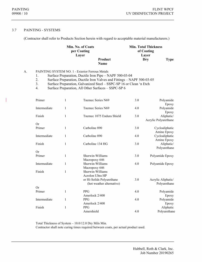
PAINTING FLINT WPCF09900 / 10 UV DISINFECTION PROJECT
Hubbell, Roth & Clark, Inc.Job Number 20190265
3.7 PAINTING - SYSTEMS
(Contractor shall refer to Products Section herein with regard to acceptable material manufacturers.)
Min. No. of Coats Min. Total Thicknessper Coating of Coating
Layer LayerProduct Dry TypeName
A. PAINTING SYSTEM NO. 1 - Exterior Ferrous Metals1. Surface Preparation, Ductile Iron Pipe – NAPF 500-03-042. Surface Preparation, Ductile Iron Valves and Fittings – NAPF 500-03-053. Surface Preparation, Galvanized Steel – SSPC-SP 16 or Clean ‘n Etch4. Surface Preparation, All Other Surfaces – SSPC-SP 6
Primer 1 Tnemec Series N69 3.0 Polyamide Epoxy
Intermediate 1 Tnemec Series N69 4.0 PolyamideEpoxy
Finish 1 Tnemec 1075 Endura Shield 3.0 Aliphatic/Acrylic Polyurethane
OrPrimer 1 Carboline 890 3.0 Cycloaliphatic
Amine EpoxyIntermediate 1 Carboline 890 4.0 Cycloaliphatic
Amine EpoxyFinish 1 Carboline 134 HG 3.0 Aliphatic/
PolyurethaneOrPrimer 1 Sherwin-Williams 3.0 Polyamide Epoxy
Macropoxy 646Intermediate 1 Sherwin-Williams 4.0 Polyamide Epoxy
Macropoxy 646Finish 1 Sherwin-Williams
Acrolon Ultra HPor Hi-Solids Polyurethane 3.0 Acrylic Aliphatic/ (hot weather alternative) Polyurethane
OrPrimer 1 PPG 4.0 Polyamide
Amerlock 2/400 EpoxyIntermediate 1 PPG 4.0 Polyamide
Amerlock 2/400 EpoxyFinish 1 PPG Aliphatic
Amershield 4.0 Polyurethane
Total Thickness of System – 10.0/12.0 Dry Mils Min.Contractor shall note curing times required between coats, per actual product used.

FLINT WPCF PAINTINGUV DISINFECTION PROJECT 09900 / 11
Hubbell, Roth & Clark, Inc.Job Number 20190265
Min. No. of Coats Min. Total Thicknessper Coating of Coating
Layer LayerProduct Dry TypeName
B. PAINTING SYSTEM NO. 2 – Ferrous Metals, Piping and Equipment Located Indoors1. Surface Preparation, Ductile Iron Pipe – NAPF 500-03-042. Surface Preparation, Ductile Iron Valves and Fittings – NAPF 500-03-053. Surface Preparation, Galvanized Steel – SSPC-SP 16 or Clean ‘n Etch4. Surface Preparation, All Other Surfaces – SSPC-SP 6
Primer 1 Tnemec Series N69 3.0 EpoxyEpoxoline
Finish 2 Tnemec Series N69 8.0 EpoxyEpoxoline
OrPrimer 1 Carboline 890 3.0 Cycloaliphatic
Amine EpoxyFinish 2 Carboline 890 8.0 Cycloaliphatic
Amine EpoxyOrPrimer 1 Sherwin-Williams 3.0 Polyamide Epoxy
Macropoxy 646Finish 2 Sherwin-Williams 8.0 Polyamide Epoxy
Macropoxy 646OrPrimer 1 PPG 4.0 Polyamide
Amerlock 2/400 EpoxyFinish 2 PPG 7.0 Polyamide
Amerlock 2/400 Epoxy
Total Thickness of System – 11.0 Dry Mils Min.

PAINTING FLINT WPCF09900 / 12 UV DISINFECTION PROJECT
Hubbell, Roth & Clark, Inc.Job Number 20190265
Min. No. of Coats Min. Total Thicknessper Coating of Coating
Layer LayerProduct Dry TypeName
C. PAINTING SYSTEM NO. 3A - Interior Masonry unitsSurface Preparation - SSPC-SP 13/NACE 6.
Undercoater 1 Tnemec 130-6602 60-80 s.f. WaterborneEnvirofill gal. Cementitious
AcrylicPrimer 1 Tnemec Series N69 4.0 Epoxy
Hi-Build Epoxoline IIFinish 1 Tnemec Series N69 4.0 Epoxy
Hi-Build Epoxoline IIOrUndercoater 1 Carboline Sanitile 500 60-100 s.f. Water Based
Block Filler gal. Epoxy FillerPrimer 1 Carboline 890 4.0 Cycloaliphatic
Amine EpoxyFinish 1 Carboline 890 4.0 Cycloaliphatic
PolyurethaneOrUndercoater 1 Sherwin-Williams 60-100 s.f. Cementitious
Cement-Plex 875 gal. Waterborne Block filler
Primer 1 Sherwin-Williams 4.0 Polyamide EpoxyMacropoxy 646
Finish 1 Sherwin-Williams 4.0 Polyamide EpoxyMacropoxy 646
OrPrimer 1 PPG 60-100 s.f. Epoxy Masonry
Amerlock 400BF Block FillerIntermediate 1 PPG 4.0 Polyamide
Amerlock 2/400 EpoxyFinish 1 PPG
Amerlock 2/400 4.0 Polyamide Epoxy
Total Thickness of System – 8.0 Dry Mils Minimum over filled surface.

FLINT WPCF PAINTINGUV DISINFECTION PROJECT 09900 / 13
Hubbell, Roth & Clark, Inc.Job Number 20190265
SCHEDULE -EQUIPMENT COLORS
EQUIPMENT COLORC. Blowers *D. Compressors *E. Couplings YellowF. Cranes (Hoists) YellowG. Blocks Yellow and Capacity in BlackH. Fans OrangeI. Flow Meters *J. Gear Reducers YellowK. Guards OrangeL. Motors OrangeM. Pumps *N. Screens *O. Switch Enclosure OrangeP. Tanks *Q. Valves *R. Valve Operators YellowS. Handrail/Guardrail Orange **T. Handrail/Guardrail-Removable Yellow & Black **U. Fire Protection Equipment RedV. Emergency Stop Bars, Buttons, Etc. RedW. First Aid Kits and Enclosures-
containing First Aid Equipment GreenX. Safety Showers, Face Washes, etc.
(Area Around) GreenY. Transformers OrangeZ. Switchgear Grey or BuffAA. Misc. Metal Black (unless otherwise noted)
AA. * Color will depend on service. The color will be obtained from the "PIPE COLOR CODE" for the service. (No stripes used on equipment.)
BB ** Brass, aluminum or stainless steel need NOT be painted.
The following colors shall be in conformity with the current ANSI Z553.1-2006 as referred to by MIOSHA.
1. Red2. Orange3. Yellow4. Green5. Blue6. Purple7. Black8. White
Note: Colors shall meet the tests specified in Section 3, Color Definitions, of the current ANSI/NEMA Z535.1-2006

PAINTING FLINT WPCF09900 / 14 UV DISINFECTION PROJECT
Hubbell, Roth & Clark, Inc.Job Number 20190265
3.8 SCHEDULE -PIPING COLORS
SERVICE COLOR STRIPE
A. Potable Water - Cold GreenB. Potable Water - Hot Green Aluminum (1)C. Emergency Shower Water Green Yellow (1)D. Flushing Water Gray Blue (1)E. Decant Water Gray White (1)F. Industrial Water BlueG. Ground Water Blue Green (1)H. Instrument Air Purple Blue (1)I. Natural Gas YellowJ. Vacuum Purple Aluminum (1)K. Roof Conductors Match BackgroundL. Floor Drains Match BackgroundM. Sump Pump Discharge Gray Black (1)N. Sanitary Drains & Vents BlackO. Raw Sewage or Waste Water GrayP. Sample Lines Match System Being SampledQ. Electrical Conduit Match BackgroundR. Stainless Steel 6" band with 3/4"
stripes at 1"S. Copper 6" band with 3/4"
stripes at 1"T. Plastic 6" band with 3/4"
stripes at 1"

FLINT WPCF PAINTINGUV DISINFECTION PROJECT 09900 / 15
Hubbell, Roth & Clark, Inc.Job Number 20190265
END OF SECTION


FLINT WPCF SIGNS
UV DISINFECTION PROJECT 10441 / 1
Hubbell, Roth & Clark, Inc.
Job Number 20190265
SECTION 10441
SIGNS
PART 1 GENERAL
1.1 SECTION INCLUDES
A. Metal, raised letter, Room Identification signs.
B. Metal, painted safety signage.
C. Cast aluminum dedication plaque.
D. Miscellaneous mounting hardware and anchors.
1.2 RELATED SECTIONS
A. Section 15400 Plumbing: Industrial water "Unsafe Water" signage.
1.3 SUBMITTALS
A. Submit shop drawings under provisions of Section 01300.
B. Submit shop drawings listing sign styles, lettering and locations, and overall dimensions of
each sign.
C. Submit full size drawing of plaque indicating actual text size, spacing, and width.
D. Submit samples under provisions of Section 01300.
E. Submit two samples illustrating full size sample sign, of type, style and color specified
including method of attachment.
F. Submit manufacturer's installation instructions under provisions of Section 01300.
G. Include installation template and hardware.
1.4 DELIVERY, STORAGE, AND HANDLING
A. Deliver products to site under provisions of Section 01600.
B. Store and protect products under provisions of Section 01600.
C. Package signs, labeled in name groups.
D. Store adhesive tape at ambient room temperatures.

SIGNS FLINT WPCF
10441 / 2 UV DISINFECTION PROJECT
Hubbell, Roth & Clark, Inc.
Job Number 20190265
1.5 ENVIRONMENTAL REQUIREMENTS
A. Do not install adhesive tape mounted signs when ambient temperature is below 70 degrees F
(21 degrees C). Maintain this minimum during and after installation of signs for adhesive to
cure.
PART 2 PRODUCTS
2.1 MANUFACTURERS
A. Safety Signage:
1. Stonehouse
2. Seton Name Plate Company
3. Brady, USA, Inc.
B. Dedication Plaque:
1. The Supersine Company
C. Substitutions: Under provisions of Section 01600.
2.2 LETTERING
A. Dedication Plaque:
1. 1 inch Helvetica Medium lettering (400 letters, maximum); upper and lower case
lettering as selected by the Owner.
B. Safety Signage:
1. Per MIOSHA requirements.
2. Colors: As noted in schedule.
2.3 ACCESSORIES
A. Dedication Plaque: Tamper-resistant, corrosion proof wood screws, material and finish to
match plaque.
B. Safety Signage: Non-corrosive, stainless steel, theft-proof mounting screws and anchors for
required for substrate.
PART 3 EXECUTION
3.1 EXAMINATION
A. Provide signage for each of the rooms or areas identified in the Signage Schedule.
B. Provide safety signage as indicated in the Signage Schedule.
C. Verify that surfaces are ready to receive work.
D. Beginning of installation means installer accepts existing surfaces.

FLINT WPCF SIGNS
UV DISINFECTION PROJECT 10441 / 3
Hubbell, Roth & Clark, Inc.
Job Number 20190265
3.2 INSTALLATION
A. Install in accordance with manufacturer's instructions and current State of Michigan Barrier
Free requirements.
B. Install signs after surfaces are finished, in locations adjacent to the doors (or adjacent to
accessories for safety signage), at the required heights to meet current State of Michigan
Barrier Free, and applicable NFPA, MIOSHA requirements.
C. Use fasteners appropriate for the substrate.
D. Locate sign on wall surface, level.
E. Clean and polish.
3.3 SIGNAGE SCHEDULE
UNSAFE WATER SIGN
The Contractor shall furnish and install a sign reading "CAUTION-Unsafe Water - Do Not Drink" at all
industrial water outlet locations. The sign shall be a minimum of 10" wide and 8" high with letters a minimum
1" high. The sign shall be of weatherproof construction, permanently affixed to the building structure. The
word "CAUTION" shall be yellow on a black background in the upper panel. The lower panel where
additional wording is, shall be black letters on a yellow background.
DEDICATION PLAQUE:
Dedication Plaque: 18 inch by 24 inch, cast aluminum. No. 214 alloy, standard radius border edge No. 505.
With pebble background, plaque finish No. AL-100: letters to be satin polish finish. Spray entire plaque with
2 coats of clear lacquer upon completion.
Plaque copy to be determined by the Owner based on 400 letters total; minimum of one hundred 1 inch letters,
one hundred 3/4 inch letters, one hundred fifty 5/8 inch letters and fifty 3/8 inch letters, made up of both upper
and lower case Helvetica Medium letters.
END OF SECTION


FLINT WPCF GATES & STOP PLATESUV DISINFECTION PROJECT 11282 / 1
Hubbell, Roth & Clark, Inc.Job Number 20190265
SECTION 11282
GATES & STOP PLATES
PART 1 GENERAL
1.1 GENERAL REQUIREMENTS
A. Furnish all labor, materials, anchors, tools, equipment, and supervision required to complete all gate installations, as indicated on the drawings and specified herein, and all other work incidental thereto, except as otherwise noted.
B. The gates and appurtenances shall be supplied in accordance with the latest edition of AWWA C561 Standard for Fabricated Stainless-Steel Slide Gates as modified herein. The allowable leakage rate for gates and plates shall be .01 GPM per lineal foot, or the latest revision of AWWA C561.
C. Weir gates and operators shall be of the type and size indicated on the Gate Schedule shown on the Drawings.
1.2 ITEMS SPECIFIED ELSEWHERE
A. Requirements for anchoring, guides and support of piping and valves shall be as specified in Section 15030.
B. The requirements of Section 15000, "General Equipment”, and all other applicable sections of the Specifications, form a part of this Section and govern work covered in this Section.
C. Shop drawings and Operation and Maintenance Manuals are required for each item in this section of the specifications. Each shop drawing and O & M Manual submittal shall include all information as specified in Sections 01300, 01730 and 15000.
D. Gate Operators for gates shall be as specified herein and as called for on the Contract Drawings.
1.3 SUBMITTALS
A. Shop drawings are specified in Section 01300.
B. O&M Manuals are specified in Section 01730.
C. Submit design calculations to certify compliance with AWWA C-561.
1.4 QUALITY ASSURANCE
A. All the equipment specified under this Section shall be furnished by a single manufacturer with a minimum of 20 years of experience designing and manufacturing gates for the water

GATES & STOP PLATES FLINT WPCF11282 / 2 UV DISINFECTION PROJECT
Hubbell, Roth & Clark, Inc.Job Number 20190265
and wastewater industry. Gate and actuator manufacturers are required to coordinate designs to match seating/unseating torques, gate speed, etc.
B. Wall thimbles, pedestals, and steel stem covers must be designed, and shop drawings submitted by the gate manufacturer, but can be fabricated and/or galvanized locally, subject to the approval of the Engineer.
C. Gates and actuators shall confirm to the appropriate ANSI/ WWA standards listed above.
D. All welding shall be conducted in accordance with American Welding Society (AWS) D1.6 – Structural Welding Code, Stainless Steel. Welders shall be qualified and certified in accordance with ASME Section IX.
E. All gates that cannot be leak tested in the field, shall be leak tested in the factory. The leakage test shall apply pressures matching or exceeding the design head. Provide a certified test result prior to shipment.
F. All stainless-steel gates and materials shall be cleaned and passivated prior to shipment. The pre-cleaning solution, pickling paste, and neutralizing rinse shall be applied in accordance with the manufacturer’s instructions. Finish: Mill finish on stainless steel. Welds shall be sandblasted to remove weld burn and scale. All iron and steel components shall be properly prepared, and shop coated with a primer.
G. Slide gates shall be shipped fully assembled unless the overall width of the slide gate exceeds 96 inches, or the overall height of the slide gate exceed 25 feet.
PART 2 PRODUCTS
2.1 GENERAL
A. Gates shall be of stainless-steel construction, self-contained meeting the requirements of ANSI/AWWA C561, latest edition, and shall be furnished and installed complete with wall mounting frames, operating stems, bench stands, actuators, and other appurtenances or accessories, as specified or shown on the drawings.
2.2 MANUFACTURER
A. The isolation gates and modulating weir gates shall be Model RW750-S as manufactured by RW Gate Company.
2.3 GATES
A. When modulating service is specified, gate configuration shall be weir type, opening downward.
B. Modulating Weir Gates (MWGs) shall be self-contained and shall be designed and manufactured by an experienced and reputable manufacturer, based on the AWWA C561 Standard for Fabricated Stainless-Steel Slide Gates and AWWA C542 Standard for Electric Motor Actuators for Valves and Slide Gates in effect as of the date of this specification.
FLINT WPCF GATES & STOP PLATESUV DISINFECTION PROJECT 11282 / 3
Hubbell, Roth & Clark, Inc.Job Number 20190265
C. Modulating weir gates will be designed to maintain the minimum channel effluent level required to keep lamps continually submerged.
D. MWGs shall be designed for the following performance criteria: 1. MWG actuation speeds shall be between 10” (255 mm) and 14” (356 mm) per minute.1. MWG maximum design rate of change of flow shall be limited to 25% of the Peak
Design Flow/Channel per minute, or alternatively, flow shall be ramped up (zero to peak) or down (peak to zero) in no less than 4 minutes.
E. Isolation Gates shall be self-contained.
F. All materials used in the construction of the stainless-steel gates and appurtenances shall be well suited for the application and shall conform to the following specifications:1. Frame, yoke, stem guides, slide, and stem extension stainless steel ASTM A- 276
Type 316L.2. Side and top seals, stem guide liner ultra-high molecular weight polyethylene
(UHMWPE) ASTM D-4020.3. Top seal Neoprene ASTM D-2000 Grade 2 BC-510.4. Compression Cord Nitrile ASTM D-2000, M6BG-708, A14, B14, E014, E034.5. Threaded stem Stainless steel ASTM A-276 Type 316.6. Fasteners ASTM F593 and F594 GR1 for type 304 and GR2 for type 316.7. Gasket (between frame and wall) EPDM ASTM 1056.8. Stem cover Polycarbonate or Lexan ASTM A-707.9. Stem thrust nut: ASTM A276, type 316 for rising stems, bronze ASTM B584 Alloy
432 for non-rising stems.10. Lift nut Manganese bronze ASTM B584 UNS-C86500.11. Floor Stand/Pedestal, 316SS.12. The seals shall be mounted so as not to obstruct the water way opening.13. Gates that utilize rubber “J” seals or “P” seals are not acceptable.14. The seal system shall have been factory tested to confirm negligible wear (less than
0.01”) and proper sealing. The factory testing shall consist of an accelerated wear test comprised of a minimum of 25,000 open-close cycles using a well-agitated sand/water mixture to simulate fluidized grit.
G. Specific construction requirements for stainless steel sluice gates are as follows:1. Sluice gates shall be stainless steel with self-adjusting sealing system with side and
top wedging system and bottom seal for seating and unseating head conditions. Unless noted elsewhere, all gate components shall be designed to safely withstand a seating and unseating head, the height between gate center (closed position) and pedestal base.
2. The gate frame shall be stainless steel constructed of structural members or formed plate welded to form a rigid one-piece frame. Frame shall be designed to mate with a wall thimble, where rigid. When installed over a concrete pipe, the gate must be oversized such that anchors are not placed in the concrete pipe.
3. Gate shall be of Stainless-Steel construction, consisting of a flat plate reinforced with formed plates or structural members to limit its deflection to 1/720 of the gate’s span under the design head.
4. The guide slot shall be made of UHMWPE (ultra-high molecular weight polyethylene) and shall be of such length as to retain and support at least two thirds (2/3) of the vertical height of the slide in the fully open position.

GATES & STOP PLATES FLINT WPCF11282 / 4 UV DISINFECTION PROJECT
Hubbell, Roth & Clark, Inc.Job Number 20190265
5. The wedging system for the side and top seals shall be of UHMWPE construction and shall be self-adjusting. A compression cord shall ensure contact between the UHMPE guide and gate in all positions.
6. The sealing system shall maintain efficient sealing in any position of the slide and allow the water to flow only in the opened part of the gate. The top seal shall be made of resilient neoprene set into the top member of the frame.
7. Gate stem shall be a minimum 1-1/2”, maximum L/R of 200, the length sized to provide full travel plus 1 foot.
8. The operating system shall be stainless steel of a size to safely withstand, without bucking or permanent distortion, the stresses induced by normal operating forces. The stem shall be designed to transit in compression at least two times the rated output of the floor stands with a 40-lb. effort on the crank or handwheel.
9. Stem guides shall be fabricated from type 316L stainless steel. The guide shall be equipped with an UHMWPE bushing. Guides shall be adjustable and spaced in accordance with the manufacturer’s recommendation. The L/R ratio shall not be greater than 200.
10. A clear, Polycarbonate or butyrate plastic pipe stem cover shall be provided for each gate. Each stem cover shall be graduated in one-inch increments between full open and full closed positions to show the position of the gate at all times. The valve position indicator shall be compatible and coordinated with the valve operator.
H. Wall thimbles1. Where shown on the Drawings or Gate Schedule, wall thimbles shall be 316L SS,
one-piece, machined face, minimum ¼” thick, and depth shall match the wall thickness.
I. Stem1. Gate stems shall be rising type for the modulating weir gates and non-rising type for
the isolation gates. 2. Gate stems shall be designed for the manual or actuated thrust and compression loads
and safety factors established in C561. Stems shall be rolled.3. Stem couplings shall be threaded and keyed and shall be of greater strength than the
stem.4. Rising stems shall be secured to the slide via threaded thrust nut keyed to the stem.
Non-rising stems shall be threaded but not keyed. 5. Stem guides shall be provided to maintain L/R ratio less than 200. The guide shall be
equipped with an UHMWPE bushing. (Greaseable bushings are not acceptable.) Guides shall be adjustable and spaced in accordance with the manufacturer’s recommendation, or as shown on the drawings. Where guides are not shown on the Drawings, it is imperative that the Manufacturer coordinate their locations with the Contractor so that the placement of stem guides does not interfere with any equipment, conduits, etc.
6. Stem guides shall be adjustable, and of sufficient length to anchor to the supporting wall.
7. Each gate requires a stem cover, of sufficient diameter and length to permit full, unobstructed travel. Covers shall be vented and mounted to an adaptor plate suitable to the actuator Mfr. When clear stem covers are specified, each cover shall be graduated in one-inch increments between full open and full closed positions to show the position of the gate at all times. (Graduations are not required for steel covers.)

FLINT WPCF GATES & STOP PLATESUV DISINFECTION PROJECT 11282 / 5
Hubbell, Roth & Clark, Inc.Job Number 20190265
The valve position indicator shall be compatible with and coordinated with the valve operator.
8. The stem shall be constructed of solid stainless-steel bar for the entire length, the metal having a tensile strength of not less than 75,000 psi.
9. The stem shall be threaded to allow full travel of the slide unless the travel distance is otherwise shown on the Contract Drawings.
10. In compression, the stem shall be designed for a critical buckling load caused by a 40-lb. effort on the crank or handwheel with a safety factor of 2, using the Euler column formula.
11. The threaded portion of the stem shall have machine rolled threads of the full Acme type with a 16-micro inch finish or better. Stub threads are not acceptable.
12. Stems of more than one section shall be joined by stainless steel or bronze couplings. The coupling shall be bolted to the stems.
J. At locations indicated on the Drawings where gate operators are installed above slotted floor openings, to allow for installation and removal of the gate, the gate manufacturer shall furnish structural steel operator support members. The members shall be designed to span the opening and support loads produced by the gate operator. Structural steel supports shall be complete with stainless steel anchors and hardware.
K. The completely assembled gate, in vertical position, shall be shop inspected for proper seating, operation and leakage and adjusted before shipping. The gate disc shall be fully opened and closed in its guide system to ensure that it operates freely. There shall be no assembling or adjusting on job sites other than for the lifting mechanism.
L. At locations indicated on the Drawings where gate operators are installed above floor openings, the gate manufacturer shall furnish structural steel operator support members. The members shall be designed to span the opening and support loads produced by the sluice gate operator. Structural steel supports shall be 316L SS, complete with 316 SS anchor bolts.
2.4 GATE OPERATORS
A. Electric Actuators (Type EM)1. General
a. Gates shall be electrically operated with an actuator in conformance with AWWA C-561. The actuator shall be furnished by the gate supplier to operate his gate under the operating conditions given in the schedule as shown on the Drawings. The actuators shall be as manufactured by Rotork (no equals or substitutions allowed).
b. Each motorized operator shall consist of a motor operator, unit gearing, limit contacts, torque switches, terminal strips, gear case, stem nut, stem cover, control cabinet, reversing magnetic starter, push button control, indicator lights, shop wiring, and all other accessories required to provide satisfactory operation. A handwheel for operation in case of power failure shall also be provided. Gate operators shall be sized to guarantee gate closure at the specified differential pressure. The safety margin of motor power available for seating and unseating the valve shall be sufficient to ensure torque switch trip at maximum valve torque with the supply voltage 10% below nominal. The operating speed shall be not less than 12"/min.

GATES & STOP PLATES FLINT WPCF11282 / 6 UV DISINFECTION PROJECT
Hubbell, Roth & Clark, Inc.Job Number 20190265
c. Each valve operator shall be designed to operate the valve from and/or to any intermediate position and shall be of sufficient size and rating to open and close the valve under any condition of operation.
d. Two sets of limit contacts shall be provided for remote indication of valve or gate position (open, closed). Two field programmable contacts and auxiliary contacts for monitor relay shall be included. Dry and isolated contacts for monitoring and alarm shall be provided as indicated on the Drawings.
e. Each operator housing shall be of ductile iron or die cast aluminum construction. Unless specified otherwise herein, power to each operator shall be 460 V, 3-phase, 60 Hz., and all electrical enclosures shall be: NEMA Type 4 watertight (operator type EM), suitable for outdoor installation.
f. Modulating Service1) When modulating service is specified, the actuator shall respond to a
control signal as indicated on the Drawings. The package shall include an electromechanical reversing starter, control transformer, local controls, indicating lights and position indicator. Gate shall be capable of being stopped in any intermediate position.
2) MWG actuators shall employ AWWA compliant, S4-50% duty class motors with a rated minimum 900 starts per hour capability.
3) MWG actuators shall employ AWWA compliant, Class B, solid-state Thyristor based switchgear capable of at least 5,000,000 modulating steps before overhaul; electromechanical type actuators and controls are not permitted.
4) The operator shall be rated for a minimum accuracy of plus or minus one percent.
5) The operator shall accept a discrete position command signal and shall provide an isolated 4 to 20 mADC position feedback signal, as indicated on the Drawings.
g. Multiple Turn Movement1) Gates which require multiple turn movement shall be provided with
Bevel Gear valve actuators.h. Warranty
1) Electric actuators shall be warranted against defects in workmanship and material for a period of five (5) years from the date of acceptance.
2. The electrical classification of the operator shall comply with the electrical classification shown on the contract electrical drawings.
3. Actuators shall be designed to exceed twice the torque developed by the seating/unseating heads.
PART 3 EXECUTION
3.1 INSTALLATION
A. Installation of the gates and appurtenances shall be done in a workmanlike manner. It shall be the responsibility of the Contractor to handle, store and install the equipment specified in this Section in strict accordance with the manufacturer’s recommendations.
FLINT WPCF GATES & STOP PLATESUV DISINFECTION PROJECT 11282 / 7
Hubbell, Roth & Clark, Inc.Job Number 20190265
B. The Contractor shall review the installation drawings and installation instruction prior to installing the gates.
C. The wall thimbles and gate assemblies shall be installed in a true vertical plane, square and plumb. Wall thimbles must be properly supported prior to the concrete pour.
D. The Contractor shall fill the void between the gate frame and the wall with non-shrink grout as shown on the installation drawing and in accordance with the manufacturer’s recommendations.
E. The Contractor shall add a mastic gasket between the gate frame and wall thimble (when thimble is not machined) in accordance with the manufacturer’s recommendations.
3.2 INSPECTION REQUIREMENTS
A. Factory gate and actuator representatives shall visit the site to certify proper installation, set open/close contacts and torque overloads and to provide training. The scheduling of this service shall be coordinated with the Owner and the cost of this service shall be included in the price of the equipment.
3.3 FIELD TESTING
A. After installation, all gates and shall be field tested in the presence of the Engineer and Owner to ensure that all items of equipment are in full compliance with this Section. Each gate shall be cycled to confirm that they operate without binding, scraping, or distorting.
B. Each gate shall be water tested by the Contractor, at the discretion of the Engineer and Owner, to confirm that leakage does not exceed the specified allowable leakage rate of 0.10 GPM per LF of gate perimeter, or the latest AWWA leakage specifications.
C. The effort to open and close manual operators shall be measured and shall not exceed the maximum operating effort specified above. Electric motor actuators shall function smoothly and without interruption. Local and remote functions and over-torque alarms shall be demonstrated. Where gate position is specified, position shall be field verified and four positions.
D. If any of the above do not meet the specifications, the equipment shall be remedied as necessary and re-tested at the Contractor’s expense.
END OF SECTION


FLINT WPCF ULTRAVIOLET DISINFECTION EQUIPMENTUV DISINFECTION PROJECT 11380 / 1
Hubbell, Roth & Clark, Inc.Job Number 20190265
SECTION 11380
ULTRAVIOLET DISINFECTION EQUIPMENT
PART 1 GENERAL
1.1 DESCRIPTION
A. Scope1. Furnish all labor, materials, equipment, and appurtenances required to provide an
open channel, gravity flow, low pressure high intensity ultraviolet lamp (UV) disinfection system complete with an automatic chemical/mechanical cleaning system and variable output lamp drivers. The UV system shall be complete and operational with all control equipment and accessories as shown and specified herein including isolation and weir gates on each channel. This system will be capable of disinfecting effluent to meet the water quality standards listed in this section.
B. Related Work Specified Elsewhere:1. Section 01300: Submittals2. Section 03300: Concrete3. Section 11282: Gates4. Division 15: Mechanical5. Division 16: Electrical
1.2 QUALITY ASSURANCE
A. Performance Requirements1. The ultraviolet disinfection system will produce an effluent conforming to the
following discharge permit: 200 fecal coliform/100 ml, based on a 30-day Geometric Mean. Grab samples will be taken in accordance with the Microbiology Sampling Techniques found in Standard Methods for the Examination of Water and Wastewater, 21st Ed
2. Provide a UV disinfection system complete with UV Banks, System Control Center, Power Distribution Center(s), Support Rack(s) and Level Controller(s) as shown on the contract drawings and as herein specified.
3. The UV system will be designed to deliver a minimum UV dose of 27 mJ/cm2 at peak flow, in effluent with a UV Transmission of 65% at end of lamp life (EOLL) after reductions for quartz sleeve fouling. The basis for evaluating the UV dose delivered by the UV system will be the independent third-party bioassay, without exception. Bioassay validation methodology to follow protocols described in NWRI Ultraviolet Disinfection Guidelines for Drinking Water and Water Reuse (May 2003) and/or applicable sections of the US EPA Design Manual – Municipal Wastewater Disinfection (EPA/625/1-86/021).
4. The UV Dose will be adjusted using an end of lamp life factor of 0.5 to compensate for lamp output reduction over the period corresponding to the manufacturer’s lamp warranty. The use of a higher lamp aging factor will be considered only upon review and approval of independent third party verified data that has been collected and analyzed in accordance with protocols described in NWRI Ultraviolet Disinfection Guidelines for Drinking Water and Water Reuse (May 2003, 2012).

ULTRAVIOLET DISINFECTION EQUIPMENT FLINT WPCF11380 / 2 UV DISINFECTION PROJECT
Hubbell, Roth & Clark, Inc.Job Number 20190265
5. The UV Dose will be adjusted using an end of lamp life factor of 0.5 to compensate for lamp output reduction over the time period corresponding to the manufacturer’s lamp warranty. The use of a higher lamp aging factor will be considered only upon review and approval of independent third party verified data that has been collected and analyzed in accordance with protocols described in the NWRI Ultraviolet Disinfection Guidelines for Drinking Water and Water Reuse (May 2003, 2012).
6. The RED will be adjusted using a quartz sleeve fouling factor of 0.8 to compensate for quartz sleeve transmission reduction due to wastewater effluent fouling. The use of a higher quartz sleeve fouling factor will be considered only upon review and approval of independently verified data that has been collected and analyzed in accordance with protocols described in the NWRI Ultraviolet Disinfection Guidelines for Drinking Water and Water Reuse (May 2003, 2012). The data recorded for the determination of the validated fouling factor must be obtained by testing in secondary wastewater effluent utilizing the same lamp, quartz sleeve and cleaning system proposed by the UV manufacturer.
7. Independent Validation for use of higher factors (lamp aging and sleeve fouling) must be submitted to the Engineer a minimum of fifteen (15) days prior to bid. The independent validation shall have oversight by a qualified registered professional engineer with knowledge and experience in testing and evaluation of UV systems as defined in the EPA UVDGM (Appendix C, Section C.3.3)
8. The system will be able to continue providing disinfection while replacing UV lamps, quartz sleeves, ballasts and while cleaning the UV lamp sleeves.
B. DESIGN CRITERIA1. Provide equipment that will disinfect effluent with the following characteristics:
Design Peak Flow: 70 MGD
Maximum Hydraulic Capacity: 80 MGD
Average Flow: 20 MGD
Minimum Flow: 10 MGD
Total Suspended Solids: 25 mg/L, 30 Day Average of grab samples
Effluent Temperature Range: 33 to 85ºF (1 to 30ºC)
Ultraviolet Transmittance @ 253.7 nm: 65%, minimum
Maximum Mean Particle Size: 30 microns
UV Dose: 30 ml/cm+ min. @ 70 MGD
27 ml/cm+ min. @ 80 MGD
Effluent standards to be achieved: 200 fecal coliform/100 ml based on a 30-day Geometric Mean of daily samples for the effluent standard as specified. Effluent standards will be guaranteed regardless of influent count to UV system.

FLINT WPCF ULTRAVIOLET DISINFECTION EQUIPMENTUV DISINFECTION PROJECT 11380 / 3
Hubbell, Roth & Clark, Inc.Job Number 20190265
2. The UV system is to be installed in 2 open channels having dimensions shown on the Drawings.
3. The maximum effluent depth in the channel will be 74.97 in.4. System configuration:
a. The UV system must fit within the UV channel(s) as stated without modification.
b. The UV system configuration will be as follows:
Channels: 2 Banks per Channel: 4 (3 Duty – 1 Redundant) Lamps per bank: 24 Total Lamps in System: 192 (Including 48 Redundant Lamps) System Control Centers: 1 UV Detection Sensors: 1 per bank Power Distribution Centers: 4 Level Controllers: 2
1.3 SUBMITTALS
A. Submit for review, shop drawings showing the following:1. Complete description in sufficient detail to permit an item comparison with the
specification.2. Dimensions and installation requirements.3. Descriptive information including catalogue cuts and manufacturers’ specifications
for major components.4. Electrical schematics and layouts.5. Hydraulic calculations demonstrating compliance with the required hydraulic
characteristics.6. Independent bioassay validation and dosage calculations demonstrating compliance
with the specified dose requirements.7. Disinfection performance guarantee.
1.4 WARRANTEES
A. Equipment1. The equipment furnished under this section will be free of defects in material and
workmanship, including damages that may be incurred during shipping for a period of 12 months from date of start-up or 18 months after shipment, whichever comes first.
B. UV Lamps1. The UV lamps to be warranted for a minimum of 15,000 hours when operated in
automatic mode, prorated after 9,000 hours. On/off cycles are limited to an average of four (4) per day accumulated over the guaranteed life of the lamp.
C. UV Lamp Drivers:1. Lamp Drivers will be warranted for 10 years, prorated after 1 year.
D. UV Intensity Sensors:1. UV intensity sensors will be warranted for 5 years, prorated after 1 year.

ULTRAVIOLET DISINFECTION EQUIPMENT FLINT WPCF11380 / 4 UV DISINFECTION PROJECT
Hubbell, Roth & Clark, Inc.Job Number 20190265
PART 2 PRODUCTS
2.1 MANUFACTURER
A. The manufactured equipment shall be the TrojanUVSigna system as supplied by Trojan Technologies, London, Ontario, Canada. No other manufacturers shall be considered.
2.2 DESIGN, CONSTRUCTION, AND MATERIALS
A. General1. All UV Bank metal components in contact with effluent will be Type 316 stainless
steel.2. All metal components above the effluent will be stainless steel except for the ballast
enclosure, which is constructed of anodized aluminum.3. All wiring exposed to UV light will be TeflonTM or other UV resistant coated material.
B. Lamp Array Configuration1. The lamp array configuration will be in a staggered inclined arrangement. 2. The system will be designed for complete submersion of the UV lamps under all flow
conditions including both electrodes and the full length of the lamp arc. 3. To maximize performance and ensure safety, bank light locks will be used in each
bank to prevent potential short circuiting over the top of the lamps.
C. UV Module1. Each UV bank will consist of UV lamps, quartz sleeves and an automatic
chemical/mechanical cleaning system mounted in a Type 316 stainless steel frame.2. Each lamp will be enclosed in its individual quartz sleeve, one end of which will be
closed, and the other end sealed by a lamp end seal. To be considered as an alternate, lamp quartz sleeves that are open at both ends will be supplied with twice the amount of specified spare seals and lamps.
3. The closed end of the quartz sleeve will be held in place by a retaining O-ring. The quartz sleeve will not come in contact with any steel in the frame.
4. Each UV bank will contain a pre-formed Type 316 stainless steel wall on each side to prevent possible short-circuiting at the side walls of the reactor.
5. Each UV bank will contain light locks at the top of the bank to prevent short circuiting over the top of the lamps and maximize disinfection efficiency.
6. Each UV bank will be rated Type 6P. UV banks that are not Type 6P rated are not acceptable.
7. To minimize maintenance, equipment must be provided by the UV manufacturer to enable lifting a complete bank of lamps from the channel at once for inspection and/or servicing.
D. UV Lamps1. Lamps will be high intensity low pressure amalgam design. Lamps that are not
amalgam will not be allowed.2. The filament shall be significantly rugged to withstand shock and vibration.3. Electrical connections for the lamp will consist of four (4) pins at one end of the lamp
only. Lamp wiring shall be Teflon insulated stranded wire.

FLINT WPCF ULTRAVIOLET DISINFECTION EQUIPMENTUV DISINFECTION PROJECT 11380 / 5
Hubbell, Roth & Clark, Inc.Job Number 20190265
4. Lamps without maintenance coating or that do not have four (4) pins are considered instant-start and are not acceptable due to reduced reliability and increased maintenance and operating costs.
5. Lamps will be rated to produce zero levels of ozone.6. The lamp shall withstand an average of four (4) on/off cycles per day without
reducing lamp life, warranty or causing any damage to the lamp.7. Lamps will be operated by electronic lamp drivers with variable output capabilities
ranging from 30% to 100% of nominal power. The lamp assembly shall incorporate active filament heating to maintain a minimum lamp efficiency of 35% across varying water temperatures and between the minimum and maximum stated lamp power levels.
E. Lamp Plugs1. Each lamp plug will be accessible from the top of the UV bank to facilitate lamp
removal without moving the UV banks or any other components.2. Optional: Each lamp plug shall have provisions for a light emitting diode (LED)
visual indicator that indicates on/off status for each lamp. 3. An integral safety interlock in the lamp plug will prevent removal of energized lamps.4. The lamp plug shall be rated Type 6P.
F. Lamp Drivers:1. Each lamp driver will independently power two (2) UV lamps. Failure of one lamp
will not affect operation of the other lamp.2. The lamp driver will have a power factor correction circuit to ensure minimum 99%
power factor and less than 5% total harmonic distortion (THD) current at the maximum power level and nominal input voltage.
3. The lamp driver electrical efficiency will be minimum 95% at the maximum power level.
4. The lamp driver will be programmed-start type utilizing filament preheat followed by a high voltage pulse to ignite the lamp.
5. During lamp operation, variable filament heating current shall be provided according to a predetermined curve to maintain optimum filament temperature and amalgam temperature to ensure maximum lamp life and maintain a minimum lamp efficiency of 35% across varying water temperatures and between the minimum and maximum stated lamp power levels.
6. A ground fault in the output circuit shall be detected and communicated as a warning to the external controls system while the corresponding lamp operates undisturbed.
7. The communication protocol shall be Modbus implemented on an RS485 electrical interface.
8. Local visual diagnostic will be provided with LEDs for lamp driver status, lamp status (on, idle, preheat, fault), power and communication status.
9. For reliability and to facilitate trouble shooting, at a minimum, the following external indicators (protections, status, warnings and alarms) shall be provided: lamp status, driver status, ground fault, and communication time-out.
10. The lamp driver shall be UL, CE, and RoHS compliant.
G. Quartz Sleeves:1. Quartz sleeves will be clear fused quartz circular tubing containing 99.9% silicon
dioxide.

ULTRAVIOLET DISINFECTION EQUIPMENT FLINT WPCF11380 / 6 UV DISINFECTION PROJECT
Hubbell, Roth & Clark, Inc.Job Number 20190265
2. Sleeves will have minimum UV transmittance at 254nm of 87% (2.5mm wall thickness).
3. Sleeves will be open at one end only and domed at the other end.
H. Cleaning System:1. An automatic in-situ cleaning system will be provided to clean the quartz sleeves
using both chemical and mechanical methods. Wiping sequence will be automatically initiated with capability for manual override.
2. The cleaning system shall also incorporate an integrated debris removal device to clear the quartz sleeves of any large solids or debris to maximize the life of the chemical/mechanical cleaning system.
3. The wiper on the cleaning system shall be parked out of the effluent when not in use.4. Cleaning systems that utilize a screw-drive or park the wiper in the effluent while not
in use shall not be acceptable due to collection of debris in and around the wetted parts of the wiper.
5. The cleaning system will be fully operational while UV lamps and modules are submerged in the effluent channel and energized.
6. To minimize maintenance, UV System will be designed such that cleaning solution replacement can be performed while the UV Bank and lamps are in place and operational in the channel.
7. Cleaning sequence frequency will be field adjustable to enable optimization with effluent characteristics.
8. Cleaning system operation will be remote auto (default) or remote manual.9. The cleaning system will be provided with the required solutions necessary for initial
equipment testing and for equipment start-up.10. The wipers shall travel the full length of the UV lamp arc. Designs in which the
wipers only travel part way along the sleeves will not be acceptable. 11. The UV intensity sensor shall be cleaned utilizing the same chemical/mechanical
cleaning method as that of the lamp quartz sleeves. UV intensity sensors that only utilize a mechanical means shall not be acceptable.
12. To be considered as alternate, systems that use only mechanical wiping must have the ability to periodically be cleaned out of channel using a chemical bath. Out of channel cleaning will include lifting slings, removable banks, cleaning tanks, agitation system and air compressors, as required. The UV manufacturer will be responsible for supplying all equipment including any equipment not specifically listed required to perform out of channel chemical cleaning. Contactor will be responsible for installation.
I. Gates:1. Modulating Weir Gates (MWGs) shall be provided in each channel, size as shown on
the DRAWINGS, to maintain the minimum channel effluent level required to keep lamps continually submerged.
2. MWG design and performance criteria shall be as specified in Specification Section 11282 – Gates.
3. Isolation gates shall be provided in each channel to shut off flow to the UV equipment. Size of the gates is provided on the DRAWINGS, open-close motor operator shall be provided on the gates as specified in Section 11282.
J. Light Locks
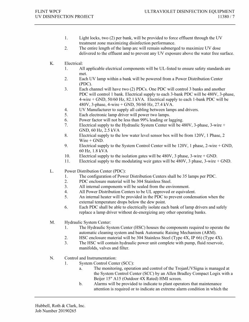
FLINT WPCF ULTRAVIOLET DISINFECTION EQUIPMENTUV DISINFECTION PROJECT 11380 / 7
Hubbell, Roth & Clark, Inc.Job Number 20190265
1. Light locks, two (2) per bank, will be provided to force effluent through the UV treatment zone maximizing disinfection performance.
2. The entire length of the lamp arc will remain submerged to maximize UV dose delivered to the effluent and to prevent any UV exposure above the water free surface.
K. Electrical:1. All applicable electrical components will be UL-listed to ensure safety standards are
met.2. Each UV lamp within a bank will be powered from a Power Distribution Center
(PDC).3. Each channel will have two (2) PDCs. One PDC will control 3 banks and another
PDC will control 1 bank. Electrical supply to each 3-bank PDC will be 480V, 3-phase, 4-wire + GND, 50/60 Hz, 82.1 kVA. Electrical supply to each 1-bank PDC will be 480V, 3-phase, 4-wire + GND, 50/60 Hz, 27.4 kVA.
4. UV Manufacturer to supply all cabling between lamps and drivers.5. Each electronic lamp driver will power two lamps.6. Power factor will not be less than 99% leading or lagging.7. Electrical supply to the Hydraulic System Center will be 480V, 3-phase, 3-wire +
GND, 60 Hz, 2.5 kVA8. Electrical supply to the low water level sensor box will be from 120V, 1 Phase, 2
Wire + GND.9. Electrical supply to the System Control Center will be 120V, 1 phase, 2-wire + GND,
60 Hz, 1.8 kVA10. Electrical supply to the isolation gates will be 480V, 3 phase, 3-wire + GND. 11. Electrical supply to the modulating weir gates will be 480V, 3 phase, 3-wire + GND.
L. Power Distribution Center (PDC):1. The configuration of Power Distribution Centers shall be 35 lamps per PDC.2. PDC enclosure material will be 304 Stainless Steel.3. All internal components will be sealed from the environment.4. All Power Distribution Centers to be UL approved or equivalent.5. An internal heater will be provided in the PDC to prevent condensation when the
external temperature drops below the dew point.6. Each PDC shall be able to electrically isolate each bank of lamp drivers and safely
replace a lamp driver without de-energizing any other operating banks.
M. Hydraulic System Center:1. The Hydraulic System Center (HSC) houses the components required to operate the
automatic cleaning system and bank Automatic Raising Mechanism (ARM).2. HSC enclosure material will be 304 Stainless Steel (Type 4X, IP 66) (Type 4X).3. The HSC will contain hydraulic power unit complete with pump, fluid reservoir,
manifolds, valves and filter.
N. Control and Instrumentation:1. System Control Center (SCC):
a. The monitoring, operation and control of the TrojanUVSigna is managed at the System Control Center (SCC) by an Allen Bradley Compact Logix with a Beijer 15" A15 (Outdoor 4X Rated) HMI screen.
b. Alarms will be provided to indicate to plant operators that maintenance attention is required or to indicate an extreme alarm condition in which the

ULTRAVIOLET DISINFECTION EQUIPMENT FLINT WPCF11380 / 8 UV DISINFECTION PROJECT
Hubbell, Roth & Clark, Inc.Job Number 20190265
disinfection performance may be jeopardized. The alarms will include, but not be limited to:1) Individual Lamp Failure 2) Multiple Lamp Failure3) UV Sensor Deviation Alarm4) Bank Communication Alarm
c. The 100 most recent alarms will be recorded in an alarm history register and will be displayed when prompted.
d. Mode of operation for UV Banks can be manual, automatic or remote.e. Elapsed time of each bank will be recorded and displayed on the display
screen when prompted.2. Low Water Level Sensor:
a. The UV Manufacturer will provide one (1) low water level sensor for each UV channel.
b. During all modes of system operation (manual, automatic and remote), the water level sensor will ensure that lamps extinguish automatically if the water level in the channel drops below an acceptable level.
3. UV Intensity Sensors:a. A UV sensor will continuously monitor the UV intensity produced within
each UV Bank.b. The sensors will measure only the germicidal portion of light emitted by the
lamps.c. The UV sensor shall be factory-calibrated to US National Institute for
Standards and Technology (NIST). Sensors requiring field-calibration are not acceptable.
d. The sensor shall be digitally calibrated to ensure calibration accuracy.e. To ensure continuous disinfection, the sensor shall be accessible without
shutting down the system, lifting a bank/module or removing lamps.f. Sensors will be designed to provide UV intensity data for dose monitoring
and control functions. Dose pacing program will enable use of measured UV intensity along with flow rate and UVT to determine the delivered dose during operation.
g. Sensors will be designed such that reference sensor readings can be taken without interrupting disinfection and without removing UV lamps, banks/modules or sleeves.
4. Dose-Pacing:a. A dose-pacing system will be supplied to modulate the lamp UV output in
relationship to a 4-20 mA DC signal from an effluent flow meter (supplied and installed by Others) and UV intensity sensor(s).
b. The system to be dose-paced such that as the flow and effluent quality change, the design UV dose is delivered while conserving power.
c. The dose-pacing system will allow the operator to vary the design dose setting. Logic and time delays will be provided to regulate UV Bank ON/OFF cycling.
5. On-Line UV Transmission Monitor: a. An on-line UVT monitor will be provided to automatically and continuously
track the UV transmission of the effluent at the 254-nm wavelength. UVT monitor will be UVAS as manufactured by Hach Company.
b. The UVT monitor will measure transmittances from 25 to 100%.

FLINT WPCF ULTRAVIOLET DISINFECTION EQUIPMENTUV DISINFECTION PROJECT 11380 / 9
Hubbell, Roth & Clark, Inc.Job Number 20190265
c. A shielded twisted pair cable to be provided by the Contractor for connecting the UVT monitor (4-20 mA signal) to the System Control Center. The SCC will modulate the lamp intensity in response to the effluent UV Transmission.
d. Power feed of 100 – 230 VAC ± 10%, 50/60 Hz, 1 phase, 2-wire (plus ground), 50 VA required to the sensor located at the UV channel as shown on the Drawings.
O. UV Bank Lifting Device: 1. The lifting device for UV Banks will be supplied by the UV Manufacturer. 2. An Automatic Raising Mechanism (ARM) will be designed and supplied to facilitate
lifting a UV bank from the channel without use of ancillary equipment. 3. The ARM will be integrated into the UV Bank for simple and seamless operation.4. The UV Bank will be raised from the channel for easier access and maintenance.5. The ARM design will provide access to components without having to break electrical
connections thus reducing wear on connectors.
P. Spare Parts:
The following spare parts and safety equipment will be supplied.
1. 10 UV Lamps2. 10 Quartz Sleeves3. 5 Lamp Drivers4. 1 Operators Kit that includes UV-resistant face shield, gloves and cleaning solution.
PART 3 EXECUTION
3.1 INSTALLATION
A. In accordance with contract drawings, manufacturers' shop drawings, instructions and installation checklist. Contractor Installation Checklist to be completed and returned at least two (2) weeks prior to date requested for commissioning. Photographs illustrating site readiness are required. The Contractor assumes all responsibility for the installation readiness of the UV system.
All labor, materials and test apparatus necessary for completing the installation shall be furnished by the Contractor at no additional cost to the Manufacturer.
Contractor shall install all components of the UV system and shall provide connecting pipes/wires between components. Contractor shall be responsible for providing all necessary conduit, wiring, piping, and installation of components as required for a complete system.
3.2 MANUFACTURER’S SERVICES
A. Installation assistance and certification: As required for proper installation prior to start up.
B. Start-up and field testing: 3 full days on site, including all travel expenses.

ULTRAVIOLET DISINFECTION EQUIPMENT FLINT WPCF11380 / 10 UV DISINFECTION PROJECT
Hubbell, Roth & Clark, Inc.Job Number 20190265
Start-up and Field Services will only be scheduled upon written request. Contractor shall notify Trojan of schedule requirements at least ten (10) working days in advance. Upon arrival to commission the equipment, if the Trojan’s Certified Service Technician determines the Contractor work is not complete and the start-up cannot be completed in the allotted time. A return visit will be scheduled at the Contractors expense. Contractor will issue a change order or purchase order for the return trip and additional time required.
C. Operator Training: 1 full day on site.
Contractor responsible to schedule the training during the commissioning time allocated. If trainees are not available a return visit will be scheduled at the Contractors expense.
D. Warranty Service: As required during the warranty period.
END OF SECTION

FLINT WPCF EQUIPMENT, GENERAL
UV DISINFECTION PROJECT 15000 / 1
Hubbell, Roth & Clark, Inc.
Job Number 20190265
SECTION 15000
EQUIPMENT, GENERAL
PART 1 GENERAL
1.1 GENERAL REQUIREMENTS
A. The Contract Drawings and the general provisions of the specifications included in Division 0-
Contract Provisions and Division 1-General Requirements, are a part of these Specifications.
The Contractor shall consult them for instructions pertaining to the work.
B. This section is comprised of standards of construction and materials for those divisions of
these Specifications under which process and service equipment is provided and installed.
The Contractor shall refer to the drawings to ascertain which systems he is required to
provide. Construction methods and materials for special systems, not described in this section
are specified under the detailed section to which they apply. Where more stringent
construction methods are required than imposed by this section, they are specified in the
detailed sections and shall apply.
1.2 WORK INCLUDED
A. These specifications and the accompanying drawings are intended to comprise the furnishing
and installing of all materials, equipment and supplies as specified herein and required for the
satisfactory completion by the Contractor of all work including the installation of Owner
furnished equipment.
B. The drawings and these specifications are complementary to each other in that all apparatus,
materials and equipment shown on the drawings and/or specified herein shall be considered
essential to the contract requirements.
C. The Contractor is responsible for all work shown on the drawings and all the systems
described herein, unless otherwise shown on the drawings or specified herein.
D. All apparatus and equipment furnished and installed by the Contractor must be of such
dimensions and design as to be adapted to the arrangement of the installation and to fit within
the limits of the space available for them.
1.3 SHOP DRAWINGS & OPERATION & MAINTENANCE MANUALS
A. Shop drawings are required for each item of equipment, apparatus, device and piping
furnished in this Division of the specifications. Shop drawings shall be as described in
Section 01300 Submittals.
PART 2 PRODUCTS
Not Used.
EQUIPMENT, GENERAL FLINT WPCF
15000 / 2 UV DISINFECTION PROJECT
Hubbell, Roth & Clark, Inc.
Job Number 20190265
PART 3 EXECUTION
3.1 DRAWINGS AND MEASUREMENTS
The drawings show the arrangement, general design and extent of the systems. The equipment, main
lines and connections are shown in diagram and in their general locations, except where, in certain
cases, the drawings may include details giving the exact location and arrangement.
The drawings are not intended to be scaled for roughing-in measurements nor to serve as shop
drawings. Where drawings are required for these purposes or must be made from field measurements,
they shall be prepared by the Contractor.
Field measurements necessary for getting out materials and fitting in the installation to the building
construction shall be taken by the Contractor.
Shop drawings and/or equivalent information shall be submitted to the contractor by sub-contractors
and will be passed upon by the Owner and returned through the Contractor.
3.2 RECORD "AS BUILT" DRAWINGS
The Contractor shall comply with all requirements of Section 01700 of these Specifications.
3.3 CUTTING AND REPAIRING
All cutting and repairing of existing and completed work, including manholes, which is required for
the installation of the Contractor's work shall be done by the respective contractors for the various
trades involved, at the Contractor's expense.
The Contractor shall provide openings in the floors, walls, etc., as required for the installation of the
piping and equipment.
3.4 APPORTIONMENT OF THE WORK
The Contractor shall classify and apportion all materials and the performance of all labor to the several
trades involved in accordance with all local customs, rules, regulations, jurisdictional awards,
decisions, etc., insofar as they may apply to and as required to efficiently execute the work involved in
this contract, regardless of the classification indicated in these specifications.
3.5 MATERIALS AND EQUIPMENT
All material shall be new and be the standard products of the manufacturer, unless otherwise specified
or approved by the Owner. The Owner reserves the right to disapprove and reject any materials,
proposed or installed, which in his opinion fail to meet these quality standards. The Contractor shall,
at his own expense, remove and replace with approved materials, any materials which in the opinion
of the Owner do not comply with these quality standards.
Any substitutions so made, shall be deemed to be made for the convenience of the Contractor and any
and all additional costs resulting therefrom shall be borne by the contractor making the substitution.
Any items required to complete the work and not specifically mentioned herein, shall conform fully to
the quality pattern established by these specifications.

FLINT WPCF EQUIPMENT, GENERAL
UV DISINFECTION PROJECT 15000 / 3
Hubbell, Roth & Clark, Inc.
Job Number 20190265
3.6 STORAGE AND HANDLING OF MATERIALS AND EQUIPMENT
The Contractor shall coordinate delivery of equipment with his construction program so that an undue
amount of storage space is not required. Space for contractor's use will be designated by the Owner.
The Contractor shall exercise care in the protection of materials and equipment furnished and/or
installed under this contract while they are in storage at the site and during and after installation prior
to final acceptance.
All materials and equipment shall be handled in a manner to avoid damage or breakage and delay in
the completion of the work. The Contractor shall repair or replace, without cost to the Owner and to
the satisfaction of the Owner, all items damaged or broken as a result of his operation.
All machined surfaces of the equipment subject to corrosion shall be protected by coating with grease
immediately after finishing.
All flanges shall be protected prior to installation by means of wooden flanges bolted in place.
Pump casings shall be thoroughly drained of all water.
Equipment and materials stored outdoors shall be blocked up at least six inches above the ground.
Openings in tanks, valves and pipe shall be kept covered to prevent dirt, rubbish or water from
entering, with machined surfaces such as flange faces, pipe threads, machined weld ends of pipe, and
fittings protected from corrosion by proper Owner approved compounds.
All materials shall be protected from serious shock, denting, and marring of surfaces.
All unpainted steel surfaces shall be prevented from rusting by an Owner approved method.
Plate and sheet metal work shall be handled and stored with care to prevent permanent deformations or
crimps in the material.
Whenever the shop coat of protective paint is damaged, spot coating shall be made immediately to
prevent rusting.
All parts of the equipment shall be carefully crated to facilitate shipping and handling. The crates
shall be constructed to completely protect the equipment and shall be sufficiently strong to permit
lifting and skidding without requiring additional bracing or reinforcement.
All materials shall be so delivered, stored, and handled as to prevent the inclusion of foreign materials
and/or damage by water, breakage or other causes. Packaged materials shall be delivered in original
unopened containers and shall be stored until ready for use. Packages or materials showing evidence
of damage or contamination, regardless of cause, will be rejected. All materials which have been
stored shall be subject to retest and shall meet the requirements of these Specifications at the time they
are used in the work and at the time of final acceptance of the work.
The Contractor shall obtain a letter from the equipment manufacturer describing the recommended
methods of outdoor or indoor storage of the equipment at the site and shall fully comply with such
recommendations.

EQUIPMENT, GENERAL FLINT WPCF
15000 / 4 UV DISINFECTION PROJECT
Hubbell, Roth & Clark, Inc.
Job Number 20190265
All materials to be incorporated in the work shall be properly arranged, covered, and protected and the
Contractor shall be solely responsible for the safety of the same.
Materials may be stored on the site in locations designated by the Owner.
3.7 ASBESTOS
No asbestos containing materials shall be allowed on the job site. No asbestos gaskets, packing
insulation, etc. shall be furnished as a part of any item provided under these specifications.
3.8 MAINTENANCE PRIOR TO FINAL ACCEPTANCE
The Contractor shall be responsible for the maintenance of equipment and systems installed until final
acceptance by the Owner and shall take such measures as necessary to insure adequate protection of
all equipment and materials during delivery, storage, installation, start up, temporary operation, and
shut down.
3.9 ADJUSTMENT AND OPERATION OF SYSTEMS
When the work included in these specifications is complete, and at such time as directed by the
Owner, the Contractor shall adjust all parts of the systems, advising the Owner when this has been
done and the work is ready for final tests.
If it becomes necessary for temporary use of the systems by the Contractor, before all parts are
complete, the Contractor shall adjust all parts as far as possible in order to make said temporary use as
effective as possible.
If such temporary use is for the Owner's benefit and cleaning or repairing of damage is necessary due
to the Owner's actions, such cleaning and repair cost shall be paid by the Owner based on a prior
negotiated price.
After temporary use and before acceptance tests, all systems shall be readjusted to meet permanent
operational requirements. All systems shall be cleaned internally and externally before placing in
operation, and any damaged surfaces shall be restored to as new condition.
3.10 EQUIPMENT BASES
All equipment on concrete floors shall be mounted on minimum 6" high concrete pads, unless
otherwise noted on the drawings or required by the equipment for proper installation.
All motor driven equipment installed by suspension from building structure shall be so designed and
so installed as to effectively isolate all vibration of the equipment from the building structure. The
Owner will reject any installations where equipment vibration is not effectively isolated.
Except where otherwise hereinafter specified, the Contractor shall provide structural steel or cast-iron
bases for all equipment which is to be installed on concrete floor slabs. Unless otherwise shown on
the drawings, motors and the equipment they drive, shall be mounted on common bases from the floor.
Where structural bases, integral with floor slabs, are required, these shall be the responsibility of the
Contractor. These shall be sized as recommended by the manufacturer of the equipment. The
Contractor shall arrange for their pouring at the same time as the floor slab. All costs incidental to the

FLINT WPCF EQUIPMENT, GENERAL
UV DISINFECTION PROJECT 15000 / 5
Hubbell, Roth & Clark, Inc.
Job Number 20190265
pouring of these bases shall be the responsibility of the contractor including modification of the details
as shown on the drawings.
3.11 NAMEPLATES
Each component of equipment, unless otherwise specified, shall have the manufacturer's name and
catalog number on a plate securely attached to the item or equipment, or the name and catalog number
may be stamped or cast into the body of the item, nameplates shall also give data pertinent to the
operation and characteristics of the equipment.
All equipment installed shall be identified in accordance with the following unless otherwise indicated
on the drawings.
Individual pieces of equipment shall bear legend plates identifying the equipment numbers as called
for on the drawings. Plates shall be white laminated plastic with engraved black letters.
The legend plates shall be 1-1/4" high and 3-1/2" wide and shall be attached to the equipment by
means of stainless steel countersunk head machine screws with Phillips slots. The plates shall be
approximately 3/32-inch-thick with beveled edges and shall have letter sizes and legends as approved
by the Owner.
3.12 COORDINATION
Before proceeding with installation of piping, ductwork or other system, contractor shall inspect the
contract documents and determine that the location of the work does not interfere with other work. In
case of interference, the owner shall be notified in writing. The Owner shall then determine the
resolution of the interference and shall so inform the Contractor. The Owner's decision shall be
binding.
3.13 ACCEPTANCE TESTS
Upon completion of each installation of each equipment or process system and within 60 days after the
date of initial operation of each system, the Contractor shall, at his expense, conduct complete
performance tests in the present of the Owner, to fully demonstrate the capacity and all other
characteristics of each system. These tests shall be run for not less than one (1) hour for each point,
and shall fully demonstrate the ability of each piece of apparatus to perform as herein required and/or
as called for on drawings and/or shown on the catalog of the manufacturer of the specified item and/or
shown on the submitted shop drawings.
Upon completion of the work, the Contractor shall conduct a complete inspection of all items of work
required by the contract documents, and make whatever corrections and adjustments are necessary to
obtain a complete, well-functioning system, which meets the requirements of the Owner. All
nameplates on equipment shall be kept clean for easy reading.
Pumps, motors and apparatus shall be made to operate at any condition up to full capacity without
undue vibration, objectionable noise or overheating. Motors shall be proven not to heat to a
temperature exceeding 80 degrees centigrade.
The Contractor shall provide all materials and labor necessary to perform these tests.

EQUIPMENT, GENERAL FLINT WPCF
15000 / 6 UV DISINFECTION PROJECT
Hubbell, Roth & Clark, Inc.
Job Number 20190265
This Specification shall apply unless more stringent tests are outlines for a item of equipment.
3.14 PRESSURE TESTS
The testing requirements for the respective piping systems shall include all those of the applicable
governing codes, such as state, local, and insurance, and those hereinafter specified. All code required
inspection certificates shall be furnished by the Contractor, as required.
The Contractor shall make pressure tests on all piping included in the contract. All tests shall be made
before piping is painted, covered or concealed. The Contractor shall furnish all pumps, compressors,
gauges and other necessary testing equipment, material, and labor, and make all connections necessary
for the tests.
All tests shall be made in the presence of the Owner and where required, the inspection department
having jurisdiction, who shall be notified by the Contractor in sufficient time to enable him to be
present. If inspection or tests show defects, such defective work or material shall be replaced and
inspection and tests repeated. All repair to piping shall be made with new material and to the
satisfaction of the authorized inspectors.
3.15 MAXIMUM PERMISSIBLE NOISE LEVEL
All steady or cyclical noise levels produced by machinery or equipment at the operator's position, and
at all other points five feet from the equipment, shall not exceed 85 decibels (unless otherwise
specified) when measured by a sound level meter meeting ANSI S1.4-1971, "Specification for
General Purpose Sound Level Meters" set to "A" weighting and slow response.
3.16 ALIGNMENT
Alignment of all mechanical equipment shall be field checked by the contractor and adjusted as
required prior to equipment start-up. This includes drives, couplings and piping connections. Log
sheets for each coupling shall be submitted and shall include: date of alignment, gap, end float,
angular and offset measurements. Log sheets shall also include the coupling manufacturer's maximum
allowable for each measurement. The measured misalignment shall not be greater than 50% of the
maximum allowable.
Piping connection to all mechanical equipment shall be disconnected after the installation is complete
to verify that no strain is being placed on the equipment by the piping.
3.17 VIBRATION
Equipment shall be designed and installed so as to preclude excessive vibration. The Owner will
reject any installations where excessive equipment vibration is in evidence.
3.18 INSERTS AND ANCHOR BOLTS
A. The pumps are to be secured to the concrete basin floors with expansion type stainless steel
anchor bolts.
B. For the suspended piping, anchor bolts shall be Red-Head, Hilti,Wejit, Parabolt, Kwikbolt, or
equal. The by-pass discharge piping shall be supported from the overhead pre-cast decking

FLINT WPCF EQUIPMENT, GENERAL
UV DISINFECTION PROJECT 15000 / 7
Hubbell, Roth & Clark, Inc.
Job Number 20190265
with stainless steel bolts specifically recommended by the manufacturer for drilling into pre-
cast decking.
END OF SECTION


FLINT WPCF PLUMBING & HVAC GENERAL PROVISIONS
UV DISINFECTION PROJECT 15010 / 1
Hubbell, Roth & Clark, Inc.
Job Number 20190265
SECTION 15010
PLUMBING & HVAC GENERAL PROVISIONS
PART 1 – GENERAL
1.01 GENERAL PROVISIONS
A. “Provide” means furnish, install, commission and make fully operational.
B. Although the drawings attempt to depict existing piping and equipment as installed, actual
conditions and locations of existing may differ from that which is shown. Field verify actual
conditions prior to bid.
C. Field mark and then verify all demolition work with OWNER prior to commencing work.
D. Coordinate shutdown of all utilities with OWNER prior to shutdown. Note that surrounding
areas of the Existing Equipment Building will remain in use. Temporary shut-down and tie-
ins may be required during special off-hour periods.
E. Submit equipment and product submittals to the Architect/Engineer for approval prior to
construction.
F. Attend progress and commissioning meetings as required by Division 1.
G. Make sure all mechanical systems are properly tested, balanced, and placed into operation.
H. Demonstrate to the OWNER and ENGINEER that all systems are fully commissioned and are
operating as intended.
I. Provide Operation and Maintenance Manuals. Train the OWNER’s personnel in the operation
and maintenance of all equipment as required.
J. Provide "as-built" red lined drawings indicating final locations, routing, sizes, etc. of all
mechanical equipment, ductwork, piping, sensors, etc.
1.02 CONSTRUCTION REQUIREMENTS
A. Contractors shall commission all equipment as specified in the various technical specification
sections. The Contractors shall conduct field tests and submit reports, startup and check
equipment and submit reports, shall assist with test and balance activities, as specified in these
specifications and as directed by the OWNER and ENGINEER.
B. Coordinate the fabrication, construction, and installation of all mechanical work with all other
trades prior to construction.
C. The Contractor shall assume full responsibility to construct and install all mechanical systems
so as not to interfere with other trades. If potential conflicts arise which may cause ducts or
piping to be lower than stated on the drawings or if the drawings are incorrect and the
specified installation height will not allow the eventual construction of other work as shown

PLUMBING & HVAC GENERAL PROVISIONS FLINT WPCF
15010 / 2 UV DISINFECTION PROJECT
Hubbell, Roth & Clark, Inc.
Job Number 20190265
on other drawing, the Contractor shall contact the ENGINEER immediately prior to any
mechanical construction and installation. Any piping or ductwork constructed or installed that
interferes with other trades due to a lack of coordination will be removed, modified, and
reinstalled at no expense to the OWNER, even if installed as shown on the drawings, unless
written permission was first obtained from the ENGINEER.
1.03 HVAC WORK SCOPE SUMMARY
A. Provide a new horizontal roof mounted direct fired make up air unit for air circulation and
heat in the new UV Disinfection building. Engage the services of the manufacturers
authorized representative to provide startup and a written startup report.
B. Provide new aluminum supply ductwork and air outlets as shown.
C. Provide two new upblast exhaust fans on the roof with curbs and dampers.
D. Provide temperature controls equipment to monitor and control the new makeup air unit and
exhaust fans from the existing Tridium BMS system.
E. Engage the services of an independent Test and Balance Contractor to provide test and
balance services as specified in Section 15970.
1.04 PLUMBING WORK SCOPE SUMMARY
A. Provide natural gas piping from the existing Equipment Building to the makeup air unit on the
new UV Disinfection building roof. Coordinate with the OWNER and other trades the
connection of new piping into the existing natural gas piping in the basement of the existing
Equipment Building. Coordinate with the OWNER and other trades the location and
installation of new piping underground and penetrations through the existing north wall of the
Equipment Building. Provide required hole cutting, patching, pipe sleeves, excavation, and
backfill. Provide new natural gas piping including all piping, drip legs, valves, unions, flexible
piping, fittings, pipe supports, etc. to natural gas fired equipment as shown on the drawings.
B. Provide effluent water piping from the existing Equipment Building to two new hose reels in
the new UV Disinfection building. Coordinate with the OWNER and other trades the
connection of new piping into the existing effluent water piping in the basement of the
existing Equipment Building. Coordinate with the OWNER and other trades the location and
installation of new piping underground and penetrations through the existing north wall of the
Equipment Building. Provide required hole cutting, patching, pipe sleeves, excavation, and
backfill. Provide new water piping including all piping, valves, unions, flexible piping,
fittings, pipe supports, pipe insulation, etc. to equipment as shown on the drawings.
C. Painting is by Architectural Trades.
1.05 INTENT
A. The intent of this Division is to call for finished work, tested and ready for operation.
B. Furnish all materials, supplies, equipment, tools, transportation and facilities, and perform all
labor and services necessary for the complete installation of the mechanical systems as shown

FLINT WPCF PLUMBING & HVAC GENERAL PROVISIONS
UV DISINFECTION PROJECT 15010 / 3
Hubbell, Roth & Clark, Inc.
Job Number 20190265
on the Drawings, as herein specified, and as required to make complete and operating systems.
C. The work shall also include the completion of such details of mechanical work not mentioned
or specifically shown, but which are necessary for the successful operation of all mechanical
systems.
1.06 CODES
A. Where Standards or Codes are mentioned, the latest edition or revision in force shall be
followed.
B. Contract Documents shall take precedence when they are more stringent than codes,
ordinances, standards, and statutes. Codes, ordinances, standards and statutes shall take
precedence when they are more stringent or conflict with the Drawings and Specifications.
C. Should any change be required to conform to the codes, ordinances and rules, the Contractor
shall notify the Engineer and shall include the costs involved in this work. Contractor shall be
held to complete all work necessary to meet these local code requirements without additional
compensation after award of the Contract.
1.07 PERMITS AND INSPECTIONS
A. Secure and pay for all permits, inspections, tests and fees required for the work to be
performed.
B. Upon completion of the work, furnish Inspection Certificates as normally issued in connection
with the work.
1.08 DRAWINGS AND SPECIFICATIONS
A. Schedules shown on Drawings are for convenience and not intended to be a count of
equipment, fixtures, etc. Each supplier shall make a separate count of these items and shall be
required to furnish the equipment, fixture and materials wherever shown on the Drawings but
not included in the Schedule.
B. Drawings show arrangement, general design and extent to the systems and are diagrammatic
except where in certain cases they are detailed giving exact locations and arrangement.
C. Drawings are not intended to be scaled for rough-in dimensions. Where shop drawings are
required for this purpose or field measurements are needed for the installation, they shall be
prepared by the installing Contractor.
1.09 SUBMITTALS
A. Submit under provisions of Division 1.
B. Shop Drawings: Prior to delivery of any material to the job site, the Contractor shall submit
shop drawings for review by the Engineer.
C. See individual technical specification sections for additional requirements.

PLUMBING & HVAC GENERAL PROVISIONS FLINT WPCF
15010 / 4 UV DISINFECTION PROJECT
Hubbell, Roth & Clark, Inc.
Job Number 20190265
D. Operating and Maintenance Instructions per Division 1.
1.10 RECORD DRAWINGS
A. The Contractor shall be responsible to maintain a complete and accurate set of marked up
drawings during construction per Division 1.
B. Record drawings shall be delivered to the Engineer after completion of the work as a
permanent record of the installation as actually constructed.
1.11 CONTRACTOR RESPONSIBILITY
A. Each Contractor shall be responsible for the safety and good condition of all work and
materials in Contract until its completion.
B. Assume entire responsibility for all the materials, workmanship and satisfactory performance
of the systems installed. It is not intended to limit or restrict the Contractor to the use of
materials and manner of shop fabrication or erection that is not in accord with best standard
practice.
C. It is also not intended that the drawings or this Specification indicate or specify each item or
material, which is required to complete a satisfactory installation. Where such items are
required and they are considered to be the accepted trade practice to provide same, they shall
be considered to be both specified and indicated.
D. The design and construction of all equipment and materials specified herein shall conform in
all details with the latest revised codes of the American Society of Mechanical Engineers, the
American Standards Association, American Society of Heating, Refrigeration, and Air
Conditioning Engineers, and all existing laws, ordinances and requirements of the State.
1.12 DELIVERY, STORAGE, AND HANDLING
A. Protect all materials and equipment during delivery and during storage on site. Store materials
and equipment on suitable blocking to maintain parts clear of the ground and to insure
drainage of all rainwater.
1.13 COORDINATION AND COOPERATION
A. Submit to and obtain from trades concerned, copies of shop drawings and catalog data of work
which connects with or affects their work.
B. Make arrangements with other trades as required to properly correlate installation into the
overall project.
C. Each Contractor shall be responsible for establishing elevations and routing of ductwork and
piping and to correlate the work with other trades.
D. Coordinate location and arrangement of equipment, piping, ductwork, etc. In case of
interferences between various items, or if simplified construction procedures are possible by
relocation or changes in arrangement, change may be made if approved by Engineer in

FLINT WPCF PLUMBING & HVAC GENERAL PROVISIONS
UV DISINFECTION PROJECT 15010 / 5
Hubbell, Roth & Clark, Inc.
Job Number 20190265
writing.
1.14 WARRANTY
A. Warranty all labor, materials, and workmanship for a period of one (1) year from date of final
acceptance.
B. Alterations, repairs, or replacement of defects in materials, equipment, and labor shall be
borne by the Contractor at Contractor’s expense.
1.15 MAINTENANCE AND SERVICE ACCESSIBILITY
A. Install equipment, ductwork and piping to permit service and maintenance to all parts of the
systems installed. Minor deviations from the drawings may be made to provide proper
accessibility, but any major change will require written approval.
PART 2 – PRODUCTS
2.01 GENERAL:
A. Reference applicable technical sections in this Division for specific systems.
2.02 MATERIALS, EQUIPMENT AND WORKMANSHIP
A. All materials shall be new and shall be prepared, fabricated and installed with skill and
workmanship as is commonly considered to be the best in the trade involved. Work shall be
performed at such times as will be best for the proper conduct of the entire project.
B. The ENGINEER shall notify the Contractor of rejected or faulty work upon discovery, but this
failure to detect omissions or violations of the Contract will not act as a waiver of the right to
demand correction of defects in materials or workmanship.
C. Certain materials and equipment are specified by manufacturer or trade name and catalog or
model number to establish standards of quality, performance, design and suitability for
intended use. The products of other manufacturers may be authorized by the OWNER and
Engineer if they are so approved in writing by the Engineer prior to Bid.
D. If the Contractor provides approved equipment or materials other than that upon which the
design is based, it shall be Contractor’s responsibility to coordinate its installation with the
work of all other trades and with the space available. Contractor shall also pay for any
changes caused to other trades as a result of the substitution.
2.03 EQUIPMENT SUPPORTS
A. Provide the supports and hangers for equipment installed under this work. Where equipment
is to be suspended from the roof steel, provide intermediate support members such that the
load is carried at the panel points of the joists or trusses.
2.04 COMPONENTS AND REVISIONS

PLUMBING & HVAC GENERAL PROVISIONS FLINT WPCF
15010 / 6 UV DISINFECTION PROJECT
Hubbell, Roth & Clark, Inc.
Job Number 20190265
A. Components normally furnished with equipment shall be considered as part of the
specification whether specifically mentioned or not. Any revision necessary due to
substitution shall be the responsibility of the Contractor without extra cost to the project.
PART 3 – EXECUTION
3.01 EXAMINATION OF PREMISES
A. Verify site conditions under which this work must be conducted prior to commencing.
Contractor shall be held to have examined the premises and shall be satisfied and fully
conversant with all conditions. No claim for additional compensation due to Contractor’s
failure to make this evaluation is allowed.
B. Examine all spaces, surfaces, and areas to receive the work. Do not proceed until corrections,
if any required, have been made.
C. Verify dimensions, elevations, grades and obtain all measurements required for proper
execution of the work.
D. Verify points of connections to utilities prior to start of construction and report any
inconsistency before commencing work.
3.02 INSTALLATION REQUIREMENTS
A. Each sub-Contractor shall have in charge of work a competent, experienced superintendent
who shall be qualified for the work to be performed.
B. Coordinate and schedule the work with other trades to properly expedite the completion of the
project. Consult with other trades so that they are informed for coordination of all services.
C. Equipment shall be set in place when necessary prior to enclosing the spaces. Any equipment
which will not enter the normal openings provided or which will not fit into the designated
areas will not be acceptable.
D. Equipment shall be cleaned, aligned to tolerances specified by equipment manufacturer, and
lubricated prior to start-up. Flush piping, valves, strainers, and similar devices. Adjust
systems for proper operation.
E. Perform system adjustments and place all equipment in operating condition. Obtain the
services of approved factory trained technicians where specified in this Division to start the
equipment in accordance with factory recommendations.
3.03 CLEARANCES
A. Mechanical equipment shall be installed so that maintenance and replacement can be
performed without the removal of other equipment.
B. Clearance around pumps, coils, fans, air conditioners, etc. shall be provided for operation,
maintenance, replacement, repair and removal.
C. Piping connections to equipment shall be made with valves, unions, or flange fittings to permit
FLINT WPCF PLUMBING & HVAC GENERAL PROVISIONS
UV DISINFECTION PROJECT 15010 / 7
Hubbell, Roth & Clark, Inc.
Job Number 20190265
their repair or removal without causing damage to piping or equipment.
D. Install all ducts, piping, conduit, wiring, switches, panels, fixtures, etc. to accommodate any
obstacles anticipated or encountered during construction. Determine exact route and location
of ductwork, piping or raceway prior to fabrication.
E. Prior to shop fabrication of ductwork, piping, conduit, etc., make field measurements and
make shop drawings to check for clearances and interferences.
F. Due to the scale of drawings, all required fittings, offsets, elevation changes, and routing are
not shown. The intent of these drawings and specifications is that these shall be installed
without additional cost.
G. Maintain proper headroom and pitch of lines.
3.04 OPENINGS
A. Provide openings in walls, ceilings, floors or roofing which are required for the installation of
the work.
B. The location and size of all openings shall be the responsibility of each sub-Contractor for the
trade involved.
C. Install and provide sleeves, inserts, panels, raceways, boxes, curbs, etc. ahead of the work to
be performed.
D. Openings shall be neatly patched after installation of the work.
E. Flash and counterflash where mechanical equipment or piping passes through waterproofed
walls, floors, and roofs.
F. Provide Link-Seal pipe sleeves for pipe, duct, conduit, etc. that pass through floors and
foundation walls below grade.
3.05 CUTTING AND PATCHING
A. Cutting shall be avoided whenever possible, but any cutting required in the new construction
shall be performed by the Contractor under the direction of the Construction Manager.
B. Where piping, ductwork, conduit, etc. must pass through walls, floors or other building
components, the Contractor shall provide reinforcement or support adjacent to the opening to
compensate for the removal of any support material.
3.06 GENERAL CLEANING
A. Upon completion of the work, leave all surfaces broom clean and vacuum all ductwork,
piping, conduit external surfaces.
B. The entire installation shall be thoroughly free from oil and grease, dust and dirt, and any

PLUMBING & HVAC GENERAL PROVISIONS FLINT WPCF
15010 / 8 UV DISINFECTION PROJECT
Hubbell, Roth & Clark, Inc.
Job Number 20190265
other foreign matter.
C. Special cleaning methods shall be described in individual sections of this specification.
3.07 REMOVAL OF RUBBISH
A. Remove on a daily basis all rubbish, debris, dirt, cartons, materials, etc. resulting from the
work. Remove during construction to keep dirt accumulation to a minimum.
3.08 PROTECTION
A. Protect all work from damage and protect the OWNER’s property from injury or loss during
the performance of the work.
B. Properly protect adjacent property as provided by law and the contract documents. Provide
and maintain all passageways, guard fences, lights and other facilities for protections required
by local conditions.
C. Any damage shall be repaired to original condition and acceptable to the OWNER’s.
D. Seal all equipment openings, air handling units, pumps, etc., from dirt and debris during
construction.
E. Seal all ductwork and piping that is incomplete from dirt and debris during construction.
3.09 LEAK DAMAGE
A. Damage caused by leaks in any of the equipment or piping installed by the Contractor to the
building or to the work of other Contractors, or to the contents, etc. shall be repaired by the
Contractor who caused such damage at Contractor’s expense.
END OF SECTION

FLINT WPCF PIPING INSTALLATION, GENERAL
UV DISINFECTION PROJECT 15030 / 1
Hubbell, Roth & Clark, Inc.
Job Number 20190265
SECTION 15030
PIPING INSTALLATION, GENERAL
PART 1 GENERAL
1.1 WORK INCLUDED
A. This section of these specifications is intended to outline the basic construction methods and
materials to be used for the installation of all piping and equipment systems, and such other
work and materials that shall be used to meet the Contract requirements of the mechanical
systems for the project to the best accepted level of practice, to meet the requirements of
governing codes and as approved by the Owner.
1.2 NOTE
A. This section is comprised of standards of construction and materials for the Mechanical
Division of these specifications. The contractor shall refer to the detailed sections of the
Mechanical Division of these specifications and to the drawings to ascertain which systems he
is required to provide. Construction methods and materials for special systems, not described
in this section are specified under the detailed section to which they apply. Where more
stringent construction methods are required than imposed by this Section, they are specified in
the particular sections and shall apply.
1.3 COORDINATION
A. Before proceeding with installation of piping, etc. the contractor shall inspect the contract
documents and determine that the location of the work does not interfere with other work. In
case of interference, the Owner shall be notified in writing. The Owner will then determine
the resolution of the conflict and his decision shall be binding.
PART 2 PRODUCTS
2.1 PIPING
A. In the description of piping materials, the following abbreviations are used:
T & C Thread & Couple
Blk Black
stl steel
M.I. malleable iron
F.S. forged steel
C.S. cast steel
C.I. cast iron
D.I. ductile iron
scrd screwed
thk thick
galv galvanized
flgd flanged

PIPING INSTALLATION, GENERAL FLINT WPCF
15030 / 2 UV DISINFECTION PROJECT
Hubbell, Roth & Clark, Inc.
Job Number 20190265
sched. schedule
B. All ratings in this description of piping materials shall be taken to mean American National
Standard Institute ratings.
2.2 BOLTS, STUDS AND NUTS
A. All steel bolts, studs and nuts shall be in conformity with the current Tentative Specifications
for Low Carbon Steel Externally and Internally Threaded Standard Fasteners, ASTM
Designation: A-307, Grade B.
B. All carbon steel bolts and nuts used for joining flanged pipe shall be galvanized or cadmium
plated unless otherwise called for. All bolts shall be coated with anti-seize compound prior to
assembly.
C. Sleeves for anchor bolts shall be made of Schedule 40 steel pipe and shall be at least 1/2 inch
larger in inside diameter than the anchor bolt.
2.3 ANCHORS
A. Anchors shall be provided to rigidly and securely fasten piping to building construction where
shown or as required.
B. Anchors shall be located in such a manner that they will not distort any part of the building as
the result of expansion and contraction of piping.
C. Anchors may be angle iron, inserts, U-bolts and anchor chairs, or a combination of the above.
Anchors may also be the screwed coupling type.
2.4 INSERTS AND ANCHOR BOLTS
A. All piping which must be supported from concrete walls, ceiling slabs, columns and other
building masonry (except floors) shall be attached by means of approved inserts embedded in
concrete or masonry, unless otherwise noted.
B. Inserts shall be continuous slotted inserts approximately 1-5/8" wide, 1-3/8" deep by length as
required, roll formed not less than 12 gage steel into slotted "U" conformation for 5/8 in. bolt
size unless otherwise indicated, with anchors spaced on not more than 6 in. centers, plates and
bolts and nuts as required by conditions, shall be provided. Slotted inserts shall be Gateway
Erectors, Inc., Type "G", Hohman and Barnard Type CH05, or equal.
C. Piping to be secured to floor slabs or concrete bases shall be supported with approved
prefabricated supports anchored to the floor or cast in place concrete supports.
D. Drilled expansive anchor bolts are permissible provided that electric hammers are used, and
that the specific hammers have been approved for the purpose by the Owner. Anchor bolts
shall be Wejit, Parabolts, Kwikbolt, or equal. All bolts shall be stainless steel coated with
anti-seize compound prior to assembly.

FLINT WPCF PIPING INSTALLATION, GENERAL
UV DISINFECTION PROJECT 15030 / 3
Hubbell, Roth & Clark, Inc.
Job Number 20190265
2.5 PRESSURE GAUGES
A. Pressure gauges shall be provided and installed on the suction and discharge lines of each
pump. Range for the gauges shall be 0-50 psi on the discharge and 15-0-15 psi on the suction.
Gauges shall be a minimum of 4 inches in diameter and shall be glycerin filled. Rated
accuracy shall be one (1%) percent of full scale reading. Gauges shall be Ashcroft or equal.
B. Gauges shall be mounted firmly secured to pumps or piping. Gauge installations shall be
complete with all hoses and fittings, and shall include a shutoff valve and sludge/solids
isolater installed in each gauge line at the point of connection to suction and discharge pipes.
Isolater shall be Red Valve Series 742 or equal.
2.6 PIPE GUIDES AND SPACING
A. Approved pipe alignment guides shall be provided in the piping adjacent to and on each side
of all pipe expansion joints and loops, in order to control the pipe movement in true
perpendicular alignment to the expansion joints and loops.
B. First guides at 4 pipe diameters on each side of device.
C. Second guides at 14 pipe diameters beyond first guide.
D. Intermediate guides per standard of Expansion Joint Manufacturers Association (E.J.M.A.).
PART 3 EXECUTION
3.1 EXCAVATION AND BACKFILLING - UNDERGROUND PIPING
A. The contractor shall perform all necessary excavating, trenching, backfilling, shoring and
restoring, in connection with his work as specified herein. Excavations shall conform to the
invert dimensions designated on the drawings or as required by field conditions and/or
directed by the Owner.
B. On excavations which occur near and below any foundation footings, the backfilling materials
shall consist of concrete poured up to the level of the bottom of footing of the same strength as
the concrete in the footings.
C. Crossing Protection: Adequate temporary crossovers for pedestrian and vehicular traffic shall
be provided including guard rails, lamps and flags, as required by agencies having jurisdiction
and as directed by the Owner. All items shall be removed when necessity for such protection
ceases.
3.2 UNDERGROUND PIPING INSTALLATION
A. No piping shall be installed in filled or disturbed earth until the earth has been compacted to
properly support general construction, as specified in the backfill requirements.
B. All trenches shall be dry and clean when pipe is being laid.

PIPING INSTALLATION, GENERAL FLINT WPCF
15030 / 4 UV DISINFECTION PROJECT
Hubbell, Roth & Clark, Inc.
Job Number 20190265
C. Pipe and fittings shall be inspected for defects prior to being lowered into the trench and shall
be cleaned both inside of the bell and outside of the spigot.
D. All pipe lines shall be laid straight and in true alignment with the grade and location
established on the drawings, or as directed by the Owner.
E. Pipes passing through walls below grade and passing through sleeves shall be made watertight
by sealing as specified or in an approved manner.
F. In some cases, pipe shall pass through boxed out areas in slabs or walls, as shown on the
Drawings.
G. Pipes or tubing passing through or under building grade beams shall be installed in a sleeve
giving 4 in. clearance to prevent possible damage from settling of the building.
3.3 FLUSHING UNDERGROUND SYSTEMS
A. Before backfilling and before connecting aboveground systems to the underground
connections, all pipe, fittings, valves, etc., shall be cleaned of core sand, scale and other
foreign matter.
B. Underground piping shall be flushed with water at a velocity of at least 6 ft. per second for a
fifteen (15) minute period, or until all dirt and debris are thoroughly flushed out.
3.4 ABOVEGROUND PIPING INSTALLATION-ALL SERVICES
A. General
1. Pipe lines aboveground shall be run parallel with the lines of the building unless
otherwise shown or noted on the drawings. All horizontal runs of piping shall be kept
as high as possible so as to provide maximum head room. Vertical lines shall be kept
as close to the columns or walls as possible. Pipe lines shall be run so as not to
interfere with ducts, conduits or apparatus and with approved offsets around columns,
beams and other obstructions, and with necessary expansion joints, pipe bends or
fitting offsets, as may be indicated on the drawings or required as essential to an
approved installation.
2. All pipe ends shall be reamed. Care shall be taken at all times to prevent foreign
material from entering any pipe.
3. All threaded coupling shall be made using an approved teflon tape on the male end.
Care shall be taken to prevent the tape from reaching the pipe interior.
4. All horizontal lines shall pitch to low points to provide for complete drainage of each
system. Pitch, unless otherwise shown on the drawings shall be not less than 1 inch in
40 feet against direction of flow. Air vents shall be installed at all high points and at
locations where air may pocket on all water lines. Air vents shall be drained to sewers
or suitable receivers. Hot water heating, gas and air lines shall pitch as stated, but in
direction of flow.
5. All gaseous piping connections to equipment shall be valved and where practical shall
be taken off the top of the main or sub-main.
6. Structural steel shall not be cut burned or welded to aid in piping installation except
with written approval of the Owner.

FLINT WPCF PIPING INSTALLATION, GENERAL
UV DISINFECTION PROJECT 15030 / 5
Hubbell, Roth & Clark, Inc.
Job Number 20190265
B. Placement of Valves:
1. Valves shall be installed at all service connections to equipment, branch lines from
main lines, at low points for draining each system and as shown on the drawings.
2. Chain wheel operators shall be provided for all valves located 7'-0" or more above
floor surfaces.
C. Piping Hangers and Supports:
1. All piping shall be adequately supported by means of hangers and supports. Overhead
lines shall be carried directly on supports or suspended by clevis hangers from
supports. All support steel, hangers, etc., shall be furnished and installed. Piping at
all equipment, control valves, etc., shall be supported so that equipment, valves, etc.,
can be removed without further supporting the piping. Additional support for valves
installed in fiberglass and PVC pipe lines shall be provided as required. Piping shall
not introduce any strains or distortion to the connected equipment.
2. Spacing of supports for horizontal piping shall be no greater than shown on the
following schedule or as detailed on the drawings:
Support | Support
Steel & SS Pipe Spacing | Copper Pipe Bracing
|
1/2” & smaller 7'-0" | 1/2" 6'-0"
3/4” - 1" 8'-0" | 3/4" - 1" 8'-0"
1-1/4” - 1-1/2" 9'-0" | 1-1/2" - 2" 10'-0"
2” 10'-0" | 2-1/2" - 5" 12'-0"
2-1/2” - 3-1/2" 12'-0" | 6" & larger 14'-0"
4” - 5" 14'-0" |
6” 16'-0" |
8” - 12" 20'-0" |
Fiberglass Support | PVC & Poly- Support
Pipe Spacing | Propylene Pipe Bracing
|
2” 7'-0" | 1/2" - 3/4" 3'-0"
3” 7'-6" | 1" - 1-1/2" 3'-6"
4” 8'-0" | 2" 4'-0"
6” 9'-0" | 2-1/2" - 3" 4'-6"
8” 10'-0" | 4" 5'-0"
10” 11'-0" | 6" 6'-0"
12” 12'-0" |
14” and larger 13'-0" |
.
3. Cast iron soil pipe shall be supported close to hubs. A minimum of one support shall
be used for each pipe length.
4. Cast iron and ductile iron pipe shall be supported at each joint or at 12'-0" maximum
centers, whichever is closer.
5. Hanger rods used in conjunction with clevis hangers shall be sized as indicated in the
following schedule. Rods shall be cold rolled steel. Rods installed in below grade
galleries, in wet wells, or within retention structure shall be stainless steel.

PIPING INSTALLATION, GENERAL FLINT WPCF
15030 / 6 UV DISINFECTION PROJECT
Hubbell, Roth & Clark, Inc.
Job Number 20190265
Pipe Size Hanger Rod Dia.
1/2” - 2" 3/8"
2-1/2” - 3-1/2" 1/2"
4” - 5" 5/8"
6” 3/4”
8” - 12" 7/8"
14” -18" 1"
6. All stainless steel piping shall be supported with stainless steel brackets and hardware.
7. Trapeze hangers with U-Bolt type fastening may be used in lieu of clevis hangers in
congested areas.
8. "Unistrut" used to support piping shall be Series P1000, galvanized, as manufactured
by the Unistrut Products Co., Super Strut A-1200, Power Strut PS-200, or equal.
9. Risers shall be supported at intermediate points as required for rigidity.
10. Vertical piping shall be supported at its base by a hanger placed in the horizontal line
near the riser, or by a base fitting set on a pedestal or foundation.
11. Hanger rods shall be connected to beam clamps, concrete inserts, or expansion
shields. These devices shall be Underwriter's Laboratories approved. C-clamps will
not be allowed.
12. Inserts shall be used for suspending hangers from concrete. Cadmium coated or
galvanized inserts shall be used where galvanized hangers are required. Other means
of setting anchors must be approved by the Owner.
13. Perforated band iron or wire hangers shall not be used.
14. Clevis type pipe hangers shall be adjustable wrought steel. Grinnel Figure No. 260,
Fee and Mason Fig. 239, Carpenter and Patterson Fig. 100, or equal, complete with
bolts, rods and nuts.
15. Beam clamps shall be malleable iron with bolt, nut and pocket threaded for rod
connection. Grinnel Fig. 229, or Elcen Fig. 95.
D. Unions and Flanges:
1. Unions shall be provided at all valves up to 4" size, and at final connections to
equipment, or apparatus. Sufficient joints shall be provided in piping systems to
provide means of readily dismantling each system. Joints shall also be provided
where shown on the drawings.
2. Unions shall be of the type, material and pressure rating as herein specified for the
services involved. Unions for 4 in. pipe size and larger shall be made with gasketed
companion flanges or grooved pipe couplings, as specified.
3. Unions for copper pipe shall be cast or wrought copper solder type pressure fittings of
suitable size and end connections.
4. Unions and companion flanges shall be installed in the pipe lines at such locations as
needed to permit the removal of fixtures, apparatus or equipment without dismantling.
Unions and companion flanges shall not be installed in walls, ceilings, partitions or
other inaccessible locations.
5. Wherever flanges with raised faces are joined to companion flanges with a flat face,
the raised face shall be machined down to a smooth matching surface and a full face
gasket shall be used.

FLINT WPCF PIPING INSTALLATION, GENERAL
UV DISINFECTION PROJECT 15030 / 7
Hubbell, Roth & Clark, Inc.
Job Number 20190265
E. Reducer Fittings:
1. For proper drainage and air elimination eccentric type fittings shall be used when
decrease in pipe size is necessary. Bushings shall not be permitted.
2. For water and other liquid lines top of pipe shall be installed on a continuous straight
line.
3. For hot water heating, gas and air lines bottom of the pipe shall be installed on a
continuous straight line.
F. Pipe Sleeves, Cover Plates & Flashings:
1. All pipe shall be provided with sleeves, flashings and plates shall be furnished, located
and set for sections of the work where piping passes through floors, walls, ceilings or
roof. Where sleeves pass through concrete construction, sleeves shall be located and
set before concrete is poured.
2. All sleeves through concrete or masonry walls or floors shall be schedule 40 black
steel pipe or molded non-metallic high density polyethylene Model CS Century-Line
sleeves as manufactured by CSI-Thunderline/Link-Seal or equal. Sleeves passing
through walls or floors with water, earth or weather on one side shall be provided with
1/4" thick leakplates continuously welded to the sleeves at mid slab. Floor pipe
sleeves shall extend 2" above floor surface. Space between pipe and exterior sleeves
shall be sealed so as to provide air tightness for above ground installations and water
tightness for below grade installations. Sealing medium shall consist of synthetic
rubber links, corrosion resistant pressure plates and 316 Stainless Steel bolts as
manufactured by PSI-Thunderline/Link-Seal. Caulking or other type mastic sealants
or lead oakum joints are not acceptable.
3. Sleeves shall be of sufficient diameter to allow for pipe insulation and its jacketing,
where insulation is required.
4. Piping extending into finished areas of the building shall have chrome plated floor,
wall or ceiling plates, large enough to cover the pipe sleeves.
G. Pipe Welding:
1. All pipe welding may be by either oxy-acetylene or arc method, and shall be done by
approved welders, qualified in accordance with accepted "Welder Qualifications and
Procedures". Welding procedures and joint quality shall strictly conform to above
procedures. The Owner reserves the right to require qualifying demonstrations at the
mechanical contractor's expense, of any welders assigned to the job.
2. Tee connections in welded piping shall be made with a factory fabricated butt welding
tee or with Weld-o-let of butt, socket or threaded type. When Weld-o-lets are used,
the size of the branch connection shall be one-half the diameter of the main or less.
Scarf welding or direct butt welding of side connections shall not be permitted. Tees
fabricated from pipe shall not be permitted.
3. Long radius welding ells, shall, whenever possible, be used in changing pipe
directions of welded pipe lines. Mitered joints shall not be used unless approved by
Owner.
H. All insulated piping (FEW water piping) shall be covered with a vapor barrier jacket and
regardless of jacket, shall be supported on saddles, such as Grinnel Fig. 167, Elcen Fig. 219
B-Line systems Fig. B-315, or equal.

PIPING INSTALLATION, GENERAL FLINT WPCF
15030 / 8 UV DISINFECTION PROJECT
Hubbell, Roth & Clark, Inc.
Job Number 20190265
3.5 PIPE SADDLES FOR INSULATED PIPING (GENERAL)
A. For installations where the supported weight of the pipe is sufficient to distort the pipe
insulation with the shield in place, hard wood blocking shall be installed against the pipe.
Wood blocking shall be the same thickness as the insulation and shall be paraffin coated.
Wood blocking shall be B-Line Systems Fig. B3169, Elcen Fig. 216 or equal. Vapor barrier
shall be installed over the wood blocking to maintain the integrity of the system.
3.6 MISCELLANEOUS IRON WORK
A. All structural supports, platforms, braces or tie rods required to support or hang piping and
mechanical equipment without vibration shall be furnished and installed as required or
directed by the Owner.
3.7 SHOP PRIMING PROCEDURES
A. Unless specified otherwise, ferrous metal items, except items to be encased in concrete and
areas adjacent to field welds shall be thoroughly cleaned and prime painted as described in
Section 09900.
3.8 PROTECTION/CLEANING OF PIPING AND EQUIPMENT SYSTEMS
A. It shall be the responsibility of this Contractor to install and maintain pipe and equipment
which is reasonably clean and free from rust, dirt, scale, etc. Where necessary, this contractor
shall provide temporary airtight covers at all pipe and equipment openings.
END OF SECTION

FLINT WPCF PIPE AND PIPE FITTINGS
UV DISINFECTION PROJECT 15060 / 1
Hubbell, Roth & Clark, Inc.
Job Number 20190265
SECTION 15060
PIPE AND PIPE FITTINGS
PART 1 GENERAL
1.1 SUMMARY OF WORK
A. Furnish all labor, materials, tools, equipment, testing, and supervision required to complete all
piping systems, as indicated on the drawings and specified herein, and all other work
incidental thereto, except as otherwise noted.
B. The requirements of Section 15000, “General Mechanical Provisions” and Section 15030,
“Construction Methods” form a part of this Section and govern work covered in this Section.
1.2 RELATED WORK
A. Section 09900 - Painting.
B. Section 15000 - “General Equipment.”
C. Section 15030 - “Construction Methods.”
D. Section 15100 - “Valves.”
1.3 SUBMITTALS
A. Shop drawings are required for each item in this section of the specifications, including, but
not limited to piping, couplings, gaskets, fittings, layouts, dimensions, etc. in accordance with
Section 01300.
B. Pressure Test Reports.
1.4 DELIVERY STORAGE AND PROTECTION
A. Properly store, protect, and handle all pipe per manufacturer recommendations.
B. Store all plastic pipe indoors or cover until installed.
PART 2 PRODUCTS
2.1 PIPING MATERIALS
A. Various types of piping materials are used to meet the specific requirements of the different
piping systems as indicated in the “Piping Systems Schedule.” This schedule shall be
followed unless another piping material is chosen for a specific piping system, in which case
that material alone shall be used throughout that entire system of pipe and fittings, unless
noted otherwise on the drawings.

PIPE AND PIPE FITTINGS FLINT WPCF
15060 / 2 UV DISINFECTION PROJECT
Hubbell, Roth & Clark, Inc.
Job Number 20190265
B. Flanges or grooved couplings shall be installed at connections to all equipment and valves 3
inches and over.
C. Unions or grooved couplings shall be installed at connections to all equipment and valves 2
inches and below.
2.2 ABOVE GRADE DUCTILE IRON PIPE (D.I.)
A. Ductile iron pipe and fittings shall be standard cement lined and shall meet the requirements of
the current ANSI A21.15, (AWWA C115), "Ductile-Iron Pipe, Centrifugal Cast in Metal
Molds or Sandlined Molds, for Water or other Liquids," and ANSI A21.10 (AWWA C110)
"Ductile Iron and Gray Iron Fittings 3" through 48" for water and other liquids. Cement
lining shall conform to ANSI 21.4 (AWWA C104) requirements. Compact Fittings are not
acceptable, except as otherwise specified herein.
B. The minimum pipe thickness shall be Class 53.
C. Flanged joints for above--grade piping shall be in conformity with the current ANSI B16.1,
"Cast Iron Pipe Flanges and Flanged Fittings," Class 125. Non-Threaded mechanical flange
fittings are not allowed.
D. Bolts for all pipe materials shall be cadmium plated or hot-dipped galvanized as specified in
Section 15030 unless otherwise specified. All bolts shall be coated with anti-seize compound
prior to assembly.
E. Gaskets for D.I. pipe shall be full face type made of minimum 1/8-inch thick nitrile with a
durometer hardness of 55 to 65 and shall conform to ANSI/AWWA A21.11/C 111
requirements unless otherwise specified. Gaskets for blind flanges shall cover the full face of
the blind flange. Gaskets shall be as manufactured by Manville, Garlock or equal.
F. Grooved Pipe Couplings
1. Grooved couplings for ductile iron pipe shall be Victaulic Style 31, or equal, with
Grade “S” gaskets and grooves cut for rigid joints.
2. Grooved fittings for ductile iron pipe shall be Victaulic with rigid grooves conforming
to ANSI/AWWA C-606.
3. Couplings shall engage the grooved pipe around the entire circumference, and bolt
together with two or more track head bolts. All bolts and nuts shall be cadmium or
zinc plated except inside the wet well or corrosive areas where they shall be 316 SS.
G. Joints for non-buried piping shall be flanged or grooved pipe couplings. In general pipe
connections to valves or equipment shall be flanged unless otherwise indicated on the
Drawings.
2.3 BURIED DUCTILE IRON PIPE (D.I.)
A. Buried ductile iron pipe shall be Class 54 and shall conform to ANSI/AWWA C151/A21.51-
02 with standard cement lining. Cement lining shall conform to ANSI 21.4 (AWWA C104)
requirements.

FLINT WPCF PIPE AND PIPE FITTINGS
UV DISINFECTION PROJECT 15060 / 3
Hubbell, Roth & Clark, Inc.
Job Number 20190265
B. Pipe joints for below grade shall be restrained push on type or mechanical joints with retainer
type glands. Retainer glands shall be Series 1100 Megalug as manufactured by Ebaa Iron
Sales, Inc. Bolts shall be protected from corrosion by coating with Bitumastic No. 50 or
cement mortar to a minimum thickness of one inch.
C. Polyethylene wrap shall be installed on all pipes except concrete encased pipes. The
polyethylene wrap shall be cross-laminated high density and manufactured of virgin
polyethylene material conforming to the requirements of ASTM A-674-00. Raw materials
used for the film, its strength, thickness, tube size, or sheet width must conform to
ANSI/AWWA C105/A21.5.99.
D. All bends, tees, wyes and other special fittings shall be cast iron Class 250 conforming to
ANSI/AWWA C110/A21.10-98 or ductile iron Class 350 conforming to AWWA
C153/A21.53-00 with standard cement lining.
2.4 CAST IRON SOIL PIPE (CISP)
A. Cast iron soil pipe and fittings shall be bell and spigot type conforming to current ASTM A74
specifications with neoprene gasket compression joints. Pipe and fittings shall be tar coated.
2.5 STEEL PIPE
A. Steel pipe and fittings shall be schedule 40 black steel pipe and shall conform to the following
specification:
B. All joints in piping 3" and smaller shall be screwed. Fittings shall be 150 lb. M.I. ANSI B16.3.
All joints in piping 4” and larger shall be welded, flanged or grooved pipe couplings. In
general pipe connections to valves or equipment shall be flanged unless otherwise indicated on
the Drawings.
C. Coated steel pipe shall be as specified above, with welded joints. The piping exterior shall be
grit blasted to SSPC No. 6 specifications prior to coating and a 10 mils thick coating of a
modified rubber adhesive shall be applied. A high density polyethylene (extrusion process)
coating shall be applied over the adhesive according to the following schedule:
Pipe Size Coating Thickness
3/8” – 1-1/2” 25 mils
2” – 2-1/2” 30 mils
3” – 4” 35 mils
D. Galvanized steel pipe and fittings shall be Schedule 40 in conformity with the requirements of
ASTM Specification A 120 for hot dipped galvanized Welded and Seamless Steel Pipe for
ordinary uses. Connections shall be screwed type.
E. Unions and Pipe Couplings
1. All steel pipe unions shall be malleable iron with ground joint, iron to brass seat and
shall be rated for a steam working pressure of not less than 150 psi. The opening
through the union shall have an area of not less than the full area of the pipe. Unions
shall be galvanized when installed in galvanized lines. The unions shall be No. 7716,
as manufactured by Walworth, or equal.

PIPE AND PIPE FITTINGS FLINT WPCF
15060 / 4 UV DISINFECTION PROJECT
Hubbell, Roth & Clark, Inc.
Job Number 20190265
2. Unions shall be compatible with the specific piping system where they are installed.
F. Grooved Pipe Couplings
1. Grooved couplings and fittings for steel pipe 1” to 24” shall be Victaulic Style 07 and
Vic-ring Type D for 30” and above or equal for rigid connections. Grooved couplings
and fittings for flexible connections shall be Victaulic Style 77 or equal. Gaskets shall
be Grade “T”.
a. Grooving of pipe shall be done to supply rigid grooves in accordance with
ANSI/AWWA C-606.
b. Couplings shall engage the grooved pipe around the entire circumference, and
bolt together with two or more track head bolts. All bolts and nuts shall be
cadmium or zinc plated except inside the wet well or corrosive areas where
they shall be 316SS.
2.6 STAINLESS STEEL PIPE (SS)
A. Stainless steel pipe shall be Schedule 10, manufactured from ASTM-A240 annealed and
pickled sheets and plates in accordance with ASTM A778 in type 304L stainless steel. Pipe
shall be manufactured to nominal pipe sizes as listed in ANSI B36.19, Table 2.
B. Fittings shall be butt weld type or grooved end manufactured in accordance with ASTM-A-
774 of the same raw material and in the same thicknesses as the pipe. Long radius elbows up
to 24” diameter shall be smoothflow; i.e. centerline to end of elbow equals 1.5 times the
nominal pipe size. All short radius, special radius, and reducing elbows and long radius
elbows greater than 24” diameter shall be of mitered construction with at least (5) miter
sections for 90 degree bends, (3) mitered sections for 45 to 60 degree bends, and (2) mitered
sections for 30 degree and smaller bends. Reducers shall be straight tapered, cone type. Tees,
crosses, laterals and wyes shall be shop fabricated from pipe.
C. The finish on the raw material, manufactured to ASTM A-20 shall be No. 1, HRAP (hot rolled
annealed and pickled) or better. The finish on the completed pipe and fittings shall be as
specified in ASTM A778 and A774, respectively.
D. Flanged pipe ends shall be made up on type 304L stainless steel slip-on type rolled angle face
rings and (primed or hot dipped galvanized) ductile iron back-up flanges drilled to ANSI 16.1
class 125 standard. The angle face ring thickness shall be equal to or greater than the wall of
the pipe or fitting to which it is welded and it shall be continuously welded on both sides to
the pipe or fitting. The angle leg shall not interfere with the flange bolt holes. The back-up
flanges shall be supplied with the following nominal thicknesses.
Nom. Pipe Size (in) Flange Thickness (in)
2 ½ - 3 ½
4 9/16
6-10 5/8
12-16 ¾
8-20 7/8

FLINT WPCF PIPE AND PIPE FITTINGS
UV DISINFECTION PROJECT 15060 / 5
Hubbell, Roth & Clark, Inc.
Job Number 20190265
E. Arched band type couplings shall be stainless steel of equal superior alloy and wall thickness
as the pipe and shall be Depend-O-Lok type as manufactured by Victaulic Brico or equal.
Couplings indicated on the drawings shall be fixed type, expansion type, or fixed by
expansion type as recommended by the coupling manufacturer to control expansion and
contraction in the aeration piping system. The pipe shall be plain end with external weld
beads ground smooth and with S.S. restraining rings shop welded to the piping for fixed type
couplings.
F. Stainless steel pipe may be grooved end in accordance with ANSI/AWWA C-606 at the
contractor’s option. Where grooved joints are utilized coupling shall be a galvanized
Victaulic Style 07 coupling with grade E gaskets for liquid service and grade L silicone for air
service.
2.7 STAINLESS STEEL TUBING & FITTINGS (SST)
A. Air tubing shall be welded, Type 316 stainless steel meeting ASTM A269. Hardness shall be
80 Rb or less, 200 psig minimum pressure rating.
B. Tubing diameters indicated on the drawings are minimum Inside Diameters (I.D.). Tubing
Outside Diameters (O.D.) shall be determined on the pressure and temperature constraints
above, the ultimate tensile strength and the minimum wall thickness as determined by
ASME/ANSI B31.3.
C. Tube fittings and ferrules shall be type 316 stainless steel free of scratches and suitable for
bending and flaring. Threads shall meet NPT specifications.
D. Fittings shall be Swagelok as manufactured by Crawford Fitting Company or CPI fittings as
manufactured by Parker Hannifin.
2.8 REINFORCED CONCRETE PIPE (ASTM C-76)
A. Modified groove tongue joint with approved rubber gasket, ASTM C-443 except as such
specifications relate to infiltration limitations.
2.9 FEW (IW) PIPING
A. Copper Tubing (<3”): ASTM B88 (ASTM B88M), Type [M,] [L,] [K,] hard drawn.
1. Fittings: ASME B16.18, cast copper alloy or ASME B16.22, wrought copper and
bronze.
2. Joints: ASTM B32, solder, Grade 95TA.
B. Steel Pipe (>=3”): ASTM A53 Schedule 40, galvanized.
1. Fittings: Cast iron.
2. Joints: Grooved mechanical couplings.
C. Use dielectric unions when joining dissimilar metals.
2.10 CHEMICAL/PRESSATE PIPING
A. PVC Pipe (discharge pipe): Sch. 80 ASTM D1785 or ASTM D2241.

PIPE AND PIPE FITTINGS FLINT WPCF
15060 / 6 UV DISINFECTION PROJECT
Hubbell, Roth & Clark, Inc.
Job Number 20190265
1. Fittings: ASTM D2665, PVC.
2. Joints: ASTM D2846, solvent weld with ASTM F493 solvent cement.
B. Chemical Tubing (suction hose): Tubing shall be clear with braided reinforcement. The
tubing shall have a pressure rating of 150 psi and a temperature range from -75F to 160F.
Submit documentation that the proposed tubing is compatible with the chemical feed use and
concentration for which it is intended. Tubing shall be Tygon, Tygothane, Excelon or
approved equal.
2.11 FLANGED ADAPTER COUPLINGS
A. Flanged adapter couplings shall be installed at locations indicated on the Drawings and shall
be of the bolted split sleeve type with one-piece split housing, flanged sleeve, gasket
assembly, end rings (for welding to pipe and flanged sleeve) and bolts and nuts for attachment
of the split housing. Couplings shall be of ASTM A-36 carbon steel construction with double
arch cross section split sleeve and Buna N gasket designed to create a radial seal as the
coupling is assembled around the pipe. Bolts and nuts shall be carbon steel ASTM A-325.
B. Couplings shall be furnished with carbon steel end rings for field welding to the pipe and
flanged sleeve. The rings shall be designed to engage shoulders at the ends of the split sleeve
and provide for restraint of the joint. Welding dimensions and specifications shall be in strict
accordance with the coupling manufacturers recommendations.
C. Interior wetted surfaces of the coupling shall be coated in accordance with painting system
No. 6, specification section 09900.
D. Couplings, end rings and ring welding shall be suitable for the following pressure ratings:
Piping System Pressure Rating
Sewage and Sludge 50 psi
E. Flanged adapter couplings shall be MEGAFLANGE Series 2100 as manufactured by EBAA
Iron.
2.12 BOLTED FLEXIBLE COUPLINGS
A. Bolted flexible couplings shall be Style 38, Dresser Couplings with plain grade 42 gaskets, or
equal. All bolted flexible couplings on pressurized lines installed above grade shall be
provided with restraining rods designed to resist the test pressure of the piping system.
2.13 FLEXIBLE PIPE CONNECTORS
A. Provide flexible connectors on inlet and outlet piping to the air blowers and as shown on the
Drawings. Existing flexible coupling from the two existing blowers made by re-used.
B. Connectors shall have one-arch synthetic rubber construction with integral 150 lb. flanged
ends. Units shall be rated for temperatures up to 230º F at 65 psi.
C. Connectors shall be Mercer spool type 100 HT, Red Valve, Proco, or equal.

FLINT WPCF PIPE AND PIPE FITTINGS
UV DISINFECTION PROJECT 15060 / 7
Hubbell, Roth & Clark, Inc.
Job Number 20190265
PART 3 EXECUTION
3.1 INSTALLATION
A. Pipe and Fittings shall be installed according to Section 15000 and per manufacturer
recommendations.
B. Flanges shall be used at connections to all equipment. Where screwed ends are present, a
union shall be installed.
C. Ductile Iron Pipe
1. Flanges shall not be assembled in the field.
2. The flanges shall be power assembled and screwed tight on the pipe until pipe ends
project beyond the face line of the flange. The face of the flange and the end of the
pipe shall be machine finished to the same plane and normal to the pipe centerline.
The flange hub shall completely cover the threaded portion of the pipe so that the
machined surface of the pipe is protected against corrosion. After assembly to the
pipe, bolt holes shall be drilled. The holes shall accurately straddle pipe and fittings
centerline. Drilled holes for flanges shall be spot faced on the back of the flanges.
All flange faces shall be machined to a smoothness of not less than 125 rms.
D. Coated Steel Pipe Joints
1. Joints shall be primed and taped per the coating manufacturer’s recommendation.
Piping shall be handled with rope or burlap slings. No metallic pipe handling
equipment shall be allowed. Trenches shall be backfilled with sand. No stones shall
be allowed in the backfill material. The pipe during manufacturing, upon delivery and
after placement, shall be subject to inspection and testing. The coating shall be as
manufactured by Standard Pipe Protection or equal.
E. Steel Pipe and Fittings
1. Where field welding is required, it shall be done in accordance with Section 15030.
F. Steel Tubing and Fittings
1. The minimum radii of all tube bends, as measured from the centerline, shall comply
with the following table.
2. Where fittings are installed near tube bends, the minimum straight length of tubing
required following the bend shall comply with the following table.
Tube O.D. Minimum Radius
(90°bend)
Minimum Length
3/8” 1” 3/4”
1/2” 1-1/2” 1”
5/8” 1-3/4” 1-1/4”
3/4” 2” 1-1/2”
7/8” 2-1/2” 1-1/2”
1” 3” 1-3/4”
1-1/4” 4” 2”
1-1/2” 4-1/2” 2-1/2”
2” 8” 3-1/2”

PIPE AND PIPE FITTINGS FLINT WPCF
15060 / 8 UV DISINFECTION PROJECT
Hubbell, Roth & Clark, Inc.
Job Number 20190265
G. Copper Tubing
1. Solder joint type fittings shall be in conformity with the current ANSI B16.18: "Cast
Brass Solder Joint Fittings". Solder shall be 95-5 tin antimony. Only lead free solder
shall be used.
2. Flared joint type fittings shall be made of brass and shall be the SAE Type with long
nuts. Tubing shall be flared by proper flaring tools designed specifically for such
joints.
H. LAYING OF TRUSS PIPE, ABS AND PVC
1. Bedding ABS, PVC and Truss Pipe shall be in accordance with current specifications
of A.S.T.M. D-2321, except only Class I and Class II embedment materials may be
used; embedment shall extend to a minimum 12” above top of pipe; flooding or
puddling shall not be used. Class I embedment material is angular (1/4 to 3/4 in.),
graded stone, slag, cinders or crushed stone. Class II embedment material is coarse
sand and gravel with maximum particle size (1 1/2 in.), including various graded
sands and gravels containing small percentages of fines, generally granular and non-
cohesive, either wet or dry. It is essential that it be recognized that the successful use
of flexible and semi-flexible pipe requires bedding that provides unyielding side
support and complete bedding contact under pipe haunches. See sewer detail sheet.
2. Where unstable bottoms are encountered, the Contractor shall provide a foundation
consisting of an approved graded and processed angular stone or gravel to act as an
impervious mat to prevent migration or vertical movement of unstable soils or
bedding materials. Where trench sheeting, plates, or a trench box are used due to
unstable ground conditions, all voids to the side and below the top of the piped caused
by the sheeting, plates or box withdrawal shall be completely filled or the supports left
in place below the top of the pipe.
3. Concrete cradle bedding shall not be used where allowable trench widths are
exceeded. In lieu of concrete cradle bedding, standard pipe bedding shall be provided
to the full width between undisturbed trench walls, or at least to 2.5 pipe diameters on
both sides of the pipe.
4. Potential damage to exterior walls of Truss Pipe, particularly under cold weather
conditions can occur if rocks, frozen material, or large objects strike the pipe. The
Contractor shall carefully avoid dumping any materials other than approved bedding
sand or stone on the pipe until a 12” cover is placed on it. Pipe walls and joints shall
also be protected from abrasion and damage during handling and shall be fully
inspected just prior to placing in the trench. Care shall be taken during bedding
compaction to avoid distorting the shape of the pipe or damaging its exterior wall.
5. Joints
a. Joints for ABS and Truss pipe shall be chemically welded, in accordance with
the manufacturer’s recommendation. Additionally, all ends of truss pipe shall
be fully and thoroughly coated with plastic jointing cement, prior to making
joints, so as to insure proper bonding. Pipes shall be rotated during joint
insertion to insure a complete spread of jointing cement. ABS plastic cement
and ABS plastic cement primer shall arrive at the job site in sealed and
labeled containers. Johnny Mops or similar swab type applicators shall be
used to apply primer and cement. Opened containers in the trench shall be
protected from dirt, water and other contaminants.
b. Joints for PVC pipe and fittings shall be of the elastomeric gasket push-on
type. Gasket joints shall be installed in accordance with procedures specified
by the pipe manufacturer. Care should be taken to ensure all joints being

FLINT WPCF PIPE AND PIPE FITTINGS
UV DISINFECTION PROJECT 15060 / 9
Hubbell, Roth & Clark, Inc.
Job Number 20190265
pushed to the full home position and held tightly in home position during any
grade or line adjustments.
6. Cutting & Handling
a. Cutting of pipe lengths, where required, shall be performed by the use of tools
or equipment that will provide a neat, perpendicular cut without damage to the
plastic or the filler material. Bowing or warping of pipe can occur with
temperature fluctuations. The Contractor shall store and protect the pipe to
minimize bowing. Nominal 12’-6” pipe lengths having deviations from
straight greater than 1” shall not be used.
7. Special Conditions
a. The completed installation shall, at no point, have out-of-round pipe
deflections greater than 5%. The Owner shall have the option of requiring
deflectometer or go/no-go gauging tests run prior to acceptance on pipelines
where high deflections are suspected. Pipe with deflections greater than 5%
will be considered unacceptable and shall be re-laid by the Contractor.
b. Unless specified otherwise in these specifications, as a means of ensuring that
pipe laying is properly done and that all joints are in a “home” position, the
Contractor shall provide for television viewing of 100% of the truss pipe
footage laid. The Contractor shall provide 24 hours notice to the Owner prior
to television viewing, so that a representative may be present.
c. Flexible manhole joints shall be provided in all new manhole construction.
To maintain the flexibility of the pipe materials, concrete encasement of drop
connections shall not be used. Where adapters to other materials are required,
only approved adapters and joints may be used. When constructing a
manhole over an existing sewer, flexible joints shall not be required at the
walls of the existing sewer connecting into the manhole. The existing sewer
pipe within the manhole shall not be removed as required to provide the
channel until the newly constructed sewer extension has been tested and
approved. During removal of the existing sewer within the manhole, every
effort will be taken to prevent any debris from entering the sewer line.
3.2 PREVENTION OF ELECTROLYSIS
A. Insulating couplings shall be provided at all joints between piping systems constructed of
dissimilar metals.
3.3 PRESSURE TESTS
A. Piping shall be hydrostatically pressure tested according to Section 15000.
3.4 DISINFECTION OF DOMESTIC WATER PIPING SYSTEM
A. Disinfect water distribution system in accordance with AWWA and MDEQ requirements..
3.5 PAINTING
A. Ductile, Cast Iron, Carbon Steel, Copper and Plastic pipe shall be painted according to Section
09900 of these specifications.
B. Stainless Steel Pipe and Tubing shall not be painted.

PIPE AND PIPE FITTINGS FLINT WPCF
15060 / 10 UV DISINFECTION PROJECT
Hubbell, Roth & Clark, Inc.
Job Number 20190265
C. The following schedule shall be used for painting items specified in the following Piping
Sections and Valve Sections:
Item Painting System No.
Exterior ferrous piping 1
Interior ferrous piping
(not specified elsewhere)
2
Submerged and non-submerged ferrous
piping
7
3.6 PIPING SCHEDULE –SEE DRAWINGS FOR PROCESS PIPING
PIPING SYSTEM MATERIALS
Bubbler Tubing SS
Chemical Pipes
Polymer
Sodium Permanganate
PVC, Tubing
Final Effluent Water (E) Copper, STL
Hydraulic Piping SST
Laboratory Drains P
Natural Gas (E) STL
Natural Gas (B) MDMWPE
Non-Potable Water (E) Copper
Non-Potable Water (B) Copper, D.I.
Roof Conductors PVC
Sample Lines SST
Pressate Drain DIP/PVC
Seal Water Copper
Sludge D.I.
Vent D.I.
Wastewater D.I.
Water Main (E) Copper
Water Main (B)
Potable Water
Industrial Water
SFE
D.I.
Notes:
1. B - Below Grade E – Exposed S-Submerged
2. Piping shall be tested in accordance with local Plumbing Codes and certified.
3. Reinforced Concrete Pipe (RCP) shall be as specified in Division 2.
4. Ductile iron (D.I) water main piping below grade shall be as specified in Division 2.
5. Refer to Section 15400 for miscellaneous plumbing system piping materials.

FLINT WPCF PIPE AND PIPE FITTINGS
UV DISINFECTION PROJECT 15060 / 11
Hubbell, Roth & Clark, Inc.
Job Number 20190265
PRESSURE TEST REPORT FORM
Project: Date:
Contractor: M T W TH F S
Owner: Job No.:
Test Location: Report No.:
GENERAL
System To Be Tested:
Location of Pipe:
Type of Pipe Material: DI/CI Steel Cu PVC HDPE Other
Length of Pipe Tested: ft.
SPECIFICATION
Type Of Test: Hydrostatic Pneumatic Other
Duration Of Test: hrs
Test Pressure: psi
Pressure / Gallons Loss Allowed: psi/gallons
TEST DATA
Pressure Time
Start of Test: psi AM / PM
Completion of Test: psi AM / PM
Pressure / Gallons Lost at Finish: psi/gallon
Results: Pass Fail
SYSTEM TEST PERFORMED BY:
Contractor Date
WITNESSED BY:
Engineer Date
ACCEPTED BY:
Owner Date
PIPE AND PIPE FITTINGS FLINT WPCF
15060 / 12 UV DISINFECTION PROJECT
Hubbell, Roth & Clark, Inc.
Job Number 20190265
END OF SECTION

FLINT WPCF VALVES AND ACTUATORS
UV DISINFECTION PROJECT 15100 / 1
Hubbell, Roth & Clark, Inc.
Job Number 20190265
SECTION 15100
VALVES AND ACTUATORS
PART 1 GENERAL
1.1 SUMMARY OF WORK
A. Furnish all labor, materials, tools, equipment, and supervision required to complete all valve
installations as indicated on the drawings and specified herein, and all other work incidental
thereto, except as otherwise noted.
1.2 RELATED WORK
A. Section 01300 - Submittals.
B. Section 01730 – Shop Drawings and Operation and Maintenance Manuals.
C. Section 09900 - Painting.
D. Section 15000 - General Mechanical Provisions.
E. Section 15030 – Piping Installation, General.
F. Section 15060 - Pipe & Pipe Fittings.
1.3 SYSTEM DESCRIPTION
A. Valves and operators shall be of the type and size indicated on the Valve Schedule shown on
the Drawings or included herein.
1.4 SUBMITTALS
A. Shop drawings and Operation and Maintenance Manuals as specified in Section 01730 are
required for each item in this section of the specifications, including, but not limited to valves,
actuators, manual operators, pneumatic cylinders, flushing monitors, etc.
1.5 WARRANTY
A. The warranty period for all items covered by this Section of the Specifications, except electric
actuators, shall be two years from the date of equipment start up as specified in the General
Conditions. Electric actuators shall be warranted against defects in workmanship and material
as specified hereinafter.

VALVES & ACTUATORS FLINT WPCF
15100 / 2 UV DISINFECTION PROJECT
Hubbell, Roth & Clark, Inc.
Job Number 20190265
PART 2 PRODUCTS
2.1 BUTTERFLY VALVES
A. TYPE B1-R
1. Butterfly valves shall be of the flanged type conforming to AWWA C-504, Class 150
B requirements.
2. Valve body shall be ASTM A-126 Class B cast iron. Valve disc shall be ASTM A-48
Class 40 C cast iron or ASTM A-536 grade 65-45-12 ductile iron.
3. Seat material shall be Buna-N with stainless steel shaft, permanently self-lubricated
non-metallic bushings and self-adjusting seal.
4. Valves shall have field replaceable seats, and shaft seals. Seats are vulcanized into the
body now and are not replaceable, per AWWA standards
5. Valves shall be as manufactured by DeZurik, Pratt, ValMatic or Crispin.
2.2 MUD VALVES
1. The Mud valve shall be of the heavy-duty flanged type designed to provide a positive
seal under both seating and unseating head conditions. The Valve shall be non-rising
stem style as detailed on the Drawings.
2. The frame, yoke and gate shall be sturdily proportioned for strength and rigidity and
be of cast iron conforming to ASTM specifications A126 Class B.
3. The stem and operating nut shall be bronze. The stem shall be machined with
accurately cut modified acme threads.
4. The seat ring shall be bronze with a tapered, accurately machined seating face. The
plug seat shall be a seamless molded ring of BUNA-N tapered to accurately mate with
the seat ring to form a positive seal.
5. Mud valves shall be F-3075-T non-rising stem design as furnished by Clow Valve or
approved equal.
2.3 OPERATORS
A. WRENCH NUT (WN)
1. Wrench nut operators shall be provided, as indicated in the “Valve Schedule” and
shall be 2-inch square nut for operation by a T-handle wrench. Wrench nuts shall be
provided with a cast iron valve box.
B. VALVE OPERATOR ACCESSORIES
1. General
a. Where indicated in the valve schedule and/or on the Drawings, extension
stems with bronze bushings and stem guides spaced as required with valve
boxes shall be provided. Valve operator accessories shall be as follows:
- Extension Stems - Type 304 S.S.
- Couplings - Bronze or Stainless Steel
- Valve Boxes - C.I. with 6" clear opening and removable cover
- Operating Nuts - 2" square cast iron
FLINT WPCF VALVES AND ACTUATORS
UV DISINFECTION PROJECT 15100 / 3
Hubbell, Roth & Clark, Inc.
Job Number 20190265
2. Neck Extensions
a. Each valve shall be provided with a neck extension with threaded stem. All
components shall be totally enclosed in a cast iron case and cover. Positive
mechanical seals shall be provided on the operating nut to exclude moisture
and dirt.
b. Neck extensions shall be supplied by the valve manufacturer. Extensions shall
be designed to seal the neck of the valve and support the actuator properly
when actuated. The outer support piping shall not require external supports
under 15’ lengths. The inner pipe shall be sized not to twist and shall include
any supports required within the outer pipe to allow full operation of the disc
and allow the actuator to hold any mid-travel position without fluttering. The
neck extension shall be stainless steel.
PART 3 EXECUTION
3.1 INSTALLATION
A. Piping and valve installation shall be as specified in Sections 15000 and 15030 and as
specified in other applicable sections of these specifications.
3.2 MANUFACTURER’S FIELD SERVICE
A. A factory representative employed by the manufacturer shall visit the site prior to equipment
start-up to verify the proper installation of the equipment and to instruct the Owner's operating
personnel in the maintenance and operation of these units. The scheduling of this service shall
be coordinated with the Owner and the cost of this service shall be included in the Contractor's
bid price.
B. Operation and maintenance training shall be provided for each type of actuator, unless
otherwise specified.
3.3 PAINTING
A. The following schedule shall be used for painting items specified in the following Piping
Sections and Valve Sections
Painting Item System No.
- Interior, valves & operators (not specified
elsewhere) 2
B. For detailed painting requirements and system descriptions refer to Section 09900 of the
Specifications.
3.4 STORAGE OF MATERIAL
A. All material shall be stored prior to installation in accordance with Sections 01600 and per
manufacturer’s instructions. Valve actuators shall be stored in a manner to prevent damage
due to moisture or water intrusion.

VALVES & ACTUATORS FLINT WPCF
15100 / 4 UV DISINFECTION PROJECT
Hubbell, Roth & Clark, Inc.
Job Number 20190265
B. Conduits connected to valve actuators shall be temporarily sealed during construction to
prevent water entrance through open conduit systems.
END OF SECTION

FLINT WPCF PLUMBING & HVAC MATERIALS AND METHODS
UV DISINFECTION PROJECT 15110 / 1
Hubbell, Roth & Clark, Inc.
Job Number 20190265
SECTION 15110
PLUMBING & HVAC MATERIALS AND METHODS
PART 1 GENERAL
1.1 SECTION INCLUDES
A. Basic materials and methods and related items for plumbing.
B. Basic materials and methods and related items for heating, ventilating and air conditioning.
1.2 SUBMITTALS
A. Product Data:
1. Pipe wall, floor or roof penetration sleeves.
2. Valves and gas cocks.
3. Gas pressure regulators.
4. Proposed system testing procedures and dates.
5. Results of all pressure tests.
PART 2 PRODUCTS
2.1 EFFLUENT (NON-POTABLE) WATER PIPING
A. Above Ground Interior 2 Inches and Smaller: Type “L” hard drawn, seamless, copper tubing,
conforming to ASTM B88. Fittings shall be sweat type wrought copper, ANSI B16.22. Tees
formed into mains are not allowed.
B. Buried: Type "K" light drawn or annealed, seamless, copper tubing, conforming to ASTM
B88. Fittings shall be flared or compression, conforming to ANSI B16.26.
C. Use dielectric unions when joining dissimilar metals.
D. All interior pipe shall be painted and marked “EFFL WATER” to match existing. Painting
will be by general trades as described in Specification section “0990 – PAINTING”
E. Hose Reels:
1. Hannay Reels Series N800 Model N816-19-20J spring rewind reel.
2. Description: Heavy duty hose reel, 1” NPT(F) inlet and outlet, 1000 PSI maximum.
Include 25’ ft EPDM rubber water hose and sprayer.
2.2 NATURAL GAS SYSTEM
A. Piping:
1. Interior Above Ground 2" and Smaller: Black steel pipe, electric resistance welded,
conforming to ASTM A53, Type E, Grade B, Schedule 40, with screwed joints and
125 psi fittings. Elbows shall be long radius design.
2. Exterior Underground:

PLUMBING & HVAC MATERIALS AND METHODS FLINT WPCF
15110 / 2 UV DISINFECTION PROJECT
Hubbell, Roth & Clark, Inc.
Job Number 20190265
a. Black steel pipe with plastic X-Tru-Coat pipe coating. Pipe shall meet
specifications for interior and exterior piping above.
b. Medium Density Polyethylene conforming to ASTM D 2513 and marked
“gas” and marked “ASTM D2513”.
3. Fittings Above Ground 2" and Smaller: taper pipe threads conforming to IFC 2006,
NFPA 54 and ASME B16.3 malleable iron fittings. Elbows to be long radius design.
B. Gas Shut-Off Cocks:
1. AGA approved plug cocks in sizes 2" and smaller.
2. Acceptable Manufacturers: DeZurik, Crane, Powell, or equal.
C. Gas Pressure Regulator:
1. Sensus model 496-20 or equal, 1/4” valve body, 10 PSI natural gas inlet, Green
regulator spring for 6.0”-14.0” w.c. outlet, coated for corrosion protection.
D. All interior pipe shall be painted and marked “GAS” to match existing. Painting will be by
general trades as described in Specification section “09900 – PAINTING”
2.3 STEEL BOLTS, STUDS, AND NUTS
A. Comply with the current ASTM A307, Grade B, or approved equal.
B. Threads: American National form right hand machine cut threads complying with the current
American Standard for Screw Threads ANSI B1.1, Coarse Thread Series, and Class 2 fit.
C. Provide galvanized or cadmium plated carbon steel bolts and nuts for flanged pipe joints.
D. Provide stainless steel Type 304 bolts and nuts for underground pipe joints.
E. Bolt Heads and Nuts: Semi-finished, hexagonal, complying with the dimensions for the
current American Standard for Wrench Head Bolts and Nuts and Wrench Openings, ANSI
B18.2, Heavy Series.
2.4 PIPE HANGERS AND SUPPORTS
A. Hangers for Pipe Sizes 1/2 Inch to 1-1/2 Inch: Adjustable wrought steel ring.
B. Hangers for Pipe Sizes 2 Inches and Above: Adjustable clevis hanger.
C. Wall Support for Pipe Sizes to 3 Inches: Cast iron hook.
D. Vertical Support: Steel riser clamp.
E. Floor Support for Pipe Sizes to 4 Inches and All Cold Pipe Sizes: Cast iron adjustable pipe
saddle, locknut nipple, floor flange and concrete pier to steel support.
F. Design hangers to impede disengagement by movement of supported pipe.
G. Provide copper plated hangers and supports for copper piping or provide sheet lead packing
between hanger or support and piping.
H. Acceptable Manufacturers: Fee and Mason, Elcen, and Grinnel, or approved equal.

FLINT WPCF PLUMBING & HVAC MATERIALS AND METHODS
UV DISINFECTION PROJECT 15110 / 3
Hubbell, Roth & Clark, Inc.
Job Number 20190265
2.5 PIPE SLEEVES
A. For pipes that pass through the building, both below and above grade:
1. Modular Mechanical Type Seal: LINKSEAL type pipe sleeves for the annular space
between pipes and sleeves to seal against water or earth, consisting of interlocking
synthetic rubber links compressed to positive seal by through bolts bearing on delrin
plastic pressure plates. Provide with 316 stainless steel bolts
B. For pipes passing between non-fire rated walls:
1. Material: Seamless pipe, galvanized, ASTM A53 Large enough to accommodate the
pipe and its covering, wall sleeves to be flush on both sides, and floor sleeves to be
extended 1 inch above floor level. Where escutcheon plates are required, extend the
sleeves 1/4 inch above the floor.
2.6 BALL VALVES
A. Ball Valve: Full port ball valve, selected for intended service.
PART 3 EXECUTION
3.1 INSTALLATION
A. Contractor shall provide survey to locate pipes, elevations, ducts, conduits, etc. and to prepare
shop drawings. Variations to suit existing conditions, structural features or mechanical
equipment shall be Contractor’s responsibility.
B. Run piping parallel with building lines and as direct as possible. Piping shall be concealed as
far as possible in the finished portions of the building.
C. Downfeed run-outs for water piping shall be taken at 45 degrees or from bottom of main and
upfeed run-outs from the top of the main.
D. Cut pipe accurately and install without springing or forcing. All burrs shall be removed after
cutting.
E. Install to applicable code requirements.
F. Install shutoff valves on all branches serving two or more outlets close to the point where the
branches leave the main.
G. Install shut-off valves for all equipment.
3.2 PIPE AND FITTINGS
A. Preparation: Ream pipes and tubes, clean off scale and dirt, inside and outside, before
assembly. Remove welding slag or other foreign material from piping.
B. Connection: Screw joint steel piping up to and including 2 inches.

PLUMBING & HVAC MATERIALS AND METHODS FLINT WPCF
15110 / 4 UV DISINFECTION PROJECT
Hubbell, Roth & Clark, Inc.
Job Number 20190265
C. Make screwed joints with full cut standard taper pipe threads with red lead and linseed oil or
other approved non-toxic joint compound applied to make threads only.
D. Use main sized saddle type branch connections or directly connecting branch lines to mains in
steel piping if main is at least one pipe size larger than the branch for up to 6 inch mains and if
main is at least two pipe sizes larger than branch for 8 inches and larger mains. Do not project
branch pipes inside the main pipe.
E. Make connections to equipment and branch mains with unions.
F. Provide non-conducting type connections wherever jointing dissimilar metals in open systems.
Brass adapters and valves are acceptable.
3.3 PIPE HANGERS AND SUPPORTS
A. Support horizontal steel and copper piping as follows:
Nominal Pipe
Size (in.)
Max. Distance
Between
Support (ft.)
1/2 to 1-1/2 6
2 & 2-1/2 10
3 & 4 12
6 to 12 14
B. Install hangers to provide minimum 1/2 inch clear space between finished covering and
adjacent work.
C. Place a hanger within one foot of each horizontal elbow.
D. Use hangers that are vertically adjustable 1-1/2 inch minimum after piping is erected.
E. Support vertical piping at every other floor.
F. Where several pipes can be installed in parallel and at same elevation, provide multiple or
trapeze hangers.
G. Where practical, support riser piping independently of connected horizontal piping.
H. Do not support pipe from other pipe.
3.4 FLASHING
A. Flash and counter flash where mechanical equipment ductwork or pipe passes through weather
or waterproofed walls, floors, and roofs.
3.5 SLEEVES
A. Refer to Part 2.5 – Products for applications.

FLINT WPCF PLUMBING & HVAC MATERIALS AND METHODS
UV DISINFECTION PROJECT 15110 / 5
Hubbell, Roth & Clark, Inc.
Job Number 20190265
B. Wherever possible, set sleeves in position in advance of concrete work. Provide suitable
reinforcing around sleeves.
C. Where piping or ductwork passes through floor, ceiling or wall where no potential moisture
exists, close off space between pipe or duct and construction with non-combustible insulation.
Provide tight fitting metal caps on both sides and caulk.
D. Install chrome plated escutcheons where piping passes through finished surfaces.
3.6 VALVES
A. General:
1. Provide valves of same manufacturer throughout where possible.
2. Provide valves with manufacturer's name and pressure rating clearly marked on
outside of body.
B. Installation:
1. Install valves with stems upright or horizontal, not inverted.
Miscellaneous
Valve
Schedule:
Type
Size
Hmst.
Cat. #
Crane
Cat. #
Nibco
Cat. #
Ball Valves 2" and smaller BV711-T 2330TF T590Y
3.7 LUBRICATION
A. Ensure that all motors and equipment, as required, are properly lubricated before such items
are accepted by the OWNER.
3.8 PIPE AND EQUIPMENT IDENTIFICATION
A. Label all piping to match existing piping.
B. Place label adjacent to each valve and branch takeoff, at each side of a wall or partition
through which pipe passes; and at 20 feet 0 inch spacing on straight runs.
3.9 VALVE IDENTIFICATION
A. Brass Tags: 1 inch diameter secured to each valve with brass S-hook and stamped with
system designation and assigned number.
B. Obtain existing valve schedule from OWNER and review existing valve naming sequence.
Submit proposed schedule showing proposed continuation of sequence to Architect / Engineer
for approval. Provide a printed schedule, in duplicate, describing each valve by number,
giving location and service for which used.

PLUMBING & HVAC MATERIALS AND METHODS FLINT WPCF
15110 / 6 UV DISINFECTION PROJECT
Hubbell, Roth & Clark, Inc.
Job Number 20190265
3.10 TESTING AND CLEANING OF PLUMBING SYSTEMS
A. General:
1. Submit a notice of intention to test to the Architect / Engineer, and OWNER at least
seven (7) days prior to the test.
2. If desired by any of Architect / Engineer, and OWNER to witness the test, coordinate
the tests to accommodate the appropriate schedules.
3. Provide pumps, gauges, instruments, test equipment personnel and clean auxiliary
water.
4. Submit a complete test report to the Architect / Engineer.
5. Test prior to painting, installation and insulation, or concealment.
6. Tests may be made on sections of piping as installed.
7. Re-test repaired or revised piping.
B. Pressure Systems:
1. Natural gas.
2. Test Pressure:
a. Minimum Pressure: 50 psi.
b. Period: 2 hours minimum.
C. Submit reports per Division 1.
END OF SECTION

FLINT WPCF MOTORS
UV DISINFECTION PROJECT 15170 / 1
Hubbell, Roth & Clark, Inc.
Job Number 20190265
SECTION 15170
MOTORS
PART 1 GENERAL
1.1 SECTION INCLUDES
A. General requirements for electric motors furnished on equipment specified in other Sections,
including single phase and three phase electric motors.
1.2 RELATED WORK
A. Section 11236 – Automatic Backwash Discfilter Equipment.
B. Section 11342 – Dry Submersible Wastewater Pumps.
C. Section 15060 - Piping and Valves.
D. Division 16 - Electrical.
1.3 REFERENCES
A. AFBMA 9 - Load Ratings and Fatigue Life for Ball Bearings.
B. AFBMA 11 - Load Ratings and Fatigue Life for Roller Bearings.
C. ANSI/IEEE 112 - Test Procedure for Polyphase Induction Motors and Generators.
D. ANSI/NEMA MG1 - Motors and Generators.
E. ANSI/NFPA 70 - National Electrical Code.
F. UL 674 - UL Standard for Safety Electric Motors and Generators for Use in Division 1
Hazardous (Classified) Locations.
1.4 SUBMITTALS
A. Submit product data under provisions of Section 01300.
B. Submit test results verifying nominal efficiency, inrush current, and power factor for three
phase, high efficiency or energy efficient motors.
C. Submit manufacturer's installation instructions under provisions of 01300.
1.5 OPERATION AND MAINTENANCE DATA
A. Submit operation and maintenance data under provisions of Section 01700.
B. Include assembly drawings, bearing data including replacement sizes, and lubrication
instructions.

MOTORS FLINT WPCF
15170 / 2 UV DISINFECTION PROJECT
Hubbell, Roth & Clark, Inc.
Job Number 20190265
1.6 REGULATORY REQUIREMENTS
A. Conform to applicable electrical codes and ANSI/NFPA 70.
B. Conform to UL Component Recognition for appropriate sizes.
1.7 DELIVERY, STORAGE, AND HANDLING
A. Deliver products to site under provisions of Section 01600.
B. Store and protect products under provisions of Section 01600.
C. Protect motors stored on site from weather and moisture by maintaining factory covers and
suitable weather-proof covering. For extended outdoor storage, remove motors from
equipment and store separately.
1.8 WARRANTY
A. Provide one year manufacturer's warranty under provisions of Section 01700.
PART 2 PRODUCTS
2.1 MANUFACTURERS
A. General Electric.
B. Reliance.
C. U.S. Motors.
D. Substitutions: Under provisions of Section 01600.
2.2 GENERAL CONSTRUCTION AND REQUIREMENTS
A. Motors: Design for continuous operation in 40 degrees C ambient, and for temperature rise in
accordance with ANSI/NEMA MG1 limits for insulation class, Service Factor, and motor
enclosure type. Motor speed shall not exceed 1800 RPM, unless specified otherwise.
B. Each electric motor shall be designed, constructed, and tested in conformity with all
requirements of the applicable standards of the IEEE, NEMA, and ANSI, except as modified
herein.
C. The electric motors, unless otherwise specified, shall be of the totally enclosed, fan cooled,
squirrel cage induction type, designed for continuous operation. Each motor shall have
sufficient horsepower rating so that the motor current at rated voltage shall not exceed the
nameplate rating under any condition of operation of the respective equipment.
D. The motors hall be rated for continuous duty operation using Class B insulation suitable for
operation in an ambient temperature of 40 degrees C.

FLINT WPCF MOTORS
UV DISINFECTION PROJECT 15170 / 3
Hubbell, Roth & Clark, Inc.
Job Number 20190265
E. The motor speed shall not exceed 1800 rpm, unless otherwise specified.
F. The motors shall be equipped with grease lubricated ball bearings.
G. The motor terminal leads shall be brought outside the motor frame to an approved terminal
box mounted on the side of the motor and the leads shall be equipped with terminal lugs.
Oversize terminal boxes shall be provided where specified or so indicated on the Drawings.
The motor frame shall have drain plugs.
H. Where called for in specific sections of these Specifications, special quiet motors shall be
provided.
I. Where called for in specific sections of these Specifications, motors shall be of the inverter
duty type, suitable for operation with a variable frequency controller, as specified in
Section 16483.
J. Visible Nameplate: Indicating motor horsepower, voltage, phase, cycles, RPM, full load
amps, locked rotor code letters, ambient temperature rating, temperature rise or insulation
class, NEMA design letter (integral horsepower motors), frame size, manufacturer’s name and
model number, service factor, power factor, and nominal efficiency. Nameplate shall be of
stainless steel or other approved corrosion resistant material providing a permanent legible
marking. Nominal full load efficiency shall be identified on nameplate in accordance with
NEMA MG-1-12.54.2
K. Electrical Connection: Conduit connection boxes, threaded for conduit, shall be provided with
motor terminal leads brought outside the motor frame and equipped with terminal lugs. For
fractional horsepower motors where connection is made directly, provide threaded conduit
connection in end frame.
L. A connection plate shall be provided for dual voltage motors and fastened firmly to the frame
near the terminal box indicating the proper grouping of external leads for the power supply.
This plate shall be of stainless steel or other corrosion resistant material which will provide a
permanent legible marking.
M. The nameplates and connection plates shall be attached to the motor frame by stainless steel
rivets or screws.
2.3 SINGLE PHASE POWER - SPLIT PHASE MOTORS
A. Motors less than 1/4 HP shall be 115-volt AC, single phase, 60 Hz, unless indicated otherwise.
B. Starting Current: Up to seven times full load current.
C. Drip-proof Enclosure: Class A (50 degrees C temperature rise) insulation, NEMA Service
Factor, prelubricated sleeve or ball bearings.
D. Enclosed Motors: Class A (50 degrees C temperature rise) insulation, 1.0 Service Factor, pre-
lubricated ball bearings, automatic reset overload protector.

MOTORS FLINT WPCF
15170 / 4 UV DISINFECTION PROJECT
Hubbell, Roth & Clark, Inc.
Job Number 20190265
2.4 THREE PHASE POWER - SQUIRREL CAGE MOTORS
A. Motors 1/4 HP and larger shall be 460/230 or 460-volt, 3 phase, 60 Hz, unless otherwise
indicated.
B. Starting Torque: Between one (1) and one and one-half (1 1/2) times full load torque.
C. Starting Current: Up to six (6) times full load current.
D. Power Output, Locked Rotor Torque, Breakdown or Pullout Torque: NEMA Design B
characteristics.
E. Design, Construction, Testing, and Performance: Conform to ANSI/NEMA MG1 for Design
B motors.
F. Insulation System: NEMA Class B or better.
G. Testing Procedure: In accordance with ANSI/IEEE 112, Test Method B. Load test motors to
determine freedom from electrical or mechanical defects and compliance with performance
data.
H. Motor Frames: NEMA standard frames of steel, aluminum, or cast iron with end brackets of
cast iron or aluminum with steel inserts. Motor frames shall have drain plugs.
I. Bearings: Grease lubricated anti-friction ball bearings with housings equipped with plugged
provision for relubrication, rated for minimum AFBMA 9, L-10 life of 20,000 hours.
Calculate bearing load with NEMA minimum V-belt pulley with belt center line at end of
NEMA standard shaft extension. Stamp bearing sizes on nameplate.
J. Sound Power Levels: To ANSI/NEMA MG1.
K. Motor Enclosure: Totally enclosed, fan cooled, unless otherwise specified.
L. Service Factor: 1.15, unless otherwise indicated.
M. Nominal Efficiency: Meet or exceed EPACT values at full load and rated voltage when tested
in accordance with ANSI/IEEE 112. High efficiency or energy efficient motors shall be in
accordance with NEMA Standard MG-1-12.55 and efficiencies shall equal or exceed the
efficiency values listed in NEMA MG-1 Table 12-10.
PART 3 EXECUTION
3.1 APPLICATION
A. Motors drawing less than 250 Watts and intended for intermittent service may be germaine to
equipment manufacturer and need not conform to these Specifications.
B. Explosion proof motors shall be provided for areas indicated as hazardous.
C. Motors shall be high efficiency or energy efficient type.

FLINT WPCF MOTORS
UV DISINFECTION PROJECT 15170 / 5
Hubbell, Roth & Clark, Inc.
Job Number 20190265
3.2 SHOP DRAWINGS
A. Shop drawings for motor driven equipment MUST include the following motor information:
1. Horsepower
2. Voltage
3. Phase
4. Frequency
5. Speed
6. Maximum Temperature
Rise In Continuous
Service
7. Enclosure Type
8. Frame
9. Service Factor
10. Power Factor
11. Efficiency
12. NEMA Design Code
Letter
13. Manufacturer
14. Full Load Amperes
15. NEC Code Letter
16. Insulation Class
3.3 INSTALLATION
A. Section 01400 - Quality Control: Manufacturer’s instructions.
B. Install securely on firm foundation. Mount ball bearing motors with shaft in any position.
C. Check line voltage and phase and ensure agreement with nameplate.
END OF SECTION


FLINT WPCF PLUMBING INSULATION
UV DISINFECTION PROJECT 15250 / 1
Hubbell, Roth & Clark, Inc.
Job Number 20190265
SECTION 15250
PLUMBING INSULATION
PART 1 GENERAL
1.1 SUMMARY
A. This Section includes the furnishing and installation of thermal insulation for mechanical
piping and ductwork as indicated on the Drawings, as specified herein, and as required for the
proper and complete performance of the Work.
B. Types of mechanical insulation specified in this Section include the following:
1. Piping Systems Insulation:
a. Fiberglass
1.2 RELATED SECTIONS
A. Section 15010 – Plumbing and HVAC General Provisions.
B. Section 15110 – Plumbing and HVAC Materials and Methods.
1.3 SUBMITTALS
A. Submit under provisions of Division 1
B. Product Data: Submit manufacturer's technical product data and installation instructions for
each type of insulation. Submit schedule showing manufacturer's product number, k-value,
thickness, r-factor, and furnished accessories for each mechanical system requiring insulation.
1.4 QUALITY ASSURANCE
A. Installer's Qualifications: Firm with at least 5 years successful installation experience on
projects with mechanical insulation's similar to that required for this project.
B. Flame/Smoke Ratings: Provide composite mechanical insulation (insulation, jackets,
coverings, sealers, mastics and adhesives) with flame-spread index of 25 or less, and smoke-
developed index of 50 or less, as tested by ASTM E84 (NFPA 255) method and U.L. 723.
Shipping containers for insulating materials shall bear the U. L. label.
1.5 DELIVERY, STORAGE, AND HANDLING
A. Deliver insulation, coverings, cements, adhesives, and coatings to site in containers with
manufacturer's stamp or label, affixed showing fire hazard indexes of products.
B. Protect insulation against dirt, water, and chemical and mechanical damage. Do not install
damaged or wet insulation; remove from project site.

PLUMBING INSULATION FLINT WPCF
15250 / 2 UV DISINFECTION PROJECT
Hubbell, Roth & Clark, Inc.
Job Number 20190265
1.6 WARRANTY
A. Provide one year material and labor warranty for 1 year from date of final acceptance.
PART 2 PRODUCTS
2.1 PIPING INSULATION MATERIALS
A. Subsequent references by name/model number to specific manufacturer's products are
intended to indicate level of quality only.
B. Fiberglass: Provide 1-piece, preformed, rigid molded fibrous glass, 4-lb density, with k-factor
of 0.24 at 75 deg F complying with ASTM C547, rated for use to 850 degrees F; with factory-
applied, self sealing lap vapor barrier jacketing complying with ASTM C921.
1. Subject to compliance with requirements, provide products of one of the following:
a. Knauf Fiberglass GmbH.
b. Manville.
c. Owens-Corning Fiberglas Corporation, "SSL-II."
C. Jackets for Field Application to Piping Insulation:
1. All purpose high density jacket, white kraft bonded to aluminum foil complying with
ASTM C921; Type I (vapor barrier) for piping with temperatures below ambient,
Type II (water vapor permeable) for piping with temperatures above ambient. Subject
to compliance with requirements, provide products equal to Manville Micro-Lok
D. Piping Insulation Accessories: Provide staples, bands, wires, and cement as recommended by
insulation manufacturer for applications indicated.
E. Piping Insulation Compounds: Provide adhesives, sealers, and protective finishes as
recommended by insulation manufacturer for applications indicated. Adhesives shall be
waterproof.
1. Adhesives:
a. Benjamin Foster.
b. Childers.
c. Marathon Corporation.
PART 3 EXECUTION
3.1 EXAMINATION
A. Examine areas and conditions under which pipe insulation is to be installed. Do not proceed
with work until unsatisfactory conditions have been corrected in manner acceptable to
Installer.
3.2 INSTALLATION OF PIPING INSULATION
A. Install insulation products as specified herein; and in accordance with manufacturer's written
instructions, and recognized industry practices to ensure that insulation serves its intended
purpose.

FLINT WPCF PLUMBING INSULATION
UV DISINFECTION PROJECT 15250 / 3
Hubbell, Roth & Clark, Inc.
Job Number 20190265
B. Install insulation on pipe systems subsequent to testing and acceptance of tests.
C. Install insulation materials with smooth and even surfaces. Insulate each continuous run of
piping with full-length units of insulation, with single cut piece to complete run. Do not use
cut pieces or scraps abutting each other.
D. Clean and dry pipe surfaces prior to insulating. Butt insulation joints firmly together to ensure
complete and tight fit over surfaces to be covered.
E. Maintain integrity of vapor-barrier jackets on pipe insulation, and protect to prevent puncture
or other damage. Stapling of vapor barrier jackets on cold piping will be permitted only if the
staples are sealed with an approved vapor barrier mastic of vapor barrier tape. Maintain the
vapor barrier seal throughout each system.
F. Extend piping insulation and vapor barrier without interruption through walls, floors and
similar piping penetrations, except where otherwise indicated or prohibited by code.
G. Continue pipe covering for all insulated cold piping through all hangers and sleeves, with
protective metal shield at each hanger, and with 12-inch section of covering material at each
hanger of sufficient density to avoid crushing the insulation and damage to vapor barrier. .
3.3 PROTECTION AND REPLACEMENT
A. Insulation Installer shall advise CONTRACTOR of required protection for insulation work
during remainder of construction period, to avoid damage and deterioration.
B. Replace damaged insulation which cannot be repaired satisfactorily, including units with
vapor barrier damage and moisture saturated units.
C. Remove and replace all insulating materials on which mold or mildew has occurred, or which
have been discolored or stained due to mold, mildew or condensation within 1 year of
Substantial Completion.
3.4 INSULATION THICKNESS
A. Effluent Water: All Sizes: 1” Thick
END OF SECTION


FLINT WPCF DIRECT FIRED MAKE UP AIR UNITS
UV DISINFECTION PROJECT 15622 / 1
Hubbell, Roth & Clark, Inc.
Job Number 20190265
SECTION 15622
DIRECT FIRED MAKE UP AIR UNIT
PART 1 GENERAL
1.1 SECTION INCLUDES
A. The requirements of this Section and Section 15960 HVAC Controls and Sequences of
Operation shall serve as part of the work scope and contract obligations.
B. Provide horizontal, roof mounted, direct fired, constant volume makeup air unit (MAU). The
MAU shall be configured to operate with either 100% outside air (OA) or 20% OA and 80%
return air (RA).
1. MAU equipment and controls as specified herein and Section 15960.
2. Shipping to the job site in Flint, Michigan.
3. Factory authorized assistance with all disassembling and reassembling MAU
equipment if required for shipping. See Paragraph 3.1 for additional requirements.
4. Warranty. See Paragraph 1.7 for additional information.
5. All components, programming and software as required to control the MAU and two
roof mounted Exhaust Fans and integrate into the existing Tridium BMS as stated
herein and described in the HVAC Sequences of Operations and Controls Points list.
6. Factory authorized start-up services.
7. Factory authorized verification of controls point-to-point connections
8. Factory authorized functional testing to the systems are operating as intended and that
all safeties have been tested.
9. Factory authorized Owner Training.
10. Coordination with Installing Contractor and Electrical Contractor.
1.2 RELATED SECTIONS
A. 15010 - PLUMBING & HVAC GENERAL PROVISIONS
B. 15960 – HVAC CONTROLS AND SEQUENCES OF OPERATION
1.3 REFERENCES
A. American National Standards Institute (ANSI): (Establishes requirements applicable to
certifying direct gas-fired heaters.)
1. Standard Z83.18; Recirculating Direct Gas-Fired Heating and Forced Ventilation
Appliances for Commercial and Industrial Applications.
B. American Society for Testing Materials (ASTM):
1. Standard A653/653M; Standard Specification for Steel Sheet, Zinc-Coated
(Galvanized) or Zinc-Iron Alloy-Coated (Galvannealed) by the Hot Dip Process
C. Factory Mutual Insurance (FM): (Certifies gas manifold to owner's insurance carrier.)
D. Industrial Risk Insurance (IRI): (Certifies gas manifold to owner's insurance carrier.)

DIRECT FIRED MAKE UP AIR UNITS FLINT WPCF
15622 / 2 UV DISINFECTION PROJECT
Hubbell, Roth & Clark, Inc.
Job Number 20190265
E. National Electrical Manufacturers Association (NEMA):
1. Standard 250; Enclosures for Electrical Equipment (1000 V Maximum)
F. National Fire Protection Association (NFPA): (Establishes fire prevention standards.)
1. Article 54; National Fuel Gas Code
2. Article 70; National Electric Code
3. Article 90A; Installation of Air Conditioning and Ventilating Systems
G. Occupational Safety and Health Administration (OSHA): (Enforces air quality standards and
safety in the workplace.)
H. Underwriters Laboratories, Inc. (UL): (Nationally recognized testing laboratory certifies code
conformance, product labeling and listing.)
1. Standard UL916 Energy Management Equipment
2. Standard UL873 Temperature Indicating & Regulating Equipment
1.4 SUBMITTALS
A. Submit under the provisions of Division 1.
B. General:
1. Shop Drawings: Provide detailed product data and drawings including dimensions and
weights, description of the design, manufacturer, model numbers, construction,
materials, complete performance data and operational features of the equipment
proposed.
2. Description of controls, electrical data, and preliminary electrical and controls wiring
diagrams.
3. Sequence of Operation.
4. Sub-assembly/Reassembly: Provide a brief description of all and any required sub-
assemblies or reassembly if required at the job site
5. Warranty: Provide a complete warranty statement.
6. Complete and Final Wiring Diagrams
7. Complete Installation Instructions including Rigging Instructions
8. Maintenance Manuals
C. Submittals Required for Closeout
1. Factory Authorized Startup Reports
a. Submit point to point control connection verification lists.
b. Submit a written list of all required sequences of operation.
c. Submit a written list of functional tests used to verify that the systems are
operating as intended and that all safeties have been tested.
2. Owner Training Sign-in Sheets.
3. Warranties Submit manufacturer’s warranty and ensure forms have been filled out in
owner’s name and registered with the manufacturer
4. As-built drawings, O&M Manuals, etc. to be submitted by installing contractor.
1.5 QUALITY ASSURANCE
A. Manufacturer Qualifications: Company specializing in manufacturing the products specified in
this section (modulating direct-fired makeup air unit) with a minimum of ten years

FLINT WPCF DIRECT FIRED MAKE UP AIR UNITS
UV DISINFECTION PROJECT 15622 / 3
Hubbell, Roth & Clark, Inc.
Job Number 20190265
documented experience. Equipment shall be the standard product of the manufacturer and
shall have complete cataloged data.
B. Installer Qualifications: All installation and service of direct fired air handlers must be
performed by a contractor qualified in the installation and service of said products with proof
of a minimum of three years documented experience.
C. Factory Testing: Each makeup air unit shall be factory-tested. Testing shall consist of
checking all circuits for continuity, operability of all valves, control motors, fan speed,
linkages, switches and burner. Each makeup air unit shall be test-fired for minimum and high
fire conditions.
D. The manufacturer’s representative must coordinate all aspects of the work with the Installing
Contractor, including submittals, shipping, start-up and testing, etc.
1.6 REGULATORY REQUIREMENTS
A. Conform to ANSI Standards Z83.18 or Z83.4 (latest revision) and provide evidence that the
makeup air unit and its control system have been found in compliance as a system with these
standards by a nationally recognized testing laboratory.
B. Conform to NFPA 90A.
C. Conform to the National Fuel Gas Code (NFPA 54 / ANSI Z223.1).
D. Conform to required or specified insurance specifications (FM, IRI, etc.) for the gas manifold
construction.
1.7 WARRANTY
A. Limited warranty of twenty-four (24) months from the date of start-up or twenty-seven (27)
months from date of shipment, whichever occurs first, applied to parts furnished by
manufacturer that prove to be defective
B. Reimbursement for labor for removing and/or re-installing replacement parts for a period of
30 days from field start-up or 90 days from shipment, whichever comes first. Labor cost must
be approved by manufacturer prior to the work being performed.
PART 2 PRODUCTS
2.1 GENERAL
A. Model: AbsolutAire, as scheduled on the drawings.
B. Acceptable Models and Manufacturers: For a MAU to be considered acceptable, it shall be
equivalent (as determined by the Engineer) to the specified model on the drawings.
1. The MAU shall be of welded construction using aluminized steel, insulated double
wall with stainless steel interior panels.
2. Alternate units as manufactured by Rapid, Cambridge Air Solutions, ThermoTek, or
Titan may be determined to be acceptable based on full shop drawings submitted to

DIRECT FIRED MAKE UP AIR UNITS FLINT WPCF
15622 / 4 UV DISINFECTION PROJECT
Hubbell, Roth & Clark, Inc.
Job Number 20190265
the Engineer no later than seven days before the bid due date. If considered to be
acceptable, the alternate manufacturer and model will be listed in an Addenda.
2.2 CABINET:
A. Exterior cabinet fabricated of 18 gauge aluminized steel.
B. Interior liner shall be constructed of 20 gauge stainless steel.
C. Rigid welded frame.
D. Access Panels: Weather-resistant, easy access hinged access doors with lock open braces for
complete access to furnace, fan motor assemblies, and filter mixbox section.
E. Internal Insulation: Fibrous-glass duct lining, 1-inch thick, 1-1/2 pound density.
F. Finish: Interior and exterior of unit to have a PPG PSX700 epoxy paint finish, or equivalent,
with light gray color.
2.3 ROOF CURB:
A. MAU manufacturer shall provide a full-perimeter curb, 20” single pitch, formed of heavy-
gauge aluminum. Curb to have 1” thermafiber insulation pinned and glued on the interior.
2.4 SUPPLY-AIR FAN
A. Fan Type: Centrifugal, double-width, double-inlet forward-curved fan rated according to
AMCA 210; statically and dynamically balanced, galvanized steel; mounted on solid-steel
shaft with heavy-duty, self-aligning, grease-lubricated pillow block ball bearings. Include
extended lube lines.
B. Fan Bearings: Rated to a minimum of 100,000 hours (L-10 Life).
C. Motor: Corrosion duty. TEFC drip-proof single-speed motor.
D. Drive: V-belt drive with matching fan pulley and adjustable motor sheaves and belt assembly.
E. Mounting: Fan wheel, motor, and drives shall be mounted in fan casing.
2.5 OUTSIDE-AIR INTAKE
A. Sized to supply maximum 100 percent outside air.
B. Include bird screen and rain shield.
C. Finish: all components to have epoxy paint finish for corrosion protection.
2.6 FILTERED MIXING BOX
A. Routes both RA and OA through the filters.
B. Dampers

FLINT WPCF DIRECT FIRED MAKE UP AIR UNITS
UV DISINFECTION PROJECT 15622 / 5
Hubbell, Roth & Clark, Inc.
Job Number 20190265
1. Outside-Air and Return-Air Damper: Aluminum, opposed-blade dampers with vinyl
blade seals and stainless-steel jamb seals, having a maximum leakage of 5 cfm/sq. ft.
of damper area, at differential pressure of 2-inch wg.
2. Damper Operator: Direct coupled, electronic with spring return as required by the
control sequence
C. Air Filters
1. Two inch thick, aluminum cleanable metal mesh.
2. Comply with NFPA 90A.
D. A differential pressure switch shall be installed to sense the pressure drop across the filters.
Pressure drop adjustment range is 0.2" W.C. to 1.0" W.C. When the pressure switch set point
is exceeded, a clogged filter alarm is sent to the BMS operator workstation. Refer to Section
15960 HVAC Controls and Sequences of Operation.
E. Adequate access to the filters shall be provided. Filter media to be positioned in welded
channels.
2.7 DIRECT-FIRED GAS FURNACE
A. Description: Factory assembled, piped, and wired; and complying with ANSI Z83.4, "Direct
Gas-Fired Make-Up Air Heaters"; ANSI Z83.18, "Direct Gas-Fired Industrial Air Heaters";
and NFPA 54, "National Fuel Gas Code."
B. Burners: Cast-aluminum burner with stainless-steel mixing plates.
1. Control Valve: Modulating with minimum turndown ratio of 30:1.
2. Fuel: Natural gas.
3. Pilot: spark ignition system, UV scanner flame failure system.
4. No air from the indoor space shall be allowed to recirculate across the burner at any
time. Service of the flame rod and burner igniter shall be accomplished thru an access
door.
5. Burner profile adjustment system shall provide a means to automatically adjust the
pressure differential across the burner profile while the fan is operating.
C. Burner safety controls: Safety switches and controls to comply with FM standards.
1. High Gas Pressure
2. Low Gas Pressure
3. High Temperature Limit with manual reset
4. Air Flow Proving
5. Safety Lockout Switch for multiple burner ignition failures
2.8 UNIT CONTROLS:
A. The MAU Manufacturer shall furnish, install and configure required components, wiring, and
programming to control and monitor the system and integrate into the existing BMS as
described and required per the contract documents. Refer to Section 15960 HVAC Controls
and Sequences of Operation.
B. Before shipping the MAU, all internal and unit mounted components not limited to sensors,
valves, actuators, controllers and interfaces shall be installed, wired, programmed and
configured at the factory.

DIRECT FIRED MAKE UP AIR UNITS FLINT WPCF
15622 / 6 UV DISINFECTION PROJECT
Hubbell, Roth & Clark, Inc.
Job Number 20190265
C. Unit Mounted Control Panel: NEMA 4X, stainless steel. Including:
1. Distech Smart-Vue Interface or equal.
2. Unit control system touch screen interface with all information necessary to operate
and diagnose the unit.
a. Fan on/off command and status.
b. Selectable heat/vent mode.
c. Temperature set points.
d. Unit status including all sensors, fan and burner operation.
e. Unit alarms.
f. Burner lockout reset command.
g. Status indicator for two roof mounted exhaust fans.
3. Unit Controller:
a. Distech ECB-400 or equal
b. Microprocessor based programmable controller designed for building HVAC
units.
c. Compatible with Universal Inputs and Outputs.
1) Thermistors and resistance temperature detectors (RTDs) from 0 to
350,000 Ohms.
2) Inputs requiring 0 to 10VDC or a pulse count.
3) Inputs and Outputs requiring 0-20mA, including a jumper to
eliminate the need for external resistors.
4) Minimum of (4) universal inputs that support fast pulse count reading
up to 50 Hz.
d. Enable/disable contacts for two roof mounted exhaust fans with motorized
dampers. Refer to 15960 HVAC Controls and Sequences of Operation
e. Current transmitter contacts for two roof mounted exhaust. Refer to 15960
HVAC Controls and Sequences of Operation
4. BACNet Multi-Network Router:
a. Contemporary Controls model BASRT-B or equal
b. BACnet/IP to MS/TP to Ethernet DIN
c. Rail Mount
D. CONTROL DEVICES:
1. Remote wall mount temperature sensor, 24V, NEMA 4, equal to Johnson Controls
series A19.
2. Outdoor air and discharge air sensors.
3. Control components included in the MAU sections as described above.
PART 3 EXECUTION
3.1 INSTALLATION ASSISTANCE AND START-UP SERVICES
A. Attend pre-installation coordination meeting with Contractor, Engineer and Owner prior to
installation. Verify that the Contractor has all required written installation instructions.
B. Answer contractor questions during installation.
C. Inspect MAU installation prior to start-up. Complete and submit an installation verification
checklist to the Engineer and Owner prior to start-up.

FLINT WPCF DIRECT FIRED MAKE UP AIR UNITS
UV DISINFECTION PROJECT 15622 / 7
Hubbell, Roth & Clark, Inc.
Job Number 20190265
D. Factory trained service engineer to start the unit, perform performance and safety check test,
summer / winter operation, alarm conditions, etc.
3.2 OWNER TRAINING
A. Provide Owner Training in the proper operation and maintenance of the new MAU equipment.
B. Allow a total of four (4) hours for Owner Training.
3.3 INSTALLATION
A. Install equipment in strict accordance with manufacturer’s instructions
B. Install per NFPA 90A and NFPA 54 (ANSI Z223. 1)
C. Units which are shipped in multiple sections shall be assembled on the job site by the
installing contractor. Assembly includes caulking all seams weather tight and extending
electrical power and network control wires to the terminals provided, reconnecting the motor
and control wiring between sections to create a complete and operable installation (per air
handler manufacturer’s recommendations).
D. Provide a proper gas service drip leg and a lockable, lever handle manual shutoff valve. A
high pressure regulator shall be installed.
E. Furnish Division 16 (Electrical) Contractor with field wiring diagram and electrical data to
permit power wiring connections to the unit.
F. Work with factory trained and authorized service technician to check, test and commission all
equipment.
G. Provide a copy of the start-up report and functional testing report to the engineer.
H. Provide the owner’s operating personnel with instruction on proper use of the makeup air unit
and controls.
END OF SECTION


FLINT WPCF DUCTWORK AND DUCTWORK ACCESSORIES SOLIDS HANDLING IMPROVEMENTS 15810 / 1
Hubbell, Roth & Clark, Inc.
Job Number 20190265
SECTION 15810
DUCTWORK & DUCTWORK ACCESSORIES
PART 1 GENERAL
1.1 SECTION INCLUDES
A. Aluminum ductwork and ductwork accessories
1.2 SUBMITTALS
A. Submit in accordance with applicable provisions of Division 1.
B. Product Data: Provide schedule for proposed ductwork material, fabrication methods
including joining methods and duct sealing class, and pressure class for each duct system.
1.3 PERFORMANCE REQUIREMENTS
A. No variation of duct configuration or sizes permitted except by written permission.
1.4 COORDINATION
A. Prior to fabrication and installation, verify duct location relative to other installations
including but not limited to lighting fixtures, electrical raceways and mechanical piping.
B. Advise other trades regarding size, shape and location of all required openings for ducts and
related accessories.
C. Resolve all post-installation duct location conflicts at no additional cost to Owner.
1.5 SUBMITTALS
A. Submit in accordance with applicable provisions of Division 1.
B. Product Data: Provide schedule for proposed ductwork material, fabrication methods
including joining methods and duct sealing class, and pressure class for each duct system.
1.6 ENVIRONMENTAL REQUIREMENTS
A. Do not install duct sealants when temperatures are less than those recommended by sealant
manufacturers.
B. During construction provide temporary closures of metal or taped polyethylene on open
ductwork to prevent construction dust from entering ductwork system.

DUCTWORK AND DUCTWORK ACCESSORIES FLINT WPCF 15810 / 2 SOLIDS HANDLING IMPROVEMENTS
Hubbell, Roth & Clark, Inc.
Job Number 20190265
PART 2 PRODUCTS
2.1 DUCTWORK AND FITTINGS:
A. Metal ductwork shall be constructed of aluminum and supported and braced as specified
in Paragraph 2.2. Construct all ductwork as shown in the SMACNA duct manual.
B. All ductwork shall be joined by gasketed flanged fittings. Use approved sealant to caulk
all joints and seams airtight.
C. Seal all transverse joints, longitudinal seams, and duct penetrations per SMACNA Seal
Class A.
D. Duct sizes shown on Drawings are inside clear dimensions.
E. Joint and seams for rectangular ducts and transformations are at least one gauge heavier
than the duct material and all laps to be in the direction of air flow. No sheet metal screws
used in the joining or fabrication of ducts when it is possible to use rivets and bolts. All
edges and slips finished smooth inside the ducts. Joints and seams air tight.
F. All ducts shall be braced and stiffened so as not to breathe, rattle, vibrate or sag. The bracing
applied to the outside of all ducts same as shown in said schedule, and may consist of
standing seams, modified S slips or angles, and cross breaking supplemented by angle
stiffener.
G. Elbows and tees constructed with a center line radius of at least one and a half times the
duct diameter or equivalent duct dimensions in case of rectangular ducts. Where space
conditions necessitate the use of short radius elbows use turning vanes properly positioned
and free from rattles. Square ells provided with duct turn blades. The inlet stream edges of
the blades properly stiffened, installed straight and securely fastened by riveting to the
inside of ducts.
H. All branch takeoffs shall be 45º entry or conical type. Straight entries, 90º entries or “A”
collars are not allowed.
I. The CONTRACTOR shall strategically locate opposed blade dampers, splitters, or
adjustable air extractors to accurately regulate the flow of air. Accessible means provided
for operating all dampers and splitters from the outside of the duct such as the use of damper
quadrants or other approved means. Sheet metal screws shall not be used in the construction
of dampers.
2.2 DUCT HANGERS AND SUPPORTS
A. All ducts shall be supported by 1/4 inch threaded rods and either angle type trapeze brackets
or, for round ductwork, round saddle band.
B. Interior hanger spacing shall not exceed 8 feet. Comply with SMACNA’s “HVAC Duct
Construction Standards” for duct hangers minimum size and spacing. Interior hanger rods
shall be constructed of stainless steel.
C. Support vertical ducts with stainless steel angles or channel secured to the sides of the duct
with welds, bolts, sheet metal screws, or blind rivets. Support at each floor and at maximum

FLINT WPCF DUCTWORK AND DUCTWORK ACCESSORIES SOLIDS HANDLING IMPROVEMENTS 15810 / 3
Hubbell, Roth & Clark, Inc.
Job Number 20190265
intervals of 12 feet.
2.3 DUCTWORK FABRICATION
A. Fabricate and support in accordance with SMACNA HVAC Duct Construction Standards
– Metal, Flexible, and FRP and as indicated below:
1. Return and Exhaust duct shall be – 2.0 inches negative pressure class.
2. Supply duct shall be + 2.0 inches positive pressure class.
B. For all ductwork, seal all transverse joints, longitudinal seams, and duct penetrations per
SMACNA Seal Class A.
C. Construct T's, bends, and elbows with radius of not less than 1-1/2 times width of duct on
centerline. Where not possible and where rectangular elbows must be used, provide air foil
turning vanes.
D. Increase duct sizes gradually, not exceeding 15 degrees divergence wherever possible;
maximum 30 degrees divergence upstream of equipment and 45 degrees convergence
downstream.
E. Make all ductwork field joints in accordance with SMACNA HVAC Duct Construction
Standards or by using approved, pre-manufactured duct connection systems.
2.4 DUCT SEALANTS
A. Joint Sealers and Sealants – General Application
1. Non-hardening, water resistant, mildew and mold resistant. Heavy mastic or liquid
used alone or with tape, suitable for joint configuration and compatible with
substrates, and recommended by manufacturer for pressure class of ducts
2. Surface Burning Characteristics: Flame spread of zero, smoke developed of zero,
when tested in accordance with ASTM E 84
3. Non-hardening, water resistant, fire resistive, compatible with mating materials;
liquid used alone or with tape, or heavy mastic
4. Provide products which are U.L. classified for 15/0/20 flame spread, fuel
contributed and smoke developed
PART 3 EXECUTION
3.1 INSTALLATION
A. Install all items in accordance with manufacturer's instructions.
B. Install in first class and workmanlike manner, true to the dimensions indicated on the
drawings, straight and smooth on the inside and with airtight joints.
END OF SECTION


FLINT WPCF EXHAUST FANS UV DISINFECTION PROJECT 15860 / 1
Hubbell, Roth & Clark, Inc.
Job Number 20190265
SECTION 15860
EXHAUST FANS
PART 1 GENERAL
1.1 SECTION INCLUDES
A. Aluminum Centrifugal Upblast Exhaust Fans and Accessories
B. Aluminum Roof Curbs
1.2 SUBMITTALS:
A. Submit under the provisions of Division 1.
B. Product Data:
1. Fan model numbers, cut sheets, performance data, motor data, dimensional data, ac-
cessories, etc.
2. Provide data on fans and accessories including fan curves with specified operating
point clearly plotted, power, RPM, sound power levels at rated capacity, and electrical
characteristics and connection requirements
1.3 QUALITY ASSURANCE
A. Test and rate power ventilators in accordance with AMCA standards, a provide AMCA Certi-
fied Rating Seal.
B. Provide power ventilator electrical components which have been listed and labeled by Under-
writers Laboratory.
C. Products Requiring Electrical Connection: Listed and classified by Underwriters Laboratories
Inc. as suitable for the purpose specified and indicated.
PART 2 PRODUCTS
2.1 EXHAUST FANS
A. As scheduled on the drawings.
B. Provide all required accessories and components as scheduled on the drawings and otherwise
as required for a complete working system.
C. Manufacturers: Loren Cook, or equivalent by Greenheck, as approved by the Engineer and
Owner. See Section 15010 – HVAC & Plumbing Work Scope and General Requirements re-
garding product substitutions.

EXHAUST FANS FLINT WPCF 15860 / 2 UV DISINFECTION PROJECT
Hubbell, Roth & Clark, Inc. Job Number 20190265
PART 3 EXECUTION
3.1 INSTALLATION
A. Install in accordance with manufacturer’s instructions.
B. Coordinate with architectural trades regarding installation of roof curbs.
C. Provide all necessary incidental equipment, wiring and materials for complete installation.
Allow adequate clearance around equipment, piping and fittings for maintenance and opera-
tion.
D. Provide adjustable pitch sheaves to aid in balancing. Test and Balance Contractor shall
change out the adjustable pitch sheave with a fixed pitch sheave after balancing is complete.
E. Provide for connection to electrical service. Refer to Division 16.
END OF SECTION

FLINT WPCF AIR INLETS AND OUTLETS
UV DISINFECTION PROJECT 15940 / 1
Hubbell, Roth & Clark, Inc.
Job Number 20190265
SECTION 15940
AIR INLETS AND OUTLETS
PART 1 GENERAL
1.1 SECTION INCLUDES
A. Supply diffusers
1.2 RELATED SECTIONS
A. Section 15810 – Ductwork and Duct Accessories
1.3 REFERENCES
A. AMCA 511 - Certified Ratings Program for Air Control Devices.
B. ASTM B209 - Standard Specification for Aluminum and Aluminum-Alloy Sheet and Plate.
1.4 SUBMITTALS
A. Submit under provisions of Division 1.
B. Product Data:
1. Provide data for equipment required for this project. Review outlets and inlets as to
size, finish, and type of mounting prior to submission.
2. Submit schedule of outlets and inlets showing type, size, location, application, and
noise level.
1.5 DELIVERY, STORAGE, AND HANDLING
A. Store products in manufacturer's unopened packaging until ready for installation.
B. Store materials in a dry area indoors, protected from damage and in accordance with
manufacturer's instructions.
C. Handling: Protect materials and finishes during handling and installation to prevent damage.
PART 2 PRODUCTS
2.1 SUPPLY GRILLES
A. See Schedules on Drawings.
B. Allowable Manufacturers:
1. Titus
2. Kees
3. Price

AIR INLETS AND OUTLETS FLINT WPCF
15940 / 2 UV DISINFECTION PROJECT
Hubbell, Roth & Clark, Inc.
Job Number 201190265
4. Other manufacturers as determined equal by the Engineer. See Section 15010 –
HVAC & Plumbing Work Scope and General Requirements for additional
requirements for substitutions.
C. Grilles and diffusers shall be of the size and type shown on the schedule and drawings.
PART 3 EXECUTION
3.1 INSTALLATION
A. Install at locations indicated on the drawings and in accordance with manufacturer's
instructions.
B. Install in first class and workmanlike manner, true to the dimensions indicated on the
Drawings, straight and smooth on the inside, and with airtight joints
3.2 SUPPLY AIR ADJUSTMENT
A. Adjust all air directional vanes and sectorizing baffles so as to direct all airflow in the fully
horizontal position. Verify desired vane direction with Engineer prior to adjusting.
END OF SECTION
FLINT WPCF HVAC CONTROLS AND SEQUENCES OF OPERATIONUV DISINFECTION PROJECT 15960 / 1
Hubbell, Roth & Clark, Inc.Job Number 20190265
SECTION 15960
HVAC CONTROLS AND SEQUENCES OF OPERATION
PART 1 GENERAL
1.1 DESCRIPTION OF WORK
A. In general, miscellaneous controls, sensors, actuators, and Makeup Air Unit (MAU) mounted control panels are furnished by Division 15. Items directly connected to the MAU are factory installed and wired. Equipment not connected to the MAU is installed, including all required conduit and wiring, by Division 16.
B. See Division 16 for additional products and installation methods.
C. The requirements of this Section shall serve as part of the work scope and contract obligations of the both the Mechanical and Electrical Contractors.
D. In general, the Mechanical and Electrical Contractors shall be jointly responsible for commissioning and demonstrating all control system and sequences.
E. Mechanical Contractor provides:1. For HVAC equipment: MAU supplier shall include control related accessories,
programming, start-up and owner training as indicated in the drawings and specifications. Exhaust Fan supplier shall include motorized dampers and actuators as indicated in the drawings and specifications.
2. Services of a Tridium Niagara certified service technician or Temperature Controls Subcontractor for the following:a. Coordination with Electrical Contractor and assistance with connecting the
new HVAC equipment controls into the new UV Building Control Panel (provided by the Electrical Contractor).
b. Pre start-up inspection and startup assistance including submittal of written startup form from Manufacturer’s service technician.
c. Attendance at HVAC Owner Training and Demonstration activities during construction and close-out activities.
F. All materials and equipment used shall be standard components, regularly manufactured for this and/or other systems and not custom designed especially for this project. All systems and components shall have been thoroughly tested and proven in actual use for at least two years
G. Electrical Contractor provides:1. Equipment and components required to extend the existing Building Management
System (BMS) to new HVAC equipment. The connecting wiring and equipment shall be capable of data transmission as required to control the new HVAC equipment as stated herein and described in the HVAC Sequences of Operations and Controls Points list.
2. For EF-1 and EF-2: fan mounted equipment and components to start and stop based on signals from the MAU control panel.

HVAC CONTROLS AND SEQUENCES OF OPERATION FLINT WPCF15960 / 2 UV DISINFECTION PROJECT
Hubbell, Roth & Clark, Inc.Job Number 20190265
3. Wiring between the roof-mounted MAU control panel (unit mounted) and the following components. Also refer to the Controls Schematic on sheet M-4.a. EF-1 motor start-stop.b. EF-2 motor start-stop.c. Wall mounted thermostat inside UV Building.
H. Makeup Air Unit (MAU-1) supplier provides:1. Unit mounted control panel
a. Controls MAUb. Contacts and programming to enable/disable EF-1 and EF-2. c. BACnet/IP network translation card to transmit, via Category 5 Ethernet
Cable, all data described in the HVAC Sequences of Operations and Controls Points list
d. Miscellaneous controls, sensors, actuators and relays within MAU-1, mounted, calibrated and connected to the unit control panel.
2. All programming and software as required to control the new HVAC equipment as stated herein and described in the HVAC Sequences of Operations and Controls Points list.
3. BACnet/IP network translation card and any other components required to transmit, via Category 5 Ethernet Cable, all data described in the HVAC Sequences of Operations and Controls Points list.
I. SUBMITTALS1. Provide product submittals as required under Division 1, Section 15622 Direct Fired
Makeup Air Unit, Section 15860 Exhaust Fans, and related Division 16 Sections.2. Prior to construction, submit proposed commissioning forms for engineering review
as follows:a. Submit proposed point to point control connection verification lists.b. Submit a written list of all required sequences of operation.c. Submit a written list of required functional tests that will be used to verify that
the systems are operating as intended and that all safeties have been tested.3. After systems are installed and working properly, submit completed commissioning
forms for engineering review as follows:a. Submit completed point to point control connection verification lists.b. Submit a written list of completed functional tests that were used to verify that
the systems were operating as intended and that all safeties were tested.
1.4 WARRANTY
A. Provide all labor, services, materials, parts, and equipment necessary for the successful operation of the new control system for a period of one year after substantial completion.
PART 2 - PRODUCTS
2.1 GENERAL
A. Provide standard products that are compatible with the existing the Niagara system as manufactured by Tridium Inc.

FLINT WPCF HVAC CONTROLS AND SEQUENCES OF OPERATIONUV DISINFECTION PROJECT 15960 / 3
Hubbell, Roth & Clark, Inc.Job Number 20190265
PART 3 EXECUTION
3.1 SEQUENCES OF OPERATION
A. The Make-up Air Unit (MAU-1) circulates a constant volume of air. 1. 6 Air Changes Per Hour.2. 24/7 Operation, no occupied/unoccupied modes.3. MAU-1 supply fan is on.
B. Heating Mode1. When the OA temperature is lower than the Heat-Vent setpoint (60°F, adjustable), the
MAU-1 dampers provide 20% OA / 80% RA.2. EF-1 and EF-2 are off. The motorized dampers for EF-1 and EF-2 are closed.3. The MAU-1 burner modulates to maintain space temperature (55°F, adjustable), as
sensed by the wall mounted thermostat (furnished with MAU-1).
C. Ventilation and Heat Relief Mode1. When the OA temperature is higher than the Heat-Vent setpoint (60°F, adjustable), the
dampers are set to provide 100% OA / 0% RA.2. The motorized dampers for EF-1 and EF-2 open. EF-1 and EF-2 are energized for
constant operation.3. The MAU-1 burner is off.
3.2 BMS DATA MONITORING
A. Safeties and Alarms1. High temperature burner safety switch. 2. Low temperature lockout alarm.3. Outside air temperature sensor malfunction alarm.4. Discharge air temperature sensor malfunction alarm.5. Return air temperature sensor malfunction alarm.6. Burner lockout alarm.7. MAU motor not responding alarm. (Deleted two items after #7)8. Dirty filter indication.
B. Controls Points List1. Space temperature.2. Outside air temperature.3. Discharge air temperature.4. Heat command.5. Heat set point.6. MAU fan command (off-on-auto).7. Heat-vent mode.8. EF-1 fan command (enable-disable).9. EF-2 fan command (enable-disable).10. Heat lockout setpoint.11. Low temperature alarm setpoint.12. Low temperature alarm delay.

HVAC CONTROLS AND SEQUENCES OF OPERATION FLINT WPCF15960 / 4 UV DISINFECTION PROJECT
Hubbell, Roth & Clark, Inc.Job Number 20190265
13. Minimum discharge temperature.14. Maximum discharge temperature.15. Burner Reset.16. BMS operator space temperature override setpoint.17. Unit control type (discharge-space).
3.3 DEMONSTRATION TO OWNER AND ENGINEER
A. The Temperature Control Contractor shall allow a minimum of four (4) hours to work with the Engineer to demonstrate proper operation of all systems and to adjust and fine tune operating sequences as required to improve performance.
B. Owner Training1. The Temperature Control Contractor shall furnish a minimum of four (4) hours of
Owner training by factory trained and certified personnel. The training will provide an overview of the job specific control components, sequences of operation, network capability and structure, etc.
2. Operation and maintenance manuals, including as-built wiring diagrams and component lists, shall be provided for each training attendee.
END OF SECTION

FLINT WPCF TESTING, ADJUSTING AND BALANCING
UV DISINFECTION PROJECT 15970 / 1
Hubbell, Roth & Clark, Inc.
Job Number 20190265
SECTION 15970
TESTING, ADJUSTING AND BALANCING
PART 1 GENERAL
1.1 DESCRIPTION
A. This Section specifies the requirements and procedures for total mechanical systems
testing, adjusting, and balancing. Requirements include measurement and establishment
of mechanical systems airflow rates as required to meet design specifications; and
recording and reporting the results of these measurements.
B. Systems testing, adjusting, and balancing (T/A/B) consists of checking and adjusting all
building environmental systems to produce design objectives. It includes, but is not
necessarily limited to, the following:
1. Adjustment of total system to provide design airflow rates.
2. Electrical measurements.
3. Verification of performance of all equipment and automatic controls.
C. Test, adjust, and balance the following mechanical systems:
1. Makeup air unit MAU-1 and associated air outlets including complete supply
duct system.
2. Exhaust fans EF-1 and EF-2.
1.2 SUBMITTALS
A. Submit product data under provisions of DIVISION 1.
B. Certified Reports: Submit T/A/B reports bearing the seal and signature of the Test and
Balance Engineer. The reports shall be certified proof that the systems have been tested,
adjusted, and balanced in accordance with the referenced standards; are an accurate
representation of how the systems have been installed; are true representation of how the
systems are operating at the completion of the T/A/B procedures; and are an accurate
record of all final quantities measured, to establish normal operating values of the
systems. Follow the procedures and format specified below:
1. Report Contents: Provide the following minimum information, forms and data:
2. General Information and Summary: Inside cover sheet to identify T/A/B agency,
CONTRACTOR, OWNER, ENGINEER, and Project. Include addresses, and
contact names and telephone numbers. Also include certification sheet
containing the seal and name address, telephone number, and signature of the
Certified Test and Balance Engineer. Include in this division listing of the
instrumentation's used for the procedures along with the proof of calibration.
1.3 QUALITY ASSURANCE
A. Codes and Standards: Perform T/A/B work in accordance with applicable provisions of
the following:
1. AABC: National Standards For Total System Balance, 7th edition.

FLINT WPCF TESTING, ADJUSTING, AND BALANCING
UV DISINFECTION PROJECT 15970 / 2
Hubbell, Roth & Clark, Inc.
Job Number 20190265
2. ASHRAE: ASHRAE Handbook, 2019 Applications Volume, Chapter 39,
Testing, Adjusting, and Balancing.
3. ASHRAE: ASHRAE Standard 111-2008 (RA 2017) Testing, Adjusting, and
Balancing of Building HVAC Systems (ANSI Approved)
B. All airflows shall be balanced to within 10% of the value listed in the drawing schedules.
1.4 PROJECT CONDITIONS
A. Systems shall be fully operational prior to beginning procedures.
PART 2 PRODUCTS
Not Used
PART 3 EXECUTION
3.1 PRELIMINARY PROCEDURES FOR AIR SYSTEM BALANCING
A. Before operating the system, perform these steps:
1. Obtain design drawings and specifications and become thoroughly acquainted
with the design intent.
2. Obtain copies of approved shop drawings of all air handling equipment
3. Compare design to installed equipment and field installations.
4. Check dampers for correct and locked position, and temperature control for
completeness of installation before starting fans.
5. Prepare report test sheets for both fans and outlets. Obtain manufacturer's outlet
factors and recommended procedures for testing. Prepare summation of required
outlet volumes to permit crosscheck with required fan volumes.
6. Place outlet dampers in the full open position.
7. Lubricate all motors and bearings.
8. Check fan belt tension.
9. Check fan rotation.
3.2 MEASUREMENTS
A. Provide all required instrumentation to obtain proper measurements, calibrated to the
tolerances specified in the referenced standards. Instruments shall be properly
maintained and protected against damage.
3.3 PERFORMING TESTING, ADJUSTING, AND BALANCING
A. Perform testing and balancing procedures on each system identified, in accordance with
the detailed procedures outlined in the referenced standards.
B. Cut ductwork for installation of test probes to the minimum extent necessary to allow
adequate performance of procedures.

FLINT WPCF TESTING, ADJUSTING AND BALANCING
UV DISINFECTION PROJECT 15970 / 3
Hubbell, Roth & Clark, Inc.
Job Number 20190265
C. Seal ducts and piping, and test for and repair leaks.
D. Mark equipment settings, including damper control positions, valve indicators, fan speed
control levers, and similar controls and devices, to show final settings. Mark with paint
or other suitable, permanent identification materials.
E. Retest, adjust, and balance systems subsequent to significant system modifications, and
resubmit test results.
F. Perform balance activities as required to achieve airflows within 10% of the values listed
in the drawing schedules.
3.4 RECORD AND REPORT DATA
A. Record all data obtained during testing, adjusting, and balancing in accordance with, and
on the forms recommended by the referenced standards, and as approved on the sample
report forms.
B. Reports shall include final static pressure setpoints for tested AHU’s and exhaust fans.
END OF SECTION


FLINT WPCF GENERAL ELECTRICAL, INSTRUMENT,
UV DISINFECTION PROJECT AND CONTROL REQUIREMENTS
16010 / 1
Hubbell, Roth & Clark, Inc.
Job Number 20190265
SECTION 16010
GENERAL ELECTRICAL, INSTRUMENT, AND CONTROL REQUIREMENTS
PART 1 GENERAL
1.1 SECTION INCLUDES
A. General requirements for electrical power, instrumentation, and controls systems.
1.2 RELATED SECTIONS
A. Section 00700 – General Conditions.
B. Section 00800 – General Supplementary Conditions.
C. Section 01000 – General Specifications.
D. Section 16050 – Basic Electrical Materials and Methods.
E. Section 16055 – Basic I & C Materials and Methods.
1.3 REFERENCES
A. All equipment and workmanship shall be in conformance with the following documents:
1. National Electrical Code, latest approved edition.
2. Any and all Federal, State, and/or local codes, ordinances, or regulations.
3. Latest approved standards of ISA, IEEE, ANSI, NEMA, and Underwriters’
Laboratories.
B. All equipment shall be designed, constructed, installed, and tested in conformity with all
requirements, as a minimum, of applicable standards of IEEE, NEMA, ISA, ANSI, ICEA, and
OSHA, except as modified herein.
1.4 GENERAL REQUIREMENTS
A. Unless otherwise specified, provide tools, equipment, apparatus, transportation, labor, and
supervision to complete and place in satisfactory operation the work indicated on the
Drawings and specified herein. Where permits or inspection fees are required in connection to
the work under this Specification, the Contractor shall secure such permits and pay all fees.
B. Where any public or private utilities are encountered, the Contractor shall be responsible for
any damages thereto resulting from his operations. Any existing lines or utilities damaged
during the construction and which are not to be abandoned or removed, shall be replaced or
repaired. The Contractor shall be responsible for determining the exact location of all
underground or otherwise concealed utilities, conduit runs, piping, etc. which may interfere
with construction or which require modifications.

GENERAL ELECTRICAL, INSTRUMENT, FLINT WPCF
AND CONTROL REQUIREMENTS UV DISINFECTION PROJECT
16010 / 2
Hubbell, Roth & Clark, Inc.
Job Number 20190265
C. All work shall be done in conformity with the applicable requirements of the codes, rules, and
regulations of public utilities and all others having jurisdiction.
D. Where the Specifications describe or the Drawings show materials of higher quality than
required by the above rulings and codes, the Drawings and Specifications shall govern the
quality of materials which shall be furnished.
E. The wire, conduit, and equipment sizes shown on the Contract Drawings are based on
estimated ratings. If ratings of equipment as furnished under the Contract exceed the
estimated ratings, the wire, conduit, and equipment sizes shall be adjusted to meet NEC
requirements at no additional cost to the Owner.
F. The phrase "below grade," when used in reference to the interior of buildings, rooms, or other
structures in these Specifications and on the Drawings, shall apply to the entire internal
volume of the room, area, or structure where 50% or more of the volume is actually below the
average of the exterior finished grade elevations. In all other cases, the phrase shall only
apply to the volume of space actually below finished grade.
G. Dry locations are defined as interior; above grade; heated rooms, structures, buildings,
cabinets, enclosures, etc. not normally subject to dampness or wetness. Damp locations are
defined as interior; above grade; unheated rooms, structures, and buildings. Wet locations are
defined as all outdoor areas; all underground rooms, structures, building areas, vaults, etc.;
whether heated or unheated. Refer to National Electrical Code Article 100, “Location:” for
additional definitions.
1.5 PROJECT CONDITIONS
A. Before submitting his proposal, this Contractor shall be held to have examined the site and
satisfied himself as to the existing conditions under which he will be obliged to work. The
Contractor will be allowed no claim(s) for extra(s) due to his failure to make the above
examination.
1.6 INSPECTION
A. At the proper time, the Contractor shall file application for inspection of his work with the
local, State, or National authority having jurisdiction and shall deliver to the Owner all
required certificates attesting to approval by such authorities.
1.7 GUARANTEE
A. The equipment and installation furnished under this Section shall be guaranteed for a period of
one (1) year as specified under Section 01700, Contract Closeout, except as modified by the
Division 16 Specifications.
B. Repair and maintenance for the guarantee period is the responsibility of the Contractor and
shall include all repairs and maintenance other than that which is considered as routine. (This
is replacement of lamps, oiling, greasing, etc.) The Owner shall be the judge of what shall be
considered as routine maintenance.
FLINT WPCF GENERAL ELECTRICAL, INSTRUMENT,
UV DISINFECTION PROJECT AND CONTROL REQUIREMENTS
16010 / 3
Hubbell, Roth & Clark, Inc.
Job Number 20190265
PART 2 PRODUCTS
2.1 MATERIALS AND EQUIPMENT
A. All materials and equipment shall be new, except where specifically identified otherwise.
B. All materials and equipment shall be listed or labeled by Underwriters’ Laboratories, Inc.,
except for materials and equipment not available from any source with such listing and/or
labeling, or as specifically required by the Division 16 Sections.
C. All conductor terminations, lugs, and connectors on all equipment supplied under this
Contract shall be 75°C rated for copper conductors.
D. Concrete for electrical work shall be as specified in Section 03300.
2.2 LOOSE AND DETACHABLE PARTS
A. The Contractor shall retain all loose and small detachable parts of the apparatus and
equipment furnished under his Contract, until the completion of his work, and shall then turn
same over to the Owner or his representative delegated to receive them and obtain from the
Owner an itemized receipt, therefore, in triplicate, the Owner retaining the original. The
Contractor shall retain one copy of this receipt for his files and shall attach the other two to
any request for final payment for the work.
2.3 STANDARDS
A. All materials shall be new and shall conform as a minimum with NEMA, ANSI, and
Underwriters’ Laboratories, Inc. (UL) in every case where such a standard has been
established for the particular type of material in question.
2.4 SPARE PARTS
A. Spare parts shall be provided for electrical equipment supplied under this Contract, as
specified in individual Specification Sections, and shall be furnished and delivered to the
Owner. Spare fuses are specified under Section 16477.
B. Spare parts shall be packed and individually boxed for storing with each box labeled with the
part's description including its part or catalog number, its use, and the equipment for which it
is a part. Parts used during startup shall be replaced prior to acceptance.
PART 3 EXECUTION
3.1 GENERAL REQUIREMENTS
A. All floor mounted equipment shall be provided with a minimum 4 inch high concrete pad,
unless a higher dimension is shown (or called for) on the Drawings.

GENERAL ELECTRICAL, INSTRUMENT, FLINT WPCF
AND CONTROL REQUIREMENTS UV DISINFECTION PROJECT
16010 / 4
Hubbell, Roth & Clark, Inc.
Job Number 20190265
B. Material and equipment furnished and installed by the Contractor shall be completely
protected against damage, pilferage, dampness, or abuse until turned over and accepted by the
Owner.
C. Concrete shall be maintained in moist condition for at least five (5) days after placement, by
means approved by the Owner.
D. The installation of all electrical, instrumentation, and control equipment shall meet the
requirements of the State and Federal Occupational Safety and Health Statutes.
3.2 DRAWINGS AND MEASUREMENTS
A. Drawings shall be submitted in accordance with Sections 01300 and 01700 of these
Specifications and as specified hereinafter. No work shall be undertaken until the Engineer
has reviewed and approved the shop drawings. Only approved materials shall be installed and
only approved installation methods shall be used.
B. The Drawings show the arrangement, general design, and extent of the systems. The work is
shown on the Drawings by symbols, as shown in a legend on the Drawings. Equipment is
shown in its general location, except where in certain cases the Drawings may include details
giving the exact location and arrangement. Existing, underground or otherwise concealed
utilities, piping, conduit runs, etc. indicated on the Drawings are shown in approximate
locations and orientations only; the Contractor shall field verify exact locations.
C. The Drawings are not intended to be scaled for roughing-in measurements nor to serve as shop
drawings. Where drawings are required for these purposes or have to be made from field
measurements, they shall be prepared by the Contractor. Field measurements necessary to
determine the required quantities of materials and fitting the installation of all materials and
equipment into the building construction shall be taken by the Contractor.
D. Installation drawings and manufacturer's shop drawings are required for all electrical,
instrumentation, and control work. Installation drawings shall show panel layout, conduit
connection sizes, and location and equipment foundations, details, and locations, accurately
dimensioned. Exposed runs of conduit need not be dimensioned. Conduit layout and
installation drawings shall be submitted for approval and shall show all conduit runs, complete
from origination to termination, and shall indicate conduit sizes and fills, raceway system
components, methods and spacing of supports, etc.
E. Control schematics shall be provided for all new and modified existing control circuits.
Control schematics shall use the ladder diagram type format incorporating line numbers,
operation function statements, contact location line numbers with underlines indicating
normally closed contacts. A description of operation of each device and complete written
sequence of operation shall be provided with all control schematics. Format and symbols shall
be as approved by the Owner. Wire and terminal numbers shall be clearly shown.
F. Upon completion of the work, complete “As-Built” drawings shall be provided. For
additional requirements see Section 01700, Contract Closeout, Project Record Documents.

FLINT WPCF GENERAL ELECTRICAL, INSTRUMENT,
UV DISINFECTION PROJECT AND CONTROL REQUIREMENTS
16010 / 5
Hubbell, Roth & Clark, Inc.
Job Number 20190265
3.3 STORING OF EQUIPMENT
A. All equipment shall be stored in accordance with the manufacturer's recommendations. A
letter from the manufacturer shall be provided stating those recommendations.
B. All equipment which has been set in place but not in operation shall be protected from damage
or deterioration from whatever causes in accordance with the manufacturer’s
recommendations until the equipment has been accepted by the Owner.
C. All wire and cable shall be stored on the original, manufacturer’s reels, protected from the
weather, and all cable end seals shall be maintained intact until the cable is installed.
D. During construction, all electrical equipment insulation shall be protected against absorption
of moisture and metallic components shall be protected against corrosion by strip heaters,
lamps, or other acceptable means. This protection shall be provided immediately upon receipt
of the equipment and maintained continuously.
3.4 CLEANUP
A. After substantial completion and prior to final acceptance, all electrical equipment shall be
cleaned up, interior and exterior, to be free of dust and other foreign matter. Internal
components shall be vacuumed, including windings of dry type transformers, and wiped free
of dust.
B. De-energization of equipment to accomplish the cleaning work shall be done at a time as
approved by the Owner.
3.5 PAINTING
A. The exterior of all enclosures shall be cleaned and touched up with matching paint where
scratched or marred so that the exterior presents an "as new" appearance.
B. All factory finished equipment shall be protected from damage during erection, thoroughly
cleaned after erection, and touched up as required. If the factory finish has, in the opinion of
the Owner, been seriously damaged, the equipment shall be refinished as specified in Section
09900, Painting.
3.6 SALVAGED ELECTRICAL EQUIPMENT
A. All electrical equipment in the existing treatment facility that is removed and not reused shall
be turned over to the Owner or disposed of as directed by the Owner. See the Drawings for
additional demolition and renovation work requirements.
3.7 SUBSTANTIAL COMPLETION
A. Substantial Completion is the stage in the progress of the Work when the Work or designated
portion thereof is sufficiently complete, in accordance with the Contract Documents, such that
the Owner can occupy the facilities and/or utilize the system for its intended use.

GENERAL ELECTRICAL, INSTRUMENT, FLINT WPCF
AND CONTROL REQUIREMENTS UV DISINFECTION PROJECT
16010 / 6
Hubbell, Roth & Clark, Inc.
Job Number 20190265
B. Substantial Completion shall be determined by the Owner and/or the Engineer based on
completion of Testing, Start-up, and Demonstration requirements as specified in Sections
16960, 16970, and 16980. See Section 01700, Contract Closeout for additional requirements.
END OF SECTION

FLINT WPCF BASIC ELECTRICAL MATERIALS AND METHODS
UV DISINFECTION PROJECT 16050 / 1
Hubbell, Roth & Clark, Inc.
Job Number 20190265
SECTION 16050
BASIC ELECTRICAL MATERIALS AND METHODS
PART 1 GENERAL
1.1 SECTION INCLUDES
A. General electrical equipment and installation requirements.
1.2 RELATED SECTIONS
A. Section 00700 – General Conditions.
B. Section 00800 – General Supplementary Conditions.
C. Section 01000 – General Specifications.
D. Section 16010 – General Electrical, Instrument, and Control Requirements.
1.3 WORK INCLUDED
A. The Contractor shall furnish all labor, material, and equipment required for the installation of
the electrical systems, modifications to existing electrical systems, and the completion of the
work as herein specified and/or indicated on the Drawings. It is the intent that the Drawings
and Specifications, which are general only, shall provide for finished, first-class work, and that
the equipment and appurtenances thereto shall be of such construction and details, and of such
materials, as to function completely and properly, and so as to be of long life; and such as not
to require excessive upkeep or maintenance; and that operation shall be simple and control
convenient. Any items omitted therefrom which are clearly necessary for the completion of
the work or its appurtenances shall be considered a portion of the work though not directly
specified or shown. All work shall conform with NECA 1-2010, Good Workmanship in
Electrical Contracting.
B. The Contractor shall install and wire all remote mounted heating and ventilating thermostats,
electrical components, and control panels furnished by the equipment suppliers under Division
15 of these Specifications.
C. The Contractor shall install and wire all electric resistance heaters and any associated, remote
mounted thermostats furnished under Division 15 of these Specifications.
D. The Contractor shall provide and install all conduit and wire connections required between
components of equipment and systems supplied under other Sections of these Specifications,
where shown or indicated on the Drawings.
E. The Contractor shall furnish and install a complete primary power supply system and
modifications to the existing primary distribution system.

BASIC ELECTRICAL MATERIALS AND METHODS FLINT WPCF
16050 / 2 UV DISINFECTION PROJECTS
Hubbell, Roth & Clark, Inc.
Job Number 20190265
F. The Contractor shall furnish and install complete secondary power distribution systems and
modifications to existing secondary power distribution systems.
G. The Contractor shall furnish and install a complete lighting system and modifications to
existing lighting systems.
H. The Contractor shall furnish and install complete auxiliary systems and existing auxiliary
system modifications, as specified herein and as shown on the Drawings.
1.4 DESCRIPTION OF SYSTEMS
A. The existing secondary power is 480 volts, 3 phase, 60 Hertz, 3 wire plus ground as received
from the existing MCC’s in the Electrical Building.
B. Lighting system shall be 120/240 volts, single phase, 3 wire plus ground, 60 Hertz.
PART 2 PRODUCTS
2.1 MATERIALS AND EQUIPMENT
A. The Contractor shall furnish and install modifications to the existing power distribution
system, together with all necessary supports, framing, hangers, and all other appurtenances.
He shall furnish and arrange for the setting of anchor bolts, channels, etc. which are to be set
in the concrete. He shall connect and make operable any and all electrical equipment whether
or not it was furnished under this section of the Specifications, except as stated in Section
15000. The work shall include, but is not limited to, the following items:
1. Distribution Panelboards
2. Electrical Equipment and Devices
3. Raceway System
4. Power Feeder and Branch Circuit Wiring
5. Modifications to Existing Motor Control Centers
6. Disconnect Switches
B. The Contractor shall furnish and install a complete lighting system, together with all necessary
supports, framing, hangers, outlets, fixtures, panels, receptacles, and all other appurtenances.
He shall furnish and arrange for the setting of anchor bolts, concrete inserts, etc. which are to
be set in the concrete or in masonry walls. The work shall include, but is not limited to, the
following items:
1. Dry Type Transformers
2. Lighting Panelboards
3. Raceway System
4. Wiring
5. Wiring Devices and Hardware
6. Lighting Fixtures and Lamps
7. Photocells
8. Lighting Control Devices

FLINT WPCF BASIC ELECTRICAL MATERIALS AND METHODS
UV DISINFECTION PROJECT 16050 / 3
Hubbell, Roth & Clark, Inc.
Job Number 20190265
C. The Contractor shall furnish and install modifications to the existing auxiliary systems,
together with all necessary supports, framing, hangers, outlets, fixtures, panels, and all other
appurtenances. He shall furnish and arrange for the setting of anchor bolts, concrete inserts,
etc. which are to be set in the concrete or in masonry walls. The work shall include, but is not
limited to, the following items:
1. Wire, Cable, and Raceways for all Auxiliary Communication Systems
2. Fiber-optic cable installation and testing
PART 3 EXECUTION
3.1 TEMPORARY POWER FOR CONSTRUCTION
A. The Contractor shall be responsible for providing temporary electrical power as required
during the course of construction and shall remove temporary service equipment when no
longer required. The Contractor shall coordinate with the Owner for sources of required
temporary power. Temporary power sources shall be installed per NECA 200-2010,
Temporary Electric Power at Construction Sites, Standards.
B. Portable, diesel, engine-generator sets may be utilized for temporary power to maintain loads
during construction. Each engine-generator set shall be sized to adequately handle the
intended load, including largest motor starting with all other loads running. The following
shall be submitted for each engine-generator set and approved prior to use:
1. A schedule indicating loads served, starting date, ending date, set size, and location on
the site; coordinate with the Sequence of Construction and Demolition hereinafter.
2. Generator sizing calculations including load tabulation and motor starting sequence.
3. Engine-generator set data including size, manufacturer, catalog number, load cable
size and type, and load connection location.
Each engine-generator set shall be secure during use and shall be maintained for efficient and
continuous operation. The Contractor shall provide all necessary fuel, replenished to ensure
continuous operation, and maintenance required during use.
Load cables shall be routed and protected to prevent damage and to prevent exposing
personnel to hazards. Cables shall be of the heavy duty jacketed type, Bronco/66 Type G
cable as manufactured by Teledyne Western Wire Co., Essex Type G, or equal.
Engine-generator sets shall be as manufactured by Kohler Power Systems, Cummins Power
Generation, Caterpillar, Inc., or equal.
3.2 DRAWINGS AND MEASUREMENTS
A. Outlets connected by lines show switch control or circuiting only and are not actual runs of
conduit. All light and receptacle outlets are lettered and numbered; the letter indicates the
panelboard from which the circuit is to be powered. All outlets bearing the same letter and
number shall be connected to the same circuit.
B. Power feeders shall be run in individual conduits, from source to load, as indicated in
schedules, wiring diagrams, or by home runs on the Drawings.

BASIC ELECTRICAL MATERIALS AND METHODS FLINT WPCF
16050 / 4 UV DISINFECTION PROJECTS
Hubbell, Roth & Clark, Inc.
Job Number 20190265
3.3 SHORT CIRCUIT, FLASH HAZARD, AND PROTECTIVE DEVICES COORDINATION
ANALYSES
A. A power system short circuit analysis shall be provided by the Contractor to analyze the
electrical system and verify the correct application of the power system devices and other
power system components provided under this Contract. This and the following flash hazard
and coordination analyses shall be carried from the existing MCC through the branch circuit
protective devices.
B. A flash hazard analysis shall be provided by the Contractor to determine the flash protection
boundary and the level of personal protective equipment (PPE) required for each switch
enclosure, panel, device, and equipment containing electrical circuits per NFPA 70E. The
results of this analysis shall be used to prepare arc-flash and shock hazard warning labels for
electrical equipment enclosures, where required by the National Electrical Code.
C. A protective devices coordination analysis shall be provided by the Contractor to analyze and
verify the selection and settings of the protective devices in the electrical system. Devices
shall be selected to provide a maximum of circuit protection and selectivity consistent with a
maximum in service continuity. Composite coordination curves shall be provided by the
Contractor to verify that selectivity will be provided by the devices used.
D. Provide six (6) bound documents, each of which shall include complete short circuit, flash
hazard, and protective devices coordination analyses, including device coordination and time-
current curves for the distribution system protective devices.
E. In the short circuit analysis, provide calculation methods and assumptions, the base quantities
selected, one-line diagram, source impedance data (including power company system
characteristics), impedance diagrams or data tables, typical calculations, tabulations of
calculated quantities and results, conclusions, and recommendations. Provide calculated short
circuit interrupting and momentary duties for an assumed three phase bolted fault at the
[primary switch, secondary switchboard, the primary switchgear, secondary unit substations,
service entrance switch, automatic transfer switch, motor control centers, distribution
panelboards, branch panelboards], and other significant locations throughout the [modified
and added] distribution system. Include in the tabulations: fault impedance, X/R ratios,
asymmetry factors, motor contribution, short circuit kVA, and symmetrical and asymmetrical
fault currents. Calculations shall be of the per unit impedance method on a 100 MVA or 1,000
kVA base.
F. The flash hazard analysis shall include calculations of the flash protection boundary and
incident energy for each piece of electrical equipment utilizing the formulas in NFPA
70E-2015 and IEEE Standard 1584. The analysis results shall include the following for each
piece of electrical equipment:
1. Nominal System Voltage
2. Arc Flash Boundary in inches.
3. Available Incident energy and the corresponding working distance in calories per
square centimeter (cal/cm2) and/or minimum arc rating of clothing and/or site-specific
level of PPE .
4. Limited approach distance (when door or cover is open) in inches.
5. Restricted approach distance (when door or cover is open) in inches.

FLINT WPCF BASIC ELECTRICAL MATERIALS AND METHODS
UV DISINFECTION PROJECT 16050 / 5
Hubbell, Roth & Clark, Inc.
Job Number 20190265
G. In the protective devices coordination analysis, provide time-current curves graphically
indicating the coordination proposed for the system, including ground fault protection,
centered on conventional full size log-log paper. Include with each curve sheet a complete
title and one-line diagram with legend identifying the specific portions of the system covered
by that particular curve sheet. Each curve sheet shall display curves for a maximum of four
(4) protective devices. Include a detailed description of each protective device identifying
type, function, and degree of coordination achieved. Tabulate recommended device pick-up,
instantaneous, and time delay settings.
H. Include on the curve sheets low voltage equipment circuit breaker trip device and fuse
characteristics, pertinent transformer characteristics, pertinent motor and generator
characteristics, and characteristics of other system load protective devices. Include all devices
down to the low voltage feeder breakers. Include transformer destruct curves (ANSI method;
including thermal and mechanical stress limits) and significant symmetrical and asymmetrical
fault currents. Terminate device characteristic curves at a point reflecting the maximum
symmetrical or asymmetrical fault current to which the device is exposed.
I. The short circuit, flash hazard, and protective devices coordination analyses may be prepared
with a digital computer or by written calculations, but must include complete fault tabulations
from the sources shown on the Drawings. Obtain the existing analyses for the existing
portions of the plant’s electrical distribution from the Owner, as a basis for the additions and
modifications.
J. The short circuit, flash hazard, and protective devices coordination analyses shall be provided
by an electrical power distribution equipment manufacturer or an electrical distribution
systems analyst. Analyses shall be prepared by persons experienced in the work.
K. The Drawings and Specifications indicate the general requirements for the electrical
equipment being provided. Changes and additions to equipment characteristics may be
suggested by the results of the short circuit, flash hazard, and protective devices coordination
analyses. Submit any such proposed changes and additions as a part of the analyses
document. Necessary field settings of devices, adjustments, and modifications to equipment
to accomplish conformance with the approved short circuit, flash hazard, and protective
devices coordination analyses shall be carried out by the particular manufacturer or by the
Contractor at no additional cost to the Owner.
END OF SECTION

FLINT WPCF BASIC I & C MATERIALS AND METHODS
UV DISINFECTION PROJECT 16055 / 1
Hubbell, Roth & Clark, Inc.
Job Number 20190265
SECTION 16055
BASIC I & C MATERIALS AND METHODS
PART 1 GENERAL
1.1 SECTION INCLUDES
A. General instrumentation and controls requirements.
1.2 RELATED SECTIONS
A. General Provisions.
B. Section 00800 – General Supplementary Conditions.
C. Division 1 – General Requirements.
D. Section 01000 – General Specifications.
E. Section 16010 – General Electrical, Instrument, and Control Requirements.
1.3 DESCRIPTION OF SYSTEMS
A. Field mounted (local) panels, instruments, devices, etc. shall be furnished as indicated on the
Drawings, and as required to provide a complete and functional installation.
PART 2 PRODUCTS
2.1 SYSTEM HOUSES
A. It is recognized that one manufacturer may not make all instrumentation and control
equipment provided under this entire Contract, but it is required to insure an integrated system
of all components, that the instrument equipment manufacturer or system supplier furnish and
be responsible for all instrumentation equipment covered under this Contract, regardless of
manufacturer. The instrument equipment manufacturer or system supplier shall supply the
complete control and instrumentation system, prepare all wiring diagrams and installation
drawings, coordinate the installation of all equipment and devices, perform all necessary
testing and start-up, prepare Operation and Maintenance Manuals, and train the Owner in the
use of the instruments, devices, and the instrumentation and control system.
B. The System House shall be one of the following (listed in alphabetical order):
1. Aggressive Systems, Inc., telephone (248) 477-5300
2. Commerce Controls, Inc., telephone (248) 476-1442

BASIC I & C MATERIALS AND METHODS FLINT WPCF
16055 / 2 UV DISINFECTION PROJECT
Hubbell, Roth & Clark, Inc.
Job Number 20190265
2.2 MATERIALS AND EQUIPMENT
A. The Contractor shall provide for all conduit and wire connections required between
components of equipment and systems supplied under other Sections of these Specifications,
where shown or indicated on the Drawings.
B. The work covered shall include the furnishing, installation and start up of the control panels
together with the related remote devices completely connected and properly operating.
Equipment detailed, or implied, in this section of the Specifications, or indicated on the
Drawings, shall be furnished as a single item to insure system compatibility and responsibility.
The instrumentation and controls in general consist of instruments and control panels for
controlling and monitoring equipment and processes at the Retention Treatment Basin.
C. The instrument and control system supplier shall prepare and furnish coordinated wiring
diagrams for ALL 120 volt, and lower, interconnections required by all equipment and
systems furnished as a part of this Contract, whether furnished by the systems supplier or not.
This shall include all motor control, and all field installed control devices and equipment.
Package equipment interconnections to devices furnished as a part of the package under other
Divisions of these Specifications shall not be a part of these coordinated Drawings, but all
control interconnections to equipment and devices furnished under Division 16 shall be
included.
D. The work shall include, but is not limited to, the following major items:
1. Field Instrument devices, and associated appurtenances, including:
a. Level instrument devices; Flow instrument devices; Pressure instrument
devices, etc., as shown on the Drawings.
2. Test and Calibration devices, and appurtenances.
3. Testing, Start-up, Demonstration, and Training for all instrumentation and controls
equipment and/or systems furnished and installed as a part of Division 16.
PART 3 EXECUTION
3.1 GENERAL REQUIREMENTS
A. The Contractor shall furnish all labor, material, and equipment required for the installation of
the instrumentation and control systems and the completion of the work as herein specified
and/or indicated on the Drawings. It is the intent that the Drawings and Specifications, which
are general only, shall provide for finished, first-class work, and that the equipment and
appurtenances thereto shall be of such construction and details, and of such materials, as to
function completely and properly, and so as to be of long life; and such as not to require
excessive upkeep or maintenance; and that operation shall be simple and control convenient.
Any items omitted therefrom which are clearly necessary for the completion of the work or its
appurtenances shall be considered a portion of the work though not directly specified or
shown.
B. The Contractor shall furnish and install a complete Instrumentation and Control system,
together with all necessary supports, and all other appurtenances. He shall furnish and arrange
for the setting of anchor bolts, channels, etc. which are to be set in the concrete or in masonry
walls. He shall connect and make operable any and all instruments, control equipment, and

FLINT WPCF BASIC I & C MATERIALS AND METHODS
UV DISINFECTION PROJECT 16055 / 3
Hubbell, Roth & Clark, Inc.
Job Number 20190265
devices whether or not they were furnished under this section of the Specifications, except as
stated in Section 15010.
C. All instrumentation and controls shall be installed under the supervision of the instrument
equipment manufacturer or system supplier. In order to insure a coordinated instrumentation
and control system, the Contractor shall require the instrumentation equipment manufacturer
or system supplier to certify coordination of the overall control and instrumentation system so
that all devices provided under this Contract are compatible and provide a complete and
operable system. The certification by the instrumentation manufacturer or system supplier
does not relieve the Contractor of the responsibility of providing a complete and operable
system. The system drawings shall be updated for all as-built changes, after start-up in each
area of the plant.
D. Written certification, signed by a responsible individual of the firm equipping this system,
shall be submitted to the Owner before final approval. This certification shall state that all
equipment is:
1. Designed, installed, and functioning within the parameters herein delineated, and as
shown and described on the Drawings.
2. Free from defects in workmanship and constructed of proven quality components.
3. Subject to all manufacturing guarantees for new equipment including components
incorporated, though manufactured by others.
4. Subject to any other warranty or guarantee required to satisfy these Specifications or
Owner’s standards.
E. The Systems House shall warranty all work for a period of one year after final acceptance of
the Control System. Defects found during this warranty period shall be corrected at no
additional cost to the Owner.
F. Acceptance of the individual components shall not constitute acceptance of the System. The
System shall be accepted based on a successful uninterrupted Demonstration of all functions
and features, for all areas of the Retention Treatment Basin. This Demonstration shall be
Witnessed and signed off by an Owner’s Designated Representative.
END OF SECTION


FLINT WPCF RACEWAYS
UV DISINFECTION PROJECT 16110 / 1
Hubbell, Roth & Clark, Inc.
Job Number 20190265
SECTION 16110
RACEWAYS
PART 1 GENERAL
1.1 SECTION INCLUDES
A. Metal conduit.
B. Liquidtight flexible metal conduit.
C. Non-metallic conduit.
D. Flexible non-metallic conduit.
E. Fittings and conduit bodies.
1.2 RELATED SECTIONS
A. Section 16010 – General Electrical, Instrument, and Control Requirements.
B. Section 16050 – Basic Electrical Materials and Methods.
C. Section 16118 – Underground Conduit System.
D. Section 16130 – Boxes.
E. Section 16170 – Grounding and Bonding.
F. Section 16190 – Supporting Devices.
G. Section 16195 – Electrical Identification.
1.3 REFERENCES
A. ANSI C80.1 – Rigid Steel Conduit, Zinc Coated.
B. ANSI C80.3 – Electrical Metallic Tubing, Zinc Coated.
C. ANSI/NEMA FB 1 – Fittings, Cast Metal Boxes, and Conduit Bodies for Conduit and Cable
Assemblies.
D. ANSI/NFPA 70 – National Electrical Code.
E. NECA 101-2013, Steel Conduits (Rigid, IMC, EMT).
F. NECA 111-2003, Standard for Installing Non-metallic Raceways.

RACEWAYS FLINT WPCF
16110 / 2 UV DISINFECTION PROJECT
Hubbell, Roth & Clark, Inc.
Job Number 20190265
G. NEMA RN 1 – Polyvinyl Chloride (PVC) Externally Coated Galvanized Rigid Steel Conduit
and Intermediate Metal Conduit.
H. NEMA TC 2 – Electrical Plastic Tubing (EPT) and Conduit (EPC-40 and EPC-80).
I. NEMA TC 3 – PVC Fittings for Use with Rigid PVC Conduit and Tubing.
J. UL 6 Standard for Rigid Metal Conduit.
1.4 SUBMITTALS
A. Submit under provisions of Section 01300.
B. Shop Drawings: Indicate materials, finishes, dimensions, listings, and standards compliance.
C. Product Data: Provide data for conduit, tubing, duct, fittings, and accessories.
D. Manufacturer’s Instructions: Indicate application conditions and limitations of use stipulated
by Product testing agency specified under Regulatory Requirements. Include instructions for
storage, handling, protection, examination, preparation, and installation of Product.
1.5 DELIVERY, STORAGE, AND HANDLING
A. Deliver, store, protect, and handle Products to site under provisions of Section 01600.
B. Accept conduit on site. Inspect for damage.
C. Conduit shall be delivered at the construction site in not less than ten foot lengths; each length
of conduit to have approval label of the Underwriters.
D. Protect conduit from corrosion and entrance of debris by storing above grade. Provide
appropriate covering.
E. Protect PVC conduit from sunlight.
1.6 PROJECT CONDITIONS
A. Verify that field measurements are as shown on Drawings.
B. Verify routing and termination locations of conduit prior to rough-in.
C. Conduit routing is shown on Drawings in approximate locations, unless dimensioned. Route
as required to complete the raceway system.

FLINT WPCF RACEWAYS
UV DISINFECTION PROJECT 16110 / 3
Hubbell, Roth & Clark, Inc.
Job Number 20190265
PART 2 PRODUCTS
2.1 CONDUIT AND FITTINGS
A. Provide all conduit, conduit fittings, outlet boxes, pull boxes, supports, hangers, plates, and
such other items as are incidental to or required for a complete installation, all of which shall
be made of aluminum, unless indicated otherwise.
B. No threadless couplings or running threads will be permitted on rigid conduits.
C. No conduit smaller than 3/4 inch shall be used, unless otherwise indicated or specified.
D. All raceways shall be marked with the manufacturer’s name or trademark as well as type of
raceway and size. This marking shall appear at least once every 10 feet and shall be of
sufficient durability to withstand the environment involved.
E. Wherever conduits cross building, tank, or other structural expansion joints, the Contractor
shall provide and install conduit expansion/deflection fittings as manufactured by
O.Z./Gedney Type DX, Crouse-Hinds, Thomas & Betts, or equal, unless indicated on the
Drawings as requiring an expansion fitting.
F. Expansion fittings with copper, ground bonding jumpers shall be installed where indicated on
the Drawings and shall be O.Z./Gedney Type AX with Type BJ bonding jumper, Crouse-
Hinds, or equal.
2.2 RIGID METAL CONDUIT
A. Rigid aluminum conduits shall be manufactured of 6063 alloy, temper T-1, and especially
selected with reference to uniformity of thickness and freedom from defects.
B. Manufacturers:
1. V.A.W. of America, Inc.
2. Alcoa
3. Wheatland Tube
4. Or Approved Equal
C. Rigid Aluminum Conduit: ANSI C80.5, UL 6.
D. Fittings and Conduit Bodies: ANSI/NEMA FB 1; UL Standard 514B; all steel fittings.
2.3 LIQUIDTIGHT FLEXIBLE METAL CONDUIT
A. Manufacturers:
1. Anaconda “Sealtite” Type LA
2. Electriflex
3. AFC
4. Thomas & Betts Corp.
B. Description: Interlocked steel construction with PVC jacket.

RACEWAYS FLINT WPCF
16110 / 4 UV DISINFECTION PROJECT
Hubbell, Roth & Clark, Inc.
Job Number 20190265
C. Fittings: ANSI/NEMA FB 1.
D. All fittings used with this conduit shall be of the liquidtight type and shall be equipped with
approved type grounding devices to insure continuity between the conduit and the connection.
The fittings shall seal out vapors, coolants, oil, water, dust, and other foreign matter and shall
be installed with a sealing O-ring between the fitting and the box. The fittings shall be “ST”
series connections as manufactured by Appleton Electric Co., Ideal Industries 75-000 Series,
or equal.
2.4 NON-METALLIC, PVC CONDUIT
A. Manufacturers:
1. Thomas & Betts – Carlon
2. JM Eagle
3. Osburn Associates, Inc.
4. IPEX - Scepter
5. Cantex
B. Description: NEMA TC 2; Schedule 40 PVC.
C. Fittings and Conduit Bodies: NEMA TC 3.
D. Plastic (PVC) conduit shall be heavy wall, Schedule 40 with integral bell, polyvinyl chloride
(PVC), non-metallic conduit.
2.5 MISCELLANEOUS FITTINGS AND MATERIALS
A. Insulated grounding bushings shall be Type HBLG as manufactured by O.Z./Gedney,
American Fittings Corp., Thomas & Betts, or equal.
B. Insulating bushings shall be high impact resistant, thermoset plastic, 150°C rated, Type A as
manufactured by O.Z./Gedney, American Fittings Corp., Thomas & Betts, or equal.
C. All locknuts shall be of the sealing type, O.Z./Gedney Type SLG, Appleton, American
Fittings Corp., Thomas & Betts, or equal.
D. Liquidtight hubs shall have a sealing ring between the fitting and the box and an insulated
throat to insure protection of the wires as pulled. Hubs shall be made of nodular or malleable
iron steel, zinc plated for corrosion resistance, UL listed, and shall meet or exceed the
requirements of UL test 514B. Liquidtight hubs shall be Bridgeport, O.Z./Gedney Type
CHM, Ideal Industries 75-000 Series, American Fittings Corp., Thomas & Betts, or equal.
E. Sealing fittings shall be Crouse-Hinds Co. Type EYS, Appleton, or equal. Sealing fittings
used as water stops shall have an integral drain and shall be Crouse-Hinds Type EYD,
Appleton, Thomas & Betts, or equal. Sealing fittings in hazardous or corrosive areas shall be
PVC coated.
F. Conduit sealing compound shall be Waterguard Desiccants Industrial Encapsulant, Polywater
FST-250, or equal.

FLINT WPCF RACEWAYS
UV DISINFECTION PROJECT 16110 / 5
Hubbell, Roth & Clark, Inc.
Job Number 20190265
G. Link seal for sealing conduits into sleeves and cored openings shall be GPT Industries -
Thunderline, Metraflex Co. Metraseal, Calpico, or equal.
PART 3 EXECUTION
3.1 INSTALLATION OF RACEWAYS
A. Install conduit in accordance with NECA 101-2013, Steel Conduits (Rigid, IMC, EMT).
B. Arrange supports to prevent misalignment during wiring installation.
C. Do not support conduit with wire or perforated pipe straps. Remove wire used for temporary
supports.
D. Do not attach conduit to ceiling support wires.
E. Arrange conduit to maintain headroom and present neat appearance.
F. Identify raceway systems under provisions of Section 16195.
G. Joints shall be made tight with standard couplings and corners turned with elbows or long
radius bends in pipe.
H. Exposed multiple runs of conduit indoors shall be supported on hangers suspended from
concrete inserts or structural steel. Single runs of conduit may be attached to ceilings or walls
by means of approved type anchors. Conduit and other equipment may be attached to
structural steel only where approved by the Owner. All conduit shall be secured to the
supports by means of galvanized malleable iron clamps using two bolts or machine screws.
Conduit supports, hangers, and anchors shall be as specified under Section 16190.
I. The use of wood plugs for anchoring raceways to concrete or masonry will not be permitted.
J. All conduits installed exposed shall be run vertically or horizontally and shall be parallel or at
right angles to the building or structure walls.
K. The Contractor shall provide and install, where required, the additional steel to adequately
support all conduits, boxes, and all other electrical equipment.
L. All conduit shall be dry, clean, and free of obstructions before conductors are pulled in. If
there is evidence of moisture, obstructions, or foreign matter in the conduit when the
conductors are installed, the wiring shall be removed and the conduit cleaned to the
satisfaction of the Owner. All wiring showing evidence of damaged insulation shall be
replaced.
M. Concealed conduit shall be placed in floors, ceilings, and walls before concrete is poured and
in masonry walls as the walls are laid up. The conduit shall be blocked and fastened in place
to prevent any displacement during construction. Conduits shall be separated by at least one
conduit diameter, unless specifically authorized by the Owner to do otherwise. All conduit
joints shall be made tight with aluminum couplings or approved unions.

RACEWAYS FLINT WPCF
16110 / 6 UV DISINFECTION PROJECT
Hubbell, Roth & Clark, Inc.
Job Number 20190265
N. All aluminum conduit run exposed shall be supported at intervals not exceeding 8 feet, unless
shown otherwise on the Drawings. Multiple runs of conduit shall be mounted with steel
supports so arranged that each individual conduit is clamped in place.
O. Conduit installed on walls shall be mounted on spacers to provide not less than 1/4 inch space
between the conduit and the wall.
P. Conduit installed exposed outdoors shall be supported by structural steel members.
Q. All conduit entrances through below grade walls and poured-in-place concrete roofs shall be
installed through sleeves poured in place or through core drilled opening, unless poured in
place.
R. Sleeves for passage of conduits through poured concrete roofs and below grade walls shall be
constructed of heavy wall steel pipe with full circle continuously welded water stop plate.
Sleeves shall be sized to accommodate the conduit and link seal combination as specified
hereinbefore.
S. All conduits passing through openings or sleeves in roofs, below grade walls, or floors shall
be sealed in place and made watertight with link seal.
T. All conduit stubs for future use shall be terminated with pipe caps.
U. Conduit runs installed horizontally overhead shall allow a minimum of 7 feet of headroom,
except where installed along structures, piping, equipment, or in other areas where headroom
cannot be maintained because of other considerations.
V. Wherever a conduit emerges from the underside of a slab or roof or enters an area from above
and that slab or area or conduit is exposed to the weather, then that conduit shall be provided
with a pull box or fitting and filled to a length of 12 inches minimum with conduit sealing
compound where the conduit emerges indoors to prevent water from following the conduit
interior. The sealing compound shall be as specified hereinbefore under Miscellaneous
Fittings and Materials.
W. Wherever a conduit enters an electrical equipment enclosure from an underground or outdoor
location and other locations where indicated on the Drawings, the conduit opening shall be
sealed after the wires and/or cables are pulled. One and one half (1½) inch and smaller
conduits with more than 20 percent wire fill may be sealed with conduit sealing compound; all
other conduits, where required, shall be provided with conduit sealing bushings or compound
bushings with ground conductor connectors, as manufactured by O.Z./Gedney or equal.
Conduit sealing compound shall be forced into conduits to a minimum depth of 12 inches.
X. Field bends in conduit shall not be of a lesser radius than that of manufactured elbows of the
same trade size and shall show no flattening of the conduit. Conduit bends shall be held to as
large a radius as possible for ease in pulling of conductors and to provide a neatly installed
appearance. Generally, conduits 1" and smaller shall be bent in the field. Other conduit bends
shall conform to the following: 2" and 2½" conduit, 24" radius, 3" and larger with a minimum
radius of 36". Except where conduit runs are shown in exact detail on Drawings, the
maximum length of straight conduit runs shall be 200 ft. between pull boxes, with 50 ft.

FLINT WPCF RACEWAYS
UV DISINFECTION PROJECT 16110 / 7
Hubbell, Roth & Clark, Inc.
Job Number 20190265
deducted for each 90 degree bend and 25 ft. deducted for each 45 degree bend, reduction in
length for all other angle bends shall be figured on a similar basis.
Y. Conduit parallel to or crossing uninsulated hot water or steam pipes shall be separated from
same by 12", if parallel, or 7", if crossing. Where hot water or steam pipe lines are insulated,
conduit shall clear the insulation surface by 2". Conduit shall not run directly under cold
water lines.
Z. Conduit stub-ups into the bottom of NEMA Type 12, floor mounted enclosures, including
motor control centers, shall enter the enclosure through individual holes in the bottom plate or
sheet steel bottom and the openings shall be sealed around each conduit to maintain the
enclosure’s NEMA Type 12 rating.
AA. All conduits and sleeves passing through openings in walls above grade or floors shall be
sealed in place and made watertight with non-shrink grout or other Owner approved sealant.
Non-shrink grout used in floor or wall openings, shall be of the non-metallic type. All
openings in fire rated walls and floors shall also be sealed with a fire barrier sealing system
capable of maintaining the designed fire rating of the wall or floor and suitable for sealing out
smoke and fumes. The fire barrier sealing system shall be capable of passing the ASTM E-
814 (UL 1479) fire test and shall be subject to compliance with through penetration firestop
systems (XHEZ) listed in Volume II of the UL Fire Resistance Directory; provide products by
Hilti Construction Chemicals, Inc.; 3M Fire Protection Products; or equal.
BB. Openings in boxouts through floors or walls or in the bottom of electrical equipment shall be
closed using split insulating blocks or non-shrink grout in a manner as approved by the
Owner. All unused sleeves shall be capped or plugged at both ends with approved fittings.
CC. Metallic sleeves containing a ground conductor shall be bonded at each end to the ground
conductor.
DD. The ends of all metallic conduits or elbows shall be cut square, reamed, and threaded.
EE. The threads of all steel conduit connections concealed in concrete shall be coated at the time
of installation with No. B69A45 Zinc clad primary coating, as manufactured by Sherwin
William’s Corp., Ideal Industries No. 40-630, CRC Chemicals Zinc-It, or equal.
FF. The threads (metallic) of all corrosive area, outdoor, below grade, and hazardous area
equipment connections including conduit, conduit fittings, pull and junction box covers,
lighting fixture reflector, guard, and outlet box connections, wiring device boxes, etc. shall be
coated with an anti-seize, lubricating, and protective compound prior to final assembly.
Coating compound shall be NO-OX-ID “A Special” by Sanchem, Inc., Never-Seez as
manufactured by Bostik Div. of Emhart Corp., “Dry Molybdenum Lubricant” No. 40-640 by
Ideal Industries, CRC Chemicals Lectra-Shield, or equal.
GG. Ground and bond metallic raceway systems under provisions of Section 16170.
HH. All metallic conduits, except those terminated in metal boxes or enclosures without knockouts
and secured with double locknuts, integral hubs, or liquidtight hubs, shall be terminated with
insulated grounding bushings. Conduits terminated in metal boxes or enclosures without
knockouts and secured with double locknuts shall be terminated with an insulating bushing.

RACEWAYS FLINT WPCF
16110 / 8 UV DISINFECTION PROJECT
Hubbell, Roth & Clark, Inc.
Job Number 20190265
II. All conduits and sleeves, metallic and non-metallic, intended for the passage of wire or cable
and not terminated with a fitting, shall be terminated with a bushing or end bell.
JJ. All connections between metallic conduits and NEMA Type 1 or NEMA Type 12 steel boxes
shall be made with double locknuts. All connections between conduits and NEMA Type 3,
3R, 4, and 4X boxes shall be made with watertight connections. Watertight connections shall
consist of integral hubs or liquidtight hubs.
KK. Electrical metal tubing or so called “Thin Wall” conduit and fittings shall not be used.
LL. Raceway systems, in general, shall consist of Rigid Metal Conduit and fittings or Non-
metallic, Conduit and fittings.
MM. Conduit and fittings in areas classified as corrosive, hazardous, and other areas indicated on
the Drawings, shall be PVC coated metal conduit and fittings, unless constructed of stainless
steel. The installation of such conduit and fittings shall be in strict accordance with the manu-
facturer’s printed instructions and using the manufacturer’s recommended tools and touch-up
procedures.
NN. To guarantee proper installation procedures and insure the validation of the manufacturer’s
warranty, the Contractor must request installation training from the manufacturer, or his
appointed representative, prior to installing any PVC Coated Conduit and Fittings on the
project. The manufacturer shall provide installation training at no cost to the Contractor. The
Contractor shall provide the time and place, preferably at the job site, and the manufacturer
shall certify every Contractor’s employee completing the installation training.
OO. All metallic conduit, conduit fittings, supports, hangers, and other exposed metal components
installed in areas classified as hazardous and in corrosive areas shall be factory encased in
polyvinyl chloride of minimum .040 inch (40 mil) thickness. Where factory PVC coating is
not available or where PVC coating would void UL listing or labeling, factory or field coating
with a corrosion resistant, epoxy paint shall be provided.
PP. Flexible conduit may be used only where rigid conduit is impracticable or where indicated on
the Drawings.
QQ. Liquidtight, PVC coated, flexible metal conduit and associated fittings shall be installed as
follows:
1. All sections of flexible conduit larger than 1¼ inches in diameter shall be paralleled
with a braided copper bonding strap connected between the last section of rigid
conduit and the frame of the equipment to ensure a continuous ground.
2. Liquidtight, PVC coated, flexible metal conduit shall be installed with watertight
connectors and in minimum lengths without sharp bends.
RR. All final conduit connections to motors and other machinery, equipment, and devices which
may be subject to movement or vibration shall be made with 15" to 18" of flexible, liquidtight,
metallic conduit.
SS. Plastic (PVC) conduit may be used only where indicated on the Drawings.
TT. Install non-metallic conduit in accordance with manufacturer’s instructions.

FLINT WPCF RACEWAYS
UV DISINFECTION PROJECT 16110 / 9
Hubbell, Roth & Clark, Inc.
Job Number 20190265
UU. Join non-metallic, PVC conduit using cement as recommended by manufacturer. Wipe non-
metallic conduit dry and clean before joining. Apply full even coat of cement to entire area
inserted in fitting. Allow joint to cure for 20 minutes, minimum. The Contractor shall allow
24 hours, minimum, for all solvents to evaporate after cementing the last joint in the raceway
system before pulling in any wires or cables.
END OF SECTION


FLINT WPCF UNDERGROUND CONDUIT SYSTEM
UV DISINFECTION PROJECT 16118 / 1
Hubbell, Roth & Clark, Inc.
Job Number 20190265
SECTION 16118
UNDERGROUND CONDUIT SYSTEM
PART 1 GENERAL
1.1 SECTION INCLUDES
A. Direct buried conduit.
1.2 RELATED SECTIONS
A. Section 02200 – Earthwork.
B. Section 03300 – Concrete Work.
C. Section 16010 – General Electrical, Instrument, and Control Requirements.
D. Section 16050 – Basic Electrical Materials and Methods.
E. Section 16110 – Raceways.
1.3 REFERENCES
A. ANSI C80.1 – Rigid Steel Conduit, Zinc-Coated.
B. UL 6 Standard for Rigid Metal Conduit.
C. ANSI/ASTM A153 – Zinc Coating (Hot Dip) on Iron and Steel Hardware.
D. ANSI/ASTM A569 – Steel, Sheet and Strip, Carbon (0.15 Maximum Percent), Hot-Rolled,
Commercial Quality.
E. ANSI/IEEE C2 – National Electrical Safety Code.
F. ANSI/NEMA FB 1 – Fittings, Cast Metal Boxes, and Conduit Bodies for Conduit and Cable
Assemblies.
G. ANSI/NFPA 70 – National Electrical Code.
H. ASTM A48 – Gray Iron Castings.
I. ASTM A123 – Zinc (Hot-Galvanized) Coatings on Products Fabricated from Rolled, Pressed,
and Forged Steel Shapes, Plates, Bars, and Strips.
J. NEMA TC 2 – Electrical Plastic Tubing (EPT) and Conduit (EPC-40 and EPC-80).
K. NEMA TC 3 – PVC Fittings for Use with Rigid PVC Conduit and Tubing.

UNDERGROUND CONDUIT SYSTEM FLINT WPCF
16118 / 2 UV DISINFECTION PROJECT
Hubbell, Roth & Clark, Inc.
Job Number 20190265
L. NEMA TC 6 – PVC and ABS Plastic Utilities Duct for Underground Installation.
M. NEMA TC 7 – Smooth Wall Coilable Polyethylene Electrical Plastic Duct.
N. NEMA TC 8 – Extra-Strength PVC Plastic Utilities Duct for Underground Installation.
O. NEMA TC 9 – Fittings for ABS and PVC Plastic Utilities Duct for Underground Installation.
P. NEMA TC 10 – PVC and ABS Plastic Communications Duct and Fittings for Underground
Installation.
Q. NEMA TC 14 – Filament-Wound Reinforced Thermosetting Resin Conduit and Fittings.
1.4 SUBMITTALS
A. Submit under provisions of Section 01300.
B. Shop Drawings: Indicate dimensions, reinforcement, size and locations of openings, and
accessory locations for precast manholes and handholes.
C. Shop Drawings: Indicate dimensions, reinforcement, size, and routings of all underground
ducts and duct banks.
D. Product Data: Provide for metallic conduit; non-metallic duct, conduit, and duct fittings;
manhole and handhole accessories, frames, and covers.
E. Manufacturer’s Instructions: Include instructions for storage, handling, protection,
examination, preparation, and installation.
1.5 PROJECT RECORD DOCUMENTS
A. Submit under provisions of Section 01700.
B. Accurately record actual locations of exact routing of all duct banks and underground conduit
runs.
C. Accurately record actual locations of each manhole and handhole.
1.6 REGULATORY REQUIREMENTS
A. Conform to requirements of ANSI/NFPA 70.
B. Provide Products listed and classified by Underwriters Laboratories, Inc., or other testing firm
acceptable to the authority having jurisdiction, as suitable for the purpose specified and
indicated.
1.7 DELIVERY, STORAGE, AND HANDLING
A. Deliver, store, protect, and handle Products to site under provisions of Section 01600.
B. Accept conduit on site. Inspect for damage.

FLINT WPCF UNDERGROUND CONDUIT SYSTEM
UV DISINFECTION PROJECT 16118 / 3
Hubbell, Roth & Clark, Inc.
Job Number 20190265
C. Protect conduit from corrosion and entrance of debris by storing above grade. Provide
appropriate covering.
1.8 PROJECT CONDITIONS
A. Verify that field measurements are as shown on Drawings.
B. Verify routing and termination locations of conduit prior to excavation for rough-in.
C. Conduit routing is shown on Drawings in approximate locations, unless dimensions are
indicated. Route as required to complete conduit system.
PART 2 PRODUCTS
2.1 RIGID STEEL CONDUIT
A. Manufacturers: As specified under Section 16110, Raceways.
B. Rigid Steel Conduit: ANSI C80.1, UL6.
C. Fittings: ANSI/NEMA FB 1; UL Standard 514B; steel.
2.2 NON-METALLIC CONDUIT
A. Manufacturers:
1. Carlon
2. JM Eagle
3. Osburn Associates, Inc.
4. Scepter
5. Cantex
B. Description: NEMA TC 2; Schedule 40 PVC.
C. Fittings and Conduit Bodies: NEMA TC 3. All fittings and adapters shall be as supplied by
the conduit manufacturer.
2.3 NON-METALLIC, PVC DUCT
A. Manufacturers:
1. Carlon
2. JM Eagle
3. Robintech
4. Osburn Associates, Inc.
B. Plastic Utilities Duct: NEMA TC 8; PVC, Type EB or DB.
C. Plastic Utility Duct Fittings: NEMA TC 9.
D. Plastic Communications Duct and Fittings: NEMA TC 10, Type EB or DB.

UNDERGROUND CONDUIT SYSTEM FLINT WPCF
16118 / 4 UV DISINFECTION PROJECT
Hubbell, Roth & Clark, Inc.
Job Number 20190265
E. All fittings and adapters shall be as supplied by the duct manufacturer.
2.4 ACCESSORIES
A. Polypropylene fish line: 240 pounds (minimum) tensile strength.
B. Warning tape shall be as manufactured by Brady, Panduit, or equal.
PART 3 EXECUTION
3.1 EXAMINATION
A. Verify excavation under provisions of Section 02200.
B. Verify that excavation, base material installation, and compaction is completed.
3.2 DIRECT BURIED CONDUIT INSTALLATION
A. Underground conduits for direct burial shall be rigid aluminum conduit or non-metallic
conduit.
B. Install rigid steel conduit according to NECA 101-2006.
C. Plastic fittings shall be of the type recommended for the type of conduit used. All conduits
shall be coupled together to make a water-tight connection.
D. Install non-metallic conduit in accordance with manufacturer’s instructions.
E. Join non-metallic conduit using cement as recommended by manufacturer. Wipe non-metallic
conduit dry and clean before joining. Apply full, even coat of cement to entire area inserted in
fitting. Allow joint to cure for 20 minutes, minimum. The Contractor shall allow 24 hours,
minimum, for all solvents to evaporate after cementing the last joint in the raceway system
before pulling in any wires or cables.
F. All direct buried conduits shall be installed 30" minimum below grade (unless otherwise
shown on Plans) and shall slope (minimum 3" per 100 feet) to handholes, manholes, cable
vaults, or other structures.
G. All changes in conduit elevation such as ells, stubs, bends, etc., shall be rigid aluminum. All
conduit risers above grade shall be rigid aluminum. Conduits shall be rigid aluminum within
10'-0" of all structures. All conduits under buildings shall be rigid aluminum.
H. Provide suitable fish line in each spare or empty duct, except sleeves and nipples.
I. Excavate and backfill trenches under provisions of Section 02200. Install warning tape above
all duct runs, as indicated on the Drawings.
END OF SECTION

FLINT WPCF WIRE AND CABLE
UV DISINFECTION PROJECT 16123 / 1
Hubbell, Roth & Clark, Inc.
Job Number 20190265
SECTION 16123
WIRE AND CABLE
PART 1 GENERAL
1.1 SECTION INCLUDES
A. Building wire.
B. Underground feeder and branch circuit wire.
C. Instrumentation cable.
D. Communications cables.
E. Wiring connectors and connections.
1.2 RELATED SECTIONS
A. Section 16050 – Basic Electrical Materials and Methods.
B. Section 16110 – Raceways.
C. Section 16130 – Boxes.
D. Section 16190 – Supporting Devices.
E. Section 16195 – Electrical Identification.
1.3 REFERENCES
A. ANSI/NFPA 70 – National Electrical Code.
B. Underwriters’ Laboratories Standard UL-83.
C. Underwriters’ Laboratories Standard UL-44.
D. Federal Specification A-A-59544.
E. ANSI Standard C33.80.
F. ICEA – Insulated Cable Engineers Association.
G. ASTM – American Society for Testing and Materials.
1.4 SUBMITTALS
A. Submit under provisions of Section 01300.

WIRE AND CABLE FLINT WPCF
16123 / 2 UV DISINFECTION IMPROVEMENTS
Hubbell, Roth & Clark, Inc.
Job Number 20190265
B. Product Data: Provide for all wire and cable.
C. Test Reports: Indicate procedures and values obtained.
D. Manufacturer’s Installation Instructions: Indicate application conditions and limitations of use
stipulated by product testing agency.
1.5 PROJECT CONDITIONS
A. Verify that field measurements are as shown on Drawings.
B. Wire and cable routing shown on Drawings is approximate. Route wire and cable as required
to meet Project Conditions.
C. Where wire and cable routing is not shown, and destination only is indicated, determine exact
routing and lengths required.
1.6 COORDINATION
A. Coordinate Work under provisions of Section 01039.
B. Determine required separation between cable and other work.
C. Determine cable routing to avoid interference with other work.
PART 2 PRODUCTS
2.1 GENERAL
A. All wires and cables shall be permanently identified, at intervals not exceeding 3 feet,
indicating type, size, voltage rating, and manufacturer’s name.
B. All wires and cables shall be continuous and shall be delivered in reels or in coils. Reels and
coils shall be plainly marked for complete identification, including the wire or cable size, the
number of conductors, the type of wire or cable, length, weight, thickness and character of the
insulation, and the name of the manufacturer.
C. All coils and reels of wires or cables shall carry original date perforated inspection labels of
the Underwriter’s laboratories, Inc. showing the number of feet and type of wire contained.
2.2 MANUFACTURERS – BUILDING WIRE
A. General Cable
B. Southwire Corporation
2.3 BUILDING WIRE
A. Description: Single conductor insulated wire.

FLINT WPCF WIRE AND CABLE
UV DISINFECTION PROJECT 16123 / 3
Hubbell, Roth & Clark, Inc.
Job Number 20190265
B. Conductor: Annealed, uncoated copper. All conductors shall be stranded. ASTM designation
B-3.
C. Conductor Temperature Rating: 90°C in wet locations; 90°C in dry locations.
D. Insulation Voltage Rating: 600 volts.
E. Insulation: ANSI/NFPA 70, Type THWN; high temperature polyvinyl chloride with nylon
jacket or Type XHHW-2, high temperature cross-linked polyethylene.
2.4 MANUFACTURERS – UNDERGROUND FEEDER AND BRANCH-CIRCUIT WIRE
A. General Cable
B. Southwire Corporation
2.5 UNDERGROUND FEEDER AND BRANCH-CIRCUIT WIRE
A. Description: Single conductor, ANSI/NFPA 70, Type USE-2.
B. Conductor: Annealed copper. All conductors shall be stranded. ASTM designation B-3.
C. Conductor temperature rating: 90°C in wet locations; 90°C in dry locations.
D. Insulation voltage rating: 600 volts.
E. Insulation: Type RHW-2.
2.6 MANUFACTURERS – INSTRUMENTATION CABLE
A. Single Pair Cable:
1. Belden No. 8760
2. Southwire Corporation
3. General Cable/Carol Brand No. C2534.
B. Multiple Pair Cable:
1. Belden No. 9773 through No. 9777
2. Southwire Corporation
3. General Cable/Carol Brand No. C6047-C6051.
C. Three Conductor Cable:
1. Belden No. 8770.
2. Southwire Corporation
3. General Cable/Carol Brand No. C2535.
2.7 INSTRUMENTATION CABLE
A. Description, general:
1. Single pair cable shall be a single twisted pair, No. 18 gauge, stranded conductors
with shield, drain wire, and overall jacket.
2. Multiple pair cable shall be two or more individual twisted pair, No. 18 gauge,
stranded conductors, each pair with shield and drain wire, and an overall jacket.

WIRE AND CABLE FLINT WPCF
16123 / 4 UV DISINFECTION IMPROVEMENTS
Hubbell, Roth & Clark, Inc.
Job Number 20190265
3. Three conductor cable shall be three No. 18 gauge, stranded conductors with shield,
drain wire, and overall jacket.
B. Underground and General Use Cables:
1. Conductors: Tinned copper.
2. Insulation voltage rating: 300 volts.
3. Insulation material:
a. Single pair cable – polyethylene.
b. Multiple pair cable – polyethylene or polypropylene.
c. Three conductor cable – polyethylene.
4. Shield material: 100 percent aluminum polyester.
5. Drain wire: Stranded, tinned copper.
6. Jacket: Chrome vinyl (PVC).
C. Riser and Plenum Use Cables:
1. These cables shall be similar to the underground and general use cables specified
above, except that the insulation and the overall jacket materials shall be either FEP or
PVDF.
2.8 MANUFACTURERS – COMMUNICATIONS CABLE
A. RS-232/422, RS-485/DH-485, Ethernet (Category 5), DH+ (Twinaxial), Unshielded twisted
pair (UTP), and telephone cables shall be as manufactured by: Belden; Alpha; or Manhattan.
B. Fiber optic Cables shall be 62.5/125 micron, multi-mode, tight-buffered, breakout type rated
for indoor/outdoor use, shall be as manufactured by Optical Cable Corp. Ultra-Fox B-Series,
Siecor, or AT&T.
2.9 COMMUNICATIONS CABLE
A. Wire type communications cables shall meet all applicable standards of EIA/TIA, IEEE, and
the NEC.
B. Fiberoptic cable shall meet all applicable standards of EIA/TIA-4292.AAAA-1989, IEEE, and
the NEC.
C. Riser and Plenum Use Cables:
1. These cables shall be similar to the underground and general use cables specified
above, except that the insulation and the overall jacket materials shall be either FEP or
PVDF.
2.10 MANUFACTURERS – WIRING CONNECTORS AND ASSOCIATED MATERIALS
A. Solderless Pressure Connectors:
1. 3M Company Model Scotchlok
2. Thomas & Betts Model Sta-Kon
3. Burndy Model Insulug Type TN
B. Spring Wire Connectors:
1. 3M Company Model Scotchlok
2. Ideal Model Wing-Nut
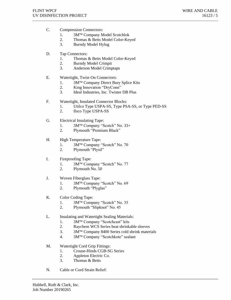
FLINT WPCF WIRE AND CABLE
UV DISINFECTION PROJECT 16123 / 5
Hubbell, Roth & Clark, Inc.
Job Number 20190265
C. Compression Connectors:
1. 3M Company Model Scotchlok
2. Thomas & Betts Model Color-Keyed
3. Burndy Model Hylug
D. Tap Connectors:
1. Thomas & Betts Model Color-Keyed
2. Burndy Model Crimpit
3. Anderson Model Crimptaps
E. Watertight, Twist-On Connectors:
1. 3M Company Direct Bury Splice Kits
2. King Innovation “DryConn”
3. Ideal Industries, Inc. Twister DB Plus
F. Watertight, Insulated Connector Blocks:
1. Utilco Type USPA-SS, Type PSA-SS, or Type PED-SS
2. Ilsco Type USPA-SS
G. Electrical Insulating Tape:
1. 3M Company “Scotch” No. 33+
2. Plymouth “Premium Black”
H. High Temperature Tape:
1. 3M Company “Scotch” No. 70
2. Plymouth “Plysil”
I. Fireproofing Tape:
1. 3M Company “Scotch” No. 77
2. Plymouth No. 50
J. Woven Fiberglass Tape:
1. 3M Company “Scotch” No. 69
2. Plymouth “Plyglas”
K. Color Coding Tape:
1. 3M Company “Scotch” No. 35
2. Plymouth “Slipknot” No. 45
L. Insulating and Watertight Sealing Materials:
1. 3M Company “Scotchcast” kits
2. Raychem WCS Series heat shrinkable sleeves
3. 3M Company 8400 Series cold shrink materials
4. 3M Company “Scotchkote” sealant
M. Watertight Cord Grip Fittings:
1. Crouse-Hinds CGB-SG Series
2. Appleton Electric Co.
3. Thomas & Betts
N. Cable or Cord Strain Relief:

WIRE AND CABLE FLINT WPCF
16123 / 6 UV DISINFECTION IMPROVEMENTS
Hubbell, Roth & Clark, Inc.
Job Number 20190265
1. Hubbell-Kellems
2. Daniel Woodhead Co.
O. Cable Pulling Lubricant:
1. American Polywater “Dyna-Blue”
2. Ideal “Aqua Gel”
3. Minerallac “Golden Glide”
4. 3M Company “GEL”
2.11 WIRING CONNECTORS AND ASSOCIATED MATERIALS
A. All wiring connectors shall be 75°C rated and suitable for use on copper conductors.
B. Cable or cord strain reliefs shall consist of stainless steel wire mesh with support bale. Strain
reliefs shall be of the split rod type where required or indicated on the Drawings.
C. Cable Pulling Lubricant:
1. Lubricant shall be UL listed and approved for use on the cable jacket or insulation.
2. Lubricant shall be polymer based and shall dry completely when exposed to air.
PART 3 EXECUTION
3.1 EXAMINATION
A. Verify that interior of building has been protected from weather.
B. Verify that mechanical work likely to damage wire and cable has been completed.
3.2 PREPARATION
A. Completely and thoroughly swab raceway before installing wire.
3.3 WIRING METHODS
A. Interior Locations:
1. Wire for general power, light, and control shall be building wire, Type THWN or
Type XHHW-2 insulation, in raceway or metal sheathed or metal clad cable, where
indicated.
2. Cables for instrumentation signals shall be single or multiple pair Instrumentation
Cable.
3. All wire for connections between Variable Frequency Controllers and associated
motors shall be shielded and shall be VFD Load Wire.
B. Exterior Locations:
1. Wire and cable for general power, light, and control for use in raceways exterior to
buildings and in underground raceways shall be underground feeder and branch circuit
wire.
2. Cables for instrumentation signals shall be three or more pair Instrumentation Cable.
C. Use wiring methods indicated on Drawings.

FLINT WPCF WIRE AND CABLE
UV DISINFECTION PROJECT 16123 / 7
Hubbell, Roth & Clark, Inc.
Job Number 20190265
D. Color Coding:
The color schedule for the conductor insulation of wire and cable shall conform to the following:
1. Three phase lighting and power, 208Y/120 VAC-Black, Red, Dark Blue, White or
Gray, and Green ground.
2. Three phase lighting and power, 120/240 VAC-Black, Red, Orange (high leg to
ground), White or Gray, and Green ground.
3. Single phase lighting and power, 120/240 VAC-Black, Red, White or Gray, and
Green ground.
4. Three phase lighting and power, 480 VAC-Brown, Orange, Yellow, and Green
ground.
5. Three phase lighting and power, 480Y/277 VAC-Brown, Orange, Yellow, Gray, and
Green ground.
6. DC power – Red with White stripe (+) and Light Blue with White stripe (-).
7. Single conductor control, AC voltage – Red.
8. Multi-conductor control cables – ICEA Method 1.
9. Alarm, annunciator, instrumentation, graphic, and telemetering (if not shielded), AC
voltage – Pink.
10. Alarm, annunciator, instrumentation, graphic, and telemetering (if not shielded), DC
voltage – Light Blue.
11. Intrinsically safe circuits – Purple.
12. On wire sizes larger than Number 8 AWG and/or where authorized by the Owner,
coding may be identified by taping with the appropriate colored self-adhesive vinyl
color coding tape.
13. Grounding conductors shall be continuous green or bare for all systems.
14. Neutral conductors shall be continuous white or gray for all systems.
E. The installation of intrinsically safe circuits shall meet all requirements of the NEC.
F. Wiring Connections:
1. Dry location splices and tap connections shall consist of compression connectors or
tap connectors, taped to 150 percent of insulation rating of the conductors.
2. Final connections to equipment wire leads for No. 8 AWG and smaller wire in dry
locations only, except 480 volt motor leads, may be made with spring wire
connectors.
3. Wet and damp location splices and tap connections shall consist of compression
connectors or tap connectors with insulating and watertight sealing materials; water
tight, twist-on connectors for wire sizes up to three No. 10 AWG; or watertight,
insulated connector blocks; providing watertight connections suitable for direct burial.
4. All conductor terminations at screw terminals shall consist of solderless pressure
connectors, except where conductor terminations are included with the equipment
being connected.
5. Insulation of connections in lighting fixture and high temperature equipment shall
consist of silicone rubber type high temperature tape with a woven fiberglass tape
over-wrap.
6. Electrical insulating tape (plastic type) shall be used on all splice and tap connections,
unless wire manufacturer’s recommendations require otherwise.
3.4 INSTALLATION
A. The installation of communication cables shall meet the requirements of NECA/BICSI
568-2001, Telecommunications.

WIRE AND CABLE FLINT WPCF
16123 / 8 UV DISINFECTION IMPROVEMENTS
Hubbell, Roth & Clark, Inc.
Job Number 20190265
B. The installation of fiber optic cables shall be per NECA/FOA 301-1997, Fiber Optic Cables,
requirements.
C. All wiring shall be run in rigid metal raceway systems, underground conduit systems, or non-
metallic FRP conduit systems, unless noted otherwise.
D. Install products in accordance with manufacturer’s instructions.
E. The minimum size of conductors shall be No. 12 AWG, unless specifically approved and/or
shown otherwise on the Drawings.
F. Use stranded conductors for control circuits, No. 14 AWG minimum, unless shown otherwise
on the Drawings.
G. Multi-conductor underground feeder, branch-circuit, and control cable shall meet the
requirements of Article 340 of the National Electrical Code.
H. Use No. 10 AWG conductors for 20 ampere, 120 volt branch circuits longer than 60 feet.
I. Use No. 8 AWG conductors for 20 ampere, 120 volt branch circuits longer than 100 feet.
J. Use No. 6 AWG conductors for 20 ampere, 120 volt branch circuits longer than 170 feet.
K. Use No. 4 AWG conductors for 20 ampere, 120 volt branch circuits longer than 270 feet.
L. Use No. 3 AWG conductors for 20 ampere, 120 volt branch circuits longer than 420 feet.
M. Where conductors or cables are to be installed in non-metallic raceway systems, the
Contractor shall allow 24 hours, minimum, for all solvents to evaporate after cementing the
last joint before pulling wires or cables.
N. Pull all conductors into raceway at same time. Cable pulling tensions shall not exceed
manufacturer’s recommended values.
O. Use suitable wire pulling lubricant for wire, No. 4 AWG and larger, and for all cables. No
soap flakes, vegetable oils, clays, or grease shall be permitted in raceways.
P. Use suitable cable fittings and connectors.
Q. Neatly train and lace wiring inside boxes, equipment, and panelboards. Wires and cables shall
be bundled and laced as specified in Section 16190.
R. All wires and cables routed through manholes, handholes, cable vaults, large pull boxes, and
terminal cabinets shall be looped to provide two to three feet (minimum) of slack within the
enclosure, where practical.
S. Clean conductor surfaces before installing lugs and connectors.
T. Make splices, taps, and terminations to carry full ampacity of conductors with no perceptible
temperature rise.
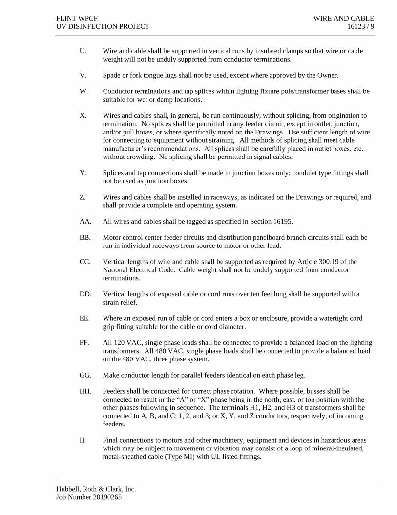
FLINT WPCF WIRE AND CABLE
UV DISINFECTION PROJECT 16123 / 9
Hubbell, Roth & Clark, Inc.
Job Number 20190265
U. Wire and cable shall be supported in vertical runs by insulated clamps so that wire or cable
weight will not be unduly supported from conductor terminations.
V. Spade or fork tongue lugs shall not be used, except where approved by the Owner.
W. Conductor terminations and tap splices within lighting fixture pole/transformer bases shall be
suitable for wet or damp locations.
X. Wires and cables shall, in general, be run continuously, without splicing, from origination to
termination. No splices shall be permitted in any feeder circuit, except in outlet, junction,
and/or pull boxes, or where specifically noted on the Drawings. Use sufficient length of wire
for connecting to equipment without straining. All methods of splicing shall meet cable
manufacturer’s recommendations. All splices shall be carefully placed in outlet boxes, etc.
without crowding. No splicing shall be permitted in signal cables.
Y. Splices and tap connections shall be made in junction boxes only; condulet type fittings shall
not be used as junction boxes.
Z. Wires and cables shall be installed in raceways, as indicated on the Drawings or required, and
shall provide a complete and operating system.
AA. All wires and cables shall be tagged as specified in Section 16195.
BB. Motor control center feeder circuits and distribution panelboard branch circuits shall each be
run in individual raceways from source to motor or other load.
CC. Vertical lengths of wire and cable shall be supported as required by Article 300.19 of the
National Electrical Code. Cable weight shall not be unduly supported from conductor
terminations.
DD. Vertical lengths of exposed cable or cord runs over ten feet long shall be supported with a
strain relief.
EE. Where an exposed run of cable or cord enters a box or enclosure, provide a watertight cord
grip fitting suitable for the cable or cord diameter.
FF. All 120 VAC, single phase loads shall be connected to provide a balanced load on the lighting
transformers. All 480 VAC, single phase loads shall be connected to provide a balanced load
on the 480 VAC, three phase system.
GG. Make conductor length for parallel feeders identical on each phase leg.
HH. Feeders shall be connected for correct phase rotation. Where possible, busses shall be
connected to result in the “A” or “X” phase being in the north, east, or top position with the
other phases following in sequence. The terminals H1, H2, and H3 of transformers shall be
connected to A, B, and C; 1, 2, and 3; or X, Y, and Z conductors, respectively, of incoming
feeders.
II. Final connections to motors and other machinery, equipment and devices in hazardous areas
which may be subject to movement or vibration may consist of a loop of mineral-insulated,
metal-sheathed cable (Type MI) with UL listed fittings.

WIRE AND CABLE FLINT WPCF
16123 / 10 UV DISINFECTION IMPROVEMENTS
Hubbell, Roth & Clark, Inc.
Job Number 20190265
JJ. All secondary wire and cables run exposed through manholes, handholes, and cable vaults
shall be fireproofed, where exposed. Fireproofing of wire and cables shall be accomplished
with half lapped taping using fireproofing tape made of heat resistant organic fabric coated on
one side with a flame retardant elastomer. The fireproofing tape shall be held in place by spiral
wrapping at recommended intervals using woven fiberglass tape.
3.5 INTERFACE WITH OTHER PRODUCTS
A. Identify wire and cable under provisions of Section 16195.
B. Identify each conductor with its circuit number or other designation indicated on Drawings.
3.6 FIELD QUALITY CONTROL
A. Perform field inspection and testing under provisions of Sections 01400 and 16960.
B. Inspect wire and cable for physical damage and proper connection.
C. Measure tightness of bolted connections and compare torque measurements with manu-
facturer’s recommended values.
D. Verify continuity of each branch circuit conductor.
E. Verify continuity of each feeder conductor.
F. All communication cables shall be tested and certified by a qualified third-party after
installation in accordance with industry standards, and copies of the certified test results
turned over to the Owner.
END OF SECTION

FLINT WPCF BOXES
UV DISINFECTION PROJECT 16130 / 1
Hubbell, Roth & Clark, Inc.
Job Number 20190265
SECTION 16130
BOXES
PART 1 GENERAL
1.1 SECTION INCLUDES
A. Wall and ceiling outlet boxes.
B. Pull and junction boxes.
C. Wireways.
1.2 RELATED SECTIONS
A. Section 16010 - General Electrical, Instrument, and Control Requirements.
B. Section 16050 - Basic Electrical Materials and Methods.
C. Section 16110 - Raceways.
D. Section 16140 - Wiring Devices.
E. Section 16160 - Cabinets and Enclosures.
F. Section 16190 - Supporting Devices.
G. Section 16195 - Electrical Identification.
1.3 REFERENCES
A. NECA - Standard of Installation.
B. NEMA FB 1 - Fittings and Supports for Conduit and Cable Assemblies.
C. NEMA OS 1 - Sheet-steel Outlet Boxes, Device Boxes, Covers, and Box Supports.
D. NEMA OS 2 - Non-metallic Outlet Boxes, Device Boxes, Covers and Box Supports.
E. NEMA 250 - Enclosures for Electrical Equipment (1000 Volts Maximum).
F. NFPA 70 - National Electrical Code.
1.4 SUBMITTALS
A. Submit under provisions of Section 01300.
B. Shop Drawings: Indicate materials, finishes, dimensions, listings, and standards compliance.

BOXES FLINT WPCF
16130 / 2 UV DISINFECTION PROJECT
Hubbell, Roth & Clark, Inc.
Job Number 20190265
C. Product Data: Provide data for boxes, wireways, and accessories.
D. Manufacturer’s Instructions: Indicate application conditions and limitations of use stipulated
by Product testing agency specified under Regulatory Requirements. Include instructions for
storage, handling, protection, examination, preparation, and installation of Product.
1.5 SUBMITTALS FOR CLOSEOUT
A. Section 01700 - Contract Closeout: Submittals for Project closeout.
B. Record actual locations and mounting heights of outlet, pull, and junction boxes on project
record documents.
1.6 REGULATORY REQUIREMENTS
A. Conform to requirements of NFPA 70, National Electrical Code.
B. Provide Products listed and classified by Underwriters Laboratories, Inc. or other testing firm
acceptable to the authority having jurisdiction, as suitable for the purpose specified and
indicated.
C. All boxes shall be sized per Article 314 of the National Electrical Code as a minimum.
PART 2 PRODUCTS
2.1 OUTLET BOXES
A. Sheet Metal Outlet Boxes: NEMA OS 1, galvanized steel.
1. Luminaire and Equipment Supporting Boxes: Rated for weight of equipment
supported; include 1/2 inch (13 mm) male fixture studs where required.
2. Concrete Ceiling Boxes: Concrete type.
B. Non-metallic Outlet Boxes: NEMA OS 2.
C. Cast Boxes: NEMA FB 1, Type FD, cast feralloy. Provide gasketed cover by box
manufacturer. Provide threaded hubs.
D. Wall Plates for Finished Areas: As specified in Section 16140.
E. Covers for boxes containing wiring devices shall be as specified in Section 16140.
F. Telephone outlets shall be floor mounted, single gang, FSY cast boxes or wall mounted, single
gang FS cast boxes as indicated on the Drawings. All telephone outlet boxes shall be
furnished with a stainless steel cover with a 3/8" bushed opening for the telephone cabling.
G. Outlet boxes for pendant mounted lighting fixtures shall be ball mount, GS or AL Series as
manufactured by Appleton Electric Co. or equal. Outlet boxes for pendant mounted fixtures
in hazardous areas shall be similar, except explosion proof, Appleton Electric Co. EFHU or
equal.

FLINT WPCF BOXES
UV DISINFECTION PROJECT 16130 / 3
Hubbell, Roth & Clark, Inc.
Job Number 20190265
H. Floor mounted outlet boxes shall be single gang, FSY cast boxes with appropriate covers.
I. Outlet boxes in hazardous locations shall be explosion proof, Class I, Division 1, Group D and
shall be Type GUA, GUF, and GUJ as manufactured by Crouse-Hinds Co., Appleton, or
equal.
2.2 PULL AND JUNCTION BOXES
A. Sheet Metal Boxes: NEMA OS 1, galvanized steel.
B. Hinged Enclosures: As specified in Section 16160.
C. Surface Mounted Cast Metal Box: NEMA 250, Type 4; flat-flanged, surface mounted
junction box:
1. Material: Galvanized cast iron.
2. Cover: Furnish with ground flange, neoprene gasket, and stainless steel cover screws.
D. Single and two gang pull boxes and junction boxes shall be rust proof, cast metal, Type FD
boxes with gasketed covers.
E. Larger boxes and raceways shall be NEMA Type 12, in indoor, above grade locations, or
stainless steel NEMA Type 4 or non-metallic NEMA Type 4X with stainless steel hardware in
all other locations or where indicated on the Drawings, built of Code gauge steel, with angle
iron supports and braces. Cable support racks shall be provided where required. Access shall
be by means of removable, gasketed screw covers fastened with machine screws.
F. NEMA Type 4X boxes shall be of corrosion resistant, high impact strength, fiberglass
reinforced polyester material suitable for surface mounting. Barriers shall be provided where
indicated on the Drawings or required.
G. All pull boxes installed below grade within the structures shall be provided with a drain,
Crouse-Hinds ECD Universal Series, Appleton, or equal mounted on a bolt-on, gasketed hub
or Stahlin Drain Vent on NEMA Type 4X boxes.
H. In-line pull boxes, where shown on the Drawings, shall be Appleton Type PTC with solid
gasket or equal.
I. Threaded conduit fittings with gasketed covers shall be used for all exposed conduit outlets
and boxes.
J. Conduit bodies and fittings shall be of cast iron, malleable iron, and/or galvanized steel.
2.3 WIREWAYS
A. Wiring ducts shall be NEMA Type 12 galvanized steel in indoor, above grade locations;
non-metallic, NEMA Type 4X in corrosive locations; or stainless steel, NEMA Type 4 in all
other locations or where indicated on the Drawings. Metallic wireways shall be 14 gauge steel
raceways and all wireways shall be provided with removable covers held with captive screws.
All fittings shall be designed to be used with the ducts to result in an unobstructed system.

BOXES FLINT WPCF
16130 / 4 UV DISINFECTION PROJECT
Hubbell, Roth & Clark, Inc.
Job Number 20190265
The ducts and fittings shall be sized as shown on the Drawings. All hardware on stainless
steel and non-metallic wiring ducts shall be made of stainless steel.
B. The wiring ducts shall be as manufactured by Keystone, Hoffman Engineering Co., B-Line, or
equal.
2.4 MISCELLANEOUS COMPONENTS
A. Anti-seize, lubricating, and protective compound shall be Never-Seez as manufactured by
Bostik Div. of Emhart Corp., "Dry Molybdenum Lubricant" No. 40-640 by Ideal Industries,
CRC Chemicals Lectra-Shield, Crouse-Hinds HTL, Sanchem, Inc. NO-OX-ID “A Special”, or
equal.
PART 3 EXECUTION
3.1 EXAMINATION
A. Verify locations of floor boxes and outlets in all work areas prior to rough-in.
3.2 INSTALLATION
A. Install boxes in accordance with NECA "Standard of Installation."
B. Install pull boxes and junction boxes in locations as shown on Drawings, and as required for
splices, taps, wire pulling, equipment connections and compliance with regulatory
requirements.
C. Pull boxes and/or junction boxes shall be used in any conduit run where a splice is required.
Pull boxes shall be provided every 200 feet of straight run, every 150 feet after 90 degrees of
bends, every 100 feet after 180 degrees of bends, and every 50 feet after 270 degrees of bends.
More than 270 degrees worth of bends shall not be installed between pulling points in any
conduit run.
D. Pull boxes, auxiliary pull fittings (slip joints), and cable raceways for the pulling, nesting, or
concealment of wires or cables shall be provided where indicated on the Drawings and also
where required, though not indicated, as specified above.
E. Mark or label all boxes as specified in Section 16195.
F. Set wall mounted boxes at elevations to accommodate mounting heights indicated.
G. Enough room shall be supplied in boxes for insulating joints, wires, and bushings, and deep
boxes shall be installed where required by the type of fixture or outlet called for on the
Drawings.
H. Wire and cable splices and tap connections shall be made in junction boxes only; condulet
type fittings shall not be used as junction boxes.

FLINT WPCF BOXES
UV DISINFECTION PROJECT 16130 / 5
Hubbell, Roth & Clark, Inc.
Job Number 20190265
I. Electrical boxes are shown on Drawings in approximate locations, unless dimensioned.
Adjust box location up to 8 feet, if required to accommodate intended purpose.
J. Orient boxes to accommodate wiring devices oriented as specified in Section 16140.
K. Maintain headroom and present neat mechanical appearance.
L. Align adjacent wall mounted outlet boxes for switches, thermostats, and similar devices.
M. Use flush mounting outlet box in finished areas.
N. Locate flush mounting box in masonry wall to require cutting of masonry unit corner only.
Coordinate masonry cutting to achieve neat opening.
O. At each concealed outlet in slabs or walls in dry locations only, a galvanized, pressed steel box
of the knockout type, of not less than No. 12 B & S gauge, shall be placed and securely
fastened. The conduits shall be fastened to these boxes with lock nuts, inside and outside, and
bushings. All unused knockouts or holes must be left sealed.
P. Support boxes independently of conduit.
Q. Use gang box where more than one device is mounted together. Do not use sectional box.
R. Use cast outlet box in exterior locations and wet locations.
S. Set floor boxes level.
T. Wall and ceiling mounted pull and junction boxes shall be spaced 1/2 inch minimum out from
the wall or ceiling using corrosion resistant channel: Unistrut; Grinnell “Power-Strut”, or
other approved corrosion resistant spacers.
U. Large Pull Boxes: Use hinged enclosure in interior dry locations, surface-mounted cast metal
box in other locations.
V. The threads of all corrosive area, hazardous area, outdoor, and below grade equipment
connections including conduit, conduit fittings, pull and junction box covers, lighting fixture
reflector, guard, and outlet box connections, wiring device boxes, etc. shall be coated with an
anti-seize, lubricating, and protective compound prior to final assembly.
W. All metallic, except stainless steel, pull boxes, junction boxes, outlet boxes, and other exposed
metal components installed in areas classified as hazardous and in corrosive areas shall be
factory encased in polyvinyl chloride of minimum .040 inch (40 mil) thickness. Where
factory PVC coating is not available or where PVC coating would void UL listing or labeling,
factory or field coating with a corrosion resistant, epoxy paint shall be provided.
3.3 ADJUSTING
A. Section 01700 - Contract Closeout: Adjusting installed work.
B. Adjust flush-mounting outlets to make front flush with finished wall material.

BOXES FLINT WPCF
16130 / 6 UV DISINFECTION PROJECT
Hubbell, Roth & Clark, Inc.
Job Number 20190265
C. Install knockout closures in unused box openings.
3.4 CLEANING
A. Section 01700 - Contract Closeout: Cleaning installed work.
B. Clean interior of boxes to remove dust, debris, and other material.
C. Clean exposed surfaces and restore finish.
END OF SECTION

FLINT WPCF WIRING DEVICES
UV DISINFECTION PROJECT 16140 / 1
Hubbell, Roth & Clark, Inc.
Job Number 20190265
SECTION 16140
WIRING DEVICES
PART 1 GENERAL
1.1 SECTION INCLUDES
A. Wall switches.
B. Receptacles.
C. Device plates and box covers.
1.2 RELATED SECTIONS
A. Section 16010 - General Electrical, Instrument, and Control Requirements.
B. Section 16050 - Basic Electrical Materials and Methods.
C. Section 16130 - Boxes.
1.3 REFERENCES
A. NECA - Standard of Installation.
B. NEMA WD 1 - General Requirements for Wiring Devices.
C. NEMA WD 6 - Wiring Device -- Dimensional Requirements.
D. NFPA 70 - National Electrical Code.
1.4 SUBMITTALS FOR REVIEW
A. Section 01300 - Submittals: Procedures for submittals.
B. Product Data: Provide manufacturer's catalog information showing dimensions, materials,
finishes, and configurations.
C. Submit manufacturer's installation instructions.
1.5 REGULATORY REQUIREMENTS
A. Conform to requirements of NFPA 70.
B. Provide Products listed and classified by Underwriters Laboratories, Inc., or other testing firm
acceptable to the authority having jurisdiction, as suitable for the purpose specified and
indicated.

WIRING DEVICES FLINT WPCF
16140 / 2 UV DISINFECTION PROJECT
Hubbell, Roth & Clark, Inc.
Job Number 20190265
PART 2 PRODUCTS
2.1 WALL SWITCHES
A. Switches for local control of 120 volt lighting shall be quiet, quick make, slow break design
with totally enclosed case, flush type, single pole, toggle switches, 20 ampere capacity at
120/277 volts. Switches shall be UL listed and shall meet NEMA standard WD-1.
B. Two pole, 3-way, 4-way, and key switches shall have similar ratings.
C. Where pilot lights are indicated, provide switches as specified above plus a separate pilot
receptacle with plate and bull's eye in a two gang box.
D. Lighting switches shall be Hubbell Series HBL1220, Leviton Series 1220, General Electric
GE5951, Cooper Wiring Devices, or equal.
E. Lighting switches for contactor control, designated Src, shall be momentary contact, 20
ampere, single pole, double throw, Hubbell No. HBL1557, Leviton 1257, General Electric
GE5935, Cooper Wiring Devices, or equal.
F. Lighting switches installed in corrosive areas shall consist of switches as specified above
installed in non-metallic corrosion resistant, FD type boxes with weatherproof, corrosion
resistant, flexible silicone rubber, bubble type covers; Hubbell No. HBL1795, Pass &
Seymour No. 4517, or equal.
2.2 RECEPTACLES
A. Duplex receptacles shall be 20 amp, 125 volt, 3 wire, grounding type, Hubbell Cat. No.
HBL5362, General Electric GE5362, Cooper Wiring Devices No.5362B, or equal. Covers for
general use receptacles shall be Crouse-Hinds Co. No. DS23G, Leviton 5362, Appleton
Electric Co., or equal.
B. Duplex receptacles installed in corrosive areas shall consist of a 20 amp, 125 volt, 3 wire,
grounding type, corrosion resistant receptacle; Hubbell Cat. No. HBL53CM62, Leviton
53CM-62, General Electric GE0526C, Cooper Wiring Devices No. 5362CRY, or equal
mounted in a non-metallic, corrosion resistant box with a corrosion resistant, weatherproof
cover; Carlon, TayMac Corp., or equal.
C. Isolated ground duplex receptacles shall be similar to duplex receptacles, except Hubbell Cat.
No. HBLIG5362-H, Leviton 5362-IG, General Electric GE5362-IG, Cooper Wiring Devices
No. IG8300RN, or equal.
D. G.F.C.I. duplex receptacles shall be 20 amp, 125 volt, 3 wire, ground fault circuit interrupter
type receptacles with face mounted "test" and "reset" pushbuttons and matching stainless steel
cover plate. G.F.C.I. receptacles shall be Hubbell Cat. No. HBL GF-5362-I, Leviton 6898-I,
General Electric GFR5362, Cooper Wiring Devices, or equal.
E. Twist-lock duplex receptacles shall be 15 amp, 125 volt, 3 wire, ground type, Hubbell Cat.
No. HBL4700, General Electric GL0516, Cooper Wiring Devices, or equal with surface

FLINT WPCF WIRING DEVICES
UV DISINFECTION PROJECT 16140 / 3
Hubbell, Roth & Clark, Inc.
Job Number 20190265
mounting type cover plates. Matching plugs for twist-lock receptacles, shall be Hubbell No.
HBL4720-C, Leviton 4720-C, General Electric GLD0511, Cooper Wiring Devices, or equal.
F. Single receptacles shall be 20 amp, 125 volt, 3 wire, grounding type, Hubbell Cat. No.
HBL5361, Leviton 5361, General Electric GE5361, Cooper Wiring Devices, or equal. Covers
for single receptacles in dry locations shall be Crouse-Hinds No. DS21G, Appleton Electric
Co., or equal.
2.3 WALL AND COVER PLATES
A. Materials:
1. Polycarbonate: Corrosion resistant, molded with self-closing, gasketed door(s),
suitable for wet locations and with gasket at box/cover connection.
2. Cast Metal: Die cast profile, ribbed for strength, flash removed, PVC coated,
furnished complete with mounting screws.
3. Gaskets: Resilient rubber or closed cell foam urethane.
4. Fiberglass-reinforced polyester: Corrosion resistant, gasketed, stainless steel
hardware, cap screw retained.
5. All device plate screws shall be stainless steel with countersunk heads.
B. Plates:
1. Plates for duplex convenience outlets shall be polycarbonate with a single, self-
closing door, Hubbell No. HBL52CM21, Leviton, Bryant, Pass & Seymour, Crouse-
Hinds, or equal.
2. Plates for equipment receptacles shall be polycarbonate with a single, self-closing
gasketed door, Hubbell No. HBL74CM25WO, Leviton, Bryant, Pass & Seymour,
Crouse-Hinds, or equal. The plate shall incorporate a gasket at the interface between
the receptacle, the plate, and the connecting plug. This gasket’s opening shall be
coordinated with the receptacle and plug faces for a proper, watertight fit.
3. Weatherproof covers for toggle light switches shall be of the clear, silicone rubber,
bubble type for mounting on Type FD and standard boxes. Toggle switch cover plates
shall be Hubbell No. HBL1795, Leviton, Bryant, Pass & Seymour, Crouse-Hinds, or
equal.
4. Blank cover plates for pull and junction boxes shall be of the same material as the box
with gasket and stainless steel screws.
2.4 MISCELLANEOUS
A. Anti-seize, lubricating, and protective compound shall be Never-Seez as manufactured by
Bostik Div. of Emhart Corp., "Dry Molybdenum Lubricant" No. 40-640 by Ideal Industries,
CRC Chemicals Lectra-Shield, Crouse-Hinds HTL, Sanchem, Inc. NO-OX-ID “A Special”, or
equal.
B. All metallic, except stainless steel, device boxes, outlet boxes, cover plates, fittings, supports,
hangers, and other exposed metal components installed in areas classified as hazardous and in
corrosive areas shall be factory encased in polyvinyl chloride of minimum .040 inch (40 mil)
thickness. Where factory PVC coating is not available or where PVC coating would void UL
listing or labeling, factory or field coating with a corrosion resistant, epoxy paint shall be
provided.

WIRING DEVICES FLINT WPCF
16140 / 4 UV DISINFECTION PROJECT
Hubbell, Roth & Clark, Inc.
Job Number 20190265
PART 3 EXECUTION
3.1 EXAMINATION
A. Section 01039 - Coordination and Meetings: Verification of existing conditions prior to
beginning work.
B. Verify that outlet boxes are installed at proper height.
C. Verify that wall openings are neatly cut and will be completely covered by wall plates.
D. Verify that branch circuit wiring installation is completed, tested, and ready for connection to
wiring devices.
3.2 PREPARATION
A. Provide extension rings to bring outlet boxes flush with finished surface.
B. Clean debris from outlet boxes.
3.3 INSTALLATION
A. Install in accordance with NECA "Standard of Installation."
B. Install devices plumb and level.
C. Install switches with OFF position down.
D. Install receptacles with grounding pole on top.
E. Connect wiring device grounding terminal to branch circuit equipment grounding conductor.
F. Where more than one switch occurs in the same location, they shall be installed in gang type
boxes.
G. Duplex receptacles, shown on the Drawings outdoors or below grade, shall be mounted in
weatherproof boxes and cover plates. The boxes shall be rust proof, cast metal having
threaded openings for conduit connections and shall be mounted horizontally on or in the wall.
H. Receptacles in dry, indoor locations shall be installed in surface mounting, Type FD boxes
with mounting lugs.
I. The threads of all hazardous area, outdoor, and below grade equipment connections including
conduit, conduit fittings, outlet box connections, wiring device boxes, cover plate screws, etc.
shall be coated with an anti-seize, lubricating, and protective compound prior to final
assembly.
J. See Section 16195 for nameplate, circuit number marker, wire marker, etc. requirements.

FLINT WPCF WIRING DEVICES
UV DISINFECTION PROJECT 16140 / 5
Hubbell, Roth & Clark, Inc.
Job Number 20190265
3.4 INTERFACE WITH OTHER PRODUCTS
A. Coordinate locations of outlet boxes provided under Section 16130 to obtain mounting heights
specified or indicated on the Drawings.
3.5 FIELD QUALITY CONTROL
A. Inspect each wiring device for defects.
B. Operate each wall switch with circuit energized and verify proper operation.
C. Verify that each receptacle device is energized.
D. Test each receptacle device for proper polarity.
E. Test each GFCI receptacle device for proper operation.
3.6 ADJUSTING
A. Adjust devices and wall plates to be flush and level.
3.7 CLEANING
A. Section 01700 - Contract Closeout: Cleaning installed work.
B. Clean exposed surfaces to remove splatters and restore finish.
END OF SECTION


FLINT WPCF CABINETS AND ENCLOSURES
UV DISINFECTION PROJECT 16160 / 1
Hubbell, Roth & Clark, Inc.
Job Number 20190265
SECTION 16160
CABINETS AND ENCLOSURES
PART 1 GENERAL
1.1 SECTION INCLUDES
A. Hinged cover enclosures.
B. Cabinets.
C. Terminal boxes.
D. Accessories.
1.2 RELATED SECTIONS
A. Section 16010 - General Electrical, Instrument, and Control Requirements.
B. Section 16050 - Basic Electrical Materials and Methods.
C. Section 16055 - Basic I & C Materials and Methods.
D. Section 16110 - Raceways.
E. Section 16130 - Boxes.
F. Section 16190 - Supporting Devices.
G. Section 16195 - Electrical Identification.
1.3 REFERENCES
A. NEMA 250 - Enclosures for Electrical Equipment (1000 Volts Maximum).
B. NEMA ICS 4 - Terminal Blocks for Industrial Control Equipment and Systems.
C. ANSI/NFPA 70 - National Electrical Code.
1.4 SUBMITTALS
A. Submit under provisions of Section 01300.
B. Product Data: Provide manufacturer's standard data for enclosures and cabinets.
C. Manufacturer's Instructions: Indicate application conditions and limitations of use stipulated
by Product testing agency specified under Regulatory Requirements. Include instructions for
storage, handling, protection, examination, preparation, installation, and starting of Product.

CABINETS AND ENCLOSURES FLINT WPCF
16160 / 2 UV DISINFECTION PROJECT
Hubbell, Roth & Clark, Inc.
Job Number 20190265
D. Certified shop drawings and diagrams shall be furnished by the Contractor and delivered to
the Owner for approval as follows:
1. General dimensions and outline drawings showing the principal dimensions of the
equipment and the location and size of electrical conduit connections.
2. Detailed drawings, descriptive data, and other data sheets showing design information
which verified that the equipment meets the technical requirements of the
Specifications.
1.5 REGULATORY REQUIREMENTS
A. Conform to requirements of ANSI/NFPA 70.
B. Furnish products listed and classified by Underwriters Laboratories, Inc. or other testing firm
acceptable to authority having jurisdiction, as suitable for purpose specified and shown.
1.6 EXTRA MATERIALS
A. Furnish under provisions of Section 01700.
B. Provide three (3) of each cabinet key.
PART 2 PRODUCTS
2.1 CABINETS AND HINGED COVER ENCLOSURES
A. Manufacturers: Manufacturers and model numbers of cabinets, enclosures, and associated
components shall be as follows:
1. Cabinets and Enclosures: Hoffman Engineering Co., Saginaw Controls, Stahlin, or
Hammond.
2. Anti-condensation Heaters: Saginaw Control & Engineering No. SCE-AHC50 or
equal.
3. Terminal Blocks: Allen-Bradley No. 1492-CA1, CA3, or -CD8.
4. Substitutions: Items of equal function and performance are acceptable, if in
conformance with all sections of this Specification.
B. Cabinets and enclosures in dry locations shall be dust and oil tight, rated NEMA Type 12, and
of 14 gauge (minimum) painted sheet steel construction or comparable non-metallic.
C. Cabinets and enclosures in wet locations shall be watertight, rated NEMA Type 4, and of 14
gauge (minimum) painted sheet steel construction or comparable non-metallic.
D. Cabinets and enclosures in corrosive areas shall be water, dust, and sleet tight, rated NEMA
Type 4X, and of stainless steel construction or comparable non-metallic.
E. Doors shall be equipped with a padlockable latch or padlock hasp and shall be provided with
one (1) padlock with three keys.
F. The top, sides, and doors of outdoor cabinets and enclosures shall be insulated with a 2-inch
thick layer of extruded polystyrene material.

FLINT WPCF CABINETS AND ENCLOSURES
UV DISINFECTION PROJECT 16160 / 3
Hubbell, Roth & Clark, Inc.
Job Number 20190265
G. The doors shall be gasketed.
H. Provide an internal, mild steel sub-plate for mounting of internal components.
I. Provide and install two (2) minimum, 120 volt, anti-condensation heaters within each outdoor
cabinet or enclosures. The heaters shall be of the self-limiting type, 50 watts, 120 VAC.
J. Cabinets and enclosures shall be provided with full-length door hinges. Hinges shall be
stainless steel and the doors shall have a one point latch.
K. All interior cabinet or enclosure surfaces, except fittings, shall be painted with two coats of
primer and two coats of white, high gloss, baked epoxy enamel paint. The exterior shall be
painted with one coat of primer, two coats of ANSI 61 gray paint, and a final coat of clear
polyurethane.
L. Terminal blocks shall be provided for all wiring entering cabinets and enclosures from
external devices. Provide 10 percent spare terminals, in addition to those required.
M. Terminal boxes shall be similar to cabinets and enclosures, except they shall have screw
covers in lieu of hinged and latched doors.
2.2 TERMINAL BOXES
A. Explosion proof terminal boxes for connection of the submersible dewatering and sample
pump motor cable(s) shall be provided where shown on the Drawings. The terminal box shall
be 12" high by 18" wide by 8" deep minimum with internal mounting plate for terminal
blocks, cast iron or cast aluminum with external mounting ears for surface mounting, hinged
cover with stainless steel bolts and NEMA Type 4 seal, explosion proof, Class I, Division 1,
Group D with bossed, drilled, and tapped conduit entrances as required for conduit and fitting
connections as indicated on the Drawings. Explosion proof terminal boxes shall be factory or
field coated with a corrosion resistant, epoxy paint.
B. Terminal blocks for power conductor connections shall be power distribution blocks for
connection of copper wire with individual, set screw type connectors for each terminated
conductor, Gould Shawmut 66000 Series, Marathon 143 Series, or equal. Terminal blocks for
control conductor connections shall be of the screw terminal type, number of blocks as
required, Allen-Bradley No. 1492-CA1 with associated mounting devices, Square D, or equal.
Control terminal blocks and conductors shall be coated with a conformal coating compound
after permanent terminations have been completed. Conformal coating compound shall be
Chemtronics Konform, GC Electronics Conkoat, or equal. Provide an engraved, laminated
plastic instruction plate, adjacent to the control terminal block, engraved: "RECOAT
CONTROL TERMINATIONS WITH CONFORMAL COATING COMPOUND AFTER
EACH RETERMINATION OF CONDUCTORS TO PREVENT NUISANCE MOTOR
LEAK ALARMS".
C. Provide an insulating barrier between the power and the control terminations.
2.3 ENCLOSURE ACCESSORIES
A. All hardware on the exterior of NEMA Type 4 and NEMA Type 4X enclosures, including
hinge pins, screws, bolts, nuts, washers, etc., shall be made of 300 series stainless steel.

CABINETS AND ENCLOSURES FLINT WPCF
16160 / 4 UV DISINFECTION PROJECT
Hubbell, Roth & Clark, Inc.
Job Number 20190265
B. Combination drain and breather shall be Crouse-Hinds ECD Combination Series, Appleton, or
equal. Combination drain and breather shall be Stahlin Drain Vent or equal on NEMA Type
4X enclosures.
C. Anti-seize, lubricating, and protective compound shall be Never-Seez as manufactured by
Bostik Div. of Emhart Corp., "Dry Molybdenum Lubricant" No. 40-640 by Ideal Industries,
CRC Chemicals Lectra-Shield, Crouse-Hinds HTL, Sanchem, Inc. NO-OX-ID “A Special”, or
equal.
PART 3 EXECUTION
3.1 EXAMINATION
A. Verify installation conditions under provisions of Section 01039.
B. Verify that surfaces are ready to receive work.
3.2 INSTALLATION
A. Install Products in accordance with manufacturer's instructions.
B. Install enclosures and boxes plumb. Anchor securely to wall and structural supports at each
corner.
C. Install cabinet fronts plumb.
D. All equipment installed in hazardous areas shall be provided in explosion proof enclosures,
except equipment listed as intrinsically safe may be provided in NEMA Type 4 or
non-metallic NEMA Type 4X enclosures. All explosion proof enclosures shall be factory or
field coated with a corrosion resistant finish.
E. NEMA Type 4 and Type 4X enclosures in other than corrosive areas shall be equipped with a
combination drain and breather. The drain shall be mounted on a bolt-on, gasketed hub.
F. All internal cabinet and enclosure components shall be mounted on the sub-plate positioned
for easy access, convenient wiring, and for easy removal.
G. Convenience receptacle mounted within cabinets and enclosures shall be mounted in a handy
box with a cover plate.
H. See Section 16110, Raceways for conduit entrance to cabinets and enclosures requirements.
I. Mark or label all boxes, cabinets, and enclosures as specified in Section 16195.
J. The threads of all corrosive area, hazardous area, outdoor, and below grade equipment
connections including conduit, conduit fittings, pull and junction box covers, cable fittings,
etc. shall be coated with an anti-seize, lubricating, and protective compound prior to final
assembly.
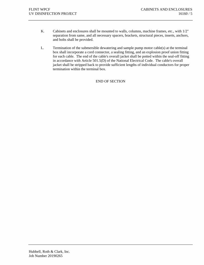
FLINT WPCF CABINETS AND ENCLOSURES
UV DISINFECTION PROJECT 16160 / 5
Hubbell, Roth & Clark, Inc.
Job Number 20190265
K. Cabinets and enclosures shall be mounted to walls, columns, machine frames, etc., with 1/2"
separation from same, and all necessary spacers, brackets, structural pieces, inserts, anchors,
and bolts shall be provided.
L. Termination of the submersible dewatering and sample pump motor cable(s) at the terminal
box shall incorporate a cord connector, a sealing fitting, and an explosion proof union fitting
for each cable. The end of the cable's overall jacket shall be potted within the seal-off fitting
in accordance with Article 501.5(D) of the National Electrical Code. The cable's overall
jacket shall be stripped back to provide sufficient lengths of individual conductors for proper
termination within the terminal box.
END OF SECTION


FLINT WPCF GROUNDING AND BONDING
UV DISINFECTION PROJECT 16170 / 1
Hubbell, Roth & Clark, Inc.
Job Number 20190265
SECTION 16170
GROUNDING AND BONDING
PART 1 GENERAL
1.1 SECTION INCLUDES
A. Grounding electrodes and conductors.
B. Equipment grounding conductors.
C. Bonding.
1.2 RELATED SECTIONS
A. Section 03300 - Concrete Work.
B. Section 16010 - General Electrical, Instrument, and Control Requirements.
C. Section 16050 - Basic Electrical Materials and Methods.
D. Section 16670 - Surge Suppression Systems.
E. Section 16960 – Electrical Testing and Equipment.
1.3 REFERENCES
A. ANSI/NFPA 70 - National Electrical Code.
1.4 GROUNDING ELECTRODE SYSTEM
A. Metal underground utility piping.
B. Metal frame of the building.
C. Ground loops, risers, and conductors.
D. Rod electrodes.
E. Ground mat.
1.5 PERFORMANCE REQUIREMENTS
A. Grounding System Resistance: 5 ohms.
B. In the event that the ground resistance is not 5 ohms or less, additional rods or longer rods
shall be installed or the soil treated to reduce its resistance by approved practices. All ground

GROUNDING AND BONDING FLINT WPCF
16170 / 2 UV DISINFECTION PROJECT
Hubbell, Roth & Clark, Inc.
Job Number 20190265
resistance measurements shall be made using the fall-of-potential method only and test reports
shall be provided as specified under Section 16960, Electrical Testing and Equipment.
1.6 SUBMITTALS
A. Submit under provisions of Section 01300.
B. Product Data: Provide data for grounding electrodes and connections.
C. Test Reports: Indicate facility's overall resistance to ground.
D. Manufacturer's Instructions: Include instructions for storage, handling, protection,
examination, preparation and installation of exothermic connectors.
1.7 PROJECT RECORD DOCUMENTS
A. Submit under provisions of Section 01700.
B. Accurately record actual locations of grounding electrodes.
1.8 REGULATORY REQUIREMENTS
A. Conform to requirements of ANSI/NFPA 70.
B. Furnish products listed and classified by Underwriters Laboratories, Inc. or other testing firm
acceptable to authority having jurisdiction, as suitable for purpose specified and shown.
PART 2 PRODUCTS
2.1 ROD ELECTRODES
A. Ground rods shall be 3/4" diameter by 10 feet long and shall have copper jackets and steel
cores. The rods shall be as manufactured by Blackburn/Eritech, Erico Electrical Products,
Harger, or equal.
2.2 MECHANICAL CONNECTORS
A. All compression connectors, lugs, etc., used in grounding circuits in any location shall have
bolts, nuts, etc., of silicon bronze alloy equal to "Everdur" metal. Grounding connections,
clamps, etc., shall be as manufactured by Burndy Engineering Company, Thomas and Betts
Company, Delta-Star Electric Company, Harger, or equal.
B. Fittings for bonding a grounding conductor to metallic conduit shall be Thomas and Betts
Series 3900BU or equal. Fittings for bonding a grounding conductor to its own conduit shall
be Burndy Engineering Company GAR-BU Series, Thomas and Betts Series 3900, Harger, or
equal.
C. Where connections to ground rods or ground mats must be disconnected for testing, the
fittings shall be Burndy Engineering Co. Type GD, GG, GAR; Thomas and Betts Co. Series
3902BU; Harger; or equal.

FLINT WPCF GROUNDING AND BONDING
UV DISINFECTION PROJECT 16170 / 3
Hubbell, Roth & Clark, Inc.
Job Number 20190265
2.3 EXOTHERMIC CONNECTIONS
A. Connections to steel, between conductors, and for water stops shall consist of exothermic
welding similar and equal to Burndy Engineering Company's "Thermoweld", Erico Products,
Inc. "Cadweld Kits", Thomas & Betts Corp. “Furseweld”, or Harger.
2.4 CONDUCTORS
A. Grounding conductors, loops, and risers shall be bare, stranded, soft-drawn copper and shall
be of the sizes indicated on Drawings.
B. All bonding jumpers shall be copper and of a cross-sectional area at least equal to their
corresponding grounding conductors.
PART 3 EXECUTION
3.1 EXAMINATION
A. Verify that final backfill and compaction has been completed before driving rod electrodes.
3.2 INSTALLATION
A. Install Products in accordance with manufacturer's instructions.
B. Install rod electrodes at locations indicated. Install additional rod electrodes as required to
achieve specified resistance to ground. Rod electrodes shall be driven into undisturbed earth
or engineered backfill only.
C. Provide bonding to meet Regulatory Requirements.
D. The non-current carrying parts of all electrical equipment installed under this Contract,
including but not limited to raceways, raceway supports, and equipment enclosures, shall be
bonded by means of bare copper cable or copper strap to the grounding system as shown on
the Drawings and specified hereinafter.
E. All underground, metallic, service piping (water, gas, etc.) shall be solidly connected to the
building grounding system with a No. 4/0 AWG grounding conductor (minimum) at the
piping’s entrance to the building.
F. All exposed, including painted or coated, structural and architectural metal shall be bonded to
the grounding system or rigidly secured to and in good electrical contact with grounded metal.
G. All grounding cables, bus, etc., in locations where subject to mechanical damage, shall be
protected by rigid metal conduit, steel guards, non-metallic conduit, or other suitable shield.
In all cases, where conduit or other metallic encasement of grounding conductors is required,
the conductor shall be permanently and effectively grounded to the enclosure at both ends of
its length. This requirement applies to all such enclosures regardless of their length.

GROUNDING AND BONDING FLINT WPCF
16170 / 4 UV DISINFECTION PROJECT
Hubbell, Roth & Clark, Inc.
Job Number 20190265
H. Where grounding conductors pass through floor slabs, building walls, etc., and are not encased
in the concrete pour, sleeves of rigid metal conduit or non-metallic conduit of the required
size, shape, and length shall be provided with both ends of the sleeve sealed with duct seal
after installation of the grounding conductor.
I. Where grounding conductors pass through a concrete pour (encased), from underground to the
interior of a structure, an exothermic water stop shall be provided on the grounding conductor
within the pour.
J. Where attached to equipment, conduits, cabinets, etc., suitable approved solderless lugs,
compression connectors, or clamps shall be used. No soldered connections shall be used on
grounding circuits at any point.
K. Where a grounding cable is to be bonded to structural or architectural metal, the exact location
of each bond shall be approved by the Owner. The location of such grounding connections
shall be at points where they will not be subject to mechanical damage and, if possible, shall
be accessible for inspection.
L. Where welding to steel is prohibited, the grounding conductor shall be bolted directly to the
steel as approved by the Owner. The contact surfaces of all bolted connections shall be
thoroughly cleaned and coated with Alcoa No. 2 Electrical Joint Compound or equal.
M. Taps and splices in grounding cables and connections to ground rods shall be made by an
exothermic weld process.
N. All metal ducts, conduits, starters, panels, switches, etc., which are not rigidly secured to and
in good electrical contact with the grounded structural metal frame of the building or grounded
conduit system, or which are subject to excessive vibration and loosened ground contacts,
shall be securely bonded to grounded building steel or to the grounded conduit system by
means of stranded copper jumpers. This jumper shall have a circular-mil cross section of not
less than 50 percent of that of the largest conductor entering the enclosure being grounded,
with a minimum size of No. 8 AWG stranded copper being used in any jumper.
O. Conduits which run to boxes or cabinets having concentric or eccentric knockouts which
partially perforate the metal around the conduit and impair the electrical connection to ground
shall be provided with approved bonding jumpers. Jumpers shall consist of a stranded,
braided copper wire at least No. 8 AWG with solderless indent type lugs. Jumper shall be
connected from a grounding type locknut or bushing on the conduit inside the box to a stud or
silicon bronze alloy bolt in the cabinet frame.
P. All metal support racks for electrical equipment and enclosures shall be securely bonded to
grounded building steel or the grounding system with a No. 2 AWG grounding conductor.
Q. A copper ground conductor shall be carried for each power, lighting at 120 volts and higher,
and receptacle circuit with the circuit conductors. The ground conductor shall have the same
type insulation as the circuit conductors and shall be green in color through No. 10 AWG and
bare copper wire for larger sizes.

FLINT WPCF GROUNDING AND BONDING
UV DISINFECTION PROJECT 16170 / 5
Hubbell, Roth & Clark, Inc.
Job Number 20190265
R. Switchgear, motor control center, distribution panelboard, and automatic transfer switch
grounding shall consist of ground connections to feeder conduits, ground busses, etc. as
required or as indicated on the Drawings.
S. Splices in wire or cable ground leads shall not be permitted.
3.3 FIELD QUALITY CONTROL
A. Inspect grounding and bonding system conductors and connections for tightness and proper
installation.
B. Use suitable test instrument to measure resistance to ground of system. Perform testing in
accordance with test instrument manufacturer's recommendations using the fall-of-potential
method.
END OF SECTION


FLINT WPCF SUPPORTING DEVICES
UV DISINFECTION PROJECT 16190 / 1
Hubbell, Roth & Clark, Inc.
Job Number 20190265
SECTION 16190
SUPPORTING DEVICES
PART 1 GENERAL
1.1 SECTION INCLUDES
A. Conduit and equipment supports.
B. Anchors and fasteners.
1.2 REFERENCES
A. NECA - National Electrical Contractors Association.
B. ANSI/NFPA 70 - National Electrical Code.
1.3 SUBMITTALS
A. Submit under provisions of Section 01300.
B. Product Data: Provide manufacturer's catalog data for fastening systems.
C. Manufacturer's Instructions: Indicate application conditions and limitations of use stipulated
by Product testing agency specified under Regulatory Requirements. Include instructions for
storage, handling, protection, examination, preparation, installation, and starting of Product.
1.4 REGULATORY REQUIREMENTS
A. Conform to requirements of ANSI/NFPA 70.
B. Furnish products listed and classified by Underwriters Laboratories, Inc. or other testing firm
acceptable to authority having jurisdiction, as suitable for purpose specified and shown.
PART 2 PRODUCTS
2.1 PRODUCT REQUIREMENTS
A. Materials and Finishes: Provide adequate corrosion resistance.
B. Provide materials, sizes, and types of anchors, fasteners and supports to carry the loads of
equipment and conduit. Consider weight of wire in conduit when selecting products.
C. Conduit and equipment supports and hangers shall be made of galvanized structural steel, with
welded or bolted joints. Conduit and equipment supports and hangers shall be fabricated from
"Unistrut" Series P1000 galvanized channels and fittings, as manufactured by the Unistrut
Products Company, Superstrut A-1200 Series, Grinnell "Power-Strut" PS-200, or equal.

SUPPORTING DEVICES FLINT WPCF
16190 / 2 UV DISINFECTION PROJECT
Hubbell, Roth & Clark, Inc.
Job Number 20190265
D. All conduit and equipment supports, hangers, beam clamps (no "C" clamps shall be allowed),
and other similar devices made of steel shall be hot dipped galvanized or sherardized after
fabrication. All hanger rods, U-bolts, bolts, nuts, and other threaded support components shall
be electro-galvanized (per ASTM-B633 Type III SC1) or sherardized. Field cuts and all welds
shall be coated with an approved cold or hot galvanizing compound: Z.R.C., CRC Chemicals
Zinc-It, or equal. All hanger rods shall be 3/8 inch diameter minimum. All such hardware
shall be factory encased with polyvinyl chloride (PVC) of minimum .040 inch (40 mil)
thickness where indicated on the Drawings and where indicated elsewhere in Division 16. All
touch-up required in the field shall be in strict accordance with the manufacturer's printed
instructions.
E. Concrete inserts shall be of the continuous channel or spot type. The channel type shall be
No. 12 gauge steel with integral anchors, Super Strut No. C-302, Kindorf No. D-990, or equal.
Spot inserts shall be Super Strut No. 452, Kindorf No. D-255, or equal.
F. Threaded anchors for use in concrete shall be self-drilling type expansion anchors made of
case hardened and drawn carburized steel. The anchors and expander plugs shall be furnished
with a rustproof finish. The expansion anchors shall be concrete fasteners as manufactured by
the ITW "Red Head", Ideal Industries Co., or equal.
G. Threaded anchors for heavy loads (i.e.: panels, transformers, disconnect switches) supported
from masonry or precast concrete panels shall be epoxy based adhesive anchors with threaded
rod and screen tube. Adhesives shall match the application, as recommended by the anchor
manufacturer. Threaded rods, nuts, and washers shall be furnished with a rustproof finish.
Adhesive anchors shall be Hilti Type HIT or equal.
H. Anchors for light loads (i.e.: conduit clamps, outlet boxes, small pull and junction boxes)
supported from masonry or precast concrete panels shall be lead type or plastic expansion
anchors with corrosion resistant screws.
I. Threaded rods, nuts, washers, screws, and bolts for anchors used in areas classified as
hazardous and in corrosive areas shall be made of 316 stainless steel. Also expansion anchors
for light loads used in masonry or precast concrete panels in these areas shall be plastic only.
J. Anti-seize, lubricating, and protective compound shall be Never-Seez as manufactured by
Bostik Div. of Emhart Corp., "Dry Molybdenum Lubricant" No. 40-640 by Ideal Industries,
CRC Chemicals Lectra-Shield, Crouse-Hinds HTL, Sanchem, Inc. NO-OX-ID “A Special”, or
equal.
PART 3 EXECUTION
3.1 INSTALLATION
A. Install products in accordance with manufacturer's instructions. Tighten all bolted connections
to manufacturer’s recommended torque values with compensation for lubricated threads
(anti-seize, lubricating and protective compound applied) to avoid over-torqueing.
B. Provide anchors, fasteners, and supports in accordance with NECA "Standard of Installation".

FLINT WPCF SUPPORTING DEVICES
UV DISINFECTION PROJECT 16190 / 3
Hubbell, Roth & Clark, Inc.
Job Number 20190265
C. Do not anchor supports from pipes, ducts, mechanical equipment, or conduit.
D. Do not use spring steel clips and clamps.
E. Obtain permission from Architect/Engineer before using powder-actuated anchors.
F. Obtain permission from Architect/Engineer before drilling or cutting structural members.
G. Fabricate supports from structural steel or steel channel. Rigidly weld members or use
hexagon head bolts to present neat appearance with adequate strength and rigidity. Use spring
lock washers under all nuts.
H. Install surface-mounted cabinets and panelboards with minimum of four anchors.
I. In wet and damp locations use steel channel supports to stand cabinets and panelboards one
inch (25 mm) off wall.
J. All electrical enclosures, including raceways, boxes, panelboards, motor control equipment,
etc., shall be securely attached to the building or structure walls by means of concrete inserts
or expansion anchors, unless indicated as rack mounted on the Drawings or of free standing
design. Unless otherwise indicated, all electrical enclosures, except conduit and outlet boxes,
shall be spaced at least 1/2 inch from the wall or ceiling with Unistrut, Grinnell "Power-Strut",
or equal.
K. The use of wood plugs for anchoring raceways, cabinets, enclosures, or equipment to concrete
or masonry will not be permitted.
L. The Contractor shall provide and install, where required, the additional steel to adequately
support all conduits, boxes, and all other electrical equipment.
M. All wires and cables shall be laced when entering or leaving pull or junction boxes and at each
termination. Wires and cables shall be laced so that the wires of the individual circuits are
laced together by circuit. All wiring entering and exiting electrical enclosures shall be
bundled into groups. Power, lighting, control, alarm, annunciator, and instrumentation wiring
shall be bundled and laced as specified herein.
N. The threads of all corrosive area, hazardous area, outdoor, and below grade support
connections shall be coated with an anti-seize, lubricating, and protective compound prior to
final assembly.
O. All metallic, except stainless steel, supports, hangers, and other exposed metal components
installed in areas classified as hazardous and in corrosive areas shall be factory encased in
polyvinyl chloride of minimum .040 inch (40 mil) thickness as specified under Section 16110,
Raceways. Where factory PVC coating is not available, factory or field coating with a
corrosion resistant, epoxy paint shall be provided.
END OF SECTION


FLINT WPCF ELECTRICAL IDENTIFICATION
UV DISINFECTION PROJECT 16195 / 1
Hubbell, Roth & Clark, Inc.
Job Number 20190265
SECTION 16195
ELECTRICAL IDENTIFICATION
PART 1 GENERAL
1.1 SECTION INCLUDES
A. Nameplates and labels.
B. Wire and cable markers.
C. Conduit markers.
D. Electrical signs.
1.2 RELATED SECTIONS
A. Section 09900 - Painting.
1.3 REFERENCES
A. ANSI/NFPA 70 - National Electrical Code.
1.4 SUBMITTALS
A. Submit under provisions of Section 01300.
B. Product Data: Provide catalog data for nameplates, labels, signs, diagrams, and markers.
C. Manufacturer's Instructions: Indicate application conditions and limitations of use stipulated
by Product testing agency specified under regulatory requirements. Include instructions for
storage, handling, protection, examination, preparation and installation of Product.
1.5 REGULATORY REQUIREMENTS
A. Conform to requirements of ANSI/NFPA 70.
PART 2 PRODUCTS
2.1 NAMEPLATES AND LABELS
A. The nameplates shall be 1 1/4" high by 3 1/2" wide (minimum), except pushbutton and
selector switch stations and other enclosures where space is limited may have smaller plates of
suitable size and shall be attached to the equipment by means of corrosion resistant screws.
Nameplates may be attached to equipment located in dry, interior areas by means of pressure
sensitive, firm acrylic adhesive tape, 3M "Scotch" No. 468 or equal. The plates shall be white

ELECTRICAL IDENTIFICATION FLINT WPCF
16195 / 2 UV DISINFECTION PROJECT
Hubbell, Roth & Clark, Inc.
Job Number 20190265
laminated plastic with engraved black letters approximately 3/32" thick with beveled edges.
Engraved letters shall be 1/8" high (minimum), block type.
B. Circuit number markers shall consist of self adhesive vinyl cloth or polyvinyl fluoride film
markers with 1/8" high (minimum), black lettering on a yellow background, W. H. Brady Co.
3410 Series, Ideal Industries 44-500 Series and 44-600 Series, or equal. Circuit number
markers may also consist of computer or typewriter generated, vinyl cloth, permanent,
non-smearing, self-adhesive markers such as Brady Datab, BradyMarker XC Plus, 3M
Scotchcode SCS or STS, or equal. Circuit number markers for panelboard circuit breakers
may be the manufacturer's standard.
C. Arc flash and shock hazard warning labels shall consist of self-adhesive vinyl or polyester
signs, 3-1/2” by 5” minimum, with “! WARNING” header (black letters on orange field), “Arc
Flash and Shock Hazard” subheader and write-in spaces for the following information:
____ Flash Hazard Boundary
____ cal/cm2 Flash Hazard at 18 inches
____ PPE ___________________________________
____ Shock Hazard When Cover is ____________________
____ Limited Approach
____ Restricted Approach ___________________________
Equipment Name: __________________________________
Warning labels shall be in compliance with NEC 110.16 requirements. Warning labels shall
be Brady Signmark No. 89220, Lab Safety Supply Co. No. 68691, Seton Style No. M0548, or
equal.
2.2 ELECTRICAL SIGNS
A. Electrical Sign shall be engraved, laminated plastic, 5” by 9” with 1/4” high black letters on a
white background. The engraving shall indicate the type and location of the disconnecting
means. The sign shall be attached with four (4) corrosion resistant screws.
2.3 WIRE MARKERS
A. Wire and cable tags for use in large pull boxes, large junction boxes shall be made of
minimum 1/8" thick white laminated plastic, 1-1/4" by 3-1/2", with black engraved
identification in letters 3/64" deep by 3/16" high minimum. Tags shall be drilled at each end
and secured twice to each cable by 3/32" minimum diameter polyethylene cord. Tags shall be
engraved with the circuit number, equipment served, and associated nominal voltage level.
B. Wire and cable number tags for use in pull or junction boxes and at termination points shall be
computer or typewriter generated, vinyl cloth, permanent, non-smearing, self-adhesive
markers such as Brady Datab, Brady Marker XC Plus, or 3M Scotchcode. Pre-printed, vinyl
cloth, plastic coated, self-adhesive, tape markers as manufactured by W. H. Brady Co. or 3M
Company shall also be acceptable.

FLINT WPCF ELECTRICAL IDENTIFICATION
UV DISINFECTION PROJECT 16195 / 3
Hubbell, Roth & Clark, Inc.
Job Number 20190265
PART 3 EXECUTION
3.1 PREPARATION
A. Degrease and clean surfaces to receive adhesive nameplates and labels.
3.2 INSTALLATION
A. Nameplates shall be installed on the doors or covers of all panels, panelboards, starters,
contactors, transfer switches, relays, control devices, signaling devices, and all other electrical
equipment furnished under this Contract, except remote mounted pushbutton and selector
switch stations, mounted adjacent to identified and associated disconnect switches or other
control devices, need not be identified as described herein.
B. Nameplate engraving for equipment and devices associated with motor control center, motor
starters, panelboard, or control panel circuits shall match the engraving indicated in schedules
on the Drawings, except nameplates for spare units and devices shall be furnished blank. All
other nameplates shall be engraved as follows and shall be included on nameplate schedules
submitted to the Owner for approval:
1. First Line - Process description, equipment served, or area served (if applicable).
2. Second Line - Equipment or device description.
3. Third Line - Equipment or device designation number and power source circuit
number.
4. Abbreviations shall be used only where full wording will not fit. See the Drawings
for nameplate details.
C. All devices and equipment powered from lighting panelboards shall be marked with the
appropriate circuit number(s). Lighting circuits shall be identified on switch cover plates,
receptacles on cover plates, and other devices on enclosure door or on associated disconnect
switch door or cover.
D. All pull boxes shall be marked with the type of system within them, i.e.: 480V power, alarm,
120V control, etc.
E. All wires and cables within control panels, motor starters, motor control centers, terminal
boxes, etc. shall be tagged at each termination.
F. The wires and cables of each circuit in pull boxes and junction boxes larger than 12" by 12"
by 8" shall be bundled together, neatly arranged, and clearly identified with a tag secured with
polyethylene cabling twine indicating circuit number, equipment served, and nominal voltage
level.
G. A system shall be developed and submitted to prevent duplication of wire numbers for all
wiring external to equipment. Equipment numbers or designations may be used as prefixes.
Interconnecting diagrams shall clearly show wire numbers, originating terminal numbers, and
destination terminal numbers.
H. All enclosures, panels, boxes, and devices containing electrical components and circuits with
exposed, energized parts when the door is open, shall have an arc flash and shock hazard
warning label affixed to the door. All label blank fields shall be filled in with permanent

ELECTRICAL IDENTIFICATION FLINT WPCF
16195 / 4 UV DISINFECTION PROJECT
Hubbell, Roth & Clark, Inc.
Job Number 20190265
markers according to the results of the Short Circuit, Flash Hazard, and Protective Devices
Coordination Analyses, in Section 16050.
I. Label or otherwise clearly identify all panelboard branch circuit breakers feeding emergency
lighting and exit fixtures as required by National Electrical Code Article 700.12(E).
END OF SECTION

FLINT WPCF DRY TYPE TRANSFORMERS
UV DISINFECTION PROJECT 16461 / 1
Hubbell, Roth & Clark, Inc.
Job Number 20190265
SECTION 16461
DRY TYPE TRANSFORMERS
PART 1 GENERAL
1.1 SECTION INCLUDES
A. Dry type two winding transformers.
1.2 RELATED SECTIONS
A. Section 16110 - Raceways.
B. Section 16170 - Grounding and Bonding.
C. Section 16190 - Supporting Devices.
D. Section 16195 - Electrical Identification.
1.3 REFERENCES
A. NEMA ST 1 - Specialty Transformers.
B. NEMA ST 20 - Dry Type Transformers for General Applications.
C. NFPA 70 - National Electrical Code.
D. ANSI-C57.
E. 10 CFR Part 431 Energy Conservation Program: Energy Conservation Standards for
Distribution Transformers.
1.4 SUBMITTALS
A. Submit under provisions of Section 01300.
B. Product Data: Provide outline and support point dimensions of enclosures and accessories,
unit weight, voltage, kVA, and impedance ratings and characteristics, tap configurations,
insulation system type, and rated temperature rise.
C. Test Reports: Indicate loss data, efficiency at 25, 50, 75, and 100 percent rated load, and
sound level.
D. Manufacturer's Instructions: Indicate application conditions and limitations of use stipulated
by Product testing agency specified under Regulatory Requirements. Include instructions for
storage, handling, protection, examination, preparation, installation, and starting of Product.
E. Manufacturer's Certificate: Certify that Products meet or exceed specified requirements.

DRY TYPE TRANSFORMERS FLINT WPCF
16461 / 2 UV DISINFECTION PROJECT
Hubbell, Roth & Clark, Inc.
Job Number 20190265
1.5 QUALITY ASSURANCE
A. Perform Work in accordance with NECA Standard of Installation.
1.6 REGULATORY REQUIREMENTS
A. Conform to requirements of NFPA 70.
B. Furnish products listed and classified by Underwriters Laboratories, Inc. or other testing firm
acceptable to authority having jurisdiction, as suitable for purpose specified and shown.
1.7 DELIVERY, STORAGE, AND HANDLING
A. Store, protect, and handle products to site under provisions of Section 01600.
B. Deliver transformers individually wrapped for protection and mounted on shipping skids.
C. Accept transformers on site. Inspect for damage.
D. Store in a clean, dry space. Maintain factory wrapping or provide an additional heavy canvas
or heavy plastic cover to protect units from dirt, water, construction debris, and traffic.
E. Handle in accordance with manufacturer's written instructions. Lift only with lugs provided
for the purpose. Handle carefully to avoid damage to transformer internal components,
enclosure, and finish.
PART 2 PRODUCTS
2.1 DRY TYPE TRANSFORMERS
A. The transformers shall be indoor or outdoor, self air-cooled, dry type, designed in full
accordance with the latest revisions of ANSI C57.
B. Transformers shall have taps as follows:
1. Single and three phase, 15 kVA and below: two 5% FCBN
2. Single phase, 25 kVA and above: two 2-1/2% FCAN and four 2-1/2% FCBN
3. Three phase, 30 kVA and above: two 2-1/2% FCAN and four 2-1/2% FCBN
C. The transformers shall be rated as shown on the Drawings. Three phase units shall have 480
volt primary and 208Y/120 volt secondary and 480 volt primary and 480Y/277 volt secondary
as shown on the Drawings.
D. The transformers shall be designed and tested to have a BIL of not less than 10 kV on the
primary and secondary.
E. Single and three phase units less than 30 kVA shall be rated 115°C type rise with insulation
system designed for a total temperature of 185°C. 30 kVA and larger units shall be rated
150°C rise with insulation system designed for a total temperature of 220°C.

FLINT WPCF DRY TYPE TRANSFORMERS
UV DISINFECTION PROJECT 16461 / 3
Hubbell, Roth & Clark, Inc.
Job Number 20190265
F. The transformer cases shall be equipped with knockouts for conduit and shall be prepared for
painting by "Bonderizing" or other process. A primer coat followed by two finish coats shall
then be applied. The color of the finish coat shall be ANSI No. 61 Gray or as otherwise
approved by the Owner. Transformers installed outdoors shall be provided with weather
shields.
G. Appropriate terminals shall be provided to permit proper termination of copper conductors in
the event that transformer windings are aluminum. All terminals or lugs shall be 75°C rated
for copper conductors.
H. Transformers shall meet the requirements of the most current version of federal law 10 CFR
Part 431 “Energy Efficiency Program for Certain Commercial and Industrial Equipment”.
Refer to Transformer Efficiency Table.
I. The dry type transformers shall be Eaton, Sola/Hevi-Duty, Micron, or Square D by Schneider
Electric.
2.2 Transformer Efficiency Table
Single-Phase Three-Phase
kVA Efficiency % kVA Efficiency %
15 97.70% 15 97.89%
25 98.00% 30 98.23%
37.5 98.20% 45 98.40%
50 98.30% 75 98.60%
75 98.50% 112.5 98.74%
100 98.60% 150 98.83%
167 98.70% 225 98.94%
250 98.80% 300 99.02%
333 98.90% 500 99.14%
750 99.23%
1000 99.28%
PART 3 EXECUTION
3.1 EXAMINATION
A. Verify installation conditions under provisions of Section 01039.
B. Verify that surfaces are suitable for installing transformer supports.
3.2 PREPARATION
A. Provide concrete pad for floor mounted transformers under provisions of Section 03300.

DRY TYPE TRANSFORMERS FLINT WPCF
16461 / 4 UV DISINFECTION PROJECT
Hubbell, Roth & Clark, Inc.
Job Number 20190265
3.3 INSTALLATION
A. Install Products in accordance with manufacturer's instructions and NECA 409-2002, Dry
Type Transformers.
B. Set transformer plumb and level.
C. Use flexible conduit, under the provisions of Section 16110, 2 ft. (0.6 M) minimum length, for
connections to transformer case. Make conduit connections to side panel of enclosure.
D. Mount transformers on vibration isolating pads suitable for isolating the transformer noise
from the building structure.
E. Provide grounding and bonding in accordance with Section 16170.
F. The transformer windings shall be single phase or three phase, as shown on the Drawings.
The neutral connection of the secondary winding shall be terminated with an approved
solderless lug and shall be solidly connected to ground.
G. The transformers shall be given shop tests to verify the rating and potential tests in conformity
with applicable IEEE and NEMA Standards. Three certified copies of all test reports shall be
furnished the Owner for approval prior to shipment together with a description of how the test
was made.
H. See Section 16195 for marking and labeling requirements.
3.4 FIELD QUALITY CONTROL
A. Field inspection and testing will be performed under provisions of Section 16960.
B. Check for damage and tight connections prior to energizing transformer.
C. Measure primary and secondary voltages and make appropriate tap adjustments.
END OF SECTION

FLINT WPCF PANELBOARDS
UV DISINFECTION PROJECT 16470 / 1
Hubbell, Roth & Clark, Inc.
Job Number 20190265
SECTION 16470
PANELBOARDS
PART 1 GENERAL
1.1 SECTION INCLUDES
A. Distribution panelboards.
B. Lighting panelboards.
1.2 RELATED SECTIONS
A. Section 16010 – General Electrical, Instrument, and Control Requirements.
B. Section 16050 – Basic Electrical Materials and Methods.
C. Section 16190 – Supporting Devices.
D. Section 16195 – Electrical Identification: Engraved nameplates.
1.3 REFERENCES
A. NECA (National Electrical Contractors Association) “Standard of Installation.”
B. NEMA AB 1 – Molded Case Circuit Breakers.
C. NEMA PB 1 – Panelboards.
D. NEMA PB 1.1 – Instructions for Safe Installation, Operation and Maintenance of Panelboards
Rated 600 Volts or less.
E. NFPA 70 – National Electrical Code.
1.4 SUBMITTALS
A. Submit under provisions of Section 01300.
B. Shop Drawings: Indicate outline and support point dimensions, voltage, main bus ampacity,
integrated short circuit ampere rating, circuit breaker arrangement and sizes.
C. Manufacturers’ Installation Instructions: Indicate application conditions and limitations of use
stipulated by Product testing agency. Include instructions for storage, handling, protection,
examination, preparation, installation, and starting of Product.
1.5 PROJECT RECORD DOCUMENTS
A. Submit under provisions of Section 01700.

PANELBOARDS FLINT WPCF
16470 / 2 UV DISINFECTION PROJECT
Hubbell, Roth & Clark, Inc.
Job Number 20190265
B. Record actual locations of Products; indicate actual branch circuit arrangement.
1.6 OPERATION AND MAINTENANCE DATA
A. Submit under provisions of Section 01700.
B. Maintenance Data: Include spare parts data listing; source and current prices of replacement
parts and supplies; and recommended maintenance procedures and intervals.
1.7 QUALITY ASSURANCE
A. Perform Work in accordance with NECA Standard of Installation.
1.8 REGULATORY REQUIREMENTS
A. Conform to requirements of NFPA 70.
B. Furnish products listed and classified by Underwriters Laboratories, Inc. or other testing firm
acceptable to authority having jurisdiction, as suitable for purpose specified and shown.
PART 2 PRODUCTS
2.1 DISTRIBUTION PANELBOARDS
A. The distribution panelboards shall be NEMA Type 12 rated and shall have overall doors.
Boxes shall be made of galvanized steel and the fronts and doors shall be made of painted
steel. The fronts shall be designed for surface or floor mounting as shown on the Drawings.
The doors shall be equipped with flush hinges and locks. All locks shall be keyed alike and
six keys shall be furnished and delivered to the Owner. Glazed directory frames and cards
designating the branch circuits shall be mounted on the inside of each of the cabinet doors.
The door and panel trim shall be given one primer coat and not less than two coats of ANSI 61
paint. The panelboards shall have ground buses for terminating ground conductors.
B. The panelboards shall be of the circuit breaker type and shall be designed for 600 volt, 3
phase, 3 wire, 60 Hertz alternating current service. The panelboards shall be equipped with
main lugs and bus and branch circuits of sizes as shown on the Drawings. Feed through lugs,
sized the same as the main lugs, shall be included where space limitations require additional
panelboard section(s) to accommodate the scheduled branch circuit breakers. All panelboard
bus work shall be copper and all terminals or lugs shall be 75°C rated for copper conductors.
C. The circuit breakers shall be of the molded case, bolt-in-place type with thermal magnetic trip
and shall be 600 volt, quick-make, quick-break with indicating trip and 25,000 A. interrupting
capacity minimum at 480 volts. Breaker handles shall clearly indicate the “on”, “off”, and
“tripped” positions. Each circuit breaker shall be provided with a padlockable handle lock
hasp.
D. The panelboards shall be Eaton Cutler-Hammer Pow-R-Line 4B, Square D by Schneider
Electric I-Line Type HCM, or General Electric Type CCB.

FLINT WPCF PANELBOARDS
UV DISINFECTION PROJECT 16470 / 3
Hubbell, Roth & Clark, Inc.
Job Number 20190265
2.2 LIGHTING PANELBOARDS
A. Lighting panelboards shall be factory assembled for 208Y/120 volt, three phase, 4 wire, solid
neutral service, as shown on the Drawings, with ground bus. Panelboards shall have main
circuit breakers or main lugs only with single, two, or three pole circuits as indicated on the
Drawings.
B. All panelboard bus work shall be copper and all terminals or lugs shall be 75°C rated for
copper conductors.
C. Provide locking devices for 20% of the circuit breakers in each panelboard.
D. The panelboard boxes shall be surface or flush mounted, as indicated on the Drawings, of code
gauge commercial hot galvanized sheet steel, and with angle iron supports provided for ease in
alignment of panel interior. The door and panel trim shall be finished with one prime coat and
at least one finish coat of gray enamel. Doors shall be furnished with flush type combination
catch and lock. All lighting panel locks shall be keyed alike and six (6) keys shall be
furnished and delivered to the Owner. Panelboards shall have a NEMA Type 12 rating.
E. The panelboards shall be listed by UL with an integrated interrupting capacity of 22,000 RMS
symmetrical amperes at 240 VAC, minimum.
F. Interiors shall be furnished with circuit breakers of the molded case, bolt-in-place type using
single pole or common trip, two or three pole as indicated on the Drawings. Circuit breakers
shall be of the molded case type with thermal magnetic trip and breaker handles indicating
"on" – "off" and "trip" positions. Ground fault circuit interrupter (GFCI) type breakers shall
be provided where indicated on the Drawings. Breakers shall have 22,000 ampere interrupting
capacity and shall be approved for “switching duty.” Circuits shall be sequence phased.
Panelboards shall be 20" w. x 5-3/4" d. minimum with an overall door, Panelboards shall be
Eaton Cutler-Hammer Pow-R-Line 1, Square D by Schneider Electric NQOD, or General
Electric Type AQ.
G. The panels shall be provided with a directory on the inside of the door. Card shall be protected
by a permanently transparent plastic window.
PART 3 EXECUTION
3.1 INSTALLATION
A. Install panelboards in accordance with NEMA PB 1.1 and NECA 407-2015, Panelboards.
B. Install panelboards plumb. Install recessed panelboards flush with wall finishes. Provide
supports in accordance with Section 16190.
C. Wall Mounting Height: 6 ft. (2 M) to top of panelboard; install panelboards taller than 6 ft. (2
M) with bottom no more than 4 inches (10 cm) above floor.
D. Provide filler plates for unused spaces in panelboards.

PANELBOARDS FLINT WPCF
16470 / 4 UV DISINFECTION PROJECT
Hubbell, Roth & Clark, Inc.
Job Number 20190265
E. Provide typed circuit directory for each branch circuit panelboard. Revise directory to reflect
circuiting changes required to balance phase loads.
F. All panelboard circuit breakers or switches shall have a circuit number marker on or adjacent
to the breaker or switch.
G. Provide engraved plastic nameplates and circuit number markers under the provisions of
Section 16195.
H. Arc-flash and shock hazard warning labels shall be provided on the door of each panelboard
and shall be marked as specified in Section 16195.
3.2 FIELD QUALITY CONTROL
A. Field inspection and testing will be performed under provisions of Sections 01400 and 16960.
B. Measure steady state load currents at each panelboard feeder; rearrange circuits in the
panelboard to balance the phase loads to within 20 percent of each other. Maintain proper
phasing for multi-wire branch circuits.
C. Visual and Mechanical Inspection: Inspect for physical damage, proper alignment, anchorage,
and grounding. Check proper installation and tightness of connections for circuit breakers and
lugs.
END OF SECTION

FLINT WPCF FUSES
UV DISINFECTION PROJECT 16477 / 1
Hubbell, Roth & Clark, Inc.
Job Number 20190265
SECTION 16477
FUSES
PART 1 GENERAL
1.1 SECTION INCLUDES
A. Fuses.
1.2 RELATED SECTIONS
A. Section 16010 - General Electrical, Instrument, and Control Requirements.
B. Section 16050 - Basic Electrical Materials and Methods.
1.3 REFERENCES
A. NFPA 70 - National Electric Code.
B. NEMA FU 1 - Low Voltage Cartridge Fuses.
1.4 SUBMITTALS
A. Submit under provisions of Section 01300.
B. Product Data: Provide data sheets showing electrical characteristics including time-current
curves and fuse let-through values for fault current available.
1.5 PROJECT RECORD DOCUMENTS
A. Submit under provisions of Section 01700.
B. Submit series ratings for fuse and circuit breaker combinations, where applicable.
C. Provide type II documents for motor starters.
D. Record actual fuse sizes.
1.6 REGULATORY REQUIREMENTS
A. Conform to requirements of NFPA 70.
B. Furnish products listed and classified by Underwriters Laboratories, Inc. or other testing firm
acceptable to authority having jurisdiction, as suitable for purpose specified and shown.
1.7 MAINTENANCE MATERIALS
A. Provide maintenance materials under provisions of Section 01700.

FUSES FLINT WPCF
16477 / 2 UV DISINFECTION PROJECT
Hubbell, Roth & Clark, Inc.
Job Number 20190265
B. Provide two fuse pullers.
1.8 EXTRA MATERIALS
A. Furnish under provisions of Section 01700.
B. Provide ten (10) spare fuses of each size and type, rated 600 VAC and lower, installed.
C. For additional spare parts requirements, see Section 16010.
PART 2 PRODUCTS
2.1 MANUFACTURERS
A. Bussmann
B. Mersen
C. Edison
D. Littelfuse
2.2 FUSE REQUIREMENTS
A. Dimensions and Performance: NEMA FU 1, Class as specified or indicated.
B. Voltage: Provide fuses with voltage rating suitable for circuit phase-to-phase voltage.
C. Fuses shall be dual element or current limiting type, Class R, or as otherwise required for
installation in the equipment furnished, and as shown on the Drawings. Fuses shall provide
type II protection for motor circuits.
PART 3 EXECUTION
3.1 INSTALLATION
A. Install fuses in accordance with manufacturer's instructions.
B. Install fuse with label oriented such that manufacturer, type, and size are easily read.
C. All fuse holders shall be provided with fuses.
D. The Contractor shall replace all blown fuses and the quantities specified above shall be turned
over to the Owner at the time of completion.
E. Spare fuses shall, be packed and boxed for storing with each box labeled with fuse rating,
class, etc.
FLINT WPCF FUSES
UV DISINFECTION PROJECT 16477 / 3
Hubbell, Roth & Clark, Inc.
Job Number 20190265
END OF SECTION

FLINT WPCF MOTOR CONTROL CENTERS
UV DISINFECTION PROJECT 16482 / 1
Hubbell, Roth & Clark, Inc.
Job Number 20190265
SECTION 16482
MOTOR CONTROL CENTERS
PART 1 GENERAL
1.1 SECTION INCLUDES
A. Modifications to existing motor control centers.
1.2 RELATED SECTIONS
A. Section 03300 - Concrete Work: Housekeeping pads.
B. Section 16010 - General Electrical, Instrument, and Control Requirements.
C. Section 16050 - Basic Electrical Materials and Methods.
D. Section 16195 - Electrical Identification: Engraved nameplates.
E. Section 16477 - Fuses.
F. Section 16960 – Electrical Testing and Equipment.
G. Section 16970 – Calibration and Start-up of Systems.
H. Section 16980 - Demonstration and Training.
1.3 REFERENCES
A. NFPA 70 - National Electrical Code.
B. UL 198C - High-Interrupting Capacity Fuses; Current Limiting Type.
C. UL 198E - Class R Fuses.
D. NECA 402-2014 – Motor Control Centers (ANSI).
E. NEMA AB 1 - Molded Case Circuit Breakers.
F. NEMA ICS 2 - Industrial Control Devices, Controllers, and Assemblies.
G. NEMA ICS 2.3 - Instructions for the Handling, Installation, Operation, and Maintenance of
Motor Control Centers.
1.4 SUBMITTALS
A. Submit under provisions of Section 01300.

MOTOR CONTROL CENTERS FLINT WPCF
16482 / 2 UV DISINFECTION PROJECT
Hubbell, Roth & Clark, Inc.
Job Number 20190265
B. Shop Drawings: Include front and side views of enclosures with overall dimensions shown;
conduit entrance locations and requirements; nameplate legends; size and number of bus bars
per phase, neutral, and ground; electrical characteristics including voltage, frame size and trip
ratings, withstand ratings, and time/current curves of all equipment and components.
C. Wiring diagrams shall be provided as specified under Section 16010.
D. Test Reports: Indicate field test and inspection procedures and test results.
E. Manufacturer's Installation Instructions: Indicate application conditions and limitations of use
stipulated by Product testing agency specified under Regulatory Requirements. Include
instructions for storage, handling, protection, examination, preparation, installation, and
starting of Product.
F. The equipment shall not be released for manufacture prior to approval of, and coordination
with, the Short Circuit, Flash Hazard, and Protective Devices Coordination Analyses specified
in Section 16050.
1.5 OPERATION AND MAINTENANCE DATA
A. Submit under provisions of Section 01700.
B. Maintenance Data: Include spare parts data listing; source and current prices of replacement
parts and supplies; and recommended maintenance procedures and intervals.
1.6 QUALITY ASSURANCE
A. Perform Work in accordance with NEMA ICS 2.3.
1.7 REGULATORY REQUIREMENTS
A. Conform to requirements of NFPA 70.
B. Furnish products listed and classified by Underwriters Laboratories, Inc. or other testing firm
acceptable to authority having jurisdiction, as suitable for purpose specified and shown.
1.8 DELIVERY, STORAGE, AND HANDLING
A. Deliver, store, protect, and handle products to site under provisions of Section 01600.
B. Deliver in shipping splits, individually wrapped for protection, and mounted on shipping
skids.
C. Store in a clean, dry space. Maintain factory wrapping or provide an additional heavy canvas
or heavy plastic cover to protect units from dirt, water, construction debris, and traffic.
D. Handle in accordance with NEMA ICS 2.3. Lift only with lugs provided for the purpose.
Handle carefully to avoid damage to motor control center components, enclosure, and finish.

FLINT WPCF MOTOR CONTROL CENTERS
UV DISINFECTION PROJECT 16482 / 3
Hubbell, Roth & Clark, Inc.
Job Number 20190265
1.9 ENVIRONMENTAL REQUIREMENTS
A. Conform to NEMA ICS 2 service conditions during and after installation of motor control
centers.
1.10 FIELD MEASUREMENTS
A. Verify that field measurements are as indicated on the Drawings.
1.11 EXTRA MATERIALS
A. Furnish under provisions of Section 01700.
B. Furnish one (1) set of replaceable contacts for each type of relay and each size of contactor or
starter installed in motor control centers modified under this Contract.
C. Furnish three (3) push-to-test indicating light assemblies to match those installed in motor
control centers or modified under this Contract.
D. Furnish ten (10) indicating light lamps.
E. Furnish two (2) indicating light lenses of each color installed in motor control centers
modified under this Contract.
F. Furnish one (1) control switch assembly of each type installed in motor control centers
modified under this Contract.
G. For additional spare parts requirements, see Section 16010.
PART 2 PRODUCTS
2.1 MODIFICATIONS TO EXISTING MOTOR CONTROL CENTERS
A. The existing motor control centers shall be modified by the addition of new devices and by
wiring revisions as shown on the Drawings.
B. Nameplates shall be installed on the door of each unit and shall be attached by means of
corrosion resistant screws. The plates shall be 1-1/4” high by 3-1/2” wide (minimum), white
laminated plastic with engraved black letters. Letters shall be 1/8” high (minimum), block
type. Nameplate engraving shall be as indicated in schedules on the Drawings, except
nameplates for spare units shall be furnished blank. See the Drawings for nameplate details.
C. All equipment devices mounted within the units shall be identified as to function and
schematic identification abbreviation. Identification plates shall be 1” by 3” engraved white
lamicoid with black letters, attached with corrosion resistant screws.
D. Main circuit breakers shall be manually operated, 3 pole, 600 VAC rated, with 65kA
symmetrical interrupting rating at 480 V., thermal magnetic, molded case type. The main
circuit breakers shall have the trip rating indicated on the Drawings.

MOTOR CONTROL CENTERS FLINT WPCF
16482 / 4 UV DISINFECTION PROJECT
Hubbell, Roth & Clark, Inc.
Job Number 20190265
E. Circuit protective devices shall be provided in accordance with the Short Circuit and
Protective Devices Coordination Analyses specified under Section 16050.
F. Added control devices shall be as specified in Section 16910.
G. Added transient voltage surge suppressors shall be as specified in Section 16670 and shall be
designed to fit within an MCC unit or space.
H. Branch feeder protection shall be thermal magnetic, molded case, circuit breakers of frame
and ratings sizes as indicated on the Drawings and with interrupting capacity to match that of
existing circuit breakers in the motor control center.
I. The number and size of starters, contactors, and branch feeder circuit breakers added to each
motor control center shall be as indicated on the Drawings and shall fit into the space shown.
J. Each added or modified starter, contactor, and/or circuit breaker shall have a reduced size,
approved, “as-built,” schematic wiring diagram, in ladder diagram format, inside each unit,
indicating all internal components and wiring terminal strip connections, all 480 volt power
wiring, all 120 volt control and power wiring, all instrument wiring , and all external
components and wiring (shown dotted). Wiring diagrams shall have a plasticized coating to
protect them from dirt, heat, and normal wear and tear.
K. Terminal blocks shall be installed, where required, to provide terminal block connections for
all wiring to devices external to the motor control centers. All power feeder terminals or lugs
shall be 75C rated for copper conductors. Terminal blocks for control and alarm connections
shall match the existing terminal blocks or shall be Allen-Bradley Types CA-1, CA-3, or CD-
8; Square D Co.; or equal.
L. Wire for control and alarm wiring revisions within the motor control centers shall be No. 14
AWG minimum, Type MTW, 60C. All wiring installed within a motor control center, which
is powered from sources external to the MCC, shall be color coded yellow.
M. All door mounted control devices shall be furnished with anti-rotation keyways or other
device to prevent slewing after mounting. Existing motor control centers are Allen Bradley
Bulletin 2100.
PART 3 EXECUTION
3.1 EXAMINATION
A. Verify conditions under the provisions of Section 01039.
B. Verify that area is suitable for motor control center installation.
3.2 PREPARATION
A. Provide housekeeping pads under the provisions of Section 03300.
FLINT WPCF MOTOR CONTROL CENTERS
UV DISINFECTION PROJECT 16482 / 5
Hubbell, Roth & Clark, Inc.
Job Number 20190265
3.3 INSTALLATION
A. Install motor control centers and components in accordance with manufacturer's instructions
and per NECA 402-2014 Standards.
B. Tighten accessible bus connections and mechanical fasteners after placing motor control
center.
C. Install fuses in fusible switches.
D. Select and install heater elements or set solid state overload relays in motor starters to match
installed motor characteristics. The Contractor shall assume full responsibility for the
selection and installation of the proper rating of thermal heater elements or the settings on
solid state overload relays in all motor starters to which the Contractor makes the feeder
connections and/or completely wires.
E. Provide labels and engraved plastic nameplates under the provisions of Section 16195.
F. Motor Data: Provide neatly typed label inside each motor starter door identifying motor
served, nameplate horsepower, full load amperes, code letter, service factor, and voltage/phase
rating.
G. Arc flash and shock hazard warning labels shall be provided on an upper door of each vertical
section and shall be marked as specified in Section 16195.
3.4 FIELD QUALITY CONTROL
A. Field inspection and testing shall be performed under provisions of Sections 01400 and 16960.
B. Inspect and test motor control center and each added or modified controller to NEMA ICS 2.
END OF SECTION


FLINT WPCF LIGHTING FIXTURES AND LUMINAIRES
UV DISINFECTION PROJECT 16510 / 1
Hubbell, Roth & Clark, Inc.
Job Number 20190265
SECTION 16510
LIGHTING FIXTURES AND LUMINAIRES
PART 1 GENERAL
1.1 SECTION INCLUDES
A. Lighting fixtures, luminaires, and accessories.
B. Emergency lighting units.
C. Illuminated exit signs.
D. Drivers.
1.2 RELATED SECTIONS
A. Section 16010 - General Electrical, Instrument, and Control Requirements.
B. Section 16050 - Basic Electrical Materials and Methods.
C. Section 16123 - Wire and Cable.
D. Section 16130 - Boxes.
1.3 REFERENCES
A. ANSI C78.379 - Electric Lamps - Incandescent and High- Intensity Discharge Reflector
Lamps - Classification of Beam Patterns.
B. ANSI C82.1 - Ballasts for Fluorescent Lamps - Specifications.
C. ANSI C82.4 - Ballasts for High-Intensity Discharge and Low Pressure Sodium Lamps
(Multiple Supply Type).
D. ANSI/NFPA 70 - National Electrical Code.
E. ANSI/NFPA 101 - Life Safety Code.
F. NEMA WD 6 - Wiring Devices-Dimensional Requirements.
1.4 SUBMITTALS
A. Submit under provisions of Section 01300.
B. Shop Drawings: Indicate dimensions and components for each luminaire that is not a standard
product of the manufacturer.

LIGHTING FIXTURES AND LUMINAIRES FLINT WPCF
16510 / 2 UV DISINFECTION PROJECT
Hubbell, Roth & Clark, Inc.
Job Number 20190265
C. Product Data: Provide dimensions, ratings, and performance data.
D. Manufacturer's Instructions: Indicate application conditions and limitations of use stipulated
by product testing agency specified under Regulatory Requirements.
E. Manufacturer's Instructions: Include instructions for storage, handling, protection,
examination, preparation, and installation of product.
1.5 PROJECT RECORD DOCUMENTS
A. Submit under provisions of Section 01700.
B. Accurately record actual locations of each luminaire.
1.6 OPERATION AND MAINTENANCE DATA
A. Submit under provisions of Section 01700.
B. Maintenance Data: Include replacement parts list.
1.7 REGULATORY REQUIREMENTS
A. Conform to requirements of ANSI/NFPA 70.
B. Furnish products listed and classified by Underwriters Laboratories, Inc. or other testing firm
acceptable to the authority having jurisdiction, as suitable for the purpose specified and
shown.
1.8 SPARE PARTS
A. Furnish under provisions of Section 01700.
B. Furnish ten (10) lamps of each type, size, and wattage installed in fixtures supplied under this
Contract.
C. See Section 16010 for additional spare parts requirements.
PART 2 PRODUCTS
2.1 LUMINAIRES
A. Furnish products as specified in the Lighting Fixture Schedule on the Drawings. Refer to
Section 01600 for substitutions and product options.
B. Provide UL listed and labeled lighting fixtures complete with lamps at locations indicated on
the Drawings. Each fixture shall bear the UL Label, and shall comply with Code
Requirements. Exterior fixtures shall be UL approved for damp locations in soffits and for
wet locations elsewhere, and shall be so labeled.

FLINT WPCF LIGHTING FIXTURES AND LUMINAIRES
UV DISINFECTION PROJECT 16510 / 3
Hubbell, Roth & Clark, Inc.
Job Number 20190265
C. Design (including the frames) of recessed fixtures shall be compatible with the ceiling
construction. Verify the type of ceiling and suspension method prior to ordering fixtures.
Owner’s representative’s favorable review of the shop drawings for both the ceiling system
and the lighting fixtures, with “No Exception Taken” or “Approved” on the Owner’s
representative’s stamp, will not relieve the Contractor of the ceiling/lighting fixture
compatibility requirement.
D. Fixtures are listed and described in the Lighting Fixture Schedule and in the following
paragraphs. Fixture catalog numbers are to be used as a guide only and shall be understood to
be followed by the words “except as modified by the total fixture description both text and
pictorial.” Provide accessories, features, and adaptations necessary to meet the requirements of
the description.
E. Install ballasts, lamps, and specified accessories at factory.
F. Wire for use in fluorescent fixture wiring channels shall be polyvinyl chloride (PVC) insulated
copper conductors with not less than 3/64" insulation and shall conform to Underwriters'
Laboratories requirements for Fixture and Appliance Wire rated 105 deg. C, 600 volts.
G. Wire for final connection at all high intensity discharge lighting fixture sockets shall be NEC
Type SF-2, copper fixture wire rated 200 deg. C, 600 volts.
H. Wire for final connection at all incandescent lighting fixture sockets shall be NEC Type SF-2,
copper fixture wire rated 200 deg. C, 600 volts.
I. All fixtures shall be ruggedly constructed and simple and easy to maintain.
2.2 LED LUMINAIRE REQUIREMENTS
A. General Requirements
1. Luminaires shall be as specified for each type in the Lighting Fixture Schedule on the
Drawings. Refer to Section 01600 for substitutions and product options.
2. Luminaire shall have an external label per ANSI C136.15
3. Luminaire shall have an internal label per ANSI C136.22.
4. Nominal luminaire input wattage shall account for nominal applied voltage and any
reduction in driver efficiency due to sub-optimal driver loading.
5. Luminaires shall start and operate in -40°C to +60°C ambient.
6. Electrically test fully assembled luminaires before shipment from factory.
7. Luminaires shall be designed for ease of component replacement and end-of-life
disassembly.
8. LED light source(s) shall be RoHS compliant.
9. Transmissive optical components shall be applied in accordance with OEM design
guidelines to ensure suitability for the thermal/mechanical/chemical environment.
10. The Contractor shall provide and install all lighting fixtures of the size and type as
indicated on the Drawings. All fixtures shall be wired and installed complete
including all lamps and/or tubes, transformers, fuses, ballasts, starters, supports,
brackets, canopies, globes and other parts and devices necessary for complete
installation and operation.
11. All fixtures shall be ruggedly constructed and simple and easy to maintain.

LIGHTING FIXTURES AND LUMINAIRES FLINT WPCF
16510 / 4 UV DISINFECTION PROJECT
Hubbell, Roth & Clark, Inc.
Job Number 20190265
12. The manner in which these fixtures are purchased, wired, assembled, and hung shall
be in strict accordance with all requirements prevalent in the locality where the
fixtures are to be installed.
13. Lamping - This Contractor shall furnish and install all LEDs for the entire lighting
fixture installation and shall replace all burned out LEDs up to the time of final
acceptance of the work.
14. Enough room shall be supplied in boxes for insulating joints, wires, connections, and
bushings; and deep boxes shall be installed where required by the type of fixture
called for on the Drawings.
B. Driver
1. Rated case temperature shall be suitable for operation in the luminaire operating in the
ambient temperatures indicated in section 2.2-A above.
2. Shall accept the voltage or voltage range indicated in the Lighting Fixture Schedule at
50/60 Hz, and shall operate normally for input voltage fluctuations of plus or minus
10 percent.
3. Shall have a minimum Power Factor (PF) of 0.90 at full input power and across
specified voltage range.
4. Driver(s) shall be RoHS compliant.
C. Electromagnetic interference
1. Shall have a maximum Total Harmonic Distortion (THD) of 20% at full input power
and across specified voltage range.
2. Shall comply with FCC 47 CFR part 15 non-consumer RFI/EMI standards.
D. Electrical safety testing
1. Luminaire shall be listed for wet locations by UL or an OSHA Nationally Recognized
Testing Laboratory (NRTL).
2. Luminaires shall have locality-appropriate governing mark and certification.
E. Painted or finished luminaire components exposed to the environment
1. Shall exceed a rating of six per ASTM D1654 after 1000hrs of testing per ASTM
B117.
2. The coating shall exhibit no greater than 30% reduction of gloss per ASTM D523,
after 500 hours of QUV testing at ASTM G154 Cycle 6.
F. Thermal management
1. Mechanical design of protruding external surfaces (for heat sink fins) shall facilitate
hose-down cleaning and discourage debris accumulation.
2. Liquids or other moving parts shall be clearly indicated in submittals, shall be
consistent with product testing, and shall be subject to review by Owner.
G. Minimum Color Rendering Index (CRI): 70.
H. The following shall be in accordance with corresponding sections of ANSI C136.37
1. Wiring and grounding
a. All internal components shall be assembled and pre-wired using modular
electrical connections.
2. Mounting provisions
a. Specific configurations are indicated in the Lighting Fixture Schedule

FLINT WPCF LIGHTING FIXTURES AND LUMINAIRES
UV DISINFECTION PROJECT 16510 / 5
Hubbell, Roth & Clark, Inc.
Job Number 20190265
3. Terminal blocks for incoming AC lines
4. Photocontrol receptacle
5. Latching and hinging
6. Ingress protection
PART 3 EXECUTION
3.1 INSTALLATION
A. The Contractor shall provide and install all lighting fixtures of the size and type as indicated
on the Drawings or specified herein. All fixtures shall be wired and installed complete
including all lamps and/or tubes, transformers, fuses, ballasts, starters, supports, brackets,
canopies, globes, and other parts and devices necessary for complete installation and
operation. The installation of the lighting system shall meet the requirements of
NECA/IESNA 502-2006, Industrial Lighting and NECA/IESNA 501-2006, Exterior Lighting.
B. The manner in which the fixtures are purchased, wired, assembled, and hung shall be in strict
accordance with all requirements prevalent in the locality where the fixtures are to be
installed.
C. Install in accordance with manufacturers instructions.
D. See the Drawings for the fixture mounting details.
E. Install suspended luminaires using pendants supported from swivel hangers. Provide pendant
length required to suspend luminaire at indicated height.
F. Install surface mounted luminaires and exit signs plumb and adjust to align with building lines
and with each other. Secure to prohibit movement.
G. Install wall mounted luminaires, emergency lighting units, and exit signs at height as indicated
on Drawings.
H. Install accessories furnished with each luminaire.
I. Install specified lamps in each luminaire, emergency lighting unit, and exit sign.
J. Furnish and install all lamps and/or tubes for the entire lighting fixture installation and replace
all burned out lamps and/or tubes up to the time of final acceptance of the work.
K. The threads of all hazardous area, corrosive area, outdoor, and below grade fixture or
luminaire connections including conduit, reflector, guard, and outlet box connections, etc.
shall be coated with an anti-seize, lubricating, and protective compound prior to final
assembly. Coating compound shall be Never-Seez as manufactured by Bostik Div. of Emhart
Corp., "Dry Molybdenum Lubricant" No. 40-640 by Ideal Industries, CRC Chemicals
Lectra-Shield, Crouse-Hinds HTL, Sanchem, Inc. NO-OX-ID “A Special”, or equal.

LIGHTING FIXTURES AND LUMINAIRES FLINT WPCF
16510 / 6 UV DISINFECTION PROJECT
Hubbell, Roth & Clark, Inc.
Job Number 20190265
3.2 FIELD QUALITY CONTROL
A. Operate each luminaire after installation and connection. Inspect for proper connection and
operation.
3.3 CLEANING
A. Clean Work under provisions of Section 01700.
B. Clean electrical parts to remove conductive and deleterious materials.
C. Remove all non-essential labels and other markings.
D. Remove dirt and debris from enclosure. Wash dirty luminaires inside and out with
non-abrasive mild soap or cleaner.
E. Clean photometric control surfaces as recommended by manufacturer.
F. Clean finishes and touch up damage.
3.4 DEMONSTRATION
A. Provide systems demonstration under provisions of Section 16980.
END OF SECTION
FLINT WPCF ANALYSIS INSTRUMENTS
UV DISINFECTION PROJECT 16810 / 1
Hubbell, Roth & Clark, Inc.
Job Number 20190265
SECTION 16810
ANALYSIS INSTRUMENTS
PART 1 GENERAL
1.1 SECTION INCLUDES
A. Field-mount Analysis measuring and sensing Instruments, and associated devices and
appurtenances.
1.2 RELATED SECTIONS
A. Section 16010 – General Electrical, Instrument, and Control Requirements.
B. Section 16960 – Electrical Testing and Equipment.
C. Section 16970 – Calibration and Start-up of Systems.
D. Section 16980 – Demonstration and Training.
1.3 REGULATORY REQUIREMENTS AND REFERENCES
A. Conform to requirements of NFPA 70 National Electrical Code.
B. Furnish Products listed and classified by Underwriters Laboratories, Inc. (UL), Factory
Mutual (FM), and/or Canadian Standards Association (CSA), as specifically indicated, as
acceptable to the authority having jurisdiction, and as suitable for purpose Specified, and as
indicated on the Drawings.
C. All equipment and workmanship shall be in conformance with all applicable standards and
requirements of any and all Federal, State, and/or local codes, ordinances, or regulations,
including OSHA/MIOSHA.
D. All Products shall meet the latest approved standards of ISA, IEEE, ANSI, NEMA, and
Underwriters’ Laboratories, including, but not limited to:
1. ANSI/ISA applicable standards for measurement and instrumentation.
2. NEMA, including ICS 1 – General Standards for Industrial Control Systems, NEMA
ICS 2 – Standards for Industrial Control Devices, Controllers and Assemblies, and
NEMA ICS 6 – Enclosures for Industrial Controls and Systems.
1.4 SUBMITTALS
A. Submittals shall be as required under provisions of Division 1 and Section 16010. Shop
Drawings shall indicate electrical characteristics and connection requirements, including
layout of complete assemblies, interconnecting cabling, dimensions, weights, and external
power requirements for each Product supplied. Provide Product Data showing manufacturer’s
specifications, electrical characteristics, and connection requirements for each Product
supplied.
ANALYSIS INSTRUMENTS FLINT WPCF
16810/ 2 UV DISINFETION PROJECT
Hubbell, Roth & Clark, Inc.
Job Number 20190265
B. Include Application and Installation Instructions indicating all conditions and limitations of
use stipulated by the manufacturer, and/or Product Testing Agency, and any instructions for
storage, handling, protection, examination, preparation, installation, and starting for each
Product supplied.
1.5 PROJECT RECORD DOCUMENTS
A. Submit under provisions of Division 1, and Sections 16960 and 16970.
B. Record actual locations of primary devices, and other devices connected to instruments.
Include interconnection wiring and cabling information, and all terminal arrangements.
1.6 OPERATION AND MAINTENANCE DATA
A. Submittals shall be as required under provisions of Division 1 and Section 16010.
B. Installation and Start-Up Requirements shall be clearly identified, described and/or detailed.
Include bound copies of programming and operating instructions.
C. Maintenance Data shall include component parts diagrams and Lists, calibration, adjustment,
and preventative maintenance procedures, troubleshooting procedures, and repair or
replacement procedures.
1.7 QUALIFICATIONS
A. Manufacturer: Company specializing in manufacturing the Products specified in this section
with minimum ten (10) years documented experience.
B. Supplier: Authorized distributor, or representative of specified manufacturer with minimum
three years documented experience.
1.8 DELIVERY, STORAGE, AND HANDLING
A. Deliver, store, protect, and handle products as required under the provisions of Division 1, and
Section 16010.
B. Accept products on site in factory containers. Inspect for damage. Store products in clean,
dry area; maintain temperature to NEMA ICS 1.
1.9 ENVIRONMENTAL REQUIREMENTS
A. Instruments shall be provided in enclosures, or housings, suitable for the environment of the
intended installed location, as shown on the Drawings, and as described hereinbelow.
Manufacturer shall provide integral heater(s) and/or cooler(s) where required for proper
operation under normally expected conditions. Normal ambient temperatures at the facility
site range from minus 30 to plus 45 degrees Celsius (minus 25 to plus 115 degrees
Fahrenheit). Instruments in outdoor locations shall be suitable for operation under these
conditions, while in direct sunlight, or under windy conditions with associated “chill” factors.
B. Maintain instruments free of dirt and dust during and after installation.

FLINT WPCF ANALYSIS INSTRUMENTS
UV DISINFECTION PROJECT 16810 / 3
Hubbell, Roth & Clark, Inc.
Job Number 20190265
PART 2 PRODUCTS
2.1 DISSOLVED OXYGEN TRANSMITTER (AE/ATI)
A. The dissolved oxygen measuring instruments shall be as manufactured by the Hach Company
Model LDO2 or YSI IQ SensorNet FDO.
B. Each dissolved oxygen (D.O.) measuring system shall consist of a D.O. sensor (AE) and
transmitter module including sun screen. Transmitter module shall be capable of connection
to at least 2 sensors. The location(s) shall be as shown on the Drawings.
C. Each D.O. sensor shall be entirely corrosion-resistant and fully immersible and shall provide
stable and long life operation with low maintenance. DO probe shall not require calibration
for the entire two year life of the sensor cap.
D. D.O. sensor mounting assemblies shall be provided and installed as a part of this work, as
indicated on the Drawings. See the Contract Drawings for mounting detail.
E. Each D.O. Sensor shall be provided with minimum 30 feet of cable for connection to the D.O.
transmitter.
F. The D.O. transmitter shall accept the D.O. sensor signal and convert it to a 4-20ma linear D.O.
level output signal calibrated in 0-5 ppm. Transmitter accuracy shall be +/- 0.1 ppm or +/-
0.5% of full scale reading. Output relays shall be provided for high and low D.O. level and
for D.O. measuring system trouble. A D.O. transmitter shall be provided for each D.O.
sensor.
G. The transmitter shall include an LCD display which shall be programmable to indicate D.O.
and up to 20 other parameters. Transmitter shall be Hach Company model SC200 or YSI
MIQ/TC 2020 3G.
H. The D.O. transmitter shall operate at 120 VAC and be housed in a remote mounted waterproof
and splash proof enclosure for protection of electronic parts. The enclosure shall have an
integral heater to keep the electronics warm and dry.
I. The D.O. transmitters shall be connected to the inputs in the UV Building Control Panel.
PART 3 EXECUTION
3.1 INSTALLATION
A. Install in accordance with manufacturer’s instructions.
B. Do not install products until major construction is complete and building interior is enclosed
and heated.
C. Make all instrumentation interconnections (process, electrical, etc.) as indicated and required
for proper operation and intended use.

ANALYSIS INSTRUMENTS FLINT WPCF
16810/ 4 UV DISINFETION PROJECT
Hubbell, Roth & Clark, Inc.
Job Number 20190265
D. See Section 16195 for nameplate, circuit number marker, and wire marker, etc. requirements.
3.2 FIELD QUALITY CONTROL
A. Field inspection and testing will be performed under provisions of Section 16960.
B. Perform operational testing on instrumentation and control systems to verify proper operation
and field wiring connections.
3.3 MANUFACTURER’S FIELD SERVICES
A. Prepare, calibrate and start systems under provisions of Section 16970.
B. Calibrate and/or verify each device for the zeros, ranges, and spans indicated on the Drawings.
3.4 DEMONSTRATION
A. Demonstrate calibration and operation of devices.
B. Provide systems demonstration under provisions of Section 16980.
3.5 SPARES
A. In addition to the installed equipment, as Specified above, and as shown on the Drawings,
provide one spare primary element/sensor (complete with 30 feet of cable where the cable is
integral to the sensor), each packaged as indicated in Section 16010.
END OF SECTION

FLINT WPCF FLOW INSTRUMENTS
UV DISINFECTION PROJECT 16820 / 1
Hubbell, Roth & Clark, Inc.
Job Number 20190265
SECTION 16820
FLOW INSTRUMENTS
PART 1 GENERAL
1.1 SECTION INCLUDES
A. Field-mount Flow measuring and sensing Instruments, and associated devices and
appurtenances.
1.2 RELATED SECTIONS
A. Section 16010 – General Electrical, Instrument, and Control Requirements.
B. Section 16055 – Basic I & C Materials and Methods.
C. Section 16960 – Electrical Testing and Equipment.
D. Section 16970 – Calibration and Start-up of Systems.
E. Section 16980 – Demonstration and Training.
1.3 REGULATORY REQUIREMENTS AND REFERENCES
A. Conform to requirements of NFPA 70 National Electrical Code.
B. Furnish Products listed and classified by Underwriters Laboratories, Inc. (UL), Factory
Mutual (FM), and/or Canadian Standards Association (CSA), as specifically indicated, as
acceptable to the authority having jurisdiction, and as suitable for purpose Specified, and as
indicated on the Drawings.
C. All equipment and workmanship shall be in conformance with all applicable standards and
requirements of any and all Federal, State, and/or local codes, ordinances, or regulations,
including OSHA/MIOSHA.
D. All Products shall meet the latest approved standards of ISA, IEEE, ANSI, NEMA, and
Underwriters’ Laboratories, including, but not limited to:
1. ANSI/ISA applicable standards for measurement and instrumentation.
2. NEMA, including ICS 1 – General Standards for Industrial Control Systems, NEMA
ICS 2 – Standards for Industrial Control Devices, Controllers and Assemblies, and
NEMA ICS 6 – Enclosures for Industrial Controls and Systems.
1.4 SUBMITTALS
A. Submittals shall be as required under provisions of Division 1, and Section 16010. Shop
Drawings shall indicate electrical characteristics and connection requirements, including
layout of complete assemblies, interconnecting cabling, dimensions, weights, and external
power requirements for each Product supplied. Provide Product Data showing manufacturer’s
FLOW INSTRUMENTS FLINT WPCF
16820 / 2 UV DISINFECTION PROJECT
Hubbell, Roth & Clark, Inc.
Job Number 20190265
specifications, electrical characteristics, and connection requirements for each Product
supplied.
B. Include Application and Installation Instructions indicating all conditions and limitations of
use stipulated by the manufacturer, and/or Product Testing Agency, and any instructions for
storage, handling, protection, examination, preparation, installation, and starting for each
Product supplied.
1.5 PROJECT RECORD DOCUMENTS
A. Submit under provisions of Division 1, and Sections 16960, and 16970.
B. Record actual locations of primary devices, and other devices connected to instruments.
Include interconnection wiring and cabling information, and all terminal arrangements.
1.6 OPERATION AND MAINTENANCE DATA
A. Submittals shall be as required under provisions of Division 1, and Section 16010.
B. Installation and Start-Up Requirements shall be clearly identified, described and/or detailed.
Include bound copies of programming and operating instructions.
C. Maintenance Data shall include component parts diagrams and Lists, calibration, adjustment,
and preventative maintenance procedures, troubleshooting procedures, and repair or
replacement procedures.
1.7 QUALIFICATIONS
A. Manufacturer: Company specializing in manufacturing the Products specified in this section
with minimum ten (10) years documented experience.
B. Supplier: Authorized distributor, or representative of specified manufacturer with minimum
three years documented experience.
1.8 DELIVERY, STORAGE, AND HANDLING
A. Deliver, store, protect, and handle products as required under the provisions of Division 1, and
Section 16010.
B. Accept products on site in factory containers. Inspect for damage. Store products in clean,
dry area; maintain temperature to NEMA ICS 1.
1.9 ENVIRONMENTAL REQUIREMENTS
A. Instruments shall be provided in enclosures, or housings, suitable for the environment of the
intended installed location, as shown on the Drawings, and as described hereinbelow.
Manufacturer shall provide integral heater(s) and/or cooler(s) where required for proper
operation under normally expected conditions. Normal ambient temperatures at the facility
site range from minus 30 to plus 45 degrees Celsius (minus 25 to plus 115 degrees

FLINT WPCF FLOW INSTRUMENTS
UV DISINFECTION PROJECT 16820 / 3
Hubbell, Roth & Clark, Inc.
Job Number 20190265
Fahrenheit). Instruments in outdoor locations shall be suitable for operation under these
conditions, while in direct sunlight, or under windy conditions with associated “chill” factors.
B. Maintain instruments free of dirt and dust during and after installation.
PART 2 PRODUCTS
2.1 FLUME/WEIR SONIC FLOWMETER SYSTEMS (FE/EFI)
A. Furnish and install two (2) Parshall flume liners as specified hereinafter and as shown on
the Drawings. The 48” Parshall flumes shall be complete fiberglass liners for
measuring flows as shown on the Drawings. The liners shall be accurate in dimension
and included m one integral piece, approach, throat, and downstream sections, a floor for
these sections and 45" high sidewalls. The flume liners shall be fabricated from
polyester plastic resin reinforced by fiberglass mat not less than 30% by weight, exclusive of
resin rich surfaces. Thickness of the liners shall be a minimum of 1/4” throughout, plus the
thickness of the rib overlay. 2” x 2” angle brackets with 9/16” anchor holes shall be included
on both sides for anchoring the walls in concrete or grout.
B. The inside surface of the liners shall be smooth and free of any irregularities. The
outside surface shall include flange and anchor members for firm, permanent anchorage
in concrete.
C. The liners shall be shipped in one piece ready for setting in the channel prior to the
pouring of concrete. Temporary horizontal stiffeners shall be included for maintaining
the rigidity and stability of the sidewalls at the time of pouring concrete. These
stiffeners shall be readily removable following setting of the concrete.
D. Liners shall be as manufactured by Plasti-Fab. Inc., Warminster Fiberglass or approved equal.
E. The flume/weir flow transmitter/indicators shall be as manufactured by Siemens Hydroranger
200 Series, Model No. 7ML5034-1AA01.
F. Each flume/weir flowmeter system shall consist of a flume/weir flow/level transmitter
indicator (FTI), which receives a level signal from a level measuring device at the flume or
weir, and outputs a 4 to 20 milliamp flow, or level signal (selectable).
G. Each flume/weir flow/level transmitter/indicator shall be of the microprocessor type and shall
have an integral keypad and display to provide for operator interface and set-up.
Characterization curves and equations for common flumes, weirs, and primary elements,
including contracted and non-contracted rectangular, V-notch, and Cipolletti weirs, Parshall,
Palmer-Bowlus, Leopold-Lagco, and “H” flumes, venturi elements, Kennison nozzles, and the
Manning formula. In addition the transmitter/indicator shall provide for the characterization
of custom flow curves, via a minimum of 20 programmable points for linearization.
Programming shall be stored in non-volatile memory, protected from loss for a minimum of
five years.

FLOW INSTRUMENTS FLINT WPCF
16820 / 4 UV DISINFECTION PROJECT
Hubbell, Roth & Clark, Inc.
Job Number 20190265
H. The flow/level transmitter/indicator shall provide power for the remote level device, shall
accept the signal for the remote flume/weir level sensor and shall characterize the signal into
an isolated, 4-20 ma linear, selectable flow or level signal as well as a scaled pulse output.
Accuracy of the conversion shall be at least +/- 0.25% of rate of full range. The signal
converter shall: be microprocessor based; have adjustable damping; provide full isolation of
I/O; and maintain continuous zero stability.
I. Each flow/level transmitter indicator shall output the following signals: an isolated 4 to 20
milliamp flow and/or level signal; a scaled pulse output contact plus a failure alarm relay, and
four user programmable relays.
J. The flow/level transmitter shall operate at 120 VAC and be housed in a remote mounted
waterproof and splashproof enclosure, rated NEMA Type 4X, for protection of electronic
parts. An integral flow/level indicator capable of being scaled in the field shall be provided.
Flow/level transmitter/indicator electronics shall be industrial grade, rated for operation in
ambient temperatures of -20º to + 160ºF.
K. Transducer Assemblies:
1. Transducers installed at the flumes shall be piezoelectric type, with mounting
arrangement as indicated on the Drawings. Transducer assemblies shall be
constructed of corrosion resistant materials suitable for the Class 1, Division 1, Group
D environments, as shown on the Drawings.
2. Transducers shall have integral temperature sensor.
3. Transducer cables shall be routed through raceways, and brought to a common
penetration, exiting the raceway and routed to the flow/level transmitter-indicator as
shown on the Drawings.
4. Transducers type shall be Milltronics XPS-10F Part No. 7ML1171-1DA10 to match
the Owner’s existing.
L. The Contractor shall furnish all cable between the transducers and the electronic console. The
cable shall be the type of specified by the manufacturer. Any connectors to the transducers
that may be required shall be supplied by the manufacturer.
2.2 CALIBRATION
A. Each flow/level sensor and transmitter shall be provided with a certified calibration traceable
to NIST.
B. A copy of the manufacturer’s configuration software and any necessary cables shall be
provided to the Owner, for use in calibrating the flow transmitter instruments. If software is
not available, then two (2) handheld configurators shall be provided to the Owner.
PART 3 EXECUTION
3.1 INSTALLATION
A. Install in accordance with manufacturer’s instructions.

FLINT WPCF FLOW INSTRUMENTS
UV DISINFECTION PROJECT 16820 / 5
Hubbell, Roth & Clark, Inc.
Job Number 20190265
B. Do not install products until major construction is complete and building interior is enclosed
and heated.
C. Make all instrumentation interconnections (process, electrical, etc.) as indicated and required
for proper operation and intended use.
D. See Section 16195 for nameplate, circuit number marker, and wire marker, etc. requirements.
3.2 FIELD QUALITY CONTROL
A. Field inspection and testing shall be performed under provisions of Section 16960.
B. Perform operational testing on instrumentation and control systems to verify proper operation
and field wiring connections.
3.3 MANUFACTURER’S FIELD SERVICES
A. Prepare, calibrate, and start systems under provisions of Section 16970.
B. Calibrate and/or verify each device for the zeros, ranges, and spans indicated on the Drawings.
3.4 DEMONSTRATION
A. Demonstrate calibration and operation of devices.
B. Provide systems demonstration under provisions of Section 16980.
C. After acceptance of the flow instrument equipment, the Owner’s operators shall be provided
with one-half day (minimum) of on-site training in the use and maintenance of each type of
the equipment. The training shall cover the calibration of the flow instruments, preventative
maintenance of all equipment, and troubleshooting and repair/replacement procedures.
3.5 SPARES
A. In addition to the installed equipment, as Specified above, and as shown on the Drawings,
provide one spare of each type transmitter-indicator, and one spare of each type of flow
switch, each packaged as indicated in Section 16010.
B. Turn over calibration devices(s), software, and all spares at the time of, and as a condition of,
acceptance.
END OF SECTION


FLINT WPCF ELECTRICAL TESTING AND EQUIPMENT
UV DISINFECTION PROJECT 16960 / 1
Hubbell, Roth & Clark, Inc.
Job Number 20190265
SECTION 16960
ELECTRICAL TESTING AND EQUIPMENT
PART 1 GENERAL
1.1 SECTION INCLUDES
A. Division 16 testing requirements.
B. Test equipment requirements.
C. Sample forms.
1.2 RELATED SECTIONS
A. Section 01400 - Quality Control: Manufacturer's Field Reports.
B. Section 16010 - General Electrical, Instrument, and Control Requirements.
C. Section 16050 - Basic Electrical Materials and Methods.
D. Section 16055 - Basic I & C Materials and Methods.
E. Section 16970 – Calibration and Start-up of Systems.
1.3 REFERENCES
A. All testing methods shall be in conformance with the following documents:
1. National Electrical Code, latest approved edition.
2. Any and all Federal, State, and/or local codes, ordinances, or regulations.
3. NETA Acceptance and Maintenance Specifications and Safety Guidelines.
B. All equipment shall be tested in conformity with all requirements, as a minimum, of
applicable standards of IEEE, NEMA, ISA, ANSI, ICEA, UL, and OSHA, except as modified
herein.
1.4 PROJECT RECORD DOCUMENTS
A. Submit test results under provisions of Section 01700.
1.5 OPERATION AND MAINTENANCE DATA
A. Submit under provisions of Section 01700.
B. Operation Data: Include bound copies of operating and programming instructions.

ELECTRICAL TESTING AND EQUIPMENT FLINT WPCF
16960 / 2 UV DISINFECTION PROJECT
Hubbell, Roth & Clark, Inc.
Job Number 20190265
C. Manufacturer's Instructions: Indicate application conditions and limitations of use stipulated
by Product testing agency. Include instructions for storage, handling, protection, examination,
preparation, installation, and use of product(s).
1.6 QUALIFICATIONS
A. Cable testing shall be performed by technicians certified in accordance with ANSI/NETA
ETT-2000 Standards for the Certification of Electrical Testing Technicians. Technicians
performing these electrical tests and inspections shall be trained and experienced concerning
the apparatus and systems being evaluated. These individuals shall be capable of conducting
the tests in a safe manner and with complete knowledge of the hazards involved. They must
evaluate the test data and make an informed judgment on the continued serviceability or
nonserviceability of the specific equipment. Each on-site crew leader shall hold a current
certification, Level III or higher, in electrical testing.
1.7 REGULATORY REQUIREMENTS
A. All test instruments and devices shall be in conformance with all applicable standards and
requirements of ISA, IEEE, ANSI, NEMA, and Underwriters' Laboratories. NIST – traceable
certificates of calibration shall be provided with each instrument/device.
PART 2 PRODUCTS
None.
PART 3 EXECUTION
3.1 TESTING
A. The Contractor shall perform all testing necessary to ensure that the work performed under the
Contract is satisfactory and in conformity with the requirements of the Contract Documents.
B. All testing shall be performed prior to start-up of equipment or systems as specified under
Section 16970.
C. All tests shall be witnessed by the Owner’s Representative and four (4) copies of all field tests,
as specified herein and in other Sections, shall be submitted to the Owner. Twenty-four (24)
hours (minimum) written notice shall be given the Owner prior to performing the tests. Such
tests shall be scheduled at a time agreed upon by the Owner and the Contractor.
D. Testing shall include, but shall not be limited to, the following tests:
1. Insulation resistance to ground of all conductors and equipment.
2. Continuity, connections, and integrity of the facility's entire grounding system.
3. Continuity, polarity, phase sequence, and connection of all current carrying
conductors and equipment.
4. Ground fault detection systems shall be tested in accordance with the NEC, UL, and
manufacturer's recommendations.

FLINT WPCF ELECTRICAL TESTING AND EQUIPMENT
UV DISINFECTION PROJECT 16960 / 3
Hubbell, Roth & Clark, Inc.
Job Number 20190265
5. Power Cable Tests shall be performed by a NETA full member testing company,
supervised by a certified NETA testing leader, and made as follows:
a. All new 480 volt feeder and branch circuit wires and cables between
transformers and low voltage switchgear and all motor control center and
distribution panelboard conductors shall be given a dielectric absorption test.
The dielectric absorption tests shall be made in accordance with NETA
Acceptance and Maintenance Specifications and NETA Safety Guidelines.
b. Wire insulation tests shall be made with a 1000 volt megger on 480 volt
power distribution cables and/or wires. Each test shall be continued for a time
sufficient to charge the cable or wire.
6. The following information shall be included in a test report on each cable:
a. Complete identification of cable, including approximate length.
b. Approximate average cable temperature.
c. Megger readings versus time data, including converted values (480 volt cables
only).
7. In order to be acceptable, the cable must withstand the specified high voltage without
breakdown or have satisfactory megger readings.
E. All improper connections, or materials, and equipment not adapted to the purpose for which it
is intended, or material, or equipment found to be faulty while performing the tests, shall be
corrected; and any changes or repairs necessary to put the work in satisfactory condition and
operation shall be done by the Contractor and re-tested at no additional cost to the Owner.
3.2 CONTRACTOR'S ASSISTANCE
A. Testing of Package equipment, as described in Section 16010, shall be as required in other
Sections of this Specification.
B. The Contractor shall provide the services of an electrician to assist either the Contractor or the
equipment manufacturer's service representatives on any and all field test and adjustments as
may be made or required by equipment manufacturers or the Contractor as the equipment is
put into service. The Contractor shall make equipment manufacturers' service representatives
available as required to assist in testing or putting equipment into operation.
END OF SECTION

FLINT WPCF ELECTRICAL TESTING AND EQUIPMENT
UV DISINFECTION PROJECT 16960 / 4
Hubbell, Roth & Clark, Inc.
Job Number 20190265
CABLE TEST CERTIFICATE
1.0 TECHNICIAN INFORMATION
Company Name: Contact Person:
Address: Phone No.:
2.0 CABLE IDENTIFICATION
Cable Designation or Circuit No.:
Cable Source Air Temperature
Termination Point Humidity
Connected Equipment Equipment Temperature
Test Voltage No. of Conductors Age
Length Size Operating Voltage
Cable Type Rated Voltage Ground Type
Manufacturer Insulation Type
Insulation Thickness Installed In
Conductor Material
Phase Color Identification
Phase A: Phase B: Phase C:
3.0 TEST INSTRUMENT
Manufacturer Model No.
4.0 POWER CABLE TEST – MEGGER TEST
Time Phase A Megohms Phase B Megohms Phase C Megohms
Minutes Before After Before After Before After
.25
.50
.75
1.00
1.25
1.50
1.75
2.00
2.25
2.50
2.75
3.0
4.0
5.0
5.0 CERTIFICATION
I certify that the above information is correct and that the cable installation and condition conforms to manufacturer and
Contract Specification requirements, unless otherwise noted.
Technician Signature: Date:
6.0 ENGINEER REVIEW
Test Witnessed: Yes No Reviewer Signature: Date:

FLINT WPCF CALIBRATION AND START-UP OF SYSTEMS
UV DISINFECTION PROJECT 16970 / 1
Hubbell, Roth & Clark, Inc.
Job Number 20190265
SECTION 16970
CALIBRATION AND START-UP OF SYSTEMS
PART 1 GENERAL
1.1 SECTION INCLUDES
A. Requirements for Setup and Calibration of devices and instruments.
B. Requirements for Start-up of Systems furnished/installed under this Contract.
C. Calibration equipment requirements.
D. Sample Forms.
1.2 RELATED SECTIONS
A. Section 01400 - Quality Control: Manufacturer's Field Reports.
B. Section 16010 - General Electrical, Instrument, and Control Requirements.
C. Section 16050 - Basic Electrical Materials and Methods.
D. Section 16055 - Basic I & C Materials and Methods.
E. Section 16950 - [Sequence of Operation] [Systems Integration].
F. Section 16960 - Electrical Testing and Equipment.
1.3 REFERENCES
A. All setup, calibration, and workmanship shall be in conformance with the following
documents:
1. National Electrical Code, latest approved edition.
2. Any and all Federal, State, and/or local codes, ordinances, or regulations.
B. All equipment shall be designed, constructed, installed, tested and calibrated in conformity
with all requirements, as a minimum, of applicable standards of IEEE, NEMA, ISA, ANSI,
ICEA, UL, and OSHA.
1.4 SUBMITTALS
A. Submit under provisions of Section 01300.
B. Product Data: Indicate electrical characteristics and specifications; including layout of
switches, buttons, displays, dimensions, weights, and external power requirements; and, list
cables, connections and all available accessories.

CALIBRATION AND START-UP OF SYSTEMS FLINT
WPCF
16970 / 2 UV DISINFECTIONS PROJECT
Hubbell, Roth & Clark, Inc.
Job Number 20190265
1.5 PROJECT RECORD DOCUMENTS
A. Submit calibration, setup and programming documentation under provisions of Section 01700.
1.6 OPERATION AND MAINTENANCE DATA
A. Submit under provisions of Section 01700.
B. Operation Data: Include bound copies of operating and programming instructions. Include
component parts replacement, adjustments, and preventative maintenance procedures and
materials.
C. Manufacturer's Instructions: Indicate application conditions and limitations of use stipulated
by Product testing agency. Include instructions for storage, handling, protection, examination,
preparation, installation, and use of product(s).
1.7 QUALIFICATIONS
A. Manufacturer: Company specializing in manufacturing the Products specified in this section
with minimum ten (10) years documented experience.
1.8 REGULATORY REQUIREMENTS
A. Furnish Products listed and classified by Underwriters Laboratories, Inc. (UL), Factory
Mutual (FM), and/or Canadian Standards Association (CSA), as specifically indicated, and as
acceptable to authority having jurisdiction, as suitable for purpose specified and indicated.
B. All instruments and devices shall be in conformance with all applicable standards and
requirements of ISA, IEEE, ANSI, NEMA, and Underwriters' Laboratories.
1.9 DELIVERY, STORAGE, AND HANDLING
A. Deliver, store, protect, and handle products to site under provisions of Section 01600.
B. Accept products on site in factory containers. Inspect for damage.
C. Turn products over to Owner immediately.
PART 2 PRODUCTS
None.

FLINT WPCF CALIBRATION AND START-UP OF SYSTEMS
UV DISINFECTION PROJECT 16970 / 3
Hubbell, Roth & Clark, Inc.
Job Number 20190265
PART 3 EXECUTION
3.1 START-UP REQUIREMENTS
A. Setup, calibration and start-up of equipment and/or systems shall be performed as described
below, and per the requirements of the Section under which the equipment/system was
furnished.
B. Prior to scheduling Start-up of any equipment and/or system, the Contractor shall have
complied with the requirements of Section 16960, Electrical Testing and Equipment, and shall
have submitted reports indicating successful completion of testing for the equipment/system
being started.
C. Prior to energizing and operating any equipment or system, the Contractor shall arrange for
the manufacturer's representative to inspect the installation for compliance to the
manufacturer's recommendations. As a part of this inspection, the Contractor and/or the
manufacturer's service personnel shall set all protective devices as required by the Short
Circuit, Flash Hazard, and Protective Devices Coordination Analyses specified under Section
16050.
D. The Contractor shall energize the equipment/system and perform all setting of equipment limit
and safety switches. The calibration of all sensing relays, and all timer/sequencer, etc. settings,
along with any programming required for proper operation shall be made at this time. The
Contractor shall then start-up the equipment/system and verify the proper operation of all
features and functions as required by the Specifications and Drawings.
E. After completing the above items, the Contractor shall schedule a "Witnessed" Start-up.
Twenty-four (24) hours (minimum) written notice shall be given the Owner's Representative
prior to performing any Start-up. Start-up shall be scheduled at a time agreed upon by the
Owner and the Contractor.
F. Start-up and operation of the equipment and/or system shall be performed using the
manufacturer's Operation and Maintenance Manual. Any deficiencies in the O & M Manual
noted during Start-up shall be corrected prior to scheduling the Owner's Demonstration as
specified under Section 16980. Start-up will be witnessed by the Owner’s Representative.
G. Verification of the start-up performance of the equipment and/or system shall be provided in
the form of a start-up report, indicating that the Owner's Representative witnessed all
functions and operations required of the equipment and/or system. Four (4) copies of all Start-
up reports, as specified herein and in other Sections, shall be submitted to the Owner.
H. All improperly functioning equipment not adapted to the purpose for which it is intended, or
material, or equipment found to be faulty while performing the tests, shall be corrected; and
any changes or repairs necessary to put the work in satisfactory condition and operation shall
be done by the Contractor at no additional cost to the Owner. Start-up of the repaired
equipment/system shall be witnessed by the Owner's Representative.
I. Successful and approved completion of the Start-up requirements is a prerequisite to
determining whether the Work or a portion of the Work is Substantially Complete as specified
under Section 16010.

CALIBRATION AND START-UP OF SYSTEMS FLINT
WPCF
16970 / 4 UV DISINFECTIONS PROJECT
Hubbell, Roth & Clark, Inc.
Job Number 20190265
3.2 CONTRACTOR'S ASSISTANCE
A. Setup, calibration, and Start-up of Package Equipment as described in Section 16010 shall be
as required in other Sections of this Specification.
B. The Contractor shall provide the services of an electrician to assist either the Contractor or the
equipment manufacturer's service representatives on any and all field tests and adjustments as
may be made or required by equipment manufacturers or the Contractor as the equipment is
started up. The Contractor shall make equipment manufacturers' service representatives
available as required to assist in putting equipment into operation.
END OF SECTION

FLINT WPCF CALIBRATION AND START-UP OF SYSTEMS
UV DISINFECTION PROJECT 16970 / 5
Hubbell, Roth & Clark, Inc.
Job Number 20190265
INSTRUMENT CALIBRATION CERTIFICATE
1.0 INSTRUMENT IDENTIFICATION
Tag Number
Instrument Name
DCS Point Reference
Manufacturer
Model Number
Part Number
Cal. Range
Serial Number
2.0 CALIBRATION / TEST EQUIPMENT IDENTIFICATION
Description
Manufacturer
Model Number
Part Number
Serial Number
Calibration Date
Accuracy
3.0 INSTRUMENT INSTALLATION
Installed per manufacturers instructions: ____ Yes ____ No
Installed per Contract Specifications: ____ Yes ____ No
Discrepancy Description
Wiring Continuity from Instrument to Instrument: ____ N/A ____ OK
Wiring Continuity from Instrument to RIO Cabinet: ____ N/A ____ OK
4.0 INSTRUMENT CALIBRATION – ANALOG / DIGITAL
Level Input Units Value at Indicator Value at DCS/PLC
0 % _________ _____________ ______________
10 % _________ _____________ ______________
50 % _________ _____________ ______________
80 % _________ _____________ ______________
100 % _________ _____________ ______________
Setting Deadband Activation at Device Activation at DCS
Point 1 _______ ________ ________________ _______________
Point 2 _______ ________ ________________ _______________
Point 3 _______ ________ ________________ _______________
5.0 INSTRUMENT ADJUSTMENT SEALED
Adjustment Device Sealed With Colored Lacquer _________
6.0 CERTIFICATION
I certify that the above information is correct and that the instrument installation conforms to manufacturer and Contract Specifications,
unless otherwise noted.
Technician Signature Date:
7.0 ENGINEER REVIEW
Calibration Witnessed: Yes No Reviewer Signature Date:


FLINT WPCF DEMONSTRATION AND TRAINING
UV DISINFECTION PROJECT 16980 / 1
Hubbell, Roth & Clark, Inc.
Job Number 20190265
SECTION 16980
DEMONSTRATION AND TRAINING
PART 1 GENERAL
1.1 SECTION INCLUDES
A. Requirements for Demonstration of equipment and/or systems for the Owner's personnel.
B. Requirements for Training of Owner's personnel in the operation and maintenance of the
equipment/system.
C. Acceptance requirements and sample forms.
1.2 RELATED SECTIONS
A. Section 01400 - Quality Control: Manufacturer's Field Reports.
B. Section 01700 - Contract Closeout.
C. Section 01800 - Training.
D. Section 16010 - General Electrical, Instrument, and Control Requirements.
E. Section 16050 - Basic Electrical Materials and Methods.
F. Section 16055 - Basic I & C Materials and Methods.
G. Section 16960 - Electrical Testing and Equipment.
H. Section 16970 – Calibration and Start-up of Systems.
1.3 REFERENCES
A. All equipment and workmanship shall be in conformance with the following documents:
1. National Electrical Code (NEC), latest approved edition.
2. Any and all Federal, State, and/or local codes, ordinances, or regulations.
B. All equipment shall be designed, constructed, installed, and tested in conformity with all
requirements, as a minimum, of applicable standards of IEEE, NEMA, ISA, ANSI, ICEA, UL
and OSHA, except as modified herein.
PART 2 PRODUCTS
None.

DEMONSTRATION AND TRAINING FLINT WPCF
16980 / 2 UV DISINFECTION PROJECT
Hubbell, Roth & Clark, Inc.
Job Number 20190265
PART 3 EXECUTION
3.1 DEMONSTRATION OF EQUIPMENT
A. Demonstration of equipment and systems, and training of the Owner's personnel in the proper
operation and maintenance of the equipment and systems, shall be performed as required
under Section 01800, as described below, and per the requirements of the Section under which
the equipment/system was furnished.
B. The following shall occur prior to scheduling demonstration and training of any equipment
and/or system:
1. The Contractor shall have fully complied with the requirements of Section 16970,
Calibration and Start-up of Systems, and shall have submitted reports indicating
successful completion of start-up for the equipment/system being started.
2. Any deficiencies in the manufacturer's Operation and Maintenance (O&M) Manuals
and/or “As-Built” drawings, noted during Start-up shall be corrected prior to
scheduling the Owner's Demonstration and Training, as required per Section 16970.
3. The Contractor shall submit for approval a proposed agenda for said
demonstration/training and shall adhere to the approved agenda for the demonstration
and training session(s).
4. Any and all test equipment, maintenance equipment, tools, or devices, and/or spare
parts required to be furnished under Division 16 shall be turned over and stored as
required under Sections 01700 and 16010.
C. After completing the above items, the Contractor shall schedule the Owner's Demonstration
and Training. Seventy-two (72) hours (minimum) written notice shall be given the Owner's
Representative prior to performing any Demonstration and/or Training. Such sessions shall be
scheduled at a time agreed upon by the Owner and the Contractor. Multiple sessions shall be
scheduled to allow attendance by all Owner’s Personnel.
D. The Demonstration shall instruct the Owner's personnel in all facets, features, and functions of
the operation of the equipment and/or system. Training shall be performed using the
manufacturer's Operation and Maintenance Manual and “As-Built” drawings, and shall
familiarize the Owner's personnel in identifying improper operation, troubleshooting for the
cause(s), and performing repair, replacement, and recalibration/setup necessary to correct the
mis-operation. Use of any test equipment necessary, and a review of any recommended
and/or provided spare parts shall be included in the Training.
E. Verification of the Demonstration and Training for the equipment and/or system shall be
provided in the form of a report, indicating that the Owner's personnel attended and witnessed
all functions and operations required of the equipment and/or system, and received the
required instruction. Demonstration and Training will be witnessed by the Owner's
Representative and four (4) copies of all demonstration and training reports, as specified
above and in other Sections, shall be submitted to the Owner.
F. Successful and approved completion of the Demonstration and Training requirements is a
prerequisite to determining whether the Work or a portion of the Work is Substantially
Complete as specified under Section 16010.

FLINT WPCF DEMONSTRATION AND TRAINING
UV DISINFECTION PROJECT 16980 / 3
Hubbell, Roth & Clark, Inc.
Job Number 20190265
3.2 CONTRACTOR'S ASSISTANCE
A. Demonstration and Training of Package Equipment, as described in Section 16010, shall be as
required in other Sections of this Specification.
B. The Contractor shall provide the services of an electrician to assist either the Contractor or the
equipment manufacturers' service representatives on any and all field set-ups and adjustments
as may be required to demonstrate operation of the equipment or system. The Contractor shall
make equipment manufacturers' service representatives available as required to assist in
demonstrating equipment operation.
3.3 CLEANUP
A. Cleanup shall occur as required under Section 01700, and as specified under Section 16010.
3.4 ACCEPTANCE
A. Acceptance shall occur after all the above requirements have been satisfied, and as per Section
01700.
B. Acceptance of equipment and/or systems shall be signified by execution of Guarantees as
described below.
3.5 GUARANTEES
A. The equipment and installation furnished under Division 16 shall be guaranteed for a period of
one (1) year as specified under Section 01700, Contract Closeout.
B. The Contractor's Guarantee shall be furnished as follows:
1. Provide multiple copies.
2. Execute for Owner's signature a certificate of Contractor's guarantee, listing date of
acceptance as start of warranty period (except where indicated otherwise under the
detailed equipment specifications), for all work and materials provided and installed
under this Division.*
3. Execute and assemble any and all transferable warranty and/or license documents
from Subcontractors, suppliers, and manufacturers.
4. Provide Table of Contents and assemble in three D, side ring binder with durable
plastic cover.
For items of Work delayed beyond date of Substantial Completion, provide updated submittal within
10 days after acceptance, listing date of Owner’s acceptance as start of warranty period.
C. The Owner's dated signature on these documents shall constitute acceptance for warranty
purposes.
END OF SECTION


APPENDIX A – SCADA WORK


City of FlintFlint, Michigan
WPCF 2020 Projects
UV Disinfection
MAK-2004
MAK: Michael Lancina City of Flint: John [email protected] [email protected](734) 770-8785 (810) 577-8909

UV Disinfection.xlsxSystem Features & Functions
Scope
Provide engineering support to integrate the process changes necessitated by the new UV Disinfection equipment.
Justification
A parallel system of UV Disinfection systems will be added to the Plant infastructure. This proposal covers integration work necessary to added these control systems to the greater plant SCADA system.
Each system (x2) is supplied with a Compact Logix / PanelView system.
Ancillary modifications to the system will require additional I/O.
Description
The two UV Systems will be engineered, supplied and installed by others. The scope of this proposal covers the engineering necessary to integrate the new controls into the existing Plant SCADA system.
In addition to network integration, all of the PanelView graphics from the UV panels will be replicated into the plant's FactoryTalk View system.
A small Compact Logix controller and I/O will be supplied and configured (installation by others). The primary function of this panel will be to control the gates in and out of the process, as well as miscellaneous process monitoring (dissolved Ox) in the area. See the BOM for details.
System commissioning support and engineering support during construction will be provided as necessary.
Project Documentation: panel drawings, loop sheets and operator training.
Payment Terms
MAK Controls requests the following payment terms: Contract Award - 50% Project Complete - 50%
The following is a lump-sum proposal for this project:
$16,323.00
UV Disinfection.xlsx: System Features & FunctionsM. Lancina, PE
Page 2 of 41/31/2020 4:50 PM

UV Disinfection.xlsxBill of Materials
Qty Item Manufacturer Description
1 Enclosure for Remote I/O Panel SCE 16" x 20" x 8", NEMA 4x
1 Enclosure Subpanel SCE Subpanel, Bent
1 Ethernet Switch Phoenix Contact Fiber-Optic & 4-port ethernet switch
1 Power Supply, 24vdc PULS Power Supply 100w 24vdc
1 Miscellaneous Panel Hardware various DIN rail, terminal blocks, panduit
Miscellaneous Hardware
1 End Cap, Right Rockwell 1769-ECR
1 CompactLogix Analog Input Modules (8pt.) Rockwell 1769-IF8
1 CompactLogix 120Vac Isolated Digital input Modules (8pt.) Rockwell 1769-IA8I
1 CompactLogix Processor w/ Ethernet and RS232 ports Rockwell 1769-L32E
1 CompactLogix Relay Output Module (16pt.) Rockwell 1769-OW16
1 CompactLogix 120Vac Chassis Power Supply Rockwell 1769-PA4
Contracted Services
1 CCS Services Calc MAK Controls engineering services
Engineering Services
UV Disinfection.xlsx: Bill of MaterialsM. Lancina, PE
Page 3 of 41/31/2020 4:50 PM

UV Disinfection.xlsxTerms and Conditions
The terms and conditions stated below shall become a part of any service agreement or contract including services by MAK Controls LLC (hereinafter “MAKControls”)
1. COMPENSATION:
Unless otherwise agreed to by MAK Controls, the Purchaser will pay MAK Controls for services rendered which shall be invoiced at the hourly rates applicable to the type ofservice(s) provided by the MAK Controls employee(s) during the billing period. Services shall include the travel spent to Purchaser’s place of business from the office orhome of the MAK Controls employees. Purchasers shall reimburse MAK Controls for reasonable out or pocket expenses as defined in Section 8. Payments must bemade in full within 30 days of the dates of the invoices.
2. TAXES AND OTHER CHARGES:
The Purchaser shall pay MAK Controls an additional amount equal to any taxes, duties or charges by any governmental or quasi-governmental authority which accruesdue to this contract except for taxes on net income.
3. SCOPE CHANGES:
Any changes in the scope of order other than for services or any material change in the scope of an order for services must be documented in writing by the Purchaser andsubject to incorporation in the original agreement by written approval by an Officer of MAK Controls. Any of these changes authorized by Purchaser may result in price,delivery and/or condition changes. Price changes shall be on the then current rates.
4. NORMAL WORK DAY:
The normal workday shall be an eight (8) hour day shift excluding Saturdays, Sundays and holidays observed by MAK Controls.
5. OVERTIME:
Any service or travel not performed or done during a normal workday shall be invoiced at MAK Controls’s overtime rate only when agreed to by Purchaser.
6. SHIFT WORK:
When shift work (eight (8) hour shifts other than the normal work day) is required, a twenty percent (20%) premium shall be added for service during the other shifts.Overtime rates plus twenty percent (20%) shall be applicable for work in excess of eight (8) hours during these other shifts.
7. ADVANCED COMMITMENTS:
Service time committed in advance by MAK Controls on the basis of a pre-specified number of days shall not be deemed to include overtime or shift work. If overtime orshift work is required on such commitments, the pre-specified time so committed in advance shall be appropriately reduced.
8. EXPENSES:
Unless otherwise agreed upon in writing, Purchaser shall reimburse MAK Controls for expenses as follows:A. Automobile travel expenses shall be reimbursed on the basis of the current IRS approved standard mileage rate.B. All other travel and living expenses shall be reimbursed at cost.C. Applicable communication expense accrued on the job shall be reimbursed at cost.Travel time and expenses shall accrue from the point of origin. Airline travel shall be at Coach class unless Purchaser’s needs versus seat availability dictates otherwise.Living accommodations shall be of business class quality unless unavailable in which case the next best available accommodations shall be selected.
9. DELAYS
Unless the MAK Controls representative has been released from the jobsite, or has completed his assignment, the Purchaser will pay MAK Controls charges computed asif the MAK Controls representative was working a normal work week, regardless of whether or not the representative is prevented from working due to delays beyond thiscontrol. Release from the jobsite shall entitle the representative to return to his point of origin, with travel time and expenses for the account of Purchaser.
10. STANDBY TIME:
Standby time is defined as the time during which a MAK Controls representative is requested to remain in readiness and available for work commencing at theconvenience of the Purchase. Such time shall be considered as time worked, whether or not the representative is at the jobsite, and Purchaser will be billed accordingly. Ifstandby time is outside normal working hours, overtime rates will be applicable. Standby time will be added to time actually worked for the computation of overtimecharges, etc.11. WORKING CONDITIONS:
The MAK Controls representative reserves the right to refuse to work under hazardous conditions. In case of doubt, mutual agreement must be reached prior tocommencement of any work. All staging and rigging required for access to equipment to be serviced shall be erected by and at the expense of others and shall complywith reasonable safety requirements. The MAK Controls representative shall comply with all plant regulations where applicable. However, any clothing or equipment,except the standard safety hat, safety glasses, safety shoes, and nomex coveralls, shall be provided by Purchaser.
12. LIMITATION OF LIABILITY:
MAK Controls representatives are authorized to act only in a consulting capacity and are not authorized or licensed to operate equipment. All responsibility for operatingequipment shall rest with others. Except as provided in Paragraph 14, MAK Controls shall not be liable for loss or damage of any nature.
13. TOOLS AND TEST EQUIPMENT:
The MAK Controls representative will be equipped with instruments, tools and test equipment as required to fulfill service obligations.
14. INSURANCE INDEMNITY:
MAK Controls will at Purchaser’s request submit Certificates of Insurance from Sureties chosen by MAK Controls showing the limits of coverage. MAK Controls agrees toindemnify and save harmless Purchaser only against liability imposed on Purchaser by law with respect to bodily injury or property damage to the extent such liability results from the performance of MAK Controls under this contract. MAK Controls does not agree to indemnify and save Purchaser harmless except as set forth herein. Purchaseragrees to indemnify and save harmless MAK Controls for all loss, cost or damage incurred by MAK Controls as a result of Purchaser’s or third party’s misuse ofmisapplication of MAK Controls’s supplied products. IN NO EVENT, REGARDLESS OF CAUSE, SHALL MAK Controls BE LIABLE FOR INCIDENTAL ORCONSEQUENTIAL DAMAGE EITHER REAL OR ALLEGED.
15. MISCELLANEOUS:
UV Disinfection.xlsx: Terms and ConditionsM. Lancina, PE
Page 4 of 41/31/2020 4:50 PM