Embed Size (px)
Citation preview
SPECIFICATION SHEET
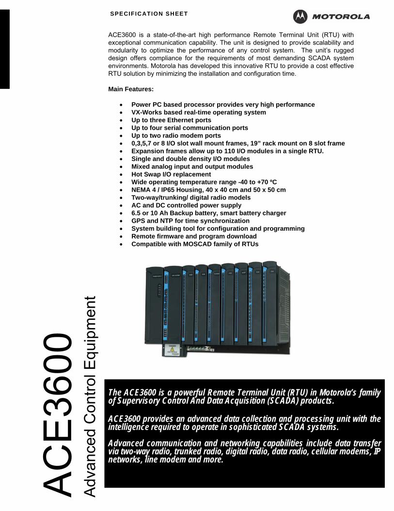
ACE3600 is a state-of-the-art high performance Remote Terminal Unit (RTU) with exceptional communication capability. The unit is designed to provide scalability and modularity to optimize the performance of any control system. The unit’s rugged design offers compliance for the requirements of most demanding SCADA system environments. Motorola has developed this innovative RTU to provide a cost effective RTU solution by minimizing the installation and configuration time. Main Features:
• Power PC based processor provides very high performance • VX-Works based real-time operating system • Up to three Ethernet ports • Up to four serial communication ports • Up to two radio modem ports • 0,3,5,7 or 8 I/O slot wall mount frames, 19” rack mount on 8 slot frame • Expansion frames allow up to 110 I/O modules in a single RTU. • Single and double density I/O modules • Mixed analog input and output modules • Hot Swap I/O replacement • Wide operating temperature range -40 to +70 ºC • NEMA 4 / IP65 Housing, 40 x 40 cm and 50 x 50 cm • Two-way/trunking/ digital radio models • AC and DC controlled power supply • 6.5 or 10 Ah Backup battery, smart battery charger • GPS and NTP for time synchronization • System building tool for configuration and programming • Remote firmware and program download • Compatible with MOSCAD family of RTUs
Adv
ance
d C
ontro
l Equ
ipm
ent
April 2009 Motorola reserves the rights to change the specifications without notice.
The ACE3600 is a powerful Remote Terminal Unit (RTU) in Motorola’s family of Supervisory Control And Data Acquisition (SCADA) products. ACE3600 provides an advanced data collection and processing unit with the intelligence required to operate in sophisticated SCADA systems. Advanced communication and networking capabilities include data transfer via two-way radio, trunked radio, digital radio, data radio, cellular modems, IP networks, line modem and more.

LOCAL INTELLIGENCE ACE3600 is a microprocessor-based RTU with large memory capacity that can make control decisions on-site, based on status conditions and values from local and remote sources. Local intelligence permits control decisions without the need for real-time messages from other supervisory centers; ACE3600 can operate in sophisticated control systems. PROGRAMMABLE ACE3600 uses an advanced symbolic ladder logic application language to develop the data base conditions, values, and RTU profile that must exist for each control action, message transmission, etc. to occur. Routines written in ‘C’ may be executed as a whole or part of the total application. Powerful applications may easily be defined using industry accepted ladder logic and ‘C’. The task is made easier by using the SCADA application development software and a PC-style computer. PROTOCOLS ACE3600 uses the OSI-based MDLC communication protocol for all data signaling. Third party MODBUS, DNP 3.0 DF1 (Allen Bradley) and IEC 60870-5 protocols are also supported. MDLC was specifically developed for radio use but is completely applicable to Ethernet, wireline, and other media. It permits large volumes of data to be quickly transferred between units using packet transmission techniques. The MDLC protocol enables adding the ACE3600 easily to existing MOSCAD systems where system expansion is required. COMMUNICATIONS ACE3600 permits communication to occur RTU-to-central and RTU-to-RTU (peer-to-peer). Communication may occur between individual units or may be broadcast to several units simultaneously. Store-&-forward may be employed to pass messages RTU-to-RTU throughout the system. Direct communication, where possible, or repeated messaging over one or multiple communication media, may be intermixed within the system. UPLOAD/DOWNLOAD ACE3600, via the MDLC data transfer capability, uploads the data collected and
calculated by the application program to a central site. It also receives downloaded changes to the application program and/or to the parameters that control how the application operates. The process being supervised does not need to be static; operational variables and limits, and the process definition itself, can be easily changed and transmitted to the RTU from anywhere in the system’s network. A unique feature of ACE3600, also enables remote firmware safe download from anywhere in the system’s network. This allows remote firmware upgrades. The above features minimize site visits by maintenance personnel after the unit’s initial installation. COMMUNICATION PORTS Connectors on the various CPU modules permit the connection for local application programming, or connection to other on-site devices to supervise their operation, and to the communication media device. Multiple connectors, multiple communication types, and variable data speeds allow practically all external data devices to be connected to the CPU module. CHASSIS AND ENCLOSURES ACE3600 can be provided on a metal chassis or in a painted steel NEMA 4 (IP56) rated outdoor enclosure that can hold the RTU frame, modules, battery and up to two radios (depending on enclosure size). An optional tamper switch can be ordered with the enclosure. 19” RACK MOUNT ACE3600 may be ordered with frame and mounting accessories that permit direct mounting onto standard 19” equipment racks. The frame contains space for power supply, CPU module and up to eight I/O modules. Optionally, a 19” metal chassis can be ordered for installation of backup battery, accessories and up to two radios. I/O EXPANSION The ACE3600 RTU can be expanded to include up to 110 I/O modules controlled from the CPU. The I/O expansion is based on Ethernet LAN connection between the CPU module and the I/O expansion frames. The I/O expansion frames can be co-located with RTU on the main frame (installed in the same 19” rack or cabinet) or distributed in the same site up to 50 meters from the main frame location.
April 2009 Motorola reserves the rights to change the specifications without notice.
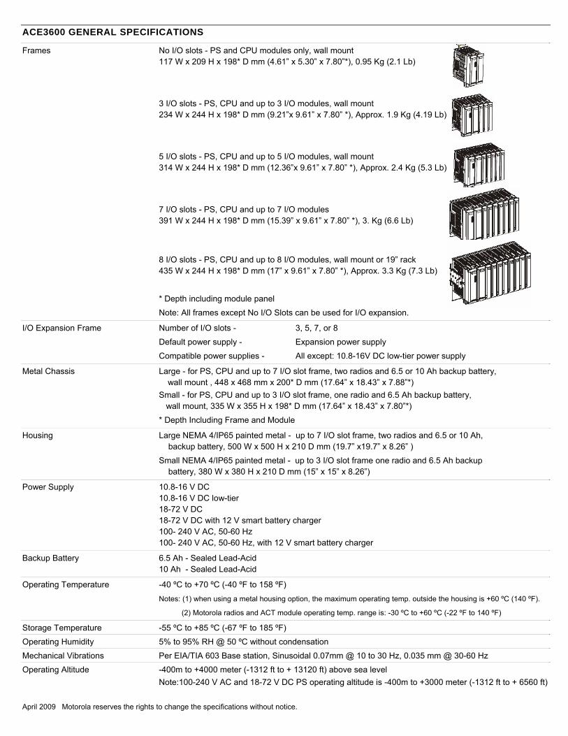
ACE3600 GENERAL SPECIFICATIONS
Frames No I/O slots - PS and CPU modules only, wall mount 117 W x 209 H x 198* D mm (4.61” x 5.30” x 7.80”*), 0.95 Kg (2.1 Lb)
3 I/O slots - PS, CPU and up to 3 I/O modules, wall mount 234 W x 244 H x 198* D mm (9.21”x 9.61” x 7.80” *), Approx. 1.9 Kg (4.19 Lb)
5 I/O slots - PS, CPU and up to 5 I/O modules, wall mount 314 W x 244 H x 198* D mm (12.36”x 9.61” x 7.80” *), Approx. 2.4 Kg (5.3 Lb)
April 2009 Motorola reserves the rights to change the specifications without notice.
7 I/O slots - PS, CPU and up to 7 I/O modules 391 W x 244 H x 198* D mm (15.39” x 9.61” x 7.80” *), 3. Kg (6.6 Lb)
8 I/O slots - PS, CPU and up to 8 I/O modules, wall mount or 19” rack 435 W x 244 H x 198* D mm (17” x 9.61” x 7.80” *), Approx. 3.3 Kg (7.3 Lb)
* Depth including module panel
Note: All frames except No I/O Slots can be used for I/O expansion.
I/O Expansion Frame Number of I/O slots - 3, 5, 7, or 8
Default power supply - Expansion power supply
Compatible power supplies - All except: 10.8-16V DC low-tier power supply
Metal Chassis Large - for PS, CPU and up to 7 I/O slot frame, two radios and 6.5 or 10 Ah backup battery, wall mount , 448 x 468 mm x 200* D mm (17.64” x 18.43” x 7.88”*)
Small - for PS, CPU and up to 3 I/O slot frame, one radio and 6.5 Ah backup battery, wall mount, 335 W x 355 H x 198* D mm (17.64” x 18.43” x 7.80”*)
* Depth Including Frame and Module
Housing Large NEMA 4/IP65 painted metal - up to 7 I/O slot frame, two radios and 6.5 or 10 Ah, backup battery, 500 W x 500 H x 210 D mm (19.7” x19.7” x 8.26” )
Small NEMA 4/IP65 painted metal - up to 3 I/O slot frame one radio and 6.5 Ah backup battery, 380 W x 380 H x 210 D mm (15” x 15” x 8.26”)
Power Supply 10.8-16 V DC 10.8-16 V DC low-tier 18-72 V DC 18-72 V DC with 12 V smart battery charger 100- 240 V AC, 50-60 Hz 100- 240 V AC, 50-60 Hz, with 12 V smart battery charger
Backup Battery 6.5 Ah - Sealed Lead-Acid 10 Ah - Sealed Lead-Acid
Operating Temperature -40 ºC to +70 ºC (-40 ºF to 158 ºF)
Notes: (1) when using a metal housing option, the maximum operating temp. outside the housing is +60 ºC (140 ºF).
(2) Motorola radios and ACT module operating temp. range is: -30 ºC to +60 ºC (-22 ºF to 140 ºF)
Storage Temperature -55 ºC to +85 ºC (-67 ºF to 185 ºF)
Operating Humidity 5% to 95% RH @ 50 ºC without condensation
Mechanical Vibrations Per EIA/TIA 603 Base station, Sinusoidal 0.07mm @ 10 to 30 Hz, 0.035 mm @ 30-60 Hz
Operating Altitude -400m to +4000 meter (-1312 ft to + 13120 ft) above sea level Note:100-240 V AC and 18-72 V DC PS operating altitude is -400m to +3000 meter (-1312 ft to + 6560 ft)

April 2009 Motorola reserves the rights to change the specifications without notice.
REGULATORY STANDARDS Safety UL 60950-1:2001
CSA 22.2-60950-1
IEC 60950-1
AS/NZS 60950
FM/cFM certified as Nonincendive Class I, Division 2 - standard FM 3611
(Note: FM approval refers to model F7509 only and most of the ACE3600 options.)
Emission Emission standards per:
CFR 47 FCC part 15, subpart B (class A)
EN55022:2003 Class A
EN61000-3-2
EN61000-3-3
Immunity Immunity standards for industrial environments per EN50082-2 /IEC 61000-6-2
IEC 61000-4-2
IEC 61000-4-3
IEC 61000-4-4
IEC 61000-4-5
IEC 61000-4-6
IEC 61000-4-8
IEC 61000-4-11
COMMUNICATIONS
Communication Ports: Up to 5 ports per CPU
Serial - up to 4 x RS-232 ports
Multi-drop – up to 3 x RS-485 ports
Ethernet - up to 2 x 10/100 MB ports and 1 x 10 MB port
Two-way radio/analog trunked radio - up 2 x modem ports
Motorola Radio Support Mobile conventional two-way radios - CM200, CM340, GM3188, EM200, CDM750
Portable conventional two way radios – HT750, GP320, GP328, PRO5150
Analog Trunk radios – XTL5000, XTL2500
Digital Trunk radios – XTL5000, XTL2500, XTS2500, MTM800 (Tetra)
Third Party Radio Support Two way radios, data radios, TETRA radio (PD)
Modem Support Dial-up modems, cellular modems (dial mode & PD)
Protocols MDLC, TCP, UDP, IP, PPP, NTP, DHCP
Third Party Protocol Support MODBUS RTU: master on RS-232 / RS-485 / Ethernet, slave on RS-232 / RS-485 / Ethernet DF1 (Allen Bradley): master on RS-232
DNP 3.0 Plus: master & slave on RS-232 / RS-485 / Ethernet
IEC 60870-5-101: slave on RS-232
User Protocol (user program) Possible on RS-232, RS-485 and Ethernet ports

April 2009 Motorola reserves the rights to change the specifications without notice.
CPU 3610/CPU 3640 MODULES SPECIFICATIONS
Microprocessor Freescale – Power PC II, MPC8720, 32-bit, extended communication capability, DMA and floating point calculation support
Microprocessor Clock 200 MHz
Memory Flash: 16 MB
DRAM: 32 MB
SRAM plug-in board (optional): 4 MB
Real-Time Clock Full calendar with leap year support (Year, Month, Day, Hours, Minutes, Seconds) Time drift: max. 2.5 seconds per day (when power is on)
SRAM and RTC Retention 3 V Rechargeable lithium backup battery
Serial Port 1 Configurable RS-232C or RS-485 port:
- RS-232C: A synch, Full Flow Control, up to 230.4 kb/s, GPS receiver interface
- RS-485, multi-drop 2-Wire up to 230.4 kb/s
Serial Port 2 RS-232C, Asynch, Full Flow Control, up to 230.4 kb/s, GPS receiver interface
Plug-In Port 1 Supports the following Plug-In ports: - Radio Modem, DPSK 1.2 kb/s, FSK 1.2 / 1.8 / 2.4 kb/s, DFM 2.4/3.6/4.8 kb/s
- RS-232, Sync/Asynch, Full Flow Control, up to 230.4 kb/s, GPS receiver interface
- RS-485, multi-drop 2-wire, up to 230.4 kb/s
- Ethernet 10/100 Mb/s
Plug-In Port 2 Supports the following Plug-In ports:
- Radio Modem, DPSK 1.2 kb/s, FSK 1.2 / 1.8 / 2.4 kb/s, DFM 2.4/3.6/4.8 kb/s and
- RS-232, Sync/Asynch, Full Flow Control, up to 230.4 kb/s, GPS receiver interface
- RS-485, multi-drop 2-Wire up to 230.4 kb/s
- Ethernet 10 Mb/s
Ethernet Port 1 10/100 Mb/s, (on CPU 3640 only)
LEDs Display 4 CPU diagnostics LEDS, port status LEDs and user application LEDs
Power Consumption See ACE3600 Maximum Power Ratings below.
Operating Voltage 10. 8 -16 V DC (from the motherboard connector)
Dimensions 56 mm W x 225 mm H x 180 mm D (2.2“ W x 8.7“ H x 7.1“ D)
Weight Approx. 0.38 Kg (0.84 Lb)
April 2009 Motorola reserves the rights to change the specifications without notice.
12 V DC POWER SUPPLY MODULE (DEFAULT)
Input Voltage 10.8 - 16 V DC
Outputs Motherboard connector (to CPU and I/O modules): equal to input voltage, max. 4 A AUX1A/AUX1B: equal to input voltage, max. 8 A, on/off controlled by user program
AUX2A/AUX2B (configurable): equal to input voltage (default), max. 8A,
or 3.3, 5, 7.5, 9 V DC ±10%, max. 2.5A, on/off controlled by user program
Note: max. 8 A total current consumption from all outputs
No Load power consumption Max. 50 mA
Diagnostics LEDs Status LED for: input voltage, AUX1 and AUX2 outputs, 12V control for DO modules
Input Protection Internal Line Fuse, replaceable
Output Protection AUX2A/B Short Circuit, automatic recovery on 3.3, 5, 7.5, 9 V
Dimensions 56 mm W x 225 mm H x 180 mm D (2.2“ W x 8.7“ H x 7.1“ D)
Weight Approx. 0.43Kg (0.95 Lb)
12 V DC LOW-TIER POWER SUPPLY MODULE
Input Voltage 10.8 - 16 V DC
Outputs Motherboard connector (to CPU and I/O modules): The same as input voltage / max. 4 A AUX1A/AUX1B: equal to input voltage max. 8A
Note: max. 8 A total current consumption from all outputs
Input Protection Internal Line Fuse, replaceable
Dimensions 56 mm W x 225 mm H x 180 mm D (2.2“ W x 8.7“ H x 7.1“ D)
Weight Approx. 0.4Kg (0.9 Lb)

April 2009 Motorola reserves the rights to change the specifications without notice.
18-72 V DC POWER SUPPLY MODULES
Input Voltage 18-72 V DC
Total Power 18-72 V DC: Max. 60 Watt continuous, Max. 105 Watt peak @ 25% duty cycle
Outputs Motherboard connector (to CPU and I/O modules): 13.2 V DC ±20%, max. 4 A AUX1A/AUX1B: equal to input voltage, max. 8 A, on/off controlled by user program
AUX2A/AUX2B (configurable): equal to input voltage (default), max. 8A,
or 3.3, 5, 7.5, 9 V DC ±10%, max. 2.5A, on/off controlled by user program
Note: max. 8 A total current consumption from all outputs
Battery Charger 12 V Lead-Acid battery charger (in PS model with charger)
Automatic charging of 6.5 or 10 Ah backup battery, battery temperature sensing, overcharging
protection, battery capacity test and diagnostics, automatic battery switch-over
Diagnostics LEDs Status LED for: input voltage, AUX1 and AUX2 outputs, 12V control for DO modules and battery
No Load power consumption Max. 250 mA
Efficiency 80% typical, 76% with full load
In-rush Current 10 A maximum, for 2 mSec. Max, cold start at 25°C
Protection Internal line input fuse (replaceable), Short Circuit automatic recover
Output Protection AUX2A/B Short Circuit, automatic recovery on 3.3, 5, 7.5, 9 V
Insulation Input to case: 500 V DC, input to output: 500 V DC
Dimensions 56 mm W x 225 mm H x 180 mm D (2.2“ W x 8.7“ H x 7.1“ D)
Weight Approx. 1Kg (2.2 Lb)

April 2009 Motorola reserves the rights to change the specifications without notice.
AC POWER SUPPLY MODULES
Input Voltage 100-240 V AC, 50/60 Hz
Total Power Max. 60 Watt continuous, Max. 105 Watt peak @ 25% duty cycle
Outputs Motherboard connector (to CPU and I/O modules): 13.2 V DC ±20%, max. 4 A AUX1A/AUX1B user connectors: 13.2V DC ±20%, max. 8 A, on/off controlled by user program
AUX2A/AUX2B: 13.2 V DC ±20%, max. 8A or 3.3, 5, 7.5, 9 V DC ±10% (configurable), max. 2.5A , on/off controlled by user program
Note: max. 8 A total current consumption from all outputs
Battery Charger 12 V Lead-Acid battery charger (in PS with charger)
Automatic charging of 6.5 or 10 Ah backup battery, battery temperature sensing, overcharging
protection, battery capacity test and diagnostics, automatic battery switch-over
Diagnostics LEDs Status LED for: input voltage, AUX1 and AUX2 outputs, 12V control for DO modules and battery
No Load power consumption 130 mA @ 220 V AC
Efficiency 80% typical @230 V AC, 76% typical @115 V AC (full load)
Inrush Current 25 A maximum, for 2 mSec. Max, cold start at 25°C
Power Factor 0.98 typical at 230 V AC, 0.99 typical at 115 V AC
Protection Internal Line Fuse, replaceable
Output Protection AUX2A/B Short Circuit, automatic recovery on 3.3, 5, 7.5, 9 V
Insulation Input to case: 1500 V AC, input to output: 3000 V AC
Dimensions 56 mm W x 225 mm H x 180 mm D (2.2“ W x 8.7“ H x 7.1“ D)
Weight Approx. 1Kg (2.2 Lb)
24 V DC PLUG-IN POWER SUPPLY
Input Voltage 10.8-16V (from I/O module)
Output 24V floating, max. 150 mA
Efficiency 75% typical
Protection Automatic output shut down on over-voltage and over-current
Insulation Input to output: 1500 V AC
Dimensions 78 mm W x 15 mm H x 68 mm D (3.1“ W x 0.6“ H x 2.7“ D)
Weight Approx. 0.04 Kg (0.09 Lb)
EXPANSION POWER SUPPLY
See below.
April 2009 Motorola reserves the rights to change the specifications without notice.
16/32 DI FAST 24 V MODULES
Total Number of Inputs 16 DI
32 DI
Input Arrangement Isolated groups of 16 inputs with shared common
Fast Counter Inputs Inputs that can be used as fast counters: - All inputs in 16 DI module
- First 20 inputs in 32 DI module
AC Input Frequency 45 – 65 Hz
AC Input Delay Maximum 0.2 mS
Fast Counter Input Frequency 0 - 12.5 KHz, minimum pulse width 40 µS
Max. DC Input Voltage Max. ±40 V DC (relative to input common)
“ON” DC Voltage Range +9 to +30 V DC, -30 to -9 V DC
“OFF” DC Voltage Range -3 to +3 V DC
“ON” AC Voltage Range 10 to 27 V AC (RMS)
“OFF” AC Voltage Range 0 to 5 V AC (RMS)
Input Current Max. 3.5 mA
Fast Capture Resolution 1 mS (Interrupt upon change of state)
Event Time Tagging Resolution 1 mS (Interrupt upon change of state)
Input Filtering 0 to 50.8 mS (DC, programmable in 0.2 mSec steps)
Counter Input Filtering 0 to 12.75 mS
(Programmable in 0.05 mSec steps for inputs configured as high speed counters)
24 V DC Output Supports optional isolated 24 V plug-in “Wetting” Power Supply
(One in 16 DI, two in 32 DI)
Diagnostics LEDs Status LED per each input, module error LED, Plug-In 24V status LED
User Connection 2 or 4 Terminal Blocks (3.5mm pitch), Maximum 18 AWG
Cable & TB Holder 20 or 40 Wire cable with Terminal Block Holder connector, 26 AWG wires
Module Replacement Hot swap replacement – module extraction/insertion under voltage
Input Isolation 2.5 k V RMS between input and module logic per IEC60255-5
Input Insulation Insulation resistance 100 MΩ @ 500 V DC, per IEC60255-5
Operating Voltage 10.8 -16 V DC and 3.3 V DC (from the motherboard connector)
Power Consumption See ACE3600 Maximum Power Ratings below.
Dimensions 37 mm W x 225 mm H x 180 mm D (1.5“ W x 8.7“ H x 7.1“ D)
Weight 16 DI: approx. 0.28 Kg (0.62 Lb), 32 DI: approx. 0.29 Kg (0.63 Lb)

April 2009 Motorola reserves the rights to change the specifications without notice.
16/32 DIGITAL INPUT FAST 24 V IEC 61131-2 TYPE II MODULES
Total Number of Inputs 16 DI
32 DI
Input Arrangement Isolated Groups of 16 inputs with shared common
Fast Counter Inputs Inputs that can be used as fast counters: - All inputs in 16 DI
- First 20 inputs in 32 DI
Fast Counter Input Frequency 0 - 10 KHz, minimum pulse width 50 µS
Max. DC Input Voltage Max. ±40 V DC
“ON” DC Voltage Range +11 to +30 V DC, -30 to -11 V DC
“OFF” DC Voltage Range -5 to +5 V DC
Input Current 6-10 mA
Fast Capture Resolution 1 mS (Interrupt upon change of state)
Event Time Tagging Resolution 1 mS (Interrupt upon change of state)
Input Filtering 0 to 50.8 mS (DC, programmable in 0.2 mSec steps)
Counter Input Filtering 0 to 12.75 mS
(Programmable in 0.05 mSec steps for inputs used as high speed counters)
24 V DC Output Supports isolated 24 V plug-in “Wetting” Power Supply
(one in 16 DI, two in 32 DI)
Diagnostics LEDs LED per each input status, module error LED, 24V Plug-In status LED
User Connection 2 or 4 Terminal Blocks (3.5mm pitch), Maximum 18 AWG
Cable & TB Holder 20 or 40 Wire Cable with Terminal Block Holder connector, 26 AWG
Module Replacement Hot swap replacement– module extraction/insertion under voltage
Input Isolation 2.5 kV RMS between input and module logic per IEC60255-5
Input Insulation Insulation resistance 100 MΩ @ 500 V DC, per IEC60255-5
Operating Voltage 10.8 -16 V DC and 3.3 V DC (from the motherboard connector)
Power Consumption See ACE3600 Maximum Power Ratings below.
Dimensions 37 mm W x 225 mm H x 180 mm D (1.5“ W x 8.7“ H x 7.1“ D)
Weight 16 DI: approx. 0.28 Kg (0.62 Lb), 32 DI: approx. 0.29 Kg (0.63 Lb)
April 2009 Motorola reserves the rights to change the specifications without notice.
16 DIGITAL INPUT 120/230V MODULE
Total Number of Inputs 16 DI
Input Characteristics IEC 61131-2 Type 1
Input Arrangement Two isolated groups of 6 inputs and one isolated group of 4 inputs.
AC Input Frequency 47 - 63 Hz
AC Input Delay Maximum 25.0 mS
Max. DC Input Voltage Max. ±264 V DC (relative to input common)
“ON” DC Voltage Range +79.0 V DC to +264.0 V DC, -79.0 V DC to -264.0 V DC
“OFF” DC Voltage Range -40 to +40 V DC
“ON” AC Voltage Range 79.0 to 264.0 V AC (RMS)
“OFF” AC Voltage Range 0 to +40 V AC (RMS)
Input Current At 110VDC 1.0 to 3.0 mA
At 230VDC 0.4 to 2.0 mA
At 110VAC > 2.0 mA RMS
At 230VAC > 3.0 mA RMS
Input Filtering 0 to 50.8 mS (DC, programmable in 0.2 mSec steps), minimum effective filter value - 7.0 msec.
Diagnostics LEDs LED per each input status, module error LED
User Connection 3 Terminal Blocks (5.00mm pitch), Maximum 14 AWG
Cable & TB Holder 30 Wire Cable with Terminal Block Holder connector, 20 AWG wires
Module Replacement Hot swap replacement– module extraction/insertion under voltage
Input Isolation 2.5 kV RMS between input and module logic per IEC60255-5
Input Insulation Insulation resistance 100 MΩ @ 500 V DC
Operating Voltage 10.8 -16 V DC and 3.3 V DC ±10% (from the motherboard connector)
Power Consumption See ACE3600 Maximum Power Ratings below.
Dimensions 37 mm W x 225 mm H x 180 mm D (1.5“ W x 8.7“ H x 7.1“ D)
Weight approx. 0.367 Kg (0.80 Lb)

April 2009 Motorola reserves the rights to change the specifications without notice.
8/16 RELAY OUTPUT MODULES Total Number of Outputs 8 EE relay outputs
16 EE relay outputs
8 ML relay outputs
16 ML relay outputs
Output Arrangement 8 DO: 3 X Form C (SPDT) and 5 X Form A (SPST)
16 DO: 6 X Form C (SPDT) and 10 X Form A (SPST)
Contact Voltage Ratings Max. 60 V DC, or 30 V AC RMS (42.4 V peak).
Contact Power Ratings 2A @ 30 V DC, 0.6A @ 60V DC or 0.6A @ 30V AC (resistive load)
Relay Back Indication Contact position - hardware back indication
DO Frequency Max. 10 Hz
Diagnostics LEDs LED per each output status, module error LED
User Connection 2 or 4 Terminal Blocks (3.5mm pitch), Maximum 18 AWG
Cable & TB Holder 20 or 40 Wire Cable with Terminal Block Holder connector, 26 AWG
Fail State Configurable relay state on CPU fail: On, Off or ‘last value’
All Relays Disable/Enable Selectable per module, controlled from the power supply
Module Replacement Hot swap replacement– module extraction/insertion under voltage
Output Isolation Between open contacts: 1kV, between contact and coil: 1.5 kV, between contact sets: 1.5 kV
Insulation Insulation resistance 100 MΩ @ 500 V DC per IEC60255-5,
Insulation impulse 1.5 kV per IEC60255-5
Operating Voltage 10.8 -16 V DC and 3.3 V DC (from the motherboard connector)
Power Consumption See ACE3600 Maximum Power Ratings below.
Dimensions 37 mm W x 225 mm H x 180 mm D (1.5“ W x 8.7“ H x 7.1“ D)
Weight 8 DO: approx. 0.29 Kg (0.64 Lb), 16 DO: approx. 0.32 Kg (0.7 Lb)

April 2009 Motorola reserves the rights to change the specifications without notice.
12 RELAY OUTPUT 120/230V MODULES Total Number of Outputs 12 EE relay outputs
12 ML relay outputs
Output Arrangement 12 x 1 Form A
Contact Power Ratings 3A @ 250 V AC, 3A @ 30 V DC, or 0.20A @ 125 V DC (resistive load).
Minimum Contact Load Current 10.0 mA @+5.00 V DC.
Maximum Switching Current 3.00 A
Relay Back Indication Contact position - hardware back indication
DO Frequency Max. 10 Hz (resistive load)
Diagnostics LEDs LED per each output status, module error LED
User Connection 3 Terminal Blocks (5.00mm pitch), Maximum 14 AWG
Cable & TB Holder 30 Wire Cable with Terminal Block Holder connector, 20 AWG wires
Fail State Configurable relay state on CPU fail: On, Off or ‘last value’
All Relays Disable/Enable Selectable per module, controlled from the power supply
Module Replacement Hot swap replacement– module extraction/insertion under voltage
Output Isolation Between output and module logic: 2.5 kV, per IEC60255-5
Insulation Insulation resistance 100 MΩ @ 500 V DC per IEC60255-5,
Insulation impulse 5 kV per IEC60255-5
Operating Voltage 10.8 -16 V DC and 3.3 V DC ±10% (from the motherboard connector)
Power Consumption See ACE3600 Maximum Power Ratings below.
Dimensions 37 mm W x 225 mm H x 180 mm D (1.5“ W x 8.7“ H x 7.1“ D)
Weight approx. 0.423 Kg (0.90 Lb)
April 2009 Motorola reserves the rights to change the specifications without notice.
8/16 ANALOG INPUT MODULES
Total Number of Inputs 8 AI, ±20 mA
16 AI, ±20 mA
8 AI, ±5 V
16 AI, ±5 V
Input Configuration Isolated (floating) analog inputs
A to D Resolution 16 Bit (including sign)
Input Accuracy ±0.1% of full scale
Input Sampling Time 10 mSec @ 50 Hz filtering
8.33 mSec @ 60 Hz filtering
Smoothing Selectable input averaging: 1, 2, 4, 8, 16, 320, 64 or 128 samples (x10 mS)
Permitted potential between Inputs 75 V DC, 60 V AC (RMS)
Input Impedance ±20 mA input: Rin < 250 Ω ±5 V input: Rin > 1 MΩ
Crosstalk Rejection Better than 80 dB between any pair of inputs
Temperature Stability Better than ±25 PPM/ºC
Interference Suppression Selectable 50 or 60 Hz filtering,
Common mode rejection > 80 dB,
Differential mode rejection > 50 dB
24 V DC Output Supports optional isolated 24V Plug-in Power Supply (one in 8 DI, two in 16 DI)
Diagnostics LEDs Overflow and Underflow LED per each input, module error LED, 24V Plug-In status LED
The module Overflow and Underflow levels can be configured to:
Current inputs: ±20mA/4-20 mA
Voltage inputs: ±5 V/0-5 V/1-5 V
User Connection 2 or 4 Terminal Blocks (3.5mm pitch), Maximum 18 AWG
Cable & TB Holder 20 or 40 Wire Cable with Terminal Block Holder connector, 26 AWG
Module Replacement Hot swap replacement– module extraction/insertion under voltage
Input Isolation 1.5 kV RMS between input and module logic, per IEC60255-5
Input Insulation Insulation resistance 100 MΩ @ 500 V DC, per IEC60255-5
Operating voltage 10.8-16 V DC and 3.3 V DC (from the motherboard connector)
Power Consumption See ACE3600 Maximum Power Ratings below.
Dimensions 37 mm W x 225 mm H x 180 mm D (1.5“ W x 8.7“ H x 7.1“ D)
Weight 8 AI: approx. 0.32 Kg (0.71 Lb), 16 AI: approx. 0.34 Kg (0.75 Lb)

April 2009 Motorola reserves the rights to change the specifications without notice.
4 ANALOG OUTPUT MODULE
Total Number of Outputs 4
Output Configuration Isolated floating channels, each channel can be connected as 0 -20 mA or 0-10 V DC voltage
D to A Resolution 14 Bit
Output Accuracy ±0.1% of full scale @25°C
Temperature Stability Better than ±25 PPM/°C
Internal Settling Time Max. 1 ms
Output Load Voltage: > 1.0 kΩ, < 1.0 µf, Current: < 750 Ω (internal power source)
Crosstalk Rejection Better than 50 dB between any pair of outputs
Interference Suppression Common Mode Rejection: > 60 dB
Output protection Voltage output: short-circuit current, max. 30 mA
Current output: No-load voltage max. 22 V DC
Diagnostics LEDs Module Error LED. Voltage mode LED, Current mode LED, Calibration LED per channel
User Connection 2 Terminal Blocks (3.5mm pitch), Maximum 18 AWG
Cable & TB Holder 20 Wire Cable with Terminal Block Holder connector, 26 AWG
Module Replacement Hot swap replacement– module extraction/insertion under voltage
Isolation 1.5 kV between output and module logic
Insulation Insulation resistance 100 MΩ @ 500 V DC, per IEC60255-5
Operating voltage 10.8 -16 V DC and 3.3 V DC (from the motherboard connector)
Power Consumption See ACE3600 Maximum Power Ratings below.
Dimensions 37 mm W x 225 mm H x 180 mm D (1.5“ W x 8.7“ H x 7.1“ D)
Weight 0.29 Kg (0.64 Lb)

April 2009 Motorola reserves the rights to change the specifications without notice.
MIXED 4 ANALOG OUTPUT 8 ANALOG INPUT MODULES Total Number of I/Os 4 AO + 8 AI (AI: ±20 mA or ±5 V DC)
I/O Arrangement AO - each channel can be connected as 0 -20 mA or 0-10 V, AI - Isolated (floating) analog inputs
AO D to A Resolution 14 Bit
AO Accuracy ±0.1% of full scale @25°C
AO Temperature Stability Better than ±25 PPM/°C
AO Internal Settling Time Max. 1 ms
AO Load Voltage: > 1.0 kΩ, < 1.0 µf, Current: < 750 Ω
AO Crosstalk Rejection Better than 50 dB between any pair of outputs
AO Interference Suppression Common Mode Rejection: > 60 dB
AO Voltage Output Protection Short-circuits protection, max. 30 mA
(all other operating channels remain fully functional)
AO Current output no-load voltage Max. 22 V DC
AO Isolation 1.5 kV between output and module logic
AO Insulation Insulation resistance 100 MΩ @ 500 V DC, per IEC60255-5
AI A to D Resolution 16 Bit (including sign)
AI Accuracy ±0.1% of full scale @ -40ºC to +70ºC
AI Sampling Time 10 mSec @ 50 Hz filtering
8.33 mSec @ 60 Hz filtering
AI Smoothing Selectable input averaging: 1, 2, 4, 8, 16, 32, 64 or 128 samples (x10 mS)
Permitted Potential between Inputs 75 V DC, 60 V AC (RMS)
AI Input Impedance ±20 mA input: Rin < 250 Ω ±5 V input: Rin > 1 MΩ
AI Crosstalk Rejection Better than 80 dB between any pair of inputs
AI Temperature Stability Better than ±25 PPM/ºC
AI Interference Suppression Selectable 50 or 60 Hz filtering,
Common mode rejection > 80 dB,
Differential mode rejection > 50 dB
24 V DC Output Supports one optional isolated 24V Plug-in Power Supply
Diagnostics LEDs AO - Voltage mode LED, Current mode LED, Calibration LED per channel
AI - Overflow and Underflow LED per each input, 24V Plug-in status LED
The module Overflow and Underflow levels can be configured to: ±20mA/4-20 mA or ±5 V/0-5 V/1-5 V General - Module error LED
AI Input Isolation 1.5 kV between input and module logic
AI Input Insulation Insulation resistance 100 MΩ @ 500 V DC, per IEC60255-5
User Connection 4 Terminal Blocks (3.5mm pitch), Maximum 18 AWG
Cable & TB Holder 40 Wire Cable with Terminal Block Holder connector, 26 AWG
Module Replacement Hot swap replacement– module extraction/insertion under voltage
Operating Voltage 10.5-16 V DC and 3.3 V DC (from the motherboard connector)
Power Consumption See ACE3600 Maximum Power Ratings below.
Dimensions 37 mm W x 225 mm H x 180 mm D (1.5“ W x 8.7“ H x 7.1“ D)
Weight Approx. 0.34 Kg (0.75 Lb)
April 2009 Motorola reserves the rights to change the specifications without notice.
16/32 DIGITAL OUTPUT/DIGITAL INPUT MODULES (16/32 DO/DI)
Total Number of Inputs/Outputs 16/32
I/O Arrangement 2/4 groups of 8 I/Os with shared common
Each group can be configured to function as FET DO or dry contact DI
Counter Inputs 20 first inputs can be used as counter inputs
Counter Input Frequency 0 - 1 KHz, minimum pulse width 500 µS
Max. DC Input Voltage Max. 30 V DC (relative to input common)
Input “ON” Resistance 0-4 kΩ
Input “OFF” Resistance ≥50 kΩ
Fast Capture Resolution 1 mS (Interrupt upon change of state)
Event Time Tagging Resolution 1 mS (Interrupt upon change of state)
Input Current Max. 0.3 mA (when the input is shorted)
Input Filtering 0 to 50.8 mS (programmable in 0.2 mSec steps) Not relevant, minimum allowed is 1mSec
Counter Input Filtering 0 to 12.75 mS (programmable in 0.05 mSec steps) Not relevant, minimum allowed is 1mSec
Output Type MOSFET
Output Voltage Range 5-30 V DC (user-supplied voltage)
DO Frequency Max. 1 KHz (resistive load)
DO Output current Max. 500 mA sink current (resistive load)
Output Fail State Configurable output state on CPU fail: On, Off or ‘last value’
Diagnostics LEDs LED per each input/output status, module error LED
User Connection 4 Terminal Blocks (3.5mm pitch), Maximum 18 AWG
Cable & TB Holder 20 or 40 Wire Cable with Terminal Block Holder connector, 26 AWG
Module Replacement Hot swap replacement– module extraction/insertion under voltage
Input/Output Isolation 2.5 kV between input/output and module logic
Input Insulation Insulation resistance 100 MΩ @ 500 V DC per IEC60255-5
Operating Voltage 10.8-16 V DC and 3.3 V DC (from the motherboard connector)
Power Consumption See ACE3600 Maximum Power Ratings below.
Dimensions 37 mm W x 225 mm H x 180 mm D (1.5“ W x 8.7“ H x 7.1“ D)
Weight Approx. 0.25 Kg (0.55 Lb)

April 2009 Motorola reserves the rights to change the specifications without notice.
MIXED I/O 16DI + 4DO + 4AI MODULES Total Number of Inputs/Outputs 16 Digital Inputs + 4 EE Relay Outputs + 4 Analog Inputs, ±20 mA
16 Digital Inputs + 4 ML Relay Outputs + 4 Analog Inputs, ±20 mA
I/O Arrangement 1 group of 16 DIs with shared common, 4 relay outputs - Form C, 4 isolated analog inputs
DI Counter Inputs The first 12 inputs can be configured as fast counters.
DI Frequency 0 - 1 KHz
DI Fast Counter Frequency 0 - 5 KHz minimum pulse width 100 µS
DI Max. DC Voltage Max. 40 V DC
DI “ON” DC Voltage Range +11 to +30 V DC, -30 to -11 V DC
DI “OFF” DC Voltage Range -5 to +5 V DC
DI Current 6-10 mA
Fast Capture Resolution 1 mS (Interrupt upon change of state)
Event Time Tagging Resolution 1 mS (Interrupt upon change of state)
DI Filtering 0 to 50.8 mS (DC, programmable in 0.2 mSec steps)
DI Counter Filtering 0 to 12.75 mS (programmable in 0.05 mSec steps for inputs configured as high speed counters)
DO Contact Voltage Ratings Max. 60 V DC or 30 V AC RMS (42.4 V peak).
DO Contact Power Ratings 2A @ 30 V DC, 0.6A @ 60V DC or 0.6A @ 30V AC (resistive load)
DO Relay Back Indication Contact position - hardware back indication
DO Fail State Configurable relay state on CPU fail: On, Off or ‘last value’
AI Resolution 16 Bit (including sign)
AI Accuracy ±0.1% @ -40ºC to +70ºC
AI Sampling time 10 mSec @ 50 Hz filtering, 8.33 mSec @ 60 Hz filtering
AI Smoothing Selectable input averaging: 1, 2,4,8, 16, 32, 64 or 128 samples (x10 mS)
AI max. Potential between AIs 75 V DC, 60 V AC (RMS)
AI Impedance Rin < 250 Ω
AI Crosstalk Rejection Better than 80 dB between any pair of inputs
AI Temperature Stability Better than ±25 PPM/ºC
AI Interference Suppression Selectable 50 or 60 Hz filtering, common mode rejection > 80 dB, differential mode rejection > 50 dB
Diagnostics LEDs LED per each input/output status, module error LED, 24V Plug-in status LED
24 V DC Output Supports one isolated 24V plug-in ”Wetting” Power Supply
User Connection 4 Terminal Blocks (3.5mm pitch), Maximum 18 AWG
Cable & TB Holder 40 Wire Cable with Terminal Block Holder connector, 26 AWG
Module Replacement Hot swap replacement– module extraction/insertion under voltage
Input / Output Isolation DI: 2.5 kV RMS between input and module logic per IEC60255-5 DO: Between open contacts: 1kV, between output and module logic: 1.5 kV, per IEC60255-5
AI: 1.5 kV between input and module logic per IEC60255-5
Input Insulation Insulation resistance 100 MΩ @ 500 V DC per IEC60255-5
Operating Voltage 10.8-16 V DC and 3.3 V DC (from the motherboard connector)
Power Consumption See ACE3600 Maximum Power Ratings below.
EE Relay on : 0.2 W typical (15 mA @ 13.8 V DC at PS)
(Not including 24 V Plug-in Power Supply)
Dimensions 37 mm W x 225 mm H x 180 mm D (1.5“ W x 8.7“ H x 7.1“ D)
Weight Approx. 0.31 Kg (0.68 Lb)

April 2009 Motorola reserves the rights to change the specifications without notice.
EXPANSION POWER SUPPLY MODULE Input Voltage DC 10.8-16 V
Outputs To Motherboard connector – +10.80 to +16.00 VDC, max. 4A
To cascaded expansion power supply - +10.80 to +16.00 VDC, max. 8A
Over Current Protection 4.0 A (Slow blow fuse), protecting the expansion frame 8.0 A (Slow blow fuse), protecting the cascaded expansion power supply
Maximum Current via Power IN/OUT circuit 8.0 A (Slow blow fuse)
Over Voltage Protection +17.00 ±1 VDC (protecting the expansion frame)
Absolute Maximum Voltage +18.00 VDC
Dimensions 56 mm W x 225 mm H x 180 mm D (2.2" W x 8.7" H x 7.1" D)
Weight Approx. 0.43Kg (0.94 Lb)
EXPANSION MODULE Microprocessor Freescale – Power PC II, MPC8720, 32-bit
Microprocessor Clock 200 MHz
Serial Port RS232C Asynch, Full Flow Control port, up to 230.4 kb/s; used for STS only
Ethernet Port 10/100 Mb/s – connection to the main frame
LAN Cable Category 5E shielded (FTP), up to 50 meter
LEDs Display 4 CPU diagnostic LEDs, Port status LEDs and Expansion Address LEDs
Power Consumption See ACE3600 Maximum Power Ratings below.
Operating Voltage 10.8-16 V DC (from the motherboard connector)
Dimensions 56 mm W x 225 mm H x 180 mm D (2.2" W x 8.7" H x 7.1" D)
Weight Approx. 0.38 Kg (0.84 Lb)
EXPANSION LAN SWITCH Ethernet Port 1-8 8 on board 10/100 Mb/s Ethernet ports (Auto crossover)
LEDs Display Error LED, Port status LEDs
Power Consumption See ACE3600 Maximum Power Ratings below.
Module Replacement Hot swap replacement – module extraction/insertion under voltage
Operating Voltage (from the motherboard connector) 10.8-16 V DC, 3.30 VDC +/-10%
User Connection (Ethernet Ports) 8 shielded RJ45 connectors
LAN Cable Category 5E shielded (FTP), up to 50 meter
Operating Voltage 10.8-16 V DC (from the motherboard connector)
Dimensions 37 mm W x 225 mm H x 180 mm D (1.5" W x 8.7" H x 7.1" D)
Weight Approx 0.32 Kg (0.7 Lb)

April 2009 Motorola reserves the rights to change the specifications without notice.
ACE3600 MAXIMUM POWER RATINGS The tables below list the typical maximum power consumption (at room temperature) for each of the ACE3600 RTU building blocks (CPU, Power Supply, I/O modules, radios, etc.) and the maximum peak power allowed for a fully loaded RTU, based on the housing type.
The values in the tables below are derived by using the power supply (AC: 100 to 240 VAC or DC: 18 to 72 VDC and 13.8 VDC) and have the power supply efficiency factor included in them.
Before deploying your RTU, add up the power consumption of all components of your system to verify that it is within the maximum peak power for your housing type. In systems with I/O expansion, consider all modules which consume power from their respective AC/DC main power sources when calculating the required power requirements.
Maximum Peak Power Allowed for Fully Loaded RTU
Housing Type Description Maximum Input Power into Power Supply Module (Watts) 19" Rack (w/out metal enclosure) 100
Large NEMA metal housing (50x50 cm) 120*
Small NEMA metal housing (40x40 cm) 105*
Power Consumption per RTU Module
Module Name Self Power Consumption, no active I/O
(Watts)
Maximum Power Consumption, per Active I/O
(Watts)
Self Power Consumption, no active I/O
(Watts)
Maximum Power Consumption, per Active I/O
(Watts)
Maximum Power Consumption,
all I/Os, LEDs Active
(Watts)
AC: 100 to 240 VAC DC: 18 to 72 VDC
Vin = +13.8 VDC
Power Supply (maximum)
12.60 N/A 2.20 (156 mA) (12 VDC Power Supply Module ONLY)
N/A N/A
Power Supply (Expansion)
0.0 N/A 0.0 N/A N/A
CPU (3640/3610) 5.20 N/A 4.20 (304 mA) N/A 4.00 (290 mA)
Expansion Module 5.20 N/A 4.20 (304 mA) N/A 4.00 (290 mA)
Expansion LAN Switch
1.50 0.220 1.20 (87 mA) 0.176 (12.75 mA) 3.10 (225 mA) (x8 ports ON)
Digital Input Fast 24V (x16/x32)
0.100 0.100 (powered by internal 24V PS)
0.080 (5.8 mA) 0.100 (7 mA) (powered by internal 24V PS)
3.50 (254 mA) (x32 inputs ON powered by x1 internal 24V PS)
Digital Input Fast 24V IEC Type 2 (x16/x32)
0.100 0.230 (powered by internal 24V PS)
0.080 (5.8 mA) 0.230 (17 mA) (powered by internal 24V PS)
8.20 (594 mA) (x32 inputs ON powered by x2 internal 24V PS)
Digital Input 120/230V
0.100 0.015 0.080 (5.8 mA) 0.012 (1 mA) 0.524 (38 mA) (x16 inputs ON)
Digital Output ML Relay (x8/x16)
0.120 0.010 0.100 (7.2 mA) 0.008 (0.5 mA) 0.483 (35 mA) (x16 relays ON)
Digital Output EE Relay (x8/x16)
0.170 0.200 0.136 (10 mA) 0.160 (11.6 mA) 3.26 (236 mA) (x16 relays ON)
Digital Output ML Relay 120/230V
0.200 0.006 0.160 (11.6 mA) 0.005 (0.4 mA) 0.248 (18.0 mA) (x12 relays ON)
Digital Output EE Relay 120/230V
0.290 0.260 0.232 (17 mA) 0.210 (0.15 mA) 3.12 (226 mA) (x12 relays ON)

April 2009 Motorola reserves the rights to change the specifications without notice.
Module Name
Self Power Consumption, no active I/O
(Watts)
Maximum Power Consumption, per Active I/O
(Watts)
Self Power Consumption, no active I/O
(Watts)
Maximum Power Consumption, per Active I/O
(Watts)
Maximum Power Consumption,
all I/Os, LEDs Active
(Watts)
AC: 100 to 240 VAC DC: 18 to 72 VDC
Vin = +13.8 VDC
FET Digital Output/Digital Input
0.120 DI = 0.014 (per input channel)
DO = 0.014 (per output channel)
0.100 (7.2 mA) DI = 0.011 (per input channel)
DO = 0.011 (per output channel)
0.552 (40 mA) (x32 LEDs/ inputs ON)
Mixed I/O (DO ML +DI IEC Type 2)
0.480 DI = 0.250 (powered by internal 24V PS)
DO = 0.010
0.384 (28 mA) DI = 0.250 (powered by internal 24V PS)
DO = 0.008
4.70 (341 mA) (x4 relays ON, x16 inputs ON, x4 AI ON, powered by internal 24V PS)
Mixed I/O (DO EE + DI IEC Type 2)
0.480 DI = 0.250 (powered by internal 24V PS)
DO = 0.200
0.384 (28 mA) DI = 0.250 (powered by internal 24V PS)
DO = 0.160
5.50 (400 mA) (x4 relays ON, x16 inputs ON, x4 AI ON, powered by internal 24V PS)
Analog Output 1.10 0.600 (per output channel @20.0 mA)
0.880 (64 mA) 0.480 (35 mA) (per output channel @20.0 mA)
3.33 (241 mA) (x4 outputs sourcing 20.0 mA)
Mixed Analog Current/Voltage
1.40 0.600 (per output channel @20.0 mA)
1.12 (81 mA) 0.480 (35 mA) (per output channel @20.0 mA)
3.61 (261 mA) (x4 outputs sourcing 20.0 mA)
Analog Input Current/Voltage (x8/x16)
0.530 N/A 0.440 (32.0 mA) N/A 0.870 (63.0 mA)
24V Floating Plug-In Power Supply (No load)
0.410 N/A 0.328 (24 mA) N/A N/A
24V Floating Plug-In Power Supply (externally loaded 150 mA)
4.80 N/A 3.84 (278 mA) N/A N/A

April 2009 Motorola reserves the rights to change the specifications without notice.
Ordering Information
Note: For detailed ordering information, refer to the ACE3600 Catalog. ACE3600 MODELS
All RTU models include no I/O slots frame, 10.8-15.5 V DC PS and CPU3610. All radio models require Metal Chassis or Housing option. No Radio Model
• ACE3600 Basic Model No Radio F7509 Conventional VHF Radio Models
• ACE3600 CM200/CM140/EM200/GM3188 VHF F7573 • ACE3600 with CDM750 136-174 MHz F7563 • ACE3600 with HT750/GP320/GP328 /PRO5150 VHF F7553
Conventional UHF Radio Models
• ACE3600 with CM200/CM140/EM200/GM3188 UHF F7574 • ACE3600 with CDM750 403-512 MHz F7564 • ACE3600 with HT750/GP320/GP328 /PRO5150 UHF F7554
Analog Trunked VHF Radio Models
• ACE3600 with XTL2500 136-174 MHz Analog F7533 • ACE3600 with XTL2500 136-174 MHz Digital F7593 • ACE3600 with XTS2500 136-174 MHz Digital F7543
Trunked UHF Radio Models
• ACE3600 with XTL2500 380-520 MHz Analog F7534 • ACE3600 with XTL2500 380-520 MHz Digital F7594 • ACE3600 with XTS2500 380-520 MHz Digital F7544
Trunked 800 MHz Radio Models
• ACE3600 with XTL2500 800 MHz Analog F7538 • ACE3600 with XTL2500 800 MHz Digital F7598 • ACE3600 with XTS2500 800 MHz Digital F7548
I/O Expansion
• ACE3600 Expansion Frame Unit F7510 Software Tools
• ACE3600 System Tools Suite (STS) F7500 • ACE3600 C Toolkit (CTK) F7600 • ACE3600 Enhanced PID FVN5680
STS add-on Software
• ACE3600 AGA 7+8 CD FVN5510 • ACE3600 DNP 3.0 Plus Master Drivers CD FVN5511 • ACE3600 DNP 3.0 Plus Slave Drivers CD FVN5512 • ACE3600 IEC60870-5-101 Slave driver CD FVN5513

April 2009 Motorola reserves the rights to change the specifications without notice.
ACE3600 OPTIONS Regional Radio Options CM200/CM140/EM200/CM3188
One of the following options must be ordered for models F7573 and F7574: • CM200 V851 • CM140 V852 • GM3188 V853 • EM200 V854
HT750/GP320/GP328/PRO5150
One of the following options must be ordered for models F7553 and F7554. • HT750 V951 • GP320 V952 • GP328 V953 • PRO5150 V954
Frames
• 3 I/O slots frame V103 • 5 I/O slots frame V105 • 7 I/O slot frame V107 • 8 I/O slots frame V108 • 19" rack brackets for 8 I/O slots frame V051
Metal Chassis
• 48 x 48 cm Metal Chassis (up to 7 I/O slots) V056 • 38 x 38 cm Metal Chassis (up to 3 I/O slots) V214 • 8 I/O (19”) Metal Chassis V269
Housing
• 50 x 50 cm Metal Housing (up to 7 I/O slots) V228 • 50 x 50 cm Metal Housing with padlock accessory VA00405 • 40 x 40 cm Metal Housing (up to 3 I/O slots) V276 • 40 x 40 cm Metal Housing with padlock accessory VA00406 • Housing Tamper Switch V224
Power Supply, Battery Charger and Backup Battery Note: The default PS is 10.8-16 V DC input
• AC Power Supply 100-240 V V346 • AC PS 100-240 V with Battery charger V261 • DC Power Supply 18-72 V V251 • DC PS 18-72 V with Battery charger V367 • DC Low Tier PS 10.8 -16 V V149 • 6.5 Ah Backup Battery V114 • 10 Ah Backup Battery V328
CPU Upgrade Note: The default CPU is CPU3610
• ACE CPU3640 V446 CPU Plug-in Ports / Memory
• Plug-in RS-232 Port V184 • Plug-in RS 485 Port V440 • Plug-in Ethernet 10 M Port V204 • Plug-in Ethernet 10/100 M Port V212 • Plug-in Radio Port VA00362 • Plug-in 4 MB SRAM V447

April 2009 Motorola reserves the rights to change the specifications without notice.
Digital Input Modules
• 16 DI FAST 24V DC V265 • 32 DI FAST 24V DC V379 • 16 DI FAST 24V IEC TP2 V117 • 32 DI FAST 24V IEC TP2 V959 • 16 DI 120/230V VA00331AA
Relay Output Modules
• 8 DO EE relay 2A V508 • 16 DO EE relay 2A V616 • 8 DO ML relay 2A V314 • 16 DO ML relay 2A V516 • 12 DO EE 120/230V VA00348 • 12 DO ML 120/230V VA00332
Analog Modules
• 8 AI ±20 mA V318 • 16AI ±20 mA V463 • 8 AI ±5 V V741 • 16AI ±5 V V742 • 4 AO V118 • 4 AO / 8 AI (AI = ±20 mA) V562 • 4 AO / 8 AI (AI = ±5 V) V460
Mixed Input/Output Modules
• 16 DI/DO FET V480 • 32 DI/DO FET V481 • 16 DI 4 DO EE 4 AI, ±20 mA V245 • 16 DI 4 DO ML 4 AI, ±20 mA V453
I/O Modules Cables and Accessories
• 20 wire cable with TB holder 3 m V253 • 30 wire cable with TB holder 3 m V202 • 40 wire cable with TB holder 3 m V358 • 20 pin TB holder kit V158 • 30 pin TB Holder kit V203 • 40 pin TB holder kit V153 • Blank I/O module V20
I/O Expansion
• Expansion LAN Switch VA00226 • LAN Cable 60cm length V529 • LAN Cable 2m length V648 • LAN Cable 3m length V666 • LAN Cross Cable V665
Communications Interface
• RS-485 Junction Box V186

Radio Installation Kits
• CM200/CM140/EM200/GM3188 Installation kit V148 • CDM750 Installation kit V143 • HT750/GP320/GP328 /PRO5150 Installation kit V154 • XTL5000/XTL2500 Digital Installation kit V681 • XTL5000/XTL2500 Analog Installation kit V157 • XTS2500 Digital Installation kit V156 • MDS X710/9810 installation kit V152 • MDS iNET900/Transnet Installation Kit V680 • Transnet 900 OEM Installation Kit VA00225
Software License (RTU options)
• 3rd Party Protocol License (ModBus, DF1) V377 • AGA 8 License V284 • DNP3 License master/slave - RTU V283 • IEC 60870-5 License V242
April 2009 Motorola reserves the rights to change the specifications without notice.