Embed Size (px)
Citation preview


SPECIFICATION No.: GDRS: 018 /00 FGD BYPASS BI-PLANE DAMPER
Page 2 of 20
CONTENTS
SlNo
Particulars
PageNo
1
Project Information
4
2 Application 5
3 Scope of supply 5
4 Working Environment 5 -6
5 Operational Requirement 6 -7
6 Design Criteria 7 - 8
7 Construction Details 8 -9
8 Material of Construction:- 9 - 10
9 Seal Air system 10
10 Actuator System for Damper 10 - 11
11 Painting Requirements: 11
12 Quality Plan &Testing 11 - 12
13 Packing for dispatch 12
14 Qualification Requirement (Offer Acceptance Criteria)
12 - 13
15 Responsibility 13 - 14
16 Assistance for Erection & Commissioning 14
17 Spares 14
18 Special Tools 15
19 Instrumentation in vendor’s scope of supply 15
20 Auxiliary power consumption & Operating pressure details
15 -16
21 Documents to be submitted 17 -18
22 Key plan drawing of Bypass damper 19
23 Flue Gas property 20
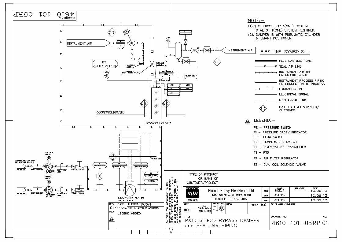
24 P&ID of FGD Bypass damper & seal air piping
4610-101-05RP

SPECIFICATION No.: GDRS: 018 /00 FGD BYPASS BI-PLANE DAMPER
Page 3 of 20
25
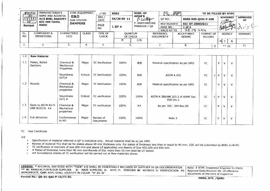
BHEL Quality Plan
R502/ 04
26 MQP Sample format for reference only 1 page
27 NTPC format – Evaluation Report ( for information only)
QS-01-QAI-P-04/ F1-R2 ( page 1 of 1)
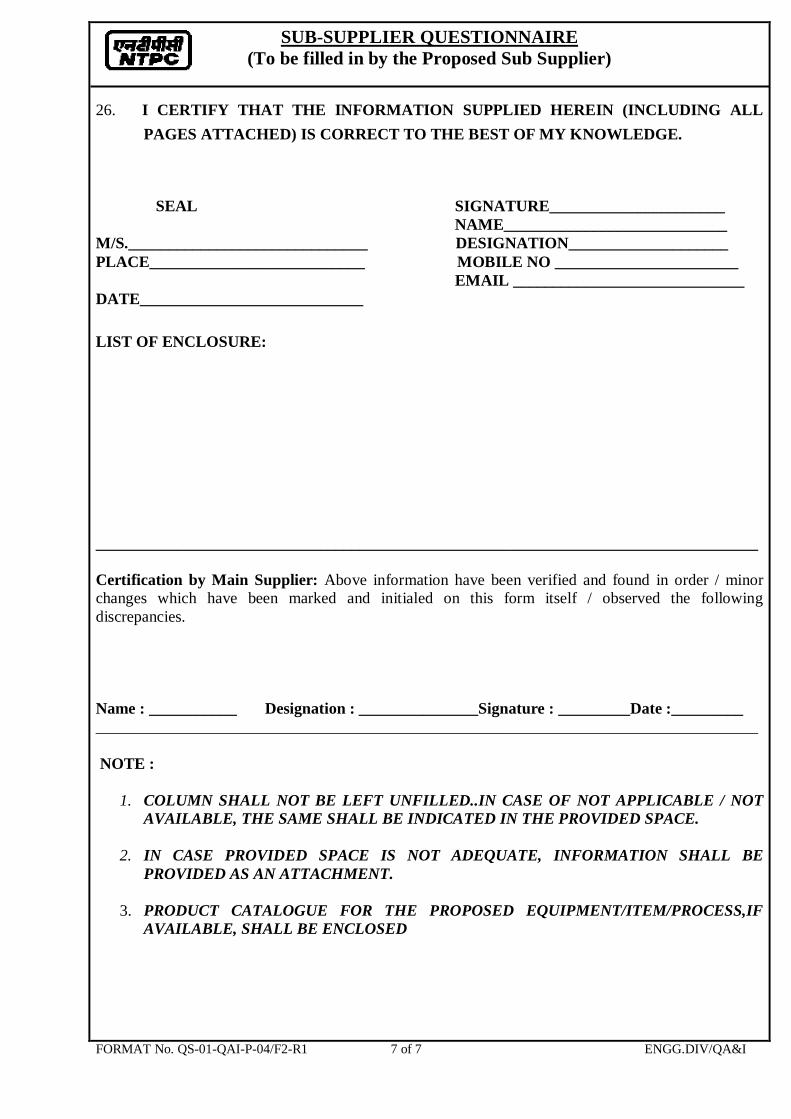
28 NTPC format – Evaluation Report ( to be filled up and submitted by bidder)
QS-01-QAI-P-04/ F2-R1 ( page 1 to 7 of 7)
29 Painting Schedule PS VINDHYACHAL R549 REV.00 dt 16.08.2012 ( 1 page)
30 Technical Specification for LT Motor ( Applicable for Motor of seal air blower)
TECI: :LT MOTOR: REV 01
31 Technical specification of Pneumatic cylinder TCI: 143. Rev.08
32 Technical specification of Smart Positioner TDC: TCI: 317 /REV.02
33 TB Wiring diagram of Power cylinder 3-97-599-21822 Rev.00
34 Quality Plan for Pneumatic Actuator QA: CI: STD: QP: 42. Rev.04
35 Packing procedure for Actuators & Electrical equipments
QA: CI: STD: PR:03 /Rev.02
36 NTPC Technical Specification for Instrumentation
Inst_Spec-57583
37 Leak Tightness Type Test Procedure G&D: LTTP
38 Data sheet for FGD Bypass damper DS-57583
39 Total Final Price Schedule ( Proforma Invoice)
PI- 57583
40 Check List for FGD Bypass damper CL-BL-57583
Filled up sl. nos. 28 and 38 to 40 shall be submitted by bidder along with Technical Offer.

SPECIFICATION No.: GDRS: 018 /00 FGD BYPASS BI-PLANE DAMPER
Page 4 of 20
1.0.0
PROJECT INFORMATION
Owner
NTPC Ltd.
Buyer
BHEL, Ranipet
Process/ application
Wet Lime Stone FGD system
1.1.0
SITE CONDITIONS
Ambient temperature (Guarantee)
27 Deg C
Ambient temperature( Max.) Ambient temperature ( Min.)
50 Deg C 6 Deg C
Relative Humidity
60%
1.2.0
LOCATION and APPROACH
Project location
Vindhyachal STPS, Vindhyanagar
District
Singrauli
State
Madhya Pradesh
Height above sea level
281m
1.3.0
Other Project details
Seismic load
As per IS: 1893 (Part I); 2002 and IS: 1893 (Part 4): 2005
1.4.0
Wind Load a) Basic wind speed at 10 meters above the
mean ground level b) Risk coefficient, “ K” c) Category of terrain
As per IS: 875 (Part-3) 47 m/s 1.07 Category – 2

SPECIFICATION No.: GDRS: 018 /00 FGD BYPASS BI-PLANE DAMPER
Page 5 of 20
2.0 Application: Bi-plane * damper is located in between ID fan and chimney. This damper is required for diverting the flue gas into FGD plant for sulphur removal treatment instead of allowing the flue gas directly into the chimney (Refer Key plan, clause no. 22)
* - Twin blade louver damper i.e. Two plates mounted to a single shaft trunnions ( stub shafts) and are reinforced with stiffeners between the plates or other approved tandem seal blade designs.
3.0 Scope of supply: Design, Manufacture, Testing, Painting & Packing for Shipment and Assistance for
Erection& Commissioning including: 3.1 Bi-plane damper assembly (1 No.)with mating flanges on both sides (Upstream & Downstream) 3.2 Electro Pneumatic Actuator(s) ( quantity as per technical requirement , also refer specification for Power cylinder- TCI:143.Rev.08 & Smart positioner- TDC:TCI :317 Rev.02 enclosed) 3.3 Seal air system with– (a)Blower with motor- 2 x 100%, with check valves at the outlet.
(b)Heater & its related accessories/ Instrumentation( Refer clause 19.0) (c) Air operated knife edge gate, or butterfly valve with solenoid valve & air filter regulator and (d) seal air piping from Blower till seal air opening in damper frame.( The seal air skid for this damper containing the Blowers with Motors, Heater, Isolating valves and all required Instrumentation is in vendor scope of supply and it shall be mounted on platform above the duct. Mounting platform for supporting seal air skid and access ladder alone will be supplied by Purchaser.) (e) Pressure switch with root valve in common line ( after junction of 2 x 100% seal air line, refer P&ID 4610-101-05RP)
3.4 Leak Tightness Type test( Volumetric flow method) to be conducted on the damper to be supplied for the first unit. Separate Break up price for this type test is to be indicated. ( Refer clause no. 12.0)
3.5 Erection & Commissioning support. ( Refer clause nos. 6.2, 6.3 & 16.0) 3.6 Mandatory spares ( will be covered separately but vendor to quote with
breakup price for the following) (i) 1 set of seals of each type for the damper (Set means complete
Replacement for one damper covering total duct cross section area of 72.042 m2. In case 2 split dampers of modular design are being supplied to cover the duct area of 72.042 m2, vendor has to supply complete set of seals for each of the 2 split dampers.)
(ii) 1 number Actuator (Pneumatic cylinder) for the damper
4.0 Working Environment: The medium of flow in the gate is corrosive Flue gas and the properties of the
medium is enclosed in Clause No.23.

SPECIFICATION No.: GDRS: 018 /00 FGD BYPASS BI-PLANE DAMPER
Page 6 of 20
5.0 Operational Requirement:
During start up of boiler both gates( FGD Inlet & Outlet )are in closed condition. When the FGD is ready to operate and ID fans are under normal running condition then FGD inlet and outlet gates are opened by control system. After ensuring 100% opening of both inlet and outlet gates through limit switches, the FGD bypass damper is then gradually closed for diverting the flue gas into the FGD plant for treatment. The pressure loss along the FGD is about 300 mm of water column. For taking shutdown maintenance of FGD plant, bypass damper is gradually opened, after ensuring 100 percent opening of bypass damper, both gates are allowed to close.
BHEL will only supply the power and control signals for damper operation. Compressed air at 4.5 kg/cm2 (max) will be made available at site. Vendor shall provide details of actuator and its accessories during offer with write up to explain how the adjustable quick opening times are achievable in their offer. Provision of opening damper by hand wheel in case of emergency shall be provided.
Vendor shall submit the Pneumatic hook up diagram ( as applicable ) showing all accessories in the circuit and provide all important details of actuator and its accessories during Offer. BHEL will only supply the power and control signals for Electro-pneumatic actuator and compressed air and control signals for Pneumatic actuator. Limit switch and Solenoid valves have to be wired to a Terminal box mounted on damper frame by the vendor. All other accessories & inter connecting wiring / tubing are in vendor scope. 5.1 Normal closing of biplane damper with intermittent stop(40%-40%- 20%) After ensuring the opening of FGD inlet and outlet gates, command for closing of bypass damper will be issued manually through Distributed Control System(DCS). a) On receiving closing command (4-20mA signal) from DCS, the actuator shall rotate up to 40% (36 degree rotation) and then it shall stop. The time of closure may be more than 24 seconds. After the above stoppage, the pressure monitoring system of the boiler is observed. The required pressure difference will be maintained by adjusting the ID fan / Booster fan speed, as applicable if required.
b) If all the pressure readings are normalized, the next closing command to actuator will be issued from DCS for closing (4-20mA signal) of another 40% (36 degree rotation) of bypass damper, The actuator shall stop automatically after reaching the above position. The time of closure may be more than 24 seconds. The pressure level of the boiler is monitored by adjusting the ID fan/ Booster fan speed as applicable.
c) If everything goes well, final command will be issued to actuator from DCS for closing (4-20mA signal) of remaining 20 % (18 degree rotation) of the bypass damper. Since closing of final 20% of bypass damper will cause more pressure variation of the boiler than closing the first / second 40% of the bypass damper, hence close

SPECIFICATION No.: GDRS: 018 /00 FGD BYPASS BI-PLANE DAMPER
Page 7 of 20
monitoring and communication for each system is required and more time will be allowed during this period. The time allowed will be more than 12 seconds for final closing in order to maintain the normal pressure level of the boiler by adjusting the ID fans / Booster fans speed as applicable.
5.2 Normal opening of biplane damper : The sequence of opening will be reverse order of normal closing ie 3steps (20%,40% & 40%)
a) On receipt of Open command from DCS (4-20mA signal), the actuator opens first 20% (18 degree rotation) and then it shall stop. After the above step, the pressure monitoring system of the boiler is observed. The required pressure difference of the boiler will be maintained by adjusting the ID fan/ Booster fan speed as applicable.
b) Secondly, if all the pressure readings are normal, command will be issued from DCS for opening (4-20mA signal) of another 40% (36 degree rotation), then pressure readings are monitored.
c) Command for opening (4-20mA signal) the remaining 40% (36 degree rotation) will be issued to actuator after stabilizing the boiler pressure difference
5.3 Quick opening during emergency: Quick opening is required to protect the FGD in case any trouble in the FGD equipment and allow the flue gas directly to chimney without affecting the operation of boiler. Actuator shall open the damper completely i.e. from full close to full open positions within ‘t’ seconds without any intermittent stops. ( t - the quick opening / closing time of damper should be adjustable between 10 to 20 seconds to meet the FGD supplier requirements) Note : Vendor shall supply electro-pneumatic actuator including all accessories required for proper and safe operation of above damper. BHEL will only supply the power and control signals for damper operation. Vendor shall provide details of actuator and its accessories during offer.
6.0 Design Criteria:
Damper is to be designed to meet the criteria stated below Duct inner dimensions 6000mm width x 12007 mm height Data sheet for FGD Bypass damper ( DS–57583) Flue gas property ( Clause no. 23.0).
6.1 Modular/Combination of Modular & split design: Damper size being large, it is not possible to dispatch as single piece. Hence only modular design or a combination of modular & split design damper shall be supplied. After all applicable testing at vendor’s works, this Damper is to be dismantled and packed for transportation. At site, it should be assembled for erection & installing in duct. Vendor has to specify the method of construction & mounting details during the offer.( Refer Clauseno.13.0 & 14.0)

SPECIFICATION No.: GDRS: 018 /00 FGD BYPASS BI-PLANE DAMPER
Page 8 of 20
6.2 Site Assembly Scope: Considering that the Damper is shipped to project site in knocked down condition, site assembly (including consumables for welding / bolting etc. required for making it into a whole assembly), arranging for all necessary manpower for assembling the Damper at site, special tools, special equipment and special temporary attachments as applicable for safe erection on a rental basis are to be arranged by vendor as part of their scope of supply and the Damper is to be erected to the connecting duct by the vendor at site. However the welding of the damper mating flanges to the upstream and downstream connecting ducts and consumables required for welding the mating flanges of Damper to the Connecting ducts are in Purchaser’s scope. Vendor is responsible for the erection of Damper in duct and has to estimate the requirements of manpower , their duration at site, the rentals for applicable items required for enabling erection in duct at site and quote suitably. The above activity has to be done in the first visit i.e. Erection support visit. BHEL will inform the vendor sufficiently in advance when the Erection support ( first visit ) is required at site. The vendor has to make their own travel to site, boarding and lodging arrangements at / near site during this period including local travel. ( Also refer clause 16.0) 6.3 Commissioning support at site: The vendor has to offer commissioning support at the project site for the offered Damper and its accessories to enable successful completion of all commissioning and operation of applicable interlocks during the second visit of 2 days in site ( Commissioning support visit). BHEL will inform the vendor sufficiently in advance when the Commissioning support ( second visit ) is required at site. The vendor has to make their own travel to site, boarding and lodging arrangements at / near site during this period including local travel. The Bidder has to quote separate Breakup Price lumpsum( including charges of above clause nos. 6.2 and 6.3 meeting requirements of clause no. 16.0) in sl. no. 4 of Proforma Invoice ( PI-57583).
7.0 Construction Details:
7.1 Casing:- Casing shall be fabricated to the dimension as per the datasheet with suitable thickness. It shall have a provision for seal air entry duct. Lifting lugs shall be provided for handling. The frame shall be suitably stiffened. Name plate details with Purchase order number, Vendor name, Address & email ID is to be fastened visibly on drive side on the frame. A Blade position indicator shall be mounted on the drive side of casing.
7.2 Locking device: manual locking device shall be provided both at full open
and full close positions.

SPECIFICATION No.: GDRS: 018 /00 FGD BYPASS BI-PLANE DAMPER
Page 9 of 20
7.3 Blades:-Blades are designed in such a way that it should have deflection
resistant configuration and have suitable thickness to with stand the pressure given in the datasheet. Vendor has to specify the blade design in the offer.
7.4 Shaft:- Suitable material shall be selected to withstand the high torque. Vendor has to specify the shaft design, material specification and provision for expansion of the blades.
7.5 Stuffing Boxes: Special external stuffing boxes are to be installed at drive side of the damper casing for tight sealing of the passage of the trunnion (stub shaft) through the damper casing. The stuffing box packing shall not deflect during blade movement or due to thermal expansion and shall remain gas tight. Vendor has to specify their design.
7.6 Bearings:- suitable bearing shall be provided for the shaft (either maintenance free flanged ball bearings or graphite based sleeve bearings) for supporting the trunnion (stub shaft). The bearings are to be designed to avoid jamming of the damper blades even under arduous conditions.
7.7 Sealing System: Alloy C276 or better material seals ( based on springback
properties) are to be installed on the periphery of the damper blades. Sealing arrangements shall ensure minimum 99.50% sealing efficiency on flow without seal air and 100% with seal air. Seals shall have minimum service life of three years before replacement. The seal fixing arrangement for blade to blade, blade to frame and jamb seal shall be clearly specified in the drawing. The seal and mounting design shall have the facility for easy replacement of seals during maintenance.
7.8 Linkage Mechanism: Vendor to furnish details.
8.0 Material of Construction:-
8.1) The Adjoining duct is made up of S–Ten1 material of 9mm thickness.
8.2 ) Bypass Damper:
(a) Frame:( For all parts of frame in contact with flue gas) S-Ten 1 / A36 lined with 5 mm thick SS317LMN or better material / C276 cladding (Refer note regarding cladding below) of sheet thickness 1.6 mm on downstream side. (The alternate better material should have a higher PREN value compared to SS317LMN when calculated using the chemical composition formula “ PREN = *%Cr + 3.3*%Mo + 16*%N ”
(b) Blade: ( On downstream side of flow i.e. facing Chimney side) SS317LMN or better material/ C276 cladding of sheet thickness 1.6 mm (Refer Note below).

SPECIFICATION No.: GDRS: 018 /00 FGD BYPASS BI-PLANE DAMPER
Page 10 of 20
Note: cladding shall be attached properly to the base to ensure that the base material does not come into contact with the corrosive gases under any circumstance.)
8.3) Seals:- HASTELLOY Alloy C-276 (ASTMB575 UNSN10276) or better material based on spring back properties. 8.4) Drive, Slave & Stub shaft: Vendor to specify suitable material for sulphuric acid corrosion resistance.
8.5) Note for Materials offered: If alternate materials are offered like JIS, DIN etc., other than ASTM indicated in our specification/ datasheet, then vendor has to indicate nearest equivalent ASTM material codes in addition to their offered codes with chemical Composition for our review. (Chinese standard for materials are not acceptable). The alternate materials are to be equal or better than those corresponding specified. . Vendor has to submit justification for these, showing comparison of physical, chemical, strength, spring back property as applicable for the intended part/ service.
9.0 Seal Air system (2 x 100%)
Seal air is required during normal operation of the FGD ( Bypass damper is in closed condition) to avoid leaking of upstream side hot flue gas ( i.e. from ID Fan duct side) into chimney thereby minimizing atmospheric SOX pollution. In the outlet of each blower, individual check valve ( NRV) is required (Refer P&ID enclosed). The offered damper design should require seal air only in Damper closed condition and blower and Heater will be switched off when Damper is in open condition. Seal air system shall consist of blowers with motors, Electrical heater, air operated knife edge gate or butterfly valve with solenoid valve, filter cum regulator and connected piping arrangement (skid mounted ) in vendor scope. Vendor to specify the seal air flow, pressure, blower kilo watt rating with the technical offer. The solenoid coil rating shall be 24VDC. Blower selected shall be suitable for 3 phase power supply, 50 Hz & 415V AC.The motors shall be Energy efficient motors, Efficiency class- IE2 conforming to IS12615. (Refer TECI :: LT MOTOR: REV.01 for motor spec of seal air blower). The noise level of Blower with motor at 1.5 meter above floor level & at 1 meter horizontal distance shall not exceed 85dBA. Electrical wiring termination shall be at termination box with double compression type nickel plated brass cable gland with insulated tinned copper crimping lug. Electrical Heater shall be provided to heat the seal air. Vendor shall size the heater suitably to avoid condensation of water vapour on Damper blades, ash deposition, to minimize the thermal differential across the damper and to meet the design criteria.
The electric Heater shall heat the seal air to at least 130ºC (The dew point temperature of flue gas)
10 .0 Actuator System for Damper: Electro Pneumatic actuator for modulation duty with double acting smart positioner. Damper shall have emergency opening on loss of power or pressure and manual hand

SPECIFICATION No.: GDRS: 018 /00 FGD BYPASS BI-PLANE DAMPER
Page 11 of 20
wheel over ride. One pair of integral limit switches each shall be provided in the actuator for the Open & Close positions. A continuous 4 – 20 mA position feedback signal shall be provided to enable achieving intermediate opening positions of 40% and 80% as specified in clause 5.1 & 5.2. Also specification requirements of SMART positioner (TDC: TCI: 317/ Rev.02) and Power Cylinder Regulating type (TCI:143 Rev.08) enclosed shall be complied.
11.0 Painting requirements: ( Also refer PS VINDHYACHAL R549 REV.00 dt.
16/08/2012 , 1 page 11 of 12) Power tool cleaning to St3 (SSPC-SP3) followed by i) Two coats of Heat resistant aluminum paint Gr. 2 as per IS 13183 with total film
thickness of 40 microns for the gate surfaces. (ii) Painting is not applicable for stainless steel surface, C276 seals & cladding surfaces
12.0 Quality plan & Testing: Vender shall submit QUALITY PLAN for approval covering the following: a) Vender has to submit their QUALITY PLAN (QP) for customer (NTPC) approval. While preparing QP, vendor shall consider BHEL quality requirements as specified in the BHEL quality plan No: R502/04 dated 30-09-2011 approved by NTPC . The vendor has to follow the same in line with NTPC Manufacturing QP (MQP) taking care of all the applicable clauses and the vendor has to submit the MQP accordingly for NTPC Approval. A sample MQP of a different vendor for a different product is enclosed for reference ( 1 page) . NTPC will require minimum 3 weeks time to approve the MQP. b) Vendor has to submit GA drawing of damper assembly showing all important dimensions like overall height, dis-mantlable locations ( modules) for shipping. The GA shall include all item details with BOM and material specification. Seal arrangement on all the four sides, blade construction, frame construction & sectional views on all four sides. Actuator location, platform requirement & arrangement for the seal air skid, Seal air entry interface details. Modular details for dispatch. Supplier’s drawing should be approved by BHEL / Customer before start of manufacturing by vendor. c) Detailed test procedure for (i) routine / acceptance test, (ii) Detailed test procedure with
test parameters for leak tightness with & without seal air is to be prepared inline with BHEL/Ranipet test procedure No G&D: LTTP and same shall be submitted for customer approval with drawing showing the test set up and sample calculations. The damper should be tested at manufacturer’s works for operation, seal gap measurements and leak tightness without & with seal air to prove the guaranteed
sealing e f f i c i e n c y o f ≥ 9 9 . 5 % & 1 0 0 % r e s p e c t i v e l y and report should be submitted. Vendor shall make their own arrangements for test stand, test equipment like blowers, Actuator, Air tanks and instruments. The tests will be witnessed by BHEL and customer or their authorized inspection agency. Leak tightness test Report without seal air and with seal air should be submitted and it has to prove the guaranteed sealing efficiency. The damper is to be dispatched only on explicit clearance by BHEL after review of test records. For testing the leak tightness, seal air at sufficient pressure above the operating pressure is to be supplied to ensure 100% leak tightness. Detailed test procedure for leak tightness testing ( G&D: LTTP), 7 pages is enclosed. After Purchase Order is placed, vendor shall

SPECIFICATION No.: GDRS: 018 /00 FGD BYPASS BI-PLANE DAMPER
Page 12 of 20
submit their Test Procedure for Leak tightness test for approval. This has to be the same as that required in BHEL enclosure ( G&D: LTTP). Alternate testing procedures(Bidder’s counter offer) of leak tightness efficiency by surface area method or seal air consumption method as against volumetric flow specified in the test procedure No G&D:LTPP is not acceptable. Vendor has to give 15 days advance intimation for witnessing of leak tightness type test for making travel arrangement. The damper is to be dispatched only on explicit clearance by BHEL after review of test records.
d) Damper material test certificates and Inspection records. e) Damper Open and Close testing using actuator f) NDT requirements of the weld. g) NTPC Approved painting procedure to be followed. h) Quality plan for Pneumatic actuator (QA:CI: STD: QP: 42) enclosed with this specification. i) Supplier’s drawing should be approved by BHEL before manufacturing. j) NTPC format evaluation reports enclosed
1) Format No. QS-01-QAI-P-04 / F1-R2 page 1 of 1 which will be filled up by BHEL and submitted to NTPC. This is for Bidder’s information.
2) Format No. QS-01-QAI-P-04 / F2-R1 pages 1 to 7 of 7. This has to be filled up and submitted by Bidder along with Technical offer.
13.0 Packing for dispatch: Damper and accessories are to be painted and packaged to take care of corrosion due to sea voyage and handling at port & site. Packing has to withstand power station outdoor condition for the period of six months. Packing shall be done in accordance with General shipping instructions.
Sufficient amount of transport stiffeners are to be welded on all the sides of gate to avoid distortion ( if applicable) during transit & handling. Stiffeners should be painted yellow. Description, quantity &weight details of each items have to be neatly marked on each crate. Damper spares shall be packed in a crate separately.
Overall Transportation Limitations for Indian Roads( for guidance) Width of road transport = 5500 mm maximum Height of the consignment = 5000 mm maximum Length of consignment = 20000mm Weights of the consignment = 40000kg
Vendor shall submit shipping bill of material with packages, identified with overall size, quantity and weight. Overall dimensions shall be as per transport limitations furnished above.
14.0 Qualification Requirement ( Offer Acceptance Criteria) The Bidder to qualify should have engineered and supplied ( manufactured by themselves or through their outsourced manufacturers or through their technology licensee ) both the following 2 items (a) and (b) :

SPECIFICATION No.: GDRS: 018 /00 FGD BYPASS BI-PLANE DAMPER
Page 13 of 20
(a) A large size Bi-plane damper (tandem louver) meeting the technical requirements of clause 6.1 of this specification for a large duct of at least 50 m2 cross sectional area and a width of at least 5m. ( All dimensions being internal dimensions of duct. For this purpose duct cross section for this Vindhyachal project FGD bypass damper is 72.042 m2 i.e. 6m x 12.007m). The damper engineered and supplied for the reference project may be either of the following 2 designs only: (i) A single damper assembly dispatched in 3 or more modules (The dismantlable
joints being along the damper height) with 1 or maximum 2 pneumatic actuators.
(ii) A design combining both Modular and split damper features: A maximum of 2 split dampers vertically one above the other and each split damper having 1 or maximum 2 pneumatic actuators. Further each split damper should mandatorily be of a modular (dismantlable) design dispatched in 2 or more modules is acceptable.
(b) A Guillotine gate or a Louver/Bi-plane Damper with special materials like SS317LMN / C2205/ 904L if the bidder proposes to supply the same for this FGD Bypass damper (or) a Gate / Louver/Bi-plane damper with C276 cladding for Blades and Frame if C276 is contemplated by the bidder for this project.
The above 2 items (a)(i) /(a)(ii) and (b) should have been erected and completed at least 1 year of satisfactory operation as on date of tender opening. If the Bidder has designed and supplied a Bi-plane damper meeting above 2 conditions (a)(i)/(a)(ii) and (b), then a single reference is sufficient. (c) The Bidder shall provide their customer reference details for (a) and (b) above showing name of project, date of commissioning and service. Bidder shall also submit General Arrangement drawing for the above showing clearly Bidder / Licensee / Licensor name in title block as applicable, size of damper, BOM for proof of materials for (b) above, Assembled weight and proof that it is of dis-mantlable design as specified in clause no. 6.1 & 14.0 (a)(i) / 14.0(a)(ii). (d) In case a Licensee is the bidder, the licensee shall furnish a Certificate from the qualified Licensor( meeting the technical requirements of (a) and (b) above, that the bidder is authorized to quote for this project and they will provide the Engineering support to enable the licensee to complete all deliverables indicated in scope of supply clause 3.0, 12.0 and 16.0. Also the reference details and G.A. drawings of the supplies made by the Licensor for (a) and (b) above shall be enclosed. Non submission of details and back up documents specified in (c) and in the case of a Licensee (c) and (d) above will lead to rejection of Bidder’s offer and the same will not be considered for further evaluation.
15.0 Responsibility The extent of supply stated here in is not necessarily exhaustive and shall not relieve the supplier from his responsibilities to provide goods & services necessary to satisfy

SPECIFICATION No.: GDRS: 018 /00 FGD BYPASS BI-PLANE DAMPER
Page 14 of 20
the purchaser’s performance criteria & required life, to be complete for installation & to be fit for purpose, safe, reliable, easily maintained and efficient in operation.
Bidder shall make all possible efforts to comply strictly with the requirements of this specification and other specifications/ attachments to inquiry/ order.
In general, deviations are not acceptable. In case, deviations are considered essential by the Bidder ( after exhausting all possible efforts), these shall be separately listed in the Bidder’s proposal titled as “List of Deviations/ Exceptions to the Enquiry Document”. Deviation shall be listed separately for each document with cross reference to Page No./ Para etc. of the respective document supported with proper reasons for the deviation for purchaser’s consideration. Any deviation, not listed under the above section, even if reflected in any other portion of the proposal, shall not be considered applicable. No deviation or exception shall be permitted without the written approval of the purchaser. In case the Bidder considers requirement of additional instrumentation, controls, safety devices and any other accessories /auxiliaries essential for safe and satisfactory operation of the equipment, he shall recommend the same along with reasons in a separate section along with his proposal and include the same in his scope of supply.
16.0 Assistance for Erection & Commissioning: The Bidder shall quote separate breakup price per diem basis for support to be rendered during erection and commissioning of the damper at the project site. The vendor has to offer erection support in the first visit as indicated in clause no. 6.2 and 2 separate days at site for commissioning in the second visit as indicated in clause no. 6.3. Payment will be made on certification by site engineer on satisfactory completion of both the erection and commissioning support. The vendor has to make their own travel to site, boarding and lodging arrangements at / near site during this period including local travel. The Bidder has to quote separate Price lumpsum( including charges of above clause nos. 6.2 and 6.3 in sl. no. 4 of Proforma Invoice ( PI-57583). Bidder shall indicate lumpsum value and not give counter offer by indicating travel, accommodation, man hour / man day, rental costs etc. in PI-57583.
17.0 Spares:
The Bidder shall offer for the following. a. Commissioning spares –Quantity with per unit rate b.
Recommended spares for 3 years operation – Quantity with per unit rate
The above commissioning & Recommended spares will not be included for price comparison between vendors. BHEL reserves the option of procuring any or all of these at a later stage. Prices are to be valid for a period of period of 3 years from offer submission stage. Vendor has to quote for the Mandatory spares indicated in PI-57583.

SPECIFICATION No.: GDRS: 018 /00 FGD BYPASS BI-PLANE DAMPER
Page 15 of 20
18.0 Special Tools:
The Gates shall be designed to be assembled, disassembled and maintained with standard hand tools. However, if at all the vendor desires special tools are required, the same has to be supplied along with the Gate. List of special tools if applicable is to be brought out clearly in “ SCOPE OF SUPPLY”.
19.0 Instrumentation in Vendor’s Scope of supply: (Refer P&ID:4610-101-05RP) Local Pressure gauge with isolating root valve upstream of Heater. 1 Pressure switch in common Pneumatic line downstream of seal air blowers with isolating
root valve. Flow switch for Heater protection ( connection to FGD DCS by Purchaser) Seal Air Heater ( 3 ph, 415V, 50Hz. Should withstand a variation of ± 10% in Input voltage, ±
5% in frequency and a combined variation of ± 10% and designed for continuous operation.) Control panel is in NTPC scope of supply.
Temperature switch for Heater Protection (connection to FGD DCS by Purchaser) Temperature Transmitter for Heater Protection (connection to FGD DCS by Purchaser) Local control panel for mounting valves, pneumatic fittings & signal cables required for
Pneumatic circuitry of damper for achieving Quick opening & normal timings in clause 5.1 & 5.2.
Air tank ( Air receiver), Pressure indicator, root valves, drain valves, safety relief valve, double acting smart positioner, pressure switch & solenoid valves for achieving emergency quick opening during loss of electrical or pneumatic signal are in vendor scope.
The Instrumentation / control cables for all the above instruments are to be terminated in Field Junction boxes to be supplied in vendor scope. The above are in addition to other items specified in clause no. 3 – Scope of supply. Instrument air will be provided at a pressure of 4.5 kg /cm2(g) for the pneumatic operation of the isolating valve in seal air line. The exact air regulator setting to be furnished by the vendor. Also for the pneumatic actuator of the isolating valve, Instrument air requirements in m3/sec x __ sec ( duration of open / close time) to be furnished by vendor. BHEL will only supply the power and control signals for Damper operation. All accessories & interconnection wiring / tubing and other instrumentation are in vendor scope.
20.0 (A) Auxiliary Power consumption: The Bypass damper will be in Open condition when FGD is not in service and Damper blades will be in Closed condition when FGD is in service. When Damper is in closed condition, heated seal air will be supplied to the hollow volume of the damper blades by switching on the blower and heater. When the damper is open, the heater & blower will be switched off.
The design and material selection of all the Damper components is to be done such that when the FGD is not in operation ( i.e. Damper Blades are in open condition), the Electrical heater and seal air blower will be switched off and no component of the Damper shall be corroded. All materials including Frame, blades, shaft and other internals exposed to Flue gas to be taken care to prevent sulfuric acid corrosion when Damper is in open condition. Vendor has to confirm in Check list enclosed that the heater and Blower can be switched off when Blade is in open condition. ( This will minimize auxiliary power consumption to end user).

SPECIFICATION No.: GDRS: 018 /00 FGD BYPASS BI-PLANE DAMPER
Page 16 of 20
When the FGD is in operation ( i.e. Damper Blades are in closed condition), the auxiliary power consumption of heater is estimated at 352 KW considering the Ambient air temperature of 27 deg C & 60% Relative humidity and heated to 130 deg C. The seal air blower power consumption is estimated as 45 KW for FGD in operation. The total auxiliary power consumption in FGD mode is 397 KW( i.e. 352 + 45).In the technical offer, if the bidder’s power consumption in FGD mode exceeds 397 KW, a price loading @ Indian Rupees 2,25,000/- per KW increase above 397 KW will be added to the vendor’s quoted price for price comparison purpose between different vendors. Hence bidder shall consider auxiliary power consumption values carefully for equipment selection. However bonus / preference is not applicable if the vendor’s quoted auxiliary power consumption is less than 397 KW.
(B)Operating pressure for this Damper in mm WC: Upstream side of Damper : Duct from ID Fan outlet ( Refer Key plan drg in Clause 22.0) Downstream side of Damper : Duct to Chimney
When Damper open When Damper closed Upstream pressure mm WC
Upstream Temp deg C 10 to 40 approx
130 to 145 10 to 40 approx
130 to 145
Downstream Pressure mm WC Downstream Temp deg C
10 to 40 approx 130 to 145
10 approx 100 to 105 deg C

SPECIFICATION No.: GDRS: 018 /00 FGD BYPASS BI-PLANE DAMPER
Page 17 of 20
21.0 DOCUMENTS:
Vendor shall submit the following documents and drawings in English 21.1 Documents to be submitted along with Offer.
Sl.no:
DOCUMENTS
Vendor Acceptance
comments/ deviation 1 (i) Comments/deviation for the Specification No.
GDRS 018 & related enclosures (ii) Filled up Data sheet for Damper: DS-57583 (iii) Sketch of Pneumatic circuitry and write up
explaining how the timings specified in clause 5.0, 5.1 & 5.2 are proposed to be achieved
(iv) Filled up Proforma Invoice ( Un-Priced Price Bid) : PI-57583 (v) Filled up Checklist : CL-BL-57583
2 General arrangement drawing with dimensions showing location of Accessories like Blower, Heater, Isolation valve, Actuator, Air Receiver, BOM & Weight.
3 Vendor quality plan for review ( should be in line with BHEL Quality Plan )
4 Recommended spares list for commissioning & three year operations
5 Reference list & documents of FGD Bypass damper– ( as per Clause no.14.0) to prove Qualification Requirement
6
Vendor confirmation for all documents submission in 21.2, 21.3 & 21.4 for approval as specified after placement of purchase order
7 Draft Erection & Commissioning Procedure applicable for the offered design and scope of supply.
21.2 Vendor shall submit the following Documents for BHEL approval within 30 days after placing Purchase Order. Only after BHEL Approval, vendor can commence manufacturing activity.
SlNo Documents No
Copies required
Vendor acceptance comments / deviation
1 Revised Quality plan(if any) 1
2 Test Setup & procedure for Leak tightness test 1

SPECIFICATION No.: GDRS: 018 /00 FGD BYPASS BI-PLANE DAMPER
Page 18 of 20
3 Final Damper Datasheet
1
4 Finalized details with make & model nos. for Air cylinder, Smart positioner, Instrumentation, local control panel etc.
1
5 Basic engineering transmittal for approach and platform for maintenance
1
6 G.A Dimensions and Mounting details of Damper and its Accessories, End to end dimensions of Damper with mating flanges, Skid mounting details / Layout arrangement of seal air skid (To enable BHEL design & supply platform for skid mounting & ladder for access), P&IDs, Power & Control schemes
1
21.3 Documents to be submitted before dispatch
Sl. No.
Documents No Copies
required
Vendor acceptance comments / deviation
1 Complete inspection/ test records of Dampers & accessories.
2
2 Leak test results with & without seal air 2 3 Raw material Test Certificates 2 4 Packing drawing & specification 2 5 Erection drawing & Erection manual(in English for
Damper, Actuator & all accessories) 3
6 Protection / Interlocks, Operating Procedures / Trouble shooting & Maintenance etc.
3
21.4 Documents to be submitted along with Dispatch
Sl. No.
Documents No Copies
required
Vendor acceptance comments / deviation
1 Shipping list / supply schedule 3 2 List of spares dispatched 3 3 O&M manual (in English for Damper, Accessories &
Instrumentation) 3


SPECIFICATION No.: GDRS: 018 /00 FGD BYPASS BI-PLANE DAMPER
Page 20 of 20
23.0 FLUE GAS Property
Sl.No Item Description Unit Values (Worst coal)
01
Inlet dust concentration to FGD mg/Nm3
50 - 200
02
SO2 concentration at FGD inlet gate mg/Nm3
GP -1912 DP -1852
03
SO2 concentration at FGD outlet gate mg/Nm3
GP – 180 DP - 178
04
Flue gas flow through Gate / Damper Nm3/s
GP – 565.6 DP – 643.3
05
Density of flue gas Kg/m3
0.784
06
Inlet SO2
%( byvol)
0.07
07
SO3
%
1.5% (conversion from SO2)
08
SO2 removal efficiency
%
GP – 90.6 DP – 90.4
09
Moisture (wet basis)
%( by vol)
GP – 13.61 DP – 16.06
10
Flue gas temperature at FGD inlet
Deg. Centigrade
GP – 125 DP - 145
11
Flue Temperature of gas at FGD outlet gate
Deg. Centigrade
100
12
Ambient Air temperature
Deg. Centigrade
GP – 27 DP - 42
13
Relative humidity
%
60
Note: GP : Guarantee Point ; DP – Design Point
The Leak tightness type test is to be done for the Design Point parameters indicated.


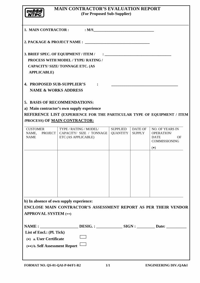
MAIN CONTRACTOR’S EVALUATION REPORT (For Proposed Sub-Supplier)
FORMAT NO. QS-01-QAI-P-04/F1-R2 1/1 ENGINEERING DIV./QA&I
1. MAIN CONTRACTOR : : M/S______________________________ 2. PACKAGE & PROJECT NAME : ___________________________________ 3. BRIEF SPEC. OF EQUIPMENT / ITEM / : ____________________________________ PROCESS WITH MODEL / TYPE/ RATING / CAPACITY/ SIZE/ TONNAGE ETC. (AS APPLICABLE) 4. PROPOSED SUB-SUPPLIER’S : _________________________________ NAME & WORKS ADDRESS 5. BASIS OF RECOMMENDATIONS: a) Main contractor’s own supply experience REFERENCE LIST (EXPERIENCE FOR THE PARTICULAR TYPE OF EQUIPMENT / ITEM /PROCESS) OF MAIN CONTRACTOR:
CUSTOMER NAME, PROJECT NAME
TYPE / RATING / MODEL/ CAPACITY/ SIZE / TONNAGE ETC (AS APPLICABLE)
SUPPLIED QUANTITY
DATE OF SUPPLY
NO. OF YEARS IN OPERATION/ DATE OF COMMISSIONING
(*)
b) In absence of own supply experience: ENCLOSE MAIN CONTRACTOR’S ASSESSMENT REPORT AS PER THEIR VENDOR APPROVAL SYSTEM (**) NAME : ___________________ DESIG. : _____________ SIGN : _________ Date: __________ List of Encl.: (Pl. Tick)
(*) a. User Certificate
(**) b. Self Assessment Report

SUB-SUPPLIER QUESTIONNAIRE (To be filled in by the Proposed Sub Supplier)
FORMAT No. QS-01-QAI-P-04/F2-R1 1 of 7 ENGG.DIV/QA&I
Name of Equipment / Item / Process with Model/ Type/ Rating / Capacity/ Size/ Tonnage etc. (As applicable):
_________________________________________________________ Trade Name of Product (if any) : ______________________ ______________________________________________________________________ 1. Name of Proposed Sub-Supplier: ______________________________ Website: _____________________ 2. Address of Regd. Office: Details of contact person: _____________________ Name______________________ _____________________ Mobile no.____________________ _____________________ Desig.______________________ E-mail: 3. Branch/ Liaison office in Delhi/NCR Details of contact person: __________________________ Name______________________ __________________________ Mobile no.____________________ __________________________ Desig.______________________ E-mail: Weekly off day __________ Details of contact person: 4. Address of Works where Name______________________ Item is being manufactured ____________________ ____________________ Mobile no.____________________ _____________________ Desig.______________________ E-mail:

SUB-SUPPLIER QUESTIONNAIRE (To be filled in by the Proposed Sub Supplier)
FORMAT No. QS-01-QAI-P-04/F2-R1 2 of 7 ENGG.DIV/QA&I
5. Details of Proposed Works: a. Year of Establishment of present works : __________________________ b. Year of Commencement of : ___________________________ Manufacturing at the above works c. Details of change in works address in past, if any : ______________________ d.. TotalArea / Covered Area : ______________________ e. Details of covered area like no. of sheds, ______________________ Area of each shed etc. f. Electric power- Connected load: _________________________ Electric power- Stand by load & system: _________________________ 6. Annual Turnover & : _______________________ Profit in past three years _______________________ _______________________ 7. Do you have in-house Department for: a) Design Yes/No b) Research & Development Yes/No c) Quality control/Inspection Yes/No d) After Sales Service Yes/No 8. Shift works per day One/Two/Three 9. Present Manpower Status:
Graduate Division Status Technica
l Non-
Technical
Diploma Skilled Un-Skilled Remarks
Design
Production
Quality Control/ Inspection
After Sales Service

SUB-SUPPLIER QUESTIONNAIRE (To be filled in by the Proposed Sub Supplier)
FORMAT No. QS-01-QAI-P-04/F2-R1 3 of 7 ENGG.DIV/QA&I
a. Organization chart of the proposed works is enclosed as Annexure: _____ b Organization chart of QA / QC Deptt. is enclosed as Annexure: _____ c. List of Qualified Welders with process etc. is enclosed as Annexure: _____ d. List of Qualified NDT personnel with area of specialization is enclosed as Annexure:
_____ 10. Brief details of items manufactured:
Sl. No. Item & Material
(Type/Size/Rating/Model/ Capacity /Tonnage , as
applicable)
Installed Capacity
Annual Production Capacity
Annual Production for last Three years
I II III
11. Details of foreign Collaboration, if any:
Collaboration Sl. No.
Product Name & Address of Collaborator Scope Year Valid
upto
12. Type Test report for the proposed product (similar or higher rating )if applicable is enclosed as Annexure: _____
13 Approval / Certification by National / International standards / Accredited
agency for the proposed product (if applicable) is enclosed as Annexure: _____
14. Statutory / mandatory certification for the proposed product (if applicable) is enclosed as Annexure: _____
15. Supply Experience list of the proposed product (similar or higher rating) is
enclosed as Annexure: _____ [List shall include Item description, (Type/Size/Rating/Model/Capacity/Tonnage, as applicable), Customer name, Quantity, Year of Supply and Year of commissioning]

SUB-SUPPLIER QUESTIONNAIRE (To be filled in by the Proposed Sub Supplier)
FORMAT No. QS-01-QAI-P-04/F2-R1 4 of 7 ENGG.DIV/QA&I
16. End User's operational feedback certificate for the proposed product is
enclosed as Annexure: _____ 17 List of equipment & machinery specific to the proposed product is enclosed as
Annexure: _____ (List shall include name of equipment, capacity & nos. etc.) 18. Process Flow Diagram indicating in-house & outsourced process enclosed as
Annexure:_____ 19 General manufacturing facilities available in-house: Sl. No.
Description of machine
Type /Capacity / Size / Rating etc as applicable
Number
a) Material Handling Mobile Crane Fork Lift Over Head Cranes
b) Metal Cutting & Bending
c) Casting
d) Forging
e) Fabrication
f) Welding
g) Machining h) Heat Treatment i) Surface Cleaning
Sand Blasting Shot Blasting Pickling
j) Painting k) Metal Coating

SUB-SUPPLIER QUESTIONNAIRE (To be filled in by the Proposed Sub Supplier)
FORMAT No. QS-01-QAI-P-04/F2-R1 5 of 7 ENGG.DIV/QA&I
l) Packing m) Other, if any
20. a. Inspection & Testing Facilities available in-house:
Sl. No.
Description Capacity & Nos.
Make & year of Mfg.
Calibration Status Validity period

SUB-SUPPLIER QUESTIONNAIRE (To be filled in by the Proposed Sub Supplier)
FORMAT No. QS-01-QAI-P-04/F2-R1 6 of 7 ENGG.DIV/QA&I
b. List of Testing & Inspection Facilities outsourced, if any with Source of testing
and Description enclosed as Annexure: ________
21. Storage of finished goods (covered / open) : ___________ 22 List of the source / make with location of major raw material, bought out items
and out sourced process enclosed as Annexure: _________ 23. Quality management: 23.1 General
23.1.1. Work Instruction for different processes available. (Y/N). ___
If yes, enclose list as Annexure______
23.1.2. Evaluation system for raw material/bought out item’s supplier is available. (Y/N) _______
23.1.3. Records generated during inspection maintained & available for review (Y/N) _______
23.1.4 Statistical quality control techniques used (Y/N) ______
23.1.5 ISO certificate for the works available (Y/N). ____ If yes, enclose copy as Annexure______
23,2 Corrective action
23.2.1 Specifically confirm whether System for identification & disposition of Non Conformity in the process / product is available. (Y/N) ___________
23.2.2 Specifically confirm whether System for Customer complains & their satisfactory disposal is available. (Y/N) ___________
23.3. Documentation Control
23.3.1 Procedure available for documentation control (Y/N) ___
23.4. Control of Inspection, Measuring & Testing equipments.
23.4.1 Procedure for calibration of testing & measuring instrument available. (Y/N) ___
24. Any Special Information: ______________________
SUB-SUPPLIER QUESTIONNAIRE (To be filled in by the Proposed Sub Supplier)
FORMAT No. QS-01-QAI-P-04/F2-R1 7 of 7 ENGG.DIV/QA&I
26. I CERTIFY THAT THE INFORMATION SUPPLIED HEREIN (INCLUDING ALL
PAGES ATTACHED) IS CORRECT TO THE BEST OF MY KNOWLEDGE. SEAL SIGNATURE______________________ NAME____________________________ M/S.______________________________ DESIGNATION____________________ PLACE___________________________ MOBILE NO _______________________ EMAIL _____________________________ DATE____________________________ LIST OF ENCLOSURE: ___________________________________________________________________________________ Certification by Main Supplier: Above information have been verified and found in order / minor changes which have been marked and initialed on this form itself / observed the following discrepancies. Name : ___________ Designation : _______________Signature : _________Date :_________ ___________________________________________________________________________________ NOTE :
1. COLUMN SHALL NOT BE LEFT UNFILLED..IN CASE OF NOT APPLICABLE / NOT AVAILABLE, THE SAME SHALL BE INDICATED IN THE PROVIDED SPACE.
2. IN CASE PROVIDED SPACE IS NOT ADEQUATE, INFORMATION SHALL BE
PROVIDED AS AN ATTACHMENT.
3. PRODUCT CATALOGUE FOR THE PROPOSED EQUIPMENT/ITEM/PROCESS,IF AVAILABLE, SHALL BE ENCLOSED


TDC: TCI:143 / REV 08 PAGE 02 OF 08
SL. NO. DETAILS TECHNICAL REQUIREMENTS
1.0 Site conditions :
1.1 Ambient temperature 50° C
1.2 Relative humidity 100 %
1.3 Atmosphere Dusty, Salty, Highly Polluted & Corrosive
1.4 Altitude above MSL 1000 metre
2.0 General :
2.1 Application Regulating Dampers
2.2 Actuator type Double acting piston type
2.3 Air Supply
Power
Air
Minimum : 3 kg/sq cm (g)
Maximum : 7 kg/sq cm(g)
Signal
Air Minimum : 0.2 to 1kg/sq cm(g)
2.4 Duty Cycle Continuous
2.5 Location Outdoor
2.6 Mounting Foot mounted, with output lever having an angular movement
2.7 Angle of Travel Refer Purchase Enquiry
2.8 Operation Speed
required. Refer Purchase Enquiry
2.9 Action on Loss of Power
Air Supply. Stay put (Fail freeze)
2.10 Action on Loss of
Command Signal. Stay put (Fail freeze)
2.11 Position indicator 1 No. local mechanical position indicator is required
2.12 Provision for reversal of
action Required
2.13 Type of stay put device Self Reset

TDC: TCI:143 / REV 08 PAGE 03 OF 08
SL. NO. DETAILS TECHNICAL REQUIREMENTS
3.0 Material :
3.1 Piston rod Hard chrome plated high strength steel
3.2 Piston High Strength Steel
3.3 Cylinder barrel Honed & hard chrome plated seamless Carbon steel
3.4 Piston& Cylinder seals Viton
4.0 Accessories
4.1 Limit Switch :
4.1.1 Quantity One for open and one for close
4.1.2 Number of contacts In case of Conventional positioner 2 NO + 2 NC
In case of SMART positioner 1 NO + 1 NC
4.1.3 Type Snap action
4.1.4 Limit Switch Enclosure Dust & Weather Proof, IP 65
4.1.5 Contact Rating 5A at 240 V AC / 0.2A at 220 V DC
4.1.6 Make Shall be as per the manufacturer’s standard
4.2 Positioner :
4.2.1 Features
Input Signal Air: 0.2 to 1kg/sq cm (g). Positioner shall be suitable
for working at an air pressure of 3 to 7 kg/sq.cm.(g) Shall be
integrally mounted on the power cylinder and shall be suitable
for both direct and reverse acting. Each Positioner shall be
provided with three pressure gauges. One for Signal Air and one
each on either side of the power air to the cylinder.
4.2.2
Cam characteristics
1 No. linear cam to be fixed on the positioner.
1 No. equal percentage, 1 No. square root and 1 No. blank cam to
be supplied extra along with the Positioner in a separate pack.
(Refer to Note-2)

TDC: TCI:143 / REV 08 PAGE 04 OF 08
SL. NO. DETAILS TECHNICAL REQUIREMENTS
4.2.3 Enclosure Shall be as per manufacturer’s standard
4.2.4
Applicability of SMART
Positioner
Refer Purchase enquiry. Separate technical specification for
SMART positioner will be attached, if applicable.
4.3 Air Lock Device :
4.3.1 Type Set point adjustable with Self Reset
4.4 Air filter cum regulator :
4.4.1 Supply air pressure 7 Kg / sq.cm
4.4.2 Type Diaphragm
4.4.3 Pressure rating 15 Kg / sq.cm
4.4.4
Material : (If there any project specific requirement the same will be indicated in the
purchase enquiry )
a. Body Die-cast aluminium
b. Inner valve and
seating Stainless steel
c. Spring Stainless steel
4.4.5 Output pressure 0 – 7 Kg / sq.cm
4.4.6 Filter size Pneumatic positioner - 25 microns.
SMART positioner – 5 microns
4.4.7 Make Placka/Shavo Norgren
4.4.8
Pressure gauge :
a. Dial 50 mm Diameter
b. Type Bourdon
TDC: TCI:143 / REV 08 PAGE 05 OF 08
SL. NO. DETAILS TECHNICAL REQUIREMENTS
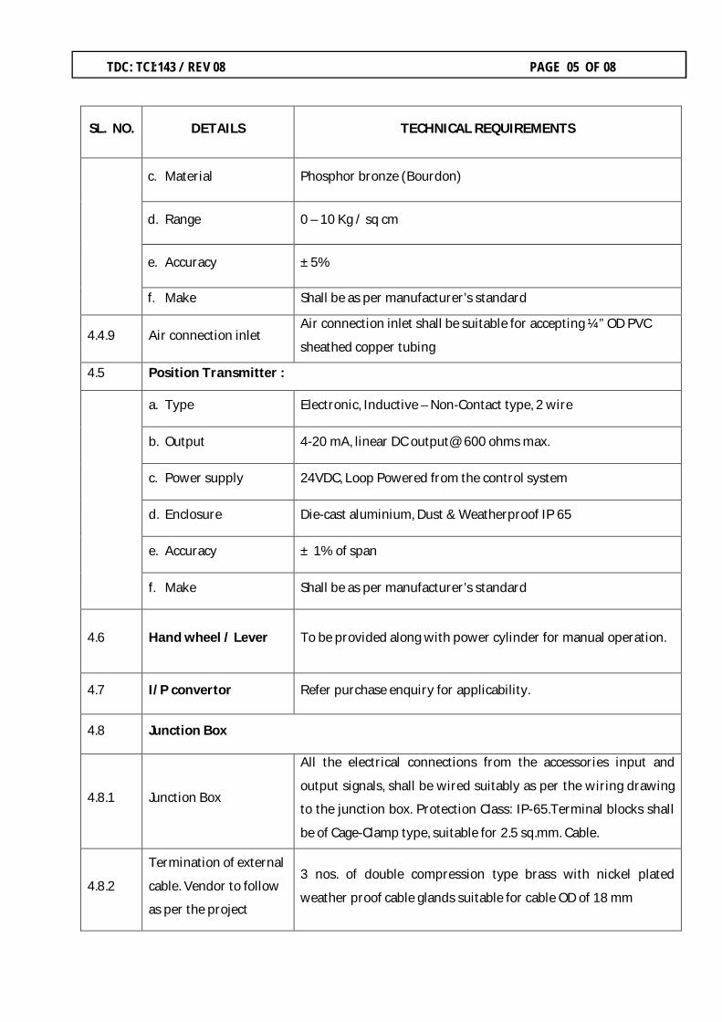
c. Material Phosphor bronze (Bourdon)
d. Range 0 – 10 Kg / sq cm
e. Accuracy ± 5%
f. Make Shall be as per manufacturer’s standard
4.4.9 Air connection inlet Air connection inlet shall be suitable for accepting ¼” OD PVC
sheathed copper tubing
4.5 Position Transmitter :
a. Type Electronic, Inductive – Non-Contact type, 2 wire
b. Output 4-20 mA, linear DC output@ 600 ohms max.
c. Power supply 24VDC, Loop Powered from the control system
d. Enclosure Die-cast aluminium, Dust & Weatherproof IP 65
e. Accuracy ± 1% of span
f. Make Shall be as per manufacturer’s standard
4.6 Hand wheel / Lever To be provided along with power cylinder for manual operation.
4.7 I/P convertor Refer purchase enquiry for applicability.
4.8 Junction Box
4.8.1
Junction Box
All the electrical connections from the accessories input and
output signals, shall be wired suitably as per the wiring drawing
to the junction box. Protection Class: IP-65.Terminal blocks shall
be of Cage-Clamp type, suitable for 2.5 sq.mm. Cable.
4.8.2
Termination of external
cable. Vendor to follow
as per the project
3 nos. of double compression type brass with nickel plated
weather proof cable glands suitable for cable OD of 18 mm
TDC: TCI:143 / REV 08 PAGE 06 OF 08
SL. NO. DETAILS TECHNICAL REQUIREMENTS
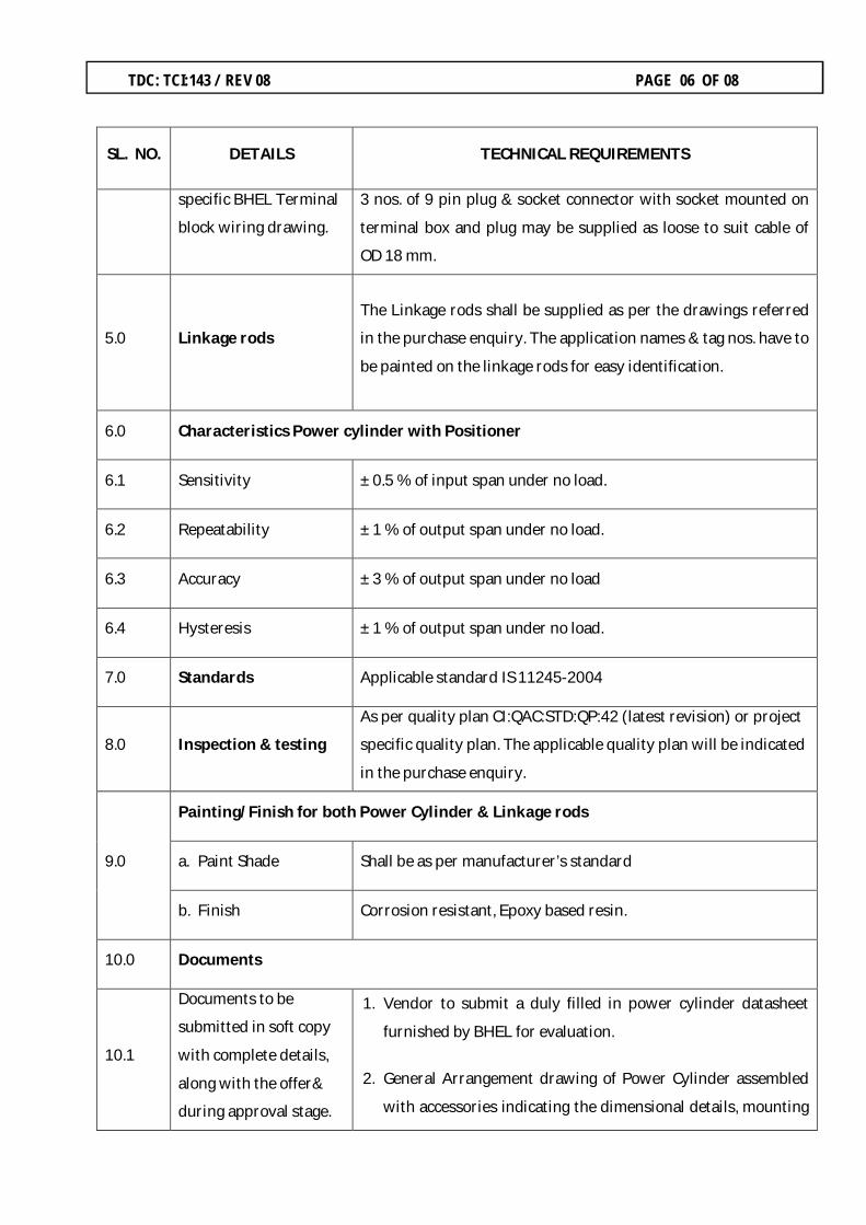
specific BHEL Terminal
block wiring drawing.
3 nos. of 9 pin plug & socket connector with socket mounted on
terminal box and plug may be supplied as loose to suit cable of
OD 18 mm.
5.0
Linkage rods
The Linkage rods shall be supplied as per the drawings referred
in the purchase enquiry. The application names & tag nos. have to
be painted on the linkage rods for easy identification.
6.0 Characteristics Power cylinder with Positioner
6.1 Sensitivity ± 0.5 % of input span under no load.
6.2 Repeatability ± 1 % of output span under no load.
6.3 Accuracy ± 3 % of output span under no load
6.4 Hysteresis ± 1 % of output span under no load.
7.0 Standards Applicable standard IS 11245-2004
8.0 Inspection & testing
As per quality plan CI:QAC:STD:QP:42 (latest revision) or project
specific quality plan. The applicable quality plan will be indicated
in the purchase enquiry.
9.0
Painting/Finish for both Power Cylinder & Linkage rods
a. Paint Shade Shall be as per manufacturer’s standard
b. Finish Corrosion resistant, Epoxy based resin.
10.0 Documents
10.1
Documents to be
submitted in soft copy
with complete details,
along with the offer&
during approval stage.
1. Vendor to submit a duly filled in power cylinder datasheet
furnished by BHEL for evaluation.
2. General Arrangement drawing of Power Cylinder assembled
with accessories indicating the dimensional details, mounting

TDC: TCI:143 / REV 08 PAGE 07 OF 08
SL. NO. DETAILS TECHNICAL REQUIREMENTS
arrangement& foundation details. Vendor has to submit a
neat & legible, soft copy of the Auto Cad drawing in pdf
version.
3. Tubing drawing indicating all the accessories.
4. Wiring drawing with terminal blocks numbers.
5. Taking care of all the requirements indicated in the technical
specification of the power cylinder, technical specification of
the SMART Positioner (for applicable projects) & technical
specification of the I to P Converter (for applicable projects)&
terminal block wiring drawing, vendor has to submit the No-
deviation format. In the “No Deviation format”, vendor to
specify the BHEL’s enquiry details, project details &reference
details of the documents/drawings referred above and should
indicate as “No – Deviation”. If vendor takes any deviation, the
offer is considered as incomplete and the same is liable for
rejection.
6. Point wise Confirmation to the applicable quality plan &
packing procedure.
7. Offer for :
a) Commissioning spares
b) Maintenance spares for two years operation

TDC: TCI:143 / REV 08 PAGE 08 OF 08
SL. NO. DETAILS TECHNICAL REQUIREMENTS
10.2
Operation &
Maintenance Manuals
1. 1 set of soft copy (loaded on a DVD) & 1 set of Hard Copy of
the O&M manual comprising of the following documents shall
be submitted to BHEL Trichy.
Operation & Maintenance instruction set.
Power Cylinder datasheets.
Dimensional drawing of the assembled power
cylinder.
Tubing drawing.
Wiring Drawing.
Erection/Calibration procedure.
Catalogues of the power cylinder & its accessories.
2. 1 No. of O&M manual and erection/calibration procedure
shall be placed in each power cylinder package for usage
during erection & commissioning activity.
10.0 Packing As per packing procedure No.
QA:CI:STD:PR:03 (latest revision).
11.0
Pre Qualification
Requirements
(For open tender case only)
Vendor should have supplied and commissioned similar products
of suitable ratings to thermal power plant applications and the
same shall be working satisfactorily for a period of minimum 2
years as on the date of techno-commercial bid opening.
The bidder can offer and supply such equipment with
collaboration or valid license agreement for design, engineering,
manufacture, supply of such equipment in India provided the
collaborator meets the above provenness criteria.
NOTE :-
1. Refer current valid list for revision status of Quality Plan, Drawing No. & Packing
Procedure.
2. Foundation bolts, Fasteners & Positioner cams shall be identified separately in shipping
list/ Delivery challan.

,
Bharat Heavy Electricals LimitedHIGH PRESSURE BOILER PLANT, TIRUCHIRAPPALLI 620014.
TECHNICAL DELIVERY CONDITIONS
FOR SUB· DELIVERY COMPONENTS OF
CONTROLS AND INSTRUMENTATION
ITDC: TCI: 317/REV 02 PAGE 01 OF 03
TECHNICAL SPECIFICATIONOF
SMART POSITION ER
Rev. DATE DESCRIPTION PREPARED REVIEWED APPROVED
No.
ENGG QAC
M.Muruga Prabu V.M.Selvaraaj D.Mahendrababu N.Sridhar
00 11-12-2009 Initial Release -sd- -sd- -sd- -sd-01 --- General Revisions -sd- -sd- I -sd- -sd-02 26'{)9-2013 Revised to edit the
r;JJ~ <2-.. v., ~#various clauses as
N'~,'-lY" ~~per the sitefeedback
v

TDC: TCI: 317 / REV 02 PAGE 02 OF 03
General instructions to the vendor :-
Vendor to quote the SMART positioner along with the position feedback module and alarm module.
Sl. No Technical Description/Requirement
1
SITE CONDITIONS :- Altitude above Sea Level Atmosphere Relative humidity Design Ambient temperature
500 Meters Tropical, Dusty, Windy & Heavily polluted atmosphere 0 – 95 % 50 ⁰C
2 Make SIEMENS / ABB
3 Type of Input
4-20 mA, 24VDC , 2 wire system (Loop powered from the external supply)
4 Operational signal range 3.6 mA - 21 mA (4-20 mA). Split range operation shall also be possible.
5 Voltage Vendor to specify.
6 Input impedance Vendor to specify.
7 Supply Air pressure 5 – 7 kg/cm2
8 Air Capacity Vendor to match with the requirement of the actuator.
9 Sensitivity, Characteristic Deviation, Hysteresis Vendor to match with the requirement of the actuator.
10 Type of Acting (Direct/Reverse) Vendor to match with the requirement of the actuator.
11 Stroke time Vendor to match with the requirement of the actuator.
12 No. of pneumatic outputs (Single/Double)
Vendor to match with the requirement of the actuator.
13 Pneumatic Process Connection ¼” NPT (F)

TDC: TCI: 317 / REV 02 PAGE 03 OF 03
Sl. No Technical Description/Requirement
14 Communication by Hart Protocol SMART positioner shall be compatible for Remote calibration & Diagnostics using Hart Management System.
15 Calibration SMART positioner shall be compatible for Auto Start with self calibration, Remote calibration & manual calibration using push buttons available on the positioner.
16 Position feed back 4-20mA position feedback signal shall be provided.
17 Indication for travel Electronic Indication shall be provided.
18 Electrical Cable entry Side or bottom entry to avoid water ingress.
19 Protection Class IP 65 minimum
20 Action of actuator during 4 to 20 mA control signal failure.
SMART positioner shall be compatible for achieving Fail Open, Fail Close & Stay put (Fail freeze) functions.
21 Accessories For Supply & output pressure, gauges shall be provided.
22 EMC Compliance SMART positioner shall conform to IEC 61000-6-2, 3, IEC 61326; or equivalent standards.
23 Influence of Temperature rise & Vibration effect on SMART Positioner
Vendor to specify.


BHARAT HEAVY ELECTRICALS LIMITED TIRUCHIRAPPALLI - 620014
QUALITY PLAN FOR
PNEUMATIC ACTUATOR (POWER CYLINDER) (OPEN / CLOSE AND REGULATING TYPE)
QA:CI:STD:QP:42 Rev: 04 Page: 2 of 4
M- MANUFACTURER/ SUB-VENDOR; B - BHEL / TPI ; C - CUSTOMER / TPI P - PERFORM; W - WITNESS V - VERIFICATION;
Sl. No
Component & Operation Characteristics Class Type of
Check
Quantum of check Ref Doc. & Acceptance STD
Format of
record
AGENCY Remarks
M B/C M B C
A RAW MATERIALS & BOUGHT OUT ITEMS INSPECTION 01 Cylinder Piston rod a. Material Critical CHEM One of
sample - Specification,
BS 970 TC V V -
b. Dimension Critical MEAS -do- - Mfr. Std. IIR/LGB P - -
02 “ O “ ring a. Material Critical CHEM -do- - Specification TC V V -
b. Dimension Critical MEAS -do- - Mfr. Std. IIR/LGB P - -
c. Hardness Critical MEAS -do- - -do- TC V V -
03 Cylinder Barrel & End Cover a. Material Critical CHEM -do- - Specification TC V V -
b. Dimension Critical MEAS -do- - Mfr. Std. IIR/LGB P - -
04 Piston Cylinder a. Pressure Resistance Test Major PHYS -do- - JIS B 8377 IIR/LGB P V -
05 Air filter Regulator a. Make & Type Major PHYS 100% - Specification, Data Sheet
IIR/LGB P - -
b. Output Gauge range Major PHYS -do- - Specification IIR/LGB P - -
c. Process connection Size Major MEAS -do- - -do- IIR/LGB P - -
d. Filter size in Microns Major PHYS -do- - -do- TC V V -
06 Limit Switches a. Make & Type Major PHYS -do- - Specification, Data Sheet
IIR/LGB P - -
b. Functional check Major ELEC -do- - Mfr. Std. IIR/LGB P - -
07 Air Lock Relay a. Make & Type Major PHYS -do- - Specification IIR/LGB P V -
b. Functional check Major ELEC -do- - Mfr. Std. IIR/LGB P - -
08 Solenoid valve (Applicable Only for open / close)
a. Make & Type Major PHYS -do- - Specification, Data Sheet
TC P - -
b. Coil Voltage Major MEAS -do- - -do- TC P - -
c. Class of Insulation Major PHYS -do- - -do- TC P - -
d. Duty Major VISU -do- - Mfr. Std. TC P -
e. Functional check Major ELEC & MECH
-do- - -do- IIR/LGB P - -
09 Positioner (Applicable only for regulating power Cylinder)
a. Make & Type Major VISU -do- - Data Sheet IIR/LGB P - - Performance to be checked during complete assembly testing

BHARAT HEAVY ELECTRICALS LIMITED TIRUCHIRAPPALLI - 620014
QUALITY PLAN FOR
PNEUMATIC ACTUATOR (POWER CYLINDER) (OPEN / CLOSE AND REGULATING TYPE)
QA:CI:STD:QP:42 Rev: 04 Page: 3 of 4
M- MANUFACTURER/ SUB-VENDOR; B - BHEL / TPI ; C - CUSTOMER / TPI P - PERFORM; W - WITNESS V - VERIFICATION;
Sl. No
Component & Operation Characteristics Class Type of
Check
Quantum of check Ref Doc. & Acceptance STD
Format of
record
AGENCY Remarks
M B/C M B C
B INPROCESS INSPECTION 01 Complete Assembly a. Functional check Major PHYS &
ELEC 100% - Mfr. Std. IIR/LGB P - -
b. Leak test Major PHYS -do- - JIS B 8377 IIR/LGB P - -
C FINISHED PRODUCT INSPECTION 01 Routine Test a. No Load test Major PHYS 100% 20% Mfr. Std. IIR/LGB P W -
b. Verification of Mounting of Accessories
Major VISU -do- -do- BHEL App. Drg. IIR/LGB P W -
c. Dimensional check including Process connections
Major MEAS -do- -do- BHEL App. Drg. LGB P W -
d. Verification of name plate for Type & Model Number
Major VISU -do- -do- BHEL App. Drg. IIR/LGB P W -
e. Stroke length & Time Major MEAS -do- -do- Spec. & BHEL App. Data Sheet
IIR/LGB P W -
f. Verification of accessories (Make and Model number)
Major VISU -do- -do- Spec. & BHEL App. Data Sheet
IIR/LGB P W -
g. Performance test (Sensitivity, Hysterisis, Accuracy, Repeatability) Applicable for Regulating duty
Major MEAS -do- -do- Specification IIR/LGB P W -
h. Stay put device Operation Major PHYS -do- -do- Mfr. Std. IIR/LGB P W -
i. Solenoid valve – Coil voltage rating, Insulation & duty (Applicable only for open/ close duty)
Major VISU &
ELEC
-do- -do- BHEL App. Data Sheet
IIR/LGB P W -
j. Air Filter- Filter Element size in microns
Major VISU -do- -do- Specification IIR/LGB P W -
02 Type Tests a. Load operation test Major PHYS One of sample
One of sample
Mfr. Std. TC P V -
b. Durability test Major PHYS -do- -do- JIS B 8377 TC P V -

BHARAT HEAVY ELECTRICALS LIMITED TIRUCHIRAPPALLI - 620014
QUALITY PLAN FOR
PNEUMATIC ACTUATOR (POWER CYLINDER) (OPEN / CLOSE AND REGULATING TYPE)
QA:CI:STD:QP:42 Rev: 04 Page: 4 of 4
M- MANUFACTURER/ SUB-VENDOR; B - BHEL / TPI ; C - CUSTOMER / TPI P - PERFORM; W - WITNESS V - VERIFICATION;
D.NOTES: 1.LEGENDS:
MECH : Mechanical MEAS : Measurement ELEC : Electrical TC : Test certificate TR : Test Report CHEM : Chemical VISU : Visual IIR : Internal Inspection Report
2. The vendor shall arrange all testing facilities at their works. Tests for which facilities are not available are to be carried out at recognized National Test Houses like ETDC/CIL/NPL/ERTL etc., at vendor cost.
3. Through Log Book / any other documents available at the vendor’s works, it shall be possible to correlate the finished products with raw material and in process stage checks / inspection carried out.
4. All Measuring and Testing Instruments shall be periodically calibrated from recognized test
houses & certificates made available during inspection for verification.
5. Test reports for routine tests are to be furnished by the vendor.
6. Type test certificate shall not be earlier than 5 years from the date of
Purchase enquiry.
7. Vendor to give tentative inspection program in advance and confirm exact date two weeks in advance for arranging BHEL’s inspection.
8. Packing shall be as per the “PACKING PROCEDURE “indicated in the
specification. E. REFERENCE STANDARDS: (For Indicated Standards Refer the Latest Version)
JIS B 8377 : Specification for Pneumatic Cylinder BS 970 : Specification for Wrought Steel for Mechanical end
SQP42R4.DOC


QA:CI:STD:PR:03 / Rev 02 Page 2 of 4
1.0 SCOPE
1.1 This procedure gives minimum guidelines to be complied with for packing of Electrical actuators,
Power cylinders and other Electrical equipments. This packing shall be suitable for different
handling operations and for the adverse conditions during transportation and during indoor /
outdoor storage for periods more than one year.
2.0 WOOD SPECIFICATION FOR PACKING
2.1 Rubber wood as per manufacturer standard.
2.2 Silver Oak as per procedure PR:CHEM:017 or as per relevant International Standards.
3.0 PACKING
3.1 For Inland packing, rubber wood and export packing Silver Oak wood shall be used. The wood
used shall be seasoned and treated.
3.2 The required wood case for the equipment to be packed shall be made out of individual planks of
single length. The case should not have joints. Sufficient number of horizontal, vertical and
diagonal planks (dimensions depending up on case size) shall be used for binding and
strengthening runners have to be provided with metallic sling plates for handling.
3.3 Support planks are to be provided such that, no force is acting on the parts of equipment or its
parts.
3.4 Power cylinders have to be packed with the piston in the closed condition.
3.5 Preservative chemicals are to be applied, wherever required.
3.6 Blank holes if any, shall be plugged.
3.7 Spring actuated equipments have to be de-energised before packing.
3.8 The equipments covered with a polythene sheet shall be kept inside the box, followed by coir,
wooden bottoms, thermo coal, etc to prevent vibration effect during loading, transportation, etc.
3.9 The gap between job and the box shall be filled with suitable material like jute, coir, thermo coal,
etc.
3.10 On all sides of the inner case, black polythene sheet shall be nailed.
3.11 Loose items of the equipment, if any, shall be packed separately.
3.12 Each case must have sufficient quantity of silica gel, packed in cotton cloth bags, shall be kept at
different places as required.
The bags used shall have the following information marked on it.
Silica Gel activator type:
Blue: Active
Rose: Reduced active
White: No activity. To be replaced with fresh Silica gel.
QA:CI:STD:PR:03 / Rev 02 Page 3 of 4
4.0 MARKING
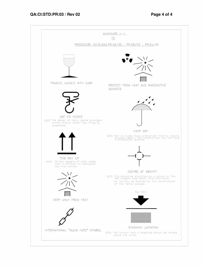
4.1 After completing the packing, Stencil marking, as per dispatch instructions and symbol marking as
per Annexure – I shall be made. Please ensure the box is stenciled with “FRAGILE ITEM”,
“HANDLE WITH CARE”
5.0 PACKING SLIP
5.1 A copy of the packing slip, kept in a polythene cover shall be kept inside the box. Another copy of
the packing slip, kept in a polythene cover shall be kept out side the box and covered with a
metallic plate to the case.
6.0 CAUTION
Do not pack any other Mechanical items with this case.
7.0 GENERAL
7.1 These packing procedures are the minimum requirements in addition to the standard instructions
mentioned in the Purchase Order and Specification.
7.2 Deviation to meet the packing procedure requirements / non-clarity in packing approach in any
quotation will be liable for rejection of offer.
QA:CI:STD:PR:03 / Rev 02 Page 4 of 4


CLAUSE NO. TECHNICAL REQUIREMENTS
VINDHYACHAL SUPER THERMAL POWER PROJECT
STAGE-V (1X500 MW) FLUE GAS DESULPHURISATION (FGD)
SYSTEM PACKAGE
TECHNICAL SPECIFICATION SECTION-VI
BID DOCUMENT NO.: CS-2260-109-2
PART-B SUB-SECTION-III-C2
MEASURING INSTRUMENTS
PAGE 2 OF 16
1.06.00 All instruments shall be provided with durable epoxy coating for housings and all exposed surfaces of the instruments.
2.00.00 SPECIFICATION FOR ELECTRONIC TRANSMITTER FOR PRESSURE, D.P., FLOW AND LEVEL
Sl. No. Features Essential/Minimum Requirements
1. Type of Transmitter
Microprocessor based 2 wire type, HART protocol compatible.
2. Accuracy ± 0.1% of calibrated span ( minimum)
3. Output signal range
4-20 mA DC (Analog) alongwith superimposed digital signal (based on HART protocol)
10:1 for vacuum/very low pressure applications. 4. Turn down ratio
30:1 for other applications.
5. ± 0.1% of calibrated span for six months for Ranges up to and including70 Kg/cm².
Stability
± 0.25% of calibrated span for six months for Ranges more than 70 Kg/cm²(g).
+/- 0.015% per deg.C at max span. 6. Zero and span drift
+/-0.11% per deg.C at min. span.
7. Load impedance
500 ohm (min.)
8. Housing Weather proof as per IP-55 with durable corrosion resistant coating.
9. Over Pr. 150% of max. Operating pr.
10. Connection (Electrical)
Plug and socket type
11. Process connection
1/2 inch NPT (F)

CLAUSE NO. TECHNICAL REQUIREMENTS
VINDHYACHAL SUPER THERMAL POWER PROJECT
STAGE-V (1X500 MW) FLUE GAS DESULPHURISATION (FGD)
SYSTEM PACKAGE
TECHNICAL SPECIFICATION SECTION-VI
BID DOCUMENT NO.: CS-2260-109-2
PART-B SUB-SECTION-III-C2
MEASURING INSTRUMENTS
PAGE 3 OF 16
Sl. No. Features Essential/Minimum Requirements
12. Span and Zero
Continuous, tamper proof, Remote as well as adjustability manual from instrument with zero suppression and elevation facility.
-Diaphragm seal, pulsation dampeners, syphon etc. as required by service and operating condition.
-2 valve manifold for absolute pressure transmitters (3-valve manifold for gauge/ vacuum pressure transmitters) and 5 valve manifold for DP/level/flow transmitters.
13. Accessories
-For hazardous area, explosions proof enclosure as described in NEC article 500.
14. Diagnostics Self Indicating feature
15. Power supply 24V DC ± 10%.
16. Adjustment/calibration/maintenance
Centralised PC based system (In Employer's Scope). In addition total two (2) no. of hand- held type universal calibrators compatible with HART protocol, shall be provided.
Notes. In case it becomes necessary to use a DP transmitter for pressure measurement then a 3-valve manifold should be used in place of 2-valve manifold.
LVDT type is not acceptable.
Where the process fluids are corrosive, viscous,solid bearing or slurry type, diaphragm seals shall be provided. Parts below the diaphragm shall be removable for cleaning. The entire volume above the diapragm shall be completely filled with an inert liquid suitable for the application.
3.00.00 ULTRASONIC TYPE LEVEL TRANSMITTERS
Sl.No.
Features Essential/Minimum requirements
1. Type of Transmitter Non contact Microprocessor based 2 wire type, HART protocol compatible Ultrasonic transmitter
2. Output signal Galvanically isolated 4-20mA DC (Analog) along

CLAUSE NO. TECHNICAL REQUIREMENTS
VINDHYACHAL SUPER THERMAL POWER PROJECT
STAGE-V (1X500 MW) FLUE GAS DESULPHURISATION (FGD)
SYSTEM PACKAGE
TECHNICAL SPECIFICATION SECTION-VI
BID DOCUMENT NO.: CS-2260-109-2
PART-B SUB-SECTION-III-C2
MEASURING INSTRUMENTS
PAGE 5 OF 16
Sl.No.
Features Essential/Minimum requirements
14. Display Minimum 4 character LCD display with integral keypad, access protected by user code
15. Diagnostics Loss of echo alarm etc
16. Load Impedance 500 ohms minimum
17. Electrical Connection Plug and socket
18. Accessories All weather canopy for protection from direct sunlight and direct rain.
All mounting hardware and accessories required for erection and commissioning mounting fittings material shall be SS 316.
For hazardous areas, explosion proof enclosure as described in NEC article 500.
Note:-
Contractor can also provide Radar type transmitter in place of ultrasonic transmitters subject to approval by Employer during detailed Engineering.
4.00.00 SPECIFICATION FOR PR. GAUGE, D.P. GAUGE, TEMP. GAUGE AND LEVEL GAUGE.
Sl.No
FEATURES ESSENTIAL/MINIMUM REQUIREMENTS
Pr. Gauge/ DP Gauge/Draught gauges
TemperatureGauge
Level Gauge
1 Sensing Element and material
Bourdon for high pressure, Diaphragm/Bellow for low pr. Of 316 SS
Mercury in steel for below 450°C and inert gas actuated for above 450°C of SS bulb and capillary.
Tempered toughened Borosilicate gauge glass steel armoured reflex or transparent type.

CLAUSE NO. TECHNICAL REQUIREMENTS
VINDHYACHAL SUPER THERMAL POWER PROJECT
STAGE-V (1X500 MW) FLUE GAS DESULPHURISATION (FGD)
SYSTEM PACKAGE
TECHNICAL SPECIFICATION SECTION-VI
BID DOCUMENT NO.: CS-2260-109-2
PART-B SUB-SECTION-III-C2
MEASURING INSTRUMENTS
PAGE 6 OF 16
Sl.No
FEATURES ESSENTIAL/MINIMUM REQUIREMENTS
Pr. Gauge/ DP Gauge/Draught gauges
TemperatureGauge
Level Gauge
2 Body material
Die-cast aluminium
Die-cast aluminium Forged carbon steel/304 SS
3 Dial size 150mm 150 mm Tubular covering entire range
4 End connection
1/2 inch NPT (F)
3/4" NPT (F) Process connection as per ASME PTC and drain/vent 15 NB
5 Accuracy ±1% of span ± 1% of span ± 2%
6 Scale Linear, 270° arc graduated in metric units
Linear, 270° arc graduated in °C
Linear vertical
7 Range selection
Cover 125% of max. of scale
Cover 125% of max. of scale
Cover 125% of max. of scale
8 Over range test
Test pr. for the assembly shall be1.5 to the max. Design pr. at 38°C.
9 Housing Weather and dust proof as per IP-55
Weather and dust proof as per IP-55
CS/304 SS leakproof
10 Zero/span adjustment
Provided Provided --
11 Identification Engraved with service legend or laminated phenolic name plate
12 Accessories Blow out disc, siphon, snubber, pulsation dampener, chemical seal
SS Thermowell Gasket for all KEL-F shield for transparent type vent and drain valves of Steel/SS as per CS/Alloy process

CLAUSE NO. TECHNICAL REQUIREMENTS
VINDHYACHAL SUPER THERMAL POWER PROJECT
STAGE-V (1X500 MW) FLUE GAS DESULPHURISATION (FGD)
SYSTEM PACKAGE
TECHNICAL SPECIFICATION SECTION-VI
BID DOCUMENT NO.: CS-2260-109-2
PART-B SUB-SECTION-III-C2
MEASURING INSTRUMENTS
PAGE 7 OF 16
Sl.No
FEATURES ESSENTIAL/MINIMUM REQUIREMENTS
Pr. Gauge/ DP Gauge/Draught gauges
TemperatureGauge
Level Gauge
(if required by process) gauge isolation valve
Requirement.
13 Material of Bourdon/ movement
316 SS / 304 SS
316 SS / 304 SS
Notes:-
Length of gauge glass shall not be more than 1400 mm. If the vessel is higher, multiple gauge glasses with 50 mm overlapping shall be provided.
Where the process fluids are corrosive, viscous, solid bearing or slurry type, diaphragm seals shall be provided. Parts below the diaphragm shall be removable for cleaning. The entire volume above the diaphragm shall be completely filled with an inert liquid suitable for the application.
5.00.00 PROCESS ACTUATED SWITCHES
FEATURES ESSENTIAL / MINIMUM REQUIREMENTS
Pressure/ Draft Switches/ DP Switches
Temperature switches
Level switches
Float type switches/RF type for applications as decided by Employer during detailed engineering.
Sensing Element
Piston actuated for high pressure and diaphragm or bellows for low pr./ vacuum
Vapor pressure sensing, liquid filled bellow type with SS bulb and capillary (10 m minimum) above gland Radio-
frequency/capacitance type for other application.

CLAUSE NO. TECHNICAL REQUIREMENTS
VINDHYACHAL SUPER THERMAL POWER PROJECT
STAGE-V (1X500 MW) FLUE GAS DESULPHURISATION (FGD)
SYSTEM PACKAGE
TECHNICAL SPECIFICATION SECTION-VI
BID DOCUMENT NO.: CS-2260-109-2
PART-B SUB-SECTION-III-C2
MEASURING INSTRUMENTS
PAGE 8 OF 16
FEATURES ESSENTIAL / MINIMUM REQUIREMENTS
Pressure/ Draft Switches/ DP Switches
Temperature switches
Level switches
Material 316 SS Bulb 316 SS/ capillary 304 SS
316 SS
End connection
½ inch NPT (F) ½ inch NPT (F) Manufacturer standard
Over range proof pressure
150% of max. design pr.
- 150% of max. design pressure
Repeat-ability
+ 0.5% of full range
No. of contacts
2 No.+2NC. SPDT snap action dry contact
Rating of contacts
60 V DC, 6 VA (or more if required by or PLC)*
Elect. Connection
Plug in socket
Set point/ dead band adjustment
Provided over full range
Enclosure Weather and dust proof as per IP-55
Accessories Syphon, snubber, chemical seal, pulsation dampeners as required by process
Thermo well of 316 SS and packing glands
All mounting accessories

CLAUSE NO. TECHNICAL REQUIREMENTS
VINDHYACHAL SUPER THERMAL POWER PROJECT
STAGE-V (1X500 MW) FLUE GAS DESULPHURISATION (FGD)
SYSTEM PACKAGE
TECHNICAL SPECIFICATION SECTION-VI
BID DOCUMENT NO.: CS-2260-109-2
PART-B SUB-SECTION-III-C2
MEASURING INSTRUMENTS
PAGE 9 OF 16
FEATURES ESSENTIAL / MINIMUM REQUIREMENTS
Pressure/ Draft Switches/ DP Switches
Temperature switches
Level switches
Mounting Suitable for enclosure/ rack mounting or direct mounting
Suitable for rack mounting or direct mounting
-
Where the process fluids are corrosive, viscous, solid bearing or slurry type, diaphragm seals shall be provided. Parts below the diaphragm shall be removable for cleaning. The entire volume above the diaphragm shall be completely filled with an inert liquid suitable for the application.
5.01.00 Limit switches shall be silver plated with high conductivity and non-corrosive type. Contact rating shall be sufficient to meet the requirement of Fire alarm Control System subject to a minimum of 60V, 6VA rating. Protection class shall be IP-55.
6.00.00 SOLENOID VALVES
Solenoid valves shall fulfill the following requirements : -
a) Type 2/3/4 way SS 316/ forged brass (depending on the application subject to Employer’s approval during detailed engg.)
b) Power supply 24V DC.
c) Plug in connector connection.
d) Insulation : Class “H”
7.00.00 TEMPERATURE ELEMENTS
7.01.00 Thermocouple
---------------------------------------------------------------------------------------------------------------- Sr. No. Features Essential/Minimum Requirements ---------------------------------------------------------------------------------------------------------------- 1 Type of Thermocouple. : 16 AWG wire of Chromel-Alumel (Type K) or 24
AWG wire Pt-Rhodium Pt (Type R) depending on operating temperature Range (ungrounded type).

CLAUSE NO. TECHNICAL REQUIREMENTS
VINDHYACHAL SUPER THERMAL POWER PROJECT
STAGE-V (1X500 MW) FLUE GAS DESULPHURISATION (FGD)
SYSTEM PACKAGE
TECHNICAL SPECIFICATION SECTION-VI
BID DOCUMENT NO.: CS-2260-109-2
PART-B SUB-SECTION-III-C2
MEASURING INSTRUMENTS
PAGE 10 OF 16
2 No. of element : Duplex 3 Housing/Head : IP-55/Diecast Aluminium. Plug in connectors
are to be provided for external signal cable connection.
4 Sheathing of : Swaged type magnesium oxide insulation. Thermocouple 5 Calibration and accuracy : As per IEC-751/ANSI-C-96.1(special class) for
T/C. 6 Characteristic : Linear with respect to temp, within ±1/2 percent
of top range value. 7 Accessories : Thermo well (as specified below) and shall be
spring loaded for positive contacts with the well. 8 Standard : ANSI C 96.1 for Thermocouple and ASME
PTC-19.3 for Thermo-well. 7.02.00 Resistance Temperature Detector (RTD) ---------------------------------------------------------------------------------------------------------------- Sr. No. Features Essential/Minimum Requirements ---------------------------------------------------------------------------------------------------------------- 1 Type of RTD. : Four wire, Pt-100 (100 Ohms resistance at zero
degree Centigrade). 2 No. of element : Duplex 3 Housing/Head : IP-55/Diecast Aluminium. Plug in connectors
are to be provided for external signal cable connection.
4 Sheathing of RTD : Metal sheathed, ceramic packed 5 Calibration and accuracy : As per DIN-43760 Class-A for RTD 6 Characteristic : Linear with respect to temp, within ±1/2 percent
of top range value. 7 Accessories : Thermo well (as specified below) and shall be
spring loaded for positive contacts with the well. 8 Standard : DIN-43760 for RTD and ASME PTC-19.3 for
Thermo-well.

CLAUSE NO. TECHNICAL REQUIREMENTS
VINDHYACHAL SUPER THERMAL POWER PROJECT
STAGE-V (1X500 MW) FLUE GAS DESULPHURISATION (FGD)
SYSTEM PACKAGE
TECHNICAL SPECIFICATION SECTION-VI
BID DOCUMENT NO.: CS-2260-109-2
PART-B SUB-SECTION-III-C2
MEASURING INSTRUMENTS
PAGE 11 OF 16
7.03.00 Thermo well (for all process temp. elements)
(a) Shall be one piece solid bored type of 315 SS of step-less tapered design. (As per ASME PTC 19.3 1974)
(b) For Mill classifier outlet long life solid sintered tungsten carbide material of high abrasion resistance shall be provided.
(c) For Air & Flue gas 316 SS protecting tube with welded cap. (However contractor shall provide better material for Flue gas service if require based on the specify boiler design parameters).
(d) For furnace zone, impervious ceramic protecting tube of suitable material along with Incoloy supporting tubes and adjustable flanges.
8.00.00 TEMPERATURE TRANSMITTER
Following types of 2-wire temperature transmitter (directly powered from 4-20mA input cards of PLC) shall be provided. The temperature transmitter shall be fully compatible with thermocouples and RTDs being provided by the contractor. Temperature compensation of the thermocouples shall be performed in the temperature transmitter itself.
a. Single Input Head mounted Temperature Transmitter
These shall be suitable for mounting in the head of temperature element itself. The protection class of head of thermo well along with its plug-in connector shall be min. IP65.
b. Single Input DIN-rail mounted Temperature Transmitter
These shall be especially designed for DIN-rail mounting in JBs. The specifications of the JBs shall be same as indicated in Subsection-IV:I7 (INST CABLE) with additional DIN-rails and IP 65 Protection class. This temperature transmitter shall be the ones which are specially designed for DIN-rail mounting with IP 20 protection class. These shall have terminals for input/output provided on front side when mounted on DIN-rail. Head mounted temperature transmitter with clamps to make it suitable for DIN-rail mounting shall not be acceptable under this category.
c. Dual-input Temperature Transmitter With Indicator:
The dual-input TTs shall be suitable for mounting in enclosures/racks and shall be provided with clamps. Indicator shall be provided with these transmitters. These transmitters shall have bump less change over facility to

CLAUSE NO. TECHNICAL REQUIREMENTS
VINDHYACHAL SUPER THERMAL POWER PROJECT
STAGE-V (1X500 MW) FLUE GAS DESULPHURISATION (FGD)
SYSTEM PACKAGE
TECHNICAL SPECIFICATION SECTION-VI
BID DOCUMENT NO.: CS-2260-109-2
PART-B SUB-SECTION-III-C2
MEASURING INSTRUMENTS
PAGE 12 OF 16
second sensor in case first sensor fails .This change-over is to be alarmed. Protection class shall be IP65 minimum.
d. Common requirements for each of the above type of temperature transmitters
Output : 2-wire (power supply from input card of Control System) with 4-20mA output with superimposed HART protocol signal.
Input : Same transmitter shall be capable to handle Pt-100 RTD , Thermocouples -K&R types (input type to be selectable at site through HART terminal)
Isolation : min. 500 V AC
EMC compatibility : as per EN 61326
Operating ambient : 0 to 85 deg C (without indicator) temperature 0 to 70 deg C (with indicator)
Power supply compatible with input module of Control System
Accessories Mounting arrangements including clamps etc.
Composite (a) For head mounted and DIN-rail mounted
Accuracy types: (Refer note 2 ) RTD =<0.4% of 0-250 deg C span T/C-K type =<0.4% of 0-600 deg C span T/C-R type =<0.4% of 0-1000 deg C span CJC accuracy (for thermocouples) shall be =< 1 deg C (b) For dual-input type: RTD =<0.25% of 0-250 deg C span T/C-K type =<0.2% of 0-600 deg C span CJC accuracy (for thermocouples) shall be =< 1 deg C

CLAUSE NO. TECHNICAL REQUIREMENTS
VINDHYACHAL SUPER THERMAL POWER PROJECT
STAGE-V (1X500 MW) FLUE GAS DESULPHURISATION (FGD)
SYSTEM PACKAGE
TECHNICAL SPECIFICATION SECTION-VI
BID DOCUMENT NO.: CS-2260-109-2
PART-B SUB-SECTION-III-C2
MEASURING INSTRUMENTS
PAGE 13 OF 16
9.00.00 SPECIFICATION FOR FLOW ELEMENTS
9.01.00 Orifice Plate
---------------------------------------------------------------------------------------------------------------- Features Essential/Minimum Requirements ---------------------------------------------------------------------------------------------------------------- Type Concentric as per ASME PTC-19.5 (Part-II),
ISA RP-3.2, 1960 or BS-1042 Material 316 SS Thickness 3 mm for main pipe diameter up to 300 mm
and6 mm for main pipe dia above300 mm. Material of branch pipe Same as main pipe Root valve type Globe Root valve material 316 SS Root valve size 1 inch Impulse pipe of same material Required up to root valve Tappings Flanged weld neck. 3 pairs. of tapping. Beta Ratio 0.34 to 0.7 Beta Ratio calculation to be Yes submitted Assembly drg. and flow Vs Yes DP Curves Accessories Root valves, flanges, Vent/drain hole (As
required)
Contractor shall submit certified flow calculation and differential pressure vs. flow curves for each element for Employer's approval. Sizing calculation, precise flow calculation for all the flow elements, fabrication and assembly drawings and installation drawings shall be submitted for Employer's approval. One Flow element of each type shall be calibrated in the test laboratory for validation of computated flow calculations.

CLAUSE NO. TECHNICAL REQUIREMENTS
VINDHYACHAL SUPER THERMAL POWER PROJECT
STAGE-V (1X500 MW) FLUE GAS DESULPHURISATION (FGD)
SYSTEM PACKAGE
TECHNICAL SPECIFICATION SECTION-VI
BID DOCUMENT NO.: CS-2260-109-2
PART-B SUB-SECTION-III-C2
MEASURING INSTRUMENTS
PAGE 14 OF 16
9.02.00 Flow Nozzle
---------------------------------------------------------------------------------------------------------------- Features Essential/Minimum Requirements ---------------------------------------------------------------------------------------------------------------- Type Long radius, welded type as per ASME
PTC-19.5 (Part-III) or BS-1042 Material 316 SS Thickness Suitable for intended application. Material of branch pipe Same as main pipe Root valve type Globe Root valve material 316 SS Root valve size 1 inch Impulse pipe of same material Required up to root valve Tapping D and D/2 (3 Nos. of tappings) Beta Ratio Around 0.7 Beta Ratio calculation to be Yes submitted Assembly drg. and flow Yes Vs DP Curves Accessories Root valves, vent and drain hole. ----------------------------------------------------------------------------------------------------------------
Contractor shall submit certified flow calculation and differential pressure vs. flow curves for each element for Employer's approval. Sizing calculation, precise flow calculation for all the flow elements, fabrication and assembly drawings and installation drawings shall be submitted for Employer's approval. One Flow element of each type shall be calibrated in the test laboratory for validation of computed flow calculations.


1. Scope
This procedure deals with the Test set up, methodology and calculations involved in type testing of Gate / Damper for establishing the leak tightness of Gate / Damper used in pressurized systems.
2. Reference documents
2.1 Corresponding Drawings 2.2 Approved Quality Plan
3. General
3.1 The Gate & Flap damper shall be tested in vertical position and the damper shall be tested in horizontal position Approved Quality Plan.
3.2 The Gate / Damper shall be operated for a minimum of five (5) times, before testing.
3.3 One operation is defined as from fully closed position to fully open position and back to fully closed position.
3.4 Upon completion of testing, the Gate / Damper shall be visually inspected for any physical damage to its components.
4. Test Procedure
4.1 Equipment requirement for type test is detailed out and the arrangement of the test equipment shall be as shown in the Annexure – II & III when they are to be tested without using seal air and as per Annexure – IV & V when they are to be tested with seal air.
4.2 The Gate / Damper ( Item No. 01) shall be kept closed.
4.3 Energize the pressurizing fan ( Item No. 02) and by adjusting the by-pass valve ( Item No. 06) set the plenum duct ( Item No. 04) pressure to the Gate / Damper pressure at MCR condition by using pressure tap ( Item No. 07) and U Tube Manometer / Digital manometer.
4.4 Measure and record the velocity head at Pitot tubes ( Item No. 08). Minimum three readings will be taken in each measurement and average will be recorded. Readings will be tabulated as per Annexure –I.
4.5 Using the formulae given in clause 5.0, calculate the leakage flow rate and estimate the degree of leak tightness of Gate / Damper.
G&D : L TTP Page 2 of 7

4.6 If Seal Air is applicable, the same shall be connected and leakage will measured and calculated with Seal Air as per the step 4.3 to 4.5. Refer test set up drawings, Annexure – IV & V)
5 Calculations
Variables
QS - Volumetric flow rate of medium at MCR m3 /sec D - ID of connecting pipe mm T - Temperature deg C Pst - Plenum Chamber Pressure (static) mm WC Vp - Velocity head mm WC d - Density of air kg/m3
A - Connecting duct area of Cross section m2 V - Velocity m/sec Q - Flow rate (leak rate) m3/ sec
V = 4.4222 x K x SVp
√d Where V - Velocity of air in m /sec Vp - Velocity head in mm of WC measured in pitot tube
K - Constant for single point reading ( 0.91 for single point reading) d - Air density (kg/m3) at test temperature and pressure. d = 1.225 x (288.5) X (10335 + Pst )
( 273 + TºC ) 10335 Q = A x V % Leakage = Leakage flow (Q) _ X 100 Flow rate of medium at MCR Correction for Temperature & Pressure: Q1 = Q x ( d/ d1) Where, Q1 - Leak rate of medium at specified temperature & pressure d1 - Density of medium at specified temperature & pressure
G & D : LTTP Page 3 of 7

Percentage Leak at site condition, LS = (Q1/QS) x 100 Therefore Leak Tightness at site, LTS = ( 100 – LS )% = ( 1 - Q1/QS ) x 100%
Equipment List
Item No.
Description
01 Typical Gate / Damper : Gate / Damper to be tested
02 Pressurizing Fan sized to provide air supply at rated pressure to the plenum duct ( Item No. 04) for testing.
03 Connecting pipe to connect pressurizing fan and plenum duct.
04 Plenum Duct to apply pressure to the Gate / Damper
05 Thermometer to measure the Temperature.
06 Bypass Valve mounted on the connecting duct to regulate the pressure in the plenum duct.
07 Pressure Tap provided to measure the air pressure in the plenum duct.
08 Pitot tube to measure velocity head.
09 Seal Air Blower ( In case of testing using seal air supply. Refer Annexure- IV & V)
G & D : LTTP Page 4 of 7

G & D : LTTP Page 5 of 7


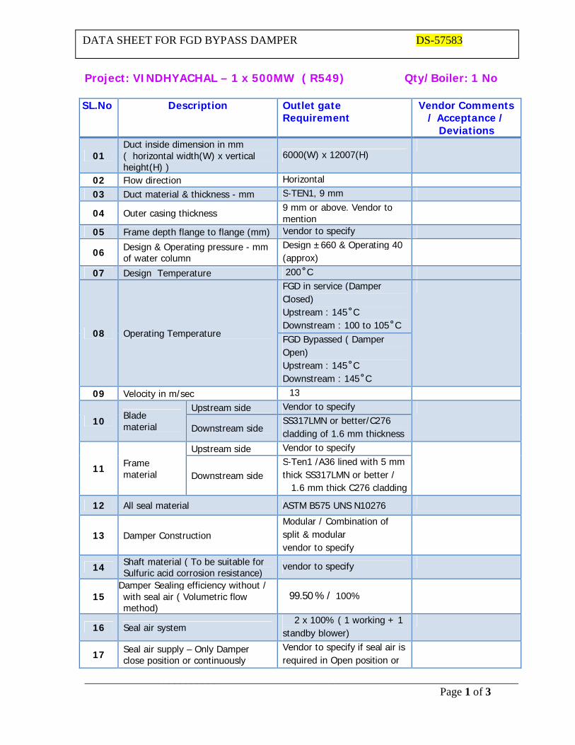
_____________________________________________________________________________ Page 1 of 3
DATA SHEET FOR FGD BYPASS DAMPER DS-57583
Project: VINDHYACHAL – 1 x 500MW ( R549) Qty/Boiler: 1 No SL.No Description Outlet gate
Requirement Vendor Comments
/ Acceptance / Deviations
01 Duct inside dimension in mm ( horizontal width(W) x vertical height(H) )
6000(W) x 12007(H)
02 Flow direction Horizontal
03 Duct material & thickness - mm S-TEN1, 9 mm
04 Outer casing thickness 9 mm or above. Vendor to mention
05 Frame depth flange to flange (mm) Vendor to specify
06 Design & Operating pressure - mm of water column
Design ±660 & Operating 40 (approx)
07 Design Temperature 200 ̊ C
08 Operating Temperature
FGD in service (Damper Closed) Upstream : 145 ̊ C Downstream : 100 to 105 ̊ C
FGD Bypassed ( Damper Open) Upstream : 145 ̊ C Downstream : 145 ̊ C
09 Velocity in m/sec 13
10 Blade material
Upstream side Vendor to specify
Downstream side SS317LMN or better/C276 cladding of 1.6 mm thickness
11 Frame material
Upstream side Vendor to specify
Downstream side S-Ten1 /A36 lined with 5 mm thick SS317LMN or better /
1.6 mm thick C276 cladding
12 All seal material ASTM B575 UNS N10276
13 Damper Construction Modular / Combination of split & modular vendor to specify
14 Shaft material ( To be suitable for Sulfuric acid corrosion resistance)
vendor to specify
15 Damper Sealing efficiency without / with seal air ( Volumetric flow method)
99.50 % / 100%
16 Seal air system 2 x 100% ( 1 working + 1
standby blower)
17 Seal air supply – Only Damper close position or continuously
Vendor to specify if seal air is required in Open position or

_____________________________________________________________________________ Page 2 of 3
DATA SHEET FOR FGD BYPASS DAMPER DS-57583
required blower can be switched off.
18 Blower mounting & seal air piping arrangement
Vendor to provide GA drg.
19 Seal air volumetric flow (CFM) & pressure (mm WC) at i) Blower & ii) Damper frame inlet
Vendor to specify
20 Blower motor rating in KW Blower Make & Model no.
Vendor to specify
21 Damper Actuator Make& Model No. SMART Positioner Make& Model no.
Vendor to specify
22 Actuation timings
a) Normal open /close timing without intermediate stops > 60 seconds
b) Quick open timings < t seconds ( t should be adjustable between 10 to 20 seconds)
23 Intermediate closing / opening positions
a)(i) First 40% closing (ii) Next 40% closing (iii) Final 20% closing
b) Opening is in the reverse order of above closing
24
Air consumption for one operation (Open to close / close to open) in m3 /sec for i) Normal operation & ii)Quick opening
Vendor to specify
25 Integral limit switches at the actuator
Pair of limit switches shall be provided at open & Close positions and continuous position feedback of 4 -20 mA to achieve intermediate opening positions
26 Actuator mounting with drive shaft Vendor to specify
27 Heater and related instrumentation for seal air – Make, Model no. & Rating KW
Vendor to specify
28
Pressure switch – Make & Model no. Circuitry type Contacts rating
Vendor to specify Heavy duty DPDT
(2NO+2NC) Continuous rating of 10A at 250V AC/ 0.1 A at 250V DC

_____________________________________________________________________________ Page 3 of 3
DATA SHEET FOR FGD BYPASS DAMPER DS-57583
29
Auxiliary Power consumption in KW when FGD is in operation ( Damper closed condition)
i) Seal air Blower ii) Seal air Heater
Considering ambient air temp of 27°C & 60% Relative humidity and heated to 130°C.
Vendor to specify
29 Weight of Assembled Damper with all Accessories in kg
Vendor to specify
VENDOR SIGNATURE : SEAL:

Rev.00. dt. 04-11-2014 Page 1 of 1
PI-57583
PROFORMA INVOICE / PRICE BID for FGD BYPASS DAMPER
PROJECT : NTPC Vindhyachal #13 – 1 x 500 MW (R549) , ENQUIRY NO:_______ The scope of supply shall mandatorily cover the following items and the "Quantities" indicated against each item description in the table. Sl. No.
ITEM DESCRIPTION Unit Rate
Enquiry Quantity
Total Price
1 FGD Bypass Damper with mating flanges, Pneumatic Actuators and accessories as per specification GDRS: 018, Clause no. 3.0 & 19.0
1 set
2 Mandatory spares consisting of : i) 1 no. Pneumatic actuator for the damper ii) 1 set of seals ( set means for complete
replacement of all damper(s) applicable in 1 duct of size 6m x 12.007m)
1 set
3 Leak tightness type test charges ( on Volumetric flow ) as per GDRS: 018, clause no. 12.0
1
4 Erection & commissioning support as per clause no. 6.2, 6.3 & 16.0 of GDRS: 018
1
5 Grand Total price for above scope (sl nos. 1 to 4)
Note: In unpriced PRICE BID, bidder has to indicate “Quoted” against the columns “Unit Rate” and “Total Price” in above Table. The numerical values ( Price) for all the above to be quoted in “price bid” only. No conditional clause shall be inserted into price bid by bidder. Any conditions added in price bid will cause rejection of bidder’s offer. Certified that all items indicated in above table are covered in scope of supply. BIDDER’s SIGNATURE : BIDDER’s SEAL :

CL-BL-57583 CHECKLIST for FGD BYPASS Bi-Plane Damper ( Vindhyachal 500 MW, R549)
Rev.00. dt. 04-11-2014 Vendor seal & signature Page 1 of 1
(Vendor shall submit this checklist duly filled along with Technical offer)
Sl. no:
DOCUMENTS Furnished status / Confirmation
(Yes/No) 1 Filled up Data sheets - DS-57583 2 Comments /Acceptance/Deviations against the General specification as
per GDRS: 018
3 Proforma Invoice – PI-57583 filled and enclosed and all items as per cl.no.3.0 of GDRS: 018 included in scope of supply.
4 Mandatory spares (Pneumatic Actuator & set of seals ) price considered in the proforma Invoice PI-57583
5 Leak tightness test charges considered in the proforma Invoice PI-57583 for one damper
6 Erection and commissioning support charges confirming to cl.nos. 6.2, 6.3 & 16.0 in Technical specification GDRS: 018 First visit - for erection, second visit - 2 days for commissioning considered in Proforma Invoice PI-57583, sl.no.4
7 Scope of supply clearly indicating terminal points & exclusions. 8 General arrangement drawing enclosed with Technical offer showing:
a) Overall Dimensions of Damper with all accessories with BOM, b) Material of construction, c) Split / modular details , d) Seals
arrangement on all the four sides , e) Blade construction detail & f) weight details.
9 i)Quality plan in line with BHEL QP & ii) filled up NTPC format no. QS-01-QAI-P-04/ F2-R1 (7 pages) enclosed
10 Spares list quoted & valid for a period of 3 years: a) Commissioning spares b) Recommended spares for three years trouble free operation
11 Reference list details & G.A. drawings satisfying the Qualification Requirements enclosed as per cl. No. 14.0 (c) & (d) of GDRS: 018
12 Vendor confirmation for submission of specified drawing / document for approval (as specified in the general specification GDRS: 018 clause no. 21.2, 21.3 & 21.4) after placement of purchase order
13 Bidder’s confirmation of leak tightness testing to meet ≥ 99.50% efficiency without seal air and 100% with seal air by volumetric flow method and as per enclosure G&D:LTTP ( 7 pages)
14 Confirmation to painting requirement as per PS VINDHYACHAL R549 REV.00 .dt. 16.08.2012 ( 1 page)
15 Confirmation that Damper proposed is of Modular( dismantlable)/ combination of Split & Moduar design for transportation & Assembly at site as per GDRS:018, Clause no. 6.1.
16 Confirmation that all Instrumentation as specified in GDRS: 018 & BHEL P&ID : 4610-101-05RP and Inst_Spec-57583 are supplied in vendor scope.
17
Confirmation that Electrical Heater and Blower can be switched off when the Damper Blades are in Open condition ( FGD not in operation) and none of the flue gas exposed parts will be subject to corrosion ( as per cl. No. 20.0 (A) )

![ACATacat.or.th/download/acat_or_th/journal-4/04 - 04.pdf · APmin APmax Appendix G [1] AP APmax Overpressure Relief Damper Damper 12 Relief Damper Relief Damper (Vent) Fire Damper](https://img.pdfslide.us/doc/110x75/5f7cb481641db55595223717/-04pdf-apmin-apmax-appendix-g-1-ap-apmax-overpressure-relief-damper-damper.jpg)