Embed Size (px)
Citation preview

C I T Y O F R I V E R S I D E
PUBLIC UTILITIES DEPARTMENT
WATER DIVISION
SPECIFICATION NO. 205
FOR THE DESIGN AND INSTALLATION
OF POTABLE WATER DISTRIBUTION SYSTEMS JUNE 2013

TABLE OF CONTENTS
PART 1 GENERAL PROVISIONS 1 thru 19 Section 1 - Terms, Definitions, Abbreviations & Symbols 1 Section 2 - Scope & Control of the Work 5 Section 3 - Changes in Work 8 Section 4 - Control of Materials 13 Section 5 - Utilities 14 Section 6 - Prosecution, Progress & Acceptance of the Work 14 Section 7 - Responsibilities of the Contractor 15 Section 8 - Facilities for Agency Personnel 18 Section 10 - Telephone 19
PART 2 CONSTRUCTION MATERIALS 20 thru 42 Section 200 - Rock Materials 20 Section 201 - Concrete, Mortar and Related Materials 20 Section 203 - Bituminous Materials 21 Section 207 - Pipe 22 Section 207-9 - Ductile Iron Pipe 22 Section 207-10 - Steel Pipe 24 Section 207-25 - Miscellaneous Pipe 27 Section 210 - Paint and Protective Coatings 28 Section 250 - Valving, Appurtenances and Miscellaneous Materials 29 Section 250-1 - Nuts and Bolts 29 Section 250-2 - Gaskets 29 Section 250-3 - Insulation Gaskets 29 Section 250-4 - Butterfly Valves 31 Section 250-5 - Gate Valves 32 Section 250-6 - Valve Box Caps 34 Section 250-7 - Air Valves 34 Section 250-8 - Brass and Bronze Items 35 Section 250-9 - Flanges 37 Section 250-10 - Fire Hydrants/Blowoff Assemblies 38 Section 250-11 - Bolted Sleeve-Type Couplings 39 Section 250-12 - Meter Boxes 41 Section 250-13 - Joint Lubricants 41 Section 250-14 - Polyethylene Encasement 42
PART 3 CONSTRUCTION METHODS 42 thru 74 Section 300 - Earthwork 42 Section 301 - Treated Soils, Subgrade Preparation and Placement Of Base Materials 43 Section 302 - Roadway Surfacing 43

Section 306 - Underground Conduit Construction 45 Section 306-1 - Open Trench Operations 45 Section 306-9 - Appurtenant Pipeline Structures and Installation 62 Section 306-10 - Protective Coating 68 Section 306-11 - Fire Hydrant Installations 68 Section 307 - Street Lighting and Traffic Signals 69 Section 310 - Painting 70 Section 312 - Pavement Marker Placement and Removal 73 Section 313 - "As Built" Drawings 74
PART 7 TESTING AND DISINFECTION OF WATER MAINS
AND APPURTENANCES 75 thru 83 Section 700-1 - General 75 Section 700-2 - Pressure Test 75 Section 700-3 - Allowable Leakage 76 Section 700-4 - Flushing 77 Section 700-5 - Disinfection 78 Section 700-6 - Bacteriological Tests 80 Section 700-7 - Bacteriological Tests 81 Section 700-8 - Contractor's Responsibility for Testing
and Disinfection 82 Section 700-8 - System Connections to Existing City Water Lines 83
APPENDIX I DESIGN CRITERIA
APPENDIX II APPROVED MATERIAL LIST – DECEMBER 2012
APPENDIX III STANDARD DRAWINGS

1
CITY OF RIVERSIDE - PUBLIC UTILITIES DEPARTMENT
WATER DIVISION
WATER DISTRIBUTION SYSTEM
SPECIFICATION NO. 205
SPECIAL PROVISIONS The following revisions and additions supplement, modify and take precedence over the “Standard Specifications for Public Works Construction” (Latest Edition and any adopted supplements) applying to private contracts for Public Improvement. (Refer Subsection 2-5.1 of Part I)
PART 1 – GENERAL PROVISIONS
SECTION 1 - TERMS, DEFINITIONS, ABBREVIATIONS AND SYMBOLS
1-2 DEFINITIONS Agency (City, Owner)- The City of Riverside. Base Course - The layers of a two or more course pavement placed between
the surface course and the sub-grade. Board - The Board of Public Utilities of the City of Riverside. City - The City of Riverside. Contractor - The Individual, Partnership, Corporation, Joint Venture, or
other legal entity having a contract with the Developer to perform the work.
Developer - The Individual, Partnership, Corporation, Joint Venture, or
other legal entity under a permit issued by the Agency. Engineer - The Principal Engineer – Water Contract Administrator of
the Public Utilities Department, Construction Division, or Engineer’s authorized representative.
House Connection Sewers - Sewer lateral. Inspector - The representative of the Engineer who is assigned to

2
inspect conformance of the work in accordance with the Plans and Specifications.
Open Graded A.C. - A thin layer of special asphalt concrete placed on a surface
course or existing pavement to improve the surface conformation and friction factor. Open Graded A.C. shall
conform to State of California Division of Highways Standard Specifications.
Overlay - A supplemental surface course placed on an existing
pavement to improve its surface conformation. Owner’s Representative - The person or firm authorized by the Owner to represent it
during the performance of the work by the Contractor. Private Engineer - The Registered Civil Engineer who prepared and signed the
Plans. Roadbed - That portion of the street included between the outside lines
of curbs or paving. Soils Engineer - The Soils Engineer as referred to in the Grading Ordinance. Standard Plans - Standard Detail Drawings of the Engineering Section of the
Public Utilities Department, Water Division, of the City of Riverside, which drawings are also referred to as Standard Drawings.
Surface Course - The top layer of pavement (exclusive of open graded A.C.),
designed to provide structural values and a surface resistant to traffic abrasion.
Traveled Way - That portion of the roadway reserved for the movement of
vehicles for the general public, exclusive of shoulders and auxiliary lanes. Where traffic has been diverted or restricted to certain lanes, with the approval of the Traffic Engineer, these diversions or restricted lanes become the traveled way.
Right-of-Way - Includes City of Riverside Public Right-of-Way and City of
Riverside Public Easements.

3
1-3 ABBREVIATIONS
1-3.2 Common Usage AV Air Valve B/B Bell by Bell BFV Butterfly Valve Bk Back BO Blow Off B/S Bell by Spigot C Caulked Cad Cadmium CC Corporation Cock CML&C Cement-mortar lined and coated Cplg Coupling CT Compound Turbine CTF Cut to Fit DIP Ductile Iron Pipe DIPRA Ductile Iron Pipe Research Association Elec Electrical Ell Elbow F/B Flange by Bell F/F Flange by Flange Flg Flange or Flanged FPT Female Pipe Thread F/S Flange by Spigot G Gas line or service gpm Gallons per minute GV Gate Valve HPI Horizontal Point of Intersection IPF Iron Pipe Female IPM Iron Pipe Male IPT Iron Pipe Thread LD Loop Detector MHT Male Hose Threads ML&C Mortar Lined and Coated NPDES National Pollutant Discharge Elimination System NRS Non-Rising Stem OO Out to Out OSY Outside Screw and Yoke Perp Perpendicular ppm Parts Per Million PT Pipe Threads RWGV Resilient Wedge Gate Valve S Sewer main or house lateral St Lt Street Light SW Sweat Weld
4
SWP Standard Working Pressure t Thick UG Underground VPI Vertical Point of Intersection w/ With W Water Main or Service WO Work Order
1-3.3 Institutions AWWA American Water Works Association
CDPH California Department of Public Health
CRSI Concrete Reinforcing Steel Institute
CWD City Water Division
PWD Public Works Department
SSPWC Standard Specifications for Public Works Construction
All institution publications shall be the latest edition unless otherwise shown on the construction drawings, standard drawings, or these specifications.
1-3.4 Symbols Symbols shown on Plans, Water Division Standard Drawings, and Public Works Department Standard Drawings also apply.
1-4 UNITS OF MEASURE
1-4.1 General
The U.S. Standard Measures, also called the U.S. Customary System, is used as the principal measurement system in these Special Provisions and shall be used for construction.

5
SECTION 2 - SCOPE AND CONTROL OF THE WORK
2-1 AWARD AND EXECUTION OF CONTRACT
2-1.1 Scope of The Project
The work to be done, in general, shall include furnishing all labor, materials, tools, equipment, and incidentals, unless otherwise specified, to construct the waterline complete in place in accordance with the Plans and Specifications.
2-5 PLANS AND SPECIFICATIONS
2-5.1 General The work embraced herein shall be done in accordance with the provisions of the “Greenbook” STANDARD SPECIFICATIONS FOR PUBLIC WORKS CONSTRUCTION (Latest Edition and all supplements), prepared by Public Works Standards, Inc. (Published by BNI Publications, Inc.), insofar as the same may apply, which specifications are hereinafter referred to as the Standard Specifications, and as provided herein. Should any discrepancy or apparent error occur in Plans and Specifications, or should any work of others affect this work, the Contractor shall notify the Private Engineer at once. If the Contractor proceeds with the work affected without instructions from the Private Engineer, he/she shall correct any resultant damage or defect.
2-5.2 Precedence of Plans and Specifications In the event of any discrepancy between any drawing and the figures written thereon, the figures shall be taken as correct. Detailed drawings shall prevail over general drawings.
2-5.3 Shop Drawings Shop drawings need not be reproducible. A minimum of two copies shall be submitted to the Engineer for approval.
2-5.4 Plans Plans shall be submitted for approval by City, and shall bear the signature and seal of the Private Engineer, with expiration date. The project location, nature, size, extent, form and detail of its various features shall be shown on the Plans prepared by the Private Engineer.
2-5.5 Certification
Written original letters of compliance from the manufacturer and/or supplier on valves, pipe or mechanical equipment shall be submitted to the City at the preconstruction conference. Maintenance manuals, parts list and related drawings shall be submitted prior to

6
acceptance by City.
2-5.6 Publications All manufacturers publications shall be the latest edition unless otherwise shown on the construction drawings, standard drawings, or these specifications.
2-5.7 Material List and Drawing The Contractor shall submit to the Engineer, for the Engineer’s approval, an original list of materials which the contractor proposes to install. The Contractor shall be responsible for any material purchased, labor performed, or delay to the work prior to such approval. The list shall be complete as to the name of the manufacturer, size and catalog number of unit; and shall be supplemented by such other data as may be required, including detailed scale drawings, and any non-standard special material, and shall show any proposed deviation from the Plans. The Contractor shall submit for approval when requested, sample articles of any materials proposed for use. All such data shall be submitted in duplicate for checking. After checking, correction and approval, not less than three complete sets shall be submitted to the Engineer. The Contractor shall also furnish all literature and drawings which are received with the maintenance of that equipment.
2-7 SUBSURFACE DATA The Contractor assumes all responsibility for the foreknowledge of the extent and nature of the soil properties in the construction zone before and during construction.
2-9 SURVEYING
2-9.1 Permanent Survey Markers The Contractor shall not disturb or destroy any existing monuments or benchmarks. If any survey monuments or benchmarks need to be removed and replaced, Contractor shall notify the Engineer prior to construction. Before removing any monuments in preparation for construction, the City will set at least four ties for each monument to be removed and replaced, all at Contractor’s expense. After construction, the City will replace each monument using the aforementioned ties and file a corner record for each replaced monument, all at Contractor’s expense.
2-9.2 Survey Service The Contractor shall provide a minimum four working days written notice of survey requirements to allow for scheduling and completion of survey staking. The Contractor shall bear the expense for the replacement of survey stakes, in case of their removal or destruction, at the rate set forth by the City of Riverside, Public Works Department—

7
Survey. For the welded steel water transmission pipelines, the City will provide construction staking at pipeline connections, grade breaks, at fittings, and at appurtenances (construction staking will not be provided for water services).
2-9.4 Line and Grade With regard to vertical alignment, pipelines shall be constructed so that actual flow line elevations, measured at pipe joints, are within 0.1 foot of design flow line elevations. Pipelines, when installed, shall have continuous slope upgrade or downgrade, corresponding with design slope, without any high spots. With regard to horizontal alignment, waterline shall be constructed so that actual waterline centerlines, measured at pipe joints, are within 0.1 foot of design centerlines.
2-9.4.1 Grade Sheets All grade sheets will be issued by the Engineer at the Engineer’s office at 3750 University Drive, 3
rd Floor, Riverside, California. No grade sheet will be issued until the Contractor has
obtained and paid for all necessary permits.
2-11 INSPECTION A City Inspector will be required on the job site at all times as deemed necessary by the City. A 48 hour minimum notice is required when requesting inspection. The Contractor is also obligated to arrange inspection by other agencies as required by State or local laws. All work carried out by the Contractor without the Inspector’s knowledge will be required to be repeated at no cost to the City. Inspection of the work shall not relieve the contractor of the obligation to fulfill all conditions of the contract.
2-11.1 Overtime Inspection Payment for inspection during overtime hours, beyond a normal eight hour, Saturdays, Sundays and City Holidays will be deducted from the Contractors payment at the rate of one and one-half the Inspectors hourly pay rate plus overhead. Time from midnight to 7:00 a.m. will be deducted at two times the Inspectors pay rate plus overhead.
2-11.2 City Holidays
CITY HOLIDAYS WILL BE OBSERVED ON THE FOLLOWING DAYS: January 1
st .......................................................................... New Years Day
Third Monday in January ............................ Martin Luther King Jr's Birthday Third Monday in February .................................................. President's Day Last Monday in May ............................................................... Memorial Day
8
July 4th ............................................................................ Independence Day
First Monday in September ......................................................... Labor Day Second Monday in October .................................................. Columbus Day November 11 ......................................................................... Veteran's Day Fourth Thursday in November......................................... Thanksgiving Day The day following Thanksgiving Day December 25 ........................................................................ Christmas Day If a holiday falls on a Saturday, it will be observed on the preceding Friday. If a holiday falls on a Sunday, it will be observed on the following Monday.
SECTION 3 - CHANGES IN WORK
3-3 EXTRA WORK.
3-3.2 Payment
3-3.2.1 General When the price for the extra work cannot be agreed upon, the City will pay for the extra work as provided in Subsection 3-3.2.2 and Subsection 3-3.2.3 as amended herein. The labor, materials and equipment used in the performance of such work shall be subject to the approval of the Engineer.
3-3.2.2 Basis for Establishing Costs
(a) Labor. The Contractor will be paid the cost of labor for the workers including foremen (when authorized by the Engineer) used in the actual and direct performance of the work. The cost of labor, whether the employer is the Contractor, subcontractor, or other forces, will be the sum of the following: Actual Wages - The actual wages paid shall include any employer payments to or on behalf of the worker for health and welfare, pension, vacation, and similar purposes. Labor Surcharge - To the actual wages, as defined above, will be added a labor surcharge set forth in the California Department of Transportation, Standard Specification, Section 9-1.03A(1b) “Labor Surcharge and Equipment Rental Rates" which is in effect on the date the work is performed.
(b) Materials. Only materials furnished by the Contractor and necessarily used in the performance of the work will be paid for. The cost of such material will be the cost to the purchaser, whether Contractor, subcontractor or other forces, from the supplier thereof as evidenced by supplier's invoice. The City reserves the right to approve materials and sources of supply, or to supply
9
materials to the Contractor if necessary for the progress of the work. No markup shall be applied to any material provided by the City.
(c) Tool and Equipment Rental. The Contractor will be paid for the use of equipment at the rental rates listed for such equipment in the Department of Transportation publication entitled "Labor Surcharge and Equipment Rental Rates" which is in effect on the date upon which the work is performed. These rental rates shall include the cost of fuel, oil, lubrication, supplies, small tools, necessary attachments, repairs and maintenance of any kind, depreciation, storage, insurance, and all incidentals. Move in and out or minimum charges, other than the hourly rate, shall not apply to equipment available from the work force already on the job site. When owner-operated equipment is used to perform extra work to be paid for on a force account basis, the Contractor will be paid for the equipment and operator, as follows: Payment for the equipment will be made at the rental rates isted for such equipment in the Department of Transportation publication entitled "Labor Surcharge and Equipment Rental Rates" which is in effect on the date upon which the work is performed. Individual pieces of equipment or tools not listed in the Equipment Rental Rates and having a replacement value of $200 or less, whether or not consumed by use, shall be considered to be small tools and no payment will be made therefore. Payment for the cost of labor will be made at the rates paid by the Contractor to other workers operating similar equipment already on the project or, in the absence of such other workers, at the rates for such labor established by collective bargaining agreements for the type of workers and location of the work, whether or not the owner-operator is actually covered by such an agreement. (d) Other Items. Not amended. (e) Invoices. Not amended.
3-3.2.3 Markup
(a) Work by Contractor. A markup of 15 percent shall be added to the Contractor’s costs for labor, materials, and equipment rentals, shall constitute the markup for all overhead and profits. In addition to this markup 1 percent shall be added to the Contractor’s costs as compensation for bonding.
(b) Work by Subcontractor. When any of the extra work is performed by a Subcontractor, the markup established in 3-3.2.3(a) of these Special Provisions shall be
applied to the Subcontractor’s costs as determined under 3-3.2.2. There will be no
additional allowance for the Contractor’s administrative cost, overhead and profit.

10
3-3.3 Daily Reports by Contractor The Contractor shall maintain Contractor’s records in such a manner as to provide a clear distinction between the direct costs of extra work paid for on a force account basis and the costs of other operations. From the above records, the Contractor shall furnish the Engineer completed daily extra work reports, on forms furnished by the City, for each day’s extra work to be paid on a force account basis. The daily extra work reports shall itemize the materials used, and shall cover the direct cost of labor and the charges for equipment rental, whether furnished by the Contractor, subcontractor, or other forces. The daily extra work reports shall provide names or identifications and classifications of workers, the hourly rate of pay and hours worked, and also the size, type and identification number of equipment, and hours operated. Material charges shall be substantiated by valid copies of vendor’s invoices. Such invoices shall be submitted with the daily extra work reports, or if not available, they shall be submitted with subsequent daily extra work reports. Said daily extra work reports shall be signed by the Contractor or the Contractor’s authorized representative, and submitted to the Engineer within 48-hours of the date the work is performed. The Engineer will compare Engineer’s records with the completed daily extra work reports furnished by the Contractor and make any necessary adjustments. When these daily extra work reports are agreed upon and signed by both parties, said reports shall become the basis of payment for the work performed.
3-3.3.1 Daily Reports for Extra Work The daily report specified in Section 3-3.3 of the Standard Specifications shall include only that work which is included in the contractor’s claim for extra work.
3-4 Changed Conditions Section 7104 of the Public Contract Code requires the following provisions for any project, which involves digging trenches or other excavations that extend deeper than four feet below the surface. These following provisions are hereby extended to apply to all public works projects:
a) The Contractor shall promptly, and before the following conditions are disturbed, notify the Engineer, in writing, of any:
1. Material that the Contractor believes may be material that is hazardous waste, as defined in Section 25117 of the Health and Safety Code, and that is required to be removed to a Class I, Class II, or Class III disposal site in accordance with provisions of law;
11
2. Subsurface or latent physical conditions at the site differing from those indicated by information about the site made available to bidders prior to the deadline for submitting bids; and 3. Unknown physical conditions at the site of any unusual nature, different materially from those ordinarily encountered and generally recognized as inherent in work of the character provided for in the Contract.
b) In response to the Contractor’s written notice, the Engineer shall promptly investigate the conditions, and if the Engineer finds that the conditions do materially so differ, or do involve hazardous waste, and cause a decrease or increase in the Contractor's cost of, or the time required for, performance of any part of the work shall issue a change order under the procedures described in the Contract. c) In the event that a dispute arises between the Engineer and the Contractor, whether the conditions materially differ, or involve hazardous waste, or cause a decrease or increase in the Contractor's cost of, or time required for, performance of any part of the work, the Contractor shall not be excused from any scheduled completion date provided for by the Contract, but shall proceed with all work to be performed under the Contract. The Contractor shall retain any and all rights provided either by Contract or by law which pertain to the resolution of disputes and protests between the contracting parties.
3-5 Disputed Work In any case where the Contractor believes extra compensation is due the Contractor for work or materials not clearly covered in the Contract, or not ordered by the Engineer as “extra work”, the Contractor shall notify the Engineer in writing of the Contractor's intention to make claim for such extra compensation before the Contractor begins the work on which Contractor bases the claim. If such notification is not given, or the Engineer is not afforded proper facilities by the Contractor for keeping strict account of actual cost, then the Contractor shall be deemed to have waived the claims for such extra compensation. Such notice by the Contractor, and the fact that the Engineer has kept account of the cost as aforesaid, shall not in any way be construed as proving the validity of the claim. The validity of the claim must be determined by the Engineer. If the Engineer determines that the claim is well founded, it shall be allowed and paid for as “extra work”; if the Engineer determines that the claim is not well founded, it shall be disallowed and not paid.
3-6 Unauthorized Work Work done beyond the lines and grades shown on the Plans, work done in the absence or without the knowledge of the Engineer or any alleged extra work done without the City’s written authorization, will be considered as unauthorized and at the expense of the Contractor and will not be measured or paid for by the City. The Contractor may be required to remove such unauthorized work at no expense to the City, as determined by the Engineer.

12
3-7 Notice of Potential Claim
The Contractor shall not be entitled to the payment of any additional compensation or extension of time unless the Contractor has given the Engineer a written Notice of Potential Claim as required herein. Compliance with this Section 3-7 shall not be a prerequisite as to matters within the scope of the protest provisions in Section 6-7, "Time of Completion," or the notice provisions in Section 3-4, "Changed Conditions," nor to any claim which is based on differences in measurements or errors of computation as to Contract quantities. Contractor shall submit the written Notice of Potential Claim to the Engineer prior to the time that the Contractor performs the work giving rise to the potential claim for additional compensation and/or time. Contractor’s written Notice of Potential Claim shall be submitted on the appropriate form furnished by the City, and shall be certified with reference to the California False Claims Act, Government Code Sections 12650 - 12655. A copy of the Notice of Potential Claim form is contained in these Special Provisions. The notice shall set forth the justification for the additional compensation, as well as a breakdown of the estimated costs. Within fifteen (15) calendar days of completing the affected work, the Contractor shall submit substantiation of the Contractor's actual costs. Failure to do so shall be sufficient cause for denial of any claim subsequently filed on the basis of the Notice of Potential Claim. The intention of this section is to bring differences between the parties to the attention of the Engineer as early as possible, in order to expedite resolution. Contractor waives its right to any additional compensation and/or extension of time for any claim not submitted in accordance with this section. Upon request by City, Contractor shall make available for inspection and copying, any and all documents or records in Contractor’s possession which pertain to the potential claim.
13
SECTION 4 - CONTROL OF MATERIALS
4-0 GENERAL All affidavits of compliance and certifications referenced herein shall be addressed to the City of Riverside, identify the items supplied, and specify the project or plan number for which the material is being supplied.
4-1 MATERIALS AND WORKMANSHIP
4-1.1.1 Conformity with Contract Documents and Allowable Deviations
The work shall conform to the lines, grades, dimensions, tolerances, and material and equipment requirements shown on the plans or set forth in the specifications. Although measurement, sampling, and testing may be considered evidence as to such conformity, the Engineer shall be the sole judge as to whether the work or materials deviate from the plans and specifications, and his decision as to any allowable deviations therefrom shall be final. If specific lines, grades, and dimensions are not shown on plans, those furnished by the Engineer shall govern.
4-1.1.2 Manufacturer’s Instructions All materials and equipment shall be applied, installed, connected, erected, used, cleaned, and conditioned in accordance with the instructions of the applicable manufacturer, fabricator, supplier, or distributor, except as otherwise specifically provided in the Contract Documents.
4-1.1.3 Property Rights in Material After the Contractor has the material attached or affixed to the work or the soil, and after RPU accepts the system, it shall become the property of the City.
4-1.4 Tests of Materials The following conditions and materials will be tested by the City in addition to the required manufacturer or other test specified: Bituminious paving materials, base material and relative compaction. These tests shall be made by and at the expense of the City after requested by the Contractor in such number and at such locations as deemed necessary by the Engineer to ensure compliance with Specification. However, the cost of retesting any portion of the work which has failed the initial tests taken by the City shall be borne by the Contractor.

14
4-1.5 Certification Written test certificates, maintenance manuals, parts list, and related drawings on the material listed in section 2-5.3 shall be submitted for approval prior to installation; other certificate requirements are set forth in Part 2 Construction Materials.
SECTION 5 - UTILITIES
5-2 PROTECTION Sewer laterals which are accidentally broken while working on a trench shall be repaired by the Contractor at Contractor’s expense. The Contractor shall immediately notify the CWD and the PWD of the damaged sewer laterals. Construction to be in accordance with City of Riverside Public Works Department Standard Drawing No. 554. The Contractor shall call Underground Service Alert (DIG ALERT) at 1-800-227-2600, two working days before proceeding with any excavation work.
5-4 RELOCATION
5-4.1 Utility Interferences
The Contractor shall adjust the pipeline grade as necessary (after approval by the Engineer) to clear all utilities or other interferences including, but not limited to, gas, telephone, underground electrical, water mains, and sewer services and storm drains. The Contractor shall have the appropriate agencies locate their facilities prior to construction. All utility interferences shall be verified prior to actual construction by exposing the utility. It shall be the Contractor’s responsibility to notify the Engineer of any utility conflicts which have been verified by exposing the utility.
SECTION 6 - PROSECUTION, PROGRESS AND ACCEPTANCE OF THE
WORK
6-3 SUSPENSION OF WORK
6-3.3 Suspension of Work Due to a Stage III Smog Episode No work shall be done on a day for which a Stage III smog episode is forecast as defined by the Air Quality Management District (AQMD). The Contractor will not be entitled to any delay damages for such a suspension, but an automatic time extension will be granted. When the AQMD predicts that a Stage III episode level will be reached the following day, an announcement containing the specifics will generally be provided by 2:00 p.m. on the day the prediction is made.

15
6-8 COMPLETION, ACCEPTANCE AND WARRANTY
The Work will be inspected by the Engineer for final acceptance upon receipt of the Contractor’s written assertion that all Work has been completed. When, in the judgment of the Engineer, all work has been completed in accordance with the plans and specifications and is ready for final acceptance, the Engineer may accept the Work as complete. The date of the Engineer’s acceptance of the Work will be the date when the Contractor is relieved from responsibility to protect and maintain the Work.
6-8.1 One-Year Guarantee The Contractor shall be responsible for and guarantee the maintenance of all workmanship and materials for a period of one year following the completion and final acceptance by the City. Any defective labor and materials furnished in the performance of the work shall be repaired or replaced immediately. The Engineer may elect to repair or replace the defective work by the use of City forces or any other methods, at the Contractor’s expense, if Public Safety is endangered.
SECTION 7 - RESPONSIBILITIES OF THE CONTRACTOR
7-3 LIABILITY INSURANCE The liability insurance shall be issued by an insurance company or companies authorized to transact liability insurance business in the State of California, shall cover comprehensive general and automobile liability for both bodily injury (including death) and property damage, and shall contain the following provisions:
1. Comprehensive General Liability Coverage
2. Premises - Operations Coverage
3. Independent Contractor
4. Underground Hazard Coverage
5. Coverage for owned and non-owned automobiles.
6. Manufacturers and Contractors liability.
7. Broad form property damage in any case where the Contractor has any property belonging to the City in Contractor’s care, custody or control.
8. Owners and Contractors protective liability. 9. Blanket contractual liability.

16
10. Products and completed operations coverage.
11. Coverage for collapse, explosion, and excavation.
12. An endorsement containing the following provisions: "Solely as respects work done by or on behalf of the named insured for the City of Riverside, it is agreed that the City of Riverside and its officers and employees are added as additional insureds under this policy. It is further agreed that the other insurance conditions of the policy are amended to conform herewith."
13. An endorsement or rider providing that in the event of expiration, material change, or
proposed cancellation of such policy or policies for any reason whatsoever, the City shall be notified by registered or certified mail not less than 30 days before such expiration, material change or cancellation is effective.
7-5 PERMITS No work shall be started within the street right-of-way or on City property until the Contractor has obtained the necessary permits. The Contractor shall obtain and pay for all permits and fees and give all notices necessary and incident to the due and lawful prosecution of the work and to the preservation of the public health and safety. Fees will not be collected on those permits obtained from the City of Riverside Public Works Department. The Contractor shall have a permit for excavation from the Division of Industrial Safety as provided for in Labor Code Section 6500. A copy of this permit shall be kept at the job site.
Excavations with depth greater than 7.4 feet are subject to OSHA excavation permit requirements. The Contractor shall obtain the permit, at his own expense, with no additional cost to the City.
7-5.1 Licenses The Contractor shall obtain at Contractor’s expense all licenses necessitated by Contractor’s operations. Prior to starting any work, the Contractor shall be required to have a City of Riverside Business Tax Registration valid for the life of the contract. Contractor’s subcontractors shall also have registrations valid for the time they are engaged in the work.
7-10 PUBLIC CONVENIENCE AND SAFETY The Contractor shall comply with all regulations and requirements of the City of Riverside Public Works Department, the Director of Public Works, and shall obtain written approval from the City Traffic Engineer for variances from the traffic provisions of this section.
7-10.1 Traffic and Access In general, the following traffic and access control measures will be required:
17
(a) The Contractor is responsible to provide and deploy traffic control and traffic access measures in compliance with the standards and requirements of the City of Riverside, or County of Riverside, Traffic Divisions. (b) The Contractor shall avoid starting a new project on a Friday, or before a holiday, if the work will restrict traffic flow.
7-10.2 Storage of Equipment and Materials in Public Streets Approval must be obtained from the local governing agencies to store equipment or materials within or along side the public right-of-way. The Contractor shall assume full responsibility for any damage caused by stockpiling of materials and shall repair same at Contractor’s expense. The Contractor shall also be responsible for providing traffic control as required to protect the public from hazards caused by stockpiling within the right-of-way.
7-10.3 Street Closures, Detours, Barricades The Contractor will be required to get approval for signing and barricading from the local governing agencies' Traffic Engineer prior to starting any operation which will interfere with the normal flow of traffic. For convenience to the Contractor in complying with the other provisions of this section, refer to the telephone numbers located in Section 10-1 of this Specification. If the telephone numbers in Section 10-1, are changed, or if project location is within another governing agencies’ jurisdiction, the Contractor is not relieved of the responsibility of notifying the various departments. Construction signs, barricades, and their applications shall conform with the most current issues of the State of California Business and Transportation Agency, Department of Transportation, Division of Operations "Uniform Sign Chart" and the "Manual of Traffic Controls" for Construction and Maintenance Work Zones and the City of Riverside Public Works Department Standard Drawing No. 658.
7-10.4.2 Use of Explosives Blasting permits shall be obtained from the Fire Department or other local agencies if outside City limits.
7-10.4.5 Public Safety During Non-Working Hours Notwithstanding the Contractor's primary responsibility for safety on the job site, when the Contractor is not present, the Engineer at his option after attempting to contact the Contractor may direct City forces to perform any functions Contractor may deem necessary to ensure public safety at or in the vicinity of the job site. If such procedure is implemented the Contractor will bear all expenses incurred by the City. In all cases the judgment of the Engineer shall be final in determining whether or not an unsafe situation exists.
18
7-16 FLOOD HAZARDS AND DRY WEATHER FLOW Special attention is directed to possible flood hazards and/or nuisance water such as irrigation and other runoff. The Contractor shall be responsible for all injuries or damages to any portion of the work occasioned by the above causes and Contractor shall make good such injuries or damages at no cost to the City prior to the completion and acceptance of the work.
7-17 UNSAFE WORKING CONDITIONS If the Engineer or his representative is of the opinion that an unsafe working condition exists, Engineer shall immediately notify the Contractor and the appropriate agency for a determination. If in the opinion of the Engineer the unsafe working condition is not corrected immediately and satisfactorily, a written Notice to Stop Work will be given to the Contractor. Work will not commence until the unsafe condition has been corrected.
7-18 WRITTEN COMMUNICATIONS
Contractor’s written communications, including letters, field memoranda, requests for substitution (RFS) and requests for information (RFI) shall be written in a clear and concise manner. In particular, RFSs and RFIs shall clearly describe the condition or issue of concern, the cause of the condition or issue and the proposed solution or specific question being posed to the Engineer. Contractor shall not be entitled to any delays or additional compensation as a result of issues that in the Engineer’s opinion originated with, or were exacerbated by, poor written communications by the Contractor.
SECTION 8 - FACILITIES FOR AGENCY PERSONNEL
8-1 GENERAL Facilities for City personnel will not be required.

19
SECTION 10 - TELEPHONE
10-1 TELEPHONE The Contractor shall maintain a telephone where the Contractor or Contractor’s responsible agent may be reached at all hours during the day or night for emergencies. The number will be given to the Engineer, Inspector, Police, Sheriff, Street Maintenance Division, Public Works Department Engineer, and any other necessary parties. For convenience to the Contractor in complying with the other provisions of this section, the following telephone numbers are listed:
CITY OF RIVERSIDE Electric (951) 826-5489 Fire Department (951) 826-5321 Police Department (951) 826-5700 Street Light Repair (951) 351-6005 Street Superintendent (951) 351-6127 Traffic Engineering Division (951) 826-5366 Traffic Signal Maintenance (951) 351-6096 Water (951) 826-5285 Water Division – Cross Connection (951) 351-6320 Utility Operation Center – (951) 351-6223 Customer Service Division
OTHER AGENCIES Alvord Schools (for bus lines) (951) 351-9325 American Medical Response Ambulance Service (909) 684-5520 California Highway Patrol (909) 637-8000 County of Riverside (Transportation Dept.) (951) 955-6790 Mining and Tunneling Unit (909) 637-8000 Pac Bell (Emergency) 1-800-421-2568 RTA (951) 684-0850 Riverside Schools (951) 788-7134 (for bus lines) Southern California Edison (Emergency) 1-800-611-1911 Southern California Gas Company (Emergency) 1-800-427-2200 Special Services Transportation (951) 687-8080 (for bus lines) AT&T (Emergency) 1-800-288-2020
Underground Service Alert (USA) 1-800-227-2600
20
PART 2 - CONSTRUCTION MATERIALS
All as provided in Part 2 of the Standard Specifications for Public Works Construction, except as modified herein. Material lists may be modified from time to time by addendum insertions.
200.01 GENERAL All material shall comply with the Standard Specifications for Public Works Construction (Greenbook), latest adopted edition, with Amendments, except as modified herein.
200.02 MATERIAL AFFIDAVITS AND CERTIFICATIONS All pipe, fittings, valves and appurtenances shall be supplied with the manufacturer’s affidavit of compliance or certification of compliance stating that the furnished material has been sampled, tested and inspected in accordance with the reference requirements and that the results thereof comply with the requirements of the specifications. Certifications shall be wet signed originals and addressed to the City of Riverside and shall identify the item supplied, specify the project and plan number for which the material is being supplied.
SECTION 200 – ROCK MATERIALS
200-2 UNTREATED BASE MATERIALS
200-2.1 General Crushed slag base is deleted as an option to crushed aggregate base.
SECTION 201 - CONCRETE, MORTAR, AND RELATED MATERIALS
201-1 PORTLAND CEMENT CONCRETE
201-1.1.2 Concrete Used
Concrete used for this project shall be in accordance with the Standards Specifications. Concrete for thrust blocks shall be Class 450-C-2000, Type II Cement. Concrete for curb, gutter, sidewalk, and driveway replacement shall be Class 520-C-2500, Type II Cement.
201-1.1.3 Concrete Specified by Compressive Strength Mix designs with more than 45% of fine and coarse aggregate shall not be permitted.

21
201-1.2.1.1 Prepackaged Cement-Aggregate Mix Prepackaged cement-aggregate mix shall not be allowed.
201-1.4.4 Hand Mixing Hand mixed concrete shall not be allowed.
201-5 CEMENT MORTAR
201-5.1 General
Hand mixed mortar shall not be allowed. Cement mortar shall be used within 45 minutes after mixing with water.
SECTION 203 - BITUMINOUS MATERIALS 203-6 ASPHALT CONCRETE
Where dense graded asphalt is being constructed in two layers or more, the Asphalt Concrete pavement for the base course shall be B-PG-64-10. When dense graded asphalt is being constructed in a single layer and for a finishing course or Asphalt Concrete overlay, the Asphalt Concrete pavement shall be C2-PG-64-10.
203-6.1 Asphalt Types for Various Uses. The materials listed below shall be used. Blast furnace or steel slag is not acceptable as an aggregate in asphalt concrete.
TYPE
USE
B-PG-64-10
Base course for streets
C2-PG-64-10
Base course for trench resurfacing
C2-PG-64-10
Surface course for streets and trenches
D2-PG-70-10
Type 1 asphalt concrete berm
D2-PG-64-10
Overlay less than 1-inch thick
203-6.6 Mixing. Automatic batch mixing is required.
203-11 ASPHALT RUBBER HOT MIX (ARHM) WET PROCESS.
203-11.2.3 Crumb Rubber Modifier (CRM). The Contractor shall certify that all crumb rubber used in the project is derived from California used and waste tires.

22
203-11.3 Composition and Grading. The Contractor shall use ARHM-GG-C with type I binder.
SECTION 207 - PIPE The following Sections shall be used in the construction of the water main and appurtenances. All affidavits of compliance and certifications referenced herein shall be addressed to the City of Riverside, identifying the item supplied, and specifying the project or plan number for which the material is being supplied. Wet signed originals are required.
Written Certification from the pipe manufacturer indicating that all supplied pipe materials have been manufactured, sampled, and tested according to these Specifications, must be submitted by the Contractor and approved by the Engineer prior to construction. The manufacturer shall also supply copies of the certified physical test results, identifiable to the class and size of pipe, shift period, the date of test, and the purchase order number. Pipe furnished for this Contract shall be in accordance with the Standard Specifications unless otherwise specified herein.
The pipe manufacturer shall submit shop drawings covering all pipe manufacturing specifications and fabrication details, along with a layout sheet showing the physical placement of each piece of pipe for City approval before starting the manufacturing of pipe. The layout sheet shall include the invert elevation at the end of section of pipe (only required when the construction drawings include a pipeline profile). The pipe manufacturer shall provide pipe specials and fitting drawings showing all pertinent details and dimensions of elbows, reducers, connections, outlets, tees, crosses, bulkheads, closures and their required items. The Engineer / the inspector or his designee shall reserve the right to reject pipe on his own discretion. The Contractor shall schedule inspection of pipe delivery 48 hours minimum in advance.
207-9 DUCTILE IRON PIPE AND FITTINGS
207-9.1 General. This section applies only to Ductile Iron Pipe (D.I.P.) and fittings for water distribution mains. All ductile iron pipe shall be Class 350 D.I.P., per A.N.S.I. A21.51/A.W.W.A. C-151. Fittings and appurtenances shall have a minimum pressure rating of 250 psi and shall be manufactured in accordance with A.N.S.I. A21.10/A.W.W.A. C-110 and/or A.N.S.I. A21.11/A.W.W.A. C-111. Ductile iron compact fittings shall have a minimum pressure rating of 350 psi and shall be manufactured in accordance with A.N.S.I. A21.53/A.W.W.A. C-153.

23
Ductile Iron Pipe installed shall be pressure class 350. Inspection within the manufacturing plant shall be provided by the manufacturer. Copies of all test reports shall be submitted to the Water Division. All Ductile Iron Pipe used for below ground installations shall be push on or mechanical joint type and encased in a polyethylene sleeve and cement lined as specified herein, unless otherwise indicated on the Plans or in these Specifications. Fittings and appurtenances shall consist of, but not be limited to, bends, tees, crosses, etc.
207-9.2.1.1 Certification by Manufacturer The manufacturer shall submit a wet signed original sworn statement that the pipe furnished has been sampled, tested and inspected in accordance with these Specifications and that the results thereof comply with the requirements of this Specification.
207-9.2.2 Pipe Joints Ductile Iron Pipe and fittings shall have one of the following joint types as shown on the Plans or Standard Drawings. Unless otherwise specified, all DIP shall have restrained joints. (1) Mechanical joint ANSI A21.11/AWWA C111; ROMAGRIP Ring and MegaLug are acceptable to use for 14” & greater. (2) Rubber gasket push-on joint – ANSI A21.11/AWWA C111 (3) Flanged joint - ANSI A21.10/AWWA C110 (4) Restrained joint - ANSI A21.10/AWWA C110. "Field-LOK" Gaskets, for use with “Tyton” joint pipe only, as manufactured by U.S. Pipe and Foundry Company, or McWane “Sure Stop 350” Gaskets, for use with “tyton” joint pipe only, as manufactured by Pacific States Cast Iron Pipe Company, or “Fast-Grip” Gaskets, for use with “Fastite” joint pipe only, as manufactured by American Cast Iron Pipe Company, or "Grip Ring", as manufactured by Romac Industries, Inc., or “Lok-Ring” as manufactured by American Cast Iron Pipe Company, are accepted for joint restraint. EBBA Iron, “Megalug” and Romac Industries’ “RomaGrip” are acceptable on 14-inch water mains and larger, “Gripper
Gaskets” by the Gripper Gasket Company are not permitted. Any restrained joint gasket
must be inspected, by the City Inspector, before use.
207-9.2.3 Fittings. This section covers all fittings required for closures, bends, tees, crosses, reducers, plugs, caps, blowoffs, fire hydrant buries, and connections to mainline valves shown on the Plans. All fittings shall be restrained mechanical joint. All fittings shall have a minimum pressure rating of 250 psi and shall be manufactured per ANSI A21.10/AWWA C110 and/or ANSI A21.11/AWWA C111. Ductile Iron compact fittings shall have a minimum pressure rating of 350 psi and shall be manufactured per ANSI A21.53/AWWA C153.
24
207-9.2.4 Lining and Coating. Ductile Iron Pipe and fittings shall be lined with cement mortar per ANSI A21.4/AWWA C104. The coating shall be a bituminous coating with a minimum thickness of one (1) mil.
207-9.2.5 Inspection and Certification. The manufacturer shall submit a sworn statement that the pipe furnished has been sampled, tested and inspected in accordance with these Specifications and that the results thereof comply with the requirements of this Specification.
207-9.4 Inspection and Testing. Inspection in the plant shall be by the manufacturer. Copies of all test reports shall be submitted to the Engineer. CWD Engineer/ Inspector reserves the right to reject fittings at his/her own discretion.
207-9.5 Approved Pipe Manufacturers. a. Pacific States Cast Iron Pipe Company b. United States Pipe and Foundry Company c. American Cast Iron Pipe Company d. Griffin Pipe Products Company
207-9.6 Approved Fittings Manufacturers. a. Star b. Sigma/Nappco
c. Tyler/Union d. SIP Industries
207-10 STEEL PIPE
207-10.2.1.1 General. The Grade of steel used, for the steel cylinders, with thickness less than 0.230-inches, shall be per ASTM A1011, SS Grade 36 (formerly ASTM A570). For thickness greater than or equal to 0.230-inches, shall be per ASTM A1018, SS Grade 36 (formerly ASTM A907), as referenced in AWWA C200, Standard for Steel Water Pipe.
This section applies to cement-mortar lined and coated steel pipe for water distribution mains. All CML&C steel pipe used on a project shall be manufactured under one roof, by one company. This provision is to confine the manufacturing process of the pipe and pipe specials to one manufacturer. For welded steel pipe, this will include the milling of steel plate or coil into the pipe cylinder, lining and coating operations, the fabrication of fittings and pressure testing. Welded steel pipe may be manufactured by a Water Division

25
approved subcontractor of the pipe supplier, with the supplier providing for fabrication of all fittings and appurtenances. However, the supplier shall provide the quality control inspection of the pipe manufacturing process. Pipe supplied by the Contractor shall be engineered and designed by the pipe manufacturer. This shall include all engineering calculations called for in the applicable A.W.W.A. or ASTM standards and any other calculations required to design the pipe in accordance with sound engineering practices. The pipe manufacturer shall submit shop drawings covering all pipe manufacturing specifications and fabrication details. Inspection within the plant shall be provided by the manufacturer. Testing to insure compliance with the requirements shall be made in accordance with A.N.S.I./A.W.W.A. C-200 and C-205 within the Continental United States at the last point of loading on rubber tired vehicles before delivery to the job site.
207-10.2.1.2 Design Criteria. CML&C steel pipe shall be designed to meet the following requirements: A. A working water pressure of 150 psi.
B. Water hammer pressure at 45 psi.
C. Design pressure of 150 psi.
D. Traffic loading to be AASHTO H-20, S-16, with an impact factor of 1.5 for depths to 4.0 feet.
E. Deflection limit of 2 percent of pipe I.D.
F. Water hammer stress + static pressure stress shall not exceed 0.75 yield stress.
G. Weight of soil to be 140 lbs. per cubic foot (4 foot minimum), and a Ku of 0.150.
H. The cross-sectional area of steel in the pipe wall shall be based on ½ of the yield point of the steel used, but not to exceed 16,500 psi. Minimum wall thickness shall be 12 gauge (0.105-inch).
The manufacturer’s specifications for fabrication, handling, installation, rubber gaskets and joint lubricant shall be submitted to the Water Division.
207-10.2.1.3 Fabricated Steel Pipe. Fabricated steel pipe shall consist of straight butt seam or spiral butt seam electrical welded steel cylinders, shop fabricated from plates or sheets, manufactured and tested in accordance with A.W.W.A. C-200 and Federal Specification SS-P-385a. In addition, for water pipe 6-inches and larger, ASTM A-570, Grade 36, as referenced in A.W.W.A. C-200, shall be used.
207-10.2.1.4 Bonding Jumpers. Bonding jumpers are required at all pipe joints. Bonding jumpers shall be the type as indicated in the Standard Drawing CWD-924 and shall be sized to limit the resistance of the jumpers divided by the resistance of the cylinder to a maximum of 0.30 ohm to a minimum of 0.10 ohm. Bonding jumpers will be required for

26
steel pipe unless indicated otherwise on the plans or in these Specifications. Bonding jumpers are not required for ductile iron pipe.
207-10.4.2.1 Cement Mortar Lining and Coating. All steel pipe furnished shall be cement mortar lined and coated in accordance with AWWA C205 and Sub-section 207-10 except that Table 1, AWWA C205 is revised as follows:
Pipe Diameter (inches)
*Pipe ID
Lining
Coating
Thickness (inches)
Tolerance (inches)
Thickness (inches)
Tolerance (in.) (No minus tolerance)
4 thru 12 14 thru 18
20 and Larger
5/16 3/8 1/2
±1/16 ±1/16 ±1/16
3/4 3/4 3/4
+1/4 +1/4 +1/4
*Pipe ID shall be greater than the nominal size specified in the plan; and Pipe ID shall be measured from the inside face of lining to inside face of lining. Type II Cement shall be used for the lining and Type II cement shall be used for the coating. The pipe manufacturer shall provide internal bracing for all pipe sizes 10-inches and larger. Bracing shall remain in the pipe until installation, bedding, and backfill materials operations have been completed. Ten-inch thru 36-inch pipe shall be braced with 4pt, 2 places 12-inches from each end. Bracing to be 2" x 4" with wedges. These bracing requirements shall be considered as a minimum. The Contractor shall provide additional internal bracing and take the necessary precautions as required to ensure that the pipe will not deflect more than 2 percent.
207-10.4.2.2 Approved Pipe and Fittings Manufacturers. (a) Ameron International (b) Northwest Pipe and Casting Company (c) Kelly Pipe Company (d) West Coast Pipe Linings Inc. (e) Southland Pipe Corp. (f) Imperial Pipe Services, LLC

27
207-25 MISCELLANEOUS PIPE
207-25.1 General These Specifications apply to miscellaneous piping used for appurtenant construction and water services. All miscellaneous piping shall conform to these Specifications unless shown otherwise on the Plans or Standard Drawings.
207-25.1.1 Copper Tubing or Pipe Copper tubing or pipe used for service connections, air valves or blow-offs shall be Type "K" soft copper conforming to ASTM B-88. Hard drawn copper shall be used for air valve and blow-off risers. When wrought copper solder type fittings are shown on the Plans or Standard Drawings the joints shall be soldered using a lead free, tin based alloy solder meeting Federal requirements for lead free solders mandated by the Federal Safe Drinking Water Act, with a flux specifically designed for the solder alloy. Use J. W. Harris Co., Stay Safe 50, Stay Safe Bridget, or City approved equal. 1” Copper- no sweat fittings are permitted. 2” Copper – full 20 foot lengths are to be used keeping solder couplings to a minimum.
207-25.2 Red Brass Pipe Red brass pipe used for service connections, air valves or blow-offs shall conform to ASTM B-43.
207-25.3 Steel Pipe Steel pipe used in 4 inch and larger fire or domestic services and guard posts shall conform to ASTM A-120, Schedule 40.
207-25.4 Galvanized Steel Pipe Galvanized Steel Pipe used as 2-inch service bypasses shall conform to ASTM A-120, Schedule 40.
207-25.5 Gate Box Material The respective minimum thicknesses of steel pipe used for 8-inch and 10-inch gate boxes shall be 12 Gauge Pipe and shall be seamless steel, conforming with the requirements of ANSI/AWWA C-200. Material shall be factory dipped in Trumble Asphalt Dip, or an approved equal.

28
SECTION 210 - PAINT AND PROTECTIVE COATINGS
210-1.5 Paint Systems/ Painting Schedule
Painting Schedule. All paint and protective coatings shall be holiday free. The following paint schedule shall apply to Water Division facilities: No. Application Primer Paint
1 Gate Box Caps & Rims 1 coat, Red, Rust-Oleum,
Dunn/Devoe 2 coats of Rust-Oleum, Dunn/Devoe,
Safety Blue or City Approved
2 Air Valves 1 coat, Red, Rust-Oleum,
Dunn/Devoe 2 coats of Rust/Oleum, Dunn/Devoe,
Forest Green or City Approved
3 Fire Hydrants 1 coat, Red, Rust-Oleum,
Dunn/Devoe 2 coats of Rust-Oleum, Dunn/Devoe,
Safety Yellow or City Approved
4 Blowoff Hydrants 1 coat, Red, Rust-Oleum,
Dunn/Devoe 2 coats of Rust-Oleum, Dunn/Devoe,
Safety Yellow/Safety Blue
5 Air Valve Guard Posts 1 coat, Red, Rust-Oleum,
Dunn/Devoe 2 coats of Rust-Oleum, Dunn/Devoe,
Forest Green
6 Hydrant Guard Posts 1 coat, Red, Rust-Oleum,
Dunn/Devoe 2 coats of Rust-Oleum, Dunn/Devoe,
Safety Yellow
7 Locating Guard Posts 1 coat, Red, Rust-Oleum,
Dunn/Devoe 2 coats of Rust-Oleum, Dunn/Devoe,
Safety Yellow
8 Steel Vault Lid 1 coat, Red, Rust-Oleum,
Dunn/Devoe 2 coats of Rust-Oleum, Dunn/Devoe,
Soft Grey
9 Above Grade Piping 1 coat, Red, Rust-Oleum,
Dunn/Devoe 2 coats of Rust-Oleum, Dunn/Devoe,
San Tan
10 Curb Markings 1 coat, Red, Rust-Oleum,
Dunn/Devoe 2 coats of Rust-Oleum, Dunn/Devoe,
Safety Blue
Miscellaneous Appurtenances - “Tnemec” Pota-Pox Plus series 140F epoxy coating, or City approved equal.
All paint and protective coatings shall be holiday free.
Suppliers:
(1) Dunn Edwards, Riverside – (951) 784-1758 (2) Glidden Professional, Riverside – (951) 274-7888 (3) Vista Paint, Riverside - (951) 689-2501
All the above paints, with the exception of red and black primer shall be industrial
strength. “SprayCan” application will be allowed for the blue marking paint only. A minimum thickness of 5 mils shall be attained after the final paint coat has dried.
29
SECTION 250 - VALVING, APPURTENANCES AND MISCELLANEOUS
MATERIALS
250-1 NUTS AND BOLTS. Where nuts and bolts are to be furnished for fastening flanged joints, they shall be hexagonal head machine bolts and hexagonal nuts. Steel Standard ASTM A-307 Grade B; dimensions of bolts and nuts, ANSI B-18.2.1; threads of bolts and nuts, ANSI B1.1 coarse thread series, Class 2A fit on bolts and Class 2B fit on the nuts; nuts and bolts shall be cadmium plated conforming to ASTM A-165, type TS; electroplated zinc per ASTM B-633, SC 1; or hot-dip galvanized per ASTM A-153, Class C. Minimum bolt lengths shall be the sum of the mating flange thickness, the gasket, and the depth of the nut plus 1/8” before torqueing. Break-off bolts shall have a hole drilled in the shank with the dimensions of 11/32-inch (for 5/8-inch bolts) and 13/32-inch (for 3/4-inch bolts) and 2 3/8-inch deep and shall be supplied filled with silicone.
250-1.1 Check Valves. Check valves 2 ½-inch and larger shall conform to the following: 1. Valves shall be of a swing type with grooved ends complying with A.W.W.A. C-508. Valve bodies for valves up to 4-inches shall be bronze. Valves bodies for valves 6-inches to 12-inches shall be ductile iron. 2. Valves shall be designed for a working pressure of 175 psi. 3. The valves shall be supplied with an external lever arm, external spring, and a no-flow micro switch. 4. Check valves shall be operable in both the vertical and horizontal positions. 5. The disc arm, pin, and spring material shall be constructed of stainless steel in conformance with ASTM A276, Type 316. The valve seat shall be bronze. Check valves made by Victaulic, Series 317 C-040 (060) have been approved by the Water Division.
250-2 GASKETS. Where gaskets are to be furnished, they shall be 1/8" minimum thickness, micro finish, full face, red rubber style 150 by “Active Packing” Gaskets or City approved equal. This shall meet Federal Specification HH-P-151.
250-3 INSULATION GASKETS. Unless otherwise specified, insulation gaskets shall conform to the following:
1. The insulation gasket shall fit between the class of flanges as specified, with a pressure rating equal to, or greater than, the flange pressure rating.

30
2. Insulation gaskets shall be full pattern, fabric-reinforced phenolic, neoprene face phenolic, 1/8-inch thick. 3. The gaskets shall have the following assembly minimum physical characteristics:
a. Compression strength .................................................................... 24,000 psi b. Dielectric strength ............................................................................ 500 V/Mil c. Operating temperature ................................................................ up to 175° F d. Water absorption .................................................................................... 1.6%
4. A one-piece Acetal Resin sleeve and Washer shall be used in combination with a single phenolic washer on each bolt. A steel washer designed to be used with the insulating washer shall be used, one each side of the flange bolts.
a. One-piece sleeve washer shall have the following physical characteristics:
(1) Sleeve thickness ........................................................................ 1/32-inch (2) Washer thickness ....................................................................... 5/32-inch (3) Dielectric strength .................................................................... 1200 V/Mil (4) Operating temperature ........................................................... up to 175° F (5) Water absorption.................................................................... 0.22% Max.
b. Single phenolic washers shall have the following physical characteristics:
(1) Thickness ..................................................................................... 1/8-inch (2) Dielectric strength ...................................................................... 500 V/Mil (3) Compressive strength ............................................................... 26,000 psi (4) Operating temperature ........................................................... up to 300° F (5) Water absorption......................................................................... 1% Max.
c. Flange Insulation kits shall be:
(1) PSI Products, Inc., Burbank, California (2) Central Plastics Company, Shawnie, Oklahoma (3) CALPICO Inc., San Francisco, California

31
250-4 BUTTERFLY VALVES. Butterfly valves shall conform to the latest revision of AWWA C504 and the following:
1. Butterfly valves and operators shall be class 150B, constructed for direct burial and have flanged ends. 2. Butterfly valves shall be furnished with operators of the traveling nut or worm gear type, self-locking in any position, and sealed (with gaskets), and lubricated to withstand a submersion in water to 10 psi. The valve shall open by counter-clockwise rotation of a 2-inch square AWWA operating nut.
3. The operator shall be capable of meeting the torque requirements for opening and closing the valve against:
a. 150 psi upstream and 0 psi downstream pressure. b. Maximum inlet-outlet velocity of 12 feet per second, normal velocity of 6 feet per second, and shall be provided with AWWA stops capable of absorbing up to 300 foot-pounds of input torque without damage to the valve or operator.
4. Butterfly valves shall have Buna N seat bonded or mechanically retained without use of metal retainers or other devices located in the flow stream, to the body and have a disc seating edge of ni-chrome or stainless steel. All internal mountings or working parts shall be stainless steel. All internal nuts and bolts, excepting the operating nut shall be of stainless steel. Butterfly valves shall have the shaft V-type self-adjusting packing. The shaft shall not be exposed between the valve body and the operator. 5. The use of a stop or lug cast integrally with or mechanically secured to the body for the purpose of limiting disc travel by means of direct contact or interference with the valve disc in either the open or closed position and which utilizes a ferrous metal bearing surface in direct rubbing contact with an opposing ferrous metal surface, will not be acceptable. 6. Butterfly valves shall be furnished with records of tests specified in AWWA C504, Section 2.3 and Section 5. Butterfly valve seats shall be tested and certified for a 150 psi working pressure. The certificate shall be attached to the Butterfly valve. All valves shall be furnished with certified drawings and parts list of the value and operator. An affidavit of compliance to AWWA C504 shall be furnished for all valves. Five sets of the above information shall be furnished to the City. 7. Butterfly valves shall have their internal and external surfaces epoxy coated, except flange faces and stainless steel and rubber surfaces, with a minimum of 8 mils of "Ameron” Amercoat 370 epoxy coating, Holiday Free, or City approved equal. "Ameron” Amercoat 370 epoxy coating shall be applied at the manufacturer's plant or approved manufacturer's representative's plant in accordance with the manufacturer's application specifications.

32
250-4.1.1 Approved Manufacturers: a. Pratt - Groundhog, Triton XR-70. b. Mueller – Lineseal III c. DeZurik Model BAW or City approved Equal
250-5 GATE VALVES.
250-5.1 2-inch to 3-inch Gate Valves. Unless otherwise specified, gate valves 2-inch through 3-inch shall conform to ANSI/NSF 61, and the following:
a. Gate valves shall be rated 250 psi max working pressure, iron body with 10 mils epoxy coating interior and exterior, Triple O-ring seal, non-rising stem, iron wedge and threaded ends. b. Gate valves used in corp stop, 2-inch blowoff or corp stop shall have a 2-inch square cast iron operator nut. c. Iron gate valves shall be:
(1) Mueller Co. A-2360
250-5.2 Resilient Seat Gate Valves.
250-5.2.1 General. This section of the Specification covers resilient-seated gate valves for use in the water distribution system. Resilient-seated gate valves shall conform to the latest revision of AWWA C509 or C515 and the following: (1) Resilient-seated gate valves shall be iron bodied with all stainless steel internal mountings and working parts. Valve stems shall be cold rolled stainless steel 430F with a minimum yield strength of 40,000 psi. (2) Resilient-seated gate valves shall have non-rising stems, "O"-ring sealed with two “O”-rings above the thrust collar, with a 2-inch square operating nut, opening counter-clockwise, and shall be designed for 200 psi water working pressure. (3) Resilient-seated gate valves shall have sizes and type of valve ends as shown on the plans or Standard Drawings. (4) Resilient-seated gate valve suppliers shall furnish the City with an affidavit of compliance to AWWA C509 or C515. (5) Resilient-seated gate valves shall have their internal and external surface epoxy coated, Holiday Free, except stainless steel and rubber surface with epoxy applied by the manufacturer of the valve.

33
250-5.2.2 Resilient Seat Gate Valves - Tapping. Tapping gate valves shall conform to all requirements of Subsection 250-5.2.1 and the following: (1) Tapping valves shall have a Class 125, ANSI B16.1 flanged inlet and an outlet as shown on the construction plans. (2) Tapping valves shall be compatible with the tapping sleeve and the tapping machine utilized for wet tapping the water main.
250-5.2.3 Approved Manufacturers. (1) American Flow Control Series 2500 (2) AVK Series 45 or 65
250-5.3 Tapping Sleeves.
a. Tapping sleeves shall be:
(1) Ductile Iron body construction, with mechanical type joints on both sleeve ends, and a class 125 ANSI B16.1 flanged outlet.
(2) ASTM A-276, type 304 or 304L stainless steel body construction, with
full circumference gasket, and flange outlets meeting the requirements of Section 250-9. Flanges materials may include ASTM A-276, type 304 or 304L stainless steel.
b. Sleeves shall be compatible with the tapping gate valves. c. Sleeves shall be designed for a working pressure of 200 psi and be supplied
with a 1/2" or 3/4" IPF coupling or tap and corporation stop for pressure testing sleeve.
250-5.3.1 Approved Manufacturers. Stainless Steel Sleeve (1) Smith-Blair 662 and 663 (2) Romac SST or Romac FTS 420 (3) Powerseal 3490-AS Mechanical Type Joint (1) Mueller-Mechanical Joint Tapping Sleeve

34
(2) Clow-Mechanical Joint Tapping Sleeve (3) American Flow Control - Mechanical Joint Tapping Sleeve
250-5.4 Abandoning Existing Valves. All existing valves shall be abandoned by Contractor unless otherwise noted on the plans. After pipelines have been tested and disinfected by Contractor, and accepted by City, and after City has completed all service connections and waterline connections, Contractor shall remove valve cans a minimum of 12" below finish grade, remove operating nut extensions, and fill valve cans with concrete. Thereafter, Contractor shall sawcut existing asphalt concrete pavement (2' square section) or concrete (at construction joints) around existing valve boxes, remove said asphalt concrete pavement or concrete and dispose of same at a legal disposal site, and place concrete or asphalt concrete pavement over abandoned valve boxes. Valve box caps and extensions shall be returned to the City.
250-6 VALVE BOX CAPS.
Where valve box caps are to be furnished; the valve box caps shall be composed of 8-inch or 10-inch valve boxes and shall consist of a cap of cast iron with the cap marked CWD with the City of Riverside pattern. The cap shall be supplied with two coats of paint thereon and one coat primer. See painting schedule, Section 210-1.5. Cap shall be manufactured by South Bay Foundry, San Diego, CA, or City approved equal.
250-7 AIR VALVES.
Unless otherwise specified, air valves, 2-inch and larger, shall conform to the following:
1. Air valves shall have their internal body casting epoxy coated with a minimum of 12 mils of “Ameron” Amercoat 370 epoxy coating, Holiday Free, or City approved equal. The “Ameron” Amercoat 370 epoxy coating shall be applied at the manufacturer's plant or approved manufacturer's representative's plant, in accordance with the manufacturer's application specifications.
2. Air valves shall be:
(1) Crispin, 2-inch - UL20.1-Universal Air Release Valve, Screw on (2) Crispin, 4-inch – UL41.1- Universal Air Release Valve, Flanged, 125 # (3) Crispin, 6-inch – C61- Combination Air Valve, Flanged, 125 # (4) Crispin, 8-inch – C81- Combination Air Valve, Flanged, 125 # (5) A.R.I. valves Model # D-060-CHF (2” thru 10”)
250-7.1 Abandoning Existing Air Valves. See Abandoning Existing Valves (Section
35
250-5.4).
a. All existing air valves shall be abandoned by Contractor unless otherwise noted on the plans. After pipelines have been tested and disinfected by Contractor, and accepted by City, Contractor shall remove air valves and piping a minimum of 12" below finish grade and fill void and piping with concrete. Thereafter, Contractor shall saw cut existing concrete at construction joints around abandoned air valves, remove said concrete and dispose of same at a legal disposal site, and place concrete over abandoned air valve. If existing air valves are located in an area without concrete, Contractor shall remove and replace, in kind, the area around abandoned air valves.
b. Contractor shall restore landscaping and existing improvements around
abandoned fire hydrants.
c. Air Valves shall be delivered to the City of Riverside, Utilities Operation Center. Call the Water Superintendent at (951) 351-6384.
250-8 BRASS AND BRONZE ITEMS. Brass and bronze items cover corporation stops, angle ball meter valves, meter couplings and service fittings. All material used in the manufacture of this equipment shall be copper base alloy complying with ASTM B62 and AWWA C800. All compression fittings shall be pack joint type connection for use with tubing and should comply with the “Lead-Free” rule.
250-8.1 Service Fittings. All angle ball meter valves and corporation stops shall be constructed of the following: Heavy cast bronze body, double Buna-N rubber 0-rings in stem, molded Buna-N rubber seat and supplied with lockwing.

36
250-8.1.1 Approved Manufacturers and Models. A.Y. CAMBRIDGE ITEM FORD JONES McDONALD MUELLER BRASS 1" Ball Corp. MIPT X MIPT B500-4 E-1943 73131B B-20013 301-M4M4 1” Couplings FIPT X Pack Joint for CTS C14-44G E-2607 74754-22 P-15451 2" Ball Corp. MIPT x MIPT FB-500-7 E-1943 73131B B-2969 301-M7M7 2" Corp. Stop CC x IPT FB-400-7 E-1944 73128B 1" Angle Ball BA43-E- Meter Stop 444W 1963W 74602B-22 B-24258 210-H4T4 F7M 2" Angle Ball BA11- Meter Stop 777W-NL 2" Coupling (MIPT x Comp.) CB4-77 E-2605 H-15428 117-H7M7 1" x 3/4" Meter Adaptor A34 E-128-H 444-N4R2 1" Meter Coupling C38-44- 2625 E-134 74620 H-10891 417-T4M4 3/4" Meter Coupling C38-23- 25 E-134 74620 H-10891 417-T3M3 Operating Nut for 2” Angle Ball QT67 J2816NB 6122
250-8.2 Service Saddles (Service Clamps). Saddles shall be all bronze double strap type, with neoprene seal ring gasket.
250-8.2.1 Approved Manufacturers and Models. (1) Mueller Cat. No. BR 2 B 0474 IP, BR 2 B 0684 IP, BR 2 B 0899 IP, BR 2 B 1104 IP, BR 2 B 1314 IP

37
(2) Smith-Blair Cat. No. 323-0510 thru 323-1426 (3) R.H. Baker Cat. No. 183-413 TAP thru 183-1426 TAP (4) Jones Cat. No. E-979 (5) McDonald No. 3826 (6) Ford - 202B (7) Cambridge Cat. No. 810 (8) Rockwell Cat No. 323-0510 thru 323-
250-8.3 Water Sampler Fittings. All angle ball meter valves and corporation stops shall be constructed of the following: Heavy cast bronze body, double Buna-N rubber 0-rings in stem, molded Buna-N rubber seat and supplied with lockwing.
250-8.3.1 Approved Manufacturers and Models.
ITEM FORD JONES 1" Corp. Stop IPT x Compression 1"-F-1100 1"-E-3403 1" Corp. Stop IPT x 1 PT 1"-F-500 1"-E-41 1" Angle Ball Meter Stop BA43-444W 1"-E-1963W 1" x 3/4" Meter Adaptor A34 1" x 1-1/4", E-128-H
250-9 FLANGES.
Unless otherwise specified, flanges shall conform to the following:
1. All steel flange sizes 4-inch through 12-inch shall be Class "D" and shall comply with AWWA C207, Section 1.1, 175 psi primary service rating. All steel flange sizes greater than 12-inches in diameter shall be Class "E" and shall comply with AWWA C207, Section 1.1, 275 psi primary service rating. All ductile iron flanges shall conform with the requirements of AWWA C115.
2. Steel flange sizes 4-inch through 20-inch shall be furnished in the slip-on welding
type. 3. Flanges shall be faced smooth or may have a serrated finish of approximately 32
serrations per inch, approximately 1/64-inch deep. Serrations may be spiral or concentric.
4. Plate or blind flanges shall have all flange faces machined flat and shall be center
drilled and tapped, 1-inch IPT, 4-inch through 10-inch; 2-inch IPT 12-inch and larger; and furnished with a standard square head pipe plug.
38
5. Final machining on the contact faces of all flanges shall be done prior to being welded to the full length adjacent steel-plate section. Flange faces shall be checked with a straight edge and shall be perpendicular to the pipeline. All warped flanges will be returned to the pipe company for adjustment. The Contractor is responsible for all additional expenses and delays.
6. For 1-1/2 inch and 2-inch water service installations, a 2-inch brass screw meter
flange shall be used, conforming with Section 4.4 of AWWA C701.
250-10 FIRE HYDRANTS/BLOWOFF ASSEMBLIES. Unless otherwise specified, fire hydrants and blow off hydrants shall conform to the latest revision of AWWA C503 and the following:
1. Hydrants shall have 6- inch flanged inlet connection with 6-3/4 inch holes drilled on a 9-3/8 inch bolt circle.
2. Hydrants shall have outlet nozzles of the quantity and size specified with National
Standard Hose Thread. 3. Hydrants shall be furnished with 1-3/4 inch pentagon spanner nuts on operator
stems and nozzle caps. Nozzle caps shall be constructed of cast iron. 4. Hydrants from Clow Corporation shall be supplied with Type B carrier valves. Valve
rubber shall be 5/8-inch thick for 2-1/2 inch outlets and 3/4-inch thick for 4- inch outlets.
5. Hydrant valves shall be slow opening. 6. Hydrant stems shall have "O" ring packing and be constructed of ASTM B-62 (85%
copper, 5% tin, 5% lead, 5% zinc). 7. Hydrants shall be painted per AWWA C503. Exterior color shall be fire hydrant
yellow. 8. Hydrant supplier shall furnish an affidavit of compliance to AWWA C503. 9. Hydrant (1 - 2-1/2" and 1 - 4" Outlets), Super Hydrant (2 - 2-1/2" and 1 - 4" Outlets)
250-10.1 Approved Manufacturers and Models.
a. Regular Hydrant:
CLOW CORP., Corona, California, Ranger, 800 and 900 Series, Model 950
AMERICAN AVK CO., Fresno, California, Model 2472

39
b. Super Hydrant:
CLOW CORP., Corona, California, Ranger, 800 and 900 Series, Model 960
AMERICAN AVK CO., Fresno, California, Model 2492
250-10.2 Abandoning Existing Fire Hydrants. a. All existing fire hydrants shall be abandoned by Contractor unless otherwise
noted on the plans. After pipelines have been tested and disinfected by Contractor, and accepted by City, Contractor shall remove fire hydrants and fire hydrant burys a minimum of 12" below finish grade and fill fire hydrant burys with concrete. Thereafter, Contractor shall sawcut existing concrete at construction joints around abandoned fire hydrant burys, remove said concrete and dispose of same at a legal disposal site, and place concrete over abandoned fire hydrant burys. If existing fire hydrants are located in an area without concrete, Contractor shall remove and replace in kind area around abandoned fire hydrant burys.
b. Contractor shall restore landscaping and existing improvements around
abandoned fire hydrants. c. Contractor shall notify City Fire Department of the location of the fire hydrants
that are out of service. d. Hydrants to be delivered to the City of Riverside, Utilities Operation Center.
Call the Water Maintenance Superintendent at (951) 351-6384.
250-10.3 Abandoning Existing Blowoffs. See Abandoning Existing Fire Hydrants (Section 250-10.2) and Abandoning Existing Valves (Section 250-5.4).
250-11 BOLTED, SLEEVE-TYPE COUPLINGS.
Unless otherwise specified bolted, sleeve-type couplings shall conform to the latest revision of AWWA C219.
250-11.1 Flexible Couplings.
a. Each coupling shall consist of one steel middle ring, two steel followers, gaskets, and sufficient numbers of steel bolts to compress the gasket without distorting the followers.
b. The thickness of the middle ring shall be such that the stress in the steel shall
not exceed 50 percent of the yield point when subjected to the hydrostatic test pressure of the pipe line. The middle ring thickness shall not be less than the thickness of the pipe jointed.

40
c. Middle rings shall be cold expanded a minimum of 1 percent increase in diameter to test the weld and the size to the proper dimension.
d. The middle rings shall be coated with “Ameron” Amercoat 370 epoxy coating,
Holiday Free, or City approved coating to a minimum dry film thickness of 10 mils. Follower rings shall be coated with a compatible shop coat for field coating.
e. Bolts shall be 5/8-inch diameter carriage bolts with hexagon nuts. Steel bolts
shall have a minimum yield strength of 40,000 psi. f. Gaskets shall be composed of a crude or synthetic rubber base suitable for
use in potable water supply systems.
250-11.1.1 Approved Manufacturers and Models. (1) Baker Series 200 (2) Dresser Style 38 (3) Smith-Blair 411 and 441 (4) Romac Style 501 (5) Ford Style FC1 and FC2
250-11.2 Flanged Coupling Adapters.
a. Each adapter shall consist of an adapter flange body, follower flange, wedge gasket, and sufficient bolts to compress the gasket without distorting the follower.
b. Adapter flange and follower shall be constructed of steel or ductile iron. Ductile
iron adapters shall meet or exceed ASTM A536, grade 65-45-12. The flange bolt dimensions shall meet AWWA C207 for a Class "D" flange.
c. Gasket shall be composed of a rubber base meeting, or exceeding, ASTM
D2000 3 BA 715 and suitable for use in potable water supply systems. d. Nuts and bolts shall conform with requirements of AWWA C111, and the
above flexible coupling requirements listed in 250-11.1. e. Adapter flange and follower shall be painted with a factory applied shop coat.
250-11.2.1 Approved Manufacturers and Models.
(1) Baker Series 601 (2) Smith-Blair 912, 913, and 914 (3) Ford Style FFCA (4) Romac FCA 501
41
250-12 METER BOXES Pre-cast concrete meter boxes shall be provided for 5/8-inch through 2-inch water meters. Meter boxes shall be furnished with a Polymer concrete cover and lid except where cast iron or steel traffic covers are specified. Where meter boxes are to be placed within a landscaped area, plastic boxes shall be used.
250-12.1 Approved Manufacturers and Models. Meter boxes provided shall be one of the following models. Many other manufacturers are readily available. Any substitution must be approved by the Engineer and shall be of the same size and description as those specified below:
a. 3/4" and 1" Meters: Manufacturer Model Armorcast No. 37 (Polymer Concrete Cover) Old Castle, formerly Carson Industries 1017 (Plastic Box and Cover with Reading Lid) J & R Concrete Products No. 4 ½ (Polymer- Water Meter Box Series) b. 1-1/2" and 2" Meters: Manufacturer Model Armorcast No. 65 (Polymer Concrete Cover) J & R Concrete Products No. 5 ½ (Polymer- Water Meter Box Series)
250-12.2 Terminal Housing Boxes
Meter boxes shall be provided for test lead terminal housing and water quality sampling station. The size shall be the same as for a 5/8-inch meter to 1-inch meter but shall be furnished with a cast iron traffic cover painted yellow.
250-12.3 Approved Manufacturers and Models. Terminal housing boxes provided shall be one of the following models. Many other manufacturers are readily available. Any substitution must be approved by the Engineer and shall be of the same size and description as those specified below:
Manufacturer Model Armorcast No. 37 (Polymer Concrete Cover) J & R Concrete Products No. 4 ½ (Polymer- Water Meter Box Series)
250-13 JOINT LUBRICANT Joint lubricant used on ductile iron and steel pipe joints where there is no internal sealing of the space between the pipe sections shall contain an effective preservative per U.S.

42
Pharmacopeia, 1975, 19th Edition. The supplier shall submit test reports from an independent laboratory for approval. Joint lubricant shall be kept free of dirt and debris, etc. at all times.
250-14 POLYETHYLENE ENCASEMENT Polyethylene encasement shall have a minimum thickness of 8 mil and conform with Section 4.1 of AWWA C105/ANSI A21.5. Pipe should be wrapped and taped per Ductile Iron Pipe Research Association (DIPRA) recommended methods.
All valves, fittings, and welded flanges shall be wrapped with two layers of 8 mil PE and tapped with 10 mil PE pipe tape.
PART 3 - CONSTRUCTION METHODS
All as provided in Part 3 of Standard Specifications for Public Works Construction except as modified herein.
SECTION 300 - EARTHWORK
300-1 CLEARING AND GRUBBING
300-1.1 General
The following work is included under clearing and grubbing:
a. Mobilization in accordance with Section 9-3.4 of the Standard Specifications.
b. Maintaining dust control at all times, by watering during the entire time of the project, whether extended or not, including developing a water supply and furnishing and placing all water for all work done in the contract, including water used for extra work.
c. Site Clean-up.

43
SECTION 301 – TREATED SOILS,
SUBGRADE PREPARATION AND PLACEMENT OF BASE MATERIALS
301-1 SUBGRADE PREPARATION
301-1.3 Relative Compaction Where asphalt concrete is used as a base material and over 0.50 of a foot in depth, the subgrade shall be compacted to 95 percent relative compaction.
301-2 UNTREATED BASE
301-2.1 General
In lieu of crushed aggregate base as per Section 200-2.2 of the Standard Specifications, the Contractor may use, at the Contractor’s option, processed miscellaneous base as per Standard Specifications, Section 200-2.5, or Class 2 aggregate base as per Section 26-1.02 of the State Standard Specifications. All base material shall be compacted to 95 percent relative compaction.
SECTION 302 – ROADWAY SURFACING
302-4 EMULSION AGGREGATE SLURRY
302-4.3.2.1 Spreading at Joints
The joint between the edge of pavement and the concrete gutter shall be sealed with slurry seal. The slurry may overlap the concrete gutter edge no more than one (1) inch. The edges of the slurry shall be maintained in a neat and uniform line.
302-4.4.1 Cleanup of Tools The Contractor shall not allow any liquids used for cleanup of tools and equipment (such as diesel or solvents) to spill on the pavement, curbs, gutter, parkways, or other improved areas.
302-4.5 Payment
Payment for Emulsion Aggregate Slurry shall be made per square foot of applied slurry seal. This payment shall be full compensation for all labor, tools, equipment, materials, additives, and traffic control to place the slurry as described in these special Provisions and within the limits shown on the plans.
302-5 ASPHALT CONCRETE PAVEMENT
44
302-5.4 Tack Coat
A tack coat is required on all cut pavement edges and on overlay surfaces.
302-5.5 Distribution and Spreading
A Prime Coat is not required where the thickness of Asphalt Concrete is more than 5-inches. The Contractor shall lay Asphalt Concrete in two (2) courses where the thickness is more than 5-inches. The Contractor shall overlay the roadway in accordance with the City of Riverside, Public Works Department Standard Drawing 453. Payment for all materials, labor, tools, equipment, and apparatus required for the complete installation of the overlay, by whatever method, shall be included in the price per linear foot bid, regardless of the overlay width, and no additional compensation will be allowed.
302-9 ASPHALT RUBBER HOT MIX (ARHM)
302-9.4.1 Methods of Distribution and Spreading A paving machine that picks up the asphalt concrete material from a windrow then spreads the material to a specified thickness may be used. However, the Engineer may require the Contractor to use a paving machine which accepts the asphalt concrete material directly from the delivery truck, at no additional cost to the City, if the temperature of the asphalt concrete in the windrow cannot be maintained above the lower temperature limit specified in Section 302-5.5 of the Standard Specifications, or if the windrow blocks access to any driveway or side street for more than fifteen prior to the paving machine spreading the asphalt concrete material. The Engineer reserves the right to suspend delivery of AC to the jobsite to ensure the AC placement operations are completed and the full traveled way is opened to traffic prior to the time limits specified in Subsection 7-10.1 of these Special Provisions.
302-9.7 Pavement Preparation
Pavement preparation shall consist of the following:
1. Seven days prior to the crack routing operation, all cracks containing weed or grass shall be treated with a contact herbicide such as Dupont Chemicals, “Oust XP” or City approved equal and to the manufacturer’s recommendation. 2. Prior to the application of any sealant, all cracks shall be completely cleaned of deleterious material using a blower or any air compressor. All wedged-in materials that are not readily removed by air shall be removed by gouging or plowing. In addition, the street surface shall be completely cleaned of all pavement preparation debris by a power-driven street sweeper or any suitable means at the end of each workday. 3. All cracks greater than 1/2” in width shall be routed to a depth of ¾” to 1”.
45
4a. All cracks less than 1” in width shall be cleaned no more than 24 hours before the start of resurfacing work. 4b. All cracks greater than 1” in width shall be filed with F-PG-64-10 asphalt concrete. This treatment method shall be called “Crack Repair” on the Plans and the Proposal Forms. 5. After cleaning and routing but prior to the application of any sealant, all cracks shall be treated with a selective pre-emergent herbicide such as ACME Industrial PRODUCTS Barrier 50W Dichlobenil Herbicide or City approved equal and to the manufacturer’s recommendation. 6. Performing traffic control for the pavement preparation work. 7. All “alligator” cracked areas of the pavement shall be removed to a depth specified by the Engineer and replaced by DGAC. Replacement DGAC shall be described as “Asphalt Concrete- Pavement Preparation” on the Plans and in these Special Provisions.
302-9.8 Measurement and Payment All areas if ARHM-GG paving are shown or limits are indicated on the Plans and are included in the bid item “Asphalt Rubber Hot Mix- gap Graded”. Payment shall be made at the Contract unit price per ton. Payment includes full compensation for placing the tack coat as specified in the Standard Specifications and these Special Provisions.
SECTION 306 - UNDERGROUND CONDUIT CONSTRUCTION
306-1 OPEN TRENCH OPERATIONS
306-1.1 Trench Excavation
306-1.1.1 General Unless otherwise specified in these Specifications, excavation shall include the removal of all materials of whatever nature encountered, including rock and all obstructions of any nature that would interfere with the proper execution and completion of the Work. Payment for excavation shall be included in the installation cost of the pipe for the items involved, regardless of trench width, adjustment to pipeline horizontal and vertical alignment or realignment, and no additional compensation will be allowed.
306-1.1.3 Maximum and Minimum Width of Trench For water pipelines, the minimum width of trench shall be the pipe O.D. plus 12 inches. The maximum trench width shall be the pipe O.D. plus 36-inches. Width shall be
46
measured at the top of the pipe.
306-1.1.3.1 Trench Cave-In
Where the maximum trench width is exceeded and the trench sides are caving-in, the Engineer may, require the Contractor to use concrete or other means of special bedding for vertical distance of not less than one-half the pipe outside diameter.
306-1.1.3.2 Minimum Cover and Clearance Unless otherwise shown on the plan, the minimum depth of cover listed below shall be provided between the top of the main and the undisturbed subgrade or finished grade, whichever provides the greater cover.
Sub-Grade Finished Grade (1) 6" & 8" diameter 2' - 0" 3' - 0" 10” & 12” diameter 3’ - 0” 4’ - 0” (2) Cover between top of the valve stem and the subgrade surface at the time of construction shall be 6-inches.
A minimum vertical clearance of 12 inches shall be maintained between all foreign structures or utilities unless shown on the Plans and approved by the Engineer.
306-1.1.5 Removal and Replacement of Surface Improvements The cost of removal and replacement of existing improvements interfering with the Contractor’s operations shall be included in the price bid for the item involved unless otherwise specified.
306-1.1.6 Bracing Excavations (Trench Shoring)
306-1.1.6.1 General
The lump sum bid for shoring, bracing, or trench sloping, shall be full compensation for designing, providing, installing, maintaining, relocating, and removing any shoring or trench sloping system in accordance with applicable State and Local Safety requirements and in compliance with Section 6500 and 6707 of the Labor Code, which reads substantially as follows: Whenever the City issues a call for bids for the construction of a pipeline, sewer, sewage disposal system, boring and jacking pits, or similar trenches or open excavations, which are five feet or deeper, such call, shall specify that each bid is submitted in response thereto shall contain as a bid item, adequate sheeting, shoring, and bracing or equivalent method for the protection of life or limb which shall confirm to applicable safety orders. Nothing in this section shall be construed or impose tort liability on the body awarding the contract or any of its employees.

47
Constructor shall hire a Registered Civil Engineer in the State of California to design the trench shoring for this project.
306-1.1.7 Trench Dewatering
Prior to submitting Contractor’s bid, it shall be the Contractor’s responsibility to determine the extent of the groundwater. The Contractor shall be responsible for removal of such groundwater per section 7-8.6.2. Where groundwater or soft, spongy, unstable material is encountered and the native material does not afford a solid foundation for pipe sub-grade, the trench shall suitably be dewatered and a firm, stable base shall be constructed for the pipe by excavating any unsuitable material to twenty four inches minimum depth below sub-grade base, or if required a stable base shall be constructed by placing a City approved rock bedding upon which the sub-grade can be prepared. If the necessity for such additional bedding material is required for control of groundwater, the Contractor shall bear the expense of the additional excavation and bedding. All costs involved in the removal of groundwater shall be included in the contract lump sum price, and no separate compensation will be allowed.
306-1.2 INSTALLATION OF PIPE
306-1.2.1 Bedding
Bedding Material as defined in the Standard Specifications shall include the following:
(1) The Contractor shall import sand bedding material and place the sand
bedding material in accordance with CWD-040-1 & 2. The bedding material shall have a “sand equivalent” 30 or greater upon approval of the inspector or designee.
(2) Where unstable soil consisting of loose, soft, spongy, or organic earth is
encountered, it shall be removed from trench bottom to depth determined in the field by the Engineer and trench shall be refilled to proper grade with imported sand bedding material, tamped in place to 90% relative compaction minimum. Said imported bedding material shall have a sand equivalent 30 or greater. Trench bottom shall be graded flat and prepared to provide firm and uniform bearing for pipe.
Where unyielding soil consisting of rock, rocky earth, or cemented earth is
encountered, it shall be removed from trench bottom to at least 9 inches below grade and trench shall be refilled to proper grade with imported sand bedding material, tamped in place to 90% relative compaction minimum. Said imported bedding material shall have a sand equivalent greater than 30. Trench bottom shall be graded flat and prepared to provide firm and uniform bearing for pipe.
48
(3) Bell holes shall be dug from the bedding such that the pipe barrel when first laid, shall uniformly bear on the bedding material. The bedding material shall be compacted to 90% of relative density by hand or mechanical tamping method.
(4) Initial backfilling shall be performed as soon as possible after pipe has been
laid. Loose, moist bedding material shall be placed in trench simultaneously on each side of pipe to a depth not greater than pipe centerline (springline) or 12 inches (loose measurement), whichever is less, and it shall then be tamped under pipe so that all voids are eliminated and material is compacted to 90% relative compaction minimum.
(5) Subsequent backfilling shall be performed immediately following initial
backfilling. Loose, moist backfill material shall continue to be placed in trench simultaneously on each side of pipe in lifts not exceeding 12 inches in thickness (loose measurement), with each lift being tamped, until the pipe has been covered by at least 12 inches of well compacted material. Alternatively, backfill material may be densified by water settlement until the pipe has been covered by at least 12 inches of well densified material. Backfill material shall be tamped or settled to 90% relative compaction minimum.
(6) Regardless of compaction or densification technique, care in backfilling shall
be exercised to avoid any damage to pipe, fittings, and appurtenances, to avoid any damage to persons or property, and to achieve relative compaction of backfilled material of at least 90% minimum.
(7) At the close of the construction day, the pipe end shall be closed with a
watertight, rodent-proof plug and backfilled. (8) In the inspection of the water mains, no more than 300 feet of pipe shall be
laid without being inspected.
(9) The Sand Bedding Material is suitable for water jetting. Trench backfill material, above the pipe bedding material zone, shall not be placed until the compaction of the pipe bedding material zone complies with the specified compaction as shown on the Plans and Specifications. Ductile iron pipe and CML&C steel pipe shall be placed on a 4-inch minimum layer of evenly graded sand bedding. Sand bedding is defined as import material free of rocks and other debris, and having a sand equivalent of 30 or greater. In rocky ground the bedding shall be extended to 6 inches below the pipe.

49
306-1.2.2.1 Systems Connections (General)
The Water Division will make all system connections to the existing mains, unless otherwise shown on the plans. The Contractor shall verify the station, offset, depth, pipe diameter, and material of the existing connection point prior to laying the last 100 feet toward the station. The Contractor shall make the necessary cut-to-fits, and shall adjust the line and grade as necessary. After the chlorination, and pressure and bacteriological tests have passed inspection, but prior to final paving, the system connection closures will be made by the City of Riverside Field
Forces unless specified otherwise on the plans. If City Forces have to make corrections
to the line or grade to make the system connections then all labor and materials
shall be charged to the Contractor to perform work. Valves shall be operated by City of Riverside field forces only.
Payment for Contractor installed system connections materials shall be at the bid item unit price. The system connection bid item includes all materials and appurtenances required for the complete closure installation, including but not limited to cut-to-fit fabrication closure pipe, fittings, outlets, valves, and flange insulation kits.
306-1.2.2.2 Sanitary Precautions The Contractor shall take necessary precautions to protect the pipe interior, fittings, and valves from contamination. Fabricated pipe will be delivered to the work site with temporary end seals. The Contractor shall leave these seals in place until the pipe is ready for use to minimize the entrance of dirt or foreign material. When pipe laying is not in progress, or at the end of the days work, all openings in the pipeline shall be closed with watertight, rodent-proof plugs. The Contractor shall have an emergency plug at the pipe heading at all times during pipe laying for use in case of an accidental break of an adjacent or crossing facility. Should water, mud, or any other matter enter the pipe, the pipe shall be thoroughly cleaned and swabbed as necessary with a 5 percent hypochlorite disinfecting solution. Contaminated material may have additional bacteriological samples taken at the Inspector’s discretion. All exterior joints of the pipe laid in the trench shall be completed before the work day is stopped.
No contaminated material or material capable of supporting prolific growth of
micro-organisms shall be used for sealing or lubricating joints. Packing material shall be handled in such a manner as to avoid contamination. Packing material for ductile iron pipe shall conform to AWWA C-600. Materials such as jute or hemp shall not be used. The lubricant used in the installation of sealing gaskets shall be suitable for use in potable water. The lubricant shall be delivered in closed containers and shall be kept clean.
50
306-1.2.2.3 Construction Water Water required for the initial filling, pressure testing, leakage testing, flushing, and chlorination, may be obtained from an existing City main or fire hydrant by use of a City meter and an Approved Backflow Prevention Device. The Contractor shall not operate any gate valve on any existing main. All water must be measured through a hydrant meter backflow device which shall be assigned to a specific location and secured in place by a City of Riverside representative. To request installation or relocation of such device, Contractor can do so by contacting the City’s Utilities Operation Center (UOC) located at 2911 Adams Street during normal business hours. All construction equipment involving the filling, pumping, spraying and carrying of water, etc., shall be under cross-connection control regulations, of the City Water Division and shall be checked by the Cross-Connection Technician prior to using the equipment on the job site, (Phone 951-351-6320). A City appointed hydrant meter backflow device shall be used while filling, flushing, or chlorinating the mains. Valves at the system connections shall not be opened to supply water for any purpose until all testing is accepted by the Engineer. NOTE: The Contractor shall pay all rental and deposit fees for the use of fire hydrant meters or backflow devices. Before the “fire hydrant meters” and “backflow devices” are obtained, all rental deposits and water charges shall be paid by the Contractor, to the City’s Utility Operation Center, Customer Service Division located at 3025 Madison Street, Riverside, CA., (Phone 951-351-6223) Cross-connection, including non-permanent and all temporary sources of potable water that come in close proximity to other utilities are subject to strict fines up to and including imprisonment.
306-1.2.2.4 Pipe Installation
(1) Loading, Transporting, and Unloading
After the pipe has been tested, it shall be loaded on rubber-tired vehicles, and adequately supported and checked to prevent any damage during transportation, and delivered to the Work site. During loading, unloading, and stringing operations, pipe and fittings shall be moved with care to prevent damage thereto. Unloading shall be accomplished in a workmanlike manner as directed by the manufacturer. Under no circumstances are pipe and fittings to be dropped or bumped in handling.
(2) Defective or Damaged Material
Pipe and fittings shall be carefully inspected for defects. Any pipe found to be defective in workmanship or materials or so damaged as to make repair and use impossible shall be rejected and removed from the Work site.
51
In the event that pipe is damaged, damaged portions may be removed, as approved by the Engineer, and discarded. Contractor shall be responsible for any and all damage to material and he shall stand the expense of repairing or replacing same. Contractor shall take proper precautions to assure that rubber gaskets are protected from oxidation or undue deterioration.
(3) Installation
Pipe manufacturer, fitting manufacturer, and material supplier, in addition to the City's representative(s), shall have access to the Work during installation. Contractor shall use assistance provided by either manufacturer or supplier where required for proper installation of pipe, fittings, or materials; however, Contractor shall limit role of either manufacturer or supplier to advisory service.
(4) Ductile Iron Pipe
All pipe shall be laid true to line and grade and at the locations shown by the construction drawings or as specified. Pipe shall be installed in accordance with applicable provisions of AWWA C600, latest, applicable provisions of Ductile Iron Pipe Research Association "Guide for the Installation of Ductile Iron Pipe", latest, and manufacturer's directions. Bell ends shall be placed uphill unless otherwise permitted. After pipe has been set in trench, exterior of spigot and interior of bell shall be thoroughly cleaned. Lubricant recommended by pipe manufacturer and as approved by the Engineer shall be applied to rubber gasket. Lubricant shall be water soluble, nontoxic, shall impart no objectionable taste or odor to the water, shall have no deteriorating effects on the rubber gaskets, and shall not support growth of bacteria. Excess lubricant shall be removed. Pipe ends shall be aligned, and spigot shall be pulled into bell with come-along devices, or hoists with chains and slings, unless permitted otherwise. If either the pry bar or the backhoe bucket method is permitted, a timber header shall be placed between the pipe and the pry bar or backhoe bucket before the spigot is pushed into bell. Curved alignment by use of pulled joints will be permitted. Maximum joint deflection shall be 80% of the manufacturer's recommended joint deflection. For purposes of reducing angular deflections at pipe joints, Contractor may install pipe sections of less than standard length. Whenever cutting of pipe is required, it shall be done with a special cutting tool specifically made for cutting and machining ductile iron pipe. Cut ends and rough edges shall be ground smooth and beveled for push-on joints. As Work progresses, a pipe cleaning tool as approved by the Engineer shall be drawn through pipe to remove dirt, rocks, or other foreign material. At the

52
end of each day's work, all openings in the pipeline shall be plugged with watertight expandable plugs or approved equal.
(5) Cement Mortar Lined and Coated Welded Steel Pipe
(a) Pipe and fittings shall be laid to the lines and grades shown on the contract drawings except as amended and supplemented by the manufacturer's tabulated layout drawings as approved by the Engineer.
(b) Prior to assembling the pipe joints, thoroughly clean the bell and spigot
groove surfaces and rubber gasket, the initial 2-inches of the bell entry. The spigot groove and the rubber gasket shall be lubricated with a soft, vegetable soap compound. The gasket shall be positioned in the spigot groove so that the rubber is distributed uniformly around the circumference.
(c) The position of the gasket shall be checked with a thin metal feeler
gauge, around the entire circumference. If the gasket is out of position, then the pipe shall be withdrawn and the gasket checked to see that it is not cut or damaged, the pipe shall then be relaid and the gasket rechecked for position.
(d) Pipe shall be joined together to provide the proper space between
abutting pipe ends. To maintain the laying length shown on the contract drawings, the joint space width may be varied to compensate for the pipe length and field installation tolerances.
(e) Inside joint recesses shall be filled with stiff cement mortar consisting of
1 part cement to 1-1/2 parts sand utilizing hand holes per City of Riverside Standard Drawing CWD-220. For pipe diameters 21-inches and smaller an accessory such as a specially designed rubber ball wrapped in burlap shall be used to screed off excess mortar leaving a smooth and continuous surface between pipe sections as it is pulled through the pipe.
(f) Exterior joint spaces shall be filled with cement mortar consisting of 1
part cement to 2 parts of sand. The mortar shall be poured into the opening of a polyethylene foam grout band which is centered over the pipe joint and is snugly strapped in the exterior wall. The mortar grout shall completely fill the outside annular space between pipe ends and around the complete circumference. After the spaces have been filled, the opening shall be closed and the mortar allowed to set before bedding and backfilling at the joint. The pipeline field test shall be planned so that no pipe section is hydrostatically tested to less than 150 psi.
(6) Polyvinyl Chloride Pipe
53
All pipe shall be laid true to line and grade and at the locations shown by the construction drawings or as specified. Pipe shall be installed in accordance with applicable provisions of AWWA C900, latest, and manufacturer's directions. Bell ends shall be placed uphill unless otherwise permitted.
PVC pipe shall be installed within one year of its manufacturer's date. Pipe older than one year shall not be brought to the construction site.
Pipe shall be properly crated and packaged in a manner acceptable to the manufacturer. Pipe shall be loaded on trucks and securely strapped to the truck bed to prevent movement and distortion. Straps must be wide fabric web type.
Chains or cables shall not be utilized. During loading and unloading operations the pipe shall be moved with slings whose webbing is no less than four (4) inches in width. Unloading shall be accomplished in a workmanlike manner and pipe shall not be dropped or damaged. After pipe has been set in trench, exterior of spigot and interior of bell shall be thoroughly cleaned. Lubricant recommended by pipe manufacturer and as approved by the Engineer shall be applied to rubber gasket. Lubricant shall be water soluble, nontoxic, shall impart no objectionable taste or odor to the water, shall have no deteriorating effects on the rubber gaskets, and shall not support growth of bacteria. Excess lubricant shall be removed. Curved alignment by use of pulled joints will be permitted. Maximum joint deflection shall be 80% of the manufacturer's recommended joint deflection. For purposes of reducing angular deflections at pipe joints, Contractor may install pipe sections of less than standard length. Whenever cutting of pipe is required, it shall be done with a special cutting tool specifically made for cutting and machining PVC Pipe. As Work progresses, a pipe cleaning tool as approved by the Engineer shall be drawn through pipe to remove dirt, rocks, or other foreign material. At the end of each day's work, all openings in the pipeline shall be plugged with watertight expandable plugs or approved equal.
306-1.2.4.1 Field Jointing of Mortar Lined and Coated Steel Pipe. Mortar lined and coated steel pipe and fittings shall be joined in accordance with the manufacturer's installation manual and AWWA M11. Bonding jumpers or flange insulation is required.
(1) Adjustment Pipe. The Contractor shall provide necessary cut-to-fits to place all valves, elbows,
54
or outlets on the design station. (2) Joint Deflection. The Contractor may deflect the joints to "pull through" the vertical angle points as shown on the plans. The Contractor shall limit deflection of the joint to 80 percent of that listed by the manufacturer.
306-1.2.6 Field Jointing of (Ductile) Iron Pipe Ductile iron pipe and fittings shall be joined in accordance with the manufacturer's installation manual and AWWA C-600 unless otherwise indicated herein.
(1) Adjustment Pipe The Contractor shall provide necessary cut-to-fits to place all valves, elbows, or outlets on the design station. All cut ends and rough edges shall be ground smooth and for push-on type joints, the cut end shall be beveled slightly. (2) Joint Deflection The Contractor may deflect the joints to "pull through" the vertical angle points or horizontal curves shown on the plans. The Contractor shall limit deflection of the joint to 80% of that listed by the manufacturer. (3) Polyethylene Encasement All Ductile Iron Pipe shall be wrapped with 8 mil minimum thickness polyethylene encasement per Section 4.1 of the latest edition of AWWA C-105/ANSI A21.5. The Contractor shall use Method A, B, or C as shown in DIPRA manual for installing the polyethylene tube or sheet from DIPRA manual.
306-1.2.6.1 Flanged Joints (General) In assembling a flanged joint, the Contractor shall align the flanges and draw up the flange bolts evenly so that no portion of the assembly will become prestressed. All nut and bolt threads shall be lubricated with oil and graphite or “No-Ox-Id-Grease” prior to installation. Flange joints shall be coated with Koppers #50 bitumastic or City approved equal after assembly. Flange joints shall be wrapped with two layers of 8 mil polyethylene and shall be secured to
55
the pipe and valve with 2-inch wide polyethylene adhesive tape, Scotchwrap #50, or City approved equal.
306-1.2.6.2 Flexible Couplings (All Pipe) Flexible coupling joints shall be used only when shown on the Plans or Standard Drawings. Flexible coupling joints shall be installed in accordance with the manufacturer's recommendations. When indicated on the Plans or Standard Drawings, special anchoring devices shall be provided to prevent joint failure. Couplings shall be coated with Super Tank Solution, Koppers #50 bitumastic or a City approved equal coating and wrapped with 2 layers of 8 mil polyethylene. The polyethylene shall be secured to the pipe with 2 inch Scotchrap No. 50 or City approved equal polyethylene adhesive tape.
306-1.2.14 Welded Joints and Split Butt-Straps All welding carried out by the Contractor shall be governed by AWWA C-206, Field Welding of Steel Water Pipe, and as noted below.
(a) General 1. Field welding of steel pipes and fittings shall conform to requirements of AWWA C206. Field welding of ductile and cast iron pipe or fittings is prohibited. 2. All welding shall be done by an unvarying arc-welding process which excludes the atmosphere during the process of deposition and while the metal is in a molten state. The size and type of electrode used, and the current and voltage required, shall in all cases be subjected to the approval of the Engineer. The type of wire and flux to be used for automatic processes shall also be subject to the approval of the Engineer. 3. Rusted or otherwise damaged electrodes shall not be used, and violation of this provision shall be sufficient cause for rejection of the work. Used flux from automatic welders shall be sifted free of fines and coarse pieces and shall have all mill scale removed before reusing. 4. All welds shall be of uniform composition, neat, smooth, full strength, ductile, and shall be made with a technique which will ensure uniform distribution of load throughout the welded section with a minimum tendency to produce eccentric stress or distortion in the weld or in the metal adjacent thereto.

56
(b) Quality of Welds 1. There shall be no greater evidence of oxidation in the metal of the weld than in the metal of the unwelded plate. All welded joints shall be of a type that will produce complete fusion of the plates and shall be free from unsound metal, pinholes, and cracks. 2. The finish of welded joints shall be reasonably smooth and free from grooves, depressions, burrs, and other irregularities, and there shall be no valley or undercut in the center or edges of any weld. 3. All back chipping on both automatic and hand welding, whether for repairs or preparation of the groove for the original weld, shall be subject to inspection before being filled with weld metal. All butt welds shall be back chipped with a round-nosed tool to sound metal and inspected before welding the reverse side. (c) Field Joints 1. Field joints shall be of the weld bell and spigot type. Welded joints shall conform to the details shown on the drawings for welded field joints or for butt-strap joints where required for closure. 2. At all welded lap or butt-strapped field joints, the outside weld or welds, as the case may be, shall be made with at least one (1) downhand pass and one (1) uphand pass. Fitting of butt straps shall be done with angle- bar clips and bolts pulled tight; provided that such angle-bar clips shall be removed to the satisfaction of the Engineer upon completion of welding. The use of chains and jacks to pull up straps will not be permitted. (d) Hand Welding a. In all hand welding, the metal shall be deposited in successive layers so that there will be at least as many passes or beads in the completed weld as indicated in the following table:
Plate Thicknesses (inches)
Fillet Weld, Minimum Number of Passes
3/16 1 1/4 2
5/16 3 3/8 3
13/32 3 7/16 4
15/32 4 1/2 4
57
More than 1/2 1 for each 1/8 inch and any remaining fraction thereof
2. For all hand butt welds and other hand welds where possible, except
plain 90-degree fillet welds, the plate edges shall be so prepared that there will be sufficient angle in the welding groove to prevent side arcing of the electrode and to permit penetration at the deepest point of the groove. All such welds shall be back chipped with a round-nosed tool to clean metal on the reverse side from the side of deepest penetration before any welding is done on said reverse side. Each hand pass and each back chipped welding groove shall be subject to inspection before the ensuing pass is made. Each hand pass shall be the full width of the weld.
3. For all hand welds, not more than 1/8" of metal shall be deposited in
each pass. Each pass except the final one, whether in butt or fillet welds, shall be ground and/or chipped to remove dirt, slag, or flux before the succeeding bead is applied. Each pass shall be thoroughly fused into the plates at each side of the welding groove or fillet and shall not be permitted to pile up in the center of the weld. Undercutting along the side will not be permitted.
(e) Defects All porosity and cracks, trapped welding flux, or other defects in the welds shall be completely chipped out in a manner which will permit proper and complete repair by welding. Defective welds shall in general be repaired by hand welding; provided that the repair of defects in automatic welds shall be made on automatic welding machines where, in the Engineer’s opinion, the defect is so extensive as to make a hand repair undesirable. (f) Contractor’s Equipment The Contractor's equipment for all welding and flame cutting shall be designed and maintained in such condition, at all times, as to permit qualified welding operators to obtain the requirements prescribed in these specifications. In all welding by an automatic process, both the rate of deposition of weld metal and the rate of travel of the electrode shall be automatically controlled. The submerged arc process shall be used for automatic welding. (g) Welders 1. Welding shall be done by skilled welders who have had adequate experience in the method and materials to be used. All welding operators shall be qualified under the standard qualification procedure of the latest edition of the ASME Boiler and Pressure Vessel Code, Section IX, Welding
58
Qualifications. Any welder or welding operator performing work under this contract shall have been qualified for the process involved within the past three (3) years. 2. The Contractor, when required by the Engineer, shall conduct tests of his welders to determine their ability to produce welds that are in compliance with these specifications. Tests shall be made in accordance with the above-named qualification procedure using machines and electrodes similar to those that are to be used on the work and in the presence of the Engineer, who shall determine the quality of the work done. In lieu of tests conducted in the presence of the Engineer, the City may require that welders be qualified under the ASME qualification procedure by a testing agency approved by the City. The specimens shall be welded in the same position in which the welder is qualifying to work, and the same number of passes shall be used. 3. The City may call for additional test plates as the work progresses and may demand the removal of any welder from the work under the contract whose work on the pipe is not satisfactory, regardless of the quality of the test welds. The Contractor shall furnish all materials and bear all expense of qualifying welders. 4. The sequence of welding and all welding procedures shall be subject to approval by the Engineer. Field Weld joints shall have the exterior joint recess grouted; split butt-straps shall be coated with a stiff Class "C" mortar in accordance with the Standard Specification and reinforced with expandable metal lath or two layers of 2" x 4" x 13 gauge weld mesh.
306-1.3 BACKFILL AND DENSIFICATION
306-1.3.1 General The backfill material as defined in the Standard Specifications shall include the following:
(1) The Backfill Zone shall be considered as the volume between the top of the bedding zone to the bottom of the paving base material. (2) The excavated material is not suitable to be used within the pipe zone nor in the pipe bedding zone unless the excavated material is blended with imported coarse grain sandy soil to meet the project specifications. The excavated material is suitable to be used as backfill material in the pipe trench zone provided it is free form organic matter and other deleterious materials.
59
(3) Backfill material shall consist of moist clean loose earth, sand, gravel, or rock free of clay and silt as well as brush, roots, and organic substances. From the top of selected backfill for the bedding material to within 1 foot of ground surface or pavement subgrade, backfill material shall be free of material exceeding 3 inches in greatest dimension. It shall also be compacted to 90 percent relative compaction minimum. Within 1 foot of ground surface or pavement subgrade, backfill material shall be free of material exceeding 2 inches in greatest dimension and it shall be compacted to 95 percent relative compaction minimum. Rocks shall be mixed with suitable soil to eliminate voids; they shall not be nested. Backfill material shall be well graded. (4) Backfill material shall be placed in lifts not exceeding 12 inches in thickness (loose measurement) and each lift shall be compacted to 90 percent relative compaction minimum by hand tampers, pneumatic tampers, or mechanical compactors except that the upper 12 inches of backfill shall be compacted with mechanical compactors or compaction equipment, excluding stompers, to 95 percent relative compaction. Alternatively and except for the upper 12 inches of backfill, sandy, granular soils may be densified by water settlement. Trench to be backfilled by water settlement shall be diked at suitable intervals not exceeding 100 feet. Impounded water shall be of sufficient depth so that earth pushed or shoveled into trench will at all times fall into water, becoming completely saturated. If necessary, jetting may augment flooding. Backfill densified by water settlement shall be densified to 90 percent relative compaction minimum. Contractor shall use mechanical compactors or compaction equipment, excluding stompers, to achieve required compaction if required densification is not achieved by water settlement. (5) Internal pipe bracing or strutting shall not be removed until the backfill material is compacted to the specified requirement. If the backfill material is densified with water, the bracing shall not be removed until the backfill material has settled and dried.
306-1.3.2 Mechanically Compacted Backfill At the discretion of the Contractor, impact type pavement breakers (stompers) will be permitted over CML&C steel and ductile iron pipe. Damaged mains or appurtenances will be replaced at the Contractor's expense.
306-1.3.3.1 Floatation of Pipe The Contractor shall at all times protect the pipe against floatation due to water entering the trench from any source, and shall assume full responsibility for any damage due to this cause, and shall at his own expense, restore and replace the pipe to its specified condition and grade. Flooding will not be permitted.
60
The Contractor shall provide for drainage of the trench when jetting the bedding or backfill.
306-1.3.3.2 Compacting The native backfill material is not suitable for water jetting.
306-1.4 Testing Pipelines See Part 7 of this Specification. Testing and disinfection of Water Mains and Appurtenances.
306-1.5 TRENCH RESURFACING Compaction and trench resurfacing in the public street right-of-way is performed under the jurisdiction of the City Public Works Department. The Contractor must meet all requirements of that department as it relates to this portion of the Work. Final payment for trench resurfacing items will not be made until acceptance is received from the Public Works Director or his authorized representative.
306-1.5.1.1 Temporary Resurfacing Temporary resurfacing, 3-inches deep (minimum), will be required at the following locations:
(a) All paved trench areas. (b) Payment shall be the bid item price per linear feet of temporary resurfacing material placed on the trench and shall include full compensation for furnishing, placing, maintaining, removing, and disposing of such temporary materials as specified in these Specifications. (c) Temporary pavement shall be maintained in a smooth cohesive condition, flush with the existing pavement, until replaced by permanent pavement. Any voids, ripples, breaks, etc., shall be repaired before the end of the work day.
306-1.5.2.1 Permanent Resurfacing Permanent resurfacing shall consist of placing the asphalt concrete pavement material in accordance with the City of Riverside, Public Works Department, Standard drawing 453, and these Specifications. Measurement of payment for permanent asphalt concrete pavement and crushed aggregate base shall be at the unit price indicated in the bid item and shall include all related costs for providing, placing and compacting the asphalt concrete pavement and crushed aggregate base, including all materials and labor necessary to complete the work.

61
The Contractor shall adjust all water facilities to finished grade, clean the inside of the valve boxes, clean pavement off the valve lid, prime and paint per CWD-515. Re-striping of the streets shall be done by the Contractor per City standards. Striping shall be included in the pipe unit price.
306-1.5.3 Sanitary Sewer Clearance Broken or damaged sanitary sewer laterals shall be immediately repaired or remodeled per PWD Standard Drawing Nos. 554-1 and 2. Stipulated prices apply only for laterals requiring remodeling. The Contractor shall support and backfill the sanitary sewer lateral at said locations.
306-2 JACKING OPERATIONS
306-2.1 General The Water Division will provide a grade point for establishing the casing pipe elevation for the Contractor and layout the jacking pit with hubs. The Contractor shall submit for approval, a drawing of the jacking pit, showing the pit dimensions and the shoring plan and steel plate design, if necessary.
The Contractor shall provide the necessary traffic control equipment in compliance with Section 7-10 of these specifications.
a. The ends of the casing pipe shall be sealed with brick and mortar. The void area between the carrier pipe and the casing pipe shall be filled with sand slurry. b. The end of the casing pipe shall be square cut by mechanical methods. c. The City Surveyor will check the grade and the alignment of the casing pipe. d. All casing pipe length shall be equal to the auger length.
Jacking pits left open overnight require the approval of the Engineer. Any and all additional cost for approval and requirements shall be at the expense of the Contractor.
The Contractor’s representative in charge of the jacking operations shall have a minimum of two years field experience and shall be on the job site at all times when jacking work is in progress.
The Contractor shall call the Senior Engineer of the State of California, Division of Occupational Safety and Health, Mining and Tunneling Unit, (909) 383-6782, to setup a pre-job conference at the job sites.
306-2.3 Jacking Steel Casing
The Contractor shall be responsible for all cutting and welding of the casing pipe for the
62
project. The lengths of the casing pipe shall be in even multiples of ten feet, unless otherwise specified by the boring contractor and approved by the Engineer. This does not apply to field cut sections. The casing pipe can be used pipe if it meets the same specification as new pipe and approved by the Engineer.
306-2.5 Tolerances Jacking tolerances shall be between 1 percent right and 1 percent left from the survey line and shall be between 1 percent up and 1 percent down from the theoretical grade.
306-2.6 Payment
Payment shall be the Bid Item Price per linear foot of casing pipe installed and shall include but not be limited to the following: all labor, shoring, steel plating, materials, tools, equipment, and incidentals and no additional compensation will be allowed.
306-9 APPURTENANT PIPELINE STRUCTURES AND INSTALLATION
306-9.1 General The Contractor shall furnish all transportation, materials, equipment, and labor to complete the excavations, backfill materials, street repairs and other earthwork incidental to the construction of appurtenant structures and appurtenances, and any work necessary or incidental to provide a complete and operating water main as contemplated in the plans and these Specifications.
306-9.1 Flange Insulation and Test Lead Installation a. No less than 2 snug fitting alignment pins shall be used in aligning the flanges for the
insulating joints. These pins shall remain in place until the bolts have been installed in all the remaining holes and have been drawn up tightly.
b. The City shall make electric tests after the installation to ensure that the insulating
sections are effective.
c. The #4 stranded copper test leads shall be attached to steel pipe with Cadweld HA-3 connection, CAHAA-IL W/F33, standard charge; and to Ductile Iron Pipe with Cadweld HB connection, CAHBA-IL, XF-19 charge.
d. Mix and firmly apply epoxy putty to provide a watertight seal at least 1/4-inch thick over weld and bare wire. Overlay wire insulation by 1/2-inch.
e. Upon completion of the project and prior to placing the trench pavement, the Contractor, at his own expense, shall hire a qualified testing firm to test the continuity of all bonds. Tests shall be conducted between test stations and the measured resistance shall not exceed the theoretical resistance by more than 130%. All test data shall be submitted to the Engineer for review and approval. Contractor, at his
63
own expense, shall repair all bonds that fail the continuity test and shall retest those sections for continuity.
306-9.3 Valve Installations
1. The Contractor shall install the valves at the locations shown on the Plans and Standard Drawings. The Plans shall indicate the station, size and type of all mainline valves. The Standard Drawings shall indicate such information for appurtenant installations. 2. Valves shall be installed in a level position with the operating stem vertical except where shown otherwise on the Plans. 3. After installation of the mainline pipe is completed, the Contractor shall apply one coat of Koppers #50, or City approved equal, bitumastic coating to damaged areas of buried valves and shall wrap the entire valve with two layers of 8 mil polyethylene and seal all seams with 2-inch wide #50 Scotchwrap tape. 4. Valves shall be stabilized and supported separately from the pipeline as shown on the Plans or on the Standard Drawings. Mainline valves shall be considered as a dead end for thrust block sizing. 5. Mainline and appurtenant valves shall be tested for leak-proof tightness after the main line has been pressure tested, at the test pressure. 6. "Valve Location Ties" shall be made by City Forces either in accordance with Section 306-9.8 in these Special Provisions or as a white 4" x 4" witness post set at the property line. 7. The Contractor shall install valve boxes at all valve locations except where shown otherwise on the Plans. All valves shall be installed in conformance with Appendix A of AWWA C-500. 8. Butterfly valves shall be installed with the valve operator on the “up station”, right side of the valve.
306-9.4 Valve Box Installations
1. The Contractor shall install valve box cap and rim, and valve operator extensions of the type indicated in the Standard Drawings at each valve location shown on the Plans. 2. Operator extensions and sleeves shall be centered and set plumb over the valve operator nut. 3. Shaft extension is required where the distance between the finished ground surface to the valve operator nut is greater than 3.5 feet.

64
4. Operator extensions shall be fitted with an AWWA 2-inch square operating nut and a tapered socket end for the valve operating nut. The extension shaft shall extend from the valve nut to within 18-inches of the finished ground surface. 5. Operator extension shaft, nut, socket and centering guide shall be painted with one coat of primer after fabrication. 6. The valve box caps shall be set flush to 1/4" above the finished pavement surface. 7. Where valve box or Manhole installations are not within paved areas, a 6-inch thick concrete pad, 520-A-2500, 24-inches greater in diameter shall be formed around the appurtenance. 8. The valve box cap shall be painted per paint schedule, Section 310-1.1.1. 9. Valve box caps shall fit securely in the slip sleeves, to prevent displacement due to traffic loads.
306-9.4.1 Valve Box Adjustments Valve boxes within an area to be paved will be set to the finished pavement grade by the Contractor after paving of the street. Repaving required as the result of adjusting the valve boxes to grade shall be the responsibility of the Contractor.
306-9.5 BLOW-OFF INSTALLATIONS
1. The piping between the outlet valve and the pumper riser shall be at a continuous downgrade of not less than 1/4-inch per foot. 2. Where blowoff manholes are placed in sidewalk areas, the sidewalk shall be saw-cut and removed to the nearest score line. The manhole cover and rim shall be set to sidewalk grade and the sidewalk replaced. 3. Where blowoff manholes are placed in unpaved areas, the cover and rim shall be set flush with the existing edge of pavement or as directed by the Engineer. 4. The manhole cover and rim shall be Alhambra Foundry A-1252, diamond thread finish and lettered CWD. 5. The manhole cover and rim shall be painted per paint schedule, Section 310-1.1.1. 6. The blind and mating flange shall be painted with two (2) coats of primer paint.
306-9.5.1 Temporary Blowoff Installations
1. Temporary blow-offs may be used for pressure testing, flushing and disinfecting

65
the main. City Forces will remove the temporary blow-off when making the tie-in to the existing City System. Temporary blow-off installation materials will be returned to the Contractor at the job site. 2. Should the Contractor use a concrete thrust block, Contractor shall provide a suitable separation material (such as tar paper or wood blocking) so that Contractor may remove the thrust block without disturbing the end cap. The Contractor shall remove any temporary concrete thrust block prior to system connection by City.
306-9.6 AIR VALVE INSTALLATIONS
1. The Contractor shall install air valve installations at the locations shown on the Plans or at high points in the main as directed by the Engineer in accordance with Standard Drawings. 2. The Plans shall indicate the outlet station, size, direction and location of the air valve assembly. 3. The piping between the outlet valve and the elbow on the air valve riser shall be at a continuous up grade of ¼-inch per foot. 4. On 2-inch air valves, all joints shall be sweat welded per Section 207-25.1.1, unless shown as a screwed fitting. The riser shall be hard drawn copper. 5. The long axis of the air valve shall be set parallel to the street. 6. The air valve and exposed riser shall be painted per Section 310. Air valves shall have their internal body casting epoxy coated with a minimum of 12 mils. holiday free City approved epoxy. Epoxy shall be applied at the manufacturer's plant or approved manufacturer's representative's plant in accordance with the manufacturer's application specification. 7. The number and position of guard posts will be shown on the Plans.
306-9.7 Terminal Housing Installations
1. The Contractor shall install terminal housing boxes at the locations shown on the Standard Drawings. 2. All terminal housing boxes located in the sidewalk or paved areas shall be set flush with the existing surface.
306-9.8 Concrete for Thrust, Anchor, and Bearing Blocks
1. Concrete thrust blocks and anchors shall be poured at the locations and with the dimensions shown on the Plans or Standard Drawings.

66
2. Portland Cement shall be Type II. Concrete shall be Class 450-C-2000, shall be poured against undisturbed soil and shall make positive contact with the pipe with a minimum thickness of 12 inches. 3. Sandbags may be used to form thrust blocks or anchors unless otherwise specified. 4. Concrete shall be placed such that bell ends of fittings shall be available for repairs. Concrete placed over joints shall be removed. 5. Structural steel exposed directly to the soil shall be coated with Koppers #50 bitumastic coating, or a City approved equal, prior to pouring the thrust blocks.
306-9.9 CURB MARKINGS “Location ties” for valves and blow-offs shall be marked by the Contractor with a 2" x 1/2"
wide "+" using blue marking paint on the top of the closest curb from two (2) locations. One edge of the "+" in the direction of the tie shall be elongated 1" with the distance from tie to curb face shown in 2-inch high lettering. One set of the Plans shall be marked with the locations and dimensions and submitted to the Engineer upon completion of the Work. “Location Ties” shall be installed by City Forces.
The locations of all services shall be marked with a chiseled "+" on the curb face. The pipe line station and length of service from corporation stop to angle stop shall be "As Built" on the Plans and submitted to the Water Division Inspector. The "+" shall be grinded in the curb by the Contractor at the time of construction. The grind "+" shall be 2" high by 2" wide and 1/8" deep.
306-9.9.1 Abandoning Curb Markers
After the existing water valves have been abandoned, the Contractor shall remove existing painted "Location Ties" to the satisfaction of the City. All stray markings shall be removed by Contractor.
306-9.11 WATER AND FIRE SERVICE WET TAP VALVE INSTALLATIONS
1. Valves shall be installed in conformance with Section 306-9.3. 2. Tapping tee and valve shall be disinfected per Section 700-5. 3. Contractor shall pressure test the tapping sleeve and gate valve per Section 700-2, prior to tapping main. 4. Contractor or subcontractor shall have a State of California Class A, C-34, or C-61 (Water Main Drilling) contractor's license and shall submit to the Engineer for approval, a minimum of three references from prior potable water wet tapping projects.
67
306-9.12 SERVICE INSTALLATIONS
1. The Contractor shall install water or fire services at the locations shown on the Plans in accordance with Standard Drawings. 2. The Plans shall indicate the water service station, size, direction and location of the meter box. 3. The Contractor shall place the service connection to the mainline within 18 inches of the desired location, and spaced a minimum of 2 feet on center. 4. The Contractor may open cut or "shoot-in" service laterals for copper services. 5. Splicing of copper tubing is not allowed, except where 2-inch copper services exceed 20 feet in length and then only the minimum number of joints. Two inch copper splices shall be made using a solder coupling. 6. Saddles shall be used for all service connections of 2-inches or less. 7. Where meter boxes are located in sidewalk areas, a meter spacer and meter coupling shall be installed and a sleeve of sufficient diameter shall be laid beyond the sidewalk prior to sidewalk installation. 8. Due to a change in the Driveway (D/W) Approach Standard 302 by the PW department to conform with ADA requirements, the placement of the meter boxes are revised as follows: Where the meter box falls with a D/W approach and the sidewalk being installed is curb sidewalk, (this is Type Curb-I typical section), the front of the meter box needs to be placed 3 feet from the back of the curb. This will allow the box to fit in the flat sidewalk area of the D/W. The service run and angle ball meter stop will need to be set back accordingly. Ultimately, the Public Works inspector will need to make final acceptance of these installations.
306-9.13 PRECAST VAULT, MANHOLE & METER BOX INSTALLATIONS
1. The Contractor shall install precast vaults, manholes and meter boxes at the locations shown on the Plans or Standard Drawings.
2. The Plans or Standard Drawing shall indicate the station, location and size of the installation.
3. Cement for vault and manhole footings shall be Type II. Concrete shall be 480-B-2000, and poured against undisturbed or well compacted soil to the dimensions shown on the Plans or Standard Drawings.

68
4. All vaults and meter boxes located in sidewalk or paved areas shall be set flush with the existing surface.
306-9.14 CONNECTIONS TO EXISTING MAINS The Water Division will make all wet-tap connections to existing mains (except large services installed by contractor) and make closures thereto unless otherwise shown on the Plans. The Contractor shall verify the station, offset, and depth of the existing connection prior to laying the last 100 feet toward that station. The Contractor shall make necessary cut-to-fit, adjusting line and grade as necessary.
After the chlorination and pressure tests have passed inspection, but prior to final paving, the system connection closures will be made by the City of Riverside Field Forces unless
specified otherwise on the plans. If City Forces have to make corrections to the line or
grade to make the system connections then all labor and materials to perform the
work shall be charged to the Contractor.
306-10 PROTECTIVE COATING All ferrous metal fittings and joints (valves, couplings, flanges, etc.) in contact with the soil shall be coated with one coat of Koppers #50 bitumastic after assembly to the main-line pipe and shall be wrapped with two layers of 8 mil polyethylene which shall be secured to the pipe with two-inch wide Scotchwrap #50 or City approved equal.
306-11 FIRE HYDRANT INSTALLATIONS
1. The Contractor shall install fire hydrants at the locations shown on the Plans in accordance with Standard Drawings. 2. The Plans shall indicate the outlet station, type, direction and location of the fire hydrant assembly. 3. The lateral between the outlet valve and the Fire Hydrant bury shall be a continuous run of all ductile iron pipe with approved joints. 4. The Contractor shall use non-breakaway flanged spools to adjust the Fire Hydrant to proper grade. 5. Fire Hydrant shall be painted per Section 310. 6. The bolts used to attach the Fire Hydrant to bury shall be counterbore knock off bolt type. Bolts shall be installed with threads pointing up and pack the counter bore with no-oxide grease, silicon, or approved equal.

69
7. The number and position of guard posts will be shown on the plans. 8. Warf Head hydrants shall be installed only with the approval of the Engineer. 9. Contractor shall install hydrant markers in conformance with State of California, Department of Transportation State Standard Specifications, Section 85, and Standard Drawing No. C.W.D.-700.
SECTION 307 - STREET LIGHTING AND
TRAFFIC SIGNALS
307-4 TRAFFIC SIGNAL CONSTRUCTION
307-4.1.1 General Modifying traffic signals and payment therefore shall conform to the provisions in Section 86 "Signals, Lighting and Electrical Systems," of the State of California, Department of Transportation (DOT), Standard Specifications and these Special Provisions.
307-4.5.1 Wiring Conductors and wiring shall conform to the provisions in Section 86-2.08, "Conductors," and Section 86-2.09, "Wiring," of the State DOT Standard Specifications and these Special
Provisions. Conductors for each inductive detector loop shall be Type 2. If a "C" shaped compression connector is used for splicing, the conductors shall also be soldered.
Splices shall be insulated by "Method B" as shown in the Standard Plans.
307-4.9 Vehicle Detectors.
307-4.9.1.1 General Detectors shall conform to the provisions in Section 86-5. "Detectors," of the State DOT
Standard Specifications and these Special Provisions. Detector loop configuration shall
be type E.
307-4.9.3.1 Inductive Loops Inductive detector loop slots in asphalt shall be cut deep enough to have a minimum cover of one inch over the top conductor. Slots must be wide enough to place insulated wire without the use of force to insert. Water shall be used to clean out slots. In lieu of terminating the detector loop conduit stub-outs as indicated in the Standard Plans, said stub-outs shall terminate at the edge of the gutter; depth shall be below the bottom of the gutter. The lead-in saw cuts shall accommodate this depth providing a smooth transition to the conduit stub-out.
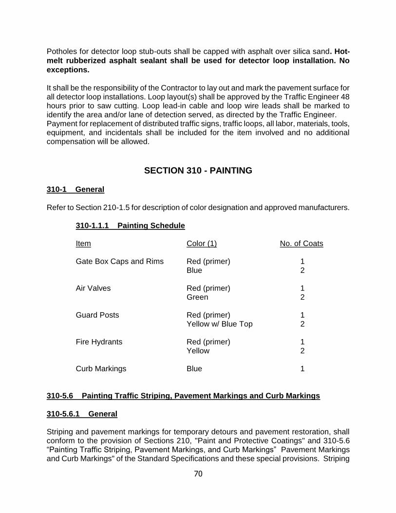
70
Potholes for detector loop stub-outs shall be capped with asphalt over silica sand. Hot-
melt rubberized asphalt sealant shall be used for detector loop installation. No
exceptions.
It shall be the responsibility of the Contractor to lay out and mark the pavement surface for all detector loop installations. Loop layout(s) shall be approved by the Traffic Engineer 48 hours prior to saw cutting. Loop lead-in cable and loop wire leads shall be marked to identify the area and/or lane of detection served, as directed by the Traffic Engineer. Payment for replacement of distributed traffic signs, traffic loops, all labor, materials, tools, equipment, and incidentals shall be included for the item involved and no additional compensation will be allowed.
SECTION 310 - PAINTING
310-1 General
Refer to Section 210-1.5 for description of color designation and approved manufacturers.
310-1.1.1 Painting Schedule Item Color (1) No. of Coats Gate Box Caps and Rims Red (primer) 1
Blue 2 Air Valves Red (primer) 1
Green 2 Guard Posts Red (primer) 1
Yellow w/ Blue Top 2 Fire Hydrants Red (primer) 1
Yellow 2 Curb Markings Blue 1
310-5.6 Painting Traffic Striping, Pavement Markings and Curb Markings
310-5.6.1 General Striping and pavement markings for temporary detours and pavement restoration, shall conform to the provision of Sections 210, "Paint and Protective Coatings" and 310-5.6 “Painting Traffic Striping, Pavement Markings, and Curb Markings” Pavement Markings and Curb Markings" of the Standard Specifications and these special provisions. Striping
71
and marking shall be under the direction of the City of Riverside Public Works, Construction Inspector, phone (951) 826-5889. Thermoplastic paint shall be utilized for permanent pavement striping and markings. All permanent striping shall be in place within 48 hours from the completion of asphalt overlay and or rubberized emulsion-aggregate slurry application. The thermoplastic material shall be applied by extrusion method in a single uniform layer. Stencils shall be used when applying thermoplastic material for pavement markings. The pavement surface to which thermoplastic material is applied shall be completely coated by the material and the voids of the pavement surface shall be filled. The thermoplastic material for traffic stripes shall be applied at a minimum thickness of 0.060-inch. Thermoplastic material for pavement markings shall be applied at a thickness of 0.100-inch to 0.150 inch. Glass beads shall be applied immediately to the surface of the molten thermoplastic material at a rate of not less than 8 pounds per 100 square feet. The amount of glass beads applied shall be measured by stabbing the glass bead tanks with a calibrated rod. The Contractor shall provide for temporary or permanent striping on the same day the street is paved or resurfaced. Under no circumstances shall the traveled way be without lane delineation. Permanent and/or temporary striping shall be placed on the pavement surface within 48 hours after notification by the Engineer. Pursuant to this requirement, the Contractor's attention is directed to Section 7-10.4.5, "Public Safety During Non-Working Hours" of these Special Provisions. As an option, reflective adhesive tape may be utilized for temporary striping as directed by the Engineer. For dashed four (4) inch lane lines a minimum three (3) foot strip of tape shall be placed at twelve (12) foot intervals (gaps) regardless of the posted speed for the zone requiring temporary striping. Temporary striping shall also include the designation (paint or type) of crosswalks at signalized intersections. The Contractor shall remove all reflective adhesive tape applied to the pavement surface as directed by the Engineer. Temporary striping shall also include the designation (paint or tape) of crosswalks at signalized intersections. Implementation shall be as directed by the Engineer. If the job is suspended because of weather or for any other reason, the Contractor shall be responsible for applying temporary striping as specified herein, and to maintain (repaint/retape) the temporary striping as directed by the Engineer. Said Section 7-10.4.5 of the Special Provisions will apply. In addition to the requirements of Section 310-5.6.8 "Application of Paint" for bituminous seal coats, the Contractor shall apply two coats of paint to any new pavement surface.
72
There shall be a minimum of 2 days between applications. This requirement shall not apply when painting over existing paint and/or existing untreated pavement surface. The two (2) applications requirement applies to permanent striping and pavement markings. "Cat Tracking" (premarking) for permanent and temporary striping shall consist of placing spots of paint not more than 3 inches in width and not more than 5 feet apart along the line established. Paint for "cat tracks" shall be the same as that used for the traffic stripe for which it is placed. If painting is scheduled on the same day as "Cat Tracking", the spray can method may be used in lieu of the requirements specified herein. The Contractor is responsible for a straight layout of the striping with smooth, long radius curves with no abrupt radius changes. Connecting curves shall be an appropriate radius to provide for smooth traffic flow at prevailing speeds. All transitions shall be approved by the Public Works Inspector prior to painting. Angle points and off-sets in the striping will not be allowed. Striping details not shown on the plans or specified in Sec. 310-5.6.4 shall be done in conformance with the Traffic Manual as published by Caltrans. All paint premarking ("cat tracking") for permanent striping is subject to the approval of the Public Works inspector prior to painting. The rope used for premarking shall have a minimum length of 500 feet of continuous fabrication, or longer if needed for smooth layout. Drips, overspray or improper markings shall be immediately removed from the pavement surface by blast cleaning or methods approved by the Public Works Inspector at the Contractor's expense. The lengths of the gaps and individual stripes that form broken traffic stripes shall not deviate more than 3 inches from the lengths shown on the plans. The lengths of the gaps and individual stripes shall be of such uniformity throughout the entire length of each broken traffic stripe that a "suitable" striping machine will be able to repeat the pattern and superimpose additional coats of paint upon the traffic stripe being painted. Where the traffic stripe is of such a nature, either due to configuration or location, as to render the striping machine unsuitable for use, traffic paint and glass spheres may be applied by other approved methods and equipment. The Public Works inspector will determine if the striping machine is unsuitable for a particular use. All stencils and templates shall conform in configuration and size to the State of California, Department of Transportation "Legends." The Public Works Inspector has the discretion to require random testing and sampling of the items covered herein. 10 percent, or greater, failure of samples of items shall be cause for rejection.

73
310-5.7 Traffic Stripe and Pavement Marker Removal Temporary construction zone traffic stripes and pavement markings shall be removed as directed by the Engineer. Removal of traffic striping shall be accomplished through the method of wet "sandblasting" or other approved methods. The sandblasting operation shall be continued until all of the stripes, markers, debris or other materials are removed to the satisfaction of the Engineer. When sandblasting within 10 feet of a lane occupied by public traffic, the residue, including dust, shall be removed immediately after contact between the sand and the surface being treated. Striping equipment shall meet all applicable standards of the United States Environmental Protection Agency and the Riverside County Air Pollution Control District. Areas of removed striping shall be feathered as not to leave a distinct shape of the removed painted item. Measurement of the double yellow centerline shall be 0.667 square foot per linear foot. Beach sand containing salt or excessive amounts of silt will not be allowed. The development of a water supply and all water required for the striping work and its application shall be by a method approved by the Engineer. All equipment used for the application of water shall be equipped with a positive means of shutoff. If the Contractor elects to use water from the City water system, he shall make arrangements with the Public Utilities Department of the City of Riverside and pay for all water used and comply with NPDES requirements.
SECTION 312 - PAVEMENT MARKER
PLACEMENT AND REMOVAL
312-1.1 Placement of Reflective Markers
Contractor shall be required to furnish and install Type I two-way blue reflective markers as shown on the Public Utilities Department Standard Drawing C.W.D. - 700.
312-3.1 Traffic Stripe and Pavement Marker Removal Temporary construction zone traffic stripes and pavement markings shall be removed as directed by the Engineer. Removal of traffic striping shall be accomplished through the method of wet "sandblasting" or other approved methods. The sandblasting operation shall be continued until all of the stripes, markers, debris or other materials are removed to the satisfaction of the Engineer. When sandblasting within 10 feet of a lane occupied by public traffic, the residue, including dust, shall be removed immediately after contact between the sand and the surface being

74
treated. Striping equipment shall meet all applicable standards of the United States Environmental Protection Agency and the Riverside County Air Pollution Control District.
Areas of traffic striping removal shall be feathered so as not to leave a distinct shape of the removed painted item. Measurement of the double yellow centerline shall be 0.667 square foot per linear foot. Beach sand containing salt or excessive amounts of silt will not be allowed. The development of a water supply and all water required for the traffic striping work and its application shall be by a method approved by the Engineer. All equipment used for the application of water shall be equipped with a positive means of shutoff. If the Contractor elects to use water from the City water system, Contractor shall make arrangements with the Public Utilities Department of the City and pay for all water used.
SECTION 313 "AS BUILT" DRAWINGS After construction has been completed, and before pressure testing and flushing can commence, "As Built" drawings shall be submitted by the Contractor showing pipe size, material, class and/or pipe thickness, the actual locations (invert elevations) and stations of all valves, tees, and special fittings, and stationing of all water service laterals and their run length. Service connections to the main are stationed on pipeline stationing. The Contractor shall show lengths of installed services and stationing of service corp stops, and note any deviations from the original plans on the "As Built" drawings. "As Built" drawings shall be prepared on a clean print and shall be legibly marked in red ink. The “As Built” drawings are required to be submitted to RPU Inspector for acceptance prior to scheduling hydrostatic tests.
75
PART 7 - TESTING & DISINFECTION
OF WATER MAINS & APPURTENANCES
700-1 GENERAL All water mains and appurtenances shall be tested for pressure and leakage, shall be disinfected , and bacteriological tests accepted by the City of Riverside Public utilities prior to utilizing the water mains and appurtenances for domestic use Testing and disinfection of water mains and appurtenances shall be in accordance with the applicable AWWA Standards except as herein modified. All testing and disinfection shall be made in the presence of the Engineer. The Contractor shall notify the Engineer not less than forty eight (48) hours in advance of the actual time of testing and/or disinfection so that the Engineer may observe the procedure. When the pressure test, leakage test, chlorination or bacteriological and plate count tests fail to meet the requirement of the Specifications, the Contractor shall make necessary repairs, replacements or repetition of procedures to conform to the specified requirements at Contractor’s own expense. Adequate backflow protection and proper metering of all potable water shall be provided by the Contractor and approved by the City of Riverside Public Utilities prior to commencement of any procedure(s) hereinafter.
700-2 PRESSURE TEST All water mains and appurtenances shall be tested as described herein. The pressure test shall not be performed until the following conditions have been met:
(1) All blowoffs, air valves, services, hydrants, and other appertances have been installed and adjusted to final grade and location; (2) The backfill material shall have been compacted to the required compaction through the 90 percent compaction zone as shown on CWD-040- 1 & 2. (3) All concrete anchor and thrust blocks shall have cured for a minimum of three (3) days. (4) Base materials with the exception of the final surface course of asphalt concrete, may be placed prior to the pressure test. (5) “As-built” drawings and all affidavits and certificates of compliance have been submitted to the Inspector.

76
The pressure test shall be maintained on the test section not less than two (2) hours. The Contractor may at Contractor’s convenience conduct a preliminary pressure test at any time prior to the City’s pressure test. The results of the preliminary test will not be considered by the City. The test pressure shall be 200 psi as measured at the lowest elevation of the water main under test. The length of water main footage to be tested at one time shall be determined by the Engineer or his designee. Each section of the water main to be tested shall be slowly filled with water from the nearest source by a means approved by the Engineer. The pipelines shall be filled with water and placed under a slight pressure for at least twenty-four (24) hours before the pressure test. All air shall be vented from high spots in the water main, fire hydrants and services before making a pressure test. If hydrants or other outlets are not available, taps shall be made at the high points to expel the air by the Contractor at Contractor’s expense. The locations shall be reviewed and approved by RPU Inspector prior to installation. These taps shall be capped by the Contractor after testing. The pressure test shall be applied by means of a pump connected to the pipeline in a manner approved by the Engineer. The pump, pipe connections, bulkheads, pressure gages and other equipment, labor and materials required to perform the test shall be furnished by the Contractor, at no additional cost to the City. The Engineer may check the test pressure by installing City pressure gages in place of the Contractor's gage. In case of a difference in pressure readings between gages, the City's gage reading shall govern. All appurtenant facilities shall be tested at the same pressure and for the same duration as the mainline pipe. All valves shall be tested for leak-proof tightness after the mainline pressure test with the test pressure on one side of the valve and atmospheric pressure on the other side. Wet tap valve sleeves shall be hydrostatically pressure tested for a period of 1 hour at a test pressure of 200 psi. During and at the end of test, a solution of soapy water shall be applied at all joints to test for leakage. No pressure loss or leakage will be permitted.
700-3 ALLOWABLE LEAKAGE All water mains and appurtenances shall be tested as described herein. The test pressure applied to the water main for the leakage test shall be maintained as constant as possible for not less than two (2) hours. The leakage test shall be held concurrently with the pressure test. For C-900 PVC pipe (Class 150), the test pressure
77
shall be 225 psi and the test duration shall be four (4) hours. The lengths of fire hydrant, blowoff, or air valve laterals and service lines are not included in the overall length of pipe in determining the allowable leakage. All welded sections of steel pipe mains are also excluded from the calculated allowable leakage. All noticeable leaks shall be stopped regardless of the results of the test. Defective pipe, fittings, valves, and other appurtenances discovered during the test shall be removed and replaced. Repair clamps of any kind or type are not allowed. The Engineer is to be notified of any repair work performed. The test shall be repeated until satisfactory results are obtained. All gaskets to be used only once. The allowable leakage volume shall not exceed the following:
(1) Non-welded steel joints 15 gal/in. dia./mile/24 hours (2) Ductile Iron Pipe and CML&C Steel Pipe 15 gal/in. dia./mile/24 hours (3) Welded Joints – no allowable.
It is the Contractor's responsibility for locating leaks and restoring the bedding and pipe zone material in accordance with the Standard Plans and these Specifications. Damage to pipe bedding and backfill resulting from leaks discovered during the pressure leakage test need to be restored in compliance with the specification. Any retesting shall be at Contractor’s expense. The pump, pipe connection, measuring devices, gages and all other equipment, labor and materials necessary for performing the leakage test shall be furnished by Contractor. The Engineer may, however, use City's measuring device in place of Contractor's equipment. In case of a difference in the measured leakage rate between the measuring devices, the City's measured leakage shall govern.
700-4 FLUSHING The new mains shall be cleaned and flushed prior to chlorination. The flushing velocity to be obtained for pipes 12 inches and smaller in diameter shall not be less than 2.5 feet per second. The Contractor shall make necessary arrangements to attain the minimum velocity. The Contractor shall take due precaution in providing for adequate drainage from the site. The minimum volume of water to be flushed, at required velocity, shall be not less than the 1.5 times the volume of the pipe line from the point of filling to the point of blow-off. The Contractor should verify that proposed hydrants to be used have adequate pressure to perform his flushing operation. If necessary, the Contractor shall use a pump to acquire adequate pressure for his flushing operation, all in his expense. The following table is a guide only:
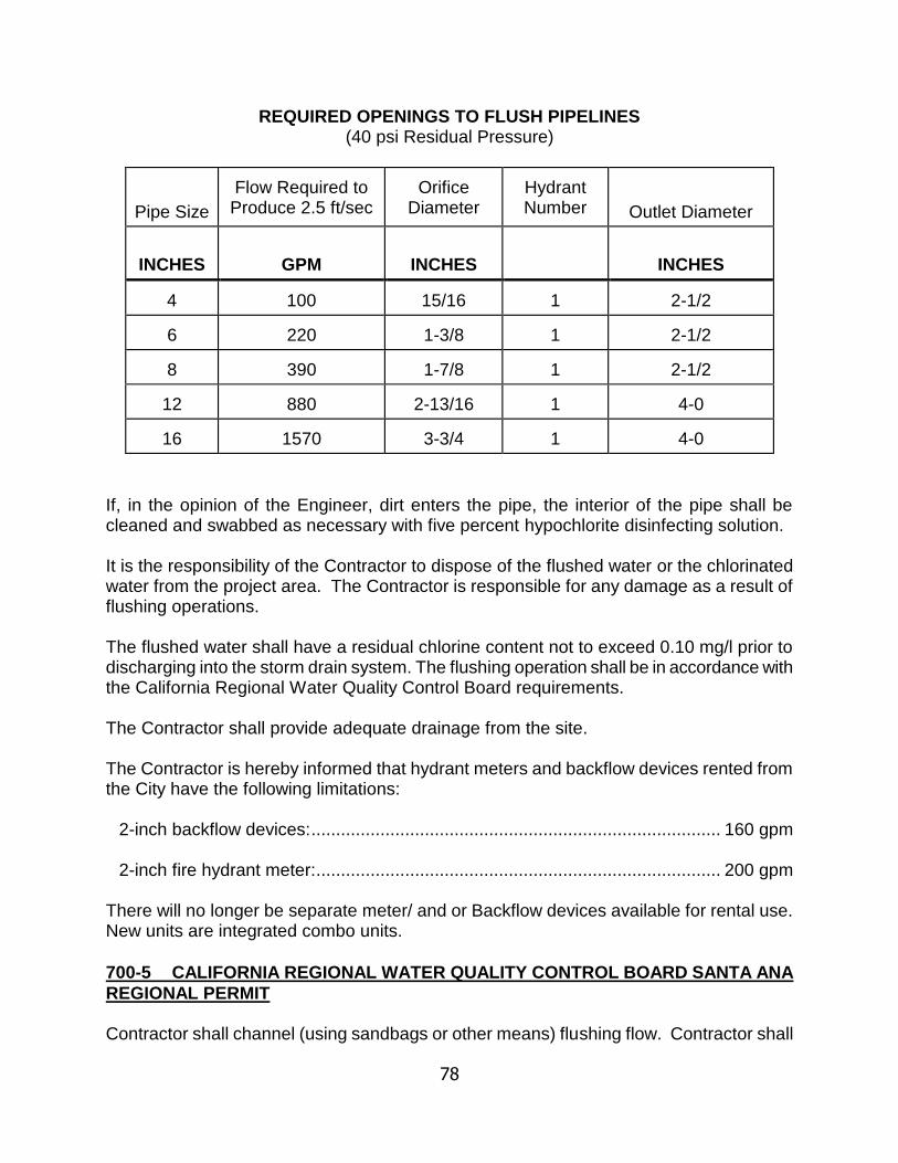
78
REQUIRED OPENINGS TO FLUSH PIPELINES (40 psi Residual Pressure)
Pipe Size
Flow Required to Produce 2.5 ft/sec
Orifice
Diameter
Hydrant Number
Outlet Diameter
INCHES
GPM
INCHES
INCHES
4
100
15/16 1
2-1/2
6
220
1-3/8
1
2-1/2
8
390
1-7/8
1
2-1/2
12
880
2-13/16
1
4-0
16
1570
3-3/4
1
4-0
If, in the opinion of the Engineer, dirt enters the pipe, the interior of the pipe shall be cleaned and swabbed as necessary with five percent hypochlorite disinfecting solution.
It is the responsibility of the Contractor to dispose of the flushed water or the chlorinated water from the project area. The Contractor is responsible for any damage as a result of flushing operations. The flushed water shall have a residual chlorine content not to exceed 0.10 mg/l prior to discharging into the storm drain system. The flushing operation shall be in accordance with the California Regional Water Quality Control Board requirements. The Contractor shall provide adequate drainage from the site. The Contractor is hereby informed that hydrant meters and backflow devices rented from the City have the following limitations:
2-inch backflow devices: ................................................................................... 160 gpm
2-inch fire hydrant meter: .................................................................................. 200 gpm There will no longer be separate meter/ and or Backflow devices available for rental use. New units are integrated combo units.
700-5 CALIFORNIA REGIONAL WATER QUALITY CONTROL BOARD SANTA ANA
REGIONAL PERMIT Contractor shall channel (using sandbags or other means) flushing flow. Contractor shall
79
protect all property from flooding and other damage during flushing operations. Contractor shall post "flooding ahead" signs in streets as required and as directed by Engineer. Because of demand on existing water system, the Engineer may require Contractor to flush the pipeline over several days, in the evenings, weekends, or holidays, at Contractor's expense.
Contractor shall not allow any discharges from the construction site which may have an adverse effect on receiving waters of the United States.
Contractor shall, at his expense, obtain a discharge permit from the California Regional Water Quality Control Board, Santa Ana Region (Regional Board) for discharge of water from trench dewatering, line flushing, and testing operations. A copy of said discharge permit shall be provided to the City. Contractor shall comply with conditions therein and perform the monitoring required. If the Regional Board determines that a discharge permit is not required for said work, then the Contractor shall comply with any and all applicable criteria and conditions established by the Regional Board, including compliance with the requirements of the General Water Discharge Requirements for Discharges to Surface Waters which pose an insignificant De Minimus threat to water quality (Order No. 98-67).
Order No. 98-67 includes submittal of a Notice of Intent and a waste discharge report to
the Regional Board. In addition, Template Monitoring and Reporting Program No. 98-67, appended to Order No. 98-67, includes the following monitoring and reporting requirements:
1. Estimate and report daily discharge flow, collect samples of each discharge and
have them analyzed for the 8 parameters listed on Pages 2 and 3 of the Template Monitoring and Reporting Program No. 98-67. All samples shall be representative of the waste discharge under conditions of peak load.
All sample collection, sample preservation, and analyses shall be performed in
accordance with the latest edition of "Guidelines Establishing Test Procedures for Analysis of Pollutants" promulgated by the U.S. Environmental Protection Agency (40 CFR 136). All sample analyses shall be performed by an analytical laboratory certified by the California Department of Health Services to perform such analyses.
2. Report any discharge which is in violation of the discharge specifications (Order No.
98-67) to the Regional Board, Santa Ana Region within 24 hours.
3. Notify the Regional Board 5 days before commencing any discharge.
4. Prepare monthly monitoring reports for submittal to the Regional Board. The reports shall include:
a. Results from all analyses for the previous month. b. Daily flow data. c. A report detailing Contractor's compliance or noncompliance with Order No.
98-67 and the discharge authorization letter.
80
700-6 DISINFECTION All newly laid water mains and appurtenances shall be disinfected in accordance with AWWA C-651, Disinfecting Water Mains, except as modified herein. Contractor must use one of the RPU approved companies who are licensed to perform chlorination (Mattchlor, Inc; Southwest Chlorination, Inc; Aqua Backflow; Spencor Inc; Morr-is Tested; Peirce Chlorine). Should the contractor choose to use a different company, of equal qualifications, contractor shall obtain prior approval from the Engineer. Chlorine used for disinfection must be a liquid chlorine solution by directly feeding hypo (sodium hypochlorite less than or equal 15%; typically 12.5%) or by mixing Cal-hypo (calcium hypochlorite 65-70% ) granular or tablets into a liquid solution by pre-dissolving or using a feeder. Either product sodium hypo or calcium hypo shall be NSF 61 approved for potable water use. Tablets inserted (glued) inside each pipe length shall not be used. Safe handling practices contained in A.W.W.A. Manual M-20 shall be followed by the Contractor. The chlorine solution shall be applied by the continuous feed method as outlined in Sub-section 5.2 of AWWA C-651-05 except as may be modified by the Engineer. Contractor must keep Material Safety Data Sheet (MSDS) onsite. The chlorine solution shall be applied at the beginning of the water main to be disinfected through a corporation stop installed for this purpose, through curb stop or through any other opening as may be allowed or required by the Engineer. Fire hydrants and air valves shall not be used for this purpose. However, an air valve riser pipe with the air valve removed may be an appropriate chlorine solution feed point. Water used to convey the chlorine solution throughout the water main shall be obtained from the existing distribution system. The rate of flow shall be so controlled that water will flow slowly into the undisinfected main during the application of chlorine. The end of the main being chlorinated shall be kept open and running during the application of chlorine and until the desired chlorine concentration is reached, after which each curb stop, fire hydrant, air valve line or any other connection to the water main shall be individually opened and flushed with the chlorine solution. After the water main and all appurtenances thereto have been loaded with chlorine to the proper concentration, the water source, chlorine feeder and all other openings to the water main shall be closed. The initial minimum concentration shall not be less than fifty (50) milligrams per liter (Mg/L) of chlorine, but not greater than 150 (Mg/L). The chlorine solution shall remain in the water main for not less than twenty-four (24) hours after which the treated water through the length of the main shall contain not less than twenty-five (25) Mg/L of chlorine. The chlorine content of the water shall be tested by the Engineer and if found to be less than twenty-five (25) Mg/L after twenty-four (24) hours contact, the water main and appurtenances shall be rechlorinated and held for another minimum twenty-four (24) hour period. No chlorination shall be started unless it can be completed by 2 p.m. on a Thursday. During the period of chlorination, all main line valves and blow-off valves shall be operated to insure that the discs and seats are fully open to chlorinated water. Air valves, when

81
removed, shall be chlorinated separately under the direction of the Engineer. Upon approval of the chlorine residual at twenty-four (24) hours by the Engineer, the chlorine solution shall be flushed from the water main through each service, fire hydrant and blow-off. Flushing shall continue until the chlorine residual is not more than five-tenths (0.5) Mg/L as determined by the Engineer using a digital instrument. In no case shall a chlorine solution of over five-tenths (0.5) Mg/L be held in the main or appurtenances for more than five (5) days from the initial injection to the final flushing. It is the responsibility of the Contractor to dispose of the chlorinated water from the project area. The chlorinated water shall have a residual chlorine content not to exceed 0.10 Mg/L prior to discharging into the storm drain system. The flushing operation shall be in accordance with the California Regional Water Quality Control Board requirements. The Contractor has two options for disposing of the chlorinated water from the project site.
Option 1. The Contractor can treat the chlorinated water with chemicals. This treatment shall neutralize any chlorine residual from the water. After treatment the dechlorinated water can be discharged into the street storm drain system.
Option 2. The Contractor shall dispose of the chlorinated water at a State of California approved treatment disposal plant.
The Contractor is responsible for any damage as a result of the disinfection operation and shall provide adequate drainage from the project site. The Contractor is hereby informed that hydrant meters and backflow devices rented from the City have the following limitations:
2-inch backflow devices: ................................................................................... 160 gpm
2-inch fire hydrant meter: .................................................................................. 200 gpm
700-7 BACTERIOLOGICAL TESTS A twenty-four (24) hour period between the final flushing and the taking of bacteriological samples is required. No flushing or any movement of water in pipe is allowed during sampling phase. Following the 24 hour period, the Contractor shall have a representative or employee of California Department of Public Health (CDPH) certified laboratory take water samples for bacteriological tests. All sampling shall be done in the presence of the Inspector. Contractor shall notify the Engineer 48 hours in advance of sampling procedures. Samples will be taken in the field by a laboratory technician and transported to the laboratory for testing. Such tests shall meet DPH requirements for drinking water standards. The number and location of such samples will be as directed by the Engineer; however, a minimum of one bacteriological test sample per 500 feet of main and a
82
minimum of 2 samples per day, per test section, are required. One set of samples is
required for two consecutive days, 24-hours apart. All samples, each day, must
indicate ten tubes negative and have a standard plate count of less than 200. Failure
of any sample will require complete retesting, under these procedures, for two
consecutive days. Testing laboratory shall fax results to Public Utilities, Water
Division at (951) 826-2498 immediately, once results are known. If a sample test fails
any of the one or two day tests, then the Contractor is directed to contact the Water
Division immediately. It is very important that all test results be submitted in writing to the Water Inspector as soon as available. Here is the list of the qualified companies who are licensed and approved by RPU to perform sampling: E.S. Babcock & Sons, Inc.; Western Analytical Laboratories, Inc., Associated Laboratories; Clinical Laboratories; Microbac Laboratories, Inc.; and Truesdail Laboratories, Inc.; If contractor wants to use a different company which is equal will need to get approval from RPU before using the company. All laboratory testing shall be at the Contractor’s expense. Original report of the test results shall be given directly to the Engineer. Emailing the results to the Engineer is preferable. It is the responsibility of the Contractor to accomplish this task. System connections cannot be scheduled until this report is submitted to the Engineer. All results must be submitted to RPU Engineer or his designee no later than three calendar days of sample date or risk resampling all samples. Upon successful completion of bacteriological testing, the pipeline will be accepted for use in the City potable water system; however, standard policy is to accept the water mains for use upon the City giving written Notice of Final Acceptance.
700-8 CONTRACTOR”S RESPONSIBILITY FOR TESTING AND DISINFECTION It is the sole responsibility of Contractor to construct a water main which passes the pressure and leakage test and to complete the disinfection of the water main. The fact that City provides inspection during the construction and testing of the water facilities and receives laboratory testing results does not relieve Contractor's responsibility in this regard. It's the responsibility of Contractor to prevent the consumption of water for any and all uses from undisinfected mains whether by their workmen, subcontractors or any other person who may come in contact with the water from the undisinfected main. Contractor shall indemnify and save the City harmless from any suits, claims, or actions brought by any person or persons for, or on account of, any sickness or death sustained or arising out of the consumption of water from the main until final acceptance by the City. Water required for the initial filling, pressure testing, leakage testing, flushing and chlorination, may be obtained from an existing City of Riverside main or fire hydrant by use of a City of Riverside Water Division meter and an Approved Backflow Prevention Device.

83
All water must be measured through a City of Riverside Water Division meter. The Contractor may use Contractor’s own Approved Backflow Prevention Device, however, it shall be approved by the City of Riverside, Backflow Program Specialist before use. The operation of any valve on any existing main shall be performed by the utility owner.
700-9 System Connections to Existing City Water Lines Under no circumstances shall a connection be made, permanent or otherwise, between any existing water main, hydrant or other source to any unapproved contractor installed water main regardless of size. No permanent connection between any Contractor installed water main and existing water mains shall be made by the Contractor, except for wet tapped water services larger than 2 inches and fire services. All wet taps require full time City inspection. Wet tapped connections with mechanical joint tapping sleeves shall be cleaned and disinfected in accordance with AWWA C-651, Sections 9 and 10. The Work shall include treating trench with a hypochlorite solution, as deemed necessary by the Engineer; thoroughly cleaning the main to be tapped, and the interiors of the sleeve and tapping gate; and swabbing the tapping sleeve interior with a 1 percent hypochlorite solution. Water required for the initial filling, pressure testing, leakage testing, flushing and chlorination may be obtained from an existing City main or fire hydrant by use of a City hydrant backflow meter device.
All water must be measured through a City hydrant meter backflow device. If in a case where greater volume is required, the Contractor may use his own Approved Backflow
Prevention Device of larger size, however, the Contractor shall provide to the City of
Riverside water inspector, a certificate of approval from the City of Riverside
Backflow Program Specialist before use. The Contractor shall not operate any gate valve on any existing main. The Contractor shall pay all rental and deposit fees for hydrant backflow meter devices checked out from the City plus charges for water used.

APPENDIX I
DESIGN CRITERIA

APPENDIX I
DESIGN CRITERIA
CONTENTS
1.0 INTRODUCTION ................................................................................................ 1
1.01 PURPOSE ........................................................................................... 1
1.02 GENERAL SERVICE CRITERIA ......................................................... 1
1.03 OTHER PUBLIC AGENCY REQUIREMENTS .................................... 3
1.04 WATER PLAN APPROVAL PROCESS ............................................... 3
2.0 DESIGN CRITERIA FOR WATER DISTRIBUTION SYSTEMS ......................... 6
2.01 SYSTEM DEMAND CRITERIA ............................................................ 6
2.02 SYSTEM ANALYSIS ............................................................................ 6
2.03 WATER PIPELINE SIZING CRITERIA ................................................ 7
2.04 PIPELINE STRENGTH ........................................................................ 7
2.05 WATER PIPELINE LOCATION ........................................................... 7
2.06 ALTERNATIVE CRITERIA FOR PIPELINE CONSTRUCTION ........... 9
2.07 PIPELINE CURVE DATA ................................................................... 15
2.08 STANDARD DRAWINGS .................................................................. 15
2.09 PIPE JOINTS ..................................................................................... 15
2.10 WATER PIPELINE MATERIALS ....................................................... 15
2.11 VALVES ............................................................................................. 15
2.12 COMBINATION AIR VACUUM AND AIR RELEASE VALVES .......... 16
2.13 BLOW-OFF VALVE ASSEMBLIES ..................................................... 16
2.14 PUBLIC FIRE HYDRANTS ................................................................ 16
2.15 BACKFLOW PREVENTION .............................................................. 17
2.16 SERVICE INSTALLATIONS .............................................................. 17
2.17 METER VAULTS ............................................................................... 17
2.18 BOOSTER AND PRESSURE REDUCING STATIONS ...................... 18

2.19 CORROSIVE SOIL ......................................................................... 18
3.0 PLAN FORMAT AND REQUIREMENTS ......................................................... 18
3.01 SHEET FORMAT - GENERAL .......................................................... 18
3.02 COVER SHEET ................................................................................. 19
3.03 PLAN FORMAT ................................................................................. 19
3.04 PROFILE FORMAT REQUIREMENTS .............................................. 21
3.05 GENERAL NOTES ............................................................................ 22

1
1.0 INTRODUCTION
The City of Riverside Public Utilities Water Division is a municipal utility with the mission of providing water supply and water resource management to the public in a safe, reliable, environmentally sensitive, and financially responsible manner.
1.01 PURPOSE
This manual was developed to guide Developers and their Engineers through the process of design and construction of new public water facilities. The included information is pertinent to tract development and commercial buildings. If, after utilizing this handbook, you have any questions or comments regarding the contents, please contact the Water Engineering Development Services at (951) 826-5285.
1.02 GENERAL
Within the Design Manual, the term “Water Division” means City of Riverside Public Utilities Water Division. “Developer’s Engineer” means a currently licensed Registered Civil Engineer retained by the Owner or Developer to perform engineering for water systems in conjunction with land division development. “City” means City of Riverside. The Water Division provides water service to properties located within the City of Riverside service area. If customers are outside the existing service area, they may be able to obtain service by annexing into the City or by seeking service from other nearby Public or Private Utility. The Water Division should be consulted for advice regarding service in any of the above circumstances. Water facilities that are necessary to deliver sufficient water at adequate volume and pressure to the development will be required to be installed by the Developer. These facilities can include: water pipelines and related appurtenances, booster stations, water storage reservoirs, and pressure regulating stations, some of which may be offsite. If water service is desired within the existing service area, service can normally be provided if the Developer meets the following conditions:
1. Designs, constructs, and dedicates to Water Division the necessary facilities.
The Water Division will review all plans, and may revise, modify or request the redesign of any concepts, plans or details submitted. All plans must be approved and signed by Water Division prior to the issuance of a Construction Permit.
2. Grants fee title parcels and/or easements to Water Division on City prepared
deed forms for all facilities not located within public right-of-way. Water facility easements shall be a minimum of 30 feet in width unless otherwise approved by the Water Division.
3. Pays current applicable fees in addition to completing the requirements listed
above. Fees may include: Plan Check Fees, Connection Charges, Inspection Fees, Added Facilities Charges, Elevation Fees, Backup Capacity Fees, Service

2
Connection Fees, Meter charges and Distribution System Fees. Water Division should be consulted for current and applicable fees.
The procedures for the development of water systems for Tract Map, Parcel Map, and Single Lot development differ only slightly. The design standards contained herein are primarily prepared for Tract Map development, but can be used for all three types within the City of Riverside. The applicable minimum requirements are as follows:
Design required facilities to Water Division’s standards.
Prepare water plans. Water Division has the authority to waive this requirement for single lot developments.
Water Division’s staff reviews and approves plans.
Dedicate right-of-way for all facilities to be owned and operated by Water
Division.
Pay all necessary fees.
Post bonds with Water Division, retain a qualified licensed Contractor, and provide proof of insurance.
Fund and obtain inspection services by Water Division.
Obtain a written “Notice to Proceed” before construction begins.
Have an engineer certify that the proposed final road grade (as shown on the
plan and approved by the City of Riverside Public Works Department) over the pipeline alignment has been achieved. If the existing surface of the alignment is not to be changed, it will be necessary to so certify.
Construct facilities to Water Division’s standards.
Water Division’s staff provides final approval of facilities constructed.
Submit “as-built” plans (field changes recorded on prints of approved Plan) to
Water Division.
For Water Division facilities outside of the Riverside City Limits, the following additional requirements are required:
Submit plans to the applicable Riverside County departments for their review and approval. Signature blocks to be added to the cover sheet.
Agreement for Construction, between the Developer and Water Division, to be
executed prior to plan approval. All costs will be the responsibility of the Developer.
3
1.03 OTHER PUBLIC AGENCY REQUIREMENTS
The requirements for water plan design for public water facilities specified herein do not waive, nor are they intended to contradict any requirements of other legal governing public agencies. Engineers designing water systems for inclusion in Water Division’s system must be knowledgeable of and comply with the regulations of the State of California, the County of Riverside, the City of Riverside, or any other local agency having jurisdiction. These shall include Administrative Codes, Civil Codes, and Health Regulations.
1.04 WATER PLAN APPROVAL PROCESS
The Developer’s Engineer must design the facilities and prepare the construction drawings (water plans) to Water Division’s standards. Water Division will review all water plans and may revise, modify, or require redesign of the drawings, or details submitted. Once the water plans have been approved by the Water Division, the Developer has one year, from the approval date of the plans, to start construction. If more than one year has elapsed, the water plans will be voided and the project must go through a new plan check procedure before any construction can start. The steps required to obtain water plan approval are as follows:
1. Attend A Preliminary Planning Meeting.
This meeting is strongly suggested but is not a requirement. The Developer shall call the Water Division at 951-826-5285, to arrange a preliminary planning meeting to discuss the proposed project. At the preliminary planning meeting, submit a tentative tract map, or project site map with the preliminary water facilities shown. Upon review of the project, Water Division may require a preliminary hydraulic report and/or hydraulic network analysis.
Water Division will discuss the general location and size of required facilities as well as provide information on known existing Water Division facilities in the area. If available, Water Division will provide as-built plans for existing facilities.
2. Submit Preliminary Hydraulic Report and/or Hydraulic Network Analyses (if required).
If required, the preliminary hydraulic report and hydraulic network analyses must be submitted to Water Division for review and comments. The preliminary hydraulic report and/or hydraulic network analyses must be approved prior to submittal of any drawings for plan check. Once Water Division and the Developer’s Engineer have agreed on a conceptual design, detailed plans may be prepared and submitted.
3. Submit first plan check with plan check fee.
The submittals for first plan check shall consist of the following:
1. Two copies of the water construction plan.
2. One copy of the street improvement plan.

4
3. One copy of the grading plan.
4. One copy of the storm drain plan.
5. One copy of the sewer plan.
6. Two copies of tentative Tract/Parcel Map.
7. One copy of Tract Phasing Map (including lot numbers and street
names).
8. One copy of the Soil Report.
Submittals must be complete or they will be rejected. Each submittal shall include a transmittal listing all items submitted. Details regarding design criteria are included in Section 2.0. Details regarding preparation of plans are included in Section 3.0. The Water Division’s goal for the first plan check is 20 working days. The Water Division strives to meet these goals but the plan review time can vary depending on the number of plans in the review process, size of project, complexity of the plans, and the completeness of the plans. Water Division will provide comments on one set of the water plans and return them to Developer’s Engineer for revisions. In addition, the Water Division will provide a copy of plan Check Required Item Checklist listing all required submittals. After the first set of check prints are returned, no changes except those requested or approved by Water Division shall be made by the Developer’s Engineer. If the Developer’s Engineer wishes to make a change other than that requested by Water Division, a print marked with the proposed change in red pencil shall be submitted for approval. Only after written approval shall the original be changed. The authorized change shall be highlighted on the next recheck submittal. Drawings that do not conform to CWD-010-1, CWD-010-2, and CWD-010-3, or other requirements contained in the Design Manual and/or that are unclear, misleading, or confusing will be subject to rejection without review.
4. Submit subsequent plan checks.
For each subsequent plan check, Developer’s Engineer must submit the following:
• All previous Water Division plan check sets.
• Two copies of the revised construction drawings.
• Any additional material requested.
Submittals must be complete or they will be rejected. If the drawings are not yet satisfactory, Water Division will make comments on one set of the drawings and return same to Developer’s Engineer for revisions. This procedure will be repeated as necessary until the drawings are acceptable. If Developer’s Engineer does not return the previous Water Division plan check sets, the plan
5
check procedure will start from the beginning.
Water Division’s goal is to complete all subsequent plan checks within 10 working days of receipt of a complete submittal. Plan review time may vary depending on the number of plans in the review process, size of project, complexity of plans, and completeness of plans.
5. Submit final Plans for approval.
After all plan checks are completed and the plans are acceptable to the Water Division, the original mylars must be submitted to Water Division for signature. The Developer must pay all required fees prior to final approval of the construction drawings.
6. Water Division Signs Plans.
Once all submittals have been completed to Water Division’s satisfaction, the mylars will be signed. The Developer’s Engineer is required to obtain signatures from all other agencies and provide Water Division with the original mylars and 2 sets of prints. Original water plan mylars become the property of the Water Division. Water Division will furnish the Developer with the pre-construction requirements.
Once signed, the originals cannot be modified without written permission from Water Division’s Principal Engineer. Any modification after signing shall be noted in the plan’s revision block.
Plan checks resubmitted after one year, regardless of number of previous submittals, will be deemed “expired”. “Expired” plan checks resubmitted will be subject to Water Division’s current Water Division design requirements, including the plan check fee, and considered a “first plan check submittal”.
6
2.0 DESIGN CRITERIA FOR WATER DISTRIBUTION SYSTEMS
Water system improvements proposed for inclusion into Water Division’s service area shall be designed in accordance with all appropriate AWWA standards and the following criteria: 2.01 SYSTEM DEMAND CRITERIA The Water Division reserves the right to determine criteria for each water system or sub-system based upon conditions that may exist for that particular location, anticipated level of development, planned use or other criteria. Specific fire flow requirements shall be determined by the Water Division using the recommendations of the Fire Department. Fire flows for most areas will generally fall within the following limits:
Single Family Residence w/sprinklers 500 gpm @ a minimum 20 psi Single Family Residence wo/sprinklers 1000 gpm @ a minimum 20 psi Multiple Residential & Condominiums 1500 gpm @ a minimum 20 psi Commercial 1750 - 8000 gpm @ a minimum 20 psi Industrial 1750 - 8000 gpm @ a minimum 20 psi Commercial and industrial development requirements shall be analyzed separately based on the specific proposed project. Water distribution pipelines to all service areas shall be looped to provide dual direction supply and system flexibility. Dead end mains are undesirable, but can be considered on a case-by-case basis.
2.02 SYSTEM ANALYSIS
The proposed water system shall be analyzed, if requested by the Water Division, for the following three conditions:
1. Peak hour demands with booster pumping plants on.
For the peak hour demand flow analysis, the pressure at each node shall be a minimum of 40 psi and a maximum of 125 psi.
2. Maximum day demand plus fire flow with booster pumping plants off.
For the maximum day demand plus fire flow analysis, fire flow should be selected for the worst-case scenario (typically the hydrant furthest from the connection(s) to Water Division's distribution system, at the highest system elevation) and as directed by Water Division’s staff. The pressure at each node shall be a minimum of 20 psi and the maximum velocity in the pipelines shall be 10 feet per second.

7
3. Minimum hour demands with wells and boosters on.
For the minimum hour demand analysis, the maximum velocity in the pipelines shall be 6.0 feet per second and the maximum pressure at each node shall be 125 psi.
The Developer’s Engineer will be required to submit an analysis of anticipated flow demands; average, maximum hour flow, and maximum day plus fire flow. Water Division shall accept or modify the submitted analysis.
2.03 WATER PIPELINE SIZING CRITERIA
In residential zones, an 8-inch (I.D.) diameter D.I.P. line shall be the minimum standard size for water mains. A 4-inch D.I.P. may be used in single family residential cul-de-sac streets, not requiring fire hydrants and serving not more than 10 services. For commercial and industrial zones, the minimum standard pipeline size shall be a 12-inch (I.D.) D.I.P. Larger size pipelines may be required to meet Fire Department flow requirements and/or high development flows. The zoning designations, per the City of Riverside Planning Department, for commercial districts are RO, CO, C-1, C-1-A, CL, C-2 and C-3. The zoning designations for industrial districts are MP, M-1, M-2, WC, RWY and AIR. Water Division reserves the right to specify sizing of any water pipeline. Due to master planning, Water Division may require a larger size pipeline than normally required for a particular project to satisfy Water Division’s design standards for system distribution requirement purposes. Water Division’s Board of Public Utilities may authorize participation and payment of increased cost of such water pipeline in accordance with Water Division’s criteria.
2.04 PIPELINE STRENGTH
All water mains 12-inches and under shall be Class 350 D.I.P. per A.W.W.A. C-151. For pipes over 12-inches, contact the Water Division. Contact the Water Engineering Development Group (951) 826-5285 for anticipated pressures in the proposed development area. External loads shall be designed to withstand the weight of the earth cover plus live loads based on the application of an H-20 truckload, using appropriate impact factors, which recognize depth of pipe, plus a safety factor of 1.5. 2.05 WATER PIPELINE LOCATION Unless otherwise approved by Water Division, all water pipelines shall be located on the southerly or westerly side of the street, with the centerline of the pipe 8 feet from the street centerline. The location shall not interfere with other existing or planned utilities or proposed street improvements.

8
The cover over the water pipeline shall be sufficient to provide protection to the pipeline and for the operation of the appurtenances. The depth for 8-inch diameter and under pipelines shall be 3.0 feet from the ground surface (pavement, graded travel way, or open ground) to the top of the pipeline. For pipelines 12-inches and larger, the depth shall be 4.0 feet to the top of the pipeline. These depths may be increased or decreased by the Water Division, as necessary, to cover non-standard conditions. Minimum slope of water pipelines shall be 0.2 percent unless otherwise authorized by Water Division. A minimum of 3 ½ feet clearance shall be provided between centerline of pipe and face of curb at straight sections. When curb curves, 4 feet clearance shall be provided. Water mains shall not be designed to run under planters, medians, islands, or parking spaces. Water main separations shall be governed by CWD-015 and the following rules:
1. Installation of sewer pipe and water mains shall not be located within the same trench.
2. Water mains shall be installed with a minimum horizontal separation of 10 feet
outside of pipe to the outside of pipe (hereafter shown as (O.O.)) from, and with a minimum vertical separation of 1 foot (O.O.) above, any parallel pipeline conveying:
(a) Untreated sewage,
(b) Primary or secondary treated sewage,
(c) Disinfected secondary – 2.2 recycled water (defined in Title 22 CA Code of Regulations, Section 60301.220),
(d) Disinfected secondary – 23 recycled water (defined in Title 22 CA Code
of Regulations, Section 60301.225), and (e) Hazardous fluids such as fuels, industrial wastes and wastewater
sludge.
3. Horizontal separation of less than 10 feet (O.O.), but greater than 5 feet
(O.O.), requires the approval of the Water Division and the use of special construction methods outlined herein. Horizontal separation of less than 5 feet (O.O.) for gravity sewers and 10 feet (O.O.) for sewer force mains is prohibited.
4. Water mains shall be installed with a minimum horizontal separation of 4 feet
(O.O.) from, and with a minimum vertical separation of 1 foot (O.O.) above, any parallel pipeline conveying:

9
(a) Disinfected tertiary recycled water (defined in Title 22 CA Code of Regulations, Section 60301.230), and
(b) Storm drainage.
5. If crossing a pipeline conveying a fluid listed in paragraph 2 or 4, above, a new
water main shall be constructed perpendicular to and at least 1 foot above that pipeline. No connection joints shall be made in the water main within 8 horizontal feet of the fluid pipeline.
6. The vertical separation specified in 2, 4 and 5 above is required only when the
horizontal distance between the water main and a pipeline is 11 feet or less. 7. All separations referred to herein are either horizontal or vertical distances,
which are measured at right angles to the water main. Crossing at less than a 45-degree angle will not be permitted.
8. Details of water main/sewer pipe conflicts involving special construction
methods for greater than 12-inch diameter pipelines shall be shown on the Plans.
9. Where sewer is referred to herein, it shall be interpreted as sewer main or
sewer lateral. This also applies to Water Division Standard Drawings CWD-023-1 and CWD-023-2.
10. When a new sewer force main crosses under an existing water main, all
portions of the sewer force main within 10 feet horizontally of the water main, shall be enclosed in a continuous pipe casing, per Water Division Standard Drawing CWD-023-1 and -2.
11. When a new water main crosses over an existing sewer force main, the water
main shall be constructed of pipe materials with a minimum rated working pressure of 200 psi or an equivalent pressure rating.
2.06 ALTERNATIVE CRITERIA FOR PIPELINE CONSTRUCTION
When existing conditions dictate the installation of water mains, sanitary sewer mains, storm drain mains or other non-potable pipelines at separation distances less than that required above, alternative construction criteria may be approved by the Water Division. Water Division Standard Drawings CWD-015-1 and CWD-015-2 show alternative construction criteria for two different cases where the regulatory criteria cannot be met.
Case 1: New sanitary sewer main and a new or existing water main. Alternative construction criteria apply to the sanitary sewer main.
Case 2: New water main and an existing sanitary sewer main. Alternative
construction criteria may apply to either or both the water main and sanitary sewer main.

10
Case 1 – New Sanitary Sewer Main Installation (CWD-015-1)
Zone Special Construction Required for Sanitary Sewer Main
A Sanitary sewer mains parallel to water mains shall not be permitted in this zone without prior written approval from the Water Division.
B If the water main paralleling the sanitary sewer main does not meet the Case 2,
Zone B requirements, the sanitary sewer main should be constructed of one of the following:
1. Extra strength vitrified clay pipe with compression joints;
2. Cast or ductile iron pipe with compression joints; or
3. PVC sewer pipe with rubber ring joints (per ASTM D3034) or equivalent. C If the water main crossing below the sanitary sewer main does not meet the
Case 2, Zone C requirements, the sanitary sewer main should have no joints within 10 feet from either side of the water main (in Zone C) and should be constructed of one of the following:
1. A continuous section of ductile iron pipe with hot dip bituminous coating;
or
2. One of the Zone D options 2, 3, or 4 below. D If the water main crossing above the sanitary sewer main does not meet the
Case 2, Zone D requirements, the sanitary sewer main should have no joints within 4 feet from either side of the water main (in Zone D) and should be constructed of one of the following:
1. Ductile iron pipe with hot dip bituminous coating and mechanical joints
(gasketed, bolted joints); 2. A continuous section of Class 200 (DR 14 per AWWA C900-97) PVC pipe
or equivalent, centered over the pipe being crossed; 3. A continuous section of reinforced concrete pressure pipe (per AWWA
C302-95) centered over the pipe being crossed; or 4. Any sanitary sewer main within a continuous sleeve.
Case 2 – New Water Main Installation (CWD-015-2) Zone Special Construction Required for Water Main
A No water mains parallel to sanitary sewer mains shall be constructed in this zone without prior written approval from the Water Division.
B If the sanitary sewer main paralleling the water main does not meet the Case 1,
11
Zone B requirements, the water main should be constructed of one of the following:
1. Ductile iron pipe with hot dip bituminous coating; or
2. Dipped and wrapped ¼-inch thick welded steel pipe. C If the sanitary sewer main crossing above the water main does not meet the
Case 1, Zone C requirements, the water main should have no joints within 10 feet from either side of the sanitary sewer main (in Zone C) and should be constructed of one of the following:
1. Ductile iron pipe with hot dip bituminous coating; or
2. Dipped and wrapped ¼-inch thick welded steel pipe. D If the sanitary sewer main crossing below the water main does not meet the
Case 1, Zone D requirements, the water main should have no joints within 4 feet from either side of the sanitary sewer main (in Zone D) and should be constructed as for Zone C.
Water Mains and Pipelines Conveying Non-potable Fluids When the basic separation criteria cannot be met between water mains and pipelines conveying non-potable fluids, the requirements described above for sanitary sewer mains should apply. This includes the requirements for selecting special construction materials and the separation requirements shown in Figures 1 and 2. Note that not all construction materials allowed for sanitary sewer mains will be appropriate for other non-potable fluid lines. For example, certain plastic lines may not be appropriate for the transport of some fuel products. The selection of compatible materials of construction for non-potable fluids is a decision to be made by the project engineer. Water Mains and Sewage Force Mains
Sewage force mains shall not be installed within ten feet (horizontally) of a water main.
When a sewage force main must cross a water main, the crossing should be as
close as practical to the perpendicular. The sewage force main should be at least one foot below the water main.
When a new sewage force main crosses under an existing water main, and a
one foot vertical separation cannot be provided, all portions of the sewage force main within eight feet (Horizontally) of the outside walls of the water main should be enclosed in a continuous sleeve. In these cases, a minimum vertical separation distance of 4 inches should be maintained between the outside edge of the bottom of the water main and the top of the continuous sleeve.

12
When a new water main crosses over an existing sewage force main, the water main should be constructed of pipe materials with a minimum rated working pressure of 200 psig or the equivalent.
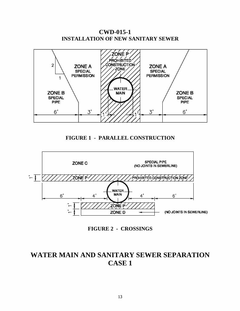
13
CWD-015-1 INSTALLATION OF NEW SANITARY SEWER
FIGURE 1 - PARALLEL CONSTRUCTION
FIGURE 2 - CROSSINGS
WATER MAIN AND SANITARY SEWER SEPARATION
CASE 1

14
CWD-015-2 INSTALLATION OF NEW WATER MAIN
FIGURE 1 - PARALLEL CONSTRUCTION
FIGURE 2 - CROSSINGS
WATER MAIN AND SANITARY SEWER SEPARATION
CASE 2

15
2.07 PIPELINE CURVE DATA Pipeline joints for ductile iron pipe shall not be pulled more than 80 percent of the manufacturers’ recommendations. When the pipe curve radius is greater than 241 feet, standard length pipe of 18 feet will pull the curve within the allowable joint deflection angle. When the pipe curve radius is less than 241 feet, the Engineer must calculate the required pipe length to be used with the following equation:
Pipe Length = R x 2(TAN /2)
All sheets that incorporate curves in pipelines shall include a “Curve Data Table” per the standard plans.
Pipe segments shall be no less than 13 feet in length. 2.08 STANDARD DRAWINGS See CWD-010-1, CWD-010-2, and CWD-010-3 or Visit the Web site at http://www.riversideca.gov/utilities/water-ugconstruction.asp 2.09 PIPE JOINTS All pipe joints shall be restrained with Romac Industries, Inc. “Grip Ring” gaskets, U.S. Pipe and Foundry Company “Field-LOK” gaskets or Water Division approved equal. 2.10 WATER PIPELINE MATERIALS Unless otherwise authorized by Water Division’s staff, all water pipelines 12" and under shall be ductile iron pipe, Class 350, per A.W.W.A. C-151. All water pipelines 14" and larger shall be either CML/CMC welded steel pipe and fittings in accordance with Water Division's standards or ductile iron pipe, Class 350, per A.W.W.A. C-151. 2.11 VALVES Location:
• Water pipelines (12-inch diameter and smaller): To provide flexibility of
operation, generally located on discharge side of pipeline connections; 3 at crosses, 2 at tees (Water Division may require 3 depending on the circumstances) and at beginning of dead end mains. Valves shall be spaced every 500 feet with no more than 2 fire hydrants between the valves.
• At all outlets, hydrants, blow-offs, air valves, and at service connections as
shown on the Standard Drawings. Dead end valves placed for future extensions shall be suitably capped or plugged.
• If one of the options above does not apply, valves shall be spaced at 1,320-foot
maximum intervals or as directed by Water Division. Size:

16
• Full line size gate valves through 12-inch. For valves larger than 12-in, contact the Water Division. Maximum velocity through valves normally limited to 12 feet per second, never to exceed 20 feet per second.
Unless otherwise provided for, all valves shall be resilient seat gate or butterfly type valves conforming to AWWA Standards C509, C515, and C504. Valves shall be installed with valve can and cover as shown on Water Division’s Standard Drawing CWD-500. Pressure class rating shall be the same as the water pipe on which the valve is being installed. 2.12 COMBINATION AIR VACUUM AND AIR RELEASE VALVES Air valves shall be located at all high points of water pipelines; however, air valves shall not be installed at the end of cul-de-sacs unless the slope of the water pipeline is 5% or greater. Minimum size of air valves shall be 2" for all pipelines through 16-inches. In phased tract development, air valves are often located at the end of the pipeline as dictated by the phasing plan. When additional phases are constructed, the air valve shall be removed unless it is required by one of the criteria listed above. Provide 4-inch guard posts on either side per Water Division’s Standard Drawing CWD-900. 2.13 BLOW-OFF VALVE ASSEMBLIES Blowoff valve assemblies shall be installed in accordance with Water Division's Standard Drawings CWD-411-A or CWD-411-B. Blowoff valve assemblies shall be installed at the termination of all dead end mains. If special conditions so warrant, additional blow-off valve assemblies shall be installed at low points in the water main. 2.14 PUBLIC FIRE HYDRANTS Hydrants shall be set so that they are easily accessible to fire department pumpers. Locations in depressions, cut outs or on embankments high above the street are not acceptable. Hydrant locations are subject to the review and approval of the Fire Marshal. A signature block for the Fire Department is required on the Plans. Hydrants shall be 6-inch, wet barrel, type A.W.W.A. C-503, with one 4-inch outlet and one 2 1/2-inch outlet and a 6-inch ductile iron bury. Super hydrants, for commercial and industrial districts, shall have two 2 ½-inch outlets and one 4-inch outlet and a 6-inch ductile iron bury. Spacing of fire hydrants in residential areas shall be 500 feet where the homes are equipped with fire suppression sprinklers and 350 feet when the homes are not
17
equipped with fire sprinklers. For commercial and industrial areas, the hydrants shall be spaced every 350 feet. Design consideration shall be taken to locate hydrants at intersections wherever possible. Fire hydrants shall be installed in accordance with Water Division's Standard Drawing CWD-700. 2.15 BACKFLOW PREVENTION Where Water Division’s Domestic Water System has the potential of becoming cross-connected to other water supplies or sources, an approved backflow prevention device is required by Title 17, Drinking Water Supplies, of the California Administrative Code, and shall be installed in accordance with Water Division’s Standard Drawings CWD-616 & 617 and approved materials list. An approved backflow prevention device is required for all fire service connections. All non-residential water services shall have a Water Division approved backflow prevention device installed adjacent to meter unless otherwise approved by City of Riverside Backflow Program Specialist. 2.16 SERVICE INSTALLATIONS Services shall be stationed and shown on the Plan at their proposed locations. The private engineer shall give due consideration to any proposed improvements by others (i.e., driveways, catch basins, pullboxes and sewer laterals). Services and meters shall be sized in accordance with the provisions of Section 1009 of the Uniform Plumbing Code, using minimum pressures expected in the system. Minimum service pipe diameter shall be 1-inch with a minimum meter size of 3/4-inch. All meters will be set by the Water Division. The Contractor will be required to lay all services on new water main construction, including the meter stop, meter spacer and the meter couplings, and set the meter box in accordance with Water Division’s Standard Drawings CWD-600, CWD-601, CWD-615, CWD-620, CWD-621 and CWD-622. Meter spacers will be provided by the Water Division. All pipe ends shall be suitably covered to prevent any entrance of foreign matter into the service lines. 2.17 METER VAULTS All vaults for water services, 3-inches and greater, shall be shown in a separate detail on the Plans. The detail shall show location and distances to driveways, curbs, sidewalks, structures and utilities within 10 feet of the meter vault. Both sides of the vault shall be stationed in the detail. Structural calculations, stamped and signed by a registered civil engineer, shall be submitted for vaults located in traffic areas. 2.18 BOOSTER & PRESSURE REDUCING STATIONS If the project requires a booster or pressure reducing station, contact the Water Division

18
prior to starting design. 2.19 CORROSIVE SOIL Where steel pipelines are to be constructed in corrosive soil conditions, as shown in the Preliminary Soil Report, the engineer shall contact the Water Division for direction.
3.0 PLAN FORMAT AND REQUIREMENTS
The Developer’s engineer shall prepare water system improvement plans that are clear, concise, and meet Water Division’s standards. A set of plans that meet all the requirements set forth herein, but are difficult to interpret, mislead the Contractor, confuse the reader, or do not address previous plan check comments, are unacceptable and will be subject to rejection without review. 3.01 SHEET FORMAT – GENERAL Drawings shall be drawn in ink on D size (24" x 36") mylar (4 mil double matted) sheets with Water Division’s standard title blocks as shown on the standard plans available online. The improvement plans shall be professional quality especially prepared as WATER IMPROVEMENT PLANS. Work shall be of standard engineering practice and shall be well arranged, neat, legible and present the proposed construction without confusion. Applicable prints, submitted for checking, shall be clear, bright duplications. Profiles are not generally required for water mains under 12-inches in diameter. However, profiles will be required when the construction will involve numerous grade changes to avoid conflicts with other utilities or buried conflicts or when required by the Water Division. Profiles will also be required when the water main will be in an unimproved area, easements or areas without curb and gutter. All drawings shall be drawn to scale using 1”= 40’ on the horizontal scale. Profiles, when required, shall be drawn at an appropriate vertical scale that matches the plan data. Match lines and continuations from sheet to sheet shall be used and identified with applicable station points and cross-reference. Duplicate data, outside of the match lines, shall be fogged or shaded. Always indicate true north with a suitable north arrow. Indicate tract number and sheet number on all drawings. Each sheet shall have a title block with tract number, street name and stations appearing on that sheet. Stationing must conform to established stationing on approved City plans. Stationing on all sheets shall be from the left to right (even if this requires north to be “down”). No negative stationing. If there are any questions or problems on stationing, contact the Water Division prior to design. For special assemblies, unusual and/or complex connections provide a detail schematic (preferably on the same sheet). The detail schematic shall be drawn to scale, show pipe size, and shall fully identify all the parts in the detail. Show and call out all special

19
features and indicate scale. The Engineer shall note on the plans, all connections to existing water facilities and note who is to construct them. Contractors are not authorized to make connections to existing water facilities. Contractors shall not operate any valve on any portion of Water Division’s system that is under pressure.
3.02 COVER SHEET
As a minimum, the Cover Sheet shall show the following:
1. Water Division’s standard title block.
2. General notes. See Section 3.05 herein.
3. Vicinity Map showing a north arrow, scale and project location.
4. Index Map at a 1” = 100’ scale, showing the proposed improvements and plan sheet index. If there is a water line in an easement, show the easement limits.
5. Provide a City approved Bench Mark and Basis of Bearings.
6. Show legend per most current standard plans (available online). 7. Provide a “Bill of Materials” which should include the applicable Standard
Drawing Number(s).
8. Provide a signature block for the Fire Department when the installation of fire hydrants are required or when existing fire hydrants are relocated.
9. Provide a signature block for Public Utilities Electrical Division.
10. Provide Underground Service Alert notification (this should be on each plan sheet).
11. The following note “NOTE: THIS SYSTEM SERVED BY _____ ZONE”.
3.03 PLAN FORMAT The plan sheets shall be drawn at a horizontal scale of 1" = 40'. As a minimum, the drawings shall show the following:
1. Title Block – Water Division’s standard title block shall be used and shall include the City case or project number and street names.
2. North Arrow - North Arrow shall point either up or to the left to conform with
stationing. 3. Street Names - All street names shall be shown. 4. Lot Lines - All lot lines or parcel lines, lot numbers, frontage distances and

20
full pad elevations (i.e., 1020.5 not 20.5). All adjacent tracts shall be identified.
5. Right-of-Way - Existing and proposed right-of-way shall be identified with
dimensions from street centerline. 6. Utilities - All existing and proposed utilities shall be shown including, but not
be limited to, water (existing Water Division water pipelines shall be identified by Water Division Plan No.), sewer, gas, power, telephone, storm drain, irrigation, traffic, and cable television. Each utility shall be identified with a symbol and the size of the utility shall be shown. Dimensions from street centerline to centerline of each utility shall be shown.
7. Existing and Proposed Improvements - All existing surface improvements
shall be shown including, but not limited to, curb and gutter, edge of pavement, power poles, driveways, sidewalks, and fences. Existing and/or proposed curbs shall be identified with dimensions from street centerline shown.
8. Proposed Pipeline - Proposed pipeline shall be indicated with a heavy line
and dimensioned from the street centerline to the centerline of the pipeline. 9. Stationing - Stationing for pipelines shall be along the centerline of the
improvement. Stationing shall increase from left to right. Stationing shall be identified with tick marks at 100 foot intervals. For water pipelines with curves, stations for the beginning and end of each curve shall be shown. In addition, a curve data table shall be included showing the delta, curve radius, curve length, and tangent length for each curve.
10. Match Lines – Match lines for each end of the sheet shall be shown as
follows:
Sta 15+00.00 Match Line See Sheet 5
11. Water Pipelines - Water pipelines and appurtenances (valves, fittings, fire
hydrants, air valves, water services, and blowoffs) shall be identified by station and a numerical identification corresponding to a construction note as shown on the standard plans.
Only those construction notes that apply to each sheet shall be shown. All connections to existing water system shall be identified by station and size. Details for connections shall be used where required. Each connection shall have the following note, "System Connection by City Forces". If a water main crosses a railroad track, the steel casing shall be shown with
21
the beginning and ending stations. The casing shall be labeled with its size and thickness. Boring and receiving pits shall be shown, flagged and labeled. The engineer shall submit a copy of the permit issued by the railroad for the proposed pipeline crossing and the boring and jacking operation. The engineer shall detail all water and sewage pipeline crossings and show the clearance between the two pipelines.
12. Callout Notes – All callout notes shall be oriented horizontally per CWD-010-2 and CWD-010-3.
3.04 PROFILE FORMAT REQUIREMENTS Only the profile for the waterline shall be shown. All other utility profiles shall not be shown unless conflicting, or where crossing over or under (i.e. storm drain). All existing utilities in the area being profiled shall be shown with dashed and/or greyed out lines.
1. Stationing - Stations shall be shown along bottom of profile grid at 100 foot intervals. Profile stationing shall line up with plan stationing and shall be shown at the bottom of the profile grid. Label and show stations and flowline elevations at the beginning of the pipeline, every 100 feet, at the B.C. and E.C. of curves, all appurtenances, and at the end of the pipeline.
2. Datum Elevations - Elevations shall be shown at even gridlines on both ends of the profile.
3. Existing and Proposed Ground Surface – Show the proposed surface over
the proposed pipeline and flag the surface elevations every 100 feet. Note elevations to the nearest 0.1 feet.
4. Match Lines - Match lines for each end of sheet shall be shown as follows:
Sta 15+00.00 Match Line See Sheet 5
5. Water pipelines: Show and label the connection to the existing water main. The label should show the existing station and elevation. Pipelines under 12-inches in diameter shall be 36-inches below the top of the finished surface to the top of pipe. Pipelines 12-inches and over shall be 48-inches below the top of finished surface to the top of the pipe. Show pipe size, pipe material, pressure class and pipe slope using S = 0.0000 format. All fittings and services shall be shown and stationed in profile.
6. Utility Crossings: Both existing and proposed underground utility crossings

22
shall be shown. Show all existing topo which impacts the proposed water pipeline.
7. Railroad Crossings: When the water main runs under a railroad track, show
the size, thickness, material and limits of the casing. Stations and elevations shall be shown for each end of the casing along with the grade of the casing in the S = 0.0000 format.
3.05 GENERAL NOTES
All of the following General Notes shall be included on the cover sheet of the Water Improvement Plans.
SAMPLE GENERAL NOTES
1. All construction shall be in accordance with these Plans and in conformance with the City of Riverside Public Utilities Department, Water Division, Standard Specification No. 205 for Water Distribution Systems, latest revision; all applicable A.W.W.A. Standards and Specifications, except as noted; and the Standard Specifications for Public Works Construction (Greenbook), latest adopted edition and amendments.
2. All water mains 12 inch and under shall be Class 350 D.I.P. per A.W.W.A. C-151. All pipe joints shall be restrained with Romac Industries, Inc. “Grip Ring” gaskets, U.S. Pipe and Foundry Company “Field-LOK” gaskets or Water Division approved equal. All fittings shall be restrained mechanical joint type.
3. Approval of this Plan by the Water Division does not relieve the private engineer
of the design responsibility thereof. The private engineer signing these plans is responsible for assuring the accuracy and acceptability of the work hereon. In the event of discrepancies arising during construction, the private engineer shall be responsible for determining an acceptable solution and revising the plans for approval by the City.
4. The developer shall be responsible for preserving or re-establishing and
referencing survey monuments destroyed, disturbed or buried as a result of the construction shown hereon.
5. Water mains shall be laid to the line and grade shown on the Plan and per CWD-
040.
A. The Developer’s Engineer shall provide a construction off-set line and station all fittings and appurtenances. Cut sheets shall be provided for pipelines on all streets.
B. Minimum depth of cover over water mains under 12-inches in diameter
shall be 3.0 feet, unless otherwise noted. All 12-inch and larger diameter

23
water mains shall have 4.0 feet of cover.
6. The existence and location of any underground utility pipes, conduits, cables or structures shown on these Plans were obtained by a search of available records. To the best of our knowledge, there are no existing utilities except as shown on these Plans. The Contractor is required to take due precautionary measures to protect the utility lines shown, or any other lines not of record or not shown on these Plans.
7. Proposed electrical underground and street light facilities are not shown on the
Plan. The Contractor shall coordinate installation with the Developer and Public Utilities Department, Electrical Division, 951-826-5489, for locations of the proposed electrical and street light facilities.
8. Pipe shall be handled so as to protect pipe at all times and shall be carefully
bedded to provide continuous bearing and to prevent uneven settlement. Pipe shall be protected against flotation at all times. Open ends shall be sealed at all times when construction is not in progress.
9. Unless otherwise approved, water mains and sewer mains shall not cross with
less than 1.0 foot of vertical clearance. Water service lines and sewer laterals shall not be in the same trench, a minimum, horizontal clearance of 10 feet is required. Water mains shall clear all house sewer laterals by a minimum of 1.0 foot vertical clearance (per CWD-015 and CWD-023).
10. Water meter boxes and fire hydrants shall be placed at curb site locations. The
Contractor shall adjust the meter boxes to sidewalk grade after the sidewalks have been poured. Water meter boxes shall not be located in driveways.
11. A material list, per Water Division Specification No. 205, Appendix I – Approved
Material List and material certifications must be submitted for Water Division approval prior to installation.
12. The Contractor may begin construction only after a preconstruction meeting is
held with the Water Division Engineering staff. Contact Water Contract Administration at 951-826-5482, at least one week prior to the planned start of construction of the waterlines to arrange this meeting.
13. The Contractor shall call in a location request to Underground Service Alert
(USA), Dial 811, two working days before digging. No Street Opening Permit will be issued by the Public Works Department involving excavation for underground facilities unless the applicant has been provided an inquiry identification number by USA. All necessary permits shall be taken out by the construction Contractor. A Street Opening Permit, issued by the Public Works Department, or a Riverside County Encroachment Permit, depending upon jurisdiction, is required prior to the start of construction.
14. The Contractor shall pothole existing utilities, prior to construction, to determine
24
the depth of cover. The water main shall be installed with the required vertical clearance. If insufficient cover exists, the Contractor shall contact the private engineer who signed the plan to determine an acceptable solution.
15. The Contractor shall request Water Division inspection two working days prior to
trenching. Plans and Specifications shall be on-site at all times.
16. Water mains shall be sand bedded in accordance with CWD-040 and per Part 3, Section 306-1.2.1 of the Specification 205.
17. The Contractor shall not backfill any trenches until Contractor has obtained as-
built stationing on all fittings and appurtenances. Pressure testing will not be allowed until “As-Builts,” submitted by the Contractor, have been approved by the Water Division.
18. The Contractor shall bulkhead mains, place and compact backfill, test, sterilize
and pass bacteriological testing before any tie-ins are made to the City system. City forces will make the final system connections from the existing main. No connections will be made until all testing is complete and written passing bacteriological test results have been submitted to the Water Division.
A. Pressure testing shall be conducted after the trench backfill has passed the
required compaction tests. Hydro test pressure shall be 200 psi for two hours. The leakage limit is 15 gallons per inch diameter per mile, per 24 hours for DIP pipe. No leakage is allowed for welded steel pipe.
B. Chlorination shall be performed per Part 7, Section 700-5 of Specification
205. Gas chlorination will not be allowed. After the minimum chlorination contact time, the Contractor shall dechlorinate the test water in accordance with the California Regional Water Quality Control Board, Santa Ana Region Order No. 98-67 and National Pollution Discharge Elimination System (NPDES) No. CAG998001.
C. A minimum of two bacteriological tests are required, per day.
Approximately one sample shall be taken per 500 feet of main for two consecutive days.
19. Refer to City of Riverside Public Works Department drawings (list the R-, S-, and
D- numbers) for project coordination.
20. Blue hydrant reflectors are required for each hydrant.
21. All curbs, gutters, sewer lines and storm drain lines must be installed prior to beginning any water line installation.
22. All paving, including city forces work, shall be per the latest edition of the City of Riverside Public Works Standard 453 and shall be completed by the developer.
APPENDIX II
APPROVED MATERIAL LIST

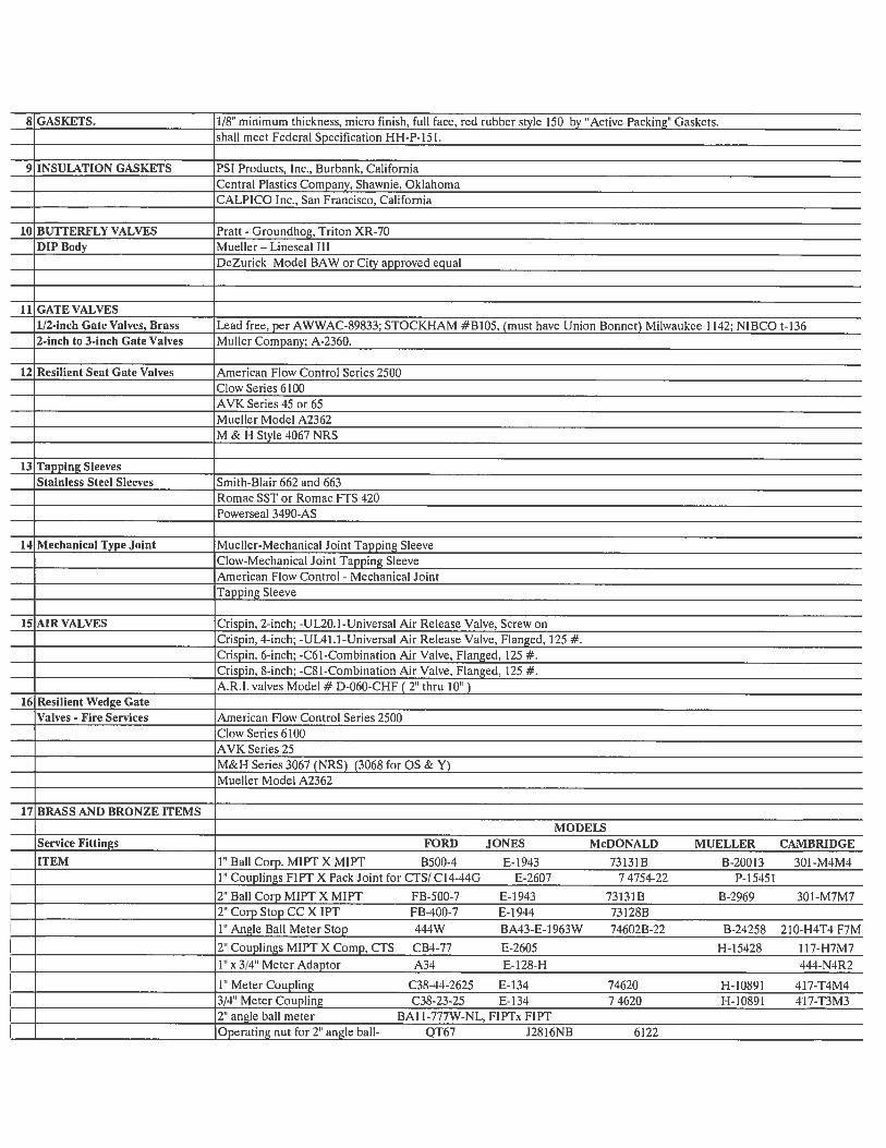


APPENDIX III
STANDARD DRAWINGS
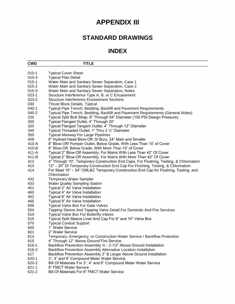
APPENDIX III
STANDARD DRAWINGS
INDEX
CWD TITLE
010-1 Typical Cover Sheet 010-3 Typical Plan Detail 015-1 Water Main and Sanitary Sewer Separation, Case 1 015-2 Water Main and Sanitary Sewer Separation, Case 2 015-3 Water Main and Sanitary Sewer Separation, Notes 023-1 Structure Interference Type A, B, or C Encasement 023-2 Structure Interference Encasement Sections 030 Thrust Block Details, Typical 040-1 Typical Pipe Trench, Bedding, Backfill and Pavement Requirements 040-2 Typical Pipe Trench, Bedding, Backfill and Pavement Requirements (General Notes) 220 Typical Split Butt Strap, 8” Through 54” Diameter (150 PSI Design Pressure) 300 Typical Flanged Outlet, 4” Through 20” 320 Typical Flanged Tangent Outlet, 4” Through 12” Diameter 340 Typical Threaded Outlet, 1” Thru 2 ½” Diameter 350 Typical Manway For Large Pipelines 409 6” Hydrant Head Blow-Off, Di Bury, 24” Main and Smaller 410-A 8” Blow-Off/ Pumper Outlet, Below Grade, With Less Than 10’ of Cover 410-B 8” Blow-Off, Below Grade, With More Than 10’ of Cover 411-A Typical 2” Blow-Off Assembly, For Mains With Less Than 42” Of Cover 411-B Typical 2” Blow-Off Assembly, For Mains With More Than 42” Of Cover 412 4” Through 10”, Temporary Construction End Caps, For Flushing, Testing, & Chlorination 413 12” – 20” DI Temporary Construction End Cap For Flushing, Testing, & Chlorination 414 For Steel 16” – 54” CML&C Temporary Construction End Cap for Flushing, Testing, and
Chlorination 432 Temporary Water Sampler 433 Water Quality Sampling Station 451 Typical 2” Air Valve Installation 460 Typical 4” Air Valve Installation 462 Typical 6” Air Valve Installation 465 Typical 8” Air Valve Installation 500 Typical Valve Box For Gate Valves 504 Tapping Sleeve And Tapping Valve Detail For Domestic And Fire Services 510 Typical Valve Box For Butterfly Valves 515 Typical Split-Sleeve Liner And Cap For 8” and 10” Valve Box 570 Typical Conduit Support 600 1” Water Service 601 2” Water Service 614 Temporary, Emergency, or Construction Water Service / Backflow Protection 615 4” Through 12” Above Ground Fire Service 616-1 Backflow Prevention Assembly ¾ - 2-1/2” Above Ground Installation 616-2 Backflow Prevention Assembly Alternative Location Installation 617 Backflow Prevention Assembly 3” & Larger Above Ground Installation 620-1 3”, 4” and 6” Compound Meter Water Service 620-2 Bill Of Materials For 3”, 4” and 6” Compound Meter Water Service 621-1 8” FMCT Water Service 621-2 Bill Of Materials For 8” FMCT Water Service
INDEX
CWD TITLE
622-1 10” Domestic Water Service 622-2 Bill Of Materials for 10” Compound Water Service 700 Regular and Super Fire Hydrant Detail 800-1 Traffic Rated Vault For 3” Thru 6” Compound Meters 800-2 Traffic Rated Vault For 3” Thru 6” Compound Meters 811 Blow-Off Manhole Installation 816 Manhole Detail 48” Max ID Pipe 900-A 4” Dia. Guard Post Installation 900-B 2.5” Dia. Guard Post Installation 922 Test Lead Installation 923 Flange Insulation and Test Lead Installation 924 Joint Bond Details 960-1 Notification Sign 960-2 Notification Sign

APPR
OVED
BY
VOID
ONE
YEA
R FR
OM T
HIS
DATE
DATE
CA
LL
T
OL
L F
RE
E:
1-8
00
22
7-2
60
0
GE
NE
RA
L N
OT
ES
NO
TE
: T
HIS
S
YS
TE
M S
ER
VE
D B
Y Z
ON
E.
CIT
Y O
F R
IV
ER
SID
E
PU
BLIC
U
TILIT
IE
S D
EP
AR
TM
EN
T
D5-X
XX
XX
X
WA
TE
R IM
PR
OV
EM
EN
T P
LA
NS
PR
OJE
CT
N
AM
E
WA
TE
R D
IV
IS
IO
N
AP
PR
OV
ED
B
Y:
FIR
E H
YD
RA
NT
L
OC
AT
IO
N O
NL
Y
RIVE
RSID
E FI
RE D
EPAR
TMEN
TDI
VISI
ON O
F FI
RE P
ROTE
CTIO
NDA
TE
CIT
Y O
F R
IV
ER
SID
E
PU
BL
IC
U
TIL
IT
IE
S D
EP
AR
TM
EN
T
OV
ER
HE
AD
&
U
ND
ER
GR
OU
ND
APPR
OVED
BY
DATE
EN
GIN
EE
RIN
G C
OM
PA
NY
T
IT
LE
BE
NC
HM
AR
K:
BA
SIS
O
F B
EA
RIN
GS
:
BLO
CK
IN
CLU
DE
E
NG
IN
EE
R'S
PR
OV
ID
E A
V
IC
IN
IT
Y M
AP
SH
OW
IN
G P
RO
JE
CT
LO
CA
TIO
N,
PR
OV
ID
E A
N IN
DE
X M
AP
A
T A
S
CA
LE
O
F 1" =
100' S
HO
WIN
G
PR
OP
OS
ED
IM
PR
OV
EM
EN
TS
A
ND
P
LA
N S
HE
ET
IN
DE
X
(R
EQ
UIR
ED
W
HE
N P
LA
N H
AS
2 O
R M
OR
E S
HE
ET
S)
DIS
HE
D-H
EA
D
EN
D C
AP
W
/ B
O
FIR
E H
YD
RA
NT
FIR
E S
ER
VIC
E
ELB
OW
CR
OS
S
WA
TE
R LIN
E
AIR
V
ALV
E
CH
EC
K V
ALV
E
WA
TE
R S
ER
VIC
E
WA
TE
R V
ALV
E
TE
E
TE
ST
LE
AD
S
RE
DU
CE
R
TA
P S
LE
EV
E
LE
GE
ND
IT
EM
BILL O
F M
AT
ER
IA
LS
CIT
Y F
OR
CE
S IN
ST
ALLA
TIO
NS
CA
BLE
T
V
ELE
CT
RIC
GA
S
SE
WE
R
ST
OR
M D
RA
IN
TE
LE
PH
ON
E
NO
RT
H A
RR
OW
A
ND
S
CA
LE
SIG
NA
TU
RE
A
ND
S
TA
MP
WA
TE
R S
ER
VIC
E
(LA
ND
SC
AP
E)
WA
TE
R S
ER
VIC
E
(B
Y C
IT
Y F
OR
CE
S)
TR
AC
T
BO
UN
DA
RY
MA
NH
OLE
W/ M
AN
WA
Y
DO
ME
ST
IC
C
OM
PO
UN
D
WA
TE
R S
ER
VIC
E
RE
FE
R T
O: S
PE
CIF
IC
AT
IO
N 205
AP
PE
ND
IX
I - D
ES
IG
N C
RIT
ER
IA
SE
CT
IO
N 3.05 G
EN
ER
AL N
OT
ES

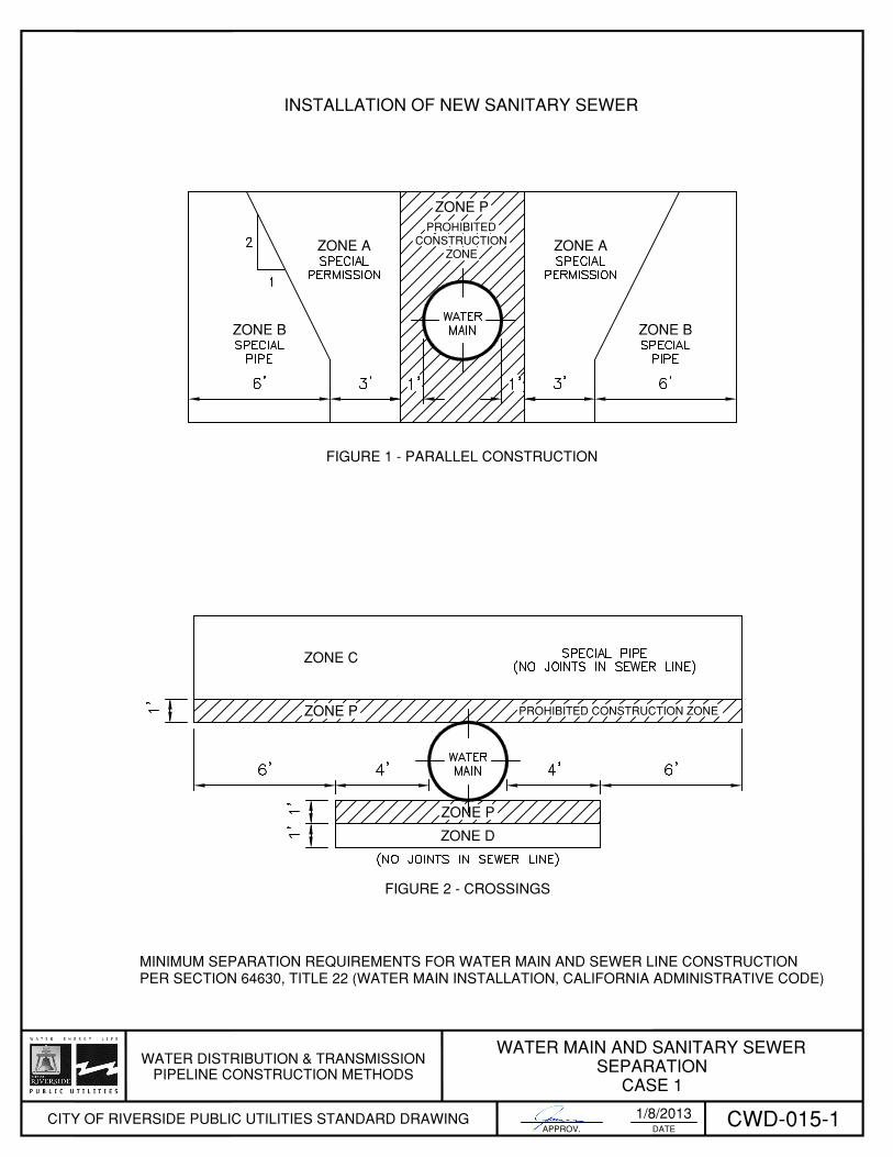
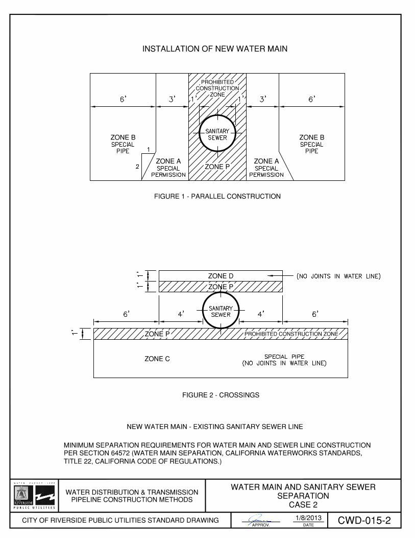
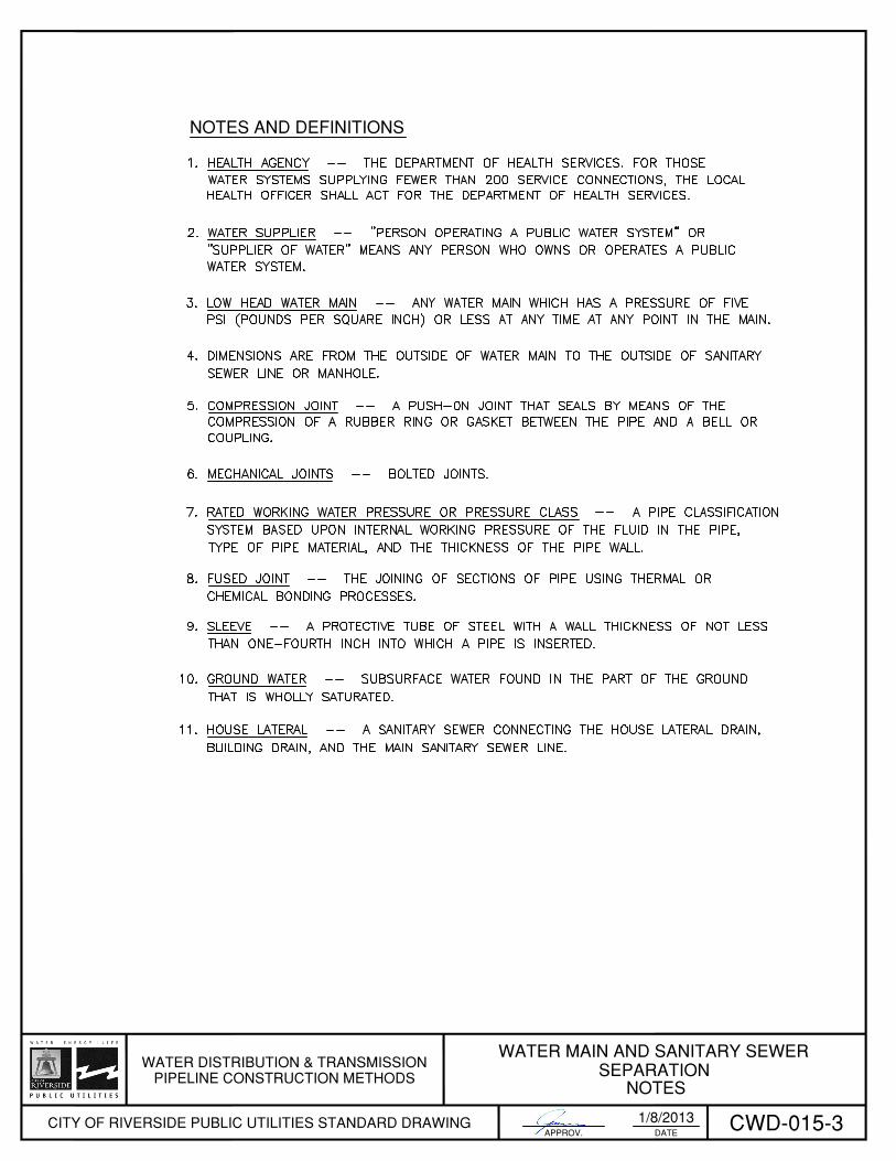
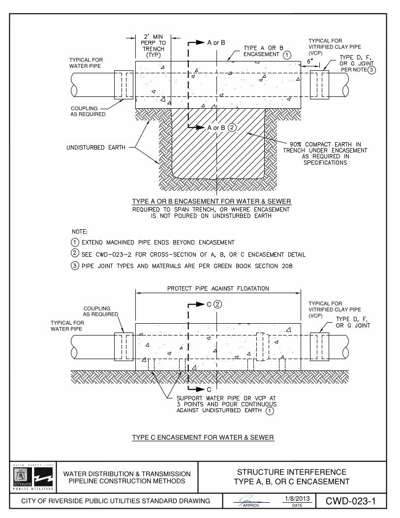

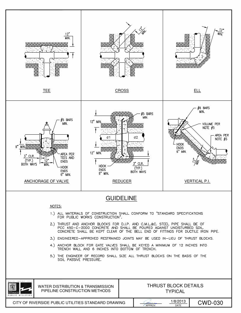


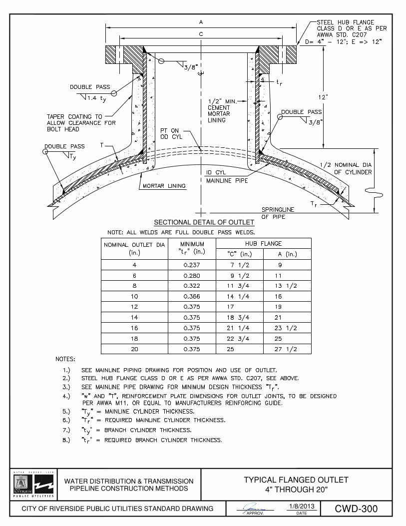

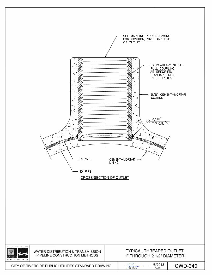
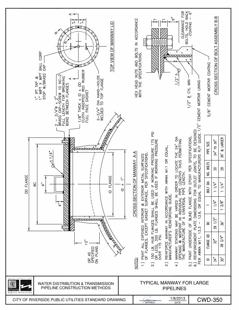


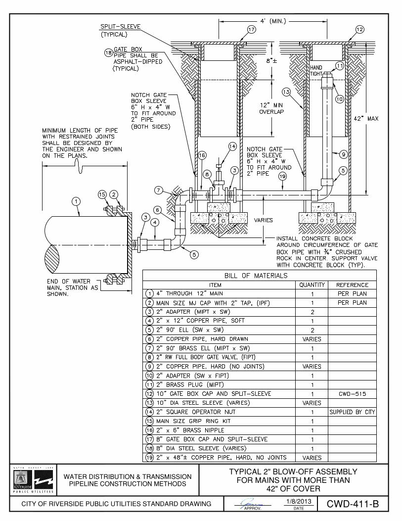
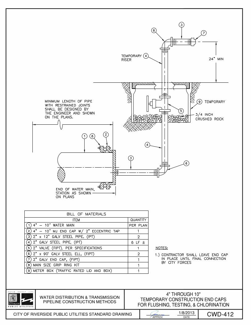
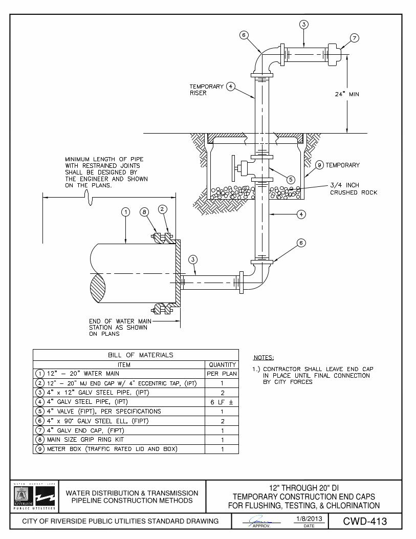

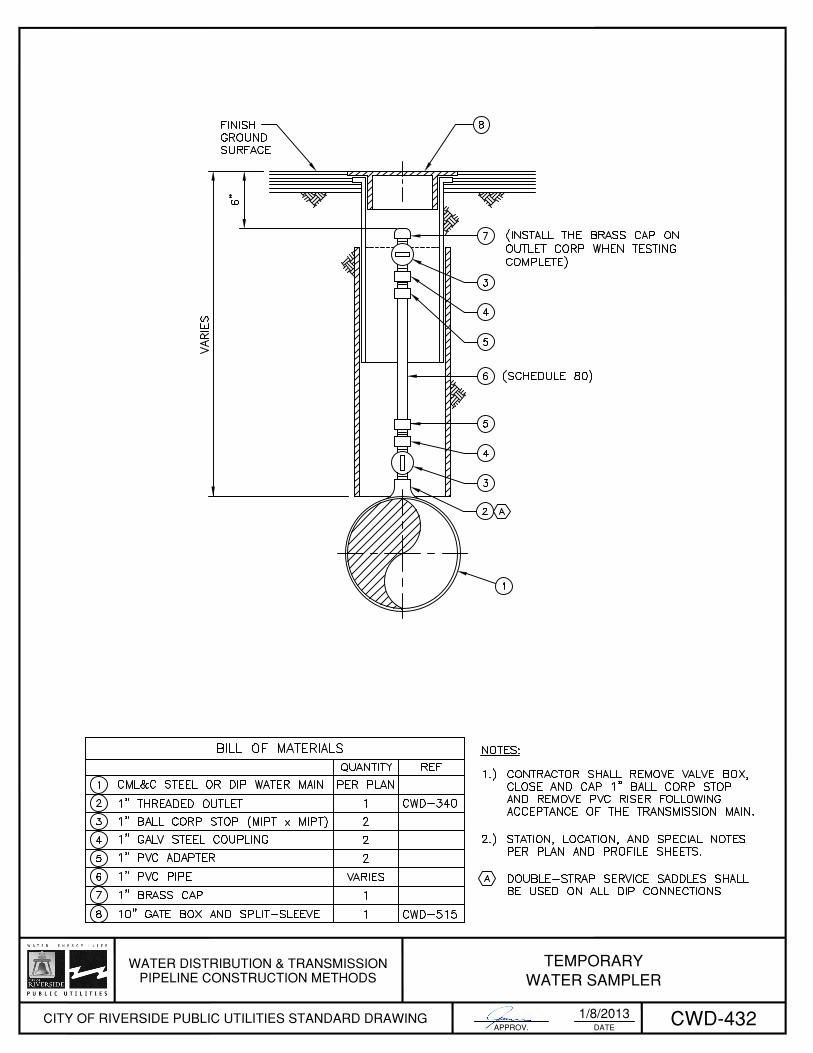
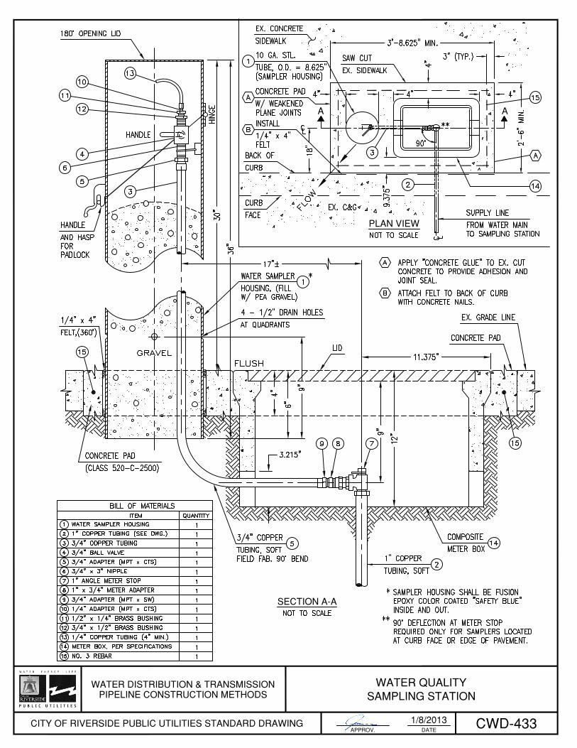
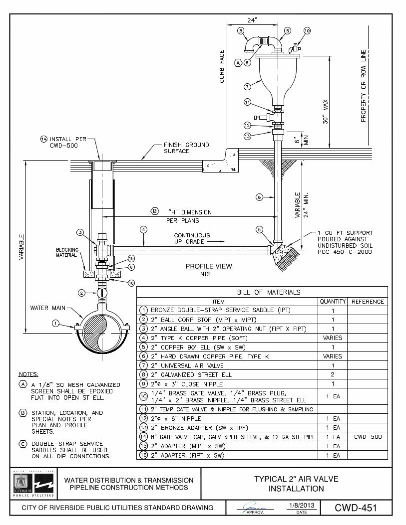


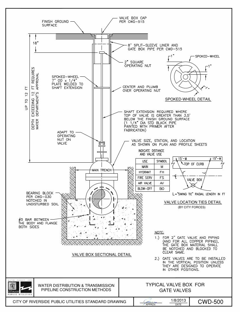


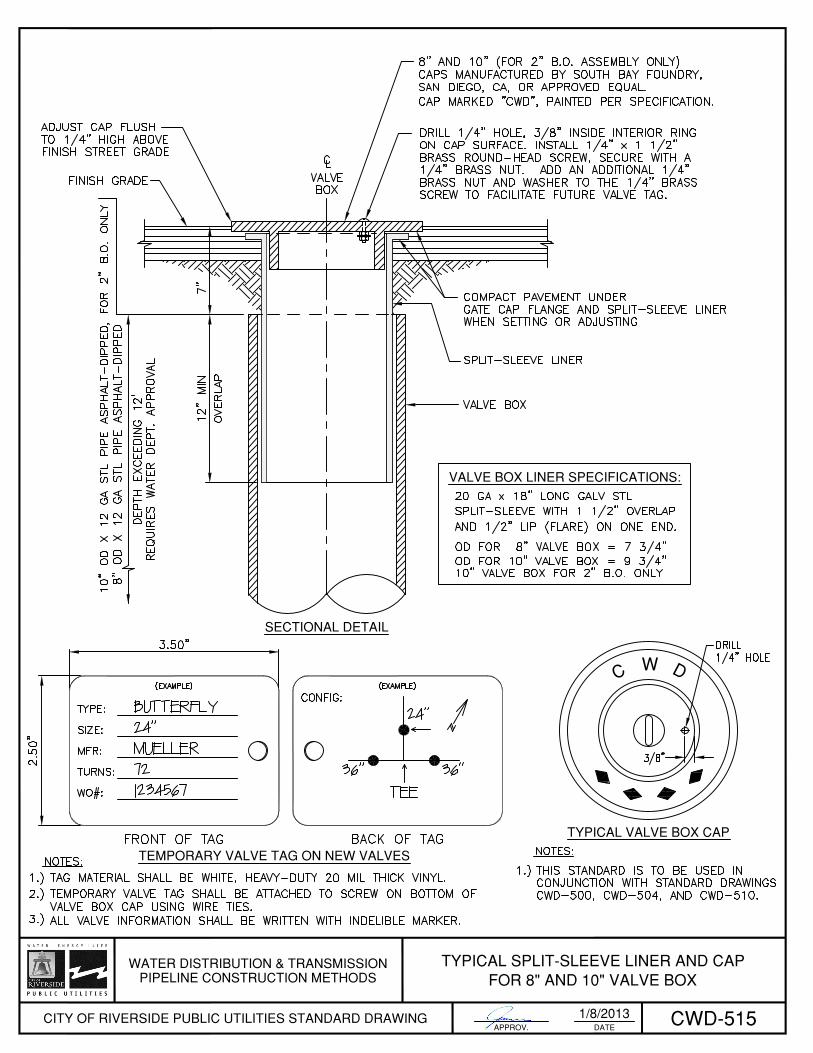
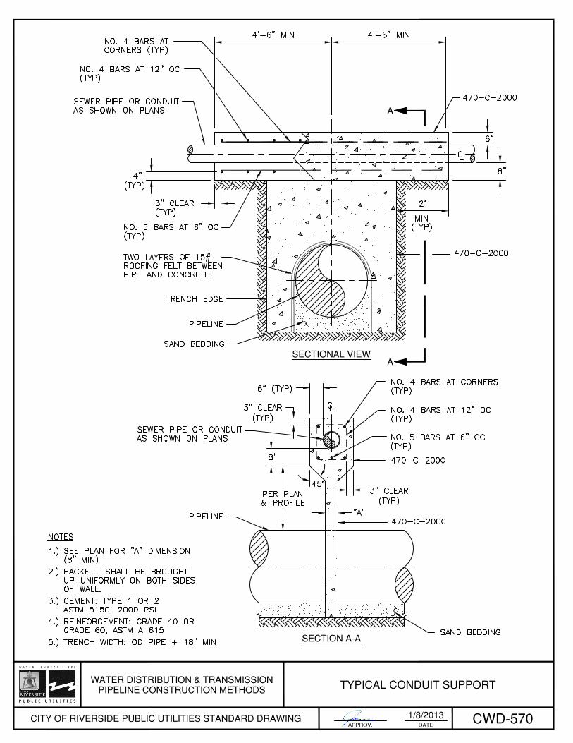

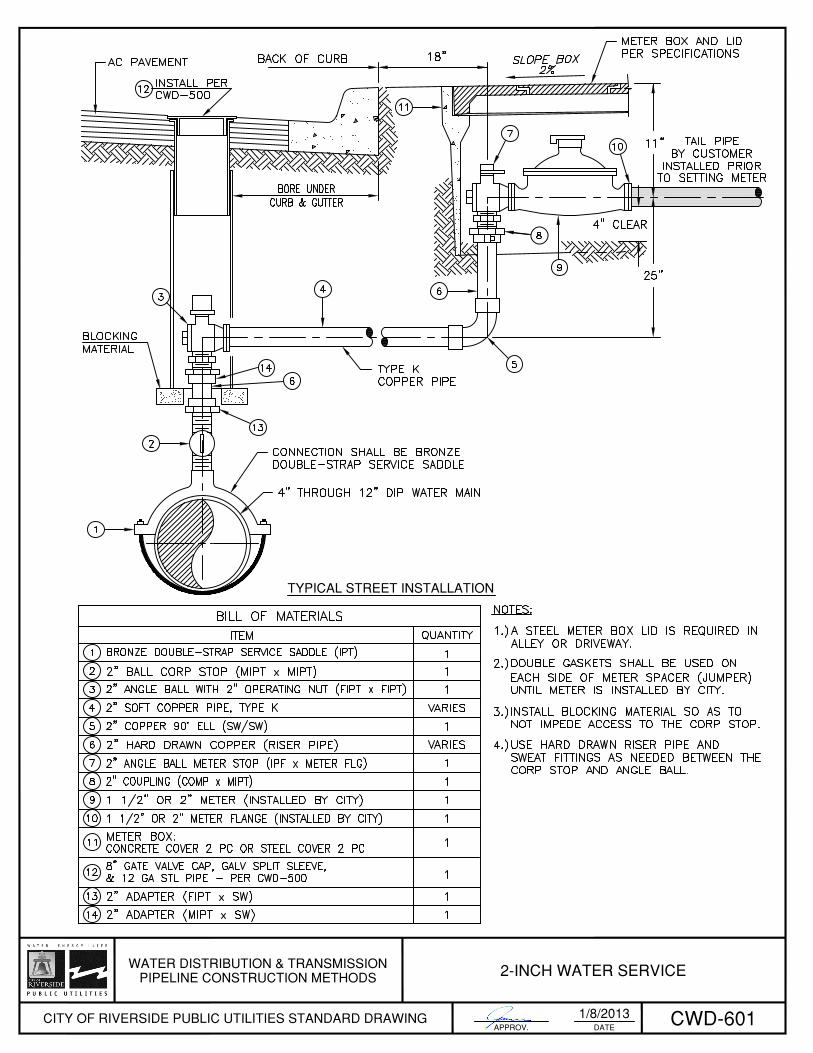

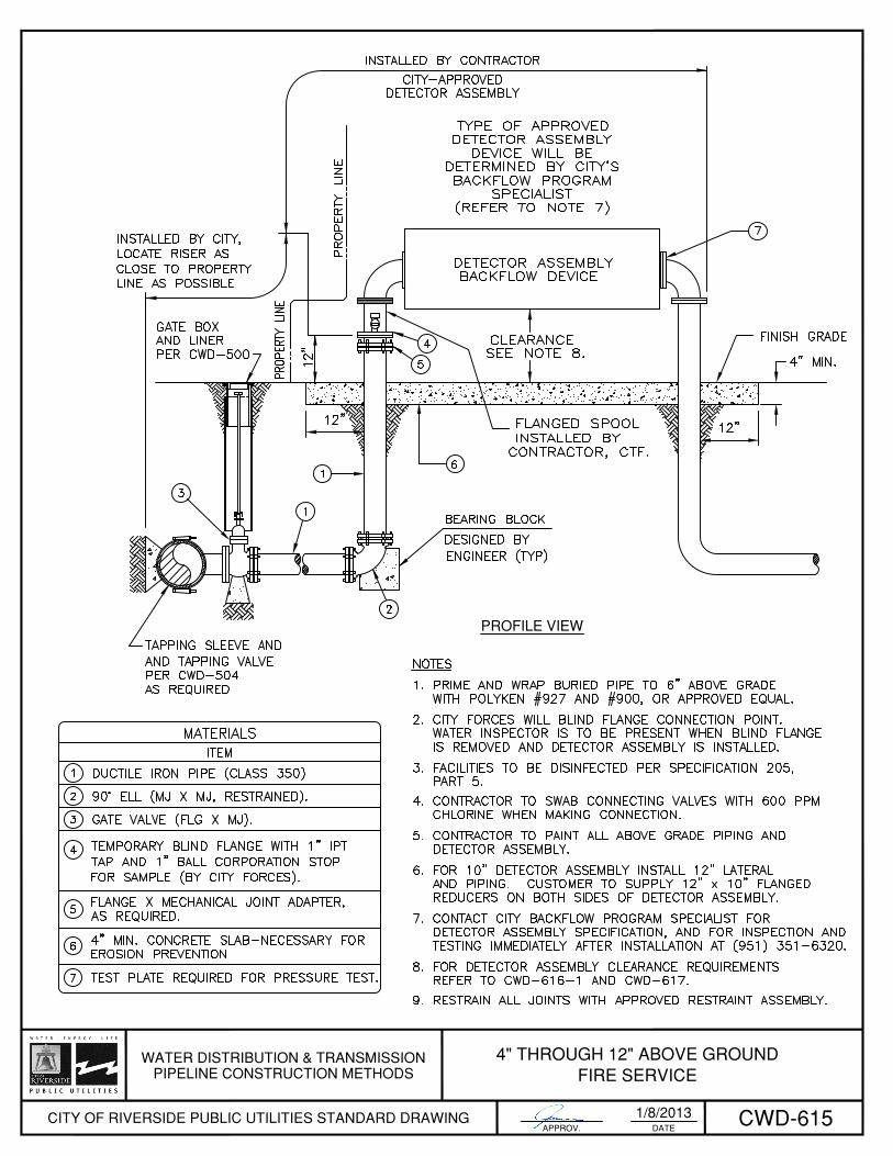


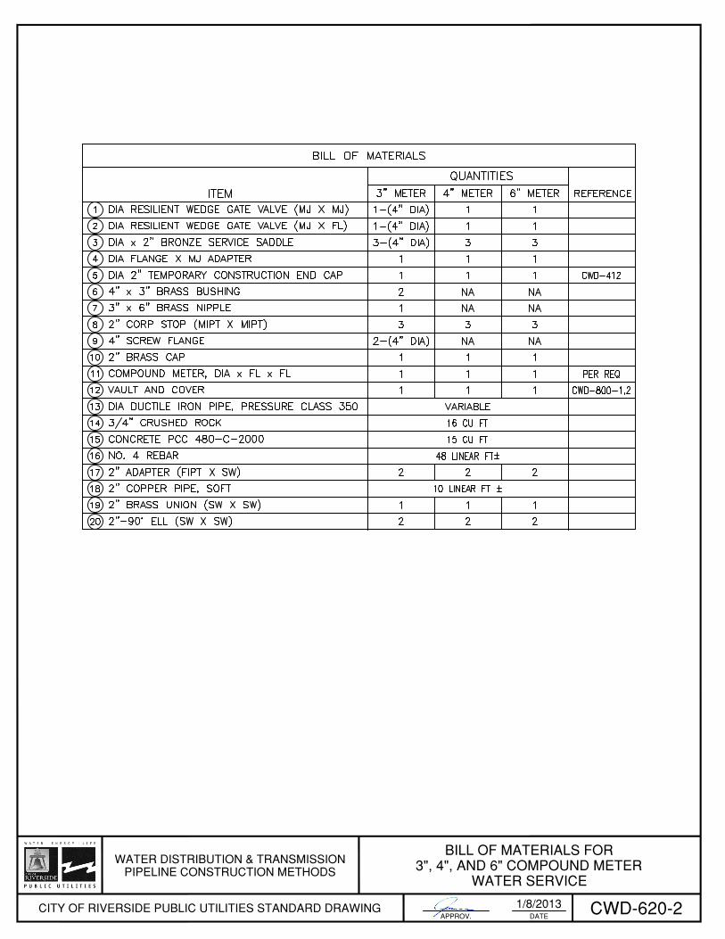
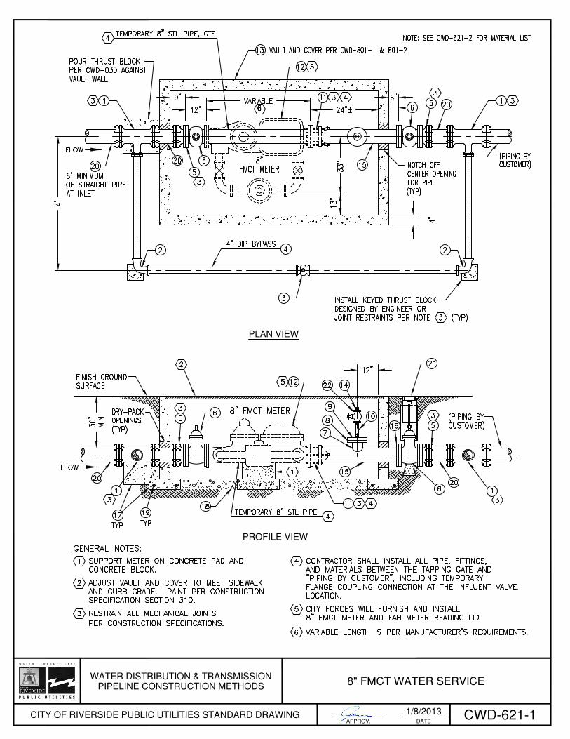
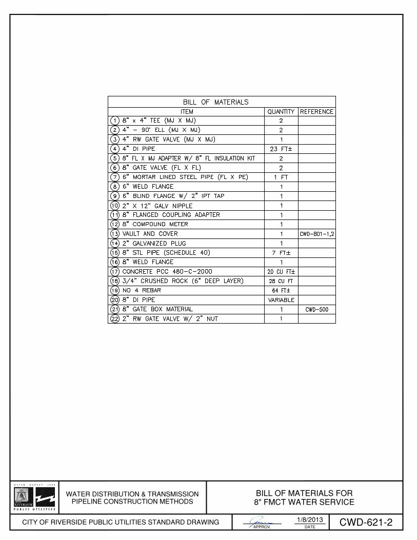


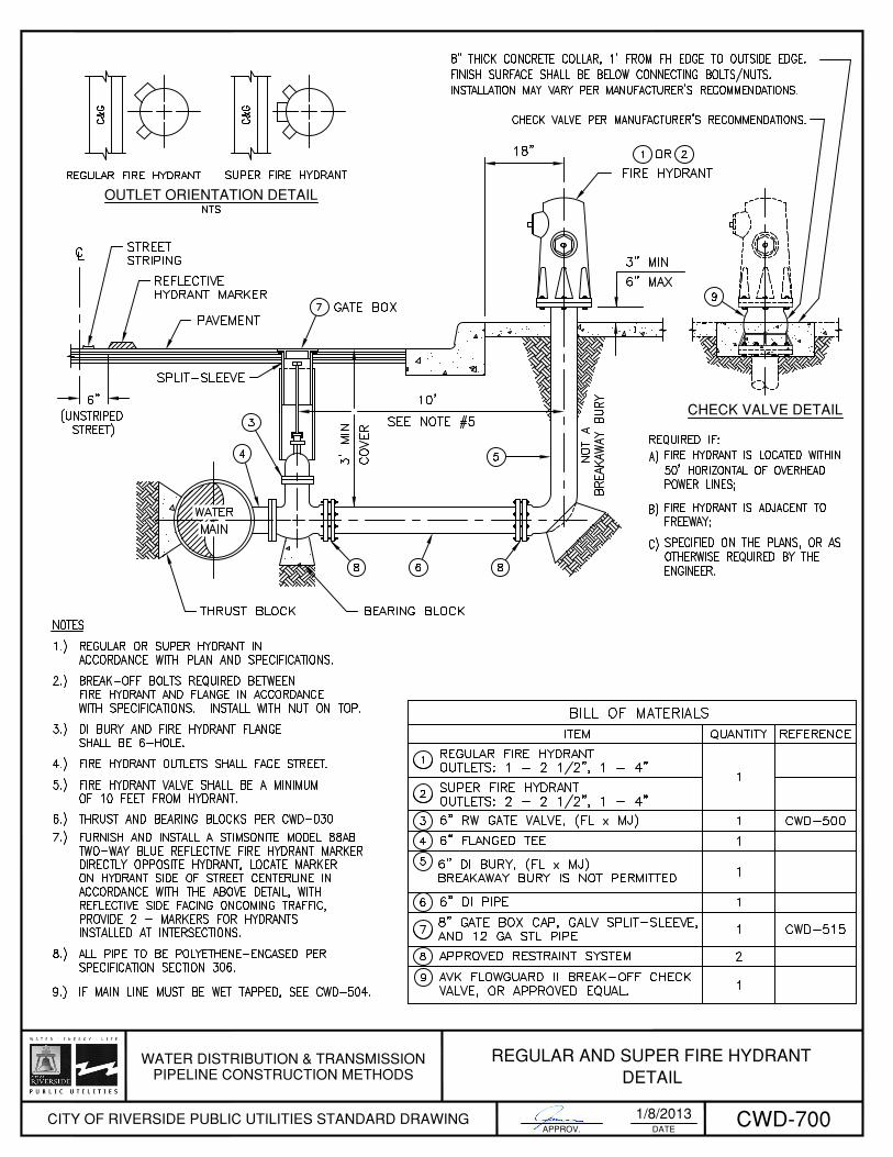

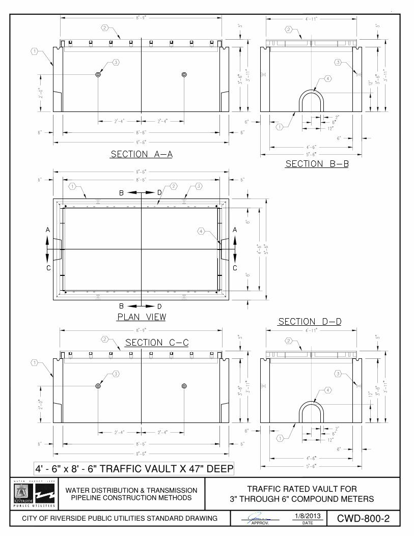


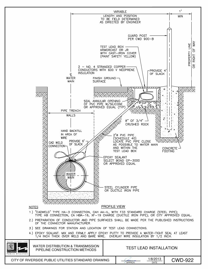
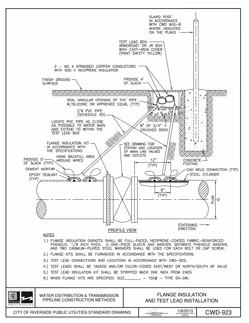


RIV
ERSI
DE R
ENA
ISSA
NC
E
WA
RD
PRO
JEC
T
MA
YOR
CITY
CO
UNC
IL M
EMBE
RS
CITY
MA
NA
GER
CO
UNC
IL M
EMBE
RPR
OJE
CT N
AM
E /
WA
TER
MA
INPr
ojec
t Nam
e:
Stre
ets I
mpa
cted
:
Proj
ect D
urat
ion:
Con
tract
or:
Phon
e N
o.:
ww
w.R
iver
sideC
a.go
vRI
VERS
IDE
PUBL
IC U
TILITI
ES: (
951)
826
-531
1w
ww
.rive
rsid
epub
licut
ilitie
s.com