Embed Size (px)
Citation preview
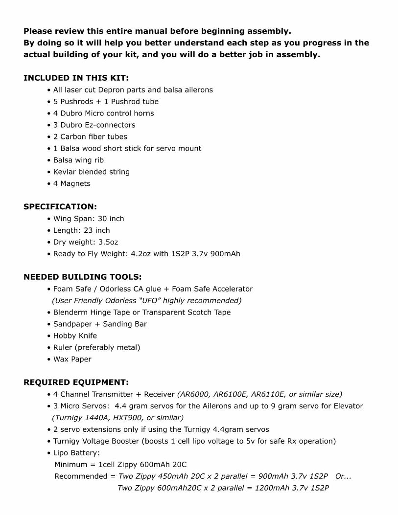
Please review this entire manual before beginning assembly. By doing so it will help you better understand each step as you progress in the actual building of your kit, and you will do a better job in assembly.
INCLUDED IN THIS KIT:• All laser cut Depron parts and balsa ailerons
• 5 Pushrods + 1 Pushrod tube
• 4 Dubro Micro control horns
• 3 Dubro Ez-connectors
• 2 Carbon fiber tubes
• 1 Balsa wood short stick for servo mount
• Balsa wing rib
• Kevlar blended string
• 4 Magnets
SPECIFICATION:• Wing Span: 30 inch
• Length: 23 inch
• Dry weight: 3.5oz
• Ready to Fly Weight: 4.2oz with 1S2P 3.7v 900mAh
NEEDED BUILDING TOOLS:• Foam Safe / Odorless CA glue + Foam Safe Accelerator
(User Friendly Odorless “UFO” highly recommended)
• Blenderm Hinge Tape or Transparent Scotch Tape
• Sandpaper + Sanding Bar
• Hobby Knife
• Ruler (preferably metal)
• Wax Paper
REQUIRED EQUIPMENT:• 4 Channel Transmitter + Receiver (AR6000, AR6100E, AR6110E, or similar size)
• 3 Micro Servos: 4.4 gram servos for the Ailerons and up to 9 gram servo for Elevator
(Turnigy 1440A, HXT900, or similar)
• 2 servo extensions only if using the Turnigy 4.4gram servos
• Turnigy Voltage Booster (boosts 1 cell lipo voltage to 5v for safe Rx operation)
• Lipo Battery:
Minimum = 1cell Zippy 600mAh 20C
Recommended = Two Zippy 450mAh 20C x 2 parallel = 900mAh 3.7v 1S2P Or...
Two Zippy 600mAh20C x 2 parallel = 1200mAh 3.7v 1S2P
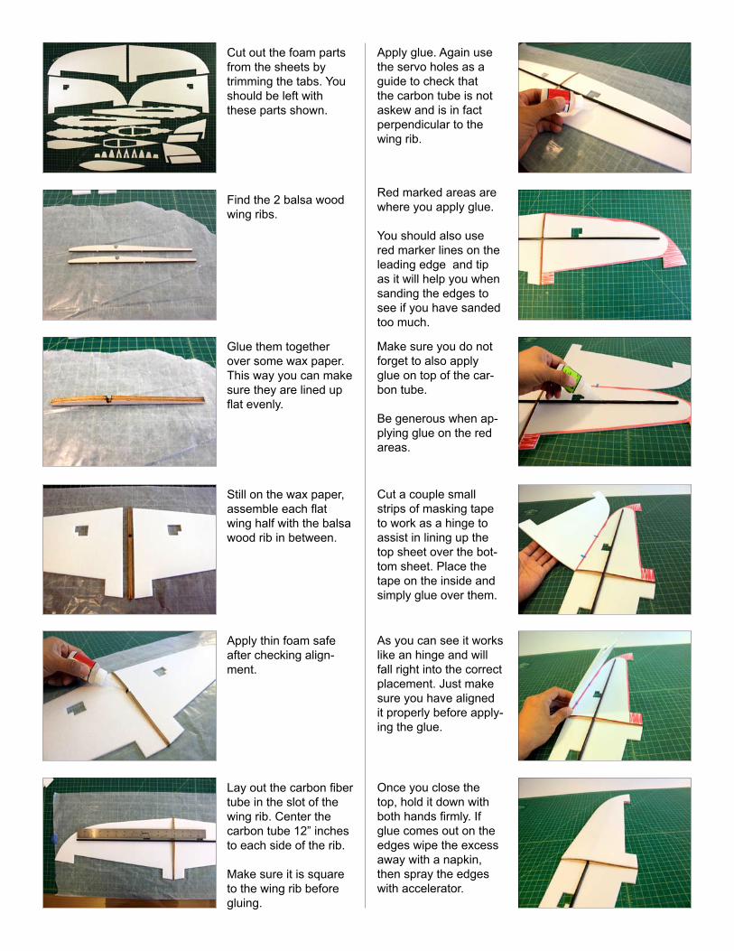
Cut out the foam parts from the sheets by trimming the tabs. You should be left with these parts shown.
Find the 2 balsa wood wing ribs.
Glue them together over some wax paper. This way you can make sure they are lined up flat evenly.
Still on the wax paper, assemble each flat wing half with the balsa wood rib in between.
Apply thin foam safe after checking align-ment.
Lay out the carbon fiber tube in the slot of the wing rib. Center the carbon tube 12” inches to each side of the rib.
Make sure it is square to the wing rib before gluing.
Apply glue. Again use the servo holes as a guide to check that the carbon tube is not askew and is in fact perpendicular to the wing rib.
Red marked areas are where you apply glue.
You should also use red marker lines on the leading edge and tip as it will help you when sanding the edges to see if you have sanded too much.
Make sure you do not forget to also apply glue on top of the car-bon tube.
Be generous when ap-plying glue on the red areas.
Cut a couple small strips of masking tape to work as a hinge to assist in lining up the top sheet over the bot-tom sheet. Place the tape on the inside and simply glue over them.
As you can see it works like an hinge and will fall right into the correct placement. Just make sure you have aligned it properly before apply-ing the glue.
Once you close the top, hold it down with both hands firmly. If glue comes out on the edges wipe the excess away with a napkin, then spray the edges with accelerator.
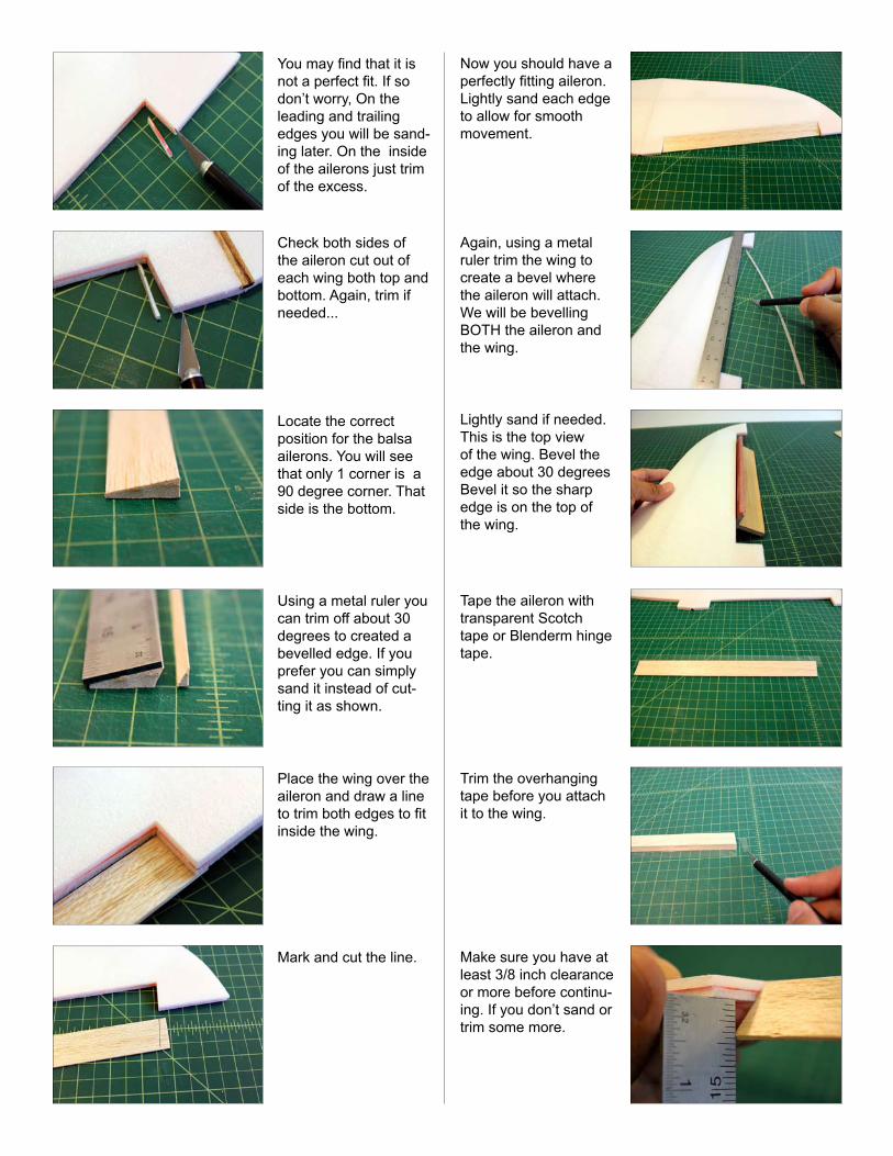
You may find that it is not a perfect fit. If so don’t worry, On the leading and trailing edges you will be sand-ing later. On the inside of the ailerons just trim of the excess.
Check both sides of the aileron cut out of each wing both top and bottom. Again, trim if needed...
Locate the correct position for the balsa ailerons. You will see that only 1 corner is a 90 degree corner. That side is the bottom.
Using a metal ruler you can trim off about 30 degrees to created a bevelled edge. If you prefer you can simply sand it instead of cut-ting it as shown.
Place the wing over the aileron and draw a line to trim both edges to fit inside the wing.
Mark and cut the line.
Now you should have a perfectly fitting aileron.Lightly sand each edge to allow for smooth movement.
Again, using a metal ruler trim the wing to create a bevel where the aileron will attach. We will be bevelling BOTH the aileron and the wing.
Lightly sand if needed. This is the top view of the wing. Bevel the edge about 30 degrees Bevel it so the sharp edge is on the top of the wing.
Tape the aileron with transparent Scotch tape or Blenderm hinge tape.
Trim the overhanging tape before you attach it to the wing.
Make sure you have at least 3/8 inch clearance or more before continu-ing. If you don’t sand or trim some more.
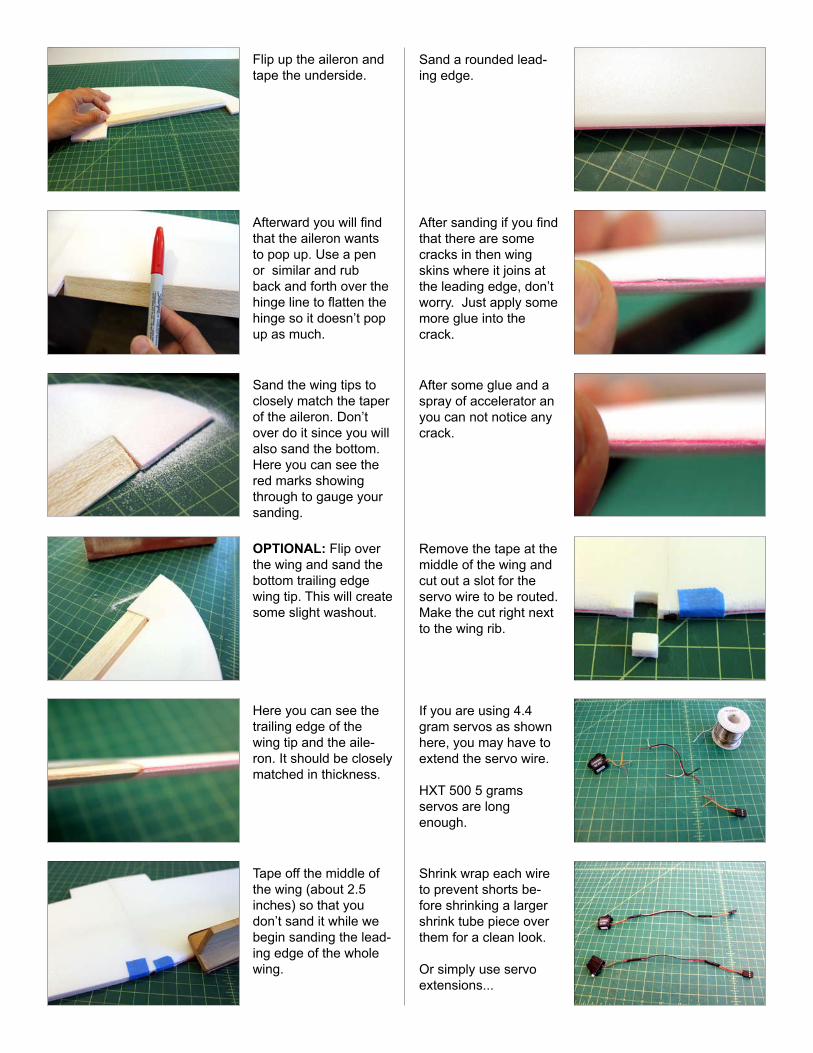
Flip up the aileron and tape the underside.
Afterward you will find that the aileron wants to pop up. Use a pen or similar and rub back and forth over the hinge line to flatten the hinge so it doesn’t pop up as much.
Sand the wing tips to closely match the taper of the aileron. Don’t over do it since you will also sand the bottom.Here you can see the red marks showing through to gauge your sanding.
OPTIONAL: Flip over the wing and sand the bottom trailing edge wing tip. This will create some slight washout.
Here you can see the trailing edge of the wing tip and the aile-ron. It should be closely matched in thickness.
Tape off the middle of the wing (about 2.5 inches) so that you don’t sand it while we begin sanding the lead-ing edge of the whole wing.
Sand a rounded lead-ing edge.
After sanding if you find that there are some cracks in then wing skins where it joins at the leading edge, don’t worry. Just apply some more glue into the crack.
After some glue and a spray of accelerator an you can not notice any crack.
Remove the tape at the middle of the wing and cut out a slot for the servo wire to be routed. Make the cut right next to the wing rib.
If you are using 4.4 gram servos as shown here, you may have to extend the servo wire.
HXT 500 5 grams servos are long enough.
Shrink wrap each wire to prevent shorts be-fore shrinking a larger shrink tube piece over them for a clean look.
Or simply use servo extensions...
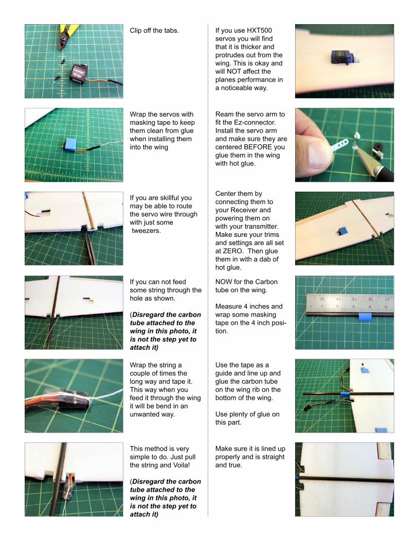
Clip off the tabs.
Wrap the servos with masking tape to keep them clean from glue when installing them into the wing
If you are skillful you may be able to route the servo wire through with just some tweezers.
If you can not feed some string through the hole as shown.
(Disregard the carbon tube attached to the wing in this photo, it is not the step yet to attach it)
Wrap the string a couple of times the long way and tape it. This way when you feed it through the wing it will be bend in an unwanted way.
This method is very simple to do. Just pull the string and Voila!
(Disregard the carbon tube attached to the wing in this photo, it is not the step yet to attach it)
If you use HXT500 servos you will find that it is thicker and protrudes out from the wing. This is okay and will NOT affect the planes performance in a noticeable way.
Ream the servo arm to fit the Ez-connector.Install the servo arm and make sure they are centered BEFORE you glue them in the wing with hot glue.
Center them by connecting them to your Receiver and powering them on with your transmitter. Make sure your trims and settings are all set at ZERO. Then glue them in with a dab of hot glue.
NOW for the Carbon tube on the wing.
Measure 4 inches and wrap some masking tape on the 4 inch posi-tion.
Use the tape as a guide and line up and glue the carbon tube on the wing rib on the bottom of the wing.
Use plenty of glue on this part.
Make sure it is lined up properly and is straight and true.
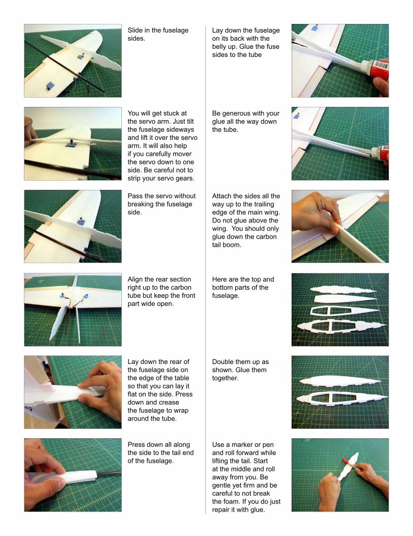
Slide in the fuselage sides.
You will get stuck at the servo arm. Just tilt the fuselage sideways and lift it over the servo arm. It will also help if you carefully mover the servo down to one side. Be careful not to strip your servo gears.
Pass the servo without breaking the fuselage side.
Align the rear section right up to the carbon tube but keep the front part wide open.
Lay down the rear of the fuselage side on the edge of the table so that you can lay it flat on the side. Press down and crease the fuselage to wrap around the tube.
Press down all along the side to the tail end of the fuselage.
Lay down the fuselage on its back with the belly up. Glue the fuse sides to the tube
Be generous with your glue all the way down the tube.
Attach the sides all the way up to the trailing edge of the main wing. Do not glue above the wing. You should only glue down the carbon tail boom.
Here are the top and bottom parts of the fuselage.
Double them up as shown. Glue them together.
Use a marker or pen and roll forward while lifting the tail. Start at the middle and roll away from you. Be gentle yet firm and be careful to not break the foam. If you do just repair it with glue.
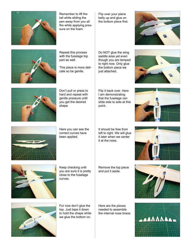
Remember to lift the tail while sliding the pen away from you all the while applying pres-sure on the foam.
Repeat this process with the fuselage top part as well.
This piece is more deli-cate so be gentle.
Don’t pull or press to hard and repeat with gentle pressure until you get the desired shape
Here you can see the correct curves have been applied.
Keep checking until you are sure it is pretty close to the fuselage curves.
For now don’t glue the top. Just tape it down to hold the shape while we glue the bottom on.
Flip over your plane belly up and glue on the bottom piece first.
Do NOT glue the wing saddle area yet even though you are temped to right now. Only glue the bottom piece we just attached.
Flip it back over. Here I am demonstrating that the fuselage can slide side to side at this point.
It should be free from left to right. We will glue it later when we center it at the nose.
Remove the top piece and put it aside.
Here are the pieces needed to assemble the internal nose brace.
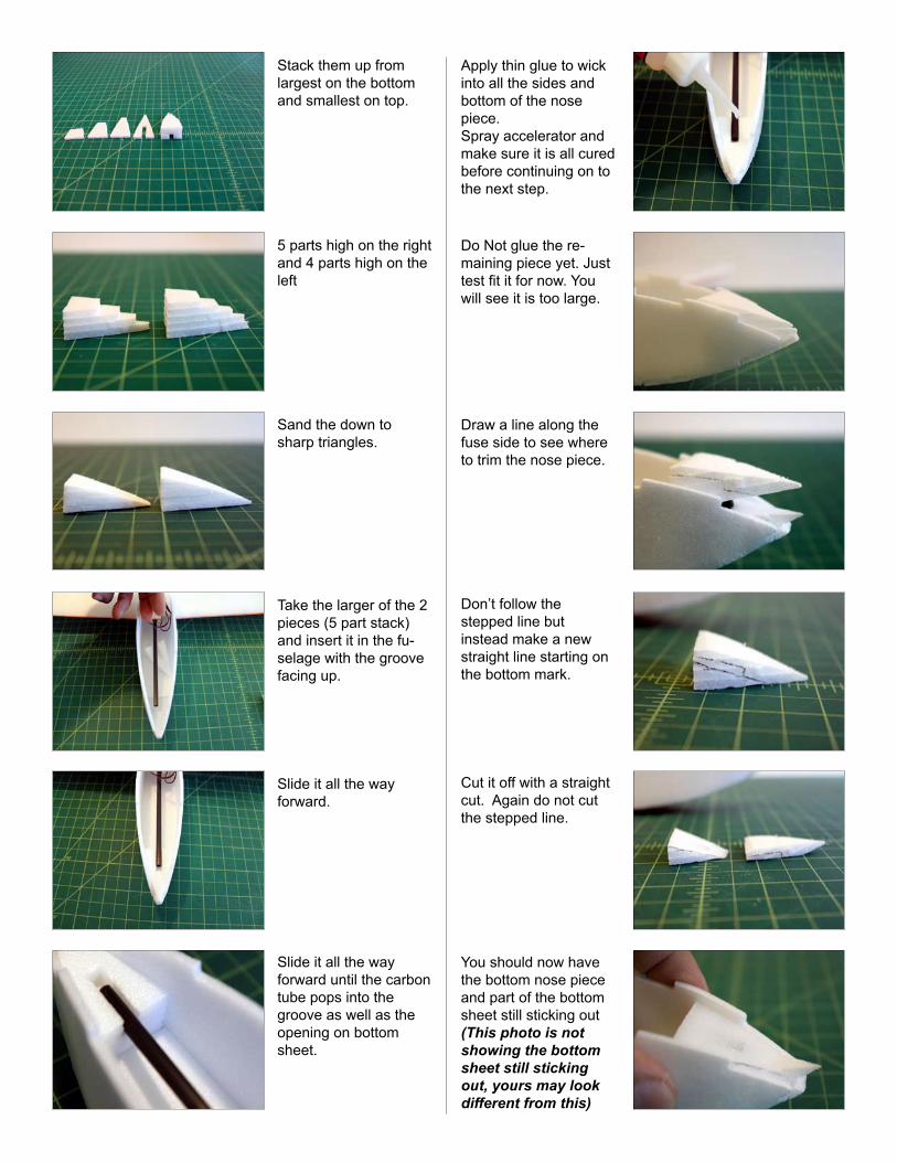
Stack them up from largest on the bottom and smallest on top.
5 parts high on the right and 4 parts high on the left
Sand the down to sharp triangles.
Take the larger of the 2 pieces (5 part stack)and insert it in the fu-selage with the groove facing up.
Slide it all the way forward.
Slide it all the way forward until the carbon tube pops into the groove as well as the opening on bottom sheet.
Apply thin glue to wick into all the sides and bottom of the nose piece.Spray accelerator and make sure it is all cured before continuing on to the next step.
Do Not glue the re-maining piece yet. Just test fit it for now. You will see it is too large.
Draw a line along the fuse side to see where to trim the nose piece.
Don’t follow the stepped line but instead make a new straight line starting on the bottom mark.
Cut it off with a straight cut. Again do not cut the stepped line.
You should now have the bottom nose piece and part of the bottom sheet still sticking out(This photo is not showing the bottom sheet still sticking out, yours may look different from this)
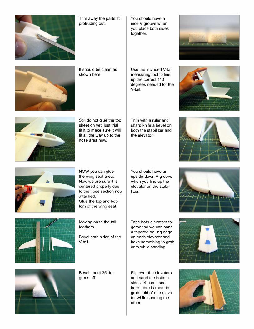
Trim away the parts still protruding out.
It should be clean as shown here.
Still do not glue the top sheet on yet, just trial fit it to make sure it will fit all the way up to the nose area now.
NOW you can glue the wing seat area. Now we are sure it is centered properly due to the nose section now attached.Glue the top and bot-tom of the wing seat.
Moving on to the tail feathers...
Bevel both sides of the V-tail.
Bevel about 35 de-grees off.
You should have a nice V groove when you place both sides together.
Use the included V-tail measuring tool to line up the correct 110 degrees needed for the V-tail.
Trim with a ruler and sharp knife a bevel on both the stabilizer and the elevator.
You should have an upside-down V groove when you line up the elevator on the stabi-lizer.
Tape both elevators to-gether so we can sand a tapered trailing edge on each elevator and have something to grab onto while sanding.
Flip over the elevators and sand the bottom sides. You can see here there is room to grab hold of one eleva-tor while sanding the other.
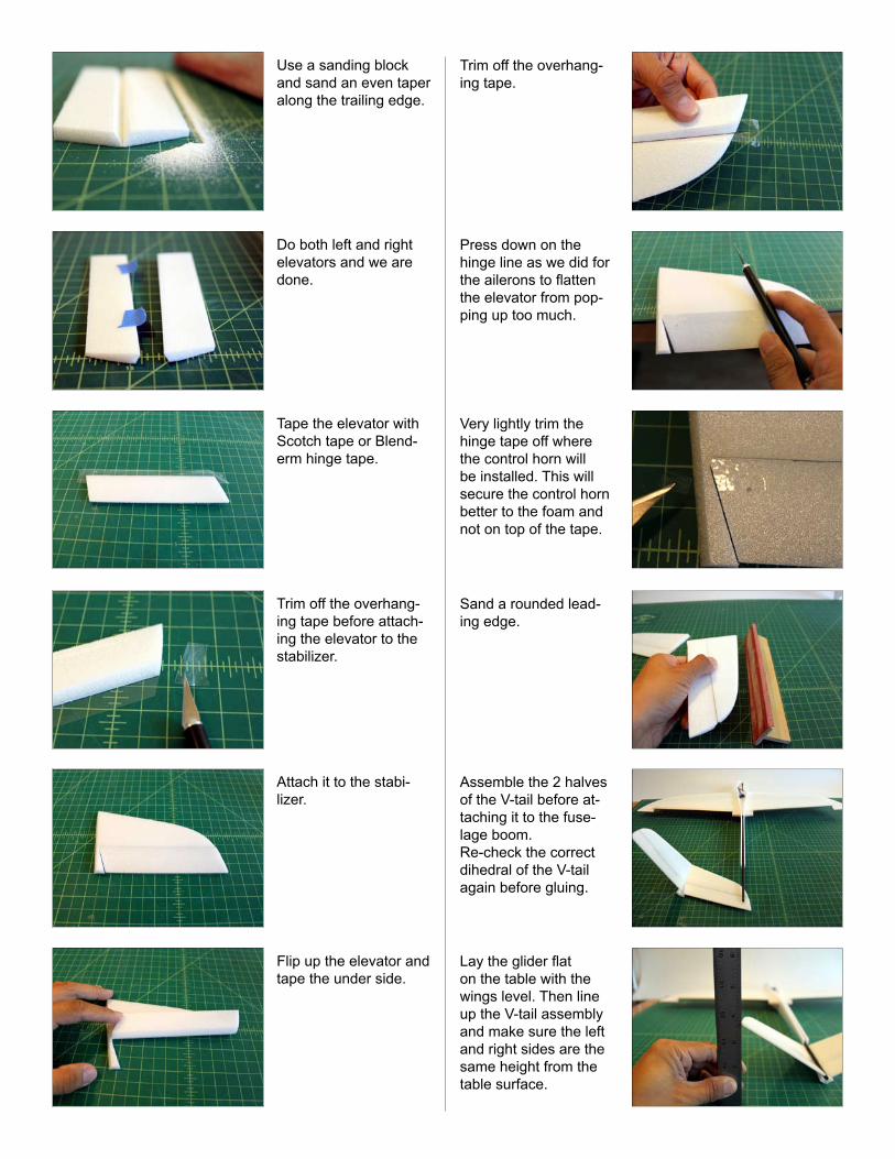
Use a sanding block and sand an even taper along the trailing edge.
Do both left and right elevators and we are done.
Tape the elevator with Scotch tape or Blend-erm hinge tape.
Trim off the overhang-ing tape before attach-ing the elevator to the stabilizer.
Attach it to the stabi-lizer.
Flip up the elevator and tape the under side.
Trim off the overhang-ing tape.
Press down on the hinge line as we did for the ailerons to flatten the elevator from pop-ping up too much.
Very lightly trim the hinge tape off where the control horn will be installed. This will secure the control horn better to the foam and not on top of the tape.
Sand a rounded lead-ing edge.
Assemble the 2 halves of the V-tail before at-taching it to the fuse-lage boom. Re-check the correct dihedral of the V-tail again before gluing.
Lay the glider flat on the table with the wings level. Then line up the V-tail assembly and make sure the left and right sides are the same height from the table surface.
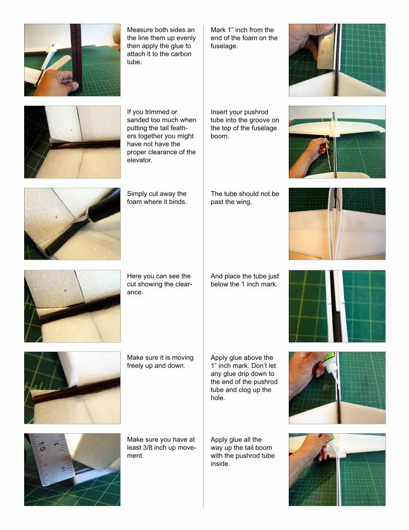
Measure both sides an the line them up evenly then apply the glue to attach it to the carbon tube.
If you trimmed or sanded too much when putting the tail feath-ers together you might have not have the proper clearance of the elevator.
Simply cut away the foam where it binds.
Here you can see the cut showing the clear-ance.
Make sure it is moving freely up and down.
Make sure you have at least 3/8 inch up move-ment.
Mark 1” inch from the end of the foam on the fuselage.
Insert your pushrod tube into the groove on the top of the fuselage boom.
The tube should not be past the wing.
And place the tube just below the 1 inch mark.
Apply glue above the 1” inch mark. Don’t let any glue drip down to the end of the pushrod tube and clog up the hole.
Apply glue all the way up the tail boom with the pushrod tube inside.
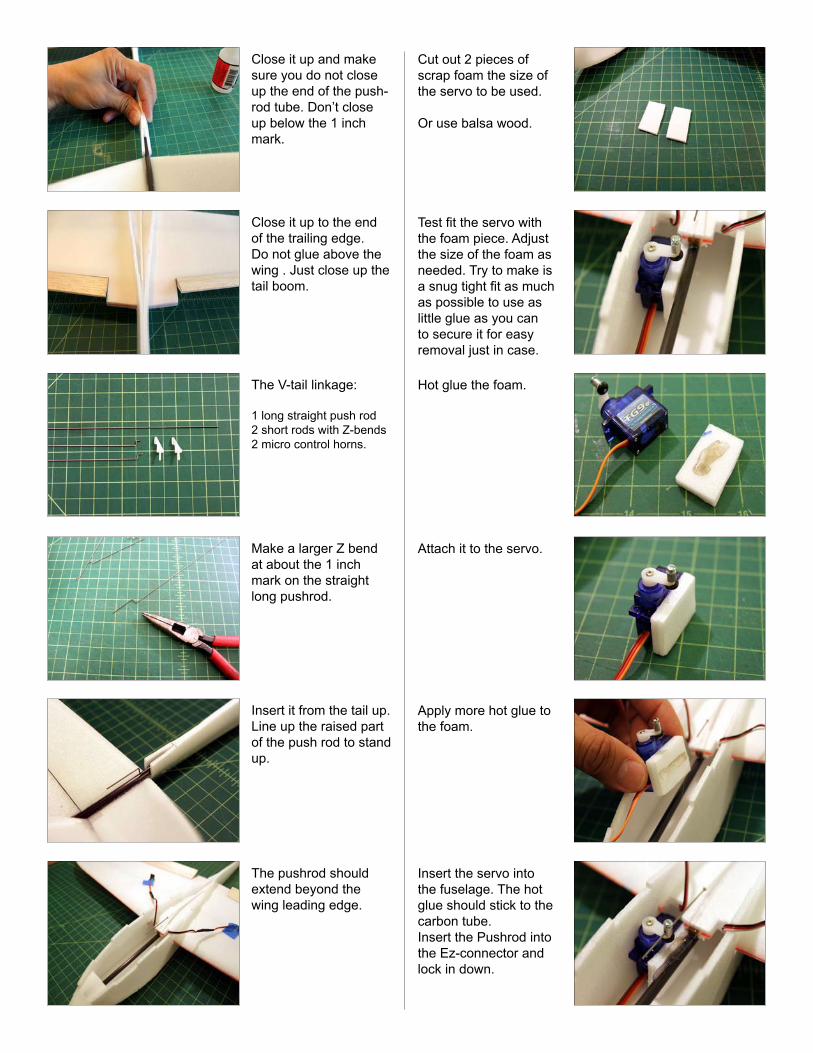
Close it up and make sure you do not close up the end of the push-rod tube. Don’t close up below the 1 inch mark.
Close it up to the end of the trailing edge. Do not glue above the wing . Just close up the tail boom.
The V-tail linkage:
1 long straight push rod2 short rods with Z-bends2 micro control horns.
Make a larger Z bend at about the 1 inch mark on the straight long pushrod.
Insert it from the tail up.Line up the raised part of the push rod to stand up.
The pushrod should extend beyond the wing leading edge.
Cut out 2 pieces of scrap foam the size of the servo to be used.
Or use balsa wood.
Test fit the servo with the foam piece. Adjust the size of the foam as needed. Try to make is a snug tight fit as much as possible to use as little glue as you can to secure it for easy removal just in case.
Hot glue the foam.
Attach it to the servo.
Apply more hot glue to the foam.
Insert the servo into the fuselage. The hot glue should stick to the carbon tube. Insert the Pushrod into the Ez-connector and lock in down.
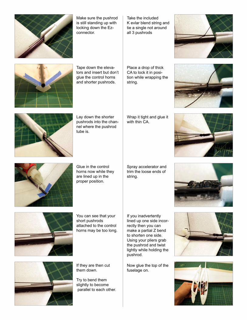
Make sure the pushrod is still standing up with locking down the Ez-connector.
Tape down the eleva-tors and insert but don’t glue the control horns and shorter pushrods.
Lay down the shorter pushrods into the chan-nel where the pushrod tube is.
Glue in the control horns now while they are lined up in the proper position.
You can see that your short pushrods attached to the control horns may be too long.
If they are then cut them down.
Try to bend them slightly to become parallel to each other.
Take the included K evlar blend string and tie a single not around all 3 pushrods
Place a drop of thick CA to lock it in posi-tion while wrapping the string.
Wrap it tight and glue it with thin CA.
Spray accelerator and trim the loose ends of string.
If you inadvertently lined up one side incor-rectly then you can make a partial Z bend to shorten one side. Using your pliers grab the pushrod and twist lightly while holding the pushrod.
Now glue the top of the fuselage on.
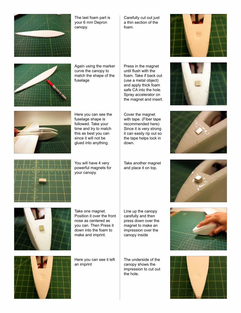
The last foam part is your 6 mm Depron canopy.
Again using the marker curve the canopy to match the shape of the fuselage
Here you can see the fuselage shape is followed. Take your time and try to match this as best you can since it will not be glued into anything.
You will have 4 very powerful magnets for your canopy.
Take one magnet. Position it over the front nose as centered as you can. Then Press it down into the foam to make and imprint.
Here you can see it left an imprint
Carefully cut out just a thin section of the foam.
Press in the magnet until flush with the foam. Take if back out (use a metal object) and apply thick foam safe CA into the hole.Spray accelerator on the magnet and insert.
Cover the magnet with tape. (Fiber tape recommended here) Since it is very strong it can easily rip out so the tape helps lock in down.
Take another magnet and place it on top.
Line up the canopy carefully and then press down over the magnet to make an impression over the canopy inside
The underside of the canopy shows the impression to cut out the hole.
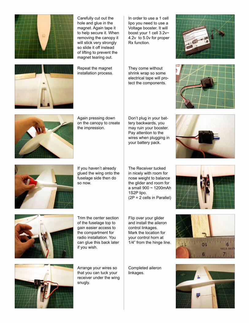
Carefully cut out the hole and glue in the magnet. Again tape it to help secure it. When removing the canopy it will stick very strongly so slide it off instead of lifting to prevent the magnet tearing out.
Repeat the magnet installation process.
Again pressing down on the canopy to create the impression.
If you haven’t already glued the wing onto the fuselage side then do so now.
Trim the center section of the fuselage top to gain easier access to the compartment for radio installation. You can glue this back later if you wish.
Arrange your wires so that you can tuck your receiver under the wing snugly.
In order to use a 1 cell lipo you need to use a Voltage booster. It will boost your 1 cell 3.2v~ 4.2v to 5.0v for proper Rx function.
They come without shrink wrap so some electrical tape will pro-tect the components.
Don’t plug in your bat-tery backwards, you may ruin your booster. Pay attention to the wires when plugging in your battery pack.
The Receiver tucked in nicely with room for nose weight to balance the glider and room for a small 900 ~ 1200mAh 1S2P lipo. (2P = 2 cells in Parallel)
Flip over your glider and install the aileron control linkages.Mark the location for your control horn at 1/4” from the hinge line.
Completed aileron linkages.
Glider flight Characteristics:
This is a very unique approach to slope gliders. It will change your mind of what you thought about Depron gliders. (If you ever even thought about it) Although it is made with Depron it can be very durable when covered with light packing tape. It has a large flight envelope; in light to moderate winds it is a great light weight aerobatic glider, but in stronger winds it will zip around like an mini slope racer with the addition of a couple ounces of ballast.
With no bad habits this little glider can handle most aerobatics that a Flaperon/Elevator glider can perform. For those who want full house aerobatic capabilities you can easily add a second elevator servo, one for each side of the V-tail, and transform your elevator into a Ruddevator!
PLEASE FOLLOW THE RECOMMENDED SET UP. VERY IMPORTANT!!!
Center of Gravity: 1” 7/8” to 2” 1/8” from the leading edge at the wing root.
R.T.F. Weight: 5.5oz - 6oz
Aileron Throw: Up and Down = 1/4” ~ 5/16”Dual Rates for 65% low, 80% highExpo is at your preference 10% to 30%
Elevator Throw: Up and Down = 1/4” ~ 3/8”Dual Rates 40% low, 60% highExpo is at your preference at 10% to 30%
Recommended Set Up:
Receiver: AR6100E or AR6110E (or similar micro Rx recommended) (AR6000 will barely fit, very tight)
Turnigy Voltage Booster (boosts 1 cell lipo voltage to 5v for safe Rx operation)
Lipo Battery: Two (2) Zippy 450mAh 20C x 2 parallel = 900mAh acting as 1cell (900mAh 3.7v 1S2P) or Two (2) Zippy 600mAh20C x 2 parallel = 1200mAh as 1cell (1200mAh 3.7v 1S2P)
Maximum Battery size: 50x30x10 mm (1200mAh 3.7v 1S2P)(Size is very crucial here. This is the largest fit for length, width, and thickness possible in the small fuselage, If you install an additional elevator servo then you may wish to use the two 450mAh batteries for easier fit.)
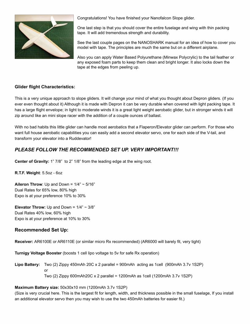
Congratulations! You have finished your Nanofalcon Slope glider.
One last step is that you should cover the entire fuselage and wing with thin packing tape. It will add tremendous strength and durability.
See the last couple pages on the NANOSHARK manual for an idea of how to cover you model with tape. The principles are much the same but on a different airplane.
Also you can apply Water Based Polyurethane (Minwax Polycrylic) to the tail feather or any exposed foam parts to keep them clean and bright longer. It also locks down the tape at the edges from peeling up.