Embed Size (px)
DESCRIPTION
Using Servos
Citation preview
http://www.instructables.com/id/Using-Servos/
Food Living Outside Play Technology Workshop
Using Servosby Higgs Boson on December 21, 2011
Table of Contents
Using Servos . . . . . . . . . . . . . . . . . . . . . . . . . . . . . . . . . . . . . . . . . . . . . . . . . . . . . . . . . . . . . . . . . . . . . . . . . . . . . . . . . . . . . . . . . . . . . . . . . . . . . . . . . . . . . . . . . 1
Intro: Using Servos . . . . . . . . . . . . . . . . . . . . . . . . . . . . . . . . . . . . . . . . . . . . . . . . . . . . . . . . . . . . . . . . . . . . . . . . . . . . . . . . . . . . . . . . . . . . . . . . . . . . . . . . . 2
Step 1: What is a Servo motor . . . . . . . . . . . . . . . . . . . . . . . . . . . . . . . . . . . . . . . . . . . . . . . . . . . . . . . . . . . . . . . . . . . . . . . . . . . . . . . . . . . . . . . . . . . . . . . . . 2
Step 2: Testing the servo . . . . . . . . . . . . . . . . . . . . . . . . . . . . . . . . . . . . . . . . . . . . . . . . . . . . . . . . . . . . . . . . . . . . . . . . . . . . . . . . . . . . . . . . . . . . . . . . . . . . . 2
Step 3: New code . . . . . . . . . . . . . . . . . . . . . . . . . . . . . . . . . . . . . . . . . . . . . . . . . . . . . . . . . . . . . . . . . . . . . . . . . . . . . . . . . . . . . . . . . . . . . . . . . . . . . . . . . . 3
Step 4: Prepare the sensor . . . . . . . . . . . . . . . . . . . . . . . . . . . . . . . . . . . . . . . . . . . . . . . . . . . . . . . . . . . . . . . . . . . . . . . . . . . . . . . . . . . . . . . . . . . . . . . . . . . 4
Step 5: Using the sensor with the servo . . . . . . . . . . . . . . . . . . . . . . . . . . . . . . . . . . . . . . . . . . . . . . . . . . . . . . . . . . . . . . . . . . . . . . . . . . . . . . . . . . . . . . . . . . 6
Step 6: Using a 555 and a potentiometer . . . . . . . . . . . . . . . . . . . . . . . . . . . . . . . . . . . . . . . . . . . . . . . . . . . . . . . . . . . . . . . . . . . . . . . . . . . . . . . . . . . . . . . . . 6
Step 7: Using a 555 and push buttons . . . . . . . . . . . . . . . . . . . . . . . . . . . . . . . . . . . . . . . . . . . . . . . . . . . . . . . . . . . . . . . . . . . . . . . . . . . . . . . . . . . . . . . . . . . 7
Related Instructables . . . . . . . . . . . . . . . . . . . . . . . . . . . . . . . . . . . . . . . . . . . . . . . . . . . . . . . . . . . . . . . . . . . . . . . . . . . . . . . . . . . . . . . . . . . . . . . . . . . . . . . . 9
Advertisements . . . . . . . . . . . . . . . . . . . . . . . . . . . . . . . . . . . . . . . . . . . . . . . . . . . . . . . . . . . . . . . . . . . . . . . . . . . . . . . . . . . . . . . . . . . . . . . . . . . . . . . . . . . . . . . 9
Comments . . . . . . . . . . . . . . . . . . . . . . . . . . . . . . . . . . . . . . . . . . . . . . . . . . . . . . . . . . . . . . . . . . . . . . . . . . . . . . . . . . . . . . . . . . . . . . . . . . . . . . . . . . . . . . . . 9
http://www.instructables.com/id/Using-Servos/
Author:Higgs Boson Ben's science wonderlandScience is my passion. I find myself constantly working on countless experiments, from low energy particle accelerators to good old simple electronics. I alsolike making model rockets, and playing cello.
Intro: Using ServosIn this instructable, I am going to show you what a servo motor is, how to use it, and ideas for starting projects using it. I used arduino to control my servo, I added how touse a 555 in some of the later steps.
Step 1: What is a Servo motorIf you are like me, then you knew very little about servo motors, and how to use them, so we should start from the beginning. A Servo motor uses pulse width modulation(pwm) from a microcontroller or a 555 timing IC (or something different I haven't heard about) to know what position to move its horn to. They can move both clockwise orcounterclockwise thanks to an H bridge which is hardwired into them. Most Servos, unlike conventional electric motors do not move in continuous rotations. the standardservo moves anywhere between 0 and 180 degrees, which make them useful for animatronics and robotics. The servo has three wires coming out of it which usuallyends in a female jack. the wire colors are black, which gets connected to ground, red which gets connected to the positive power supply, and white or yellow which getsconnected to the output of the microcontroller or 555 IC, and receives the pwm. Okay now that you know the basics, lets get started
Step 2: Testing the servothe first thing that you should do is make sure your servo motor is working. because the servos wires end in a female header, you cannot plug it into the arduino (unlessyou have a shield. insert solid core wires into the headers, so you can attach it to the pins of the arduino (or anything else). When you downloaded your programmingenvironment for arduino, it should have two examples for the servo. The one we are going to use first is called sweep. Go to the "open" icon next to save near the top ofthe window on the environment. click on it, and a list of files should come up. go down to the one that says servo, and put your mouse over it. two files should come out ofit. one called "sweep" and one called "knob". click on the one called sweep, compile the code and upload it to your board. if everything is connected correctly, the servoshould begin to go back and forth from 0 to 180 degrees. If you cannot find the code, copy this:
// Sweep// by BARRAGAN <http://barraganstudio.com>// This example code is in the public domain.
#include <Servo.h>
Servo myservo; // create servo object to control a servo// a maximum of eight servo objects can be created
int pos = 0; // variable to store the servo position
void setup(){myservo.attach(9); // attaches the servo on pin 9 to the servo object}
void loop(){for(pos = 0; pos < 180; pos += 1) // goes from 0 degrees to 180 degrees{ // in steps of 1 degreemyservo.write(pos); // tell servo to go to position in variable 'pos'delay(15); // waits 15ms for the servo to reach the position}for(pos = 180; pos>=1; pos-=1) // goes from 180 degrees to 0 degrees{myservo.write(pos); // tell servo to go to position in variable 'pos'delay(15); // waits 15ms for the servo to reach the position}}
http://www.instructables.com/id/Using-Servos/
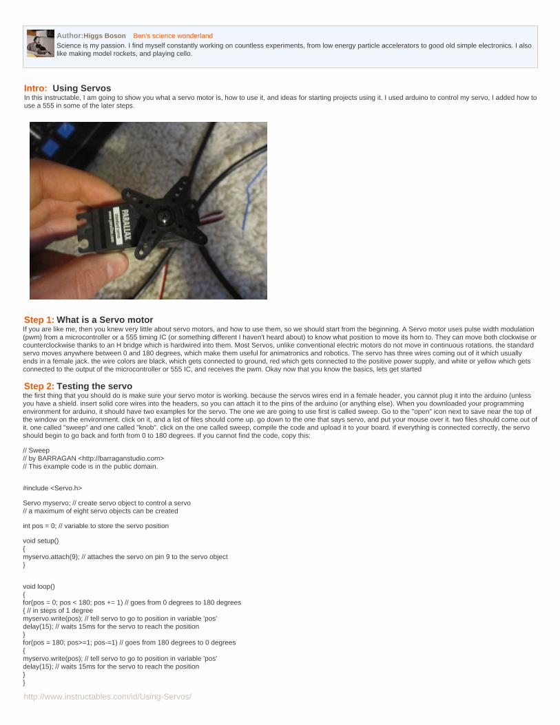
be sure to plug in the white wire to digital pin 9, the black wire to one of the ground pins on arduino, and the red wire to the 5v pin on the arduino board.
Image Notes1. white wire from the servo goes to pin 9.2. connect black to ground and red to 5v
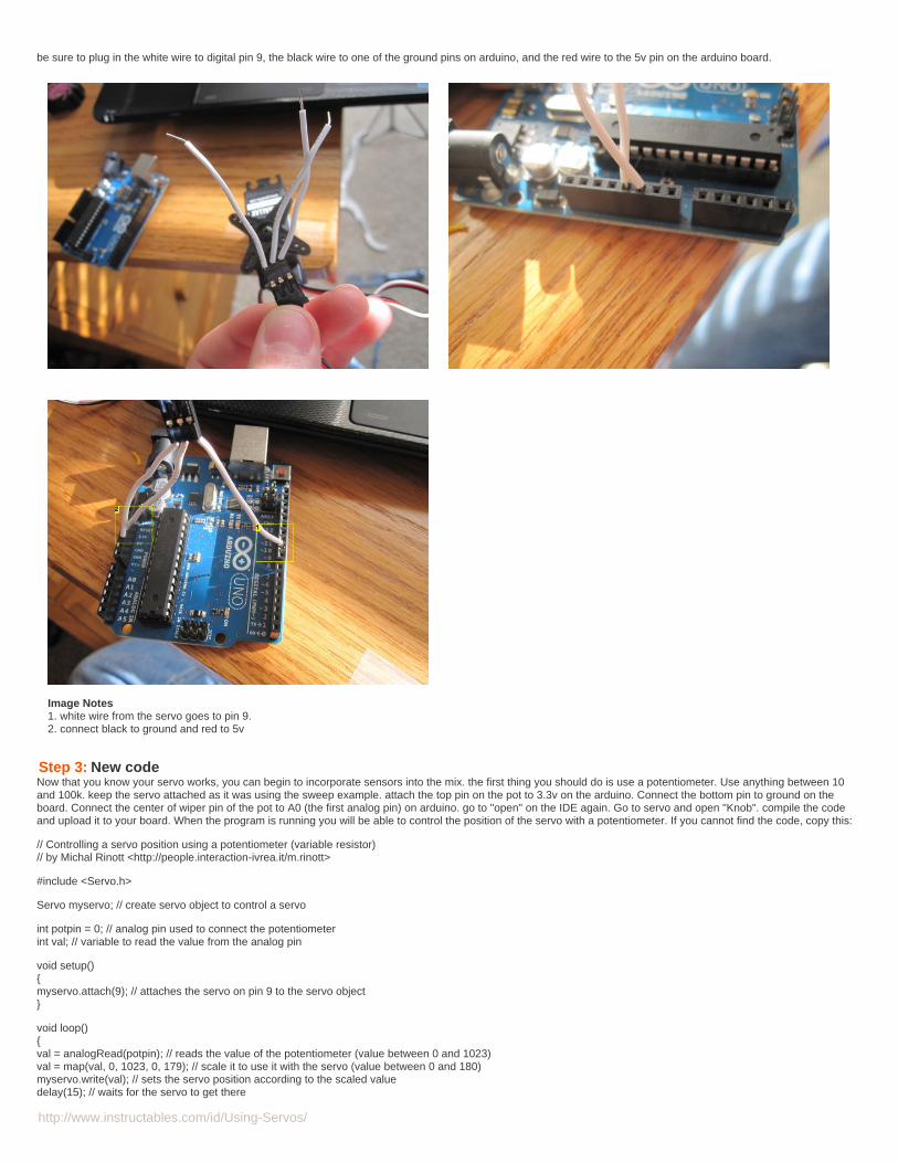
Step 3: New codeNow that you know your servo works, you can begin to incorporate sensors into the mix. the first thing you should do is use a potentiometer. Use anything between 10and 100k. keep the servo attached as it was using the sweep example. attach the top pin on the pot to 3.3v on the arduino. Connect the bottom pin to ground on theboard. Connect the center of wiper pin of the pot to A0 (the first analog pin) on arduino. go to "open" on the IDE again. Go to servo and open "Knob". compile the codeand upload it to your board. When the program is running you will be able to control the position of the servo with a potentiometer. If you cannot find the code, copy this:
// Controlling a servo position using a potentiometer (variable resistor)// by Michal Rinott <http://people.interaction-ivrea.it/m.rinott>
#include <Servo.h>
Servo myservo; // create servo object to control a servo
int potpin = 0; // analog pin used to connect the potentiometerint val; // variable to read the value from the analog pin
void setup(){myservo.attach(9); // attaches the servo on pin 9 to the servo object}
void loop(){val = analogRead(potpin); // reads the value of the potentiometer (value between 0 and 1023)val = map(val, 0, 1023, 0, 179); // scale it to use it with the servo (value between 0 and 180)myservo.write(val); // sets the servo position according to the scaled valuedelay(15); // waits for the servo to get there
http://www.instructables.com/id/Using-Servos/
}
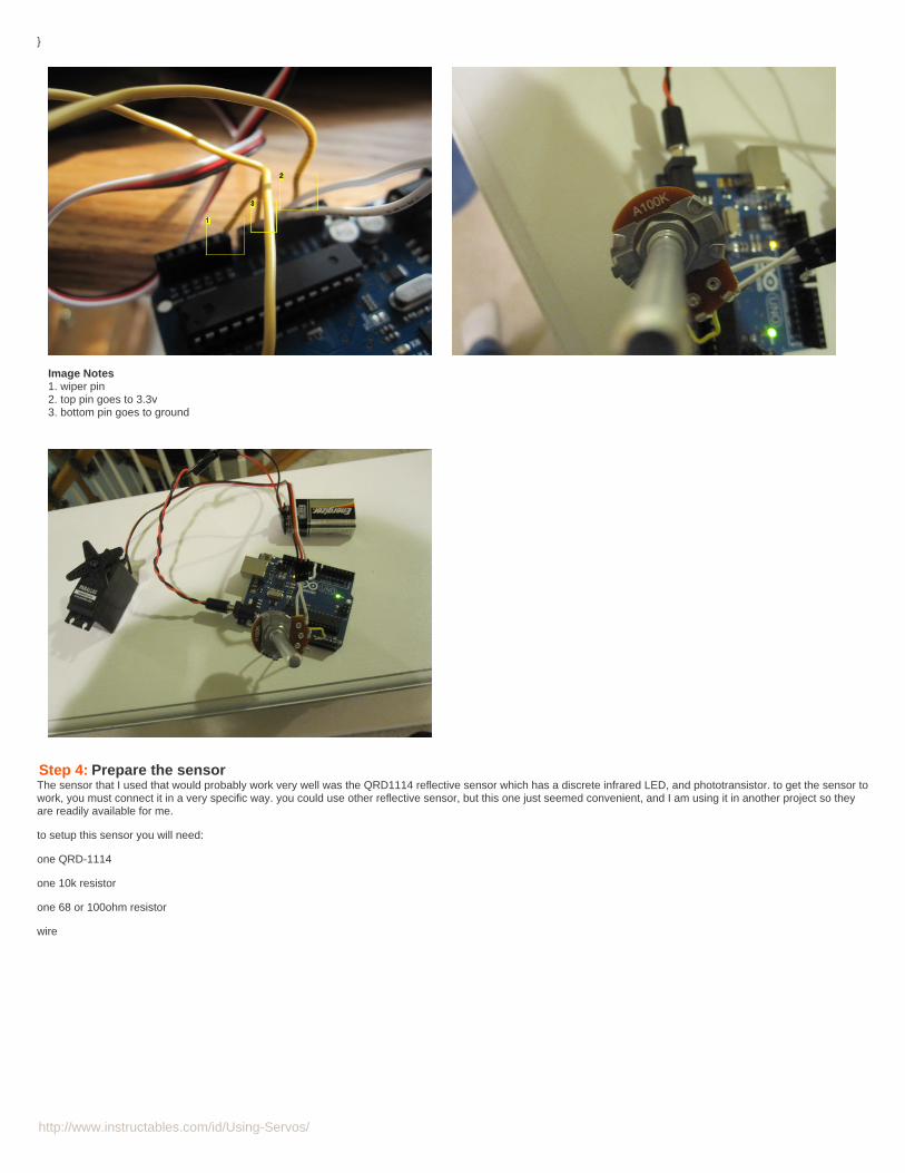
Image Notes1. wiper pin2. top pin goes to 3.3v3. bottom pin goes to ground
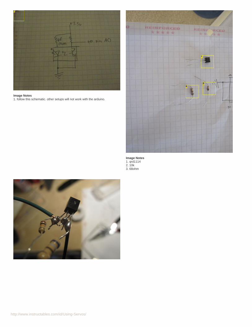
Step 4: Prepare the sensorThe sensor that I used that would probably work very well was the QRD1114 reflective sensor which has a discrete infrared LED, and phototransistor. to get the sensor towork, you must connect it in a very specific way. you could use other reflective sensor, but this one just seemed convenient, and I am using it in another project so theyare readily available for me.
to setup this sensor you will need:
one QRD-1114
one 10k resistor
one 68 or 100ohm resistor
wire
http://www.instructables.com/id/Using-Servos/
Image Notes1. follow this schematic. other setups will not work with the arduino.
Image Notes1. qrd11142. 10k3. 68ohm
http://www.instructables.com/id/Using-Servos/
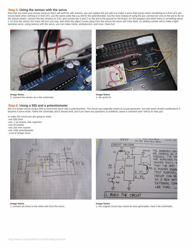
Step 5: Using the sensor with the servoNow that you have your sensor setup so that it will work for with arduino, you can replace the pot with it to make a servo that moves when something is in front of it andmoves back when nothing is in front of it. use the same code that you did for the potentiometer. but this time instead of using the pot, connect pin one on the qrd to A0 onthe arduino board. connect the two resistors to 3.3v, and connect pin 4 and 2 on the qrd to the ground on the board. run the program and when there is something about1 cm from the sensor the motor will turn one way, and when the object moves away from the sensor the servo will move back. try adding a photo cell to make a lightsensitive servo. using sensors with the servo, you can make robots, animatronics, and more. Have fun!
Image Notes1. connect the sensor as in the schematic.
Image Notes1. the qrd1114
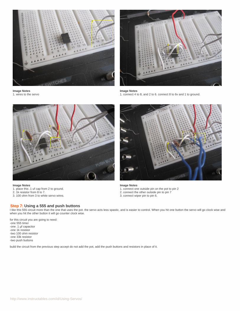
Step 6: Using a 555 and a potentiometerthis is a simple circuit using a 555 to control the servo with a potentiometer. The circuit was originally meant as a tone generator, but with some simple modifications itbecame a servo tester. follow the schematic and it should work, but if you have any questions or problems, leave a comment and I will try to help you.'
to make this circuit you are going to need:-one 555 timer-one .1 µf ceramic disk capacitor-one 1k resistor-one 100 ohm resistor-one 100k potentiometer- a lot of jumper wires
Image Notes1. connect pin three to the white wire from the servo.
Image Notes1. the original circuit was meant for tone generation. here's the schematic.
http://www.instructables.com/id/Using-Servos/
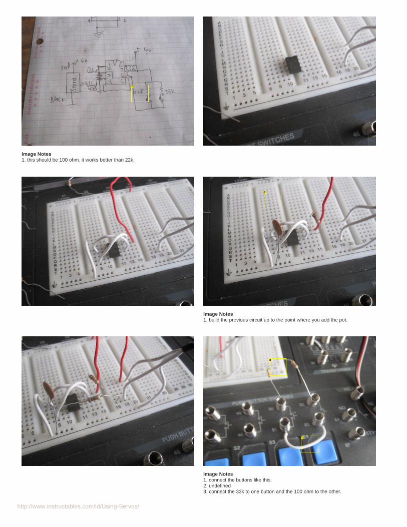
Image Notes1. wires to the servo
Image Notes1. connect 4 to 8, and 2 to 6. connect 8 to 6v and 1 to ground.
Image Notes1. place this .1 uf cap from 2 to ground.2. 1k resistor from 8 to 7.3. 100 ohm from 3 to white servo wires.
Image Notes1. connect one outside pin on the pot to pin 22. connect the other outside pin to pin 73. connect wiper pin to pin 6.
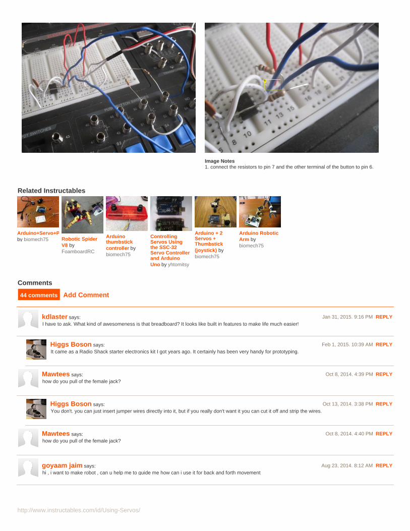
Step 7: Using a 555 and push buttonsI like this 555 circuit more than the one that uses the pot. the servo acts less spastic, and is easier to control. When you hit one button the servo will go clock wise andwhen you hit the other button it will go counter clock wise.
for this circuit you are going to need:-one 555 timer-one .1 µf capacitor-one 1k resistor-two 100 ohm resistor-one 33k resistor-two push buttons
build the circuit from the previous step accept do not add the pot, add the push buttons and resistors in place of it.
http://www.instructables.com/id/Using-Servos/
Image Notes1. this should be 100 ohm. it works better than 22k.
Image Notes1. build the previous circuit up to the point where you add the pot.
Image Notes1. connect the buttons like this.2. undefined3. connect the 33k to one button and the 100 ohm to the other.
http://www.instructables.com/id/Using-Servos/
Image Notes1. connect the resistors to pin 7 and the other terminal of the button to pin 6.
Related Instructables
Arduino+Servo+Potentiometerby biomech75 Robotic Spider
V8 byFoamboardRC
Arduinothumbstickcontroller bybiomech75
ControllingServos Usingthe SSC-32Servo Controllerand ArduinoUno by yhtomitsy
Arduino + 2Servos +Thumbstick(joystick) bybiomech75
Arduino RoboticArm bybiomech75
Advertisements
Comments
44 comments Add Comment
kdlaster says: Jan 31, 2015. 9:16 PM REPLYI have to ask. What kind of awesomeness is that breadboard? It looks like built in features to make life much easier!
Higgs Boson says: Feb 1, 2015. 10:39 AM REPLYIt came as a Radio Shack starter electronics kit I got years ago. It certainly has been very handy for prototyping.
Mawtees says: Oct 8, 2014. 4:39 PM REPLYhow do you pull of the female jack?
Higgs Boson says: Oct 13, 2014. 3:38 PM REPLYYou don't. you can just insert jumper wires directly into it, but if you really don't want it you can cut it off and strip the wires.
Mawtees says: Oct 8, 2014. 4:40 PM REPLYhow do you pull of the female jack?
goyaam jaim says: Aug 23, 2014. 8:12 AM REPLYhi , i want to make robot , can u help me to guide me how can i use it for back and forth movement

http://www.instructables.com/id/Using-Servos/
rokas.lepsys says: Aug 20, 2014. 12:15 AM REPLYwill it work with a potentiometer?
peng.s.lim says: Aug 12, 2014. 12:46 AM REPLYHi, may i know for step 6, where do i put in the potentialmeter? Please advise me on it. Thanks!
omar elattal says: May 14, 2014. 2:16 PM REPLYone more thing Can you help me how to control a one servo using a JOYSTICK [OR] KEYPAD
Higgs Boson says: May 23, 2014. 3:02 PM REPLYI'm sure you can find code all over the internet for arduino, but you could modify the knob example for them since most joystick modules are nothing buttwo potentiometers. You would need to change how you map your values since the pots probably start centered for zero instead of at on extreme, but itshould be pretty straight forward.
omar elattal says: May 14, 2014. 1:59 PM REPLYman you are so great THANK YOU i searched about this a lot :)
mushfiq1996 says: Apr 9, 2014. 7:14 AM REPLYHelp ASAP. Emergency Please. How i can rotate my servo to a specific angle for reading from amoisture sensor?
Higgs Boson says: Apr 9, 2014. 2:50 PM REPLYThe easiest thing would be to use a microcontroller.
Higgs Boson says: Apr 9, 2014. 2:53 PM REPLYUsing the arduino you could map the values from your sensor to 180 degrees and then use the Servo.write command to move your servo to an anglecorresponding to the reading. that is pretty much what is done in the Knob example under servos in the arduino ide. You would just replace the potwith your new sensor and maybe rework some of the values to get the desired effect.
Paulg42 says: Dec 10, 2013. 5:40 PM REPLYHi, Im Fairly new to electronics and I just cant get this circuit to work and I need it for a school project !! Does the potentiometer HAVE to be 100k ohm inorder for it to work ? because I was using a 10k and the it was only when I attached the battery that it jolted a degree or two in one direction but that was it !!
Liammc-c says: Nov 20, 2013. 4:25 AM REPLYHi, i am currently completing my L3 extended diploma in mechanical and electrical engineering and i have to complete a project of my choice. I need to turna Continuous Rotation servo without any push buttons, the circuit will need to turn on the servo after 4 hours have passed, any ideas for the circuit?any comments will be helpful- thanks
ataylor999 says: Oct 23, 2013. 9:39 AM REPLYHey, I have a quick question. I have 3 servos that we have taken the casing and gears off of. we need to attach propellers to the motors and test that theservos are working. what is a quick and easy way to do this?
Step by step instructions would be great! Thanks!
Higgs Boson says: Nov 10, 2013. 7:10 AM REPLYYou could use any of the methods shown here. This should get the motor running, but with the Servo's potentiometer removed you may run intoproblems with direction control. If you just want forward and backwards control then leave the pot connected and just glue it in the 90 degree position.This way any signal past 90 degrees will result in one direction, and anything below whill result in the opposite direction.
infanati says: Jun 25, 2013. 7:53 AM REPLYHi, I started on a project using IR sensors but for some reason my servos only keep moving forward even if the sensor detects an object ahead. I checkedthe code and it seems to be fine. the connections are according to the codes. so im not quite sure whats going on there. any ideas?
Higgs Boson says: Jun 25, 2013. 8:03 PM REPLYTry sending the values from the sensor to the serial read on the IDE. If there is a problem with your connections these values will likely be sporadic. Also,it would be good to see how it responds to objects near it. Although it would be intuitive that the value would increase when an object is near, it maydecrease (depending on how it is connected). That would be a good starting point if you're sure it's not the code.
http://www.instructables.com/id/Using-Servos/
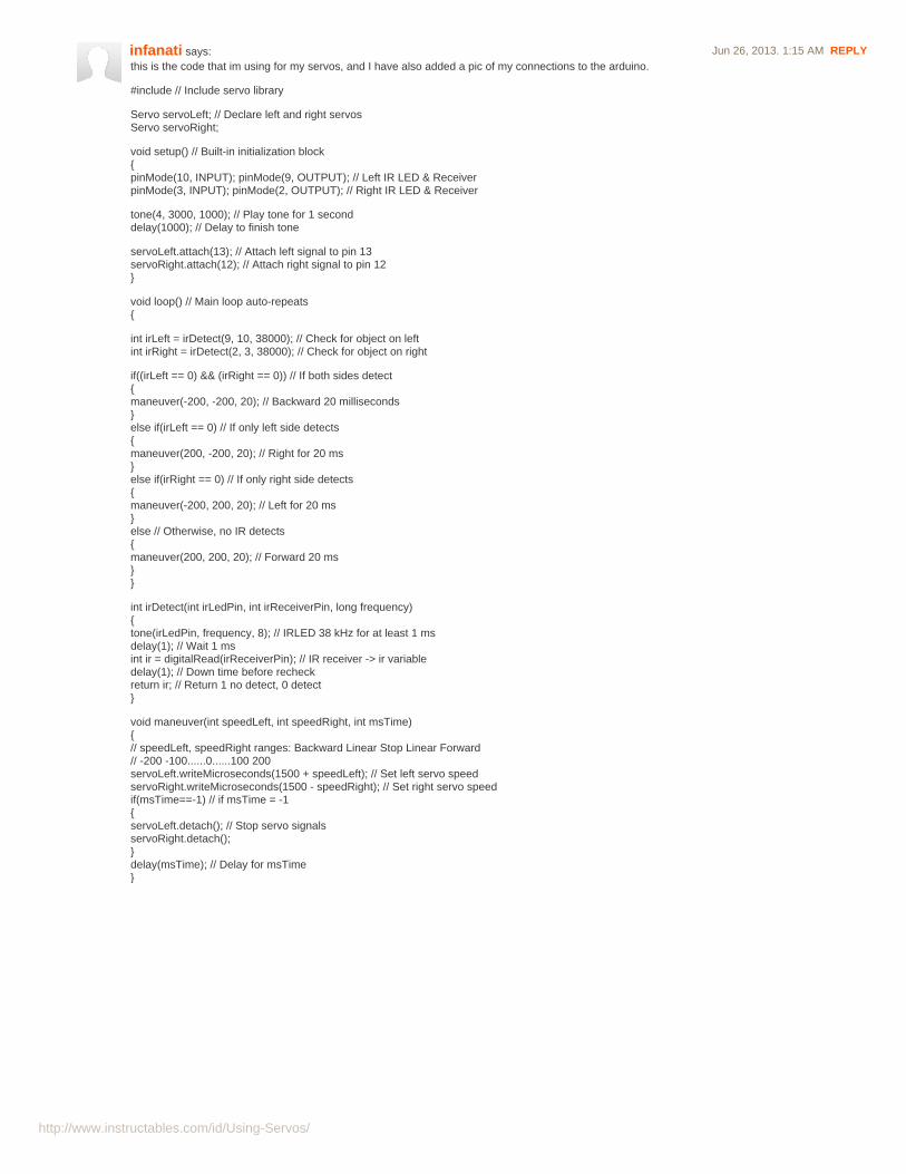
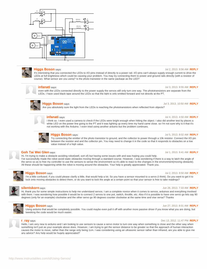
infanati says: Jun 26, 2013. 1:15 AM REPLYthis is the code that im using for my servos, and I have also added a pic of my connections to the arduino.
#include // Include servo library
Servo servoLeft; // Declare left and right servosServo servoRight;
void setup() // Built-in initialization block{pinMode(10, INPUT); pinMode(9, OUTPUT); // Left IR LED & ReceiverpinMode(3, INPUT); pinMode(2, OUTPUT); // Right IR LED & Receiver
tone(4, 3000, 1000); // Play tone for 1 seconddelay(1000); // Delay to finish tone
servoLeft.attach(13); // Attach left signal to pin 13servoRight.attach(12); // Attach right signal to pin 12}
void loop() // Main loop auto-repeats{
int irLeft = irDetect(9, 10, 38000); // Check for object on leftint irRight = irDetect(2, 3, 38000); // Check for object on right
if((irLeft == 0) && (irRight == 0)) // If both sides detect{maneuver(-200, -200, 20); // Backward 20 milliseconds}else if(irLeft == 0) // If only left side detects{maneuver(200, -200, 20); // Right for 20 ms}else if(irRight == 0) // If only right side detects{maneuver(-200, 200, 20); // Left for 20 ms}else // Otherwise, no IR detects{maneuver(200, 200, 20); // Forward 20 ms}}
int irDetect(int irLedPin, int irReceiverPin, long frequency){tone(irLedPin, frequency, 8); // IRLED 38 kHz for at least 1 msdelay(1); // Wait 1 msint ir = digitalRead(irReceiverPin); // IR receiver -> ir variabledelay(1); // Down time before recheckreturn ir; // Return 1 no detect, 0 detect}
void maneuver(int speedLeft, int speedRight, int msTime){// speedLeft, speedRight ranges: Backward Linear Stop Linear Forward// -200 -100......0......100 200servoLeft.writeMicroseconds(1500 + speedLeft); // Set left servo speedservoRight.writeMicroseconds(1500 - speedRight); // Set right servo speedif(msTime==-1) // if msTime = -1{servoLeft.detach(); // Stop servo signalsservoRight.detach();}delay(msTime); // Delay for msTime}
http://www.instructables.com/id/Using-Servos/
Higgs Boson says: Jul 2, 2013. 9:56 AM REPLYIt's interesting that you connected the LEDs to I/O pins instead of directly to a power rail. I/O pins can't always supply enough current to drive theLEDs at full brightness which could be causing your problem. You may try connecting them to power and ground rails directly (with a resistor ofcourse). What sensor are you using? Is the photo transistor in the same package as the LED?
infanati says: Jul 3, 2013. 9:55 AM REPLYeven with the LEDs connected directly to the power supply the servos still only turn one way. The phototransistors are separate from theLEDs. I have used black tape around the LEDs so that the light is only emitted forward and not directly at the PT.
Higgs Boson says: Jul 3, 2013. 10:50 AM REPLYAre you absolutely sure the light from the LEDs is reaching the phototransistors when reflected from objects?
infanati says: Jul 4, 2013. 4:50 AM REPLYi think so. I even used a camera to check if the LEDs were bright enough when hitting the object. I also did another test by places awhite LED on the power line going to the PT and it was lighting up every time my hand came close. so I'm not sure why is it that it'snot working with the Arduino. I even tried using another arduino but the problem continues.
Higgs Boson says: Jul 5, 2013. 8:02 AM REPLYTry connecting the emitter of the photo transistor to ground, and the collector to power through a 10k resistor. Connect the I/O pinbetween the resistor and and the collector pin. You may need to change it in the code so that it responds to obstacles on a lowvalue instead of a high value.
Goh Tai Wei Glen says: Jul 1, 2013. 9:41 AM REPLYHi, I'm trying to make a obstacle avoiding robot(well, sort of) but having some issues with and was hoping you could help.I've successfully made the robot avoid static obstacles moving through a standard course. However, I was wondering if there is a way to latch the angle ofthe servo so as to free my controller to use the sensors to sense the environment so it's able to react to the changes in the environment(moving obstacle).All these should be happening while the robot is moving around the obstacles. Your help is greatly appreciated. Thank you.
Higgs Boson says: Jul 2, 2013. 9:50 AM REPLYI'm a little confused, if you could please clarify a little, that would help a lot. So you have a sensor mounted to a servo (I think). Do you want to get it tolock onto moving obstacles to detect them, or do you want to lock the angle at a certain point so that your sensor is free to take readings?
silentskorn says: Jun 26, 2013. 7:33 AM REPLYHi, thank you for some simple instructions to help me understand servos. I am a complete novice when it comes to servos, arduinos and everything involvedwith them. I was wondering how possible it would be to connect 2 servos to one pot, switch, throttle, etc. Also if it is possible to have one servo go lets say 90degrees (only for an example) clockwise and the other servo go 90 degrees counter clockwise at the same time and vise versa? Thanks
Higgs Boson says: Jun 27, 2013. 8:01 AM REPLYUsing arduino that would be completely possible. You could maybe even pull it off with another more passive driver if you know what you are doing, buttweeking the code would be much easier.
r_ray says: Dec 13, 2012. 11:47 PM REPLYHello, I am very new to arduino and I am looking to use sensors to cause a servo motor to turn one way when something is close and the other way whensomething isn't just as your example above does. However, I am trying to get the sensor distance to be greater so that the approach of human interactioncauses the motor to move, rather than the range only being 1cm. I was considering using an ultrasonic sensor rather than infrared, are you able to give meany advice? Any help would be hugely appreciated?
http://www.instructables.com/id/Using-Servos/
Higgs Boson says: Dec 15, 2012. 7:24 AM REPLYThe range finder would be better suited, but you also may consider a PIR sensor, as they are easy to use, but are more of a motion sensor than adistance sensor. It really depends on what you want the end result to be as to which sensor you use.
ratankumarsaha says: Dec 31, 2011. 1:16 AM REPLYwhich electrical thing contain this servo motor..how can find it??????????
RATAN BANGLADESH.....
Tariq802 says: Mar 19, 2012. 9:23 AM REPLYtry a local hobby store if not radio shack. any place that specializes in rc stuff...
smitlrx says: Dec 31, 2011. 4:47 AM REPLYUnfortunately servo's are not used often in standard equipment. The are however used in remote controlled airplanes, helicopters, cars and boats tofacilitate the operation of the vehicle, like steering and acceleration. One can buy the remotes and normally you get the receiver and a couple of servo'swith. You can also buy all these units separately.
Higgs Boson says: Dec 31, 2011. 2:50 PM REPLYI was able to find mine at radio shack, so they are pretty common. you don't need to take anything apart to find them. if they are not at your localstore, try amazon or ebay.
nilved says: Jan 28, 2012. 12:45 AM REPLYcould you hook up the arduino with multiple servos and pots to control them and if so can you post a comment with the code
A.C.E. says: Feb 28, 2012. 12:51 PM REPLYWhile Higgs is getting more servos, Ill try to help you understand a bit. When you create the servo object (Servo myservo;) this is creating one servoobject with the name of "myservo". If you wanted 3 servos, you would need three of those lines, but with different names, such as:
Servo myservo1;Servo myservo2;Servo myservo3;
you would also need more potentiometers, so youd need to add more potpins, and have the potentiometers hooked up to their respective pins, I thinkthat would look like this:
int potpin1 = 0;int potpin2 = 1;int potpin3 = 2;
where potpin1 is what we are calling analog pin 0, but will control myservo1. You also need more variables to store the data from the potpins, so makethose too.
int val1;int val2;int val3;
the numbers will correspond with the servos of the same number.
now you just need to add the commands for checking all 3 servos into the loop, which would look like this:
void loop(){val1 = analogRead(potpin1); // reads the value of potentiometer 1val1 = map(val1, 0, 1023, 0, 179); // scale itmyservo1.write(val1); // sets servo 1's position according to the scaled valueval2 = analogRead(potpin2); // reads the value of potentiometer 2val2 = map(val2, 0, 1023, 0, 179); // scale itmyservo2.write(val2); // sets servo 2's position according to the scaled valueval3 = analogRead(potpin3); // reads the value of potentiometer 3val3 = map(val3, 0, 1023, 0, 179); // scale itmyservo3.write(val3); // sets servo 3's position according to the scaled valuedelay(15); // delays for 15ms to let the servos catch up}
I think this would work, but someone check over my work because I'm a complete noob at arduino coding. Someone with an arduino and 3 servos shouldwrite this and see if it works :p
Tariq802 says: Mar 19, 2012. 9:15 AM REPLYbefore you can start reading and writing you also need to attach the servo objects to their pins ie:
void setup() {myservo1.attach(9); //attach servo 1 to pin 9myservo2.attach(10); //attach servo 2 to pin 10myservo3.attach(11); //attach servo 3 to pin 11}

http://www.instructables.com/id/Using-Servos/
etc.
Tariq802 says: Mar 19, 2012. 9:21 AM REPLYyou're also going to want to use a power supply separate from the arduino board if you're using a lot of servos, otherwise you might breaksomething. it could probably handle 3 servos but i definately wouldn't go with more than that without isolating the power supply
Higgs Boson says: Jan 28, 2012. 2:46 PM REPLYYes you can. I'll try and post the code in a few days.
Higgs Boson says: Feb 8, 2012. 6:12 AM REPLYSorry. This may take longer because I need to get more servos (all of mine are being used in projects right now).
bertus52x11 says: Jan 3, 2012. 6:38 AM REPLYDid you find the little particles yet...?
nima_juniper says: Dec 27, 2011. 3:27 AM REPLYthank you that was very useful for me