Embed Size (px)
Citation preview

Specification TFT-LCD module
If there is no special request from customer, SHENZHEN FEIGEDA ELECTRONIC CO.,LTD will not reserve the tooling of the product under the following conditions: 1.There is no response from customer in one years after SHENZHEN FEIGEDA ELECTRONIC CO.,LTD submit The samples; 2.There is no order in one years after the latest mass production.And correlated data (include quality record) will be reserved one year more after tooling was discarded.
Approved by(批准): Qualified(合格): Unqualified(不合格):
PREPARED CHECKED APPROVED
--------------------------------------------------------------------------------------------------------------------
Module(型号): FGD700C4001 Customer(客户):
Customer P/N(客户型号):

FGD700C4001 Ver: A - 1 - 800RGB480dots-matrix
REVISION RECORD REV NO REV DATE CONTENTS REMARKS
1.0 2011-06-13 First Release

FGD700C4001 Ver: A - 2 - 800RGB480dots-matrix
TABLE OF CONTENT
GENERAL SPECIFICATIONS
ABSOLUTE MAXIMUM RATINGS
ELECTRICAL CHARACTERISTICS
、 BACKLIGHT CHARACTERISTICS
DIMENSIONAL DRAWING INTERFACE PIN CONNECTIONS ELECTRO-OPTICAL CHARACTERISTICS INSPECTION CRITERIA
RELIABILITY PRECAUTIONS FOR USING LCD MODULE
USING LCD MODULES
FGD700C4001 Ver: A - 3 - 800RGB480dots-matrix
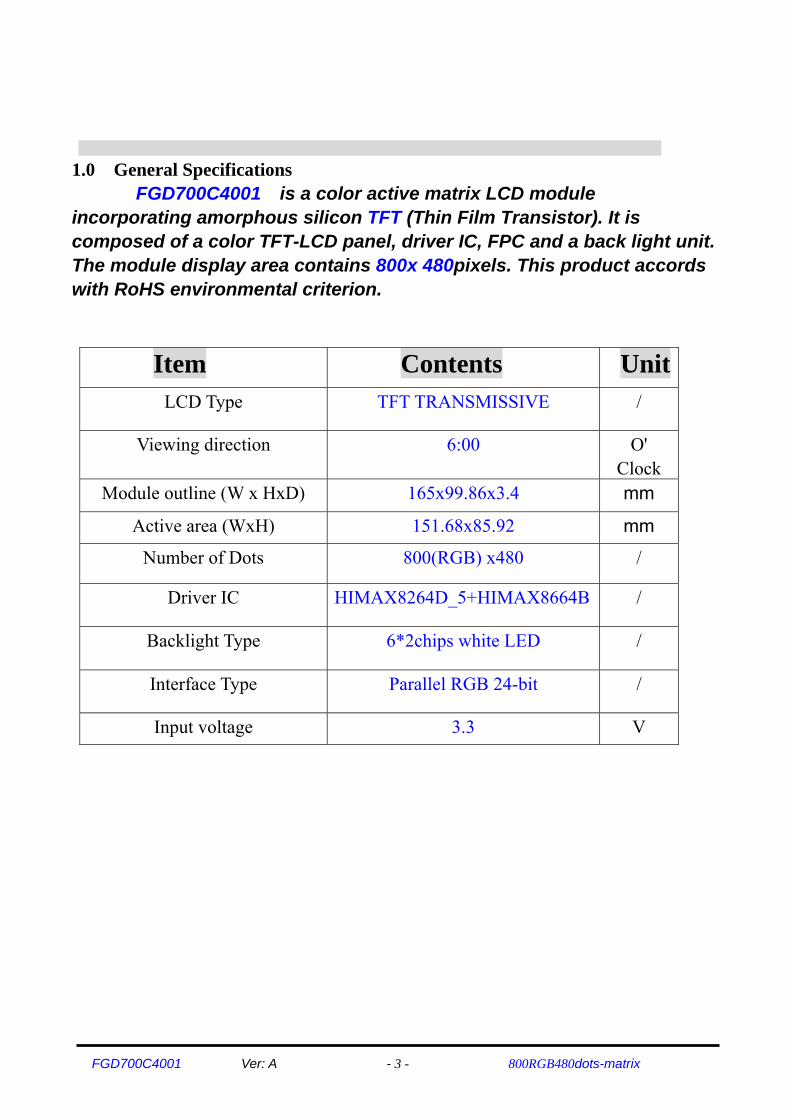
1.0 General Specifications FGD700C4001 is a color active matrix LCD module
incorporating amorphous silicon TFT (Thin Film Transistor). It is composed of a color TFT-LCD panel, driver IC, FPC and a back light unit. The module display area contains 800x 480pixels. This product accords with RoHS environmental criterion.
Item Contents UnitLCD Type TFT TRANSMISSIVE /
Viewing direction 6:00 O' Clock
Module outline (W x HxD) 165x99.86x3.4 mm
Active area (WxH) 151.68x85.92 mm
Number of Dots 800(RGB) x480 /
Driver IC HIMAX8264D_5+HIMAX8664B /
Backlight Type 6*2chips white LED /
Interface Type Parallel RGB 24-bit /
Input voltage 3.3 V

FGD700C4001 Ver: A - 4 - 800RGB480dots-matrix
2.0 ABSOLUTE MAXIMUM RATINGS
AGND= GND=0V, Ta = 25℃ ITEM Symbol Min Max Uint Note
Digital Supply Voltage VDD -0.5 5 V Analog Supply Voltage AVDD -0.5 15 V Gate On Voltage VDDG -0.3 +42 V Gate Off Voltage VEEG -20 +0.3 V Gate On - Gate Off Voltage VDDG-VEEG 12 40 V Operation Temperature Top -20 70 ℃ Stotage Temperature Tstg -30 80 ℃ Note1:If users use the product out off the environmemtal operation range(temperature and humidity), it will have visual quality concerns.
3.0 ELECTRICAL CHARACTERISTICS Recommended Operating Condition
ITEM Symbol Min TYP Max Uint Note Digital Supply Voltage VDD 2.7 3.3 3.6 V Analog Supply Voltage AVDD 6.5 8.6 13.5 V Gate On Voltage VDDG 16.5 23 24.0 V Gate Off Voltage VEEG -8.2 -7.8 -7.4 V Common Electrode Driving Signal
VCOM 2.6 2.8 3.0 V
Note1:Please adjust VCOM to make the flicker level be minimum.
4.0 BACKLIGHT CHARACTERISTICS
Item Symbol Min Typ Max Unit Condition Forward voltage Vf - 19.2 - V If=40mA
Luminance Lv 2800 3200 - cd/m2 If=40mA
Number of LED -- 12 Piece --
Connection mode P 2chips serial *6 -- --
FGD700C4001 Ver: A - 5 - 800RGB480dots-matrix
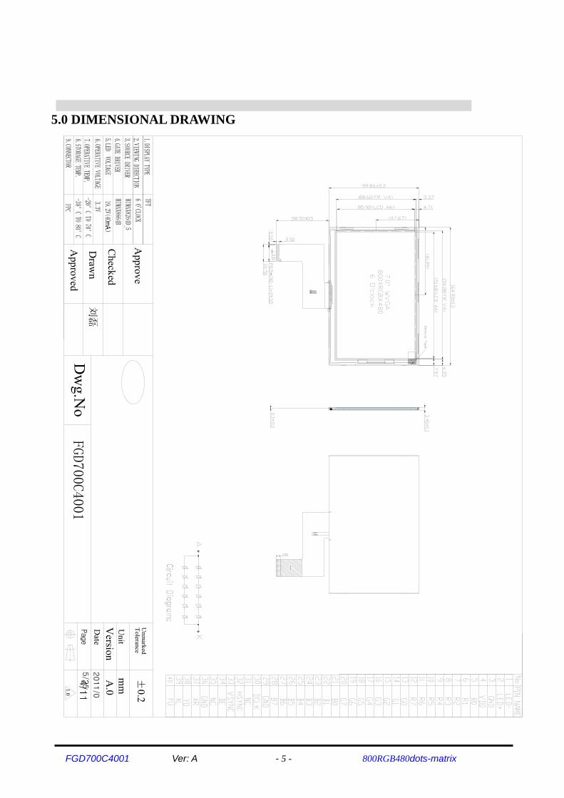
5.0 DIMENSIONAL DRAWING
单面区
刘磊
A.0
Version
FGD700C4001
1.0
4/11
2011/0
5/25
Page
Approved
Unit
Unm
arked
mm ±0.2
ToleranceA
pprove
Draw
n
Checked
Date
Dw
g.No
FGD700C4001 Ver: A - 6 - 800RGB480dots-matrix
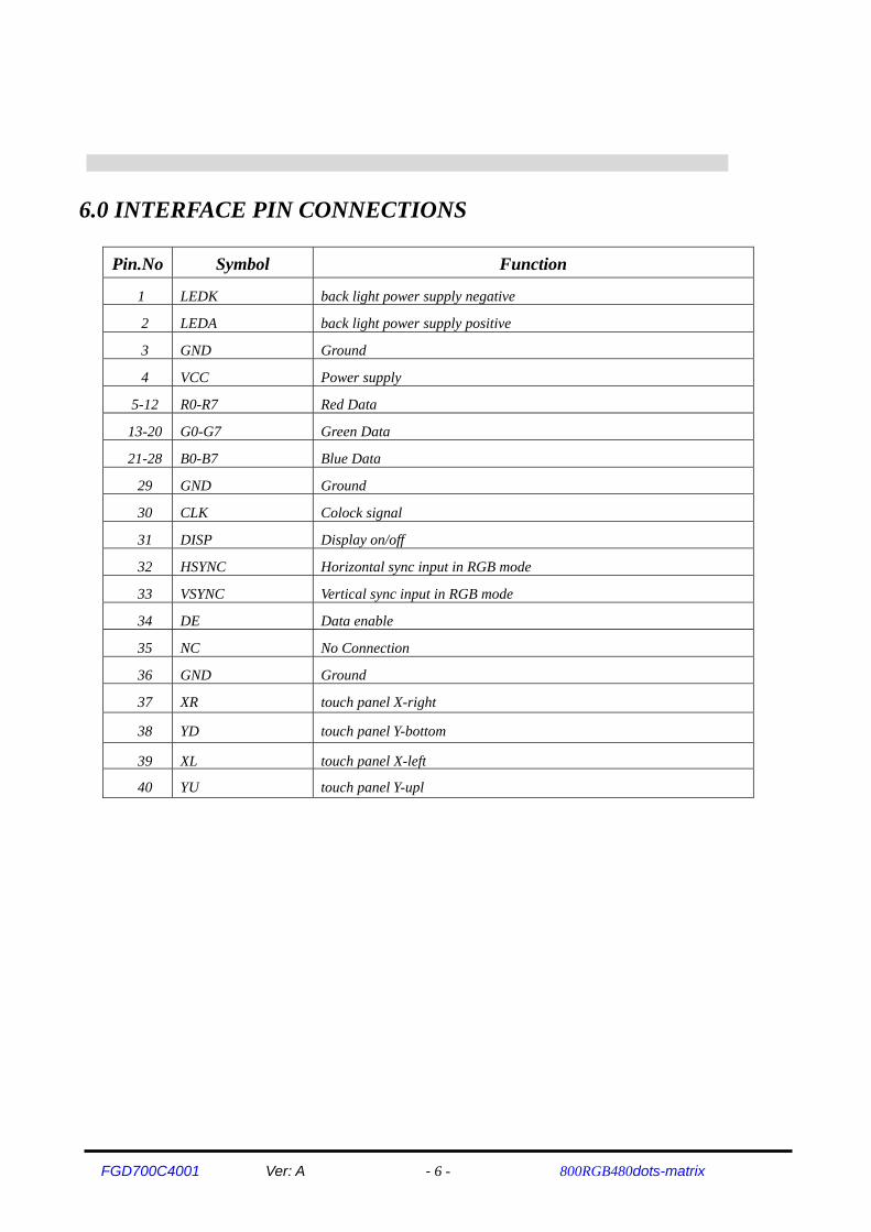
6.0 INTERFACE PIN CONNECTIONS
Pin.No Symbol Function
1 LEDK back light power supply negative
2 LEDA back light power supply positive
3 GND Ground
4 VCC Power supply
5-12 R0-R7 Red Data
13-20 G0-G7 Green Data
21-28 B0-B7 Blue Data
29 GND Ground
30 CLK Colock signal
31 DISP Display on/off
32 HSYNC Horizontal sync input in RGB mode
33 VSYNC Vertical sync input in RGB mode
34 DE Data enable
35 NC No Connection
36 GND Ground
37 XR touch panel X-right
38 YD touch panel Y-bottom
39 XL touch panel X-left
40 YU touch panel Y-upl
FGD700C4001 Ver: A - 7 - 800RGB480dots-matrix

FGD700C4001 Ver: A - 8 - 800RGB480dots-matrix
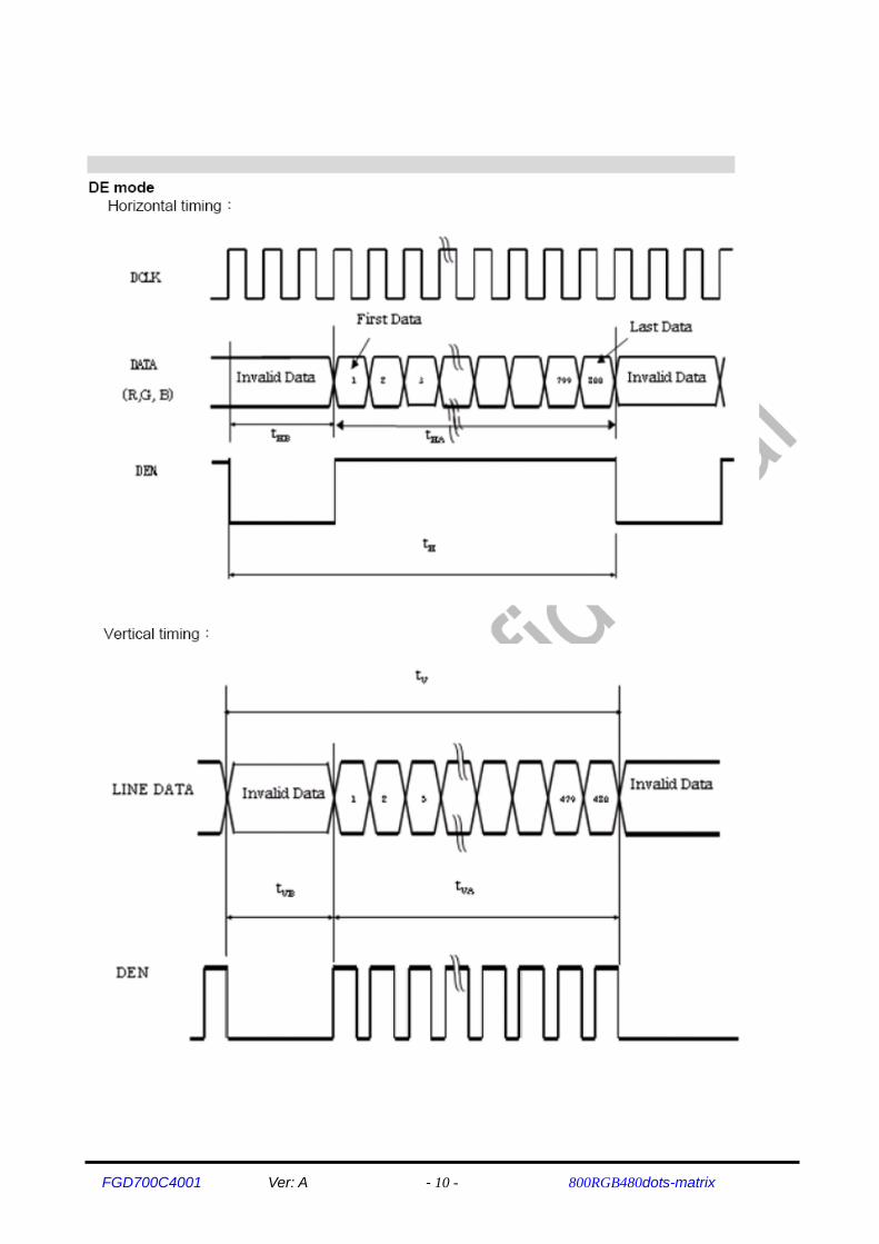
6.1 Timing characteristics 6.1.1 Prallel RGB input timing table

FGD700C4001 Ver: A - 9 - 800RGB480dots-matrix
FGD700C4001 Ver: A - 10 - 800RGB480dots-matrix

FGD700C4001 Ver: A - 11 - 800RGB480dots-matrix

FGD700C4001 Ver: A - 12 - 800RGB480dots-matrix
6.1.2 Power、Signal sequence
FGD700C4001 Ver: A - 13 - 800RGB480dots-matrix
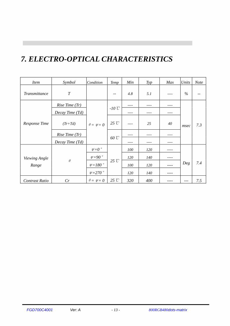
7. ELECTRO-OPTICAL CHARACTERISTICS
Item Symbol Condition Temp Min Typ Max Units Note
Transmittance T -- 4.8 5.1 ---- % --
Response Time
Rise Time (Tr)
θ=ψ= 0
-10℃---- ---- ----
msec 7.3
Decay Time (Td) ---- ---- ----
(Tr+Td) 25℃ ---- 25 40
Rise Time (Tr) 60℃
---- ---- ----
Decay Time (Td) ---- ---- ----
Viewing Angle Range
θ
ψ=0°
25℃
100 120 ----
Deg 7.4 ψ=90° 120 140 ----
ψ=180° 100 120 ----
ψ=270° 120 140 ----
Contrast Ratio Cr θ=ψ= 0 25℃ 320 400 ---- --- 7.5

FGD700C4001 Ver: A - 14 - 800RGB480dots-matrix
7.1 ELECTRO-OPTICAL CHARACTERISTICS TEST METHOD
Polarizer Liquid Crystal
Panel
Light Source for
Transmission Type
Light Source for
Reflective Type
Response Time
Photo-detector
θθo

FGD700C4001 Ver: A - 15 - 800RGB480dots-matrix
7.2 DEFINITION OF OPERATING VOLTAGE, VOP Vop = (V10,ON +V90,OFF)/2
7.3 DEFINITION OF OPTICAL RESPONSE TIME
V10,ON V90,OFF
10%
90%
Brightness Curve for Selected Segment
Brightness Curve for
Non-selected Segment
Brig
htne
ss (%
)
Driving Voltage
100%
Selected Waveform
Non-selected Waveform Non-selected
Waveform
Brig
htne
ss (%
)
Time (ms)
90% 100%
10%
Rise Time, Tr Decay Time, Td

FGD700C4001 Ver: A - 16 - 800RGB480dots-matrix
7.4 DEFINITION OF VIEWING ANGLE Θ AND
7.5 DEFINITION OF CONTRAST RATIO, CR Brightness of Non-selected Segment (B2)
Brightness of Selected Segment (B1)
12 O’clock Direction
9 O’clock Direction
3 O’clock Direction
φ=90° φ=270°
φ=180°
φ=0°
Viewing Direction
6 O’clock Direction
φ
θ
Normal :
θ=0°
CR =
V,max
CR,max
Contrast
Driving Voltage
Brig
htne
ss (%
)
B2
B1
Brightness Curve for
Selected Segment
Brightness Curve for
Non-selected Segment100%
0%

FGD700C4001 Ver: A - 17 - 800RGB480dots-matrix
8.INSPECTION CRITERIA
8.1Inspection Conditions
8.1.1Environmental conditions The environmental conditions for inspection shall be as follows Room temperature: 20±3°C Humidity: 65±20%RH
8.1.2 The external visual inspection With a single 20-watt fluorescent lamp as the light source, the inspection was in the distance of 30cm or more from the LCD to the inspector's eyes .
8.2 LIGHT METHOD
Fluorescent lamp perpendicular to the display surface.

FGD700C4001 Ver: A - 18 - 800RGB480dots-matrix
Inspection distance and angle
Inspection should be performed within angleφ(φis usually 30°) from Z axis to each X and Y.
Inspection distance in any direction within φmust be kept 30±5cm from the display surface.
.
8.3 Classification of defects 8.3.1Major defect
A major defect refers to a defect that may substantially degrade usability for product applications.
8.3.2 Minor defect
A minor defect refers to a defect which is not considered to be able substantially degrade the product application or a
defect that deviates from existing standards almost unrelated to the effective use of the product or its operation.
FGD700C4001 Ver: A - 19 - 800RGB480dots-matrix
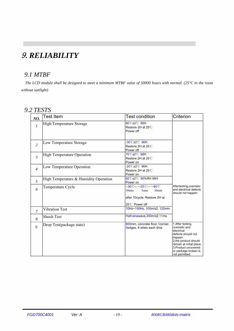
9.RELIABILITY
9.1 MTBF The LCD module shall be designed to meet a minimum MTBF value of 50000 hours with normal. (25°C in the room
without sunlight)
9.2 TESTS NO. Test Item Test condition Criterion
1 High Temperature Storage 80℃±2℃ 96H Restore 2H at 25℃ Power off
2 Low Temperature Storage -30℃±2℃ 96H Restore 2H at 25℃ Power off
3 High Temperature Operation 70℃±2℃ 96H Restore 2H at 25℃ Power on
4 Low Temperature Operation -20℃±2℃ 96H Restore 2H at 25℃ Power on
5 High Temperature & Humidity Operation 60℃±2℃ 90%RH 96H Power on
6 Temperature Cycle --30℃←→25℃←→80℃ 30min 5min 30min
after 10cycle, Restore 2H at
25℃ Power off
Aftertesting,cosmeticand electrical defectsshould not happen.
7 Vibration Test 10Hz~150Hz, 100m/s2, 120min
8 Shock Test Half-sinewave,300m/s2,11ms
9 Drop Test(package state)
800mm, concrete floor,1corner, 3edges, 6 sides each time
1.After testing, cosmetic and electrical defects should not happen. 2.the product shouldremain at initial place3.Product uncoveredor package broken isnot permitted.

FGD700C4001 Ver: A - 20 - 800RGB480dots-matrix
10. PRECAUTIONS FOR USING LCD MODULE
10.1 HANDING PRECAUTIONS (1) The display panel is made of glass. Do not subject it to a mechanical shock or impact by dropping it.
(2) If the display panel is damaged and the liquid crystal substance leaks out, be sure not to get any in your mouth. If
the substance contacts your skin or clothes, wash it off using soap and water.
(3) Do not apply excessive force to the display surface or the adjoining areas since this may cause the color tone to
vary.
(4) The polarizer covering the display surface of the LCD module is soft and easily scratched. Handle this polarizer
carefully.
(5) If the display surface becomes contaminated,breathe on the surface and gently wipe it with a soft dry cloth. If it is
heavily contaminated, moisten a cloth with one of the following solvents:
- Isopropyl alcohol
- Ethyl alcohol
(6) Solvents other than those above mentioned may damage the polarizer.
Especially, do not use the following:
- Water
- Ketone
- Aromatic solvents
(7) Extra care to minimize corrosion of the electrode. Water droplets, moisture condensation or a current flow in a
high-humidity environment accelerates corrosion of the electrode.
(8) Install the LCD Module by using the mounting holes. When mounting the LCD Module, make sure it is free of
twisting, warping and distortion. In particular, do not forcibly pull or bend the I/O cable or the backlight cable.
(9) Do not attempt to disassemble or process the LCD Module.
(10) NC terminal should be open. Do not connect anything.
(11) If the logic circuit power is off, do not apply the input signals.
(12) To prevent destruction of the elements by static electricity, be careful to maintain an optimum work environment.
- Be sure to ground the body when handling he LCD Module.
- Tools required for assembling, such as soldering irons, must be properly grounded. -To reduce the amount of static electricity generated, do not conduct assembling and other work
under dry conditions. -The LCD Module is coated with a film to protect the display surface. Exercise care when peeling off this protective
film since static electricity may be generated.

FGD700C4001 Ver: A - 21 - 800RGB480dots-matrix
10.2 STORAGE PRECAUTIONS When storing The LCD Module, avoid exposure to direct sunlight of fluorescent lamps. Keep the modules in bags
(avoid high temperature/ high humidity and low temperatures below 0℃). Whenever possible, the LCD Module should
be stored in the same conditions in which they were shipped from our company.
10.3 OTHERS Liquid crystals solidify under low temperature (below the storage temperature range) leading to defective
orientation or the generation of air bubbles (black or white). Air bubbles may also be generated if the module is subject
to a low temperature.
If the LCD Module have been operating for a long time showing the same display patterns the display
patterns may remain on the screen as ghost images and a slight contrast irregularity may also appear. A normal
operating status can be recovered by suspending use for some time. It should be noted that this phenomenon does not
adversely affect performance reliability.
To minimize the performance degradation of the LCD Module resulting from destruction caused by static
electricity etc. exercise care to avoid holding the following sections when handling the modules.
- Exposed area of the printed circuit board.
- Terminal electrode sections.
11. USING LCD MODULES
11.1 LIQUID CRYSTAL DISPLAY MODULES LCD is composed of glass and polarizer. Pay attention to the following items when handling.
(1) Please keep the temperature within specified range for use and storage. Polarization degradation, bubble generation
or polarizer peel-off may occur with high temperature and high humidity.
(2) Do not touch, push or rub the exposed polarizers with anything harder than a HB pencil lead (glass, tweezers, etc).
(3) N-hexane is recommended for cleaning the adhesives used to attach front/rear polarizers and reflectors made of
organic substances, which will be damaged by chemicals such as acetone, toluene, toluene, ethanol and isopropyl
alcohol.
(4) When the display surface becomes dusty, wipe gently with absorbent cotton or other soft material like chamois
soaked in petroleum ether. Do not scrub hard to avoid damaging the display surface.
(5) Wipe off saliva or water drops immediately, contact with water over a long period of time may cause deformation or
color fading.
(6) Avoid contacting oil and fats.

FGD700C4001 Ver: A - 22 - 800RGB480dots-matrix
(7) Condensation on the surface and contact with terminals due to cold will damage, stain or polarizers. After products
are tested at low temperature they must be warmed up in a container before coming is contacting with room
temperature air.
(8) Do not put or attach anything on the display area to avoid leaving marks on.
(9) Do not touch the display with bare hands. This will stain the display area and degrade insulation between terminals
(some cosmetics are determinate to the polarizers).
(10)As glass is fragile, it tends to become or chipped during handling especially on the edges. Please avoid dropping or
jarring.
11.2 INSTALLING LCD MODULE Attend to the following items when installing the LCM.
(1) Cover the surface with a transparent protective plate to protect the polarizer and LC cell.
(2) When assembling the LCM into other equipment, the spacer to the bit between the LCM and the fitting plate should
have enough height to avoid causing stress to the module surface, refer to the individual specifications for
measurements. The measurement tolerance should be ±0.1mm.
11.3 ELECTRO-STATIC DISCHARGE CONTROL Since this module uses a CMOS LSI, the same careful attention should be paid for electrostatic discharge
as for an ordinary CMOS IC.
(1) Make certain that you are grounded when handing LCM.
(2) Before removing LCM from its packing case or incorporating it into a set, be sure the module and your body have
the same electric potential.
(3) When soldering the terminal of LCM, make certain the AC power source for the soldering iron does not leak.
(4) When using an electric screwdriver to attach LCM, the screwdriver should be of ground potentiality to minimize as
much as possible any transmission of electromagnetic waves produced sparks coming from the commutator of the
motor.
(5) As far as possible, make the electric potential of your work clothes and that of the workbenches to the ground
potential.
(6) To reduce the generation of static electricity , be careful that the air in the work is not too dried. A relative humidity
of 50%-60% is recommended.

FGD700C4001 Ver: A - 23 - 800RGB480dots-matrix
11.4 PRECAUTION FOR SOLDERING TO THE LCM (1) Observe the following when soldering lead wire, connector cable and etc. to the LCM.
-Soldering iron temperature: 280 ±10°C.
-Soldering time: 3-4 sec.
-Solder: eutectic solder.
If soldering flux is used, be sure to remove any remaining flux after finishing to soldering operation. (This
does not apply in the case of a non-halogen type of flux.) It is recommended that you protect the LCD surface with a
cover during soldering the prevent any damage due to flux spatters.
(2) When soldering the electroluminescent panel and PC board, the panel and board should not be detached more than
three times. This maximum number is determined by the temperature and time conditions mentioned above, though
there may be some variance depending on the temperature of the soldering iron.
(3) When removing the electroluminescent panel from the PC board, be sure the solder has completely melted, otherwise
the soldered pad on the PC board could be damaged.
11.5 PRECAUTIONS FOR OPERATION (1) Viewing angle varies with the change of liquid crystal driving voltage (Vo). Adjust Vo to show the best contrast.
(2) Driving the LCD in the voltage above the limit will shorten its lifetime.
(3) Response time is greatly delayed at temperature below the operating temperature range. However, this does not
mean the LCD will be out of the order. It will recover when it returns to the specified temperature range.
(4) If the display area is pushed hard during operation, the display will become abnormal. However, it will return to
normal if it is turned off and then on.
(5) Condensation on terminals can cause an electrochemical reaction disrupting the terminal circuit. Therefore, it must
be used under the relative condition of 40°C, 50% RH.
(6) When turning the power on, input each signal after the positive/negative voltage becomes stable.
11.6 STORAGE When storing LCDS as spares for some years, the following precaution are necessary.
(1) Store them in a sealed polyethylene bag. If properly scaled, there is no need for desiccant.
(2) Store them in a dark place. Do not expose to sunlight or fluorescent light, keep the temperature between 0°C and
35°C.
(3) The polarizer surface should not come in contact with any other objects. (We advise you to store them in the
container in which they were shipped.)
(4) Environmental conditions:
-Do not leave them for more than 168hrs. at 60 °C.
-Should not be left for more than 48hrs. at –20 °C.

FGD700C4001 Ver: A - 24 - 800RGB480dots-matrix
11.7 SAFETY (1) It is recommended to crush damaged or unnecessary LCDs into pieces and wash them off with solvents such as
acetone and ethanol, which should later be burned.
(2) If any liquid leaks out of a damaged glass cell and comes in contact with the hands, wash off thoroughly with soap
and water.
11.8 LIMITED WARRANTY Unless agreed between GIANTPLUS and customer, GIANTPLUS will replace or repair any of its LCD and
modules which are found to be functionally defective when inspected in accordance with GIANTPLUS LCD acceptance
standards (copies available upon request) for a period of one year from date of shipments. Cosmetic/visual defects must
be returned to GIANTPLUS within 90 days of shipment. Confirmation of such date shall be based on freight documents.
The warranty liability of GIANTPLUS is limited to repair and/or replacement on the terms set forth above. GIANTPLUS
will not be responsible for any subsequent or consequential events.
11.9. RETURN LCM UNDER WARRANTY
No warranty can be granted if the precautions stated above have been disregarded. The typical examples of
violations are:
-Broken LCD glass.
-PCB eyelet’s damaged or modified.
-PCB conductors damaged.
-Circuit modified in any way, including addition of components.
-PCB tampered with by grinding, engraving or painting varnish.
-Soldering to or modifying the bezel in any manner.
Module repairs will be invoiced to the customer upon mutual agreement. Modules must be returned with
sufficient description of the failures or defects. Any connectors or cable installed by the customer must be removed
completely without damaging the PCB eyelet’s conductors and terminals.

![MS6M01544 6MBP15VSC060-50 General.ppt [互換モード] · trr 0.20 0.30. DWG.NO. H04-004-03 This material and the information herei n is the property of Fuji Electric Co.,Ltd. They](https://img.pdfslide.us/doc/110x75/5f58df7a1ee8f015117479f5/ms6m01544-6mbp15vsc060-50-fff-trr-020-030-dwgno-h04-004-03-this.jpg)