Embed Size (px)
Citation preview

GUIDE SPECIFICATION Los Angeles World Airports
BASIC TELECOMMUNICATION REQUIREMENTS 27 05 00 - 1
July 2016 Communications
SECTION 27 05 00 – BASIC TELECOMMUNICATION REQUIREMENTS
PART 1 – GENERAL
1.1 SUMMARY
A. Contractor shall include in the Bid all labor, materials, tools, plant, transportation, storage costs, training, equipment, insurance, temporary protection, permits, inspections, taxes and all necessary and related items required to provide complete and operational systems shown and described in the Specifications. This section governs all systems provided in installed as part of Division 27 and Division 28 (security) sections. Additional specific telecommunica-tion systems requirements are included in the individual Division 27 and Division 28 re-quirements and are intended to complement the requirements of this section. Where con-flicts arise between this section and referenced sections or documents, the more stringent of the requirements shall apply.
B. The Contractor is responsible for providing and coordinating final equipment arrangements,
locations, phased activities and construction methods that minimize disruption to Terminal operations and provide complete and operational systems. Materials and labor not specifi-cally mentioned in these requirements but are required for proper installation, performance, and operation of the equipment or systems shall be furnished by the contractor.
C. The Contractor shall coordinate interfaces to existing systems that are being extended in the
Project in order to minimize disruption to the existing systems operations. Any systems out-ages shall be approved in advance and scheduled with LAWA (refer to Section 27 05 05 – Selective Demolition Telecommunication Systems) following approved utility shutdown ap-proval procedures
D. The Contractor shall coordinate specialty electronic, ACAMS, Information Technology (IT)
data networks, common use and flight information systems and displays, CCTV, public ad-dress and any other IT infrastructure systems.
E. The Contractor shall coordinate interfaces to existing systems that are being extended into
the project to minimize disruption to existing Terminal operations (refer to Section 27 13 33 – Communication Systems Interfaces (Legacy Systems). Contractor shall be responsible for employing a System Manager to plan, coordinate, integrate, execute, test, and commission the work required in Division 27 and Division 28 (security) specifications and other systems that interface with Communication Systems.
GUIDE SPECIFICATION Los Angeles World Airports
BASIC TELECOMMUNICATION REQUIREMENTS 27 05 00 - 2
July 2016 Communications
F. The Contractor is required to coordinate the work performed as part of this Project with other related works projects so that Division 27 and 28 specialty electronic, IT, Security, paging, and infrastructure systems that will be extended into other related works projects are coordi-nated technically and from a managerial perspective (schedule) to ensure that interfaces be-tween the various related works projects and this Project are coordinated.
G. Related documents included in the specification requirements:
1. LAWA Information Management and Technology Group (IMTG) Information Technolo-gy. Infrastructure Standards of Practice Volumes 1, 2, and 3, dated April 2016 or verify latest version with LAWA IMTG if current version is greater than 6 months old.
2. LAWA IT Requirements for New Concessions Model. 3. Section 01 11 00 – Summary of Work 4. Section 01 25 00 – Substitution Procedure 5. Section 01 31 00 – Administrative Requirements 6. Section 01 33 00 – Submittal 7. Section 01 40 00 – Quality Requirements 8. Section 01 43 00 – Quality Assurance 9. Section 01 64 00 – Owner Furnished Products 10. Section 01 77 13 – Preliminary Closeout Reviews 11. Section 01 77 16 – Final Closeout Review 12. Section 01 78 00 – Close Out Submittals 13. Section 23 14. Section 26 15. Section 27 05 26 – Grounding and Bonding for Telecommunications Systems 16. Section 27 05 28 – Pathways for Telecommunications Systems 17. Section 27 10 00 – Premise Wiring Distribution Systems 18. Section 27 11 00 – IT Communication Rooms (Telecom & MPOE) Requirements 19. Section 27 11 16 – Communications Cabinets, Racks, Frames, Enclosures, Manufactured
Metal Case Work 20. Section 27 13 00 – Communications Backbone Cabling 21. Section 27 13 33 – Communications Systems Interfaces (Legacy Systems) 22. Section 27 15 00 – Communications Horizontal Cabling 23. Section 27 21 00 – Local Area Network 24. Section 27 21 33 – Wireless Communication System (WiFi) 25. Section 27 42 19 – Electronic Visual Information Display System (EVIDS) 26. Section 27 42 20 – Common Use Systems (CUTE) 27. Section 27 51 13 – Paging System 28. Section 28 13 00 – Access Control and Alarm Monitoring System (ACAMS) 29. Section 28 23 00 – Video Surveillance System (VSS)
1.2 (NOT USED)

GUIDE SPECIFICATION Los Angeles World Airports
BASIC TELECOMMUNICATION REQUIREMENTS 27 05 00 - 3
July 2016 Communications
1.3 REFERENCES
A. See IT Infrastructure Standards of Practice Volume 3, Appendices.
B. Codes, Standards, and References
1. All work and materials shall conform to and be installed, inspected and tested in accord-ance with the governing rules and regulations of the telecommunications industry, as well as federal, state and local governmental agencies, including, but not limited to the following: a. ANSI C80.1 Rigid Steel Conduit, Zinc-Coated b. ANSI C80-3 Electrical Metallic Tubing, Zinc-Coated c. ICEA S-83-596 Optical Fiber Premises Distribution Cable d. TIA-455-107 FOTP-107 Determination Of Component Reflectance Or Link/System
Return Loss Using A Loss Test Set e. ANSI/TIA/EIA-455 Test Procedures For Fiber Optic Fibers, Cables, TR f. ANSI/TIA/EIA 455-57 Optical Fiber End Preparation and Examination. g. ANSI/TIA/EIA 455-59 Optical Time Domain Reflectometry h. ANSI/TIA/EIA 455-60 OTDR Measurement Of Fiber Optic Cable Length i. ANSI/TIA/EIA -526-7 Measurement of Optical Power Loss of Installed Single-
Mode Fiber Cable Plant j. ANSI/TIA/EIA 526-14 OFSTP-14 Optical Power Loss Measurements Of Installed
Multimode Fiber Cable Plant k. ANSI/TIA/EIA-568-C.1 Commercial Building Telecommunications Cabling Stand-
ard Part 1: General Requirements, 02/02/09 l. ANSI/TIA/EIA-568-C.2 Balanced Twisted-Pair Telecommunications Cabling Com-
ponents and Standards, April, 2010 m. ANSI/TIA/EIA-568-C.3 Optical Fiber Cabling Components Standard, June, 2008 n. ANSI/TIA/EIA –569-B Commercial Building Standard for Telecommunications
Pathways and Spaces, May 2009 o. ANSI/TIA/EIA 598-C Optical Fiber Cable Color Coding, 2005 p. ANSI/TIA/EIA -604-1 Fiber Optic Connector Intermateability Standard, 2002 q. ANSI/TIA/EIA -606-A Administration Standard for Commercial Telecommunica-
tions Infrastructure, 11/24/08 r. ANSI/TIA/EIA -607 Commercial Building Grounding and Bonding Requirements
for Telecommunications, August 2013 s. ANSI/TIA/EIA –758-A Customer-Owned Outside Plant Telecommunications Infra-
structure Standard 2004 t. ANSI/TIA/EIA – 854 A Full Duplex Ethernet Specification for 1000Mb/s
(1000BASE-TX) Operating over Category 6 Balanced Twisted-Pair Cabling, 2001

GUIDE SPECIFICATION Los Angeles World Airports
BASIC TELECOMMUNICATION REQUIREMENTS 27 05 00 - 4
July 2016 Communications
u. ANSI/TIA/EIA – 862 Building Automation Systems Cabling Standard for Commer-cial Buildings, 2002
v. ANSI/TIA/EIA-4750000B Generic Specifications for Fiber Optic Connectors w. ASTM E814 Standard Test Method For Fire Tests Of Penetration Firestop Systems x. BICSI Telecommunications Distribution Methods Manual (Thirteenth Edition) y. FCC 47 Part 68 Code of Federal Regulations, Title 47, Telecommunications z. IEEE National Electrical Safety Code (NESC); IEEE C2-2012 aa. ISO/IEC 11801 Information Technology - Generic Cabling For Customer Premises bb. LADBS Los Angeles Department of Building and Safety - City of Los Angeles Elec-
trical Code cc. NEMA 250 Enclosures for Electrical Equipment (1000 V Maximum) dd. NFPA-70 National Electric Code; 2014 ee. TIA/EIA TSB 67 Transmission Performance Specification for Field Testing of Un-
shielded Twisted-Pair Cabling Systems ff. TIA/EIA TSB 72 Centralized Optical Fiber Cabling Guidelines gg. TIA/EIA TSB 75 Additional Horizontal Cabling Practices for Open Offices hh. TIA/EIA TSB 95 Additional Transmission Performance Guidelines For 4-Pair 100
Ohm Category 5 Cabling ii. UL 1459 Underwriters Laboratories Standard for Safety – Telephone Equipment jj. UL 1863 Underwriters Laboratories Standard for Safety – Communications Circuit
Accessories 2. References to codes and standards called for in the Specifications refer to the latest edi-
tion, amendments, and revisions to the codes and standards in effect on the date of these Specifications.
3. LAWA IMTG Information Technology (IT) Infrastructure Standards of Practice Vol-umes 1, 2, and 3, dated April 2016 or verify latest version with LAWA IMTG if current Version is greater than 6 months old, shall be adhered to for standards specific to LAWA.
1.4 ADMINISTRATIVE REQUIREMENTS
A. SSI - Protection of Contract Documents. All telecom infrastructure documents shall be con-sidered Sensitive Security Information (SSI) and shall be handled as defined in 49 CFR, Parts 15 and 1520. See IT Infrastructure Standards of Practice Volume 3, Appendices.
1.5 SUBMITTALS
A. Comply with all LAWA submittal procedures given in other Sections and Section 01 33 00 – Submittal Procedures. The following is in addition to or complementary to any require-ments given elsewhere. The contractor shall develop a submittal matrix in MS Excel indi-cating all submittals required as part of the Division 27 and Division 28 (security) sections

GUIDE SPECIFICATION Los Angeles World Airports
BASIC TELECOMMUNICATION REQUIREMENTS 27 05 00 - 5
July 2016 Communications
for review by LAWA. The matrix shall indicate all submittals required by each specifica-tion Section and shall be arranged by sequential Section numbers.
B. Submit a letter of approval or other certification from the manufacturer indicating that the
Bidder is a manufacturer certified installer of the proposed cabling system(s) (submit with Bid).
C. Submit a detailed bill-of-materials listing all manufacturers, part numbers, and quantities that
the Bidder proposes to use in this project. Submit a two-foot length sample of each fiber ca-ble type/count and inner duct to be installed prior to approval for installation – with manu-facturer markings.
D. Submit manufacturers’ data sheets for proposed racks and cabinets, termination equipment,
cable management or support hardware, power and grounding equipment, and labeling ma-terial in PDF form. Specific part numbers shall be identified with highlighting or by arrows.
E. Submit manufacturers’ instructions for storage, handling, protection, examination, prepara-
tion, operation, maintenance, and installation of all products. Include any application condi-tions or limitations of use stipulated by any product testing agency in PDF Form.
F. Submit all applicable Material Safety Data Sheets in PDF form. G. Submit all factory test information of cables prior to installation of the product in PDF form. H. Submit a complete test plan (and subsequent test data) per ANSI/TIA/EIA-568-C and
ANSI/TIA/EIA TSB-67 for all cabling. I. Submit (2) hardbound copies of all cable test results and three electronic compact disc. J. Submit calibration reports for all test equipment, the calibration shall be performed by manu-
facturer certified calibration facility and be dated no more than sixty (60) days prior to the start of testing.
K. Submit all proposed labeling materials and nomenclature for approval. L. Coordination Drawings:
1. Indicate locations where space is limited for installation and access. Contractor shall provide the following at a minimum: a. Complete front panel equipment fabrication dimensions with equipment locations of
equipment racks and cabinets.

GUIDE SPECIFICATION Los Angeles World Airports
BASIC TELECOMMUNICATION REQUIREMENTS 27 05 00 - 6
July 2016 Communications
b. Equipment wiring terminal point-to-point, color coded, wiring diagrams. Drawings shall show each item of equipment, location, all wiring, and all connections. Wiring color code shall be as described by the individual specification sections. If no color code is specified, then the color code shall be as recommended by the equipment manufacturer.
c. All devices schematically represented on wiring diagrams shall be identified with room numbers corresponding to equipment locations in the building.
d. Submittal shall include block diagram of equipment to show equipment relationship and signal flow paths.
e. Provide coordination drawings that clearly indicate interfaces to related work. 2. Submit floor plans, elevations, and details indicating major equipment and end device
locations. Indicate all floors, wall and ceiling penetrations and their relationship to other penetrations and installations. Floor plans shall indicate proposed locations and routing of major raceway systems, equipment and materials. Include the following: a. Clearances for servicing equipment, including space for equipment disassembly re-
quired for periodic maintenance. b. Fire-rated wall and floor penetrations. c. Equipment connections and support details. d. Seismic support details. e. Sizes and locations of required concrete pads and bases. f. Indicate scheduling, sequencing, movement, and positioning of large equipment into
the building during construction. Submit conduit riser, fiber optic riser, copper riser, and communications grounding riser drawings. Submit fiber optic backbone cable segment spreadsheet. Use the LAWA-provided WireCAD template. Submit end-to-end IT circuit diagrams for each circuit installed. Use the LAWA-provided WireCAD template. See IT Infrastructure Standards of Practice Volume 3, Chapter 1.
3. Layout of Telecommunication Rooms: Within sixty (60) days before beginning installa-tion, the Contractor shall furnish a telecommunications room drawing showing the ini-tial layout design and plans for the proposed equipment, cable routings, and ter-mination locations for all cable and equipment including HVAC and UPS equipment, equipment cabinets, equipment layouts within cabinets, and placement of wall mounted equipment to LAWA for review. See IT Infrastructure Standards of Practice Volume 1, Chapter 2.
M. Project Record Documents required include:
1. Marked-up copies of Contract Drawings 2. Marked-up copies of Shop Drawings 3. Newly prepared Drawings 4. Marked-up copies of Specifications, Addenda and Change Orders 5. Marked-up Project Data submittals

GUIDE SPECIFICATION Los Angeles World Airports
BASIC TELECOMMUNICATION REQUIREMENTS 27 05 00 - 7
July 2016 Communications
6. Record Samples 7. Field records for variable and concealed conditions 8. Record information on Work that is recorded only schematically 9. As-built drawings - See IT Infrastructure Standards of Practice Volume 3, Chapter 1 10. Record drawings 11. Electronic as-built and LAWA AEGIS requirements 12. Compiled list of approved substitutions, contract modifications, and actual equipment
and materials installed.
N. Post changes and modifications to the Documents as they occur. Drawings will be updated electronically and submitted to LAWA in accordance with the schedule provided for this by LAWA. Do not wait until the end of the Project. Design Consultant will periodically re-view Project Record Documents to assure compliance with this requirement.
O. At every quarter, submit Project Record Documents for LAWA's records.
1. Upon completion of the as built drawings, LAWA inspection and LAWA IMTG will review the as built work with the Contractor.
2. The Contractor shall develop as-built drawings for all systems and installation provided as part of this Project.
3. If the as built work is not complete, the Contractor will be so advised and shall com-plete the work as required.
P. Project Record Drawings shall also be submitted in electronic format. Electronic drawing
format shall be AutoCAD® Release 2014 or later. LAWA shall have the right and capabil-ity to manipulate all electronic file drawings and documentation. 1. For Division 27 and 28 Sections, prepare record documents in accordance with the re-
quirements of Section 01 78 39- Project Record Document and the requirements con-tained in the individual Division 27 and 28 sections. In additional to the requirements specified in Division 1, indicate installed conditions for:
a. Raceway systems, size, and location for both exterior and interior; locations of control devices; distribution and branch electrical circuitry and fuse and circuit breaker size and arrangements for systems and equipment specified in Division 27 and 28 sections.
b. Equipment locations (exposed and concealed), dimensioned from prominent building lines.
c. Indicate all equipment placement, conduit, and cable routings, outlet locations, and in-frastructure and equipment connectivity. Provide: 1) Floor Plan Drawings 2) Equipment Room Wall Elevations 3) Equipment Rack Elevations 4) Equipment Signal Flow Diagrams 5) Riser Diagrams

GUIDE SPECIFICATION Los Angeles World Airports
BASIC TELECOMMUNICATION REQUIREMENTS 27 05 00 - 8
July 2016 Communications
6) Spreadsheets 7) Block Diagrams 8) Infrastructure Cross Connect 9) Labeling
d. See IT Infrastructure Standards of Practice Volume 3, Chapter 1.
1.6 MAINTENANCE MATERIAL SUBMITTALS
A. Maintenance Manuals: Manuals including maintenance instructions and other descriptive ma-terial as received from the manufacturers shall be provided that will enable LAWA person-nel to maintain equipment and test equipment. The Contractor shall make reasonable effort to obtain specified maintenance documentation for all third party equipment. This docu-mentation shall include descriptions, specifications, theory of operation (where applicable), layout drawings (showing component types and positions), and back-panel and assembly wiring diagrams. In addition to hardcopies, electronic copies, in a Design Consultant ap-proved format, shall be provided. Prepare maintenance manuals in accordance with Divi-sion 1 contract submittal procedures and the requirements in the individual Division 27 and Division 28 Sections.
B. Preventative Maintenance: Instructions shall be provided for preventive maintenance proce-
dures that include examinations, tests, adjustments, and periodic cleaning. The manuals shall provide guidelines for isolating the causes of hardware malfunctions and for localizing faults. The manuals shall provide thorough instructions on the use of any specialized test equipment needed for hardware maintenance. Provide normal and preventative maintenance requirements. In addition to hardcopies, electronic copies, in a Design Consultant approved format, shall be provided for each system
C. Maintenance Schedule: A recommended schedule for preventative, routine, and emergency
maintenance indicating frequency and response time. Preventative maintenance services during peak activity periods shall be avoided. The Contractor shall coordinate with LAWA to define peak activity periods. The Contractor shall submit a finalized preventative mainte-nance schedule for Design Consultant approval.
D. System Configurations: A record of as-built configurations shall be provided for each device
and every system. Configurations include setup, customization, interfaces, and optimization settings at time of final acceptance of the system.
E. Test Results: A record of all required approved test results for each system, subsystem, and
infrastructure shall be provided. Also include all calibration certifications for tests conduct-ed. Calibration certificates shall be current at time of testing. See IT Infrastructure Stand-ards of Practice Volume 2, Chapters 2 and 3.
GUIDE SPECIFICATION Los Angeles World Airports
BASIC TELECOMMUNICATION REQUIREMENTS 27 05 00 - 9
July 2016 Communications
1.7 QUALITY ASSURANCE
A. Contractor Experience:
1. The Contractor or approved sub-contractor shall be a Manufacturer-Certified Cable In-staller, for the manufacturer specified cable(s) with the capability of providing a manu-facturer’s warranty of not less than fifteen (15) years for the horizontal and backbone ca-bling and associated manufacturer-specified termination equipment. The Contractor shall offer proof of cable installer certification by submitting a copy of certification with the Bid.
2. The Contractor or approved sub-contractor shall have at least five verifiable years’ expe-rience in installing electronic systems and equipment of the type used for projects of similar size and complexity and shall provide documentation on three successful projects completed over the last five years.
3. All equipment shall be installed by technicians trained by the equipment manufacturer or a recognized school or course for the installations of systems installed on this project. The contractor shall maintain all records of individuals at the jobsite and, if requested, show proof of a specific individual’s training upon request.
B. The Contractor shall have at least one (1) Registered Communications Distribution Designer
(RCDD) on staff for the duration of the project. The Contractor shall offer proof of RCDD certification by submitting a copy of the certification with the Bid. The Contractors RCDD shall be part of the Contractors team throughout the duration of the project to assist on shop drawings and other related technical issues. The RCDD is required to maintain active certi-fication during the project duration.
C. The Contractor’s Quality Assurance Inspector shall conduct a visual inspection of all instal-lations to verify that the installations are in accordance with the LAWA’s and manufacturer's specifications. Records of the inspections signed and dated by the Quality Assurance In-spector shall be provided to the Design Consultant. The Design Consultant shall be notified by the Contractor of any inspection(s) and the Design Consultant/LAWA may elect to partic-ipate in any inspection(s). All QC information shall be provided to LAWA for input into the CMMS (refer to paragraph 3.13).
D. All contractors providing new or modifying existing software products currently running on operational LAWA IT and electronic systems or interfacing to existing systems shall be re-quired to provide implementation by the current LAWA approved maintenance vendor.
E. Operating system software: System software and language development software shall be
LAWA IMTG-approved existing, industry accepted, and of a type widely used in commer-cial systems.

GUIDE SPECIFICATION Los Angeles World Airports
BASIC TELECOMMUNICATION REQUIREMENTS 27 05 00 - 10
July 2016 Communications
F. Application Software: The application software shall be LAWA IMTG approved and shall
have been used for a minimum of two years and shall be written in a standard, industry ac-cepted, computer language. The contractor shall be responsible to verify application soft-ware version for compatibility with current LAWA systems at time of installation.
G. Database Software: Database software shall be LAWA IMTG approved and shall be a commercially available software program.
H. Fully configured and installable software back-up copies shall be provided by the contractor for all software provided on the project on CD ROM media with full documentation includ-ing all software error messages (Codes), code descriptions, and troubleshooting guide.
1.8 DELIVERY, STORAGE AND HANDLING
A. Equipment shall be delivered in original packages with labels intact and identification clearly marked.
B. Equipment and components shall be protected from the weather, humidity, temperature varia-
tions, dirt, dust, or other contaminants. C. Equipment damaged prior to system acceptance shall be replaced at no cost to the Owner.
1.9 SUBSTITUTION OF EQUIPMENT
A. Approval of alternate or substitute equipment or material in no way voids Specification re-
quirements.
B. Under no circumstances shall LAWA be required to prove that an item proposed for substitu-tion is not equal to the specified item. It shall be mandatory that the Contractor submits to Engineer all evidence to support the contention that the item proposed for substitution is equal to the specified item. The Owner’s decision as to the equality of substitution shall be final and without further recourse.
C. In the event that the Design Consultant is required to provide additional engineering services
as a result of substitution of equivalent materials or equipment by the Contractor, or changes by the Contractor in dimension, weight, power requirements, etc., of the equipment and ac-cessories furnished, or if the Design Consultant is required to examine and evaluate any changes proposed by the Contractor for the convenience of the Contractor, then the Design Consultant’s expenses in connection with such additional services shall be paid by the Con-tractor and may be deducted from any moneys owed to the Contractor.
GUIDE SPECIFICATION Los Angeles World Airports
BASIC TELECOMMUNICATION REQUIREMENTS 27 05 00 - 11
July 2016 Communications
D. Unapproved materials: The use of acceptable equipment does not relieve the Contractor of
responsibility for use of any unapproved, substituted equipment. The Contractor, at no cost to LAWA, shall remove and replace: 1. Unapproved substitute with the specified equipment 2. Equipment or system that shows evidence of improper operation, function, or size, or 3. Equipment or system that does not meet the performance or quality requirements speci-
fied in the contract specification or by the manufacturer’s specifications.
1.10 EQUIPMENT CERTIFICATION
A. Provide materials that meet the following minimum requirements: 1. Electrical enclosures, equipment and systems shall meet UL Standards (or equivalent) and
requirements of the NEC. This listing requirement applies to the entire assembly. Any modifications to equipment to suit the intent of the specifications shall be performed in accordance with these requirements.
2. Equipment shall meet all applicable FCC Regulations, TIA/EIA, ANSI for product per-formance and quality.
3. All materials, unless otherwise specified, shall be new and be the standard products of the manufacturer. Used equipment or damaged material is not acceptable and will be reject-ed.
4. The listing of a manufacturer as “acceptable” does not indicate acceptance of a standard or catalogued item of equipment. All equipment and systems must conform to the Speci-fications.
5. Where applicable, all materials and equipment shall bear the label and listing of Under-writers Laboratory or Factory Mutual. Application and installation of all equipment and materials shall be in accordance with such labeling and listing. For equipment without a label or listing, Contractor shall be responsible for obtaining listing via UL, ETL, or other LAWA approved agency.
6. Manufacturers of equipment assemblies that include components made by others shall as-sume complete responsibility for the final assembled unit.
7. All components of an assembled unit need not be products of the same manufacturer. 8. Constituent parts, which are alike, shall be from a single manufacturer. 9. Components shall be compatible with each other and with the total assembly for intended
service. 10. Unless noted otherwise in the individual Division 27, 28 13 00, and 28 23 00 specification
sections, the Contractor shall guarantee for a minimum of two (2) years, the performance of assemblies of components, and shall repair or replace elements of the assemblies as re-quired to deliver specified performance of the complete assembly.

GUIDE SPECIFICATION Los Angeles World Airports
BASIC TELECOMMUNICATION REQUIREMENTS 27 05 00 - 12
July 2016 Communications
B. Components of equipment shall bear the manufacturer's name or trademark, model number and serial number on a nameplate securely affixed in a conspicuous place, or cast integral with, stamped or otherwise permanently marked upon the components of the equipment.
C. Major items of equipment that serve the same function must be the same make and model. D. Equipment and materials installed shall be compatible in all respects with other items being
furnished and with existing items so that a complete and fully operational system will result. E. Maximum standardization of components shall be provided to reduce spare part requirments.
1.11 FIELD CONDITIONS
A. Installation and testing crews shall have completed all appropriate training in copper and fi-ber cabling installation as required by the manufacturer and be certified in confined space safety if access to confined spaces is required.
B. The Contractor shall employ the maintenance contractor with whom LAWA has a mainte-
nance contract to perform the disconnection, connection, re-connection or configuration of ACAMS or other existing systems that might be affected by this Work.
C. The Contractor shall provide all new UTP cable, optical fiber cable, innerduct, racks, cabi-
nets, patch panels, cover plates, outlet boxes, related hardware, distribution, termination equipment, and any other appurtenances and equipment associated with this project.
D. The Contractor shall be responsible for the proper placement of all cabling, racks, cabinets,
patch panels, cover plates, outlet boxes, and related hardware, as well as all distribution, and termination equipment.
E. The Contractor shall obtain the approval of Engineer or Design Consultant for the final lay-
out of telecommunications rooms and tenant wiring closets prior to the installation of any materials or equipment. Shop drawings showing proposed room layouts shall be submitted for approval before beginning installation.
F. The Contractor shall furnish an adequate supply of technicians and materials at all times, and
shall perform the work in the most appropriate, expeditious, and economical manner con-sistent with the interests of the LAWA.
G. The Contractor shall be responsible to LAWA for the acts and omissions of its employees,
subcontractors and their agents and employees, and other persons performing any of the work under a contract with the Contractor.

GUIDE SPECIFICATION Los Angeles World Airports
BASIC TELECOMMUNICATION REQUIREMENTS 27 05 00 - 13
July 2016 Communications
H. The Contractor shall not unreasonably encumber the site with any material or equipment.
Operations shall be confined to areas permitted by law, permits, and contract documents.
I. The Contractor shall have an experienced Project Manager on site at all times when work is in progress on any project. The individual who represents the Contractor shall be the single point of contact between the Contractor and LAWA, and shall be responsible for the entire project. This representative shall be able to communicate with LAWA or designated repre-sentative whenever requested throughout the life of the project.
J. While working in the facility, the Contractor shall not block any entrances, egresses, or other
passageways that are necessary for normal, safe operation. It should be noted that the Con-tractor is responsible to provide any lifts, hand trucks, etc. that it will need to transport its materials and equipment throughout the site.
K. The Contractor shall protect all buildings, walls, floors, and property from damage resulting
from the installation. Any and all damage to property shall be repaired by the Contractor at its expense. If the Contractor enters an area that has damage (not caused by the Contractor), the Contractor shall immediately bring this to the attention of the LAWA so the area can be appropriately noted.
L. Following each day’s work, the Contractor shall clean up the areas in which it has been
working and dump all trash in the appropriate designated areas.
1.12 WARRANTY
A. Unless otherwise noted in individual specification sections or elsewhere in this specification section, materials and workmanship shall meet or exceed industry standards and be fully guaranteed for a minimum of two (2) years from Final Acceptance. If the manufacturer’s standard warranty is longer than two (2) years, then the Contractor shall provide the longer warranty.
B. All labor must be thoroughly competent and skilled, and all work shall be executed in strict
accordance with the best practice of the trades.
C. The Contractor shall be responsible for and make good, without expense to LAWA, any and all defects arising during this warranty period that are due to imperfect materials, appliances, improper installation or poor workmanship. Cable integrity and associated termination’s shall be thoroughly inspected, fully tested and guaranteed as free from defects, transposi-tions, opens-shorts, tight kinks, damaged jacket insulation, etc. Contractor is responsible for shipment of non-functioning device to the manufacturer for repair via their RMA (Return
GUIDE SPECIFICATION Los Angeles World Airports
BASIC TELECOMMUNICATION REQUIREMENTS 27 05 00 - 14
July 2016 Communications
Merchandise Authorization) process. Contractor is responsible for providing a warranty log with resolution of issue identified to closeout a warranty item.
D. The Bidder shall submit a copy of all manufacturer warranty information prior to final Appli-
cation for Payment.
E. The structured cabling system (See IT Infrastructure Standards of Practice Volume 2, Chap-ter 2) manufacturer of the cable products to be submitted shall provide a minimum twenty (20) year extended product warranty and application assurance (system performance warran-ty). The warranty shall provide the following: 1. Ensure against all product defects. 2. Ensure that all copper and fiber approved cabling and components meet or exceed the
specifications of ANSI/TIA/EIA-568-C and ISO/IEC IS 11801, meet or exceed the NEXT requirements of ANSI/TIA/EIA TSB-67, TSB-95 and ISO/IEC IS 11801 for ca-bling links/channels.
3. Ensure that the installation of copper and fiber components will meet or exceed the loss and bandwidth requirements of ANSI/TIA/EIA TSB-67, TSB-95 and ISO/IEC IS 11801 for a twenty year period.
4. Cover the repair or replacement of defective products, and the labor for repair or re-placement of such defective products.
5. Application assurance which shall cover the failure of the cabling system to support the application which it was designed to support, as well as additional applications in-troduced in the future by recognized standards or user forums that use the ANSI/TIA/EIA-568-C or ISO/IEC IS 11801 component and link/channel specifications.
6. The Bidder shall submit a letter of approval or other certification from the manufacturer indicating that the Bidder is a manufacturer certified installer of the proposed cabling system (submit with bid).
G. Warranty, Operations, and Maintenance between Substantial completion through Final Ac-
ceptance shall be provided by the contractor to include the following: 1. Warranty:
a. Replacement of faulty equipment b. Repair of software/hardware defects via firmware upgrades and/or software patches. c. Creation of warranty log, updated with issue resolutions and submitted to LAWA af-
ter each warranty issue is resolved. 2. Maintenance:
a. On-site service for break/fix issues. Minimum of two (2) technical on-site support staff shall continue through systems Final Acceptance. Hours shall be from 6:00AM to 6:00 PM excluding holidays.

GUIDE SPECIFICATION Los Angeles World Airports
BASIC TELECOMMUNICATION REQUIREMENTS 27 05 00 - 15
July 2016 Communications
b. Contractor’s response to address system problems with a service level agreement as they occur with response time, time to restore system to operation, and explanation of root cause and resolution as required by the individual specification sections.
c. Attends regular LAWA Planning & Development Group (PDG) meetings to re-view/discuss/plan resolution to outstanding system problems.
3. Operation: a. Preventative maintenance including cleaning field equipment. b. Maintaining the new telecom rooms clean (vacuuming dust from equipment and dry-
mopping. c. Routinely monitors equipment in telecom rooms for anomalies and resolves issues. d. Maintains a log of all configuration changes which will be submitted at time of Final
Acceptance. e. For stand-alone systems or systems that have not been connected to a live LAWA
system, performs configuration changes as needed to support the project and airport operations.
f. Performs system backups, system failover/failback tests, and other scheduled activi-ties and schedules LAWA maintenance staff to shadow for transition of system knowledge.
PART 2 - PRODUCTS
2.1 EQUIPMENT CABINETS
See IT Infrastructure Standards of Practice Volume 1, Chapter 2; and Volume 3, Appendices Parts List.
2.2 CABLE TRAY/WIRE RUNWAY/FLEXIBLE WIRE BASKET
See IT Infrastructure Standards of Practice Volume 2, Chapter 1; and Volume 3, Appendices Parts Lis Cable Tray and Wire Basket.
2.3 UNSHIELDED TWISTED PAIR CABLE
See IT Infrastructure Standards of Practice Volume 2, Chapter 2 and 3; and Volume 3, Appen-dices Parts List.
2.4 UTP PATCH PANELS
See IT Infrastructure Standards of Practice Volume 3, Appendices Parts List.

GUIDE SPECIFICATION Los Angeles World Airports
BASIC TELECOMMUNICATION REQUIREMENTS 27 05 00 - 16
July 2016 Communications
2.5 OPTICAL FIBER
See IT Infrastructure Standards of Practice Volume 3, Appendices Parts List.
2.6 OPTICAL FIBER PATCH PANELS
See IT Infrastructure Standards of Practice Volume 3, Appendices Parts List.
2.7 INNERDUCT
See IT Infrastructure Standards of Practice Volume 2, Chapter 1; and Volume 3, Appendices Parts List.
2.8 FIBER CABLE TESTER
See IT Infrastructure Standards of Practice Volume 2, Chapter 3.
2.9 HORIZONTAL UNSHIELDED TWISTED PAIR CABLE TESTER
See IT Infrastructure Standards of Practice Volume 2, Chapter 2.
2.10 LABELS
See IT Infrastructure Standards of Practice Volume 3, Chapter 1, and Volume 3, Appendices.
2.11 FIRESTOPPING MATERIALS
A. Fire stopping for openings through fire-rated and smoke-rated walls and floor assemblies shall be listed or classified by an approved independent testing laboratory for "Through- Penetration Fire Stop Systems." The system shall meet the requirements of "Fire Tests of Through-Penetration Fire Stops" designated ASTM E814.
B. Inside of all conduits, the fire stop system shall consist of dielectric, water resistant, non-
hardening, permanently pliable/re-enterable putty along with the appropriate damming or backer materials (where required). The sealant must be capable of being removed and rein-stalled and must adhere to all penetrants and common construction materials and shall be capable of allowing normal wire/cable movement without being displaced.
C. See IT Infrastructure Standards of Practice Volume 2, Chapter 1; and Volume 3, Appendices.

GUIDE SPECIFICATION Los Angeles World Airports
BASIC TELECOMMUNICATION REQUIREMENTS 27 05 00 - 17
July 2016 Communications
PART 3 - EXECUTION
3.1 GENERAL
A. System installation and construction methods shall conform to LAWA requirements, re-quirements of the State of California and all applicable building codes.
B. Contractor shall install equipment to meet Code and as stated herein.
C. Where undefined by codes and standards, Contractor shall apply a safety factor of at least 2
times the rated load to all fastenings and supports of system components.
D. Before construction work commences, the Contractor shall visit the site and identify the ex-act routing for all horizontal and backbone pathways. Contractor shall notify LAWA if any proposed horizontal pathways may exceed the maximum distance for the purpose it is in-tended prior to installation.
E. Before construction work commences, the Contractor shall visit the site and identify the ex-
act routing for all horizontal and backbone pathways.
F. The maximum allowable Category 6A UTP cable distance (as measured by electronic UTP Test Equipment) between the wall outlet and the serving "Port" on the Ethernet switch in the serving Telecommunications Room is 90 meters. Planned horizontal cable conduit runs that will result in a cable run that exceeds 90 meters shall be pointed out to Engineer before they are installed for appropriate redesign or waiver.
G. All equipment locations shall be coordinated with other trades and existing conditions.
Coordinate work with other trades and existing conditions to verify exact routing of all cable tray, conduit, etc. before installation. Coordinate with all the Telecommunications, Mechan-ical, Baggage Handling and Electrical Drawings. Verify with LAWA the exact location and mounting height of all equipment in finished areas, such as equipment racks and telecommu-nications devices.
H. The Contractor shall use existing conduit and raceway where possible and practicable.
All work shall be concealed above ceilings and in walls, below slabs, and elsewhere throughout building. If concealment is impossible or impractical, Engineer shall be notified before starting that part of the work. In areas with no ceilings, install only after LAWA re-views and comments on arrangement and appearance.
I. Where more than one trade is involved in an area, space or chase, all shall cooperate and in-
stall their own work to utilize the space equally between them in proportion to their individ-

GUIDE SPECIFICATION Los Angeles World Airports
BASIC TELECOMMUNICATION REQUIREMENTS 27 05 00 - 18
July 2016 Communications
ual requirements. There will be no priority schedule for trades. If, after installation of any equipment, piping, ducts, conduit, and boxes, it is determined that ample maintenance and passage space has not been provided, rearrange work and/or furnish other equipment as re-quired for ample maintenance space. Any changes in the size or location of the material or equipment supplied or proposed that may be necessary in order to meet field conditions or in order to avoid conflicts between trades, shall be brought to the immediate attention of Engi-neer and approval received before such alterations are made.
J. Provide easy, safe, and code mandated clearances at equipment racks and enclosures, and
other equipment requiring maintenance and operation. All TR cabinets and racks shall be mounted a minimum of 48-inches from the cabinet doors to the walls.
K. Where required, the Contractor shall be responsible for cutting, patching, coring and associ-
ated work for the complete cabling system at no additional cost to the Owner. Cut and drill from both sides of walls to eliminate splaying. Remove all evidence of slurry. Patch adja-cent existing work disturbed by installation of new work. Cut openings in prefabricated con-struction units in accordance with manufacturer's instructions. Provide and maintain tempo-rary partitions or dust barriers adequate to prevent the spread of dust and dirt to adjacent are-as and active LAWA equipment. See IT Infrastructure Standards of Practice Volume 1, Chapter 2; and Volume 2, Chapter 1.
L. All conduit and sleeve openings used by the Contractor shall be waterproofed or fireproofed
in compliance with State and Local Building and Fire Codes. Strict adherence to National, State, and Local Fire Codes, particularly fire stopping will be required.
M. The Contractor shall patch all openings remaining around and inside all conduit, sleeves and
cable penetrations to maintain the integrity of any fire rated wall, ceiling, floor, etc. The fire stop system shall consist of a dielectric, water resistant, non-hardening, permanently plia-ble/re-enterable putty along with the appropriate damming materials (where required). The sealant must be capable of being removed and reinstalled and must adhere to all penetrants and common construction materials and shall be capable of allowing normal wire/cable movement without being displaced. See IT Infrastructure Standards of Practice Volume 2, Chapter 1.
N. All building conduits and sleeves installed and/or used under these Specifications shall be
fire stopped, or re-fire stopped, upon cable placement through such passageways.
O. Fire stopping for Openings through Fire and Smoke Rated Wall and Floor Assemblies: 1. To be used inside all conduits and sleeves. Caulk on exterior of conduit penetration.
GUIDE SPECIFICATION Los Angeles World Airports
BASIC TELECOMMUNICATION REQUIREMENTS 27 05 00 - 19
July 2016 Communications
2. Provide fire stop system seals at all locations where conduit, fiber, cable trays, ca-bles/wires, and similar utilities pass through or penetrate fire rated wall or floor assem-bly. Provide fire stop seal between sleeve and wall for drywall construction.
3. The minimum required fire resistance ratings of the wall or floor assembly shall be maintained by the fire stop system. The installation shall provide an air and watertight seal.
4. The methods used shall incorporate qualities that permit the easy removal or addition of conduits or cables without drilling or use of special tools. The product shall adhere to itself to allow repairs to be made with the same material and permit the vibration, ex-pansion and/or contraction of any items passing through the penetration without crack-ing, crumbling and resulting reduction in fire rating. Typical rating: a. Floors – three (3) hours b. Corridor walls – two (2) hours c. Offices – three-quarters (0.75) hour d. IT rooms – one (1) hour e. Smoke partitions – three-quarters (0.75) – one (1) hour f. Provide fire stop pillows for existing cable tray penetrations through firewalls
P. Manufacturer's recommended installation standards must be closely followed (i.e. minimum
depth of material, use of ceramic fiber and installation procedures). The contractor shall in-stall all system components including owner furnished equipment and appurtenances in ac-cordance with the manufacturer’s instructions, NFPA 70, ANSI-C2, and State and local codes. Contractor shall furnish all cables, connectors, terminators, interconnections, ser-vices, licenses, and adjustments required for a complete and operable system.
Q. The Contractor shall seal all foundation penetrating conduits and all service entrance con-
duits and sleeves to eliminate the intrusion of moisture and gases into the building. This re-quirement also includes spare conduits designated for telecommunications use.
R. Spare conduits shall be plugged with expandable plugs. See IT Infrastructure Standards of
Practice Volume 2, Chapter 1.
S. All service entrance conduits through building shall be sealed or resealed upon cable place-ment.
T. Provide required supports, beams, angles, hangers, rods, bases, braces, straps, struts, and
other items to properly support work. Supports shall meet the approval of Design Consult-ant. See IT Infrastructure Standards of Practice Volume 3, Appendices.
U. Fiber and Copper Cable Dressing: Where fiber or copper cables enter telecommunications
room it shall be neatly bundled and fastened and a suitable transition device installed to min-

GUIDE SPECIFICATION Los Angeles World Airports
BASIC TELECOMMUNICATION REQUIREMENTS 27 05 00 - 20
July 2016 Communications
imize tension and bend radius on cables. All cable runs shall be horizontal or vertical, and bends shall comply with minimum specified cable bending radii, or 10x the cable diameter for indoor cable and 20x the cable diameter for outdoor cable. 1. Cables shall be combed and each strand shall run parallel with the other strands. 2. After combing and straightening strands, Contractor shall separate strands into bundles
according to routing requirements and termination points. 3. Bundles looked professionally dressed and shall be secured with hook-and-loop cable
strap material. 4. Cable ties manufactured from a hard polymer material, such as plastic or nylon, shall not
be used. 5. Hook-and-loop material shall be low life cycle, back-to-back type, black in color, and ½
inches wide. 6. Contractor shall begin to bundle and strap cables within 6 inches of exit from conduit,
and bundles shall have cable straps applied at intervals not greater than 10 feet for entire length of vertical and horizontal run.
7. See IT Infrastructure Standards of Practice Volume 2, Chapters 1 and 2.
3.2 PHASES OF IMPLEMENTATION
A. Provide a consolidated and integrated schedule for all phases of the implementation. The
schedule shall have all Division 27 and 28 systems and other systems that interface into these systems such as lighting controls, building management, and other systems identified by the system manager in the required integration report per specification section 27 13 33.
B. The phases for which the integrated schedule must address are as follows:
1. Phase 1 – schedule development, requirements development, workshops with stake-holders, integration definition, submittal development, and other pre-work activities.
2. Phase 2 – Preliminary installation of systems. 3. Phase 3 – System integration, programming, configurations, and interoperability. 4. Phase 4 – System pre-test, integrated testing, performance verification, systems com-
missioning, and final acceptance testing.
3.3 INSPECTIONS AND VERIFICATIONS
A. The Contractor shall perform a detailed inspection of the site prior to submitting any tech-nical data for approval.
B. The Contractor shall verify that the proposed equipment and methods of installation are
compatible with the existing conditions and prepare a corresponding written report of their findings.
GUIDE SPECIFICATION Los Angeles World Airports
BASIC TELECOMMUNICATION REQUIREMENTS 27 05 00 - 21
July 2016 Communications
C. LAWA shall be notified in writing if modifications of the existing building are required in
order to accommodate the new equipment. These modifications shall be made only upon receiving written approval from LAWA.
D. Submit installation drawings for LAWA review and approval prior to installation of any
equipment or material. Format shall be both in PDF and AutoCAD and shall include all installation information necessary for mounting equipment, routing of conduit, type of ca-bling, locations of pull boxes, and identification of equipment.
3.4 FLOOR MOUNTED CABINETS AND RACKS
A. All racks shall be securely anchored to the floor (slab, not floor tile) with a minimum of
3/4-inch x 4” drop in anchors and shall be seismically braced to structure to prevent top-pling. Mounting shall comply with Code. Contractor shall submit proposed mounting method for approval prior to beginning installation. Propose mounting method submitted shall be stamped by Contractor’s Structural Engineer that meets Codes and mounting re-quirements herein.
B. Provide vertical and horizontal cable management for all cabling installed by this Contrac-
tor. See IT Infrastructure Standards of Practice Volume 2, Chapter 1.
C. Mount with a minimum of 48 inches of clear access behind and in front of cabinets unless otherwise noted on Construction Drawings. Submit all proposed Telecommunications Rooms layouts with dimensions for approval prior to beginning installation. See IT Infra-structure Standards of Practice Volume 1, Chapter 2.
D. Ground the cabinets and racks to the equipment ground busbar with an insulated #6 AWG
copper wire, green in color. Refer to Construction Drawing grounding details for specific requirements.
3.5 CABLE TRAY
A. Cable tray shall be appropriately secured as indicated in Construction Drawings. Mounting shall comply with Code. Contractor shall submit proposed mounting method for approval prior to beginning installation. Proposed mounting method submitted shall be stamped by Contractor’s Structural Engineer that it meets local codes and mounting requirements here-in.

GUIDE SPECIFICATION Los Angeles World Airports
BASIC TELECOMMUNICATION REQUIREMENTS 27 05 00 - 22
July 2016 Communications
3.6 GROUNDING
A. See IT Infrastructure Standards of Practice Volume 1, Chapter 2.
B. Exothermic Welded Connections: Use for connections to structural steel or grounding bus-bar. Comply with manufacturer's written recommendations. Welds that are puffed up or show convex surfaces indicating improper cleaning are not acceptable and will be re-done at Contractor’s expense.
C. Terminate insulated equipment grounding conductors for feeders and branch circuits with
pressure type grounding lugs. Where metallic raceways terminate at metallic housings without mechanical and electrical connection to the housing, terminate each conduit with a grounding bushing. Connect grounding bushings with a bare grounding conductor to the ground bus in the housing. Bond electrically non-continuous conduits, at both entrances and exits with grounding bushings and bare grounding conductors.
D. Tighten grounding and bonding connectors and terminals, including screws and bolts, in ac-
cordance with manufacturer's published torque tightening values for connectors and bolts. Where manufacturer's torque tightening requirements are not indicated, tighten connections to comply with torque tightening values specified in UL 486A and UL 486B.
3.7 SYSTEM STARTUP
A. The Contractor shall not apply power to the system until after:
1. System and components have been installed and inspected in accordance with the manu-facturer's installation instructions.
2. A visual inspection of the system components has been conducted to ensure that defec-tive equipment items have not been installed and that there are no loose connections.
3. System wiring has been tested and verified as correctly connected as indicated. 4. All system grounding and transient protection systems have been verified as properly in-
stalled and connected, as indicated. 5. Power supplies to be connected to the system and equipment have been verified as the
correct voltage, phasing, and frequency as indicated. B. Satisfaction of the above requirements shall not relieve the Contractor of responsibility for
incorrect installations, defective equipment items, or collateral damage as a result of Con-tractor work/equipment.

GUIDE SPECIFICATION Los Angeles World Airports
BASIC TELECOMMUNICATION REQUIREMENTS 27 05 00 - 23
July 2016 Communications
3.8 OPTICAL FIBER TESTING
A. Factory Test: Prior to shipment of the optical fiber cable, 100 percent of the fibers shall be tested with an optical time domain reflectometer. 1. The optical time domain reflectometer shall be calibrated to show anomalies of 0.2 dB as
a minimum. 2. PDF copies of the traces shall be furnished as part of the submittals.
B. Pre-installation Test: An optical time domain reflectometer test of every fiber of each cable
on the reel prior to installation. 1. The optical time domain reflectometer shall be calibrated to show anomalies of 0.2 dB as
a minimum. 2. Copies of the traces shall be furnished to Architect/Engineer.
C. Contractor's Field Test: The Contractor shall verify the integrity of the installed fiber ring by
testing the installed fiber with an optical time domain reflectometer. 1. Tests shall be performed on 100 percent of the fibers and repeated from the opposite end
of each fiber. 2. The optical time domain reflectometer shall be calibrated to show anomalies of 0.2 dB as
a minimum. 3. Copies of the traces shall be furnished as part of the submittals. 4. Installed cable optical time domain reflectometer test:
a. Prior to installation Contractor shall perform onsite, on reel testing under the super-vision of Engineer or Design Consultant.
b. An optical time domain reflectometer test of all fibers shall be performed on the fi-ber optic cable after it is installed.
c. The optical time domain reflectometer shall be calibrated to show anomalies of 0.2 dB as a minimum.
d. If the optical time domain reflectometer test results are unsatisfactory, the cable segment is unacceptable.
e. The unsatisfactory segments of cable shall be replaced with a new segment of cable at Contractor’s expense.
f. The new segment of cable shall then be tested to demonstrate acceptability. g. Copies of the traces for each circuit shall be furnished as part of the submittals.
D. The Contractor shall provide bidirectional end-to-end attenuation testing using an approved
Power Meter and Light Source per ANSI/EIA/TIA 455-53A.
E. Backbone singlemode fiber shall be tested in both directions at both 1310 nm and 1550 nm in accordance with ANSI/EIA/TIA-526-14A method B.
GUIDE SPECIFICATION Los Angeles World Airports
BASIC TELECOMMUNICATION REQUIREMENTS 27 05 00 - 24
July 2016 Communications
F. Perform optical attenuation measurements for each optical fiber after both ends of an optical cable have been connectorized, dressed, and mounted into outlets, panels, or frames to show losses of the optical cable, connectors, and couplers.
G. General: Cables and components that fail performance tests shall be replaced and retested
until they meet the required performance standards. H. Fiber Optic Cable:
1. Record cable length from either length markings on cable or through OTDR test. 2. After installing connectors perform OTDR on all fibers to evaluate connector loss and
validate connector. 3. Loss shall not exceed manufacturer's listed maximum loss for connector type installed. 4. Connector shall be replaced at Contractors expense if it fails test. 5. See IT Infrastructure Standards of Practice Volume 2, Chapter 3.
3.9 HORIZONTAL UNSHIELDED CABLE TESTING
A. Test all new UTP cables. B. Testing shall conform to ANSI/TIA/EIA TSB-67 Transmission Performance Specifications
for Field Testing of Unshielded Twisted-Pair Cabling Systems and ANSI/TIA/EIA-568-C.2, Propagation Delay and Delay Skew Specification for 100 Ohm 4-Pair Cable.
C. See IT Infrastructure Standards of Practice Volume 2, Chapter 2.
3.10 BACKBONE CABLE TESTING
A. Testing shall be according to device manufacturer’s specification. Testing for cable integrity
after installation shall be performed to include as a minimum, DC resistance, opens or shorts.
3.11 TEST RESULTS
A. Fiber Optic Cables:
1. The Contractor shall test all fiber optic cables and submit all fiber test result data in an electronic format and provide five (5) hard copies of the test results showing graphically, the entire length of the fiber.
2. Reports shall show circuit ID, cursor marks, total attenuation, date of installation and test used.
GUIDE SPECIFICATION Los Angeles World Airports
BASIC TELECOMMUNICATION REQUIREMENTS 27 05 00 - 25
July 2016 Communications
3. The Contractor shall submit one (1) copy of software capable of viewing the electronic test result files.
4. Contractor shall create and provide a spreadsheet or database summary report of all fiber links to include origin, destination, patch panel, designations, OTDR distances, OTDR and return loss results.
B. Horizontal Copper Cabling:
1. The Contractor shall test all cables and submit all horizontal copper cable test result data in electronic format, with the resulting file formatted with one test result per 8.5-inch x 11-inch page.
2. Files exported and saved as *.txt files shall NOT be acceptable. 3. The Contractor shall submit (1) copy of software capable of viewing the electronic test
result files and (1) hardcopy.
C. Systems: 1. The Contractor shall perform test and submit test results to LAWA for approval and as
required by individual specifications sections. 2. Submit test plans to LAWA for approval 45 days in advance of scheduled testing.
D. Requirements: 1. General
a. LAWA has the right to observe and verify all fiber optic tests. The Installer shall no-tify LAWA ADG & IMTG one week prior to testing so that testing can be observed. LAWA will require the Installer to retest at the Installer’s own expense if the tests are conducted without properly notifying the Project Manager.
b. The testing shall demonstrate that there are no errors, damaged or incorrectly in-stalled components, that the installation is correctly labeled and that all of the in-stalled components meet or exceed the criteria detailed in these specifications.
c. Any test that does not show that a component is satisfactorily installed, as per these specifications, shall be repeated. If a test procedure needs to be modified to satisfac-torily test some components, the modifications shall be submitted for approval to the Project Manager, prior to the tests being conducted.
d. The Installer shall supply all test equipment required to carry all of these tests. The Installer shall include the cost of obtaining, calibrating, and maintaining test equip-ment, and the cost of carrying out and recording the tests detailed in the specifica-tion, including labor costs, in the total bid lump sum. No extra or additional costs will be considered.
e. If on submittal of the test results there are any missing test results or incorrectly named files, the test shall be repeated at no additional cost to LAWA.
GUIDE SPECIFICATION Los Angeles World Airports
BASIC TELECOMMUNICATION REQUIREMENTS 27 05 00 - 26
July 2016 Communications
f. The Installer shall test every fiber optic strand in the installation in accordance with the field test specifications defined by the TIA standard ANSI/TIA/EIA-568-B, or by the appropriate network application standard(s) whichever is more demanding.
g. The Installer shall offset-null the power meter before starting a testing session to eliminate the detector dark currents. Offset nulling shall be performed before every test session or when environmental conditions change.
h. The Installer shall use “Two Jumper reference” when referenced specification not di-rected by primary specification to create reference test levels. The reference connec-tions resemble those used during the actual loss test, which means that the same de-tectors are matched to the same sources for both the reference and the test. See Ap-pendix.
i. Before starting any new testing session or when a test jumper has been disconnected from the source port of either test set, the two jumper reference shall be repeated.
j. Link attenuation does not include any active devices or passive devices other than cable, connectors, and splices, i.e. link attenuation does not include such devices as optical bypass switches, couplers, repeaters, or optical amplifiers.
k. The link test limits attenuation are based on the use of the Two Reference Jumper Method specified by ANSI/TIA/EIA-526-14A, Method A and ANSI/TIA/EIA-526-7, Method A.1; or the equivalent method. The user shall follow the procedures estab-lished by these standards or application notes to accurately conduct performance testing.
l. The Installer shall test 100% of the installed cabling links, all cabling links must pass the requirements of the standards mentioned. The Installer shall diagnose and correct all failing links. The corrective action shall be followed with a new test to prove that the corrected link meets the performance requirements. The final and passing result of the tests for all links shall be provided in the test results documentation.
m. Trained technicians who have successfully attended an appropriate training program and have obtained a certificate as proof thereof shall execute the tests. These certifi-cates may have been issued by any of the following organizations or an equivalent organization: 1) The manufacturer of the fiber optic cable and/or the fiber optic connectors 2) The manufacturer of the test equipment used for the field certification 3) Training organizations authorized by BICSI (Building Industry Consulting Ser-
vices International with headquarters in Tampa, Florida) or by the ACP (Associ-ation of Cabling Professionals™) Cabling Business Institute located in Dallas, Texas.
n. Test Jumpers shall have the core diameter and numerical aperture nominally equal to those of the cable plant being measured.
o. The fiber optic launch cables, test reference cables, test jumpers, test aids and adapt-ers must be of high quality and the cables shall not show excessive wear resulting from repetitive coiling and storing of the tester interface adapters. All test or refer-
GUIDE SPECIFICATION Los Angeles World Airports
BASIC TELECOMMUNICATION REQUIREMENTS 27 05 00 - 27
July 2016 Communications
ence optical patch cords shall be 3 meters in length, no more than 0.25 dB of total insertion loss, and 0.15 dB of repeatability over 10 mating cycles.
p. Any test reference cable, launch cable or test aid used in the acquisition of a perfor-mance measurement of a fiber optic link or component shall never be coiled in a di-ameter less than 12 inches during testing.
q. The Pass or Fail condition for the link-under-test is determined by the results of the required individual tests. A Pass or Fail result for each parameter is determined by comparing the measured values with the specified test limits for that parameter.
2. Fiber Optic Test Parameters a. The maximum allowable splice loss = 0.2 dB b. The maximum allowable connector loss = 0.50 dB c. The link attenuation shall be calculated by the following formulas specified in
ANSI/TIA/EIA standard 568-B: 1) Cable Attenuation (dB) = Attenuation Coefficient (dB/km) x Length (Km) 2) Attenuation Coefficient for Single-mode is: 1310 nm = .65 (Depending on fiber)
1550 nm = .50 (Depending on fiber) 3) Attenuation Coefficient for Multimode is:
850 nm = 3.5 (Depending on fiber) 1300 nm = 1.0 (Depending on fiber) Link Attenuation (dB) = Cable Attenuation + Connector Attenuation + Splice At-tenuation Splice Attenuation (dB) = number of splices (S) x splice loss (dB) Connector Attenuation (dB) = number of connector pairs x connector loss (dB)
3. Singlemode Testing a. The Installer shall perform the following tests on all singlemode fiber links.
1) Bi-Directional Attenuation / Insertion Loss using an Optical Power Meter. 2) Bi-Directional Optical Return Loss (ORL). 3) Bi-Directional Optical performance Trace using an Optical Time Domain Reflec-
tometer (OTDR). b. Optical End Face visible inspection. c. Singlemode backbone links shall be tested at 1310 nm and 1550 nm in accordance
with ANSI/TIA/EIA-526-7, Method A.1, Two Reference Jumper or the equivalent method. All singlemode links shall be certified with test tools using laser light sources at 1310 nm and 1550nm.
d. Singlemode links shall be tested at 1310 nm and 1550 nm in accordance with ANSI/TIA/EIA-526-7, Method A.1, Two Reference Jumper cable Measurement.
e. All singlemode links shall be certified with test tools using laser light sources at 1310 nm and 1550nm.
f. The Installer shall test attenuation/insertion loss bi-directionally, in accordance with TIA/EIA-526-7, Method A –1.
GUIDE SPECIFICATION Los Angeles World Airports
BASIC TELECOMMUNICATION REQUIREMENTS 27 05 00 - 28
July 2016 Communications
g. The Installer shall test ORL bi-directionally in accordance with TIA/EIA 107, Return Loss for Fiber Optic Components.
h. The Installer shall perform an optical performance trace using an OTDR, bi-directionally, in accordance with TIA/EIA –455-59, “Measurement of Fiber Point De-fects Using An OTDR”, TIA/EIA 455-60, “Measurement of Fiber or Cable Length Using An OTDR”, TIA/EIA 455-61, “Measurement of Fiber or Cable Attenuation Using An OTDR”.
4. Multimode Testing a. The Installer shall perform the following tests on all multimode fiber links b. Bi-Directional Attenuation / Insertion Loss using an Optical Power Meter. c. Bi-Directional Optical performance Trace using an Optical Time Domain Reflec-
tometer (OTDR). d. Optical End Face visible inspection. e. Multimode backbone links shall be tested at 850 nm and 1300 nm. All multimode
links shall be certified with test tools using laser light sources at 850 nm and 1300 nm.
f. Multimode links shall be tested at 850 nm and 1300 nm in accordance with ANSI/TIA/EIA-526-14A, Method A..2, Two Reference Jumper cable Measurement.
g. All multimode links shall be certified with test tools using LED light sources at 850 nm and 1300nm.
h. Link segments less than 200 meters need only be tested at 850nm, because attenua-tion deltas due to wavelength are insignificant.
i. Bi-Directional Attenuation / Insertion Loss. j. Bi-Directional Optical performance Trace using an Optical Time Domain Reflec-
tometer (OTDR). k. Optical End Face visible inspection.
5. Optical Fiber Test Results and Documentation a. The test result information for each link shall be recorded in the memory of the field
tester upon completion of the test. b. The test result records saved by the tester shall be transferred into a Windows™-
based database utility that allows for the maintenance, inspection and archiving of these test records. A guarantee must be made that these results are transferred to the PC unaltered, i.e., “as saved in the tester” at the end of each test. The popular ‘csv’ format (comma separated value format) does not provide adequate protection and shall not be acceptable.
c. The database for the completed job shall be stored and delivered on CD- ROM; this CD-ROM shall include the software tools required to view, inspect, and print any se-lection of test reports.
d. A paper copy of the test results shall be provided that lists all the links that have been tested with the following summary information:

GUIDE SPECIFICATION Los Angeles World Airports
BASIC TELECOMMUNICATION REQUIREMENTS 27 05 00 - 29
July 2016 Communications
1) The identification of the link in accordance with the naming convention defined in the overall system documentation.
2) The overall Pass/Fail evaluation of the link-under-test including the Attenuation worst case margin (margin is defined as the difference between the measured val-ue and the test limit value).
3) The date and time the test results were saved in the memory of the tester. e. General Information to be provided in the electronic data base containing the test re-
sult information for each link: 1) The identification of the customer site as specified by the end-user. 2) The overall Pass/Fail evaluation of the link-under-test. 3) The name of the standard selected to execute the stored test results. 4) The cable type and the value of the ‘index of refraction’ used for length calcula-
tions. 5) The date and time the test results were saved in the memory of the tester. 6) The brand name, model and serial number of the tester. 7) The revision of the tester software and the revision of the test standards database
in the tester. f. The detailed test results data to be provided in the electronic database for each tested
optical fiber must contain the following information: 1) The identification of the link/fiber in accordance with the naming convention de-
fined in the overall system documentation. 2) The insertion loss (attenuation) measured at each wavelength, the test limit calcu-
lated for the corresponding wavelength and the margin (difference between the measured attenuation and the test limit value).
3) The link length shall be reported for each optical fiber for which the test limit was calculated.
g. Acceptance of the fiber cable installation is partially contingent on the review and ap-proval of the fiber power meter/source test data submitted
6. Performance Data a. Submit all performance data in feet. b. All tracings shall cover between 50% and 75% of the displayed scale on the tracing.
7. Submittals a. Submit product data for the following:
1) Optical Loss Test Set model and manufacturer. 2) OTDR model and manufacturer.
b. Submit certification or calibration data for the following: 1) Optical Loss Test Set. 2) OTDR.
3.12 IDENTIFICATION AND LABELING
GUIDE SPECIFICATION Los Angeles World Airports
BASIC TELECOMMUNICATION REQUIREMENTS 27 05 00 - 30
July 2016 Communications
See IT Infrastructure Standards of Practice Volume 3, Chapter 1 and Appendices.
3.13 COMPUTERIZED MAINTENANCE MANAGEMENT SYSTEM
A. LAWA is in the process of procuring and implementing a CMMS. Information regarding all
equipment including model, nomenclature, serial number, function, location, recommended preventative maintenance schedule, Quality Assurance Inspections and other pertinent data will be stored in the CMMS database. Contractor shall include in their Bid the cost for col-lecting and inputting this data for all systems and equipment provided by this Contract into this database. Specific information for Division 27 and 28 system devices as well Servers, Workstations, NAT devices, Network Switches, Hubs, Routers, Controllers, and PLCs pro-vided under other Division specifications sections that is required to be documented in an Excel spreadsheet for delivery to LAWA includes: 1. Manufacturer 2. Model Number 3. Serial Number 4. Function 5. Location 6. ID (per contract documents) 7. LAWA provided device name 8. MAC address 9. IP address 10. Network Switch 11. Network Switch Port
B. The Contractor shall be responsible for the application of LAWA provided asset manage-ment tags to the contractor provided equipment (both installed and spares). Asset manage-ment tags shall be applied as specified in individual Division 27 and 28 specification sec-tions as well as Servers, Workstations, NAT devices, Network Switches, Hubs, Routers, Controllers, and PLCs provided under other Division specification sections.
C. WireCAD:
See IT Infrastructure Standards of Practice Volume 3, Chapter 1.
3.14 FINAL INSPECTION AND ACCEPTANCE
A. Completion of the installation, in-progress and final inspections, receipt of the test and as-
built documentation including data input of all installed cables in the LAWA management system and successful performance of the cabling system for a two-week period will

GUIDE SPECIFICATION Los Angeles World Airports
BASIC TELECOMMUNICATION REQUIREMENTS 27 05 00 - 31
July 2016 Communications
constitute acceptance of the system. Upon successful completion of the installation and sub-sequent inspection, LAWA shall be provided with a numbered certificate from the Manufac-turer registering the installation. See IT Infrastructure Standards of Practice Volume 3, Chapter 1.
END OF SECTION 27 05 00
GUIDE SPECIFICATION Los Angeles World Airports
SELECTIVE DEMOLITION TELECOMMUNICATION SYSTEMS 27 05 05 - 1
July 2016 Communications
SECTION 27 05 05 SELECTIVE DEMOLITION TELECOMMUNICATION SYSTEMS
PART 1 - GENERAL
1.1 SUMMARY
A. Section Includes: 1. Demolition and removal of selected portions of building or structure. 2. Demolition, temporary removal, relocation, or reconfiguration of selected site elements
and/or Information Technology (IT), Security or other Special Systems or infrastruc-ture.
3. Salvage of existing items to be reused or recycled.
B. Contractor shall include in the Bid all labor, materials, tools, plant, transportation, stor-age costs, equipment, insurance, temporary protection, permits, inspections, taxes and all necessary and related items required to provide complete demolition and cutover of exist-ing telecommunication systems shown and described in the Specifications.
C. The Contractor is responsible for providing and coordinating phased activities and con-
struction methods that minimize disruption to Terminal operations and provide complete and operational systems. Equipment and devices shall not be removed or reconfigured un-til removal or reconfiguration has been coordinated with owner and approval is given in writing.
D. The Contractor shall coordinate interfaces to existing systems that are being demolished in
order to minimize disruption to the existing systems operations. Any systems outages shall be approved in advance and scheduled with LAWA. Minimum required notification to the Shutdown Control Center is 30 days. Shutdown of ACAMS may require 60 days notifica-tion depending on the situation to be coordinated with LAWA PD.
E. The Contractor shall coordinate specialty electronic, ACAMS, IT data networks, common
use and flight information systems and displays, CCTV, public address and any other IT infrastructure systems.
F. Related documents included in the scope of this work:
Section 01 11 00 – Summary of Work Section 01 25 00 – Substitution Procedure Section 01 31 00 – Administrative Requirements Section 01 33 00 – Submittal Section 01 40 00 – Quality Requirements and all sub-sections Section 01 43 00 – Quality Assurance
GUIDE SPECIFICATION Los Angeles World Airports
SELECTIVE DEMOLITION TELECOMMUNICATION SYSTEMS 27 05 05 - 2
July 2016 Communications
Section 01 64 00 – Owner-Furnished Products Section 01 77 13 – Preliminary Closeout Reviews Section 01 77 16 – Final Closeout Review Section 27 05 00 – Basic Telecommunication Requirements
1.2 PRICE AND PAYMENT PROCEDURES (NOT USED)
1.3 REFERENCES
A. Definitions
1. Remove: Detach items from existing construction and legally dispose of them off-site unless indicated to be removed and salvaged or removed and reinstalled.
2. Remove and Salvage: Carefully detach from existing construction, in a manner to pre-vent damage, and deliver to Owner [ready for reuse].
3. Remove and Reinstall: Detach items from existing construction, prepare for reuse, and reinstall where indicated.
4. Existing to Remain: Existing items of construction that are not to be permanently re-moved and that are not otherwise indicated to be removed, removed and salvaged, or removed and reinstalled.
1.4 ADMINISTRATIVE REQUIREMENTS
A. Pre-Demolition Meeting
1. Conduct a pre-demolition meeting at Project Site with LAWA and all affected stake-holders. a. Inspect and discuss condition of construction to be selectively demolished. b. Review and finalize selective demolition schedule and verify availability of materi-
als, demolition personnel, equipment, and facilities needed to make progress and avoid delays.
c. Existing telecommunications rooms that have demolition work may involve elec-trical, mechanical and architectural demolition. Review and coordinate require-ments of work performed by other trades.
d. Review areas where existing construction is to remain and requires protection. e. Review procedures to be followed when critical systems are inadvertently inter-
rupted. The Contractor shall be responsible for the coordination required with LAWA prior to device removal to ensure systems that must remain operational are not compromised during the demolition process.

GUIDE SPECIFICATION Los Angeles World Airports
SELECTIVE DEMOLITION TELECOMMUNICATION SYSTEMS 27 05 05 - 3
July 2016 Communications
1.5 SUBMITTALS
A. Action Submittals 1. Comply with all LAWA submittal procedures given in other Sections. 2. Proposed Protection Measures: Submit report, including drawings, that indicates the
measures proposed for protecting individuals and property, for environmental protec-tion, dust control and for noise control. Indicate proposed locations and construction of barriers.
3. Submit a Schedule of selective demolition and cutover activities which indicates the following as a minimum: a. Detailed sequence of selective demolition and removal work, with starting and end-
ing dates for each activity. Ensure Owner's and tenants' on-site operations are un-interrupted.
b. How long IT and security services will be interrupted and when systems cannot be disabled and temporary parallel service is required submit how this is proposed to be accomplished.
c. The contractor’s plan for coordination of shutoff, capping, and continuation of IT and all other utility services.
d. Use of elevator and stairs. e. Coordination of Owner's continuing occupancy of portions of existing building and
of Owner's partial occupancy of completed Work. f. Phone tree and procedures to be followed when critical systems are inadvertently
interrupted (for each shift). 4. Inventory: Submit a list of items to be removed and salvaged and deliver to Owner
prior to start of demolition. Inventory shall contain Make/Model, Serial Number, De-scription, Identification, and Condition. LAWA will advise whether salvaged material shall be disposed of by Contractor, delivered to LAWA, or reused by the Contractor on another part of the project.
5. Pre-demolition Photographs or Video: Submit before Work begins. 6. Warranties: Documentation indicated that existing warranties are still in effect after
completion of selective demolition.
B. Closeout Submittals 1. Submit a list of items that have been removed and salvaged 2. Indicate receipt and acceptance of hazardous wastes by a landfill facility licensed
to accept hazardous wastes. 3. Submit as-built documentation of all remaining IT and security systems conduit and
cabling that remains
1.6 QUALITY ASSURANCE (NOT USED)

GUIDE SPECIFICATION Los Angeles World Airports
SELECTIVE DEMOLITION TELECOMMUNICATION SYSTEMS 27 05 05 - 4
July 2016 Communications
1.7 DELIVERY, STORAGE AND HANDLING A. As specified in Section 27 05 00 – Basic Telecommunications Requirements
1.8 MATERIAL OWNERSHIP
A. Unless otherwise indicated, demolition waste becomes property of Contractor.
B. Historic items, relics, antiques, and similar objects including, but not limited to, corner-
stones and their contents, commemorative plaques and tablets, and other items of interest or value to Owner that may be uncovered during demolition remain the property of Owner. 1. Carefully salvage in a manner to prevent damage and promptly return to Owner.
1.9 FIELD/SITE CONDITIONS
A. Owner will occupy portions of building immediately adjacent to selective demolition ar-
ea. Conduct selective demolition so Owner's operations will not be disrupted.
B. Conditions existing at time of inspection for bidding purpose will be maintained by Owner as far as practical. 1. Before selective demolition, Owner will remove the following items:
a. LAWA Network Switches .
C. Field verify the existing conditions, device equipment locations to determine the extent of the demolition required. Notify Engineer of discrepancies between existing conditions and Drawings before proceeding with selective demolition.
D. Hazardous Materials: It is not expected that hazardous materials will be encountered in
the Work. 1. Hazardous materials will be removed by Owner before start of the Work. 2. If suspected hazardous materials are encountered, do not disturb; immediately noti-
fy Engineer. Hazardous materials will be removed by Owner under a separate contract. E. Storage or sale of removed items or materials on-site is not permitted. F. Utility Service: Maintain existing utilities indicated to remain in service and protect
them against damage during selective demolition operations.
1.10 WARRANTY
A. Existing Warranties: Remove, replace, patch, and repair materials and surfaces cut or damaged during selective demolition, by methods and with materials so as not to void

GUIDE SPECIFICATION Los Angeles World Airports
SELECTIVE DEMOLITION TELECOMMUNICATION SYSTEMS 27 05 05 - 5
July 2016 Communications
existing warranties. Notify warrantor before proceeding. Existing warranties include the following: 1. Structured Cabling System. See IT Infrastructure Standards of Practice Volume 2,
Chapter 2.
B. Notify warrantor on completion of selective demolition, and obtain documentation verify-ing that existing system has been inspected and warranty remains in effect. Submit docu-mentation at Project closeout.
PART 2 - PRODUCTS (NOT USED)
PART 3 - EXECUTION
3.1 GENERAL – SELECTIVE DEMOLITION
A. Demolition and construction methods shall conform to LAWA requirements, requirements
of the State of California and all applicable building codes.
B. Demolish and remove existing construction only to the extent required by new construc-tion and as indicated. Use methods required to complete the Work within limitations of governing regulations and as follows: 1. Proceed with selective demolition systematically, from higher to lower level. Com-
plete selective demolition operations above each floor or tier before disturbing sup-porting members on the next lower level. Remove all abandoned cable from origin to destination.
2. Neatly cut openings and holes plumb, square, and true to dimensions required. Use cutting methods least likely to damage construction to remain or adjoining con-struction. Use hand tools or small power tools designed for sawing or grinding, not hammering and chopping, to minimize disturbance of adjacent surfaces. Temporarily cover openings to remain.
3. Cut or drill from the exposed or finished side into concealed surfaces to avoid mar-ring existing finished surfaces.
4. Do not use cutting torches until work area is cleared of flammable materials. At concealed spaces, such as duct and pipe interiors, verify condition and contents of hidden space before starting flame-cutting operations. Maintain fire watch and/or portable fire- suppression devices during flame-cutting operations. See IT Infrastruc-ture Standards of Practice Volume 3, Chapter 1 – Safety Guidelines.
5. Maintain adequate ventilation when using cutting torches. 6. Remove decayed, vermin-infested, or otherwise dangerous or unsuitable materials
and promptly dispose of off-site.

GUIDE SPECIFICATION Los Angeles World Airports
SELECTIVE DEMOLITION TELECOMMUNICATION SYSTEMS 27 05 05 - 6
July 2016 Communications
7. Remove structural framing members and lower to ground by method suitable to avoid free fall and to prevent ground impact or dust generation.
8. Locate selective demolition equipment and remove debris and materials so as not to impose excessive loads on supporting walls, floors, or framing.
9. Dispose of demolished items and materials promptly.
C. Work in Historic Areas: Selective demolition may be performed only in areas of the Pro-ject that are not designated as historic. In historic spaces, areas, and rooms or on historic surfaces, the terms "demolish" or "remove" shall mean historic "removal" or "dismantling".
D. Removed and Salvaged Items:
1. Clean salvaged items. 2. Pack or crate items after cleaning. Identify contents of containers. 3. Store items in a secure area until delivery to Owner. 4. Transport items to Owner's designated storage area. Coordinate delivery of equipment
with LAWA seven (7) days prior to delivery. 5. Protect items from damage during transport and storage.
E. Removed and Reinstalled Items:
1. Clean and repair items to functional condition adequate for intended reuse. 2. Pack or crate items after cleaning and repairing. Identify contents of containers. 3. Protect items from damage during transport and storage. 4. Reinstall items in locations indicated. Comply with installation requirements for
new materials and equipment. Provide connections, supports, and miscellaneous ma-terials necessary to make item functional for use indicated.
5. Perform testing on reinstalled active systems and get sign-off by a LAWA approved in-spector that systems are re-connected and working properly.
F. Existing Items to Remain: Protect construction indicated to remain against damage
and soiling during selective demolition. When permitted by Engineer, items may be re-moved to a suitable, protected storage location during selective demolition and cleaned and reinstalled in their original locations after selective demolition operations are complete.
3.2 EXAMINATION
A. Verify that utilities have been disconnected and capped per LAWA approved proce-
dures before starting selective demolition operations.
B. Review record documents of existing construction provided by Owner. Owner does not guarantee that existing conditions are same as those indicated in record documents.

GUIDE SPECIFICATION Los Angeles World Airports
SELECTIVE DEMOLITION TELECOMMUNICATION SYSTEMS 27 05 05 - 7
July 2016 Communications
C. Survey existing condition of all IT related conduits and cables from origin to destination and correlate with requirements indicated to determine extent of selective demolition re-quired.
D. Label all conduits and cables with origin, destination and what system they serve.
E. Consult with LAWA to determine whether systems can be disabled or whether a new paral-
lel system needs to be installed.
F. When unanticipated mechanical, electrical, or structural elements that conflict with intend-ed function or design are encountered, investigate and measure the nature and extent of conflict. Promptly submit a written report to Engineer.
G. Engage a professional engineer to perform an engineering survey of condition of building
to determine whether removing any element might result in structural deficiency or un-planned collapse of any portion of structure or adjacent structures during selective building demolition operations. 1. Perform surveys as the Work progresses to detect hazards resulting from selective
demolition activities. 2. Steel Tendons: Locate tensioned steel tendons and include recommendations for
de- tensioning.
H. Survey of Existing Conditions: Record existing conditions by use of preconstruction pho-tographs or video. 1. Inventory and record the condition of items to be removed and salvaged. Provide pho-
tographs or video of conditions that might be misconstrued as damage caused by sal-vage operations.
2. Before selective demolition or removal of existing building elements that will be repro-duced or duplicated in final Work, make permanent record of measurements, materi-als, and construction details required to make exact reproduction.
3.3 UTILITY SERVICES AND MECHANICAL / ELECTRICAL SYSTEMS
A. Existing Services/Systems to Remain: Maintain services/systems indicated to remain
and protect them against damage. 1. Comply with requirements for existing services/systems interruptions. 2. When temporary bypass systems are installed, test and get approval from Engineer be-
fore proceeding with demolition of existing systems. 3. For existing equipment cabinets with active components in them, provide an air tight
dust seal around the cabinet and circulate cooling air with a portable air conditioning unit or other means to ensure equipment does not overheat.

GUIDE SPECIFICATION Los Angeles World Airports
SELECTIVE DEMOLITION TELECOMMUNICATION SYSTEMS 27 05 05 - 8
July 2016 Communications
B. Existing Services/Systems to Be Removed, Relocated, or Abandoned: Locate, identify,
disconnect, and seal or cap off indicated utility services and mechanical/electrical sys-tems serving areas to be selectively demolished. 1. Owner will arrange to shut off indicated services/systems when requested by Contractor.
Coordinate the disconnection of all electrical circuits with the Electrical Contractor pri-or to disconnection.
2. Arrange to shut off indicated utilities with utility companies. 3. If services/systems are required to be removed, relocated, or abandoned, provide
temporary services/systems that bypass area of selective demolition and that main-tain continuity of services/systems to other parts of building.
4. Disconnect, demolish, and remove fire-suppression systems, plumbing, and HVAC systems, equipment, and components indicated to be removed.
a. Piping to Be Removed: Remove portion of piping indicated to be removed and cap or plug remaining piping with same or compatible piping material.
b. Piping to Be Abandoned in Place: Drain piping and cap or plug piping with same or compatible piping material.
c. Equipment to Be Removed: Disconnect and cap services and remove equipment. d. Equipment to Be Removed and Reinstalled: Disconnect and cap services and re-
move, clean, and store equipment; when appropriate, reinstall, reconnect, and make equipment operational.
e. Equipment to Be Removed and Salvaged: Disconnect and cap services and re-move equipment and deliver to Owner.
f. Ducts to Be Removed: Remove portion of ducts indicated to be removed and plug remaining ducts with same or compatible ductwork material.
g. Ducts to Be Abandoned in Place: Cap or plug ducts with same or compati-ble ductwork material.
C. Refrigerant: Remove refrigerant from mechanical equipment to be selectively demol-
ished according to 40 CFR 82 and regulations of authorities having jurisdiction.
3.4 PREPARATION
A. Site Access and Temporary Controls: Conduct selective demolition and debris-removal operations to ensure minimum interference with roads, streets, walks, walkways, and other adjacent occupied and used facilities. 1. Comply with requirements for access and protection.
B. Temporary Facilities: Provide temporary barricades and other protection required to pre-
vent injury to people and damage to adjacent buildings and facilities to remain.
GUIDE SPECIFICATION Los Angeles World Airports
SELECTIVE DEMOLITION TELECOMMUNICATION SYSTEMS 27 05 05 - 9
July 2016 Communications
1. Provide protection to ensure safe passage of people around selective demolition area and to and from occupied portions of building.
2. Provide temporary weather protection, during interval between selective demolition of existing construction on exterior surfaces and new construction, to prevent water leakage and damage to structure and interior areas.
3. Protect walls, ceilings, floors, and other existing finish work that are to remain or that are exposed during selective demolition operations.
4. Cover and protect furniture, furnishings, and equipment that have not been removed. 5. Comply with requirements for temporary enclosures, dust control, heating, and cooling.
C. Temporary Shoring: Provide and maintain shoring, bracing, and structural supports as re-
quired to preserve stability and prevent movement, settlement, or collapse of construction and finishes to remain, and to prevent unexpected or uncontrolled movement or collapse of construction being demolished. 1. Strengthen or add new supports when required during progress of selective demolition.
3.5 DISPOSAL OF DEMOLISHED MATERIALS
A. General: Except for items or materials indicated to be recycled, reused, salvaged, rein-
stalled, or otherwise indicated to remain Owner's property, remove demolished mate-rials from Project site and legally dispose of them in an EPA-approved landfill. 1. Do not allow demolished materials to accumulate on-site. 2. Remove and transport debris in a manner that will prevent spillage on adjacent sur-
faces and areas. 3. Remove debris from elevated portions of building by chute, hoist, or other device
that will convey debris to grade level in a controlled descent.
B. Burning: Do not burn demolished materials.
C. Disposal: Transport demolished materials off Owner's property and legally dispose of them.
3.6 CLEANING
A. Clean adjacent structures and improvements of dust, dirt, and debris caused by selective demolition operations. Return adjacent areas to condition existing before selective demo-lition operations began.
B. The contractor shall be required, on a daily basis, to dispose of any demolished material
not required to be returned to the Owner. All materials shall be transported off of the Owner’s property at the expense of the Contractor.

GUIDE SPECIFICATION Los Angeles World Airports
SELECTIVE DEMOLITION TELECOMMUNICATION SYSTEMS 27 05 05 - 10
July 2016 Communications
C. At the end of each work day or shift, the Contractor shall be required to clean-up the work
area and remove all construction debris such that the site is clean and usable without haz-ard to workers.
3.7 CLOSEOUT ACTIVITIES (NOT USED)
END OF SECTION 27 05 05

GUIDE SPECIFICATION Los Angeles World Airports
GROUNDING AND BONDING FOR COMMUNICATIONS SYSTEMS 27 05 26 - 1
July 2016 Communications
SECTION 27 05 26 – GROUNDING AND BONDING FOR COMMUNICATIONS SYSTEMS
PART 1 - GENERAL
1.1 SUMMARY
A. For the purpose of this document, the term “Grounding and Bonding for Communications Systems” defines a portion of LAWA’s communication infrastructure. Grounding and Bonding for Communications Systems includes products and materials required for the grounding and bonding of electronic equipment, conduit pathways, equipment room fittings and other equipment for support of telecommunications systems.
B. See It Infrastructure Standards of Practice Volume 1, Chapter 2 for requirements.
1.2 CODES, STANDARDS AND REFERENCES
A. As specified in Section 27 05 00 – Basic Telecommunication Requirements and Section 26 05 01 – Basic Electrical Requirements.
B. Telecommunications and Electrical Industry Standards 1. American National Standards Institute – ANSI
a. ANSI: J-STD-607-A - Commercial Building Grounding (Earthing) and Bonding Requirements for Telecommunications”
2. National Electrical Code (NEC) a. Article 250 b. Article 800
C. UL Compliance: requirements of UL Standards Nos. 467: Electrical Grounding and Bonding Equipment, and UL 869: Electrical Service Equipment, pertaining to grounding and bonding of systems, circuits and equipment. In addition, require compliance with UL Std. 486A: Wire Connectors. Grounding and bonding products are to be UL listed and labeled for their intended usage.
D. IEEE Compliance: requirements and recommended installation practices of IEEE Standards 80, 81, 141 and 142 pertaining to grounding and bonding of systems, circuits and equipment.
1.3 PROJECT COORDINATION
A. The Contractor shall coordinate installation and termination of grounding conductors at equipment with Divisions 26, 27 and 28.

GUIDE SPECIFICATION Los Angeles World Airports
GROUNDING AND BONDING FOR COMMUNICATIONS SYSTEMS 27 05 26 - 2
July 2016 Communications
B. Coordination with LAWA for grounding of owner provided equipment.
1.4 SUBMITTALS
A. Comply with the requirements of Section 01 33 00 – Submittal Procedures and with Section 27 05 00 – Basic Telecommunications Requirements.
B. Shop drawings: Contractor shall submit shop drawings indicating location of system grounding connections and routing of grounding conductors.
C. Bonding equipment including exothermic or removable screw type.
D. Submit all field test reports.
E. Submit product data and samples.
F. Provide as-built documentation in compliance 27 05 00 – Basic Telecommunications Requirements for the installed telecommunications grounding system.
1.5 QUALITY ASSURANCE
A. Standards of workmanship shall meet or exceed accepted industry installation practices.
1.6 RELATED WORKS COORDINATION
A. Installation to be coordinated with all Division 26, 27 and 28 contractors.
1.7 WARRANTY
A. Contractor shall provide a warranty for products and work provided under this Section as specified in Section 27 05 00 – Basic Telecommunications Requirements.
PART 2 - PRODUCTS
2.1 GENERAL
A. See IT Infrastructure Standards of Practice Volume 3, Appendices – Parts List.

GUIDE SPECIFICATION Los Angeles World Airports
GROUNDING AND BONDING FOR COMMUNICATIONS SYSTEMS 27 05 26 - 3
July 2016 Communications
2.2 TESTING
A. Submit test results in compliance with the requirements of Section 01 33 00 – Submittal Proce-dures and with Section 27 05 00 – Basic Telecommunications Requirements
B. The Telecommunications Ground & Bonding System shall be tested with an Earth Ground Re-sistance Tester used in the Two Point Test Method.
C. The following will be needed to test the grounding and bonding. 1. An Earth Ground Resistance Tester with the attachments. 2. All testing should be completed with the building in operation. 3. These tests shall be recorded on sheets designed and provided for this purpose. 4. If the resistance value is less than 0.1 Ohm between the two test points the bonding is ad-
equate.
D. Tests to be conducted: 1. Test between the TGB and:
a. Equipment racks and cabinets. b. Cable tray c. Telecommunication conduit d. Caging (TWC) e. Electronic equipment.
END OF SECTION 27 05 26

GUIDE SPECIFICATION Los Angeles World Airports
PATHWAYS FOR COMMUNICATIONS SYSTEMS 27 05 28 - 1
July 2016 Communications
SECTION 27 05 28 – PATHWAYS FOR COMMUNICATIONS SYSTEMS
PART 1 - GENERAL
1.1 SUMMARY
A. See IT Infrastructure Standards of Practice Volume 2, Chapter 1.
B. For the purpose of this Specification, the term “Telecommunication Pathways” defines a portion of Los Angeles World Airport’s (LAWA) communication infrastructure. Telecommunication Pathways include products provided for the routing, segregation and support of telecommunication cabling both inside and outside of facilities.
C. Provide pathways as required for the premise wiring distribution system (PWDS) and other Division 27 and 28 telecommunications and electronic systems as required for cabling being installed as part of this Project.
D. All penetrations through fire-rated walls, floors or ceilings as shown on the drawings and fire-safing of existing penetrations used for the passage of PWDS wiring systems and other Division 27 and 28 systems using the PWDS for signal carriage shall be the responsibility of the Contractor.
E. Fiber optic cabling systems: the Contractor shall install conduit and boxes in locations and sizes as shown on the drawings. All conduits, conduit bends, pull boxes and junction boxes shall be sized in accordance with the fiber optic cable manufacturer’s minimum bend radius requirements for the cable being installed.
F. Related documents: as specified in Section 27 05 00 – Basic Telecommunication Requirements.
G. Related Sections: as specified in Section 27 05 00 – Basic Telecommunication Requirements.
1.2 CODES STANDARDS AND REFERENCES
A. As specified in Section 27 05 00 – Basic Telecommunication Requirements, Section 27 10 00 – Premise Wiring Distribution System.
B. References: 1. American Society for Testing and Materials (ASTM)
a. ASTM A123 / A123M – 09: Standard Specification for Zinc (Hot-Dip Galvanized) Coatings on Iron and Steel Products
b. ASTM B633 – 07: Standard Specification for Electrodeposited Coatings of Zinc on Iron and Steel

GUIDE SPECIFICATION Los Angeles World Airports
PATHWAYS FOR COMMUNICATIONS SYSTEMS 27 05 28 - 2
July 2016 Communications
c. ASTM E814 – 09: Standard Test Method for Fire Tests of Penetration Firestop Systems
2. National Electrical Manufacturers Association (NEMA) a. NEMA VE-1: Metal Cable Tray Systems b. NEMA VE-2: Cable Tray Installation Guidelines.
3. Underwriters Laboratories a. UL 94: The Standard for Safety of Flammability of Plastic Materials for Parts in
Devices and Appliances Testing
1.3 PROJECT CONDITIONS
A. The locations of telecommunications devices, equipment and raceways are shown diagrammatically on the drawings. Exact locations of items of work shall be field coordinated prior to installation.
B. Provide site inspection to verify areas of work, conditions, products to match existing and conflicts between contract documentation and site conditions. Bring conflicts to Engineer’s attention for resolution.
C. Verify locations of pull and junction boxes prior to rough in.
1.4 PROJECT COORDINATION
A. As specified in Section 27 05 00 – Basic Telecommunication Requirements and Section 27 10 00 – Premise Wiring Distribution System.
B. Coordinate the work of this Section with that of other Divisions as required to ensure that the entire work of this project will be carried out in an orderly, complete and coordinated fashion.
1.5 ROUTING OF CONDUITS
A. Conduits installed in support of the telecommunications and Ethernet connected IT systems indicated in Division 27 systems are shown on the drawings in a diagrammatic form. It is the Contractors responsibility to coordinate with other trades and architectural and structural features and conditions and route conduits between end devices and serving Telecommunications Rooms (TR) and other spaces indicated on the drawings and schedules to minimize distances. The maximum allowable cable distance between an Ethernet connected device and the serving port on the Ethernet switch located in the serving TR is 295 feet. Where a conduit routing will exceed 295’ the Contractor shall notify the engineer prior to installation. This requirements does not apply to fiber optic cables nor high count category 3 voice grade copper cables

GUIDE SPECIFICATION Los Angeles World Airports
PATHWAYS FOR COMMUNICATIONS SYSTEMS 27 05 28 - 3
July 2016 Communications
1.6 CONTRACTOR QUALIFICATIONS
A. As specified in Section 27 05 00 – Basic Telecommunication Requirements and Section 27 10 00 – Premise Wiring Distribution System and Section 26 05 00 – Common Work Results for Electrical.
1.7 QUALITY ASSURANCE
A. Standards of workmanship shall meet or exceed accepted telecommunications systems industry installation practices.
B. As specified in Section 27 05 00 – Basic Telecommunication Requirements and Section 27 10 00 – Premise Wiring Distribution System and 26 05 00 – Common Work Results for Electrical.
1.8 SUBMITTALS
A. As specified in Section 27 05 00 – Basic Telecommunication Requirements and Section 27 10 00 – Premise Wiring Distribution System.
1.9 WARRANTY
A. Contractor shall provide a warranty for products and work provided under this Section as specified in Section 27 05 00 – Basic Telecommunications Requirements.
PART 2 - PRODUCTS
2.1 CABLE TRAYS
A. See IT Infrastructure Standards of Practice Volume 3, Appendices – Parts List.
B. Cable Trays: cable tray installations shall be used for extension of backbone plant and station cabling between TRs and other points of demarcation as shown on the drawings. 1. Cable tray width as indicated on drawings with a 4” loading depth. 2. Rungs shall be removable, and capable of sustaining minimum 75 pounds per linear foot
when supported at 10-foot interval with a maximum deflection of 0.6 inches at the center of cable tray width for each 24-inch tray. Grounding connections shall be in accordance with the latest edition of NEC and Section 27 05 26 – Grounding and Bonding for Communication Systems.
3. Provide supports, couplings, elbows, tees, dropouts and other fittings as required. Support assemblies shall support at least 200 percent of tray system allowable load.
GUIDE SPECIFICATION Los Angeles World Airports
PATHWAYS FOR COMMUNICATIONS SYSTEMS 27 05 28 - 4
July 2016 Communications
2.2 CONDUIT SYSTEMS
A. Conduit pathways shall be provided as complete conduit systems including: 1. Conduit with pull strings. 2. Pull box / Junction box assemblies. 3. Mounting / attachment hardware. 4. Labeling. 5. Grounding.
B. Conduit fill calculations: calculate and provide conduit systems with sizing and quantities to assure conduit wire/cable fill does not exceed pulling tensions, crush limits, performance properties of cables installed and code requirements.
C. Minimum conduit sizes for horizontal copper station cables (excludes horizontal fiber optic and backbone cabling systems) 1. Between telecommunications outlet and telecommunications room / cable tray:
a. 1 Cable – ¾” b. 2 Cables – 1” c. 3 Cables – 1” d. 4 and 5 Cables – 1-1/4” e. 6 Cables and greater - 1-1/2” to 40% cable fill per NEC calculations. f. Cable quantities shall not exceed 40% fill per NEC calculations.
2. Backboxes for Communications Outlets shall be 4” sq. x 2-1/2” D and provided with a single gang device ring and faceplate for outlets configured with 1 through 6 ports, and double gang device ring and double faceplate for outlets with greater than 6 ports.
a. Coordinate with trade for installation and sizes for communications conduit and outlet boxes that terminate in millwork and other specialized structures.
D. Conduit trade sizes: typical conduit trade sizes used in outside plant telecommunications pathways: 1. Trade size 4-inch PVC type C or galvanized steel / iron pipe. 2. Trade size 2-Inch PVC type C or galvanized steel / iron pipe. 3. Trade Size 1-inch PVC type C or galvanized steel / iron pipe
E. Typical conduit trade sizes used in inside plant telecommunications pathways: 1. Trade Size 1-inch EMT. 2. Trade Size 1-½ inch EMT. 3. Trade Size 2-inch EMT. 4. Trade Size 3-inch EMT. 5. Trade Size 4-inch EMT. 6. Various trade size of flexible (flex) conduit (typically limited to 6-feet in length).
Approval required for each instance of use.

GUIDE SPECIFICATION Los Angeles World Airports
PATHWAYS FOR COMMUNICATIONS SYSTEMS 27 05 28 - 5
July 2016 Communications
F. Underground duct banks, manholes / hand-holes design load rating: 1. AASHTO extra heavy duty rating for aircraft apron / taxiway / runway areas. 2. AASHTO H-20 rating for typical roadway / commercial traffic areas.
G. Duct material: typical conduit (duct) trade sizes used in outside plant telecommunication pathways: 1. Trade Size 4-Inch PVC type C or Galvanized Steel/Iron Pipe
H. Telecommunication hand-holes and manholes (maintenance holes): 1. See IT Infrastructure Standards of Practice Volume 1, Chapter 2. 2. Telecommunications hand-holes: the use of hand-holes should be limited to low density
cable runs. All proposed hand-hole applications shall be reviewed with LAWA in the early stages of design.
3. Telecommunications manholes: a. Shall not be used by lighting and power cable plant. b. Used for telecommunication cable pulling and splicing. c. Manhole covers and frames shall be load rated for expected traffic load. d. Standard manhole configurations:
1) Type A 2) Type J 3) Type V 4) Application specific design as field and cable density/routing conditions
require. e. Manhole corrosion resistant accessories:
1) Sump 2) Ladder 3) Cable Rack/Ladder 4) Pulling Eyes 5) Grounding hardware
4. Building entrances a. Pulling eyes b. Splice frame c. Grounding / protection hardware d. Sealing and capping of conduit and innerducts to prevent migration of, pests,
water and vapors into the facility
2.3 INNERDUCTS
A. Contractor shall install inside and outside plant innerduct. 1. See IT Infrastructure Standards of Practice Volume 2, Chapter 1. 2. Inside plant innerduct shall be plenum rated in building conduits 3-inches and larger. 3. Outside plant innerduct shall be installed in UG conduits and duct banks.

GUIDE SPECIFICATION Los Angeles World Airports
PATHWAYS FOR COMMUNICATIONS SYSTEMS 27 05 28 - 6
July 2016 Communications
B. Inside plant innerduct shall plenum-rated Maxcell 3-inch 3-cell fabric innerduct. 1. Innerducts shall be furnished with factory installed nylon pull ropes. 2. Innerduct reel lengths shall be provided as necessary to insure that ducts are continuous;
one piece runs from communication room to communication room. No innerduct connectors, inserts or splices will be allowed between rooms.
3. Pulling accessories used for innerduct shall be compatible with materials being pulled. 4. Each segment of innerduct shall extend at least twelve inches beyond the end of the
service conduit and or cable tray. Innerduct ends shall be neatly restrained with wall mount clamps.
C. Outside Plant Inner Ducts shall be Maxcell 3-inch 3-cell fabric innerduct. Outside plant innerduct shall include the following features: 1. Innerducts shall be furnished with factory installed nylon pull ropes. 2. Innerduct reel lengths shall be provided as necessary to insure that ducts are continuous;
one piece runs from manhole/handhole to manhole/handhole. No innerduct connectors will be allowed between manholes/handholes.
3. Pulling accessories used for innerduct shall be compatible with materials being pulled. Accessories shall be furnished as required to complete the installation, including but not limited to, inner duct lubricants, spreaders, applicators, grips, swivels, harnesses, and line missiles.
4. Each segment of innerduct shall extend at least twelve inches beyond the end of the service conduit.
5. At building entrance locations, innerduct shall be extended into racking infrastructure and securely fastened to prevent pull back into the conduit systems.
6. In manholes planned for cable pull through, (non-pull point for cable) innerduct shall be properly racked and secure to minimize congestion in the manholes. In manholes where cable pulling is required, innerducts shall be secured to racking to prevent pull back, and sealed to minimize migration or water, vapors and pests.
7. Design selection: Maxcell 3-inch 3-cell fabric innerduct.
2.4 FIRESTOPPING
A. Firestopping shall be provided for Telecommunication Pathways at penetration areas for fire rated walls and floors. Firestopping shall meet or exceed the hour rating of wall or floor penetrated by the Telecommunication Pathway.
B. Firestopping shall comply with latest release of NEC NFPA 70
C. Firestopping products and applications shall provide containment of smoke, fumes and flame with performance in accordance with ASTM E814-09 (UL 1479).
D. Local Authority Having Jurisdiction – building code requirements

GUIDE SPECIFICATION Los Angeles World Airports
PATHWAYS FOR COMMUNICATIONS SYSTEMS 27 05 28 - 7
July 2016 Communications
E. Types of firestopping hardware and materials include: 1. Mechanical firestopping products:
a. Conduit sleeves. b. Cable tray penetrations. c. Penetration frame products.
2. Non-mechanical firestopping products: a. Putties. b. Caulks. c. Cementitious / foams / intumescent materials. d. Prefabricated Pillows, Blocks and Blankets
3. Firestopping products shall be installed per manufacturer’s practices. 4. Manufacturers include:
a. Specified Technologies Inc. (STI) SpecSeal. b. 3M Products. c. CSD Sealing Systems
2.5 GROUNDING
A. Provide products as specified in Section 27 05 26 – Grounding and Bonding for Communication Systems.
2.6 IDENTIFICATION PRODUCTS
A. See LAWA IT Infrastructure Standards of Practice Manual Volume 3, Chapter 1 and Appendices.
B. Comply with requirements in Section 26 05 00 – Identification for Electrical Systems.
PART 3 - EXECUTION
3.1 INSTALLATION PRACTICES
A. See IT Infrastructure Standards of Practice Manual Volume 2, Chapter 1.
B. Installations shall meet or exceed industry standards and installation practices listed herein. 1. Cable Tray & Vertical Ladder Runway.
See IT Infrastructure Standards of Practice Manual Volume 2, Chapter 1. 2. Conduits:
a. Power lines shall not run in communications conduits. b. EMT and Rigid metallic conduit shall be reamed and have bushings installed. c. Conduit shall be sized for forty percent of perfect fill. d. The maximum number of cables that can be installed with two 90-degree bends
is 40 percent of perfect fill.

GUIDE SPECIFICATION Los Angeles World Airports
PATHWAYS FOR COMMUNICATIONS SYSTEMS 27 05 28 - 8
July 2016 Communications
e. Conduit fill shall be reduced by 15 percent for each additional 90-degree bend, not to exceed 360 degrees of bend.
f. Conduits shall not run more than 150 feet or have more than two 90 degree bends without pull-boxes.
g. Each conduit shall have a pull-string inserted and tied off at each end. h. One 4 inch conduit entering the IT room and one 4 inch conduit leaving the IT
room shall have three, 1-1/4”, orange-colored, innerducts or four 1- inch orange-colored innerducts installed with pull-strings in each.
i. All conduit bends shall be long sweeping bends. j. The inside bend radius for conduits sized 2 inches or less shall be a minimum of
6x the internal diameter of the conduit. k. The inside bend radius of conduits sized greater than 2 inches shall be a
minimum of 10x the internal diameter of the conduit. l. All conduits shall be labeled on both origin and destination ends.
C. Product installations failing to meet standards and practices shall be removed and replaced at no additional cost to the Owner.
D. The PWDS Contractor shall be responsible for any damage to any surfaces or work disrupted as a result of his work. Repair of surfaces including painting shall be included as necessary.
E. Install all equipment in strict accordance with the manufacturer’s recommendations and in compliance with the latest issue of the TIA/EIA-568-C Telecommunications Standards and Telecommunications Distributions Methods Manual (TDMM) guidelines.
F. The installation shall be in compliance with the requirements of the NEC, OSHA and the rules, regulations and requirements of the FCC.
G. The installation shall comply with federal, city, county and state laws, ordinances, regulations, and codes applicable to the installation.
H. Contractor shall supply all tools and test equipment necessary for successful completion of the Project.
I. If deviations from the drawings are required, they shall require approval by the Engineer prior to placement of the affected work.
J. Protection Of Material And Work 1. The Installer shall protect all finished and unfinished work against loss or damage until
the final acceptance of the completion of the entire project. 2. In the event of a loss or damage, the Installer shall promptly notify the LAWA ADG &
IMTG Project Manager.
GUIDE SPECIFICATION Los Angeles World Airports
PATHWAYS FOR COMMUNICATIONS SYSTEMS 27 05 28 - 9
July 2016 Communications
K. Protection Of Person(s) And Property 1. The Installer shall not interfere with the airlines and/or passenger circulation or tenants in
front of or within the terminals, in the parking structures, or on the airfield during the course of the installation without obtaining prior permission from both LAWA ADG & IMTG and the airline or tenant.
2. The Installer shall protect all persons and all private and public property from hazardous conditions, damage, injury, and death during the course of the installation. These precautions shall include, but shall not be limited to cordoning off the Installer’s construction area with lights, barricades, enclosures and sufficient guards at and about the construction site.
3. The Installer shall promptly notify the LAWA ADG & IMTG Project Manager after the occurrence of such damage, loss or injury and shall prepare a full and complete written report to the LAWA IMTG Project Manager within 24-hours.
L. Traffic Control 1. See IT Infrastructure Standards of Practice Manual Volume 3, Chapter 1. 2. The Installer shall comply with Department of Transportation standards and the
requirements of the Airport Police in the control of traffic during installation.
3.2 BUILDING RACEWAY SYSTEM
A. Provide conduits and raceways as shown on the drawings. Ensure that adequate conduit facilities are installed to support the intended systems. Primary raceways and conduits are shown on the drawings; however, the Contractor shall also be responsible for additional raceways as required to provide a complete conduit system.
B. All telecommunications raceways shall be installed per the latest issue of the TIA/EIA-569B Standards and shall comply with the National Electrical Code and all other applicable state and local codes and regulations.
C. All telecommunication raceways shall be grounded per NEC requirements.
D. Conduit requirements: 1. See IT Infrastructure Standards of Practice Manual Volume 2, Chapter 1. 2. The minimum size of conduits used for raceways shall be no less than 1-inch trade size. 3. Provide pull stings in all conduits for installation of the cables by the Contractor. 4. No section of conduit shall be longer than 150 feet between pull points and shall contain
no more than 180 degrees of total bend. 5. All conduit bends shall be sweeping and shall not be smaller than the manufacturer’s
stated minimum bend radius for cable during installation.

GUIDE SPECIFICATION Los Angeles World Airports
PATHWAYS FOR COMMUNICATIONS SYSTEMS 27 05 28 - 10
July 2016 Communications
6. The inside bend radius of conduits shall be at least 6 times the internal diameter for conduits under 2-inches and 10 times the internal diameter for conduits 2 inches and larger.
7. Where conduits are installed for the installation of fiber optic cables the minimum bending radius shall be 10 times the ID of the conduit.
8. In no case shall conduit bodies or LB’s be used. 9. All conduits shall be terminated with bushings.
E. Pull boxes should be placed in straight sections of conduit and not used in lieu of a bend. Pull boxes shall have a length of at least 8 times the trade-size diameter of the largest conduit.
F. Label all telecommunications conduits at regular intervals and at each side of junction or pull boxes. See IT Infrastructure Standards of Practice Manual Volume 3, Chapter 1.
3.3 UNDERGROUND RACEWAY SYSTEM
A. Install all outside plant (OSP) raceways and cables as shown on the drawings in compliance with the latest issues of the National Electrical Safety Code, the TIA/EIA-758 Telecommunications Standard and BISCI’s Customer-Owned Outside Plant Design Manual guidelines. See IT Infrastructure Standards of Practice Manual Volume 3, Chapter 1.
B. Duct shall have an imbedded copper conductor for use in toneable locates. USE GROUND WIRE FOR DETECTION.
C. Install Maxcell innerduct in accordance with the manufacturer’s instructions and industry standards. Contractor to install a #6 AWG ground trace wire and tracer warning tape above the raceway.
D. Install three (3) Maxcell 3-inch, 3-cell innerducts within the 4-inch conduits in the underground communications duct bank as indicated on the drawings.
E. The maximum length of underground raceways between buildings, manholes and hand holes shall not exceed 400 feet.
F. There shall not be more than the equivalent of two 90 degree bends within raceway sections between buildings, manholes and handholes.
G. All underground raceway bends shall be sweeping and shall not be smaller than the manufacturer’s stated minimum bend radius for cable during installation. 1. If rigid nonmetallic PVC is used, all conduits and bends shall be 4-inch schedule 40 PVC
and shall be encased. 2. Ductbank installation shall meet state general order #128 codes.
GUIDE SPECIFICATION Los Angeles World Airports
PATHWAYS FOR COMMUNICATIONS SYSTEMS 27 05 28 - 11
July 2016 Communications
3. Conduits shall be encased in concrete and shall have an orange electronic marker strip for future location purposes.
4. A minimum of three (3) Maxcell 3-inch, 3-cell innerducts in a 4-inch conduit along the installed pathway.
5. All conduits and innerducts shall have poly pull rope installed and secured at each end.
H. Ducts or inner ducts in which cable is placed shall be sealed to resist liquid and gas infiltration at all manholes and building entrance point locations.
I. Underground minimum clearances (NEC article 300.5) 1. Minimum of 3 inches when near power, light, and other conduits. 2. Minimum of 6 inches when crossing oil, gas, water, and other pipes. 3. Minimum of 12 inches when running parallel to oil, gas, water, and other pipes. 4. Minimum of 12 inches when below the top of railroad rails. 5. Orange colored, detectable, plastic warning tapes shall be installed to prevent accidental
dig-ups.
J. Maintenance/Man Holes 1. See IT Infrastructure Standards of Practice Manual Volume 1, Chapter 2. 2. Shall have an H-20 or higher rating for deliberate heavy vehicular traffic for non-airfield
installations. 3. Airfield installations shall have an aircraft rating. See LAWA Engineering & Facilities
Management Division for specifications. 4. Maintenance holes shall be tested for explosive and oxygen-displacing gases, prior to
entry. 5. Maintenance holes shall be exhausted and ventilated as required. 6. Maintenance holes having abnormal gas levels shall be reported to the IMTG Supervisor,
Risk Management and Airfield Ops for record-keeping. 7. Distances between maintenance holes shall not exceed 400 feet, (Consult LAWA IMTG,
Airfield Ops). 8. Bend radii of conduit entering maintenance holes shall be four (4) feet minimum. 9. New maintenance holes shall have cable rack supports, cable hangars, and a metal ladder
secured to the structure. 10. Maintenance hole covers shall be numbered by welding the numbers on top of the
maintenance hole cover. Consult LAWA IMTG for a numbering sequence. 11. Maintenance hole numbers shall also be painted on the inside collar of the maintenance
hole. 12. Maintenance hole shall be water-proofing applied on the exterior surfaces at the
manufacturer and painted white inside.

GUIDE SPECIFICATION Los Angeles World Airports
PATHWAYS FOR COMMUNICATIONS SYSTEMS 27 05 28 - 12
July 2016 Communications
3.4 FIRE AND SMOKE PARTITION PENETRATIONS
A. Sealing of openings between floors, through rated fire and smoke walls, existing or created by this Contractor for cable pass through shall be the responsibility of the PWDS Contractor.
B. Sealing material and application of this material shall be accomplished in such a manner that is acceptable to the local fire and building authorities having jurisdiction over this work.
C. Openings created by or for this Contractor and left unused shall also be sealed as part of the Contractor’s work.
D. Additional penetrations through rated assemblies necessary for passage of PWDS wiring shall be made using an approved method and permanently sealed after installation of cables.
END OF SECTION 27 05 28
GUIDE SPECIFICATION Los Angeles World Airports
PREMISE WIRING DISTRIBUTION SYSTEM 27 10 00 - 1
July 2016 Communications
SECTION 27 10 00 – PREMISE WIRING DISTRIBUTION SYSTEM
PART 1 - GENERAL
1.1 SUMMARY
A. See IT Infrastructure Standards of Practice Volume 2, Chapters 1, 2, and 3; and Volume 3, Chapter 1 and Appendices.
B. This project at Los Angeles International Airport (LAX) includes the procurement, installation, testing and commissioning of a complete Premise Wiring Distribution System (PWDS) also known as a Structured Cabling System (SCS).
C. The infrastructure elements specified in this section include the copper and fiber optic backbone and horizontal cabling systems and supporting termination systems and facilities required for the Project.
D. When complete, the PWDS shall be certified and have a 20 year warranty.
E. The Contractor shall furnish and install, complete with all accessories, a PWDS consisting of single mode fiber optic (SMF) cables, Category 6A station cables, Category 3 voice grade cables and other cabling as described in the specifications and as shown on the drawings. 1. Work includes provision and installation of connectors, termination facilities and
hardware for fiber optic and copper cables required as part of this work. 2. Work includes provision and installation of copper and fiber optic cross connect
hardware including fiber optic jumpers and cross connect wiring and patch cords required to achieve specified systems operation.
F. The PWDS shall provide wiring, cable, pathways, connectors, copper and fiber optic termination systems, terminations, cable management, system administration and testing as defined herein and in applicable related documents.
G. The PWDS system shall serve as a vehicle for transport of signals from new and existing telecommunications rooms and new telecommunications and electronic systems specified in Divisions 27 and 28 (Security Systems).
H. The Contractor shall install conduit and boxes in locations and sizes as indicated on the drawings. All pull boxes and junction boxes shall be sized in accordance with the NEC, Section 27 05 28 – Pathways for Communication Systems, and the copper and fiber optic cable manufacturer’s minimum bend radius. Contractor to verify conduit sizes for compliance with manufacturer’s requirements.

GUIDE SPECIFICATION Los Angeles World Airports
PREMISE WIRING DISTRIBUTION SYSTEM 27 10 00 - 2
July 2016 Communications
I. Penetrations through new and existing fire-rated walls, floors or ceilings as shown on the drawings shall be as described in Section 27 05 28 – Pathways for Communication Systems.
J. The Contractor shall be responsible for the patching of fiber optic and metallic circuits to provide connectivity for the local area network (LAN) and voice systems, video systems and infrastructure supporting telecommunications, IT and electronic systems specified in individual Division 27 and 28 sections requiring signal carriage on the PWDS.
K. Owner will provide a connection schedule to the Contractor 90 days prior to beneficial use of the system indicating by outlet configuration requirements for voice and LAN services. This requirement is not the same as the Contractors obligation to configure, connect, patch and make operational special systems specified as part of the contract documents.
L. Contractor shall provide testing of all cable and components installed for the PWDS.
M. All work shall be completed in compliance with: 1. Local Building Codes 2. NFPA-101 Life Safety Code 3. NFPA 70 - National Electrical Code (NEC) 4. National Electrical Safety Code (NESC) 5. The American with Disabilities Act (ADA)
N. Related documents: as specified in Section 27 05 00 – Basic Telecommunication Requirements.
1.2 CODES STANDARDS AND REFERENCES
A. IT Infrastructure Standards of Practice Volume 2, Chapters 1, 2, and 3; and Volume 3, Chapter 1 and Appendices.
B. Codes, standards, and references shall be as described in Section 27 05 00 – Basic Telecommunication Requirements.
C. Materials and workmanship shall conform to the latest issue of all industry standards, publications, codes, regulations or requirements of regulatory agencies referenced in this section.
1.3 PROJECT COORDINATION
A. Coordinate all work of this specification with the responsibilities of the Systems Manager. Refer to specification 27 13 33 Communications Systems Interfaces
B. Coordinate the work of this section with that of other Divisions as required to ensure that the entire work of this project will be carried out in an orderly, complete and coordinated fashion.

GUIDE SPECIFICATION Los Angeles World Airports
PREMISE WIRING DISTRIBUTION SYSTEM 27 10 00 - 3
July 2016 Communications
C. The Contractor is required to supply all necessary supervision and coordination of information to any contractor or subcontractor who is performing work to accommodate the work of this section and minimize interferences.
D. Prior to installation of any work, participate in detailed coordination planning meetings with all other building utilities system trades, under the direction of the General Contractor, so as to completely establish routings, elevations, space requirements and coordination of the work with all other trades.
E. Coordinate exact mounting locations of equipment racks and cabinets within the communications rooms with the Owner and Engineer prior to installation.
F. All system outages necessary as part of this scope of work shall be coordinated with LAWA, Tenant, or Federal Agency. Shutdown Requests shall be submitted to and approved by LAWA, Tenant, or Federal Agency a minimum of two weeks prior to the shutdown.
G. Any work penetrating concrete walls or floors shall require saw cutting and/or core drilling and shall be X-rayed.
H. Coordinate the cabling systems and connectivity requirements with the LAWA IT Infrastructure Manager as specified in 27 13 33 Communications Systems Interfaces (Legacy Systems), to ensure that infrastructure cabling resources that support the signal requirements of other systems is installed, allocated, configured and prioritized to support the phased installation and commissioning of any dependent systems and the operational requirements of those systems including their commissioning and testing. Systems that are dependent on the PWDS include but are not limited to: 1. Legacy Systems as described in 27 13 33 Communications Systems Interfaces (Legacy
Systems) 2. 27 21 00 Local Area Network 3. 27 21 33 Wireless Communications Systems 4. 27 42 16 Electronic Visual Information Display Systems 5. 27 42 20 Common Use Systems 6. 27 51 13 Paging Systems 7. 28 13 00 Access Control and Alarm Monitoring Systems (ACAMS) 8. 28 23 00 Video Surveillance Systems 9. Voice Communications systems including the connectivity requirements of
a. Emergency Telephones b. Pay Telephones c. Defibrillator Alarms d. Other Analog Circuits e. Building Management Systems as specified in Division 23 f. Network Lighting Control Systems as specified in Division 26

GUIDE SPECIFICATION Los Angeles World Airports
PREMISE WIRING DISTRIBUTION SYSTEM 27 10 00 - 4
July 2016 Communications
g. Power Monitoring Systems as specified in Division 26 h. Fueling Systems i. Others not identified at this point in time
I. The Contractor shall coordinate the work in this contract with related works, contracts and contractors where infrastructure resources being provided and installed in this project are extended into related works projects.
1.4 CONTRACTOR QUALIFICATIONS
A. The PWDS Contractor shall be experienced in all aspects of this work and shall be required to demonstrate direct experience on recent systems of similar type and size. The Contractor shall own and maintain tools and equipment necessary for successful installation and testing of optical and metallic premise distribution systems and have personnel who are adequately trained in the use of such tools and equipment.
B. A resume of qualification shall be submitted with the Contractor's bid. In addition to those requirements, the Contractor shall submit the following information. 1. A list of (3) three completed PWDS projects over the past 5 years of similar type and size
with contact names and telephone numbers for each. 2. A list of test equipment proposed for use in verifying the installed integrity of fiber and
metallic cable systems on this project. 3. A technical resume of experience for the Contractor's Engineer and on-site installation
foreman who will be assigned to this project. 4. Refer to specification section 27 13 33 Communications Systems Interfaces – Legacy
Systems for additional requirements for the coordination requirements between the contractor and the System Manager.
5. Similar documentation for any subcontractor who will assist the PWDS Contractor in performance of this work.
6. Reference Section 27 05 00 – Basic Telecommunication Requirements for additional Contractor qualification requirements.
1.5 QUALITY ASSURANCE
A. Standards of workmanship shall meet or exceed accepted telecommunications systems industry installation practices.
B. Refer to specifications 27 05 00 – Basic Telecommunication Requirements, for quality assurance requirements.

GUIDE SPECIFICATION Los Angeles World Airports
PREMISE WIRING DISTRIBUTION SYSTEM 27 10 00 - 5
July 2016 Communications
1.6 SUBMITTALS
A. Comply with the requirements of Section 01 33 00 – Submittal Procedures and with Section 27 05 00 – Basic Telecommunications Requirements. In addition to the requirements found in the Sections cited, provide the following: 1. Coordinate with the Systems Manager 2. Submittal quantities: The Contractor shall submit PDF copies of all required PWDS
submittals 3. Product Data Submittals: indicate the UL listing and cable type for each type of cable
installed as part of the PWDS. 4. Shop Drawings: prepare and submit coordination drawings detailing raceways and
system components and materials in relationship with other building systems and components.
5. Running As-Built documents: The Contractor shall maintain real-time running as-built documentation for the as installed PWDS. Electronic as-Built information shall be submitted quarterly to LAWA and the engineer for review. See IT Infrastructure Standards of Practice Volume 3, Chapter 1 and Appendices.
6. Detail Drawings: submit detailed drawings for: a. Wall-mounted facilities on terminal backboards. b. Equipment rack and cabinet elevations for all termination locations. c. Manhole and hand hole diagrams indicating conduit and inner duct assignments
and usage for existing cables and new fiber optic cable. d. Detail drawings shall include clearances for servicing equipment, including space
for equipment disassembly required for periodic maintenance. 7. Cable and equipment labeling schemes and sample labels as coordinated with LAWA.
B. Contractor shall submit Contractor qualifications. 1. Manufacturers certifications for Category 6A cable installation technicians 2. Manufacturers certifications for fiber optic cable installation technicians
C. Review of product data shall not relieve the Contractor from responsibility for deviations from the drawings or specifications, unless the Contractor has, in writing, called attention to such deviations at the time of submission and secured written approval.
D. Product Data Manuals: upon completion of the project, submit final Product Data Manuals that include: 1. A complete as-installed equipment list of all components installed with manufacturers'
names and model numbers. 2. A complete set of product data sheets for all products installed. Product data sheets shall
be clearly marked, identifying the specific items installed. 3. Updated and completed circuit schedule spreadsheets to reflect all voice and data
horizontal wiring (station wiring), backbone cable and pairs used on each backbone to
GUIDE SPECIFICATION Los Angeles World Airports
PREMISE WIRING DISTRIBUTION SYSTEM 27 10 00 - 6
July 2016 Communications
support each circuit, including circuit ID and user. This submittal shall be provided in both hard copy and in electronic format.
4. Submit ten (10) identical sets of Product Data Manuals with electronic copies of circuit schedule spreadsheets in MS Excel format.
E. Record Drawings 1. As-Built documents are to include updating and revising contract documents to record
actual locations (as-installed) of all equipment, pull boxes, devices, raceways, cabling, outlets, communications rooms and all Premise Distribution cable infrastructure components.
2. Coordinate As-Build documents with the Systems Manager 3. As-Built drawings shall include:
a. Complete floor plans and site plans, indicating placement and routing of as-installed raceways, communications outlet locations and types with labels and cabling facilities installed under this scope of work.
b. A complete Premise Distribution System riser diagram, showing as-installed originations, destinations, and type of pathways for all cabling. Include wire numbers, terminal block numbers and layouts, and other designations.
c. Equipment rack/cabinet and wallboard as-installed elevation drawings shall be provided for each communication room and termination location.
d. Manhole and handhole diagrams indicating as-installed conduit and innerduct assignments where new raceway interfaces to the manholes installed as part of the LAWA project.
e. Wiring terminal point-to-point color-coded wiring diagrams. Drawings shall show each item of equipment, locations, all wiring, and all connections. Wiring color code shall be as described by the specifications. If no color code is specifically mentioned, the color code shall be as recommended by the equipment manufacturer.
F. Test Reports: The Contractor as coordinated with and in conjunction with the Systems manager shall be responsible for recording all test data. Copies of all test results are to be submitted to the Engineer for review as part of final acceptance and subsequently submitted to the Owner for their records. 1. Submit ten (10) printed copies of a final test reports and communication circuit schedules
(typed and bound) and ten (10) electronic copies (CD media), which confirms that the cabling infrastructure has been tested, labeled and documented.
2. Submit test reports in both printed format and an electronic format to assist the Engineer in the final review process. Printed test reports shall be provided in 8-1/2 x 11-inch three ring binders. Electronic copies of the test reports shall be either in a file format that can be imported or viewed using standard office software or in a file format used by the testing software, provided the testing software program is also submitted with the raw testing files.

GUIDE SPECIFICATION Los Angeles World Airports
PREMISE WIRING DISTRIBUTION SYSTEM 27 10 00 - 7
July 2016 Communications
3. Refer to the testing section of the Specifications for details on the data that shall be included in the test reports.
4. Submit ten (10) printed copies of the test reports and ten (10) electronic copies of the test reports with the testing software program on CD-ROM.
G. The Contractor shall provide an as-built list of the initial patch cable connections that with the Schedule of Outlets will enable the Engineer to trace the circuit continuity of each voice and data outlet to its point of demarcation.
1.7 WARRANTY
A. Contractor shall provide a warranty for products and work provided under this Section as specified in Section 27 05 00 – Basic Telecommunications Requirements.
B. Contractor to provide a structured cabling solution with a 20 year warranty
1.8 CIRCUIT ENGINEERING AND HELP DESK
A. If required by the project, the Contractor shall provide on-site staff to coordinate and engineer circuit and LAN service requests from LAWA, Tenants, Federal Agency and other building system contractors requiring signal carriage on the PWDS. The Contractor shall provision all required circuits and services and act as a single point of contact for these entities to initiate and status ongoing work requests and report and track trouble and repairs.
B. The Contractor shall create a circuit catalog and nomenclature system for each type of circuit to be provisioned. This catalog shall contain a specification for each circuit type describing the use of the circuit, the four character Uniform Service Order Call (USOC) or similar four-character custom code for the circuit, type of termination used for the circuit and worst case technical parameters for the circuit. Circuit identifiers shall be assigned for each circuit in the following form: XXYYYYNNNNNN where: 1. XX – For circuits delivered to the Core, from the Central Office this shall be the two digit
number provided by the regulated provider identifying the originating central office. For all circuits which run exclusively within the Core or between points on the LAWA infrastructure the digits “99” shall be used since they are not used in the regulated environment.
2. YYYY – For circuits delivered to the Core by the regulated provider, the four digit USOC alpha code provided by the regulated provider shall be used. These may include USOC codes for centrex lines, data circuits, T1 lines and other standard USOC codes. Additional codes shall be created which uniquely identify special LAWA only circuits such as ELAN – Ethernet LAN, LADA – Local Area Data, CCAM – CCTV Camera, etc. Coordinate the complete list of circuit identifiers with the Systems Manager and LAWA prior to first use.

GUIDE SPECIFICATION Los Angeles World Airports
PREMISE WIRING DISTRIBUTION SYSTEM 27 10 00 - 8
July 2016 Communications
3. NNNNNN – For circuits delivered to the Core by the regulated provider, this number shall be the unique circuit number assigned by the provider. For LAWA only circuits, this shall be a sequential number which is the next available for a specific circuit type.
4. These circuit identifiers shall be used when developing circuit data for input into LAWA’s future Cable Management System (CMS). All circuits shall be tagged with these circuit numbers at end points. System contractors, tenants, airlines and other circuit users shall utilize these numbers when reporting trouble or requesting provisioning status on any circuit or group of circuits.
C. The Contractor shall coordinate with the Systems Manager and LAWA to determine specific circuit requirements for each entity within the building and Contractor connectivity requirements for other systems and related works systems. These circuits may be LAN connections, voice connections or any variety of point-to-point connections. Circuits may originate at the point of interface with regulated and competitive providers and terminate at an Owner, airline, tenant or subsystem device. Other circuits may originate and end at any two outlets or demarcation points in the building.
D. Each circuit shall be engineered by the Contractor through assignment of cable pairs, fiber strands, cross connects and coordinate LAN switch ports, and where applicable, IP and VLAN assignments. The contractor shall engineer each circuit, assign circuit ID, circuit type, and a unique circuit identifier. This information shall be in the form of a cutsheet used by the Contractor’s installers to build the circuits. Circuit records shall also designate specific end user and subsystems using the circuits.
E. The Contractor shall design, configure, furnish, and install these circuits based on the engineering cutsheets. This work shall include provision of all intermediate jumpers, cross connects and patching cables as may be required to provision each circuit from end-to-end. Once installed, each circuit shall be tested from end-to-end and tagged at both ends with the circuit type and unique circuit number. Upon completion, copies of these cutsheets shall be given to the circuit end user for reference and record keeping purposes.
F. All copper patch cords shall be provided with one factory installed RJ-45 connector and anti- snag boot. Patch cords shall be installed, neatly routed to their final destination, cut to length and terminated with a field installed RJ-45 connector and no-snag boot. Provide labeling in compliance with LAWA standards on both ends of each patch cord reflecting the circuit number. Coordinate color code for voice, LAN and special circuit patch cords with the System manager. For each spare switch ports provide an equal quantity of one, two and three-meter double ended no-snag boot patch cord.
G. Single and multimode fiber patch cord routings shall be measured for length and provided in the exact length or the next larger standard length. Excess fiber jumper length shall be neatly stored. All fiber patch cords shall be factory terminated using a yellow jacket for single mode

GUIDE SPECIFICATION Los Angeles World Airports
PREMISE WIRING DISTRIBUTION SYSTEM 27 10 00 - 9
July 2016 Communications
cords and an orange jacket for multimode cables. Provide machine imprinted label on both ends of each patch cord reflecting the circuit number.
H. If required by the project, the Contractor’s on-site staff shall organize and staff a help desk. The help desk shall take orders for new circuits, provide status on work in progress and take trouble calls on circuits that may be experiencing problems. The help desk shall be manned during normal working hours.
I. All new circuit requests shall be engineered, installed and tested within five (5) calendar days from the date the order is placed. Any circuit problems shall be corrected within 24-hours commencing at the time the report is received.
1.9 CABLE MANAGEMANT SYSTEM DOCUMENTATION
A. See IT Infrastructure Standards of Practice Volume 3, Chapter 1.
PART 2 - PRODUCTS
2.1 GENERAL
A. All equipment shall be new and unused.
B. All equipment, materials, accessories, devices, and other facilities covered by this Specification or noted on the contract drawings shall be the best suited for the intended use and shall be provided by a single manufacturer.
C. Provide all components, equipment, parts, accessories and associated quantities required for complete installations and according to the manufacturer’s installation specifications. All components may not be specified herein.
D. PWDS Equipment Specified Elsewhere 1. Section 27 05 26 – Grounding and Bonding for Communication Systems:
communications grounding. 2. Section 27 05 28 – Pathways for Communications Systems: communication pathways
and cable trays. 3. Section 27 11 00 – Communications Equipment Room Fittings: cable ladder racks;
communications room accessories. 4. Section 27 11 16 – Communications Cabinets, Racks, Frames, Enclosures, and
Manufactured Metal Casework: equipment enclosures and relay racks.

GUIDE SPECIFICATION Los Angeles World Airports
PREMISE WIRING DISTRIBUTION SYSTEM 27 10 00 - 10
July 2016 Communications
5. Section 27 13 00 – Communications Backbone Cabling: fiber optic; copper backbone cables; fiber optic connectors; fiber optic and copper backbone termination equipment; fiber optic patch cords.
6. Section 27 15 00 – Communications Horizontal Cabling: fiber optic and copper horizontal cables; fiber optic patch panels; copper station outlets; copper termination facilities.
PART 3 - EXECUTION
3.1 GENERAL
A. Installations shall meet or exceed industry standards and installation practices listed in the Specification.
B. Product installations failing to meet standards and practices shall be removed and replaced at no additional cost to the Owner.
C. The PWDS Contractor shall be responsible for any damage to any surfaces or work disrupted as a result of his work. Repair of surfaces including painting shall be included as necessary.
3.2 INSTALLATION PRACTICES
A. Install equipment in strict accordance with the manufacturer’s recommendations and in compliance with the latest issue of the TIA/EIA-568C Telecommunications Standards and BISCI’s Telecommunications Distributions Methods Manual (TDMM) guidelines.
B. The installation shall be in compliance with the requirements of the NEC, OSHA and the rules, regulations and requirements of the FCC.
C. The installation shall comply with federal, city, county and state laws, ordinances, regulations, and codes applicable to the installation.
D. Contractor shall supply all tools and test equipment necessary for successful completion of the Project.
E. If deviations from the drawings are required, they shall require approval by the Engineer prior to placement of the affected work.
F. The locations of raceways, stub ups, outlets, panels, equipment racks and cabinets and other related products as indicated on the drawings are diagrammatic in location. Contractor should have precise and definite locations accepted by the Engineer before proceeding with the installation.

GUIDE SPECIFICATION Los Angeles World Airports
PREMISE WIRING DISTRIBUTION SYSTEM 27 10 00 - 11
July 2016 Communications
G. Contractor shall field coordinate the exact mounted heights and locations of cable ladder within the Communications rooms prior to installation.
3.3 CABLE INSTALLATION PRACTICES
A. A portion of the PWDS wiring installed within the building will be installed above ceilings within cable tray in areas used for circulation of environmental air. Cables installed within these areas shall be rated for use in such plenum locations and shall bear the CMP marking.
B. Contractor shall pull cable in accordance with manufacturer’s recommendations, industry-accepted practices and within the limits of cable bend radius and pulling tension specifications.
C. Use pulling lubricants compatible with the cable. Petroleum products shall not be used as cable pulling lubricant.
D. Vertical riser cables shall be properly secured to prevent slippage due to gravity. As a minimum requirement, cables shall be supported at their uppermost point and at each two floors of vertical travel.
E. Contractor shall not install more cables in a conduit than shown unless approved in writing by the Engineer. 1. Conduit systems shall not exceed 40 percent cable fill. The Contractor shall provide
larger conduit or additional conduit should be planned.
F. Contractor shall plan cable pulls so that the maximum number of cables required in the conduit is pulled simultaneously.
G. Restraints shall be provided on each backboard associated with cable terminations that meet industry standards for cable restraint hardware. Provide sufficient quantities to assure cables routed on backboards are restrained at periodic intervals.
H. Avoid routing copper wire horizontal telecommunications cables near sources of EMI and specifically motors associated with the baggage conveyance systems. Maintain a minimum clearance of 4-feet from power transformers and motors and 12-inches from fluorescent lighting and power distribution cables. Advise the Engineer of field conditions where EMI issues may arise prior to proceeding with that portion of the work.
I. All horizontal telecommunications cables shall not exceed 295-feet in length from the station outlets to the horizontal cross-connects within the Communications rooms.
J. Horizontal cables shall not be spliced but must be continuous from the station outlets to the horizontal cross-connects within TRs.

GUIDE SPECIFICATION Los Angeles World Airports
PREMISE WIRING DISTRIBUTION SYSTEM 27 10 00 - 12
July 2016 Communications
K. Terminate all horizontal telecommunications cables according to the TIA/EIA T568C.1 .2 and .3 wiring scheme.
L. The Category 6A connecting hardware used shall be installed to provide minimal signal impairment by preserving wire pair twists as closely as possible to the point of mechanical termination. The amount of untwisting in a pair as a result of termination to connecting hardware shall be according to manufacturer specifications.
M. All fiber optic cables shall include a twenty-five (25) foot service loop located on both ends, unless otherwise noted. Service loops entering from the cable tray or above grade conduits shall be neatly organized and secured in the cable ladder in the originating and destination Telecommunications Rooms. Shop drawings shall indicate all locations where services loops will be provided.
N. All optical fiber terminations are to be made by personnel trained and certified by the fiber manufacturer. All connectors shall be installed utilizing the appropriate certified tool kit and equipment as recommended by the manufacturer.
O. Fiber optic splices are not allowed except where specifically noted on the drawings and where pre-terminated pigtails are used for fiber terminations. If field conditions are discovered that require additional splices, submit a request in writing to the Engineer and obtain approval prior to performing the splicing.
P. All fiber optic splices shall be made by fusing splicing and shall be performed in the field by a qualified splicer. Provide heat shrink protection for all fiber optic splices and store within splice trays. Mechanical splices are not allowed.
Q. The maximum optical attenuation for fusion splicing shall not exceed 0.2 dB which is more stringent than the TIA/EIA-568C Standards.
R. Contractor shall ensure that all cable reel tests have been performed and that the cable has passed all pre-installation tests.
S. All Premise Wiring Distribution system cabling shall be installed from end to end in communication pathways (i.e. conduit, cable tray, cable ladder, device boxes, pull boxes, etc.) specified and installed for such purpose. PWDS cabling within telecommunication rooms shall be installed in pathways or restrained on telecommunication room backboard per specifications.
3.4 FIRE AND SMOKE PARTITION PENETRATIONS
A. Conduit sleeves have been provided as a means of routing cables between various TR rooms and into the cable tray in the ceiling space. Openings in sleeves and conduits used for the
GUIDE SPECIFICATION Los Angeles World Airports
PREMISE WIRING DISTRIBUTION SYSTEM 27 10 00 - 13
July 2016 Communications
PWDS system cables and those which remain (empty) spare shall be sealed with an approved smoke barrier, fireproof, removable material by the PWDS Contractor.
B. Sleeves which pass vertically between floors shall be sealed in a similar manner using an approved re-enterable system.
C. Additional penetrations through fire rated assemblies necessary for passage of PWDS wiring shall be made using an approved method and permanently sealed after installation of cables.
3.5 BUILDING RACEWAY SYSTEM
A. Provide conduits and raceways as specified in See IT Infrastructure Standards of Practice Volume 2, Chapters 1.
3.6 GROUNDING
A. Provide grounding installation as specified in IT Infrastructure Standards of Practice Volume 1, Chapter 2.
3.7 LABELING
A. Provide labeling as specified in See IT Infrastructure Standards of Practice Volume 3, Chapters 1.
3.8 TESTING
A. Complete cable testing as specified in See IT Infrastructure Standards of Practice Volume 2, Chapters 1, and 2. 1. Fiber optic cable:
a. All fiber optic cable shall be factory tested, pre-installation tested, and post installation tested. All test reports shall be required to be submitted to the Engineer for approval.
2. Pre-installation testing: the factory shall test cabling prior to shipment to jobsite. a. The Contractor shall be responsible for performing pre-installation testing of each
fiber strand on each reel to verify the cable and all strands are acceptable, the fiber contains no breaks or anomalies, the fiber meets attenuation requirements defined within the specifications and no damage was incurred during shipping.
b. Report defective cables immediately to the Engineer. c. Submit pre-installation test results to Engineer prior to cable installation. d. Test data shall include cable reel serial number and cable product number for
identification.

GUIDE SPECIFICATION Los Angeles World Airports
PREMISE WIRING DISTRIBUTION SYSTEM 27 10 00 - 14
July 2016 Communications
e. Repeat pre-installation tests if necessary if cable reels are stored unprotected on the job site or are mishandled. Do not install defective cables.
3. Post Installation Testing : a. Tests shall be performed on 100 percent of the fibers of each circuit and repeated
from the opposite end of each circuit. b. Contractor shall perform post installation tests on 100 percent of fiber strands with
an OTDR and power meter light source at the following wavelengths: 1) Single mode fiber: 9/125 micron at 1310 and 1550 nanometers.
c. Perform optical attenuation measurements for each optical fiber after both ends of an optical cable have been connectorized, dressed, and mounted into outlets, panels, or frames to show losses of the optical cable, connectors, and couplers. 1) Optical attenuation measurements shall be made from both ends of each
fiber of each circuit. 2) Record results on the appropriate test forms.
4. Post Installation OTDR Testing: perform OTDR testing according to the manufacturer’s recommendations and industry practices. Single mode fiber optic testing shall also be in compliance with ANSI/TIA/EIA-526-7, Method B. a. A launch cable shall be used when performing OTDR testing to ensure accurate
test results. b. Record cable length of each strand tested, through OTDR test. c. Each strand test shall be documented and submitted for approval. d. OTDR test methods and testing documentation shall include:
1) Test equipment model and tested wavelength 2) Date tested 3) Cable label identification (Compliant with LAWA IT Standards of Practice) 4) Fiber type (singlemode type or multimode type) 5) Fiber strand identification – color 6) Total link length 7) Link loss in dB/km 8) OTDR settings. 9) OTDR trace at each operating wavelength for each strand of fiber tested 10) Name of technician performing tests
e. Test for 2-point loss average (dB/Km) for each strand shall be measured by placement of OTDR cursors following launch peak and prior to end reflection peak.
f. Test for splice loss shall be used where splicing is planned for and defined in the project drawings. Splices shall be measured using auto-testing mode on the OTDR. No splice loss exceeding 0.2 dB shall be acceptable.
g. Any anomalies in the OTDR trace, indicating discontinuities, macrobends, microbends, or other loss features shall be noted and corrected by the Contractor.

GUIDE SPECIFICATION Los Angeles World Airports
PREMISE WIRING DISTRIBUTION SYSTEM 27 10 00 - 15
July 2016 Communications
Uncorrectable anomalies in excess of 0.2 dB losses shall require complete cable replacement by the Contractor at no additional cost to the Owner.
5. Post Installation Power Meter Attenuation Testing: a. Power Meter / Light Source testing is required for each fiber strand installed in the
project. b. Testing shall be in compliance with ANSI/TIA/EIA-568-B and ANSI/TIA/EIA-
526-14A, Method B (two jumper method) for multimode fibers and ANSI/TIA/EIA-526-7, Method A.1 (one jumper method) for single-mode fibers. The one jumper method validates connector losses since it measures the loss of the fiber segment plus the connectors at both ends.
c. Testing shall be completed on the “Permanent Link” following connector terminations on each installed strand using a fiber optic power meter / light source test set.
d. Tests shall be made with an optical source and receiving power meter at the designated window wavelength of 850nm and 1300nm for MMF and 1310nm and 1550nm for SMF.
e. Power Meter / Light Source testing methods and testing documentation shall include: 1) Test equipment model and tested wavelength 2) Date tested 3) Cable label identification including communications room ID, Patch panel
and Port ID. 4) Fiber type (singlemode type or multimode type) 5) Fiber strand identification-color 6) Cable length 7) The flux shall be measured at the optical fiber receiver end and shall be
compared to the flux injected at the transmitter end. 8) The circuit loss shall be recorded and shall not exceed the calculated loss
which shall include length of fiber being tested, splices, and connectors. 9) Comparison of loss between tests in opposite directions shall not be greater
than 1dB. 10) Optical attenuation for each circuit shall not exceed the predicted total
attenuation (PTA). PTA for each circuit shall be calculated using the following formula: a) PTA = (CoQ x CoA) + (CaL x CaA) where: b) CoQ = Connector Quantity c) CoA = Connector Attenuation (in dB) d) CaL = Cable Length (in kilometers) e) CaA = Cable Attenuation (in dB per kilometer)

GUIDE SPECIFICATION Los Angeles World Airports
PREMISE WIRING DISTRIBUTION SYSTEM 27 10 00 - 16
July 2016 Communications
11) Contractor shall calculate PTA for each circuit and enter predicted value and measured value on test form.
12) All test failures must be documented in the "miscellaneous notes" section of the test form prior to correcting the failure.
13) Failing connectors shall be replaced and fully retested until they pass. 14) Negative losses (i.e. gainers) and 0dB test results are unacceptable and must
be retested by the Contractor at no additional expense to the Owner.
B. Category 6A, 4-Pair UTP Cable Testing: 1. Test the 4-pair UTP horizontal cables after both ends of a UTP cable have been
connectorized and mounted into outlets, panels, or frames, thereby including losses of the UTP cable, connectors, frames, etc.
2. Test all 4-pair UTP horizontal cables using a Level III Field Tester. Prior to commencing the testing submit to the Engineer for review, information on the field tester that shall be used for testing, including calibration reports.
3. Perform the permanent link test on all 4-pair UTP horizontal cables. 4. Field test measurements shall be made in accordance with annex I of ANSI/TIA/EIA-
568-B.2 Standard and shall be conducted from 1 MHz to 500 MHz. For extended Category 6A cables that exceed the 500 MHz bandwidth, test to the highest reference frequency per the manufacturer’s recommendations.
5. Field test the following transmission performance parameters: 6. Wire map
a. Length b. Attenuation c. Near End Crosstalk (NEXT) d. Power Sum Near End Crosstalk (PSNEXT) e. Equal Level Far-End Crosstalk (ELFEXT) f. Power Sum Equal Level Far-End Crosstalk (PSELFEXT) g. Return loss h. Propagation Delay i. Delay skew j. At a minimum attenuation, NEXT, PSNEXT, ELFEXT and PSELFEXT
performance parameters shall be sweep/step tested from 1 MHz to 500 MHz per compliance with ANSI/TIA/EIA-568C For extended Category 6A cables that exceed the 500 MHz bandwidth, sweep/step from 1 MHz to the highest reference frequency per the manufacturer’s recommendations.
k. Test the NEXT, PSNEXT, ELFEXT and PSELFEXT performance parameters from both ends of the cable.
l. Each report shall include all completed cable test forms bound in order by room number. Record the test pass or fail on the appropriate UTP cable test form. All

GUIDE SPECIFICATION Los Angeles World Airports
PREMISE WIRING DISTRIBUTION SYSTEM 27 10 00 - 17
July 2016 Communications
test failures must be documented in the "miscellaneous notes" section of the test form prior to correcting the failure.
m. All four-pair UTP copper cables must have the following data recorded and submitted: 1) Technician name 2) The cable tester used during testing 3) Cable ID/Pair # 4) Wire Map 5) Cable Length 6) Attenuation 7) NEXT 8) Attenuation to Crosstalk (ACR) ratio 9) Capacitance 10) Impedance 11) DC Loop Resistance 12) PSNEXT 13) Far-End Crosstalk (FEXT) 14) ELFEXT 15) PSELFEXT 16) Return Loss 17) Propagation Delay 18) Delay Skew 19) Pass/Fail for each parameter 20) Overall pass/fail for the circuit
C. Multi-Pair Cable Testing: 1. All multi-pair copper cables installed by the Contractor shall be wire map tested to verify
pair-to-pair termination at each end and to check for installation connectivity errors. For all of the conductors in the cable, the wire map shall indicate: a. Continuity to the remote end b. Shorts between any two or more conductors c. Crossed pairs d. Reversed pairs e. Split pairs f. Other miscellaneous wiring errors
END OF SECTION 27 10 00

GUIDE SPECIFICATION Los Angeles World Airports
IT COMMUNICATION ROOMS (Telecom & MPOE) REQUIREMENTS 27 11 00 - 1
July 2016 Communications
SECTION 27 11 00 IT COMMUNICATION ROOMS (Telecom & MPOE) REQUIREMENTS
PART 1 - GENERAL
1.1 SUMMARY
A. Requirements in this Section pertains to building new, or expanding Telecom and Mini-mum Point of Entry Rooms (MPOE). See IT Infrastructure Standards of Practice Volume 1, Chapter 2.
B. Related Sections included in the specification requirements: Section 01 11 00 – Summary of Work Section 01 25 00 – Substitution Procedure Section 01 31 00 – Administrative Requirements Section 01 33 00 – Submittal Section 01 40 00 – Quality Requirements Section 01 43 00 – Quality Assurance Section 01 64 00 – Owner Furnished Products Section 01 77 13 – Preliminary Closeout Reviews Section 01 77 16 – Final Closeout Review Section 01 78 00 – Close Out Submittals Section 07 84 00 – Firestopping Section 03 82 00 – Concrete Boring Section 27 05 00 – Basic Telecommunication Requirements Section 27 11 26.13 - UPS for Telecom Rooms Section 27 11 26.16 - UPS for MPOE Rooms
1.2 PRICE AND PAYMENT PROCEDURES (NOT USED)
1.3 REFERENCES
A. See IT Infrastructure Standards of Practice Volume 3, Appendices.
B. Codes, Standards, and References 1. All work and materials shall conform to and be installed, inspected and tested in ac-
cordance with the governing rules and regulations of the telecommunications industry, as well as federal, state and local governmental agencies, including, but not limited to the following: a. ANSI/TIA/EIA -606-A Administration Standard for Commercial Telecommunica-
tions Infrastructure, 11/24/08

GUIDE SPECIFICATION Los Angeles World Airports
IT COMMUNICATION ROOMS (Telecom & MPOE) REQUIREMENTS 27 11 00 - 2
July 2016 Communications
b. ANSI/TIA/EIA -607 Commercial Building Grounding and Bonding Requirements for Telecommunications, August 1994
c. ANSI/TIA/EIA –758-A Customer-Owned Outside Plant Telecommunications Infra-structure Standard 2004
d. ANSI/TIA/EIA – 854 A Full Duplex Ethernet Specification for 1000Mb/s(1000BASE-TX) Operating over Category 6 Balanced Twisted-Pair Ca-bling, 2001
e. ANSI/TIA/EIA – 862 Building Automation Systems Cabling Standard for Commer-cial Buildings, 2002
f. ASTM E814 Standard Test Method For Fire Tests Of Penetration Firestop Sytems. g. BICSI Telecommunications Distribution Methods Manual (Thirteenth Edition) h. FCC 47 Part 68 Code of Federal Regulations, Title 47, Telecommunications i. IEEE National Electrical Safety Code (NESC); 2007 j. ISO/IEC 11801 Information Technology - Generic Cabling For Customer Premises k. LADBS Los Angeles Department of Building and Safety - City of Los Angeles
Electrical Code l. NFPA-70 National Electric Code; 2008
2. References to codes and standards called for in the Specifications refer to the latest edi-tion, amendments, and revisions to the codes and standards in effect on the date of these Specifications.
1.4 ADMINISTRATIVE REQUIREMENTS (NOT USED)
1.5 SUBMITTALS
A. Action Submittals
1. The contractor shall submit cut-sheets (submittals) for each component to be used be-fore the installation begins. The cut-sheets must be organized in a binder with an index identifying each component. All components must be compatible with and meet the performance specifications outlined in this document. Index the material cut-sheets by manufacturer and type of component.
2. The following project work activities should be documented and recorded: a. Statement of work to be performed b. Project schedules c. Minutes of meetings d. Cell phone numbers of all Contractors’ project supervisory staff e. Emergency contact lists f. Miscellaneous notes and photos
B. Close-out Submittals
1. See IT Infrastructure Standards of Practice Volume 3, Chapter 1.
GUIDE SPECIFICATION Los Angeles World Airports
IT COMMUNICATION ROOMS (Telecom & MPOE) REQUIREMENTS 27 11 00 - 3
July 2016 Communications
2 . The contractor will also submit final cut-sheets at the end of the project that include any changes or additional components. Three (3) hardcopies of these submittals must be provided in a binder.
1.6 QUALITY ASSURANCE
A. Equipment Certification - Provide materials that meet the following minimum requirements:
1. Electrical equipment and systems shall meet UL Standards (or equivalent) and re-quirements of the NEC. This listing requirement applies to the entire assembly. Any modifications to equipment to suit the intent of the specifications shall be performed in accordance with these requirements.
2. Equipment shall meet all applicable FCC Regulations. 3. All materials, unless otherwise specified, shall be new and be the standard products of
the manufacturer. Used equipment or damaged material is not acceptable and will be rejected.
4. The listing of a manufacturer as “acceptable” does not indicate acceptance of a stand-ard or catalogued item of equipment. All equipment and systems must conform to the Specifications.
5. Where applicable, all materials and equipment shall bear the label and listing of Un-derwriters Laboratory or Factory Mutual. Application and installation of all equipment and materials shall be in accordance with such labeling and listing.
6. Manufacturers of equipment assemblies that include components made by others shall assume complete responsibility for the final assembled unit.
7. All components of an assembled unit need not be products of the same manufacturer. 8. Constituent parts, which are alike, shall be from a single manufacturer. 9. Components shall be compatible with each other and with the total assembly for in-
tended service.
1.7 SUBSTITUTION OF EQUIPMENT
A. Approval of alternate or substitute equipment or material in no way voids Specifica-tion requirements.
B. Under no circumstances shall the LAWA be required to prove that an item proposed
for substitution is not equal to the specified item. It shall be mandatory that the Con-tractor submits to LAWA all evidence to support the contention that the item proposed for substitution is equal to the specified item. LAWA’s decision as to the equality of substitu-tion shall be final and without further recourse.
C. In the event that the Design Consultant is required to provide additional engineering ser-
vices as a result of substitution of equivalent materials or equipment by the Contractor, or
GUIDE SPECIFICATION Los Angeles World Airports
IT COMMUNICATION ROOMS (Telecom & MPOE) REQUIREMENTS 27 11 00 - 4
July 2016 Communications
changes by the Contractor in dimension, weight, power requirements, etc., of the equip-ment and accessories furnished, or if the Design Consultant is required to examine and evaluate any changes proposed by the Contractor for the convenience of the Contractor, then the Design Consultant’s expenses in connection with such additional services shall be paid by the Contractor and may be deducted from any moneys owed to the Contractor.
1.8 DELIVERY, STORAGE, AND HANDLING
A. Submit manufacturers’ instructions for storage, handling, protection, examination, prepara-
tion, operation, and installation of all products. Include any application conditions or limi-tations of use stipulated by any product testing agency.
1.9 FIELD/SITE CONDITIONS
A. Material and Work
1. The Installer shall protect all finished and unfinished work against loss or damage until the final acceptance of the completion of the entire project.
2. In the event of a loss or damage, the Installer shall promptly notify the LAWA ITG Project Manager.
3. Protection of Person(s) And Property 4. The Installer shall not interfere with the airlines and/or passenger circulation or tenants
in front of or within the terminals, in the parking structures, or on the airfield during the course of the installation without obtaining prior permission from both LAWA ITG and the airline or tenant.
5. The Installer shall protect all persons and all private and public property from hazard-ous conditions, damage, injury, and death during the course of the installation. These precautions shall include, but shall not be limited to cordoning off the Installer’s con-struction area with lights, barricades, enclosures and sufficient guards at and about the construction site.
6. The Installer shall promptly notify the LAWA ITG Project Manager after the occur-rence of such damage, loss or injury and shall prepare a full and complete written re-port to the LAWA ITG Project Manager within 24-hours.
7. Components of equipment shall bear the manufacturer's name or trademark, model number and serial number on a nameplate securely affixed in a conspicuous place, or cast integral with, stamped or otherwise permanently marked upon the components of the equipment.
8. Major items of equipment that serve the same function must be the same make and model.
9. Equipment and materials installed shall be compatible in all respects with other items being furnished and with existing items so that a complete and fully operational system will result.

GUIDE SPECIFICATION Los Angeles World Airports
IT COMMUNICATION ROOMS (Telecom & MPOE) REQUIREMENTS 27 11 00 - 5
July 2016 Communications
10. Maximum standardization of components shall be provided to reduce spare part re-quirements.
11. The Contractor shall obtain the approval the Design Consultant and LAWA for the fi-nal layout of telecommunications rooms and tenant wiring closets prior to the installa-tion of any materials or equipment. Shop drawings showing proposed room layouts shall be submitted for approval before beginning installation.
1.10 WARRANTY
See IT Infrastructure Standards of Practice Volume 3, Chapter 1. PART 2 – PRODUCTS See IT Infrastructure Standards of Practice Volume 1, Chapter 2; and Volume 3, Appendices.
2.1 DESIGN REQUIREMENTS
A. See IT Infrastructure Standards of Practice Volume 1, Chapter 2 for the following subjects.
• Environment • Location • Size • Construction • Ceiling • Flooring • Seismic Bracing • Walls • Doors • Windows • Power • Lighting • Grounding/Bonding • Mechanical • Fire Systems • Monitoring Systems • Plumbing • Security • Conduit Sleeves • Clearances

GUIDE SPECIFICATION Los Angeles World Airports
IT COMMUNICATION ROOMS (Telecom & MPOE) REQUIREMENTS 27 11 00 - 6
July 2016 Communications
B. Cross-Connect Facilities
1. All VOICE backbone and horizontal cables shall be terminated on CAT6 rated, 110 style punch-blocks. All DATA backbone and horizontal cables shall be terminated in jack- fields that are rack-mounted.
2.2 PATHWAYS
A. General - See IT Infrastructure Standards of Practice Volume 2, Chapter 1.
B. Pull Boxes
1. See IT Infrastructure Standards of Practice Volume 2, Chapter 1. 2. The minimum size pull box for ¾ inch conduit is 12 inches long x 4 inches wide x
3 inches deep (12” x 4” x 3”). 3. The minimum size pull box for 4-inch conduit is 60 inches x 15 inches wide x 8
inches deep (60” x 15” x 8”). 4. Conduits shall not run more than 150 feet or have more than two 90 degree bends with-
out pull boxes. 5. Conduit entry points shall be placed at opposite ends of the pull box, if possible.
C. Innerduct - See IT Infrastructure Standards of Practice Volume 2, Chapter 1.
D. Ductbanks - See IT Infrastructure Standards of Practice Volume 2, Chapter 1.
E. Cable Tray & Ladder - See IT Infrastructure Standards of Practice Volume 2, Chapter 1.
F. Raised Access Floors - Telecom and MPOE rooms shall not have raised floors un-less specifically noted by LAWA.
G. Surface Mount - Surface mount raceways shall be used only if there is no other alterna-
tive pathway for cables.
H. Fire Stopping (also refer to Section 07 84 00) 1. All penetrations made through fire-rated structures by conduits, cables, innerducts, ca-
ble trays, and duct banks shall be sealed with approved fire stopping material. 2. Fire stopping materials shall be sufficient to restore the fire-rating of the penetrated
structure. 3. Putty-type fire stopping material is preferred for ease of fire stop reentry. 4. Acceptable Products: See IT Infrastructure Standards of Practice Volume 3, Appen-
dices.

GUIDE SPECIFICATION Los Angeles World Airports
IT COMMUNICATION ROOMS (Telecom & MPOE) REQUIREMENTS 27 11 00 - 7
July 2016 Communications
I. Core Drilling – See IT Infrastructure Standards of Practice Volume 2, Chapter 1.
2.3 CABINETS
See IT Infrastructure Standards of Practice Volume 1, Chapter 2; and Chapter 3 Appendices. 2.4 CABLE REQUIREMENTS FOR TELECOM AND MPOE ROOMS
See IT Infrastructure Standards of Practice Volume 2, Chapters 1 and 2.
2.5 RACKS See IT Infrastructure Standards of Practice Volume 1, Chapter 2.
2.6 LABELING See IT Infrastructure Standards of Practice Volume 3, Chapter 1.
PART 3 – EXECUTION
3.1 GENERAL
A. System installation and construction methods shall conform to LAWA requirements, and the requirements of the State of California and all applicable building codes.
B. Contractor shall install equipment to meet Codes and as stated herein.
C. Where undefined by codes and standards, Contractor shall apply a safety factor of at least
2 times the rated load to all fastenings and supports of system components.
D. Before construction work commences, the Contractor shall visit the site and identify the ex-act routing for all horizontal and backbone pathways.
E. The maximum allowable Category 6A UTP cable distance (as measured by electronic
UTP Test Equipment) between the wall outlet and the serving "Port" on the Ethernet switch in the serving Telecommunications Room is 90 meters. Planned horizontal cable conduit runs that will result in a cable run that exceeds 90 meters shall be pointed out to LAWA before they are installed for appropriate redesign or waiver.

GUIDE SPECIFICATION Los Angeles World Airports
IT COMMUNICATION ROOMS (Telecom & MPOE) REQUIREMENTS 27 11 00 - 8
July 2016 Communications
F. All equipment locations shall be coordinated with other trades and existing conditions. Coordinate work with other trades and existing conditions to verify exact routing of all ca-ble tray, conduit, etc. before installation. Coordinate with all the Telecommunications, Me-chanical, Baggage Handling and Electrical Drawings. Verify with Design Consultant / LAWA the exact location and mounting height of all equipment in finished areas, such as equipment racks and telecommunications devices.
G. Where more than one trade is involved in an area, space or chase, all shall cooperate
and install their own work to utilize the space equally between them in proportion to their individual requirements. There will be no priority schedule for trades. If, after installation of any equipment, piping, ducts, conduit, and boxes, it is determined that ample mainte-nance and passage space has not been provided, rearrange work and/or furnish other equipment as required for ample maintenance space. Any changes in the size or location of the material or equipment supplied or proposed that may be necessary in order to meet field conditions or in order to avoid conflicts between trades, shall be brought to the imme-diate attention of LAWA and approval received before such alterations are made.
H. Provide easy, safe, and code mandated clearances at equipment racks and enclosures,
and other equipment requiring maintenance and operation. All TR cabinets and racks shall be mounted a minimum of 48-inches from the wall, any wall mounted equip-ment, other cabinets, equipment or power panels (or per NEC for voltages exceeding 120VAC).
I. Where required, the Contractor shall be responsible for cutting, patching, coring and as-
sociated work for the complete cabling system at no additional cost to LAWA. Cut and drill from both sides of walls to eliminate splaying. Patch adjacent existing work disturbed by installation of new work. Cut openings in prefabricated construction units in accordance with manufacturer's instructions.
J. All conduit and sleeve openings used by the Contractor shall be waterproofed or fire-
proofed in compliance with State and Local Building and Fire Codes. Strict adherence to National, State, and Local Fire Codes, particularly fire stopping will be required.
K. The Contractor shall patch all openings remaining around and inside all conduit, sleeves
and cable penetrations to maintain the integrity of any fire rated wall, ceiling, floor, etc. The fire stop system shall consist of a dielectric, water resistant, non-hardening, perma-nently pliable/re-enterable putty along with the appropriate damming materials (where required). The sealant must be capable of being removed and reinstalled and must adhere to all penetrants and common construction materials and shall be capable of allowing normal wire/cable movement without being displaced.
GUIDE SPECIFICATION Los Angeles World Airports
IT COMMUNICATION ROOMS (Telecom & MPOE) REQUIREMENTS 27 11 00 - 9
July 2016 Communications
L. All building conduits and sleeves installed and/or used under these Specifications shall be fire stopped, or re-fire stopped, upon cable placement through such passageways.
M. Fire stopping for Openings through Fire and Smoke Rated Wall and Floor Assemblies:
1. To be used inside all conduits and sleeves. Caulk on exterior of conduit penetration. 2. Provide fire stop system seals at all locations where conduit, fiber, cable trays, ca-
bles/wires, and similar utilities pass through or penetrate fire rated wall or floor as-sembly. Provide fire stop seal between sleeve and wall for drywall construction.
3. The minimum required fire resistance ratings of the wall or floor assembly shall be maintained by the fire stop system. The installation shall provide an air and watertight seal.
4. The methods used shall incorporate qualities that permit the easy removal or addition of conduits or cables without drilling or use of special tools. The product shall ad-here to itself to allow repairs to be made with the same material and permit the vibra-tion, expansion and/or contraction of any items passing through the penetration with-out cracking, crumbling and resulting reduction in fire rating. Typical rating: a. Floors – three (3) hours b. Corridor walls – two (2) hours c. Offices – three-quarters (0.75) hour d. Smoke partitions – three-quarters (0.75) – one (1) hour e. Provide fire stop pillows for existing cable tray penetrations through firewalls
N. Manufacturer's recommended installation standards must be closely followed. O. The Contractor shall seal all foundation penetrating conduits and all service entrance con-
duits and sleeves to eliminate the intrusion of moisture and gases into the building. This requirement also includes spare conduits designated for telecommunications use.
P. Spare conduits shall be plugged.
Q. All service entrance conduits through building shall be sealed or resealed upon cable
placement.
R. Provide required supports, beams, angles, hangers, rods, bases, braces, straps, struts, and other items to properly support work. Supports shall meet the approval of the Design Consultant/LAWA.
S. Fiber and Copper Cable Dressing: Where fiber or copper cables enter telecommunica-
tions room it shall be neatly bundled and fastened and a suitable transition device installed to minimize tension and bend radius on cables. All cable runs shall be horizontal or vertical, and bends shall comply with minimum specified cable bending radii.
GUIDE SPECIFICATION Los Angeles World Airports
IT COMMUNICATION ROOMS (Telecom & MPOE) REQUIREMENTS 27 11 00 - 10
July 2016 Communications
1. Cables shall be combed and each strand shall run parallel with the other strands. 2. After combing and straightening strands, Contractor shall separate strands into bun-
dles according to routing requirements and termination points. 3. Bundles shall be secured with hook-and-loop cable strap material. 4. Cable ties manufactured from a hard polymer material, such as plastic or nylon, shall
not be used. 5. Hook-and-loop material shall be low life cycle, back-to-back type, black in color, and
½ inches wide. 6. Contractor shall begin to bundle and strap cables within 6 inches of exit from con-
duit, and bundles shall have cable straps applied at intervals not greater than 10 feet for entire length of vertical and horizontal run.
3.2 EXAMINATION
A. The Contractor shall perform a detailed inspection of the site prior to submitting any tech-
nical data for approval.
B. The Contractor shall verify that the proposed equipment and methods of installation are compatible with the existing conditions and prepare a corresponding written report of their findings.
C. LAWA shall be notified in writing if modifications of the existing building are required
in order to accommodate the new equipment. These modifications shall be made only up-on receiving written approval from LAWA.
C. Submit Installation drawing for LAWA review and approval prior to any construction.
3.3 IDENTIFICATION AND LABELING See IT Infrastructure Standards of Practice Volume 3, Chapter 1.
3.4 CLOSEOUT ACTIVITIES - ACCEPTANCE See IT Infrastructure Standards of Practice Volume 3, Chapter 1.
END OF SECTION 27 11 00
GUIDE SPECIFICATION Los Angeles World Airports
COMMUNICATIONS UNINTERRUPTIBLE POWER PROTECTION SYSTEM FOR MIN. POINT OF ENTRY (MPOE) ROOMS (30 KVA UPS) 27 11 26.13 - 1
July 2016 Communications
SECTION 27 11 26.13 COMMUNICATIONS UNINTERRUPTIBLE POWER PROTECTION SYSTEM FOR MINIMUM POINT OF ENTRY (MPOE) ROOMS (30 KVA UPS)
PART 1 – GENERAL
1.1 SUMMARY
A. See IT Infrastructure Standards of Practice Volume 1, Chapter 2; and Chapter 3, Appendices. B . This specification defines the electrical and mechanical characteristics and requirements for a
continuous-duty three-phase, solid-state, uninterruptible power system (UPS). The UPS shall provide high-quality AC power for sensitive electronic equipment loads. This specification pro-vides requirements for the following options: 1. Option #1: MPOE Room UPS Requirement: 30 kVA, Electrical 280V
2. Option #2: MPOE Room UPS Requirement: 30 kVA, Electrical 480V
C. All references to model numbers and other pertinent information herein are intended to establish
standards of performance, quality and construction. These model numbers are based on equip-ment manufactured by Liebert. Equivalent products may be considered if adequate information is submitted to the specifying engineer for approval beforehand.
D. Related documents included in the specification requirements:
1. Section 01 11 00 – Summary of Work 2. Section 01 25 00 – Substitution Procedure 3. Section 01 31 00 – Administrative Requirements 4. Section 01 33 00 – Submittal 5. Section 01 40 00 – Quality Requirements 6. Section 01 43 00 – Quality Assurance 7. Section 01 64 00 – Owner Furnished Products 8. Section 01 77 13 – Preliminary Closeout Reviews 9. Section 01 77 16 – Final Closeout Review 10. Section 01 78 00 – Close Out Submittals 11. Section 27 05 00 – Basic Telecommunication Requirements
1.2 PRICE AND PAYMENT PROCEDURES (NOT USED)

GUIDE SPECIFICATION Los Angeles World Airports
COMMUNICATIONS UNINTERRUPTIBLE POWER PROTECTION SYSTEM FOR MIN. POINT OF ENTRY (MPOE) ROOMS (30 KVA UPS) 27 11 26.13 - 2
July 2016 Communications
1.3 REFERENCES
A. Standards 1. The UPS shall be designed in accordance with the applicable sections of the current revision
of the following documents. Where a conflict arises between these documents and state-ments made herein, the statements in this specification shall govern. a. ASME b. CSA 22.2, No. 107.1 c. FCC Part 15, Class A d. IEC 1000-4-5 e. ISO 9001 f. National Electrical Code (NFPA-70) g. NEMA PE-1 h. OSHA i. UL Standard 1778
2. The UPS shall be UL listed per UL Standard 1778, and shall be CSA certified.
1.4 ADMINISTRATIVE REQUIREMENTS (NOT USED)
1.5 SUBMITTALS
A. Proposal Submittals with the proposal shall include: 1. System configuration with single-line diagrams. 2. Functional relationship of equipment including weights, dimensions, and heat dissipation. 3. Descriptions of equipment to be furnished, including deviations from these specifications. 4. Size and weight of shipping units to be handled by installing contractor. 5. Detailed layouts of customer power and control connections. 6. Detailed installation drawings including all terminal locations.
B. Action Submittals
1. Submittals upon UPS delivery shall include a complete set of submittal drawings and one (1) set of instruction manuals that shall include a functional description of the equipment with block diagrams, safety precautions, instructions, step-by-step operating procedures and rou-tine maintenance guidelines, including illustrations.
1.6 QUALITY ASSURANCE
A. A minimum of twenty years’ experience in the design, manufacture, and testing of solid-state
UPS systems is required. The system shall be designed and manufactured according to world class quality standards. The manufacturer shall be ISO 9001 certified.
GUIDE SPECIFICATION Los Angeles World Airports
COMMUNICATIONS UNINTERRUPTIBLE POWER PROTECTION SYSTEM FOR MIN. POINT OF ENTRY (MPOE) ROOMS (30 KVA UPS) 27 11 26.13 - 3
July 2016 Communications
B. Before shipment, the manufacturer shall fully and completely test the system to assure compli-
ance with the specification.
1.7 SUBSTITUTION OF EQUIPMENT
A. Approval of alternate or substitute equipment or material in no way voids Specification require-ments.
B. Under no circumstances shall the LAWA be required to prove that an item proposed for substitu-
tion is not equal to the specified item. It shall be mandatory that the Contractor submits to Engineer all evidence to support the contention that the item proposed for substitution is equal to the specified item. The Owner’s decision as to the equality of substitution shall be final and without further recourse.
C. In the event that the Design Consultant is required to provide additional engineering services as a
result of substitution of equivalent materials or equipment by the Contractor, or changes by the Contractor in dimension, weight, power requirements, etc., of the equipment and accessories furnished, or if the Design Consultant is required to examine and evaluate any changes proposed by the Contractor for the convenience of the Contractor, then the Design Consultant’s expenses in connection with such additional services shall be paid by the Contractor and may be deducted from any moneys owed to the Contractor.
1.8 DELIVERY, STORAGE AND HANDLING
A. Submit manufacturers’ instructions for storage, handling, protection, examination, prepara-
tion, operation, and installation of all products. Include any application conditions or limitations of use stipulated by any product testing agency.
1.9 FIELD/SITE – ENVIRONMENT CONDITIONS
A. The UPS shall be able to withstand the following environmental conditions without damage or
degradation of operating characteristics: 1. Operating Ambient Temperature
a. UPS Module: 32°F to 104°F (0°C to 40°C). b. Battery: 77°F ±9°F (25°C ±5°C).
2. Storage/Transport Ambient Temperature a. UPS Module: -4°F to 158°F (-20°C to 70°C). b. Battery: -4°F to 92°F (-20°C to 33°C)
3. Relative Humidity - 0 to 95%, non-condensing.

GUIDE SPECIFICATION Los Angeles World Airports
COMMUNICATIONS UNINTERRUPTIBLE POWER PROTECTION SYSTEM FOR MIN. POINT OF ENTRY (MPOE) ROOMS (30 KVA UPS) 27 11 26.13 - 4
July 2016 Communications
4. Altitude a. Operating: to 3300 ft. (1000 meters) above Mean Sea Level. Derated for higher al-
titude applications. b. Storage/Transport: to 40,000 ft. (12,200 meters) above Mean Sea Level.
5. Audible Noise – Noise generated by the UPS under any condition of normal operation shall not exceed 54 dBA measured 1 meter from surface of the UPS.
1.10 WARRANTY
A. The UPS manufacturer shall warrant the UPS module against defects in materials and workman-
ship for 12 months after initial start-up or 18 months after ship date, whichever period ex-pires first.
B. The battery manufacturer’s standard warranty shall be passed through to the end user.
PART 2 - PRODUCTS
2.1 SYSTEM DESCRIPTION
A. Voltage: Input/output voltage specifications of the 30 kVA UPS shall be:
1. Rectifier Input: 120/208 volts, three-phase, 4-wire-plus-ground. 2. Output: 120/208 volts, three-phase, 4-wire-plus-ground.
B. Output Load Capacity: Specified output load capacity of the UPS shall be 30kVA/16kW at 0.8 lagging power factor.
2.2 DESIGN REQUIREMENTS
A. Battery Design Requirements for 30 kVA UPS:
1. Battery Cells: Sealed, lead-acid, valve-regulated. 2. Reserve Time: 10 minutes at 16kW full load, with ambient temperature of 25°C 3. Recharge Time: to 95% capacity within ten (10) times discharge time
B. Modes of Operation – The UPS shall be designed to operate as on on-line, double-
conversion, reverse-transfer system in the following modes: 1. Normal – The Critical AC load is continuously supplied by the UPS inverter. The rectifi-
er/charger derives power from a utility AC source and supplies DC power to the inverter while simultaneously float-charging the reserve battery.

GUIDE SPECIFICATION Los Angeles World Airports
COMMUNICATIONS UNINTERRUPTIBLE POWER PROTECTION SYSTEM FOR MIN. POINT OF ENTRY (MPOE) ROOMS (30 KVA UPS) 27 11 26.13 - 5
July 2016 Communications
2. Emergency – Upon failure of utility AC power, the critical AC load is supplied by the in-verter, which, without any switching, obtains power from the battery. There shall be no inter-ruption in power to the critical load upon failure or restoration of the utility AC source.
3. Recharge – Upon restoration of utility AC power, after a utility AC power outage, the rec-tifier/charger shall automatically restart, walk-in, and gradually assume the inverter and battery recharge loads.
4. Bypass – If the UPS must be taken out of service for maintenance or repair, or should the in-verter overload capacity be exceeded, the static transfer switch shall perform a reverse transfer of the load from the inverter to the bypass source with no interruption in power to the critical AC load.
2.3 PERFORMANCE REQUIREMENTS
A. AC Input to UPS
1. Voltage Configuration for Standard Units: three-phase, 4-wire plus ground. 2. Voltage Range: +10%, -20% of nominal. 3. Frequency: Nominal frequency 5%. 4. Power Factor: Up to 0.99 lagging at nominal input voltage and full rated UPS output
load. 5. Inrush Current: 800% of full load current maximum. 6. Current Limit: 125% of nominal AC input current maximum. 7. Input Current Walk-In: 20 seconds to full rated input current maximum. Field selectable 5
through 20 seconds. 8. Current Distortion: 4% reflected THD maximum at full load. 9. Surge Protection: Sustains input surges without damage per criteria listed in IEC 1000-4-5.
B. AC Output, UPS Inverter 1. Voltage Configuration: three-phase, 4-wire plus ground 2. Voltage Regulation:
a. ±1% three-phase RMS average for a balanced three-phase load for the combined variation effects of input voltage, connected load, battery voltage, ambient temperature, and load power factor.
b. ±2% three-phase RMS average for a 100% unbalanced load for the combined variation effects of input voltage, connected load, battery voltage, ambient temperature, and load power factor.
3. Frequency: Nominal frequency ±0.1%. 4. Frequency Slew Rate: 1.0 Hertz per second maximum. Field selectable from 0.1 to 1.0 Hz
per second. 5. Phase Displacement:
a. ±0.5 degree for balanced load,
GUIDE SPECIFICATION Los Angeles World Airports
COMMUNICATIONS UNINTERRUPTIBLE POWER PROTECTION SYSTEM FOR MIN. POINT OF ENTRY (MPOE) ROOMS (30 KVA UPS) 27 11 26.13 - 6
July 2016 Communications
b. ±1.0 degrees for 100% unbalanced load. 6. Bypass Line Sync Range:
a. ±0.5 Hertz, b. Field selectable ±0.5 to 5.0 Hz.
7. Voltage Distortion: a. 1% total harmonic distortion (THD) for linear loads. b. <4% THD for 100% nonlinear loads (3:1 crest factor) without kVA/kW
derating. 8. Load Power Factor Range: 0.7 lagging to 0.95 leading without derating. 9. Output Power Rating: Rated kVA at 0.8 lagging power factor. 10. Overload Capability:
a. 125% for ten minutes (without bypass source). b. 150% for one minute (without bypass source).
11. Inverter Output Voltage Adjustment: ±5% manual adjustment. 12. Voltage Transient Response:
a. 100% load step ±4.0%.
b. Loss or return of AC input power ±1.0%. c. Manual transfer of 100% load ±3.0%.
13. Transient Recovery Time: to within 1% of output voltage within one cycle. 14. Voltage Unbalance: 100% unbalanced load ±1%.
2.4 APPROVED MANUFACTURER FOR MPOE ROOM UPS
A. MPOE Room: UPS, 208Volt Input (4 wire plus ground) 1. Provide (1) 30kVA/16kW 120/208V-input, 3-phase UPS, model Liebert NX
38SB030C0CHX. Include internal VRLA battery capacity rated to 10 minutes at full load w/ disconnect facility for maintenance.
2. UPS shall be packaged in a single 24” wide cabinet with automatic continuous static trans-fer switch and internal manual bypass.
3. Include seismic anchoring 4. Include (1) OC-485 Webcard to interface w/ Sitelink system. 5. Connect 120/208V output to single wall-mounted panelboard. 6. Options for MPOE are:
a. Option #1 1) Provide (1) external VRLA battery cabinet providing for a total of (26) minutes
at 16kW load, model Liebert 38BP030RHX1BNR. 2) Include DC cables so that 27” battery cabinet can be directly bolted to right side of
UPS cabinet. 3) Include seismic anchoring.
b. Option #2

GUIDE SPECIFICATION Los Angeles World Airports
COMMUNICATIONS UNINTERRUPTIBLE POWER PROTECTION SYSTEM FOR MIN. POINT OF ENTRY (MPOE) ROOMS (30 KVA UPS) 27 11 26.13 - 7
July 2016 Communications
1) Provide (1) external maintenance bypass cabinet, model Liebert 38MB0300CC6AL.
2) Include interconnecting cables for bolting to left side of UPS. 3) Cabinet shall be 27” wide with single rotary switch interlocked for make- be-
fore-break manual transfers. 4) Include seismic anchoring.
B. MPOE Room UPS, 480Volt Input (3 wire plus ground)
1. Provide (1) 30kVA/16kW 480V-input, 120/208v output, 3-phase UPS. Model Liebert NX 38SB030C0CHX.
2. Include internal VRLA battery capacity rated to 18 minutes at full load w/ disconnect facility for maintenance.
3. UPS shall be packaged in a single 24” wide cabinet with automatic continuous static trans-fer switch and internal manual bypass.
4. Include (1) OC-485 Webcard to interface w/ Sitelink system that shall connect to LAWA’s network. Obtain latest details for configuration, programming, and head-end equipment from LAWA.
5. Include (1) external maintenance bypass/transformer cabinet, model Liebert 38MB0200AC6DL.
6. Include interconnecting cables for bolting to left side of UPS. 7. Cabinet shall be 27” wide with 480V input isolation transformer and single rotary switch
interlocked for making before-break manual transfers. 8. Include seismic anchoring for both cabinets. 9. Connect 120/208V UPS output to single wall mounted panelboard. 10. Option for MPOE Room:
a. Option 1: 1) Provide (1) external VRLA battery cabinet providing for a total of (26)
minutes at 16kW load, model Liebert 38BP030RHX1BNR. 2) Include DC cables so that 27” battery cabinet can be directly bolted to right side of
UPS cabinet. 3) Include seismic anchoring.
Note: All references to model numbers and other pertinent information herein are intended to establish standards of performance, quality and construction. These model numbers are based on equipment manu-factured by Liebert. Equivalent Liebert products may be considered if adequate information is submitted to the specifying engineer for approval beforehand. Verify Liebert models supported by LAWA 6 months prior to installation.

GUIDE SPECIFICATION Los Angeles World Airports
COMMUNICATIONS UNINTERRUPTIBLE POWER PROTECTION SYSTEM FOR MIN. POINT OF ENTRY (MPOE) ROOMS (30 KVA UPS) 27 11 26.13 - 8
July 2016 Communications
2.5 FABRICATION
A. Materials 1. All materials of the UPS shall be new, of current manufacture, high grade and free from all
defects and shall not have been in prior service except as required during factory testing.
2. The maximum working voltage, current, and di/dt of all solid-state power components and electronic devices shall not exceed 75% of the ratings established by their manufacturer. The operating temperature of solid-state component sub-assembly shall not be greater than 75% of their ratings. Electrolytic capacitors shall be computer grade and be operated at no more than 95% of their voltage rating at the maximum rectifier charging voltage.
B. Wiring
1. Wiring practices, materials and coding shall be in accordance with the requirements of the National Electrical Code (NFPA 70). All bolted connections of bus bars, lugs, and cables shall be in accordance with requirements of the National Electrical Code and other applicable standards. All electrical power connections are to be torqued to the required value and marked with a visual indicator.
2. Provision shall be made for power cables to enter or leave from the top or bottom of the UPS cabinet.
C. Construction and Mounting
1. The UPS unit, comprised of an input circuit breaker, rectifier/charger, inverter, static transfer switch and maintenance bypass switch, shall be housed in a single free-standing NEMA type 1 enclosure. Cabinet doors/covers shall require a tool for gaining access. Casters and stops shall be provided for ease of installation. Front access only shall be required for ex-pedient servicing and adjustments. The UPS cabinet shall be structurally adequate and have provisions for hoisting, jacking, and forklift handling.
2. The UPS cabinet shall be cleaned, primed, and painted with the manufacturer’s standard color. The UPS shall be constructed of replaceable subassemblies. Printed circuit assemblies shall be plug connections. Like assemblies and like components shall be interchangeable.
D. Cooling
1. Cooling of the UPS shall be by forced air. Low-velocity fans shall be used to minimize au-dible noise output. Fan power shall be provided by the UPS output. There shall be re-dundant fans.
2. The thermal design, along with all thermal and ambient sensors, shall be coordinated with the protective devices before excessive component or internal cabinet temperatures are exceed-ed.

GUIDE SPECIFICATION Los Angeles World Airports
COMMUNICATIONS UNINTERRUPTIBLE POWER PROTECTION SYSTEM FOR MIN. POINT OF ENTRY (MPOE) ROOMS (30 KVA UPS) 27 11 26.13 - 9
July 2016 Communications
E. Grounding 1. The AC output neutral shall be electrically isolated from the UPS chassis. The UPS
chassis shall have an equipment ground terminal. Provisions for local bonding shall be pro-vided.
2.6 COMPONENTS
A. Rectifier/Charger
1. General a. The term rectifier/charger shall denote the solid-state equipment and controls necessary
to convert incoming AC power to regulated DC power for input to the inverter and for battery charging. The rectifier/charger shall be a solid-state SCR/IGBT type with con-stant voltage/current limiting control circuitry.
2. AC Input Current Limiting a. The rectifier/charger unit shall be provided with AC input current limiting whereby the
maximum input current shall be limited to 125% of the full input current rating. The rec-tifier/charger shall operate at a reduced current limit mode whenever the critical load is powered from the UPS static bypass circuit such that the maximum UPS input current will not exceed 125% of full load input current. In addition, the rectifier/charger shall have a battery current limit, adjustable from 0 to 25% of the full load input current.
3. Input Current Walk-In a. The rectifier/charger shall contain a timed walk-in circuit that causes the unit to
gradually assume the load over a 20-second time interval after input voltage is applied. Walk-in time shall be field selectable for 5 through 20 seconds.
4. DC Filter a. The rectifier/charger shall have a filter to minimize ripple voltage into the battery. b. Under no conditions shall ripple voltage into the battery exceed 1% RMS. The filter shall
be adequate to ensure that the DC output of the rectifier/charger will meet the input re-quirements of the inverter. The inverter shall be able to operate from the rectifier/charger with the battery disconnected.
5. Automatic Rectifier Restart a. Upon restoration of utility AC power, after a utility AC power outage and prior to a
UPS automatic end-of-discharge shutdown, the rectifier/charger shall automatically re-start, walk-in, and gradually assume the inverter and battery recharge loads.
6. Battery Recharge a. In addition to supplying power for the inverter load, the rectifier/charger shall be ca-
pable of producing battery charging current sufficient to replace 95% of the battery dis-charge power within ten (10) times the discharge time. After the battery is recharged, the rectifier/charger shall maintain the battery at full charge until the next emergency opera-tion.
7. Overvoltage Protection

GUIDE SPECIFICATION Los Angeles World Airports
COMMUNICATIONS UNINTERRUPTIBLE POWER PROTECTION SYSTEM FOR MIN. POINT OF ENTRY (MPOE) ROOMS (30 KVA UPS) 27 11 26.13 - 10
July 2016 Communications
a. There shall be DC over-voltage protection so that if the DC voltage rises to the pre- set limit, the UPS is to shut down automatically and initiate an uninterrupted load transfer to the static bypass line.
B. Inverter 1. General
a. The term inverter shall denote the solid-state equipment and controls to convert DC power from the rectifier/charger or battery to regulated AC power for supporting the critical load. The inverter shall use Insulated Gate Bipolar Transistors (IGBTs) in a phase-controlled, pulse width modulated (PWM) design capable of providing the speci-fied AC output.
2. Overload Capability a. The inverter shall be capable of supplying current and voltage for overloads exceeding
100%. The inverter is to provide 150% of full load for 1 minute and 125% of full load for 10 minutes. A status indicator and audible alarm shall indicate overload operation. The UPS shall transfer the load to bypass when overload capacity is exceeded.
3. Fault Clearing and Current Limit a. The inverter shall be capable of supplying an overload current of 150% of its full-
load rating for one minute. For greater currents or longer time duration, the inverter shall have electronic current-limiting protection to prevent damage to components. The crit-ical load will be transferred to the static bypass automatically and uninterrupted. The in-verter shall be self-protecting against any magnitude of connected output overload. In-verter control logic shall sense and disconnect the inverter from the critical AC load without the requirement to clear protective fuses.
4. Step Load Response a. The output voltage shall be maintained to within ±4% with a 0-to-100% step load
change or a 100%-to-0 step load change. The output voltage shall recover to within 1% of nominal voltage within 1 cycle.
5. Voltage Distortion a. For linear loads, the output voltage total harmonic distortion (THD) shall not be
greater than 1%. For 100% rated load of 3:1 crest factor nonlinear loads, the output volt-age total harmonic distortion shall not be greater than 4%. The output rating is not to be derated in kVA nor kW due to the 100% nonlinear load with 3:1 crest factor.
6. Phase Balance a. Electronic controls shall be provided to regulate each phase so that an unbalanced
loading will not cause the output voltage to go outside the specified voltage un-balance or phase displacement. With 100% load on one phase and 0% load on the other 2 phases or 100% load on 2 phases and 0% load on the other phase, the voltage balance is to be within 2% and the phase displacement is to be 120 degrees within ±1 degree.
7. Fuse Failure Protection

GUIDE SPECIFICATION Los Angeles World Airports
COMMUNICATIONS UNINTERRUPTIBLE POWER PROTECTION SYSTEM FOR MIN. POINT OF ENTRY (MPOE) ROOMS (30 KVA UPS) 27 11 26.13 - 11
July 2016 Communications
a. Power semiconductors in the inverter unit shall be fused with fast-acting fuses, so that loss of any one power semiconductor will not cause cascading failures.
8. Inverter Shutdown a. For rapid removal of the inverter from the critical load, the inverter control
electronics shall instantaneously turn off the inverter transistors. Simultaneously, the static transfer switch shall be turned on to maintain continuous power to the critical load.
9. Inverter DC Protection a. The inverter shall be protected by the following disconnect levels:
1) DC Overvoltage Shutdown 2) DC Undervoltage Warning (Low Battery Reserve), adjustable 3) DC Undervoltage Shutdown (End of Discharge)
10. Inverter Output Voltage Adjustment a. The inverter shall use a software control to adjust the output voltage from ±5% of the
nominal value. 11. Output Frequency
a. The output frequency of the inverter shall be controlled by an oscillator. The os-cillator shall be temperature compensated and hold the inverter output frequency to ±0.1% for steady state and transient conditions. Drift shall not exceed 0.1% during a 24-hour period. Total frequency deviation, including short time fluctuations and drift, shall not exceed 0.1% from the rated frequency.
C. Display and Controls
1. Monitoring and Control a. The UPS shall be provided with a microprocessor based unit status display and
controls section designed for convenient and reliable user operation. A graphical display shall be used to show a single-line diagram of the UPS, and shall be provided as part of the monitoring and controls sections of the UPS. All of the operator controls and monitors shall be located on the front of the UPS cabinet. The monitoring func-tions such as metering, status and alarms shall be displayed on the graphical LCD dis-play. Additional features of the monitoring system shall include: 1) Alarm history with time and date stamp 2) Battery backed-up memory 3) Menu-driven display & pushbutton navigation 4) Real time clock (time and date)
2. Metering a. The following parameters shall be displayed:
1) Active power 2) Apparent power 3) Battery charge/discharge current 4) Battery time left during battery operation 5) Battery voltage

GUIDE SPECIFICATION Los Angeles World Airports
COMMUNICATIONS UNINTERRUPTIBLE POWER PROTECTION SYSTEM FOR MIN. POINT OF ENTRY (MPOE) ROOMS (30 KVA UPS) 27 11 26.13 - 12
July 2016 Communications
6) Input AC current for each phase 7) Input AC voltage line-to-line 8) Input frequency 9) Output AC current for each phase 10) Output AC voltage line-to-line and line-to-neutral for each phase 11) Output frequency
3. Alarm Messages a. Display the following alarm messages:
1) Battery charger problem 2) Battery failed test 3) Bypass frequency out of range 4) Control error 5) Critical power supply failure 6) DC bus overvoltage 7) Excessive retransfers attempted 8) External shutdown (remote EPO activated) 9) Fan failure 10) Input power out of tolerance 11) Load transferred due to internal protection 12) Load transferred to bypass 13) Load transferred to bypass due to overload 14) Low battery shutdown 15) Low battery warning 16) Output overcurrent 17) Output overvoltage 18) Output undervoltage 19) Overload shutdown 20) Overtemperature shutdown 21) Overtemperature shutdown impending 22) Static switch failure 23) System output overloaded 24) UPS output not synchronized to bypass power
b. An audible alarm shall be provided and activated by any of the above alarm conditions. 4. Status Messages
a. The following UPS status messages shall be displayed: 1) Load on maintenance bypass 2) Load on static bypass 3) Load on UPS 4) Normal operation 5) System shutdown 6) UPS on battery

GUIDE SPECIFICATION Los Angeles World Airports
COMMUNICATIONS UNINTERRUPTIBLE POWER PROTECTION SYSTEM FOR MIN. POINT OF ENTRY (MPOE) ROOMS (30 KVA UPS) 27 11 26.13 - 13
July 2016 Communications
5. Controls a. UPS start-up, shutdown, and maintenance bypass operations shall be accomplished
through the front-panel pushbutton controls. Menu-driven user prompts shall be provided to guide the operator through system operation without the use of additional manuals. Pushbuttons shall be provided to display the status of the UPS and to test and reset visu-al and audible alarms. A mimic screen shall be available on the LCD screen to depict a single-line diagram of the UPS, with switch positions and power flow.
6. On-Line Battery Test a. The UPS shall be provided with a menu-driven On-Line Battery Test feature. The test
shall ensure the capability of the battery to supply power to the inverter while the load is supplied power in the normal mode.
D. Static Transfer Switch
1. General a. A static transfer switch and bypass circuit shall be provided as an integral part of the
UPS. The static switch shall be a naturally commutated high-speed static (SCR-type) device rated to conduct full load current continuously. The switch shall have an overload rating to clear a 20-ampere load branch circuit breaker.
b. The static transfer switch control logic shall contain an automatic transfer control circuit that senses the status of the inverter logic signals, and operating and alarm conditions. This control circuit shall provide an uninterrupted transfer of the load to an alternate bypass source, without exceeding the transient limits specified herein, when an over-load or malfunction occurs within the UPS, or for bypassing the UPS for maintenance.
2. Uninterrupted Transfer a. The transfer control logic shall automatically turn on the static transfer switch, trans-
ferring the critical AC load to the bypass source, after the transfer logic senses any of the following conditions: 1) Battery protection period expired 2) Critical AC load overvoltage or undervoltage 3) Inverter overload capacity exceeded 4) UPS fault condition
b. The transfer control logic shall inhibit an automatic transfer of the critical load to the by-pass source if any of the following conditions are present: 1) Inverter/bypass voltage difference exceeding preset limits 2) Bypass frequency out-of-limits 3) Bypass out-of-synchronization range with inverter output
3. Uninterrupted Retransfer a. Retransfer of the critical AC load from the bypass source to the inverter output shall be
automatically initiated unless inhibited by manual control. The transfer control logic shall inhibit an automatic retransfer of the critical load to the inverter if one of the fol-lowing conditions exists:

GUIDE SPECIFICATION Los Angeles World Airports
COMMUNICATIONS UNINTERRUPTIBLE POWER PROTECTION SYSTEM FOR MIN. POINT OF ENTRY (MPOE) ROOMS (30 KVA UPS) 27 11 26.13 - 14
July 2016 Communications
1) Bypass out of synchronization range with inverter output 2) Inverter/bypass voltage difference exceeding preset limits 3) Overload conditions exist in excess of inverter full load rating 4) UPS fault condition present
E. Maintenance Bypass Switch
1. General a. A manually operated maintenance bypass switch shall be incorporated into the UPS
cabinet to directly connect the critical load to the bypass AC input power source, bypass-ing the rectifier/charger, inverter, and static transfer switch.
2. Isolation a. All energized terminals shall be shielded to ensure that maintenance personnel do not in-
advertently come in contact with energized parts or terminals. A means to de- energize the static switch shall be provided when the UPS is in the maintenance bypass mode of operation.
3. Maintenance Capability a. With the critical load powered from the maintenance bypass circuit, it shall be
possible to check out the operation of the rectifier/charger, inverter, battery, and static transfer switch. When the application calls for the Maintenance Bypass Switch to be bolted to the UPS cabinet, the interconnecting cables are to be provided, precut and pre-lugged.
4. Battery Power Pack a. The battery power pack shall include sealed, lead-acid valve regulated battery cells
housed in a separate cabinet that matches the UPS cabinet styling to form an integral system line-up. Battery cells shall be mounted on slide-out trays for ease of mainte-nance. A battery disconnect circuit breaker shall be included for isolation of the battery pack from the UPS module. The UPS shall automatically be disconnected from the bat-tery when the battery reaches the minimum discharge voltage level. Casters and leveling feet shall also be provided with the battery power pack cabinet for ease of installation. When the application calls for the battery cabinet to be bolted to the UPS cabinet, the in-terconnecting cables are to be provided, precut and prelugged.
F. Accessories (Optional Equipment)
1. Optional External Maintenance Bypass Cabinet a. A matching external maintenance bypass cabinet shall be provided to enable the UPS
module to be completely isolated from the electrical system while the critical load is powered through the external maintenance bypass line. This optional cabinet shall provide make-before-break operation for transfers to and from the external maintenance bypass line with a single rotary switch.
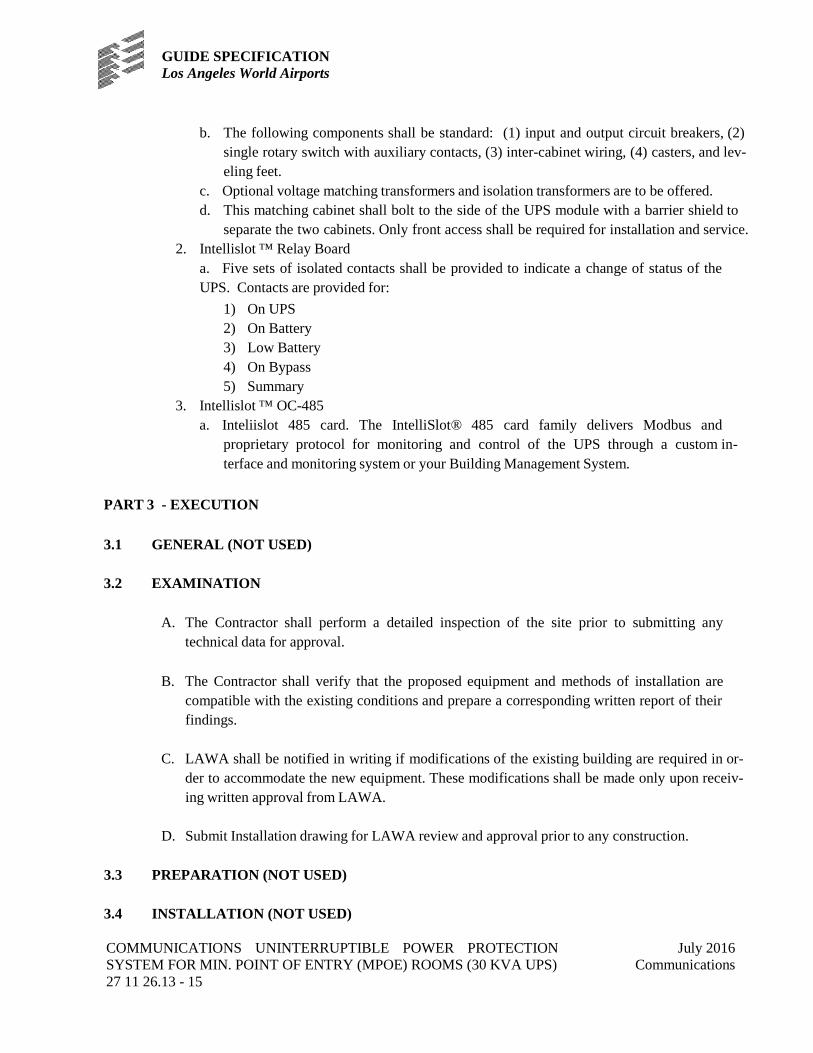
GUIDE SPECIFICATION Los Angeles World Airports
COMMUNICATIONS UNINTERRUPTIBLE POWER PROTECTION SYSTEM FOR MIN. POINT OF ENTRY (MPOE) ROOMS (30 KVA UPS) 27 11 26.13 - 15
July 2016 Communications
b. The following components shall be standard: (1) input and output circuit breakers, (2) single rotary switch with auxiliary contacts, (3) inter-cabinet wiring, (4) casters, and lev-eling feet.
c. Optional voltage matching transformers and isolation transformers are to be offered. d. This matching cabinet shall bolt to the side of the UPS module with a barrier shield to
separate the two cabinets. Only front access shall be required for installation and service. 2. Intellislot ™ Relay Board
a. Five sets of isolated contacts shall be provided to indicate a change of status of the UPS. Contacts are provided for:
1) On UPS 2) On Battery 3) Low Battery 4) On Bypass 5) Summary
3. Intellislot ™ OC-485 a. Inteliislot 485 card. The IntelliSlot® 485 card family delivers Modbus and
proprietary protocol for monitoring and control of the UPS through a custom in-terface and monitoring system or your Building Management System.
PART 3 - EXECUTION
3.1 GENERAL (NOT USED)
3.2 EXAMINATION
A. The Contractor shall perform a detailed inspection of the site prior to submitting any
technical data for approval.
B. The Contractor shall verify that the proposed equipment and methods of installation are compatible with the existing conditions and prepare a corresponding written report of their findings.
C. LAWA shall be notified in writing if modifications of the existing building are required in or-
der to accommodate the new equipment. These modifications shall be made only upon receiv-ing written approval from LAWA.
D. Submit Installation drawing for LAWA review and approval prior to any construction.
3.3 PREPARATION (NOT USED)
3.4 INSTALLATION (NOT USED)

GUIDE SPECIFICATION Los Angeles World Airports
COMMUNICATIONS UNINTERRUPTIBLE POWER PROTECTION SYSTEM FOR MIN. POINT OF ENTRY (MPOE) ROOMS (30 KVA UPS) 27 11 26.13 - 16
July 2016 Communications
3.5 FIELD QUALITY CONTROL - TESTING
A. Site Test and inspections
1. Field Inspection – The following inspections and test procedures shall be performed by fac-tory-trained field service personnel during the UPS startup. a. Visual Inspection
1) Inspect equipment for signs of damage 2) Verify installation per drawings 3) Inspect cabinet for foreign objects 4) Verify neutral and ground conductors are properly sized and configured 5) Inspect battery cases 6) Inspect battery for proper polarity 7) Verify all printed circuit boards are configured properly
c. Mechanical Inspection: 1) Check all control wiring connections for tightness 2) Check all power wiring connections for tightness 3) Check all terminals screws, nuts and/or spade lungs for tightness
d. Electrical Inspection: 1) Check all fuses for continuity 2) Confirm input voltage and phase rotation is correct 3) Verify control transformer connections are correct for voltages being used. 4) Assure connection and voltage of the battery string(s) B. Non-Conforming Work
3.6 CLEANING (NOT USED)
3.8 IDENTIFICATION AND LABELING
IT Infrastructure Standards of Practice Volume 3, Chapter 1.
3.9 CLOSEOUT ACTIVITIES - ACCEPTANCE
A. Acceptance
1. Completion of the installation, in-progress and final inspections, receipt of the test and as-built documentation including data input of all installed cables in the LAWA management system and successful performance of the UPS and cabling system for a two-week period will constitute acceptance of the system. Upon successful completion of the installation and subsequent inspection, LAWA shall be provided with a numbered certificate from the Manufacturer registering the installation.
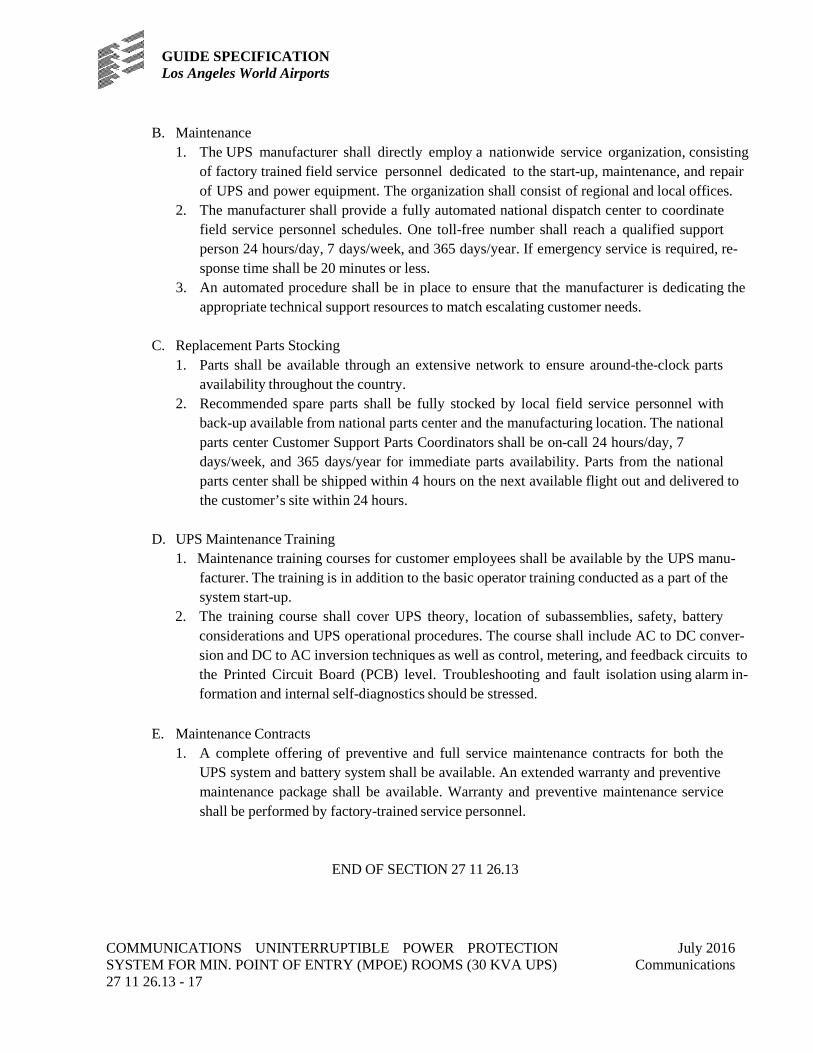
GUIDE SPECIFICATION Los Angeles World Airports
COMMUNICATIONS UNINTERRUPTIBLE POWER PROTECTION SYSTEM FOR MIN. POINT OF ENTRY (MPOE) ROOMS (30 KVA UPS) 27 11 26.13 - 17
July 2016 Communications
B. Maintenance 1. The UPS manufacturer shall directly employ a nationwide service organization, consisting
of factory trained field service personnel dedicated to the start-up, maintenance, and repair of UPS and power equipment. The organization shall consist of regional and local offices.
2. The manufacturer shall provide a fully automated national dispatch center to coordinate field service personnel schedules. One toll-free number shall reach a qualified support person 24 hours/day, 7 days/week, and 365 days/year. If emergency service is required, re-sponse time shall be 20 minutes or less.
3. An automated procedure shall be in place to ensure that the manufacturer is dedicating the appropriate technical support resources to match escalating customer needs.
C. Replacement Parts Stocking
1. Parts shall be available through an extensive network to ensure around-the-clock parts availability throughout the country.
2. Recommended spare parts shall be fully stocked by local field service personnel with back-up available from national parts center and the manufacturing location. The national parts center Customer Support Parts Coordinators shall be on-call 24 hours/day, 7 days/week, and 365 days/year for immediate parts availability. Parts from the national parts center shall be shipped within 4 hours on the next available flight out and delivered to the customer’s site within 24 hours.
D. UPS Maintenance Training
1. Maintenance training courses for customer employees shall be available by the UPS manu-facturer. The training is in addition to the basic operator training conducted as a part of the system start-up.
2. The training course shall cover UPS theory, location of subassemblies, safety, battery considerations and UPS operational procedures. The course shall include AC to DC conver-sion and DC to AC inversion techniques as well as control, metering, and feedback circuits to the Printed Circuit Board (PCB) level. Troubleshooting and fault isolation using alarm in-formation and internal self-diagnostics should be stressed.
E. Maintenance Contracts
1. A complete offering of preventive and full service maintenance contracts for both the UPS system and battery system shall be available. An extended warranty and preventive maintenance package shall be available. Warranty and preventive maintenance service shall be performed by factory-trained service personnel.
END OF SECTION 27 11 26.13

GUIDE SPECIFICATION Los Angeles World Airports
COMMUNICATIONS RACK MOUNTED UNINTERRUPTIBLE POWER PROTECTION SYSTEM (20 KVA UPS) 27 11 26.16 - 1
July 2016 Communications
SECTION 27 11 26.16 COMMUNICATIONS RACK MOUNTED UNINTERRUPTIBLE POWER PROTECTION SYSTEM (20 KVA UPS) FOR TELECOMMUNICATION ROOMS
PART 1 - GENERAL
1.1 SUMMARY
A. See IT Infrastructure Standards of Practice Volume 1, Chapter 2; and Chapter 3, Appen-
dices. B. This specification defines the electrical and mechanical characteristics and requirements for
a continuous-duty three-phase, solid-state, uninterruptible power system (UPS). The UPS shall provide high-quality AC power for sensitive electronic equipment loads. This specifi-cation provides requirements for the following options: 1. Option #1: Telecom Room UPS Requirement: 20 kVA, Electrical 208V 2. Option #2: Telecom Room UPS Requirement: 20 kVA, Electrical 480V
C. All references to model numbers and other pertinent information herein are intended to es-
tablish standards of performance, quality and construction. These model numbers are based on equipment manufactured by Liebert. Equivalent products may be considered if ade-quate information is submitted to the specifying engineer for approval beforehand. Verify latest model supported by LAWA within 6 months of installation.
D. Related documents included in the specification requirements:
1. Section 01 11 00 – Summary of Work 2. Section 01 25 00 – Substitution Procedure 3. Section 01 31 00 – Administrative Requirements 4. Section 01 33 00 – Submittal 5. Section 01 40 00 – Quality Requirements 6. Section 01 43 00 – Quality Assurance 7. Section 01 64 00 – Owner Furnished Products 8. Section 01 77 13 – Preliminary Closeout Reviews 9. Section 01 77 16 – Final Closeout Review 10. Section 01 78 00 – Close Out Submittals 11. Section 27 05 00 – Basic Telecommunication Requirements
1.2 PRICE AND PAYMENT PROCEDURES (NOT USED)
1.3 REFERENCES
A. Standards

GUIDE SPECIFICATION Los Angeles World Airports
COMMUNICATIONS RACK MOUNTED UNINTERRUPTIBLE POWER PROTECTION SYSTEM (20 KVA UPS) 27 11 26.16 - 2
July 2016 Communications
1. The UPS shall be designed in accordance with the applicable sections of the cur-rent revision of the following documents. Where a conflict arises between these docu-ments and statements made herein, the statements in this specification shall govern. a. ASME b. CSA 22.2, No. 107.1 c. FCC Part 15, Class A d. IEC 1000-4-5 e. ISO 9001 f. National Electrical Code (NFPA-70) g. NEMA PE-1 h. OSHA i. UL Standard 1778
2. The UPS shall be UL listed per UL Standard 1778, and shall be CSA certified.
1.4 ADMINISTRATIVE REQUIREMENTS (NOT USED)
1.5 SUBMITTALS
A. Proposal Submittals with the proposal shall include: 1. System configuration with single-line diagrams. 2. Functional relationship of equipment including weights, dimensions, and heat dissipa-
tion. 3. Descriptions of equipment to be furnished, including deviations from these specifica-
tions. 4. Size and weight of shipping units to be handled by installing contractor. 5. Detailed layouts of customer power and control connections. 6. Detailed installation drawings including all terminal locations.
B. Action Submittals
1. Submittals upon UPS delivery shall include a complete set of submittal drawings and one (1) set of instruction manuals that shall include a functional description of the equipment with block diagrams, safety precautions, instructions, step-by-step operating procedures and routine maintenance guidelines, including illustrations.
1.6 QUALITY ASSURANCE
A. A minimum of twenty years’ experience in the design, manufacture, and testing of solid-
state UPS systems is required. The system shall be designed and manufactured according to world class quality standards. The manufacturer shall be ISO 9001 certified.

GUIDE SPECIFICATION Los Angeles World Airports
COMMUNICATIONS RACK MOUNTED UNINTERRUPTIBLE POWER PROTECTION SYSTEM (20 KVA UPS) 27 11 26.16 - 3
July 2016 Communications
B. Before shipment, the manufacturer shall fully and completely test the system to assure
compliance with the specification.
1.7 SUBSTITUTION OF EQUIPMENT
A. Approval of alternate or substitute equipment or material in no way voids Specification re-quirements.
B. Under no circumstances shall the LAWA be required to prove that an item proposed for
substitution is not equal to the specified item. It shall be mandatory that the Contrac-tor submits to Engineer all evidence to support the contention that the item proposed for substitution is equal to the specified item. The Owner’s decision as to the equality of sub-stitution shall be final and without further recourse.
C. In the event that the Design Consultant is required to provide additional engineering ser-
vices as a result of substitution of equivalent materials or equipment by the Contractor, or changes by the Contractor in dimension, weight, power requirements, etc., of the equip-ment and accessories furnished, or if the Design Consultant is required to examine and evaluate any changes proposed by the Contractor for the convenience of the Contractor, then the Design Consultant’s expenses in connection with such additional services shall be paid by the Contractor and may be deducted from any moneys owed to the Contractor.
1.8 DELIVERY, STORAGE AND HANDLING
A. Submit manufacturers’ instructions for storage, handling, protection, examination, prepa-
ration, operation, and installation of all products. Include any application conditions or limitations of use stipulated by any product testing agency.
1.9 FIELD/SITE AND ENVIRONMENT CONDITIONS
A. The UPS shall be able to withstand the following environmental conditions without dam-
age or degradation of operating characteristics: 1. Operating Ambient Temperature
a. UPS Module: 32°F to 104°F (0°C to 40°C). b. Battery: 77°F±9°F (25°C ±5°C).
2. Storage/Transport Ambient Temperature a. UPS Module: -4°F to 158°F (-20°C to 70°C). b. Battery: -4°F to 92°F (-20°C to 33°C)
3. Relative Humidity - 0 to 95%, non-condensing
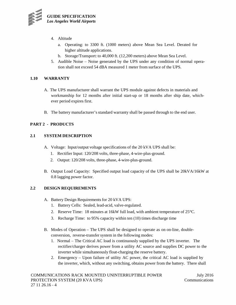
GUIDE SPECIFICATION Los Angeles World Airports
COMMUNICATIONS RACK MOUNTED UNINTERRUPTIBLE POWER PROTECTION SYSTEM (20 KVA UPS) 27 11 26.16 - 4
July 2016 Communications
4. Altitude a. Operating: to 3300 ft. (1000 meters) above Mean Sea Level. Derated for
higher altitude applications. b. Storage/Transport: to 40,000 ft. (12,200 meters) above Mean Sea Level.
5. Audible Noise – Noise generated by the UPS under any condition of normal opera-tion shall not exceed 54 dBA measured 1 meter from surface of the UPS.
1.10 WARRANTY
A. The UPS manufacturer shall warrant the UPS module against defects in materials and
workmanship for 12 months after initial start-up or 18 months after ship date, which-ever period expires first.
B. The battery manufacturer’s standard warranty shall be passed through to the end user.
PART 2 - PRODUCTS
2.1 SYSTEM DESCRIPTION
A. Voltage: Input/output voltage specifications of the 20 kVA UPS shall be:
1. Rectifier Input: 120/208 volts, three-phase, 4-wire-plus-ground. 2. Output: 120/208 volts, three-phase, 4-wire-plus-ground.
B. Output Load Capacity: Specified output load capacity of the UPS shall be 20kVA/16kW at
0.8 lagging power factor.
2.2 DESIGN REQUIREMENTS
A. Battery Design Requirements for 20 kVA UPS: 1. Battery Cells: Sealed, lead-acid, valve-regulated. 2. Reserve Time: 18 minutes at 16kW full load, with ambient temperature of 25°C. 3. Recharge Time: to 95% capacity within ten (10) times discharge time
B. Modes of Operation – The UPS shall be designed to operate as on on-line, double-
conversion, reverse-transfer system in the following modes: 1. Normal – The Critical AC load is continuously supplied by the UPS inverter. The
rectifier/charger derives power from a utility AC source and supplies DC power to the inverter while simultaneously float-charging the reserve battery.
2. Emergency – Upon failure of utility AC power, the critical AC load is supplied by the inverter, which, without any switching, obtains power from the battery. There shall

GUIDE SPECIFICATION Los Angeles World Airports
COMMUNICATIONS RACK MOUNTED UNINTERRUPTIBLE POWER PROTECTION SYSTEM (20 KVA UPS) 27 11 26.16 - 5
July 2016 Communications
be no interruption in power to the critical load upon failure or restoration of the utility AC source.
3. Recharge – Upon restoration of utility AC power, after a utility AC power outage, the rectifier/charger shall automatically restart, walk-in, and gradually assume the inverter and battery recharge loads.
4. Bypass – If the UPS must be taken out of service for maintenance or repair, or should the inverter overload capacity be exceeded, the static transfer switch shall perform a reverse transfer of the load from the inverter to the bypass source with no interruption in power to the critical AC load.
2.3 PERFORMANCE REQUIREMENTS
A. AC Input to UPS
1. Voltage Configuration for Standard Units: three-phase, 4-wire plus ground. 2. Voltage Range: +10%, -20% of nominal. 3. Frequency: Nominal frequency 5%. 4. Power Factor: Up to 0.99 lagging at nominal input voltage and full rated UPS out-
put load. 5. Inrush Current: 800% of full load current maximum. 6. Current Limit: 125% of nominal AC input current maximum. 7. Input Current Walk-In: 20 seconds to full rated input current maximum. Field se-
lectable 5 through 20 seconds. 8. Current Distortion: 4% reflected THD maximum at full load. 9. Surge Protection: Sustains input surges without damage per criteria listed in IEC 1000-
4-5.
B. AC Output, UPS Inverter 1. Voltage Configuration: three-phase, 4-wire plus ground. 2. Voltage Regulation:
a. ±1% three-phase RMS average for a balanced three-phase load for the com-bined variation effects of input voltage, connected load, battery voltage, ambient temperature, and load power factor.
b. ±2% three-phase RMS average for a 100% unbalanced load for the com-bined variation effects of input voltage, connected load, battery voltage, ambient temperature, and load power factor.
3. Frequency: Nominal frequency ±0.1%. 4. Frequency Slew Rate: 1.0 Hertz per second maximum. Field selectable from 0.1 to
1.0Hz per second. 5. Phase Displacement:
a. ±0.5 degree for balanced load.
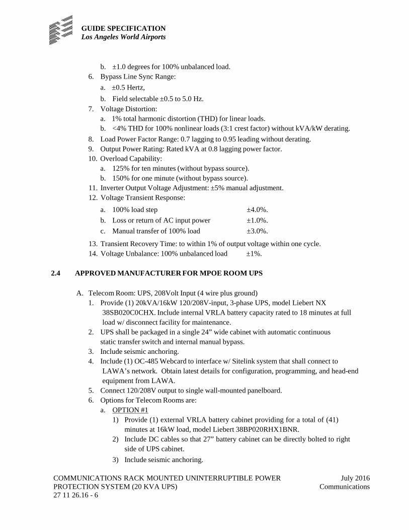
GUIDE SPECIFICATION Los Angeles World Airports
COMMUNICATIONS RACK MOUNTED UNINTERRUPTIBLE POWER PROTECTION SYSTEM (20 KVA UPS) 27 11 26.16 - 6
July 2016 Communications
b. ±1.0 degrees for 100% unbalanced load. 6. Bypass Line Sync Range:
a. ±0.5 Hertz, b. Field selectable ±0.5 to 5.0 Hz.
7. Voltage Distortion: a. 1% total harmonic distortion (THD) for linear loads. b. <4% THD for 100% nonlinear loads (3:1 crest factor) without kVA/kW derating.
8. Load Power Factor Range: 0.7 lagging to 0.95 leading without derating. 9. Output Power Rating: Rated kVA at 0.8 lagging power factor. 10. Overload Capability:
a. 125% for ten minutes (without bypass source). b. 150% for one minute (without bypass source).
11. Inverter Output Voltage Adjustment: ±5% manual adjustment. 12. Voltage Transient Response:
a. 100% load step ±4.0%. b. Loss or return of AC input power ±1.0%. c. Manual transfer of 100% load ±3.0%.
13. Transient Recovery Time: to within 1% of output voltage within one cycle. 14. Voltage Unbalance: 100% unbalanced load ±1%.
2.4 APPROVED MANUFACTURER FOR MPOE ROOM UPS
A. Telecom Room: UPS, 208Volt Input (4 wire plus ground)
1. Provide (1) 20kVA/16kW 120/208V-input, 3-phase UPS, model Liebert NX 38SB020C0CHX. Include internal VRLA battery capacity rated to 18 minutes at full load w/ disconnect facility for maintenance.
2. UPS shall be packaged in a single 24” wide cabinet with automatic continuous static transfer switch and internal manual bypass.
3. Include seismic anchoring. 4. Include (1) OC-485 Webcard to interface w/ Sitelink system that shall connect to
LAWA’s network. Obtain latest details for configuration, programming, and head-end equipment from LAWA.
5. Connect 120/208V output to single wall-mounted panelboard. 6. Options for Telecom Rooms are:
a. OPTION #1 1) Provide (1) external VRLA battery cabinet providing for a total of (41)
minutes at 16kW load, model Liebert 38BP020RHX1BNR. 2) Include DC cables so that 27” battery cabinet can be directly bolted to right
side of UPS cabinet. 3) Include seismic anchoring.
GUIDE SPECIFICATION Los Angeles World Airports
COMMUNICATIONS RACK MOUNTED UNINTERRUPTIBLE POWER PROTECTION SYSTEM (20 KVA UPS) 27 11 26.16 - 7
July 2016 Communications
b. OPTION #2
1) Provide (1) external maintenance bypass cabinet, model Liebert 38MB0200CC6AL.
2) Include interconnecting cables for bolting to left side of UPS. 3) Cabinet shall be 27” wide with single rotary switch interlocked for make-
before- break manual transfers. 4) Include seismic anchoring.
B. Telecom Room UPS, 480Volt Input (3 wire plus ground)
1. Provide (1) 20kVA/16kW 480V-input, 120/208v output, 3-phase UPS. Model Liebert NX 38SB020C0CHX.
2. Include internal VRLA battery capacity rated to 18 minutes at full load w/ discon-nect facility for maintenance.
3. UPS shall be packaged in a single 24” wide cabinet with automatic continuous static transfer switch and internal manual bypass.
4. Include (1) OC-485 Webcard to interface w/ Sitelink system. 5. Include (1) external maintenance bypass/transformer cabinet, model Liebert
38MB0200AC6DL. 6. Include interconnecting cables for bolting to left side of UPS. 7. Cabinet shall be 27” wide with 480V input isolation transformer and single rotary
switch interlocked for making before-break manual transfers. 8. Include seismic anchoring for both cabinets. 9. Connect 120/208V UPS output to single wall mounted panelboard. 10. Option for Telecom Room:
1) Provide (1) external VRLA battery cabinet providing for a total of (41) minutes at 16kW load, model Liebert 38BP020RHX1BNR.
2) Include DC cables so that 27” battery cabinet can be directly bolted to right side of UPS cabinet.
3) Include seismic anchoring.
Note: All references to model numbers and other pertinent information herein are intended to estab-lish standards of performance, quality and construction. These model numbers are based on equip-ment manufactured by Liebert. Equivalent Liebert products may be considered if adequate information is submitted to the specifying engineer for approval beforehand. Verify Liebert models supported by LAWA 6 months prior to installation.
GUIDE SPECIFICATION Los Angeles World Airports
COMMUNICATIONS RACK MOUNTED UNINTERRUPTIBLE POWER PROTECTION SYSTEM (20 KVA UPS) 27 11 26.16 - 8
July 2016 Communications
2.5 FABRICATION
A. Materials 1. All materials of the UPS shall be new, of current manufacture, high grade and free
from all defects and shall not have been in prior service except as required during fac-tory testing.
2. The maximum working voltage, current, and di/dt of all solid-state power compo-nents and electronic devices shall not exceed 75% of the ratings established by their manufacturer. The operating temperature of solid-state component sub-assembly shall not be greater than 75% of their ratings. Electrolytic capacitors shall be computer grade and be operated at no more than 95% of their voltage rating at the maximum rectifier charging voltage.
B. Wiring
1. Wiring practices, materials and coding shall be in accordance with the requirements of the National Electrical Code (NFPA 70). All bolted connections of bus bars, lugs, and cables shall be in accordance with requirements of the National Electrical Code and other applicable standards. All electrical power connections are to be torqued to the required value and marked with a visual indicator.
2. Provision shall be made for power cables to enter or leave from the top or bottom of the UPS cabinet.
C. Construction and Mounting
1. The UPS unit, comprised of an input circuit breaker, rectifier/charger, inverter, static transfer switch and maintenance bypass switch, shall be housed in a single free-standing NEMA type 1 enclosure. Cabinet doors/covers shall require a tool for gaining access. Casters and stops shall be provided for ease of installation. Front access only shall be required for expedient servicing and adjustments. The UPS cabi-net shall be structurally adequate and have provisions for hoisting, jacking, and forklift handling.
2. The UPS cabinet shall be cleaned, primed, and painted with the manufacturer’s stand-ard color. The UPS shall be constructed of replaceable subassemblies. Printed circuit assemblies shall be plug connections. Like assemblies and like components shall be interchangeable.
D. Cooling
1. Cooling of the UPS shall be by forced air. Low-velocity fans shall be used to mini-mize audible noise output. Fan power shall be provided by the UPS output. There shall be redundant fans.
GUIDE SPECIFICATION Los Angeles World Airports
COMMUNICATIONS RACK MOUNTED UNINTERRUPTIBLE POWER PROTECTION SYSTEM (20 KVA UPS) 27 11 26.16 - 9
July 2016 Communications
2. The thermal design, along with all thermal and ambient sensors, shall be coordinated with the protective devices before excessive component or internal cabinet tempera-tures are exceeded.
E. Grounding
1. The AC output neutral shall be electrically isolated from the UPS chassis. The UPS chassis shall have an equipment ground terminal. Provisions for local bonding shall be provided.
2.6 COMPONENTS
A. Rectifier/Charger
1. General a. The term rectifier/charger shall denote the solid-state equipment and controls nec-
essary to convert incoming AC power to regulated DC power for input to the in-verter and for battery charging. The rectifier/charger shall be a solid-state SCR/IGBT type with constant voltage/current limiting control circuitry.
2. AC Input Current Limiting a. The rectifier/charger unit shall be provided with AC input current limiting
whereby the maximum input current shall be limited to 125% of the full input cur-rent rating. The rectifier/charger shall operate at a reduced current limit mode whenever the critical load is powered from the UPS static bypass circuit such that the maximum UPS input current will not exceed 125% of full load input current. In addition, the rectifier/charger shall have a battery current limit, adjustable from 0 to 25% of the full load input current.
3. Input Current Walk-In a. The rectifier/charger shall contain a timed walk-in circuit that causes the unit
to gradually assume the load over a 20-second time interval after input voltage is applied. Walk-in time shall be field selectable for 5 through 20 seconds.
4. DC Filter a. The rectifier/charger shall have a filter to minimize ripple voltage into the bat-
tery. Under no conditions shall ripple voltage into the battery exceed 1% RMS. The filter shall be adequate to ensure that the DC output of the rectifier/charger will meet the input requirements of the inverter. The inverter shall be able to oper-ate from the rectifier/charger with the battery disconnected.
5. Automatic Rectifier Restart a. Upon restoration of utility AC power, after a utility AC power outage and prior to
a UPS automatic end-of-discharge shutdown, the rectifier/charger shall automati-cally restart, walk-in, and gradually assume the inverter and battery recharge loads.

GUIDE SPECIFICATION Los Angeles World Airports
COMMUNICATIONS RACK MOUNTED UNINTERRUPTIBLE POWER PROTECTION SYSTEM (20 KVA UPS) 27 11 26.16 - 10
July 2016 Communications
6. Battery Recharge a. In addition to supplying power for the inverter load, the rectifier/charger shall
be capable of producing battery charging current sufficient to replace 95% of the battery discharge power within ten (10) times the discharge time. After the battery is recharged, the rectifier/charger shall maintain the battery at full charge until the next emergency operation.
7. Overvoltage Protection a. There shall be DC over-voltage protection so that if the DC voltage rises to the
pre- set limit, the UPS is to shut down automatically and initiate an uninterrupt-ed load transfer to the static bypass line.
B. Inverter
1. General a. The term inverter shall denote the solid-state equipment and controls to convert
DC power from the rectifier/charger or battery to regulated AC power for support-ing the critical load. The inverter shall use Insulated Gate Bipolar Transistors (IG-BTs) in a phase-controlled, pulse width modulated (PWM) design capable of providing the specified AC output.
2. Overload Capability a. The inverter shall be capable of supplying current and voltage for overloads
exceeding 100%. The inverter is to provide 150% of full load for 1 minute and 125% of full load for 10 minutes. A status indicator and audible alarm shall indi-cate overload operation. The UPS shall transfer the load to bypass when overload capacity is exceeded.
3. Fault Clearing and Current Limit a. The inverter shall be capable of supplying an overload current of 150% of its
full- load rating for one minute. For greater currents or longer time duration, the inverter shall have electronic current-limiting protection to prevent damage to components. The critical load will be transferred to the static bypass automatically and uninterrupted. The inverter shall be self-protecting against any magnitude of connected output overload. Inverter control logic shall sense and disconnect the inverter from the critical AC load without the requirement to clear protective fuses.
4. Step Load Response a. The output voltage shall be maintained to within ±4% with a 0-to-100% step
load change or a 100%-to-0 step load change. The output voltage shall recover to within 1% of nominal voltage within 1 cycle.
5. Voltage Distortion a. For linear loads, the output voltage total harmonic distortion (THD) shall not
be greater than 1%. For 100% rated load of 3:1 crest factor nonlinear loads, the output voltage total harmonic distortion shall not be greater than 4%. The output

GUIDE SPECIFICATION Los Angeles World Airports
COMMUNICATIONS RACK MOUNTED UNINTERRUPTIBLE POWER PROTECTION SYSTEM (20 KVA UPS) 27 11 26.16 - 11
July 2016 Communications
rating is not to be derated in kVA nor kW due to the 100% nonlinear load with 3:1 crest factor.
6. Phase Balance a. Electronic controls shall be provided to regulate each phase so that an unbal-
anced loading will not cause the output voltage to go outside the specified voltage unbalance or phase displacement. With 100% load on one phase and 0% load on the other 2 phases or 100% load on 2 phases and 0% load on the other phase, the voltage balance is to be within 2% and the phase displacement is to be 120 degrees within ±1 degree.
7. Fuse Failure Protection a. Power semiconductors in the inverter unit shall be fused with fast-acting fuses,
so that loss of any one power semiconductor will not cause cascading failures. 8. Inverter Shutdown
a. For rapid removal of the inverter from the critical load, the inverter con-trol electronics shall instantaneously turn off the inverter transistors. Simultane-ously, the static transfer switch shall be turned on to maintain continuous power to the critical load.
9. Inverter DC Protection a. The inverter shall be protected by the following disconnect levels:
1) DC Overvoltage Shutdown 2) DC Undervoltage Warning (Low Battery Reserve), adjustable 3) DC Undervoltage Shutdown (End of Discharge)
10. Inverter Output Voltage Adjustment a. The inverter shall use a software control to adjust the output voltage from ±5% of
the nominal value. 11. Output Frequency
a. The output frequency of the inverter shall be controlled by an oscillator. The oscillator shall be temperature compensated and hold the inverter output fre-quency to 0.1% for steady state and transient conditions. Drift shall not exceed 0.1% during a 24-hour period. Total frequency deviation, including short time fluc-tuations and drift, shall not exceed 0.1% from the rated frequency.
C. Display and Controls
1. Monitoring and Control a. The UPS shall be provided with a microprocessor based unit status display
and controls section designed for convenient and reliable user operation. A graph-ical display shall be used to show a single-line diagram of the UPS, and shall be provided as part of the monitoring and controls sections of the UPS. All of the operator controls and monitors shall be located on the front of the UPS cabinet. The monitoring functions such as metering, status and alarms shall be
GUIDE SPECIFICATION Los Angeles World Airports
COMMUNICATIONS RACK MOUNTED UNINTERRUPTIBLE POWER PROTECTION SYSTEM (20 KVA UPS) 27 11 26.16 - 12
July 2016 Communications
displayed on the graphical LCD display. Additional features of the monitoring sys-tem shall include: 1) Alarm history with time and date stamp 2) Battery backed-up memory 3) Menu-driven display with pushbutton navigation 4) Real time clock (time and date)
2. Metering a. The following parameters shall be displayed:
1) Active power 2) Apparent power 3) Battery charge/discharge current 4) Battery time left during battery operation 5) Battery voltage 6) Input AC current for each phase 7) Input AC voltage line-to-line 8) Input frequency 9) Output AC current for each phase 10) Output AC voltage line-to-line and line-to-neutral for each phase 11) Output frequency
3. Alarm Messages a. The following alarm messages shall be displayed:
1) Battery charger problem 2) Battery failed test 3) Bypass frequency out of range 4) Control error 5) Critical power supply failure 6) DC bus overvoltage 7) Excessive retransfers attempted 8) External shutdown (remote EPO activated) 9) Fan failure 10) Input power out of tolerance 11) Load transferred due to internal protection 12) Load transferred to bypass 13) Load transferred to bypass due to overload 14) Low battery shutdown 15) Low battery warning 16) Output overcurrent 17) Output overvoltage 18) Output undervoltage 19) Overload shutdown

GUIDE SPECIFICATION Los Angeles World Airports
COMMUNICATIONS RACK MOUNTED UNINTERRUPTIBLE POWER PROTECTION SYSTEM (20 KVA UPS) 27 11 26.16 - 13
July 2016 Communications
20) Overtemperature shutdown 21) Overtemperature shutdown impending 22) Static switch failure 23) System output overloaded 24) UPS output not synchronized to bypass power
b. An audible alarm shall be provided and activated by any of the above alarm condi-tions.
4. Status Messages a. The following UPS status messages shall be displayed:
1) Load on maintenance bypass 2) Load on static bypass 3) Load on UPS 4) Normal operation 5) System shutdown 6) UPS on battery
5. Controls a. UPS start-up, shutdown, and maintenance bypass operations shall be accom-
plished through the front-panel pushbutton controls. Menu-driven user prompts shall be provided to guide the operator through system operation without the use of additional manuals. Pushbuttons shall be provided to display the status of the UPS and to test and reset visual and audible alarms. A mimic screen shall be available on the LCD screen to depict a single-line diagram of the UPS, with switch positions and power flow.
6. On-Line Battery Test a. The UPS shall be provided with a menu-driven On-Line Battery Test feature.
The test shall ensure the capability of the battery to supply power to the inverter while the load is supplied power in the normal mode.
D. Static Transfer Switch
1. General a. A static transfer switch and bypass circuit shall be provided as an integral part of
the UPS. The static switch shall be a naturally commutated high-speed static (SCR-type) device rated to conduct full load current continuously. The switch shall have an overload rating to clear a 20-ampere load branch circuit breaker.
b. The static transfer switch control logic shall contain an automatic transfer control circuit that senses the status of the inverter logic signals, and operating and alarm conditions. This control circuit shall provide an uninterrupted transfer of the load to an alternate bypass source, without exceeding the transient limits specified herein, when an overload or malfunction occurs within the UPS, or for bypassing the UPS for maintenance.
2. Uninterrupted Transfer

GUIDE SPECIFICATION Los Angeles World Airports
COMMUNICATIONS RACK MOUNTED UNINTERRUPTIBLE POWER PROTECTION SYSTEM (20 KVA UPS) 27 11 26.16 - 14
July 2016 Communications
a. The transfer control logic shall automatically turn on the static transfer switch, transferring the critical AC load to the bypass source, after the transfer logic sens-es any of the following conditions: 1) Battery protection period expired 2) Critical AC load overvoltage or undervoltage 3) Inverter overload capacity exceeded 4) UPS fault condition
b. The transfer control logic shall inhibit an automatic transfer of the critical load to the bypass source if any of the following conditions are present: 1) Inverter/bypass voltage difference exceeding preset limits 2) Bypass frequency out-of-limits 3) Bypass out-of-synchronization range with inverter output
3. Uninterrupted Retransfer a. Retransfer of the critical AC load from the bypass source to the inverter output
shall be automatically initiated unless inhibited by manual control. The transfer control logic shall inhibit an automatic retransfer of the critical load to the inverter if one of the following conditions exists: 1) Bypass out of synchronization range with inverter output 2) Inverter/bypass voltage difference exceeding preset limits 3) Overload conditions exist in excess of inverter full load rating 4) UPS fault condition present
E. Maintenance Bypass Switch
1. General a. A manually operated maintenance bypass switch shall be incorporated into the
UPS cabinet to directly connect the critical load to the bypass AC input power source, bypassing the rectifier/charger, inverter, and static transfer switch.
2. Isolation a. All energized terminals shall be shielded to ensure that maintenance personnel do
not inadvertently come in contact with energized parts or terminals. A means to de- energize the static switch shall be provided when the UPS is in the mainte-nance bypass mode of operation.
3. Maintenance Capability a. With the critical load powered from the maintenance bypass circuit, it shall
be possible to check out the operation of the rectifier/charger, inverter, battery, and static transfer switch. When the application calls for the Maintenance Bypass Switch to be bolted to the UPS cabinet, the interconnecting cables are to be pro-vided, precut and prelugged.
4. Battery Power Pack a. The battery power pack shall include sealed, lead-acid valve regulated battery
cells housed in a separate cabinet that matches the UPS cabinet styling to form an

GUIDE SPECIFICATION Los Angeles World Airports
COMMUNICATIONS RACK MOUNTED UNINTERRUPTIBLE POWER PROTECTION SYSTEM (20 KVA UPS) 27 11 26.16 - 15
July 2016 Communications
integral system line-up. Battery cells shall be mounted on slide-out trays for ease of maintenance. A battery disconnect circuit breaker shall be included for isola-tion of the battery pack from the UPS module. The UPS shall automatically be dis-connected from the battery when the battery reaches the minimum discharge volt-age level. Casters and leveling feet shall also be provided with the battery power pack cabinet for ease of installation. When the application calls for the battery cab-inet to be bolted to the UPS cabinet, the interconnecting cables are to be provided, precut and prelugged.
F. Accessories (Optional Equipment)
1. Optional External Maintenance Bypass Cabinet a. A matching external maintenance bypass cabinet shall be provided to enable the
UPS module to be completely isolated from the electrical system while the critical load is powered through the external maintenance bypass line. This optional cabinet shall provide make-before-break operation for transfers to and from the external maintenance bypass line with a single rotary switch.
b. The following components shall be standard: (1) input and output circuit break-ers, (2) single rotary switch with auxiliary contacts, (3) inter-cabinet wiring, (4) casters, and leveling feet.
c. Optional voltage matching transformers and isolation transformers are to be offered. d. This matching cabinet shall bolt to the side of the UPS module with a barrier
shield to separate the two cabinets. Only front access shall be required for installa-tion and service.
2. Intellislot ™ Relay Board a. Five sets of isolated contacts shall be provided to indicate a change of status of
the UPS. Contacts are provided for: 1) On UPS 2) On Battery 3) Low Battery 4) On Bypass 5) Summary
3. Intellislot ™ OC-485 a. Inteliislot 485 card. The IntelliSlot® 485card family delivers Modbus and pro-
prietary protocol for monitoring and control of the UPS through a custom interface and monitoring system or your Building Management System.

GUIDE SPECIFICATION Los Angeles World Airports
COMMUNICATIONS RACK MOUNTED UNINTERRUPTIBLE POWER PROTECTION SYSTEM (20 KVA UPS) 27 11 26.16 - 16
July 2016 Communications
PART 3 - EXECUTION
3.1 GENERAL
3.2 EXAMINATION
A. The Contractor shall perform a detailed inspection of the site prior to submitting any technical data for approval.
B. The Contractor shall verify that the proposed equipment and methods of installation
are compatible with the existing conditions and prepare a corresponding written report of their findings.
C. LAWA shall be notified in writing if modifications of the existing building are required
in order to accommodate the new equipment. These modifications shall be made only upon receiving written approval from LAWA.
D. Submit Installation drawing for LAWA review and approval prior to any construction.
3.3 PREPARATION (NOT USED)
3.4 INSTALLATION (NOT USED)
3.5 FIELD QUALITY CONTROL - TESTING
A. Site Test and inspections
1. Field Inspection – The following inspections and test procedures shall be performed by factory-trained field service personnel during the UPS startup. a. Visual Inspection
1) Inspect equipment for signs of damage 2) Verify installation per drawings 3) Inspect cabinet for foreign objects 4) Verify neutral and ground conductors are properly sized and configured 5) Inspect battery cases 6) Inspect battery for proper polarity 7) Verify all printed circuit boards are configured properly
b. Mechanical Inspection: 1) Check all control wiring connections for tightness 2) Check all power wiring connections for tightness 3) Check all terminals screws, nuts and/or spade lungs for tightness

GUIDE SPECIFICATION Los Angeles World Airports
COMMUNICATIONS RACK MOUNTED UNINTERRUPTIBLE POWER PROTECTION SYSTEM (20 KVA UPS) 27 11 26.16 - 17
July 2016 Communications
c. Electrical Inspection: 1) Check all fuses for continuity 2) Confirm input voltage and phase rotation is correct 3) Verify control transformer connections are correct for voltages being used. 4) Assure connection and voltage of the battery string(s) B. Non-Conforming
work
3.6 CLEANING (NOT USED)
3.7 COMPUTERIZED MAINTENANCE MANAGEMENT SYSTEM
A. Information regarding all equipment including model, nomenclature, serial number, func-tion, location, recommended preventative maintenance schedule, Quality Assurance In-spections and other pertinent data will be stored in the CMMS database. Contractor shall include in their Bid the cost for collecting and inputting this data for all cables, equipment and systems provided by this Contract into this database.
3.8 IDENTIFICATION AND LABELING
IT Infrastructure Standards of Practice Volume 3, Chapter 1.
3.9 CLOSEOUT ACTIVITIES-ACCEPTANCE
A. Acceptance 1. Completion of the installation, in-progress and final inspections, receipt of the test
and as-built documentation including data input of all installed cables in the LAWA management system and successful performance of the UPS and cabling system for a two-week period will constitute acceptance of the system. Upon successful comple-tion of the installation and subsequent inspection, LAWA shall be provided with a numbered certificate from the Manufacturer registering the installation.
B. Maintenance
1. The UPS manufacturer shall directly employ a nationwide service organization, con-sisting of factory trained field service personnel dedicated to the start-up, mainte-nance, and repair of UPS and power equipment. The organization shall consist of re-gional and local offices.
2. The manufacturer shall provide a fully automated national dispatch center to coordi-nate field service personnel schedules. One toll-free number shall reach a qualified support person 24 hours/day, 7 days/week, and 365 days/year. If emergency service is required, response time shall be 20 minutes or less.

GUIDE SPECIFICATION Los Angeles World Airports
COMMUNICATIONS RACK MOUNTED UNINTERRUPTIBLE POWER PROTECTION SYSTEM (20 KVA UPS) 27 11 26.16 - 18
July 2016 Communications
3. An automated procedure shall be in place to ensure that the manufacturer is dedicat-ing the appropriate technical support resources to match escalating customer needs.
C. Replacement Parts Stocking
1. Parts shall be available through an extensive network to ensure around-the-clock parts availability throughout the country.
2. Recommended spare parts shall be fully stocked by local field service personnel with back-up available from national parts center and the manufacturing location. The national parts center Customer Support Parts Coordinators shall be on-call 24 hours/day, 7 days/week, and 365 days/year for immediate parts availability. Parts from the national parts center shall be shipped within 4 hours on the next available flight out and delivered to the customer’s site within 24 hours.
D. UPS Maintenance Training
1. Maintenance training courses for customer employees shall be available by the UPS manufacturer. The training is in addition to the basic operator training conducted as a part of the system start-up.
2. The training course shall cover UPS theory, location of subassemblies, safety, bat-tery considerations and UPS operational procedures. The course shall include AC to DC conversion and DC to AC inversion techniques as well as control, metering, and feedback circuits to the Printed Circuit Board (PCB) level. Troubleshooting and fault isolation using alarm information and internal self-diagnostics should be stressed.
E. Maintenance Contracts
1. A complete offering of preventive and full service maintenance contracts for both the UPS system and battery system shall be available. An extended warranty and pre-ventive maintenance package shall be available. Warranty and preventive mainte-nance service shall be performed by factory-trained service personnel.
END OF SECTION 27 11 26.16

GUIDE SPECIFICATION Los Angeles World Airports
LOCAL AREA NETWORK 27 21 00 - 1
July 2016 Communications
SECTION 27 21 00 – LOCAL AREA NETWORK
PART 1 - GENERAL
1.1 SUMMARY
A. General: Los Angeles World Airports (LAWA) has deployed a large scale campus Wide Cisco Multi-Protocol Label Switching (MPLS) layer three networks with Cisco 6500E/6800 series core switches at two physically separate locations on the Airport. Individual Terminals and various other locations around the airport also have Cisco 6500E/6800 series switches that serve as distribution layer switches as well as the Campus MPLS provider edge switch-es. Telecommunication Rooms deploy Cisco 6500E/6800 distribution/provider edge switches. These switches contain 10GBASE-LR Blades and modules that accept uplinks from Cisco 3850/4500E series access switches. All assignments of distribution / PE switch ports are coordinated with LAWA.
B. Furnish and install new Access Layer PoE stackable switches with redundant power sup-
plies and voice gateways as shown on the contract drawings. Include all cabling between redundant power supplies and stackable switches. Include all stack-wise cabling for both switch-to-switch connections and for a wrap-around StackWise link from top to bot-tom switch in stack. Furnish and install SFP-10G-LR and X2-10G-LR adapters as shown on the contract drawings, both at the switch stack and at the blades at the distribution switches.
C. Furnish and install new industrial switches, expansion modules and power supplies as
shown on the contract drawings. Include DIN rail mounting for each switch, expansion module and power supply. Provide UL listed 120VAC US power cord for power sup-plies. Furnish and install two SFP 1000-base-LX adaptors in each switch with correspond-ing SFP modules at distribution switches. Each switch shall have dual power supplies pro-vided.
D. Coordinate with the Systems Manager and LAWA IT to develop a standard template con-
figuration for all Access Layer PoE stackable switches and industrial switches. Template shall include switch names, temporary password, spanning tree configuration, trunk config-uration, storm control, multi-tiered Quality of Service, multicast and disabling of unneces-sary services. Once approved by LAWA IT and the Systems Manager, apply templates to all switches.
E. Contractor shall work with LAWA to provide basic configuration for the switch stacks in-
cluding uplink trunks, Port-channel configuration, HSRP configuration, spanning tree con-figuration, quality of service, switch naming, passwords and disabling of unnecessary ser-
GUIDE SPECIFICATION Los Angeles World Airports
LOCAL AREA NETWORK 27 21 00 - 2
July 2016 Communications
vices for each concourse 3850 switch stack to ensure uniformity with similar LAWA switch stacks, configuration of access ports for end devices, as well as complete configura-tion of IE-3000 industrial switches.
F. Related documents included in the specification requirements: Section 01 11 00 – Summary of Work
Section 01 25 00 – Substitution Procedure Section 01 31 00 – Administrative Requirements Section 01 33 00 – Submittal Section 01 40 00 – Quality Requirements Section 01 43 00 – Quality Assurance Section 01 64 00 – Owner Furnished Products Section 01 77 13 – Preliminary Closeout Reviews Section 01 77 16 – Final Closeout Review Section 01 78 00 – Closeout Submittals Section 27 05 00 – Basic Telecommunication Requirements Section 27 13 33 – Communications Systems Interfaces (Legacy Systems)
G. Systems to be supported on the Local Area Network shall include but are not be limited to
the following: 1. Electronic Visual Information Display System 2. Terminal Area Support Systems (TASS) 3. VoIP telephone 4. Closed circuit television 5. Access control and video surveillance systems 6. Public address (paging), Visual paging 7. LAWA administrative network 8. Tenant local area networks 9. Tenant high speed internet access & VPN transport 10. Building Automation Management 11. Other networks 12. Liebert SiteLink for UPS and HVAC remote monitoring 13. Netbotz monitoring to APC Manager 14. Network Lighting Control 15. Metering Electrical Power Monitoring
NOTE: VoIP supports the Common Use Systems (CUTE) used at airline ticket counters and gates. Coordinate with LAWA to ensure correct CISCO design configuration to sup-port CUTE functionality and CUTE interface with the Avaya VoIP Telephone System.
GUIDE SPECIFICATION Los Angeles World Airports
LOCAL AREA NETWORK 27 21 00 - 3
July 2016 Communications
H. Provide all necessary fiber patch cords for connection of network equipment uplinks and downlinks. Provide all copper patch cords to interconnect switches to horizontal cabling at access layer switch locations. Provide patch cords from wall jack faceplates to VoIP tel-ephones. Tenant and subsystem users will provide their own patch cords from wall jack faceplates to their respective equipment.
I. If applicable, furnish, install, and configure new Wireless LAN access points at loca-
tions shown on the contract drawings as specified in Section 27 21 33 - Wireless Commu-nication System. Configure access points to provide public internet access as well as pri-vate wireless services.
J. If applicable, furnish and install new analog courtesy telephones, utility room tele-
phones, loading bridge telephones and elevator telephones as shown on the contract draw-ings. Connect telephones to voice gateway using single pair circuits in the Premise Wiring and Distribution System. Configure telephones with telephone numbers, auto ring-down or other features as instructed by LAWA IT.
K. If applicable, furnish, install and configure desk style 6-button VoIP telephones at
gate podiums and other locations shown on the contract drawings. Connect telephones to PoE switch ports at IDF using circuits assigned by the Premise Wiring and Distribution System. Deliver phones with appropriate licenses to function on existing LAWA call man-ager system for LAWA to program and configure. LAWA shall return the telephones to the Contractor for installation.
L. The System Manager will compile a list of LAN connections, VoIP telephones and ana-
log gateway circuits required by each tenant and subsystem. Provide all necessary configu-rations for trunks, switch ports and gateway connections to support these connections. Ful-ly test all connections prior to releasing them for use by tenants and subsystems.
1.2 REFERENCES
A. Definitions:
1. AAA: Authentication, Authorization, and Accounting 2. CCIE: Cisco Certified Internetwork Expert 3. GBIC: Gigabit Interface Converter 4. LAN : Local Area Network 5. MPLS: Multi-Protocol Label Switching 6. NTP: Network Time Protocol 7. PoE: Power over Ethernet 8. QoS: Quality of Service 9. SNMP: Simple Network Management Protocol

GUIDE SPECIFICATION Los Angeles World Airports
LOCAL AREA NETWORK 27 21 00 - 4
July 2016 Communications
10. TCP/IP: Transmission Control Protocol / Internet Protocol 11. VLAN: Virtual Local Area Network 12. VoIP: Voice over Internet Protocol
B. All work and materials shall conform to and be installed, inspected and tested in accord-ance with the governing rules and regulations of the telecommunications industry, as well as federal, state and local governmental agencies, including, but not limited to the Codes, Standards and References as specified in Section 27 05 00 – Basic Telecommunications Requirements Cisco Recommended Practices.
C. References to codes and standards called for in the Specifications refer to the latest edi-
tion, amendments, and revisions to the codes and standards in effect on the date of these Specifications.
1.3 ADMINISTRATIVE REQUIREMENTS
A. Coordinate all aspects of this specification section with the requirements and responsibili-
ties of the Systems Manager and LAWA IT.
B. Coordinate the Local Area Network transport requirements with the Systems Manager as specified in 27 13 33 Communications Systems Interfaces (Legacy Systems) and other systems vendors to ensure that LAN resources to support the network carriage require-ments of other systems (dependent systems) is provisioned and configured and prioritized to support the phased installation and commissioning of the dependent systems and the op-erational requirements of those systems including their commissioning and testing. Sys-tems t h a t are dependent on the Local Area Network include (but not limited to): 1. Legacy Systems as described in Communications Systems Interfaces (Legacy Systems) 2. Wireless Communications Systems (WiFi) 3. Electronic Visual Information Display Systems (EVIDS) 4. Common User Terminal Equipment (CUTE) 5. Paging Systems (PA) 6. Access Control and Alarm Monitoring Systems (ACAMS) 7. Video Surveillance Systems (VSS) 8. Voice Communications systems including the connectivity requirements of
a. VoIP Telephones b. Defibrillator Alarms thru the Analog interface c. Other Analog Circuits thru the Analog interface d. Building Management Systems as specified in Division 23 e. Network Lighting Control Systems as specified in Division 26 f. Power Monitoring Systems as specified in Division 26 g. Fueling Systems

GUIDE SPECIFICATION Los Angeles World Airports
LOCAL AREA NETWORK 27 21 00 - 5
July 2016 Communications
h. Others not identified at this point in time
C. The Contractor shall be required to coordinate the work in this contract with related works contracts and contractors where infrastructure resources being provided and installed in this project are extended into related works projects.
D. Coordinate IP addressing schema for switches, voice gateways, and end devices with
LAWA IT.
E. Coordinate configuration of call managers, voice mail system and network management with LAWA IT.
F. Coordinate requirements for uplink circuits and circuit assignment to end devices with
the Premise Wiring and Distribution System contractor.
G. Coordinate activation and commissioning schedule for network services with LAWA IT. Schedule network activation to support test and commissioning activities for all supported subsystems.
H. Coordinate requirements for network end device connections, IP address assignments
with each subsystem contractor, LAWA IT and Airline Users. Request IP addressing and port assignments from LAWA IT using the approved Network Port Assignment Template (NPAT).
1.4 SUBMITTALS
A. General – Comply with all LAWA submittal procedures given in other Sections. The fol-
lowing is in addition to or complementary to any requirements given elsewhere. 1. Contractor shall provide submittals as specified in Section 01 33 00 – Submittal Proce-
dures and Section 27 05 00 – Basic Telecommunication Requirements. 2. Product Data
a. Distribution Switch Blades b. Access Layer Switches and redundant power supplies c. Voice Gateways d. SFP and GBIC Modules e. VoIP and analog Telephones
3. Composite Network Diagram – Provide a complete diagram indicating all access layer switch stacks, voice gateways and uplinks. Indicate specific interfaces used for uplinks and downlinks and management IP addresses for all devices.
4. Test Plans and Procedures a. Sample of data forms to be used during performance testing.

GUIDE SPECIFICATION Los Angeles World Airports
LOCAL AREA NETWORK 27 21 00 - 6
July 2016 Communications
b. Certification that Contractor has successfully completed operational and field testing of the systems and it is ready for demonstration of compliance with Con-tract requirements.
B. As-Built Documentation
1. See IT Infrastructure Standards of Practice Volume 3, Chapter 1. 2. Provide a comprehensive network diagram reflecting all switches, voice gateways, de-
vice names, IP address assignments and uplink / downlink interfaces. 3. Provide a spreadsheet indicating IP addresses and switch ports, and VLAN assignments
used to support all connected LAN devices. 4. Provide documentation of all switch configurations in hard and soft copy format pro-
poses to use in this project.
1.5 QUALITY ASSURANCE
A. Contractor shall develop a complete test plan to ensure that all network devices are func-tioning and configured in a consistent manner in accordance with requirements of this specification and LAWA requirements. Include failover testing for all redundant paths and links recording recovery times after a forced failover. The Test Plan developed by the contractor shall be coordinated with the Systems Manager (refer to Specification Section 27 13 33 – Communications Systems Interfaces (Legacy Systems) for specific Systems Manager responsibilities and duties related to this specification).
1.6 EQUIPMENT CERTIFICATION
A. Provide materials that meet the following minimum requirements:
1. Electrical equipment and systems shall meet UL Standards (or equivalent) and re-quirements of the NEC. This listing requirement applies to the entire assembly. Any modifications to equipment to suit the intent of the specifications shall be performed in accordance with these requirements.
2. Equipment shall meet all applicable FCC Regulations. 3. All materials, unless otherwise specified, shall be new and be the standard products of
the manufacturer. Used equipment, refurbished or damaged material is not accepta-ble and will be rejected.
4. The listing of a manufacturer as “acceptable” does not indicate acceptance of a stand-ard or catalogued item of equipment. All equipment and systems must conform to the Specifications.
5. Where applicable, all materials and equipment shall bear the label and listing of Under-writers Laboratory or Factory Mutual. Application and installation of all equipment and materials shall be in accordance with such labeling and listing.

GUIDE SPECIFICATION Los Angeles World Airports
LOCAL AREA NETWORK 27 21 00 - 7
July 2016 Communications
B. Components of equipment shall bear the manufacturer's name or trademark, model num-ber and serial number on a nameplate securely affixed in a conspicuous place, or cast integral with, stamped or otherwise permanently marked upon the components of the equipment.
C. Major items of equipment that serve the same function must be the same make and model
/version/service pack.
D. Equipment and materials installed shall be compatible in all respects with other items be-ing furnished and with existing items so that a complete and fully operational system will result. Contractor is responsible for all software, firmware, licenses and accessories re-quired for a fully operational system is delivered to LAWA.
1.7 FIELD/SITE CONDITIONS
A. The Contractor shall be responsible for the proper placement of all cabling, racks, cabi-
nets, patch panels, cover plates, outlet boxes, and related hardware, as well as all distribu-tion, and termination equipment.
B. The Contractor shall obtain the approval of Engineer or Design Consultant for the final lay-
out of any equipment to be installed in new or existing telecommunications rooms and ten-ant wiring closets prior to the installation of any materials or equipment. Shop drawings showing proposed installation details shall be submitted for approval before beginning in-stallation.
C. The Contractor shall furnish an adequate supply of technicians and materials at all times,
and shall perform the work in the most appropriate, expeditious, and economical manner consistent with the interests of the LAWA.
D. The Contractor shall be responsible to LAWA for the acts and omissions of its employ-
ees, subcontractors and their agents and employees, and other persons performing any of the work under a contract with the Contractor.
E. The Contractor shall not unreasonably encumber the site with any material or equip-
ment. Operations shall be confined to areas permitted by law, permits, and contract docu-ments.
F. The Contractor shall have an experienced Project Manager on site at all times when work
is in progress on any project. The individual who represents the Contractor shall be the single point of contact between the Contractor and LAWA, and shall be responsible for the

GUIDE SPECIFICATION Los Angeles World Airports
LOCAL AREA NETWORK 27 21 00 - 8
July 2016 Communications
entire project. This representative shall be able to communicate with LAWA or designated representative whenever requested throughout the life of the project.
G. While working in the facility, the Contractor shall not block any entrances, egresses, or
other passageways that are necessary for normal, safe operation. It should be noted that the Contractor is responsible to provide any lifts, hand trucks, etc. that it will need to transport its materials and equipment throughout the site.
H. The Contractor shall protect all buildings, walls, floors, and property from damage result-
ing from the installation. Any and all damage to property shall be repaired by the Con-tractor at its expense. If the Contractor enters an area that has damage (not caused by the Contractor), the Contractor shall immediately bring this to the attention of the Engineer so the area can be appropriately noted.
I. Following each day’s work, the Contractor shall clean up the areas in which it has
been working and dump all trash in the appropriate designated areas.
1.8 WARRANTY
A. Contractor shall provide a warranty for products and work provided under this Section as specified in Section 27 05 00 – Basic Telecommunications Requirements.
B. Provide one year Cisco SMARTnet coverage on all new items of Cisco equipment exclud-
ing SFP and GBIC modules. SMARTnet coverage shall be 8 x 5 x Next Business Day. C. Submit a copy of all manufacturer warranty information with LAWA as the
named owner on the warranty.
PART 2 - PRODUCTS
Contractor Please Note: All references to model numbers or manufacturers and other pertinent information herein are intended to establish standards of performance, quality and construc-tion. These model numbers are based on equipment currently installed at LAWA. Equivalent products may be considered if adequate information is submitted to the specifying engineer for approval beforehand. Verify models supported by LAWA within 6 months of installation.
2.1 ACCESS LAYER SWITCHES
A. Access Layer PoE switches shall be Cisco WS-C3850-24P-S or WS C3850-48F-S or non-
stack WS-C4510RE-S7+96V+/WS-C4507RE- S7+96V+/units with dual Supervisors. Switches shall provide full 802.3AT Power over Ethernet + support on all ports. In stacks

GUIDE SPECIFICATION Los Angeles World Airports
LOCAL AREA NETWORK 27 21 00 - 9
July 2016 Communications
that exceed two switches include a wraparound one meter StackWise cable to interconnect top and bottom switch in stack. Switch quantities are shown on the contract drawings. Each switch stack shall be provided with one SFP-10G-LR module located in the top switch in the stack with a second SFP-10G-LR uplink module in the bottom switch in the stack. X2-10GB-LR/SFP-10G-LR modules shall also be provided at ports on distribution switch-es to support uplinks.
B. Access Layer switches located at locations outside of LAWA IT rooms (with prior approval
from LAWA ITMG) shall be Cisco IE-4000 industrial series switches. Each switch shall be provided with one Cisco IEM-4000 100/1000-BASE-T expansion module and PWR-IE4000-AC power supply module and two GLC-LH-SM SFP Modules. Provide DIN rail mount for switch, expansion module and power supply. Provide UL listed grounding power cord for power supply. Include two GLC-LH-SM SFP modules for ports on distri-bution switch to receive uplinks. Equip each IE-4000 at gate cabinets with one Panduit model DPOEKIT 8-port midspan power inserter kit with DPOEWM8B wall mount bracket to supply power to 6-button VoIP Telephones at gates.
C. Building control systems that have their own network architecture shall utilize Cisco man-
aged 8-port switches (model 3560-CX to be verified with LAWA IT 6 months prior to in-stallation). These systems shall connect to the LAWA MPLS network for connectivity to other locations at LAX (i.e. CUP, ARCC, Telecom Bldg., etc.)
2.2 REDUNDANT POWER SUPPLIES
A. Redundant power supplies shall be provided. Verify power supply modules and power ca-bles with LAWA ITMG. One RPS chassis shall be provided for each stack of up to six switch-es or fraction thereof. Power supply DC power cable shall be provided for each supported switch.
2.3 VOICE GATEWAYS
A. NOT USED 2.4 DISTRIBUTION SWITCH MODULES
A. Distribution / PE switch modules and new Cisco 6509E switches shall be provided.
2.5 VOICE OVER IP TELEPHONES
A. Desk top Voice over IP telephones shall be Cisco Unified IP phone model 8851 or whatever
is the current model used by LAWA. Verify with LAWA which desk top phones (adminis-

GUIDE SPECIFICATION Los Angeles World Airports
LOCAL AREA NETWORK 27 21 00 - 10
July 2016 Communications
trative, managerial, etc ) will require the Cisco model 8800 expansion module.
B. Wall mount Voice over IP telephones shall be Cisco Unified IP phone model 6901 (char-coal, slimline) or whatever is the current model used by LAWA.
C. Emergency telephones shall be Code Blue ip5000 speaker phone with ToolVox feature or
whatever is the current model used by LAWA.
2.6 ANALOG WALL TELEPHONES
A. Analog wall mount telephones shall be Allen Tel trimline units with DTMF dial pad, hookswitch and cradle, armored handset cord and hearing aid compatible receiver. Units shall be Allen Tel model GB2554V44AC or approved equal. Color shall be ash.
2.7 PATCH CORDS
A. Copper patch cords shall be factory manufactured units certified to Category 6A specifica-
tions. Coordinate patch cord colors for voice and data services with the LAWA IT de-partment. Cables shall be provided in various lengths to allow for neat, organized instal-lation with a minimum of excess cable. All RJ-45 connectors shall be provided with no-snag boots. Coordinate color code for patch cords with LAWA IT.
B. Fiber patch cords shall be provided in a duplex configuration with connector types as ap-
propriate for the connected equipment. Patch cords shall be provided with factory installed SC/APC connections.
2.8 LABELS
A. See IT Infrastructure Standards of Practice Volume 3, Chapter 1 for general and specific la-
beling requirements.
PART 3 - EXECUTION
3.1 GENERAL
A. System installation and construction methods shall conform to LAWA requirements, re-quirements of the State of California and all applicable building codes.
B. Contractor shall install equipment to meet Seismic Zone 4 requirements of the State of
California and as stated herein.
GUIDE SPECIFICATION Los Angeles World Airports
LOCAL AREA NETWORK 27 21 00 - 11
July 2016 Communications
1. Where undefined by codes and standards, Contractor shall apply a safety factor of at least 2 times the rated load to all fastenings and supports of system components.
C. Cable Dressing: See IT Infrastructure Standards of Practice Volume2, Chapters 1, 2, and 3.
3.2 PHASES OF IMPLEMENTATION
A. Provide a consolidated and integrated schedule.
3.3 EXAMINATION
A. The Contractor shall perform a detailed inspection of the site prior to submitting any tech-
nical data for approval.
B. The Contractor shall verify that the proposed equipment and methods of installation are compatible with the existing conditions and prepare a corresponding written report of their findings.
C. LAWA shall be notified in writing if modifications of the existing building are required
in order to accommodate the new equipment. These modifications shall be made only upon receiving written approval from LAWA.
D. Submit installation drawings for LAWA review and approval.
3.4 GENERAL SWITCH CONFIGURATION
A. Deliver switches to LAWA IT for configuration. Switches will be returned to contractor
for installation upon completion of configuration.
B. Provide all required accessories (power supplies, uplinks, cords, etc.) for LAWA to config-ure the network switches.
3.5 DEPLOYMENT OF VoIP TELEPHONES
A. Furnish and install Category 6A patch cords and VoIP telephones at locations shown on the contract drawings. Test each telephone for correct operation.
B. Furnish and install all analog telephones and provide patch cables to copper backbone.
Test all analog telephones for correct operation.

GUIDE SPECIFICATION Los Angeles World Airports
LOCAL AREA NETWORK 27 21 00 - 12
July 2016 Communications
C. Provide all necessary patching from assigned ports on voice gateways to third party tele-phones in locations such as elevator cabs. Test each telephone after connections are made.
3.6 INSTALLATION
A. All installation shall follow applicable manufacturer manuals and/or industry best practices.
3.7 FIELD SITE QUALITY CONTROL
A. Test Plan/Procedure: The Contractor shall develop and submit a comprehensive Net-
work Test Plan that has been coordinated with LAWA IT for testing of the network to the LAWA Systems Manager for review and approval 60 days prior to the beginning of any testing activities. The test plan shall detail the objectives of all tests. The tests shall clear-ly demonstrate that the system and its components fully comply with the requirements specified herein.
B. Contractor shall provide full staff and equipment support to LAWA IT staff during testing
of the network. This support shall include failover testing for all uplinks, pre-emptive fail back and testing of uplink bandwidth utilization. Support shall include provision of two (2) network technicians with CCIE certifications for a period of at least two weeks. 1. Test Reports: The Contractor shall submit for each test, a test report document
that shall certify successful completion of that test. Submit for review and acceptance within seven (7) days following each test. The test report shall contain, at a minimum: a. Commentary on test results. b. A listing and discussion of all discrepancies between expected and actual results
and of all failures encountered during the test and their resolution. c. Complete copy of test procedures and test data sheets with annotations show-
ing dates, times, initials, and any other annotations entered during execution of the test.
d. Signatures of persons who performed and witnessed the test. e. Test Resolution: Any discrepancies or problems discovered during these tests
shall be corrected by the Contractor at no cost to the Owner. The problems iden-tified in each phase shall be corrected and the percentage of the entire system re-tested determined by the Design Consultant, before any subsequent testing phase is performed.
2. Termination a. Performance verification test shall be terminated when:
1) Individual components, subsystems, or the integrated system fail to perform as specified

GUIDE SPECIFICATION Los Angeles World Airports
LOCAL AREA NETWORK 27 21 00 - 13
July 2016 Communications
2) It is determined that system is missing components or installation is not complete.
b. Upon termination, corrective work shall be performed and performance verifica-tion test rescheduled with LAWA IT.
c. Retesting shall be performed by Contractor at no additional ex-pense.
d. Contractor shall continue to perform corrective actions and retest until system passes all tests to satisfaction of LAWA IT.
C. Final Inspection and Acceptance
1. After testing is complete, review tabulated records with LAWA IT. 2. The Contractor will not be responsible for failures caused by:
a. Outage of main power in excess of backup power capability provided that auto-matic initiation of all backup sources was accomplished and automatic shutdowns and restarts of systems performed as specified.
b. Failure of any LAWA furnished power, communications, and control cir-cuits provided failure was not due to Contractor furnished equipment, installation, or software.
c. Failure of existing LAWA equipment provided failure was not due to Contrac-tor furnished equipment, installation, or software.
3.8 STARTUP
A. The Contractor shall not apply power to the system until after:
1. System and components have been installed and inspected in accordance with the man-ufacturer's installation instructions.
2. A visual inspection of the system components has been conducted to ensure that de-fective equipment items have not been installed and that there are no loose connec-tions.
3. System wiring has been tested and verified as correctly connected as indicated. 4. All system grounding and transient protection systems have been verified as properly
installed and connected, as indicated. 5. Power supplies to be connected to the system and equipment have been verified as
the correct voltage, phasing, and frequency as indicated.
B. Satisfaction of the above requirements shall not relieve the Contractor of responsibility for incorrect installations, defective equipment items, or collateral damage as a result of Contractor work/equipment.
GUIDE SPECIFICATION Los Angeles World Airports
LOCAL AREA NETWORK 27 21 00 - 14
July 2016 Communications
3.9 IDENTIFICATION AND LABELING
A. See IT Infrastructure Standards of Practice Volume 3, Chapter 1.
3.10 COMPUTERIZED MAINTENANCE MANAGEMENT SYSTEM
A. LAWA CMMS: Information regarding all equipment including model, nomenclature, se-rial number, function, location, recommended preventative maintenance schedule, Quality Assurance Inspections and other pertinent data will be stored in the CMMS database. Con-tractor shall include in their Bid the cost for collecting and inputting this data for all sys-tems and equipment provided by this Contract into this database.
3.11 CLOSEOUT ACTIVITIES – ACCEPTANCE, MAINTENANCE, TRAINING
A. Acceptance - Completion of the installation, in-progress and final inspections, receipt of
the test and as-built documentation including data input of all installed cables in the LAWA management system and successful performance of the system for a 60-day period will constitute acceptance of the system. Upon successful completion of the installation and subsequent inspection, LAWA shall be provided with a numbered certificate from the Manufacturer registering the installation.
END OF SECTION 27 21 00
GUIDE SPECIFICATION Los Angeles World Airports
WIRELESS COMMUNICATION SYSTEM - WiFi 27 21 33 - 1
July 2016 Communications
SECTION 27 21 33 - WIRELESS COMMUNICATION SYSTEM - WiFi
PART 1 - GENERAL
1.1 SUMMARY
A. See IT Infrastructure Standards of Practice Volume 2, Chapters 1 and 2 for infrastructure requirements.
B. LAWA contractors, LAWA tenants and their contractors shall include in the construction submittal all necessary details about the proposed installation, including equipment, WiFi coverage projection, network connections, WiFi access point (AP) installation, IT rooms to be accessed/used, and estimated cost /installation duration.
C. LAWA contractors, LAWA tenants and their contractors are responsible for providing
and coordinating final equipment arrangements, locations, phased activities and construction methods that minimize disruption to airport/terminal operations in providing complete and operational WiFi systems.
D. LAWA contractors, LAWA tenants and/or their contractors shall coordinate with LAWA
for provision of horizontal conduit and field boxes required to accommodate cabling of all WiFi access points and other system equipment.
E. LAWA contractors, LAWA tenants and/or their contractors shall inform and coordinate
with LAWA if there are specialty electronic systems, information technology (IT) data networks and any other IT infrastructure systems that depend on or are transported by the WiFi communications.
F. Related documents within the LAWA Design and Construction Handbook: Section 27 05 00
– Basic Telecommunication Requirements
1.2 REFERENCES
A. Glossary 1. ANSI American National Standards Institute 2. AP Access Point (wireless receive and transmit antenna) 3. ASTM American Society for Testing Materials 4. BFU Board of Fire Underwriters 5. BICSI Building Industry Consulting Services International 6. CSA Canadian Standards Association 7. DEC Department of Environmental Conservation 8. EIA Electronics Industry Association

GUIDE SPECIFICATION Los Angeles World Airports
WIRELESS COMMUNICATION SYSTEM - WiFi 27 21 33 - 2
July 2016 Communications
9. ER Equipment Room 10. FCC Federal Communications Commission 11. FM Factory Mutual 12. IEEE Institute of Electrical and Electronics Engineers 13. ISO International Standards Organization 14. NEC National Electrical Code 15. NEMA National Electrical Manufacturers’ Association 16. NESC National Electrical Safety Code 17. NFPA National Fire Protection Association 18. OSHA Occupational Safety and Health Administration 19. TIA Telecommunications Industry Association 20. TR Telecommunications Room 21. TWC Tenant Wiring Closet 22. UFBC Uniform Fire Prevention and Building Code 23. UL Underwriter’s Laboratories, Inc. 24. SSID WiFi Service Set Identification, also known as a WiFi network name 25. WPA2 WiFi Protected Access II protocol 26. RSSI Received Signal Strength Indication 27. AEGIS LAWA Airport Engineering Geographical Information System (also
known as LUSAD – LAWA Utility Survey and Drawing System) 28. DHCP Dynamic Host Configuration Protocol, a standardized network
protocol for computer servers or network controller to allocate IP addresses to computer network devices
B. All work and materials shall conform to and be installed, inspected and tested in
accordance with the governing rules and regulations of the telecommunications industry, as well as federal, state and local governmental agencies, including, but not limited to the following References: 1. IEEE 802.11 (a, b/g, n, ac) - Information Technology - Telecommunications And
Information Exchange Between Systems - Local and Metropolitan Area Networks - Specific Requirements Part 11: Wireless LAN Medium Access Control (MAC) And Physical Layer (PHY) Specifications
2. ANSI/TIA/EIA-568-C.1 Commercial Building Telecommunications Cabling Standard Part 1: General Requirements, 02/02/09
3. ANSI/TIA/EIA –569-B Commercial Building Standard forTelecommunications Pathways and Spaces, May 2009
4. ANSI/TIA/EIA -606-A Administration Standard for Commercial Telecommunications Infrastructure, 11/24/08
5. ANSI/TIA/EIA -607 Commercial Building Grounding and Bonding Requirements for
GUIDE SPECIFICATION Los Angeles World Airports
WIRELESS COMMUNICATION SYSTEM - WiFi 27 21 33 - 3
July 2016 Communications
Telecommunications, August 1994 6. ANSI/TIA/EIA – 862 Building Automation Systems Cabling Standard for Commercial
Buildings, 2002 7. FCC 47 Part 68 Code of Federal Regulations, Title 47, Telecommunications 8. IEEE National Electrical Safety Code (NESC); 2007 9. ISO/IEC 11801 Information Technology - Generic Cabling For Customer Premises 10. LADBS - Los Angeles Department of Building and Safety - City of Los Angeles
Electrical Code 11. NEMA 250 - Enclosures for Electrical Equipment (1000 V Maximum) 12. NFPA-70 - National Electric Code; 2008 13. UL 1863 - Underwriters Laboratories Standard for Safety – Communications Circuit
Accessories
C. References to codes and standards called for in the Specifications refer to the latest edition, amendments, and revisions to the codes and standards in effect on the date of these Specifications.
1.3 SUBMITTALS
A. General – Comply with all LAWA submittal procedures given in other Sections. The
following is in addition to or complementary to any requirements given elsewhere.
B. Action Submittals 1. Submit a detailed bill-of-materials listing all manufacturers, part numbers, and quantities. 2. Submit all proposed labeling materials and nomenclature. 3. Coordination Drawings:
a. Indicate locations where space is limited for installation and access. b. Submit floor plans, elevations, and details indicating major equipment and end
device locations. Indicate all floor, wall and ceiling penetrations. 4. Submit details of proposed WiFi system, access point locations (refer to paragraph
3.4), bandwidth(s) and other details to LAWA for approval and coordination with other existing WiFi systems and applicable LAWA wireless usage agreements and procedures.
5. Submit floor plans with heat maps overlaid that show the results of contractor’s WiFi vendor’s predicative analysis modeling to indicate areas of coverage and extrapolated signal strength.
6. Submit all testing plans (acceptance and endurance) for review and approval prior to the performance of any testing.
C. Closeout Submittals – If the construction of the proposed WiFi system is approved and
the system is installed, tenants and their contractors must submit to LAWA as-built system drawings for record. The drawings shall be in current AutoCAD format (wherever

GUIDE SPECIFICATION Los Angeles World Airports
WIRELESS COMMUNICATION SYSTEM - WiFi 27 21 33 - 4
July 2016 Communications
applicable) and shall include: 1. Marked-up copies of Contract Drawings
2. Marked-up copies of Shop Drawings
3. Newly prepared Drawings
4. Marked-up copies of Specifications, Addenda and Change Orders
5. Marked-up Project Data submittals
6. Record Samples
7. Field records for variable and concealed conditions
8. Record information on work that is recorded only schematically
9. As-built drawings
10. Record drawings
11. Operation and maintenance manuals
12. Electronic as-built – all electronic as-built drawings covering the above, wherever applicable, shall be submitted to LAWA at the conclusion of the construction to be included as a part of the AEGIS repository.
1.4 QUALITY ASSURANCE
The Contractor shall conduct a visual inspection of all installations to verify that the installations are in accordance with the LAWA’s permit and manufacturer's specifications. Records of the inspections signed and dated by the Contractor shall be included as a part of the Closeout Submittals to LAWA. LAWA may elect to participate in any inspection(s). All QC information shall be provided to LAWA for input into the CMMS (refer to paragraph 3.09).
1.5 APPROVED EQUIPMENT & SUBSTITUTION
A. Current LAWA approved WiFi equipment (as of May 1st, 2016) is listed below. All WiFi
equipment is standardized on Cisco devices. Verify latest models supported by LAWA within 6 months of installation.
Model Name / Number Remarks AIR-CAP1572I-A-K9 Outdoor Access Points AIR-CAP1572Ex-A-K9 Outdoor Access Points w/ External Antenna AIR-CAP3802E-A-K9 Indoor Access Points with External Antenna AIR-CAP3802I-A-K9 Indoor Access Points with Built-In Antenna AIR-ANT-LOC-01= Hyperlocation Antenna, Model 1 AIR-RM3010L-B-K9= Hyperlocation Module WS-C3850-xxU-PoE WiFi Controller/Switch WLC-5520 or 2504* WiFi Controller with Code 8.1.113 or Later

GUIDE SPECIFICATION Los Angeles World Airports
WIRELESS COMMUNICATION SYSTEM - WiFi 27 21 33 - 5
July 2016 Communications
*Anchor controller
Approval of alternate or substitute equipment or material in no way voids specification requirements.
B. LAWA Contractors, LAWA tenants, and tenant contractors who are performing the
construction of WiFi system/equipment at LAWA airports must contact LAWA IT Infrastructure Division to verify the latest approved LAWA WiFi equipment list.
C. Any substitution from the approved WiFi equipment list must receive LAWA Infrastructure Division’s approval. Approval of alternate or substitute equipment or material shall in no way void other Specification requirement set forth in this document.
D. Under no circumstances shall LAWA be required to prove that an item proposed for
substitution is not equal to the specified item. It shall be mandatory that the Contractor submits to LAWA all evidence to support the contention that the item proposed for substitution is equal to the specified item. LAWA’s decision as to the equality of substitution shall be final and without further recourse.
1.6 EQUIPMENT CERTIFICATION
A. Provide materials that meet the following minimum requirements:
1. Electrical equipment and systems shall meet UL Standards (or equivalent) and requirements of the NEC. Any modifications to equipment to suit the intent of the specifications shall be performed in accordance with these requirements.
2. Equipment shall meet all applicable FCC Regulations.
3. All equipment and systems must conform to the Specifications. 4. Where applicable, all materials and equipment shall bear the label and listing of
Underwriters Laboratory or Factory Mutual. Application and installation of all equipment and materials shall be in accordance with such labeling and listing.
B. Components of equipment shall bear the manufacturer's name or trademark, model
number and serial number on a nameplate securely affixed in a conspicuous place, or cast integral with, stamped or otherwise permanently marked upon the components of the equipment.
C. Major items of equipment that serve the same function must be the same make and model. D. Equipment and materials installed shall be compatible in all respects with other items
being furnished and with existing items so that a complete and fully operational system will result.

GUIDE SPECIFICATION Los Angeles World Airports
WIRELESS COMMUNICATION SYSTEM - WiFi 27 21 33 - 6
July 2016 Communications
E. Maximum standardization of components shall be provided to reduce spare part requirements.
1.7 FIELD/SITE CONDITIONS
A. The Contractor shall be responsible for the proper placement of all cabling, racks,
cabinets, patch panels, cover plates, outlet boxes, and related hardware, as well as all distribution, and termination equipment.
B. The Contractor shall obtain the approval of LAWA for the final layout of any equipment
to be installed in new or existing telecommunications rooms and tenant wiring closets prior to the installation of any materials or equipment. Shop drawings showing proposed installation details shall be submitted for approval before beginning installation.
C. The Contractor shall furnish an adequate supply of technicians and materials at all times,
and shall perform the work in the most appropriate, expeditious, and economical manner consistent with the interests of the LAWA.
D. The Contractor shall be responsible to LAWA for the acts and omissions of its
employees, subcontractors and their agents and employees, and other persons performing any of the work under a contract with the Contractor.
E. The Contractor shall not unreasonably encumber the site with any material or equipent.
Construction, installation and operations shall be confined to areas permitted by law, permits, and contract documents.
F. The Contractor shall have an experienced Project Manager on site at all times when work
is in progress on any project. The individual who represents the Contractor shall be the single point of contact between the Contractor and LAWA, and shall be responsible for the entire project. This representative shall be able to communicate with LAWA or designated representative whenever requested throughout the life of the project.
G. While working in the facility, the Contractor shall not block any entrances, egresses, or
other passageways that are necessary for normal and safe operation. It should be noted that the Contractor is responsible to provide any lifts, hand trucks, etc. that it will need to transport its materials and equipment throughout the site.
H. The Contractor shall protect all buildings, walls, floors, and property from damage
resulting from the installation. Any and all damage to property shall be repaired by the Contractor at its expense. If the Contractor enters an area that has damage (not caused by the Contractor), the Contractor shall immediately bring this to the attention of LAWA so the area can be appropriately noted.

GUIDE SPECIFICATION Los Angeles World Airports
WIRELESS COMMUNICATION SYSTEM - WiFi 27 21 33 - 7
July 2016 Communications
I. Following each day’s work, the Contractor shall clean up the areas in which it has
been working and dump all trash in the appropriate designated areas.
J. The Contractor shall notify LAWA or any existing facility shutdowns through LAWA’s USR (Utility Shutdown Request) and ASR (Area Shutdown Request) process when working in the airport terminals.
PART 2 - WIFI SYSTEM AND INSTALLATION
2.1 TENANT WIFI SYSTEM GUIDELINES
Section 2.01 of this document applies to LAWA tenants and their contractors.
In order to mitigate potential interference between various WiFi systems in operation, the Tenant shall wire all its access points (APs) and/or Tenant’s network switch to LAWA IT Infrastructure Division designated location to be connected to a LAWA network switch.
The Tenant who plans to install WiFi system and equipment in its leased areas must adhere to the following LAWA guidelines:
A. The Tenant shall plan and design their WiFi access point (AP) distribution within the
confine of the Tenant’s lease area.
B. The Tenant, as a part of the construction request, shall submit the WiFi system and AP distribution design to LAWA IT Infrastructure Division for approval. In the interest of mitigating wireless interference between various WiFi systems, LAWA IT Infrastructure Division reserves the right to work with the Tenant and its Contractor in modifying the design.
C. The Tenant shall submit the plan and design with installation details, including proposed
physical locations of all devices, in AutoCAD (.dwg) format. The submitted plan and design shall also include parts list.
D. LAWA’s WiFi system and equipment standard is currently set to Cisco systems and
equipment. The Tenant and its Contractor shall plan, design, purchase and install only Cisco WiFi systems and equipment. During the planning stage, the Tenant and its Contractors are encouraged to contact LAWA IT Infrastructure Division to receive the current approved WiFi equipment list.
E. LAWA’s communications network cabling standard is currently set to single mode fiber
optic and CAT 6A copper communications cables. The Tenant and its Contractor shall plan,
GUIDE SPECIFICATION Los Angeles World Airports
WIRELESS COMMUNICATION SYSTEM - WiFi 27 21 33 - 8
July 2016 Communications
design, purchase and install its wiring part of the system with single mode fiber optic and CAT 6A copper communications cables, wherever applicable.
F. The Tenant shall be responsible for the purchase/installation of all the APs and the Layer 2
switches that interface directly with LAWA network. The mentioned shall be managed by LAWA IT Infrastructure Division. The Tenant can choose from one of the following two options to connect its APs to LAWA’s infrastructure: 1. Wire all APs to LAWA telecommunications room or closet as designated by LAWA
IT Infrastructure Division. 2. Wire all APs to the Tenant’s own telecommunications room or closet, terminate them on
a Tenant’s purchased (but LAWA managed) Layer 2 switch, and install an uplink cable to LAWA telecommunications room or closet. The Tenant shall provide LAWA Infrastructure Division with the Layer 2 switch for configuration. After LAWA configures the switch, the Tenant shall physically install the switch in the tenant telecom room or closet.
G. These APs shall be registered with LAWA WiFi controller(s). LAWA IT Infrastructure
Division can configure up to 2 SSID’s for each Tenant’s WiFi system.
H. The tenant is responsible for installing network cables for the network devices mentioned in Section 2.01F above.
I. Tenant equipment that is connected to LAWA network shall become LAWA owned when
the tenant terminate its lease with LAWA unless the tenant notifies LAWA of its intention to remove the equipment. In the latter case, the tenant shall be responsible for all cost associated with removing the WiFi equipment and associated cabling, and the tenant must coordinate the removal with LAWA IT Infrastructure Division to mitigate any disruption to LAWA WiFi systems.
J. The tenant WiFi system traffic will be transported to the Tenant’s router (within the
Tenant’s leased space) through LAWA MPLS network infrastructure.
K. The Tenant is responsible to provision its own Internet service, which typically connects to a Tenant network router, for routing all Tenant Internet traffic from its WiFi equipment. The tenant shall coordinate with LAWA IT Infrastructure Division to extend its Internet service provider’s demarcation from the main telecommunications room (commonly known as MPOE – minimum point of entry) to the tenant’s leased area where the network router is located.
L. All wiring for the WiFi system must be installed in conduit. The Tenant and its
Contractor shall provide electrical conduit and cables for the necessary work.

GUIDE SPECIFICATION Los Angeles World Airports
WIRELESS COMMUNICATION SYSTEM - WiFi 27 21 33 - 9
July 2016 Communications
M. The tenant may choose one of the following options to connect to LAWA network for its wireless traffic. Option 1 and 2 may require the tenant to have a Layer 3 connection to LAWA network. Option 3 requires prior approval from LAWA IT Infrastructure Division. 1. Tunnel Handoff – The tenant must have a WiFi controller (refer to the Section 1.05
A for the acceptable controller) in the tenant’s space. The tenant shall provide DHCP service and authentication to its wireless clients.
2. Layer 3 Handoff – The tenant does not have a WiFi controller within its space. LAWA shall assign IP address to the tenant’s wireless clients.
3. Layer 2 Handoff – LAWA IT Infrastructure Division approval for this option is required. The tenant may or may not have a WiFi controller within its space. The tenant shall provide DHCP and authentication services to its wireless clients.
IT Infrastructure Division can provide details of implementing each of the above three options upon request.
2.2 WiFi EQUIPMENT GENERAL SPECIFICATIONS
A. WiFi Access Points and Other Network Equipment
1. All APs shall be current approved Cisco equipment per LAWA list (See Section 1.05 A). 2. All network switch shall be Cisco equipment such as Cisco Catalyst 3850-XXU-PoE
or later. 3. All network routers shall be Cisco equipment.
B. This section (Section 2.02B) applies to LAWA Contractors only.
Provide a minimum of -50 dBm RSSI at the following locations: 1. Curbside areas 2. Ticketing check-in and ATO office spaces 3. Tenant and concessions areas 4. Concourses and holdrooms 5. Ramp areas 6. Inbound and outbound baggage makeup areas Provide a minimum of -70 dBm RSSI at the following locations: 1. Paging rooms 2. Mechanical rooms 3. Air conditioning (HVAC) rooms 4. IT communications rooms 5. Electrical rooms 6. LAWA shops 7. All basement area (where cell phone signal cannot be accessed due to thick walls)
GUIDE SPECIFICATION Los Angeles World Airports
WIRELESS COMMUNICATION SYSTEM - WiFi 27 21 33 - 10
July 2016 Communications
2.3 LABELS
A. See IT Infrastructure Standards of Practice Volume 3, Chapter 1 for general requirements and LAWA for specific requirements.
2.4 FIRESTOPPING MATERIALS
A. Fire stopping for openings through fire-rated and smoke-rated walls and floor
assemblies shall be listed or classified by an approved independent testing laboratory for "Through- Penetration Fire Stop Systems." The system shall meet the requirements of "Fire Tests of Through-Penetration Fire Stops" designated ASTM E814.
B. Inside of all conduits, the fire stop system shall consist of dielectric, water resistant, non-
hardening, permanently pliable/re-enterable putty along with the appropriate damming or backer materials (where required). The sealant must be capable of being removed and reinstalled and must adhere to all penetrants and common construction materials and shall be capable of allowing normal wire/cable movement without being displaced.
PART 3 - EXECUTION
3.1 GENERAL
A. System installation and construction methods shall conform to LAWA requirements,
requirements of the State of California and all applicable building codes. B. Before construction work commences, the Contractor shall visit the site and identify the exact
routing for all horizontal and backbone pathways. C. The Contractor shall install equipment to meet Seismic Zone 4 requirements of the State of
California and as stated herein. 1. Where undefined by codes and standards, Contractor shall apply a safety factor of at least 2
times the rated load to all fastenings and supports of system components. D. All equipment locations shall be coordinated with other trades and existing conditions.
Coordinate work with other trades and existing conditions to verify exact routing of all cable conduit, etc. before installation. Coordinate with all the Telecommunications, Mechanical, Baggage Handling and Electrical Drawings. Verify with LAWA the exact location and mounting height of all equipment in finished areas.
E. All work shall be concealed above ceilings and in walls, below slabs, and elsewhere
throughout building. If concealment is impossible or impractical, LAWA shall be notified before starting that part of the work. In areas with no ceilings, install only after LAWA

GUIDE SPECIFICATION Los Angeles World Airports
WIRELESS COMMUNICATION SYSTEM - WiFi 27 21 33 - 11
July 2016 Communications
reviews and comments on arrangement and appearance. F. The Contractor shall patch all openings remaining around and inside all conduit, sleeves and
cable penetrations to maintain the integrity of any fire rated wall, ceiling, floor, etc. The fire stop system shall consist of a dielectric, water resistant, non-hardening, permanently pliable/re-enterable putty along with the appropriate damming materials (where required). The sealant must be capable of being removed and reinstalled and must adhere to all penetrants and common construction materials and shall be capable of allowing normal wire/cable movement without being displaced.
G. Provide required supports, beams, angles, hangers, rods, bases, braces, straps, struts, and
other items to properly support work. Supports shall meet the approval of LAWA. H. Cable Dressing: Where fiber or copper cables enter telecommunications room it shall be
neatly bundled and fastened and a suitable transition device installed to minimize tension and bend radius on cables. All cable runs shall be horizontal or vertical, and bends shall comply with minimum specified cable bending radii. 1. Cables shall be combed and each strand shall run parallel with the other strands. 2. After combing and straightening strands, Contractor shall separate strands into
bundles according to routing requirements and termination points. 3. Bundles shall be secured with hook-and-loop cable strap material.
a. Cable ties manufactured from a hard polymer material, such as plastic or nylon, shall not be used.
b. Hook-and-loop material shall be low life cycle, back-to-back type, black in color, and ½ inches wide.
4. Contractor shall begin to bundle and strap cables within 6 inches of exit from conduit, and bundles shall have cable straps applied at intervals not greater than 10 feet for entire length of vertical and horizontal run.
3.2 PHASES OF IMPLEMENTATION
A. Provide a consolidated and integrated schedule.
3.3 EXAMINATION
A. The Contractor shall perform a detailed inspection of the site prior to submitting any
technical data for approval.
B. The Contractor shall verify that the proposed equipment and methods of installation are compatible with the existing conditions and prepare a corresponding written report of their findings.

GUIDE SPECIFICATION Los Angeles World Airports
WIRELESS COMMUNICATION SYSTEM - WiFi 27 21 33 - 12
July 2016 Communications
C. LAWA shall be notified in writing if modifications of the existing building are required in order to accommodate the new equipment. These modifications shall be made only upon receiving written approval from LAWA.
D. Submit installation drawings for LAWA review and approval.
3.4 AP SITE SURVEY
A. A full site survey of the Terminal(s) shall be conducted in order to determine and
document the exact number, placement, and coverage of access point devices and the type of antenna required by each to provide full wireless network coverage. The contractor shall carry out and document the survey at its cost, working closely with Design Consultant and stakeholders.
B. Upon concurrence and approval of AP design and layout, provide installation,
programming and commissioning of all AP and wireless network components.
3.5 INSTALLATION
A. APs shall be mounted horizontally with facing down toward the floor. The Contractor shall notify LAWA prior to any AP installation where the AP faces a large metal object or the AP can only be mounted in vertical orientation.
B. APs shall be mounted at temper-safe places and be at least eight feet above, but not
higher than fifteen feet, above ground. AP’s in public areas shall have a security device installed to prevent removal of the AP by an unauthorized person. The Contractor shall confer with LAWA IT Infrastructure Division on acceptable security device.
C. The Ethernet network patch cable to the APs shall be yellow in color. This jumper cable
shall be labeled with the AP’s MAC address at each end.
D. APs must be installed with adequate clearance to allow a technician to perform periodical maintenance safely on a ladder.
E. APs shall be provisioned and tested before mounting. For example, the AP shall be
physically connected to a switch port. The AP’s working condition shall be verified by examining its LEDs according to the guidelines published in the AP’s installation manual.
F. Each cable between the AP and the demarcation point must be tested end-to-end and
certified with a cable tester. The report of the test results for each cable must be individually identified and submitted to LAWA IT Infrastructure Division.

GUIDE SPECIFICATION Los Angeles World Airports
WIRELESS COMMUNICATION SYSTEM - WiFi 27 21 33 - 13
July 2016 Communications
G. At the end of the project, the Contractor shall configure the network switch port where the Aps are connected to as part of the switch port requirement. Contract shall contact LAWA IT Infrastructure Division for the latest switch port configuration guidelines.
3.6 QUALITY CONTROL
A. Phases of Testing 1. On-Site Performance Verification Testing 2. On-Site Endurance Testing
B. Test Plan/Procedure: The Contractor shall submit a Test Plan for each testing phase for the review and approval of LAWA. The test plan for each phase shall detail the objectives of all tests. The tests shall clearly demonstrate that the system and its components fully comply with the requirements specified herein. The test plan shall be provided at least forty-five (45) days prior to the scheduled start of each test. Test plans shall contain at a minimum: 1. Functional procedures including use of any test equipment. 2. Test equipment is to be identified by manufacturer and model. The Contractor shall
provide current calibration certificates for all test equipment as well as technician training certificates.
3. Interconnection of test equipment and steps of operation shall be defined. 4. Expected results required to comply with specifications. 5. Record of test results with witness initials or signature and date performed. 6. Pass or fail evaluation with comments. 7. The test procedures shall provide conformity to all specification requirements. Satisfactory
completion of the test procedure is necessary as a condition of system acceptance. 8. Documentation verification, both interconnects and functionality shall be part of the test.
Where documentation is not in accordance with the installed system interconnect and operating procedures, the system shall not be considered accepted until the system and documentation correlate.
9. The Contractor shall cooperate with and provide LAWA representative(s) the opportunity(s) to witness any or all of the tests.
10. Test Reports: The Contractor shall submit for each test, a test report document that shall certify successful completion of that test. Submit for review and acceptance within seven (7) days following each test. The test report shall contain, at a minimum: a. Summary and commentary on test results. b. A listing and discussion of all discrepancies between expected and actual results and
of all failures encountered during the test and their resolution. c. Complete copy of test procedures and test data sheets with annotations showing
dates, times, initials, and any other annotations entered during execution of the test. d. Signatures of persons who performed and witnessed the test. e. Test Resolution: Any discrepancies or problems discovered during these tests shall
be corrected by the Contractor at no cost to the Owner. The problems identified in
GUIDE SPECIFICATION Los Angeles World Airports
WIRELESS COMMUNICATION SYSTEM - WiFi 27 21 33 - 14
July 2016 Communications
each phase shall be corrected and the percentage of the entire system re-tested determined by the Design Consultant/LAWA, before any subsequent testing phase is performed.
C. Performance Verification Testing: 1. AP Testing
a. Verify Ethernet Link light of the AP when the other end of the cable is connected to a network switch.
b. Verify that the AP had successfully joined a WiFi controller by examining the solid ring light on the front cover of the AP.
c. Verify the RF coverage with AirMagnet or similar WiFi test equipment and provide a report to LAWA IT Infrastructure Division.
2. Complete operational testing of all components and systems shall be witnessed by designated LAWA Representatives.
3. Schedule test with LAWA. Do not begin testing until: a. All systems have been installed and individually and jointly tested to ensure they are
operating properly. b. Written permission from LAWA has been received.
4. Testing: As part of performance verification, test all components of system. The tests shall demonstrate system features.
5. Verification: Verify correct operation of the required system functionality as defined in these specifications.
6. Adjustment, Correction, and Completion: a. Correct deficiencies and retest affected components. b. Make necessary adjustments and modification to system after obtaining approval of
LAWA. c. Completion: Performance verification test shall be complete when testing or
retesting of each component has produced a positive result and has been approved in writing by LAWA.
7. Recording: a. Describe actual operational tests performed and equipment used and list personnel
performing tests. b. Record in tabular form all test results, deficiencies, and corrective measures.
8. Termination a. Performance verification test shall be terminated by LAWA when:
1) Individual components, subsystems, or the integrated system fail to perform as specified.
2) It is determined that system is missing components or installation is not complete.
b. Upon termination, corrective work shall be performed and performance verification test rescheduled with LAWA.
c. Retesting shall be performed by Contractor at no additional expense.

GUIDE SPECIFICATION Los Angeles World Airports
WIRELESS COMMUNICATION SYSTEM - WiFi 27 21 33 - 15
July 2016 Communications
d. Contractor shall continue to perform corrective actions and retest until system passes all tests to satisfaction of LAWA.
D. Endurance Testing
1. The Contractor shall provide personnel to monitor the systems 24 hours per day, including weekends and holidays during endurance testing.
2. Start test after: a. Successful completion of performance verification testing.
b. Training as specified has been completed. c. Correction of deficiencies has been completed.
d. Receipt of written start notification from LAWA. 3. Monitor all systems during endurance testing. Coordinate monitoring with LAWA. 4. Recording: Record data on approved forms so as to provide a continuous log of systems
performance. Include: a. Date and time for all entries. b. Name of individual making entry. c. Environmental conditions. d. Authority activities in process. e. Description of all alarm annunciations, responses, corrective actions, and causes
of alarms. Classify as to type of alarm. f. Description of all equipment failures, including software errors. g. Description of all maintenance and adjustment operations performed on system. h. Daily and weekly tabulations. i. Daily entries of performance data shall be reviewed by LAWA’s
representative designated to observe monitoring of system. 5. LAWA may terminate testing at any time when the system fails to perform as specified.
Upon termination of testing the Contractor shall commence an assessment period as described in Phase II.
6. Testing a. Phase I - Initial Testing:
1) Time: 24 hours per day for 15 consecutive calendar days. 2) Make no repairs during this phase unless authorized in writing by LAWA.
3) If system experiences no failures, proceed to Phase III - Final Testing. b. Phase II - Initial Assessment:
1) After conclusion of Phase I or terminating of testing, identify all failures, determine causes, and repair. Submit report explaining: Nature of each failure, corrective action taken, results of tests performed to verify corrective action as being successful, and recommended point for resumption of testing.
2) After submission of report, schedule review meeting at job site. Schedule date and time with LAWA.
3) At review meeting, demonstrate that all failures have been corrected by performing verification tests.
GUIDE SPECIFICATION Los Angeles World Airports
WIRELESS COMMUNICATION SYSTEM - WiFi 27 21 33 - 16
July 2016 Communications
4) Based on report and review meeting, LAWA will direct the Contractor to repeat Phase I, restart Phase I, or proceed to Phase III - Final Testing.
c. Phase III - Final Testing: 1) Time: 24 hours per day for 15 consecutive calendar days.
2) Make no repairs during this phase unless authorized in writing by LAWA. 7. Phase IV - Final Assessment:
a. After conclusion of Phase III or termination of testing, identify all failures, determine causes, and repair. Submit explaining the nature of each failure, corrective action taken, results of tests performed, and recommended point for resumption of testing.
b. After submission of report schedule review meeting at job site. Schedule date and time with LAWA.
c. At review meeting, demonstrate that all failures have been corrected by performing verification tests.
d. Based on report and review meeting, LAWA will approve endurance test or direct the Contractor to repeat all or part of Phases III and IV.
8. Adjustment, Correction, and Maintenance: a. During endurance testing make adjustments and corrections to system only after
obtaining written approval of LAWA. b. During endurance testing, perform required maintenance on systems including provision
of replacement parts. E. Commissioning Testing 1. The Contractor shall develop a commissioning test plan that includes the following
components, as a minimum: a. LAWA readiness b. Operational procedures verification c. Disaster recovery procedures d. Computerized Maintenance Management System data verification e Change management procedures
2. The commissioning test plan/procedures shall be submitted to LAWA for review and approval.
F. Final Inspection and Acceptance
1. After endurance testing is complete, review tabulated records with LAWA. 2. The Contractor will not be responsible for failures caused by:
a. Outage of main power in excess of backup power capability provided that automatic initiation of all backup sources was accomplished and automatic shutdowns and restarts of systems performed as specified.
b. Failure of any LAWA furnished power, communications, and control circuits provided failure was not due to the Contractor furnished equipment, installation, or software.
c. Failure of existing LAWA equipment provided failure was not due to the Contractor furnished equipment, installation, or software.
GUIDE SPECIFICATION Los Angeles World Airports
WIRELESS COMMUNICATION SYSTEM - WiFi 27 21 33 - 17
July 2016 Communications
3. When performance of integrated system does not fall within the above rates, determine cause of deficiencies, correct, and retest.
4. When requested by LAWA, extend monitoring period for a time as designated by LAWA. 5. Period shall not exceed 60 days exclusive of retesting periods caused by termination of
Phases I or III and assessment period of Phases II and IV. 6. Submit final report of endurance testing containing all recorded data.
3.7 STARTUP
A. The Contractor shall not apply power to the system until after: 1. System and components have been installed and inspected in accordance with the
manufacturer's installation instructions. 2. A visual inspection of the system components has been conducted to ensure that defective
equipment items have not been installed and that there are no loose connections. 3. System wiring has been tested and verified as correctly connected as indicated. 4. All system grounding and transient protection systems have been verified as properly
installed and connected, as indicated. 5. Power supplies to be connected to the system and equipment have been verified as the
correct voltage, phasing, and frequency as indicated.
B. Satisfaction of the above requirements shall not relieve the Contractor of responsibility for incorrect installations, defective equipment items, or collateral damage as a result of Contractor work/equipment.
3.8 IDENTIFICATION AND LABELING
A. See IT Infrastructure Standards of Practice Volume 3, Chapter 1.
B. All WiFi devices shall have a LAWA asset tag affixed. The Contractor shall obtain the asset tags from LAWA.
3.9 COMPUTERIZED MAINTENANCE MANAGEMENT SYSTEM (CMMS)
A. LAWA CMMS: Information regarding all equipment including model, nomenclature, serial number, function, location, MAC address, IP address, switch/port information, recommended preventative maintenance schedule, Quality Assurance Inspections and other pertinent data will be stored in the CMMS database. Contractor shall include in their Bid the cost for collecting and inputting this data for all systems and equipment provided by this Contract into this database.

GUIDE SPECIFICATION Los Angeles World Airports
WIRELESS COMMUNICATION SYSTEM - WiFi 27 21 33 - 18
July 2016 Communications
3.10 CLOSEOUT ACTIVITIES – ACCEPTANCE, MAINTENANCE, TRAINING
A. Acceptance - Completion of the installation, in-progress and final inspections, receipt of the test and as-built documentation including data input of all installed cables in the LAWA management system and successful performance of the system for a 90-day period will constitute acceptance of the system. Upon successful completion of the installation and subsequent inspection, LAWA shall be provided with a numbered certificate from the Manufacturer registering the installation.
B. Training:
1 By means of training classes augmented by individual instruction as necessary, the Contractor shall fully instruct LAWA’s designated staff and Airline personnel in the operation, adjustment and maintenance of all products, equipment and systems.
2 The Contractor shall be required to provide all training aids, e.g., notebooks, manuals. 3 The Contractor shall provide an appropriate training area equipped with all
required equipment. The location of the training area shall be coordinated with the Design Consultant/LAWA.
4 All training shall be completed a minimum of two weeks prior to system cut over. Training schedule shall be subject to the Design Consultant/LAWA’s approval.
5 Training shall be conducted by experienced personnel and supported by training aids. An adequate number and amount of training material shall be provided by the Contractor. The following is considered a minimum: a. Functional flow-charts, overall block diagrams, and descriptive material for all
software b. Schematic drawings for each of the hardware components c. All procedure manuals, specification manuals, and operating manuals d. As-built drawings
6. Participants shall receive individual copies of technical manuals and pertinent documentation at the time the course is conducted. The courses shall be scheduled such that LAWA personnel can participate in all courses (no overlap).
C. Types of Training
1. User Training: System users shall be instructed in all aspects of operations of the system. Four (4) hours of basic user training shall be provided. Additionally, four (4) hours of advanced user training shall be provided.
2. Technician Training: Two days or two 8-hours of maintenance training shall be provided. Training for maintenance technicians shall be provided on site, and shall include, but not be limited to, installation, operation, renovation, alteration, inspection, maintenance and service on each system and subsystem provided, so as to enable troubleshooting and repair to the component level.
3. System Administrator Training: System Administrator Training shall be provided. System Administrator Training shall include both classroom work and on the job
GUIDE SPECIFICATION Los Angeles World Airports
WIRELESS COMMUNICATION SYSTEM - WiFi 27 21 33 - 19
July 2016 Communications
training and shall be provided on-site at LAX or at a location within 50 miles of LAX. 4. Classroom Training: Three days or three 8-hours of software training shall be
provided for each system. The Contractor shall structure the course to describe all systems, software and applications and support programs. This course shall include a functional overview of the complete software system. The course material must be presented in depth with the instructor covering detailed design, structure, and algorithms.
END OF SECTION 27 21 33
GUIDE SPECIFICATION
Los Angeles World Airports
COMMUNICATION SYSTEMS INTERFACES (LEGACY SYSTEMS) 27 26 26 - 1
July 2016 Communications
SECTION 27 26 26 – COMMUNICATION SYSTEMS INTERFACES (LEGACY SYSTEMS) PART 1 – GENERAL 1.1 SUMMARY
A. This Section describes requirements for interface to and/or connection to existing Termi-
nal systems that are to remain. Additionally, this section includes: 1. The requirements, responsibilities and duties of the Information Technology (IT)
System Manager (SM) to be provided by the Contractor in the integration, transi-tion, expansion, coordination, installation, testing and commissioning of new sys-tems and existing legacy electronic, information technology, and infrastructure systems.
2. General procedures for movement of legacy equipment, start up, and transition of existing and legacy equipment and complete systems for LAWA.
3. Specific requirements for creation and maintenance of the Contractor’s Transition Plan for all equipment specified to be relocated or expanded as part of the project.
4. Requirements for maintaining and preserving airport operations and functionality of existing systems.
B. Contractor shall include in the Bid all labor, materials, tools, plant, transportation, storage
costs, training, equipment, insurance, temporary protection, permits, inspections, taxes and all necessary and related items required to provide complete and operational systems shown and described in the Specifications.
C. The Contractor is responsible for providing and coordinating final equipment arrange-
ments, locations, phased activities and construction methods that minimize disruption to Terminal operations and provide complete and operational systems.
D. The Contractor shall coordinate interfaces to existing systems that are being extended in the
Project in order to minimize disruption to the existing systems operations. Any systems out-ages shall be approved in advance and scheduled with LAWA (refer to Section 27 05 05 – Selective Demolition Telecommunication Systems).
E. Related documents:
1. Section 27 51 13 - Paging Systems 2. Section 28 13 00 – Access Control and Alarm Monitoring System (ACAMS) 3. Section 27 05 00 – Basic Telecommunication Requirements 4. Section 27 10 00 – Premise Wiring Distribution System

GUIDE SPECIFICATION
Los Angeles World Airports
COMMUNICATION SYSTEMS INTERFACES (LEGACY SYSTEMS) 27 26 26 - 2
July 2016 Communications
5. Section 27 42 19 – Electronic Visual Information Display System (EVIDS) 6. Section 27 42 20 – Common Use Systems (CUTE) 7. Section 27 21 33 – Wireless Communications System (WiFi) 8. Division 23 - Building Management System 9. Division 26 – Network Lighting Control System and Power Monitoring System
F. Storage, Handling, and Delivery 1. New equipment shall be delivered in original packages with labels intact and identifica-
tion clearly marked. 2. Both new equipment and existing equipment shall be protected from the weather, hu-
midity, temperature variations, dirt, dust, or other contaminants.
1.2 GLOSSARY
A. ANSI American National Standards Institute B. ASTM American Society for Testing Materials C. BFU Board of Fire Underwriters D. CSA Canadian Standards Association E. DEC Department of Environmental Conservation F. EIA Electronics Industry Association G. ER Equipment Room H. FCC Federal Communications Commission I. FM Factory Mutual J. IEEE Institute of Electrical and Electronics Engineers K. ISO International Standards Organization L. NEC National Electrical Code M. NEMA National Electrical Manufacturers’ Association N. NESC National Electrical Safety Code O. NFPA National Fire Protection Association P. OSHA Occupational Safety and Health Administration Q. TIA Telecommunications Industry Association R. TR Telecommunications Room S. TWC Tenant Wiring Closet T. UFBC Uniform Fire Prevention and Building Code U. UL Underwriter’s Laboratories, Inc.
1.3 SUBMITTALS
A. Comply with all LAWA submittal procedures given in Division 1and Section 27 05 00. The following is in addition to or complementary to any requirements given elsewhere.

GUIDE SPECIFICATION
Los Angeles World Airports
COMMUNICATION SYSTEMS INTERFACES (LEGACY SYSTEMS) 27 26 26 - 3
July 2016 Communications
B. Legacy equipment inventory list: A complete list of existing systems requiring interface to, modification or are otherwise affected by this work.
C. Submit all proposed labeling materials and nomenclature for approval.
D. Documentation: 1. Testing: testing of existing systems prior to interface, expansion or relocation to estab-
lish functionality and benchmark of demarcation. a. Test Procedures (Testing plans and forms as required to document functionality of
communication cabling; and equipment and system functionality.) b. Test Results
2. Transition Plan: a. Transition / interface schedule / work plan b. Method of Procedure form (Contractor’s methodology for interfacing to, expanding
or relocating existing systems.) c. Where systems or equipment are interrelated, transition / cutover plan(s) may be
submitted under one cover.
E. Project Record Documents required include: 1. Marked-up copies of Contract Drawings 2. Marked-up copies of Shop Drawings 3. Newly prepared Drawings 4. Marked-up copies of Specifications, Addenda and Change Orders 5. Marked-up Project Data submittals 6. Record Samples 7. Field records for variable and concealed conditions 8. Record information on Work that is recorded only schematically 9. As-built drawings, block diagrams, wiring diagrams, and point-to-point interconnection
diagrams for equipment and systems installed, expanded, or interfaced with. 10. Record drawings 11. Electronic as-built and LAWA LUSAD requirements 12. New Equipment:
a. Manufacturer’s product data sheets b. Operator’s manuals c. Service manuals
F. Post changes and modifications to the Documents as they occur. Drawings will be updat-
ed electronically and submitted to LAWA in accordance with the schedule provided for this by LAWA. Do not wait until the end of the Project. Design Consultant will periodical-ly review Project Record Documents to assure compliance with this requirement.

GUIDE SPECIFICATION
Los Angeles World Airports
COMMUNICATION SYSTEMS INTERFACES (LEGACY SYSTEMS) 27 26 26 - 4
July 2016 Communications
G. At every quarter, submit Project Record Documents to Design Consultant for LAWA's rec-ords. 1. Upon completion of the as built drawings, the Design Consultant will review the as
built work with the Contractor. 2. If the as built work is not complete, the Contractor will be so advised and shall com-
plete the work as required.
H. Project Record Drawings shall also be submitted in electronic format. Electronic draw-ing format shall be AutoCAD® Release 2008 or later. LAWA shall have the right and capa-bility to manipulate all electronic file drawings and documentation.
1.4 CODES, STANDARDS AND REFERENCES
A. All work and materials shall conform to and be installed, inspected and tested in accord-
ance with the governing rules and regulations of the telecommunications industry, as well as federal, state and local governmental agencies, including, but not limited to the following: 1. ANSI C80.1 – Rigid Steel Conduit, Zinc-Coated 2. ANSI C80-3 – Electrical Metallic Tubing, Zinc-Coated 3. ANSI/TIA/EIA-568-C.1 – Commercial Building Telecommunications Cabling
Standard Part 1: General Requirements, 02/02/09 4. ANSI/TIA/EIA –569-B – Commercial Building Standard for Telecommunications
Pathways and Spaces, May 2009 5. ANSI/TIA/EIA -606-A – Administration Standard for Commercial Telecommuni-
cations Infrastructure, 11/24/08 6. ANSI/TIA/EIA -607 – Commercial Building Grounding and Bonding Requirements
for Telecommunications, August 1994 7. ANSI/TIA/EIA – 862 Building Automation Systems Cabling Standard for Commer-
cial Buildings, 2002 8. ASTM E814 – Standard Test Method For Fire Tests Of Penetration Firestop Systems 9. FCC 47 Part 68 – Code of Federal Regulations, Title 47, Telecommunications 10. IEEE – National Electrical Safety Code (NESC); 2007 11. ISO/IEC 11801 Information Technology – Generic Cabling For Customer Premises 12. LADBS – Los Angeles Department of Building and Safety - City of Los Angeles Electri-
cal Code 13. NEMA 250 – Enclosures for Electrical Equipment (1000 V Maximum) 14. NFPA-70 –National Electric Code; 2008 15. UL 1459 – Underwriters Laboratories Standard for Safety – Telephone Equipment 16. UL 1863 – Underwriters Laboratories Standard for Safety – Communications Circuit Ac-
cessories

GUIDE SPECIFICATION
Los Angeles World Airports
COMMUNICATION SYSTEMS INTERFACES (LEGACY SYSTEMS) 27 26 26 - 5
July 2016 Communications
B. References to codes and standards called for in the Specifications refer to the latest edi-tion, amendments, and revisions to the codes and standards in effect on the date of these Specifications.
1.5 QUALITY ASSURANCE
A. The Contractor’s Quality Assurance Inspector shall conduct a visual inspection of all installa-
tions to verify that the installations are in accordance with the LAWA’s and manufacturer's specifications. Records of the inspections signed and dated by the Quality Assurance Inspector shall be provided to the Design Consultant. The Design Consultant shall be notified by the Contractor of any inspection(s) and the Design Consultant may elect to participate in any in-spection(s). All QC information shall be provided to LAWA for input into the CMMS (refer to paragraph 3.13).
B. Systems Manager (SM): 1. The Contractor shall provide an on-site, full-time Systems Manager who will be the single
point of contact (SPOC) for the project and be responsible for coordinating and managing all division 27 and 28 systems, related works systems, and interfaces, overall coordination of integration, installation, testing, and commissioning. Specific responsibilities of the SM shall include the suite of new, existing, and related works systems identified in para-graph 1.1 and specifically identified in the individual technical specifications, Section 27 05 00, and the following activities: a. Circuit and Infrastructure Allocation: Interface and management of circuit allocation
for systems connectivity. The SM shall serve as the contractor’s manager for the al-location of infrastructure resources, circuit design, and work with PWDS contractor in support of these activities. Refer to Section 27 10 00 for responsibilities of the PWDS contractor.
b. Overall Systems Implementation Schedule: Develop in conjunction with Division 23, 26, 27and 28 and related works vendors and contractors an overall implementa-tion schedule for the suite of technical systems that fall under the SM responsibility. Liaise with LAWA, the Engineer and 23, 26, 27and 28 and related works vendors and contractors on an as needed basis (minimally monthly) to maintain, status and update the project schedule. The consolidated and integrated project schedule shall be delineated by system and indicate as milestones all critical activities such as “submittal dates, installation and incremental completion dates, dated where infor-mation is required and due between various systems to support integration require-ments, all phases of installation and testing and commissioning requirements.
c. Local Area Network Asset Management: Interface to and planning / coordination of all systems requiring LAN Port allocation for systems connectivity. Working directly with LAWA, the SM shall provide information to LAWA necessary for the alloca-tion of network resources and shall track VLAN and address assignments. Systems
GUIDE SPECIFICATION
Los Angeles World Airports
COMMUNICATION SYSTEMS INTERFACES (LEGACY SYSTEMS) 27 26 26 - 6
July 2016 Communications
Integration: The SM shall be responsible for the coordination of all subsystems and their integration. Working closely with the subsystems vendors the SM shall: 1. Understanding that many of the systems that will be interfaced to as part of the
project are operational systems and that their continued operation is critical, de-velop an overall systems integration plan that identifies by system all systems with integration requirements and intersystem dependencies and define inter-face requirements inclusive of LAN interfaces between subsystems. The Inte-gration plan shall include interfaces to existing systems and new systems and identify critical interfaces that will require systems down time, off line integra-tion development and a corresponding integration schedule. The integration plan shall be cognizant of change management procedures and provide a roadmap for subsystem interfaces, new systems interfaces to existing legacy systems, integration of related works systems and the development of new / ad-ditional functionality specified and required as part of new and legacy systems expansion. The Integration plan shall include methods and procedures forms for each integration element and a detailed integration schedule for the implementa-tion of the agreed integration strategy.
2. The integration plan shall be submitted to LAWA and the Engineer for review and approval 120 days prior to commencing any integration activities for re-view and coordination.
3. The SM shall develop an integration form for the capture of integration of sub-systems and intersystem dependencies and submit the form to LAWA prior to use.
4. The overall integration plan shall be developed by the SM in conjunction with the systems vendors, LAWA, the engineer.
5. Labeling and Asset Management: To ensure continuity of the labeling scheme by LAWA throughout previous projects, the SM shall be responsible for label and asset management including assignment of labeling conventions for all equipment, equipment racks, devices and backbone and horizontal cabling sys-tems. Working directly with LAWA the SM shall manage the labeling scheme based on LAWA standards for all or the new and legacy systems. Coordinate labeling scheme with the PWDS. The SM shall maintain the asset inventory in an Excel spreadsheet and submit an electronic copy quarterly with the as-built documentation.
d. Systems Testing and Proof of Performance: This requirement encompasses two ele-ments. The first is the development of a test plan for individual systems under their normal integration profile e.g. EVIDS and Common Use functionality and interoper-ability etc. The Systems Manager shall be responsible for working directly with the various systems vendors and contractors to develop test plans and regiments to suc-cessfully prove systems performance. The second is to develop an integrated test plan. This test plan which is in addition to Contractor developed test plans for the

GUIDE SPECIFICATION
Los Angeles World Airports
COMMUNICATION SYSTEMS INTERFACES (LEGACY SYSTEMS) 27 26 26 - 7
July 2016 Communications
specific systems as coordinated with the Systems Manager is intended to provided testing and proof of performance for the integrated systems environment. The Inte-grated test plan shall prove systems interoperability and integration of the agreed sys-tems integration plan. All test and proof of performance plans shall be submitted to LAWA for approval 90 days prior to scheduled performance of tests.
e. Commissioning: It will be the responsibility of the Systems Manager to manage and coordinate the commission all of the IT system identified in 1.1 F and G above. The SM shall be responsible for the development of a coordinated commissioning sched-ule and coordinating the systems commissioning requirements in a standalone and integrated environment. The SM shall be responsible for the development of an inte-grated commissioning plan and its execution. The SM shall be responsible for coor-dinating all activities and working directly with the systems vendors and contractors to identify and manage vendor and contractor actions where deficiencies were dis-covered during commissioning process through the re-commissioning process. The SM shall present the commissioning plan to LAWA and the engineer for approval 60 days prior to beginning commissioning activities.
f. As-Built Documentation: Systems Manager shall review and sign off on all systems submittals prior to submission to LAWA to ensure that all interface, integration and coordination has occurred with all of the related systems and subcontractors, includ-ing conformance with LAWA IMTG’s IT Infrastructure Standards of Practice Vol-umes 1, 2, and 3. Submittals received by LAWA without this review and sign off will be returned to the Contractor and shall not be resubmitted until this internal re-view has occurred. It is the Contractor’s responsibility to submit complete and coor-dinated submittals to LAWA per the contractual due dates.
g. The Systems Manager shall develop an Integration matrix summarizing all integra-tion requirements, where check marks can be used to show each requirement com-pleted/fulfilled.
h. Systems Manager shall maintain a log of system issues/problems, cause, and correc-tive action for all new systems, and end/field devices installed by the contractor, and system problems related to changes made to existing systems by the contractor.
2. Systems Manager Qualifications: Manager shall have a minimum of 7 years of experience in system design, integration, construction, installation and commissioning aspects on pro-jects of similar size and complexity and experience with a suite of systems and duties as this Project. The Systems Manager shall be a CISCO Certified CCDP in good standing. The proposed systems managers resume and references shall be submitted to LAWA for review and approval within thirty (30) days of Notice of Award. LAWA reserves the right to interview the proposed Systems Manager prior to approval.
3. The Systems manager shall have specific experience related to the project requirements including the expansion of legacy systems, interfacing requirements between systems and the installation on new systems.
4. The Systems Manager shall be part of the Contractor’s on-site personnel and dedicated

GUIDE SPECIFICATION
Los Angeles World Airports
COMMUNICATION SYSTEMS INTERFACES (LEGACY SYSTEMS) 27 26 26 - 8
July 2016 Communications
solely to the project from notice-to-proceed (NTP) through Project closeout.
1.6 SUBSTITUTION OF EQUIPMENT
A. Approval of alternate or substitute equipment or material in no way voids Specification re-quirements.
B. Under no circumstances shall the LAWA be required to prove that an item proposed for sub-
stitution is not equal to the specified item. It shall be mandatory that the Contractor submits to Engineer all evidence to support the contention that the item proposed for substitution is equal to the specified item. The Owner’s decision as to the equality of substitution shall be final and without further recourse.
C. In the event that the Design Consultant is required to provide additional engineering services
as a result of substitution of equivalent materials or equipment by the Contractor, or changes by the Contractor in dimension, weight, power requirements, etc., of the equipment and ac-cessories furnished, or if the Design Consultant is required to examine and evaluate any changes proposed by the Contractor for the convenience of the Contractor, then the Design Consultant’s expenses in connection with such additional services shall be paid by the Con-tractor and may be deducted from any moneys owed to the Contractor.
1.7 EQUIPMENT CERTIFICATION
A. Provide materials that meet the following minimum requirements:
1. Electrical equipment and systems shall meet UL Standards (or equivalent) and re-quirements of the NEC. This listing requirement applies to the entire assembly. Any modifications to equipment to suit the intent of the specifications shall be performed in accordance with these requirements.
2. Equipment shall meet all applicable FCC Regulations. 3. All materials, unless otherwise specified, shall be new and be the standard products of
the manufacturer. Used equipment or damaged material is not acceptable and will be rejected.
4. The listing of a manufacturer as “acceptable” does not indicate acceptance of a stand-ard or catalogued item of equipment. All equipment and systems must conform to the Specifications.
5. Where applicable, all materials and equipment shall bear the label and listing of Un-derwriters Laboratory or Factory Mutual. Application and installation of all equipment and materials shall be in accordance with such labeling and listing.

GUIDE SPECIFICATION
Los Angeles World Airports
COMMUNICATION SYSTEMS INTERFACES (LEGACY SYSTEMS) 27 26 26 - 9
July 2016 Communications
B. Manufacturers of equipment assemblies that include components made by others shall as-sume complete responsibility for the final assembled unit. 1. All components of an assembled unit need not be products of the same manufacturer. 2. Constituent parts, which are alike, shall be from a single manufacturer. 3. Components shall be compatible with each other and with the total assembly for intend-
ed service. 4. The Contractor shall guarantee for a minimum of two (2) years, the performance of
assemblies of components, and shall repair or replace elements of the assemblies as required to deliver specified performance of the complete assembly.
C. Components of equipment shall bear the manufacturer's name or trademark, model number
and serial number on a nameplate securely affixed in a conspicuous place, or cast integral with, stamped or otherwise permanently marked upon the components of the equipment.
D. Major items of equipment that serve the same function must be the same make and model.
E. Equipment and materials installed shall be compatible in all respects with other items be-
ing furnished and with existing items so that a complete and fully operational system will re-sult.
F. Maximum standardization of components shall be provided to reduce spare part requirements.
1.8 WARRANTY
A. Materials and workmanship shall meet or exceed industry standards and be fully guaranteed
for a minimum of two (2) years from Final Acceptance. 1. All labor must be thoroughly competent and skilled, and all work shall be executed
in strict accordance with the best practice of the trades. 2. The Contractor shall be responsible for and make good, without expense to LAWA,
any and all defects arising during this warranty period that are due to imperfect ma-terials, appliances, improper installation or poor workmanship.
B. The Bidder shall submit a copy of all manufacturer warranty information.
1.9 ON-SITE PERSONNEL REQUIREMENTS
A. The Contractor shall employ the maintenance contractor with whom LAWA has a mainte-
nance contract to perform the disconnection, connection, re-connection or configuration of existing systems that might be affected by this Work.

GUIDE SPECIFICATION
Los Angeles World Airports
COMMUNICATION SYSTEMS INTERFACES (LEGACY SYSTEMS) 27 26 26 - 10
July 2016 Communications
B. The Contractor shall be responsible for the proper placement of all cabling, racks, cabi-nets, patch panels, cover plates, outlet boxes, and related hardware, as well as all distribution, and termination equipment.
C. The Contractor shall obtain the approval of Engineer or Design Consultant for the final lay-
out of equipment to be installed in existing or new telecommunications rooms and tenant wiring closets prior to the installation of any materials or equipment. Shop drawings showing proposed room layouts shall be submitted for approval before beginning installation (refer to Paragraph 1.2).
D. The Contractor shall furnish an adequate supply of technicians and materials at all times,
and shall perform the work in the most appropriate, expeditious, and economical manner consistent with the interests of the LAWA.
E. The Contractor shall be responsible to LAWA for the acts and omissions of its employ-
ees, subcontractors and their agents and employees, and other persons performing any of the work under a contract with the Contractor.
F. The Contractor shall not unreasonably encumber the site with any material or equip-
ment. Operations shall be confined to areas permitted by law, permits, and contract documents.
G. The Contractor shall have an experienced Project Manager on site at all times when work is in progress on any project. The individual who represents the Contractor shall be the single point of contact between the Contractor and LAWA, and shall be responsible for the entire project. This representative shall be able to communicate with LAWA or designated repre-sentative whenever requested throughout the life of the project.
H. While working in the facility, the Contractor shall not block any entrances, egresses, or
other passageways that are necessary for normal, safe operation. It should be noted that the Contractor is responsible to provide any lifts, hand trucks, etc. that it will need to transport its materials and equipment throughout the site.
I. The Contractor shall protect all buildings, walls, floors, and property from damage result-
ing from the installation. Any and all damage to property shall be repaired by the Contractor at its expense. If the Contractor enters an area that has damage (not caused by the Contrac-tor), the Contractor shall immediately bring this to the attention of the Engineer so the area can be appropriately noted.
J. Following each day’s work, the Contractor shall clean up the areas in which it has been work-
ing and dump all trash in the appropriate designated areas.
GUIDE SPECIFICATION
Los Angeles World Airports
COMMUNICATION SYSTEMS INTERFACES (LEGACY SYSTEMS) 27 26 26 - 11
July 2016 Communications
1.10 LEGACY SYSTEMS
A. In addition to Systems listed in paragraph 1.1.E above, LAWA requires that provisions be made for extension or interface to the following legacy systems: 1. Common Antenna Television System (CATV) 2. Telephone Systems, Emergency Phones, Pay Telephones, and Defibrillator Alarms
B. CATV Systems:
1. Cable television service is provided in existing LAX terminal buildings by the Time Warner Cable. LAWA Commercial Development manages this service contract for LAWA.
2. Contractor shall provide all cable, conduit, equipment and connection to bring “last mile” service to required areas from the Time Warner Cable fiber cabinet in existing or new telecommunications rooms to the tenant, concession or other required space.
3. Coordinate with Time Warner Cable to ensure all necessary cable and active and pas-sive components are provided to provide cable television ready outlets where required.
4. Submit proposed installation plans and details for approval.
C. Telephone Systems: 1. Telephone service is provided in existing LAX terminal buildings by various vendors.
Contractor shall work with Service Provider and provide a report with a spreadsheet de-tailing: a. Identification of circuit b. Circuit type c. Points of demarcation d. Whether the move requires: tap, hot cutover, new circuit, or new pathway/cable
2. Contractor shall provide all cable, conduit, equipment and connection to bring “last mile” service to required areas from the incoming service in the existing or new tele-communications rooms to the tenant, concession or other required space.
3. Coordinate with tenant or concession to ensure all necessary cable and active and pas-sive components are provided to provide voice ready outlets where required.
4. Provide Category 6A UTP cabling to all outlets to enable future conversion to voice over Internet Protocol voice services.
5. Submit proposed installation plans and details for approval. Contractor shall identify Service Provider circuits serving LAWA and tenants within the project boundaries in ex-isting communications closets. Contractor shall coordinate with the Service Provider for the relocation and/or extension of these circuits between the old locations and new loca-tions.
D. Emergency Phones
1. Obtain latest part numbers from LAWA.

GUIDE SPECIFICATION
Los Angeles World Airports
COMMUNICATION SYSTEMS INTERFACES (LEGACY SYSTEMS) 27 26 26 - 12
July 2016 Communications
E. Defibrillator Telephone & Alarm Circuits
1. Obtain latest part numbers from LAWA. 2. Alarm circuits shall connect to the Airport Police Dispatch Center (CAD) located in the
Telecom Building.
PART 2 - PRODUCTS
2.1 GENERAL
A. Interface to existing or legacy systems shall be accomplished with products of the same manufacturer, currently available fully compatible make and model. Verify with equip-ment manufacturer what model or part number is recommended for the intended interface or extension of the existing system.
2.2 LABELS
See IT Infrastructure Standards of Practice Volume 3, Chapter 1.
2.3 FIRESTOPPING MATERIALS
A. Fire stopping for openings through fire-rated and smoke-rated walls and floor assemblies
shall be listed or classified by an approved independent testing laboratory for "Through-Penetration Fire Stop Systems. The system shall meet the requirements of "Fire Tests of Through- Penetration Fire Stops" designated ASTM E814.
B. Inside of all conduits, the fire stop system shall consist of dielectric, water resistant, non-
hardening, permanently pliable/re-enterable putty along with the appropriate damming or backer materials (where required). The sealant must be capable of being removed and rein-stalled and must adhere to all penetrants and common construction materials and shall be capable of allowing normal wire/cable movement without being displaced.
PART 3 - EXECUTION
3.1 GENERAL
A. System installation and construction methods shall conform to LAWA requirements, require-
ments of the State of California and all applicable building codes.
B. Contractor shall install equipment to meet Seismic Zone 4 requirements of the State of Cali-fornia and as stated herein.

GUIDE SPECIFICATION
Los Angeles World Airports
COMMUNICATION SYSTEMS INTERFACES (LEGACY SYSTEMS) 27 26 26 - 13
July 2016 Communications
1. Where undefined by codes and standards, Contractor shall apply a safety factor of at least 2 times the rated load to all fastenings and supports of system components.
C. Before construction work commences, the Contractor shall visit the site and identify the ex-
act routing for all horizontal and backbone pathways.
D. All equipment locations shall be coordinated with other trades and existing conditions. Co-ordinate work with other trades and existing conditions to verify exact routing of all cable tray, conduit, etc. before installation. Coordinate with all the Telecommunications, Mechan-ical, Baggage Handling and Electrical Drawings. Verify with Design Consultant the exact location and mounting height of all equipment in finished areas, such as equipment racks and telecommunications devices.
E. The Contractor shall use existing conduit and raceway where possible and practicable. All
work shall be concealed above ceilings and in walls, below slabs, and elsewhere throughout building. If concealment is impossible or impractical, Engineer shall be notified before start-ing that part of the work. In areas with no ceilings, install only after Design Consultant re-views and comments on arrangement and appearance.
F. Where more than one trade is involved in an area, space or chase, all shall cooperate and in-
stall their own work to utilize the space equally between them in proportion to their individu-al requirements. There will be no priority schedule for trades. If, after installation of any equipment, piping, ducts, conduit, and boxes, it is determined that ample maintenance and passage space has not been provided, rearrange work and/or furnish other equipment as re-quired for ample maintenance space. Any changes in the size or location of the material or equipment supplied or proposed that may be necessary in order to meet field conditions or in order to avoid conflicts between trades, shall be brought to the immediate attention of Engi-neer and approval received before such alterations are made.
G. Provide easy, safe, and code mandated clearances at equipment racks and enclosures, and
other equipment requiring maintenance and operation. All TR cabinets and racks shall be mounted a minimum of 36-inches from the wall, any wall mounted equipment, other cabi-nets, equipment or power panels (or per NEC for voltages exceeding 120VAC).
H. Where required, the Contractor shall be responsible for cutting, patching, coring and associ-
ated work for the complete cabling system at no additional cost to the Owner. Cut and drill from both sides of walls to eliminate splaying. Patch adjacent existing work disturbed by installation of new work. Cut openings in prefabricated construction units in accordance with manufacturer's instructions.
GUIDE SPECIFICATION
Los Angeles World Airports
COMMUNICATION SYSTEMS INTERFACES (LEGACY SYSTEMS) 27 26 26 - 14
July 2016 Communications
I. All conduit and sleeve openings used by the Contractor shall be waterproofed or fireproofed incompliance with State and Local Building and Fire Codes. Strict adherence to National, State, and Local Fire Codes, particularly fire stopping will be required.
J. The Contractor shall patch all openings remaining around and inside all conduit, sleeves
and cable penetrations to maintain the integrity of any fire rated wall, ceiling, floor, etc. The fire stop system shall consist of a dielectric, water resistant, non-hardening, permanently pliable/re- enterable putty along with the appropriate damming materials (where required). The sealant must be capable of being removed and reinstalled and must adhere to all penetrants and common construction materials and shall be capable of allowing normal wire/cable movement without being displaced.
K. All building conduits and sleeves installed and/or used under these Specifications shall be
fire stopped, or re-fire stopped, upon cable placement through such passageways.
L. Fire stopping for Openings through Fire and Smoke Rated Wall and Floor Assemblies: 1. To be used inside all conduits and sleeves. Caulk on exterior of conduit penetration. 2. Provide fire stop system seals at all locations where conduit, fiber, cable trays, ca-
bles/wires, and similar utilities pass through or penetrate fire rated wall or floor as-sembly. Provide fire stop seal between sleeve and wall for drywall construction.
3. The minimum required fire resistance ratings of the wall or floor assembly shall be maintained by the fire stop system. The installation shall provide an air and water-tight seal.
4. The methods used shall incorporate qualities that permit the easy removal or addition of conduits or cables without drilling or use of special tools. The product shall ad-here to itself to allow repairs to be made with the same material and permit the vibra-tion, expansion and/or contraction of any items passing through the penetration without cracking, crumbling and resulting reduction in fire rating. Typical rating: a. Floors – three (3) hours b. Corridor walls – two (2) hours c. Offices – three-quarters (0.75) hour d. Smoke partitions – three-quarters (0.75) – one (1) hour
5. Provide fire stop pillows for existing cable tray penetrations through firewalls.
M. Manufacturer's recommended installation standards must be closely followed (i.e. mini-mum depth of material, use of ceramic fiber and installation procedures).
N. The Contractor shall seal all foundation penetrating conduits and all service entrance con-
duits and sleeves to eliminate the intrusion of moisture and gases into the building. This re-quirement also includes spare conduits designated for telecommunications use.
GUIDE SPECIFICATION
Los Angeles World Airports
COMMUNICATION SYSTEMS INTERFACES (LEGACY SYSTEMS) 27 26 26 - 15
July 2016 Communications
O. Spare conduits shall be plugged with expandable plugs. P. All service entrance conduits through building shall be sealed or resealed upon cable place-ment. Q. Provide required supports, beams, angles, hangers, rods, bases, braces, straps, struts, and
other items to properly support work. Supports shall meet the approval of Design Consultant.
R. Cable Dressing: Where fiber or copper cables enter telecommunications room it shall be neatly bundled and fastened and a suitable transition device installed to minimize tension and bend radius on cables. All cable runs shall be horizontal or vertical, and bends shall comply with minimum specified cable bending radii. 1. Cables shall be combed and each strand shall run parallel with the other strands. 2. After combing and straightening strands, Contractor shall separate strands into bun-
dles according to routing requirements and termination points. 3. Bundles shall be secured with hook-and-loop cable strap material.
a. Cable ties manufactured from a hard polymer material, such as plastic or ny-lon, shall not be used.
b. Hook-and-loop material shall be low life cycle, back-to-back type, black in col-or, and ½ inch wide.
4. Contractor shall begin to bundle and strap cables within 6 inches of exit from con-duit, and bundles shall have cable straps applied at intervals not greater than 10 feet for entire length of vertical and horizontal run.
3.2 PHASES OF IMPLEMENTATION
A. Provide a consolidated and integrated schedule.
B. Transition Planning
1. The contractor shall not start work until a Transition Plan has been submitted and the transition schedule/Work Plan, Method of Procedure form, and the Master Project Schedule is approved by LAWA.
2. Contractor shall not start work until the Transition Plan has been submitted and approved by LAWA.
3. Contractor shall prepare a system transition / cutover plan for: a. New equipment or installations with potential for causing an existing system to fail. b. Systems requiring interfaces to other systems c. Systems with signal carriage dependencies on the Premise Wiring Distribution Sys-
tem. d. New and relocated existing equipment or installations with potential for causing
service outages for Airport’s, tenants’, or other agencies’ system users.

GUIDE SPECIFICATION
Los Angeles World Airports
COMMUNICATION SYSTEMS INTERFACES (LEGACY SYSTEMS) 27 26 26 - 16
July 2016 Communications
4. Transition / Cutover plan shall address: a. Time and date of transition / cutover. b. Number of Contractor personnel involved and tasks during transition and cutover. c. Contractor material required to transition and cutover systems or equipment. d. Owner-furnished personnel or material required to transition, cutover systems or
equipment. e. Contractor’s plan for transitioning and cutting over between systems or bringing a
new system online. f. Exact phasing of transition and cutover. g. If a system will need to be taken off-line, Contractor shall state duration of sched-
uled outage. h. Expected scope of outage and impact to Airport operations. i. Contractor’s proposed contingency measures to mitigate loss of service. j. Maximum scope of outage that could be expected and impact to Airport operations. k. Contractor’s proposed contingency measures to mitigate maximum loss of service.
C. Scheduling/Coordination
1. Contractor’s Project schedule shall specifically identify Transition and Startup Activities for all new systems and expanded legacy systems.
2. All outages or interruptions of service shall be specifically identified in the Contractor’s project schedule.
3. All outages or interruptions of service shall be specifically identified (along with any changes in the scheduled outage) as part of the Contractor’s meeting agenda. Refer to the special conditions for frequency of coordination meetings.
4. Coordinate schedule for Startup of systems to ensure proper sequencing. 5. Schedule startup and transition activities so as to impose the least inconvenience on sys-
tem users, tenants, and other Airport agencies. This may require that the Contractor to schedule work off-shift in order to avoid conflicts with Airport operations.
6. Notify Owner a minimum of fourteen business days prior to Startup and Transition of each system.
D. Prior to moving equipment, the Contractor shall document all system installation, configura-tion, and programming activities prior to requesting permission to begin Startup and Transition.
1. Contractor may be required to demonstrate system functionality and operation to the Owner’s satisfaction prior to Startup and Transition of any new systems or deactivation and removal of existing systems or equipment.
2. Contractor shall ensure that development of system is complete, required approvals of submittals have been obtained, and sufficient equipment procured to completely demon-strate and test the system or equipment.

GUIDE SPECIFICATION
Los Angeles World Airports
COMMUNICATION SYSTEMS INTERFACES (LEGACY SYSTEMS) 27 26 26 - 17
July 2016 Communications
E. Mission critical systems: When a system is determined to be mission-critical by the LAWA, Contractor shall provide redundant operation while moving equipment or shall move equip-ment so that system is not inoperable. Mission critical systems include, but are not limited to:
1. Video Surveillance System 2. Access Control and Alarm Monitoring Systems (ACAMS) 3. Regulated and Non Regulated voice and data connectivity 4. EVIDS and associated computer and network appearances 5. Terminal Airline Support Systems and Common Use Systems (CUTE) 6. Premise Wiring Distribution System 7. Paging System 8. Local Area Networks 9. Wireless Communications Systems 10. Voice Communications Systems 11. Non Division 27 and 28 Systems
a. Building Management Systems as specified in Division 23 b. Network Lighting Control Systems as specified in Division 26 c. Power Monitoring Systems as specified in Division 26 d. Fueling Systems
F. Cleaning:
1. Contractor shall clean exterior surfaces of equipment after the equipment has been moved to its new location. Cleaning shall include front, rear, top, bottom, and side surfaces.
3.3 INSPECTIONS
A. The Contractor shall perform a detailed inspection of the site prior to submitting any tech-
nical data for approval.
B. The Contractor shall verify that the proposed equipment and methods of installation are com-patible with the existing conditions and prepare a corresponding written report of their findings.
C. LAWA shall be notified in writing if modifications of the existing building are required in or-
der to accommodate the new equipment. These modifications shall be made only upon receiv-ing written approval from LAWA.
F. Submit installation drawings for LAWA review and approval.
G. Legacy equipment: Contractor shall inspect legacy equipment prior to moving it, including ca-
bles or other appurtenances the Contractor is planning to re-use to install equipment in the new location.
1. Contractor shall make an Inventory List of equipment:

GUIDE SPECIFICATION
Los Angeles World Airports
COMMUNICATION SYSTEMS INTERFACES (LEGACY SYSTEMS) 27 26 26 - 18
July 2016 Communications
a. Equipment name, manufacturer, serial number. b. Physical condition of equipment. c. Operational condition of equipment.
2. Contractor shall submit list for approval at least 20 days prior to scheduled equipment movement.
3. Contractor shall not move equipment until list has been approved.
H. Contractor shall verify that system wiring has been tested prior to startup and transition.
3.4 SYSTEM STARTUP
A. The Contractor shall not apply power to the system until after: 1. System and components have been installed and inspected in accordance with the
manufacturer's installation instructions. 2. A visual inspection of the system components has been conducted to ensure that de-
fective equipment items have not been installed and that there are no loose connec-tions.
3. System wiring has been tested and verified as correctly connected as indicated. 4. All system grounding and transient protection systems have been verified as
properly installed and connected, as indicated. 5. Power supplies to be connected to the system and equipment have been verified as
the correct voltage, phasing, and frequency as indicated. 6. Agreed system software and firmware are completely compatible with existing LAWA
systems and system integrations interfaces have been verified as operational.
B. Satisfaction of the above requirements shall not relieve the Contractor of responsibility for incorrect installations, defective equipment items, or collateral damage as a result of Contrac-tor work/equipment.
C. Execute Startup and Transition under supervision of the Systems Manager in accordance
with manufacturer's instructions for new systems and upgraded legacy systems. D. When specified in individual sections, require manufacturer to provide authorized repre-
sentative to be present at site to inspect, check, and approve equipment and system installa-tion prior to startup and to supervise placing equipment and system in operation.
E. Provide demonstration and training as specified in the Technical Specifications.
3.5 IDENTIFICATION AND LABELING
See IT Infrastructure Standards of Practice Volume 3, Chapter 1

GUIDE SPECIFICATION
Los Angeles World Airports
COMMUNICATION SYSTEMS INTERFACES (LEGACY SYSTEMS) 27 26 26 - 19
July 2016 Communications
3.6 COMPUTERIZED MAINTENANCE MANAGEMENT SYSTEM
A. LAWA is in the process of procuring and implementing a CMMS. Information regarding all equipment including model, nomenclature, serial number, function, location, recommended preventative maintenance schedule, Quality Assurance Inspections and other pertinent data will be stored in the CMMS database. Contractor shall include in their Bid the cost for collecting and inputting this data for all systems and equipment provided by this Contract into this data-base.
B. Provide list of LAWA approved asset control, labeling scheme for equipment, and cables to be labeled with nomenclature, as it will appear on label.
3.7 FINAL INSPECTION AND ACCEPTANCE
A. Completion of the installation, in-progress and final inspections, receipt of the test and as-built
documentation including data input of all installed cables in the LAWA management system and successful performance of the cabling system for a two-week period will constitute ac-ceptance of the system. Upon successful completion of the installation and subsequent inspec-tion, LAWA shall be provided with a numbered certificate from the Manufacturer registering the installation.
B. Contractor shall be required to test all equipment after it has been installed and interfaced to re-quired systems. All testing activities and procedures are the responsibility of the Contractor and shall developed and coordinated in conjunction with and under the supervision of the Systems Manager.
C. Contractor shall develop test procedures with original equipment manufacturer (OEM) and shall have equipment and systems tested by OEM or by factory trained and certified technicians qual-ified to perform the work. 1. Owner may request written evidence of training and / or installation personnel’s qualifica-
tions.
D. Contractor shall submit comprehensive test procedures for approval at least 45 days prior to scheduled commissioning date. 1. Contractor shall not test or move equipment until test procedures have been approved. 2. Functional tests shall be developed on a paragraph-by-paragraph basis from each specifica-
tion to show compliance with performance requirements and to demonstrate that the sys-tem is fully functional.
GUIDE SPECIFICATION
Los Angeles World Airports
COMMUNICATION SYSTEMS INTERFACES (LEGACY SYSTEMS) 27 26 26 - 20
July 2016 Communications
E. Submit test data as each test sequence (existing locations/new locations) is completed. 1. Contractor shall develop a test plan that includes data forms for tracking testing. 2. Data forms shall have rows with a brief description of test, and “Pass,” “Fail,” “Condition-
al Acceptance,” and “Comments” columns for each procedure.
F. Testing procedures shall be conducted in a manner that shall not compromise the operation of the Airport or its systems. 1. If the Contractor is unsure of a test procedure’s effect on an operating system, or the test
procedure may cause the system to stop operating, Contractor shall make such test proce-dures known during the development of the test procedures.
2. Owner may require such tests to be performed during non-peak periods where system fail-ure will have the least effect on the Airport’s operations.
3. Test scheduling will be at the sole discretion of LAWA.
G. Contractor shall test each piece of new and legacy equipment and demonstrate that it is fully functional.
H. Contractor shall test each piece of legacy equipment that has been moved or interfaced to and demonstrate that it is fully functional.
I. After testing and demonstrating individual equipment functionality, Contractor shall test equip-ment as a system and demonstrate that systems are fully functional. 1. Test and demonstrate interfaces and interaction with other systems. 2. Test and demonstrate software functions as required. 3. Test and demonstrate control functions as required.
J. Equipment and systems that cannot be demonstrated as being fully functional shall be repaired
and retested by Contractor at no additional cost to the LAWA. 1. The Owner will not accept equipment or systems until they have been tested and demon-
strated by the Contractor as being fully functional. 2. All test results shall be documented and submitted to LAWA for review and acceptance.
END OF SECTION 27 26 26

GUIDE SPECIFICATION Los Angeles World Airports
RADIO COMMUNICATION SYSTEM & EQUIPMENT 27 32 43 - 1
July 2016 Communications
SECTION 27 32 43 - RADIO COMMUNICATION SYSTEM & EQUIPMENT
PART 1 - GENERAL
1.1 SUMMARY
A. This Section includes the minimum requirements for Radio Communication Equipment
(System) required as part of LAWA renovations. LAWA uses a 2-way trunked radio system. The newest Radio System currently deployed at Los Angeles County Airports is Motorola Astro 25 UHF Trunked Digital Radio System. However, any LAWA approved P25 trunk based system will be considered. The current installed Motorola System includes dispatch consoles, core system equipment, tower site equipment, dispatch alpha-numeric paging system, and end-user radios. All airport renovations that require trunked radios shall be an extension of this System and therefore must be 100% compatible. Design / Installation requirements may include radio site improvements, subject to site assessment and gap analysis.
B. Contractor shall include in the Bid all labor, equipment, materials, software, licenses,
installation, integration, testing, training, warranties, maintenance, tools, transportation cost, storage costs, insurance, bonds, temporary protection, permits, inspections, taxes, on-site and remote project management cost, and all necessary and related items required to provide complete and operational system shown and described in the Specifications and Drawings.
C. After Notice to Proceed (NTP): Contractor shall:
a. Meet with the LAWA project team to review operational requirements, establish a defined baseline for the system design and identify any special product and/or user requirements including additional reports.
b. Conduct site evaluations to capture site details for the final system design. c. Submit final design document to Design Consultant for LAWA Approval. d. Meet with LAWA user groups to develop user requirements and obtain approval
of fleet map for the Radio Communication System.
D. Related documents included in the specification requirements: 1. Section 01 11 00 – Summary of Work 2. Section 01 25 00 – Substitution Procedure 3. Section 01 27 00---P25 Inter RF Subsystem Interface (P25 ISSI) 4. Section 01 31 00 – Administrative Requirements 5. Section 01 33 00 – Submittal 6. Section 01 40 00 – Quality Requirements

GUIDE SPECIFICATION Los Angeles World Airports
RADIO COMMUNICATION SYSTEM & EQUIPMENT 27 32 43 - 2
July 2016 Communications
7. Section 01 43 00 – Quality Assurance 8. Section 01 64 00 – Owner Furnished Products 9. Section 01 77 13 – Preliminary Closeout Reviews 10. Section 01 77 16 – Final Closeout Review 11. Section 01 78 00 – Close Out Submittals 12. Section 23 81 23.13 and .15 HVAC for MPOE and Telecommunication Rooms 13. Section 27 05 00 – Basic Telecommunication Requirements 14. Section 27 11 00 – Telecommunication Room Requirements
E. Products furnished (but not installed) under this section. F. Products installed (but not furnished) under this section.
1.2 PRICE AND PAYMENT PROCEDURES (NOT USED)
1.3 REFERENCES
A. Glossary
1. ANSI American National Standards Institute
2. Antenna/AP Antenna/Access Point (wireless receive and transmit antenna)
3. ASTM American Society for Testing Materials
4. BFU Board of Fire Underwriters
5. BICSI Building Industry Consulting Services International
6. CSA Canadian Standards Association
7. DEC Department of Environmental Conservation
8. EIA Electronics Industry Association
9. ER Equipment Room
10. FCC Federal Communications Commission
11. FM Factory Mutual
12. IEEE Institute of Electrical and Electronics Engineers
13. ISO International Standards Organization
14. P25 ISSI Project 25 Inter RF Subsystem Interface (P25 ISSI)
15. NEC National Electrical Code
GUIDE SPECIFICATION Los Angeles World Airports
RADIO COMMUNICATION SYSTEM & EQUIPMENT 27 32 43 - 3
July 2016 Communications
16. NEMA National Electrical Manufacturers’ Association
17. NESC National Electrical Safety Code
18. NFPA National Fire Protection Association
19. OSHA Occupational Safety and Health Administration
20. TIA Telecommunications Industry Association
21. TR Telecommunications Room
22. TWC Tenant Wiring Closet
23. UFBC Uniform Fire Prevention and Building Code
24. UL Underwriter’s Laboratories, Inc.
B. All work and materials shall conform to and be installed, inspected and tested in accordance
with the governing rules and regulations of the telecommunications industry, as well as with federal, state and local governmental agencies, including, but not limited to the following References: 1. IEEE 802.11 (a, b/g, n) - Information Technology - Telecommunications and
Information Exchange Between Systems - Local And Metropolitan Area Networks - Specific Requirements Part 11: Wireless LAN Medium Access Control (MAC) And Physical Layer (PHY) Specifications
2. ANSI/TIA/EIA-568-C.1 Commercial Building Telecommunications Cabling Standard Part 1: General Requirements, 02/02/09
3. ANSI/TIA/EIA –569-B Commercial Building Standard for Telecommunications Pathways and Spaces, May 2009
4. ANSI/TIA/EIA -606-A Administration Standard for Commercial Telecommunications Infrastructure, 11/24/08
5. ANSI/TIA/EIA -607 Commercial Building Grounding and Bonding Requirements for Telecommunications, August 1994
6. ANSI/TIA/EIA – 862 Building Automation Systems Cabling Standard for Commercial Buildings, 2002
7. FCC 47 Part 68 Code of Federal Regulations, Title 47, Telecommunications 8. IEEE National Electrical Safety Code (NESC); 2007 9. ISO/IEC 11801 Information Technology - Generic Cabling For Customer Premises 10. LADBS Los Angeles Department of Building and Safety - City of Los Angeles
Electrical Code 11. NEMA 250 Enclosures for Electrical Equipment (1000 V-Symmetrical Maximum) 12. NFPA-70 National Electric Code; 2008 13. UL 1863 Underwriters Laboratories Standard for Safety – Communications Circuit
Accessories

GUIDE SPECIFICATION Los Angeles World Airports
RADIO COMMUNICATION SYSTEM & EQUIPMENT 27 32 43 - 4
July 2016 Communications
14. LAWA’s IT Infrastructure Standards of Practice – latest edition
C. References to codes and standards called for in the Specifications refer to the latest edition, amendments, and revisions to the codes and standards in effect on the date of these Specifications.
D. All supplied equipment must have “UL Approved” Label.
1.4 ADMINISTRATIVE REQUIREMENTS (NOT USED)
1.5 SUBMITTALS
A. General – Comply with all LAWA submittal procedures given in other Sections. The
following is in addition to or complementary to any requirements given elsewhere.
B. Action Submittals – Contractor shall submit: 1. A detailed bill-of-materials listing all manufacturers, part numbers, and quantities that the
Bidder proposes to use in this project. 2. All proposed labeling materials and nomenclature for approval. 3. Coordination Drawings:
a. Indicate locations where space is limited for installation and access. b. Submit drawings showing all access points and antennas. c. Submit floor plans, elevations, and details indicating major equipment and end device
locations. Indicate all floor, wall and ceiling penetrations. 4. Details of proposed Radio Equipment, access point, bandwidth(s) and other details to
LAWA for approval and coordination with other existing or concurrent systems. 5. Floor plans with heat maps overlaid that show the results of contractor’s wireless
vendor’s predicative analysis modeling to indicate areas of coverage and extrapolated signal strength.
6. All testing plans (acceptance and endurance) for review at least 60 days prior to test date for LAWA approval.
7. Comprehensive Parts Lists, detailing all equipment and infrastructure that will be installed.
8. A detailed Installation Work Plans (including WBS) showing work schedule, tasks, labor and material for all work being performed during the three week look ahead.
9. A Master Schedule with weekly updated three-week look ahead. Three-week look ahead to bring out any risks and unresolved issues that threatens the schedule.
10. A detailed (1) Factory Acceptance Test Plan, (2) Coverage Acceptance Test Procedure,

GUIDE SPECIFICATION Los Angeles World Airports
RADIO COMMUNICATION SYSTEM & EQUIPMENT 27 32 43 - 5
July 2016 Communications
(3) Final Acceptance Test Procedure, and (4) Endurance Test 11. A Training Plan 12. Cutover Plan 13. A Maintenance Plan 14. Any Applicable Metrics 15. Project Management Plan
C. Closeout Submittals - Project Record Documents required include:
1. System Level Diagram 2. Site Block Diagram 3. Site Floor Plans 4. Site Equipment Rack Final Configurations 5. Antenna Network Drawings for RF Sites 6. Test Reports for FAT, CATP, FAT and Endurance Test sheets and results 7. Final Equipment Inventory List 8. Console Programming Template 9. Operation, Maintenance Manuals 10. User Manuals for each subscriber 11. Console Operator Manual (2 each for each dispatch center) 12. Technical Service Manuals 13. Marked-up copies of Contract Drawings 14. Marked-up copies of Shop Drawings 15. Newly prepared Drawings 16. Marked-up copies of Specifications, Addenda and Change Orders 17. Marked-up Project Data submittals 18. Record Samples 19. Field records for variable and concealed conditions 20. Record information on Work that is recorded only schematically 21. As-built drawings 22. Record drawings 23. Electronic as-Built 24. Warranty Status on Installed and/or Spare Equipment 25. Final Project Report 26. Scope Verification Report 27. Pilot Test Report: with applicable Metrics & Data 28. Phase Gate Entry and Exit Reports and Related Metrics
D. Electronic as-built and LAWA requirements:
1. Post changes and modifications to the Documents as they occur. Drawings will be updated electronically and submitted to LAWA in accordance with the schedule provided

GUIDE SPECIFICATION Los Angeles World Airports
RADIO COMMUNICATION SYSTEM & EQUIPMENT 27 32 43 - 6
July 2016 Communications
by Contractor for this by LAWA. Do not wait until the end of the Project. Design Consultant will periodically review Project Record Documents to assure compliance with this requirement.
2. At every calendar quarter, submit Project Record Documents to Design Consultant for LAWA's records.
3. Upon completion of the as built drawings, the Design Consultant will review the as-built work with the Contractor.
4. If the as-built work is not complete, the Contractor will be so advised and shall complete the work as required.
5. Project Record Drawings shall also be submitted in electronic format. Electronic drawing format shall be AutoCAD® Release 2008 or later. LAWA shall have the right and capability to manipulate all electronic file drawings and documentation.
1.6 QUALITY ASSURANCE
A. The Contractor’s Quality Assurance Inspector shall conduct a visual inspection of all installations to verify that the installations are in accordance with the LAWA’s and manufacturer's specifications. Records of the inspections signed and dated by the Quality Assurance Inspector shall be provided to the Design Consultant. The Design Consultant shall be notified by the Contractor of any inspection(s) and the Design Consultant/LAWA may elect to participate in any inspection(s). All QC information shall be provided to LAWA for input into the CMMS (refer to paragraph 3.09). Contractor shall be responsible for all project Scope Gaps for which corrective action is required to meet base-lined constraints, operational requirements and performance specifications.
1.7 SUBSTITUTION OF EQUIPMENT
A. Approval of alternate or substitute equipment or material in no way voids Specification requirements.
B. Under no circumstances shall the LAWA be required to prove that an item proposed for
substitution is not equal to the specified item. It shall be mandatory that the Contractor submits to Engineer all evidence to support the contention that the item proposed for substitution is equal to the specified item. The Owner’s decision as to the equality of substitution shall be final and without further recourse.
C. In the event that the Design Consultant is required to provide additional engineering services
as a result of substitution of materials or equipment deemed equivalent by the Contractor, or

GUIDE SPECIFICATION Los Angeles World Airports
RADIO COMMUNICATION SYSTEM & EQUIPMENT 27 32 43 - 7
July 2016 Communications
changes by the Contractor in dimension, weight, power requirements, etc., of the equipment and accessories furnished, or if the Design Consultant is required to examine and evaluate any changes proposed by the Contractor for the convenience of the Contractor, then the Design Consultant’s expenses in connection with such additional services shall be paid by the Contractor and may be deducted from any moneys owed to the Contractor.
1.8 EQUIPMENT CERTIFICATION
A. Provide materials that meet the following minimum requirements: 1. Electrical equipment and systems shall meet UL Standards (or equivalent) and
requirements of the NEC. This listing requirement applies to the entire assembly of installed and/or spare equipment. Any modifications to equipment to suit the intent of the specifications shall be performed in accordance with these requirements and shall be at the expense of the Contractor. Under no circumstance shall the Contractor installed used and/or damaged equipment as a part of project installations.
2. Equipment shall meet all applicable FCC Regulations. 3. All materials, unless otherwise specified, shall be new and be the standard products of the
manufacturer. Used equipment or damaged material is not acceptable and will be rejected.
4. The listing of a manufacturer as “acceptable” does not indicate acceptance of a standard or catalogued item of equipment. All equipment and systems must conform to the Specifications.
5. Where applicable, all materials and equipment shall bear the label and listing of Underwriters Laboratory or Factory Mutual. Application and installation of all equipment and materials shall be in accordance with such labeling and listing.
B. Manufacturers of equipment assemblies that include components made by others shall
assume complete responsibility for the final assembled unit. 1. All components of an assembled unit need not be products of the same manufacturer. 2. Constituent parts, which are alike, shall be from a single manufacturer. 3. Components shall be compatible with each other and with the total assembly for intended
service. 4. All integration Scope Gaps shall be the responsibility of the Contractor
C. Components of equipment shall bear the manufacturer's name or trademark, model number
and serial number on a nameplate securely affixed in a conspicuous place, or cast integral with, stamped or otherwise permanently marked upon the components of the equipment. There exists the likelihood that some equipment items do not have serial numbers.

GUIDE SPECIFICATION Los Angeles World Airports
RADIO COMMUNICATION SYSTEM & EQUIPMENT 27 32 43 - 8
July 2016 Communications
D. Major items of equipment that serve the same function must be the same make and model.
E. Equipment and materials installed shall be compatible in all respects with other items being furnished and with existing items so that a complete and fully operational system will result. Manufacture shall be responsible for all integration school
F. Maximum standardization of components shall be provided to reduce spare part
requirements.
1.9 DELIVERY, STORAGE AND HANDLING (NOT USED)
1.10 FIELD/SITE CONDITIONS
A. The Contractor shall be responsible for the proper placement of all cabling, racks, cabinets,
patch panels, cover plates, outlet boxes, and related hardware, as well as all distribution, and termination equipment.
B. The Contractor shall obtain the approval of Design Consultant / LAWA for the final layout of
any equipment to be installed in new or existing telecommunications rooms and tenant wiring closets prior to the installation of any materials or equipment. Shop drawings showing proposed installation details shall be submitted for approval at least 21 calendar before beginning installation.
C. The Contractor shall furnish an adequate supply of technicians and materials at all times, and
shall perform the work in the most appropriate, expeditious, and economical manner consistent with the interests of LAWA.
D. The Contractor shall be responsible to LAWA for the acts and omissions of its employees,
subcontractors and their agents and employees, and other persons performing any of the work under a contract with the Contractor.
E. The Contractor shall not unreasonably encumber the site with any material or equipment.
Operations shall be confined to areas permitted by law, permits, and contract documents.
F. The Contractor shall have an experienced Project Manager on site at all times when work is in progress on any project. The individual who represents the Contractor shall be the single point of contact between the Contractor and LAWA, and shall be responsible for the entire project. This representative shall be able to communicate with LAWA or designated

GUIDE SPECIFICATION Los Angeles World Airports
RADIO COMMUNICATION SYSTEM & EQUIPMENT 27 32 43 - 9
July 2016 Communications
representative whenever requested throughout the life of the project.
G. All work shall be performed within the guidelines LAWA policies. Contractor’s bid shall include all labor regardless of time shift required to work.
H. While working in the facility, the Contractor shall not block any entrances, egresses, or other
passageways that are necessary for normal, safe operation. It should be noted that the Contractor is responsible to provide any lifts, hand trucks, etc. that it will need to transport its materials and equipment throughout the site.
I. The Contractor shall protect all buildings, walls, floors, and property from damage resulting
from the installation. Any and all damage to property shall be repaired by the Contractor at its expense. If the Contractor enters an area that has damage (not caused by the Contractor), the Contractor shall immediately bring this to the attention of the Engineer so the area can be appropriately noted.
J. Following each day’s work, the Contractor shall clean up the areas in which it has been
working and dump all trash in the appropriate designated areas.
1.11 WARRANTY (NOT USED)
PART 2 – PRODUCTS 2.1 RADIO EQUIPMENT – GENERAL REQUIREMENTS: (includes, but are not limited to) Note: All references to model numbers or manufacturers and other pertinent information herein
are intended to establish standards of performance, quality and construction. These model numbers are based on equipment currently installed at LAWA. Equivalent products may be considered if adequate information is submitted to the specifying engineer for approval beforehand.
A. Contractor shall provide a P25 Trunked Base System, including but not limited to: 1. All required software, licenses, and integration, including warranty per LAWA
requirements. 2. Access Points. 3. Antenna Systems for RF Sites and Dispatch. 4. Portable Radios, battery, remote speakers, single-unit dual rate rapid tri-chemistry 110V
battery charger, associated belt clip, carry case, one spare replacement battery (per radio)
GUIDE SPECIFICATION Los Angeles World Airports
RADIO COMMUNICATION SYSTEM & EQUIPMENT 27 32 43 - 10
July 2016 Communications
5. Dispatch Site Equipment. 6. Terminal RF Hotspots – all equipment, services and installation. Includes
Motorola’sAP7131 access points, or approved equal. 7. Base Stations(s) and Repeaters(s). 8. Central Electronics Banks(s) including logging Recorder Interface and Network Hubs. 9. Channel Banks. 10. Computers, keyboards, mice and trackballs, flat screen monitors. 11. Consoles - dispatch control center, including all required software and network hardware
for a fully functional Control Center including headset jacks, dual footswitches, and Gooseneck microphones.
12. Controller(s) – Trunking for prime and remote sites. 13. Recording Equipment and Software. 14. Digital Interface Unit(s). 15. Digital Signaling Modem(s). 16. Digital Voice Modem(s). 17. Management Terminals with interface with the Communications Systems. 18. Microwave Equipment. 19. Flat Panel with touch screen displays connected to computers that directly interface with
or control the Radio Communications System. 20. Remote Terminal Unit (TRU) that provides data collection and processing unit with
intelligence to operate SCADA systems. 21. Network Fault Management. 22. Printers that directly interface with Radio Communication System. 23. Remote Access Server(s). 24. Base Station/Repeater/Receiver. 25. Simulcast Distribution Amplifier(s). 26. Site Frequency Standards including Atomic Clock, GPS and Netclocks Systems. 27. Simulcast Controller Interface(s). 28. UPS Systems with batteries. 29. Zone Manager and Zone Controller terminals, Zone Statistical server and software. 30. Packet routing network, packet data gateway server. 31. Conventional channel gateway. 32. Gateways and site controllers. 33. PBX. 34. Database server, full vision server, interconnect server. 35. Air traffic router. 36. System statistics server. 37. User configuration server. 38. Cross connect switch. 39. RF Site with site controllers, comparators, stations.
GUIDE SPECIFICATION Los Angeles World Airports
RADIO COMMUNICATION SYSTEM & EQUIPMENT 27 32 43 - 11
July 2016 Communications
40. Repeater RF Site with site controllers and Stations. 41. Network includes, but not limited to: racks, servers, gateway peripheral border and site
routers, HP switches; Ethernet switches, protocol routers, transceivers, surge protection, master prime, console and repeater site switches.
42. System shall be capable of providing required reports, such as Case Activity and Network Monitoring Service Reports – per user requirements. All reports must be exportable to Excel.
43. Power Cord for RF Controller Power Supply. 44. Wireless Security & Compliance, infrastructure management and network assurance
solution. 45. Wireless Intrusion Protection System. 46. Power Supply/Injector for Access Points. 47. Radio Frequency Management Software. 48. Wireless LAN (WLAN) Switch/controller. 49. RF Switch for redundancy and clustering. 50. Spectrum Analysis Module. 51. Core Security Management Server with firewall, intrusion detection sensors, anti-virus
management application, authentication management application and centralized logging server.
2.2 MODEL NUMBERS
A. Actual devices, currently in use at LAWA, that new equipment must include or be equal to and compatible with include, but are not limited to, the following: 1 Motorola Astro 25 UHF Digital Trunked Radio System version 7.14, or approved equal. 2 MCC75 P25 Astro Dispatch Console 3 MCC7500 Dispatch Consoles 4 XTS5000 Model 3 (hardware encryption) Portable Radios with standard RSA 3-yr
Warranty, Speaker Microphone, Carry Case & Single Unit Charger or approved equal. 5 XTS2500 Model 1.5 Portables Radios with remote speaker microphone with emergency
button. Standard RSA 3-yr Warranty or approved equal. 6 XTS1500 Model 1.5 Portables Radios with standard RSA 3-yr Warranty or approved
equal. 7 XTS5000 Model 3 Mobiles with standard RSA 3-yr Warranty or approved equal. 8 Control Stations / Consolettes with standard RSA 3-yr warranty or approved equal. 9 XTS5000/160 XTL5000 Flash Upgrades. 10 MC55 Field Service Mobile Computers with Comprehensive Warranty. Includes single
slot cradle kit with power supply or approved equal. 11 MC75 3G Mobile Phone, Windows Mobile 6.0 Computer with GPS, Bluetooth and Laser
GUIDE SPECIFICATION Los Angeles World Airports
RADIO COMMUNICATION SYSTEM & EQUIPMENT 27 32 43 - 12
July 2016 Communications
(1D) Barcode Reader with comprehensive warranty. Includes single slot cradle kit with power supply or approved equal.
12 EWP2000 Ruggedized Team Phones with 3-yr comprehensive warranty on equipment and software. Includes WSM, NSM, Desktop Charger, Installation and Commissioning or approved equal.
13 RFS7000 wireless switch, power cord with required number of licenses and 1-year software and Hardware Maintenance including next business day replacement of equipment or approved equal.
14 Zero Port RFS7000 RF Switch for redundancy and clustering or approved equal. 15 WLAN Access Point – Dual Radio 802.11n Adaptive Access Point – Dependent Mode,
with QIG and 1-yr Software and Hardware Maintenance for Access Point, including next business day replacement of equipment.
16 Dual-Band Dipole Antenna (Environment: Indoor, Type: Dipole, Gain:[email protected], 4dBI@5GHz; Beam Width: E-Plane: 35 degrees, H-Plane: 360 degrees; Connector: RP- SMA Male and 1-yr Software and Hardware Maintenance for Access Point, including next business day replacement of equipment.
17 802.3af Power Supply/Injector, 100-250 VAC; with Power Cord and 1-yr Software and Hardware Maintenance for Access Point, including next business day replacement of equipment.
18 Radio Frequency Management Software (RFMS) that provides intuitive browser-based Wi-Fi site planning, management, troubleshooting and monitoring including Server software and 50 user base License and 1-yr Support for RFMS Server Software. Includes all applicable materials, conduit, cabling, installation, configuration, programming and testing. Includes, as applicable, any license certificate upgrades and corresponding 1-yr support for those license upgrades or approved equal.
19 Wireless Intrusion Protection System (WIPS) License for sensor with 1-yr Software Support for WIPS Sensor License, including technical support and software updates for base WIPS License or approved equal.
20 AirDefense (24x7 Wireless Security & Compliance, infrastructure management and network assurance solution) Advance Forensics for Historical Storage and 1-yr Software support for Advanced Forensics Module or approved equal. Includes all applicable materials, conduit, cabling, installation, configuration, programming and testing.
21 AirDefense (Wireless Security & Compliance, infrastructure management and network assurance solution) Advance Troubleshooting and 1-yr Software support for advance troubleshooting module (per sensor license quantity) or approved equal. Includes all applicable materials, conduit, cabling, installation, configuration, programming and testing.
22 Spectrum Analysis Module License per sensor. Includes 1-yr Software Support for Spectrum Analysis Module; price per sensor license. Includes technical support and software updates for Spectrum Analysis software license or approved Equal.
GUIDE SPECIFICATION Los Angeles World Airports
RADIO COMMUNICATION SYSTEM & EQUIPMENT 27 32 43 - 13
July 2016 Communications
23 AirDefense (Wireless Security & Compliance, infrastructure management and network assurance solution) Appliance Model 4250 including first year maintenance/service program or approved Equal.
24 APX 8000 Model 3.5 (DES, AES encrypted) portable radios with standard RSA 3-yr. warranty, smartzone operation, P25 9600 baud trunking, Astro CAl operation, WiFi capability, advanced system key, NM/ZC license key 7.14, UCS license key 7.141mpres windporting, softwareAPX CPS download, speaker microphone, 4200-4400mAH (QA00781) battery, carry case and single unit charger or approved equal.
25 APX 1000 Model UHF R2 1.5 portable radios with standard RSA 3-yr warranty, smartzone operation, P25 9600 baud trunking, speaker microphone, battery, belt clip, carry case and single unit charger or approved equal.
26 Other Products and Systems TBD.
2.3 ADDITIONAL REQUIREMENTS
A. Additional Contractor requirements associated with Radio Communication Equipment Installation include, but are not limited to: 1. Development and validation of Equipment List for all items required to meet LAWA
requirements, including but not limited to: Ensuring valid model numbers, versions, and compatible options to main equipment. Equipment List must contain the correct model numbers, versions, options and delivery data. Ensure all Licenses, Warranties, and Maintenance Plans are identified. Equipment List must include 100% of everything needed to provide a fully functional System. Contractor shall certify new equipment is 100% compatible with existing System.
2. Responsibility to provide, install, program, integrate, configure, interconnect and test all System devices and fixed network equipment necessary for Radio Communication System to operate per Manufacturer Specification, Contract Specification and for the purpose intended.
3. Responsibility to provide and set up all mobile and portable radios and ensure each are 100% functional and meets intended purpose, including operation and function requirements.
4. Provision, installation, programming, integrating, configuring, interconnection and testing of all third party equipment (non-Motorola) equipment necessary for the fully operational system.
5. Responsibility for providing and coordinating final equipment arrangements, locations, phased activities and construction methods that minimize disruption to LAWA operations and provide complete and operational systems.
6. Providing / installing horizontal conduit and field boxes required to accommodate cabling of all radio access points and other system equipment.

GUIDE SPECIFICATION Los Angeles World Airports
RADIO COMMUNICATION SYSTEM & EQUIPMENT 27 32 43 - 14
July 2016 Communications
7. Coordination of specialty electronic, Information Technology (IT) data networks and any other IT infrastructure systems that depend on or are transported by Radio communications. Contractor is required to provide and install all such specialty electronic, network devices and any other IT infrastructure required for a fully operational Radio Communication System.
8. Installation of all required power panels, circuit breakers, new feeders, disconnect switch, transient voltage suppression devices, grounding bus-bars and battery back-up for complete provision of a back-up emergency power in the event of power outage that may be required.
9. Installation of any HVAC units and ducts as may be required. 10. Installation of all cable trays, conduits and cables with terminations as may be required. 11. Installation of radio communications racks and equipment. 12. Installation of all antennas and mounting devices. 13. Installation of RF Site roof top GPS, weather-head. TVSS. power, UPS, conduit, cables. 14. Any demolition described in the drawings. 15. Designing, manufacturing, and installing any concrete slabs with all foundation work and
plan checks ground rods as may be required. 16. Ensuring that installation meets all Seismic requirements. 17. Providing any required telephone line and dial tone as may be required. 18. Providing all network devices (including but not limited to: Cisco devices/cards and
upgrades, power supplies, cables, connectors, licenses, router, switch, T1 interface, fiber to copper converter, microwave T1 circuit cards, UPS).
19. Provision of all terminations, installation, and perform all testing requirements for all devices, systems, and equipment provided under this contract.
20. Provision of room temperature monitoring to transmit same via a Telco line to Telecom Dispatch.
21. Providing Ground Clamp Meter for Ground resistance measurements.
2.4 LABELS
All labels and labeling schemes shall be pre-defined and meet the following guidelines:
A. Shall meet the legibility, defacement, exposure and adhesion requirements of UL 969. B. Shall be pre-printed or laser printed type. C. Where used for cable marking, a label with a vinyl substrate and white printing area and a
clear “tail” that self laminates the printed area when wrapped around the cable shall be provided. The label color shall be different than that of the cable to which it is attached.

GUIDE SPECIFICATION Los Angeles World Airports
RADIO COMMUNICATION SYSTEM & EQUIPMENT 27 32 43 - 15
July 2016 Communications
D. Where insert type labels are used, provide clear plastic cover over label. E. Conform to the Following Acceptable Manufacturers:
1. W.H. Brady 2. Brother 3. Panduit 4. Other equal
2.5 FIRESTOPPING MATERIALS
A. Fire stopping for openings through fire-rated and smoke-rated walls and floor assemblies
shall be listed or classified by an approved independent testing laboratory for "Through- Penetration Fire Stop Systems." The system shall meet the requirements of "Fire Tests of Through-Penetration Fire Stops" designated ASTM E814.
B. Inside of all conduits, the fire stop system shall consist of dielectric, water resistant, non-
hardening, permanently pliable/re-enterable putty along with the appropriate damming or backer materials (where required). The sealant must be capable of being removed and reinstalled and must adhere to all penetrants and common construction materials and shall be capable of allowing normal wire/cable movement without being displaced.
PART 3 - EXECUTION
3.1 GENERAL
A. System installation and construction methods shall conform to LAWA requirements, requirements of the State of California and all applicable building codes.
B. Before construction work commences, the Contractor shall visit the site and identify the
exact routing for all horizontal and backbone pathways and layout of all devices including access point, antennas, and Telecom Room layouts.
C. Contractor shall install equipment to meet Seismic Zone 4 requirements of the State of
California and as stated herein. 1. Where undefined by codes and standards, Contractor shall apply a safety factor of at least
two (2) times the rated load to all fastenings and supports of system components.

GUIDE SPECIFICATION Los Angeles World Airports
RADIO COMMUNICATION SYSTEM & EQUIPMENT 27 32 43 - 16
July 2016 Communications
D. All equipment locations shall be coordinated with other trades and existing conditions. Coordinate work with other trades and existing conditions to verify exact routing of all cable conduit, etc. before installation. Coordinate with all the entities and parties responsible for Telecommunications, Mechanical, Baggage Handling and Electrical Drawings. Verify with Design Consultant the exact location and mounting height(s) of all equipment in finished areas.
E. All work shall be appropriately concealed above ceilings and in walls, below slabs, and
elsewhere throughout building. If concealment is impossible or impractical, Design Consultant shall be notified before starting that part of the work. In areas with no ceilings, install only after Design Consultant / LAWA reviews and comments on arrangement and appearance.
F. The Contractor shall patch all openings remaining around and inside all conduit, sleeve and
cable penetrations to maintain the integrity of any fire rated wall, ceiling, floor, etc. The fire stop system shall consist of a dielectric, water resistant, non-hardening, permanently pliable/re-enterable putty along with the appropriate damming materials (where required). The sealant must be capable of being removed and reinstalled and must adhere to all penetrants and common construction materials and shall be capable of allowing normal wire/cable movement without being displaced.
G. Provide required supports, beams, angles, hangers, rods, bases, braces, straps, struts, and
other items to properly support work. Supports shall meet the approval of Design Consultant/LAWA.
H. Cable Dressing: Where fiber or copper cables enter telecommunications room it shall be
neatly bundled and fastened and a suitable transition device installed to minimize tension and bend radius on cables. All cable runs shall be horizontal or vertical, and bends shall comply with minimum specified cable bending radii. 1. Cables shall be combed and each strand shall run parallel with the other strands. 2. After combing and straightening strands, Contractor shall separate strands into bundles
according to routing requirements and termination points. 3. Bundles shall be secured with hook-and-loop cable strap material.
a. Cable ties manufactured from a hard polymer material, such as plastic or nylon, shall not be used.
b. Hook-and-loop material shall be low life cycle, back-to-back type, black in color, and ½ inches wide.
4. Contractor shall begin to bundle and strap cables within 6 inches of exit from conduit, and bundles shall have cable straps applied at intervals not greater than 10 feet for entire length of vertical and horizontal run.

GUIDE SPECIFICATION Los Angeles World Airports
RADIO COMMUNICATION SYSTEM & EQUIPMENT 27 32 43 - 17
July 2016 Communications
I. System installation include, but is not limited to, the following:
1. Provision of dedicated connectivity for monitoring the P25 System. 2. Verification of connectivity and event monitoring prior to System Acceptance / Start
Date. System must be able to interpret System events and determine appropriate response.
3.2 PHASES OF IMPLEMENTATION
A. Provide a consolidated and integrated schedule, with updated weekly three-week look ahead. B. Provide detailed work plan for each phase 30 days before start of each work phase. C. Provide Phase Gates entry and exit reports. D. Obtain approval prior to start of each phase.
3.3 EXAMINATION
A. The Contractor shall perform a detailed inspection of the site prior to submitting any technical
data for approval.
B. The Contractor shall verify that the proposed equipment and methods of installation are compatible with the existing conditions and shall prepare a corresponding written report of their findings.
C. LAWA shall be notified in writing if modifications of the existing building are required in
order to accommodate the new equipment. These modifications shall be made only upon receiving written approval from LAWA.
D. If the installation parameters must be varied from the original design parameters prior to
submitting such modification request to LAWA, the Contractor is required to also submit a new coverage map along with the requested design modification (as applicable) for LAWA’s consideration and approval. The new maps will reflect the measured losses and gains associated with the proposed infrastructure and subscribers change.
E. Submit installation drawings for LAWA review and approval.

GUIDE SPECIFICATION Los Angeles World Airports
RADIO COMMUNICATION SYSTEM & EQUIPMENT 27 32 43 - 18
July 2016 Communications
3.4 RF / ANTENNA/AP SITE SURVEY
A. A radio frequency (RF) site survey shall be performed and submitted for approval prior to deployment of the Wireless network. Contractor shall ensure at a minimum the following steps are performed: 1. Obtain a facility diagram in order to identify the potential radio frequency (RF) obstacles. 2. Visually inspect the facility to look for potential barriers or the propagation of RF signals
and identify metal racks. 3. Identify user areas that are highly used and the ones that are not used. 4. Determine preliminary access point (Antenna/AP) locations. These locations include
the power and wired network access, cell coverage and overlap, channel selection, and mounting locations and antenna.
5. Perform the actual surveying in order to verify the Antenna/AP location. Ensure that the same Antenna/AP model that is used for the survey is used in production. While the survey is performed, relocate Antenna/APs as needed and re-test.
6. Document the findings. Record the locations and maintain log of signal readings as well as data rates at outer boundaries.
B. A full site survey of the affected areas shall be conducted to determine RF coverage per area,
check for RF interference and determine and document the exact number, placement, and coverage of access point devices and the type of antenna required by each to provide full wireless network coverage. The Contractor shall carry out and document the survey at its cost, working closely with the Design Consultant and stakeholders.
C. Upon LAWA concurrence and written approval of Factory Acceptance Test,
RF/Antenna/AP design, layout and coverage map and other required submittals, Contractor shall proceed with installation, programming and commissioning of all Antenna/AP and wireless network components.
3.5 INSTALLATION
A. Contractor shall: 1. Install, program, System network equipment as specified by the Equipment List, System
Description, System Specification, and System Drawings ensuring a fully functional System.
2. Install, program, set-up all Wireless Network Infrastructure and Equipment as specified by the Equipment List, System Description, System Specification, and System Drawings ensuring a fully functional System.
3. Install all dispatch consoles, install dedicated Local Area Network at each dispatch center

GUIDE SPECIFICATION Los Angeles World Airports
RADIO COMMUNICATION SYSTEM & EQUIPMENT 27 32 43 - 19
July 2016 Communications
and connect to the console as specified by the Equipment List, System Description, System Specification, and System Drawings ensuring a fully functional System.
4. Install appropriate equipment to ground system. 5. Perform the console programming based on LAWA approved Contractor submittals. 6. Optimize System: (1) Verify all equipment is operating properly and that all electrical
and signal levels are set accurately. (2) Optimize all subsystems. 7. Verify that all audio and data levels are at factory settings. 8. Check forward and reflected power for all radio equipment, after connection to the
antenna systems to verify that power is within tolerances. 9. Check audio and data levels to verify factory settings. 10. Test features and functionality to ensure that these are in accordance with manufacturers’
and Contract Specifications and drawings, and that they comply with the final configuration established during the Acceptance Test.
11. Install, test and optimize the System in accordance with manufacturers’ and Contract Specifications and drawings and that they comply with the final configuration established during the Acceptance Test.
12. Set up consoles to perform the dispatching operations in accordance with manufacturers’ and Contract Specifications and drawings and that they comply with the final configuration established during the Factory Acceptance Test.
13. Perform test to verify site link performance prior to the interconnection of the new supplied equipment to the link equipment.
14. Program, install and test mobile radios in accordance with manufacturer and Contract Documents, and that they comply with the final configuration established during the Factory Acceptance Test, LAWA approved programming templates, and fleet-map.
15. Install all the mobile radios in the vehicles, as identified in the equipment list, and in accordance with the installation schedule and permanently mount the antennas on each vehicle according to the approved prototype appropriate for the vehicle type. Install the antennas close to the same location as the existing antennas and where practical, in vehicles that already have antennas installed. However, install the antennas on the roof where practical, on new antenna installations. Plug the old antenna hole with an appropriate rubber plug, if the antenna requires a new location on the vehicle. Remove the existing mobiles from the vehicles at the time of installation of new radios.
16. If any installations require variations from the approved plan, LAWA must approve, before proceeding with the changed scope.
17. Program and test portable radios in accordance with manufacturer and Contract Documents, and ensure that they comply with the final configuration established during the Acceptance Test, LAWA approved programming templates, and fleet-map.
B. Cutover Plan
1. Contractor and LAWA shall develop a mutually agreed upon cutover plan. During

GUIDE SPECIFICATION Los Angeles World Airports
RADIO COMMUNICATION SYSTEM & EQUIPMENT 27 32 43 - 20
July 2016 Communications
cutover, contractor shall follow the written cutover plan. Contractor shall conduct cutover meetings with the user groups to address both how to mitigate technical and communication problems impact to the users during cutover and during the general operation of the System.
3.6 QUALITY CONTROL
A. Phases of Testing:
1. Staging Acceptance Test Plan 2. Coverage Acceptance Test Procedure 3. Final Site (System) Acceptance Test Procedure 4. 60-day Endurance Test
B. Test Plan/Procedure: The Contractor shall submit a comprehensive Test Plan/Procedures, (each Testing Phase) for the review and approval of the Design Consultant, LAWA IT and Stakeholders. The test plan and procedure for each phase shall detail the objectives of all tests. The tests shall clearly demonstrate that the system and its components fully comply with the requirements specified herein. The test plan shall be provided at least sixty (60) days prior to the scheduled start of each test. Test plans shall contain at a minimum: 1. Functional procedures including use of any test equipment. 2. Test equipment is to be identified by manufacturer and model. 3. Interconnection of test equipment and steps of operation shall be defined. 4. Expected results required to comply with specifications. 5. Record of test results with witness initials or signature and date performed. 6. Pass or fail evaluation with comments. 7. The test procedures shall provide conformity to all specification requirements.
Satisfactory completion of the test procedure is necessary as a condition of system acceptance.
8. Documentation verification, both interconnects and functionality shall be part of the test. Where documentation is not in accordance with the installed system interconnect and operating procedures, the system shall not be considered accepted until the system and documentation correlate.
9. The Contractor shall cooperate with and provide LAWA representative(s) the opportunity(s) to participate in any or all of the tests.
10. Test Reports: The Contractor shall submit, for each test, a test report document that shall certify successful completion of that test. Submit the test results for review and acceptance within seven (7) days following each test. The test report shall contain, at a minimum: a. Commentary on test results.
GUIDE SPECIFICATION Los Angeles World Airports
RADIO COMMUNICATION SYSTEM & EQUIPMENT 27 32 43 - 21
July 2016 Communications
b. A listing and discussion of all discrepancies between expected and actual results and of all failures encountered during the test and their resolution.
c. Complete copy of test procedures and test data sheets with annotations showing dates, times, initials, and any other annotations entered during execution of the test.
d. Signatures of persons who performed and witnessed the test. e. Test Resolution: Any discrepancies or problems discovered during these tests shall
be corrected by the Contractor at no cost to LAWA. The problems identified in each phase shall be corrected and the percentage of the entire system re-tested determined by the Design Consultant, before any subsequent testing phase is performed.
C. Factory Acceptance Test Plan
1. Major components of the voice system may be operationally staged at the factory site. Functional testing of the staged equipment will be conducted to demonstrate and verify that the new system operates as designed. Representatives of LAWA will be in attendance to observe this testing. The result of this testing will be documented and submitted for LAWA approval prior to release for shipment or to begin Site Installation.
2. Factory Acceptance Test is a functional test which will be performed on the actual new equipment assembled at the Factory’s integration center. All issues must be resolved prior to shipment to site and eventual installation.
3. In tests where a majority of the supplied equipment is identical, LAWA may elect to perform the Factory Acceptance Test on a sampling of the available equipment. A failure of a test shall not require the re-running of the entire Factory Acceptance Test. However the Contractor is required to re-run any failed portion of the test following resolution of the problem. This resolution and re-test must be successfully performed to the satisfaction of LAWA prior to approval to proceed with installation.
D. Coverage Acceptance Test Plan – Voice System
1. The Coverage Acceptance Test Plan (CATP) is designed to verify that the voice radio system implemented meets or exceeds the required coverage reliability within LAWA’s service area as indicated on the submitted and approved coverage maps. The CATP shall define the coverage testing method and procedure, the coverage acceptance criteria, the test documentation.
2. The CATP shall be based upon a coverage prediction that accurately represents the implemented infrastructure and parameters that are consistent with the Contract requirements.
3. To verify that the radio coverage reliability is met, the indicated coverage area within LAWA’s operating area will be divided into: a. Portable Talkout (transmit to portable) on the street – ¼ mile X ¼ mile equally sized
test grids within 1 mile boundary of the airport. 4. The CATP shall also prove the coverage area meets or exceeds design requirements. The

GUIDE SPECIFICATION Los Angeles World Airports
RADIO COMMUNICATION SYSTEM & EQUIPMENT 27 32 43 - 22
July 2016 Communications
CATP also shall include test for the Channel Performance Criteria. The Channel Performance Criteria (CPC) is the specified minimum design performance level in a faded channel. For this system’s voice communication, the CPC is a 2.0 BER, which under standard faded performance conditions provides a Delivered Audio Quality of DAQ-3.4 (the DAQ definitions are provided in the table below). For this system’s data communication, the CPC provides a Message Success Rate (MSR) of 98%. The Reliability (percentage of the locations within the coverage area that meet or exceed specified CPC) must be at least 98%.
5. Submit final report of CATP testing containing all recorded data for LAWA Approval. E. Site (System) Acceptance Test
1. Contractor shall provide test procedure and scripts that prove all equipment installed under this Contract operates per manufacturers and LAWA design specification. This encompasses from the Handheld Radios, the antennas, the P25 System, the associated network and/or infrastructure, power and HVAC – everything as a system operating as designed.
2. Submit final report of Site Acceptance testing containing all recorded data for LAWA Approval.
F. Endurance Testing
1. Contractor shall provide personnel to monitor the Systems 24 hours per day, including weekends and holidays during endurance testing.
2. Start test after: a. Successful completion of Coverage Acceptance Test and Final System Acceptance
Test. b. Training as specified has been completed. c. Correction of deficiencies has been completed. d. Receipt of written start notification from the Design Consultant.
3. Monitor all systems during endurance testing. Coordinate monitoring with the Design Consultant.
4. Recording: Record data on approved forms so as to provide a continuous log of systems performance. Include: a. Date and time for all entries. b. Name of individual making entry. c. Environmental conditions. d. Authority activities in process. e. Description of all alarm annunciations, responses, corrective actions, and causes of
alarms. Classify as to type of alarm. f. Description of all equipment failures, including software errors. g. Description of all maintenance and adjustment operations performed on system.

GUIDE SPECIFICATION Los Angeles World Airports
RADIO COMMUNICATION SYSTEM & EQUIPMENT 27 32 43 - 23
July 2016 Communications
h. Daily and weekly tabulations. i. Daily entries of performance data shall be reviewed by the Design Consultant’s
representative designated to observe monitoring of system. j. Location
5. During Endurance Testing make adjustments and corrections to System only after obtaining written approval of the Design Consultant/LAWA.
6. The Design Consultant /LAWA may terminate testing at any time when the system fails to perform as specified. Upon termination of testing the Contractor shall commence an assessment period as described below, verify corrections, resolved the problem(s) and restart the 60 day Endurance Test again.
7. After endurance testing is complete, review tabulated records with the Design Consultant/LAWA.
G. Factory Acceptance Testing, Site Acceptance Testing and Endurance Testing Failures –
Procedure: 1. After conclusion of any testing or terminating of testing, identify all failures, determine
causes, and repair. Submit report explaining: Nature of each failure, corrective action taken, results of tests performed to verify corrective action as being successful, and recommended point for resumption of testing.
2. After submission of report, schedule review meeting. Schedule date and time with the Design Consultant / LAWA.
3. At review meeting, demonstrate that all failures have been corrected by performing verification tests.
4. Based on report and review meeting, the Design Consultant / LAWA will direct Contractor to repeat Testing.
5. Based on the severity of any failure during the Endurance Test, Design Consultant/LAWA has to right to instruct the Contractor to restart the 60-day Endurance Test from the beginning.
H. Exemptions from Contractor Responsibility:
1. The Contractor will not be responsible for failures caused by: a. Outage of main power in excess of backup power capability provided that automatic
initiation of all backup sources was accomplished and automatic shutdowns and restarts of systems performed as specified.
b. Failure of any LAWA furnished power, communications, and control circuits provided failure was not due to Contractor furnished equipment, installation, or software.
c. Failure of existing LAWA equipment provided failure was not due to Contractor furnished equipment, installation, or software.
GUIDE SPECIFICATION Los Angeles World Airports
RADIO COMMUNICATION SYSTEM & EQUIPMENT 27 32 43 - 24
July 2016 Communications
3.7 STARTUP
A. The Contractor shall not apply power to the system until after:
1. System and components have been installed and inspected in accordance with the manufacturer's installation instructions.
2. A visual inspection of the system components has been conducted to ensure that defective equipment items have not been installed and that there are no loose connections.
3. System wiring has been tested and verified as correctly connected as indicated. 4. All system grounding and transient voltage protection systems have been verified as
properly installed and connected, as indicated. 5. Power supplies to be connected to the system and equipment have been verified as the
correct voltage, phasing, and frequency, as indicated.
B. Satisfaction of the above requirements shall not relieve the Contractor of responsibility for incorrect installations, defective equipment items, or collateral damage as a result of Contractor work/equipment.
3.8 IDENTIFICATION AND LABELING
A. All cables and patch cables shall have a permanent label attached at both ends.
B. The Contractor shall confirm specific labeling requirements with the Design Consultant prior to cable installation or termination.
C. All indoor cable and patch cable labels shall be pre-printed using BRADY TLS 2200 printer
or equivalent and shall be placed loose on the patch cable near the connector end without heat shrinking labels. Labels shall use a three line format with the origination patch panel and port on the first line, the destination patch panel and port on the second line and the system or other descriptive information on the third line.
3.9 COMPUTERIZED MAINTENANCE MANAGEMENT SYSTEM
A. LAWA CMMS: Information regarding all equipment including model, nomenclature, serial number, function, location, recommended preventative maintenance schedule, Quality Assurance Inspections and other pertinent data will be stored in the CMMS database.

GUIDE SPECIFICATION Los Angeles World Airports
RADIO COMMUNICATION SYSTEM & EQUIPMENT 27 32 43 - 25
July 2016 Communications
Contractor shall include in their Bid the cost for collecting and inputting this data for all systems and equipment provided by this Contract into this database.
3.10 CLOSEOUT ACTIVITIES – ACCEPTANCE, MAINTENANCE, TRAINING
A. Acceptance - Completion of the installation, all testing phases, receipt of the test and close- out documentation including data input of all installed cables in the LAWA management system and successful Endurance Test Performance of the system for a 60-day period (indicated by LAWA Approval of all Test Results) will constitute Acceptance of the System.
B. Training:
1 Contractor shall adhere to the requirements of the Training Plan Submittal in the time frame specified in Section 1. Training cannot begin until Training Plan has been Approved.
2 By means of training classes augmented by individual instruction as necessary, the Contractor shall fully instruct LAWA’s designated staff in the operation, adjustment and maintenance of all products, equipment and systems.
3 The Contractor shall be required to provide all training aids, e.g., notebooks, manuals. 4 The Contractor shall provide an appropriate training area equipped with all required
equipment. The location of the training area shall be coordinated with the Design Consultant.
5 All training shall be completed a minimum of two weeks prior to system cut over. Training schedule shall be subject to the Design Consultant/LAWA approval.
6 Training shall be conducted by experienced personnel and supported by training aids. An adequate number and amount of training material shall be provided by the Contractor. The following is considered a minimum. a. Functional flow-charts, overall block diagrams, and descriptive material for all
software; b. Schematic drawings for each of the hardware components; c. All procedure manuals, specification manuals, user manuals, and operation and
maintenance manuals; d. As-built drawings.
6. Participants shall receive individual copies of technical manuals and pertinent documentation at the time the course is conducted. The courses shall be scheduled such that LAWA personnel can participate in all courses (no overlap).
7. Training Course class times shall cover both day and night time shifts of LAWA Users.
C. Types of Training 1. Radio Technician Training. Two Sessions - Five (5) days of training for Radio
GUIDE SPECIFICATION Los Angeles World Airports
RADIO COMMUNICATION SYSTEM & EQUIPMENT 27 32 43 - 26
July 2016 Communications
Technician Training for five (5) attendees per session. Course material must include Portable and mobile radio maintenance and programming. Training class must have lab exercises and troubleshooting practice.
2. System Manager / Administrators Training: Two Sessions – Each Session set up for 5 attendees each. Each Session contains four courses. First Course - Basic – bridging the gap to new P25 Network based system (5 days). Second Course – Networking, provides technicians with necessary networking information required to understand the network components of the newly installed system (1 day). Third Course provides instructions into the Radio System Management Applications (5 day). Fourth Course shall be a workshop that covers management functions for the P25 integrated voice and data system (5 days).
3. Operator Training – Console Operator Training– 20 each / 5-day Sessions (10 each day time shift and 10 each night time shift) – Each class day is four hours with a total of four attendees per class session. A maximum of 80 dispatch/supervisors and managements will be able to attend one of these sessions. Attendees shall learn how to perform tasks associated with console operations through hands-on activities.
4. Console Administrator Training – shall be one 4-hr daytime session and one 4-hr nighttime session for Console administrator/Supervisor. Participants will be provided the knowledge and skills to manage and utilize the console administrator functions through hands-on activities. This course shall also show the Console Administrator how to customize the console screens.
5. Radio Trainer Training (Trainer) – shall be a one 8-hr day time session and one 8-hr night time session, each session for up to 5 attendees. Provide attendees with the knowledge and practice that will enable them to successfully train their students. Course material must include a combination of Video, instructor training, and hands-on activities to become proficient with the operation and subsequent ability to train employees on the use of the radios. This course must be provided after programming but PRIOR TO cutover.
3.11 MAINTENANCE (NOT USED)
END OF SECTION 27 32 43
GUIDE SPECIFICATION Los Angeles World Airports
ELECTRONIC VISUAL INFORMATION DISPLAY SYSTEM 27 42 16 - 1
July 2016 Communications
SECTION 27 42 16 - ELECTRONIC VISUAL INFORMATION DISPLAY SYSTEM PART 1 - GENERAL 1.1 SUMMARY
A. This Section includes the minimum requirements for provision of an integrated dynamic display system providing tenants, passengers and staff with synchronized and accurate travel related in-formation.
B. The term EVIDS (Electronic Visual Information Displays System) as known in the industry in-cludes the following related subsystems and processes: For the purposes of this project and uni-formity with LAWA terminology the following displays types will all be referred to as “EVIDS”: 1. Flight Information Display System (FIDS)
a. The Flight Information Display System (FIDS) displays departure and arrival flight infor- mation for the Terminal and will provide Terminal wide Airline Visual Paging scrolling marquee. 2. Baggage Information Display System (BIDS)
a. The Baggage Information Display System (BIDS) displays flight assignment of inbound flights and designated carousel numbers. There are two types of BIDS displays, one can be located on the carousel to display flights assigned to that specific carousel. Second type is a general directory display on a strategic egress location and displays a summary of inbound flight and corresponding carousels.
3. Gate Information Display System (GIDS) a. The Gate Information Display System (GIDS) displays updated flight information and boarding information to passengers at the assigned boarding gate podium. This dis play will also provide a scrolling marquee for visual paging through the IED TCAS sys- tem when sent to the local departure gate that this display corresponds to. Free text or canned messages can also be displayed through the Eclipsx user interface.
4. Counter Information Display System (CIDS) or Ticketing Backwalls a. The Counter Information Display System (CIDS) displays assignment and flight information at the airline counters throughout the airport including Ticketing Check-in and Service desks. Airline branding and regulatory TSA images will also be dis played.
5. Ramp Information Display RIDS a. Exterior LED Dakronics sign to display arrival flight information and carousel assign-
ments for inbound flights. b. Display also provides Departure flight information with shot-clock functionality. Config-
uration of this display to be similar to Bradley West RIDS. 6. Pier Entrance Displays
a. Prior to pier entrance these displays are used for passenger type queuing by airlines with inputs from Eclipsx user interface and activated based on resource assignments on gate

GUIDE SPECIFICATION Los Angeles World Airports
ELECTRONIC VISUAL INFORMATION DISPLAY SYSTEM 27 42 16 - 2
July 2016 Communications
resource and management system (AMS). Default LAWA content and Gate numbers are displayed when not in use.
7. Boarding Bridge Door Display a. This display indicates type of passenger or seating sections prior to entering boarding
bridge to aircraft. Airline agent will use Eclipsx user interface to enter information to be displayed on this display. Default LAWA content will be displayed when not in use.
8. Dynamic Way-finding Displays a. Coordinate with LAWA IT EVIDS system owner for dynamic way-finding display de-
sign and implementation. 9. Integrated Environmental Multimedia Display system (IEMS)
a. Coordinate with LAWA IT if common use EVIDS displays will be used as sponsorship displays as an extension of the Bradley West IEMS system.
10. Tug Information Displays a. LED Daktronics product for exterior of terminal. This display provides a summary of
terminal’s inbound flights and carousel assignment for those individual flights. 11. Tug Driver Baggage Drop Displays
a. LED signage with associated Tugman Keypads for inbound bag drop locations. 12. Sort Pier Information Displays
a. LED signage indicating departing airline flight number and sort piers assigned for pro-cessing outbound baggage.
13. Emergency Visual Paging Displays a. LCD displays to be installed at same locations where FIDS banks of displays will be lo-
cated. Require the capability to display emergency notification messages to passengers through the IED announcement system for audio and visual sync capabilities. The dis-plays will be driven by the IED Visual Paging software. These displays will be required to be on building emergency power.
C. The EVIDS will be an integrated extension on the existing LAWA Terminal & Airline Support
System (TASS) database which includes software and hardware components provided by SITA. As with other Terminal improvement projects supported by this head-end system additional serv-er hardware and software will be required. This project will require provision and installation of flat-panel LCD display screens, LED dynamic signage, personal computers workstations, addi-tion of gateways / interfaces to flight record and related resource assignments from various Air-lines as required to populate daily and season flight schedules in the existing LAWA TASS data-bases. In Addition, the Contract will require coordination of Network interface to the LAWA TASS, and the IED paging system for import and display of visual paging as scrolling messages on EVIDS display footers. Installation of Emergency Visual Paging displays will be required at strategic locations typically where FIDS banks will be installed. These will be controlled through an announcement system at the ARCC through the IED Paging solution. Coordinate with LAWA to identify suitable locations for Emergency Visual Paging Displays.

GUIDE SPECIFICATION Los Angeles World Airports
ELECTRONIC VISUAL INFORMATION DISPLAY SYSTEM 27 42 16 - 3
July 2016 Communications
D. The EVIDS shall utilize communications infrastructure and LAWA Local Area Network (LAN) equipment to communicate among field devices and the servers.
E. The EVIDS system final design and construction shall comply with the design intent as well as
design specifications listed herein and associated schematic design drawings.
F. The Contractor shall develop display contents for each display in the project. The development task will require a minimum of two workshops with Airline representatives and LAWA stake-holders to present options and modify the contents to meet operating Airlines and LAWA ap-proval.
1.2 REFERENCES
A. The publications listed below form a part of this Specification to the extent referenced. The publi-cations are referred to in the text by basic designation only.
B. Specific reference in Specifications to codes, rules regulations, standards, manufacturer’s instruc-
tions or requirements of regulatory agencies shall mean the latest printed edition of each in effect at date of Contract unless the Document is shown dated.
C. Comply with all local codes and requirements of Authorities Having Jurisdiction (AHJ).
D. Reference to General Conditions
1. LAWA’s General Conditions shall be considered as forming an integral part of the Specifi-cation and shall be carefully examined before proposals for any work are submitted. Unless this section contains statements which are more definitive or more restrictive than those con-tained in LAWA’s General Conditions, this Specification shall not be interpreted as waiv-ing or overruling any requirements expressed in the General Conditions.
E. Publication References. Applicable portions of the following codes, standards, regulations and
recommendations shall be observed in the design and implementation of the converged network system, equipment and associated technologies:
1. ANSI: American National Standards Institute including: a. ANSI-C2 (2007); b. ANSI/TIA/EIA-526-7 – Measurement of Optical Power Loss of Installed Single- Mode Fiber Cable Plant (Method A) c. ANSI/TIA/EIA-526-14A – Measurement of Optical Power Loss of Installed Multimode Fiber Cable Plant d. ANSI/TIA-568-C.0 Generic Telecommunications Cabling for Customer Premises e. ANSI/TIA-568-C.1 Commercial Building Telecommunications Cabling Standard f. ANSI/TIA-568-C.2 Balanced Twisted-Pair Telecommunication Cabling and

GUIDE SPECIFICATION Los Angeles World Airports
ELECTRONIC VISUAL INFORMATION DISPLAY SYSTEM 27 42 16 - 4
July 2016 Communications
Components Standard g. ANSI/TIA-568-C.3 Optical Fiber Cabling Components Standard h. ANSI/TIA/EIA-569-A i. ANSI/TIA/EIA-569-A-1 to A-7 j. ANSI/TIA/EIA-569-B Commercial Building Standard for Telecommunications Pathways and Spaces k. ANSI/TIA/EIA-606-A Administration Standard for the Telecommunications Infrastructure of Commercial Buildings l. ANSI/TIA/EIA Joint Standard – 607-A Commercial Building Grounding and Bonding Requirements for Telecommunications m. ANSI/TIA/EIA-758-A – Customer-Owned Outside Plant Telecommunications Cabling Standard n. ANSI/TIA-758-1 – Addendum No. 1 to Customer-Owned Outside Plant Telecommunications Cabling Standard o. ANSI/TIA/EIA/IS-811 Telephone Terminal Equipment, Performance and p. Interoperability for VoIP Feature Telephones. q. ANSI/TIA/EIA-854 Full Duplex Ethernet Specification for 1000Mbps Operating r. Over Category 6 Balanced Twisted Pair Cabling s. q. ANSI/TIA/EIA-942 Data Center Standards
2. ASTM: American Society for Testing Materials 3. Building Industry Consulting Service International (BICSI). 4. CFR: Code of Federal Regulations; CFR 47 Part 15; Radio Frequency Devices 5. Federal Aviation Administration (FAA) 6. Federal Communications Commission (FCC) regulations and standards. 7. ICEA: Insulated Cable Engineers Association S-84-608-1994 Telecommunications
Cable, Filled, Polyolefin Insulated Copper Conductor 8. IEC 603-7
a. NTPv2 (RFC 1119), NTPv3 (RFC 1305) b. SNTP (RFC 1361), Time protocol (RFC 868)
9. Institute of Electrical & Electronics Engineers (IEEE). a. 142-1991 Recommended Practice for Grounding of Industrial and Commercial Power
Systems b. 1100-1999 Recommended Practice for Powering and Grounding Sensitive Electronic
Equipment in Industrial and Commercial Power Systems c. C62.41 Recommended Practice on Surge Voltages in Low-Voltage AC Power Circuits d. 802.1 LAN/MAN Bridging and Management e. 802.3 CSMA/CD Access Methods (Ethernet) f. 802.3ae 10 Gigabit Specification g. 802.3z 1000 Base-S specification h. 802.3ab 1000 Base-T specification i. 802.3af/at Power over Ethernet

GUIDE SPECIFICATION Los Angeles World Airports
ELECTRONIC VISUAL INFORMATION DISPLAY SYSTEM 27 42 16 - 5
July 2016 Communications
j. 802.3u 100 Base-T specification k. 802.1Q VLAN l. 802.1P Prioritization m. 802.11 a/b/g/n CSMA/CA Access Methods (Wireless LANs)
10. International Air Transport Association (IATA) a. IATA PDF417 2D Bar Code – Latest Standards b. IATA RP 740, 740a; BTP related resolutions. c. IATA CUSS Standard RP 1706c. d. IATA CUPPS – RP 1797 latest version.
11. International Telecommunications Union–Telecommunications (ITU-T) a. ITU-T FG IPTV
12. IEC 603-7 13. IETF: Internet Engineering Task Force
a. NTPv2 (RFC 1119), NTPv3 (RFC 1305) b. SNTP (RFC 1361), Time protocol (RFC 868)
14. IBC: International Building Code 2006 15. ISO: International Organization for Standardization including:
a. International Standards Organization/International Electromechanical Commission (ISO/IEC) DIS11801, January 6, 1994;
b. ISO 9001; Quality Assurance in Design/Development, Production, Installations and Ser-vicing;
c. ISO 9003; Quality Assurance in Final Inspection and Test; d. ISO 9004; Quality Management and Quality System Elements Guidelines; e. ISO/IEC JTC 1/SC 25/WG 3 N655 (Nov. 2001) f. Class D ISO/IEC 11801, 2nd Ed., Information Technology – Generic Cabling for Cus-
tomer; g. Premises, 2002; h. Class E ISO/IEC 11801, 2nd Ed., Information Technology – Generic Cabling for Cus-
tomer Premises; i. Class EA Amendment 1 to ISO/IEC 11801, 2nd Ed., Information Technology – Generic
Cabling for Customer Premises, pending publication; Class F ISO/IEC 11801, 2nd Ed., Information Technology – Generic Cabling for Customer Premises, 2002;
j. Class FA Amendment 1 to ISO/IEC 11801, 2nd Ed. k. ISO 9003 – Model for Quality Assurance in Final Inspection and Test l. ISO 10012-1 – Quality Assurance Requirements for Measuring Equipment. m. ISO 18000-6C EPC Gen2 UHF RFID Tags
16. Local/National Electrical codes. 17. Local/National Health & Safety codes. 18. Local/National radio frequency regulations. 19. Local and national regulations and codes in effect as of date of purchase. 20. Motorola R56, “Standards for Communications Sites”.
GUIDE SPECIFICATION Los Angeles World Airports
ELECTRONIC VISUAL INFORMATION DISPLAY SYSTEM 27 42 16 - 6
July 2016 Communications
21. NEC: National Electrical Code – Articles 770 and 800 22. NEMA: National Electrical Manufacturers Association (NEMA) 23. NFPA: National Fire Protection Association
a. NFPA-70 (2008) b. NFPA-72 (2010) c. NFPA 101 (2009 ed.) d. NFPA 780 (2008) e. NFPA 5000 (2006 ed.)
24. NESC: National Electrical Safety Code 25. OSHA: Occupational Safety and Health Agency 26. UL: Underwriters Laboratories;
a. UL 83 Thermoplastic Insulated Wire and Cables b. UL 96 Lightning Protection Components c. UL96A Installation Requirements for Lightning Protection Systems d. UL 467 Grounding and Bonding Equipment e. UL 497 Protectors for Paired-Conductor Communication Circuits
27. Wireless Communications Principles and Practice second edition, Theodore S. Rappaport.
F. Design and Install cabling in accordance with the most recent edition of Building Industry Con-sulting Services International (BICSI®) publications: 1. BICSI – Telecommunications Distribution Methods Manual (TDMM) 2. BICSI – Information Technology Systems Installation Methods Manual (ITSIMM) 3. BICSI – Network Design Reference Manual 4. BICSI – Outside Plant Design reference Manual 5. BICSI – Wireless Design Reference Manual 6. BICSI – Electronic Safety and Security Design Reference Manual
G. LAWA Standards
1. LAWA Information Management and Technology Group Infrastructure Standards of Practice Volumes 1, 2, and 3 - most recent revision at start of work.
2. LAWA IT Requirements for New Concessions Model.
H. Conflicts: Where the requirements of the specifications conflict with other documents the follow-ing shall apply: 1. Between Plans and Specifications, between different specifications, or between different
plans: Comply with the one establishing the more stringent requirement. 2. Between referenced requirements or between industry standards: Comply with the one estab-
lishing the more stringent requirements. 3. Between referenced requirements and Contract documents: Comply with the one establishing
the more stringent requirements.

GUIDE SPECIFICATION Los Angeles World Airports
ELECTRONIC VISUAL INFORMATION DISPLAY SYSTEM 27 42 16 - 7
July 2016 Communications
1.3 RELATED SECTIONS
A. Specification 27 05 00 Communication Pathways.
B. Specification 27 05 05 Selective Demolition for Communications.
C. Specification 27 05 26 Grounding and Bonding for Communications Systems.
D. Specification 27 05 53 Identification for Communications Systems.
E. Specification 27 11 00 Communications Equipment Room Fittings.
F. Specification 27 13 00 Communications Backbone Cabling.
G. Specification 27 15 00 Communications Horizontal Cabling.
H. Specification 27 42 16 Electronic Visual Information Display System.
I. Specification 27 42 20 Common Use System.
J. Specification 27 51 16 Public Address System.
K. Specification Section 28 05 00 “General Requirements for Security systems”.
L. Specification Section 28 13 00 “Access Control and Monitoring System”.
M. Specification Section 28 23 00 “Video Surveillance System”.
1.4 SCOPE OF WORK
A. The Contractor shall provide, based on these specifications and design development drawings, the final construction design and construction documents and all equipment, software, interfaces, ma-terial, labor and services required to construct and install the EVIDS including, but not limited to: 1. All design services, drawing and specifications, equipment, materials, labor and services, not
specifically mentioned or shown, which may be necessary to complete the design and instal-lation of the EVIDS.
2. Hardware including workstations, gateways, display screens, display controllers, mounting hardware and rack accessories as specified for the system and any hardware that is specific to the Contractor system.
3. Software application and any other software that may be required to make the system fully operational as specified including the interface to existing databases, interfaces to flight schedule resources, displays and the Eclipsx user interfaces as required by each type of dis-play and operational required functionality for manual dynamic information.
4. Coordination with other trades as required assuring each display has proper fit and functional-ity, including power, network, data, millwork for proper access for ventilation and servicea-bility and related works. Design of shrouds or enclosures for monitors shall include review from LAWA IT for monitor serviceability access.

GUIDE SPECIFICATION Los Angeles World Airports
ELECTRONIC VISUAL INFORMATION DISPLAY SYSTEM 27 42 16 - 8
July 2016 Communications
5. Installation and setup of the system hardware and software including development of inter-faces as needed to acquire and populate the database with flight schedules for seasonal and real-time updates for Airline operations.
6. Development of display contents in various formats for public and operational areas of the project.
7. Final connection of hardware to power, infrastructure termination and patch cords connecting system equipment to the data outlets and/or LAN equipment.
8. Specifications and As-built documentation for all EVIDS hardware, software, logical connec-tivity, configured dynamic display rules, electrical breaker panel schedules and interface components specifically provided under this specification section.
9. Coordination and development of gateway or interface as required to post scrolling visual paging messages originating from operating end-users via common use workstations or des-ignated terminal workstations through the IED TCAS user interface.
10. Test plans, system testing and commissioning. 11. System warranty as specified herein. 12. Training as specified herein. 13. Maintenance and support as specified herein.
1.5 QUALIFICATIONS
A. General Qualifications 1. The Contractor must currently be and have been in the business of selling, installing, and
maintaining similar systems at airports for a minimum of five (5) years. The Contractor must have been actively engaged in designing, installing, maintaining and operating similar sys-tems and services as outlined in this document.
2. The Contractor must have a minimum of three (3) customer sites that are actively using the same or similar solutions, and each of those solutions must be currently in operation, and have been in operation for at least the preceding twelve (12) months.
3. The Contractor is required to submit information regarding a minimum of three (3) reference sites that are actively using the same or similar systems. The sites should be similar in terms of number of equipment, devices throughput, and network operations. This reference infor-mation shall include the contact name, address, telephone number, and date of original instal-lation for each reference site listed. Additionally, for each reference site detail the features that make it a qualified site (e.g., final system acceptance date, number of devices, etc.).
4. Code Certification: The Contractor shall have a working knowledge of the systems specified herein.
5. The Contractor shall have a fully staffed service department capable of responding to system needs as specified. The minimum requirement is a fully staffed service department within 60 miles of the project site.

GUIDE SPECIFICATION Los Angeles World Airports
ELECTRONIC VISUAL INFORMATION DISPLAY SYSTEM 27 42 16 - 9
July 2016 Communications
B. Organization Qualifications 1. The Contractor shall provide a complete description of organizations and/or firms involved
including: a. Involvement of Sub-Contractors or product vendors b. The name of the Team Leader responsible for the project coordination, development and
ongoing Implementation c. Detailed description of the team and organization chart noting its structure d. Percentage of time committed for the project by each key personnel e. Mobilization plans for the different phases of the project f. Listing of all current projects where there is an overlap or potential for overlap of man-
power resources. For these projects provide a detailed description of the role, committed level of effort, schedule and completion date for each key individual of the proposed team.
2. Interface to Existing LAWA TASS will require SITA staff or SITA certified technicians and programmers.
3. EVIDS programming shall be completed by Com-Net / SITA certified technicians and pro-grammers.
C. Project Qualifications
1. Installation, data entry and commissioning of an EVIDS installation is as follows: a. Operates on a standard TCP/IP Ethernet network (i.e. not a proprietary network) b. Utilizes flat-panel display technology driven by industry standard PC-based controllers
(i.e., not a proprietary converters) and manages a minimum of three hundred (300) net-worked display devices (e.g., LEDs or LCD screens)
c. Utilizes industry standard relational database as well as intelligent PC-based work-stations for data input, administration and management (i.e. not dumb terminals or hierar-chal databases)
d. Manages seasonal flight information and automatic data update e. Interfaces to a minimum of twenty five (25) external airline data feeds
1.6 SUBMITTALS
A. Proposal Submittals:
1. In addition to all required proposal submittals listed in the appropriate Division, the Contractor shall provide the following submittals:
a. Design Approach: In designing the systems, it is desired to standardize hardware, operat-ing systems, etc. in order to facilitate long-term maintenance of the systems. However, the Contractor may propose an alternative solution to any of the design requirements. These alternatives shall be clearly delineated and shall be bid as options, in addition to the base design. Preference shall be given to vendor solutions which best integrate into the overall system design.

GUIDE SPECIFICATION Los Angeles World Airports
ELECTRONIC VISUAL INFORMATION DISPLAY SYSTEM 27 42 16 - 10
July 2016 Communications
b. References: The Contractor is required to submit data sheets for same or similar imple-mentations as specified in the “Qualifications” article of this specification. Qualifica-tions: The Contractor shall supply qualification data sheets for firms and persons as spec-ified in the “Qualifications” article of this specification to demonstrate their capabilities and experience.
B. Contract Submittals: 1. Work Plan and Schedule: The Contractor shall supply a schedule of proposed installation and
implementation, including dates and milestones within 30 days of contract award. Updates shall be submitted monthly.
2. Proposed product data sheets: The Contractor shall submit catalogue cut-sheets that include manufacturer, trade name, listings, and complete model number for each product specified. Model number shall be handwritten and/or highlighted to indicate exact selection. Identify applicable specification section reference for each product. Product data sheets shall include a product index listing the model number and description of product.
3. Shop Drawings: The Contractor shall submit floor plans scaled not smaller than 1/8”=1’ and shall include a bar scale on the respective sheets. The shop drawing package shall include: a. Floor plans to scale b. Riser diagrams showing all panels, devices, interconnections with other systems, and in-
terconnections between components. c. Input/Output matrix showing sequence of operation between actions.
4. Samples: Submit one sample of the product components and if required a complete assem-bly.
5. Other Drawings: The Contractor shall review other discipline drawings and confirm that all are acceptable. If unacceptable, it is the responsibility of the Contractor to submit written comments, including revised drawings markups (if required) to ensure the adequacy of all other work applicable to the Contractor’s system.
6. System Block Diagram: The Contractor shall supply a block diagram that depicts the final system design, including riser diagrams, logical flow, and single line diagrams.
7. Configuration: Submit complete lists of all proposed configuration setups, business rules, process flows, and processes implemented in the system. Lists must be submitted monthly during the project and thirty (30) days prior to any formal testing.
8. Parts Lists: The Contractor shall supply complete Systems parts lists and breakdowns that identify each component (to the lowest repairable unit) as well as ordering information for these parts shall be provided. The characteristics of each component shall also be shown, where applicable, to aid in obtaining substitute parts. Schematics and parts layout drawings to the component level are to be provided when available. The Contractor shall supply a com-plete list and cross-reference of all supplied documents (i.e., name, brief description, and document number).
9. Test Plans, Test Procedures and Test Reports: Indicate testing methods, devices, and proce-dures. Progress payments shall depend on the successful completion of testing and documen-

GUIDE SPECIFICATION Los Angeles World Airports
ELECTRONIC VISUAL INFORMATION DISPLAY SYSTEM 27 42 16 - 11
July 2016 Communications
tation. Provide the test plan at least forty five (45) days prior to the scheduled start of the first test. The test plan shall detail the objectives of all tests and samples of all proposed test forms reviewable by LAWA for approval.
10. Test Results: The Contractor shall supply report of test results in accordance with test proce-dures specified herein.
11. Manufacturers’ system manuals for each system/component provided under the referenced specification Section, including: a. Design and Installation. b. Operation/System Administration. c. Maintenance and Service. d. End-user.
12. Training Plan: Indicate proposed training methods as specified in the “Training” section of this specification.
13. Progress Schedule – The Contractor shall submit to Owner estimated construction progress schedules for the Work.
14. Compliance Matrix: The Contractor shall submit a compliance matrix that summarizes com-pliance or non-compliance with each specification component.
C. Systems Manager Coordination Schedules and related documents for Passive and Active network and service circuits including; 1. Schedule for cutover and activation of cable plant throughout phasing 2. Network switch port assignments 3. Outlet & patch port ID’s for LAWA 4. IP addresses assignments for LAWA systems 5. LAWA remote (communication bldg and similar) patch panel and switch port ID’s for
LAWA Systems 6. Service provider circuit punch down and port identities 7. Updated outlets schedules and related documents. 8. MPOE fiber and copper cutover assignments.
D. Supply all documents necessary to enable users to operate all systems and to change feature as-
signments and software parameters without assistance from the Contractor. This includes a com-plete listing of all software parameters of the system.
E. Record Drawings: Furnish hardcopy and electronic drawings, in PDF and AutoCAD latest for-mat, of completed work including labeling, where applicable. See LAWA Information Manage-ment and Technology Group (IMTG) Information Technology Infrastructure Standards of Prac-tice Volumes 3, Chapter 1.
GUIDE SPECIFICATION Los Angeles World Airports
ELECTRONIC VISUAL INFORMATION DISPLAY SYSTEM 27 42 16 - 12
July 2016 Communications
1.7 INTELLECTUAL PROPERTY
A. Software: All furnished software shall be Common-off-the-shelf (COTS) and shall be delivered with standard documentation and shall be registered in the name of LAWA. Proprietary software is subject to exceptions by LAWA for COTS requirement. 1. A backup copy of the configured system software shall be provided on DVD/CD-ROM me-
dia. All original distribution software shall be delivered with an installable backup. 2. All required software licenses shall be identified and supplied by the Contractor with the ex-
ception of software licenses provided by LAWA. All software licenses shall be sized to ac-commodate the number of seats/users expected for use of the project systems.
3. Commercial software packages shall have all registration and licensing documentation filed indicating LAWA as the owner of the software. The price of an ongoing service contract shall be separately identified, and shall include a per year price for continuing the contract.
B. Patents: Should patented articles, methods, materials apparatus, etc., be used in this work, the
Contractor shall acquire the right to use same. The Contractor shall hold LAWA harmless for any delay, action, suit, or cost growing out of the patent rights for all devices or software used on this Project.
C. Copyrights: Should copyrighted software be used in this work, the Contractor shall acquire the
right to use same. The Contractor shall hold LAWA harmless for any delay, action, suit, or cost growing out of the copyrights for any software on this Project
1.8 WARRANTY
A. General: 1. The Contractor shall warrant complete installation of the hardware equipment, system, and
software to be free from defects in materials and workmanship for a period of no less than twenty-four (24) months, starting with the date of Substantial Completion.
B. Hardware Warranty: 1. The Contractor shall warrant that the proposed hardware equipment will conform to its de-
scription and any applicable specifications, and shall be of good quality for the known pur-pose for which it is intended. This Warranty shall be in addition to any standard Warranty or service guarantee given by the Contractor to the Owner.
2. The Warranty shall allow for replacement or repair of failed systems, equipment and compo-nents.

GUIDE SPECIFICATION Los Angeles World Airports
ELECTRONIC VISUAL INFORMATION DISPLAY SYSTEM 27 42 16 - 13
July 2016 Communications
3. The hardware warranty can be supplied by a service contract. If a service contract is used to provide warranty, the price of the contract shall be separately identified, and shall include a per year price for continuing the contract.
4. All hardware installed without an on-site spare shall have a twenty-four (24) hour re-pair/replacement Warranty from the time the Contractor is notified of the hardware failure.
C. Software Warranty: 1. The warranty shall allow for replacement or repair of failed components. All software neces-
sary to compile, modify, and maintain software supplied for this specification shall be includ-ed in this warranty.
2. The software warranty can be supplied by a service contract. If a service contract is used to provide warranty, the price of the contract shall be separately identified, and shall include a per year price for continuing the contract.
3. The warranties shall include the price of all software upgrades and computer operating sys-tem upgrades during the warranty period. If a new version of the system software becomes available during the warranty period, it shall be upgraded as part of the warranty.
1.9 QUALITY ASSURANCE
A. General: In addition to the general requirements, the Contractor must have been in the business of selling and installing similar systems for a minimum of five (5) years. The Contractor shall have been actively engaged in installing, maintaining and operating similar systems and services as outlined in the Related Sections portion of this document. 1. Unless accepted otherwise by LAWA / designated System Manager, use manufacturers and
installers that employ a Quality Management System complying with the program described in ISO 9001-2000, or similar system.
2. The Contractor shall upgrade each software package and firmware (where applicable or as approved by LAWA) used in the system to the latest version by the end of the Warranty peri-od. Installation personnel shall meet manufacturer’s training and education requirements for implementation of extended warranty program.
B. National Electrical Code (NEC) Compliance: Comply with NEC as applicable to construction
and installation of all system components and accessories including fire rating to all cables and enclosures as applicable.
C. UL Compliance and Labeling: Provide system components, which are UL-listed and labeled.
D. Equipment and materials supplied shall be a standard product of manufacturers regularly engaged
in the manufacture and installation of that type of equipment and shall be the manufacturer's latest standard design. Items of the same classification shall be by the same manufacturer and shall be
GUIDE SPECIFICATION Los Angeles World Airports
ELECTRONIC VISUAL INFORMATION DISPLAY SYSTEM 27 42 16 - 14
July 2016 Communications
the same series and model. This requirement includes equipment, modules, assemblies, parts, and components. Electrically powered equipment shall be UL approved. Electronic equipment shall meet the requirements of CFR 47 Part 15.
E. All technicians providing final wire terminations, configurations, and programming on major components shall be manufacturer certified and trained on products being installed under this pro-ject.
1.10 DELIVERY, STORAGE, AND HANDLING
A. Delivery: Deliver system components properly packaged in factory-fabricated containers or pack-aging.
B. Handling: Handle equipment and components carefully to avoid breakage, impact, denting and
scoring finishes. Do not install damaged equipment. Replace and return damaged units to equip-ment manufacturer.
C. Equipment delivered to the job site shall be opened and inspected immediately upon arriving and
compared to the approved Shop Drawing submittal and checked for defects. If the equipment is not correct, the equipment shall be returned to the manufacturer immediately and a new order for the approved equipment shall be placed at no cost to LAWA.
D. Equipment and components shall be protected from the prolonged exposure, weather, humidity,
temperature variations, dirt, dust, or other contaminants. Non-active equipment installed in con-struction area shall be covered and protected from debris or damage. Equipment damaged prior to system acceptance shall be replaced at no cost to LAWA.
PART 2 – PRODUCTS 2.1 MANUFACTURERS
A. Subject to compliance with requirements, manufacturers shall meet all specifications require-ments and shall be approved by LAWA / designated Systems Manager.
2.2 SOFTWARE
A. System software shall be furnished, installed and configured as required to meet operational and performance requirements found within this section. Software shall include but not be limited to:

GUIDE SPECIFICATION Los Angeles World Airports
ELECTRONIC VISUAL INFORMATION DISPLAY SYSTEM 27 42 16 - 15
July 2016 Communications
1. Operating System Software for system, workstations / tugman user interfaces, and display processors (OPS) DDCs.
2. Interface existing Database software as required for synchronized transactions with the SITA TASS (AODB) flight records and schedules and the accurate posting of daily and real time flight and baggage schedules for passenger information displays.
3. Applications including a variety of EVIDS, anti-virus, display interface and web based prod-ucts as required to meet the performance and operational requirement of the system defined herein.
B. All supplied software running on servers or clients shall synchronize to a Network Time Protocol (NTP) source. The Contractor shall coordinate with other trades such as the LAN provider to de-velop the exact IP address of the NTP source on LAWA LAN.
2.3 USER INTERFACE
A. User interfaces for the EVIDS system shall include the following resources and methods: 1. LAWA authorized EVIDS Workstations for Airline end-users and other Operations author-
ized users. 2. EVIDS applications or web based interface residing on Common Use workstations. 3. Baggage system tugman keypads 4. IED TCAS user interface for Airline Visual Paging and IED Emergency Visual Paging
B. User interfaces shall be provisioned with secure administrative control of user rights and privileg-
es as described in part 2.6 of this section.
2.4 OPERATING SYSTEM
A. O/S: The Contractor shall select and submit for approval an internationally well known, version tracked, and commercially available Operating System to use across SITA/Com-Net certified, workstations and OPS DDCs. Keypads and display processors, certified for use on the EVIDS system. The supplier shall specify the server operating system along with any exceptions. The server operating system shall support Multi-core processors. Operating System licensing to iden-tify LAWA as the owner.
2.5 SYSTEM ARCHITECTURE
A. The system shall utilize a multi-tier architecture. End devices shall be clients to the applications servers 1. Application servers in turn shall communicate with the database servers.
GUIDE SPECIFICATION Los Angeles World Airports
ELECTRONIC VISUAL INFORMATION DISPLAY SYSTEM 27 42 16 - 16
July 2016 Communications
2. All information shall be communicated between the server(s) and clients using the LAWA Airport
3. Local Area Network using a dedicated VLAN.
B. Network communications shall utilize TCP/IP network communications protocol. The Contractor shall identify the network bandwidth required to support the EVIDS.
C. The system architecture shall be an expansion of the existing LAWA TASS which is resilient and
redundant with automatic fail-over to insure that performance and high-availability objectives are met without manual intervention. Interface to the existing LAWA TASS shall be designed and completed so there is not any single point of failure or causing any disruptions to operations on this active system.
D. All Data interfaces between EVIDS and other systems shall be coordinated with other contractors
and LAWA for final system design confirmation, through integration design workshops.
2.6 SECURITY
A. Authorized users shall log into the system using a unique user name and password. Depending on assigned user access privileges, the user shall be either granted or denied access to individual ap-plications, forms, fields or data.
B. The Airport’s System Administrator shall be able to add, delete, set, and change user privileges and access authorization via a GUI built into the general operations of the applications and serv-ers. All system security parameters shall be configurable by the System Administrator.
C. The system shall have a "inactivity timeout period" such that if any workstation is determined to be inactive by having no input/output performed at that workstation for the defined timeout peri-od, that workstation shall be automatically logged out of the system. The timeout period shall be configurable by the System Administrator. NOTE: This requirement applies only to interactive users, not to automated interfaces which are expected to be inactive during certain periods where no data is transmitted.
D. The inactivity timeout described above shall be recorded in the fault log, showing date, time,
workstation identifier, and the user name logged in when the inactivity timeout occurred.
E. The system shall provide an audit trail of all transactions. The audit trail shall track on a per user basis. The audit trail file shall indicate any changes that occurred to applications configuration, data structure, or database fields/records, and shall contain the date and time of the change, the identification of the user or the subsystem that made the change, and the details of the change.
GUIDE SPECIFICATION Los Angeles World Airports
ELECTRONIC VISUAL INFORMATION DISPLAY SYSTEM 27 42 16 - 17
July 2016 Communications
The audit trail or logs shall remain on the respective system for no less than 30 days until it may be overwritten or deleted.
F. The system shall provide automated tracking of the audit trail database, and alert the System Ad-ministrator when the file has exceeded pre-determined size restrictions. The operator shall then have the ability to archive this database, along with the ability to restore it for reporting purposes. The system shall also include the option of a “rolling window”. In this case, the audit trail data-base shall use a rolling window with a System Administrator configurable window (i.e., after de-fined period of time oldest records are automatically dumped). The system shall assign a specific user authorization for each user. The system shall provide the following four access levels as a minimum: 1. Read-only: This access level allows only read capabilities for authorized database fields and
screens. 2. Default Airline/Airport: This access level allows read capabilities and limited write capabili-
ties for database fields associated with or relevant to the Airline, Airport or ground handler user.
3. Privileged User: This access level allows read capabilities and write capabilities for database fields associated with the user’s airline and all code-share partners and all airline-operated re-sources. Resources include gates, baggage carousels, and ticketing counters.
4. System Administrator: This access level allows unlimited read and write capabilities.
G. In no case shall any user identified via user name and password as an airline employee or any other user without proper authorization gain access to any other airline’s proprietary or nonpublic data, other than that pertaining to their own passengers, flights, and baggage.
H. All supplied systems and computers shall be protected by virus protection software. The contrac-tor shall coordinate with the Employer the exact model and configuration of the virus protection software.
2.7 DATABASE
A. The EVIDS database (within TASS) shall be populated to support all operating Airlines.
B. Database Security: The database security shall include data encryption using a strong encryption
technique such as Triple DES.
C. Flight Schedule Databases: Database shall contain a minimum of three flight schedules. These in-
clude:
GUIDE SPECIFICATION Los Angeles World Airports
ELECTRONIC VISUAL INFORMATION DISPLAY SYSTEM 27 42 16 - 18
July 2016 Communications
1. Seasonal Flight Schedule: This database shall contain all scheduled flights with associated start and end (if scheduled) of operation. This Database shall be regularly updated by season-al information updates using the AODB.
2. Active (or Daily) Flight Database: This database shall contain the current day’s flight sched-ule and is constructed from the seasonal schedules residing in the AODB. This Database shall reflect real time updates to reflect the latest inputs from the RMS subsystem as well as EVIDS interface updates applicable to that day’s operations. The Database shall synchronize with other systems using the AODB.
3. Historic Flight Database: This database shall contain a log of completed actual flight opera-tions. The database provides a historical log resource feed to the AODB which can be used for billing and similar historical records of transactions that occurred on a specific day or de-fined time frame.
D. Database Fields: Database fields shall be programmed and populated with information as required to accommodate operations as well as monitoring and control of EVIDS displays and user inter-faces to the LAWA TASS system. The sample Data Elements to be programmed into the AODB platform are indicated in the table below are required at a minimum: 1. Message Exchange Information 2. Flight Specific Information 3. Carrier Information 4. Flight Times 5. Route Information 6. Aircraft Information (Use IATA Types) 7. Flight Location & Resources 8. Flight Status 9. Flight Schedule 10. Baggage resource assignments for inbound and outbound baggage processing and passenger
reclaim. 11. Display contents for EVIDS as well as other display types listed in this section.
E. Database Development & Test Environments: The Contractor shall provide complete develop-
ment of all EVIDS databases to support ongoing development and test environments at the Air-port.
F. Database Maintenance: The database maintenance system shall be capable of maintaining config-
uration control (i.e., keep track of changes and compare versions of the database). Database maintenance software shall be provided to allow modification of designated database fields. Da-tabase documentation shall be provided to enable the updating or regeneration of the database ta-bles when inputs are changed and added and as programs are modified or added

GUIDE SPECIFICATION Los Angeles World Airports
ELECTRONIC VISUAL INFORMATION DISPLAY SYSTEM 27 42 16 - 19
July 2016 Communications
2.8 PERFORMANCE REQUIREMENTS
A. General: The System Design is based upon IATA and Airport Industry EVIDS systems perfor-
mance requirements, at a minimum the system shall provide functional real time performance supporting airline operations and passenger information resources including but not limited to: 1. Processing and display of flight and baggage schedule information shall be uniform and accu-
rate throughout the facility. 2. The EVIDS system must support operations and display of check-in, flight and baggage data
for each airline. 3. The system shall provide display contents for general Terminal information. 4. The EVIDS displays shall post updated information within 60 seconds of data update entry
into the system. 5. The EVIDS displays and database shall post new data information within 2 minutes of data
entry into the system. 6. EVIDS Eclipsx user interface shall display user input or free-text information to the designat-
ed fields of the corresponding display within 2 minutes of the confirmed entered message.
2.9 SYSTEM MANAGEMENT
A. All devices connected to the network shall have SNMP management capability. Remote monitor-ing client software shall be loaded, configured and operational on all EVIDS devices connected to the network. EVIDS management software to monitor devices is an acceptable substitute.
B. System failures, including server or device failures, shall be viewable at a central control point (i.e., the System Administrator's workstation). A failure shall initiate an alarm and add a failure record to the failure database table. Additionally, the system administrator shall receive a warning message on the system administrator workstation, notifying him of the failure. The system shall also be capable of providing pager and e-mail notification. Server failure shall include any hard-ware or software based failure.
C. In the event that a server or end device goes out of service, the central control log shall be updat-ed. Therefore, where practical, a positive relationship (e.g., system heart beat) shall exist between all components of the systems at all time.
2.10 EVIDS APPLICATION SOFTWARE
A. The EVIDS application software shall support airline data and developed configuration require-ments for display contents and operational requirements. The contents of each EVIDS display shall be developed, presented and modified as require by the owner, stakeholders and their repre-sentatives during a workshop scheduled specifically for this task. The including:

GUIDE SPECIFICATION Los Angeles World Airports
ELECTRONIC VISUAL INFORMATION DISPLAY SYSTEM 27 42 16 - 20
July 2016 Communications
1. Fonts a. The EVIDS will be required to post screen contents in English or other languages as re-
quired. b. The system shall be able to display information in a variety of fonts. Contractor shall
supply a minimum of twelve (12) different font styles with the system, and include an ex-ample of each. The default font shall be, or be similar to, the “Arial” font.
c. The user shall be able to specify the font, type, style, and size on a “per field” basis. d. The system shall provide capability to use multiple fonts within one display format. e. Scalable outline font technology shall be used to display fonts on the video monitors. f. The system shall provide capability to automatically scroll text if either the font is too big
or the text is too long to fit the displayed field 2. Colors
a. The user shall be able to specify the colors to be used in any screen format from a palette of no less than 65,000 colors.
b. Color shall be able to be specified for the format background and foreground. c. The user shall be able to specify colors on a per-field basis, defaulting to the d. specified foreground color. e. Colors shall be able to be assigned based on field content; i.e., for Remarks, the f. content of “On Time” is color #1, the content of “Delayed” is color #2, the content g. of “Canceled” is color #3, etc.
3. Graphics a. The user shall be able to specify selected graphic images to be used within a video moni-
tor display format. b. The graphic images shall be supported locally on the display screen control computer,
and shall be automatically downloaded from a Central Server via the communications network whenever files are changed or forced to re-transmit.
c. The system shall store graphic images in an industry-standard graphic format; i.e., BMP, PCX, GIF, JPEG, TIFF, AVI and video formats; i.e., MPEG, AVI, WMV, SWF.
d. The system shall provide video streaming capability including the definition of a stream-ing window with the screen format.
e. The user shall be able to specify the size of the target location for the graphic image; the graphic image shall be dynamically adjusted and scaled to fit the specified target if it is not already the correct size.
f. A graphic image may be designed to be used as “wallpaper” or as a watermark for a giv-en display format; i.e., a full screen graphic that data (text and/or other graphics) are overlaid onto.
g. The system shall provide capability to specify multiple graphics to be displayed simulta-neously within a single display format.
4. Display Control a. The authorized user shall have control over the way information is displayed in a given
format. This shall include but not be limited to the time field (12-hour, 24- hour,

GUIDE SPECIFICATION Los Angeles World Airports
ELECTRONIC VISUAL INFORMATION DISPLAY SYSTEM 27 42 16 - 21
July 2016 Communications
“AM/PM” indication, no indication), the date field (MM/DD/YYYY, YYYY/MM/DD, Month DD, YYYY), and the display of city names to fit within the space allocated for the city name field. All formats shall be displayed in either portrait or landscape as defined by the user.
5. Various Screen and Signage Formats a. The system shall have the capability to display multiple formats on any display device
and shall be programmed to support each type of display format found in the project drawings set. The contractor shall develop screen and signage content samples for work-shop demonstration, modification and approval by Airline Representatives and LAWA including, but not limited to: 1. Integrated Display Clusters FIDS: LCD Arrival / Departure screens with Visual Pag-
ing in scrolling footer line: 2. Baggage Information Display System (BIDS)
a. The Baggage Information Display System (BIDS) displays flight assignment of inbound flights and designated carousel numbers. There are two types of BIDS displays, one can be located on the carousel to display flights assigned to that specific carousel. Second type is a general directory display on a strategic egress location and displays a summary of inbound flight and corresponding carousels.
3. Gate Information Display System (GIDS) a. The Gate Information Display System (GIDS) displays updated flight infor-
mation and boarding information to passengers at the assigned boarding gate po-dium. This display will provide a scrolling marquee for visual paging through the IED TCAS system when sent to the local departure gate that this display corre-sponds to.
4. Counter Information Display System (CIDS) or Ticketing Backwalls a. The Counter Information Display System (CIDS) displays assignment and flight
information at the airline counters throughout the airport including Ticketing Check-in and Service desks.
5. Ramp Information Display RIDS a. Exterior LED Dakronics sign to display arrival flight information and carousel
assignments for inbound flights. b. Display also provides Departure flight information with shot-clock functionality.
Configuration of this display to be similar to Bradley West RIDS. 6. Pier Entrance Displays
a. Prior to pier entrance this displays is used for passenger type queuing by airlines with inputs from Eclipsx user interface and activated based on resource assign-ments on AMS. Default LAWA content and Gate numbers are displayed when not in use.
7. Boarding Bridge Door Display a. This display indicates type of passenger or seating sections prior to entering
boarding bridge to aircraft. Airline agent will use Eclipsx user interface to enter

GUIDE SPECIFICATION Los Angeles World Airports
ELECTRONIC VISUAL INFORMATION DISPLAY SYSTEM 27 42 16 - 22
July 2016 Communications
information to be displayed on this display. Default LAWA content will be dis-played when not in use.
8. Dynamic Way-finding Displays a. Coordinate with LAWA IT EVIDS system owner for dynamic way-finding dis-
play design and implementation. 9. Integrated Environmental Multimedia Display system (IEMS)
a. Coordinate with LAWA IT if common use EVIDS displays will be used as spon-sorship displays as an extension of the Bradley West IEMS system.
10. Tug Information Displays a. LED Daktronics product for exterior of terminal. This display provides a sum-
mary of terminal’s inbound flights and carousel assignment for those individual flights.
11. Tug Driver Baggage Drop Displays a. LED signage with associated Tugman Keypads for inbound bag drop locations.
12. Sort Pier Information Displays a. LED signage indicating departing airline flight number and sort piers assigned
for processing outbound baggage. 6. Free-Form Text
a. The system shall allow free-form text to be displayed on a monitor. This format is differ-ent from other formats in that there may be no data coming from the database to update the contents of the display. The data shall be something of the Employer’s choosing; i.e., a monitor displaying “Please remain seated until your seating section is announced”.
b. The authorized user shall be able to enter and format text, choosing font style, type, size, and colors in the same manner as is allowed with other formats. There shall be defaults for all of these formatting options, as specified and approved by the Employer.
c. The user shall also be allowed to insert graphic image(s) into the free-text format, resiz-ing the graphic image(s) to fit the defined location(s) as is allowed with other formats.
d. The system shall allow any number of free-text formats to be used and shown simultaneously on different monitors.
e. Individual User Interfaces shall be created under the Eclipsx system for dynamic free-text or canned messages for each designated display types as operations require.
B. Business Rules 1. The authorized user shall be able to specify a number of business rules that define how and
when data will be displayed using any specific display format. In some cases, these are the automatic actions that shall be performed if no contradictory inputs are received from another source. These business rules include, but are not limited to, the following items: a. Length of time a flight is displayed with a “DEPARTED” (or similar) status after the
flight has actually departed. This shall be definable both on a system-wide basis, and on an airline-specific basis.
GUIDE SPECIFICATION Los Angeles World Airports
ELECTRONIC VISUAL INFORMATION DISPLAY SYSTEM 27 42 16 - 23
July 2016 Communications
b. For flight departures, the user shall be able to specify how long before departure time the flight status changes to “Boarding” and/or “Final Boarding”, or is considered to be “De-parted”. This shall be definable both on a system-wide basis, on an airline-specific basis, and by location. In conjunction with this trigger, there shall be a parameter, changeable by the authorized user, which indicates whether or not to utilize this automatic timing feature, or to require manual input from an authorized user.
c. For flight arrivals, the user shall be able to specify how long before the flight actually ar-rives that the flight status changes to “In Range” and/or “Landing”, and finally “At Gate”. This shall be definable both on a system-wide basis, and on an airline-specific basis. In conjunction with this trigger, there shall be a parameter, changeable by the authorized us-er, which indicates whether or not to utilize this automatic timing feature, or to require manual input from an authorized user.
2. An authorized user shall have the capability to override any automatic update of flight status remarks for a particular flight.
3. If the scheduled time of a flight is changed, the default Remark for that flight shall be auto-matically changed to show “ARR AT <new time>” for an arriving flight, or “DEP AT <new time>” for a departing flight. The user may also have the capability to change the remark and shall not be limited to “canned” remarks.
4. If the Estimated Time of Arrival (ETA) from external data sources (e.g. airline data) is within 10 minutes (plus or minus) of Scheduled Time of Arrival (STA) in the database, the STA shall appear. In every other event, the ETA shall appear.
5. Any monitor that is displaying a specific format, controlled by the display device controller, shall be capable of displaying a different format upon command from the servers, initiated by an authorized user.
6. The authorized user shall be able to view the name of the format that is currently being dis-played on any display device. When the user makes a change to the format being used by that device, the display device controller shall be notified of the change via the network, and that device shall use the new format immediately.
7. No systems or computers shall require rebooting or shutdown in order to change the format being used by any display device controller.
8. EVIDS system shall have the ability to display emergency messages when initiated by an au-thorized user. EVIDS provider to work with LAWA to configure system for authorized users and for zoning of EVIDS displays for emergency messages by individual zones. Paging zones shall be identified on a floor plan upon final configuration.
C. Timing Windows 1. The term “timing window” is used to refer to the amount of time prior to a scheduled event
that an item becomes eligible for display. It is typically used for monitors showing flight arri-vals or flight departures. For arrivals, the timing window is the amount of time prior to the scheduled arrival time of a flight before the flight is considered eligible for display. For de-

GUIDE SPECIFICATION Los Angeles World Airports
ELECTRONIC VISUAL INFORMATION DISPLAY SYSTEM 27 42 16 - 24
July 2016 Communications
partures, the timing window is the amount of time prior to the scheduled departure time be-fore a flight is considered eligible for display.
2. The system shall support two types of timing windows: a static mode and a dynamic mode. a. Static Mode: The static mode timing window shall be defined by the authorized user and
shall define a period of time (i.e., 120 minutes) for the arrivals timing window and the departures timing window. There shall be an option to allow these timing windows to be set on a system-wide basis, on an airline-specific basis, on a flight type basis
b. Dynamic Mode: The dynamic mode timing window shall be automatically adjusted by the software regularly throughout system operation. It can be viewed as a “target” timing window that the software attempts to achieve. In this mode, the requirement is that all monitors be completely filled with flight information. The dynamic timing window may be set to 120 minutes, but in order to fill all monitors with flight information, the system shall dynamically adjust this window to be a higher or lower value, depending on wheth-er the system has determined that it needs more or fewer flights to completely fill the bank of monitors, perhaps even extending into the next day’s flights. If the next day’s flights are displayed, a separator should be displayed to distinguish them from flights for the present day.
3. In determining a flight’s eligibility for display within the desired time window, the scheduled time of arrival or departure is normally used. However, if a flight is delayed, the actual or es-timated time is used for that flight. For example, if a flight is scheduled to arrive at 1:00pm and the Arrivals timing window is set to 60 minutes, and the flight is two hours late, the flight would still be displayed on the Arrivals monitors at 2:30pm because the estimated time of ar-rival is now 3:00pm which is well within the Arrivals timing window.
4. The system shall default to dynamic mode timing window and fill all monitors with data for displays indicating flight information.
5. The Contractor shall coordinate with Airlines, LAWA Operations designated personnel for defining timing windows to establish contents at each type of device. When monitors are not actively displaying flight or airline information, alternative material shall be displayed on end devices as per LAWA and/or airline’s choosing.
D. Codeshare Partners 1. The system shall accommodate the operational needs for Codeshare Partners. 2. The system shall default to one line of flight information for each flight. The System Admin-
istrator shall be able to modify this setting. 3. The system shall provide capability to scroll all Codeshare partners within the same field us-
ing various scrolling methods, such as a logo flip. 4. The authorized user shall be allowed to abbreviate airline names and separate them with a de-
limiter character so that the multiple airline names can be shown on a single line within the space allocated for displaying the airline name.
GUIDE SPECIFICATION Los Angeles World Airports
ELECTRONIC VISUAL INFORMATION DISPLAY SYSTEM 27 42 16 - 25
July 2016 Communications
5. The system shall allow, via a setting by the System Administrator, the ability to display mul-tiple airline names on single line. For example, using flight SQ 91 that is operated by Singa-pore Airlines and partnered with AirTran Airline. a. The system software shall ensure, if multiple monitors are used to display arriving
or departing flight information, that Codeshare flights are displayed and alternate in yel-low code share flight numbers and alternating logo
2.11 NETWORK REQUIREMENTS
A. The system shall utilize the LAWA Airport LAN to provide services to all devices and work-stations. The primary and backup servers for the system shall be located in two different main communication rooms and shall be connected to the LAN switches via 1000-BaseT Ethernet. Cli-ents shall be connected to the LAN via 10/100/1000 Mbps Ethernet (autonegotiating). The cli-ents shall communicate with the system applications utilizing the TCP/IP network protocol. 1. Network port assignments to be coordinated by the contractor and submitted through the
LAWA Network Access Request (NAR) process.
B. All systems shall be capable of being SNMP managed, and monitored by the centralized remote management system. It is understood that the internal proprietary code of the Contractor may be monitored by a specialized program and not by SNMP. However, this must be coordinated with the requirements of the LAN and approved by the Airport Project Representative.
C. The EVIDS System provider is required to coordinate with LAWA the network provider and par-ticipate in network definition and commissioning as required to define IP, VLAN, NTP and DNS needed for operation of displays, servers, tugman keypads and workstations on the airport net-work. This coordination shall include features and functionality and the interfaces needed for EVIDS support from the existing LAWA TASS, including but not limited to patch cable provi-sioning and installation, port assignments, display identification, IP addresses and contents post-ing.
D. Provide record documentation of all EVIDS network identities, locations and coordination notes as part of project as-built documentation.
2.12 HARDWARE REQUIREMENTS
A. All hardware requirements given are the minimum requirements. Contractor’s product shall meet or exceed these requirements. Additionally, the hardware selected shall meet the operational, functional, and performance requirements specified herein.

GUIDE SPECIFICATION Los Angeles World Airports
ELECTRONIC VISUAL INFORMATION DISPLAY SYSTEM 27 42 16 - 26
July 2016 Communications
B. The system shall include all configured hardware necessary for a fully functional system. The Contractor shall supply all servers, workstations, rack accessories, converters, terminal servers, gateways, cabling, connectors, adapters, and termination equipment necessary to interconnect all system hardware and software. All hardware and materials shall be new. 1. Contractor shall acquire and apply LAWA asset tags to each major equipment item. A list of
asset tag numbers and locations shall be submitted for review by the systems manager, LAWA and the design team.
C. All Servers and Workstation under warranty must be maintained by contractor through warranty
period agreed upon.
D. Hardware shall be ordered as close to the actual installation date for a given phase as possible. Fi-nal hardware approval and scheduled order date are at the sole discretion of the Employer.
E. Approved Equivalent Substitution: The Contractor may propose an Employer approved equiva-lent device. Requests for hardware substitution shall be submitted in writing and include the hardware cut sheet and the exact configuration being proposed.
F. Environmental Rating: Equipment shall be rated for continuous operation under the ambient envi-ronmental temperature, humidity, and vibration conditions encountered at the installed location. For devices located in harsh environments such as interior uncontrolled or exterior environments, the Contractor shall provide the necessary housings or enclosures to ensure proper equipment op-eration and performance. The equipment shall meet the following requirements based location: 1. Interior controlled environment: 15 to 45 degrees C dry bulb and 20 to 90 percent relative
humidity, non-condensing. Communication rooms shall be considered this type of environ-ment.
2. Interior, uncontrolled environment: 0 to 60 degrees C dry bulb and 10 to 95 percent relative humidity, non-condensing. Baggage make-up and breakdown areas shall be considered this type of environment
3. Exterior environments: - 5 degrees to 70 degrees C dry bulb and 5 to 100 percent relative humidity, condensing.
G. The Contractor shall provide all termination components to the data outlet including patch cords for a fully operational system unless noted otherwise.
H. Active Infrastructure components (e.g., network equipment) will be supplied as part of the Air-
port LAN equipment as shown in the drawings and as noted in the specifications.
I. Hardware Structures: Contractor shall review all EVIDS casework and structure mounted loca-tions to ensure proper structural attachment, cabling interfaces, access to display data ports/reset, fit of equipment, ventilation, access for monitor serviceability, etc. Contractor shall verify dis-

GUIDE SPECIFICATION Los Angeles World Airports
ELECTRONIC VISUAL INFORMATION DISPLAY SYSTEM 27 42 16 - 27
July 2016 Communications
plays are secure and meet manufacturer’s requirements for warranty and operational intent. The attachment of all display equipment shall be structurally designed for load requirements and seismic concerns, therefore shop drawings with Structural P.E. Seal shall be submitted for each displays mounting configuration.
J. Equipment racks: Equipment located in telecommunications rooms shall be rack mounted in
standard 19-inch (483-mm) racks. Contractor shall provide the appropriate factory or custom rack mount adapters for all equipment installed in the equipment racks, whether specifically itemized or not.
K. Enclosure Accessories: Contractor is responsible for providing fans, shelves, drawers, special
power wiring, ground connections, cables, connectors, appurtenances, and adapters of any kind necessary to accommodate the system installation, operation, testing, or maintenance.
L. Server Requirements:
1. Existing LAWA TASS Equipment with added hardware as required to support EVIDS im-plementation
2. Existing AODB interfaced and FlightView feeds to support design of EVIDS content.
M. LCD Flat Panel Integrated Controllers 1. General: Flat Panel Integrated Controllers (OPS) shall operate on the lowest hierarchy level
of the system and shall receive information from the EVIDS application server or distribution servers for display on devices. Controllers shall work independently and without attendance of any personnel. The functions available on the Flat Panel Integrated Controllers shall be ac-cessible from system user workstations.
2. All Flat Panel Integrated Controllers shall be integrated with the display screens. Basis of de-sign is the OPS solution offered by NEC.
3. IBoot remote control shall be provided for each display. 4. Minimum requirements include:
a. 2 GHz (or faster) processor b. 2 Gig RAM c. 10/100 Mbps Ethernet card (auto-negotiating) d. High Definition video that supports no less than 1920 x 1080 resolution at 24 bit color,
and has no less than 64 Mb of onboard memory. e. Video shall be flicker-free, display web pages on display screens referenced in this doc-
ument without pixelization, and display streaming video at 25 FPS seamlessly f. 2 USB ports (minimum) g. Minimum 250GB storage Solid State HDD h. Include software and licenses and antivirus as required for each unit.
N. EVIDS Workstation (EW)
1. LAWA standard desktop is manufactured by Hewlett Packard. This project workstations
GUIDE SPECIFICATION Los Angeles World Airports
ELECTRONIC VISUAL INFORMATION DISPLAY SYSTEM 27 42 16 - 28
July 2016 Communications
2. shall meet or exceed the LAWA standards product and be certified for use with 3. SITA/Com-net EVIDS. The minimal requirements for EVIDS workstations are as follows:
a. 3.6 GHz Pentium4 processor with hyper threading technology b. 4 GB DDR2 SDRAM c. 160 GB ATA Hard Drive (7200 rpm) d. 10/100/1000Mbps Ethernet card e. 128 MB PCI Video card f. 48x CD-RW drive plus 16x DVD+RW/+R drive g. 2 serial ports, 1 parallel port, and 4 2.0 USB 2.0 ports h. Standard windows keyboard and USB 2-button wheel mouse i. 17-in LCD monitor
O. Tugman-Input Devices
1. Tugman-input devices shall be utilized at inbound tug drop points to allow notification to the EVIDS display system and AODB database that baggage has arrived at the belt input area and post first bag and last bag notice and Public baggage claim displays that inbound baggage is in process.
2. The Tugman Input shall take input from the baggage tug driver upon arrival at the baggage inbound drop points. Tugman Device shall: a. Be IP addressable. b. Be SNMP supported c. Use PoE Power. d. Allow selection of specific inbound flights e. Provide real time transactions updating EVIDS/TASS database. f. First bag on and last bag off functionality. g. Having the various features enabled/disabled selectively within the software by a h. System Administrator – individually for each location.
3. Tugman device shall be controlled by a dedicated Network Interface Card (NIC) embedded within each Tugman device for Ethernet interface
4. Tugman Device shall: a. Be ruggedized and intended for use in the environment that exists in the airport’s in-
bound baggage ramp area. Exterior environment is defined as 10 – 120 degrees F, 0 to 100 percent humidity, IP66 housing required.
b. Have humidity/weather resistant pushbuttons. c. Include permanent mounted operating instructions next to each device.
5. Each Tugman Keypad shall be provisioned with a mounting bracket and plate to provide rig-id positioning of the keypad and extension of the keypad out over the baggage belt for easy access. Coordinate with the BHS provider to develop and submit shop drawings for approval prior to fabrication of Tugman Keypad mounting brackets.
6. Design Selection and LAWA recommended Tugman keypad product: a. Com-Net Tugman A7
GUIDE SPECIFICATION Los Angeles World Airports
ELECTRONIC VISUAL INFORMATION DISPLAY SYSTEM 27 42 16 - 29
July 2016 Communications
2.13 LCD FLAT-PANEL DISPLAY SCREENS
A. Flat-panel LCD displays shall be used to display various contents at various locations. Refer to set drawings and display content types found in this section for additional information.
B. The Flat Panel shall be based on TFT technology utilizing LED for backlighting.
C. The screen area shall have an aspect ratio of 16:9 and shall have a visible area as indicated in the
drawings, measured diagonally.
D. Each Flat-Panel shall be controlled by a dedicated, integrated display processor (OPS DDC) de-vice.
E. Display format resolution shall be a minimum of 1920 x 1080, non-interlaced at minimum 60Hz.
F. Horizontal line frequency shall be no less than 31.5 kHz at full resolution.
G. Viewing angle in the horizontal plane with respect to the monitor centerline shall be no less than
170 degree
H. Monitor shall be clearly legible in ambient light conditions ranging from 32 lux to 1,000 lux. The monitor shall have a contrast ratio of 3000 or more.
I. Monitor and controller shall be capable of displaying at least 65,000 colors simultaneously from a
palette of at least 16,000,000 colors.
J. Regulatory: UL 1950, FCC CFR 47 Class A
K. Power: 120/230 VAC, 60/50 Hz. Power consumption shall be less than 300 watts.
L. Controls: Horizontal size, vertical size, brightness, contrast, horizontal position, vertical position via built in control keys. Adjustments shall also be controllable via system software.
M. Remote Operation: Provide addressable infrared remote control for tuning of adjustable parame-
ters.
N. External Interfaces: power in shall be standard IEC socket with separate mains on/off switch, network connection shall be an Ethernet 10/100BaseT RJ-45, provide 9 pin D-sub serial port, 15-pin D-sub parallel port, mini-DIN keyboard connector.
O. Reliability:
1. The MTBF for the monitor, excluding backlight shall be rated at no less than 100,000 hours. 2. The backlight lifetime (to ½ brightness) shall be rated at no less than 50,000 hours.

GUIDE SPECIFICATION Los Angeles World Airports
ELECTRONIC VISUAL INFORMATION DISPLAY SYSTEM 27 42 16 - 30
July 2016 Communications
3. Supplier shall provide complete MTBF information with his submittal.
P. Ambient Conditions: 5° to 35°C, 20% to 80% non-condensing humidity.
Q. Mounting Assemblies 1. Provide mounting brackets as required from approved manufacturer. The mounting brackets
will be required to be provided in configurations to support service access: a. Wall mount type with tilt of up to 15 degrees b. Wall mount pop-out type for access at checkin GIDS locations or recessed monitor instal-
lations locations. The pop out type mounts shall be suitable for video wall configuration with simple pop-out functionality.
2. Coordinate attachment requirements with other trades as required. 3. Millwork and casework for displays are defined by architectural and structural sections. 4. Submit for approval display mounting/attachment shop drawings engineered and sealed by
State of California Structural P.E. for each display type found in the project.
R. Design Selection Manufacturer: 1. NEC model LCD Display X464UN for GIDS and NEC model P403 for FIDS, Pier Entrance
Displays and Boarding Door Displays 2. iBoot Remote Control
2.14 LED DYNAMIC SIGNAGE
A. The Contractor shall furnish and install LED dynamic signage for tug driver drop points as well as Sort Pier area. These displays shall post operational information for tug drivers which inbound baggage claim belt to drop off select flight baggage at or for outbound bag sortation. LED sign-age shall include the following features and functionality: 1. NEMA 3R enclosure suitable for exterior, dirty & dusty environment 2. Support display of a minimum of 4 inbound flights with dedicated 4 lines of 16 characters per
line. 3. Displays shall post Amber color text, minimum character height 2.1 inches. 4. 8 mm pixel pitch (center to center) 5. Viewing angle shall be 30 degree H & V or better. 6. Communication: Ethernet -IP addressable 7. Coordinate sign mounting location and data outlet with Tugman Keypad and BHS belt start
location.
B. Design Selection Manufacture P/N: 1. AF-3200-48X96-8-A
GUIDE SPECIFICATION Los Angeles World Airports
ELECTRONIC VISUAL INFORMATION DISPLAY SYSTEM 27 42 16 - 31
July 2016 Communications
2.15 DISPLAY FORMATS
A. The Contractor shall develop all required screen and signage formats by individual location dur-ing the detailed design phase. All formats shall be approved by Airline Representatives, LAWA IT and LAWA Operations based upon workshop presentations and final submitted samples, in writing prior to implementation in the production environment. Screen formats shall include: 1. Type of Information: Departure, Arrival, GIDS, BIDS and others 2. Extent of Coverage: Time window, full screens or others 3. Sort Order: By time, by City or others 4. Codeshare Listing: Separate lines, rotating logos/flight number or others 5. Downstream Cities: City name length, Separate lines, rotating City names or others 6. Business Rules: Actions, data flow or other 7. Screen Attributes: Font Size, Font Type, Colors, Logos Size, Headers, and other
Attributes
B. Sample Layout: Provide a submittal of project implementation book of colored printouts for all designed screen formats identifying the location and quantity of each format using the sample screen contents found in the drawings, then modify as needed. Provide sample jpg images of sample templates to display on test monitor for final approval. 1. Contractor shall conduct 2 day workshop with project stakeholders to define, demonstrate,
modify and produce acceptable screen and signage contents for each type of display planned for the EVIDS system.
2. Workshop schedule, agenda, displays needed for demonstation, provision of a suitable room location on or near the Terminal site and related logistics shall be within the contractor’s scope of work.
2.16 QUANTITIES
A. Refer to Project Drawings. 2.17 EXPANSION AND SPARES
A. The Contractor shall provide 2% spare equipment for all field devices (e.g. LCD Screens, DDC etc.
PART 3 – EXECUTION 3.1 EXAMINATION
A. LAWA assumes no responsibility or liability for transportation from country of origin, storage fees, drayage, import taxes, duty taxes, or other costs associated with the delivery and storage of system components.
GUIDE SPECIFICATION Los Angeles World Airports
ELECTRONIC VISUAL INFORMATION DISPLAY SYSTEM 27 42 16 - 32
July 2016 Communications
B. The Contractor shall be responsible for any and all loss or damage in the shipment and delivery of
all material until transfer of title to LAWA.
C. The Contractor shall store products in accordance with manufacturer's instructions, within Con-tractor's staging area and with seals and labels intact and legible. Store sensitive products in weather-tight enclosures; maintain within temperature and humidity ranges required by manufac-turer's instructions.
D. The Contractor shall provide coverings to protect products from damage from traffic and con-
struction operations, remove when no longer needed.
E. The Contractor shall ensure that all work performed under these Specifications is in accordance with the requirements and standards defined and referenced in these Specifications. Any work performed in deviation of these Specifications, any of the referenced material, or any applicable standards or requirements, shall immediately be corrected by the Contractor without additional charges, regardless of the stage of completion. The Contractor shall record all inspection observa-tions. As a minimum, the record shall include the name(s) of personnel conducting the inspection, a brief description of the inspection and the observations. These records shall be available for LAWA to review at any time. Also, these records shall be delivered to LAWA before final ac-ceptance.
F. Installation Inspections: Installation inspections shall be undertaken through the performance of
pre-installation, in-progress, and final inspections as follows: 1. Pre-Installation Inspection: The Contractor shall make an inspection of all equipment and ma-
terial to be used prior to installation. All items shall be verified for compliance with the re-quirements of these Specifications and all other applicable standards. All equipment, cable, and associated hardware identified for installation shall be inspected for damage and com-pleteness utilizing standard practices to determine integrity and acceptability.
2. In-Progress Inspection: At LAWA’s discretion, the Contractor shall perform inprogress in-spections that shall include visual inspections of equipment, wiring practices, cabling, place-ment of equipment, marking of cables and adherence to safety procedures. In addition, LAWA, or his representative, may conduct additional inspections any time.
3. Final Inspection: The Contractor shall conduct a final inspection that encompasses all por-tions of the installation. This inspection shall be performed to ensure that all aspects of the in-stallation have been performed in accordance with these Specifications, standard industry practices and the publications referenced herein. All non-compliance items shall be noted by the Contractor during this inspection. LAWA shall witness this inspection.
4. Corrective Action and Verification Inspection: The Contractor shall perform all corrective ac-tions to ensure that all non-compliance items identified during the final inspection have been corrected.

GUIDE SPECIFICATION Los Angeles World Airports
ELECTRONIC VISUAL INFORMATION DISPLAY SYSTEM 27 42 16 - 33
July 2016 Communications
3.2 INSTALLATION
A. General: 1. Contractor shall examine existing conditions and project drawings for suitability of locations
then coordinate with other trades and report to the architect any known conflicts prior to in-stallation of EVIDS equipment.
2. Install equipment and cable/wires in accordance with manufacturer's instructions. 3. Install equipment and cables as required to comply with all applicable requirements of the
references and/or regulatory requirements called for under PART 1 of this section of specifi-cations, as a minimum installation requirement. Exceed this minimum requirement when called for herein.
4. Where applicable, shop drawings and coordinated detail design shall be completed and sub-mitted for approval prior to installation of equipment. This requirement is specifically intend-ed to apply to millwork coordination for EVIDS displays.
5. EVIDS attachments shall be structurally designed for seismic and public accessibility con-cerns. No display shall be installed without attachment hardware and attachment methods rat-ed for predicted worse case loading.
6. EVIDS Displays shall be protected and covered until activated with live data contents. 7. Coordinate with Power, Low Voltage (data) and millwork trades for optimal display position-
ing and support, then to schedule installations/activations throughout this phased project. 8. Display adjustments: EVIDs displays shall be set to be uniform in brightness, color and
overall presentation compliant with industry standards and manufacturers quality control. Adjust displays to meet this criterion where auto settings are not meeting this requirement.
9. Flight/ Baggage Information and Display timing shall be accurate, uniform and synchronized throughout the system.
B. Standards: All installation activities shall be performed in a neat and professional manner in ac-
cordance with all applicable local and national codes. Additionally, the Contractor and all subse-quent Sub-Contractors employed to satisfy the requirements of these specifications shall obtain, or satisfy, the following prior to installation: 1. All licenses and permits 2. All insurance and bonding as required 3. All other standards or requirements specified in this document
C. The Contractor shall install and inspect all hardware required in this specification in accordance
with the manufacturer's installation instructions.
D. The Contractor shall adhere to the following during installation of the system: 1. Underwriter’s Laboratories (UL) listing for restricted access installations in business and cus-
tomer premises applications. This listing is required by the National Electric Code for cus-tomer premise installations.
GUIDE SPECIFICATION Los Angeles World Airports
ELECTRONIC VISUAL INFORMATION DISPLAY SYSTEM 27 42 16 - 34
July 2016 Communications
2. Fire resistance requirements specified by Underwriter’s Laboratories in UL 1459, 2nd edition.
E. Where undefined by codes and standards, the Contractor shall apply a safety factor of at least [two (2)] times the rated load to all fastenings and supports of system components.
F. The Contractor shall install all system components including furnished equipment, and appurte-
nances in accordance with the manufacturer's instructions, and shall furnish all cables, connect-ors, terminators, interconnections, services, and adjustments required for a complete and operable system.
G. Rack Mounted Equipment:
1. As a general practice, the Contractor shall run power cables, control cables, and high level cables on the left side of an equipment rack as viewed from the rear.
2. The Contractor shall run other cables on the right side of an equipment rack, as viewed from the rear.
3. For equipment mounted in drawers or on slides, provide the rack accessories as well as inter-connecting cables with a service loop of not less than three feet and ensure that the cable is long enough to allow full extension of drawer or slide.
H. Contractor shall install all custom and packaged software in the development and production en-
vironments’.
I. Contractor shall provide a migration plan for all new and updated software to be migrated from within the development environment to the production environment.
J. Final hardware selected and installation of hardware shall be submitted for review by the Engi-
neer. Additionally, the Contractor shall review the cabinets and equipment room to ensure venti-lation requirements are met or recommend modifications.
K. Contractor shall install and configure all software required in this Specification in accordance
with the software manufacturer's installation instructions. Apply the latest patches and security updates. Register the application with the manufacturer to LAWA.
L. The contractor shall facilitate, configure, document and test all network connections required by
other systems or other facilities not in contract that require access to the network specified herein.
M. Contractor shall place materials only in those locations that have been previously authorized. Any other locations shall be authorized, in writing, by LAWA / designated Systems Manager.
N. Contractor shall provide all tools, applications and test equipment required to install, verify, and test the installation and to determine that it meets the specifications. The Contractor shall furnish all necessary materials required to implement and to achieve the required work performance.

GUIDE SPECIFICATION Los Angeles World Airports
ELECTRONIC VISUAL INFORMATION DISPLAY SYSTEM 27 42 16 - 35
July 2016 Communications
O. Contractor to adhere to LAWA inspection guidelines.
P. Contractor to coordinate with LAWA for Change Management process when integrating or im-
pacting live systems prior to installation.
3.3 DOCUMENTATION
A . See IT Infrastructure Standards of Practice Volume 3, Chapter 1.
B. This Section requires complete documentation of all systems for the purpose of system operation and maintenance during and after the Warranty period. It is intended that the operation and maintenance manuals be exhaustive in the coverage of the system to the extent that they may be used as the sole guide to the troubleshooting, identification, and repair of defective parts. All doc-umentation, as described here-in shall comply with NFPA 72 and shall be submitted to LAWA for approval thirty (30) days prior to final submission.
C. Provide documentation and enter input for all provided cables, equipment, telecom infrastructure
and systems into the existing Airport Computerized Maintenance Management System (CMMS) database per Section 27 05 53
D. Scope: The Contractor shall provide LAWA with Operation and Maintenance Manuals and other
documentation on all installed systems. These manuals shall include basic wiring diagrams, schematics, and functional details such that any component, wire, or piece of equipment in the system may be easily identified by going to the actual equipment and making reference to this manual. Include documentation of Business and Display rules and logic, along with screen shots of expected visual outcome per display. It is required that everything in the system be neatly la-beled and easily identifiable. Every terminal, wire, component, or piece of equipment, and other such items shall have a number or letter designation. All of these identification characteristics shall be included in the maintenance and operation manuals.
E. The maintenance manual requirement of this Section is in addition to Shop Drawing require-
ments. Maintenance manuals and Drawing sets shall be compiled after system fabrication and testing, and shall incorporate any changes made after Shop Drawing submittal. The maintenance manuals and drawing books shall be permanently bound in hard plastic covers.
F. Maintenance Manuals, Manufacturer's Literature: Provide manufacturer's standard literature, cov-
ering all equipment included in the system. The maintenance manuals shall contain specifications, adjustment procedures, circuit schematics, component location diagrams, and replacement parts identification. All references to equipment not supplied on this Project shall be crossed out.

GUIDE SPECIFICATION Los Angeles World Airports
ELECTRONIC VISUAL INFORMATION DISPLAY SYSTEM 27 42 16 - 36
July 2016 Communications
G. Drawing Books: All Drawings developed specifically for this Project shall be created at 30” x 42”
and bound. The Drawings provided shall be easily readable after printing, even if this requires breaking large Drawings into several parts. Text shall be no smaller than 3/32”. The drawing book documents shall be produced with current version of AutoCAD and the electronic files shall be provided to LAWA at the completion of the Project on DVD/CD-ROM. Provide component identification and cross reference on the Drawings to allow the maintenance department to under-stand the function of each item (the block diagram), find the room where the device is mounted (Contract Document plans), find its location in a rack (Arrangement Drawings), find how it is wired (wiring diagrams), and its detailed Specifications (vendor data sheets), and how to repair it (spare part lists). Include the following drawings as a minimum: 1. System Block Diagram: Drawings shall depict the final System overview, including equip-
ment types, location, and any special information. 2. System Riser Diagram(s): Drawings shall show all System components, wire numbers, color
codes, pin numbers, component locations and connections, depicting the “as-built”, final con-figuration.
3. Rack Elevation and Wiring Diagram(s): Elevation diagrams shall depict the front views of the equipment racks identifying all equipment installed within. Complete wiring diagrams of the racks shall also be included.
4. Floor plans of the communications rooms showing the location of all equipment affected as a part of this contract within the communications rooms.
5. Elevation drawings of all wall mounted equipment showing the location of each component on the wall. Components on the walls shall be identified as in the functional block diagrams.
6. Wiring Diagrams: Provide wiring diagrams showing all field installed interconnecting wiring. Wire identification on the diagrams shall agree with the wire markers installed on the equip-ment.
7. System Administrator Documentation: The Contractor shall supply three (3) hardcopies of administrator documentation and [three (3)] copies of the documentation in PDF format on CD-ROM that detail the operation of the system. This documentation shall provide complete information on the configuration, business rules, operation, maintenance, and trouble-shooting of the system.
8. Bill of Materials (BOM); Purpose/Make/Model/Serial # /LAWA Asset Tagging, etc. Refer to Section 1.6. C of this specification for additional requirements for Systems Manager Docu-mentation.
H. Warranty: The Contractor shall supply all warranties as required in the “Warranty” article of this
specification.

GUIDE SPECIFICATION Los Angeles World Airports
ELECTRONIC VISUAL INFORMATION DISPLAY SYSTEM 27 42 16 - 37
July 2016 Communications
3.4 GENERAL TESTING REQUIREMENTS
A. Phases of Testing: 1. Factory Acceptance Testing 2. Integration Testing 3. Endurance Testing
B. Project Testing: The system installation shall not be considered complete until On-Site Endurance
Testing is completed. The purpose is to test the complete system and demonstrate that all speci-fied features and performance criteria are met. All requirements of the specification shall be test-ed, including: 1. Functionality, including reporting and response 2. System capacity 3. Hardware and software interaction 4. Failure Recovery 5. Report generation
C. Test Plan/Procedure: Contractor shall provide six (6) copies of the proposed test plan/procedures
for each testing phase for the review of LAWA / designated Systems Manager. The test plan for each phase of testing shall detail the objectives of all tests. The tests shall clearly demonstrate that the system and its components fully comply with the requirements specified herein. The submis-sion of Test Plans shall adhere to the following: 1. A draft test plan shall be presented to LAWA / designated Systems Manager at least forty-
five (45) days prior to the scheduled start of each test 2. A workshop for reviewing comments shall be conducted with LAWA / designated Systems
Manager at least thirty (30) days prior to the scheduled start of each test 3. A final test plan shall be submitted to LAWA / designated Systems Manager at least fourteen
(14) days prior to the scheduled start of each test
D. Test plans shall contain at a minimum:
1. Functional procedures including use of any test or sample data per display type and Eclipsx user interface dedicated for each display type as a comprehensive test. Data through test flights from AMS is the only valid test process to assure proper data fields are populated and screen activations are in accordance to AMS resource allocations.
2. Test equipment is to be identified by manufacturer and model including LAN analyzers and packet sniffers
3. Interconnection of test equipment and steps of operation shall be defined 4. Expected results required to comply with specifications 5. Traceability matrix referencing Specification requirements with specific test procedures 6. Record of test results with witness initials or signature and date performed 7. Pass or fail evaluation with comments.

GUIDE SPECIFICATION Los Angeles World Airports
ELECTRONIC VISUAL INFORMATION DISPLAY SYSTEM 27 42 16 - 38
July 2016 Communications
E. The test procedures shall provide conformity to all Specification requirements. Satisfactory com-
pletion of the test procedure is necessary as a condition of system acceptance. F. All Test plans must be reviewed by LAWA / designated Systems Manager. To successfully com-
plete a test, the test document must be signed and dated by both the Contractor an LAWA / des-ignated Systems Manager.
G. LAWA / designated Systems Manager will review, witness and validate the execution of all for-
mal test procedures prepared by the Contractor and deliverable under the contract to assure the tests cover all requirements and that there is a conformity between the conducted test, the test re-sults and Specification requirements.
H. Documentation verification both interconnects and operationally, shall be part of the test. Where
documentation is not in accordance with the installed system interconnect and operating proce-dures, the system shall not be considered accepted until the system and documentation correlate.
I. The Contractor shall provide LAWA or LAWA representative the opportunity(s) to participate in
any or all of tests.
J. Test Reports: The Contractor shall prepare, for each test, a test report document that shall certify successful completion of that test. Six (6) copies of the test report shall be submitted to LAWA representative for review and acceptance within seven (7) days following each test. The test re-port shall contain, at a minimum: 1. Commentary on test results 2. A listing and discussion of all discrepancies between expected and actual results and of all
failures encountered during the test and their resolution 3. Complete copy of test procedures and test data sheets with annotations showing dates, times,
initials, and any other annotations entered during execution of the test 4. Signatures of persons who performed and witnessed the test
K. Test Resolution: Any discrepancies or problems discovered during these tests shall be corrected
by the Contractor at no cost to Owner. The problems identified in each phase shall be corrected and the percentage of the entire system re-tested determined by LAWA / designated Systems Manager before any subsequent testing phase is performed.
3.5 FACTORY ACCEPTANCE TESTING
A. The purpose of this test is to validate that the individual systems components function as Standalone equipment and all specified features are met.

GUIDE SPECIFICATION Los Angeles World Airports
ELECTRONIC VISUAL INFORMATION DISPLAY SYSTEM 27 42 16 - 39
July 2016 Communications
B. The Contractor shall ensure that development of the system is complete, required approvals of submittals have been obtained, and sufficient equipment has been procured to completely demon-strate and test the system.
C. Factory Acceptance testing shall be completed at an Owner authorized test site.
D. Test Setup Equipment: Equipment shall be the actual products or identical models of products to those designated to be delivered and installed at the site. The following equipment shall be setup and used for conducting pre-delivery test: 1. Equipment associated with the system 2. Devices associated with system 3. Software associated with system 4. Administrative tools and equipment 5. Sufficient data to provide accurate simulation of all potential permutations of operational
conditions as required by design
E. Acceptance: Acceptance of system to perform sufficiently and provide specified functions shall be determined by the Engineer. Testing may be witnessed by additional Owner authorized per-sonnel.
F. Acceptance Criteria: Performance of system shall equal or exceed criteria stated in individual
Specification sections.
G. If system does not perform satisfactorily, the Contractor shall make corrections and modifications and schedule new test with the Engineer.
H. Reporting:
1. Record all test procedures and results 2. Submit report in accordance with reporting requirements in General Testing Requirements
Section. 3.6 INTEGRATION TESTING
A. The purpose of this test is to validate integration between the system and other interfaced subsys-tems or systems and to demonstrate that all specified features are met. All requirements of the System integration shall be tested including connectivity, interaction, interface, format, and data flow.
B. Integration testing shall be completed at the systems integration laboratory or other authorized lo-cation on-site. Interfaces may be tested using simulated data to/from other systems.
GUIDE SPECIFICATION Los Angeles World Airports
ELECTRONIC VISUAL INFORMATION DISPLAY SYSTEM 27 42 16 - 40
July 2016 Communications
C. Field Testing: All cabling and connectors shall comply with and be tested to ANSI/TIA-568-C.0 and C.2 and as specified in Part 3.
D. Test Setup Equipment: Equipment shall be actual products or identical models of products to
those designated to be delivered and installed at the site. The following equipment shall be setup and used for conducting the test: 1. Equipment associated with the system 2. Devices associated with system 3. Software associated with system 4. Administrative tools and equipment 5. Sufficient data to provide accurate simulation of all potential permutations of operational
conditions as required by design
E. Acceptance: Acceptance of system to perform sufficiently and provide specified functions shall be determined by LAWA / designated Systems Manager. Testing may be witnessed by additional Owner’s personnel.
F. Acceptance Criteria: Performance of system shall equal or exceed criteria stated in individual
Specification sections.
G. If system does not perform satisfactorily, the Contractor shall make corrections and modifications and schedule new test with LAWA / designated Systems Manager.
H. Reporting:
1. Record all test procedures and results 2. Submit report in accordance with reporting requirements in General Testing Requirements
Section 3.7 ENDURANCE TESTING
A. The purpose of this test is to validate that the fully integrated system meets the Endurance and High Availability requirements.
B. Integration testing shall be completed on-site. All interfaces shall be tested using actual interfaces
to other systems (i.e. no stubs or dummy data.)
C. Requirements: 1. Provide personnel to monitor system operations during TBIT and new terminal operating
hours, including weekends and holidays during Endurance Testing 2. Start test after:
a. Successful completion of Integration Testing b. Training as specified has been completed

GUIDE SPECIFICATION Los Angeles World Airports
ELECTRONIC VISUAL INFORMATION DISPLAY SYSTEM 27 42 16 - 41
July 2016 Communications
c. Correction of deficiencies has been completed d. Receipt of written start notification from LAWA / designated Systems Manager
3. Monitor all systems during Endurance Testing. Coordinate monitoring with LAWA / desig-nated Systems Manager
4. Recording: Record data on forms so as to provide a continuous log of systems performance. Include: a. Date and time for all entries b. Name of individual making entry c. Environmental conditions d. Activities in process e. Description of all alarms, responses, corrective actions, and causes of alarms. Classify as
to type of alarm f. Description of all equipment failures, including software errors g. Description of all maintenance and adjustment operations performed on system h. Daily and weekly tabulations i. Daily entries of performance data shall be reviewed by LAWA / designated Systems
Manager 5. Owner may terminate testing at any time when the system fails to perform as specified. Upon
termination of testing the Contractor shall commence an assessment period as described in Stage II
D. Testing
1. Stage I - Initial Phase Testing: a. Time: 24 hours per day for 15 consecutive calendar days b. Make no repairs during this stage unless authorized in writing by LAWA / designated
Systems Manager c. If system experiences no failures, proceed to Stage III - Final Testing
2. Stage II - Initial Phase Assessment: a. After conclusion of Stage I, or terminating of testing, identify all failures, determine
causes, and repair. Submit report explaining: Nature of each failure, corrective action taken, results of tests performed to verify corrective action as being successful, and rec-ommended point for resumption of testing
b. After submission of report, schedule review meeting at job site. Schedule date and time with LAWA / designated Systems Manager
c. At review meeting, demonstrate that all failures have been corrected by performing veri-fication tests
d. Based on report and review meeting, LAWA / designated Systems Manager will direct Contractor to repeat
e. Stage I, restart Stage I, or proceed to Stage III - Final Testing 3. Stage III - Final Phase Testing:
a. Time: 24 hours per day for 15 consecutive calendar days

GUIDE SPECIFICATION Los Angeles World Airports
ELECTRONIC VISUAL INFORMATION DISPLAY SYSTEM 27 42 16 - 42
July 2016 Communications
b. Make no repairs during this stage unless authorized in writing by LAWA / designated Systems Manager
4. Stage IV - Final Phase Assessment: a. After conclusion of Stage III or termination of testing, identify all failures, determine
causes, and repair. Submit explaining the nature of each failure, corrective action taken, results of tests performed, and recommended point for resumption of testing
b. After submission of report schedule review meeting at job site. Schedule date and time with LAWA / designated Systems Manager
c. At review meeting, demonstrate that all failures have been corrected by performing veri-fication tests
d. Based on report and review meeting, LAWA / designated Systems Manager will review Endurance Test or direct Contractor to repeat all or part of Stages III and IV
E. Adjustment, Correction, and Maintenance 1. Adjustment and Correction: Make adjustments and corrections to system only after obtaining
written approval of LAWA / designated Systems Manager 2. Maintenance: Perform required maintenance on systems including provision of replacement
parts
F. Final Inspection and Acceptance 1. After Endurance Testing is complete, review tabulated records with LAWA / designated Sys-
tems Manager 2. Contractor will not be responsible for failures caused by:
a. Outage of main power in excess of backup power capability provided that automatic ini-tiation of all backup sources was accomplished and automatic shutdowns and restarts of systems performed as specified
b. Failure of any owner furnished power, communications, and control circuits provided failure not due to Contractor furnished equipment, installation, or software
c. Failure of existing Owner equipment provided failure not due to Contractor furnished equipment, installation, or software
3. When performance of system does not fall within the above parameters, determine cause of deficiencies, correct, and retest
4. When requested by LAWA / designated Systems Manager, extend monitoring period for a time as designated by LAWA / designated Systems Manager
5. Period shall not exceed 60 days exclusive of retesting periods caused by termination of Stag-es I or III and assessment period of Stages II and IV
6. Submit final report of Endurance Testing containing all recorded data

GUIDE SPECIFICATION Los Angeles World Airports
ELECTRONIC VISUAL INFORMATION DISPLAY SYSTEM 27 42 16 - 43
July 2016 Communications
3.8 MAINTENANCE AND SUPPORT
A. General 1. The Contractor shall provide maintenance and support of all components associated with this
system at no additional charge during the warranty period. This extends to systems requiring vendor pre-purchased maintenance agreements.
2. The Contractor shall supply a list of special tools, test equipment, and outside inventory re-quired for this Project. The Contractor may recommend specific items to facilitate long-term support of the system as an option.
3. All lead technicians performing installation and maintenance shall have a minimum of two (2) years experience on the proposed system and be manufacturer certified on all hard-ware/software applications. All maintenance technicians shall be provisioned to attend a one (1) week manufacturer training class each year. Pre-assigned backup technicians shall be available to backfill for onsite technicians who are on vacation, in training or who are out sick.
4. The Contractor shall provide twenty-four (24) hours/seven (7) days a week telephone support as a minimum maintenance and support agreement. Additionally, the Contractor shall specify a maximum amount of time to get the system up and operational in the event of a system fail-ure. This time period shall be subject to Owner’s approval.
B. Hardware and Software Support 1. Hardware and Software support shall be supplied by the Contractor directly or by a Sub-
Contractor reviewed by LAWA. Support shall cover all equipment and systems referenced in this Specification
2. The Contractor shall assume full responsibility for the performance of all equipment supplied by LAWA, provided that such equipment meets the specifications set forth by the Contractor.
3. All software shall be delivered with an installable backup
C. Definitions 1. Preventive and Routine Maintenance: Preventive and routine maintenance services shall be
provided in accordance with the provisions of the maintenance manual for each component. Preventative maintenance services shall include inspection, test, necessary adjustment, lubri-cation, parts cleaning, and upgrades. Routine maintenance services shall include scheduled overhauls as recommended by the equipment manufacturer.
2. Emergency Failure: A system failure is considered an emergency if any of the key compo-nents are inoperative to the extent the system cannot function in a normal manner. Emergency services shall include inspections and necessary tests to determine the causes of equipment or software malfunction or failure. The emergency services shall include furnishing and in-stalling components, parts, or software changes required to replace malfunctioning system el-ements. The Contractor shall provide telephone support twenty four (24) hours a day, seven (7) days a week. The Contractor shall provide support onsite within eight (8) hours of request.
GUIDE SPECIFICATION Los Angeles World Airports
ELECTRONIC VISUAL INFORMATION DISPLAY SYSTEM 27 42 16 - 44
July 2016 Communications
3. Support: Support shall be supplied by the Contractor directly or by a sub-Contractor reviewed by LAWA. Support shall cover all equipment referenced in this specification
3.9 CLEANING
A. Upon completion of system installation, including outlet fittings and devices, inspect exposed fin-ish. Remove burrs, dirt, and construction debris and repair damaged finish, including chips, scratches, and abrasions.
B. Communications Rooms will be active during the project. Contractor shall keep Communications Rooms free of debris and dust; and shall not place equipment that prevents others from working in the rooms.
3.10 TRAINING
A. The User Training shall include on-the-job-training of at least forty (40) hours 5 sessions in eight (8) hour increments on scheduled dates throughout project duration phase. The training shall be conducted on site at the airport.
B. The System Administrators Training shall include on-the-job training. 40 hours of on-the job
training shall be provided. This training shall be conducted on site at the airport or agreed upon facility.
C. The Contractor shall provide LAWA specified trainees with detailed As-built information by the
Contractor Lead Network Engineer. The training shall provide the system Administrators with a working knowledge of the system design and layout, and shall provide troubleshooting methods and techniques. In addition, the training shall cover testing, maintenance, and repair procedures for all equipment and applications, which are provided under this Specification.
D. Course materials shall be delivered to LAWA. Final delivery of the course materials shall include
a master hard copy of all materials and an electronic copy in a format reviewed in advance by LAWA. The Contractor shall supply a videotape of each training course.
E. All training shall be completed a minimum of two weeks prior to the system becoming operation-
al and utilized by LAWA. Training schedule subject to LAWA’s review.

GUIDE SPECIFICATION Los Angeles World Airports
ELECTRONIC VISUAL INFORMATION DISPLAY SYSTEM 27 42 16 - 45
July 2016 Communications
3.11 ACCEPTANCE
A. The Contractor shall not apply power to the system until after: 1. System and components have been installed and inspected in accordance with the manufac-
turer's installation instructions. 2. A visual inspection of the system components has been conducted to ensure that defective
equipment items have not been installed and that there are no loose connections. 3. System wiring has been tested and verified as correctly connected as indicated. 4. All system grounding and transient protection systems have been verified as properly in-
stalled and connected, as indicated. 5. Power supplies to be connected to the system and equipment have been verified as the correct
voltage, phasing, and frequency as indicated
B. Satisfaction of the above requirements shall not relieve the Contractor of responsibility for incor-rect installations, defective equipment items, or collateral damage as a result of Contractor work/equipment.
C. Acceptance will be withheld until the following have been completed successfully:
1. Acceptance of all submittals 2. Successful testing and delivery of approved test results 3. Completed Training as per the specifications as well as successful demonstration of the oper-
ation of the entire system 4. Final cleanup of the system and work areas 5. Delivery of all documentation including accepted As-built documentation.
END OF SECTION 27 42 16
GUIDE SPECIFICATION Los Angeles World Airports
COMMON USE SYSTEMS 27 42 20 - 1
July 2016 Communications
SECTION 27 42 20 – COMMON USE SYSTEMS
PART 1 - GENERAL
1.1 SUMMARY
A. Definitions:
1. Common Use Terminal Equipment (CUTE) 2. Common Use Passenger Processing (CUPPS) 3. Common Use Self Service (CUSS) Kiosks 4. Boarding Pass Printers (BPP) 5. Baggage Tag Printer (BTP) 6. Boarding Gate Reader (BGR) 7. General Purpose Printer (GPP) 8. International Air Transportation Association (IATA) 9. Shared Use Systems (SUS) 10. Terminal & Airline Support System (TASS)
B. Scope of Work: Provide a functional extension of the existing common use systems currently being used as operational as part of the Tom Bradley International Terminal passenger processing system. Systems workstations and peripherals, will be deployed at all concourse gate check-in desks including, but not limited to boarding pass printers, boarding gate readers, general purpose printers and a functional extension of the existing common use systems shall be included in the work.
C. Typical equipment set configurations and locations are shown on the drawings.
D. The Work defined for this Section is for the installation of CUTE/CUPPS equipment and programming of system functionality. The CUTE/CUPPS system is an extension of the existing CUTE/CUPPS system currently operational in the Tom Bradley International Terminal (TBIT), and will be supported by existing servers and software and include all of the Terminal & Airline Support Systems (TASS), Resource Management System functionality and interfaces. All programming, system configuration and set up is proprietary and is to be completed by the existing CUTE/CUPPS maintenance service provider, SITA (Societe Internationale de Telecommunications Aeronautiques). The contact at SITA is Tony Thien, he can be reached at (310) 652-5257
GUIDE SPECIFICATION Los Angeles World Airports
COMMON USE SYSTEMS 27 42 20 - 2
July 2016 Communications
1.2 SYSTEM DESCRIPTION
A. Existing Common Use System Description: SITA CUTE/CUPPS Airport Connect and common use workstations provide airlines the ability to process passengers by establishing required connectivity to operating airlines’ host systems. Other related systems:
1. Electronic Visual Information Displays (EVIDS) 2. Airline Data Feeds 3. IATA Messaging 4. Resource Management 5. Baggage Information 6. Cisco voip 7. Other systems 8. SUS workstations provide user access to Airport Connect (CUTE/CUPPS) as well as
additional resources available including various user interface programs such as, Baggage Reconciliation System, IED TCAS for Visual Paging and Eclipsx for manual messaging to EVIDS displays.
B. The Work defined for this Section includes, but is not limited to:
1. Expansion of the existing SITA airport Connect (CUTE/CUPPS) gate agent check-in desk SUS equipment sets.
2. Coordination with Networking and Premise Wiring Trades 3. Coordination with Millwork Trades 4. Coordination with Electrical Power Trades 5. System Implementation Phasing 6. Systems Programming 7. Systems Testing 8. Systems Training
C. Installation shall include provisioning of equipment, software and programming, associated with installation of the equipment for a fully functional extension of the existing SITA common use system.
1.3 CODES, STANDARDS AND REFERENCES
A. As specified in Section 27 05 00 – Basic Telecommunication Requirements and Section 27 10 00 – Premise Wiring Distribution System, and the following standards:
1. International Air Transportation Association (IATA)
a. IATA RP 1797, Dated November 13, 2009
GUIDE SPECIFICATION Los Angeles World Airports
COMMON USE SYSTEMS 27 42 20 - 3
July 2016 Communications
b. Latest Version of IATA CUPPS Specifications and Recommended Practices as posted at: http://www.cupps.aero/documents
c. See It Infrastructure Standards of Practice Volume 1, 2 and 3 for infrastructure requirements.
1.4 SUBMITTALS
A. As specified in Section 27 05 00 – Basic Telecommunication Requirements and Section 27 10 00 – Premise Wiring Distribution System; and the following submittals.
B. Contractor shall provide:
1. Block diagrams indicating system architecture, component manufacturers and model numbers, wiring types, and all proposed connections to new and existing equipment.
2. Network identities and system administration records for each workstation shall be coordinated with network service providers and submitted for approval. Contractor to use LAWA’s Network Access Request (NAR) format for VLAN, port count confirmation to enable switchport configurations.
3. Contractor shall provide detailed scheduling listing activities, dates and milestones for:
a. Network coordination b. Installation of Common Use SUS workstation equipment sets as in locations as
noted on drawings. c. Testing of SUS workstations and associated peripheral equipment sets for basic
functionality d. Testing of SUS workstations and associated peripheral equipment sets for use by
each required airline. Test will consist of each airline testing at each gate through established connections to the Airline’s host system. Once airline’s host connectivity has been established the testing of the airline’s program and peripherals will be considered a valid test with pass or fail results. Contractor is responsible to make corrections at no cost to owner and coordinate re-scheduling with airlines for testing until successful comprehensive test results. Updates will be provided by the Contractor on an excel spreadsheet through-out the testing process with test results for each airline. Spreadsheet will include individual peripherals at each gate and results by each airline in testing these peripherals.
e. Testing of interface to appropriate LAWA Terminal & Airline Support System (TASS), and subsequent interfaces to voip, RMS, IED Paging System and EVIDS.
f. Contractor shall verify with LAWA for latest approved hardware standards six months prior to installation of hardware.
g. Change in proposed hardware will be provided as a submittal and require LAWA approval.
GUIDE SPECIFICATION Los Angeles World Airports
COMMON USE SYSTEMS 27 42 20 - 4
July 2016 Communications
4. Test Procedures/Tests: The Contractor shall prepare test procedures and reports for the Contractor’s field test and the performance verification test.
a. Contractor shall provide a step-by-step test plan and procedure with check off lines for LAWA and Airline representative witness initials.
b. Test Plan and Procedures shall include:
1) Quality control verification of CUTE/CUPPS equipment 2) Demonstration of workstation features and functionality 3) Testing of interfaces to TASS. 4) Provision of TASS user interfaces and CISCO voip functionality. 5) Demonstration CUTE /CUPPS workstations and peripheral support of
airline applications through established airline host connectivity. 6) Network redundancy test of gate’s cute workstations to SITA CUTE/CUPPS
core head-end system. 7) Noted and initialized copies of LAWA and Airline representative’s
witnessed final performance verification and test/demonstration procedures and report shall be submitted after completion of the tests. Contractor is responsible for coordination and scheduling of airlines for initial test and failed results re-test dates.
5. Training manuals shall be submitted for approval prior to training sessions with airlines and LAWA. Training manuals shall include user’s troubleshooting guides providing resolution to common use problems with software and hardware.
6. Admin Training shall be provided as required, and manuals shall include physical and logical data flow and interface diagrams highlighting various systems connection points’ source and destination IPs, protocols, logical ports, rack elevations, system configurations, and users troubleshooting guides providing resolution to common use problems with software and hardware.
7. As-built documentation: Contractor shall provide as built documentation for products and work provided under this specific Section as specified in Section 27 05 00 – Basic Telecommunications Requirements.
1.5 QUALITY ASSURANCE
A. As specified in Section 27 05 00 – Basic Telecommunication Requirements.
B. Standards of workmanship shall meet or exceed IATA industry installation practices.
C. Installations not meeting the approval of the Owner shall be reworked or replaced until acceptable to the Owner.

GUIDE SPECIFICATION Los Angeles World Airports
COMMON USE SYSTEMS 27 42 20 - 5
July 2016 Communications
D. The Contractor shall not install any new software types, versions or patches on the active (production) system or LAWA network, without approval from the LAWA Change Management Process. The Contractor shall be responsible for testing the software change item, prior to coordinating with the System Manager for submission to the LAWA Change Management Process for approval.
1.6 PROJECT COORDINATION REQUIREMENTS
A. Coordinate all work of this specification with the responsibilities under the contractor’s dedicated Systems Manager.
B. Related works coordination
1. Coordinate with millwork and power trades to assure proper fit and functionality of CUTE/CUPPS equipment sets in gate check-in desk millwork. LAWA IT representative needs to be part of millwork approval process for IT equipment at airline counter podiums.
2. Coordinate with Network and PWDS trades to verify proper “single sign on” and general communication support for system. This coordination shall include expansion of the voip telephone handset synchronization with authorized sign-on at gate desk SUS workstations. Provide all necessary technical support to the network contractor and the Systems Manager to successfully develop, test, implement and configure interfaces between the network and the Common Use system.
3. Coordinate with LAWA and Airline Users to plan activation, training and testing of the system.
C. Contractors/Subcontractors shall coordinate all work with LAWA IT and the designated “Systems Manager”. Specific coordination tasks include, but are not limited to:
1. Network cabling and outlet assignments for support of Common Use Systems. 2. Data circuit requirements for support of Common Use and interface to existing TASS. 3. IP address assignments and VLAN allocation for support of Common Use. 4. Scheduling activation of Common Use 5. Equipment labeling, naming conventions, and LAWA asset management tracking 6. Software Change Management approval through LAWA program 7. System Training, Testing and Commissioning
D. The Common Use Systems (“Systems”) shall integrate with SITA systems currently installed at LAWA. The key elements of systems integration include:
1. Integration with and/or upgrade as required of the existing airport operations database
(DB) including an existing storage area network as the data repository.

GUIDE SPECIFICATION Los Angeles World Airports
COMMON USE SYSTEMS 27 42 20 - 6
July 2016 Communications
2. Electronic Visual Information Display System (EVIDS) which includes flight, baggage, dynamic signage, visual paging and way finding signage.
3. Integration / Interfaces with the Passenger Messaging System (PMS) and the IED paging system including both audio and visual messaging.
4. Resource Management System (RMS/AMS) including gate, ticket counter, shared bag-gage, and bus resource allocation.
5. Shared Use Systems including common use passenger processing (CUPPS) and common use self-service (CUSS).
6. Integration / Interfaces to the Local Departure Control System (LDCS). 7. Interface to the existing LAWA Message Broker System (MBS) supporting both interna-
tional and domestic bag routing messages as required. 8. Voice Over Internet Protocol (voip) Cisco telephone system. 9. Baggage Reconciliation System (BRS) to support all Terminal operations. 10. Active Networks 11. Any software updates, patches and revisions shall be approved by the LAWA Change
Management Process prior to installation on an active, production system.
E. Systems shall support all airlines that inhabit the new Terminal/Gate Hold area along with alliance partners and charter airlines. It also shall be capable of provisioning domestic carriers that will inhabit the renovated area via the same flexible provisioning systems in use at TBIT.
F. Systems will utilize common physical telecommunications infrastructure. Contractor will provide whatever active data network components are required to interface and integrate with TASS, TBIT integrated systems and data networks.
G. Contractor is responsible for providing all data cabling information and closely coordinating with data cabling subcontractor to ensure that all conduit and Category 6A cabling is provided and tested wherever needed. Contractor is responsible for providing all power load information, single line diagrams and closely coordinating with electrical subcontractor to ensure that all conduit, cabling, power circuits (particularly for special needs such as core network switches or servers that require extra power) needed for the components of the Systems in this Specification.
H. Contractor is responsible for providing heat loads in all telecommunications rooms where Systems equipment is to be installed and for closely coordinating with mechanical contractor to ensure that appropriate cooling is provided for the components.
I. Contractor shall include in the Bid all labor, materials, tools, transportation, storage costs, training, equipment, insurance, temporary protection, permits, inspections, taxes, installation, software licenses, software, software integration, all required testing/documentation and all necessary and related items required to provide complete and operational system shown and described in the Specifications

GUIDE SPECIFICATION Los Angeles World Airports
COMMON USE SYSTEMS 27 42 20 - 7
July 2016 Communications
J. The Contractor is responsible for providing and coordinating final equipment arrangements, locations, phased activities and construction methods that minimize disruption to Terminal operations and provide complete and operational systems.
K. The Contractor shall coordinate with electrical contractor for provision of horizontal conduit and
field boxes required to accommodate cabling and other system equipment. L. The Contractor shall coordinate specialty electronic, Information Technology (IT) data networks
and any other IT infrastructure systems that depend on or are interfaced to Common Use Systems. M. Bill of Material: Submit a detailed bill-of-materials listing that include; Location / Purpose /
Make/ Model / Serial # /Asset tagging. N. Labeling: Submit all proposed labeling materials and nomenclature for approval. O. Coordination Drawings:
1. Indicate locations where space is limited for installation and access. 2. Submit floor plans, elevations, and details indicating major equipment and end device loca-
tions. Indicate all floor, wall and ceiling penetrations.
P. Training Manuals shall be submitted for approval 120 days prior to training sessions with airlines and LAWA. Training manuals shall include user’s troubleshooting guides providing resolution to common use problems with software and hardware. Admin Training Manuals shall include phys-ical and logical data flow and interface diagrams, rack elevations, system configurations, and us-ers troubleshooting guides providing resolution to common use problems with software and hardware.
Q. Post changes and modifications to the Documents as they occur. Drawings will be updated elec-
tronically and submitted to LAWA in accordance with the schedule provided for this by LAWA. Do not wait until the end of the Project. Design Consultant will periodically review Project Rec-ord Documents to assure compliance with this requirement.
R. At every quarter, submit Project Record Documents to Design Consultant for LAWA's records.
1. Upon completion of the as built drawings, the Design Consultant will review the as-built work with the Contractor. 2. If the as built work is not complete, the Contractor will be so advised and shall complete the work as required.
S. Project Record Drawings shall also be submitted in electronic format. Electronic drawing format shall be AutoCAD and PDF. LAWA shall have the right and capability to manipulate all elec-tronic file drawings and documentation.

GUIDE SPECIFICATION Los Angeles World Airports
COMMON USE SYSTEMS 27 42 20 - 8
July 2016 Communications
1.7 STORAGE, HANDLING AND DELIVERY
A. As specified in Section 27 05 00 – Basic Telecommunication Requirements.
B. All equipment shall be new and unused, delivered in original packages with labels intact and identification clearly marked.
C. Equipment and components shall be protected from the weather, humidity, temperature variations, dirt, dust, or other contaminants.
D. Equipment damaged prior to system acceptance shall be replaced at no cost to the Airport.
E. The Contractor shall protect equipment from theft and vandalism.
1.8 FIELD / ON-SITE REQUIREMENTS
A. The contractor shall obtain the approval of LAWA or designee for the final layout of any equipment to be installed in new or existing telecommunications rooms, tenant wiring closets, and casework prior to the installation of any materials or equipment. Shop drawings showing proposed installation details shall be submitted for approval before beginning installation.
B. The contractor shall furnish an adequate supply of technicians and materials at all times, and shall perform the work in the most appropriate, expeditious, and economical manner consistent with the interests of the LAWA.
C. The contractor shall be responsible to LAWA for the acts and omissions of its employees, subcontractors and their agents and employees, and other persons performing any of the work under a contract with the contractor.
D. The contractor shall not unreasonably encumber the site with any material or equipment. Operations shall be confined to areas permitted by law, permits, and contract documents.
E. The contractor shall have an experienced it project manager on site at all times when work is in progress on any project. The individual who represents the contractor shall be the single point of contact between the contractor and LAWA, and shall be responsible for the entire project. This representative shall be able to communicate with LAWA or designated representative whenever requested throughout the life of the project.
F. While working in the facility, the contractor shall not block any entrances, egresses, or other passageways that are necessary for normal, safe operation. It should be noted that the contractor is responsible to provide any lifts, hand trucks, etc. That it will need to transport its materials and equipment throughout the site.
GUIDE SPECIFICATION Los Angeles World Airports
COMMON USE SYSTEMS 27 42 20 - 9
July 2016 Communications
G. The contractor shall protect all buildings, walls, floors, and property from damage resulting from the installation. Any and all damage to property shall be repaired by the contractor at its expense. If the contractor enters an area that has damage (not caused by the contractor), the contractor shall immediately bring this to the attention of LAWA/the engineer so the area can be appropriately noted.
H. Following each day’s work, the contractor shall clean up the areas in which it has been working and dump all trash in the appropriate designated areas.
1.9 WARRANTY
A. Contractor shall provide 1-year warranty from time of written acceptance of the complete system on equipment, material, and labor unless noted otherwise in a specific Division 27 or 28 Section.
B. Provide duplicate notarized copies of warranties.
C. Execute and assemble warranties from subcontractors, suppliers, and manufacturers.
D. Provide table of contents and assemble in three-ring binder with a hard durable plastic cover. Internally subdivide the binder contents with permanent page dividers, with tab titling clearly typed under reinforced laminated plastic tabs in addition a soft copy in PDF format.
E. Submit prior to final Application for Payment.
F. Hardware warranty duration: 1 year manufacturer’s warranty offering. If the manufacturers’ standard offering is longer than 1 year, then Contractor shall provide the longer warranty.
G. The hardware warranty shall allow the replacement or repair of failed items at the discretion of LAWA
H. Software warranty Duration: 1 Year manufacturers / developers warranty. If the manufacturers standard offering is longer than 1 year, then Contractor shall provide the longer warranty
I. The Software warranty shall allow for the replacement or repair of software at the discretion of LAWA. All software necessary to compile, change and maintain software developed for the systems are included in this warranty. Software upgrades shall be provided during the warranty period and their implementation shall be coordinated with the Systems Manager through the change management process. All software shall be licensed to LAWA unless exception is provided by LAWA IT.
J. Warranty shall begin after Final Acceptance. Contractor shall provide timely response and non-warranty repairs until warranty begins at Final Acceptance.

GUIDE SPECIFICATION Los Angeles World Airports
COMMON USE SYSTEMS 27 42 20 - 10
July 2016 Communications
K. For items of Work delayed beyond date of Substantial Completion, provide updated submittal within ten days after acceptance, listing date of acceptance as start of warranty period.
L. The Contractor shall be responsible for negotiating a service level agreement with LAWA for all systems provided and maintained by the Contractor.
M. Warranty, Operations, Maintenance Characteristics (for IT systems)
1. Warranty Includes:
a. Repair of equipment or request for contractor to return to site to address workmanship issues.
b. Contractor to be responsible for shipment of non-functioning device to the manufacturer for repair via their RMA (Return Merchandise Authorization) process.
c. Includes the contractor returning to the site to resolve system issues, perform move/add/change (MAC) work due to system stability issues, or to resolve catastrophic outages for system operation prior to Final acceptance.
d. Includes repair of software/hardware defects via firmware upgrades, software patches. e. Create and maintains warranty log to submitted at project completion
2. Maintenance
a. Break/fix services. Includes an on-site service provision. b. Contractor responds to address minor, major, and catastrophic system problems as
they occur. c. Requires that the contractor meet a service level agreement (with determined response
time, time to restore system to operation, and explanation of cause and cure). d. Attends regular meetings to review/discuss/plan outstanding system problems e. Creation and update of maintenance log f. Contractor performs triage to assess system/device problem and resolves or reports to
contractor’s maintenance team for resolution g. Provide responsibility matrix with contact information for maintenance of each system
and sub-systems. Contractor is responsible to provide updated maintenance/support contact information to LAWA as changes occur.
3. Operation
a. Preventative maintenance (PM), including cleaning field equipment
1) Maintaining the Telecom rooms as clean rooms (vacuuming dust from equipment, dry-mopping)
2) Other PM tasks as defined by the manufacturer and LAWA
GUIDE SPECIFICATION Los Angeles World Airports
COMMON USE SYSTEMS 27 42 20 - 11
July 2016 Communications
b. Performs daily system health checks c. Routinely monitors equipment in Telecom rooms (and Telecom room, rack
ambient environment) for anomalies and responds or reports to the systems maintenance team to respond and resolve
d. Creates and Maintains pm/service logs e. Maintains a log of all configuration changes f. Performs configuration changes as needed to support the project, airport operations g. Adds/deletes users. Modifies users permission levels h. Updates logical documentation (i.e. Logical names for network ports to identify
where the device using that port terminates in the field) to reflect current system environment
i. Follows LAWA’s Change Management process j. Performs system backups, system failover/failback tests, other scheduled activities k. Attends regular meetings to review/discuss/plan outstanding MAC work l. LAWA staff shadows this team to transition system knowledge
4. Time frame for when Warranty, Operations, and maintenance is required
a. Substantial Completion through Final Acceptance b. Warranty/Operation/Maintenance (WOM) – from beneficial occupancy (or
substantial completion) through final system acceptance
1) Unlimited regular time callbacks are included with the applicable response time. Regular time will be Monday through Friday, 6:00am to 11pm, exclusive of holidays. Overtime\Premium time call backs originating from an operational error related to the performance requirements of the equipment shall be borne by the Contractor.
5. Final acceptance
a. Warranty – 1 year after final acceptance
Maintenance – also provided within 1 year after final acceptance. On-call service provision for a specific number of hours as defined per system. Refer to 27-05 00 Attachment 1- Service and Support Response Matrix.
PART 2 - PRODUCTS
2.1 GENERAL
A. Equipment shall be new and unused.

GUIDE SPECIFICATION Los Angeles World Airports
COMMON USE SYSTEMS 27 42 20 - 12
July 2016 Communications
B. Equipment, materials, accessories, devices, and other facilities covered by this specification or noted on the contract drawings shall be the best suited for the intended use and shall be provided by a single manufacturer per respective equipment.
C. Provide all components, equipment, parts, accessories and associated quantities required for complete installations and according to the manufacturer’s installation specifications. All components may not be specified herein.
D. Should conflicts in quantities be identified in the project documents, the Contactor shall provide the greater amount.
2.2 COMMON USE SYSTEM EXPANSION PRODUCTS
A. Gate Agent Equipment Sets
1. SUS Workstations –HP Product, latest SITA certified model 2. Specialty Keyboards- Access Product, latest SITA certified model with OCR AND MSR
readers 3. Boarding Pass Printers – IER 400 or latest SITA certified model 4. Boarding Gate Readers - Access Product, with OCR scanning, or latest SITA certified
model 5. General Purpose Document Printers (8.5 x 11) –Okidata 430 or latest SITA certified
model. 6. SITA to provide latest alternative technology solutions to respective equipment for
LAWA consideration.
B. System Software
1. Operating Software –Windows 7 professional or latest SITA certified solution supporting operating airlines’ host applications
2. Application Software –SITA Applications as required 3. Anti-Virus Software –SITA certified 4. Include software and software licenses for all software installed 5. Common Use workstations should scale to support Windows 7 OS and applications. 6. Plugins or additional software to support user interfaces to various systems such as IED
TCAS, Eclisx for EVIDS, and additional software as required.
2.3 MISCELLANEOUS HARDWARE, CABLING AND WIRING
A. Furnish miscellaneous hardware, power and communication cords, cabling and wiring as required to properly install and activate the SUS Workstations and associated peripheral equipment sets.

GUIDE SPECIFICATION Los Angeles World Airports
COMMON USE SYSTEMS 27 42 20 - 13
July 2016 Communications
2.4 GENERAL INTEGRATION REQUIREMENTS
A. Contractor shall be responsible for writing all necessary code, performing all stakeholder interviews and data gathering, and performing all data level systems integration and interfaces for the systems components identified herein.
B. Contractor shall be responsible for the development of interface design documents as follows:
1. An interface design document (idd) shall be developed for each interface and shall provide the functional and technical descriptions and guidelines for the required data, hardware, transport, protocol, and software configurations for each interface. This document should reflect standards based protocols, interfaces, and a modular approach to each system to be integrated. Idd shall include interfacing systems’ comprehensive data flow diagram highlighting various systems connection points’ source and destination ips, protocols, logical ports etc.
2. Each idd shall include the following sections: general characteristics, general architecture, functional characteristics, data formats (as applicable), application programming interfaces, translation tables (as applicable), transport definition, physical characteristics, and required hardware/software and configuration items.
3. Each idd shall be submitted for review and approval in accordance with the overall submittal schedule.
C. All systems workstations shall have the ability to run all applications and modules that are provided as part of common use systems. This shall include common use applications, database applications, resource management applications, baggage reconciliation applications, and evids applications. As an example, the systems workstation at a common use ticket counter or gate shall have the ability to perform common use applications as well as evids applications. In the bag makeup location, the systems workstation shall have the ability to perform common use applications as well as brs applications. The use of a particular application at a specific workstation shall be secured via user log in access rights. A simple pointing device or keyboard action shall allow the agent to switch between the common use applications and any other available applications.
2.5 LOCAL DEPARTURE CONTROL SYSTEM INTEGRATION REQUIREMENTS
A. The ldcs will provide automated check-in departure control for non-hosted airlines and will support irregular flight operations for all airlines operating out of the terminal.
B. The ldcs shall interface with the rms so that it can be provided with resource assignments.

GUIDE SPECIFICATION Los Angeles World Airports
COMMON USE SYSTEMS 27 42 20 - 14
July 2016 Communications
C. The ldcs shall interface with the mb and brs to transmit and receive baggage service messages (bsm) for baggage checked. The ldcs shall transmit this information via systems to the mb and brs. The ldcs shall also receive baggage processed messages from the mb and brs.
D. The ldcs shall have a data replication interface with the db to transmit statistical and accounting data to the db and to receive required data for ldcs operations.
E. The ldcs shall interface with all peripheral devices including, but not limited to, 2d bar code printer, btp, document printer, and bar code scanner.
F. Any systems workstation shall have the ability to run the ldcs. These workstations shall be fully functional workstations. A simple pointing device or keyboard action shall allow the agent to switch between the ldcs and any other available applications.
PART 3 - EXECUTION
3.1 GENERAL
A. Installation:
1. Contractor shall coordinate installation with LAWA, Airline Representatives and Systems Manager to plan for start up and testing as required to meeting operations.
2. Contractor shall acquire and apply LAWA asset tags to each major equipment item. A list of asset tag numbers and locations shall be submitted for review by the systems manager, LAWA and the design team.
3. Determine that area is finished as required for equipment installation. SUS equipment shall not be installed until the Gate counter positions and equipment rooms are clean environments free of dust and debris, and shall not be exposed to construction activity in the immediate area. Contractor to protect or remove and reinstall equipment that will be exposed to dust and debris that is the result of subsequent construction activity.
4. Common use equipment shall be properly protected of dust and debris after installation until activation of set gate for operations.
3.2 PROGRAMMING AND INTEGRATION
A. Programming:
1. Each SUS Gate workstation and associated peripheral equipment set shall be programmed to provide full support of departure operations tasks to each of the airlines using the LAWA Common Use System.

GUIDE SPECIFICATION Los Angeles World Airports
COMMON USE SYSTEMS 27 42 20 - 15
July 2016 Communications
2. Each SUS workstation and peripheral equipment shall be programmed and successfully tested for use by each of TBIT’s Common Use System airline user.
3. Programming of the four (4) bgrs and location of the bgrs in the departure gate area to be coordinated with LAWA/ADG prior to final configuration.
B. Integration:
1. Each new SUS Gate workstation and associated peripheral equipment set shall be integrated into the existing SITA CUTE/CUPPS core.
2. Integration plans and testing shall be witnessed and approved by LAWA.
3.3 FIELD QUALITY CONTROL
A. Functionality
1. Each SUS workstation shall be installed and programmed as IATA RP 1797 CUTE/CUPPS compliant and be fully functional to meet airline operational requirements.
B. Printer adjustments
1. Each ATB printer shall be adjusted to correct boarding pass coupon production and provisioned with Pectabs suitable for each airline user operations with legible text and in appropriate fields for each individual airline coupons or boarding passes.
3.4 TESTING, COMMISSIONING AND DEMONSTRATION
A. Equipment Set Testing Commissioning and Demonstration Requirements
1. Each SUS workstation and associated peripheral equipment set shall be demonstrated and fully tested to meet basic functionality and airline operational requirements.
2. Each SUS workstation and associated peripheral equipment set shall be commissioned using SITA certified commissioning program.
3. All bgrs need to be uniformly adjusted to properly read barcodes of all operating airlines’ boarding passes.
B. Final Testing
1. Develop a comprehensive Common Use Equipment Test Plan and submit to LAWA IT and Systems Manager for review and approval
2. Conduct testing with Airline, LAWA, and Design Team representatives present 3. Rework all failed tests until acceptable test results are achieved

GUIDE SPECIFICATION Los Angeles World Airports
COMMON USE SYSTEMS 27 42 20 - 16
July 2016 Communications
4. All workstations and associated peripheral equipment set shall be tested to meet operational requirements for each airline operating and commissioned to allow any airline to operate at any Gate.
5. Test and demonstrate each workstations integration with the existing TASS and each participating airline application.
6. Network redundancy test of gate’s common use workstations to SITA CUTE/CUPPS core head-end system.
7. Submit Test Reports initialed by Airline and LAWA witnesses
3.5 TRAINING
A. Training: Conduct training for LAWA CUTE/CUPPS administration. This training shall be a SITA CUTE refresher course developed for airline staff and Operations.
B. A training syllabus shall be developed and submitted for approval, then once approved, each student shall be provided with a handout copy of the syllabus.
C. Conduct airline user training on workstation, CUTE applications and peripheral equipment sets. This training will be provided for a total of 20 hours, on five (5) scheduled dates of 4 hour increments throughout the project’s phased duration.
D. Develop and submit 2 reproducible and 2 electronic files of troubleshooting guides/ training manuals for LAWA and Airline Personnel. These troubleshooting guides/ training manuals shall address common PC and peripherals troubleshooting, typical use and contact information to escalate operational issues.
END OF SECTION 27 42 20
GUIDE SPECIFICATION Los Angeles World Airports
PAGING SYSTEMS 27 51 13 - 1
December 2016 Communications
SECTION 27 51 13 – PAGING SYSTEMS
PART 1 - GENERAL
1.1 SUMMARY
A. This Section includes the minimum requirements for public address announcement and paging systems to be installed and interfaced to existing systems as part of Terminal renovations. Contractor shall interface with the existing public address system which is manufactured by Innovative Electronic Designs, Inc. (IED) and shall provide all equipment and cabling necessary for a complete and upgraded system. Contractor shall upgrade existing IED system as required to meet the requirements given in this Specification Section.
B. Contractor shall include in the Bid all labor, materials, tools, plant, transportation, storage
costs, training, equipment, insurance, temporary protection, permits, inspections, taxes and all necessary and related items required to provide complete and operational system shown and described in the Specifications.
C. The Contractor is responsible for providing and coordinating final equipment arrangements,
locations, phased activities and construction methods that minimize disruption to Terminal operations and provide complete and operational systems.
D. The Contractor shall coordinate with electrical contractor for provision of horizontal conduit
and field boxes required to accommodate cabling of all loudspeakers, microphones and other system equipment.
E. Work Included:
1. All wiring and cabling as shown on the drawings. 2. All paging system receptacles as shown on the drawings. 3. All equipment and materials as shown on the drawings. 4. Cover-plates for outlet and junction boxes. 5. Extension rings where required to provide a flush surface for cover plate mounting on
finished walls. 6. Engraved nameplates on all boxes. 7. Coordination of the paging system Ethernet VLANs with the MPLS provider. 8. Integration of the new announcement control system (vACS) with the existing
“Globalcom” announcement control system. The Contractor shall hire the Installer responsible for maintenance of the existing Paging System to configure and program the linking of the new Announcement Control System (vACS) and the existing “ACS”.
9. The coordination of all millwork mounting of devices with the millwork providers.

GUIDE SPECIFICATION Los Angeles World Airports
PAGING SYSTEMS 27 51 13 - 2
December 2016 Communications
10. The Paging System acoustical design shall meet or exceed the minimum acoustic performance specifications for each zone. Demonstrate by specified tests that all components and the completed systems meet the specifications including acoustical performance requirements.
11. The Contractor shall ensure new equipment shall be capable of tying into existing system. Contractor shall hire the LAWA contractor responsible for maintaining the existing paging system for this work to program and configure the paging head-end equipment.
12. Additional conduit and cabling as required by LAWA per Division 27. Except for network cabling from microphone paging stations, all paging cabling shall be run in 100% conduit runs separate from other systems. Additionally, high level, low level and control circuit wiring shall be routed in separate conduit from each other between the end devices and the associated Telecommunications Equipment Cabinet.
13. Set-up and adjustment of digital line-array loudspeakers in the field with the manufacturer’s and LAWA’s representative.
14. All conduits, device junction boxes and pull-wires per Division 27. 15. Safety wires for all fixed system equipment. 16. The isolated grounding electrode conductor and other equipment and materials for the
isolated ground system. 17. Loudspeaker back-cans for ceiling loudspeakers are furnished under this section. 18. The Paging system shall interface with the Common Use system. The system shall be
configured so that the Common Use system can trigger pre-recorded boarding announcements from the paging control computer. Reference section 27 42 20.
19. The Paging system shall interface with the Fire Alarm system. The Fire Alarm system shall provide contact closure or serial digital interface to the paging system as well as one audio input to the paging system.
F. The Contractor shall coordinate specialty electronic, Information Technology (IT) data
networks and any other IT infrastructure systems necessary for transport of paging systems audio or data information.
G. Refer to Construction Drawings for device locations and details. H. Related documents included in the specification requirements:
1. Section 01 11 00 – Summary of Work 2. Section 01 25 00 – Substitution Procedure 3. Section 01 31 00 – Administrative Requirements 4. Section 01 33 00 – Submittal 5. Section 01 40 00 – Quality Requirements 6. Section 01 43 00 – Quality Assurance

GUIDE SPECIFICATION Los Angeles World Airports
PAGING SYSTEMS 27 51 13 - 3
December 2016 Communications
7. Section 01 64 00 – Owner Furnished Products 8. Section 01 77 13 – Preliminary Closeout Reviews 9. Section 01 77 16 – Final Closeout Review 10. Section 01 78 00 – Close Out Submittals 11. Section 27 05 00 - Basic Telecommunications Requirements 12. Section 27 05 05 – Selective Demolition Telecommunication Systems
I. Products furnished (but not installed) under this section.
J. Products installed (but not furnished) under this section.
1.2 PRICE AND PAYMENT PROCEDURES (NOT USED)
1.3 REFERENCES
A. Abbreviations and Acronyms
AAS Ambient Analysis System ACS/vACS Announcement Control System/Globalcom Announcement System ANSI American National Standards Institute ASTM American Society for Testing Materials BFU Board of Fire Underwriters BICSI Building Industry Consulting Services International CSA Canadian Standards Association DEC Department of Environmental Conservation DRP Digital Record/Playback EIA Electronics Industry Association ER Equipment Room FCC Federal Communications Commission FM Factory Mutual IED Innovative Electronic Designs, Inc. IEEE Institute of Electrical and Electronics Engineers ISO International Standards Organization NEC National Electrical Code NEMA National Electrical Manufacturers’ Association NESC National Electrical Safety Code NFPA National Fire Protection Association OSHA Occupational Safety and Health Administration PDRP Permanent Digital Record/Playback TIA Telecommunications Industry Association TR Telecommunications Room
GUIDE SPECIFICATION Los Angeles World Airports
PAGING SYSTEMS 27 51 13 - 4
December 2016 Communications
TWC Tenant Wiring Closet UFBC Uniform Fire Prevention and Building Code UL Underwriter’s Laboratories, Inc. vACS Globalcom Announcement Control System
B. References
1. All work and materials shall conform to and be installed, inspected and tested in accordance with the governing rules and regulations of the telecommunications industry, as well as federal, state and local governmental agencies, including, but not limited to the following: a. CFR 47 Part 15 Radio Frequency Devices b. EIA-160 Sound Systems c. EIA-219 Audio Facilities for Radio Broadcasting Systems d. ANSI/TIA/EIA-568-C.1 Commercial Building Telecommunications Cabling Standard
Part 1: General Requirements, 02/02/09 e. ANSI/TIA/EIA –569-B Commercial Building Standard for Telecommunications
Pathways and Spaces, May 2009 f. ANSI/TIA/EIA -606-A Administration Standard for Commercial Telecommunications
Infrastructure, 11/24/08 g. ANSI/TIA/EIA -607 Commercial Building Grounding and Bonding Requirements for
Telecommunications, August 1994 h. ANSI/TIA/EIA – 862 Building Automation Systems Cabling Standard for Commercial
Buildings, 2002 i. FCC 47 Part 68 Code of Federal Regulations, Title 47, Telecommunications j. IEC 60849 Sound Systems for Emergency Purposes k. IEEE National Electrical Safety Code (NESC); 2007 l. ISO/IEC 11801 Information Technology - Generic Cabling For Customer Premises m. LADBS Los Angeles Department of Building and Safety - City of Los Angeles
Electrical Code n. NEMA 250 Enclosures for Electrical Equipment (1000 V Maximum) o. NFPA-70 National Electric Code; 2008 p. NFPA 72 National Fire Alarm and Signaling Code q. UL 1863 Underwriters Laboratories Standard for Safety – Communications Circuit
Accessories 2. References to codes and standards called for in the Specifications refer to the latest
edition, amendments, and revisions to the codes and standards in effect on the date of these Specifications.

GUIDE SPECIFICATION Los Angeles World Airports
PAGING SYSTEMS 27 51 13 - 5
December 2016 Communications
3. System installation and construction practices shall conform to standard industry practices as defined by the National Association of Broadcasters Engineering Handbook (latest edition), and Sound System Engineering (Don and Carolyn Davis, Howard W. Sams, publisher).
1.4 ADMINISTRATIVE REQUIREMENTS (NOT USED)
1.5 SUBMITTALS
A. Action Submittals: 1. Comply with all LAWA submittal procedures per Division 1 and requirements given in
other individual Division 27 Sections. The following is in addition to or complementary to any requirements given elsewhere.
2. Submit a detailed bill-of-materials listing all manufacturers, part numbers, and quantities that the Bidder proposes to use in this project.
3. Submit all proposed labeling materials and nomenclature for approval. 4. Coordination Drawings:
a. Indicate locations where space is limited for installation and access. b. Submit floor plans, elevations, and details indicating major equipment and end device
locations. Indicate all floor, wall and ceiling penetrations. 5. Submit all testing plans (acceptance, and endurance) for review and approval prior to the
performance of any testing. 6. Paging Zone Code Documents:
a. Submit floor plans which use color coding and shading to indicate all of the individual loudspeaker zones and the codes that access each loudspeaker zone individually and each zone group. Laminated color copies and PDF format software copies shall be provided.
b. Submit a list of all paging stations, their locations, and which buttons or codes access which zone groups. If the paging stations are of the 12-button type and require a user-access code, the document is to contain a list of the user types, a description of their level of access, and what the access code is. The user types (for instance: emergency, administrator, airline employee, etc.) and levels of access shall be determined by the Owner and submitted to the Contractor in a timely manner.
c. The documents above are to be submitted to LAWA and the Design Engineer for approval prior to the System Acceptance testing. The final version of this document shall be created after one month of regular system use and written approval from the Owner that paging station zone group assignment are satisfactory.
B. Project / Closeout Documents required include:
1. Marked-up copies of Contract Drawings

GUIDE SPECIFICATION Los Angeles World Airports
PAGING SYSTEMS 27 51 13 - 6
December 2016 Communications
2. Marked-up copies of Shop Drawings 3. Newly prepared Drawings 4. Marked-up copies of Specifications, Addenda and Change Orders 5. Marked-up Project Data submittals 6. Record Samples
a. Labels for wire and cable identification. b. Labels for equipment racks and equipment. c. Example of engraved cover plates. d. Labeling convention shall be in accordance with LAWA IT Labeling
Convention/Standard. 7. Field records for variable and concealed conditions 8. Record information on Work that is recorded only schematically 9. As-built drawings 10. Record drawings:
a. Post changes and modifications to the Documents as they occur. Drawings will be updated electronically and submitted to LAWA in accordance with the schedule provided for this by LAWA. Do not wait until the end of the Project. LAWA and the Design Engineer will periodically review Project Record Documents to assure compliance with this requirement.
b. At every quarter, submit Project Record Documents to LAWA and the Design Engineer for LAWA's records.
c. Upon completion of the as built drawings, LAWA and the Design Engineer will review the as built work with the Contractor.
d. If the as built work is not complete, the Contractor will be so advised and shall complete the work as required.
e. Project Record Drawings shall also be submitted in electronic format. Electronic drawing format shall be AutoCAD® Release 2014 or later. LAWA shall have the right and capability to manipulate all electronic file drawings and documentation.
C. Maintenance Material Submittals D. Shop drawings shall be submitted for review on all items that require assembly by the
Contractor including, but not limited to all: 1. Floor plans incorporating the Architect's latest backgrounds indicating equipment, boxes,
conduit and cabling. The Contractor’s standard nomenclature shall be employed. It shall not be deemed acceptable for the Contractor to use the Consultants electronic drawing files as their shop drawings.
2. Riser diagrams shall be submitted if applicable and if conduit and cabling information is more readily conveyed this way than in plan format as in #1 above.
3. Detailed system diagrams with separate drawings for Audio, Video and Control subsystems if appropriate given the complexity of the systems. Diagrams shall include
GUIDE SPECIFICATION Los Angeles World Airports
PAGING SYSTEMS 27 51 13 - 7
December 2016 Communications
Contractor's labeling, symbols and nomenclature. It shall not be deemed acceptable for the Contractor to use the Consultant's electronic drawing files as their shop drawings.
4. Equipment room layouts showing equipment locations and dimensions with equipment cabinets and clearances.
5. Loudspeaker enclosures, aiming and mounting. 6. Supporting brackets for the suspension and support of fixed systems components. Shop
drawings shall be stamped and signed by a structural engineer registered in the State of California.
7. Supporting brackets for the suspension and support of portable systems components. 8. Receptacle cover plates indicating connectors, jacks, controls and labeling to scale. 9. Any equipment custom manufactured by the Contractor. 10. Acoustic performance mapping of each loudspeaker in situ (EASE analysis) for each
zone. E. Test results shall be submitted for review for the following as specified herein:
1. Performance tests on completed component sub-assemblies including all racks, consoles and enclosures.
2. Performance tests on the complete system. 3. The test procedures for the test described in Part 3 below shall be submitted for review 30
days prior to the performance of the tests. F. Product Data Submittal: The Contractor shall submit for review a complete and final list of
all components that are to be furnished. This list shall be in the same order and format as the Specifications and shall include confirming manufacturers' independent test data for each specified item. A brochure and photograph (unless included in the brochure) of each item shall also be furnished.
1.6 QUALITY ASSURANCE
A. The Contractor’s Quality Assurance Inspector shall conduct a visual inspection of all
installations to verify that the installations are in accordance with LAWA’s and manufacturer's specifications. Records of the inspections signed and dated by the Quality Assurance Inspector shall be provided to LAWA and the Design Engineer. LAWA and the Design Engineer shall be notified by the Contractor of any inspection(s) and LAWA and the Design Engineer may elect to participate in any inspection(s). All QC information shall be provided to LAWA for input into the CMMS (refer to paragraph 3.10).
B. Unless otherwise stated, all electrical, electronic and optical equipment shall be products of
firms regularly engaged in the manufacture of electrical, electronic or optical equipment. The equipment shall be the latest model or type offered which meets the applicable specifications

GUIDE SPECIFICATION Los Angeles World Airports
PAGING SYSTEMS 27 51 13 - 8
December 2016 Communications
at the time of the submittal. Discontinued items replaced by newer models or versions are prohibited and should not be submitted for review.
C. All materials and products shall be new and of professional quality. No used materials shall be
installed. No existing equipment shall be re-used except as noted on the drawings.
1.7 SUBSTITUTION OF EQUIPMENT
A. Approval of alternate or substitute equipment or material in no way voids Specification requirements.
B. Under no circumstances shall LAWA be required to prove that an item proposed for
substitution is not equal to the specified item. It shall be mandatory that the Contractor submits to Engineer all evidence to support the contention that the item proposed for substitution is equal to the specified item. The Owner’s decision as to the equality of substitution shall be final and without further recourse.
C. In the event that LAWA or the Design Engineer is required to provide additional engineering
services as a result of substitution of equivalent materials or equipment by the Contractor, or changes by the Contractor in dimension, weight, power requirements, etc., of the equipment and accessories furnished, or if the Design Engineer is required to examine and evaluate any changes proposed by the Contractor for the convenience of the Contractor, then the Design Engineer’s expenses in connection with such additional services shall be paid by the Contractor and may be deducted from any moneys owed to the Contractor.
1.8 EQUIPMENT CERTIFICATION
A. Provide materials that meet the following minimum requirements:
1. Electrical equipment and systems shall meet UL Standards (or equivalent) and requirements of the NEC. This listing requirement applies to the entire assembly. Any modifications to equipment to suit the intent of the specifications shall be performed in accordance with these requirements.
2. Equipment shall meet all applicable FCC Regulations. 3. All materials, unless otherwise specified, shall be new and be the standard products of the
manufacturer. Used equipment or damaged material is not acceptable and will be rejected.
4. The listing of a manufacturer as “acceptable” does not indicate acceptance of a standard or catalogued item of equipment. All equipment and systems must conform to the Specifications.

GUIDE SPECIFICATION Los Angeles World Airports
PAGING SYSTEMS 27 51 13 - 9
December 2016 Communications
5. Where applicable, all materials and equipment shall bear the label and listing of Underwriters Laboratory or Factory Mutual. Application and installation of all equipment and materials shall be in accordance with such labeling and listing.
B. Manufacturers of equipment assemblies that include components made by others shall
assume complete responsibility for the final assembled unit. 1. All components of an assembled unit need not be products of the same manufacturer. 2. Constituent parts, which are alike, shall be from a single manufacturer. 3. Components shall be compatible with each other and with the total assembly for intended
service. 4. The Contractor shall guarantee for a minimum of two (2) years, the performance of
assemblies of components, and shall repair or replace elements of the assemblies as required to deliver specified performance of the complete assembly.
C. Components of equipment shall bear the manufacturer's name or trademark, model number
and serial number on a nameplate securely affixed in a conspicuous place, or cast integral with, stamped or otherwise permanently marked upon the components of the equipment.
D. Major items of equipment that serve the same function must be the same make and model.
E. Equipment and materials installed shall be compatible in all respects with other items being
furnished and with existing items so that a complete and fully operational system will result.
F. Maximum standardization of components shall be provided to reduce spare part requirements.
1.9 DELIVERY, STORAGE AND HANDLING (NOT USED)
1.10 FIELD/SITE CONDITIONS AND ON-SITE PERSONNEL REQUIREMENTS
A. Contractor shall be (or shall subcontract with an installer who is) certified by the paging system manufacturer (IED) to install their equipment. Contractor shall secure the services of the LAWA designated maintenance contractor for any work involving configuration or programming changes made to the active LAWA paging system at no additional cost to LAWA.
B. The Contractor shall be responsible for the proper placement of all cabling, racks, cabinets,
patch panels, cover plates, outlet boxes, and related hardware, as well as all distribution, and termination equipment.
GUIDE SPECIFICATION Los Angeles World Airports
PAGING SYSTEMS 27 51 13 - 10
December 2016 Communications
C. The Contractor shall obtain the approval of LAWA or Design Engineer for the final layout of any equipment to be installed in new or existing telecommunications rooms and tenant wiring closets prior to the installation of any materials or equipment. Shop drawings showing proposed installation details shall be submitted for approval before beginning installation.
D. The Contractor shall furnish an adequate supply of technicians and materials at all times, and
shall perform the work in the most appropriate, expeditious, and economical manner consistent with the interests of LAWA.
E. The Contractor shall be responsible to LAWA for the acts and omissions of its employees,
subcontractors and their agents and employees, and other persons performing any of the work under a contract with the Contractor.
F. The Contractor shall not unreasonably encumber the site with any material or equipment.
Operations shall be confined to areas permitted by law, permits, and contract documents.
G. The Contractor shall have an experienced Project Manager on site at all times when work is in progress on any project. The individual who represents the Contractor shall be the single point of contact between the Contractor and LAWA, and shall be responsible for the entire project. This representative shall be able to communicate with LAWA or designated representative whenever requested throughout the life of the project.
H. While working in the facility, the Contractor shall not block any entrances, egresses, or other
passageways that are necessary for normal, safe operation. It should be noted that the Contractor is responsible to provide any lifts, hand trucks, etc. that it will need to transport its materials and equipment throughout the site.
I. The Contractor shall protect all buildings, walls, floors, and property from damage resulting
from the installation. Any and all damage to property shall be repaired by the Contractor at its expense. If the Contractor enters an area that has damage (not caused by the Contractor), the Contractor shall immediately bring this to the attention of the Engineer so the area can be appropriately noted.
J. Following each day’s work, the Contractor shall clean up the areas in which it has been
working and dump all trash in the appropriate designated areas.
GUIDE SPECIFICATION Los Angeles World Airports
PAGING SYSTEMS 27 51 13 - 11
December 2016 Communications
1.11 WARRANTY
A. Materials and workmanship shall meet or exceed industry standards and be fully guaranteed for a minimum of two (2) years from Final Acceptance. The Contractor shall provide the highest available level of IED maintenance service during the warranty period. 1. The Contractor shall use current LAWA maintenance provider to conduct all
maintenance work. Service personnel must be local to the project jurisdiction to allow required response times to be met.
2. The Contractor shall be responsible for and make good, without expense to LAWA, any and all defects arising during this warranty period that are due to imperfect materials, appliances, improper installation or poor workmanship.
3. The Contractor shall submit, in writing, provision during the warranty period of two years for on-site availability of service personnel within twenty-four hours of call seven days a week and for exchange of faulty components within 1 additional day. This service requires assurance of commitment by the subcontractors and suppliers of all components.
B. Submit a copy of all manufacturer warranty information.
C. The Contractor shall, within the warranty period, schedule two visits to inspect and perform
preventive maintenance on the system. The first visit shall be six months after the commencement of the warranty period. The last visit shall be just prior to the end of the warranty period. All work done must be submitted to LAWA in a written report describing the work, the amount of time taken, and all the individual’s names who performed the work.
D. The Contractor shall return 90 to 120 days after the system has been turned over to the Owner
for additional programming, maintenance and system fine-tuning. Conduct interviews with the user group via telephone to acquire information needed to complete this task. Allow for one full day of programming in your initial bid to complete. Provide a per hour programming fee that will be charged if additional programming is needed.
E. The following items shall be furnished to the Owner by the Contractor for future maintenance
and repair: 1. Provide (6) spare 12 button paging stations (horizontal orientation) which include hand-held
microphone with magnet on the back. 2. Provide (3) spare 200-watt amplifier cards. 3. Provide (2) spare 400-watt amplifier cards. 4. Provide (1) spare 500R card. 5. Provide (2) spare ambient noise sensors. 6. Provide ceiling/wall loudspeaker spares in quantities of 10 per type installed. 7. Provide (1) spare line-array loudspeaker.
GUIDE SPECIFICATION Los Angeles World Airports
PAGING SYSTEMS 27 51 13 - 12
December 2016 Communications
PART 2 - PRODUCTS
2.1 PAGING SYSTEM GENERAL DESCRIPTION
A. System shall be a professional quality, multi-function system to be used primarily for transmission and broadcast of emergency and audible paging messages and background music sources. New equipment shall consist of: 1. New loudspeakers, connectors, transformers, crossovers, signal delays, cabling, conduit,
boxes, wiring, and appurtenances for a fully functional and operational systems as described herein and shown on the contract drawings. Installation shall include all branch conduits, required for a complete installation including all fittings, pull strings, seismic supports/bracing, etc.
2. Amplifiers, mixers, signal conditioning equipment, digital message repeaters and storage, compressor/limiters, switchers/routers, equalizers, operating software, test equipment, and head end equipment as described herein and shown on the contract drawings.
3. All system operations and controls shall be controlled by a microprocessor and appropriate digital processing. The microprocessor shall manage and control all system functions and hardware such as microphone stations and associated queuing, telephone interfaces, distribution of emergency announcements, local announcements, terminal announcements, background music, recorded announcements, and pre-recorded messages.
4. The equipment listed herein, consists of major equipment for the project. The contractor shall integrate into the system design and provide any additional components, wiring, programming, etc., to complete a functional system operating as described within the specifications and shown on the drawings.
5. In the event that a specified piece of equipment or product has been superseded, discontinued or is no longer available from the manufacturer, the Contractor shall submit a request for substitution of the originally specified product. The substitute product shall be the manufacturer's most current model of the specified product, or if the specific product line has been discontinued, a product by the same manufacturer with specifications meeting or exceeding, and as close as possible to those of the originally specified product.
B. Public address system shall consist of the following:
1. Announcement control system (ACS/vACS) 2. Globalcom Announcement Control System (vACS) 3. System control computer 4. Ambient analysis system (AAS- Ambient sensors & Ambient Sensor Collectors) 5. Monitor/test system 6. Gate, podium, and supervisory microphone stations 7. Equalizers 8. Amplifiers/Titan Frames

GUIDE SPECIFICATION Los Angeles World Airports
PAGING SYSTEMS 27 51 13 - 13
December 2016 Communications
9. Loudspeakers 10. Logic Voltage I/O 11. Audio I/P Module
C. Globalcom Announcement control system (ACS/vACS) shall consist of:
1. The vACS/ACS microprocessor controlled multiple microphone station/Titan Frame/Client Server inputs and multiple output zones.
2. All microphone input stations shall be assignable to any combination of the output zones. 3. Assignments must be readily changeable by qualified authorized personnel through the
use of the system control computer. 4. Message types shall have the following priority:
Description: Priority:
a. Fire Marshalls Microphone 1
Dispatch Center Emergency All Call (Airport-wide)
b. Emergency Pre-Recorded Message -Fire 2 Emergency Pre-Recorded Message Evacuation (Bomb Threat/Earthquake)
c. Gate – Direct 3 Podium/Supervisor – Direct Local Multi-Zoned Group (Flight Calls) Local Multi-Zoned Pre-Recorded (Area Specific Advisories) Local Multi-Zoned Group Pre-Recorded (Tenant/Airport Specific Advisories)
d. Remote Zoned (Communications Center 4 Operators) Terminal Zone Group - Prerecorded
D. Use of the Fire Marshall’s microphone or Dispatch Center Emergency ‘All Call’ (Airport-
wide) shall override all other messaging, including supervisory microphones. 1. Only one emergency announcement may be made at a time, regardless of zone
assignments, and an emergency announcement or message shall interrupt and prevent any other use of the system.
E. A multi-local or local announcement shall not prevent a terminal announcement from
playing, but it shall interrupt and override the terminal announcement in the zones that have been assigned to multi-local or local zone’s use.
GUIDE SPECIFICATION Los Angeles World Airports
PAGING SYSTEMS 27 51 13 - 14
December 2016 Communications
F. System shall be capable of making at least 8 local announcements simultaneously, as long as there is no zone overlap.
G. ACS/vACS shall be capable of recording at least 8 terminal announcements
simultaneously, but shall only play 1 terminal announcement in each zone at a time.
H. All audio switching circuits shall be designed and constructed so that no switching transients, clicks, pops or microphone keying tones will be audible.
I. All external connections to the ACS/vACS shall be made with compression type screw
terminal strips.
J. Redundant power supplies shall be furnished so that the system can continue to operate if a power supply fails.
K. Control system components shall be mounted on printed circuit cards installed in plug-in card
files.
L. All control system equipment shall be rack mounted in 42” deep LAWA standard 19-inch equipment cabinets per Section 27 11 00 located within LAWA Telecom rooms.
M. ACS/vACS shall incorporate audio and control inputs from the following:
1. Main Terminal Dispatch Center: up to 6 inputs 2. Podium microphones 3. Gate microphones 4. Fire Marshall’s microphone 5. Supervisory microphones located throughout the Terminal 6. Emergency relay contact from the facility life safety system 7. FIDS/BIDS/GIDS server 8. Emergency Visual Messaging System 9. Terminal Courtesy Announcement System (T-ACS) 10. Other ACS and vACS
N. Public address system control computer system:
1. Contractor shall furnish a permanent PC-compatible computer for configuration and control of the ACS/vACS, control and operation of the AAS specified functions, manipulation and operation of the DRP and PDRP, and operation of the PA system’s monitor/test system.

GUIDE SPECIFICATION Los Angeles World Airports
PAGING SYSTEMS 27 51 13 - 15
December 2016 Communications
2. Minimum hardware/software requirements: control system computer configuration shall be sufficient to ensure proper operation of the public address system and shall incorporate, at a minimum: a. Processor based PC-compatible computer with fastest available processor speed at
time of product submittal. ACS/vACS host computer shall come equipped with multiple serial and parallel data ports.
b. 19-inch or larger color flat panel monitor.
O. Program storage: 1. Permanent program storage shall be accomplished in non-volatile memory and
EPROMS. 2. Following interruption of service, power restoration shall be automatically sequenced in a
minimum of two stages - processing equipment followed by amplification equipment. 3. There shall be no loss of operating configuration information and operator intervention
shall not be required in order to restore system operation.
P. Digital record/playback system (DRP): 1. The DRP shall be designed so it can be installed in the ACS/vACS as an integral part
of the whole system. 2. The DRP shall have at least 8 separate channels and each channel shall be able to record
at least 600 seconds of audio. When a microphone station zone group selection button is momentarily pressed the following functions shall be performed: a. The microprocessor shall detect the action. b. The system shall find an open DRP channel. c. The ‘READY’ LED indicator shall illuminate on the microphone station. d. The DRP channel shall be assigned, and the announcement from the microphone
station shall be stored. The announcement time duration shall be preset to 50 seconds.
e. The green LED associated with that button shall start to flash 8 seconds before the preset announcement limit.
f. The announcement shall be retained for playback when the microphone or announce button is released. The microphone or announce button must be released prior to the preset announcement limit or prior to any 5 second silent period.
3. The announcement will play back automatically, to the selected zones, in its assigned queue position.
4. An announcement shall be canceled when a microphone or announce button is pressed and held for a 5 second silent period. Cancellation shall be indicated by the green light going off.
5. The red ‘BUSY’ LED’s beside the zone group select buttons on the microphone station shall light when all DRPS channels are busy.

GUIDE SPECIFICATION Los Angeles World Airports
PAGING SYSTEMS 27 51 13 - 16
December 2016 Communications
6. The microphone station shall be able to select a desired zone group when all DRPS channels are busy. The ‘BUSY’ LED will flash acknowledging acceptance of the station into the queue (first-in, first-out). When the station reaches the top of the queue, the station beeper will sound and the green ‘READY’ LED will turn on and the microphone station can proceed with its announcement recording.
Q. Permanent digital record/ playback system (PDRP):
1. The PDRP system shall be designed as an integral part of the announcement control system.
2. The PDRP system shall have a non-volatile Memory capable of storing not less than 800 seconds of audio messages.
3. Playback of the PDRP system messages shall be assignable to any zone or zones by the microcomputer.
4. Scheduling of PDRP system messages shall be set by the microcomputer. a. The PDRP system shall have the ability to record and play back a limited or
unlimited repeat sequence, or to play any message at a specified interval on a real time clock schedule.
b. Initiation or interruption of a playback sequence, on site recording, or monitoring of all PDRP messages shall be possible from any assigned microphone station.
c. It shall be possible to play a message to the zone map for multi-local group 1 of that microphone station, or to a terminal zone group instead of to the zone map assigned to the message.
5. The PDRP system shall hold in permanent storage recorded messages such as: a. Emergency evacuation instructions. b. Fire warning/life safety instructions c. Public service messages (clean air act announcements, white zone, vehicle parking
messages, and freedom of speech area identification.) d. Airline regulatory announcements such as the number of bags allowed on a flight, or
non-smoking flights. e. Institutional messages such as baggage matching/unattended baggage
announcements.
R. Ambient analysis system (AAS): 1. The AAS shall control specified audio levels in response to ambient or background noise
levels. 2. All parameters governing the manner in which the system responds to noise and adjusts
the program signal shall be set individually for each channel. 3. Manufacturer’s software package shall be provided to set up the system, observe and
tailor its operation, permanently save the setup parameters, and produce a printed record of them.
GUIDE SPECIFICATION Los Angeles World Airports
PAGING SYSTEMS 27 51 13 - 17
December 2016 Communications
4. The AAS shall have the capability to differentiate between ambient noise and the actual program material.
5. The system shall be a microprocessor based system with software which removes the contribution of the program signal from the sensed signal to determine the true level of the ambient noise.
6. The microprocessor shall direct the associated digital attenuator(s) corresponding to the appropriate program channel(s) to increase or decrease level accordingly.
7. The period of time over which levels can be adjusted shall be established in the software in the range of 1 second to 5.25 hours.
8. Each AAS shall be configured in the field from the portable control computer system. The public address system control computer shall be the permanent host for the setup software package following initial set-up.
9. A ‘CALIBRATE CHANNEL’ screen shall display real-time levels of 4 key parameters, allowing the Owner to accurately fine-tune the system and verify its proper operation.
10. A computer shall only be required for setup and monitoring. Once the initial set-up procedure is completed, setup parameters shall be saved in non-volatile memory in the AAS. Following set-up, the AAS shall then operate without the use of a computer.
11. The AAS shall have the ability to control one channel or a group of channels in real-time response to the ambient noise.
12. The AAS microprocessor shall be capable of controlling at least 44 channels simultaneously.
13. The system shall provide precise control of the program level in response to inputs from remote sensors.
14. AAS ambient noise sensor units shall have mounting options for deep double gang electrical boxes, or 4-inch speaker back boxes and grills.
15. One sensor shall be capable of controlling from one to forty-four attenuators simultaneously. A group of sensors shall be capable of being averaged to control one attenuator.
16. Each AAS microphone shall consist of an omnidirectional condenser microphone, a preamplifier, and an analog signal converter.
17. Each AAS microphone shall be capable of being located up to 5,000 feet from the mainframe.
18. Connections between the sensors and the mainframe shall be made using standard audio shielded twisted pair cable of 18 AWG or larger.
S. Monitor/test system:
1. The monitor/test system shall have the capability to audibly monitor the signal at any point in the system. As a part of the monitor system, manual or programmed audible frequency self-testing shall be available, as well as an inaudible (20 kHz) test designed to exceed the requirements of NFPA 72F. The monitor test system shall be a full function monitoring system with self-diagnostics systems testing capability.

GUIDE SPECIFICATION Los Angeles World Airports
PAGING SYSTEMS 27 51 13 - 18
December 2016 Communications
2. The monitor/test system shall be designed to allow the user to check status and condition of the audio and non-audio signals both audibly and visually. a. Via the System control computer, the monitor/test system shall be capable of
selecting and feeding any one of remotely located monitor/test points to an audio interface module which measures and attenuates the signal for use by the computer and monitor amplifier which shall be connected to a dedicated monitor/amplifier.
b. This feature shall allow the operator of the computer to select any remote signal, measure its level and listen to this level at some fixed predetermined level independent of the original, so that a quality and magnitude comparison can be made both electronically and audibly.
c. At the same time, the output level shall be displayed numerically on the screen. System shall also be capable of monitoring power supply voltages throughout the system. The monitor test system shall also be capable of monitoring low impedance power amplifiers (8 ohms or less), line level audio, DC voltages, and AC voltages.
d. System shall have a useful input signal range of minus 55dB to plus 40dB. e. System shall consist of high quality line level amplifiers that can be switched to a
single line level output. 3. The monitor/test system shall consist of two main parts: the first part shall be a rack
mount unit, and the second shall be the monitor interface module. These two products shall be designed to be used together or to be used independently. a. The monitor/test system shall consist of the monitor test card, physical housing, power
supply and motherboard. The monitor test card shall contain 64 balanced, differential, high impedance, gain adjustable, high quality audio amplifiers. These amplifiers shall normally be set to accept a standard 70 Volt line input at clipping level but shall also be capable of accepting input level from DC to 1000 Volts AC. The outputs of these 64 amplifiers shall be computer switched to an active output module. The monitor test card shall also contain necessary card edge connections and circuitry to interface a standard EIA-422 digital link to the 64 switches that select one of the inputs.
b. A support panel that serves as a card guide and mount for the plus 15 V and plus 5 V power supply shall be physically mounted to the monitor test card.
c. The monitor test system board shall be the motherboard that is the rear panel of the housing, shall provide a mounting for all internal and external connectors and shall provide the interconnecting wiring. The external connectors shall be: 1) Wire-in compression screw terminal that provides access to all 64 audio inputs
with 192 individual screw terminals and three additional terminals for access to the audio line output.
2) The AC line connector which shall be a standard 3 pin male European style socket;
3) Two each 37 pin sub D connectors that shall provide access to the controlling computer and to other components in the EIA- 422 circuit.

GUIDE SPECIFICATION Los Angeles World Airports
PAGING SYSTEMS 27 51 13 - 19
December 2016 Communications
a) Up to 255 monitor/test systems shall be able to be linked together per intercommunications port on the monitor-test system.
T. Microphone Stations:
1. Each microphone station shall originate announcements into zone groups as detailed in the floor plans and public address system drawings.
2. Any microphone station shall be capable of being programmed into any zone group. 3. Microphone stations shall be capable, if so programmed, of making emergency zone
group announcements, terminal zone group announcements, local zone group announcements, and multi-local group announcements.
4. If programmed, microphone stations shall also be capable of performing any or all of the control functions of prerecorded messages. These control functions shall include initiating a playback sequence, interrupting a playback sequence, recording a message, monitoring a message, or playing back a message to its own multi local zone group, or to a terminal zone group instead of to the zone map assigned to that message.
5. Microphone stations shall include a hand-held, push-to-talk microphone. Gooseneck paging microphones are not allowed. Each microphone station shall have buttons for zone group selection to activate that microphone station for announcements into pre-programmed zones. Each station shall contain its own microphone preamplifier, limiter/compressor, and line amplifier with balanced output. Each microphone station will be provided complete with cut-outs and mounting hardware for microphone stations mounted in furniture, fixtures, equipment, or structure. Provide horizontal orientation microphone stations. If vertical orientation microphone stations are requested due to physical mounting constraints, Contractor must obtain prior approval from LAWA IT. Microphone stations shall be either flush wall mounted or millwork mounted. Table top mounted microphone stations are not permitted without approval from LAWA IT. a. A green ‘READY’ LED shall illuminate when the desired portion of the system is
ready for the announcement. b. After the green LED is illuminated, any 5 second pause in the announcement whether
before, during or at the end of the announcement, will terminate the announcement. c. A red ‘BUSY’ LED on the microphone station shall indicate when the portion of the
system requested is busy. d. If the portion is busy, selecting the desired zone group will automatically enter that
microphone station into the queue (first-in/first-out). e. The red ‘BUSY’ LED shall begin to flash, acknowledging acceptance of the
microphone station into the queue. f. When the microphone station gets to the top of the queue, the beeper shall beep and
the green LED shall illuminate, indicating that the microphone station is available for the announcement.
g. The normal procedure for making an announcement on the microphone station type being used shall be resumed before the cessation of the beeps.
GUIDE SPECIFICATION Los Angeles World Airports
PAGING SYSTEMS 27 51 13 - 20
December 2016 Communications
U. Podium and supervisory microphone stations:
1. Supervisory microphone stations shall have a twelve (12) button keypad for data entry plus an LCD digital display. Microphone stations shall be either flush wall mounted or millwork mounted. Table top mounted microphone stations are not permitted without approval from LAWA IT. a. Keypad entry shall enable them to select any zone group or prerecorded message
function in the system to which it has been given access by programming from the computer keyboard.
b. Supervisory microphone stations shall have three non-announcement functions available from the keypad by entry of a number sequence:
2. Keypad disable/enable. 3. Self-test. 4. Internal oscillator ‘ON/OFF’ for system test purposes.
V. Gate microphone stations:
1. Gate microphone stations shall consist of a push-to-talk microphone, microphone clip and connector. Microphone stations shall be either flush wall mounted or millwork mounted. Table top mounted microphone stations are not permitted without approval from LAWA IT.
2. When a gate microphone is activated, it will activate the zone to which the associated podium microphone is normally programmed to activate.
3. Connection to the public address system shall be via a connection to the podium station with which the gate microphone is associated.
4. No access to preprogrammed announcements shall be available from the gate microphone stations.
W. Telephone interface:
1. Telephone interface stations, when addressed from a tone type telephone, shall have capabilities similar to those of the supervisory microphone stations.
2. Provide three dual input telephone interface stations.
X. Loudspeakers shall be the type and number depicted in the contract drawings and as required by the Contract Documents.
Y. Amplification shall:
1. Be provided as shown in the Contract Drawings. 2. Provide full bandwidth signals to those loudspeakers that have a single, full range audio
input.
GUIDE SPECIFICATION Los Angeles World Airports
PAGING SYSTEMS 27 51 13 - 21
December 2016 Communications
3. Provide crossovers and a high and low frequency signal to those loudspeakers which are bi-amplified.
4. Be capable of supplying 4 Ohm, 8 Ohm, 16 Ohm and 70 Volt output without the use of a transformer.
5. Be provided with adequate cooling for the amplifiers, as recommended by the amplifier’s manufacturer.
Z. Connection to the emergency announcement system:
1. Emergency messaging shall be automatically initiated whenever the system is notified of a general alarm condition in the new Terminal. a. Whenever a local alarm condition is detected by the fire alarm system, the fire alarm
system will initiate immediate notification of the alarm condition to the Dispatch Center.
b. If a General Alarm Condition is annunciated the fire alarm system will immediately provide contact closure to the system.
c. The system shall automatically broadcast emergency instructions whenever a General Alarm notification is transmitted. The System emergency message shall repeat for a minimum of 20 minutes or until the fire alarm system is manually reset.
2. The system shall be provided with a sensing input which will accept a relay or contact closure from the fire alarm system which will completely and fully mute the system.
3. When the relay or contact closure is removed, the system shall return to normal operational status with the settings that were active and in place just prior to the system's receipt of the contact closure.
2.2 GENERAL PERFORMANCE REQUIREMENTS
A. System Performance:
1. Electrical Performance; Source Input to Power Amplifier Output: a. Frequency Response (Equalizer flat): +/- 0.2 dB 20 Hz to 20 kHz. b. Total Harmonic Distortion (THD): Less than 0.05%, 20 Hz to 20 kHz, 4 ohms. c. Noise: At least -105 dB, 20 Hz to 20 kHz, referenced to input of +4 dBm. d. Crosstalk: At least 60 dB, 20 Hz to 20 kHz. e. Damping Factor: Greater than 20 (below 1 kHz).
2. Nominal gain from microphone station output to input of Ambient Noise Analysis system shall be 0dB.
3. Nominal voltage at input of Ambient Noise Analysis Systems shall be 1.00 volt RMS. 4. Electro/Acoustic Performance; Distributed Systems: 90 dB maximum RMS single word
level, 80 dB average RMS measure at ear level in each zone with test speech source having equivalent RMS voltage equal to that measured at the microphone station output with 65dBA speech at normal microphone distance from the mouth.

GUIDE SPECIFICATION Los Angeles World Airports
PAGING SYSTEMS 27 51 13 - 22
December 2016 Communications
5. Intelligibility Performance; objective measurements of intelligibility, as referenced in IEC standard 60268-16, shall be performed in all representative acoustical environments. Representative acoustical environments are defined as major functional areas such as Baggage Claim areas, Departures Ticketing Lobby, Departures Hold Rooms, etc. Measurements are to meet or exceed standards established by IEC 60849 which calls for a ‘Common Intelligibility Scale’ greater than or equal to 0.7 (STI equivalent of 0.5). Measurements shall be carried out according to all provisions and limitations as provided by IEC 60849.
6. Loudspeakers located near microphone stations in low ceiling areas may need to be tapped down to avoid possible feedback.
B. Ambient Noise Analysis System:
1. Shall be adjusted in each zone to provide variable attenuation in the range of 0 to -10dB. To be calibrated to correspond with minimum and maximum expected ambient noise levels, but not to exceed 10dB, + or – 3dB, above maximum ambient noise level, as measured when area is full of people. Ambient Noise Analysis System must be calibrated by a manufacturer-approved consultant, and calibration process must include at least 2 follow-up visits which measure all representative acoustical environments. Observations and measurements must be submitted in written form.
2. Contractor shall confirm that ambient microphone positions are not located in close proximity to noise emitting equipment which turns on and off intermittently, providing false ambient noise information to the system.
C. Monitor/Test System: Shall perform routine, automatic diagnostic tests utilizing a self-
generated test tone. Refer to manufacturer’s instructions and recommendations for settings.
D. Each output zone shall be adjusted at the corresponding power amplifier and using the system software so that volume levels (using an appropriate pink noise source) from zone to adjacent zone are within 3dB of each other, before any Ambient Noise System auto-attenuation takes place.
E. General Network Requirements:
1. A 100Mbps switched Ethernet network is required for general audio, switched at a layer 2 (MAC) protocol level throughout.
2. Microphone Station to ACS/vACS - One dedicated VLAN at 100Mbps. 3. Digital Amplifier to ACS/vACS - One dedicated VLAN at 100Mbps. 4. ACS/vACS to ACS/vACS - One dedicated VLAN at 100Mbps. 5. Quality of Service - QoS shall be used to give the time sensitive CobraNet data
precedence over less sensitive computer traffic, insuring that other transactions occurring over the network do not affect audio delivery.

GUIDE SPECIFICATION Los Angeles World Airports
PAGING SYSTEMS 27 51 13 - 23
December 2016 Communications
2.3 MAJOR EQUIPMENT
A. Schedule of Major Equipment (or equivalent):
Description
Mfr.
Model
Speakers:
Ceiling Loudspeaker – 6.5” Atlas FAP 62T with and without custom hanger
Ceiling Loudspeaker – 8” Atlas FAP 82T w. hanger
Ceiling Loudspeaker – 8” for flush mounting on metal pan ceilings
JBL 8138
Outdoor-rated ceiling speaker – 8” Misco JC80WP-10T70-A
Outdoor-rated ceiling speaker – 5” Misco JC5WP-4T70
Ceiling-mount speaker system EAW CP621
Ceiling Loudspeaker – Low Profile for ceiling clearance problem areas
Sound Tube CM42-EZII
Wall speaker Atlas Sound SM42T-W
Wall speaker –Surface mount TOA H3 Line-Array Loudspeaker – for high volume areas or high ceiling areas
Renkus-Heinz IC16
Amplifier and DSP Section:
Titan Mainframe System 120VAC IED TITANSYS-L Titan DSP Software IED T-DSP Titan Monitor/Test Software IED T-MON Titan Backup power amp switching
software IED T-BACK
Power Amp Card Dual 70-Volt 200W 120VAC
IED IED6272L
Power Amp Card 70-Volt 400W 120VAC
IED IED6472L
Ambient Analysis Sensor Collector IED IED6540TSYS-L

GUIDE SPECIFICATION Los Angeles World Airports
PAGING SYSTEMS 27 51 13 - 24
December 2016 Communications
Ambient Sensor Collector Software IED T-AMB Ambient Sensor - 2 Gang Plate IED IED0540S Ambient Sensor IED IED9032NS Headend Section:
ACS/vACS "Announcement Control System"
IED IED1200ACS/vACS
Backup CPU/Hard Drive Card IED 510CPU Digital Frame link Card - Multimode
with Back ST IED 510N and NT
Microphone station input card and STRIP
IED 500C and FT
Globalcom 2 Logic in/2 relay out module IED IED1522LK
Atlas computer keyboard/drawer assembly
IED IED 0590KDS
2 Channel analog to Cobranet input module
IED IED 1502Ai
ACS microphone station 528 rackmount IED IED 528SRME-H
Globalcom Lifeline failover software IED IED 1000LL
Dell Power Edge Server IED 1151 8 input keyboard/video/mouse switcher IED 900 SWS
Titan Amplifier Frame IED T-9160L Duel Channel 200W 70,7 V amplifier card
IED T-6472L
Logic I/O relay IED T-9302L1R
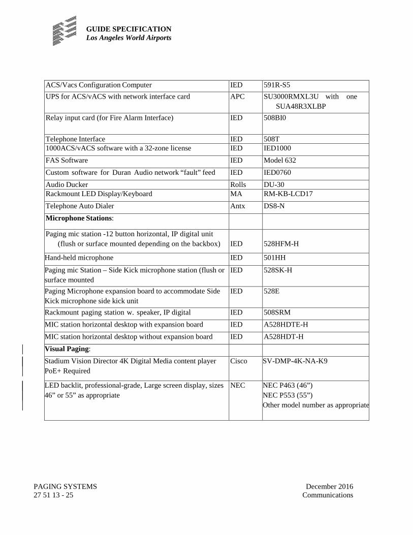
GUIDE SPECIFICATION Los Angeles World Airports
PAGING SYSTEMS 27 51 13 - 25
December 2016 Communications
ACS/Vacs Configuration Computer IED 591R-S5 UPS for ACS/vACS with network interface card APC SU3000RMXL3U with one
SUA48R3XLBP Relay input card (for Fire Alarm Interface) IED 508BI0
Telephone Interface IED 508T 1000ACS/vACS software with a 32-zone license IED IED1000 FAS Software IED Model 632 Custom software for Duran Audio network “fault” feed IED IED0760 Audio Ducker Rolls DU-30 Rackmount LED Display/Keyboard MA RM-KB-LCD17 Telephone Auto Dialer Antx DS8-N Microphone Stations:
Paging mic station -12 button horizontal, IP digital unit (flush or surface mounted depending on the backbox)
IED
528HFM-H
Hand-held microphone IED 501HH
Paging mic Station – Side Kick microphone station (flush or surface mounted
IED 528SK-H
Paging Microphone expansion board to accommodate Side Kick microphone side kick unit
IED 528E
Rackmount paging station w. speaker, IP digital IED 508SRM MIC station horizontal desktop with expansion board IED A528HDTE-H MIC station horizontal desktop without expansion board IED A528HDT-H Visual Paging: Stadium Vision Director 4K Digital Media content player PoE+ Required
Cisco SV-DMP-4K-NA-K9
LED backlit, professional-grade, Large screen display, sizes 46” or 55” as appropriate
NEC NEC P463 (46”) NEC P553 (55”) Other model number as appropriate

GUIDE SPECIFICATION Los Angeles World Airports
PAGING SYSTEMS 27 51 13 - 26
December 2016 Communications
2.4 VISUAL PAGING
A. Visual Paging: The visual paging system shall be integrated into the SITA Shared Use Station (SUS) and shall meet the requirements of that system and the existing system functionality. The Contractor shall be responsible for providing the information necessary for and coordinating the programming of visual paging system so that visual and audio zones are synchronized. The Contractor shall also be responsible for any programming changes required in the visual paging system to accept from SITA flight information associated with new gates.
B. Emergency Visual Messaging System: The emergency visual messaging system shall be integrated to the existing Emergency Visual Paging which monitors are strategically located throughout the terminal SSCP areas including the Baggage Claim, Ticketing and Gate areas. Contractor shall integrate the new system to the existing Cisco Vision Director System in coordination with LAWA IT.
C. General Audio/Visual Paging System: If LAWA determines that a new Globalcom is necessary for the new system, the Contractor shall integrate the new system to the existing Globalcom and shall designate the new Globalcom system as "ACS/vACS #X" where “X” shall be provided by LAWA. Contractor shall also work with the LAWA Network Group to establish a “shared VLAN” or shall provide and install two (2) IED model11 OODAB digital audio bridges in case of two systems on “separate VLAN’s”. Contractor shall also upgrade the firmware within the main and lifeline Globalcom CPU assemblies to the latest version. Upon completion of the integration, ARCC staff using the two ARCC microphone stations #9 and #67 shall be able to make audio/visual pages to the Terminals in the CTA area.
2.5 CUSTOM FABRICATION
A. Equipment cabinets: Telecommunications Rooms and equipment cabinets are
supplied by Section 27 05 00. Contractor may arrange with cabinet supply contractor to ship cabinets to their factory for pre-rack and wiring of paging equipment. Paging system contractor is responsible for providing all cooling equipment, shelves, drawers, special power wiring, ground connections, cables, connectors, appurtenances, and adapters of any kind necessary to accommodate the PA system installation, operation, testing, or maintenance. 1. Contractor shall provide the appropriate factory or custom rack mount adapters
for all equipment installed in the equipment rack, whether specifically itemized or not.
2. Contractor shall provide security covers for all equalizers, crossovers, signal delays, and other adjustable signal processors.

GUIDE SPECIFICATION Los Angeles World Airports
PAGING SYSTEMS 27 51 13 - 27
December 2016 Communications
3. Unused slots shall be covered using blank panels provided by the system manufacturer.
4. Contractor shall provide at least one security screw for each piece of equipment and four security screw tools for the system.
B. Interface tie points: Contractor shall furnish custom-fabricated interface tie points to
accommodate distribution of system program material, and to transition wiring types between the paging system equipment racks and loudspeaker zones. Contractor shall furnish operable methods for labeling, dressing, and distributing wires, shields, and grounding conductors so as not to adversely impact the quality of system voice and data transmission. Contractor shall provide test points at each audio and data circuit appearance for that tie point for maintenance and testing purposes. All circuits and cables shall be clearly labeled. All interface tie-points will be mounted within NEMA 12 enclosures, to be sized by Contractor in accordance with the requirements of the NFPA 70. Enclosures are to include integral door locks. All interface tie points are to be keyed alike. Keys shall be turned over to the Owner at Final Acceptance.
C. Transformers: Where required by the function of the system, provide appropriate
impedance ratio and power handling capacity for audio transformers required in the system.
D. Loudspeaker hardware: Contractor is solely responsible for ensuring that all grilles, transformers, enclosures, baffles, and ancillary hardware to be supplied are compatible with the loudspeakers specified.
E. Pads: Contractor shall provide balanced pads, comprised of 0.5 watt, 5 percent
composition resistors soldered to fixed connection points at each end, as required to achieve proper impedance matching and levels.
F. Remote control panels and receptacle plates: Contractor shall fabricate with 1/8-
inch thick 6061-T6 aluminum with a brushed, anodized finish (color to match surrounding surfaces).
G. System functional diagrams: Contractor shall provide 1/2-size as-built functional
diagram, framed with acrylic cover and mounted adjacent to equipment rack, for each control or audio system (including patch field designations). Mounting inside interface tie point enclosures will be acceptable.

GUIDE SPECIFICATION Los Angeles World Airports
PAGING SYSTEMS 27 51 13 - 28
December 2016 Communications
2.6 LABELS
A. Shall meet the legibility, defacement, exposure and adhesion requirements of UL 969. B. Shall be pre-printed or laser printed type. C. Where used for cable marking, a label with a vinyl substrate and white printing
area and a clear “tail” that self laminates the printed area when wrapped around the cable shall be provided. The label color shall be different than that of the cable to which it is attached.
D. Where insert type labels are used, provide clear plastic cover over label. E. Acceptable Manufacturers:
1. W.H. Brady 2. Brother 3. Panduit 4. Other equal
F. Contractor shall provide permanently mounted 1/32-inch thick by 1/4-inch high black
lamicoid or anodized, brushed aluminum labels with 1/8-inch engraved lettering for each piece of equipment and every user-adjustable control and input on the audiovisual equipment.
2.7 FIRESTOPPING MATERIALS
A. Fire stopping for openings through fire-rated and smoke-rated walls and floor
assemblies shall be listed or classified by an approved independent testing laboratory for "Through- Penetration Fire Stop Systems." The system shall meet the requirements of "Fire Tests of Through-Penetration Fire Stops" designated ASTM E814.
B. Inside of all conduits, the fire stop system shall consist of dielectric, water resistant, non- hardening, permanently pliable/re-enterable putty along with the appropriate damming or backer materials (where required). The sealant must be capable of being removed and reinstalled and must adhere to all penetrants and common construction materials and shall be capable of allowing normal wire/cable movement without being displaced.
GUIDE SPECIFICATION Los Angeles World Airports
PAGING SYSTEMS 27 51 13 - 29
December 2016 Communications
PART 3 - EXECUTION
3.1 GENERAL
A. System installation and construction methods shall conform to LAWA requirements, requirements of the State of California and all applicable building codes.
B. Contractor shall install equipment to meet Seismic Zone 4 requirements of the
State of California and as stated herein. 1. Where undefined by codes and standards, Contractor shall apply a safety factor of
at least 2 times the rated load to all fastenings and supports of system components
C. All equipment locations shall be coordinated with other trades and existing conditions. Coordinate work with other trades and existing conditions to verify exact routing of all cable conduit, etc. before installation. Coordinate with all the Telecommunications, Mechanical, Baggage Handling and Electrical Drawings. Verify with Design Engineer the exact location and mounting height of all equipment in finished areas.
D. All work shall be concealed above ceilings and in walls, below slabs, and elsewhere
throughout building. If concealment is impossible or impractical, LAWA and the Design Engineer shall be notified before starting that part of the work. In areas with no ceilings, install only after LAWA and the Design Engineer reviews and comments on arrangement and appearance.
E. The Contractor shall patch all openings remaining around and inside all conduit,
sleeves and cable penetrations to maintain the integrity of any fire rated wall, ceiling, floor, etc. The fire stop system shall consist of a dielectric, water resistant, non-hardening, permanently pliable/re-enterable putty along with the appropriate damming materials (where required). The sealant must be capable of being removed and reinstalled and must adhere to all penetrants and common construction materials and shall be capable of allowing normal wire/cable movement without being displaced.
F. Provide required supports, beams, angles, hangers, rods, bases, braces, straps,
struts, and other items to properly support work. Supports shall meet the approval of LAWA and the Design Engineer.
G. Cable Dressing: Where fiber or copper cables enter telecommunications room it
shall be neatly bundled and fastened and a suitable transition device installed to

GUIDE SPECIFICATION Los Angeles World Airports
PAGING SYSTEMS 27 51 13 - 30
December 2016 Communications
minimize tension and bend radius on cables. All cable runs shall be horizontal or vertical, and bends shall comply with minimum specified cable bending radii. 1. Cables shall be combed and each strand shall run parallel with the other strands. 2. After combing and straightening strands, Contractor shall separate strands into
bundles according to routing requirements and termination points. 3. Bundles shall be secured with hook-and-loop cable strap material.
a. Cable ties manufactured from a hard polymer material, such as plastic or nylon, shall not be used.
b. Hook-and-loop material shall be low life cycle, back-to-back type, black in color, and ½ inches wide.
4. Contractor shall begin to bundle and strap cables within 6 inches of exit from conduit, and bundles shall have cable straps applied at intervals not greater than 10 feet for entire length of vertical and horizontal run. Power distribution cabling shall be on the opposite side from signal wiring in equipment enclosures and shall be uniformly located throughout an installation.
5. No splicing (including with terminal blocks) is allowed for cabling homeruns. 3.2 EXAMINATION
A. Before construction work commences, the Contractor shall visit the site and identify
the exact routing for all horizontal and backbone pathways. Before construction work commences, the Contractor shall visit the site and identify the exact routing for all horizontal and backbone pathways.
3.3 PREPARATION A. Ensure that all equipment/materials to be installed are UL (or equivalent) listed as
required by LADBS. B. Prior to installation of equipment, Contractor shall conduct a field walk with LAWA IT
to ensure that construction has advanced to a point where equipment is ready to be installed. Telecom equipment rooms in which equipment is to be installed shall have no work pending where construction dust or debris can impact the equipment upon installation.
C. The Contractor shall conduct workshops with LAWA IT to acquire the necessary
information needed to allow the proper programming of this system as he is directed. The contractor, after interviewing the client, shall then submit a written report stating his interpretation of the client’s requirements for approval. Only after the LAWA has approved the programming report may the contractor proceed with the programming of this system.
GUIDE SPECIFICATION Los Angeles World Airports
PAGING SYSTEMS 27 51 13 - 31
December 2016 Communications
3.4 INSTALLATION - PHASES OF IMPLEMENTATION
A. The Contractor shall perform a detailed inspection of the site prior to submitting any technical data for approval.
B. The Contractor shall verify that the proposed equipment and methods of installation
are compatible with the existing conditions and prepare a corresponding written report of their findings.
C. LAWA shall be notified in writing if modifications of the existing building are
required in order to accommodate the new equipment. These modifications shall be made only upon receiving written approval from LAWA.
D. Submit installation drawings for LAWA review and approval. E. Provide a consolidated and integrated schedule. F. Functionality of the existing paging system shall be maintained at all times. The
work shall be done in such a fashion that no existing paging zone is out of service during the hours of 5:00 am to Midnight, and no zone is out of service at all for more than 1 hour in areas which are still in use. Temporary paging must be provided as required at no additional cost to the LAWA.
3.5 QUALITY CONTROL – SITE TEST AND INSPECTION
A. Phases of Testing 1. On-Site Performance Verification Testing 2. On-Site Endurance Testing
B. Test Plan/Procedure: The Contractor shall submit a Test Plan for each testing phase
for the review and approval of LAWA and the Design Engineer. The test plan for each phase shall detail the objectives of all tests. The tests shall clearly demonstrate that the system and its components fully comply with the requirements specified herein. The test plan shall be provided at least forty-five (45) days prior to the scheduled start of each test. Test plans shall contain at a minimum: 1. Functional procedures including use of any test equipment. 2. Test equipment is to be identified by manufacturer and model. 3. Interconnection of test equipment and steps of operation shall be defined. 4. Expected results required to comply with specifications. 5. Record of test results with witness initials or signature and date performed. 6. Pass or fail evaluation with comments.

GUIDE SPECIFICATION Los Angeles World Airports
PAGING SYSTEMS 27 51 13 - 32
December 2016 Communications
7. The test procedures shall provide conformity to all specification requirements. Satisfactory completion of the test procedure is necessary as a condition of system acceptance.
8. Documentation verification, both interconnects and functionality shall be part of the test. Where documentation is not in accordance with the installed system interconnect and operating procedures, the system shall not be considered accepted until the system and documentation correlate.
9. The Contractor shall cooperate with and provide LAWA representative(s) the opportunity(s) to participate in any or all of the tests.
10. Test Reports: The Contractor shall submit for each test, a test report document that shall certify successful completion of that test. Submit for review and acceptance within seven (7) days following each test. The test report shall contain, at a minimum: a. Commentary on test results. b. A listing and discussion of all discrepancies between expected and actual
results and of all failures encountered during the test and their resolution. c. Complete copy of test procedures and test data sheets with annotations
showing dates, times, initials, and any other annotations entered during execution of the test.
d. Signatures of persons who performed and witnessed the test. e. Test Resolution: Any discrepancies or problems discovered during
these tests shall be corrected by the Contractor at no cost to the Owner. The problems identified in each phase shall be corrected and the percentage of the entire system re-tested determined by LAWA and the Design Engineer before any subsequent testing phase is performed.
C. Performance Verification Testing:
1. Complete operational testing of all components and systems shall be witnessed by designated LAWA Representatives.
2. Schedule test with LAWA and the Design Engineer. Do not begin testing until: a. All systems have been installed and individually and jointly tested to ensure
they are operating properly. b. Written permission from LAWA and the Design Engineer has been received.
3. Testing: As part of performance verification, test all components of system. The tests shall demonstrate system features.
4. Verification: Verify correct operation of the required system functionality as defined in these specifications.
5. Adjustment, Correction, and Completion: a. Correct deficiencies and retest affected components. b. Make necessary adjustments and modification to system after obtaining
approval of LAWA and the Design Engineer.

GUIDE SPECIFICATION Los Angeles World Airports
PAGING SYSTEMS 27 51 13 - 33
December 2016 Communications
c. Completion: Performance verification test shall be complete when testing or retesting of each component has produced a positive result and has been approved in writing by LAWA and the Design Engineer.
6. Recording: a. Describe actual operational tests performed and equipment used and list
personnel performing tests. b. Record in tabular form all test results, deficiencies, and corrective measures.
7. Termination: a. Performance verification test shall be terminated by LAWA and the Design
Engineer when: 1) Individual components, subsystems, or the integrated system fail to
perform as specified. 2) It is determined that system is missing components or installation is not
complete. b. Upon termination, corrective work shall be performed and performance
verification test rescheduled with LAWA and the Design Engineer. c. Retesting shall be performed by Contractor at no additional expense. d. Contractor shall continue to perform corrective actions and retest until
system passes all tests to satisfaction of LAWA and the Design Engineer.
D. Endurance Testing: 1. Provide personnel to monitor the systems 24 hours per day, including
weekends and holidays during endurance testing. 2. Start test after:
a. Successful completion of performance verification testing. b. Training as specified has been completed. c. Correction of deficiencies has been completed. d. Receipt of written start notification from LAWA and the Design Engineer.
3. Monitor all systems during endurance testing. Coordinate monitoring with the Design Engineer.
4. Recording: Record data on approved forms so as to provide a continuous log of systems performance. Include: a. Date and time for all entries. b. Name of individual making entry. c. Environmental conditions. d. Authority activities in process. e. Description of all alarm annunciations, responses, corrective actions, and
causes of alarms. Classify as to type of alarm. f. Description of all equipment failures, including software errors. g. Description of all maintenance and adjustment operations performed on system. h. Daily and weekly tabulations.

GUIDE SPECIFICATION Los Angeles World Airports
PAGING SYSTEMS 27 51 13 - 34
December 2016 Communications
i. Daily entries of performance data shall be reviewed by the Design Engineer’s representative designated to observe monitoring of system.
5. LAWA and the Design Engineer may terminate testing at any time when the system fails to perform as specified. Upon termination of testing the Contractor shall commence an assessment period as described in Phase II.
6. Testing a. Phase I - Initial Testing:
1) Time: 24 hours per day for 15 consecutive calendar days. 2) Make no repairs during this phase unless authorized in writing by LAWA
and the Design Engineer. 3) If system experiences no failures, proceed to Phase III - Final Testing.
b. Phase II - Initial Assessment: 1) After conclusion of Phase I or terminating of testing, identify all failures,
determine causes, and repair. Submit report explaining: Nature of each failure, corrective action taken, results of tests performed to verify corrective action as being successful, and recommended point for resumption of testing.
2) After submission of report, schedule review meeting at job site. Schedule date and time with LAWA and the Design Engineer.
3) At review meeting, demonstrate that all failures have been corrected by performing verification tests.
4) Based on report and review meeting, LAWA and the Design Engineer will direct Contractor to repeat Phase I, restart Phase I, or proceed to Phase III - Final Testing.
c. Phase III - Final Testing: 1) Time: 24 hours per day for 15 consecutive calendar days. 2) Make no repairs during this phase unless authorized in writing by
Engineer. 7. Phase IV - Final Assessment:
1) After conclusion of Phase III or termination of testing, identify all failures, determine causes, and repair. Submit explaining the nature of each failure, corrective action taken, results of tests performed, and recommended point for resumption of testing.
2) After submission of report schedule review meeting at job site. Schedule date and time with the Design Engineer.
3) At review meeting, demonstrate that all failures have been corrected by performing verification tests.
4) Based on report and review meeting, LAWA and the Design
Engineer will approve endurance test or direct Contractor to repeat all or part of Phases III and IV.

GUIDE SPECIFICATION Los Angeles World Airports
PAGING SYSTEMS 27 51 13 - 35
December 2016 Communications
8. Adjustment, Correction, and Maintenance: a. During endurance testing make adjustments and corrections to system
only after obtaining written approval of LAWA and the Design Engineer. b. During endurance testing, perform required maintenance on systems
including provision of replacement parts.
E. Commissioning Testing 1. The Contractor shall develop a commissioning test plan that includes the
following components, as a minimum: a. LAWA readiness b. Operational procedures verification c. Disaster recovery procedures d. Computerized Maintenance Management System data verification e. Change management procedures
2. The commissioning test plan/procedures shall be submitted to the Engineer for review and approval.
F. Final Inspection and Acceptance:
1. After endurance testing is complete, review tabulated records with LAWA and the Design Engineer.
2. The Contractor will not be responsible for failures caused by: a. Outage of main power in excess of backup power capability provided that
automatic initiation of all backup sources was accomplished and automatic shutdowns and restarts of systems performed as specified.
b. Failure of any LAWA furnished power, communications, and control circuits provided failure was not due to Contractor furnished equipment, installation, or software.
c. Failure of existing LAWA equipment provided failure was not due to Contractor furnished equipment, installation, or software.
3. When performance of integrated system does not fall within the above rates, determine cause of deficiencies, correct, and retest.
4. When requested by LAWA and the Design Engineer, extend monitoring period for a time as designated by LAWA and the Design Engineer.
5. Period shall not exceed 60 days exclusive of retesting periods caused by termination of Phases I or III and assessment period of Phases II and IV.
6. Submit final report of endurance testing containing all recorded data.

GUIDE SPECIFICATION Los Angeles World Airports
PAGING SYSTEMS 27 51 13 - 36
December 2016 Communications
3.6 SYSTEM STARTUP
A. Upon completion of the installation of all equipment in an area, perform the following tests and record results. Verify safe and proper operation of all components, devices, or equipment, establish nominal signal levels within the systems and verify the absence of extraneous or degrading signals. Make all preliminary adjustments and document the setting of all controls, parameters of all corrective networks, voltages at key system interconnection points, gains and losses, as applicable. Submit test report. Correct all non-conforming conditions prior to requesting Acceptance Testing. Perform at least the following procedures:
B. Mechanical. Verify:
1. Integrity of all support provisions. 2. Absence of debris of any kind, tools, etc.
C. Power and Isolated Ground. Verify: 1. Isolation of Isolated Ground system from raceway and related ground. 2. Grounding of devices and equipment. Integrity of signal and technical power
system ground connections. a. System shall be hum free, stable and free of oscillation with earth ground
temporarily disconnected. b. The earth ground shall be made at only one point in the system and shall be in
accordance with NFPA 70-1990, paragraphs 250-74 Exception No. 4, 250-75 Exception 384-2 Exception or the equivalent from the latest version of NEC.
c. The equipment racks shall be isolated from, and not electrically connected to, the building grounding system. This means that the conduit system shall not be electrically connected to the equipment racks and that the equipment racks shall be installed so that they are electrically isolated from the building structural steel. The racks shall be electrically connected at only one point to the isolated grounding system.
3. Proper provision of power to devices and equipment. 4. Circuits feeding paging system equipment shall be 120 VAC, 20A isolated ground
type with separate green ground wire. Receptacles serving paging system equipment shall be orange isolated ground type. Paging system power circuits shall be from a dedicated isolated ground panel supplied from the isolation transformer.
5. Paging system power grounds shall ultimately terminate only at the isolation transformer ground and shall not be connected to or be in electrical contact with building steel, or the conduit system.
6. The isolation transformer ground shall be bonded to the building grounding electrode or similar reliable earth ground point.
GUIDE SPECIFICATION Los Angeles World Airports
PAGING SYSTEMS 27 51 13 - 37
December 2016 Communications
7. Rotating machinery or other noise inducing equipment must not be powered by the paging power system or share a ground bus with the paging power system.
8. Paging system equipment racks shall be direct wired to the paging power system. The appropriate number of 20A circuits shall be dedicated to the paging equipment racks to power current equipment and to provide an additional 30% for future expansion. The paging equipment racks shall not make electrical contact with the conduit system.
D. Signal Wiring. Verify:
1. Integrity of all insulation, shield terminations and connections. 2. Integrity of soldered connections. Absence of solder splatter, solder bridges. 3. Routing and dressing of wire and cable. 4. Continuity, including conformance with wire designations on running sheets,
field and shop drawings. 5. Absence of ground faults. 6. Polarity.
E. Use the proper sequence of energizing systems to minimize the risk of damage. F. Sound Systems:
1. Electronic Tests; confirm: a. Gain at 1 kHz. b. Maximum output. c. Input clipping level. d. Frequency response. e. Total harmonic distortion. f. Signal-to-Noise ratio. g. Signal-to-Crosstalk ratio.
2. Gain control settings: Establish tentative normal settings for all gain controls. Set all equalizers flat. Set all automatic gain control devices to bypass. Terminate power amplifier outputs with power load resistors with resistance value within 10% the nominal output impedance of the respective amplifier. Adjust all gain controls on equipment for optimum signal to noise ratio and signal balance and, unless they are sub panel mounted, cap them to prevent tampering. Unless specified or directed otherwise, adjust gains such that in a given system the "front end" operates at unity gain and maintains 10 dB of clip margin referenced to the first onset of clipping of the associated power amplifier(s). Measure and document system gains at 1 kHz. Settings may require further adjustment by the Contractor, a result of testing by the representative of the Owner.
3. Freedom from parasitic oscillation and radio frequency pickup: Maintain previous setup. Set up for each mode of operation specified in the functional requirements;

GUIDE SPECIFICATION Los Angeles World Airports
PAGING SYSTEMS 27 51 13 - 38
December 2016 Communications
verify that all systems are free from spurious oscillation and radio frequency pickup using broadband oscilloscope. Correct any such defects.
4. Hum and noise level/signal to noise level/signal to crosstalk level: Maintain previous setup. Terminate microphone and line level inputs with shielded resistors of 150 and 600 ohms, respectively. Set available variable gain controls such that full power amplifier output would be achieved with 40 dBm input level at a microphone input and +12 dBm at a line level input. Measure and document the specified parameters of the system overall for each microphone input channel and line level input channel. Compare with nominal signal level.
5. Total Harmonic Distortion: Maintain previous setup. Measure at reference operating level at 63 Hz, 125 Hz, 1 kHz, 10 kHz.
G. Electro/Acoustic Tests:
1. Uniformity of coverage. 2. Electronic and acoustic frequency response/one third octave equalization.
Measure at ear level. Comply with applicable portions of ANSI (SMPTE) PH22.202M-1984, "B chain electro-acoustic response - control rooms and indoor theaters." Adjust to "curve X of B chain characteristic". Representative of the Owner will direct final adjustment.
3. Maximum continuous sound pressure level (in the reverberant field). Drive systems with broadband pink noise. Sustain for at least five minutes with no system damage. Measure for "A" and "C" weightings at ear level on loudspeaker axis. Turn off noise.
4. Acoustic signal to noise ratio referenced to the specified maximum continuous sound pressure level in the reverberant field. Measure for "A" and "C" weightings at ear level on loudspeaker axis with mechanical systems operating. Present comparison with previous measurement.
5. Acoustic gain before feedback. Locate acoustic source (4-inch loudspeaker/pink noise generator) two feet from system microphone. Measure at system microphone position and at most distant listener position at ear level. Present comparison.
H. System Overall:
1. Verify levels. 2. Provide permanent "wedge" type labels on all controls, as applies, to indicate
correct settings after systems performance testing and adjustment procedures have been successfully completed.
I. At least 10% of the total number of zones must be tested at two different times and
at two different locations within the zone during peak hours and during quiet hours. These tests must indicate that pages are at least 6dB, but no greater than 10dB

GUIDE SPECIFICATION Los Angeles World Airports
PAGING SYSTEMS 27 51 13 - 39
December 2016 Communications
above, ambient noise levels. Measured ambient noise levels must be time averaged over a period of at least one minute and are not to include announcements from the paging system.
J. Upon completion of the installation of all loudspeakers in an area, perform the
following tests and record results. Correct non-conforming conditions, unless the cause is clearly outside the Work of this Section, in which case submit the apparent cause to the Owner. 1. Loudspeaker Line Impedance: At terminal cabinets at equipment rooms,
measure the impedance of each loudspeaker line. Sweep from at least 20 Hz to at least 16 kHz.
2. Loudspeaker Polarity: Test the acoustic polarity of all loudspeakers using an Acoustic Polarity Tester. 3. Freedom from Buzzes, Rattles and Objectionable Distortion: Individually apply
to each loudspeaker line a slow sine wave sweep from 50 Hz to 5 kHz at a level of 6 dB below rated power amplifier output voltage. Listen carefully for buzzes, rattles and objectionable distortion.
4. Uniformity of Coverage: Apply broadband Pink Noise. Adjust level to approximately 70-80 dBA at measurement locations. Measure in 4 kHz octave band at ear level. Adjust loudspeaker aiming and 70 Volt loudspeaker taps for uniformity of coverage.
K. Satisfaction of the above requirements shall not relieve the Contractor of
responsibility for incorrect installations, defective equipment items, or collateral damage as a result of Contractor work/equipment.
3.7 CLEANING (NOT USED)
3.8 IDENTIFICATION AND LABELING
A. See IT Infrastructure Standards of Practice Volume 3, Chapter 1.
B. The Contractor shall confirm specific labeling requirements with LAWA and the
Design Engineer prior to cable installation or termination.
C. All indoor cable and patch cable labels shall be pre-printed using BRADY TLS 2200 printer or equivalent and shall be placed loose on the patch cable near the connector end without heat shrinking labels. Labels shall use a three-line format with the origination patch panel and port on the first line, the destination patch panel and port on the second line and the system or other descriptive information on the third line.

GUIDE SPECIFICATION Los Angeles World Airports
PAGING SYSTEMS 27 51 13 - 40
December 2016 Communications
3.9 TRAINING
A. General 1. By means of training classes augmented by individual instruction as necessary,
the Contractor shall fully instruct LAWA’s designated staff and Airline personnel in the operation, adjustment and maintenance of all products, equipment and systems.
2. The Contractor shall be required to provide all training aids, e.g., notebooks and manuals.
3. The Contractor shall provide an appropriate training area equipped with all required equipment. The location of the training area shall be coordinated with LAWA and the Design Engineer.
4. All training shall be completed a minimum of two weeks prior to system cut over. Training schedule shall be subject to LAWA and the Design Engineer’s approval.
5. Training shall be conducted by experienced personnel and supported by training aids. An adequate number and amount of training material shall be provided by the Contractor. The following is considered a minimum: a. Functional flow-charts, overall block diagrams, and descriptive material for
all software; b. Schematic drawings for each of the hardware components; c. All procedure manuals, specification manuals, and operating manuals; d. As-built drawings.
6. Participants shall receive individual copies of technical manuals and pertinent documentation at the time the course is conducted. The courses shall be scheduled such that LAWA personnel can participate in all courses (no overlap).
B. Types of Training:
1. User Training: System users shall be instructed in all aspects of operations of the system. Four (4) hours of basic user training shall be provided in two sessions. Additionally, four (4) hours of advanced user training shall be provided in two s sessions.
2. Technician Training: Eight (8) hours of maintenance training shall be provided in two sessions. Training for maintenance technicians shall be provided on site, and shall include, but not be limited to, installation, operation, renovation, alteration, inspection, maintenance and service on each system and subsystem provided, so as to enable troubleshooting and repair to the component level. The training shall include on-the-job training that allows LAWA field techs train on the equipment installed in the field.
3. System Administrator Training: System Administrator Training shall be provided. System Administrator Training shall include both classroom work and
GUIDE SPECIFICATION Los Angeles World Airports
PAGING SYSTEMS 27 51 13 - 41
December 2016 Communications
on the job training and shall be provided on-site at LAX or at a location within 50 `miles of LAX.
4. Classroom Training: Eight (8) hours of software training shall be provided for each system in two sessions. The Contractor shall structure the course to describe all systems, software and applications and support programs. This course shall include a functional overview of the complete software system. The course material must be presented in depth with the instructor covering detailed design, structure, and algorithms.
5. The person or persons providing the training shall have detailed knowledge of the system design, installation, performance and operations and shall have recent IED training. Instructions shall include step-by-step procedures that provide instruction on how to perform daily health checks, system startup and shutdown, system failover and failback, database and system backup (for the visual and audio components of the application).
C. Prior to the training sessions, the Contractor shall provide:
1. As-built drawings and record drawings in accordance with the Section 27 05 00. 2. Manuals of operating and maintenance literature, pursuant to the requirements of
the Section 27 05 00. 3. System geographical layout and block diagrams under a plastic cover on the wall
of the equipment rooms. 4. The Contractor shall submit the training plan to LAWA for approval three weeks
prior to propose training date. The Contractor training shall include description of the system physical topology, how to adjust the ACS/vACS, and the review of configuration details.
3.10 COMPUTERIZED MAINTENANCE MANAGEMENT SYSTEM
A. Information regarding all equipment including model, nomenclature, serial number,
function, location, recommended preventative maintenance schedule, Quality Assurance Inspections and other pertinent data will be stored in the CMMS database. Contractor shall include in their Bid the cost for collecting and inputting this data for all systems and equipment provided by this Contract into this database.
B. Asset tags shall be installed and recorded for all paging head end equipment (including ACS/vACS, Noise Sensor Collector, amplifier frames, UPS, etc…), line-array speakers, microphone paging stations, and workstations installed.
GUIDE SPECIFICATION Los Angeles World Airports
PAGING SYSTEMS 27 51 13 - 42
December 2016 Communications
3.11 CLOSEOUT ACTIVITIES, FINAL INSPECTION AND ACCEPTANCE
A. Completion of the installation, in-progress and final inspections, receipt of the test and as- built documentation including data input of all installed cables in LAWA management system and successful performance of the Paging System and its components for a thirty (30) day period will constitute acceptance of the system.
END OF SECTION 27 51 13