Embed Size (px)
Citation preview
AISI STANDARD Commentary on the Standard for Cold-Formed Steel Framing – Prescriptive Method for One and Two Family Dwellings, 2001 Edition with 2004 Supplement
Endorsed by:
ii Commentary on the Prescriptive Method for One and Two Family Dwellings - 2004
DISCLAIMER
The material contained herein has been developed by the American Iron and Steel Institute Committee on Framing Standards. The Committee has made a diligent effort to present accurate, reliable, and useful information on cold-formed steel framing design and installation. The Committee acknowledges and is grateful for the contributions of the numerous researchers, engineers, and others who have contributed to the body of knowledge on the subject.
With anticipated improvements in understanding of the behavior of cold-formed steel framing and the continuing development of new technology, this material may eventually become dated. It is anticipated that AISI will publish updates of this material as new information becomes available, but this cannot be guaranteed.
The materials set forth herein are for general purposes only. They are not a substitute for competent professional advice. Application of this information to a specific project should be reviewed by a design professional. Indeed, in many jurisdictions, law requires such review. Anyone making use of the information set forth herein does so at their own risk and assumes any and all liability arising there from.
The user is advised to check the availability of specific framing material in the region in which the dwelling is being constructed.
1st Printing – December 2004
Copyright American Iron and Steel Institute 2004
Commentary on the Prescriptive Method for One and Two Family Dwellings - 2004 iii
PREFACE
The American Iron and Steel Institute (AISI) Committee on Framing Standards (COFS) has developed this Commentary on the Standard for Cold-Formed Steel Framing - Prescriptive Method for One and Two Family Dwellings [Commentary] to provide the background, supplemental information, engineering assumptions and methods, and detailed calculations for the provisions of the Prescriptive Method (AISI, 2001d). In 2004, this Commentary was expanded to address the 2004 Supplement to the Standard for Cold-Formed Steel Framing – Prescriptive Method for One and Two Family Dwellings, 2001 Edition (AISI, 2004).
The loads, load combinations, and other design parameters used to develop the provisions in the Prescriptive Method were based on the International Residential Code (ICC, 2000b), the International Building Code (ICC, 2000a) (where no provisions are included in the IRC) and ASCE 7 (ASCE, 1998).
Commentary is provided only for those sections of the Prescriptive Method where background or supplemental information is of benefit to the user. Sections thought to need no explanation are left blank.
This document is divided into two sections. Section 1, Commentary, contains the background, supplemental information and engineering assumptions. Section 2, Design Examples, contains detailed calculations that demonstrate how the values in the Prescriptive Method were derived.
Terms within the body of this Commentary that are shown in italics indicate that the italicized word is a defined term by the Prescriptive Method or by the General Provisions (AISI, 2001a).
The Committee acknowledges and is grateful for the contributions of the numerous engineers, researchers, producers and others who have contributed to the body of knowledge on the subjects. The Committee wishes to also express their appreciation for the support and encouragement of the Steel Framing Alliance.

iv Commentary on the Prescriptive Method for One and Two Family Dwellings - 2004
AISI COMMITTEE ON FRAMING STANDARDS
Richard Haws, Chairman NUCONSTEEL Steve Fox, Vice Chairman Canadian Sheet Steel Building Institute Jay Larson, Secretary American Iron and Steel Institute Don Allen Steel Stud Manufacturers Association John Butts John F. Butts & Associates Brad Cameron Keymark Engineering John Carpenter Alpine Engineered Products Nader Elhajj NAHB Research Center Jeff Ellis Simpson Strong-Tie Ray Frobosilo Super Stud Building Products Michael Gardner Gypsum Association Greg Greenlee USP Structural Connectors John Heydon Heydon Building Systems Jeff Klaiman ADTEK Engineers Roger LaBoube University of Missouri-Rolla John Matsen Matsen Ford Design Associates Michael Meek Allied Studco Kenneth Pagano Scosta Corporation Nabil Rahman The Steel Network Greg Ralph Dietrich Industries Gary Rolih SENCO Fastening Systems Reynaud Serrette Santa Clara University Fernando Sesma California Expanded Metal Products Marge Spencer Compass International Peter Tian Berridge Manufacturing Steven Walker Steven H. Walker, P.Eng. Lei Xu University of Waterloo Rahim Zadeh Marino\Ware

Commentary on the Prescriptive Method for One and Two Family Dwellings - 2004 v
PRESCRIPTIVE METHODS SUBCOMMITTEE
Steve Fox, Chairman Canadian Sheet Steel Building Institute Jay Larson, Secretary American Iron and Steel Institute Don Allen Steel Stud Manufacturers Association Nader Elhajj NAHB Research Center Michael Gardner Gypsum Association Greg Greenlee USP Structural Connectors Richard Layding NUCONSTEEL Hank Martin American Iron and Steel Institute John Matsen Matsen Ford Design Associates Dean Peyton Anderson-Peyton Engineers Greg Ralph Dietrich Industries Fernando Sesma California Expanded Metal Products Tim Waite Simpson Strong-Tie Lei Xu University of Waterloo Rahim Zadeh Marino\Ware

vi Commentary on the Prescriptive Method for One and Two Family Dwellings - 2004
This Page Intentionally Left Blank
Commentary on the Prescriptive Method for One and Two Family Dwellings - 2004 vii
TABLE OF CONTENTS
COMMENTARY ON THE STANDARD FOR COLD-FORMED STEEL FRAMING –
PRESCRIPTIVE METHOD FOR ONE AND TWO FAMILY DWELLINGS DISCLAIMER................................................................................................................................ ii PREFACE..................................................................................................................................... iii AISI COMMITTEE ON FRAMING STANDARDS.......................................................................... iv PRESCRIPTIVE METHODS SUBCOMMITTEE............................................................................. v
PART 1 – COMMENTARY............................................................................................................1 A. GENERAL................................................................................................................................1
A1 Scope ............................................................................................................................................. 1 A1.1 Limits of Applicability .................................................................................................... 1 A1.2 Limitations In High Seismic and High Wind Areas ................................................... 2
A2 Definitions .................................................................................................................................... 2 A4 Limitations of Framing Members ............................................................................................. 2
A4.1 General .............................................................................................................................. 2 A4.2 Physical Dimensions........................................................................................................ 3 A4.3 Material Properties .......................................................................................................... 4 A4.4 Web Holes ......................................................................................................................... 4 A4.5 Hole Patching ................................................................................................................... 4
B. CONNECTIONS .......................................................................................................................5 B1 Fastening Requirements ............................................................................................................. 5 B2 Bearing Stiffeners......................................................................................................................... 5 B3 Clip Angles................................................................................................................................... 6
D. FLOOR FRAMING...................................................................................................................7 D2 Floor to Foundation or Structural Wall Connection............................................................... 7 D3 Minimum Floor Joist Sizes ......................................................................................................... 7
D3.1 Floor Cantilevers .............................................................................................................. 8 D4 Bearing Stiffeners......................................................................................................................... 8 D5 Joist Bracing and Blocking ......................................................................................................... 9
D5.1 Joist Top Flange Bracing ................................................................................................. 9 D5.2 Joist Bottom Flange Bracing/Blocking.......................................................................... 9 D5.3 Blocking at Interior Supports ......................................................................................... 9 D5.4 Blocking at Cantilevers.................................................................................................... 9
D6 Splicing ......................................................................................................................................... 9 D7 Framing of Floor Openings...................................................................................................... 10 D8 Floor Trusses .............................................................................................................................. 10 D9 Diaphragms................................................................................................................................ 10
D9.1 Floor Diaphragms in High Seismic and High Wind Areas ..................................... 10 E. WALL FRAMING.................................................................................................................. 11
E2 Wall to Foundation or Floor Connection ............................................................................... 11 E3 Minimum Stud Sizes................................................................................................................. 11 E4 Stud Bracing ............................................................................................................................... 13 E5 Splicing ....................................................................................................................................... 13 E6 Corner Framing ......................................................................................................................... 13
viii Commentary on the Prescriptive Method for One and Two Family Dwellings - 2004
E7 Headers ....................................................................................................................................... 14 E7.1 Box-Beam Headers......................................................................................................... 14 E7.2 Back-to-Back Headers.................................................................................................... 14 E7.3 Double L-Headers.......................................................................................................... 14 E7.4 Jack and King Studs and Head Track ......................................................................... 15
E8 Wall Bracing ............................................................................................................................... 15 E8.1 Strap Bracing (X-brace) ................................................................................................. 15 E8.2 Structural Sheathing ...................................................................................................... 15 E8.3 Structural Sheathing Fastening .................................................................................... 17 E8.4 Hold-down Requirements ............................................................................................ 17
E9 Exterior Wall Covering............................................................................................................. 17 E11 Braced Walls in High Wind and High Seismic Areas.......................................................... 17
E11.1 General ............................................................................................................................ 17 E11.2 Braced Wall Lines .......................................................................................................... 19 E11.3 Type I (Solid Sheathed) Braced Wall Panels .............................................................. 19 E11.4 Type II (Perforated) Braced Wall Lines....................................................................... 20
E12 Braced Wall Design in High Seismic Areas ........................................................................... 20 E12.2 Braced Wall Anchorage and Chord Stud Requirements.......................................... 20 E12.3 Wall Top Track ............................................................................................................... 20
E13 Braced Wall Design in High Wind Areas .............................................................................. 20 E13.3 Connections of Walls in High Wind Areas ................................................................ 20
F. ROOF FRAMING.................................................................................................................. 21 F1 Roof Construction ..................................................................................................................... 21 F2 Ceiling Joists............................................................................................................................... 21
F2.1 Minimum Ceiling Joist Size .......................................................................................... 21 F2.2 Ceiling Joist Bearing Stiffeners..................................................................................... 21 F2.3 Ceiling Joist Bottom Flange Bracing............................................................................ 21 F2.4 Ceiling Joist Top Flange Bracing.................................................................................. 21 F2.5 Ceiling Joist Splicing...................................................................................................... 22
F3 Roof Rafters ................................................................................................................................ 22 F3.1 Minimum Roof Rafter Sizes.......................................................................................... 22 F3.2 Roof Rafter Support Brace ............................................................................................ 22 F3.3 Rafter Splice .................................................................................................................... 22 F3.5 Rafter Bottom Flange Bracing ...................................................................................... 22
F4 Framing of Openings in Roofs and Ceilings ......................................................................... 23 F5 Roof Trusses ............................................................................................................................... 23 F6 Roof Diaphragms ...................................................................................................................... 23
PART 2 – DESIGN EXAMPLES................................................................................................. 24 A. INTRODUCTION................................................................................................................... 24
A1 Member Properties.................................................................................................................... 24 A2 Design Loads.............................................................................................................................. 24
A2.1 Roof Snow Loads ........................................................................................................... 25 A2.2 Wind Loads..................................................................................................................... 25
A3 Load Combinations................................................................................................................... 29 A4 Deflection Limits ....................................................................................................................... 30 A5 Design Checks and Assumptions ........................................................................................... 30 A6 Load Path.................................................................................................................................... 34
Commentary on the Prescriptive Method for One and Two Family Dwellings - 2004 ix
A6.1 Vertical Load Path.......................................................................................................... 35 A6.2 Lateral Load Path........................................................................................................... 35
D. FLOOR FRAMING DESIGN EXAMPLES ............................................................................. 39 D1 Floor Joist Design ...................................................................................................................... 39
D1.1 Shear Capacity................................................................................................................ 39 D1.2 Moment Capacity........................................................................................................... 40 D1.3 Deflection Limit.............................................................................................................. 40 D1.4 Web Crippling Capacity ............................................................................................... 41
D2 Header Joist Design................................................................................................................... 42 D3 Trimmer Joist Design ................................................................................................................ 42 D4 Floor Diaphragm Design.......................................................................................................... 44
E. WALL FRAMING DESIGN EXAMPLES ............................................................................... 46 E1 Wall Stud Design....................................................................................................................... 46
E1.1 Design Assumptions...................................................................................................... 46 E1.2 Design Loads .................................................................................................................. 46 E1.3 Load Combinations ....................................................................................................... 47 E1.4 Member Properties ........................................................................................................ 47 E1.5 Combined Axial and Bending Capacity ..................................................................... 48 E1.6 Deflection Limit.............................................................................................................. 50
E2 Box Header Design.................................................................................................................... 50 E2.1 Design Loads .................................................................................................................. 51 E2.2 Load Combinations ....................................................................................................... 51 E2.3 Member Properties ........................................................................................................ 51 E2.4 Bending Capacity........................................................................................................... 51 E2.5 Deflection Limit.............................................................................................................. 52 E2.6 Shear Capacity................................................................................................................ 52 E2.7 Combined Bending and Web Crippling Capacity .................................................... 52
E3 Back-to-Back Header Design ................................................................................................... 54 E3.1 Design Loads .................................................................................................................. 54 E3.2 Load Combinations ....................................................................................................... 54 E3.3 Member Properties ........................................................................................................ 54 E3.4 Bending Capacity........................................................................................................... 54 E3.5 Deflection Limit.............................................................................................................. 54 E3.6 Shear Capacity................................................................................................................ 55 E3.7 Combined Bending and Web Crippling Capacity .................................................... 55
E4 Double L-Header Design (Gravity Loading)......................................................................... 56 E4.1 Design Loads .................................................................................................................. 56 E4.2 Load Combinations ....................................................................................................... 57 E4.3 Member Properties ........................................................................................................ 57 E4.4 Bending Capacity........................................................................................................... 57
E5 Double L-Header Design (Uplift Loading Case 1) ............................................................... 57 E5.1 Design Loads .................................................................................................................. 57 E5.2 Load Combinations: ...................................................................................................... 58 E5.3 Member Properties ........................................................................................................ 58 E5.4 Bending Capacity........................................................................................................... 58
E6 Double L-Header Design (Uplift Loading Case 2) ............................................................... 59 E6.1 Design Loads .................................................................................................................. 59 E6.2 Load Combinations ....................................................................................................... 59
x Commentary on the Prescriptive Method for One and Two Family Dwellings - 2004
E6.3 Member Properties ........................................................................................................ 59 E6.4 Bending Capacity........................................................................................................... 59
E7 Head Track Design.................................................................................................................... 60 E7.1 Design Loads and Assumptions .................................................................................. 60 E7.2 Design Capacity ............................................................................................................. 61
E8 Shear Wall Design (General).................................................................................................... 61 E9 Shear Wall Design (One Story Building)................................................................................ 64
E9.1 Design Loads .................................................................................................................. 65 E9.2 Required Sheathing ....................................................................................................... 65
E10 Shear Wall Design (Two Story Building) ............................................................................... 66 E10.1 Design Loads .................................................................................................................. 66 E10.2 Required Sheathing (First Floor Walls)....................................................................... 67
E11 Shear Wall Design (High Seismic Area)................................................................................. 67 E11.1 Design Assumptions...................................................................................................... 67 E11.2 Design Loads .................................................................................................................. 67 E11.3 Required Sheathing (Side Walls) ................................................................................. 71 E11.4 Hold Downs and Multiple Stud Posts (Side Walls) .................................................. 71 E11.5 Required Sheathing (End Walls).................................................................................. 72 E11.6 Hold Downs and Multiple Stud Posts (End Walls) .................................................. 73 E11.7 Continuous Strap for Drag Force................................................................................. 74 E11.8 Stabilizing Clip at Eave Block ...................................................................................... 75 E11.9 Connection of Shear Wall to Floor Diaphragm to Shear Wall Below..................... 75
E12 Shear Wall Design (High Wind Area) .................................................................................... 75 E12.1 Design Assumptions...................................................................................................... 75 E12.2 Length of Shear Panel (Side Walls) ............................................................................. 78 E12.3 Length of Shear Panel (End Walls).............................................................................. 79 E12.4 Braced Wall Hold Down Anchorage........................................................................... 80
F. ROOF FRAMING DESIGN EXAMPLES ............................................................................... 81 F1 Ceiling Joist Design ................................................................................................................... 81
F1.1 Design Assumptions...................................................................................................... 81 F1.2 Design Loads .................................................................................................................. 81 F1.3 Member Properties ........................................................................................................ 81 F1.4 Bending Capacity........................................................................................................... 81 F1.5 Shear Capacity................................................................................................................ 82 F1.6 Deflection Limit.............................................................................................................. 82
F2 Rafter Design.............................................................................................................................. 83 F2.1 Design Assumptions...................................................................................................... 83 F2.2 Design Methodology ..................................................................................................... 83 F2.3 Design Loads .................................................................................................................. 83 F2.4 Load Combinations ....................................................................................................... 85 F2.5 Member Properties ........................................................................................................ 85 F2.6 Bending Capacity........................................................................................................... 85 F2.7 Shear Capacity................................................................................................................ 86 F2.8 Deflection Limit.............................................................................................................. 86
F3 Ridge Member Shear Connection ........................................................................................... 86 F4 Ceiling Joist to Rafter Connection........................................................................................... 87 F5 Roof Diaphragm Design (First Example)............................................................................... 88 F6 Roof Diaphragm Design (Second Example) .......................................................................... 89

Commentary on the Prescriptive Method for One and Two Family Dwellings - 2004 xi
F7 Roof Rafter or Truss to Wall Connection ............................................................................... 90 F8 Ridge Tension Strap Connection Requirement..................................................................... 91 F9 Ridge Tension Strap Design..................................................................................................... 92
REFERENCES ........................................................................................................................... 93
APPENDIX A METRIC CONVERSION................................................................................... 95

xii Commentary on the Prescriptive Method for One and Two Family Dwellings - 2004
This Page Intentionally Left Blank
Commentary on the Prescriptive Method for One and Two Family Dwellings - 2004 1
PART 1 – COMMENTARY
ON THE STANDARD FOR COLD-FORMED STEEL FRAMING –
PRESCRIPTIVE METHOD FOR ONE AND TWO FAMILY DWELLINGS
A. GENERAL
A1 Scope
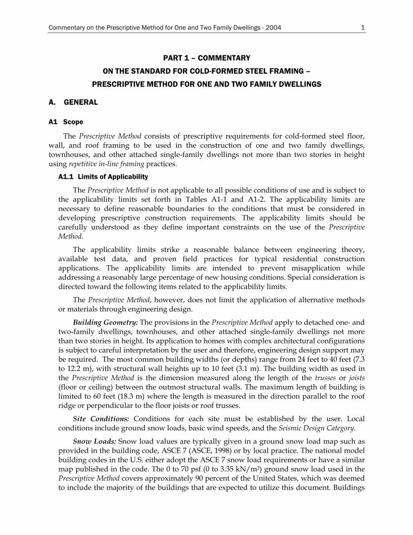
The Prescriptive Method consists of prescriptive requirements for cold-formed steel floor, wall, and roof framing to be used in the construction of one and two family dwellings, townhouses, and other attached single-family dwellings not more than two stories in height using repetitive in-line framing practices.
A1.1 Limits of Applicability
The Prescriptive Method is not applicable to all possible conditions of use and is subject to the applicability limits set forth in Tables A1-1 and A1-2. The applicability limits are necessary to define reasonable boundaries to the conditions that must be considered in developing prescriptive construction requirements. The applicability limits should be carefully understood as they define important constraints on the use of the Prescriptive Method.
The applicability limits strike a reasonable balance between engineering theory, available test data, and proven field practices for typical residential construction applications. The applicability limits are intended to prevent misapplication while addressing a reasonably large percentage of new housing conditions. Special consideration is directed toward the following items related to the applicability limits.
The Prescriptive Method, however, does not limit the application of alternative methods or materials through engineering design.
Building Geometry: The provisions in the Prescriptive Method apply to detached one- and two-family dwellings, townhouses, and other attached single-family dwellings not more than two stories in height. Its application to homes with complex architectural configurations is subject to careful interpretation by the user and therefore, engineering design support may be required. The most common building widths (or depths) range from 24 feet to 40 feet (7.3 to 12.2 m), with structural wall heights up to 10 feet (3.1 m). The building width as used in the Prescriptive Method is the dimension measured along the length of the trusses or joists (floor or ceiling) between the outmost structural walls. The maximum length of building is limited to 60 feet (18.3 m) where the length is measured in the direction parallel to the roof ridge or perpendicular to the floor joists or roof trusses.
Site Conditions: Conditions for each site must be established by the user. Local conditions include ground snow loads, basic wind speeds, and the Seismic Design Category.
Snow Loads: Snow load values are typically given in a ground snow load map such as provided in the building code, ASCE 7 (ASCE, 1998) or by local practice. The national model building codes in the U.S. either adopt the ASCE 7 snow load requirements or have a similar map published in the code. The 0 to 70 psf (0 to 3.35 kN/m2) ground snow load used in the Prescriptive Method covers approximately 90 percent of the United States, which was deemed to include the majority of the buildings that are expected to utilize this document. Buildings
2 Commentary on the Prescriptive Method for One and Two Family Dwellings - 2004
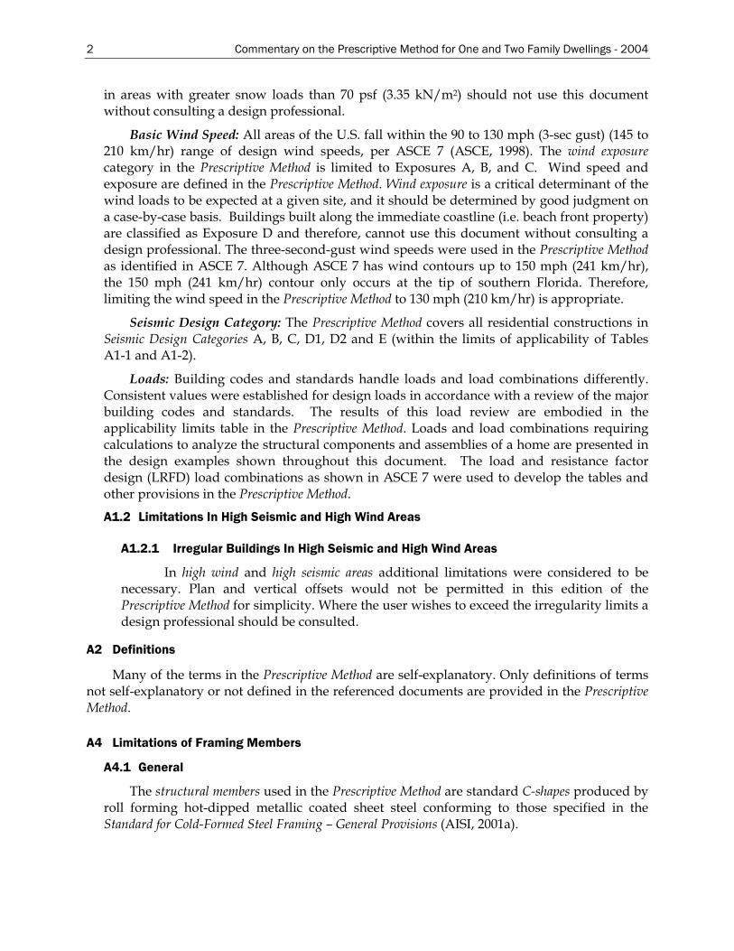
in areas with greater snow loads than 70 psf (3.35 kN/m2) should not use this document without consulting a design professional.
Basic Wind Speed: All areas of the U.S. fall within the 90 to 130 mph (3-sec gust) (145 to 210 km/hr) range of design wind speeds, per ASCE 7 (ASCE, 1998). The wind exposure category in the Prescriptive Method is limited to Exposures A, B, and C. Wind speed and exposure are defined in the Prescriptive Method. Wind exposure is a critical determinant of the wind loads to be expected at a given site, and it should be determined by good judgment on a case-by-case basis. Buildings built along the immediate coastline (i.e. beach front property) are classified as Exposure D and therefore, cannot use this document without consulting a design professional. The three-second-gust wind speeds were used in the Prescriptive Method as identified in ASCE 7. Although ASCE 7 has wind contours up to 150 mph (241 km/hr), the 150 mph (241 km/hr) contour only occurs at the tip of southern Florida. Therefore, limiting the wind speed in the Prescriptive Method to 130 mph (210 km/hr) is appropriate.
Seismic Design Category: The Prescriptive Method covers all residential constructions in Seismic Design Categories A, B, C, D1, D2 and E (within the limits of applicability of Tables A1-1 and A1-2).
Loads: Building codes and standards handle loads and load combinations differently. Consistent values were established for design loads in accordance with a review of the major building codes and standards. The results of this load review are embodied in the applicability limits table in the Prescriptive Method. Loads and load combinations requiring calculations to analyze the structural components and assemblies of a home are presented in the design examples shown throughout this document. The load and resistance factor design (LRFD) load combinations as shown in ASCE 7 were used to develop the tables and other provisions in the Prescriptive Method.
A1.2 Limitations In High Seismic and High Wind Areas
A1.2.1 Irregular Buildings In High Seismic and High Wind Areas
In high wind and high seismic areas additional limitations were considered to be necessary. Plan and vertical offsets would not be permitted in this edition of the Prescriptive Method for simplicity. Where the user wishes to exceed the irregularity limits a design professional should be consulted.
A2 Definitions
Many of the terms in the Prescriptive Method are self-explanatory. Only definitions of terms not self-explanatory or not defined in the referenced documents are provided in the Prescriptive Method.
A4 Limitations of Framing Members
A4.1 General
The structural members used in the Prescriptive Method are standard C-shapes produced by roll forming hot-dipped metallic coated sheet steel conforming to those specified in the Standard for Cold-Formed Steel Framing – General Provisions (AISI, 2001a).
Commentary on the Prescriptive Method for One and Two Family Dwellings - 2004 3
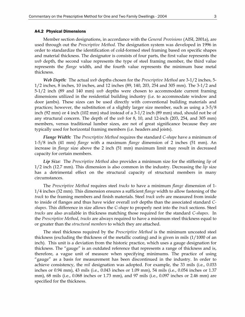
A4.2 Physical Dimensions
Member section designations, in accordance with the General Provisions (AISI, 2001a), are used through out the Prescriptive Method. The designation system was developed in 1996 in order to standardize the identification of cold-formed steel framing based on specific shapes and material thickness. The designator is consists of four parts, the first value represents the web depth, the second value represents the type of steel framing member, the third value represents the flange width, and the fourth value represents the minimum base metal thickness.
Web Depth: The actual web depths chosen for the Prescriptive Method are 3-1/2 inches, 5-1/2 inches, 8 inches, 10 inches, and 12 inches (89, 140, 203, 254 and 305 mm). The 3-1/2 and 5-1/2 inch (89 and 140 mm) web depths were chosen to accommodate current framing dimensions utilized in the residential building industry (i.e. to accommodate window and door jambs). These sizes can be used directly with conventional building materials and practices; however, the substitution of a slightly larger size member, such as using a 3-5/8 inch (92 mm) or 4 inch (102 mm) stud instead of a 3-1/2 inch (89 mm) stud, should not be of any structural concern. The depth of the web for 8, 10, and 12-inch (203, 254, and 305 mm) members, versus traditional lumber sizes, are not of great significance because they are typically used for horizontal framing members (i.e. headers and joists).
Flange Width: The Prescriptive Method requires the standard C-shape have a minimum of 1-5/8 inch (41 mm) flange with a maximum flange dimension of 2 inches (51 mm). An increase in flange size above the 2 inch (51 mm) maximum limit may result in decreased capacity for certain members.
Lip Size: The Prescriptive Method also provides a minimum size for the stiffening lip of 1/2 inch (12.7 mm). This dimension is also common in the industry. Decreasing the lip size has a detrimental effect on the structural capacity of structural members in many circumstances.
The Prescriptive Method requires steel tracks to have a minimum flange dimension of 1-1/4 inches (32 mm). This dimension ensures a sufficient flange width to allow fastening of the track to the framing members and finish materials. Steel track webs are measured from inside to inside of flanges and thus have wider overall web depths than the associated standard C-shapes. This difference in size allows the C-shape to properly nest into the track sections. Steel tracks are also available in thickness matching those required for the standard C-shapes. In the Prescriptive Method, tracks are always required to have a minimum steel thickness equal to or greater than the structural members to which they are attached.
The steel thickness required by the Prescriptive Method is the minimum uncoated steel thickness (excluding the thickness of the metallic coating) and is given in mils (1/1000 of an inch). This unit is a deviation from the historic practice, which uses a gauge designation for thickness. The “gauge” is an outdated reference that represents a range of thickness and is, therefore, a vague unit of measure when specifying minimums. The practice of using “gauge” as a basis for measurement has been discontinued in the industry. In order to achieve consistency, the mil designation was adopted. For example, the 33 mils (i.e., 0.033 inches or 0.94 mm), 43 mils (i.e., 0.043 inches or 1.09 mm), 54 mils (i.e., 0.054 inches or 1.37 mm), 68 mils (i.e., 0.068 inches or 1.73 mm), and 97 mils (i.e., 0.097 inches or 2.46 mm) are specified for the thickness.
4 Commentary on the Prescriptive Method for One and Two Family Dwellings - 2004
The design thickness is defined as the minimum delivered thickness divided by 0.95, which follows the provisions of the AISI Specification (AISI, 1999). The reduction in thickness that occurs at corner bends is purposefully ignored, and the design thickness of the flat steel stock, exclusive of coatings, is used in the structural calculations. This adjustment reasonably accounts for the normal variation in material thickness above the minimum delivered material thickness required.
The bend radius is measured on the inside of bends in cold-formed steel members. It has an impact on the capacity of structural members. Strength increases are realized in the regions of bends due to a phenomenon known as cold working which locally increases the yield strength of the steel.
A4.3 Material Properties
The Prescriptive Method applies to steel with minimum yield strength of 33 ksi (230 MPa) or 50 ksi (345 MPa). The 33 ksi (230 MPa) steels are the minimum required for all steel floors, roofs, and header components. Steel stud tables are provided for both 33 ksi (230 MPa) and 50 ksi (345 MPa) minimum yield strength. The 50 ksi (345 MPa) yield strength steel was included as separate option for wall studs selection because of the notable economic benefit in this particular application.
The user is advised to check the availability of specific framing material in the region in which the dwelling is being constructed. Not all material specified in the Prescriptive Method is expected to be available in all locations. The user is advised to check with suppliers for availability.
Strength increase from the cold work of forming (where allowed by the AISI Specification) is utilized for the standardized C-shaped members in the Prescriptive Method concerning the calculated bending strength of flexural members, concentrically loaded compression members, and members with combined axial and bending loads. The reader is referred to Section 2 of this document for engineering calculations illustrating the stress increase due to cold work of forming and its use in calculating section properties.
A4.3.1 Material Properties in High Wind and High Seismic Areas
Further limitations on material properties are imposed for the use of the Prescriptive Method in high wind and high seismic areas. These limitations were imposed to reflect the material properties used in the available shear wall test data.
A4.4 Web Holes
All structural members (i.e., floor and ceiling joists, wall studs and headers), except cantilevered portions of framing members, used in the Prescriptive Method are designed assuming maximum hole dimensions as shown in Figure A4-1 and A4-2 of the Prescriptive Method. The design procedure follows the AISI Specification (AISI, 1999).
A4.5 Hole Patching
This section provides fixes for holes violating the requirements of Section A4.4. The hole patch details are not applicable when (a) the depth of the hole, measured across the width of the web, exceeds 70% of the depth of the web; and/or, (b) the length of the hole measured along the length of the web, exceeds 10 inches (254 mm) or exceeds the depth of the web, whichever is greater.
Commentary on the Prescriptive Method for One and Two Family Dwellings - 2004 5
B. CONNECTIONS
B1 Fastening Requirements
Fastening of cold-formed steel framing members is limited to screws in the Prescriptive Method. Self-drilling tapping screws conforming to the requirements of the General Provisions (AISI, 2001a) are specified. Requirements for sharp point screws connecting gypsum board and sheathing to steel studs are found in ASTM C1002 (ASTM, 2001) and ASTM C954 (ASTM, 2000). The edge distance and center-to-center spacing of these screws follow industry recommendations and the AISI Specification (AISI, 1999). This section in the Prescriptive Method is not intended to limit the fastening techniques to screws. Other fastening methods are permitted to be used, provided that the connection capacity is shown to exceed that implied in the Prescriptive Method. Testing, design, or code approvals may be necessary for alternate fastening techniques.
In certain applications, No. 10 screws are specified in the Prescriptive Method for practical purposes and added capacity. The point style of the screw will affect the constructability in certain applications. For example, a sharp point screw may be efficiently used to connect gypsum board and other panel products to steel framing members that are no thicker than 33 mils (0.84 mm). For these reasons, screw manufacturer recommendations should be consulted.
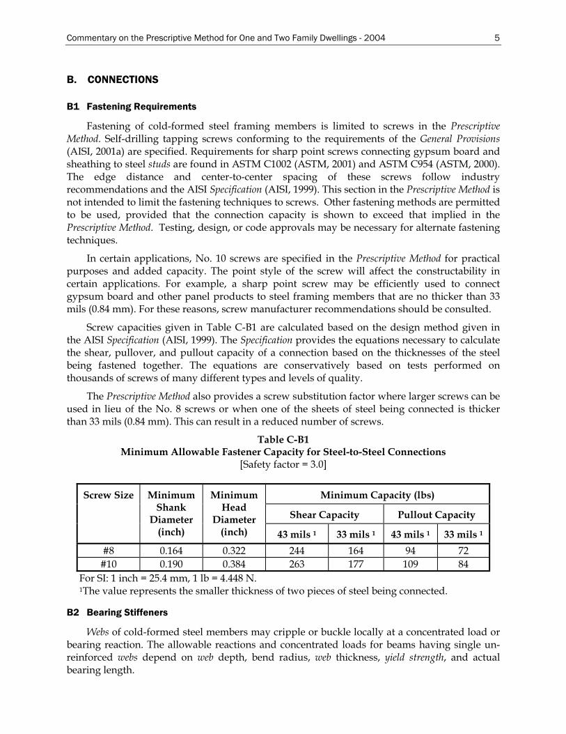
Screw capacities given in Table C-B1 are calculated based on the design method given in the AISI Specification (AISI, 1999). The Specification provides the equations necessary to calculate the shear, pullover, and pullout capacity of a connection based on the thicknesses of the steel being fastened together. The equations are conservatively based on tests performed on thousands of screws of many different types and levels of quality.
The Prescriptive Method also provides a screw substitution factor where larger screws can be used in lieu of the No. 8 screws or when one of the sheets of steel being connected is thicker than 33 mils (0.84 mm). This can result in a reduced number of screws.
Table C-B1 Minimum Allowable Fastener Capacity for Steel-to-Steel Connections
[Safety factor = 3.0]
Minimum Capacity (lbs)
Shear Capacity Pullout Capacity
Screw Size Minimum Shank
Diameter (inch)
Minimum Head
Diameter (inch) 43 mils 1 33 mils 1 43 mils 1 33 mils 1
#8 0.164 0.322 244 164 94 72 #10 0.190 0.384 263 177 109 84
For SI: 1 inch = 25.4 mm, 1 lb = 4.448 N. 1 The value represents the smaller thickness of two pieces of steel being connected.
B2 Bearing Stiffeners
Webs of cold-formed steel members may cripple or buckle locally at a concentrated load or bearing reaction. The allowable reactions and concentrated loads for beams having single un-reinforced webs depend on web depth, bend radius, web thickness, yield strength, and actual bearing length.
6 Commentary on the Prescriptive Method for One and Two Family Dwellings - 2004
The floor joist spans in the Prescriptive Method were derived assuming bearing stiffeners (also called transverse or web stiffeners) are located at all support or bearing point locations. Ceiling joist span tables were developed for two cases, 1) assuming bearing stiffeners are located at all support or bearing point locations and 2) bearing stiffeners are not installed at support or bearing point locations. Where specified, bearing stiffeners are to be a minimum of 43 mil (1.09 mm) track section or 33 mil (0.84 mm) C-shaped member.
B3 Clip Angles
All clip angle dimensions prescribed are shown as minimums. Clip angles that are of a greater base steel thickness or have greater overall dimensions, or both, are permitted to be used.
Commentary on the Prescriptive Method for One and Two Family Dwellings - 2004 7
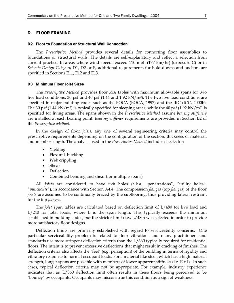
D. FLOOR FRAMING
D2 Floor to Foundation or Structural Wall Connection
The Prescriptive Method provides several details for connecting floor assemblies to foundations or structural walls. The details are self-explanatory and reflect a selection from current practice. In areas where wind speeds exceed 110 mph (177 km/hr) (exposure C) or in Seismic Design Category D1, D2 or E, additional requirements for hold-downs and anchors are specified in Sections E11, E12 and E13.
D3 Minimum Floor Joist Sizes
The Prescriptive Method provides floor joist tables with maximum allowable spans for two live load conditions: 30 psf and 40 psf (1.44 and 1.92 kN/m2). The two live load conditions are specified in major building codes such as the BOCA (BOCA, 1997) and the IRC (ICC, 2000b). The 30 psf (1.44 kN/m2) is typically specified for sleeping areas, while the 40 psf (1.92 kN/m2) is specified for living areas. The spans shown in the Prescriptive Method assume bearing stiffeners are installed at each bearing point. Bearing stiffener requirements are provided in Section B2 of the Prescriptive Method.
In the design of floor joists, any one of several engineering criteria may control the prescriptive requirements depending on the configuration of the section, thickness of material, and member length. The analysis used in the Prescriptive Method includes checks for:
• Yielding • Flexural buckling • Web crippling • Shear • Deflection • Combined bending and shear (for multiple spans)
All joists are considered to have web holes (a.k.a. “penetrations”, “utility holes”, “punchouts”), in accordance with Section A4.4. The compression flanges (top flanges) of the floor joists are assumed to be continually braced by the subflooring, thus providing lateral restraint for the top flanges.
The joist span tables are calculated based on deflection limit of L/480 for live load and L/240 for total loads, where L is the span length. This typically exceeds the minimum established in building codes, but the stricter limit (i.e., L/480) was selected in order to provide more satisfactory floor designs.
Deflection limits are primarily established with regard to serviceability concerns. One particular serviceability problem is related to floor vibrations and many practitioners and standards use more stringent deflection criteria than the L/360 typically required for residential floors. The intent is to prevent excessive deflections that might result in cracking of finishes. The deflection criteria also affects the "feel" (e.g. perception) of the building in terms of rigidity and vibratory response to normal occupant loads. For a material like steel, which has a high material strength, longer spans are possible with members of lower apparent stiffness (i.e. E x I). In such cases, typical deflection criteria may not be appropriate. For example, industry experience indicates that an L/360 deflection limit often results in these floors being perceived to be "bouncy" by occupants. Occupants may misconstrue this condition as a sign of weakness.
8 Commentary on the Prescriptive Method for One and Two Family Dwellings - 2004
While a deflection-to-span ratio of L/360 may be adequate under static loading, it is suggested that a significantly tighter deflection-to-span ratio under the full design live load only may be appropriate to ensure adequate performance. A higher deflection limit is usually recommended to overcome the concern with nuisance vibrations as it relates to human comfort. To ensure dynamic performance, the Australians (AISC, 1991) for example, consider a deflection-to-span ratio of L/750 (under full live loading) to be appropriate in the absence of full dynamic analysis. Furthermore, the Australians provide a criterion to determine what is an acceptable "house" system, based on critical damping. This method is not generic and requires the calculation of the first natural frequency and percent damping of the floor, which depend on the physical dimensions, stiffness, and attachments of the house. Due to this fact, a more simplistic approach would be to tighten the deflection criteria. A floor deflection-to-span ratio of L/480 (with 40 psf live load) typically results in an increase in the percent of critical damping as suggested by the AISC and thus ensures that vibration does not exceed a tolerable level. Many engineers apply an L/480 deflection criterion when designing steel floor joists.
Multiple spans are commonly used in the residential steel building market. With multiple spans, certain measures are necessary to address the responses of the loaded members. The magnitude of the reaction at the middle support will be greater than the end reactions, and may cause a web crippling failure at this location, which is controlled by requiring bearing stiffeners at all bearing points. The second issue is the presence of negative moments (i.e. reversed bending) at the middle support region, causing the compression flanges to be at the bottom rather than the top of the joists. If left unbraced, this would cause lateral instability and may cause premature failure of the joists under maximum loading conditions. Furthermore, shear and bending interaction need to be checked for multiple spans due to the presence of high shear and bending stresses at the middle reactions, creating greater susceptibility of web buckling.
Bottom flange bracing at interior supports is provided by ceiling finishes (when present) and by positive connection to the interior bearing wall. Possible benefits from composite action with the floor diaphragm were not utilized in the development of the Prescriptive Method.
Since multiple spans are often limited by strength considerations instead of deflection, steels with higher yield strengths can result in longer spans. Therefore, an additional table for 50 ksi (345 MPa) steels is provided for multiple spans. The 50 ksi (345 MPa) steel is not used for single spans because most of the entries in the single span tables are controlled by deflection rather than bending.
D3.1 Floor Cantilevers
In many cases, cantilevers support structural walls, which create special loading conditions that require separate engineering analysis. In the Prescriptive Method, floor cantilevers are limited to a maximum of 24 inches (610 mm) for floors supporting one wall and roof only (one story). This limitation is imposed to minimize the impact of the added load on the floor joists. To fully utilize the strength of the joist, web holes are not permitted in cantilevered portions. The Prescriptive Method provides details for first and second story cantilevered floors. It is essential that blocking be installed between cantilevered joists at the bearing locations to adequately transfer floor diaphragm or shear wall loads (refer to Section D5.4).
D4 Bearing Stiffeners
The floor spans in the Prescriptive Method were calculated assuming bearing stiffeners (also
Commentary on the Prescriptive Method for One and Two Family Dwellings - 2004 9
called transverse or web stiffeners) are located at all support or bearing point locations. The bearing stiffeners are specified to be a minimum of 43 mil (1.09 mm) track section or 33 mil (0.84 mm) C-shaped member. It is possible that a bearing stiffener may not be required for certain floor spans that are controlled by failure modes other than web crippling (such as deflection or bending). The web-crippling equations of the AISI Specification (AISI, 1999) may be checked to determine if a bearing stiffener is not required.
D5 Joist Bracing and Blocking
D5.1 Joist Top Flange Bracing
Steel floors have long been designed by considering the joists as simple beams acting independently without consideration of composite action from floor sheathing. For typical residential floors, it has been assumed that the function of the floor sheathing is to transfer the loads to the joists, and to provide continuous lateral bracing to the compression flanges neglecting many factors that affect the strength and stiffness of a floor. Testing has indicated that using a single joist for strength calculation agrees with actual behavior when uniform loads are applied (WJE, 1977).
D5.2 Joist Bottom Flange Bracing/Blocking
Bracing the bottom flanges of joists as specified in the Prescriptive Method is based on industry practice and engineering judgment. Steel strapping and finished ceilings (e.g. application of gypsum board) are considered to be adequate bracing for the tension flanges. It is necessary, however, for steel strapping to have blocking installed at a maximum spacing of 12 feet (3.7 m) and at the termination ends of all straps. Alternatively, the ends of steel straps may be fastened to a stable component of the building in lieu of blocking (i.e. to a bearing wall or foundation).
D5.3 Blocking at Interior Supports
Single floor joists that are lapped over interior supports do not require blocking as the lapped sections provide adequate lateral strength to prevent lateral movements. Continuous joists over interior supports, on the other hand, require blocking at 12 feet (3.7 m) intervals to provide adequate support to prevent lateral movement.
D5.4 Blocking at Cantilevers
Blocking is required for cantilevered supports to transfer shear loads from the floor diaphragm or shear wall.
D6 Splicing
Splicing of structural members is not permitted by the Prescriptive Method, however, there may be some situations where splicing would be useful. Applications may include repair of damaged joists, simplified details for dropped floors, and others. In these situations a design professional must be consulted.
Splices, generally, are required to transfer shear, bending moments, and axial loads. Some splices may occur over points of bearing and may only be required to transmit nominal axial loads. The floor joist spans provided in the Prescriptive Method are based on the assumption that the joists are continuous, with no splices. Therefore, splicing of joist members in the Prescriptive
10 Commentary on the Prescriptive Method for One and Two Family Dwellings - 2004
Method requires an approved design except when lapped joists occur at interior bearing points.
D7 Framing of Floor Openings
Openings in floors are needed for several reasons (such as at stairs, chases, chimneys). The Prescriptive Method limits the maximum width of the floor opening to 8 feet (2.4 m) and provides a provision for reinforcing the members around floor openings. All members around floor openings (i.e. header and trimmer joists) are required to be box-type members made by nesting a C-shaped joist into a track and fastening them together along the top and bottom flanges. These built-up members are required to be equal to or a greater in size and steel thickness than the floor joists, which they are connecting to. Each header joist is required to be connected to the trimmer joist with a clip angle on either side of each side of each connection. The clip angle is required to be of a thickness equivalent to the floor joists.
D8 Floor Trusses
This section is included so that pre-engineered floor trusses can be used in conjunction with this document. The American Iron and Steel Institute has developed a Standard for Cold-Formed Steel Framing – Truss Design (AISI, 2001b) to assist in truss design.
D9 Diaphragms
Floor diaphragms are required to adequately transfer shear loads to the foundation. In steel floors, this is typically accomplished by sheathing the top flanges of the joists with wood structural sheathing (such as OSB or plywood). Shear values used in verifying the adequacy of the floor diaphragms were taken from LGSEA Technical Note No. 558b-1 (LGSEA, 1998) for oriented-strand-board (OSB) panels fastened to steel members with No. 8 screws at 6 inch (152 mm) on center spacing at panel edges and 12 inch (305 mm) on center spacing at intermediate supports. Additional requirements for steel floors constructed in high wind (110 mph (177 km/hr) or greater) or high seismic areas (Seismic Design Category D1, D2 and E) are specified in Section D9.1.
D9.1 Floor Diaphragms in High Seismic and High Wind Areas
Shear values used in verifying the adequacy of the floor diaphragms were taken from LGSEA Technical Note No. 558b-1 (LGSEA, 1998) for oriented-strand-board (OSB) panels fastened to steel members with No. 8 screws at 6 inch (152 mm) on center spacing at panel edges and 6 inch (152 mm) on center spacing at intermediate supports. The reduced fastener spacing from 12 inches (305 mm) to 6 inches (152 mm) is to ensure that the diaphragm adequately transfers shear loads to the foundation.
Commentary on the Prescriptive Method for One and Two Family Dwellings - 2004 11
E. WALL FRAMING
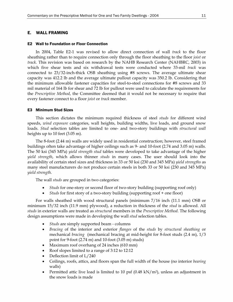
E2 Wall to Foundation or Floor Connection
In 2004, Table E2-1 was revised to allow direct connection of wall track to the floor sheathing rather than to require connection only through the floor sheathing to the floor joist or track. This revision was based on research by the NAHB Research Center (NAHBRC, 2003) in which five shear tests and six withdrawal tests were conducted where 33-mil track was connected to 23/32-inch-thick OSB sheathing using #8 screws. The average ultimate shear capacity was 412.2 lb and the average ultimate pullout capacity was 350.2 lb. Considering that the minimum allowable fastener capacities for steel-to-steel connections for #8 screws and 33 mil material of 164 lb for shear and 72 lb for pullout were used to calculate the requirements for the Prescriptive Method, the Committee deemed that it would not be necessary to require that every fastener connect to a floor joist or track member.
E3 Minimum Stud Sizes
This section dictates the minimum required thickness of steel studs for different wind speeds, wind exposure categories, wall heights, building widths, live loads, and ground snow loads. Stud selection tables are limited to one- and two-story buildings with structural wall heights up to 10 feet (3.05 m).
The 8-foot (2.44 m) walls are widely used in residential construction; however, steel framed buildings often take advantage of higher ceilings such as 9- and 10-foot (2.74 and 3.05 m) walls. The 50 ksi (345 MPa) yield strength stud tables were developed to take advantage of the higher yield strength, which allows thinner studs in many cases. The user should look into the availability of certain steel sizes and thickness in 33 or 50 ksi (230 and 345 MPa) yield strengths as many steel manufacturers do not produce certain steels in both 33 or 50 ksi (230 and 345 MPa) yield strength.
The wall studs are grouped in two categories:
• Studs for one-story or second floor of two-story building (supporting roof only) • Studs for first story of a two-story building (supporting roof + one floor)
For walls sheathed with wood structural panels (minimum 7/16 inch (11.1 mm) OSB or minimum 15/32 inch (11.9 mm) plywood), a reduction in thickness of the stud is allowed. All studs in exterior walls are treated as structural members in the Prescriptive Method. The following design assumptions were made in developing the wall stud selection tables.
• Studs are simply supported beam - columns • Bracing of the interior and exterior flanges of the studs by structural sheathing or
mechanical bracing (mechanical bracing at mid-height for 8-foot studs (2.4 m), 1/3 point for 9-foot (2.74 m) and 10-foot (3.05 m) studs)
• Maximum roof overhang of 24 inches (610 mm) • Roof slopes limited to a range of 3:12 to 12:12 • Deflection limit of L/240 • Ceilings, roofs, attics, and floors span the full width of the house (no interior bearing
walls) • Permitted attic live load is limited to 10 psf (0.48 kN/m2), unless an adjustment in
the snow loads is made
12 Commentary on the Prescriptive Method for One and Two Family Dwellings - 2004
• Second floor live load is 30 psf (1.44 kN/m2) unless an adjustment is made to the snow loads
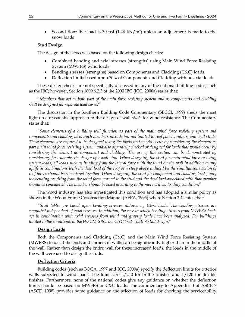
Stud Design
The design of the studs was based on the following design checks:
• Combined bending and axial stresses (strengths) using Main Wind Force Resisting System (MWFRS) wind loads
• Bending stresses (strengths) based on Components and Cladding (C&C) loads • Deflection limits based upon 70% of Components and Cladding with no axial loads
These design checks are not specifically discussed in any of the national building codes, such as the IBC; however, Section 1609.6.2.3 of the 2000 IBC (ICC, 2000a) states that:
“Members that act as both part of the main force resisting system and as components and cladding shall be designed for separate load cases.”
The discussion in the Southern Building Code Commentary (SBCCI, 1999) sheds the most light on a reasonable approach to the design of wall studs for wind resistance. The Commentary states that:
“Some elements of a building will function as part of the main wind force resisting system and components and cladding also. Such members include but not limited to roof panels, rafters, and wall studs. These elements are required to be designed using the loads that would occur by considering the element as part main wind force resisting system, and also separately checked or designed for loads that would occur by considering the element as component and cladding. The use of this section can be demonstrated by considering, for example, the design of a wall stud. When designing the stud for main wind force resisting system loads, all loads such as bending from the lateral force with the wind on the wall in addition to any uplift in combinations with the dead load of the roof or a story above induced by the simultaneous action of roof forces should be considered together. When designing the stud for component and cladding loads, only the bending resulting from the wind force normal to the stud and the dead load associated with that member should be considered. The member should be sized according to the more critical loading condition.”
The wood industry has also investigated this condition and has adopted a similar policy as shown in the Wood Frame Construction Manual (AFPA, 1995) where Section 2.4 states that:
“Stud tables are based upon bending stresses induces by C&C loads. The bending stresses are computed independent of axial stresses. In addition, the case in which bending stresses from MWFRS loads act in combination with axial stresses from wind and gravity loads have been analyzed. For buildings limited to the conditions in the WFCM-SBC, the C&C loads control stud design.”
Design Loads
Both the Components and Cladding (C&C) and the Main Wind Force Resisting System (MWFRS) loads at the ends and corners of walls can be significantly higher than in the middle of the wall. Rather than design the entire wall for these increased loads, the loads in the middle of the wall were used to design the studs.
Deflection Criteria
Building codes (such as BOCA, 1997 and ICC, 2000a) specify the deflection limits for exterior walls subjected to wind loads. The limits are L/240 for brittle finishes and L/120 for flexible finishes. Furthermore, none of the national codes give any guidance on whether the deflection limits should be based on MWFRS or C&C loads. The commentary to Appendix B of ASCE 7 (ASCE, 1998) provides some guidance on the selection of loads for checking the serviceability
Commentary on the Prescriptive Method for One and Two Family Dwellings - 2004 13
limit state of buildings and components thereof. Section B1.2 therein, states in part:
“Use of factored wind load in checking serviceability is exclusively conservative. The load combination with an annual probability of 0.05 of being exceeded, which can be used in checking short-term effects, is
D + 0.5L + 0.7W ”
Thus using 70% of the wind load from Components and Cladding (C&C) would conservatively satisfy the above.
AISC Design Guide No. 3 (AISC, 1990) also recommends reduced wind loads when checking serviceability of cladding based upon a 10-year return period on the wind or a probability of 0.10.
The Wood Frame Construction Manual (AFPA, 1995) is based slightly on a different criterion. The deflection limit is set at L/120 using MWFRS loads. The use of MWFRS appears to be within the intent of the recommended provisions of ASCE 7 (ASCE, 1998) Appendix B, since MWFRS loads are often about 70% of the C&C at least in the middle of the walls. This is an acceptable approach for studs supporting flexible finishes however, it is questioned if appropriate for use in studs supporting brittle finishes such as stucco. Therefore, stud deflections were checked against 70% of the C&C loads in the middle of the wall.
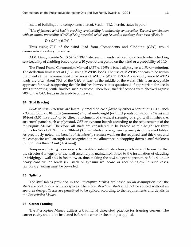
E4 Stud Bracing
Studs in structural walls are laterally braced on each flange by either a continuous 1-1/2 inch x 33 mil (38.1 x 0.84 mm) (minimum) strap at mid-height (or third points for 9-foot (2.74 m) and 10-foot (3.05 m) studs) or by direct attachment of structural sheathing or rigid wall finishes (i.e. structural panels such as plywood, OSB or gypsum board) according to the requirements of the Prescriptive Method. Therefore, all studs are considered to be braced at mid-height (or third points for 9-foot (2.74 m) and 10-foot (3.05 m) studs) for engineering analysis of the stud tables. As previously noted, the benefit of structurally sheathed walls on the required stud thickness and the composite wall strength are recognized in the allowance in dropping down a stud thickness (but not less than 33 mil (0.84 mm)).
Temporary bracing is necessary to facilitate safe construction practices and to ensure that the structural integrity of the wall assembly is maintained. Prior to the installation of cladding or bridging, a wall stud is free to twist, thus making the stud subject to premature failure under heavy construction loads (i.e. stack of gypsum wallboard or roof shingles). In such cases, temporary bracing must be provided.
E5 Splicing
The stud tables provided in the Prescriptive Method are based on an assumption that the studs are continuous, with no splices. Therefore, structural studs shall not be spliced without an approved design. Tracks are permitted to be spliced according to the requirements and details in the Prescriptive Method.
E6 Corner Framing
The Prescriptive Method utilizes a traditional three-stud practice for framing corners. The corner cavity should be insulated before the exterior sheathing is applied.
14 Commentary on the Prescriptive Method for One and Two Family Dwellings - 2004
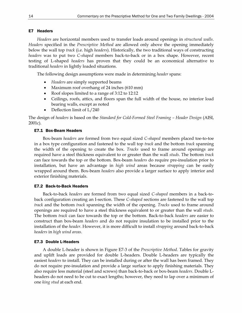
E7 Headers
Headers are horizontal members used to transfer loads around openings in structural walls. Headers specified in the Prescriptive Method are allowed only above the opening immediately below the wall top track (i.e. high headers). Historically, the two traditional ways of constructing headers was to put two C-shaped members back-to-back or in a box shape. However, recent testing of L-shaped headers has proven that they could be an economical alternative to traditional headers in lightly loaded situations.
The following design assumptions were made in determining header spans:
• Headers are simply supported beams • Maximum roof overhang of 24 inches (610 mm) • Roof slopes limited to a range of 3:12 to 12:12 • Ceilings, roofs, attics, and floors span the full width of the house, no interior load
bearing walls, except as noted • Deflection limit of L/240
The design of headers is based on the Standard for Cold-Formed Steel Framing – Header Design (AISI, 2001c).
E7.1 Box-Beam Headers
Box-beam headers are formed from two equal sized C-shaped members placed toe-to-toe in a box type configuration and fastened to the wall top track and the bottom track spanning the width of the opening to create the box. Tracks used to frame around openings are required have a steel thickness equivalent to or greater than the wall studs. The bottom track can face towards the top or the bottom. Box-beam headers do require pre-insulation prior to installation, but have an advantage in high wind areas because strapping can be easily wrapped around them. Box-beam headers also provide a larger surface to apply interior and exterior finishing materials.
E7.2 Back-to-Back Headers
Back-to-back headers are formed from two equal sized C-shaped members in a back-to-back configuration creating an I-section. These C-shaped sections are fastened to the wall top track and the bottom track spanning the width of the opening. Tracks used to frame around openings are required to have a steel thickness equivalent to or greater than the wall studs. The bottom track can face towards the top or the bottom. Back-to-back headers are easier to construct than box-beam headers and do not require insulation to be installed prior to the installation of the header. However, it is more difficult to install strapping around back-to-back headers in high wind areas.
E7.3 Double L-Headers
A double L-header is shown in Figure E7-3 of the Prescriptive Method. Tables for gravity and uplift loads are provided for double L-headers. Double L-headers are typically the easiest headers to install. They can be installed during or after the wall has been framed. They do not require pre-insulation and provide a large surface to apply finishing materials. They also require less material (steel and screws) than back-to-back or box-beam headers. Double L-headers do not need to be cut to exact lengths; however, they need to lap over a minimum of one king stud at each end.
Commentary on the Prescriptive Method for One and Two Family Dwellings - 2004 15
In 2004, the requirements in the Prescriptive Method for the L-header to king stud connection was revised to be consistent with the Header Standard (AISI, 2001c). This was unintentionally missed in the previous edition of the Prescriptive Method.
E7.4 Jack and King Studs and Head Track
The required number of jack and king studs was calculated based on the size of the opening. The number was determined by taking the width of the opening, divided by the stud spacing, and rounding the decimal to the next higher number. The resulting number is further divided into jack and king studs based on the required axial capacity being provided by the jack studs only. King and jack studs are required to be the same size and thickness as the adjacent wall studs. Jack and king studs are interconnected by structural sheathing (plywood or OSB) to transfer lateral loads (when multiple king and jack studs are required).
Head tracks are those located at top or bottom of window or door openings. Head tracks span the full width of the opening and were designed for lateral loads only. The maximum spans for the head tracks were calculated using C&C wind loads with 48 inch (1.22 m) tributary span (i.e., assuming the opening covers the entire height of the 8-foot (2.44 m) wall.) As the tributary span decreases, the head track span increases, as it will have to resist less wind loads. Therefore, for a 4-foot (1.22 m) opening, the tributary span decreases to 2 feet (0.61 m) and hence the maximum head track span increases by a factor of 1.75. Similarly, for a 6-foot (1.83 m) opening, the tributary span decreases to 3 feet (0.92 m) and hence the maximum head track span increases by a factor of 1.50.
E8 Wall Bracing
The wall bracing provisions of this section are applicable to buildings classified as Seismic Design Category A, B and C and for buildings located where the basic wind speed is 90 mph (145 km/hr) or less.
Three different bracing methods are recognized in the Prescriptive Method:
• Steel strap bracing (diagonal X-bracing) • Structural sheathing (plywood or OSB) • Sheet steel (in high wind and high seismic regions)
E8.1 Strap Bracing (X-brace)
The wall bracing in the Prescriptive Method was conservatively limited to the use of continuously sheathed walls with limitations on loading conditions and building geometry. The use of sheet steel diagonal bracing (strapping) must be designed in accordance with approved engineering practices.
E8.2 Structural Sheathing
Shear wall testing of steel-framed walls provided the data necessary to develop the provisions and tables of values for the structural sheathing sections. All tests performed were based on sheathing panels, which consisted of either 15/32 inch (0.47 mm) plywood or 7/16 inch (0.44 mm) oriented strand board as the bracing method (AISI, 1998).
The wall bracing requirements in the Prescriptive Method were based on an engineered approach that utilized available technical knowledge. The allowable shear capacities for plywood and oriented- strand-board (OSB) sheathing are based on test results summarized in
16 Commentary on the Prescriptive Method for One and Two Family Dwellings - 2004
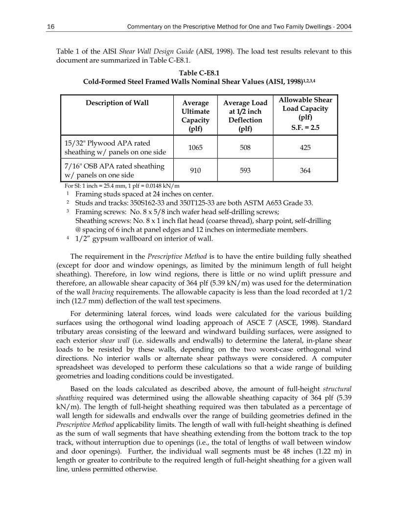
Table 1 of the AISI Shear Wall Design Guide (AISI, 1998). The load test results relevant to this document are summarized in Table C-E8.1.
Table C-E8.1 Cold-Formed Steel Framed Walls Nominal Shear Values (AISI, 1998)1,2,3,4
Description of Wall Average Ultimate Capacity
(plf)
Average Load at 1/2 inch Deflection
(plf)
Allowable Shear Load Capacity
(plf) S.F. = 2.5
15/32" Plywood APA rated sheathing w/ panels on one side 1065 508 425
7/16" OSB APA rated sheathing w/ panels on one side 910 593 364
For SI: 1 inch = 25.4 mm, 1 plf = 0.0148 kN/m 1 Framing studs spaced at 24 inches on center. 2 Studs and tracks: 350S162-33 and 350T125-33 are both ASTM A653 Grade 33. 3 Framing screws: No. 8 x 5/8 inch wafer head self-drilling screws;
Sheathing screws: No. 8 x 1 inch flat head (coarse thread), sharp point, self-drilling @ spacing of 6 inch at panel edges and 12 inches on intermediate members.
4 1/2” gypsum wallboard on interior of wall.
The requirement in the Prescriptive Method is to have the entire building fully sheathed (except for door and window openings, as limited by the minimum length of full height sheathing). Therefore, in low wind regions, there is little or no wind uplift pressure and therefore, an allowable shear capacity of 364 plf (5.39 kN/m) was used for the determination of the wall bracing requirements. The allowable capacity is less than the load recorded at 1/2 inch (12.7 mm) deflection of the wall test specimens.
For determining lateral forces, wind loads were calculated for the various building surfaces using the orthogonal wind loading approach of ASCE 7 (ASCE, 1998). Standard tributary areas consisting of the leeward and windward building surfaces, were assigned to each exterior shear wall (i.e. sidewalls and endwalls) to determine the lateral, in-plane shear loads to be resisted by these walls, depending on the two worst-case orthogonal wind directions. No interior walls or alternate shear pathways were considered. A computer spreadsheet was developed to perform these calculations so that a wide range of building geometries and loading conditions could be investigated.
Based on the loads calculated as described above, the amount of full-height structural sheathing required was determined using the allowable sheathing capacity of 364 plf (5.39 kN/m). The length of full-height sheathing required was then tabulated as a percentage of wall length for sidewalls and endwalls over the range of building geometries defined in the Prescriptive Method applicability limits. The length of wall with full-height sheathing is defined as the sum of wall segments that have sheathing extending from the bottom track to the top track, without interruption due to openings (i.e., the total of lengths of wall between window and door openings). Further, the individual wall segments must be 48 inches (1.22 m) in length or greater to contribute to the required length of full-height sheathing for a given wall line, unless permitted otherwise.
Commentary on the Prescriptive Method for One and Two Family Dwellings - 2004 17
As a final step necessary for a basic prescriptive approach, the requirements were conservatively reduced to the minimum percent lengths of full-height sheathed wall shown in the wall-bracing table of the Prescriptive Method. The only building geometry parameter retained was roof slope due to a significant impact on the wind loads transferred to the shear walls. Footnotes to the shear wall table provide additional information related to the proper applications of the requirements.
E8.3 Structural Sheathing Fastening
Fastening of structural sheathing is typically done at 6 inch (152 mm) spacing at the perimeters and 12 inch spacing (305 mm) in the field. When this spacing is reduced to 4 inches (102 mm) (perimeter spacing only), the percentage of full height sheathing is permitted to be multiplied by 0.72.
E8.4 Hold-down Requirements
In wind conditions greater than 100 mph (161 km/hr) exposure C, hold-down brackets in accordance with Table E2-1 are required to stabilize the shear walls. A hold-down bracket shall consist of an approved strap or bracket adequately attached to the base of the stud and anchored to the foundation, floor, or wall below to form a continuous load path to the foundation. Hold-downs may also be added to reduce the amount of full-height sheathing required, or to increase the shear (racking) strength of the wall.
E9 Exterior Wall Covering
It is recommended that exterior coverings be installed in accordance with the recommendations of the manufacturer. The Prescriptive Method limits the total exterior envelope dead load (total load = stud framing plus wall coverings) to 10 psf (0.48 kN/m2). If the total exterior envelope dead load exceeds that value, then the walls must be engineered for that load (see Table A1-2 for maximum wall dead loads in high seismic areas).
E11 Braced Walls in High Wind and High Seismic Areas
E11.1 General
This section provides additional shear wall requirements for buildings located in high seismic areas (i.e., Seismic Design Categories D1, D2 and E) or high wind areas (i.e., wind speed between 100 to 130 mph (161 to 209 km/hr)). In high seismic areas, buildings are required to comply with Section E11 and E12; and in high wind areas, buildings are required to comply with the requirements in Section E11 and E13.
The following general assumptions and building configurations were used in developing the high seismic tables and high wind provisions:
• Provisions and tables are limited to buildings no more than two-stories • Provisions and tables are limited to buildings on slab-on-grade or spread footing
with stemwall foundation system with a single top of slab/top of stemwall elevation
• Wall clear heights are limited to 8, 9, and 10 feet (2.44, 2.74 and 3.05 m) • Maximum roof slope is limited to 6.9:12 • All ceilings are considered leveled (i.e., no offsets or cathedral ceilings)
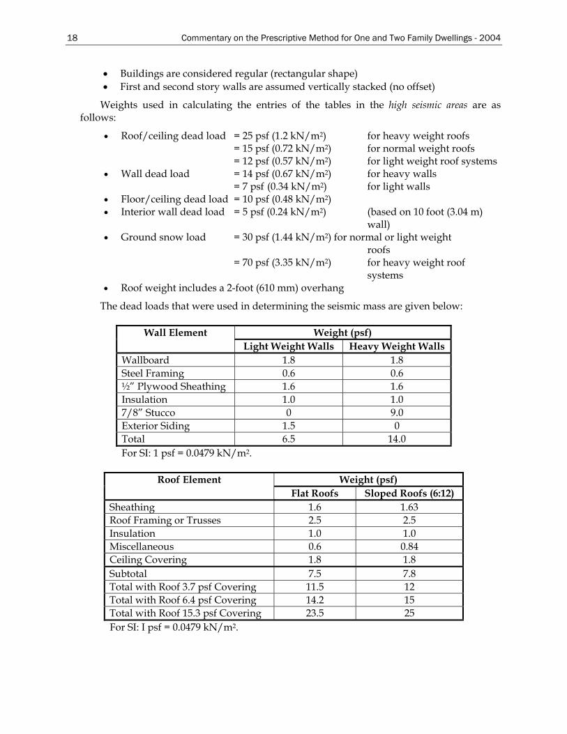
18 Commentary on the Prescriptive Method for One and Two Family Dwellings - 2004
• Buildings are considered regular (rectangular shape) • First and second story walls are assumed vertically stacked (no offset)
Weights used in calculating the entries of the tables in the high seismic areas are as follows:
• Roof/ceiling dead load = 25 psf (1.2 kN/m2) for heavy weight roofs = 15 psf (0.72 kN/m2) for normal weight roofs = 12 psf (0.57 kN/m2) for light weight roof systems
• Wall dead load = 14 psf (0.67 kN/m2) for heavy walls = 7 psf (0.34 kN/m2) for light walls
• Floor/ceiling dead load = 10 psf (0.48 kN/m2) • Interior wall dead load = 5 psf (0.24 kN/m2) (based on 10 foot (3.04 m)
wall) • Ground snow load = 30 psf (1.44 kN/m2) for normal or light weight
roofs = 70 psf (3.35 kN/m2) for heavy weight roof systems
• Roof weight includes a 2-foot (610 mm) overhang
The dead loads that were used in determining the seismic mass are given below:
Weight (psf) Wall Element Light Weight Walls Heavy Weight Walls
Wallboard 1.8 1.8 Steel Framing 0.6 0.6 ½” Plywood Sheathing 1.6 1.6 Insulation 1.0 1.0 7/8” Stucco 0 9.0 Exterior Siding 1.5 0 Total 6.5 14.0 For SI: 1 psf = 0.0479 kN/m2.
Roof Element Weight (psf)
Flat Roofs Sloped Roofs (6:12) Sheathing 1.6 1.63 Roof Framing or Trusses 2.5 2.5 Insulation 1.0 1.0 Miscellaneous 0.6 0.84 Ceiling Covering 1.8 1.8 Subtotal 7.5 7.8 Total with Roof 3.7 psf Covering 11.5 12 Total with Roof 6.4 psf Covering 14.2 15 Total with Roof 15.3 psf Covering 23.5 25 For SI: I psf = 0.0479 kN/m2.
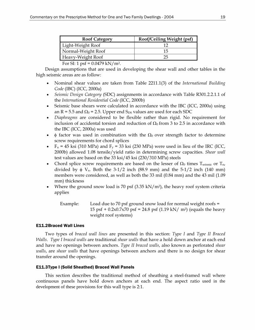
Commentary on the Prescriptive Method for One and Two Family Dwellings - 2004 19
Roof Category Roof/Ceiling Weight (psf)
Light-Weight Roof 12 Normal-Weight Roof 15 Heavy-Weight Roof 25 For SI: 1 psf = 0.0479 kN/m2.
Design assumptions that are used in developing the shear wall and other tables in the high seismic areas are as follow:
• Nominal shear values are taken from Table 2211.1(3) of the International Building Code (IBC) (ICC, 2000a)
• Seismic Design Category (SDC) assignments in accordance with Table R301.2.2.1.1 of the International Residential Code (ICC, 2000b)
• Seismic base shears were calculated in accordance with the IBC (ICC, 2000a) using an R = 5.5 and Ω0 = 2.5. Upper end SDS values are used for each SDC
• Diaphragms are considered to be flexible rather than rigid. No requirement for inclusion of accidental torsion and reduction of Ω0 from 3 to 2.5 in accordance with the IBC (ICC, 2000a) was used
• φ factor was used in combination with the Ω0 over strength factor to determine screw requirements for chord splices
• Fu = 45 ksi (310 MPa) and Fy = 33 ksi (230 MPa) were used in lieu of the IRC (ICC, 2000b) allowed 1.08 tensile/yield ratio in determining screw capacities. Shear wall test values are based on the 33 ksi/45 ksi (230/310 MPa) steels
• Chord splice screw requirements are based on the lesser of Ω0 times Tseismic or Tn, divided by φ Vn. Both the 3-1/2 inch (88.9 mm) and the 5-1/2 inch (140 mm) members were considered, as well as both the 33 mil (0.84 mm) and the 43 mil (1.09 mm) thickness
• Where the ground snow load is 70 psf (3.35 kN/m2), the heavy roof system criteria applies
Example: Load due to 70 psf ground snow load for normal weight roofs =
15 psf + 0.2x0.7x70 psf = 24.8 psf (1.19 kN/ m2) (equals the heavy weight roof systems)
E11.2 Braced Wall Lines
Two types of braced wall lines are presented in this section: Type I and Type II Braced Walls. Type I braced walls are traditional shear walls that have a hold down anchor at each end and have no openings between anchors. Type II braced walls, also known as perforated shear walls, are shear walls that have openings between anchors and there is no design for shear transfer around the openings.
E11.3 Type I (Solid Sheathed) Braced Wall Panels
This section describes the traditional method of sheathing a steel-framed wall where continuous panels have hold down anchors at each end. The aspect ratio used in the development of these provisions for this wall type is 2:1.
20 Commentary on the Prescriptive Method for One and Two Family Dwellings - 2004
E11.4 Type II (Perforated) Braced Wall Lines
The Type II Braced Wall, or perforated shear wall method, requires hold-downs at each end of each wall rather than at each end of continuous panels. The aspect ratio is also 2:1 for this wall type. For a defined Type II (perforated shear wall), the adjustment factors given in Table E11-2 define the magnitude by which the strength of an otherwise solid wall must be divided to get the strength of the Type II (perforated) wall. The tabulated values, adopted from wood frame construction, were justified on the basis of a series of full-scale reversed cyclic tests by Vagh, Dolan and Easterling (2000) in which it was demonstrated that the wall capacities were greater than the reductions (inverse of the values on Table E11-2) recommended in the table.
E12 Braced Wall Design in High Seismic Areas
E12.2 Braced Wall Anchorage and Chord Stud Requirements
Hold-downs and the proper number and thickness of chord studs are essential to allow the building to resist uplift forces in high seismic areas.
E12.3 Wall Top Track
The top track splice shall be adequate to transfer diaphragm forces. Table E12-5 provides the number of screws required for each splice.
E13 Braced Wall Design in High Wind Areas
E13.3 Connections of Walls in High Wind Areas
E13.3.3 Header Uplift Connections
In 2004 a figure was added to the Prescriptive Method to illustrate a header uplift connection to a back-to-back header beam. For back-to-back headers supporting roof and ceiling only, these provisions require that uplift straps be installed on both sides of the header beam (inside and outside of the wall) in order to minimize any effect of torsion. The Committee felt this was appropriate since back-to-back header beams lack sufficient torsional strength and stiffness. For back-to-back headers supporting loads from one floor, roof and ceiling, and for any box and double L-headers, a single uplift strap is permitted and may be installed on either side of the header beam.
Commentary on the Prescriptive Method for One and Two Family Dwellings - 2004 21
F. ROOF FRAMING
F1 Roof Construction
Roof construction in the Prescriptive Method is limited to roof rafters and ceiling joists. Roof trusses are not prescriptively addressed in the Prescriptive Method, but are permitted and must be designed by a design professional. Hips, valleys, and roof girders are also not addressed in the Prescriptive Method.
F2 Ceiling Joists
F2.1 Minimum Ceiling Joist Size
Ceiling joist tables in the Prescriptive Method provide the maximum allowable ceiling joist spans for two loading conditions: 10 psf (0.48 kN/m2) and 20 psf (0.96 kN/m2) attic live loads.
In the design of ceiling joists, any one of several engineering criteria may control the prescriptive requirements depending on the configuration of the section, thickness of material and member length. The analysis must include checks for:
• Yielding • Flexural buckling • Web crippling (not required if web stiffeners are specified) • Shear • Deflection
The engineering approach used to develop ceiling joist span tables for the Prescriptive Method is similar to that used for floor joists with the exception of the magnitude of dead and live loads.
F2.2 Ceiling Joist Bearing Stiffeners
Bearing stiffeners are required at the ends of ceiling joists unless the tables with no bearing stiffeners are used.
F2.3 Ceiling Joist Bottom Flange Bracing
Gypsum board (i.e. finished ceilings) is considered to be adequate bracing for the bottom (tension) flanges of the ceiling joists. Steel strapping can also be used as bottom flange bracing for ceiling joists.
F2.4 Ceiling Joist Top Flange Bracing
For braced top (compression) flanges it is necessary for steel strapping to have blocking (or bridging) installed at a maximum spacing of 12 feet (3.66 m) and at the termination of all straps. Moreover, the ends of steel straps are to be fastened to a stable component of the building if end blocking is not installed. Ceiling joist tables provide spans for braced, as well as unbraced, top flanges.
22 Commentary on the Prescriptive Method for One and Two Family Dwellings - 2004
F2.5 Ceiling Joist Splicing
Splicing of ceiling joists in the Prescriptive Method requires an approved design except when lapped ceiling joists occur at an interior bearing wall.
F3 Roof Rafters
F3.1 Minimum Roof Rafter Sizes
The rafter span table was designed based primarily on gravity loads, hence the rafter spans are based on the horizontal projection of the rafter, regardless of the slope. The gravity loads consist of a 7 psf (0.34 kN/m2) dead load and the greater of a 16 psf (0.77 kN/m2) live load or the applied roof snow load.
Wind load effects are developed by a procedure that equates the wind loads to equivalent snow loads as shown in Table F3.2 of the Prescriptive Method. Wind pressures were calculated using the ASCE 7 (ASCE, 1998) Components and Cladding coefficients. Wind loads acting perpendicular to the plane of the rafter were adjusted to represent loads acting orthogonal to the horizontal projection of the rafter. Wind loads were examined for both uplift and downward loads and the worst case was correlated to a corresponding snow load.
Permissible roof slopes range between 3:12 through 12:12 and more importantly, the roof system must consist of both ceiling joists (i.e. acting as rafter ties) and rafters. The Prescriptive Method does not currently address cathedral ceilings because a prescriptive ridge beam and post design is not provided.
Lapped ceiling joists must be connected with the same screw size and number (or more) as the heel joint connection to ensure adequate transfer of tension loads across the spliced joint. The splice must occur over an interior bearing wall.
F3.1.1 Eave Overhang
The 24 inch (610 mm) eave overhang was used in calculating the rafter spans in the Prescriptive Method.
F3.2 Roof Rafter Support Brace
The support brace is used to increase the span of a particular member. When the brace is used, the rafter span is determined from the heel joint to the brace point or from the ridge member to the brace point (horizontal projection), whichever is greater.
F3.3 Rafter Splice
The rafter spans provided in the Prescriptive Method are based on the assumption that the members are continuous, with no splices. Therefore, rafters are not to be spliced without an approved design.
F3.5 Rafter Bottom Flange Bracing
The bracing requirements provided in the Prescriptive Method are commonly used in residential steel construction. The requirements are similar to those found in the floor framing section when gypsum wallboard is not applied to the bottom of the joists.
Commentary on the Prescriptive Method for One and Two Family Dwellings - 2004 23
F4 Framing of Openings in Roofs and Ceilings
This section is similar to the openings in floors, with the maximum opening width limited to 4 feet (1.22 m).
F5 Roof Trusses
The Prescriptive Method does not contain provisions for trusses. This section is included so that pre-engineered trusses may be used in conjunction with this document. The Standard for Cold-Formed Steel Framing – Truss Design (AISI, 2001b) was developed to assist in the design, manufacturing and installation of steel trusses.
F6 Roof Diaphragms
Roof diaphragms are required to adequately transfer shear loads to the braced wall lines in a structure. In steel-framed roofs, this is typically accomplished by sheathing the roof-framing members with wood structural panels. Shear values used in the design of roof diaphragms were taken from LGSEA Technical Note No. 558b-1 (LGSEA, 1998). The values given in this document are based on the calculated strength of the fastener connection for a defined configuration with reductions in that strength taken for panel grade, panel buckling and lightly loaded diaphragms. Additional requirements for steel roof diaphragms in high wind areas (i.e., 110 mph (177 km/hr) or greater wind speed) or high seismic areas (i.e., Seismic Design Category D1, D2 and E) are specified in Section F6.1 and F6.2.
24 Commentary on the Prescriptive Method for One and Two Family Dwellings - 2004
PART 2 – DESIGN EXAMPLES
FOR THE STANDARD FOR COLD-FORMED STEEL FRAMING –
PRESCRIPTIVE METHOD FOR ONE AND TWO FAMILY DWELLINGS
A. INTRODUCTION
This section provides technical substantiation and design examples for the Prescriptive Method (AISI, 2001d). These design examples are based primarily on existing available reference standards such as the American Iron and Steel Institute Specification for the Design of Cold-Formed Steel Structural Members (AISI, 1999), the American Society of Civil Engineers standard ASCE-7 Minimum Design Loads for Buildings and Other Structures (ASCE, 1998) and the American Iron and Steel Institute Standard for Cold-Formed Steel Framing – Header Design (AISI, 2001c).
This document was developed as a supplemental information package, which illustrates the basis for the development of the prescriptive requirements for steel framing.
These design examples are shown in U.S. customary units. For appropriate conversions to the International System of Units (SI); i.e., metric conversion, refer to Appendix A.
A1 Member Properties
All section properties and member capacities were calculated using the Specification. Floor and ceiling joist members were assumed to have holes with 2½” wide x 4” long along the centerline of the web. Studs and other structural elements were assumed to have holes with 1½” wide x 4” long along the centerline of the web.
Minimum Fy = 33 ksi Minimum Fu = 45 ksi Minimum Fy = 50 ksi Minimum Fu = 65 ksi
The design thickness (minimum thickness divided by 0.95) used in calculating member capacity and section properties was based on the Specification Section A3.4.
A2 Design Loads
The following loads were used in designing the various steel-framing members:
Ceiling dead load = 5 psf Roof dead load = 7 psf Floor dead load = 10 psf First floor live load = 40 psf Second floor live load = 30 psf Wall dead load = 10 psf Attic live load = 10 psf for attics with no storage Attic live load = 20 psf for attics with storage Wind load = Varies by wind speed and exposure (3-sec. Gust) Seismic Load = Varies by Seismic Design Category: A, B, C, D1, D2, or E Roof snow load = 0.7 x Ground snow load Roof live load = greater of 16 psf live load or the applied snow load
Commentary on the Prescriptive Method for One and Two Family Dwellings - 2004 25
A2.1 Roof Snow Loads
Applied roof snow loads were calculated by multiplying the ground snow load by a 0.7 conversion factor in accordance with ASCE 7 (ASCE, 1998). No further reductions were made for special cases.
The sloped roof snow load, Ps = Cs x Pf, where Pf is the flat roof snow load. Pf = 0.7 Ce Ct I Pg
Cs Cs is the roof slope factor ranging from approximately 0.1 to 1.0. For warm roofs
(i.e. house roofs) the Cs curve is slightly smoother than that for cold roofs. Roofs with slopes up to 6:12 have a slope factor of 1.0, while roofs with slopes greater than 7:12 have a slope factor between 0.4 to 1.0. A slope factor of 1.0 is judged to be conservative for houses with roof slopes from 3:12 to 12:12.
Ce Ce is the exposure factor depending on the location of the house. Ce varies from 0.8 for windy, unsheltered areas, to 1.2 for heavily sheltered areas. A factor of 1.0 is deemed reasonable for residential buildings that are partially exposed (ASCE 7, Table 7-2).
Ct Ct is a thermal factor that varies from 1.0 for heated structures to 1.2 for unheated structures. The thermal factor should be used based on the thermal condition that is likely to exist during the life of the structure. Houses are typically considered heated structures with Ct = 1.0 (ASCE 7, Table 7-3). Although it is possible that a brief interruption of power will cause temporary cooling of a heated house, the joint probability of this with a peak snow load is highly unlikely. Houses that are unoccupied during cold seasons, may experience a higher thermal factor, however, for unoccupied buildings the importance factor drops to 0.8, thus reducing the design loads by 20%, which offsets the 20% increase in the thermal factor.
I I is the importance factor based on building classification. Houses are typically Category II structures, with an importance factor of 1.0 (ASCE 7, Table 7-4).
Pg Pg is the ground snow load from the ASCE 7 estimated ground snow map (psf). This map is also included in all major building codes.
Unbalanced snow loads, sliding snow loads, and snow drifts on lower roofs were not
considered due to the lack of evidence for damage from unbalanced loads on homes and the lack of data to typify the statistical uncertainties associated with this load pattern on residential structures. Rain-on-snow surcharge load was also not considered in the calculations. Roof slopes in this document exceed the ½-inch per foot requirement by ASCE 7 for the added load to be considered. Therefore, roof snow load was computed as: 1.0 * 0.7 * 1.0 * 1.0 * Pg = 0.7 Pg.
A2.2 Wind Loads
Wind loads were based on 3-second gust wind speeds ranging from 85 to 130 mph, Exposure A, B, or C.
q = 0.00256 x Kz x (GCp + GCpi) x (V2 x I) Kz = 0.87 at 20 feet, for Exposure C GCp = 0 for Zone 1, Tributary area = 75 ft2, (ASCE 7-1998, page 18) GCpi = ± 0.25 for Components and Cladding, interior pressure, enclosed buildings
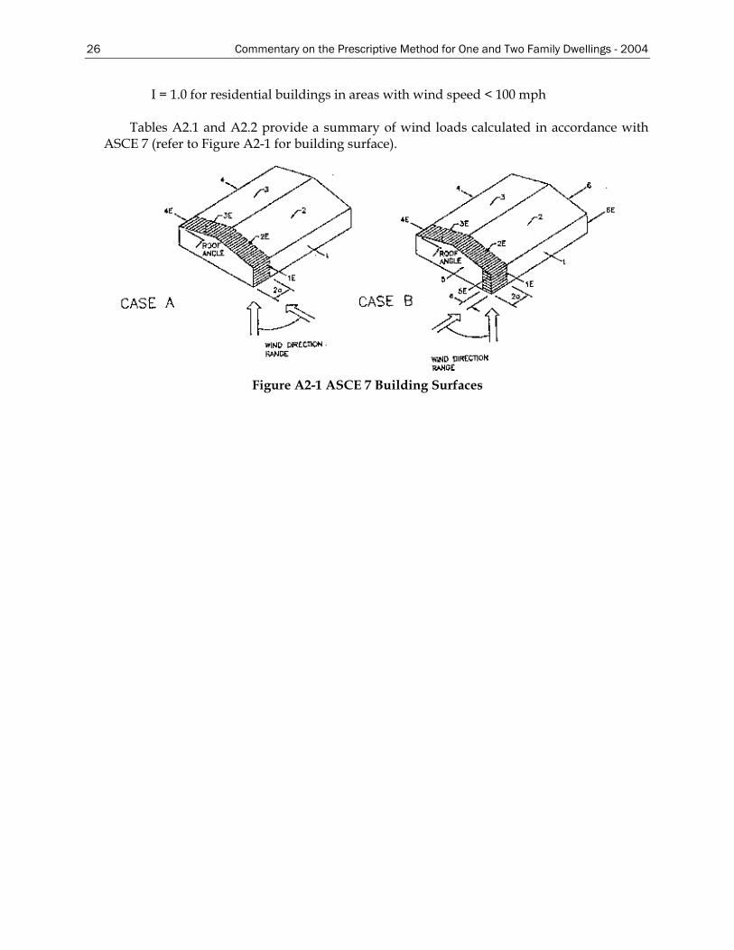
26 Commentary on the Prescriptive Method for One and Two Family Dwellings - 2004
I = 1.0 for residential buildings in areas with wind speed < 100 mph
Tables A2.1 and A2.2 provide a summary of wind loads calculated in accordance with ASCE 7 (refer to Figure A2-1 for building surface).
Figure A2-1 ASCE 7 Building Surfaces
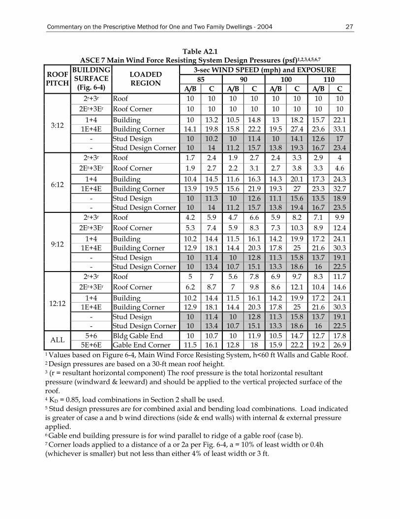
Commentary on the Prescriptive Method for One and Two Family Dwellings - 2004 27
Table A2.1 ASCE 7 Main Wind Force Resisting System Design Pressures (psf)1,2,3,4,5,6,7
3-sec WIND SPEED (mph) and EXPOSURE 85 90 100 110
ROOF PITCH
BUILDING SURFACE (Fig. 6-4)
LOADED REGION
A/B C A/B C A/B C A/B C 2r+3r Roof 10 10 10 10 10 10 10 10
2Er+3Er Roof Corner 10 10 10 10 10 10 10 10 1+4 Building 10 13.2 10.5 14.8 13 18.2 15.7 22.1
1E+4E Building Corner 14.1 19.8 15.8 22.2 19.5 27.4 23.6 33.1 - Stud Design 10 10.2 10 11.4 10 14.1 12.6 17
3:12
- Stud Design Corner 10 14 11.2 15.7 13.8 19.3 16.7 23.4 2r+3r Roof 1.7 2.4 1.9 2.7 2.4 3.3 2.9 4
2Er+3Er Roof Corner 1.9 2.7 2.2 3.1 2.7 3.8 3.3 4.6 1+4 Building 10.4 14.5 11.6 16.3 14.3 20.1 17.3 24.3
1E+4E Building Corner 13.9 19.5 15.6 21.9 19.3 27 23.3 32.7 - Stud Design 10 11.3 10 12.6 11.1 15.6 13.5 18.9
6:12
- Stud Design Corner 10 14 11.2 15.7 13.8 19.4 16.7 23.5 2r+3r Roof 4.2 5.9 4.7 6.6 5.9 8.2 7.1 9.9
2Er+3Er Roof Corner 5.3 7.4 5.9 8.3 7.3 10.3 8.9 12.4 1+4 Building 10.2 14.4 11.5 16.1 14.2 19.9 17.2 24.1
1E+4E Building Corner 12.9 18.1 14.4 20.3 17.8 25 21.6 30.3 - Stud Design 10 11.4 10 12.8 11.3 15.8 13.7 19.1
9:12
- Stud Design Corner 10 13.4 10.7 15.1 13.3 18.6 16 22.5 2r+3r Roof 5 7 5.6 7.8 6.9 9.7 8.3 11.7
2Er+3Er Roof Corner 6.2 8.7 7 9.8 8.6 12.1 10.4 14.6 1+4 Building 10.2 14.4 11.5 16.1 14.2 19.9 17.2 24.1
1E+4E Building Corner 12.9 18.1 14.4 20.3 17.8 25 21.6 30.3 - Stud Design 10 11.4 10 12.8 11.3 15.8 13.7 19.1
12:12
- Stud Design Corner 10 13.4 10.7 15.1 13.3 18.6 16 22.5 5+6 Bldg Gable End 10 10.7 10 11.9 10.5 14.7 12.7 17.8 ALL
5E+6E Gable End Corner 11.5 16.1 12.8 18 15.9 22.2 19.2 26.9 1 Values based on Figure 6-4, Main Wind Force Resisting System, h<60 ft Walls and Gable Roof. 2 Design pressures are based on a 30-ft mean roof height. 3 (r = resultant horizontal component) The roof pressure is the total horizontal resultant pressure (windward & leeward) and should be applied to the vertical projected surface of the roof. 4 KD = 0.85, load combinations in Section 2 shall be used. 5 Stud design pressures are for combined axial and bending load combinations. Load indicated is greater of case a and b wind directions (side & end walls) with internal & external pressure applied. 6 Gable end building pressure is for wind parallel to ridge of a gable roof (case b). 7 Corner loads applied to a distance of a or 2a per Fig. 6-4, a = 10% of least width or 0.4h (whichever is smaller) but not less than either 4% of least width or 3 ft.
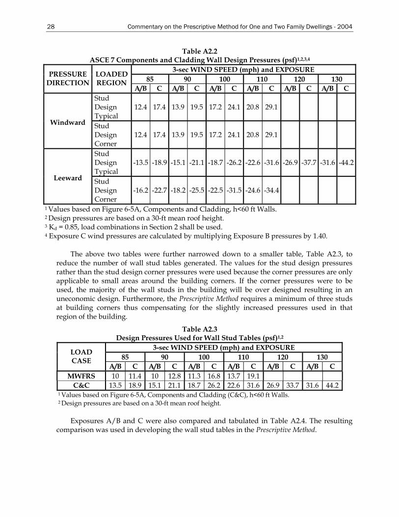
28 Commentary on the Prescriptive Method for One and Two Family Dwellings - 2004
Table A2.2 ASCE 7 Components and Cladding Wall Design Pressures (psf)1,2,3,4
3-sec WIND SPEED (mph) and EXPOSURE 85 90 100 110 120 130
PRESSURE DIRECTION
LOADED REGION
A/B C A/B C A/B C A/B C A/B C A/B C Stud Design Typical
12.4 17.4 13.9 19.5 17.2 24.1 20.8 29.1
Windward Stud Design Corner
12.4 17.4 13.9 19.5 17.2 24.1 20.8 29.1
Stud Design Typical
-13.5 -18.9 -15.1 -21.1 -18.7 -26.2 -22.6 -31.6 -26.9 -37.7 -31.6 -44.2
Leeward Stud Design Corner
-16.2 -22.7 -18.2 -25.5 -22.5 -31.5 -24.6 -34.4
1 Values based on Figure 6-5A, Components and Cladding, h<60 ft Walls. 2 Design pressures are based on a 30-ft mean roof height. 3 Kd = 0.85, load combinations in Section 2 shall be used. 4 Exposure C wind pressures are calculated by multiplying Exposure B pressures by 1.40.
The above two tables were further narrowed down to a smaller table, Table A2.3, to reduce the number of wall stud tables generated. The values for the stud design pressures rather than the stud design corner pressures were used because the corner pressures are only applicable to small areas around the building corners. If the corner pressures were to be used, the majority of the wall studs in the building will be over designed resulting in an uneconomic design. Furthermore, the Prescriptive Method requires a minimum of three studs at building corners thus compensating for the slightly increased pressures used in that region of the building.
Table A2.3 Design Pressures Used for Wall Stud Tables (psf)1,2
3-sec WIND SPEED (mph) and EXPOSURE 85 90 100 110 120 130
LOAD CASE
A/B C A/B C A/B C A/B C A/B C A/B C MWFRS 10 11.4 10 12.8 11.3 16.8 13.7 19.1
C&C 13.5 18.9 15.1 21.1 18.7 26.2 22.6 31.6 26.9 33.7 31.6 44.2 1 Values based on Figure 6-5A, Components and Cladding (C&C), h<60 ft Walls. 2 Design pressures are based on a 30-ft mean roof height.
Exposures A/B and C were also compared and tabulated in Table A2.4. The resulting
comparison was used in developing the wall stud tables in the Prescriptive Method.
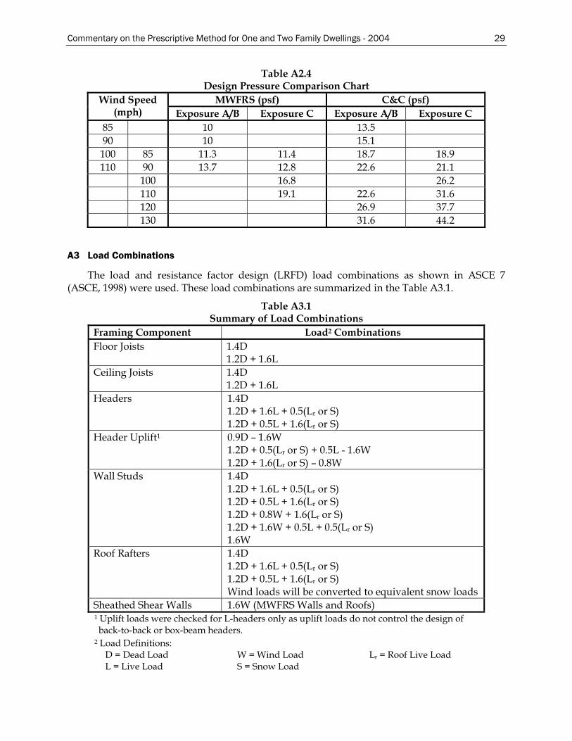
Commentary on the Prescriptive Method for One and Two Family Dwellings - 2004 29
Table A2.4 Design Pressure Comparison Chart
MWFRS (psf) C&C (psf) Wind Speed (mph) Exposure A/B Exposure C Exposure A/B Exposure C
85 10 13.5 90 10 15.1
100 85 11.3 11.4 18.7 18.9 110 90 13.7 12.8 22.6 21.1
100 16.8 26.2 110 19.1 22.6 31.6 120 26.9 37.7 130 31.6 44.2
A3 Load Combinations
The load and resistance factor design (LRFD) load combinations as shown in ASCE 7 (ASCE, 1998) were used. These load combinations are summarized in the Table A3.1.
Table A3.1 Summary of Load Combinations
Framing Component Load2 Combinations Floor Joists 1.4D
1.2D + 1.6L Ceiling Joists 1.4D
1.2D + 1.6L Headers 1.4D
1.2D + 1.6L + 0.5(Lr or S) 1.2D + 0.5L + 1.6(Lr or S)
Header Uplift1 0.9D – 1.6W 1.2D + 0.5(Lr or S) + 0.5L - 1.6W 1.2D + 1.6(Lr or S) – 0.8W
Wall Studs 1.4D 1.2D + 1.6L + 0.5(Lr or S) 1.2D + 0.5L + 1.6(Lr or S) 1.2D + 0.8W + 1.6(Lr or S) 1.2D + 1.6W + 0.5L + 0.5(Lr or S) 1.6W
Roof Rafters 1.4D 1.2D + 1.6L + 0.5(Lr or S) 1.2D + 0.5L + 1.6(Lr or S) Wind loads will be converted to equivalent snow loads
Sheathed Shear Walls 1.6W (MWFRS Walls and Roofs) 1 Uplift loads were checked for L-headers only as uplift loads do not control the design of back-to-back or box-beam headers.
2 Load Definitions: D = Dead Load W = Wind Load Lr = Roof Live Load L = Live Load S = Snow Load
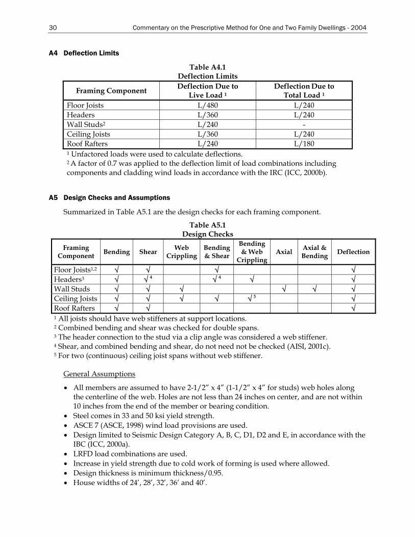
30 Commentary on the Prescriptive Method for One and Two Family Dwellings - 2004
A4 Deflection Limits
Table A4.1 Deflection Limits
Framing Component Deflection Due to Live Load 1
Deflection Due toTotal Load 1
Floor Joists L/480 L/240 Headers L/360 L/240 Wall Studs2 L/240 - Ceiling Joists L/360 L/240 Roof Rafters L/240 L/180 1 Unfactored loads were used to calculate deflections. 2 A factor of 0.7 was applied to the deflection limit of load combinations including components and cladding wind loads in accordance with the IRC (ICC, 2000b).
A5 Design Checks and Assumptions
Summarized in Table A5.1 are the design checks for each framing component.
Table A5.1 Design Checks
Framing Component Bending Shear Web
Crippling Bending & Shear
Bending & Web
Crippling Axial Axial &
Bending Deflection
Floor Joists1,2 √ √ √ √ Headers3 √ √ 4 √ 4 √ √ Wall Studs √ √ √ √ √ √ Ceiling Joists √ √ √ √ √ 5 √ Roof Rafters √ √ √ 1 All joists should have web stiffeners at support locations. 2 Combined bending and shear was checked for double spans. 3 The header connection to the stud via a clip angle was considered a web stiffener. 4 Shear, and combined bending and shear, do not need not be checked (AISI, 2001c). 5 For two (continuous) ceiling joist spans without web stiffener.
General Assumptions
• All members are assumed to have 2-1/2” x 4” (1-1/2” x 4” for studs) web holes along the centerline of the web. Holes are not less than 24 inches on center, and are not within 10 inches from the end of the member or bearing condition.
• Steel comes in 33 and 50 ksi yield strength. • ASCE 7 (ASCE, 1998) wind load provisions are used. • Design limited to Seismic Design Category A, B, C, D1, D2 and E, in accordance with the
IBC (ICC, 2000a). • LRFD load combinations are used. • Increase in yield strength due to cold work of forming is used where allowed. • Design thickness is minimum thickness/0.95. • House widths of 24’, 28’, 32’, 36’ and 40’.
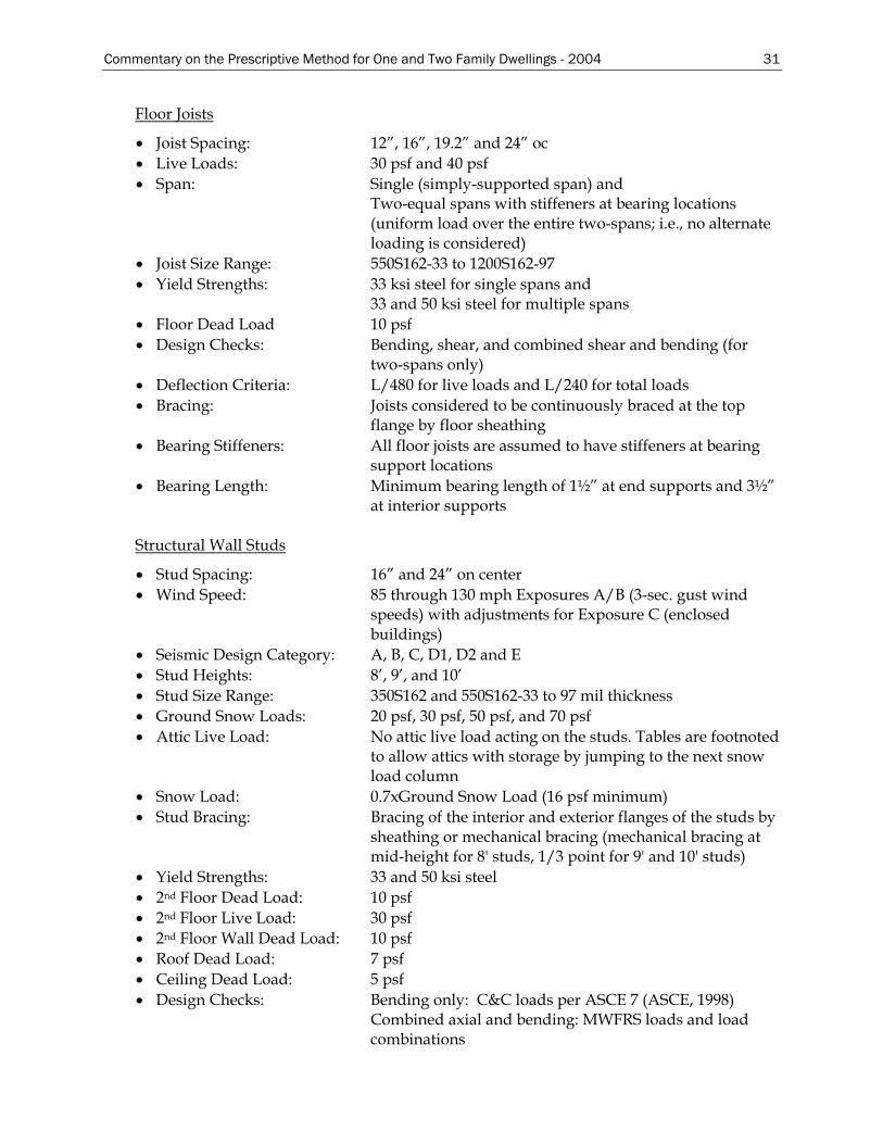
Commentary on the Prescriptive Method for One and Two Family Dwellings - 2004 31
Floor Joists
• Joist Spacing: 12”, 16”, 19.2” and 24” oc • Live Loads: 30 psf and 40 psf • Span: Single (simply-supported span) and
Two-equal spans with stiffeners at bearing locations (uniform load over the entire two-spans; i.e., no alternate loading is considered)
• Joist Size Range: 550S162-33 to 1200S162-97 • Yield Strengths: 33 ksi steel for single spans and
33 and 50 ksi steel for multiple spans • Floor Dead Load 10 psf • Design Checks: Bending, shear, and combined shear and bending (for
two-spans only) • Deflection Criteria: L/480 for live loads and L/240 for total loads • Bracing: Joists considered to be continuously braced at the top
flange by floor sheathing • Bearing Stiffeners: All floor joists are assumed to have stiffeners at bearing
support locations • Bearing Length: Minimum bearing length of 1½” at end supports and 3½”
at interior supports Structural Wall Studs
• Stud Spacing: 16” and 24” on center • Wind Speed: 85 through 130 mph Exposures A/B (3-sec. gust wind
speeds) with adjustments for Exposure C (enclosed buildings)
• Seismic Design Category: A, B, C, D1, D2 and E • Stud Heights: 8’, 9’, and 10’ • Stud Size Range: 350S162 and 550S162-33 to 97 mil thickness • Ground Snow Loads: 20 psf, 30 psf, 50 psf, and 70 psf • Attic Live Load: No attic live load acting on the studs. Tables are footnoted
to allow attics with storage by jumping to the next snow load column
• Snow Load: 0.7xGround Snow Load (16 psf minimum) • Stud Bracing: Bracing of the interior and exterior flanges of the studs by
sheathing or mechanical bracing (mechanical bracing at mid-height for 8' studs, 1/3 point for 9' and 10' studs)
• Yield Strengths: 33 and 50 ksi steel • 2nd Floor Dead Load: 10 psf • 2nd Floor Live Load: 30 psf • 2nd Floor Wall Dead Load: 10 psf • Roof Dead Load: 7 psf • Ceiling Dead Load: 5 psf • Design Checks: Bending only: C&C loads per ASCE 7 (ASCE, 1998)
Combined axial and bending: MWFRS loads and load combinations
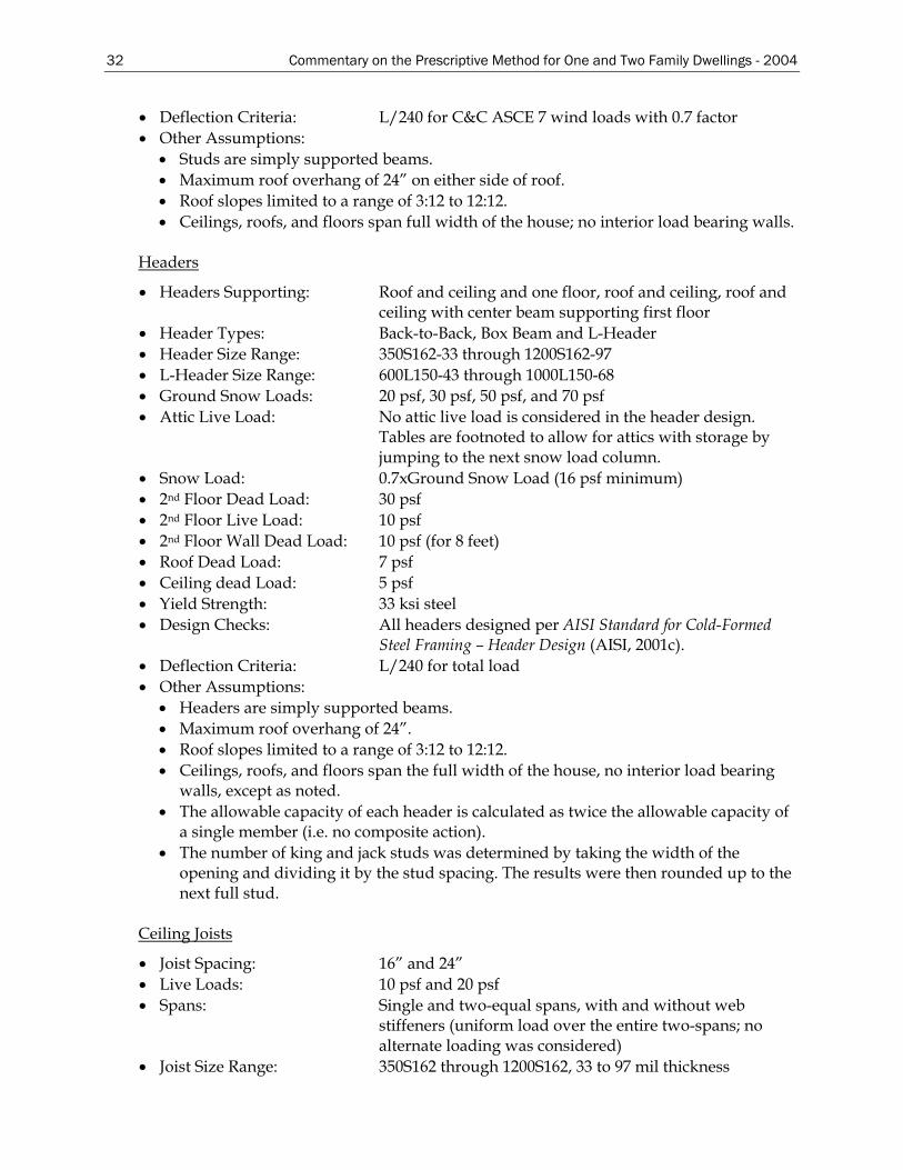
32 Commentary on the Prescriptive Method for One and Two Family Dwellings - 2004
• Deflection Criteria: L/240 for C&C ASCE 7 wind loads with 0.7 factor • Other Assumptions:
• Studs are simply supported beams. • Maximum roof overhang of 24” on either side of roof. • Roof slopes limited to a range of 3:12 to 12:12. • Ceilings, roofs, and floors span full width of the house; no interior load bearing walls.
Headers
• Headers Supporting: Roof and ceiling and one floor, roof and ceiling, roof and ceiling with center beam supporting first floor
• Header Types: Back-to-Back, Box Beam and L-Header • Header Size Range: 350S162-33 through 1200S162-97 • L-Header Size Range: 600L150-43 through 1000L150-68 • Ground Snow Loads: 20 psf, 30 psf, 50 psf, and 70 psf • Attic Live Load: No attic live load is considered in the header design.
Tables are footnoted to allow for attics with storage by jumping to the next snow load column.
• Snow Load: 0.7xGround Snow Load (16 psf minimum) • 2nd Floor Dead Load: 30 psf • 2nd Floor Live Load: 10 psf • 2nd Floor Wall Dead Load: 10 psf (for 8 feet) • Roof Dead Load: 7 psf • Ceiling dead Load: 5 psf • Yield Strength: 33 ksi steel • Design Checks: All headers designed per AISI Standard for Cold-Formed
Steel Framing – Header Design (AISI, 2001c). • Deflection Criteria: L/240 for total load • Other Assumptions:
• Headers are simply supported beams. • Maximum roof overhang of 24”. • Roof slopes limited to a range of 3:12 to 12:12. • Ceilings, roofs, and floors span the full width of the house, no interior load bearing
walls, except as noted. • The allowable capacity of each header is calculated as twice the allowable capacity of
a single member (i.e. no composite action). • The number of king and jack studs was determined by taking the width of the
opening and dividing it by the stud spacing. The results were then rounded up to the next full stud.
Ceiling Joists
• Joist Spacing: 16” and 24” • Live Loads: 10 psf and 20 psf • Spans: Single and two-equal spans, with and without web
stiffeners (uniform load over the entire two-spans; no alternate loading was considered)
• Joist Size Range: 350S162 through 1200S162, 33 to 97 mil thickness
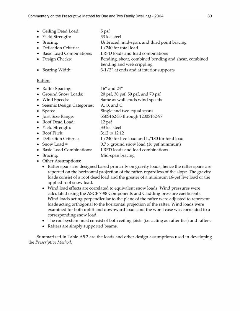
Commentary on the Prescriptive Method for One and Two Family Dwellings - 2004 33
• Ceiling Dead Load: 5 psf • Yield Strength: 33 ksi steel • Bracing: Unbraced, mid-span, and third point bracing • Deflection Criteria: L/240 for total load • Basic Load Combinations: LRFD loads and load combinations • Design Checks: Bending, shear, combined bending and shear, combined
bending and web crippling • Bearing Width: 3-1/2” at ends and at interior supports
Rafters
• Rafter Spacing: 16” and 24” • Ground Snow Loads: 20 psf, 30 psf, 50 psf, and 70 psf • Wind Speeds: Same as wall studs wind speeds • Seismic Design Categories: A, B, and C • Spans: Single and two-equal spans • Joist Size Range: 550S162-33 through 1200S162-97 • Roof Dead Load: 12 psf • Yield Strength: 33 ksi steel • Roof Pitch: 3:12 to 12:12 • Deflection Criteria: L/240 for live load and L/180 for total load • Snow Load = 0.7 x ground snow load (16 psf minimum) • Basic Load Combinations: LRFD loads and load combinations • Bracing: Mid-span bracing • Other Assumptions:
• Rafter spans are designed based primarily on gravity loads; hence the rafter spans are reported on the horizontal projection of the rafter, regardless of the slope. The gravity loads consist of a roof dead load and the greater of a minimum 16-psf live load or the applied roof snow load.
• Wind load effects are correlated to equivalent snow loads. Wind pressures were calculated using the ASCE 7-98 Components and Cladding pressure coefficients. Wind loads acting perpendicular to the plane of the rafter were adjusted to represent loads acting orthogonal to the horizontal projection of the rafter. Wind loads were examined for both uplift and downward loads and the worst case was correlated to a corresponding snow load.
• The roof system must consist of both ceiling joists (i.e. acting as rafter ties) and rafters. • Rafters are simply supported beams.
Summarized in Table A5.2 are the loads and other design assumptions used in developing
the Prescriptive Method.
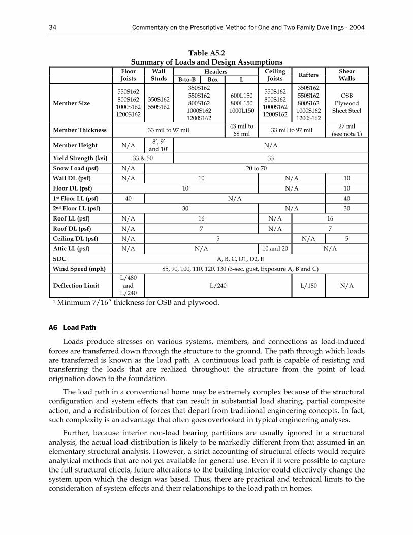
34 Commentary on the Prescriptive Method for One and Two Family Dwellings - 2004
Table A5.2 Summary of Loads and Design Assumptions
Headers Floor Joists
Wall Studs B-to-B Box L
Ceiling Joists Rafters Shear
Walls
Member Size
550S162 800S162 1000S162 1200S162
350S162 550S162
350S162 550S162 800S162
1000S162 1200S162
600L150 800L150 1000L150
550S162 800S162
1000S162 1200S162
350S162 550S162 800S162
1000S162 1200S162
OSB Plywood
Sheet Steel
Member Thickness 33 mil to 97 mil 43 mil to 68 mil 33 mil to 97 mil 27 mil
(see note 1)
Member Height N/A 8’, 9’ and 10’ N/A
Yield Strength (ksi) 33 & 50 33 Snow Load (psf) N/A 20 to 70 Wall DL (psf) N/A 10 N/A 10 Floor DL (psf) 10 N/A 10 1st Floor LL (psf) 40 N/A 40 2nd Floor LL (psf) 30 N/A 30 Roof LL (psf) N/A 16 N/A 16 Roof DL (psf) N/A 7 N/A 7 Ceiling DL (psf) N/A 5 N/A 5 Attic LL (psf) N/A N/A 10 and 20 N/A SDC A, B, C, D1, D2, E Wind Speed (mph) 85, 90, 100, 110, 120, 130 (3-sec. gust, Exposure A, B and C)
Deflection Limit L/480
and L/240
L/240 L/180 N/A
1 Minimum 7/16” thickness for OSB and plywood.
A6 Load Path
Loads produce stresses on various systems, members, and connections as load-induced forces are transferred down through the structure to the ground. The path through which loads are transferred is known as the load path. A continuous load path is capable of resisting and transferring the loads that are realized throughout the structure from the point of load origination down to the foundation.
The load path in a conventional home may be extremely complex because of the structural configuration and system effects that can result in substantial load sharing, partial composite action, and a redistribution of forces that depart from traditional engineering concepts. In fact, such complexity is an advantage that often goes overlooked in typical engineering analyses.
Further, because interior non-load bearing partitions are usually ignored in a structural analysis, the actual load distribution is likely to be markedly different from that assumed in an elementary structural analysis. However, a strict accounting of structural effects would require analytical methods that are not yet available for general use. Even if it were possible to capture the full structural effects, future alterations to the building interior could effectively change the system upon which the design was based. Thus, there are practical and technical limits to the consideration of system effects and their relationships to the load path in homes.
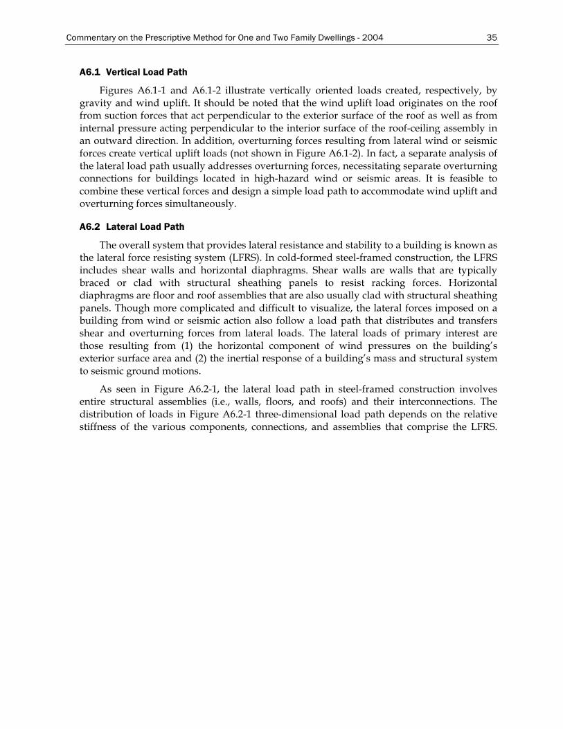
Commentary on the Prescriptive Method for One and Two Family Dwellings - 2004 35
A6.1 Vertical Load Path
Figures A6.1-1 and A6.1-2 illustrate vertically oriented loads created, respectively, by gravity and wind uplift. It should be noted that the wind uplift load originates on the roof from suction forces that act perpendicular to the exterior surface of the roof as well as from internal pressure acting perpendicular to the interior surface of the roof-ceiling assembly in an outward direction. In addition, overturning forces resulting from lateral wind or seismic forces create vertical uplift loads (not shown in Figure A6.1-2). In fact, a separate analysis of the lateral load path usually addresses overturning forces, necessitating separate overturning connections for buildings located in high-hazard wind or seismic areas. It is feasible to combine these vertical forces and design a simple load path to accommodate wind uplift and overturning forces simultaneously.
A6.2 Lateral Load Path
The overall system that provides lateral resistance and stability to a building is known as the lateral force resisting system (LFRS). In cold-formed steel-framed construction, the LFRS includes shear walls and horizontal diaphragms. Shear walls are walls that are typically braced or clad with structural sheathing panels to resist racking forces. Horizontal diaphragms are floor and roof assemblies that are also usually clad with structural sheathing panels. Though more complicated and difficult to visualize, the lateral forces imposed on a building from wind or seismic action also follow a load path that distributes and transfers shear and overturning forces from lateral loads. The lateral loads of primary interest are those resulting from (1) the horizontal component of wind pressures on the building’s exterior surface area and (2) the inertial response of a building’s mass and structural system to seismic ground motions.
As seen in Figure A6.2-1, the lateral load path in steel-framed construction involves entire structural assemblies (i.e., walls, floors, and roofs) and their interconnections. The distribution of loads in Figure A6.2-1 three-dimensional load path depends on the relative stiffness of the various components, connections, and assemblies that comprise the LFRS.
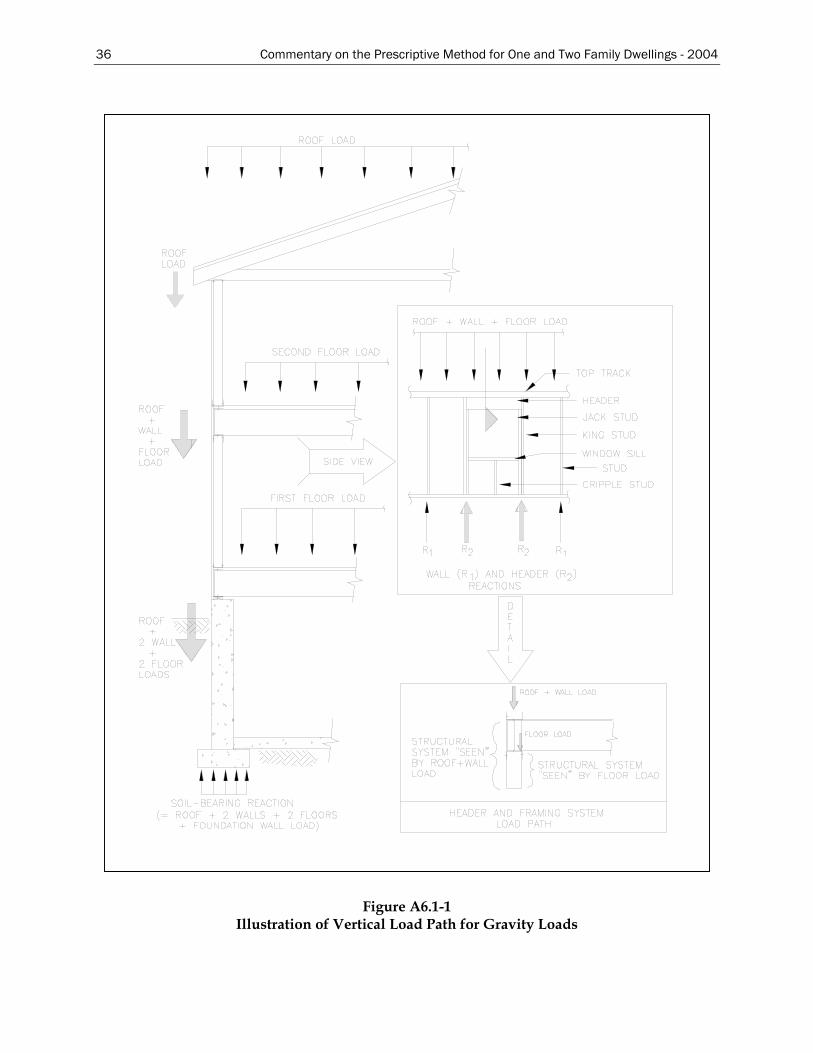
36 Commentary on the Prescriptive Method for One and Two Family Dwellings - 2004
Figure A6.1-1 Illustration of Vertical Load Path for Gravity Loads
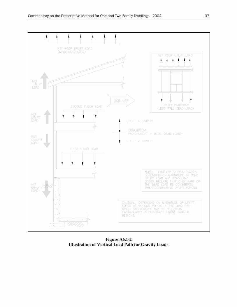
Commentary on the Prescriptive Method for One and Two Family Dwellings - 2004 37
Figure A6.1-2
Illustration of Vertical Load Path for Gravity Loads
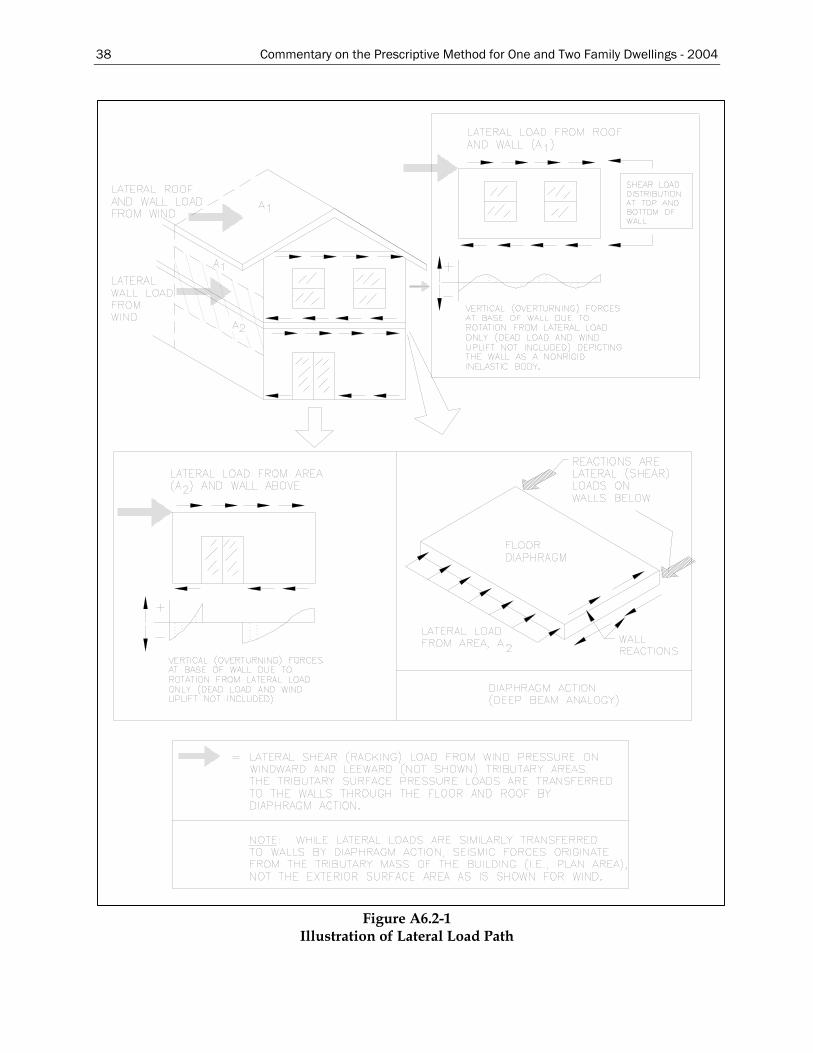
38 Commentary on the Prescriptive Method for One and Two Family Dwellings - 2004
Figure A6.2-1 Illustration of Lateral Load Path
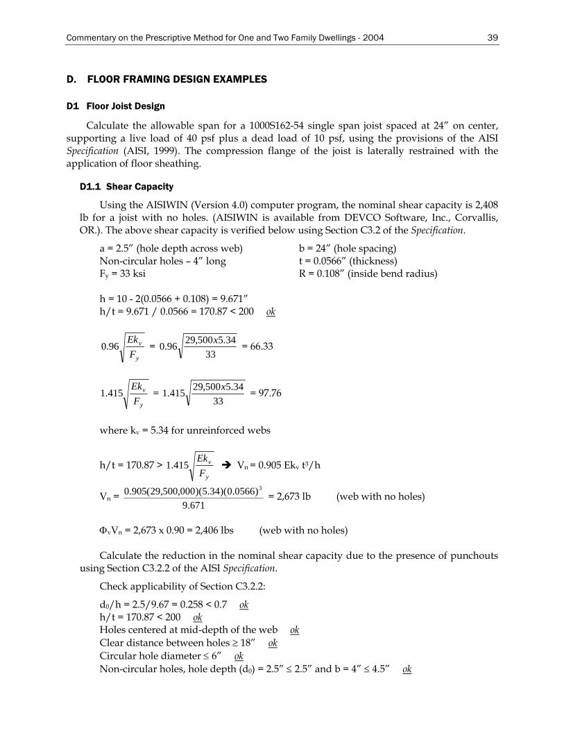
Commentary on the Prescriptive Method for One and Two Family Dwellings - 2004 39
D. FLOOR FRAMING DESIGN EXAMPLES
D1 Floor Joist Design
Calculate the allowable span for a 1000S162-54 single span joist spaced at 24” on center, supporting a live load of 40 psf plus a dead load of 10 psf, using the provisions of the AISI Specification (AISI, 1999). The compression flange of the joist is laterally restrained with the application of floor sheathing.
D1.1 Shear Capacity
Using the AISIWIN (Version 4.0) computer program, the nominal shear capacity is 2,408 lb for a joist with no holes. (AISIWIN is available from DEVCO Software, Inc., Corvallis, OR.). The above shear capacity is verified below using Section C3.2 of the Specification.
a = 2.5” (hole depth across web) b = 24” (hole spacing) Non-circular holes – 4” long t = 0.0566” (thickness) Fy = 33 ksi R = 0.108” (inside bend radius) h = 10 - 2(0.0566 + 0.108) = 9.671” h/t = 9.671 / 0.0566 = 170.87 < 200 ok
y
v
FEk
96.0 = 33
34.5500,2996.0 x = 66.33
y
v
FEk
415.1 = 33
34.5500,29415.1 x = 97.76
where kv = 5.34 for unreinforced webs
h/t = 170.87 > y
v
FEk
415.1 Vn = 0.905 Ekv t3/h
Vn = 671.9
)0566.0)(34.5)(000,500,29(905.0 3
= 2,673 lb (web with no holes)
ΦvVn = 2,673 x 0.90 = 2,406 lbs (web with no holes)
Calculate the reduction in the nominal shear capacity due to the presence of punchouts
using Section C3.2.2 of the AISI Specification.
Check applicability of Section C3.2.2:
d0/h = 2.5/9.67 = 0.258 < 0.7 okh/t = 170.87 < 200 okHoles centered at mid-depth of the web okClear distance between holes ≥ 18” okCircular hole diameter ≤ 6” okNon-circular holes, hole depth (d0) = 2.5” ≤ 2.5” and b = 4” ≤ 4.5” ok
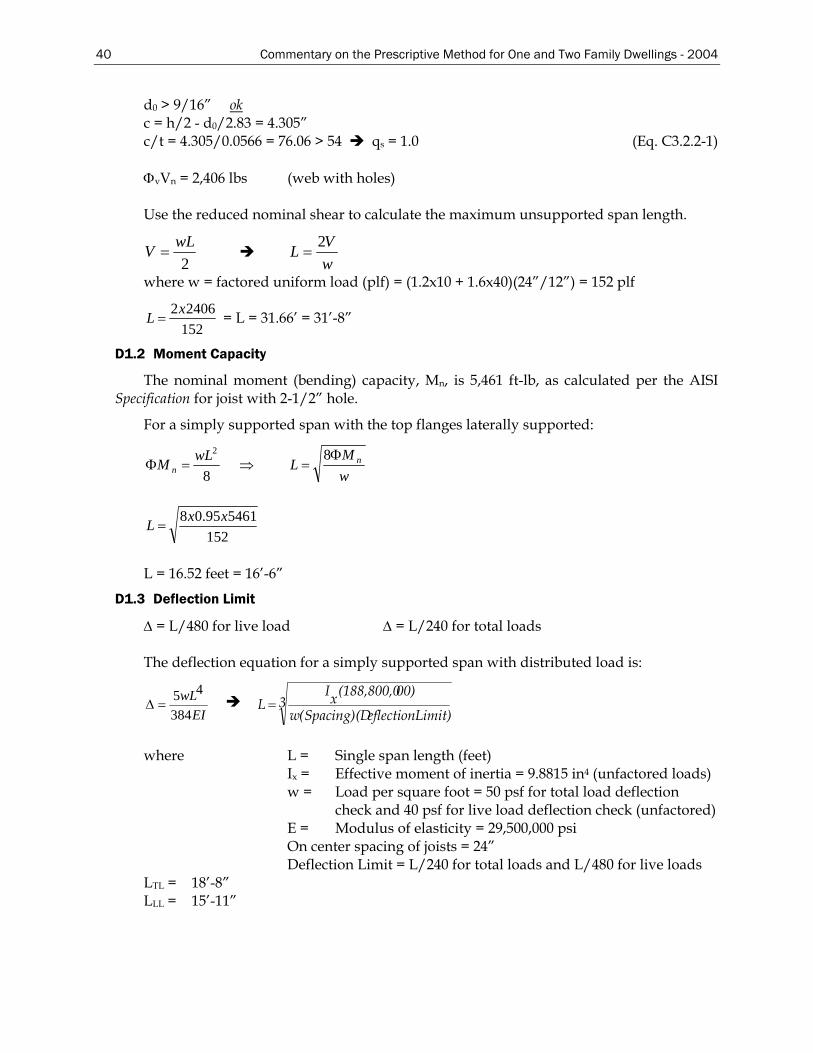
40 Commentary on the Prescriptive Method for One and Two Family Dwellings - 2004
d0 > 9/16” okc = h/2 - d0/2.83 = 4.305” c/t = 4.305/0.0566 = 76.06 > 54 qs = 1.0 (Eq. C3.2.2-1) ΦvVn = 2,406 lbs (web with holes)
Use the reduced nominal shear to calculate the maximum unsupported span length.
2wLV =
wVL 2
=
where w = factored uniform load (plf) = (1.2x10 + 1.6x40)(24”/12”) = 152 plf
15224062xL = = L = 31.66’ = 31’-8”
D1.2 Moment Capacity
The nominal moment (bending) capacity, Mn, is 5,461 ft-lb, as calculated per the AISI Specification for joist with 2-1/2” hole.
For a simply supported span with the top flanges laterally supported:
8
2wLM n =Φ ⇒ wM
L nΦ=
8
152546195.08 xxL =
L = 16.52 feet = 16’-6”
D1.3 Deflection Limit
∆ = L/480 for live load ∆ = L/240 for total loads The deflection equation for a simply supported span with distributed load is:
EIwL
384
45=∆ 3
Limit) eflectionSpacing)(D(w
00)(188,800,0xIL =
where L = Single span length (feet)
Ix = Effective moment of inertia = 9.8815 in4 (unfactored loads) w = Load per square foot = 50 psf for total load deflection
check and 40 psf for live load deflection check (unfactored) E = Modulus of elasticity = 29,500,000 psi On center spacing of joists = 24” Deflection Limit = L/240 for total loads and L/480 for live loads
LTL = 18’-8” LLL = 15’-11”
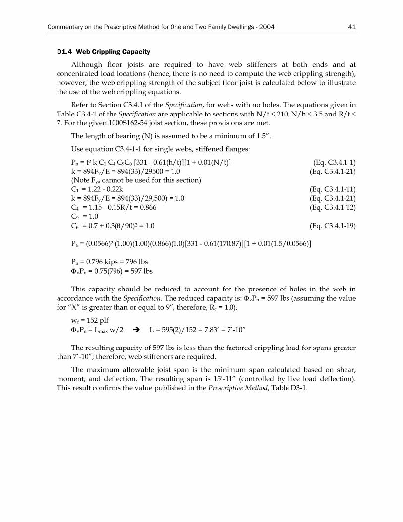
Commentary on the Prescriptive Method for One and Two Family Dwellings - 2004 41
D1.4 Web Crippling Capacity
Although floor joists are required to have web stiffeners at both ends and at concentrated load locations (hence, there is no need to compute the web crippling strength), however, the web crippling strength of the subject floor joist is calculated below to illustrate the use of the web crippling equations.
Refer to Section C3.4.1 of the Specification, for webs with no holes. The equations given in Table C3.4-1 of the Specification are applicable to sections with N/t ≤ 210, N/h ≤ 3.5 and R/t ≤ 7. For the given 1000S162-54 joist section, these provisions are met.
The length of bearing (N) is assumed to be a minimum of 1.5”.
Use equation C3.4-1-1 for single webs, stiffened flanges:
Pn = t2 k C1 C4 C9Cθ [331 - 0.61(h/t)][1 + 0.01(N/t)] (Eq. C3.4.1-1) k = 894Fy/E = 894(33)/29500 = 1.0 (Eq. C3.4.1-21) (Note Fya cannot be used for this section) C1 = 1.22 - 0.22k (Eq. C3.4.1-11) k = 894Fy/E = 894(33)/29,500) = 1.0 (Eq. C3.4.1-21) C4 = 1.15 - 0.15R/t = 0.866 (Eq. C3.4.1-12) C9 = 1.0 Cθ = 0.7 + 0.3(θ/90)2 = 1.0 (Eq. C3.4.1-19) Pa = (0.0566)2 (1.00)(1.00)(0.866)(1.0)[331 - 0.61(170.87)][1 + 0.01(1.5/0.0566)] Pn = 0.796 kips = 796 lbs ΦvPn = 0.75(796) = 597 lbs This capacity should be reduced to account for the presence of holes in the web in
accordance with the Specification. The reduced capacity is: ΦvPn = 597 lbs (assuming the value for “X” is greater than or equal to 9”, therefore, Rc = 1.0).
wf = 152 plf ΦvPn = Lmax w/2 L = 595(2)/152 = 7.83’ = 7’-10”
The resulting capacity of 597 lbs is less than the factored crippling load for spans greater
than 7’-10”; therefore, web stiffeners are required.
The maximum allowable joist span is the minimum span calculated based on shear, moment, and deflection. The resulting span is 15’-11” (controlled by live load deflection). This result confirms the value published in the Prescriptive Method, Table D3-1.
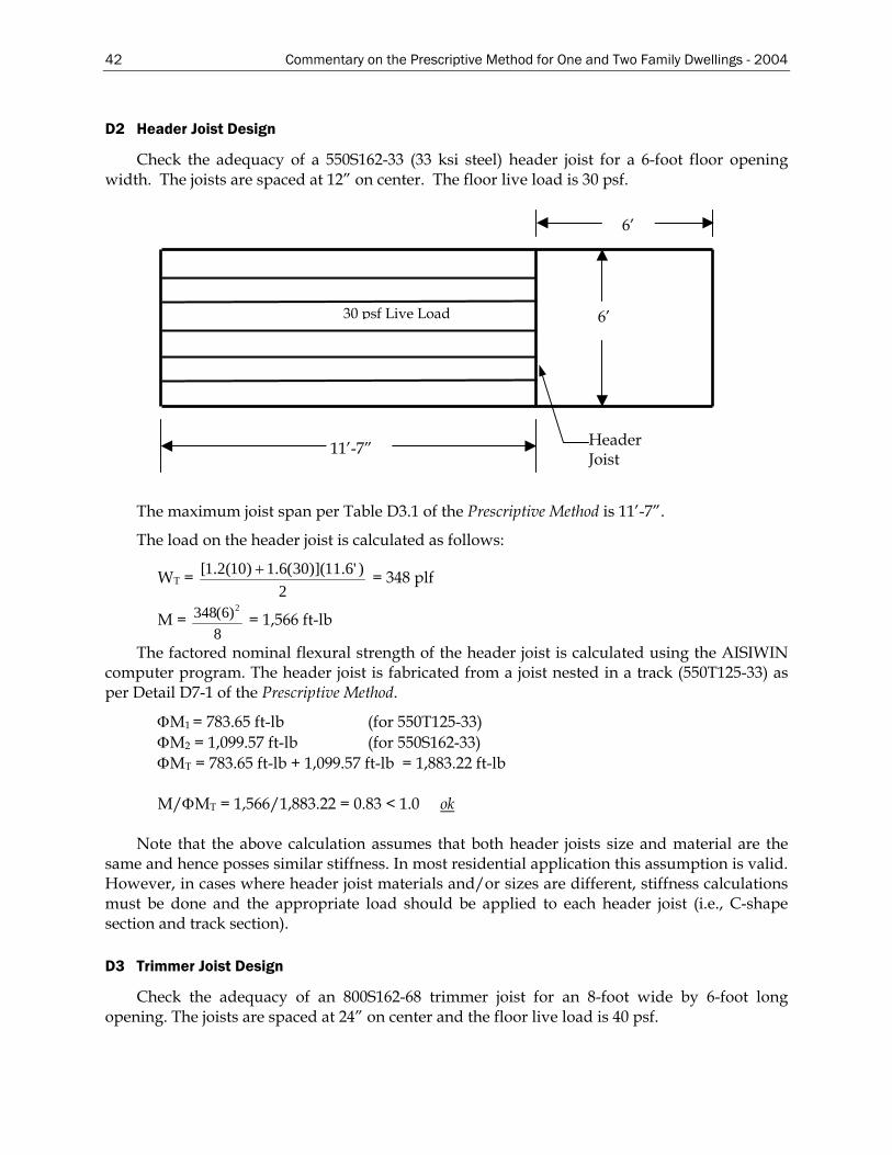
42 Commentary on the Prescriptive Method for One and Two Family Dwellings - 2004
D2 Header Joist Design
Check the adequacy of a 550S162-33 (33 ksi steel) header joist for a 6-foot floor opening width. The joists are spaced at 12” on center. The floor live load is 30 psf.
6’
30 psf Live Load 6’
11’-7” Header Joist
The maximum joist span per Table D3.1 of the Prescriptive Method is 11’-7”.
The load on the header joist is calculated as follows:
WT = 2
)'6.11)](30(6.1)10(2.1[ + = 348 plf
M = 8
)6(348 2 = 1,566 ft-lb
The factored nominal flexural strength of the header joist is calculated using the AISIWIN computer program. The header joist is fabricated from a joist nested in a track (550T125-33) as per Detail D7-1 of the Prescriptive Method.
ΦM1 = 783.65 ft-lb (for 550T125-33) ΦM2 = 1,099.57 ft-lb (for 550S162-33) ΦMT = 783.65 ft-lb + 1,099.57 ft-lb = 1,883.22 ft-lb M/ΦMT = 1,566/1,883.22 = 0.83 < 1.0 ok
Note that the above calculation assumes that both header joists size and material are the same and hence posses similar stiffness. In most residential application this assumption is valid. However, in cases where header joist materials and/or sizes are different, stiffness calculations must be done and the appropriate load should be applied to each header joist (i.e., C-shape section and track section).
D3 Trimmer Joist Design
Check the adequacy of an 800S162-68 trimmer joist for an 8-foot wide by 6-foot long opening. The joists are spaced at 24” on center and the floor live load is 40 psf.
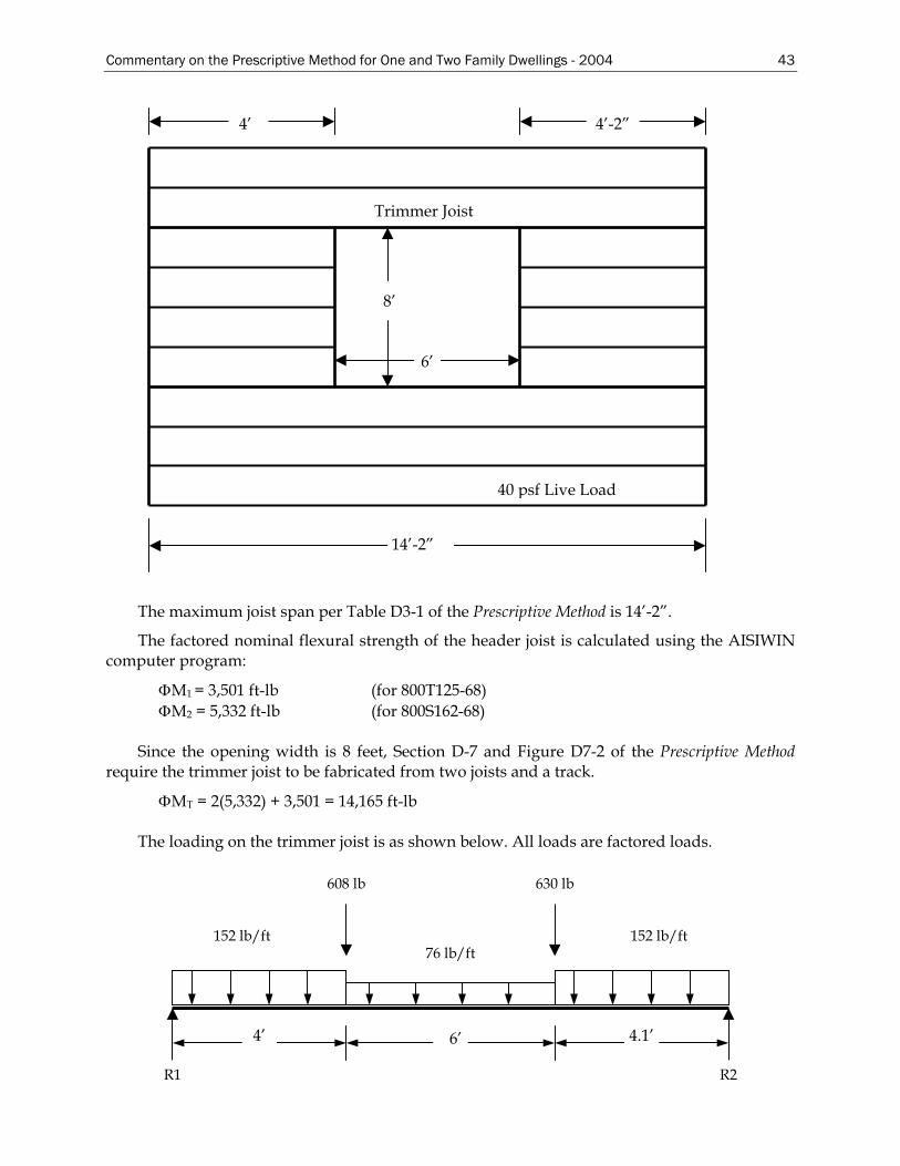
Commentary on the Prescriptive Method for One and Two Family Dwellings - 2004 43
4’ 4’-2”
Trimmer Joist
40 psf Live Load
6’
8’
14’-2”
The maximum joist span per Table D3-1 of the Prescriptive Method is 14’-2”.
The factored nominal flexural strength of the header joist is calculated using the AISIWIN computer program:
ΦM1 = 3,501 ft-lb (for 800T125-68) ΦM2 = 5,332 ft-lb (for 800S162-68)
Since the opening width is 8 feet, Section D-7 and Figure D7-2 of the Prescriptive Method
require the trimmer joist to be fabricated from two joists and a track.
ΦMT = 2(5,332) + 3,501 = 14,165 ft-lb
The loading on the trimmer joist is as shown below. All loads are factored loads.
152 lb/ft
R1
6’ 4.1’ 4’
R2
630 lb 608 lb
76 lb/ft 152 lb/ft
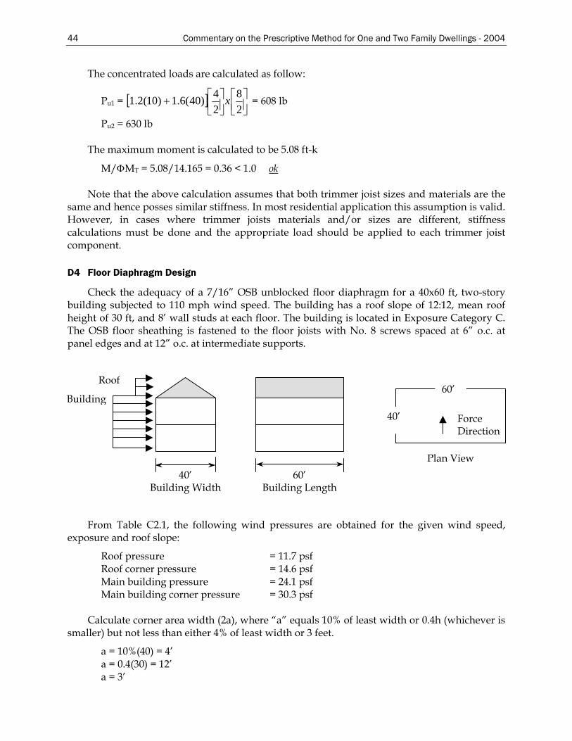
44 Commentary on the Prescriptive Method for One and Two Family Dwellings - 2004
The concentrated loads are calculated as follow:
Pu1 = [ ] ⎥⎦⎤
⎢⎣⎡
⎥⎦⎤
⎢⎣⎡+
28
24)40(6.1)10(2.1 x = 608 lb
Pu2 = 630 lb
The maximum moment is calculated to be 5.08 ft-k
M/ΦMT = 5.08/14.165 = 0.36 < 1.0 ok
Note that the above calculation assumes that both trimmer joist sizes and materials are the same and hence posses similar stiffness. In most residential application this assumption is valid. However, in cases where trimmer joists materials and/or sizes are different, stiffness calculations must be done and the appropriate load should be applied to each trimmer joist component.
D4 Floor Diaphragm Design
Check the adequacy of a 7/16” OSB unblocked floor diaphragm for a 40x60 ft, two-story building subjected to 110 mph wind speed. The building has a roof slope of 12:12, mean roof height of 30 ft, and 8’ wall studs at each floor. The building is located in Exposure Category C. The OSB floor sheathing is fastened to the floor joists with No. 8 screws spaced at 6” o.c. at panel edges and at 12” o.c. at intermediate supports.
40’ Building Width
Building
Roof
60’ Bui thlding Leng
Force Direction
60’
40’
Plan View
From Table C2.1, the following wind pressures are obtained for the given wind speed, exposure and roof slope:
Roof pressure = 11.7 psf Roof corner pressure = 14.6 psf Main building pressure = 24.1 psf Main building corner pressure = 30.3 psf
Calculate corner area width (2a), where “a” equals 10% of least width or 0.4h (whichever is
smaller) but not less than either 4% of least width or 3 feet.
a = 10%(40) = 4’ a = 0.4(30) = 12’ a = 3’
Commentary on the Prescriptive Method for One and Two Family Dwellings - 2004 45
Use a = 4’ Corner area = 2a = 8’ Shear = (60’ – 16’)(8’)(24.1 psf) + 16’(8’)(30.3 psf) = 12,361 lbs Floor level diaphragm load = (12,361/2)/40 = 155 plf Factored diaphragm shear load = 155x1.6 = 248 plf
IBC Table 2211.1(1) (ICC, 2000a) provides nominal shear values for wood structural shear panels on steel studs. For 7/16” OSB with No. 8 screws spaced at 6” at edges and 12” in field, the unblocked shear value is 364 plf. The Light Gauge Steel Engineering Association Technical Note No. 558b-1 (LGSEA, 1998) also provides allowable shear values for unblocked diaphragms. For 7/16” OSB with No. 8 screws spaced at 6” the unblocked shear value is 272 plf.
Using the IBC or the LGSEA diaphragm values, the diaphragm in this example is adequate.
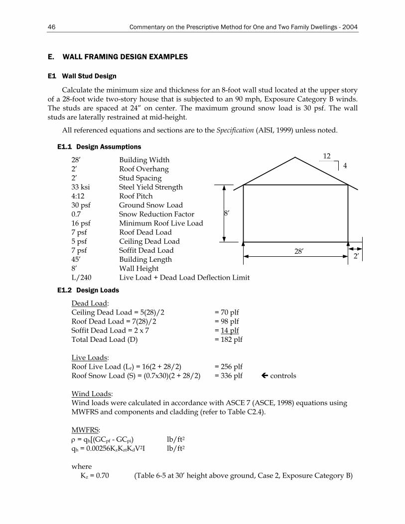
46 Commentary on the Prescriptive Method for One and Two Family Dwellings - 2004
E. WALL FRAMING DESIGN EXAMPLES
E1 Wall Stud Design
Calculate the minimum size and thickness for an 8-foot wall stud located at the upper story of a 28-foot wide two-story house that is subjected to an 90 mph, Exposure Category B winds. The studs are spaced at 24” on center. The maximum ground snow load is 30 psf. The wall studs are laterally restrained at mid-height.
All referenced equations and sections are to the Specification (AISI, 1999) unless noted.
E1.1 Design Assumptions
28’ 2’
4 12
8’
28’ Building Width 2’ Roof Overhang 2’ Stud Spacing 33 ksi Steel Yield Strength 4:12 Roof Pitch 30 psf Ground Snow Load 0.7 Snow Reduction Factor 16 psf Minimum Roof Live Load 7 psf Roof Dead Load 5 psf Ceiling Dead Load 7 psf Soffit Dead Load 45’ Building Length 8’ Wall Height L/240 Live Load + Dead Load Deflection Limit
E1.2 Design Loads
Dead Load: Ceiling Dead Load = 5(28)/2 = 70 plf Roof Dead Load = 7(28)/2 = 98 plf Soffit Dead Load = 2 x 7 = 14 plf Total Dead Load (D) = 182 plf Live Loads: Roof Live Load (Lr) = 16(2 + 28/2) = 256 plf Roof Snow Load (S) = (0.7x30)(2 + 28/2) = 336 plf controls Wind Loads: Wind loads were calculated in accordance with ASCE 7 (ASCE, 1998) equations using MWFRS and components and cladding (refer to Table C2.4). MWFRS: ρ = qh[(GCpf - GCpi) lb/ft2
qh = 0.00256KzKztKdV2I lb/ft2
where
Kz = 0.70 (Table 6-5 at 30’ height above ground, Case 2, Exposure Category B)
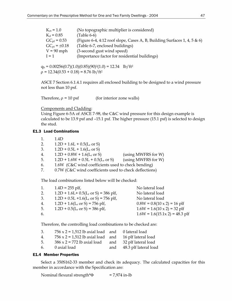
Commentary on the Prescriptive Method for One and Two Family Dwellings - 2004 47
Kzt = 1.0 (No topographic multiplier is considered) Kd = 0.85 (Table 6-6) GCpf = 0.53 (Figure 6-4, 4:12 roof slope, Cases A, B, Building Surfaces 1, 4, 5 & 6) GCpi = ±0.18 (Table 6-7, enclosed buildings) V = 90 mph (3-second gust wind speed) I = 1 (Importance factor for residential buildings)
qh = 0.00256(0.7)(1.0)(0.85)(90)2(1.0) = 12.34 lb/ft2
ρ = 12.34(0.53 + 0.18) = 8.76 lb/ft2
ASCE 7 Section 6.1.4.1 requires all enclosed building to be designed to a wind pressure not less than 10 psf.
Therefore, ρ = 10 psf (for interior zone walls)
Components and Cladding: Using Figure 6-5A of ASCE 7-98, the C&C wind pressure for this design example is calculated to be 13.9 psf and –15.1 psf. The higher pressure (15.1 psf) is selected to design the stud.
E1.3 Load Combinations
1. 1.4D 2. 1.2D + 1.6L + 0.5(Lr or S) 3. 1.2D + 0.5L + 1.6(Lr or S) 4. 1.2D + 0.8W + 1.6(Lr or S) (using MWFRS for W) 5. 1.2D + 1.6W + 0.5L + 0.5(Lr or S) (using MWFRS for W) 6. 1.6W (C&C wind coefficients used to check bending) 7. 0.7W (C&C wind coefficients used to check deflections) The load combinations listed below will be checked:
1. 1.4D = 255 plf, No lateral load 2. 1.2D + 1.6L+ 0.5(Lr or S) = 386 plf, No lateral load 3. 1.2D + 0.5L +1.6(Lr or S) = 756 plf, No lateral load 4. 1.2D + 1.6(Lr or S) = 756 plf, 0.8W = 0.8(10 x 2) = 16 plf 5. 1.2D + 0.5(Lr or S) = 386 plf, 1.6W = 1.6(10 x 2) = 32 plf 6. 1.6W = 1.6(15.1x 2) = 48.3 plf Therefore, the controlling load combinations to be checked are:
3. 756 x 2 = 1,512 lb axial load and 0 lateral load 4. 756 x 2 = 1,512 lb axial load and 16 plf lateral load 5. 386 x 2 = 772 lb axial load and 32 plf lateral load 6. 0 axial load and 48.3 plf lateral load
E1.4 Member Properties
Select a 350S162-33 member and check its adequacy. The calculated capacities for this member in accordance with the Specification are:
Nominal flexural strength*Φ = 7,974 in-lb
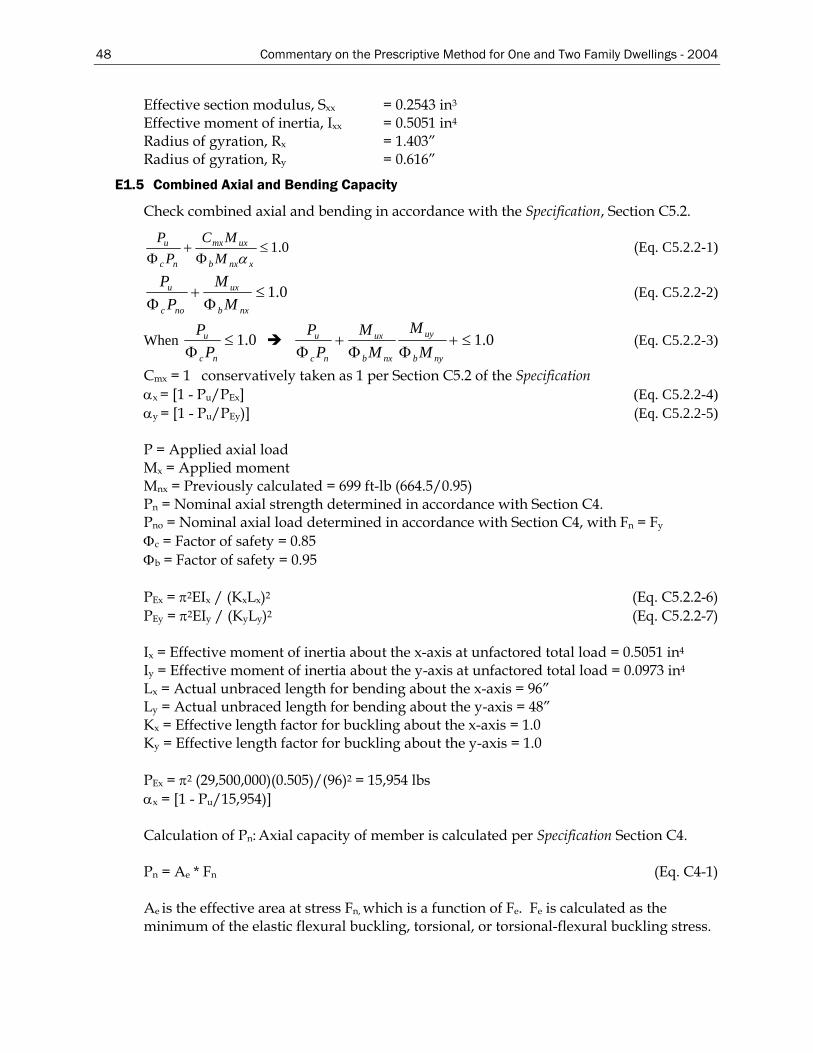
48 Commentary on the Prescriptive Method for One and Two Family Dwellings - 2004
Effective section modulus, Sxx = 0.2543 in3
Effective moment of inertia, Ixx = 0.5051 in4
Radius of gyration, Rx = 1.403” Radius of gyration, Ry = 0.616”
E1.5 Combined Axial and Bending Capacity
Check combined axial and bending in accordance with the Specification, Section C5.2.
0.1≤Φ
+Φ xnxb
uxmx
nc
u
MMC
PP
α (Eq. C5.2.2-1)
0.1≤Φ
+Φ nxb
ux
noc
u
MM
PP
(Eq. C5.2.2-2)
When 0.1≤Φ nc
u
PP
0.1≤+ΦΦ
+Φ nyb
uy
nxb
ux
nc
u
MM
MM
PP
(Eq. C5.2.2-3)
Cmx = 1 conservatively taken as 1 per Section C5.2 of the Specification αx = [1 - Pu/PEx] (Eq. C5.2.2-4) αy = [1 - Pu/PEy)] (Eq. C5.2.2-5) P = Applied axial load Mx = Applied moment Mnx = Previously calculated = 699 ft-lb (664.5/0.95) Pn = Nominal axial strength determined in accordance with Section C4. Pno = Nominal axial load determined in accordance with Section C4, with Fn = Fy
Φc = Factor of safety = 0.85 Φb = Factor of safety = 0.95 PEx = π2EIx / (KxLx)2 (Eq. C5.2.2-6) PEy = π2EIy / (KyLy)2 (Eq. C5.2.2-7) Ix = Effective moment of inertia about the x-axis at unfactored total load = 0.5051 in4
Iy = Effective moment of inertia about the y-axis at unfactored total load = 0.0973 in4
Lx = Actual unbraced length for bending about the x-axis = 96” Ly = Actual unbraced length for bending about the y-axis = 48” Kx = Effective length factor for buckling about the x-axis = 1.0 Ky = Effective length factor for buckling about the y-axis = 1.0 PEx = π2 (29,500,000)(0.505)/(96)2 = 15,954 lbs αx = [1 - Pu/15,954)] Calculation of Pn: Axial capacity of member is calculated per Specification Section C4. Pn = Ae * Fn (Eq. C4-1) Ae is the effective area at stress Fn, which is a function of Fe. Fe is calculated as the minimum of the elastic flexural buckling, torsional, or torsional-flexural buckling stress.
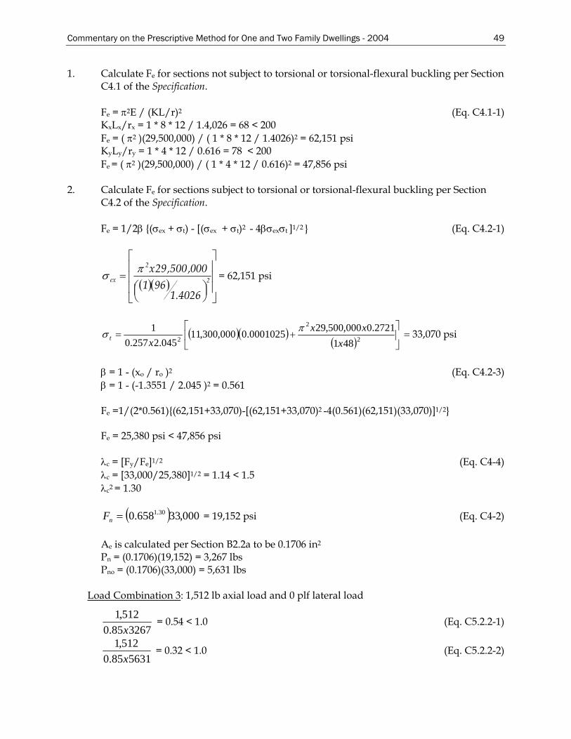
Commentary on the Prescriptive Method for One and Two Family Dwellings - 2004 49
1. Calculate Fe for sections not subject to torsional or torsional-flexural buckling per Section C4.1 of the Specification.
Fe = π2E / (KL/r)2 (Eq. C4.1-1) KxLx/rx = 1 * 8 * 12 / 1.4,026 = 68 < 200 Fe = ( π2 )(29,500,000) / ( 1 * 8 * 12 / 1.4026)2 = 62,151 psi KyLy/ry = 1 * 4 * 12 / 0.616 = 78 < 200 Fe = ( π2 )(29,500,000) / ( 1 * 4 * 12 / 0.616)2 = 47,856 psi
2. Calculate Fe for sections subject to torsional or torsional-flexural buckling per Section
C4.2 of the Specification.
Fe = 1/2β (σex + σt) - [(σex + σt)2 - 4βσexσt ]1/2 (Eq. C4.2-1)
( )( ) ⎥⎥⎥
⎦
⎤
⎢⎢⎢
⎣
⎡
⎟⎠⎞⎜
⎝⎛
= 2
2
ex
4026.1961
000,500,29xπσ = 62,151 psi
( )( )( ) ⎥
⎦
⎤⎢⎣
⎡+= 2
2
2 4812721.0000,500,290001025.0000,300,11
045.2257.01
xxx
xtπσ = 33,070 psi
β = 1 - (xo / ro )2 (Eq. C4.2-3) β = 1 - (-1.3551 / 2.045 )2 = 0.561 Fe =1/(2*0.561)(62,151+33,070)-[(62,151+33,070)2 -4(0.561)(62,151)(33,070)]1/2
Fe = 25,380 psi < 47,856 psi λc = [Fy/Fe]1/2 (Eq. C4-4) λc = [33,000/25,380]1/2 = 1.14 < 1.5 λc2 = 1.30
( ) 000,33658.0 30.1=nF = 19,152 psi (Eq. C4-2) Ae is calculated per Section B2.2a to be 0.1706 in2
Pn = (0.1706)(19,152) = 3,267 lbs Pno = (0.1706)(33,000) = 5,631 lbs
Load Combination 3: 1,512 lb axial load and 0 plf lateral load
326785.0512,1x
= 0.54 < 1.0 (Eq. C5.2.2-1)
563185.0512,1x
= 0.32 < 1.0 (Eq. C5.2.2-2)
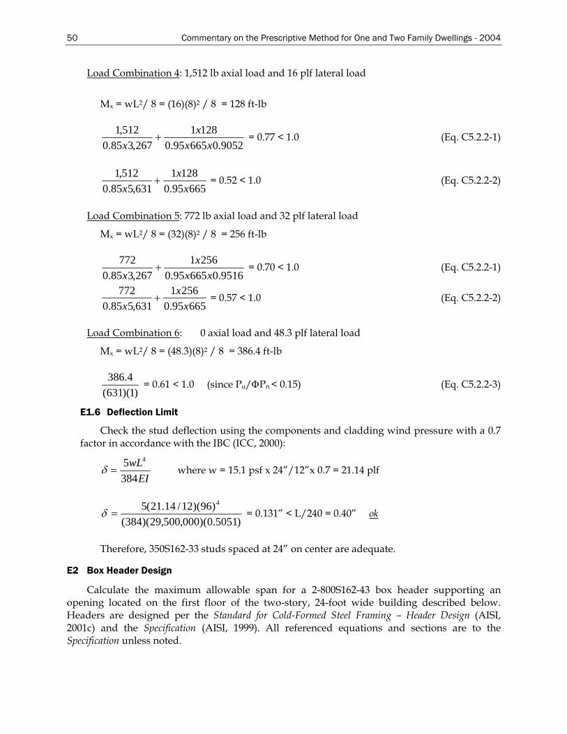
50 Commentary on the Prescriptive Method for One and Two Family Dwellings - 2004
Load Combination 4: 1,512 lb axial load and 16 plf lateral load
Mx = wL2/ 8 = (16)(8)2 / 8 = 128 ft-lb
9052.066595.01281
267,385.0512,1
xxx
x+ = 0.77 < 1.0 (Eq. C5.2.2-1)
66595.01281
631,585.0512,1
xx
x+ = 0.52 < 1.0 (Eq. C5.2.2-2)
Load Combination 5: 772 lb axial load and 32 plf lateral load
Mx = wL2/ 8 = (32)(8)2 / 8 = 256 ft-lb
9516.066595.02561
267,385.0772
xxx
x+ = 0.70 < 1.0 (Eq. C5.2.2-1)
66595.02561
631,585.0772
xx
x+ = 0.57 < 1.0 (Eq. C5.2.2-2)
Load Combination 6: 0 axial load and 48.3 plf lateral load
Mx = wL2/ 8 = (48.3)(8)2 / 8 = 386.4 ft-lb
)1)(631(4.386
= 0.61 < 1.0 (since Pu/ΦPn < 0.15) (Eq. C5.2.2-3)
E1.6 Deflection Limit
Check the stud deflection using the components and cladding wind pressure with a 0.7 factor in accordance with the IBC (ICC, 2000):
δ =5384
4wLEI
where w = 15.1 psf x 24”/12”x 0.7 = 21.14 plf
)5051.0)(000,500,29)(384()96)(12/14.21(5 4
=δ = 0.131” < L/240 = 0.40” ok
Therefore, 350S162-33 studs spaced at 24” on center are adequate.
E2 Box Header Design
Calculate the maximum allowable span for a 2-800S162-43 box header supporting an opening located on the first floor of the two-story, 24-foot wide building described below. Headers are designed per the Standard for Cold-Formed Steel Framing – Header Design (AISI, 2001c) and the Specification (AISI, 1999). All referenced equations and sections are to the Specification unless noted.
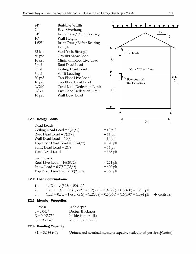
Commentary on the Prescriptive Method for One and Two Family Dwellings - 2004 51
24’ Building Width 2’ Eave Overhang 24” Joist/Truss/Rafter Spacing 10’ Wall Height 1.625” Joist/Truss/Rafter Bearing
Length
8’
24’
12 9
2’
L-Header
Box-Beam & Back-to-Back
30 psf LL + 10 psf
10’
33 ksi Steel Yield Strength 50 psf Ground Snow Load 16 psf Minimum Roof Live Load 7 psf Roof Dead Load 5 psf Ceiling Dead Load 7 psf Soffit Loading 30 psf Top Floor Live Load 10 psf Top Floor Dead Load L/240 Total Load Deflection Limit L/360 Live Load Deflection Limit 10 psf Wall Dead Load
E2.1 Design Loads
Dead Loads: Ceiling Dead Load = 5(24/2) = 60 plf Roof Dead Load = 7(24/2) = 84 plf Wall Dead Load = 10(8) = 80 plf Top Floor Dead Load = 10(24/2) = 120 plf Soffit Dead Load = 2(7) = 14 plf Total Dead Load = 358 plf
Live Loads: Roof Live Load = 16(28/2) = 224 plf Snow Load = 0.7(50)(28/2) = 490 plf Top Floor Live Load = 30(24/2) = 360 plf
E2.2 Load Combinations
1. 1.4D = 1.4(358) = 501 plf 2. 1.2D + 1.6L + 0.5(Lr or S) = 1.2(358) + 1.6(360) + 0.5(490) = 1,251 plf 3. 1.2D + 0.5L + 1.6(Lr or S) = 1.2(358) + 0.5(360) + 1.6(490) = 1,394 plf controls
E2.3 Member Properties
H = 8.0” Web depth t = 0.045” Design thickness R = 0.09375” Inside bend radius Ixx = 9.21 in4 Moment of inertia
E2.4 Bending Capacity
Mn = 3,166 ft-lb Unfactored nominal moment capacity (calculated per Specification)
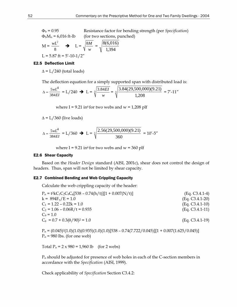
52 Commentary on the Prescriptive Method for One and Two Family Dwellings - 2004
Φb = 0.95 Resistance factor for bending strength (per Specification) ΦbMn = 6,016 ft-lb (for two sections, punched)
M = 8
2wL L = wM8 =
394,1)016,6(8
L = 5.87 ft = 5’-10-1/2”
E2.5 Deflection Limit
∆ = L/240 (total loads) The deflection equation for a simply supported span with distributed load is:
EIwL
3845 4
=∆ = L/240 L = 384.3w
EI = 3208,1
)21.9)(000,500,29(84.3 = 7’-11”
where I = 9.21 in4 for two webs and w = 1,208 plf
∆ = L/360 (live loads)
EIwL
3845 4
=∆ = L/360 L = 3360
)21.9)(000,500,29(56.2 = 10’-5”
where I = 9.21 in4 for two webs and w = 360 plf
E2.6 Shear Capacity
Based on the Header Design standard (AISI, 2001c), shear does not control the design of headers. Thus, span will not be limited by shear capacity.
E2.7 Combined Bending and Web Crippling Capacity
Calculate the web crippling capacity of the header:
Pn = t2kC1C2C9Cθ[538 – 0.74(h/t)][1 + 0.007(N/t)] (Eq. C3.4.1-4) k = 894Fy/E = 1.0 (Eq. C3.4.1-20) C1 = 1.22 – 0.22k = 1.0 (Eq. C3.4.1-10) C2 = 1.06 – 0.06R/t = 0.935 (Eq. C3.4.1-11) C9 = 1.0 Cθ = 0.7 + 0.3(θ/90)2 = 1.0 (Eq. C3.4.1-19) Pn = (0.045)2(1.0)(1.0)(0.935)(1.0)(1.0)[538 – 0.74(7.722/0.045)][1 + 0.007(1.625/0.045)] Pn = 980 lbs. (for one web) Total Pn = 2 x 980 = 1,960 lb (for 2 webs) Pn should be adjusted for presence of web holes in each of the C-section members in accordance with the Specification (AISI, 1999). Check applicability of Specification Section C3.4.2:
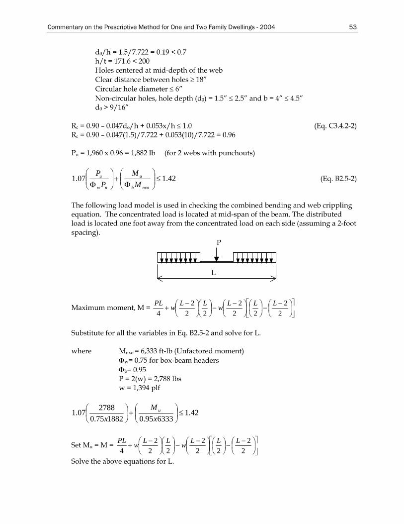
Commentary on the Prescriptive Method for One and Two Family Dwellings - 2004 53
d0/h = 1.5/7.722 = 0.19 < 0.7 h/t = 171.6 < 200 Holes centered at mid-depth of the web Clear distance between holes ≥ 18” Circular hole diameter ≤ 6” Non-circular holes, hole depth (d0) = 1.5” ≤ 2.5” and b = 4” ≤ 4.5” d0 > 9/16”
Rc = 0.90 – 0.047do/h + 0.053x/h ≤ 1.0 (Eq. C3.4.2-2) Rc = 0.90 – 0.047(1.5)/7.722 + 0.053(10)/7.722 = 0.96 Pn = 1,960 x 0.96 = 1,882 lb (for 2 webs with punchouts)
42.107.1 ≤⎟⎟⎠
⎞⎜⎜⎝
⎛Φ
+⎟⎟⎠
⎞⎜⎜⎝
⎛Φ nxob
u
nw
u
MM
PP
(Eq. B2.5-2)
The following load model is used in checking the combined bending and web crippling equation. The concentrated load is located at mid-span of the beam. The distributed load is located one foot away from the concentrated load on each side (assuming a 2-foot spacing).
P
L
Maximum moment, M = ⎥⎦
⎤⎢⎣
⎡⎟⎠⎞
⎜⎝⎛ −
−⎟⎠⎞
⎜⎝⎛
⎟⎠⎞
⎜⎝⎛ −
−⎟⎠⎞
⎜⎝⎛
⎟⎠⎞
⎜⎝⎛ −
+2
222
222
24
LLLwLLwPL
Substitute for all the variables in Eq. B2.5-2 and solve for L. where Mnxo = 6,333 ft-lb (Unfactored moment)
Φw= 0.75 for box-beam headers Φb= 0.95 P = 2(w) = 2,788 lbs w = 1,394 plf
42.1633395.0188275.0
278807.1 ≤⎟⎠⎞
⎜⎝⎛+⎟
⎠⎞
⎜⎝⎛
xM
xu
Set Mu = M = ⎥⎦
⎤⎢⎣
⎡⎟⎠⎞
⎜⎝⎛ −
−⎟⎠⎞
⎜⎝⎛
⎟⎠⎞
⎜⎝⎛ −
−⎟⎠⎞
⎜⎝⎛
⎟⎠⎞
⎜⎝⎛ −
+2
222
222
24
LLLwLLwPL
Solve the above equations for L.
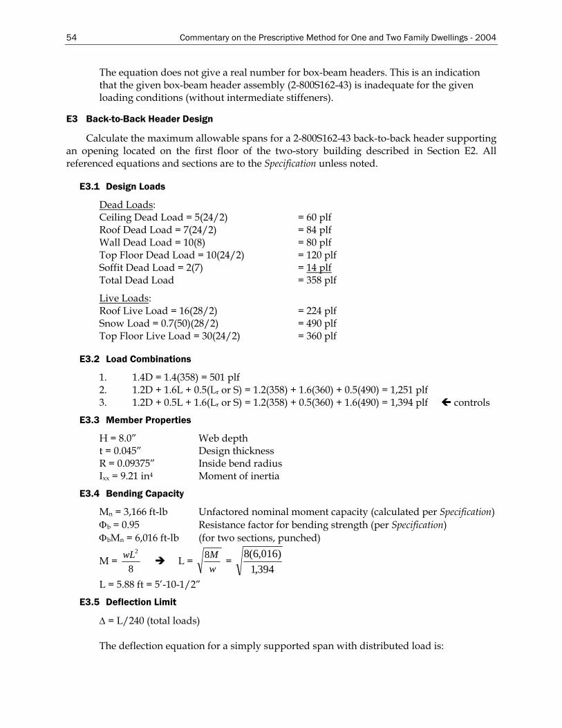
54 Commentary on the Prescriptive Method for One and Two Family Dwellings - 2004
The equation does not give a real number for box-beam headers. This is an indication that the given box-beam header assembly (2-800S162-43) is inadequate for the given loading conditions (without intermediate stiffeners).
E3 Back-to-Back Header Design
Calculate the maximum allowable spans for a 2-800S162-43 back-to-back header supporting an opening located on the first floor of the two-story building described in Section E2. All referenced equations and sections are to the Specification unless noted.
E3.1 Design Loads
Dead Loads: Ceiling Dead Load = 5(24/2) = 60 plf Roof Dead Load = 7(24/2) = 84 plf Wall Dead Load = 10(8) = 80 plf Top Floor Dead Load = 10(24/2) = 120 plf Soffit Dead Load = 2(7) = 14 plf Total Dead Load = 358 plf
Live Loads: Roof Live Load = 16(28/2) = 224 plf Snow Load = 0.7(50)(28/2) = 490 plf Top Floor Live Load = 30(24/2) = 360 plf
E3.2 Load Combinations
1. 1.4D = 1.4(358) = 501 plf 2. 1.2D + 1.6L + 0.5(Lr or S) = 1.2(358) + 1.6(360) + 0.5(490) = 1,251 plf 3. 1.2D + 0.5L + 1.6(Lr or S) = 1.2(358) + 0.5(360) + 1.6(490) = 1,394 plf controls
E3.3 Member Properties
H = 8.0” Web depth t = 0.045” Design thickness R = 0.09375” Inside bend radius Ixx = 9.21 in4 Moment of inertia
E3.4 Bending Capacity
Mn = 3,166 ft-lb Unfactored nominal moment capacity (calculated per Specification) Φb = 0.95 Resistance factor for bending strength (per Specification) ΦbMn = 6,016 ft-lb (for two sections, punched)
M = 8
2wL L = wM8 =
394,1)016,6(8
L = 5.88 ft = 5’-10-1/2”
E3.5 Deflection Limit
∆ = L/240 (total loads) The deflection equation for a simply supported span with distributed load is:
Commentary on the Prescriptive Method for One and Two Family Dwellings - 2004 55
EIwL
3845 4
=∆ = L/240 L = 384.3w
EI = 3208,1
)21.9)(000,500,29(84.3 = 7’-11”
where I = 9.21 in4 for two webs and w = 1,208 plf
∆ = L/360 (live loads)
EIwL
3845 4
=∆ = L/360 L = 3360
)21.9)(000,500,29(56.2 = 10’-5”
where I = 9.21 in4 for two webs and w = 360 plf
E3.6 Shear Capacity
Based on the Header Design standard (AISI, 2001c), shear does not control the design of headers. Thus, span will not be limited by shear capacity.
E3.7 Combined Bending and Web Crippling Capacity
Calculate the web crippling capacity of the header:
Pn = t2 Fy C5 [0.88 + 0.12m][15 + 3.25(N/t)1/2] (Eq. C3.4.1-5) k = 894Fy/E = 1.0 (Eq. C3.4.1-20) m = t/0.075 = 0.0451/0.075 = 0.601 (Eq. C3.4.1-21) C5 = 1.49 – 0.53(1.0) = 0.96 (Eq. C3.4.1-13) Pn = (0.0451)2(33)(0.96)[0.88 + 0.12(0.601)][15 + 3.25(1.625/0.0451)1/2] Pn = 2.117 kips = 2,117 lb (for one web.) Total Pn = 2 x 2,117 = 4,234 lb Pn should be adjusted for presence of web holes in each of the C-section members in accordance with the Specification (AISI, 1999). Check applicability of Specification Section C3.4.2:
d0/h = 1.5/7.722 = 0.19 < 0.7 h/t = 171.6 < 200 Holes centered at mid-depth of the web Clear distance between holes ≥ 18” Circular hole diameter ≤ 6” Non-circular holes, hole depth (d0) = 1.5” ≤ 2.5” and b = 4” ≤ 4.5” d0 > 9/16”
Rc = 0.90 – 0.047do/h + 0.053x/h ≤ 1.0 (Eq. C3.4.2-2) Rc = 0.90 – 0.047(1.5)/7.722 + 0.053(10)/7.722 = 0.96 Pn = 4,234 x 0.96 = 4,064 lb (for 2 webs with punchouts)
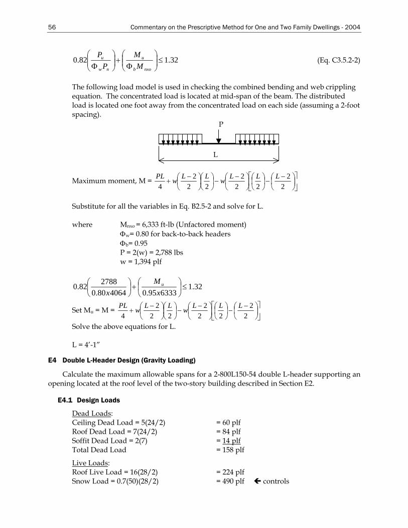
56 Commentary on the Prescriptive Method for One and Two Family Dwellings - 2004
32.182.0 ≤⎟⎟⎠
⎞⎜⎜⎝
⎛Φ
+⎟⎟⎠
⎞⎜⎜⎝
⎛Φ nxob
u
nw
u
MM
PP
(Eq. C3.5.2-2)
The following load model is used in checking the combined bending and web crippling equation. The concentrated load is located at mid-span of the beam. The distributed load is located one foot away from the concentrated load on each side (assuming a 2-foot spacing).
P
L
Maximum moment, M = ⎥⎦
⎤⎢⎣
⎡⎟⎠⎞
⎜⎝⎛ −
−⎟⎠⎞
⎜⎝⎛
⎟⎠⎞
⎜⎝⎛ −
−⎟⎠⎞
⎜⎝⎛
⎟⎠⎞
⎜⎝⎛ −
+2
222
222
24
LLLwLLwPL
Substitute for all the variables in Eq. B2.5-2 and solve for L. where Mnxo = 6,333 ft-lb (Unfactored moment)
Φw= 0.80 for back-to-back headers Φb= 0.95 P = 2(w) = 2,788 lbs w = 1,394 plf
32.1633395.0406480.0
278882.0 ≤⎟⎠⎞
⎜⎝⎛+⎟
⎠⎞
⎜⎝⎛
xM
xu
Set Mu = M = ⎥⎦
⎤⎢⎣
⎡⎟⎠⎞
⎜⎝⎛ −
−⎟⎠⎞
⎜⎝⎛
⎟⎠⎞
⎜⎝⎛ −
−⎟⎠⎞
⎜⎝⎛
⎟⎠⎞
⎜⎝⎛ −
+2
222
222
24
LLLwLLwPL
Solve the above equations for L. L = 4’-1”
E4 Double L-Header Design (Gravity Loading)
Calculate the maximum allowable spans for a 2-800L150-54 double L-header supporting an opening located at the roof level of the two-story building described in Section E2.
E4.1 Design Loads
Dead Loads: Ceiling Dead Load = 5(24/2) = 60 plf Roof Dead Load = 7(24/2) = 84 plf Soffit Dead Load = 2(7) = 14 plf Total Dead Load = 158 plf
Live Loads: Roof Live Load = 16(28/2) = 224 plf Snow Load = 0.7(50)(28/2) = 490 plf controls
Commentary on the Prescriptive Method for One and Two Family Dwellings - 2004 57
E4.2 Load Combinations
1. 1.4D = 1.4(158) = 221 plf 2. 1.2D + 1.6L + 0.5(Lr or S) = 1.2(158) + 0.5(490) = 435 plf 3. 1.2D + 0.5L + 1.6(Lr or S) = 1.2(158) + 1.6(490) = 974 plf controls
E4.3 Member Properties
L1 = 8.0” Long leg of angle L2 = 1.5” Short leg of angle t = 0.0566” Design thickness Sxtop = 0.8564 in3 Section modulus for one angle
E4.4 Bending Capacity
Mn = Sec Fy
where
Fy = design yield stress Sec = elastic section modulus of the effective section calculated at f = Fy in the
extreme compression fibers. Mn = (0.8564)(33,000) = 28,260 in-lb (for one angle) The factored moment is determined as follows: Mf = ΦMn = 28,260(0.90) = 25,434 in-lb For two angles: Mf = 50,868 in-lb
8
2wLM =Φ ⇒ wML Φ
=8
12974
)868,50(8=L = 5’-11”
E5 Double L-Header Design (Uplift Loading Case 1)
Calculate the maximum span for an L800S150-54 double L-header for the design example in Section E2. The fastest-mile wind speed is 100 mph, Exposure Category C.
E5.1 Design Loads
Dead Loads: Ceiling Dead Load = 5(24/2) = 60 plf Roof Dead Load = 7(24 + 4)/2 = 98 plfTotal Dead Load = = 158 plf Live Loads: Roof Live Load = 16(24 + 4)/2 = 224 plf Roof Snow Load = 0.7(50)(24 +/4)/2 = 490 plf controls Wind Uplift Load: Wind pressures are taken from Table C2.1 of ASCE 7 (ASCE, 1998) for roof corner MWFRS wind pressures for 9:12 roof pitch, 100 mph Exposure Category C. The
58 Commentary on the Prescriptive Method for One and Two Family Dwellings - 2004
tabulated pressures (Table C2.1) are perpendicular to the vertical projection of the roof. The uplift component of the pressure can be calculated as follows:
Wind Uplift Load = ⎟⎟⎠
⎞⎜⎜⎝
⎛°°)86.36sin()86.36cos(3.10 = 13.73 psf (perpendicular to header)
Applying this wind pressure over a 21-foot member length, the uplift load is: Wind Uplift Load = 13.73 psf x 21 ft = 288.3 lbs/ft
E5.2 Load Combinations:
1. 0.9D – 1.6W = 0.9(158) – 1.6(288.3) = -319 plf controls 2. 1.2D – 1.6W + 0.5(Lr or S) = 1.2(158) – 1.6(288.3) + 0.5(490) = 26.7 plf 3. 1.2D – 0.8W + 1.6(Lr or S) = 1.2(158) – 0.8(288.3) + 1.6(490) = 743 plf
E5.3 Member Properties
L1 = 8.0” Long leg of angle L2 = 1.5” Short leg of angle t = 0.0566” Design thickness Sxtop = 0.8564 in3 Section modulus for one angle
E5.4 Bending Capacity
Mnu = R Mng (Eq. B3.1.2-1) where
Mng = gravity moment capacity determined by Eq. B3.1.1-1 R = uplift reduction factor = 0.25 for Lh/t ≤ 150 = 0.20 for Lh/t ≥ 170 = use linear interpolation for 150 < Lh/t < 170 Lh = vertical leg dimension of the angle t = design thickness
For LRFD, the design moment capacity for uplift shall be determined as follows: Mu = ΦMnu Eq. B3.1.3-4 Φ = 0.80 Mng = (1.7128)(33,000) = 56,519 lb-in (for two angles) Lh/t = 8.0/0.0566 = 141.3 ≤ 150, Therefore, R = 0.25 Mnu = 0.25(56,519) = 14,130 in-lb
8
2wLM =Φ wML Φ
=8
12319
)130,14)(8.0(8=L = 4’-10”
Commentary on the Prescriptive Method for One and Two Family Dwellings - 2004 59
E6 Double L-Header Design (Uplift Loading Case 2)
Calculate the maximum span for a 2-L800S150-54 L-header located in the first story of a the two-story building described in Section F1, subjected to 110 mph Exposure Category C wind speed and 20 psf ground snow load.
E6.1 Design Loads
Dead Loads: Ceiling Dead Load = 5(24/2) = 60 plf Roof Dead Load = 7(24 + 4)/2 = 98 plf Floor Dead Load = 10(24/2) = 120 plf Wall Dead Load = 100* plfTotal Dead Load = = 378 plf
* Note: conservatively use 100 plf instead of 8x10 psf = 80 plf
Live Loads: Floor Live Load = 30(24/2) = 360 plf Roof Snow Load = 0.7(20)(24 +4)/2 = 196 plf Roof Live Load = 16(24 + 4)/2 = 224 plf controls
Wind Uplift Load: Wind pressures are taken from Table C2.1 (roof corner MWFRS wind pressures for 9:12 roof pitch, 110 mph Exposure Category C). The tabulated pressures (Table C2.1) are perpendicular to the vertical projection of the roof. The uplift component of the pressure can be calculated as follows:
Wind Uplift Load = ⎟⎟⎠
⎞⎜⎜⎝
⎛°°)86.36sin()86.36cos(4.12 = 16.54 psf (acting perpendicular to header)
Applying this wind pressure over a 14-foot member length, the wind uplift load is: Wind Uplift Load = 16.54 psf x 14 ft = 232 lbs./ft
E6.2 Load Combinations
1. 0.9D – 1.6W = 0.9(378) – 1.6(232) = -31 plf controls 2. 1.2D – 1.6W + 0.5(Lr or S) = 1.2(378) – 1.6(232) + 0.5(224) + 0.5(360) = 374 plf 3. 1.2D – 0.8W + 1.6(Lr or S) = 1.2(378) – 0.8(232) + 1.6(224) = 624.4 plf
E6.3 Member Properties
L1 = 8.0” Long leg of angle L2 = 1.5” Short leg of angle t = 0.0566” Design thickness Sxtop = 0.8564 in3 Section modulus for one angle
E6.4 Bending Capacity
Mnu = R Mng (Eq. B3.1.2-1) where:
Mng = gravity moment capacity determined by Eq. B3.1.1-1 R = uplift reduction factor = 0.25 for Lh/t ≤ 150
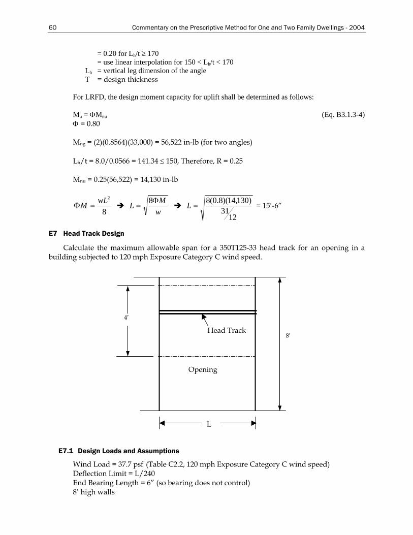
60 Commentary on the Prescriptive Method for One and Two Family Dwellings - 2004
= 0.20 for Lh/t ≥ 170 = use linear interpolation for 150 < Lh/t < 170 Lh = vertical leg dimension of the angle T = design thickness
For LRFD, the design moment capacity for uplift shall be determined as follows: Mu = ΦMnu (Eq. B3.1.3-4) Φ = 0.80 Mng = (2)(0.8564)(33,000) = 56,522 in-lb (for two angles) Lh/t = 8.0/0.0566 = 141.34 ≤ 150, Therefore, R = 0.25 Mnu = 0.25(56,522) = 14,130 in-lb
8
2wLM =Φ wML Φ
=8
12
31)130,14)(8.0(8
=L = 15’-6”
E7 Head Track Design
Calculate the maximum allowable span for a 350T125-33 head track for an opening in a building subjected to 120 mph Exposure Category C wind speed.
Head Track
Opening
L
4’
8’
E7.1 Design Loads and Assumptions
Wind Load = 37.7 psf (Table C2.2, 120 mph Exposure Category C wind speed) Deflection Limit = L/240 End Bearing Length = 6” (so bearing does not control) 8’ high walls
Commentary on the Prescriptive Method for One and Two Family Dwellings - 2004 61
E7.2 Design Capacity
Head track spans are calculated using the AISIWIN– V4.0 computer program. The following is a sample output.
SECTION DESIGNATION: 350S125-33 INPUT PROPERTIES: Web Height = 3.646 in Top Flange = 1.250 in Bottom Flange = 1.250 in Steel Thickness = 0.0346 in Inside Corner Radius = 0.0764 in Yield Stress, Fy = 33.0 ksi Fy with Cold-Work, Fya = 33.0 ksi INPUT PARAMETERS Nominal Load = 37.7 psf Deflection Limit = L/240 Load Factor = 1.6 Bearing Length for Web Crippling= 6 in ALLOWABLE SPANS – SIMPLE SPAN TRIBUTARY HEAD TRACK BRACING AT: AREA NONE MID Pt THIRD Pt48.0 in 3’ 5” 3’ 8” 3’ 8”
E8 Shear Wall Design (General)
The design of the lateral force resisting systems (LFRS) of light-frame buildings generally follows one of three methods: Tributary Area Approach (Flexible Diaphragm); Total Shear Approach (Eyeball Method); and Relative Stiffness Design Approach (Rigid Diaphragms). Each differs in its approach to distributing whole-building lateral forces through the horizontal diaphragms to the shear walls. Each varies in the level of calculation, precision, and dependence on designer judgment. While different solutions can be obtained for the same design by using the different methods, one approach is not necessarily preferred to another. All may be used for the distribution of seismic and wind loads to the shear walls in a building. However, some of the most recent building codes may place limitations or preferences on certain methods. In developing the shear wall tables for the Prescriptive Method the Tributary Area Approach, as described below, is used.
The tributary area approach is perhaps the most popular method used to distribute lateral building loads. Tributary areas based on building geometry are assigned to various components of the LFRS to determine the wind or seismic loads on building components (i.e., shear walls and diaphragms). The method assumes that a diaphragm is relatively flexible in comparison to the shear walls (i.e., a “flexible diaphragm”) such that it distributes forces according to tributary areas rather than according to the stiffness of the supporting shear walls. This hypothetical condition is analogous to conventional beam theory, which assumes rigid supports as illustrated in Figure G1.1 for a continuous horizontal diaphragm (i.e., floor) with three supports (i.e., shear walls).
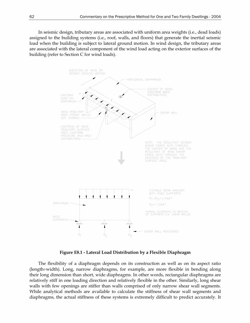
62 Commentary on the Prescriptive Method for One and Two Family Dwellings - 2004
In seismic design, tributary areas are associated with uniform area weights (i.e., dead loads) assigned to the building systems (i.e., roof, walls, and floors) that generate the inertial seismic load when the building is subject to lateral ground motion. In wind design, the tributary areas are associated with the lateral component of the wind load acting on the exterior surfaces of the building (refer to Section C for wind loads).
Figure E8.1 - Lateral Load Distribution by a Flexible Diaphragm
The flexibility of a diaphragm depends on its construction as well as on its aspect ratio (length÷width). Long, narrow diaphragms, for example, are more flexible in bending along their long dimension than short, wide diaphragms. In other words, rectangular diaphragms are relatively stiff in one loading direction and relatively flexible in the other. Similarly, long shear walls with few openings are stiffer than walls comprised of only narrow shear wall segments. While analytical methods are available to calculate the stiffness of shear wall segments and diaphragms, the actual stiffness of these systems is extremely difficult to predict accurately. It
Commentary on the Prescriptive Method for One and Two Family Dwellings - 2004 63
should be noted that if the diaphragm is considered infinitely rigid relative to the shear walls and the shear walls have roughly equivalent stiffness, the three shear wall reactions will be roughly equivalent (i.e., R1 = R2 = R3 = 1/3[w][l]). If this assumption were more accurate, the interior shear wall would be over designed and the exterior shear walls under designed with use of the tributary area method. In many cases, the correct answer is probably somewhere between the apparent over- and under-design conditions.
The tributary area approach is reasonable when the layout of the shear walls is generally symmetrical with respect to even spacing and similar strength and stiffness characteristics. It is particularly appropriate in concept for simple buildings with diaphragms supported by two exterior shear wall lines (with similar strength and stiffness characteristics) along both major building axes. More generally, the major advantages of the tributary area LFRS design method are its simplicity and applicability to simple building configurations. In more complex applications, the designer should consider possible imbalances in shear wall stiffness and strength that may cause or rely on torsional response to maintain stability under lateral load.
Once the whole-building lateral loads have been distributed and assigned to the floor and roof diaphragms and various designated shear walls, each of these subassemblies is designed to resist the assigned shear loads. As discussed, the whole-building shear loads are distributed to various shear walls in accordance with the principle of tributary area approach. Similarly, the distribution of the assigned shear load to the various shear wall segments within a given shear wall line is based on the same principle, but at a different scale. The scale is the subassembly (or shear wall) as opposed to the whole building.
The methods for designing and distributing the forces within a shear wall line differ as described below. As with the three different approaches mentioned for the distribution of lateral building loads, the shear wall design methods place different levels of emphasis on analytic rigor and judgment. Ultimately, the configuration of the building (i.e., are the walls inherently broken into individual segments by large openings or many offsets in plan dimensions?) and the required demand (i.e., shear load) should drive the choice of a shear wall design approach and the resulting construction detailing. Thus, the choice of which design method to use is a matter of designer judgment and required performance. In turn, the design method itself imposes detailing requirements on the final construction in compliance with the analysis assumptions. Accordingly, the above decisions affect the efficiency of the design effort and the complexity of the resulting construction details. The method used in this document is the segmented shear wall design approach.
The segmented shear wall design approach, well recognized as a standard design practice, is the most widely used method of shear wall design. It considers the shear resisting segments of a given shear wall line as separate “elements,” with each segment restrained against overturning by the use of hold-down connectors at its ends. Each segment is a fully sheathed portion of the wall without any openings for windows or doors. The design shear capacity of each segment is determined by multiplying the length of the segment (sometimes called segment width) by tabulated unit shear design values that are available in the building codes and design standards. In its simplest form, the approach analyzes each shear wall segment for static equilibrium in a manner analogous to a cantilevered beam with a fixed end. In a wall with multiple designated shear wall segments, the typical approach to determining an adequate total length of all shear wall segments is to divide the design shear load demand on the wall by the unit shear design value of the wall construction. The effect of stiffness on the actual shear force distribution to the various segments is simply handled by complying with code-required
64 Commentary on the Prescriptive Method for One and Two Family Dwellings - 2004
maximum shear wall segment aspect ratio (i.e., segment height divided by segment width). Although an inexact and circuitous method of handling the problem of shear force distribution in a shear wall line, the SSW approach has been in successful practice for many years, partly due to the use of conservative unit shear design values.
When stiffness is considered, the stiffness of a shear wall segment is assumed to be linearly related to its length (or its total design shear strength). However, the linear relationship is not realistic outside certain limits. For example, stiffness begins to decrease with notable nonlinearly once a shear wall segment decreases below a 4-foot length on an 8-foot-high wall (i.e., aspect ratio of 2 or greater). This does not mean that wall segments shorter than 4 feet in width cannot be used but rather that the effect of relative stiffness in distributing the load needs to be considered. The SSW approach is also less favorable when the wall as a system rather than individual segments (i.e., including sheathed areas above and below openings) may be used to economize on design while meeting required performance.
It is common either to neglect the contribution of dead load or assume that the dead load on the wall is uniformly distributed, as would be the case under gravity loading only. In fact, unless the wall is restrained with an infinitely rigid hold-down device (an impossibility), the uniform dead load distribution will be altered as the wall rotates and deflects upward during the application of shear force. As a result, depending on the rigidity of the framing system above, the dead load will tend to concentrate more toward the “high points” in the wall line, as the various segments begin to rotate and uplift at their leading edges. Thus, the dead load may be somewhat more effective in offsetting the overturning moment on a shear wall segment than is suggested by the uniform dead load assumption. Unfortunately, this phenomenon involves non-rigid body, nonlinear behavior for which there is no simplified method of analysis. Therefore, this effect is generally not considered, particularly for walls with specified restraining devices (i.e., hold-downs) that are, by default, generally assumed to be completely rigid.
E9 Shear Wall Design (One Story Building)
The segmented shear wall line has the following dimensions:
Wall construction: Building Width = 30’ Building Length = 45’ Wall Height = 8’ Roof Slope = 6:12 Exterior sheathing is 7/16-inch-thick OSB with No. 8 screws spaced 6 inches on center on panel edges and 12 inches on center in panel field Interior sheathing is 1/2-inch-thick gypsum wall board with No. 6 screws at 12 inches on center Framing studs are 350S162-33 spaced at 24 inches on center
Calculate the sheathing requirements for the side and end walls. The building is subjected to a wind speed of 100 mph, Exposure Category C.
Commentary on the Prescriptive Method for One and Two Family Dwellings - 2004 65
E9.1 Design Loads
From Table C2.1: (100 mph, Exposure Category C, 6:12 roof slope) MWRFS building corner wind pressure = 27 psf MWRFS building wind pressure = 20.1 psf Roof corner wind pressure = 3.8 psf Roof wind pressure = 3.3 psf Building gable end = 14.7 psf Building gable end corner = 22.2 psf
Nominal shear value per foot of shear wall for 7/16 inch thick OSB at the stated
fastening and a 2:1 aspect ratio is 910 plf (Table 2211.1(3) of IBC 2000 (ICC, 2000a)). The IBC provides shear values for GWB with 7 inch o.c. fastener spacing. It provides no shear values for 12 inch o.c. fastener spacing.
Where LRFD is used, the IBC 2000 requires the factored design shear value to be determined by multiplying the ultimate shear value by a resistance factor (Φ) of 0.55.
Area End = 6/12(15’)(15’) + ½(8’)(30’) = 233 ft2
Area Side = (8’/2)(45’) =180 ft2
Building aspect ratio = 45/30 = 1.50 Actual shear at each side wall = (20.1 psf)(1.6)(180 ft2)/2 = 2,894 lb Actual shear at each end wall = (20.1 psf)(1.6)(233 ft2)/2 = 3,747 lb a = 10%(30) = 3’ a = 0.4(15.5) = 6.2’ (building height = 8’ + 7.5’ = 15.5’)
Use a = 3’ 2a = 6’
End wall corner area = ½(8)(2x3) = 24 ft2
End wall area = ½(8’)(30’) - 24 = 968 ft2
End wall roof corner area = 1/2(7.5)(3) = 11.25 ft2
End wall roof area = (6/12)(15’)(15’) – 11.25 = 101.25 ft2
Side wall corner area = ½(8)(6) = 24 ft2
Side wall area = ½(8’)(45’) – 24 = 156 ft2
Side wall roof corner area = (7.5)(6) = 45 ft2
Side wall roof area = (7.5’)(45’) – 45 = 292.5 ft2
Building aspect ratio = 45/30 = 1.50 Design shear at each side wall = [24 ft2 (22.2 psf) + 96 ft2 (14.7 psf) + 11.25 ft2 (22.2) + 101 ft2 (14.7)](1.6)/2 = 2,943 lb Design shear at each end wall = [24 ft2 (27 psf) + (156 ft2 (20.1 psf) + 45 ft2 (3.8 psf) + 292.5 psf ft2 (3.3)](1.6)/2 = 3,936 lb
E9.2 Required Sheathing
Each end wall: )55.0(910
936,3= 7.86 ft This equates to 26% of wall length.
Each side wall: )55.0(910
943,2= 5.88 ft This equates to 13% of wall length.
66 Commentary on the Prescriptive Method for One and Two Family Dwellings - 2004
E10 Shear Wall Design (Two Story Building)
The segmented shear wall line has the following dimensions:
Wall construction: Building width = 30’ Building length = 50’ Wall Height = 8’ Roof slope = 6:12 Exterior sheathing is 7/16-inch-thick OSB with No. 8 screws spaced 6 inches on center on panel edges and 12 inches on center in panel field Interior sheathing is 1/2-inch-thick gypsum wall board with No. 6 screws at 12 inches on center Framing studs are 350S162-33 spaced at 24 inches on center
Calculate the sheathing requirements for the side and end walls. The building is subjected to a wind speed of 100 mph, Exposure Category C.
E10.1 Design Loads
From Table C2.1: (100 mph, exposure C, 6:12 roof slope) MWRFS building corner wind pressure = 27 psf MWRFS building wind pressure = 20.1 psf Roof corner wind pressure = 3.8 psf Roof wind pressure = 3.3 psf Building gable end = 14.7 psf Building gable end corner = 22.2 psf Nominal shear value per foot of shear wall for 7/16 inch thick OSB at the stated
fastening and a 2:1 aspect ratio is 910 plf (Table 2211.1(3) of IBC 2000 (ICC, 2000a)). The IBC provides shear values for GWB with 7 inch o.c. fastener spacing. It provides no shear values for 12 inch o.c. fastener spacing.
Where LRFD is used, the IBC 2000 (ICC, 2000a) requires the factored design shear value to be determined by multiplying the ultimate shear value by a resistance factor (Φ) of 0.55.
Calculate corner area width (2a), where “a” equals 10% of least width or 0.4h (whichever is smaller) but not less than either 4% of least width or 3 feet.
a = 10%(30) = 3’ a = 0.4(30) = 12’ Use a = 3’ 2a = 6’
End wall corner area = (4’+8’)(6’) = 72 ft2
End wall area = (4’+8’)(30’) - 72 = 288 ft2
End wall roof corner area = (1/2)(7.5)(3’) = 11.25 ft2
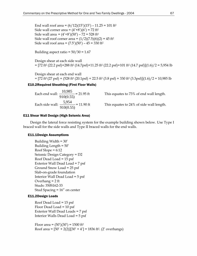
Commentary on the Prescriptive Method for One and Two Family Dwellings - 2004 67
End wall roof area = (6/12)(15’)(15’) – 11.25 = 101 ft2
Side wall corner area = (4’+8’)(6’) = 72 ft2
Side wall area = (4’+8’)(50’) – 72 = 528 ft2
Side wall roof corner area = (1/2)(7.5)(6)(2) = 45 ft2
Side wall roof area = (7.5’)(50’) – 45 = 330 ft2
Building aspect ratio = 50/30 = 1.67 Design shear at each side wall = [72 ft2 (22.2 psf)+288 ft2 (14.7psf)+11.25 ft2 (22.2 psf)+101 ft2 (14.7 psf)](1.6)/2 = 5,954 lb Design shear at each end wall = [72 ft2 (27 psf) + (528 ft2 (20.1psf) + 22.5 ft2 (3.8 psf) + 330 ft2 (3.3psf)](1.6)/2 = 10,985 lb
E10.2 Required Sheathing (First Floor Walls)
Each end wall: )55.0(910
985,10= 21.95 ft This equates to 73% of end wall length.
Each side wall: )55.0(910
954,5= 11.90 ft This equates to 24% of side wall length.
E11 Shear Wall Design (High Seismic Area)
Design the lateral force resisting system for the example building shown below. Use Type I braced wall for the side walls and Type II braced walls for the end walls.
E11.1 Design Assumptions
Building Width = 30’ Building Length = 50’ Roof Slope = 6:12 Seismic Design Category = D2 Roof Dead Load = 15 psf Exterior Wall Dead Load = 7 psf Ground Snow Load = 25 psf Slab-on-grade foundation Interior Wall Dead Load = 5 psf Overhang = 2 ft Studs: 350S162-33 Stud Spacing = 16” on center
E11.2 Design Loads
Roof Dead Load = 15 psf Floor Dead Load = 10 psf Exterior Wall Dead Loads = 7 psf Interior Walls Dead Load = 5 psf Floor area = (50’)(30’) = 1500 ft2
Roof area = [50’ + 2(2)][30’ + 4’] = 1836 ft2. (2’ overhangs)
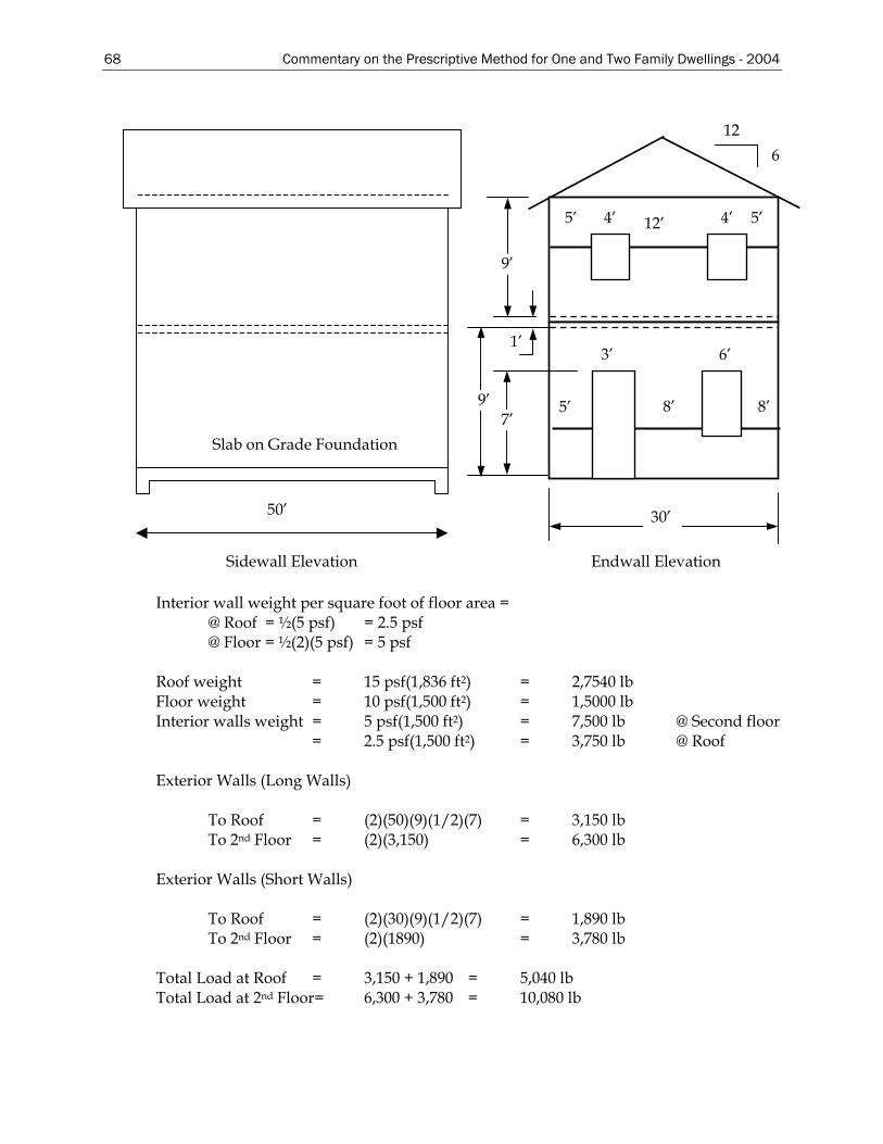
68 Commentary on the Prescriptive Method for One and Two Family Dwellings - 2004
1’
30’
12 6
9’
9’
12’
8’ 5’7’
8’
3’ 6’
4’ 5’ 5’ 4’
Endwall Elevation
Slab on Grade Foundation
50’
Sidewall Elevation
Interior wall weight per square foot of floor area = @ Roof = ½(5 psf) = 2.5 psf @ Floor = ½(2)(5 psf) = 5 psf Roof weight = 15 psf(1,836 ft2) = 2,7540 lb Floor weight = 10 psf(1,500 ft2) = 1,5000 lb Interior walls weight = 5 psf(1,500 ft2) = 7,500 lb @ Second floor = 2.5 psf(1,500 ft2) = 3,750 lb @ Roof Exterior Walls (Long Walls) To Roof = (2)(50)(9)(1/2)(7) = 3,150 lb To 2nd Floor = (2)(3,150) = 6,300 lb Exterior Walls (Short Walls) To Roof = (2)(30)(9)(1/2)(7) = 1,890 lb To 2nd Floor = (2)(1890) = 3,780 lb Total Load at Roof = 3,150 + 1,890 = 5,040 lb Total Load at 2nd Floor= 6,300 + 3,780 = 10,080 lb
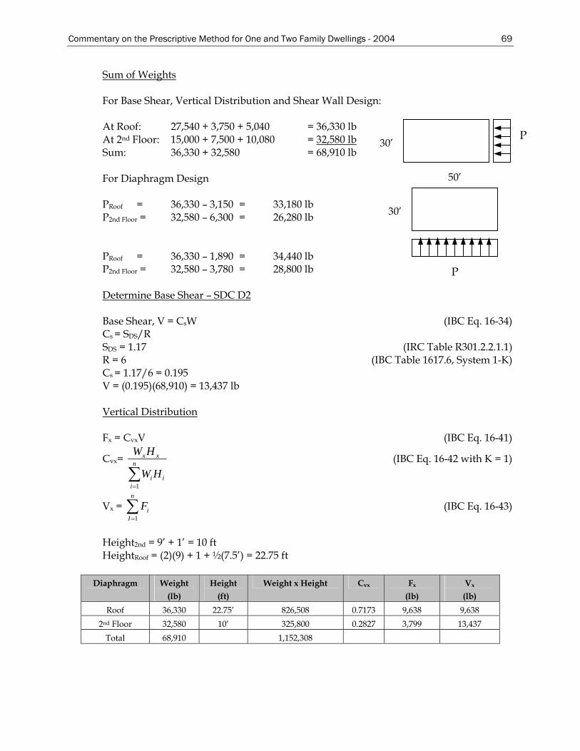
Commentary on the Prescriptive Method for One and Two Family Dwellings - 2004 69
Sum of Weights For Base Shear, Vertical Distribution and Shear Wall Design: At Roof: 27,540 + 3,750 + 5,040 = 36,330 lb
30’ P At 2nd Floor: 15,000 + 7,500 + 10,080 = 32,580 lb
Sum: 36,330 + 32,580 = 68,910 lb
30’
50’ For Diaphragm Design PRoof = 36,330 – 3,150 = 33,180 lb P2nd Floor = 32,580 – 6,300 = 26,280 lb
P PRoof = 36,330 – 1,890 = 34,440 lb P2nd Floor = 32,580 – 3,780 = 28,800 lb Determine Base Shear – SDC D2 Base Shear, V = CsW (IBC Eq. 16-34) Cs = SDS/R SDS = 1.17 (IRC Table R301.2.2.1.1) R = 6 (IBC Table 1617.6, System 1-K) Cs = 1.17/6 = 0.195 V = (0.195)(68,910) = 13,437 lb Vertical Distribution Fx = CvxV (IBC Eq. 16-41)
Cvx=
∑=
n
iii
xx
HW
HW
1
(IBC Eq. 16-42 with K = 1)
Vx = (IBC Eq. 16-43) ∑=
n
IiF
1
Height2nd = 9’ + 1’ = 10 ft HeightRoof = (2)(9) + 1 + ½(7.5’) = 22.75 ft
Diaphragm Weight
(lb) Height
(ft) Weight x Height Cvx Fx
(lb) Vx
(lb) Roof 36,330 22.75’ 826,508 0.7173 9,638 9,638
2nd Floor 32,580 10’ 325,800 0.2827 3,799 13,437 Total 68,910 1,152,308
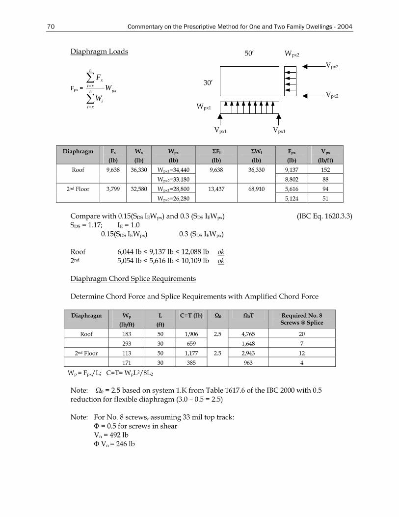
70 Commentary on the Prescriptive Method for One and Two Family Dwellings - 2004
Diaphragm Loads 50’
Vpx2
Vpx2
Vpx1Vpx1
Wpx1
30’
Wpx2
Fpx = pxn
xii
n
xix
WW
F
∑
∑
=
=
Diaphragm Fx
(lb) Wx
(lb) Wpx
(lb) ΣFi
(lb) ΣWi
(lb) Fpx
(lb) Vpx
(lb/ft) Wpx1=34,440 9,137 152 Roof 9,638 36,330 Wpx2=33,180
9,638 36,330 8,802 88
Wpx1=28,800 5,616 94 2nd Floor 3,799 32,580 Wpx2=26,280
13,437 68,910 5,124 51
Compare with 0.15(SDS IEWpx) and 0.3 (SDS IEWpx) (IBC Eq. 1620.3.3) SDS = 1.17; IE = 1.0 0.15(SDS IEWpx) 0.3 (SDS IEWpx) Roof 6,044 lb < 9,137 lb < 12,088 lb ok2nd 5,054 lb < 5,616 lb < 10,109 lb ok Diaphragm Chord Splice Requirements Determine Chord Force and Splice Requirements with Amplified Chord Force
Diaphragm Wp
(lb/ft) L
(ft) C=T (lb) Ω0 Ω0T Required No. 8
Screws @ Splice
Roof 183 50 1,906 4,765 20 293 30 659
2.5 1,648 7
2nd Floor 113 50 1,177 2,943 12 171 30 385
2.5 963 4
Wp = Fpx/L; C=T= WpL2/8L2
Note: Ω0 = 2.5 based on system 1.K from Table 1617.6 of the IBC 2000 with 0.5 reduction for flexible diaphragm (3.0 – 0.5 = 2.5) Note: For No. 8 screws, assuming 33 mil top track: Φ = 0.5 for screws in shear Vn = 492 lb Φ Vn = 246 lb
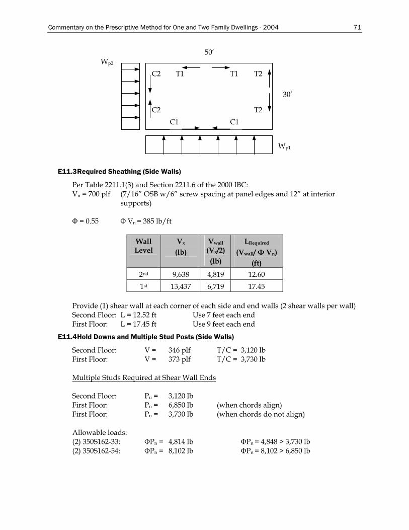
Commentary on the Prescriptive Method for One and Two Family Dwellings - 2004 71
30’
T2
T2 C2
C2
C1
T1 T1
C1
Wp1
50’ Wp2
E11.3 Required Sheathing (Side Walls)
Per Table 2211.1(3) and Section 2211.6 of the 2000 IBC: Vn = 700 plf (7/16” OSB w/6” screw spacing at panel edges and 12” at interior
supports) Φ = 0.55 Φ Vn = 385 lb/ft
Wall Level
Vx
(lb) Vwall
(Vx/2) (lb)
LRequired
(Vwall/ Φ Vn) (ft)
2nd 9,638 4,819 12.60 1st 13,437 6,719 17.45
Provide (1) shear wall at each corner of each side and end walls (2 shear walls per wall) Second Floor: L = 12.52 ft Use 7 feet each end First Floor: L = 17.45 ft Use 9 feet each end
E11.4 Hold Downs and Multiple Stud Posts (Side Walls)
Second Floor: V = 346 plf T/C = 3,120 lb First Floor: V = 373 plf T/C = 3,730 lb Multiple Studs Required at Shear Wall Ends Second Floor: Pu = 3,120 lb First Floor: Pu = 6,850 lb (when chords align) First Floor: Pu = 3,730 lb (when chords do not align) Allowable loads: (2) 350S162-33: ΦPn = 4,814 lb ΦPn = 4,848 > 3,730 lb (2) 350S162-54: ΦPn = 8,102 lb ΦPn = 8,102 > 6,850 lb
72 Commentary on the Prescriptive Method for One and Two Family Dwellings - 2004
Hold Downs Required at Shear Wall Ends Single Shear Wall: Tu = 3,730 lbs TASD = 2,710 lb Aligning Shear Walls: Tu = 6,910 lbs TASD = 4,940 lb Using Simpson’s S/HTT-14 Hold Down with 5/8” diameter bolt for single shear wall: Tallow = 5,260 lbs Tallow = 3,950 lbs (without 1/3 increase for wind/seismic) Tallow > TASD = 2,710 lb Using Simpson’s S/HD8 Hold Down with 5/8” diameter bolt for aligning shear wall: Tallow = 7,920 lbs Tallow = 5,940 lbs (without 1/3 increase for wind/seismic) Tallow > TASD = 4,940 lb
E11.5 Required Sheathing (End Walls)
End wall shear walls use 7/16” OSB fastened with No. 8 screws at 6” at panel edges and 12” at intermediate supports. Per previous calculations, LRequired at 2nd floor = 12.6’; and LRequired at 1st floor = 17.45’. Try Type II walls (perforated shear wall): Determine percentage of fully sheathed wall @ 2nd floor = (5+12+5)/30 = 0.73 = 73.3% @ 1st floor = (5+8+8)/30 = 0.70 = 70% Maximum unrestrained opening at 1st and 2nd floor = 7’, with wall fully sheathed above and below. Interpolate for length adjustment factor for both “percent fully sheathed wall” and “Maximum unrestrained opening”: At 2nd Floor:
% Fully Sheathed 6.75’ 7’ 7.5’ 60 1.28 1.32
73.3 1.176 1.182 1.203 80 1.12 1.14
Therefore, the required length of fully sheathed (Type II) wall = (1.182)(12.60’) = 14.89’ 14.89’ < 22’ ok At 1st Floor:
% Fully Sheathed 6.75’ 7’ 7.5’ 60 1.28 1.293 1.32 70 1.2 1.21 1.23 80 1.12 1.127 1.14
Therefore, the required length of fully sheathed (Type II) wall = (1.21)(17.45’) = 21.11’
Commentary on the Prescriptive Method for One and Two Family Dwellings - 2004 73
E11.6 Hold Downs and Multiple Stud Posts (End Walls)
Second Floor: V = 162 plf T/C = 1,460 lb (when chords align) First Floor: V = 228 plf T/C = 3,730 lb (when chords do not align) Allowable loads: (2) 350S162-33: ΦPn = 4,814 lb ΦPn = 4,848 > 3,730 lb ok Hold Downs Required at Shear Wall Ends Single Shear Wall: Tu = 1,460 lbs TASD = 1,040 lb Aligning Shear Walls: Tu = 3,730 lbs TASD = 2,670 lb Using Simpson’s S/HTT-14 Hold Down with 5/8” diameter bolt. For single shear walls: Tallow = 5,260 lbs Tallow = 3,950 lbs (without 1/3 increase for wind/seismic) Tallow > TASD = 1,040 lb Determination of Top Track Requirements to Accommodate Diaphragm Chord Forces From the above, @Roof Cmax = 1,906 lb @2nd Floor Cmax = 1,177 lb Using AISIWIN, the maximum axial capacity of a 350T125-33 (top track) is 2,882 lbs (concentric load with no weak axis bracing and a maximum track length of 1.33 ft). For L = 16” with track considered fully braced, ΦPn = 2,882 lb > 1,906 lb Note: The diaphragm chord forces were tabulated for the various roof and wall height combinations at various diaphragm spans with some breakdown of diaphragm aspect ratios where warranted. Establish Shear Anchor Requirements Based on Shear Wall Edge Screw Spacing Use shear wall capacity, based on shear wall edge screw spacing (6” o.c. at panel edges) to determine required shear anchor capacity: ΦVn = 385 plf @ 6” panel edge screw spacing Check 350T125-33 bottom track with nested 350S162-33 stud: ΦPn(Track) = 2,420 lb bearing capacity of track plus stud (Table E3.3-2) where: Fu = 45 ksi
t = 0.0346” d = 0.5” Φ = 0.7 (Table E3.3-2)
74 Commentary on the Prescriptive Method for One and Two Family Dwellings - 2004
фPn = 3,444 lb shear capacity of ½” diam. bolt (Eq. E3.4-1) where: Ab = 0.196 in2
Fnv = 27 ksi (Table E3.4-1) Φ = 0.65 (Table E3.4-1)
Required Fastener Spacing = 2,420/385 = 6.28 feet
E11.7 Continuous Strap for Drag Force
A. Tensile Capacity of 2.5” x 43-mil Strap
ΦTn = (0.95)(33 ksi)(2.5”)(0.0451”) = 3.535 kips Where: Fy = 33 ksi An = 0.113 in2
Φ = 0.95 Tn = 3.720 kips
B. Screw Shear Capacity for Strap End Connections:
Screw Size Va*(lb) Ω Φ ΦVn No. Required**
No. 8 Screw 244 3 0.5 366 11
No. 10 Screw 263 3 0.5 395 10 *Values for screw shear capacity was obtained from Section 1, Table C-B1. **No. 8 screw: Φ Vn = (244)(ΩΦ) = 244(3)(0.5) = 366 lb/screw No. 10 screw: Φ Vn = (263)(ΩΦ) = 263(3)(0.5) = 395 lb/screw 3,720/366 = 10.16 Use (11) No. 8 screws, or, 3,720/395 = 9.42 Use (10) No. 10 screws
Maximum diaphragm shear = 346 plf (at roof level)
C. Maximum Blocking Spacing Based on Tensile Capacity of Strap Spacing = 3,720/346 = 10.75 feet
D. Maximum Blocking Spacing Based on Capacity of Blocking Block properties: h = 7.5 in
t = 0.0566 in h/t = 132.51 kv = 5.34 (assume unreinforced web) Fy = 33 ksi [Ekv/Fy]1/2 = 68.5
0.96(68.5) = 65.76 < 132.51 1.415(68.5) = 96.93 <132.51 Vn = 0.905Ekvt3/h (Eq. C3.2-3)
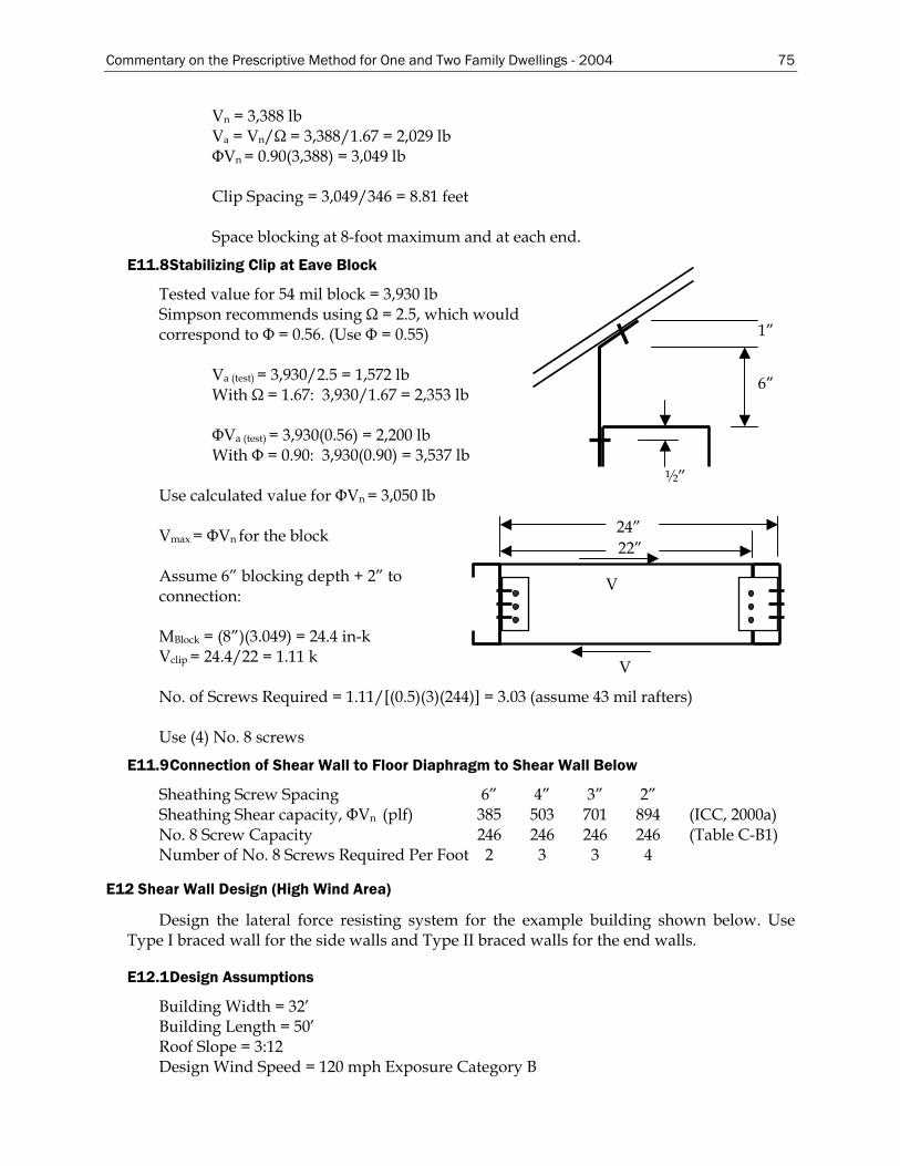
Commentary on the Prescriptive Method for One and Two Family Dwellings - 2004 75
Vn = 3,388 lb Va = Vn/Ω = 3,388/1.67 = 2,029 lb ΦVn = 0.90(3,388) = 3,049 lb Clip Spacing = 3,049/346 = 8.81 feet Space blocking at 8-foot maximum and at each end.
E11.8 Stabilizing Clip at Eave Block
Tested value for 54 mil block = 3,930 lb Simpson recommends using Ω = 2.5, which would correspond to Φ = 0.56. (Use Φ = 0.55) 1” Va (test) = 3,930/2.5 = 1,572 lb 6” With Ω = 1.67: 3,930/1.67 = 2,353 lb ΦVa (test) = 3,930(0.56) = 2,200 lb With Φ = 0.90: 3,930(0.90) = 3,537 lb ½” Use calculated value for ΦVn = 3,050 lb
24” 22”
V
V
Vmax = ΦVn for the block Assume 6” blocking depth + 2” to connection: MBlock = (8”)(3.049) = 24.4 in-k Vclip = 24.4/22 = 1.11 k No. of Screws Required = 1.11/[(0.5)(3)(244)] = 3.03 (assume 43 mil rafters) Use (4) No. 8 screws
E11.9 Connection of Shear Wall to Floor Diaphragm to Shear Wall Below
Sheathing Screw Spacing 6” 4” 3” 2” Sheathing Shear capacity, ΦVn (plf) 385 503 701 894 (ICC, 2000a) No. 8 Screw Capacity 246 246 246 246 (Table C-B1) Number of No. 8 Screws Required Per Foot 2 3 3 4
E12 Shear Wall Design (High Wind Area)
Design the lateral force resisting system for the example building shown below. Use Type I braced wall for the side walls and Type II braced walls for the end walls.
E12.1 Design Assumptions
Building Width = 32’ Building Length = 50’ Roof Slope = 3:12 Design Wind Speed = 120 mph Exposure Category B
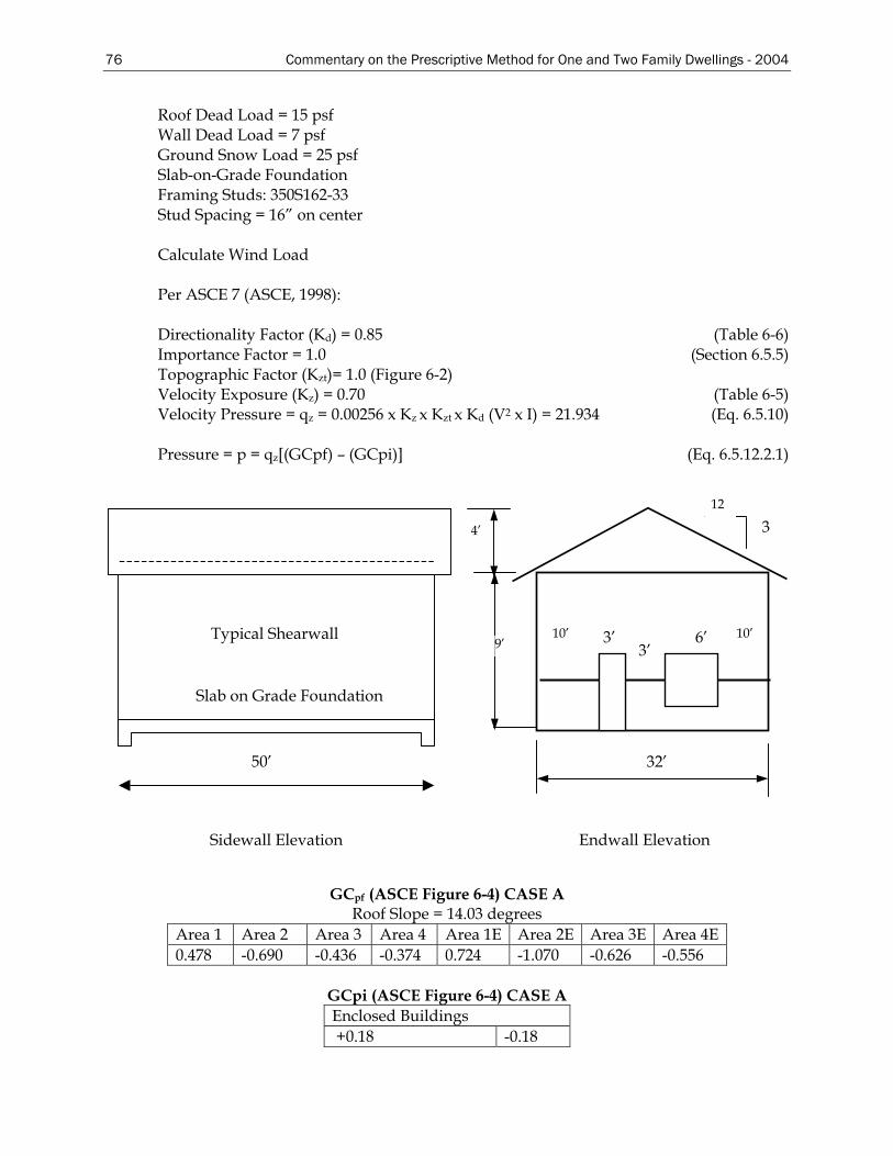
76 Commentary on the Prescriptive Method for One and Two Family Dwellings - 2004
Roof Dead Load = 15 psf Wall Dead Load = 7 psf Ground Snow Load = 25 psf Slab-on-Grade Foundation Framing Studs: 350S162-33 Stud Spacing = 16” on center Calculate Wind Load Per ASCE 7 (ASCE, 1998): Directionality Factor (Kd) = 0.85 (Table 6-6) Importance Factor = 1.0 (Section 6.5.5) Topographic Factor (Kzt)= 1.0 (Figure 6-2) Velocity Exposure (Kz) = 0.70 (Table 6-5) Velocity Pressure = qz = 0.00256 x Kz x Kzt x Kd (V2 x I) = 21.934 (Eq. 6.5.10) Pressure = p = qz[(GCpf) – (GCpi)] (Eq. 6.5.12.2.1)
12
3 4’
9’ 3’ 3’ 10’ 6’ 10’
32’
Endwall Elevation
Typical Shearwall
Slab on Grade Foundation
50’
Sidewall Elevation
GCpf (ASCE Figure 6-4) CASE A
Roof Slope = 14.03 degrees Area 1 Area 2 Area 3 Area 4 Area 1E Area 2E Area 3E Area 4E 0.478 -0.690 -0.436 -0.374 0.724 -1.070 -0.626 -0.556
GCpi (ASCE Figure 6-4) CASE A Enclosed Buildings +0.18 -0.18
Commentary on the Prescriptive Method for One and Two Family Dwellings - 2004 77
GCpf (ASCE Figure 6-4) CASE B Roof Slope = 14.03 degrees
Area 1
Area 2
Area 3
Area 4
Area 5
Area 6
Area 1E
Area 2E
Area 3E
Area 4E
Area 5E
Area 6E
-0.45 -0.69 -0.37 -0.45 0.4 -0.29 -0.48 -1.07 -0.53 -0.48 0.61 -0.43
p (psf) - CASE A Roof Slope = 14.03 degrees
Area 1 Area 2 Area 3 Area 4 Area 1E Area 2E Area 3E Area 4E 14.43 -19.08 -13.51 -12.15 19.83 -27.42 -17.68 -16.14
p (psf) - CASE B
Roof Slope = 14.03 degrees Area 1
Area 2
Area 3
Area 4
Area 5
Area 6
Area 1E
Area 2E
Area 3E
Area 4E
Area 5E
Area 6E
-13.8
2
-19.08
-12.06
-13.82 12.72 -10.31
-14.48 -27.42 -15.57 -14.48 17.33 -13.38
The above are based on corner length as follows: 0.4 x Building Height = 5.20 ft (height = 13.00 ft) 0.1 x min. Width = 3.20 ft Not less than 3’ = 3.00 ft a = 3.20 ft Corner Length = 2a = 6.40 ft Roof Area 2 Factored Wind Load = 19.08 (1.6) = 30.52 psf Roof Area 3 Factored Wind Load = 13.51 (1.6) = 21.62 psf Factored Roof Dead Load = 0.9(15 psf) = 13.5 psf Determine Forces in Walls Side Walls
P = 12.72 + 10.31 = 23.03 psf (interior) P = 17.33 + 13.38 = 30.71 psf (exterior, corner)
Force/Wall
= ⎥⎦⎤
⎢⎣⎡−⎥⎦
⎤⎢⎣⎡+⎥⎦
⎤⎢⎣⎡ −
2)8.0)('2.3(03.23
2)'4)('32)(2/1(03.23
2'4.6'32)'9)(2/1(03.23 psf
wallspsf
wallspsf
+ ⎥⎦⎤
⎢⎣⎡+⎥⎦
⎤⎢⎣⎡
2)8.0)('2.3)(71.30(
2)'9)('2.3(71.30 psfpsf
Force/Wall = 2515 lb/side wall
78 Commentary on the Prescriptive Method for One and Two Family Dwellings - 2004
End Walls P = 14.43 + 12.15 = 26.58 psf (interior) P = 19.82 + 16.14 = 35.96 psf (corner)
Roof: P1 = -19.08 psf (Area 2), P2 = -13.51 psf (Area 1)
[Sin(14.03)][-19.08] = -4.62 psf [Sin(14.03)][13.51] = 3.27 psf P1 = -27.41 psf (Area 2E), P2 = -17.67 psf (Area 1E)
Total load from roof = 4.62 – 3.27 = 1.35 psf. (typ.) Total load from roof = 2.36 psf (corner)
Force/Wall = (26.58 psf )(9’x1/2)(50’-12.8’)/2 walls + (35.96 psf)(1/2)(9’)(6.4’)
+ (-4.35 psf)(4’)[(50’-12.8’)/2] + (-2.36 psf)(4’)(6.4’) = 3,099 lb/end wall However, per ASCE 7 (page 42, Figure 6.4): The total horizontal shear shall not be less than that determined by neglecting wind roof surfaces. Therefore,
Force/wall = (26.58 psf)(9’/2)(37.2’) + (35.96 psf)(9’/2)(12.8’) = 6,520 lb/2 sides = 3,260 lb
Chords v = 1,258 lb Side wall / 4’ long = 315 plf v = 1,630 lb End wall /5’ long = 326 plf Wall height = 9 feet Maximum chord force = 326(9) = 2,934 lb Post: Use (2) 350S162-33 studs braced at 4’ (Pall = 4,848 lb) Hold Downs P = 2,934 lb Attach hold down to each end of each shear wall panel. Use S/HTT-14 hold-downs from Simpson Catalog with 5/8” diameter bolt (Pall = 3,295 lb). The 3,295 lb hold down capacity is calculated as follows:
Pall = 4,385 lb for 54 mil member with 14 No. 10 screws. Pall = (177 lb/screw)(14)(1.33) = 3,295 lb for 33 mil member.
E12.2 Length of Shear Panel (Side Walls)
P = 2,515/2 panels = 1,258 lb per shear wall Per Table 2211.1(1) of IBC 2000: Vn = 910/2.5 = 364 lb Length of shear panel required = 1,258/364 = 3.46 ft/shear wall
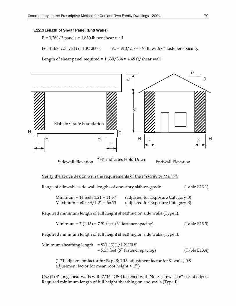
Commentary on the Prescriptive Method for One and Two Family Dwellings - 2004 79
E12.3 Length of Shear Panel (End Walls)
P = 3,260/2 panels = 1,630 lb per shear wall Per Table 2211.1(1) of IBC 2000: Vn = 910/2.5 = 364 lb with 6” fastener spacing. Length of shear panel required = 1,630/364 = 4.48 ft/shear wall
“H” indicates Hold Down Endwall Elevation
Slab on Grade Foundation
12
3 4’
9’
5’ 5’
H H H
H H
4’ 4’
Sidewall Elevation
H
Verify the above design with the requirements of the Prescriptive Method: Range of allowable side wall lengths of one-story slab-on-grade (Table E13.1)
Minimum = 14 feet/1.21 = 11.57’ (adjusted for Exposure Category B) Maximum = 60 feet/1.21 = 66.11 (adjusted for Exposure Category B)
Required minimum length of full height sheathing on side walls (Type I):
Minimum = 7’(1.13) = 7.91 feet (6” fastener spacing) (Table E13.3) Required minimum length of full height sheathing on side walls (Type I): Minimum sheathing length = 8’(1.13)(1/1.21)(0.8)
= 5.23 feet (6” fastener spacing) (Table E13.4)
(1.21 adjustment factor for Exp. B; 1.13 adjustment factor for 9’ walls; 0.8 adjustment factor for mean roof height < 15’)
Use (2) 4’ long shear walls with 7/16” OSB fastened with No. 8 screws at 6” o.c. at edges. Required minimum length of full height sheathing on end walls (Type I):
80 Commentary on the Prescriptive Method for One and Two Family Dwellings - 2004
Minimum sheathing length = 8’(1.13)(0.8)(1/1.21) = 5.97 feet
(1.21 adjustment factor for Exp. B; 1.13 adjustment factor for 9’ walls; 0.8 adjustment factor for mean roof height < 15’)
Since this is a Type II shear wall, check the applicability of any factors: The length of full height sheathing cannot be multiplied by any factor from Table E12.1 because the roof dead load is greater than 11 psf and the wall dead load is not less than 7 psf. L = 5.97 feet. (6” o.c. edge fastener spacing) Use (2) 5’ long shear walls with 7/16” OSB fastened with No. 8 screws at 6” o.c. at edges.
E12.4 Braced Wall Hold Down Anchorage
Required hold down anchor force from Table E12.2 = 3,535 lbs. (9-foot walls and 6” screw spacing). F = 3,535/1.4 = 2,525 lb (The 1.4 factor is from Table E12-2 of the Prescriptive Method)
Commentary on the Prescriptive Method for One and Two Family Dwellings - 2004 81
F. ROOF FRAMING DESIGN EXAMPLES
F1 Ceiling Joist Design
Calculate the maximum allowable single span for a 550S162-33 ceiling joist (attics with limited storage) with bearing stiffeners at each support. The deflection limit is L/240 (total loads). The joists are spaced at 24 inches on center and laterally braced (on compression flange) at mid-span.
F1.1 Design Assumptions
Joist Spacing = 24” Steel Yield Strength = 33 ksi Live Load + Dead Load Deflection Limit = L/240 Ceiling Dead Load = 5 psf Attic Live Load for Attics with Limited Storage = 20 psf Bracing: Mid-Span Bracing Punchouts: 2-1/2” wide x 4” long along centerline of joist
F1.2 Design Loads
Dead Load: Ceiling Dead Load = 5 psf Live Loads: Attic Live Load = 20 psf Design factored loads acting on joist = P 1. 1.4D = 1.4(5 psf )(24”/12”) = 14 plf 2. 1.2D + 1.6L = [1.2(5 psf ) + 1.6(20 psf)](24”/12”) = 76 plf The controlling factored design load, w, is 76 plf
F1.3 Member Properties
Nominal moment and shear capacities were calculated in accordance with the Specification (AISI, 1999).
Nominal Moment Capacity*Φ = 1,100 ft-lb Nominal Shear Capacity*Φ = 744.13 lb Effective Moment of Inertia, Ixx = 1.4506 in4
Effective Section Modulus, Sxx = 0.4209 in3
F1.4 Bending Capacity
Mn = smallest nominal moment of Sections C3.1.1, C3.1.2, and C3.1.3 of the Specification. C3.1.1 Nominal Section Strength Mn = SeFy (Eq. C3.1.1-1) Se = Sx
Mn = (0.4209)(33,000) = 13,890 in-lb Φb = 0.95
82 Commentary on the Prescriptive Method for One and Two Family Dwellings - 2004
C3.1.2.1 Lateral Buckling Strength Mn = ScFc (Eq. C3.1.2.1-1) Φb = 0.90 By calculating the effective section modulus based on mid-span compression flange bracing, the resulting un-factored nominal moment is: Mn = 12,921 in-lb (iterative calculation) C3.1.3 "Beams Having One Flange Through-Fastened to Deck or Sheathing" Does not apply. The factored moment is the smallest nominal moment calculated per AISI Specification Sections C3.1.1, C3.1.2, and C3.1.3 multiplied by the appropriate resistant factor, Φ.
Mu = 8
2wLM n =Φ wM
L nbΦ=
8
1276
)921,12)(90.0(8=L
L = 121.2” L = 10’-2”
F1.5 Shear Capacity
Design shear strength = Φv V = 744.13 lbs, w = uniform load (plf) = 76 plf Use the design shear strength to calculate the maximum unsupported span length.
2wLV =
wVL 2
= 76
13.7442xL = = 19’-7”
F1.6 Deflection Limit
Deflection due to total loads:
δ =5384
4wLEI
(simply supported single span deflection equation)
W = (5 psf + 20 psf)(24”/12”) = 50 plf (service load)
3
12)50)(240(5
)4506.1)(000,500,29(384=L = 12'-5"
Deflection due to live load: W = (20 psf)(24”/12”) = 40 plf (service load)
3
12)40)(360(5
)4506.1)(000,500,29(384=L = 11'-8"
The resulting joist span is 10’-2” (controlled by lateral buckling strength)
Commentary on the Prescriptive Method for One and Two Family Dwellings - 2004 83
F2 Rafter Design
Determine if an unbraced 800S162-43 steel rafter (6:12 slope) is adequate for a 32-foot building subjected to 90 mph (Exposure Category B) wind speed and 30 psf ground snow load. Assume ceiling joist is 43 mil thick.
F2.1 Design Assumptions
Rafter Spacing = 24” Ceiling Joist Bearing Length = 3.5” Steel Yield Strength = 33 ksi Roof Dead Load = 7 psf Ceiling Dead Load = 5 psf Total Load Deflection Limit = L/180
F2.2 Design Methodology
The rafter span table was designed based primarily on gravity loads, hence the rafter spans are reported on the horizontal projection of the rafter, regardless of the slope. The gravity loads consist of a 7 psf dead load and the greater of a minimum 16 psf live load or the applied roof snow load (applied snow loads are calculated by multiplying the ground snow load by 0.7 and no further reductions or increases are made for special cases).
Wind load effects are correlated to equivalent snow loads wind pressures were calculated using the ASCE 7-98 components and cladding coefficients. Wind loads acting perpendicular to the plane of the rafter were adjusted to represent loads acting orthogonal to the horizontal projection of the rafter (as shown in Figure I4.1). Wind loads were examined for both uplift and downward loads and the worst case was correlated to a corresponding snow load.
F2.3 Design Loads
Dead Load = (7 psf)( cos 26.56°)(24”/12”) = 15.65 psf Roof Live Load is the maximum of Roof Snow Load and Roof Minimum Live Load:
Roof Snow Load = 0.7(30 psf)(24”/12”) = 42 plf Roof Live Load = 16 psf (24”/12”) = 32 plf
Both uplift and inward acting wind loads must be examined and the worst case converted to an equivalent snow load effect. ASCE 7 (ASCE, 1998) components and cladding pressure coefficients are used to calculate the wind load.
ρ = qh[(GCp) – (GCpi)] lb/ft2 (Eq. 6-18) qh = 0.00256KzKztKdV2I (Eq. 6-13)
Kz = 0.70 for exposure B (Table 6-5) Kzt = 0.72 (maximum value used) (Figure 6-2) Kd = 0.85 (Table 6-6) GCp = -1.4 (Tributary area = 100 ft2) (Figure 6-5B) GCp = +0.3 (Tributary area = 100 ft2) (Figure 6-5B) GCpi = ± 0.18 (Table 6-7)
Downward load (inward): q = 0.00256(0.70)(0.72)(0.85)(90)2[0.3 – (-0.18)] = 4.26 psf Upward load (uplift or outward): q = 0.00256(0.70)(0.72)(0.85)(90)2[-1.4 - (0.18)] = -14 psf
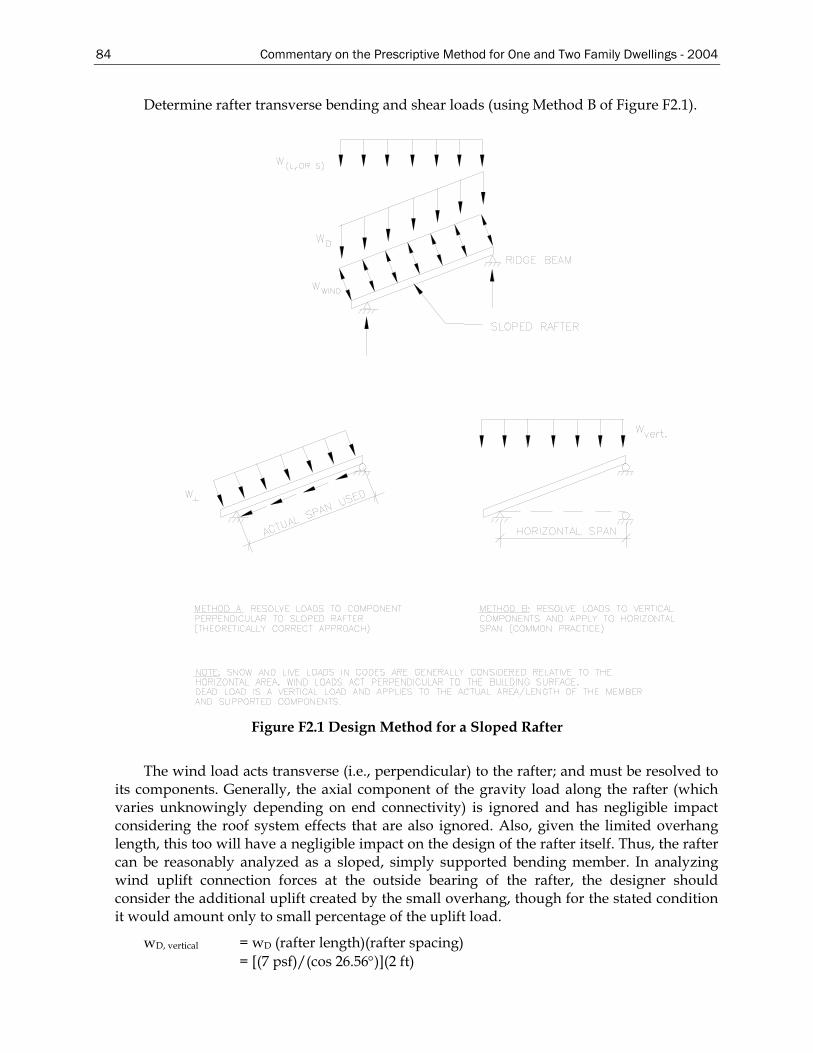
84 Commentary on the Prescriptive Method for One and Two Family Dwellings - 2004
Determine rafter transverse bending and shear loads (using Method B of Figure F2.1).
Figure F2.1 Design Method for a Sloped Rafter
The wind load acts transverse (i.e., perpendicular) to the rafter; and must be resolved to its components. Generally, the axial component of the gravity load along the rafter (which varies unknowingly depending on end connectivity) is ignored and has negligible impact considering the roof system effects that are also ignored. Also, given the limited overhang length, this too will have a negligible impact on the design of the rafter itself. Thus, the rafter can be reasonably analyzed as a sloped, simply supported bending member. In analyzing wind uplift connection forces at the outside bearing of the rafter, the designer should consider the additional uplift created by the small overhang, though for the stated condition it would amount only to small percentage of the uplift load.
wD, vertical = wD (rafter length)(rafter spacing) = [(7 psf)/(cos 26.56°)](2 ft)
Commentary on the Prescriptive Method for One and Two Family Dwellings - 2004 85
= 15.65 plf wsnow = 0.7(30 psf)(16 ft)(2 ft)/16 ft-horizontal = 42 plf wy(upward) = -14/(cos 26.56°)2(2’) = -35 psf wy(downward) = 4.26/(cos 26.56°)2(2’) = 10.64 psf
F2.4 Load Combinations
1. 1.4D = 1.4(15.65) = 21.91 plf (downward) 2. 1.2D + 1.6L = 1.2(15.65) + 1.6(42) = 85.98 plf (downward) 3a. 0.9D + 1.6W = 0.9(15.65) + 1.6(-35) = -41.92 plf (upward) 3b. 0.9D + 1.6W = 0.9(15.65) + 1.6(10.64) = 31.11 plf (downward) Load combination 2 controls rafter design in inward-bending direction (compression
side of rafter laterally supported). Load combination 3a would also need to be checked, as it may control rafter design in outward-bending direction since the compression side now has no lateral bracing unless specified; also important to rafter connections at the bearing wall and ridge member. In this case, load combination 3a was not found to control.
8
2wLM u = =8
)16(98.85 2
= 2,751.36 ft-lb = 33,016 in-lb
F2.5 Member Properties
Sx = 1.145 in3
Ix = 4.581 in4
F2.6 Bending Capacity
(Bending per AISI Specification Section C3, "Flexural Members", all referenced equations and sections are those of the AISI Specification (AISI, 1999)). Factored Nominal Moment = ΦbMn
Mn = smallest nominal moment of C3.1.1, C3.1.2, C3.1.3 C3.1.1 Nominal Section Strength The nominal moment capacity of this section is calculated using AISIWIN computer program. Mn = 37,795 in-lb C3.1.2 Lateral Buckling Strength: This section does not apply because roof sheathing provides lateral support. C3.1.3 Beams Having One Flange Through Fastened to Deck or Sheathing: This section does not apply. Factored Moment, ΦMn = (37,795)(0.95) = 35,905 in-lb
8
2wLM n =Φ wM
L nbΦ=
8
1286
)905,35(8=L = 200 in 16'-8"
86 Commentary on the Prescriptive Method for One and Two Family Dwellings - 2004
F2.7 Shear Capacity
Nominal shear strength x Φv = 1,532 lb (punched section) w = uniform load (plf) = 86 plf
2wLV =
wVL 2
= 8615322xL = = 35’-7”
F2.8 Deflection Limit
δ =5384
4wLEI
= L/180 (simply supported single span deflection equation)
3
12)7.57)(180(5
)581.4)(000,500,29(384=L
where, w = (7/cos26.56 psf + 0.7x30 psf)(24”/12”) = 57.7 plf L= 19’-1" Bending controls the design, hence the allowable rafter span is L = 16'-8". This is adequate for the given example.
F3 Ridge Member Shear Connection
Consider the horizontal projection of a simply supported rafter. Vmax = wL/2 (L=16 ft, w = 86 plf) Vmax = 86 x 16/2 = 688 lb Screw Shear Capacity (calculated per Section E4.3 of the Specification (AISI, 1999)). Screw diameter, d = 0.19 inches (# 10 screw, based on AISI Commentary to Specification Table C-E4-1). Ultimate capacity of steel = 45 ksi (tensile) Steel design thickness = 0.0451” (43 mils minimum thickness) Φ = 0.5 t2/t1 ≤ 1.0, The nominal shear strength per screw, Pns, is the smallest of:
Pns = 2322.4 uFdt ⎟
⎠⎞⎜
⎝⎛ (Eq. E4.3.1-1)
Pns = 2.7t1dFu1 (Eq. E4.3.1-2) Pns = 2.7t2dFu2 (Eq. E4.3.1-3) where: t1 = t2 = 0.0451” and Fu1 = Fu2 = 45 ksi Pns = 789 lbs.
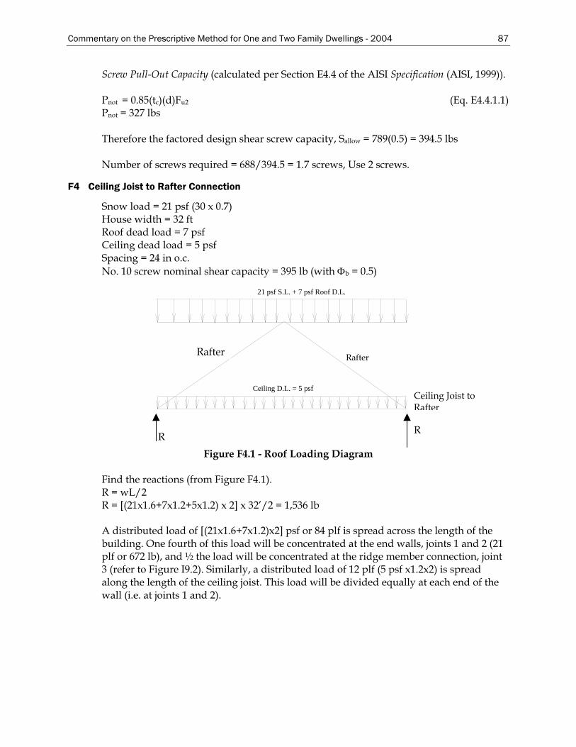
Commentary on the Prescriptive Method for One and Two Family Dwellings - 2004 87
Screw Pull-Out Capacity (calculated per Section E4.4 of the AISI Specification (AISI, 1999)). Pnot = 0.85(tc)(d)Fu2 (Eq. E4.4.1.1) Pnot = 327 lbs Therefore the factored design shear screw capacity, Sallow = 789(0.5) = 394.5 lbs Number of screws required = 688/394.5 = 1.7 screws, Use 2 screws.
F4 Ceiling Joist to Rafter Connection
Snow load = 21 psf (30 x 0.7) House width = 32 ft Roof dead load = 7 psf Ceiling dead load = 5 psf Spacing = 24 in o.c. No. 10 screw nominal shear capacity = 395 lb (with Φb = 0.5)
21 psf S.L. + 7 psf Roof D.L.
Ceiling D.L. = 5 psf
Rafter Rafter
Ceiling Joist to Rafter
Figure F4.1 - Roof Loading Diagram
R R
Find the reactions (from Figure F4.1). R = wL/2 R = [(21x1.6+7x1.2+5x1.2) x 2] x 32’/2 = 1,536 lb A distributed load of [(21x1.6+7x1.2)x2] psf or 84 plf is spread across the length of the building. One fourth of this load will be concentrated at the end walls, joints 1 and 2 (21 plf or 672 lb), and ½ the load will be concentrated at the ridge member connection, joint 3 (refer to Figure I9.2). Similarly, a distributed load of 12 plf (5 psf x1.2x2) is spread along the length of the ceiling joist. This load will be divided equally at each end of the wall (i.e. at joints 1 and 2).
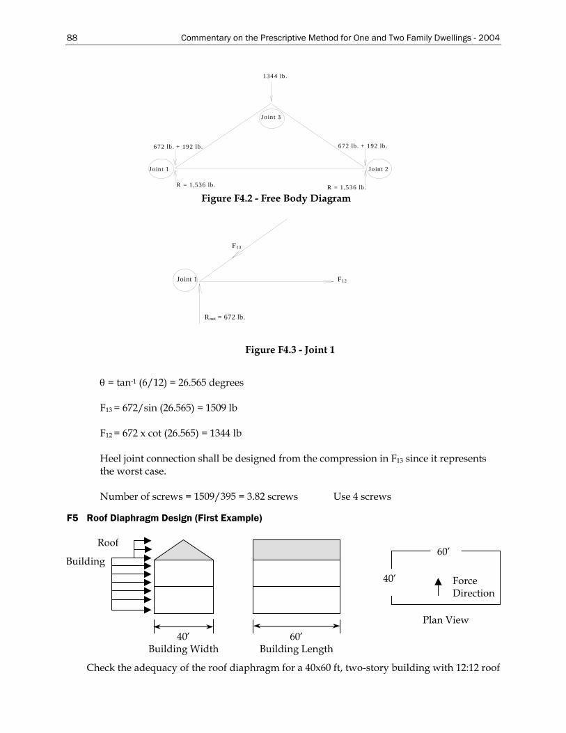
88 Commentary on the Prescriptive Method for One and Two Family Dwellings - 2004
F13
Rnet = 672 lb.
Joint 1 F12
1344 lb .
R = 1 ,536 lb .
672 lb . + 192 lb .
Joint 1
Joint 3
R = 1,536 lb .
Jo int 2
672 lb . + 192 lb .
Figure F4.2 - Free Body Diagram
Figure F4.3 - Joint 1
θ = tan-1 (6/12) = 26.565 degrees F13 = 672/sin (26.565) = 1509 lb F12 = 672 x cot (26.565) = 1344 lb Heel joint connection shall be designed from the compression in F13 since it represents the worst case. Number of screws = 1509/395 = 3.82 screws Use 4 screws
F5 Roof Diaphragm Design (First Example)
40’ Building Width
Building
Roof
60’ Bui thlding Leng
Force Direction
60’
40’
Plan View
Check the adequacy of the roof diaphragm for a 40x60 ft, two-story building with 12:12 roof
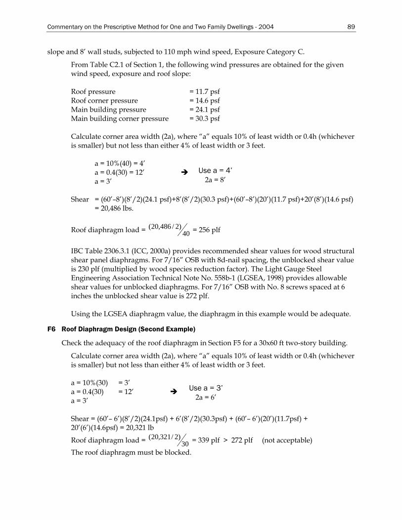
Commentary on the Prescriptive Method for One and Two Family Dwellings - 2004 89
slope and 8’ wall studs, subjected to 110 mph wind speed, Exposure Category C.
From Table C2.1 of Section 1, the following wind pressures are obtained for the given wind speed, exposure and roof slope: Roof pressure = 11.7 psf Roof corner pressure = 14.6 psf Main building pressure = 24.1 psf Main building corner pressure = 30.3 psf Calculate corner area width (2a), where “a” equals 10% of least width or 0.4h (whichever is smaller) but not less than either 4% of least width or 3 feet. a = 10%(40) = 4’
Use a = 4’ 2a = 8’
a = 0.4(30) = 12’ a = 3’ Shear = (60’–8’)(8’/2)(24.1 psf)+8’(8’/2)(30.3 psf)+(60’–8’)(20’)(11.7 psf)+20’(8’)(14.6 psf)
= 20,486 lbs.
Roof diaphragm load = 40)2/486,20( = 256 plf
IBC Table 2306.3.1 (ICC, 2000a) provides recommended shear values for wood structural shear panel diaphragms. For 7/16” OSB with 8d-nail spacing, the unblocked shear value is 230 plf (multiplied by wood species reduction factor). The Light Gauge Steel Engineering Association Technical Note No. 558b-1 (LGSEA, 1998) provides allowable shear values for unblocked diaphragms. For 7/16” OSB with No. 8 screws spaced at 6 inches the unblocked shear value is 272 plf. Using the LGSEA diaphragm value, the diaphragm in this example would be adequate.
F6 Roof Diaphragm Design (Second Example)
Check the adequacy of the roof diaphragm in Section F5 for a 30x60 ft two-story building.
Calculate corner area width (2a), where “a” equals 10% of least width or 0.4h (whichever is smaller) but not less than either 4% of least width or 3 feet.
a = 10%(30) = 3’ Use a = 3’
2a = 6’ a = 0.4(30) = 12’ a = 3’
Shear = (60’– 6’)(8’/2)(24.1psf) + 6’(8’/2)(30.3psf) + (60’– 6’)(20’)(11.7psf) + 20’(6’)(14.6psf) = 20,321 lb
Roof diaphragm load = 30)2/321,20( = 339 plf > 272 plf (not acceptable)
The roof diaphragm must be blocked.
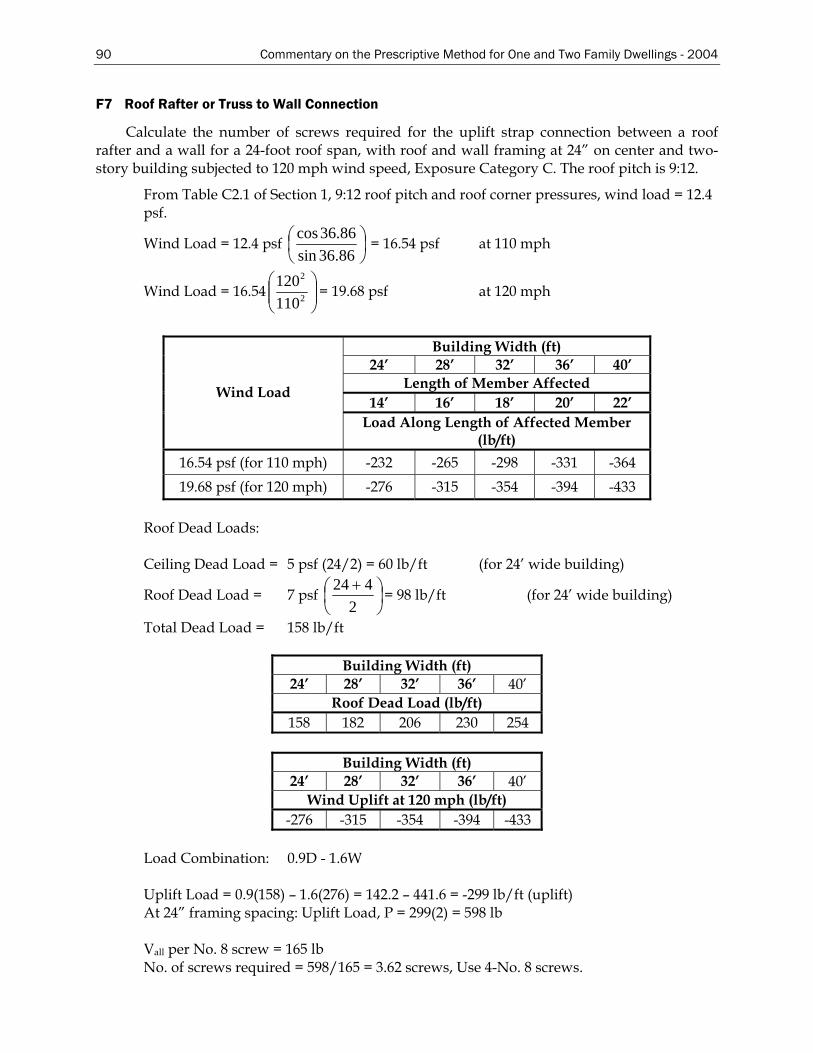
90 Commentary on the Prescriptive Method for One and Two Family Dwellings - 2004
F7 Roof Rafter or Truss to Wall Connection
Calculate the number of screws required for the uplift strap connection between a roof rafter and a wall for a 24-foot roof span, with roof and wall framing at 24” on center and two-story building subjected to 120 mph wind speed, Exposure Category C. The roof pitch is 9:12.
From Table C2.1 of Section 1, 9:12 roof pitch and roof corner pressures, wind load = 12.4 psf.
Wind Load = 12.4 psf ⎟⎠⎞
⎜⎝⎛
86.36sin86.36cos
= 16.54 psf at 110 mph
Wind Load = 16.54 ⎟⎟⎠
⎞⎜⎜⎝
⎛2
2
110120
= 19.68 psf at 120 mph
Building Width (ft)
24’ 28’ 32’ 36’ 40’ Length of Member Affected
14’ 16’ 18’ 20’ 22’ Wind Load
Load Along Length of Affected Member (lb/ft)
16.54 psf (for 110 mph) -232 -265 -298 -331 -364 19.68 psf (for 120 mph) -276 -315 -354 -394 -433
Roof Dead Loads: Ceiling Dead Load = 5 psf (24/2) = 60 lb/ft (for 24’ wide building)
Roof Dead Load = 7 psf ⎟⎠⎞
⎜⎝⎛ +
2424
= 98 lb/ft (for 24’ wide building)
Total Dead Load = 158 lb/ft
Building Width (ft) 24’ 28’ 32’ 36’ 40’
Roof Dead Load (lb/ft) 158 182 206 230 254
Building Width (ft)
24’ 28’ 32’ 36’ 40’ Wind Uplift at 120 mph (lb/ft)
-276 -315 -354 -394 -433 Load Combination: 0.9D - 1.6W Uplift Load = 0.9(158) – 1.6(276) = 142.2 – 441.6 = -299 lb/ft (uplift) At 24” framing spacing: Uplift Load, P = 299(2) = 598 lb Vall per No. 8 screw = 165 lb No. of screws required = 598/165 = 3.62 screws, Use 4-No. 8 screws.
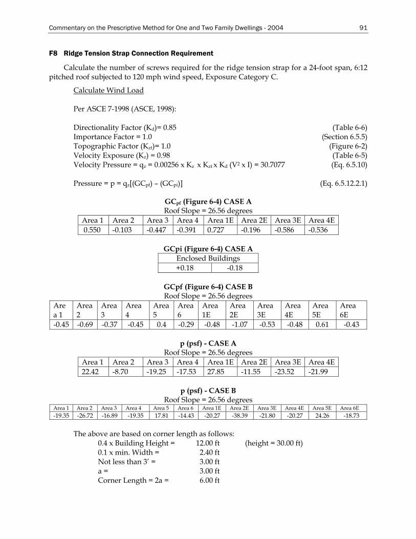
Commentary on the Prescriptive Method for One and Two Family Dwellings - 2004 91
F8 Ridge Tension Strap Connection Requirement
Calculate the number of screws required for the ridge tension strap for a 24-foot span, 6:12 pitched roof subjected to 120 mph wind speed, Exposure Category C.
Calculate Wind Load Per ASCE 7-1998 (ASCE, 1998): Directionality Factor (Kd)= 0.85 (Table 6-6) Importance Factor = 1.0 (Section 6.5.5) Topographic Factor (Kzt)= 1.0 (Figure 6-2) Velocity Exposure (Kz) = 0.98 (Table 6-5) Velocity Pressure = qz = 0.00256 x Kz x Kzt x Kd (V2 x I) = 30.7077 (Eq. 6.5.10) Pressure = p = qz[(GCpf) – (GCpi)] (Eq. 6.5.12.2.1)
GCpf (Figure 6-4) CASE A Roof Slope = 26.56 degrees
Area 1 Area 2 Area 3 Area 4 Area 1E Area 2E Area 3E Area 4E 0.550 -0.103 -0.447 -0.391 0.727 -0.196 -0.586 -0.536
GCpi (Figure 6-4) CASE A
Enclosed Buildings +0.18 -0.18
GCpf (Figure 6-4) CASE B Roof Slope = 26.56 degrees
Area 1
Area 2
Area 3
Area 4
Area 5
Area 6
Area 1E
Area 2E
Area 3E
Area 4E
Area 5E
Area 6E
-0.45 -0.69 -0.37 -0.45 0.4 -0.29 -0.48 -1.07 -0.53 -0.48 0.61 -0.43
p (psf) - CASE A Roof Slope = 26.56 degrees
Area 1 Area 2 Area 3 Area 4 Area 1E Area 2E Area 3E Area 4E 22.42 -8.70 -19.25 -17.53 27.85 -11.55 -23.52 -21.99
p (psf) - CASE B
Roof Slope = 26.56 degrees Area 1 Area 2 Area 3 Area 4 Area 5 Area 6 Area 1E Area 2E Area 3E Area 4E Area 5E Area 6E -19.35 -26.72 -16.89 -19.35 17.81 -14.43 -20.27 -38.39 -21.80 -20.27 24.26 -18.73
The above are based on corner length as follows: 0.4 x Building Height = 12.00 ft (height = 30.00 ft) 0.1 x min. Width = 2.40 ft Not less than 3’ = 3.00 ft a = 3.00 ft Corner Length = 2a = 6.00 ft
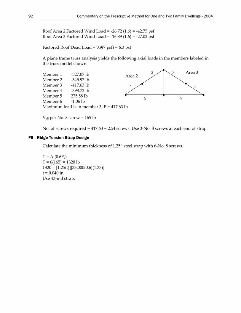
92 Commentary on the Prescriptive Method for One and Two Family Dwellings - 2004
Roof Area 2 Factored Wind Load = -26.72 (1.6) = -42.75 psf Roof Area 3 Factored Wind Load = -16.89 (1.6) = -27.02 psf Factored Roof Dead Load = 0.9(7 psf) = 6.3 psf A plane frame truss analysis yields the following axial loads in the members labeled in the truss model shown.
2
4
3
5 6
1
Area 3 Area 2 Member 1 -327.07 lb
Member 2 -345.97 lb Member 3 -417.63 lb Member 4 -398.72 lb Member 5 275.58 lb Member 6 -1.06 lb Maximum load is in member 3, P = 417.63 lb Vall per No. 8 screw = 165 lb No. of screws required = 417.63 = 2.54 screws, Use 3-No. 8 screws at each end of strap.
F9 Ridge Tension Strap Design
Calculate the minimum thickness of 1.25” steel strap with 6-No. 8 screws. T = A (0.6Fy) T = 6(165) = 1320 lb 1320 = [1.25(t)][33,000(0.6)(1.33)] t = 0.040 in Use 43-mil strap.
Commentary on the Prescriptive Method for One and Two Family Dwellings - 2004 93
REFERENCES
(AFPA, 1995), Wood Frame Construction Manual, American Forest and Paper Association, Washington DC, 1995.
(AISC, 1990), Steel Design Guide Series No. 3, Serviceability Design Considerations for Low-Rise Buildings, American Institute of Steel Construction, Chicago IL, 1990.
(AISC, 1991), Structural Performance Requirements For Domestic Steel Framing, Australian Institute of Steel Construction, Milsons Point, Australia, 1991.
(AISI, 1998), Shear Wall Design Guide, American Iron and Steel Institute, Washington, DC, 1998.
(AISI, 1999), Specification for the Design of Cold-Formed Steel Structural Members, 1996 Edition with 1999 Supplement, American Iron and Steel Institute, Washington, DC, 1999.
(AISI, 2001a), Standard for Cold-Formed Steel Framing – General Provision, American Iron and Steel Institute, Washington, DC, 2001.
(AISI, 2001b), Standard for Cold-Formed Steel Framing – Truss Design, American Iron and Steel Institute, Washington, DC, 2001.
(AISI, 2001c), Standard for Cold-Formed Steel Framing – Header Design, American Iron and Steel Institute, Washington, DC, 2001.
(AISI, 2001d), Standard for Cold-Formed Steel Framing – Prescriptive Method for One and Two Family Dwellings, American Iron and Steel Institute, Washington, DC, 2001.
(AISI, 2004), 2004 Supplement to the Standard for Cold-Formed Steel Framing – Prescriptive Method for One and Two Family Dwellings, 2001 Edition, American Iron and Steel Institute, Washington, DC, 2004.
(ASCE, 1998), ASCE 7, Minimum Design Loads for Buildings and Other Structures, American Society of Civil Engineers, Reston VA, 1998.
(ASTM, 2000), ASTM C954, Standard Specification for Steel Drill Screws for the Application of Gypsum Panel Products or Metal Plaster Bases to Steel Studs From 0.033 in. (0.84 mm) to 0.112 in. (2.84 mm) in Thickness, ASTM International, West Conshohocken PA, 2000.
(ASTM, 2001), ASTM C1002, Standard Specification for Steel Self-Piercing Tapping Screws for the Application of Gypsum Panel Products or Metal Plaster Bases to Wood Studs or Steel Studs, ASTM International, West Conshohocken PA, 2001.
(BOCA, 1997), National Building Code, 1997 Edition, Building Officials and Code Administrators International, Country Club Hills, IL, 1997.
(ICC, 2000a), International Building Code, International Code Council Falls Church, VA, 2000.
(ICC, 2000b), International Residential Code, International Code Council Falls Church, VA, 2000.
(LGSEA, 1998), Technical Note No. 558b-1, Lateral Load Resisting Elements: Diaphragm Design Values, Light Gauge Steel Engineers Association, Washington, DC, 1998.
(NAHBRC, 2003), Hybrid Wood and Steel Sole Plate Connection Walls to Floors Testing Report, National Association of Home Builders’ Research Center, Upper Marlboro, MD, 2003.
(SBCCI, 1999), Standard Building Code, Southern Building Code Congress International, Birmingham, AL, 1999.
Vagh, Dolan and Easterling (2000), Effect of Anchorage and Sheathing Configuration on the Cyclic

94 Commentary on the Prescriptive Method for One and Two Family Dwellings - 2004
Response of Long Steel-Frame Shear Walls, Report No. TE-2000-002, Virginia Polytechnic Institute and State University, Blacksburg, VA, 2000.
Wiss, Janney, Elstner Associates (1977), Report Number 73345, Report of Laboratory Tests and Analytical Studies of Structural Characteristics of Cold-Formed Steel-Joists Floor Systems, San Francisco, CA, 1977.
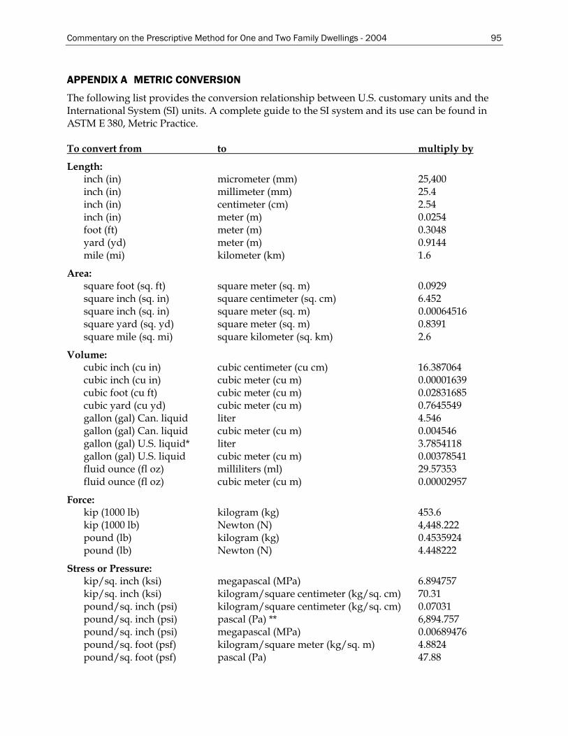
Commentary on the Prescriptive Method for One and Two Family Dwellings - 2004 95
APPENDIX A METRIC CONVERSION
The following list provides the conversion relationship between U.S. customary units and the International System (SI) units. A complete guide to the SI system and its use can be found in ASTM E 380, Metric Practice. To convert from to multiply by
Length: inch (in) micrometer (mm) 25,400 inch (in) millimeter (mm) 25.4 inch (in) centimeter (cm) 2.54 inch (in) meter (m) 0.0254 foot (ft) meter (m) 0.3048 yard (yd) meter (m) 0.9144 mile (mi) kilometer (km) 1.6
Area: square foot (sq. ft) square meter (sq. m) 0.0929 square inch (sq. in) square centimeter (sq. cm) 6.452 square inch (sq. in) square meter (sq. m) 0.00064516 square yard (sq. yd) square meter (sq. m) 0.8391 square mile (sq. mi) square kilometer (sq. km) 2.6
Volume: cubic inch (cu in) cubic centimeter (cu cm) 16.387064 cubic inch (cu in) cubic meter (cu m) 0.00001639 cubic foot (cu ft) cubic meter (cu m) 0.02831685 cubic yard (cu yd) cubic meter (cu m) 0.7645549 gallon (gal) Can. liquid liter 4.546 gallon (gal) Can. liquid cubic meter (cu m) 0.004546 gallon (gal) U.S. liquid* liter 3.7854118 gallon (gal) U.S. liquid cubic meter (cu m) 0.00378541 fluid ounce (fl oz) milliliters (ml) 29.57353 fluid ounce (fl oz) cubic meter (cu m) 0.00002957
Force: kip (1000 lb) kilogram (kg) 453.6 kip (1000 lb) Newton (N) 4,448.222 pound (lb) kilogram (kg) 0.4535924 pound (lb) Newton (N) 4.448222
Stress or Pressure: kip/sq. inch (ksi) megapascal (MPa) 6.894757 kip/sq. inch (ksi) kilogram/square centimeter (kg/sq. cm) 70.31 pound/sq. inch (psi) kilogram/square centimeter (kg/sq. cm) 0.07031 pound/sq. inch (psi) pascal (Pa) ** 6,894.757 pound/sq. inch (psi) megapascal (MPa) 0.00689476 pound/sq. foot (psf) kilogram/square meter (kg/sq. m) 4.8824 pound/sq. foot (psf) pascal (Pa) 47.88
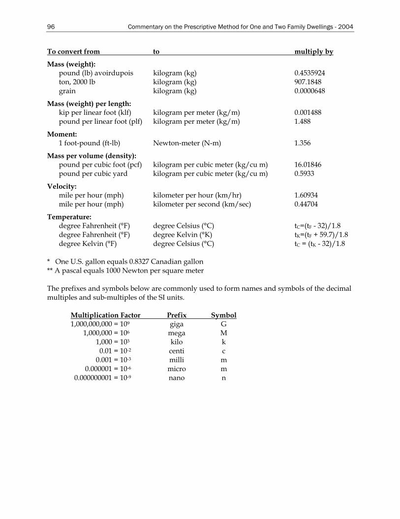
96 Commentary on the Prescriptive Method for One and Two Family Dwellings - 2004
To convert from to multiply by
Mass (weight): pound (lb) avoirdupois kilogram (kg) 0.4535924 ton, 2000 lb kilogram (kg) 907.1848 grain kilogram (kg) 0.0000648
Mass (weight) per length: kip per linear foot (klf) kilogram per meter (kg/m) 0.001488 pound per linear foot (plf) kilogram per meter (kg/m) 1.488
Moment: 1 foot-pound (ft-lb) Newton-meter (N-m) 1.356
Mass per volume (density): pound per cubic foot (pcf) kilogram per cubic meter (kg/cu m) 16.01846 pound per cubic yard kilogram per cubic meter (kg/cu m) 0.5933
Velocity: mile per hour (mph) kilometer per hour (km/hr) 1.60934 mile per hour (mph) kilometer per second (km/sec) 0.44704
Temperature: degree Fahrenheit (°F) degree Celsius (°C) tC=(tF - 32)/1.8 degree Fahrenheit (°F) degree Kelvin (°K) tK=(tF + 59.7)/1.8 degree Kelvin (°F) degree Celsius (°C) tC = (tK - 32)/1.8
* One U.S. gallon equals 0.8327 Canadian gallon ** A pascal equals 1000 Newton per square meter The prefixes and symbols below are commonly used to form names and symbols of the decimal multiples and sub-multiples of the SI units.
Multiplication Factor Prefix Symbol 1,000,000,000 = 109 giga G 1,000,000 = 106 mega M 1,000 = 103 kilo k 0.01 = 10-2 centi c 0.001 = 10-3 milli m 0.000001 = 10-6 micro m 0.000000001 = 10-9 nano n