Embed Size (px)
Citation preview

SPE-13-8-049/D/WY Page 1 of 22
Specification
Part No. : Shockwave TL.10.1HH11W
Product Name : Wideband Direct Mount antenna
2G/3G/4G Cellular - ISM- Wi-Fi Bands
Feature : LTE / GSM / CDMA /DCS /PCS / WCDMA / UMTS / HSDPA
/ GPRS / EDGE /GPS /Wi-Fi
698MHz to 960MHz, 1575.42MHz,
1710MHz to 2700Mhz,
Highest Efficiency and Peak Gain –up to 90%
White UV resistant housing
(Applied Dupont Imron 2.8HG coating)
IP67 Waterproof and IP69K
NMO (M) Connector
RoHS Compliant
Shockwave TL.10 with Magnetic Mount
Assembly
Shockwave TL.10 with Direct Mount Assembly

SPE-13-8-049/D/WY Page 2 of 22
1. Introduction
The Shockwave TL.10 NMO series is a new generation of antenna, one part number
that is a highly efficient, high gain omni-directional permanent mount antenna
designed for all common Cellular, Wi-Fi and ISM bands worldwide. It is specially
designed for easy and cost effective vandal-proof and waterproof mounting
requirements on meters, terminal boxes, and heavy equipment and vehicles.
In installation, the antenna connects to a NMO Mount connector jutting out from a
metal panel. A unique indent tab on the base itself on the antenna allows a wrench to
be used to solidly lock the antenna on top of its mounting location, thus preventing
removal by hand later by vandals, but crucially allowing for replacement antenna to be
installed by qualified personnel in the future without the need to open the device or
box it is mounted on itself. A waterproof O-ring around the bottom outer edge prevents
water leaking under the antenna.
The antenna is IP67 waterproof and IP69K resistant against high pressure water jets in
commercial cleaning environments, incorporating highest quality stainless steel
mounting base ensuring corrosion resistance. It also has UV resistant housing (applied
Dupont Imron 2.8HG coating).
The Shockwave TL.10 has been tested on a variety of mounting conditions as below
specification, with excellent efficiency and gain measured in all typical common
mounting conditions. Radiation patterns are consistent, and show very good stability
in the azimuth on lower and upper bands.
Housing, frequency application, mounting type and connector are customizable,
subject to minimum order quantities. Please contact your local Taoglas sales office for
more information. The antenna also comes in Black as standard.

SPE-13-8-049/D/WY Page 3 of 22
2. Specification
ELECTRICAL
Frequency (MHz) 698~800 824~960 1575.42 1710 ~ 1880 1850 ~ 1990 1920 ~ 2170 2400~2700
Peak Gain (dBi)
Free Space -1.7 -0.9 0.8 1.3 1.3 1.7 3.5
10x10cm GP center -1.3 0.1 0.3 0.1 0.4 0.5 2.3
30x30cm GP center 2.7 2.5 1.0 2.2 2.1 2.2 3.1
50x50cm GP center 2.6 2.5 1.2 3.1 3.2 3.1 2.8
Average Gain (dBi)
Free Space -6.6 -5.1 -1.8 -1.5 -1.5 -1.3 -0.9
10x10cm GP center -3.1 -1.9 -1.9 -2.1 -2.0 -1.9 -1.4
30x30cm GP center -0.4 -1.1 -1.6 -1.7 -1.3 -1.3 -1.6
50x50cm GP center -0.3 -1.0 -1.6 -1.2 -0.8 -0.9 -1.6
Efficiency
Free Space 22% 31% 64% 69% 69% 72% 80%
10x10cm GP center 48% 63% 63% 60% 63% 63% 71%
30x30cm GP center 90% 76% 67% 67% 73% 73% 69%
50x50cm GP center 91% 78% 68% 75% 83% 81% 68%
Impedance 50Ω
Polarization Vertical
Radiation Pattern Omni
MECHANICAL
Casing PC+PBT
Connector NMO
Base Stainless Steel
ENVIRONMENTAL
Temperature Range -40°C to 85°C
Humidity Non-condensing 65°C 95% RH

SPE-13-8-049/D/WY Page 4 of 22
LTE BANDS
Band Number LTE / LTE-Advanced / WCDMA / HSPA / HSPA+ / TD-SCDMA
Uplink Downlink Covered
1 UL: 1920 to 1980 DL: 2110 to 2170 2 UL: 1850 to 1910 DL: 1930 to 1990 3 UL: 1710 to 1785 DL: 1805 to 1880 4 UL: 1710 to 1755 DL: 2110 to 2155 5 UL: 824 to 849 DL: 869 to 894 7 UL: 2500 to 2570 DL:2620 to 2690 8 UL: 880 to 915 DL: 925 to 960 9 UL: 1749.9 to 1784.9 DL: 1844.9 to 1879.9 11 UL: 1427.9 to 1447.9 DL: 1475.9 to 1495.9 12 UL: 699 to 716 DL: 729 to 746 13 UL: 777 to 787 DL: 746 to 756 14 UL: 788 to 798 DL: 758 to 768 17 UL: 704 to 716 DL: 734 to 746 (LTE only) 18 UL: 815 to 830 DL: 860 to 875 (LET only) 19 UL: 830 to 845 DL: 875 to 890 20 UL: 832 to 862 DL: 791 to 821 21 UL: 1447.9 to 1462.9 DL: 1495.9 to 1510.9 22 UL: 3410 to 3490 DL: 3510 to 3590 23 UL:2000 to 2020 DL: 2180 to 2200 (LTE only) 24 UL:1625.5 to 1660.5 DL: 1525 to 1559 (LTE only) 25 UL: 1850 to 1915 DL: 1930 to 1995 26 UL: 814 to 849 DL: 859 to 894 27 UL: 807 to 824 DL: 852 to 869 (LTE only) 28 UL: 703 to 748 DL: 758 to 803 (LTE only) 29 UL: - DL: 717 to 728 (LTE only) 30 UL: 2305 to 2315 DL: 2350 to 2360 (LTE only) 31 UL: 452.5 to 457.5 DL: 462.5 to 467.5 (LTE only) 32 UL: - DL: 1452 - 1496 35 1850 to 1910 38 2570 to 2620 39 1880 to 1920 40 2300 to 2400 41 2496 to 2690 42 3400 to 3600 43 3600 to 3800

SPE-13-8-049/D/WY Page 5 of 22
3. Antenna Characteristics
3.1 Return Loss
3.2 Maximum Gain

SPE-13-8-049/D/WY Page 6 of 22
3.3 Average Gain
3.4 Efficiency
SPE-13-8-049/D/WY Page 7 of 22
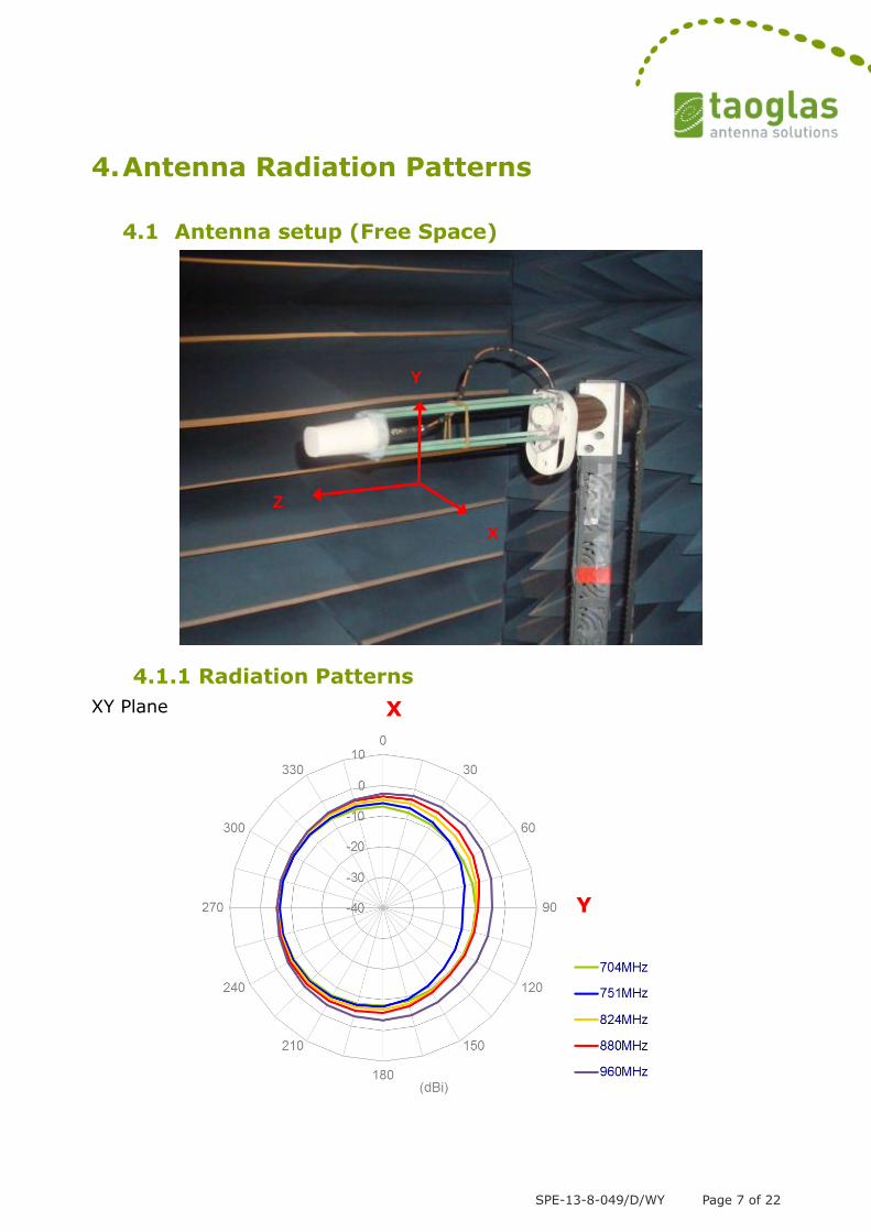
4. Antenna Radiation Patterns
4.1 Antenna setup (Free Space)
4.1.1 Radiation Patterns
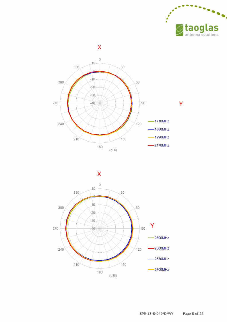
XY Plane
Y
Z
X
X
Y
SPE-13-8-049/D/WY Page 8 of 22
Y
X
Y
X
SPE-13-8-049/D/WY Page 9 of 22
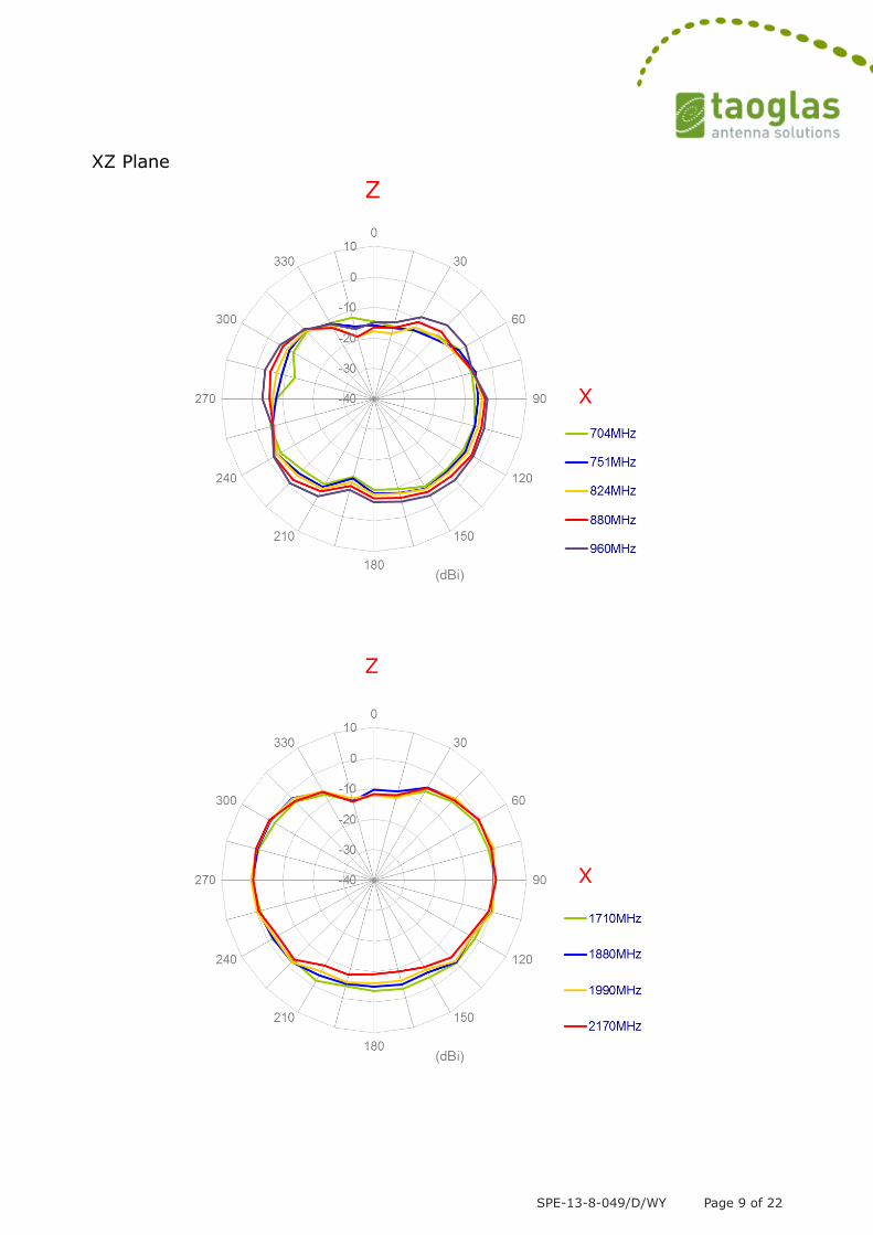
XZ Plane
X
Z
X
Z

SPE-13-8-049/D/WY Page 10 of 22
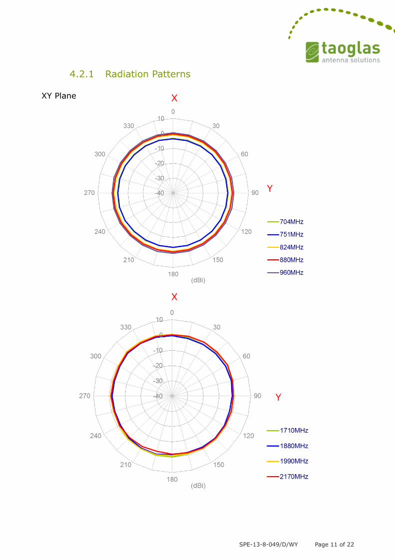
4.2 Antenna setup (10x10cm Metal Ground Plane)
Y
Z
X
X
Z
SPE-13-8-049/D/WY Page 11 of 22
4.2.1 Radiation Patterns
XY Plane
X
Y
X
Y

SPE-13-8-049/D/WY Page 12 of 22
XZ Plane
X
Y
X
Z

SPE-13-8-049/D/WY Page 13 of 22
X
Z
X
Z

SPE-13-8-049/D/WY Page 14 of 22
4.3 Antenna setup (30x30cm Metal Ground Plane)
4.3.1 Radiation Patterns
XY Plane
Y
Z
X
X
Y

SPE-13-8-049/D/WY Page 15 of 22
X
Y
X
Y

SPE-13-8-049/D/WY Page 16 of 22
XZ Plane
X
Z
X
Z

SPE-13-8-049/D/WY Page 17 of 22
4.4 Antenna setup (50x50cm Metal Ground Plane)
X
Z
Y
Z
X

SPE-13-8-049/D/WY Page 18 of 22
4.4.1 Radiation Patterns
XY Plane
X
Y
X
Y

SPE-13-8-049/D/WY Page 19 of 22
XZ Plane
X
Y
X
Z
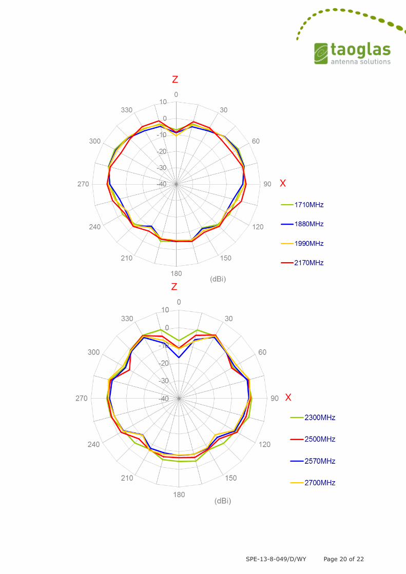
SPE-13-8-049/D/WY Page 20 of 22
X
Z
X
Z

SPE-13-8-049/D/WY Page 21 of 22
5. Drawing
Name Material Finish Quantity
1 Antenna Top PC + PBT White 1
2 Antenna Bottom (NMO Connector) SUS N/A 1
3 O-Ring NBR Red 1
4 PIN Brass Gold 1

SPE-13-8-049/D/WY Page 22 of 22
6. Installation
Recommended torque for mounting is 95Nm or 70ft lbs
Maximum torque for munting is 135.6Nm or 100ft lbs
40mm wrench or 1-9/16” wrench can be used