Embed Size (px)
Citation preview

Specific Control & Display Products
Product Focus
Monitoring, Measurement, Control & Display
April 2007
PG05400001E For more information visit: www.eaton.com
Counters, Panel Meters, Tachometers and Timers 1
Description Page
Totalizers
Product Family Overview . . . . . . . . . . . . . . . . . . . . . . . . . . . . . . . . . . . . . . . 2
Mechanical . . . . . . . . . . . . . . . . . . . . . . . . . . . . . . . . . . . . . . . . . . . . . . . . . . 3
Electromechanical . . . . . . . . . . . . . . . . . . . . . . . . . . . . . . . . . . . . . . . . . . . . . 16
Electronic . . . . . . . . . . . . . . . . . . . . . . . . . . . . . . . . . . . . . . . . . . . . . . . . . . . . 22
Count Controls/Preset Counters . . . . . . . . . . . . . . . . . . . . . . . . . . . . . . . . . . . 36
Tachometers/Ratemeters . . . . . . . . . . . . . . . . . . . . . . . . . . . . . . . . . . . . . . . . . 51
Digital Panel Meters . . . . . . . . . . . . . . . . . . . . . . . . . . . . . . . . . . . . . . . . . . . . . 57
Timers/Hour Meters
Product Family Overview . . . . . . . . . . . . . . . . . . . . . . . . . . . . . . . . . . . . . . . 62
Electronic . . . . . . . . . . . . . . . . . . . . . . . . . . . . . . . . . . . . . . . . . . . . . . . . . . . . 63
Electromechanical . . . . . . . . . . . . . . . . . . . . . . . . . . . . . . . . . . . . . . . . . . . . . 66
Time Controls . . . . . . . . . . . . . . . . . . . . . . . . . . . . . . . . . . . . . . . . . . . . . . . . 68
Flow Totalizers, Transmitters and Controls . . . . . . . . . . . . . . . . . . . . . . . . . . 71
Special Function Controls . . . . . . . . . . . . . . . . . . . . . . . . . . . . . . . . . . . . . . . . . 74
Fusion® Integrated Machine Control . . . . . . . . . . . . . . . . . . . . . . . . . . . . . . . . 79
Accessories and Encoders . . . . . . . . . . . . . . . . . . . . . . . . . . . . . . . . . . . . . . . . 82
Dimensions, Weights and RatingsDimensions, weights and ratings given in this Product Guide are approximate and should not be used for construction purposes. Drawings giving exact dimensions are available upon request. All listed product specifications and ratings are subject to change without notice. Photographs are representative of production units.
Terms and ConditionsAll orders accepted by Eaton are subject to the general terms and conditions as set forth in Sellers Policy 25-000.
Other Cutler-Hammer® ProductsEaton’s electrical business is a leader in the development and manufacturing of power distribution equipment, electrical control products and advanced industrial automation solutions.
For more information on Cutler-Hammer products and services, visit our Web site at www.eaton.com.
WARNING
The installation and use of Cutler-Hammer products should be in accordance withthe provisions of the U.S. National Electrical Code and/or other local codes orindustry standards that are pertinent to the particular end use. Installation or usenot in accordance with these codes and standards could be hazardous topersonnel and/or equipment.

April 2007
2
For more information visit: www.eaton.com PG05400001E
Counters, Panel Meters, Tachometers and TimersTotalizersProduct Family Overview
IntroductionTotalizers are used in a wide variety of applications where accurate totals are needed. Typical applications include counting the number of parts produced, amount of material used, or the number of machine cycles occurring. Totalizers are the simplest and most common type of counter. As an added bonus, some models can perform both totalizing and ratemeter functions.
Application Example Parts are fed into a machine or process, an operation is performed, and the finished parts exit the machine or process. The subtract totalizer is used to indicate the number of parts in process.
Totalizer Product Family OverviewTable 1. Product Family Overview
RSTT / R Durant ®
Limit Switch
Limit Switch
Finished Parts
ManufacturingProcess
Raw Parts
Application Example
Product Family Characteristics Typical Applications Panel Cutoutin Inches (mm)
PageNumber
■ Non-replaceable battery (min. 8-yr. life)
■ Compact, low cost and high efficiency
■ 8-Digit LCD totalizers
■ Manual or electrical reset
■ Various counting modes/inputs
■ Replacement for mechanical counters
■ Transaction counting
■ Parts counting
■ Position indication or measurement
0.870 x 1.772(22 x 44)
22
■ Compact device with bright, LED display
■ Multiple functions available: count, time, rate, multifunction, double-function
■ 24V DC Power
■ Count, measure, time where small package and easy-to-read display required
■ Position display
■ Motor/pulley RPM
0.870 x 1.772(22 x 44)
24
■ Economical, multifunction display
■ Large, LED characters
■ AC or DC power options
■ Large, easy-to-read display
■ Position display
■ Motor/pulley RPM
1.772 x 1.622(45 x 92)
27
■ Replaceable lithium battery
■ 8-digit, high-visibility LCD display
■ Optional backlighting
■ Various input options available
■ Portable/mobile/remote flow monitoring (e.g. sewer pumping, pesticide application)
■ Position display, RPM
■ Length measurement (e.g. carpet, cable)
1.299 x 2.677(33 x 68)
25
■ 6-digit, super bright LED display
■ Multiple models available: totalizers, ratemeters, count controls, digital panel meters and flow controls
■ Length measurement and control
■ Flow monitoring and control
■ Process monitoring and display
■ Voltage and current monitoring and display
1.772 x 1.622(45 x 92)
28
■ 8-digit, high-visibility, 2-line LCD display
■ User-configurable control inputs
■ Highly flexible control/display
■ Flow control where simultaneous total and rate display are required
■ Cut-to-length and other simple processes where flexibility of inputs/outputs required
2.667 x 2.667(68 x 68)
34
■ Bright LED display w/14 mm characters
■ Simple configuration with 14-button tactile keypad
■ Many different versions fit almost any application
■ Cut-to-length machinery with batching
■ Parts batching/palletizing
■ Die press positioning control
■ Applications where parameter changes are required
2.667 x 5.433(68 x 138)
30
■ Various price, voltage and size ranges for different duty cycles and environments
■ Long life and always readable display
■ Coin-operated equipment
■ Gaming machines
■ Printing presses
■ Secondary machines (e.g. punch press)
Various MountingConfigurations
16
■ Various size ranges for different duty cycles and environments
■ No power supply needed
■ Long life and always readable display
■ Winding and spooling equipment
■ Position display
■ Mechanical piece/cycle counting
Various MountingConfigurations
3
E5-024-C
E5-_24-E
E5-496-E
Courier
Eclipse
Ambassador
President
Electromechanical
Mechanical

April 2007
PG05400001E For more information visit: www.eaton.com
3Counters, Panel Meters, Tachometers and TimersMechanical Totalizers — StrokeX Series/Pushbutton Desk Tally — Durant®
ContentsDescription Page
Mechanical Totalizers — Stroke
X Series/PushbuttonDesk Tally . . . . . . . . . . . . 3
CS Series . . . . . . . . . . . . . . 4
H Series . . . . . . . . . . . . . . . 5
D Series . . . . . . . . . . . . . . . 6
Product DescriptionModel X Series is a dustproof and rustproof series of counters for light and medium-duty work. They are sound and durable, requiring a minimum of driving effort, and have been especially designed for incorporation as integral parts of a variety of machines and equipment.
Pushbutton Desk Tally
Ruggedly constructed counters with feather-touch pushbutton operation and maximum readability. Specifica-tions and dimensions are basically the same as the X Series counters. Will give long and accurate service in areas requiring hand counting or during hand operations.
Cat. No. 5-X-1-1-R
Technical Data and Specifications
■ Figures: 4 or 5
■ Speed: 1000 cpm
■ Shaft: 0.125" (3.2 mm) diameter stainless steel
■ Drive: Drive parts of nylon
■ Bearings: Oil-less, maintenance free
■ Finish: Black frame and Cycolac black cover
■ Stroke Operation: 33° minimum; 58° maximum
�
■ Figure Size: 3/16 inch (4.8 mm) high, white-on-black background
■ Reset: Knob
� Operating stroke angles apply to forward stroke counter only. Check factory for angles of reverse stroke counter.
Product SelectionTable 2. Product Selection — X Series Stroke Counters and Pushbutton Desk Tallies
� Reverse stroke.
When Ordering SpecifyTo determine a model number from the Product Selection table for Model X Series Stroke Counters and Pushbutton Desk Tallies, consider:
■ Number of figures
■ Drive
Dimensions
Figure 1. X Series — Approximate Dimensions in Inches (mm)
Table 3. X Series — Approximate Dimensions in Inches (mm)
No. ofFigures
Drive Reset Mounting CatalogNumber
OrderNumber
*
454
L.H. LeverL.H. LeverR.H. Lever
KnobKnobKnob
BaseBaseBase
4-X-1-1-L5-X-1-1-L4-X-1-1-R
402634004027240140263401
544
R.H. LeverL.H. LeverR.H. Lever
KnobKnobKnob
BaseBaseBase
5-X-1-1-R4-X-1-1-L-REV
�
4-X-1-1-R-REV
�
402724024026340340263402
5544
L.H. LeverR.H. LeverPush BarPushbutton
KnobKnobKnobKnob
BaseBaseBaseBase
5-X-1-1-L-REV
�
5-X-1-1-R-REV
�
4-X-24-X-2-A
40272400402724032161940033245400
Model A B C D
4-X-1-1_ 1.86 (47.2) 2.76 (70.2) 0.62 (15.7) 0.89 (22.6)5-X-1-1_ 2.16 (54.8) 3.06 (77.8) 0.81 (20.6) 0.95 (24.1)
PreStroke
0.12(3.2)
C D
0.97(24.6)
1.20(30.6)
1.44(36.5)
BA
0.44 (11.1)
0.53 (13.5) Dia. 0.093(2.36)
0.89(22.6)
12° ±5°
0.14(3.6)
1.38 (35.1)
Total Stroke
58° ±5°
45° ±5°
Index Stroke
Discount Symbol . . . . . . . . . . . . . . . . . . . . . . . . CC-2* Consult Sales Office for Pricing

April 2007
4
For more information visit: www.eaton.com PG05400001E
Counters, Panel Meters, Tachometers and TimersMechanical Totalizers — StrokeCS Series — Durant®
Product DescriptionModel CS Series of small, compact, top reading stroke counters is designed for use in most industrial applications. These counters are ruggedly built and feature a single casting case, which assures great rigidity and a tight seal for working parts.
Technical Data and Specifications
■ Figures: 4 or 5
■ Speed: 600 cpm
■ Stroke Operation: 37-1/2° minimum; 75° maximum
■ Shaft: 0.25" (6.4 mm) diameter stain-less steel, rustproof
■ Drive: Accurately machined, hard-ened steel parts
■ Bearings; Oil-less, maintenance free■ Figure Size: 11/32" (8.7 mm) high,
black-on-white background■ Reset: Contoured wing nut■ Finish: Black frame■ Operating Lever; Cast zinc.
Adjustable to any position. Furnished complete with pull spring.
Cat. No. 4-CS-1-1-R
Product SelectionTable 4. Product Selection — CS Series Stroke Counters
� Special Feature: Rustproof.
When Ordering SpecifyTo determine a model number from the Product Selection table for Model CS Series Stroke Counters, consider:■ Number of figures ■ Drive lever
Dimensions
Figure 2. CS Series — Approximate Dimensions in Inches (mm)
Table 5. CS Series — Approximate Dimensions in Inches (mm)
No. ofFigures
Drive Reset Mounting CatalogNumber
OrderNumber
*
45
R.H. LeverR.H. Lever
Wing NutWing Nut
BaseBase
4-CS-1-1-R5-CS-1-1-R
3106240031062401
555
L.H. LeverR.H. LeverL.H. Lever
Wing NutWing NutWing Nut
BaseBaseBase
5-CS-1-1-L5-CS-1-1-R-RP �
5-CS-1-1-L-RP �
310614010146440000445400
Model A B C D
4-CS-1_ 3.12 (79.2) 3.50 (88.9) 4.03 (102.3) 1.87 (47.6)5-CS-1_ 3.62 (91.9) 4.00 (101.6) 4.53 (115.0) 2.38 (60.5)
0.47(11.9)
Dia. 0.156 4 Mtg. Holes
D 0.73(18.6)
0.42(10.7)
0.92(23.4)
0.50 (12.7)
ABC
1.19(30.2)
1.00(25.4)
Dia. 0.25(6.35)
Stroke37.5° Min. – 75° Max.
1.34(34.1)
2.09(53.1)
0.56(14.3)
1.69 (42.9)
1.25(31.8)
0.22(5.6)
1.25(31.8)
Discount Symbol . . . . . . . . . . . . . . . . . . . . . . . . CC-2* Consult Sales Office for Pricing

April 2007
PG05400001E For more information visit: www.eaton.com
5Counters, Panel Meters, Tachometers and TimersMechanical Totalizers — StrokeH Series — Durant®
Product DescriptionModel H Series heavy-duty counters are designed for hard usage and long, trouble-free service. They are high-speed, streamlined counters constructed of the highest quality materials and drive shaft moves in oil-less bearings. All shafts are stainless steel. The drive action is designed with overstroke so counter does not bottom, increasing life and permitting easier installation. The sturdy cover is stamped steel, locked into position on a heavy, die-cast base of a special alloy. A heavy steel mounting plate is adjustable for either bottom or back mounting. Model “H” has earned the reputation of being the “work horse” of industrial counters. Wing nut or tamper-proof reset lock which requires a key to reset the counter, guarding against unauthorized resetting or tampering.
Technical Data and Specifications■ Figures: 5■ Speed: 800 cpm■ Stroke Operation: 37° stroke to
count; 60° maximum stroke■ Shaft: 0.31" (7.9 mm) diameter stain-
less steel, rustproof■ Drive: Accurately machined, hard-
ened steel parts; Geneva drive for extra long life
■ Bearings: Oil-less, maintenance free■ Figure Sizes; 11/32" (8.7 mm) high,
black-on-white background■ Reset: Wing nut or tumbler lock
reset■ Finish: Black frame and cover■ Operating Lever: Adjustable to any
position. Furnished complete with pull spring for attaching.
Cat. No. 5-H-1-1-R
Product SelectionTable 6. Product Selection — H Series Stroke Counters
� Special Feature: Reverse stroke. � Special Feature: Rustproof.
When Ordering SpecifyTo determine a model number from the Product Selection table for Model H Series Stroke Counters, consider:■ Number of figures■ Drive lever location (left or right side)
■ Type of reset (lock or wing nut)
Figure 3. Direction Location for 5H5 and 5H6
Dimensions
Figure 4. H Series — Approximate Dimensions in Inches (mm)
Table 7. H Series — Approximate Dimensions in Inches (mm)
No. ofFigures
Drive Reset Mounting CatalogNumber
OrderNumber
*
5555
R.H. LeverL.H. LeverR.H. LeverL.H. Lever
Wing NutWing NutWing NutWing Nut
BaseBaseBaseBase
5-H-1-1-R5-H-1-1-L5-H-1-1-R-REV �
5-H-1-1-L-REV �
40205400402054010059740000598400
5555
R.H. LeverL.H. LeverR.H. LeverL.H. Lever
Wing NutWing NutLock ResetLock Reset
BaseBaseBaseBase
5-H-1-1-R-RP �
5-H-1-1-L-RP �
5-H-1-2-R5-H-1-2-L
40205404402054054020640440206405
5555
R.H. LeverR.H. LeverR.H. LeverL.H. Lever
Lock ResetLock ResetWing NutWing Nut
BaseBaseRearRear
5-H-1-2-R-RP �
5-H-1-2-L-RP �
5-H-1-4-R5-H-1-4-L
40206400402064010050740000508400
5555
R.H. Trip ArmR.H. Trip ArmL.H. Trip ArmL.H. Trip Arm
Wing NutWing NutWing NutWing Nut
BaseBaseBaseBase
5-H-5-A5-H-5-B5-H-5-C5-H-5-D
31049400310494013104940231049403
5555
R.H. Trip ArmR.H. Trip ArmL.H. Trip ArmL.H. Trip Arm
Lock ResetLock ResetLock ResetLock Reset
BaseBaseBaseBase
5-H-6-A5-H-6-B5-H-6-C5-H-6-D
01533400015344000153540001536400
A
B
C
D
1.20(30.6) C 0.98
(25.0)
1.12(28.4)A
B
Dia. 0.31(7.92)
2.25 (57.2)
0.91(23.0)
1.0(25.4)
0.75(19.1)
0.75(19.1)
1.80(45.7)
2.76(70.1)
Lock Reset
WingNutReset
Model A B C
5 Figure Units 3.95(100.4)
4.38(111.3)
2.75(69.9)
Discount Symbol . . . . . . . . . . . . . . . . . . . . . . . . CC-2* Consult Sales Office for Pricing

April 2007
6
For more information visit: www.eaton.com PG05400001E
Counters, Panel Meters, Tachometers and TimersMechanical Totalizers — StrokeD Series — Durant®
Product DescriptionModel D Series are medium-duty stroke counters available with 4, 5 or 6 figures that have been designed for general service on small production machines. Although compact, Durant® “D” models are sturdily constructed and thoroughly tested for accuracy and efficient operation.
Technical Data and Specifications■ Figures: 4, 5 and 6■ Speed: 400 cpm■ Shaft: 0.25" (6.4 mm) diameter stain-
less steel, rustproof■ Drive: Nylon rachet and Delrin drive
plate. Right-hand drive standard; left-hand drive available
■ Bearings: Oil-less, maintenance free■ Figure Size: 1/4" (6.4 mm) high,
black-on-white background■ Reset: Wing nut■ Finish: Black frame and cover■ Operating lever: Adjustable to any
position. Furnished complete with pull string
Cat. No. 5-D-1-1-R
Product SelectionTable 8. Product Selection — D Series Stroke Counters
When Ordering SpecifyTo determine a model number from the Product Selection table for Model D Series Stroke Counters, consider:■ Number of figures ■ Drive lever
Dimensions
Figure 5. D Series — Approximate Dimensions in Inches (mm)
Table 9. D Series — Approximate Dimensions in Inches (mm)
No. ofFigures
Drive Reset Mounting CatalogNumber
OrderNumber
*
456
R.H. LeverR.H. LeverR.H. Lever
Wing NutWing NutWing Nut
BaseBaseBase
4-D-1-1-R5-D-1-1-R6-D-1-1-R
342694013426940234269403
456
L.H. LeverL.H. LeverL.H. Lever
Wing NutWing NutWing Nut
BaseBaseBase
4-D-1-1-L5-D-1-1-L6-D-1-1-L
342694053426940634269407
Model A B C
4-D-1-1_ 1.59 (40.4) 2.20 (55.9) 1.20 (30.6)5-D-1-1_ 1.92 (48.8) 2.53 (64.3) 1.51 (38.5)6-D-1-1_ 2.26 (57.5) 2.87 (73.0) 1.83 (46.4)
C 0.62 (15.7)
A0.50
(12.7) B
Dia. 0.12(3.05)4 Mtg.Holes
1.72(43.6)
1.25(31.8)
1.62 (41.3)
1.87 (47.6)
Discount Symbol . . . . . . . . . . . . . . . . . . . . . . . . CC-2* Consult Sales Office for Pricing

April 2007
PG05400001E For more information visit: www.eaton.com
7Counters, Panel Meters, Tachometers and TimersMechanical Totalizers — RevolutionX Series — Durant®
ContentsDescription Page
Mechanical Totalizers — Revolution
X Series . . . . . . . . . . . . . . . 7
CS Series . . . . . . . . . . . . . . 8
D-7 Series . . . . . . . . . . . . . 9
D-6 Series . . . . . . . . . . . . . 10
HDW Series . . . . . . . . . . . . 11
T Series . . . . . . . . . . . . . . . 12
H Series . . . . . . . . . . . . . . . 13
Product DescriptionModel X Series are dust- and rust-proof counters designed for small, medium-duty units, accurate, durable and require a minimum of driving effort. They are especially designed for incorporation as integral parts of a variety of equipment that gets severe usage under adverse climatic conditions.
Technical Data and Specifications■ Figures: 4 or 5■ Speed —
❑ 1000 cpm in 1:1 ratio;❑ 10,000 cpm in 10:1 ratio for inter-
mittent duty■ Rotation Direction: Clockwise or
anti-clockwise when viewed from right-hand end of counter
■ Ratio —❑ 1:1 and 10:1 standard in 4-X-7
models❑ 10:1 standard in 5-X-7 models
■ Shaft: 0.125" (3.2 mm) diameter stainless steel; standard length 0.44" (11.1 mm)
■ Bearings: Oil-less, maintenance free■ Figure Size: 3/16 inch (4.8 mm) high,
white-on-black background■ Reset: Knob■ Finish: Black frame, Cycolac black
cover■ Drive: Right- or left-hand drive; drive
parts of Delrin■ Ratio Information: 1:1 is one count
to each revolution of drive shaft, 10:1 is ten counts to each revolution
Cat. No. 5-X-7-1-L-CL
Product SelectionTable 10. Product Selection — X Series Revolution Counters
� Special Feature: 10:1 ratio.
Figure 6. Top View — Right-Hand Drive Figure 7. Top View — Left-Hand DriveNote: When shaft is turned in the reverse direction of rotation, the counter will subtract.
When Ordering SpecifyTo determine a model number from the Product Selection table for Model X Series Revolution Counters, consider:■ Number of figures■ Ratio
■ Drive shaft location■ Shaft rotation direction
Dimensions
Figure 8. X Series — Approximate Dimensions in Inches (mm)
Table 11. X Series — Approximate Dimensions in Inches (mm)
No. ofFigures
Drive Rotation Reset Mounting CatalogNumber
OrderNumber
*
4545
L.H.L.H.L.H.L.H.
Clockwise �
Clockwise �
Anti-Clockwise �
Anti-Clockwise �
KnobKnobKnobKnob
BaseBaseBaseBase
4-X-7-1-L-CL5-X-7-1-L-CL4-X-7-1-L-AC5-X-7-1-L-AC
40270406402754044027040440275407
4545
R.H.R.H.R.H.R.H.
Clockwise �
Clockwise �
Anti-Clockwise �
Anti-Clockwise �
KnobKnobKnobKnob
BaseBaseBaseBase
4-X-7-1-R-CL5-X-7-1-R-CL4-X-7-1-R-AC5-X-7-1-R-AC
40270407402754054027040540275406
4545
L.H.L.H.L.H.L.H.
Clockwise �
Clockwise �
Anti-Clockwise �
Anti-Clockwise �
KnobKnobKnobKnob
BaseBaseBaseBase
4-X-7-1-L-CL �
5-X-7-1-L-CL �
4-X-7-1-L-AC �
5-X-7-1-L-AC �
40270402402754024027040040275400
4545
R.H.R.H.R.H.R.H.
Clockwise �
Clockwise �
Anti-Clockwise �
Anti-Clockwise �
KnobKnobKnobKnob
BaseBaseBaseBase
4-X-7-1-R-CL �
5-X-7-1-R-CL �
4-X-7-1-R-AC �
5-X-7-1-R-AC �
40270403402754034027040140275401
Clockwise Shaft Rotation
Anti-clockwise Shaft Rotation
�
�
Clockwise Shaft Rotation
Anti-clockwise Shaft Rotation
�
�
Model A B C D E
4-X-7-1_ 1.86 (47.2) 2.76 (70.2) 0.62 (15.7) 0.19 (4.8) 0.89 (22.6)5-X-7-1_ 2.16 (54.8) 3.06 (77.8) 0.81 (20.6) 0.25 (6.4) 0.95 (24.1)
CL
AC
0.12(3.2)
D
A
C EDia. 0.12
(3.2)
0.97(24.6)
1.20(30.6)
1.44(36.5)
0.14(3.6)
1.38 (35.1)
0.45(11.5)0.44 (11.1)
0.53 (13.5)
B
Discount Symbol . . . . . . . . . . . . . . . . . . . . . . . . CC-2* Consult Sales Office for Pricing

April 2007
8
For more information visit: www.eaton.com PG05400001E
Counters, Panel Meters, Tachometers and TimersMechanical Totalizers — RevolutionCS Series — Durant®
Product DescriptionModel CS Series top reading revolution counters are designed for use in most industrial applications. The entire case is a single casting. This provides greater rigidity, tighter seal of working parts and more streamlined contour. The unit is compact, rugged and features a flush mounted window to assure greater visibility.
Technical Data and Specifications■ Figures: 4 or 5■ Speed: 600 cpm in 1:1 ratio■ Rotation Direction: Clockwise or
anti-clockwise when viewed from right-hand end of counter
■ Ratio: 1:1 standard■ Shaft: 0.25" (6.4 mm) diameter
stainless steel; standard length 1" (25.4 mm)
■ Drive: Spur gear■ Bearings: Oil-less, maintenance free■ Figure Size: 11/32 inch (8.7 mm)
high, black-on-white background■ Reset: Contoured wing nut■ Finish: Black frame
Table 12. X Series — Approximate Dimensions in Inches (mm)Model A B C D
4-CS-7_ 3.12(79.2)
3.50(88.9)
4.03(102.3)
1.89(47.9)
5-CS-7_ 3.62(91.9)
4.00(101.6)
4.53(115.0)
2.38(60.5)
Cat. No. 5-CS-7-1-R-CL
Product SelectionTable 13. Product Selection — CS Series Revolution Counters
� Special Feature: 10:1 ratio.� Special Feature: 10:1 ratio, non-reset, double shaft.
Figure 9. Top View — Right-Hand Drive
Figure 10. Top View — R.H. and L.H. Drive
Figure 11. Top View — Right-Hand Drive
Figure 12. Top View — R.H. and L.H. DriveNote: When shaft is turned in the reverse direction of rotation, the counter will subtract.
When Ordering SpecifyTo determine a model number from the Product Selection table for Model CS Series Revolution Counters, consider:■ Number of figures■ Ratio
■ Drive shaft location■ Shaft rotation direction
Dimensions
Figure 13. CS Series — Approximate Dimensions in Inches (mm)
No. ofFigures
Drive Rotation Reset Mounting CatalogNumber
OrderNumber
*
5555
L.H.R.H.L.H.R.H.
ClockwiseClockwise �
Anti-ClockwiseAnti-Clockwise �
Wing NutWing NutWing NutWing Nut
BaseBaseBaseBase
5-CS-7-1-L-CL5-CS-7-1-R-CL5-CS-7-1-L-AC5-CS-7-1-R-AC
31060408310604093106041031060411
54554
L.H.R.H.R.H.L.H.R.H.
ClockwiseClockwise �
Clockwise �
Anti-ClockwiseAnti-Clockwise �
Wing NutWing NutWing NutWing NutWing Nut
BaseBaseBaseBaseBase
5-CS-7-1-L-CL �
4-CS-7-1-R-CL �
5-CS-7-1-R-CL �
5-CS-7-1-L-AC �
4-CS-7-1-R-AC �
0044040031057401004414000044240031057403
54455
R.H.R.H. & L.H.R.H. & L.H.R.H. & L.H.R.H. & L.H.
Anti-Clockwise �
Clockwise �
Anti-Clockwise �
Clockwise �
Anti-Clockwise �
Wing NutNoneNoneNoneNone
BaseBaseBaseBaseBase
5-CS-7-1-R-AC �
4-CS-7-3-CL �
4-CS-7-3-AC �
5-CS-7-3-CL �
5-CS-7-3-AC �
0044340031057408310574093105741031057411
Clockwise Shaft Rotation
�
Clockwise Shaft Rotation
�
Anti-clockwise Shaft Rotation
�
Anti-clockwise Shaft Rotation
�
Dia. 0.156 (3.96) 4 Mtg. Holes D
0.73(18.6)
0.42(10.7)
0.92 (23.4)0.50 (12.7)
ABC 1.00
(25.4)
1.19 (30.2)
Dia. 0.25(6.4)
1.69 (42.9)
1.25(31.8)
0.22(5.6)
0.56(14.3)
1.34(34.1)
2.09(53.1)
Discount Symbol . . . . . . . . . . . . . . . . . . . . . . . . CC-2* Consult Sales Office for Pricing

April 2007
PG05400001E For more information visit: www.eaton.com
9Counters, Panel Meters, Tachometers and TimersMechanical Totalizers — RevolutionD-7 Series — Durant®
Product DescriptionModel D-7 Series spur gear end drive units are compact counters that meet a variety of needs. Accurate, dependable and moderately prices, they are especially recommended for braiding machines, low-speed coil winders, wire measuring equipment and all medium-duty revolution applications.
Technical Data and Specifications■ Figures: 5 standard■ Speed: Up to 800 cpm in 1:1 ratio■ Rotation Direction: Clockwise or
anti-clockwise when viewed from right-hand end of counter
■ Ratio: 1:1 standard■ Shaft: 0.31" (7.9 mm) diameter
stainless steel; 0.66" (16.7 mm) right-hand drive, 0.63" (15.9 mm) left-hand drive
■ Drive: Right- or left-hand spur gear drive
■ Bearings: Oil-less, maintenance free■ Figure Size: 1/4 inch (6.4 mm) high,
black-on-white background■ Finish: Black frame and cover■ Reset: Wing nut or non-reset
Cat. No. 5-D-7-1-L-CL
Product SelectionTable 14. Product Selection — D-7 Series Revolution Counters
Figure 14. Top View — Right-Hand Drive Figure 15. Top View — Left-Hand DriveNote: When shaft is turned in the reverse direction of rotation, the counter will subtract.
When Ordering SpecifyTo determine a model number from the Product Selection table for Model D-7 Series Revolution Counters, consider:■ Number of figures■ Shaft drive
■ Shaft rotation direction■ Reset or Non-reset
Dimensions
Figure 16. D-7 Series — Approximate Dimensions in Inches (mm)
No. ofFigures
Drive Rotation Reset Mounting CatalogNumber
OrderNumber
*
5555
L.H.L.H.R.H.R.H.
Clockwise �
Anti-Clockwise �
Clockwise �
Anti-Clockwise �
Wing NutWing NutWing NutWing Nut
BaseBaseBaseBase
5-D-7-1-L-CL5-D-7-1-L-AC5-D-7-1-R-CL5-D-7-1-R-AC
31127408311274053112743131127400
5555
L.H.L.H.R.H.R.H.
Clockwise �
Anti-Clockwise �
Clockwise �
Anti-Clockwise �
NoneNoneNoneNone
BaseBaseBaseBase
5-D-7-3-L-CL5-D-7-3-L-AC5-D-7-3-R-CL5-D-7-3-R-AC
31127416311274123112743831127442
Clockwise Shaft Rotation
Anti-clockwise Shaft Rotation
�
�
Clockwise Shaft Rotation
Anti-clockwise Shaft Rotation
�
�
1.62 (41.3)
1.72(43.6)
Dia. 0.120(3.05)4 Mtg.Holes
1.17(29.8)
0.50(12.7)
Dia. 0.31 (7.9)
0.12(3.2)
0.75(19.0)
1.51(38.5)
0.50(12.7) 2.53 (64.3)
1.92 (48.8)0.78
(19.8)
Discount Symbol . . . . . . . . . . . . . . . . . . . . . . . . CC-2* Consult Sales Office for Pricing

April 2007
10
For more information visit: www.eaton.com PG05400001E
Counters, Panel Meters, Tachometers and TimersMechanical Totalizers — RevolutionD-6 Series — Durant®
Product DescriptionModel D-6 right-angle worm drive counters are ruggedly designed for high speeds on light duty applications. Small “D” counters are easily adapted as accessory equipment on machinery where right-angle drive is desired to permit full view reading of the counter.
Technical Data and Specifications■ Figures: 5 ■ Speed: Up to 1500 cpm in 1:1 ratio■ Rotation Direction: Clockwise or
anti-clockwise when viewed from right-hand end of counter
■ Ratio: 1:1 standard■ Shaft: 0.31" (7.9 mm) diameter stain-
less steel; 1.25" (31.8 mm) length standard
■ Drive: Worm drive■ Bearings: Oil-less, maintenance free■ Figure Size: 1/4" (6.4 mm) high,
black-on-white background■ Finish: Black frame and cover■ Reset: Wing nut
Cat. No. 5-D-6-1-AC
Product SelectionTable 15. Product Selection — D-6 Series Revolution Counters
� Special Feature: Measuring wheels and brackets available for lineal measurement in Feet. � Special Feature: Measuring wheels and brackets available for lineal measurement in Yards
and 1/8ths.� Special Feature: Measuring wheels and brackets available for lineal measurement in Yards.
Figure 17. Top View of Counter Figure 18. Top View of CounterNote: When shaft is turned in the reverse direction of rotation, the counter will subtract.
When Ordering SpecifyTo determine a model number from the Product Selection table for Model D-6 Series Revolution Counters, consider:■ Shaft rotation direction
Dimensions
Figure 19. D-6 Series — Approximate Dimensions in Inches (mm)� A = 1.85 (46.9) for 6 figures and 1.53 (38.9) for 5 figures.
No. ofFigures
Drive Rotation Reset Mounting CatalogNumber
OrderNumber
*
5555
Front & RearFront & RearFront & RearFront & Rear
Anti-Clockwise �
Anti-Clockwise �
Clockwise �
Clockwise �
Wing NutWing NutWing NutWing Nut
BaseBaseBaseBase
5-D-6-1-AC6-D-6-1-AC5-D-6-1-CL6-D-6-1-CL
31052401310524023105240431052405
5555
Front & RearFront & RearFront & RearFront & Rear
Anti-Clockwise �
Anti-Clockwise �
Clockwise �
Clockwise �
Wing NutWing NutWing NutWing Nut
BaseBaseBaseBase
5-D-8-1-AC �
6-D-8-1-AC �
5-D-8-1-CL �
6-D-8-1-CL �
40187401401874024018741740187418
5555
Front & RearFront & RearFront & RearFront & Rear
Clockwise �
Anti-Clockwise �
Clockwise �
Anti-Clockwise �
Wing NutWing NutWing NutWing Nut
BaseBaseBaseBase
5-D-9-1-CL �
5-D-9-1-AC �
5-D-90-1-CL �
5-D-90-1-AC �
40187404401874104018741440187408
Clockwise Shaft Rotation
�
Anti-clockwise Shaft Rotation
�
ReadingLine
0.50 (12.7) 0.66 (16.7)
3.19 (81.0)
2.81 (71.4)
A 0.84(21.4)
0.34(8.7)
0.12(3.0)
2.0(50.8)
0.75(19.0)
Dia. 0.31(7.93)
1.16(29.4)
1.23(31.4)
3.62 (92.1)2.00 (50.8)
1.62(41.3)
Dia. 0.144(3.66)4 Mtg.Holes
�
Discount Symbol . . . . . . . . . . . . . . . . . . . . . . . . CC-2* Consult Sales Office for Pricing

April 2007
PG05400001E For more information visit: www.eaton.com
11Counters, Panel Meters, Tachometers and TimersMechanical Totalizers — RevolutionHDW Series — Durant®
Product DescriptionModel HDW Series are high speed, end drive revolution counters that have the rugged features of all Durant “H” counters, with the addition of double worm drive that produces speeds up to 2000 cpm. Lightweight precision molded wheels reduce centrifugal force and eliminate slipping. They are particularly recommended for quick starting and stopping machines, such as coil winders and wire measuring or reeling equipment and on applications where continuous high speed measuring is required.
Technical Data and Specifications■ Figures: 5■ Speed: Up to 2000 cpm■ Rotation Direction: Clockwise or
anti-clockwise when viewed from right-hand end of counter
■ Ratio: 1:1 only■ Shaft: 0.31" (7.9 mm) diameter
stainless steel; standard length 2" (50.8 mm)
■ Drive: Right- or left-hand drive■ Bearings: Oil-less, maintenance free■ Figure Size: 11/16 inch (17.5 mm)
high, white-on-black background■ Reset: Wing nut or tumbler lock
reset■ Finish: Black frame and cover
HDW Series Revolution Counter
Product SelectionTable 16. Product Selection — HDW Series Revolution Counters
� Mounting plate is adjustable for base or back mounting.
Figure 20. Top View — Right-Hand Drive Figure 21. Top View — Left-Hand DriveNote: When shaft is turned in the reverse direction of rotation, the counter will subtract.
When Ordering SpecifyTo determine a model number from the Product Selection table for Model HDW Series Revolution Counters, consider:■ Shaft drive ■ Shaft rotation direction
Dimensions
Figure 22. HDW Series — Approximate Dimensions in Inches (mm)
No. ofFigures
Drive Rotation Reset Mounting�
CatalogNumber
OrderNumber
*
5555
R.H.R.H.L.H.L.H.
Clockwise �
Anti-Clockwise �
Clockwise �
Anti-Clockwise �
Wing NutWing NutWing NutWing Nut
BaseBaseBaseBase
5-HDW-7-1-R-CL5-HDW-7-1-R-AC5-HDW-7-1-L-CL5-HDW-7-1-L-AC
31050400310504013105040231050403
�
�
Clockwise Shaft Rotation
Anti-clockwise Shaft Rotation
Clockwise Shaft Rotation
Anti-clockwise Shaft Rotation
�
�
0.96 (24.4)
0.90(22.9)
1.80(45.7)
2.76(70.1)
Dia. 0.312(7.9)
2.00(50.8)
0.98(25.0)2.75
(69.9)
Dia. 0.22 (5.59)4 Mtg. Holes
0.75(19.1)
4.51(100.3)
4.94(111.3)
0.34(8.5)
1.12(28.4)2.25
(57.2)
Discount Symbol . . . . . . . . . . . . . . . . . . . . . . . . CC-2* Consult Sales Office for Pricing

April 2007
12
For more information visit: www.eaton.com PG05400001E
Counters, Panel Meters, Tachometers and TimersMechanical Totalizers — RevolutionT Series — Durant®
Product DescriptionModel T Series worm drive revolution counters are sturdy, high speed instruments used on many heavy machines, engines or motors. Variety of drive permits direct connection. Suitable for panel mounting.
Technical Data and Specifications■ Figures: 5 standard■ Speed: 1500 cpm in 1:1 ratio■ Rotation Direction: Clockwise or
anti-clockwise determined top look-ing down
■ Ratio: 1:1 standard■ Shaft: 0.31" (7.9 mm) diameter
stainless steel; standard extends 2" (50.8 mm) top and bottom
■ Drive: Hobbed steel and bronze worm gearing; subtracts when reversed
■ Bearings: Oil-less, maintenance free■ Figure Size: 11/32 inch (8.7 mm)
high, black-on-white background■ Reset: Left-hand wing nut standard■ Finish: Black frame and face plate
Cat. No. 5T61CL
Product SelectionTable 17. Product Selection — T Series Revolution Counters
� Special Feature: Measuring wheels and brackets available for lineal measurement in Feet. � Special Feature: Measuring wheels and brackets available for lineal measurement in Yards
and 1/8ths.� Special Feature: Measuring wheels and brackets available for lineal measurement in Yards.
Figure 23. Top View of Counter Figure 24. Top View of CounterNote: When shaft is turned in the reverse direction of rotation, the counter will subtract.
When Ordering SpecifyTo determine a model number from the Product Selection table for Model T Series Revolution Counters, consider:■ Shaft rotation direction
Dimensions
Figure 25. T Series — Approximate Dimensions in Inches (mm)
No. ofFigures
Drive Rotation Reset Mounting CatalogNumber
OrderNumber
*
5555
Top & BottomTop & BottomTop & BottomTop & Bottom
Clockwise �
Anti-Clockwise �
Clockwise �
Anti-Clockwise �
Wing NutWing NutWing NutWing Nut
BackBackBackBack
5T61CL5T61AC5T81CL �
5T81AC �
40342400403424014017940240179403
5555
Top & BottomTop & BottomTop & BottomTop & Bottom
Clockwise �
Anti-Clockwise �
Clockwise �
Anti-Clockwise �
Wing NutWing NutWing NutWing Nut
BackBackBackBack
5T91CL �
5T91AC �
5T901CL �
5T901AC �
40179408401794094017940640179407
Clockwise Shaft Rotation
�
Anti-clockwise Shaft Rotation
�
1/4-20 UNC-2B4 Mtg. Holes
5.00 (127.0)
0.75(19.1)
0.47(11.9)
2.97 (75.4)
1.36 (34.5)
2.38(60.5)
0.24(6.2)
1.41(35.7)
1.38(35.1)
0.62(15.9)
1.87(47.6)
0.25(6.4)2.19
(55.6)4.50 (114.2)
Discount Symbol . . . . . . . . . . . . . . . . . . . . . . . . CC-2* Consult Sales Office for Pricing

April 2007
PG05400001E For more information visit: www.eaton.com
13Counters, Panel Meters, Tachometers and TimersMechanical Totalizers — RevolutionH Series — Durant®
Product DescriptionModel H Series are heavy-duty, end drive revolution counters designed for industrial use; suitable for speeds up to 800 cpm. They are available with either right- or left-hand drive, and with wing nut reset.
Technical Data and Specifications■ Figures: 5■ Speed: Up to 800 cpm in 1:1 ratio■ Rotation Direction: Clockwise or
anti-clockwise when viewed from right-hand end of counter
■ Ratio: 1:1 standard■ Shaft: 0.31" (7.9 mm) diameter
stainless steel; standard length 2" (50.8 mm)
■ Drive: Right- or left-hand drive■ Bearings: Oil-less, maintenance free■ Figure Size: 11/32 inch (8.7 mm)
high, white-on-black background■ Reset: Wing nut■ Finish: Black frame and cover
Cat. No. 5-H-7-1-R-CL
Product SelectionTable 18. Product Selection — H Series Revolution Counters
� Mounting plate is adjustable for base or back mounting.� Special Feature: Measuring wheels and brackets available for lineal measurement in Feet. � Special Feature: Measuring wheels and brackets available for lineal measurement in Yards
and 1/8ths.� Special Feature: Measuring wheels and brackets available for lineal measurement in Yards.
Figure 26. Top View — Right-Hand Drive
Figure 27. Top View — R.H. and L.H. Drive
Figure 28. Top View — Left-Hand Drive
Figure 29. Top View — R.H. and L.H. DriveNote: When shaft is turned in the reverse direction of rotation, the counter will subtract.
When Ordering SpecifyTo determine a model number from the Product Selection table for Model H Series Revolution Counters, consider:■ Drive shaft location ■ Shaft rotation direction
No. ofFigures
Drive Rotation Reset Mounting�
CatalogNumber
OrderNumber
*
5555
L.H.L.H.R.H.R.H.
Clockwise �
Anti-Clockwise
Clockwise �
Anti-Clockwise �
Wing NutWing NutWing NutWing Nut
BaseBaseBaseBase
5-H-7-1-L-CL5-H-7-1-L-AC5-H-7-1-R-CL5-H-7-1-R-AC
00509400005104000051340000514400
5555
L.H.L.H.R.H.R.H.
Clockwise �
Anti-Clockwise
Clockwise �
Anti-Clockwise �
Wing NutWing NutWing NutWing Nut
BaseBaseBaseBase
5-H-8-1-L-CL �
5-H-8-1-L-AC �
5-H-8-1-R-CL �
5-H-8-1-R-AC �
00601400006024000060540000606400
5555
L.H.L.H.R.H.R.H.
Clockwise �
Anti-Clockwise
Clockwise �
Anti-Clockwise �
Wing NutWing NutWing NutWing Nut
BaseBaseBaseBase
5-H-9-1-L-CL �
5-H-9-1-L-AC �
5-H-9-1-R-CL �
5-H-9-1-R-AC �
00619400006204000061740000618400
5555
L.H.L.H.R.H.R.H.
Clockwise �
Anti-Clockwise
Clockwise �
Anti-Clockwise �
Wing NutWing NutWing NutWing Nut
BaseBaseBaseBase
5-H-9-0-1-L-CL �
5-H-9-0-1-L-AC �
5-H-9-0-1-R-CL �
5-H-9-0-1-R-AC �
00611400006124000060940000610400
Clockwise Shaft Rotation
Anti-clockwise Shaft Rotation
�
�
Clockwise Shaft Rotation
Clockwise Shaft Rotation
Anti-clockwise Shaft Rotation
�
Anti-clockwise Shaft Rotation
Discount Symbol . . . . . . . . . . . . . . . . . . . . . . . . CC-2* Consult Sales Office for Pricing

April 2007
14
For more information visit: www.eaton.com PG05400001E
Counters, Panel Meters, Tachometers and TimersMechanical Totalizers — RevolutionH Series — Durant®
Dimensions
Figure 30. H Series — Approximate Dimensions
4.38 (111.3)
0.34(8.5)
1.12(28.4)
2.25 (57.2)
3.95(100.4)
2.75(69.9) 0.98
(25.0)
Dia. 0.312(7.92)
1.80(45.7)
2.76(70.1)
0.91(23.0)
2.00(50.8)
Dia. 0.220 4 Mtg. Holes

April 2007
PG05400001E For more information visit: www.eaton.com
15Counters, Panel Meters, Tachometers and TimersMechanical Totalizers — Can CountersHF Series — Durant®
Product DescriptionModel HF Series can counters are designed for use on can filling, labeling and sealing machines and conveyors to count various sizes of cans. Gear box on counter is changeable to any one of four positions, giving great flexibility of installation. Adjustable tension screw prevents spinning and assures peak accuracy.
Technical Data and Specifications■ Figures: 6■ Figure Sizes: 11/32 inch (8.7 mm)
high, white-on-black background■ Reset: Wing nut or key-lock
Cat. No. 6-HF-4-1-R-CL
Product SelectionTable 19. Product Selection — HF Series Can Counters
� Special Feature: 6:1 ratio. � Special Feature: 4:1 ratio.
When Ordering SpecifyTo determine a model number from the Product Selection table for Model HF Series Can Counters, consider:■ Type of reset ■ Rotation direction of star wheel
Positions
Figure 31. HF Series — Can Counter Positions
Note: All Model HF Series counters are shipped from the factory in position 1. The instruction sheet that accompanies each counter provides directions for moving the star wheel to position 2, 3 or 4.
Dimensions
Figure 32. HF Series — Approximate Dimensions in Inches (mm)
No. ofFigures
Drive Rotation Reset Mounting CatalogNumber
OrderNumber
*Star Wheel Diameter — 6-pt., 5.25" (133.4 mm)6666
R.H.R.H.R.H.R.H.
ClockwiseAnti-ClockwiseClockwiseAnti-Clockwise
Wing NutWing NutKey-LockKey-Lock
BackBackBackBack
6-HF-4-1-R-CL �
6-HF-4-1-R-AC �
6-HF-4-2-R-CL �
6-HF-4-2-R-AC �
40181402401814034018140640181407
Star Wheel Diameter — 4-pt., 7.375" (187.3 mm)6666
R.H.R.H.R.H.R.H.
ClockwiseAnti-ClockwiseClockwiseAnti-Clockwise
Wing NutWing NutKey-LockKey-Lock
BackBackBackBack
6-HF-3-1-R-CL �
6-HF-3-1-R-AC �
6-HF-3-2-R-CL �
6-HF-3-2-R-AC �
40182402401824034018240640182407
ACCL
ACCL
ACCL
ACCL
Position 1
Position 3
Position 2
Position 4
KeyLockReset
WingNut
Reset
4.51 (114.6)0.75(19.1)
1.20 (30.6)
8.18(207.9)
Dia. 0.196 (4.98)4 Mtg. Holes
3.00(76.2)
2.06(52.4)
3.73(94.8)
6.20(157.6)
2.47(62.7)
3.53(89.7)
2.13(54.0)
0.81(20.6)
3.00 (76.2)
1.62(41.1)
3.00(76.2)
1.41(35.8)
Discount Symbol . . . . . . . . . . . . . . . . . . . . . . . . CC-2* Consult Sales Office for Pricing

April 2007
16
For more information visit: www.eaton.com PG05400001E
Counters, Panel Meters, Tachometers and TimersElectromechanical TotalizersMicro Display Counter — Eaton
ContentsDescription Page
Electric Counters
Micro Display Courier . . . . 16
SE Series . . . . . . . . . . . . . . . 17
MF Series . . . . . . . . . . . . . . 18
RMF Series . . . . . . . . . . . . . 19
ME Series . . . . . . . . . . . . . . 20
Features■ 7-digit micro adding counter■ High shock resistance■ Low power consumption; suitable
for battery consumption■ Small dimensions■ Large optical figures■ Different viewing possibilities■ Flush mount with integrated spring
clip■ Protection IP65■ Stores value also at power failure■ Long service life
Standards and Certifications■ cRU®us Certified■ CE Marked
Cat. No. 7-Y-3013PM-401
Technical Data and Specifications■ Electrical Connections: Built-in
counter, flying leads, AWG 22, approx. 5.9 Inch (150 mm)
■ Power consumption at 68°F (20°C) and nominal voltage — ❑ At 25 lmp/s: Approx. 250 mW
■ Rated Voltage: 12V DC ±10%■ Counting Frequency: 25 lmp/s■ Pulse Duration: Min. 20 mS■ Pulse Interval: Min. 20 mS■ Cycle Duration Factor: 100%■ Number of Digits: 7
■ Counting System: Adding■ Height of Figures: 0.05 x 0.16 Inch
(1.2 x 4 mm) Optical■ Color of Figures: White-on-black■ Reset: No reset■ Ambient Temperature: 14 to 140°F
(-10 to 60°C)■ Mounting Position: Any■ Operating Life: >50x106 pulses■ Protection: IP65 (only front side)■ Housing: Clear plastic■ Weight: 0.53 – 0.71 oz (15 – 18 g)
Product SelectionTable 20. Product Selection — Micro Display Counter
Dimensions
Figure 33. Micro Display Counter — Approximate Dimensions in Inches (mm)
Description CatalogNumber
*
Micro Display Counter 7-Y-3013PM-401
1.26 (32)
0.59 (15)
0.59(15)
1.29(32.7)
0.51 x 1.18(13 x 29.9)
0.08 (2)
0.04 (1.1)
0.12 (3)Max.
Rmax 0.02 (0.5)
0.51 +0.02
(13 +0.5)1.18 +0.01
(30 +0.3)
Discount Symbol . . . . . . . . . . . . . . . . . . . . . . . . CC-2* Consult Sales Office for Pricing
April 2007
PG05400001E For more information visit: www.eaton.com
17Counters, Panel Meters, Tachometers and TimersElectromechanical TotalizersSE Series
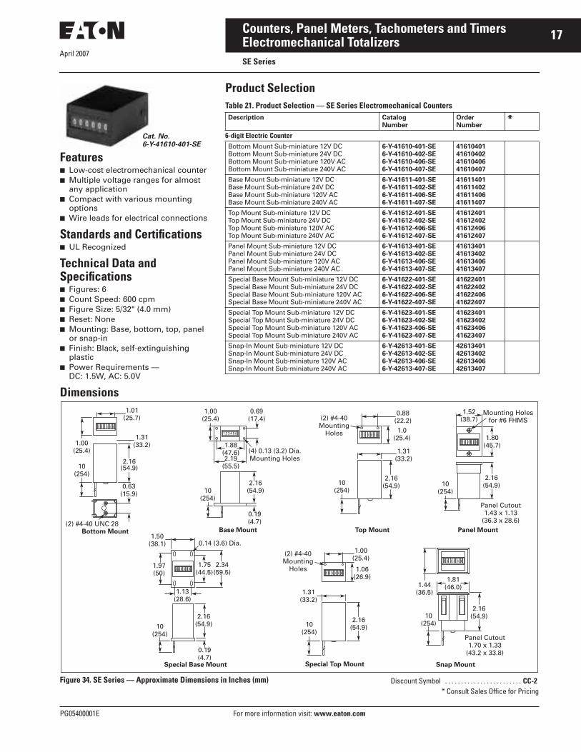
Features■ Low-cost electromechanical counter■ Multiple voltage ranges for almost
any application■ Compact with various mounting
options■ Wire leads for electrical connections
Standards and Certifications■ UL Recognized
Technical Data and Specifications■ Figures: 6■ Count Speed: 600 cpm■ Figure Size: 5/32" (4.0 mm)■ Reset: None■ Mounting: Base, bottom, top, panel
or snap-in■ Finish: Black, self-extinguishing
plastic■ Power Requirements —
DC: 1.5W, AC: 5.0V
Dimensions
Cat. No.6-Y-41610-401-SE
1.01(25.7)
1.00(25.4)
Bottom Mount Panel MountTop Mount
Special Top Mount Snap Mount
Base Mount
Special Base Mount
1.31(33.2)
2.16(54.9)
0.63(15.9)
10(254)
10(254)10
(254)
10(254)
(2) #4-40 UNC 28
1.80(45.7)
0.69(17.4)
1.97(50)
1.50(38.1)
1.75(44.5)
1.13(28.6)
2.34(59.5)
2.16(54.9)
0.19(4.7)
1.00(25.4)
1.88(47.6) (4) 0.13 (3.2) Dia.
Mounting Holes
0.14 (3.6) Dia.
2.19(55.5)
2.16(54.9)
0.19(4.7)
1.52(38.7)
Mounting Holesfor #6 FHMS
2.16(54.9)
0.88(22.2)(2) #4-40
MountingHoles 1.0
(25.4)
1.31(33.2)
2.16(54.9)10
(254)
1.00(25.4)
(2) #4-40Mounting
Holes 1.06(26.9)
1.31(33.2)
1.81(46.0)1.44
(36.5)
2.16(54.9)2.16
(54.9)10(254)
10(254)
Panel Cutout1.70 x 1.33
(43.2 x 33.8)
Panel Cutout1.43 x 1.13
(36.3 x 28.6)
Figure 34. SE Series — Approximate Dimensions in Inches (mm)
Product SelectionTable 21. Product Selection — SE Series Electromechanical Counters Description Catalog
NumberOrderNumber
*6-digit Electric CounterBottom Mount Sub-miniature 12V DCBottom Mount Sub-miniature 24V DCBottom Mount Sub-miniature 120V ACBottom Mount Sub-miniature 240V AC
6-Y-41610-401-SE6-Y-41610-402-SE6-Y-41610-406-SE6-Y-41610-407-SE
41610401416104024161040641610407
Base Mount Sub-miniature 12V DCBase Mount Sub-miniature 24V DCBase Mount Sub-miniature 120V ACBase Mount Sub-miniature 240V AC
6-Y-41611-401-SE6-Y-41611-402-SE6-Y-41611-406-SE6-Y-41611-407-SE
41611401416114024161140641611407
Top Mount Sub-miniature 12V DCTop Mount Sub-miniature 24V DCTop Mount Sub-miniature 120V ACTop Mount Sub-miniature 240V AC
6-Y-41612-401-SE6-Y-41612-402-SE6-Y-41612-406-SE6-Y-41612-407-SE
41612401416124024161240641612407
Panel Mount Sub-miniature 12V DCPanel Mount Sub-miniature 24V DCPanel Mount Sub-miniature 120V ACPanel Mount Sub-miniature 240V AC
6-Y-41613-401-SE6-Y-41613-402-SE6-Y-41613-406-SE6-Y-41613-407-SE
41613401416134024161340641613407
Special Base Mount Sub-miniature 12V DCSpecial Base Mount Sub-miniature 24V DCSpecial Base Mount Sub-miniature 120V ACSpecial Base Mount Sub-miniature 240V AC
6-Y-41622-401-SE6-Y-41622-402-SE6-Y-41622-406-SE6-Y-41622-407-SE
41622401416224024162240641622407
Special Top Mount Sub-miniature 12V DCSpecial Top Mount Sub-miniature 24V DCSpecial Top Mount Sub-miniature 120V ACSpecial Top Mount Sub-miniature 240V AC
6-Y-41623-401-SE6-Y-41623-402-SE6-Y-41623-406-SE6-Y-41623-407-SE
41623401416234024162340641623407
Snap-In Mount Sub-miniature 12V DCSnap-In Mount Sub-miniature 24V DCSnap-In Mount Sub-miniature 120V ACSnap-In Mount Sub-miniature 240V AC
6-Y-42613-401-SE6-Y-42613-402-SE6-Y-42613-406-SE6-Y-42613-407-SE
42613401426134024261340642613407
Discount Symbol . . . . . . . . . . . . . . . . . . . . . . . . CC-2* Consult Sales Office for Pricing

April 2007
18
For more information visit: www.eaton.com PG05400001E
Counters, Panel Meters, Tachometers and TimersElectromechanical TotalizersMF Series — Durant®
Product DescriptionModel MF Series are shaded pole electric counters with straight AC operation and feature a non-rectified, shaded pole coil designed to withstand tran-sient, high voltage spikes. This feature, combined with a simplified, hinged escapement drive, also eliminates the possibility of mis- counts and greatly adds to the life of the counter. Tallies at speeds up to 750 cpm.
Technical Data and Specifications■ Figures: 6 or 7■ Speed: Up to 750 cpm■ Figure Size: 3/16 inch (4.8 mm) high,
white-on-black background■ Reset: Knob, key or non-reset
Cat. No. 6-Y-1-MF-120A
Panel Mounted with Tumbler Lock4.62 x 1.44 (117.3 x 36.5) Panel Opening
Panel Mounted3.51 x 1.44 (89.3 x 36.5) Panel Opening
Base Mounted
5.50 (139.7)5.12 (130.2)
C D
0.12(3.0)
0.19(4.8)
2.12(54.0)
1.75(44.5)
0.97 (24.6)Dia. 0.15 (3.81)
4 Mtg. Holes
0.16(4.0)
1.25(31.8) 0.09
(2.4)
0.06(1.6)
3.68 (93.5)
Panel2.56
(65.0)2.09
(53.1)
0.25(6.3)
3.68 (93.5)
2.56 (65.0)0.56(14.2)
0.62(15.7)
2.56(65.0)
Panel
0.30 (7.5)
0.19 (4.8)
A B4.00 (101.6)4.37 (111.1)
Dia. 0.15 (3.81)4 Mtg. Holes
#6-32 Top MountModels Only4 Mtg. Holes
1.25(31.8)
1.62(41.3)
E F
1.37(34.9)
0.87(22.2)
Dia. 0.14 (3.6)4 Mtg. Holes
0.28(7.1)
2.56(65.0)
0.62(15.7)
3.16 (80.2) 0.41(10.3)
2.09(53.1)
0.25(6.3)
3.68 (93.5)
3.31 (84.1)
2.56 (65.0) 0.56(14.2)
0.19(4.8)
Figure 35. MF Series — Approximate Dimensions in Inches (mm)
■ Mounting: Base or panel mount■ Finish: Black frame and side covers■ Electrical Connections: 2-wire
leads, 9" (229 mm) long, AWG 22 (0.34 mm2), stripped 0.38" (9.5 mm)
■ Power Requirements: 12 watts■ Coils: Various AC voltages and fre-
quencies can be supplied on special order. Count coils are designed for continuous duty at rated voltage.
Product SelectionTable 22. Product Selection — MF Series Electric Counters
� UL Recognized.
DimensionsTable 23. MF Series — Approximate Dimensions in Inches (mm)
No. ofFigures
Voltage Reset Mounting CatalogNumber
OrderNumber
*
7766
120 AC240 AC120 AC24 AC
KnobKnobKnobKnob
BaseBaseBaseBase
7-Y-1-MF-120A �
7-Y-1-MF-240A6-Y-1-MF-120A �
6-Y-1-MF-24A
32650400326504023265140032651402
6677
240 AC230 AC/50 Hz120 AC120 AC
KnobKnobKnobNon-reset
BaseBasePanelPanel
6-Y-1-MF-240A6-Y-1-MF-230A7-Y-1-MF-PM-120A �
7-Y-13-MF-PM-120A �
32651403326514123265240032652402
6666
120 AC24 AC
240 AC120 AC
KnobKnobKnobNon-reset
PanelPanelPanelPanel
6-Y-1-MF-PM-120A �
6-Y-1-MF-PM-24A6-Y-1-MF-PM-240A6-Y-13-MF-PM-120A �
32653400326534023265340332653405
6666
240 AC120 AC24 AC
240 AC
Non-resetKeylock resetKeylock resetKeylock reset
PanelPanelPanelPanel
6-Y-13-MF-PM-240A6-Y-12-MF-PM-120A �
6-Y-12-MF-PM-24A6-Y-12-MF-PM-240A
32653410326544003265440332654404
7667
120 AC120 AC240 AC120 AC
Keylock resetNon-resetNon-resetNon-reset
PanelBaseBaseBase
7-Y-12-MF-PM-120A �
6-Y-13-MF-120A �
6-Y-13-MF-240A7-Y-13-MF-120A
32655400326584003265840232659400
Model A B C D E F
6 Figures 1.73 (44.0) 1.58 (40.0) 1.73 (43.9) 2.80 (71.1) 1.73 (44.0) 1.12 (28.6)7 Figures 2.02 (51.4) 1.29 (32.7) 2.03 (51.6) 2.50 (63.5) 2.02 (51.4) 0.84 (21.2)
Discount Symbol . . . . . . . . . . . . . . . . . . . . . . . . CC-2* Consult Sales Office for Pricing

April 2007
PG05400001E For more information visit: www.eaton.com
19Counters, Panel Meters, Tachometers and TimersElectromechanical TotalizersRMF Series — Durant®
Product DescriptionModel RMF Series of electric counters are designed to give accurate counts through a wide range of speeds up to 1000 cpm. It features a strong, silent, fast operating DC electromagnetic drive with a compact, dependable built-in higher capacity rectifier for AC operation. The counter has a minimum of moving parts that never need lubri-cation under normal operating condi-tions. Compact and rigid, it continues to operate dependably even when sub-ject to severe shock and vibrations. Entirely enclosed to prevent damage from moisture and dust. Available in 6 or 7 figures.
Technical Data and Specifications■ Figures: 6 or 7■ Speed: Up to 1000 cpm■ Figure Size: 3/16 inch (4.8 mm) high,
white-on-black background■ Reset: Knob, key or non-reset■ Mounting: Base or panel mount■ Finish: Black frame and side covers■ Electrical Connections: 2-wire
leads, 9" (229 mm) long, AWG 22 (0.34 mm2), stripped 0.38" (9.5 mm)
■ Power Requirements: 7 watts■ Coils: Various voltages and frequen-
cies can be supplied on special order. Count coils are designed for continuous duty at rated voltage.
Cat. No. 6-Y-1-RMF-115A
Product SelectionTable 24. Product Selection — RMF Series Electric Counters
� UL Recognized.
When Ordering SpecifyTo determine a model number from the Product Selection table for Model RMF Series Electronic Counters, consider:■ Number of figures■ Voltage
■ Type of reset■ Type of mounting
DimensionsRefer to Table 23 and Figure 35 on Page 18 for information.
No. ofFigures
Voltage Reset Mounting CatalogNumber
OrderNumber
*66777
24 DC24 AC24 DC115 AC230 AC
KnobKnobKnobKnobKnob
PanelPanelPanelBaseBase
6-Y-1-RMF-PM-24D6-Y-1-RMF-PM-24A7-Y-1-RMF-PM-24D7-Y-1-RMF-115A �
7-Y-1-RMF-230A
3101340031013402310194003102540031025402
77776
115 AC115 AC115 AC230 AC115 AC
Non-resetKnobNon-resetKnobNon-reset
BasePanelPanelPanelBase
7-Y-13-RMF-115A �
7-Y-1-RMF-PM-115A �
7-Y-13-RMF-PM-115A �
7-Y-1-RMF-PM-230A6-Y-13-RMF-115A �
3102640031026401310264023102641031039400
66666
230 AC24 AC230 AC115 AC115 AC
Non-resetNon-resetKnobKnobKeylock reset
BaseBasePanelPanelPanel
6-Y-13-RMF-230A6-Y-13-RMF-24A6-Y-1-RMF-PM-230A6-Y-1-RMF-PM-115A �
6-Y-12-RMF-PM-115A �
3103940431039407310664133106641631083403
67667
230 AC115 AC24 AC24 DC24 DC
Keylock resetKeylock resetKeylock resetKeylock resetKeylock reset
PanelPanelPanelPanelPanel
6-Y-12-RMF-PM-230A7-Y-12-RMF-PM-115A �
6-Y-12-RMF-PM-24A6-Y-12-RMF-PM-24D7-Y-12-RMF-PM-24D
3108340531083409310834113108341531083421
76666
230 AC24 AC240 AC115 AC115 AC
Keylock resetKnobKnobKnobNon-reset
PanelBaseBaseBasePanel
7-Y-12-RMF-PM-230A6-Y-1-RMF-24A6-Y-1-RMF-240A6-Y-1-RMF-115A �
6-Y-13-RMF-PM-115A �
3108342731155400311554013115540231155405
677766
24 DC24 AC24 DC24 DC230 AC24 AC
Non-resetNon-resetNon-resetNon-resetNon-resetNon-reset
PanelBaseBasePanelPanelPanel
6-Y-13-RMF-PM-24D7-Y-13-RMF-24A7-Y-13-RMF-24D7-Y-13-RMF-PM-24D6-Y-13-RMF-PM-230A6-Y-13-RMF-PM-24A
311554423157340031573401331834003318340433183405
Discount Symbol . . . . . . . . . . . . . . . . . . . . . . . . CC-2* Consult Sales Office for Pricing

April 2007
20
For more information visit: www.eaton.com PG05400001E
Counters, Panel Meters, Tachometers and TimersElectromechanical TotalizersME Series — Durant®
Product DescriptionSmall in size and price, but large in design versatility and model variety is the ME Series of miniature electric counters. Models in most popular AC or DC voltages operate on as little as 3 watts, with the non-reset models measuring only 1 x 1.593 x 2.187 inches (25.4 x 40.5 x 55.5 mm) and weighing just three ounces (85 grams).
Available in 4, 6 or 7 figures, the counters feature stainless steel self-lubricating shafts, nylatron pinions and a synchronous electromagnetic drive to assure accurate, reliable, long life operation. Designed for mounting flexibility and aesthetic attractiveness, the miniature electric counters are available with three types of mounting and a glare retarding finish Delrin, with crisp easy-to-read numerals set close to a tamper-proof sealed figure window.
Standards and Certifications■ UL Recognized
Technical Data and Specifications■ Figures: 4, 6 and 7■ Speed: Up to 1000 cpm■ Figure Size: 3/16 inch (4.8 mm) high■ Reset: Pushbutton and non-reset■ Reset Force: Pushbutton models
only, 20 oz. (568 grams) maximum■ Mounting: Base, bottom, panel and
plug-in pin■ Finish: Black self-extinguishing plastic■ Electrical Connections: Wire leads,
10 inches (254 mm) long, AWG 20, stripped 3/8 inch (9.5 mm), and pin terminals
■ Power Requirements: 3W■ Coils: Count coils are designed for
continuous duty at rated voltage.
Cat. No. 6-Y-41346-406-ME
Product Selection
Table 25. Product Selection — ME Series Miniature Electric Counters
When Ordering SpecifyWhen ordering ME Series Miniature Electric Counters, specify Catalog Numbers according to the features selected.
No. ofFigures
Voltage Mounting Reset CatalogNumber
OrderNumber
*
4 12V DC24V DC
120V AC240V AC
Bottom Pushbutton 4-Y-41312-401-MEQ4-Y-41312-402-MEQ4-Y-41312-406-MEQ4-Y-41312-407-MEQ
41312401413124024131240641312407
4 12V DC24V DC
120V AC240V AC
Base Pushbutton 4-Y-41313-401-MEQ4-Y-41313-402-MEQ4-Y-41313-406-MEQ4-Y-41313-407-MEQ
41313401413134024131340641313407
4 12V DC24V DC
120V AC240V AC
Panel Pushbutton 4-Y-41314-401-MEQ4-Y-41314-402-MEQ4-Y-41314-406-MEQ4-Y-41314-407-MEQ
41314401413144024131440641314407
6 12V DC24V DC
120V AC240V AC
Bottom Non-reset 6-Y-41119-401-ME6-Y-41119-402-ME6-Y-41119-406-ME6-Y-41119-407-ME
41119401411194024111940641119407
6 12V DC24V DC
120V AC240V AC
Base Non-reset 6-Y-41345-401-ME6-Y-41345-402-ME6-Y-41345-406-ME6-Y-41345-407-ME
41345401413454024134540641345407
6 12V DC24V DC
120V AC240V AC
Panel Non-reset 6-Y-41346-401-ME6-Y-41346-402-ME6-Y-41346-406-ME6-Y-41346-407-ME
41346401413464024134640641346407
7 12V DC24V DC
120V AC240V AC
Bottom Non-reset 7-Y-41238-401-ME7-Y-41238-402-ME7-Y-41238-406-ME7-Y-41238-407-ME
41238401412384024123840641238407
7 12V DC24V DC
120V AC240V AC
Base Non-reset 7-Y-41337-401-ME7-Y-41337-402-ME7-Y-41337-406-ME7-Y-41337-407-ME
41337401413374024133740641337407
7 12V DC24V DC
120V AC240V AC
Panel Non-reset 7-Y-41349-401-ME7-Y-41349-402-ME7-Y-41349-406-ME7-Y-41349-407-ME
41349401413494024134940641349407
Bottom Mount Wire Leads
Base Mount Wire Leads
Panel Mount Wire Leads
Discount Symbol . . . . . . . . . . . . . . . . . . . . . . . . CC-2* Consult Sales Office for Pricing

PG05400001E For more information visit: www.eaton.com
21Counters, Panel Meters, Tachometers and Timers
April 2007Electromechanical TotalizersME Series — Durant®
Dimensions
Figure 36. ME Series Counter — Approximate Dimensions
Table 26. ME Series Counter — Approximate Dimensions in Inches (mm)
Table 27. Recommended Panel Mount Cut-Outs in Inches (mm)
4 Figure Pushbutton Reset Counters 6 and 7 Figure Non-reset Counters
Dimension Inches (mm) Dimension Inches (mm)
ABCDEFGHJKLMNPQRST
1.00 (25.4)1.60 (40.6)2.64 (67.1)2.19 (55.6)1.80 (45.7)1.80 (45.7)1.40 (35.6).69 (17.5)
1.88 (47.8).50 (12.7).49 (12.4).94 (23.9)
2.45 (62.2)2.45 (62.2).45 (11.4).63 (16.0).19 (4.8).68 (17.3)
ABCDEFGHJKLMNPQRST
1.00 (25.4)1.60 (40.6)2.38 (60.5)2.19 (55.6)1.80 (45.7)1.80 (45.7)1.40 (35.6).69 (17.5)
1.88 (47.8).50 (12.7).49 (12.4).94 (23.9)
2.19 (55.6)2.19 (55.6).45 (11.4).63 (16.0).19 (4.8).88 (22.4)
4 Figure Counters 6 and 7 Figure Counters
Pushbutton Reset Non-reset
1.72 x 1.11 (43.7 x 28.2)
1.72 x 1.11(43.7 x 28.2)
Panel MountedBottom Mounting
Base Mounted Bottom Mounted

April 2007
22
For more information visit: www.eaton.com PG05400001E
Counters, Panel Meters, Tachometers and TimersElectronic Totalizers1/32 DIN LCD — Totalizers
ContentsDescription Page
Electronic Totalizers
1/32 DIN LCD — Totalizers . . . . . . . . . . . . . . 22
1/32 DIN LED Multifunction Totalizer/Timer/Ratemeter . . . . . . . . 24
Courier Series . . . . . . . . . . . 25
1/8 DIN LED Multifunction Totalizer/Timer/Ratemeter . . . . . . . . 27
Eclipse Series . . . . . . . . . . . 28
President Series . . . . . . . . . 30
Ambassador Series . . . . . . 34
Features■ Low price and high efficiency■ Large 8-digit LCD display, height of
the figures 0.31 Inch (8 mm)■ Various counting modes like up/
down differential and phase discriminator counting, also with pulse doubling for connection with incremental encoders
■ High voltage input for 10 – 260V AC/DC voltage pulses
■ IP65■ Screw terminals, RM 5 mm■ Lifetime of the battery
approximately 8 years■ Locking of the reset key■ Operating temperature 14 to 140°F
(-10 to 60°C)■ All version of positive or negative
counting edge■ Filter function for bounce-free
counting with mechanical contacts
Cat. No. E5-024-C0400
Standards and Certifications■ UL Recognized■ CE Marked
Technical Data and Specifications■ Power Supply: Non-replaceable
lithium battery (lifetime approximately 8 years at 68°F (20°C)
■ Display: LCD, 8-digits, height of the figures 0.31 Inch (8 mm)
■ Mode: Adding or subtracting (selectable), counting direction, differential counting or phase discriminator single or dual evaluation (selectable)
■ Display Range: -9999999 – 99999999, with overflow display
■ Reset: Manual and electrical■ Interference Emissions: EN 55011
Class B, EN 61 000-6-2, EN 61010 Section 1 (only AC versions)
■ Housing; Dark gray RAL 7021■ Operating Temperature: 14 to 131°F
(-10 to 55°C)■ Ambient Temperature: 14 to 140°F
(-10 to 60°C)■ Storage Temperature: -4 to 158°F
(-20 to 70°C)■ Protection: IP65 (from front)■ Weight: Approx. 1.76 oz (50 g)■ Counting Inputs —
❑ Counting input of the DC version, max. 30V DC– Slow counting input, max.
30 Hz (NPN)– Fast counting input, max.
12 kHz (PNP)– Switching Level —
NPN:Low 0 – 0.7V, High 3 – 30V DCPNP:Low 0 – 0.7V, High 4 – 30V DC
❑ Counting Input of the High Volt-age Versions: 10 – 260V AC/DC– Counting Input: Optocoupler
input, max. 30 Hz– Min. Pulse Time: 16 mS– Switching Level—
Low: 0 – 2V AC/DCHigh: 10 – 260V AC/DC
■ Counting Direction Switching (only DC versions) —❑ Contact input, open collector NPN
(switching at 0V DC)❑ Switching level, NPN —
Low, 0 – 0.7V, High 3 – 5V DC
■ Reset Input (only DC and High Voltage) —❑ Minimum pulse time, DC: 50 mS;
high voltage: 16 mS❑ Contact input NPN —
– Low: 0 – 0.7V– High: 3 – 30V DC
❑ High voltage input, 10 – 260V AC/DC
■ Electrical Reset Key Locking (for DC and AC) —❑ Contact input, open collector NPN
(switching at 0V)❑ Switching level, NPN —
Low, 0 – 0.7V, High 3 – 5V DC

PG05400001E For more information visit: www.eaton.com
23Counters, Panel Meters, Tachometers and Timers
April 2007Electronic Totalizers1/32 DIN LCD — Totalizers
Product SelectionTable 28. Product Selection — 1/32 DIN LCD, Totalizers
Dimensions
Figure 37. 1/32 DIN LCD, Totalizers — Approximate Dimensions in Inches (mm)
Description CatalogNumber
*8-digit LCD Totalizer, Battery Power0.94 x 1.89 Inch (24 x 48 mm)10 – 260V Input 0.94 x 1.89 Inch (24 x 48 mm)Count Up/Down 0.94 x 1.89 Inch (24 x 48 mm)
E5-024-C0400E5-024-C0408E5-024-C0410
1.77 + 0.024
(45 + 0.6)
1.77 + 0.012
(22.2 +0.3)
572690.43
1.89 (48)MAX. 1.89 (19.3)
0.11 (2.8)
0.12 (3)1.88 (47.7)
0.87 x 1.77(22 x 45)
0.94(24)
Discount Symbol . . . . . . . . . . . . . . . . . . . . . . . . CC-4* Consult Sales Office for Pricing

April 2007
24
For more information visit: www.eaton.com PG05400001E
Counters, Panel Meters, Tachometers and TimersElectronic Totalizers1/32 DIN LED Multifunction Totalizer/Timer/Ratemeter
Features■ Display counter adding and
subtracting■ Position display■ Frequency counter/ratemeter■ Timer■ Display Range: -199.999 – 999.999
with zero blanking■ Screw terminal■ Locking SET-Key
Standards and Certifications■ UL Recognized■ CE Marked
Technical Data and Specifications■ Supply Voltage: 10 – 30V DC
with reverse polarity protection■ Current Consumption: Max. 50 mA■ Display: 6-digit red, 7-segment LED
display; 0.31 Inch (8 mm) high■ Data Backup: EEPROM■ Housing: Dimension 3.78 x 1.89 Inch
(96 x 48 mm) according to DIN 43 700; RAL 7021 gray
■ Polarity of Inputs: Programmable, NPN or PNP
■ Input Resistance: Approx. 10 k■ Counting Frequency: 20 kHz, can be
damped to 30 Hz, position display max. 11 kHz
■ Resolution: Timer 0.001 sec.■ Reset Time: 5 mS■ Level of Inputs —
❑ High: 0.6 x UB – 30V DC❑ Low: 0 – 0.2 x UB [V DC]
■ Octocoupler Output: Max. 30V, 10 mA
■ Error —❑ Tachometer: <0.1%❑ Timer: <50 ppm
Cat. No. E5-024-E0402
■ Ambient Temperature: 14 to 122°F(-10 to 50°C)
■ Storage Temperature: -13 to 167°F(-25 to 75°C)
■ EMC: According to EC EMC directive 89/36/EWG
■ Immunity to Interference: EN 61 000-6-4/ EN 55011 Class B
■ Emitted Interference: EN 61 000-6-2■ Protection: IP65 (from front)■ Weight: Approx. 5.29 (150 g)
Product SelectionTable 29. Product Selection — 1/32 DIN LED Multifunction Totalizer/Timer/Ratemeter
Dimensions
Figure 38. 1/32 DIN LED Multifunction Totalizer/Timer/Ratemeter — Approximate Dimensions in Inches (mm)
Description CatalogNumber
*
LED Single Channel Totalizer, 10 – 30V DC Power0.94 x 1.89 Inch (24 x 48 mm)
E5-024-E0402
LED Multifunction Totalizer/Timer/Ratemeter 10 – 30V DC Power 0.94 x 1.89 Inch (24 x 48 mm)
E5-424-E0402
LED Double-Function Totalizer/Timer/Ratemeter 10 – 30V DC Power 0.94 x 1.89 Inch (24 x 48 mm)
E5-524-E0402
LED Totalizer with Quadrature, 10 – 30V DC Power 0.94 x 1.89 Inch (24 x 48 mm)
E5-024-E0432
2.32(59.0)
0.26(6.5)
0.16(4.0)
Max. 0.76(19.3)
0.87 x 1.77(22.0 x 45.0)
1.89(48.0)
Panel Cut-Out:0.87 + 0.01 x 1.77 + 0.02
(22.2 + 0.3 x 45 + 0.6)
0.94(24.0)
2.09(53.0)
1.10(28.0)
0.98 + 0.02
(25 + 0.5)
1.97 + 0.02
(50 + 0.6)
Panel Cut-Out
0.98 x 1.97(25 x 50)
0.16(4.0)
0.04(1.0)
M3
2.20(56.0)
1.57(40)
1.26(32)
0.98 + 0.02
(25 + 0.5)1.26 + 0.004
(32 + 0.1)
1.97 + 0.02
(50 + 0.6)
Panel Cut-Out
0.98 x 1.97(25 x 50)
0.16(4.0)
0.04(1.0)
Connections:
Discount Symbol . . . . . . . . . . . . . . . . . . . . . . . . CC-4* Consult Sales Office for Pricing

April 2007
PG05400001E For more information visit: www.eaton.com
25Counters, Panel Meters, Tachometers and TimersElectronic TotalizersCourier Series — Durant®
Features■ 8-digit totalizer■ 1/Tau ratemeter■ Scaling capabilities■ Remote reset terminal■ 0.43-inch (10.9 mm) display■ Front panel reset■ NEMA 4X
Standards and Certifications■ CE Marked
Technical Data and SpecificationsPower■ Internal Battery: 3V, Lithium■ Life expectancy: 5 years +■ Replacement Part: 36367-202
Backlight10 – 30V DC @ 30 mA max.Note: Derate operating temperature 1°C/Volt above 17V DC.
■ Reverse polarity protected
Courier Series
Physical■ Operating Temperature: -4 to 158°F
(-20 to 70°C)■ Storage Temperature: -4 to 158°F
(-20 to 70°C)■ Operating Humidity: 60%
Non-condensing.■ Weight: 2.2 oz. (62 g) net.■ Display Size: 0.43" (10.9 mm) high ■ Front Panel Rating: NEMA 4X when
mounted with gasket provided■ Case Material: Cycolac X-17
Totalizer■ Type: UP counting■ Digits: 8
Count Accuracy■ 100% when operated within
specifications
DC Common (Terminal 1) Count Inputs■ Input B (Terminal 2) Low speed
input designed for contact closures to DC common❑ Speed: 0 to 20 Hz❑ Min. Low Time: 10 mS❑ Min. High Time: 40 mS❑ Input Impedance: 101k Ohm❑ Voltage Thresholds —
Low: 0 – 0.4V DCHigh: 2.0 – 28V DCMax. High: 28V DC
■ Input A (Terminal 3) High speed input requiring a voltage source such as a current sourcing sensor or a current sinking sensor used with the provided pull up resistors❑ Speed: 0 to 10 kHz❑ Min. Low Time: 80 mS❑ Min. High Time: 20 mS
Note: The above times are with a 0 – 5.0V swing.
❑ Input Impedance: 2k Ohm above 5V DC
❑ Voltage Thresholds —Low: 0 – 1.2V DCHigh: 2.0 – 28V DCMax. High: 28V DC
Reset Input■ Reset Input (Terminal 4) designed
for contact closures to DC common❑ Min. Low: 0.25 to 1 sec. (reset is
maintained)Note: The required pulse width varies with count speed, scale factor and number of digits displayed.
❑ Voltage Thresholds —Low: 0 – 0.4V DCHigh: 2.0 – 28V DC
Front Panel Reset Enable■ Front Panel Reset Enable
(Terminal 5)❑ Operation: Level sensitive
(maintained)

April 2007
26
For more information visit: www.eaton.com PG05400001E
Counters, Panel Meters, Tachometers and TimersElectronic TotalizersCourier Series — Durant®
Product SelectionTable 30. Product Selection — Courier Series, 8-digit LCD
When Ordering SpecifyWhen ordering Courier series electronic totalizers and ratemeters, specify Order Numbers according to the features selected.
Dimensions
Figure 39. Courier Series Totalizers — Approximate Dimensions in Inches (mm)
Description CatalogNumber
*
Totalizer, BatteryAdd/Subtract (10k Hz, PNP input) Totalizer, BatteryAdd/Subtract (20 Hz, NPN/Contact input) Totalizer, BatteryQuadrature (10k Hz, PNP input) Totalizer, Battery
53300400533004015330040253300403
Totalizer/Ratemeter, BatteryTotalizer/Ratemeter @ 100 Hz, BatteryRMF Panel Mount Totalizer, Key Reset, 60 – 160V AC/DC Count InputRMF Panel Mount Totalizer, Dry Contact InputRMF Panel Mount Totalizer, 60 – 160V AC/DC Count Input
5330040553300465533008005330085053300851
Totalizer — Extended Temperature Range, BatteryTotalizer — 1/Tau Ratemeter — Extended Temperature RangeTotalizer/Ratemeter — Extended Temperature Range, BatteryTotalizer/Ratemeter, Mag Pickup, BatteryBacklight Totalizer, Battery
5330140053301404533014055330147553302400
Backlight Add/Subtract (10k Hz, PNP input) Totalizer, BatteryBacklight Add/Subtract (20 Hz, NPN/Contact input) Totalizer, BatteryBacklight Quadrature (10k Hz, PNP input) Totalizer, BatteryBacklight Totalizer/Ratemeter, Battery
53302401533024025330240353302405
1.30(33.0)
1.57(39.9)
1.25(31.8)
2.67 (67.8)2.95 (74.9)
RecommendedPanel Cutout
T/R RST
Discount Symbol . . . . . . . . . . . . . . . . . . . . . . . . CC-1* Consult Sales Office for Pricing

April 2007
PG05400001E For more information visit: www.eaton.com
27Counters, Panel Meters, Tachometers and TimersElectronic Totalizers1/8 DIN LED Multifunction Totalizer/Timer/Ratemeter
Features■ Display counter adding and
subtracting■ Position display■ Frequency counter/ratemeter■ Timer, res. up to 0.001 sec.■ Programmable mode■ Display Range: -199.999 – 999.999
with zero blanking■ Connection with screw terminal■ Locking SET-Key for reset
Standards and Certifications■ UL Recognized■ CE Marked
Technical Data and Specifications■ Supply Voltage: 10 – 30V DC
with reverse polarity protection; 90 – 260V AC
■ Current Consumption: Max. 50 mA6 VA
■ Display: 6-digit red, 7-segment LED display; 0.55 Inch (14 mm) high
■ Data Backup: EEPROM■ Housing: Dimension 3.78 x 1.89 Inch
(96 x 48 mm) according to DIN 43 700; RAL 7021 gray
■ Polarity of Inputs: Programmable, NPN or PNP for all inputs
■ Input Resistance: Approx. 10 k■ Counting Frequency: 60 kHz, can be
damped to 30 Hz depending on operating mode at position display max. 25 kHz �
■ Reset Time: 5 mS■ Resolution Timer: Up to 0.001 sec.� For further specifications, please refer to the
user manual.
Cat. No. E5-496-E0401
■ Input Switching Level — DC Version (standard version)❑ High: 0.6 x UB – 30V DC❑ Low: 0 – 0.2 x UB [V DC]AC Version❑ High: 12 – 30V DC❑ Low: 0 – 4V DC
■ Input Switching Level — 5V Version❑ High: 4 – 30V DC❑ Low: 0 – 2V DC
■ Voltage Supply for Sensors: 24V DC ±15%/100 mA at AC versions
■ Accuracy —❑ Tachometer: <0.1%❑ Timer: <50 ppm
■ Ambient Temperature: -4 to 149°F (-20 to 65°C)
■ Storage Temperature: -13 to 167°F(-25 to 75°C)
■ EMC: According to EC EMC directive 89/36/EWG
■ Immunity to Interference: EN 61 000-6-4/ EN 55011 Class B
■ Emitted Interference: EN 61-000-6-2■ Protection: IP65 (from front)■ Weight: Approx. 5.29 oz (150 g)
Product SelectionTable 31. Product Selection — 1/8 DIN LED Multifunction Totalizer/Timer/Ratemeter
Dimensions
Figure 40. 1/8 DIN LED Multifunction Totalizer/Timer/Ratemeter — Approximate Dimensions in Inches (mm)
Description CatalogNumber
*LED Multifunction Counter/Timer/Ratemeter90 – 260V AC Power 3.78 x 1.89 Inch (96 x 48 mm)10 – 30V DC Power 3.78 x 1.89 Inch (96 x 48 mm)
E5-496-E0401E5-496-E0402
3.62 +0.03
(92.0 +0.8)
1.77 +0.02
(45.0 +0.6)
1.89(48.0)
3.78(96.0)
1.77 x 3.62(44.9 x 91.9)
0.61(15.5)
2.64(67.1)
0.26(6.5)
0.16(4.0)
Max. 0.75(19.0)
Discount Symbol . . . . . . . . . . . . . . . . . . . . . . . . CC-4* Consult Sales Office for Pricing

April 2007
28
For more information visit: www.eaton.com PG05400001E
Counters, Panel Meters, Tachometers and TimersElectronic TotalizersEclipse Series — Durant®
Features■ 1/8 DIN cutout■ NEMA 4X front panel ■ Universal AC power supply
(85 – 265V AC)■ DC power models (9 – 30V DC)■ Removable screw terminals■ Short Depth: 3.6 inch (91 mm)■ Front panel programming
Standards and Certifications■ UL and cUL Listed, CE Marked
Technical Data and SpecificationsMechanical■ Cutout Dimensions:
3.62" W x 1.77" H (92 mm x 45 mm) DIN standard
■ Outline Dimensions: 4.04" W x 2.19" H x 3.87" D (103 mm x 56 mm x 98 mm)3.60" (92 mm) maximum depth in panel
■ Enclosure: Plastic with polyester front label
■ Connectors: Up to six depluggable terminal blocks
Cat. No. 57700480
Environmental■ Operating Environment: Indoor use
to 2000 meters ■ Temperature —
❑ Operating: 32 to 122°F (0 to 50°C)❑ Storage: -4 to 158°F (-20 to 70°C)
■ Humidity: 0 to 85% RH, non-condensing
■ Vibration: 2.5 Gs, 30 to 200 Hz■ Shock: 30 Gs, 11 mS half sinewave■ EMC —
❑ Immunity to EN 50082-2 (Heavy Industrial)
❑ Emissions to EN 50081-2 (Heavy Industrial)
■ Front Panel: NEMA 4X when mounted with gasket provided
■ CE EMC immunity and emissions requirements were met using shielded wiring on the RS-485, analog output and pulse input/ power lines. The shields were connected to earth ground at the Eclipse end of the shields.
■ Pollution Degree 2: Overvoltage category II
Input Power■ AC Powered Models (57701-4XX) —
❑ Input Power: 85 – 295V AC, 47 – 63 Hz, 20 VA
❑ External Fuse: 0.2A, 250V AC, Time Delay (T200 mA, 250V)
❑ Isolation Dielectric Strength: 2300V AC
■ DC Powered Models (57700-4XX) —❑ Input Power: 9 – 30V DC, 12 VA❑ External Fuse: 2.0A, 50V DC, Time
Delay (T2A, 50V)❑ Reverse Voltage Protection: Yes❑ Isolation Dielectric Strength:
2300V AC to signal outputs and relays, 500V AC to RS-485 and analog outputs
Human Interface■ Display: +6, -5 digits■ Type: 0.56" (14.2 mm) high, seven
segment, red LED
Data Retention■ Memory Type: EEPROM, no batter-
ies required■ Duration: 100 years
Count Signal Input■ Sensor Type: Sink or source, DIP
switch selectable■ Input Impedance: 4.75k ohms to
+5V DC or 34.9k ohms to ground■ Thresholds —
❑ High: 3.5 – 28V DC❑ Low: 0 – 1.9V DC, for single ended
signals■ Magnetic Pickup Range: 200 mV p-p
to 65 VRMS into 34.9k ohms■ Slow Response: 200 Hz max. (DIP
switch 2 and/or 5 ON)■ Fast Response — Count Mode:
A or B❑ Add/Add, Add/Subtract, Add w/
Inh: 8250/8250■ Fast Response — Count Mode:
A and B❑ Add/Add, Add/Subtract, Add w/
Inh: 3000/3000❑ Quad x1, Quad x2: 3250❑ Quad x4: 2000
Control Inputs■ Sensor Type: Sink only■ Input Impedance: 4.75k ohms to
+5V DC■ Thresholds —
❑ High: 3.5 to 28V DC❑ Low: 0 – 1.9V DC
■ Response: 25 mS maximum (5V signal)
Accessory Power Output■ Voltage: 12V DC +10%/-13%■ Current: 75 mA max.■ Protection: Short circuit protected

April 2007
PG05400001E For more information visit: www.eaton.com
29Counters, Panel Meters, Tachometers and TimersElectronic TotalizersEclipse Series — Durant®
Product SelectionTable 32. Product Selection — Eclipse Series Totalizer, 6-digit LED
Dimensions
Figure 41. Eclipse Series Totalizer — Approximate Dimensions in Inches (mm)
Description CatalogNumber
*
9 – 30V DC Power85 – 265V AC Power
5770048057701480
Analog Out, 9 – 30V DC PowerAnalog Out, 85 – 265V AC Power
5770048257701482
RS-485 Out, 9 – 30V DC PowerRS-485 Out, 85 – 265V AC Power
5770048457701484
RS-485 Out and Analog Out, 9 – 30V DC PowerRS-485 Out and Analog Out, 85 – 265V AC Power
5770048657701486
Durant®
3.622 ±0 .03 (92.00 ±0.8)
Panel CutoutMax. Panel Thickness 0.190 (4.83)
4.04(102.6)
PGM
3.31(84.1)
3.63(92.2)
0.27(6.9)
2.19(55.6) 1.772 ±0.02
(45 ±0.6)
Discount Symbol . . . . . . . . . . . . . . . . . . . . . . . . CC-1* Consult Sales Office for Pricing

April 2007
30
For more information visit: www.eaton.com PG05400001E
Counters, Panel Meters, Tachometers and TimersElectronic TotalizersPresident Series — Durant®
Features■ 8-digit, LED display, 0.56" (14 mm)■ Programmable decimal point and
count and rate scaling■ 15V DC @ 100 mA output power■ Rear panel screw terminals■ NEMA 4 front panel
Standards and Certifications■ UL Listed, CSA marked■ CE Marked
Technical Data and SpecificationsPower Requirements■ AC Operation: 115/230V AC
(+10%, -20%) 47 – 63 Hz■ DC Operation: 11 – 28V DC■ Power: 18 watts
DC Power Output■ 15V DC (+1, -2).■ 150 mA if powered from AC or less
than 24V DC■ 100 mA if powered from 24V DC or
greater
Note: DC power output is only regulated if unit is powered by AC or greater than 18.5V DC.
Environment■ Operating Temperature: 32 to 130°F
(0 to 55°C)■ Storage Temperature: -40 to 160°F
(-40 to 70°C)■ Operating Humidity: 85% non-
condensing relative
Physical■ Memory Types: PROM, RAM, Non-
volatile NVRAM
Counter■ Count Range: 8 digits (0 to
99,999,999) with rollover■ Offset Range: 8 digits (0 to
99,999,999) (Offset is used to reset to a non-zero number.)
■ Count Modes —❑ Count with Add and Subtract
inputs❑ Count with Up/Down direction
input (Hardware doubling for above modes is provided)
❑ Count with Count Inhibit input❑ Quadrature❑ Doubled Quadrature
■ Count Speed (Scale Factor of 1.0000 assumed)❑ 0 to 7,500 counts per second
(CPS) with Durant Shaft Encoders or solid-state sensors
❑ 0 to 3,750 CPS when hardware doubling is implemented or when quadrature shaft encoders are used
❑ 0 to 150 CPS when Low Frequencyis selected
Count Input RatingsThe count inputs are designed to work with current sinking sensors (open-collector NPN transistor output with or without passive pull-up resistor) or contact closures to DC Common.
■ Input Voltage — ❑ High state (Logical “1“, sensor off
or contact open)– 10.5 – 24.5V DC when control is
powered by AC line– 7.0 – 24.5V DC when control is
powered by 11V DC– 11.0 – 24.5V DC when control is
powered by 16V DC❑ Low state (Logical “0”, sensor on
or contact closed)– 0 – 4.5V DC when control is
powered by AC line– 0 – 3.3V DC when control is
powered by 11V DC– 0 – 4.8V DC when control is
powered by 16V DC■ Input Impedance —
❑ 6800 ohms to 15V DC when con-trol is powered by AC line
❑ 6800 ohms to 10V DC when con-trol is powered by DC supply
■ Input Current: 20 mA peak, 3 mA steady state
■ Input Response —❑ High State (Logical “1”, sensor off
or contact open)– High Speed (Low Speed
jumpers not connected)– 110 μS minimum at 15V DC
(6,800 ohms to +DC)– 160 μS minimum at 13.5V DC
(50,000 ohms to +DC)❑ High State (Logical “1“, sensor off
or contact open)– Low Speed (Low Speed
jumpers connected)– 5.5 mS minimum at 15V DC
(6,800 ohms to +DC) – 7.5 mS minimum at 13.5V DC
(50,000 ohms to +DC)❑ Low State (Logical “0”, sensor on
or contact closed)– High Speed (Low Speed
jumpers not connected)– 20 μS minimum at 0.1V DC
(0 ohms to DC Common)– 45 μS minimum at 1.5V DC
(500 ohms to DC Common)❑ Low State (Logical “0”, sensor on
or contact closed)– Low Speed (Low Speed
jumpers connected)– 1.0 mS minimum at 0.1V DC
(0 ohms to DC Common)– 2.0 mS minimum at 1.5V DC
(500 ohms to DC Common)
Scale Factor■ Range: 5 digits (0.0001 to 9.9999)
Control Inputs■ Input Voltage —
❑ High State (Logical “1”, contact open) 15V DC maximum
❑ Low State (Logical “0”, contact closed) 1.2V DC maximum
■ Input Impedance: 4.75K ohms to +5V DC.
■ Threshold —❑ High: +3.5 to +22V DC❑ Low: +0.0 to +1.0V DC
■ Response Time —❑ Min. High: 5.3 mS❑ Min. Low: 3.9 mS
Note: The reset and unlatch signals will both occur in less than 200 microseconds after the input signal is detected. The start of the print will occur within 2 milliseconds after the input is detected if the unit is not counting.
Cat. No. 58811400
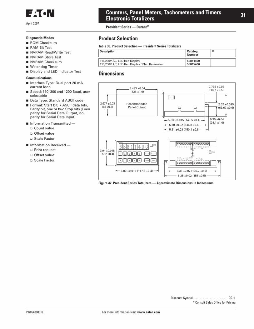
April 2007
PG05400001E For more information visit: www.eaton.com
31Counters, Panel Meters, Tachometers and TimersElectronic TotalizersPresident Series — Durant®
Diagnostic Modes■ ROM Checksum■ RAM Bit Test■ NVRAM Read/Write Test■ NVRAM Store Test■ NVRAM Checksum■ Watchdog Timer■ Display and LED Indicator Test
Communications■ Interface Type: Dual port 20 mA
current loop■ Speed: 110, 300 and 1200 Baud, user
selectable■ Data Type: Standard ASCII code■ Format: Start bit, 7 ASCII data bits,
Parity bit, one or two Stop bits (Even parity for Serial Data Output, no parity for Serial Data Input)
■ Information Transmitted — ❑ Count value❑ Offset value❑ Scale Factor
■ Information Received —❑ Print request❑ Offset value❑ Scale Factor
Product SelectionTable 33. Product Selection — President Series Totalizers
Dimensions
Figure 42. President Series Totalizers — Approximate Dimensions in Inches (mm)
Description CatalogNumber
*
115/230V AC, LED Red Display115/230V AC, LED Red Display, 1/Tau Ratemeter
5881140058815400
1 2 3 4 5
6 7 8 9 0
Count
19 20+ +IN OUT
21 22 23 24 25
115/230V~50/60 Hz
26 27 28 29 30 31 32 33 34 35 36
1 2 3 4
K1
USEEXTERNALFUSE!
K2
IN1 IN25 6 7 8 9 10 11 12 13 14 15 16 17 18
OffsetCount
Durant
Preset 1
Reset
Function
Enter
0.95 ±0.04(24.1 ±1.0)
5.53 ±0.015 (140.5 ±0.4)
5.78 ±0.02 (146.8 ±0.5)
5.91 ±0.03 (150.1 ±0.8)
5.80 ±0.015 (147.3 ±0.4)
5.433 ±0.04(138 ±1.0)
RecommendedPanel Cutout
2.677 ±0.03(68 ±0.7)
3.04 ±0.015(77.2 ±0.4)
0.735 ±0.02(18.7 ±0.5)
2.62 ±0.025(66.67 ±0.6)
5.38 ±0.02 (136.7 ±0.5)
6.25 ±0.02 (158 ±0.5)
Discount Symbol . . . . . . . . . . . . . . . . . . . . . . . . CC-1* Consult Sales Office for Pricing

April 2007
32
For more information visit: www.eaton.com PG05400001E
Counters, Panel Meters, Tachometers and TimersElectronic TotalizersPresident Series — Durant®
Features■ 8-digit, LED display, 0.56" (14 mm)■ 15V DC @ 100 mA output power■ Rear panel screw terminals■ NEMA 4 front panel
Standards and Certifications■ UL Listed, CSA marked■ CE Marked
Technical Data and SpecificationsPower Requirements■ AC Operation: 115/230V AC
(+10%, -20%) 47 – 63 Hz■ DC Operation: 11 – 28V DC■ Power: 18 watts
DC Power Output■ 15V DC (+1, -2)■ 150 mA if powered from AC or less
than 24V DC■ 100 mA if powered from 24V DC or
greater
Note: DC power output is only regulated if unit is powered by AC or greater than 18.5V DC.
Environment■ Operating Temperature: 32 to 130°F
(0 to 55°C)■ Storage Temperature: -40 to 160°F
(-40 to 70°C)■ Operating Humidity: 85% non-
condensing relative
Physical■ Memory Types: PROM, RAM, Non-
volatile NVRAM
Counter■ Count Range: 8 digits (0 to
99,999,999) with rollover■ Offset Range: 8 digits (0 to
99,999,999) (Offset is entered through serial communication only. It is used to reset to a non-zero number.)
■ Count Modes —❑ Count with Add and Subtract
inputs❑ Count with Up/Down direction
input (Hardware doubling for above modes is provided)
❑ Count with Count Inhibit input❑ Quadrature❑ Doubled Quadrature
■ Count Speed❑ 0 to 10,000 counts per second
(CPS) with Durant Shaft Encoders or solid-state sensors with internal pull-up resistor
❑ 0 to 7,500 CPS minimum for sensors with open collector transistor output
❑ 0 to 5,000 CPS when hardware doubling is implemented
❑ 0 to 150 CPS when Low Frequencyis selected
Count Input RatingsThe count inputs are designed to work with current sinking sensors (open-collector NPN transistor output with or without passive pull-up resistor) or contact closures to DC Common.
■ Input Voltage — ❑ High state (Logical “1“, sensor off
or contact open)– 10.5 – 24.5V DC when control is
powered by AC line– 7.0 – 24.5V DC when control is
powered by 11V DC– 11.0 – 24.5V DC when control is
powered by 16V DC❑ Low state (Logical “0”, sensor on
or contact closed)– 0 – 4.5V DC when control is
powered by AC line– 0 – 3.3V DC when control is
powered by 11V DC– 0 – 4.8V DC when control is
powered by 16V DC■ Input Impedance —
❑ 6800 ohms to 15V DC when con-trol is powered by AC line
❑ 6800 ohms to 10V DC when con-trol is powered by DC supply
■ Input Current: 20 mA peak, 3 mA steady state
■ Input Response —❑ High State (Logical “1”, sensor off
or contact open)– High Speed (Low Speed
jumpers not connected)– 110 μS minimum at 15V DC
(6,800 ohms to +DC)– 160 μS minimum at 13.5V DC
(50,000 ohms to +DC)❑ High State (Logical “1“, sensor off
or contact open)– Low Speed (Low Speed
jumpers connected)– 5.5 mS minimum at 15V DC
(6,800 ohms to +DC) – 7.5 mS minimum at 13.5V DC
(50,000 ohms to +DC)❑ Low State (Logical “0”, sensor on
or contact closed)– High Speed (Low Speed
jumpers not connected)– 20 μS minimum at 0.1V DC
(0 ohms to DC Common)– 45 μS minimum at 1.5V DC
(500 ohms to DC Common)❑ Low State (Logical “0”, sensor on
or contact closed)– Low Speed (Low Speed
jumpers connected)– 1.0 mS minimum at 0.1V DC
(0 ohms to DC Common)– 2.0 mS minimum at 1.5V DC
(500 ohms to DC Common)
Control Inputs■ Impedance: 4.75k ohms to +5V DC■ Threshold —
❑ High: +3.5 to +22V DC❑ Low: +0.0 to +1.0V DC
Response Time —❑ Min. High: 5.3 mS❑ Min. Low: 3.9 mS
Note: The reset and unlatch signals will both occur in less than 200 microseconds after the input signal is detected. The start of the print will occur within 2 milliseconds after the input is detected if the unit is not counting.
Counter Operating Modes■ Reset —
❑ Reset to zero❑ Reset to offset value
■ Maintained Reset■ Momentary Reset
Cat. No. 58810400

April 2007
PG05400001E For more information visit: www.eaton.com
33Counters, Panel Meters, Tachometers and TimersElectronic TotalizersPresident Series — Durant®
Communications■ Interface Type: Dual port 20 MA
current loop■ Speed: 110, 300 and 1200 Baud, user
selectable■ Data Type: Standard ASCII code■ Format: Start bit, 7 ASCII data bits,
Parity bit, one or two Stop bits (Even parity for Serial Data Output, no parity for Serial Data Input)
■ Information Transmitted — ❑ Count value❑ Offset value
■ Information Received —❑ Print request❑ Offset value❑ Print offset enable or disable
Product SelectionTable 34. Product Selection — President Series Totalizers
Dimensions
Figure 43. President Series Totalizers — Approximate Dimensions in Inches (mm)
Description CatalogNumber
*
115V AC, 7-digit LED Red Display, Basic Pulse Count115/230V AC, LED Red DisplayFeet/Inches Totalizer
578104005881040057810402
5.43 ±0.04(138 ±1.0)
RecommendedPanel Cutout
1.77 ±0.025(45 ±0.6)
Durant
Reset
5.80 ±0.015 (147.3 ±0.4)
2.16 ±0.015(54.9 ±0.4)
5.53 ±0.015 (140.5 ±0.4)
0.17 ±0.01 (4.3 ±0.24)
1.74 ±0.01(44.20 ±0.25)
1 2+ +IN OUT IN1
3 4 5 6 7
115/230V~50/60 Hz8 9 10 11 12 13 14 15 16 17 18
P R
SWA SWB
IN2
1 2 3 4 5 6 7 8 1 2 3 4 5
5.38 ±0.015 (136.7 ±0.4)
Discount Symbol . . . . . . . . . . . . . . . . . . . . . . . . CC-1* Consult Sales Office for Pricing

April 2007
34
For more information visit: www.eaton.com PG05400001E
Counters, Panel Meters, Tachometers and TimersElectronic TotalizersAmbassador Series — Durant®
Features■ AC/DC powered, 2-line LCD display■ 8-digit totalizer■ 1/Tau ratemeter■ Totalizer and ratemeter scaling■ Four user-configurable control
inputs■ Two solid-state outputs■ RS-485 Serial communications
Standards and Certifications■ UL Listed■ CE Marked
Technical Data and SpecificationsPower Input■ AC Operation —
❑ 115V AC (±15%) std., 50 to 60 Hz, 7W
❑ 230V AC (±15%) opt., 50 to 60 Hz, 7W
■ DC Operation: 10 – 15V DC opt., 300 mA maximum
DC Power Output■ 12V DC (±25%), 100 mA maximum
(includes all line and load variations)
Environmental■ Operating Temperature: 32 to 131°F
(0 to 55°C)■ Storage Temperature: -4 to 158°F
(-20 to 70°C)■ Operating Humidity: 85% Relative,
non-condensing■ NEMA 4 rating when mounted with
gasket provided
Cat. No. 57600400
Totalizer■ Type: Bi-directional■ Digits: 8■ Scaler Range: 0.00001 to 9.99999■ Decimal Point: 5 positions,
programmable
Totalizer Count SpeedsThe maximum count speed depends on the selected count mode. All maximum speeds are shown with square waves (50% duty cycle) input.
■ Maximum Speed — Solid-State (High Speed)❑ Mode Input A/ Input B —
Add/Sub: 20 kHzAdd/Add: 20 kHzCount/Direction: 15 kHzCount x 2/Direction: 7.5 kHzQuadrature: 6.5 kHzQuadrature x 2: 6.5 kHz
■ Maximum Speed — Contact (Low Speed)❑ Mode Input A/ Input B —
Add/Sub: 40 kHzAdd/Add: 40 kHzCount/Direction: 40 kHz
Count Inputs■ Sink —
❑ Impedance: 4.6k ohms to +5V DC ❑ Voltage —
High: 3.5 to 34.0V DCLow: 0.0 to 1.9V DC
■ Source (high) —❑ Impedance: 2.3k ohms to
common❑ Voltage —
High: 3.5 to 17.0V DC (100% duty cycle)Low: 0.0 to 1.9V DC
■ Source (low) —❑ Impedance: 2.3k ohms to
common❑ DC Voltage —
High: 0.6 to 17.0V DCLow: -17.0 to -0.6V DC
❑ AC Voltage: 17V AC (48V Peak-Peak) maximum
Control Inputs■ Impedance: 4.7k ohms to +5V DC ■ Voltage —
❑ High: +3.7 to +24V DC❑ Low: 0.0 to 0.9V DC
■ Response: Minimum low 15 mS, minimum high 15 mS
Transistor Outputs (2)■ Type: NPN open collector with tran-
sient protection ■ Maximum Voltage (OFF state):
30V DC ■ Maximum Current (ON state):
200 mA @ 1.3V DC
Communication■ Type: RS-485 ■ Format: 1 start bit, 7 data bits
(ASCII), 1 parity bit, 1 stop bit ■ Protocol: Opto-22 compatible ■ Speed: 300, 1200, 2400, 4800, 9600
and 19200 baud ■ Parity: Odd, Even, None (space
transmitted, ignore received)
Count Accuracy■ 100% when operated within the
specified count speeds and count signal high and low times
Rate Indicator■ Type: 1/Tau■ Digits: 6■ Scaler Range: 0.00001 to 99999■ Decimal Point: 5 positions,
programmable■ Accuracy: ± 0.015% of reading■ Update Time: 1 second, fixed■ Zero Time: 10 seconds, fixed
Connections■ Type: Dual depluggable screw
terminal strips ■ Conductor Size: 14 – 22 AWG
(2.1 – 0.38 mm2), 600V, solid, stranded or fused (preferred)

April 2007
PG05400001E For more information visit: www.eaton.com
35Counters, Panel Meters, Tachometers and TimersElectronic TotalizersAmbassador Series — Durant®
Product SelectionTable 35. Product Selection — Ambassador Series Totalizers
Dimensions
Figure 44. Ambassador Series Totalizers — Approximate Dimensions in Inches (mm)
Description CatalogNumber
*
10 – 15V DC LCD 115V AC LCD 230V AC LCD
576004005760140057602400
1
12
23456789
1011
123456789
10
2.946 ±0.015(74.83 ±0.38)
C 123456P1 10000
2.946 ±0.015(74.83 ±0.38)
2.677 ±0.028(68.00 ±0.70)
2.677 ±0.028(68.00 ±0.70)
Panel CutoutMax. PanelThickness0.50 (12.7)
5.60 ±0.03(142.24 ±0.76)
RSTCLR
RUNPGM
PRNT
•
EXIT ENT SEL
Durant®
Gasket
Discount Symbol . . . . . . . . . . . . . . . . . . . . . . . . . CC-1* Consult Sales Office for Pricing

April 2007
36
For more information visit: www.eaton.com PG05400001E
Counters, Panel Meters, Tachometers and TimersCount Controls/Preset CountersProduct Family Overview
IntroductionCount controls are counters that provide output signal(s) at preset count value(s). Typical applications include cut-to-length, batching, filling, mixing and dispensing. Available from Eaton are a variety of count controls in different sizes, display types and feature sets.
Application Example The illustration shows a simple cut-to-length application. The roll of paper is measured using a measuring wheel and rotary contactor (or encoder). Once the desired length is reached, an output signal may be directed to a shear for activation. Following the cut-off, the count control will reset to zero and begin measurement of the next piece. Options such as batch counting, where the number of cut pieces is counted, are also typical of this application.
Count Control Product Family OverviewTable 36. Product Family Overview
Rotary Contactor
Roll
Paper
MeasuringWheel
Application Example
Product Family Characteristics Panel Cutoutin Inches (mm)
PageNumber
■ Low cost, simple count control■ Various power options: battery, AC, DC■ Easy-to-change preset values■ 2-line display: input and preset values
1.772 x 1.772(45 x 45)
37
■ 6-digit, super bright LED display■ Multiple models available: totalizers, ratemeters, count controls,
digital panel meters and flow controls
1.772 x 1.622(45 x 92)
41
■ 6-digit, high-visibility, 2-line LCD display■ User-configurable control inputs■ Highly flexible control/display
2.667 x 2.667(68 x 68)
43
■ Bright LED display w/14 mm characters■ Simple configuration with 14-button tactile keypad■ Many different versions fit almost any application
2.667 x 5.433(68 x 138)
46
■ Integrated controller combines operator interface, ladder logic and high-speed counting
2.667 x 5.433(68 x 138)
79
■ Various price, voltage and size ranges for different duty cycles and environments
■ Long life and always readable display
Various Mounting Configurations
50
E5-148-C
Eclipse
Ambassador
President
Fusion
Electromechanical

April 2007
PG05400001E For more information visit: www.eaton.com
37Counters, Panel Meters, Tachometers and TimersCount Control1/16 DIN Battery Powered LCD Count Control
ContentsDescription Page
Count Control
1/16 DIN Battery Powered LCD Count Control . . . . . 37
1/16 DIN LCD Count Control . . . . . . . . . . . . . . . 39
Eclipse Series . . . . . . . . . . 41
Ambassador Series . . . . . . 43
President Series . . . . . . . . 46
PD-Q and PD-ERSeries . . . . . . . . . . . . . . . . 50
Features■ Replacement for electromechanical
preset counters■ No power supply necessary (battery
operated)■ Count and reset input electrically
separated from counter through optocoupler input range 12 – 250V AC/DC
■ 2-line LC display count, preset and level of the output
■ Screw terminal■ Data security, through two
exchangeable lithium batteries, lifetime minimum 8 years
■ Easy programming■ Counter presets easily via presetting
keys allocated to each decade■ Output: Potential free relay,
programmable normally open or normally closed contact
Cat. No. E5-148-C1400
Standards and Certifications■ cRU®us Approval■ CE Marked
Technical Data and Specifications■ Power Supply: 2 pcs user
exchangeable lithium batteries, Type 1/2 AA lithium 3.6V
■ Display: 2-line LCD display, 6 digits; 999999, height of figure 0.28 Inch (7 mm) or 0.18 Inch (4.5 mm)
■ Input: Reset, count and key lock inputs
■ Polarity of the Inputs: Bidirectional optocoupler input for the reset count inputs; reset, count and keyboard lock is connected to 3V DC
■ Min. pulse duration of the Inputs: Reset input 50 mS; keyboard lock input 15 mS
■ Switching Levels of the Inputs —❑ Low: <3V AC/DC❑ High: 12 – 250V AC/DC
■ Input Frequency: Max. 25 Hz■ Input Resistance: 110 k■ Output: Bistable relay with potential
free contact (programmable as normally closed or normally open contact)
■ Max. Switching Voltage: 250V AC/220V DC
■ Max. Switching Current: 2A■ Max. Switching Capacity: 60 VA/30W■ Output Response Time: <20 mS,
max. 4 Hz■ Data Retention: Via 2 batteries, 8
years or 5x10⁶ power operations of the output relay and an ambient temperature of 77°F (25°C)
■ Ambient Temperature: 14 to 122°F(-10 to 50°C)
■ Storage Temperature: -13 to 140°F(-25 to 60°C)
■ EMC: According to EC EMC directive 89/36/EWG, EN 61 000-6-4/ EN 55011 Class B, EN 61 000-6-2
■ Protection: IP65 (front)■ Weight: Approx. 2.82 oz (80 g)

April 2007
38
For more information visit: www.eaton.com PG05400001E
Counters, Panel Meters, Tachometers and TimersCount Control1/16 DIN Battery Powered LCD Count Control
Product SelectionTable 37. Product Selection — 1/16 DIN Battery Powered LCD Count Control
Dimensions
Figure 45. 1/16 DIN Battery Powered LCD Count Control — Approximate Dimensions in Inches (mm)
Description CatalogNumber
*1 Preset Count ControlBattery Power 1.89 x 1.89 Inch (48 x 48 mm) E5-148-C1400
648.7328 5 0 . 0 0 0
1 2 3 4 5 6 7
1 2 3 4 5 6 7
648.7328 5 0 . 0 0 0
648.7328 5 0 . 0 0 0
1.89(48.0)
1.89(48.0)
SQ 1.77(45)
Max. 0.41(10.5)
2.49(63.2)
0.63(16.0)
0.12(3.0)
2.17(55.0)
2.17(55.0)
SQ 1.77(45)
SQ 1.97(50)
Max. 0.37(9.5)
2.45(62.2)
0.63(16.0)
0.16(4.0)
2.95(75.0)
Flush Bf4, DIN 74
2.36(60.0)
SQ 1.77(45)
2.48(63)
SQ 1.97(50)
Max. 0.37(9.5)
2.45(62.2)
0.63(16.0)
0.16(4.0)
Panel Cut-Out 1.77 x 1.77 (45 x 45)
With Front Bezel No. 2Panel Cut-Out 1.97 x 1.97 (50 x 50)
With Front Bezel No. 3Panel Cut-Out 1.97 x 1.97 (50 x 50)
Discount Symbol . . . . . . . . . . . . . . . . . . . . . . . . CC-4* Consult Sales Office for Pricing

April 2007
PG05400001E For more information visit: www.eaton.com
39Counters, Panel Meters, Tachometers and TimersCount Control1/16 DIN LCD Count Control
Features■ 2-Line LCD display■ Programmable as impulse counter,
frequency meter or time meter with sign and zero blanking
■ Power Supply: 90 – 260V AC or 10 – 30V DC
■ Batch mode■ Display range -199.999 – 999.999
with zero blanking■ Easy to operate and set the preset
values via 4 keys■ Relay or octocoupler-output■ Scaling factor 0.0001 – 9.9999
❑ 1 preset value, 1 output❑ 2 preset values, 2 outputs
Standards and Certifications■ cRU®us Approval■ CE Marked
Cat. No. E5-148-C2421
Technical Data and Specifications■ Supply Voltage: 10 – 30V DC
with reverse polarity protection; 90 – 260V AC max. 4 VA
■ Display: 2-line LCD display, 6-digits■ Count Inputs: 2 count inputs, 4 input
modes are programmable■ Polarity of the Inputs:
Programmable for all inputs in common
■ Input Resistance: Approx. 10 k■ Count Frequency: 10 kHz via DIP-
switches reducible for INP A and INP B to 30 Hz (0.7 kHz at input mode E3 and E4 phase discriminator), automatic repeat at 900 Hz without losing counts (500 Hz for input mode E4)
■ Min. Pulse Duration of the Inputs: 5 mS
■ Input Sensitivity —DC Supply Voltages❑ High: 0.6 x UB – 30V DC❑ Low: 0 – 0.2 x UB [VDC]AC Supply Voltages❑ High: 12 – 30V DC❑ Low: 0 – 4V DC
■ Pulse Shape: Variable (Schmitt-Trigger characteristics)
■ Output 1: Relay —❑ With potential free contact, pro-
grammable as normally open or normally closed
❑ Switching voltage max.: 250V AC/ 125V DC
❑ Switching current max.: 3A❑ Switching current at DC min.:
30 mA❑ Switching power at DC: 90W❑ Switching power at AC max.:
750 VA
ORNPN Optocoupler —❑ With open collector and emitter
switching power 30V DC/15 mA■ Output 2: Relay —
❑ With potential free contact, pro-grammable as normally open or normally closed
❑ Switching voltage max.: 250V AC/ 125V DC
❑ Switching current max.: 3A❑ Switching current at DC min.:
30 mA❑ Switching power at DC: 90W❑ Switching power at AC max.:
750 VAOR
NPN Optocoupler —❑ With open collector and emitter
switching power 30V DC/15 mA■ Reaction Time of the Inputs —
❑ Relay: Approx. 7 mS❑ Optocoupler: Approx. 1 mS
■ Data Retention: Min. 10 years or 1x10⁶ memory cycles
■ Transmitter Voltage: 24V DC -40%/ ±15%. 100 mA at 90 – 250V AC❑ With optional backlight —
24V DC -40% ±15%. 60 mA at 90 – 260V AC
■ Ambient Temperature: 32 to 122°F(0 to 50°C)
■ Storage Temperature: -13 to 158°F(-25 to 70°C)
■ EMC: According to EC EMC directive 89/36/EWG, EN 61 000-6-4/ EN 55011 Class B, EN 61 000-6-2
■ Protection: IP65 (front)■ Weight: Approx. 8.47 oz (240 g), AC
version with relay

April 2007
40
For more information visit: www.eaton.com PG05400001E
Counters, Panel Meters, Tachometers and TimersCount Control1/16 DIN LCD Count Control
Product SelectionTable 38. Product Selection — 1/16 DIN LCD Count Control
Dimensions
Figure 46. 1/16 DIN LCD Count Control — Approximate Dimensions in Inches (mm)
Description CatalogNumber
*1 Preset LCD Count Control90 – 260V AC Power 1.89 x 1.89 Inch (48 x 48 mm)10 – 30V DC Power 1.89 x 1.89 Inch (48 x 48 mm)
E5-148-C1421E5-148-C1422
2 Preset LCD Count Control90 – 260V AC Power 1.89 x 1.89 Inch (48 x 48 mm)10 – 30V DC Power 1.89 x 1.89 Inch (48x 48 mm)
E5-148-C2421E5-148-C2422
-903.682-903.250
PR1
1 2 3 4 5 6 7
1 2 3 4 5 6 7
1.89(48.0)
1.89(48.0)
SQ 1.77(45)
Max. 0.41(10.5)
3.40(86.5)
Panel Cut-Out 1.77 x 1.77 (45 x 45)
0.61(15.5)
0.12(3.0)
-903.682-903.250
PR1
1 2 3 4 5 6 7
1 2 3 4 5 6 7
2.17(55.0)
2.17(55.0)
SQ 1.77(45)
SQ 1.97(50)
Max. 0.37(9.5)
3.37(85.5)
0.61(15.5)
0.12(4.0)
With Front Bezel No. 2Panel Cut-Out 1.97 x 1.97 (50 x 50)
-903.682-903.250
PR1
1 2 3 4 5 6 7
1 2 3 4 5 6 7
2.95(75.0)
Flush Bf4, DIN 74
2.36(60.0)
SQ 1.77(45)
2.48(63)
SQ 1.97(50)
Max. 0.37(9.5)
3.37(85.5)
0.61(15.5)
0.16(4.0)
With Front Bezel No. 3Panel Cut-Out 1.97 x 1.97 (50 x 50)
Discount Symbol . . . . . . . . . . . . . . . . . . . . . . . . CC-4* Consult Sales Office for Pricing
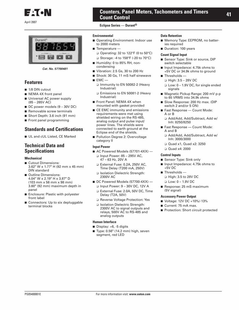
April 2007
PG05400001E For more information visit: www.eaton.com
41Counters, Panel Meters, Tachometers and TimersCount ControlEclipse Series — Durant®
Features■ 1/8 DIN cutout■ NEMA 4X front panel ■ Universal AC power supply
(85 – 265V AC)■ DC power models (9 – 30V DC)■ Removable screw terminals■ Short Depth: 3.6 inch (91 mm)■ Front panel programming
Standards and Certifications■ UL and cUL Listed, CE Marked
Technical Data and SpecificationsMechanical■ Cutout Dimensions:
3.62" W x 1.77" H (92 mm x 45 mm) DIN standard
■ Outline Dimensions: 4.04" W x 2.19" H x 3.87" D (103 mm x 56 mm x 98 mm)3.60" (92 mm) maximum depth in panel
■ Enclosure: Plastic with polyester front label
■ Connectors: Up to six depluggable terminal blocks
Environmental■ Operating Environment: Indoor use
to 2000 meters ■ Temperature —
❑ Operating: 32 to 122°F (0 to 50°C)❑ Storage: -4 to 158°F (-20 to 70°C)
■ Humidity: 0 to 85% RH, non-condensing
■ Vibration: 2.5 Gs, 30 to 200 Hz■ Shock: 30 Gs, 11 mS half sinewave■ EMC —
❑ Immunity to EN 50082-2 (Heavy Industrial)
❑ Emissions to EN 50081-2 (Heavy Industrial)
■ Front Panel: NEMA 4X when mounted with gasket provided
■ CE EMC immunity and emissions requirements were met using shielded wiring on the RS-485, analog output and pulse input/ power lines. The shields were connected to earth ground at the Eclipse end of the shields.
■ Pollution Degree 2: Overvoltage category II
Input Power■ AC Powered Models (57701-4XX) —
❑ Input Power: 85 – 295V AC, 47 – 63 Hz, 20V A
❑ External Fuse: 0.2A, 250V AC, Time Delay (T200 mA, 250V)
❑ Isolation Dielectric Strength: 2300V AC
■ DC Powered Models (57700-4XX) —❑ Input Power: 9 – 30V DC, 12V A❑ External Fuse: 2.0A, 50V DC, Time
Delay (T2A, 50V)❑ Reverse Voltage Protection: Yes❑ Isolation Dielectric Strength:
2300V AC to signal outputs and relays, 500V AC to RS-485 and analog outputs
Human Interface■ Display: +6, -5 digits■ Type: 0.56" (14.2 mm) high, seven
segment, red LED
Data Retention■ Memory Type: EEPROM, no batter-
ies required■ Duration: 100 years
Count Signal Input■ Sensor Type: Sink or source, DIP
switch selectable■ Input Impedance: 4.75k ohms to
+5V DC or 34.9k ohms to ground■ Thresholds —
❑ High: 3.5 – 28V DC❑ Low: 0 – 1.9V DC, for single ended
signals■ Magnetic Pickup Range: 200 mV p-p
to 65 VRMS into 34.9k ohms■ Slow Response: 200 Hz max. (DIP
switch 2 and/or 5 ON)■ Fast Response — Count Mode:
A or B❑ Add/Add, Add/Subtract, Add w/
Inh: 8250/8250■ Fast Response — Count Mode:
A and B❑ Add/Add, Add/Subtract, Add w/
Inh: 3000/3000❑ Quad x1, Quad x2: 3250❑ Quad x4: 2000
Control Inputs■ Sensor Type: Sink only■ Input Impedance: 4.75k ohms to
+5V DC■ Thresholds —
❑ High: 3.5 to 28V DC❑ Low: 0 – 1.9V DC
■ Response: 25 mS maximum (5V signal)
Accessory Power Output■ Voltage: 12V DC +10%/-13%■ Current: 75 mA max.■ Protection: Short circuit protected
Cat. No. 57700481

April 2007
42
For more information visit: www.eaton.com PG05400001E
Counters, Panel Meters, Tachometers and TimersCount ControlEclipse Series — Durant®
Product SelectionTable 39. Product Selection — LED Count Control, 6-digit
Dimensions
Figure 47. Eclipse Series Count Control — Approximate Dimensions in Inches (mm)
Description CatalogNumber
*
Relay Out, 9 – 30V DC PowerRelay Out, 85 – 265V AC Power
5770048157701481
Relay & Analog Out, 9 – 30V DC PowerRelay & Analog Out, 85 – 265V AC Power
5770048357701483
Relay & RS-485 Out, 9 – 30V DC PowerRelay & RS-485 Out, 85 – 265V AC Power
5770048557701485
Relay, Analog & RS-485 Out, 9 – 30V DC PowerRelay, Analog & RS-485 Out, 85 – 265V AC Power
5770048757701487
Durant®
3.622 ±0 .03 (92.00 ±0.8)
Panel CutoutMax. Panel Thickness 0.190 (4.83)
4.04(102.6)
PGM
3.31(84.1)
3.63(92.2)
0.27(6.9)
2.19(55.6) 1.772 ±0.02
(45 ±0.6)
Discount Symbol . . . . . . . . . . . . . . . . . . . . . . . . CC-1* Consult Sales Office for Pricing

April 2007
PG05400001E For more information visit: www.eaton.com
43Counters, Panel Meters, Tachometers and TimersCount ControlAmbassador Series — Durant®
Features■ AC/DC powered, 2-line LCD display■ 8-digit totalizer■ 1/Tau ratemeter■ Totalizer and ratemeter scaling■ Four user-configurable control
inputs■ Up to two output relays■ Two solid-state outputs■ RS-485 Serial communications■ Feet/Inches control available
Standards and Certifications■ UL Listed■ CE Marked
Technical Data and SpecificationsPower Input■ AC Operation —
❑ 115V AC (±15%) std., 50 to 60 Hz, 7W
❑ 230V AC (±15%) opt., 50 to 60 Hz, 7W
■ DC Operation: 10 – 15V DC opt., 300 mA maximum
DC Power Output■ 12V DC (±25%), 100 mA maximum
(includes all line and load varia-tions)
Environmental■ Operating Temperature: 32 to 131°F
(0 to 55°C)■ Storage Temperature: -4 to 158°F
(-20 to 70°C)■ Operating Humidity: 85% Relative,
non-condensing■ NEMA 4 rating when mounted with
gasket provided
Main Counter■ Type: Bi-directional■ Digits: 6 ■ Presets: Varies by Model■ Reset modes: Auto or manual reset
to zero or preset ■ Scaler Range: 0.00001 to 9.99999 ■ Decimal Point: 5 positions, (6 on 4-
preset models)■ Output Latency: See Table 40
Batch Counter■ Type: Increment with main counter
recycle or final preset signal ■ Digits: 6 ■ Presets: 1■ Output Latency: < 1 mS
Totalizer■ Type: Bi-directional, same or
opposite of main counter ■ Digits: 8 ■ Scaler: Shared with main counter ■ Decimal Point: Tracks main counter
Count Input Speeds■ See Tables 42 and 43
Count Inputs■ Sink —
❑ Impedance: 4.6k ohms to +5V DC ❑ Voltage —
High: 3.5 to 34.0Low: 0.0 to 1.9V DC
■ Source (high) —❑ Impedance: 2.3k ohms to
common❑ Voltage —
High: 3.5 to 17.0V DC (100% duty cycle)Low: 0.0 to 1.9V DC
■ Source (low) —❑ Impedance: 2.3k ohms to
common❑ DC Voltage —
High: 0.6 to 17.0V DCLow: -17.0 to -0.6V DC
❑ AC Voltage: 17V AC (48V Peak-Peak) maximum
Control Inputs■ Impedance: 4.7k ohms to +5V DC ■ Voltage —
❑ High: +3.7 to +24V DC❑ Low: 0.0 to 0.9V DC ❑ Response: Minimum low 15 mS,
minimum high 15 mS
Relay Outputs■ Type: SPDT contacts ■ UL Ratings: 250V AC, 360V A Pilot
Duty
Transistor Outputs (2)■ Type: NPN open collector with tran-
sient protection ■ Maximum Voltage (OFF state):
30V DC ■ Maximum Current (ON state):
200 mA @ 1.3V DC
Communication■ Type: RS-485 ■ Format: 1 start bit, 7 data bits
(ASCII), 1 parity bit, 1 stop bit ■ Protocol: Opto-22 compatible ■ Speed: 300, 1200, 2400, 4800, 9600
and 19200 baud ■ Parity: Odd, Even, None (space
transmitted, ignore received)
Rate Indicator (Not available on models 57601-415 and 57601-485)■ Type: 1/Tau ■ Digits: 6 ■ Presets: 2 ■ Scaler Range: 0.00001 to 99999 ■ Decimal Point: 5 positions,
programmable■ Accuracy: ±0.015% of reading ■ Update Time: See Table 41
■ Zero Time: See Table 41
Connections■ Type: Dual depluggable screw
terminal strips ■ Conductor Size: 14 – 22 AWG
(2.1 – 0.38 mm2), 600V, solid, stranded, or fused (preferred)
Cat. No. 57601401

April 2007
44
For more information visit: www.eaton.com PG05400001E
Counters, Panel Meters, Tachometers and TimersCount ControlAmbassador Series — Durant®
Table 40. Output Latency for Ambassador Control
Table 41. Rate Indicator Specs for Ambassador Control
Table 42. Ambassador Count Input Speeds — 5760X405, 5760X415 �
� Contact inputs = 40 Hz; B Direction inputs = 40 Hz and B Reset input = 10 μS Min. Low. Input A not active on Feet/Inches control.
Table 43. Ambassador Count Input Speeds — 5760X401, 5760X402, 5760X403, 5760X404
� The maximum count speed depends on the selected count mode. All maximum speeds are shown with square waves (50% duty cycle) input.
Style Number Output Latency
5760X4015760X4025760X403
0.7 to 2 mS0.7 to 2 mS0.7 to 2.7 mS
5760X4045760X4055760X415
0.7 to 2.7 mS< 1 mS< 1 mS
Style Number Update Time Zero Time
5760X4015760X4025760X403
1 second, fixed1 second, fixed1 second, fixed
10 seconds, fixed10 seconds, fixed10 seconds, fixed
5760X4045760X405
5760X415
1 second, fixed0.1 to 99.9 sec, programmable
0.1 to 999.9 sec, programmable
10 seconds, fixed0.1 to 99.9 sec, programmable
0.1 to 999.9 sec, programmable
Solid-State A or B A and B
A - B A + B -A + B
8250/82508250/82508000/8000
3000/30004000/40003000/3000
A, B Dir 2A, B Dir A, B Rst
8000/404500/408250
———
Quad x 1 Quad x 2 Quad x 4
———
325032502000
Tot A/Cnt B Tot + Cnt B
14000/900016000/8500
6500/65006500/6500
ModeInput A/B
Maximum Speed �
Solid-State(High Speed)
Contact(Low Speed)
Add/SubAdd/Add
20 kHz20 kHz
40 kHz40 kHz
Count/DirectionCount x 2/Direction
15 kHz7.5 kHz
40 kHz—
QuadratureQuadrature x 2
6.5 kHz6.5 kHz
——

April 2007
PG05400001E For more information visit: www.eaton.com
45Counters, Panel Meters, Tachometers and TimersCount ControlAmbassador Series — Durant®
Product SelectionTable 44. Product Selection — Ambassador Series Count Control
Dimensions
Figure 48. Ambassador Series Count Control — Approximate Dimensions in Inches (mm)
Description CatalogNumber
*
Single Preset with Rate, 115V ACSingle Preset with Rate, Batch and Totalizer, 115V AC
5760140157601402
Dual Preset with Rate, 115V ACDual Preset with Rate, Batch and Totalizer, 115V AC
5760140357601404
Four Preset with Rate, Batch and Totalizer, 10 – 15V DCFour Preset with Rate, Batch and Totalizer, 115V ACFour Preset with Rate, Batch and Totalizer, 230V AC
576004055760140557602405
Feet/Inches Control, 115V ACFeet/Inches Control, 230V AC
5760141557602415
1
12
23456789
1011
123456789
10
2.946 ±0.015(74.83 ±0.38)
C 123456P1 10000
2.946 ±0.015(74.83 ±0.38)
2.677 ±0.028(68.00 ±0.70)
2.677 ±0.028(68.00 ±0.70)
Panel CutoutMax. PanelThickness0.50 (12.7)
5.60 ±0.03(142.24 ±0.76)
RSTCLR
RUNPGM
PRNT
•
EXIT ENT SEL
Durant®
Gasket
Discount Symbol . . . . . . . . . . . . . . . . . . . . . . . . CC-1* Consult Sales Office for Pricing

April 2007
46
For more information visit: www.eaton.com PG05400001E
Counters, Panel Meters, Tachometers and TimersCount ControlPresident Series — Durant®
Features■ 5- or 6-digit, LED display,
0.56" (14 mm)■ 1, 2 or 3 presets■ 15V DC @ 100 mA output power■ Rear panel screw terminals■ 20 mA current loop communications■ 2 Form C relays■ Tactile keypad NEMA 4 front panel
Standards and Certifications■ UL Listed, CSA marked■ CE Marked
Technical Data and SpecificationsTable 45. President Series — Count Control Specifications
� DC power output is only regulated if unit is powered by AC or greater than 18.5V DC.
Cat. No. 58831400
Description Model
57820400 57820401 58821400 58825400 58831400
AC Power Requirements 120V ±10% 240V ±10% 120V/240V +10%/-20%, 47 – 63 Hz
DC Power Requirements 11 – 30V DC 11 – 28V DC
Power Consumption 8 Watts max. 18 Watts maximum
DC Power Output � 15V DC +1/-2 @ 85 mA max. 15V DC +1/-2; 150 mA if powered from AC or less than 24V DC,100 mA if powered from 24V DC or greater
Operating Temperature 32 to 130°F (0 to 55°C)
Operating Humidity 85% relative, non-condensing
Storage Temperature -10 to 160°F (-40 to 71°C)
Front Panel Rating NEMA 4 rating when mounted with gasket provided
Main Counter Scaler Range N/A 5 Digits (0.0001 to 9.9999)
Count Input Frequency 10 kHz(5 kHz in Quadrature)
SeeTable 46
SeeTable 52
SeeTable 47
Count Input Impedance 6.8 k to 15V DC when control is powered by AC line;6.8 k to 10V DC when control is powered by DC line
Control Input Threshold High 10.5 to 24.5V DC; Low 0.0 to 4.5V DC when powered by AC
Control Input Impedance 4.5 k to +5V DC
Control Input Response Time Min. High 5.3 mS; Min. Low 3.9 mS
Relay Contact Output Ratings SPDT Form C; 10 amps resistive @ 24V DC or 230V AC; 1/3 hp @ 115V AC or 230V AC; 150V DC max switched voltage; 5,000,000 operations mechanical life, 100,000 operations at resistive rating
Transistor Output Ratings Open collector NPN transistor with Zener diode transient surge protection; 30V DC max. load; 300 mA max. per transistor; 480 mA total for all transistors.
Use 5 mA per relay coil when calculating total transistor current
Communications N/A Dual Port 20 mA current loop, Standard ASCII code

April 2007
PG05400001E For more information visit: www.eaton.com
47Counters, Panel Meters, Tachometers and TimersCount ControlPresident Series — Durant®
Table 45. President Series — Count Control Specifications (Continued)
� DC power output is only regulated if unit is powered by AC or greater than 18.5V DC.
Table 46. 58821400 Count Frequency Table 47. 58831400, 58841400, 58861400 Count Frequency
Table 48. 58851400 Count Frequency
Description Model
58841400 58851400 58827400 58827410 58867400
AC Power Requirements 120V/240V +10%/-20%, 47 – 63 Hz
DC Power Requirements 11 – 28V DC
Power Consumption 18 Watts max.
DC Power Output � 15V DC +1/-2; 150 mA if powered from AC or less than 24V DC,100 mA if powered from 24V DC or greater
Operating Temperature 32 to 130°F (0 to 55°C)
Operating Humidity 85% relative, non-condensing
Storage Temperature -10 to 160°F (-40 to 71°C)
Front Panel Rating NEMA 4 rating when mounted with gasket provided
Main Counter Scaler Range 5 Digits (0.0001 to 9.9999) 6 Digits(0.00001 to 9.99999)
Count Input Frequency SeeTable 47
SeeTable 48
SeeTable 49
SeeTable 51
SeeTable 50
Count Input Impedance 6.8 k to 15V DC when control is powered by AC line;6.8 k to 10V DC when control is powered by DC line
Control Input Threshold High 10.5 to 24.5V DC; Low 0.0 to 4.5V DC when powered by AC
Control Input Impedance 4.5 k to +5V DC
Control Input Response Time Min. High 5.3 mS; Min. Low 3.9 mS
Relay Contact Output Ratings SPDT Form C; 10 amps resistive @ 24V DC or 230V AC; 1/3 hp @ 115V AC or 230V AC; 150V DC max switched voltage; 5,000,000 operations mechanical life, 100,000 operations at resistive rating
Transistor Output Ratings Open collector NPN transistor with Zener diode transient surge protection; 30V DC max. load; 300 mA max. per transistor; 480 mA total for all transistors.
Use 5 mA per relay coil when calculating total transistor current
Communications Dual Port 20 mA current loop, Standard ASCII code
Scale Factor Count Speed (Pulses per Second)
Nominal Count Quadrature and/or Doubled Count
< 1.0000 6,250 3,125
1.0000 7,500 3,750
1.9999 5,000 2,500
2.0000 6,250 3,125
9.0000 2,500 1,250
9.9999 2,000 1,000
Scale Factor Count Speed (Pulses per Second)
Nominal Count Quadrature and/or Doubled Count
< 1.0000 5,000 2,500
1.0000 7,500 3,750
1.9999 4,000 2,000
2.0000 6,000 3,000
9.0000 2,000 1,000
9.9999 1,500 750
Scale Factor Count Speed (Pulses per Second)
Function 61 value = “0” Function 61 value = “1”
Nominal Count Quadrature and/or Doubled Count Nominal Count Quadrature and/or Doubled Count
< 1.0000 5,000 2,500 3,500 1,750
1.0000 7,500 3,750 4,500 2,250
1.9999 4,000 2,000 2,400 1,200
2.0000 6,000 3,000 3,600 1,800
9.0000 2,000 1,000 1,100 550
9.9999 1,500 750 1,000 500

April 2007
48
For more information visit: www.eaton.com PG05400001E
Counters, Panel Meters, Tachometers and TimersCount ControlPresident Series — Durant®
Table 49. 58827400 Count Frequency Table 50. 58867400 Count Frequency
Note: The maximum count input frequency depends only on the selected count mode (doubled or quadrature x4). The maximum input frequencies shown are with square wave (50% duty cycle) input.
Table 51. 58827410 Count Frequency
� C1: Counter #1; C2: Counter #2; C3: Counter #3; RM: Ratemeter.
Table 52. 58825400 Count Frequency
Scale Factor Count Speed (Pulses per Second)
Count Up Count Down Quadrature
0.999 4,000 2,250 2,000
1.000 5,000 3,500 3,500
1.999 3,500 2,000 1,250
2.000 4,000 3,000 2,750
9.000 1,500 1,500 1,500
9.999 1,250 1,000 1,000
Count Mode Count Speed (Pulses per Second)
X1 X2 X3
High Speed 30,000 15,000 7,500
Low Speed 200 200 200
Sample Scale Factor Count Speed (Pulses per Second)
Typical Combinations of Features �
C1 = ONC2 = OFFC3 = OFFRM = OFF
C1 = ONC2 = ONC3 = OFFRM = OFF
C1 = ONC2 = ONC3 = ONRM = OFF
C1 = ONC2 = ONC3 = OFFRM = ON
C1 = ONC2 = ONC3 = ONRM = ON
0.0001 – 0.9999 6,000 3,000 2,300 2,600 2,0001.0000 9,000 4,500 3,500 4,000 3,0005.0000 4,500 2,250 1,000 2,000 7509.9999 1,500 1,000 500 750 550
Scale Factor Count Speed (Pulses per Second)
Nominal Count Quadrature and/or Doubled Count
< 1.0000 4,200 2,100
1.0000 7,500 3,750
1.9999 3,450 1,720
2.0000 6,250 3,120
9.0000 2,500 1,250
9.9999 1,800 900

April 2007
PG05400001E For more information visit: www.eaton.com
49Counters, Panel Meters, Tachometers and TimersCount ControlPresident Series — Durant®
Product SelectionTable 53. Product Selection — President Series Count Control
� These models have, in addition to the main count register, a register that may be configured to be used as either a totalizer or single preset batch counter. These two functions are mutually exclusive.
� The Model 58827-400 has both a totalizer and a batch counter, each with a single preset. In addition, the batch counter may be configured as an additional totalizer with control instead of batch counter.
� The Model 58827-410 has two completely independent count input channels feeding two independent, single preset count registers. In addition, a third single preset register may be used as either a totalizer or a batch counter for one or both of the two main counters.
Dimensions
Figure 49. President Series Count Control — Approximate Dimensions in Inches (mm)
Description Features CatalogNumber
*Totalizer Batch
CounterRate Scaler Crop-
CutMainCounter
Presets Digits
120V AC, No Communications240V AC, No CommunicationsSingle Preset
———
———
✓✓—
——✓
———
111
111
555
578204005782040158821400
Single Preset with RateDual PresetDual Preset with BatchDual Preset with Totalizer or Batch Counter
———�
——✓�
✓———
✓✓✓✓
——✓✓
1111
1222
5566
58825400588314005884140058851400
Three Preset with Floating Pre-WarnMain Counter, Batch and Totalizer PresetsTwo Independent Count RegistersHigh-Speed Count Control — 30 kHz Max.
—�
�
—
—�
�
✓
—✓✓✓
✓✓✓✓
————
1331
31 ea.1 ea.2
6666
58861400588274005882741058867400
1 2 3 4 5
6 7 8 9 0
Count
Count
19 20+ +IN OUT
21 22 23 24 25
115/230V~50/60 Hz
26 27 28 29 30 31 32 33 34 35 36
1 2 3 4
K1
K1
K2
USE
EXTERNAL
FUSE!
K2
IN1 IN25 6 7 8 9 10 11 12 13 14 15 16 17 18Preset
Durrant
Preset 1 Preset 2
Reset
Function
Enter
0.95 ±0.04(24.1 ±1.0)
5.53 ±0.015 (140.5 ±0.4)
5.78 ±0.02 (146.8 ±0.5)5.91 ±0.03 (150.1 ±0.8)
5.80 ±0.015(147.3 ±0.4)
5.433 ±0.04(138 ±1.0)
RecommendedPanel Cutout
2.677 ±0.03(68 ±0.7)
3.04 ±0.015(77.2 ±0.4)
0.735 ±0.02(18.7 ±0.5)
2.62 ±0.025(66.67 ±0.6)
5.38 ±0.02 (136.7 ±0.5)
6.25 ±0.02 (158 ±0.5)
Discount Symbol . . . . . . . . . . . . . . . . . . . . . . . . CC-1* Consult Sales Office for Pricing

April 2007
50
For more information visit: www.eaton.com PG05400001E
Counters, Panel Meters, Tachometers and TimersCount ControlPD-Q and PD-ER Series — Durant®
Product DescriptionThe PD-Q Series is a five-digit, true subtracting electric predetermined counter that features pushbutton oper-ation of both predetermined count settings and reset. The predetermined count is set by holding the RESET but-ton in and then depressing the easy to operate pushbutton selectors under each digit. The unit subtracts, one count for each contact closure or impulse and actuates a 4 ampere, 250V AC switch when zero is reached. The output signal from this switch can be used to halt or change the flow of items being counted, and/or operate other electrical apparatus. The counter returns to the predetermined number when the RESET button is depressed and it is immediately ready to control the next lot or batch.
The PD-ER Series is identical to the PD-Q Series, except that it has electric reset (ER) for remote operation, allow-ing either local or remote use.
Technical Data and Specifications■ Number of Digits: 5■ Speed: 1000 cpm■ Window: Acrylic■ Shaft: Stainless Steel■ Frame: Zinc Alloy Die Cast■ Digit Size: 3/16 inch high by
7/64 inch wide (4.8 x 2.8 mm)■ Weight —
❑ Series PD-Q: 0.53 Lb. (0.24 kg)❑ Series PD-ER: 1.06 Lb. (0.48 kg)
■ Finish: Dull Instrument Black with Red RESET Button
■ Power Consumption —❑ Series PD-Q: 9 Watts❑ Series PD-ER: Count Coil 9 Watts,
Reset Coil 20 Watts
■ Switch Rating: SPDT, 4 amperes at 250V AC
Cat. No. 5-Y-41433-*-PD-Q
Product SelectionTable 54. Product Selection — PD-Q and PD-ER Series Predetermined Counters
� UL Recognized.
When Ordering SpecifyWhen ordering PD-Q and PD-ER Series Predetermined Counters, specify Catalog Numbers according to the features selected.
Dimensions
Figure 50. PD-Q and PD-ER Series — Approximate Dimensions in Inches (mm)
Voltage Mounting Wire Leads
CatalogNumber
OrderNumber
*
12 DC24 DC
120 AC240 AC
PanelPanelPanelPanel
RearRearRearRear
5-Y-41433-401-PD-Q5-Y-41433-402-PD-Q5-Y-41433-406-PD-Q5-Y-41433-407-PD-Q
4143340141433402 �
41433406 �
41433407
24 AC12 DC24 DC
120 AC
PanelBaseBaseBase
RearRearRearRear
5-Y-41433-408-PD-Q5-Y-41469-401-PD-Q5-Y-41469-402-PD-Q5-Y-41469-406-PD-Q
414334084146940141469402 �
41469406 �
240 AC24 AC12 DC24 DC
BaseBaseBaseBase
RearRearSideSide
5-Y-41469-407-PD-Q5-Y-41469-408-PD-Q5-Y-41470-401-PD-Q5-Y-41470-402-PD-Q
41469407414694084147040141470402 �
120 AC240 AC24 AC12 DC
BaseBaseBasePanel
SideSideSideRear
5-Y-41470-406-PD-Q5-Y-41470-407-PD-Q5-Y-41470-408-PD-Q5-Y-41625-401-PD-ER
41470406 �
414704074147040841625401
24 DC120 AC240 AC24 AC
PanelPanelPanelPanel
RearRearRearRear
5-Y-41625-402-PD-ER5-Y-41625-406-PD-ER5-Y-41625-407-PD-ER5-Y-41625-408-PD-ER
41625402 �
41625406 �
4162540741625408
1.69(42.8)
2.69(68.2)
3.06(77.8)
Hole Dia.0.13 (3.2)
1.18(30.1)
1.56(39.7)
3.00(72.6)
3.38(85.7)
1.59(40.5)
2.72(69.0)2.69
(68.2)
1.56(39.7)
2.97(75.4)
Dia. 0.14(3.6)
3.00(76.2)3.38
(85.7)
1.31(33.3)
1.69(42.8)
4.38(111.1)
4.00(101.6)
2.69(68.2)
2.00(50.8)
1.63(41.3)
3.22(81.8)
1.69(42.8)
Discount Symbol . . . . . . . . . . . . . . . . . . . . . . . . CC-2* Consult Sales Office for Pricing

April 2007
PG05400001E For more information visit: www.eaton.com
51Counters, Panel Meters, Tachometers and TimersTachometers/RatemetersProduct Family Overview
IntroductionRatemeters are used in a variety of applications where it is necessary to monitor the speed of a process. Conveyors, baking ovens, material flow and motor speed are typical uses for ratemeters. Eaton/Durant models with alarm out-puts can be used to detect high or low rates. Rate indicators are often included as a standard feature on totalizers and count controls.
Application Example One of the most common ratemeter applications is a tachometer. A tachometer displays motor or shaft RPM. The inductive proximity sensor detects the key on the shaft and the meter calculates the rate at which the shaft is turning based on a user-defined scaling factor. Signals from encoders, mag pick-ups, Hall effect sensors, etc. may also be used as inputs.
Ratemeter Product Family OverviewTable 55. Product Family Overview
High Alarm Output
0 to 10V DC Feedback to Motor Drive
Low Alarm Output
ProximitySensor
Motor
Application Example
Product Family Characteristics Panel Cutoutin Inches (mm)
PageNumber
■ Compact device with bright, LED display■ Multiple functions available: count, time, rate, multifunction,
double-function■ 24V DC Power
0.870 x 1.772(22 x 44)
24
■ Low cost, simple count control■ Various power options: battery, AC, DC■ Easy-to-change preset values■ 2-line display: input and preset values
1.772 x 1.772(45 x 45)
37
■ Economical, multifunction display■ Large, LED characters■ AC or DC power options
1.772 x 1.622(45 x 92)
27
■ Replaceable lithium battery■ 8-digit, high-visibility LCD display■ Optional backlighting■ Various input options available
1.299 x 2.677(33 x 68)
52
■ 6-digit, super bright LED display■ Multiple models available: totalizers, ratemeters, count controls,
digital panel meters and flow controls
1.772 x 1.622(45 x 92)
53
■ 6-digit, high-visibility, 2-line LCD display■ User-configurable control inputs■ Highly flexible control/display
2.667 x 2.667(68 x 68)
55
■ Bright LED display w/14 mm characters■ Simple configuration with 14-button tactile keypad■ Many different versions fit almost any application
2.667 x 5.433(68 x 138)
30
■ Integrated controller combines operator interface, ladder logic and high-speed counting
2.667 x 5.433(68 x 138)
79
E5-_24-E
E5-148-C
E5-496-C
Courier
Eclipse
Ambassador
President
Fusion

April 2007
52
For more information visit: www.eaton.com PG05400001E
Counters, Panel Meters, Tachometers and TimersTachometers/RatemetersCourier Series — Durant®
ContentsDescription Page
Tachometers/Ratemeters
Courier Series . . . . . . . . . . . 52
Eclipse Series . . . . . . . . . . . 53
Ambassador Series . . . . . . 55
Features■ 1/Tau ratemeter■ Scaling capabilities■ Remote reset terminal■ 0.43 inch (10.9 mm) display■ Front panel reset■ NEMA 4X
Standards and Certifications■ CE Marked
Technical Data and SpecificationsPower■ Internal Battery: 3V, Lithium■ Life Expectancy: 5 years +■ Replacement Part: 35367-202
Backlight■ 10 – 30V DC @ 30 mA max.Note: Derate operating temperature 1°C/Volt above 17V DC.
■ Reverse polarity protected
Physical■ Operating Temperature —
❑ Model 53300-404: 32 to 131°F(0 to 55°C)
❑ Model 53301-404: -4 to 158°F(-20 to 70°C)
❑ Model 53302-404: 32 to 131°F(0 to 55°C)
■ Storage Temperature: -4 to 158°F(-20 to 70°C)
Courier Series
■ Operating Humidity: 60% R.H.(non-condensing)
■ Weight: 2.2 oz. (62 g) net■ Display Size: 0.43" (10.9 mm) high■ Front Panel Rating: NEMA 4X when
mounted with gasket provided■ Case Material: Cycolac X-17
Rate Indicator■ Type: 1/Tau■ Digits: 4/5 (4 calculated, 5 displayed
with fixed 0 in LSD)■ Scaler Range: 0.001 to 9999.■ Decimal Point: 5 positions,
programmable■ Accuracy: ± 0.2%■ Update Time: 0.7 seconds■ Zero Time: 10 seconds
DC Common (Terminal 1) Rate Inputs■ Input B (Terminal 2) Low speed
input designed for contact closures to DC common❑ Speed: 0 to 20 Hz❑ Min. Low Time: 10 mS❑ Min. High Time: 40 mS❑ Input Impedance: 101k Ohm
❑ Voltage Thresholds —Low: 0 – 0.4V DCHigh: 2.0 – 28V DCMax. High: 28V DC
■ Input A (Terminal 3) High speed input requiring a voltage source such as a current sourcing sensor or a current sinking sensor used with the provided pull up resistors❑ Speed: 0 to 10 Hz❑ Min. Low Time: 80 mS❑ Min. High Time: 20 mS
Note: The above times are with a 0 – 5.0V swing.
❑ Input Impedance: 2k Ohm above 5V DC
❑ Voltage Thresholds —Low: 0 – 1.2V DCHigh: 2.0 – 28V DCMax. High: 28V DC
Programmable Enable Input (Terminal 5)■ Operation: Level sensitive
(maintained)
Count Accuracy■ 100% when operated within
Product SelectionTable 56. Product Selection — LCD 1/Tau Ratemeter
Note: For units with Rate and Total, see Totalizers.
Dimensions
Figure 51. Courier Series Ratemeter — Approximate Dimensions in Inches (mm)
Description OrderNumber
*
BatteryExtended Temperature Range, BatteryBacklight, Battery
533004045330140453302404
1.30(33.0)
1.57(39.9)
1.25(31.8)
2.67 (67.8)2.95 (74.9)
RecommendedPanel Cutout
T/R RST
Discount Symbol . . . . . . . . . . . . . . . . . . . . . . . . CC-1* Consult Sales Office for Pricing

April 2007
PG05400001E For more information visit: www.eaton.com
53Counters, Panel Meters, Tachometers and TimersTachometers/RatemetersEclipse Series — Durant®
Features■ 1/8 DIN Cutout■ NEMA 4X Front Panel■ Universal AC Power Supply
(85 – 265V AC)■ DC Power Modules (9 – 30V DC)■ Removable Screw Terminals■ Short Depth: 3.6 inch (91 mm)■ Front Panel Programming
Standards and Certifications■ UL and cUL Listed, CE Marked
Technical Data and SpecificationsInput Power■ AC Powered Models (57701-4XX) —
❑ Input Power: 85 – 265V AC, 47 – 63 Hz, 20V A
❑ External Fuse: 0.2A, 250V AC, Time Delay (T200 mA, 250V)
❑ Isolation Dielectric Strength: 2300V AC
■ DC Powered Models (57700-4XX)—❑ Input Power: 9 – 30V DC, 12 VA❑ External Fuse: 2.0A, 50V DC, Time
Delay, (T2A, 50V)❑ Reverse Voltage Protection: Yes❑ Isolation Dielectric Strength:
2300V AC to signal inputs and relays, 500V AC to RS-485 and analog outputs
Human Interface■ Display: 5 digits■ Type: 0.56" high, seven segment,
red LED ■ Indicator: One red LED program/
calibration indicator ■ Update Time: 0.1 to 99.9 seconds
minimum
Data Retention■ Memory Type: EEPROM, no
batteries required ■ Duration: 100 years
Signal Input■ Rate/Process Time: Signal In ■ Sensor Type: Sink or source, DIP
switch selectable ■ Input Impedance: 4.75 k ohms to
+5V DC or 34.9 k Ohms to ground■ Thresholds —
❑ High 3.5 to 28V DC❑ Low 0 to 1.9V DC, for single
ended signals ■ Magnetic Pickup Range: 200 mV p-p
to 65 VRMS into 34.9 k Ohms ■ Frequency Response: 200 Hz max.
or 10 kHz max. (5V signals), DIP switch selectable
Program Enable Input■ Sensor Type: Sink only ■ Input Impedance: 4.75 k Ohms to
+5V DC ■ Thresholds —
❑ High 3.5 to 28V DC❑ Low 0 to 1.9V DC
■ Response: 25 mS max. (5V signal)
Accessory Power Output■ Voltage: 12V DC ± 12% ■ Current: 75 mA max. ■ Protection: Short circuit protected
Optional Outputs■ Relay Board —
❑ Number of relays: 2 ❑ Contact type: 1 set form C per
relay❑ Contact rating: 5A, 250V AC or
30V DC ❑ Isolation dielectric strength:
2300V AC ■ Analog Retransmission —
❑ Output signals: 4 – 20 mA (<750 ) and 0 – 10V (>2500 )
❑ Accuracy: 0.13% full scale and 100 PPM /°C (and 0.07% full scale change over 4 – 20 mA load ranges)
❑ Isolation dielectric strength: 2300V AC to signal inputs, relays and AC power inputs; 500V AC to RS-485 and DC power inputs
■ RS-485 Serial Communications —❑ Baud Rate: 1200, 2400, 4800,
9600, or 19,200, programmable❑ Parity: Even, odd or no parity❑ Address Range: 00 to 99 decimal❑ Protocol: Opto 22® compatible❑ Isolation Dielectric Strength:
2300V AC to signal inputs, relays and AC power inputs; 500V AC to analog outputs and DC power inputs
Environmental■ Operating Environment: Indoor use
to 2000 meters ■ Temperature —
❑ Operating: 32 to 122°F (0 to 50°C)❑ Storage: -4 to 158°F (-20 to 70°C)
■ Humidity: 0 to 85% RH, non-condensing
■ Vibration: 2.5 Gs, 30 to 200 Hz■ Shock: 30 Gs, 11 mS half sinewave■ EMC —
❑ Immunity to EN 50082-2 (Heavy Industrial)
❑ Emissions to EN 50081-2 (Heavy Industrial)
■ Front Panel: NEMA 4X when mounted with gasket provided
■ CE EMC immunity and emissions requirements were met using shielded wiring on the RS-485, analog output and pulse input/ power lines. The shields were connected to earth ground at the Eclipse end of the shields.
■ Pollution Degree 2: Overvoltage category II
Cat. No. 57700470

April 2007
54
For more information visit: www.eaton.com PG05400001E
Counters, Panel Meters, Tachometers and TimersTachometers/RatemetersEclipse Series — Durant®
Product SelectionTable 57. Product Selection — Eclipse Series 5-digit LED Ratemeter
Dimensions
Figure 52. Eclipse Series Ratemeters — Approximate Dimensions in Inches (mm)
Description CatalogNumber
*
9 – 30V DC9 – 30V DC, Alarms9 – 30V DC, Analog Out9 – 30V DC, Alarms, Analog Out
57700470577004715770047257700473
9 – 30V DC, RS-4859 – 30V DC, Alarms, RS-4859 – 30V DC, Analog Out, RS-4859 – 30V DC, Alarms, Analog Out, RS-485
57700474577004755770047657700477
85 – 265V AC85 – 265V AC, Alarms85 – 265V AC, Analog Out85 – 265V AC, Alarms, Analog Out
57701470577014715770147257701473
85 – 265V AC, RS-48585 – 265V AC, Alarms, RS-48585 – 265V AC, Analog Out, RS-48585 – 265V AC, Alarms, Analog Out, RS-485
57701474577014755770147657701477
Durant®
Max. Panel Thickness0.190 (4.83)
3.622 ±0 .031 (92.00 ±0.8)
Panel Cutout
4.04(102.6)
PGM
3.31(84.1)
3.63(92.2)
0.27(6.9)
2.19(55.6) 1.772 ±0.02
(45 ±0.6)
Discount Symbol . . . . . . . . . . . . . . . . . . . . . . . . CC-1* Consult Sales Office for Pricing

April 2007
PG05400001E For more information visit: www.eaton.com
55Counters, Panel Meters, Tachometers and TimersTachometers/RatemetersAmbassador Series — Durant®
Features■ AC/DC powered, 2-line LCD display■ 2-Line, 5-digit, high visibility, 0.3"
(7.5 mm) characters, backlit display■ 1 or 2 rate inputs■ 2 rate alarms■ Dual rate unit ratio calculations —
A/B, A-B or draw■ Programmable average and zero
times■ Programmable decimal point■ 12V DC, 100 mA max. output power■ Removable screw terminals■ RS-485 communications■ NEMA 4 front panel
Standards and Certifications■ UL and cUL Listed, CE Marked
Technical Data and SpecificationsPower Input■ Model 57150-40X: 10 to 15V DC,
300 mA maximum■ Model 57151-40X: 115V AC (±15%)
50 – 60 Hz, 7W■ Model 57152-40X: 230V AC (±15%)
50 – 60 Hz, 7W
DC Power Output (AC Models Only)■ 12V DC (±25%), 100 mA maximum
(includes all line and load variations)
Environment■ Operating Temperature: 32 to 131°F
(0 to 55°C)■ Storage Temperature: -4 to158°F
(-20 to 70°C)■ Operating Humidity: 85% Relative,
non-condensing■ NEMA 4 rating when mounted with
gasket provided
Ratemeter■ Type: 1/Tau■ Digits: 5 with overrange indication■ Scaler Range: 0.00001 to 99999■ Decimal Point: 5 positions,
programmable■ Average Time: 0.1 to 99.9 seconds,
programmable■ Zero Time: 0.1 to 99.9 seconds,
programmable■ Accuracy: ±0.015% of reading
Maximum Rate Input Frequencies■ All maximum frequencies listed are
with a square wave input (50-50 duty cycle).
Contact Input■ 40 Hz
Solid-State Input■ Sinking Sensor
(All DIPs off): 7.3 kHz■ Sourcing Sensor
(Push-Pull Output) —❑ High Threshold (DIPs 1 and 2 on,
3 and 4 off) —– 0 – 5V, single input 50 kHz– 0 – 5V, two inputs 30 kHz
(each input)– 0.5 – 4.5V, single input 40 kHz– 0.5 – 4.5V, two inputs 30 kHz
(each input)– 0 – 15V, two inputs 22 kHz
(each input)❑ Low Threshold (All DIPs on) —
– -1 to +1V, single input 27 kHz– -2 to +2V, single input 43 kHz– -3 to +3V, single input 60 kHz– -2 to +2V, two inputs 30 kHz
(each input)
Rate Inputs■ Sink —
❑ Impedance: 4.6k ohms to +5V DC ❑ Voltage: High 3.5 to 34.0, low 0.0 to
1.9V DC
■ Source (High) —❑ Impedance: 2.3k ohms to
common❑ Voltage: High 3.5 to 17.0V DC, low
0.0 to 1.9V DC■ Source (Low) —
❑ Impedance: 2.3k ohms to common
❑ DC Voltage: High 0.63 to 17.0V DC, low -17.0 to -0.6V DC
❑ AC Voltage: 17V AC (48V Peak-Peak) maximum
Control Inputs■ Impedance: 4.7k ohms to +5V DC■ Voltage: High +3.7 to +24V DC, low
0.0 to 0.9V DC■ Response: Min Low 15 mS,
Min High 15 mS
Transistor Outputs (x2 for 5715X-401;x4 for 5715X-405)■ Type: NPN open collector with
transient protection■ Max. Voltage (OFF state): 30V DC■ Max. Current (ON state): 200 mA @
1.3V DC
Communication■ Type: RS-485■ Format: 1 start bit, 7 data bits
(ASCII), 1 parity bit, 1 stop bit■ Protocol: Opto-22 compatible■ Speed: 300, 1200, 2400, 4800, 9600,
19200 Baud■ Parity: Odd, Even, None (space
transmitted, ignore received)
Analog Output (Models 5715X-401 Only)■ Range: 0 – 10V DC ± 0.2% at 5 mA■ DAC Resolution: 12 bit
Connections■ Type: Dual depluggable screw
terminal strips■ Conductor Size: 14 – 22 AWG
(2.1 – 0.38 mm2), 600V, solid, stranded or fused (preferred)
Cat. No. 57150400

April 2007
56
For more information visit: www.eaton.com PG05400001E
Counters, Panel Meters, Tachometers and TimersTachometers/RatemetersAmbassador Series — Durant®
Product SelectionTable 58. Product Selection — Ambassador Series Ratemeters
� The accuracy of the ratio calculation is dependent upon the resolution of the displayed rates, which are calculated as rounded integers. The ratio calculation treats the displayed rate as integers and the result is displayed as a rounded integer. A and B scalers should be adjusted for maximum resolution.
Dimensions
Figure 53. Ambassador Series Ratemeters — Approximate Dimensions in Inches (mm)
Description CatalogNumber
*Single InputLCD Rate indicator, 2 Rate Alarms, 10 – 15V DCLCD Rate indicator, 2 Rate Alarms, 115V ACLCD Rate indicator, 2 Rate Alarms, 230V AC
571504005715140057152400
Dual Input �
Rate/Ratio/Draw with Alarms & Analog Out, 10 – 15V DCRate/Ratio/Draw with Alarms & Analog Out, 115V ACRate/Ratio/Draw with Alarms & Analog Out, 230V AC
571504055715140557152405
1
12
23456789
1011
123456789
10
2.946 ±0.015(74.83 ±0.38)
A 12345R/M
2.946 ±0.015(74.83 ±0.38)
2.677 ±0.028(68.00 ±0.70)
2.677 ±0.028(68.00 ±0.70)
Panel CutoutMax. PanelThickness0.50 (12.7)
5.60 ±0.03(142.24 ±0.76)
UNLCLR
RUNPGM
AKN
•
EXIT ENT SEL
Durant®
Discount Symbol . . . . . . . . . . . . . . . . . . . . . . . . CC-1* Consult Sales Office for Pricing
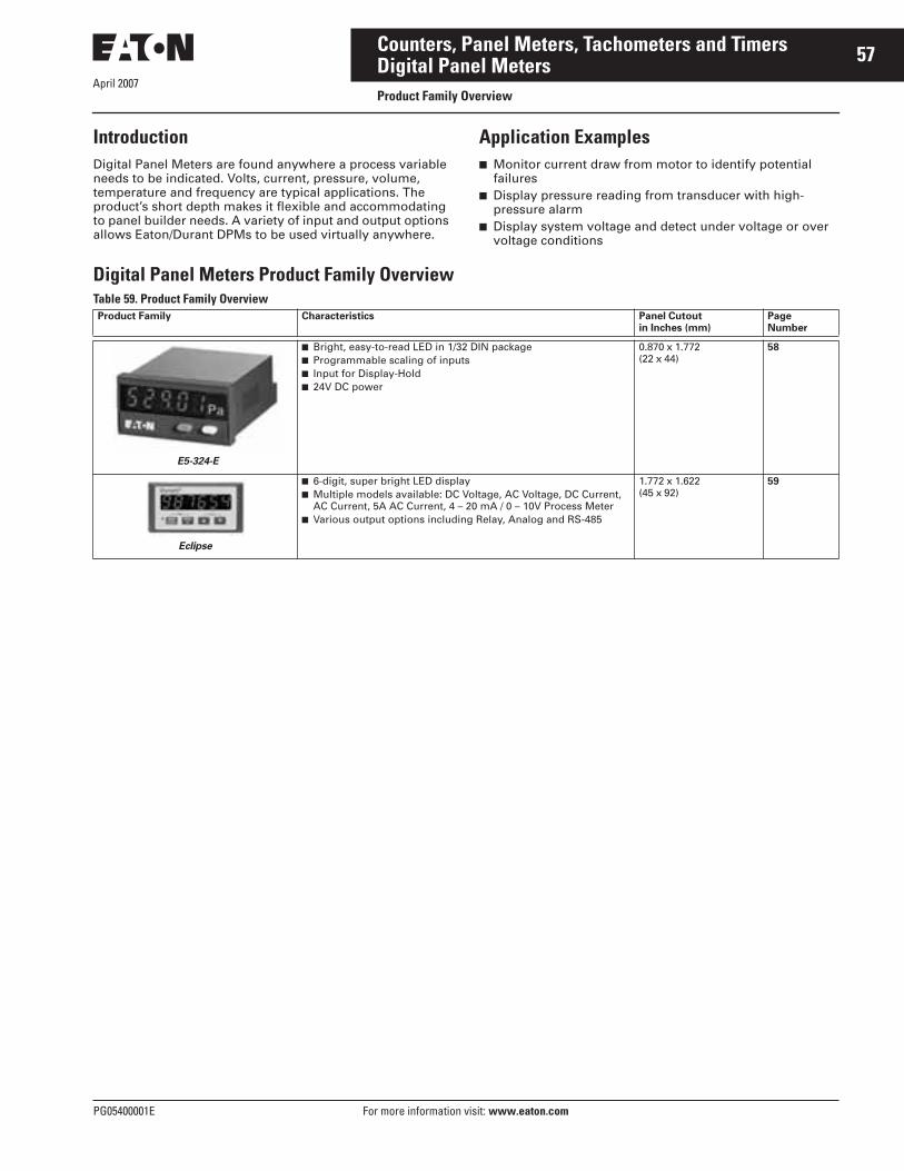
April 2007
PG05400001E For more information visit: www.eaton.com
57Counters, Panel Meters, Tachometers and TimersDigital Panel MetersProduct Family Overview
IntroductionDigital Panel Meters are found anywhere a process variable needs to be indicated. Volts, current, pressure, volume, temperature and frequency are typical applications. The product’s short depth makes it flexible and accommodating to panel builder needs. A variety of input and output options allows Eaton/Durant DPMs to be used virtually anywhere.
Application Examples■ Monitor current draw from motor to identify potential
failures■ Display pressure reading from transducer with high-
pressure alarm■ Display system voltage and detect under voltage or over
voltage conditions
Digital Panel Meters Product Family OverviewTable 59. Product Family OverviewProduct Family Characteristics Panel Cutout
in Inches (mm)PageNumber
■ Bright, easy-to-read LED in 1/32 DIN package■ Programmable scaling of inputs■ Input for Display-Hold■ 24V DC power
0.870 x 1.772(22 x 44)
58
■ 6-digit, super bright LED display■ Multiple models available: DC Voltage, AC Voltage, DC Current,
AC Current, 5A AC Current, 4 – 20 mA / 0 – 10V Process Meter■ Various output options including Relay, Analog and RS-485
1.772 x 1.622(45 x 92)
59
E5-324-E
Eclipse

April 2007
58
For more information visit: www.eaton.com PG05400001E
Counters, Panel Meters, Tachometers and TimersDigital Panel MetersE5-324-E Series
ContentsDescription Page
Digital Panel Meters
E5-324-E Series . . . . . . . . . . 58
Eclipse Series . . . . . . . . . . . 59
Features■ Galvanic isolation with protection
against incorrect polarity■ Automatic MIN/MAX value
detection■ Freely programmable characteristic
curve end points■ Input Range —
❑ 1 current measuring input❑ 1 voltage measuring input
■ Compact display for analog standard signals
■ Display range -19.999 to 99.999 with zero blanking
■ Modern industrial design■ Input for Display-Hold
Standards and Certifications■ UL Recognized■ CE Marked
Technical Data and Specifications■ Supply Voltage: 10 – 30V DC, gal-
vanically isolated with integrated protection against incorrect polarity
■ Current Consumption: Max. 50 mA■ Display: 5-digit display, red 7-segment
LEDs; 0.31 Inch (8 mm) high■ Measuring Rate: 2 measurements/
second■ Data Backup: EEPROM■ Housing: Housing for control panel
1.898 x 0.94 Inch (48 x 24 mm); Acc. to DIN 43 700, RAL 7021, dark gray
Cat. No. E5-324-E0402
■ Ambient Temperature: 14 to 122° F(-10 to 50°C)
■ EMC: According to EC EMC directive 89/36/EEC
■ Interference Emissions: EN 61 000-6-4/EN 55011 Class B
■ Interference Resistance: EN 61 000-6-2■ Protection: IP65 (front)■ Input Current Measurement:
0 – 20 mA, 4 – 20 mA, voltage drop max. 1.5V DC
■ Input Voltage Measurement: 0 – 10V, 2 – 10V❑ Input resistance approx.: 1 M❑ Max. input signal level: 30V DC
■ Control Inputs —❑ High: 4 – 30V DC❑ Low: 0 – 2V DC
■ Resolution: 14 bits■ Error: <0.1% For the whole
measuring range at an ambient temperature of 68°F (20°C)
■ Weight: Approx. 1.76 oz (50 g)■ Connection Technique: Screw
terminal, pitch 0.2 Inch (5.08 mm),7 poles
Product SelectionTable 60. Product Selection — E5-324-E0402
Dimensions
Figure 54. E5-324-E Series — Approximate Dimensions in Inches (mm)
Description CatalogNumber
*
LED Digital Panel Meter, 24 x 48 mm E5-324-E0402
2.32(59.0)
0.26(6.5)
0.16(4.0)
Max. 0.76(19.3)
0.87 x 1.77(22.0 x 45.0)
1.89(48.0)
Panel Cut-Out:0.87 + 0.01 x 1.77 + 0.02
(22.2 + 0.3 x 45 + 0.6)
0.94(24.0)
2.09(53.0)
1.10(28.0)
0.98 + 0.02
(25 + 0.5)
1.97 + 0.02
(50 + 0.6)
Panel Cut-Out
0.98 x 1.97(25 x 50)
0.16(4.0)
0.04(1.0)
M3
2.20(56.0)
1.57(40)
1.26(32)
0.98 + 0.02
(25 + 0.5)1.26 + 0.004
(32 + 0.1)
1.97 + 0.02
(50 + 0.6)
Panel Cut-Out
0.98 x 1.97(25 x 50)
0.16(4.0)
0.04(1.0)
Connections:
Discount Symbol . . . . . . . . . . . . . . . . . . . . . . . . CC-4* Consult Sales Office for Pricing

April 2007
PG05400001E For more information visit: www.eaton.com
59Counters, Panel Meters, Tachometers and TimersDigital Panel MetersEclipse Series — Durant®
Features■ 4 Full digits■ 1/8 DIN Size■ Red, LED display■ 0.56" (14 mm) high characters■ Scalable display■ Flashing alarms■ Maximum/minimum data hold■ Optional analog, relay and RS-485
outputs■ NEMA 4X■ Depluggable terminal blocks
Standards and Certifications■ UL and cUL Listed, CE Marked
Technical Data and SpecificationsInput Power■ AC Powered Models (57751-4XX)
❑ Input Power: 85 – 265V AC, 47 – 63 Hz, 20 VA
❑ External Fuse: 0.2A, 250V AC, Time Delay (T200mA, 250V)
❑ Isolation Dielectric Strength: 2300V AC
■ DC Powered Models (57750-4XX)❑ Input Power: 9-30V DC, 12 VA ❑ External Fuse: 2.0A, 50V DC, Time
Delay (T2A, 50V)❑ Reverse Voltage Protection: Yes❑ Isolation Dielectric Strength:
2300V AC to signal inputs and relays, 500V AC to RS-485 and analog outputs
Human Interface■ Display: ±4 full digits■ Type: 0.56" (14 mm) high, seven
segment, red LED■ Update Time: 0.4 seconds■ Alarm: Flashing display ■ Indicator: One red LED program/
calibration indicator with max./min. capture and hold
Data Retention■ Memory Type: EEPROM, no batter-
ies required ■ Duration: 100 years
Signal Input■ DC Voltage Models (5770X-40X) —
❑ Range: ±199.9 mV DC, ±1.999V DC, ±19.99V DC, ±199.9V DC, DIP Switch Selectable
❑ Impedance: 1 M (ohms)❑ Overrange: 750V DC/530V AC
except 220V DC/AC on 199.9 mV range
❑ Accuracy: ±0.1% of reading, ±0.03% FS, ±0.5 digit, and ±80 PPM/°C
■ AC Voltage Models (5770X-41X) —❑ Range: 199.9 mV AC, 1.999V AC,
19.99V AC, 199.9V AC, DIP Switch Selectable, all ranges true RMS
❑ Frequency: 40 to 1000 Hz❑ Impedance: 1 M (capacity
coupled)❑ Overrange: 750V DC/530V AC
except 220V DC/AC on 199.9 mV range
❑ Accuracy: ±0.5% of reading, ±0.13% FS, ±0.5 digit, ±180 PPM/°C for crest factor = 1; plus ±0.7% for crest factor = 1 to 3; and ±2.5% for crest factor = 5
■ DC Current Models (5770X-42X) —❑ Range: ±199.9 μA DC, ±1.999 mA
DC, ±19.99 mA DC, ±199.9 mA DC, DIP Switch Selectable
❑ Impedance: 199.9 mV/selected range
❑ Overrange: 30 mA (1 99.9 μA range), 100 mA (1. 999 mA range), 300 mA (19.99 mA range), 1 A (199.9 mA range)
❑ Accuracy: ±0.1% of reading, ±0.03% FS, ±0.5 digit, and ±120 PPM/°C
■ AC Current Models (5770X-43X)❑ Range: 199.9 μA AC, 1.999 mA
AC, 19.99 mA AC, 199.9 mA AC, DIP Switch Selectable, all ranges true RMS
❑ Frequency: 40 to 1000 Hz❑ Impedance: 199.9 mV/selected
range (shunt output capacitive coupled)
❑ Overrange: 30 mA (11 99.9 μA range), 100 mA (1.999 mA range), 300 mA (19.99 mA range), 1A (199.9 mA range)
❑ Accuracy: ±0.5% of reading, ±0.13% FS, ±0.5 digit, and ±200 PPM/°C for crest factor = 1; plus ±0.7% for crest factor = 1 to 3; and ±2.5% for crest factor = 5
■ 5A AC Models (5770X-44X) —❑ Range: 5A AC, true RMS❑ Frequency: 40 to 1000 Hz❑ Impedance: 0.02 ohms (shunt out-
put capacitive coupled)❑ Overrange: 10A Maximum❑ Accuracy: ±0.4% of reading,
±0.13% FS, ±0.5 digit, and ±200 PPM/°C for crest factor = 1; plus ±0.7% for crest factor = 1 to 3; and ±2.5% for crest factor = 5
■ Process Models (5770X-45X) — ❑ Range: 4 – 20 mA DC, 0 – 10V DC,
1 – 5V DC; separate input terminals for voltage and current signals
❑ Impedance: 100 (current input) and 1.27 M (voltage input)
❑ Overrange: 50 mA maximum (cur-rent input) and 100V maximum (voltage input)
❑ Power Output: 24V DC ±10%, 90 mA max, short circuit protected
❑ Accuracy: ±0.1% of reading, ±0.03% FS, ±0.5 digit, and ±80 PPM/°C
Optional Outputs■ Relay Board —
❑ Dual relay: 1 set of form C contacts each
❑ Contact rating; 5A, 250V AC or 30V DC
❑ Isolation dielectric strength: 2300V AC
■ Analog Retransmission —❑ Output Signals: 4 – 20 mA
(<750 ) and 0 – 10V (>2500 )❑ Accuracy: 0.13% FS, 100 PPM/°C,
0.07% FS change with 4 – 20 mA load, ±0.3% FS for 4 – 20 mA output, only after exposure to 85% relative humidity
❑ Isolation dielectric strength: 2300V AC to signal inputs, relays and AC power input; 500V AC to RS-485 and DC power inputs
Cat. No. 57700400

April 2007
60
For more information visit: www.eaton.com PG05400001E
Counters, Panel Meters, Tachometers and TimersDigital Panel MetersEclipse Series — Durant®
■ RS-485 Serial Communication —❑ Baud Rate: 1200, 2400, 4800, 9600
or 19,200, programmable❑ Parity: Even, odd or no parity❑ Address Range: 00 to 99 decimal❑ Protocol: Opto 22® compatible❑ Isolation Dielectric Strength:
2300V AC to signal inputs, relays, and AC power input; 500V AC to analog outputs and DC power inputs
Environmental■ Operating Env.: Indoor use to 2000
meters■ Temperature —
❑ Operating: 32 to 122°F (0 to 50°C)❑ Storage: -4 to 158°F (-20 to 70°C)
■ Humidity: 0 to 85% RH, non-condensing
■ Vibration: 2.5 Gs, 30 to 200 Hz■ Shock: 30 Gs, 11 mS half sinewave■ EMC/EMI: Per EN 61326-1 Industrial■ Front Panel: NEMA 4X when
mounted with gasket provided■ Agency Approval:
❑ CE EMC immunity and emissions requirements were met using shielded wiring on the RS-485, analog output and signal input lines. The shields were connected to earth ground at the Eclipse end of the shields.
❑ Conducted emissions requirements were met assuming that the AC signal input would not be connected directly to the AC Mains.
❑ The measurement error during RF immunity testing was less than ±5% of full scale. In addition, models with an AC signal input had measurement error of less than +25% of full scale during RF immunity testing of the RS-485 at frequencies below 1 MHz.
■ Pollution Deg. 2: Overvoltage Category II
Catalog Number SelectionTable 61. Eclipse Series Digital Panel Meters Numbering System
� Output Options 0, 2, 4 are not available for models -41X and -43X.
5 7 7 0 X - 4 X X
Power Supply
0 = DC (9 – 30V DC)1 = AC (85 – 265V AC)
Input Option
0 = DC Volt1 = AC Volt TRMS2 = DC Amp3 = AC Amp TRMS4 = 5A AC TRMS5 = Process (4 – 20 mA,
0 – 10V, 1 – 5V)6 = Temperature (J, K, T,
PT100 RTD)
Output Option �
0 = No Option1 = Dual Relay2 = Analog Output (4 – 20 mA
and 0 – 10V)3 = Dual Relay, Analog Output
(4 – 20 mA and 0 – 10V)4 = RS-485 Communications5 = Dual Relay, RS-4856 = Analog, RS-485 (4 – 20 mA
and 0 – 10V)7 = Dual Relay, Analog, RS-485
(4 – 20 mA and 0 – 10V)
Discount Symbol . . . . . . . . . . . . . . . . . . . . . . . . CC-1* Consult Sales Office for Pricing

April 2007
PG05400001E For more information visit: www.eaton.com
61Counters, Panel Meters, Tachometers and TimersDigital Panel MetersEclipse Series — Durant®
Dimensions
Figure 55. Eclipse Series Digital Panel Meters — Approximate Dimensions in Inches (mm)
Durant®
Max. Panel Thickness0.19 (4.8)
3.622 ±0 .031 (92.0 ±0.8)
Panel Cutout
4.04(102.6)
PGM
3.31(84.1)
3.63(92.2)
0.27(6.9)
2.19(55.6) 1.772 ±0.02
(45 ±0.6)

April 2007
62
For more information visit: www.eaton.com PG05400001E
Counters, Panel Meters, Tachometers and TimersTimers/Hour MetersProduct Family Overview
IntroductionTimers are used in applications where time itself is the main focus. These include simple knowledge of how long a machine has been running to determine machine mainte-nance, for example, (elapsed time) to knowing when to change an elevator cable (cable life and safety). Timers generally have the ability to stop and then to continue on from the point at which they stopped. Timer Relays are used in applications where an output is required to make some-thing happen at a predetermined point in time (to stop or start the process).
Application Examples ■ Elapsed time indication for interval maintenance of
construction and agricultural equipment■ Usage metering for determining charges on rental
equipment■ Controlled process timing for adhesive application/curing
equipment
Timers/Hour Meters Product Family OverviewTable 62. Product Family OverviewProduct Family Characteristics Panel Cutout
in Inches (mm)PageNumber
■ Non-replaceable battery (min. 8-yr. life)■ Compact, low cost and high efficiency■ 8-Digit LCD timer■ Manual or electrical reset■ Various timing modes (Hr/Min/Sec)
0.870 x 1.772(22 x 44)
63
■ Compact device with bright, LED display■ Multiple functions available: count, time, rate, multifunction,
double-function■ 24V DC Power
0.870 x 1.772(22 x 44)
24
■ Panel-mount, battery powered time relay■ 8 timing modes, 9 time ranges■ 3 programmable activation modes■ 8A relay contacts (N.O. or N.C.)
1.772 x 1.772(45 x 45)
68
■ Economical, multifunction display■ Large, LED characters■ AC or DC power options
1.772 x 3.622(45 x 92)
27
■ Compact, low-cost LCD and electromechanical elapsed time meters
■ Various power options for almost any power supply
Various 65
■ DIN Rail-mount, battery-powered time relay■ 8 timing modes■ 1 million operations or 10 years■ 10A contact rating
N/A 70
E5-224-C
E5-_24-E
E5-248-C
E5-496-E
Hour Meters
E42DP55

April 2007
PG05400001E For more information visit: www.eaton.com
63Counters, Panel Meters, Tachometers and TimersTimers/Hour Meters — Electronic1/32 DIN LCD — Timers
ContentsDescription Page
Timers/Hour Meters — Electronic
1/32 DIN LCD — Timers . . . 63
E42DI24/E42DIR Series . . . 65
Timers/Hour Meters — Electromechanical
1/16th DIN Hour Meters. . . 66
71.1 Round Hour Meter . . . 67
Time Controls
Battery-Powered LCD . . . . 68
E42DP55 Battery Powered . . . . . . . . . . . . . . 70
Features■ Low price and high efficiency■ Large 8-digit LCD display, height of
the figures 0.31 Inch (8 mm)■ Different time ranges from 0.1
second to 100,000 hours■ 0.1 second synchronization makes
it suitable for very short activation times
■ High voltage input for 10 – 260V AC/DC voltage pulses
■ IP65■ Screw terminals, RM 5 mm■ Lifetime of the battery
approximately 8 years■ Locking of the reset key■ Operating temperature 14 to 140°F
(-10 to 60°C)
Standards and Certifications■ UL Recognized■ CE Marked
Technical Data and Specifications■ Power Supply: Non-replaceable
lithium battery (lifetime approximately 8 years at 68°F (20°C)
■ Display: LCD, 8-digits, height of the figures 0.31 Inch (8 mm)
■ Counting Direction: Adding■ Display Range —
❑ Time Range: 99999 h 59 m (134)Display:
❑ Time Range: 99999.99 h (134)Display:
❑ Time Range: 9999 h 59 m 59 s (135)Display:
❑ Time Range: 9999999.9 s (135)Display:
■ Reset: Manual and electrical■ Timer Inputs, DC versions
(max. 30V DC) —❑ Timer input: NPN or PNP
depending on the type❑ Switching level —
NPN Low: 0 – 0.7VNPN High: 3 – 30V DCPNP Low: 0 – 0.7VPNP High: 4 – 30V DC
❑ Counting start —NPN: For low signal at the timer inputPNP: For high signal at the timer input
■ Timer Inputs, High voltage version (10 – 260V DC/V AC) —❑ Timer input: Optocoupler input
max. 30 Hz❑ Min. pulse time: 16 mS❑ Switching level —
Low: 0 – 2V DC/V ACHigh: 10 – 260V DC/V AC
❑ Counting start: For high signal at the timer input
■ Time Range Change (Mode) —❑ Contact input —
Open collector (switching at 0V)NPN Low: 0 – 0.7VNPN High: 3 – 5V DC
❑ Time Range: Depending on the circuit
■ Reset Input (Only DC and High Voltage) —❑ Minimum pulse time—
DC: 50 mSHigh Voltage: 10 mS
❑ Contact input (DC) —NPN Low: 0 – 0.7VNPN High: 3 – 30V DC
❑ High voltage input: 10 – 260V DC/V AC
■ Reset Locking Input (For DC and AC), Electrical Reset Key Locking —❑ Input not active: Reset key locked❑ Contact input: Open collector
NPN (switching at 0V)❑ Switching level —
NPN Low: 0 – 0.7VNPN High: 3 – 5V DC
■ Interference Emissions: EN 55011 Class B, EN 61 000-6-2, EN 61010 Section 1 (only AC versions)
■ Housing; Dark gray RAL 7021■ Operating Temperature: 14 to 131°F
(-10 to 55°C)■ Ambient Temperature: 14 to 140°F
(-10 to 60°C)■ Storage Temperature: -4 to 158°F
(-20 to 70°C)■ Protection: IP65 (from front)■ Weight: Approx. 1.76 oz (50 g)
Cat. No. E5-224-C0440
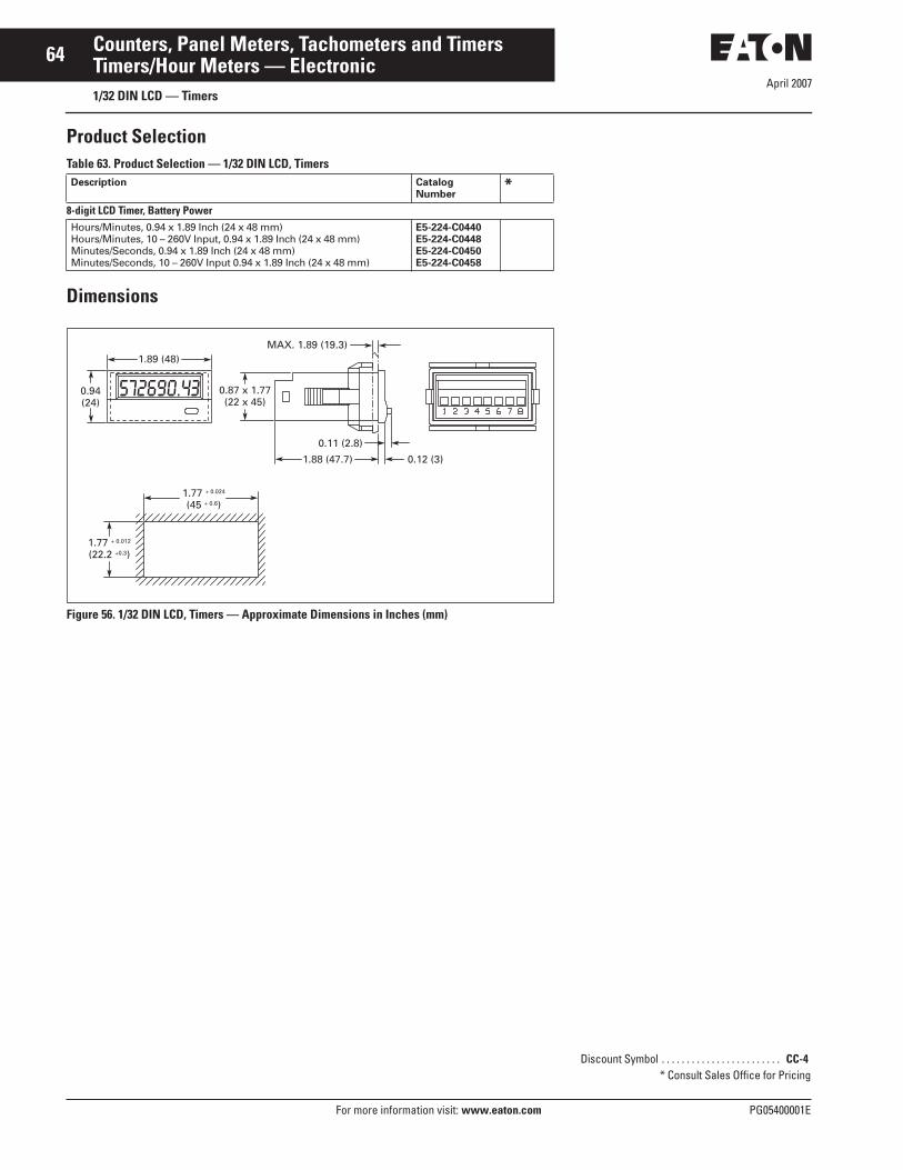
April 2007
64
For more information visit: www.eaton.com PG05400001E
Counters, Panel Meters, Tachometers and TimersTimers/Hour Meters — Electronic1/32 DIN LCD — Timers
Product SelectionTable 63. Product Selection — 1/32 DIN LCD, Timers
Dimensions
Figure 56. 1/32 DIN LCD, Timers — Approximate Dimensions in Inches (mm)
Description CatalogNumber
*8-digit LCD Timer, Battery PowerHours/Minutes, 0.94 x 1.89 Inch (24 x 48 mm)Hours/Minutes, 10 – 260V Input, 0.94 x 1.89 Inch (24 x 48 mm)Minutes/Seconds, 0.94 x 1.89 Inch (24 x 48 mm)Minutes/Seconds, 10 – 260V Input 0.94 x 1.89 Inch (24 x 48 mm)
E5-224-C0440E5-224-C0448E5-224-C0450E5-224-C0458
1.77 + 0.024
(45 + 0.6)
1.77 + 0.012
(22.2 +0.3)
572690.43
1.89 (48)MAX. 1.89 (19.3)
0.11 (2.8)
0.12 (3)1.88 (47.7)
0.87 x 1.77(22 x 45)
0.94(24)
Discount Symbol . . . . . . . . . . . . . . . . . . . . . . . . CC-4* Consult Sales Office for Pricing

April 2007
PG05400001E For more information visit: www.eaton.com
65Counters, Panel Meters, Tachometers and TimersTimers/Hour Meters — ElectronicE42DI24/E42DIR Series — Durant®
Features■ Solid-state hour meters■ Record and display up to 99,999.9
hours, rollover and continue timing■ EEPROM memory can retain data
for 25+ years■ Time accumulation indicated by
flashing hourglass icon■ Memory will arm only when power
has been applied for 5 seconds
Standards and Certifications■ UL recognized■ CE compliant
Technical Data and Specifications■ Function: Solid-state hour meter■ Power Supply —
❑ E42DIXX1260X:12 – 48V DC ±25%/20 – 60V AC ±25%
❑ E42DIXX48230X:48 – 150V DC +23% -25%/100 – 230V AC +17% -25%
■ Frequency Range: 48 – 440 Hz■ Display: 6-digit LCD, 0.20" (5 mm)■ Accuracy: ±0.1%■ Recording/Display Capacity:
99,999.9 hours■ Resolution: 0.1 hour (6 minutes)■ Current Consumption Max. @
Nominal Voltage❑ E42DIXX1260X:
0.8 mA @ 12V DC5.0 mA @ 48V DC0.5 mA @ 20V AC2.5 mA @ 60V AC
❑ E42DIXX48230X:0.8 mA @ 48V DC2.5 mA @ 150V DC0.9 mA @ 100V AC2.0 mA @ 230V AC
Cat. No. E42DIR
Cat. No. E42DI24
■ Input Impedance Minimum (Pins 3 and 4) —❑ E42DIXX1260X: 70k ohms❑ E42DIXX48230X: 480k ohms
■ Operating Temperature: -40 to 185°F (-40 to 85°C)
■ Storage Temperature: -58 to 194°F(-50 to 90°C)
■ Weight —❑ E42DIRXXXXXX: 1.94 oz (55 g)❑ E42DI24XXXXXX: 0.78 oz (22 g)
Product SelectionTable 64. Product Selection — E42DI24/E42DIR Series Elapsed Time Meters
Dimensions
Figure 57. E42DI24/E42DIR Series — Approximate Dimensions in Inches (mm)
Description CatalogNumber
*Round LCDElapsed Hour Meter, 48 – 150V DC/100 – 230V ACElapsed Hour Meter w/Reset, 48 – 150V DC/100 – 230V ACElapsed Hour Meter, 12 – 48V DC/20 – 60V AC
E42DIR48230E42DIR48230RE42DIR1260
Rectangular LCDElapsed Hour Meter, 48 – 150V DC/100 – 230V ACElapsed Hour Meter, w/Reset, 48 – 150V DC/100 – 230V ACElapsed Hour Meter, 12 – 48V DC/20 – 60V AC
E42DI2448230E42DI2448230RE42DI241260
1.40(35.6)
0.89(22.6)
1.22(31.1)
1.75(44.5)2.00
(53.1)
Dia. 2.30(58.4) Max.
Dia. 2.06(52.3) Max.
U Clamp for0.03 – 0.25 (7.6 – 6.4)
Panel Thickness
Black Bezel
Washer
Thumbnut 0.16 (4.0)
Terminal 0.25(6.4) Max.
0.52 (13.2)Max.
1.13(28.7)0.06
(1.5)
Terminal0.25 (6.4)
0.93 (23.6)0.95 +0.01
-0.00
(24.1 +0.25-0.00)
1.45 +0.01-0.00
(36.8 +0.25-0.00)0.71
(18)
0.18(4.7)
0.35 (8.9)Max.
1.13 (28.6)Max.
HOURS
Durant 1/10
HOURS
Durant
QUARTZ
1—10
Discount Symbol . . . . . . . . . . . . . . . . . . . . . . . . CC-4* Consult Sales Office for Pricing

April 2007
66
For more information visit: www.eaton.com PG05400001E
Counters, Panel Meters, Tachometers and TimersTimers/Hour Meters — Electromechanical1/16th DIN Hour Meters — Eaton
Features■ High shock resistance■ Without reset■ Small dimension■ Magnified figures■ Protection IP65■ Data retention if power is lost■ Long service life■ Optional mounting position
Applications■ General elapsed time■ Service interval for measurement
systems —❑ Respiratory ventilators❑ Oxygen machines❑ Dialysis machines
■ Small appliances■ UV lamps■ Display panels in cars
Standards and Certifications■ UL Recognized
Technical Data and Specifications■ Electrical Connection: Clamp
terminal for cable diameter up to 14 AWG (2.5 mm2), tightening torque max. 0.59 lb-ft (0.8 Nm)
■ Power Consumption —❑ 10 – 30V DC: Approx. 500 mW❑ 100 – 130V DC: Approx. 750 mW
■ Rated Voltages❑ 100 – 130V AC, 50 or 60 Hz❑ 10 – 30V DC
■ On Time: 100%■ Display —
❑ 7 at AC: 99999.99❑ 8 at DC: 999999.99
■ Accuracy —❑ AC: Supply frequency + 30 mS❑ DC: <0.003% (24 h)
■ Count Mode: Adding
Cat. No. 7-T-65-4848PM-406
■ Height of Figures: 0.16 Inch (4 mm)■ Color of Figures: White and Red-on-
Black■ Ambient Temperature: 5 to 122°F
(-15 to 50°C)■ Mounting Position: Any■ Protection: IP65■ Housing: Plastic■ Weight: 1.7 oz (48 g)■ Operating Indicator of the Running
Time Meter —❑ AC: Fast rotating wheel with red
dashes❑ DC: 1/100 h display turns
continuously by 1-digit in 36 sec.■ Test voltage: 2000V AC, 50 Hz for AC
counters■ Options: Further voltages on
request■ Color of Housing: Gray
Product SelectionTable 65. Product Selection — 1/16th DIN Hour Meters
Accessory
Figure 58. DIN Rail Adapter — Approximate Dimensions in Inches (mm)
Table 66. Product Selection — DIN Rail Adapter
Dimensions
Figure 59. 1/16th DIN Hour Meters — Approximate Dimensions in Inches (mm)
Description CatalogNumber
*Electromechanical Hour Meters
10 – 30V DC, 1.89 x 1.89 Inch (48 x 48 mm)10 – 30V DC, 1.89 x 1.89 Inch (48 x 48 mm), 50 pc. package
8-T-65-4848PM-4028-T-65-4848PM-40284
100 – 130V AC, 1.89 x 1.89 Inch (48 x 48 mm)100 – 130V AC, 1.89 x 1.89 Inch (48 x 48 mm), 50 pc. package
7-T-65-4848PM-4067-T-65-4848PM-40684
Cat. No. T4848DINADAPT
2.42(61.5)
1.91(48.5)
0.75(19)
1.62(41.1)
Description CatalogNumber
*
DIN Rail Adapter for DIN Electromechanical Hour Meter T4848DINADAPT
1.10(28)
0.28(7)
0.35 (9)Max.
Dia. 1.97(50)
1.77+0.02 (45+0.6)
SQ.
Panel Cut-Out
1.77 (45) SQ.
ScrewTerminal
1.89 (48) SQ.
Discount Symbol . . . . . . . . . . . . . . . . . . . . . . . . CC-2* Consult Sales Office for Pricing

April 2007
PG05400001E For more information visit: www.eaton.com
67Counters, Panel Meters, Tachometers and TimersTimers/Hour Meters — Electromechanical71.1 Round Hour Meters — Eaton
Features■ 6-digit hour meter for round panel
cut-out■ Low cost■ High shock resistance■ Low power consumption■ Small dimension■ Magnified figures■ Waterproof■ Protection IP65■ Data retention if power is lost■ Available in 50 pc. bulk package
Applications■ General elapsed time■ Utility vehicles■ Construction machines■ Generators■ Fork-lift trucks■ Car washes■ Outside areas
Cat. No. 6-T-3H-508RPM-406
Technical Data and Specifications■ Electrical Connection: Flat pins
0.8 x 6.3■ Power Consumption —
❑ AC: Max., 0.4 VA❑ 12V DC: Max., 0.08W❑ 48V DC: Max., 0.7W
■ Rated Voltages: 115V AC ±10%, 50/60 Hz, 10 – 80V DC
■ On Time: 100%■ Display: 6-digits, 99999.9 h
■ Count Mode: Adding■ Height of Figures: 0.14 Inch
(3.5 mm)■ Reset: None■ Ambient Temperature: -22 to 149°F
(-30 to 65°C)■ Mounting Position: Any■ Protection: IP65■ Housing: Plastic■ Error: <0.02% over the full range
Product SelectionTable 67. Product Selection — 71.1 Round Hour Meters
Dimensions
Figure 60. 71.1 Round Hour Meters — Approximate Dimensions in Inches (mm)
Description CatalogNumber
*Electric Hour Meters115V AC, 2.80 Inch (71.1 mm) Round115V AC, 2.80 Inch (71.1 mm) Round — 50-piece Package
6-T-3H-508RPM-4066-T-3H-508RPM-40684
10 – 80V DC, 2.80 Inch (71.1 mm) Round10 – 80V DC, 2.80 Inch (71.1 mm) Round — 50-piece Package
6-T-3H-508RPM-4026-T-3H-508RPM-40284
0.21(5.3)
1.26(32)
0.47(12)
1.68(42.7)
0.03 x 0.25(0.8 x 6.3)
Dia. 2(50.8)
Dia. 2(50.8)
120°Dia. 0.15
(3.8)
Dia.0.13(3.3)
Dia. 2.80(71.1)
Dia. 2.44(62)
Dia. 2.54(64.5)
Panel Cut-Out
Discount Symbol . . . . . . . . . . . . . . . . . . . . . . . . CC-2* Consult Sales Office for Pricing

April 2007
68
For more information visit: www.eaton.com PG05400001E
Counters, Panel Meters, Tachometers and TimersTime ControlsBattery-Powered LCD Time Control, 48 x 48 mm — Eaton
Features■ No external voltage supply, because
of internal replaceable lithium battery
■ High contrast, 2-line LCD display, 5-digit with many symbols for easy operation and reading
■ 9 programmable time ranges from 0.20 seconds up to 99.999 hours
■ Resolution up to 0.01 seconds■ Inputs for start and reset; universal
inputs for 12 – 260V AC/DC■ 8 timing modes —
❑ ON Delay, OFF Delay, One Shot and Single Shot
❑ Repeat cycle modes: Delay, Cycle, Symmetrical delay
■ 3 programmable activation modes■ Relay contacts rated at 8A
programmable to NO or NC■ Protection IP65■ Plug-in connector
Standards and Certifications■ CE Marked
Cat. No. E5-248-C1420
Technical Data and Specifications■ Voltage Supply: 2 x 3V, 1/2AA
replaceable lithium battery, service life > 10 years or 500,000 relay charges
■ Timing and Reset Inputs: 12 – 260V AC/DC, impedance 180 k , min. impulse 20 mS (optocoupler)
■ Display — ❑ Time: 5-digit LCD display, 0.26
Inch (6.5 mm) high❑ Set Time Mode: 5-digit LCD
display, 0.14 Inch (3.5 mm) high■ Accuracy: +50/-20 mS respectively
0.5% of setting time (higher value counts)
■ 0.3% of setting time■ Operating Temperature: 14 to 122°F
(-10 to 50°C)■ Storage Temperature: -4 to 158°F
(-20 to 70°C)■ Relative Humidity: 80% max. up to
89°F (31°C); decreasing to max., 50% to 104°F (40°C)
■ Protection: IP65 with delivered seal
■ Output Relays — ❑ Contact connection: SPTST volt-
age free contacts programmable as NO or NC
❑ Contact rating: 250V AC at 8A; cos ø = 1250V AC at 5A; cos ø = 0.4
30V DC at 8A; cos ø = 1■ Reaction Time: < 20 mS■ Expected Life: 2A ohm’s load
1,000,000 switching cycles■ EMC: CE-conform to EC-guideline
89/36/EWG■ Electromagnetic Radiation:
EN 61000-6-4/EN 55011 Class B■ Electromagnetic Immunity:
EN 61-000-6-2■ Weight: Approx. 2.8 oz (80 g)■ Time Ranges —
❑ 1 – 99999 sec; 0.2 - 9999.9 sec; 0.02 – 999.99 sec
❑ 1 – 99999 min; 0.1 - 9999.9 min; 0.01 – 999.99 min
❑ 1 – 99999 hour; 0.1 – 9999.9 hour; 0.01 – 999.99 hour
Timing Modes
Figure 61. Timing Modes
Relay
Single Shot
Start
Relay
Reset
One Shot
Start
Relay
Reset
Reset
OFF Delay
Start
Relay
Level Trig Edge Trig Edge Retrig
ON Delay
Start
ttt
pwt
pwt
pwtt
t t t
t
tttt
pw
tt
Repeat Cycle Symmetrical
Start
Relay
Reset
Reset
Repeat Cycle Symmetrical DelayStart
Relay
Reset
Repeat Cycle
Start
Relay
Level Trig Edge Trig Edge Retrig
Repeat Cycle Delay
Start
=t =t =t =t =t =t=t
=t =t =t =t =t =t =t =t
t+t-t+t+
t-t+t-t+
t+ t- t+ t- t+ t+ t- t+

PG05400001E For more information visit: www.eaton.com
69Counters, Panel Meters, Tachometers and Timers
April 2007Time ControlsBattery Powered LCD Time Control, 48 x 48 mm — Eaton
Product SelectionTable 68. Product Selection — Battery-Powered Time Control
Dimensions
Figure 62. Battery-Powered LCD Time Control, 48 x 48 mm — Approximate Dimensions in Inches (mm)Note: Panel Cut-Out is 177 + 0.02 Inch Sq. (45 +0.6 mm Sq.).
Description CatalogNumber
*Battery-Powered LCD Time Control, 1.89 x 1.89 Inch (48 x 48 mm)
E5-248-C1420
1.89(48)
1.89(48)
1.77(45)
0.63(16)
2.49(63.2)
0.12(3)
0.41 (10.5) Max.;0.37 (9.5)
at Front Panel
Discount Symbol . . . . . . . . . . . . . . . . . . . . . . . . CC-1* Consult Sales Office for Pricing

April 2007
70
For more information visit: www.eaton.com PG05400001E
Counters, Panel Meters, Tachometers and TimersTime ControlsE42DP55 Battery Powered, DIN Rail Mounted
Features■ Digital time control with 8 timing
modes■ Battery powered — 1 million
operations or 10 years■ Battery included■ DIN Rail mounted■ 0.2 Seconds to 999.99 hours■ Easy-to-read LCD display with mode
annunciators
Technical Data and SpecificationsOperating Modes■ ON Delay■ OFF Delay■ Cycle One-Shot■ Single-Shot■ Repeat Cycle Delay■ Repeat Cycle■ Repeat Cycle Delay =■ Repeat Cycle =
Time Setting Ranges■ 1 – 999, 1 – 99.9 sec.■ 1 – 999, 0.1 – 99.9, 0.01 – 9.99 min.■ 1 – 999, 0.1 – 99.9, 0.01 – 9.99 hrs.
Cat. No. E42DP55
Display■ 2 rows of 3 digits, black on silver
LCD■ Upper row 0.275" (7 mm) indicates
time■ Lower row 0.157" (4 mm) indicates
set point
Power Supply■ Two 1/2AA 3V lithium batteries■ 10 year expected life (the built-in
batteries are sealed for life and are not replaceable
Timing Input■ 12 – 260V opto-isolated inputs■ Selectable sink (NPN) or source
(PNP) if using DC input device■ Input Impedance: 220k ohm■ Level or edge triggered■ Minimum pulse width of 20 mS
Output Relays■ Contacts: SPDT voltage free
contacts■ Contact Rating: 10A 380V or 220V■ Power Rating: 2000VA/150W■ Reaction Time: <20 mS■ Mechanical Life: 10,000,000
operations■ Electrical Life —
❑ 100,000 operations @ 8A (resistive load)
❑ 1,000,000 operations @ 2A (resistive load)
Repeat Accuracy■ 0.3% of set time
Setting Accuracy■ +50 -20 mS or 0.5% of set time
(whichever is greater)
Temperature —■ Operating: 14 to 140°F (-10 to 60°C)■ Storage: -4 to 158°F (-20 to 70°C)
Product SelectionTable 69. Product Selection — E42DP55 Battery-Powered Time Control
Dimensions
Figure 63. E42DP55 Time Control — Approximate Dimensions in Inches (mm)Note: The E42DP55 is designed to snap mount to any standard 35 mm DIN Rail.
Description CatalogNumber
*Battery-Powered Time Control, DIN Rail Mounted E42DP55
3.94(100.0)
3.40(86.3)
0.89(22.5)
Discount Symbol . . . . . . . . . . . . . . . . . . . . . . . . CC-4* Consult Sales Office for Pricing

April 2007
PG05400001E For more information visit: www.eaton.com
71Counters, Panel Meters, Tachometers and TimersFlow Totalizers, Transmitters and ControlsProduct Family Overview
IntroductionFlow products are used in a variety of applications where liquid gas flow needs to be monitored or controlled. Eaton offers models for flow total, flow rate and flow batch control. Several optional outputs allow great flexibility to meet most application needs.
Application Example In many processes, it is desirable to know both the total quantity of product being produced and the rate at which the product is being produced.
In the illustration at right, the output of a turbine flow sensor is connected to a totalizer/ratemeter. The flow sensor produces a known number of pulses per gallon (or other unit of measure). The instrument scales these pulses into the desired units of flow volume (gallons, liters, barrels, etc.), and flow rate (gallons/minute, barrels/hour, etc.).
Flow Totalizers/Controls Product Family OverviewTable 70. Product Family Overview
RSTT / R Durant ®
Liquid
Application Example
53300-405Totalizer/Ratemeter
Flow Sensor
Product Family Characteristics Typical Applications Panel Cutoutin Inches (mm)
PageNumber
■ Replaceable lithium battery■ 8-digit, high-visibility LCD display■ Optional backlighting■ Various input options available
■ Portable/mobile/remote flow monitoring (e.g. sewer pumping, pesticide application)
1.299 x 2.677(33 x 68)
25
■ 6-digit, super bright LED display■ Multiple models available: totalizers,
ratemeters, count controls, digital panel meters and flow controls
■ Length measurement and control■ Flow monitoring and control■ Process monitoring and display■ Voltage and current monitoring and display
1.772 x 1.622(45 x 92)
72
Courier
Eclipse

April 2007
72
For more information visit: www.eaton.com PG05400001E
Counters, Panel Meters, Tachometers and TimersFlow Totalizers, Transmitters and ControlsEclipse Series — Durant®
Features■ 6- or 10-digit display■ 1/8 DIN Size■ Red, LED display■ 0.56" (14 mm) high characters■ Scalable display■ Analog or pulse input versions■ Accessory power output■ 15-point linearization available■ Dual valve pre-warn available■ Optional analog, relay and RS-485
outputs■ NEMA 4X■ Depluggable terminal blocks
Standards and Certifications■ UL and cUL Listed■ CE Marked
Technical Data and SpecificationsInput Power■ AC Powered Models (57751-4XX)
❑ Input Power: 85 – 265V AC, 47 – 63 Hz, 20 VA
❑ External Fuse: 0.2A, 250V AC, Time Delay (T200mA, 250V)
❑ Isolation Dielectric Strength: 2300V AC
■ DC Powered Models (57750-4XX)❑ Input Power: 9 – 30V DC, 12 VA ❑ External Fuse: 2.0A, 50V DC, Time
Delay (T2A, 50V)❑ Reverse Voltage Protection: Yes❑ Isolation Dielectric Strength:
2300V AC to signal inputs and relays, 500V AC to RS-485 and analog outputs
Human Interface■ Display: 6 digits■ Type: 0.56" high, seven segment,
red LED
Data Retention■ Memory Type: EEPROM, no
batteries required■ Duration: 100 years
Count Signal Input/Count Inhibit Signal Input■ Sensor Type: Sink or source, DIP
switch selectable ■ Input Impedance: 4.75k ohms to
+5V DC or 34.9 k Ohms to ground■ Thresholds —
❑ High 3.5 to 28V DC❑ Low 0 to 1.9V DC, for single
ended signals ■ Magnetic Pickup Range: 50 mV p-p
to 65 VRMS into 34.9 k Ohms ■ Slow Response: 50 Hz max. (DIP
switch 2 and/or 5 ON)■ Flat Response: 10 kHz
Flow Signal Input (Analog Input Models)■ Types: 4 – 20 mA and 0 – 10V DC■ Input Impedance: 100 ohms (current
input), 1.27M ohms (voltage input)■ Overrange: 50 mA max (current
input), 100V max (voltage input)■ Accuracy: ±0.1% of reading, ±1 digit,
and ±80 PPM/°C
Control Inputs■ Sensor Type: Sink only■ Input Impedance: 4.75k ohms to
+5V DC■ Thresholds —
❑ High 3.5 to 28V DC❑ Low 0 to 1.0V DC
■ Response: 25 mS maximum (5V signal)
Accessory Power Output (Pulse Input Models)■ Voltage: 12V DC +10%/-13%■ Current: 75 mA max.■ Protection: Short circuit protected
Accessory Power Output (Analog Input Models)■ Voltage: 24V DC ±10%■ Current: 90 mA max.■ Protection: Short circuit protected
Relay/Transistor Outputs (standard on batch controls, optional on totalizers)■ Number: 2 relays or 1 relay and 1
transistor■ Relay Contact Type: 1 set form C per
relay■ Relay Contact Rating: 5A, 250V AC
or 30V DC■ Transistor Type: NPN, Opto Isolated
■ OFF State Block: 30V DC max., 0.1 mA max. leakage current
■ ON State Conduct: 50 mA max., 1.2V DC max. C-E drop
■ Max. Switching Frequency: 4 kHz (50-50 duty cycle)
■ Isolation dielectric strength: 2300V AC
Optional Outputs■ Analog Retransmission —
❑ Output signals: 4 – 20 mA (<750 ) and 0 – 10V (>2500 )
❑ Accuracy: 0.13% full scale and 100 PPM/°C (and 0.07% full scale change over 4 – 20 mA load ranges
❑ Isolation dielectric strength: 2300V AC to signal inputs, relays and AC power inputs; 500V AC to analog outputs and DC power inputs
■ RS-485 Serial Communications❑ Baud Rate: 1200, 2400, 4800,
9600, or 19,200, programmable❑ Parity: Even, odd or no parity❑ Address Range: 00 to 99 decimal
(00 indicates off line)❑ Protocol: Opto 22® compatible❑ Isolation Dielectric Strength:
2300V AC to signal inputs, relays and AC power inputs; 500V AC to analog outputs and DC power inputs
Environmental■ Operating Environment: Indoor use
to 2000 meters■ Temperature —
❑ Operating: 32 to 122°F (0 to 50°C)❑ Storage: -4 to 158°F (20 to 70°C)❑ Humidity: 0 to 85% RH, non-
condensing■ Vibration: 2.5 Gs, 30 to 200 Hz■ Shock: 30 Gs, 11 mS half sinewave■ EMC —
❑ Immunity to EN 50082-2 (Heavy Industrial)
❑ Emissions to EN 50081-2 (Heavy Industrial)
■ Front Panel: NEMA 4X when mounted with gasket provided
■ Agency Approval — ❑ CE EMC immunity and emissions
requirements were met using shielded wiring on the RS-485, analog output and pulse input/power lines. The shields were connected to earth ground at the Eclipse end of the shields.
■ Pollution Degree 2: Overvoltage Category II
Cat. No. 57750-400

April 2007
PG05400001E For more information visit: www.eaton.com
73Counters, Panel Meters, Tachometers and TimersFlow Totalizers/Transmitters & ControlsEclipse Series — Durant®
Catalog Number SelectionTable 71. Eclipse Flow Model Numbering System
� Output Options 0, 2, 4 are not available for models -41X and -43X.
Dimensions
Figure 64. Eclipse Flow Models — Approximate Dimensions in Inches (mm)
5 7 7 5 X - 4 X X
Power Supply
0 = DC (9 – 30V DC)1 = AC (85 – 265V AC)
Input Option
0 = Pulse InputTotalizer/Ratemeter
1 = Pulse Input Batch Control2 = Analog Input
Totalizer/Ratemeter3 = Analog Input Batch Control
Output Option �
0 = No Option1 = Dual Relays (Standard or Batch)2 = Analog Output (4 – 20 mA
and 0 – 10V)3 = Dual Relays and Analog Output4 = RS-485 Communications5 = Dual Relay and RS-4856 = Analog Output and RS-4857 = Dual Relays, Analog Output
and RS-485A = One Relay, One TransistorB = One Relay, One Transistor,
Analog OutputC = One Relay, One Transistor,
RS-485D = One Relay, One Transistor,
Analog Output and RS-485
PGM
View EditEnter
Start StopReset
PGM
BATCH
Durant®
3.622 ±0 .031 (92.00 ±0.8)
Panel Cutout
4.04(102.6)
3.31(84.1)
3.63(92.2)
0.27(6.9)
2.19(55.6) 1.772 ±0.02
(45 ±0.6)
Max. Panel Thickness0.190 (4.83)
Discount Symbol . . . . . . . . . . . . . . . . . . . . . . . . CC-1* Consult Sales Office for Pricing
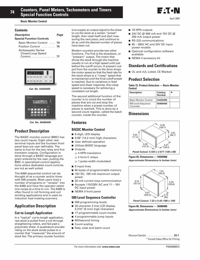
April 2007
74
For more information visit: www.eaton.com PG05400001E
Counters, Panel Meters, Tachometers and TimersSpecial Function ControlsBasic Monitor Control
ContentsDescription Page
Special Function Controls
Basic Monitor Control . . . . 74
Position Control . . . . . . . . . 75
Ambassador Series Closed-Loop Speed Control . . . . . . . . . . . . . . . . 77
Product DescriptionThe BASIC monitor control (BMC) has two count inputs. Eight other rear terminal inputs and the fourteen front panel keys are user definable. The same is true for the two relay and five transistor outputs. Configuration is done through a BASIC language pro-gram entered by the user, putting the BMC in specialized control applica-tions where dedicated count controls are not as well suited.
The 6460 sequential control can be thought of as a counter and/or timer with 500 presets. Most users load a number of programs or “recipes” into the 6460 and have the operator select one recipe at a time to run. The 6460 is often found in roll forming and coil winding applications and is used on induction heat treating scanners.
Application Description
Cut-to-Length ApplicationIn a “typical” cut-to-length application, raw stock is pulled from a coil through straightening rollers, and fed past a pneumatic shear. A quadrature encoder riding on the stock sends pulses to a counter that “measures” the amount of stock fed. The primary counter function
Cat. No. 54420400
Cat. No. 56460400
is to supply an output signal to the shear to cut the stock at a certain “preset” length, then reset itself and start mea-suring the next piece, and continue to do so until the desired number of pieces have been cut.
Modern counters provide two other functions. The first is the slowdown, or “prewarn” output. The motor that drives the stock through the machine usually is run at a high speed until just before the cutoff occurs. A prewarn out-put from the counter to the drive drops the motor speed so that the feed rate for the stock slows to a “creep” speed that is maintained until the final cutoff preset is reached. Due to variations in feed speed and shear response, this creep speed is necessary for achieving a consistent cut length.
The second additional function of the counter is to count the number of pieces that are cut and stop the machine when a preset number of pieces is reached. This is done by a second count register, called the batch counter, inside the counter.
Features
BASIC Monitor Control■ 6-digit, LED display■ 0.56" (14.2 mm) high characters■ User defined operation■ Utilizes BASIC language■ Outputs
❑ 4 NPN transistors❑ 2 form-C relays❑ 1 pulse-width modulated
■ 8 input lines■ 8k bytes of programmable memory■ 15V DC, 100 mA maximum output
power■ 20 mA current loop communication■ Accepts 115/230V AC and 11 – 16V
DC input power■ NEMA 4 front panel
500 Level Sequence Controller■ 500 programming levels■ 32-character 2 line LCD display
0.315" (8 mm) high characters■ 17 programmable count modes■ 4 programmable jump inputs■ Millisecond timing■ Count scaling■ Rate, total and batch count
■ 16 NPN outputs■ 24V DC @ 800 mA and 15V DC @
200 mA output power■ RS-232 communications■ 85 – 265V AC and 24V DC input
power models■ Optional configuration software
available■ NEMA 4 accessory kit
Standards and Certifications■ UL and cUL Listed, CE Marked
Product SelectionTable 72. Product Selection — Basic Monitor Control
Dimensions
Figure 65. Dimensions — 54420400Approximate Dimensions in Inches (mm)
Figure 66. Dimensions — 56460400Approximate Dimensions in Inches (mm)
Description CatalogNumber
*
Basic Monitor Control 54420400
500 Level Sequence Controller
56460400
Discount Symbol . . . . . . . . . . . . . . . . . . . . . . . . CC-1* Consult Sales Office for Pricing
3.04(77.2)
5.80(147.3)
5.38(136.7)
2.62(66.7)
5.91(150.1)
Panel Cutout: 5.433 x 2.677 (138 x 68)
5.35(135.9)
6.18(157.0)
3.74(95)
7.24(183.9)
8.07(205.0)
Panel Cutout: 7.32 x 5.43 (186 x 138)

April 2007
PG05400001E For more information visit: www.eaton.com
75Counters, Panel Meters, Tachometers and TimersSpecial Function ControlsPosition Control
Product DescriptionThe 58868400 closed-loop position control provides digital output signals (run, direction and fast/slow) to a drive to cause a motor-driven tool to be positioned along a single axis. These signals can also be used to control val-ues in a hydraulic positioning system. Typically, a quadrature encoder, cou-pled to the drive mechanism, provides the feedback signal to the position control. Up to five destinations can be automatically sequenced through in a move-and-dwell process, or the opera-tor can select a single destination for move-and-stop positioning.
Features■ 6-digit, LED display, 14 mm (0.56")
high characters■ 4 move registers plus home■ 2 Form C relays and 5 NPN
transistor outputs■ 28 kHz count speed■ 5 dwell time settings■ 15V DC @ 100 mA power output■ Manual or automatic operation■ Programmable offset, prewarn and
kerf values■ Backlash compensation■ Programmable high/low limits■ 20 mA current loop communications■ NEMA 4X front panel
Standards and Certifications■ UL Listed
Cat. No. 58868400
Technical Data and SpecificationsPower Input■ AC Operation: 120/240V AC
± 10%, -20%), 47 to 63 Hz■ DC Operation: 11 to 16V DC
(0.7 Amp max.)■ Power Consumption: 18 Watts
maximum
DC Power Output■ 15V DC (+1, -2), 100 mA maximum
Environment■ Operating Temperature: 32 to 130°F
(0 to 55°C)■ Storage Temperature: -40 to 160°F
(-40 to 71°C)■ Operating Humidity: 85% relative,
non-condensing.■ NEMA 4 rating when mounted with
gasket provided
Control Input Response■ Start/Stop: 1 mS■ Go home input: 5 mS■ Load Position: 5 mS■ Reference Input: 1.7 mS
Input Voltage■ Count Inputs —
❑ High: 10.5 to 24.5V DC❑ Low: 0 to 4.5V DC
■ Control Inputs — ❑ High: 3.8 to 15.0V DC❑ Low: 0 to 1.2V DC
Input Impedances■ Count Inputs: 6.8 k to +15V DC
(2.2 mA at 0V DC)■ Control Inputs: 2.2 k to +5V DC
(2.3 mA at 0V DC)
Relay Outputs (2) ■ Type: Form C contacts■ Load Voltage: up to 240V AC or
280V DC■ Load Current: 5A resistive, 1.5A at
80% PF
Transistor Outputs (5) ■ Type: NPN open collector with surge
protection■ Load Voltage: 30V DC maximum■ Load Current: 300 mA maximum■ Saturation: 1.5V max. @ 300 mA■ Latency: 150 + 5 μS/1 kHz input
speed ± 10 μS
Communication■ Type: 20 mA loop (active transmit,
passive receive)■ Speed: 110, 300 or 1200 Baud■ Parity: Odd, even, space■ Format: 1 start bit, 7 data bits
(ASCII), 1 parity bit, 1 stop bit (110 baud uses 2 stop bits)
■ Load Voltage: 30V DC maximum■ Load Current: 300 mA maximum■ Saturation: 1.5V max. @ 300 mA■ Latency: 150 + 5 μS/1 kHz input
speed ± 10
Input Frequency■ The maximum input frequency only
on the selected quadrature operation
Quadrature Selection
Note: Only function 60 and the double jumper affect the maximum input speed. The scale factor does not affect the input speed.
Position Control Features■ Setpoints: Four move setpoints plus
one home setpoint■ Range for all setpoints is -99999 to
999999■ Decimal Point: Four positions,
programmable■ Dwell Times: Five, one for each
setpoint. Dwell time range is 00.01 to 99.98 seconds.
■ Scale Factor: Scale factor range is 0.00100 to 9.999999.
■ Accuracy: 100% when the position control is operated within the specified speeds and input voltages
X1 X2 X4
High Speed 28 kHz 14 kHz 7 kHz
Low Speed 150 Hz 150 Hz 150 Hz
Low speed jumper installed.

April 2007
76
For more information visit: www.eaton.com PG05400001E
Counters, Panel Meters, Tachometers and TimersSpecial Function ControlsPosition Control
Product SelectionTable 73. Product Selection — Position Control
Dimensions
Figure 67. President Series Position Control — Approximate Dimensions in Inches (mm)
Description CatalogNumber
*
Single-Axis Position Control 58868400
1
6
2
7
3
8
4
9
5
0
+ / -DWELL
POSITION
RUN
MOVE
DWELL
Durant
STARTSTOP
FUNCTION
RECALL FAST JOG+
MOVE
JOG- POSITION
HOME
ENTER
5.80(147.3)
5.38(137)
5.91(150)
Panel mounting clip fits into foursquare holes in side of counter.
Recommended Panel Cutout: 5.43 W x 2.68 H (137.9 x 68.1)
GasketsPt. #28720-216 (Standard)Pt. #28720-217
Panel
Note:
Spacer Kit Pt. #38820-400
1 gasket standard.2nd gasket andspacer optional.Use of optionalspacer and gasketreduces unit depthfrom 5.91 (150)to 5.38 (137.3).
Spacer
CounterFrontBezel
3.04(77.2)
2.62(66.7)
19 20+
21 22 23 24 25 26 27 28 29 30 31 32 33 34 35 36
1 2 3 4
K1
K1NO C NO AC INPUTS NC C NO
K2
K2
IN1 IN25 6 7 8 9 10 11 12 13 14 15 16 17 18588904
Discount Symbol . . . . . . . . . . . . . . . . . . . . . . . . CC-1* Consult Sales Office for Pricing

April 2007
PG05400001E For more information visit: www.eaton.com
77Counters, Panel Meters, Tachometers and TimersSpecial Function ControlsAmbassador Series Closed-Loop Speed Control
Product DescriptionThe Ambassador speed control pro-vides a tightly regulated, isolated, 0 – 10V speed reference signal to a drive. It is most often used in follower mode applications, such as conveyor speed matching/mis-matching, cable produc-tion lay control, cable take-up reel tra-versing mechanism speed control and many others. In master mode, it is most commonly used for constant web speed take-up roll control, where the increasing roll diameter requires constant motor slowing over the course of filling a roll. Also, where feedback scaling and presets are required in units other than RPM or Hz. For instance, using a flowmeter as the feedback sensor, control the speed of a motor-driven pump in units of gallons/minute.
The two preset version offers addi-tional features, such as reversing, and remote preset adjustments by “bump-ing” external pushbuttons.
Features■ 2-line, 16-character, alphanumeric,
high visibility, LCD backlit, 7.5 mm [0.3"] high character display
■ 1 or 2 speed presets■ Isolated 1 – 10V DC analog out■ Selectable master/slave/jog modes■ Proportional integral error
correction■ 35 kHz frequency inputs■ ±0.015% speed regulation■ 12V DC @ 125 mA power output■ 12-Bit DAC resolution■ RS-485 serial communications■ NEMA 4X front panel
Standards and Certifications■ UL Listed
Cat. No. 57401400
Technical Data and SpecificationsPower Input■ 57401-40X: 115V AC (±15%) std.,
50 to 60 Hz, 0.2A■ 57402-40X: 230V AC (±15%) opt.,
50 to 60 Hz, 0. 1A
DC Power Output■ 12V DC (±10%), 125 mA maximum
(includes all line and load variations)
Environment■ Operating Temperature: 32 to 131°F
(0 to 55°C).■ Storage Temperature: -4 to 158°F
(-20 to 70°C).■ Operating Humidity: 85% Relative,
non-condensing■ NEMA 4X rated when mounted with
gasket provided
Speed Regulation (Closed Loop)■ Accuracy: ±0.015%■ Update Time: 5 mS
Frequency Inputs■ Current Sinking —
❑ Impedance: 4.75K❑ Voltage Maximum: 24V DC❑ High threshold: 3.5V DC❑ Low threshold: 1.9V DC❑ Pulse Rate: 1 Hz – 35 kHz
■ Magnetic — ❑ Impedance: 16 k min.❑ Voltage —
– Maximum: 65V AC rms– Maximum: 200 mV p-p
❑ Pulse Rate: 1 Hz – 35 kHz
Control Inputs■ Impedance: 4.75k ohms to +5V DC■ Voltage —
❑ High: +3.7 to +24V DC❑ Low: 0.0 to 0.9V DC
■ Response: 40 Hz maximum
Control Outputs■ Type: NPN open-collector with
transient protection■ Max. Voltage (OFF state): 30V DC■ Max. Current (ON state): 200 mA at
1.3V DC
Drive Signal■ Separate power supply with 1500V
AC isolation❑ 5740X-400:
– Resolution: 12 bits– Full Scale Voltage: 10V DC
minimum into 5 mA❑ 5740X-401:
– Resolution: 12 bits– Full Scale Voltage: ±10V DC
minimum into 5 mA; Drive Reference potentiometer allows full scale voltage to be reduced to less than ±3V DC
Communication■ Type: RS-485■ Format: 1 start bit, 1 parity bit, 1
stop bit, seven-bit ASC I I characters■ Protocol: Opto-22 compatible■ Speed: 300, 1200, 2400, 4800, 9600
and 19200 baud■ Parity: None
Connections■ Type: Unpluggable screw terminal
strips■ Conductor Size: 14 – 22 AWG
(2.1 – 0.38 mm2) 600V solid, stranded or fused (preferred)

April 2007
78
For more information visit: www.eaton.com PG05400001E
Counters, Panel Meters, Tachometers and TimersSpecial Function ControlsAmbassador Series Closed-Loop Speed Control
Product SelectionTable 74. Product Selection — Closed Loop Speed Control
Dimensions
Figure 68. Closed Loop Speed Control — Approximate Dimensions in Inches (mm)
Description CatalogNumber
*
1 Preset, 115V AC2 Presets, 115V AC
5740140057401401
1 Preset, 230V AC2 Presets, 230V AC
5740240057402401
1
12
23456789
1011
34
23
33323130292827262524
13141516171819202122
2.946 ±0.015(74.83 ±0.38)
SPEED250 F/M
2.946 ±0.015(74.8 ±0.38)
2.677 ±0.028(68.00 ±0.70)
2.677 ±0.028(68.00 ±0.70)
Panel CutoutMax. PanelThickness0.50 (12.7)
5.60 ±0.03(142.24 ±0.76)
PGM
CLR
VIEW
ADJ
STEP
•
EXIT ENT SEL
Gasket
Discount Symbol . . . . . . . . . . . . . . . . . . . . . . . . CC-1* Consult Sales Office for Pricing

April 2007
PG05400001E For more information visit: www.eaton.com
79Counters, Panel Meters, Tachometers and TimersFusion® Integrated Machine ControlFeatures and Benefits
Product DescriptionThe Fusion Integrated Machine Con-trol has advanced features, including a five-preset high speed counter with prewarn, a totalizer with preset, a batch counter with preset and a rate-meter with high and low setpoints. Unique to the count control world, the Fusion has five output relays (rather than two), along with two transistors and two analog setpoint or follower outputs. Its ten available parameter sets of pre-loaded values are useful as recipes, for job-stacking or for a vari-ety of application-specific purposes.
The Fusion has a multi-line alphanu-meric display which can be pro-grammed to show text messages, logic-generated prompts, alarms and machine status. Up to eight screens can be shown or optionally locked out. Count and time presets can be made view-only or editable. Preset entry is achieved with simple 0-9 keys on the front panel rather than complicated scrolling methods. The Fusion’s real time clock/calendar may be displayed and/or used to time and date stamp printouts.
With its ladder logic, the Fusion is actually a 26 I/O controller, making it a complete control for many machines and processes, integrating the func-tions of external timers, pushbuttons, power supplies, indicating lights, con-trol relays and other components in the same box.
Cat. No. 57550400
Features■ User-configurable operator interface
with back-lit LCD display and 18-button tactile feedback keypad
■ High speed counter with 5 presets and prewarn, totalizer, batch counter and ratemeter
■ 10 parameter sets■ 13 digital inputs■ (2) 4 – 20 mA inputs
■ (2) 0 – 10V input■ (3) Form C, 2 Form A, 2 NPN
transistor, (1) 4 – 20 mA, & (1) 0 – 10V outputs
■ RS-232 and RS-485 serial communications
■ 100-line ladder logic processor for ultimate flexibility
■ Configuration software included■ NEMA 4X enclosure
Table 75. Features and Benefits Feature Customer Benefit
High speed count functions; including scaling, main counter, five presets, prewarn, totalizer, batch and rate
“Canned” count functions offer flexibility and ease of setup in the desired units of measure.
High speed counting independent of ladder scan time
Precise and repeatable output response for high performance applications.
Flexible display with selectable character sizes (large, medium, small), run screens and ladder triggered messages.
Minimizes confusion and operator errors as information can be tailored to what they need and in their language. Maintenance/management data can be separated. Different character sizes allow optimization of information displayed. Machine status information can be displayed allowing operators to take action.
Simple front panel layout and keypad. Four soft keys & six function keys can be used as inputs.
Ease of use for operator. Numeric keypad allows for ease of preset and machine parameter entry. Function keys and soft keys allow easy and quick access to information and/or parameters needed by the operator and don’t require using additional inputs. Eliminates cost associated with external pushbuttons and inputs.
Parameter sets Allows for predefined recipes/jobs to be preloaded for the operator. Simplifies operator interaction and minimizes errors.
Programmable relay logic Well understood programming method that allows flexibility in control functionality. Easy to tailor the control to various applications.
26 I/O (digital & analog) Provides application flexibility. Analog inputs allow monitoring key process parameters. Analog outputs allow interfacing to drives and other control products.
Integrated solution Reduced overall control costs, installation and commissioning. More flexible and capable than traditional count/control solutions but less complex than many PLC solutions.
Windows® and front panel programming Ease of programming and configuration control.
RS-232 and RS-485 serial communication ports Allow for direct connection to PC for programming, connection to Modbus® networks, interface to serial printer.
Robust type 4X package. DIN cutout and short depth 2.82 Inches (71.6 mm).
Suited for wet applications. Same cutout as the President Series — easing the migration. Short depth minimizes the cost and size of the machine panel or control enclosure.
Input power: 85 – 265V AC 50/60 Hz or 10 – 30V DC models
Greatly reduces models required for different control voltages.
Output power: 12V DC @75 mA, 24V DC @100 mA
Eliminates the need for an external power supply for encoders, analog transducers, etc.
Depluggable screw terminals Allows for ease of wiring and removal of control. Terminals are different sizes to error-proof installation.
Non-volatile memory and capacitor backed real time clock
Don’t have to worry about a battery failing down the road.
Real time clock Allows for control functions to be performed on day/time and allows for date/time stamping on printouts.
UL, cUL and CE Marked Ease of meeting machine agency requirements and robust EMC performance.

April 2007
80
For more information visit: www.eaton.com PG05400001E
Counters, Panel Meters, Tachometers and TimersFusion® Integrated Machine ControlTechnical Data and Specifications
Standards and Certifications■ UL and cUL Listed; CE Marked
Technical Data and SpecificationsEnvironmental■ Operation: Indoor use to 2000m■ Temperature:
❑ 32 to 122°F (0 to 50°C) operating❑ -4 to 158°F (-20 to 70°C) storage
■ Humidity: 0 to 85% RH, non-condensing
■ Vibration: 2.5 Gs, 30 – 200 Hz■ Shock: 30 Gs, 11 mS half
sinewave■ EMC:
❑ EN61326:1997❑ All I/O lines except RS-485 <30m
■ Front Panel:❑ Type 4X indoor use only, when
mounted with gasket provided■ Safety: UL and cUL Listed, CE
Compliant
Input Power■ AC Model: 85 – 265V AC, 47 – 63 Hz,
20 VA; Isolation 2300V AC■ DC Model: 10 – 30V DC, 15 VA
Inputs■ Control:
❑ Number: 10❑ Impedance: 4.75k Ohms to +5V DC❑ Thresholds:
– High 3.5 – 30V DC– Low 0 – 1.0V DC
■ Counter:❑ Number: 3 (including reset)❑ Impedance: 4.75k Ohms to +5V DC
or 26.9k Ohms to ground❑ Thresholds:
– High 3.5 – 30V– Low 0 – 1.5V, or 200 mV p-p to
50V rms @ 26.9k Ohms (mag pickup)
❑ Response:– 140 Hz or 14 kHz for sinking,
push-pull or mag pickup inputs– 60 Hz or 6 kHz for sourcing only
inputs– All frequencies based on 50-50
duty cycle– 6 kHz maximum sustained
count speed■ Analog:
❑ Number: 4❑ Type: 4 – 20 mA and two 0 – 10V DC❑ Accuracy: ± 0.5% FS and
± 200 PPM/°C❑ Impedance: 100 Ohms (current
input), 1.27M Ohms (voltage input)❑ Overrange: 45 mA max. (current
input), 20V max. (voltage input)
Outputs■ Power (AC input model only):
❑ 24V DC ± 15%, 100 mA max., short circuit protected
❑ 12V DC ± 10%, 75 mA max., short circuit protected
■ Relays:❑ Number: 3 (Form C), 2 (Form A)❑ Contacts: 5A, 250V AC, 30V DC❑ Isolation: 2300V AC
■ Transistors:❑ Number: 2❑ Type: NPN Darlington❑ Ratings: 150 mA max. ON current,
30V DC max. OFF voltage■ Analog:
❑ Number: 2, short circuit protected❑ Type: 4 – 20 mA (<450 Ohms),
0 – 10V (>2500 Ohms)❑ Accuracy: ± 0.5% FS and
± 200 PPM/°C❑ Common Mode Voltage Rating:
250V AC❑ Isolation: 2300V AC
■ RS-232:❑ Connector: DB-9S❑ Polarity: DCE❑ Baud Rate: 1200 – 19200
■ RS-485:❑ Connector: 6 wire RJ-12 phonejack❑ Baud Rate: 1200 – 19200
Data Retention■ Program Data:
❑ Type: Non-volatile❑ Duration: 100 Years, no batteries
■ Real Time Clock:❑ Type: Capacitor❑ Charge Time: 3 Minutes❑ Retention: 1 – 5 Days
Human Interface■ Display:
❑ Type: 128 x 64 pixel graphic LCD with LED backlight
❑ Character Size: – 0.12" (3 mm) high, 21 characters
per line, 6 lines maximum– 0.24" (6 mm) high, 10 characters
per line, 3 lines maximum– 0.35" (9 mm) high, 7 characters
per line, 2 lines maximum■ Keys:
❑ Number: 18❑ Type: membrane switches with
tactile feedback■ Real Time Clock Format: Seconds,
minutes, hours, day and date

April 2007
PG05400001E For more information visit: www.eaton.com
81Counters, Panel Meters, Tachometers and TimersFusion® Integrated Machine ControlProduct Selection
Product SelectionTable 76. Product Selection — Fusion Integrated Machine Control
Dimensions
Figure 69. Fusion Integrated Machine Control — Approximate Dimensions in Inches (mm) Note: Recommended Panel Cutout is 0.375 Inch (9.5 mm) max. panel thickness.
Description CatalogNumber
*
Fusion Integrated Machine Control — 10 – 30V DC PowerFusion Integrated Machine Control — 85 – 265V AC PowerFusion Configuration Software
575504005755140057590400
Durant®
123
xxxx
L1L2
222RUN 3
456789101112131415151617
P/N 57551 400
01
F1
1F2
1F3
1F4
4F5
5F6
6
1 2 3
5
5.33 (135.5)
6.18 (157) 2.50 (63.5)
2.79 (70.8)
5.433±0.039(138±1)
3.42(86.9)
2.57(65.3)
2.677±0.028(68±0.7)
0.38(9.7)
Discount Symbol . . . . . . . . . . . . . . . . . . . . . . . . CC-1* Consult Sales Office for Pricing

April 2007
82
For more information visit: www.eaton.com PG05400001E
Counters, Panel Meters, Tachometers and TimersAccessories and EncodersDIN Rail Adapter
ContentsDescription Page
Accessories
DIN Rail Adapter . . . . . . . . . 82
Vane Pickup Sensor . . . . . . 83
C-Face Ring Tachometer . . . . . . . . . . . . 83
Magnetic Pickup Sensor and Gear . . . . . . . . . . . . . . 83
Rotary Contactor . . . . . . . . . 84
Measuring Wheels . . . . . . . 84
Encoders
Cube Style . . . . . . . . . . . . . . 85
Heavy Duty . . . . . . . . . . . . . 87
Right Angle, Size 20 . . . . . . 89
Features■ For panel-mounting all DIN size
counters, timers and process indicators 0.94 x 1.89 Inch (24 x 48 mm) or 1.97 x 0.98 Inch (50 x 25 mm)
■ Cut-out: 0.98 x 1.97 Inch (25 x 50 mm)■ For snap-on fitting to 35 mm top hat
DIN rails■ Construction —
❑ Mounting panel for counter: Chrome-plated sheet steel
❑ Top hat DIN rail adapter: Glass fiber reinforced polymide
Cat. No. A2448DINADAPT
Product SelectionTable 77. Product Selection — DIN Rail Adapter
Dimensions
Figure 70. DIN Rail Adapter — Approximate Dimensions in Inches (mm)
Description CatalogNumber
*
DIN Rail Adapter for 1/32 DIN Panel Mount Devices A2448DINADAPT
3.98 (101.0)
1.77(45.0)
3.29(83.5)
2.95(75.0)
1.77(45.0)
2.76(70.0)
1.0(25.4)
1.98 (50.4)
Discount Symbol . . . . . . . . . . . . . . . . . . . . . . . . CC-1* Consult Sales Office for Pricing

April 2007
PG05400001E For more information visit: www.eaton.com
83Counters, Panel Meters, Tachometers and TimersAccessories and EncodersAccessories
Vane Pickup Sensor
Features■ 10 – 15V DC input power■ 35 mA current draw■ 10-foot (3m) shielded cable■ Environmentally sealed■ 3000 Hz maximum speed
Table 78. Product Selection — Vane Pickup Sensor
C-Face Ring Tachometer
Features■ 5 – 16V DC input power■ NPN transistor output, 20 mA sinking capacity■ 60 pulses per resolution■ Zero speed pickup■ Variety of motor C-face sizes: 56, 184, 254, 256■ 39 to 225°F (4 to 107°C) operating temperature
Table 79. Product Selection — C-Face Ring Tachometer
Magnetic Pickup Sensor and Gear
Features
Magnetic Pickup■ 0.25" (6.4 mm) diameter■ Ideal for tachometer and rate control applications■ -40 to 298°F (-40 to 148°C) operating temperature■ Output is AC signal, amplitude proportional to speed of
target■ 10-foot (3m) cable attached■ L-Mounting bracket included
30-Tooth Gear Accessory■ 1.6" (41 mm) diameter■ 0.275" (7 mm) bore diameter■ Mounting set screw included
Table 80. Product Selection — Magnetic Pickup Sensor and Gear
Description CatalogNumber
*
Vane Pickup Sensor with 10-foot (3m) Cable 39400400
Description CatalogNumber
*C-Face SensorMotor Size 56C 47007056
Motor Size 143TC, 145TC, 182C, 184C 47007184
Motor Size 184TC, 213C, 215C, 254C 47007215
Cat. No. 39400400
Cat. No. 47007056
Description CatalogNumber
*
Magnetic Pickup 47004400
30-Tooth Gear for Magnetic Pickup 28433400
Discount Symbol . . . . . . . . . . . . . . . . . . . . . . . . CC-3* Consult Sales Office for Pricing
Cat. No. 47004400 and 28433400

April 2007
84
For more information visit: www.eaton.com PG05400001E
Counters, Panel Meters, Tachometers and TimersAccessories and EncodersAccessories
Rotary Contactor
Features■ No power required■ Reed switch output models for electronic counters■ Contact closure output■ Leaf switch output models for electromechanical counters■ 5/16" (7.9 mm) double shaft, 2400 rpm max. at 1:1 ratio■ 12" (304.8 mm) wire leads
Table 81. Product Selection — Rotary Contactor
Measuring Wheels
Features■ For use with shaft encoders and rotary contactors■ 12-inch (304.8 mm) meter circumference■ Urethane, rubber and knurled edges available
Table 82. Product Selection — Measuring Wheels
Description CatalogNumber
*Rotary Contactor12:1 Ratio Reed Switch Output10:1 Ratio Reed Switch Output
3910040039100401
1:1 Ratio Reed Switch Output1:3 Ratio Reed Switch Output1:3.28 Ratio Reed Switch Output1:10 Ratio Reed Switch Output
41100400411004014110040241100403
1:10 Ratio Leaf Switch Output1:1 Ratio Leaf Switch Output1:3 Ratio Leaf Switch Output
408924004089140040892401
Cat. No. 39100400
Description CatalogNumber
*1-Foot Circumference Measuring Wheel5/16" Bore, Urethane Rim3/8" Bore, Urethane Rim
2014430020144303
5/16" Bore, Rubber Rim3/8" Bore, Rubber Rim
2015430020154301
5/16" Bore, Knurled Rim3/8" Bore, Knurled Rim
2015630020156301
Discount Symbol . . . . . . . . . . . . . . . . . . . . . . . . CC-3* Consult Sales Office for Pricing
Measuring Wheel

April 2007
PG05400001E For more information visit: www.eaton.com
85Counters, Panel Meters, Tachometers and TimersAccessories and EncodersShaft Encoders — Cube Style
Features■ 5 – 28V DC input power■ 80 mA current draw■ NPN transistor output, 250 mA
sinking capacity■ Square wave output (50-50 duty
cycle)■ Single channel and quadrature
models■ Up to 600 pulses per revolution■ 3/8" (9.5 mm) double ended shaft■ ABEC 3 double sealed ball bearings■ Tapped holes for face or base
mounting■ Military style connector
Cat. No. 38150600
Technical Data and SpecificationsElectrical■ Input (38150) —
❑ Voltage: 9 to 16V DC❑ Current: 60 mA max. @ 16V DC❑ Ripple: 2%
■ Input (38151) —❑ Voltage: 5 to 28V DC❑ Current: 60 mA nom., 100 mA
max.❑ Ripple: 2%
■ Output —❑ Type: Current sinking transistor
with 1.5 k pull-up– Sinking current: 100 mA max.– Max. voltage @ 100 mA: 1.3V DC– Blocking voltage: 40V DC max.
❑ Polarity: Positive❑ Wave Shape: Square wave❑ Pulse Rate —
– 38150: 1 to 20,000 pulse per second
– 38151: 1 to 10,000 pulse per second
❑ Rise Time: < 1 μS❑ Pulses per Rev.: 1 to 1270❑ Accuracy: Within ± 0.1°
Environmental■ Operating Temperature: 32 to 167°F
(0 to 75°C)■ Vibration: 3 Gs at 5 to 1000 cps■ Shock: 20 Gs, 10 mS
Mechanical■ Shaft Speed: 6000 RPM max.■ Shaft Rotation: CW or CCW■ Bearings: Sealed ball bearings■ Starting Torque: 0.1 oz-in■ Moment of Inertia: 0.0025 ounce
inch-sec2
■ Radial Loading: 50 pounds operating
■ Axial Loading: 10 pounds operating■ Shaft: 3/8" (9.5 mm) dia.■ Operating Life: Up to 100,000 hours,
depending on speed■ Housing: Aluminum with black
anodized finish. Sealed against dust, oil, vapor and moisture.
■ Mounting: Bottom or front face■ Weight: 1 lb. (0.5 kg) max.■ Connector: MS-3102E-14S-6P■ Mating Connector: MS-3106A-14S-6S
with 10' (3m) shielded cable and termination for electronic controls
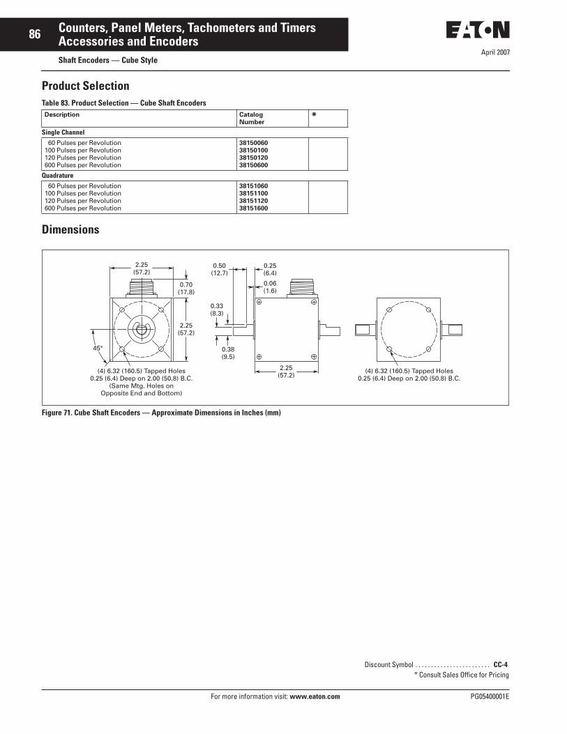
April 2007
86
For more information visit: www.eaton.com PG05400001E
Counters, Panel Meters, Tachometers and TimersAccessories and EncodersShaft Encoders — Cube Style
Product SelectionTable 83. Product Selection — Cube Shaft Encoders
Dimensions
Figure 71. Cube Shaft Encoders — Approximate Dimensions in Inches (mm)
Description CatalogNumber
*Single Channel
60 Pulses per Revolution100 Pulses per Revolution120 Pulses per Revolution600 Pulses per Revolution
38150060381501003815012038150600
Quadrature60 Pulses per Revolution
100 Pulses per Revolution120 Pulses per Revolution600 Pulses per Revolution
38151060381511003815112038151600
0.70(17.8)
0.50(12.7)
0.33(8.3)
0.38(9.5)
2.25(57.2)
(4) 6.32 (160.5) Tapped Holes0.25 (6.4) Deep on 2.00 (50.8) B.C.
(4) 6.32 (160.5) Tapped Holes0.25 (6.4) Deep on 2.00 (50.8) B.C.
(Same Mtg. Holes onOpposite End and Bottom)
0.25(6.4)
0.06(1.6)
2.25(57.2)
45°
2.25(57.2)
Discount Symbol . . . . . . . . . . . . . . . . . . . . . . . . CC-4* Consult Sales Office for Pricing

April 2007
PG05400001E For more information visit: www.eaton.com
87Counters, Panel Meters, Tachometers and TimersAccessories and EncodersShaft Encoders — Heavy Duty
Features■ 5 – 28V DC input power■ 80 mA current draw■ NPN transistor output, 250 mA
sinking capacity■ Square wave output■ Single channel and quadrature
models■ 3/8" (9.5 mm) single ended shaft■ ABEC 3 double sealed ball bearings■ Tapped holes for face or base
mounting■ Military style connector
Cat. No. 48370060
Technical Data and SpecificationsElectrical■ Input —
❑ Voltage: 5 to 28V DC❑ Current: 60 mA nom., 100 mA
max.❑ Ripple: -2%
■ Output —❑ Type: Current sinking transistor
with 1.5 k pull-up– Sinking current: 100 mA max.– Max. voltage @ 100 mA: 1.3V DC– Blocking voltage: 40V DC max.
❑ Polarity: Positive❑ Wave Shape: Square wave (50-50
duty)❑ Pulse Rate: 0 to 20,000 pulse per
second❑ Rise Time: < 1 μS❑ Pulses per Rev.: 1 to 1270❑ Accuracy: Within ± 0.1° or 6 arc
minutes
Environmental■ Operating Temperature: 32 to 167°F
(0 to 75°C)■ Vibration: 3 Gs at 58 to 500 cps■ Shock: 50 Gs, 11 mS duration
Mechanical■ Shaft Speed: 6000 RPM max.■ Shaft Rotation: CW or CCW■ Bearings: Sealed ball bearings■ Starting Torque: 1.0 oz-in■ Radial Loading: 50 pounds
operating■ Axial Loading: 35 pounds operating■ Shaft: 3/8" (9.5 mm) dia.■ Housing: Aluminum with black
painted finish. Sealed against dust, oil, vapor and moisture.
■ Mounting: Provisions for bottom or front face
■ Weight: 3.25 lbs. (1.47 kg) max.■ Connector: MS-3102E-14S-6P■ Mating Connector —
❑ MS-3106A-14S-6S with 10' (3m) shielded cable and termination for electronic controls(Part No. 29665-300)
❑ Connector, clamp and bushing only (Part No. 29729-300)
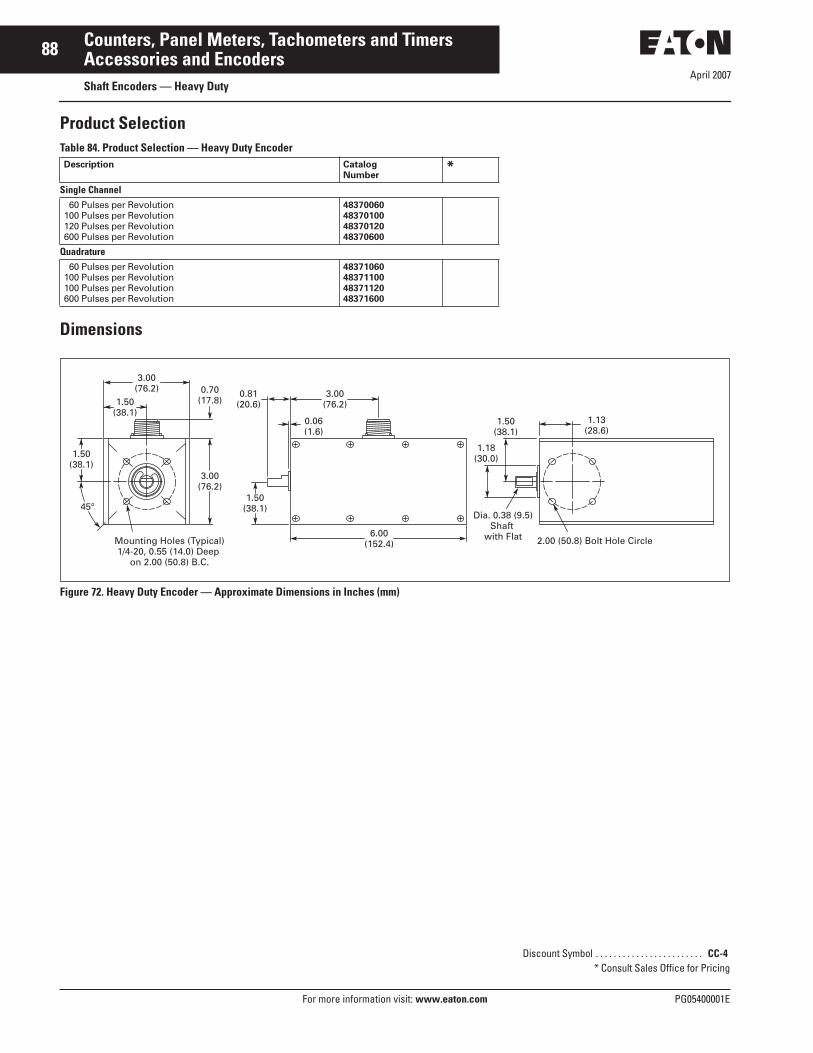
April 2007
88
For more information visit: www.eaton.com PG05400001E
Counters, Panel Meters, Tachometers and TimersAccessories and EncodersShaft Encoders — Heavy Duty
Product SelectionTable 84. Product Selection — Heavy Duty Encoder
Dimensions
Figure 72. Heavy Duty Encoder — Approximate Dimensions in Inches (mm)
Description CatalogNumber
*Single Channel
60 Pulses per Revolution100 Pulses per Revolution120 Pulses per Revolution600 Pulses per Revolution
48370060483701004837012048370600
Quadrature60 Pulses per Revolution
100 Pulses per Revolution100 Pulses per Revolution600 Pulses per Revolution
48371060483711004837112048371600
0.70(17.8)
0.81(20.6)
1.50(38.1)
6.00(152.4)
1.18(30.0)
1.50(38.1)
1.13(28.6)
Dia. 0.38 (9.5)Shaft
with Flat 2.00 (50.8) Bolt Hole CircleMounting Holes (Typical)1/4-20, 0.55 (14.0) Deep
on 2.00 (50.8) B.C.
3.00(76.2)
0.06(1.6)
3.00(76.2)
45°
3.00(76.2)
1.50(38.1)
1.50(38.1)
Discount Symbol . . . . . . . . . . . . . . . . . . . . . . . . CC-4* Consult Sales Office for Pricing

April 2007
PG05400001E For more information visit: www.eaton.com
89Counters, Panel Meters, Tachometers and TimersAccessories and EncodersShaft Encoders — Right Angle, Size 20
Features■ 5 – 28V DC input power■ 100 mA current draw■ NPN transistor output, 100 mA
sinking capacity■ Quadrature output, 2 square waves■ Up to 1800 pulses per revolution■ Flange mounting■ 3/8" (9.5 mm) shaft diameter■ Double shielded ball bearings■ Military style connector
Cat. No. 38159100
Technical Data and SpecificationsElectrical■ Input
❑ Voltage: 5 to 28V DC (4.75 min., 28.0 max.)
❑ Current: 100 mA max. with no output load
❑ Ripple: -2% peak to peak at 5V DC
■ Output❑ Type: Quadrature current sinking
transistors with 2.2 k pull-up❑ Sinking current: 100 mA max.❑ Max. voltage @ 100 mA: 1.3V DC❑ Blocking voltage: 40V DC max.❑ Polarity: Positive❑ Wave Shape: Square wave (50-50
duty cycle)❑ Pulse Rate: 0 to 100,000 pulses
per second❑ Noise Immunity: Tested to BS
EN6100-4-2; IEC801-3; BS EN61000-4-4; DDENV 50141; DDENV 50204; BS EN55022 (with European compliance option)
❑ Symmetry: 180 electrical degrees ± 18
❑ Quadrature Phasing: 90 electrical degrees ± 36
❑ Minimum Edge Separation: 54 electrical degrees
❑ Rise Time: < 1 μS❑ Pulses per Rev.: 1 to 1270❑ Accuracy: Within ± 0.1°
Environmental■ Operating Temperature: 32 to 158°F
(0 to 70°C)■ Vibration: 20 Gs at 50 to 500 cps■ Shock: 75 Gs, 11 mS
Mechanical■ Shaft Speed: 8000 RPM max.■ Shaft Rotation: CW or CCW■ Bearings: Double shielded ball
bearings■ Starting Torque: 1.0 oz-in typical■ Moment of Inertia: 5.2 x 10⁴ ounce
inch-sec2
■ Radial & Axial Loading: (80 lbs max.) 20 – 40 lbs for bearing life of 1.5x10⁹ revolutions
■ Maximum Acceleration: 1x10⁵
Radians/second2
■ Shaft: 0.375" (9.5 mm) dia.■ Housing: Black non-corrosive finish.
Sealed against dust, oil, vapor and moisture.
■ Mounting: Flange mount■ Weight: 11 oz (312 g)■ Connector: MS-3102E-14S-6P■ Mating Connector —
❑ MS-3106A-14S-6S with 10' (3m) shielded cable and termination for electronic controls(Part No. 29665-300)
❑ Connector, clamp and bushing only (Part No. 29729-300)

April 2007
90
For more information visit: www.eaton.com PG05400001E
Counters, Panel Meters, Tachometers and TimersAccessories and EncodersShaft Encoders — Right Angle, Size 20
Product SelectionTable 85. Product Selection — Right-Angle Shaft Encoder, Size 20
Dimensions
Figure 73. Right-Angle Shaft Encoder — Approximate Dimensions in Inches (mm)
Description CatalogNumber
*
100 Pulses per Revolution120 Pulses per Revolution600 Pulses per Revolution
381591003815912038159600
1000 Pulses per Revolution1800 Pulses per Revolution
381591000381591800
2.06(52.3)
1.41(35.9)
1.18(30)
6-32 UNC0.25 (6.4) Deep 4 x 90°Dia. 2.0 (50.8) B.C.
Dia. 0.16 (4.0)Through 4 x 90°Dia. 2.48 (62.9) B.C.
0.05(1.3)
0.05(1.3)
0.30(7.6) 2.0
(50.8)
0.60(15.2)
2.0(50.8)
0.80(20.3)
0.75(19.1)
Shaft Size
3/8" 0.3745 (9.512)
0.63(15.9)
0.87(22.1)
Side MountMS Style
Connector
1.75(44.5)
2.06(52.3)
Discount Symbol . . . . . . . . . . . . . . . . . . . . . . . . CC-4* Consult Sales Office for Pricing

1
© 2007 Eaton CorporationAll Rights ReservedPrinted in USAForm No. PG05400001EApril 2007
Eaton CorporationElectrical Group1000 Cherrington ParkwayMoon Township, PA 15108United States877-ETN CARE (877-386-2273)Eaton.com
Eaton’s electrical business is a global leader in electrical control, power distribution, uninterruptible power supply and industrial automation products and services. Eaton’s global electrical brands, including Cutler-Hammer®, Powerware®, Holec® and MEM®,provide customer-driven PowerChain ManagementTM
solutions to serve the power system needs of the industrial, institutional, government, utility, commercial, residential, IT, mission critical and OEM markets worldwide.
Eaton Corporation is a diversified industrial manufacturer with 2006 sales of $12.4 billion. Eaton is a global leader in electrical systems and components for power quality, distribution and control; fluid power systems and services for industrial, mobile and aircraft equipment; intelligent truck drivetrain systems for safety and fuel economy; and automotive engine air management systems, powertrain solutions and specialty controls for performance, fuel economy and safety. Eaton has 60,000 employees and sells products to customers in more than 125 countries. For more information, visit www.eaton.com.