Embed Size (px)
Citation preview
Bars A And B At 45
Placed On Top Of
2-#7 Each Way
10/16/2017
8:3
9:5
6
AM
RE
VISIO
N DESCRIPTION:
REVISION
LAST
ofSTANDARD PLANS
FY 2018-19 SHEETINDEX
11/01/17STRUCTURE BOTTOMS TYPE J AND P
425-010 1 5
� Type A Or B Riser
� Structure
@ 5" O.C.
2 Additional Bars A
(See Section A-A)
Perpendicular Bars A#5 Hoop Bar
(See Section A-A)
Parallel Bars B
� Structure BottomReference Axis
#4 Hoop Bar
� Type A Or B Riser
Permitted)
(2 Lap Splices
2-#5 Hoop Bars
(See Note 10)
Corner Fillet
(Minimum #4 Bars)
A @ 5" O.C.
2 Additional Bars
(See Section B-B)
Bars A Short Way
(Minimum #4 Bars)
Side Of Opening
@ 5" Max. O. C. Each
2 Additional Bars B
(Minimum #4 Bars)
Side Of Opening
@ 5" Max. O. C. Each
2 Additional Bars B
(See Section B-B)
Bars B Long Way
� Type A Or B Riser
(See Section B-B)
Bars B Long Way (Minimum #4 Bars)
@ 5" O.C.
2 Additional Bars A
(1 Lap Splice Permitted)
#4 Hoop Bar
(See Section)
9-#4 Ties @ 12" Max. O.C.
Reinforcement
#5 Peripheral
Maintain Cover
As Required To
Rotate #4 Bars
Construction Joints.
425-001 for Optional
Permitted. See Index
Construction Joint
Wall Reinforcing
Reinforcement
#5 Peripheral
#4 Ties @ 12" O.C.
Bottom SlabBars BBars A
Top Slab
Bars A
Bars B
Bars A Bars B Bottom Slab
(See Note)
At Opening
Reinforcing
Extra
Top Slab
Bars A
Bars B
(See Table 8)
Horiz. Wall Reinf.
(Vertical Bars)
#4 @ 12" Ctrs.
(See Table 8)
Vertical Wall Reinf.
(See Table 8)
Horizontal Wall Reinf.
(Typ. For Walls)
to Horizontal Bars
Or 2" Cl. (Double Layer)
3" Cl. (Single Layer)
t� (Type B)t� (Type A) or
" Min.211
" (Typ.)21" to 14
3
10° Draft
Structure Wall For All Bar Sizes
4" Min. Beyond Inside Face of
Rebar Straight End Embedment
Embedment Beyond Inside Face
To Achieve Minimum Rebar
Extend Top and Bottom Slabs
Bottom Slab Reinforcing
Optional Shear Key
Shear Key
Shear Key
Top Slab Reinforcing
to Maintain Cover
Bend Bars As Required
Optional Shear Key
Wall Reinforcing
& 1 Each Side)
@ 3" Min. Spacing
Opening (2 Above
Extra #4's At
3'-6" Dia.
� Structure Bottom
Sta./Offset Location
� Structure Bottom
Sta./Offset Location
for Precast
(CIPL) See Table 1
#4 @ 12" Both Ways
Precast & 10' Dia.
See Table 1 for
Ways (CIPL 10' Dia.)
#4 @ 12" Both
A A
4'-0"
Dia.
3'-6"
Or
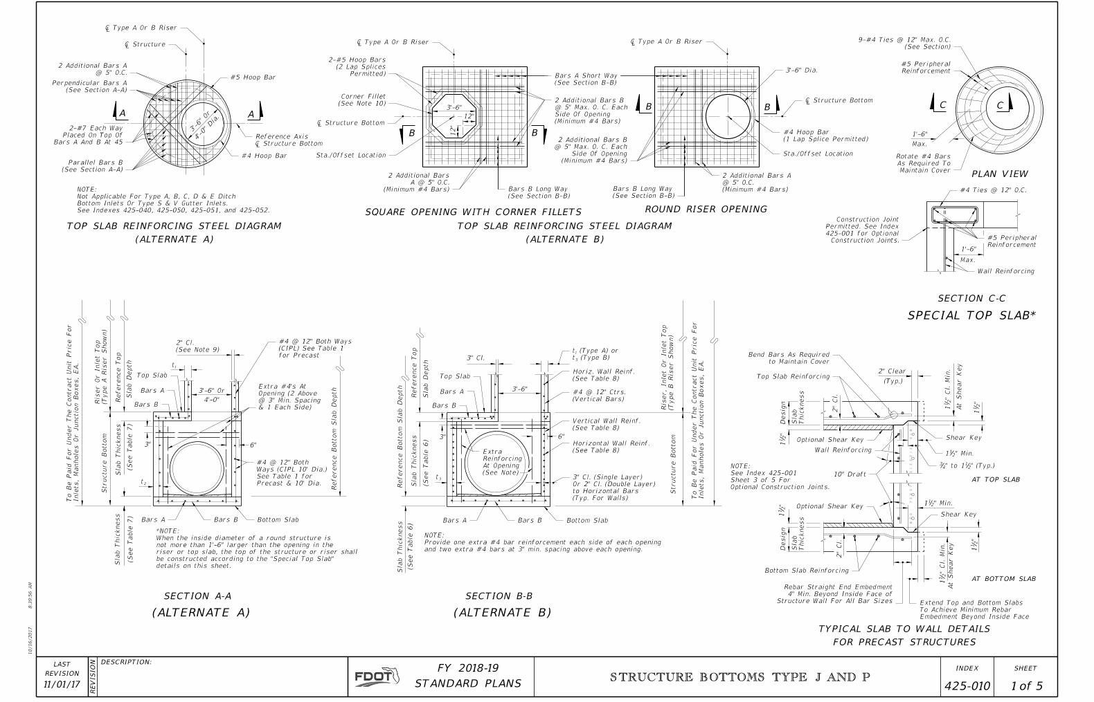
(ALTERNATE A)
TOP SLAB REINFORCING STEEL DIAGRAM
(ALTERNATE B)
TOP SLAB REINFORCING STEEL DIAGRAM
SQUARE OPENING WITH CORNER FILLETS ROUND RISER OPENING
3'-6"
12"
12"
B B
B B
1'-6"
Max.
PLAN VIEW
CC
Max.
1'-6"
SECTION C-C
SECTION A-A SECTION B-B
SPECIAL TOP SLAB*
(ALTERNATE A) (ALTERNATE B)
FOR PRECAST STRUCTURES
TYPICAL SLAB TO WALL DETAILS
AT TOP SLAB
AT BOTTOM SLAB
Inlets,
Manhole
s
Or Junctio
n B
oxes,
EA.
To Be Paid For
Under The Contract
Unit Pric
e For
Structure B
otto
m(T
ype
A Ris
er S
ho
wn)
Ris
er
Or Inlet Top
Reference Top
Sla
b
Depth
Sla
b Thic
kness
(See Table 7)
Sla
b Thic
kness
(See Table 7)
t�
t�
(See Note 9)
2" Cl.
Reference B
otto
m Sla
b
Depth
details on this sheet.
be constructed according to the "Special Top Slab"
riser or top slab, the top of the structure or riser shall
not more than 1'-6" larger than the opening in the
When the inside diameter of a round structure is
*NOTE:
3'-6" Or
4'-0"
t�
and two extra #4 bars at 3" min. spacing above each opening.
Provide one extra #4 bar reinforcement each side of each opening
NOTE:
Sla
b Thic
kness
(See Table 6)
Reference B
otto
m Sla
b
Depth
Sla
b Thic
kness
Reference Top
Sla
b
Depth
(See Table 6)
3" Cl.
Structure B
otto
m(T
ype B Ris
er S
ho
wn)
Ris
er, Inlet
Or Inlet Top
Inlets,
Manhole
s
Or Junctio
n B
oxes,
EA.
To Be Paid For
Under The Contract
Unit Pric
e For
3'-6"
" Cl.
Min.
21
1 At S
hear
Key
"2
11
2" Clear
(Typ.)
Thic
kness
Sla
b
Desig
n"
21
1Desig
n
Thic
kness
Sla
b
"2
11
" Cl.
Min.
21
1
At S
hear
Key
"2
11
" Min.211
2"
Cl.
2"
Cl.
Optional Construction Joints.
Sheet 3 of 5 For
See Index 425-001
NOTE:
3" 6"
6"3"
See Indexes 425-040, 425-050, 425-051, and 425-052.
Bottom Inlets Or Type S & V Gutter Inlets.
Not Applicable For Type A, B, C, D & E Ditch
NOTE:
10/16/2017
8:3
9:5
6
AM
RE
VISIO
N DESCRIPTION:
REVISION
LAST
ofSTANDARD PLANS
FY 2018-19 SHEETINDEX
11/01/17STRUCTURE BOTTOMS TYPE J AND P
425-010 2 5
GENERAL NOTES
See Table 8 for Reinforcing Schedule.
TABLE 2 NOTES:
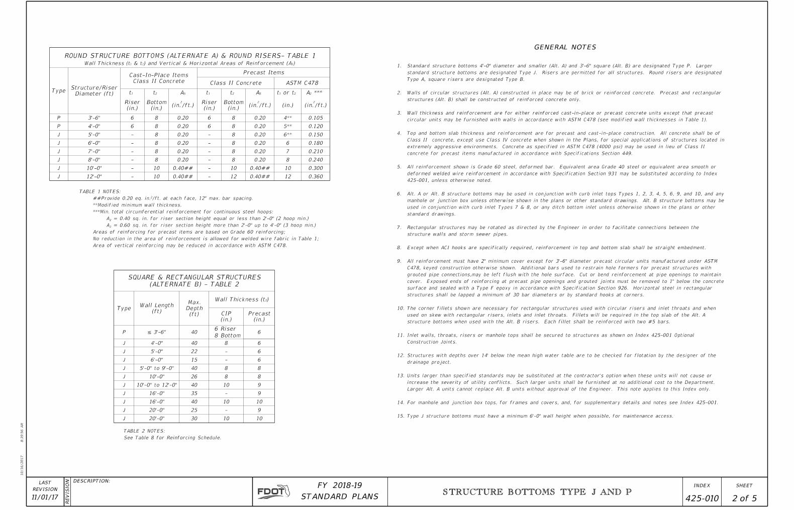
ROUND STRUCTURE BOTTOMS (ALTERNATE A) & ROUND RISERS- TABLE 1
Wall Thickness (t1 & t2) and Vertical & Horizontal Areas of Reinforcement (AS)
TypeStructure/Riser
Diameter (ft)
Cast-In-Place Items
Class II Concrete
Precast Items
Class II Concrete ASTM C478
t1 t2 AS t1 t2 AS t1 or t2 A2 ***
Riser
(in.)
Bottom
(in.)(in.
2
/ft.)Riser
(in.)
Bottom
(in.)(in.
2
/ft.) (in.) (in.2
/ft.)
P 3'-6" 6 8 0.20 6 8 0.20 4** 0.105
P 4'-0" 6 8 0.20 6 8 0.20 5** 0.120
J 5'-0" - 8 0.20 - 8 0.20 6** 0.150
J 6'-0" - 8 0.20 - 8 0.20 6 0.180
J 7'-0" - 8 0.20 - 8 0.20 7 0.210
J 8'-0" - 8 0.20 - 8 0.20 8 0.240
J 10'-0" - 10 0.40## - 10 0.40## 10 0.300
J 12'-0" - 10 0.40## - 12 0.40## 12 0.360
SQUARE & RECTANGULAR STRUCTURES
(ALTERNATE B) - TABLE 2
TypeWall Length
(ft)
Max.
Depth
(ft)
Wall Thickness (t3)
CIP
(in.)
Precast
(in.)
P ≤ 3'-6" 406 Riser
68 Bottom
J 4'-0" 40 8 6
J 5'-0" 22 - 6
J 6'-0" 15 - 6
J 5'-0" to 9'-0" 40 8 8
J 10'-0" 26 8 8
J 10'-0" to 12'-0" 40 10 9
J 16'-0" 35 - 9
J 16'-0" 40 10 10
J 20'-0" 25 - 9
J 20'-0" 30 10 10
Area of vertical reinforcing may be reduced in accordance with ASTM C478.
No reduction in the area of reinforcement is allowed for welded wire fabric in Table 1;
Areas of reinforcing for precast items are based on Grade 60 reinforcing;
A� = 0.60 sq. in. for riser section height more than 2'-0" up to 4'-0" (3 hoop min.)
A� = 0.40 sq. in. for riser section height equal or less than 2'-0" (2 hoop min.)
***Min. total circumferential reinforcement for continuous steel hoops:
**Modified minimum wall thickness.
##Provide 0.20 eq. in.²/ft. at each face, 12" max. bar spacing.
TABLE 1 NOTES:
Type J structure bottoms must have a minimum 6'-0" wall height when possible, for maintenance access.15.
For manhole and junction box tops, for frames and covers, and, for supplementary details and notes see Index 425-001.14.
Larger Alt. A units cannot replace Alt. B units without approval of the Engineer. This note applies to this Index only.
increase the severity of utility conflicts. Such larger units shall be furnished at no additional cost to the Department.
Units larger than specified standards may be substituted at the contractor's option when these units will not cause or 13.
drainage project.
Structures with depths over 14' below the mean high water table are to be checked for flotation by the designer of the 12.
Construction Joints.
Inlet walls, throats, risers or manhole tops shall be secured to structures as shown on Index 425-001 Optional 11.
structure bottoms when used with the Alt. B risers. Each fillet shall be reinforced with two #5 bars.
used on skew with rectangular risers, inlets and inlet throats. Fillets will be required in the top slab of the Alt. A
The corner fillets shown are necessary for rectangular structures used with circular risers and inlet throats and when 10.
structures shall be lapped a minimum of 30 bar diameters or by standard hooks at corners.
surface and sealed with a Type F epoxy in accordance with Specification Section 926. Horizontal steel in rectangular
cover. Exposed ends of reinforcing at precast pipe openings and grouted joints must be removed to 1" below the concrete
grouted pipe connections,may be left flush with the hole surface. Cut or bend reinforcement at pipe openings to maintain
C478, keyed construction otherwise shown. Additional bars used to restrain hole formers for precast structures with
All reinforcement must have 2" minimum cover except for 3'-6" diameter precast circular units manufactured under ASTM 9.
Except when ACI hooks are specifically required, reinforcement in top and bottom slab shall be straight embedment.8.
structure walls and storm sewer pipes.
Rectangular structures may be rotated as directed by the Engineer in order to facilitate connections between the 7.
standard drawings.
used in conjunction with curb inlet Types 7 & 8, or any ditch bottom inlet unless otherwise shown in the plans or other
manhole or junction box unless otherwise shown in the plans or other standard drawings. Alt. B structure bottoms may be
Alt. A or Alt. B structure bottoms may be used in conjunction with curb inlet tops Types 1, 2, 3, 4, 5, 6, 9, and 10, and any 6.
425-001, unless otherwise noted.
deformed welded wire reinforcement in accordance with Specification Section 931 may be substituted according to Index
All reinforcement shown is Grade 60 steel, deformed bar. Equivalent area Grade 40 steel or equivalent area smooth or 5.
concrete for precast items manufactured in accordance with Specifications Section 449.
extremely aggressive environments. Concrete as specified in ASTM C478 (4000 psi) may be used in lieu of Class II
Class II concrete, except use Class IV concrete when shown in the Plans, for special applications of structures located in
Top and bottom slab thickness and reinforcement are for precast and cast-in-place construction. All concrete shall be of 4.
circular units may be furnished with walls in accordance with ASTM C478 (see modified wall thicknesses in Table 1).
Wall thickness and reinforcement are for either reinforced cast-in-place or precast concrete units except that precast 3.
structures (Alt. B) shall be constructed of reinforced concrete only.
Walls of circular structures (Alt. A) constructed in place may be of brick or reinforced concrete. Precast and rectangular 2.
Type A, square risers are designated Type B.
standard structure bottoms are designated Type J. Risers are permitted for all structures. Round risers are designated
Standard structure bottoms 4'-0" diameter and smaller (Alt. A) and 3'-6" square (Alt. B) are designated Type P. Larger 1.
10/16/2017
8:3
9:5
7
AM
RE
VISIO
N DESCRIPTION:
REVISION
LAST
ofSTANDARD PLANS
FY 2018-19 SHEETINDEX
11/01/17STRUCTURE BOTTOMS TYPE J AND P
425-010 3 5
Structure Wall
Note Section B-B)
Each Side Of Opening (See
Provide Extra Reinforcing
Shown For Clarity)
Wall Reinforcing Not
Reinforcing (Vertical
Horizontal Wall Skew Angle
(Outside)
2" Clear
Not Shown For Clarity)
Reinf. (Vertical Wall Reinf.
Single Layer Horiz. Wall Structure Wall
Not Shown For Clarity)
Reinf. (Vertical Wall Reinf.
Double Layer Horiz. Wall
Sheet 1 of 5)
(See Note Section B-B
Ea. Side Of Opening
Provide Extra Reinf.
� Pipe
(Typ.)
Precast Structures
Masonry Seal for
(See Section A-A)
Each Side Of Opening
1-Extra #4 BarStructure Wall
For Clarity)
Reinf. Not Shown
Reinf. (Vert. Wall
Horiz. Wall
Or 40 Bar Diameters For Smooth Wire)
Vertical Wire Spacing Plus 2" For WWR
Deformed Wire Or Bar, But Not Less Than
Typical Lap Splice (20 Bar Diameter For
5'-0"
6'-0"
7'-0"
8'-0"
6'-0"
9'-0"
6'-0"
7'-0"
7'-0"
8'-0"
10'-0"
10'-0"
12'-0"
12'-0"
12'-0"
30"
36"
42"
48"
54"
60"
66"
72"
78"
9'-0"84"
4'-0"
5'-0"
6'-0"
6'-0"
7'-0"
8'-0"
7'-0"
8'-0"
10'-0"
12'-0" N/A
3'-6" 4'-0"
5'-0"
18"
24"
3'-6"
3'-6" 3'-6"
2
3
4
3'-6"/4'-0"
4'-0"/5'-0"
7'-0"/8'-0"
Number
Note
Per Side
Single PipeSIZE
PIPESide Dimension (L)
RECTANGULAR ROUND
Diameter (D)
θ=90°
Pipes
2 to 4
θ=180°
or
Single Pipe
PER SIDE
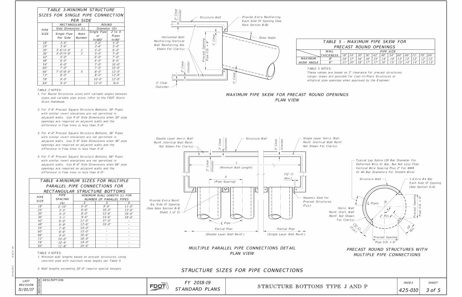
SIZES FOR SINGLE PIPE CONNECTION
TABLE 3-MINIMUM STRUCTURE
18"
24"
30"
36"
42"
54"
48"
60"
66"
72"
78"
84"
2'-10"
3'-5"
4'-3"
5'-1'
6'-0"
6'-9"
7'-8"
8'-6"
9'-0"
10'-0"
10'-9"
11'-8"
6'-0"
6'-6"
8'-0"
9'-6"
11'-0"
12'-6"
14'-0"
15'-0"
16'-6"
18'-0"
19'-0"
20'-6"
8'-6"
10'-0"
12'-6"
14'-6"
17'-0"
13'-6"
16'-6"
19'-6"
-
-
-
-
-
-
-
-
-
-
-
-
-
-
19'-0"
11'-0"
SIZE
PIPE
(S)
SPACING
PIPE
NUMBER OF PARALLEL PIPES
MINIMUM WALL LENGTH (L) FOR
2 3 4
RECTANGULAR STRUCTURE BOTTOMS
PARALLEL PIPE CONNECTIONS FOR
TABLE 4-MINIMUM SIZES FOR MULTIPLE
18"
19°
24"
17° 16° 16° 15° 14° 14° 13°
30" 36" 42" 48" 54" 60"
13° 13° 12° 12°
66" 72" 78" 84"
21° 20° 18° 17° 17° 16° 15° 15° 14° 14° 13° 13°SKEW ANGLE
MAXIMUM 8"
6"
THICKNESS
WALL PIPE SIZE
PRECAST ROUND OPENINGS
TABLE 5 - MAXIMUM PIPE SKEW FOR
elliptical pipe openings when approved by the Engineer.
Larger skews are possible for Cast-In-Place Structures or
These values are based on 2" clearance for precast structures.
TABLE 5 NOTES:
PLAN VIEW
MAXIMUM PIPE SKEW FOR PRECAST ROUND OPENINGS
MULTIPLE PIPE CONNECTIONS
PRECAST ROUND STRUCTURES WITH
PLAN VIEW
MULTIPLE PARALLEL PIPE CONNECTIONS DETAIL
STRUCTURE SIZES FOR PIPE CONNECTIONS
difference in flow lines is less than 4'-0".
openings are required on adjacent walls and the
adjacent walls. Use 8'-0" Side Dimensions when 66" pipe
with similar invert elevations are not permitted in
For 7'-0" Precast Square Structure Bottoms, 66" Pipes 4.
difference in flow lines is less than 3'-0".
openings are required on adjacent walls and the
adjacent walls. Use 5'-0" Side Dimensions when 36" pipe
with similar invert elevations are not permitted in
For 4'-0" Precast Square Structure Bottoms, 36" Pipes 3.
difference in flow lines is less than 3'-0".
openings are required on adjacent walls and the
adjacent walls. Use 4'-0" Side Dimensions when 30" pipe
with similar invert elevations are not permitted in
For 3'-6" Precast Square Structure Bottoms, 30" Pipes 2.
Drain Handbook.
pipes and variable pipe sizes, refer to the FDOT Storm
For Round Structures sizes with variable angles between 1.
TABLE 3 NOTES:
Wall lengths exceeding 20'-0" require special designs.2.
concrete pipe with maximum skew angles per Table 5.
Minimum wall lengths based on precast structures, using 1.
TABLE 4 NOTES:
Precast
Openin
g
Pip
e
O.D.
+ 6"
1"
Cle
ar
1"
Cle
ar2
" Cle
ar
(Insid
e)
3"
Cle
ar
(Insid
e)
Partial Plan
(Double Layer Wall Reinf.) (Single Layer Wall Reinf.)
Partial Plan
S
(Pipe Spacing)
L
(Minimum Wall Length)
(Insid
e)
2"
Cle
ar
2"
Cle
ar
(Outsid
e)
3"
Cle
ar
(Insid
e)
(Min.)
" Cl.211
Precast
Openin
g
Pip
e
O.D.
+ 6"
(Typ.)
" Cl.
211
Precast Opening
Pipe O.D. + 6"
2" Min.
D� Pipes
10"
Min.
θ
10/16/2017
8:3
9:5
8
AM
RE
VISIO
N DESCRIPTION:
REVISION
LAST
ofSTANDARD PLANS
FY 2018-19 SHEETINDEX
11/01/17STRUCTURE BOTTOMS TYPE J AND P
425-010 4 5
LONG-WAYSHORT-WAY
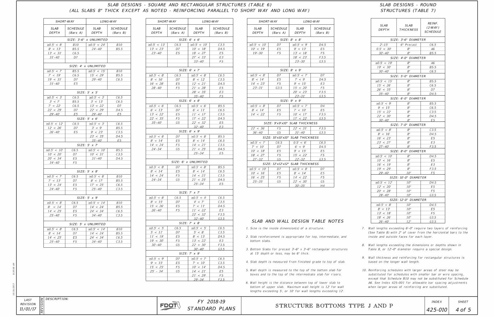
SLAB DESIGNS - SQUARE AND RECTANGULAR STRUCTURES (TABLE 6)
(ALL SLABS 8" THICK EXCEPT AS NOTED - REINFORCING PARALLEL TO SHORT WAY AND LONG WAY)
DEPTH
SLAB
(Bars A)
SCHEDULE
DEPTH
SLAB
(Bars B)
SCHEDULE
SHORT-WAY
DEPTH
SLAB
(Bars A)
SCHEDULE
DEPTH
SLAB
LONG-WAY
(Bars B)
SCHEDULE
SHORT-WAY
DEPTH
SLAB
(Bars A)
SCHEDULE
DEPTH
SLAB
LONG-WAY
(Bars B)
SCHEDULE
SIZE: 8' x 8'SIZE: 6' x 6'SIZE: 3'-6" x UNLIMITED
SIZE: 4' x UNLIMITED
SIZE: 6' x 7' SIZE: 8' x 9'
SIZE: 9' x 9'SIZE: 6' x 8'
SIZE: 5' x 5'
SIZE: 5' x 6'
SIZE: 6' x 9'
SIZE: 9'x9'x10" SLAB THICKNESS
SIZE: 5' x 7'
SIZE: 5' x 8'
SIZE: 5' x 9'
SIZE: 5' x UNLIMITED
SIZE: 7' x 7'
SIZE: 6' x UNLIMITED
SIZE: 7' x 8'
SIZE: 12'x12'x12" SLAB THICKNESS
SIZE: 10'x10'x10" SLAB THICKNESS
SIZE: 7' x 9'
31'-40'
13' < 31'
8' < 13'
≥0.5' < 8'
D7
C6.5
B5.5
B10
24'-40'
≥0.5' < 24' B10
B5.5
31'-40'
19' < 31'
7' < 19'
≥0.5' < 7'
E5
D7
C6.5
B5.5
C6.5
B5.5
B10
29'-40'
15' < 29'
≥0.5' < 15'
29'-40'
22' < 29'
7' < 22'
3' < 7'
≥0.5' < 3'
E5
D7
C6.5
B5.5
C6.5
E5
D4.5
D7
C6.5
C6.5
29'-40'
22' < 29'
13' < 22'
3' < 13'
≥0.5' < 3'
26'-40'
12' < 26'
≥0.5' < 12'
E5
D7
C6.5
E5
D4.5
C3.5
B5.5
C6.5
35'-40'
23' < 35'
9' < 23'
3' < 9'
≥0.5' < 3'
F5
E5
D7
C6.5
D4.5
C3.5
B5.5
34'-40'
20' < 34'
10' < 20'
≥0.5' < 10'
31'-40'
10' < 31'
≥0.5' < 10'
F5
E5
D7
C6.5
C3.5
C6.5
B5.5
B10
24'-40'
13' < 24'
7' < 13'
≥0.5' < 7'
25'-40'
17' < 25'
8' < 17'
≥0.5' < 8'
F5
E5
D7
C6.5
C3.5
C6.5
B5.5
B10
25'-40'
14' < 25'
8' < 14'
≥0.5' < 8'
34'-40'
24' < 34'
14' < 24'
≥0.5' < 14'
F5
E5
D7
C6.5
C3.5
C6.5
B5.5
B10
25'-40'
14' < 25'
8' < 14'
≥0.5' < 8'
34'-40'
24' < 34'
14' < 24'
≥0.5' < 14'
E5
D7
C6.5
F5
E3
E5
D4.5
C3.5
F5
E3
E5
D4.5
C3.5
C6.5
F5
E5
D7
C6.5
23'-40'
13' < 23'
≥0.5' < 13'
33'-40'
27' < 33'
18' < 27'
10' < 18'
≥0.5' < 10'
28'-40'
16' < 28'
8' < 16'
≥0.5' < 8'
35'-40'
28' < 35'
21' < 28'
12' < 21'
8' < 12'
≥0.5' < 8'
G5
F5
E5
D7
C6.5
E3
E5
D4.5
C3.5
C6.5
B5.5
G5
F5
E5
D7
E5
D4.5
C3.5
C6.5
B5.5
35'-40'
22' < 35'
13' < 22'
6' < 13'
≥0.5' < 6'
32'-40'
22' < 32'
17' < 22'
11' < 17'
6' < 11'
≥0.5' < 6'
24'-34'
14' < 24'
8' < 14'
≥0.5' < 8'
25'-34'
21' < 25'
14' < 21'
8' < 14'
≥0.5' < 8'
G5
F5
E5
D7
E5
D4.5
C3.5
C6.5
B5.5
F5
E5
D7
C6.5
G3.5
F3.5
E3
D4.5
C3.5
C6.5
24'-34'
14' < 24'
8' < 14'
≥0.5' < 8'
25'-34'
21' < 25'
14' < 21'
8' < 14'
≥0.5' < 8'
26'-40'
15' < 26'
8' < 15'
≥0.5' < 8'
32'-40'
22' < 32'
11' < 22'
7' < 11'
4' < 7'
≥0.5' < 4'
G5
F5
E5
D7
C6.5
G3.5
F3.5
E3
D4.5
C3.5
C6.5
G5
F5
E5
D7
F3.5
F5
E5
D4.5
C3.5
C6.5
30'-40'
19' < 30'
11' < 19'
5' < 11'
≥0.5' < 5'
30'-40'
22' < 30'
13' < 22'
8' < 13'
5' < 8'
≥0.5' < 5'
29'-34'
21' < 29'
14' < 21'
10' < 14'
7' < 10'
≥0.5' < 7'
25' - 34'
15' < 25'
9' < 15'
≥0.5' < 9'
F5
E5
D7
G3.5
F3.5
F5
E5
D4.5
G3.5
F5
E5
D7
G3.5
F3.5
F5
E3
D4.5
D7
F5
E5
D7
G3.5
F3.5
E5
D4
19'-30'
10' < 19'
≥0.5' < 10'
23'-30'
18' < 23'
13' < 18'
9' < 13'
≥0.5' < 9'
23'-31'
20' < 23'
15' < 20'
9' < 15'
7' < 9'
≥0.5' < 7'
23'-31'
14' < 23'
8' < 14'
≥0.5' < 8'
14' < 22'
8' < 14'
≥0.5' < 8'
17' < 22'
10' < 17'
7' < 10'
≥0.5' < 7'
36'-40'
22' < 36'
G5
F5
31'-40'
22' < 31'
G3.5
F3.5
G3.5
F5
E5
D4.5
C6.5
22'-32'
15' < 22'
9' < 15'
6' < 9'
0.5' < 6'
G5
F5
E5
D7
C6.5
G5
F5
E5
D7
H4
G5
F5
E5
D7
27'-32'
18' < 27'
10' < 18'
7' < 10'
≥0.5' < 7'
25'-35'
16' < 25'
10' < 16'
≥0.5' < 10'
30'-35'
22' < 30'
14' < 22'
8' < 14'
≥0.5' < 8'
SLAB DESIGNS - ROUND
STRUCTURES (TABLE 7)
SIZE: 3'-6" DIAMETER
SIZE: 4'-0" DIAMETER
SIZE: 5'-0" DIAMETER
SIZE: 6'-0" DIAMETER
SIZE: 7'-0" DIAMETER
SIZE: 8'-0" DIAMETER
SIZE: 12'-0" DIAMETER
SIZE: 10'-0" DIAMETER
DEPTH
SLAB
THICKNESS
SLAB
SCHEDULE
(2-WAY)
REINF.
30'-40'
0.5' < 30'
2'-15'
8"
8"
6" Precast
B5.5
A6
C6.5
8"
8"
8"
C6.5
B5.5
A6
8"
8"
8"
8"
D4.5
D7
C6.5
B5.5
8"
8"
8"
8"
8"
E5
D4.5
C3.5
C6.5
B5.5
8"
8"
8"
8"
8"
F3.5
E3
E5
D4.5
C3.5
10"
8"
8"
8"
8"
F5
F3.5
E3
E5
D4.5
10"
10"
10"
10"
G3.5
F5
E5
D4.5
12"
10"
10"
10"
10"
G3.5
G3.5
F5
E5
D4.5
30'-40'
19' < 30'
≥0.5' < 19'
35'-40'
26' < 35'
15' < 26'
≥0.5' < 15'
30'-40'
22' < 30'
15' < 22'
9' < 15'
≥0.5' < 9'
27'-40'
23' < 27'
16' < 23'
8' < 16'
≥0.5' < 8'
29'-40'
19' < 29'
16' < 19'
10' < 16'
≥0.5' < 10'
28'-40'
20' < 28'
12' < 20'
≥0.5' < 12'
26'-40'
18' < 26'
13' < 18'
8' < 13'
≥0.5' < 8'
SLAB AND WALL DESIGN TABLE NOTES
lengths exceeding 5', or 10' for wall lengths exceeding 12'.
bottom of upper slab. Maximum wall height is 12' for wall
Wall height is the distance between top of lower slab to 6.
boxes and to the top of the intermediate slab for risers.
Wall depth is measured to the top of the bottom slab for 5.
Slab depth is measured from finished grade to top of slab.4.
at 15' depth or less, may be 6" thick.
Bottom Slabs for precast 3'-6" x 3'-6" rectangular structures 3.
bottom slabs.
Slab reinforcement is appropriate for top, intermediate, and 2.
Size is the inside dimension(s) of a structure.1.
when larger areas of reinforcing are substituted.
A6. See Index 425-001 for allowable bar spacing adjustments
except that Schedule B10 may not be substituted for Schedule
substituted for schedules with smaller bar or wire spacing,
Reinforcing schedules with larger areas of steel may be 10.
based on the longer wall length.
Wall thickness and reinforcing for rectangular structures is 9.
Table 8, or 12'-0" diameter require a special design.
Wall lengths exceeding the dimensions or depths shown in 8.
inside and outside faces for each layer.
(See Table 8) with 2" of cover from the horizontal bars to the
Wall lengths exceeding 6'-0" require two layers of reinforcing 7.
10/16/2017
8:3
9:5
8
AM
RE
VISIO
N DESCRIPTION:
REVISION
LAST
ofSTANDARD PLANS
FY 2018-19 SHEETINDEX
11/01/17STRUCTURE BOTTOMS TYPE J AND P
425-010 5 5
Structure Wall� Lap Splice
Wall Reinforcing
Double Layer
Wall Reinforcing
Single Layer
Spaces Plus 2" For WWR)
Than Two Vertical Wire
Diameters, But Not Less
Corner Spliced Bar (30 Bar
Option 3) Lap Splice:
Spacing Plus 2" For WWR)
Diameters Or Vertical Wire
At Quarter Point (30 Bar
Option 1) Lap Splice:
#5's, 12" #6's)
(8" For #4's, 10" For
Hooks At Corners
With Standard 90°
Option 2) Lap Splice:
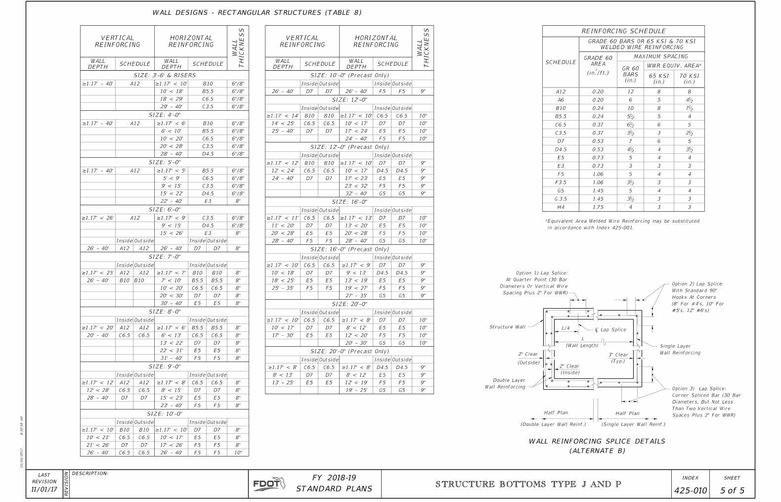
WALL DESIGNS - RECTANGULAR STRUCTURES (TABLE 8)
(ALTERNATE B)
WALL REINFORCING SPLICE DETAILS
(Single Layer Wall Reinf.)
Half PlanHalf Plan
(Double Layer Wall Reinf.)
3" Clear
(Typ.)
(Wall Length)
L
L/4
2" Clear
(Inside)
(Outside)
2" Clear
REINFORCING SCHEDULE
SCHEDULE
GRADE 60 BARS OR 65 KSI & 70 KSI
WELDED WIRE REINFORCING
GRADE 60
AREA
MAXIMUM SPACING
GR 60
BARS
(in.)
WWR EQUIV. AREA*
(in.2
/ft.)65 KSI
(in.)
70 KSI
(in.)
A12 0.20 12 8 8
A6 0.20 6 5 4ƀ
B10 0.24 10 8 7ƀ
B5.5 0.24 5ƀ 5 4
C6.5 0.37 6ƀ 6 5
C3.5 0.37 3ƀ 3 2ƀ
D7 0.53 7 6 5
D4.5 0.53 4ƀ 4 3ƀ
E5 0.73 5 4 4
E3 0.73 3 3 3
F5 1.06 5 4 4
F3.5 1.06 3ƀ 3 3
G5 1.45 5 4 4
G.3.5 1.45 3ƀ 3 3
H4 1.75 4 3 3
VERTICAL
REINFORCING
HORIZONTAL
REINFORCING
WA
LL
THIC
KN
ES
S
WALL
DEPTHSCHEDULE
WALL
DEPTHSCHEDULE
SIZE: 3'-6' & RISERS
≥1.17' - 40' A12 ≥1.17' < 10' B10 6"/8"
10' < 18' B5.5 6"/8"
18' < 29' C6.5 6"/8"
29' - 40' C3.5 6"/8"
SIZE: 4'-0"
≥1.17' - 40' A12 ≥1.17' < 6' B10 6"/8"
6' < 10' B5.5 6"/8"
10' < 20' C6.5 6"/8"
20' < 28' C3.5 6"/8"
28' - 40' D4.5 6"/8"
SIZE: 5'-0"
≥1.17' - 40' A12 ≥1.17' < 5' B5.5 6"/8"
5' < 9' C6.5 6"/8"
9' < 15' C3.5 6"/8"
15' < 22' D4.5 6"/8"
22' - 40' E3 8"
SIZE: 6'-0"
≥1.17' < 26' A12 ≥1.17' < 9' C3.5 6"/8"
9' < 15' D4.5 6"/8"
15' < 26' E3 8"
Inside Outside Inside Outside
26' - 40' A12 A12 26' - 40' D7 D7 8"
SIZE: 7'-0"
Inside Outside Inside Outside
≥1.17' < 25' A12 A12 ≥1.17' < 7' B10 B10 8"
26' - 40' B10 B10 7' < 10' B5.5 B5.5 8"
10' < 20' C6.5 C6.5 8"
20' < 30' D7 D7 8"
30' - 40' E5 E5 8"
SIZE: 8'-0"
Inside Outside Inside Outside
≥1.17' < 20' A12 A12 ≥1.17' < 6' B5.5 B5.5 8"
20' - 40' C6.5 C6.5 6' < 13' C6.5 C6.5 8"
13' < 22' D7 D7 8"
22' < 31' E5 E5 8"
31' - 40' F5 F5 8"
SIZE: 9'-0"
Inside Outside Inside Outside
≥1.17' < 12' A12 A12 ≥1.17' < 8' C6.5 C6.5 8"
12' < 28' C6.5 C6.5 8' < 15' D7 D7 8"
28' - 40' D7 D7 15' < 23' E5 E5 8"
23' - 40' F5 F5 8"
SIZE: 10'-0"
Inside Outside Inside Outside
≥1.17' < 10' B10 B10 ≥1.17' < 10' D7 D7 8"
10' < 21' C6.5 C6.5 10' < 17' E5 E5 8"
21' < 26' D7 D7 17' < 26' F5 F5 8"
26' - 40' C6.5 C6.5 26' - 40' F5 F5 10"
VERTICAL
REINFORCING
HORIZONTAL
REINFORCING
WA
LL
THIC
KN
ES
S
WALL
DEPTHSCHEDULE
WALL
DEPTHSCHEDULE
SIZE: 10'-0" (Precast Only)
Inside Outside Inside Outside
26' - 40' D7 D7 26' - 40' F5 F5 9"
SIZE: 12'-0"
Inside Outside Inside Outside
≥1.17' < 14' B10 B10 ≥1.17' < 10' C6.5 C6.5 10"
14' < 25' C6.5 C6.5 10' < 17' D7 D7 10"
25' - 40' D7 D7 17' < 24' E5 E5 10"
24' - 40' F5 F5 10"
SIZE: 12'-0" (Precast Only)
Inside Outside Inside Outside
≥1.17' < 12' B10 B10 ≥1.17' < 10' D7 D7 9"
12' < 24' C6.5 C6.5 10' < 17' D4.5 D4.5 9"
24' - 40' D7 D7 17' < 23' E5 E5 9"
23' < 32' F5 F5 9"
32' - 40' G5 G5 9"
SIZE: 16'-0"
Inside Outside Inside Outside
≥1.17' < 11' C6.5 C6.5 ≥1.17' < 13' D7 D7 10"
11' < 20' D7 D7 13' < 20' E5 E5 10"
20' < 28' E5 E5 20' < 28' F5 F5 10"
28' - 40' F5 F5 28' - 40' G5 G5 10"
SIZE: 16'-0" (Precast Only)
Inside Outside Inside Outside
≥1.17' < 10' C6.5 C6.5 ≥1.17' < 9' D7 D7 9"
10' < 18' D7 D7 9' < 13' D4.5 D4.5 9"
18' < 25' E5 E5 13' < 19' E5 E5 9"
25' - 35' F5 F5 19' < 27' F5 F5 9"
27' - 35' G5 G5 9"
SIZE: 20'-0"
Inside Outside Inside Outside
≥1.17' < 10' C6.5 C6.5 ≥1.17' < 8' D7 D7 10"
10' < 17' D7 D7 8' < 12' E5 E5 10"
17' - 30' E5 E5 12' < 20' F5 F5 10"
20' - 30' G5 G5 10"
SIZE: 20'-0" (Precast Only)
Inside Outside Inside Outside
≥1.17' < 8' C6.5 C6.5 ≥1.17' < 8' D4.5 D4.5 9"
8' < 13' D7 D7 8' < 12' E5 E5 9"
13' - 25' E5 E5 12' < 19' F5 F5 9"
19' - 25' G5 G5 9"
in accordance with Index 425-001.
*Equivalent Area Welded Wire Reinforcing may be substituted


![For top segment roll lines in slab casters fitted with CARB ... maintenance guidelines For top segment roll lines in slab casters fitted with CARB toroidal roller bearings ; _ j ]](https://img.pdfslide.us/doc/110x75/5b094ff87f8b9a3d018d832f/for-top-segment-roll-lines-in-slab-casters-fitted-with-carb-maintenance-guidelines.jpg)