Embed Size (px)
Citation preview

Special Lecture/Session 3: Energy Demand and Smart Community Projects in Emerging Markets
Progress and Update of Demonstration Project for Smart Communities in Indonesian Industrial Park
June 9, 2017Sumisho Machinery Trade Corporation
Infrastructure Plant Business DepartmentGeneral Manager
Mr. Kohei Kono

1 Project Summary1-1.Overview of the System1-2.Project Framework1-3.Project Site
2 Introduction of the System2-1.Distribution Automation System2-2.High Quality Power Supply System2-3.Demand Side Management System2-4.Cloud-based Factory Energy Management System2-5.Private Factory Energy Management System 2-6.ICT Platform
3 Progress, Issues and Update of the Project3-1.Progress and Issues of the Project3-2.Update of the Project
Contents

1.Project Summary

PLN
Industrial Park FactoryPLN
: Normal Quality Power Line
: High Quality Power Line
: Communication Line
/ : Principal Systems
: Key Components
DAS
LVR
HQPS
DSM
FEMS
ICT
UPS
: Distribution Automation System
: Low Voltage Regulator
: High Quality Power Supply System
: Demand Side Management System
: Factory Energy Management System
: Information and Communication Technology
: Uninterruptible Power Supply
High Quality Power
Supply System
UPSLoad Dispatching
Center
Substation
Distribution
Automation
System
LVR
Switch
ICT
Platform Demand Side
Management System
High Quality Power Line
Normal Quality Power Line
FEMS
<Core technologies for the demonstration>
1.Stabilization of power supply
=> DAS,LVR and HQPS
2.Achievement of power reduction
=> DSM, FEMS and ICT
1-1. Overview of the System

1-2. Project Framework
MOU
ID
MEMR
Indonesia
Instructions
Japan
Entrustment
PLN
(Memorandum Of
Understanding)
(ImplementationDocument)
MEMR: The Ministry of Energy and Mineral ResourcesPLN : State Electricity CompanyNEDO : New Energy and Industrial Technology Development Organization

Suryacipta City of Industry
1-3. Project Site

2.Introduction of the System

2-1.Distribution Automation System (DAS)

TURIP
SAKURA
LILY
X
Search SWFeeder highlight
04 Jun 2013 14:00
CSITGH BSTR R
BKRT
R
R R R
PBO
R
5 Not entered
4 Not entered
Not entered
Not entered
DS AAA
LBS ABC-1
LBS ACB-2
Sect ion
State
Not entered
3
2
№ Device Name
1 Feeder CB ROSE
XAttribute Input List
№ Equipment Status
Regist
TURIP
SAKURA
LILY
X
Search SWFeeder highlight
04 Jun 2013 14:00
CSITGH BSTR R
BKRT
R
R R R
PBO
R
Connect End
Equipment
LBS CB Busbar Po in t
Connec t End
Primary feeder
LINE LINE Busbar
Angle of rotation
Operation
Add De le te Modify Move
RotateCo n n e c tio n
Mo di f y
Rec tangle
Move
FCB Custome r Enc lose
PBO Cus t omer CB
Mainsubstation Drowing
Attr ibu te
Inpu t
Logic al
Check
Registe r
Execu teSave
90° 180° -90° Reve rse
Function
Se t Cance l
XMaintenance
L INE L INE
~
1. Advanced accident recovery function- DAS execute this function(FDIR) fully automatically.- This function can respond to the various systems.
2. Easy database maintenance- Create the system diagram by drawing. - Can create the future system diagram by stacking the subjects of maintenance-data.
Drawing
Select
Drawing
Automatically generate topology
DB input
№ Maintenance NamePredetermined
TimeRegistrant
1Distr ibut ion DiagramMaintenance
2012/06/01 11 :00TaroFu j i
2Distr ibut ion DiagramMaintenance
2012/07/02 15 :00TaroFu j i
XSubject List of Maintenance
New Subject Decompression
№ Type of maintenance Scheduled time Register by Status
Register Execute Logical Check Delete
Sectio
n
Before introduction of DAS
Outage time
After introduction of DASSectio
nDetermine & Isolation of fault section
Restore of non-fault section
Fully automaticallyFault detection
Subjects of maintenance-data
Future system diagram
Connect End
Equipment
LBS CB Busbar Po in t
Connec t End
Primary feeder
LINE LINE Busbar
Angle of rotation
Operation
Add De le te Modify Move
RotateCo n n e c tio n
Mo di f y
Rec tangle
Move
FCB Custome r Enc lose
PBO Cus t omer CB
Mainsubstation Drowing
Attr ibu te
Inpu t
Logic al
Check
Registe r
Execu teSave
90° 180° -90° Reve rse
Function
Se t Cance l
XMaintenance
L INE L INE
~Code Mounted Code Mounted MountedTM
TM I RTM AMF T
TSS AR レ
TM AMF S レ 1 1111 1001TM AMF R
1111 1005TM CCB レ 1111 1004TM P レ 1111 1003
TSS BRF レ 1111 1006
Attribute Input
OK
X
Data Type
ON
Object = Feeder Object ID = 001
Name = ROSE
Capacity = 500 Overload = 500 State =
Tr Ratio = 150/20
Code Mounted Rat io ASDU_AD IO_AD
Load
Equipment attribute input

Display Server
DS、SS・RTU
At training 1
At training 2
In the server rack
At construction 1
At construction 2
2-2.High Quality Power Supply System (HQPS)

Under usual condition, electricity is supplied to customers from utility grid (PLN) via HQPS.And float charge is performed to the storage battery.
When the voltage of the grid line falls below the threshold value, the HQPS switches instantaneously (within 4ms) to the inverter supply and backs up the power supply from the battery to the customer in a certain time to prevent serious voltage drop (dip) and voltage interruption.
Before After
outragevoltage drop
Benefit of Factory(1) Improvement of power quality
(2) Stabilization of production(3) Reduction of loss cost
Benefit of Power Company(1) Improving service level
(2) Increasing customer satisfaction and
Decreasing customer complaint.
Improve utilization efficiency of facilities by providing services
with a total of 4 MVA facilities in multiple factories
HQPS
Substation
(PLN)
Substation
(PLN)
ImportantFacilitiesImportant
Facilities
Loss of Productivity
Operation Suspension
Damage to Products
and Facilities
HighQualityPower
GeneralFacilities
GeneralFacilities
Factory Factory AFactory B
Factory C
Factory D
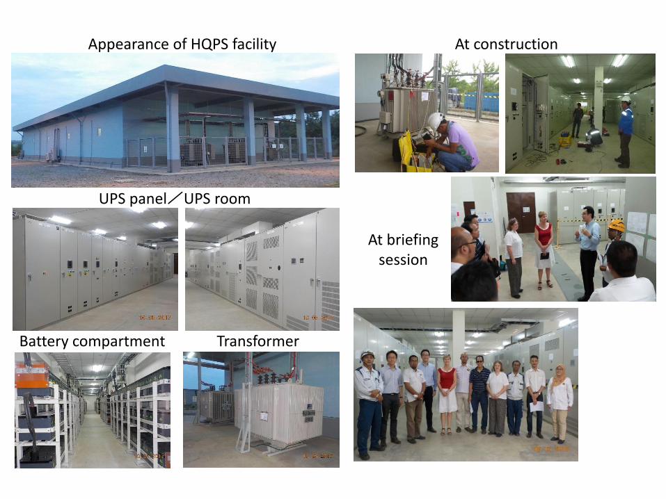
UPS panel/UPS room
Transformer
At briefingsession
Battery compartment
Appearance of HQPS facility At construction

2-3.Demand Side Management System (DSM)


2-4. Cloud-based Factory Energy Management System
(Cloud-FEMS)

※1/2補助対象でも工事費補助は1/3
rooter
Cloud-based FEMS
data
Order
Substation
Utility Air-Con Lighting Production
facilitychiller Cooling tower
pump
EMS Client
DSM Client
Distribution board Distribution board
■Visualization
■Collection of Energy Consumption
■Measurement of energy consumption
■Demand Control
■Aggregation
■Demand Monitoring
■Management of Energy GEN-TAN-I *
■Manufacture event management
■Alarm notificationPlanning of an electric
power reduction
ICT
Platform
Collection Equipment
■Collection of Manufacture event
Input
inverter
* GEN-TAN-I : The amount of energy used per product
Collection Equipment
Production
facility
Production
facility
Production
facility
Execution of an
electric
power reduction
Cloud-based Factory Energy Management System (cloud-FEMS)
Cloud based FEMS is consisted of a cloud
FEMS server set in a data center,
measuring devices of electric power
consumption equipped with factories, data
collection equipment and FEMS client PC.
Cloud FEMS server gathers measured data,
then application services is provided by
FEMS client PC at each factory.

2-5. Private Factory Energy Management System
(Private-FEMS)


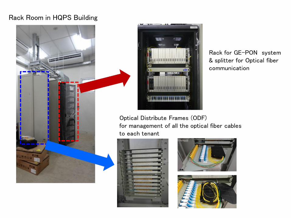
2-6. ICT Platform


3. Progress, Issues and Update of the Project
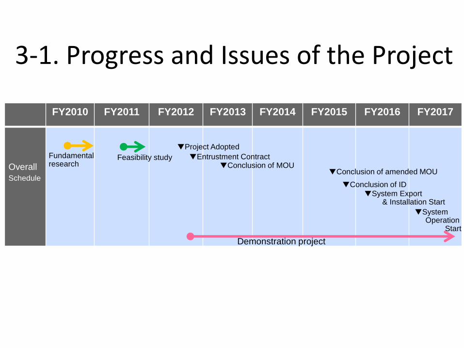
3-1. Progress and Issues of the Project
実証事業
設備導入
▽第1フェーズ開始
▽第2フェーズ開始
設計・製造
事前調査
実証事業
FY2010 FY2011 FY2012 FY2013 FY2014 FY2015 FY2016 FY2017
Overall
Schedule
Fundamental research
Feasibility study ▼Conclusion of MOU
Demonstration project
▼Conclusion of amended MOU
▼Conclusion of ID
▼Project Adopted
▼Entrustment Contract
▼System Export& Installation Start
▼SystemOperation
Start

3-2. Update of the Project
Start-up Operation Ceremony has been held on 23 May 2017

THANK YOU FOR YOUR ATTENTION!