Embed Size (px)
Citation preview
gGE Power Systems
Installation andOutage ManagementProcesses andTechnologies
Cynthia BreitkreuzGE Power SystemsAtlanta, GA
GER-4205

Contents
Introduction . . . . . . . . . . . . . . . . . . . . . . . . . . . . . . . . . . . . . . . . . . . . . . . . . . . . . . . . . . . . . . . . . . 1Installation Planning and Management . . . . . . . . . . . . . . . . . . . . . . . . . . . . . . . . . . . . . . . . . . . 1
Pre-Installation Meeting . . . . . . . . . . . . . . . . . . . . . . . . . . . . . . . . . . . . . . . . . . . . . . . . . . . . . . 2Installation Processes. . . . . . . . . . . . . . . . . . . . . . . . . . . . . . . . . . . . . . . . . . . . . . . . . . . . . . . . 2
Material Control . . . . . . . . . . . . . . . . . . . . . . . . . . . . . . . . . . . . . . . . . . . . . . . . . . . . . . . . . . . . . . 2Arrival and Inspection. . . . . . . . . . . . . . . . . . . . . . . . . . . . . . . . . . . . . . . . . . . . . . . . . . . . . . . . 2Inventory Control . . . . . . . . . . . . . . . . . . . . . . . . . . . . . . . . . . . . . . . . . . . . . . . . . . . . . . . . . . . 3Case Number . . . . . . . . . . . . . . . . . . . . . . . . . . . . . . . . . . . . . . . . . . . . . . . . . . . . . . . . . . . . . . 3Material Shortages. . . . . . . . . . . . . . . . . . . . . . . . . . . . . . . . . . . . . . . . . . . . . . . . . . . . . . . . . . 3Material Shortage Report. . . . . . . . . . . . . . . . . . . . . . . . . . . . . . . . . . . . . . . . . . . . . . . . . . . . . 4
Installation Coordination . . . . . . . . . . . . . . . . . . . . . . . . . . . . . . . . . . . . . . . . . . . . . . . . . . . . . . . 4Technical Direction Role . . . . . . . . . . . . . . . . . . . . . . . . . . . . . . . . . . . . . . . . . . . . . . . . . . . . . . 4Installation Change Control . . . . . . . . . . . . . . . . . . . . . . . . . . . . . . . . . . . . . . . . . . . . . . . . . . . 4
Procedural Documentation . . . . . . . . . . . . . . . . . . . . . . . . . . . . . . . . . . . . . . . . . . . . . . . . . . . . . 4Installation Schedule . . . . . . . . . . . . . . . . . . . . . . . . . . . . . . . . . . . . . . . . . . . . . . . . . . . . . . . . 5Progress Meetings . . . . . . . . . . . . . . . . . . . . . . . . . . . . . . . . . . . . . . . . . . . . . . . . . . . . . . . . . . 5As Built Construction Prints . . . . . . . . . . . . . . . . . . . . . . . . . . . . . . . . . . . . . . . . . . . . . . . . . . . 5Special Tools . . . . . . . . . . . . . . . . . . . . . . . . . . . . . . . . . . . . . . . . . . . . . . . . . . . . . . . . . . . . . . 5Post-Installation Meeting . . . . . . . . . . . . . . . . . . . . . . . . . . . . . . . . . . . . . . . . . . . . . . . . . . . . . 5
Maintenance Management . . . . . . . . . . . . . . . . . . . . . . . . . . . . . . . . . . . . . . . . . . . . . . . . . . . . . 5Maintenance Planning . . . . . . . . . . . . . . . . . . . . . . . . . . . . . . . . . . . . . . . . . . . . . . . . . . . . . . . 6Post-Outage Review Meeting. . . . . . . . . . . . . . . . . . . . . . . . . . . . . . . . . . . . . . . . . . . . . . . . . . 7Advanced Review Meeting. . . . . . . . . . . . . . . . . . . . . . . . . . . . . . . . . . . . . . . . . . . . . . . . . . . . 7Managing Outage Duration . . . . . . . . . . . . . . . . . . . . . . . . . . . . . . . . . . . . . . . . . . . . . . . . . . . 8Summary . . . . . . . . . . . . . . . . . . . . . . . . . . . . . . . . . . . . . . . . . . . . . . . . . . . . . . . . . . . . . . . . . 9
List of Figures . . . . . . . . . . . . . . . . . . . . . . . . . . . . . . . . . . . . . . . . . . . . . . . . . . . . . . . . . . . . . . . 11
Installation and Outage Management Processes and Technologies
GE Power Systems ■ GER-4205 ■ (04/01) i

GE Power Systems ■ GER-4205 ■ ( 04/01) ii
IntroductionAvailability is critical to an equipment owner.When equipment is not operable, revenue gen-eration capability is reduced. Whether anowner is installing new units or performingmaintenance on its existing fleet, rigorous proj-ect management is key. Most owners will quan-tify the quality of an installation or outage by afew critical factors:
■ On-time completion
■ Equipment performance
■ Quality of workmanship
■ Completion within budget
With over 11,000 units installed worldwide, GEhas developed standard processes for the plan-ning and execution of installations and outages,continually building on experience. This paperdiscusses these procedures.
Installation Planning and ManagementAn efficient and high quality installationrequires Management, Supervision, and Tech-nical Direction to supplement the materialspurchased. General Electric International, Inc.(GEII) provides a full range of services begin-
ning with the simplest form, Technical Direction ofInstallation; continuing with complete turnkeysolutions, Centerline Installation Services; and cul-minating in plant Performance Testing Services.While technical direction is the most commonactivity, both performance testing and turnkeycenterline installations are increasing.
Technical Direction of Installation for the tur-bine equipment is an active, on-site service pro-vided by GEII. It provides engineering andtechnical guidance, advice, and counsel to thecustomers and their agents, with the objectiveto provide a technically-correct, high-quality,safe installation. Work that is supervised, man-aged, and performed by others is audited,observed, evaluated, and reported with com-parisons being made to applicable and up-to-date GE specifications, instructions, drawings,recommendations, practices, procedures, andtechniques.
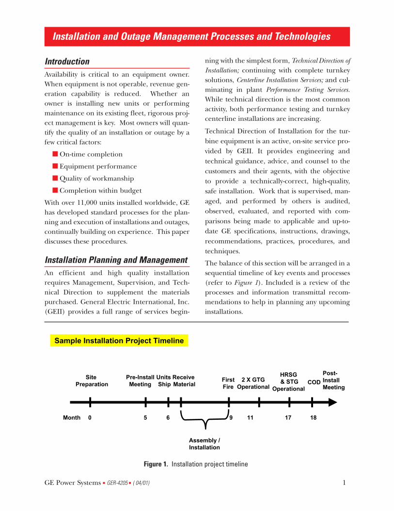
The balance of this section will be arranged in asequential timeline of key events and processes(refer to Figure 1). Included is a review of theprocesses and information transmittal recom-mendations to help in planning any upcominginstallations.
Installation and Outage Management Processes and Technologies
GE Power Systems ■ GER-4205 ■ ( 04/01) 1
Pre-InstallMeeting
Units Ship COD
Post- InstallMeeting
Site Preparation
Month 0 5 6 18
2 X GTGOperational
1711
HRSG & STG
Operational
9
FirstFire
Sample Installation Project Timeline
Receive Material
Assembly /Installation
Figure 1. Installation project timeline
Pre-Installation Meeting A pre-installation meeting is normally heldbefore shipment of the major alignment com-ponents.
Pre-installation meetings are held for the pur-pose of bringing together those people who willbe responsible for the successful installation ofthe GE turbine equipment.
The objectives are fourfold:
1. To discuss the information describedin the installation plan.
2. To establish a mutual understandingof commitments.
3. To describe the General ElectricInternational, Inc. installation supportactivities
4. To establish a channel ofcommunication during the installationperiod.
Installation Processes The following activities must be considered andplanned as part of a successful installation andstart-up:
■ Unloading of material
■ Material movement, such as skiddingand cribbing of heavy components
■ Examination of material for loss ordamage
■ Inspection of site storage andwarehousing facilities
■ Maintenance of adequate storagerecords
■ Installation coordination
■ Coordination and administration ofthe procurement of tools andequipment
■ Inspection of foundation and settingof foundation plates
■ Installation, inspection, and assemblyof the turbines and associatedequipment
■ Inspection of assembly, clearances,alignment and cleanliness
■ Fluid and auxiliary systems flushingand cleaning operations
■ Commissioning coordination
■ Equipment start-up and initialoperation responsibilities
■ Equipment placed into service
■ Post-installation meeting
Material Control Recent data collected on global installation sitesindicates that 10.8% of all installer delays maybe linked to material receiving, storage andcontrol processes. The importance of creatingproper facilities and procedures for receiving,cataloguing, and storing material at the job sitecannot be overemphasized. We recommend thefollowing procedures for handling the materialafter it is received. It has been demonstratedthat installation efficiency can be maximizedwhen material is readily available at therequired time. While identification and accessi-bility are major factors, the need for quicklyreplacing damaged or missing material is prob-ably more significant in maintaining a sensiblework plan. We strongly recommend that themethods outlined in this section be given care-ful consideration to ensure prompt replace-ments or repairs when required.
Arrival and Inspection All material and equipment should be inspect-ed upon arrival at the carrier's final deliverypoint. This inspection should include but notbe limited to the following:
Installation and Outage Management Processes and Technologies
GE Power Systems ■ GER-4205 ■ ( 04/01) 2
1. Inspect the protective covering andpacking for obvious damage in transit.
2. Inspect the “HUMP METERS” andblocking of components on thetransport vehicle for shifting duringshipment.
3. Check the orientation of anycomponents related to gas turbinefoundation where special orientationhad been requested.
4. Check the condition of all equipmentand material when received, andinventory it.
5. Review the carrier's documentationbefore accepting the delivery for thefollowing:
■ Material Safety Data Sheets (MSDS)for HAZARDOUS material.
■ A packing list of the equipment being delivered.
Carload shipments should be promptlyunloaded to avoid demurrage charges andarranged in an accessible and convenient man-ner for further inspection and handling.
Inventory Control The importance of a system for proper invento-ry control cannot be overemphasized if aneffective and efficient installation is to beaccomplished.
The process of receiving material shippeddirectly from GE suppliers includes the follow-ing steps:
Once the proper information isreceived, GE issues a Notification ofShipping Release (NSR) to thesupplier. A copy of this notification isfaxed to your material representative.The NSR contains the followinginformation:
■ Weights and dimensions
■ Package type (case, skid, crate, box)
■ Vendor
■ Case number
Case Number The case number is very important. It identifiesthe material with the following information.The first digit is the unit number designated forthis material. The next four alphanumeric char-acters identify the MLI or model list item num-ber. The last two digits are assigned sequential-ly for the particular MLI, starting with 01. Forexample, the first case (or crate or skid) for theInlet Duct Arrangement, A041, will be assignedcase number 1A04101. If there were 16 “cases”for this shipment, the last case would be1A04116.
When the material is received, the bill of ladingshould include the case number(s). However, itshould be checked against the actual case num-bers to make sure the material was delivered asintended. Each case should have a packing list,both outside and inside the box.
A running tally of the cases received against theNotification of Shipping Release (NSR) shouldbe kept. We suggest using a site map using thecase numbers to identify the locations of thevarious boxes. Generally, all the crates for singleitems should be received within three weeksafter the NSR is issued.
Material Shortages As materials are received, shortages may appear.In a broad sense “shortages” are defined as anypart needed but not available at the job site.Shortages fall into one of four categories:
1. Material known to be shipped but notreceived at the job site.
2. Material not known to be shipped butknown to be needed.
Installation and Outage Management Processes and Technologies
GE Power Systems ■ GER-4205 ■ ( 04/01) 3
3. Material received in insufficientquantity.
4. Material received but damaged inshipment or on site, or lost on site.
Material Shortage Report The Technical Director will issue a MaterialShortage Report in all cases where:
1. An insufficient quantity of materials isreceived at the site.
2. Needed materials are not received andare not known to be shipped.
3. Materials are known to be shipped butare not received.
A Material Shortage Report, indicating therequired information and reason for the short-age, will serve as an order for the requiredmaterials and initiate shipment of the part(s) tothe job site.
Installation Coordination
Technical Direction Role The size and complexity of many turbines pro-hibits full assembly and testing in the factory. Toensure that the equipment is properly installed,aligned, and checked out before operation,GEII provides Technical Direction duringinstallation. This service is essential for a prop-er interpretation of the design criteria, asexpressed in the drawings and instructionbooks during installation and start-up.
Installation Change Control Equipment changes are sometimes required inthe field for a number of reasons. Additionally,GEII continuously evaluates installation meth-ods. As new and better methods are developed,they will be provided. The formal transmittal ofthese changes is made through the use ofEngineering Change Notices (ECNs) orTechnical Information Letters (TILs).
1. ECNs are limited to the description ofequipment changes. The principalpurpose of ECNs is to leveragecorrective actions that were discoveredin the field on similar units, andimplement the corrective actionbefore the same issue is realized. TheECN will list the drawings affected,parts required, and the disposition ofthe affected equipment.
2. TILs are used when a generic-type ofchange is involved, especially when alarge distribution is required. TILs arealso used as a means to transmitinstallation recommendations invarious areas where drawing changesare not involved.
For gas turbine installations, the site TechnicalDirection team will conduct three periodic con-ference calls with the Product Service andEngineering teams. These calls occur threemonths prior to first fire, one month prior tofirst fire, and one week prior to first fire. Theintent of this call series is to ensure that the siteteam has received and implemented all TILsand ECNs applicable to your particular unit andthat the team has access to the latest and mostcurrent system documentation.
Procedural Documentation GEII uses several other methods of providinginstallation directions to the job site. Many pub-lications with identifying series numbers such asGEI-86151 (Low Voltage Power Circuit Breaker)and GEK-39672 (Switchgear) are issued by cog-nizant engineering functions. Most of thesepublications are included in the instructionbooks that are distributed at the time the unitships. There are a few that are not directly relat-ed to specific equipment and are not includedin the instruction book. These are distributed
Installation and Outage Management Processes and Technologies
GE Power Systems ■ GER-4205 ■ ( 04/01) 4
by the local GEII office when they are applica-ble to the installation.
Installation Schedule A basic requirement for a successful installationplan is the installation schedule. This schedulecan take various forms from a bar chart to acomplex logic network programmed with provi-sions for resource allocations. The bar chartallows you to list your work activities in sequen-tial order, plan your job duration, determineyour labor and material requirements, andtrack the job. The logic network, when proper-ly programmed, allows all of the above plus crit-ical-path planning, periodic job tracking withcompensation for manpower and material defi-ciencies, and job-cost tracking. The installationschedule that you use on the turbine installa-tion should be designed to meet your needs andprovide the optimum installation cycle.
While responsibility for schedule creation,maintenance, and adherence remain with theinstaller, it is critical that the installer and GEIITechnical Direction team review the scheduletasks in concert, to ensure that all work tasks areprovided for and to fully leverage the past expe-riences of both parties.
Certain interfaces between the turbines andother equipment on-site will take place duringthe installation. Prior to interface activities,depending on the operation involved, a meet-ing should be held to discuss dates, problems,specifications, and any special requirementsthat may be involved.
Progress Meetings Periodic reviews of the installation and commis-sioning activities are of major importance if thecommercial operating date is to be achieved.
As Built Construction Prints The Construction Print List contains all the pri-mary and secondary drawings, process instruc-
tions, applicable parts lists, and a few detailedmachine drawings. These prints, which repre-sent the “as built” condition of the gas turbines,are provided to the technical director to assisthim in his consulting capacity. Any drawings inthe sets that are changed during the installationperiod are replaced with the updated drawing.When the installation is complete, theTechnical Director will provide the customerwith a set of the construction prints less theparts lists (PLs) and machine drawings. This setwill describe the “as built” condition of the gasturbine.
Special Tools GE will supply a variety of special tools for thegas turbines and generators that are not nor-mally furnished by the installation contractor. Alist of special tools provided by GE is includedwith the construction print list under “ToolList” or “Installation Device.” The special toolsshown on these lists are part of the turbine andgenerator packages and are turned over anddocumented at the completion of the turbineinstallation. It is important that these devices becarefully stored and protected for future main-tenance on the machine.
Post-Installation Meeting In addition to the pre-installation meeting,additional job-site meetings will be scheduledon an as needed basis. The last meeting thatGEII will schedule as part of turbine installationis the post-installation meeting. The post-instal-lation meeting is the formal conclusion of allinstallation activities and includes the presenta-tion and review of installation data, tools, andconstruction prints. The post-installation meet-ing is normally held one month after the com-mercial operating date.
Maintenance Management Turbine maintenance has been viewed tradi-
Installation and Outage Management Processes and Technologies
GE Power Systems ■ GER-4205 ■ ( 04/01) 5
tionally as an activity that takes place at standardintervals during a scheduled outage. That viewis changing. While turbine maintenance oftentakes place according to established plantschedules (for example, during a nuclear refu-eling) the approach has evolved to one of man-aging Asset Performance. Equipment owners areevaluating their overall fleet and analyzing themost effective way to maximize the revenue gen-erated. This could include extending intervalsbetween maintenance cycles, or it could meantaking an outage earlier than usual in order toinstall a performance enhancement package.The increasingly macro view of turbine equip-ment compels a need for even more rigorousplanning and analysis. In the past, Owners andService Providers considered the planning formaintenance as an activity that began about 6months to a year in advance of an outage. Itwould begin with an Advanced Review Meetingand end with a Post-Outage Review Meeting,where the final inspection report and futurerecommendations would be reviewed. Someactions were taken, but often the report wouldnot be filed until the next planning cycle.
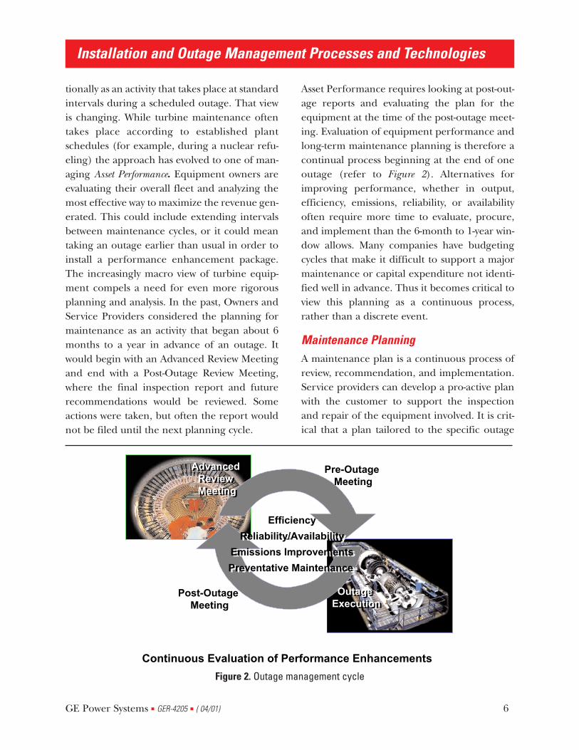
Asset Performance requires looking at post-out-age reports and evaluating the plan for theequipment at the time of the post-outage meet-ing. Evaluation of equipment performance andlong-term maintenance planning is therefore acontinual process beginning at the end of oneoutage (refer to Figure 2). Alternatives forimproving performance, whether in output,efficiency, emissions, reliability, or availabilityoften require more time to evaluate, procure,and implement than the 6-month to 1-year win-dow allows. Many companies have budgetingcycles that make it difficult to support a majormaintenance or capital expenditure not identi-fied well in advance. Thus it becomes critical toview this planning as a continuous process,rather than a discrete event.
Maintenance Planning A maintenance plan is a continuous process ofreview, recommendation, and implementation.Service providers can develop a pro-active planwith the customer to support the inspectionand repair of the equipment involved. It is crit-ical that a plan tailored to the specific outage
GE Power Systems ■ GER-4205 ■ ( 04/01) 6
Installation and Outage Management Processes and Technologies
Continuous Evaluation of Performance EnhancementsContinuous Evaluation of Performance Enhancements
Outage Execution
Outage Execution
Post-Outage Meeting
Post-Outage Meeting
Pre-Outage Meeting
Pre-Outage Meeting
AdvancedReview
Meeting
AdvancedReview
Meeting
Efficiency
Reliability/Availability
Emissions Improvements
Preventative Maintenance
Efficiency
Reliability/Availability
Emissions Improvements
Preventative Maintenance
Figure 2. Outage management cycle
scope is developed so that participants under-stand their responsibilities and the impact thatoutage planning has on its successful comple-tion. This plan must include all work activities,as well as the schedule, parts lists, tooling andequipment requirements, and repair servicesexpected. Service providers can assist in devel-oping recommendations for parts, and cantrack and expedite as needed. Additionally, theycan review repair requirements and can assist inplanning the workscope with the selected repairfacility. It is key to the outage schedule that allrepairs are coordinated. Utilizing a ThreeMeeting Concept is an effective process to use fordeveloping maintenance plans. The purpose ofeach meeting is described below.
Post-Outage Review Meeting This meeting is the end point of one outageand the start point for the next. It is held fol-lowing the completion of an outage. Its purposeis to review the outage report, performance,and findings, as well as to identify problems,determine best practices, and discuss recom-mendations. A performance review, for whichcriteria should be established at the pre-outagemeeting, should take place. In addition, partsrecommendations can be made and a prelimi-nary plan for the next scheduled outage can beoutlined. The final outage report shouldinclude:
■ Job summary
■ Inspection summary
■ Recommendations
■ Parts used and recommended
■ TIL/ECN activity
■ Combustion section data
■ Compressor section data (ifapplicable)
■ Turbine section data (if applicable)
■ Lube oil system inspection (ifapplicable)
■ Coupling inspection (if applicable)
■ Enclosures (if applicable)
■ Alignment and clearance overview (ifapplicable)
■ Start Up comments
Advanced Review Meeting The current condition of the equipment isreviewed to determine recommendations foroperational and outage planning. Parts, materi-al, technical and procedural issues areaddressed to ensure that actions are imple-mented as required to support the scheduledmaintenance program. These meetings areheld 6-to-8 months in advance of all scheduledoutages. The following activities take place atthis session.
■ Review previous inspection report
■ Review unit history since lastinspection and identify additionalwork scope
- This includes operational trendingdata
- Forced outage occurrences
- Operational issues, which requiremaintenance activity at a scheduledinspection (such as lube oil leaks,faulty instrumentation, etc.)
- Specific fleet issues, which mayaffect reliability of the unit
■ Review parts inventory for unit
■ Review all parts orders and associateddelivery dates
■ Review TIL list for unit for additionalworkscope and parts requirements
■ Review status of parts beingrefurbished
Installation and Outage Management Processes and Technologies
GE Power Systems ■ GER-4205 ■ ( 04/01) 7
■ Review completion / ship dates
■ Review inspection reports / findings
■ Review changes in safety regulations,which require implementation duringthe next inspection
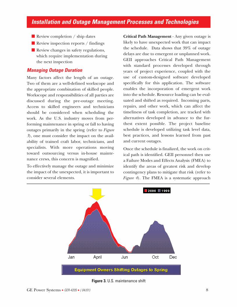
Managing Outage Duration Many factors affect the length of an outage.Two of them are a well-defined workscope andthe appropriate combination of skilled people.Workscope and responsibilities of all parties arediscussed during the pre-outage meeting.Access to skilled engineers and techniciansshould be considered when scheduling thework. As the U.S. industry moves from per-forming maintenance in spring or fall to havingoutages primarily in the spring (refer to Figure3), one must consider the impact on the avail-ability of trained craft labor, technicians, andspecialists. With more operations movingtoward outsourcing versus in-house mainte-nance crews, this concern is magnified.
To effectively manage the outage and minimizethe impact of the unexpected, it is important toconsider several elements.
Critical Path Management - Any given outage islikely to have unexpected work that can impactthe schedule. Data shows that 39% of outagedelays are due to emergent or unplanned work.GEII approaches Critical Path Managementwith standard processes developed throughyears of project experience, coupled with theuse of custom-designed software developedspecifically for this application. The softwareenables the incorporation of emergent workinto the schedule. Resource loading can be eval-uated and shifted as required. Incoming parts,repairs, and other work, which can affect thetimeliness of task completion, are tracked withalternatives developed in advance to the fur-thest extent possible. The project baselineschedule is developed utilizing task level data,best practices, and lessons learned from pastand current outages.
Once the schedule is finalized, the work on crit-ical path is identified. GEII personnel then usea Failure Modes and Effects Analysis (FMEA) toidentify the areas of greatest risk and developcontingency plans to mitigate that risk (refer toFigure 4). The FMEA is a systematic approach
Installation and Outage Management Processes and Technologies
GE Power Systems ■ GER-4205 ■ ( 04/01) 8
Figure 3. U.S. maintenance shift
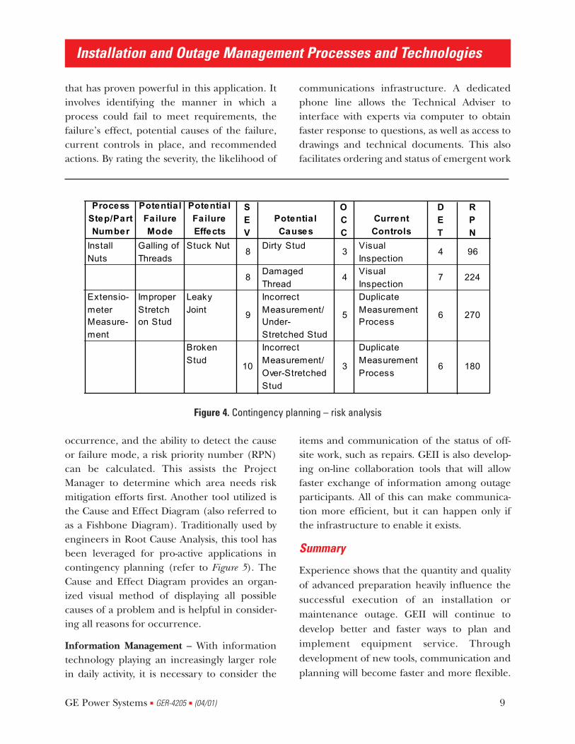
that has proven powerful in this application. Itinvolves identifying the manner in which aprocess could fail to meet requirements, thefailure’s effect, potential causes of the failure,current controls in place, and recommendedactions. By rating the severity, the likelihood of
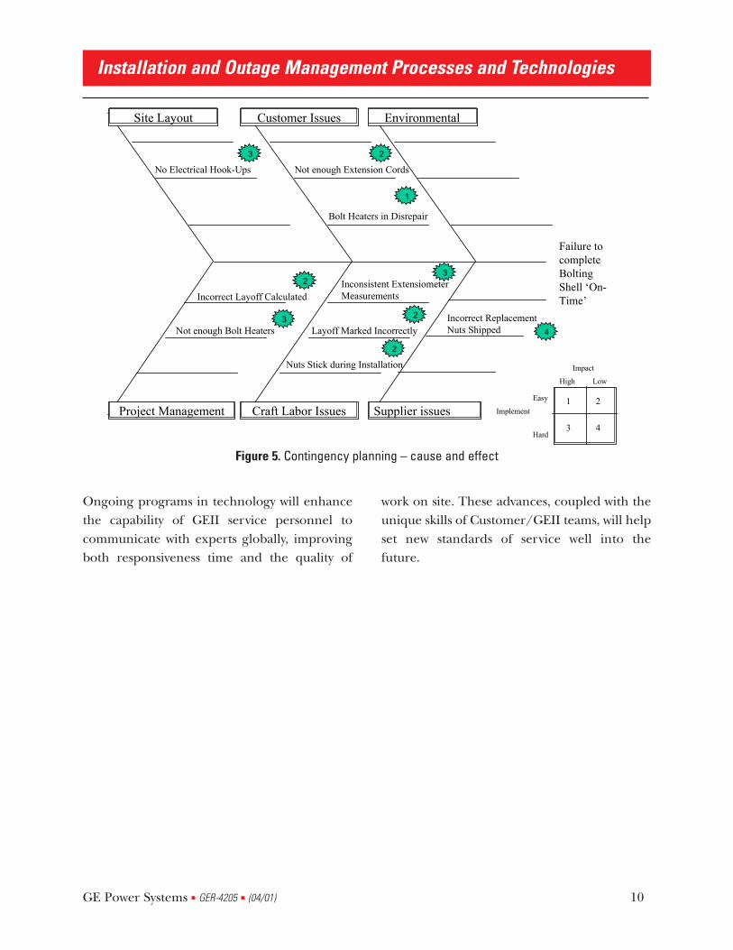
occurrence, and the ability to detect the causeor failure mode, a risk priority number (RPN)can be calculated. This assists the ProjectManager to determine which area needs riskmitigation efforts first. Another tool utilized isthe Cause and Effect Diagram (also referred toas a Fishbone Diagram). Traditionally used byengineers in Root Cause Analysis, this tool hasbeen leveraged for pro-active applications incontingency planning (refer to Figure 5). TheCause and Effect Diagram provides an organ-ized visual method of displaying all possiblecauses of a problem and is helpful in consider-ing all reasons for occurrence.
Information Management – With informationtechnology playing an increasingly larger rolein daily activity, it is necessary to consider the
communications infrastructure. A dedicatedphone line allows the Technical Adviser tointerface with experts via computer to obtainfaster response to questions, as well as access todrawings and technical documents. This alsofacilitates ordering and status of emergent work
items and communication of the status of off-site work, such as repairs. GEII is also develop-ing on-line collaboration tools that will allowfaster exchange of information among outageparticipants. All of this can make communica-tion more efficient, but it can happen only ifthe infrastructure to enable it exists.
Summary
Experience shows that the quantity and qualityof advanced preparation heavily influence thesuccessful execution of an installation ormaintenance outage. GEII will continue todevelop better and faster ways to plan andimplement equipment service. Throughdevelopment of new tools, communication andplanning will become faster and more flexible.
Installation and Outage Management Processes and Technologies
GE Power Systems ■ GER-4205 ■ (04/01) 9
Process Step/Part Number
Potentia l Failure Mode
Potentia l Failure Effects
SEV
Potentia l Causes
OCC
Current Controls
DET
RPN
Install Nuts
Galling of Threads
Stuck Nut8
Dirty Stud3
Visual Inspection
4 96
8Damaged Thread
4Visual Inspection
7 224
Extensio-meter Measure-ment
Improper Stretch on Stud
Leaky Joint 9
Incorrect Measurement/Under-Stretched Stud
5
Duplicate Measurement Process
6 270
Broken Stud
10
Incorrect Measurement/Over-Stretched Stud
3
Duplicate Measurement Process
6 180
Figure 4. Contingency planning – risk analysis
Ongoing programs in technology will enhancethe capability of GEII service personnel tocommunicate with experts globally, improvingboth responsiveness time and the quality of
work on site. These advances, coupled with theunique skills of Customer/GEII teams, will helpset new standards of service well into thefuture.
Installation and Outage Management Processes and Technologies
GE Power Systems ■ GER-4205 ■ (04/01) 10
1 2
3 4
Implement
Easy
Hard
Impact
High Low
Failure tocomplete Bolting Shell ‘On-Time’
Site Layout
Supplier issuesCraft Labor IssuesProject Management
EnvironmentalCustomer Issues
No Electrical Hook-Ups
Bolt Heaters in Disrepair
Nuts Stick during Installation
Not enough Bolt Heaters
Inconsistent ExtensiometerMeasurements
Incorrect ReplacementNuts Shipped
Not enough Extension Cords
Incorrect Layoff Calculated
Layoff Marked Incorrectly
2
2
2
3
3
3
1
2
4
Figure 5. Contingency planning – cause and effect
List of Figures Figure 1. Installation project timeline
Figure 2. Outage management cycle
Figure 3. U.S. maintenance shift
Figure 4. Contingency planning – risk analysis
Figure 5. Contingency planning – cause and effect
Installation and Outage Management Processes and Technologies
GE Power Systems ■ GER-4205 ■ (04/01) 11

Installation and Outage Management Processes and Technologies
GE Power Systems ■ GER-4205 ■ (04/01) 12


![Cell outage management in LTE networks [.pdf]](https://img.pdfslide.us/doc/110x75/584d41631a28ab857390778d/cell-outage-management-in-lte-networks-pdf.jpg)