Embed Size (px)
Citation preview


COPYRIGHT American Petroleum Institute


SPECIAL NOTES
API publications necessarily address problems of a general nature. With respect to partic-ular circumstances, local, state, and federal laws and regulations should be reviewed.
API is not undertaking to meet the duties of employers, manufacturers, or suppliers towarn and properly train and equip their employees, and others exposed, concerning healthand safety risks and precautions, nor undertaking their obligations under local, state, orfederal laws.
Information concerning safety and health risks and proper precautions with respect to par-ticular materials and conditions should be obtained from the employer, the manufacturer orsupplier of that material, or the material safety data sheet.
Nothing contained in any API publication is to be construed as granting any right, byimplication or otherwise, for the manufacture, sale, or use of any method, apparatus, or prod-uct covered by letters patent. Neither should anything contained in the publication be con-strued as insuring anyone against liability for infringement of letters patent.
Generally, API standards are reviewed and revised, reafÞrmed, or withdrawn at least everyÞve years. Sometimes a one-time extension of up to two years will be added to this reviewcycle. This publication will no longer be in effect Þve years after its publication date as anoperative API standard or, where an extension has been granted, upon republication. Statusof the publication can be ascertained from the API Upstream Segment [telephone (202) 682-8000]. A catalog of API publications and materials is published annually and updated quar-terly by API, 1220 L Street, N.W., Washington, D.C. 20005.
This document was produced under API standardization procedures that ensure appropri-ate notiÞcation and participation in the developmental process and is designated as an APIstandard. Questions concerning the interpretation of the content of this standard or com-ments and questions concerning the procedures under which this standard was developedshould be directed in writing to the standardization manager (shown on the title page of thisdocument), American Petroleum Institute, 1220 L Street, N.W., Washington, D.C. 20005.Requests for permission to reproduce or translate all or any part of the material publishedherein should also be addressed to the director.
API standards are published to facilitate the broad availability of proven, sound engineer-ing and operating practices. These standards are not intended to obviate the need for apply-ing sound engineering judgment regarding when and where these standards should beutilized. The formulation and publication of API standards is not intended in any way toinhibit anyone from using any other practices.
Any manufacturer marking equipment or materials in conformance with the markingrequirements of an API standard is solely responsible for complying with all the applicablerequirements of that standard. API does not represent, warrant, or guarantee that such prod-ucts do in fact conform to the applicable API standard.
All rights reserved. No part of this work may be reproduced, stored in a retrieval system, or transmitted by any means, electronic, mechanical, photocopying, recording, or otherwise,
without prior written permission from the publisher. Contact the Publisher, API Publishing Services, 1220 L Street, N.W., Washington, D.C. 20005.
Copyright © 2001 American Petroleum Institute
COPYRIGHT American Petroleum Institute

iii
FOREWORD
This speciÞcation is under the jurisdiction of the API Subcommittee on Drill Stem Ele-ments and Compounds.
American Petroleum Institute (API) speciÞcations are published as aids to the procure-ment of standardized equipment and materials, as well as instructions to manufacturers ofequipment or materials covered by an API speciÞcation. These speciÞcations are notintended to obviate the need for sound engineering, nor to inhibit in any way anyone frompurchasing or producing products to other speciÞcations.
The formulation and publication of API speciÞcations and the API monogram program isnot intended in any way to inhibit the purchase of products from companies not licensed touse the API monogram.
API speciÞcations may be used by anyone desiring to do so, and diligent effort has beenmade by the Institute to assure the accuracy and reliability of the data contained therein.However, the Institute makes no representation, warranty, or guarantee in connection withthe publication of any API speciÞcation and hereby expressly disclaims any liability orresponsibility for loss or damage resulting from their use, for any violation of any federal,state, or municipal regulation with which an API speciÞcation may conßict, or for theinfringement of any patent resulting from the use of an API speciÞcation.
Any manufacturer marking equipment or materials in conformance with the markingrequirements of an API speciÞcation is solely responsible for complying with all the appli-cable requirements of that speciÞcation. The American Petroleum Institute does not repre-sent, warrant or guarantee that such products do in fact conform to the applicable APIspeciÞcation.
Metric (SI) conversions of U.S. customary units are provided throughout the text of thisspeciÞcation in parentheses, e.g., 6 inches (152.4 millimeters). Metric equivalents of U.S.customary values are also included in tables and Þgures, some of which are reproduced inthe metric system in Appendix M.
Suggested revisions are invited and should be submitted to the standardization manager,American Petroleum Institute, 1220 L Street, N.W., Washington, D.C. 20005.
This standard shall become effective on the date printed on the cover but voluntary con-formance to the revisions may be used in whole or in part and either in lieu of or in conjunc-tion with the current specification from the date of distribution to constitute conformancewith the edition applicable at the date of manufacture.
COPYRIGHT American Petroleum Institute

COPYRIGHT American Petroleum Institute

v
CONTENTS
Page
1 SCOPE . . . . . . . . . . . . . . . . . . . . . . . . . . . . . . . . . . . . . . . . . . . . . . . . . . . . . . . . . . . . . . . 11.1 Coverage . . . . . . . . . . . . . . . . . . . . . . . . . . . . . . . . . . . . . . . . . . . . . . . . . . . . . . . . 11.2 Material Requirements. . . . . . . . . . . . . . . . . . . . . . . . . . . . . . . . . . . . . . . . . . . . . . 1
2 REFERENCES . . . . . . . . . . . . . . . . . . . . . . . . . . . . . . . . . . . . . . . . . . . . . . . . . . . . . . . . 1
3 DEFINITIONS. . . . . . . . . . . . . . . . . . . . . . . . . . . . . . . . . . . . . . . . . . . . . . . . . . . . . . . . . 1
4 UPPER AND LOWER KELLY VALVES . . . . . . . . . . . . . . . . . . . . . . . . . . . . . . . . . . . 44.1 General . . . . . . . . . . . . . . . . . . . . . . . . . . . . . . . . . . . . . . . . . . . . . . . . . . . . . . . . . . 44.2 Design Criteria . . . . . . . . . . . . . . . . . . . . . . . . . . . . . . . . . . . . . . . . . . . . . . . . . . . . 44.3 Connections . . . . . . . . . . . . . . . . . . . . . . . . . . . . . . . . . . . . . . . . . . . . . . . . . . . . . . 44.4 Inspection and Testing . . . . . . . . . . . . . . . . . . . . . . . . . . . . . . . . . . . . . . . . . . . . . . 54.5 Hydrostatic Testing . . . . . . . . . . . . . . . . . . . . . . . . . . . . . . . . . . . . . . . . . . . . . . . . 54.6 Marking . . . . . . . . . . . . . . . . . . . . . . . . . . . . . . . . . . . . . . . . . . . . . . . . . . . . . . . . . 6
5 SQUARE AND HEXAGON KELLYS . . . . . . . . . . . . . . . . . . . . . . . . . . . . . . . . . . . . . 65.1 Size, Type, and Dimensions. . . . . . . . . . . . . . . . . . . . . . . . . . . . . . . . . . . . . . . . . . 65.2 Dimensional Gauging . . . . . . . . . . . . . . . . . . . . . . . . . . . . . . . . . . . . . . . . . . . . . . 65.3 Connections . . . . . . . . . . . . . . . . . . . . . . . . . . . . . . . . . . . . . . . . . . . . . . . . . . . . . . 65.4 Square Forged Kellys. . . . . . . . . . . . . . . . . . . . . . . . . . . . . . . . . . . . . . . . . . . . . . . 65.5 Mechanical Properties . . . . . . . . . . . . . . . . . . . . . . . . . . . . . . . . . . . . . . . . . . . . . . 65.6 Marking . . . . . . . . . . . . . . . . . . . . . . . . . . . . . . . . . . . . . . . . . . . . . . . . . . . . . . . . 10
6 TOOL JOINTS. . . . . . . . . . . . . . . . . . . . . . . . . . . . . . . . . . . . . . . . . . . . . . . . . . . . . . . . 106.1 Tool Joint Size and Style . . . . . . . . . . . . . . . . . . . . . . . . . . . . . . . . . . . . . . . . . . . 106.2 Mechanical Properties . . . . . . . . . . . . . . . . . . . . . . . . . . . . . . . . . . . . . . . . . . . . . 106.3 Dimensional Requirements . . . . . . . . . . . . . . . . . . . . . . . . . . . . . . . . . . . . . . . . . 106.4 Tool JointDrill Pipe Weld Zone Requirements . . . . . . . . . . . . . . . . . . . . . . . . . . 106.5 Connections . . . . . . . . . . . . . . . . . . . . . . . . . . . . . . . . . . . . . . . . . . . . . . . . . . . . . 156.6 Marking . . . . . . . . . . . . . . . . . . . . . . . . . . . . . . . . . . . . . . . . . . . . . . . . . . . . . . . . 18
7 DRILL-STEM SUBS . . . . . . . . . . . . . . . . . . . . . . . . . . . . . . . . . . . . . . . . . . . . . . . . . . 187.1 Class and Type . . . . . . . . . . . . . . . . . . . . . . . . . . . . . . . . . . . . . . . . . . . . . . . . . . . 187.2 Types A & B Dimensions . . . . . . . . . . . . . . . . . . . . . . . . . . . . . . . . . . . . . . . . . . 187.3 Type C (Swivel Sub) Dimensions . . . . . . . . . . . . . . . . . . . . . . . . . . . . . . . . . . . . 187.4 Type D (Lift Sub) Dimensions . . . . . . . . . . . . . . . . . . . . . . . . . . . . . . . . . . . . . . 187.5 Material Mechanical Properties. . . . . . . . . . . . . . . . . . . . . . . . . . . . . . . . . . . . . . 197.6 Connection Stress Relief Feature . . . . . . . . . . . . . . . . . . . . . . . . . . . . . . . . . . . . 197.7 Cold Working On Thread Roots . . . . . . . . . . . . . . . . . . . . . . . . . . . . . . . . . . . . . 197.8 Marking . . . . . . . . . . . . . . . . . . . . . . . . . . . . . . . . . . . . . . . . . . . . . . . . . . . . . . . . 19
8 DRILL COLLARS . . . . . . . . . . . . . . . . . . . . . . . . . . . . . . . . . . . . . . . . . . . . . . . . . . . . 228.1 General . . . . . . . . . . . . . . . . . . . . . . . . . . . . . . . . . . . . . . . . . . . . . . . . . . . . . . . . . 228.2 Standard Steel Drill Collars . . . . . . . . . . . . . . . . . . . . . . . . . . . . . . . . . . . . . . . . . 228.3 Nonmagnetic Drill Collars. . . . . . . . . . . . . . . . . . . . . . . . . . . . . . . . . . . . . . . . . . 25
9 DRILLING AND CORING BITS . . . . . . . . . . . . . . . . . . . . . . . . . . . . . . . . . . . . . . . . 289.1 Roller Bits and Blade Drag Bits . . . . . . . . . . . . . . . . . . . . . . . . . . . . . . . . . . . . . 289.2 Diamond Drilling Bits, Diamond Core Bits, and Polycrystalline
Diamond Compact (PDC) Bits . . . . . . . . . . . . . . . . . . . . . . . . . . . . . . . . . . . . . . 28
COPYRIGHT American Petroleum Institute
vi
Page
10 ROTARY SHOULDERED CONNECTIONS. . . . . . . . . . . . . . . . . . . . . . . . . . . . . . . 3110.1 Size and Style. . . . . . . . . . . . . . . . . . . . . . . . . . . . . . . . . . . . . . . . . . . . . . . . . . . . 3110.2 Dimensions. . . . . . . . . . . . . . . . . . . . . . . . . . . . . . . . . . . . . . . . . . . . . . . . . . . . . . 3110.3 Equivalent Connections . . . . . . . . . . . . . . . . . . . . . . . . . . . . . . . . . . . . . . . . . . . . 31
11 GAUGING PRACTICE, ROTARY SHOULDERED CONNECTIONS. . . . . . . . . . 3511.1 Reference Master Gauges . . . . . . . . . . . . . . . . . . . . . . . . . . . . . . . . . . . . . . . . . . 3511.2 Working Gauges. . . . . . . . . . . . . . . . . . . . . . . . . . . . . . . . . . . . . . . . . . . . . . . . . . 3511.3 Gauge Relationship . . . . . . . . . . . . . . . . . . . . . . . . . . . . . . . . . . . . . . . . . . . . . . . 3511.4 Standoff Tolerances . . . . . . . . . . . . . . . . . . . . . . . . . . . . . . . . . . . . . . . . . . . . . . . 3511.5 Calibration System. . . . . . . . . . . . . . . . . . . . . . . . . . . . . . . . . . . . . . . . . . . . . . . . 35
12 GAUGE SPECIFICATION, ROTARY SHOULDERED CONNECTIONS . . . . . . . 3712.1 Grand and Regional Master Gauges . . . . . . . . . . . . . . . . . . . . . . . . . . . . . . . . . . 3712.2 Reference Master Gauges . . . . . . . . . . . . . . . . . . . . . . . . . . . . . . . . . . . . . . . . . . 3712.3 Working Gauges. . . . . . . . . . . . . . . . . . . . . . . . . . . . . . . . . . . . . . . . . . . . . . . . . . 3712.4 General Design. . . . . . . . . . . . . . . . . . . . . . . . . . . . . . . . . . . . . . . . . . . . . . . . . . . 3712.5 Lead . . . . . . . . . . . . . . . . . . . . . . . . . . . . . . . . . . . . . . . . . . . . . . . . . . . . . . . . . . . 3712.6 Taper. . . . . . . . . . . . . . . . . . . . . . . . . . . . . . . . . . . . . . . . . . . . . . . . . . . . . . . . . . . 3712.7 Root Form . . . . . . . . . . . . . . . . . . . . . . . . . . . . . . . . . . . . . . . . . . . . . . . . . . . . . . 3712.8 Initial Standoff . . . . . . . . . . . . . . . . . . . . . . . . . . . . . . . . . . . . . . . . . . . . . . . . . . . 3712.9 Miscellaneous Elements . . . . . . . . . . . . . . . . . . . . . . . . . . . . . . . . . . . . . . . . . . . 3812.10 Periodic Retest . . . . . . . . . . . . . . . . . . . . . . . . . . . . . . . . . . . . . . . . . . . . . . . . . . . 3812.11 Retest Standoff. . . . . . . . . . . . . . . . . . . . . . . . . . . . . . . . . . . . . . . . . . . . . . . . . . . 3912.12 Reconditioning. . . . . . . . . . . . . . . . . . . . . . . . . . . . . . . . . . . . . . . . . . . . . . . . . . . 3912.13 Marking . . . . . . . . . . . . . . . . . . . . . . . . . . . . . . . . . . . . . . . . . . . . . . . . . . . . . . . . 39
13 GAUGE CERTIFICATION, ROTARY SHOULDERED CONNECTIONS. . . . . . . 4313.1 CertiÞcation Agencies . . . . . . . . . . . . . . . . . . . . . . . . . . . . . . . . . . . . . . . . . . . . . 4313.2 General Requirements . . . . . . . . . . . . . . . . . . . . . . . . . . . . . . . . . . . . . . . . . . . . . 4313.3 CertiÞcation . . . . . . . . . . . . . . . . . . . . . . . . . . . . . . . . . . . . . . . . . . . . . . . . . . . . . 4313.4 Interchange Standoff . . . . . . . . . . . . . . . . . . . . . . . . . . . . . . . . . . . . . . . . . . . . . . 4313.5 Grand Master Gauges . . . . . . . . . . . . . . . . . . . . . . . . . . . . . . . . . . . . . . . . . . . . . 4313.6 Regional Master Gauges . . . . . . . . . . . . . . . . . . . . . . . . . . . . . . . . . . . . . . . . . . . 4313.7 Determination of Standoff . . . . . . . . . . . . . . . . . . . . . . . . . . . . . . . . . . . . . . . . . . 4313.8 Standoff Report . . . . . . . . . . . . . . . . . . . . . . . . . . . . . . . . . . . . . . . . . . . . . . . . . . 4413.9 Marking . . . . . . . . . . . . . . . . . . . . . . . . . . . . . . . . . . . . . . . . . . . . . . . . . . . . . . . . 44
14 CONNECTION MARKING. . . . . . . . . . . . . . . . . . . . . . . . . . . . . . . . . . . . . . . . . . . . . 44
15 INSPECTION AND REJECTION . . . . . . . . . . . . . . . . . . . . . . . . . . . . . . . . . . . . . . . . 44
APPENDIX A SUPPLEMENTARY REQUIREMENTS . . . . . . . . . . . . . . . . . . . . . . 45APPENDIX B INSTRUCTIONS FOR CARE AND USE OF REGIONAL
MASTER GAUGES . . . . . . . . . . . . . . . . . . . . . . . . . . . . . . . . . . . . . . . 47APPENDIX C INSTRUCTIONS FOR SHIPMENT OF REFERENCE
MASTER GAUGES . . . . . . . . . . . . . . . . . . . . . . . . . . . . . . . . . . . . . . . 49APPENDIX D RECOMMENDED PRACTICE FOR CARE AND USE
OF WORKING GAUGES . . . . . . . . . . . . . . . . . . . . . . . . . . . . . . . . . . 51APPENDIX E API GAUGE CERTIFICATION AGENCY REQUIREMENTS . . . . 53
COPYRIGHT American Petroleum Institute
vi
Page
APPENDIX F API GRAND AND REGIONAL MASTER ROTARY CONNECTION GAUGES . . . . . . . . . . . . . . . . . . . . . . . . . . . . . . . . . . 55
APPENDIX G RECOMMENDED THREAD COMPOUNDS FOR ROTARY SHOULDERED CONNECTIONS . . . . . . . . . . . . . . . . . . . . . . . . . . . 59
APPENDIX H RECOMMENDED PRACTICE FOR GAUGING NEW ROTARY SHOULDERED CONNECTIONS . . . . . . . . . . . . . . . . . . 61
APPENDIX I OBSOLESCENT TOOL JOINTS. . . . . . . . . . . . . . . . . . . . . . . . . . . . . 65APPENDIX J OBSOLESCENT ROTARY SHOULDERED CONNECTIONS. . . . 67APPENDIX K OBSOLESCENT ROTARY SHOULDERED CONNECTIONS. . . . 69APPENDIX L USE OF API MONOGRAM . . . . . . . . . . . . . . . . . . . . . . . . . . . . . . . . 71APPENDIX M METRIC TABLES . . . . . . . . . . . . . . . . . . . . . . . . . . . . . . . . . . . . . . . . 73APPENDIX N PURCHASER INSPECTION (OPTIONAL). . . . . . . . . . . . . . . . . . . . 89
Figures1 Typical Drill-Stem Assembly. . . . . . . . . . . . . . . . . . . . . . . . . . . . . . . . . . . . . . . . 32 Square Kellys . . . . . . . . . . . . . . . . . . . . . . . . . . . . . . . . . . . . . . . . . . . . . . . . . . . . 73 Hexagon Kellys . . . . . . . . . . . . . . . . . . . . . . . . . . . . . . . . . . . . . . . . . . . . . . . . . . 84 Sleeve Gauge for Kellys. . . . . . . . . . . . . . . . . . . . . . . . . . . . . . . . . . . . . . . . . . . . 95 Tensile Specimen and Hardness Test Location . . . . . . . . . . . . . . . . . . . . . . . . . 156 Tool Joint, Taper Shoulder, and Square Shoulder . . . . . . . . . . . . . . . . . . . . . . . 167 Tensile Test Specimen Location. . . . . . . . . . . . . . . . . . . . . . . . . . . . . . . . . . . . . 168 Impact Test Specimen Location and Orientation. . . . . . . . . . . . . . . . . . . . . . . . 169 Hardness Test Locations. . . . . . . . . . . . . . . . . . . . . . . . . . . . . . . . . . . . . . . . . . . 1710 Reference Standard. . . . . . . . . . . . . . . . . . . . . . . . . . . . . . . . . . . . . . . . . . . . . . . 1711 Sample Markings at Base of Pin . . . . . . . . . . . . . . . . . . . . . . . . . . . . . . . . . . . . 1712 Drill-Stem Subs . . . . . . . . . . . . . . . . . . . . . . . . . . . . . . . . . . . . . . . . . . . . . . . . . 2013 Float Valve Recess in Bit Subs. . . . . . . . . . . . . . . . . . . . . . . . . . . . . . . . . . . . . . 2014 Lift Subs . . . . . . . . . . . . . . . . . . . . . . . . . . . . . . . . . . . . . . . . . . . . . . . . . . . . . . . 2115 Drill Collars . . . . . . . . . . . . . . . . . . . . . . . . . . . . . . . . . . . . . . . . . . . . . . . . . . . . 2416 Connection Stress-Relief Features . . . . . . . . . . . . . . . . . . . . . . . . . . . . . . . . . . . 2417 Alternate Box Stress-Relief Feature . . . . . . . . . . . . . . . . . . . . . . . . . . . . . . . . . 2418 Low Torque Feature for 8
5
/
8
Regular Connections Machined on ODLarger Than 10
1
/
2
Inches (266.7 Millimeters) Excluding Bit Boxes . . . . . . . . 2519 Diamond Bit and PDC Bit Gauge Dimensions . . . . . . . . . . . . . . . . . . . . . . . . . 2920 Rotary Shouldered Connections. . . . . . . . . . . . . . . . . . . . . . . . . . . . . . . . . . . . . 3321 V-0.038R Product Thread Form. . . . . . . . . . . . . . . . . . . . . . . . . . . . . . . . . . . . . 3322 V-0.040 and V-0.050 Product Thread Form. . . . . . . . . . . . . . . . . . . . . . . . . . . . 3422a V-0.055 Product Thread Form . . . . . . . . . . . . . . . . . . . . . . . . . . . . . . . . . . . . . . 3423 Rotary Shouldered Connection Gauging Practice . . . . . . . . . . . . . . . . . . . . . . . 3624 Grand Regional and Reference Master Thread Gauges Rotary
Shouldered Connections. . . . . . . . . . . . . . . . . . . . . . . . . . . . . . . . . . . . . . . . . . . 3925 Working Thread Gauges Rotary Shouldered Connection . . . . . . . . . . . . . . . . . 3926 Gauge Thread Form . . . . . . . . . . . . . . . . . . . . . . . . . . . . . . . . . . . . . . . . . . . . . . 4027 Torque Hammer . . . . . . . . . . . . . . . . . . . . . . . . . . . . . . . . . . . . . . . . . . . . . . . . . 44H-1 External Taper Measurement . . . . . . . . . . . . . . . . . . . . . . . . . . . . . . . . . . . . . . . 61H-2 Internal Taper Measurement. . . . . . . . . . . . . . . . . . . . . . . . . . . . . . . . . . . . . . . . 63H-3 External Lead Measurement . . . . . . . . . . . . . . . . . . . . . . . . . . . . . . . . . . . . . . . 63H-4 Internal Lead Measurement . . . . . . . . . . . . . . . . . . . . . . . . . . . . . . . . . . . . . . . . 63H-5 Standard Lead Template. . . . . . . . . . . . . . . . . . . . . . . . . . . . . . . . . . . . . . . . . . . 63
vii
COPYRIGHT American Petroleum Institute

vi
Page
Tables1a Adjustment Factors for Impact Specimens . . . . . . . . . . . . . . . . . . . . . . . . . . . . . 41b Service Class DeÞnitions . . . . . . . . . . . . . . . . . . . . . . . . . . . . . . . . . . . . . . . . . . . 51c Hydrostatic Testing Pressures . . . . . . . . . . . . . . . . . . . . . . . . . . . . . . . . . . . . . . . 52 Square Kellys . . . . . . . . . . . . . . . . . . . . . . . . . . . . . . . . . . . . . . . . . . . . . . . . . . . . 73 Hexagon Kellys . . . . . . . . . . . . . . . . . . . . . . . . . . . . . . . . . . . . . . . . . . . . . . . . . . 84 Kelly Sleeve Gauge . . . . . . . . . . . . . . . . . . . . . . . . . . . . . . . . . . . . . . . . . . . . . . . 95 Mechanical Properties and Tests New Kellys . . . . . . . . . . . . . . . . . . . . . . . . . . . 96 Mechanical Properties of New Tool Joints at Locations Shown in Figure 5 . . 107 Tool Joint Dimensions for Grades E75, X95, G105, and S135 Drill Pipe . . . . 118 Subsize Specimen Impact Strength Requirements . . . . . . . . . . . . . . . . . . . . . . 149 Drill-Stem Subs . . . . . . . . . . . . . . . . . . . . . . . . . . . . . . . . . . . . . . . . . . . . . . . . . 1910 Mechanical Properties and Test New Steel Drill-Stem Subs . . . . . . . . . . . . . . 1911 Dimensional Data for Lift Sub Upper Lift Diameters. . . . . . . . . . . . . . . . . . . . 1912 Float Valve Recess in Bit Subs. . . . . . . . . . . . . . . . . . . . . . . . . . . . . . . . . . . . . . 2113 Drill Collars . . . . . . . . . . . . . . . . . . . . . . . . . . . . . . . . . . . . . . . . . . . . . . . . . . . . 2314 Drill Collar OD Tolerances . . . . . . . . . . . . . . . . . . . . . . . . . . . . . . . . . . . . . . . . 2315 Drill Collar Surface Imperfection Removal. . . . . . . . . . . . . . . . . . . . . . . . . . . . 2416 Stress-Relief Features for Drill Collar Connections . . . . . . . . . . . . . . . . . . . . . 2517 Mechanical Properties and Tests New Standard Steel Drill Collars . . . . . . . . . 2718 Connections for Bottom Hole Drill Collars. . . . . . . . . . . . . . . . . . . . . . . . . . . . 2719 Additional Nonmagnetic Drill Collars. . . . . . . . . . . . . . . . . . . . . . . . . . . . . . . . 2720 Mechanical Properties and Tests, New Nonmagnetic Drill Collars . . . . . . . . . 2721 Roller Bit Connections . . . . . . . . . . . . . . . . . . . . . . . . . . . . . . . . . . . . . . . . . . . . 2922 Blade Drag Bit Connections. . . . . . . . . . . . . . . . . . . . . . . . . . . . . . . . . . . . . . . . 2923 Diamond Drilling, Diamond Core, and PDC Bit Tolerances . . . . . . . . . . . . . . 3024 Diamond Drilling Bit and PDC Bit Connections . . . . . . . . . . . . . . . . . . . . . . . 3025 Product Dimensions Rotary Shouldered Connections . . . . . . . . . . . . . . . . . . . 3226 Product Thread Dimensions Rotary Shouldered Connections . . . . . . . . . . . . . 3327 Gauge Dimensions Rotary Shouldered Connections . . . . . . . . . . . . . . . . . . . . 3828 Gauge Thread Dimensions Rotary Shouldered Connections . . . . . . . . . . . . . . 4029 Tolerances On Reference Master Gauge Dimensions . . . . . . . . . . . . . . . . . . . . 4130 Tolerances On Grand and Regional Master Gauge Dimensions. . . . . . . . . . . . 4131 Tolerances on Working Gauge Dimensions. . . . . . . . . . . . . . . . . . . . . . . . . . . . 42F-1 Numbered Connections . . . . . . . . . . . . . . . . . . . . . . . . . . . . . . . . . . . . . . . . . . . 55F-2 Regular Right-Hand (REG) . . . . . . . . . . . . . . . . . . . . . . . . . . . . . . . . . . . . . . . . 56F-3 Regular Left-Hand (REG LH) . . . . . . . . . . . . . . . . . . . . . . . . . . . . . . . . . . . . . . 56F-4 Full-Hole Right-Hand (FH) . . . . . . . . . . . . . . . . . . . . . . . . . . . . . . . . . . . . . . . . 57F-5 Internal-Flush Right-Hand (IF) . . . . . . . . . . . . . . . . . . . . . . . . . . . . . . . . . . . . . 57H-1 Compensated Thread Lengths and Ball Point Diameters for Measurements
Parallel to the Taper Cone . . . . . . . . . . . . . . . . . . . . . . . . . . . . . . . . . . . . . . . . . 62I-1 Obsolescent Tool Joints With Taper Shoulder and Square Shoulder . . . . . . . . 65J-1 Product Dimensions For Obsolescent Rotary Shouldered Connections. . . . . . 67K-1 Gauge Dimensions For Obsolescent Rotary Shouldered Connections. . . . . . . 69
viii
COPYRIGHT American Petroleum Institute

vi
Page
Metric Tables
Note: The following metric tables correspond to the tables on the previous page (e.g., Table 2, SquareKellys, below is the metric table to Table 2, Square Kellys, on the previous page).
2 Square Kellys . . . . . . . . . . . . . . . . . . . . . . . . . . . . . . . . . . . . . . . . . . . . . . . . . . . 743 Hexagon Kellys . . . . . . . . . . . . . . . . . . . . . . . . . . . . . . . . . . . . . . . . . . . . . . . . . 754 Kelly Sleeve Gauge . . . . . . . . . . . . . . . . . . . . . . . . . . . . . . . . . . . . . . . . . . . . . . 757 Tool Joint Dimensions For Grade E75, X95, G105, and S13
Drill Pipe. . . . . . . . . . . . . . . . . . . . . . . . . . . . . . . . . . . . . . . . . . . . . . . . . . . . . . . 7612 Float Valve Recess In Bit Subs. . . . . . . . . . . . . . . . . . . . . . . . . . . . . . . . . . . . . . 7813 Drill Collars . . . . . . . . . . . . . . . . . . . . . . . . . . . . . . . . . . . . . . . . . . . . . . . . . . . . 7916 Stress-Relief Features for Drill-Collar Connections . . . . . . . . . . . . . . . . . . . . . 8025 Product Dimensions Rotary Shouldered Connections . . . . . . . . . . . . . . . . . . . 8126 Product Thread Dimensions Rotary Shouldered Connections . . . . . . . . . . . . . 8227 Gauge Dimensions Rotary Shouldered Connections . . . . . . . . . . . . . . . . . . . . 8228 Gauge Thread Dimensions Rotary Shouldered Connections . . . . . . . . . . . . . . 8329 Tolerances On Reference Master Gauge Dimensions . . . . . . . . . . . . . . . . . . . 8330 Tolerances On Grand and Regional Master Gauge Dimensions. . . . . . . . . . . . 8431 Tolerances On Working Gauge Dimensions . . . . . . . . . . . . . . . . . . . . . . . . . . . 84H-1 Compensated Thread Lengths and Ball Point Diameters for Measurements
Parallel to the Taper Cone . . . . . . . . . . . . . . . . . . . . . . . . . . . . . . . . . . . . . . . . . 85I-1 Obsolescent Tool Joints With Taper Shoulder and Square
Shoulder . . . . . . . . . . . . . . . . . . . . . . . . . . . . . . . . . . . . . . . . . . . . . . . . . . . . . . . 86J-1 Product Dimensions for Obsolescent Rotary Shouldered
Connections . . . . . . . . . . . . . . . . . . . . . . . . . . . . . . . . . . . . . . . . . . . . . . . . . . . . 87K-1 Gauge Dimensions for Obsolescent Rotary Shouldered
Connections . . . . . . . . . . . . . . . . . . . . . . . . . . . . . . . . . . . . . . . . . . . . . . . . . . . . 87
ix
COPYRIGHT American Petroleum Institute

COPYRIGHT American Petroleum Institute

1
Specification for Rotary Drill Stem Elements
1 Scope
1.1 COVERAGE
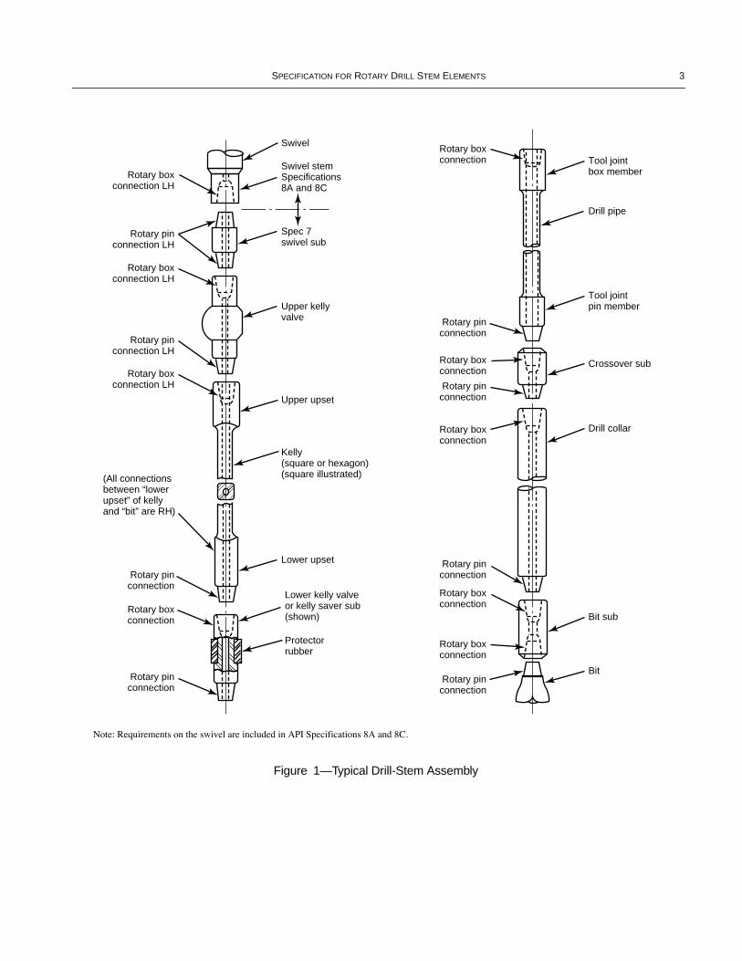
This speciÞcation covers requirements on drill-stem mem-bers (except drill pipe), including threaded connections,gauging practice, and master gauges therefor. A typical drill-stem assembly is shown in Figure 1. Also included, as appen-dices, are recommended practices on care and use of regionalmaster, reference master, and working gauges.
1.2 MATERIAL REQUIREMENTS
Where material requirements are not otherwise speciÞed,material for equipment supplied to this speciÞcation may varydepending on the application but shall comply with the manu-facturerÕs written speciÞcations. Manufacturer speciÞcationsshall deÞne:
a. Chemical composition limits.b. Heat treatment conditions.c. Mechanical property limits:
1. Tensile strength.2. Yield strength.3. Elongation.4. Hardness.
2 References
APIRP 5A3
Thread Compounds for Casing, Tubing,and Line Pipe
RP 7A1
Testing of Thread Compound for RotaryShouldered Connections
RP 7G
Drill Stem Design and Operating Limits
Spec 5D
Drill Pipe
Spec 7
Rotary Drill Stem Elements
, 32nd EditionSpec 8A
Drilling and Production HoistingEquipment
Spec 8C
Drilling and Production Hoisting Equip-ment (PSL 1 and PSL 2)
ASME
1
Boiler and Pressure Vessel Code
, Section IX, ÒWeldingand Brazing QualiÞcationsÓ
ASNT
2
RP SNT-TC-1A Recommended Practice No. SNT-TC-1A
ASTM
3
A262
Practice E
A370
Test Methods and Definitions for Mechani-cal Testing of Steel Products
A434
Steel Bars, Alloy, Hot-Wrought or Cold-Finished, Quenched and Tempered
E8
Tension Testing of Metallic Materials
E10
Test Method for Brinell Hardness of Metal-lic Materials
E23
Notched Bar Impact Testing of MetallicMaterials
E114
Ultrasonic Pulse-Echo Straight-BeamExamination by the Contact Method
E214
Immersed Ultrasonic Examination by theReflection Method Using Pulsed Longitu-dinal Waves
E709
Standard Guide for Magnetic ParticleEvaluation
E1001
Detection and Evaluation of Discontinui-ties by the Immersed Pulse-EchoUltrasonic Method Using LongitudinalWaves
NACE
4
MR-01-75
Sulfide Stress Cracking Resistant MetallicMateriall for Oil Field Equipment
3 Definitions
For the purposes of this speciÞcation, the following deÞni-tions apply:
3.1 bevel diameter:
The outer diameter of the contactface of the rotary shouldered connection.
3.2 bit sub:
A sub, usually with 2 box connections, that isused to connect the bit to the drill stem.
3.3 box connection:
A threaded connection on Oil Coun-try Tubular Goods (OCTG) that has internal (female) threads.
3.4 calibration system:
A documented system of gaugecalibration and control.
3.5 cold working:
Plastic deformation of metal at a tem-perature low enough to insure or cause permanent strain.
3.6 decarburization:
The loss of carbon from the surfaceof a ferrous alloy as a result of heating in a medium that reactswith the carbon at the surface.
1
American Society of Mechanical Engineers, 345 East 47th Street,New York, New York 10017.
2
American Society for Nondestructive Testing, Inc., 1711 ArlingateLane, Columbus, Ohio 43228.
3
American Society for Testing and Materials, 100 Barr HarborDrive, West Conshohocken, Pennsylvania 19428.
4
NACE International, P.O. Box 218340, Houston, Texas 77218-8340.
COPYRIGHT American Petroleum Institute
2 API S
PECIFICATION
7
3.7 drift:
A gauge used to check minimum ID of loops,ßowlines, nipples, tubing, casing, drill pipe, and drill collars.
3.8 drill collar:
Thick-walled pipe to provide stiffness andconcentration of weight at the bit.
3.9 drill pipe:
A length of tube, usually steel, to whichspecial threaded connections called tool joints are attached.
3.10 forging:
(1) Plastically deforming metal, usually hot,into desired shapes with compressive force, with or withoutdies. (2) A shaped metal part formed by the forging method.
3.11 full depth thread:
A thread in which the thread rootlies on the minor cone of an external thread or lies on themajor cone of an internal thread.
3.12 gauge point:
An imaginary plane, in the pin threads,perpendicular to the thread axis, in which the pitch diameterequals the value in Column 5 of Table 25.
3.13 kelly:
The square or hexagonal shaped steel pipe con-necting the swivel to the drill pipe. The kelly moves throughthe rotary table and transmits torque to the drill string.
3.14 kelly saver sub:
A short substitute that is made uponto the bottom of the kelly to protect the pin end of the kellyfrom wear during make-up and break-out operations.
3.15 last engaged thread:
The last thread on pinengaged with the box.
3.16
L
BT
:
Length of threads in the box measured from themake-up shoulder to the intersection of the non-pressureßank and crest of the last thread with full thread depth.
3.17 lower kelly valve (kelly cock):
An essentially full-opening valve installed immediately below the kelly, withoutside diameter equal to the tool joint outside diameter.Valve can be closed to remove the kelly under pressure andcan be stripped in the hole for snubbing operations.
3.18 make-up shoulder:
The sealing shoulder on arotary shouldered connection.
3.19 non-pressure flank:
The thread ßank on which noaxial load is induced from make-up of the connection or fromtensile load on the drill stem member. On the pin, it is thethread ßank farthest from the make-up shoulder. On the box,it is the thread ßank closest to the make-up shoulder.
3.20 pin end:
The external (male) threads of a threadedconnection.
3.21 pitch cone:
An imaginary cone whose diameter atany point is equal to the pitch diameter of the thread at thesame point.
3.22 pitch diameter:
The diameter at which the distanceacross the threads is equal to the distance between the threads.
3.23 quenched and tempered:
Quench hardeningÑhardening a ferrous alloy by austenitizing and then coolingrapidly enough that some or all of the austenite transforms tomartensite.
TemperingÑreheating a quenched-hardened or normal-ized ferrous alloy to a temperature below the transformationrange and then cooling at any rate desired.
3.24 reference dimension:
Dimension that is a result oftwo or more other dimensions.
3.25 rotary shouldered connection:
A connectionused on drill string elements, which has coarse, taperedthreads and sealing shoulders.
3.26 stress-relief feature:
A modiÞcation performed onrotary shouldered connections that removes the unengagedthreads of the pin or box. This process makes the joint moreßexible and reduces the likelihood of fatigue cracking in thishighly stressed area.
3.27 swivel:
Device at top of the drill stem that permitssimultaneous circulation and rotation.
3.28 tensile strength:
The maximum tensile stress that amaterial is capable of sustaining. Tensile strength is calcu-lated from the maximum load during a tension test carried torupture and the original cross-sectional area of the specimen.
3.29 test pressure:
A pressure above working pressureused to demonstrate structural integrity of a pressure vessel.
3.30 thread form:
The thread proÞle in an axial plane fora length of one pitch.
3.31 tolerance:
The amount of variation permitted.
3.32 tool joint:
A heavy coupling element for drill pipehaving coarse, tapered threads and sealing shoulders designedto sustain the weight of the drill stem, withstand the strain ofrepeated make-up and break-out, resist fatigue, resist addi-tional make-up during drilling, and provide a leak-proof seal.The male section (pin) is attached to one end of a length ofdrill pipe and the female section (box) is attached to the otherend. Tool joints may be welded to the drill pipe, screwed ontothe pipe, or a combination of screwed on and welded.
3.33 upper kelly valve (kelly cock):
A valve immedi-ately above the kelly that can be closed to conÞne pressuresinside the drill stem.
3.34 working gauges:
Gauges used for gauging productthreads.
3.35 working pressure:
The pressure to which a particu-lar piece of equipment is subjected during normal operations.
3.36 working temperature:
The temperature to which aparticular piece of equipment is subjected during normaloperations.
COPYRIGHT American Petroleum Institute
S
PECIFICATION
FOR
R
OTARY
D
RILL
S
TEM
E
LEMENTS
3
� ��
Rotary boxconnection LH
Rotary pinconnection LH
Rotary boxconnection LH
Rotary pinconnection LH
Rotary boxconnection LH
(All connectionsbetween “lowerupset” of kellyand “bit” are RH)
Rotary pinconnection
Rotary boxconnection
Rotary pinconnection
Rotary boxconnection
Rotary pinconnection
Rotary boxconnection
Rotary pinconnection
Rotary boxconnection
Rotary pinconnection
Rotary boxconnection
Rotary boxconnection
Rotary pinconnection
Swivel
Swivel stemSpecifications8A and 8C
Spec 7swivel sub
Upper kellyvalve
Upper upset
Kelly(square or hexagon)(square illustrated)
Lower upset
Lower kelly valveor kelly saver sub(shown)
Protectorrubber
Tool jointbox member
Drill pipe
Tool jointpin member
Crossover sub
Drill collar
Bit sub
Bit
Figure 1—Typical Drill-Stem Assembly
Note: Requirements on the swivel are included in API Specifications 8A and 8C.
COPYRIGHT American Petroleum Institute

4 API S
PECIFICATION
7
4 Upper and Lower Kelly Valves and Other Drill Stem Safety Valves
4.1 GENERAL
This speciÞcation primarily speciÞes the minimum design,material, inspection and testing requirements for upper andlower kelly valves. This speciÞcation also applies to drill-stemsafety valves used with overhead drilling systems. It appliesto valves of all sizes with rated working pressures of 5,000through 15,000 psi (34.5 through 103.4 MPa) applied in nor-mal service conditions (H
2
S service conditions are addressedas a supplemental requirement). Rated working temperaturesare Ð 4¡F (Ð 20¡C) and above for valve bodies; sealing systemcomponents may have other temperature limitations.
4.2 DESIGN CRITERIA
The manufacturer shall document the design criteria andanalysis for each type of valve produced under this speciÞca-tion. This documentation shall include loading conditionsthat will initiate material yield for valve body with minimummaterial properties and tolerances under combined loading;including tension, internal pressure and torsion. Body mate-rial yield loading conditions shall be documented in tabularform. The minimum design yield safety factor shall be 1.0 atthe shell test pressure found in Table 1c.
4.2.1 Material Requirements
For material requirements, see 1.2. Minimum mechanicalproperties shall conform to material requirements for drillcollars as speciÞed in Section 8.
Note: Mechanical properties shall be determined by tests on cylin-drical tensile specimens conforming to the requirements of ASTMA370, 0.2% offset method.
4.2.2 Impact Strength
4.2.2.1 Test Specimens
Three longitudinal impact test specimens per heat/heattreatment lot shall be tested in accordance with ASTM A370and ASTM E23. QualiÞcation test coupons may be integralwith the components they represent, separate from the com-ponents or a sacriÞcial production part. In all cases, test cou-pons shall be from the same heat as the components whichthey qualify and shall be heat treated with the components.
Test specimens shall be removed from integral or separatequaliÞcation test coupons such that their longitudinal centerline axis is wholly within the center
1
/
4
thickness envelope fora solid test coupon or within
1
/
8
in. (3 mm) of the mid-thick-ness of the thickest section of a hollow test coupon.
Test specimens taken from sacriÞcial production parts shallbe removed from the center
1
/
4
thickness envelope location ofthe thickest section of the part.
When the test coupon is obtained from a trepanned core orother portion removed from a production part, the test couponshall only qualify production parts that are identical in sizeand shape to the production part from which it was removed.
4.2.2.2 Requirements
The average impact value of the three specimens shall notbe less than 31 ft-lbs (42 J) with no single value below 24 ft-lbs (32 J) when tested at Ð 4¡F (Ð 20¡C).
4.2.2.3 Subsize Specimens
When it is necessary for sub-size impact test specimens tobe used, the acceptance criteria shall be multiplied by theappropriate adjustment factor listed in Table 1a. Sub-size testspecimens of width less than 5 mm are not permitted.
4.2.3 Pressure Sealing Performance Requirements
Kelly valves and other drill string safety valves (regardlessof closure mechanism) shall be designed for either surfaceonly or for surface and/or downhole service. Lower kellyvalves and lower safety valves used with overhead drillingsystems should be designed for downhole service. The designperformance requirements for pressure sealing for each ser-vice class are shown in Table 1b.
4.2.4 Basic Performance Requirements
Kelly valves and other drill string safety valves (regardlessof closure mechanism) should be designed to be capable ofthe following basic performance requirements:
a. Repeated operation in drilling mud.b. Closing to shut off a mud ßow from the drill string.c. Sealing over the design range of temperature and tensionload conditions.
4.3 CONNECTIONS
For all valves covered by this speciÞcation, end connectionsshall be as stated on the purchase order and the correspondingbevel diameters speciÞed for such connections shall be used.In the case of upper and lower kelly valves, connections shallbe of the size and type shown in Section 5, Tables 2 and 3unless otherwise stated on the purchase order. When suchconnections are employed, the corresponding bevel diametersspeciÞed for such connections shall be used. Purchaser shouldconsider specifying cold working of threads after thread gaug-ing; see Section 8 for applicable API speciÞcations.
Table 1a—Adjustment Factors for Impact Specimens
Specimen Dimensionsmm x mm Adjustment Factor
10 x 10 1.0010 x 7.5 0.83310 x 5 0.667
COPYRIGHT American Petroleum Institute
SPECIFICATION FOR ROTARY DRILL STEM ELEMENTS 5
End connections and any service connections shall be non-destructively inspected by the wet magnetic particle methodfor both transverse and longitudinal defects in accordancewith ASTM E709. The examination shall be performed inaccordance with a written procedure, which shall be madeavailable to the purchaser on request.
Note: Consult manufacturer for recommended make-up torque andcombined load rating of end connections and any service connectionssupplied. (Refer to API RP 7G, Appendix A ÒStrength and DesignFormulas,Ó for combined loading calculations for API connections.)
4.4 INSPECTION AND TESTING
The manufacturer shall maintain and provide on request tothe purchaser documentation of inspection (dimensional,visual and non-destructive) and hydrostatic testing for eachvalve supplied. The manufacturer shall maintain documenta-
tion of performance veriÞcation testing for a period of notless than 7 years after the last model is sold.
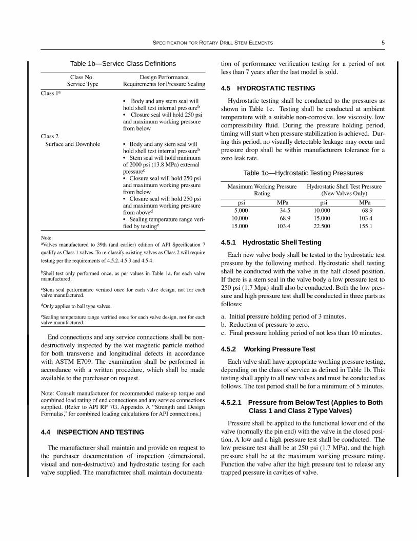
4.5 HYDROSTATIC TESTING
Hydrostatic testing shall be conducted to the pressures asshown in Table 1c. Testing shall be conducted at ambienttemperature with a suitable non-corrosive, low viscosity, lowcompressibility ßuid. During the pressure holding period,timing will start when pressure stabilization is achieved. Dur-ing this period, no visually detectable leakage may occur andpressure drop shall be within manufacturers tolerance for azero leak rate.
4.5.1 Hydrostatic Shell Testing
Each new valve body shall be tested to the hydrostatic testpressure by the following method. Hydrostatic shell testingshall be conducted with the valve in the half closed position.If there is a stem seal in the valve body a low pressure test to250 psi (1.7 Mpa) shall also be conducted. Both the low pres-sure and high pressure test shall be conducted in three parts asfollows:
a. Initial pressure holding period of 3 minutes.b. Reduction of pressure to zero.c. Final pressure holding period of not less than 10 minutes.
4.5.2 Working Pressure Test
Each valve shall have appropriate working pressure testing,depending on the class of service as deÞned in Table 1b. Thistesting shall apply to all new valves and must be conducted asfollows. The test period shall be for a minimum of 5 minutes.
4.5.2.1 Pressure from Below Test (Applies to Both Class 1 and Class 2 Type Valves)
Pressure shall be applied to the functional lower end of thevalve (normally the pin end) with the valve in the closed posi-tion. A low and a high pressure test shall be conducted. Thelow pressure test shall be at 250 psi (1.7 MPa), and the highpressure shall be at the maximum working pressure rating.Function the valve after the high pressure test to release anytrapped pressure in cavities of valve.
Table 1b—Service Class Definitions
Class No. Service Type
Design Performance Requirements for Pressure Sealing
Class 1a
¥ Body and any stem seal will hold shell test internal pressureb
¥ Closure seal will hold 250 psi and maximum working pressure from below
Class 2 Surface and Downhole ¥ Body and any stem seal will
hold shell test internal pressureb
¥ Stem seal will hold minimum of 2000 psi (13.8 MPa) external pressurec
¥ Closure seal will hold 250 psi and maximum working pressure from below¥ Closure seal will hold 250 psi and maximum working pressure from aboved
¥ Sealing temperature range veri-Þed by testinge
Note: aValves manufactured to 39th (and earlier) edition of API SpeciÞcation 7
qualify as Class 1 valves. To re-classify existing valves as Class 2 will require
testing per the requirements of 4.5.2, 4.5.3 and 4.5.4.
bShell test only performed once, as per values in Table 1a, for each valvemanufactured.
cStem seal performance veriÞed once for each valve design, not for eachvalve manufactured.
dOnly applies to ball type valves.
eSealing temperature range veriÞed once for each valve design, not for eachvalve manufactured.
Table 1c—Hydrostatic Testing Pressures
Maximum Working Pressure Rating
Hydrostatic Shell Test Pressure(New Valves Only)
psi MPa psi MPa5,000 34.5 10,000 68.9
10,000 68.9 15,000 103.415,000 103.4 22,500 155.1
COPYRIGHT American Petroleum Institute
6 API SPECIFICATION 7
4.5.2.2 Pressure from Above Test (Applies to Class 2 Type Valves Only)
Pressure shall be applied to the functional upper end of thevalve (normally the box end) with the valve in the closedposition. A low and a high pressure test shall be conducted.The low pressure test shall be at 250 psi (1.7 MPa), and thehigh pressure shall be at the maximum working pressure rat-ing. Function the valve after the high pressure test, to releaseany trapped pressure in cavities of valve, and repeat low pres-sure test.
Note: After working pressure tests completed, check that the align-ment of the ball or ßapper in the indicated Òopen positionÓ is stillwithin manufacturing tolerances. (Misalignment may cause ßuiderosion problems in Þeld applications.)
4.5.3 Stem Seal External Pressure Design Verification Test
Each Class 2 service valve design shall have appropriatestem seal external pressure testing as follows. The test periodshall be for a minimum of 5 minutes.
The stem seal external pressure test applies to Class 2 typevalves only and is only required for design veriÞcation pur-poses. Pressure shall be applied to the outside of the valve(e.g., through a high pressure sleeve mounted over the stemseal area) with the valve in the half open position. A low anda high pressure stem seal test shall be conducted. The lowpressure test shall be at 250 psi (1.7 MPa) and the high pres-sure test shall be at a minimum of 2,000 psi (13.8 MPa) butmay be higher, up to the rated working pressure, at manufac-turersÕ discretion.
4.5.4 Sealing Temperature Range Design Verification Test
This applies to Class 2 type valves only and is onlyrequired for design veriÞcation purposes. Standard non-metallic seal systems can typically cover the temperaturerange of 14¡F (Ð 10¡C) to 194¡F (90¡C), so design veriÞca-tion testing shall be conducted with the valve and test ßuid atthese temperature extremes unless purchaser speciÞes other-wise. Pressure testing shall be performed as per 4.5.2 and4.5.3 at both low and high temperature, using suitable testingßuids for extreme temperature conditions.
4.6 MARKING
Kelly valves and other drill-stem safety valves produced inaccordance with this speciÞcation shall be imprinted usinglow stress steel stamps or a low stress milling process as fol-lows:
a. Manufacturers name or mark, Spec 7, class of service,unique serial number, date of manufacture (Month/Year) and
maximum rated working pressure to be applied in milledrecess. b. Connection size and style to be applied on OD surfaceadjacent to connection.c. As appropriate, indication of rotation direction required toposition valve in closed position on OD surface adjacent toeach valve operating mechanism. d. Indication of normal mud ßow direction shall be marked onClass 1 type valves with an arrow (➔) and the word ÒFlowÓ.
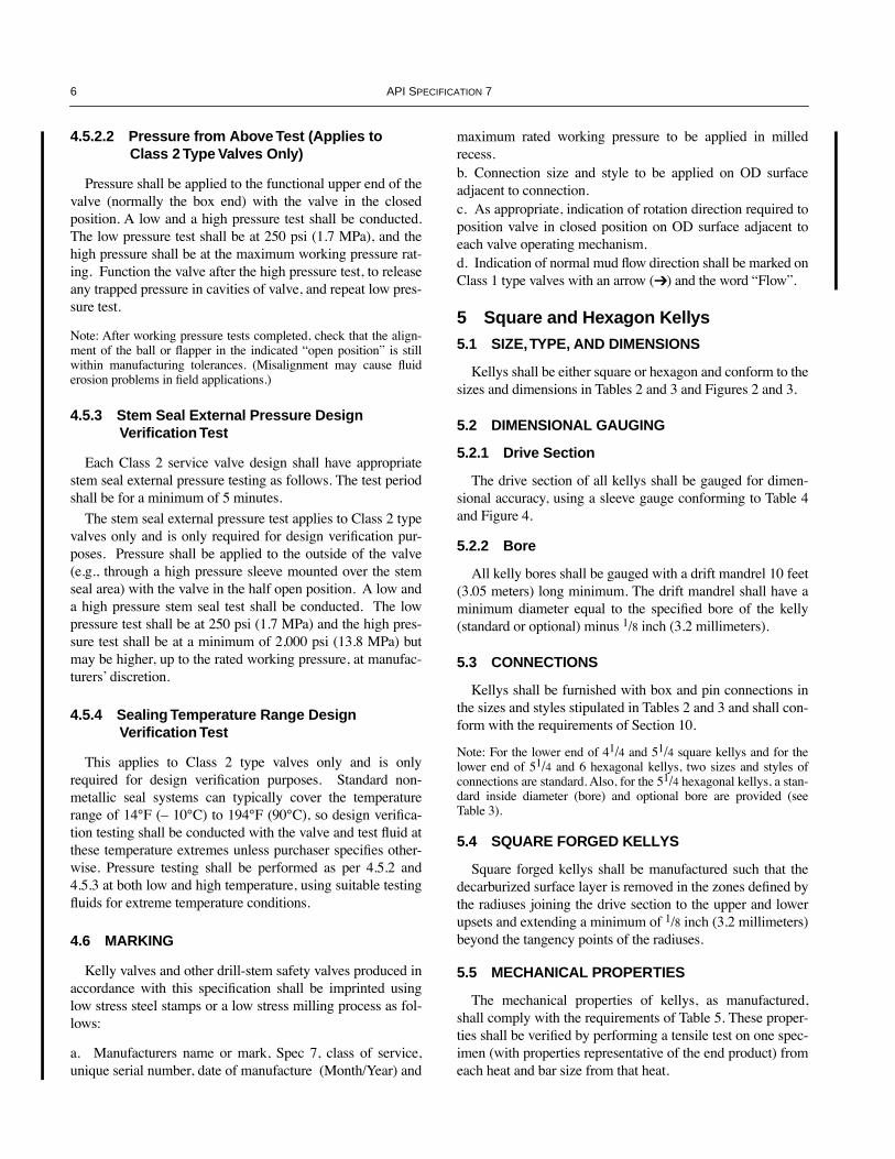
5 Square and Hexagon Kellys5.1 SIZE, TYPE, AND DIMENSIONS
Kellys shall be either square or hexagon and conform to thesizes and dimensions in Tables 2 and 3 and Figures 2 and 3.
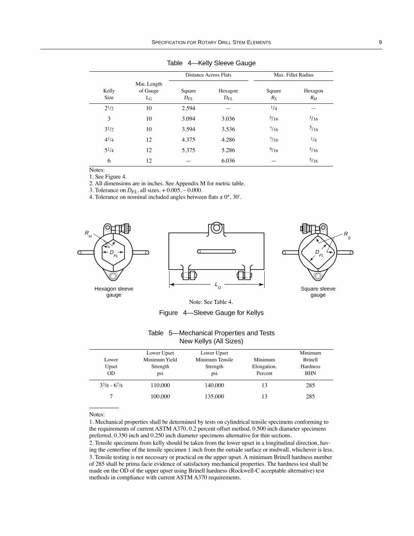
5.2 DIMENSIONAL GAUGING
5.2.1 Drive Section
The drive section of all kellys shall be gauged for dimen-sional accuracy, using a sleeve gauge conforming to Table 4and Figure 4.
5.2.2 Bore
All kelly bores shall be gauged with a drift mandrel 10 feet(3.05 meters) long minimum. The drift mandrel shall have aminimum diameter equal to the speciÞed bore of the kelly(standard or optional) minus 1/8 inch (3.2 millimeters).
5.3 CONNECTIONS
Kellys shall be furnished with box and pin connections inthe sizes and styles stipulated in Tables 2 and 3 and shall con-form with the requirements of Section 10.
Note: For the lower end of 41/4 and 51/4 square kellys and for thelower end of 51/4 and 6 hexagonal kellys, two sizes and styles ofconnections are standard. Also, for the 51/4 hexagonal kellys, a stan-dard inside diameter (bore) and optional bore are provided (seeTable 3).
5.4 SQUARE FORGED KELLYS
Square forged kellys shall be manufactured such that thedecarburized surface layer is removed in the zones deÞned bythe radiuses joining the drive section to the upper and lowerupsets and extending a minimum of 1/8 inch (3.2 millimeters)beyond the tangency points of the radiuses.
5.5 MECHANICAL PROPERTIES
The mechanical properties of kellys, as manufactured,shall comply with the requirements of Table 5. These proper-ties shall be veriÞed by performing a tensile test on one spec-imen (with properties representative of the end product) fromeach heat and bar size from that heat.
COPYRIGHT American Petroleum Institute

SPECIFICATION FOR ROTARY DRILL STEM ELEMENTS 7
Table 2—Square Kellys
1 2 3 4 5 6 7 8 9 10 11 12 13 14 15 16 17 18 19 20 21 22 23
Upper Box ConnectionLength of
Drive Section
feet
Length Overall
feet Drive SectionSize and Style LH
Outside Diameter Bevel Diameter Lower Pin Connection
Kel
ly S
ize
Stan
dard
Opt
iona
l
Stan
dard
Opt
iona
l
Acr
oss
Flat
s
Acr
oss
Cor
ners
Acr
oss
Cor
ners
Rad
ius
Rad
ius
Min
. Wal
l Ecc
. B
ore
Stan
dard
Opt
iona
l
Stan
dard
Opt
iona
l
Len
gth
Stan
dard
Opt
iona
l
Size
and
Sty
le
Out
side
Dia
met
er
Len
gth
Bev
el D
iam
eter
Insi
de D
iam
eter
(a) (b) (b) (c) (c) (d) (e) (f) (g) (l) (h) (h) (i) (j) (j) (h) (i) (j) (k)LD LD L L DFL DC DCC RC RCC t DU DU LU DF DF DLR LL DF d
21/2 37 Ñ 40 Ñ 21/2 3 9/32 3.250 5/16 15/8 0.450 65/8 REG
41/2 REG
73/4 53/4 16 721/64 519/64 NC26 33/8 20 317/64 11/4
3 37 Ñ 40 Ñ 3 315/16 3.875 3/8 115/16 0.450 65/8 REG
41/2 REG
73/4 53/4 16 721/64 519/64 NC31 41/8 20 361/64 13/4
31/2 37 Ñ 40 Ñ 31/2 417/32 4.437 1/2 27/32 0.450 65/8 REG
41/2 REG
73/4 53/4 16 721/64 519/64 NC38 43/4 20 437/64 21/4
41/4 37 51 40 54 41/4 59/16 5.500 1/2 23/4 0.475 65/8 REG
41/2 REG
73/4 53/4 16 721/64 519/64 NC46m 61/4 20 523/32 213/16
NC50m 63/8 20 61/16 213/16
51/4 37 51 40 54 51/4 629/32 6.750 5/8 33/8 0.625 65/8 REG
Ñ 73/4 Ñ 16 721/64 Ñ 51/2 FHm 7 20 623/32 31/4
NC56m 7 20 647/64 31/4
Notes: 1. See Figure 2.2. All dimensions are in inches except lengths of drive section and lengths overall, which are given in feet. See Appendix M for metric table.aSize of square kellys is the same as the dimension DFL across ßats (distance between opposite faces) as given in Column 6.bTolerance on LD, +6, Ð5.cTolerance on L, +6, Ð0.dTolerances on DFL, sizes 21/2 to 31/2 incl.: +5/64, Ð0.; sizes 41/4 and 51/4: + 3/32, Ð0. See 5.2 for sleeve-gauge test.eTolerance on DC, sizes 21/2, 3, and 31/2: +1/8, Ð0; sizes 41/4 and 51/4: +5/32, Ð0.fTolerance on DCC, +0.000, Ð0.015.gTolerance on RC, all sizes, ±1/16.hTolerance on DU and DLR, all sizes, ±1/32.iTolerance on LU and LL, all sizes, +21/2, Ð0.jTolerance on DF, all sizes, ± 1/64.kTolerance on d, all sizes, +1/64, Ð0. See 5.2 for drift-mandrel test.lReference dimension only.mSee Note, 5.3.
Figure 2—Square Kellys��� �
RC
D C �� �� RCC
DCC
Corner configurationmanufacturer’s option
DUDF
Upper upset
LH box connection
LU
LLD±2¡
45¡
±1/2" (12.7 mm)3" R (76.2 mm)
DLR DF
Lower upset
RH pin connection
LL±2¡
45¡
±1/2" (12.7 mm)2" R (50.8 mm)
���
���DFL
d
t
Note: See Table 2.
COPYRIGHT American Petroleum Institute

8 API SPECIFICATION 7
Table 3—Hexagon Kellys
1 2 3 4 5 6 7 8 9 10 11 12 13 14 15 16 17 18 19 20 21 22 23
Upper Box Connection
Length of Drive
Sectionfeet
Length Overall
feet Drive SectionSize and Style LH
Outside Diameter Bevel Diameter Lower Pin Connection
Kel
ly S
ize
Stan
dard
Opt
iona
l
Stan
dard
Opt
iona
l
Acr
oss
Flat
s
Acr
oss
Cor
ners
Acr
oss
Cor
ners
Rad
ius
Rad
ius
Min
. Wal
l Ecc
. B
ore
Stan
dard
Opt
iona
l
Stan
dard
Opt
iona
l
Len
gth
Stan
dard
Opt
iona
l
Size
and
Sty
le
Out
side
Dia
met
er
Len
gth
Bev
el D
iam
eter
Insi
de D
iam
eter
(a) (b) (b) (c) (c) (d) (e) (f) (e) (j) (e) (e) (g) (h) (h) (e) (g) (h) (i)LD LD L L DFL DC DCC RC RCC t DU DU LU DF DF DLR LL DF d
3 37 Ñ 40 Ñ 3 33/8 3.375 1/4 111/16 0.475 65/8 REG
41/2 REG
73/4 53/4 16 721/64 519/64 NC26 33/8 20 317/64 11/4
31/2 37 Ñ 40 Ñ 31/2 331/32 3.937 1/4 131/32 0.525 65/8 REG
41/2 REG
73/4 53/4 16 721/64 519/64 NC31 41/8 20 361/64 13/4
41/4 37 51 40 54 41/4 413/16 4.781 5/16 225/64 0.625 65/8 REG
41/2 REG
73/4 53/4 16 721/64 519/64 NC38 43/4 20 437/64 21/4
51/4 37 51 40 54 51/4 531/32 5.900 3/8 261/64 0.625 65/8 REG
Ñ 73/4 Ñ 16 721/64 Ñ NC46k 61/4 20 523/32 3k
NC50k 63/8 20 61/16 31/4k
6 37 51 40 54 6 613/16 6.812 3/8 313/32 0.625 65/8 REG
Ñ 73/4 Ñ 16 721/64 Ñ 51/2 FHk 7 20 623/32 31/2
NC56k 7 20 647/64 31/2
Notes: 1. See Figure 3.2. All dimensions are in inches except lengths of drive section and lengths overall, which are given in feet. See Appendix M for metric table.aSize of hexagon kellys is the same as dimensions DFL across ßats (distance between opposite faces) as given in Column 6.bTolerance on LD, +6, Ð5.cTolerance on L, +6, Ð0.dTolerance on DFL, all sizes, +1/32, Ð0; see 5.2 for sleeve-gauge test.eTolerance on DC, DU, DLR, and RC, all sizes, ±1/32.fTolerance on DCC, +0.000, Ð0.015.gTolerance on LU and LL, all sizes, +21/2, Ð0.hTolerance on DF, ±1/64.iTolerance on d, all sizes, +1/16, Ð0; see 5.2 for drift-mandrel test.jReference dimension only.kFor 51/4 hexagon kellys a bore of 213/16 shall be optional. See Note 5.3.
Figure 3—Hexagon Kellys
�� �� ��
�� ��
RC
DC �� ��
RCC
DCC
Corner configurationmanufacturer’s option
DUDF
Upper upset
LH box connection
LU
L
LD±2¡
30¡30¡
±1/2" (12.7 mm)3" R (76.2 mm)
DLR DF
Lower upset
RH pin connection
LL±2¡±1/2" (12.7 mm)
2" R (50.8 mm)
D FL
d
t
Note: See Table 3.
COPYRIGHT American Petroleum Institute
SPECIFICATION FOR ROTARY DRILL STEM ELEMENTS 9
Table 4—Kelly Sleeve Gauge
Distance Across Flats Max. Fillet Radius
KellySize
Min. Lengthof Gauge
LG
SquareDFL
HexagonDFL
SquareRS
HexagonRH
21/2 10 2.594 Ñ 1/4 Ñ
3 10 3.094 3.036 5/16 3/16
31/2 10 3.594 3.536 7/16 3/16
41/4 12 4.375 4.286 7/16 1/4
51/4 12 5.375 5.286 9/16 5/16
6 12 Ñ 6.036 Ñ 5/16
Notes: 1. See Figure 4.2. All dimensions are in inches. See Appendix M for metric table.3. Tolerance on DFL, all sizes, + 0.005, Ð 0.000.4. Tolerance on nominal included angles between ßats ± 0¡, 30'.
Figure 4—Sleeve Gauge for Kellys
Table 5—Mechanical Properties and Tests New Kellys (All Sizes)
LowerUpsetOD
Lower UpsetMinimum Yield
Strengthpsi
Lower UpsetMinimum Tensile
Strengthpsi
MinimumElongation,
Percent
MinimumBrinell
HardnessBHN
33/8 - 67/8 110,000 140,000 13 285
7 100,000 135,000 13 285
Notes: 1. Mechanical properties shall be determined by tests on cylindrical tensile specimens conforming to the requirements of current ASTM A370, 0.2 percent offset method, 0.500 inch diameter specimens preferred, 0.350 inch and 0.250 inch diameter specimens alternative for thin sections.2. Tensile specimens from kelly should be taken from the lower upset in a longitudinal direction, hav-ing the centerline of the tensile specimen 1 inch from the outside surface or midwall, whichever is less.3. Tensile testing is not necessary or practical on the upper upset. A minimum Brinell hardness number of 285 shall be prima facie evidence of satisfactory mechanical properties. The hardness test shall be made on the OD of the upper upset using Brinell hardness (Rockwell-C acceptable alternative) test methods in compliance with current ASTM A370 requirements.
LGHexagon sleeve
gaugeSquare sleeve
gauge
DFL
RS
DFL
RH
Note: See Table 4.
COPYRIGHT American Petroleum Institute
10 API SPECIFICATION 7
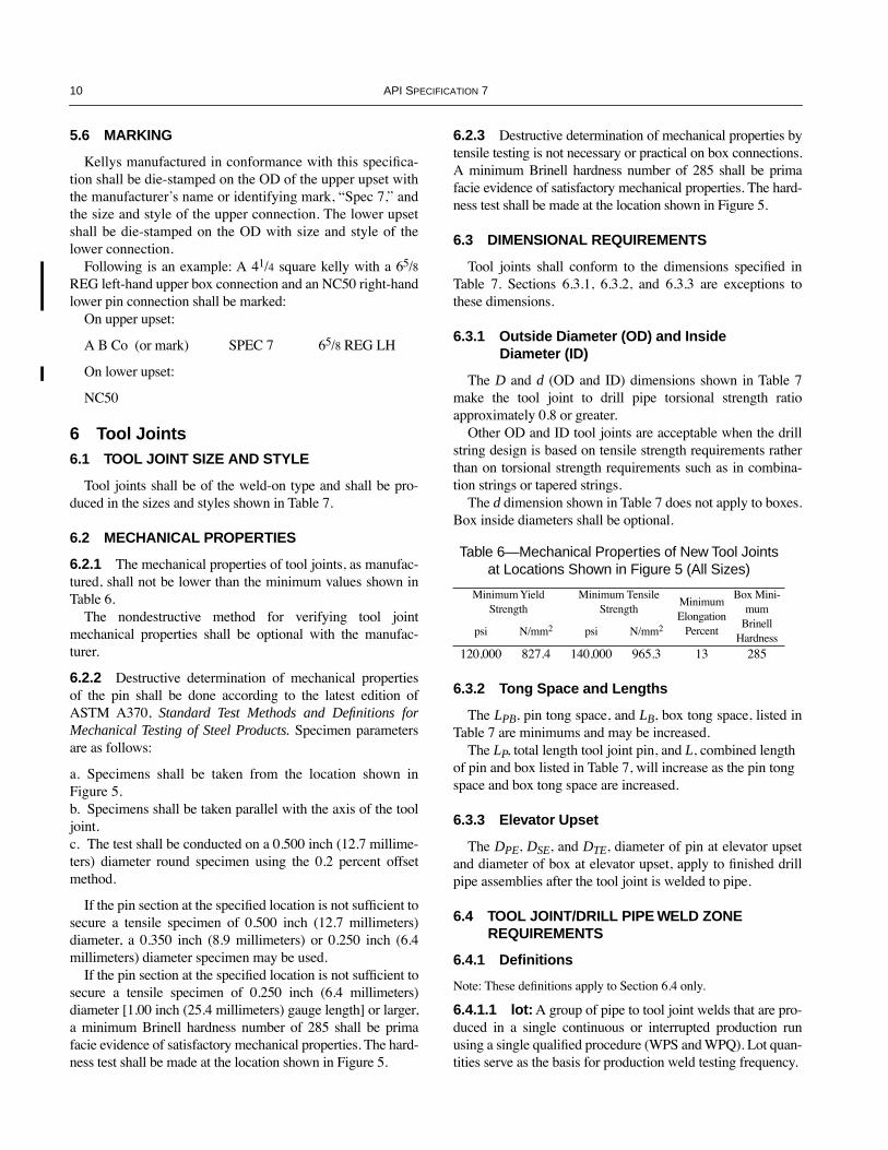
5.6 MARKING
Kellys manufactured in conformance with this speciÞca-tion shall be die-stamped on the OD of the upper upset withthe manufacturerÕs name or identifying mark, ÒSpec 7,Ó andthe size and style of the upper connection. The lower upsetshall be die-stamped on the OD with size and style of thelower connection.
Following is an example: A 41/4 square kelly with a 65/8REG left-hand upper box connection and an NC50 right-handlower pin connection shall be marked:
On upper upset:
A B Co (or mark) SPEC 7 65/8 REG LH
On lower upset:
NC50
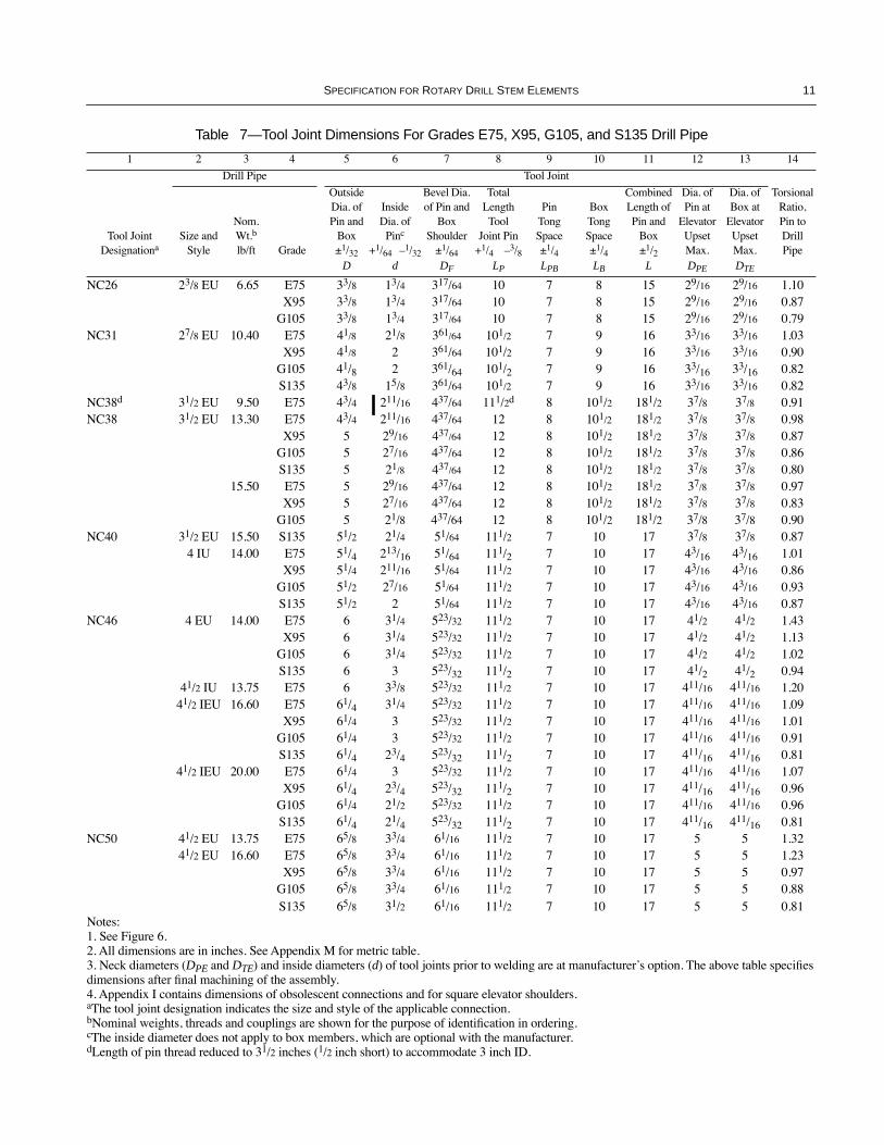
6 Tool Joints6.1 TOOL JOINT SIZE AND STYLE
Tool joints shall be of the weld-on type and shall be pro-duced in the sizes and styles shown in Table 7.
6.2 MECHANICAL PROPERTIES
6.2.1 The mechanical properties of tool joints, as manufac-tured, shall not be lower than the minimum values shown inTable 6.
The nondestructive method for verifying tool jointmechanical properties shall be optional with the manufac-turer.
6.2.2 Destructive determination of mechanical propertiesof the pin shall be done according to the latest edition ofASTM A370, Standard Test Methods and Definitions forMechanical Testing of Steel Products. Specimen parametersare as follows:
a. Specimens shall be taken from the location shown inFigure 5.b. Specimens shall be taken parallel with the axis of the tooljoint.c. The test shall be conducted on a 0.500 inch (12.7 millime-ters) diameter round specimen using the 0.2 percent offsetmethod.
If the pin section at the speciÞed location is not sufÞcient tosecure a tensile specimen of 0.500 inch (12.7 millimeters)diameter, a 0.350 inch (8.9 millimeters) or 0.250 inch (6.4millimeters) diameter specimen may be used.
If the pin section at the speciÞed location is not sufÞcient tosecure a tensile specimen of 0.250 inch (6.4 millimeters)diameter [1.00 inch (25.4 millimeters) gauge length] or larger,a minimum Brinell hardness number of 285 shall be primafacie evidence of satisfactory mechanical properties. The hard-ness test shall be made at the location shown in Figure 5.
6.2.3 Destructive determination of mechanical properties bytensile testing is not necessary or practical on box connections.A minimum Brinell hardness number of 285 shall be primafacie evidence of satisfactory mechanical properties. The hard-ness test shall be made at the location shown in Figure 5.
6.3 DIMENSIONAL REQUIREMENTS
Tool joints shall conform to the dimensions speciÞed inTable 7. Sections 6.3.1, 6.3.2, and 6.3.3 are exceptions tothese dimensions.
6.3.1 Outside Diameter (OD) and InsideDiameter (ID)
The D and d (OD and ID) dimensions shown in Table 7make the tool joint to drill pipe torsional strength ratioapproximately 0.8 or greater.
Other OD and ID tool joints are acceptable when the drillstring design is based on tensile strength requirements ratherthan on torsional strength requirements such as in combina-tion strings or tapered strings.
The d dimension shown in Table 7 does not apply to boxes.Box inside diameters shall be optional.
6.3.2 Tong Space and Lengths
The LPB, pin tong space, and LB, box tong space, listed inTable 7 are minimums and may be increased.
The LP, total length tool joint pin, and L, combined length of pin and box listed in Table 7, will increase as the pin tong space and box tong space are increased.
6.3.3 Elevator Upset
The DPE, DSE, and DTE, diameter of pin at elevator upsetand diameter of box at elevator upset, apply to Þnished drillpipe assemblies after the tool joint is welded to pipe.
6.4 TOOL JOINT/DRILL PIPE WELD ZONE REQUIREMENTS
6.4.1 Definitions
Note: These deÞnitions apply to Section 6.4 only.
6.4.1.1 lot: A group of pipe to tool joint welds that are pro-duced in a single continuous or interrupted production runusing a single qualiÞed procedure (WPS and WPQ). Lot quan-tities serve as the basis for production weld testing frequency.
Table 6—Mechanical Properties of New Tool Joints at Locations Shown in Figure 5 (All Sizes)
Minimum Yield Strength
Minimum Tensile Strength
Minimum Elongation
Percent
Box Mini-mum
Brinell Hardness
psi N/mm2 psi N/mm2
120,000 827.4 140,000 965.3 13 285
COPYRIGHT American Petroleum Institute
SPECIFICATION FOR ROTARY DRILL STEM ELEMENTS 11
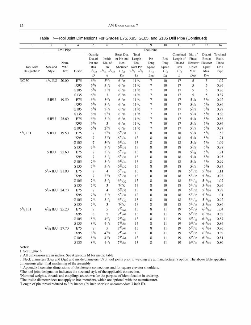
Table 7—Tool Joint Dimensions For Grades E75, X95, G105, and S135 Drill Pipe
1 2 3 4 5 6 7 8 9 10 11 12 13 14
Drill Pipe Tool Joint
Tool Joint Designationa
Size and Style
Nom.Wt.b
lb/ft Grade
Outside Dia. of Pin and
Box±1/32
InsideDia. of
Pinc
+1/64 Ð1/32
Bevel Dia. of Pin and
BoxShoulder
±1/64
Total Length Tool
Joint Pin+1/4 Ð3/8
PinTongSpace±1/4
BoxTongSpace±1/4
Combined Length of Pin and
Box±1/2
Dia. of Pin at
Elevator UpsetMax.
Dia. of Box at
Elevator UpsetMax.
Torsional Ratio, Pin to Drill Pipe
D d DF LP LPB LB L DPE DTE
NC26 23/8 EU 6.65 E75 33/8 13/4 317/64 10 7 8 15 29/16 29/16 1.10X95 33/8 13/4 317/64 10 7 8 15 29/16 29/16 0.87
G105 33/8 13/4 317/64 10 7 8 15 29/16 29/16 0.79NC31 27/8 EU 10.40 E75 41/8 21/8 361/64 101/2 7 9 16 33/16 33/16 1.03
X95 41/8 2 361/64 101/2 7 9 16 33/16 33/16 0.90G105 41/8 2 361/64 101/2 7 9 16 33/16 33/16 0.82S135 43/8 15/8 361/64 101/2 7 9 16 33/16 33/16 0.82
NC38d 31/2 EU 9.50 E75 43/4 211/16 437/64 111/2d 8 101/2 181/2 37/8 37/8 0.91NC38 31/2 EU 13.30 E75 43/4 211/16 437/64 12 8 101/2 181/2 37/8 37/8 0.98
X95 5 29/16 437/64 12 8 101/2 181/2 37/8 37/8 0.87G105 5 27/16 437/64 12 8 101/2 181/2 37/8 37/8 0.86S135 5 21/8 437/64 12 8 101/2 181/2 37/8 37/8 0.80
15.50 E75 5 29/16 437/64 12 8 101/2 181/2 37/8 37/8 0.97X95 5 27/16 437/64 12 8 101/2 181/2 37/8 37/8 0.83
G105 5 21/8 437/64 12 8 101/2 181/2 37/8 37/8 0.90NC40 31/2 EU 15.50 S135 51/2 21/4 51/64 111/2 7 10 17 37/8 37/8 0.87
4 IU 14.00 E75 51/4 213/16 51/64 111/2 7 10 17 43/16 43/16 1.01X95 51/4 211/16 51/64 111/2 7 10 17 43/16 43/16 0.86
G105 51/2 27/16 51/64 111/2 7 10 17 43/16 43/16 0.93S135 51/2 2 51/64 111/2 7 10 17 43/16 43/16 0.87
NC46 4 EU 14.00 E75 6 31/4 523/32 111/2 7 10 17 41/2 41/2 1.43X95 6 31/4 523/32 111/2 7 10 17 41/2 41/2 1.13
G105 6 31/4 523/32 111/2 7 10 17 41/2 41/2 1.02S135 6 3 523/32 111/2 7 10 17 41/2 41/2 0.94
41/2 IU 13.75 E75 6 33/8 523/32 111/2 7 10 17 411/16 411/16 1.2041/2 IEU 16.60 E75 61/4 31/4 523/32 111/2 7 10 17 411/16 411/16 1.09
X95 61/4 3 523/32 111/2 7 10 17 411/16 411/16 1.01G105 61/4 3 523/32 111/2 7 10 17 411/16 411/16 0.91S135 61/4 23/4 523/32 111/2 7 10 17 411/16 411/16 0.81
41/2 IEU 20.00 E75 61/4 3 523/32 111/2 7 10 17 411/16 411/16 1.07X95 61/4 23/4 523/32 111/2 7 10 17 411/16 411/16 0.96
G105 61/4 21/2 523/32 111/2 7 10 17 411/16 411/16 0.96S135 61/4 21/4 523/32 111/2 7 10 17 411/16 411/16 0.81
NC50 41/2 EU 13.75 E75 65/8 33/4 61/16 111/2 7 10 17 5 5 1.3241/2 EU 16.60 E75 65/8 33/4 61/16 111/2 7 10 17 5 5 1.23
X95 65/8 33/4 61/16 111/2 7 10 17 5 5 0.97G105 65/8 33/4 61/16 111/2 7 10 17 5 5 0.88S135 65/8 31/2 61/16 111/2 7 10 17 5 5 0.81
Notes: 1. See Figure 6.2. All dimensions are in inches. See Appendix M for metric table.3. Neck diameters (DPE and DTE) and inside diameters (d) of tool joints prior to welding are at manufacturerÕs option. The above table speciÞes dimensions after Þnal machining of the assembly.4. Appendix I contains dimensions of obsolescent connections and for square elevator shoulders.aThe tool joint designation indicates the size and style of the applicable connection.bNominal weights, threads and couplings are shown for the purpose of identiÞcation in ordering.cThe inside diameter does not apply to box members, which are optional with the manufacturer.dLength of pin thread reduced to 31/2 inches (1/2 inch short) to accommodate 3 inch ID.
COPYRIGHT American Petroleum Institute
12 API SPECIFICATION 7
NC 50 41/2 EU 20.00 E75 65/8 35/8 61/16 111/2 7 10 17 5 5 1.02X95 65/8 31/2 61/16 111/2 7 10 17 5 5 0.96
G105 65/8 31/2 61/16 111/2 7 10 17 5 5 0.86S135 65/8 3 61/16 111/2 7 10 17 5 5 0.87
5 IEU 19.50 E75 65/8 33/4 61/16 111/2 7 10 17 51/8 51/8 0.92X95 65/8 31/2 61/16 111/2 7 10 17 51/8 51/8 0.86
G105 65/8 31/4 61/16 111/2 7 10 17 51/8 51/8 0.89S135 65/8 23/4 61/16 111/2 7 10 17 51/8 51/8 0.86
5 IEU 25.60 E75 65/8 31/2 61/16 111/2 7 10 17 51/8 51/8 0.86X95 65/8 3 61/16 111/2 7 10 17 51/8 51/8 0.86
G105 65/8 23/4 61/16 111/2 7 10 17 51/8 51/8 0.8751/2 FH 5 IEU 19.50 E75 7 33/4 623/32 13 8 10 18 51/8 51/8 1.53
X95 7 33/4 623/32 13 8 10 18 51/8 51/8 1.21G105 7 33/4 623/32 13 8 10 18 51/8 51/8 1.09S135 71/4 31/2 623/32 13 8 10 18 51/8 51/8 0.98
5 IEU 25.60 E75 7 31/2 623/32 13 8 10 18 51/8 51/8 1.21X95 7 31/2 623/32 13 8 10 18 51/8 51/8 0.95
G105 71/4 31/2 623/32 13 8 10 18 51/8 51/8 0.99S135 71/4 31/4 623/32 13 8 10 18 51/8 51/8 0.83
51/2 IEU 21.90 E75 7 4 623/32 13 8 10 18 511/16 511/16 1.11X95 7 33/4 623/32 13 8 10 18 511/16 511/16 0.98
G105 71/4 31/2 623/32 13 8 10 18 511/16 511/16 1.02S135 71/2 3 73/32 13 8 10 18 511/16 511/16 0.96
51/2 IEU 24.70 E75 7 4 623/32 13 8 10 18 511/16 511/16 0.99X95 71/4 31/2 623/32 13 8 10 18 511/16 511/16 1.01
G105 71/4 31/2 623/32 13 8 10 18 511/16 511/16 0.92S135 71/2 3 73/32 13 8 10 18 511/16 511/16 0.86
65/8 FH 65/8 IEU 25.20 E75 8 5 745/64 13 8 11 19 615/16 615/16 1.04X95 8 5 745/64 13 8 11 19 615/16 615/16 0.82
G105 81/4 43/4 745/64 13 8 11 19 615/16 615/16 0.87S135 81/2 41/4 745/64 13 8 11 19 615/16 615/16 0.86
65/8 IEU 27.70 E75 8 5 745/64 13 8 11 19 615/16 615/16 0.96X95 81/4 43/4 745/64 13 8 11 19 615/16 615/16 0.89
G105 81/4 43/4 745/64 13 8 11 19 615/16 615/16 0.81S135 81/2 41/4 745/64 13 8 11 19 615/16 615/16 0.80
Table 7—Tool Joint Dimensions For Grades E75, X95, G105, and S135 Drill Pipe (Continued)
1 2 3 4 5 6 7 8 9 10 11 12 13 14
Drill Pipe Tool Joint
Tool Joint Designationa
Size and Style
Nom.Wt.b
lb/ft Grade
Outside Dia. of Pin and
Box±1/32
InsideDia. of
Pinc
+1/64 Ð1/32
Bevel Dia. of Pin and
BoxShoulder
±1/64
Total Length Tool
Joint Pin+1/4 Ð3/8
PinTongSpace±1/4
BoxTongSpace±1/4
Combined Length of Pin and
Box±1/2
Dia. of Pin at
Elevator UpsetMax.
Dia. of Box at
Elevator UpsetMax.
Torsional Ratio, Pin to Drill Pipe
D d DF LP LPB LB L DPE DTE
Notes: 1. See Figure 6.2. All dimensions are in inches. See Appendix M for metric table.3. Neck diameters (DPE and DTE) and inside diameters (d) of tool joints prior to welding are at manufacturerÕs option. The above table speciÞes dimensions after Þnal machining of the assembly.4. Appendix I contains dimensions of obsolescent connections and for square elevator shoulders.aThe tool joint designation indicates the size and style of the applicable connection.bNominal weights, threads and couplings are shown for the purpose of identiÞcation in ordering.cThe inside diameter does not apply to box members, which are optional with the manufacturer.dLength of pin thread reduced to 31/2 inches (1/2 inch short) to accommodate 3 inch ID.
COPYRIGHT American Petroleum Institute
SPECIFICATION FOR ROTARY DRILL STEM ELEMENTS 13
6.4.1.2 procedure qualification record (PQR): Thewritten documentation that a speciÞc WPS meets the require-ments of this speciÞcation. The record of the welding dataused to weld a test joint and the test results from specimenstaken from the test weld joint.
6.4.1.3 variable, essential: That variable parameter inwhich a change affects the mechanical properties of the weldjoint. Changes in essential variables require requaliÞcation ofthe WPS.
6.4.1.4 variable, nonessential: That variable parameterin which a change may be made in the WPS without requali-Þcation.
6.4.1.5 welder performance qualification (WPQ):The written documentation that a welding machine operatorhas demonstrated the capability to use the WPS to produce aweld joint meeting the requirements of this speciÞcation.
6.4.1.6 welding procedure specification (WPS):The written procedure prepared to proved direction for mak-ing production welds to the requirements of this speciÞcation.It must include all essential and nonessential variables forwelding of tool joints to drill pipe. A WPS applies to all thosewelds of which each member has the same speciÞed dimen-sions and chemistry that are grouped according to a docu-mented procedure which will ensure a predictable response toweld zone heat treatment for a particular grade.
6.4.2 Welding Requirements
The manufacturer shall develop and qualify a welding pro-cedure (WPS and PQR) for welding of tool joints to drillpipe. The WPS shall identify the essential and nonessentialvariables. The PQR shall include the results of all mechanicaltests listed in 6.4.5. All lots shall be welded in accordancewith a qualiÞed procedure (WPS and PQR). The manufac-turer shall qualify welding machine operators to a speciÞcWPQ for each WPS utilized by the operators.
6.4.3 Heat Treatment
6.4.3.1 The weld zone shall be austenitized, cooled belowthe transformation temperature and tempered at 1,100¡F(593¡C) minimum. The weld zone shall be heat treated fromthe OD to the ID and from the weld line to beyond where theßow lines of the tool joint and pipe material change directionas a result of the welding process.
6.4.3.2 Specimens used for destructive testing (i.e., tensile,impact) shall also be used to determine compliance with therequirements of 6.4.3.1.
A longitudinal section sufÞcient in length to include theentire Heat Affected Zone (HAZ) from heat treatment shallbe suitably prepared and etched to determine the location ofthe HAZ in relation to the weld line and transverse grain ßow.
This etched section shall be used to ensure that the tensilespecimen (see 6.4.5.2) includes the full HAZ from heat treat-ment within the gauge length.
6.4.4 Process Controls—Surface Hardness
Each weld zone shall be hardness tested at three places 120degrees apart, ±15 degrees, in the HAZ from heat treatment,around outside surface. The hardness testing method isoptional with the manufacturer. The hardness of the weldzone HAZ from heat treatment shall not exceed 37 HRC.
6.4.5 Mechanical Testing
Note: See Appendix A Supplementary Requirements.
6.4.5.1 One set of mechanical tests shall be conducted perlot or 400 welds, whichever is less.
6.4.5.2 Weld zone yield strengths shall be determined bytests on cylindrical tensile specimens taken from the locationin Figure 7 conforming to the requirements of the latest edi-tion of ASTM A370, 0.2 percent offset method. 0.500 inchdiameter specimens are preferred, 0.350 inch and 0.250 inchdiameter specimens are suitable alternatives for thin sections.
The product of the yield strength of the tensile specimenand the cross-sectional area of the weld zone shall be greaterthan the product of the speciÞed minimum yield strength ofthe drill pipe times the cross-sectional area of the drill pipebased on the dimensions speciÞed for the outside and insidediameter in API SpeciÞcation 5D. The method for calculatingthe cross-sectional area of the weld zone shall be:
Aw = 0.7854 (D2 Ð d2)
whereD = minimum allowable outside diameter speciÞed by
manufacturer,d = maximum allowable inside diameter speciÞed by
manufacturer.
6.4.5.3 Charpy V-notch Type A impact tests conforming tothe latest edition of ASTM A370 shall be conducted on threespecimens removed longitudinally from the axis of the pipewith the notch oriented radially as shown in Figure 8. Fullsize 10 millimeter x 10 millimeter specimens shall be usedwhenever possible. A test shall consist of three longitudinalspecimens. The center of the notch in the specimen shall belocated on the weld interface. For subsize specimen impactstrength requirements see Table 8.
The average value for the three specimens shall not be lessthan 12 ft-lbs. The minimum value for any single specimenshall not be less than 10 ft-lbs.
The test temperature shall be 70¡F, ± 5¡F. (21¡C, ± 2.8¡C)Tests conducted at lower temperatures that meet the testrequirements stated above are acceptable.
COPYRIGHT American Petroleum Institute
14 API SPECIFICATION 7
6.4.5.4 Transverse side bend tests, in accordance with theASME Boiler and Pressure Vessel Code, Section IX, para-graphs QW-161.1 and QW-162.1, shall be performed on twospecimens removed from the weld zone of the test piece. Theweld zone shall be centered in longitudinal specimens. Testspecimen shall be full wall thickness, approximately 3/8 inchwide, and the length shall be 6 inches minimum.
The weld zone shall be completely within the bend portionof the specimen after bending. One specimen shall be bent ineach direction (clockwise and counterclockwise) relative tothe pipe axis.
The guided-bend specimens shall have no open defects inthe weld zone exceeding 1/8 inch, measured in any directionon the convex surface of the specimen after bending. Cracksoccurring on the corners of the specimen during testing shallnot be considered unless there is deÞnite evidence that theyresult from inclusions or other internal defects.
6.4.5.5 Through-wall hardness tests of the HAZ from heattreatment shall be taken as shown in Figure 9. The hardnessvalues shall not exceed 37 HRC. A hardness value is the aver-age of three Rockwell-C readings taken at 0.100 inch to 0.250inch from the outside surface and inside surface on the pipeand tool joint sides of the weld line. Hardness readings shallbe within the portion of the HAZ that was reaustenitized.
6.4.6 Retest of Weld Zones
6.4.6.1 Surface Hardness Retest
All welds with a hardness value that exceeds 37 HRC shallbe retested or rejected. For any hardness value that exceeds37 HRC, one more hardness value shall be taken in theimmediate area.
If the new hardness value does not exceed 37 HRC, thenew hardness value will be accepted. If the new hardnessvalue exceeds 37 HRC, the weld shall be rejected.
The manufacturer may elect to reprocess the weld in accor-dance with a qualiÞed procedure and test the weld in accor-dance with 6.4.4.
6.4.6.2 Through-Wall Hardness Retest
Any weld test pieces with a hardness value that exceeds 37HRC shall be retested or the lot represented by the test pieceshall be rejected. For any test piece with a hardness value thatexceeds 37 HRC, the test surface may be reground andretested in accordance with 6.4.5.5.
If the retest hardness values do not exceed 37 HRC, thehardness values will be accepted. If any retest hardness valueexceeds 37 HRC, the lot of welds represented by the testpiece shall be rejected.
The manufacturer may elect to reprocess the entire lot inaccordance with a qualiÞed procedure and test mechanicalproperties in accordance with 6.4.4 and 6.4.5.
6.4.6.3 Tensile Retest
If a tensile test specimen representing a lot of welds fails toconform to the speciÞed requirements, the manufacturer mayelect to retest the same weld test piece. If the retest specimenconforms to the tensile requirements, all of the welds in thelot shall be accepted. If the retest specimen fails to meet thetensile requirements, the lot shall be rejected.
The manufacturer may elect to reprocess the entire lot inaccordance with a qualiÞed procedure and retest mechanicalproperties in accordance with 6.4.4 and 6.4.5.
6.4.6.4 Impact Retest
If the average absorbed energy value for a set of specimensrepresenting a lot is below the speciÞed minimum averageabsorbed energy requirement, or if one value is below theminimum value, a retest of three additional specimens may bemade from the same weld test piece. The average absorbedimpact energy value and the minimum absorbed energy valueof the retest specimens shall equal or exceed the speciÞedabsorbed energy requirements or the lot shall be rejected.
The manufacturer may elect to reprocess the entire lot inaccordance with a qualiÞed procedure and retest mechanicalproperties in accordance with 6.4.4 and 6.4.5.
6.4.6.5 Guided Transverse Side Bend Retest
If one or both of the guided-bend specimens fail to con-form to the speciÞed requirements, the manufacturer mayelect to test two additional specimens from the same weld testpiece. If both the retest specimens meet the speciÞed require-ments, the lot shall be accepted. If one or both of the retestspecimens fail to meet the speciÞed requirements, the lotshall be rejected.
The manufacturer may elect to reprocess the entire lot inaccordance with a qualiÞed procedure and retest mechanicalproperties in accordance with 6.4.4 and 6.4.5.
6.4.7 Visual Inspection
Each Þnished drill pipe upset, weld zone, and tool jointassembly shall be visually inspected and free of sharp cornersor abrupt changes of section. The internal Þnished drill pipeassembly shall permit a 90 degree hook-type tool to be pulledthrough the upset and weld zone without hang-up.
Table 8—Subsize Specimen Impact
Strength Requirements
Specimen Sizemm x mm
Percent of Requirements SpeciÞed in 6.4.5.3
10 10 100
10 7.5 80
COPYRIGHT American Petroleum Institute

SPECIFICATION FOR ROTARY DRILL STEM ELEMENTS 15
6.4.8 Alignment Inspection
The maximum misalignment between the longitudinal axisof the drill pipe and the welded-on tool joint, as measuredfrom the outside diameter of the drill pipe and the large diam-eter of the tool joint, shall not exceed 0.156 inches total indi-cator reading of parallel misalignment and shall not exceed0.008 inches per inch of angular misalignment for 41/2-inchpipe and larger and 0.010 inches per inch for pipe smallerthan 41/2 inches.
6.4.9 Wet Fluorescent Magnetic Particle Inspection
The entire outside surface of the weld zone shall be wetßuorescent magnetic particle inspected for transverse defects.All imperfections revealed shall be considered defects.
Defects may be removed by grinding, provided the remain-ing wall thickness is not less than the manufacturerÕs mini-mum weld zone wall thickness requirement. All grindingshall be blended smooth.
Defects that are not removed shall be cause for rejection.
6.4.10 Ultrasonic Inspection
Each weld zone shall be ultrasonically inspected over thecircumference with the beam directed toward the weld.
Shear wave/angle beam ultrasonic equipment capable ofcontinuous and uninterrupted inspection of the entire weldzone shall be used. The inspection shall be applied in accor-dance with the manufacturerÕs documented procedure. Thetransducer shall be square 2.25 MHz frequency attached to a
45 degree, ± 5 degree, hard, clear plastic poly(meth-ymethacrylate)-type polymer material wedge.
Any reßection greater than the calibration reference reßec-tor shall be cause for rejection of the weld zone.
A reference standard shall be used to demonstrate theeffectiveness of the inspection equipment and procedures atleast once every working turn. The equipment shall beadjusted to produce a well deÞned indication when the refer-ence standard is scanned in a manner simulating the inspec-tion of the product. The reference standard shall bemanufactured from a sound section of drill pipe assemblystock with the same speciÞc diameter and wall thickness asthe product being inspected. The reference standard may beof any convenient length as determined by the manufacturer.The reference standard shall contain a through-drilled hole asspeciÞed in Figure 10.
6.4.11 NDT Personnel Certification
A program for certiÞcation of NDT personnel shall bedeveloped by the manufacturer. The latest edition of theAmerican Society for Nondestructive Testing RecommendedPractice No. SNT-TC-1A shall be used as a guideline.
The administration of the NDT personnel certiÞcation pro-gram shall be the responsibility of the manufacturer.
6.5 CONNECTIONS
Connections shall conform to the applicable requirementsof Section 10. Right-hand threads shall be considered stan-dard. Left-hand threads conforming to the speciÞcationsherein shall be acceptable.
±1/8" (3.18 mm)11/4" (31.75 mm) Hardness test location mid-wall
as measured from thread root
±1/8" (3.18 mm)11/8" (28.6 mm)
Hardness test location mid-wallas measured from thread root
Figure 5—Tensile Specimen and Hardness Test Location
COPYRIGHT American Petroleum Institute

16 API SPECIFICATION 7
Figure 8—Impact Test Specimen Location and Orientation
���
���
���
���
���
���
���� 11/2" (38.1 mm) R
���
����
����
����
����
����
���
��
����
��� �MAX
R optionalwith mfr.
DPE
35¡, ±2¡a
dD DF Rotary shouldered
connection(see Section 8)
18¡ +2¡–0¡
dDTE
dDSE
Taper shoulder Square shoulder
RSE
LB
L
LBLPB
LP
L
Note: See Table 7 and Appendix I.�a18¡, +2¡ Ð0¡, by agreement on the order.
Drill pipe
Weldline Heat affected zone
Tensilespecimen
gaugelength
Tool joint
Figure 6—Tool Joint, Taper Shoulder, and Square Shoulder
Figure 7—Tensile Test Specimen Location
COPYRIGHT American Petroleum Institute
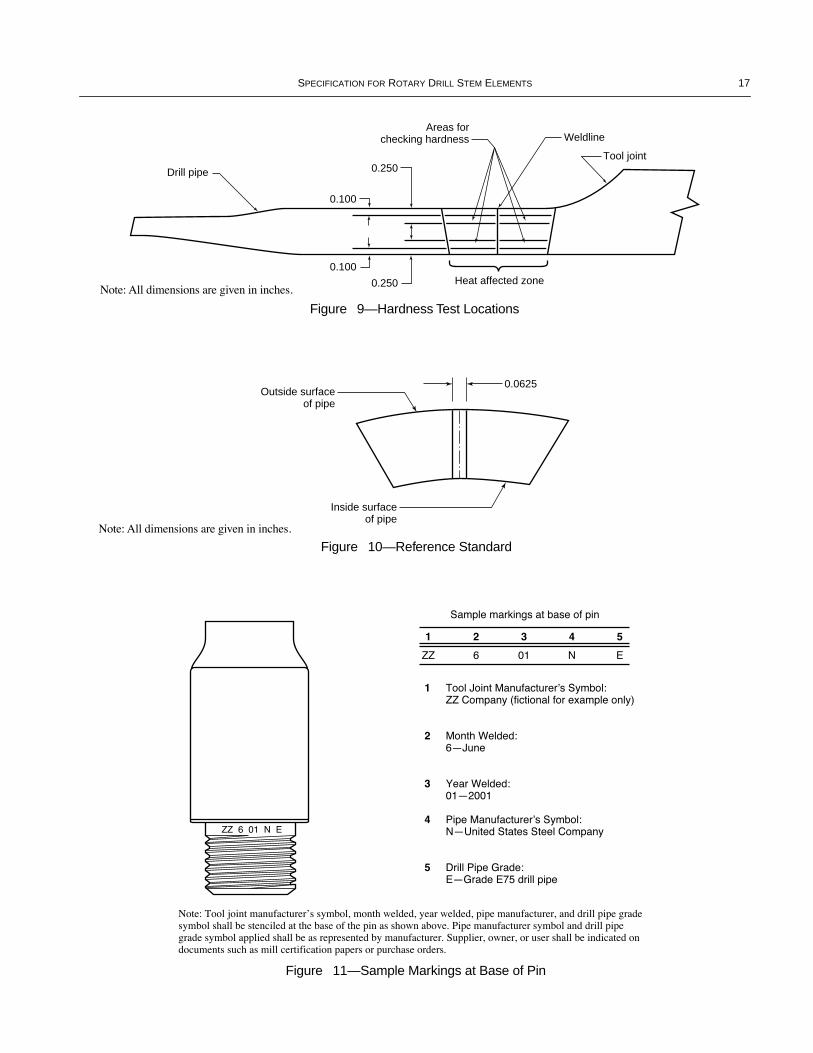
SPECIFICATION FOR ROTARY DRILL STEM ELEMENTS 17
Figure 11—Sample Markings at Base of Pin
Drill pipe
Weldline
Heat affected zone
Tool joint0.250
0.250
0.100
0.100
Areas forchecking hardness
Outside surfaceof pipe
0.0625
Inside surfaceof pipe
Figure 9—Hardness Test Locations
Figure 10—Reference Standard
Note: All dimensions are given in inches.
Note: All dimensions are given in inches.
COPYRIGHT American Petroleum Institute

18 API SPECIFICATION 7
6.6 MARKING
6.6.1 Tool joint tong space shall be die stamped with thefollowing:
a. ManufacturerÕs name or mark.b. ÒSpec 7.Óc. Tool joint designation as shown in column 1 of Table 7.
6.6.2 Tool joint pin base shall be die stamped with themarking shown in Figure 11. The marking shall be done foridentiÞcation of drill stem components by the company thatattaches the tool joint to the drill pipe.
6.6.3 Additional marks applied by the manufacturer, suchas tool joint part number, quality control inspector designatorsor manufacturing process designators, are acceptable.
7 Drill-Stem Subs7.1 CLASS AND TYPE
Drill-stem subs shall be furnished in the classes and typesshown in Table 9 and Figures 12 and 13.
7.2 TYPES A & B DIMENSIONS
7.2.1 Connections, Bevel Diameters, and Outside Diameters
The connection sizes, styles and bevel diameters (DF)and the outside diameters (D or DR) shall conform to theapplicable sizes, styles, dimensions, and tolerances speci-Þed in Tables 2 and 3 when connecting to kellys, Table 7when connecting to tool joints, Table 13 when connectingto drill collars, and Tables 21, 22, and 24 when connectingto bits.
7.2.2 Inside Diameters
The inside diameter (d) and tolerances shall be equal to theinside diameter speciÞed for the applicable connecting mem-ber with the smaller size and style connection.
7.2.3 Inside Bevel Diameter
The inside bevel diameter (dB) of the pin shall be equal to1/8, +1/16, Ð0 inches (3.2, +1.6, Ð0 millimeters) larger thanthe inside diameter speciÞed for the corresponding connect-ing member.
7.2.4 Length
Lengths and tolerances shall be as shown in Figure 12.
7.2.5 Float Valve Recess for Bit Subs
Dimensional data on boring out bit subs for installation ofßoat valve assemblies are shown in Table 12 and Figure 14.
7.3 TYPE C (SWIVEL SUB) DIMENSIONS
7.3.1 Connections, Bevel Diameters, and Outside Diameters
The swivel sub shall have pin up and pin down (both lefthand) rotary shouldered connections. The lower connectionsize, style, and bevel diameter (DF) shall conform to theapplicable sizes, styles, dimensions, and tolerances speciÞedin Tables 2 and 3 for upper kelly box connections. The upperconnection shall be the size and style of the swivel stem boxconnection, i.e., 41/2, 65/8, 75/8 API REG. The subÕs outsidediameter and tolerances shall conform to the larger of eitherthe kelly upper box connection or the swivel stem box con-nection outside diameter.
7.3.2 Inside Diameter
The maximum inside diameter (d) shall be the largestdiameter allowed for the upper kelly connection speciÞed inTable 2 or 3. In the case of step bored subs in which the borethrough the upper pin is larger than the bore through thelower pin, the upper pin bore shall not be so large as to causethe upper pin to have lower tensile strength or torsionalstrength than the lower pin as calculated per the current edi-tion of API Recommended Practice 7G.
7.3.3 Inside Bevel Diameter
The inside bevel diameter (dB) shall be 1/4, ±1/16 inch (6.4,±1.6 millimeter) larger than the bore.
7.3.4 Length
The minimum tong space allowable shall be 8 inches(203.2 millimeters).
7.4 TYPE D (LIFT SUB) DIMENSIONS
7.4.1 Pipe Diameter and Upper Lift Diameter
The pipe diameter (Dp) shall conform to applicable drillpipe size. Corresponding upper lift diameters (DL) for taperedshoulders are speciÞed in Table 11.
7.4.2 Connections, Bevel Diameters, and Outside Diameters
The connection sizes, styles, bevel diameters (DF), andoutside diameter (D) shall conform to the applicable sizes,styles, dimensions, and tolerances speciÞed in Table 13.
7.4.3 Inside Diameter
The maximum inside diameter (d) shall be the largestdiameter allowed for the lightest applicable pipe size listed inTable 7.
COPYRIGHT American Petroleum Institute
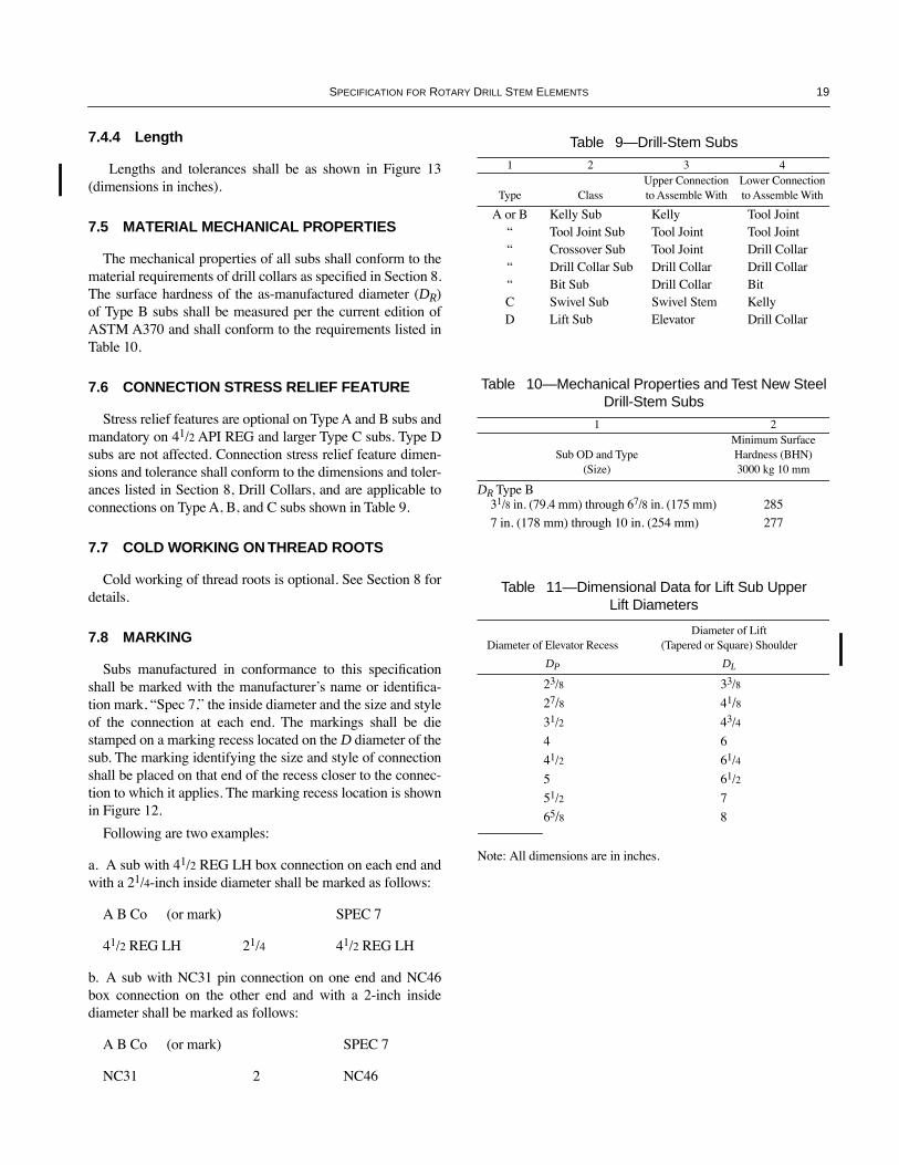
SPECIFICATION FOR ROTARY DRILL STEM ELEMENTS 19
7.4.4 Length
Lengths and tolerances shall be as shown in Figure 13(dimensions in inches).
7.5 MATERIAL MECHANICAL PROPERTIES
The mechanical properties of all subs shall conform to thematerial requirements of drill collars as speciÞed in Section 8.The surface hardness of the as-manufactured diameter (DR)of Type B subs shall be measured per the current edition ofASTM A370 and shall conform to the requirements listed inTable 10.
7.6 CONNECTION STRESS RELIEF FEATURE
Stress relief features are optional on Type A and B subs andmandatory on 41/2 API REG and larger Type C subs. Type Dsubs are not affected. Connection stress relief feature dimen-sions and tolerance shall conform to the dimensions and toler-ances listed in Section 8, Drill Collars, and are applicable toconnections on Type A, B, and C subs shown in Table 9.
7.7 COLD WORKING ON THREAD ROOTS
Cold working of thread roots is optional. See Section 8 fordetails.
7.8 MARKING
Subs manufactured in conformance to this speciÞcationshall be marked with the manufacturerÕs name or identiÞca-tion mark, ÒSpec 7,Ó the inside diameter and the size and styleof the connection at each end. The markings shall be diestamped on a marking recess located on the D diameter of thesub. The marking identifying the size and style of connectionshall be placed on that end of the recess closer to the connec-tion to which it applies. The marking recess location is shownin Figure 12.
Following are two examples:
a. A sub with 41/2 REG LH box connection on each end andwith a 21/4-inch inside diameter shall be marked as follows:
A B Co (or mark) SPEC 7
41/2 REG LH 21/4 41/2 REG LH
b. A sub with NC31 pin connection on one end and NC46box connection on the other end and with a 2-inch insidediameter shall be marked as follows:
A B Co (or mark) SPEC 7
NC31 2 NC46
Table 9—Drill-Stem Subs
1 2 3 4
Type ClassUpper Connection to Assemble With
Lower Connection to Assemble With
A or B Kelly Sub Kelly Tool JointÒ Tool Joint Sub Tool Joint Tool JointÒ Crossover Sub Tool Joint Drill CollarÒ Drill Collar Sub Drill Collar Drill CollarÒ Bit Sub Drill Collar BitC Swivel Sub Swivel Stem KellyD Lift Sub Elevator Drill Collar
Table 10—Mechanical Properties and Test New Steel Drill-Stem Subs
1 2
Sub OD and Type (Size)
Minimum SurfaceHardness (BHN) 3000 kg 10 mm
DR Type B 31/8 in. (79.4 mm) through 67/8 in. (175 mm) 2857 in. (178 mm) through 10 in. (254 mm) 277
Table 11—Dimensional Data for Lift Sub UpperLift Diameters
Diameter of Elevator RecessDiameter of Lift
(Tapered or Square) Shoulder
DP DL
23/8 33/8
27/8 41/831/2 43/4
4 6
41/2 61/4
5 61/2
51/2 7
65/8 8
Note: All dimensions are in inches.
COPYRIGHT American Petroleum Institute

20 API SPECIFICATION 7
Rotary pin or box connectionLH pin
connection
TYPE A
Markingrecesslocation
45¡max.
Rotary pin or box connection LH pinconnection
DF
dB
DF
36" (914.4 mm)+3" (76.2 mm)–1" (25.4 mm)a d
D
TYPE C
Markingrecesslocation
45¡max.
45¡max.
dB
dB
DF
DF
8" (203.2 mm)min.
d
D
TYPE B
Markingrecesslocation
1.5" (38.1 mm)2.0" (50.8 mm)
24" (609.6 mm)min.
45¡max.
45¡max.
DF
dB
DF
48" (1219.2 mm)+3" (76.2 mm)–1" (25.4 mm)b
d
D
DR
Note: See Table 9.aIf type A is a double box or double pin sub, the overall length is 36" (914.4 mm).bIf type B is a double box or double pin sub, the overall length is 48" (1219.2 mm).
Figure 13—Lift Subs (Type D)
Figure 12—Drill-Stem Subs (Types A, B and C)
D
d
DF
DP
DL
±.1253
±.031
+2–018¡
+3–136
.375
.500r
D
d
DF
DP
DL
±.1253
±.031
+3–136
.375
.500r
(+ 1/8, – 0) (+ 1/8, – 0)
Notes:1. See Table 11.2. All dimensions in inches.
COPYRIGHT American Petroleum Institute

SPECIFICATION FOR ROTARY DRILL STEM ELEMENTS 21
Table 12—Float Valve Recess in Bit Subs
API Reg. Bit Box Other Popular Connections
Diameter of Valve Assembly
Diameter of Float Recess
Length of Valve Assembly
DR, +1/64 Ð0(D, +1/32) L Size A, ±1/16 Size A, ±1/16
121/32 111/16 57/8 23/8 91/8 NC23 91/8
129/32 115/16 61/4 27/8 10 NC26 91/2
213/32 27/16 61/2 31/2 101/2 NC31 101/4
213/16 227/32 10 Ñ Ñ 31/2 FH 14
31/8 35/32 10 Ñ Ñ NC38 141/4
315/32 31/2 85/16 41/2 1213/16 NC44 131/16
321/32 311/16 12 Ñ Ñ NC46 163/4
37/8 329/32 93/4 51/2 143/4 NC50 141/2
425/32 413/16 113/4 65/8 17 51/2 IF 17
Ñ Ñ Ñ 75/8 171/4 51/2 FH 17
Ñ Ñ Ñ 85/8 173/8 NC61 171/2
511/16 523/32 145/8 85/8 201/4 65/8 IF 197/8
Note: All dimensions in inches. See Appendix M for metric table.
Figure 14—Float Valve Recess in Bit Subs
1/16 in.(1,6 mm)
1/16 in.(1,6 mm)
1/16
COPYRIGHT American Petroleum Institute
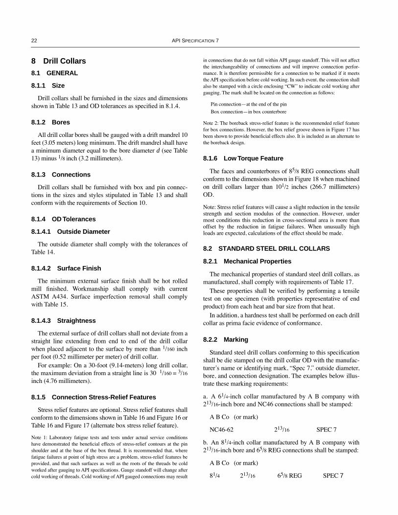
22 API SPECIFICATION 7
8 Drill Collars
8.1 GENERAL
8.1.1 Size
Drill collars shall be furnished in the sizes and dimensionsshown in Table 13 and OD tolerances as speciÞed in 8.1.4.
8.1.2 Bores
All drill collar bores shall be gauged with a drift mandrel 10feet (3.05 meters) long minimum. The drift mandrel shall havea minimum diameter equal to the bore diameter d (see Table13) minus 1/8 inch (3.2 millimeters).
8.1.3 Connections
Drill collars shall be furnished with box and pin connec-tions in the sizes and styles stipulated in Table 13 and shallconform with the requirements of Section 10.
8.1.4 OD Tolerances
8.1.4.1 Outside Diameter
The outside diameter shall comply with the tolerances ofTable 14.
8.1.4.2 Surface Finish
The minimum external surface Þnish shall be hot rolledmill Þnished. Workmanship shall comply with currentASTM A434. Surface imperfection removal shall complywith Table 15.
8.1.4.3 Straightness
The external surface of drill collars shall not deviate from astraight line extending from end to end of the drill collarwhen placed adjacent to the surface by more than 1/160 inchper foot (0.52 millimeter per meter) of drill collar.
For example: On a 30-foot (9.14-meters) long drill collar,the maximum deviation from a straight line is 30 1/160 = 3/16
inch (4.76 millimeters).
8.1.5 Connection Stress-Relief Features
Stress relief features are optional. Stress relief features shallconform to the dimensions shown in Table 16 and Figure 16 orTable 16 and Figure 17 (alternate box stress relief feature).
Note 1: Laboratory fatigue tests and tests under actual service conditionshave demonstrated the beneÞcial effects of stress-relief contours at the pinshoulder and at the base of the box thread. It is recommended that, wherefatigue failures at point of high stress are a problem, stress-relief features beprovided, and that such surfaces as well as the roots of the threads be coldworked after gauging to API speciÞcations. Gauge standoff will change aftercold working of threads. Cold working of API gauged connections may result
in connections that do not fall within API gauge standoff. This will not affectthe interchangeability of connections and will improve connection perfor-mance. It is therefore permissible for a connection to be marked if it meetsthe API speciÞcation before cold working. In such event, the connection shallalso be stamped with a circle enclosing ÒCWÓ to indicate cold working aftergauging. The mark shall be located on the connection as follows:
Pin connectionÑat the end of the pin
Box connectionÑin box counterbore
Note 2: The boreback stress-relief feature is the recommended relief featurefor box connections. However, the box relief groove shown in Figure 17 hasbeen shown to provide beneÞcial effects also. It is included as an alternate tothe boreback design.
8.1.6 Low Torque Feature
The faces and counterbores of 85/8 REG connections shallconform to the dimensions shown in Figure 18 when machinedon drill collars larger than 101/2 inches (266.7 millimeters)OD.
Note: Stress relief features will cause a slight reduction in the tensilestrength and section modulus of the connection. However, undermost conditions this reduction in cross-sectional area is more thanoffset by the reduction in fatigue failures. When unusually highloads are expected, calculations of the effect should be made.
8.2 STANDARD STEEL DRILL COLLARS
8.2.1 Mechanical Properties
The mechanical properties of standard steel drill collars, asmanufactured, shall comply with requirements of Table 17.
These properties shall be veriÞed by performing a tensiletest on one specimen (with properties representative of endproduct) from each heat and bar size from that heat.
In addition, a hardness test shall be performed on each drillcollar as prima facie evidence of conformance.
8.2.2 Marking
Standard steel drill collars conforming to this speciÞcationshall be die stamped on the drill collar OD with the manufac-turerÕs name or identifying mark, ÒSpec 7,Ó outside diameter,bore, and connection designation. The examples below illus-trate these marking requirements:
a. A 61/4-inch collar manufactured by A B company with213/16-inch bore and NC46 connections shall be stamped:
A B Co (or mark)
NC46-62 213/16 SPEC 7
b. An 81/4-inch collar manufactured by A B company with213/16-inch bore and 65/8 REG connections shall be stamped:
A B Co (or mark)
81/4 213/16 65/8 REG SPEC 7
COPYRIGHT American Petroleum Institute

SPECIFICATION FOR ROTARY DRILL STEM ELEMENTS 23
Table 13—Drill Collars
1 2 3 4 5 6
Drill Collar NumberaOutside Diameter
DbBore, +1/16 Ð0
dLength, ft. ±6 in.
LdBevel Diameter, ±1/64
DF
Reference Bending Strength Ratioe
NC23-31 31/8 11/4 30 3 2.57:1NC26-35 31/2 11/2 30 317/64 2.42:1NC31-41 41/8 2 30 or 31 361/64 2.43:1NC35-47 43/4 2 30 or 31 433/64 2.58:1NC38-50 5 21/4 30 or 31 449/64 2.38:1NC44-60 6 21/4 30 or 31 511/16 2.49:1NC44-60 6 213/16 30 or 31 511/16 2.84:1NC44-62 61/4 21/4 30 or 31 57/8 2.91:1NC46-62 61/4 213/16 30 or 31 529/32 2.63:1NC46-65 61/2 21/4 30 or 31 63/32 2.76:1NC46-65 61/2 213/16 30 or 31 63/32 3.05:1NC46-67 63/4 21/4 30 or 31 69/32 3.18:1NC50-70 7 21/4 30 or 31 631/64 2.54:1NC50-70 7 213/16 30 or 31 631/64 2.73:1NC50-72 71/4 213/16 30 or 31 643/64 3.12:1NC56-77 73/4 213/16 30 or 31 719/64 2.70:1NC56-80 8 213/16 30 or 31 731/64 3.02:165/8 REG 81/4 213/16 30 or 31 745/64 2.93:1NC61-90 9 213/16 30 or 31 83/8 3.17:175/8 REG 91/2 3 30 or 31 813/16 2.81:1NC70-97 93/4 3 30 or 31 95/32 2.57:1NC70-100 10 3 30 or 31 911/32 2.81:185/8 REGc 11 3 30 or 31 101/2 2.84:1
Notes:1. See Figure 15.2. All dimensions are in inches unless otherwise speciÞed. See Appendix M for metric table.aThe drill collar number consists of two parts separated by a hyphen. The Þrst part is the connection number in the NC style. The second part, consisting of 2 (or 3) digits, indicates the drill collar outside diameter in units and tenths of inches. Drill collars with 81/4, 91/2, and 11 inch out-side diameters are shown with 65/8, 75/8, and 85/8 REG connections, since there are no NC connections in the recommended bending strength ratio range.bSee Table 14 for tolerances.cSee Figure 17 and Table 16 for dimensions.dSee 8.3.2 for nonmagnetic drill collar tolerances.eStress relief features are disregarded in the calculation of the bending strength ratio.
Table 14—Drill Collar OD Tolerances
1 2 3 4
Size Tolerance Inclusive
Over Out-of-Roundnessa
Size: Outside Diameter in. mm Under in. mm
Over 21/2 to 31/2 inclusive 3/64 1.19 0 0.035 0.89Over 31/2 to 41/2 inclusive 1/16 1.59 0 0.046 1.17Over 41/2 to 51/2 inclusive 5/64 1.98 0 0.058 1.47Over 51/2 to 61/2 inclusive 1/8 3.18 0 0.070 1.78Over 61/2 to 81/4 inclusive 5/32 3.97 0 0.085 2.16Over 81/4 to 91/2 inclusive 3/16 4.76 0 0.100 2.54Over 91/2 1/4 6.35 0 0.120 3.05
Note: Out-of-roundness is the difference between the maximum and minimum diameters of the bar, measured at the same cross-section, anddoes not include surface Þnish tolerances outlined in 8.1.4.2.
COPYRIGHT American Petroleum Institute

24 API SPECIFICATION 7
Figure 17—Alternate Box Stress-Relief Feature
��
���
����
����
����
��
T.P.F.
1" (25.4 mm)±1/64" (±0.40 mm)
1" (25.4 mm), ±1/32" (±0.79 mm)
1/4" (6.35 mm) R, ±1/64" (±0.40 mm)
30¡ ±1¡2" (50.8 mm) ±1/4"(±6.35 mm)
2" (50.8 mm) ±1/4"(±6.35 mm)
��
����
���
��45¡ ±1¡
DRG
R
Boreback Box Stress-Relief Feature Pin Stress-Relief Feature
D CB
Lx
11/2" (38.1 mm)±1/8" (3.18 mm)
45¡ ±2¡
30¡ ±2¡LRG
Box Stress-Relief Groove
�
���
����
�����
����
���
�
1/4" (6.35 mm) R±1/64" (±0.40 mm)
13/64" (5.16 mm)+1/64" (0.40 mm)–0"
��
��� ��
�� �� �DF
Rotary boxconnection
Rotary pinconnection
L
DDFd
Figure 16—Connection Stress-Relief FeaturesNote: See Table 16.
Note: See Table 16.
Table 15—Drill Collar Surface Imperfection Removal
1 2
Maximum Stock Removal From Surface
Size: Outside Diameter in. mm
Over 21/2 to 31/2 inclusive 0.072 1.83
Over 31/2 to 41/2 inclusive 0.090 2.29
Over 41/2 to 51/2 inclusive 0.110 2.79
Over 51/2 to 61/2 inclusive 0.125 3.18
Over 61/2 to 81/4 inclusive 0.155 3.94
Over 81/4 to 91/2 inclusive 0.203 5.16
Over 91/2 0.480 12.19
Figure 15—Drill CollarsNote: See Table 13.
COPYRIGHT American Petroleum Institute

SPECIFICATION FOR ROTARY DRILL STEM ELEMENTS 25
8.3 NONMAGNETIC DRILL COLLARS
8.3.1 Dimensional Features
Nonmagnetic drill collars shall be furnished with dimen-sional features conforming to those stated in 8.1.1, Size;8.1.2, Bores; 8.1.3, Connections; 8.1.4, OD Tolerances; and8.1.5, Stress-Relief Features, with 8.3.1.1 through 8.3.1.3listed as exceptions:
8.3.1.1 Length Tolerance
The length tolerance for nonmagnetic drill collars shall be+ 6, Ð 0 inches (+152.4, Ð 0 millimeters).
8.3.1.2 Bore Eccentricity
The maximum bore eccentricity shall be 0.094 inch (2.39millimeters) at the collar ends. The center eccentricity shallnot exceed 0.250 inch (6.35 millimeters).
Note: The purpose of the eccentricity speciÞcation in the center of anonmagnetic collar is to ensure reasonably accurate alignment of asurvey instrument with the collar axis. Eccentricity in the centerdoes not have a signiÞcant effect on the torsional or tensile strengthof the collar.
8.3.1.3 Connections
In addition to the connections and outside diameter combi-nations noted in 8.1.3 and Tables 13 and 19, nonmagnetic
Figure 18—Low Torque Feature for 85/8 REG Connections Machined on ODs Larger Than 101/2 Inches (266.7 Millimeters) Excluding Bit Boxes
Table 16—Stress-Relief Features for Drill Collar Connections
1 2 3 4 5 6
Number or Size and Style of Connectiona
Length Shoulder Face to Last Thread
Scratch of Box Member in., ± 1/16 in.
LX
Diameter of Cylinder Area of Box
Memberin., + 1/64 Ð0 in.
DCB
Taper of Area Behind Cylinder Area
of Box Memberin./ft., ±1/4 in./ft.
T.P.F.
Diameter of Pin Member at Groovein., + 0 Ð.031 in.
DRG
LengthShoulder Face to
Groove of Box Member in., + 0 Ð1/8 in.
LRG
NC35 31/4 315/64 2 3.231 33/8NC38 31/2 315/32 2 3.508 35/8NC40 4 321/32 2 3.772 41/8NC44 4 4 2 4.117 41/8NC46 4 413/64 2 4.326 41/8NC50 4 45/8 2 4.742 41/8NC56 41/2 451/64 3 5.277 45/8NC61 5 515/64 3 5.839 51/8NC70 51/2 563/64 3 6.714 55/8NC77 6 635/64 3 7.402 61/841/2 REG 33/4 323/32 3 4.013 37/841/2 FH 31/2 361/64 3 4.180 35/851/2 REG 41/4 41/2 3 4.869 43/865/8 REG 41/2 59/32 2 5.417 45/875/8 REG 43/4 555/64 3 6.349 47/885/8 REG 47/8 625/32 3 7.301 5
Notes: 1. See Figures 16 and 17.2. See Appendix M for metric table.aConnections NC23, NC26, and NC31 do not have sufÞcient metal to accommodate stress-relief features.
101/2" (266.7 mm)– 1/64" (0.40 mm)
101/2" (266.7 mm)–1/64" (0.40 mm)
9" (228.6 mm)+1/32" (0.79 mm)—1/64" (0.40 mm) 9" (228.6 mm)
+1/32" (0.79 mm)—1/64" (0.40 mm)
3/8" (9.5 mm)–1/16" (1.6 mm)
3" T.P.F.
Bev. dia.
Bev. dia.Dia.
7.301" Cyl. dia.(185.5 mm, +0 - 0.79)
Dia.
1/4" (6.35 mm) R– 1/64" (– 0.40 mm)
1/4" (6.35 mm) R–1/32" (– 0.79 mm)
1/4" (6.4 mm)+1/16" (1.6 mm)— 0"
+0.000"—0.031"
COPYRIGHT American Petroleum Institute
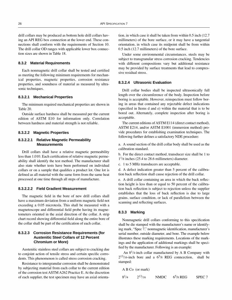
26 API SPECIFICATION 7
drill collars may be produced as bottom hole drill collars hav-ing an API REG box connection at the lower end. These con-nections shall conform with the requirements of Section 10.The drill collar OD ranges with applicable lower box connec-tion sizes are shown in Table 18.
8.3.2 Material Requirements
Each nonmagnetic drill collar shall be tested and certiÞedas meeting the following minimum requirements for mechan-ical properties, magnetic properties, corrosion resistanceproperties, and soundness of material as measured by ultra-sonic techniques.
8.3.2.1 Mechanical Properties
The minimum required mechanical properties are shown inTable 20.
Outside surface hardness shall be measured per the currentedition of ASTM E10 for information only. Correlationbetween hardness and material strength is not reliable.
8.3.2.2 Magnetic Properties
8.3.2.2.1 Relative Magnetic Permeability Measurements
Drill collars shall have a relative magnetic permeabilityless than 1.010. Each certiÞcation of relative magnetic perme-ability shall identify the test method. The manufacturer shallalso state whether tests have been performed on individualcollars or on a sample that qualiÞes a product lot. One lot isdeÞned as all material with the same form from the same heatprocessed at one time through all steps of manufacture.
8.3.2.2.2 Field Gradient Measurement
The magnetic Þeld in the bore of new drill collars shallhave a maximum deviation from a uniform magnetic Þeld notexceeding ± 0.05 microtesla. This shall be measured with amagnetoscope and differential Þeld probe having its magne-tometers oriented in the axial direction of the collar. A stripchart record showing differential Þeld along the entire bore ofthe collar shall be part of the certiÞcation of each collar.
8.3.2.3 Corrosion Resistance Requirements (for Austenitic Steel Collars of 12 Percent Chromium or More)
Austenitic stainless steel collars are subject to cracking dueto conjoint action of tensile stress and certain speciÞc corro-dents. This phenomenon is called stress corrosion cracking.
Resistance to intergranular corrosion shall be demonstratedby subjecting material from each collar to the current editionof the corrosion test ASTM A262 Practice E. At the discretionof each supplier, the test specimen may have an axial orienta-
tion, in which case it shall be taken from within 0.5 inch (12.7millimeters) of the bore surface, or it may have a tangentialorientation, in which case its midpoint shall be from within0.5 inch (12.7 millimeters) of the bore surface.
Under some environmental circumstances, steels may besubject to transgranular stress corrosion cracking. Tendencieswith different compositions vary but additional resistancemay be provided by surface treatments that lead to compres-sive residual stress.
8.3.2.4 Ultrasonic Evaluation
Drill collar bodies shall be inspected ultrasonically fulllength over the circumference of the body. Inspection beforeboring is acceptable. However, reinspection must follow bor-ing in areas that contained any rejectable defect indications(speciÞed in Items d and e) within the material that is to bebored out. Alternately, complete inspection after boring isacceptable.
The current editions of ASTM E114 (direct contact method),ASTM E214, and/or ASTM E1001 (immersion method) pro-vide procedures for establishing examination techniques. Thefollowing further deÞnes a satisfactory NDE procedure:
a. A sound section of the drill collar body shall be used as thecalibration standard.
b. For the direct contact method, transducer size shall be 1 to11/8 inches (25.4 to 28.6 millimeters) diameter.
c. 1 to 5 MHz transducers are acceptable.
d. A defect indication greater than 5 percent of the calibra-tion back reßection shall cause rejection of the drill collar.
e. A drill collar containing an area in which the back reßec-tion height is less than or equal to 50 percent of the calibra-tion back reßection is subject to rejection unless the supplierestablishes that the loss of back reßection is due to largegrains, surface condition, or lack of parallelism between thescanning and reßecting surfaces.
8.3.3 Marking
Nonmagnetic drill collars conforming to this speciÞcationshall be die stamped with the manufacturerÕs name or identify-ing mark, ÒSpec 7,Ó nonmagnetic identiÞcation, manufacturerÕsserial number, outside diameter, and bore. The example belowillustrates these marking requirements. Locations of the mark-ings and the application of additional markings shall be speci-Þed by the manufacturer. Following is an example:
An 81/4-inch collar manufactured by A B Company with213/16-inch bore and a 65/8 REG conncection, shall bestamped:
A B Co (or mark)
81/4 213/16 NMDC 65/8 REG SPEC 7
COPYRIGHT American Petroleum Institute

SPECIFICATION FOR ROTARY DRILL STEM ELEMENTS 27
Table 17—Mechanical Properties and Tests New Standard Steel Drill Collars
1 2 3 4 5
Minimum Yield Strength Minimum Tensile Strength
Drill Collar OD Range
inches psi N/mm2 psi N/mm2
Elongation, Minimum, With Gauge Length Four Times Diameter,
percent
Minimum Brinell
Hardness
31/8 through 67/8 110,000 758 140,000 965 13 2857 through 11 100,000 689 135,000 931 13 285
Notes: 1. Tensile properties shall be determined by tests on cylindrical specimens conforming to the requirements of the current ASTM A370, 0.2 per-cent offset method.2. Tensile specimens from drill collars shall be taken within 3 feet (0.9 meters) of the end of the drill collar in a longitudinal direction, having the centerline of the tensile specimen 1 inch (25 millimeters) from the outside surface or midwall, whichever is closer to the outside surface.3. Hardness test shall be on OD of drill collar using Brinell Hardness (Rockwell-C acceptable alternative) test methods in compliance with cur-rent ASTM A370 requirements.
Table 18—Connections for Bottom Hole Drill Collars
Bevel Diameter
Size: Outside Diameter Bottom Box Connection in. ± 1/64 mm ± 0.40
41/8 to 41/2 inclusive 27/8 REG 339/64 91.6843/4 to 5 inclusive 31/2 REG 47/64 104.386 to 7 inclusive 41/2 REG 521/64 135.337 to 71/4 inclusive 51/2 REG 61/2 165.1073/4 to 9 inclusive 65/8 REG 723/64 186.9391/2 to 10 inclusive 75/8 REG 815/32 215.1111 inclusive 85/8 REG 935/64 242.49
Table 19—Additional Nonmagnetic Drill Collars
1 2 3 4 5 6
Outside Diameter Bore Length ft, m Bevel Diameter
L DF
Drill CollarNumber
Din. mm
+ 1/16 Ð 0in.
+ 1.6 Ð 0mm
+ 6 Ð 0in.
+ 152.4 Ð 0 mm
±1 /64in.
± 0.4mm
Ref. BendingStrength Ratio
NC 50-67 63/4 171.5 213/16 71.4 30 or 31 9.14 or 9.45 69/32 159.5 2.37:1a
Note: See Figure 15 and Table 13.aThe NC 50-67 with 23/16 ID has a bending strength ratio of 2.37:1, which is more pin strong than is normally acceptable for standard steel collars but has proven to be acceptable for nonmagnetic drill collars.
Table 20—Mechanical Properties and Tests, New Nonmagnetic Drill Collars
Stainless Steels Beryllium Copper
Drill Collar OD Range,
inches
Minimum Yield Strength Minimum Tensile Strength Minimum Elongation,
percent
Minimum Yield Strength Minimum Tensile Strength Minimum Elongation,
percentpsi N/mm2 psi N/mm2 psi N/mm2 psi N/mm2
31/2 through 67/8 110,000 758 120,000 827 18 110,000 758 140,000 965 127 through 11 100,000 689 110,000 758 20 100,000 689 135,000 931 13
Notes:1. Tensile properties shall be determined by tests on cylindrical specimens with gauge length four times diameter conforming to the requirements of the current edition of ASTM E 8, 0.2 percent offset method.2. Tensile specimens shall be taken from excess material within 3 feet (0.9 meter) of the end of the drill collar and, at the manufacturerÕs option, may be oriented in either the longitudinal or transverse direction. The specimenÕs orientation shall be reported. The midpoint of the specimen gauge section shall be, at minimum, 1 inch (25 millimeters) beneath the outside surface, or at midwall, whichever position is closer to the outside surface.
COPYRIGHT American Petroleum Institute

28 API SPECIFICATION 7
9 Drilling and Coring Bits
9.1 ROLLER BITS AND BLADE DRAG BITS
9.1.1 Size
Roller bits shall be furnished in sizes as speciÞed on thepurchase order. See Recommended Practice 7G for com-monly used sizes for roller bits. Blade drag bits shall be fur-nished in the sizes speciÞed on the purchase order.
9.1.2 Tolerances
The gauge diameter of the cutting edge of the bit shall con-form to the size designation, within the following tolerances:
9.1.3 Connections
Roller bits shall be furnished with the size and style of pinconnection shown in Table 21. Blade drag bits shall be fur-nished with the size and style of connection shown in Table20, and shall be pin or box.
9.1.4 Marking
Bits shall be die stamped in some location other than themake-up shoulder with the manufacturerÕs name or identiÞ-cation mark, the bit size, ÒSpec 7,Ó and the size and style ofconnection. Following is an example:
A 77/8 bit manufactured by A B Company, with 41/2 REGrotary connection shall be stamped as follows:
A B Co (or mark) 77/8 SPEC 7 41/2 REG
9.2 DIAMOND DRILLING BITS, DIAMOND CORE BITS, AND POLYCRYSTALLINE DIAMOND COMPACT (PDC) BITS
9.2.1 Diamond Bit Tolerances
Diamond drilling bits, diamond core bits, and polycrystal-line diamond compact (PDC) bits shall be subject to the ODtolerances shown in Table 23.
9.2.2 Diamond Drilling Bit and PDC Connections
Diamond drilling bits and PDC bits shall be furnished withthe size and style pin connections shown in Table 24. All con-nection threads shall be right hand.
9.2.3 Diamond Bit and PDC Bit Gauging
All diamond and PDC bits will have the outer diameterinspected using the following dimensional guidelines for ringgauges.
9.2.3.1 Gauge Specification
ÒGoÓ and ÒNo GoÓ gauges should be fabricated as shownin Figure 19 and as described below:
a. ÒGoÓ and ÒNo GoÓ gauges should be rings fabricated from1-inch steel with ODs equal to nominal bit sizes plus 11/2inches (38.1 millimeters).b. ÒGoÓ gauge ID should equal nominal bit size plus 0.002inch (0.051 millimeter) clearance with a tolerance of + 0.003,Ð 0 inch (+ 0.076, Ð 0 millimeter).c. ÒNo GoÓ gauge ID should equal minimum bit size (nomi-nal less maximum negative tolerance) minus 0.002 inch inter-ference with a tolerance of + 0, Ð 0.003 inch (+ 0, Ð 0.076millimeter).
9.2.3.2 Gauging Practice
The ÒGoÓ and ÒNo GoÓ gauges should be used as follows:
a. If acceptable, the product bit should enter the ÒGoÓ gauge(product not too large).b. If acceptable, the product bit should not enter the ÒNo GoÓgauge (product not too small).c. Both the ÒGoÓ and ÒNo GoÓ gauges should be within 20¡F(11¡C) of the same temperature as the bit or corehead foraccurate measurement.
9.2.4 Marking
Diamond drilling bits, diamond core bits, and PDC bitsshall be marked as follows:
a. Diamond drilling bits and PDC bits shall be permanentlyand legibly identiÞed in some location other than the make-upshoulder with the manufacturerÕs name or identiÞcation mark,the bit size, ÒSpec 7,Ó and the size and type of connection.
Following is an example: A 71/2 bit manufactured by A B Company with 41/2 REG
rotary connection shall be stamped as follows:
A B Co (or mark) 71/2 SPEC 7 41/2 REG
b. Diamond core bits shall be permanently and legibly identi-Þed on some location other than the make-up shoulder withthe manufacturerÕs name or identiÞcation mark and ÒSpec 7Óas follows:
A B Co (or mark) SPEC 7
Because of its proprietary nature, the connection on dia-mond core bits will not be shown. The marking ÒSpec 7Óshall indicate that other dimensional requirements havebeen met.
Size of Bit Tolerance
in. in. mm
1.75 to 133/4, inclusive + 1/32 Ð 0 + 0.80 Ð 0
14 to 171/2, inclusive + 1/16 Ð 0 + 1.59 Ð 0
175/8 and larger + 3/32 Ð 0 + 2.38 Ð 0
COPYRIGHT American Petroleum Institute

SPECIFICATION FOR ROTARY DRILL STEM ELEMENTS 29
Figure 19—Diamond Bit and PDC Bit Gauge Dimensions
Table 21—Roller Bit Connections
1 2 3 4
Size of Bitinches
Size and Style of Rotary Pin Connection
Bit Sub Bevel Diametera Bit Bevel Diametera
inches ± 1/64 millimeters ± 0.40 inches ± 1/64 millimeters ± 0.40
1.75 to 2.24 inclusive 1 REGb 1.468 37.29 1.500 38.10
2.25 to 3.49 inclusive 11/2 REGc 1.932 49.07 1.964 49.89
3.50 to 4.50 inclusive 23/8 REG 3.047 77.39 3.078 78.18
45/8 to 5 inclusive 27/8 REG 339/64 91.68 341/64 93.66
51/8 to 73/8 inclusive 31/2 REG 47/64 104.38 49/64 105.17
71/2 to 93/8 inclusive 41/2 REG 521/64 135. 33 523/64 136.13
91/2 to 143/8 inclusive 65/8 REG 723/64 186.93 725/64 187.72
141/2 to 181/2 inclusive 65/8 REG or 75/8 REG 723/64 or 815/32 186.93 or 215.11 725/64 or 81/2 187.72 or 215.90
185/8 to 26 inclusive 75/8 REG or 85/8 REG 815/32 or 935/64 215.11 or 242.49 81/2 or 937/64 215.90 or 243.28
27 and larger 85/8 REG 935/64 242.49 937/64 243.28
aBevel diameter is the outer diameter of the contact face of the rotary shouldered connection.b1 REG is interchangeable with most 1 MT, 1 AMT, and 1 AMMT threads.c 11/2 REG is interchangeable with most 11/2 MT, 11/2 AMT, and 11/2 AMMT threads.
Table 22—Blade Drag Bit Connections
1 2 3 4
Size of Bitinches
Size and Style of Rotary Connection
Bit Sub Bevel Diametera Bit Bevel Diametera
inches ±1/64 millimeters ±0.40 inches ±1/64 millimeters ±0.40
1.75 to 2.24 inclusive 1 REGb 1.468 37.29 1.500 38.10
2.25 to 3.49 inclusive 11/2 REGc 1.932 49.07 1.964 49.89
3.50 to 4.50 inclusive 2 3/8 REG 3.047 77.39 3.078 78.18
45/8 to 5 inclusive 27/8 REG, pin or box 339/64 91.68 341/64 93.66
51/8 to 73/8 inclusive 31/2 REG, pin or box 47/64 104.38 49/64 105.17
71/2 to 81/2 inclusive 41/2 REG, pin or box 521/64 135.33 523/64 136.13
85/8 to 97/8 inclusive 51/2 REG, pin or box 61/2 165.10 617/32 165.89
larger than 97/8 65/8 REG, pin or box 723/64 186.93 725/64 187.72
aBevel diameter is the outer diameter of the contact face of the rotary shouldered connection.b1 REG is interchangeable with most 1 MT, 1 AMT, and 1 AMMT threads.c 11/2 REG is interchangeable with most 11/2 MT, 11/2 AMT, and 11/2 AMMT threads.
Bit size
+0.002 in. +0.003–0.000
( )+0.051 mm +0.076–0.000
Nom. bit size +1.5 in.(+38.1 mm) 1 in.
(25.4 mm)
Bit size less
Neg Tol –0.002 in. +0.000–0.003
()-0.051 mm +0.000–0.076
Nom. bit size +1.5 in.(+38.1 mm)
Go Gauge No-Go Gauge
COPYRIGHT American Petroleum Institute
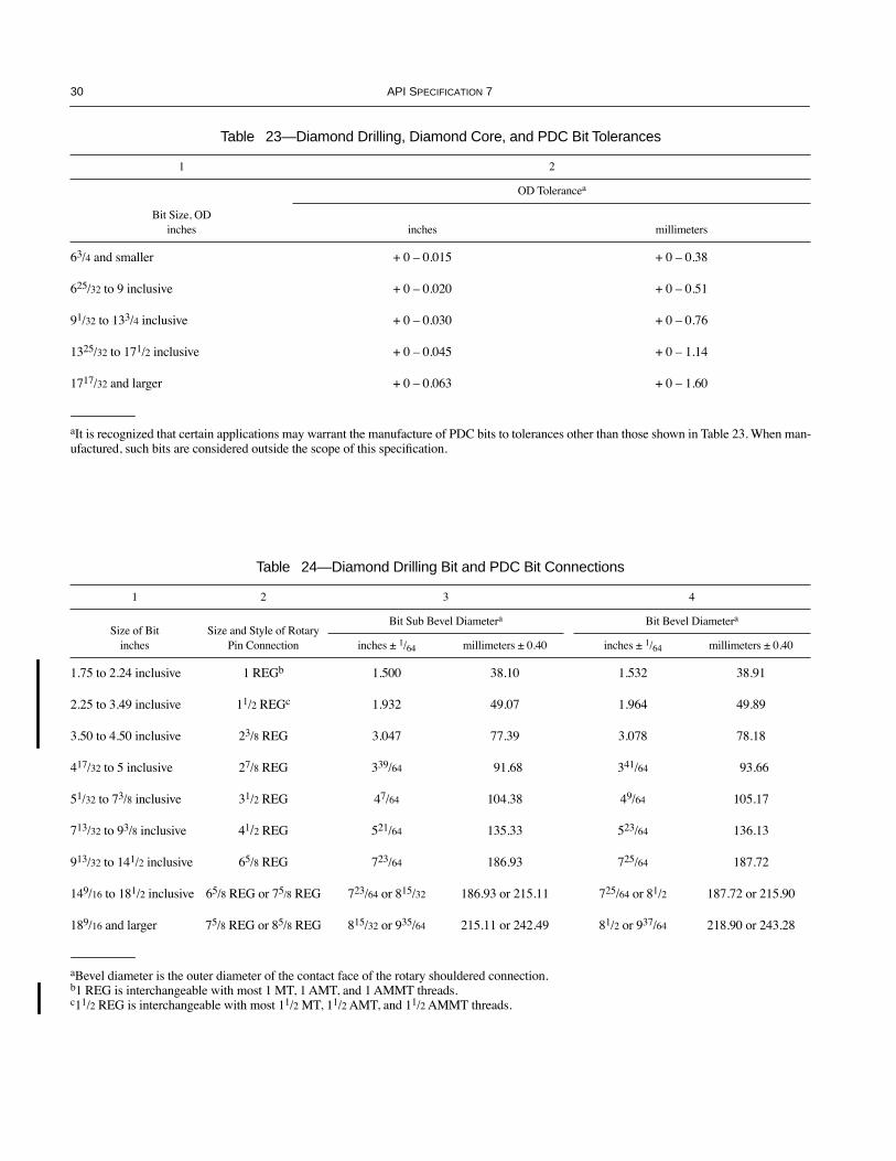
30 API SPECIFICATION 7
Table 23—Diamond Drilling, Diamond Core, and PDC Bit Tolerances
1 2
OD Tolerancea
Bit Size, ODinches inches millimeters
63/4 and smaller + 0 Ð 0.015 + 0 Ð 0.38
625/32 to 9 inclusive + 0 Ð 0.020 + 0 Ð 0.51
91/32 to 133/4 inclusive + 0 Ð 0.030 + 0 Ð 0.76
1325/32 to 171/2 inclusive + 0 Ð 0.045 + 0 Ð 1.14
1717/32 and larger + 0 Ð 0.063 + 0 Ð 1.60
aIt is recognized that certain applications may warrant the manufacture of PDC bits to tolerances other than those shown in Table 23. When man-ufactured, such bits are considered outside the scope of this speciÞcation.
Table 24—Diamond Drilling Bit and PDC Bit Connections
1 2 3 4
Size of Bitinches
Size and Style of Rotary Pin Connection
Bit Sub Bevel Diametera Bit Bevel Diametera
inches ± 1/64 millimeters ± 0.40 inches ± 1/64 millimeters ± 0.40
1.75 to 2.24 inclusive 1 REGb 1.500 38.10 1.532 38.91
2.25 to 3.49 inclusive 11/2 REGc 1.932 49.07 1.964 49.89
3.50 to 4.50 inclusive 23/8 REG 3.047 77.39 3.078 78.18
417/32 to 5 inclusive 27/8 REG 339/64 91.68 341/64 93.66
51/32 to 73/8 inclusive 31/2 REG 47/64 104.38 49/64 105.17
713/32 to 93/8 inclusive 41/2 REG 521/64 135.33 523/64 136.13
913/32 to 141/2 inclusive 65/8 REG 723/64 186.93 725/64 187.72
149/16 to 181/2 inclusive 65/8 REG or 75/8 REG 723/64 or 815/32 186.93 or 215.11 725/64 or 81/2 187.72 or 215.90
189/16 and larger 75/8 REG or 85/8 REG 815/32 or 935/64 215.11 or 242.49 81/2 or 937/64 218.90 or 243.28
aBevel diameter is the outer diameter of the contact face of the rotary shouldered connection.b1 REG is interchangeable with most 1 MT, 1 AMT, and 1 AMMT threads.c11/2 REG is interchangeable with most 11/2 MT, 11/2 AMT, and 11/2 AMMT threads.
COPYRIGHT American Petroleum Institute

SPECIFICATION FOR ROTARY DRILL STEM ELEMENTS 31
10 Rotary Shouldered Connections10.1 SIZE AND STYLE
Rotary shouldered connections shall be furnished in thesizes and styles shown in Table 25.
10.2 DIMENSIONS
Dimensions of rotary shouldered connections shall con-form to Tables 25 and 26.
The dimensions shown in Tables 25 and 26 that have nospeciÞed tolerance shall be considered reference dimensions.Deviations from these dimensions are not cause for rejection.
10.2.1 Shoulder contact faces of rotary shouldered connec-tions shall be square with the thread axis within 0.002 inch(0.05 millimeter).
10.2.2 Shoulder contact faces of rotary shouldered connec-tions shall be ßat within 0.002 inch (0.05 millimeter).
10.2.3 Threads of rotary shouldered connections shall beproduced with standoff tolerances as speciÞed in Section 11of this speciÞcation.
10.2.4 Thread axes of rotary shouldered connections,except on bits, shall not deviate from the design axes of theproduct by an angle greater than 0 degrees, 3 minutes, 26 sec-onds (0.001 inch per inch [0.001 millimeter per millimeter] ofprojected axis). The design axis shall be assumed to intersectthe thread axis at the plane of the joint shoulder.
10.2.5 The lead tolerance of rotary shouldered connectionsis as follows:
a. ± 0.0015 inch per inch (± 0.0015 millimeter per millime-ter) for any inch (millimeter) between the Þrst and last fulldepth threads.b. ± 0.0045 inch (± 0.114 millimeter) between the Þrst andlast full depth threads, or the sum of 0.001 inch (0.025 milli-meter) for each inch (mm) between the Þrst and last full depththreads, whichever is greater.
10.2.6 The taper tolerance of rotary shouldered connec-tions is as follows:
a. Pin thread: + 0.030, Ð 0.000 inch per foot (+ 2.50, Ð 0.00millimeter per meter) average taper between the Þrst and lastfull depth threads.b. Box thread: + 0.000, Ð 0.030 inch per foot (+ 0.00, Ð 2.50millimeter per meter) average taper between the Þrst and lastfull depth threads.
Appendix H of this speciÞcation contains descriptions ofsuitable tools for determining taper.
10.2.7 Pin base diameter dimensional requirements are asfollows:
a. Drill collars shall conform to the dimension DLF, Column7 of Table 25, and shall have a 0.062 inch (1.59 millimeters)radius at the pin base as shown in Figure 20 except whenstress-relief grooves are used.b. The DLF dimension, Column 7 of Table 25, and the radiusat the pin base as shown in Figure 20 are optional for all drillstem elements except drill collars.
10.3 EQUIVALENT CONNECTIONS
The number connections and their equivalent connectionsare as follows:
Number Connection Equivalent ConnectionNC26 23/8 IFNC31 27/8 IFNC38 31/2 IFNC40 4 FHNC46 4 IFNC50 41/2 IF
The number in the Connection Number, Column 1 of Table25, is the pitch diameter of the pin thread at the gauge pointrounded to units and tenths of inches.
COPYRIGHT American Petroleum Institute

32 API SPECIFICATION 7
Table 25—Product Dimensions Rotary Shouldered Connections
1 2 3 4 5 6 7 8 9 10 11 12
Connection Number or
SizeThreadForm
ThreadsPer Inch
Taper, Inches Per Foot onDiameter
Pitch Diameter of Thread at
Gauge Point
LargeDiameter
of Pin
Diameter of Flat on Pin
± 1/64
Small Diameter
of Pin
Length of pina
+ 0 Ð 1/8
Minimum Length of Box
Threadsb
Depth of Box
+ 3/8 Ð 0
Box Counter-bore+ 1/32 Ð 1/64
C DL DLF DS LPC LBT LBC QC
Number (NC) Style
NC23 V-0.038R 4 2 2.35500 2.563 2.437 2.063 3 31/8 35/8 25/8NC26 V-0.038R 4 2 2.66800 2.876 2.750 2.376 3 31/8 35/8 215/16
NC31 V-0.038R 4 2 3.18300 3.391 3.266 2.808 31/2 35/8 41/8 329/64
NC35 V-0.038R 4 2 3.53100 3.739 3.625 3.114 33/4 37/8 43/8 313/16
NC38 V-0.038R 4 2 3.80800 4.016 3.891 3.349 4 41/8 45/8 45/64NC40 V-0.038R 4 2 4.07200 4.280 4.156 3.530 41/2 45/8 51/8 411/32
NC44 V-0.038R 4 2 4.41700 4.625 4.499 3.875 41/2 45/8 51/8 411/16
NC46 V-0.038R 4 2 4.62600 4.834 4.709 4.084 41/2 45/8 51/8 429/32
NC50 V-0.038R 4 2 5.04170 5.250 5.135 4.500 41/2 45/8 51/8 55/16
NC56 V-0.038R 4 3 5.61600 5.876 5.703 4.626 5 51/8 55/8 515/16
NC61 V-0.038R 4 3 6.17800 6.438 6.266 5.063 51/2 55/8 61/8 61/2NC70 V-0.038R 4 3 7.05300 7.313 7.141 5.813 6 61/8 65/8 73/8NC77 V-0.038R 4 3 7.74100 8.000 7.828 6.376 61/2 65/8 71/8 81/16
Regular (REG) Style
1 REG V-0.055 6 1.5 1.15400 1.281 1.233 1.094 1.50 2.00 2.13 1.30111/2 REG V-0.055 6 1.5 1.54100 1.668 1.621 1.418 2.00 2.125 2.63 1.68823/8 REG V-0.040 5 3 2.36537 2.625 2.515 1.875 3 31/8 35/8 211/16
27/8 REG V-0.040 5 3 2.74037 3.000 2.890 2.125 31/2 35/8 41/8 31/16
31/2 REG V-0.040 5 3 3.23987 3.500 3.390 2.562 33/4 37/8 43/8 39/16
41/2 REG V-0.040 5 3 4.36487 4.625 4.515 3.562 41/4 43/8 47/8 411/16
51/2 REG V-0.050 4 3 5.23402 5.520 5.410 4.333 43/4 47/8 53/8 537/64
65/8 REG V-0.050 4 2 5.75780 5.992 5.882 5.159 5 51/8 55/8 61/16
75/8 REG V-0.050 4 3 6.71453 7.000 6.890 5.688 51/4 53/8 57/8 73/32
85/8 REG V-0.050 4 3 7.66658 7.952 7.840 6.608 53/8 51/2 6 83/64
Full-Hole (FH) Style
51/2 FH V-0.050 4 2 5.59100 5.825 Ñ 4.992 5 51/8 55/8 529/32
65/8 FH V-0.050 4 2 6.51960 6.753 Ñ 5.920 5 51/8 55/8 627/32
Notes:1. See Figure 20.2. All dimensions are in inches unless otherwise speciÞed. See Appendix M for metric table.aFor rolling cone drill bits only, the tolerance is + 0, Ð 3/16.bLBT is the length of threads in the box measured from the make-up shoulder to the intersection of the non-pressure ßank and crest of the last thread with full thread depth.
COPYRIGHT American Petroleum Institute

SPECIFICATION FOR ROTARY DRILL STEM ELEMENTS 33
Figure 20—Rotary Shouldered Connections
Table 26—Product Thread Dimensions Rotary Shouldered Connections
1 2 3 4 5 6 7 8 9 10 11
Width of Flat
ThreadForm
Pitchp
Taperin./ft.
Reference Thread Height, Not Truncated
H
Reference Thread Height,
Truncated hn = hs
Reference RootTruncation
srn = srs frn = frs
Reference Crest Truncation
fcn = fcs
Crest Fcn = Fcs
Root Frn = Frs
Root Radius rrn = rrs
Radius at Thread
Corners Form r
±0.008
V-0.038R 0.250000 2 0.216005 0.121844 0.038000 0.056161 0.065 Ñ 0.038 0.015
V-0.038R 0.250000 3 0.215379 0.121381 0.038000 0.055998 0.065 Ñ 0.038 0.015
V-0.040 0.200000 3 0.172303 0.117842 0.020000 0.034461 0.040 Ñ 0.020 0.015
V-0.050 0.250000 3 0.215379 0.147303 0.025000 0.043076 0.050 Ñ 0.025 0.015
V-0.050 0.250000 2 0.216005 0.147804 0.025000 0.043201 0.050 Ñ 0.025 0.015
V-0.055 0.166667 1.50 0.144200 0.055900 0.040600 0.047600 0.055 0.047 Ð 0.015
Notes: 1. See Figures 21 and 22 and 22a.2. All dimensions are in inches unless otherwise speciÞed. See Appendix M for metric table.
Figure 21—V-0.038 Product Thread Form
±3/4¡ ±3/4¡
30¡30¡
90¡
H hn
fcn
Fcn
rrn
rrs
Fcs
psrn
Box
Pin
Axis of thread
Taper here shownexaggerated
r
hs
fcs
srs
r
Note: See Table 26.
COPYRIGHT American Petroleum Institute
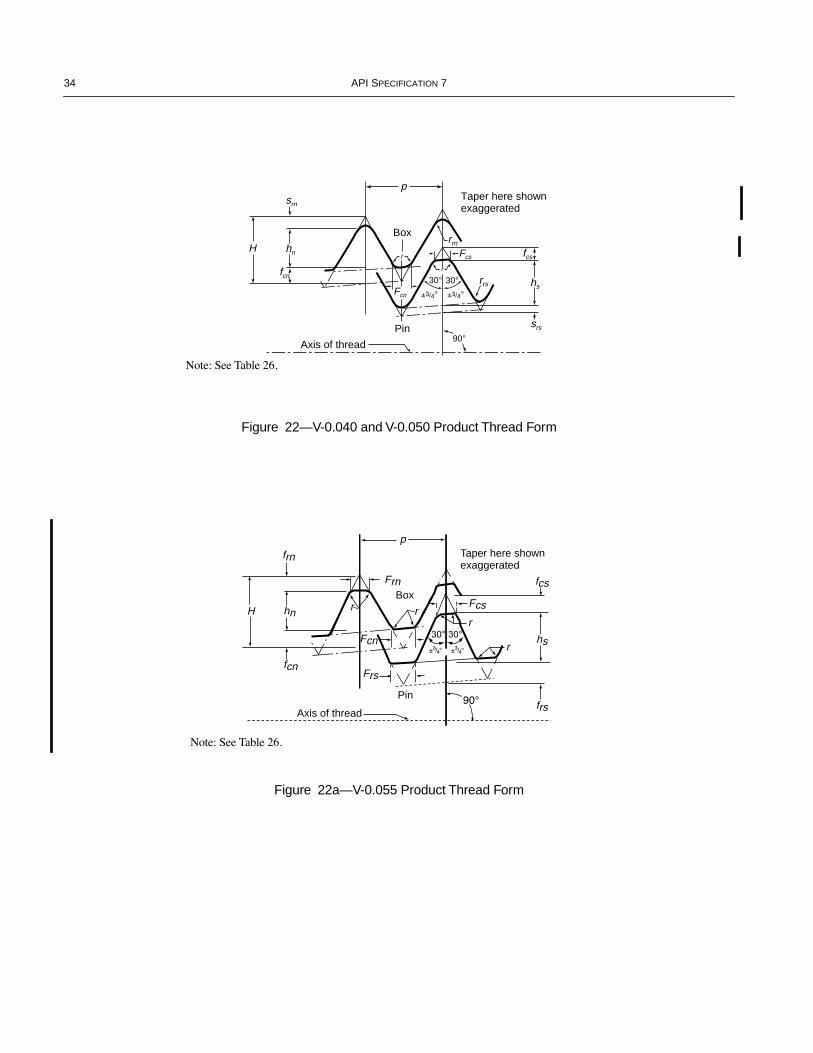
34 API SPECIFICATION 7
Figure 22—V-0.040 and V-0.050 Product Thread Form
Figure 22a—V-0.055 Product Thread Form
±3/4¡ ±3/4¡
30¡30¡
90¡
H hn
fcn
Fcn
rrn
rrs
Fcs
psrn
Box
Pin
Axis of thread
Taper here shownexaggerated
r
hs
fcs
srs
r
Note: See Table 26.
Axis of thread
fcs
hs
frs
r
hn
fcn
H
p
Pin
r
FrnBox
r
r Fcs
Frs
Fcn
frn Taper here shownexaggerated
Note: See Table 26.
COPYRIGHT American Petroleum Institute

SPECIFICATION FOR ROTARY DRILL STEM ELEMENTS 35
11 Gauging Practice, Rotary Shouldered Connections
11.1 REFERENCE MASTER GAUGES
All threads on rotary shouldered connections shall complywith the gauging practice requirements speciÞed herein.Accordingly, any manufacturer who desires to produce drillstem members utilizing API rotary shouldered connectionsconforming to this speciÞcation must own or have access tocalibrated API reference master gauges, consisting of individ-ual reference master plug(s) and mating reference master ringgauge(s), conforming to the requirements of Section 12 andcertiÞed as required in Section 13.
Notes:
1: The use of reference master gauges in checking product threadsshould be minimized. Such use should be conÞned to cases of dis-pute that cannot be settled by rechecking the working gauges againstthe reference master. Good care should be exercised when the refer-ence master gauge is assembled on a product thread.
2: It is not necessary that authority to use the API monogram be pro-cured in order to purchase API reference master gauges, but the pur-chaser of such gauges must comply with all the stipulations oncalibration and retest as given in this speciÞcation.
3: It is not necessary that a manufacturer own all possible sizes ofrotary reference master gauges, even though he may own or haveaccess to hardened and ground working gauges. It is therefore per-missible that a registered reference master may be borrowed in orderto assure the dimensional integrity of these working gauges, so longas the reference master meets the requirements speciÞed in Sections12 and 13. Furthermore, the borrower must be able to show docu-mentation and traceability as required in 11.5.
11.2 WORKING GAUGES
The manufacturer must own or have access to workinggauges for use in gauging product threads, and shall maintainall working gauges in such condition as to ensure that productthreads, gauged as required herein, are acceptable under thisspeciÞcation. (See Appendix D for recommended practice forcare and use of working gauges.)
11.3 GAUGE RELATIONSHIP
The relationship between reference master gauges, work-ing gauges, and product threads shall be as shown in Figure23, wherein the certiÞed reference master plug gauge is
shown as the standard and the certiÞed reference master ringgauge as the transfer standard. The standoff value, S, of certi-Þed reference master gauges is the distance from the plane ofthe rotary shoulder on the plug to the plane of the gauge pointon the ring. The certiÞed reference master ring gauge is usedto establish the standoff value, S1, of the working plug gauge.The certiÞed reference master plug gauge is used to establishthe standoff value, S2, of the working ring gauge. S1 and S2are measured values that the working gauges stand off fromtheir certiÞed reference master gauges and may be greater orless than S.
Note: The mating standoff of the reference master ring against thereference master plug gauge as marked on the ring gauge is intendedprimarily as the basis for establishing the limits of wear or secularchange in the gauges. Deviation from this initial S value should betaken into account in establishing working gauge standoff value.
11.4 STANDOFF TOLERANCES
Tolerances on standoff values shall be as speciÞed in Fig-ure 23. These tolerances shall apply after the connection isÞnish machined and before any antigalling and/or cold work-ing surface treatment is applied to the pin or box connection.Change in gauge standoff after the application of the surfacetreatment may cause the standoff to exceed the API limitsspeciÞed for the connection and does not constitute a causefor rejection. It is therefore permissible for a connection to bemarked with the API monogram if it meets the API speciÞca-tion before the application of the surface treatment.
11.5 CALIBRATION SYSTEM
Owners and users of API reference master and workinggauges shall establish and document a system of gauge cali-bration and control. Records shall be maintained that showconformance of gauges to the design and calibration require-ments of Sections 12 and 13. The calibration system shallestablish the frequency of retest in conformance with 12.10.Records of calibration shall show the last calibration date,identity of the individual who performed the calibration, andthe calibration history. When reference master gauges are noton the site of the gauge user, copies of the reference mastergaugesÕ certiÞcate of certiÞcation, per Section 13, shall bemaintained at the user site.
COPYRIGHT American Petroleum Institute
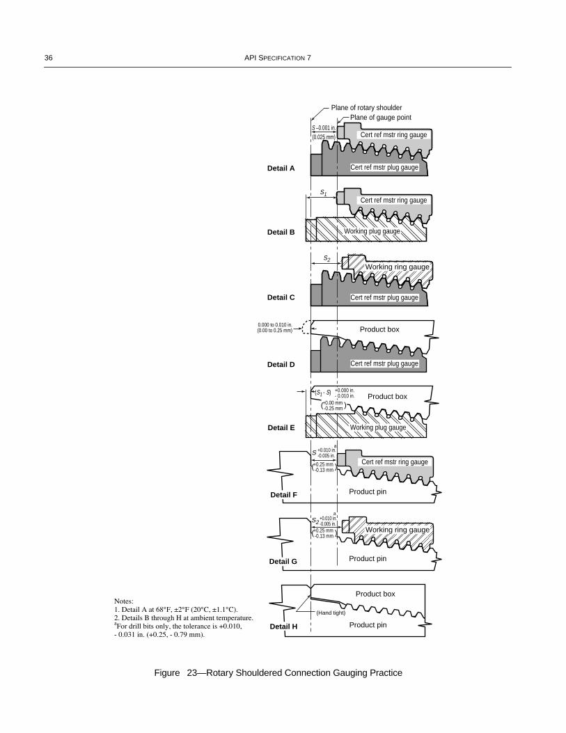
36 API SPECIFICATION 7
Figure 23—Rotary Shouldered Connection Gauging Practice
Cert ref mstr ring gauge
Cert ref mstr ring gauge
Detail E
Detail D
Detail C
Detail B
Detail A
(Hand tight)
Product pin
Product box
Detail H
Product pinDetail G
Working ring gauge
+0.010 in.-0.005 in.
S2
a
Product pin
Product box
Product box
Cert ref mstr ring gauge
Cert ref mstr plug gauge
Working plug gauge
+0.010 in.-0.005 in.S
a
Detail F
+0.25 mm -0.13 mm( )
(S1 - S)
S2
S –0.001 in.(0.025 mm)
S1
0.000 to 0.010 in.(0.00 to 0.25 mm)
Cert ref mstr plug gauge
Cert ref mstr plug gauge
Working ring gauge
Working plug gauge
Plane of rotary shoulderPlane of gauge point
+0.00 mm -0.25 mm( )
+0.000 in.- 0.010 in.
+0.25 mm -0.13 mm( )
COPYRIGHT American Petroleum Institute
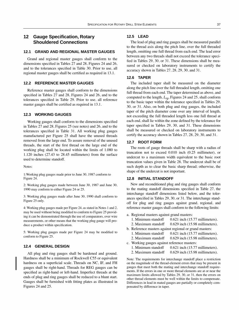
SPECIFICATION FOR ROTARY DRILL STEM ELEMENTS 37
12 Gauge Specification, Rotary Shouldered Connections
12.1 GRAND AND REGIONAL MASTER GAUGES
Grand and regional master gauges shall conform to thedimensions speciÞed in Tables 27 and 28, Figures 24 and 26,and to the tolerances speciÞed in Table 30. Prior to use, allregional master gauges shall be certiÞed as required in 13.1.
12.2 REFERENCE MASTER GAUGES
Reference master gauges shall conform to the dimensionsspeciÞed in Tables 27 and 28, Figures 24 and 26, and to thetolerances speciÞed in Table 29. Prior to use, all referencemaster gauges shall be certiÞed as required in 13.1.
12.3 WORKING GAUGES
Working gauges shall conform to the dimensions speciÞedin Tables 27 and 28, Figures 25 (see notes) and 26, and to thetolerances speciÞed in Table 31. All working plug gaugesmanufactured per Figure 25 shall have the unused threadsremoved from the large end. To assure removal of the unusedthreads, the start of the Þrst thread on the large end of theworking plug shall be located within the limits of 1.080 to1.120 inches (27.43 to 28.45 millimeters) from the surfaceused to determine standoff.
Notes:
1:Working plug gauges made prior to June 30, 1987 conform to Figure 24.
2: Working plug gauges made between June 30, 1987 and June 30,1990 may conform to either Figure 24 or 25.
3: Working plug gauges made after June 30, 1990 shall conform toFigure 25 only.
4: Working plug gauges made per Figure 24, as stated in Notes 1 and 2,may be used without being modiÞed to conform to Figure 25 provid-ing it can be demonstrated through the use of comparators, over wiremeasurements, or other means that the working plug gauge will pro-duce a product within speciÞcation.
5: Working plug gauges made per Figure 24 may be modiÞed toconform to Figure 25.
12.4 GENERAL DESIGN
All plug and ring gauges shall be hardened and ground.Hardness shall be a minimum of Rockwell C55 or equivalenthardness on a superÞcial scale. Threads on NC, IF, and FHgauges shall be right-hand. Threads for REG gauges can bespeciÞed as right-hand or left-hand. Imperfect threads at theends of plug and ring gauges shall be reduced to a blunt start.Gauges shall be furnished with Þtting plates as illustrated inFigures 24 and 25.
12.5 LEADThe lead of plug and ring gauges shall be measured parallel
to the thread axis along the pitch line, over the full threadedlength, omitting one full thread from each end. The lead errorbetween any two threads shall not exceed the tolerance speci-Þed in Tables 29, 30, or 31. These dimensions shall be mea-sured or checked on laboratory instruments to certify theaccuracy shown in Tables 27, 28, 29, 30, and 31.
12.6 TAPERThe included taper shall be measured on the diameter
along the pitch line over the full threaded length, omitting onefull thread from each end. The taper determined as above, andcomputed to the length, Lrg, Figures 24 and 25, shall conformto the basic taper within the tolerance speciÞed in Tables 29,30, or 31. Also, on both plug and ring gauges, the includedtaper of the pitch diameter cone over any interval of length,not exceeding the full threaded length less one full thread ateach end, shall lie within the zone deÞned by the tolerance fortaper speciÞed in Tables 29, 30, and 31. These dimensionsshall be measured or checked on laboratory instruments tocertify the accuracy shown in Tables 27, 28, 29, 30, and 31.
12.7 ROOT FORMThe roots of gauge threads shall be sharp with a radius of
truncation not to exceed 0.010 inch (0.25 millimeter), orundercut to a maximum width equivalent to the basic roottruncation values given in Table 28. The undercut shall be ofsuch depth as to clear the basic sharp thread; otherwise, theshape of the undercut is not important.
12.8 INITIAL STANDOFFNew and reconditioned plug and ring gauges shall conform
to the mating standoff dimensions speciÞed in Table 27, theinterchange standoff dimensions listed below, and the toler-ances speciÞed in Tables 29, 30, or 31. The interchange stand-off for plug and ring gauges against grand, regional, andreference master gauges shall conform to the following limits:
a. Regional masters against grand masters:1. Minimum standoff 0.621 inch (15.77 millimeters).2. Maximum standoff 0.629 inch (15.98 millimeters).
b. Reference masters against regional or grand masters:1. Minimum standoff 0.621 inch (15.77 millimeters).2. Maximum standoff 0.629 inch (15.98 millimeters).
c. Working gauges against reference masters:1. Minimum standoff 0.621 inch (15.77 millimeters).2. Maximum standoff 0.629 inch (15.98 millimeters).
Note: The requirements for interchange standoff place a restrictionon the magnitude of the thread-element errors that may be present ingauges that meet both the mating and interchange standoff require-ments. If the errors in one or more thread elements are at or near themaximum limits allowed by Tables 29, 30, or 31, then the errors onother thread elements must be well within the limits to compensate.Differences in lead in mated gauges are partially or completely com-pensated by difference in taper.
COPYRIGHT American Petroleum Institute
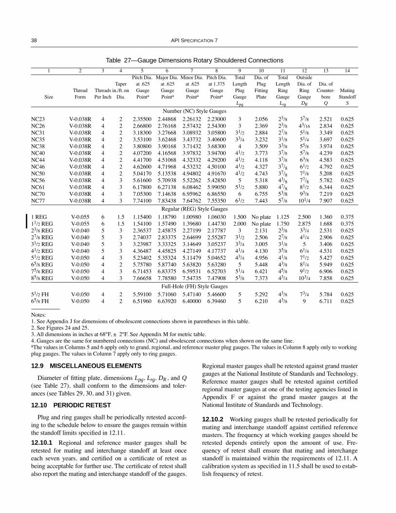
38 API SPECIFICATION 7
12.9 MISCELLANEOUS ELEMENTS
Diameter of Þtting plate, dimensions Lpg, Lrg, DR , and Q(see Table 27), shall conform to the dimensions and toler-ances (see Tables 29, 30, and 31) given.
12.10 PERIODIC RETEST
Plug and ring gauges shall be periodically retested accord-ing to the schedule below to ensure the gauges remain withinthe standoff limits speciÞed in 12.11.
12.10.1 Regional and reference master gauges shall beretested for mating and interchange standoff at least onceeach seven years, and certiÞed on a certiÞcate of retest asbeing acceptable for further use. The certiÞcate of retest shallalso report the mating and interchange standoff of the gauges.
Regional master gauges shall be retested against grand mastergauges at the National Institute of Standards and Technology.Reference master gauges shall be retested against certiÞedregional master gauges at one of the testing agencies listed inAppendix F or against the grand master gauges at theNational Institute of Standards and Technology.
12.10.2 Working gauges shall be retested periodically formating and interchange standoff against certiÞed referencemasters. The frequency at which working gauges should beretested depends entirely upon the amount of use. Fre-quency of retest shall ensure that mating and interchangestandoff is maintained within the requirements of 12.11. Acalibration system as speciÞed in 11.5 shall be used to estab-lish frequency of retest.
Table 27—Gauge Dimensions Rotary Shouldered Connections
1 2 3 4 5 6 7 8 9 10 11 12 13 14
SizeThreadForm
Threads Per Inch
Taper in./ft. on
Dia.
Pitch Dia. at .625 Gauge Pointa
Major Dia. at .625 Gauge Pointa
Minor Dia. at .625 Gauge Pointa
Pitch Dia.at 1.375GaugePointa
Total Length Plug
Gauge
Dia. of Plug
FittingPlate
Total Length Ring
Gauge
Outside Dia. of Ring
Gauge
Dia. of Counter-
boreMating
StandoffLpg Lrg DR Q S
Number (NC) Style GaugesNC23 V-0.038R 4 2 2.35500 2.44868 2.26132 2.23000 3 2.056 23/8 37/8 2.521 0.625NC26 V-0.038R 4 2 2.66800 2.76168 2.57432 2.54300 3 2.369 23/8 43/16 2.834 0.625NC31 V-0.038R 4 2 3.18300 3.27668 3.08932 3.05800 31/2 2.884 27/8 51/8 3.349 0.625NC35 V-0.038R 4 2 3.53100 3.62468 3.43732 3.40600 33/4 3.232 31/8 51/4 3.697 0.625NC38 V-0.038R 4 2 3.80800 3.90168 3.71432 3.68300 4 3.509 33/8 55/8 3.974 0.625NC40 V-0.038R 4 2 4.07200 4.16568 3.97832 3.94700 41/2 3.773 37/8 57/8 4.239 0.625NC44 V-0.038R 4 2 4.41700 4.51068 4.32332 4.29200 41/2 4.118 37/8 63/8 4.583 0.625NC46 V-0.038R 4 2 4.62600 4.71968 4.53232 4.50100 41/2 4.327 37/8 61/2 4.792 0.625NC50 V-0.038R 4 2 5.04170 5.13538 4.94802 4.91670 41/2 4.743 37/8 71/8 5.208 0.625NC56 V-0.038R 4 3 5.61600 5.70938 5.52262 5.42850 5 5.318 43/8 77/8 5.782 0.625NC61 V-0.038R 4 3 6.17800 6.27138 6.08462 5.99050 51/2 5.880 47/8 81/2 6.344 0.625NC70 V-0.038R 4 3 7.05300 7.14638 6.95962 6.86550 6 6.755 53/8 93/8 7.219 0.625NC77 V-0.038R 4 3 7.74100 7.83438 7.64762 7.55350 61/2 7.443 57/8 101/4 7.907 0.625
Regular (REG) Style Gauges1 REG V-0.055 6 1.5 1.15400 1.18790 1.00980 1.06030 1.500 No plate 1.125 2.500 1.360 0.37511/2 REG V-0.055 6 1.5 1.54100 1.57490 1.39680 1.44730 2.000 No plate 1.750 2.875 1.688 0.37523/8 REG V-0.040 5 3 2.36537 2.45875 2.27199 2.17787 3 2.131 23/8 33/4 2.531 0.62527/8 REG V-0.040 5 3 2.74037 2.83375 2.64699 2.55287 31/2 2.506 27/8 41/4 2.906 0.62531/2 REG V-0.040 5 3 3.23987 3.33325 3.14649 3.05237 33/4 3.005 31/8 5 3.406 0.62541/2 REG V-0.040 5 3 4.36487 4.45825 4.27149 4.17737 41/4 4.130 35/8 61/4 4.531 0.62551/2 REG V-0.050 4 3 5.23402 5.35324 5.11479 5.04652 43/4 4.956 41/8 71/2 5.427 0.62565/8 REG V-0.050 4 2 5.75780 5.87740 5.63820 5.63280 5 5.448 43/8 81/4 5.949 0.62575/8 REG V-0.050 4 3 6.71453 6.83375 6.59531 6.52703 51/4 6.421 45/8 91/2 6.906 0.62585/8 REG V-0.050 4 3 7.66658 7.78580 7.54735 7.47908 53/8 7.373 43/4 103/4 7.858 0.625
Full-Hole (FH) Style Gauges51/2 FH V-0.050 4 2 5.59100 5.71060 5.47140 5.46600 5 5.292 43/8 73/4 5.784 0.62565/8 FH V-0.050 4 2 6.51960 6.63920 6.40000 6.39460 5 6.210 43/8 9 6.711 0.625
Notes:1. See Appendix J for dimensions of obsolescent connections shown in parentheses in this table.2. See Figures 24 and 25.3. All dimensions in inches at 68¡F, ± 2¡F. See Appendix M for metric table.4. Gauges are the same for numbered connections (NC) and obsolescent connections when shown on the same line.aThe values in Columns 5 and 6 apply only to grand, regional, and reference master plug gauges. The values in Column 8 apply only to working plug gauges. The values in Column 7 apply only to ring gauges.
COPYRIGHT American Petroleum Institute
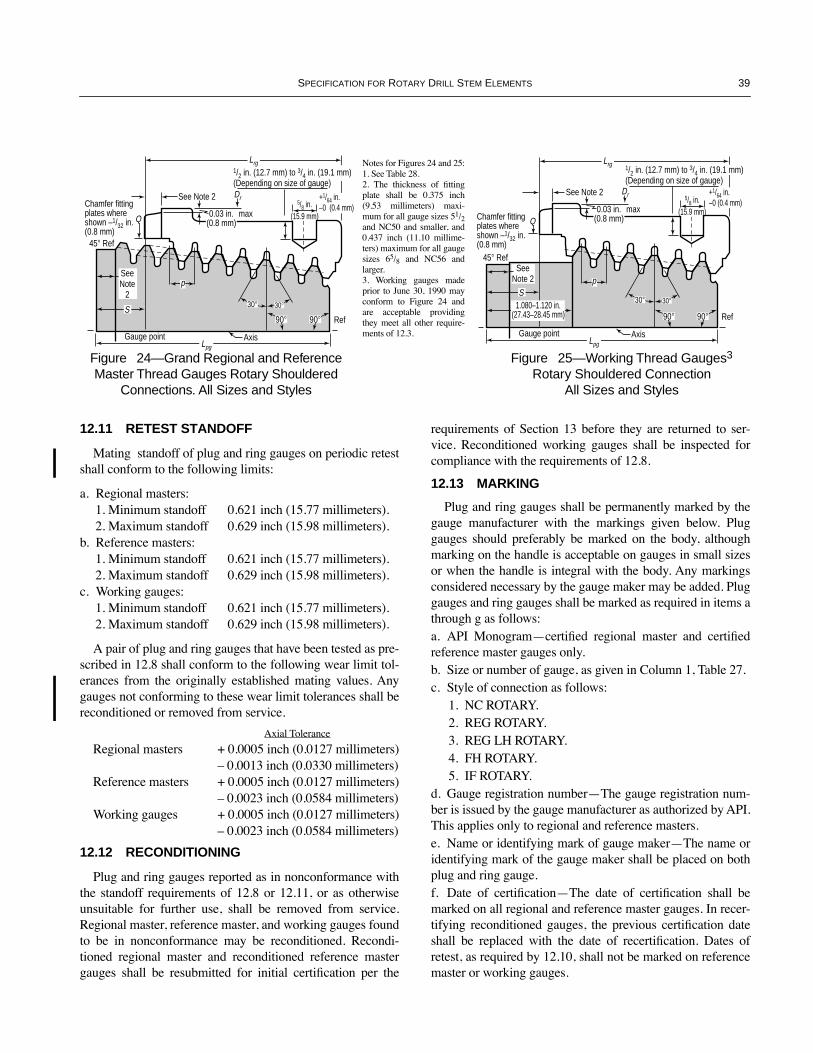
SPECIFICATION FOR ROTARY DRILL STEM ELEMENTS 39
12.11 RETEST STANDOFF
Mating standoff of plug and ring gauges on periodic retestshall conform to the following limits:
a. Regional masters:1. Minimum standoff 0.621 inch (15.77 millimeters).2. Maximum standoff 0.629 inch (15.98 millimeters).
b. Reference masters:1. Minimum standoff 0.621 inch (15.77 millimeters).2. Maximum standoff 0.629 inch (15.98 millimeters).
c. Working gauges:1. Minimum standoff 0.621 inch (15.77 millimeters).2. Maximum standoff 0.629 inch (15.98 millimeters).
A pair of plug and ring gauges that have been tested as pre-scribed in 12.8 shall conform to the following wear limit tol-erances from the originally established mating values. Anygauges not conforming to these wear limit tolerances shall bereconditioned or removed from service.
Axial Tolerance
Regional masters + 0.0005 inch (0.0127 millimeters)Ð 0.0013 inch (0.0330 millimeters)
Reference masters + 0.0005 inch (0.0127 millimeters)Ð 0.0023 inch (0.0584 millimeters)
Working gauges + 0.0005 inch (0.0127 millimeters)Ð 0.0023 inch (0.0584 millimeters)
12.12 RECONDITIONING
Plug and ring gauges reported as in nonconformance withthe standoff requirements of 12.8 or 12.11, or as otherwiseunsuitable for further use, shall be removed from service.Regional master, reference master, and working gauges foundto be in nonconformance may be reconditioned. Recondi-tioned regional master and reconditioned reference mastergauges shall be resubmitted for initial certiÞcation per the
requirements of Section 13 before they are returned to ser-vice. Reconditioned working gauges shall be inspected forcompliance with the requirements of 12.8.
12.13 MARKING
Plug and ring gauges shall be permanently marked by thegauge manufacturer with the markings given below. Pluggauges should preferably be marked on the body, althoughmarking on the handle is acceptable on gauges in small sizesor when the handle is integral with the body. Any markingsconsidered necessary by the gauge maker may be added. Pluggauges and ring gauges shall be marked as required in items athrough g as follows:a. API MonogramÑcertiÞed regional master and certiÞedreference master gauges only.b. Size or number of gauge, as given in Column 1, Table 27.c. Style of connection as follows:
1. NC ROTARY.2. REG ROTARY.3. REG LH ROTARY.4. FH ROTARY.5. IF ROTARY.
d. Gauge registration numberÑThe gauge registration num-ber is issued by the gauge manufacturer as authorized by API.This applies only to regional and reference masters.e. Name or identifying mark of gauge makerÑThe name oridentifying mark of the gauge maker shall be placed on bothplug and ring gauge.f. Date of certiÞcationÑThe date of certiÞcation shall bemarked on all regional and reference master gauges. In recer-tifying reconditioned gauges, the previous certiÞcation dateshall be replaced with the date of recertiÞcation. Dates ofretest, as required by 12.10, shall not be marked on referencemaster or working gauges.
Chamfer fittingplates whereshown –1/32 in.(0.8 mm)
45¡ Ref
Q
DrSee Note 2
Gauge point
max
Axis
Ref
5/8 in.(15.9 mm)
S
Lpg
90¡
30¡ 30¡
90¡
p
0.03 in.(0.8 mm)
Lrg1/2 in. (12.7 mm) to 3/4 in. (19.1 mm)(Depending on size of gauge)
+1/64 in.–0 (0.4 mm)
SeeNote
2
Figure 24—Grand Regional and Reference Master Thread Gauges Rotary Shouldered
Connections. All Sizes and Styles
Chamfer fittingplates whereshown –1/32 in.(0.8 mm)
45¡ Ref
Q
DrSee Note 2
Gauge point
max
Axis
Ref
5/8 in.(15.9 mm)
S1.080–1.120 in.
(27.43–28.45 mm)
Lpg
90¡
30¡ 30¡
90¡
p
0.03 in.(0.8 mm)
Lrg 1/2 in. (12.7 mm) to 3/4 in. (19.1 mm)(Depending on size of gauge)
+1/64 in.–0 (0.4 mm)
SeeNote 2
Figure 25—Working Thread Gauges3
Rotary Shouldered ConnectionAll Sizes and Styles
Notes for Figures 24 and 25:1. See Table 28.2. The thickness of Þttingplate shall be 0.375 inch(9.53 millimeters) maxi-mum for all gauge sizes 51/2and NC50 and smaller, and0.437 inch (11.10 millime-ters) maximum for all gaugesizes 65/8 and NC56 andlarger.3. Working gauges madeprior to June 30, 1990 mayconform to Figure 24 andare acceptable providingthey meet all other require-ments of 12.3.
COPYRIGHT American Petroleum Institute
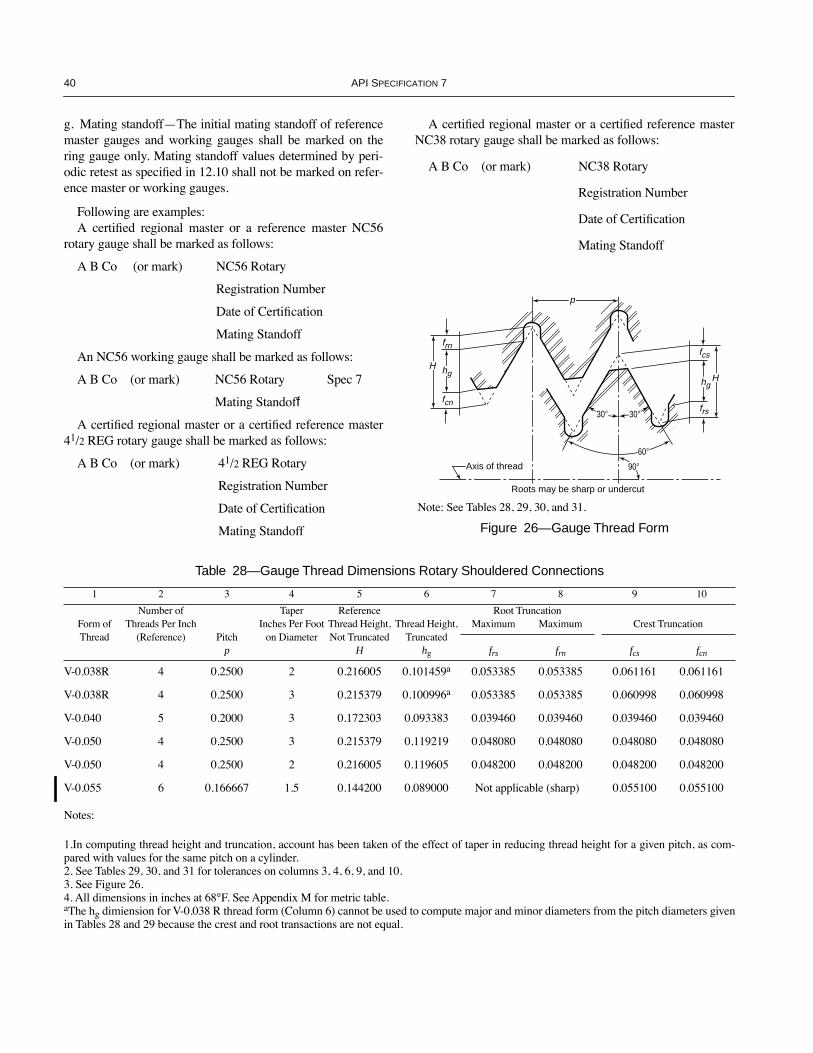
40 API SPECIFICATION 7
g. Mating standoffÑThe initial mating standoff of referencemaster gauges and working gauges shall be marked on thering gauge only. Mating standoff values determined by peri-odic retest as speciÞed in 12.10 shall not be marked on refer-ence master or working gauges.
Following are examples:A certiÞed regional master or a reference master NC56
rotary gauge shall be marked as follows:
A B Co (or mark) NC56 Rotary
Registration Number
Date of CertiÞcation
Mating Standoff
An NC56 working gauge shall be marked as follows:
A B Co (or mark) NC56 Rotary Spec 7
Mating Standoff
A certiÞed regional master or a certiÞed reference master41/2 REG rotary gauge shall be marked as follows:
A B Co (or mark) 41/2 REG Rotary
Registration Number
Date of CertiÞcation
Mating Standoff
A certiÞed regional master or a certiÞed reference masterNC38 rotary gauge shall be marked as follows:
A B Co (or mark) NC38 Rotary
Registration Number
Date of CertiÞcation
Mating Standoff
���
����
����
���
� ���
����
��� �
30¡ 30¡
90¡
frn
fcn
hgH
p
Axis of thread
Roots may be sharp or undercut
fcs
frs
hgH
60¡
�� �
Figure 26—Gauge Thread Form
Note: See Tables 28, 29, 30, and 31.
Table 28—Gauge Thread Dimensions Rotary Shouldered Connections
1 2 3 4 5 6 7 8 9 10
Form of Thread
Number ofThreads Per Inch
(Reference) Pitch p
TaperInches Per Foot
on Diameter
ReferenceThread Height, Not Truncated
H
Thread Height, Truncated
hg
Root TruncationMaximum Maximum Crest Truncation
frs frn fcs fcn
V-0.038R 4 0.2500 2 0.216005 0.101459a 0.053385 0.053385 0.061161 0.061161
V-0.038R 4 0.2500 3 0.215379 0.100996a 0.053385 0.053385 0.060998 0.060998
V-0.040 5 0.2000 3 0.172303 0.093383 0.039460 0.039460 0.039460 0.039460
V-0.050 4 0.2500 3 0.215379 0.119219 0.048080 0.048080 0.048080 0.048080
V-0.050 4 0.2500 2 0.216005 0.119605 0.048200 0.048200 0.048200 0.048200
V-0.055 6 0.166667 1.5 0.144200 0.089000 Not applicable (sharp) 0.055100 0.055100
Notes:
1.In computing thread height and truncation, account has been taken of the effect of taper in reducing thread height for a given pitch, as com-pared with values for the same pitch on a cylinder.2. See Tables 29, 30, and 31 for tolerances on columns 3, 4, 6, 9, and 10.3. See Figure 26.4. All dimensions in inches at 68¡F. See Appendix M for metric table.aThe hg dimiension for V-0.038 R thread form (Column 6) cannot be used to compute major and minor diameters from the pitch diameters givenin Tables 28 and 29 because the crest and root transactions are not equal.
COPYRIGHT American Petroleum Institute

SPECIFICATION FOR ROTARY DRILL STEM ELEMENTS 41
Table 29—Tolerances On Reference Master Gauge Dimensions
Plug Gauge Ring Gauge
Element Tolerance Element Tolerance
Pitch diameter at gauge pointa: Minor diameter at gauge point ± 0.002Sizes 65/8 and NC50 and smaller ± 0.0004 Leadb:Sizes 75/8 and NC56 and larger ± 0.0005 Sizes 1 through 51/2 and NC23 through NC50 ± 0.0006
Major diameter at gauge point ± 0.002 Sizes 65/8 and NC56 and larger ± 0.0007Diameter of Þtting plate ± 0.015 Taperc,d:Leadb: Lrg 31/2 and shorter Ð 0.0004 Ð 0.0012
Sizes 65/8 and NC50 and smaller ± 0.0004 Lrg 35/8 through 4 Ð 0.0004 Ð 0.0014Sizes 75/8 and NC56 and larger ± 0.0005 Lrg 41/8 through 41/2 Ð 0.0004 Ð 0.0016
Taperc: Lrg 45/8 through 5 Ð 0.0004 Ð 0.0018Lrg 31/2 and shorter + 0.0004 Ð 0.0000 Lrg 51/8 through 51/2 Ð 0.0004 Ð 0.0020Lrg 35/8 through 4 + 0.0005 Ð 0.0000 Lrg 55/8 through 6 Ð 0.0004 Ð 0.0022Lrg 41/8 through 41/2 + 0.0006 Ð 0.0000 Half angle of thread ± 15 minLrg 45/8 through 5 + 0.0007 Ð 0.0000 Length Lrg ± 3/32
Lrg 51/8 through 51/2 + 0.0008 Ð 0.0000 Crest truncation:Lrg 55/8 through 6 + 0.0009 Ð 0.0000 Sizes 65/8 and NC 50 and smaller ± 0.00120
Half angle of thread ± 7 min Sizes 75/8 and NC 56 and larger ± 0.00125Length Lpg ± 3/32 Outside diameter DR ± 1/64
Crest truncation: Diameter of counterbore Q ± 0.015Sizes 65/8 and NC 50 and smaller ± 0.00120 Mating standoff S ± 0.001Sizes 75/8 and NC 56 and larger ± 0.00125
Notes:1. See Figure 24.2. All dimensions in inches at 68¡F, ± 2¡F. See Appendix M for metric table.aHelix angle correction shall be disregarded in pitch diameter determinations.bMaximum allowable error in lead between any two threads whether adjacent or separated by any amount not exceeding the full length of thread less one full thread at each end.cLrg values are listed in Table 27, Column 11.dThe pitch cone of the ring gauge is provided with a minus taper in order to minimize variations in interchange standoff due to lead errors.
Table 30—Tolerances On Grand and Regional Master Gauge Dimensions
Plug Gauge Ring Gauge
Element Tolerance Element Tolerance
Pitch diameter at gauge pointa ± 0.0002 Minor diameter at gauge point ± 0.002Leadb: Leadb:
Sizes 31/2 and smaller ± 0.0002 Sizes 31/2 and smaller ± 0.0003Sizes 4 to 85/8, inclusive ± 0.0003 Sizes 4 to 85/8, inclusive ± 0.0004
Taperc + 0.0004 Taperc,d Ð 0.0006+ 0.0001 Ð 0.0012
Half angle of thread (minutes) ± 5 Half angle of thread (minutes) ± 10Length Lpg ± 3/32 Length Lrg ± 3/32
Crest truncation ± 0.00112 Crest truncation ± 0.0011Outside Diameter DR ± 1/64
Diameter of counterbore Q ± 0.015Mating standoff S ± 0.001
Notes:1. See Figure 24.2. All dimensions in inches at 68¡F, ± 2¡F. See Appendix M for metric table.aHelix angle correction shall be disregarded in pitch diameter determinations.bMaximum allowable error in lead between any two threads whether adjacent or separated by any amount not exceeding the full length of thread less one full thread at each end.cLrg values are listed in Table 27, Column 11.dThe pitch cone of the ring gauge is provided with a minus taper in order to minimize variations in interchange standoff due to lead errors.
COPYRIGHT American Petroleum Institute
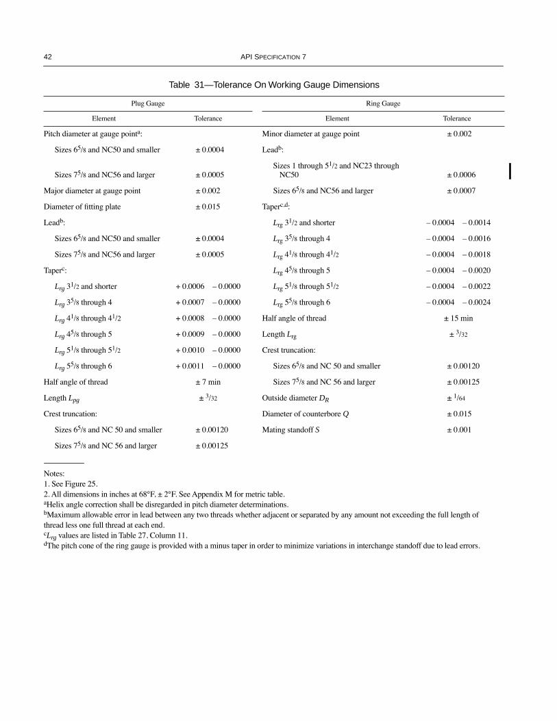
42 API SPECIFICATION 7
Table 31—Tolerance On Working Gauge Dimensions
Plug Gauge Ring Gauge
Element Tolerance Element Tolerance
Pitch diameter at gauge pointa: Minor diameter at gauge point ± 0.002
Sizes 65/8 and NC50 and smaller ± 0.0004 Leadb:
Sizes 75/8 and NC56 and larger ± 0.0005Sizes 1 through 51/2 and NC23 through
NC50 ± 0.0006
Major diameter at gauge point ± 0.002 Sizes 65/8 and NC56 and larger ± 0.0007
Diameter of Þtting plate ± 0.015 Taperc,d:
Leadb: Lrg 31/2 and shorter Ð 0.0004 Ð 0.0014
Sizes 65/8 and NC50 and smaller ± 0.0004 Lrg 35/8 through 4 Ð 0.0004 Ð 0.0016
Sizes 75/8 and NC56 and larger ± 0.0005 Lrg 41/8 through 41/2 Ð 0.0004 Ð 0.0018
Taperc: Lrg 45/8 through 5 Ð 0.0004 Ð 0.0020
Lrg 31/2 and shorter + 0.0006 Ð 0.0000 Lrg 51/8 through 51/2 Ð 0.0004 Ð 0.0022
Lrg 35/8 through 4 + 0.0007 Ð 0.0000 Lrg 55/8 through 6 Ð 0.0004 Ð 0.0024
Lrg 41/8 through 41/2 + 0.0008 Ð 0.0000 Half angle of thread ± 15 min
Lrg 45/8 through 5 + 0.0009 Ð 0.0000 Length Lrg ± 3/32
Lrg 51/8 through 51/2 + 0.0010 Ð 0.0000 Crest truncation:
Lrg 55/8 through 6 + 0.0011 Ð 0.0000 Sizes 65/8 and NC 50 and smaller ± 0.00120
Half angle of thread ± 7 min Sizes 75/8 and NC 56 and larger ± 0.00125
Length Lpg ± 3/32 Outside diameter DR ± 1/64
Crest truncation: Diameter of counterbore Q ± 0.015
Sizes 65/8 and NC 50 and smaller ± 0.00120 Mating standoff S ± 0.001
Sizes 75/8 and NC 56 and larger ± 0.00125
Notes:1. See Figure 25.2. All dimensions in inches at 68¡F, ± 2¡F. See Appendix M for metric table.aHelix angle correction shall be disregarded in pitch diameter determinations.bMaximum allowable error in lead between any two threads whether adjacent or separated by any amount not exceeding the full length of thread less one full thread at each end.cLrg values are listed in Table 27, Column 11.dThe pitch cone of the ring gauge is provided with a minus taper in order to minimize variations in interchange standoff due to lead errors.
COPYRIGHT American Petroleum Institute

SPECIFICATION FOR ROTARY DRILL STEM ELEMENTS 43
13 Gauge Certification, Rotary Shouldered Connections
13.1 CERTIFICATION AGENCIES
New and reconditioned regional master and reference mas-ter gauges shall be submitted for certiÞcation as to the accu-racy of all essential elements as required in 12.1 and 12.2.The National Institute of Standards and Technology shall bethe certifying agency for all regional master gauges.
New and reconditioned reference master gauges shall besubmitted to one of the following agencies for certiÞcation:
a. National Institute of Standards and Technology, Gaithers-burg, Maryland, U.S.A.b. National Physical Laboratory, Teddington, England.c. National Research Laboratory of Metrology, Ibaraki,Japan.d. National Measurement Laboratory, LindÞeld, N.S.W.,Australia.e. Instituto Nacional de Tecnologia Industrial, Buenos Aires,Argentina.f. National Institute of Metrology, Beijing, PeopleÕs Repub-lic of China.
Note: Application to become an API Gauge CertiÞcation Agency isopen to any metrology laboratory capable of demonstrating compli-ance with API policy and speciÞed requirements. Interested partiesshall notify the API Upstream Segment at 1220 L Street, NW, Wash-ington, D.C. 20005. Appendix E of this speciÞcation outlines certiÞ-cation agency requirements.
13.2 GENERAL REQUIREMENTS
Regional master and reference master gauges shall be cer-tiÞed in complete sets, e.g., a reference master plug and a ref-erence master ring. A single gauge may be certiÞed only ifaccompanied by a previously certiÞed mating gauge. When apreviously certiÞed mating gauge is used, the certiÞcate ofcertiÞcation shall be furnished to the certifying agency asproof of the accuracy of the mating gauge.
All gauges submitted for certiÞcation shall be perma-nently marked with its API registration number at the time ofsubmittal.
13.3 CERTIFICATION
For each set of gauges that complies with all requirements,the gauge manufacturer shall obtain a certiÞcate from the cer-tifying agency as evidence of the gauge accuracy. The certiÞ-cate shall contain the following information:
a. Name of certifying agency.b. Signature of inspector.c. Date of certiÞcation.d. API registration number of each gauge.e. Mating standoff measurement.
f. Interchange standoff measurement.g. Statement of compliance to 13.7.h. Statement of compliance to Section 12.
13.4 INTERCHANGE STANDOFF
All new and reconditioned reference master gauges shallbe submitted to one of the agencies referenced in 13.5 or 13.6for determination of interchange standoff against grand orregional master gauges, as required in 12.8.
13.5 GRAND MASTER GAUGES
One grand master gauge in each size and style of connec-tion is deposited with the National Institute of Standards andTechnology, Gaithersburg, Maryland. These grand mastergauges are used to check the interchange standoff of bothregional master gauges and reference master gauges. Onlyregional master and reference master gauges manufacturedby an API licensed gauge manufacturer shall be checked withthe grand master gauges.
Note: Grand and regional master gauges shall not be used to inspectused working gauges.
13.6 REGIONAL MASTER GAUGES
Appendix F lists the agencies that have on deposit, in avail-able sizes and styles, regional master gauges. These regionalmaster gauges are used to check the interchange standoff ofreference master gauges. Only reference master gauges man-ufactured by an API licensed gauge manufacturer shall bechecked with the regional master gauges.
Note: Grand and regional master gauges shall not be used to inspectused working gauges.
13.7 DETERMINATION OF STANDOFF
Mating and interchange standoff (see Figures 23 and 24)shall be determined as follows:
a. During the test all pieces entering into the measurement shallbe at a uniform temperature of 68¡F, ± 2¡F (20¡C, ± 1.1¡C).b. Gauges shall be free of visible evidence of contaminatesbefore mating. A thin Þlm of medicinal mineral oil shall bewiped on the threads with clean chamois skin or bristle brush.c. The pair shall be mated hand tight without spinning intoplace, and complete register shall be accomplished with thetorque hammer speciÞed for each size (see Figure 27).d. The number of torque hammer blows is unimportant. Suf-Þcient number should be made so that continued hammeringwill not move the ring relative to the plug. When testing, theplug gauge should be rigidly held, preferably in a visemounted on a rigid work bench. When so held, 12 torquehammer blows should be sufÞcient to make complete register.
COPYRIGHT American Petroleum Institute
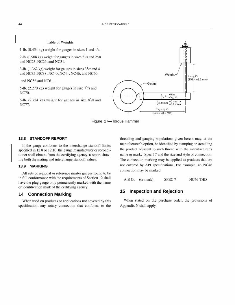
44 API SPECIFICATION 7
13.8 STANDOFF REPORT
If the gauge conforms to the interchange standoff limitsspeciÞed in 12.8 or 12.10, the gauge manufacturer or recondi-tioner shall obtain, from the certifying agency, a report show-ing both the mating and interchange standoff values.
13.9 MARKING
All sets of regional or reference master gauges found to bein full conformance with the requirements of Section 12 shallhave the plug gauge only permanently marked with the nameor identiÞcation mark of the certifying agency.
14 Connection MarkingWhen used on products or applications not covered by this
speciÞcation, any rotary connection that conforms to the
threading and gauging stipulations given herein may, at themanufacturerÕs option, be identiÞed by stamping or stencilingthe product adjacent to such thread with the manufacturerÕsname or mark, ÒSpec 7,Ó and the size and style of connection.The connection marking may be applied to products that arenot covered by API speciÞcations. For example, an NC46connection may be marked:
A B Co (or mark) SPEC 7 NC46 THD
15 Inspection and Rejection
When stated on the purchase order, the provisions ofAppendix N shall apply.
Gauge
Weight
5/8 in.+0 in.–1/64 in.
15.9 mm +0 mm–0.4 mm
63/4 ±1/8 in.(171.5 ±3.2 mm)
6 ±1/8 in.(152.4 ±3.2 mm)
Figure 27—Torque Hammer
Table of Weights
1-lb. (0.454 kg) weight for gauges in sizes 1 and 1/2.
2-lb. (0.908 kg) weight for gauges in sizes 23/8 and 27/8and NC23, NC26, and NC31.
3-lb. (1.362 kg) weight for gauges in sizes 31/2 and 4 and NC35, NC38, NC40, NC44, NC46, and NC50.
and NC56 and NC61.
5-lb. (2.270 kg) weight for gauges in size 75/8 and NC70.
6-lb. (2.724 kg) weight for gauges in size 85/8 andNC77.
COPYRIGHT American Petroleum Institute
45
APPENDIX A—SUPPLEMENTARY REQUIREMENTS
A.1 GeneralBy agreement between the purchaser and the manufacturer
and when speciÞed on the purchase order, the following sup-plementary requirements shall apply.
A.2 Kelly Valves and Other Drill Stem Safety Valves
A.2.1 GAS TIGHT SEALING SUPPLEMENTAL REQUIREMENT
Kelly valves and other drill stem safety valves have not his-torically been designed with gas tight sealing mechanisms.Valves that are designed to operate under these conditions areknown as gas tight valves. See A.2.2 for optional perfor-mance veriÞcation testing that may be requested as a supple-mental requirement by purchaser to verify gas tight sealingdesign and for routine acceptance testing for each gas tightvalve supplied.
A.2.2 GAS TIGHT SEALING PERFORMANCE VERIFICATION TESTING
Supplemental performance veriÞcation testing of kellyvalves and other drill-stem safety valves designed and built tothis speciÞcation shall be carried out and/or certiÞed by aquality organization independent of the design function.Since high pressure leak testing is potentially more hazardouswith gas than with low compressibility ßuids, high pressuregas testing shall be restricted to performance veriÞcation test-ing. Nitrogen or other suitable non-ßammable gas should beused at ambient temperature conditions. Otherwise, low andhigh pressure testing shall be conducted as per 4.5.2. No gasbubbles shall be seen in the 5-minute test period.
For each valve manufactured to the same speciÞcations asa valve that has been designed and veriÞed as being capableof gas tight sealing, a low pressure gas test to 90 psi, usingambient temperature air, shall be performed using appropriateparts of 4.5.2. No gas bubbles shall be seen in the 5-minutetest period.
A.2.3 H2S TRIM SUPPLEMENTAL REQUIREMENT
When valve trim materials conform to the requirements ofNACE MR-01-75 for H2S service, at conditions speciÞed bythe manufacturer, then the valve shall be designated ÒH2STrimÓ. H2S Trim may be requested as a supplemental require-ment by purchaser.
WARNING: H2S Trim valves shall not be considered safe foruse in a sour environment, as deÞned in NACE MR-01-75,since the material used in the body of H2S Trim valves is notsuitable for sour service.
A.2.4 SUPPLEMENTAL MARKING REQUIREMENTS
Supplemental performance veriÞcation testing informationshall be applied in a separate milled recess. Designationsshall be used to indicate veriÞed performance as follows:
Successful Gas Tight Sealing Supplemental Testing: ÒGas TightÓ
H2S Trim Supplemental Requirement: ÒH2S TrimÓ
A.3 Tool Joint/Drill Pipe Weld Zone
A.3.1 SR1—FREQUENCY OF TESTING
One set of mechanical tests shall be conducted per lot or200 welds, whichever is less.
A.3.2 SR2—CHARPY V-NOTCH TYPE A IMPACT TESTS
The test temperature shall be Ð 4¡F ± 5¡F (Ð 20¡C, ± 2.8¡C).
A.3.3 SR3—MINIMUM VALUES
The minimum average value for the three specimens shallnot be less than 20 ft-lbs. The minimum value for any singlespecimen shall not be less than 17 ft-lbs.
COPYRIGHT American Petroleum Institute

COPYRIGHT American Petroleum Institute

47
APPENDIX B—INSTRUCTIONS FOR CARE AND USE OF API REGIONAL MASTER GAUGES
B.1 The gauging surfaces of regional master gauges shouldbe protected with a coating of petrolatum brushed into thethreads. In cold weather it is advisable to heat the petrolatumslightly so that it will ßow easily. If gauges are not used for aperiod of six months, the gauges should be thoroughlycleaned and a fresh coating of petrolatum applied. (A neutraloil is effective in protecting gauges for only a short period oftime, a few days to two weeks depending on atmosphericconditions. In warm weather an oil will ßow off the surfacemuch faster than in cold weather. Eventually dust particlessettling on an oil-protected gauge will penetrate the gaugesurface and cause small rust spots. Since the custodian maynot know when the regional masters will be used again uponcompleting the check of standoff of a set of reference mastergauges against the regional masters, the use of petrolatum asprotection is advised in all cases.)
B.2 Gauges should be stored unassembled in a well con-trolled temperature environment. When gauges are storedwith plug and ring assembled with or without a protectivecoating, there is a tendency for electrolytic corrosion todevelop, appearing as a discoloration of the surfaces in con-tact. If left assembled for a long period, the surfaces mayactually rust together. The ideal storage arrangement forregional master gauges is a case or cupboard with woodshelves provided with a door with lock and key to preventunauthorized use of the gauges. Shelves should be partitionedwith wood spacers to provide a separate compartment foreach size plug gauge. This prevents damage to thread surfacesin storing. Compartments for rings are not required, but ringsshould not be stacked. Shelving should be covered withwaxed paper to protect end surfaces of plugs and rings.
B.3 In the determination of standoff values, both regionalmaster and reference master gauges should be thoroughlycleaned before assembly. This can be done most efÞciently byimmersing the gauges (plug or ring) in a suitable solvent andbrushing the thread surfaces with a stiff brush. After cleaning,the reference gauges should be inspected for damagedthreads, rust, etc. Gauges with burns or rough threads thatmay damage the regional master gauges should not be assem-bled with those gauges. With regard to discoloration on thethread surfaces, the custodian must use his judgment. ThecoefÞcient of friction between smooth and bright steel sur-faces is less than between rough and discolored surfaces. It isapparent that the friction factor enters into the determinationof standoff values. A gummy oil deposit on the gauge seri-ously adds to the friction. It is inadvisable to determine stand-off on gauges with such a deposit.
B.4 For standoff determination the thread surfaces of thegauges should be completely, but lightly, covered with medic-inal mineral oil. Excess oil should be avoided since the excesswould have to ßow out of the ends of the gauge and if trappedmay affect the standoff value.
B.5 In the assembling operation, the plug gauge should beheld rigidly in a vise. The vise should be of a heavy type andÞrmly fastened to a rigid bench. This is of importance asstandoff values, especially on the larger sizes, may beaffected by the rigidity of the holding device. In using thehammer, the lever arm should be approximately horizontal(see Figure 27). Standoff should be measured at four pointsaround the Þtting plates, avoiding contact with any raisedpoints caused by the stamping of serial numbers on the plates.The mean of the four readings should be taken as the standoffvalue to be reported.
COPYRIGHT American Petroleum Institute

COPYRIGHT American Petroleum Institute

49
APPENDIX C—INSTRUCTIONS FOR SHIPMENT OF REFERENCE MASTER GAUGES
C.1 Reference master gauges should ordinarily remain ingood condition for years if properly cared for and used onlyfor the purpose intended, namely, the checking of workinggauges with smooth, clean threads. If the gauges becomedirty, they should be cleaned by the gauge owner before ship-ment to the custodian for standoff determinations.
C.2 Oily deposits or discolorations may sometimes beremoved with a pointed, soft wood stick. To do this, the gauge(plug or ring) should be chucked in a lathe and rotated slowlywhile the stick is pressed into the thread with equal bearingon both ßanks. A large portion of such deposits can usually beremoved by this method, but it may sometimes be necessaryto charge the stick with oil and a Þne grade of emery. Acoarse or quick cutting abrasive should not be used.
Note: A Þne grade of emery ßour, such as No. 12 Washington Mills,is recommended for this purpose.
C.3 Burrs or small scored places on the threads may bestoned with a Þne grade of stone. The stoning of scoredplaces extending all the way around the gauge is not approvedas the accuracy of the gauges may be seriously affected byextensive stoning. For severe cases of pitting or scoring,regrinding by the gauge maker is advisable.
C.4 After reconditioning, the gauge must be cleaned thor-oughly.
C.5 After drying, the plug and ring gauge should be thor-oughly covered with medicinal mineral oil, assembled in mat-ing pairs, then wrapped in oil paper.
C.6 Each mating pair of gauges should be boxed separatelyfor shipment, using waste or similar packing.
C.7 Shipping boxes should be securely made and the mate-rial should be heavy enough to prevent damage to the gaugesduring shipment; 2-inch (50.8-millimeter) material is recom-mended. If gauges are received by the custodian in boxesinadequate for return shipment, the custodian will repair orreplace the shipping containers, and add cost to the inspectionfee. The gauges should be held rigidly in place in the box by afollower block with a hole through the middle that Þts thehandle of the plug gauge snugly. This follower block shouldbe fastened with wood screws through the outside of the box.
C.8 The tops of the shipping boxes should be screwed on,not nailed, with the return address afÞxed securely on thereverse side, so that the top can be reversed by the custodianfor return shipment to the owner.
C.9 All carriage charges must be prepaid. Shipment to cus-todians should preferably be by express, which is faster intransit and delivery. When returning gauges, custodians willship collect. Owners should indicate to the custodian whethergauges are to be returned by freight or express.
C.10 Custodians are not permitted to assemble grand orregional master gauges with reference master gauges thathave dirty or damaged threads. If cleaning is required, otherthan that required to remove the protective coating, the testingagency will charge for the extra work. If the gauge is rusted orscored to the extent as to require reconditioning, the gaugeowner will be so notiÞed. Failure to recondition such gaugeswill be considered justiÞcation for cancellation of the gaugesÕstatus as authorized reference master gauges.
C.11 Owners of gauges that are to be transported by shipfrom outside the United States to the National Institute ofStandards and Technology (NIST) for test must make priorarrangements with a customs broker either in the country oforigin or in the United States for entry of the gauges into theUnited States, with or without bond as may be necessary, andprepaid transportation to and from the ports of entry and exit.Entry in bond is required for gauges made outside the UnitedStates, whereas gauges made in the United States may beentered without bond. If arrangements are made with a brokerin the country of origin, that broker should, in turn, have acustoms broker in or near the port of entry arrange for entryof the gauges and prepaid transportation to the National Insti-tute of Standards and Technology, Gaithersburg, MD.
C.12 An alternative method of shipment that eliminates theneed for services of a customs broker is by air freight to NISTvia Dulles International Airport, Washington D.C. Whenshipments are made by this method, NIST will pick up thegauges at the airport, arrange for entry in bond when neces-sary, and after test obtain release from bond if required anddeliver the gauges to the airport for return shipment. Thegauges will be returned collect with transportation chargespayable at destination.
C.13 Transportation by air is much more expensive than byship but the difference is largely offset by customs brokerÕscharges. An added advantage of air transportation is the verygreat decrease in the time the gauges are away from theownerÕs factory.
C.14 The agenciesÕ charges for tests will be billed sepa-rately from those of a customs broker. Prepayment of allcharges for tests is required.
COPYRIGHT American Petroleum Institute

COPYRIGHT American Petroleum Institute

51
APPENDIX D—RECOMMENDED PRACTICE FOR CARE AND USE OF WORKING GAUGES
D.1 A reduction in mating standoff of used working gaugesis not serious, providing the wear on thread elements has beenuniform and that correction in gauging standoff, as shown bycomparison with the reference masters, is applied when gaug-ing product threads.
D.2 Because of their extreme accuracy, gauges represent aconsiderable investment. They should be handled with care.A gauge that is abused or allowed to deteriorate quickly losesits value for gauging purposes.
D.3 Gauges should be kept free from dirt and grit. It isimportant that a suitable place be provided for storage. It isadvisable that plug and ring gauges be stored separately andnot made up in pairs. They should be coated with a goodgrade of slushing oil when not in use.
D.4 Before use, the gauges should be examined for burrs onthe thread. Burrs or other rough spots should be removed witha medium Þne stone or with a Þne Þle. Gauges should begiven a periodic visual examination for pick-up of slivers onthe gauging surfaces. Those observed should be removedwith a Þne Þle or stone.
D.5 In gauging product threads, the gauges should be han-dled with care. Clean both the gauge and the product thor-oughly before assembling. A light Þlm of thin oil will protectthe gauge when in use and increase the life of the gauge. Drysurfaces, when set up under pressure, have a tendency to seizeand pick up metal. Such spots will cause inaccuracies ingauging if not removed. Gauges should be set up Þrmly onthe product. A rod about 6 inches (152.4 millimeters) longmay be used for this purpose. Loose gauging produces loosejoints.
COPYRIGHT American Petroleum Institute

COPYRIGHT American Petroleum Institute
53
APPENDIX E—API GAUGE CERTIFICATION AGENCY REQUIREMENTS
All API Gauge CertiÞcation Agency applicants shall berequired to demonstrate measurement capability in the fol-lowing areas:
Facility environment.Inspection equipment.Standards and calibration.Personnel qualiÞcations.Organizational structure.Documentation.Storage and handling.
COPYRIGHT American Petroleum Institute

COPYRIGHT American Petroleum Institute
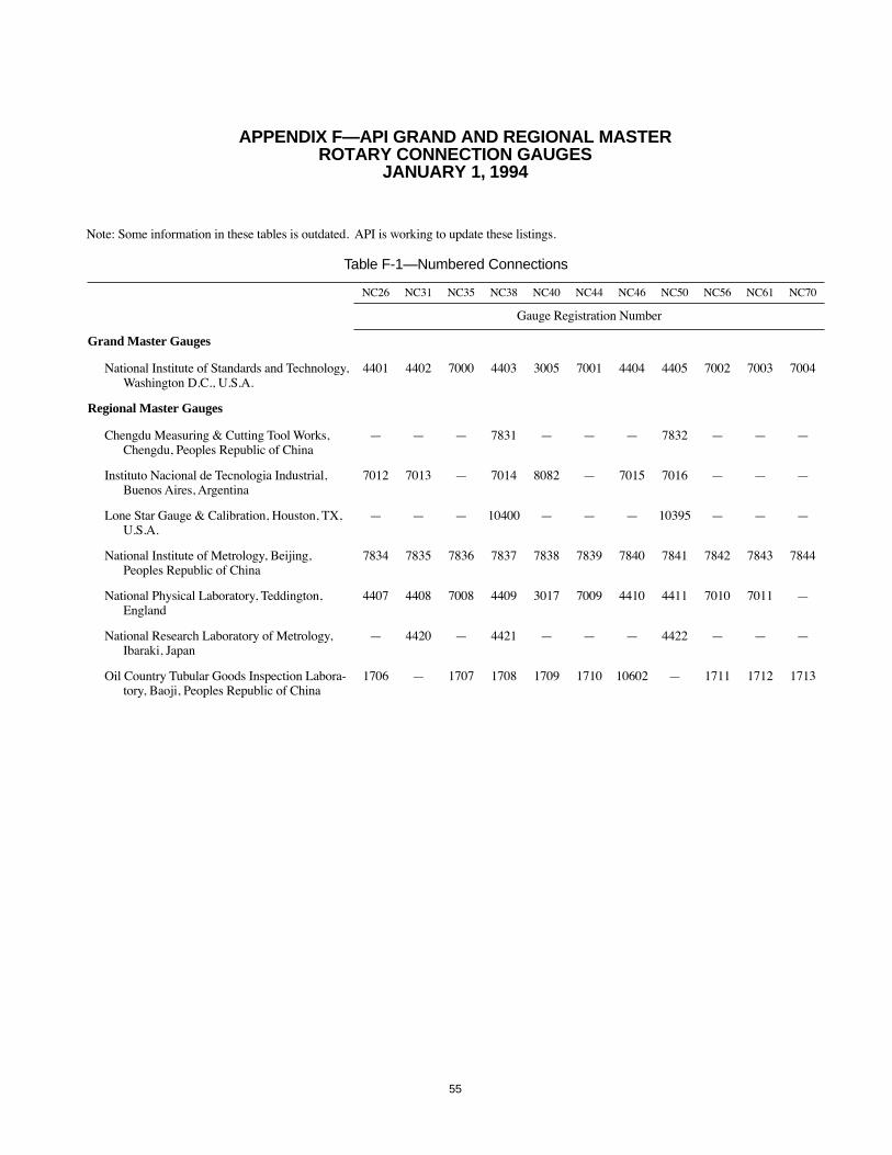
55
APPENDIX F—API GRAND AND REGIONAL MASTER ROTARY CONNECTION GAUGES
JANUARY 1, 1994
Table F-1—Numbered Connections
NC26 NC31 NC35 NC38 NC40 NC44 NC46 NC50 NC56 NC61 NC70
Gauge Registration Number
Grand Master Gauges
National Institute of Standards and Technology, Washington D.C., U.S.A.
4401 4402 7000 4403 3005 7001 4404 4405 7002 7003 7004
Regional Master Gauges
Chengdu Measuring & Cutting Tool Works, Chengdu, Peoples Republic of China
Ñ Ñ Ñ 7831 Ñ Ñ Ñ 7832 Ñ Ñ Ñ
Instituto Nacional de Tecnologia Industrial, Buenos Aires, Argentina
7012 7013 Ñ 7014 8082 Ñ 7015 7016 Ñ Ñ Ñ
Lone Star Gauge & Calibration, Houston, TX, U.S.A.
Ñ Ñ Ñ 10400 Ñ Ñ Ñ 10395 Ñ Ñ Ñ
National Institute of Metrology, Beijing, Peoples Republic of China
7834 7835 7836 7837 7838 7839 7840 7841 7842 7843 7844
National Physical Laboratory, Teddington, England
4407 4408 7008 4409 3017 7009 4410 4411 7010 7011 Ñ
National Research Laboratory of Metrology, Ibaraki, Japan
Ñ 4420 Ñ 4421 Ñ Ñ Ñ 4422 Ñ Ñ Ñ
Oil Country Tubular Goods Inspection Labora-tory, Baoji, Peoples Republic of China
1706 Ñ 1707 1708 1709 1710 10602 Ñ 1711 1712 1713

56 API SPECIFICATION 7
Table F-2—Regular Right-Hand (REG)
Size
23/8 27/8 31/2 41/2 51/2 65/8 75/8 85/8
Gauge Registration Number
Grand Master Gauges
National Institute of Standards and Technology, Washington, D.C., U.S.A.
1101 1102 1103 1104 1105 1700 1142 1701
Regional Master Gauges
Instituto Nacional de Tecnologia Industrial, Buenos Aires, Argentina
1148 1149 1150 6501 6502 6503 6504 Ñ
Lone Star Gauge & Calibration, Houston, TX, U.S.A. 1122 1123 1124 1125 1126 1127 Ñ 1128
National Physical Laboratory, Teddington, England 1129 1130 1131 1132 1133 1134 1146 1147
National Research Laboratory of Metrology, Ibaraki, Japan Ñ Ñ Ñ 1143 1144 1145 Ñ Ñ
National Measurement Laboratory, LindÞeld, N.S.W., Australia
Ñ 6022 6023 6024 Ñ 6025 Ñ Ñ
Oil Country Tubular Goods Inspection Laboratory, Baoji, PeopleÕs Republic of China
1714 1731 1715 Ñ 1716 1717 1718 1719
Table F-3—Regular Left-Hand (REG LH)
Size
23/8 27/8 31/2 41/2 51/2 65/8 75/8 85/8
Gauge Registration Number
Grand Master Gauges
National Institute of Standards and Technology, Washington, D.C., U.S.A.
1751 1752 1753 1754 1755 1756 1779 1757
Regional Master Gauges
Lone Star Gauge & Calibration, Houston, TX, U.S.A. 1758 1759 1760 1761 1762 1763 Ñ 1764
National Physical Laboratory, Teddington, England 1771 1772 1773 1774 1775 1776 Ñ Ñ
National Measurement Laboratory, LindÞeld, N.S.W., Aus-tralia
Ñ Ñ Ñ 1916 Ñ Ñ Ñ Ñ
Oil Country Tubular Goods Inspection Laboratory, Baoji, Peoples Republic of China
1724 1725 1726 Ñ 1727 1728 1729 1730
COPYRIGHT American Petroleum Institute
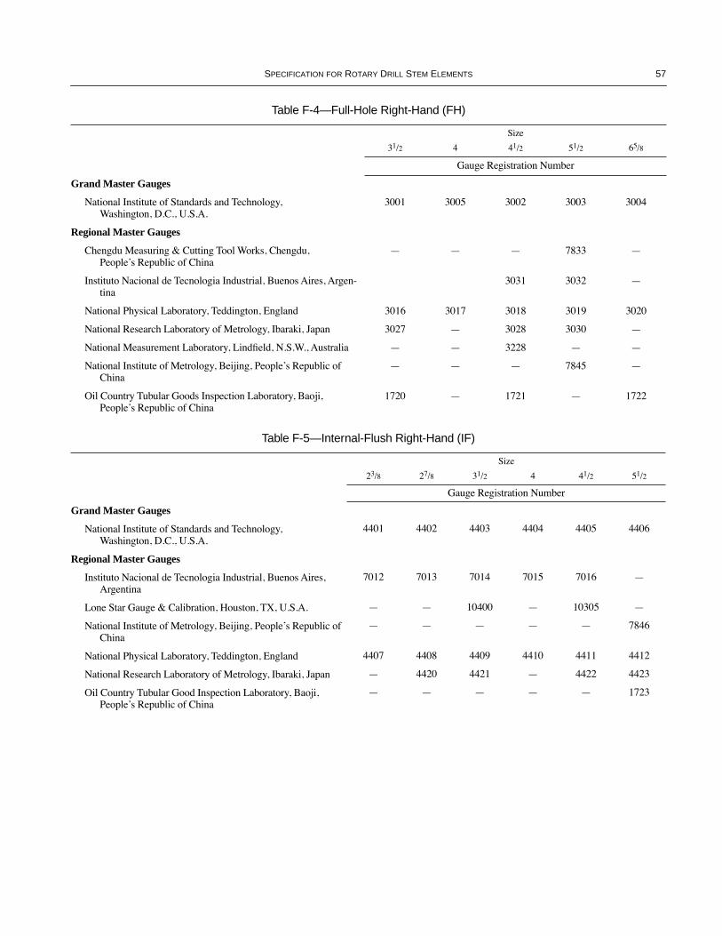
SPECIFICATION FOR ROTARY DRILL STEM ELEMENTS 57
Table F-4—Full-Hole Right-Hand (FH)
Size
31/2 4 41/2 51/2 65/8
Gauge Registration Number
Grand Master Gauges
National Institute of Standards and Technology, Washington, D.C., U.S.A.
3001 3005 3002 3003 3004
Regional Master Gauges
Chengdu Measuring & Cutting Tool Works, Chengdu, PeopleÕs Republic of China
Ñ Ñ Ñ 7833 Ñ
Instituto Nacional de Tecnologia Industrial, Buenos Aires, Argen-tina
3031 3032 Ñ
National Physical Laboratory, Teddington, England 3016 3017 3018 3019 3020
National Research Laboratory of Metrology, Ibaraki, Japan 3027 Ñ 3028 3030 Ñ
National Measurement Laboratory, LindÞeld, N.S.W., Australia Ñ Ñ 3228 Ñ Ñ
National Institute of Metrology, Beijing, PeopleÕs Republic of China
Ñ Ñ Ñ 7845 Ñ
Oil Country Tubular Goods Inspection Laboratory, Baoji, PeopleÕs Republic of China
1720 Ñ 1721 Ñ 1722
Table F-5—Internal-Flush Right-Hand (IF)
Size
23/8 27/8 31/2 4 41/2 51/2
Gauge Registration Number
Grand Master Gauges
National Institute of Standards and Technology, Washington, D.C., U.S.A.
4401 4402 4403 4404 4405 4406
Regional Master Gauges
Instituto Nacional de Tecnologia Industrial, Buenos Aires, Argentina
7012 7013 7014 7015 7016 Ñ
Lone Star Gauge & Calibration, Houston, TX, U.S.A. Ñ Ñ 10400 Ñ 10305 Ñ
National Institute of Metrology, Beijing, PeopleÕs Republic of China
Ñ Ñ Ñ Ñ Ñ 7846
National Physical Laboratory, Teddington, England 4407 4408 4409 4410 4411 4412
National Research Laboratory of Metrology, Ibaraki, Japan Ñ 4420 4421 Ñ 4422 4423
Oil Country Tubular Good Inspection Laboratory, Baoji, PeopleÕs Republic of China
Ñ Ñ Ñ Ñ Ñ 1723
COPYRIGHT American Petroleum Institute

COPYRIGHT American Petroleum Institute

59
APPENDIX G—RECOMMENDED THREAD COMPOUNDS FOR ROTARY SHOULDERED CONNECTIONS
Note: It is recommended that the label of all containers of threadcompound for use on tool joints include the metallic content, byweight, and the range of recommended temperatures.
G.1 General
Since rotary shouldered connections are subjected to hightorsional loads in service, it is important that thread com-pounds be used that will provide adequate protection againstgalling and prevent excessive make-up. Excessive make-upusually results in damage in the form of stretched or brokenpins and/or swelled boxes. API Recommended Practice 7A1,Recommended Practice for Testing of Thread Compound forRotary Shouldered Connections, provides recommendationsfor testing the frictional performance of thread compoundsfor rotary shouldered connections. The following paragraphsgive recommendations for thread compounds for use on APIrotary shouldered connections. While there may be othercompounds that will perform equally well, the compoundsdiscussed below have proven satisfactory.
G.1.1 THREAD COMPOUNDS FOR TOOL JOINTS
Zinc base compounds have proven successful for use onrotary shouldered connections on tool joints. The compoundshould contain 40 percent to 60 percent by weight of Þnelypowdered metallic zinc, and not more than 0.3 percent activesulfur.
G.1.2 THREAD COMPOUNDS FOR DRILL COLLARS
Lead base or zinc base compounds have proven successfulfor use on rotary shouldered connections on drill collars. Thecompound should contain a minimum of 60 percent byweight of Þnely powdered metallic lead or 40 percent to 60percent by weight of Þnely powdered metallic zinc, and notmore than 0.3 percent active sulfur.
G.1.3 THREAD COMPOUNDS FOR DRILLING AND CORING BITS
Zinc base compounds have proven successful for use onrotary shouldered connections on drilling and coring bits. Thecompound should contain 40 percent to 60 percent by weightof Þnely powdered metallic zinc, and not more than 0.3 per-cent sulfur.
G.2 Caution
Thread compounds may contain hazardous materials. Con-sult the product Material Safety Data Sheet for further infor-mation. Mark, store, report and dispose of thread compoundcontainers and waste materials in accordance with applicableregulations. Thread compounds made according to API Bul-letin 5A3 will produce excess make-up and are not recom-mended for use on rotary shouldered connections.
COPYRIGHT American Petroleum Institute

COPYRIGHT American Petroleum Institute

61
APPENDIX H—RECOMMENDED PRACTICE FOR GAUGING NEW ROTARY SHOULDERED CONNECTIONS
H.1 Foreword
This recommended practice is published as an aid in theprocurement and use of satisfactory instruments for determin-ing lead and taper of the threaded elements of new rotaryshouldered connections. Other instruments and methods maybe and are used to control manufacturing operations. Thisrecommended practice is not intended in any way to restrictthe use of any instrument or method to control manufacturingoperations, but in case of dispute, acceptance and rejection ofthe product shall be governed by the use of instruments fordetermining lead and taper described in this recommendedpractice. (See 12.4 and 12.5 of this speciÞcation.)
H.2 Precautions
H.2.1 TEMPERATURE
All instruments shall be exposed to the same temperatureconditions as the product to be inspected, for a time sufÞcientto eliminate any temperature difference.
H.2.2 CARE OF INSTRUMENTS
The instruments described herein are precision instrumentsand shall be handled in a careful and intelligent manner, com-mensurate with the maintenance of the high accuracy andprecision required for inspection under this recommendedpractice. If any instrument is inadvertently dropped orseverely shocked, it should not be used for inspection pur-poses until its accuracy has been reestablished.
H.2.3 CLEANING THE THREADS
All threads shall be cleaned thoroughly before gauging. Ifthe gauging is made after shipment, the thread compoundshall be removed with a brush having stiff bristles, using asuitable solvent.
H.3 Taper Measurement
H.3.1 DEFINITION
For rotary shouldered connection threads, taper shall bedeÞned as the increase in the pitch diameter of the thread, ininches per foot (millimeter per meter) of thread. On allthreads, taper tolerances are expressed in terms of inches perfoot (millimeter per meter) of threads and taper errors mustbe determined accordingly. The measurements are made forsuitable interval lengths and the observed errors should becalculated to the inches per foot (millimeter per meter) basis.
H.3.2 GAUGE CONTACTS
Contact points of taper gauges shall be of the ball-pointtype and shall preferably be made of tungsten carbide or tan-talum carbide. The dimensions of the ball-point contacts shallbe such that they contact the thread ßanks rather than theminor cone. The commonly used ball-points meeting ßankcontact requirements are shown in Table H-1.
H.3.3 EXTERNAL TAPER CALIPER
The taper of external threads can be measured with a dial-gauge caliper as illustrated in Figure H-1.
Note: A caliper having a maximum capacity less than twice the sizeof the thread should be used to ensure accurate measurements.
H.3.4 PROCEDURE FOR EXTERNAL THREADS
With the adjustable arm of the caliper set to the size of theexternal thread under test, the Þxed contact shall be placed inposition at the Þrst perfect thread and the contact on theplunger located in the same thread, 180 degrees opposite. TheÞxed contact shall be held Þrmly in position, the plunger con-tact oscillated through a small arc, and the dial gauge set sothat the zero position coincides with the maximum indication.Successive measurements at the same radial position relativeto the axis of the thread shall then be taken at suitable inter-vals for the full length of perfect threads. A line scribed on thethread crests parallel to the thread axis can be used to alignthe Þxed contact for maintaining the same radial position.The difference between successive measurements shall be thetaper in that interval of threads.
12
36
74
045
4035
3025
20
1510
5
045
4035
3025
20
1510
5
Figure H-1—External Taper Measurement
COPYRIGHT American Petroleum Institute

62 API SPECIFICATION 7
H.3.5 INTERNAL TAPER CALIPER
The taper of internal threads can be measured with aninternal taper caliper as illustrated in Figure H-2.
H.3.6 PROCEDURE FOR INTERNAL THREADS
With the adjustable arm of the caliper set to accommodatethe size of thread to be inspected, the contact on the Þxed armof the caliper shall be placed in the Þrst full depth thread posi-tion and the contact on the movable arm of the caliper in posi-tion in the same thread, 180 degrees opposite. The Þxedcontact shall be held Þrmly in position, the movable contactoscillated through a small arc, and the dial gauge set so thatthe zero position coincides with the maximum indication.Similarly, successive measurements, at the same radial posi-tion relative to the axis of the thread, shall then be taken atsuitable intervals for the length of perfect threads. A linescribed on the thread crests parallel to the thread axis can beused to align the Þxed contact for maintaining the same radialposition. The difference between successive measurementsshall be the taper in that interval of threads.
H.4 Lead MeasurementH.4.1 DEFINITION
Lead shall be deÞned as the distance from a point on athread turn to a corresponding point on the next thread turn,measured parallel to the thread axis. Lead tolerances are
expressed in terms of per inch of threads and cumulative andlead errors must be determined accordingly. For interval mea-surements over lengths other than one inch (25.40 millime-ters) the observed errors should be calculated to the per-inchbasis. For cumulative measurements, observed errors repre-sent the cumulative errors.
H.4.2 GAUGE CONTACT POINTS
The contact points of lead gauges shall be of the ball-pointtype and shall preferably be made of tungsten carbide or tan-talum carbide. The dimensions of the contact points shall besuch that they contact the thread ßanks rather than the minorcone. The commonly used ball-points meeting this require-ment have diameters shown in Table H-1.
H.4.3 LEAD GAUGES
The lead of external threads may be gauged with a leadgauge of the type illustrated in Figure H-3. The lead of inter-nal threads may be gauged with a lead gauge of the type illus-trated in Figure H-4. Lead gauges shall be so constructed thatthe measuring mechanism is under strain when the indicatorhand is adjusted to zero by means of the standard template(see Figure H-5). The standard templates shall be so con-structed as to compensate for the error in measuring lead par-allel to the taper cone instead of parallel to the thread axis,according to the values shown in Table H-1. The distancebetween any two adjacent notches of the template shall be
Table H-1—Compensated Thread Lengths and Ball Point Diameters for Measurements Parallel to the Taper Cone
1 2 3 4 5 6 7
Thread Form
Taper, inches/foot
Number Threads Per Inch
Pitch,inches
Thread Length (Parallel to Thread
Axis), inches
Compensated Length (Parallel to Taper
Cone), inchesBall Point Diameter,
inches
V-0.038R 2.00 4 0.25000 1 1.00347 0.14400V-0.038R 3.00 4 0.25000 1 1.00778 0.14400V-0.040 3.00 5 0.20000 1 1.00778 0.11500V-0.050 3.00 4 0.25000 1 1.00778 0.14400V-0.050 2.00 4 0.25000 1 1.00347 0.14400V-0.055 1.50 6 0.16667 1 1.00195 0.09600V-0.065 2.00 4 0.25000 1 1.00347 0.14400V-0.076 1.50 4 0.25000 1 1.00195 0.14400H-90 2.00 31/2 0.28571 2 2.00694 0.20203H-90 3.00 31/2 0.28571 2 2.01556 0.20203SL-H90 1.25 3 0.33333 1 1.00136 0.23570
Notes:1. Although only taper and lead measurements are recommended in this appendix, these ballpoint diameters would also apply to contour micro-scope contact points for measuring thread angle or checking thread form if desired, except that the contacts for the V-0.040 thread form should be truncated to clear the bottom of the thread. If thread height is measured, the height gauge contact points should be conical in shape, with a 50¡ included angle and a 0.002 inch radius at the tip of the cone.2. See Appendix M for metric table.
COPYRIGHT American Petroleum Institute
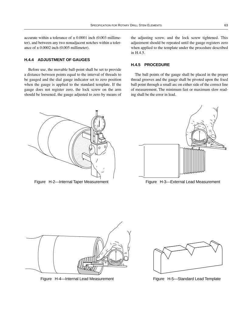
SPECIFICATION FOR ROTARY DRILL STEM ELEMENTS 63
accurate within a tolerance of ± 0.0001 inch (0.003 millime-ter), and between any two nonadjacent notches within a toler-ance of ± 0.0002 inch (0.005 millimeter).
H.4.4 ADJUSTMENT OF GAUGES
Before use, the movable ball-point shall be set to providea distance between points equal to the interval of threads tobe gauged and the dial gauge indicator set to zero positionwhen the gauge is applied to the standard template. If thegauge does not register zero, the lock screw on the armshould be loosened, the gauge adjusted to zero by means of
the adjusting screw, and the lock screw tightened. Thisadjustment should be repeated until the gauge registers zerowhen applied to the template under the procedure describedin H.4.5.
H.4.5 PROCEDURE
The ball points of the gauge shall be placed in the properthread grooves and the gauge shall be pivoted upon the Þxedball point through a small arc on either side of the correct lineof measurement. The minimum fast or maximum slow read-ing shall be the error in lead.
045
40
35
30 2520
15
10
5
045
40
35
30 2520
15
10
5
00 0
00 0
Figure H-2—Internal Taper Measurement Figure H-3—External Lead Measurement
Figure H-4—Internal Lead Measurement Figure H-5—Standard Lead Template
COPYRIGHT American Petroleum Institute

COPYRIGHT American Petroleum Institute

65
APPENDIX I—OBSOLESCENT TOOL JOINTS
Table I-1—Obsolescent Tool Joints With Taper Shoulder and Square Shoulder
1 2 3 4 5 6 7 8 9 10 11 12 13 14
Tool Joint Shoulder
Taper Square
Tool Joint
Designationa
Drill Pipe Size and
Style
Drill Pipe
NominalWeightb
lb./ft.
Outside Dia. of Pin and
Box±1/32
Inside Dia. of Pin and Boxc
+1/64 Ð1/
32
Dia. of Pin at
Elevator UpsetMax
Bevel Dia. of Pin and
Box Shoulder
±1/64
Total Length
Tool Joint Pin
+1/4 Ð3/8
PinTongSpace±1/4
BoxTongSpace±1/4
CombinedLengthof Pin
and Box±1/2
Dia. ofBox at
ElevatorUpset Max.
Dia. ofBox at
ElevatorUpsetMax.
Radiusof
ElevatorNeck±1/64
D d DPE DF LP LPB LB L DTE DSE RSE
Obsolescent Connections (To be removed from the standards at a later date)Full-Hole (FH) Style
31/2 FHe 31/2 IU 13.30 45/8 21/8 311/16 431/64 103/4 7 91/2 161/2 311/16 35/8 3/16
31/2 FHe 31/2 IU 15.50 45/8 21/8 311/16 431/64 103/4 7 91/2 161/2 311/16 35/8 3/16
4 FH (NC40) 4 IU 14.00 51/4 213/16 43/16 51/64 111/2 7 10 17 43/16 41/8 1/4
41/2 FH 41/2 IU 16.60 53/4 3 411/16 517/32 11 7 10 17 411/16 45/8 1/4
41/2 FH 41/2 IEU 20.00 53/4 3 411/16 517/32 11 7 10 17 411/16 45/8 1/4
51/2 FHf 51/2 IEU 21.90 7 4 511/16 623/32 13 8 10 18 511/16 511/16 1/4
51/2 FHf 51/2 IEU 24.70 7 4 511/16 623/32 13 8 10 18 511/16 511/16 1/4
Internal-Flush (IF) Style
23/8 IF (NC26) 23/8 EU 6.65 33/8 13/4 29/16 317/64 9 6 7 13 29/16 Ñ Ñ
27/8 IF (NC31) 27/8 EU 10.40 41/8 21/8 33/16 361/64 91/2 6 8 14 33/16 33/16 3/16
31/2 IF (NC38) 31/2 EU 13.30 43/4 211/16 37/8 437/64 11 7 91/2 161/2 37/8 37/8 3/16
31/2 IF (NC38) 31/2 EU 15.50 5 211/16 37/8 437/64 11 7 91/2 161/2 37/8 37/8 3/16
4 IF (NC46) 4 EU 14.00 53/4 31/4 41/2 517/32 111/2 7 10 17 41/2 41/2 1/4
41/2 IF (NC50) 41/2 EU 16.60 Std 61/8 33/4 5 61/16 (559/64) 111/2 7 10 17 5 5 1/4
41/2 IF (NC50) 41/2 EU 16.60 Opt 61/4 33/4 5 61/16 (559/64) 111/2 7 10 17 5 5 1/4
41/2 IF (NC50)d 5 IEU 19.50 Std 63/8 33/4 51/8 61/16 (559/64) 111/2 7 10 17 51/8 51/8 1/4
41/2 IF (NC50)d 5 IEU 19.50 Opt 61/2 31/2 51/8 61/16 (559/64) 111/2 7 10 17 51/8 51/8 1/4Notes:1. See Figure 6.2. All dimensions are in inches. See Appendix M for metric table.3. Neck diameters (DPE, DTE, and DSE) and inside diameters (d) of tool joints prior to welding are at manufacturerÕs option. The above table speciÞes the Þnished dimensions after Þnal machining of the assembly.4. See Table 7 for dimensions for numbered connections (NC).5. Bevel diameter shown in parentheses was optional with the manufacturer until June 1986, at which time 61/16 became standard. CAUTION TO USERÑAs a result of this option, precaution is advised to make sure mating NC50 connections have the same bevel diameter.aThe tool-joint designation (Column 1) indicates the size and style of the applicable connection. Those in parentheses are not a part of the size designation for the number style connections. They indicate interchangeability of these tool joints when welded to the same size, style, and weight of drill pipe. See Special Note in Table J-1.bNominal weights, threads, and coupling (Column 3) are shown for the purpose of identiÞcation in ordering.cThe bore dimensions (Column 5) do not apply to the bores of box members of REG tool joints, which are optional with the manufacturer.dNC50 (41/2 IF) joint with 63/8- and 61/2-inch OD is used on 5-inch IEU drill pipe to produce an assembly variously known as 5-inch Extra-Hole and 5-inch Semi-Internal Flush.eThe inside diameter (Column 5) of the 31/2 FH tool joint was changed from 27/16 to 21/8 inch in Appendix H of the May 1979, Thirty-Second Edition of SpeciÞcation 7.fIn 1979, the 51/2 FH tool joints were reinstated as full standard in Table 7. The dimensions were retained here primarily so that Appendix I could continue to be the single reference for square shoulder dimensions (See Figure 6).
COPYRIGHT American Petroleum Institute

COPYRIGHT American Petroleum Institute
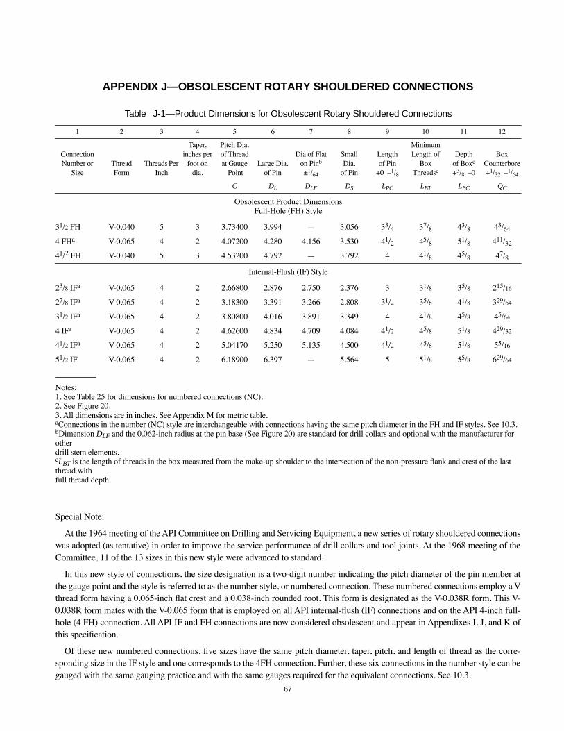
67
APPENDIX J—OBSOLESCENT ROTARY SHOULDERED CONNECTIONS
Special Note:
At the 1964 meeting of the API Committee on Drilling and Servicing Equipment, a new series of rotary shouldered connectionswas adopted (as tentative) in order to improve the service performance of drill collars and tool joints. At the 1968 meeting of theCommittee, 11 of the 13 sizes in this new style were advanced to standard.
In this new style of connections, the size designation is a two-digit number indicating the pitch diameter of the pin member atthe gauge point and the style is referred to as the number style, or numbered connection. These numbered connections employ a Vthread form having a 0.065-inch ßat crest and a 0.038-inch rounded root. This form is designated as the V-0.038R form. This V-0.038R form mates with the V-0.065 form that is employed on all API internal-ßush (IF) connections and on the API 4-inch full-hole (4 FH) connection. All API IF and FH connections are now considered obsolescent and appear in Appendixes I, J, and K ofthis speciÞcation.
Of these new numbered connections, Þve sizes have the same pitch diameter, taper, pitch, and length of thread as the corre-sponding size in the IF style and one corresponds to the 4FH connection. Further, these six connections in the number style can begauged with the same gauging practice and with the same gauges required for the equivalent connections. See 10.3.
Table J-1—Product Dimensions for Obsolescent Rotary Shouldered Connections
1 2 3 4 5 6 7 8 9 10 11 12
ConnectionNumber or
SizeThread Form
Threads Per Inch
Taper, inches per
foot on dia.
Pitch Dia. of Thread at Gauge
PointLarge Dia.
of Pin
Dia of Flat on Pinb
±1/64
SmallDia.
of Pin
Lengthof Pin
+0 Ð1/8
MinimumLength of
BoxThreadsc
Depthof Boxc
+3/8 Ð0
BoxCounterbore+1/32 Ð1/64
C DL DLF DS LPC LBT LBC QC
Obsolescent Product DimensionsFull-Hole (FH) Style
31/2 FH V-0.040 5 3 3.73400 3.994 Ñ 3.056 33/4 37/8 43/8 43/64
4 FHa V-0.065 4 2 4.07200 4.280 4.156 3.530 41/2 45/8 51/8 411/32
41/2 FH V-0.040 5 3 4.53200 4.792 Ñ 3.792 4 41/8 45/8 47/8
Internal-Flush (IF) Style
23/8 IFa V-0.065 4 2 2.66800 2.876 2.750 2.376 3 31/8 35/8 215/16
27/8 IFa V-0.065 4 2 3.18300 3.391 3.266 2.808 31/2 35/8 41/8 329/64
31/2 IFa V-0.065 4 2 3.80800 4.016 3.891 3.349 4 41/8 45/8 45/64
4 IFa V-0.065 4 2 4.62600 4.834 4.709 4.084 41/2 45/8 51/8 429/32
41/2 IFa V-0.065 4 2 5.04170 5.250 5.135 4.500 41/2 45/8 51/8 55/16
51/2 IF V-0.065 4 2 6.18900 6.397 Ñ 5.564 5 51/8 55/8 629/64
Notes:1. See Table 25 for dimensions for numbered connections (NC).2. See Figure 20.3. All dimensions are in inches. See Appendix M for metric table.aConnections in the number (NC) style are interchangeable with connections having the same pitch diameter in the FH and IF styles. See 10.3.bDimension DLF and the 0.062-inch radius at the pin base (See Figure 20) are standard for drill collars and optional with the manufacturer for other drill stem elements.cLBT is the length of threads in the box measured from the make-up shoulder to the intersection of the non-pressure ßank and crest of the last thread with full thread depth.
COPYRIGHT American Petroleum Institute

COPYRIGHT American Petroleum Institute
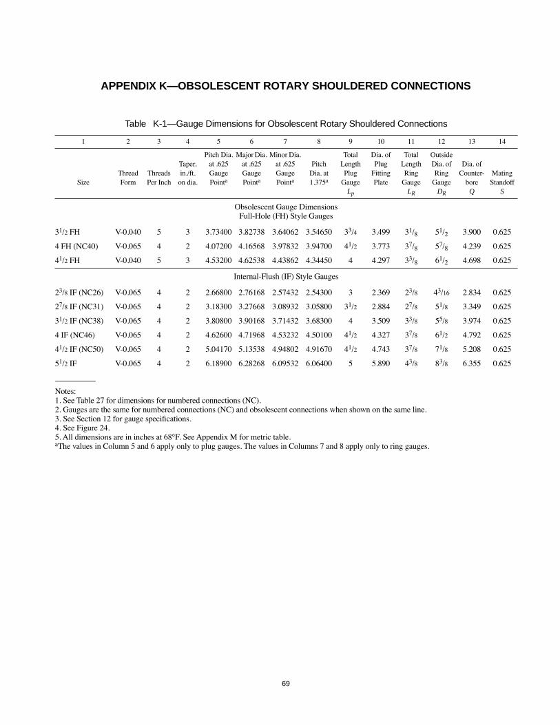
69
APPENDIX K—OBSOLESCENT ROTARY SHOULDERED CONNECTIONS
Table K-1—Gauge Dimensions for Obsolescent Rotary Shouldered Connections
1 2 3 4 5 6 7 8 9 10 11 12 13 14
SizeThread Form
Threads Per Inch
Taper, in./ft.
on dia.
Pitch Dia. at .625 Gauge Pointa
Major Dia. at .625 Gauge Pointa
Minor Dia. at .625 Gauge Pointa
Pitch Dia. at 1.375a
Total Length Plug
Gauge Lp
Dia. of Plug
Fitting Plate
Total Length Ring
Gauge LR
Outside Dia. of Ring
Gauge DR
Dia. of Counter-
bore Q
Mating Standoff
S
Obsolescent Gauge DimensionsFull-Hole (FH) Style Gauges
31/2 FH V-0.040 5 3 3.73400 3.82738 3.64062 3.54650 33/4 3.499 31/8 51/2 3.900 0.625
4 FH (NC40) V-0.065 4 2 4.07200 4.16568 3.97832 3.94700 41/2 3.773 37/8 57/8 4.239 0.625
41/2 FH V-0.040 5 3 4.53200 4.62538 4.43862 4.34450 4 4.297 33/8 61/2 4.698 0.625
Internal-Flush (IF) Style Gauges
23/8 IF (NC26) V-0.065 4 2 2.66800 2.76168 2.57432 2.54300 3 2.369 23/8 43/16 2.834 0.625
27/8 IF (NC31) V-0.065 4 2 3.18300 3.27668 3.08932 3.05800 31/2 2.884 27/8 51/8 3.349 0.625
31/2 IF (NC38) V-0.065 4 2 3.80800 3.90168 3.71432 3.68300 4 3.509 33/8 55/8 3.974 0.625
4 IF (NC46) V-0.065 4 2 4.62600 4.71968 4.53232 4.50100 41/2 4.327 37/8 61/2 4.792 0.625
41/2 IF (NC50) V-0.065 4 2 5.04170 5.13538 4.94802 4.91670 41/2 4.743 37/8 71/8 5.208 0.625
51/2 IF V-0.065 4 2 6.18900 6.28268 6.09532 6.06400 5 5.890 43/8 83/8 6.355 0.625
Notes:1. See Table 27 for dimensions for numbered connections (NC).2. Gauges are the same for numbered connections (NC) and obsolescent connections when shown on the same line.3. See Section 12 for gauge speciÞcations.4. See Figure 24.5. All dimensions are in inches at 68¡F. See Appendix M for metric table.aThe values in Column 5 and 6 apply only to plug gauges. The values in Columns 7 and 8 apply only to ring gauges.
COPYRIGHT American Petroleum Institute

COPYRIGHT American Petroleum Institute
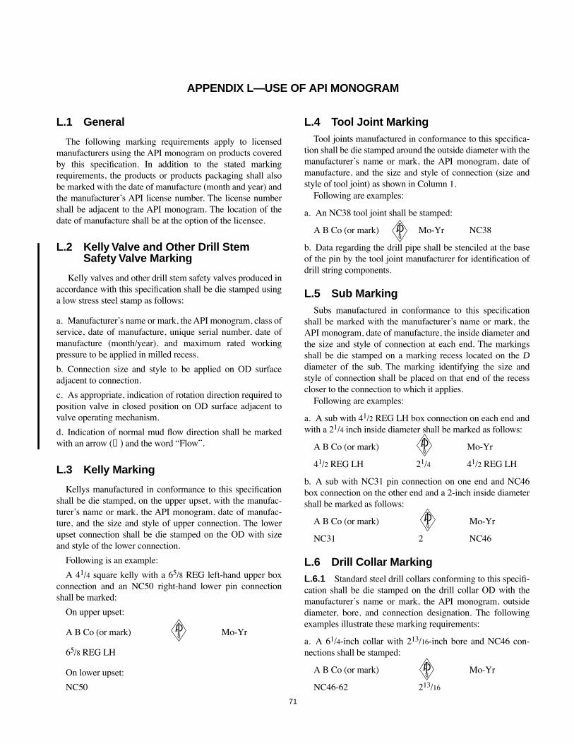
71
APPENDIX L—USE OF API MONOGRAM
L.1 General
The following marking requirements apply to licensedmanufacturers using the API monogram on products coveredby this speciÞcation. In addition to the stated markingrequirements, the products or products packaging shall alsobe marked with the date of manufacture (month and year) andthe manufacturerÕs API license number. The license numbershall be adjacent to the API monogram. The location of thedate of manufacture shall be at the option of the licensee.
L.2 Kelly Valve and Other Drill Stem Safety Valve Marking
Kelly valves and other drill stem safety valves produced inaccordance with this speciÞcation shall be die stamped usinga low stress steel stamp as follows:
a. ManufacturerÕs name or mark, the API monogram, class ofservice, date of manufacture, unique serial number, date ofmanufacture (month/year), and maximum rated workingpressure to be applied in milled recess.
b. Connection size and style to be applied on OD surfaceadjacent to connection.
c. As appropriate, indication of rotation direction required toposition valve in closed position on OD surface adjacent tovalve operating mechanism.
d. Indication of normal mud ßow direction shall be markedwith an arrow (→) and the word ÒFlowÓ.
L.3 Kelly Marking
Kellys manufactured in conformance to this speciÞcationshall be die stamped, on the upper upset, with the manufac-turerÕs name or mark, the API monogram, date of manufac-ture, and the size and style of upper connection. The lowerupset connection shall be die stamped on the OD with sizeand style of the lower connection.
Following is an example:
A 41/4 square kelly with a 65/8 REG left-hand upper boxconnection and an NC50 right-hand lower pin connectionshall be marked:
On upper upset:
A B Co (or mark) Mo-Yr
65/8 REG LH
On lower upset:
NC50
L.4 Tool Joint MarkingTool joints manufactured in conformance to this speciÞca-
tion shall be die stamped around the outside diameter with themanufacturerÕs name or mark, the API monogram, date ofmanufacture, and the size and style of connection (size andstyle of tool joint) as shown in Column 1.
Following are examples:
a. An NC38 tool joint shall be stamped:
A B Co (or mark) Mo-Yr NC38
b. Data regarding the drill pipe shall be stenciled at the baseof the pin by the tool joint manufacturer for identiÞcation ofdrill string components.
L.5 Sub MarkingSubs manufactured in conformance to this speciÞcation
shall be marked with the manufacturerÕs name or mark, theAPI monogram, date of manufacture, the inside diameter andthe size and style of connection at each end. The markingsshall be die stamped on a marking recess located on the Ddiameter of the sub. The marking identifying the size andstyle of connection shall be placed on that end of the recesscloser to the connection to which it applies.
Following are examples:
a. A sub with 41/2 REG LH box connection on each end andwith a 21/4 inch inside diameter shall be marked as follows:
A B Co (or mark) Mo-Yr
41/2 REG LH 21/4 41/2 REG LH
b. A sub with NC31 pin connection on one end and NC46box connection on the other end and a 2-inch inside diametershall be marked as follows:
A B Co (or mark) Mo-Yr
NC31 2 NC46
L.6 Drill Collar MarkingL.6.1 Standard steel drill collars conforming to this speciÞ-cation shall be die stamped on the drill collar OD with themanufacturerÕs name or mark, the API monogram, outsidediameter, bore, and connection designation. The followingexamples illustrate these marking requirements:
a. A 61/4-inch collar with 213/16-inch bore and NC46 con-nections shall be stamped:
A B Co (or mark) Mo-Yr
NC46-62 213/16
COPYRIGHT American Petroleum Institute

72 API SPECIFICATION 7
b. An 81/4-inch collar with 213/16-inch bore and 65/8 REGconnections manufactured by A B company shall be stamped:
A B Co (or mark) Mo-Yr
81/4 213/16 65/8 REG
L.6.2 Nonmagnetic drill collars conforming to this speciÞ-cation shall be die stamped with the manufacturerÕs name ormark, the API monogram, nonmagnetic identiÞcation, manu-facturerÕs serial number, outside diameter, and bore. The fol-lowing example illustrates these marking requirements.Locations of the markings and the application of additionalmarkings shall be speciÞed by the manufacturer.
Following is an example:An 81/4-inch collar with 213/16-inch bore and a 65/8 REG
connection, manufactured by A B Company shall be stamped:
A B Co (or mark) Mo-Yr
81/4 213/16 NMDC 65/8 REG
L.7 Bit MarkingL.7.1 ROLLER AND BLADE DRAG BIT MARKING
Bits shall be die stamped with the manufacturerÕs name ormark, the bit size, the API monogram, date of manufacture,and the size and style of connection.
Following is an example:A 77/8 bit with 41/2 REG connection shall be stamped as
follows:
A B Co (or mark) 77/8 Mo-Yr 41/2 REG
L.7.2 DIAMOND, CORE, AND PDC BIT MARKING
Diamond drilling bits, diamond core bits, and PDC bitsshall be marked as follows:
a. Diamond drilling bits and PDC bits shall be die stampedwith the manufacturerÕs name or mark, the API monogram,date of manufacture, and the size and style of connection.
Following is an example:
A 71/2 bit with 41/2-inch REG connection shall be stampedas follows:
A B Co (or mark) 75/8 Mo-Yr 45/8 REG
b. Diamond core bits shall be die stamped with the manufac-turerÕs name or identiÞcation mark, the API monogram, anddate of manufacture, for example:
A B Co (or mark) Mo-Yr
Because of its proprietary nature, the connection on dia-mond core bits will not be shown. The API monogram shallindicate that other dimensional requirements have been met.
L.8 Rotary Shouldered Connection Marking
Rotary shouldered connections, when used on products orfor applications not covered by this speciÞcation, but con-forming to the threading and gauging stipulations of thisspeciÞcation, shall be identiÞed by stamping or stenciling theproduct adjacent to the connection with the following:
a. ManufacturerÕs name or mark.
b. API Monogram and manufacturerÕs API lincense numberwith the letter THD directly adjacent to the Monogram.
c. Date of manufacture.
d. Size and style of connection.
The connection marking may be applied to products whichare not covered by API speciÞcations as long as the threadingand gauging stipulations of this speciÞcation are met.
For example, an NC46 connection shall be marked:
A B Co (or mark) THD Mo-Yr NC46
The monogramming of rotary shouldered connections inaccordance with this section does not assure that the productconforms to any material requirements found in this speciÞ-cation.
COPYRIGHT American Petroleum Institute

73
APPENDIX M—METRIC TABLES
The factors used for conversion of U.S. customary units to metric values are:
1 inch (in.) = 25.4 millimeters (mm) exactly.
1 square inch (sq. in.) = 645.16 square millimeters (mm2) exactly.
1 foot (ft) = 0.3048 meters (m) exactly.
1 pound (lb) = 0.454 kilograms (kg).
1 pound per foot (lb/ft) = 1.4895 kilograms per meter (kg/m).
1 pound per square inch (psi) = 0.00689476 newtons per square millimeter (N/mm2) for stress.
= 0.00689476 megapascals (MPa) for pressure.
1 foot-pound (ft-lb) = 1.355818 Joules (J) for impact energy.
= 1.355818 newton-meters (N ¥ m) for torque.
The following formula was used to convert degrees Fahrenheit (¡F) to degrees Celsius (¡C):
¡C = 5/9 (¡FÐ32)
COPYRIGHT American Petroleum Institute

74 API SPECIFICATION 7
Metric Table 2—Square Kellys
1 2 3 4 5 6 7 8 9 10 11 12 13 14 15 16 17 18 19 20 21 22 23
Upper Box Connection
Length of Drive Sec-tion meters
Length Overallmeters Drive Section
Size and Style LH
Outside Diameter Bevel Diameter Lower Pin Connection
Kel
ly S
ize
Stan
dard
Opt
iona
l
Stan
dard
Opt
iona
l
Acr
oss
Flat
s
Acr
oss
Cor
ners
Acr
oss
Cor
ners
Rad
ius
Rad
ius
Min
. Wal
l Ecc
. B
ore
Stan
dard
Opt
iona
l
Stan
dard
Opt
iona
l
Len
gth
Stan
dard
Opt
iona
l
Size
and
Sty
le
Out
side
Dia
met
er
Len
gth
Bev
el D
iam
eter
Insi
de D
iam
eter
(a) (b) (b) (c) (c) (d) (e) (f) (g) (l) (h) (h) (i) (j) (j) (h) (i) (j) (k)
in. mm LD LD L L DFL DC DCC RC RCC t DU DU LU DF DF DLR LL DF d
21/2 63.5 11.28 12.19 63.5 83.3 82.55 7.9 41.3 11.43 65/8 REG
41/2 REG
196.9 146.1 406.4 186.1 134.5 NC26 85.7 508 82.9 31.8
3 76.2 11.28 12.19 76.2 100.0 98.43 9.5 49.2 11.43 65/8 REG
41/2 REG
196.9 146.1 406.4 186.1 134.5 NC31 104.8 508 100.4 44.5
31/2 88.9 11.28 12.19 88.9 115.1 112.70 12.7 56.4 11.43 65/8 REG
41/2 REG
196.9 146.1 406.4 186.1 134.5 NC38 120.7 508 116.3 57.2
41/4 108.0 11.28 15.54 12.19 16.46 108.0 141.3 139.70 12.7 69.9 12.07 65/8 REG
41/2 REG
196.9 146.1 406.4 186.1 134.5 NC46 158.8 508 145.3 71.4
NC50 161.9 508 154.0 71.4
51/4 133.4 11.28 15.54 12.19 16.46 133.4 175.4 171.45 15.9 85.7 15.88 65/8 REG
196.9 406.4 186.1 134.5 51/2 FHm
177.8 508 170.7 82.6
NC56m 177.8 508 171.1 82.6
Notes:1. See Figure 2.2. All dimensions in millimeters except lengths of drive section and lengths overall, which are given in meters.aSize of square kellys is the same as the dimension DFL across ßats (distance between opposite faces) as given in Column 6.bTolerance on LD, +152.4, Ð127.0.cTolerance on L, + 152.4, Ð 0.0.dTolerances on DFL, sizes 21/2 to 31/2 incl.: + 2.0, Ð 0.; sizes 41/4 & 51/4: +2.4, Ð 0.0. See 5.2 for sleeve-gauge test.eTolerance on DC, sizes 21/2, 3, and 31/2: +3.2, Ð 0.0; sizes 41/4 & 51/4: + 4.0, Ð 0.0.fTolerance on DCC, + 0.0, Ð 0.38.gTolerance on RC, all sizes, ± 1.6.hTolerance on DU and DLR, all sizes, ± 0.8.iTolerance on LU and LL, all sizes, + 63.5, Ð 0.0.jTolerance on DF, all sizes, ± 0.4.kTolerance on d, all sizes, +1.6, Ð 0.0. See 5.2 for drift-mandrel test.lReference dimension only.mSee note, 5.3.
COPYRIGHT American Petroleum Institute

SPECIFICATION FOR ROTARY DRILL STEM ELEMENTS 75
Metric Table 3—Hexagon Kellys
1 2 3 4 5 6 7 8 9 10 11 12 13 14 15 16 17 18 19 20 21 22 23
Upper Box Connection
Length of Drive Section
meters
Length Overallmeters Drive Section
Size and Style, LH
Outside Diameter Bevel Diameter Lower Pin Connection
Kel
ly S
ize
Stan
dard
Opt
iona
l
Stan
dard
Opt
iona
l
Acr
oss
Flat
s
Acr
oss
Cor
ners
Acr
oss
Cor
ners
Rad
ius
Rad
ius
Min
. Wal
l Ecc
. B
ore
Stan
dard
Opt
iona
l
Stan
dard
Opt
iona
l
Len
gth
Stan
dard
Opt
iona
l
Size
and
Sty
le
Out
side
Dia
met
er
Len
gth
Bev
el D
iam
eter
Insi
de D
iam
eter
(a) (b) (b) (c) (c) (d) (e) (f) (e) (j) (e) (e) (g) (h) (h) (e) (g) (h) (i)
in. mm LD LD L L DFL DC DCC RC RCC t DU DU LU DF DF DLR LL DF d
3 76.2 11.28 12.19 76.2 85.7 85.73 6.4 42.9 12.1 65/8 REG
41/2 REG
196.9 146.1 406.4 186.1 134.5 NC26 85.7 508 82.9 31.8
31/2
88.9 11.28 12.19 88.9 100.8 100.00 6.4 50.0 13.3 65/8 REG
41/2 REG
196.9 146.1 406.4 186.1 134.5 NC31 104.8 508 100.4 44.5
41/4 108.0 11.28 15.54 12.19 16.46 108.0 122.2 121.44 7.9 60.7 15.9 65/8 REG
41/2 REG
196.9 146.1 406.4 186.1 134.5 NC38 120.7 508 116.3 57.2
51/4 133.4 11.28 15.54 12.19 16.46 133.4 151.6 149.86 9.5 75.0 15.9 65/8 REG
Ñ 196.9 Ñ 406.4 186.1 Ñ NC46 158.8 508 145.3 76.2
NC50 161.9 508 154.0 82.6
6 152.4 11.28 15.54 12.19 16.46 152.4 173.0 173.02 9.5 86.5 15.9 65/8 REG
Ñ 196.9 Ñ 406.4 186.1 Ñ 51/2 FHk 177.8 508 170.7 88.9
NC56k 177.8 508 171.1 88.9
Notes:1. See Figure 3.2. All dimensions in millimeters, except lengths of drive section and lengths overall which are given in meters.aSize of hexagon kellys is the same as dimensions DFL across ßats (distance between opposite faces) as given in Column 6.bTolerance on LD, + 152.4, Ð 127.0.cTolerance on L, + 152.4, Ð 0.0.dTolerance on DFL, all sizes, + 0.8, Ð 0.0; see 5.2 for sleeve-gauge test.eTolerance on DU, DLR, DC, and RC, all sizes, ± 0.8.fTolerance on DCC, + 0.0, Ð 0.38.gTolerance on LU and LL, all sizes, + 63.5, Ð 0.0.hTolerance on DF, ± 0.4.iTolerance on d, all sizes, + 1.6, Ð 0.0; see 5.2 for drift-mandrel test.jReference dimension only.kFor 51/4 (133.4 millimeters) hexagon kellys a bore of 71.4 millimeters shall be optional. See note, 5.3.
Metric Table 4—Kelly Sleeve Gauge
Distance Across Flats Max. Fillet Radius
Kelly Sizein. mm
Min. Length of Gauge LG
SquareDFL
HexagonDFL
SquareRS
HexagonRH
21/2 63.5 254 65.9 Ñ 6.4 Ñ3 76.2 254 78.6 77.1 7.9 4.8
31/2 88.9 254 91.3 89.8 11.1 4.841/4 108.0 304.8 111.1 108.9 11.1 6.451/4 133.4 304.8 136.5 134.3 14.3 7.9
6 152.4 304.8 Ñ 153.3 Ñ 7.9
Notes:1. See Figure 4.2. All dimensions in millimeters.3. Tolerance on DFL, all sizes, + 0.13, Ð 0.000.4. Tolerance on nominal included angles between ßats ±0¡, 30".
COPYRIGHT American Petroleum Institute
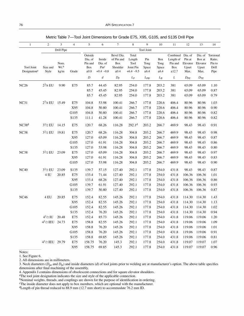
76 API SPECIFICATION 7
Metric Table 7—Tool Joint Dimensions for Grade E75, X95, G105, and S135 Drill Pipe
1 2 3 4 5 6 7 8 9 10 11 12 13 14
Drill Pipe Tool Joint
Tool JointDesignationa
Size and Style
Nom.Wt.b
kg/m Grade
Outside Dia. of Pin and
Box±0.8
InsideDia. of
Pinc
+0.4 Ð0.8
Bevel Dia. of Pin and
BoxShoulder
±0.4
Total Length Tool
Joint Pin+6.4 Ð9.5
PinTongSpace±6.4
BoxTongSpace±6.4
Combined Length of Pin and
Box±12.7
Dia. of Pin at
Elevator UpsetMax.
Dia. of Box at
Elevator UpsetMax.
Torsional Ratio, Pin to Drill Pipe
D d DF LP LPB LB L DPE DTE
NC26 23/8 EU 9.90 E75 85.7 44.45 82.95 254.0 177.8 203.2 381 65.09 65.09 1.1085.7 45.45 82.95 254.0 177.8 203.2 381 65.09 65.09 0.8785.7 45.45 82.95 254.0 177.8 203.2 381 65.09 65.09 0.79
NC31 27/8 EU 15.49 E75 104.8 53.98 100.41 266.7 177.8 228.6 406.4 80.96 80.96 1.03X95 104.8 50.80 100.41 266.7 177.8 228.6 406.4 80.96 80.96 0.90
G105 104.8 50.80 100.41 266.7 177.8 228.6 406.4 80.96 80.96 0.82S135 111.1 41.28 100.41 266.7 177.8 228.6 406.4 80.96 80.96 0.82
NC38d 31/2 EU 14.15 E75 120.7 68.26 116.28 292.1d 203.2 266.7 469.9 98.43 98.43 0.91
NC38 31/2 EU 19.81 E75 120.7 68.26 116.28 304.8 203.2 266.7 469.9 98.43 98.43 0.98X95 127.0 65.09 116.28 304.8 203.2 266.7 469.9 98.43 98.43 0.87
G105 127.0 61.91 116.28 304.8 203.2 266.7 469.9 98.43 98.43 0.86S135 127.0 53.98 116.28 304.8 203.2 266.7 469.9 98.43 98.43 0.80
NC38 31/2 EU 23.09 E75 127.0 65.09 116.28 304.8 203.2 266.7 469.9 98.43 98.43 0.97X95 127.0 61.91 116.28 304.8 203.2 266.7 469.9 98.43 98.43 0.83
G105 127.0 53.98 116.28 304.8 203.2 266.7 469.9 98.43 98.43 0.90
NC40 31/2 EU 23.09 S135 139.7 57.15 127.40 292.1 177.8 254.0 431.8 98.43 98.43 0.874 IU 20.85 E75 133.4 71.44 127.40 292.1 177.8 254.0 431.8 106.36 106.36 1.01
X95 133.4 68.26 127.40 292.1 177.8 254.0 431.8 106.36 106.36 0.86G105 139.7 61.91 127.40 292.1 177.8 254.0 431.8 106.36 106.36 0.93S135 139.7 50.80 127.40 292.1 177.8 254.0 431.8 106.36 106.36 0.87
NC46 4 EU 20.85 E75 152.4 82.55 145.26 292.1 177.8 254.0 431.8 114.30 114.30 1.43X95 152.4 82.55 145.26 292.1 177.8 254.0 431.8 114.30 114.30 1.13
G105 152.4 82.55 145.26 292.1 177.8 254.0 431.8 114.30 114.30 1.02S135 152.4 76.20 145.26 292.1 177.8 254.0 431.8 114.30 114.30 0.94
41/2 IU 20.48 E75 152.4 85.73 145.26 292.1 177.8 254.0 431.8 119.06 119.06 1.2041/2 IEU 24.73 E75 158.8 82.55 145.26 292.1 177.8 254.0 431.8 119.06 119.06 1.09
X95 158.8 76.20 145.26 292.1 177.8 254.0 431.8 119.06 119.06 1.01G105 158.8 76.20 145.26 292.1 177.8 254.0 431.8 119.06 119.06 0.91S135 158.8 69.85 145.26 292.1 177.8 254.0 431.8 119.06 119.06 0.81
41/2 IEU 29.79 E75 158.75 76.20 145.3 292.1 177.8 254.0 431.8 119.07 119.07 1.07X95 158.75 69.85 145.3 292.1 177.8 254.0 431.8 119.07 119.07 0.96
Notes:1. See Figure 6.2. All dimensions are in millimeters.3. Neck diameters (Dpe and Dte) and inside diameters (d) of tool joints prior to welding are at manufacturerÕs option. The above table speciÞes dimensions after Þnal machining of the assembly.4. Appendix I contains dimensions of obsolescent connections and for square elevator shoulders.aThe tool joint designation indicates the size and style of the applicable connection.bNominal weights, threads, and couplings are shown for the purpose of identiÞcation in ordering.cThe inside diameter does not apply to box members, which are optional with the manufacturer.dLength of pin thread reduced to 88.9 mm (12.7 mm short) to accommodate 76.2 mm ID.
COPYRIGHT American Petroleum Institute

SPECIFICATION FOR ROTARY DRILL STEM ELEMENTS 77
G105 158.75 63.50 145.3 292.1 177.8 254.0 431.8 119.07 119.07 0.96S135 158.75 57.15 145.3 292.1 177.8 254.0 431.8 119.07 119.07 0.81
NC50 41/2 EU 20.48 E75 168.28 95.25 154.0 292.1 177.8 254.0 431.8 127.00 127.00 1.3241/2 EU 24.73 E75 168.28 95.25 154.0 292.1 177.8 254.0 431.8 127.00 127.00 1.23
X95 168.28 95.25 154.0 292.1 177.8 254.0 431.8 127.00 127.00 0.97G105 168.28 95.25 154.0 292.1 177.8 254.0 431.8 127.00 127.00 0.88S135 168.28 88.90 154.0 292.1 177.8 254.0 431.8 127.00 127.00 0.81
41/2 EU 29.79 E75 168.28 92.08 154.0 292.1 177.8 254.0 431.8 127.00 127.00 1.02X95 168.28 88.90 154.0 292.1 177.8 254.0 431.8 127.00 127.00 0.96
G105 168.28 88.90 154.0 292.1 177.8 254.0 431.8 127.00 127.00 0.86S135 168.28 76.20 154.0 292.1 177.8 254.0 431.8 127.00 127.00 0.87
5 IEU 29.05 E75 168.28 95.25 154.0 292.1 177.8 254.0 431.8 130.18 130.18 0.92X95 168.28 88.90 154.0 292.1 177.8 254.0 431.8 130.18 130.18 0.86
G105 168.28 82.55 154.0 292.1 177.8 254.0 431.8 130.18 130.18 0.89S135 168.28 69.85 154.0 292.1 177.8 254.0 431.8 130.18 130.18 0.86
5 IEU 38.13 E75 168.28 88.90 154.0 292.1 177.8 254.0 431.8 130.18 130.18 0.86X75 168.28 76.20 154.0 292.1 177.8 254.0 431.8 130.18 130.18 0.86
G105 168.28 69.85 154.0 292.1 177.8 254.0 431.8 130.18 130.18 0.87
51/2 FH 5 IEU 29.05 E75 177.80 95.25 170.7 330.2 203.2 254.0 457.2 130.18 130.18 1.53X95 177.80 95.25 170.7 330.2 203.2 254.0 457.2 130.18 130.18 1.21
G105 177.80 95.25 170.7 330.2 203.2 254.0 457.2 130.18 130.18 1.09S135 184.15 88.90 170.7 330.2 203.2 254.0 457.2 130.18 130.18 0.98
5 IEU 38.13 E75 177.80 88.90 170.7 330.2 203.2 254.0 457.2 130.18 130.18 1.21X95 177.80 88.90 170.7 330.2 203.2 254.0 457.2 130.18 130.18 0.95
G105 184.15 88.90 170.7 330.2 203.2 254.0 457.2 130.18 130.18 0.99S135 184.15 82.55 170.7 330.2 203.2 254.0 457.2 130.18 130.18 0.83
51/2 IEU 32.62 E75 177.80 101.60 170.7 330.2 203.2 254.0 457.2 144.46 144.46 1.11X95 177.80 95.25 170.7 330.2 203.2 254.0 457.2 144.46 144.46 0.98
G105 184.15 88.90 170.7 330.2 203.2 254.0 457.2 144.46 144.46 1.02S135 190.50 76.20 180.2 330.2 203.2 254.0 457.2 144.46 144.46 0.96
51/2 IEU 36.79 E75 177.80 101.60 170.7 330.2 203.2 254.0 457.2 144.46 144.46 0.99X95 184.15 88.90 170.7 330.2 203.2 254.0 457.2 144.46 144.46 1.01
Metric Table 7—Tool Joint Dimensions for Grade E75, X95, G105, and S135 Drill Pipe (Continued)
1 2 3 4 5 6 7 8 9 10 11 12 13 14
Drill Pipe Tool Joint
Tool JointDesignationa
Size and Style
Nom.Wt.b
kg/m Grade
Outside Dia. of Pin and
Box±0.8
InsideDia. of
Pinc
+0.4 Ð0.8
Bevel Dia. of Pin and
BoxShoulder
±0.4
Total Length Tool
Joint Pin+6.4 Ð9.5
PinTongSpace±6.4
BoxTongSpace±6.4
Combined Length of Pin and
Box±12.7
Dia. of Pin at
Elevator UpsetMax.
Dia. of Box at
Elevator UpsetMax.
Torsional Ratio, Pin to Drill Pipe
D d DF LP LPB LB L DPE DTE
Notes:1. See Figure 6.2. All dimensions are in millimeters.3. Neck diameters (Dpe and Dte) and inside diameters (d) of tool joints prior to welding are at manufacturerÕs option. The above table speciÞes dimensions after Þnal machining of the assembly.4. Appendix I contains dimensions of obsolescent connections and for square elevator shoulders.aThe tool joint designation indicates the size and style of the applicable connection.bNominal weights, threads, and couplings are shown for the purpose of identiÞcation in ordering.cThe inside diameter does not apply to box members, which are optional with the manufacturer.dLength of pin thread reduced to 88.9 mm (12.7 mm short) to accommodate 76.2 mm ID.
COPYRIGHT American Petroleum Institute
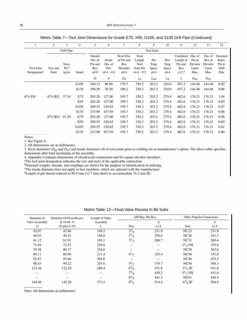
78 API SPECIFICATION 7
G105 184.15 88.90 170.7 330.2 203.2 254.0 457.2 144.46 144.46 0.92S135 190.50 76.20 180.2 330.2 203.2 254.0 457.2 144.46 144.46 0.86
65/8 FH 65/8 IEU 37.54 E75 203.20 127.00 195.7 330.2 203.2 279.4 482.6 176.21 176.21 1.04X95 203.20 127.00 195.7 330.2 203.2 279.4 482.6 176.21 176.21 0.82
G105 209.55 120.65 195.7 330.2 203.2 279.4 482.6 176.21 176.21 0.87S135 215.90 107.95 195.7 330.2 203.2 279.4 482.6 176.21 176.21 0.86
65/8 IEU 41.29 E75 203.20 127.00 195.7 330.2 203.2 279.4 482.6 176.21 176.21 0.96X95 209.55 120.65 195.7 330.2 203.2 279.4 482.6 176.21 176.21 0.89
G105 209.55 120.65 195.7 330.2 203.2 279.4 482.6 176.21 176.21 0.81S135 215.90 107.95 195.7 330.2 203.2 279.4 482.6 176.21 176.21 0.80
Metric Table 12—Float Valve Recess In Bit Subs
Diameter ofValve Assembly
D
Diameter Of Float Recess R +0.40 Ð0
(D plus 0.79)
Length of Value Assembly
L
API Reg. Bit Box Other Popular Connections
SizeA
±1.6 SizeA
±1.6
42.07 42.86 149.2 23/8 231.8 NC23 231.848.42 49.21 158.8 27/8 254.0 NC26 241.361.12 61.91 165.1 31/2 266.7 NC31 260.471.44 72.23 254.0 Ñ Ñ 31/2 FH 355.679.38 80.17 254.0 Ñ Ñ NC38 362.088.11 88.90 211.4 41/2 325.4 NC44 331.892.87 93.66 304.8 Ñ Ñ NC46 425.598.43 99.22 247.6 51/2 374.7 NC50 368.3
121.44 122.24 288.4 65/8 431.8 51/2 IF 431.8Ñ Ñ Ñ 75/8 438.2 51/2 FH 431.8Ñ Ñ Ñ 85/8 441.3 NC61 444.5
144.46 145.26 371.5 85/8 514.4 65/8 IF 504.8
Note: All dimensions in millimeters.
Metric Table 7—Tool Joint Dimensions for Grade E75, X95, G105, and S135 Drill Pipe (Continued)
1 2 3 4 5 6 7 8 9 10 11 12 13 14
Drill Pipe Tool Joint
Tool JointDesignationa
Size and Style
Nom.Wt.b
kg/m Grade
Outside Dia. of Pin and
Box±0.8
InsideDia. of
Pinc
+0.4 Ð0.8
Bevel Dia. of Pin and
BoxShoulder
±0.4
Total Length Tool
Joint Pin+6.4 Ð9.5
PinTongSpace±6.4
BoxTongSpace±6.4
Combined Length of Pin and
Box±12.7
Dia. of Pin at
Elevator UpsetMax.
Dia. of Box at
Elevator UpsetMax.
Torsional Ratio, Pin to Drill Pipe
D d DF LP LPB LB L DPE DTE
Notes:1. See Figure 6.2. All dimensions are in millimeters.3. Neck diameters (Dpe and Dte) and inside diameters (d) of tool joints prior to welding are at manufacturerÕs option. The above table speciÞes dimensions after Þnal machining of the assembly.4. Appendix I contains dimensions of obsolescent connections and for square elevator shoulders.aThe tool joint designation indicates the size and style of the applicable connection.bNominal weights, threads, and couplings are shown for the purpose of identiÞcation in ordering.cThe inside diameter does not apply to box members, which are optional with the manufacturer.dLength of pin thread reduced to 88.9 mm (12.7 mm short) to accommodate 76.2 mm ID.
COPYRIGHT American Petroleum Institute
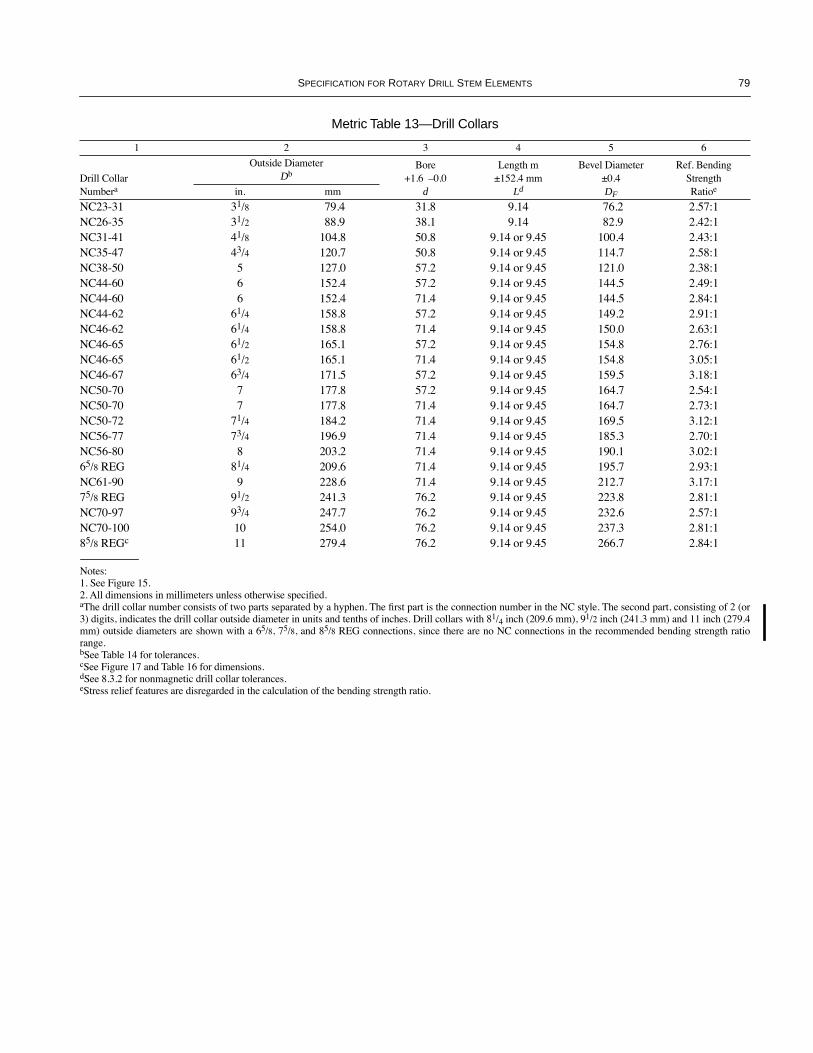
SPECIFICATION FOR ROTARY DRILL STEM ELEMENTS 79
Metric Table 13—Drill Collars
1 2 3 4 5 6
Drill CollarNumbera
Outside DiameterDb
Bore+1.6 Ð0.0
d
Length m ±152.4 mm
Ld
Bevel Diameter±0.4DF
Ref. Bending Strength Ratioein. mm
NC23-31 31/8 79.4 31.8 9.14 76.2 2.57:1NC26-35 31/2 88.9 38.1 9.14 82.9 2.42:1NC31-41 41/8 104.8 50.8 9.14 or 9.45 100.4 2.43:1NC35-47 43/4 120.7 50.8 9.14 or 9.45 114.7 2.58:1NC38-50 5 127.0 57.2 9.14 or 9.45 121.0 2.38:1NC44-60 6 152.4 57.2 9.14 or 9.45 144.5 2.49:1NC44-60 6 152.4 71.4 9.14 or 9.45 144.5 2.84:1NC44-62 61/4 158.8 57.2 9.14 or 9.45 149.2 2.91:1NC46-62 61/4 158.8 71.4 9.14 or 9.45 150.0 2.63:1NC46-65 61/2 165.1 57.2 9.14 or 9.45 154.8 2.76:1NC46-65 61/2 165.1 71.4 9.14 or 9.45 154.8 3.05:1NC46-67 63/4 171.5 57.2 9.14 or 9.45 159.5 3.18:1NC50-70 7 177.8 57.2 9.14 or 9.45 164.7 2.54:1NC50-70 7 177.8 71.4 9.14 or 9.45 164.7 2.73:1NC50-72 71/4 184.2 71.4 9.14 or 9.45 169.5 3.12:1NC56-77 73/4 196.9 71.4 9.14 or 9.45 185.3 2.70:1NC56-80 8 203.2 71.4 9.14 or 9.45 190.1 3.02:165/8 REG 81/4 209.6 71.4 9.14 or 9.45 195.7 2.93:1NC61-90 9 228.6 71.4 9.14 or 9.45 212.7 3.17:175/8 REG 91/2 241.3 76.2 9.14 or 9.45 223.8 2.81:1NC70-97 93/4 247.7 76.2 9.14 or 9.45 232.6 2.57:1NC70-100 10 254.0 76.2 9.14 or 9.45 237.3 2.81:185/8 REGc 11 279.4 76.2 9.14 or 9.45 266.7 2.84:1
Notes:1. See Figure 15.2. All dimensions in millimeters unless otherwise speciÞed.aThe drill collar number consists of two parts separated by a hyphen. The Þrst part is the connection number in the NC style. The second part, consisting of 2 (or3) digits, indicates the drill collar outside diameter in units and tenths of inches. Drill collars with 81/4 inch (209.6 mm), 91/2 inch (241.3 mm) and 11 inch (279.4mm) outside diameters are shown with a 65/8, 75/8, and 85/8 REG connections, since there are no NC connections in the recommended bending strength ratiorange.bSee Table 14 for tolerances.cSee Figure 17 and Table 16 for dimensions.dSee 8.3.2 for nonmagnetic drill collar tolerances.eStress relief features are disregarded in the calculation of the bending strength ratio.
COPYRIGHT American Petroleum Institute
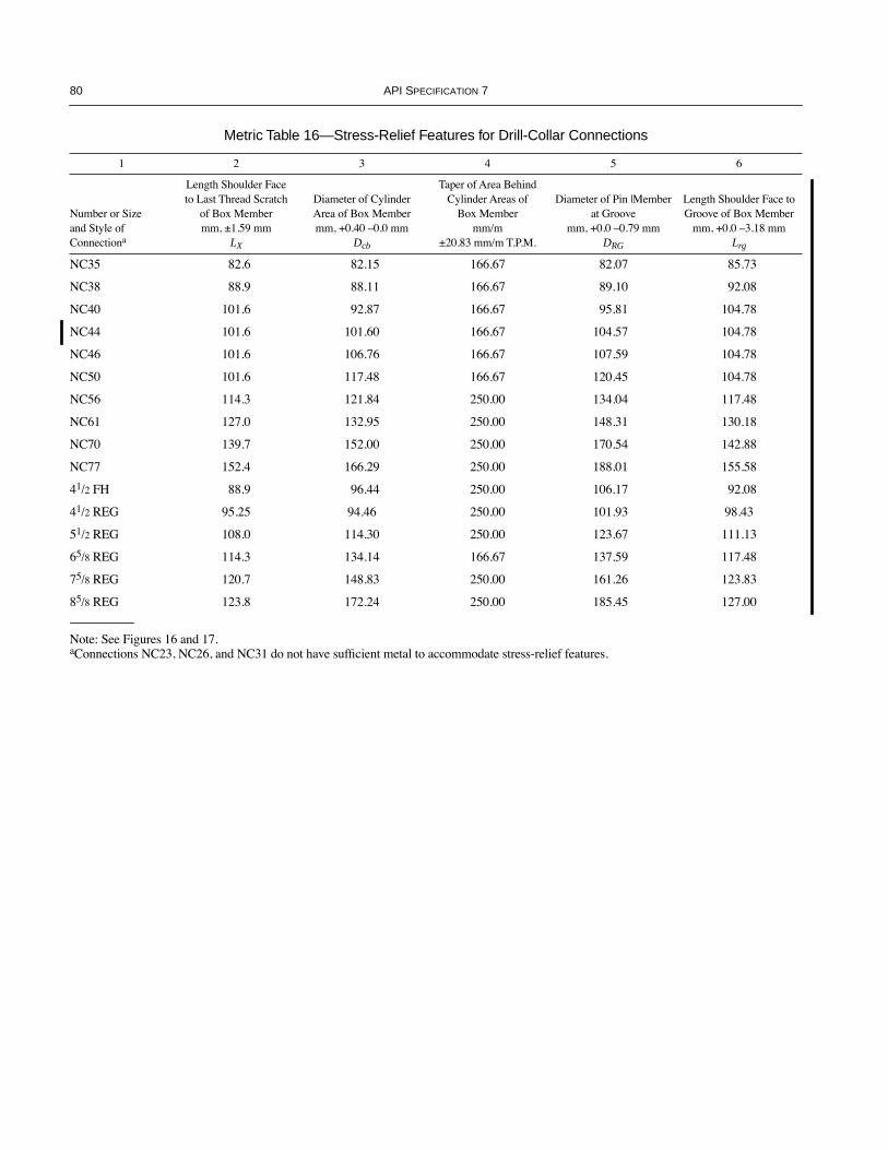
80 API SPECIFICATION 7
Metric Table 16—Stress-Relief Features for Drill-Collar Connections
1 2 3 4 5 6
Number or Size and Style of Connectiona
Length Shoulder Face to Last Thread Scratch
of Box Membermm, ±1.59 mm
LX
Diameter of Cylinder Area of Box Membermm, +0.40 Ð0.0 mm
Dcb
Taper of Area Behind Cylinder Areas of
Box Membermm/m
±20.83 mm/m T.P.M.
Diameter of Pin |Member at Groove
mm, +0.0 Ð0.79 mm DRG
Length Shoulder Face toGroove of Box Member
mm, +0.0 Ð3.18 mmLrg
NC35 82.6 82.15 166.67 82.07 85.73
NC38 88.9 88.11 166.67 89.10 92.08
NC40 101.6 92.87 166.67 95.81 104.78
NC44 101.6 101.60 166.67 104.57 104.78
NC46 101.6 106.76 166.67 107.59 104.78
NC50 101.6 117.48 166.67 120.45 104.78
NC56 114.3 121.84 250.00 134.04 117.48
NC61 127.0 132.95 250.00 148.31 130.18
NC70 139.7 152.00 250.00 170.54 142.88
NC77 152.4 166.29 250.00 188.01 155.58
41/2 FH 88.9 96.44 250.00 106.17 92.08
41/2 REG 95.25 94.46 250.00 101.93 98.43
51/2 REG 108.0 114.30 250.00 123.67 111.13
65/8 REG 114.3 134.14 166.67 137.59 117.48
75/8 REG 120.7 148.83 250.00 161.26 123.83
85/8 REG 123.8 172.24 250.00 185.45 127.00
Note: See Figures 16 and 17.aConnections NC23, NC26, and NC31 do not have sufÞcient metal to accommodate stress-relief features.
COPYRIGHT American Petroleum Institute

SPECIFICATION FOR ROTARY DRILL STEM ELEMENTS 81
Metric Table 25—Product Dimensions Rotary Shouldered Connections
1 2 3 4 5 6 7 8 9 10 11 12
Connection Number or
SizeThread Form
Threads Per 25.4 mm
Tapermm/m on
Dia.
Pitch Dia. of Thread at
Gauge Point
LargeDiameter
of Pin
Diameter of Flat on Pin± 0.4
Small Diameter
of Pin
Length of Pina
+0 Ð3.18
Minimum Length of Threadsb
Depth ofBox
+9.53 Ð0.0
Box Counterbore +0.79 Ð0.40
C DL DLF DS LPC LBT LBC QC
Number (NC) Style
NC23 V-0.038R 4 166.67 59.817 65.10 61.90 52.4 76.20 79.38 92.08 66.68
NC20 V-0.038R 4 166.67 67.7672 73.05 69.85 60.35 76.20 79.38 92.08 74.61
NC31 V-0.038R 4 166.67 80.8482 86.13 82.96 71.32 88.90 92.08 104.78 87.71
NC35 V-0.038R 4 166.67 89.6874 94.97 92.08 79.10 95.25 98.43 111.13 96.84
NC38 V-0.038R 4 166.67 96.7232 102.01 98.83 85.06 101.60 104.78 117.48 103.58
NC40 V-0.038R 4 166.67 103.4288 108.71 105.56 89.66 114.30 117.48 130.18 110.33
NC44 V-0.038R 4 166.67 112.1918 117.48 114.27 98.43 114.30 117.48 130.18 119.06
NC46 V-0.038R 4 166.67 117.5004 122.78 119.61 103.73 114.30 117.48 130.18 124.62
NC50 V-0.038R 4 166.67 128.0592 133.35 130.43 114.30 114.30 117.48 130.18 134.94
NC56 V-0.038R 4 250.00 142.6464 149.25 114.86 117.50 127.00 130.18 142.88 150.81
NC61 V-0.038R 4 250.00 156.9212 163.53 159.16 128.60 139.70 142.88 155.58 165.1
NC70 V-0.038R 4 250.00 179.1462 185.75 181.38 147.65 152.40 155.58 168.28 187.33
NC77 V-0.038R 4 250.00 196.6214 203.2 198.83 161.95 165.10 168.28 180.98 204.79
Regular (REG) Style
1 REG V-0.055 6 125.00 29.3116 32.54 31.32 27.79 38.10 50.80 54.10 33.05
11/2 REG V-0.055 6 125.00 39.1414 42.37 41.17 36.02 50.80 53.98 66.80 42.88
23/8 REG V-0.040 5 250.00 60.0804 66.68 63.88 47.63 76.20 79.38 92.08 68.26
27/8 REG V-0.040 5 250.00 69.6054 76.20 73.41 53.98 88.90 92.08 104.78 77.79
31/2 REG V-0.040 5 250.00 82.2927 88.90 86.11 65.07 95.25 98.43 111.13 90.49
41/2 REG V-0.040 5 250.00 110.8677 117.48 114.68 90.47 107.95 111.13 123.83 119.06
51/2 REG V-0.050 4 250.00 132.9441 140.21 137.41 110.06 120.65 123.83 136.53 141.68
65/8 REG V-0.050 4 166.67 146.2481 152.20 149.40 131.04 127.00 130.18 142.88 153.99
75/8 REG V-0.050 4 250.00 170.5491 177.80 175.01 144.48 133.35 136.53 149.23 184.15
85/8 REG V-0.050 4 250.00 194.7311 201.98 199.14 167.84 136.53 139.70 152.40 204.39
Full-Hole (FH) Style
51/2 FH V-0.050 4 166.67 142.0114 147.96 Ñ 126.80 127.00 130.18 142.88 150.02
65/8 FH V-0.050 4 166.67 165.5978 171.53 Ñ 150.37 127.00 130.18 142.88 173.83
Notes:1. See Figure 20.2. All dimensions are in millimeters.aFor rolling cone drill bits only, the tolerance is + 0.0, Ð 4.8 mm.bLBT is the length of threads in the box measured from the make-up shoulder to the intersection of the non-pressure ßank and crest of the last thread with full thread depth.
COPYRIGHT American Petroleum Institute

82 API SPECIFICATION 7
Metric Table 26—Product Thread Dimensions Rotary Shouldered Connections
1 2 3 4 5 6 7 8 9 10
Reference Root Truncation
srn = srs frn = frs
Width of Flat
Thread Form
Pitchp
Tapermm/m
Reference Thread
Height, Not Truncated H
Reference Thread Height,
Truncatedhn = hs
Reference Crest
Truncationfcn = fcs
CrestFcn = Fcs
RootFrn = Frs
Root Radius rrn = rrs
Radius at Thread Corners
r ±0.20 mm
V-0.038R 6.350 166.67 5.48653 3.09484 0.96520 1.42649 1.65 Ñ 0.97 0.38V-0.038R 6.350 250.00 5.47063 3.08308 0.96520 1.42235 1.65 Ñ 0.97 0.38V-0.040 5.080 250.00 4.37650 2.99319 0.50800 0.87531 1.02 Ñ 0.51 0.38V-0.050 6.350 250.00 5.47063 3.74150 0.63500 1.09413 1.27 Ñ 0.64 0.38V-0.050 6.350 166.67 5.48653 3.75422 0.63500 1.09731 1.27 Ñ 0.64 0.38V-0.055 4.233 125.00 3.66268 1.420 1.03124 1.20904 1.40 1.19 Ñ 0.38Notes:1. See Figures 21 and 22 and 22a.2. All dimensions in millimeters.
Metric Table 27—Gauge Dimensions Rotary Shouldered Connections
1 2 3 4 5 6 7 8 9 10 11 12 13 14
SizeThread Form
Threads Per 25.4
mm
Tapermm/mon Dia.
Pitch Dia.at 15.88 Gauge Pointa
Major Dia. at 15.88 Gauge Pointa
Minor Dia. at 15.88 Gauge Pointa
Pitch Dia. at 34.9 Gauge Pointa
Total Length Plug
Gauge
Dia. of Plug
Fitting Plate
Total Length Ring
Gauge
Outside Dia. of Ring
Gauge
Dia. of Counter-
boreMating
StandoffLpg Lrg DR Q S
Number (NC) Style Gauges
NC23 V-0.038R 4 166.67 59.8170 62.1965 57.4375 56.6420 76.2 52.22 60.3 98.4 64.03 15.88NC26 V-0.038R 4 166.67 67.7672 70.1467 65.3877 64.5922 76.2 60.17 60.3 106.4 71.98 15.88NC31 V-0.038R 4 166.67 80.8482 83.2277 78.4687 77.6732 88.9 73.25 73.0 130.2 85.06 15.88NC35 V-0.038R 4 166.67 89.6874 92.0669 87.3079 86.5124 95.3 82.09 79.4 133.4 93.90 15.88
NC38 V-0.038R 4 166.67 96.7232 99.1027 94.3437 93.5482 101.6 89.13 85.7 142.9 100.94 15.88NC40 V-0.038R 4 166.67 103.4288 105.8083 101.0493 100.2538 114.3 95.83 98.4 149.2 107.67 15.88NC44 V-0.038R 4 166.67 112.1918 114.5713 109.8123 109.0163 114.3 104.60 98.4 161.9 116.41 15.88NC46 V-0.038R 4 166.67 117.5004 119.8799 115.1209 114.3254 114.3 109.91 98.4 165.1 121.72 15.88NC50 V-0.038R 4 166.67 128.0592 130.4382 125.6797 124.8842 114.3 120.47 98.4 181.0 132.28 15.88
NC56 V-0.038R 4 250.00 142.6464 145.0183 140.2745 137.8339 127.0 135.08 111.1 200.0 146.86 15.88NC61 V-0.038R 4 250.00 156.9212 159.2931 154.5493 152.1587 139.7 149.35 123.8 215.9 161.14 15.88NC70 V-0.038R 4 250.00 179.1462 181.5181 176.7743 174.3837 152.4 171.58 136.5 238.1 183.36 15.88NC77 V-0.038R 4 250.00 196.6214 198.9933 192.2495 191.8589 165.1 189.05 149.2 260.4 200.84 15.88
Regular (REG) Style Gauges
1 REG V-0.055 6 125.00 29.3116 30.1727 25.6489 26.9316 38.10 No plate 28.58 63.50 34.54 9.5311/2 REG V-0.055 6 125.00 39.1414 40.0025 35.4787 36.7614 50.80 No plate 44.45 73.03 42.88 9.5323/8 REG V-0.040 5 250.00 60.0804 62.4523 57.7085 55.3179 76.2 54.13 60.3 95.3 64.29 15.8827/8 REG V-0.040 5 250.00 69.6054 71.9773 67.2335 64.8429 88.9 63.65 73.0 108.0 73.81 15.8831/2 REG V-0.040 5 250.00 82.2927 84.6646 79.9209 77.5302 95.3 76.33 79.4 127.0 86.51 15.8841/2 REG V-0.040 5 250.00 110.8677 113.2395 108.4958 106.1052 108.0 104.90 92.1 158.8 115.09 15.88
51/2 REG V-0.050 4 250.00 132.9441 135.9723 129.9157 128.1816 120.7 125.88 104.8 190.5 137.85 15.8865/8 REG V-0.050 4 166.67 146.2481 149.2860 143.2103 143.0731 127.0 138.38 111.1 209.6 151.10 15.8875/8 REG V-0.050 4 250.00 170.5491 173.5772 167.5209 165.7866 133.4 163.09 117.5 241.3 175.41 15.8885/8 REG V-0.050 4 250.00 194.7311 197.7593 191.7027 187.9686 136.5 187.27 120.7 273.1 199.59 15.88
Full-Hole (FH) Style Gauges
51/2 FH V-0.050 4 166.67 142.0114 145.0492 138.9736 138.8364 127.0 134.42 111.1 196.9 146.91 15.8865/8 FH V-0.050 4 166.67 165.5978 168.6357 162.5600 162.4228 127.0 157.73 111.1 228.6 170.46 15.88Notes:1. See Appendix K for dimensions of obsolescent connections shown in parentheses in this table.2. Gauges are the same for numbered connections (NC) and obsolescent connections when shown on the same line.3. See Figures 24 and 25.4. All dimensions in millimeters at 20¡C, ± 1.1¡C, unless otherwise speciÞed.aThe values in Column 5 and 6 apply only to grand, regional, and reference master plug gauges. The values in Column 8 apply only to working plug gauges. Thevalues in Column 7 apply only to ring gauges.
COPYRIGHT American Petroleum Institute
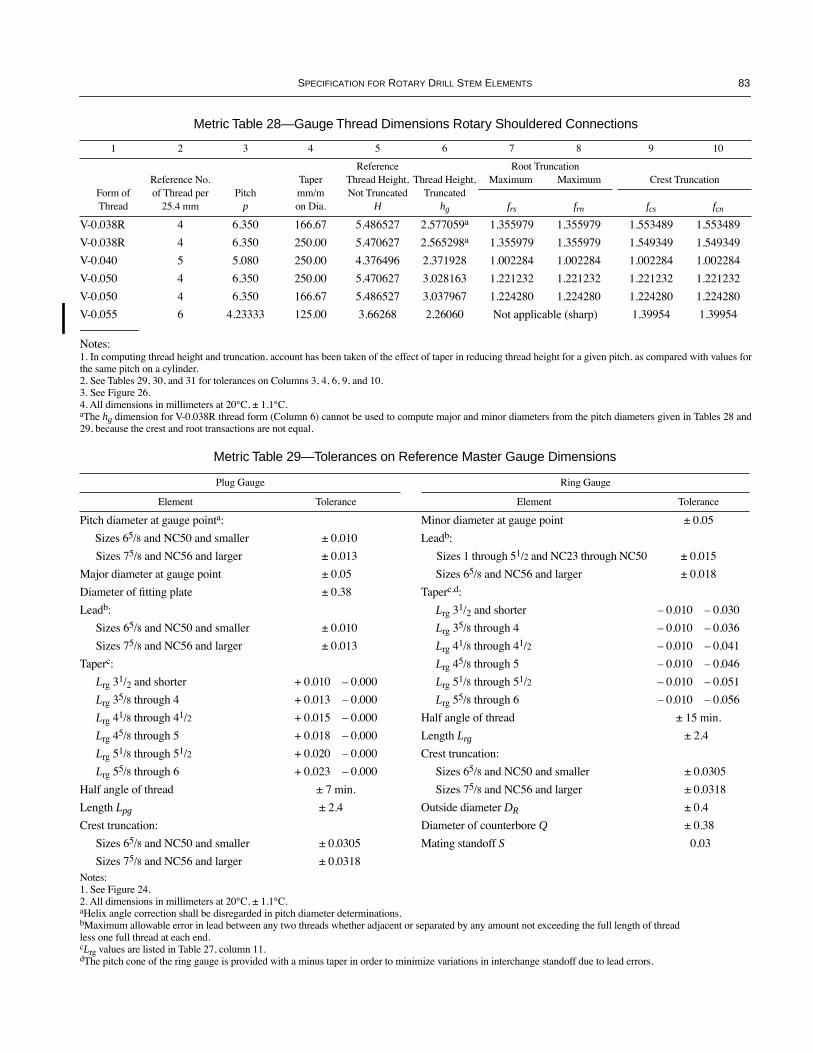
SPECIFICATION FOR ROTARY DRILL STEM ELEMENTS 83
Metric Table 28—Gauge Thread Dimensions Rotary Shouldered Connections
1 2 3 4 5 6 7 8 9 10
Form of Thread
Reference No. of Thread per
25.4 mmPitch
p
Tapermm/m on Dia.
ReferenceThread Height, Not Truncated
H
Thread Height, Truncated
hg
Root TruncationMaximum Maximum Crest Truncation
frs frn fcs fcn
V-0.038R 4 6.350 166.67 5.486527 2.577059a 1.355979 1.355979 1.553489 1.553489
V-0.038R 4 6.350 250.00 5.470627 2.565298a 1.355979 1.355979 1.549349 1.549349
V-0.040 5 5.080 250.00 4.376496 2.371928 1.002284 1.002284 1.002284 1.002284
V-0.050 4 6.350 250.00 5.470627 3.028163 1.221232 1.221232 1.221232 1.221232
V-0.050 4 6.350 166.67 5.486527 3.037967 1.224280 1.224280 1.224280 1.224280
V-0.055 6 4.23333 125.00 3.66268 2.26060 Not applicable (sharp) 1.39954 1.39954
Notes:1. In computing thread height and truncation, account has been taken of the effect of taper in reducing thread height for a given pitch, as compared with values forthe same pitch on a cylinder.2. See Tables 29, 30, and 31 for tolerances on Columns 3, 4, 6, 9, and 10.3. See Figure 26.4. All dimensions in millimeters at 20¡C, ± 1.1¡C.aThe hg dimension for V-0.038R thread form (Column 6) cannot be used to compute major and minor diameters from the pitch diameters given in Tables 28 and29, because the crest and root transactions are not equal.
Metric Table 29—Tolerances on Reference Master Gauge Dimensions
Plug Gauge Ring Gauge
Element Tolerance Element Tolerance
Pitch diameter at gauge pointa: Minor diameter at gauge point ± 0.05
Sizes 65/8 and NC50 and smaller ± 0.010 Leadb:
Sizes 75/8 and NC56 and larger ± 0.013 Sizes 1 through 51/2 and NC23 through NC50 ± 0.015
Major diameter at gauge point ± 0.05 Sizes 65/8 and NC56 and larger ± 0.018
Diameter of Þtting plate ± 0.38 Taperc,d:
Leadb: Lrg 31/2 and shorter Ð 0.010 Ð 0.030
Sizes 65/8 and NC50 and smaller ± 0.010 Lrg 35/8 through 4 Ð 0.010 Ð 0.036
Sizes 75/8 and NC56 and larger ± 0.013 Lrg 41/8 through 41/2 Ð 0.010 Ð 0.041
Taperc: Lrg 45/8 through 5 Ð 0.010 Ð 0.046
Lrg 31/2 and shorter + 0.010 Ð 0.000 Lrg 51/8 through 51/2 Ð 0.010 Ð 0.051
Lrg 35/8 through 4 + 0.013 Ð 0.000 Lrg 55/8 through 6 Ð 0.010 Ð 0.056
Lrg 41/8 through 41/2 + 0.015 Ð 0.000 Half angle of thread ± 15 min.
Lrg 45/8 through 5 + 0.018 Ð 0.000 Length Lrg ± 2.4
Lrg 51/8 through 51/2 + 0.020 Ð 0.000 Crest truncation:
Lrg 55/8 through 6 + 0.023 Ð 0.000 Sizes 65/8 and NC50 and smaller ± 0.0305
Half angle of thread ± 7 min. Sizes 75/8 and NC56 and larger ± 0.0318
Length Lpg ± 2.4 Outside diameter DR ± 0.4
Crest truncation: Diameter of counterbore Q ± 0.38
Sizes 65/8 and NC50 and smaller ± 0.0305 Mating standoff S 0.03
Sizes 75/8 and NC56 and larger ± 0.0318Notes:1. See Figure 24.2. All dimensions in millimeters at 20¡C, ± 1.1¡C.aHelix angle correction shall be disregarded in pitch diameter determinations.bMaximum allowable error in lead between any two threads whether adjacent or separated by any amount not exceeding the full length of thread less one full thread at each end.cLrg values are listed in Table 27, column 11.dThe pitch cone of the ring gauge is provided with a minus taper in order to minimize variations in interchange standoff due to lead errors.
COPYRIGHT American Petroleum Institute

84 API SPECIFICATION 7
Metric Table 30—Tolerances On Grand and Regional Master Gauge Dimensions
Plug Gauge Ring Gauge
Element Tolerance Element Tolerance
Pitch diameter at gauge pointa ± 0.005 Minor diameter at gauge point ± 0.05Leadb: Leadb:
Sizes 31/2 and smaller ± 0.005 Sizes 31/2 and smaller ± 0.008Sizes 4 to 85/8, inclusive ± 0.008 Sizes 4 to 85/8, inclusive ± 0.010
Taperc: + 0.010 Taperc,d Ð 0.015+ 0.003 Ð 0.030
Half angle of thread (minutes) ± 5 Half angle of thread (minutes) ± 10Length Lpg ± 2.4 Length Lrg ± 2.4Crest truncation ± 0.0284 Crest truncation ± 0.028
Outside diameter DR ± 0.4Diameter of counterbore Q ± 0.38Mating standoff S ± 0.03
Notes:1. See Figure 24.2. All dimensions in millimeters at 20¡C, ± 1.1¡C.aHelix angle correction shall be disregarded in pitch diameter determinations.bMaximum allowable error in lead between any two threads whether adjacent or separated by any amount not exceeding the full length of thread less one fullthread at each end.cLrg values are listed in Table 27, Column 11.dThe pitch cone of the ring gauge is provided with a minus taper in order to minimize variations in interchange standoff due to lead errors.
Metric Table 31—Tolerances On Working Gauge Dimensions
Plug Gauge Ring Gauge
Element Tolerance Element Tolerance
Pitch diameter at gauge pointa: Minor diameter at gauge point ± 0.05
Sizes 65/8 and NC50 and smaller ± 0.010 Leadb:
Sizes 75/8 and NC56 and larger ± 0.013 Sizes 1 through 51/2 and NC23 through NC50 ± 0.015
Major diameter at gauge point ± 0.05 Sizes 65/8 and NC56 and larger ± 0.018
Diameter of Þtting plate ± 0.38 Taperc,d:
Leadb: Lrg 31/2 and shorter Ð 0.010 Ð 0.036
Sizes 65/8 and NC50 and smaller ± 0.010 Lrg 35/8 through 4 Ð 0.010 Ð 0.041
Sizes 75/8 and NC56 and larger ± 0.013 Lrg 41/8 through 41/2 Ð 0.010 Ð 0.046
Taperc: Lrg 45/8 through 5 Ð 0.010 Ð 0.051
Lrg 31/2 and shorter + 0.015 Ð 0.000 Lrg 51/8 through 51/2 Ð 0.010 Ð 0.056
Lrg 35/8 through 4 + 0.018 Ð 0.000 Lrg 55/8 through 6 Ð 0.010 Ð 0.061
Lrg 41/8 through 41/2 + 0.020 Ð 0.000 Half angle of thread ± 15 min.
Lrg 45/8 through 5 + 0.023 Ð 0.000 Length Lrg ± 2.4
Lrg 51/8 through 51/2 + 0.025 Ð 0.000 Crest truncation:
Lrg 55/8 through 6 + 0.028 Ð 0.000 Sizes 65/8 and NC50 and smaller ± 0.0305
Half angle of thread ± 7 min. Sizes 75/8 and NC56 and larger ± 0.0318
Length Lpg ± 2.4 Outside diameter DR ± 0.4
Crest truncation: Diameter of counterbore Q ± 0.38
Sizes 65/8 and NC50 and smaller ± 0.0305 Mating standoff S ± 0.03
Sizes 75/8 and NC56 and larger ± 0.0318Notes:1. See Figure 25.2. All dimensions in millimeters at 20¡C, ± 1.1¡C.aHelix angle correction shall be disregarded in pitch diameter determinations.bMaximum allowable error in lead between any two threads whether adjacent or separated by any amount not exceeding the full length of thread less one fullthread at each end.cLrg values are listed in Table 27, Column 11.dThe pitch cone of the ring gauge is provided with a minus taper in order to minimize variations in interchange standoff due to lead errors.
COPYRIGHT American Petroleum Institute

SPECIFICATION FOR ROTARY DRILL STEM ELEMENTS 85
Metric Table H-1—Compensated Thread Lengths and Ball Point Diameters for
Measurements Parallel to the Taper Cone
1 2 3 4 5 6 7
Thread FormTapermm/m
Number ThreadsPer 25.4 mm
Pitchmm
Thread Length (Parallel to Thread
Axis), mm
Compensated Length (Parallel to Taper
Cone), mm
Ball Point Diameter
mm
V-0.038R 166.67 4 6.350 25.4 25.48814 3.66
V-0.038R 250.00 4 6.350 25.4 25.59761 3.66
V-0.040 250.00 5 6.350 25.4 25.59761 2.92
V-0.050 250.00 4 6.350 25.4 25.59761 3.66
V-0.050 166.67 4 6.350 25.4 25.48814 3.66
V-0.055 125.00 6 4.23333 25.4 25.44953 2.4384
V-0.065 166.67 4 6.350 25.4 25.48814 3.66
V-0.076 125.00 4 6.350 25.4 25.44953 3.66
H-90 166.67 31/2 7.257 50.8 50.97628 5.1316
H-90 250.00 31/2 7.257 50.8 51.19522 5.1316
SL-H90 104.17 3 8.467 25.4 25.43454 5.9868
Note: Although only taper and lead measurements are recommended in this appendix, these ballpoint diameters would also apply to contour microscopecontact points for measuring thread angle or checking thread form if desired, except that the contacts for the V-0.040 thread form should be truncated toclear the bottom of the thread. If thread height is measured, the height gauge contact points should be conical in shape, with a 50 degree included angleand a 0.0508 millimeter radius at the tip of the cone.
COPYRIGHT American Petroleum Institute

86 API SPECIFICATION 7
Metric Table I-1—Obsolescent Tool Joints With Taper Shoulder and Square Shoulder
1 2 3 4 5 6 7 8 9 10 11 12 13 14
Tool Joint Shoulder
Taper Square
Tool JointDesignationa
Drill Pipe Size and
Style
Drill Pipe Nom. Wt.b
kg/m
Outside Dia. of Pin and
Box±0.8
Inside Dia. of
Pin and Boxc
+0.4 Ð0.8
Dia. of Pin at
Elevator UpsetMax.
Bevel Dia. of Pin and Box Shoulder
±0.4
Total Length
Tool Joint Pin
+6.4 Ð9.5
Pin Tong Space±6.4
Box Tong Space ±6.4
Combined Length of Pin and
Box±12.7
Dia. of Box at
Elevator Upset Max.
Dia. of Box at
Elevator Upset Max.
Radius of Elevator
Neck±0.4
D d DPE DF LP LPB LB L DTE DSE RSE
Obsolescent ConnectionsFull-Hole (FH) Style
31/2 FHe 31/2 IU 19.81 117.5 54.0 93.7 113.9 273.1 177.8 241.3 419.1 93.7 92.1 4.8
31/2 FHe 31/2 IU 23.09 117.5 54.0 93.7 113.9 273.1 177.8 241.3 419.1 93.7 92.1 4.8
4 FH (NC40) 4 IU 20.85 133.4 71.4 106.4 127.4 292.1 177.8 254.0 431.8 106.4 104.8 6.4
41/2 FH 41/2 IU 24.73 146.1 76.2 119.1 140.5 279.4 117.8 254.0 431.8 119.1 117.5 6.4
41/2 FH 41/2 IEU 29.79 146.1 76.2 119.1 140.5 279.4 177.8 254.0 431.8 119.1 117.5 6.4
51/2 FHf 51/2 IEU 32.62 177.8 101.6 144.5 170.7 330.2 203.2 254.0 457.2 144.5 144.5 6.4
51/2 FHf 51/2 IEU 36.79 177.8 101.6 144.5 170.7 330.2 203.2 254.0 457.2 144.5 144.5 6.4
Internal-Flush (IF) Style
23/8 IF (NC26)
2 3/8 EU 9.91 85.7 44.5 65.1 82.9 228.6 152.4 177.8 330.2 65.1 Ñ Ñ
27/8 IF (NC31)
2 7/8 EU 15.49 104.8 54.0 81.0 100.4 241.3 152.4 203.2 355.6 81.0 81.0 4.8
31/2 IF (NC38)
31/2 EU 19.81 120.7 68.3 98.4 116.3 279.4 177.8 241.3 419.1 98.4 98.4 4.8
31/2 IF (NC38)
31/2 EU 23.09 127.0 68.3 98.4 116.3 279.4 177.8 241.3 419.1 98.4 98.4 4.8
4 IF (NC46) 4 EU 20.85 146.1 82.6 114.3 140.5 292.1 177.8 254.0 431.8 114.3 114.3 6.4
41/2 IF (NC50)
41/2 EU 24.73 Std 155.6 95.3 127.0 154.0 (150.4)
292.1 177.8 254.0 431.8 127.0 127.0 6.4
41/2 IF (NC50)
41/2 EU 24.73 Opt 158.8
95.3 127.0 154.0 (150.4)
292.1 177.8 254.0 431.8 127.0 127.0 6.4
41/2 IF (NC50)d
5 IEU 29.05 Std 161.9 95.3 130.2 154.0 (150.4)
292.1 177.8 254.0 431.8 130.2 130.2 6.4
41/2 IF (NC50)d
5 IEU 29.05 Opt 165.1
88.9 130.2 154.0 (150.4)
292.1 177.8 254.0 431.8 130.2 130.2 6.4
Notes:1. See Figure 6.2. All dimensions are in millimeters.3. Neck diameters (DPE, DTE, and DSE) and inside diameters (d) of tool joints prior to welding are at manufacturerÕs option. The above table speciÞes the Þnisheddimensions after Þnal machining of the assembly.4. See Table 7 for dimensions for numbered connections (NC).5. Bevel diameter shown in parentheses is optional with the manufacturer until June 1986, at which time 154.0 will be standard. CAUTION TO USERÑAs a resultof this option precaution is advised to make sure mating NC50 connections have the same bevel diameter.aThe tool-joint designation (Column 1) indicates the size and style of the applicable connection. Those in parentheses are not a part of the size designation for thenumber style connections. They indicate interchangeability of these tool joints when welded to the same size, style, and weight of drill pipe. See Special Note.bNominal weights, threads, and coupling (Column 3) are shown for the purpose of identiÞcation in ordering.cThe bore dimensions (Column 5) do not apply to the bores of box members of REG tool joints, which are optional with the manufacturer.dNC 50 (41/2 IF) joint with 161.9- and 165.1-mm OD is used on 5-inch IEU drill pipe to produce an assembly variously known as 5-inch Extra-Hole and 5-inchSemi-Internal Flush.eThe inside diameter (Column 5) of the 31/2 FH tool joint was changed from 61.9 to 54.0 mm in Appendix H of the May 1979, Thirty-Second Edition of SpeciÞcation 7.fIn 1979, the 51/2 FH tool joints were reinstated as full standard in Table 4.2. The dimensions were retained here primarily so that Appendix I could continue to be the single reference for square shoulder dimensions (See Figure 6).
COPYRIGHT American Petroleum Institute
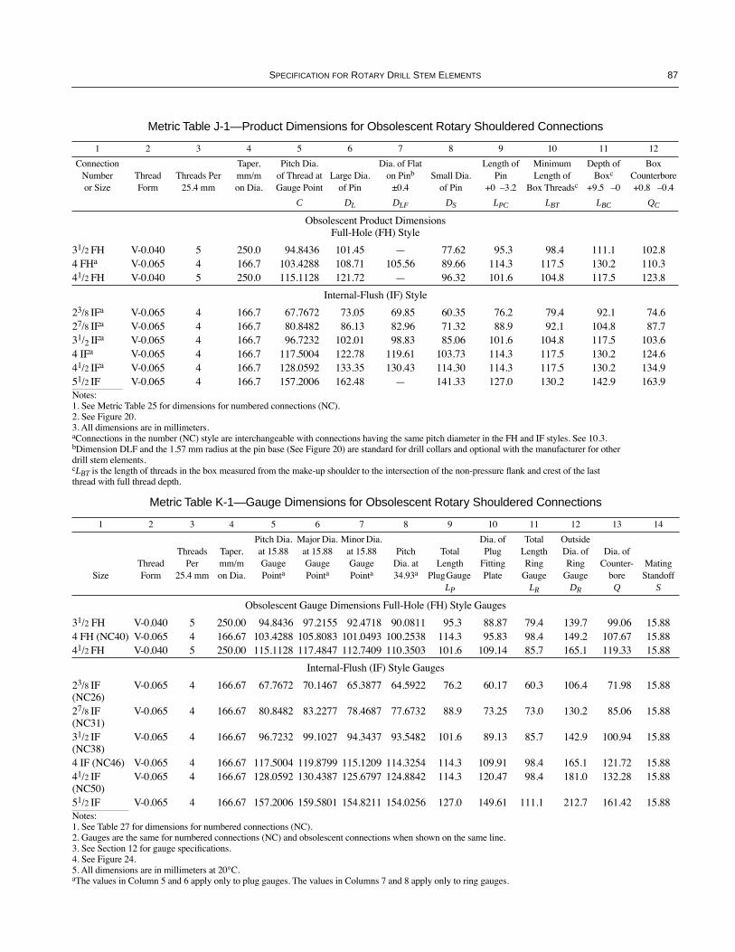
SPECIFICATION FOR ROTARY DRILL STEM ELEMENTS 87
Metric Table J-1—Product Dimensions for Obsolescent Rotary Shouldered Connections
1 2 3 4 5 6 7 8 9 10 11 12
ConnectionNumber or Size
Thread Form
Threads Per 25.4 mm
Taper, mm/m on Dia.
Pitch Dia. of Thread at Gauge Point
Large Dia. of Pin
Dia. of Flat on Pinb
±0.4Small Dia.
of Pin
Length of Pin
+0 Ð3.2
Minimum Length of
Box Threadsc
Depth of Boxc
+9.5 Ð0
Box Counterbore +0.8 Ð0.4
C DL DLF DS LPC LBT LBC QC
Obsolescent Product DimensionsFull-Hole (FH) Style
31/2 FH V-0.040 5 250.0 94.8436 101.45 Ñ 77.62 95.3 98.4 111.1 102.84 FHa V-0.065 4 166.7 103.4288 108.71 105.56 89.66 114.3 117.5 130.2 110.341/2 FH V-0.040 5 250.0 115.1128 121.72 Ñ 96.32 101.6 104.8 117.5 123.8
Internal-Flush (IF) Style
23/8 IFa V-0.065 4 166.7 67.7672 73.05 69.85 60.35 76.2 79.4 92.1 74.627/8 IFa V-0.065 4 166.7 80.8482 86.13 82.96 71.32 88.9 92.1 104.8 87.731/2 IFa V-0.065 4 166.7 96.7232 102.01 98.83 85.06 101.6 104.8 117.5 103.64 IFa V-0.065 4 166.7 117.5004 122.78 119.61 103.73 114.3 117.5 130.2 124.641/2 IFa V-0.065 4 166.7 128.0592 133.35 130.43 114.30 114.3 117.5 130.2 134.951/2 IF V-0.065 4 166.7 157.2006 162.48 Ñ 141.33 127.0 130.2 142.9 163.9Notes:1. See Metric Table 25 for dimensions for numbered connections (NC).2. See Figure 20.3. All dimensions are in millimeters.aConnections in the number (NC) style are interchangeable with connections having the same pitch diameter in the FH and IF styles. See 10.3.bDimension DLF and the 1.57 mm radius at the pin base (See Figure 20) are standard for drill collars and optional with the manufacturer for other drill stem elements.cLBT is the length of threads in the box measured from the make-up shoulder to the intersection of the non-pressure ßank and crest of the last thread with full thread depth.
Metric Table K-1—Gauge Dimensions for Obsolescent Rotary Shouldered Connections
1 2 3 4 5 6 7 8 9 10 11 12 13 14
SizeThread Form
Threads Per
25.4 mm
Taper, mm/mon Dia.
Pitch Dia. at 15.88 Gauge Pointa
Major Dia. at 15.88 Gauge Pointa
Minor Dia. at 15.88 Gauge Pointa
Pitch Dia. at 34.93a
Total Length
Plug Gauge LP
Dia. of Plug
Fitting Plate
Total Length Ring
Gauge LR
Outside Dia. of Ring
Gauge DR
Dia. of Counter-
bore Q
Mating Standoff
S
Obsolescent Gauge Dimensions Full-Hole (FH) Style Gauges
31/2 FH V-0.040 5 250.00 94.8436 97.2155 92.4718 90.0811 95.3 88.87 79.4 139.7 99.06 15.884 FH (NC40) V-0.065 4 166.67 103.4288 105.8083 101.0493 100.2538 114.3 95.83 98.4 149.2 107.67 15.8841/2 FH V-0.040 5 250.00 115.1128 117.4847 112.7409 110.3503 101.6 109.14 85.7 165.1 119.33 15.88
Internal-Flush (IF) Style Gauges
23/8 IF (NC26)
V-0.065 4 166.67 67.7672 70.1467 65.3877 64.5922 76.2 60.17 60.3 106.4 71.98 15.88
27/8 IF (NC31)
V-0.065 4 166.67 80.8482 83.2277 78.4687 77.6732 88.9 73.25 73.0 130.2 85.06 15.88
31/2 IF (NC38)
V-0.065 4 166.67 96.7232 99.1027 94.3437 93.5482 101.6 89.13 85.7 142.9 100.94 15.88
4 IF (NC46) V-0.065 4 166.67 117.5004 119.8799 115.1209 114.3254 114.3 109.91 98.4 165.1 121.72 15.8841/2 IF (NC50)
V-0.065 4 166.67 128.0592 130.4387 125.6797 124.8842 114.3 120.47 98.4 181.0 132.28 15.88
51/2 IF V-0.065 4 166.67 157.2006 159.5801 154.8211 154.0256 127.0 149.61 111.1 212.7 161.42 15.88Notes:1. See Table 27 for dimensions for numbered connections (NC).2. Gauges are the same for numbered connections (NC) and obsolescent connections when shown on the same line.3. See Section 12 for gauge speciÞcations.4. See Figure 24.5. All dimensions are in millimeters at 20¡C.aThe values in Column 5 and 6 apply only to plug gauges. The values in Columns 7 and 8 apply only to ring gauges.
COPYRIGHT American Petroleum Institute

COPYRIGHT American Petroleum Institute

89
APPENDIX N —PURCHASER INSPECTION (OPTIONAL)
N.1 Inspection NoticeWhen the purchaserÕs inspector desires to witness the man-
ufacture or testing of equipment, reasonable notice shall begiven of the time at which manufacture and testing are to bedone.
N.2 InspectionWhile work on the contract of the purchaser is being per-
formed, the purchaserÕs inspector shall have free entry at alltimes to all parts of the manufacturerÕs works that concernmanufacture of the material ordered. The manufacturer shallafford the inspector all reasonable facilities to satisfy him thatthe material is being manufactured in accordance with thisspeciÞcation. All inspections should be made at the place ofmanufacture prior to shipment, unless otherwise speciÞed onthe purchase order, and shall be so conducted as not to inter-fere unnecessarily with operation of the works.
N.3 RejectionUnless otherwise provided, material that shows defects on
inspection or subsequent to acceptance at the manufacturerÕsworks, or that proves defective when properly applied in ser-vice, may be rejected, and the manufacturer so notiÞed. Iftests that require the destruction of material are made, anyproduct that is proven not to have met the requirements of the
speciÞcation shall be rejected. Disposition of rejected productshall be a matter of agreement between the manufacturer andthe purchaser.
N.4 ComplianceThe manufacturer is responsible for complying with all of
the provisions of this speciÞcation. The purchaser may makeany investigation necessary to satisfy himself of complianceby the manufacturer and may reject any material that does notcomply with this speciÞcation.
N.5 Rotary Shouldered ConnectionAcceptance of rotary shouldered connections shall be in
accordance with this speciÞcation, which provides the oppor-tunity to conduct detailed inspection of the connections intheir as-machined condition. The surface conditions neces-sary for precise measurements will only be assured prior tosubsequent further processing, doping, shipping, handling,storing, etc., which can alter the surfaces necessary for preci-sion gauging.
Note: Connections should be visibly inspected for damage that mayhave occurred through this chain of events prior to putting the con-nections into service. Such damage is generally very minor and mostoften repairable well within the needs for good connection perfor-mance.
COPYRIGHT American Petroleum Institute

COPYRIGHT American Petroleum Institute

11/01
COPYRIGHT American Petroleum Institute

AmericanPetroleumInstitute
1220 L Street, Northwest�
Washington, D.C. 20005-4070�
202-682-8000
Additional copies are available through Global EngineeringDocuments at (800) 854-7179 or (303) 397-7956
Information about API Publications, Programs and Services isavailable on the World Wide Web at: http://www.api.org
Product No. G07040
COPYRIGHT American Petroleum Institute