Embed Size (px)
Citation preview
SPE-184254-MS
HPHT Well Integrity and Cement Failure
Bomá Wilcox Jr., Babs Oyeneyin, and Sheikh Islam, Robert Gordon University
Copyright 2016, Society of Petroleum Engineers
This paper was prepared for presentation at the SPE Nigeria Annual International Conference and Exhibition held in Lagos, Nigeria, 2–4 August 2016.
This paper was selected for presentation by an SPE program committee following review of information contained in an abstract submitted by the author(s). Contentsof the paper have not been reviewed by the Society of Petroleum Engineers and are subject to correction by the author(s). The material does not necessarily reflectany position of the Society of Petroleum Engineers, its officers, or members. Electronic reproduction, distribution, or storage of any part of this paper without the writtenconsent of the Society of Petroleum Engineers is prohibited. Permission to reproduce in print is restricted to an abstract of not more than 300 words; illustrations maynot be copied. The abstract must contain conspicuous acknowledgment of SPE copyright.
Abstract
A petroleum wellbore must have complete zonal isolation to maintain its integrity. This is primarilyachieved by the cement sheath barrier that sits between the casing and rock formation. However, effectivezonal isolation can be adversely affected by conditions such as high pressures, high temperatures, and highhole angles. These conditions are increasingly popular in deep-water drilling and can compromise thestrength and integrity of the cement sheath if not anticipated early.
This paper presents some critical issues and factors that affect well integrity in HPHT wellbores. It alsopresents an analytical model of the interaction between the casing, cement sheath, and rock formation.This model also contains mathematical relationships for the interfacial pressures at the casing-cement andcement-rock contacts/interfaces. The study was limited to vertical wells as this allowed us, for purposesof symmetry, to analyse the casing-cement-formation relationship as a composite cylinder. The area of thewellbore that was analysed is the pay-zone area where the relationship between the casing, cement androck formation is represented by a concentric composite cylinder. This paper is part of an on-goingresearch project on well integrity at Robert Gordon University, United Kingdom.
IntroductionWell Integrity is the use of technical, operational and organizational solutions to reduce the risk of anyuncontrolled release of formation fluids throughout the life cycle of a petroleum well (Torbergsen et al.2012; Calosa et al. 2010; Wakama et al. 2004; Ugwu, 2008). Complete zonal isolation of a petroleumwellbore must be attained to maintain integrity and produce economically. Hence, the entire working staffresponsible for planning and executing the drilling and completion of wells must proactively identifysolutions that would ensure safe life cycle designs (Tobergsen et al., 2012). Unfortunately, well integrityis realistically not always maintained in oil field practice. History has shown some devastating conse-quences of losing well integrity: Philips Petroleum’s Bravo blowout in 1977, Saga Petroleum’s blowoutin 1989, PTT’s Montara oil spill in 2009, and most recently, BP’s Macondo blowout in the Gulf of Mexicoin 2010 (Shadravan & Amani, 2012; Torbergsen et al. 2012). Engineers and researchers alike haveidentified �poor cement design� as the primary cause of the aforementioned oil spills (Turley, 2014;Visser, 2011; Shadravan & Amani, 2012; Garg & Gokavarapu, 2012). Cementing operations in high-pressure/high-temperature (HPHT) environments are challenging due to large differential changes in thephysical and chemical behaviour of the cement materials. These harsh conditions pose a threat during the

well cementing operations and after the cement sheath has set during its life cycle (Yetunde & Ogbonna,2011; Shadravan & Amani, 2012).
Cement Sheath BarrierThe sole aim of the annular cement sheath is to provide zonal isolation for the entire life-cycle of thepetroleum wellbore (Tahmourpour & Griffith, 2007; Yetunde & Ogbonna, 2011; Shadravan & Amani,2012; Calosa, 2010; Ravi et al. 2008). In order to achieve this aim, the entire annulus must be filled withoil-well cement after removing the drilling fluid or mud. Selecting a particular cement for well operationsdepends largely on down hole and formation conditions, but it must possess certain features that arerequired for a solid completion job (Ugwu, 2008; Nelson, 1990). These features include:
● Durability – The cement mixture/slurry must be durable and not decline in strength during theoperational phase of the wellbore.
● Optimal Setting Time – An overly reactive slurry will result in the cement mixture setting tooquickly, and inadequately reactive slurry will take too long to set. The cement slurry must have anoptimal setting time.
As indicated by the aforementioned features, the cement slurry should satisfy the short-term andlong-term requirements needed for the life-cycle integrity of the petroleum wellbore. Conventionally, theoil and gas industry has focused on the short-term features and properties that are relevant when theoil-well cement is in the slurry/paste form (Tahmourpour & Griffith, 2007). This procedure is important,but the long-term integrity of the cement depends primarily on the material and mechanical properties ofthe cement sheath such as Tensile Strength, Young’s Modulus, and its resistance to downhole chemicalattack (Bosma et al., 1999; Hunter et al., 2007; Tahmourpour & Griffith, 2007; Stiles, 2006). Thoroughlyevaluating the properties that affect the long-term integrity of the cement sheath is crucial for designinga cement system that will withstand high temperature and high pressure differentials. Any sort of failurein the cement matrix or sheath could potentially cause the formation of cracks and pathways for themovement of gas to the surface as shown in figure 3 (Yetunde & Ogbonna, 2011; Ravi et al., 2002;Nygaard, R., 2010).
Figure 1—The entire life cycle of a petroleum wellbore. The design stage, signified by the green arrow, marks the beginning of thewellbore’s lifecycle, and the red arrow signifies the end of the lifecycle, albeit petroleum wellbores can be re-stimulated long afterabandonment (Adapted from Calosa et al., 2010)
2 SPE-184254-MS

The research conducted by Ugwu (2008) shows that oil-well cement fails by three main processes:debonding, radial cracking, and cement plastic deformation. Debonding in the wellbore is usually causedby cement shrinkage which creates a weak bond between either the cement sheath and casing, or thecement sheath and rock formation (see figure 4). In radial cracking, failure is caused by the gradualformation of cracks in the cement sheath due to fatigue loading and constant pressure, as shown in figure3. Plastic deformation, as the name suggests, is the stage where the cement sheath is permanentlydeformed under loading and forms a new shape.
Figure 2—A cross-section of a petroleum wellbore showing the geometrical arrangement of the casing, cement sheath, and rockformation. dh represents the diameter of the wellbore (Adapted from Tahmourpour & Griffith, 2007)
Figure 3—High-Pressure/High-Temperature Tiers (Adapted from Zhaoguang et al., 2012)
SPE-184254-MS 3

After well cementing, if there is no immediate migration of petroleum fluids to the surface, then it ismost likely that the short-term properties shown in table 1 have been well designed (Bosma et al., 1999).Although, research shows that the stresses caused by high differentials in pressure and temperature duringlater operational phases, such as stimulation and production, cause a reduction and eventual decline in theintegrity of the cement sheath. As shown in figure 1, the life-cycle of an oil and gas well can be dividedinto two major phases that are important for the integrity of the cement sheath.
Figure 4—Possible leakage paths in a cased wellbore. The enlarged picture, a, shows debonding of the cement sheath from the casing,thereby creating a leakage path for the potential migration of fluids to the surface. The enlarged picture, e, shows a crack in the cementsheath which could adversely affect the integrity of the cement sheath (Adapted from Nygaard, 2010)
Table 1—Short-term and long-term properties required for a cement sheath sealant (Adapted from Bosma et al., 1999)
No. Short-Term Properties: The Fluidic State Long Term Properties: Solid Cement Sheath
1 Environmentally acceptable and approved for use. Thermally stable under downhole conditions of pressure andtemperature.
2 Has the required density. Should be easily detected by conventional logging techniques.
3 Can be pumped through the drill string or coiled tubing. Repel attacks from downhole chemicals.
4 It should be mixable at the surface. Should possess the right mechanical properties to withstand stressesfrom various downhole operations and provide zonal isolationfor the life of the well.
5 Non-settling under static and dynamic conditions.
6 Zero free water.
7 Desired thickening time.
8 Desired fluid loss.
9 Desired strength development.
10 100% placement in the annulus.
11 Resist fluid influx.
4 SPE-184254-MS

i. The Well Construction Phase:
X DrillingX CementingX Completion
During the well construction phase, the stresses around the wellbore will change often due to the unsteadygravity of the fluids inside the wellbore. This will affect the resultant stresses in the cement sheath.
ii. The Later Operational Phase:
X DepletionX HPHT operationX Water and steam injectionX ProductionX Fracturing, etc.
During the Later Operational Phase, the naturally developing stresses alongside other planned inter-ventions will greatly affect the integrity of the cement sheath. In order to avoid well integrity problems,realistic extremes in well operation should be properly defined (Hunter and Kinnaird, 2007; Edgley et al.,2005; Bosma, 1999). The goal is to develop a pressure-tight vessel design for each and every well.
Technical IssuesEffect of High Temperature and High Pressure
High temperatures affect the rheological features of the cement slurry and reduce the thickening time ofthe slurry, thereby causing the cement sheath to set quicker (Shadravan and Amani, 2012; Yetunde &Ogbonna, 2011). Important features such as the Bottomhole Circulating Temperature (temperature atwhich the cement mixture is pumped into the wellbore), Yield Viscosity, and the Plastic Viscosity oftendecline with an increase in temperature. If the pressure is not accurately anticipated, the casing and cementsheath may not be able to withstand the pressure from the rock formation, leading to a total collapse ofthe wellbore (Shaughnessy & Helweg, 2002).
Mechanical Properties of SealantThe cement sheath sealant has to fulfill a number of pertinent functions in the oil well such as supportingthe casing and sealing up the annulus. In general, reducing the Young’s modulus or increasing thePoisson’s ratio of the cement will cause a decrease in the stresses induced in the cement sheath, andsubsequently reduce the risk of failure (James and Boukhelifa, 2006). Conventionally, the oil and gasindustry has focused on the short-term properties that are applicable when the cement is still in slurry/pasteform. This approach is necessary for good cement-slurry mixing and placement, but the long-termintegrity of the cement sheath depends primarily its mechanical and material properties such as Young’smodulus, tensile strength and resistance to chemical attack downhole (Tahmourpour and Griffith, 2007).
Gas MigrationThe changes caused by temperature and pressure differentials cause cracks to form in the cement sheathwhich form a pathway for the migration of gas to the surface, thereby compromising the integrity of thecement sheath (Yetunde and Ogbonna, 2011; Shadravan and Amani, 2012). Research conducted byAl-Yami et al. (2009) shows that approximately eighty percent of wells in the Gulf of Mexico have gastransmitted to the surface through their cement sheaths at some point during their life cycle, and themigration of gas represents twenty-five percent of the primary cementing failures. The hydrostaticpressure of the cement sheath and mud column must be high enough to prevent fluids and gas fromentering the wellbore’s annulus, but not too high as it can fracture the rock formation and cause furtherdamage (Cesaroni et al., 1981). Research conducted by Gonzalo et al. (2005) shows that the gel strength
SPE-184254-MS 5

of the cement slurry directly affects the distribution of the hydrostatic pressure in the annular column, witha higher gel strength lowering the ability to transmit hydrostatic pressure in the annulus.
High Hole AnglesThe eccentricity of the casing is a direct function of the hole/wellbore angle, the number of centralizersused in the well development phase, and the geometry of the wellbore (Zhaoguang et al., 2012). A higherwellbore inclination angle (hole angle) often leads to higher eccentricity of the casing (Ferda et al., 2004).When a casing is not well centered in the wellbore, the fluid will flow along the wider path rather thanon the narrow side as shown in figure 5. This results in a partial velocity distribution and the displacedfluids may circumvent the slow-moving drilling mud on the narrower side (Zhaoguang et al., 2012).
Analytical ModelThis section shows an analytical model of the interaction between the casing, cement sheath, and rockformation. This model also contains mathematical relationships for the integrity of the cement sheath atthe casing-cement and cement-rock contacts/interfaces. The study was limited to vertical wells as thisallowed us, for purposes of symmetry, to analyse the casing-cement-formation relationship as a compositecylinder (see figure 7). If we consider the stress state of an element within the cement sheath, the elementis subjected to a triaxial stress state and the entire cement sealant can be regarded as being subject to atriaxial stress state. In order to facilitate the analytical modelling of the casing-cement-formationinteraction, the following assumptions were made:
Figure 5—The first figure shows a concentric arrangement of the casing, cement sheath and rock formation, while the second figureshows an eccentric arrangement of the casing, cement sheath and rock formation. In the concentric arrangement, the cement sheathis uniformly distributed between the casing and rock formation while in the eccentric arrangement, the distribution of the cementsheath is uneven around the section with a higher hole angle (Adapted from Zhaoguang et al. 2012)
6 SPE-184254-MS
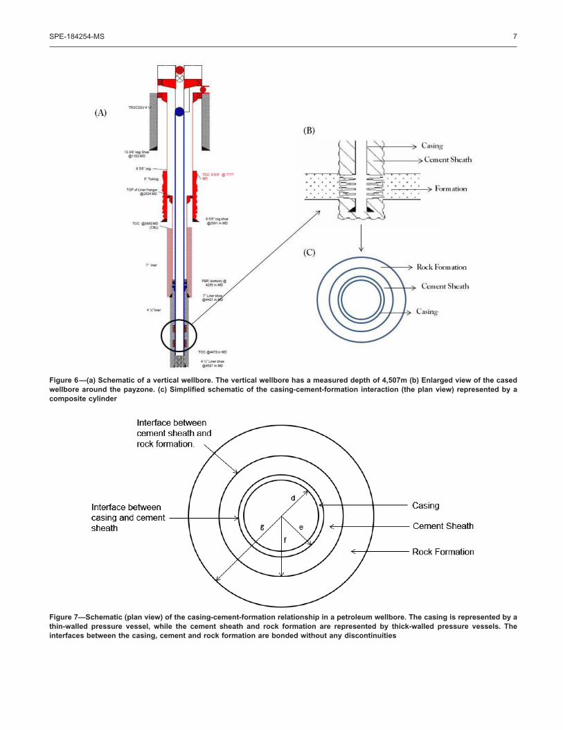
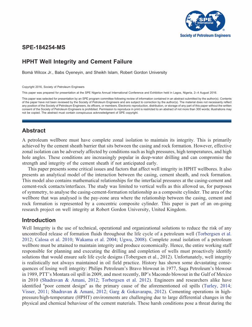
Figure 6—(a) Schematic of a vertical wellbore. The vertical wellbore has a measured depth of 4,507m (b) Enlarged view of the casedwellbore around the payzone. (c) Simplified schematic of the casing-cement-formation interaction (the plan view) represented by acomposite cylinder
Figure 7—Schematic (plan view) of the casing-cement-formation relationship in a petroleum wellbore. The casing is represented by athin-walled pressure vessel, while the cement sheath and rock formation are represented by thick-walled pressure vessels. Theinterfaces between the casing, cement and rock formation are bonded without any discontinuities
SPE-184254-MS 7

X The casing is modelled as a thin-walled cylindrical pressure vessel (as the ratio of the thickness toinner diameter of a casing cylinder is usually less than 0.05).
X The cement sheath and the rock formation are both modelled as thick-walled cylindrical pressurevessels.
X Assuming axisymmetry, the lateral principal stresses are both equal.X We assume that before the borehole was drilled, the state of stress was uniform.X We assume that the interfaces between the casing, cement and rock formation as shown in figure
7 are well bonded without any gaps, making the radial stresses the same across the boundary.X Plane strain assumption – the axial/longitudinal strain is assumed to be negligible due to large
depths.X We assumed a homogenous state of stress in the axisymmetric setup making the hoop strain equal
equivalent to the radial strain.
The hoop stress, �H, in a thin-walled cylindrical pressure vessel is given by:
(1)
The hoop stress, �H, in a thick-walled cylindrical pressure vessel is given by:
(2)
The longitudinal strain, �L, in a thin-walled cylindrical pressure vessel is given by:
(3)
The longitudinal strain, �L, in a thick-walled cylindrical pressure vessel is given by:
(4)
Where a represents the inner radius, b represents the outer radius, r represents the radial position wherethe stress is to be found, and t represents the wall thickness.
However, equations 1-4 do not account for the interfacial (contact) pressures that exist at thecasing-cement and cement-formation interfaces. Hence, both instances were analysed separately todevelop relationships for the stresses and strains on the cement sheath, and the pressures at the interfaces.
Casing-Cement AnalysisIn a typical HPHT petroleum wellbore, as shown in figure. . ., the hydrostatic wellbore pressure (innerpressure) acting on the inner walls of the casing, in addition to the rise in temperature, will cause a linearexpansion of the casing as shown in figure 8. The cement sheath will resist the expansion of the casingthereby leading to the formation of an interfacial contact pressure.
8 SPE-184254-MS

The casing’s hoop strain, �H, is given by:
(5)
Adding the linear expansion of the casing due to high-temperature differentials;
(6)
Where E represents the elastic modulus, �H represents the hoop stress, v represents the poisson’s ratio,�L represents the axial strain, �T represents the increase in temperature, and � represents the coefficientof thermal expansion.
Similarly, the casing’s longitudinal (axial) strain is given by:
(7)
In huge depths, the longitudinal strain can be considered negligible, i.e. �L is approximately 0.
(8)
Figure 8—In the casing-sealant schematic under consideration, the internal pressure, Pi, and the increase in temperature, �T, actingon the inner walls of the casing will both cause a radial expansion of the casing. The cement sheath will resist this expansion therebyleading to the formation of pressure at the casing-sealant interface
Figure 9—A schematic of the casing under consideration. The contact pressure formed at the casing-cement interface is denoted CP1.This interfacial pressure is created by the resistance of the cement sheath to the radial expansion of the casing
SPE-184254-MS 9

(9)
Substituting equation 9 (longitudinal stress in casing) into equation 5 (hoop strain in casing);
(10)
In homogenous materials, the hoop strain is equivalent to the radial strain. The radial strain in thecasing is given by:
(11)
The mathematical relationship for the hoop stress in the casing, based on the thin-walled cylindricalgeometry, is given by;
(12)
Where r represents the casing’s internal radius, p represents the internal pressure in the casing, and trepresents the casing’s thickness.
The radial stress will vary from zero at the outside surface to a value that is equal to the internalpressure, Pi. Substituting equation 12 (hoop stress in casing) into equation 11 (radial strain in the casing);
(13)
At the casing’s internal radius, when r � d, equation 13 (radial strain in the casing) can be re-writtenas;
(14)
At the casing’s outer radius, when r � e (the interface between the casing and cement sheath), equation13 can be re-written as;
(15)
Figure 10—A schematic of the cement sheath under consideration. The contact pressure formed at the cement-formation interface isdenoted CP2
10 SPE-184254-MS

Analysing the cement sheath as a thick-walled cylinder, the hoop stress in the cement sheath is givenby;
(16)
Inputting ri as e, ro as f, Pi as CP1, and Po as CP2 into equation 16;
(17)
The radial stress, �R, at a point in the cylindrical cement sheath is given by;
(18)
At the internal radius of the cement sheath, where r � e, equation 17 (hoop stress in the cement sheath)and equation 18 (radial stress in the cement sheath) can both be re-written as;
(19)
(20)
Substituting equation 20 (hoop stress in the cement sheath) into equation 11 (radial strain formula)
(21)
Equations 21 and 13 are both radial expansion formulas and can be equated to each other;
(22)
Simplifying equation 22 further;
(23)
(24)
(25)
Writing equation 25 in terms of the contact pressures, CP1 and CP2.
(26)
Where,
(27)
(28)
(29)
SPE-184254-MS 11

Cement-Formation AnalysisIn similar fashion, the interaction between the cement sheath and rock formation produces a contactpressure, CP2, at the interface. The cement sheath and rock formation are both analysed as thick-walledcylinders. The hoop stress on the cement sheath, at the cement-formation interface, is given by:
(30)
Where CP1 represents the internal pressure on the cement sheath, CP2 represents the external pressureon the cement sheath (contact pressure at the cement-formation interaction), e represents the internalradius of the cement sheath, and f represents the external radius of the cement sheath.
At the cement-formation interface, where radius � f,
(31)
The radial expansion in the cement sheath at the cement-formation interface is obtained by substitutingequation 31 (hoop stress on the cement sheath at the cement-formation interface) into equation 11 (theradial strain equation).
(32)
The relationship for the hoop stress in the rock formation at the cement-formation interface is givenby:
(33)
Where f represents the internal radius of the rock formation, g represents the outer radius of the rockformation, CP2 represents the rock formation’s internal pressure, Fp represents the formation pressure.This was determined at the cement-formation interaction, at r � f.
The radial stress in the rock formation is given by:
(34)
(35)
(36)
The radial expansion in the rock formation, at the cement-formation interface, can be determined bysubstituting the hoop stress (equation 33) into the radial strain formula (equation 11);
(37)
Equations 37 and 32 are both relationships for the radial strain at the cement-formation interface, theycan be equated and simplified further to obtain relationships for the contact pressures;
12 SPE-184254-MS

(38)
Simplifying equation 38 further;
(39)
Arranging equation 39 in terms of the contact pressures;
(40)
(41)
(42)
(43)
In order to obtain mathematical relationships for the interfacial (contact) pressures, CP1 and CP2,equations 40 and 26 are solved simultaneously to obtain the following equations;
(44)
(45)
Conclusively, the stresses on the cement sheath (hoop and radial) can be calculated using equations 17and 18 respectively, while the contact pressures can be determined using equations 27 – 29 and 41 – 45.
ConclusionsThe model presented in this paper has the potential to be used for cement sheath analysis. It can be usedto determine the stresses on the cement sheath and the contact pressures at the casing-cement andcement-formation interfaces in a vertical (concentric) wellbore setup. The area of the wellbore that wasused for the mathematical analysis is the pay-zone area where the relationship between the casing, cementand rock formation was represented by a concentric composite cylinder. Even though it has not beenverified, it is currently showing promise and is being fully developed in-house at Robert GordonUniversity, United Kingdom. Plans are underway to extend the model to other parts of the wellbore withmulti-cylinder setups and higher hole angles.
Further WorkIn the near future, the analytical model presented in this paper will be verified with results fromfinite-element simulations, analytical results from open literature, and live well data. Also, the model willbe extended to include the effects of casing eccentricity in high-angle wellbores, and model the behaviourof the cement sheath in other parts of the wellbore with multi-cylinder setups.
Nomenclaturea � Inner radius of cylindrical pressure vesselb � Outer radius of cylindrical pressure vessel
SPE-184254-MS 13

d � Casing’s internal radiuse � Casing’s external radiusf � Rock formation’s internal radiusg � Rock formation’s external radiusr � Radial position where stress is to be foundHPHT � High-Pressure/High-Temperature�H � Hoop/Circumferential Stress, N/m2
�L � Longitudinal/Axial Stress, N/m2
Pi � Internal Pressure, psi�T � Change in temperature, °FCP1 � Interfacial pressure at casing-cement interface, psiCP2 � Interfacial pressure at the cement-formation interface, psi�H � Hoop StrainE � Elastic Modulus, N/m2
v � Poisson’s ratio� � Co-efficient of thermal expansion, °C-1
ReferencesAl-Yami, A., Nasr-El-Din, H. and Al-Humaidi, A. (2009). An Innovative Cement Formula To Prevent Gas Migration
Problems In HPHT Wells. Paper SPE 120885 Presented at the SPE International Symposium On Oilfield Chemistry.Woodlands, Texas, USA, 20-24 April.
Bosma, M., Ravi, K., van Driel, W., & Jan Schreppers, G. (1999). Design Approach To Sealant Selection for The Life ofThe Well. Paper SPE 56536 Presented at the 1999 SPE Annual Technical Conference and Exhibition, Houston, Texas,3-6 October.
Calosa, W. (2010). Well Integrity Issues In Malacca Strait Contract Area. Paper Presented at the SPE Oil and Gas IndiaConference and Exhibition. Mumbai, India.
Cesaroni, R., Giacca, D., & Schenato, A. (1981). Determining Fracture Gradients While Drilling. Petroleum EngineeringInstitute, Vol. 53, 60–86.
Edgley, K., Sabins, F., & Watters, L. (2005). Supercement for Annular Seal and Long Term Integrity In Deep Hot Wells.Houston, USA: Phase II Annual Report, CSI Technologies.
Ferda, A., Shedid, A. and Hamed, A. (2004) Simulation Investigation of Casing Eccentricity for Different InclinationAngles and Tensile Forces Using Finite Element Method. Paper SPE 91811 Presented at the SPE InternationalPetroleum Conference, Mexico, 7-9 November.
Garg, T. & Gokavarapu, S. (2012). Lessons Learnt From Root Cause Analysis of Gulf of Mexico Oil Spill In 2010.Presented at the SPE Kuwait International Petroleum Conference and Exhibition, Kuwait.
Gonzalo, V., Aiskley, B., & Alicia, A. (2005). A Methodology To Evaluate Gas Migration In Cement Slurries. Presentedat the SPE Latin American and Caribbean Petroleum Engineering Conference. Rio de Janeiro, Brazil.
Hunter, L., Kinnaird, B., & MacLean, K. (2007). Life of Well Isolation Implemented In Major North Sea Development.Presented at the SPE Annual Technical Conference and Exhibition. California, USA.
James, S. and Boukhelifa, L. (2006). Zonal Isolation Modeling and Measurements - Past Myths and Today’s Realities.Paper 101310 Presented at the 2006 Abu Dhabi International Petroleum Exhibition and Conference. Abu Dhabi, UAE.
Nelson, E. (1990). Well Cementing. Development In Petroleum Science, Vol. 28.Nygaard, R. (2010). Well Design and Well Integrity-Wabamun Area CO2 Sequestration Project (WASP). University of
Calgary, Canada.Ravi, K. and Sutton, D. (1990). New Rheological Correlation or Cement Slurries As A Function of Temperature. Paper
SPE 20449 Presented at the SPE Annual Technical Conference and Exhibition, New Orleans, Louisiana, 23-26September.
Ravi, K. and Xenakis, H. (2007). Cementing Process Optimized To Achieve Zonal Isolation. Presented at the InternationalOil & Gas Conference, New Delhi, India.
Ravi, K., Bosma, M., & Gastebled, O. (2002). Safe and Economic Gas Wells Through Cement Design for Life of the Well.Presented at the SPE Gas Technology Symposium, Calgary.
14 SPE-184254-MS

Ravi, K., Vargo, R., & Lasley, B. (2008). Successful Cementing Case Study In Tuscaaloosa HPHT Well. Paper SPE115643 Presented at the SPE Russian Oil and Gas Technical Conference and Exhibition, Moscow, Russia, 28-30October.
Shadravan, A. & Amani, M. (2012). HPHT 101 - What Every Engineer or Geoscientist Should Know About High PressureHigh Temperature Wells. Presented at the SPE Kuwait International Petroleum Conference and Exhibition, Kuwait.
Shaughnessy, J. & Helweg, J. (2002). Optimizing HPHT Cementing Operations. Presented at the SPE Drilling Conference,Dallas, Texas.
Stiles, D. (2006). Effects of Long-Term Exposure To Ultrahigh Temperatures On Mechanical Parameters of Cement. PaperSPE 98896 Presented at the 2006 IADC/SPE Drilling Conference, Miami, Florida.
Tahmourpour, F. & Griffith, J. (2007). Use of Finite Element Analysis To Engineer The Cement Sheath for ProductionOperations. Journal of Canadian Petroleum Technology, Vol. 46, No. 5.
Torbergsen, H., Sangesland, S., Johnsen, S., and Lundeteigen, M. (2012). An Introduction To Well Integrity. NorwegianUniversity of Science and Technology, Stavanger, Norway.
Turley, J. (2014). An Engineering Look At The Cause of The 2010 Macondo Blowout. Presented at the IADC/SPE DrillingConference and Exhibition. Fort Worth, Texas, USA.
Ugwu, I. (2008). Cement Fatigue and Well Integrity With Application To Life of Well Prediction. Texas, USA. MScThesis, Texas A&M University.
Visser, R. (2011). Offshore Accidents, Regulations and Industry Standards. SPE Western North American RegionalMeeting. Alaska, USA: SPE.
Wakama, M., Eta, E., & Adeniyi, A. (2004). Well Integrity Management In Shell Nigeria. Presented at the 28th AnnualSPE International Technical Conference and Exhibition, Abuja, Nigeria.
Yetunde, S., & Ogbonna, J. (2011). Challenges and Remedy for Cementing of HPHT Wells In Nigerian Operation. PaperSPE 150751 Presented at the Nigerian Annual International Conference and Exhibition, Abuja, Nigeria.
Zhaoguang, Y., Schubert, J. and Teodoriu, C. (2012). The Effect of Hole Angle and Cementing Complications On HPHTWell Integrity. Paper SPE 162839 Presented at the Canadian Unconventional Resources Conference. Calgary, Canada.
SPE-184254-MS 15