Embed Size (px)
Citation preview
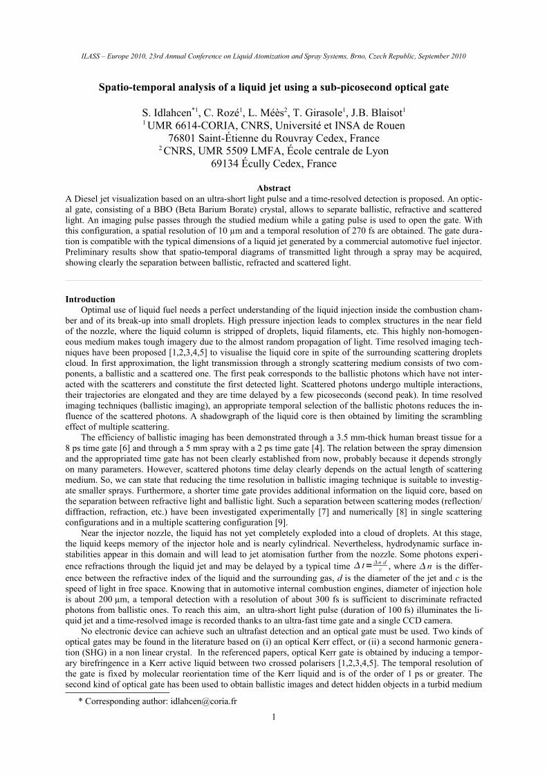
ILASS – Europe 2010, 23rd Annual Conference on Liquid Atomization and Spray Systems, Brno, Czech Republic, September 2010
Spatio-temporal analysis of a liquid jet using a sub-picosecond optical gate
S. Idlahcen*1, C. Rozé1, L. Méès2, T. Girasole1, J.B. Blaisot1
1 UMR 6614-CORIA, CNRS, Université et INSA de Rouen76801 Saint-Étienne du Rouvray Cedex, France
2 CNRS, UMR 5509 LMFA, École centrale de Lyon69134 Écully Cedex, France
AbstractA Diesel jet visualization based on an ultra-short light pulse and a time-resolved detection is proposed. An optic-al gate, consisting of a BBO (Beta Barium Borate) crystal, allows to separate ballistic, refractive and scattered light. An imaging pulse passes through the studied medium while a gating pulse is used to open the gate. With this configuration, a spatial resolution of 10 µm and a temporal resolution of 270 fs are obtained. The gate dura-tion is compatible with the typical dimensions of a liquid jet generated by a commercial automotive fuel injector. Preliminary results show that spatio-temporal diagrams of transmitted light through a spray may be acquired, showing clearly the separation between ballistic, refracted and scattered light.
IntroductionOptimal use of liquid fuel needs a perfect understanding of the liquid injection inside the combustion cham-
ber and of its break-up into small droplets. High pressure injection leads to complex structures in the near field of the nozzle, where the liquid column is stripped of droplets, liquid filaments, etc. This highly non-homogen-eous medium makes tough imagery due to the almost random propagation of light. Time resolved imaging tech-niques have been proposed [1,2,3,4,5] to visualise the liquid core in spite of the surrounding scattering droplets cloud. In first approximation, the light transmission through a strongly scattering medium consists of two com-ponents, a ballistic and a scattered one. The first peak corresponds to the ballistic photons which have not inter-acted with the scatterers and constitute the first detected light. Scattered photons undergo multiple interactions, their trajectories are elongated and they are time delayed by a few picoseconds (second peak). In time resolved imaging techniques (ballistic imaging), an appropriate temporal selection of the ballistic photons reduces the in-fluence of the scattered photons. A shadowgraph of the liquid core is then obtained by limiting the scrambling effect of multiple scattering.
The efficiency of ballistic imaging has been demonstrated through a 3.5 mm-thick human breast tissue for a 8 ps time gate [6] and through a 5 mm spray with a 2 ps time gate [4]. The relation between the spray dimension and the appropriated time gate has not been clearly established from now, probably because it depends strongly on many parameters. However, scattered photons time delay clearly depends on the actual length of scattering medium. So, we can state that reducing the time resolution in ballistic imaging technique is suitable to investig-ate smaller sprays. Furthermore, a shorter time gate provides additional information on the liquid core, based on the separation between refractive light and ballistic light. Such a separation between scattering modes (reflection/diffraction, refraction, etc.) have been investigated experimentally [7] and numerically [8] in single scattering configurations and in a multiple scattering configuration [9].
Near the injector nozzle, the liquid has not yet completely exploded into a cloud of droplets. At this stage, the liquid keeps memory of the injector hole and is nearly cylindrical. Nevertheless, hydrodynamic surface in-stabilities appear in this domain and will lead to jet atomisation further from the nozzle. Some photons experi-ence refractions through the liquid jet and may be delayed by a typical time t=n d
c , where n is the differ-ence between the refractive index of the liquid and the surrounding gas, d is the diameter of the jet and c is the speed of light in free space. Knowing that in automotive internal combustion engines, diameter of injection hole is about 200 µm, a temporal detection with a resolution of about 300 fs is sufficient to discriminate refracted photons from ballistic ones. To reach this aim, an ultra-short light pulse (duration of 100 fs) illuminates the li-quid jet and a time-resolved image is recorded thanks to an ultra-fast time gate and a single CCD camera.
No electronic device can achieve such an ultrafast detection and an optical gate must be used. Two kinds of optical gates may be found in the literature based on (i) an optical Kerr effect, or (ii) a second harmonic genera-tion (SHG) in a non linear crystal. In the referenced papers, optical Kerr gate is obtained by inducing a tempor-ary birefringence in a Kerr active liquid between two crossed polarisers [1,2,3,4,5]. The temporal resolution of the gate is fixed by molecular reorientation time of the Kerr liquid and is of the order of 1 ps or greater. The second kind of optical gate has been used to obtain ballistic images and detect hidden objects in a turbid medium
* Corresponding author: [email protected]
1

ILASS – Europe 2010 Spatio-temporal analysis of a liquid jet using a sub-picosecond optical gate
[10,11,12]. The aim of this paper is to study the potential of SHG crystal time gate to extract liquid shape proper-ties of the liquid in the near field of an injector. In the next section, temporal and spatial resolutions are presen-ted. Glass fibre and spray images are presented in the last section.
Experimental setupThe principle of optical gating is to divide the laser pulse of wavelength 800 nm into two pulses: the imaging
pulse crosses the spray, while the gating pulse is used to open the time gate and may be shifted in time by means of a delay line. The time gate consists of a beta barium-borate (BBO) crystal, which has a quadratic nonlinearity. The imaging pulse and the gating pulse are incident on the crystal with an angle θ. First, collinear second har-monic generation (SHG) occurs, so that light at wavelength 400 nm is generated along the direction of each pulse. When the two pulses overlap spatially and temporally on the crystal, non-collinear second harmonic is generated in direction k 2=k1k2 , which is the intermediate direction between the two collinear second-harmonic pulses. The crystal orientation is adjusted by a rotation around a vertical axis, in order to obtain the best conversion efficiency. The SHG is quasi-instantaneous, so that the gate duration is only limited by the gating pulse duration and angle between the pulses.
Figure 1. Schematic diagram of experiment
The integration of the gate inside the complete experimental setup is shown on Fig. 1. A Ti:Sa amplified laser system (800 nm, 1 kHz, 1 mJ) generates constant 100-femtosecond pulses. The beam profile is approxim-ately Gaussian with a 5 mm full width at half maximum (FWHM). The laser pulse is separated in two parts by means of a beam splitter (BSP), the imaging pulse and the gating pulse. The gating pulse passes through a delay line, a half wave plate (λ/2) and a neutral density filter (ND), in order to adjust time delay, polarization direction and intensity. The imaging pulse passes through a Pockels cell (PC) in order to decrease the repetition rate of the pulses down to 1 Hz (the spray repetition rate). A set of neutral density filters (NDs) is then used to adjust the lighting power. The imaging pulse next illuminates the spray injected in a chamber, equipped with glass win-dows. Imaging pulse and gating pulse are incident on a BBO crystal with the angle θ between them. Careful op-tical alignments are conducted to overlap the two beams in both spatial and temporal domains on the crystal. Non-collinear second harmonic is generated at half angle θ/2 between the directions of the two pulses direction when and where they overlap. A time gated second harmonic image of the spray is then formed by means of a lens (L1, f=150 mm). A vertical slit may be placed in the corresponding image plane, the use of which will be explained later. A second lens (L2, f=100 mm) forms a second image of the spray on the BBO crystal. A third lens is used to record the non collinear SHG on a CCD camera (Hamamatsu C9100). Light at fundamental
2

ILASS – Europe 2010 Spatio-temporal analysis of a liquid jet using a sub-picosecond optical gate
wavelength (800 nm) is scattered the camera. This noise source is eliminated by a spectral filter placed between the BBO crystal and the CCD camera, increasing notably the signal-to-noise ratio.
In order to measure the temporal profile of the gate, the power of the SHG pulse at angle θ/2 is measured for various delays between the imaging pulse and the gating pulse, without liquid jet. The maximum corresponds to a temporal and spatial synchronisation between the two pulses in the BBO crystal, whereas the tails of the curve are obtained for nonzero delays between the pulses. The duration of the gate is defined as the full width at half maximum (FWHM) of the curve and is equal to 270 fs. It depends strongly on the angle θ between gating pulse and imaging pulse and finally, θ ≈ 8° seems to be a good compromise.
To evaluate the spatial resolution of the overall system, the image of an U.S. Air Force Chart is recorded on the camera. It allows of evaluate the modulation transfer function (MTF) of the gate for a range of spatial fre-quencies. This procedure has been used to assess the resolution of the imaging system to 10 µm.
Spatio-temporal analysis of the transmitted light
Images of a glass fibreIn order to investigate the potential of the BBO crystal based time gate, preliminary images have been recor-
ded using a glass fibre as the object, without any other scattering medium. Fig. 2(a) shows the non-gated image of a fibre (diameter = 240 µm). The two strips located at each side of the image is the background light, whereas the thin line at the centre corresponds to refracted light into the fibre. When the optical gate is operating, the bal-listic light may be isolated (Fig. 2(b)). By adjusting the delay line, refractive light is isolated (Fig. 2(c)). The time delay difference between images 2(b) and 2(c) is Δτ = 380 fs, according to the fibre diameter d=240 µm and its refractive index n∼ 1.5.
(a) (b) (c)
Figure 2. a Image of a fibre without optical gate b, c for two different delays of the optical gate
Images of the liquid jet near the injectorThe same set-up has been applied to a Diesel jet visualisation. The injection pressure is 400 bars, the diamet-
er of the nozzle hole is 200 µm and the liquid is injected at atmospheric pressure and ambient temperature in a chamber. In the near field of the injector, the liquid roughly keeps the cylindrical shape of the injector hole. Ob-servation of refractive light is expected at this location. Time gated images are shown on Fig. 3, for two different delays between imaging and gating pulses. In both cases, the two pulses overlapped only partially, as a con-sequence of the angle θ, as schematically illustrated in the figure bottom. In figure 3(a), the delay line is adjusted in such a way that the gating pulse and the ballistic component of the imaging pulse overlap in the left side of the image. The right side of the image, where the two pulses do not overlap remains dark. In the middle part of the image, ballistic component does not overlap either temporally with the gating pulse. But refractive light, which is time delayed due to the jet crossing, overlap with the gating pulse and is clearly visible on the image. Con-versely, when the delay is adjusted to overlap the gating pulse and ballistic light at the right side of the image, re-fracted light is no more detected and the liquid core appears to be completely dark (Fig. 3(b)). It must be noticed
3

ILASS – Europe 2010 Spatio-temporal analysis of a liquid jet using a sub-picosecond optical gate
that if the image and gating pulses are symbolised by rectangles on the schemas of Fig. 3, their temporal and spa-tial shapes are approximately Gaussian, so that the tails of the pulses may be used to detect light at time delays smaller than the 270 fs duration, depending on the sensitivity of the detector. The time delay between image 3(a) and 3(b) is =500 fs. Knowing the refractive index of the injected liquid equal to 1.46, we can deduce an es-timation of the jet diameter of the jet diameter to about 325 µm.
a) (b)
Figure 3. Images of the liquid jet at the exit from injector hole for two different delays between image and gating pulses
Spatio-temporal diagramsThe qualitative description of the preceding images leads to the conclusion that a spatio-temporal study of
the light after interaction with an object is possible by changing the delay between the gating pulse and the image pulse. Indeed, the image on the camera is the result of the spatio-temporal correlation of the gating pulse with the image pulse along the width of the BBO crystal. The complete model is complex, because of interde-pendent phenomena: the spatio-temporal profile of each pulse, the angle between beams, the slight translation of one pulse relatively to the other inside the crystal due to their different propagation directions, etc. However, a rough interpretation of the image may be proposed by making some assumptions : (i) the image pulse and gating pulse are so short enough to be modelled by a time Dirac, (ii) the magnification of the optical system is large, so that the image pulse may be considered uniform in space before interaction with any object, (iii) the thickness of the BBO crystal is small, so that the shift of the gating pulse relatively to the image pulse is neglected, (iv) SHG light rays from the BBO are parallel.
With these assumptions, when the pump beam crosses the image beam somewhere in the crystal with angle θ between their propagation directions, a third pulse is produced, due to the SHG, at half angle. This intersection (point A on Fig. 4) produced a bright zone on the image recorded by the camera.
4
Gating pulse
Imaging pulse
Refracted light
Imaging Pumppulse
Gating pulse
Imaging pulse
ILASS – Europe 2010 Spatio-temporal analysis of a liquid jet using a sub-picosecond optical gate
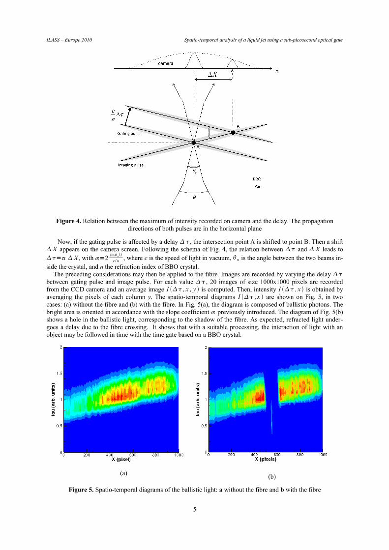
Figure 4. Relation between the maximum of intensity recorded on camera and the delay. The propagation directions of both pulses are in the horizontal plane
Now, if the gating pulse is affected by a delay , the intersection point A is shifted to point B. Then a shift X appears on the camera screen. Following the schema of Fig. 4, the relation between and X leads to = X , with =2
sinn /2
c /n , where c is the speed of light in vacuum, n is the angle between the two beams in-side the crystal, and n the refraction index of BBO crystal.
The preceding considerations may then be applied to the fibre. Images are recorded by varying the delay between gating pulse and image pulse. For each value , 20 images of size 1000x1000 pixels are recorded from the CCD camera and an average image I , x , y is computed. Then, intensity I , x is obtained by averaging the pixels of each column y. The spatio-temporal diagrams I , x are shown on Fig. 5, in two cases: (a) without the fibre and (b) with the fibre. In Fig. 5(a), the diagram is composed of ballistic photons. The bright area is oriented in accordance with the slope coefficient previously introduced. The diagram of Fig. 5(b) shows a hole in the ballistic light, corresponding to the shadow of the fibre. As expected, refracted light under-goes a delay due to the fibre crossing. It shows that with a suitable processing, the interaction of light with an object may be followed in time with the time gate based on a BBO crystal.
(a) (b)
Figure 5. Spatio-temporal diagrams of the ballistic light: a without the fibre and b with the fibre
5
ILASS – Europe 2010 Spatio-temporal analysis of a liquid jet using a sub-picosecond optical gate
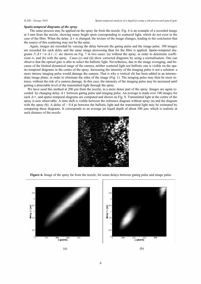
Spatio-temporal diagrams of the sprayThe same process may be applied on the spray far from the nozzle. Fig. 6 is an example of a recorded image
at 5 mm from the nozzle, showing many bright spots corresponding to scattered light, which do not exist in the case of the fibre. When the delay is changed, the texture of the image changes, leading to the conclusion that the source of this scattering may not be the same.
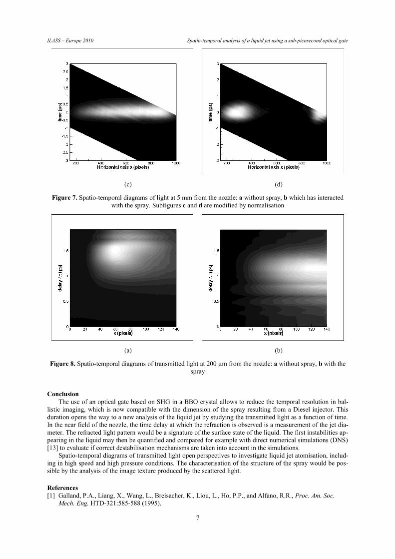
Again, images are recorded by varying the delay between the gating pulse and the image pulse. 100 images are recorded for each delay and the same image processing than for the fibre is applied. Spatio-temporal dia-grams I − x , x are shown on Fig. 7 in two cases: (a) without the spray, in order to determine coeffi-cient , and (b) with the spray. Cases (c) and (d) show corrected diagrams by using a normalisation. One can observe that the optical gate is able to select the ballistic light. Nevertheless, due to the image averaging, and be-cause of the limited dynamical range of the camera, neither scattered light nor ballistic one is visible on the spa-tio-temporal diagrams in the centre of the spray. Increasing the intensity of the imaging pulse is not a solution: a more intense imaging pulse would damage the camera. That is why a vertical slit has been added in an interme-diate image plane, in order to eliminate the sides of the image (Fig. 1). The imaging pulse may then be more in-tense, without the risk of a camera damage. In this case, the intensity of the imaging pulse may be increased until getting a detectable level of the transmitted light through the spray.
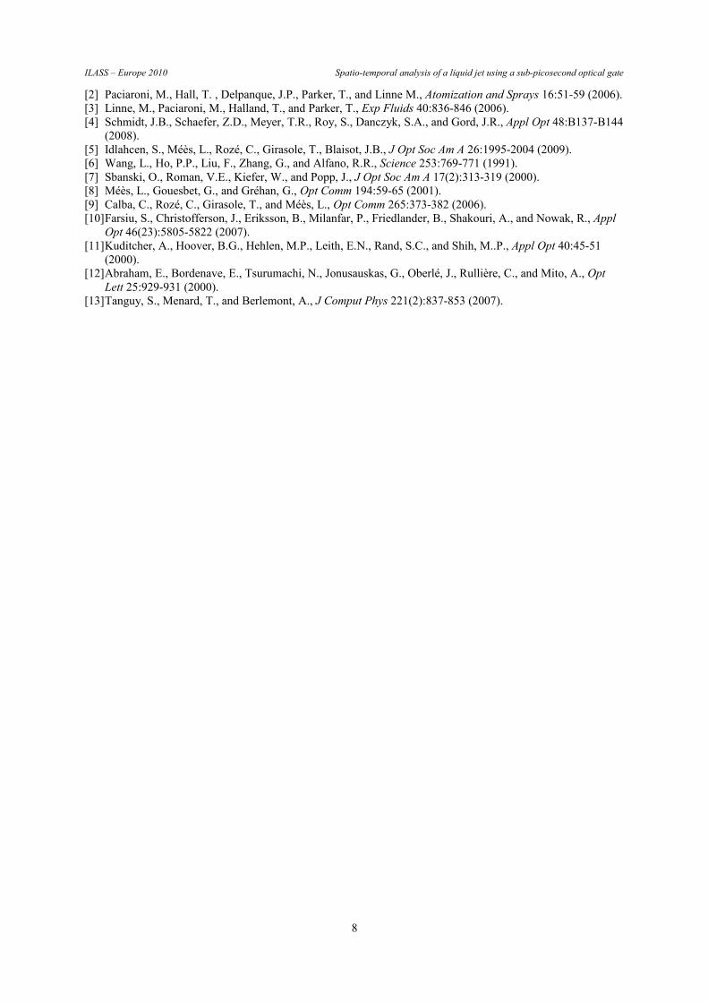
We have used this method at 200 µm from the nozzle, in a more dense part of the spray. Images are again re-corded by changing delay between gating pulse and imaging pulse. An average is made over 100 images for each , and spatio-temporal diagrams are computed and shown on Fig. 8. Transmitted light at the centre of the spray is now observable. A time shift is visible between the reference diagram without spray (a) and the diagram with the spray (b). A delay of ~ 0.4 ps between the ballistic light and the transmitted light may be estimated by comparing these diagrams. It corresponds to an average jet liquid depth of about 300 µm, which is realistic at such distance of the nozzle.
Figure 6. Image of the spray far from the nozzle, for some delays between gating pulse and image pulse
(a) (b)
6
ILASS – Europe 2010 Spatio-temporal analysis of a liquid jet using a sub-picosecond optical gate
(c) (d)
Figure 7. Spatio-temporal diagrams of light at 5 mm from the nozzle: a without spray, b which has interacted with the spray. Subfigures c and d are modified by normalisation
(a) (b)
Figure 8. Spatio-temporal diagrams of transmitted light at 200 µm from the nozzle: a without spray, b with the spray
ConclusionThe use of an optical gate based on SHG in a BBO crystal allows to reduce the temporal resolution in bal-
listic imaging, which is now compatible with the dimension of the spray resulting from a Diesel injector. This duration opens the way to a new analysis of the liquid jet by studying the transmitted light as a function of time. In the near field of the nozzle, the time delay at which the refraction is observed is a measurement of the jet dia-meter. The refracted light pattern would be a signature of the surface state of the liquid. The first instabilities ap-pearing in the liquid may then be quantified and compared for example with direct numerical simulations (DNS) [13] to evaluate if correct destabilisation mechanisms are taken into account in the simulations.
Spatio-temporal diagrams of transmitted light open perspectives to investigate liquid jet atomisation, includ-ing in high speed and high pressure conditions. The characterisation of the structure of the spray would be pos-sible by the analysis of the image texture produced by the scattered light.
References[1] Galland, P.A., Liang, X., Wang, L., Breisacher, K., Liou, L., Ho, P.P., and Alfano, R.R., Proc. Am. Soc.
Mech. Eng. HTD-321:585-588 (1995).
7
ILASS – Europe 2010 Spatio-temporal analysis of a liquid jet using a sub-picosecond optical gate
[2] Paciaroni, M., Hall, T. , Delpanque, J.P., Parker, T., and Linne M., Atomization and Sprays 16:51-59 (2006).[3] Linne, M., Paciaroni, M., Halland, T., and Parker, T., Exp Fluids 40:836-846 (2006).[4] Schmidt, J.B., Schaefer, Z.D., Meyer, T.R., Roy, S., Danczyk, S.A., and Gord, J.R., Appl Opt 48:B137-B144
(2008).[5] Idlahcen, S., Méès, L., Rozé, C., Girasole, T., Blaisot, J.B., J Opt Soc Am A 26:1995-2004 (2009).[6] Wang, L., Ho, P.P., Liu, F., Zhang, G., and Alfano, R.R., Science 253:769-771 (1991).[7] Sbanski, O., Roman, V.E., Kiefer, W., and Popp, J., J Opt Soc Am A 17(2):313-319 (2000).[8] Méès, L., Gouesbet, G., and Gréhan, G., Opt Comm 194:59-65 (2001).[9] Calba, C., Rozé, C., Girasole, T., and Méès, L., Opt Comm 265:373-382 (2006).[10]Farsiu, S., Christofferson, J., Eriksson, B., Milanfar, P., Friedlander, B., Shakouri, A., and Nowak, R., Appl
Opt 46(23):5805-5822 (2007).[11]Kuditcher, A., Hoover, B.G., Hehlen, M.P., Leith, E.N., Rand, S.C., and Shih, M..P., Appl Opt 40:45-51
(2000).[12]Abraham, E., Bordenave, E., Tsurumachi, N., Jonusauskas, G., Oberlé, J., Rullière, C., and Mito, A., Opt
Lett 25:929-931 (2000).[13]Tanguy, S., Menard, T., and Berlemont, A., J Comput Phys 221(2):837-853 (2007).
8