Embed Size (px)
Citation preview
1
Doctoral School in Materials Science and Engineering – XXIV cycle
SPARK PLASMA SINTERING
OF TITANIUM AND COBALT ALLOYS FOR
BIOMEDICAL APPLICATION
Nério Vicente Junior
April 2012

2
SPARK PLASMA SINTERING OF TITANIUM AND COBALT
ALLOYS BY FOR BIOMEDICAL APPLICATION
Nério Vicente Junior
Tutor:
Prof. Alberto Molinari
Doctoral Committee:
Prof. Paolo Scardi – University of Trento (ITA)
Prof. Scott Misture – Alfred University (USA)
Prof. Silvia L. Cuffini – Federal University of Santa Catarina (BRA)
26thApril 2012

3
To my parents and my wife.

4
INDEX
CHAPTER 1 - INTRODUCTION ___________________________________________ 7
1.1 - GENERAL ASPECTS ______________________________________________________ 7
1.2 - OBJECTIVES __________________________________________________________ 8
1.3 - THESIS OVERVIEW ______________________________________________________ 9
CHAPTER 2 – THEORETICAL FRAMEWORK _____________________________ 11
2.1 - BIOMATERIALS _____________________________________________________ 11
2.1.1 - Introduction __________________________________________________ 11
2.1.2 - Requirements of Biomaterials __________________________________ 12
2.1.2.1 - Mechanical Properties _______________________________________ 12
2.1.2.2 - Corrosion Resistance ________________________________________ 13
2.1.2.3 - Biocompatibility _____________________________________________ 14
2.2 - POROUS STRUCTURES _______________________________________________ 15
2.2.1 - Introduction __________________________________________________ 15
2.2.2 - Fabrication Methods __________________________________________ 17
2.2.3 - Scaffolds ____________________________________________________ 20
2.3 - BIOMEDICAL ALLOYS ________________________________________________ 21
2.3.1 - Cobalt and its alloys __________________________________________ 21 2.3.1.1 - Introduction ______________________________________________________ 21 2.3.1.2 - Cobalt Alloys _____________________________________________________ 22 2.3.1.3 - Co-28Cr-6Mo ____________________________________________________ 23
2.3.2 - Titanium and its alloys _________________________________________ 24 2.3.2.1 - Introduction ______________________________________________________ 24 2.3.2.2 - Titanium alloys ___________________________________________________ 25 2.3.2.3 - Ti‐6Al‐4V ________________________________________________________ 26
2.4 - PULSED ELECTRIC CURRENT SINTERING _________________________________ 28
2.4.1 - Introduction __________________________________________________ 28
2.4.2 - Heating Mechanisms __________________________________________ 29
2.4.3 - Processing and Manufacturing _________________________________ 30
CHAPTER 3 - EXPERIMENTAL PROCEDURES ___________________________ 32
3.1 - SPS APPARATUS AND SINTERING CYCLE ______________________________________ 32
3.2 - SAMPLES PREPARATION _________________________________________________ 32
3.3 - METALLOGRAPHIC MICROSTRUCTURE INVESTIGATION_____________________________ 33
3.4 - DENSITY ___________________________________________________________ 33

5
3.5 - POROSITY __________________________________________________________ 33
3.6 - X‐RAY DIFFRACTION ___________________________________________________ 37
3.7 - HARDNESS AND MICROHARDNESS __________________________________________ 38
3.8 - ADHESION TEST ______________________________________________________ 38
3.9 - STATIC SHEAR TEST ____________________________________________________ 38
3.10 - FATIGUE SHEAR TEST __________________________________________________ 39
3.11 - ABRASION TEST _____________________________________________________ 39
3.12 - TENSILE TESTS ______________________________________________________ 39
3.13 - REVERSE BENDING FATIGUE TEST _________________________________________ 39
3.14 - OPEN CIRCUIT POTENTIAL TEST ___________________________________________ 40
3.15 - CYCLIC POTENTIODYNAMIC POLARIZATION TEST ________________________________ 41
CHAPTER 4 - POROUS STRUCTURE _____________________________________ 42
4.1 - SCAFFOLD PREPARATION ________________________________________________ 43
4.2 - MORPHOLOGICAL ASPECTS _______________________________________________ 45
4.2 - POROSITY CHARACTERIZATION ____________________________________________ 51
4.3 - INTERFACIAL INTERACTIONS ______________________________________________ 52
4.4 - MECHANICAL PROPERTIES _______________________________________________ 54
4.4.1 - Adhesion Test ________________________________________________ 54
4.4.2 - Static Shear Test _____________________________________________ 55
4.4.3 - Fatigue Shear Test ___________________________________________ 55
4.4.4 - Taber Abrasion Test __________________________________________ 56
4.5 - SUMMARY OF THE RESULTS ______________________________________________ 57
CHAPTER 5 - FULL DENSITY SUBSTRATES ______________________________ 59
5.1 CO-28CR-6MO _______________________________________________________ 59
5.1.1 - Powder Microstructure ________________________________________ 59
5.1.2 - Effect of Sintering Temperature ________________________________ 61 5.1.2.1 - Relative Density __________________________________________________ 68
5.1.3 - Effect of Pressure_____________________________________________ 70
5.1.4 - Influence of Powder ___________________________________________ 74
5.1.5 - Mechanical Properties _________________________________________ 79
5.1.5.1 - Tensile properties ___________________________________________ 79
5.1.5.2 - Fatigue Properties __________________________________________ 83
5.1.6 - Corrosion Properties __________________________________________ 85
5.1.6.1 - Open Circuit Potential (OCP) Test ____________________________ 85
5.1.6.2 - Cyclic Potentialdynamic Polarization (CPP) Test ________________ 86
5.2 - TI-6AL-4V __________________________________________________________ 88
5.2.1 - Mechanical Properties _________________________________________ 88
5.2.1.1 - Tensile Properties ___________________________________________ 89

6
5.2.1.2 - Fatigue Properties __________________________________________ 92
5.2.2 - Corrosion Properties __________________________________________ 93
5.2.2.1 - Open Circuit Potential (OCP) Test ____________________________ 93
5.2.3.2 - Cyclic Potentialdynamic Polarization (CPP) Test ________________ 94
5.3 - SUMMARY OF THE RESULTS ______________________________________________ 95
CHAPTER 6 - CO-SINTERING ___________________________________________ 97
6.1 - CP-TI/CO-28CR-6MO _________________________________________________ 97
6.1.1 - Microstructure ________________________________________________ 97
6.1.2 - Sinter-bonding ______________________________________________ 100
6.1.3 - Interface Characterization ____________________________________ 102
6.1.4 - Fatigue Properties ___________________________________________ 109
6.2 - CP-TI/TI-6AL-4V ____________________________________________________ 111
6.2.1. Microstructure _______________________________________________ 111
6.2.2 - Interface Characterization ____________________________________ 112
6.2.2 - Fatigue Properties ___________________________________________ 116
6.3 - SUMMARY OF THE RESULTS _____________________________________________ 117
CHAPTER 7 – CONCLUSIONS __________________________________________ 120
REFERENCES _________________________________________________________ 121
ACKNOWLEDGEMENTS _______________________________________________ 134
PUBLICATIONS _______________________________________________________ 135

7
Chapter 1 - INTRODUCTION
1.1 - General Aspects
Commercial pure titanium (cp-Ti), Ti-6wt.%Al-4wt.%V (Ti-6Al-4V) and
Co-28wt.%Cr-6wt.%Mo (Co-28Cr-6Mo) alloys are nowadays the most
worldwide applied metals in orthopedic field (along with AISI316L stainless
steel) due to their good mechanical properties, corrosion resistance and
biocompatibility. In the case of Powder Metallurgy products, mechanical
and corrosion resistance are maximized by a full density microstructure, but
in the case of tissue regeneration, a porous structure (scaffold) is an
essential characteristic. Scaffolds have been extensively assessed by the
scientific community as the best design for bone regeneration because they
mimic the architecture of the trabecular portion of the bone. They facilitate a
prompt extra cellular matrix recognition, rapid healing and bone stable
interlocking. However, a porous structure has poor mechanical properties,
mainly fatigue resistance, and therefore it has to be combined with a full
density substrate for long withstand applications.
The Co alloy is used in the biomedical field since 50 years. It is produced
mainly by investment casting and utilized for those applications where high
wear resistance is required. Numerous studies have been carried out in
order to improve its mechanical properties by modifying the microstructural
characteristics and some Powder Metallurgy processes (HIP, MIM, SLM,
EBM) are contributing to this objective.
The Ti alloy was firstly developed for aircraft applications owing to its high
weight-to-strength ratio. The excellent corrosion resistance supported the

8
development of the applications in biomedical field. It is more resistant to
mechanical loading than pure titanium with minimal biocompatibility losses.
Forging is the main process utilized to produce components made of Ti-
6Al-4V alloy, since interstitials pick-up arises as a serious problem in
casting, resulting in severe ductility loss. Even in this case, Powder
Metallurgy is an excellent technological alternative based mainly on HIP,
MIM, SLM, EBM.
Commercial pure titanium is effectively the best biocompatible material
among those investigated in this work, and it was chosen for the production
of the porous scaffold. It has modest mechanical property and therefore it
does not have applications as structural material, even in the biomedical
field. It faces the same technological difficulties of any other titanium alloy,
and can be successfully produced by Powder Metallurgy by the above
mentioned routes.
1.2 - Objectives
This work was carried out in the frame of an industrial research project in
cooperation with K4Sint Srl (Pergine Valsugana, Trento), and Eurocoating
SpA (Pergine Valsugana, Trento) aimed at the development of the
production of commercial pure titanium (cp-Ti), Ti-6wt.%Al-4wt.%V (Ti-6Al-
4V) and Co-28wt.%Cr-6wt.%Mo (Co-28Cr-6Mo) alloys by Spark Plasma
Sintering for biomedical application. The final objective is the definition of
the process parameters for the production of a highly porous (cp-Ti), full
density materials (Ti-6Al-4V and Co-28Cr-6Mo), and their combination in a
surface functionalized full density substrate.

9
1.3 - Thesis Overview
Gas atomized pre-alloyed powders and the Spark Plasma Sintering (SPS)
process were employed to manufacture the specimens. SPS is an
emerging Powder Metallurgy process, which makes use of a pulsed electric
current and a compaction pressure for densification and sintering of
powders. It is particularly suitable to process hard-to-sinter powders to the
full density with a strict control of the microstructure, due to the relatively
low heat input.
Co-sintering and sinter-bonding were the processing approaches used to
join the scaffold and the full density substrate. Actually, the scaffold
consisted in a sort of blend (cp-Ti/CP) during sintering with subsequent
space holder extraction; this ensures a careful control of the final porosity
volume fraction, shape and size. The porous scaffold was produced by
means of the space holder technique, making use of calcium phosphate
(CP) particles.
The thesis is organized in the following chapters. In chapter 2 the
theoretical framework is presented. In chapter 3 the methodology and
characterization techniques are presented. Chapter 4 deals with the porous
scaffold. The microstructural and morphological characteristics, as well as
some mechanical and wear properties of the porous material are
presented. Chapter 5 deals with the full density materials: density,
microstructure, hardness and microhardness, tensile and fatigue, as well as
corrosion properties are presented and discussed for the Co-28Cr-6Mo
alloy and Ti-6Al-4V alloys. In chapter 6 the co-sintering and sinter-bonding
approaches to produce the porous scaffold on a full density substrate are
presented. Attention is focused not only on density and microstructure, but

10
even on the interfaces between the cp-Ti and Ti-6Al-4V and the Co-28Cr-
Mo substrates. Interdiffusion of alloying elements was verified. Bending
fatigue tests were also carried out on specimens representative of the
scaffold coated full density materials. The conclusive remarks are
summarized in Chapter 7.

11
Chapter 2 – THEORETICAL FRAMEWORK
2.1 - BIOMATERIALS
2.1.1 - Introduction
Materials in medicine date back to ancient civilizations in India, China and
Egypt, where the medicine was practiced as part of the religious and
mystical activities. Metallurgical tools were used for surgical treatment,
tendons for suture etc. The first implanted material was gold plate for cleft
palate in 1588. Till the polymer industry was developed in 1950s, the
metallic materials like silver, platinum, stainless steel and cobalt base alloys
were mainly used. [1]
A biomaterial is a synthetic material used to replace part of a living system
or function in intimate contact with living tissue [2]. Another definition is
proposed by [3]: a biomaterial is defined as any systemically,
pharmacologically inert substance or combination of substances utilized for
implantation within or incorporation with a living system to supplement or
replace functions of living tissues or organs.
More recently, Guelcher said that a biomaterial is a material that has been
shown to be compatible with living tissue and that demonstrates suitable
structural and mechanical stability for its desired use [4]. Here, the
definition takes also an engineering point of view using the structural and
mechanical stability concepts, being in this way much closer to the actual
successful of long term implantation.
A biomaterial may act as a biological device that substitute or repair bone,
cartilages, ligaments or tendons. To be utilized in bone repair or bone

12
substitute a material of course must be comparable to the bone in terms of
mechanical properties. In practice, it does not must be chemically
comparable to the bone, but at least it must show inertness in order to
avoid implant rejection. Requirements of biomaterials are nowadays very
well understood thanks to common efforts of doctors, biologists and
engineers.
2.1.2 - Requirements of Biomaterials
The design and selection of the biomaterial depend on the medical
application. Regardless the application, a biomaterial must be non-
carcinogenic, non-allergic and nontoxic [5]. Others prerequisites concerning
biomaterials are related to the material reliability, whose are: mechanical
properties (2.1.3) and corrosion properties (2.1.4) and minimal material-to-
bone affinity, that is, biocompatibility.
2.1.2.1 - Mechanical Properties
For orthopedic biomaterials the prime mechanical properties are elastic
modulus, tensile strength and elongation, fatigue resistance and wear
resistance [6,7,8]. In majority of the cases fatigue is the cause of prosthesis
failure [7,8 ].
A high tensile strength and high elongation lead to a high toughness. This
is the motive why metals are usually chosen for orthopedics. Commonly,
ceramics show high strength, but very limited elongation, leading to a poor
toughness. Wear resistance, on the other hand, is occasionally a weakness
point of metallic materials. Low wear resistance may results in metallic ions
releasing. The released ions are found to cause allergic and toxic reactions
[9,10].
13
Elastic modulus (stiffness), differently to tensile, fatigue and wear
resistance, is a property which promotes the improvement of biological
reactions. Material for bone replacement is expected to have a stiffness
equivalent to that of bone. The elastic modulus of the bone varies from 4 to
30 GPa depending on the type of the bone and the direction of
measurement [11], whilst that of customary metallic biomaterials is between
100-200 GPa [5]. Elastic modulus mismatch among the metallic biomaterial
and the surrounding bone has been identified as a major reason for implant
loosening due to stress shielding [12].
Porous structure is a current approach to overcome the problem of high
elastic modulus intrinsic to the metallic biomaterials. Literature concerning
this topic is revised in the a successive section (2.2).
2.1.2.2 - Corrosion Resistance
Metal implant corrosion is controlled by:
(1) the extent of the thermodynamic driving force;
(2) physical barriers which limit the kinetics of corrosion.
Orthopedic alloys rely on the formation of passive films to prevent
significant corrosion [13].
These films consist of metal oxides (ceramic films) which form
spontaneously on the surface of the metal in such a way that they prevent
further transport of metallic ions and/or electrons across the film. To be
effective barriers, the films must be compact and strongly adherent on the
metal surface; they must have an atomic structure that limits the migration
of ions and/or electrons across the metal oxide–solution interface; and they
must be able to remain on the surface of the alloys even when
mechanically stressed or abraded [13].

14
Even with a passivated metal, there will be a finite rate of diffusion of ions
through the oxide layer, and possible minimal dissolution of the layer itself.
[5]
Some specific mechanism of corrosion are listed:
Pitting corrosion is a localized accelerated dissolution of metal that occurs
as a result of a breakdown of the protective passive film on the metal
surface. Metallic biomaterials as stainless steels, cobalt alloys and titanium
when exposed to chloride ions and sufficiently positive potential, lead to
breakdown, giving rise to pits. Stainless steels are unlikely to resist pitting
when exposed to the body fluids indefinitely; the cobalt-based alloys may
well withstand such exposure for long times; titanium and some of its alloys
should withstand such exposure for an indefinite period [14].
Fretting corrosion takes place when the passive layer is removed by
mechanical process leaving the metallic material vulnerable. In this case
wear resistance is also concerned. Moreover, the ability to repassivate is of
great importance. In joint implants, fretting corrosion is produced by
relatively small-scale (< 100 µm) motions between components induced by
cyclic loading. The motion may increase corrosion rates because oxide
layers are continually fractured and reformed [15].
Galvanic corrosion can take place if two different metals are placed in
contact within the same solution. Electrons passing from the more anodic to
the more cathodic metal induce continuous dissolution. Evidences of this
type of corrosion have been exposed [16].
2.1.2.3 - Biocompatibility
A biomaterial distinguishes from any other material for its ability to stay in
contact with the pertinent tissues of the human body, or components of

15
tissues, without producing an unacceptable degree of injury to those
tissues or components [17].
According to [18], the term biocompatibility is misused if treated simply as
the evaluation of cell culture onto the material (in vitro test). This term refers
to a collection of mechanisms involving different but independent reactions
between a material and its host tissue.
Biocompatibility refers to ability of material to perform a function depending
not only on its interaction with tissue but also on the intrinsic mechanical
and physical properties [18]. A successful long term usage has to be
considered.
Osteointegration is another term used in biomedical science. Now, the
material-to-tissue interaction is concerned in mechanical point of view.
From [19], osteointegration is a condition “in which solid anchoring of an
alloplastic material in bone is achieved, and retained under functional
loading” [20]. Therefore, surface composition, hydrophilicity, porosity and
roughness are parameters that influence the rate and quality of
osseointegration [21].
2.2 - POROUS STRUCTURES
Regarding the mechanical requirements and the biocompatibility of
biomaterials a precise feature is desired for orthopedic implants: porous
structure. Summarily, it is positive for reducing stiffness and in turn it offers
a support for bone fixation.
2.2.1 - Introduction
Despite of the high corrosion resistance exhibited by ceramic materials,
they cannot be employed as load bearing implants, due to their intrinsic

16
brittleness. Polymeric materials, on the other hand, cannot withstand to
cyclic loading during long time (low fatigue resistance). Alternatively,
metallic materials portray high toughness, high fatigue resistance, corrosion
resistance and biocompatibility. Porous structure made of metals are then
suitable for orthopedic implantation in the case of long term application.
The three leaders metallic materials used to fabricate porous structures
(foams) are aluminum, magnesium and titanium. In the majority, research
of metallic foams processing has been focused on melt-processing of
aluminum foams with open or closed cells [22], owing to the low melting
point (662°C) and low reactivity of molten Al [23]. Nevertheless, titanium is
by far the metallic material with best properties for biomedical use [6]. It has
a melting point of 1670°C and, in this case, powder metallurgy emerges as
the main feasible route to produce foams.
Titanium foams are largely used in structural applications (closed pores)
thanks to their exceptional density-compensated strength and corrosion
resistance. But currently, biomedical application has taken further attention
[24].
The foam properties are controlled by the pore feature, i.e. size, shape,
volume percentage, interconnection, surface area and uniformity of pores,
which may be rather different in various fabrication methods [25].
Figure 2.1 shows some foam and dense materials properties. The vast list
of properties shown by foams in general cannot be obtained by dense
materials.

17
Fig. 2.1 - Properties range of foams and full density materials [26].
2.2.2 - Fabrication Methods
Ryan et al [27], reviewed the fabrication methods of porous structures
made of metals for use in orthopedic applications. Pore distribution was
selected as the main aspect to discriminate the methods. Into the
fabrication methods of non-homogeneous pores distribution accounted:
furnace sintering, space holder, replication and combustion synthesis;
homogenous pore distribution: orderly oriented wire mesh, ferromagnetic
fibres and vapor deposition; and functionally graded pore distribution:
electric field assisted sintering and rapid prototyping. Some of non-

18
homogenous and functionally graded material methods further are
presented.
Furnace sintering of loose powders or powder beads. It is based on the
partial sintering of powders in order to keep voids between particles. This
method is utilized either for manufacturing full porous structure or porous
surfaced materials. Pores are rather irregular. The volume of pores depend
on several parameters, such as: chemical composition, powder size,
powder distribution, powder shape, compaction pressure and sintering
temperature. The application of this method in the biomedical field has its
roots on 70’s, with Galante [28] and Pilliar [29], whose published and
patented their results, respectively. Several authors have dealt with this
method [30-33].
Space holder method consists in the mixing of at least two types of
particles, one to form the structural framework after sintering and another
(space holder) used to create a collection of pores. The latter is usually
extracted after shaping, but in some cases can be extracted after sintering.
In principle, space holder particles must touch one each other, creating a
continuous channel, in order to allow the extraction of material. Pore
features are changeable by varying the space holder feature. High amount
of porosity can be achieved (~70%), but in some cases warping may be a
drawback. Fig. 2.2 schematically shows the steps of space holder method.
Several authors have worked with this method [34-40].

19
Fig. 2.2 - Process steps in space holder method [34].
Rapid prototyping is the most powerful method for porous structure
manufacturing. It is based on the application of a beam (laser or electrons)
to melt or to sinter powders. The pores assembly is defined by means of
computer aided design (CAD) platform, and therefore it has a practically
unlimited architecture. A limitation regards the pore size since it is normally
linked to the beam thickness and the powder particles diameter. One
interesting use is the manufacturing of prosthesis with proper complex
design, such as used to maxillary reconstruction. A potential drawback is
the formation of metastable phases due to extremely high cooling rate.
Several authors have worked with this method [41-44].

20
2.2.3 - Scaffolds
A scaffold is an artificial three-dimensional frame structure that serves as a
mimic of extracellular matrix for cellular adhesion, migration, proliferation,
and tissue regeneration in three dimensions [45].
In the case of orthopedic applications the scaffold must offer an appropriate
surface to cell adhesion (differentiation and proliferation) as well as an
appropriate assembly to latter bone interlocking. The former focus is
intensely related to surface chemistry while the last regards the design of
the scaffold.
The bone is formed by two main constituents: the compact (cortical) and
the trabecular (cancellous) bone. The former is hard, shows some porosity
and is situated at outer part, acting as a wall. The latter is stiff, highly
porous and is located on the inner part [46]. Fig. 2.3 shows a schematic of
the bone [47].
Fig. 2.3 – The bone structure [47].
A proper scaffold for bone regeneration must be similar to the trabecular
bone in design and mechanical properties.

21
2.3 - BIOMEDICAL ALLOYS
2.3.1 - Cobalt and its alloys
2.3.1.1 - Introduction
Isolated in 1735 by Brandt, the cobalt element had its true nature
extensively studied about 40 years later by Bergman. Cobalt situates in the
transition group VIII, between iron and nickel, in the Mendeleef’s periodic
table [48].
Metallurgical uses of cobalt include the wear resistant, corrosion resistant,
and heat resistant cobalt-based alloys, the use of cobalt in nickel-base
superalloys (the largest end-use sector for cobalt), iron-based superalloys,
cemented carbides, magnetic materials, low expansion alloys, steels, and,
to a lesser extent, nonferrous alloys and cobalt coatings [49].
Cobalt exists in two atomic forms: a low temperature stable hexagonal
close packed (h.c.p.) form and a high temperature stable face centered
cubic (f.c.c.) form. The transformation temperature of pure cobalt is 417 °C.
Alloying elements such as nickel, iron, and carbon (within its soluble range)
are known as f.c.c. stabilizers, and, suppress the transformation
temperature. Chromium, molybdenum, and tungsten, on the other hand,
are h.c.p. stabilizers and have the opposite effect. [50]
Actually, the transformation is extremely sluggish, and most cobalt-base
alloys exhibit a (metastable) f.c.c. structure at room temperature, even if
their transformation temperatures are considerably higher. Partial
transformation (from f.c.c. to h.c.p.) of most cobalt-based alloys is,
however, easily induced at room temperature by plastic deformation (under
the action of mechanical stress), also called strain induced martensitic
transformation [51,52], the extent of the transformation being related to the
composition (in particular the ratio of h.c.p. stabilizers to f.c.c. stabilizers).

22
The transformation under stress progresses by the creation of large
stacking faults (the f.c.c. form of these alloys having very low stacking fault
energies) and by subsequent coalescence. Extensive micro twinning is also
observed in plastically-deformed, cobalt based alloys. Crystal structure of
cobalt are shown in Fig. 2.4.
Fig. 2.4 - Crystal structures of cobalt. A) Martensite (h.c.p.) and
B) Alpha phase (f.c.c.)
2.3.1.2 - Cobalt Alloys
Cobalt‐base alloys are strengthen either by solid‐solution on the matrix or
by precipitation of carbides. While the first is correlated to stress imposed
by distortion in the atomic arrangement the last regards the presence of
hard particles distributed both on the matrix and at grain boundaries.
Element usually added to solid-solution strengthen are chromium, tungsten,
niobium and tantalum. But normally, chromium is added with the aim of
confer corrosion resistance by forming oxides on the surface.
Tungsten and molybdenum serve to provide additional strength to the
matrix, owing to the virtue of their large atomic size. When present in large
quantities, they participate in the formation of carbides during alloy
solidification and promote the precipitation of M6C; molybdenum may also
form intermetallic compounds with cobalt [53].

23
The second‐phase strengthening (precipitates) in cobalt‐based alloys is
achieved by the addition of carbon or nitrogen. Both elements can form
compounds with high hardness (carbides or carbonitrides). Some types of
carbides can be formed in cobalt-based alloys, such as MC, M6C, M7C3,
M23C6 and occasionally M2C3.
The strengthening mechanisms provided by solid solution elements and
precipitates are different, mainly when the latter is located at grain
boundary. Solid solution of elements contribute to strengthen by adding
internal stress and defects. Carbides when located within the grain provide
obstacles to the movement of dislocations also second phase, and thus
inhibiting slip. At grain boundaries the precipitates prevent gross sliding
[48].
2.3.1.3 - Co-28Cr-6Mo
Cobalt‐chromium‐molybdenum‐carbon alloys are widely employed in
aircraft engines and prosthetic implants. High strength and wear resistance
are the main properties of this alloy, but high chromium quantities afford
very good corrosion resistance in chloride environments.
As cast Co-28Cr-6Mo alloy shows some microstructures features that result
in tensile and fatigue properties losses. Microstructural inhomogeneities
observed in cast Co-Cr-Mo alloy include porosity, coring, oxides, sigma
phase formation, large grains and grain boundary precipitates [54]. These
adversities are intrinsic to the cast processing and some of them can be
eliminated by post thermomechanical treatments.
Powder Metallurgy appears as an attractive technology to process the Co-
28Cr-6Mo alloy due to the prospective of microstructure control.
Using the traditional press-and-sinter P/M process, [55] obtained a Co-
28Cr-6Mo alloy with only 0,02% of porosity when sintered at 1350°C during

24
90 minutes in inert gas. Moreover, grains do not growth excessively,
reaching up to 87 µm. Metal Injection Moulding (MIM) [56], Electron Beam
Melting (EBM) [57] and Selective Laser Melting (SLM) [58] are also suitable
P/M technologies.
2.3.2 - Titanium and its alloys
2.3.2.1 - Introduction
Discovered in England by Gregor in 1790, the element titanium was
denominated five years later by Klaproth. Its name remind the mythological
first sons of the earth, the Titans. Titanium is one of the transition elements
in group IV and period 4 of Mendeleef’s periodic table. It has an atomic
number of 22 and an atomic weight of 47.9. Being a transition element,
titanium has an incompletely filled d shell in its electronic structure [59].
Titanium has a high melting point (1668 °C) and possesses a hexagonal
closely packed crystal structure alpha (h.c.p.) (Fig. 2.5A) up to a
temperature of 882,5 °C. Titanium transforms into a body centered cubic
structure beta (b.c.c.) (Fig. 2.5B) above this temperature [60].
Fig. 2.5 - Crystal structures of titanium. A) alpha phase (h.c.p.) and
B) Beta phase (b.c.c.) [59]

25
Titanium is worldwide recognized as a metal with high strength-to-weight
ratio, high corrosion resistance and chemical inertness. These properties
have pushed the research in order to minimize production costs.
Titanium and its alloys are strategic advanced materials for high
performance requirements, being systematically used in aircraft,
aerospace, jet engine, chemical and petroleum, automotive and biomedical.
Some biomedical applications are reported in Table 2.1.
Table 2.1 - Some biomedical application of Titanium and its alloys.
Artificial joint prostheses
Bone plates, intramedullary rods, etc.
Heart valves
Dental implants
Attachment wire
Surgical instruments
Wheelchairs
2.3.2.2 - Titanium alloys
Titanium alloys can be classified as alpha, near-alpha, alpha + beta,
metastable beta, or stable beta depending on the room temperature
microstructure [61].
In pure titanium beta phase is stable only at high temperature. At given
amount of specific alloying elements this beta phase is hindered on cooling.
If such elements are added in a high amount the beta phase can be full
hindered, but sensitive to be transformed in alpha (metastable beta), at still
higher amounts the full stable beta phase is achieved (Fig. 2.6).

26
Alloying elements usually added in titanium may be divided in three
categories:
(i) Alpha-stabilizers, such as Al, O, N, C;
(ii) Beta-stabilizers, such as Mo, V, Nb, Ta (isomorphous), Fe, W, Cr, Si,
Co, Mn, H (eutectoid);
(iii) Neutrals, such as Zr.
The effect of beta stabilizer elements on the phase diagram can be seen in
Fig. 2.6.
Fig. 2.6 - Schematic effect of alloying elements on phase diagrams of Ti
alloys [62].
The properties of the alpha + beta alloys depend on the chemical
composition, relative amounts and arrangement of phases, and the
processing history [63].
2.3.2.3 - Ti‐6Al‐4V
Developed in 50’s in the United States at the Illinois Institute of Technology
Among the Ti-6Al-4V alloy is the most widespread alpha + beta titanium
alloy. More than 50% of all alloys in use today are of this composition [61].

27
The alpha + beta microstructure can be modified by heat treatment as well
as thermomechanical treatment [64]. Fig. 2.7 shows some of these
microstructures.
Fig. 2.7 - Microstructure of an alpha-beta titanium alloy (Ti-6Al-4V) in representative metallurgical conditions. (a) Equiaxed alpha and alpha small amount of intergranular beta. (b) Equiaxed and acicular alpha and a small
amount of intergranular beta. (c) Equiaxed alpha in an acicular alpha matrix. (d) Small amount of equiaxed alpha in an acicular alpha matrix. (e)
Plate-like acicular alpha (transformed beta); alpha at prior beta grain boundaries. (f) Blocky and plate-like acicular alpha; α at prior beta grain
boundaries [65]

28
Although the recognized potential of titanium and its alloys there is a
limitation in their application in consequence of high price [66]. The high
cost of producing titanium-based materials as compared to competing
materials has led to investigations of potentially lower cost processes, such
as net-shape powder metallurgy (P/M) techniques [67,68]. Titanium P/M
fabrication offers the potential for true net shape capability combined with
mechanical properties that are equal to, or exceed, cast and wrought
products [63]. Titanium P/M has been developed as a net-shape technique
only in the last 20 years. According to the raw material, P/M can be divided
into two major categories [69]:
i) Elemental Blend (BE), in which a blend of elemental powders, along with
master alloy or other desired additions, is cold pressed into shape and
subsequently sintered to higher density and uniform chemistry; ii) Pre-
alloyed (PA), which is based on hot consolidation of powder produced from
a pre-alloyed stock. Hot Isostatic Pressing (HIP) is the primary hot
consolidation method for PA powders, but vacuum hot pressing (VHP),
extrusion, and rapid omnidirectional compaction (ROC) have also been
successfully used [70]. Some Advanced P/M techniques used to
consolidate titanium powders are: i) Metal Injection Moulding (MIM) [71]; ii)
Electron Beam Melting (EBM) [72]; iii) Selective Laser Melting [73]; iv)
Spark Plasma Sintering [74].
2.4 - PULSED ELECTRIC CURRENT SINTERING
2.4.1 - Introduction
Sintering of materials by ohmic resistance dates to 30’s. Taylor used hot
pressing to processing cemented carbides [75]. Likewise, a method based

29
on electric discharge was patented in 40’s. It was applied to aid the
sintering of powders and the sinter-joining of metals [76]. Subsequently, so
called “spark sintering” was proposed by Lenel in the 50’s [77].
Commercial units developed over the past few decades include “plasma-
assisted sintering” (PAS) [78], “pulsed electric current sintering” (PECS)
[79], “electroconsolidation” also known as electric pulsed assisted
consolidation (EPAC) [80], and “spark plasma sintering” (SPS) [81], being
the last the most employed name nowadays.
The SPS process is based on the simultaneous application of pulsed DC
current and uniaxial compaction pressure. The high pulsed DC current
flows through the conductive punches and dies (made of graphite) like in a
closed electric circuit. Depending on the magnitude of electric resistance
offered by the sample the current may either flow or not throughout the
powder particles as well.
2.4.2 - Heating Mechanisms
Tokita et al [81] argued that spark discharge and plasma took place
between adjacent particles in the case of conductive powders. They
proposed that these phenomena could remove the species adsorbed as
well as destabilize oxides, which result in improvement of sintering.
Recently, on the other hand, Hulbert et al [82] shown the absence of
plasma into SPS chamber. Lee et al [83] advocated that pulsed electric
field contributes to the fast densification, whilst Groza et al [84] do not
consider plasma, but claimed that surface oxide films are pierced when a
certain voltage level is achieved. Anderson et al [85] verified that oxides
were effectively removed.

30
Chen et al [86] added that the direction of the current had no effect on the
thickness of the product layer between Si and Mo. Furthermore, the growth
rate of the same product was significantly higher under current than in the
absence of current. Song et al [87] and Diouf and Molinari [88] shown that
overheating can take place on the contact between particles due to Joule
heating maximization in reduced area (neck).
The pulsed DC electric current (via Joule heating) then seems to be the
central element of the heating mechanism. Such effectiveness might be
correlated to the enhancement of vacancies concentration.
2.4.3 - Processing and Manufacturing
Due to the high heating rate and peculiar heating mechanisms a gradient in
the temperature can be generated either in relation to the sample itself
(external to inner part) or in relation to the difference between sample and
dies.
Modeling of the current flux can give an indication how it is distributed and
in consequence how the temperature is scattered as well. Anselmi-
Tamburini et al [89] used copper powder and alumina (Al2O3) powder to
have an insight about these extents. Fig. 2.8 shows the modeling of current
distribution in a SPS process for those both materials above mentioned.
They noted that the difference between thermocouple and pyrometer
accounted to about 150 °C at 1350 °C. Using a sample 20 mm in diameter
and 3 mm thick a radial gradient temperature of only 5 °C was detected for
copper. Eriksson et al [90] observed the same magnitude (150 °C) in their
studies.

31
Fig. 2.8 - Current distributions in the SPS die for alumina and copper
samples. Applied voltage=5V. [89].
Gradient of temperature on the sample itself and between the sample and
the dies may be linked also to the punch and dies design, and to the
contact between them, which is plausible since essentially the process is a
sort of electric circuit.
A clear example of the punches and dies design is shown by [91]. From the
top of the upper punch (also the widest) to the bottom of the lower punch a
difference in temperature reach about 500K, using an up to down current
orientation.

32
Chapter 3 - EXPERIMENTAL PROCEDURES
3.1 - SPS Apparatus and Sintering Cycle
Spark Plasma Sintering (SPS) was carried out on a DR. SINTER SPS1050
(Sumitomo Coal & Mining, now SPS Syntex Inc.) apparatus with graphite
punches and die. Fig. 3.1 reports an example of the SPS cycle.
Fig. 3.1 - SPS processing curve. 1000°C / 5 min / 60 MPa
3.2 - Samples Preparation
Co-28Cr-6Mo
Sample preparation for metallographic analysis was carried out by water-
grinding with 220, 440, 800 and 1200-grit SiC paper, in sequence, followed
by a mechanical polishing using 3 microns diamond abrasive.
Electrolytic etching was carried out with 94 ml distilled water, 4.5 ml HNO3
and 1.5 ml H2O2 solution for 3V and 4sec.

33
Cp-Ti and Ti-6Al-4V
Samples preparation was carried out by water-grinding with 220, 440, 800
and 1200-grit SiC paper, followed by a mechanical polishing using OPS
suspension (colloidal silica suspension) containing 6,5 vol.% H2O2 and 1,3
vol.% NH3. Kroll’s reagent (100 ml water, 2 ml hydrofluoric acid, 5 ml nitric
acid) was used for metallographic etching.
3.3 - Metallographic Microstructure Investigation
Metallographic characterization was carried out by a LOM microscopy
(Leica DC300) and by environmental scanning electron microscopy (ESEM,
Philips XL 30) before and after electrolytic etching. Microanalysis was
carried out by energy dispersive X‐ray spectroscopy (EDXS).
3.4 - Density
Determination of the density was performed by Archimede’s method,
according to standard ASTM B962-08. The Archimede’s density (ρs) was
calculated by Equation 1.
(
) (1)
where m is the mass of the sample, ma is the apparent mass and ρwater is
the density of water.
Weight measurements were carried out with a precision balance
(AdventurerSL ‐ OHAUS) with a sensibility of 0.0001g.
3.5 - Porosity
The imageJ ® software was employed to evaluate porosity and pores
characteristics by image analyses.
34
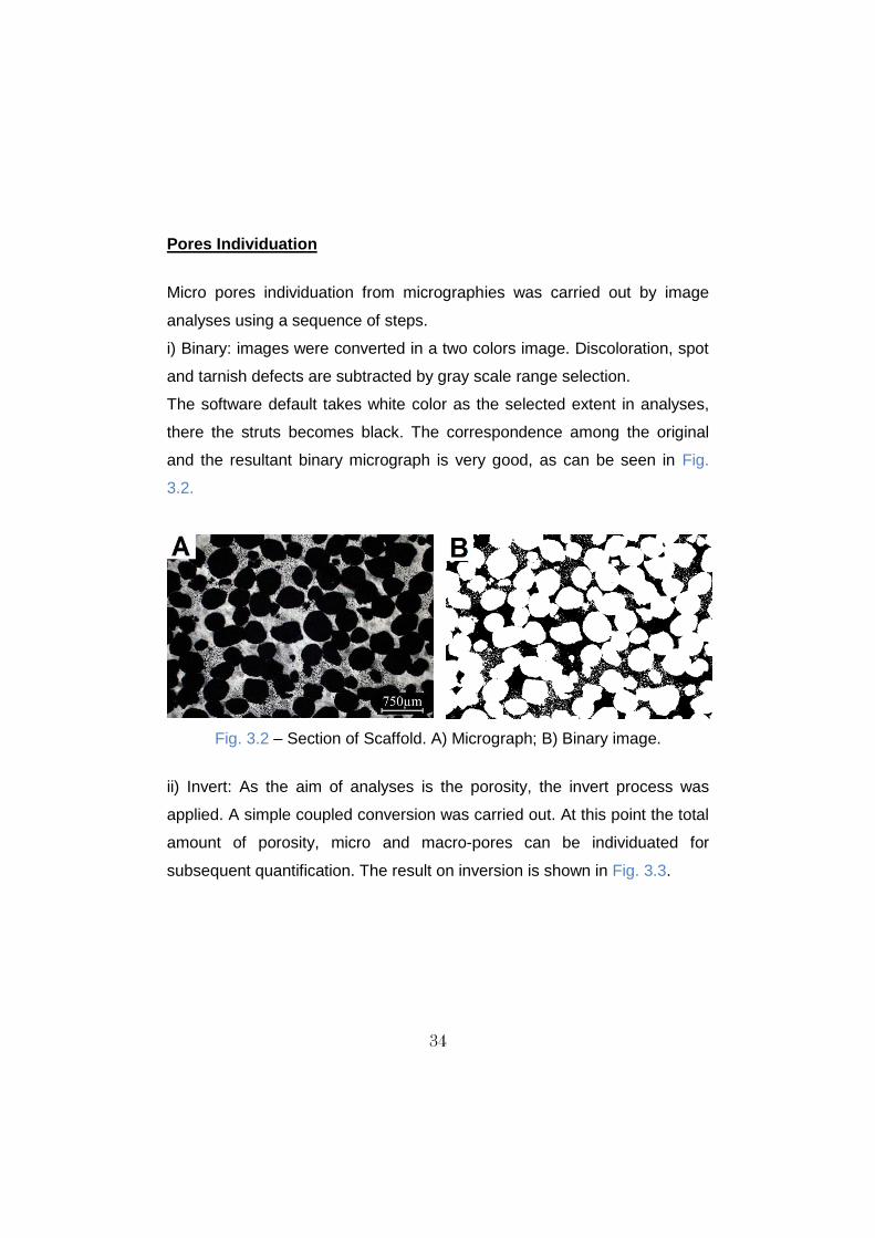
Pores Individuation
Micro pores individuation from micrographies was carried out by image
analyses using a sequence of steps.
i) Binary: images were converted in a two colors image. Discoloration, spot
and tarnish defects are subtracted by gray scale range selection.
The software default takes white color as the selected extent in analyses,
there the struts becomes black. The correspondence among the original
and the resultant binary micrograph is very good, as can be seen in Fig.
3.2.
Fig. 3.2 – Section of Scaffold. A) Micrograph; B) Binary image.
ii) Invert: As the aim of analyses is the porosity, the invert process was
applied. A simple coupled conversion was carried out. At this point the total
amount of porosity, micro and macro-pores can be individuated for
subsequent quantification. The result on inversion is shown in Fig. 3.3.

35
Fig. 3.3 - Scaffold inverted binary image
iii) Analyze Particles: In order to individuate the micropores, those with
diameter between 0 and 50 µm were considered. The mask result can be
seen in Fig. 3.4.
Fig. 3.4 - Selected pores with diameter between 0 and 50 µm.
The Fig. 3.5 shows the result of pores with diameter above 51 µm.

36
Fig. 3.5 - Selected pores with diameter above 51 µm.
There are some micropores in contact to the macropores which cannot be
distinguished. To overcome this weakness Erode and Dilate tools were
employed.
iv) Erode + Dilate: In a binary system it is possible to increase one of the
two colors using contrast. For example, using Erode black is minimized.
With this logics the pores are minimized and in contrast the strut (white) is
maximized. The contrary effect can be obtained by using Dilate. For this
study where micro- and macro-pores are very dissimilar in size, these
combined tools work very well together. The result is shown in Fig. 3.6. It
presents exactly the same macropores diameter, but with the absence of
micro pores.

37
Fig. 3.6 - Only pores with diameter above 51 µm.
Fig. 3.7 shows is the mathematical sum of Fig. 3.4 and Fig. 3.6, a
reconstruction of comparable starting binary image.
Fig. 3.7 - Whole spectra of individuated pores after image adjustment.
3.6 - X‐Ray Diffraction
X‐Ray Diffractometry (XRD) was used to investigate the cobalt matrix
constitution (f.c.c./h.c.p. phases) and the type and amount of carbides. The

38
diffraction patterns were collected using a Cu‐Kα source and the
experimental data were elaborated with the Rietveld method using the
MAUD software (“Materials Analysis Using Diffraction”) [92,93].
3.7 - Hardness and Microhardness
The microhardness was measured by the Vickers methods, according to
ASTM384, with a MHT‐4 machine (Anton Paar), on etched metallographic
specimens, with a load of 0.5N (HV0.05). The hardness was measured by
the Vickers method, according to ASTM 18, with an Emco test machine, on
unetched metallographic specimens, with a load of 300N (HV30).
3.8 - Adhesion Test
Static tensile test was carried out with an Universal Test Machine -
Tabletop - 10 kN (2,250 lb) | 311 Series. A polymeric adhesive with a
minimum tensile strength of 24.1 MPa was used to glow the specimens.
Specimens were 25,4 mm in diameter. Procedures followed the ASTM
F1147-03
3.9 - Static Shear Test
Static tensile test was carried out with an Universal Test Machine -
Tabletop - 10 kN (2,250 lb) | 311 Series. A polymeric adhesive with a
minimum tensile strength of 24.1 MPa was used to glow the specimens.
Specimens were 20 mm in diameter. Procedures followed the ASTM
F1044.

39
3.10 - Fatigue Shear Test
Samples underwent fatigue test at frequency of 30 Hz, ratio 0,1, applied
stress 1-10 MPa, in air. Run out test was assumed at 107 cycles.
Procedures followed the ASTM F1160.
3.11 - Abrasion Test
The Taber Abraser was loaded with an H-22 wheel, use a total load of 250
g-f and each sample should be run for 100 cycles. Procedures followed the
ASTM F1978-00.
3.12 - Tensile Tests
Tensile tests were carried out in an Instron 8516 SH 100 kN machine, at a
strain rate of 0.1 s‐1 and measuring strain with an axial extensometer with
a gauge length of 12.5 mm. The morphology of the fracture surfaces was
examined by ESEM. Test bars were in agreement to ASTM E 8M‐03.
3.13 - Reverse Bending Fatigue Test
Tests were carried out at room temperature, in air, at zero mean stress, R=-
1, at nominal frequency of 30 Hz. It was assumed 2 x 10⁶ cycles (standard
MPIF 56 as run out test. The staircase step was fixed at 15 MPa. It was
adopted a reduction of 5% of applied stress as failure criterion.
The fatigue limit corresponding to 50% of failure probability was obtained
by a staircase procedure. P90 and P10 denote the 90% and 10% levels of
failure probability, respectively.
Unnotched specimens, shown in Fig. 3.8, were machined from sintered
blanks.

40
Fig. 3.8 - Fatigue specimens. A) Unnotched test specimen without porous
coating; B) Unnotched test specimen with porous coating.
3.14 - Open Circuit Potential Test
The electrochemical tests were performed using a Princeton Applied
Research Potentiostat 273A. A classical three electrodes arrangement was
used. A Ag/AgCl/KCl(3.5M) reference electrode (+0.207 V vs SHE) and a
platinum ring counter electrode were used while the working electrode was
the bare substrate. The immersed areas were about 1.4 cm2.
The measurements were carried out in a thermostatically controlled cell at
37°C. For the open circuit potential monitoring the electrolyte was 0,9%
NaCl under either air or nitrogen purge.
The open circuit potential was recorded for 72 hours both under air and
nitrogen purge. The inert nitrogen gas was continuously flushed during the
test in order to remove oxygen from the solution. Procedures followed the
ISO 16429.

41
3.15 - Cyclic Potentiodynamic Polarization Test
The potentiodynamic anodic polarizations were carried out after the
stabilization of open circuit potential immersing the sample in the cell under
nitrogen purge for 30 minutes before the test start.
The potential range applied was from -0.25 mV vs OCP to 1 V for the Co-
28Cr-6Mo and 2 V for Ti-6Al-4V, with a scan rate of 0.1 mV/s. Three
measurements were performed for each sample.

42
Chapter 4 - POROUS STRUCTURE
Porous structures have reduced stiffness, high specific area and an
intricate architecture, beneficial features for material-to-bone interaction,
which are widely preferable against compact surfaces. Studies dealing with
surface functionalization by porous coating, thermal or etching treatments
have been proposed. It is noted that cells have superior responses to nano
and micro roughened surfaces than to a complete smooth one [94].
Besides, porous structures allow tissue ingrowth regeneration by cell
migration and nutrients transportation [95]. The biological performance
concerning the material-to-bone communication has a two-scale surface
topography interaction. The former on 2 dimensions, where cell adhesion,
differentiation and proliferation are concerned. The latter on 3 dimensions,
where tissue ingrowth arises. In the case of the rigid tissue regeneration the
use of porous structures is evidently rather attractive. They can offer a
proper environment for bone ingrowth and subsequent stable interlocking,
very important issue in permanent implants.
Such porous structures are called scaffold in tissue engineering and
therefore this denomination is adopted along this chapter. There are at
least three very important characteristics whose make a scaffold prone to
have good biological response. They are:
Pores size;
Pores interconnection;
Mechanical reliability.
These three aspects are considered in this chapter. The first two topics are
discussed mainly by using metallographic procedure followed by digital
images analyses, since they are strongly related to the scaffold design.
Mechanical properties were measured by means of wear, shear and pull off

43
tests. The effect of the porous structure on the substrate fatigue properties
is, on the other hand, presented in the chapter 6, where co-sintering subject
is developed. Results presented here are always concerning the
investigation of the scaffold produced by co-sintering at specific
temperature, that is, the same route projected for the final component
manufacturing.
This chapter is ordered formerly on the description of scaffold preparation
(4.1), followed by morphological aspects (4.2), porosity quantification (4.3),
some mechanical properties (4.4) and a summary of results (4.5).
4.1 - Scaffold Preparation
In order to obtain a controlled porosity the space holder technique was
employed. It consists of at least two powders mixing, one for building the
actual framework (strut) and another for acting as filler that will be
chemically extracted after sintering (in our case). Usually, space holder
particles are extracted after shaping and before sintering, since the majority
of applied space holder materials are organic and consequently
decompose at relative low temperature. In the present study the space
holder cannot be extracted after shaping, since the two steps of the
process (shaping and sintering) occur simultaneously. Poly-methyl-
methacrylate (PMMA), ammonium bicarbonate (NH4HCO3), carbamide
(CH4N2O), and NaCl are the common space holder materials. In this study
the application of PMMA could lead to carbon contamination by thermal
decomposition. NH4HCO3 is water soluble, but in the presence of oxygen it
shows a fair temperature resistance (decomposes at about 50 °C).
Moreover, the decomposition product is very dangerous (ammonia).
Carbamide resists to about 150 °C and has larger solubility in water
compared to the previous ones, but anyway it could contaminate the Ti
alloy by carbon. The last is the safest among the others, but has improper

44
mechanical resistance, with particular brittle behavior. Metallic and ceramic
materials have high thermal resistance. Magnesium for instance, does not
add carbon, but needs for rather high extraction temperature and slow
heating rate. At high temperature and long time either diffusion or reactions
leading to compounds formation can take place. In the case of space
holder made of steel the extraction is made by electrolytic reaction in acid
aqueous solution fully saturated with NaCl. Again, thermal diffusion or
reactions could take place during SPS. Hydroxyapatite has also been used
by [96] with poor product of interaction. In the present study a similar
material was chosen, here called as calcium phosphate (CP).
It consists of a ceramic material with renowned safe behavior into the
human body, and valuable features are mechanical strength and
temperature resistance, both mandatory to withstand the compaction
pressure of 60 MPa at high temperature (around 1000 °C). Moreover, its
rounded geometric aspect is beneficial for particles packing. As the scaffold
does not play a mechanical role, considering the implant overview, it was
shaped as a layer (like a coating) placed on a fully dense substrate. The
layer and the substrate were 1,5 mm and 5 mm thick (z axis), respectively,
totalizing a 6,5 mm thick assembly. The area were was about 4 x 4 mm2 (x-
y axes). The blend containing the cp-Ti2 powder and the CP particles in the
ratio 30/70 vol.% was prepared in a Turbula mixer for 1 hour. Neither
lubricant nor binder was utilized. The blend was then pre-sintered, to avoid
space holder particles segregation during die feeding. Segregation can
indeed take place due to very different particle size. Table 4.1 reports the
cp-Ti2 and space holder particle size range.
Table 4.1. Cp-Ti2 and CP particles size range.
Materials Particle Size [µm]
Cp-Ti2 < 45
Space Holder 400-600

45
The procedure followed for the production of the porous coated specimen is
made of the following steps:
i) Blend pre-sintering at 600 °C and 20 MPa without any holding time;
ii) Pre-sintered body placed into a proper cut-down punch (inferior);
iii) Powder feeding (Co or Ti) to fill-up a post sintering height of 5 mm;
iv) Cut-down punch (superior) positioning with subsequent die closing;
v) Sintering in SPS apparatus.
Co-sintering of the blend/Co alloy was carried out at 900 °C, at which
temperature the Co alloy shows the highest hardness without significant
ductility loss, as shown in Chapter 6. Co-sintering of the blend/Ti alloy was
carried out at 950 °C, at which temperature the Ti alloy is into the alpha +
beta field. Sintering in beta field could result in grain growth and in a
microstructure containing alpha lamellae colony plus primary grain
boundary alpha, both features leading to low high cycle fatigue resistance.
These microstructural features are not accepted by biomedical standard
ISO 20160. Fully dense substrates and co-sintering results are further
discussed in chapter 5 and chapter 6, respectively.
4.2 - Morphological Aspects
An example of the CP particles distribution on the x-y coordinate (4 x 4
mm2) is shown in Fig. 4.1. The stereoscopic low magnification image
displays the metallic strut as black, while the CP particles are gray.
Particles are homogeneously distributed, being this feature associated to
the effectiveness of pre-sintering before die feeding. In some regions they
do not touch each other, leading to build up a strut as thick as 500 µm.

46
Fig. 4.1. Sintered blend containing the metallic strut and CP particles.
The first requirement for pore interconnection is related to the space holder
extraction. As this step is carried out by chemical dissolution in liquid
medium, good pore interconnection is necessary in order to reach particles
far from external surface. An example of the particles distribution on the z
axis is shown in Fig 4.1.
Fig. 4.2. Sintered porous/substrate cross section (z axis).

47
Despite the thin layer, the interconnection is actually not perfectly
continuous across the z axis. The region nearby the punch (top) tends to
show larger interconnection gaps since hard particles interacts each other.
On the other hand, the region nearby the substrate (bottom) suffers the
effect of the plastic deformation of the softer metallic powder,
accommodating particles and therefore offering reduced mechanical
support to the greatest hard particles packing. An evidence of this behavior
is observed in Fig 4.2, where a CP particle is found close to the substrate.
Such CP particle could be extracted as the superficial ones, but long times
would be required. As mentioned before, the calcium phosphate does not
have any hazardous effect on human body and therefore the extraction
time was limited to 8 hours.
Fig. 4.3. Cracks identified in CP particles.
Cracks in the CP particles can be observed in the in Fig. 4.3. They are
caused by the effect of the compaction pressure on the contact point
between adjacent hard particles. Even so, a mechanical collapsing was not

48
verified even at 60 MPa. These cracks actually contribute for particles
accommodation and packing improvement.
Fig. 4.4. The scaffold obtained after space holder extraction. Arrows
indicating zones in contact with the graphite die.
The final structure of the scaffold is shown in Fig. 4.4. It is formed by two
types of pores. Macropores are essentially the cavities left by space holder
extraction and show a rounded geometric shape. They are randomly
distributed with size corresponding to that of the largest space holder
particle. The interconnection gaps are generally larger than 100 microns.
This dimension has been pointed out by some authors as the smallest
magnitude for nutrients transportation and later bone firm fixation [97].
Flat regions signed by arrows are formed by the contact of the cp-Ti
powder with the graphite punch. As carbon finds high solubility in titanium
some diffusion takes place. Such superficial contamination is limited to a
few microns due to the short sintering time. It can be removed from the
surface by low pressure blasting process, which also open some residual
surface closed pores.

49
Fig. 4.5. Metallic strut after cryogenic fracture.
The metallic strut consists in cp-Ti powder particles partially densified, as
can be seen Fig. 4.5, after cryogenic fracture. It is evident a micro-scale
roughness due to the preservation of the powder particles shape.
Interparticle necks did not grow very much. For neck enhancement,
sintering temperature or sintered time could be increased, but in contrast
the micro-scale roughness would be diminished. As shown by Chen et al
[98], a positive biological behavior may outcomes from this micro-scale
roughness. Bone cells (osteoblast-like) are prone to adhere onto the necks
since they have high superficial energy due to stress concentration caused
by the curvature. Subsequently, new cells will develop a sort of bridging
over the primary cells, resulting in proliferation rate improvement.

50
Fig. 4.6. Strut metallographic section
When struts are observed in section the micro-scale roughness become a
micro porosity, as can be seen in Fig. 4.6.
An example of the polished scaffold metallographic section (x-y plane) is
shown in Fig. 4.7. Pores are black and struts are white. As shown before,
micro pores were found out in struts, but some regions also appeared
pores free. It can be concluded that in some areas the compaction loading
is more effective, leading to a higher densification.
Fig. 4.7. Scaffold light optical micrograph

51
4.2 - Porosity Characterization
The porosity quantification was carried out by means of area fraction
analyses (ImageJ ®). The total amount of porosity, micro and macro
porosity as well as pores size and distribution were estimated.
All of these features are discussed on the basis of twenty images, but for
the sake of simplicity only some selected images are shown here. The total
amount of porosity was calculated from images similar to that shown in Fig.
4.7, as binary image. An amount of 71,55 ± 4,01% of total porosity was
counted. This quantity is in accordance with the volumetric amount of
space holder added to the blend. As the space holder particles were kept
up final sintering no shrinkage occurred. Additionally, the micro and macro
porosity were quantified individually: they result 1,73% and 69,67%,
respectively. The sum of these quantities is 0,15% less than the total
porosity. On micro porosity a satisfactory error of about 10% was achieved.
On the other hand, taking into account the total porosity this error
diminishes drastically to less than 0,2%.
Micropores distribution is shown in Fig. 4.8. It considers isolated pores only,
since those connected to macropores are not recognized by Image
Analysis as single pores. The frequency of pores size is concentrated on
very small diameter and 15 µm seems to be the typical larger pores size.

52
Fig. 4.8. Micro pores distribution
The three cumulative diameters used to describe the pore size distribution
are reported in Table 4.2.
Table 4.2. Pore size distribution
Cumulative Diameter Average size [µm]
d10 <3,15
d50 4,32
d90 15,43
Approximately 50% of the measured pores are concentrated below 5 µm
thanks to the effect of compaction pressure and broad cp-Ti particles size
distribution.
4.3 - Interfacial Interactions
An interfacial interaction between space holder particles and the metallic
strut is expected due to high processing temperature. Fig. 4.10 shows the

53
product of interaction on the surface of a particle, whilst Fig. 4.10B shows a
cross section view.
Fig. 4.10 - Products of interaction between Ti strut and calcium phosphate.
The compound shows a needle-like aspect. Interaction involves a layer of
20 µm maximum thickness. This thickness is only a few microns in contact
with poor densified zones. Table 4.3 reports the chemical composition
detected by EDX analyses.
Table 4.3 - Chemical composition of interaction products
Element wt%
P 2,55
Ca 7,24
Ti 90,21
Several compounds can be formed from Ti-P reaction, mainly Ti4P3 and
Ti5P3 are reported [99]. They are formed from diffusion of P ions into the
titanium matrix, favored by a reducing sintering atmosphere. On the other
hand, CaTiO3 was also detected in HA coated metals [100].

54
4.4 - Mechanical Properties
This section addresses the mechanical properties of the scaffold in two
subsections: the strength of the joint between the scaffold and the fully
dense substrate (pull-off and shear tests) and the wear resistance.
4.4.1 - Adhesion Test
The scaffold offers a structure for bone ingrowth and interlocking. Its
adhesion on the substrate has therefore to be ensured. Adhesion test
(named pull-off test) following the ASTM F1141 was carried out. Fig. 4.11
shows a representative stress-displacement curve of the test.
Fig. 4.11 - A representative stress-displacement curve of pull-off test.
It was observed that failure occurred the porous structure, and not at the
interface. The average strength is 39,80 MPa with a standard deviation of
3,91 MPa, much higher than 22 MPa required by the ASTM standard.
55
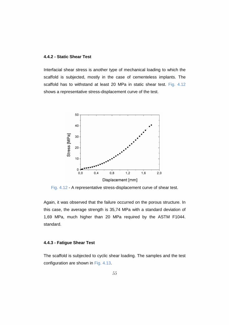
4.4.2 - Static Shear Test
Interfacial shear stress is another type of mechanical loading to which the
scaffold is subjected, mostly in the case of cementeless implants. The
scaffold has to withstand at least 20 MPa in static shear test. Fig. 4.12
shows a representative stress-displacement curve of the test.
Fig. 4.12 - A representative stress-displacement curve of shear test.
Again, it was observed that the failure occurred on the porous structure. In
this case, the average strength is 35,74 MPa with a standard deviation of
1,69 MPa, much higher than 20 MPa required by the ASTM F1044.
standard.
4.4.3 - Fatigue Shear Test
The scaffold is subjected to cyclic shear loading. The samples and the test
configuration are shown in Fig. 4.13.

56
Fig. 4.13 - Fatigue shear test samples and test configuration.
Failure after 10 million cycles were not detected. The five specimens have
all succeeded.
4.4.4 - Taber Abrasion Test
Taber test was carried out in order to evaluate the scaffold weight loss
when subjected to wear. Fig. 4.14 shows the weight loss versus the
number of cycles.
Fig. 4.14 - Weight loss versus number of cycles in taber abrasion test.
57
The weight loss rate decreases during the test likely because of the
stabilization of the contact area and, consequently, of the contact stress.
The material fully attained the ASTM F1978 standard, which requires a
weight loss lower than 65 mg after 100 cycles.
4.5 - Summary of the Results
The porous structure was produced by the space holder method,
using a Calcium Phosphate as space holder material, which is
resistant to the SPS temperature.
The total volume of pores is very close to the volume of space holder
(70%), meaning that shrinkage did not occur thanks to the stability of
the space holder material.
Same cracks were observed in the calcium phosphate particles. In
any case, an overall porous structure integrity was ensured (no
collapsing was verified).
The porous structure is formed by two types of pores: macropores
(interconnected macro porosity) and micropores, located on the struts.
Micro pores (isolate pores on the struts) accounted to about 2% of
total porosity; Macro pores are homogenously distributed on the
compaction plane and less homogeneously distributed on vertical
plane, since a gradient of particles arrangement takes place during
compaction.
Macro pores are well interconnected.
Struts are formed by partially sintered powder particles, which results
in a micro scaled roughness.
Some struts are pores-free, meaning that compaction pressure is not
equally effective in all regions.

58
Macropores size is in the range 400-600 µm, whilst micropores are
mainly smaller than 15 µm.
Interaction between the space holder and cp-Ti produces
compound(s) with needle-like aspect, containing both calcium and
phosphorus;
Adhesion strength of the porous structure on the substrate is almost
twice than that required by ASTM F1147 standard; fracture occurred
on strut.
Shear strength of the porous structure on the substrate is almost twice
than that required by ASTM F1044 standard; fracture occurred on
strut.
All five specimens succeed the fatigue shear test following ASTM
F1160.
The weight loss during taber abrasion tests was low enough to satisfy
the ASTM F1978 requirements.

59
Chapter 5 - FULL DENSITY SUBSTRATES
Full density materials are mandatory when wear and fatigue properties are
concerned [101]. Insufficient fatigue resistance results in crack formation,
propagation and subsequent failure [102], while insufficient wear resistance
promotes ions release into the body [103].
This chapter describes the development of the Co-28Cr-6Mo alloy by
presenting the effect of the sintering temperature, compaction pressure and
powders. The impact of these variables was evaluated on the basis of
density-microstructure-hardness interdependence.
Mechanical and corrosion properties are presented for both Co-28Cr-6Mo
and Ti-6Al-4V. Cast and wrought materials were also characterized for
sake of comparison.
5.1 Co-28Cr-6Mo
5.1.1 - Powder Microstructure
The gas atomized Co-28Cr-6Mo powder observed at SEM is shown in Fig.
5.1.

60
Fig. 5.1. Co-28Cr-6Mo powder. A) Particles; B) Microstructure.
Particles have a spherical shape. The microstructure (Fig. 5.1B) consists of
quasi-equiaxed grains on the order of 1 to 5 µm with carbide [104] at grain
boundary. Such arrangement is commonly called as cellular structure. The
nominal chemical composition and particle size distribution provided by the
powder supplier are reported in Table 5.1 and Table 5.2, respectively.
Table 5.1 - Typical chemical Table. 5.2 - Typical particles size composition distribution
Element Wt [%]
Cr 29,2
Mo 5,6
Si 0,77
Mn 0,74
Fe 0,28
Ni 0,030
C 0,017
O 0,046
Co BALANCE
Cumulative [%] Diameter
d10 22,4 µm
d50 33,9 µm
d90 51,1 µm
< 20µm 4,4% (Vol.)

61
5.1.2 - Effect of Sintering Temperature
Samples were sintered at different temperatures, from 800 °C to 1050 °C
with 50 °C steps, with 5 minutes isothermal holding and 45 MPa pressure.
The SPS densification curve is shown in Fig. 5.2. Densification takes place
intensely from 800 °C to 900 °C, when the maximum density is achieved. A
further increase in temperature does not cause any densification
enhancement. About 8,4% and 1,3% open porosity was found in materials
sintered at 800 °C and 850 °C, respectively.
Fig. 5.2 - Co-28Cr-6Mo densification curve at various temperature; 5 min. and 45MPa.
The microstructures of the sintered materials are shown in Fig. 5.3. Pores
are easily identified as black spots in the shiny unetched metallic matrix.
They are random distributed, reaching 20 µm of size and irregular shaped.
The materials sintered above 900 °C (included) show only isolated pores.

62
Larger pores in Fig. 5.3A and Fig. 5.3B tend to be orthogonal to the
compaction direction.
Fig. 5.3 - Unetched Co-28Cr-6Mo microstructures sintered at various temperatures, 5 min and 45 MPa. A) 800 °C, B) 850 °C, C) 900 °C, D) 950
°C, E) 1000 °C and F) 1050 °C
Etched microstructures are shown in Fig. 5.4.

63
Fig. 5.4 - Etched Co-28Cr-6Mo microstructures sintered at various
temperatures, 5 min and 45 MPa. A) 800 °C, B) 850 °C, C) 900 °C, D) 950 °C, E) 1000 °C and F) 1050 °C
In the material sintered at 800 °C pores are systematically located between
particles. Precipitates are seen as small gray particles more evident in
materials sintered at lower temperatures. Increasing SPS temperature
promotes their gradual dissolution. In particular, an intensive dissolution is
64
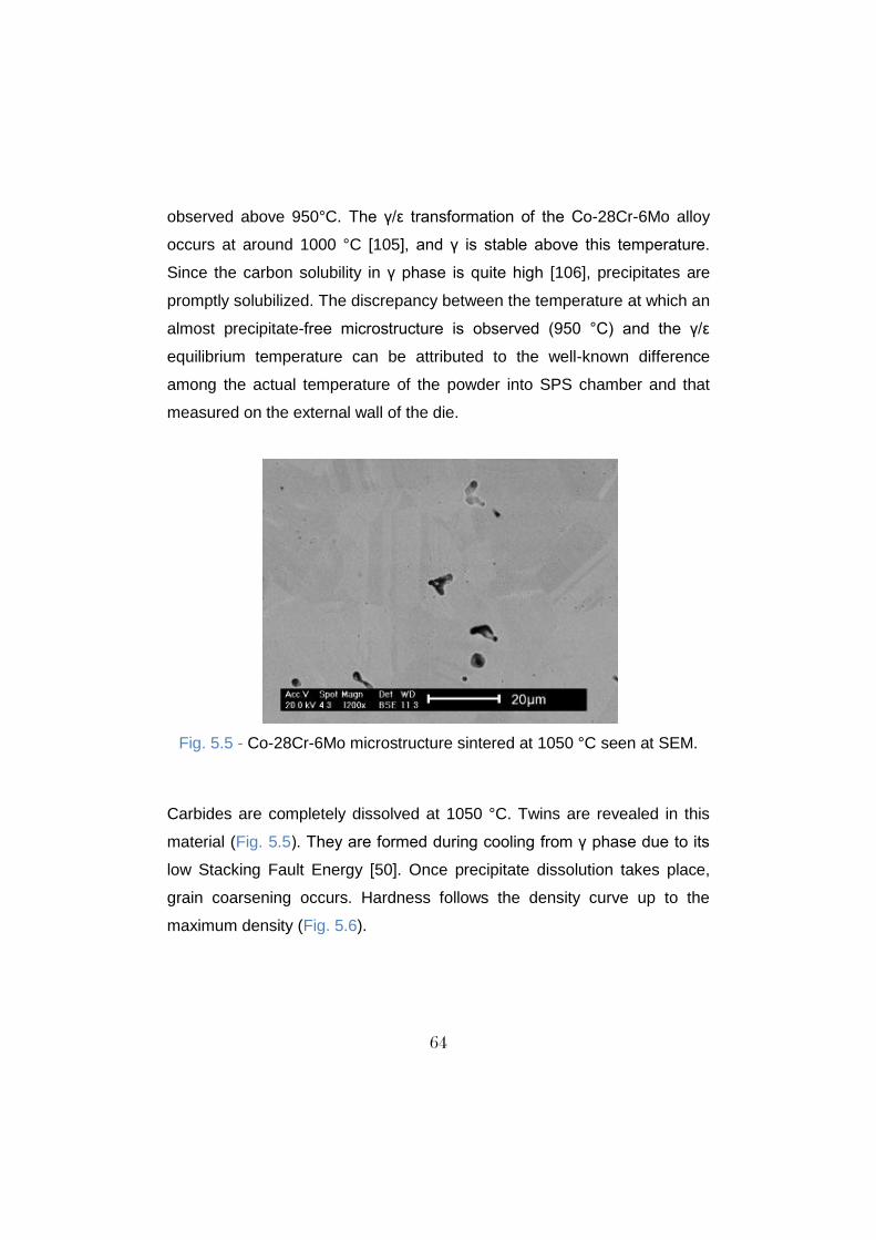
observed above 950°C. The γ/ε transformation of the Co-28Cr-6Mo alloy
occurs at around 1000 °C [105], and γ is stable above this temperature.
Since the carbon solubility in γ phase is quite high [106], precipitates are
promptly solubilized. The discrepancy between the temperature at which an
almost precipitate-free microstructure is observed (950 °C) and the γ/ε
equilibrium temperature can be attributed to the well-known difference
among the actual temperature of the powder into SPS chamber and that
measured on the external wall of the die.
Fig. 5.5 - Co-28Cr-6Mo microstructure sintered at 1050 °C seen at SEM.
Carbides are completely dissolved at 1050 °C. Twins are revealed in this
material (Fig. 5.5). They are formed during cooling from γ phase due to its
low Stacking Fault Energy [50]. Once precipitate dissolution takes place,
grain coarsening occurs. Hardness follows the density curve up to the
maximum density (Fig. 5.6).

65
Fig. 5.6 - Hardness and density vs. SPS temperature.
As indentation involves solid and pores during deformation, this behavior
was expected. Likewise, hardness significantly decreases at higher
temperatures. This behavior finds explanation in the microstructure
evolution. Precipitates strengthen the material and their dissolution drives
down hardness. This means that the hardening promoted by carbon and
alloying elements dissolution in the metallic matrix (solution hardening)
combined to the change in the matrix microstructure is less effective than
hardening promoted by precipitates (precipitation hardening). Moreover,
hardness drops continuously on further increasing temperature, as a result
of progressive dissolution of precipitates and grain growth.

66
Fig. 5.7 - Microhardness and density vs. SPS temperature.
On the other hand, microhardness does not show an appreciable variation
at low temperatures (up to 900 °C) (Fig. 5.7). It means that the amount of
precipitates dissolved at that temperature slightly affects hardness.
Standard deviation is straight correlated to microstructure, which is not well
homogeneous at low temperature, and therefore it is higher at 800 °C and
850 °C. At 950 °C and above, precipitates undergo dissolution, mostly at
1050 °C. Standard deviation in this range of temperature is much more
stable due to a better microstructure homogeneity. X-ray diffraction (XRD)
completes the structural characterization (Fig. 5.8).
Fig. 5.8 - Microstructural constituents vs. SPS temperature.

67
Analyses on the powder revealed a massive presence of γ phase (f.c.c.)
without any precipitate (metastable solid solution due to the fast
undercooling during atomization). Huang and Lopez [107] verified that
athermal ε martensite (h.c.p.) transformation is inhibited when grain size is
less than 10 µm and therefore the structure of the atomized powder is
justified by the fine cell size. Sintering at 800 °C promotes the formation of
M7C3 carbides, as can be seen in the XRD pattern shown in Fig. 5.9, which
destabilize austenite favoring the formation of ε phase up to 25%.
Fig. 5.9 - XRD pattern of Co-28Cr-6Mo sintered at 800°C.
On the other hand, by increasing sintering temperature up to 900 °C
carbides dissolution is enhanced, increasing carbon content in cobalt matrix
and stabilizing γ phase, which amount slightly increases. Finally, at highest
temperature (1050 °C) carbides are completely dissolved, grain size grows
and ε martensite transformation takes place. The constitution of the metallic
matrix is then strongly correlated to SPS temperature and to its effect on
the precipitation/solubilization of carbides.

68
Fig. 5.10 shows microhardness and the volume content of carbides at
various temperatures.
Fig. 5.10 - Hardness and carbide content vs. SPS temperature.
Microhardness shows a sudden transition temperature (900-950 °C), whilst
carbides dissolution follows a linear behaviour, indicating the importance of
γ and ε phases on microhardness.
5.1.2.1 - Relative Density
The actual theoretical density must be calculated from chemical
composition. The Co-28Cr-6Mo ASTM F75-07 standards prescribes that
chromium can vary from 27 to 30 wt% and molybdenum from 5 to 7 wt%,
for instance. The calculation of the theoretical density limits and the
theoretical density of the employed powder is shown in Table 5.3. The
calculation considers elements as natural isolate species.

69
Table 5.3 - Theoretical density limits and of the powder.
Elements Min. [wt%] Max. [wt%] Measured [wt%]
Cr 30 27 29,2
Mo 5 7 5,6
Ni 0,5 0,03
Fe 0,75 0,28
C 0,35 0,017
Si 1 0,77
Mn 1 0,74
W 0,2
P 0,02
Al 0,1
Ti 0,1
B 0,01
Co 61,67 65,3 63,317
Theoretical Range Actual
Density [g/cm3] 8,29 8,51 8,37
Table 5.4 reports the achieved relative densities at various temperature, for
5 min. and 45MPa.
Table 5.4 - Density and relative density at various temperature.
Sintering Temperature [°C]
Density [g/cm3]
Relative Density [%]
800 6,86 81,9
850 8,01 95,7
900 8,26 98,7
950 8,26 98,7
1000 8,25 98,6
1050 8,24 98,5
Theoretical density = 8,37 g/cm3

70
In principle, relative density does not exceed 99%, the lower limit usually
accepted to define “full density”. It has to be considered that the method
used for calculation of theoretical density does not consider carbides and
all the other precipitates. It may be then concluded that, within the
uncertainty of the reference datum, SPS at 900-950 °C leads to a sintered
density very close to the theoretical one.
5.1.3 - Effect of Pressure
The effect of compaction pressure on the densification during SPS process
has been discussed by some authors [88, 108, 109]. Initially, it causes
particles rearrangement, followed by elastic and plastic deformation of the
contact regions, progressively propagated into the core of the particles [88].
These events are more or less effective depending on the nature and
features of the powder. Ceramic powders, whose in essence are brittle,
normally do not undergo plastic deformation. Moreover, usually they are
non-electrical conductive, characteristic that is correlated to plastic
deformation enhancement from thermal softening promoted by localized
overheating on the particles contact points (electric current → Joule heating
→ overheating on necks → thermal softening) [87,88]. Particles
rearrangement is therefore even more important in ceramic powders
densification, mainly in the case of solid state sintering. Metallic powders,
which are conductive and ductile, are expected to be very susceptible to
compaction pressure during SPS. Keeping it in mind, compaction pressure
was increased in order to improve densification.
Although some authors have used compaction pressures up to 200 MPa
[109,111], the upper limit used in this work was 70 MPa. This limit is
imposed by the quality of the graphitic dies.

71
The densification curve at 900 °C and 5 minutes isothermal holding and at
two compaction pressures is displayed in Fig. 5.11. Early at 60 MPa density
reaches the range of fully dense material (>99%), but it rises up to 99,4% at
70 MPa. It is supposed that density can be further improved, but critical
situation regarding die failure was detected at 70 MPa. Therefore, 60 MPa
was taken as the reliable compaction pressure in the experimental
equipment used in the present study.
Fig. 5.11 - Relative density vs. compaction pressure; 5 min and 60 MPa.
The microstructures attained at 60 and 70 MPa (900 °C and 5 minutes) are
shown in Fig. 5.12. Pores are sensibly reduced at 60 MPa and practically
eliminated at 70 MPa. No effects on carbides are observed, as it was
expected.
With pores continuously removed from the microstructure on increasing
pressure, hardness increases correspondingly, as shown in Fig. 5.13.
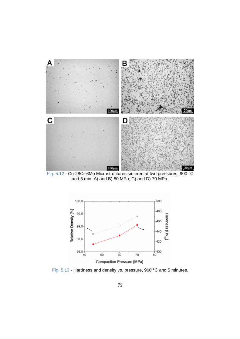
72
Fig. 5.12 - Co-28Cr-6Mo Microstructures sintered at two pressures, 900 °C
and 5 min. A) and B) 60 MPa; C) and D) 70 MPa.
Fig. 5.13 - Hardness and density vs. pressure, 900 °C and 5 minutes.

73
On the other hand, as carbides do not undergo further dissolution,
microhardness does not change significantly, as can be noticed in Fig.
5.14.
Fig. 5.14 - Microhardness and density vs. pressure, 900 °C and 5 minutes.
Fig. 5.15 shows the virtually pores-free Co-28Cr-6Mo microstructure when
sintered at 900 °C, 5 min, 70 MPa.
Fig. 5.15 - Co-28Cr-6Mo microstructure sintered at 900 °C, 5 min, 70 MPa.

74
In conclusion, the best properties interdependence by far is achieved by
means of SPS at 900 °C, 5 minutes and 60 MPa.
5.1.4 - Influence of Powder
In view of exploring raw materials, three different Co-28Cr-6Mo powders by
different suppliers were investigated. For sake of confidentiality the
suppliers cannot be disclosed.
Fig. 5.16 displays the frequency and cumulative curves of particle size.
Table 5.5 - Powders size features.
Powder d10 d50 d90 SA
A 23,85 34,96 51,67 0,18
B 17,52 27,58 44,13 0,23
C 5,93 19,91 54,43 0,43
Fig. 5.16 - Powder particle size frequency and cumulative curves. A)
Powder A; B) Powder B and C) Powder C. SA = surface area

75
Despite of the similar particle size distribution of powders A and B, the
mean diameter of powder B is around 80% of the powder A. Since both
powders have particles size restricted to around 100 µm, the largest mean
diameter of powder A is correlated to the small amount of fine particles
(<10 µm), resulting in a narrow distribution. Powder C shows a completely
different trend. It displays a pronounced amount of fine particles (~20%).
Consequently, its surface area in much larger (Table 5.5).
Table 5.6 reports the microhardness of the three powders as well as the
concentration of the main alloying elements.
Table 5.6 - Hardness, Cr, Mo and C extents of the Co-28Cr-6Mo powders.
Powder Code Hardness [HV0,02] Cr Mo C
A 415 ± 13 28,5 6,1 0,025
B 438 ± 13 29,2 5,6 0,017
C 413 ± 12 28.9 5.5 0,008

76
Fig. 5.17 - Particles shape and microstructure of powders. A) and B)
Powder A; C) and D) Powder B; and E) and F) Powder C.
Another peculiar characteristic outcomes from the microstructural analysis
(Fig. 5.17). The amount of particles containing voids is much higher in
powder C than in the other two powders, which are instead very similar.

77
Figure 5.18 shows the microstructure of sintered specimens obtained with
the three powders in the following conditions: 900 °C, 60 MPa, 5 minutes
isothermal holding.
Fig. 5.18 - Microstructures of materials sintered at 900 °C, 5 minutes and
60 MPa. A) and B) Powder A; C) and D) Powder B; E) and F) Powder C.

78
The presence of pores in materials A and C is evident, resulting in a low
relative density. In particular the material sintered with powder C shows two
typologies of pores. The former is around 10 µm and is very irregular, lying
between particles (incomplete sintering), the latter is about 20 µm and is
relatively rounded, coming from particles containing voids. A particle
containing unmodified preexisting void can be seen in Fig. 5.19. Density,
hardness and microhardness of these three selected materials are reported
in Table 5.7.
Table. 5.7 - Relative Density, Hardness and Microhardness attained after SPS at 900°C, 5 minutes and 60 MPa
Material Code
Relativity Density [%]
Hardness [HV30]
Hardness [0,05]
A 95,60 318 ± 3 451 ± 19
B 99,04 430 ± 2 462 ± 11
C 97,34 418 ± 4 455 ± 9
While hardness is dominated by density, microhardness is quite similar.
Fig. 5.19 - Microstructure of the material A. In evidence a preserved
particle.

79
5.1.5 - Mechanical Properties
Tensile and bending reverse fatigue tests were carried out. Microstructures
and fractographies are presented for complementary discussion. For sake
of comparison the as cast material was tested as well.
5.1.5.1 - Tensile properties
Differently from the samples used for the optimization of the process
parameters (sections 5.1.1 - 5.1.4), whose were discs of 20 mm in
diameter and 10 mm of height, tensile specimens were machined from bars
of 90 mm in length 10 mm in width and 7 mm in height. The microstructure
of the gage section of the as cast tensile specimen is shown in Fig. 5.20.
Fig. 5.20 - Microstructures of as cast tensile specimen.
Microstructure is characterized by large grains with some residual
micropores. Hardness and microhardness of materials are reported in
Table 5.8.

80
Table 5.8. Hardness and microhardness of materials sintered at 900°C, 950°C and of as cast material.
Authors [89,90] demonstrated that in some cases a temperature gradient
as large as 150 °C can arise during sintering by SPS. In this case study, in
specific in this asymmetrical geometry, a gradient of about 50 °C was
experimentally confirmed. It is attributed to carbides dissolution since
density is equivalent in the two regions and microhardness varied as well.
Hardness and microhardness reported in Table 5.8 clearly establish the
existence of such a temperature gradient, in particular in the tensile
specimen sintered at 950°C. Fig. 5.21 shows the hardness (HRC) variation
along the axis of the bar produced by SPS at 900 °C and 950 °C.
Fig. 5.21 - Hardness Rockwell C for tensile specimens sintered at 900 °C and 950 °C.
Material Hardness [HV30] Microhardness [HV0,05]
gage region grip region gage region grip region
SPS 900°C 435 ± 1 441 ± 2 446 ± 4 452 ± 9
SPS 950°C 369 ± 2 428 ± 3 427 ± 8 440 ± 8
As Cast 294 ± 6 297 ± 3 383 ± 5 382 ± 4

81
Fig. 5.22 shows the stress-strain curves of materials sintered at 900 °C and
950°C, and the as cast reference.
Fig. 5.22 - Tensile curves for materials sintered at 900°C and 950°C, and as cast version
SPS at 900 °C produces a material with the highest yield strength due to
smaller grain size an carbides dispersion; in contrast the elongation is the
worst. On the other hand, the material sintered at 950 °C exhibits both yield
strength and Ultimate Tensile Strength (UTS) higher than the as cast
reference, but also significantly greater ductility. Consequently, it shows the
highest toughness due to the best combination of strength and ductility.
Tensile properties are reported in Table 5.9 compared to the ISO
biomedical standard specification.
Table 5.9 - Tensile properties of the materials sintered at 900°C and 950°C, as cast and ISO standard.
Material Condition
σ0,2% ± STD [MPa]
UTS ± STD [MPa]
Δl ± STD [%]
SPS 900°C 936 ± 14 1284 ± 31 13,3 ± 3
SPS 950°C 778 ± 7 1246 ± 9 35,2 ± 2
As Cast 490 ± 8 845 ± 8 26,7 ± 2
ISO 5232-4 450 665 8,6

82
Both sintered and as cast materials match the ISO standards. Moreover,
the material sintered at 900 °C shows the lowest but fully satisfactory
percent elongation. Despite the higher amount of carbon (0,12%), large
grain size is responsible for the inferior mechanical properties of cast
material. Fracture surfaces of tensile specimens are shown in Fig. 5.23.
Fig. 5.23. Tensile fracture surfaces. A) and B) Sintered at 900 °C;
C) and D) Sintered at 950 °C and E) and F) As Cast.

83
Dimples can be clearly seen in all surfaces, but those present in the as cast
material are markedly larger than others, since grains are much larger,
favoring void coalescences. Another noticeable characteristic is the
occurrence of some flat surfaces indicating a fracture by quasi-cleavage,
less intense in the material sintered at 950 °C, but evident in the as cast
material. Finally, dimples in the material sintered at 900 °C are smaller than
2 microns and homogeneously distributed in whole fracture surface.
5.1.5.2 - Fatigue Properties
The fatigue resistance was investigated on the material with the higher
yield strength and UTS, that is, that sintered at 900 °C. Table 5.10 show the
results of the stair case procedure on the sintered material and the as cast
reference.

84
Table 5.10 - Stair case procedure table of sintered and cast materials. Stress (MPa)
1 2 3 4 5 6 7 8 9 10 11 12 13 14 15
600 x
585
570
555
540 x
525 x
510
495 x
480 x x
465 o x x o x x
450 o o o
440 x
425
410
395
380 x
365
350 x
335 x
320 x
305
290 x
275
260 x x x
245 o x x o
230 o o
x = Failed; o = Run out; -- Sintered; -- As Cast.
Table 5.11 reports the fatigue resistance calculated by using the staircase
procedure. As it can be seen, the sintered material is abundantly superior
to the as cast one. The 50% survival probability fatigue resistance, as well
as the yield stress in tensile tests, of the as cast material is indeed 52% of
those shown by the sintered material.

85
Table 5.11 - Fatigue resistance of sintered and as cast version.
Survival Probability
Material 10% 50% 90%
SPS 900°C 494 464 ± 7 451
As Cast 256 245 ± 7 234
5.1.6 - Corrosion Properties
Corrosion can take place either localized or on the whole surface. In
particular, the former case is much more common in cases related to
implant failure [112]. This type of corrosion typically outcomes from pitting
due to galvanic cell formation. Metal ions released from corrosion can
induce tissue reactions, which in turn can seriously damage to some
organs and vital functions [113].
5.1.6.1 - Open Circuit Potential (OCP) Test
Among the corrosion tests that metallic biomaterials have to fulfill for
standards requirements, the OCP is the simplest. It consists in monitoring
the potential between the material and the reference during immersion in a
solution, either with purging gas or not. Basically, three aspects have to be
considered: the free potential, the curve oscillation and the trend of
potential variation.

86
Fig. 5.24 - Open circuit potential curves for sintered and as cast materials
The sintered and the as cast materials responded very similarly to the OCP
test in the purged air, as it can be seen in Fig. 5.24. Despite the presence
of some peaks in the curve of the former, both materials show around -0,2V
of free potential and a satisfactory stable curve, with tendencially increasing
potential. Besides, the sintered material shows a pretty lower free potential
in purged nitrogen environment (absence of oxygen). It may be correlated
to the presence of larger grain boundary surface. Such evidence in any
case does not mean a worse behavior, but it is an indication that materials
respond differently to the absence of oxygen. Moreover, both materials
present an increasing potential during the 72 hours of the test. This positive
potential evolution in all cases indicates the formation of a protecting
passivation layer, ensuring the long term application.
5.1.6.2 - Cyclic Potentialdynamic Polarization (CPP) Test

87
Metallic biomaterials contain a thin oxide protective layer (passivation
layer). In order to evaluate the integrity of this protection the CPP test is
usually carried out. Integrity is assessed by the well-known anodic
polarization curve. The potential is varied and the range where the electric
current is quasi-constant is denominated passivation range. The potential
at the starting and at the end (breakdown potential) of this steady curve is
an indication of the corrosion resistance. Moreover, the current density is
related to the corrosion rate. The polarization curves for the sintered and
the as cast materials are shown in Fig. 5.25.
Fig. 5.25 - Anodic polarization curves of sintered and as cast materials
Both materials have a free potential around -0,2 V. By increasing the
potential the current density slowly increases, but not considerably. It is
called the passive region. The sintered material shows the passive
behavior up to the breakdown of oxide layer (transpassivity) at around 0,8
V vs. Ag/AgCl with a passive current density of about 5 x 10⁻⁶ A/cm2. The

88
as cast material shows a passive behavior up to the breakdown potential
due to transpassivity of 0,6 V vs. Ag/AgCl with a passive current density of
about 3 x10⁻⁶ A/cm2. Materials show similar corrosion potential and passive
region, with a slightly higher density current for the sintered one.
In particular, if a damaged film is unable to repair itself, the cathodic
reactions necessary to support corrosion can take place on the undamaged
parts of the passive film, leading to rapidly accelerated corrosion at the
damaged site.
5.2 - Ti-6Al-4V
The production of a fully dense Ti-6Al-4V alloy by SPS has been
investigated and optimized in a previous work [114]. The SPS parameters
are 850 °C, 5 minutes isothermal holding and pressure of 60 MPa. In the
present study, the fatigue and corrosion properties have been investigated.
The SPS parameters have been modified with respect to the previous work.
Since compaction pressure was reduced from 60 MPa to 45 MPa, sintering
temperature was increased up to 950 °C.
5.2.1 - Mechanical Properties
Tensile and bending reverse fatigue tests were carried out. Microstructures
and fractographies are also presented for complementary discussion. For
sake of comparison a wrought alloy (forged annealed hot rolled, in
agreement with ASTM B348) was tested as well.

89
5.2.1.1 - Tensile Properties
The tensile specimen microstructures of the SPS and the wrought materials
are shown in Fig. 5.26.
Fig. 5.26 - Microstructures of tensile specimen utile region. A) Sintered and B) Wrought.
Some few pores are present in the sintered material, whose actually do not
significantly alter density, denoting that selected SPS parameters were
adequate. Microstructure of the sintered material consists of lamellar alpha
phase plus interlaths beta phase. The wrought microstructure consists of
globular alpha phase plus coarsened beta phase. Such a microstructure
comes from the conventional thermomechanical treatment followed by
annealing into alpha plus beta field. The wrought alloy has a slightly higher
hardness than the sintered one, as reported in Table 5.12.
Table 5.12. Hardness and microhardness of material sintered at
950 °C and wrought version.
Material Hardness
[HV30] Microhardness
[HV0,05]
Wrought 318 ± 3 333 ± 9
SPS 950°C 307 ± 2 318 ± 3
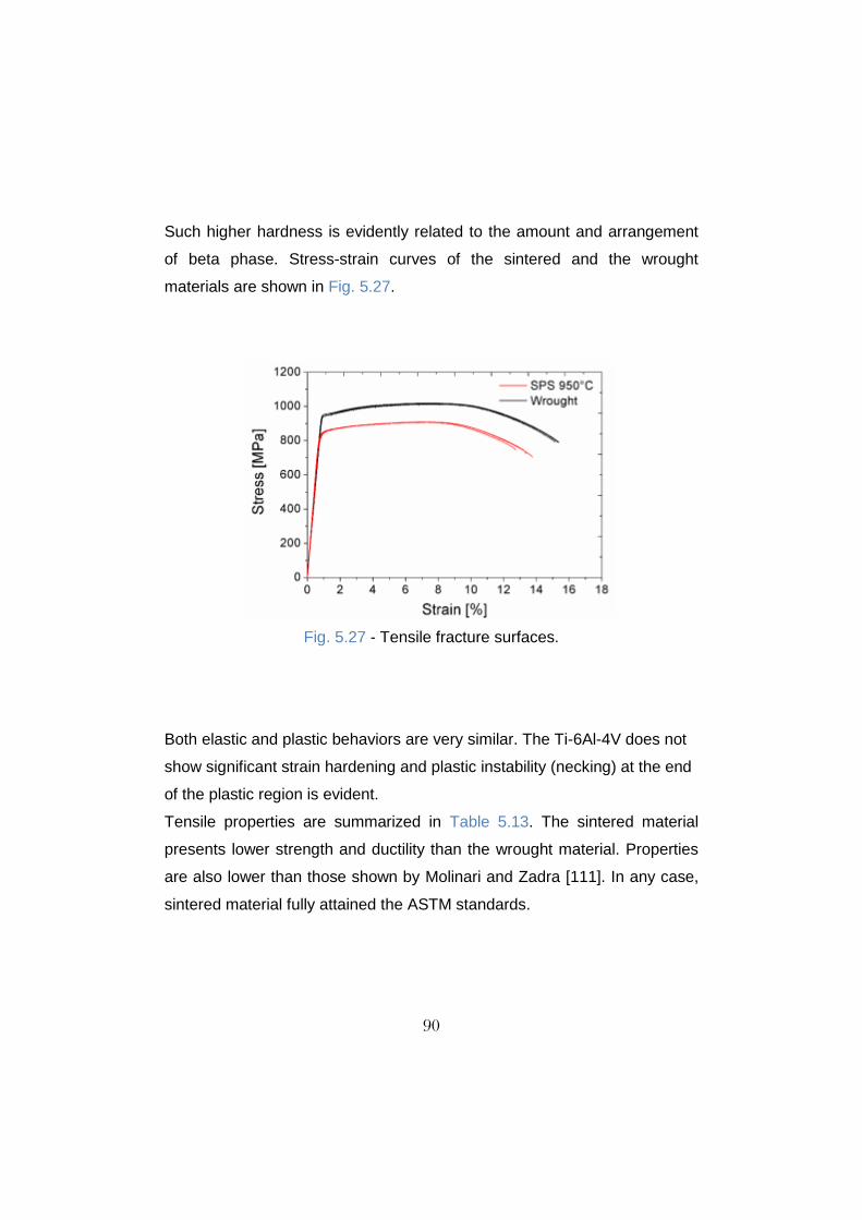
90
Such higher hardness is evidently related to the amount and arrangement
of beta phase. Stress-strain curves of the sintered and the wrought
materials are shown in Fig. 5.27.
Fig. 5.27 - Tensile fracture surfaces.
Both elastic and plastic behaviors are very similar. The Ti-6Al-4V does not
show significant strain hardening and plastic instability (necking) at the end
of the plastic region is evident.
Tensile properties are summarized in Table 5.13. The sintered material
presents lower strength and ductility than the wrought material. Properties
are also lower than those shown by Molinari and Zadra [111]. In any case,
sintered material fully attained the ASTM standards.

91
Table 5.13 - Tensile properties of material sintered at
950 °C and wrought version.
Fracture surfaces of sintered tensile specimens are shown in Fig. 5.28.
Fig. 5.28 - Fracture surfaces of sintered tensile specimens.
Fracture surfaces are quite similar. Slight larger dimples are seen in the
wrought material. This behavior is supported by the coarse microstructure
of the wrought material, which favors void coalescence. On the other hand,
thin alpha lamellae promote dislocation pile-up and, in turn, lower ductility
and smaller dimples.
Material σ0,2% ± STD
[MPa] UTS ± STD
[MPa] Δl ± STD
[%]
SPS 950°C 841 ± 3 907 ± 1 13 ± 0,4
Wrought 950 ± 4 1015 ± 3 15 ± 0,2
ASTM F1472 – 02 780 860 10

92
5.2.1.2 - Fatigue Properties
Table 5.14 reports the results of the staircase procedure.
Table 5.14 - Staircase procedure table. Stress (MPa)
1 2 3 4 5 6 7 8 9 10 11 12 13 14 15
595 x
580
565 x
550 x
535
520 x x x
505 x x x o o
490 x o x x o o x o x
475 o xo o o
460 o o o x
445 o
430
415
x = Failed; o = Run out; -- Wrought; -- SPS 950°C
Table 5.15 summarizes the fatigue resistance. The superior fatigue
resistance shown by the wrought material is due to the globular alpha
phase, which enhances high cycle fatigue (HCF) resistance [58].
Table 5.15 - Fatigue resistance of sintered and wrought materials.
Survival Probability
Material 10% 50% 90%
SPS 950°C 490 472 ± 13 454
Wrought 515 500 ± 11 484

93
5.2.2 - Corrosion Properties
As in the case of the Co-28Cr-6Mo alloy, both OCP and CPP corrosion
testes were carried out.
5.2.2.1 - Open Circuit Potential (OCP) Test
Open circuit potential curves for the sintered and the wrought material are
shown in Fig. 5.29.
Fig. 5.29 - Open circuit potential curves for sintered and wrought materials.
Despite the presence of some instability in the curves of the wrought
material, both materials reached the free potential at around -0,5 V. When
purged air the sintered material takes more time to reach the steady state,
but all curves have a tendency to increase. This positive potential evolution
in all cases indicates the formation of a protecting passivation layer,
ensuring the long term application.

94
5.2.3.2 - Cyclic Potentialdynamic Polarization (CPP) Test
In order to evaluate the integrity of the oxide protective layer and the
current density at passive region the CPP test was carried in purged
nitrogen.
Fig. 5.30 - Cyclic anodic polarization curves of sintered and wrought
Both materials have a free potential around -0,5 V, as shown in Fig. 5.30.
By increasing the potential the current density increases up to reach the
stable region (passive region). Corrosion oxide layer breakdown
(transpassivity) was not attained in both cases up to 2 V vs. Ag/AgCl.
Passive current density was about 1 x 10⁻⁶ A/cm2 for both materials.
Materials show a very similar corrosion free potential and passive region.

95
5.3 - Summary of the Results
Full Density Substrate (Co-28Cr-6Mo):
Almost full density (98,7%) was achieved at 900 °C using 5 minutes
of dwell time and 45 MPa of compaction pressure. A higher
temperature does not improve density. Pores are isolated.
The maximum density (99,4%) was achieved at 900 °C, 5 minutes and
70 MPa. A full density (100%) was not achieved due to the limit
imposed by mechanical resistance of the dies.
Only M7C3 carbides were identified; .
Carbides are slightly dissolved in the matrix up to 900 °C. partially
dissolved at 950 °C and completely dissolved at 1050°C.
Pressure does not affect carbides dissolution.
At 1050 °C an appreciable grain growth take place.
Hardness follows the densification curve up to the maximum density.
Increasing temperature promotes carbide dissolution and hardness
decreases. Consequently, interstitial carbon on the matrix is less
effective than carbides in hardening the material.
Microhardness does not change up to 900 °C. At higher temperature it
decreases as in the case of hardness.
Voids located within the powder particles are not eliminated during
SPS at the processing parameters used;
Sintering at 900 °C, 5 minutes and 60 MPa resulted in Yield Strength
and UTS twice of those of the cast material, taken as a reference,
while percent elongation at fracture is about 50% lower.
Sintering at 950 °C, 5 minutes and 60 MPa resulted in a material with
Yield Strength and UTS and percent elongation at fracture significantly
higher than those of the cast material.

96
Fatigue resistance follows tensile properties; the material sintered at
900 °C is about two times more resistant than the cast material.
A lower free potential is achieved by the sintered material in
comparison to the cast material when nitrogen was purged during
OCP test. Both materials show a trend of increasing potential.
On the cyclic potentiodynamic polarization tests a very similar
behavior was observed between SPS and cast material. Both
materials repassivate after transpassivity.
Full Density Substrate (Ti-6Al-4V):
Tensile properties of the material sintered at 950 °C, 5 minutes and
45 MPa of pressure are slightly lower than those of the wrought
material taken as a reference.
Fatigue resistance follows tensile properties. The sintered material
has a slightly lower fatigue resistance than the wrought one.
Corrosion tests are definitely similar for both materials.

97
Chapter 6 - CO-SINTERING
Co-sintering of different materials may lead to insufficient densification as
well as to extensive interfacial reactions. SPS, on the other hand, is
expected to limit such drawbacks since sintering is enhanced by pressure
and by the specific heating mechanisms, leading to a low heat input.
Co-sintering of either the Co-28Cr-6Mo and Ti-6Al-4V alloys with the cp-Ti
is discussed in this chapter. Microstructural investigation and diffusion
calculations at the interfaces are the main topics. For both the systems the
study of the fatigue resistance of a substrate with a porous coating is
presented at the end of each section.
6.1 - Cp-Ti/Co-28Cr-6Mo
Two strategies are proposed to obtain the joining of materials: co-sintering
and sinter-bonding. The former consists in the concurrently sintering of both
powders. The latter consists in the sintering of a powder on other previously
sintered material. Both sintering the cp-Ti powder on previously sintered Co
alloy and sintering the Co alloy powder on previously sintered cp-Ti were
carried out.
6.1.1 - Microstructure
The Co-28-Cr-6Mo alloy microstructure when co-sintered at 1000 °C, 5
minutes and 45 MPa or 60 MPa is shown in Fig. 6.1.
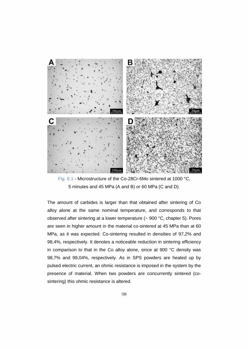
98
Fig. 6.1 - Microstructure of the Co-28Cr-6Mo sintered at 1000 °C,
5 minutes and 45 MPa (A and B) or 60 MPa (C and D).
The amount of carbides is larger than that obtained after sintering of Co
alloy alone at the same nominal temperature, and corresponds to that
observed after sintering at a lower temperature (~ 900 °C, chapter 5). Pores
are seen in higher amount in the material co-sintered at 45 MPa than at 60
MPa, as it was expected. Co-sintering resulted in densities of 97,2% and
98,4%, respectively. It denotes a noticeable reduction in sintering efficiency
in comparison to that in the Co alloy alone, since at 900 °C density was
98,7% and 99,04%, respectively. As in SPS powders are heated up by
pulsed electric current, an ohmic resistance is imposed in the system by the
presence of material. When two powders are concurrently sintered (co-
sintering) this ohmic resistance is altered.

99
Fig. 6.2 shows the interface microstructure after etching.
Fig. 6.2 - Etched Interface microstructure after co-sintering at 45 MPa.
Upper side Ti, lower side Co alloy.
Despite of the different densities, co-sintering at 45 MPa and 60 MPa
produces an interface region with the same features. It is irregular due to
the penetration of the Co alloy particles in the cp-Ti, since the former has a
higher hardness. The cp-Ti microstructure shows a layer of around 50 µm
close to the interface and a lamellar layer up to a distance of around 200
µm. Beyond this distance the typical microstructure of the cp-Ti2 is
observed. The microstructure of the cp-Ti in the interface region is thus
modified, likely by the presence of diffused alloying elements. On the other
hand, the Co alloy does not show a different microstructure between the
interface region and the bulk. Moreover, on the Co alloy interface a lower
sintering efficiency is denoted by the morphology of the particles, which
appear as only slightly deformed.

100
6.1.2 - Sinter-bonding
Pre-sintering and sinter-bonding cycles were carried out at 1000 °C, 5
minutes and 60 MPa. The microstructure of the interface after sinter-
bonding is shown in Fig. 6.3.
Fig. 6.3 - Interface microstructure after sinter-bonding. A) and B) Sinter-
bonding of Co alloy powder on a pre-sintered cp-Ti; C) and D) Sinter-
bonding of cp-Ti powder on a pre-sintered Co alloy.
In the case of the sinter-bonding of Co alloy powder on the pre-sintered cp-
Ti (Fig. 6.3A and 6.3B), the interface is still irregular owing to the harder Co
particles indentation of the sintered titanium substrate. In the other case

101
(Fig. 6.3C and 6.3D), the interface is quite flat since the Ti particles cannot
indent the sintered Co alloy substrate due to their lower hardness. In both
sinter-bonding configurations cp-Ti attained full density (no pores). Co alloy
on the other hand attained 98,7% of density when sinter-bonded on the
pre-sintered cp-Ti and 99,2% when pre-sintered.
Fig. 6.4 - Microstructure of materials sintered (left ) and subsequent
sinter-bonded (right). A) and B) titanium, C) and D) cobalt alloy.
An interesting difference between the two sinter-bonded materials is related
to grain growth in the previously sintered material, which is exposed to two
SPS cycles (sintering followed by sinter-bonding). In the Co alloy carbides
are only slightly dissolved; their presence prevents grain growth thanks to

102
grain boundary pinning. On the contrary, the cp-Ti undergoes an extensive
grain growth. Fig. 6.4 shows the cp-Ti and Co alloy after sintering and after
sinter-bonding.
6.1.3 - Interface Characterization
Fig. 6.5 shows the Ti, Co, Cr and Mo concentration line profiles measured
by EDXS across the interface of the specimen obtained by sinter-bonding
the cp-Ti powder on the previously sintered Co alloy. This profile is
representative of the other two specimens discussed, since the significant
difference among them is rather correlated to the interfacial contour.
Fig. 6.5 - EDXS line profile analysis at the interface of sinter-bonded
cp-Ti powder on the pre-sintered Co alloy.
Titanium does not diffuse into the Co alloy, whilst Co, Cr and Mo diffuse
into cp-Ti. The total diffusion depth corresponds to about 200 µm and the
diffusion distances of Co, Cr and Mo are different.
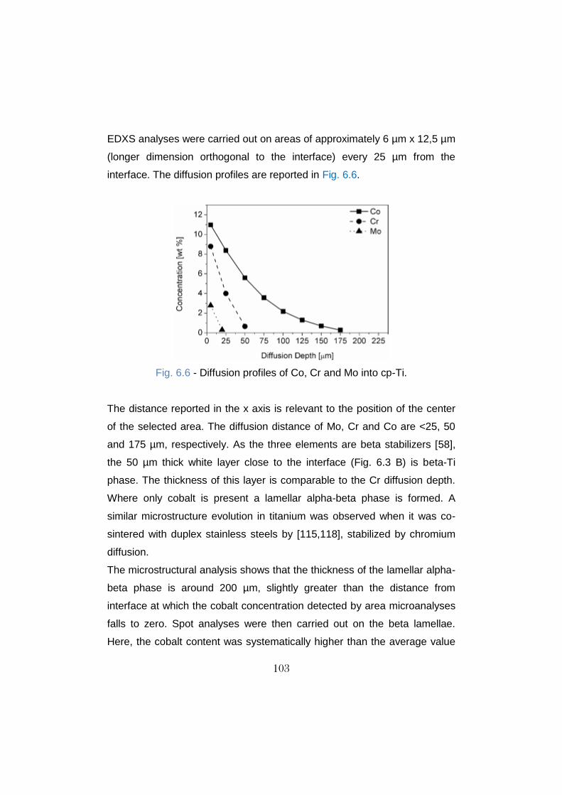
103
EDXS analyses were carried out on areas of approximately 6 µm x 12,5 µm
(longer dimension orthogonal to the interface) every 25 µm from the
interface. The diffusion profiles are reported in Fig. 6.6.
Fig. 6.6 - Diffusion profiles of Co, Cr and Mo into cp-Ti.
The distance reported in the x axis is relevant to the position of the center
of the selected area. The diffusion distance of Mo, Cr and Co are <25, 50
and 175 µm, respectively. As the three elements are beta stabilizers [58],
the 50 µm thick white layer close to the interface (Fig. 6.3 B) is beta-Ti
phase. The thickness of this layer is comparable to the Cr diffusion depth.
Where only cobalt is present a lamellar alpha-beta phase is formed. A
similar microstructure evolution in titanium was observed when it was co-
sintered with duplex stainless steels by [115,118], stabilized by chromium
diffusion.
The microstructural analysis shows that the thickness of the lamellar alpha-
beta phase is around 200 µm, slightly greater than the distance from
interface at which the cobalt concentration detected by area microanalyses
falls to zero. Spot analyses were then carried out on the beta lamellae.
Here, the cobalt content was systematically higher than the average value

104
measured at the same distance, as shown in Fig. 6.7, and the diffusion
depth of cobalt corresponds to the thickness of the biphasic lamellar
microstructure.
Fig. 6.7 - Spot analyses on the beta-Ti lamellae.
Since lamellae are very thin, their higher cobalt concentration is not
detected by the area microanalysis, since it gives the average
concentration in the whole area involved. The agreement between the
microstructure and the Co concentration in the lamellae is satisfactory.
Fig. 6.8 shows a combination of EDXS analysis and the microstructural
image in a 3D map.

105
Fig. 6.8 - Cobalt concentration map combined to the lamellar beta Ti
microstructure. 3D view.
Cobalt content gradually decreases, but a higher concentration in
comparison to area analyses is detected in the lamellae. It occurs due to
the cobalt partitioning during phase transformation.
The different diffusion distances of the three elements are due to different
diffusion coefficients. The diffusion depths can be calculated to confirm the
results of the microanalysis.
Table 6.1 reports the frequency factor (D0) and activation energy (Qd) for
diffusion of Co, Cr and Mo in beta-Ti [119]. The diffusion coefficient D at
1273 K is calculated with Equation (1)
D = D0 exp (-Qd/RT) (1)

106
and is reported in the third column of the Table 6.1. The diffusion depth x at
which the concentration of the three elements is 0,01% was calculated by
means of Equation (2) and is reported in the last column of the same table.
(Cx – C0) / (Cs – C0) = 1 – erf[x/2(Dt)1/2] (2)
Here Cx is the concentration at the distance x and time t, Cs is the
concentration at the interface and C0 is the initial concentration in titanium.
The interface concentrations measured by EDXS after 300 s at 1273 K are
10,98, 8,79 and 2,78 wt.% for Co, Cr and Mo, respectively. The
concentrations at the interface are in a different ratio than the composition
of the Co alloy. In particular, the Cr/Co ratio is around 0,5 in the alloy and
0,8 in beta-Ti at the interface; and the Mo/Co ratio is 0,1 and 0,3,
respectively. This relative enrichment of Cr and even more of Mo is due to
the different solubility of the three elements in beta titanium at the sintering
temperature reported in the fourth column of Table 6.1.
Table 6.1 - Frequency factor (D0), activation energy (Qd),diffusion
coefficient (D), solubility (S), diffusion depth (x 0,01%) of Co, Cr and Mo at
1273 K for 300 s in β-Ti
D0 *10-7 (m2 s-1)
Qd (KJ mole -1)
D *10-13 (m2/s)
S (wt %)
x 0,01% (μm)
Co 12,0 30,6 66,9 17,8 212
Cr 9,5 37,6 3,2 32,8 50
Mo 8,0 43,0 0,3 100 14
The calculated diffusion depth of the three elements corresponds quite well
with the measured one by the microanalysis.

107
The interface zone of the specimen obtained by sinter-bonding the cp-Ti
powder on the previously sintered Co alloy is shown in Fig. 6.9 at high
magnification. It is very similar to that formed in the specimens produced
with the other two strategies.
Fig. 6.9 - Interface region showing a layer constituted of three sub-layers.
An interaction layer is revealed, 3-4 µm thin, and constituted by three sub-
layers of about 1 µm thickness. The concentration line profiles (Fig. 6.10)
confirm that the layer is effectively constituted by three sub-layers of similar
thickness (around 1 µm).
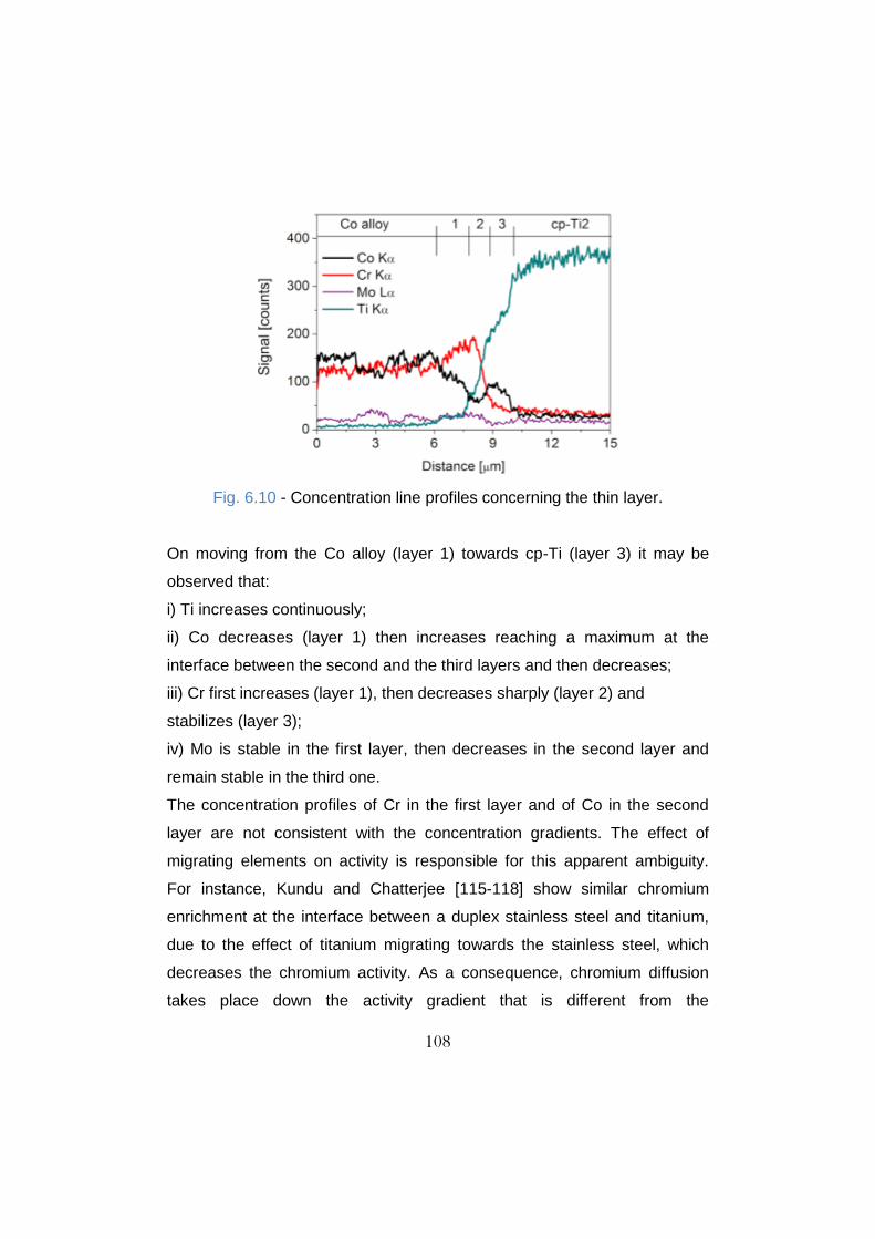
108
Fig. 6.10 - Concentration line profiles concerning the thin layer.
On moving from the Co alloy (layer 1) towards cp-Ti (layer 3) it may be
observed that:
i) Ti increases continuously;
ii) Co decreases (layer 1) then increases reaching a maximum at the
interface between the second and the third layers and then decreases;
iii) Cr first increases (layer 1), then decreases sharply (layer 2) and
stabilizes (layer 3);
iv) Mo is stable in the first layer, then decreases in the second layer and
remain stable in the third one.
The concentration profiles of Cr in the first layer and of Co in the second
layer are not consistent with the concentration gradients. The effect of
migrating elements on activity is responsible for this apparent ambiguity.
For instance, Kundu and Chatterjee [115-118] show similar chromium
enrichment at the interface between a duplex stainless steel and titanium,
due to the effect of titanium migrating towards the stainless steel, which
decreases the chromium activity. As a consequence, chromium diffusion
takes place down the activity gradient that is different from the

109
concentration gradient. The same effect can be hypothesized here to justify
the inversion of the chromium gradient in the layer close to cobalt alloy. An
analogous effect could justify the cobalt profile in the second layer. Table
6.2 reports the average Co, Cr, Mo and Ti concentrations in the three
layers.
Table 6.2 - Chemical composition of the three bonding layers
Layer Weight %
Ti Co Cr Mo
1 3,8 46,0 41,3 8,8
2 19,9 30,6 39,5 10,0
3 47,1 37,5 12,5 2,8
The system is rather complex and no reference data are available in
literature to interpret the constitution of the three layers. The binary and
ternary phase diagrams [120,121] do not support a reliable interpretation.
On the basis of the analyses and of the reference data, it may be only
hypothesized that the layers contain some intermetallic compounds as
sigma phase in layer 1, TiCo and TiCr2 in layers 2 and 3 and Ti2Co in layer
3. This hypothesis has to be verified by a detailed characterization of the
three layers. objectives futures
6.1.4 - Fatigue Properties
Fatigue specimens were prepared by sinter-bonding the presintered cp-
Ti/CP blend with the Co-28Cr-6Mo alloy with subsequent calcium
phosphate extraction.
The porous structure is very similar to that discussed in chapter 3. Samples
were produced according to the following procedure:

110
i) Mixed blend pre-sintering at 600 °C and 20 MPa without any holding
time (1,5 x 12 mm2 section and 30 mm length);
ii) Positioning of the pre-sintered body into a proper cut-down punch
(inferior), centered and aligned with the lengthier die cavity axis;
iii) Die feeding with the Co-28Cr-6Mo powder to fill-up a post sintering
volume of 6 mm height, 12 mm width and 90 mm length;
iv) Positioning of the second pre-sintered body into the another cut-down
punch (superior) with subsequent die closing;
Table 6.3 reports the results of the staircase procedure of the full density
and the porous Ti coated cobalt alloy.
Table 6.3 - Stair case procedure for fully dense and porous coated material
Stress (MPa)
1 2 3 4 5 6 7 8 9 10 11 12 13 14 15
600 x
585
570
555 x
540 x
525 x
510 x
495 x x
480 o x x x
465 x x o o x
450 x o
435 x x
420 x o x x x
405 o o x x
390 o
375
x = Failed; o = Run out; -- Full Density; -- Porous Ti Coated. Table 6.4 reports the fatigue resistance calculated by using the stair case procedure.

111
Table 6.4 - Fatigue resistance of full density and porous Ti coated Co alloy.
Failure Probability
Material 10% 50% 90%
Sintering - Fully Dense 494 464 ± 7 451
Porous Ti Coated 419 405 ± 9 391
As it can be seen, the porous coating (scaffold) decreases the fatigue
resistance down to 85% of the full density one. This drop in fatigue
resistance is related to stress concentration close to the pores. But the
porous cp-Ti coated Co-28Cr-6Mo material has a remarkable fatigue
resistance that can be attributed to reduced notch sensitivity.
6.2 - Cp-Ti/Ti-6Al-4V
Co-sintered specimens were produced at 950 °C, 5 minutes and 45 MPa.
Since no significant microstructural differences from the two materials when
sintered alone were observed, sinter-bonding experiments were not carried
out.
6.2.1. Microstructure
Fig. 6.11 shows the Ti-6Al-4V and the cp-Ti microstructures after co-
sintering.

112
Fig. 6.11 - Microstructure of materials co-sintered. A) Ti-6Al-4V and B) Cp-
Ti.
The Ti-6Al-4V microstructure consists of lamellar alpha phase plus
interlaths beta phase, whilst the cp-Ti consists of alpha phase. The Ti alloy
does not suffer grain growth due to the presence of beta phase, which
prevents grain growth. At 950 °C the Ti alloy still not overcome the beta
transus temperature [57]. On the other hand, grain growth takes place in
the cp-Ti. Moreover, at 950 °C cp-Ti is into beta phase field. As the self-
diffusion coefficient of beta Ti is higher than that of alpha Ti [57] grain
growth is enhanced.
6.2.2 - Interface Characterization
Fig. 6.11 shows the interface region. On the left side the Ti-6Al-4V
microstructure is constituted of alpha + beta phases, whilst in the right side
the cp-Ti consists in alpha phase.

113
Fig. 6.11 – Microstructure at the interface between
Ti-6Al-4V and cp-Ti after co-sintering.
The interface region is characterized by alloying elements diffusion from the
Ti alloy towards to the cp-Ti. Fig. 6.12 shows an example of the EDXS line
profile across the interface.
Fig. 6.12 - EDXS line profile analysis at the interface.

114
The Ti content increases from the Ti-6Al-4V alloy towards cp-Ti, whilst Al
decreases gradually. The V profile is uncertain, since the V Kα peak is
situated right at the same energy of the Ti Kβ one. For a quantitative
assessment, EDXS spot analyses every 10 µm from the interface were
performed, as shown in Fig. 6.13.
Fig. 6.13 - Diffusion profiles of Al and V into cp-Ti.
Here, V and Al present very similar and small diffusion depths, reaching 20
µm and 30 µm, respectively. In order to interpret the experimental results
the diffusion distances were calculated using Equation 1 and Equation 2.
The calculation considers the full concentration of the two elements in the
Ti alloy: 6 wt.% for Al and 4 wt.% for V. Fig. 6.14 show the theoretical
curves.
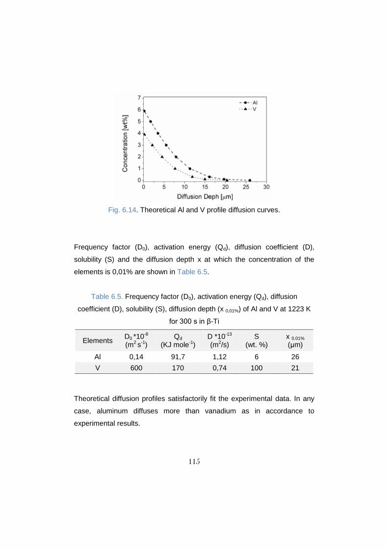
115
Fig. 6.14. Theoretical Al and V profile diffusion curves.
Frequency factor (D0), activation energy (Qd), diffusion coefficient (D),
solubility (S) and the diffusion depth x at which the concentration of the
elements is 0,01% are shown in Table 6.5.
Table 6.5. Frequency factor (D0), activation energy (Qd), diffusion
coefficient (D), solubility (S), diffusion depth (x 0,01%) of Al and V at 1223 K
for 300 s in β-Ti
Elements D0 *10-8 (m2 s-1)
Qd (KJ mole-1)
D *10-13 (m2/s)
S (wt. %)
x 0.01% (μm)
Al 0,14 91,7 1,12 6 26
V 600 170 0,74 100 21
Theoretical diffusion profiles satisfactorily fit the experimental data. In any
case, aluminum diffuses more than vanadium as in accordance to
experimental results.

116
6.2.2 - Fatigue Properties
Table 6.6 reports the results of the staircase procedure of the full density
and the porous coated materials.
Table 6.6 - Staircase procedure of fully dense and porous coated materials
Stress (MPa)
1 2 3 4 5 6 7 8 9 10 11 12 13 14 15
595
580
565 x
550
535
520 x
505
490 x x x x
475 o x o o
460 o o o x
445 o
430
415
400
385
370
355
340
325
310 x
295
280
265
250 x
235
220 x x
205 x o x x o o
190 o o x o
175 o
160
x = Failed; o = Run out; -- Full Density; -- Porous Coated.

117
Table 6.7 reports the fatigue resistance calculated by using the staircase
procedure.
Table 6.7 - Fatigue resistance of full density and porous coated materials.
Failure Probability
Material 10% 50% 90%
Sintering - Fully Dense 452 472 ± 13 493
Cp-Ti Porous Coated Ti Alloy 205 193 ± 8 181
The porous coating decreases the fatigue resistance significantly, as
expected. It is known that both Co–Cr–Mo alloys and Ti–6Al–4V alloys
experience reductions in fatigue strength when fabricated as porous
coatings on solid core structures [122-125]. The decrease of fatigue
resistance due to the porous layer is around 60%, similar to that reported
by Cook [126] who found that the high cycle fatigue strength of porous
coated Ti–6Al–4V alloy is approximately one-third that of the solid alloy
[127]. Here, the decrease is slightly smaller.
6.3 - Summary of the Results
Co-sintering (Cp-Ti/Co-28Cr-6Mo):
A noticeable reduction in the sintering efficiency in comparison to
that obtained by sintering the two materials alone was observed on
the Co alloy microstructure.
The interface between materials is irregular due to the different
hardness of the materials.
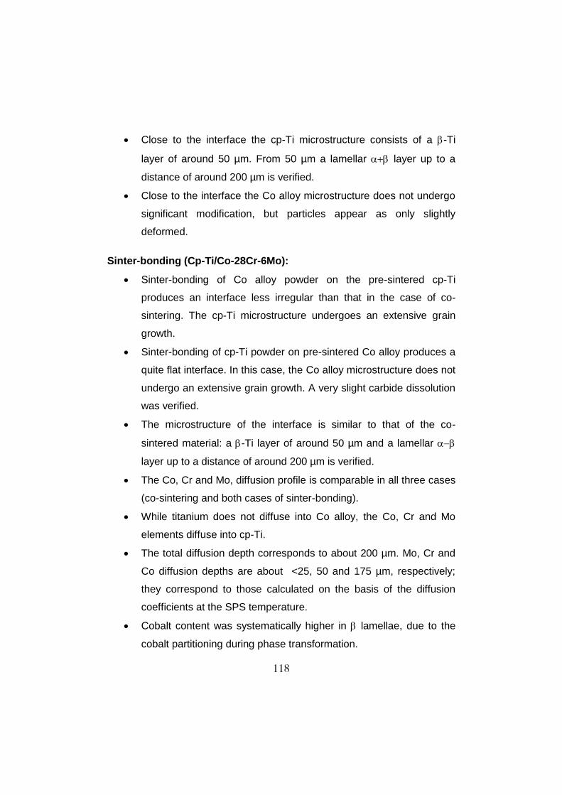
118
Close to the interface the cp-Ti microstructure consists of a -Ti
layer of around 50 µm. From 50 µm a lamellar layer up to a
distance of around 200 µm is verified.
Close to the interface the Co alloy microstructure does not undergo
significant modification, but particles appear as only slightly
deformed.
Sinter-bonding (Cp-Ti/Co-28Cr-6Mo):
Sinter-bonding of Co alloy powder on the pre-sintered cp-Ti
produces an interface less irregular than that in the case of co-
sintering. The cp-Ti microstructure undergoes an extensive grain
growth.
Sinter-bonding of cp-Ti powder on pre-sintered Co alloy produces a
quite flat interface. In this case, the Co alloy microstructure does not
undergo an extensive grain growth. A very slight carbide dissolution
was verified.
The microstructure of the interface is similar to that of the co-
sintered material: a -Ti layer of around 50 µm and a lamellar
layer up to a distance of around 200 µm is verified.
The Co, Cr and Mo, diffusion profile is comparable in all three cases
(co-sintering and both cases of sinter-bonding).
While titanium does not diffuse into Co alloy, the Co, Cr and Mo
elements diffuse into cp-Ti.
The total diffusion depth corresponds to about 200 µm. Mo, Cr and
Co diffusion depths are about <25, 50 and 175 µm, respectively;
they correspond to those calculated on the basis of the diffusion
coefficients at the SPS temperature.
Cobalt content was systematically higher in lamellae, due to the
cobalt partitioning during phase transformation.

119
At higher magnification an interaction layer is revealed, 3-4 µm thin,
and it is constituted by three sub-layers of about 1 µm thickness.
The concentration profiles of Cr in the first layer and of Co in the
second layer are not consistent with the concentration gradients,
rather they result from a Darken’s diffusion phenomenon driven by
the activity of the elements in the three layers.
The porous coating (scaffold) decreases the fatigue resistance
down to 85% of the full density one.
Co-sintering (Cp-Ti/ Ti-6Al-4V):
The Ti-6Al-4V microstructure consists of lamellar alpha phase plus
interlaths beta phase, whilst the cp-Ti consists of alpha phase.
The interface region is characterized by alloying elements diffusion
from the Ti alloy towards to the cp-Ti; vanadium and aluminum
present very similar and small diffusion depths, reaching 20 µm and
30 µm, respectively.
Theoretical diffusion profiles satisfactorily fit the experimental data.
The porous coating (scaffold) decreases the fatigue resistance
down to 40% of the full density one.

120
Chapter 7 – CONCLUSIONS
This work was carried out in the frame of an industrial research project in
cooperation with K4Sint Srl (Pergine Valsugana, Trento), and Eurocoating
SpA (Pergine Valsugana, Trento). It was aimed at the development of the
production of commercial pure titanium, Ti-6wt.%Al-4wt.%V (Ti-6Al-4V) and
Co- 28wt.%Cr-6wt.%-Mo (Co-28Cr-6Mo) alloys by Spark Plasma Sintering
for biomedical application.
The final objective was the definition of the process parameters for the
production of a highly porous (cp-Ti), full density materials (Ti-6Al-4V and
Co-28Cr-6Mo), and their combination in a surface functionalized full density
substrate. The process parameters can be summarized as follow:
Co-28Cr-6Mo alloy: 900 °C, 5 minutes and 60 MPa;
Co-sintering of the cp-Ti/Co alloy: 1000 °C, 5 minutes and 60 MPa;
Co-sintering of the cp-Ti/Ti-6Al-4V alloy: 950 °C, 5 min. and 45 MPa;
As a general conclusion it may be assessed that the processing
parameters for the production of the investigated biomaterials have been
defined and the microstructural characteristics, as well as mechanical,
corrosion properties and wear resistance satisfy the requirements on the
international standards. The results have been used to produce implants
which are under test.

121
REFERENCES
[1] Sivakumar, R., On the relevance and requirements of biomaterials.
Bulletin of Materials Science. 1999, 22 (3), 647-655.
[2] Park, J.B., Lakes, R.S., Biomaterials - An Introduction, 2nd Ed, ,
London: Plenum Press, New York, (1992).
[3] Bhat, S.V., Biomaterials, Alpha Science International Ltd., New Delhi,
India, (2002).
[4] Guelcher, S.A., Hollinger J.O., An introduction to biomaterials, 2nd Ed,
CRC Press, New York, (2011).
[5] Ratner, B.D., Hoffman, A. S., Schoen, F.J., and Lemons, J.E. (eds.),
Biomaterials science: an introduction to materials in medicine, Elsevier Sci.,
New York, (1996).
[6] Geetha M., Singh A.K., Asokamani R., Gogia A.K., Ti based
biomaterials , the ultimate choice for orthopaedic implants – A review.
Progress in Materials Science. 2008, 54 (3), 397-425.
[7] Buttaro M.A., Mayor M.B., Van C.D., Piccaluga F., Fatigue fracture of a
proximally modular, distally tapered fluted implant with diaphyseal fixation.
Journal of Arthroplasty, 2007, 22, 780–783.
[8] Lam L.O., Stoffel K., Kop A., Swarts E., Catastrophic failure of 4 cobalt-
alloy fit hip arthroplasty femoral components. Acta Orthopedic, 2008, 79,
18-21.
[9] Jacobs, J.J., Skipor, A.K., Black, J., Urban, R.M., and Galante, J.O.,
Release and excretion of metal in patients who have a total hip-
replacement component made of titanium-base alloy. Journal of Bone and
Joint Surgery, 1991, 73-A, 1475-1486.
[10] Jacobs, J.J., Skipor, A.K., Black, J., Hastings, M.C., Schavocky, J.,
Urban, R.M., and Galante, J.O., Metal release and excretion from
122
cementless titanium total knee replacements. Transactions of Orthopedic
Research Society,1991, 16, 558-562.
[11] Black J., Hastings G.W., Handbook of biomaterials properties.
Chapman and Hall; London, (1998).
[12] Pilliar R.M., Cameron H.U., Binnington A.G., Szivek J., Macnab., Bone
ingrowth and stress shielding with a porous surface coated fracture fixation
plate. Journal of Biomedical Materials Research, 1979, 13, 799-810.
[13] Yaszemski, M.J., Biomaterials in Orthopedics, Marcel Dekker Ltd.,
New York, (2003).
[14] Hoar T.P., Mears D.C., Corrosion resistant alloys in chloride solutions,
materials for surgical implants. Proceedings of the Royal Society of
London. 1966, 294, 486-493.
[15] Hallab N.J., Messina C., Skipor A., Jacobs J.J., Differences in the
fretting corrosion of metal-metal and ceramic-metal modular junctions of
total hip replacements. Journal of orthopaedic research, 2004, 22, 250-259.
[16] Gilbert, J.L., Buckley, C.A., and Jacobs, J.J., In vivo corrosion of
modular hip prosthesis components in mixed and similar metal
combinations. The effect of crevice, stress, motion, and alloy coupling.
Journal of Biomedical Materials Research.,1993, 27, 1533-1544.
[17] Van Blitterswijk, C.A., Thomsen, P., Tissue engineering. Academic
Press, London, (2008).
[18] Narayan R., Biomedical Materials. Springer Science, New York, 2009.
[19] Spiekermann H. Implantology. Quintessence: Color Atlas of Dental
Medicine. Chicago, (1995).
[20] Zarb G.A., Albrektsson T. Osseointegration: a requiem for the
periodontal ligament?, International Journal Periodontal Research Dent,
1991, 11, 88-91.

123
[21] Le Guéhennec L, Soueidan A, Layrolle P, Amouriq Y. Surface
treatments of titanium dental implants for rapid osseointegration. Dental
materials. 2007, 23, 844-854.
[22] Degischer H. P., Kriszt B. (Eds.), Handbook of Cellular Metals, Wiley,
Weinhem, (2002).
[23] Dunand D.C., Processing of Titanium Foams. Advanced Engineering
Materials. 2004, 6 (6), 369-376.
[24] Donachie M.J., Advanced Materials Processing, 1998, 7, 63-70.
[25] Gibson L.J., Journal of Biomechanics, 2005, 38, 377-381.
[26] Lorna J.G., Michael F.A., Cellular Solids: Structure and Properties, 2th
Ed., Cambridge University Press, Cambridge, (1988).
[27] Ryan G., Pandit A., Apatsidis D.P., Fabrication methods of porous
metals for use in orthopaedic applications. Biomaterials. 2006, 27, 2651-
2670.
[28] Galante J., Rostoker W., Lueck R., Ray R.D., Sintered fiber metal
composites as a basis for attachment of implants to bone. Journal of Bone
Joint Surgery, 1971, 53 (A), 101-114.
[29] Pilliar R.M., Surgical Prosthetic Device with porous metal coating, US
Patent 3,855,638, 1974.
[30] Cook S.D., Walsh K.A., Haddad Jr R.J., Interface mechanics and bone
growth into porous Co–Cr–Mo alloy implants. Clinical Orthopedic, 1985,
271–280.
[31] Dabrowski J.R., Use of powder metallurgy for development of implants
of Co–Cr–Mo alloy powder. Biomed Tech (Berlin), 2001, 46,106–108.
[32] Amigo V., Salvador M.D., Romero F., Solves C., Moreno J.F.,
Microstructural evolution of Ti-6Al-4V during the sintering of microspheres
of Ti for orthopedic implants. Journal of Materials Processing Technology.
2003, 141, 117-122.

124
[33] Oh I.H., Nomura N., Masahashi N., Hanada S., Mechanical properties
of porous titanium compacts prepared by powder sintering. Scripta
Materialia, 2003, 49, 1197–1202.
[34] Banhart J., Manufacture, characterization and application of cellular
metals and metal foams Progress in Materials Science, 2001, 46, 559-632.
[35] Ye B., Dunand D.C., Titanium foams produced by solid-state
replication of NaCl powders. Materials Science & Engineering A. 2010, 528,
691-697.
[36] Liang-jian C., Ting L.I., Yi-min L.I., Hao H.E., You-hua H.U., Porous
titanium implants fabricated by metal injection molding. Transaction of
Nonferrous Metals Society of China. 2009, 19, 1174-1179.
[37] Esen Z., Bor S., Processing of titanium foams using magnesium
spacer particles. Scripta Materialia. 2007, 56, 341-344.
[38] Ibrahim A., Zhang F., Otterstein E., Burkel E., Processing of Porous Ti
and Ti5Mn Foams by Spark Plasma Sintering. Materials and Design. 2010,
32, 146-153.
[39] Xiong J., Li Y., Wang X., Hodgson P., Wen C., Mechanical properties
and bioactive surface modification via alkali-heat treatment of a porous Ti-
18Nb-4Sn alloy for biomedical applications. Acta Biomaterilia. 2008, 4,
1963-1968.
[40] Bram M., Stiller C., Buchkremer H.P., Stöver D., Baur H., High-Porosity
Titanium, Stainless Steel, and Superalloy Parts. Advanced Engineering
Materials. 2000, 2 (4), 196-199.
[41] Li X., Wang C., Zhang W., Li Y., Fabrication and characterization of
porous Ti-6Al-4V parts for biomedical applications using electron beam
melting process. Materials Letters. 2009, 63, 403-405.
[42] Dinda G.P., Song L., Mazumder J., Fabrication of Ti-6Al-4V Scaffolds
by Direct Metal Deposition. Metallurgical and Materials Transactions A.
2008, 39, 2914-2922.

125
[43] Heinl P., Muller L., Korner C., Singer R.F., Muller F.A., Cellular Ti-6Al-
4V structures with interconnected macro porosity for bone implants
fabricated by selective electron beam melting. Acta Biomaterialia. 2008, 4,
1536-1544.
[44] Vandenbroucke B., Kruth J.P., Selective laser melting of biocompatible
metals for rapid manufacturing of medical parts. Rapid Prototyping Journal,
2007, 13 (4), 196-203.
[45] Donglu, Shi. Introduction to Biomaterials. Tsinghua University Press,
Beijing, (2006).
[46] Nordin M., Frankel V.H., Basic Biomechanics of the Musculoskeletal
System. 3rd ed. Lippincott Williams & Wilkins, Philadelphia, (2001).
[47] http://training.seer.cancer.gov/anatomy/skeletal/tissue.html on Feb.
2012.
[48] Betteridge W., Cobalt and Its Alloys, Ellis Horwood Limited, London,
(1982).
[49] Davis J.R., Nickel, cobalt and their alloys. ASM International, Materials
Park, OH , (2000).
[50] Baboian R., Corrosion Tests and Standards, Application and
Interpretation, 2nd ed., ASTM International, PA, (2005).
[51] Huang P., Lopez H.F., Strain induced E-martensite in a Co-Cr-Mo
alloy: grain size effects. Materials Letters. 1999, 39, 244-248.
[52] Lopez H.F., Saldivar-Garcia A.J., Martensitic Transformation in a Cast
Co-Cr-Mo-C Alloy. Metallurgical and Materials Transactions A. 2008; 39, 8-
18.
[53] Huang P., Liu R., Wu X.J., Yao M.X., Effects of Molybdenum Content
and Heat Treatment on Mechanical and Tribological Properties of a Low-
Carbon Stellite Alloy, Journal of Engineering Materials and Technology,
2007, 129 (4), 523-529.

126
[54] Dobbs H. S., Robertson J. L. M., Heat Treatment of Cast Co-Cr-Mo for
Orthopaedic Implant Use. Journal of Materials Science, 1983, 18, 391-401
[55] Daud Z.C., Jamaludin S.B., Bari F., Characterization of Co-28Cr-6Mo
Alloy Produced by Solid State Sintering. Advanced Materials Research.
2011, 173, 106-110.
[56] Muterlle P., Zendron M., Zanella C., Perina M., Bardini R., Molinari A.,
Effect of microstructure on the properties of a biomedical Co-Cr-Mo alloy
produced by MIM, Advances in Powder Metallurgy & Particulate Materials,
2009, 1 (4), 60-69.
[57] Gaytan S.M., Murr L.E., Martinez E., Martinez J.L., Machado B.I.,
Ramirez D.A., Medina F., Collins S., Wicker R.B. Comparison of
Microstructures and Mechanical Properties for Solid and Mesh Cobalt-Base
Alloy Prototypes Fabricated by Electron Beam Melting. Metallurgical and
Materials Transactions A. 2010, 41 (12), 3216-3227.
[58] Vandenbroucke B., Kruth J.-P., Selective laser melting of
biocompatible metals for rapid manufacturing of medical parts. Rapid
Prototyping Journal, 2007, 13 (4), 196-203.
[59] Ogden, H.R., in: A.H. Clifford (Ed.), Rare Metals Handbook, Rinhdd
Publishing Corporation, Chapman & Hall Ltd., London, (1961).
[60] Collings E.W., The physical metallurgy of titanium alloys, in: H.L. Gegel
(Ed.), ASM Series in Metal Processing, Edward Arnold Publications,
Cleveland, Metals Park, OH, (1984).
[61] C. Leyens, M. Peters, Titanium and Titanium Alloys, Wiley–VCH,
Cologne, 2003.
[62] Prasad Y.V.R.K., Sasidhara S., (Eds.), Hot Working Guide: A
Compendium of Processing Maps, ASM International, Materials Park, OH,
(1997).
[63] Polmear J.J., Titanium alloys, in: Light Alloys, Edward Arnold
Publications, London, (1981).

127
[64] Lütjering G., Williams J.C.: Titanium, Engineering Materials and
Process, Spring, Berlin, Germany,(2003).
[65] Bania P.J., in: D. Eylon, R.R. Boyer, D.A. Koss (Eds.), Titanium Alloys
in the 1990’s, The Mineral, Metals & Materials Society, Warrendale, PA,
(1993).
[66] Donachie, M. J., Titanium - a Technical Guide, 2° Ed., ASM, Metals
Park, OH, (2000)
[67] Schutz R.W., in: D. Eylon, R.R. Boyer, D.A. Koss (Eds.), Beta Titanium
Alloys in the 1990’s, The Mineral, Metals& Materials Society, Warrendale,
PA, (1993).
[68] Norgate T.E., Wellwood G. The Potential Applications for Titanium
Metal Powder and Their Life Cycle Impacts. JOM. (2006);September, 58-
63.
[69] Moxson VS, Senkov ON, Froes FH. Innovations in Titanium Powder
Processing. JOM. 2000; May, 24-26.
[70] ASM Handbook, Volume 7 Powder Metal Technologies and
Applications. 2nd Ed., Materials Park, ASM International, OH, 1998.
[71] Shibo G, Xuanhui Q, Xinbo H, Ting Z, Bohua D., Powder injection
molding of Ti-6Al-4V alloy. Journal of Materials Processing Technology.
2006;173:310-314.
[72] Facchini L., Magalini E., Robotti P., Molinari A., Microstructure and
mechanical properties of Ti-6Al-4V produced by electron beam melting of
pre-alloyed powders", Rapid Prototyping Journal, Vol. 15 (3), 2009, 171 –
178.
[73] Facchini L., Magalini E., Robotti P., Molinari A., Hoges S., Wissenbach
K., Ductility of a Ti-6Al-4V alloy produced by selective laser melting of
prealloyed powders, Rapid Prototyping Journal, 16 (6), 2010, 450–459.

128
[74] Zadra M., Casari F., Girardini L., Molinari A., Microstructure and
Mechanical Properties of CP-Titanium Produced by Spark Plasma
Sintering, Powder Metallurgy, 51 (1), 2008, 59-65.
[75] Taylor G.F., Apparatus for Making Hard Metal Compositions, U.S.
Patent 1,896,854, 1933.
[76] Cremer G.D, US Patent No. 2,355,954, 1944.
[77] Lenel V. F, Transactions of AIME 203, 1955, 158
[78]. Shon I. J., Munir Z.A., Materrials Science Engineering A, 1995, 202,
256.
[79] Xie G., Ohashi O., Song M., Mitsuishi K., Furuya K., Applied Surface
Science, 2005, 241, 102.
[80] Goldberger W.M., Merkle B., Boss D., Advanced Powder Metallurgy
and Particulate Materials, 1994, 6, 91.
[81] Tokita M., Materrials Science Forum, 1999, 83, 308–311.
[82] Hulbert D.M., Anders A., Andersson J., Lavernia E.J., Mukherjee A.K.,
A discussion on the absence of plasma in spark plasma sintering. Scripta
Materialia. 2009, 60, 835-838.
[83] Lee J.W., Munir Z.A., Shibuya M., Ohyanagi M., Journal of American
Ceramic Society, 2001, 84 (6), 1209-1216
[84] Groza J.R., Zavaliangos A., Sintering activation by external electrical
field. Materials Science and Engineering A. 2000, 287, 171-177.
[85] Anderson K.R., Groza J.R., Fendorf M., Echer C.J., Surface oxide
debonding in field assisted powder sintering. Materials Science and
Engineering A. 1999, 270, 278-282.
[86] Chen W., AnselmiI-Tamburini U., Garay J.E., Groza J.R., Munir Z.A.,
Fundamental investigations on the spark plasma sintering / synthesis
process I . Effect of dc pulsing on reactivity, Materials Science and
Engineering A, 2005, 394, 132-138.
129
[87] Song X., Liu X., Zhang J., Neck formation and self-adjusting
mechanism of neck growth of conducting powders in spark plasma
sintering, Journal of the American Ceramic Society, 2006, 89 (2), 494–500.
[88] Diouf S., Molinari A., Densification mechanisms in spark plasma
sintering: Effect of particle size and pressure. Powder Technology. 2012,
221, 220-227.
[89] Anselmi-tamburini U., Gennari S., Garay J.E., Munir Z.A., Fundamental
investigations on the spark plasma sintering / synthesis process II .
Modeling of current and temperature distributions. Materials Science and
Engineering A. 2005, 394, 139-148.
[90] Eriksson M., Shen Z., Nygren M., Fast densification and deformation of
titanium powder. Powder Metallurgy. 2005, 48 (3), 231-236.
[91] Matsugi K, Kuramoto H, Yanagisawa O, Kiritani M., A case study for
production of perfectly sintered complex compacts in rapid consolidation by
spark sintering. Materials Science and Engineering A. 2003, 354, 234-242.
[92] Lutterotti L., Matthies S., Wenk H.R., Shultz A.S., Richardson J.W.,
Combined texture and structure analysis of deformed limestone from time-
of-flight neutron diffraction spectra. Journal of applied physics, 1997, 81,
594-600.
[93] Lonardelli I., Wenk H.R., Lutterotti L., Goodwin M., Texture analysis
from synchrotron diffraction images with the Rietveld method: dinosaur
tendon and salmon scale. Journal of Synchrotron Radiation, 2005, 12, 354-
360.
[94] Liu X., Chu P.K., Ding C., Surface modification of titanium, titanium
alloys, and related materials for biomedical applications. Materials Science
and Engineering R. 2004, 47, 49-121.
[95] Lowenberg B.F., Pilliar R.M., Aubin J.E., Sodek J., Melcher A.H., Cell
attachment of human gengival fibroblasts in vitro to porous-surfaced

130
titanium alloy discs coated with collagen and platelet-derived growth factor.
Biomaterials. 1988, 9, 302-309.
[96] Eriksson M., Andersson M., Adolfsson E., Carlström E., Titanium -
hydroxyapatite composite biomaterial for dental implants. Powder
Metallurgy. 2006, 49 (1), 70-77.
[97] Cordonnier T., Sohier J., Rosset P., Layrolle P., Biomimetic Materials
for Bone Tissue Engineering – State of the Art and Future Trends .
Advanced Biomaterials. 2011, 13, 1-16.
[98] Chen J., Paetzell E., Zhou J., Lyons L., Soboyejo W., Osteoblast-like
cell ingrowth, adhesion and proliferation on porous Ti-6Al-4V with
particulate and fiber scaffolds. Materials Science and Engineering C. 2010,
30, 647-656.
[99] Ji H., Marquis P.M., Effect of heat treatment on the microstructure of
plasma-sprayed hydroxyapatite coating, Biomaterials, 1993, 14 (1), 64-68.
[100] Wei M., Ruys A.J., Swain M.V., Milthorpe B.K., Sorrell C.C.,
Hydroxyapatite-coated metals: Interface reactions during sintering, Journal
of Materials Science: Materials in Medicine, 2005, 16, 101-106.
[101] Fleck N.A., Smith R.A., Effect of density on tensile strength, fracture
toughness, and fatigue, crack propagation behavior of sintered steel.
Powder Metallurgy, 1981, 24, 121-125.
[102] Kumar P., Elements of fracture mechanics, Wheeler Publishing, New
Delhi, (1999).
[103] Hanawa T., Metal ion release from metal implants. Materials Science
Engineering C, 2004, 24, 745–52.
[104] España F.A., Balla V.K., Bose S., Bandyopadhyay A., Design and
fabrication of CoCrMo alloy based novel structures for load bearing
implants using laser engineered net shaping. Materials Science &
Engineering C. 2010, 30, 50-57.

131
[105] Chiba A., Kumagai K., Takeda H., Nomura N., Mechanical Properties
of Forged Low Ni and C- Containing Co-Cr-Mo Biomedical Implant Alloy,
Materials Science Forum, 2005, 475-479, 2317-2322.
[106] Ishida K., Nishizawa T., The C–Co (carbon–cobalt) system, Journal
of Phase Equilibria, 1991, 12, 417–424.
[107] Huang P., Lopez H.F., Athermal ε-martensite in a Co-Cr-Mo alloy:
grain size effects. Materials Letters, 1999, 39, 249-253.
[108] Guillard F., Allemand A., Lulewicz J-daniel, Galy J., Densification of
SiC by SPS-effects of time , temperature and pressure. Journal of the
European Ceramic Society. 2007, 27, 2725-2728.
[109] Maglia F., Anselmi-Tamburini U., Chiodelli G., Electrical, structural,
and microstructural characterization of nanometric
La0.9Sr0.1Ga0.8Mg0.2O3−δ (LSGM) prepared by high-pressure spark
plasma sintering. Solid State Ionics. 2009, 180 (1), 36-40.
[110] Munir Z.A., Anselmi-tamburini U., Ohyanagi M., The effect of electric
field and pressure on the synthesis and consolidation of materials : A
review of the spark plasma sintering method. Journal of Materials Science.
2006, 41, 763-777.
[111] Shen Z., Johnsson M., Zhao Z., Nygren M., Spark Plasma Sintering
of Alumina, Journal of the American Ceramic Society, 2002, 85 (8), 1921-
1927
[112] Lopez G.D., Biodeterioration and corrosion of metallic implants and
prostheses. Medicina (B Aires) 1993, 53 (3), 260–74.
[113] Steinemann S., Corrosion of Implant Alloys. Technical Principles,
Design and Safety of Joint Implants. Hogrefe & Huber Publ., Seattle-
Toronto-Bern-G¨ottingen, (1990).
[114] Molinari A., Zadra M., Influence of the sintering temperature on
microstructure and tensile properties of Ti6Al4V produced by Spark Plasma
Sintering, PM2008.

132
[115] Kundu S., Chatterjee S., Diffusion bonding between commercially
pure titanium and micro-duplex stainless steel. Materials Science and
Engineering A, 2008, 480, 316-322.
[116] Kundu S., Ghoshb M., Chatterjee S., Diffusion bonding of
commercially pure titanium and 17-4 precipitation hardening stainless steel.
Materials Science and Engineering A, 2006, 428, 18–23.
[117] Ghosh M., Chatterjee S.. Diffusion bonded transition joints of titanium
to stainless steel with improved properties. Materials Science and
Engineering A, 2003, 358, 152-158.
[118] Ghosh M., Bhanumurthy K., Kale G.B., Krishnan J., Chatterjee S..
Diffusion bonding of titanium to 304 stainless steel. Journal of Nuclear
Materials, 2003, 322, 235–241.
[119] Hood G. M.. The mechanisms of diffusion in the anomalous BCC
metals. Journal of Physics F: Metal Physics, 1976, 6, 19-26.
[120] Metals Handbook, Alloy Phase Diagram , 3 Ed., ASM International,
Materials Park, OH, (1992).
[121] Gupta A., Journal of Phase Equilibria, 2001, 22, 52-59.
[122] Yue S., Pilliar R.M., Weatherly G.C., The fatigue strength of porous-
coated Ti–6% Al–4%V implant alloy. Journal of Biomedical Materials
Research, 1984, 18, 1043–58.
[123] Kohn D.H., Ducheyne P., A parametric study of the factors affecting
the fatigue strength of porous coated Ti–6A1–4V implant alloy. J Biomed
Mater Res 1990;24:1483–501.
[124] Crowninshield R.D., Mechanical properties of porous metal total hip
prostheses. Instructural Course Lecture, 1986, 35, 144–148.
[125] Manley M.T., Kotzar G., Stern L.S., Wilde A., Effects of repetitive
loading on the integrity of porous coatings. Clinical Orthopedic Relator
Research, 1987, 293–302.

133
[126] Cook S. D. et al., Journal of Biomedical Materials Research, 1988,
22, 287-302.
[127] Wolfarth D, Ducheyne P., Effect of a change in interfacial geometry
on the fatigue strength of porous-coated Ti–6Al–4V. Journal of Biomedical
Materials Research, 1994, 28, 417–425.

134
ACKNOWLEDGEMENTS
My acknowledgments to the whole group of professors, technicians and
secretaries of the University of Trento, in particular those from the
Department of Materials Engineering and Doctoral School in Materials
Engineering.
I wish to precise my all respect and my special gratitude to my supervisor,
Prof. Dr. Alberto Molinari.
This project was co-founded by the Eurocoating Spa, my sincere thanks for
such confidence. I would like to thank Francesco Bucciotti and Luca
Facchini, whose are collaborators in this company.
I would like to thank Francesco Casari, from K4Sint, for discussions and
cooperation.
Special thanks also to all laboratory colleagues, especially to Anna
Fedrizzi, Melania Pilla, Ketner Bendo Demetrio, Palloma Mutterle Vieira,
Ligia Dione da Costa, Cinzia Menapace, Lorena Maines, Saliou Diouf,
Elena Santuliana, Ivan Lonardelli, Ibrahim Metinoz, Marco Cazzolli and
László Lábiscsák.
I wish to express my love and gratitude to my family, my awesome wife and
friends.

135
PUBLICATIONS
(concerning the thesis)
N. Vicente, F. Casari, F. Bucciotti, A. Molinari. “Microstructures and tensile
properties of Co28Cr6Mo alloy produced by Spark Plasma Sintering”.
PM2011, European Congress & Exhibition, Shrewsbury UK: EPMA, 2011,
Vol. 2, p. 483-488.
N. Vicente, A. Fedrizzi, N. Bazzanella, F. Casari, F. Bucciotti, A. Molinari. “
Microstructural interface investigation between Ti and Co-Cr-Mo alloy co-
sintered and sinter-bonded by Spark Plasma Sintering”. MATERIALS
CHARACTERIZATION. [Submitted 17th Feb 2012 ]
(during the doctorate)
L. Facchini, N. Vicente, I. Lonardelli, A. Molinari. “Metastable austenite in
17-4 precipitation hardening stainless steel produced by selective laser
melting and its effect on tensile properties”. ADVANCED ENGINEERING
MATERIALS, 2010, Vol. 12 (3), p. 184-188.
N. Vicente, I. Lonardelli, E. Magalini, A. Molinari. “Strain hardenability of
metastable 17-4PH Stainless Steel produced by Selective Laser Melting”.
PM2010, World Congress & Exhibition, Shrewsbury UK: EPMA, 2010, p.
195-200.
L. D. Da Costa, A. P. G. Nogueira, N. Vicente, G. Straffelini.
“Characterization of magnesium AZ91 alloy and AZ91 alloy with rare earth
elements addition produced via Spark Plasma Sintering”. Proceedings
SENAFOR, Porto Alegre, Brazil, 2010.

136
C. Menapace, N. Vicente, A. Molinari. “Forging of Spark Plasma Sintered
Ti64 Powder Preforms”. PM2011, European Congress & Exhibition,
Shrewsbury UK: EPMA, 2011, Vol. 3, p. 339-344.
N. Vicente, C. Menapace, A. Molinari. “Hot deformation of the Ti-6Al-4V
alloy preforms obtained by Spark Plasma Sintering of powders”.
COBEM2011, Brazilian Congress in Mechanical Engineering, CD-ROM ,
2011, Paper 18741.
C. Zanella, N. Vicente, F. Casari, A. Molinari., F. Deflorian.
“Electrochemical behavior of CoCrMo biomedical alloy in presence of
localized impurities”. ICC, International Corrosion Congress; 2011, Paper
416.
C. Menapace, N. Vicente, A. Molinari. “Hot forging of Ti6Al4V alloy
preforms produced by Spark Plasma Sintering of powders”. POWDER
METALLURGY. [Accepted 28th Jan 2012].


![Investigation of Tissue Engineering Scaffolds for ...doktori.bibl.u-szeged.hu/4158/1/phd_thesis_ zsedenyi.pdf · tissue engineering, especially for the fabrication of scaffolds [14]](https://img.pdfslide.us/doc/110x75/5f9136fac4be4300fb3b3c1b/investigation-of-tissue-engineering-scaffolds-for-zsedenyipdf-tissue-engineering.jpg)


![b`n"D [+,,),R,∆# gjr`m^gjn`_n^\g`#`)b)]`io*nom\dbco$ ^)"D (+,,],R,∆# pkk`m^gjn`_n^\g`#`)b)kpm`*dhkpm`$ _)"D [+,,],R,∆# #ojo\ggt$^gjn`_n^\g`#`)b)apgg*`hkot$ Oc`n^\g](https://img.pdfslide.us/doc/110x75/611814a3ca4296519c537895/bn-d-ra-gjrmgjnngbionomdbco-d-ra.jpg)