Embed Size (px)
Citation preview
1
SpanSetCertifi edSafety
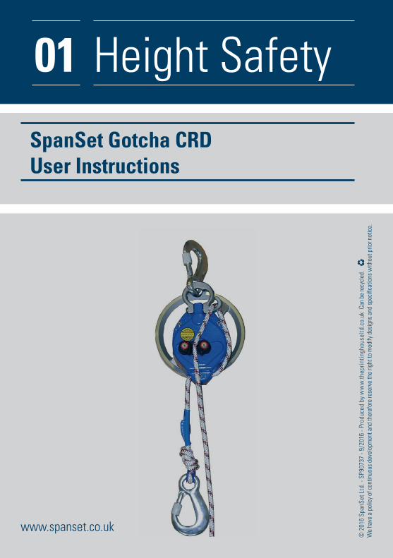
SpanSet Gotcha CRD User Instructions
2
Table of contents
Description 3
Preparation 4
Rescue of casualties 4
Alternatives for recovering the rescuer 5
Storage and transportation 5
Cleaning 5
Maintenance 5
Inspection 6
Info sheet for inspection 7
Inspection book 10
Documentation of the performed descending work 11
3
GOTCHA CRD
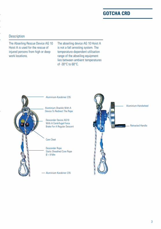
The Abseiling Rescue Device AG 10
Hoist A is used for the rescue of
injured persons from high or deep
work locations.
The abseiling device AG 10 Hoist A
is not a fall arresting system. The
temperature-dependent utilisation
range of the abseiling equipment
lies between ambient temperatures
of -30°C to 60°C.
Description
Aluminium-Handwheel
Retracted Handle
Aluminium-Karabiner 235
Aluminium-Karabiner 235
Aluminium Shackle With A
Device To Redirect The Rope
Descender Device AG10
With A Centrifugal Force
Brake For A Regular Descent
Cam Cleat
Descender Rope
Static Sheathed Core Rope
Ø = 9 Mm
4
GOTCHA CRD
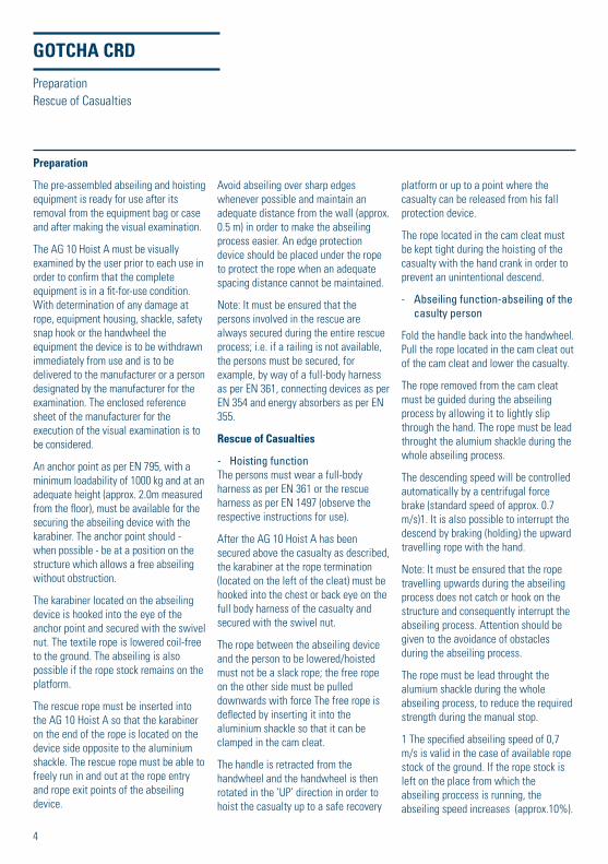
Preparation
The pre-assembled abseiling and hoisting
equipment is ready for use after its
removal from the equipment bag or case
and after making the visual examination.
The AG 10 Hoist A must be visually
examined by the user prior to each use in
order to confi rm that the complete
equipment is in a fi t-for-use condition.
With determination of any damage at
rope, equipment housing, shackle, safety
snap hook or the handwheel the
equipment the device is to be withdrawn
immediately from use and is to be
delivered to the manufacturer or a person
designated by the manufacturer for the
examination. The enclosed reference
sheet of the manufacturer for the
execution of the visual examination is to
be considered.
An anchor point as per EN 795, with a
minimum loadability of 1000 kg and at an
adequate height (approx. 2.0m measured
from the fl oor), must be available for the
securing the abseiling device with the
karabiner. The anchor point should -
when possible - be at a position on the
structure which allows a free abseiling
without obstruction.
The karabiner located on the abseiling
device is hooked into the eye of the
anchor point and secured with the swivel
nut. The textile rope is lowered coil-free
to the ground. The abseiling is also
possible if the rope stock remains on the
platform.
The rescue rope must be inserted into
the AG 10 Hoist A so that the karabiner
on the end of the rope is located on the
device side opposite to the aluminium
shackle. The rescue rope must be able to
freely run in and out at the rope entry
and rope exit points of the abseiling
device.
Avoid abseiling over sharp edges
whenever possible and maintain an
adequate distance from the wall (approx.
0.5 m) in order to make the abseiling
process easier. An edge protection
device should be placed under the rope
to protect the rope when an adequate
spacing distance cannot be maintained.
Note: It must be ensured that the
persons involved in the rescue are
always secured during the entire rescue
process; i.e. if a railing is not available,
the persons must be secured, for
example, by way of a full-body harness
as per EN 361, connecting devices as per
EN 354 and energy absorbers as per EN
355.
Rescue of Casualties
- Hoisting function
The persons must wear a full-body
harness as per EN 361 or the rescue
harness as per EN 1497 (observe the
respective instructions for use).
After the AG 10 Hoist A has been
secured above the casualty as described,
the karabiner at the rope termination
(located on the left of the cleat) must be
hooked into the chest or back eye on the
full body harness of the casualty and
secured with the swivel nut.
The rope between the abseiling device
and the person to be lowered/hoisted
must not be a slack rope; the free rope
on the other side must be pulled
downwards with force The free rope is
defl ected by inserting it into the
aluminium shackle so that it can be
clamped in the cam cleat.
The handle is retracted from the
handwheel and the handwheel is then
rotated in the ‘UP’ direction in order to
hoist the casualty up to a safe recovery
platform or up to a point where the
casualty can be released from his fall
protection device.
The rope located in the cam cleat must
be kept tight during the hoisting of the
casualty with the hand crank in order to
prevent an unintentional descend.
- Abseiling function-abseiling of the
casulty person
Fold the handle back into the handwheel.
Pull the rope located in the cam cleat out
of the cam cleat and lower the casualty.
The rope removed from the cam cleat
must be guided during the abseiling
process by allowing it to lightly slip
through the hand. The rope must be lead
throught the alumium shackle during the
whole abseiling process.
The descending speed will be controlled
automatically by a centrifugal force
brake (standard speed of approx. 0.7
m/s)1. It is also possible to interrupt the
descend by braking (holding) the upward
travelling rope with the hand.
Note: It must be ensured that the rope
travelling upwards during the abseiling
process does not catch or hook on the
structure and consequently interrupt the
abseiling process. Attention should be
given to the avoidance of obstacles
during the abseiling process.
The rope must be lead throught the
alumium shackle during the whole
abseiling process, to reduce the required
strength during the manual stop.
1 The specifi ed abseiling speed of 0,7
m/s is valid in the case of available rope
stock of the ground. If the rope stock is
left on the place from which the
abseiling proccess is running, the
abseiling speed increases (approx.10%).
Preparation
Rescue of Casualties
5
GOTCHA CRD
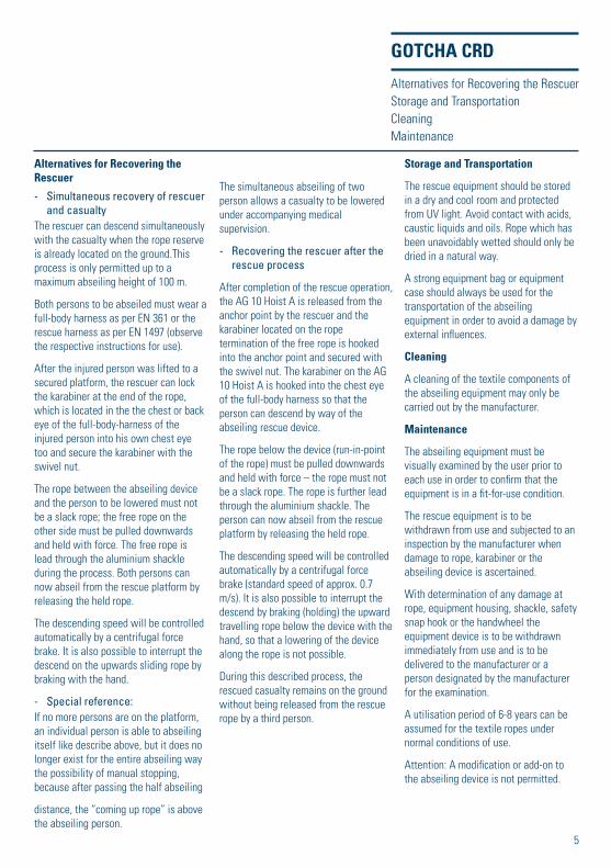
Alternatives for Recovering the Rescuer
- Simultaneous recovery of rescuer
and casualty
The rescuer can descend simultaneously
with the casualty when the rope reserve
is already located on the ground.This
process is only permitted up to a
maximum abseiling height of 100 m.
Both persons to be abseiled must wear a
full-body harness as per EN 361 or the
rescue harness as per EN 1497 (observe
the respective instructions for use).
After the injured person was lifted to a
secured platform, the rescuer can lock
the karabiner at the end of the rope,
which is located in the the chest or back
eye of the full-body-harness of the
injured person into his own chest eye
too and secure the karabiner with the
swivel nut.
The rope between the abseiling device
and the person to be lowered must not
be a slack rope; the free rope on the
other side must be pulled downwards
and held with force. The free rope is
lead through the aluminium shackle
during the process. Both persons can
now abseil from the rescue platform by
releasing the held rope.
The descending speed will be controlled
automatically by a centrifugal force
brake. It is also possible to interrupt the
descend on the upwards sliding rope by
braking with the hand.
- Special reference:
If no more persons are on the platform,
an individual person is able to abseiling
itself like describe above, but it does no
longer exist for the entire abseiling way
the possibility of manual stopping,
because after passing the half abseiling
distance, the “coming up rope” is above
the abseiling person.
The simultaneous abseiling of two
person allows a casualty to be lowered
under accompanying medical
supervision.
- Recovering the rescuer after the
rescue process
After completion of the rescue operation,
the AG 10 Hoist A is released from the
anchor point by the rescuer and the
karabiner located on the rope
termination of the free rope is hooked
into the anchor point and secured with
the swivel nut. The karabiner on the AG
10 Hoist A is hooked into the chest eye
of the full-body harness so that the
person can descend by way of the
abseiling rescue device.
The rope below the device (run-in-point
of the rope) must be pulled downwards
and held with force – the rope must not
be a slack rope. The rope is further lead
through the aluminium shackle. The
person can now abseil from the rescue
platform by releasing the held rope.
The descending speed will be controlled
automatically by a centrifugal force
brake (standard speed of approx. 0.7
m/s). It is also possible to interrupt the
descend by braking (holding) the upward
travelling rope below the device with the
hand, so that a lowering of the device
along the rope is not possible.
During this described process, the
rescued casualty remains on the ground
without being released from the rescue
rope by a third person.
Storage and Transportation
The rescue equipment should be stored
in a dry and cool room and protected
from UV light. Avoid contact with acids,
caustic liquids and oils. Rope which has
been unavoidably wetted should only be
dried in a natural way.
A strong equipment bag or equipment
case should always be used for the
transportation of the abseiling
equipment in order to avoid a damage by
external infl uences.
Cleaning
A cleaning of the textile components of
the abseiling equipment may only be
carried out by the manufacturer.
Maintenance
The abseiling equipment must be
visually examined by the user prior to
each use in order to confi rm that the
equipment is in a fi t-for-use condition.
The rescue equipment is to be
withdrawn from use and subjected to an
inspection by the manufacturer when
damage to rope, karabiner or the
abseiling device is ascertained.
With determination of any damage at
rope, equipment housing, shackle, safety
snap hook or the handwheel the
equipment device is to be withdrawn
immediately from use and is to be
delivered to the manufacturer or a
person designated by the manufacturer
for the examination.
A utilisation period of 6-8 years can be
assumed for the textile ropes under
normal conditions of use.
Attention: A modifi cation or add-on to
the abseiling device is not permitted.
Alternatives for Recovering the Rescuer
Storage and Transportation
Cleaning
Maintenance
6
GOTCHA CRD
Inspection
-- Normal application
The rescue equipment must be
inspected by the manufacturer or a
qualifi ed person at least 1 x year.
In the case of numerous use or greater
stressing (e.g. environmental or
industrial factors affecting the
materials), the complete abseiling
equipment should be subjected to
inspection at an accordingly higher
frequency.
The abseiling equipment must be
inspected by the manufacturer after
every use for rescue (not training)!
After 1000 m descending work the
device must be inspected by the
manufacturer or a qualifi ed person
authorized by the manufacturer. Also
the rope must be inspected after 100m
descending work.
- Inspection of devices used at
training facilities
On account of the numerous use of the
device during trainings it is an
obligation, that the device is visually
examinated by an expert prior to each
use. The enclosed reference sheet of
the manufacturer for the execution of
the visual examination is to be
considered.
Additional it is also an obligation to
make a Service inspection (opening the
device) on devices which are used for
trainings considering the following
Service inspection intervals by a expert
(a trained coach).
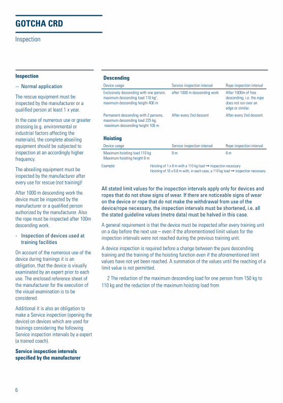
Service inspection intervals specifi ed by the manufacturer
Inspection
All stated limit values for the inspection intervals apply only for devices and
ropes that do not show signs of wear. If there are noticeable signs of wear
on the device or rope that do not make the withdrawal from use of the
device/rope necessary, the inspection intervals must be shortened, i.e. all
the stated guideline values (metre data) must be halved in this case.
A general requirement is that the device must be inspected after every training unit
on a day before the next use – even if the aforementioned limit values for the
inspection intervals were not reached during the previous training unit.
A device inspection is required before a change between the pure descending
training and the training of the hoisting function even if the aforementioned limit
values have not yet been reached. A summation of the values until the reaching of a
limit value is not permitted.
2 The reduction of the maximum descending load for one person from 150 kg to
110 kg and the reduction of the maximum hoisting load from
DescendingDevice usage Service inspection interval Rope inspection interval
Exclusively descending with one person,
maximum descending load 110 kg2,
maximum descending height 400 m
after 1000 m descending work After 1000m of free
descending, i.e. the rope
does not run over an
edge or similar.
Permanent descending with 2 persons,
maximum descending load 225 kg,
maximum descending height 100 m
After every 2nd descent After every 2nd descent.
Hoisting Device usage Service inspection interval Rope inspection interval
Maximum hoisting load 110 kg
Maximum hoisting height 8 m
8 m 8 m
Example: Hoisting of 1 x 8 m with a 110 kg load ➞ inspection necessary
Hoisting of 10 x 0.8 m with, in each case, a 110 kg load ➞ inspection necessary
7
GOTCHA CRD
The manufacturer’s Inspection Lists for
the performance of the service inspection
and the relevant Instructions for Use
must be observed.
The performed descending work and the
done revision examination must be
entered into the attached list for
documentation purposes. You must
separate the rope-work between
abseiling and hoisting.
NOTE: Authorization for the execution of training courses and exercises
Application training courses may be
implemented only by persons who were
trained by the manufacturer or a
competent person named by the
manufacturer and who have a certifi cate
of the training.
Exercises may take place only under
supervision of a person, who participated
on application training course by the
manufacturer or a competent person
named by the manufacturer and is
competent and can verify this by a
certifi cate.
The manufacturer or a direct
representative of the manufacturer trains
trainers / coaches. The training to the
coach contains at the same time the
training to experts. The trained coach is
entitled to carry out application training
courses as well as expert training
courses. The coach is not entitled to
accomplish training courses for coaches.
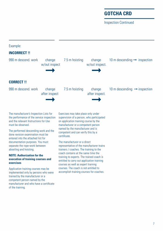
Inspection Continued
Example:
INCORRECT !!
990 m descend. work change 7.5 m hoisting change 10 m descending ➞ inspection
w/out inspect w/out inspect.
➞ ➞CORRECT !!
990 m descend. work change 7.5 m hoisting change 10 m descending ➞ inspection
after inspect after inspect.
➞ ➞
8
GOTCHA CRD
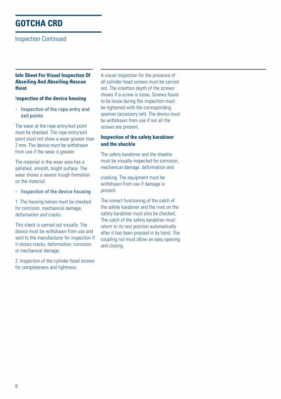
Info Sheet For Visual Inspection Of Abseiling And Abseiling-Rescue Hoist
Inspection of the device housing
- Inspection of the rope entry and
exit points
The wear at the rope entry/exit point
must be checked. The rope entry/exit
point must not show a wear greater than
2 mm. The device must be withdrawn
from use if the wear is greater.
The material in the wear area has a
polished, smooth, bright surface. The
wear shows a severe trough formation
on the material.
- Inspection of the device housing
1. The housing halves must be checked
for corrosion, mechanical damage,
deformation and cracks.
This check is carried out visually. The
device must be withdrawn from use and
sent to the manufacturer for inspection if
it shows cracks, deformation, corrosion
or mechanical damage.
2. Inspection of the cylinder head screws
for completeness and tightness.
A visual inspection for the presence of
all cylinder head screws must be carried
out. The insertion depth of the screws
shows if a screw is loose. Screws found
to be loose during the inspection must
be tightened with the corresponding
spanner (accessory set). The device must
be withdrawn from use if not all the
screws are present.
Inspection of the safety karabiner and the shackle
The safety karabiner and the shackle
must be visually inspected for corrosion,
mechanical damage, deformation and
cracking. The equipment must be
withdrawn from use if damage is
present.
The correct functioning of the catch of
the safety karabiner and the rivet on the
safety karabiner must also be checked.
The catch of the safety karabiner must
return to its rest position automatically
after it has been pressed in by hand. The
coupling nut must allow an easy opening
and closing.
Inspection Continued
9
GOTCHA CRD
Inspection of the
Sheathed Core Rope
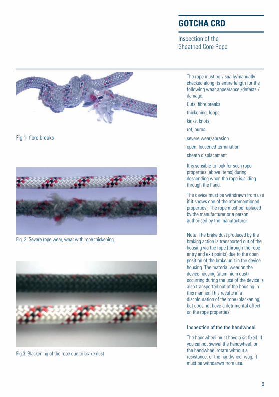
Fig.1: fi bre breaks
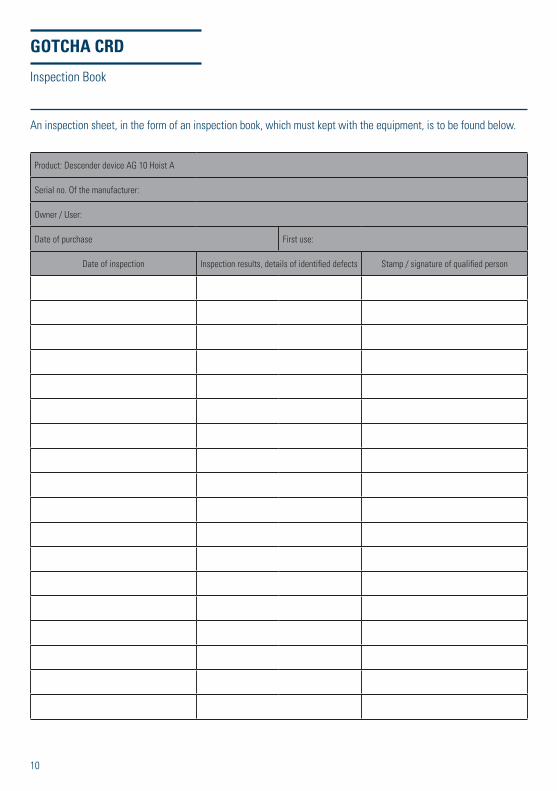
Fig. 2: Severe rope wear, wear with rope thickening
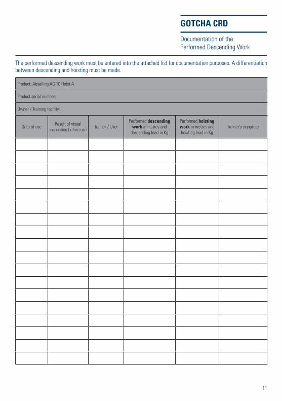
Fig.3: Blackening of the rope due to brake dust
The rope must be visually/manually
checked along its entire length for the
following wear appearance /defects /
damage:
Cuts, fi bre breaks
thickening, loops
kinks, knots
rot, burns
severe wear/abrasion
open, loosened termination
sheath displacement
It is sensible to look for such rope
properties (above items) during
descending when the rope is sliding
through the hand.
The device must be withdrawn from use
if it shows one of the aforementioned
properties.. The rope must be replaced
by the manufacturer or a person
authorised by the manufacturer.
Note: The brake dust produced by the
braking action is transported out of the
housing via the rope (through the rope
entry and exit points) due to the open
position of the brake unit in the device
housing. The material wear on the
device housing (aluminium dust)
occurring during the use of the device is
also transported out of the housing in
this manner. This results in a
discolouration of the rope (blackening)
but does not have a detrimental effect
on the rope properties.
Inspection of the the handwheel
The handwheel must have a sit fi xed. If
you cannot swivel the handwheel, or
the handwheel rotate without a
resistance, or the handwheel wag, it
must be withdarwn from use.
10
GOTCHA CRD
Inspection Book
An inspection sheet, in the form of an inspection book, which must kept with the equipment, is to be found below.
Product: Descender device AG 10 Hoist A
Serial no. Of the manufacturer:
Owner / User:
Date of purchase First use:
Date of inspection Inspection results, details of identifi ed defects Stamp / signature of qualifi ed person
11
The performed descending work must be entered into the attached list for documentation purposes. A differentiation
between descending and hoisting must be made.
GOTCHA CRD
Documentation of the
Performed Descending Work
Product: Abseiling AG 10 Hoist A
Product serial number:
Owner / Training facility:
Date of useResult of visual
inspection before useTrainer / User
Performed descendingwork in metres and
descending load in Kg
Performed hoisting work in metres and
hoisting load in Kg
Trainer’s signature
12
© 2
016
Sp
an
Se
t Lt
d.
- S
P9
07
37
- 9
/20
16 -
Pro
du
ced
by
ww
w.t
he
pri
nti
ng
ho
use
ltd
.co
.uk
Can
be
recy
cled
.
We
have
a p
olic
y of
con
tinu
ous
deve
lopm
ent
and
ther
efor
e re
serv
e th
e ri
ght
to m
odif
y de
sign
s an
d sp
ecifi
cati
ons
wit
hout
pri
or n
otic
e.
01
SpanSet Gotcha CRD User Instructions
Height Safety
www.spanset.co.uk