Embed Size (px)
Citation preview
852 J. SPACECRAFT, VOL. 35, NO. 6: ENGINEERING NOTES
Space Shuttle Family:Shuttle II, Mini Shuttle,
and Micro Shuttles
Frederick W. Boltz¤
NASA Ames Research Center,Moffett Field, California 94035
Introduction
T HE Space Shuttle or Space Transportation System (STS) isthe culmination of years of intensive development by NASA,
Rockwell International, and other contractors. NASA designed theShuttle to carry large, heavypayloadsinto low Earth orbit on crewedmissions with a high degree of safety and reliability. But it was ini-tially miscast in its role as a do-it-all launch vehicle that could beused to provide cheap, quick, and easy access to space. The truthis that the Shuttle is a huge workhorse, which is costly to operateand requires a longer turnaround time than originally anticipated.However, it has proven to be the safest and most reliable system yetdevised for crewed missions and the launching of large, heavy pay-loads into orbit.1 Rather than discard this highly successful systemin favor of a totally different and unproven one, such as that of theLockheedMartin X-33/VentureStar,2 it makes sense to � rst considerredesigningthe basic system to improve it and simplify its operationso as to becomemore costeffective.This ideahas been enunciatedinthe Shuttle II concept3 and thatof the kerosene-fueledMini Shuttle.4
The Shuttle II is a reconstitutedSpace Shuttle with essentially thesame externaltank (ET) and solid rocketboosters(SRBs)but havingan Orbiter upgraded with the latest technology and an improvedthermalprotectionsystem.5 The Mini Shuttle is a downsizedversionof the Space Shuttle usingthe same SRBs buthavinga 3
4 -sizeOrbiterand ET. In converting from liquid hydrogen to kerosene (RP-1) forfuel, there is a reduction of about 62% in the required volume ofthe ET and a reduction of about 58% in its inert mass, along witha reduction of about 23% in speci� c impulse of the liquid rocketpropulsion system. This translates into a smaller fraction of liftoffmass beingable to be placed in orbit. It has been found that the MiniShuttle can place in orbit only about 61% of the total mass of theShuttleOrbiterplus its payload.However,by downsizingthe Orbiter25% while increasing its average density slightly to keep the sameplanform loading, the Mini Shuttle has a payload capability about84% of that for the Shuttle. From all indications it appears that thenew Russian RD-180 engine,6 soon to be produced in the UnitedStates, would be an ideal liquid rocket engine for the downsizedOrbiter. It operates at high pressure and oxygen rich and so runscooler than U.S. high-performance engines. Moreover, it can bethrottled from 37 to 100% of its rated output of 933,000 lb of thrustwhile remaining � xed in speci� c impulse.
The purpose of this Note is to show how the Mini Shuttle con-cept can be extended to obtain smaller crewed or uncrewed versionsof the Mini Shuttle, which are similar in function and shape butdiffer greatly in size and weight. These Micro Shuttles have a pay-load capability that is proportional to their liftoff weight and thatis the same fraction of liftoff weight as that for the Mini Shuttle.Together with the Shuttle II and Mini Shuttle, they comprise theSpace Shuttle family. In addition to being able to ef� ciently launchsmall- to medium-size payloads (2000–14,000 lb) into orbit witha semireusable two-stage vehicle, such as the X-34, which NASAis developing to be a small, low-cost rocket launcher,7 there areother possible applications for the Micro Shuttles. The smaller ofthese vehicles could be used by the Air Force in a crewed or un-crewed mode to develop the operational capability in space it haslong sought.8 To this end, an experimental uncrewed space maneu-
Received Oct. 13, 1997; revision received July 27, 1998; accepted forpublication July 27, 1998. Copyright c° 1998 by Frederick W. Boltz. Pub-lished by the American Institute of Aeronautics and Astronautics, Inc., withpermission.
¤Aerospace Engineer, Aeronautics Division (retired). Member AIAA.
vervehicle(SMV) is currentlyundergoingpreliminarydevelopmentby Boeing Space Systems for the Air Force.9 This SMV is about thesize of the smallest ( 1
5 -size) Micro Orbiter but weighs only about 13
as much. Because of its low planform loading, it has high sensitivityto winds and gusts, as well as to timing of the landing � are. Thiswould not be a problem with the smallest Micro Orbiter, which,like the other Micro Orbiters, has the same planform loading (about65 lb/ft2) as the Space Shuttle Orbiter and the Mini Orbiter. Thepotential value of a larger military spaceplane or space operationsvehicle (SOV) for crewed or uncrewed use by the Air Force hasalso come under consideration.10¡12 It would appear that either ofthe middle-sized Micro Shuttles (having 1
4 - and 13 -size Orbiters) is
ideally suited to being an SOV with a stringent set of requirements.Among these are the ability to launch on short notice, economy ofoperation, relatively easy maintenance, and reusability.
Another suitable utilization of the middle-sized Micro Shuttleswould be for emergency or rescue operations,where, here also, thecapability of launch on short notice may be required. NASA hasrecently begun development of the X-38 lifting body as a possiblenew crew return vehicle (CRV) for the International Space Station(ISS).13 This CRV is about the size and weightof the next to smallest( 1
4-size)Micro Orbiter.Becauseof its highplanformloadingand low
lift-to-dragratio, the X-38 has a landingspeed that is consideredtoohigh for safety, and so a parafoilis used for � nal descentand landing.The 1
4 -size Micro Orbiter would not require such a risky type oflanding technique and already has a reliable means of delivery toorbit. The 1
3 -size Micro Orbiter would also be suitable for use as aCRV in a situation where the full seven-person complement of theISS has to be evacuated.
Scaling RationaleThe basis for scaling the smaller vehicles (Micro Shuttles) in the
Space Shuttle family is threefold. 1) The fractions of total liftoffweight for each of their four components (Orbiter, payload, SRBs,and ET)are the same as thecomponentfractionsfor theMiniShuttle.2) The planform loading is the same for all of the Orbiters in thefamily (including the Shuttle II and Mini Shuttle) so that the Orbiterweight or mass m is proportional to the square of its size or scalefactor (SF) with m2=m1 D .SF/2 . 3) The cubic scaling law is usedto determine the separate and distinct SFs for sizing the SRBs andET of each vehicle. The cubic scaling law infers that the mass ratioof similarlyshaped vehicle componentsof the same averagedensity(such as the SRBs and ET) is given by the cube of the SF. If m is thecomponentmass, then m2=m1 D .SF/3 . Another way of saying thisis that in shrinking the size of a vehicle component (SRB or ET) sothat all dimensions are reduced by the SF (with the average densityheld� xed), the massof the smaller componentis equal to the massofthe larger component times the SF cubed. Conversely, to determinethe SF required to achieve a desired mass ratio, it is necessary to� nd the cube root of the mass ratio, so that SF D .m2=m1/1=3.
In arbitrarily stipulating the sizes or SFs of the various MicroOrbiters ( 1
2 , 13 , 1
4 , and 15), it is a simple matter to determine their
weights according to the second basis and the given weight of theMini Orbiter. In downsizing the Shuttle Orbiter, it is desirable toincrease its average density so as to maintain about the same valueof planformloadingand ensuresimilar aerodynamiccharacteristics.This is in conformity with the natural tendency of aircraft or space-craft to increase slightly in average density when reduced in size.Then, according to the � rst basis for scaling, the payload weight ineach case is in the same proportion as that for the Mini Shuttle, asare also the propellant weights and the inert weights of the SRBsand the ET. The � nal step in the sizing process, after obtaining thevarious componentweights, is to determine the separateSFs for theSRBs and ET in each case, according to the cubic scaling law. Withthese SFs, the dimensionsof the SRBs and ETs are readilyobtained.
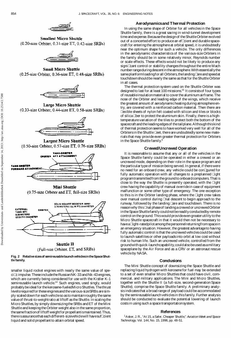
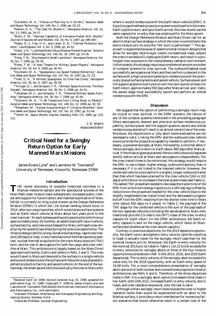
Size and Weight ResultsAn appreciationof the relative size of vehicles in the Space Shut-
tle family may be gained from the drawings to scale presented inFigs. 1 and 2. The overall dimensions of each vehicle, along withthe SFs and dimensions of its components, are listed in Table 1.It was assumed that the dimensions of the Shuttle II would be the
Dow
nloa
ded
by U
nive
rsita
ts-
und
Lan
desb
iblio
thek
Dus
seld
orf
on S
epte
mbe
r 14
, 201
3 | h
ttp://
arc.
aiaa
.org
| D
OI:
10.
2514
/2.7
588
J. SPACECRAFT, VOL. 35, NO. 6: ENGINEERING NOTES 853
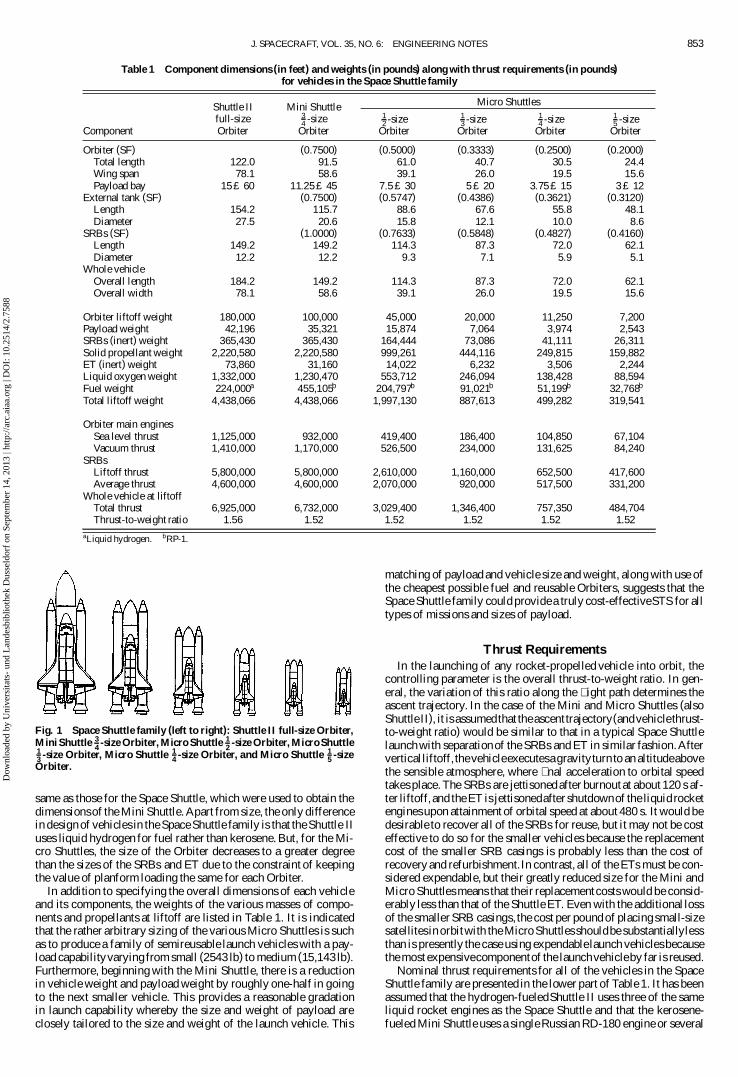
Table 1 Component dimensions (in feet) and weights (in pounds) along with thrust requirements (in pounds)for vehicles in the Space Shuttle family
Shuttle II Mini Shuttlefull-size 3
4 -sizeComponent Orbiter Orbiter
Micro Shuttles12 -size 1
3 -size 14 -size 1
5 -sizeOrbiter Orbiter Orbiter Orbiter
Orbiter (SF) (0.7500) (0.5000) (0.3333) (0.2500) (0.2000)Total length 122.0 91.5 61.0 40.7 30.5 24.4Wing span 78.1 58.6 39.1 26.0 19.5 15.6Payload bay 15 £ 60 11:25 £ 45 7:5 £ 30 5 £ 20 3:75 £ 15 3 £ 12
External tank (SF) (0.7500) (0.5747) (0.4386) (0.3621) (0.3120)Length 154.2 115.7 88.6 67.6 55.8 48.1Diameter 27.5 20.6 15.8 12.1 10.0 8.6
SRBs (SF) (1.0000) (0.7633) (0.5848) (0.4827) (0.4160)Length 149.2 149.2 114.3 87.3 72.0 62.1Diameter 12.2 12.2 9.3 7.1 5.9 5.1
Whole vehicleOverall length 184.2 149.2 114.3 87.3 72.0 62.1Overall width 78.1 58.6 39.1 26.0 19.5 15.6
Orbiter liftoff weight 180,000 100,000 45,000 20,000 11,250 7,200Payload weight 42,196 35,321 15,874 7,064 3,974 2,543SRBs (inert) weight 365,430 365,430 164,444 73,086 41,111 26,311Solid propellant weight 2,220,580 2,220,580 999,261 444,116 249,815 159,882ET (inert) weight 73,860 31,160 14,022 6,232 3,506 2,244Liquid oxygen weight 1,332,000 1,230,470 553,712 246,094 138,428 88,594Fuel weight 224,000a 455,105b 204,797b 91,021b 51,199b 32,768b
Total liftoff weight 4,438,066 4,438,066 1,997,130 887,613 499,282 319,541
Orbiter main enginesSea level thrust 1,125,000 932,000 419,400 186,400 104,850 67,104Vacuum thrust 1,410,000 1,170,000 526,500 234,000 131,625 84,240
SRBsLiftoff thrust 5,800,000 5,800,000 2,610,000 1,160,000 652,500 417,600Average thrust 4,600,000 4,600,000 2,070,000 920,000 517,500 331,200
Whole vehicle at liftoffTotal thrust 6,925,000 6,732,000 3,029,400 1,346,400 757,350 484,704Thrust-to-weight ratio 1.56 1.52 1.52 1.52 1.52 1.52
aLiquid hydrogen. bRP-1.
Fig. 1 Space Shuttle family (left to right): Shuttle II full-size Orbiter,Mini Shuttle 3
4 -size Orbiter, Micro Shuttle 12 -size Orbiter, Micro Shuttle
13 -size Orbiter, Micro Shuttle 1
4 -size Orbiter, and Micro Shuttle 15 -size
Orbiter.
same as those for the Space Shuttle, which were used to obtain thedimensionsof the Mini Shuttle. Apart from size, the only differencein design of vehicles in the Space Shuttle family is that the Shuttle IIuses liquid hydrogen for fuel rather than kerosene. But, for the Mi-cro Shuttles, the size of the Orbiter decreases to a greater degreethan the sizes of the SRBs and ET due to the constraint of keepingthe value of planform loading the same for each Orbiter.
In addition to specifying the overall dimensions of each vehicleand its components, the weights of the various masses of compo-nents and propellants at liftoff are listed in Table 1. It is indicatedthat the rather arbitrary sizing of the various Micro Shuttles is suchas to produce a family of semireusable launch vehicles with a pay-load capabilityvarying from small (2543 lb) to medium (15,143 lb).Furthermore, beginning with the Mini Shuttle, there is a reductionin vehicle weight and payload weight by roughly one-half in goingto the next smaller vehicle. This provides a reasonable gradationin launch capability whereby the size and weight of payload areclosely tailored to the size and weight of the launch vehicle. This
matching of payload and vehicle size and weight, along with use ofthe cheapest possible fuel and reusable Orbiters, suggests that theSpace Shuttle family could provide a truly cost-effectiveSTS for alltypes of missions and sizes of payload.
Thrust RequirementsIn the launching of any rocket-propelled vehicle into orbit, the
controlling parameter is the overall thrust-to-weight ratio. In gen-eral, the variation of this ratio along the � ight path determines theascent trajectory. In the case of the Mini and Micro Shuttles (alsoShuttle II), it is assumedthat theascenttrajectory(andvehiclethrust-to-weight ratio) would be similar to that in a typical Space Shuttlelaunch with separationof the SRBs and ET in similar fashion.Afterverticalliftoff, thevehicleexecutesa gravityturn to an altitudeabovethe sensible atmosphere, where � nal acceleration to orbital speedtakes place. The SRBs are jettisoned after burnout at about 120 s af-ter liftoff, and the ET is jettisonedafter shutdownof the liquid rocketenginesupon attainment of orbital speed at about 480 s. It would bedesirable to recover all of the SRBs for reuse, but it may not be costeffective to do so for the smaller vehicles because the replacementcost of the smaller SRB casings is probably less than the cost ofrecovery and refurbishment.In contrast, all of the ETs must be con-sidered expendable, but their greatly reduced size for the Mini andMicro Shuttles means that their replacementcosts would be consid-erably less than that of the Shuttle ET. Even with the additional lossof the smaller SRB casings, the cost per pound of placing small-sizesatellitesin orbitwith the Micro Shuttles shouldbe substantiallylessthan is presently the case using expendablelaunch vehiclesbecausethe most expensivecomponentof the launchvehicleby far is reused.
Nominal thrust requirements for all of the vehicles in the SpaceShuttle family are presented in the lower part of Table 1. It has beenassumed that the hydrogen-fueledShuttle II uses three of the sameliquid rocket engines as the Space Shuttle and that the kerosene-fueled Mini Shuttle uses a single Russian RD-180 engine or several
Dow
nloa
ded
by U
nive
rsita
ts-
und
Lan
desb
iblio
thek
Dus
seld
orf
on S
epte
mbe
r 14
, 201
3 | h
ttp://
arc.
aiaa
.org
| D
OI:
10.
2514
/2.7
588
854 J. SPACECRAFT, VOL. 35, NO. 6: ENGINEERING NOTES
Fig. 2 Relative sizes of semireusable launch vehicles in the SpaceShut-tle family.
smaller liquid rocket engines with nearly the same value of spe-ci� c impulse. These include the RussianNK-33 and Nk-43 engines,which are currently being considered for use with the Kistler K-1semireusable launch vehicle.14 Such engines, used singly, wouldprobablybe ideal for the kerosene-fueledMicro Shuttles.The thrustlevels required for these engines and the various-sizeSRBs are sim-ply scaled down for each vehicle so as to maintain roughly the samevalue of thrust-to-weightratio at liftoff as the Shuttle. In scaling theMicro Shuttles, by simply downsizing the SRBs and ET of the MiniShuttle and keeping the Orbiter weight also in the same proportion,the same fractionof liftoffweight for propellantis maintained.Thus,there is assurancethat each different-sizevehiclewill havesuf� cientliquid and solid propellant to attain orbital speed.
Aerodynamics and Thermal ProtectionIn using the same shape of Orbiter for all vehicles in the Space
Shuttle family, there is a great saving in wind-tunnel developmenttime and expense.Because the design of the Shuttle Orbiter evolvedout of a concerted effort to produce an ef� cient and durable space-craft for entering the atmosphere at orbital speed, it is undoubtedlynear the optimum shape for such a vehicle. The only differencesin the aerodynamic characteristics of the various-size Orbiters inthe family should be in some relatively minor, Reynolds numberor scale effects. These effects would not be likely to produce anysigni� cant control or stability changes throughout the entire Machnumber rangeduringdescent in the atmosphere.With essentiallythesame planformloadingfor all Orbiters, the landing� are and speedattouchdownshould be nearly the same as that for the Shuttle Orbiterin all cases.
The thermal protection system used on the Shuttle Orbiter wasdesigned to last for at least 100 missions.15 It consists of four typesof reusable insulationmaterial to cover the aluminum airframe. Thenose of the Orbiter and leading edge of the wings, which receivethe greatest amount of aerodynamicheating during atmosphere en-try, are covered with a reinforced carbon material. Then there are� exible sheets of nylon felt coated with silicon and tiles or blocksof silica � ber to protect the aluminum skin. Finally, there is a high-temperature variation of the tiles to protect both the bottom of thespacecraftand the leading edges of the tailplane.Although this kindof thermal protection seems to have worked very well for all of theOrbiters in the Shuttle � eet, there are undoubtedly some new mate-rials that may provide even greater thermal protection for Orbitersin the Space Shuttle family.5
Crewed/Uncrewed OperationIt is reasonable to assume that any or all of the vehicles in the
Space Shuttle family could be operated in either a crewed or anuncrewed mode, depending on their role in the space program andthe particular type of mission being served. In general, if there wereno need for an onboard crew, any vehicle could be con� gured forfully automatic operation with all changes to a preplanned � ightprogramtransmitted from the ground to onboardcomputers.That isclose to the way the Shuttle is presently operated, with the � ightcrew having the capability of manual override in case of equipmentmalfunction or some other type of emergency. The one exceptionto this is in the Orbiter landing phase, where the � ight crew takesover manual control during � nal descent to begin approach to therunway, followed by the landing � are and touchdown. There is noreason why this � nal phaseof landinga crewed or uncrewed Orbiterin the Space Shuttle family couldnotbe readilyconductedby remotecontrolon the ground.This would provide even greaterutility to theMicro Shuttle spacecraft in that it would then not be necessary tohave a � ight-ratedpilotamong the personnelreturningfromspaceinan emergency situation. However, the greatest advantage to havingfully automatic control is that the uncrewed vehicles could be usedto launch satellites or other payloads into orbit at low cost withoutrisk to human life. Such an uncrewed vehicle, controlled from thegroundwith quick-launchcapability,couldalso beused as a militaryspaceplane by the Air Force and as a CRV or an astronaut rescuevehicle by NASA.
ConclusionsThe Mini Shuttle concept of downsizing the Space Shuttle and
replacing liquid hydrogen with kerosene for fuel may be extendedto a set of even smaller Micro Shuttles that could have civil, com-mercial, and military applications. The Mini and Micro Shuttles,together with the Shuttle II (a full-size, second-generation SpaceShuttle), comprise the Space Shuttle family. A preliminary analy-sis indicates that a broad range of payload could be accommodatedby the semireusable launch vehicles in this family. Further analysisshould be conducted to evaluate the potential lowering of launchcosts in using such a space transportationsystem.
References1Asker, J. R., “At 15, a Safer, Cheaper Shuttle,” Aviation Week and Space
Technology, Vol. 144, No. 15, 1996, pp. 48–51.
Dow
nloa
ded
by U
nive
rsita
ts-
und
Lan
desb
iblio
thek
Dus
seld
orf
on S
epte
mbe
r 14
, 201
3 | h
ttp://
arc.
aiaa
.org
| D
OI:
10.
2514
/2.7
588
J. SPACECRAFT, VOL. 35, NO. 6: ENGINEERING NOTES 855
2Dornheim, M. A., “Follow-on Plan Key to X-33 Win,” Aviation Weekand Space Technology, Vol. 145, No. 2, 1996, pp. 20–23.
3Nelson, D. A., “The Case for Shuttle II,” Aerospace America, Vol. 31,No. 11, 1993, pp. 24–27.
4Boltz, F. W., “Payload Capability of Kerosene-Fueled Mini Shuttle,”Journal of Spacecraft and Rockets, Vol. 34, No. 5, 1997, pp. 685–687.
5Rasky, D. J., Tran, H. K., and Leiser, D. B., “Thermal Protection Sys-tems,” Launchspace, Vol. 3, No. 3, 1998, pp. 44–51.
6Asker, J. R., “Lockheed Martin Buys Russian Rocket Engines,” AviationWeek and Space Technology, Vol. 146, No. 26, 1997, pp. 24–26.
7Foley,T. M., “Big Hopes for Small Launchers,” Aerospace America, Vol.33, No. 7, 1995, pp. 28–34.
8Foley, T. M., “A New Theatre for Military Space Players,” AerospaceAmerica, Vol. 34, No. 9, 1996, pp. 40–43.
9Dornheim, M. A., “Spaceplane Low-Speed Testbed Rolled Out,” Avia-tion Week and Space Technology, Vol. 147, No. 10, 1997, pp. 22, 23.
10Hart, D. A., “A Military Spaceplane, Its Time Has Come,” AerospaceAmerica, Vol. 35, No. 5, 1997, pp. 26–28.
11Klinger, G. I., and Simpson, T. R., “Military Space Activities: The NextDecade,” Aerospace America, Vol. 36, No. 1, 1998, pp. 44–51.
12Johansen, M. C., and Simpson, T. R., “Potential Military Space Activ-ities,” Aerospace America, Vol. 36, No. 7, 1998, pp. 42–44.
13Dorheim, M. A., “X-38 Transitions from Lifting Body to Parafoil,”Aviation Week and Space Technology, Vol. 148, No. 12, 1998, pp. 92, 93.
14Meacham, M., “Aerojet Acquires Major K-1 Engine Shipment,” Avia-tion Week and Space Technology, Vol. 147, No. 10, 1997, pp. 61–64.
15Smith, M., Space Shuttle, Haynes, Newbury Park, CA, 1985, pp. 120,121.
J. A. MartinAssociate Editor
Critical Need for a SwingbyReturn Option for EarlyManned Mars Missions
James Evans Lyne¤ and Lawrence W. Townsend†
University of Tennessee, Knoxville, Tennessee 37996
Introduction
T HE recent discovery of possible fossilized microbes in aMartian meteorite sample and the spectacular success of the
Mars Path� nder mission have substantially increased public inter-est and support for future robotic and manned exploration of Mars.NASA is currently re� ning a plan known as the Design ReferenceMission (DRM) in which the � rst human landing would occur in2014, after two cargo launches,which would place surface systemsand an Earth return vehicle at Mars about two years prior to thecrew’s arrival.1 At each subsequentlaunchopportunity(whichoccurapproximatelyevery 26 months), an additionalEarth return vehicle,surfacefacility,and crewwould departforMars, with each crew em-ploying the systems launched during the previous opportunity.Themissiondesigncalls for a long-durationsurfacestay, rapid crew tran-sits (180 days or less), in situ manufactureof the Mars ascentpropel-lant, nuclear thermal propulsion for the trans-Mars injection (TMI)burn, and the use of aerocapture for both the cargo and crew vehi-cles at Mars. This architecture is largely based on the Mars Directapproach outlined by Zubrin and others in Refs. 2 and 3. The crewwould travel to Mars and descend to the surface in a single vehicleandwould rendezvouson the surfacewith the previouslyplacedpro-pellant production facility and ascent vehicle.At the end of the sur-facestay, the small ascentvehiclewould carry thecrew to Mars orbit,
Received April 14, 1998; revision received Aug. 31, 1998; accepted forpublication Aug. 31, 1998. Copyright c° 1998 by James Evans Lyne andLawrence W. Townsend.Publishedby the American Instituteof Aeronauticsand Astronautics, Inc., with permission.
¤Assistant Professor, Mechanical and Aerospace Engineering and Engi-neering Science. Member AIAA.
†Associate Professor, Nuclear Engineering.
where it would rendezvous with the Earth return vehicle (ERV). Aliquid oxygen/methane propulsionsystem would perform the trans-Earth injection burn, and upon Earth arrival, the crew would use thesame capsule for re-entry that was employed for the Mars ascent.
Both the Design Reference Mission and Mars Direct call for anabort to Mars surface strategy in which the crew is committed to theentire mission pro� le once the TMI burn is performed.1;4 This ap-proach is supported because of assertions that mission designs thatallow for swingby returns signi� cantly increase total mass, subjectthe crew to excessive G loads upon Earth return, and result in a pro-longed crew exposure to the interplanetary radiation environment.Unfortunately,this strategyrequiresa completerelianceona numberof complex systems for crew survival. The outbound habitat mustsuccessfully aerocapture at Mars and then perform a descent to thesurface with a high-precision landing to rendezvouswith the previ-ously placed surface systems and ascent vehicle. Surface power andlife support systems must function until the next launch window forEarth return, approximately550 days after Mars arrival, and � nally,the ascent stage must successfully launch and perform an orbitalrendezvous with the ERV.
DiscussionWe suggest that the option of performing a swingby return may
be crucial to crew survival; in the DRM scenario, the failure ofany of the complex systems mentioned in the preceding paragraph(Mars aerocapture, descent and precision surface rendezvous ca-pability, surface power and life support systems, ascent and orbitalrendezvoussystems) will result in an almost certain loss of the crew.Moreover, the objections to a � yby abort mentioned earlier are notnecessarily valid. Linking the ERV and the outbound crew vehiclewould provide the propulsive capability needed to perform, if nec-essary, a powered swingby at Mars, followed by a minimal delta VVenus swingby and a return to Earth about 380 days after Mars ar-rival. If the missiongoesas planned,the two vehicleswould separateshortly before arrival at Mars and aerocapture independently. Forthe crew transit times to be minimized, this strategy would requirethe ERV to use a faster, higher-energy,outbound trajectory than isnecessary if it is not linked to the manned vehicle. However, thecombined vehicle could perform a slightly longer outbound transitthan that which has been planned for the crew vehicle (184 vs 161days) with little or no increasein the total system mass (see Table 1).The added TMI propellantneeded to decrease the transit time of theERV from a minimum energy trajectory to a 184-day leg is offset byreductions in the propellant needed for the crew vehicle (due to theslightly lengthened crew transit time) and the decreased cryogenicboiloff from the ERV resulting from the shorter loiter time in Marsorbit (about 550 days vs 4 years). In Table 1, the payload of theTMI stage for the combined vehicle is the sum of the payloads ofthe two separate vehicles (including the aerobrakes for Mars orbitinsertions) plus the 5.5-metric-ton (MT) mass of the crew re-entrycapsule for Earth return. (In the DRM architecture, the Earth re-entry capsule is sent on the cargo vehicle, which lands on Mars’surface and doubles as the crew ascent capsule.)
Contrary to previous objections, for the 2014 departure opportu-nity, the Earth return atmospheric entry velocity (and the resultingG load) is actually lower for the swingby return case than for thenominal mission pro� le. Moreover, the Earth re-entry velocity forthe nominal 2014 pro� le listed in Table 1 (14.22 km/s) exceeds there-entry velocities for swingby aborts of three of the four missionopportunitiesconsidered in Ref. 5 (the 2014, 2016, and 2020 Earthdepartures). The re-entry velocityof the swingby abort exceeds thisvalue only for the 2018 opportunity, with an Earth entry speed of14.68 km/s. For a more comprehensive presentation of swingbyabort options for both nuclear and conventionalpropulsionmissionarchitectures, see Refs. 5 and 6. Therefore, of the three objectionslisted in Ref. 4 to a swingby abort option [increased initial mass inlow Earth orbit (IMLEO), increased Earth re-entry velocity and Gloads, and crew radiation exposure], only the last is valid.
Although a Mars swingby return does expose the crew to higherradiation levels than would be experienced with an abort to theMartian surface, it provides a return mechanism for numerous fail-ure scenarios that would otherwise result in a certain loss of the
Dow
nloa
ded
by U
nive
rsita
ts-
und
Lan
desb
iblio
thek
Dus
seld
orf
on S
epte
mbe
r 14
, 201
3 | h
ttp://
arc.
aiaa
.org
| D
OI:
10.
2514
/2.7
588