Embed Size (px)
Citation preview
SCaN-MOCS-0001
SPACE COMMUNICATIONS AND NAVIGATION PROGRAM
Space Communications and Navigation (SCaN) Mission Operations and Communications
Services (MOCS)
Revision 1
Effective Date: March 26, 2018
Expiration Date: March 26, 2023
CHECK THE SCaN NEXT GENERATION INTEGRATED NETWORK (NGIN) AT: https://scanngin.gsfc.nasa.gov
TO VERIFY THAT THIS IS THE CORRECT VERSION PRIOR TO USE.
National Aeronautics and Space Administration
NASA Headquarters Washington, D. C.
SCaN-MOCS-0001
Revision 1
Space Communications and Navigation (SCaN) Mission Operations and Communications Services
(MOCS)
Effective Date: March 26, 2018
NASA Headquarters Washington, D. C.
ii SCaN-MOCS-0001
Revision 1
Preface
This document is under configuration management of the SCaN Integrated Network Configuration
Control Board (SINCCB). This document will be changed by Documentation Change Notice
(DCN) or complete revision. Proposed changes to this document must be submitted to the SCaN
Configuration Management Office along with supportive material justifying the proposed change.
Comments or questions concerning this document and proposed changes shall be addressed to:
Configuration Management Office
Space Communications and Navigation Office NASA Headquarters
Washington, D. C.
iii SCaN-MOCS-0001
Revision 1
Change Information Page
List of Effective Pages
Page Number Issue
Title Rev 1
iii through vi Rev 1
1-1 through 1-3 Rev 1
2-1 through 2-3 Rev 1
3-1 through 3-6 Rev 1
4-1 through 4-3 Rev 1
5-1 through 5-8 Rev 1
6-1 through 6-2 Rev 1
A-1 through A-2 Rev 1
B-1 through B-2 Rev 1
C-1 through C-1 Rev 1
D-1 through D-4 Rev 1
E-1 through E-5 Rev 1
F-1 Through F-5 Rev 1
Document History
Document Number Status/Issue Effective Date CR Number
SCaN-MOCS-0001 Baseline March 21, 2016 CR 106
SCaN-MOCS-0001 Revision 1 March 26, 2018 CR 120
Change History
Revision Effective Date Description of Change
Baseline (CR 106) March 21, 2016 Initial Release
iv SCaN-MOCS-0001
Revision 1
Revision 1 (CR000120) March 26, 2018 Editorial revisions for clarity, verbiage, grammar, and acronyms throughout the document
Replaced DSN Mission Services Planning & Management Office (DMSP&MO) with CIMO throughout the document
Updates throughout the document for consistency with other SCaN documentation
Changes references from Communications Service Office (CSO) to NASCOM in Sections 3.4 and 4.2
Updated SN Rates in Section 5.3 to match published 2017 SN Rate Letter
Reconfigured Section 5.3 to create a more balanced presentation of the material between the three SCaN networks
Moved Costs for using the DSN from Section 5.4 to Appendix F
Updated contact information for the Points of Contact in Section 6
Added references to the Customer Service Portal in Section 6.1
Moved Acronym list to Appendix A
Updated references in Appendix B
Updated tables in Appendix D
Added Points of Contact to Appendix E
Updated cost algorithms in Appendix F
v SCaN-MOCS-0001
Revision 1
Contents
Preface ........................................................................................................................... ii
Change Information Page ............................................................................................ iii
Section 1. Introduction .............................................................................................. 1-1
1.1 Purpose .................................................................................................. 1-1
1.2 Scope...................................................................................................... 1-1
1.3 SCaN Network Services Division ............................................................ 1-1
1.3.1. MCO ........................................................................................ 1-2
1.3.2. The SCaN Networks ................................................................ 1-2
Section 2. SCaN Network Policies and Standards .................................................. 2-1
2.1 Use of the Electromagnetic Spectrum..................................................... 2-1
2.2 Bandwidth Efficient Modulation (DSN, NEN, SN) .................................... 2-2
2.3 Coding .................................................................................................... 2-2
2.4 Space Link Extension (DSN, NEN, SN) .................................................. 2-2
Section 3. Summary of SCaN Network Standard Services ..................................... 3-1
3.1 NEN Service Summary ........................................................................... 3-1
3.2 SN Service Summary.............................................................................. 3-2
3.3 DSN Service Summary ........................................................................... 3-2
3.4 MCO Service Summary .......................................................................... 3-3
3.5 Critical Event Communications ............................................................... 3-6
Section 4. Support from Non-SCaN Network Service Providers ............................ 4-1
4.1 Spectrum Management........................................................................... 4-1
4.2 NASA Communication Network (NASCOM) ........................................... 4-1
4.3 Flight Dynamics Facility (FDF) ................................................................ 4-2
4.4 Advanced Multi-Mission Operations System (AMMOS) .......................... 4-3
4.5 JPL Mission Design and Navigation ....................................................... 4-3
Section 5. Network Support Cost Estimation .......................................................... 5-1
5.1 Nonrecurring Engineering Costs ............................................................. 5-1
5.2 Mission Planning and Integration (MP&I) ................................................ 5-1
5.3 Cost Estimates for Using the SCaN Networks ........................................ 5-2
5.4 Critical Event Support Costing ................................................................ 5-3
5.5 Non-SCaN Support Costing .................................................................... 5-4
vi SCaN-MOCS-0001
Revision 1
Section 6. Requesting Support from the SCaN Networks ...................................... 6-1
6.1 Requesting MCO Support ....................................................................... 6-1
6.2 Process for Requesting NEN or SN Services ......................................... 6-2
6.3 Process for Requesting DSN Services ................................................... 6-2
Appendix A. Acronym List ....................................................................................... A-1
Appendix B. Reference Documents and Websites................................................. B-1
Appendix C. Sample NIMO Questionnaire .............................................................. C-1
Appendix D. Sample DSN Communications System Parameter Tables ............... D-1
Appendix E. Form for Estimating DSN Mission Support Costs ............................. E-1
Appendix F. Estimated Costs for Using the DSN .................................................... F-1
F.1. DSN Aperture Fees ................................................................. F-1
F.2. DSN Costing Calculations ........................................................ F-2
F.3. DSN Fee Reduction for Utilizing Multiple Spacecraft per Antenna (MSPA) .................................................................................... F-2
F.4. Clustered Spacecraft Aggregated DSN Costing ...................... F-3
F.5. Data Relay DSN Costing ......................................................... F-4
F.6. DDOR DSN Costing................................................................. F-4
F.7. Beacon Tone Monitoring DSN Costing .................................... F-4
List of Tables
Table 3-1: NEN Service Summary ............................................................................... 3-1
Table 3-2: SN Service Summary .................................................................................. 3-2
Table 3-3: DSN Service Summary ............................................................................... 3-3
Table 3-4: MCO Service Summary............................................................................... 3-4
Table 5-1: Pass Length Calculation.............................................................................. 5-2
Table 5-2: Rates for Estimation for Using the SCaN Networks .................................... 5-3
Table D-1: Telecommunications Parameters and Definitions ...................................... D-1
Table D-2: Sample Table for Inclusion in Proposal ..................................................... D-3
Table D-3: Sample Station Requirements by Mission Phase Table ............................ D-5
Table F-1: Service Types Included in DSN Aperture Fee ............................................. F-1
List of Figures
Figure 1-1: Network Functional Responsibility ............................................................. 1-2
1-1 SCaN-MOCS-0001
Revision 1
Section 1. Introduction
1.1 Purpose
This document is intended to assist in the preparation of proposals responding to Announcements of Opportunity (AOs) that are issued by National Aeronautics and Space Administration’s (NASA) Science Mission Directorate (SMD).
NASA provides many mission operations and communications services relating to the planning and execution of the transport of voice, video, and data for mission support. Costs accrue when using these services and estimates, and these costs need to be included in proposals responding to an AO. To facilitate proposal preparation, proposers are encouraged to read this document and to contact the individuals named in Section 6. Respondents preparing proposals should carefully review this entire document to ensure that the document that they are submitting addresses each applicable item.
It is in the interest of the selected investigation teams to provide information on the communication parameters when submitting a proposal. To that end, while this document provides an initial set of information, additional detail is often referenced. Appendix A contains references and links to websites where further information can be found. Also, Appendix C, Appendix D, and Appendix E provide samples of the information that should be submitted with the proposal. For more details on the requested information, proposers are encouraged to contact the points of contact listed in Section 6.
1.2 Scope
Services and support offered by NASA’s SCaN networks are available to all NASA sponsored flight projects and science investigators; the SCaN networks provide standard services to NASA missions—from Hubble Space Telescope to smallsat missions. Other Government agencies and commercial flight projects may become eligible for services offered by the SCaN networks through negotiation with NASA Headquarters.
The scope of this document covers the SCaN networks services that are current at the time of publication. This document will be updated over time as new services and rates are made available to the public.
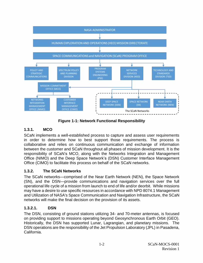
1.3 SCaN Network Services Division
NASA’s SCaN Program manages and directs the Mission Commitment Office (MCO) and the three networks that provide Data Transport, Navigation, and Radiometric and Science services for different types of missions. Functional responsibilities for the MCO and the three networks are shown in Figure 1-1.
1-2 SCaN-MOCS-0001
Revision 1
Figure 1-1: Network Functional Responsibility
1.3.1. MCO
SCaN implements a well-established process to capture and assess user requirements in order to determine how to best support those requirements. The process is collaborative and relies on continuous communication and exchange of information between the customer and SCaN throughout all phases of mission development. It is the responsibility of SCaN’s MCO, along with the Networks Integration and Management Office (NIMO) and the Deep Space Network’s (DSN) Customer Interface Management Office (CIMO) to facilitate this process on behalf of the SCaN networks.
1.3.2. The SCaN Networks
The SCaN networks—comprised of the Near Earth Network (NEN), the Space Network (SN), and the DSN—provide communications and navigation services over the full operational life cycle of a mission from launch to end of life and/or deorbit. While missions may have a desire to use specific resources in accordance with NPD 8074.1 Management and Utilization of NASA's Space Communication and Navigation Infrastructure, the SCaN networks will make the final decision on the provision of its assets.
1.3.2.1. DSN
The DSN, consisting of ground stations utilizing 34- and 70-meter antennas, is focused on providing support to missions operating beyond Geosynchronous Earth Orbit (GEO). Historically, the DSN has supported Lunar, Lagrangian, and planetary missions. The DSN operations are the responsibility of the Jet Propulsion Laboratory (JPL) in Pasadena, California.
1-3 SCaN-MOCS-0001
Revision 1
1.3.2.2. NEN
The NEN, consisting primarily of a combination of NASA, partner, and commercial ground stations with antennas up to 18 meters in diameter, is focused on supporting launch and operational activities in the Low Earth Orbit (LEO) range as well as GEO, Lunar, and Earth-Sun Lagrange points. Most NEN antennas slew very quickly, enabling the NEN to track Launch vehicles during ascent and high-speed low altitude missions with brief visibility windows. The NEN operations are the responsibility of Goddard Space Flight Center (GSFC) in Greenbelt, Maryland.
1.3.2.3. SN
The SN, consisting of a constellation of relay satellites in GEO pointing towards the Earth and the ground segment that operates the constellation, enables continuous communications services to missions operating in Medium Earth Orbit (MEO) and below with support provided to Highly Elliptical Orbit (HEO) when the orbit brings the spacecraft within range. The SN has continuous visibility to missions from Launch through LEO operations. NASA’s SN is the responsibility of the GSFC.
2-1 SCaN-MOCS-0001
Revision 1
Section 2. SCaN Network Policies and Standards
It is NASA policy that space missions receiving funding from NASA comply with all applicable international and United States regulations, standards, and agreements. Such regulations and standards include those promulgated by the:
International Telecommunications Union (ITU)
National Telecommunications and Information Agency (NTIA)
Consultative Committee for Space Data Systems (CCSDS)
Space Frequency Coordination Group (SFCG).
Information about the ITU and NTIA regulations may be obtained from NASA's Spectrum Management Office by consulting the reference documents listed in Appendix A. Additional information on recommended CCSDS standards applicable to the support that the SCaN networks provide as well as recommendations from the SFCG can also be found by consulting the reference documents listed in Appendix A.
2.1 Use of the Electromagnetic Spectrum
Per NASA Policy Directive (NPD) 2570.5E, it is NASA policy that all NASA satellite, airborne and other missions, whether directly developed and operated by NASA or those supported through contracts or other financial agreements that require the use of the electromagnetic spectrum, shall follow the United States and international spectrum regulatory rules and processes. All uses of the radio frequency spectrum require an authorization either from the NTIA, for Federal Government systems, or a license from the Federal Communications Commission (FCC) for Non-Federal Government systems (e.g., commercial, academic).
The design and operation of systems using radio-frequency communications, navigation, and sensors (i.e., any system that involves the use of the radio frequency spectrum for transmission, reception, or both) needs to consider a variety of factors, including spectrum regulations, network services, spaceflight equipment availability, and others depending upon the mission needs. Additional information concerning NASA spectrum policy and processes can be found in NPD 2570.5E and NASA Radio Frequency Spectrum Management Manual (NPR 2570.1C). These requirements and processes apply to electromagnetic spectrum use for radio frequency (<300 GHz) communication, navigation, radio science, active sensing, and passive sensing.
All missions and projects requiring the use of the electromagnetic spectrum should contact the associated Center/Facility Spectrum Manager (SM) as early in the proposal or mission development process as possible to discuss the electromagnetic spectrum operations concept and the necessary system certification and frequency authorization (licensing) requirements. The current NASA Center SMs, NASA National Spectrum Program Manager, and other points of contact are provided on NASA’s spectrum website (www.nasa.gov/directorates/heo/scan/spectrum/index.html).
2-2 SCaN-MOCS-0001
Revision 1
2.2 Bandwidth Efficient Modulation (DSN, NEN, SN)
Missions operating in the 2, 8, 2 6 , a n d 3 2 GHz spectral bands should employ bandwidth efficient modulation methods in conformance with SFCG and CCSDS recommendations. Spectral Emission Masks for Category A missions (r < 2 x 10⁶ km, where “r” is the range from the spacecraft to Earth) are found in the SFCG’s Handbook, available on the SFCG web site. Specific modulation methods meeting the SFCG mask are enumerated in CCSDS Recommendations 401 for non-deep space and Earth resources missions, respectively.
As a matter of DSN policy, it is recommended that Category B missions (r ≥ 2 x 10⁶ km) employ bandwidth efficient modulation whenever operating in the 8400 - 8450 MHz band at symbol rates above 2 megasymbols per second (Msps). CCSDS Recommendation 401 (2.4.17B) B-1 lists acceptable modulation schemes.
2.3 Coding
Most missions employ error-detecting/error-correcting codes to substantially improve telemetry link performance. Users are reminded that their encoders should conform to the CCSDS Telemetry Channel Coding Blue Book. Supported codes include but are not limited to:
1) Uncoded
2) Convolutional Rate 1/2
3) Convolutional Rate 1/3
4) Reed-Solomon
5) Convolutional/Reed-Solomon
6) Turbo codes with rates: 1/2, 1/3, 1/4, or 1/6
7) Low Density Parity Check (LDPC) Rate 1/2
8) LDPC Rate 7/8 (Note: This service has been partially implemented and is not yet
available across the SCaN networks).
DSN will implement LDPC for all frequency bands except Near Earth Ka-band (26 GHz). The SN also supports LDPC.
Proposers are encouraged to contact the representatives listed in Section 6.1, Requesting MCO Support, for the most recent list of supported codes.
2.4 Space Link Extension (DSN, NEN, SN)
Missions using DSN and SN services may utilize a standard Space Link Extension (SLE) Services Interface for transferring data to and from DSN or SN sites to control centers on the ground (e.g., Project Operations Control Center [POCC], Mission Operations Center [MOC], etc.). NEN SLE services are limited to the White Sands 1 (WS1) ground system.
Seven international space agencies, including: Agenzia Spaziale Italiana (ASI), Centre Nationale d’Etudes Spatiales (CNES), Deutsche Zentrum fur Luft- Und Raumfahrt (DLR), European Space Agency (ESA), Indian Space Research Organization (ISRO), Japanese Aerospace Exploration Agency (JAXA), and NASA have agreed to implement the SLE Services Interface to achieve full international interoperability. The interface architecture conforms to standards adopted by the CCSDS.
3-1 SCaN-MOCS-0001
Revision 1
Section 3. Summary of SCaN Network Standard Services
SCaN has developed a set of Standard Services which are inherent to the current functional capabilities of the SCaN networks without modification. There are little-to-no modifications/dependencies on the development of new functions within any of the SCaN networks for standard services. Use of the Standard Services enables more streamlined service evaluation, acquisition, and use. Current Standard Services include end-to-end transport of information between the point of origin (e.g., mission platform[s]) and destination (e.g., mission operations center, university, etc.).
Standard services for Data Transport facilitate the exchange of information between a mission’s platform(s) and locations on the Earth. Typically, minimal processing is applied to the data—only that which is necessary to communicate with the end points (e.g., RF encoding to IP-based transport). Transported data may include voice, video, and/or data. Note that Command and Telemetry data are critical subsets of Forward and Return data transport functions. As services for this type of data deal particularly with the exchange of information to and from a mission’s platform(s) for the purposes of monitoring and maintaining control of the platform, this information is typically of higher priority than other categories of data to be transported by the SCaN networks.
This section provides a very brief summary of the standard services that the SCaN networks offer their customers. For additional information on these services, please reference the SCaN Services Catalog (see Appendix A for reference information). Each of the service categories listed in the tables below may contain several services. Some of those individual services may require that special arrangements be made with SCaN before they can be provided. Proposal respondents who are interested in services that are not a part of the standard Tracking, Telemetry & Command (TT&C) set should contact the person(s) named in Section 6. for additional information.
3.1 NEN Service Summary
Table 3-1 summarizes the NEN service categories. More detailed information can be found in the SCaN Services Catalog and the NEN User Guide (See Appendix B for references).
Table 3-1: NEN Service Summary
Service Category Service Service Type
Brief Description
Data Transport Forward Data Stream Forward: Transmission of voice, video, and/or data, and delivery of telecommands to spacecraft.
Return: Telemetry voice, video, and/or data capture, decoding, and additional value-added data routing.
Return Data Stream
3-2 SCaN-MOCS-0001
Revision 1
Service Category Service Service Type
Brief Description
Navigation and Radiometric
Radiometric Raw Doppler Measurements and products based on one-way Doppler, two-way Doppler, and range tones; processing to determine orbital elements for mission platform navigation.
Radiometric Raw Ranging
Radiometric Tracking Angle Data
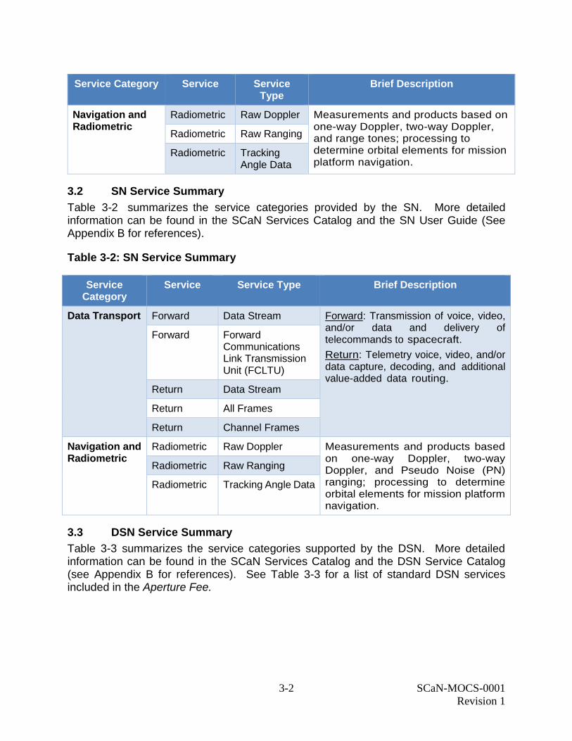
3.2 SN Service Summary
Table 3-2 summarizes the service categories provided by the SN. More detailed information can be found in the SCaN Services Catalog and the SN User Guide (See Appendix B for references).
Table 3-2: SN Service Summary
Service Category
Service Service Type Brief Description
Data Transport Forward Data Stream Forward: Transmission of voice, video, and/or data and delivery of telecommands to spacecraft.
Return: Telemetry voice, video, and/or data capture, decoding, and additional value-added data routing.
Forward Forward Communications Link Transmission Unit (FCLTU)
Return Data Stream
Return All Frames
Return Channel Frames
Navigation and Radiometric
Radiometric Raw Doppler Measurements and products based on one-way Doppler, two-way Doppler, and Pseudo Noise (PN) ranging; processing to determine orbital elements for mission platform navigation.
Radiometric Raw Ranging
Radiometric Tracking Angle Data
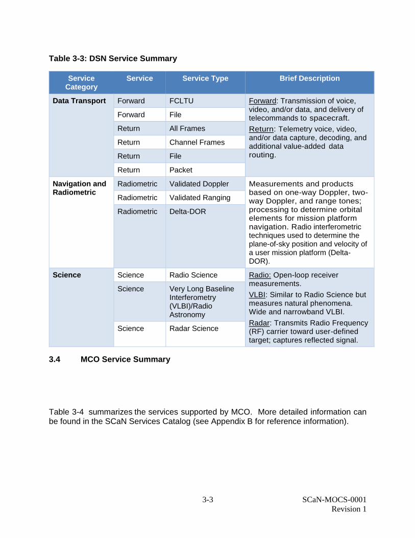
3.3 DSN Service Summary
Table 3-3 summarizes the service categories supported by the DSN. More detailed information can be found in the SCaN Services Catalog and the DSN Service Catalog (see Appendix B for references). See Table 3-3 for a list of standard DSN services included in the Aperture Fee.
3-3 SCaN-MOCS-0001
Revision 1
Table 3-3: DSN Service Summary
Service Category
Service Service Type Brief Description
Data Transport Forward FCLTU Forward: Transmission of voice, video, and/or data, and delivery of telecommands to spacecraft.
Return: Telemetry voice, video, and/or data capture, decoding, and additional value-added data routing.
Forward File
Return All Frames
Return Channel Frames
Return File
Return Packet
Navigation and Radiometric
Radiometric Validated Doppler Measurements and products based on one-way Doppler, two-way Doppler, and range tones; processing to determine orbital elements for mission platform navigation. Radio interferometric techniques used to determine the plane-of-sky position and velocity of a user mission platform (Delta-DOR).
Radiometric Validated Ranging
Radiometric Delta-DOR
Science Science Radio Science Radio: Open-loop receiver measurements.
VLBI: Similar to Radio Science but measures natural phenomena. Wide and narrowband VLBI.
Radar: Transmits Radio Frequency (RF) carrier toward user-defined target; captures reflected signal.
Science Very Long Baseline Interferometry (VLBI)/Radio Astronomy
Science Radar Science
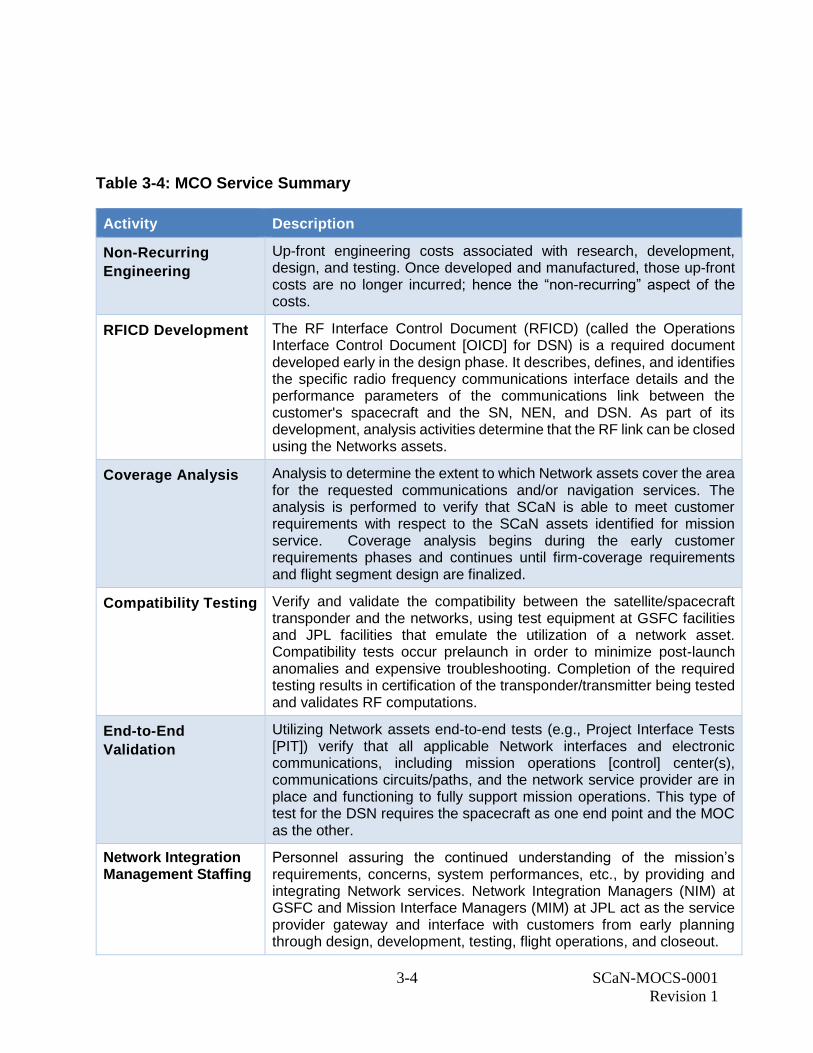
3.4 MCO Service Summary
Table 3-4 summarizes the services supported by MCO. More detailed information can be found in the SCaN Services Catalog (see Appendix B for reference information).
3-4 SCaN-MOCS-0001
Revision 1
Table 3-4: MCO Service Summary
Activity Description
Non-Recurring
Engineering
Up-front engineering costs associated with research, development, design, and testing. Once developed and manufactured, those up-front costs are no longer incurred; hence the “non-recurring” aspect of the costs.
RFICD Development The RF Interface Control Document (RFICD) (called the Operations Interface Control Document [OICD] for DSN) is a required document developed early in the design phase. It describes, defines, and identifies the specific radio frequency communications interface details and the performance parameters of the communications link between the customer's spacecraft and the SN, NEN, and DSN. As part of its development, analysis activities determine that the RF link can be closed using the Networks assets.
Coverage Analysis Analysis to determine the extent to which Network assets cover the area for the requested communications and/or navigation services. The analysis is performed to verify that SCaN is able to meet customer requirements with respect to the SCaN assets identified for mission service. Coverage analysis begins during the early customer requirements phases and continues until firm-coverage requirements and flight segment design are finalized.
Compatibility Testing Verify and validate the compatibility between the satellite/spacecraft transponder and the networks, using test equipment at GSFC facilities and JPL facilities that emulate the utilization of a network asset. Compatibility tests occur prelaunch in order to minimize post-launch anomalies and expensive troubleshooting. Completion of the required testing results in certification of the transponder/transmitter being tested and validates RF computations.
End-to-End
Validation
Utilizing Network assets end-to-end tests (e.g., Project Interface Tests [PIT]) verify that all applicable Network interfaces and electronic communications, including mission operations [control] center(s), communications circuits/paths, and the network service provider are in place and functioning to fully support mission operations. This type of test for the DSN requires the spacecraft as one end point and the MOC as the other.
Network Integration Management Staffing
Personnel assuring the continued understanding of the mission’s requirements, concerns, system performances, etc., by providing and integrating Network services. Network Integration Managers (NIM) at GSFC and Mission Interface Managers (MIM) at JPL act as the service provider gateway and interface with customers from early planning through design, development, testing, flight operations, and closeout.
3-5 SCaN-MOCS-0001
Revision 1
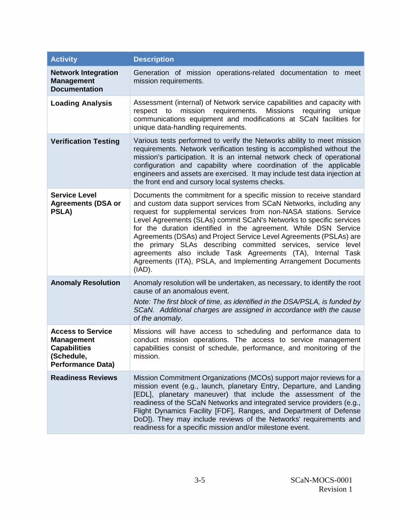
Activity Description
Network Integration Management Documentation
Generation of mission operations-related documentation to meet mission requirements.
Loading Analysis Assessment (internal) of Network service capabilities and capacity with respect to mission requirements. Missions requiring unique communications equipment and modifications at SCaN facilities for unique data-handling requirements.
Verification Testing Various tests performed to verify the Networks ability to meet mission requirements. Network verification testing is accomplished without the mission's participation. It is an internal network check of operational configuration and capability where coordination of the applicable engineers and assets are exercised. It may include test data injection at the front end and cursory local systems checks.
Service Level Agreements (DSA or PSLA)
Documents the commitment for a specific mission to receive standard and custom data support services from SCaN Networks, including any request for supplemental services from non-NASA stations. Service Level Agreements (SLAs) commit SCaN's Networks to specific services for the duration identified in the agreement. While DSN Service Agreements (DSAs) and Project Service Level Agreements (PSLAs) are the primary SLAs describing committed services, service level agreements also include Task Agreements (TA), Internal Task Agreements (ITA), PSLA, and Implementing Arrangement Documents (IAD).
Anomaly Resolution Anomaly resolution will be undertaken, as necessary, to identify the root cause of an anomalous event.
Note: The first block of time, as identified in the DSA/PSLA, is funded by SCaN. Additional charges are assigned in accordance with the cause of the anomaly.
Access to Service Management Capabilities (Schedule, Performance Data)
Missions will have access to scheduling and performance data to conduct mission operations. The access to service management capabilities consist of schedule, performance, and monitoring of the mission.
Readiness Reviews Mission Commitment Organizations (MCOs) support major reviews for a mission event (e.g., launch, planetary Entry, Departure, and Landing [EDL], planetary maneuver) that include the assessment of the readiness of the SCaN Networks and integrated service providers (e.g., Flight Dynamics Facility [FDF], Ranges, and Department of Defense DoD]). They may include reviews of the Networks' requirements and readiness for a specific mission and/or milestone event.
3-6 SCaN-MOCS-0001
Revision 1
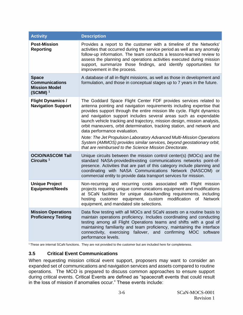
Activity Description
Post-Mission Reporting
Provides a report to the customer with a timeline of the Networks' activities that occurred during the service period as well as any anomaly follow-up information. The team conducts a lessons-learned review to assess the planning and operations activities executed during mission support, summarize those findings, and identify opportunities for improvement in the process.
Space Communications Mission Model (SCMM) 1
A database of all in-flight missions, as well as those in development and formulation, and those in conceptual stages up to 7 years in the future.
Flight Dynamics / Navigation Support
The Goddard Space Flight Center FDF provides services related to antenna pointing and navigation requirements including expertise that provides support through the entire mission life cycle. Flight dynamics and navigation support includes several areas such as expendable launch vehicle tracking and trajectory, mission design, mission analysis, orbit maneuvers, orbit determination, tracking station, and network and data performance evaluation.
Note: The Jet Propulsion Laboratory Advanced Multi-Mission Operations System (AMMOS) provides similar services, beyond geostationary orbit, that are reimbursed to the Science Mission Directorate.
OCIO/NASCOM Tail Circuits 1
Unique circuits between the mission control center(s) (MOCs) and the standard NASA-provided/existing communications networks point-of-presence. Activities that are part of this category include planning and coordinating with NASA Communications Network (NASCOM) or commercial entity to provide data transport services for mission.
Unique Project Equipment/Needs
Non-recurring and recurring costs associated with Flight mission projects requiring unique communications equipment and modifications at SCaN facilities for unique data-handling requirements, including hosting customer equipment, custom modification of Network equipment, and mandated site selections.
Mission Operations Proficiency Testing
Data flow testing with all MOCs and SCaN assets on a routine basis to maintain operations proficiency. Includes coordinating and conducting testing among all Flight Operations teams and shifts with a goal of maintaining familiarity and team proficiency, maintaining the interface connectivity, exercising failover, and confirming MOC software performance levels.
1 These are internal SCaN functions. They are not provided to the customer but are included here for completeness.
3.5 Critical Event Communications
When requesting mission critical event support, proposers may want to consider an expanded set of communications and navigation services and assets compared to routine operations. The MCO is prepared to discuss common approaches to ensure support during critical events. Critical Events are defined as “spacecraft events that could result in the loss of mission if anomalies occur.” These events include:
3-7 SCaN-MOCS-0001
Revision 1
Launch and early orbit operations
Spacecraft separation
Powered flight
Critical Maneuvers (e.g., Deep Space Maneuvers [DSMs], docking/undocking)
Orbit insertion
Entry/Descent/Landing
Flybys.
Any of the networks (NEN, SN, or DSN) can provide critical event support—including launch, early orbit, and separation—if the launch trajectory permits. However, in cases where there are coverage gaps, SCaN may need to use one or more fixed or portable ground stations from an external organization to provide adequate coverage.
4-1 SCaN-MOCS-0001
Revision 1
Section 4. Support from Non-SCaN Network Service Providers
If needed, the SCaN networks will assist user missions with procuring services from other non-SCaN network entities and partners, including but not limited to other SCaN divisions, other NASA organizations, other Government agencies, and international and commercial partners. This section discusses the most common external organizations for whom the SCaN networks assist missions with procuring services.
If the mission desires to use communication and navigation assets outside of the SCaN network, the mission should consult NPD 8074.1 and work with SCaN on the capabilities needed to ensure the most cost-effective method for the agency.
4.1 Spectrum Management
Although the Spectrum Management Office falls under the responsibility of the SCaN Program Office, it is not part of the SCaN networks or MCO (see Figure 1-1). It is NASA policy that any satellite mission supported by the Agency, whether directly developed and operated by NASA or those supported through contracts or other financial agreements that require the use of the electromagnetic spectrum for transmission, reception, or both, shall follow the United States spectrum regulatory rules and processes as well as all applicable international spectrum regulations.
The Center/Facility Spectrum Manager or NASA National Spectrum Program Manager will provide assistance during all phases of a mission or project from conceptual, preproposal efforts through formulation and implementation. The Spectrum Manager will support the project at each review in the project life cycle and assist with design and spectrum considerations such as frequency selection, conformance to regulatory constraints, and compliance with any other electromagnetic spectrum constraints. A key element of this support is assisting with or preparing inputs for spectrum certification as early in the acquisition and procurement cycles as possible.
If support from the Spectrum office is required, proposal respondents may either contact their local center Spectrum Manager or the National Spectrum Program Manager directly or request assistance in coordinating Spectrum support from the SCaN networks by consulting one of the Points of Contact listed in Section 6.
4.2 NASA Communication Network (NASCOM)
The NASCOM provides Wide Area Network (WAN) and Local Area Network (LAN) voice, video, and data services in support of the Agency.
The Corporate Communications Services are managed out of Marshall Space Flight Center (MSFC) and include NASA-wide voice and video teleconferencing, corporate network routed data services as well as Layer 2 Virtual Private Network service. The fundamental function of these services is to provide enterprise-level communications services across the Agency.
4-2 SCaN-MOCS-0001
Revision 1
The Mission Communications Services are managed out of GSFC and include mission routed data services (including IOnet), dedicated mission data services, and mission voice services. The fundamental purpose of these services is to support spacecraft operations. These include terrestrial transport of spacecraft command, telemetry, and tracking data as well as delivery of science data products. The Mission Network must also address risks to the health and safety of human life as well as serious damage or loss of spacecraft. The mission voice services provide order wire and other voice service in support of spacecraft operations.
4.3 Flight Dynamics Facility (FDF)
The GSFC FDF provides expertise in navigation analysis and system design, operations planning, trajectory design, orbit determination, network operations support, and critical real-time mission operations. This expertise spans the technical areas of orbit determination and trajectory design for low-Earth, geosynchronous, highly elliptical, lunar, libration-point, heliocentric orbits, other celestial-body centered orbits ELV and human spaceflight operations, and support of over 25 on-orbit spacecraft.
FDF evaluates tracking data from the SN, NEN, DSN, and NASA and DoD C-band radar sites and certifies tracking capability for new stations needed for mission support. FDF also participates in end-to-end verification and validation to ensure that FDF products, such as pointing data for the SN and NEN, are received in the proper format. Mission integration is a part of FDF’s support of the SCaN networks and its flight project customers. FDF can interface with any of the SCaN networks (NEN, SN, or DSN) to support a mission’s flight dynamics needs. Products generated by FDF include ephemerides, acquisition data that is used to establish two-way communication with space vehicles; maneuver planning and execution for spacecraft; on-console support for testing and real-time operations; evaluation of ELV performance during ascent utilizing guidance data; and other navigation sources, local oscillator frequency analysis for Tracking Data Relay Satellite (TDRS) transponders, orbit event predictions, and calibration of sensors used for tracking spacecraft.
The capabilities of the Goddard FDF include the following:
1) Orbit determination in multiple regimes
2) Launch vehicle support, including but not limited to Atlas V, Delta II, Delta IV, and
Sea Launch
3) Launch and early-orbit support utilizing a diversity of networks
4) Tracking performance evaluation of a multitude of ground-based and space-
borne assets
5) Certification of new tracking equipment
6) Mission integration that combines engineering knowledge of the SCaN networks
and the analytical and operational aspects of our flight project customers
7) Backup navigation support to the Human Spaceflight Program
8) International Space Station orbit determination and support to all Visiting
Vehicles.
4-3 SCaN-MOCS-0001
Revision 1
4.4 Advanced Multi-Mission Operations System (AMMOS)
AMMOS is the responsibility of the Mu l t i p le Ground S ys te m and Se rv i ces (MGSS) Program located at the JPL. AMMOS consists of a core set of products that can be readily customized to accommodate the specific needs of individual missions. AMMOS provides the elements of a Mission Operations System (MOS) that are common to multiple missions, eliminating the need for duplication of development and maintenance of the MOS. Using AMMOS may lower mission cost and risk by providing a mature base for a MOS.
AMMOS is comprised of multi-mission hardware, software, processes, procedures, and facilities used to implement and operate the MOS. Components of the AMMOS include:
Planning and Sequencing
Telemetry Processing
Data Archive
Navigation, Mission Design, and Solar System Dynamics
Operations Configuration Management
Mission Support Facilities
Ground Data System (GDS) Integration, Test, Deployment and Support Operations Engineering Data Relay Coordination for Landed Assets who do not have the direct-to-earth
bandwidth needed to execute the mission.
AMMOS supports the entire life cycle of a flight project or experimental investigation.
4.5 JPL Mission Design and Navigation
The JPL Mission Design and Navigation (MDNAV) section provides support in mission design, deep space navigation analysis and operations planning, orbit determination, maneuver design and analysis, critical real-time mission operations, and network operations support. MDNAV typically supports on the order of 25 space missions through all mission phases from pre-project through termination.
The MDNAV charter is to build the maps and tools for interplanetary navigation, design efficient routes for spacecraft to reach any remote solar system location (including within the Earth-Moon system), and safely pilot spacecraft to their ultimate destination. The overarching themes of this work are science-driven modeling, filtering and optimization, managing trajectory knowledge, control, observability, and uncertainties.
The capabilities of JPL MDNAV include the following:
1) Development and refinement of precision ephemerides for solar system bodies
2) Trajectory design and optimization satisfying multiple mission constraints
3) Launch and early-orbit phase operations for missions utilizing the DSN
4) Orbit determination in multiple regimes
5) Maneuver design and analysis
6) Multi-mission flight dynamics software development
7) Astrodynamics technology research and development
8) Certification of new tracking equipment.
5-1 SCaN-MOCS-0001
Revision 1
Section 5. Network Support Cost Estimation
As a matter of policy, NASA includes estimated costs for mission operations and communications services as well as an assessment of key parameters for mission operations in the evaluation and selection processes of all near-earth and deep-space missions. The purpose of this policy is to:
Enable evaluation of the reasonableness and cost effectiveness of the proposed
communications and navigation approach
Implement formal NASA-wide, full-cost accounting
Better manage NASA’s heavily subscribed communications resources
Promote trade-offs between space and ground, including parameters such as
data volume, data latency, data rate, contact time, aperture size, and cost of
associated systems
Encourage hardware and operations system designs minimizing life-cycle costs
while accomplishing the highest-priority science objectives.
Generally, mission proposals must include nonrecurring (e.g., Mission Planning & Integration [MP&I]) and recurring estimates as well as those for services during routine operations and critical event support.
Cost numbers and equations supplied in this section are for planning purposes only. The calculated estimate of services provided is required by the SMD to document the full value of the mission and its services. NASA missions that use standard services will not be charged by SCaN for recurring cost for aperture or per-minute fees.
This section explains how to estimate costs for the DSN, NEN, and SN. To ensure accuracy and to validate cost estimates, proposal respondents should contact the appropriate representatives listed in Section 6.
5.1 Nonrecurring Engineering Costs
Nonrecurring engineering (NRE) costs (e.g., TT&C services, ground communications, MIM support) are those associated with unique equipment that a mission customer provides at NASA facilities, including installation and sustainment engineering. NRE costs also include any unique equipment that a mission requires as well as its installation and the sustaining engineering of that equipment as well as modifications that the networks must make to their systems in order to recognize a new mission. Proposal respondents are advised to contact the point of contacts listed in Section 6. to obtain a cost estimate for their missions.
5.2 Mission Planning and Integration (MP&I)
MP&I is the set of activities performed and coordinated by the SCaN MCO, NIMO, and CIMO facilitate the successful provision of NASA’s space communications services to evaluate and address mission needs. MP&I includes those tasks that must be executed prior to the operational use of the SCaN networks as well as actual cost estimates for the
5-2 SCaN-MOCS-0001
Revision 1
use of SCaN networks in accordance with needed functionality. Typically, MP&I activities occur prior to the launch of a space vehicle, although they may occur any time within the life of a mission if changes are needed. Additionally, for longer-duration missions (e.g., interplanetary), a set of MP&I activities is typically incorporated during the initial planning activities. These MP&I activities may include the development of the RFICD, Compatibility Testing, Anomaly Resolution, and Post Mission Reporting. MP&I activities ensure common understanding of the mission services requirements, understanding of the capabilities of the SCaN networks, and mutual compatibility between the mission (i.e., platform[s], mission operations center[s]) and the SCaN networks). Funding of these efforts is dictated by NASA policies. Because both NASA missions and SCaN are funded through NASA, NASA missions fund SCaN only for the MP&I activities related to the dependencies on their processes/functionality (e.g., planning and development for non-standard services); they are not charged for the SCaN networks internal management functions related to standard services (e.g., network capacity planning). Conversely, non-NASA missions are responsible for funding all network integration and data-services activities in support of their missions, including reimbursement of SCaN costs in support of their MP&I activities. It is not possible to provide a simple cost structure such as the one used for the specific stations and/or services. Proposal respondents are advised to contact the point of contacts listed in Section 6. to obtain a cost estimate for their missions.
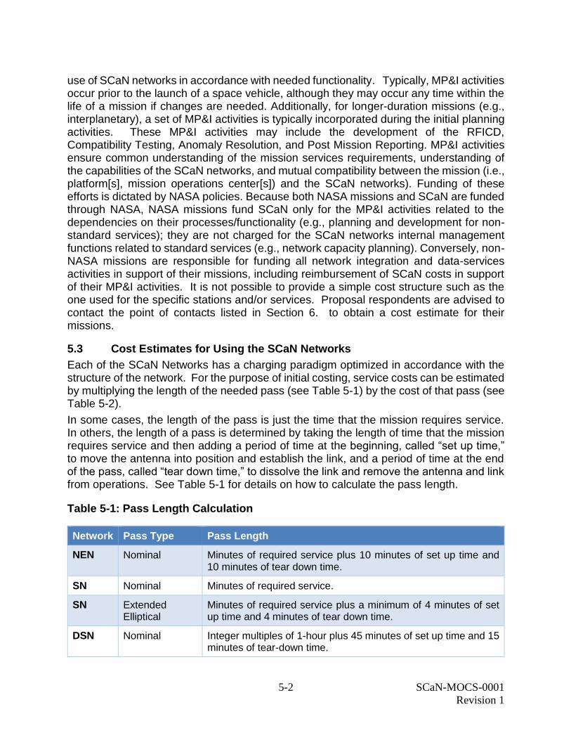
5.3 Cost Estimates for Using the SCaN Networks
Each of the SCaN Networks has a charging paradigm optimized in accordance with the structure of the network. For the purpose of initial costing, service costs can be estimated by multiplying the length of the needed pass (see Table 5-1) by the cost of that pass (see Table 5-2).
In some cases, the length of the pass is just the time that the mission requires service. In others, the length of a pass is determined by taking the length of time that the mission requires service and then adding a period of time at the beginning, called “set up time,” to move the antenna into position and establish the link, and a period of time at the end of the pass, called “tear down time,” to dissolve the link and remove the antenna and link from operations. See Table 5-1 for details on how to calculate the pass length.
Table 5-1: Pass Length Calculation
Network Pass Type Pass Length
NEN Nominal Minutes of required service plus 10 minutes of set up time and 10 minutes of tear down time.
SN Nominal Minutes of required service.
SN Extended Elliptical
Minutes of required service plus a minimum of 4 minutes of set up time and 4 minutes of tear down time.
DSN Nominal Integer multiples of 1-hour plus 45 minutes of set up time and 15 minutes of tear-down time.
5-3 SCaN-MOCS-0001
Revision 1
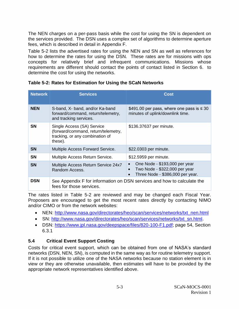
The NEN charges on a per-pass basis while the cost for using the SN is dependent on the services provided. The DSN uses a complex set of algorithms to determine aperture fees, which is described in detail in Appendix F.
Table 5-2 lists the advertised rates for using the NEN and SN as well as references for how to determine the rates for using the DSN. These rates are for missions with ops concepts for relatively brief and infrequent communications. Missions whose requirements are different should contact the points of contact listed in Section 6. to determine the cost for using the networks.
Table 5-2: Rates for Estimation for Using the SCaN Networks
Network
Services Cost
NEN S-band, X- band, and/or Ka-band forward/command, return/telemetry, and tracking services.
$491.00 per pass, where one pass is ≤ 30 minutes of uplink/downlink time.
SN Single Access (SA) Service (forward/command, return/telemetry, tracking, or any combination of these).
$136.37637 per minute.
SN Multiple Access Forward Service. $22.0303 per minute.
SN Multiple Access Return Service. $12.5959 per minute.
SN Multiple Access Return Service 24x7 Random Access.
One Node - $193,000 per year Two Node - $322,000 per year
Three Node - $386,000 per year.
DSN See Appendix F for information on DSN services and how to calculate the fees for those services.
The rates listed in Table 5-2 are reviewed and may be changed each Fiscal Year. Proposers are encouraged to get the most recent rates directly by contacting NIMO and/or CIMO or from the network websites:
NEN: http://www.nasa.gov/directorates/heo/scan/services/networks/txt_nen.html
SN: http://www.nasa.gov/directorates/heo/scan/services/networks/txt_sn.html.
DSN: https://www.jpl.nasa.gov/deepspace/files/820-100-F1.pdf; page 54, Section
6.3.1
5.4 Critical Event Support Costing
Costs for critical event support, which can be obtained from one of NASA’s standard networks (DSN, NEN, SN), is computed in the same way as for routine telemetry support. If it is not possible to utilize one of the NASA networks because no station element is in view or they are otherwise unavailable, then estimates will have to be provided by the appropriate network representatives identified above.
5-4 SCaN-MOCS-0001
Revision 1
Because mission requirements vary over such a broad range, it is not possible to provide a simple means to calculate the cost of telemetry support in the early mission phase. Please see Section 6. for the point of contact who can assist in establishing alternative solutions and/or in costing the required support.
5.5 Non-SCaN Support Costing
Cost for support from non-SCaN networks resources and entities is dependent on the mission needs and the supporting entity to be used. However, if requested, SCaN will integrate the requested support into the overall network plan. SCaN negotiates the costs for using non-SCaN assets on a case-by-case basis and therefore cannot include that information in this document. SCaN negotiates bulk-buy agreements for the use of commercial and/or international service providers and makes every effort to negotiate the most cost-effective rates possible. However, as these contracts are negotiated on a periodic basis, the actual costs for using such providers cannot be included in this document. If support is required from outside the three SCaN networks, proposal respondents shall contact MCO (per NPD 8074.1) for assistance in assessing the need, capabilities, and cost of those services. Please see Section 6. for the appropriate point of contact.
6-1 SCaN-MOCS-0001
Revision 1
Section 6. Requesting Support from the SCaN Networks
Early planning and coordination between SCaN and its customers is critical to ensuring quality service with minimal complications. Proposers are encouraged to contact SCaN as early in their development process as possible to begin premission planning and analysis activities and to ensure that the network(s) have both the capability and capacity to satisfy the mission requirements.
During the concept study phase (Phase-A or Step-2), as the mission’s concept is more clearly defined, a Letter of Commitment is generated or updated from Step 1. The resulting documentation of services and costs will be captured in the PSLA or DSA to be signed by appropriate Project and Network representatives by Preliminary Design Review (PDR) for the PSLA and Critical Design Review (CDR) for the DSA. The PSLA/DSA will identify all mission operations requirements, including those provided by non-SCaN sources, becoming a source of end-to-end operations information and documenting any cost analyses leading to the selection of non-SCaN services. A Letter of Commitment is only done for Step 1 if nonstandard services are required. Please reference the AO documentation for a description of Phase A, Step 1, and Step 2 requirements.
6.1 Requesting MCO Support
Missions desiring use of SCaN services should make contact with the SCaN networks as early in the development process as possible. For missions whose assets will be in deep space, contact the CIMO. Missions whose assets are in LEO should contact the NIMO. Missions whose assets are near Earth but beyond LEO may contact either office; the office’s first duty will be to help the mission decide which network or combination of networks should be used. Missions may also contact the SCaN Mission Commitment Manager for questions related to which network is appropriate.
The NASA Headquarters point of contact for SCaN assets is: John Hudiburg Mission Integration & Commitment Manager Space Communications and Navigation (SCaN) NASA Headquarters Washington, D.C. 20546 Office: HQ:7Z76 Phone: (202) 358-1202 Email: [email protected]
For additional information on MCO, its points of contact and the services that it and SCaN provides, proposal respondents may visit the SCaN Customer Service Portal (https://mcocsp.nasa.gov/web/guest/welcome). Please note that this is a public website. Access to the restricted section of this portal, which contains the mission-specific information, will only be granted to the selected proposers after award.
6-2 SCaN-MOCS-0001
Revision 1
6.2 Process for Requesting NEN or SN Services
At the time when initial science operations concepts are being defined, proposers should contact the person named below for information about NEN and/or SN mission operations services and costs. A representative from the NIMO will assist proposers by providing service and cost information. Further, NIMO aids in documenting initial mission operations requirements in a Networks proposal package.
The point of contact for NEN and SN services is NIMO:
Scott A. Greatorex, Chief Networks Integration Management Office, Code 450.1 Exploration and Space Communications Projects Division Goddard Space Flight Center, Greenbelt, MD 20771 Phone: (301) 286-6354; FAX: (301) 286-0275 Email: [email protected]
6.3 Process for Requesting DSN Services
Proposers should contact the person(s) named below for information about DSN mission operations services and costs at the time when initial science operations concepts are being defined. A representative will assist proposers by providing information concerning services and costs.
In order to properly estimate and document the requirements for DSN services and support, a minimum lead time of 6 weeks must be allowed for the study.
The point of contact for DSN services is CIMO:
Glen Elliott
Manager Office 912: Mission Support Definitions and Commitments
Jet Propulsion Laboratory
M/S 301-355
4800 Oak Grove Drive
Pasadena, California 91109-8099
Phone: (818) 393-6373
e-mail: [email protected]
A-1
SCaN-MOCS-0001
Revision 1
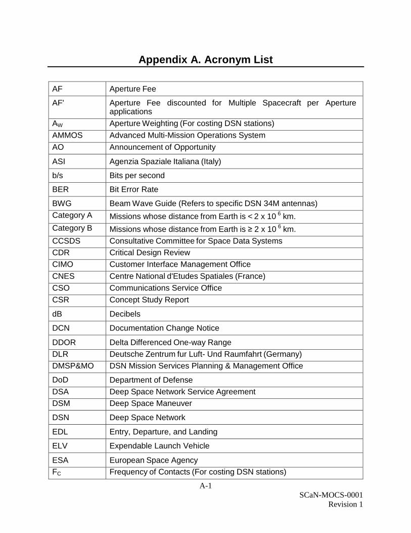
Appendix A. Acronym List
AF Aperture Fee
AF' Aperture Fee discounted for Multiple Spacecraft per Aperture applications
AW Aperture Weighting (For costing DSN stations)
AMMOS Advanced Multi-Mission Operations System
AO Announcement of Opportunity
ASI Agenzia Spaziale Italiana (Italy)
b/s Bits per second
BER Bit Error Rate
BWG Beam Wave Guide (Refers to specific DSN 34M antennas)
Category A Missions whose distance from Earth is < 2 x 10 6 km.
Category B Missions whose distance from Earth is ≥ 2 x 10 6 km.
CCSDS Consultative Committee for Space Data Systems
CDR Critical Design Review
CIMO Customer Interface Management Office
CNES Centre National d'Etudes Spatiales (France)
CSO Communications Service Office
CSR Concept Study Report
dB Decibels
DCN Documentation Change Notice
DDOR Delta Differenced One-way Range
DLR Deutsche Zentrum fur Luft- Und Raumfahrt (Germany)
DMSP&MO DSN Mission Services Planning & Management Office
DoD Department of Defense
DSA Deep Space Network Service Agreement
DSM Deep Space Maneuver
DSN Deep Space Network
EDL Entry, Departure, and Landing
ELV Expendable Launch Vehicle
ESA European Space Agency
FC Frequency of Contacts (For costing DSN stations)
A-2
SCaN-MOCS-0001
Revision 1
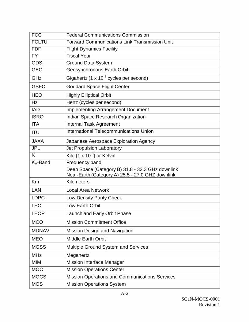
FCC Federal Communications Commission
FCLTU Forward Communications Link Transmission Unit
FDF Flight Dynamics Facility
FY Fiscal Year
GDS Ground Data System
GEO Geosynchronous Earth Orbit
GHz Gigahertz (1 x 10 9 cycles per second)
GSFC Goddard Space Flight Center
HEO Highly Elliptical Orbit
Hz Hertz (cycles per second)
IAD Implementing Arrangement Document
ISRO Indian Space Research Organization
ITA Internal Task Agreement
ITU International Telecommunications Union
JAXA Japanese Aerospace Exploration Agency
JPL Jet Propulsion Laboratory
K Kilo (1 x 10 3) or Kelvin
KA-Band Frequency band:
Deep Space (Category B) 31.8 - 32.3 GHz downlink Near-Earth (Category A) 25.5 - 27.0 GHZ downlink
Km Kilometers
LAN Local Area Network
LDPC Low Density Parity Check
LEO Low Earth Orbit
LEOP Launch and Early Orbit Phase
MCO Mission Commitment Office
MDNAV Mission Design and Navigation
MEO Middle Earth Orbit
MGSS Multiple Ground System and Services
MHz Megahertz
MIM Mission Interface Manager
MOC Mission Operations Center
MOCS Mission Operations and Communications Services
MOS Mission Operations System
A-3
SCaN-MOCS-0001
Revision 1
MP&I Mission Planning and Integration
MSFC Marshall Space Flight Center
MSPA Multiple Spacecraft per Aperture
Msps Megasymbols Per Second
NASA National Aeronautics and Space Administration
NASCOM NASA Communications Network
NEN Near Earth Network
NIM Network Integration Manager
NIMO Networks Integration Management Office at GSFC
NPD NASA Policy Directive
NPR NASA Procedural Requirements
NRE Nonrecurring Engineering
NTIA National Telecommunications and Information Agency
OCIO Office of the Chief Information Officer
OICD Operations Interface Control Document
PDR Preliminary Design Review
PIT Project Interface Test
PN Pseudo Noise
POCC Project Operations Control Center
PSLA Project Service Level Agreement
RB Base Rate (For costing DSN stations)
Rad Radians
RF Radio Frequency
RFICD RF Interface Control Document
S/C Spacecraft
SA Single Access
SCaN Space Communications and Navigation
SCMM Space Communications Mission Model
SFCG Space Frequency Coordination Group
SLA Service Level Agreement
SLE Space Link Extension
SM Spectrum Manager
A-4
SCaN-MOCS-0001
Revision 1
SMD Science Mission Directorate (formerly NASA Headquarters Office of Space Science Code S)
SN Space Network (TDRS)
TA Task Agreement
TDRS Tracking Data Relay Satellite
TT&C Tracking, Telemetry, and Command
WAN Wide Area Network
WS1 White Sands 1
VLBI Very Long Baseline Interferometry
X-Band Frequency band (Space Research Segment):
Deep Space (Category B) 7145-7190 MHz uplink, 8400-8450 MHz downlink
Near-Earth (Category A) 7190-7235 MHz uplink, 8450-8500 MHz downlink
B-1
SCaN-MOCS-0001
Revision 1
Appendix B. Reference Documents and Websites
Prospective users of NASA facilities can obtain additional information from the following documents. Please note that some of these documents may only be available behind the NASA firewall. If proposal respondents are in need of a document and cannot access it, they are advised to contact the appropriate point of contact in Section 6.
1) Radio Regulations, International Telecommunications Union, Geneva,
Switzerland, Latest Edition.
2) Manual of Regulations and Procedures for Federal Radio Frequency
Management, National Telecommunication & Information Administration,
U.S. Department of Commerce, Washington D.C., Latest Edition. Information
is available at: http://www.ntia.doc.gov/osmhome/redbook/redbook.html
3) Consultative Committee for Space Data Systems (CCSDS). Blue Books
published by the CCSDS Secretariat, NASA Headquarters, Washington D.C.
20546. Copies of CCSDS Recommendations and Reports are
available at: http://public.ccsds.org/publications/default.aspx
4) Space Frequency Coordination Group On-Line Handbook,
Recommendations and other technical documents are available at:
https://www.sfcgonline.org/resources
5) Management and Utilization of NASA's Space Communication and Navigation
Infrastructure, NPD 8074.1. Copies of the document are available at:
http://nodis3.gsfc.nasa.gov/displayDir.cfm?t=NPD&c=8074&s=1
6) SCaN Customer Service Portal. Web site located at:
https://mcocsp.nasa.gov/
7) NIMO Commitments homepage. Web site located at:
https://esc.gsfc.nasa.gov/nimo
8) Near Earth Network Homepage. Web site located at:
https://esc.gsfc.nasa.gov/nen http://esc.gsfc.nasa.gov/assets/files/453-UG-
002905%282%29.pdf
9) Space Network Homepage. Web site located at: https://esc.gsfc.nasa.gov/sn
10) Deep Space Network Homepage. Web site located at:
https://www.jpl.nasa.gov/deepspace/
11) DSN Commitments homepage. Web site located at:
https://www.jpl.nasa.gov/deepspace/about/commitments-office/
12) Space Communications and Navigation Network Service Catalog, SCaN-
SERVICE CATALOG. Copies of the document are available at:
https://mcocsp.nasa.gov/web/guest/resources
13) DSN Service Catalog, DSN No. 820-100, Rev. F, JPL D-19002, Jet Propulsion
Laboratory, latest copies available at:
https://www.jpl.nasa.gov/deepspace/files/820-100-F1.pdf
B-2
SCaN-MOCS-0001
Revision 1
14) DSN Aperture Fee Calculator located at:
https://www.jpl.nasa.gov/deepspace/about/commitments-office/proposal-
preparation/
under the heading “DSN Aperture Fee Online Tool.”
15) NASA Communication Network (NASCOM) / Communications Service Office
(CSO) homepage. Web site located at: https://cso.nasa.gov/learn
16) Flight Dynamics Facility (FDF) homepage. Web site located at:
http://fdf.gsfc.nasa.gov/services
17) AMMOS Homepage. Web site located at: https://ammos.jpl.nasa.gov/
18) Spectrum Management Office homepage. Web site located at:
http://www.nasa.gov/directorates/heo/scan/spectrum/index.html
19) NPD 2570.5E, NASA Electromagnetic Spectrum Management, 11 July 2011.
Copies of the document are available at:
http://nodis3.gsfc.nasa.gov/lib_docs.cfm?range=2
20) NPR 2570.1C, NASA Radio Frequency Spectrum Management Manual, 22
Sep 2014. Copies of the document are available at:
http://nodis3.gsfc.nasa.gov/lib_docs.cfm?range=2
C-1
SCaN-MOCS-0001
Revision 1
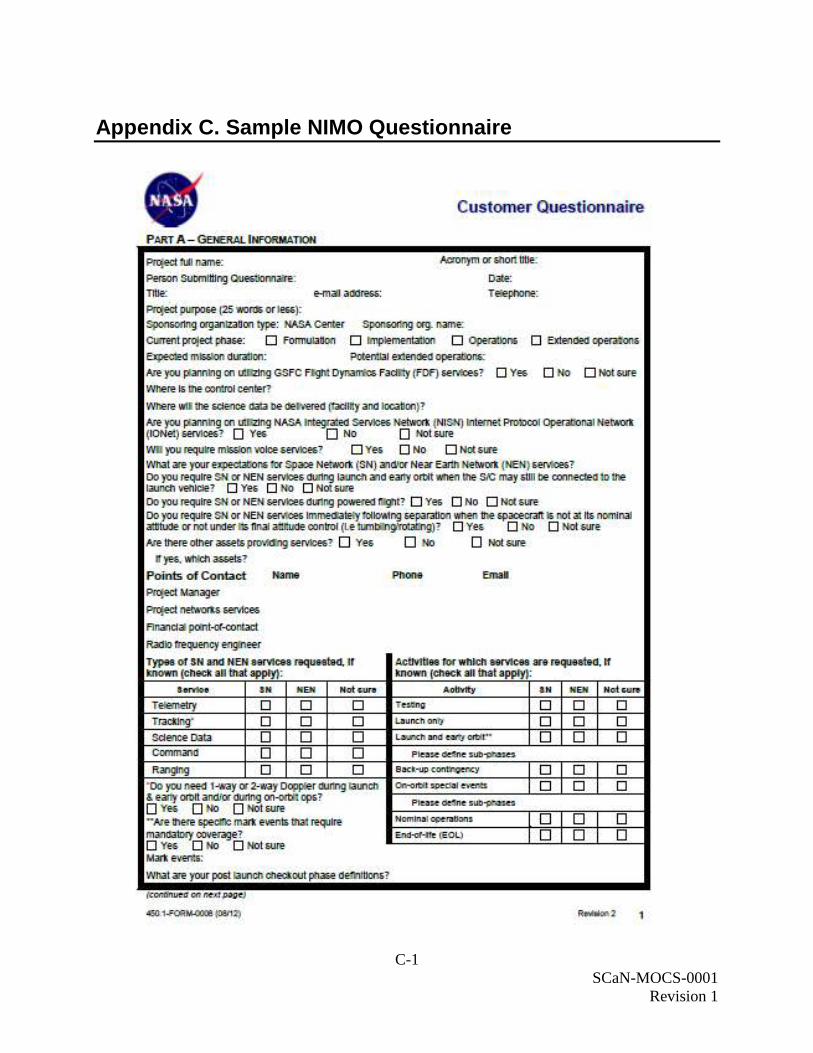
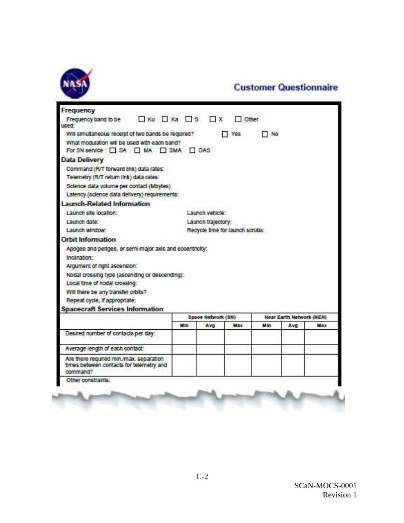
Appendix C. Sample NIMO Questionnaire
C-2
SCaN-MOCS-0001
Revision 1
D-1
SCaN-MOCS-0001
Revision 1
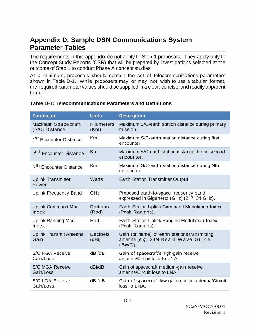
Appendix D. Sample DSN Communications System Parameter Tables
The requirements in this appendix do not apply to Step 1 proposals. They apply only to the Concept Study Reports (CSR) that will be prepared by investigations selected at the outcome of Step 1 to conduct Phase A concept studies.
At a minimum, proposals should contain the set of telecommunications parameters shown in Table D-1. While proposers may or may not wish to use a tabular format, the required parameter values should be supplied in a clear, concise, and readily apparent form.
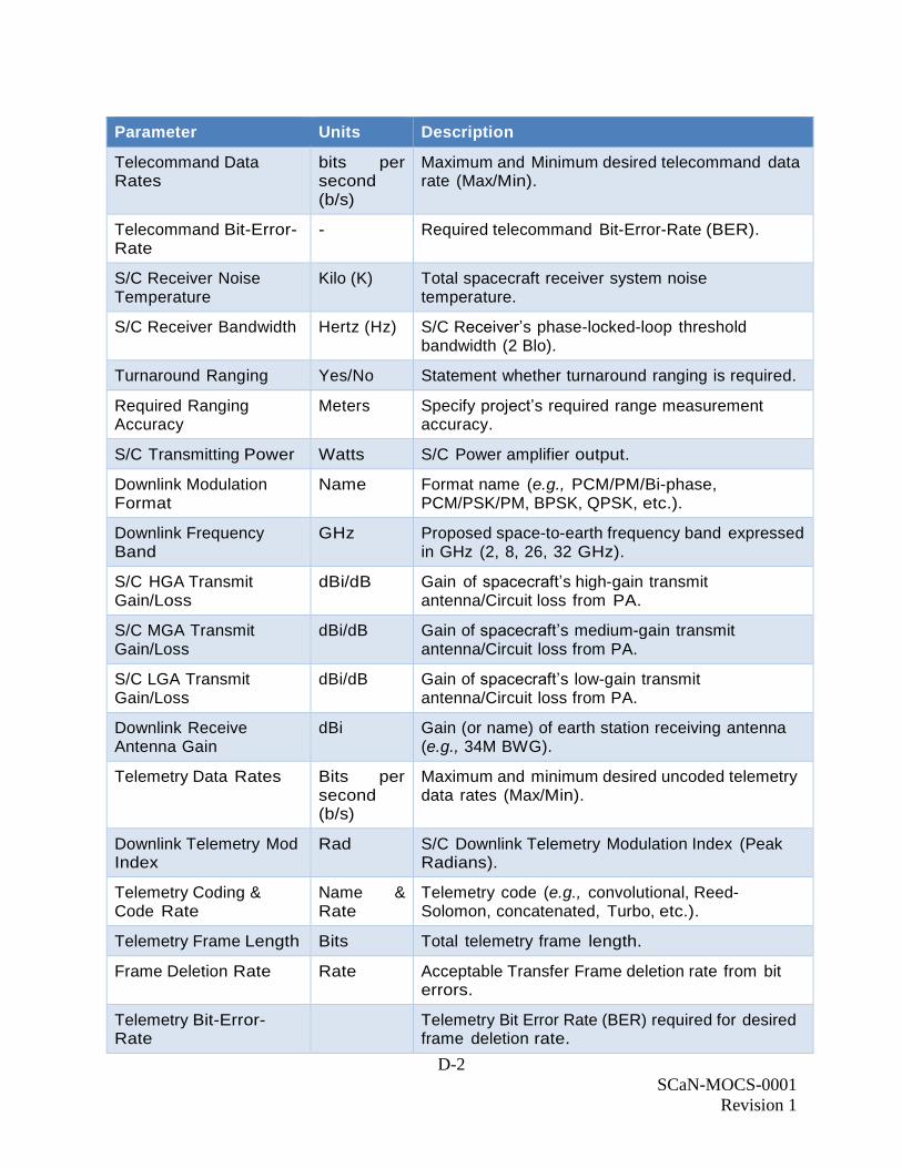
Table D-1: Telecommunications Parameters and Definitions
Parameter Units Description
Maximum Spacecraf t (S/C) Distance
Kilometers (Km)
Maximum S/C-earth station distance during primary mission.
1st Encounter Distance Km Maximum S/C-earth station distance during first encounter.
2nd Encounter Distance Km Maximum S/C-earth station distance during second encounter.
Nth Encounter Distance Km Maximum S/C-earth station distance during Nth encounter.
Uplink Transmitter Power
Watts Earth Station Transmitter Output.
Uplink Frequency Band GHz Proposed earth-to-space frequency band expressed in Gigahertz (GHz) (2, 7, 34 GHz).
Uplink Command Mod. Index
Radians (Rad)
Earth Station Uplink Command Modulation Index (Peak Radians).
Uplink Ranging Mod. Index
Rad Earth Station Uplink Ranging Modulation Index (Peak Radians).
Uplink Transmit Antenna Gain
Decibels (dBi)
Gain (or name) of earth stations transmitting antenna (e.g., 34M B e a m W a v e G u i d e ( BWG).
S/C HGA Receive Gain/Loss
dBi/dB Gain of spacecraft’s high-gain receive antenna/Circuit loss to LNA.
S/C MGA Receive Gain/Loss
dBi/dB Gain of spacecraft medium-gain receive antenna/Circuit loss to LNA.
S/C LGA Receive Gain/Loss
dBi/dB Gain of spacecraft low-gain receive antenna/Circuit loss to LNA.
D-2
SCaN-MOCS-0001
Revision 1
Parameter Units Description
Telecommand Data Rates
bits per second (b/s)
Maximum and Minimum desired telecommand data rate (Max/Min).
Telecommand Bit-Error-Rate
- Required telecommand Bit-Error-Rate (BER).
S/C Receiver Noise Temperature
Kilo (K) Total spacecraft receiver system noise temperature.
S/C Receiver Bandwidth Hertz (Hz) S/C Receiver’s phase-locked-loop threshold bandwidth (2 Blo).
Turnaround Ranging Yes/No Statement whether turnaround ranging is required.
Required Ranging Accuracy
Meters Specify project’s required range measurement accuracy.
S/C Transmitting Power Watts S/C Power amplifier output.
Downlink Modulation Format
Name Format name (e.g., PCM/PM/Bi-phase, PCM/PSK/PM, BPSK, QPSK, etc.).
Downlink Frequency Band
GHz Proposed space-to-earth frequency band expressed in GHz (2, 8, 26, 32 GHz).
S/C HGA Transmit Gain/Loss
dBi/dB Gain of spacecraft’s high-gain transmit antenna/Circuit loss from PA.
S/C MGA Transmit Gain/Loss
dBi/dB Gain of spacecraft’s medium-gain transmit antenna/Circuit loss from PA.
S/C LGA Transmit Gain/Loss
dBi/dB Gain of spacecraft’s low-gain transmit antenna/Circuit loss from PA.
Downlink Receive Antenna Gain
dBi Gain (or name) of earth station receiving antenna (e.g., 34M BWG).
Telemetry Data Rates Bits per second (b/s)
Maximum and minimum desired uncoded telemetry data rates (Max/Min).
Downlink Telemetry Mod Index
Rad S/C Downlink Telemetry Modulation Index (Peak Radians).
Telemetry Coding & Code Rate
Name & Rate
Telemetry code (e.g., convolutional, Reed-Solomon, concatenated, Turbo, etc.).
Telemetry Frame Length Bits Total telemetry frame length.
Frame Deletion Rate Rate Acceptable Transfer Frame deletion rate from bit errors.
Telemetry Bit-Error-Rate
Telemetry Bit Error Rate (BER) required for desired frame deletion rate.
D-3
SCaN-MOCS-0001
Revision 1
Parameter Units Description
Subcarrier frequency and format
Hz/Sine or Square
Subcarrier frequency used/Sine or Square wave format.
Ground Station Implementation Losses
dB Total losses, including phase jitter, demodulation loss, and waveform distortion.
Downlink Ranging Mod Index
Rad S/C Downlink Ranging Modulation Index (Peak Radians)
Hot Body Noise (K) The predicted increase from the reference temperature (Tr), resulting from the receiving antenna being directed toward a body having a temperature greater than that of the cold sky reference.
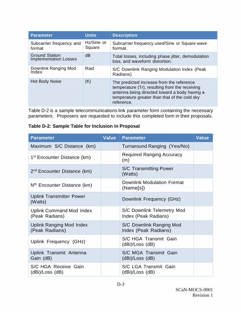
Table D-2 is a sample telecommunications link parameter form containing the necessary parameters. Proposers are requested to include this completed form in their proposals.
Table D-2: Sample Table for Inclusion in Proposal
Parameter Value Parameter Value
Maximum S/C Distance (km) Turnaround Ranging (Yes/No)
1st Encounter Distance (km) Required Ranging Accuracy (m)
2nd Encounter Distance (km) S/C Transmitting Power (Watts)
Nth Encounter Distance (km) Downlink Modulation Format (Name[s])
Uplink Transmitter Power (Watts)
Downlink Frequency (GHz)
Uplink Command Mod Index (Peak Radians)
S/C Downlink Telemetry Mod
Index (Peak Radians)
Uplink Ranging Mod Index (Peak Radians)
S/C Downlink Ranging Mod Index (Peak Radians)
Uplink Frequency (GHz) S/C HGA Transmit Gain (dBi)/Loss (dB)
Uplink Transmit Antenna Gain (dB)
S/C MGA Transmit Gain (dBi)/Loss (dB)
S/C HGA Receive Gain (dBi)/Loss (dB)
S/C LGA Transmit Gain (dBi)/Loss (dB)
D-4
SCaN-MOCS-0001
Revision 1
Parameter Value Parameter Value
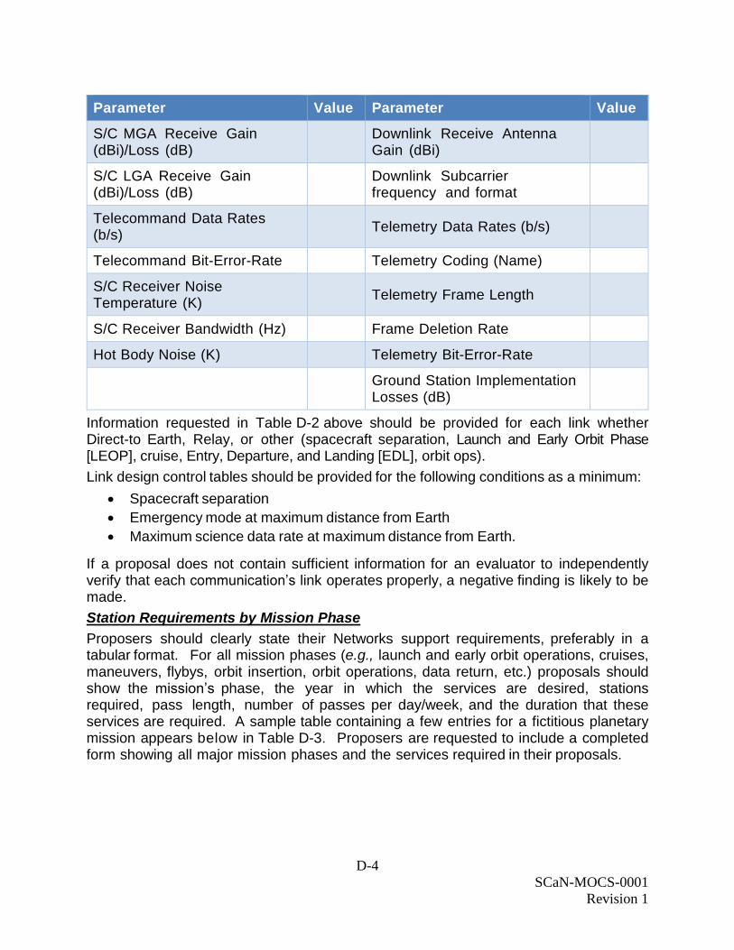
S/C MGA Receive Gain (dBi)/Loss (dB)
Downlink Receive Antenna Gain (dBi)
S/C LGA Receive Gain (dBi)/Loss (dB)
Downlink Subcarrier frequency and format
Telecommand Data Rates (b/s)
Telemetry Data Rates (b/s)
Telecommand Bit-Error-Rate Telemetry Coding (Name)
S/C Receiver Noise Temperature (K)
Telemetry Frame Length
S/C Receiver Bandwidth (Hz) Frame Deletion Rate
Hot Body Noise (K) Telemetry Bit-Error-Rate
Ground Station Implementation Losses (dB)
Information requested in Table D-2 above should be provided for each link whether Direct-to Earth, Relay, or other (spacecraft separation, Launch and Early Orbit Phase [LEOP], cruise, Entry, Departure, and Landing [EDL], orbit ops).
Link design control tables should be provided for the following conditions as a minimum:
Spacecraft separation
Emergency mode at maximum distance from Earth
Maximum science data rate at maximum distance from Earth.
If a proposal does not contain sufficient information for an evaluator to independently verify that each communication’s link operates properly, a negative finding is likely to be made.
Station Requirements by Mission Phase
Proposers should clearly state their Networks support requirements, preferably in a tabular format. For all mission phases (e.g., launch and early orbit operations, cruises, maneuvers, flybys, orbit insertion, orbit operations, data return, etc.) proposals should show the mission’s phase, the year in which the services are desired, stations required, pass length, number of passes per day/week, and the duration that these services are required. A sample table containing a few entries for a fictitious planetary mission appears below in Table D-3. Proposers are requested to include a completed form showing all major mission phases and the services required in their proposals.
D-5
SCaN-MOCS-0001
Revision 1
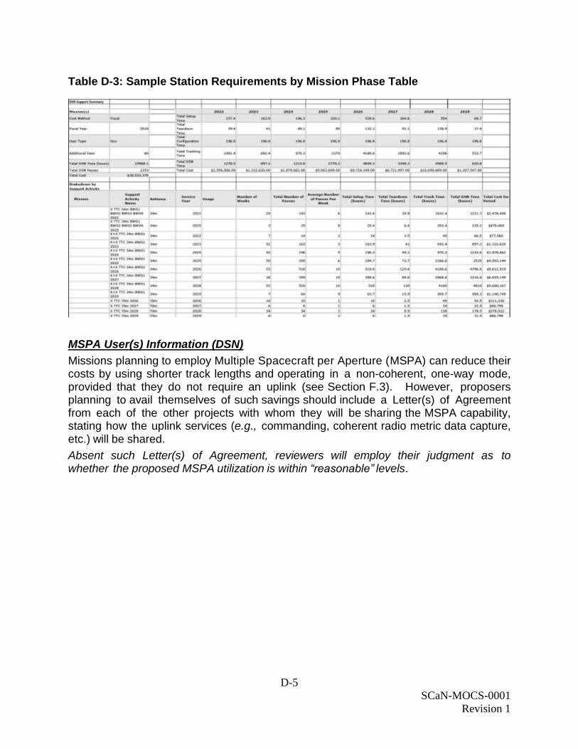
Table D-3: Sample Station Requirements by Mission Phase Table
MSPA User(s) Information (DSN)
Missions planning to employ Multiple Spacecraft per Aperture (MSPA) can reduce their costs by using shorter track lengths and operating in a non-coherent, one-way mode, provided that they do not require an uplink (see Section F.3). However, proposers planning to avail themselves of such savings should include a Letter(s) of Agreement from each of the other projects with whom they will be sharing the MSPA capability, stating how the uplink services (e.g., commanding, coherent radio metric data capture, etc.) will be shared.
Absent such Letter(s) of Agreement, reviewers will employ their judgment as to whether the proposed MSPA utilization is within “reasonable” levels.
E-1
SCaN-MOCS-0001
Revision 1
Appendix E. Form for Estimating DSN Mission Support Costs
Proposers calculating DSN aperture fees should use the on-line tool located at https://deepspace.jpl.nasa.gov/advmiss/proposalpreparation/# under the heading “DSN Aperture Fee Online Tool.” Training on the use of the tool can be provided by the following CIMO DSN Mission Interface managers:
Glen Elliott
Manager Office 912: Mission Support Definitions and Commitments
Jet Propulsion Laboratory
M/S 301-355
4800 Oak Grove Drive
Pasadena, California 91109-8099
Phone: (818) 393-6373
e-mail: [email protected]
Future training for all interested parties will be solicited and provided frequently via Webex or on site. This training can also be conducted for single proposal team users if requested from:
Glen Elliott
Manager Office 912: Mission Support Definitions and Commitments
Jet Propulsion Laboratory
M/S 301-355
4800 Oak Grove Drive
Pasadena, California 91109-8099
Phone: (818) 393-6373
e-mail: [email protected]
F-1
SCaN-MOCS-0001
Revision 1
Appendix F. Estimated Costs for Using the DSN
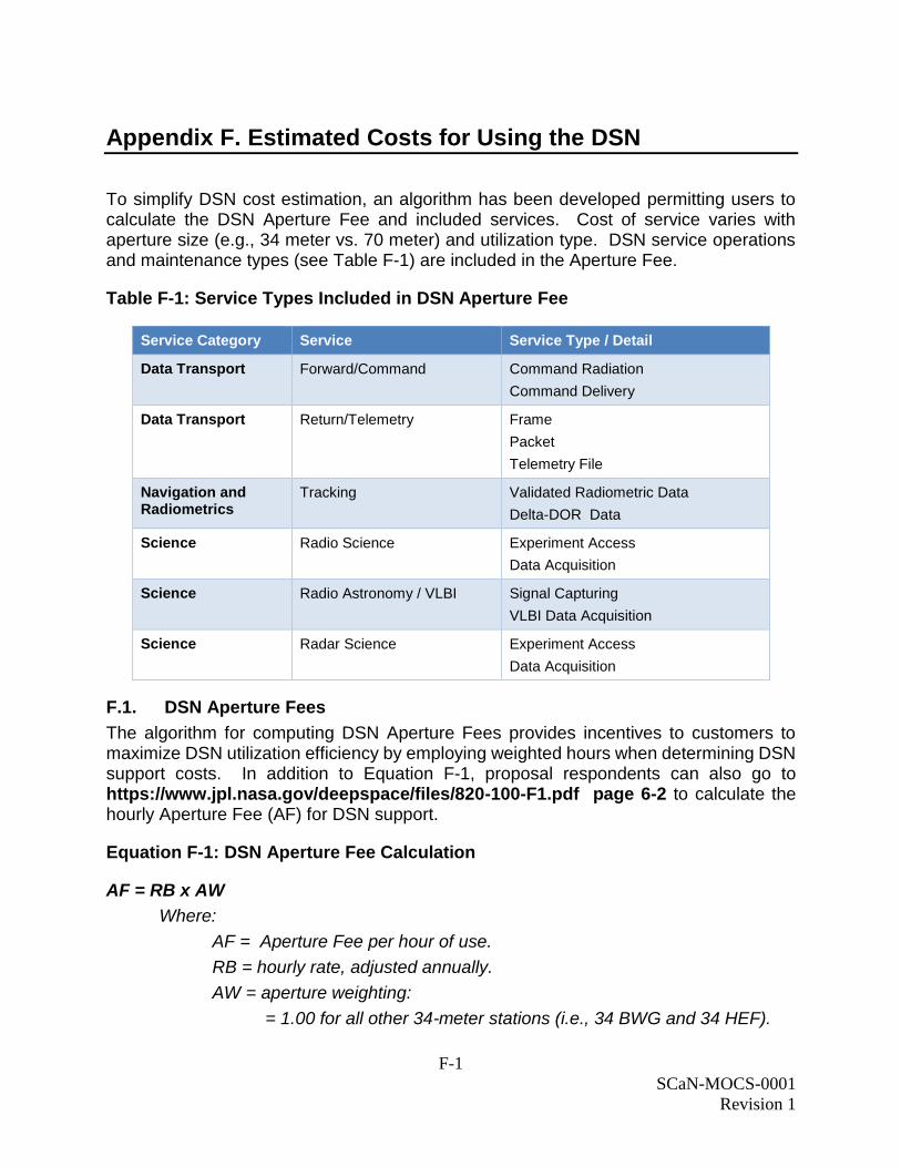
To simplify DSN cost estimation, an algorithm has been developed permitting users to calculate the DSN Aperture Fee and included services. Cost of service varies with aperture size (e.g., 34 meter vs. 70 meter) and utilization type. DSN service operations and maintenance types (see Table F-1) are included in the Aperture Fee.
Table F-1: Service Types Included in DSN Aperture Fee
Service Category Service Service Type / Detail
Data Transport Forward/Command Command Radiation
Command Delivery
Data Transport Return/Telemetry Frame
Packet
Telemetry File
Navigation and Radiometrics
Tracking Validated Radiometric Data
Delta-DOR Data
Science Radio Science Experiment Access
Data Acquisition
Science Radio Astronomy / VLBI Signal Capturing
VLBI Data Acquisition
Science Radar Science Experiment Access
Data Acquisition
F.1. DSN Aperture Fees
The algorithm for computing DSN Aperture Fees provides incentives to customers to maximize DSN utilization efficiency by employing weighted hours when determining DSN support costs. In addition to Equation F-1, proposal respondents can also go to https://www.jpl.nasa.gov/deepspace/files/820-100-F1.pdf page 6-2 to calculate the hourly Aperture Fee (AF) for DSN support.
Equation F-1: DSN Aperture Fee Calculation
AF = RB x AW
Where:
AF = Aperture Fee per hour of use.
RB = hourly rate, adjusted annually.
AW = aperture weighting:
= 1.00 for all other 34-meter stations (i.e., 34 BWG and 34 HEF).
F-2
SCaN-MOCS-0001
Revision 1
= 2.00 for a two 34-meter station array or 2-station Delta Differenced One-Way Range (DDOR).
= 3.00 for a three 34-meter station array.
= 4.00 for a four 34-meter station array.
= 2.00 for 70-meter stations.
At the time of publication of this document, the DSN contact dependent hourly rate (RB) was $950. For current rate information, proposal respondents should contact CIMO (see Section 6.3 for Points of Contact).
A station contact, Frequency of Contacts (FC), may be any length and is defined as either the duration of the spacecraft’s scheduled pass or 12 hours, whichever is less.
For a standard pass, a 45-minute setup and a 15-minute tear-down time must be added to each scheduled pass to obtain the station contact time (other configuration times apply to Beacon Monitoring, MSPA, Array, and Delta-DDOR passes—see relevant cost sections below). Note that scheduled pass-lengths should be integer multiples of 1-hour with a maximum of 12 hours per pass.
Total DSN cost is obtained by partitioning mission support into calendar weeks, grouping weeks having the same requirement in the same year, multiplying by weighted AF, and summing these fees over the mission’s duration. AFs include several services in the following categories: command, telemetry, tracking, radio science, radio astronomy, radar science, and services.
F.2. DSN Costing Calculations
Calculate DSN costs (Aperture Fee, AF in $/Hr.) by selecting a specific antenna and then determining the number and duration of tracking passes required to satisfy project commanding, telemetry, and navigation for the life of the mission (e.g., launch, cruise, maneuvers, and science phases). Each tracking pass, except Beacon Mode, DDOR, and a few others must be increased in length by one hour for reconfiguration. Once the pass length and number of passes is determined, multiply the aggregate hours by the hourly AF, adjusted to the applicable Fiscal Year (FY), to compute the mission’s cost (FY dollars) using https://deepspace.jpl.nasa.gov/advmiss/proposalpreparation/#
An on-line calculation tool DSN AF Calculator can be used to calculate DSN AFs in real-year or FY Dollars. To utilize the tool, either contact the person named in Section 6.3, Appendix E, or the DSN website listed above.
F.3. DSN Fee Reduction for Utilizing Multiple Spacecraft per Antenna (MSPA)
Some flight programs, such as those surveying Mars, have clustered several spacecraft about a planet/body. It is possible to simultaneously capture telemetry signals from two or perhaps more spacecraft provided that they lie within the beamwidth of the Earth station's antenna.
If this situation applies and the constraints set forth here and in the DSN Service Catalog are acceptable, then it may be possible to reduce the Antenna cost by half for spacecraft operating without an uplink in a non-coherent mode. To calculate the cost, first compute
F-3
SCaN-MOCS-0001
Revision 1
the AF, using https://deepspace.jpl.nasa.gov/advmiss/proposalpreparation/#. Thereafter, apply the correction factor according to the formula:
Equation F-2: Aperture Fee Cost for Multiple Spacecraft per Aperture (MSPA)
AF' = (0.50) AF
Where: AF' = weighted Aperture Fee per hour of use for spacecraft operating without an uplink in the MSPA mode. (Spacecraft having an uplink when operating in an MSPA mode should use the aperture fee (AF) computed according https://deepspace.jpl.nasa.gov/advmiss/proposalpreparation/#
The reduced price, Aperture Fee Discounted for Multiple Spacecraft per Aperture applications (AF'), reflects the lack of capability resulting from no uplink communications. It is based upon the loss of commanding and ranging services to the spacecraft operating in a one-way, non-coherent mode. If MSPA users agree, all could time share the uplink and then reallocate cost savings according to their individually negotiated sharing arrangements. When switching the uplink from one spacecraft to the next, full costs, AF, begin to apply to the new two-way coherent user at the onset of the switching operation.
MSPA exists if, and only if, the same DSN antenna is simultaneously supporting two or more spacecraft without regard to whether an uplink is required by either.
F.4. Clustered Spacecraft Aggregated DSN Costing
Occasionally a mission comprises several spacecraft flying in a geometric formation but with spacing too large to utilize MSPA. Rather than request simultaneous support from several DSN stations, the project may agree to sequentially contact each spacecraft. From a project viewpoint, it is desirable to treat sequential DSN communications with several spacecraft as a single DSN contact for costing purposes. For information on the condition and constraints that allow for Clustered Spacecraft Aggregation, please see the SCaN Services Catalog.
Clustered Spacecraft Aggregated DSN Costs are calculated by:
Adding a single setup and tear-down time for the aggregated period
Including costs for time needed to move from one spacecraft to the next
Treating the series of links during a pass as a single contact for the costing
algorithm
Computing the cost following Equation F-1 in Section F.1 or go to
https://deepspace.jpl.nasa.gov/advmiss/proposalpreparation/#.
All missions consisting of a cluster of spacecraft not meeting the criteria in Section F.3 should calculate their costs using:
https://deepspace.jpl.nasa.gov/advmiss/proposalpreparation/# in Section F.1, treating each sequential communication with a member of the cluster as a separate and individual contact.
F-4
SCaN-MOCS-0001
Revision 1
F.5. Data Relay DSN Costing
Data between a landed object and a DSN station, which is relayed through an orbiting spacecraft, may be unaccompanied or interspersed with data from other sources. At any specific time, a DSN station may be communicating with one or more surface objects.
Proposals for missions employing relays should include their pro rata share of the DSN station cost. Pass cost can be found by calculating the time required to return the total amount of relayed data, assuming that only this data being transmitted from the orbiting relay element, or by assuming 1-hour whichever is greater. Station configuration times need not be considered. Proposals should state their rationale and assumptions for their computed share of the DSN cost carefully, completely, and in sufficient detail so that evaluators can independently verify the computations.
F.6. DDOR DSN Costing
Under the correct geometric circumstances, DDOR can result in a net reduction in needed tracks. This is because adding DDOR passes can reduce the number of contacts needed to collect long data arcs of coherent Doppler and ranging measurements necessary to compute a spacecraft’s trajectory. DDOR can also be used as an independent data source to validate orbit solutions. However, two widely separated Earth stations are required simultaneously to view the spacecraft and the natural radio sources.
DSN 34M and 70M stations can be used to collect DDOR data. To calculate a cost for a DDOR pass, users should determine the following:
1) DSN stations desired for the DDOR pass.
2) Amount of DDOR data required to obtain the spacecraft’s position.
3) Pass length needed to obtain the data.
4) Setup time of 90 minutes (a 45-minute standard pass setup period for the station
plus an additional 45 minutes for DDOR). The tear-down time remains at 15
minutes for each DDOR pass (Note: There is a 90-minute setup plus 15 minutes
tear-down time for each station in the DDOR array.).
5) Cost of the pass by summing the cost for the two desired DSN stations plus
setup and tear-down times over the length of the pass.
F.7. Beacon Tone Monitoring DSN Costing
Beacon Tone Monitoring is a low-cost method for verifying spacecraft health. A spacecraft transmits up to four predetermined tone frequencies (subcarriers) indicating its current condition. Spacecraft must be designed to monitor their subsystems and direct an appropriate tone to be transmitted. Beacon Tone Monitoring is particularly useful during long cruise periods when little or no science data is being collected.
Beacon Tone tracks (exclusive of configuration time) are generally short (40 to 60 minutes) and must occur at prescheduled times when the spacecraft is in view of a DSN complex. DSN 34M or 70M stations capture tones and project personnel are informed of the frequency received. Project personnel, not DSN personnel, must determine the meaning of the received tone.
F-5
SCaN-MOCS-0001
Revision 1
Because no science or housekeeping data is received, it is possible to reduce the configuration times and hence cost for Beacon Tone Monitoring. Proposers calculating a cost for Beacon Tone Monitoring should compute AF for the requested DSN antenna using a setup time of 15 minutes and a tear-down time of 5 minutes (rather than 45 minutes and 15 minutes, respectively). The minimum pass length, including configuration times, is 1 hour (40-minute pass plus 20 minutes of setup and tear-down time).
Document Number
Space C
om
munic
atio
ns a
nd N
avig
atio
n (S
CaN
)
Mis
sio
n O
pera
tions a
nd C
om
munic
atio
ns S
erv
ice
s (M
OC
S)
Space C
om
munic
atio
ns a
nd N
avig
atio
n (S
CaN
)
Mis
sio
n O
pera
tions a
nd C
om
munic
atio
ns S
erv
ices (M
OC
S)