Embed Size (px)
Citation preview
Secure Power Ltd Secure Power Ltd, Unit 3, Bessemer Park, Bessemer Way,
Rotherham, South Yorkshire, S60 1EN. Email: [email protected] Website: www.secure-power.co.uk
S5464FU04 Rev 1
Secure Power Ltd
User Manual
SP200R Series UPS SP201R SP202R SP203R

Secure Power Ltd
User Manual
2 …………………………………………………………………………………………………………
Secure Power Ltd own the copyright to this document, which may not be copied, reproduced or disclosed to a third party without written permission.
Secure Power Ltd reserves the right to make changes in specification without notice or liability. All information is subject to Secure Power Ltd own data and is considered accurate at time of publishing.
Secure Power Ltd
User Manual
………………………………………………………………………………………………………… 3
Contents
Safety .......................................................................................................................................................... 5
Warning symbols ...................................................................................................................................... 5
Product description ................................................................................................................................... 6
Applications .............................................................................................................................................. 6 Product range ........................................................................................................................................... 6 System block diagram .............................................................................................................................. 7 Features ................................................................................................................................................... 8
Installation .................................................................................................................................................. 9
Siting considerations ................................................................................................................................ 9 Wiring considerations ............................................................................................................................... 9 Operation from a generator ...................................................................................................................... 9 Circuit breaker and cable sizes .............................................................................................................. 10 Vertical mounting ................................................................................................................................... 10 Rack mounting ....................................................................................................................................... 10 Rear panel layout ................................................................................................................................... 11 Unpacking the UPS ................................................................................................................................ 12 Wiring the UPS ....................................................................................................................................... 12
Operation .................................................................................................................................................. 13
Working modes ...................................................................................................................................... 13 On-Line mode ...................................................................................................................................................... 13 Bypass mode ....................................................................................................................................................... 13 Battery mode ....................................................................................................................................................... 13 ECO mode ........................................................................................................................................................... 13
Front panel controls and indicators ........................................................................................................ 14 LCD display ......................................................................................................................................................... 15
Before switch on ..................................................................................................................................... 16 Switching on the UPS ............................................................................................................................ 16 Switching off the UPS ............................................................................................................................ 16 Self test .................................................................................................................................................. 17 Mute sounds ........................................................................................................................................... 17 Settings .................................................................................................................................................. 17
ECO mode ........................................................................................................................................................... 17 Bypass mode ....................................................................................................................................................... 18
Checking parameters ............................................................................................................................. 19 Fault mode ............................................................................................................................................. 19
Maintenance ............................................................................................................................................. 20
Fan ......................................................................................................................................................... 20 Battery .................................................................................................................................................... 20 External battery change ......................................................................................................................... 20 Visual check ........................................................................................................................................... 20 UPS status check ................................................................................................................................... 20 Function check ....................................................................................................................................... 21
Secure Power Ltd
User Manual
4 …………………………………………………………………………………………………………
Troubleshooting ....................................................................................................................................... 21
Appendix 1 Signals options .................................................................................................................... 22
RS232 serial port .................................................................................................................................... 22 USB port ................................................................................................................................................. 22 SNMP card (advanced monitoring and control) ..................................................................................... 22 Relay card (advanced monitoring and control) ...................................................................................... 23
Appendix 2 Specifications ....................................................................................................................... 25
Electrical ................................................................................................................................................. 25 Environment ........................................................................................................................................... 26 Mechanical ............................................................................................................................................. 26
Appendix 3 Optional equipment ............................................................................................................. 27
Appendix 4 Fault codes ........................................................................................................................... 28
Appendix 5 LED indicator status ............................................................................................................ 29
Secure Power Ltd
User Manual
………………………………………………………………………………………………………… 5
Safety
WARNING!
THIS EQUIPMENT MUST BE INSTALLED, COMMISSIONED AND MAINTAINED BY A QUALIFIED ELECTRICIAN.
There are dangerous voltages and high temperatures inside the UPS. During installation, operation and maintenance please abide by local safety instructions, regulations and laws. Failure to do so may result in injury to personnel or damage to equipment. Safety instructions in this manual are supplementary to local safety instructions. Secure Power Ltd does not accept any liability caused as a result of failure to follow safety instructions. Please note the following:
■ Do not use the UPS for any other purpose than the one for which it was designed.
■ Do not exceed the rated load of the UPS.
■ Under no circumstances open the UPS. There are high capacity batteries inside and other electronics that can cause electric shock. If the UPS requires internal maintenance or battery replacement, contact Secure Power Ltd.
■ Keep the UPS in a dry well ventilated location away from any area or situation in which there is a risk of fire, such as direct sunlight or other sources of heat.
■ If the UPS emits smoke, turn off immediately the input circuit breaker and, if used, battery circuit breaker, and contact Secure Power Ltd.
WARNING!
THIS IS A PRODUCT FOR COMMERCIAL AND INDUSTRIAL APPLICATION IN THE SECOND ENVIRONMENT INSTALLATION RESTRICTIONS OR ADDITIONAL MEASURES MAY BE NEEDED TO PREVENT DISTURBANCES (AS STATED IN EN62040-2:2006).
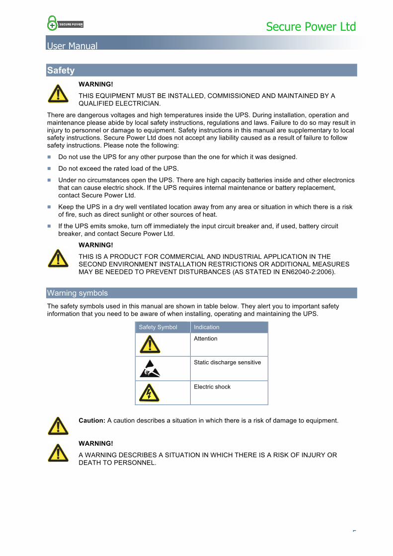
Warning symbols The safety symbols used in this manual are shown in table below. They alert you to important safety information that you need to be aware of when installing, operating and maintaining the UPS.
Safety Symbol Indication
Attention
Static discharge sensitive
Electric shock
Caution: A caution describes a situation in which there is a risk of damage to equipment.
WARNING!
A WARNING DESCRIBES A SITUATION IN WHICH THERE IS A RISK OF INJURY OR DEATH TO PERSONNEL.
Secure Power Ltd
User Manual
6 …………………………………………………………………………………………………………
Product description
Applications This UPS series provides reliable AC backup power to various types of equipment, for example computer centres, network management centres, auto control systems, and telecommunication systems.
Product range The following table lists the models available in the SP200R series. Models with an E suffix are designed for operation with an external battery.
Capacity 1 kVA 2 kVA 3 kVA
Model SP201R SP201RE SP202R SP202RE SP203R SP203RE
Battery location Internal External Internal External Internal External
Battery voltage 24 V 48 V 72 V
No. of 12 V batteries 2 4 6
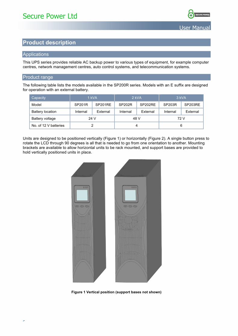
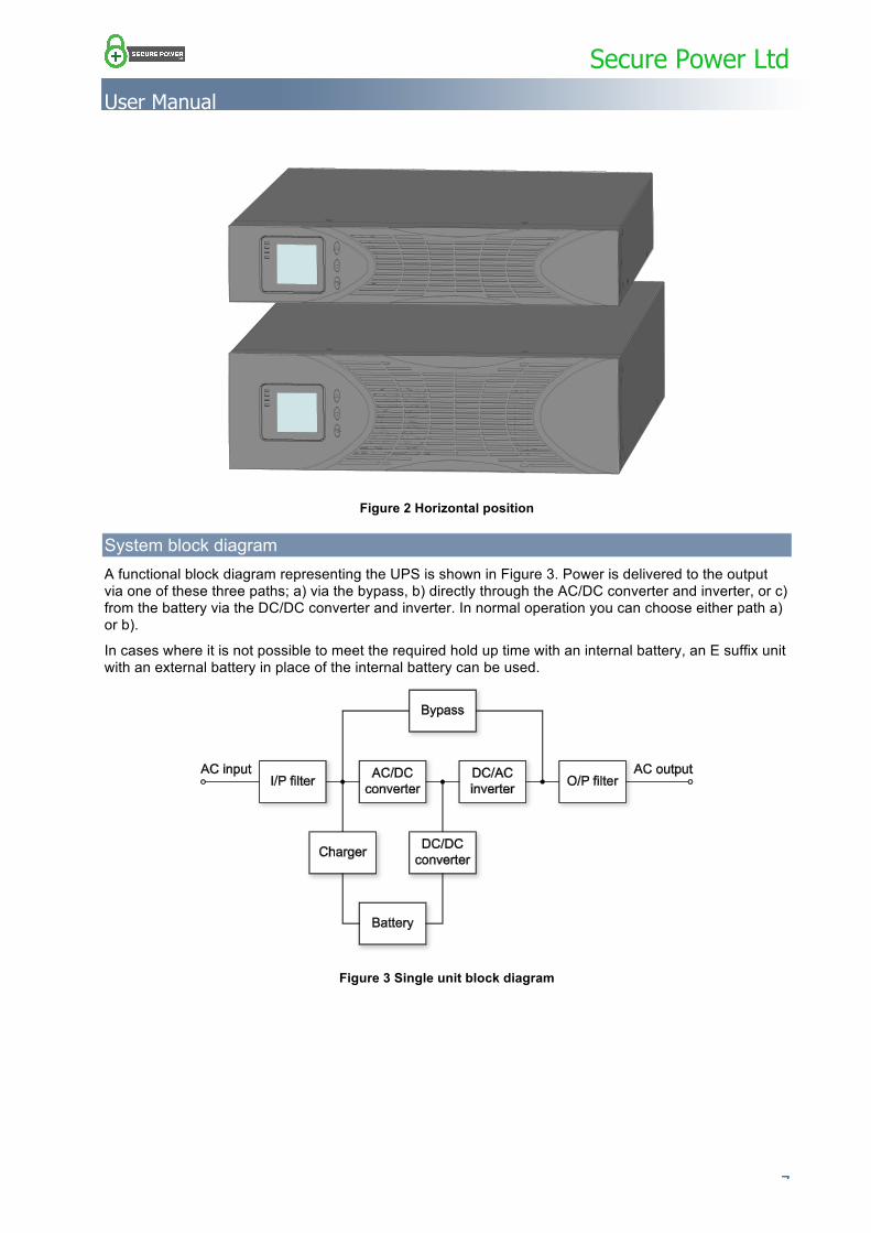
Units are designed to be positioned vertically (Figure 1) or horizontally (Figure 2). A single button press to rotate the LCD through 90 degrees is all that is needed to go from one orientation to another. Mounting brackets are available to allow horizontal units to be rack mounted, and support bases are provided to hold vertically positioned units in place.
Figure 1 Vertical position (support bases not shown)
Secure Power Ltd
User Manual
………………………………………………………………………………………………………… 7
Figure 2 Horizontal position
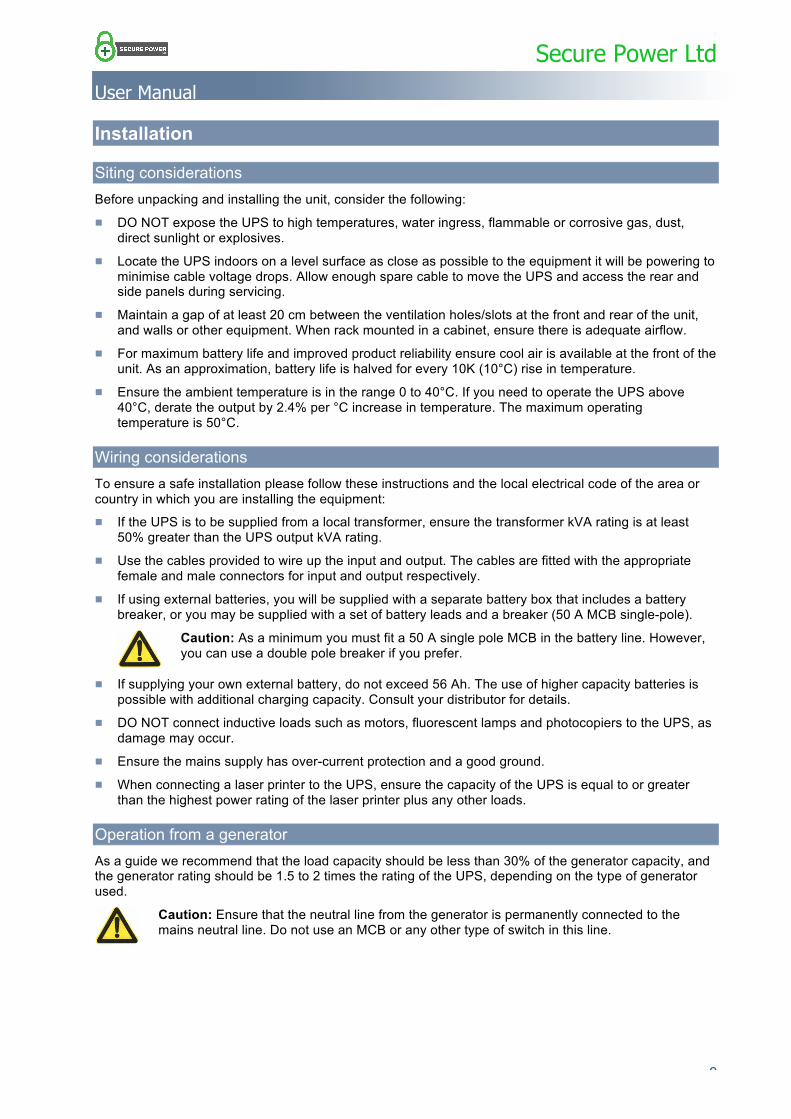
System block diagram A functional block diagram representing the UPS is shown in Figure 3. Power is delivered to the output via one of these three paths; a) via the bypass, b) directly through the AC/DC converter and inverter, or c) from the battery via the DC/DC converter and inverter. In normal operation you can choose either path a) or b).
In cases where it is not possible to meet the required hold up time with an internal battery, an E suffix unit with an external battery in place of the internal battery can be used.
Figure 3 Single unit block diagram
Secure Power Ltd
User Manual
8 …………………………………………………………………………………………………………
Features ■ SP200R series units have an intelligent online sine-wave output with power factor correction. High
frequency double-conversion and a wide input voltage range ensure continuous output for areas with poor power supply regulation.
■ DSP technology for digital control ensures high reliability, circuit protection and self-diagnostics in the unlikely event of a fault. Intelligent digital battery management extends battery life and ensures optimum performance.
■ An LCD panel and LED indicators clearly display the system status and system parameters such as input/output voltage, frequency, load, and unit temperature.
■ Network power management can be achieved using UPS monitoring software via an RS232 serial connection or a USB connection.
■ Optional SNMP or dry contact relay cards are available (either card may be fitted, but not both together).
■ If required, in-line network surge protection is available via RJ45 connectors on the rear panel.
Secure Power Ltd
User Manual
………………………………………………………………………………………………………… 9
Installation
Siting considerations Before unpacking and installing the unit, consider the following:
■ DO NOT expose the UPS to high temperatures, water ingress, flammable or corrosive gas, dust, direct sunlight or explosives.
■ Locate the UPS indoors on a level surface as close as possible to the equipment it will be powering to minimise cable voltage drops. Allow enough spare cable to move the UPS and access the rear and side panels during servicing.
■ Maintain a gap of at least 20 cm between the ventilation holes/slots at the front and rear of the unit, and walls or other equipment. When rack mounted in a cabinet, ensure there is adequate airflow.
■ For maximum battery life and improved product reliability ensure cool air is available at the front of the unit. As an approximation, battery life is halved for every 10K (10°C) rise in temperature.
■ Ensure the ambient temperature is in the range 0 to 40°C. If you need to operate the UPS above 40°C, derate the output by 2.4% per °C increase in temperature. The maximum operating temperature is 50°C.
Wiring considerations To ensure a safe installation please follow these instructions and the local electrical code of the area or country in which you are installing the equipment: ■ If the UPS is to be supplied from a local transformer, ensure the transformer kVA rating is at least
50% greater than the UPS output kVA rating.
■ Use the cables provided to wire up the input and output. The cables are fitted with the appropriate female and male connectors for input and output respectively.
■ If using external batteries, you will be supplied with a separate battery box that includes a battery breaker, or you may be supplied with a set of battery leads and a breaker (50 A MCB single-pole).
Caution: As a minimum you must fit a 50 A single pole MCB in the battery line. However, you can use a double pole breaker if you prefer.
■ If supplying your own external battery, do not exceed 56 Ah. The use of higher capacity batteries is possible with additional charging capacity. Consult your distributor for details.
■ DO NOT connect inductive loads such as motors, fluorescent lamps and photocopiers to the UPS, as damage may occur.
■ Ensure the mains supply has over-current protection and a good ground.
■ When connecting a laser printer to the UPS, ensure the capacity of the UPS is equal to or greater than the highest power rating of the laser printer plus any other loads.
Operation from a generator As a guide we recommend that the load capacity should be less than 30% of the generator capacity, and the generator rating should be 1.5 to 2 times the rating of the UPS, depending on the type of generator used.
Caution: Ensure that the neutral line from the generator is permanently connected to the mains neutral line. Do not use an MCB or any other type of switch in this line.
Secure Power Ltd
User Manual
10 …………………………………………………………………………………………………………
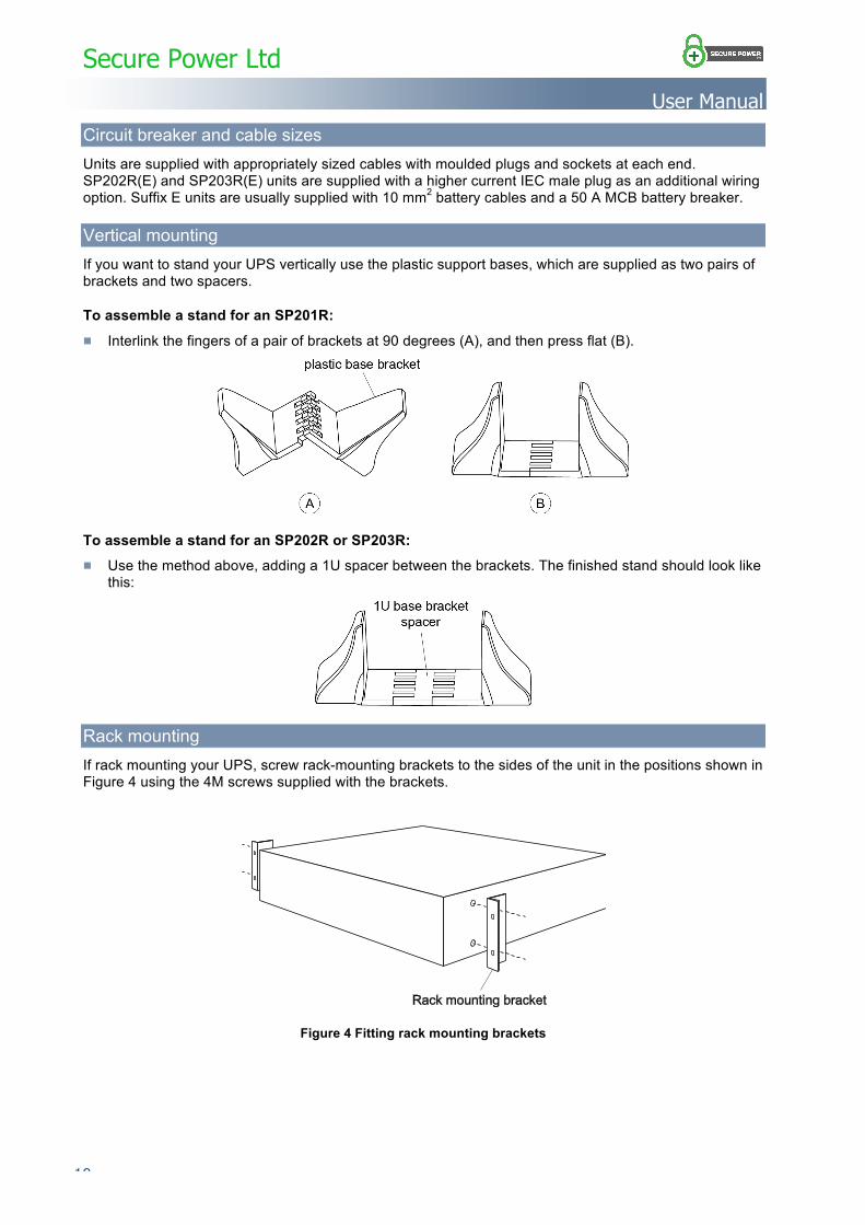
Circuit breaker and cable sizes Units are supplied with appropriately sized cables with moulded plugs and sockets at each end. SP202R(E) and SP203R(E) units are supplied with a higher current IEC male plug as an additional wiring option. Suffix E units are usually supplied with 10 mm2 battery cables and a 50 A MCB battery breaker.
Vertical mounting If you want to stand your UPS vertically use the plastic support bases, which are supplied as two pairs of brackets and two spacers.
To assemble a stand for an SP201R: ■ Interlink the fingers of a pair of brackets at 90 degrees (A), and then press flat (B).
To assemble a stand for an SP202R or SP203R: ■ Use the method above, adding a 1U spacer between the brackets. The finished stand should look like
this:
Rack mounting If rack mounting your UPS, screw rack-mounting brackets to the sides of the unit in the positions shown in Figure 4 using the 4M screws supplied with the brackets.
Figure 4 Fitting rack mounting brackets
Secure Power Ltd
User Manual
………………………………………………………………………………………………………… 11
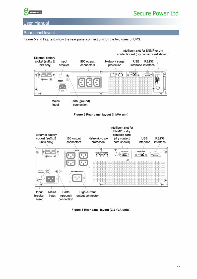
Rear panel layout Figure 5 and Figure 6 show the rear panel connections for the two sizes of UPS.
Figure 5 Rear panel layout (1 kVA unit)
Figure 6 Rear panel layout (2/3 kVA units)
Secure Power Ltd
User Manual
12 …………………………………………………………………………………………………………
Unpacking the UPS 1. Unpack the UPS and check that it has not been damaged during transportation. If damage has
occurred or parts are missing, inform Secure Power Ltd immediately.
2. Remove and retain the documentation, CD and leads from inside the box.
3. Dispose of packets of desiccant correctly.
Wiring the UPS Before connecting the UPS, read the siting considerations above.
WARNING!
BEFORE ATTEMPTING TO WIRE THE UPS ENSURE ALL BREAKERS ARE IN THE OFF POSITION.
Caution: If your system uses external batteries, DO NOT mix batteries from different manufacturers or mix different types of batteries. DO NOT use old and new batteries together.
Note: A PH2 Phillips screwdriver is required if you intend to use the terminal block on the dry contact signals card (if fitted). Do not use a pozidrive (PZ) screwdriver.
To connect the UPS to your system:
1. If your system uses an external battery, check that the number of 12 V blocks matches the number specified in your order.
a. Before connecting the battery, make sure that UPS is unplugged and the battery breaker is turned off.
b. Plug the battery cable into the rear of the UPS (see Figure 5 or Figure 6).
2. Using the supplied cables, connect the UPS output(s) to your load(s). The SP201R(E) has three IEC output sockets, and the SP202R(E) and SP203R(E) have four IEC outputs plus a high current IEC output.
Note: A plug only is supplied for use with the high current output. If you want use this output you will need to wire the plug to your load cable.
3. Ensure the loads are turned off.
4. If your unit has an SNMP or relay contact card fitted or you plan to use the RS232 port or other standard signals, see Appendix 1 Signals options on page 22.
5. Connect the UPS to the mains using the supplied IEC input power cable.
Secure Power Ltd
User Manual
………………………………………………………………………………………………………… 13
Operation
Working modes The UPS has four distinct modes of operation:
■ On-line mode
■ Bypass mode
■ Battery mode
■ ECO mode
Each operating mode is described below.
On-Line mode
This is the default mode of operation in which the load is supplied via the AC/DC converter and inverter when the a.c. input and load are within their normal ranges. In this mode the green inverter LED is on and the battery is trickle charged.
During fault conditions the UPS automatically switches to either bypass mode or battery mode without interruption to the load.
Bypass mode
In bypass mode the load is supplied directly from the a.c. input and the battery is charged. The UPS switches to bypass mode when any of the following conditions occur:
■ An output overload – the unit beeps twice every second, indicating that the load must be reduced to within its normal range as soon as possible. Once the overload is removed the inverter re-starts after a 5 minute delay. If the UPS is overloaded too many times in any one hour it will eventually remain in bypass mode.
■ The UPS is too hot – the UPS reverts to on-line mode as soon as the unit temperature returns to normal.
■ The UPS fails – a serious fault has occurred within the UPS that must be repaired.
■ The UPS is turned off.
In bypass mode the inverter LED is off and the amber bypass LED is on.
Battery mode
In battery mode the load is supplied from the battery via the DC/DC converter and inverter, the UPS beeps every 3 s, and the AC/DC converter and charger are turned off. The UPS switches to battery mode when there is no a.c. input or the a.c. input is outside its normal range. On the front panel the inverter and battery LEDs are on.
When the battery reaches a preset low limit, the system gives a low battery voltage alarm signal, the LCD provides a low battery alarm, and the UPS beeps every second. Eventually the UPS shuts down to prevent damage to the batteries.
When the a.c. mains is restored the inverter starts automatically and the UPS reverts to on-line mode.
ECO mode
If specified, your UPS may be set to operate in ECO mode instead of on-line mode. In ECO mode the load is supplied via the bypass circuit and not the AC/DC converter and inverter, allowing the UPS to work at higher efficiency. The battery is trickle charged in this mode. If the a.c. input is lost or goes beyond its normal range the UPS automatically switches to battery mode, however, the transfer speed is slower than on-line mode and may not be suitable for all applications.
Note: Do not use ECO mode when the mains is of poor quality.
Secure Power Ltd
User Manual
14 …………………………………………………………………………………………………………
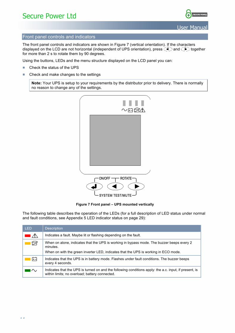
Front panel controls and indicators The front panel controls and indicators are shown in Figure 7 (vertical orientation). If the characters displayed on the LCD are not horizontal (independent of UPS orientation), press and together for more than 2 s to rotate them by 90 degrees.
Using the buttons, LEDs and the menu structure displayed on the LCD panel you can:
■ Check the status of the UPS
■ Check and make changes to the settings
Note: Your UPS is setup to your requirements by the distributor prior to delivery. There is normally no reason to change any of the settings.
Figure 7 Front panel – UPS mounted vertically
The following table describes the operation of the LEDs (for a full description of LED status under normal and fault conditions, see Appendix 5 LED indicator status on page 29):
LED Description
Indicates a fault. Maybe lit or flashing depending on the fault.
When on alone, indicates that the UPS is working in bypass mode. The buzzer beeps every 2 minutes. When on with the green inverter LED, indicates that the UPS is working in ECO mode.
Indicates that the UPS is in battery mode. Flashes under fault conditions. The buzzer beeps every 4 seconds.
Indicates that the UPS is turned on and the following conditions apply: the a.c. input, if present, is within limits; no overload; battery connected.
Secure Power Ltd
User Manual
………………………………………………………………………………………………………… 15
The following table describes the button functions:
Function Buttons Definition
Switch on/off + Press and hold for more than 0.5 s to turn on or turn off the UPS.
Menu access Press and hold for more than 2 s to enter or exit function mode. When in function mode, press and hold for more than 0.5 s but less than 2 s to change a setting.
System test / Mute
+ Operating in on-line or eco mode: press and hold for 1 s to run the self-test function. Operating in battery mode: press and hold for 1 s to mute warning sounds.
Rotate + Press and hold for more than 2 s to rotate the characters on the LED screen by 90 degrees.
Parameter check
or Press repeatedly to see input voltage, battery voltage, output voltage, load and temperature.
LCD display
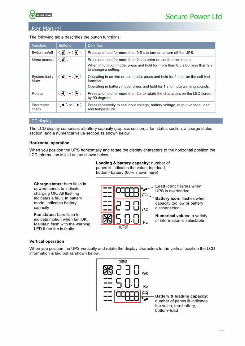
The LCD display comprises a battery capacity graphics section, a fan status section, a charge status section, and a numerical value section as shown below.
Horizontal operation
When you position the UPS horizontally and rotate the display characters to the horizontal position the LCD information is laid out as shown below.
Vertical operation
When you position the UPS vertically and rotate the display characters to the vertical position the LCD information is laid out as shown below.
Battery & loading capacity: number of panes lit indicates the value; top=battery, bottom=load
Charge status: bars flash in upward series to indicate charging OK. All flashing indicates a fault. In battery mode, indicates battery capacity
Fan status: bars flash to indicate motion when fan OK. Maintain flash with the warning LED if the fan is faulty
Loading & battery capacity: number of panes lit indicates the value; top=load, bottom=battery (60% shown here)
Numerical values: a variety of information is selectable
Load icon: flashes when UPS is overloaded
Battery icon: flashes when capacity too low or battery disconnected
Secure Power Ltd
User Manual
16 …………………………………………………………………………………………………………
Before switch on
Before turning on the unit for the first time or after any wiring or battery changes:
1. Read the section above on working modes.
2. Check all the wiring.
3. Check that the rated load does not exceed the rated output of the UPS.
Note: The UPS power output (kW rating) is limited to 80% of the kVA rating.
4. If the UPS is supplied by a generator, check that the generator is correctly rated and wired (see Operation from a generator on page 9).
Switching on the UPS
Note: It is important to switch on your UPS as described below as damage may occur when supplying certain load types.
Caution: When using the UPS for the first time, charge the batteries for at least 8 hours as they may have lost charge during the time between production and installation.
To switch on the UPS:
Note: If there is no mains and you want to start the UPS and run it from the battery, follow the procedure from step 3.
1. If your installation has an external battery, switch on the battery breaker.
2. Switch on the mains to the UPS.
You should immediately hear the fan start up. The output voltage is displayed as 0 VAC and fan operation is displayed as a series of flashing bars.
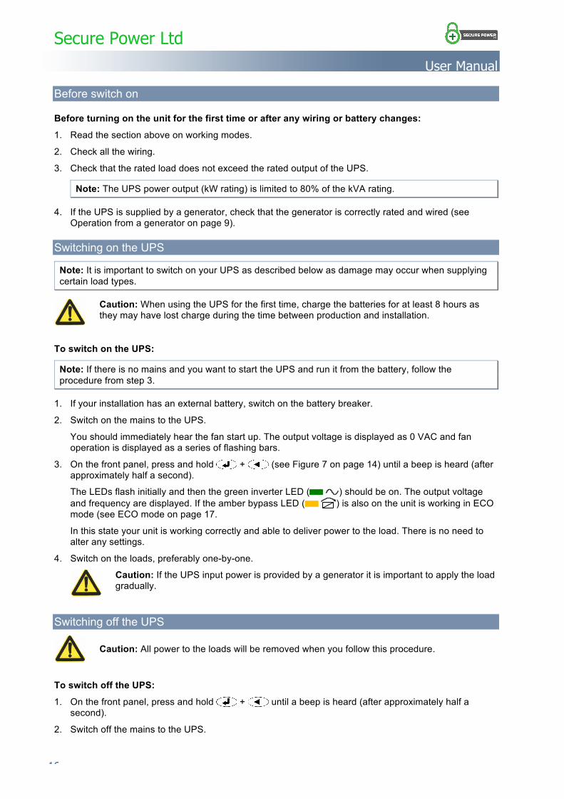
3. On the front panel, press and hold + (see Figure 7 on page 14) until a beep is heard (after approximately half a second).
The LEDs flash initially and then the green inverter LED ( ) should be on. The output voltage and frequency are displayed. If the amber bypass LED ( ) is also on the unit is working in ECO mode (see ECO mode on page 17.
In this state your unit is working correctly and able to deliver power to the load. There is no need to alter any settings.
4. Switch on the loads, preferably one-by-one.
Caution: If the UPS input power is provided by a generator it is important to apply the load gradually.
Switching off the UPS
Caution: All power to the loads will be removed when you follow this procedure.
To switch off the UPS:
1. On the front panel, press and hold + until a beep is heard (after approximately half a second).
2. Switch off the mains to the UPS.
Secure Power Ltd
User Manual
………………………………………………………………………………………………………… 17
Self test
To perform a self-test:
1. Ensure bypass mode is turned off (see Bypass mode on page 18).
2. On the front panel, press and hold + for 1 s. A self-test is performed before normal operation is resumed.
Mute sounds
To mute or unmute all warning sounds:
1. With the UPS on, turn off the mains. This switches the UPS to battery mode.
2. On the front panel, press and hold + for 1 s.
Settings You can change the following settings in any mode:
■ ECO (eco mode): ON/OFF
■ bPS (bypass mode): ON/OFF
The set information is saved only when the battery is connected.
ECO mode
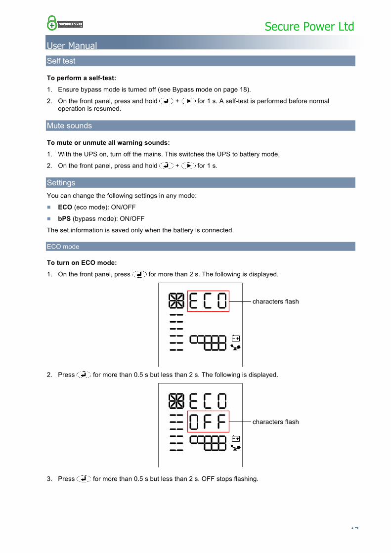
To turn on ECO mode:
1. On the front panel, press for more than 2 s. The following is displayed.
2. Press for more than 0.5 s but less than 2 s. The following is displayed.
3. Press for more than 0.5 s but less than 2 s. OFF stops flashing.
characters flash
characters flash
Secure Power Ltd
User Manual
18 …………………………………………………………………………………………………………
4. Press or to display ON, which flashes.
5. Press for more than 0.5 s but less than 2 s. ON stops flashing.
6. Press for more than 2 s. The green inverter ( ) and bypass ( ) LEDs should be on.
To turn off ECO mode: ■ Use the procedure above and select OFF instead of ON.
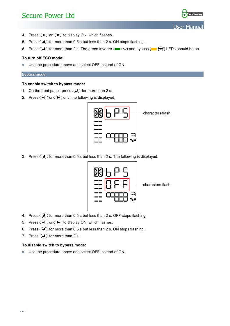
Bypass mode
To enable switch to bypass mode:
1. On the front panel, press for more than 2 s.
2. Press or until the following is displayed.
3. Press for more than 0.5 s but less than 2 s. The following is displayed.
4. Press for more than 0.5 s but less than 2 s. OFF stops flashing.
5. Press or to display ON, which flashes.
6. Press for more than 0.5 s but less than 2 s. ON stops flashing.
7. Press for more than 2 s.
To disable switch to bypass mode: ■ Use the procedure above and select OFF instead of ON.
characters flash
characters flash
Secure Power Ltd
User Manual
………………………………………………………………………………………………………… 19
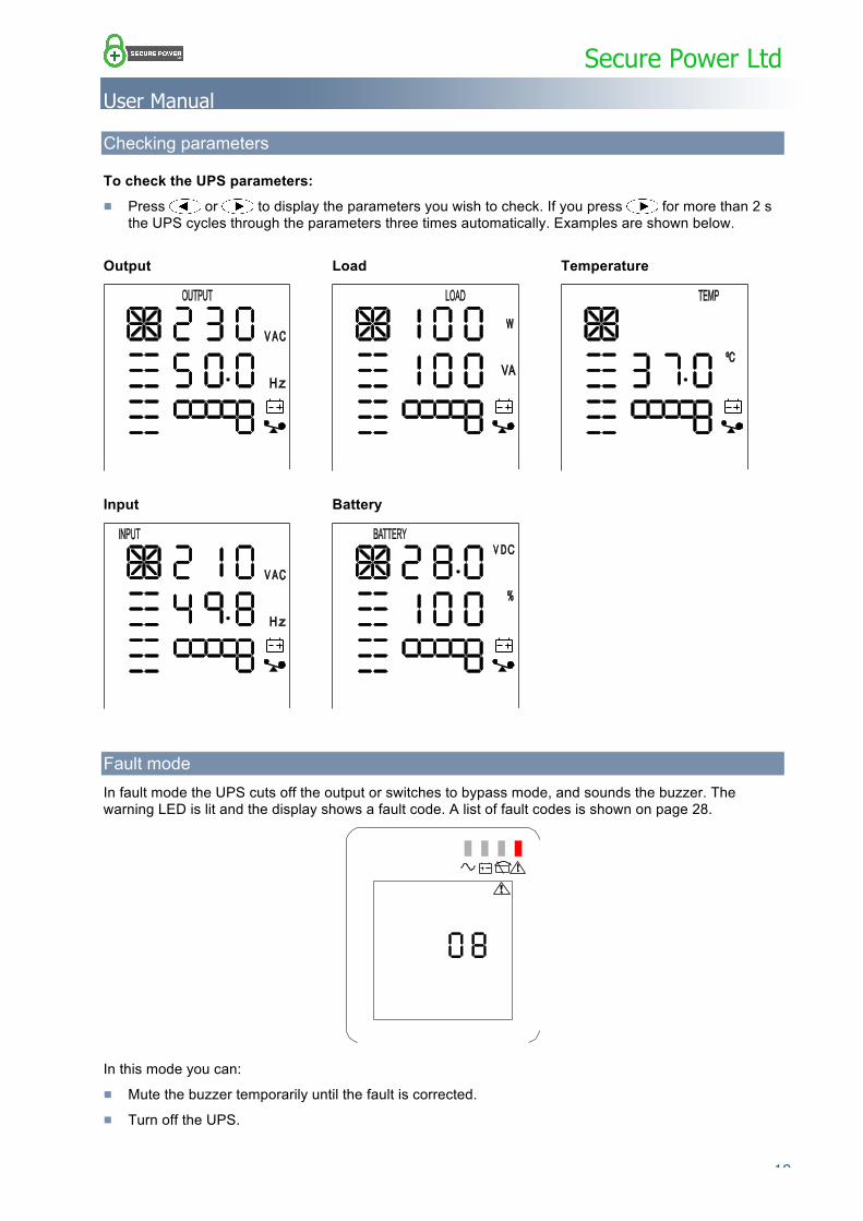
Checking parameters
To check the UPS parameters: ■ Press or to display the parameters you wish to check. If you press for more than 2 s
the UPS cycles through the parameters three times automatically. Examples are shown below.
Output Load Temperature
Input Battery
Fault mode In fault mode the UPS cuts off the output or switches to bypass mode, and sounds the buzzer. The warning LED is lit and the display shows a fault code. A list of fault codes is shown on page 28.
In this mode you can:
■ Mute the buzzer temporarily until the fault is corrected.
■ Turn off the UPS.
Secure Power Ltd
User Manual
20 …………………………………………………………………………………………………………
Maintenance SP200R series units use sealed lead acid, maintenance free batteries and require minimum maintenance in general. To keep the batteries fully charged and in good condition, ensure the UPS is plugged into the mains at all times. The UPS battery charger guards against over-charging and deep discharge.
Fan At normal room ambient temperature the fans will operate continuously for 20,000 to 40,000 hours. Increased ambient temperatures will shorten this lifetime.
Periodically ensure that there is air is blowing out of the rear of the unit.
Battery For units with external batteries we recommend the use of sealed lead acid, maintenance free batteries. Units with internal batteries are fitted with this same type of battery. Battery life depends on the ambient temperature and the number of discharge/charge cycles. Battery life is shortened with high ambient temperature and deep discharges.
To maximise the life of your batteries, maintain them as follows:
■ Maintain the ambient temperature in the range 15 to 25°C
■ Avoid discharge currents of less than 10% of full load current.
■ Do not operate the UPS in battery mode continuously for more than the specified autonomy (hold-up time).
■ Charge the battery for at least 12 hours every 3 months if it has not been used. If the ambient temperature is higher than 25°C, charge the battery every 2 months.
■ Maintain external batteries at least once a year.
If the backup time has significantly reduced, or a battery fault is displayed on the LCD screen contact your distributor to find out if the batteries need replacing.
WARNING
DON'T SHORT CIRCUIT THE BATTERY AS IT CAN CAUSE A FIRE.
DON’T OPEN THE BATTERY AS THE ELECTROLYTE INSIDE IS HARMFUL TO SKIN AND EYES.
External battery change
Caution: We strongly recommend you switch off the whole UPS when you need to change an external battery group.
Visual check Ensure there is adequate ventilation to maintain the UPS at the correct temperature.
UPS status check Check the following:
■ Ensure there are no faults or alarms indicated. ■ If the UPS is working in bypass mode, investigate the cause.
■ If the UPS is working in battery mode, make sure it is normal, if not, investigate.
Secure Power Ltd
User Manual
………………………………………………………………………………………………………… 21
Function check Perform a self-test every 6 months as described on page 17.
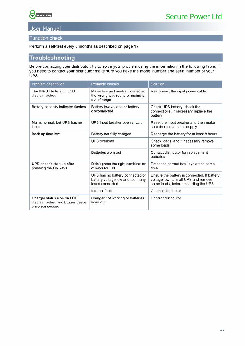
Troubleshooting Before contacting your distributor, try to solve your problem using the information in the following table. If you need to contact your distributor make sure you have the model number and serial number of your UPS.
Problem description Probable causes Solution
The INPUT letters on LCD display flashes
Mains live and neutral connected the wrong way round or mains is out of range
Re-connect the input power cable
Battery capacity indicator flashes Battery low voltage or battery disconnected
Check UPS battery, check the connections. If necessary replace the battery
Mains normal, but UPS has no input
UPS input breaker open circuit Reset the input breaker and then make sure there is a mains supply
Back up time low Battery not fully charged Recharge the battery for at least 8 hours
UPS overload Check loads, and if necessary remove some loads
Batteries worn out Contact distributor for replacement batteries
UPS doesn’t start up after pressing the ON keys
Didn’t press the right combination of keys for ON
Press the correct two keys at the same time
UPS has no battery connected or battery voltage low and too many loads connected
Ensure the battery is connected. If battery voltage low, turn off UPS and remove some loads, before restarting the UPS
Internal fault Contact distributor
Charger status icon on LCD display flashes and buzzer beeps once per second
Charger not working or batteries worn out
Contact distributor
Secure Power Ltd
User Manual
22 …………………………………………………………………………………………………………
Appendix 1 Signals options
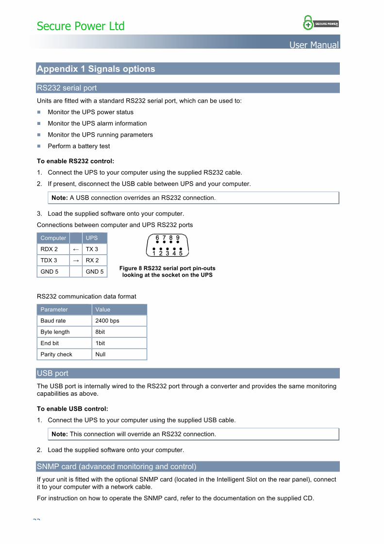
RS232 serial port Units are fitted with a standard RS232 serial port, which can be used to:
■ Monitor the UPS power status
■ Monitor the UPS alarm information
■ Monitor the UPS running parameters
■ Perform a battery test
To enable RS232 control:
1. Connect the UPS to your computer using the supplied RS232 cable.
2. If present, disconnect the USB cable between UPS and your computer.
Note: A USB connection overrides an RS232 connection.
3. Load the supplied software onto your computer.
Connections between computer and UPS RS232 ports
Computer UPS
RDX 2 ← TX 3
TDX 3 → RX 2
GND 5 GND 5
RS232 communication data format
Parameter Value
Baud rate 2400 bps
Byte length 8bit
End bit 1bit
Parity check Null
USB port The USB port is internally wired to the RS232 port through a converter and provides the same monitoring capabilities as above.
To enable USB control:
1. Connect the UPS to your computer using the supplied USB cable.
Note: This connection will override an RS232 connection.
2. Load the supplied software onto your computer.
SNMP card (advanced monitoring and control) If your unit is fitted with the optional SNMP card (located in the Intelligent Slot on the rear panel), connect it to your computer with a network cable.
For instruction on how to operate the SNMP card, refer to the documentation on the supplied CD.
Figure 8 RS232 serial port pin-outs looking at the socket on the UPS
Secure Power Ltd
User Manual
………………………………………………………………………………………………………… 23
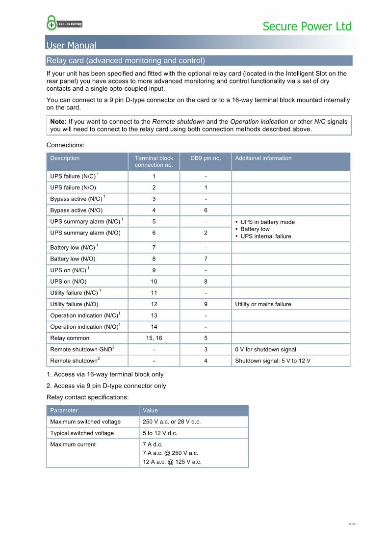
Relay card (advanced monitoring and control) If your unit has been specified and fitted with the optional relay card (located in the Intelligent Slot on the rear panel) you have access to more advanced monitoring and control functionality via a set of dry contacts and a single opto-coupled input.
You can connect to a 9 pin D-type connector on the card or to a 16-way terminal block mounted internally on the card.
Note: If you want to connect to the Remote shutdown and the Operation indication or other N/C signals you will need to connect to the relay card using both connection methods described above.
Connections:
Description Terminal block connection no.
DB9 pin no. Additional information
UPS failure (N/C) 1 1 -
UPS failure (N/O) 2 1
Bypass active (N/C) 1 3 -
Bypass active (N/O) 4 6
UPS summary alarm (N/C) 1 5 - • UPS in battery mode • Battery low • UPS internal failure UPS summary alarm (N/O) 6 2
Battery low (N/C) 1 7 -
Battery low (N/O) 8 7
UPS on (N/C) 1 9 -
UPS on (N/O) 10 8
Utility failure (N/C) 1 11 -
Utility failure (N/O) 12 9 Utility or mains failure
Operation indication (N/C)1 13 -
Operation indication (N/O)1 14 -
Relay common 15, 16 5
Remote shutdown GND2 - 3 0 V for shutdown signal
Remote shutdown2 - 4 Shutdown signal: 5 V to 12 V
1. Access via 16-way terminal block only
2. Access via 9 pin D-type connector only
Relay contact specifications:
Parameter Value
Maximum switched voltage 250 V a.c. or 28 V d.c.
Typical switched voltage 5 to 12 V d.c.
Maximum current 7 A d.c. 7 A a.c. @ 250 V a.c. 12 A a.c. @ 125 V a.c.
Secure Power Ltd
User Manual
24 …………………………………………………………………………………………………………
Opto-coupler input specifications (used for remote shutdown):
Parameter Value
Reverse voltage (VR) 6 V d.c.
Forward input voltage 30 V d.c. max., 5 to 12 V d.c. typical
Forward current 80 mA max., 16 mA typical
Pulse forward current (IFP) 1 A (100 µs pulse, 100 pps)
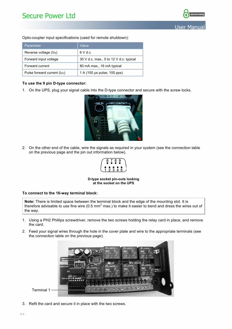
To use the 9 pin D-type connector:
1. On the UPS, plug your signal cable into the D-type connector and secure with the screw locks.
2. On the other end of the cable, wire the signals as required in your system (see the connection table on the previous page and the pin out information below).
To connect to the 16-way terminal block:
Note: There is limited space between the terminal block and the edge of the mounting slot. It is therefore advisable to use fine wire (0.5 mm2 max.) to make it easier to bend and dress the wires out of the way.
1. Using a PH2 Phillips screwdriver, remove the two screws holding the relay card in place, and remove the card.
2. Feed your signal wires through the hole in the cover plate and wire to the appropriate terminals (see the connection table on the previous page).
3. Refit the card and secure it in place with the two screws.
D-type socket pin-outs looking at the socket on the UPS
Terminal 1
Secure Power Ltd
User Manual
………………………………………………………………………………………………………… 25
Appendix 2 Specifications
Electrical
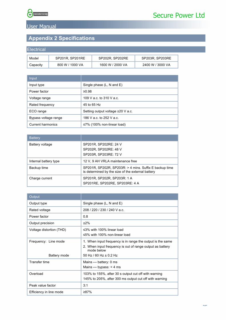
Model SP201R, SP201RE SP202R, SP202RE SP203R, SP203RE
Capacity 800 W / 1000 VA 1600 W / 2000 VA 2400 W / 3000 VA
Input
Input type Single phase (L, N and E)
Power factor ≥0.98
Voltage range 109 V a.c. to 310 V a.c.
Rated frequency 45 to 65 Hz
ECO range Setting output voltage ±20 V a.c.
Bypass voltage range 186 V a.c. to 252 V a.c.
Current harmonics ≤7% (100% non-linear load)
Battery
Battery voltage SP201R, SP202RE: 24 V SP202R, SP202RE: 48 V SP203R, SP203RE: 72 V
Internal battery type 12 V, 9 AH VRLA maintenance free
Backup time SP201R, SP202R, SP203R: > 4 mins. Suffix E backup time is determined by the size of the external battery
Charge current SP201R, SP202R, SP203R: 1 A SP201RE, SP202RE, SP203RE: 4 A
Output
Output type Single phase (L, N and E)
Rated voltage 208 / 220 / 230 / 240 V a.c.
Power factor 0.8
Output precision ±2%
Voltage distortion (THD) ≤3% with 100% linear load ≤5% with 100% non-linear load
Frequency: Line mode Battery mode
1. When input frequency is in range the output is the same 2. When input frequency is out of range output as battery
mode below 50 Hz / 60 Hz ± 0.2 Hz
Transfer time Mains ↔ battery: 0 ms Mains ↔ bypass: < 4 ms
Overload 103% to 155%, after 30 s output cut off with warning 145% to 205%, after 300 ms output cut off with warning
Peak value factor 3:1
Efficiency in line mode ≥87%
Secure Power Ltd
User Manual
26 …………………………………………………………………………………………………………
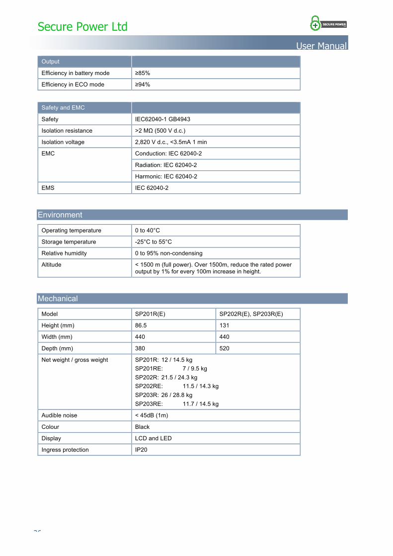
Output
Efficiency in battery mode ≥85%
Efficiency in ECO mode ≥94%
Safety and EMC
Safety IEC62040-1 GB4943
Isolation resistance >2 MΩ (500 V d.c.)
Isolation voltage 2,820 V d.c., <3.5mA 1 min
EMC Conduction: IEC 62040-2
Radiation: IEC 62040-2
Harmonic: IEC 62040-2
EMS IEC 62040-2
Environment
Operating temperature 0 to 40°C
Storage temperature -25°C to 55°C
Relative humidity 0 to 95% non-condensing
Altitude < 1500 m (full power). Over 1500m, reduce the rated power output by 1% for every 100m increase in height.
Mechanical
Model SP201R(E) SP202R(E), SP203R(E)
Height (mm) 86.5 131
Width (mm) 440 440
Depth (mm) 380 520
Net weight / gross weight SP201R: 12 / 14.5 kg SP201RE: 7 / 9.5 kg SP202R: 21.5 / 24.3 kg SP202RE: 11.5 / 14.3 kg SP203R: 26 / 28.8 kg SP203RE: 11.7 / 14.5 kg
Audible noise < 45dB (1m)
Colour Black
Display LCD and LED
Ingress protection IP20

Secure Power Ltd
User Manual
………………………………………………………………………………………………………… 27
Appendix 3 Optional equipment The following items are available as options for the UPS:
■ Extension battery box
■ Dry contact relay card
■ SNMP card
■ Battery MCB box
■ Bypass panel
Secure Power Ltd
User Manual
28 …………………………………………………………………………………………………………
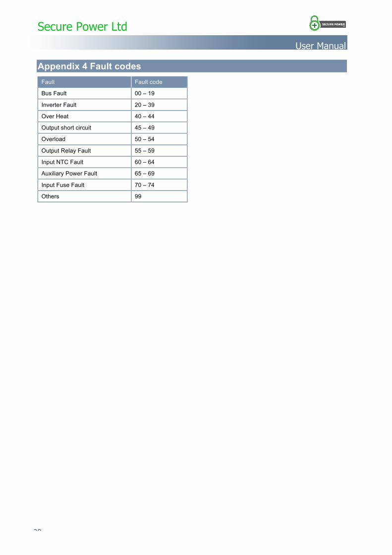
Appendix 4 Fault codes Fault Fault code
Bus Fault 00 – 19
Inverter Fault 20 – 39
Over Heat 40 – 44
Output short circuit 45 – 49
Overload 50 – 54
Output Relay Fault 55 – 59
Input NTC Fault 60 – 64
Auxiliary Power Fault 65 – 69
Input Fuse Fault 70 – 74
Others 99
Secure Power Ltd
User Manual
………………………………………………………………………………………………………… 29
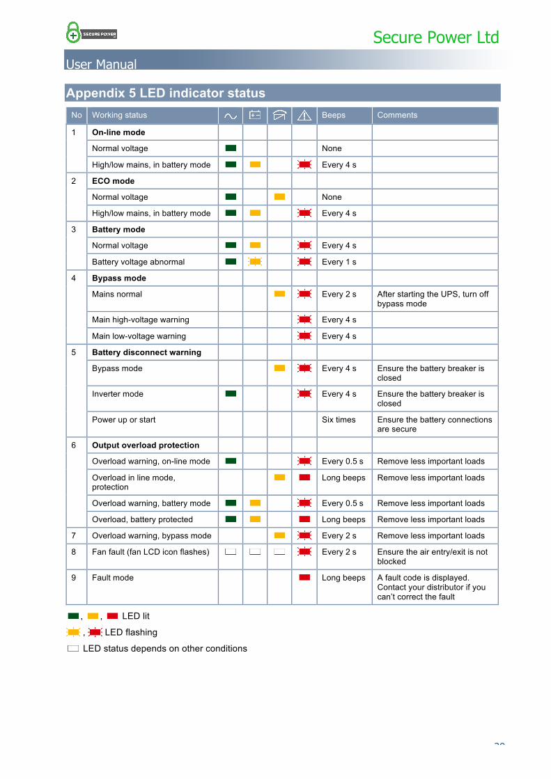
Appendix 5 LED indicator status No Working status Beeps Comments
1 On-line mode
Normal voltage None
High/low mains, in battery mode Every 4 s
2 ECO mode
Normal voltage None
High/low mains, in battery mode Every 4 s
3 Battery mode
Normal voltage Every 4 s
Battery voltage abnormal Every 1 s
4 Bypass mode
Mains normal Every 2 s After starting the UPS, turn off bypass mode
Main high-voltage warning Every 4 s
Main low-voltage warning Every 4 s
5 Battery disconnect warning
Bypass mode Every 4 s Ensure the battery breaker is closed
Inverter mode Every 4 s Ensure the battery breaker is closed
Power up or start Six times Ensure the battery connections are secure
6 Output overload protection
Overload warning, on-line mode Every 0.5 s Remove less important loads
Overload in line mode, protection
Long beeps Remove less important loads
Overload warning, battery mode Every 0.5 s Remove less important loads
Overload, battery protected Long beeps Remove less important loads
7 Overload warning, bypass mode Every 2 s Remove less important loads
8 Fan fault (fan LCD icon flashes) Every 2 s Ensure the air entry/exit is not blocked
9 Fault mode Long beeps A fault code is displayed. Contact your distributor if you can’t correct the fault
, , LED lit
, LED flashing
LED status depends on other conditions