Embed Size (px)
Citation preview
SP Belle River
Draft Wind Turbine Specifications Report – Belle River Wind Project
Prepared by:
AECOM
105 Commerce Valley Drive West, Floor 7 905 886 7022 tel
Markham, ON, Canada L3T 7W3 905 886 9494 fax
www.aecom.com
Project Number:
60321891
Date:
February, 2015
SP Belle River
Draft Wind Turbine Specifications Report – Belle River Wind Project
SP Belle River Draft Wind Turbine Specifications Report – Belle River Wind Project
Rpt_2015-02-12_Draft Wind Turbine Specification Report_60321891
Table of Contents
page
1. Introduction ..................................................................................................................................... 1
1.1 Name of Applicant ............................................................................................................................... 1 1.2 Summary of Wind Turbine Specifications Report Requirements ........................................................ 1 1.3 The Proponent ..................................................................................................................................... 1 1.4 Project Location ................................................................................................................................... 2
2. Technical Specifications ................................................................................................................ 5
2.1 Description of the Energy Source, Nameplate Capacity and Class of the Facility .............................. 5 2.2 Summary of Key Project Information and Wind Turbine Specifications .............................................. 5
2.2.1 Turbine Components .............................................................................................................. 6
3. Acoustic Emissions Data ............................................................................................................... 9
4. References ..................................................................................................................................... 10
List of Figures
Figure 1-1 Project Study Area ..................................................................................................................................... 3
Figure 1-2 Study Area in Ontario ................................................................................................................................. 4
Figure 2-1 Basic Wind Turbine Generator Specifications ........................................................................................... 6
Figure 2-2 Nacelle Arrangement (Appendix B) ............................................................................................................ 7
List of Tables
Table 1-1: Adherence to Wind Turbine Specification Report Requirements under O. Reg. 359/09, as
Amended .................................................................................................................................................... 1
Table 2-1: Summary of Key Project Information ......................................................................................................... 5
Appendices
Appendix A. Manufacturer Acoustic Emission Data
Appendix B. Additional Manufacturer Technical Data
SP Belle River Draft Wind Turbine Specifications Report – Belle River Wind Project
Rpt_2015-02-12_Draft Wind Turbine Specification Report_60321891
Acronyms and Abbreviations
Belle River Wind .......................... SP Belle River Wind, LP
dBA .............................................. Decibels
km ................................................ Kilometres
kV ................................................. Kilovolts
m .................................................. Metres
m/s ............................................... Metres per second
m2 ................................................. Metres squared
MOECC ........................................ Ontario Ministry of the Environment and Climate Change
MW ............................................... Megawatt
O. Reg. ......................................... Ontario Regulation
Pattern Development ................... Pattern Renewable Holdings Canada, ULC
PDR ............................................. Project Description Report
Project .......................................... Belle River Wind Project
PSA .............................................. Project Study Area
REA .............................................. Renewable Energy Approval
Samsung Renewable Energy ...... Samsung Renewable Energy Inc.
SP Belle River Draft Wind Turbine Specifications Report – Belle River Wind Project
Rpt_2015-02-12_Draft Wind Turbine Specification Report_60321891 1
1. Introduction
1.1 Name of Applicant
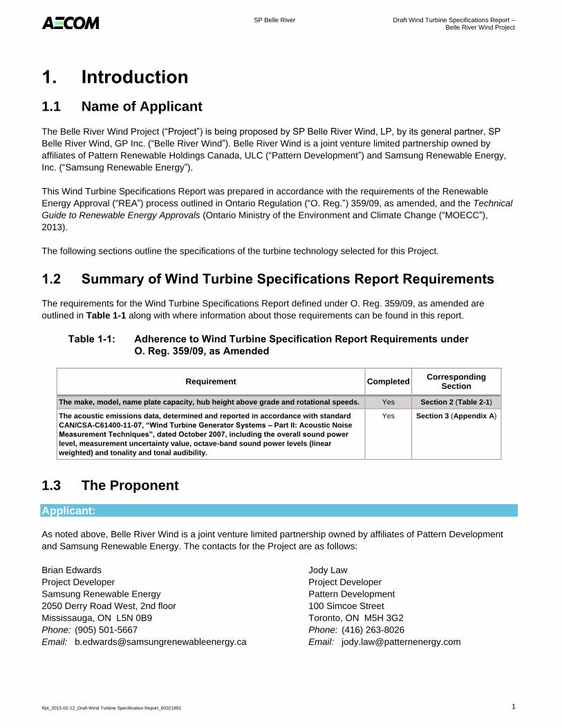
The Belle River Wind Project (“Project”) is being proposed by SP Belle River Wind, LP, by its general partner, SP
Belle River Wind, GP Inc. (“Belle River Wind”). Belle River Wind is a joint venture limited partnership owned by
affiliates of Pattern Renewable Holdings Canada, ULC (“Pattern Development”) and Samsung Renewable Energy,
Inc. (“Samsung Renewable Energy”).
This Wind Turbine Specifications Report was prepared in accordance with the requirements of the Renewable
Energy Approval (“REA”) process outlined in Ontario Regulation (“O. Reg.”) 359/09, as amended, and the Technical
Guide to Renewable Energy Approvals (Ontario Ministry of the Environment and Climate Change (“MOECC”),
2013).
The following sections outline the specifications of the turbine technology selected for this Project.
1.2 Summary of Wind Turbine Specifications Report Requirements
The requirements for the Wind Turbine Specifications Report defined under O. Reg. 359/09, as amended are
outlined in Table 1-1 along with where information about those requirements can be found in this report.
Table 1-1: Adherence to Wind Turbine Specification Report Requirements under
O. Reg. 359/09, as Amended
Requirement Completed Corresponding
Section
The make, model, name plate capacity, hub height above grade and rotational speeds. Yes Section 2 (Table 2-1)
The acoustic emissions data, determined and reported in accordance with standard
CAN/CSA-C61400-11-07, “Wind Turbine Generator Systems – Part II: Acoustic Noise
Measurement Techniques”, dated October 2007, including the overall sound power
level, measurement uncertainty value, octave-band sound power levels (linear
weighted) and tonality and tonal audibility.
Yes Section 3 (Appendix A)
1.3 The Proponent
Applicant:
As noted above, Belle River Wind is a joint venture limited partnership owned by affiliates of Pattern Development
and Samsung Renewable Energy. The contacts for the Project are as follows:
Brian Edwards
Project Developer
Samsung Renewable Energy
2050 Derry Road West, 2nd floor
Mississauga, ON L5N 0B9
Phone: (905) 501-5667
Email: [email protected]
Jody Law
Project Developer
Pattern Development
100 Simcoe Street
Toronto, ON M5H 3G2
Phone: (416) 263-8026
Email: [email protected]
SP Belle River Draft Wind Turbine Specifications Report – Belle River Wind Project
Rpt_2015-02-12_Draft Wind Turbine Specification Report_60321891 2
Consultant:
Marc Rose
Senior Environmental Planner
AECOM
105 Commerce Valley Drive West, 7th Floor
Markham, ON L3T 7W3
Phone: (905) 747-7793
Email: [email protected]
Project:
Project Email: [email protected]
Project Website: www.belleriverwind.com
1.4 Project Location
Belle River Wind is proposing to develop a wind project in the Town of Lakeshore in the County of Essex, Ontario.
The Project will be located on public and private lands south of the community of Belle River. The location of the
Project was established based on interest expressed by local landowners, the availability of wind resources, and
availability of existing infrastructure for connection to the electrical grid.
According to O. Reg. 359/09, as amended, the Project Location is “a part of land and all or part of any building or
structure in, on, or over which a person is engaging in or proposes to engage in the project and any air space in
which a person is engaging in or proposes to engage in the project”. As described therein, the Project Location
boundary is the outer limit of where site preparation and construction activities will occur (i.e., disturbance areas
described below) and where permanent infrastructure will be located, including the air space occupied by turbine
blades.
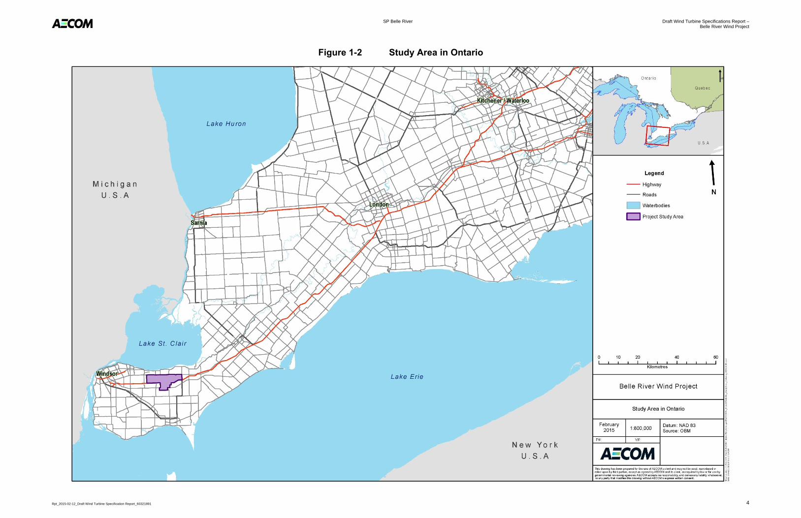
The Project is generally bounded by County Road 42 to the north, Lakeshore Road 111 to the west, Highway 401
and South Middle Road to the south, and Comber Sideroad to the east. The area encompassed by these boundaries
is referred to as the Project Study Area (“PSA”). Figure 1-1, below, shows a map of the PSA. To see the location of
the Project within Ontario, please see Figure 1-2.
SP Belle River Draft Wind Turbine Specifications Report – Belle River Wind Project
Rpt_2015-02-12_Draft Wind Turbine Specification Report_60321891 3
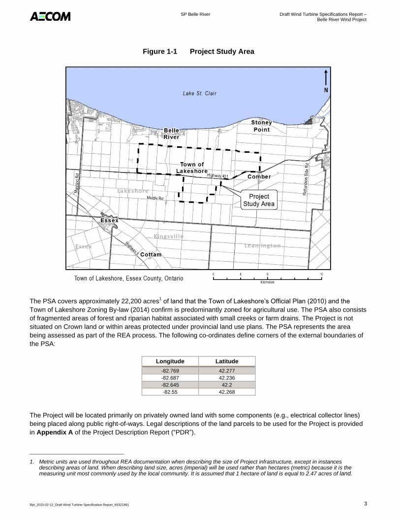
Figure 1-1 Project Study Area
The PSA covers approximately 22,200 acres1 of land that the Town of Lakeshore’s Official Plan (2010) and the
Town of Lakeshore Zoning By-law (2014) confirm is predominantly zoned for agricultural use. The PSA also consists
of fragmented areas of forest and riparian habitat associated with small creeks or farm drains. The Project is not
situated on Crown land or within areas protected under provincial land use plans. The PSA represents the area
being assessed as part of the REA process. The following co-ordinates define corners of the external boundaries of
the PSA:
Longitude Latitude
-82.769 42.277
-82.687 42.236
-82.645 42.2
-82.55 42.268
The Project will be located primarily on privately owned land with some components (e.g., electrical collector lines)
being placed along public right-of-ways. Legal descriptions of the land parcels to be used for the Project is provided
in Appendix A of the Project Description Report (“PDR”).
1. Metric units are used throughout REA documentation when describing the size of Project infrastructure, except in instances describing areas of land. When describing land size, acres (imperial) will be used rather than hectares (metric) because it is the measuring unit most commonly used by the local community. It is assumed that 1 hectare of land is equal to 2.47 acres of land.
SP Belle River Draft Wind Turbine Specifications Report – Belle River Wind Project
Rpt_2015-02-12_Draft Wind Turbine Specification Report_60321891 4
Figure 1-2 Study Area in Ontario
SP Belle River Draft Wind Turbine Specifications Report – Belle River Wind Project
Rpt_2015-02-12_Draft Wind Turbine Specification Report_60321891 5
2. Technical Specifications
2.1 Description of the Energy Source, Nameplate Capacity and Class of the Facility
The Project will use wind to generate electricity through the use of commercial wind turbine technology. The
proposed wind turbine technology for this Project is expected to be a Siemens SWT-3.2-113 or similar turbine. With
a total nameplate capacity of 100 megawatts (“MW”), the Project is categorized as a Class 4 wind facility and will be
in compliance with the requirements outlined for such facilities.
Up to 50 turbines and associated infrastructure are being assessed for the Project. However, note that up to 44
turbines will be constructed, depending on the nominal rating of each turbine.
2.2 Summary of Key Project Information and Wind Turbine Specifications
A summary of key Project information is presented in the table below.
Table 2-1: Summary of Key Project Information
General Project Name: Belle River Wind Project
Project Ownership and Operation: Belle River Wind LP
Project Lifespan (commercial operation): 20 Years
Project Nameplate Capacity: Up to 100 MW
Project Area
(as shown in Figure 1-1)
Location of Project: Privately-owned land and public road allowances
in the Town of Lakeshore, County of Essex
Total Project Study Area: 22,200 acres
Total Area of Project Location (total disturbance area): 1,780 acres
Wind Turbine
Generators
Make and Model: Siemens SWT-3.2-113 or similar
Total Number Permitted: 50 turbines
Approximate Number Constructed: 44 turbines
Nominal Turbine Power: 2.3 to 3.2 MW
Number of Blades: 3
Blade Length: 55 metres (“m”)
Hub Height: 99.5 m
Rotor Diameter: 113 m
Cut-in Wind Speed: 3 to 5 metres per second (“m/s”)
Cut-out Wind Speed: 32 m/s
Rated Wind Speed: 12 to 13 m/s
Swept Area: 10,000 metres squared (“m2”)
Foundation Dimensions: 20 m diameter
Access Roads Access Roads – Operations:
(includes shoulder, travel width and ditch) 2
50 kilometres (“km”) x 8 to 12 m
Access Roads – Construction (with shoulder): 50 km x 8 to 15 m
Collector Lines 34.5 kilovolts (“kV”) Collector Lines in Public Right-of-way:
(total combined length of proposed underground and/or overhead)
80 km x 2 to 6 m
34.5 kV Collector Lines on Private Lands (underground): 50 km x 2 to 6 m
Transmission Line 230 kV Transmission Line in Public Right-of-way or
Private Lands
5 to 10 km x 2 to 6 m
2. Dimensions are near approximations.
SP Belle River Draft Wind Turbine Specifications Report – Belle River Wind Project
Rpt_2015-02-12_Draft Wind Turbine Specification Report_60321891 6
Other Project Structures
and Facilities
Collector Substation: 10 acres
Operations and Maintenance Building: 7 acres
Interconnection Station: 10 acres
Meteorological Towers: Up to 2
Microwave Tower: 1
Temporary Land Use
(Construction Phase)
Construction Staging Areas: 10 to 15 acres
Wind Turbine Laydown Area (each turbine): 1.5 acres
Crane Pads: 0.2 acres
2.2.1 Turbine Components
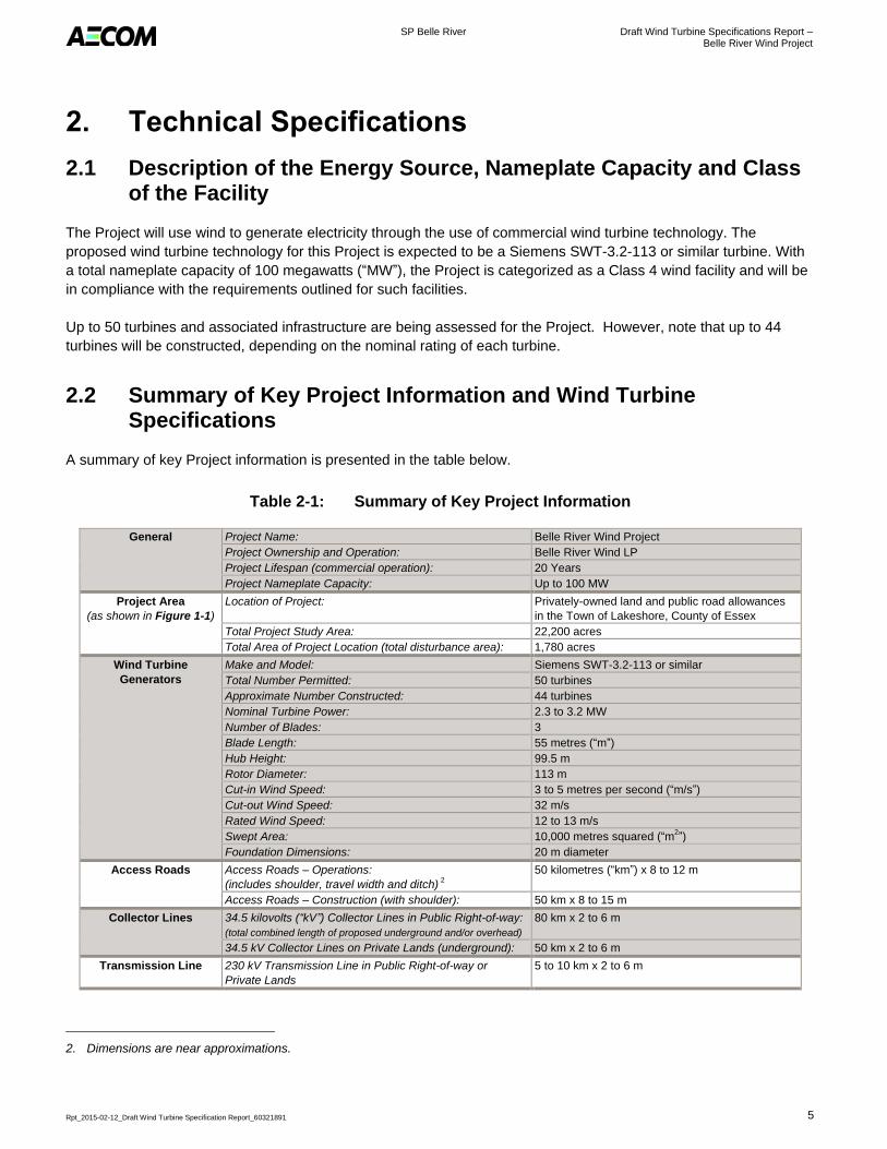
As shown on Figure 2-1, the Siemens SWT-3.2-113 wind turbine is made up of four main components: the foundation,
tower, nacelle (e.g., hub) and blades. The nacelle will be mounted on a 99.5 m high tubular steel tower which contains
an internal personnel hoists and lifts for maintenance access. A prefabricated power module is located at the bottom of
the tower and provides the platform for the power converter. The turbine pad-mounted transformer will be located
beside the tower base. The turbine will be constructed on a foundation that is approximately 20 m in diameter. The
foundation consists of poured concrete and steel rebar to provide added strength.
Figure 2-1 Basic Wind Turbine Generator Specifications
Swept Area (10,000 m2)
Blade
Blade
Length
(55 m)
Hub
Height
99.5 (m)
Tower
Foundation
Nacelle
SP Belle River Draft Wind Turbine Specifications Report – Belle River Wind Project
Rpt_2015-02-12_Draft Wind Turbine Specification Report_60321891 7
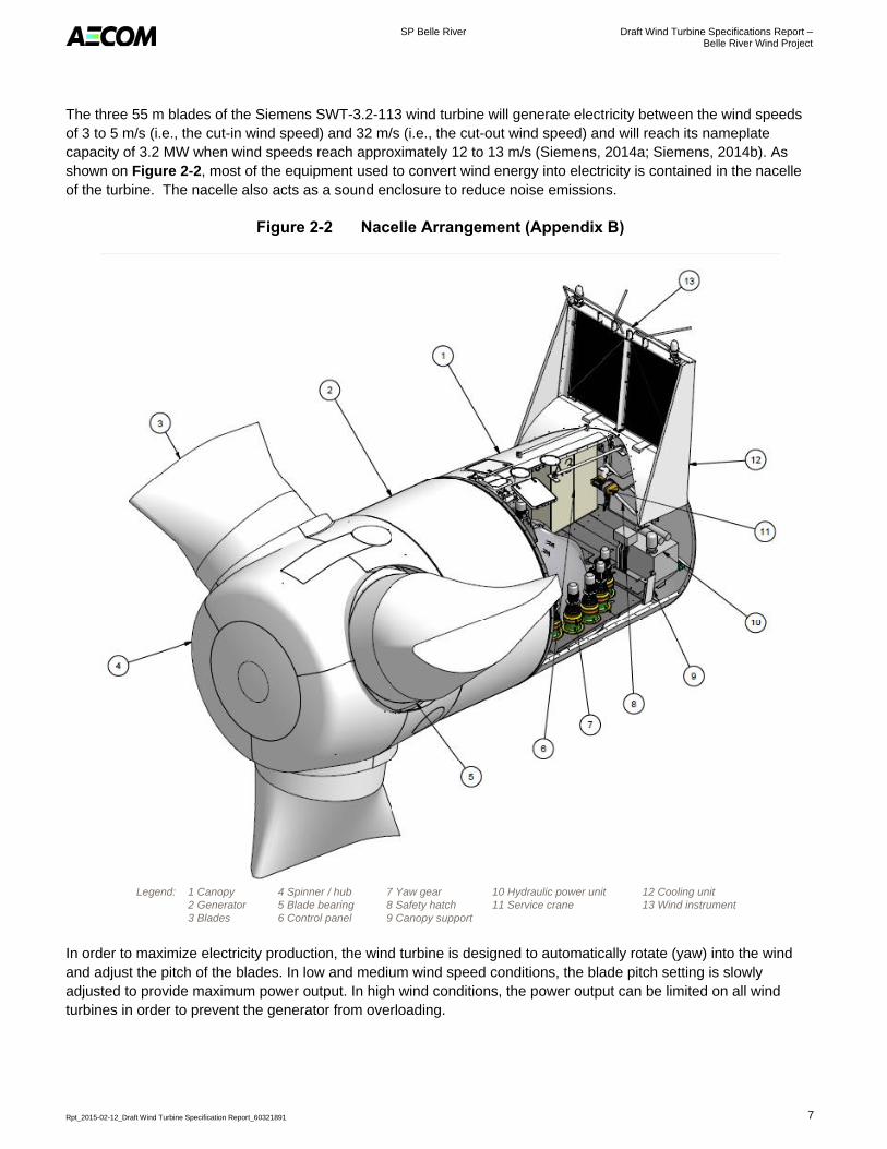
The three 55 m blades of the Siemens SWT-3.2-113 wind turbine will generate electricity between the wind speeds
of 3 to 5 m/s (i.e., the cut-in wind speed) and 32 m/s (i.e., the cut-out wind speed) and will reach its nameplate
capacity of 3.2 MW when wind speeds reach approximately 12 to 13 m/s (Siemens, 2014a; Siemens, 2014b). As
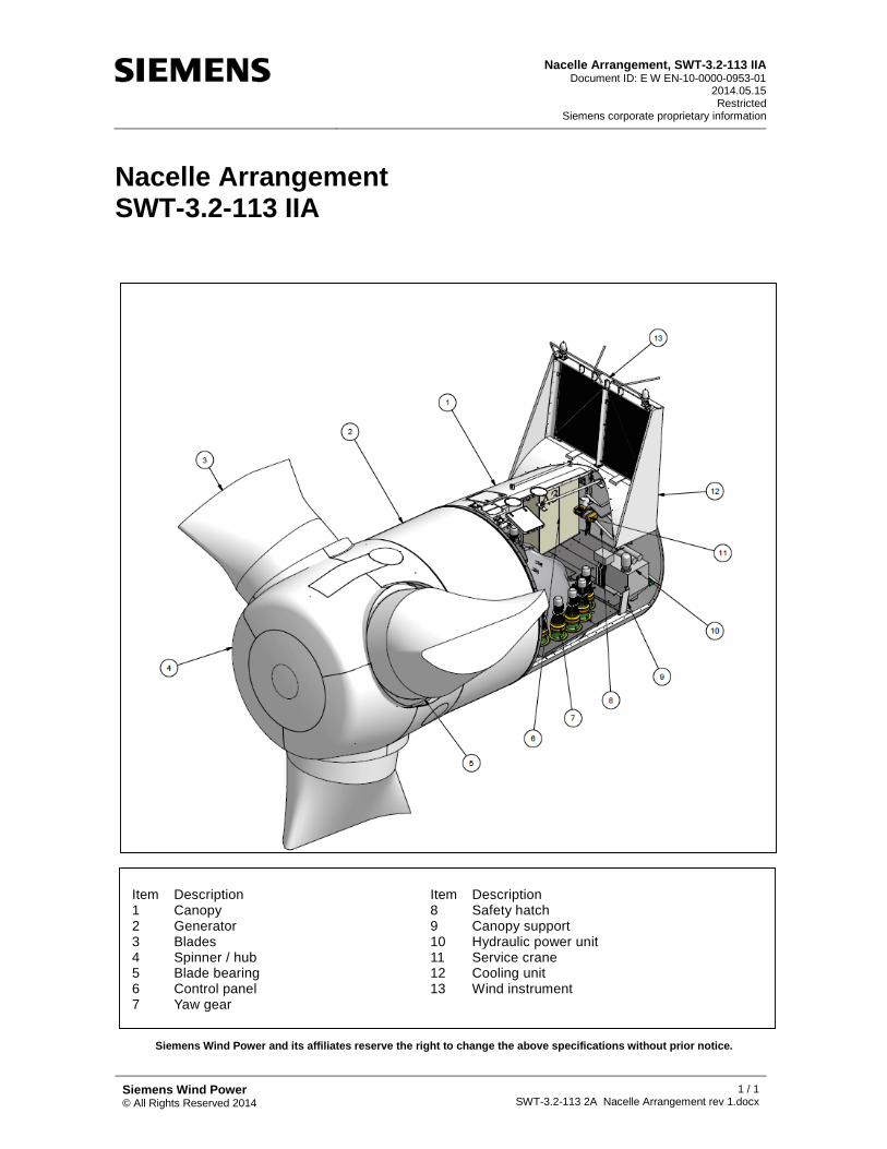
shown on Figure 2-2, most of the equipment used to convert wind energy into electricity is contained in the nacelle
of the turbine. The nacelle also acts as a sound enclosure to reduce noise emissions.
Figure 2-2 Nacelle Arrangement (Appendix B)
Legend: 1 Canopy
2 Generator
3 Blades
4 Spinner / hub
5 Blade bearing
6 Control panel
7 Yaw gear
8 Safety hatch
9 Canopy support
10 Hydraulic power unit
11 Service crane
12 Cooling unit
13 Wind instrument
In order to maximize electricity production, the wind turbine is designed to automatically rotate (yaw) into the wind
and adjust the pitch of the blades. In low and medium wind speed conditions, the blade pitch setting is slowly
adjusted to provide maximum power output. In high wind conditions, the power output can be limited on all wind
turbines in order to prevent the generator from overloading.
SP Belle River Draft Wind Turbine Specifications Report – Belle River Wind Project
Rpt_2015-02-12_Draft Wind Turbine Specification Report_60321891 8
The nacelle includes major wind turbine components such as the main shaft and bearing, gearbox, brake disc and
generator. The nacelle is climate controlled and is constructed from steel and fibreglass to protect against the
elements. The wind turbine is equipped with lightning protection to protect from the effects of direct and nearby
strikes. The overall design basis refers to the international standard IEC 61400-24 Lightning Protection Level I, and
includes (Siemens, 2010):
Protection of the blades with a dedicated protection system. A flexible integrated metal conductor
located inside the blade provides the conduction path from the receptors to the hub;
Hub casting that is used as a natural bonding conductor to the main shaft. The insulated lightning down
conductor is fed through the hub to end on the shaft structure;
Protection of the main shaft using brushes to carry the lightning current flow from the blades to the stator
and further from the nacelle bed frame to the ground;
A Nacelle canopy that provides protection for the components inside which are also grounded by natural
bonding points and metal conductors;
A pick-up system that provides ground connection from the tower to the nacelle;
Protection of the turbine controller by surge protection devices installed with mechanical overload
protection; and,
Conduction from the nacelle to the earth via the tower and heavy bounding of the foundation.
Refer to Appendix B for more information on lightning protection and other technical specifications.
SP Belle River Draft Wind Turbine Specifications Report – Belle River Wind Project
Rpt_2015-02-12_Draft Wind Turbine Specification Report_60321891 9
3. Acoustic Emissions Data
The Siemens SWT-3.2-113 wind turbine generator has a maximum broadband sound power level of 106.0 decibels
(“dBA”). Please refer to Appendix A for additional information regarding acoustic emissions, including the octave
band spectra.
SP Belle River Draft Wind Turbine Specifications Report – Belle River Wind Project
Rpt_2015-02-12_Draft Wind Turbine Specification Report_60321891 10
4. References
Ontario Ministry of the Environment and Climate Change (MOECC), 2012:
Ontario Regulation 359/09. Renewable Energy Approvals under Part V.0.1 of the Environmental Protection
Act. Consolidated May 2, 2014.
Ontario Ministry of the Environment and Climate Change (MOECC), 2013:
Technical Guide to Renewable Energy Approvals. Accessed December 2014. Available:
https://www.ontario.ca/environment-and- energy/technical-guide-renewable-energy-approvals.
Siemens, 2010:
Wind Turbines. Accessed December 2014. Available: http://www.energy.siemens.com/br/en/power-
generation/renewables/wind-power/wind-turbines/#content=Technology.
Siemens, 2014a:
Siemens D3 platform – 3.0-MW and 3.2-MW direct drive wind turbines. Reduced Complexity, Increased
Probability. Accessed January 2015. Available:
http://www.energy.siemens.com/co/pool/hq/powergeneration/renewables/windpower/platform%20brochures/
D3%20Onshore%20brochure_ENGLISH_Apr2014_WEB.pdf
Siemens, 2014b:
A clean energy solution – from cradle to grave. Onshore wind power plant employing SWT-3.2-113.
Accessed January 2015. Available: http://www.energy.siemens.com/co/pool/hq/power-
generation/renewables/wind-power/pictures/epd/epd-3-2-012015.pdf
Town of Lakeshore, 2010:
Town of Lakeshore Official Plan. Approved by the Ontario Municipal Board November 2010.
Town of Lakeshore, 2014:
Town of Lakeshore Zoning By-law. Council adopted January 2010, Modified September 2014.
RPT05_2015-02-09_Tps_60321891
Appendix A
Manufacturer Acoustic Emission Data


Siemens Wind Power A/S© All Rights Reserved 2014
p 1/1 TL20140318 / DLL20140317
SWT-3.2-113 2A, Rev.0, Max. Power 3200 kWStandard Acoustic Emission, Hub Height 99.5 m
Sound Power Levels
Wind speed [m/s] 3 4 5 6 7 8 9 10 11 12 Up to cut-out
Max. Power 3200kW 90.9 95.5 100.1 104.9 106.0 106.0 106.0 106.0 106.0 106.0 106.0Table 1: Noise emission, L WA [dB(A) re 1 pW]
Typical Sound Power Frequency Distribution
90.7 91.9 91.9 91.9 91.994.3 94.5 94.5 94.5 94.597.4 97.8 97.8 97.8 97.897.5 98.4 98.4 98.4 98.498.5 100.0 100.0 100.0 100.097.7 99.1 99.1 99.1 99.194.3 95.7 95.7 95.7 95.785.1 86.8 86.8 86.8 86.8
Table 2: Typical octave band for 6 -10 m/s, L WA [dB(A) re 1 pW]
Tonality
A measurement uncertainty range of -1.5dB(A) to +1.5dB(A) is applicable.
Restricted
Standard Acoustic Emission, SWT-3.2-113 2A, Hub Height 99.5 m
Measurement Uncertainty
The warranted sound power level is presented with reference to the code IEC 61400-11:2002 with amendment 1 dated 2006-05 based on a hub height of 99.5 m and a roughness length of 0.05 m as described in the IEC code. The sound power levels (LWA) presented are valid for the corresponding wind speeds referenced to a height of 10 m above ground level.
Typical tonal audibility for the Siemens wind turbine generators has not exceeded 3 dB(A) as determined inaccordance with IEC 61400-11:2002.
9 10
Wind Speed (m/s)
63Octave band, center frequency [Hz] 6 7
Document ID: E W ON UNA COE LS GS-10-E-00-B492-00 RJE / 2014.11.07
Typical spectra for LWA in dB(A) re 1pW for the corresponding center frequencies are tabulated below for 6 - 10m/s referenced to a height of 10.0 m above ground level.
8000
125250500100020004000
8

Siemens Wind Power A/S© All Rights Reserved 2014
p 1/1 TL20140318 / DLL20140317
SWT-3.2-113 2A, Rev.0, Max. Power 2942 kWStandard Acoustic Emission, Hub Height 99.5 m
Sound Power Levels
Wind speed [m/s] 3 4 5 6 7 8 9 10 11 12Up to cut-out
Max. Power 2942kW 90.9 95.5 100.1 104.3 105.0 105.0 105.0 105.0 105.0 105.0 105.0Table 1: Noise emission, L WA [dB(A) re 1 pW]
Typical Sound Power Frequency Distribution
90.6 91.5 91.5 91.5 91.594.1 94.0 94.0 94.0 94.096.7 96.7 96.7 96.7 96.796.8 97.3 97.3 97.3 97.397.8 98.9 98.9 98.9 98.997.0 98.0 98.0 98.0 98.093.6 94.6 94.6 94.6 94.684.4 85.7 85.7 85.7 85.7
Table 2: Typical octave band for 6 -10 m/s, L WA [dB(A) re 1 pW]
Tonality
A measurement uncertainty range of -1.5dB(A) to +1.5dB(A) is applicable.
40008000
Typical tonal audibility for the Siemens wind turbine generators has not exceeded 3 dB(A) as determined inaccordance with IEC 61400-11:2002.
Measurement Uncertainty
2000
Typical spectra for LWA in dB(A) re 1pW for the corresponding center frequencies are tabulated below for 6 - 10m/s referenced to a height of 10.0 m above ground level.
Wind Speed (m/s)
6 7 8 9 10Octave band, center frequency [Hz]631252505001000
The sound power level is presented with reference to the code IEC 61400-11 ed. 2.1 (2006-12) based on a hub height of 99.5 m and a roughness length of 0.05 m as described in the IEC code. The sound power levels (LWA) presented are valid for the corresponding wind speeds referenced to a height of 10.0 m above ground level.
Standard Acoustic Emission, SWT-3.2-113 2A, Hub Height 99.5 mDocument ID: E W TE-40-0000-B603-00
RJE / 2014.11.17Restricted

Siemens Wind Power A/S© All Rights Reserved 2014
p 1/1 TL20140318 / DLL20140317
SWT-3.2-113 2A, Rev.0, Max. Power 2772 kWStandard Acoustic Emission, Hub Height 99.5 m
Sound Power Levels
Wind speed [m/s] 3 4 5 6 7 8 9 10 11 12Up to cut-out
Max. Power 2772kW 90.9 95.5 100.1 103.7 104.0 104.0 104.0 104.0 104.0 104.0 104.0Table 1: Noise emission, L WA [dB(A) re 1 pW]
Typical Sound Power Frequency Distribution
90.5 91.3 91.3 91.3 91.393.9 93.6 93.6 93.6 93.696.1 95.6 95.6 95.6 95.696.2 96.2 96.2 96.2 96.297.2 97.8 97.8 97.8 97.896.4 96.9 96.9 96.9 96.993.0 93.5 93.5 93.5 93.583.8 84.6 84.6 84.6 84.6
Table 2: Typical octave band for 6 -10 m/s, L WA [dB(A) re 1 pW]
Tonality
A measurement uncertainty range of -1.5dB(A) to +1.5dB(A) is applicable.
The sound power level is presented with reference to the code IEC 61400-11 ed. 2.1 (2006-12) based on a hub height of 99.5 m and a roughness length of 0.05 m as described in the IEC code. The sound power levels (LWA) presented are valid for the corresponding wind speeds referenced to a height of 10.0 m above ground level.
Standard Acoustic Emission, SWT-3.2-113 2A, Hub Height 99.5 mDocument ID: E W TE-40-0000-B604-00
RJE / 2014.11.17Restricted
2000
Typical spectra for LWA in dB(A) re 1pW for the corresponding center frequencies are tabulated below for 6 - 10m/s referenced to a height of 10.0 m above ground level.
Wind Speed (m/s)
6 7 8 9 10Octave band, center frequency [Hz]631252505001000
40008000
Typical tonal audibility for the Siemens wind turbine generators has not exceeded 3 dB(A) as determined inaccordance with IEC 61400-11:2002.
Measurement Uncertainty

Siemens Wind Power A/S© All Rights Reserved 2014
p 1/1 TL20140318 / DLL20140317
SWT-3.2-113 2A, Rev.0, Max. Power 2473 kWStandard Acoustic Emission, Hub Height 99.5 m
Sound Power Levels
Wind speed [m/s] 3 4 5 6 7 8 9 10 11 12Up to cut-out
Max. Power 2473kW 90.9 95.5 99.9 102.0 102.0 102.0 102.0 102.0 102.0 102.0 102.0Table 1: Noise emission, L WA [dB(A) re 1 pW]
Typical Sound Power Frequency Distribution
90.0 90.9 90.9 90.9 90.992.6 92.9 92.9 92.9 92.993.8 93.4 93.4 93.4 93.494.2 94.0 94.0 94.0 94.095.5 95.6 95.6 95.6 95.694.7 94.7 94.7 94.7 94.791.3 91.3 91.3 91.3 91.382.3 82.4 82.4 82.4 82.4
Table 2: Typical octave band for 6 -10 m/s, L WA [dB(A) re 1 pW]
Tonality
A measurement uncertainty range of -1.5dB(A) to +1.5dB(A) is applicable.
40008000
Typical tonal audibility for the Siemens wind turbine generators has not exceeded 3 dB(A) as determined inaccordance with IEC 61400-11:2002.
Measurement Uncertainty
2000
Typical spectra for LWA in dB(A) re 1pW for the corresponding center frequencies are tabulated below for 6 - 10m/s referenced to a height of 10.0 m above ground level.
Wind Speed (m/s)
6 7 8 9 10Octave band, center frequency [Hz]631252505001000
The sound power level is presented with reference to the code IEC 61400-11 ed. 2.1 (2006-12) based on a hub height of 99.5 m and a roughness length of 0.05 m as described in the IEC code. The sound power levels (LWA) presented are valid for the corresponding wind speeds referenced to a height of 10.0 m above ground level.
Standard Acoustic Emission, SWT-3.2-113 2A, Hub Height 99.5 mDocument ID: E W TE-40-0000-B605-00
RJE / 2014.11.17Restricted
Siemens Wind Power A/S© All Rights Reserved 2014
p 1/1 TL20140318 / DLL20140317
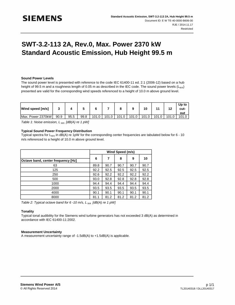
SWT-3.2-113 2A, Rev.0, Max. Power 2370 kWStandard Acoustic Emission, Hub Height 99.5 m
Sound Power Levels
Wind speed [m/s] 3 4 5 6 7 8 9 10 11 12Up to cut-out
Max. Power 2370kW 90.9 95.5 99.8 101.0 101.0 101.0 101.0 101.0 101.0 101.0 101.0Table 1: Noise emission, L WA [dB(A) re 1 pW]
Typical Sound Power Frequency Distribution
89.8 90.7 90.7 90.7 90.792.2 92.5 92.5 92.5 92.592.6 92.2 92.2 92.2 92.293.0 92.8 92.8 92.8 92.894.4 94.4 94.4 94.4 94.493.5 93.5 93.5 93.5 93.590.1 90.1 90.1 90.1 90.181.1 81.2 81.2 81.2 81.2
Table 2: Typical octave band for 6 -10 m/s, L WA [dB(A) re 1 pW]
Tonality
A measurement uncertainty range of -1.5dB(A) to +1.5dB(A) is applicable.
The sound power level is presented with reference to the code IEC 61400-11 ed. 2.1 (2006-12) based on a hub height of 99.5 m and a roughness length of 0.05 m as described in the IEC code. The sound power levels (LWA) presented are valid for the corresponding wind speeds referenced to a height of 10.0 m above ground level.
Standard Acoustic Emission, SWT-3.2-113 2A, Hub Height 99.5 mDocument ID: E W TE-40-0000-B606-00
RJE / 2014.11.17Restricted
2000
Typical spectra for LWA in dB(A) re 1pW for the corresponding center frequencies are tabulated below for 6 - 10m/s referenced to a height of 10.0 m above ground level.
Wind Speed (m/s)
6 7 8 9 10Octave band, center frequency [Hz]631252505001000
40008000
Typical tonal audibility for the Siemens wind turbine generators has not exceeded 3 dB(A) as determined inaccordance with IEC 61400-11:2002.
Measurement Uncertainty

Siemens Wind Power A/S© All Rights Reserved 2014
p 1/1 TL20140318 / DLL20140317
SWT-3.2-113 2A, Rev.0, Max. Power 2257 kWStandard Acoustic Emission, Hub Height 99.5 m
Sound Power Levels
Wind speed [m/s] 3 4 5 6 7 8 9 10 11 12Up to cut-out
Max. Power 2257kW 90.9 95.5 99.6 100.0 100.0 100.0 100.0 100.0 100.0 100.0 100.0Table 1: Noise emission, L WA [dB(A) re 1 pW]
Typical Sound Power Frequency Distribution
89.6 90.5 90.5 90.5 90.591.4 92.1 92.1 92.1 92.191.2 91.0 91.0 91.0 91.091.8 91.6 91.6 91.6 91.693.4 93.2 93.2 93.2 93.292.5 92.3 92.3 92.3 92.389.1 88.9 88.9 88.9 88.980.2 80.0 80.0 80.0 80.0
Table 2: Typical octave band for 6 -10 m/s, L WA [dB(A) re 1 pW]
Tonality
A measurement uncertainty range of -1.5dB(A) to +1.5dB(A) is applicable.
40008000
Typical tonal audibility for the Siemens wind turbine generators has not exceeded 3 dB(A) as determined inaccordance with IEC 61400-11:2002.
Measurement Uncertainty
2000
Typical spectra for LWA in dB(A) re 1pW for the corresponding center frequencies are tabulated below for 6 - 10m/s referenced to a height of 10.0 m above ground level.
Wind Speed (m/s)
6 7 8 9 10Octave band, center frequency [Hz]631252505001000
The sound power level is presented with reference to the code IEC 61400-11 ed. 2.1 (2006-12) based on a hub height of 99.5 m and a roughness length of 0.05 m as described in the IEC code. The sound power levels (LWA) presented are valid for the corresponding wind speeds referenced to a height of 10.0 m above ground level.
Standard Acoustic Emission, SWT-3.2-113 2A, Hub Height 99.5 mDocument ID: E W TE-40-0000-B607-00
RJE / 2014.11.17Restricted
RPT05_2015-02-09_Tps_60321891
Appendix B
Additional Manufacturer Technical Data
Lightning Protection and Earthing, Siemens D3Document ID: E W EN-10-0000-0837-02
2014.08.08Restricted
Siemens corporate proprietary information
Siemens Wind Power © All Rights Reserved 2014
1 / 4Siemens D3, Lightning Protection and Earthing rev 2.doc
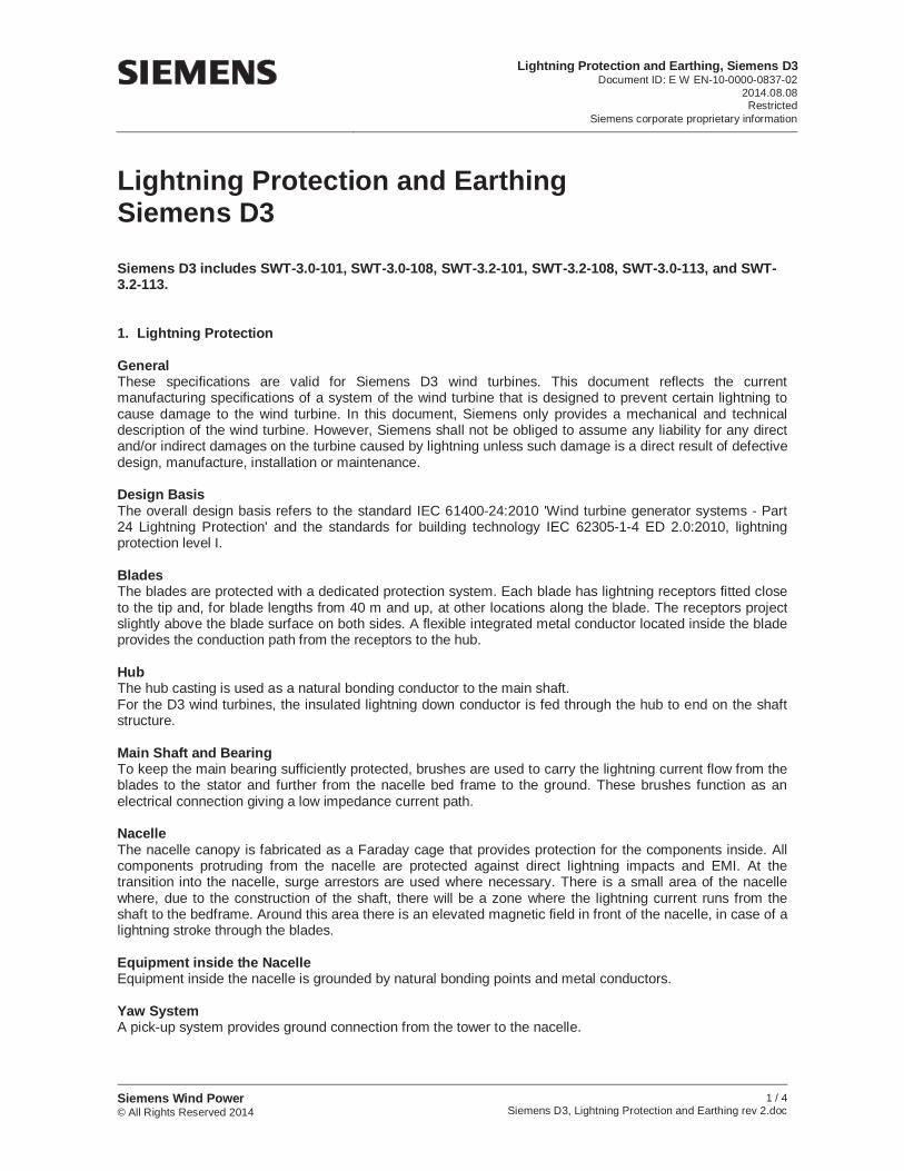
Lightning Protection and Earthing Siemens D3
Siemens D3 includes SWT-3.0-101, SWT-3.0-108, SWT-3.2-101, SWT-3.2-108, SWT-3.0-113, and SWT-3.2-113.
1. Lightning Protection
General These specifications are valid for Siemens D3 wind turbines. This document reflects the current manufacturing specifications of a system of the wind turbine that is designed to prevent certain lightning to cause damage to the wind turbine. In this document, Siemens only provides a mechanical and technical description of the wind turbine. However, Siemens shall not be obliged to assume any liability for any direct and/or indirect damages on the turbine caused by lightning unless such damage is a direct result of defective design, manufacture, installation or maintenance.
Design BasisThe overall design basis refers to the standard IEC 61400-24:2010 'Wind turbine generator systems - Part 24 Lightning Protection' and the standards for building technology IEC 62305-1-4 ED 2.0:2010, lightning protection level I.
Blades The blades are protected with a dedicated protection system. Each blade has lightning receptors fitted close to the tip and, for blade lengths from 40 m and up, at other locations along the blade. The receptors project slightly above the blade surface on both sides. A flexible integrated metal conductor located inside the blade provides the conduction path from the receptors to the hub.
Hub The hub casting is used as a natural bonding conductor to the main shaft. For the D3 wind turbines, the insulated lightning down conductor is fed through the hub to end on the shaft structure.
Main Shaft and Bearing To keep the main bearing sufficiently protected, brushes are used to carry the lightning current flow from the blades to the stator and further from the nacelle bed frame to the ground. These brushes function as an electrical connection giving a low impedance current path.
Nacelle The nacelle canopy is fabricated as a Faraday cage that provides protection for the components inside. All components protruding from the nacelle are protected against direct lightning impacts and EMI. At the transition into the nacelle, surge arrestors are used where necessary. There is a small area of the nacelle where, due to the construction of the shaft, there will be a zone where the lightning current runs from the shaft to the bedframe. Around this area there is an elevated magnetic field in front of the nacelle, in case of a lightning stroke through the blades.
Equipment inside the Nacelle Equipment inside the nacelle is grounded by natural bonding points and metal conductors.
Yaw System A pick-up system provides ground connection from the tower to the nacelle.
Lightning Protection and Earthing, Siemens D3Document ID: E W EN-10-0000-0837-02
2014.08.08Restricted
Siemens corporate proprietary information
Siemens Wind Power © All Rights Reserved 2014
2 / 4Siemens D3, Lightning Protection and Earthing rev 2.doc
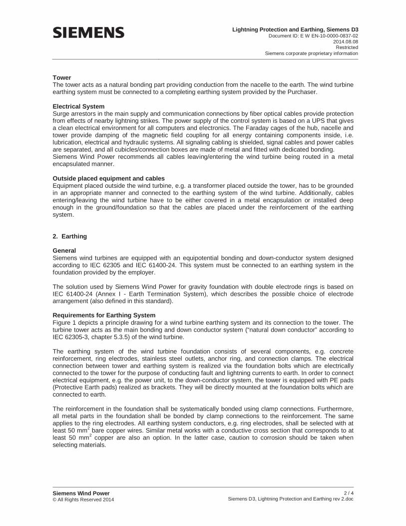
Tower The tower acts as a natural bonding part providing conduction from the nacelle to the earth. The wind turbine earthing system must be connected to a completing earthing system provided by the Purchaser.
Electrical System Surge arrestors in the main supply and communication connections by fiber optical cables provide protection from effects of nearby lightning strikes. The power supply of the control system is based on a UPS that gives a clean electrical environment for all computers and electronics. The Faraday cages of the hub, nacelle and tower provide damping of the magnetic field coupling for all energy containing components inside, i.e. lubrication, electrical and hydraulic systems. All signaling cabling is shielded, signal cables and power cables are separated, and all cubicles/connection boxes are made of metal and fitted with dedicated bonding. Siemens Wind Power recommends all cables leaving/entering the wind turbine being routed in a metal encapsulated manner.
Outside placed equipment and cables Equipment placed outside the wind turbine, e.g. a transformer placed outside the tower, has to be grounded in an appropriate manner and connected to the earthing system of the wind turbine. Additionally, cables entering/leaving the wind turbine have to be either covered in a metal encapsulation or installed deep enough in the ground/foundation so that the cables are placed under the reinforcement of the earthing system.
2. Earthing
General Siemens wind turbines are equipped with an equipotential bonding and down-conductor system designed according to IEC 62305 and IEC 61400-24. This system must be connected to an earthing system in the foundation provided by the employer.
The solution used by Siemens Wind Power for gravity foundation with double electrode rings is based on IEC 61400-24 (Annex I - Earth Termination System), which describes the possible choice of electrode arrangement (also defined in this standard).
Requirements for Earthing System Figure 1 depicts a principle drawing for a wind turbine earthing system and its connection to the tower. The turbine tower acts as the main bonding and down conductor system (“natural down conductor” according to IEC 62305-3, chapter 5.3.5) of the wind turbine.
The earthing system of the wind turbine foundation consists of several components, e.g. concrete reinforcement, ring electrodes, stainless steel outlets, anchor ring, and connection clamps. The electrical connection between tower and earthing system is realized via the foundation bolts which are electrically connected to the tower for the purpose of conducting fault and lightning currents to earth. In order to connect electrical equipment, e.g. the power unit, to the down-conductor system, the tower is equipped with PE pads (Protective Earth pads) realized as brackets. They will be directly mounted at the foundation bolts which are connected to earth.
The reinforcement in the foundation shall be systematically bonded using clamp connections. Furthermore, all metal parts in the foundation shall be bonded by clamp connections to the reinforcement. The same applies to the ring electrodes. All earthing system conductors, e.g. ring electrodes, shall be selected with at least 50 mm2 bare copper wires. Similar metal works with a conductive cross section that corresponds to at least 50 mm2 copper are also an option. In the latter case, caution to corrosion should be taken when selecting materials.
Lightning Protection and Earthing, Siemens D3Document ID: E W EN-10-0000-0837-02
2014.08.08Restricted
Siemens corporate proprietary information
Siemens Wind Power © All Rights Reserved 2014
3 / 4Siemens D3, Lightning Protection and Earthing rev 2.doc
PE conductor
Inner Ring Electrode
Outher Ring Electrode
Additional earthing system outside the foundation if necessary
Reinforcement with systematic bonding and interconnection between anchorring
reinforcement and bolts
Turb
ine
Cont
rolle
r
HV earthHV earth
Pri Sec L1 L2 L3 N
Transformer /Y
Stainless steel earth connection points
Anchor Ring
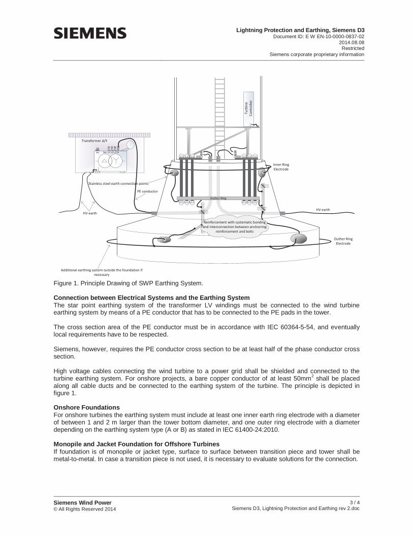
Figure 1. Principle Drawing of SWP Earthing System.
Connection between Electrical Systems and the Earthing System The star point earthing system of the transformer LV windings must be connected to the wind turbine earthing system by means of a PE conductor that has to be connected to the PE pads in the tower.
The cross section area of the PE conductor must be in accordance with IEC 60364-5-54, and eventually local requirements have to be respected.
Siemens, however, requires the PE conductor cross section to be at least half of the phase conductor cross section.
High voltage cables connecting the wind turbine to a power grid shall be shielded and connected to the turbine earthing system. For onshore projects, a bare copper conductor of at least 50mm2 shall be placed along all cable ducts and be connected to the earthing system of the turbine. The principle is depicted in figure 1.
Onshore Foundations For onshore turbines the earthing system must include at least one inner earth ring electrode with a diameter of between 1 and 2 m larger than the tower bottom diameter, and one outer ring electrode with a diameter depending on the earthing system type (A or B) as stated in IEC 61400-24:2010.
Monopile and Jacket Foundation for Offshore TurbinesIf foundation is of monopile or jacket type, surface to surface between transition piece and tower shall be metal-to-metal. In case a transition piece is not used, it is necessary to evaluate solutions for the connection.
Lightning Protection and Earthing, Siemens D3Document ID: E W EN-10-0000-0837-02
2014.08.08Restricted
Siemens corporate proprietary information
Siemens Wind Power © All Rights Reserved 2014
4 / 4Siemens D3, Lightning Protection and Earthing rev 2.doc
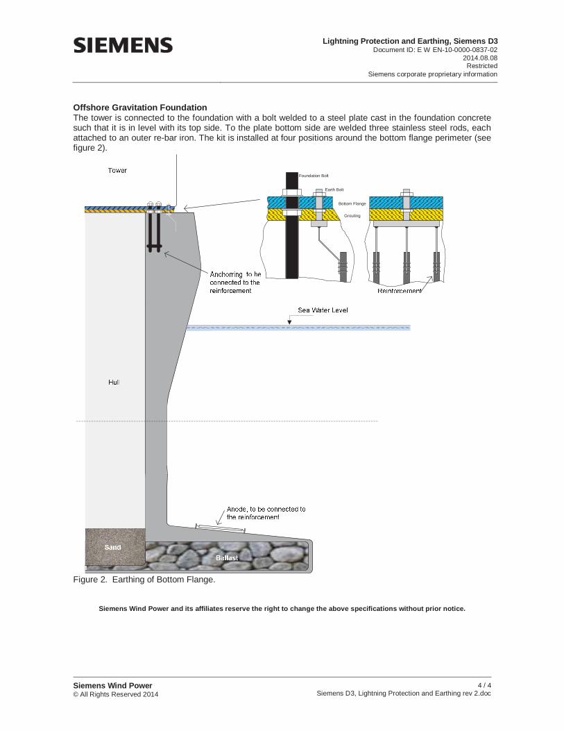
Offshore Gravitation Foundation The tower is connected to the foundation with a bolt welded to a steel plate cast in the foundation concrete such that it is in level with its top side. To the plate bottom side are welded three stainless steel rods, each attached to an outer re-bar iron. The kit is installed at four positions around the bottom flange perimeter (see figure 2).
Foundation Bolt
Earth Bolt
Grouting
Bottom Flange
Figure 2. Earthing of Bottom Flange.
Siemens Wind Power and its affiliates reserve the right to change the above specifications without prior notice.
Nacelle Arrangement, SWT-3.2-113 IIADocument ID: E W EN-10-0000-0953-01
2014.05.15Restricted
Siemens corporate proprietary information
Siemens Wind Power © All Rights Reserved 2014
1 / 1SWT-3.2-113 2A Nacelle Arrangement rev 1.docx
Nacelle ArrangementSWT-3.2-113 IIA
Siemens Wind Power and its affiliates reserve the right to change the above specifications without prior notice.
Item Description Item Description1 Canopy 8 Safety hatch2 Generator 9 Canopy support3 Blades 10 Hydraulic power unit4 Spinner / hub 11 Service crane5 Blade bearing 12 Cooling unit6 Control panel 13 Wind instrument7 Yaw gear
Cold Weather Version Specifications, SWT-3.2-113 IIADocument ID: E W EN-10-0000-1028-00
2014.05.19Restricted
Siemens corporate proprietary information
Siemens Wind Power © All Rights Reserved 2014
1 / 2SWT-3.2-113 2A Cold Climate Version Specifications rev 0.docx
Cold Climate Version SpecificationsSWT-3.2-113 IIA
GeneralThis specification describes the special features of Siemens Wind Power’s SWT-3.2-113 IIA wind turbine suited for cold climate operation and standstill. Features not mentioned are identical with the standard version of the SWT-3.2-113 IIA. It should be noted that the final specification of the cold climate version should be checked up against site-specific conditions and requirements for approvals, etc.
Temperature RangesThe standard version of the SWT-3.2-113 IIA turbine is designed to the following temperature intervals:Stand still: According to Design Climatic Conditions documentOperation: According to Design Climatic Conditions document
The cold climate version will extend the low limit temperatures to:Stand-still: -45 °COperation: -30 °C
Operation pre-requisitesFor operation down to -30 °C it is assumed that the turbine is continuously grid connected. This includesperiods with low wind in order to maintain the temperature of controller cabinets and other specific components when no or limited heat is generated by operation.
Stand-still pre-requisitesFor stand-still down to -45 °C it is assumed that the turbine is continuously grid connected or backed up by external power supply.
Special Cold Climate Material Features & ComponentsStandard turbine components are applied in the cold climate version with the exception of these components:
Low temperature rated hydraulic oilHydraulic components rated for low temperature grade oilLow temperature rated generator- and converter cooling liquidElectric heaters in tower baseElectric heaters in nacelleCold climate version of turbine controller softwareCold-resistant steel is chosen for the turbine tower where needed, according to EN 1993-1-10:2005.
Wind instrumentsA wind sensor with built-in heating element is included as standard in all SWT-3.2-113 IIA wind turbines.
Ice detectionIce detection can be included in the cold climate version as an option. Detection of ice loads which jeopardize turbine integrity during operation is included as standard.Icing issues are described in a separate document.
Blade de-icingBlade de-icing can be included in the cold climate version as an option.
Operational strategy
Cold Weather Version Specifications, SWT-3.2-113 IIADocument ID: E W EN-10-0000-1028-00
2014.05.19Restricted
Siemens corporate proprietary information
Siemens Wind Power © All Rights Reserved 2014
2 / 2SWT-3.2-113 2A Cold Climate Version Specifications rev 0.docx
The turbine is fully operational down to -30 °C. Depending on history and wind conditions the turbine will stop at temperatures lower than -30 °C. The point of restart after a period with ambient temperatures below -30 °C depends on how low the ambient temperature has been, for how long, wind speed, operational history as well as the rate of temperature increase.
The turbine components are generally designed intrinsically for operation down to -30 °C. Some components however, are rated for a higher temperature and in order to meet these design limits, electric heaters are installed in the turbine. The thermostatically controlled heaters are installed in electrical panels, nacelle, and tower base.In most wind scenarios, the power consumption in auxiliary components and losses in generator circuit will maintain components temperatures within design limits without the need for electric heater operation.
Standstill strategyThe turbine structural components generally are designed intrinsically for standstill down to -45 °C. Some components however, are rated for a higher temperature and in order to meet these design limits, electric heaters are installed in the turbine. The thermostatically controlled heaters are installed in electrical panels, generator, nacelle and tower base. The heaters are dimensioned to maintain temperature in components and relevant environment above thestandstill design rating.
Additional Power ConsumptionDue to thermostatically controlled heating elements, additional power consumption from the grid must be expected during cold weather situations.
Siemens Wind Power and its affiliates reserve the right to change the above specifications without prior notice.
Technical Description, SWT-3.2-113 IEC IIADocument ID: WP TE-10-0000-0949-04
2014.12.09Restricted
Siemens corporate proprietary information
Siemens Wind Power © All Rights Reserved 2014
1 / 3 SWT-3.2-113 IEC 2A Technical Description rev 4.docx
Technical Description SWT-3.2-113 IEC IIA
Rotor-NacelleThe rotor is a three-bladed cantilevered construction, mounted upwind of the tower. The power output is controlled by pitch regulation. The rotor speed is variable and is designed to maximize the aerodynamic efficiency while maintaining loads and noise level.
The nacelle has been designed for safe access to all service points during scheduled service. In addition the nacelle has, when it appears with machinery guards fully assembled, been designed for safe presence of service technicians in the nacelle during Service Test Runs with the wind turbine in full operation. This allows a high quality service of the wind turbine and provides optimum troubleshooting conditions.
Blades The blades are made of fiberglass-reinforced epoxy in Siemens’ proprietary IntegralBlade® manufacturing process. In this process the blades are cast in one piece to eliminate weaker areas at glue joints. The blades are mounted on pitch bearings and can be feathered 80 degrees for shutdown purposes. Each blade has its own independent pitching mechanism capable of feathering the blade under any operating condition. The blade pitch arrangement allows for optimization of the power output throughout the operating range, and the blades are feathered during standstill to minimize wind loads.
Rotor Hub The rotor hub is cast in nodular cast iron and is fitted to the generator rotor with a flange connection. The hub is sufficiently large to provide a comfortable working environment for service technicians during maintenance of blade roots and pitch bearings from inside the structure.
Main Shaft A cast, hollow and fixed main shaft ensures a comfortable internal access from the canopy to the hub.
Main Bearing The rotating parts of the wind turbine are supported by a single, double-tapered roller bearing. The bearing is grease lubricated.
Generator The generator is a fully enclosed synchronous generator with permanent magnet excitation. The generator rotor construction and stator windings are designed for high efficiency at partial loads. The generator is positioned between the tower and the hub producing a comfortably lean arrangement of the internals in the nacelle.
Mechanical Brake The mechanical brake is fitted to the non-drive end of the generator rotor and has three hydraulic calipers.
Yaw System A cast bed frame connects the shaft to the tower. The yaw bearing is an externally geared ring with a friction bearing. A series of electric planetary gear motors drives the yawing.
Canopy The weather screen and housing around the machinery in the nacelle is made of fiberglass-reinforced laminated panels with multiple fire-protecting properties. The design implies fully integrated lightning and EMC protection.
TowerThe wind turbine is mounted on a tapered tubular steel tower. The tower has internal ascent and direct access to the yaw system and nacelle. It is equipped with platforms and internal electric lighting.
Technical Description, SWT-3.2-113 IEC IIADocument ID: WP TE-10-0000-0949-04
2014.12.09Restricted
Siemens corporate proprietary information
Siemens Wind Power © All Rights Reserved 2014
2 / 3 SWT-3.2-113 IEC 2A Technical Description rev 4.docx
ControllerThe wind turbine controller is a microprocessor-based industrial controller. The controller is complete with switchgear and protection devices. It is self-diagnosing and an industrial touch panel and display may be used for easy readout of status and for adjustment of settings.
Converter The NetConverter® power conversion system allows generator operation at variable speed, frequency and voltage while supplying power at constant frequency and voltage to the MV transformer. The power conversion system is water cooled and has a modular arrangement for easy maintenance.
SCADA The wind turbine provides connection to the Siemens WebWPS SCADA system. This system offers remote control and a variety of status views and useful reports from a standard internet web browser. The status views present information including electrical and mechanical data, operation and fault status, meteorological data and grid station data.
Turbine Condition Monitoring In addition to the Siemens WebWPS SCADA system, the wind turbine is equipped with the unique Siemens condition monitoring setup. This system monitors the vibration level of the main components and compares the actual vibration spectra with a set of established reference spectra. Result review, detailed analysis and reprogramming can all be carried out using a standard web browser.
Operation SystemsThe wind turbine operates automatically. It is self-starting when the wind speed reaches the cut-in wind speed. The output increases according to the power curve until the wind speed reaches nominal wind speed. The wind turbine continues to produce power until, the wind turbines reaches the cut-out wind speed.
The wind turbine is equipped, as an embedded solution in the design, with the High Wind Ride Through (HWRT®) functionality, which provides improved grid stability by reducing the risk of simultaneous power cut outs during higher wind conditions.
During high wind conditions, a wind turbine would typically shut down and not cut in until the wind speed is below a certain threshold. HWRT® can extend power production in high wind conditions by controlling power and speed, as wind speed and wind variations increase respectively. This is done without impacting the structural integrity of the wind turbine.
The HWRT® functionality has two modes which operate independently, i.e. reduction of rotational speed and reduction of power production. The first mode, reduction of rotational speed, reduces the wind turbine’s speed as a function of the absolute value of the rotor acceleration. This gives a reduction of speed and power depending on the wind turbulence. The second mode, reduction of power production, reduces the active power as a function of the pitch angle. An illustration of the HWRT® principle together with the standard operation in high wind is shown in figure 1.
Technical Description, SWT-3.2-113 IEC IIADocument ID: WP TE-10-0000-0949-04
2014.12.09Restricted
Siemens corporate proprietary information
Siemens Wind Power © All Rights Reserved 2014
3 / 3 SWT-3.2-113 IEC 2A Technical Description rev 4.docx
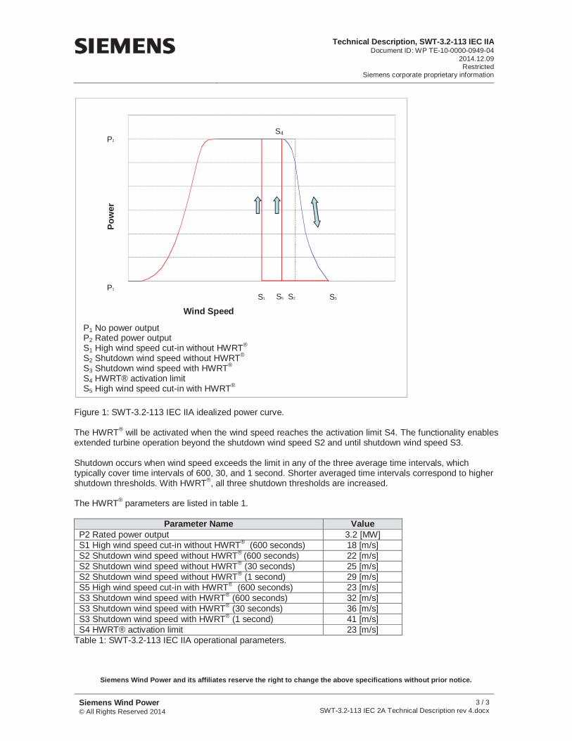
Figure 1: SWT-3.2-113 IEC IIA idealized power curve.
The HWRT® will be activated when the wind speed reaches the activation limit S4. The functionality enables extended turbine operation beyond the shutdown wind speed S2 and until shutdown wind speed S3.
Shutdown occurs when wind speed exceeds the limit in any of the three average time intervals, which typically cover time intervals of 600, 30, and 1 second. Shorter averaged time intervals correspond to higher shutdown thresholds. With HWRT®, all three shutdown thresholds are increased.
The HWRT® parameters are listed in table 1.
Parameter Name ValueP2 Rated power output 3.2 [MW] S1 High wind speed cut-in without HWRT® (600 seconds) 18 [m/s] S2 Shutdown wind speed without HWRT® (600 seconds) 22 [m/s] S2 Shutdown wind speed without HWRT® (30 seconds) 25 [m/s] S2 Shutdown wind speed without HWRT® (1 second) 29 [m/s] S5 High wind speed cut-in with HWRT® (600 seconds) 23 [m/s] S3 Shutdown wind speed with HWRT® (600 seconds) 32 [m/s] S3 Shutdown wind speed with HWRT® (30 seconds) 36 [m/s] S3 Shutdown wind speed with HWRT® (1 second) 41 [m/s] S4 HWRT® activation limit 23 [m/s]
Table 1: SWT-3.2-113 IEC IIA operational parameters.
Siemens Wind Power and its affiliates reserve the right to change the above specifications without prior notice.
P1 No power output P2 Rated power output S1 High wind speed cut-in without HWRT®
S2 Shutdown wind speed without HWRT®
S3 Shutdown wind speed with HWRT®
S4 HWRT® activation limit S5 High wind speed cut-in with HWRT®
Pow
er
S5 S2S1
P1
P2
S3
S4
Wind Speed
Technical Specifications, SWT-3.2-113 IEC IIADocument ID: WP TE-10-0000-0950-04
2014.12.09Restricted
Siemens corporate proprietary information
Siemens Wind Power © All Rights Reserved 2014
1 / 1 SWT-3.2-113 IEC 2A Technical Specifications rev 4.docx
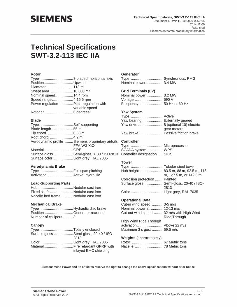
Technical Specifications SWT-3.2-113 IEC IIA
RotorType ................................Position............................Diameter ..........................Swept area .....................Nominal speed .................Speed range ....................Power regulation .............
Rotor tilt ..........................
Blade Type ...............................Blade length ....................Tip chord ........................Root chord ......................Aerodynamic profile ........
Material ...........................Surface gloss ..................Surface color ..................
Aerodynamic Brake Type ...............................Activation ........................
Load-Supporting Parts Hub .................................Fixed shaft ......................Nacelle bed frame ............
Mechanical Brake Type ...............................Position ...........................Number of callipers .........
Canopy Type ...............................Surface gloss ..................
Color ...............................Material............................
3-bladed, horizontal axis Upwind 113 m 10,000 m² 14.4 rpm 4-16.5 rpm Pitch regulation with variable speed 6 degrees
Self-supporting 55 m 0.63 m 4.2 m Siemens proprietary airfoils, FFA-W3-XXX GRE Semi-gloss, < 30 / ISO2813Light grey, RAL 7035
Full span pitching Active, hydraulic
Nodular cast iron Nodular cast iron Nodular cast iron
Hydraulic disc brake Generator rear end 3
Totally enclosed Semi-gloss, 20-40 / ISO-2813Light grey, RAL 7035 Fire retardant GFRP with inlayed EMC shielding
GeneratorType ...............................Nominal power ................
Grid Terminals (LV) Nominal power ................Voltage ...........................Frequency ......................
Yaw System Type ...............................Yaw bearing ....................Yaw drive ........................
Yaw brake ......................
Controller Type ...............................SCADA system ...............Controller designation .....
Tower Type ...............................Hub height ......................
Corrosion protection ........Surface gloss ..................
Color ...............................
Operational Data Cut-in wind speed ...........Nominal power at ............Cut-out wind speed .........
High Wind Ride Through activation .........................Maximum 3 s gust ...........
Weights (approximately)Rotor ..............................Nacelle ...........................
Synchronous, PMG 3.4 MW
3.2 MW 690 V 50 Hz or 60 Hz
Active Externally geared 8 (optional 10) electric gear motors Passive friction brake
Microprocessor WPS SICS
Tubular steel tower 83.5 m, 88 m, 92.5 m, 115 m, 127.5 m, or 142.5 m Painted Semi-gloss, 20-40 / ISO-2813Light grey, RAL 7035
3-5 m/s 12-13 m/s 32 m/s with High Wind Ride Through
Above 22 m/s 59.5 m/s
67 Metric tons 78 Metric tons
Siemens Wind Power and its affiliates reserve the right to change the above specifications without prior notice.