Embed Size (px)
Citation preview

SP-300 Installation and
Configuration Manual

i
EC declaration of conformity


iii
Equipment installation
WARNING !: The instrument is safely grounded to the Earth through the protective conductor of the AC power cable.
Use only the power cord supplied with the instrument and designed for the good current rating (10 Amax) and be sure to connect it to a power source provided with protective earth contact.
Any interruption of the protective earth (grounding) conductor outside the instrument could result in personal injury.
General description
The equipment described in this manual has been designed in accordance with EN61010 and EN61326 and has been supplied in a safe condition. The equipment is intended for electrical measurements only. It should be used for no other purpose.
Intended use of the equipment
The SP-300 is an electrical laboratory equipment intended for professional and intended to be used in laboratories, commercial and light-industrial environments. Instrumentation and accessories shall not be connected to humans.
Instructions for use
To avoid injury to an operator the safety precautions given below, and throughout the manual, must be strictly adhered to, whenever the equipment is operated. Only advanced user can use the instrument. Bio-Logic SAS accepts no responsibility for accidents or damage resulting from any failure to comply with these precautions.
GROUNDING
To minimize the hazard of electrical shock, it is essential that the equipment be connected to a protective ground through the AC supply cable. The continuity of the ground connection should be checked periodically.
ATMOSPHERE
You must never operate the equipment in corrosive atmosphere. Moreover if the equipment is exposed to a highly corrosive atmosphere, the components and the metallic parts can be corroded and can involve malfunction of the instrument. The user must also be careful that the ventilation grids are not obstructed on the right and left sides and under the chassis. An external cleaning can be made with a vacuum cleaner if necessary. Please consult our specialists to discuss the best location in your lab for the instrument (avoid glove box, hood, chemicals...).

iv
AVOID UNSAFE EQUIPMENT
The equipment may be unsafe if any of the following statements apply: - Equipment shows visible damage, - Equipment has failed to perform an intended operation, - Equipment has been stored in unfavourable conditions, - Equipment has been subjected to physical stress.
In case of doubt as to the serviceability of the equipment, don’t use it. Get it properly checked out by a qualified service technician.
LIVE CONDUCTORS
When the equipment is connected to its measurement inputs or supply, the opening of covers or removal of parts could expose live conductors. Only qualified personnel, who should refer to the relevant maintenance documentation, must do adjustments, maintenance or repair
EQUIPMENT MODIFICATION
To avoid introducing safety hazards, never install non-standard parts in the equipment, or make any unauthorised modification. To maintain safety, always return the equipment to Bio-Logic SAS for service and repair.
GUARANTEE
Guarantee and liability claims in the event of injury or material damage are excluded when they are the result of one of the following.
- Improper use of the device, - Improper installation, operation or maintenance of the device, - Operating the device when the safety and protective devices are defective
and/or inoperable, - Non-observance of the instructions in the manual with regard to transport,
storage, installation, - Unauthorized structural alterations to the device, - Unauthorized modifications to the system settings, - Inadequate monitoring of device components subject to wear, - Improperly executed and unauthorized repairs, - Unauthorized opening of the device or its components, - Catastrophic events due to the effect of foreign bodies.

v
IN CASE OF PROBLEM
Information on your hardware and software configuration is necessary to analyze and finally solve the problem you encounter.
If you have any questions or if any problem occurs that is not mentioned in this document, please contact your local retailer. The highly qualified staff will be glad to help you. Please keep information on the following at hand:
- Description of the error (the error message, mpr file, picture of setting or any other useful information) and of the context in which the error occurred. Try to remember all steps you had performed immediately before the error occurred. The more information on the actual situation you can provide, the easier it is to track the problem.
- The serial number of the device located on the rear panel device.
- The software and hardware version you are currently using. On the Help menu, click About. The displayed dialog box shows the version numbers.
- The operating system on the connected computer. - The connection mode (Ethernet, LAN, USB) between computer and
instrument.
Model: SP-300 s/n°: 0001 Power: 110-240Vac 50/60Hz Fuses: 4AF Pmax: 350W

vi
General safety considerations
Class I
The instrument is safety grounded to the Earth through the protective conductor of the AC power cable.
Use only the power cord supplied with the instrument and designed for the good current rating (10 Amax) and be sure to connect it to a power source provided with protective earth contact.
Any interruption of the protective earth (grounding) conductor outside the instrument could result in personal injury.
Guarantee and liability claims in the event of injury or material damage are excluded when they are the result of one of the following.
- Improper use of the device, - Improper installation, operation or maintenance of the
device, - Operating the device when the safety and protective
devices are defective and/or inoperable, - Non-observance of the instructions in the manual with
regard to transport, storage, installation, - Unauthorised structural alterations to the device, - Unauthorised modifications to the system settings, - Inadequate monitoring of device components subject
to wear, - Improperly executed and unauthorised repairs, - Unauthorised opening of the device or its components, - Catastrophic events due to the effect of foreign bodies.
ONLY QUALIFIED PERSONNEL should operate (or service) this equipment.
WARNING!
The instrument can measure in two different modes:
Ground: connected via a 100 - 0.1 W resistor to grounding earth.
=> Do not connect the ground lead to a power source from the earth potential greater than 3 Vdc
Float: In this mode, ensure that the upper potential on the measurements leads do not exceed 100 Vdc from the earth.
SP-300 Installation and Configuration Manual
1
Table of contents
EC declaration of conformity .................................................................................................... i Equipment installation ............................................................................................................. iii General description ................................................................................................................. iii Intended use of the equipment ................................................................................................ iii Instructions for use ................................................................................................................. iii General safety considerations ................................................................................................ vi
1. Introduction........................................................................................................................ 3
1.1 General description .................................................................................................. 4
1.2 Front panel description ............................................................................................. 5
1.3 Software features ..................................................................................................... 5
2. Cables connection ............................................................................................................. 7
2.1 Connections to the monitoring computer .................................................................. 7
2.1.1 Direct USB connection ............................................................................................. 7 2.1.2 Direct Ethernet connection ....................................................................................... 7 2.1.3 Network connections ................................................................................................ 7
2.2 Board connections on the front panel ....................................................................... 9
2.2.1 For the calibration procedure ................................................................................... 9 2.2.2 Auxiliary inputs/outputs ............................................................................................ 9
2.3 Connection to the cell ............................................................................................. 11
2.3.1 Cable connection to the cell ................................................................................... 11 2.3.2 Connection to the cell with 1A/48V booster ............................................................ 12 2.3.3 Connection to the cell with 4A/14V booster ............................................................ 12 2.3.4 Standard three-electrode connection ..................................................................... 13 2.3.5 Two-electrode connection to a battery cell ............................................................. 14 2.3.6 Four-electrode connection for liquid-liquid interfaces .............................................. 14 2.3.7 CE to Ground connection mode ............................................................................. 14 2.3.8 WE to Ground connection mode ............................................................................ 15 2.3.9 High voltage control connection mode.................................................................... 15 2.3.10 Floating mode .................................................................................................... 15
3. Software installation on the computer ........................................................................... 16
3.1 EC-Lab software installation ................................................................................... 16
3.2 EC-Lab® express software/OEM package installation ............................................ 19
3.3 Errors during the installation ................................................................................... 20
4. PC installation and configuration ................................................................................... 21
4.1 TCP/IP installation and configuration ..................................................................... 21
4.1.1 Windows configuration ........................................................................................... 21
4.2 USB driver installation ............................................................................................ 23
4.2.1 Windows XP installation ......................................................................................... 23 4.2.2 Windows Seven and Vista installation .................................................................... 26 4.2.3 Uninstall USB drivers ............................................................................................. 26
5. Connection to the computer ........................................................................................... 29
5.1 Network parameter configuration with the Ethernet connection .............................. 29
5.2 Connection to the computer with EC-Lab software ............................................... 29
5.2.1 IP address modification of the instrument ............................................................... 31
SP-300 Installation and Configuration Manual
2
5.3 Connection using EC-Lab Express software......................................................... 32
5.3.1 IP address modification of the instrument ............................................................... 34
5.4 Firmware Upgrading with EC-Lab software .......................................................... 35
5.5 Windows Security Alert .......................................................................................... 35
6. Advanced features ........................................................................................................... 36
6.1 Bandwidth .............................................................................................................. 36
6.1.1 Bandwidth selection with a standard channel ......................................................... 36 6.1.2 Bandwidth selection with the booster (1A/48V or 4A/14V) ...................................... 36
6.2 Floating mode ........................................................................................................ 37
6.3 Filtering .................................................................................................................. 37
6.4 External device control and recording .................................................................... 38
6.4.1 General description ................................................................................................ 38 6.4.2 Rotating electrodes control ..................................................................................... 39 6.4.3 Temperature control ............................................................................................... 42 6.4.4 Electrochemical Quartz Crystal Microbalance coupling .......................................... 43
6.5 Virtual potentiostat ................................................................................................. 44
7. The accessories and options .......................................................................................... 46
7.1 Boosters ................................................................................................................. 46
7.1.1 1A/48V ................................................................................................................... 46 7.1.2 4A/14V ................................................................................................................... 46
7.2 Ultra low current option .......................................................................................... 47
7.3 Dummy cell ............................................................................................................ 47
7.3.1 Test Box 2 .............................................................................................................. 47 7.3.2 Test Box 3 .............................................................................................................. 48 7.3.3 Dummy cell for booster .......................................................................................... 48
7.4 Temperature probe ................................................................................................ 48
7.5 MP-MEA option ...................................................................................................... 49
7.5.1 Description ............................................................................................................. 49 7.5.2 Connection ............................................................................................................. 50
7.6 Labview VIs............................................................................................................ 50
7.7 Electrochemistry accessories ................................................................................. 50
8. Calibration and maintenance .......................................................................................... 51
8.1 Software channel calibration .................................................................................. 51
8.2 Equipment maintenance ........................................................................................ 55
9. Technical Specifications ................................................................................................. 56
9.1 Equipment Ratings ................................................................................................. 56
9.2 Channel specifications ........................................................................................... 56
9.3 PC requirements .................................................................................................... 61
9.4 Safety precautions ................................................................................................. 61
10. Glossary ....................................................................................................................... 62
11. Index ............................................................................................................................. 64
SP-300 Installation and Configuration Manual
3
1. Introduction
Historically, the first of our potentiostats was designed to study intercalated compounds with long experiment times due to slow diffusion coefficients. It was a multichannel instrument that worked in either galvanostatic mode or potentiostatic mode (each channel was devoted to one of either mode). Then the interest for multichannel potentiostats increased with battery testing, corrosion study, and recently, biosensors development. Now our multichannel product range has different very modular multichannel instruments that are both potentiostats and galvanostats: the VMP3, VSP, and Bistat. Our range is completed with single channel potentiostat/galvanostats: SP-50 and SP-150. They can be used in most electrochemical applications from battery testing and intercalated compounds study to corrosion and multipitting. We can also mention electrochromics, fuel cells, capacitors, and biosensors study. Today, a new single potentiostat with new technology enriches the electrochemistry product range; it is the SP-300. The SP-300, which is a single potentiostat that can be extended to a bipotentiostat, is the first potentiostat of the Bio-Logic product range with breakthrough technology. The SP-300 is a Potentiostat / Galvanostat with a range of 9 intelligent bandwidths ensuring a complete stability in every usable condition. The standard channel board offers +/-12 V compliance, +/-10 V control, and +/-500 mA current. The cell control is done with a high accuracy in both potentio and galvano mode. The SP-300 is a floating instrument that can be used with grounded cells, in glove boxes, with autoclaves, and on-site corrosion experiments. It has its own operating system included in the computer board. Monitoring systems are connected to the instrument through an Ethernet connection or with an alternative USB connection (for only one computer). With the Ethernet connection, different users are able to access the instrument, but the user remains locked when an experiment is running on the unit. The aim of this manual is to guide the user in the instrument’s installation and configuration through several sections. After an introduction, the user will discover the abilities of the instrument with the different connection modes. The second through fourth sections concern the instrument’s installation and configuration and the configuration of the computer. In the fifth chapter, advanced features are explained. WHEN AN USER RECEIVES A NEW UNIT FROM THE FACTORY, THE SOFTWARE AND FIRMWARE ARE
INSTALLED AND UPGRADED. THE INSTRUMENT IS READY FOR USE. IT DOES NOT NEED TO BE
UPGRADED.
SP-300 Installation and Configuration Manual
4
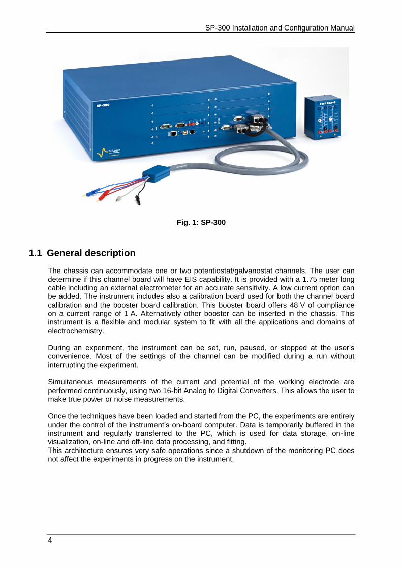
Fig. 1: SP-300
1.1 General description
The chassis can accommodate one or two potentiostat/galvanostat channels. The user can determine if this channel board will have EIS capability. It is provided with a 1.75 meter long cable including an external electrometer for an accurate sensitivity. A low current option can be added. The instrument includes also a calibration board used for both the channel board calibration and the booster board calibration. This booster board offers 48 V of compliance on a current range of 1 A. Alternatively other booster can be inserted in the chassis. This instrument is a flexible and modular system to fit with all the applications and domains of electrochemistry. During an experiment, the instrument can be set, run, paused, or stopped at the user’s convenience. Most of the settings of the channel can be modified during a run without interrupting the experiment. Simultaneous measurements of the current and potential of the working electrode are performed continuously, using two 16-bit Analog to Digital Converters. This allows the user to make true power or noise measurements. Once the techniques have been loaded and started from the PC, the experiments are entirely under the control of the instrument’s on-board computer. Data is temporarily buffered in the instrument and regularly transferred to the PC, which is used for data storage, on-line visualization, on-line and off-line data processing, and fitting. This architecture ensures very safe operations since a shutdown of the monitoring PC does not affect the experiments in progress on the instrument.
SP-300 Installation and Configuration Manual
5
1.2 Front panel description
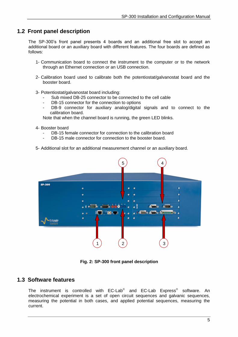
The SP-300’s front panel presents 4 boards and an additional free slot to accept an additional board or an auxiliary board with different features. The four boards are defined as follows:
1- Communication board to connect the instrument to the computer or to the network through an Ethernet connection or an USB connection.
2- Calibration board used to calibrate both the potentiostat/galvanostat board and the booster board.
3- Potentiostat/galvanostat board including: - Sub mixed DB-25 connector to be connected to the cell cable - DB-15 connector for the connection to options - DB-9 connector for auxiliary analog/digital signals and to connect to the
calibration board. Note that when the channel board is running, the green LED blinks.
4- Booster board
- DB-15 female connector for connection to the calibration board - DB-15 male connector for connection to the booster board.
5- Additional slot for an additional measurement channel or an auxiliary board.
Fig. 2: SP-300 front panel description
1.3 Software features
The instrument is controlled with EC-Lab and EC-Lab Express software. An electrochemical experiment is a set of open circuit sequences and galvanic sequences, measuring the potential in both cases, and applied potential sequences, measuring the current.
4
1 2
3
5

SP-300 Installation and Configuration Manual
6
Usual electrochemical techniques, such as Cyclic Voltammetry, Chronopotentiometry, etc.., are obtained by associations of elementary sequences and appear as flow-diagrams combining these sequences. Conditional tests can be performed at various levels of any sequence on the working electrode potential or current, the counter electrode potential, or external parameters. These conditional tests force the experiment to go to the next step, loop to a previous sequence, or end the sequence. The application software package provides useful protocols for general electrochemistry, corrosion, battery testing, super-capacitors, and custom applications. Standard graphic functions such as re-scaling, zoom, linear and log scales are available. Standard processed files can be created at the user's convenience upon running an experiment for the purpose of real time display of the experiments in progress. Post processing is also possible using built-in options to create variables at the user's convenience, such as derivative or integral values, etc... Raw data and processed data can be exported as standard ASCII text files.
The user can find more information about EC-Lab and EC-Lab Express software in the corresponding software user's manuals. This design makes the SP-300 a very versatile and modular single potentiostat. Note a second board can be added to have bipotentiostat with two independent channels. It can support most electrochemical applications from corrosion experiments to research on batteries, super-capacitors, and electrochromics. It is also a very well adapted tool for sensors applications.
It is assumed that the user is familiar with Microsoft Windows©
and knows how to use the
mouse and keyboard to access the drop-down menus.
SP-300 Installation and Configuration Manual
7
2. Cables connection
2.1 Connections to the monitoring computer
Depending on your local installation, you can use a direct connection to the instrument either through a USB connector or an Ethernet cable (1 PC to 1 SP-300) or a network connection (1 or more PCs to 1 or more SP-300s or other Bio-Logic potentiostat).
2.1.1 Direct USB connection
This connection can be done easily using the USB connection cable. One end must be connected on the instrument communication board and the other one on the control unit of the computer.
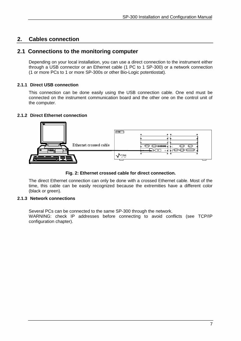
2.1.2 Direct Ethernet connection
Fig. 2: Ethernet crossed cable for direct connection.
The direct Ethernet connection can only be done with a crossed Ethernet cable. Most of the time, this cable can be easily recognized because the extremities have a different color (black or green).
2.1.3 Network connections
Several PCs can be connected to the same SP-300 through the network. WARNING: check IP addresses before connecting to avoid conflicts (see TCP/IP configuration chapter).
SP-300 Installation and Configuration Manual
8
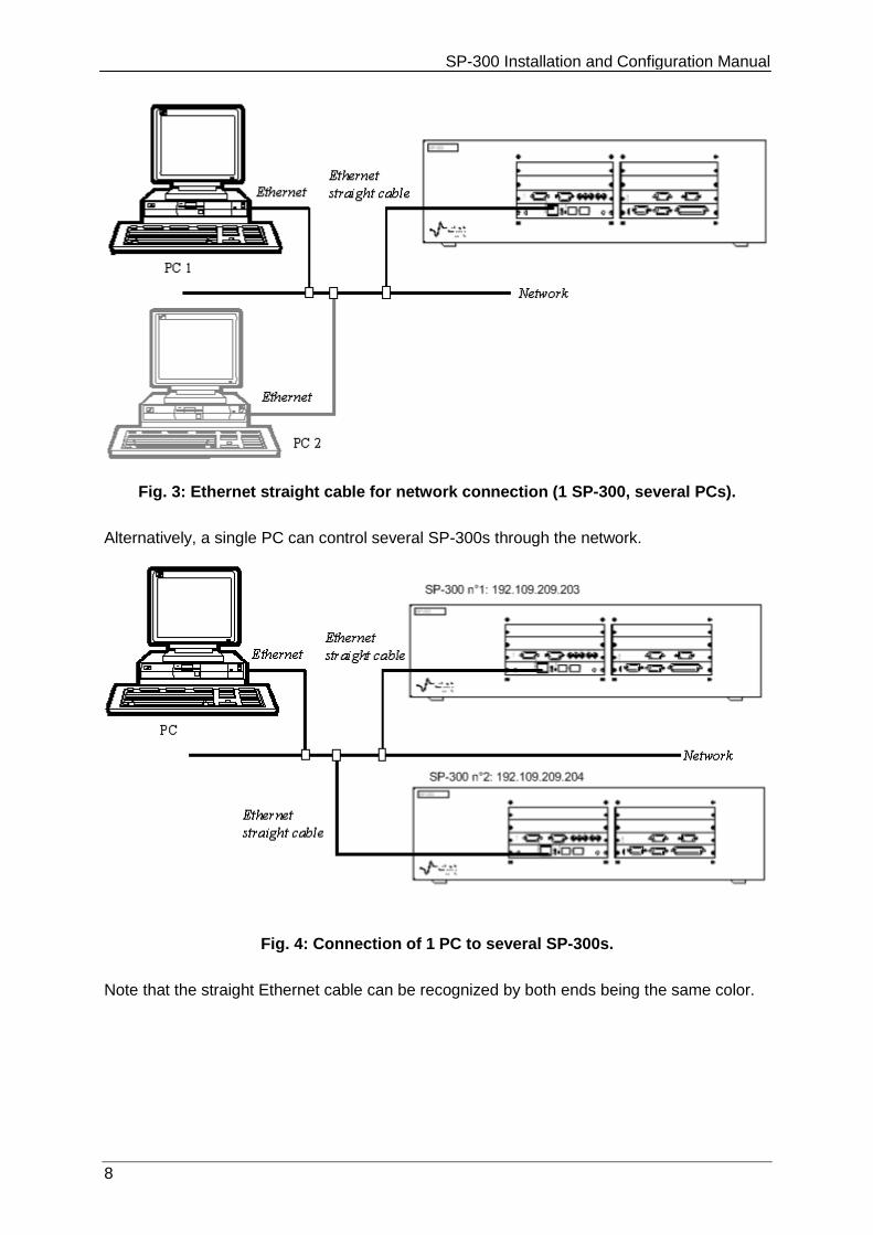
Fig. 3: Ethernet straight cable for network connection (1 SP-300, several PCs).
Alternatively, a single PC can control several SP-300s through the network.
Fig. 4: Connection of 1 PC to several SP-300s.
Note that the straight Ethernet cable can be recognized by both ends being the same color.
SP-300 Installation and Configuration Manual
9
Booster connection
Auxiliary inputs/outputs calibration
Channel and booster boards calibration
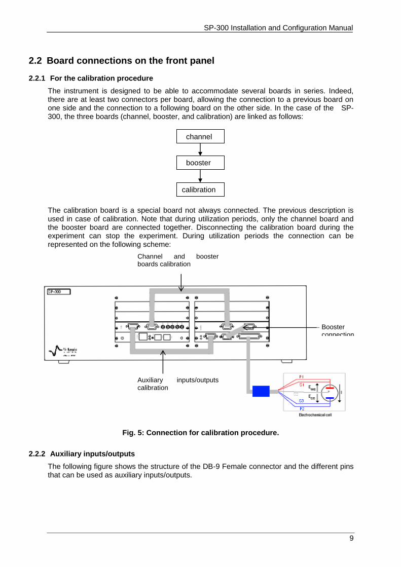
2.2 Board connections on the front panel
2.2.1 For the calibration procedure
The instrument is designed to be able to accommodate several boards in series. Indeed, there are at least two connectors per board, allowing the connection to a previous board on one side and the connection to a following board on the other side. In the case of the SP-300, the three boards (channel, booster, and calibration) are linked as follows: The calibration board is a special board not always connected. The previous description is used in case of calibration. Note that during utilization periods, only the channel board and the booster board are connected together. Disconnecting the calibration board during the experiment can stop the experiment. During utilization periods the connection can be represented on the following scheme:
Fig. 5: Connection for calibration procedure.
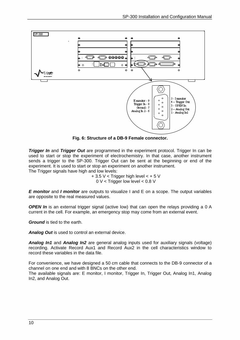
2.2.2 Auxiliary inputs/outputs
The following figure shows the structure of the DB-9 Female connector and the different pins that can be used as auxiliary inputs/outputs.
channel
booster
calibration
SP-300 Installation and Configuration Manual
10
Fig. 6: Structure of a DB-9 Female connector.
Trigger In and Trigger Out are programmed in the experiment protocol. Trigger In can be used to start or stop the experiment of electrochemistry. In that case, another instrument sends a trigger to the SP-300. Trigger Out can be sent at the beginning or end of the experiment. It is used to start or stop an experiment on another instrument. The Trigger signals have high and low levels:
+ 3.5 V < Trigger high level < + 5 V 0 V < Trigger low level < 0.8 V
E monitor and I monitor are outputs to visualize I and E on a scope. The output variables are opposite to the real measured values. OPEN In is an external trigger signal (active low) that can open the relays providing a 0 A current in the cell. For example, an emergency stop may come from an external event. Ground is tied to the earth. Analog Out is used to control an external device. Analog In1 and Analog In2 are general analog inputs used for auxiliary signals (voltage) recording. Activate Record Aux1 and Record Aux2 in the cell characteristics window to record these variables in the data file. For convenience, we have designed a 50 cm cable that connects to the DB-9 connector of a channel on one end and with 8 BNCs on the other end. The available signals are: E monitor, I monitor, Trigger In, Trigger Out, Analog In1, Analog In2, and Analog Out.
SP-300 Installation and Configuration Manual
11
2.3 Connection to the cell
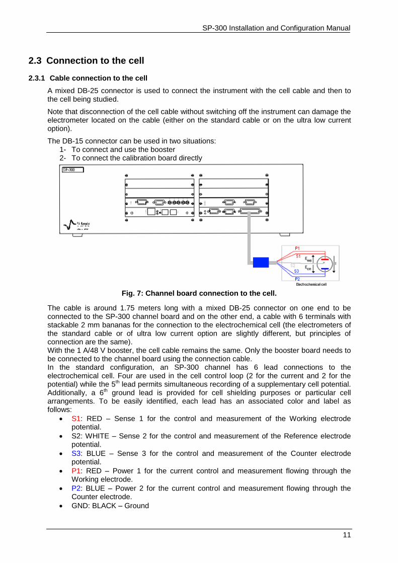
2.3.1 Cable connection to the cell
A mixed DB-25 connector is used to connect the instrument with the cell cable and then to the cell being studied.
Note that disconnection of the cell cable without switching off the instrument can damage the electrometer located on the cable (either on the standard cable or on the ultra low current option).
The DB-15 connector can be used in two situations: 1- To connect and use the booster 2- To connect the calibration board directly
Fig. 7: Channel board connection to the cell.
The cable is around 1.75 meters long with a mixed DB-25 connector on one end to be connected to the SP-300 channel board and on the other end, a cable with 6 terminals with stackable 2 mm bananas for the connection to the electrochemical cell (the electrometers of the standard cable or of ultra low current option are slightly different, but principles of connection are the same). With the 1 A/48 V booster, the cell cable remains the same. Only the booster board needs to be connected to the channel board using the connection cable. In the standard configuration, an SP-300 channel has 6 lead connections to the electrochemical cell. Four are used in the cell control loop (2 for the current and 2 for the potential) while the 5th lead permits simultaneous recording of a supplementary cell potential. Additionally, a 6th ground lead is provided for cell shielding purposes or particular cell arrangements. To be easily identified, each lead has an associated color and label as follows:
S1: RED – Sense 1 for the control and measurement of the Working electrode potential.
S2: WHITE – Sense 2 for the control and measurement of the Reference electrode potential.
S3: BLUE – Sense 3 for the control and measurement of the Counter electrode potential.
P1: RED – Power 1 for the current control and measurement flowing through the Working electrode.
P2: BLUE – Power 2 for the current control and measurement flowing through the Counter electrode.
GND: BLACK – Ground
SP-300 Installation and Configuration Manual
12
The internal structure of the SP-300 offers two working modes: grounded and floating. To switch from one mode to the other, no connection change is required. A channel has the ability to link up with 2, 3, or 4 electrodes in different configurations depending on the electrochemical cell. Ewe and Ece are measured as follows:
Ewe = S1 - S2 Ece = S3 - S2
Note: - disconnection of the cell cable without switching off the instrument can damage the electrometer located on the cable (either on the standard cable or on the ultra low current option),
- for the standard cable, maximum potential between ground and terminals should not exceeds 50 V, and not exceeds 100 V between the earth and ground.
The current (defined in the positive direction) crosses the electrochemical cell from P1 to P2. Three typical standard configurations are explained below.
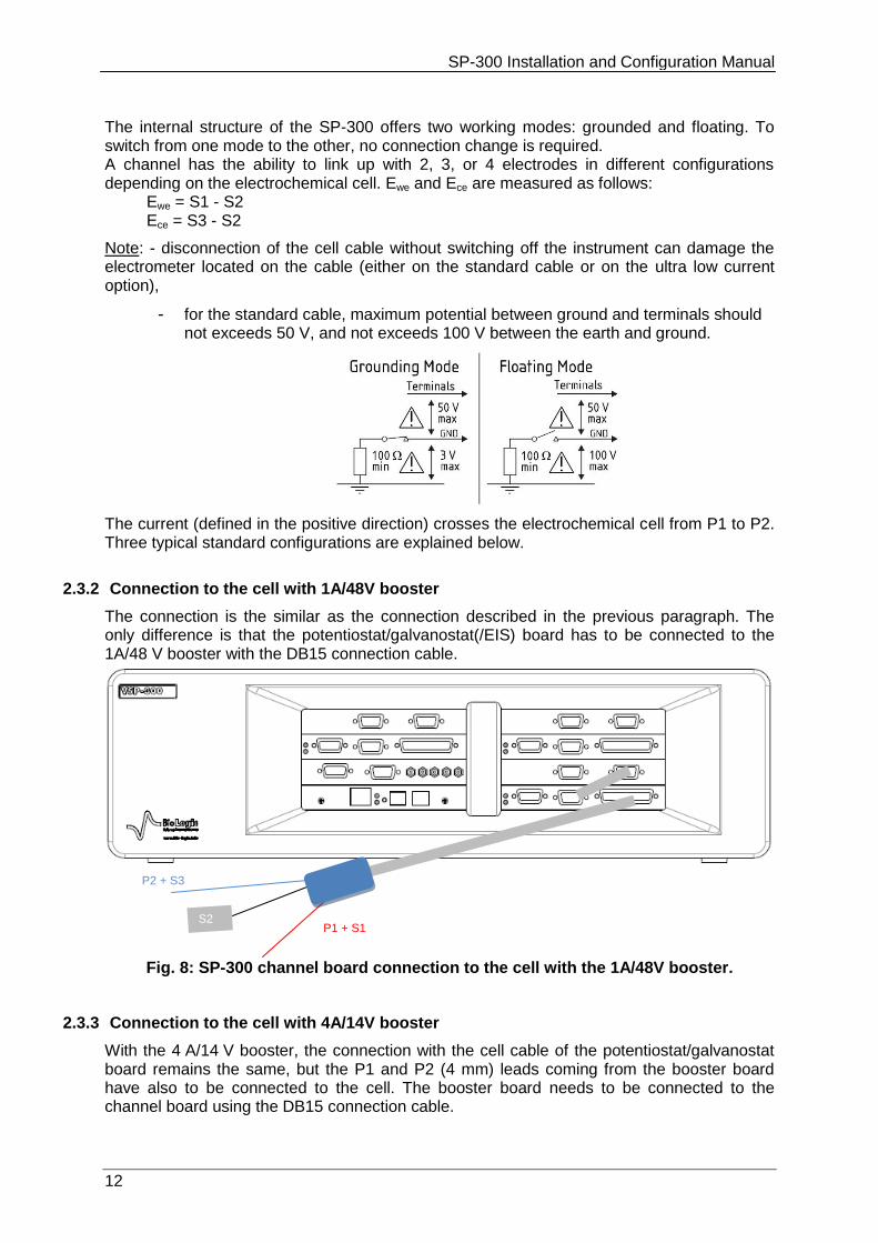
2.3.2 Connection to the cell with 1A/48V booster
The connection is the similar as the connection described in the previous paragraph. The only difference is that the potentiostat/galvanostat(/EIS) board has to be connected to the 1A/48 V booster with the DB15 connection cable.
Fig. 8: SP-300 channel board connection to the cell with the 1A/48V booster.
2.3.3 Connection to the cell with 4A/14V booster
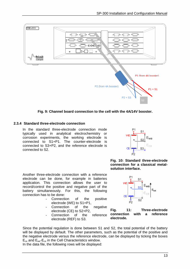
With the 4 A/14 V booster, the connection with the cell cable of the potentiostat/galvanostat board remains the same, but the P1 and P2 (4 mm) leads coming from the booster board have also to be connected to the cell. The booster board needs to be connected to the channel board using the DB15 connection cable.
P1 + S1
P2 + S3
S2
SP-300 Installation and Configuration Manual
13
Fig. 9: Channel board connection to the cell with the 4A/14V booster.
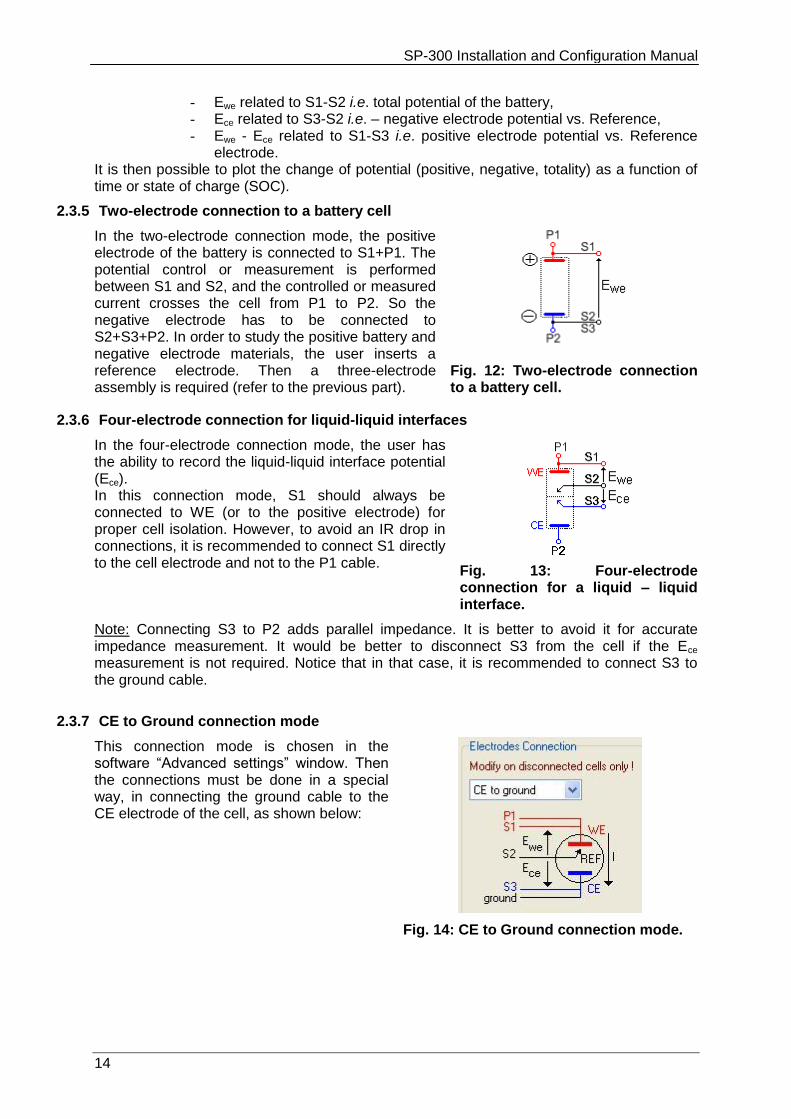
2.3.4 Standard three-electrode connection
In the standard three-electrode connection mode typically used in analytical electrochemistry or corrosion experiments, the working electrode is connected to S1+P1. The counter-electrode is connected to S3+P2, and the reference electrode is connected to S2.
Fig. 10: Standard three-electrode connection for a classical metal-solution interface.
Another three-electrode connection with a reference electrode can be done, for example in batteries application. This connection allows the user to record/control the positive and negative part of the battery simultaneously. For this, the following connection has to be done:
- Connection of the positive electrode (WE) to S1+P1,
- Connection of the negative electrode (CE) to S2+P2,
- Connection of the reference electrode (REF) to S3.
Fig. 11: Three-electrode connection with a reference electrode.
Since the potential regulation is done between S1 and S2, the total potential of the battery will be displayed by default. The other parameters, such as the potential of the positive and the negative electrode versus the reference electrode, can be displayed by ticking the boxes Ece and Ewe-Ece in the Cell Characteristics window. In the data file, the following rows will be displayed:
P1 + S1
P1 (from 4A booster)
P2 + S3
P2 (from 4A booster)
S2
SP-300 Installation and Configuration Manual
14
- Ewe related to S1-S2 i.e. total potential of the battery, - Ece related to S3-S2 i.e. – negative electrode potential vs. Reference, - Ewe - Ece related to S1-S3 i.e. positive electrode potential vs. Reference
electrode. It is then possible to plot the change of potential (positive, negative, totality) as a function of time or state of charge (SOC).
2.3.5 Two-electrode connection to a battery cell
In the two-electrode connection mode, the positive electrode of the battery is connected to S1+P1. The potential control or measurement is performed between S1 and S2, and the controlled or measured current crosses the cell from P1 to P2. So the negative electrode has to be connected to S2+S3+P2. In order to study the positive battery and negative electrode materials, the user inserts a reference electrode. Then a three-electrode assembly is required (refer to the previous part).
Fig. 12: Two-electrode connection to a battery cell.
2.3.6 Four-electrode connection for liquid-liquid interfaces
In the four-electrode connection mode, the user has the ability to record the liquid-liquid interface potential (Ece). In this connection mode, S1 should always be connected to WE (or to the positive electrode) for proper cell isolation. However, to avoid an IR drop in connections, it is recommended to connect S1 directly to the cell electrode and not to the P1 cable.
Fig. 13: Four-electrode connection for a liquid – liquid interface.
Note: Connecting S3 to P2 adds parallel impedance. It is better to avoid it for accurate impedance measurement. It would be better to disconnect S3 from the cell if the Ece measurement is not required. Notice that in that case, it is recommended to connect S3 to the ground cable.
2.3.7 CE to Ground connection mode
This connection mode is chosen in the software “Advanced settings” window. Then the connections must be done in a special way, in connecting the ground cable to the CE electrode of the cell, as shown below:
Fig. 14: CE to Ground connection mode.
SP-300 Installation and Configuration Manual
15
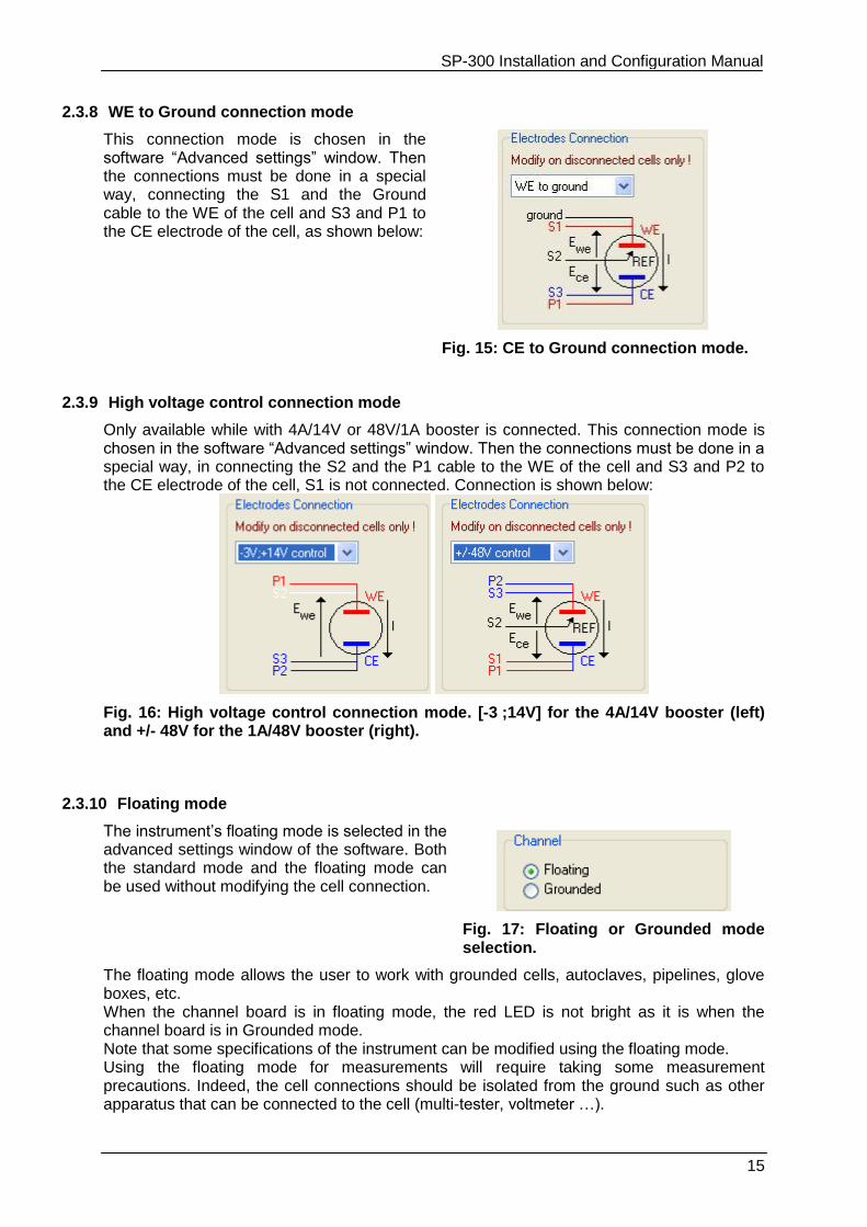
2.3.8 WE to Ground connection mode
This connection mode is chosen in the software “Advanced settings” window. Then the connections must be done in a special way, connecting the S1 and the Ground cable to the WE of the cell and S3 and P1 to the CE electrode of the cell, as shown below:
Fig. 15: CE to Ground connection mode.
2.3.9 High voltage control connection mode
Only available while with 4A/14V or 48V/1A booster is connected. This connection mode is chosen in the software “Advanced settings” window. Then the connections must be done in a special way, in connecting the S2 and the P1 cable to the WE of the cell and S3 and P2 to the CE electrode of the cell, S1 is not connected. Connection is shown below:
Fig. 16: High voltage control connection mode. [-3 ;14V] for the 4A/14V booster (left) and +/- 48V for the 1A/48V booster (right).
2.3.10 Floating mode
The instrument’s floating mode is selected in the advanced settings window of the software. Both the standard mode and the floating mode can be used without modifying the cell connection.
Fig. 17: Floating or Grounded mode selection.
The floating mode allows the user to work with grounded cells, autoclaves, pipelines, glove boxes, etc. When the channel board is in floating mode, the red LED is not bright as it is when the channel board is in Grounded mode. Note that some specifications of the instrument can be modified using the floating mode. Using the floating mode for measurements will require taking some measurement precautions. Indeed, the cell connections should be isolated from the ground such as other apparatus that can be connected to the cell (multi-tester, voltmeter …).
SP-300 Installation and Configuration Manual
16
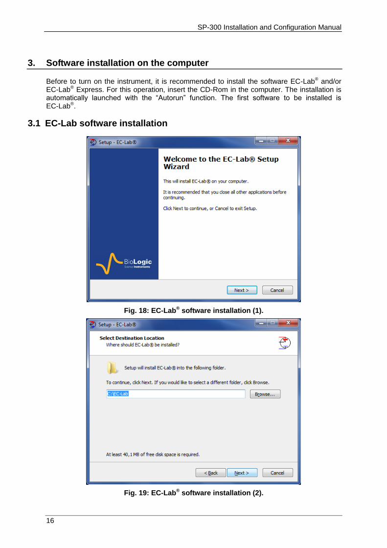
3. Software installation on the computer
Before to turn on the instrument, it is recommended to install the software EC-Lab® and/or EC-Lab® Express. For this operation, insert the CD-Rom in the computer. The installation is automatically launched with the “Autorun” function. The first software to be installed is EC-Lab®.
3.1 EC-Lab software installation
Fig. 18: EC-Lab® software installation (1).
Fig. 19: EC-Lab® software installation (2).
SP-300 Installation and Configuration Manual
17
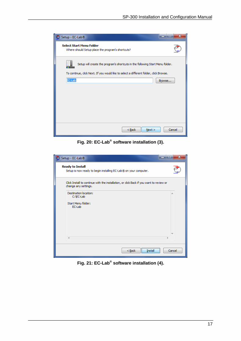
Fig. 20: EC-Lab® software installation (3).
Fig. 21: EC-Lab® software installation (4).
SP-300 Installation and Configuration Manual
18
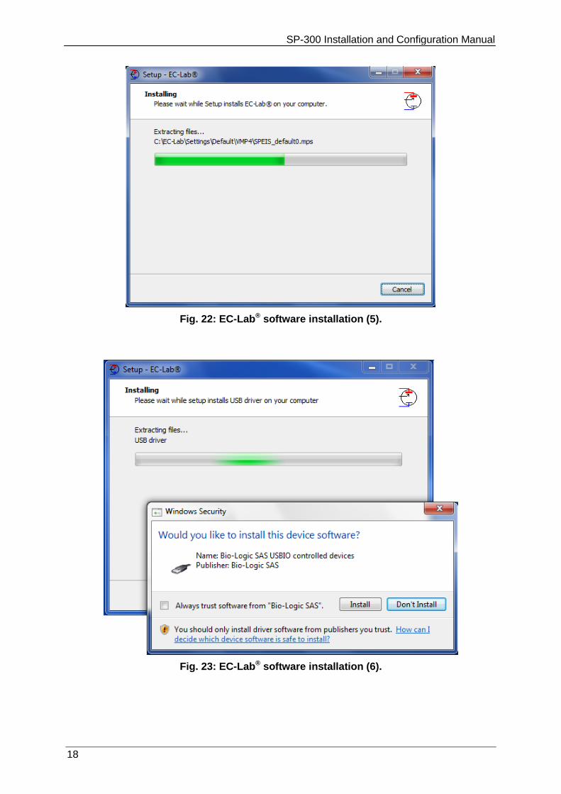
Fig. 22: EC-Lab® software installation (5).
Fig. 23: EC-Lab® software installation (6).
SP-300 Installation and Configuration Manual
19
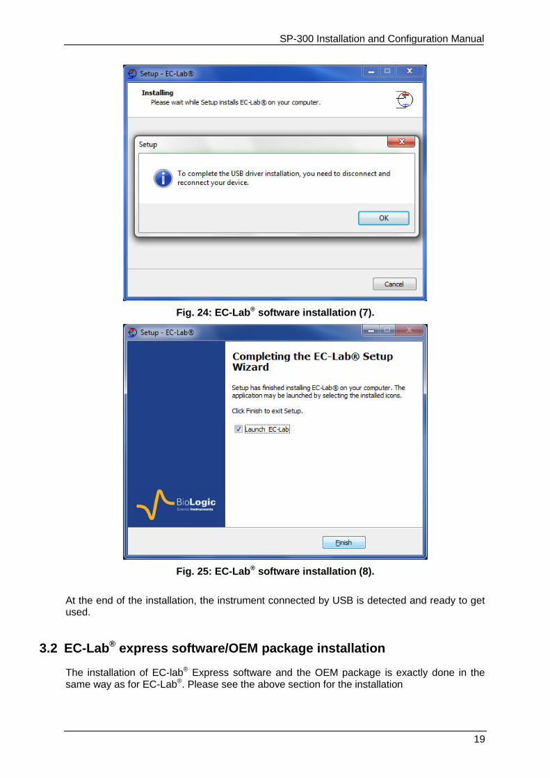
Fig. 24: EC-Lab® software installation (7).
Fig. 25: EC-Lab® software installation (8).
At the end of the installation, the instrument connected by USB is detected and ready to get used.
3.2 EC-Lab® express software/OEM package installation
The installation of EC-lab® Express software and the OEM package is exactly done in the same way as for EC-Lab®. Please see the above section for the installation
SP-300 Installation and Configuration Manual
20
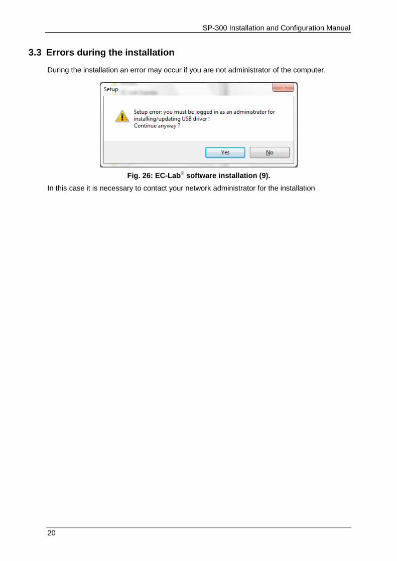
3.3 Errors during the installation
During the installation an error may occur if you are not administrator of the computer.
Fig. 26: EC-Lab® software installation (9).
In this case it is necessary to contact your network administrator for the installation

SP-300 Installation and Configuration Manual
21
4. PC installation and configuration
The instrument is safety grounded to the Earth through the protective conductor of the AC power cable. Use only the power cord supplied with the instrument and designed for the good current rating (10 Amax) and be sure to connect it to a power source provided with protective earth contact. Any interruption of the protective earth (grounding) conductor outside the instrument could result in personal injury.
IT IS HIGHLY RECOMMENDED TO ASK FOR ASSISTANCE FROM YOUR NETWORK ADMINISTRATOR.
4.1 TCP/IP installation and configuration
The instrument uses the TCP/IP (Transfer Control Protocol / Internet Protocol) to exchange data with the PC. This protocol uses IP addresses to identify hosts on a network, so you will need 2 IP numbers, one for the instrument and one for the PC. For a direct connection between the instrument and the PC, you can use the following numbers (default factory settings):
192.168.0.2 (PC)
192.168.0.1 (SP-300)
But, if you connect the PC and the instrument to your local network, you need to ask your system administrator for 2 VALID IP NUMBERS FOR YOUR INTRANET (and the sub-net mask and the gateway numbers if necessary). Note: 1- Before the installation of the TCP/IP protocol, your Ethernet board must be properly installed on your computer.
2- With Windows Vista, it is recommended to replace the default IP addresses by other ones even if the instrument is directly connected to the computer. Windows Vista does not accept universal IP addresses. You can use the following ones:
192.109.209.202 (PC)
192.109.209.201 (SP-300)
4.1.1 Windows configuration
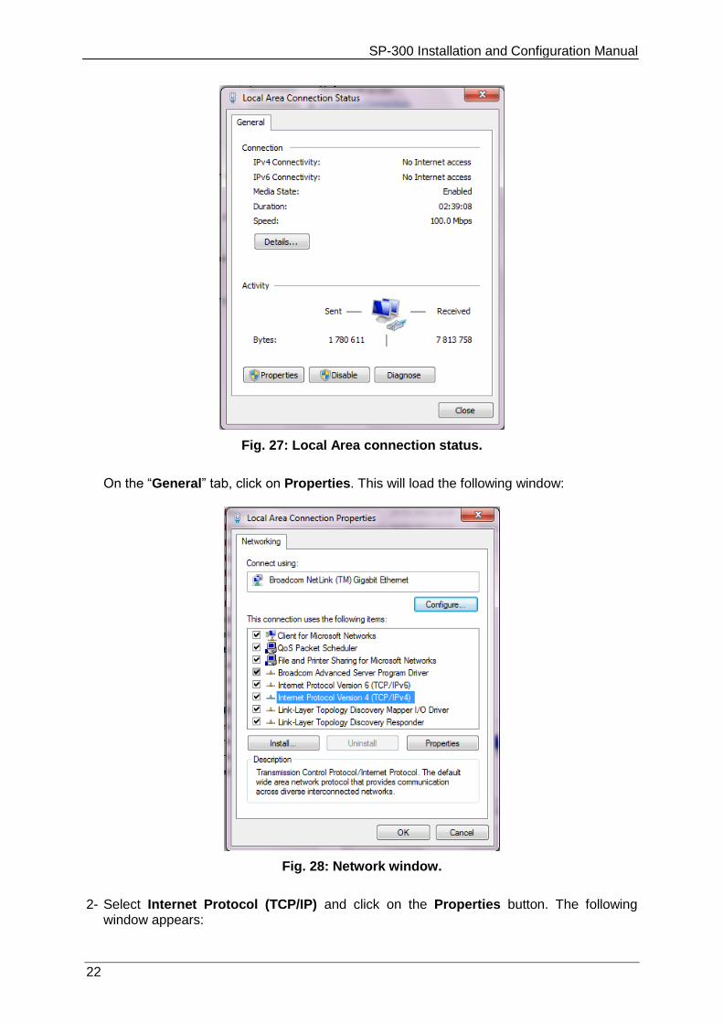
The TCP/IP protocol must be installed on the PC computer to establish the connection with the instrument. If your computer is connected to a network, the TCP/IP protocol may already be installed. In that case, the computer already has an IP address (obtained automatically). When the computer is connected directly to the instrument, it is necessary to give the computer an IP address. The following part describes how to give an IP address to the computer: 1- In the Control Panel, double click on the Network Connections icon. Then the Local
Area Connection window is displayed. Right click on the name and choose “Status” to see the computer’s IP address in the network. The window below is displayed:
SP-300 Installation and Configuration Manual
22
Fig. 27: Local Area connection status.
On the “General” tab, click on Properties. This will load the following window:
Fig. 28: Network window.
2- Select Internet Protocol (TCP/IP) and click on the Properties button. The following
window appears:
SP-300 Installation and Configuration Manual
23
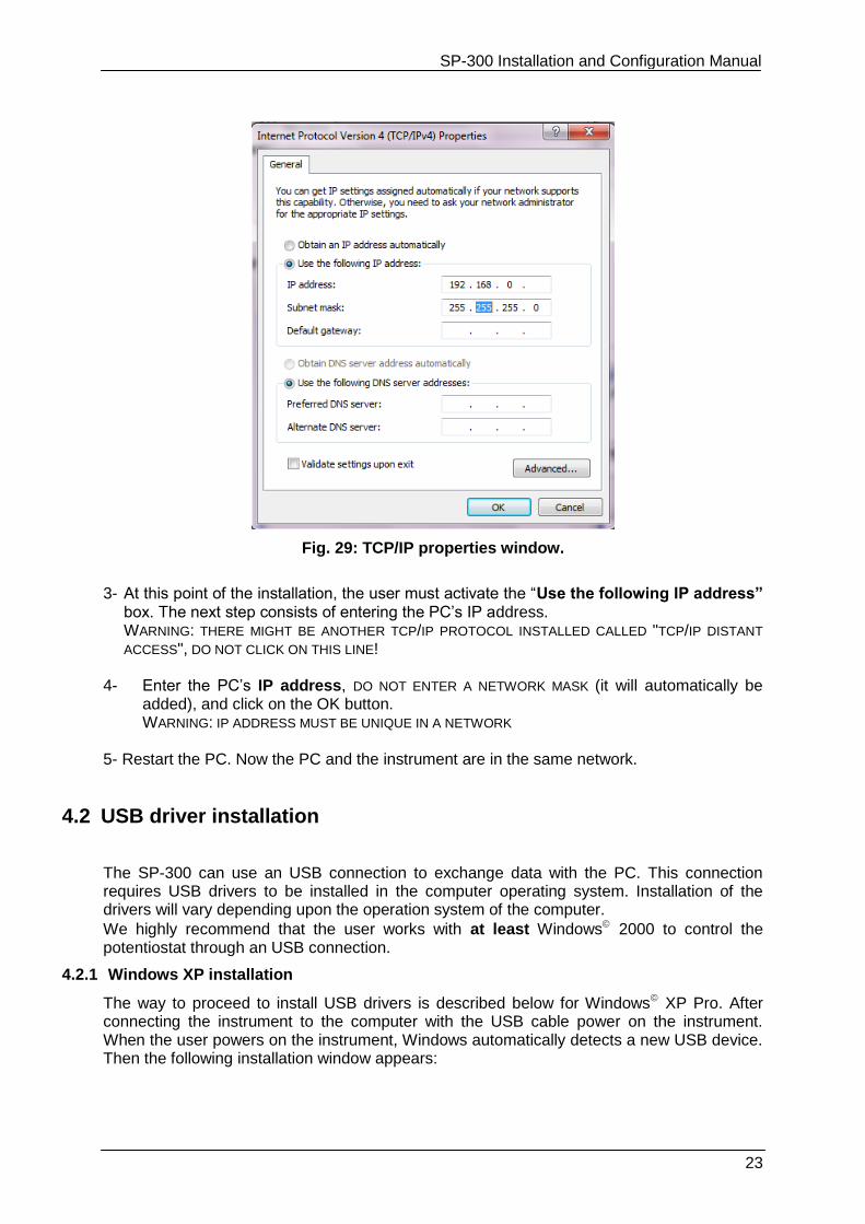
Fig. 29: TCP/IP properties window.
3- At this point of the installation, the user must activate the “Use the following IP address”
box. The next step consists of entering the PC’s IP address. WARNING: THERE MIGHT BE ANOTHER TCP/IP PROTOCOL INSTALLED CALLED "TCP/IP DISTANT
ACCESS", DO NOT CLICK ON THIS LINE! 4- Enter the PC’s IP address, DO NOT ENTER A NETWORK MASK (it will automatically be
added), and click on the OK button. WARNING: IP ADDRESS MUST BE UNIQUE IN A NETWORK
5- Restart the PC. Now the PC and the instrument are in the same network.
4.2 USB driver installation
The SP-300 can use an USB connection to exchange data with the PC. This connection requires USB drivers to be installed in the computer operating system. Installation of the drivers will vary depending upon the operation system of the computer.
We highly recommend that the user works with at least Windows 2000 to control the potentiostat through an USB connection.
4.2.1 Windows XP installation
The way to proceed to install USB drivers is described below for Windows XP Pro. After connecting the instrument to the computer with the USB cable power on the instrument. When the user powers on the instrument, Windows automatically detects a new USB device. Then the following installation window appears:
SP-300 Installation and Configuration Manual
24
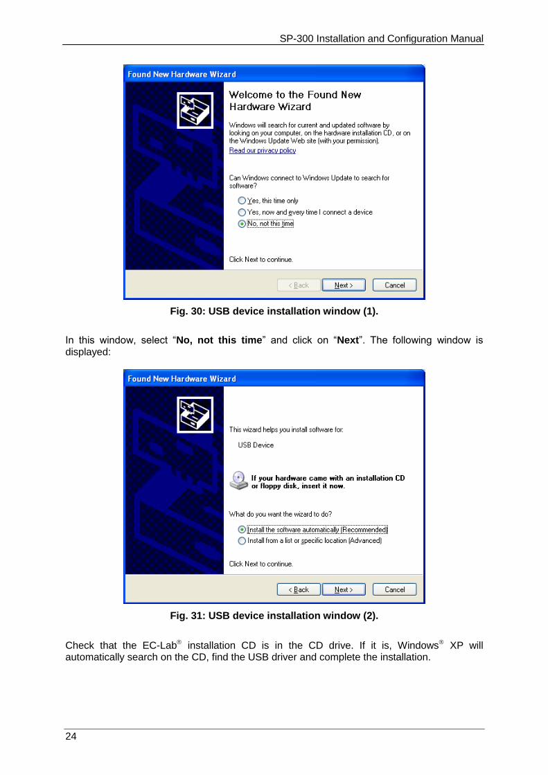
Fig. 30: USB device installation window (1).
In this window, select “No, not this time” and click on “Next”. The following window is displayed:
Fig. 31: USB device installation window (2).
Check that the EC-Lab installation CD is in the CD drive. If it is, Windows XP will automatically search on the CD, find the USB driver and complete the installation.
SP-300 Installation and Configuration Manual
25
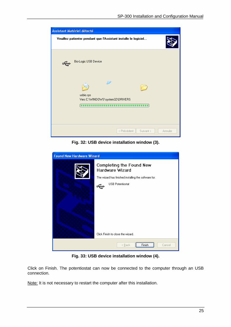
Fig. 32: USB device installation window (3).
Fig. 33: USB device installation window (4).
Click on Finish. The potentiostat can now be connected to the computer through an USB connection. Note: It is not necessary to restart the computer after this installation.
SP-300 Installation and Configuration Manual
26
Note that it is possible to communicate with the instrument from another subnet with the following ports 23455 (broadcast), 23456, 23457 and 23458.
For other Windows versions, the user will probably have to specify where to find the driver on the CD-Rom. In this window select the automatic installation of the software.
4.2.2 Windows Seven and Vista installation
With Windows seven and Vista systems, the USB driver is automatically installed when the instrument is detected. And the following message is displayed at the end of the installation:
Fig. 34: USB device installation for Seven and Vista.
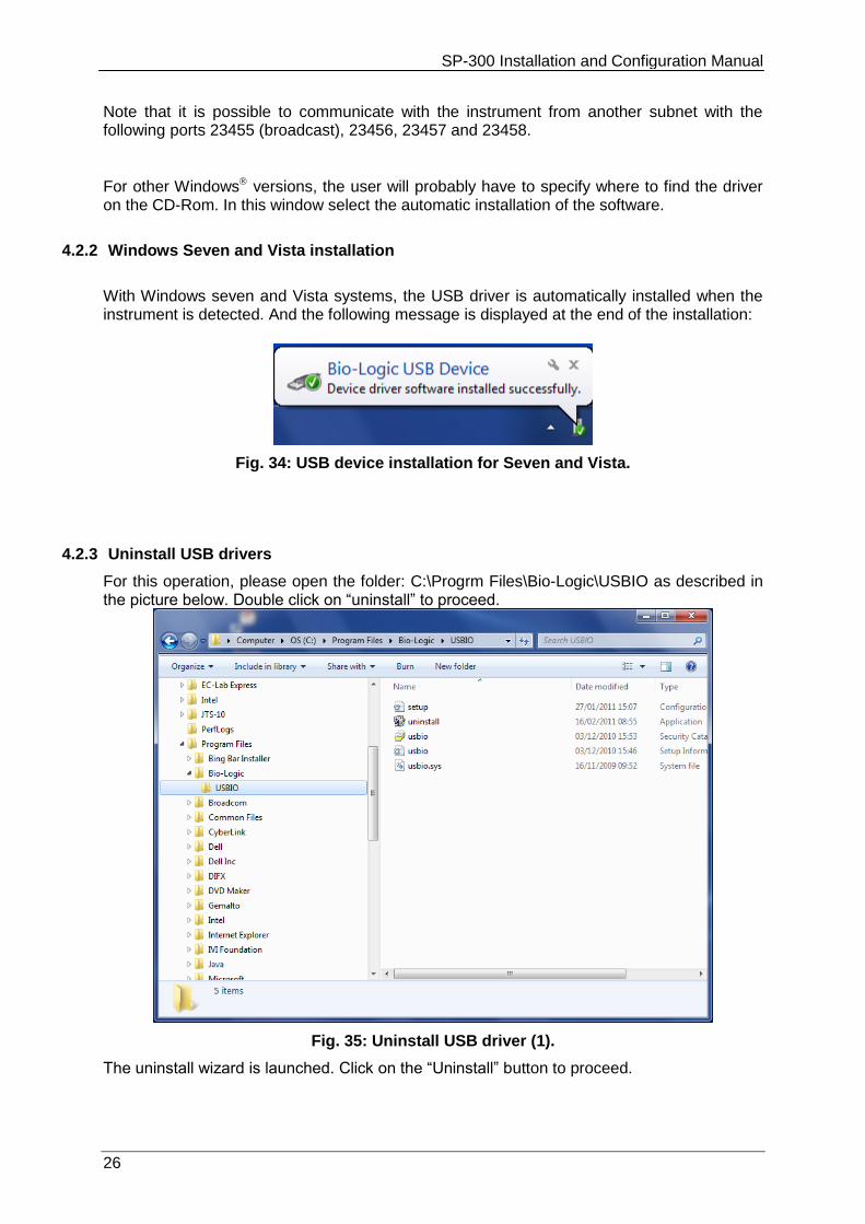
4.2.3 Uninstall USB drivers
For this operation, please open the folder: C:\Progrm Files\Bio-Logic\USBIO as described in the picture below. Double click on “uninstall” to proceed.
Fig. 35: Uninstall USB driver (1).
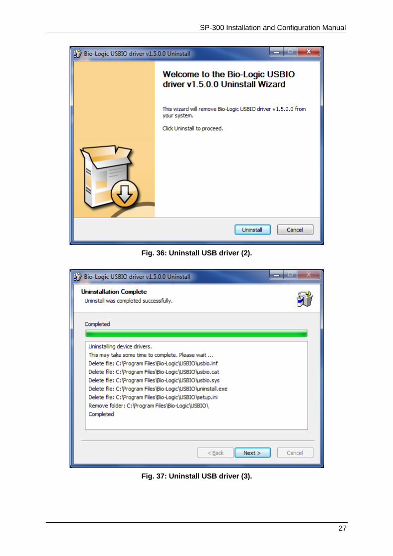
The uninstall wizard is launched. Click on the “Uninstall” button to proceed.
SP-300 Installation and Configuration Manual
27
Fig. 36: Uninstall USB driver (2).
Fig. 37: Uninstall USB driver (3).
SP-300 Installation and Configuration Manual
28
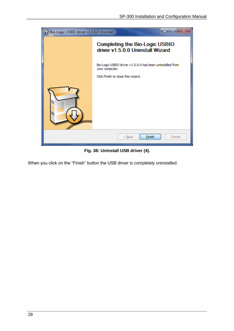
Fig. 38: Uninstall USB driver (4).
When you click on the “Finish” button the USB driver is completely uninstalled.
SP-300 Installation and Configuration Manual
29
5. Connection to the computer
5.1 Network parameter configuration with the Ethernet connection The Ethernet connection on the communication board is a 10/100 baseT compatible with every network. The USB connection is also integrated on this board. When it is installed in a Local Area Network (via the Ethernet connection), the instrument is automatically detected by the computers of the network. It becomes very easy to select an instrument in the network and modify its IP address via the Ethernet connection. This is possible with a MAC Address (set at the factory on the communication board) even if the instrument is not in the same network as the computer (before being connected together). Now new instruments are delivered with the following IP address commonly used as default: 192.168.0.1. You can either manage your instrument directly with the computer (direct connection with the crossed cable) or change the instrument’s IP address to add the instrument in your local network. The way to proceed is the same in both cases. The first step is the detection of the new instrument by a computer (directly or via the network). The second step is the IP address change before the connection, either to have both the instrument and the computer in the same LAN or to make a small network including the instrument and the PC.
Note: to switch between EC-Lab and EC-Lab Express software, the instrument has to be switched off and restarted.
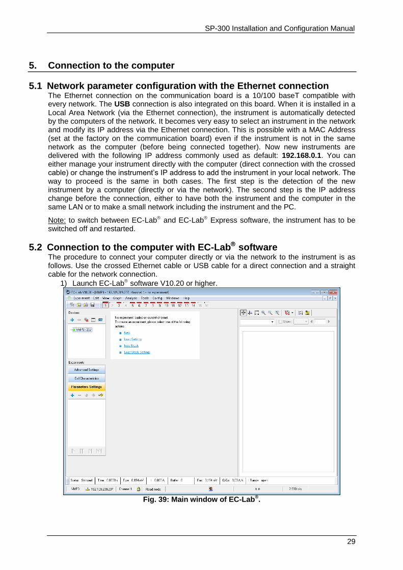
5.2 Connection to the computer with EC-Lab software The procedure to connect your computer directly or via the network to the instrument is as follows. Use the crossed Ethernet cable or USB cable for a direct connection and a straight cable for the network connection.
1) Launch EC-Lab software V10.20 or higher.
Fig. 39: Main window of EC-Lab®.
SP-300 Installation and Configuration Manual
30
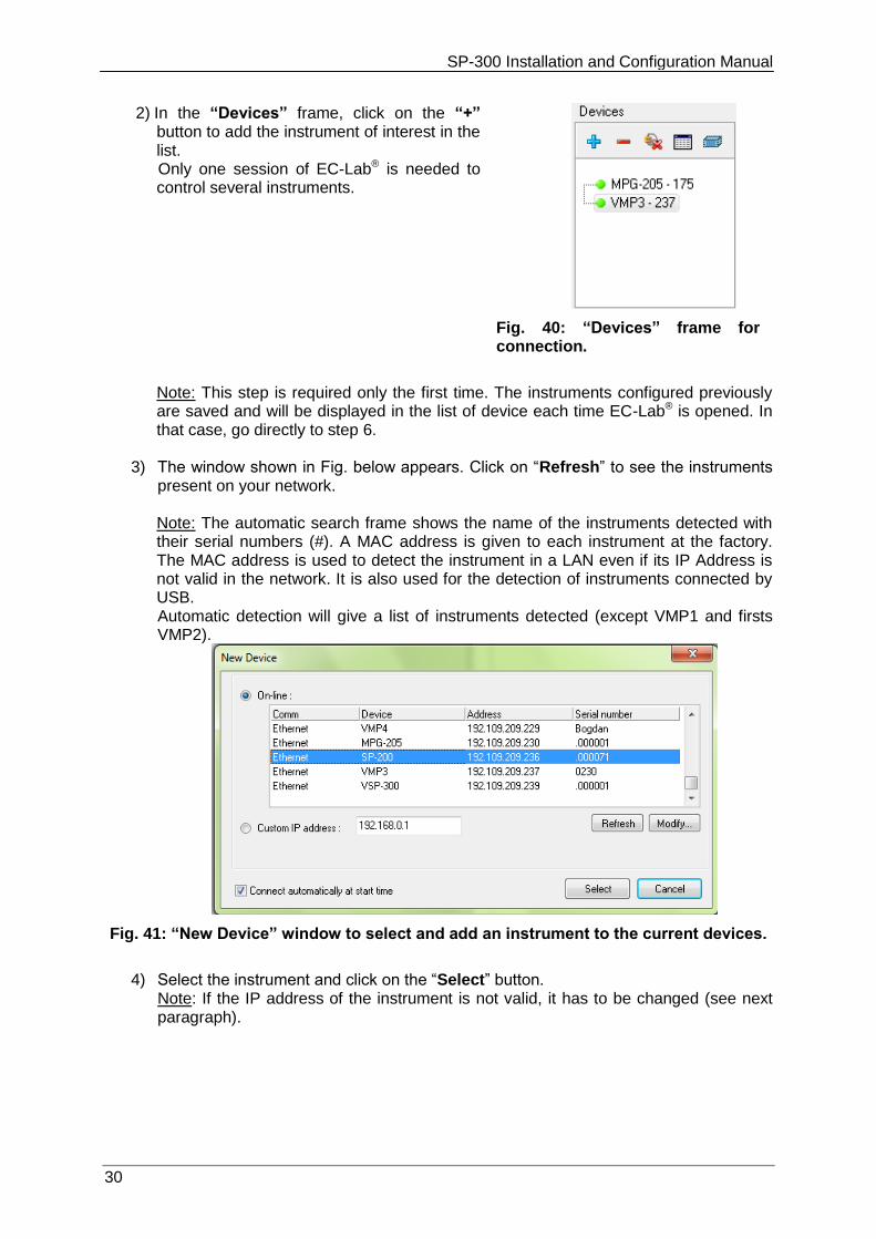
2) In the “Devices” frame, click on the “+” button to add the instrument of interest in the list.
Only one session of EC-Lab® is needed to control several instruments.
Fig. 40: “Devices” frame for connection.
Note: This step is required only the first time. The instruments configured previously are saved and will be displayed in the list of device each time EC-Lab® is opened. In that case, go directly to step 6.
3) The window shown in Fig. below appears. Click on “Refresh” to see the instruments present on your network. Note: The automatic search frame shows the name of the instruments detected with their serial numbers (#). A MAC address is given to each instrument at the factory. The MAC address is used to detect the instrument in a LAN even if its IP Address is not valid in the network. It is also used for the detection of instruments connected by USB. Automatic detection will give a list of instruments detected (except VMP1 and firsts VMP2).
Fig. 41: “New Device” window to select and add an instrument to the current devices.
4) Select the instrument and click on the “Select” button.
Note: If the IP address of the instrument is not valid, it has to be changed (see next paragraph).
SP-300 Installation and Configuration Manual
31
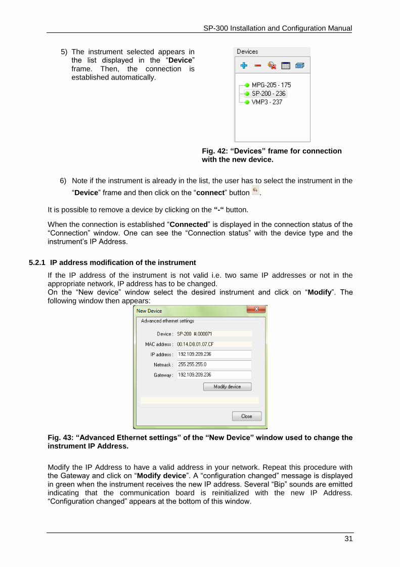
5) The instrument selected appears in the list displayed in the “Device” frame. Then, the connection is established automatically.
Fig. 42: “Devices” frame for connection with the new device.
6) Note if the instrument is already in the list, the user has to select the instrument in the
“Device” frame and then click on the “connect” button . It is possible to remove a device by clicking on the “-“ button.
When the connection is established “Connected” is displayed in the connection status of the “Connection” window. One can see the “Connection status” with the device type and the instrument’s IP Address.
5.2.1 IP address modification of the instrument
If the IP address of the instrument is not valid i.e. two same IP addresses or not in the appropriate network, IP address has to be changed. On the “New device” window select the desired instrument and click on “Modify”. The following window then appears:
Fig. 43: “Advanced Ethernet settings” of the “New Device” window used to change the instrument IP Address.
Modify the IP Address to have a valid address in your network. Repeat this procedure with the Gateway and click on “Modify device”. A “configuration changed” message is displayed in green when the instrument receives the new IP address. Several “Bip” sounds are emitted indicating that the communication board is reinitialized with the new IP Address. “Configuration changed” appears at the bottom of this window.
SP-300 Installation and Configuration Manual
32
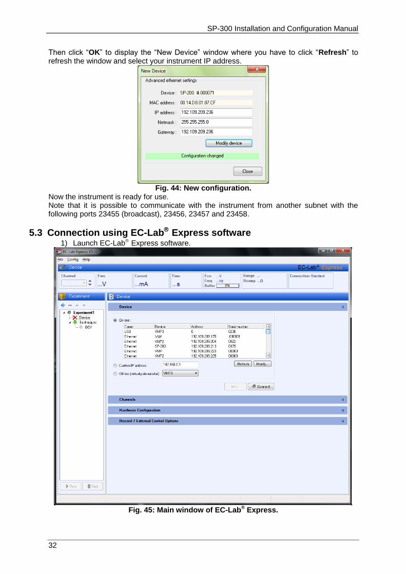
Then click “OK” to display the “New Device” window where you have to click “Refresh” to refresh the window and select your instrument IP address.
Fig. 44: New configuration.
Now the instrument is ready for use. Note that it is possible to communicate with the instrument from another subnet with the following ports 23455 (broadcast), 23456, 23457 and 23458.
5.3 Connection using EC-Lab Express software 1) Launch EC-Lab Express software.
Fig. 45: Main window of EC-Lab® Express.
SP-300 Installation and Configuration Manual
33
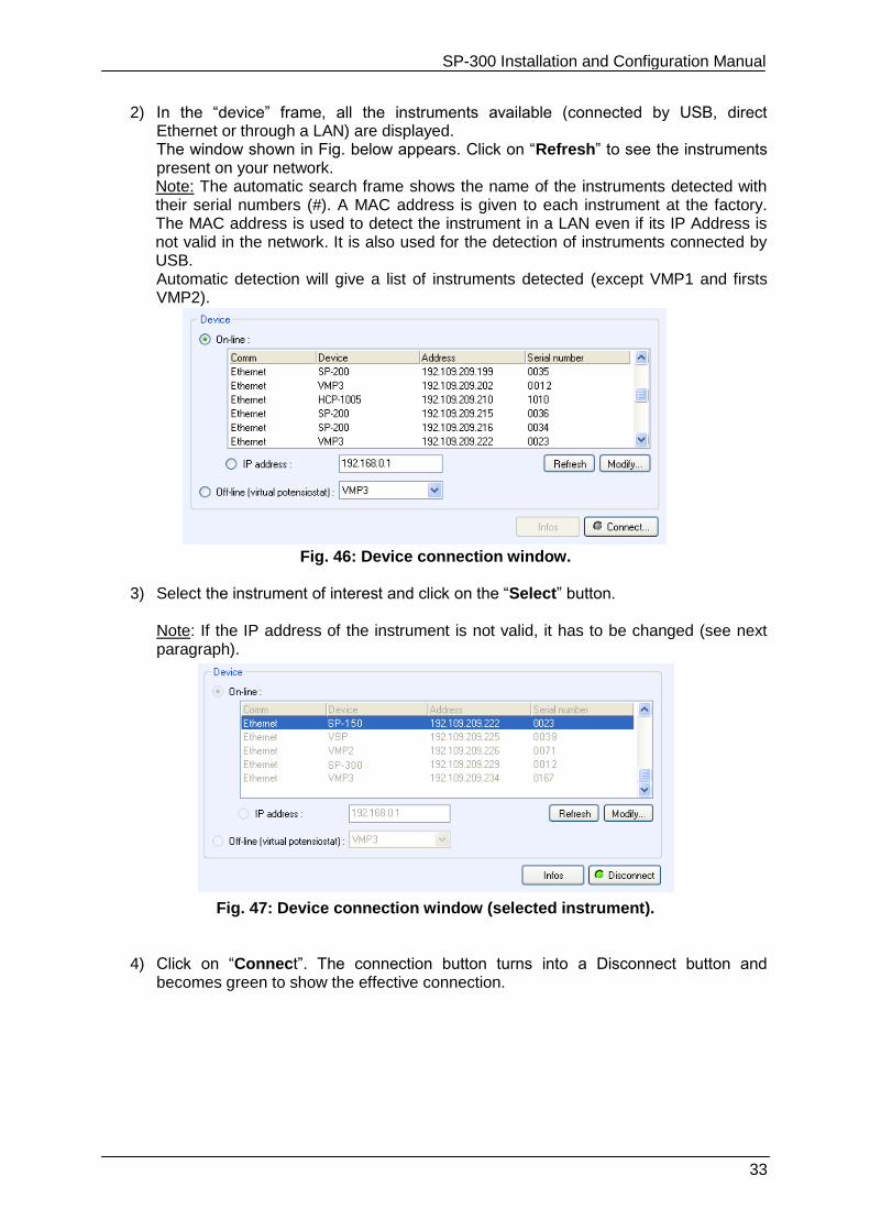
2) In the “device” frame, all the instruments available (connected by USB, direct Ethernet or through a LAN) are displayed. The window shown in Fig. below appears. Click on “Refresh” to see the instruments present on your network. Note: The automatic search frame shows the name of the instruments detected with their serial numbers (#). A MAC address is given to each instrument at the factory. The MAC address is used to detect the instrument in a LAN even if its IP Address is not valid in the network. It is also used for the detection of instruments connected by USB. Automatic detection will give a list of instruments detected (except VMP1 and firsts VMP2).
Fig. 46: Device connection window.
3) Select the instrument of interest and click on the “Select” button. Note: If the IP address of the instrument is not valid, it has to be changed (see next paragraph).
Fig. 47: Device connection window (selected instrument).
4) Click on “Connect”. The connection button turns into a Disconnect button and
becomes green to show the effective connection.
SP-300 Installation and Configuration Manual
34
5.3.1 IP address modification of the instrument
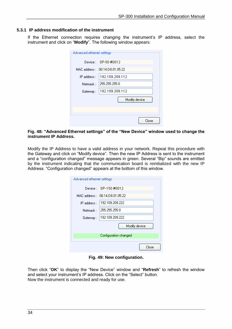
If the Ethernet connection requires changing the instrument’s IP address, select the instrument and click on “Modify”. The following window appears:
Fig. 48: “Advanced Ethernet settings” of the “New Device” window used to change the instrument IP Address.
Modify the IP Address to have a valid address in your network. Repeat this procedure with the Gateway and click on “Modify device”. Then the new IP Address is sent to the instrument and a “configuration changed” message appears in green. Several “Bip” sounds are emitted by the instrument indicating that the communication board is reinitialized with the new IP Address. “Configuration changed” appears at the bottom of this window.
Fig. 49: New configuration.
Then click “OK” to display the “New Device” window and “Refresh” to refresh the window and select your instrument’s IP address. Click on the “Select” button. Now the instrument is connected and ready for use.
SP-300 Installation and Configuration Manual
35
5.4 Firmware Upgrading with EC-Lab software When the user receives a new unit from the factory, the software (in the computer) and firmware (in the instrument) are installed and upgraded. The instrument is ready for use. It
does not need to be upgraded. However, new EC-Lab versions (with new protocols or improvements) are created, which can be downloaded and installed by the user.
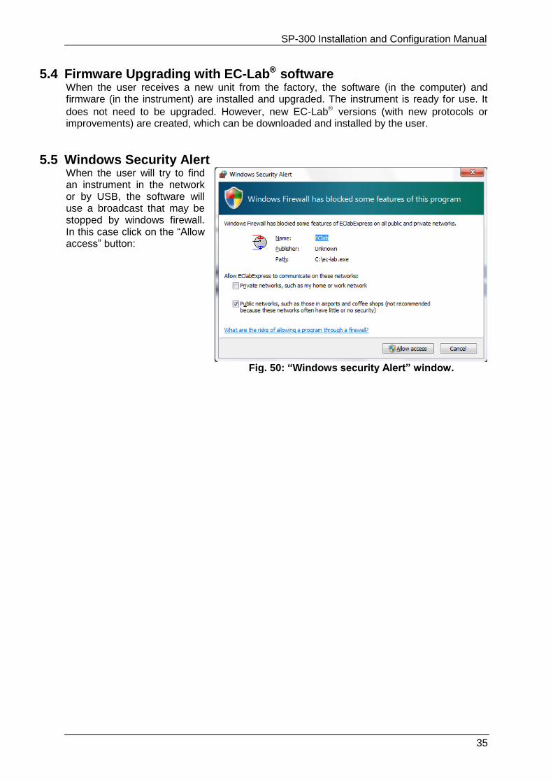
5.5 Windows Security Alert When the user will try to find an instrument in the network or by USB, the software will use a broadcast that may be stopped by windows firewall. In this case click on the “Allow access” button:
Fig. 50: “Windows security Alert” window.
SP-300 Installation and Configuration Manual
36
6. Advanced features
6.1 Bandwidth
6.1.1 Bandwidth selection with a standard channel
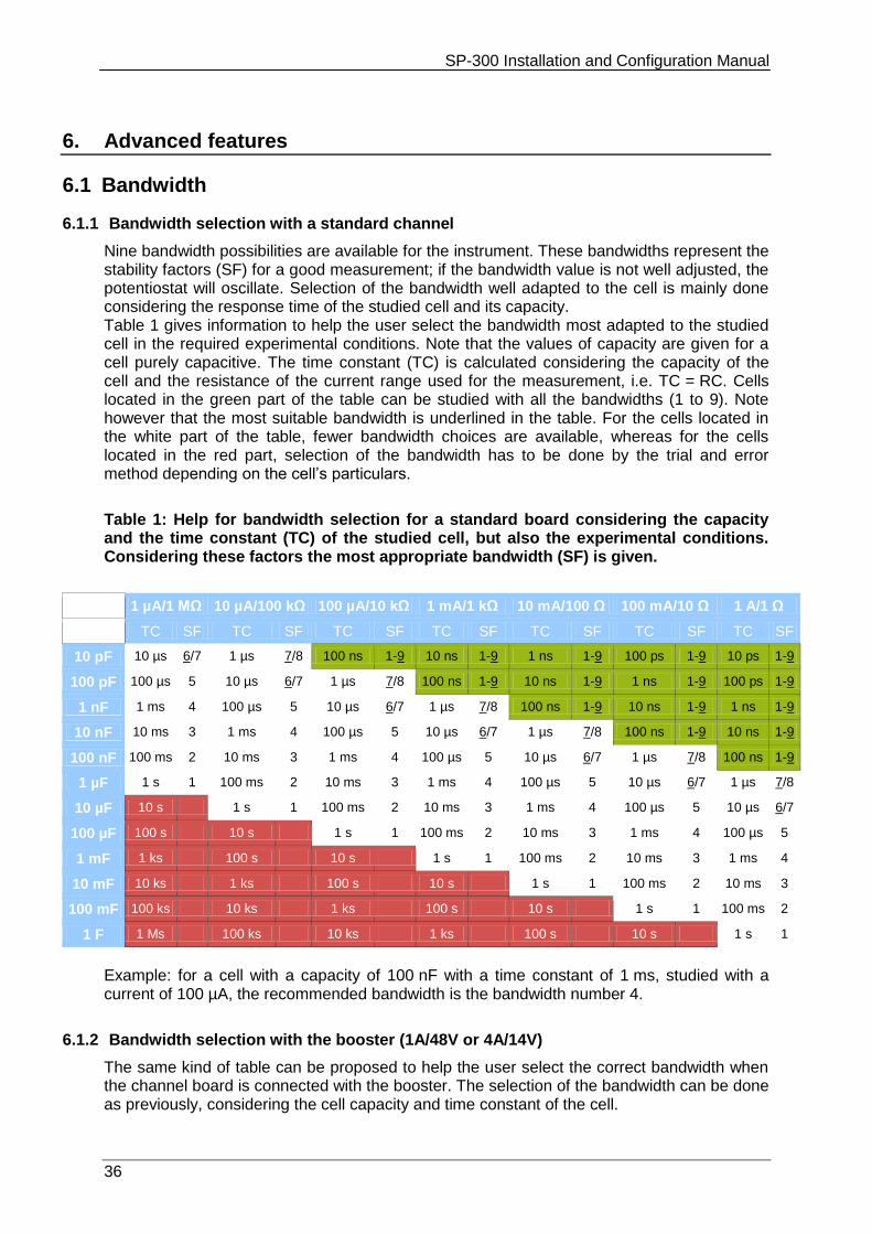
Nine bandwidth possibilities are available for the instrument. These bandwidths represent the stability factors (SF) for a good measurement; if the bandwidth value is not well adjusted, the potentiostat will oscillate. Selection of the bandwidth well adapted to the cell is mainly done considering the response time of the studied cell and its capacity. Table 1 gives information to help the user select the bandwidth most adapted to the studied cell in the required experimental conditions. Note that the values of capacity are given for a cell purely capacitive. The time constant (TC) is calculated considering the capacity of the cell and the resistance of the current range used for the measurement, i.e. TC = RC. Cells located in the green part of the table can be studied with all the bandwidths (1 to 9). Note however that the most suitable bandwidth is underlined in the table. For the cells located in the white part of the table, fewer bandwidth choices are available, whereas for the cells located in the red part, selection of the bandwidth has to be done by the trial and error method depending on the cell’s particulars.
Table 1: Help for bandwidth selection for a standard board considering the capacity and the time constant (TC) of the studied cell, but also the experimental conditions. Considering these factors the most appropriate bandwidth (SF) is given.
1 µA/1 MΩ 10 µA/100 kΩ 100 µA/10 kΩ 1 mA/1 kΩ 10 mA/100 Ω 100 mA/10 Ω 1 A/1 Ω
TC SF TC SF TC SF TC SF TC SF TC SF TC SF
10 pF 10 µs 6/7 1 µs 7/8 100 ns 1-9 10 ns 1-9 1 ns 1-9 100 ps 1-9 10 ps 1-9
100 pF 100 µs 5 10 µs 6/7 1 µs 7/8 100 ns 1-9 10 ns 1-9 1 ns 1-9 100 ps 1-9
1 nF 1 ms 4 100 µs 5 10 µs 6/7 1 µs 7/8 100 ns 1-9 10 ns 1-9 1 ns 1-9
10 nF 10 ms 3 1 ms 4 100 µs 5 10 µs 6/7 1 µs 7/8 100 ns 1-9 10 ns 1-9
100 nF 100 ms 2 10 ms 3 1 ms 4 100 µs 5 10 µs 6/7 1 µs 7/8 100 ns 1-9
1 µF 1 s 1 100 ms 2 10 ms 3 1 ms 4 100 µs 5 10 µs 6/7 1 µs 7/8
10 µF 10 s 1 s 1 100 ms 2 10 ms 3 1 ms 4 100 µs 5 10 µs 6/7
100 µF 100 s 10 s 1 s 1 100 ms 2 10 ms 3 1 ms 4 100 µs 5
1 mF 1 ks 100 s 10 s 1 s 1 100 ms 2 10 ms 3 1 ms 4
10 mF 10 ks 1 ks 100 s 10 s 1 s 1 100 ms 2 10 ms 3
100 mF 100 ks 10 ks 1 ks 100 s 10 s 1 s 1 100 ms 2
1 F 1 Ms 100 ks 10 ks 1 ks 100 s 10 s 1 s 1
Example: for a cell with a capacity of 100 nF with a time constant of 1 ms, studied with a current of 100 µA, the recommended bandwidth is the bandwidth number 4.
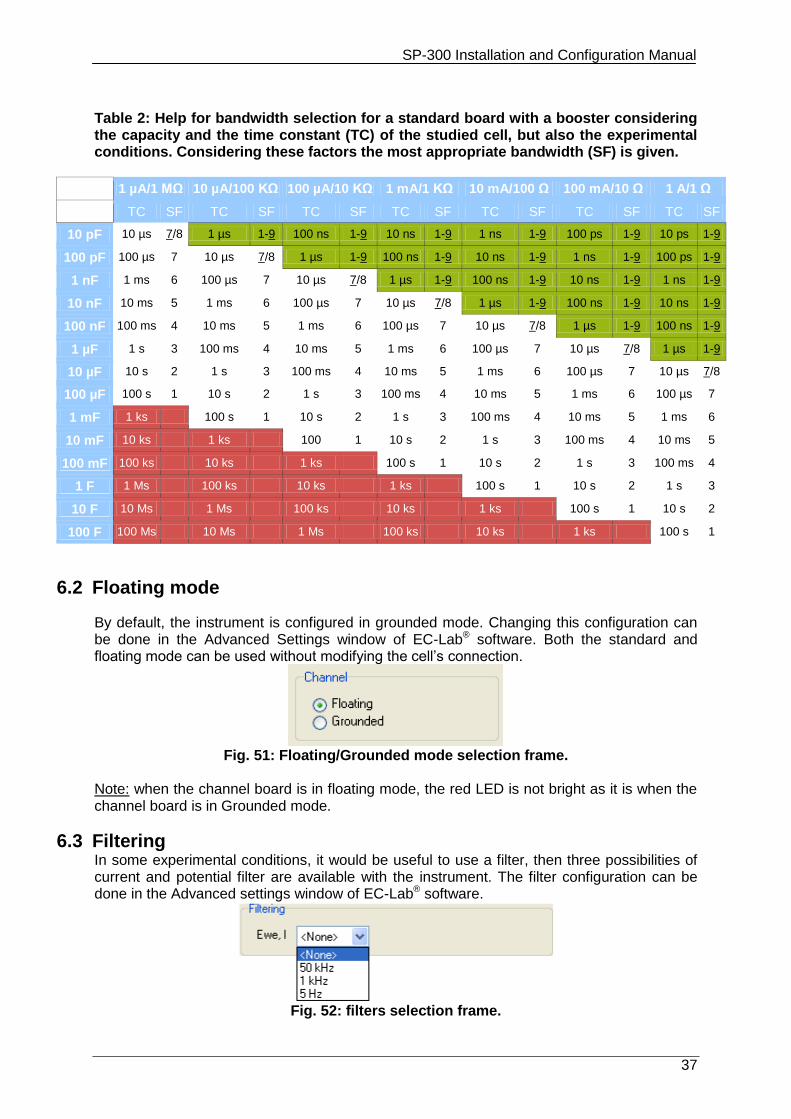
6.1.2 Bandwidth selection with the booster (1A/48V or 4A/14V)
The same kind of table can be proposed to help the user select the correct bandwidth when the channel board is connected with the booster. The selection of the bandwidth can be done as previously, considering the cell capacity and time constant of the cell.
SP-300 Installation and Configuration Manual
37
Table 2: Help for bandwidth selection for a standard board with a booster considering the capacity and the time constant (TC) of the studied cell, but also the experimental conditions. Considering these factors the most appropriate bandwidth (SF) is given.
1 µA/1 MΩ 10 µA/100 KΩ 100 µA/10 KΩ 1 mA/1 KΩ 10 mA/100 Ω 100 mA/10 Ω 1 A/1 Ω
TC SF TC SF TC SF TC SF TC SF TC SF TC SF
10 pF 10 µs 7/8 1 µs 1-9 100 ns 1-9 10 ns 1-9 1 ns 1-9 100 ps 1-9 10 ps 1-9
100 pF 100 µs 7 10 µs 7/8 1 µs 1-9 100 ns 1-9 10 ns 1-9 1 ns 1-9 100 ps 1-9
1 nF 1 ms 6 100 µs 7 10 µs 7/8 1 µs 1-9 100 ns 1-9 10 ns 1-9 1 ns 1-9
10 nF 10 ms 5 1 ms 6 100 µs 7 10 µs 7/8 1 µs 1-9 100 ns 1-9 10 ns 1-9
100 nF 100 ms 4 10 ms 5 1 ms 6 100 µs 7 10 µs 7/8 1 µs 1-9 100 ns 1-9
1 µF 1 s 3 100 ms 4 10 ms 5 1 ms 6 100 µs 7 10 µs 7/8 1 µs 1-9
10 µF 10 s 2 1 s 3 100 ms 4 10 ms 5 1 ms 6 100 µs 7 10 µs 7/8
100 µF 100 s 1 10 s 2 1 s 3 100 ms 4 10 ms 5 1 ms 6 100 µs 7
1 mF 1 ks 100 s 1 10 s 2 1 s 3 100 ms 4 10 ms 5 1 ms 6
10 mF 10 ks 1 ks 100 1 10 s 2 1 s 3 100 ms 4 10 ms 5
100 mF 100 ks 10 ks 1 ks 100 s 1 10 s 2 1 s 3 100 ms 4
1 F 1 Ms 100 ks 10 ks 1 ks 100 s 1 10 s 2 1 s 3
10 F 10 Ms 1 Ms 100 ks 10 ks 1 ks 100 s 1 10 s 2
100 F 100 Ms 10 Ms 1 Ms 100 ks 10 ks 1 ks 100 s 1
6.2 Floating mode
By default, the instrument is configured in grounded mode. Changing this configuration can be done in the Advanced Settings window of EC-Lab® software. Both the standard and floating mode can be used without modifying the cell’s connection.
Fig. 51: Floating/Grounded mode selection frame.
Note: when the channel board is in floating mode, the red LED is not bright as it is when the channel board is in Grounded mode.
6.3 Filtering In some experimental conditions, it would be useful to use a filter, then three possibilities of current and potential filter are available with the instrument. The filter configuration can be done in the Advanced settings window of EC-Lab® software.
Fig. 52: filters selection frame.
SP-300 Installation and Configuration Manual
38
6.4 External device control and recording
6.4.1 General description
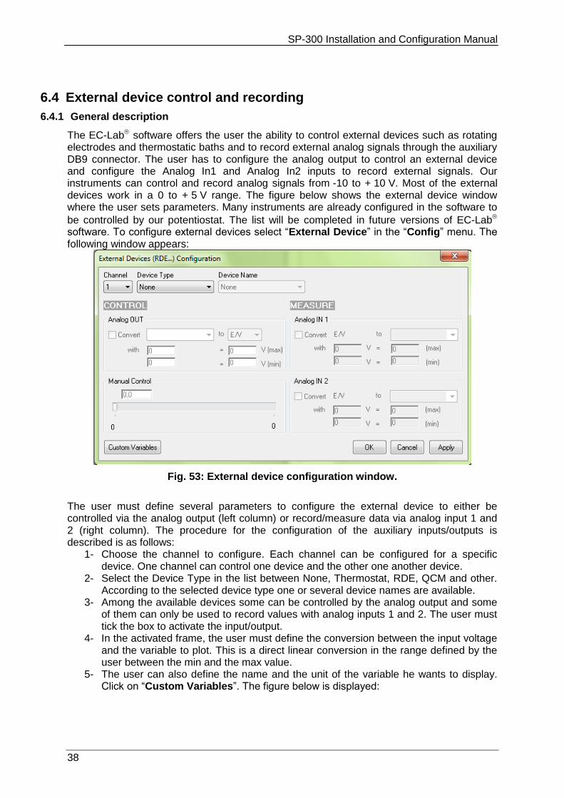
The EC-Lab software offers the user the ability to control external devices such as rotating electrodes and thermostatic baths and to record external analog signals through the auxiliary DB9 connector. The user has to configure the analog output to control an external device and configure the Analog In1 and Analog In2 inputs to record external signals. Our instruments can control and record analog signals from -10 to + 10 V. Most of the external devices work in a 0 to + 5 V range. The figure below shows the external device window where the user sets parameters. Many instruments are already configured in the software to
be controlled by our potentiostat. The list will be completed in future versions of EC-Lab software. To configure external devices select “External Device” in the “Config” menu. The following window appears:
Fig. 53: External device configuration window.
The user must define several parameters to configure the external device to either be controlled via the analog output (left column) or record/measure data via analog input 1 and 2 (right column). The procedure for the configuration of the auxiliary inputs/outputs is described is as follows:
1- Choose the channel to configure. Each channel can be configured for a specific device. One channel can control one device and the other one another device.
2- Select the Device Type in the list between None, Thermostat, RDE, QCM and other. According to the selected device type one or several device names are available.
3- Among the available devices some can be controlled by the analog output and some of them can only be used to record values with analog inputs 1 and 2. The user must tick the box to activate the input/output.
4- In the activated frame, the user must define the conversion between the input voltage and the variable to plot. This is a direct linear conversion in the range defined by the user between the min and the max value.
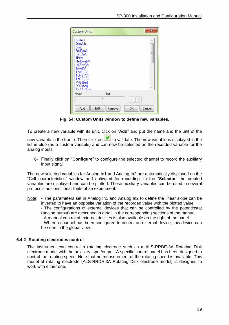
5- The user can also define the name and the unit of the variable he wants to display. Click on “Custom Variables”. The figure below is displayed:
SP-300 Installation and Configuration Manual
39
Fig. 54: Custom Units window to define new variables.
To create a new variable with its unit, click on “Add” and put the name and the unit of the
new variable in the frame. Then click on to validate. The new variable is displayed in the list in blue (as a custom variable) and can now be selected as the recorded variable for the analog inputs.
6- Finally click on “Configure” to configure the selected channel to record the auxiliary input signal
The new selected variables for Analog In1 and Analog In2 are automatically displayed on the “Cell characteristics” window and activated for recording. In the “Selector” the created variables are displayed and can be plotted. These auxiliary variables can be used in several protocols as conditional limits of an experiment. Note: - The parameters set in Analog In1 and Analog In2 to define the linear slope can be
inverted to have an opposite variation of the recorded value with the plotted value. - The configurations of external devices that can be controlled by the potentiostat (analog output) are described in detail in the corresponding sections of the manual.
- A manual control of external devices is also available on the right of the panel. - When a channel has been configured to control an external device, this device can be seen in the global view.
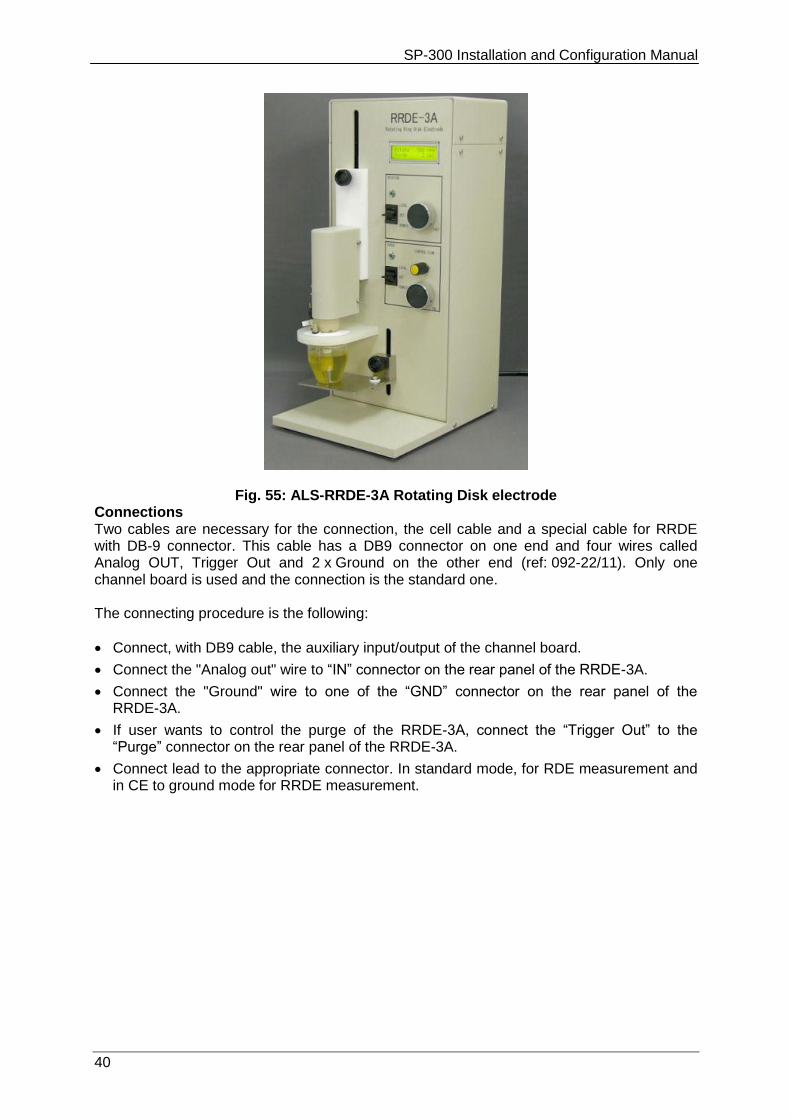
6.4.2 Rotating electrodes control
The instrument can control a rotating electrode such as a ALS-RRDE-3A Rotating Disk electrode model with the auxiliary input/output. A specific control panel has been designed to control the rotating speed. Note that no measurement of the rotating speed is available. This model of rotating electrode (ALS-RRDE-3A Rotating Disk electrode model) is designed to work with either one.
SP-300 Installation and Configuration Manual
40
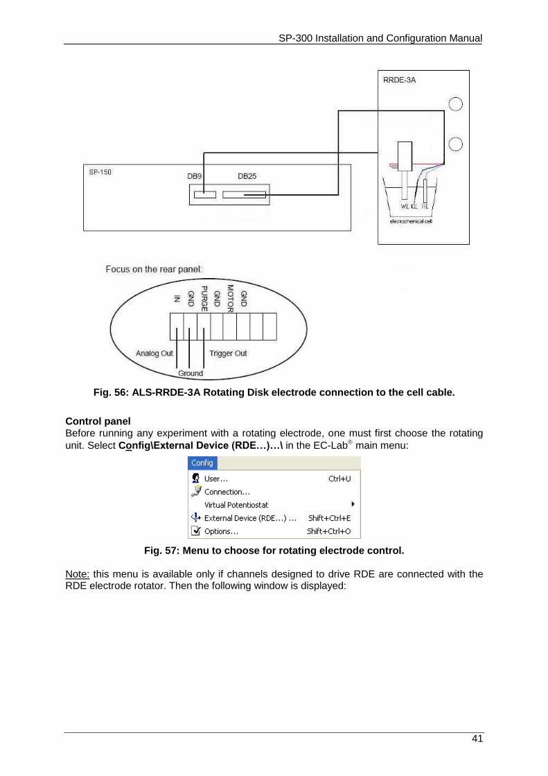
Fig. 55: ALS-RRDE-3A Rotating Disk electrode Connections Two cables are necessary for the connection, the cell cable and a special cable for RRDE with DB-9 connector. This cable has a DB9 connector on one end and four wires called Analog OUT, Trigger Out and 2 x Ground on the other end (ref: 092-22/11). Only one channel board is used and the connection is the standard one. The connecting procedure is the following:
Connect, with DB9 cable, the auxiliary input/output of the channel board.
Connect the "Analog out" wire to “IN” connector on the rear panel of the RRDE-3A.
Connect the "Ground" wire to one of the “GND” connector on the rear panel of the RRDE-3A.
If user wants to control the purge of the RRDE-3A, connect the “Trigger Out” to the “Purge” connector on the rear panel of the RRDE-3A.
Connect lead to the appropriate connector. In standard mode, for RDE measurement and in CE to ground mode for RRDE measurement.
SP-300 Installation and Configuration Manual
41
Fig. 56: ALS-RRDE-3A Rotating Disk electrode connection to the cell cable.
Control panel Before running any experiment with a rotating electrode, one must first choose the rotating
unit. Select Config\External Device (RDE…)…\ in the EC-Lab main menu:
Fig. 57: Menu to choose for rotating electrode control. Note: this menu is available only if channels designed to drive RDE are connected with the RDE electrode rotator. Then the following window is displayed:
SP-300 Installation and Configuration Manual
42
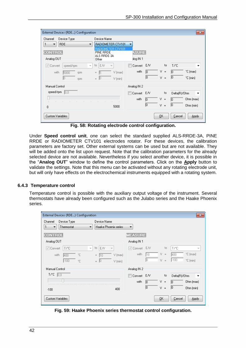
Fig. 58: Rotating electrode control configuration. Under Speed control unit, one can select the standard supplied ALS-RRDE-3A, PINE RRDE or RADIOMETER CTV101 electrodes rotator. For these devices, the calibration parameters are factory set. Other external systems can be used but are not available. They will be added onto the list upon request. Note that the calibration parameters for the already selected device are not available. Nevertheless if you select another device, it is possible in the “Analog OUT” window to define the control parameters. Click on the Apply button to validate the settings. Note that this menu can be activated without any rotating electrode unit, but will only have effects on the electrochemical instruments equipped with a rotating system.
6.4.3 Temperature control
Temperature control is possible with the auxiliary output voltage of the instrument. Several thermostats have already been configured such as the Julabo series and the Haake Phoenix series.
Fig. 59: Haake Phoenix series thermostat control configuration.
SP-300 Installation and Configuration Manual
43
The user can configure other thermostats to only record temperatures (Analog In) or to both control (Analog Out) and record (Analog In) temperature.
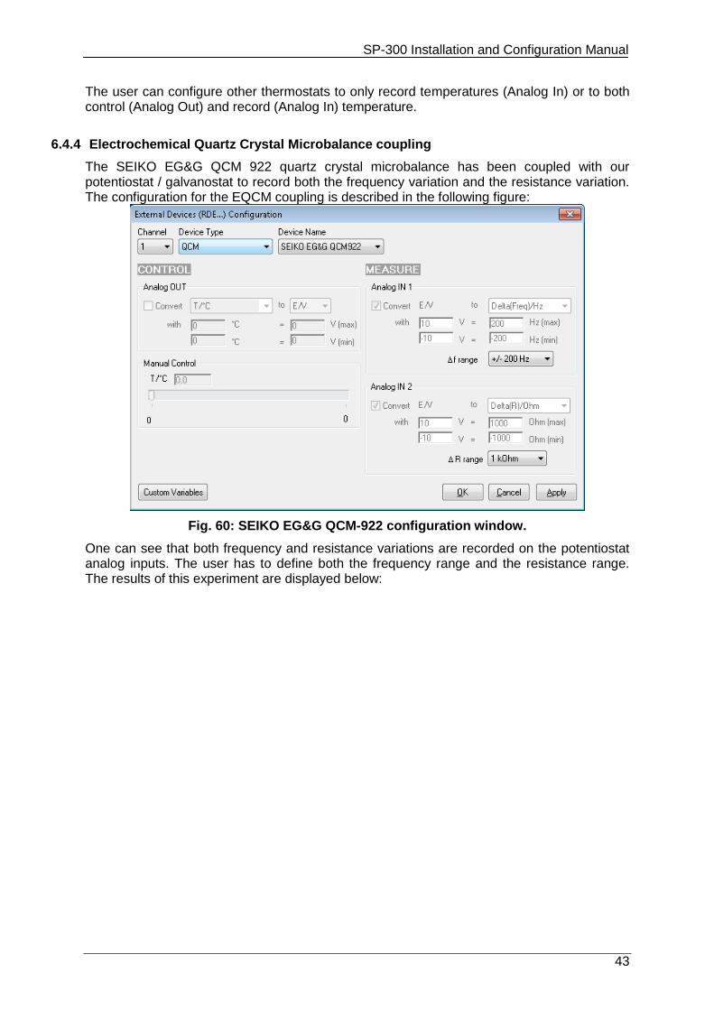
6.4.4 Electrochemical Quartz Crystal Microbalance coupling
The SEIKO EG&G QCM 922 quartz crystal microbalance has been coupled with our potentiostat / galvanostat to record both the frequency variation and the resistance variation. The configuration for the EQCM coupling is described in the following figure:
Fig. 60: SEIKO EG&G QCM-922 configuration window.
One can see that both frequency and resistance variations are recorded on the potentiostat analog inputs. The user has to define both the frequency range and the resistance range. The results of this experiment are displayed below:
SP-300 Installation and Configuration Manual
44
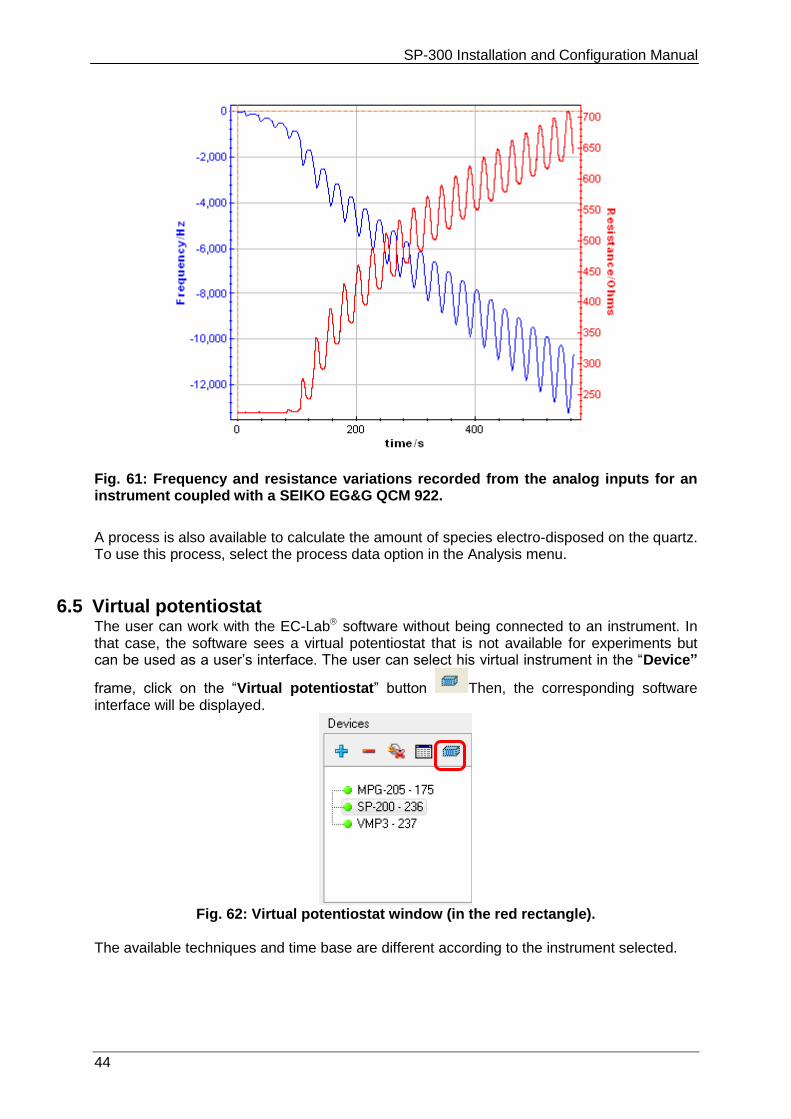
Fig. 61: Frequency and resistance variations recorded from the analog inputs for an instrument coupled with a SEIKO EG&G QCM 922.
A process is also available to calculate the amount of species electro-disposed on the quartz. To use this process, select the process data option in the Analysis menu.
6.5 Virtual potentiostat The user can work with the EC-Lab software without being connected to an instrument. In that case, the software sees a virtual potentiostat that is not available for experiments but can be used as a user’s interface. The user can select his virtual instrument in the “Device”
frame, click on the “Virtual potentiostat” button Then, the corresponding software interface will be displayed.
Fig. 62: Virtual potentiostat window (in the red rectangle).
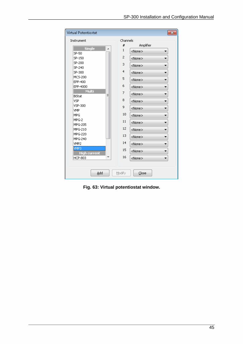
The available techniques and time base are different according to the instrument selected.
SP-300 Installation and Configuration Manual
45
Fig. 63: Virtual potentiostat window.
SP-300 Installation and Configuration Manual
46
7. The accessories and options
7.1 Boosters Two boosters are available i.e. boosters 1 A/48 V or booster 4A/14V.
7.1.1 1A/48V
This booster 1A/48V increases the unit’s compliance and the cell polarization to +/- 48 V. This option is compatible with another option the Ultra Low current option providing then current autoranging from 1 pA to 1 A. This option can be used both with EIS (maximum frequency is 2 MHz) and standard channel boards. Once the booster is connected to the potentiostat board, connection to the cell is the same as without the booster 1A/48V connected.
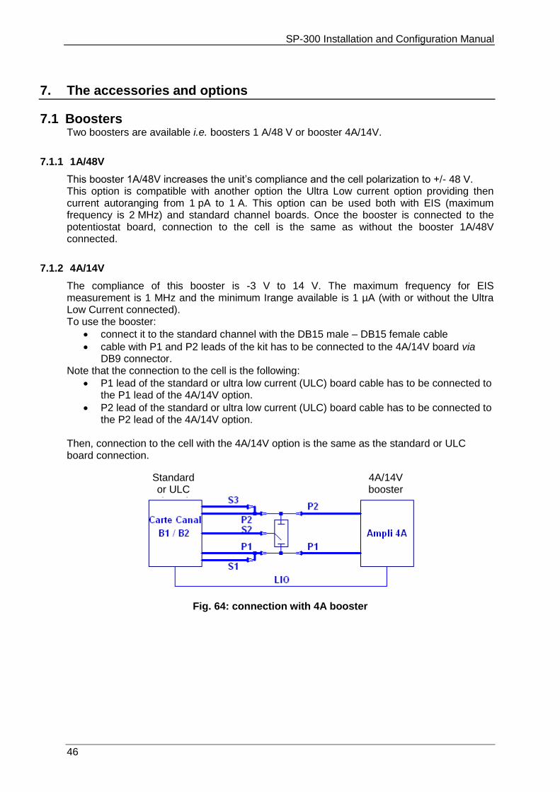
7.1.2 4A/14V
The compliance of this booster is -3 V to 14 V. The maximum frequency for EIS measurement is 1 MHz and the minimum Irange available is 1 µA (with or without the Ultra Low Current connected). To use the booster:
connect it to the standard channel with the DB15 male – DB15 female cable
cable with P1 and P2 leads of the kit has to be connected to the 4A/14V board via DB9 connector.
Note that the connection to the cell is the following:
P1 lead of the standard or ultra low current (ULC) board cable has to be connected to the P1 lead of the 4A/14V option.
P2 lead of the standard or ultra low current (ULC) board cable has to be connected to the P2 lead of the 4A/14V option.
Then, connection to the cell with the 4A/14V option is the same as the standard or ULC board connection.
Fig. 64: connection with 4A booster
4A/14V booster
Standard or ULC board
SP-300 Installation and Configuration Manual
47
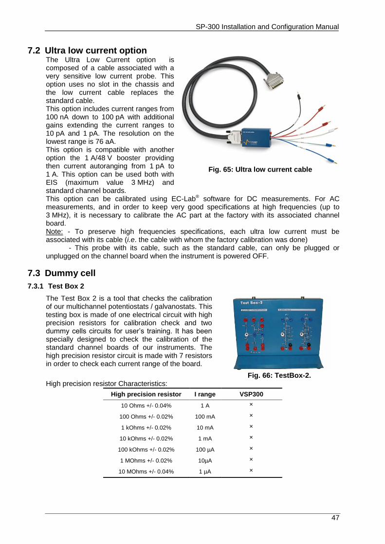
7.2 Ultra low current option The Ultra Low Current option is composed of a cable associated with a very sensitive low current probe. This option uses no slot in the chassis and the low current cable replaces the standard cable. This option includes current ranges from 100 nA down to 100 pA with additional gains extending the current ranges to 10 pA and 1 pA. The resolution on the lowest range is 76 aA. This option is compatible with another option the 1 A/48 V booster providing then current autoranging from 1 pA to 1 A. This option can be used both with EIS (maximum value 3 MHz) and standard channel boards.
Fig. 65: Ultra low current cable
This option can be calibrated using EC-Lab® software for DC measurements. For AC measurements, and in order to keep very good specifications at high frequencies (up to 3 MHz), it is necessary to calibrate the AC part at the factory with its associated channel board. Note: - To preserve high frequencies specifications, each ultra low current must be associated with its cable (i.e. the cable with whom the factory calibration was done) - This probe with its cable, such as the standard cable, can only be plugged or unplugged on the channel board when the instrument is powered OFF.
7.3 Dummy cell
7.3.1 Test Box 2
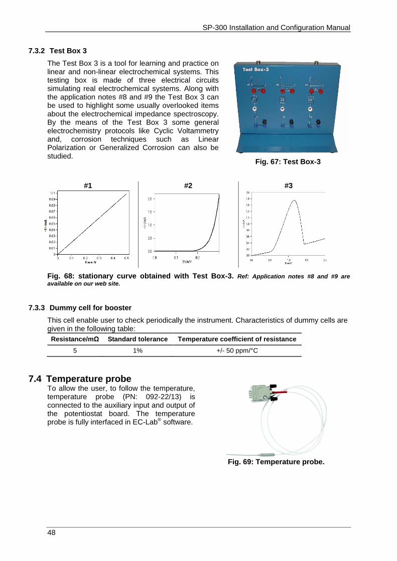
The Test Box 2 is a tool that checks the calibration of our multichannel potentiostats / galvanostats. This testing box is made of one electrical circuit with high precision resistors for calibration check and two dummy cells circuits for user’s training. It has been specially designed to check the calibration of the standard channel boards of our instruments. The high precision resistor circuit is made with 7 resistors in order to check each current range of the board.
Fig. 66: TestBox-2. High precision resistor Characteristics:
High precision resistor I range VSP300
10 Ohms +/- 0.04% 1 A
100 Ohms +/- 0.02% 100 mA
1 kOhms +/- 0.02% 10 mA
10 kOhms +/- 0.02% 1 mA
100 kOhms +/- 0.02% 100 µA
1 MOhms +/- 0.02% 10µA
10 MOhms +/- 0.04% 1 µA
SP-300 Installation and Configuration Manual
48
7.3.2 Test Box 3
The Test Box 3 is a tool for learning and practice on linear and non-linear electrochemical systems. This testing box is made of three electrical circuits simulating real electrochemical systems. Along with the application notes #8 and #9 the Test Box 3 can be used to highlight some usually overlooked items about the electrochemical impedance spectroscopy. By the means of the Test Box 3 some general electrochemistry protocols like Cyclic Voltammetry and, corrosion techniques such as Linear Polarization or Generalized Corrosion can also be studied.
Fig. 67: Test Box-3
#1
#2
#3
Fig. 68: stationary curve obtained with Test Box-3. Ref: Application notes #8 and #9 are
available on our web site.
7.3.3 Dummy cell for booster
This cell enable user to check periodically the instrument. Characteristics of dummy cells are given in the following table:
Resistance/mΩ Standard tolerance Temperature coefficient of resistance
5 1% +/- 50 ppm/°C
7.4 Temperature probe To allow the user, to follow the temperature, temperature probe (PN: 092-22/13) is connected to the auxiliary input and output of the potentiostat board. The temperature probe is fully interfaced in EC-Lab® software.
Fig. 69: Temperature probe.
SP-300 Installation and Configuration Manual
49
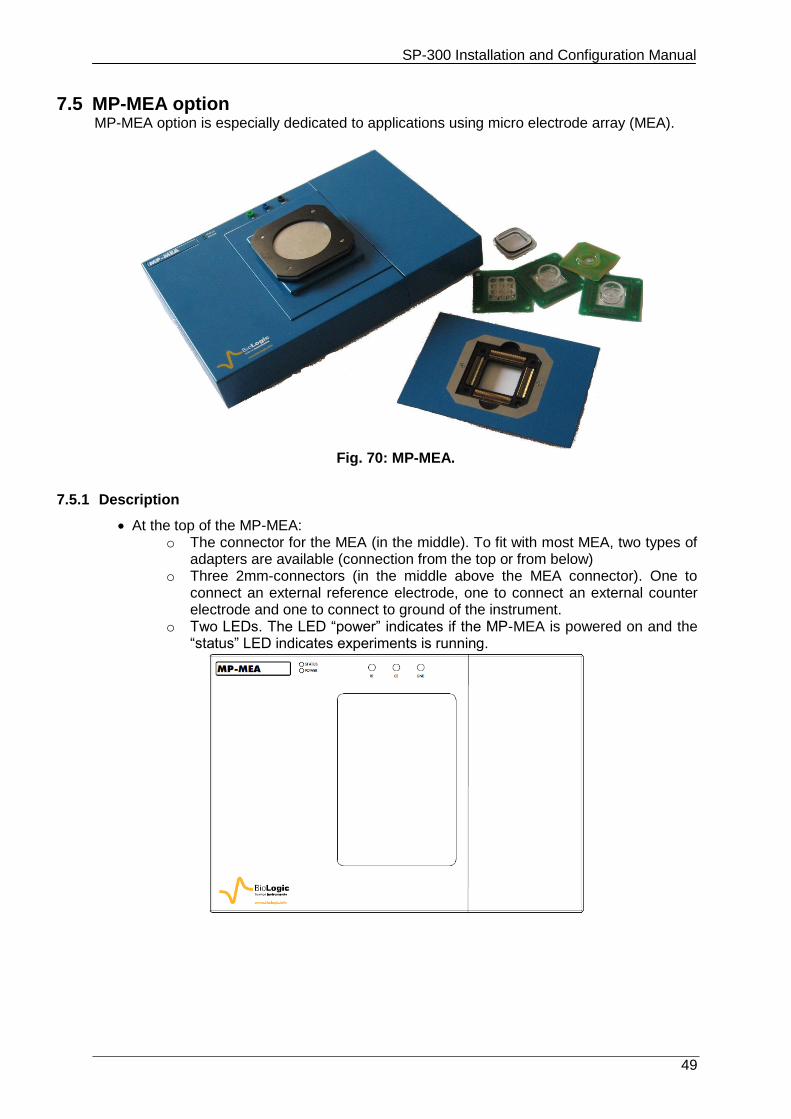
7.5 MP-MEA option MP-MEA option is especially dedicated to applications using micro electrode array (MEA).
Fig. 70: MP-MEA.
7.5.1 Description
At the top of the MP-MEA: o The connector for the MEA (in the middle). To fit with most MEA, two types of
adapters are available (connection from the top or from below) o Three 2mm-connectors (in the middle above the MEA connector). One to
connect an external reference electrode, one to connect an external counter electrode and one to connect to ground of the instrument.
o Two LEDs. The LED “power” indicates if the MP-MEA is powered on and the “status” LED indicates experiments is running.
SP-300 Installation and Configuration Manual
50
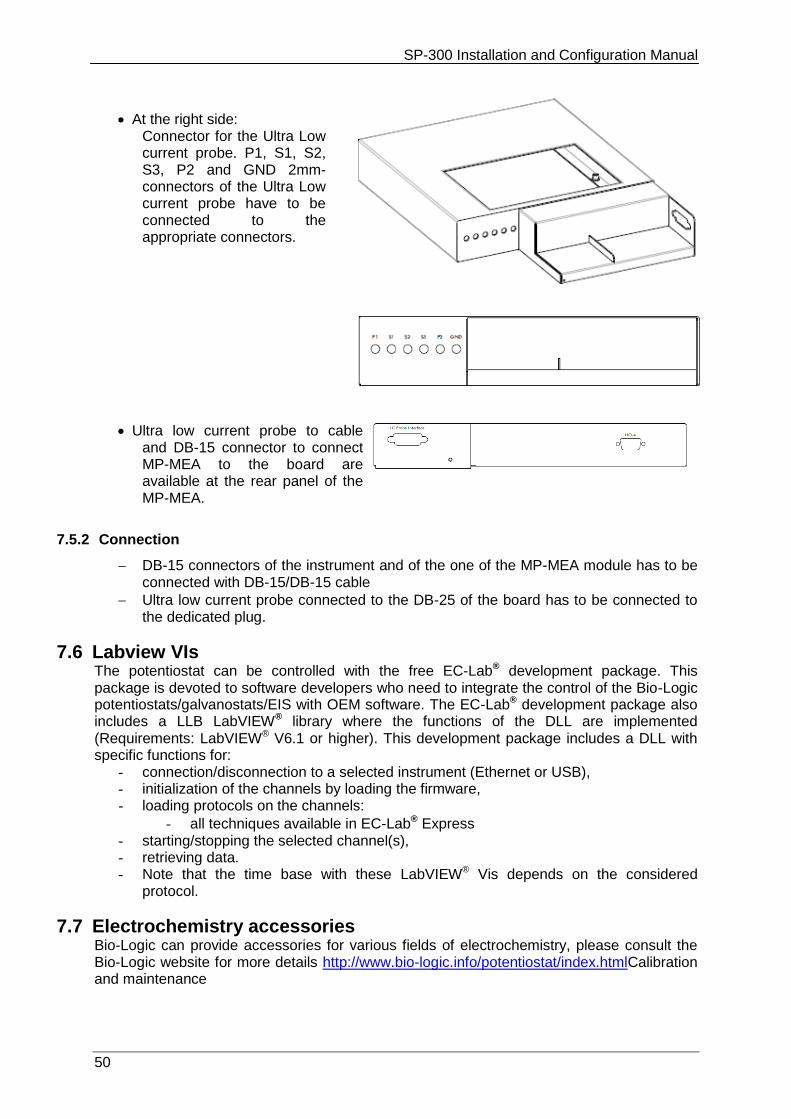
At the right side: Connector for the Ultra Low current probe. P1, S1, S2, S3, P2 and GND 2mm-connectors of the Ultra Low current probe have to be connected to the appropriate connectors.
Ultra low current probe to cable and DB-15 connector to connect MP-MEA to the board are available at the rear panel of the MP-MEA.
7.5.2 Connection
DB-15 connectors of the instrument and of the one of the MP-MEA module has to be connected with DB-15/DB-15 cable
Ultra low current probe connected to the DB-25 of the board has to be connected to the dedicated plug.
7.6 Labview VIs The potentiostat can be controlled with the free EC-Lab® development package. This package is devoted to software developers who need to integrate the control of the Bio-Logic potentiostats/galvanostats/EIS with OEM software. The EC-Lab® development package also includes a LLB LabVIEW® library where the functions of the DLL are implemented (Requirements: LabVIEW® V6.1 or higher). This development package includes a DLL with specific functions for:
- connection/disconnection to a selected instrument (Ethernet or USB), - initialization of the channels by loading the firmware, - loading protocols on the channels:
- all techniques available in EC-Lab® Express - starting/stopping the selected channel(s), - retrieving data. - Note that the time base with these LabVIEW® Vis depends on the considered
protocol.
7.7 Electrochemistry accessories Bio-Logic can provide accessories for various fields of electrochemistry, please consult the Bio-Logic website for more details http://www.bio-logic.info/potentiostat/index.htmlCalibration and maintenance
SP-300 Installation and Configuration Manual
51
8. Calibration and maintenance
8.1 Software channel calibration
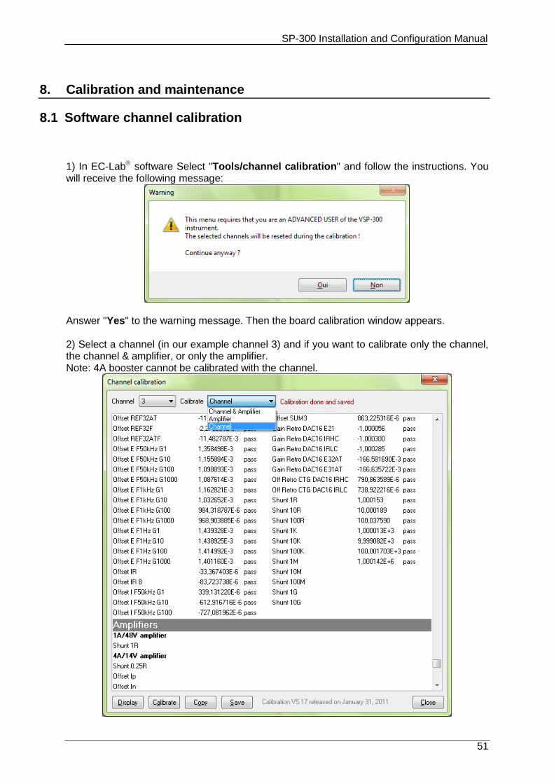
1) In EC-Lab software Select "Tools/channel calibration" and follow the instructions. You will receive the following message:
Answer "Yes" to the warning message. Then the board calibration window appears. 2) Select a channel (in our example channel 3) and if you want to calibrate only the channel, the channel & amplifier, or only the amplifier. Note: 4A booster cannot be calibrated with the channel.
SP-300 Installation and Configuration Manual
52
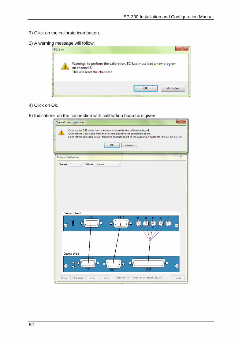
3) Click on the calibrate icon button. 3) A warning message will follow:
4) Click on Ok. 5) Indications on the connection with calibration board are given
SP-300 Installation and Configuration Manual
53
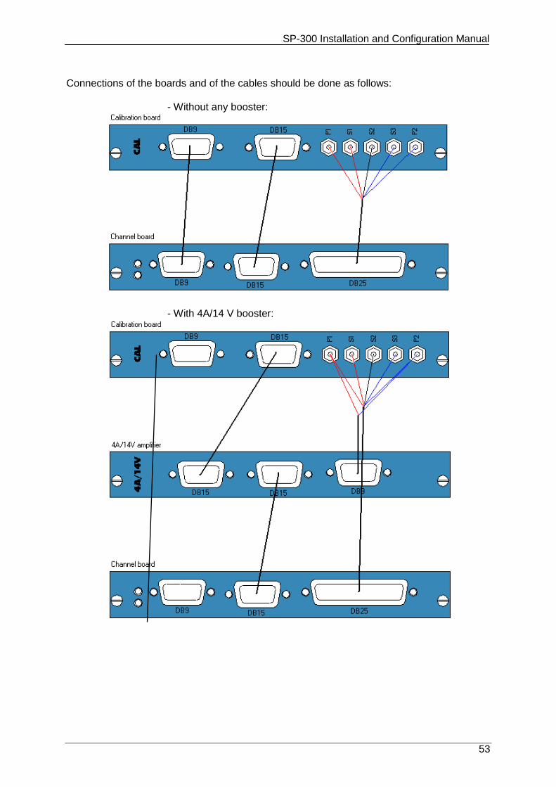
Connections of the boards and of the cables should be done as follows:
- Without any booster:
- With 4A/14 V booster:
SP-300 Installation and Configuration Manual
54
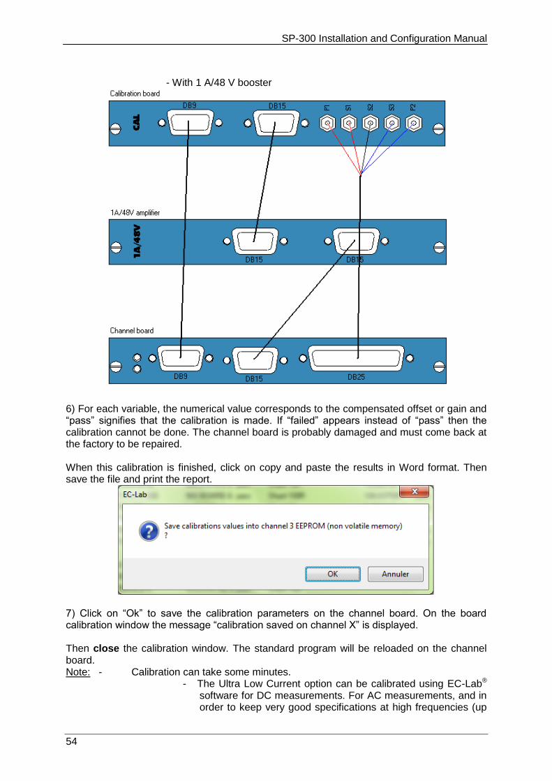
- With 1 A/48 V booster
6) For each variable, the numerical value corresponds to the compensated offset or gain and “pass” signifies that the calibration is made. If “failed” appears instead of “pass” then the calibration cannot be done. The channel board is probably damaged and must come back at the factory to be repaired. When this calibration is finished, click on copy and paste the results in Word format. Then save the file and print the report.
7) Click on “Ok” to save the calibration parameters on the channel board. On the board calibration window the message “calibration saved on channel X” is displayed.
Then close the calibration window. The standard program will be reloaded on the channel board. Note: - Calibration can take some minutes.
- The Ultra Low Current option can be calibrated using EC-Lab® software for DC measurements. For AC measurements, and in order to keep very good specifications at high frequencies (up
SP-300 Installation and Configuration Manual
55
to 3 MHz), it is necessary to calibrate the AC part at the factory with its associated channel board.
- To preserve high frequencies specifications, each ultra low current must be associated with its cable (i.e. the cable with whom the factory calibration was done) for measurements.
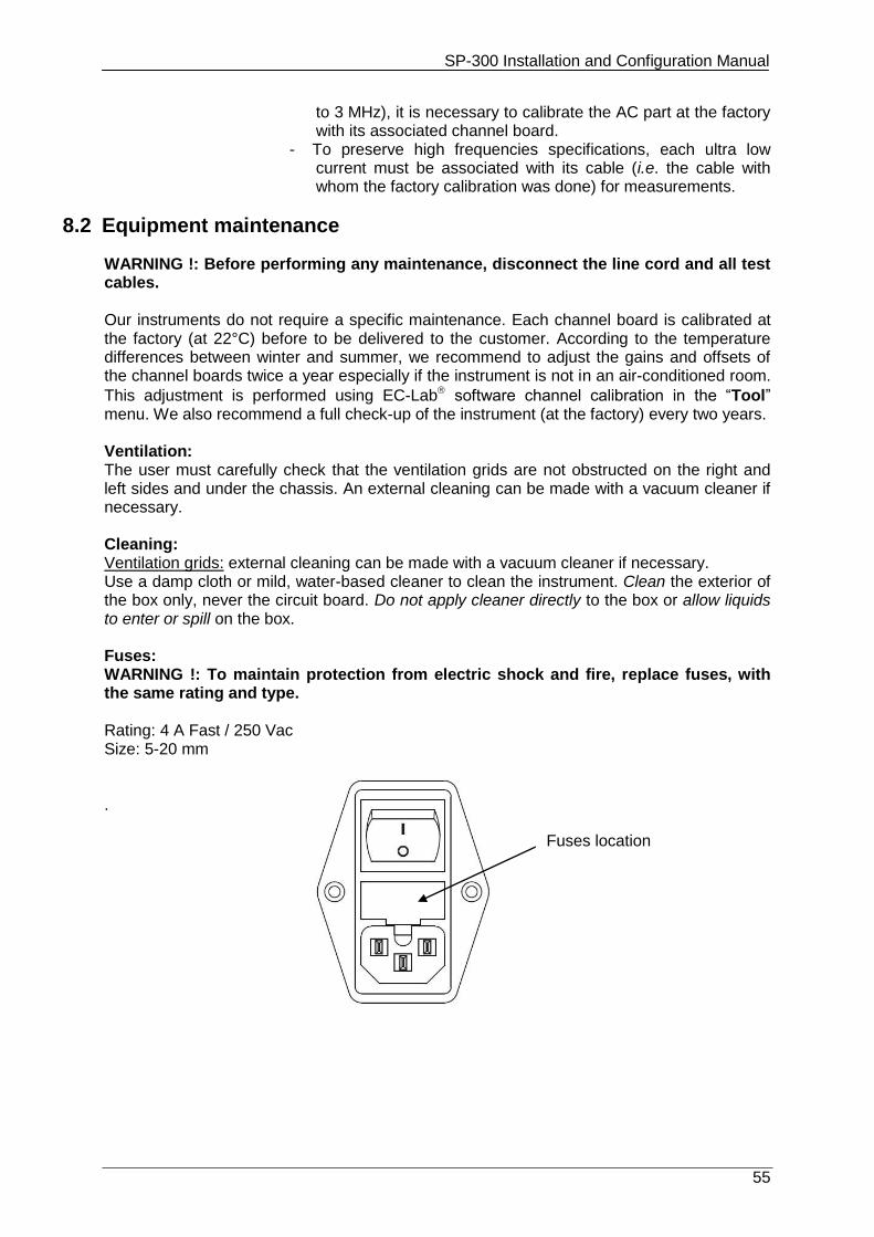
8.2 Equipment maintenance
WARNING !: Before performing any maintenance, disconnect the line cord and all test cables. Our instruments do not require a specific maintenance. Each channel board is calibrated at the factory (at 22°C) before to be delivered to the customer. According to the temperature differences between winter and summer, we recommend to adjust the gains and offsets of the channel boards twice a year especially if the instrument is not in an air-conditioned room.
This adjustment is performed using EC-Lab software channel calibration in the “Tool” menu. We also recommend a full check-up of the instrument (at the factory) every two years. Ventilation: The user must carefully check that the ventilation grids are not obstructed on the right and left sides and under the chassis. An external cleaning can be made with a vacuum cleaner if necessary. Cleaning: Ventilation grids: external cleaning can be made with a vacuum cleaner if necessary. Use a damp cloth or mild, water-based cleaner to clean the instrument. Clean the exterior of the box only, never the circuit board. Do not apply cleaner directly to the box or allow liquids to enter or spill on the box. Fuses: WARNING !: To maintain protection from electric shock and fire, replace fuses, with the same rating and type. Rating: 4 A Fast / 250 Vac Size: 5-20 mm .
Fuses location
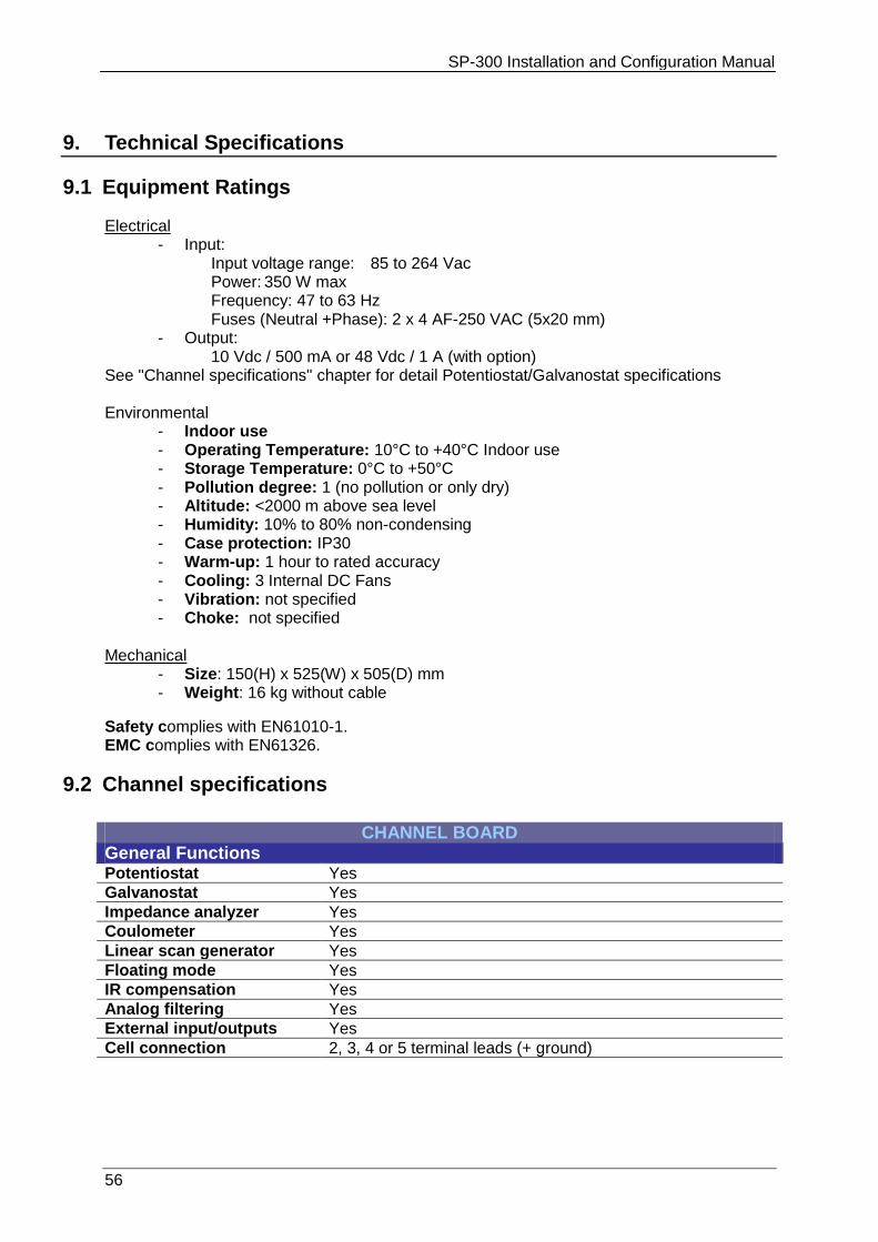
SP-300 Installation and Configuration Manual
56
9. Technical Specifications
9.1 Equipment Ratings
Electrical - Input:
Input voltage range: 85 to 264 Vac Power: 350 W max Frequency: 47 to 63 Hz Fuses (Neutral +Phase): 2 x 4 AF-250 VAC (5x20 mm)
- Output: 10 Vdc / 500 mA or 48 Vdc / 1 A (with option)
See "Channel specifications" chapter for detail Potentiostat/Galvanostat specifications Environmental
- Indoor use - Operating Temperature: 10°C to +40°C Indoor use - Storage Temperature: 0°C to +50°C - Pollution degree: 1 (no pollution or only dry) - Altitude: <2000 m above sea level - Humidity: 10% to 80% non-condensing - Case protection: IP30 - Warm-up: 1 hour to rated accuracy - Cooling: 3 Internal DC Fans - Vibration: not specified - Choke: not specified
Mechanical
- Size: 150(H) x 525(W) x 505(D) mm - Weight: 16 kg without cable
Safety complies with EN61010-1. EMC complies with EN61326.
9.2 Channel specifications
CHANNEL BOARD General Functions
Potentiostat Yes
Galvanostat Yes
Impedance analyzer Yes
Coulometer Yes
Linear scan generator Yes
Floating mode Yes
IR compensation Yes
Analog filtering Yes
External input/outputs Yes
Cell connection 2, 3, 4 or 5 terminal leads (+ ground)
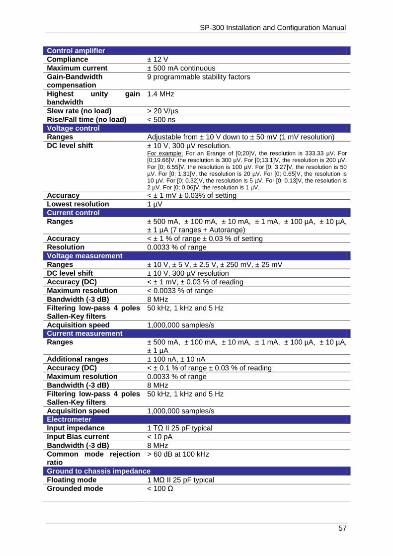
SP-300 Installation and Configuration Manual
57
Control amplifier
Compliance ± 12 V
Maximum current ± 500 mA continuous
Gain-Bandwidth compensation
9 programmable stability factors
Highest unity gain bandwidth
1.4 MHz
Slew rate (no load) > 20 V/µs
Rise/Fall time (no load) < 500 ns
Voltage control
Ranges Adjustable from ± 10 V down to ± 50 mV (1 mV resolution)
DC level shift ± 10 V, 300 µV resolution. For example: For an Erange of [0;20]V, the resolution is 333.33 µV. For [0;19.66]V, the resolution is 300 µV. For [0;13.1]V, the resolution is 200 µV. For [0; 6.55]V, the resolution is 100 µV. For [0; 3.27]V, the resolution is 50 µV. For [0; 1.31]V, the resolution is 20 µV. For [0; 0.65]V, the resolution is 10 µV. For [0; 0.32]V, the resolution is 5 µV. For [0; 0.13]V, the resolution is 2 µV. For [0; 0.06]V, the resolution is 1 µV.
Accuracy < ± 1 mV ± 0.03% of setting
Lowest resolution 1 µV
Current control
Ranges ± 500 mA, ± 100 mA, ± 10 mA, ± 1 mA, ± 100 µA, ± 10 µA, ± 1 µA (7 ranges + Autorange)
Accuracy < ± 1 % of range ± 0.03 % of setting
Resolution 0.0033 % of range
Voltage measurement
Ranges ± 10 V, ± 5 V, ± 2.5 V, ± 250 mV, ± 25 mV
DC level shift ± 10 V, 300 µV resolution
Accuracy (DC) < ± 1 mV, ± 0.03 % of reading
Maximum resolution < 0.0033 % of range
Bandwidth (-3 dB) 8 MHz
Filtering low-pass 4 poles Sallen-Key filters
50 kHz, 1 kHz and 5 Hz
Acquisition speed 1,000,000 samples/s Current measurement
Ranges ± 500 mA, ± 100 mA, ± 10 mA, ± 1 mA, ± 100 µA, ± 10 µA, ± 1 µA
Additional ranges ± 100 nA, ± 10 nA
Accuracy (DC) < ± 0.1 % of range ± 0.03 % of reading
Maximum resolution 0.0033 % of range
Bandwidth (-3 dB) 8 MHz
Filtering low-pass 4 poles Sallen-Key filters
50 kHz, 1 kHz and 5 Hz
Acquisition speed 1,000,000 samples/s Electrometer
Input impedance 1 TΩ ΙΙ 25 pF typical
Input Bias current < 10 pA
Bandwidth (-3 dB) 8 MHz
Common mode rejection ratio
> 60 dB at 100 kHz
Ground to chassis impedance
Floating mode 1 MΩ ΙΙ 25 pF typical
Grounded mode < 100 Ω
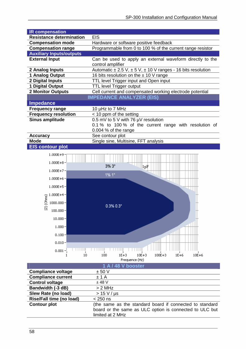
SP-300 Installation and Configuration Manual
58
IR compensation
Resistance determination EIS
Compensation mode Hardware or software positive feedback
Compensation range Programmable from 0 to 100 % of the current range resistor
Auxiliary Inputs/outputs
External Input Can be used to apply an external waveform directly to the control amplifier
2 Analog Inputs Automatic ± 2.5 V, ± 5 V, ± 10 V ranges - 16 bits resolution
1 Analog Output 16 bits resolution on the ± 10 V range
2 Digital Inputs TTL level Trigger input and Open input
1 Digital Output TTL level Trigger output
2 Monitor Outputs Cell current and compensated working electrode potential
IMPEDANCE ANALYZER (EIS) Impedance
Frequency range 10 µHz to 7 MHz
Frequency resolution < 10 ppm of the setting
Sinus amplitude 0.5 mV to 5 V with 76 µV resolution 0.1 % to 100 % of the current range with resolution of 0.004 % of the range
Accuracy See contour plot
Mode Single sine, Multisine, FFT analysis
EIS contour plot
1 A / 48 V booster
Compliance voltage ± 50 V
Compliance current ± 1 A
Control voltage ± 48 V
Bandwidth (-3 dB) > 2 MHz
Slew Rate (no load) > 15 V / µs
Rise/Fall time (no load) < 250 ns
Contour plot (the same as the standard board if connected to standard board or the same as ULC option is connected to ULC but limited at 2 MHz
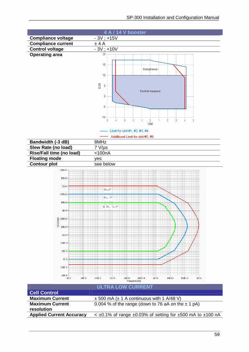
SP-300 Installation and Configuration Manual
59
4 A / 14 V booster
Compliance voltage - 3V ; +15V
Compliance current ± 4 A
Control voltage - 3V ; +10V
Operating area
Bandwidth (-3 dB) 8MHz
Slew Rate (no load) 7 V/µs
Rise/Fall time (no load) <100nA
Floating mode yes
Contour plot see below
ULTRA LOW CURRENT
Cell Control
Maximum Current ± 500 mA (± 1 A continuous with 1 A/48 V)
Maximum Current resolution
0.004 % of the range (down to 76 aA on the ± 1 pA)
Applied Current Accuracy < ±0.1% of range ±0.03% of setting for ±500 mA to ±100 nA
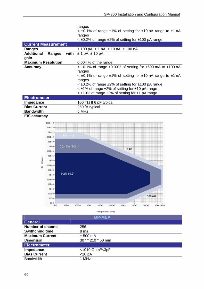
SP-300 Installation and Configuration Manual
60
ranges < ±0.1% of range ±1% of setting for ±10 nA range to ±1 nA ranges < ±0.2% of range ±2% of setting for ±100 pA range
Current Measurement Ranges ± 100 pA, ± 1 nA, ± 10 nA, ± 100 nA
Additional Ranges with gain
± 1 pA, ± 10 pA
Maximum Resolution 0.004 % of the range
Accuracy < ±0.1% of range ±0.03% of setting for ±500 mA to ±100 nA ranges < ±0.1% of range ±1% of setting for ±10 nA range to ±1 nA ranges < ±0.2% of range ±2% of setting for ±100 pA range < ±1% of range ±2% of setting for ±10 pA range < ±10% of range ±2% of setting for ±1 pA range
Electrometer Impedance 100 TΩ ІІ 6 pF typical
Bias Current 250 fA typical
Bandwidth 5 MHz
EIS accuracy
MP-MEA
General
Number of channel 256
Swithching time 8 ms
Maximum Current ± 500 mA
Dimension 307 * 210 * 50 mm
Electrometer Impedance <1010 Ohm//<3pF
Bias Current <10 pA
Bandwidth 1 MHz
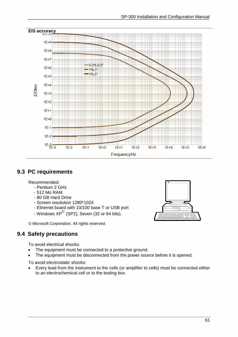
SP-300 Installation and Configuration Manual
61
EIS accuracy
9.3 PC requirements
Recommended: - Pentium 2 GHz - 512 Mo RAM - 80 GB Hard Drive - Screen resolution 1280*1024 - Ethernet board with 10/100 base T or USB port
- Windows XP© (SP2), Seven (32 or 64 bits).
© Microsoft Corporation. All rights reserved.
9.4 Safety precautions
To avoid electrical shocks:
The equipment must be connected to a protective ground.
The equipment must be disconnected from the power source before it is opened.
To avoid electrostatic shocks:
Every lead from the instrument to the cells (or amplifier to cells) must be connected either to an electrochemical cell or to the testing box.
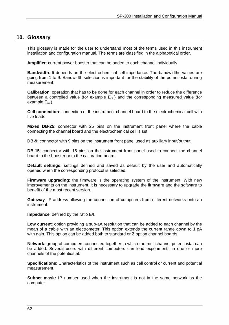
SP-300 Installation and Configuration Manual
62
10. Glossary
This glossary is made for the user to understand most of the terms used in this instrument installation and configuration manual. The terms are classified in the alphabetical order. Amplifier: current power booster that can be added to each channel individually. Bandwidth: It depends on the electrochemical cell impedance. The bandwidths values are going from 1 to 9. Bandwidth selection is important for the stability of the potentiostat during measurement. Calibration: operation that has to be done for each channel in order to reduce the difference between a controlled value (for example Ectrl) and the corresponding measured value (for example Ewe). Cell connection: connection of the instrument channel board to the electrochemical cell with five leads. Mixed DB-25: connector with 25 pins on the instrument front panel where the cable connecting the channel board and the electrochemical cell is set. DB-9: connector with 9 pins on the instrument front panel used as auxiliary input/output. DB-15: connector with 15 pins on the instrument front panel used to connect the channel board to the booster or to the calibration board. Default settings: settings defined and saved as default by the user and automatically opened when the corresponding protocol is selected. Firmware upgrading: the firmware is the operating system of the instrument. With new improvements on the instrument, it is necessary to upgrade the firmware and the software to benefit of the most recent version. Gateway: IP address allowing the connection of computers from different networks onto an instrument. Impedance: defined by the ratio E/I. Low current: option providing a sub-aA resolution that can be added to each channel by the mean of a cable with an electrometer. This option extends the current range down to 1 pA with gain. This option can be added both to standard or Z option channel boards. Network: group of computers connected together in which the multichannel potentiostat can be added. Several users with different computers can lead experiments in one or more channels of the potentiostat. Specifications: Characteristics of the instrument such as cell control or current and potential measurement. Subnet mask: IP number used when the instrument is not in the same network as the computer.

SP-300 Installation and Configuration Manual
63
TCP/IP: Transfer Control Protocol/Internet Protocol using IP addresses to identify hosts on a network. Triggers: option that allows the instrument to set a trigger out (TTL signal) at experiment start/stop or to wait for an external trigger in to start or stop the run.
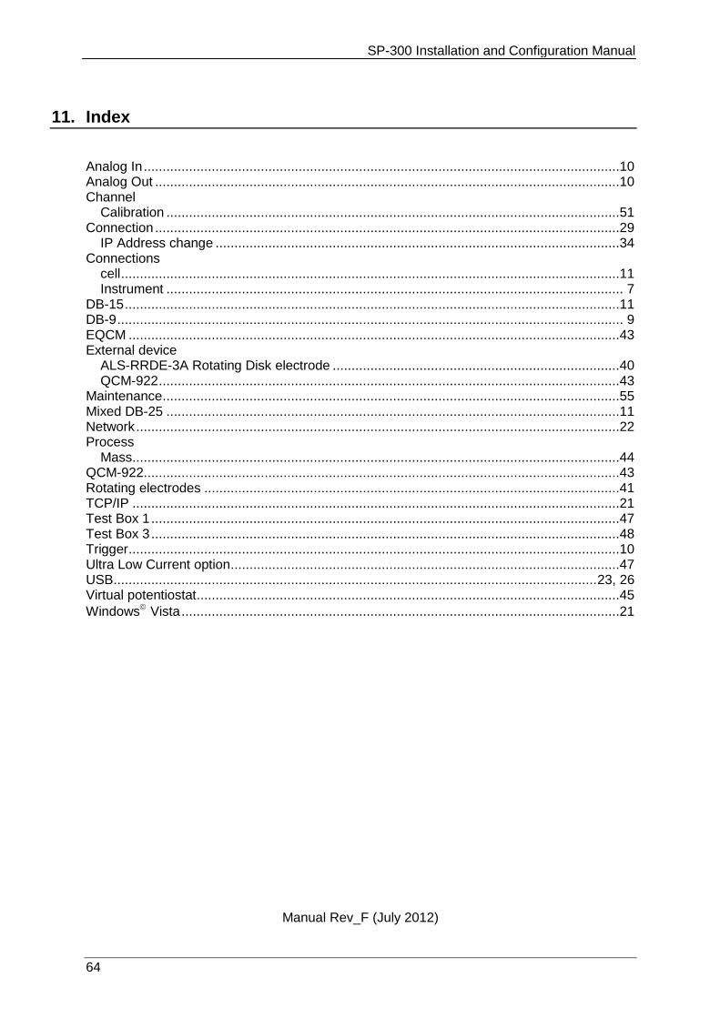
SP-300 Installation and Configuration Manual
64
11. Index
Analog In ..............................................................................................................................10 Analog Out ...........................................................................................................................10 Channel
Calibration ........................................................................................................................51 Connection ...........................................................................................................................29
IP Address change ...........................................................................................................34 Connections
cell ....................................................................................................................................11 Instrument ......................................................................................................................... 7
DB-15 ...................................................................................................................................11 DB-9 ...................................................................................................................................... 9 EQCM ..................................................................................................................................43 External device
ALS-RRDE-3A Rotating Disk electrode ............................................................................40 QCM-922 ..........................................................................................................................43
Maintenance .........................................................................................................................55 Mixed DB-25 ........................................................................................................................11 Network ................................................................................................................................22 Process
Mass.................................................................................................................................44 QCM-922..............................................................................................................................43 Rotating electrodes ..............................................................................................................41 TCP/IP .................................................................................................................................21 Test Box 1 ............................................................................................................................47 Test Box 3 ............................................................................................................................48 Trigger ..................................................................................................................................10 Ultra Low Current option .......................................................................................................47 USB ................................................................................................................................ 23, 26 Virtual potentiostat ................................................................................................................45
Windows Vista ....................................................................................................................21
Manual Rev_F (July 2012)


![[XLS]obcindia.co.in Dividend... · Web view300 300 300 300 300 300 300 300 300 300 300 300 300 300 300 300 300 300 300 300 300 300 300 300 300 300 300 300 300 300 300 300 300 300](https://img.pdfslide.us/doc/110x75/5aa6e5047f8b9ac5648b5d08/xls-dividendweb-view300-300-300-300-300-300-300-300-300-300-300-300-300-300.jpg)