Embed Size (px)
Citation preview
03/21/96 1014171.DOC LSH
Magnetic Property Measurement System
Hardware Reference Manual
Quantum Design San Diego, CA
Safety Instructions
No Operator Serviceable parts are inside, refer servicing to
_g_ualified __r_ersonnel
CE For continued protection against fire hazard, replace fuses only with same type and rating of fuses for selected line volt~e
As you use your system, observe the following safety guidelines:
• To avoid damaging your system, be sure to verify that your system power requirements match the alternating current (AC) power available at your location. If your system has not been configured for the correct power available at your location contact your local service representative prior to proceeding with the system installation.
• To prevent electrical shock, assure the equipment is properly grounded using 3 wire grounded plugs.
• To prevent electrical shock, unplug the system prior to performing installation, adjustment or servicing.
• Do not spill food or liquids on the system or its cables.
• Refer to the section titled "Safety" prior to installing or operating this system. Direct contact with the cryogen liquids, surfaces and materials recently removed from these liquids, or exposure to the boil-off gas can freeze skin or eye almost instantly causing serious injuries similar to frostbite or burns.
• When handling cryogenic liquids wear protective clothing including insulated gloves and safety eye protection.
• Transfer liquid helium only in areas that have adequate ventilation and a supply of fresh air. Helium gas can displace the air in a confined space or room, resulting in asphyxiation, dizziness, unconsciousness or death.
• Keep this system away from radiators and heat sources. Provide for adequate ventilation to allow for cooling around the cabinet and computer equipment.
• Refer to the computer and monitor operators manuals for additional safety warnings and notices prior to operating the system.
Regulatory Information
• This apparatus has been tested to the requirements of the EMC Directive 89/336/EEC.
• This apparatus meets the requirement for: ISM Group 1, Class A equipment per EN 50011:1991 (Industrial Environment)
1014175.DOC 6/7/96 WCB

Table of Contents
List of Figures .. : .............................................................................................................. iv
List of Tables .................................................................................................................. iv
Chapter One: Introduction
1 .1 The Physical Components ................................................................................. 1-1
1.2 The Functional Components .............................................................................. 1-6
1 .3 The Working Environment ................................................................................. 1-8
1.4 Unpacking And Initial Setup ............................................................................ 1-1 O 1 .4.1 Uncrate the Dewar ................................................................................ 1-11 1.4.2 Uncrate the Control Console ................................................................. 1-11 1.4.3 Uncrate the Vacuum Pump ................................................................... 1-12 1.4.4 Uncrate the MPMS Probe ..................................................................... 1-13 1.4.5 Uncrate the Sample Transport .............................................................. 1-13
1.5 Safety .... : .......................................................................................................... 1-15 1.5.1 Cryogenic Safety ................................................................................... 1-15 1.5.2 Magnet Safety ....................................................................................... 1-15 1.5.3 Electric Safety ....................................................................................... 1-17
1.6 Contacting an Authorized Quantum Design Representative ........................... 1-18
Chapter Two: The Liquid Helium System
2.1 The MPMS Dewar And Helium Level Monitor .................................................... 2-1
2.2 Safe Handling of Liquid Cryogens ..................................................................... 2-3
04/15/96 1014172.DOC LSH
ii Quantum Design MPMS Hardware Reference Manual
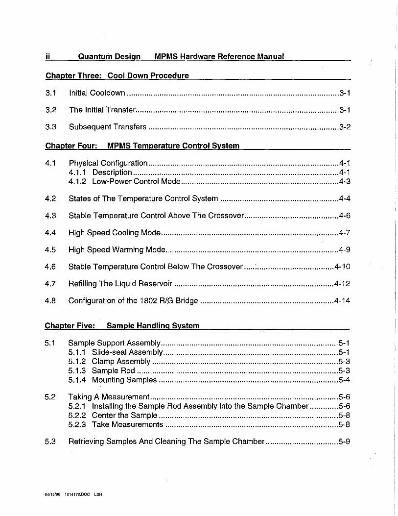
Chapter Three: Cool Down Procedure
3.1 Initial Cooldown ................................................................................................. 3-1
3.2 The Initial Transfer ............................................................................................. 3-1
3.3 Subsequent Transfers ........................................................................................ 3-2
Chapter Four: MPMS Temperature Control System
4.1 Physical Configuration ....................................................................................... 4-1 4.1.1 Description .............................................................................................. 4-1 4.1.2 Low-Power Control Mode ........................................................................ 4-3
4.2 States of The Temperature Control System ...................................................... 4-4
4.3 Stable Temperature Control Above The Crossover. .......................................... 4-6
4.4 High Speed Cooling Mode ................................................................................. 4-7
4.5 High Speed Warming Mode ............................................................................... 4-9
4.6 Stable Temperature Control Below The Crossover ......................................... 4-10
4.7 Refilling The Liquid Reservoir ......................................................................... 4-12
4.8 Configuration of the 1802 RIG Bridge ............................................................ .4-14
Chapter Five: Sample Handling System
5.1 Sample Support Assembly ................................................................................. 5-1 5.1.1 Slide-seal Assembly ................................................................................ 5-1 5.1.2 Clamp Assembly ..................................................................................... 5-3 5.1.3 Sample Rod ............................................................................................ 5-3 5.1.4 Mounting Samples .................................................................................. 5-4
5.2 Taking A Measurement ...................................................................................... 5-6 5.2.1 Installing the Sample Rod Assembly into the Sample Chamber ............. 5-6 5.2.2 Center the Sample .................................................................................. 5-8 5.2.3 Take Measurements ............................................................................... 5-8
5.3 Retrieving Samples And Cleaning The Sample Chamber ................................. 5-9
04/15/96 1014172.DOC LSH
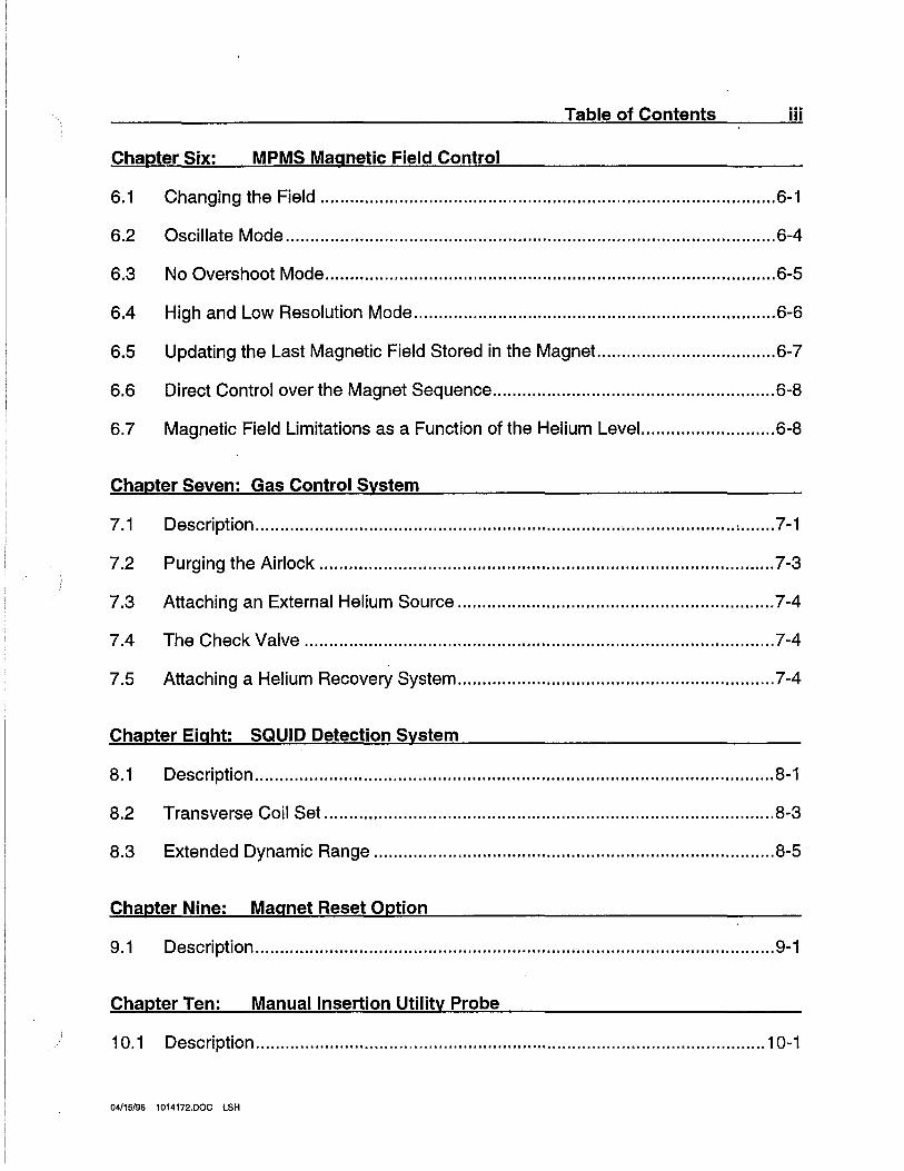
Table of Contents iii
Chapter Six: MPMS Magnetic Field Control
6.1 Changing the Field ............................................................................................ 6-1
6.2 Oscillate Mode ................................................................................................... 6-4
6.3 No Overshoot Mode ............. · .............................................................................. 6-5
6.4 High and Low Resolution Mode ......................................................................... 6-6
6.5 Updating the Last Magnetic Field Stored in the Magnet.. .................................. 6-7
6.6 Direct Control over the Magnet Sequence ......................................................... 6-8
6.7 Magnetic Field Limitations as a Function of the Helium Level ........................... 6-8
Chapter Seven: Gas Control System
7.1 Description ......................................................................................................... 7-1
7.2 Purging the Airlock ............................................................................................ 7-3
7.3 Attaching an External Helium Source ................................................................ 7-4
7.4 The Check Valve ............................................................................................... 7-4
7.5 Attaching a Helium Recovery System ................................................................ 7-4
Chapter Eight: SQUID Detection System
8. 1 Description ......................................................................................................... 8-1
8.2 Transverse Coil Set ........................................................................................... 8-3
8.3 Extended Dynamic Range ................................................................................. 8-5
Chapter Nine: Magnet Reset Option
9.1 Description ......................................................................................................... 9-1
Chapter Ten: Manual Insertion Utility Probe
10.1 Description ....................................................................................................... 10-1
04/15/96 1014172.DOC LSH
iv
Figure 1-1 Figure 1-2 Figure 1-3 Figure 1-4
Figure 2-1
Figure 4-1
Figure 5-1
Figure 6-1
Figure 7-1
Figure 8-1 Figure 8-2
Table 8-1
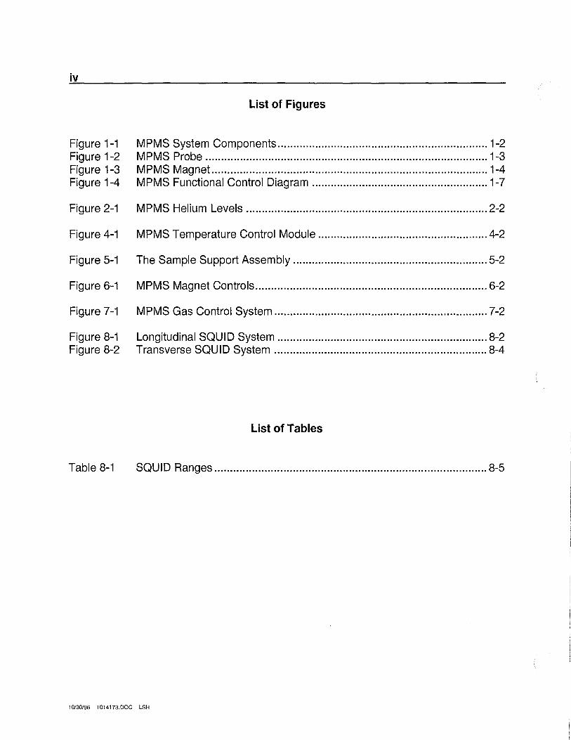
List of Figures
MPMS System Components ................................................................... 1-2 MPMS Probe .......................................................................................... 1-3 MPMS Magnet ........................................................................................ 1-4 MPMS Functional Control Diagram ........................................................ 1-7
MPMS Helium Levels ............................................................................. 2-2
MPMS Temperature Control Module ...................................................... 4-2
The Sample Support Assembly .............................................................. 5-2
MPMS Magnet Controls .......................................................................... 6-2
MPMS Gas Control System .................................................................... 7-2
Longitudinal SQUID System ................................................................... 8-2 Transverse SQUID System .................................................................... 8-4
List of Tables
SQUID Ranges ....................................................................................... 8-5
10/30/96 1014173.DOC LSH
1-1
Chapter One: Introduction
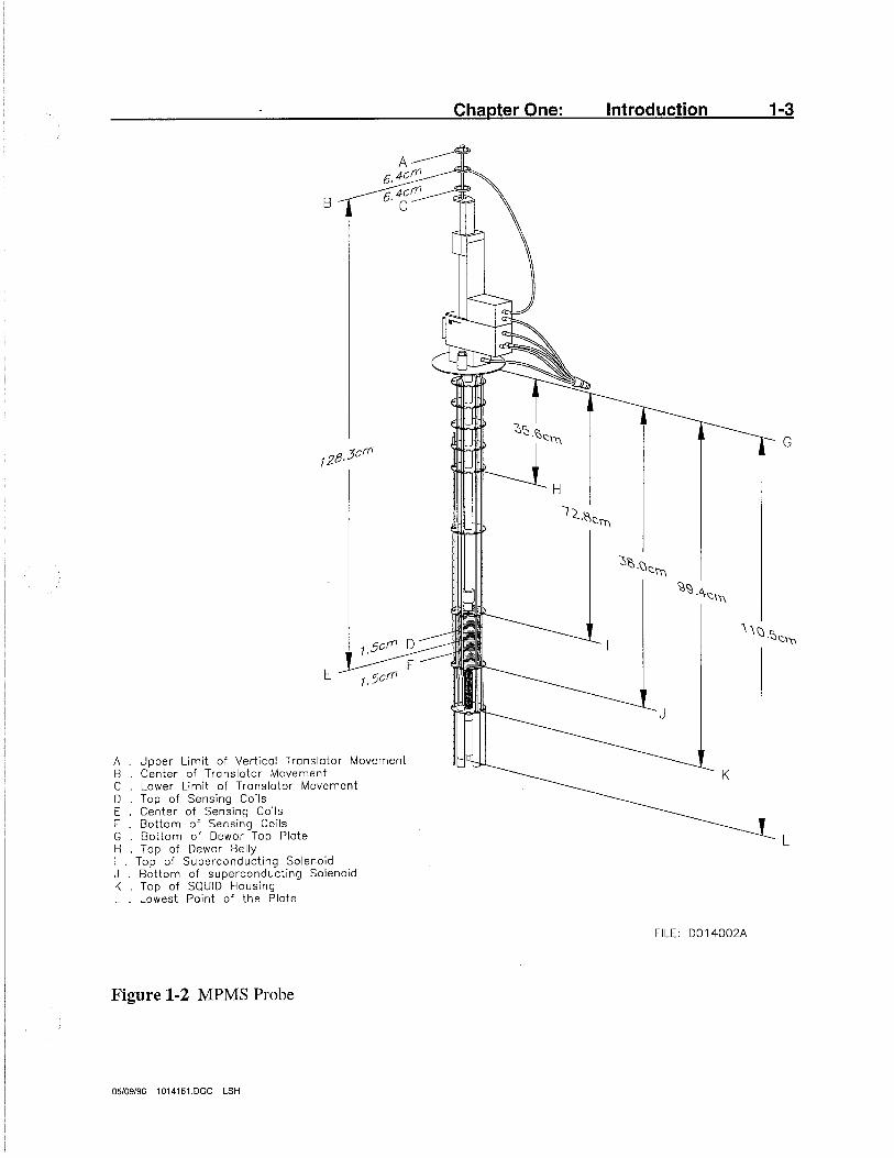
The Quantum Design Magnetic Property Measurement System (MPMS) is a sophisticated analytical instrument configured specifically for the study of the magnetic properties of small experimental samples over a broad range of temperatures and magnetic fields. The system hardware has two major components: (1) the MPMS dewar and probe assembly, and (2) the associated control system in the MPMS control console (Figures 1-1, 1-2, 1-3). Automatic control and data collection are provided by an HP computer and two independent subsystem controllers (Model 1802 and Model 1822). Most of the gas control and other ancillary functions in the system are also automated.
The cryogenic probe integrates a 5.5 tesla (1 tesla for MPMS2) superconducting magnet with a SQUID detection system and a high-performance temperature control system to provide rapid precision measurements over a temperature range of 1.9 to 400 Kelvin (4.5 to 350 Kelvin for MPMS2). The modular design of the system also allows the probe to be easily refit for additional options, or disassembled for repair.
1.1 The Physical Components
When installed, two cabinets plus the HP computer comprise the complete MPMS system, occupying an area approximately 1.5 meters by 3 meters. The system has five major physical components as follows:
1. The HP computer with the installed MPMS control system software. This unit communicates with the two MPMS subsystem controllers via the IEEE-488 Bus Interface protocol (typically referred to as the General Purpose Interface Bus (GPIB)).
2. The electronic control console is comprised of the 1822 MPMS controller, the 1802 RIG bridge, the MPMS gas control system and vacuum pump, the superconducting magnet power supply, and the microstepping sample transport controller.
3. The liquid helium dewar mounted in its cabinet.
4. The MPMS cryogenic probe which includes the Temperature Control Module (TCM) integrated with the MPMS superconducting magnet and SQUID detection system.
5. The sample transport mechanism which mounts on the top of the TCM, and three sample rod assemblies for mounting samples.
04/15/96 1014151.DOC LSH
1-2 Quantum Design MPMS Hardware Reference Manual
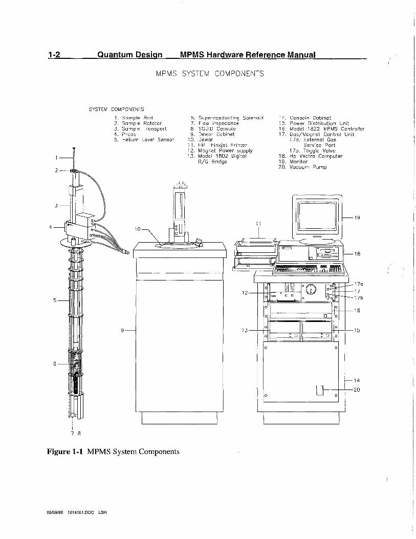
MPMS SYSTEM COMPONENTS
SYSTEM COMPONENTS
1. Sample Rod 2. Sample Rotator 3. Sample Transport 4. Probe 5. Helium Level Sensor
4
7 8
Figure 1-1 MPMS System Components
05/09/96 1014151.DOC LSH
6. Superconducting Solenoid 7. Flow impedance 8. SQUID Capsule 9. Dewar Cabinet
10. Dewar 11. HP Thinkjet Printer 12. Magnet Power supply 13. Model 1802 Digital
R/G Bridge
m!" 1)6 ~
12
13
11
l
L L
'
J Il
j
14. Console Cabinet 15. Power Distribution Unit 1 6. Model 1822 MPMS Controller 17. Gas/Magnet Contra-I Unit
170. External Gos Service Port
17b. Toggle Valve 18. Hp Vectra Computer 19. Monitor 20. Vacuum Pump
D r--
=
::r~ =
61~1 f---
£~,:&-~
19
18
J 19 Jill[ 0 (D ~ r-+-19 i;;;;Jo Q Oo 0 tot-+-
170
17 17b
0
0 D
0
0 D : D
0
0
0
0
0
0
0
0
r--
16
15
14
20
Chapter One: Introduction 1-3
A------6. 4cf17 ---~""""
B 6.4C~
c
G
H
E
A Upper Limit of Vertical Translator Movement B Center of Translator Movement K C Lower Limit of Translator Movement D Top of Sensing Coils E Center of Sensing Coils F Bottom of Sensing Coils G Bottom of Dewar Top Plate H . Top of Dewar Belly
L
I . Top of Superconducting Solenoid J Bottom of superconducting Solenoid K Top of SQUID Housing L . Lowest Point of the Plate
FILE: D014002A
Figure 1-2 MPMS Probe
05/09/96 1014151.DOC LSH
1-4 Quantum Design
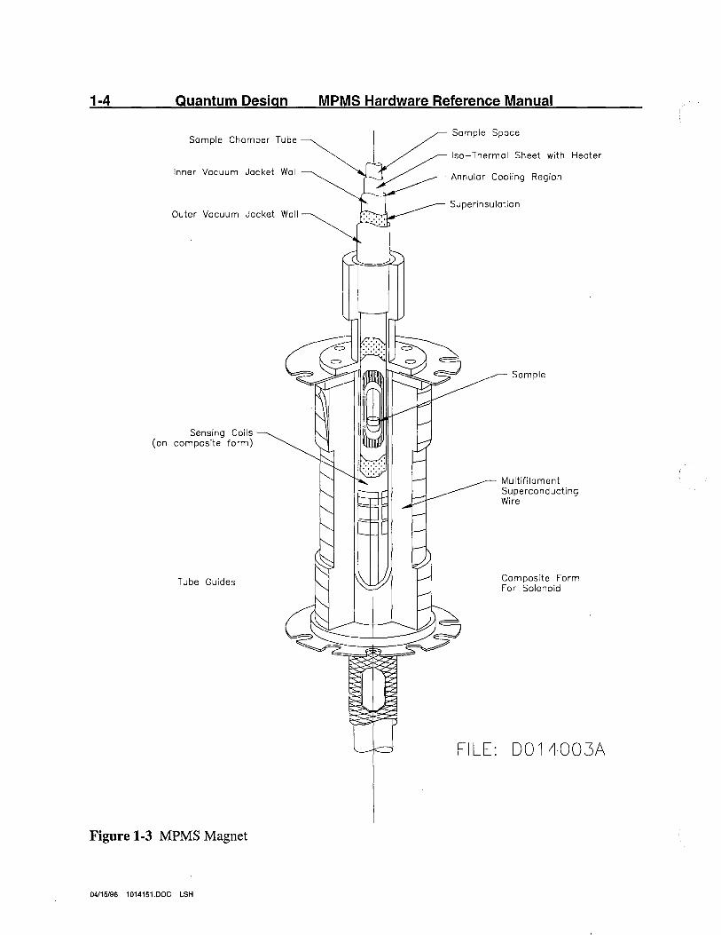
Sample Chamber Tube
Inner Vacuum Jacket Wall
Outer Vacuum Jacket Wall
Sensing Coils (on composite form)
Tube Guides
Figure 1-3 MPMS Magnet
04/15/96 1014151.DOC LSH
MPMS Hardware Reference Manual
Sample Space
Isa-Thermal Sheet with Heater
Annular Cooling Region
Superinsulation
FILE:
Som pie
Multifilament Superconducting Wire
Composite Form For Solenoid
D014003A
Chapter One: Introduction 1-5
The cables connecting the MPMS probe and sample transport to the control cabinet are color coded for convenience. Note that the two gas lines are different sizes and should be· connected with the ninety degree elbow at the control console.
The HP computer should be connected to the Thinkjet printer and to the MPMS console with the two GPIB cable provided. The GPIB cable connecting the 1802 and 1822 controllers is installed at the Quantum Design.
While the components are easily assembled during installation, the installation will normally be performed by Quantum Design service representatives. This also provides the opportunity for user training and an opportunity to discuss some of the measurement techniques we have developed. The initial installation, setup, and testing procedures are discussed in more detail in section 1.4.
04/15/96 1014151.DOC LSH
1-6 Quantum Design MPMS Hardware Reference Manual
1.2 The Functional Components
When configured for magnetic susceptibility measurements, the MPMS integrates seven major functional systems under the MPMS control software. These are as follows:
1. The Temperature Control Module (TCM) which provides an actively regulated, precision thermal environment over its entire range of operation, 1.9 to 400 K (4.5 to 350 K for MPMS2)
2. The superconducting magnet system which provides reversible field operation to plus and minus 5 .5 tesla ( 1 tesla for MPMS2) using an oscillatory technique to minimize magnet drift immediately following field changes.
3. The SQUID detector system which includes the Model 2000 SQUID Amplifier control electronics, sensing pick-up loops, and specially designed filtering with full computer control via the HP interface computer.
4. The sample handling system (sample translator and sample transport) which allows automatic sample measurements and position calibrations using a microstepping controller having a positioning resolution of .0003 cm.
5. The gas handling system which provides gas flow control for temperature regulation, flushing, and cleaning procedures.
6. Liquid helium system which provides refrigeration for the superconducting detection system and magnet, as well as providing for operation down to 1.9 Kelvin.
7. The computer control system which includes the HP computer with a hard disk, a 3.5 inch microfloppy drive, an HP Thinkjet printer, and the integrated MPMS control system operating software.
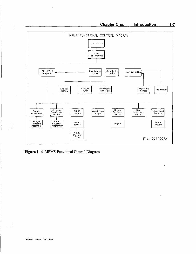
These systems are discussed in detail in the following sections of this manual. Figure 1-4, that shows the functional relationships for the MPMS control system, illustrates control paths and interactions of various system components. Most of the details of the control system shown in Figure 1-4 will be invisible to those who operate the system through the Quantum Design supplied MPMS software operating system. Nonetheless, we recommend that you become reasonably familiar with this functional structure to better understand the detailed discussions in this manual that describe both the individual systems and the interactions between the various systems.
04/15/96 1014151.DOC LSH
Chapter One: Introduction
MPMS FUNCTIONAL CONTROL DIAGRAM
1822-MPMS Computer
Hp Computer
IEEE-488 Interface
Gos Control f-------------i Panel Gos/Heater
Switch
Airblock Flushing
Vacuum Pump
Proportionol Gas Flow
Sample Translation
Somple Transport Assembly
Coupling Transformer
Heater
SQUID Coupling
Transformer
SQUID Control
SQUID Sensor
SQUID Detector
Array
Magnet Power Supply
Figure 1- 4 MPMS Functional Control Diagram
04115/96 1014151.DOC LSH
Magnet Persistent
Switch
Magnet
1802 R/G Bridge
Temperature Sensor
Flow Impedance
Heater
Gas Heater
Helium Level Detector
Dewar System
File: D014004A
1-7
1-8 Quantum Design MPMS Hardware Reference Manual
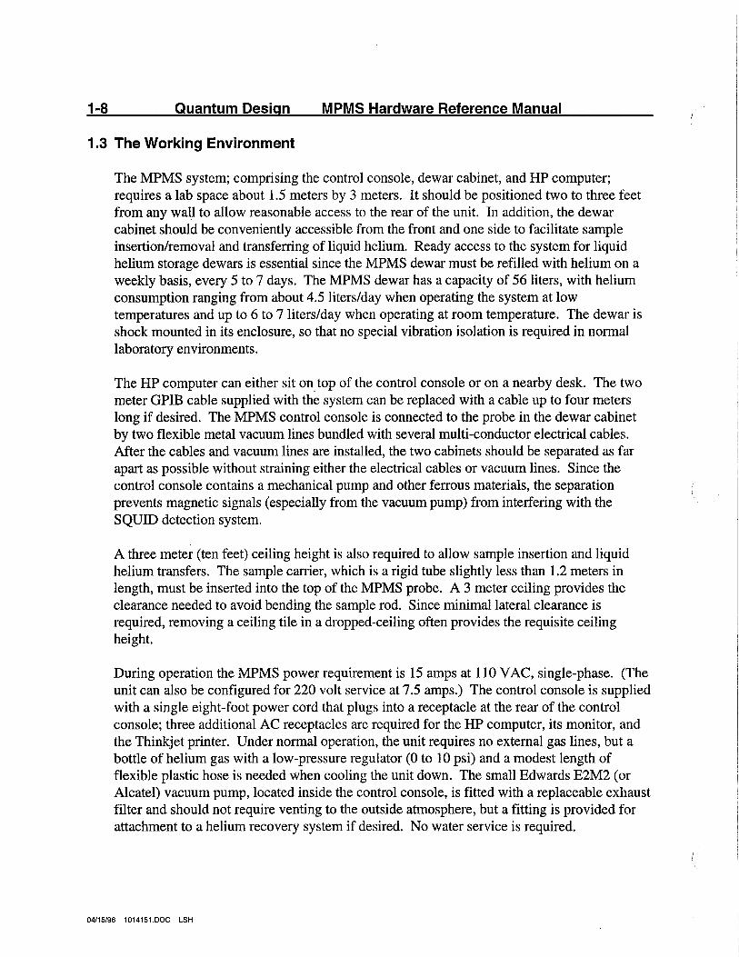
1.3 The Working Environment
The MPMS system; comprising the control console, dewar cabinet, and HP computer; requires a lab space about 1.5 meters by 3 meters. It should be positioned two to three feet from any wall to allow reasonable access to the rear of the unit. In addition, the dewar cabinet should be conveniently accessible from the front and one side to facilitate sample insertion/removal and transferring of liquid helium. Ready access to the system for liquid helium storage dewars is essential since the MPMS dewar must be refilled with helium on a weekly basis, every 5 to 7 days. The MPMS dewar has a capacity of 56 liters, with helium consumption ranging from about 4.5 liters/day when operating the system at low temperatures and up to 6 to 7 liters/day when operating at room temperature. The dewar is shock mounted in its enclosure, so that no special vibration isolation is required in normal laboratory environments.
The HP computer can either sit on top of the control console or on a nearby desk. The two meter GPIB cable supplied with the system can be replaced with a cable up to four meters long if desired. The MPMS control console is connected to the probe in the dewar cabinet by two flexible metal vacuum lines bundled with several multi-conductor electrical cables. After the cables and vacuum lines are installed, the two cabinets should be separated as far apart as possible without straining either the electrical cables or vacuum lines. Since the control console contains a mechanical pump and other ferrous materials, the separation prevents magnetic signals (especially from the vacuum pump) from interfering with the SQUID detection system.
A three meter (ten feet) ceiling height is also required to allow sample insertion and liquid helium transfers. The sample carrier, which is a rigid tube slightly less than 1.2 meters in length, must be inserted into the top of the MPMS probe. A 3 meter ceiling provides the clearance needed to avoid bending the sample rod. Since minimal lateral clearance is required, removing a ceiling tile in a dropped-ceiling often provides the requisite ceiling height.
During operation the MPMS power requirement is 15 amps at 110 V AC, single-phase. (The unit can also be configured for 220 volt service at 7.5 amps.) The control console is supplied with a single eight-foot power cord that plugs into a receptacle at the rear of the control console; three additional AC receptacles are required for the HP computer, its monitor, and the Thinkjet printer. Under normal operation, the unit requires no external gas lines, but a bottle of helium gas with a low-pressure regulator (0 to 10 psi) and a modest length of flexible plastic hose is needed when cooling the unit down. The small Edwards E2M2 (or Alcatel) vacuum pump, located inside the control console, is fitted with a replaceable exhaust filter and should not require venting to the outside atmosphere, but a fitting is provided for attachment to a helium recovery system if desired. No water service is required.
04/15/96 1014151.DOC LSH
Chapter One: Introduction 1-9
The MPMS has been designed to operate without a superconducting magnetic shield around the SQUID detection coils, allowing magnetic field changes and sample measurements to be executed in rapid succession. Rejection of interference from nearby magnetic sources is achieved by using a small spacing and high degree of balance in the second-derivative detection coils. Nonetheless, large magnetic sources (such as elevators or automobiles) can interfere with measurements if they are located very near the instrument. To avoid this type of interference, the instrument should be located at least several meters from any such large magnetic objects. Smaller items such as steel frame chairs or steel lab stools should be kept several feet away, or, at least, kept stationary while sample measurements are being performed.
04/15/96 1014151.DOC LSH
1-10 · Quantum Design MPMS Hardware Reference Manual
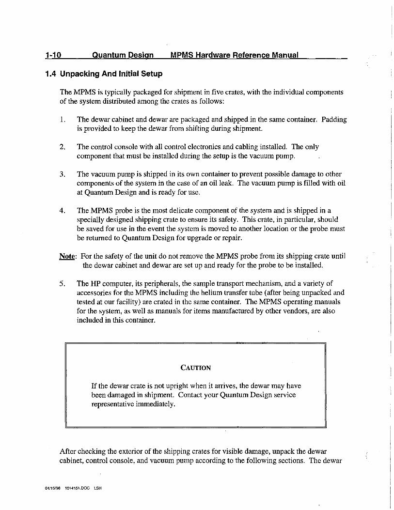
1.4 Unpacking And Initial Setup
The MPMS is typically packaged for shipment in five crates, with the individual components of the system distributed among the crates as follows:
1. The dewar cabinet and dewar are packaged and shipped in the same container. Padding is provided to keep the dewar from shifting during shipment.
2. The control console with all control electronics and cabling installed. The only component that must be installed during the setup is the vacuum pump.
3. The vacuum pump is shipped in its own container to prevent possible damage to other components of the system in the case of an oil leak. The vacuum pump is filled with oil at Quantum Design and is ready for use.
4. The MPMS probe is the most delicate component of the system and is shipped in a specially designed shipping crate to ensure its safety. This crate, in particular, should be saved for use in the event the system is moved to another location or the probe must be returned to Quantum Design for upgrade or repair.
Note: For the safety of the unit do not remove the MPMS probe from its shipping crate until the dewar cabinet and dewar are set up and ready for the probe to be installed.
5. The HP computer, its peripherals, the sample transport mechanism, and a variety of accessories for the MPMS including the helium transfer tube (after being unpacked and tested at our facility) are crated in the same container. The MPMS operating manuals for the system, as well as manuals for items manufactured by other vendors, are also included in this container.
CAUTION
If the dewar crate is not upright when it arrives, the dewar may have been damaged in shipment. Contact your Quantum Design service representative immediately.
After checking the exterior of the shipping crates for visible damage, unpack the dewar cabinet, control console, and vacuum pump according to the following sections. The dewar
04/15/96 1014151.DOC LSH
Chapter One: Introduction 1-11
cabinet, with the dewar already mounted inside, is packed in a large wooden crate. ~are has been taken at Quantum Design to ensure that the dewar was properly crated and shipped in its upright position as indicated on the crate. It should arrive at its destination in the same orientation.
1.4.1 Uncrate the Dewar
To uncrate the dewar, carefully remove the wood screws from the top and front side of the crate (maintaining its upright position), and lift the dewar and cabinet out of the shipping crate. Remove and set aside the cabinet top, and remove the foam packing material from around the top and bottom of the dewar. After the dewar and cabinet assembly are uncrated, examine the exterior of the dewar for damage. (It should not be necessary to remove the dewar from the cabinet for this inspection.) Also look inside with a flashlight to examine the neck for cracks or misalignment, and verify that the belly is clean and dry. Place the cabinet and dewar in its final position, and adjust the feet on the bottom of the support box to level the top edges of the cabinet and to prevent any wobble.
The dewar is suspended inside the cabinet with rubber shock mounts with four 1/4-20 threaded rods that should already be in place. After the cabinet is leveled, adjust the nuts at the top of the threaded rods to lift the dewar about 1 cm off the floor. Now replace the cabinet top, and check the clearance between the cabinet top and the dewar. Adjust the dewar height to leave only a small gap between the dewar and the cabinet top to prevent small screws or tools from dropping down inside the cabinet. Once the height is correct, adjust the individual supports inside the dewar cabinet to level the top of the dewar and center the bottom of the dewar in the cabinet.
1.4.2Uncrate the Control Console
Uncrate the control console by removing the wood screws from the top and front of the shipping crate and lifting out the console.
CAUTION
The control console cannot be lifted by its top. To remove the console from the crate, slide it forward until it can be lifted from the bottom lip which forms the toe space.
04/15/96 1014151.DOC LSH
1-12 Quantum Design MPMS Hardware Reference Manual
The console is shipped with its internal cabling installed. The cables that connect to the MPMS probe are connected inside the cabinet and looped through the holes in the back panel for shipment. Once the layout for the instrument has been determined, the cables can be routed through the slot on the correct side.
Remove the lower front panel from the console and open the rear door. Also, remove the protective packing from the flange on the end of the pumping line inside the console which hangs down from the gas control unit.
1.4.3Uncrate the Vacuum Pump
Uncrate the vacuum pump, and remove the blanking plate from the inlet of the 'foreline trap. The foreline trap has already been filled with absorbent, and extra absorbent is packed with the pump in a sealed container. Remove the plastic cap from the black plastic fitting at the front end of the pump, just above the oil level sight glass.
CAUTION
Verify that there is sufficient pump oil in the Edwards vacuum pump (or Alcatel) and that there are no plugs in the inlet or exhaust ports. Also, do not turn the pump on until the cap on the exhaust port has been removed.
Set the pump on the floor inside the console with its motor toward the back of.the console. Attach the hose from the oil mist filter to the black plastic fitting on the top of the pump body and tighten the hose clamp. Carefully position the pump so that the flange fitting on the end of the flexible metal hose mates readily with the foreline trap input flange without twisting or stressing the pumping line. If the flanges do not mate properly, it may be necessary to loosen the fitting at the upper end of the pumping line so the flange at the lower position can rotate slightly. If the upper fitting is loosened, take care not to over tighten it when finished. The fitting contains an o-ring seal and should be tightened only enough to keep it from loosening under vibration.
After the metal vacuum line and the exhaust lines are connected, plug the AC line cord from the pump into Jack JB-7 on the rear of the Power Distribution Unit (PDU). The vacuum pump line cord should have a label near the plug indicating the correct jack. The electric motor on the vacuum pump can be configured for either 115 V AC or 230
04/15/96 1014151.DOC LSH
Chapter One: Introduction 1-13
V AC. The motor has been configured and tested at Quantum Design at the same voltage rating as the rest of the system, and no further modifications should be required at this time.
1.4.4Uncrate the MPMS Probe
The probe is packed in a long wooden crate with skids on one side. The side opposite the skids (the top) is attached with wood screws. Lay the box down on the skids, and remove the top.
CAUTION
Do not attempt to remove the probe from its shipping crate through the end, or with the crate standing on end. Also, remember to save the crate and packing material for future use.
The head of the probe and the superconducting magnet are packed in foam rubber to prevent lateral movement and are held in place in the long dimension of the box by a wood support plate with a U-shaped notch. Remove this plate by pulling it straight up past the foam rubber, and carefully remove the top foam rubber blocks at both ends. The probe can now be lifted out by holding BOTH the head and magnet ends but avoiding pressure on the small lines that run along the shaft. If the probe is to be laid on a bench, use the foam rubber "V" from the crate to support the magnet. When inserting the probe into the dewar, let the probe hang vertically by holding it at the top as you lower it into the dewar, taking care not to bump the magnet or capsules against the edge of the dewar opening. Ensure that the o-ring between the probe and dewar is in place and properly greased.
1.4.SUncrate the Sample Transport
Now unpack the transfer tube and accessory kit. Bolt the probe into place using the 1/4-20 socket head screws provided, and attach the sample transport mechanism to the top of the probe. Ensure that the correct o-rings (Quantum Design part numbers VON2-017 and VON2-026) are installed beneath the transport mechanism. M,ount the Model 2000 SQUID amplifier on the back of the dewar cabinet. (There will be two Model 2000 SQUID amplifiers if your system was ordered with the longitudinal and transverse SQUIDs.) Mounting screws will already be inserted in the mounting holes.
04/15/96 1014151.DOC LSH
1-14 Quantum Design MPMS Hardware Reference Manual
Remove the screws and attach the amplifier(s) to the dewar cabinet. If the MPMS has the Transverse SQUID option installed, place the Transverse Model 2000 in the left mounting location, looking from the back towards the front on the dewar cabinet. Connect the cables from the control console, matching the color-coded strain relief boots on the cables with the matching rings on the receptacles mounted on the MPMS probe. Finally, connect the vacuum lines between the console and probe. The vacuum lines are different sizes and cannot be interchanged. Install both lines with the 90-degree elbow at the control console. The unit is now ready for transferring liquid helium.
04/15/96 1014151.DOC LSH
Chapter One: Introduction 1-15
1.5 Safety
The MPMS superconducting magnet produces extremely strong magnetic fields. Following safety procedures regarding the magnet is critical to laboratory safety. Furthermore,. the MPMS utilizes cryogenic liquids for temperature control. There are several concerns surrounding cryogens: they burn skin on contact and they expand rapidly when warmed. Certain safety precautions are necessary when dealing with the liquid helium (and the liquid nitrogen, if a nitrogen-jacket dewar is included in the system) that the MPMS requires. Also, general electrical safety procedures should be followed, since the MPMS has several pieces of electronic equipment.
The most useful pieces of advice concerning safety are to use common sense and to be aware of the system's state and of your surroundings. If the system behavior appears abnormal, something may be wrong with the MPMS. If so, consider whether or not the problem poses a threat to personnel in the laboratory and take appropriate action. For the most part, the MPMS is provided with safety features to keep accidents from causing injury or serious equipment damage. Read the precautions below carefully and keep them in mind whenever working with the MPMS. Inexperienced users should be supervised.
1.5.1 Cryogenic Safety
Section 2.2 explains cryogenic safety. See section 2.2 for more details.
1.5.2Magnet Safety
Because the superconducting MPMS magnet can trap magnetic flux in it, it is possible to leave a charged magnet completely unconnected to the rest of the system. Doing so leaves users no way to discharge the magnet directly, so avoid this practice. Never disconnect a charged magnet from the magnet controller and do not disconnect any of the other connections in the system while a magnet is charged. Several different cables contain connections for magnet control. Be sure to drive the magnet to zero field before disconnecting any cables if the probe ever needs to be disconnected from the controllers for any reason.
04/15/96 1014151.DOC LSH
1-16 Quantum Design MPMS Hardware Reference Manual
WARNING!
Never disconnect a charged magnet from the controllers. If the probe must be disconnected from the controllers, be sure to drive the magnet to zero field before disconnecting the controllers from the probe head.
Superconducting magnet supplied with the MPMS is capable of disturbing computer monitors, affecting electron microscopes, erasing credit cards, attracting ferromagnetic tools, etc. Transverse magnets produce substantially stronger fields surrounding the dewar than longitudinal magnets do. Keep in mind that the magnet in your system produces strong fields that are not completely confined to the system unless it contains some type of magnetic shielding.
It is recommended that the magnetic field around the MPMS be measured and a line drawn to denote the region outside which the magnetic field does not exceed five gauss. The determination of where this line lies is the user's responsibility, since it varies from system to system. It is typically found about 1-2 m (3.3-6.6 ft.) from the edge of the dewar. No heavy ferromagnetic objects (e.g. gas cylinders, large tools, etc.) should be brought within this region when the magnet is charged. Gas cylinders in the laboratory should be secured to the walls and only informed personnel should be allowed to use large tools in the presence of the MPMS. It is possible to cause injury to personnel and damage to MPMS equipment by allowing heavy objects to be attracted to the MPMS.
WARNING!
To be safe, keep all objects made of iron, nickel and other ferromagnetic substances at least 3.0-4.5 meters (10-15 feet) away from the MPMS dewar.
04/15/96 1014151.DOC LSH
Chapter One: Introduction 1-17
Furthermore, the magnetic fields produced by the MPMS can be dangerous or fatal to wearers of pacemakers and other electrical or mechanical medical devices. Anyone wearing a pacemaker or similar device should stay at least 3.0-4.5 meters (10-15 feet) away from the MPMS dewar. This information should be posted in the laboratory where the MPMS is operated so that people wearing such devices are aware of the presence of large magnetic fields.
WARNING!
Anyone wearing a pacemaker or similar medical device should stay at least 3.0-4.5 meters (10-15 feet) away from the MPMS dewar.
1.5.3Electric Safety
The MPMS component are powered by standard 120 or 240 V AC power lines. These voltages are potentially lethal and appropriate care should be exercised around the equipment. Electronic equipment should be powered down and unplugged before opening or removing any covers. Liquids should be kept away from the computer and electronics cabinet. Frayed or damaged cords should be replaced immediately.
04/15/96 1014151.DOC LSH
1-18 Quantum Design MPMS Hardware Reference Manual
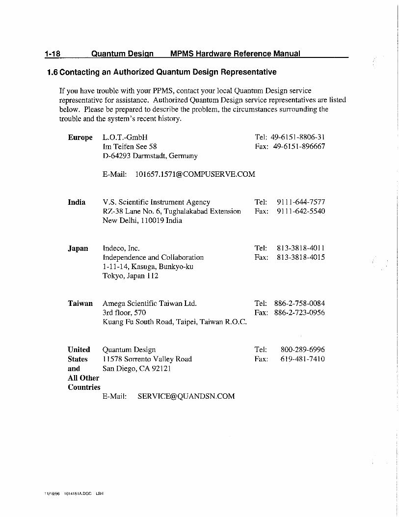
1.6 Contacting an Authorized Quantum Design Representative
If you have trouble with your PPMS, contact your local Quantum Design service representative for assistance. Authorized Quantum Design service representatives are listed below. Please be prepared to describe the problem, the circumstances surrounding the trouble and the system's recent history.
Europe L.O.T.-GmbH Im Teifen See 58 D-64293 Darmstadt, Germany
Tel: 49-6151-8806-31 Fax: 49-6151-896667
E-Mail: [email protected]
India
Japan
Taiwan
V.S. Scientific Instrument Agency RZ-38 Lane No. 6, Tughalakabad Extension New Delhi, 110019 India
Indeco, Inc. Independence and Collaboration 1-11-14, Kasuga, Bunkyo-ku Tokyo, Japan 112
Amega Scientific Taiwan Ltd. 3rd floor, 570 Kuang Fu South Road, Taipei, Taiwan R.O.C.
United Quantum Design States 11578 Sorrento Valley Road and San Diego, CA 92121 All Other Countries
E-Mail: [email protected]
11/19/96 1014151A.DOC LSH
Tel: 9111-644-7 577 Fax: 9111-642-5540
Tel: 813-3818-4011 Fax: 813-3818-4015
Tel: 886-2-758-0084 Fax: 886-2-723-0956
Tel: 800-289-6996 Fax: 619-481-7410
2-1
Chapter Two: The Liquid Helium System
The liquid helium system for the MPMS comprises the liquid helium dewar, the helium tr~nsfer line, the transfer adapter fitting packed in the utility kit, and the excitation electronics for the level meter which are integrated into the 1822 MPMS controller. In addition, the MPMS control system software automatically monitors and updates the helium level reading in the system, and provides the user with a data plotting routine with which to monitor the helium level continuously during transfers.
2.1 The MPMS Dewar And Helium Level Monitor
The MPMS liquid helium dewar of approximately 56-liter capacity provides the cryogenic environment required by the Temperature Control Module (TCM), SQUID detector system, and the MPMS superconducting magnet. It is constructed of aluminum except for the neck which is G-10 fiberglass with a thin sheet of embedded stainless steel to serve as a diffusion barrier. The dewar itself is a stand alone component, but in the MPMS system it is enclosed in a supporting framework that provides both support and vibration isolation. The dewar is raised off the floor by tightening the four nuts located above the rubber shock mounts inside the dewar cabinet. As the nuts are tightened, take care to level the top plate of the dewar, and ensure that the dewar hangs so that it is centered at the bottom of the cabinet.
The helium level in the dewar is monitored with a superconducting helium level metyr probe installed on the MPMS probe assembly. The MPMS control software automatically activates the current to the level meter once each hour, reads the voltage across it, and turns the meter off again. The helium level reading in the graph area of the HP monitor screen is then updated to reflect the new reading. It is important that the level meter not be left on since it dissipates a significant amount of heat and will increase the helium consumption substantially.
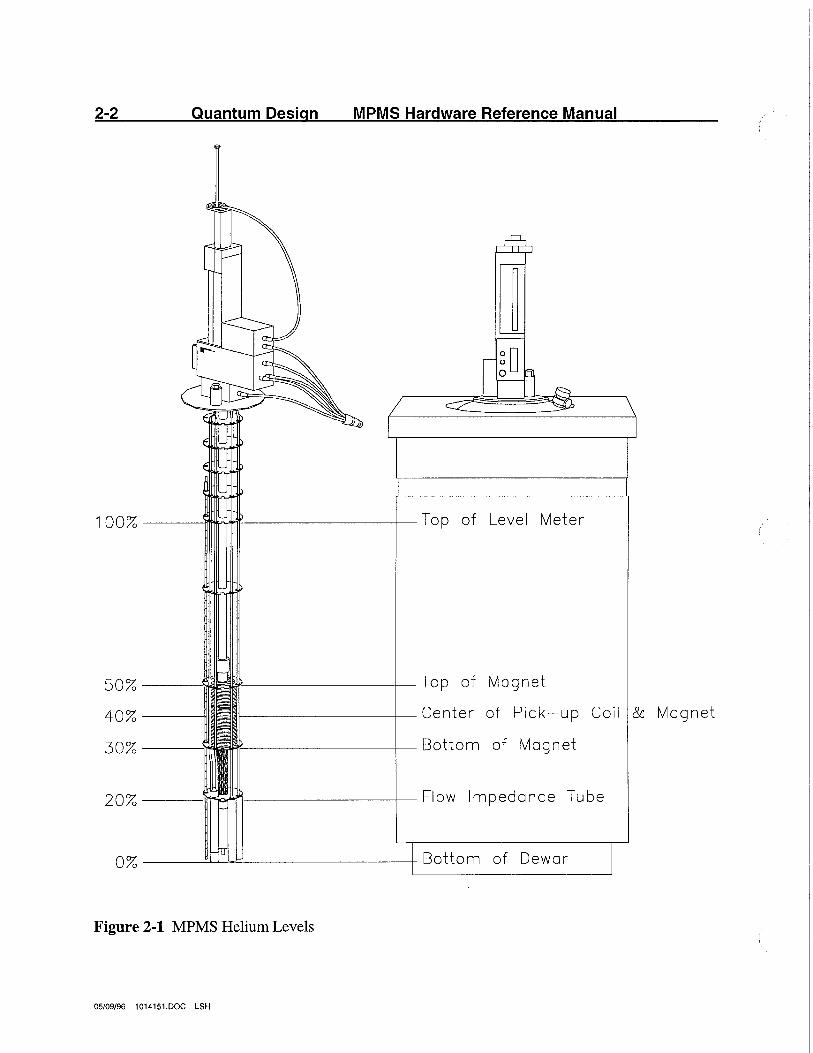
Approximate helium level locations are shown in Figure 2-1. When transferring helium, however, the user needs to monitor the helium level continuously. It is particularly useful to have the data presented in graphical form to indicate any problems that may occur during the transfer - if the storage dewar from which you are transferring is emptied, for example. The MPMS system provides both the percent of helium in the dewar and this data in graphical form in the graph area by accessing FS (Graph) I Display Graph I Helium Transfer. The helium level will now continuously plot the helium level. The percentage of helium is shown in the status window. It is important to activate the Helium Transfer within the Display Graph menu in order to provide up-to-data information, otherwise the percentage amount would represent the last half-an-hour update. (See the MPMS Software User's Manual for details.)
04/15/96 1014151.DOC LSH
2-2 Quantum Design MPMS Hardware Reference Manual
50% __ ____.!~~--------t---T op of Magnet
40% Center of Pick-up Coil & Magnet
30% Bottom of Magnet
Figure 2-1 MPMS Helium Levels
05/09/96 1014151.DOC LSH
Chapter Two: Liquid Helium System 2-3
The final components of the liquid helium equipment are a standard commercial liquid helium transfer line and a transfer adapter fitting for sealing the transfer tube to the MPMS probe assembly. When preparing to transfer, slip the adapter fitting onto the end of the transfer tube to be inserted into the MPMS dewar, then cool the transfer tube by pushing liquid through it. When the plume appears at the output of the transfer tube, put the end into the MPMS dewar through the port where the dewar relief valve normally resides, and seat the transfer adapter into the port. During the transfer the helium level can be monitored through the HP computer.
The helium consumption in the system is approximately 4.5 to 5 liters/day when running the system below about 200 K, increasing to about 6 to 7 liters/day when running at room temperature. While the MPMS dewar has a 56-liter capacity, the superconducting magnet in the system requires the liquid helium level to be at least 35 to 40 percent to operate. Hence, to operate at the highest fields, the liquid helium should be replenished every 5 to 6 days.
04/15/96 1014151.DOC LSH
2-4 Quantum Design MPMS Hardware Reference Manual
2.2 Safe Handling of Liquid Cryogens
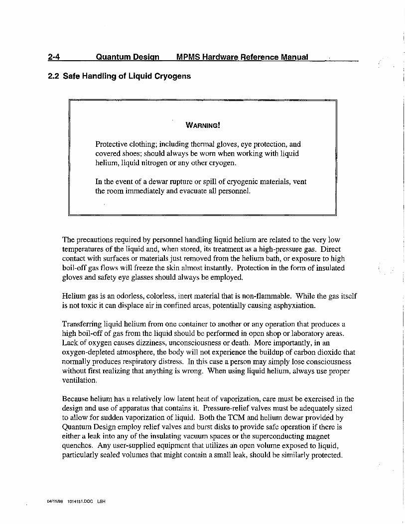
WARNING!
Protective clothing; including thermal gloves, eye protection, and covered shoes; should always be worn when working with liquid helium, liquid nitrogen or any other cryogen.
In the event of a dewar rupture or spill of cryogenic materials, vent the room immediately and evacuate all personnel.
The precautions required by personnel handling liquid helium are related to the very low temperatures of the liquid and, when stored, its treatment as a high-pressure gas. Direct contact with surf aces or materials just removed from the helium bath, or exposure to high boil-off gas flows will freeze the skin almost instantly. Protection in the form of insulated gloves and safety eye glasses should always be employed.
Helium gas is an odorless, colorless, inert material that is non-flammable. While the gas itself is not toxic it can displace air in confined areas, potentially causing asphyxiation.
Transferring liquid helium from one container to another or any operation that produces a high boil-off of gas from the liquid should be performed in open shop or laboratory areas. Lack of oxygen causes dizziness, unconsciousness or death. More importantly, in an oxygen-depleted atmosphere, the body will not experience the buildup of carbon dioxide that normally produces respiratory distress. In this case a person may simply lose consciousness without first realizing that anything is wrong. When using liquid helium, always use proper ventilation.
Because helium has a relatively low latent heat of vaporization, care must be exercised in the design and use of apparatus that contains it. Pressure-relief valves must be adequately sized to allow for sudden vaporization of liquid. Both the TCM and helium dewar provided by Quantum Design employ relief valves and burst disks to provide safe operation if there is either a leak into any of the insulating vacuum spaces or the superconducting magnet quenches. Any user-supplied equipment that utilizes an open volume exposed to liquid, particularly sealed volumes that might contain a small leak, should be similarly protected.
04/15/96 1014151.DOC LSH
Chapter Two: Liquid Helium System 2-5
Liquid helium is the coldest liquid that will exist at atmospheric pressure and is therefore a very effective cryopump. If a vessel containing liquid helium is left open to the atmosphere, air and other gases will rapidly condense and solidify inside. This can easily plug pressure relief passages and transfer ports. Since helium gas is constantly evaporating from the liquid, high pressures within the container develop quickly. It is therefore essential to maintain a positive pressure (above atmospheric pressure) within any storage container and to make certain that all ports and orifices, except proper relief valves, remain closed when immediate access to the helium is not required.
Helium-cooled surf aces exposed to the atmosphere can similarly attract and condense air. Because nitrogen has a lower boiling point than oxygen, this gas will evaporate first leaving an oxygen-enriched residue that can flow onto surrounding surfaces. Contact with spontaneously combustible materials such as oil or grease can produce ignition, therefore possible exposed surfaces should be clean and free of such materials.
04/15/96 1014151.DOC LSH

3-1
Chapter Three: Cool Down Procedure
This section outlines the initial cool down procedure. It requires only liquid helium.
3.1 Initial Cooldown
This is the procedure for cooling the system from room temperature. Ensure that the large o-ring is in the groove in the top surface of the dewar, and install the probe in the dewar. Orient the probe as you wish, and secure it with the 1/4-20 X 3/8" socket head screws. Do not overtighten the screws - they only need to seal the top plate against the o-ring. Attach the pumping lines and electrical cables according to their color coding, and connect the flexible gas lines to their respective connectors. Be sure to connect the end of the gas lines with the 90 degree elbow to the console.
Turn on the main power circuit breaker located on the back of the Power Distribution Unit (PDU) and the main power switch on the front panel of the PDU. (On earlier models of the PDU, the main power switch also serves as the main power breaker, and there is not a separate main power breaker on the rear panel.) Tum on the pump with the circuit breaker on the PDU rear panel. The HP computer system (including printer) can now be connected to the control console with its GPIB cable and turned on. Also turn on the power to the 1802 RIG bridge and the 1822 MPMS controller. Type MPMSR2 into the HP computer at the DOS prompt to initiate the control program.
04/15/96 1014151.DOC LSH
3-2 Quantum Design MPMS Hardware Reference Manual
3.2 The Initial Transfer
The initial transfer will require between 7 5 and 90 liters of liquid helium to cool down the system and fill the dewar.
For the first transfer, the output end of the transfer tube should be fitted with one of the extensions provided which will reach to within a few inches of the bottom of the MPMS dewar (about 44 inches (111.76 cm) below the top surface of the dewar). Just before the transfer tube is inserted into the dewar, the plug should be removed from the MPMS top plate, and the transfer fitting installed. It should seat in the tube sticking up from the top plate, and the horizontal tube should be directed away from the head. If a helium recovery system is being used, you may wish to connect it to this exhaust fitting. Open the cooling valve from the Diagnostic Gas Controls menu (F7-Diagnostic Menus, move cursor to Gas Controls and press Enter). This will provide full helium gas flow and help prevent blocking of the small impedance tube.
Insert one end of the transfer tube into the storage dewar and the other end into the transfer port. Insert the transfer tube into the MPMS dewar slowly, making sure that its extension does not bump into the magnet or other parts attached to the lower part of the probe. The transfer should be started slowly to take maximum advantage of the cold helium gas. Since the initial transfer will take 2 to 3 hours, it is helpful to have a small fan or a hair dryer directed across the head during the transfer to help keep excessive moisture from condensing on the head of the probe.
The transfer rate can be set by adjusting the pressure in the storage dewar. While the dewar and probe are cooling down, the pressure should be held at about 200 mm of mercury. This should produce a steady gas flow out of the transfer fitting. When liquid begins to collect, normally after about 1 hour, the flow will momentarily drop to zero, then resume. Also, if the helium level is being plotted on the HP computer, it will begin to increase at this time. As the liquid helium level increases, the gas flow out of the pump will increase to a maximum of 2.5 liters/min. Once this flow rate has been achieved and the helium level is greater than 25%, the cooling valve can be closed. The SQUID should also be tuned at this time as described in the software manual. Continue the transfer until the helium level reading reaches 100% or until the level stops increasing which indicates an empty storage dewar.
It will take 24 to 48 hours for the dewar to completely cool down and equilibrate, and a high but decreasing boiloff should be expected during this period. The quiescent boiloff of the system with the sample region cold (less than about 200 Kelvin), is about five liters of liquid per day. This loss is higher when the sample tube is warm or when the system is being cooled down in the high-power cooling mode. ·
04/15/96 1014151.DOC LSH
Chapter Three: Cool Down Procedure 3-3
3.3 Subsequent Transfers
The helium level in the system should be kept at about 40% or higher to provide cooling for the superconducting magnet. If the level drops below 40%, the magnet should not be used at its full field. Subsequent helium transfers into a cold MPMS dewar are essentially the same as the initial transfer with the following exceptions:
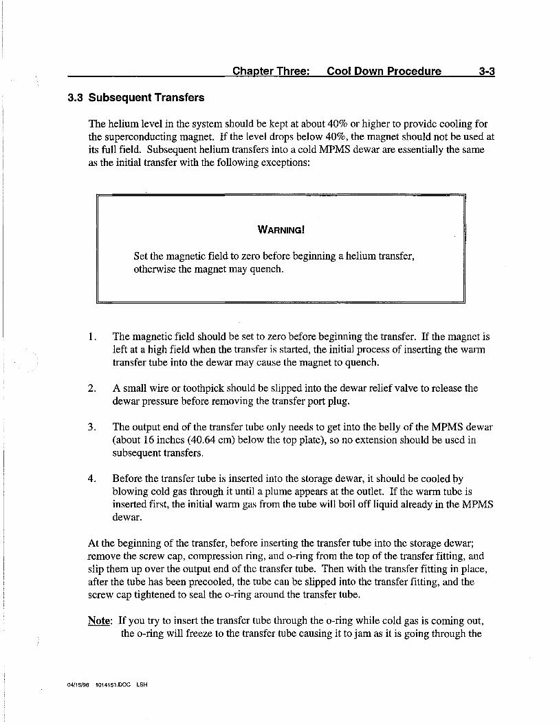
WARNING!
Set the magnetic field to zero before beginning a helium transfer, otherwise the magnet may quench.
1. The magnetic field should be set to zero before beginning the transfer. If the magnet is left at a high field when the transfer is started, the initial process of inserting the warm transfer tube into the dewar may cause the magnet to quench.
2. A small wire or toothpick should be slipped into the dewar relief valve to release the dewar pressure before removing the transfer port plug.
3. The output end of the transfer tube only needs to get into the belly of the MPMS dewar (about 16 inches (40.64 cm) below the top plate), so no extension should be used in subsequent transfers.
4. Before the transfer tube is inserted into the storage dewar, it should be cooled py blowing cold gas through it until a plume appears at the outlet. If the warm tube is inserted first, the initial warm gas from the tube will boil off liquid already in the MPMS dewar.
At the beginning of the transfer, before inserting the transfer tube into the storage dewar; remove the screw cap, compression ring, and o-ring from the top of the transfer fitting, and slip them up over the output end of the transfer tube. Then with the transfer fitting in place, after the tube has been precooled, the tube can be slipped into the transfer fitting, and the screw cap tightened to seal the o-ring around the transfer tube.
Note: If you try to insert the transfer tube through the o-ring while cold gas is coming out, the o-ring will freeze to the transfer tube causing it to jam as it is going through the
04/15/96 1014151.DOC LSH
3-4 Quantum Design MPMS Hardware Reference Manual
fitting. Be sure the o-ring, the compression ring, and the screw cap are installed over a warm transfer tube.
After the transfer tube has been inserted into the MPMS dewar, the pressure in the storage dewar can be set to about 1 psi. The progress of the transfer can be monitored on the HP computer with the helium level plot. At the transfer rate produced by the 1 psi storage dewar pressure, it will talce 30 to 40 minutes to fill the dewar when starting at a level of 40 percent.
Note: If the exhaust of the transfer tube is connected to a helium recovery system, a pressure greater than 1 psi may be required to transfer helium. The higher pressure may be needed to overcome backpressure from the helium recovery system. Typically only 1 or 2 psi more pressure would be required.
04/15/96 1014151.DOC LSH
Chapter Four: MPMS Temperature Control System
4-1
The 1802 RIG bridge provides active temperature control for the MPMS, but the 1822 MPMS controller and the MPMS control system software in the HP computer also play important roles in the variable temperature sweep capability of the system. In this section we give a brief description of the MPMS temperature control system, and discuss some of its complexities.
4.1 Physical Configuration
4.1.1 Description
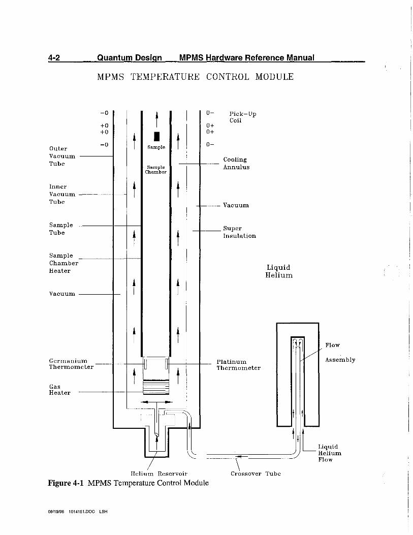
The physical configuration of the sample chamber and temperature control system is shown in Figure 4-1. Cooling is provided by cold gas drawn into the cooling annulus from the helium bath, and the sample chamber is heated by applying power to either the chamber or gas heater. Longitudinal copper wires along the length of the sample chamber maintain thermal uniformity, and a few millimeters pressure of helium gas in the sample chamber provide thermal contact with the sample.
When the system is setting a new temperature, it normally uses a high-power heating or cooling mode until the temperature nears the specified control point. In this mode, heating is provided by the chamber heater and cooling is achieved by drawing gas through the cooling annulus at high flow rates. In the high-power mode, the heating rate (when the system is initially at room temperature) is about 10 Kelvin/minute, and typical cooling rates exceed 20 Kelvin/minute. When the system temperature nears the target temperature specified by the user, the MPMS control system switches to a lowpower control mode using the gas heater.
There are two fundamentally different control mechanisms used in the system. The normal mechanism is used for all temperatures above about 4.4 Kelvin, while below this temperature, control is achieved by controlling the pressure on a small reservoir of liquid helium. The MPMS control system automatically selects the correct mechanism for the specified temperature.
Note: The crossover temperature, which can be set from the MPMS control system, depends on the boiling point of helium at ambient atmospheric pressure. Hence, its value will vary with the altitude of the user's site. The correct value for the site is normally set by the Quantum Design service representative when the system is installed and may vary from the sea level value of 4.4 Kelvin.
04/15/96 1014151.DOC LSH
4-2
Outer Vacuum Tube
Inner Vacuum Tube
Sample Tube
Sample Chamber Heater
Vacuum
Germanium Thermometer
Gas Heater
Quantum Design MPMS Hardware Reference Manual
MPMS TEMPERATURE CONTROL MODULE
-0
+O +o
-0
t t I t Sample
Sample Chamber
t t
t t
t t
t t
t
0-
o+ o+
0-
Pick-Up Coil
Cooling Annulus
Vacuum
Super Insulation
Platinum Thermometer
Liquid Helium
~lF- tt L JJ Ltr-- ......__ ...___. t,L1· iquid ~ ~-----.. -------/ Helium
/ \ Flow
Helium Reservoir Crossover Tube
Figure 4-1 MPMS Temperature Control Module
06/19/96 1014151.DOC LSH
Chapter Four: Temperature Control System 4-3
4.1.2Low-Power Mode
When the system is controlling the temperature above the crossover temperature, and is at or near its target temperature, thermal stability is maintained by using the gas heater to warm the incoming helium to the same temperature as the sample chamber. In this mode, the sample chamber can be slowly warmed or cooled by increasing or decreasing the heater power to raise or lower the temperature of the gas. Since the heat capacity of the gas is small and the flow rate is low, this mechanism provides low-power thermal control near the target temperature.
The gas flow through the annulus in this mode, about 100 cc/min at standard temperature and pressure, is controlled by a needle valve located inside the gas/magnet tray in the MPMS control console. This valve is set at Quantum Design, and should not require adjustment by the user. If this valve must be adjusted, attach a floating-ball flowmeter to the output of the vacuum pump (at the output of the mist filter just inside the rear door of the console), and adjust the needle valve to give an indicated flow of 100 cc/min. This setting corrects the flowmeter calibration for helium rather than air.
Note: The needle valve in the MPMS control console is set at Quantum Design to provide the correct flow rate. If this valve is set incorrectly, the time required to achieve temperature stability in the system will be substantially increased. However, a failure to reach or maintain the correct temperature usually indicates a more serious problem, and you should contact you Quantum Design service representative.
04/15/96 1014151.DOC LSH

4-4 Quantum Design MPMS Hardware Reference Manual
4.2 States of The Temperature Control System
While the control system above the crossover temperature is fundamentally different than below it, both regimes provide active control, and the specified temperatures are reached and maintained without manual intervention. Because of the dramatic difference in the rl?quired control mechanisms in both temperature regimes, the control system is particularly complex. Consequently, the system will sometimes appear to be malfunctioning when, in fact, it is cycling through an operation that is designed to both minimize the time required to achieve stability and eliminate thermal gradients which may have been introduced into the system.
There are essentially five states of the temperature control system that will be apparent when the system is operating. They are as follows:
1. Stable temperature control at temperatures above about 4.4 Kelvin in which the control system can maintain the specified temperature as long as required.
2. A high speed cooling mode that can provide cooling rates (when the system is initially at room temperature) of more than 20 Kelvin/minute.
3. A high-power heating mode that typically warms the sample chamber at about 10 Kelvin/minute when the system is initially at room temperature.
4. Stable control at temperatures below 4.4 Kelvin in which the control system can maintain the required temperature for periods ranging from about 45 minutes to about 3 hours depending on the temperature and thermal load on the system. Active control in this regime is achieved by controlling the pressure over a reservoir of liquid helium.
5. Recycling of the thermal system when controlling the temperature below 4.4 Kelvin. When the helium reservoir is exhausted, the system automatically refills the reservoir and reestablishes control at the requested temperature.
During some of the above operations, the system will often appear to behave rather strangely. When this occurs, allow the system to continue its operation for a few minutes before intervening. If the system does not return to its control temperature in about 30 minutes, try resetting the temperature and observe the behavior. If the system does not function correctly when controlling below the crossover temperature, the temperature control software can be reinitialized by setting a temperature of 10 Kelvin, and letting the system stabilize there. If the system controls properly at 10 Kelvin, try resetting the desired temperature. If the abnormal behavior continues, contact your Quantum Design service representative for assistance.
The following sections describe the general behavior of the system in its different control modes. You should be familiar with the various states of the system, and the characteristic
04/15/96 1014151.DOC LSH

Chapter Four: Temperature Control System 4-5
behavior when switching from one state to another. In the current MPMS control system, there is no indication on the HP computer display indicating which control mode is currently active, only whether the temperature is considered to be stable. At the end of this section we provide some useful techniques for optimizing the performance of the system.
04/15/96 1014151.DOC LSH
4-6 Quantum Design MPMS Hardware Reference Manual
4.3 Stable Temperature Control Above The Crossover
When a temperature change is initiated with the target temperature above the crossover point, the MPMS control system invokes the high-power heating or cooling mode to quickly get the temperature near the final target temperature. When close to the target value, the system is switched to the low-power mode described in section 4.1.2 to provide control at the specified temperature.
When the temperature change is initiated, the first line in the status window will indicate that the temperature is no longer stable by displaying the word Settling to the right of the temperature reading. When the system temperature has reached the target value and remains within a specified range of the target value for 1 minute, the temperature is considered to be stable, and is so indicated by the word Settling being replaced by the word Stable.
Note: In the present software revision, the temperature is considered to be stable when it has remained within 0.5% of the target temperature continuously for 60 seconds. If the temperature exceeds that window at any time, the word Settling appears in the status window until the temperature stability criteria are reestablished.
04/15/96 1014151.DOC LSH
Chapter Four: Temperature Control System 4-7
4.4 High Speed Cooling Mode
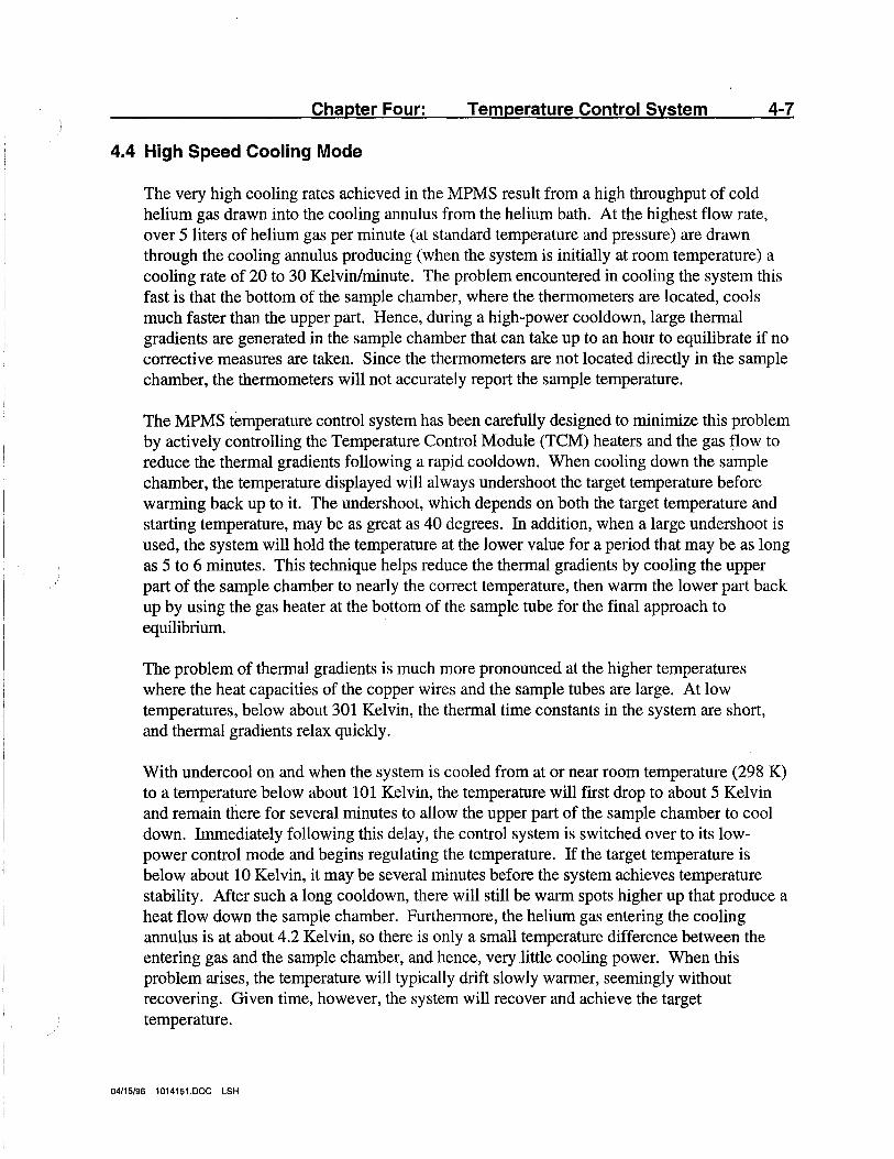
The very high cooling rates achieved in the MPMS result from a high throughput of cold helium gas drawn into the cooling annulus from the helium bath. At the highest flow rate, over 5 liters of helium gas per minute (at standard temperature and pressure) are drawn through the cooling annulus producing (when the system is initially at room temperature) a cooling rate of 20 to 30 Kelvin/minute. The problem encountered in cooling the system this fast is that the bottom of the sample chamber, where the thermometers are located, cools much faster than the upper part. Hence, during a high-power cooldown, large thermal gradients are generated in the sample chamber that can take up to an hour to equilibrate if no corrective measures are taken. Since the thermometers are not located directly in the sample chamber, the thermometers will not accurately report the sample temperature.
The MPMS temperature control system has been carefully designed to minimize this problem by actively controlling the Temperature Control Module (TCM) heaters and the gas flow to reduce the thermal gradients following a rapid cooldown. When cooling down the sample chamber, the temperature displayed will always undershoot the target temperature before warming back up to it. The undershoot, which depends on both the target temperature and starting temperature, may be as great as 40 degrees. In addition, when a large undershoot is used, the system will hold the temperature at the lower value for a period that may be as long as 5 to 6 minutes. This technique helps reduce the thermal gradients by cooling the upper part of the sample chamber to nearly the correct temperature, then warm the lower part back up by using the gas heater at the bottom of the sample tube for the final approach to equilibrium.
The problem of thermal gradients is much more pronounced at the higher temperatures where the heat capacities of the copper wires and the sample tubes are large. At low temperatures, below about 301 Kelvin, the thermal time constants in the system are short, and thermal gradients relax quickly.
With undercool on and when the system is cooled from at or near room temperature (298 K) to a temperature below about 101 Kelvin, the temperature will first drop to about 5 Kelvin and remain there for several minutes to allow the upper part of the sample chamber to cool down. Immediately following this delay, the control system is switched over to its lowpower control mode and begins regulating the temperature. If the target temperature is below about 10 Kelvin, it may be several minutes before the system achieves temperature stability. After such a long cooldown, there will still be warm spots higher up that produce a heat flow down the sample chamber. Furthermore, the helium gas entering the cooling annulus is at about 4.2 Kelvin, so there is only a small temperature difference between the entering gas and the sample chamber, and hence, very little cooling power. When this problem arises, the temperature will typically drift slowly warmer, seemingly without recovering. Given time, however, the system will recover and achieve the target temperature.
04/15/96 1014151.DOC LSH
4-8 Quantum Design MPMS Hardware Reference Manual
This problem also arises when attempting to proceed directly from room temperature to a temperature below the crossover temperature. Under these conditions, as soon as the delay at about 5 Kelvin is over, the system will immediately attempt to fill the helium reservoir, but the liquid will evaporate as quickly as it enters. The temperature control will then fail when the RIG bridge tries to control the temperature below the crossover.
A cure for both of these control problems is to first cool the system to about 20 to 30 Kelvin, allow the temperature to stabilize at that point, then proceed on to the lower temperature.
The MPMS temperature control system has been designed to provide very accurate temperature readout and precision temperature control, but the high speed temperature slewing when cooling down carries the penalty of introducing substantial thermal gradients into the sample chamber. The control system has been studied extensively to minimize the problem, but there will still be some uncertainty in the final temperature after a high-speed cooldown that we estimate could be as large as one percent. Since the temperature control during a high-speed warmup should be somewhat better, we recommend that data be collected while warming up the system rather than cooling down. Also, since there is very little overshoot when warming up, the elapsed time between data points will be shorter.
If undercooling during a high-speed cooldown presents a problem with experiments, you can tum it off. Choose Temperature Undercool in the Set Parameters menu (F4). In this mode the system will use a low-power cooling mode, and the temperature undershoot will be minimized, typically to 1 Kelvin.
In order for this mode to be operated, the following requirements must be met:
1. System temperature must initially be less than 200 K. 2. The temperature change must be 10 K or less.
If these conditions are not met, the system will function as it would with the "Undercool" turned on.
04/15/96 1014151.DOC LSH
Chapter Four: Temperature Control System 4-9
4.5 High-Speed Warming Mode
All wanning operations above the crossover temperature in the MPMS system use a twostage process. When the temperature change is initiated, the system is put into the highspeed wanning mode until the temperature approaches its target value. The control is then switched over to the low-power control mode. In the rapid warming process, up to 15 mw can be delivered to the sample chamber heater producing a warming rate at room temperature of about 10 Kelvin/minute. The heat is applied with a high spatial uniformity to avoid generating thermal gradients in the system, and for this reason we generally recommend that measurements be made as a series of increasing temperatures.
04/15/96 1014151.DOC LSH
4-10 Quantum Design MPMS Hardware Reference Manual
4.6 Stable Temperature Control Below The Crossover
There is a fundamental change in the operation of the thermal control system at temperatures below the boiling temperature of liquid helium. To operate the system below this crossover point, we must allow liquid to fill the lower part of the flow annulus and set the temperature of the system by controlling the pressure over the liquid. The annulus is "charged" with liquid by turning off the heaters and holding the temperature about 0.1 Kelvin below the boiling point of the liquid helium in the dewar. When the liquid level gets to the appropriate level, the liquid input is cut off, and the system begins regulating at the desired temp~rature.
Temperature regulation is essentially performed by adjusting the flow rate at the pump which, in tum, determines the vapor pressure over the liquid and the temperature of the system. Flow control in the system is provided by the proportional valve which in this mode is assigned to one output of the 1802 RIG bridge via the 1822 MPMS controller.
While measurements are being made in this regime, the helium level will slowly fall due to evaporation of the liquid charge. When the liquid helium from the initial filling is exhausted, the temperature of the sample space will rise rapidly. The control computer senses this condition and initiates a sequence to reopen the liquid input port, refill the annulus with a fresh charge of liquid, and once again close the impedance and finally reestablish the desired temperature by pumping on the liquid. This entire operation typically requires about 25 minutes to again reach the target temperature. The MPMS control system normally executes this entire sequence without any operator intervention, making operation in this regime completely automatic. One charge of liquid will last for a period ranging from 45 minutes to several hours, depending on the temperature being held and the heat load introduced to the system by the sample.
You should be aware of a few particular characteristics when operating the system i~ this mode. First, for the last 3 or 4 minutes before the helium reservoir is completely exhausted, the temperature control will become somewhat unstable, characterized by rapid swings of a tenth of a degree or more. When this condition occurs, the system will shortly begin the recycling process to refill the liquid reservoir.
Secondly, when performing measurements below the crossover temperature, setting the sequence of temperatures in decreasing order will dramatically increase the operating time of the reservoir between refills. The reason for this is that it requires a substantial fraction of the liquid in the reservoir to cool the remaining portion down from 4.2 to 1.9 Kelvin. Hence, if you proceed immediately to 1.9 Kelvin after filling the reservoir, approximately half of the total liquid will be consumed just cooling down the remaining liquid. But if the measurements are started near the crossover temperature, a significant fraction of the initial helium charge will be consumed as the system successively lowers the temperature, and the amount of liquid that must eventually be cooled to 1.9 Kelvin will be much less. The operating time of the reservoir when going immediately to the lowest temperature will be
04/15/96 1014151.DOC LSH
Chapter Four: Temperature Control System
approximately 35 to 43 minutes, but the helium charge will typically last for 1 to 2 hours when operating the system in the 3 to 4 Kelvin temperature regime.
4-11
One important final point must also be made here. When operating below the crossover temperature, the HP computer monitors the temperature to determine when the liquid reservoir is exhausted. The present software revision assumes that the temperature will come within 0.1 Kelvin of the target temperature within two minutes of the time that the new temperature is requested. The thermal response of the system in this regime is very fast, typically reaching the desired temperature in 20 to 30 seconds, which is consistent with the criteria used in the HP computer. However, when the reservoir is full and the target temperature is set to, say 1.75 Kelvin, it may take more than 2 minutes to reach 1.85 Kelvin because of the large volume of liquid that must be cooled down.
If this happens, the HP computer can mistakenly conclude that the reservoir is empty and begin recycling the system to refill it. This problem can usually be avoided by setting an intermediate temperature of 2.4 Kelvin or so, which will cause the 2 minute 'timer to be reset when the temperature reaches the 2.4 Kelvin intermediate value. When running the system under automatic sequence control, we recognize that you will not have this flexibility. To avoid difficulties when executing sequences, you should determine about how long the reservoir will typically last when performing a particular measurement sequence, anci structure the sequence to avoid exhausting the liquid reservoir at precisely the time the lowest temperature measurements are being performed.
04/15/96 1014151.DOC LSH
4-12 Quantum Design MPMS Hardware Reference Manual
4.7 Refilling The Liquid Reservoir
The most complex portion of the MPMS temperature control system is that which controls the sequencing of events when operating the system below the crossover temperature. This is reflected in the fact that it requires about 25 minutes to completely cycle the system through the refilling process.
When the MPMS control system determines that the reservoir is empty, it momentarily increases the temperature to approximately 12 to 15 Kelvin, and begins the sequence to open the fill port. When this fill port is open, the temperature will drop to below 5 Kelvin, and the system resets the 1802 RIG bridge to refill the system. The system is filled by maintfilning certain flow conditions in the system for a specified period of time. Once the reservoir has been refilled, the fill port is again closed, and the 1802 RIG bridge is again reset for temperature regulation at the target temperature.
The control system for these processes is complicated. In the present software revision, it is possible to confuse the system by manually setting temperatures while the computer is performing some of these operations. If this occurs, the temperature control system can be reinitialized by setting a new target temperature of 10 Kelvin or higher, and letting the system stabilize at that temperature. This will reestablish the proper control values in both the MPMS software and the two subsystem controllers (1802 and 1822).
There are several behavior patterns of which you should be aware. These are itemized, as follows, with a brief description of the expected behavior of the system in each case:
1. The system is operating below the crossover temperature and you set a target temperature above the crossover. When this occurs, the system immediately begins warming up to boil off the residual liquid in the reservoir, and initiates the sequence to open the fill port. After the temperature reaches 8 Kelvin, the HP computer monitors the system to determine when the fill port is open, and then proceeds to the new target temperature. The delay to open the fill port is required to ensure that adequate gas flow will be available to provide the proper temperature control when the system reaches its new target temperature.
2. The system is waiting for the fill port to open and you set a new target temperature. This will produce no response from the system other than that the new target temperature will appear in the status window. This is appropriate, however, since the fill port must be opened before any new temperature is set. At higher temperatures, the gas flow is required for temperature control, and at low temperatures the fill port must be opened to refill the impedance. Once the port is open, the system will proceed to the new temperature.
04/15/96 1014151.DOC LSH
Chapter Four: Temperature Control System 4-13
3. The system has just completed filling the reservoir and you set a new temperature above the crossover temperature. During a very brief few seconds at this time; the system may be vulnerable to a possible malfunction. If a new temperature is set when the fill port closing sequence is in progress, the system will immediately initiate the fill port opening sequence and begin boiling off the helium in the reservoir. When this occurs, the system can enter a mode in which the vacuum pump is drawing a large quantity of gas through the system, while the MPMS heaters are trying to warm the system above 10 Kelvin.
In this case, the gas flow will overwhelm the heaters, and the system will never reach 10 Kelvin, which represents a necessary condition for the system to proceed to its next step. When this occurs, the condition can be cleared by setting another new temperature, either below or above the crossover temperature. This condition never occurs when the system is running under automatic sequence control, and can occur only when using the system interactively as the system passes through a brief transient state. While we expect this problem to be resolved in future software revisions, it can be easily avoided or corrected in the present system once you are aware of the problem, and take care to avoid resetting the temperature at the end of the filling cycle.
04/15/96 1014151.DOC LSH
4-14 Quantum Design MPMS Hardware Reference Manual
4.8 Configuration of the 1802 RIG Bridge
While the 1802 RIG bridge is the central component in the MPMS temperature control system, the 1822 MPMS controller and MPMS control system software also play a vital part in the MPMS temperature control process. The system uses two thermometers to cover the entire temperature range of 1.9 to 400 Kelvin. A germanium resistance thermometer is used from 1.9 to 40 Kelvin, and a platinum resistance thermometer is used above 40 Kelvin. These two thermometers are assigned to two of the four thermometer inputs in the 1802 RIG bridge. The other two thermometer inputs are available on a spare connector on the 1822 rear panel.
The heater control output on the 1802, designated as Driver #1, is assigned to the MPMS gas heater at the bottom of the sample tube. The other heater output, referred to as Driver #2, can be switched between the chamber heater and the proportional flow regulator valve. The switching capability for this heater is located in the 1822 MPMS controller. In the normal configuration, Driver #1 is completely dedicated to the gas heater. When the system has the optional oven installed, the gas heater is reassigned to drive the oven heater when operating at temperatures above 400 Kelvin. Also when the oven is being used, Driver #2 controls the proportional valve to maintain the internal sample chamber temperature at about room temperature, while the oven may reach temperatures as high as 800 Kelvin.
The following list summarizes the thermometer and heater control assignments for the 1802 RIG bridge:
1. RIGB Chan# 1 - Germanium Resistance Thermometer - Used over the range l.9K < T <40K.
2. RIGB Chan# 2 - Platinum Resistance Thermometer - 100 ohms at 273 Kelvin, used over the range 40K < T < 400K.
3. RIGB Chan# 3 - Available through connector J-C2 on the 1822 rear panel. Used for the oven thermometer when the oven is installed.
4. RIGB Chan# 4 - Available through connector J-C2 on the 1822 rear panel. Not used.
5. RIGB Drvr# 1 - Assigned to the gas heater at bottom of sample tube, or switched to the oven heater when the oven is installed.
6. RIGB Drvr# 2 - Assigned to the chamber heater or to the proportional flow control valve to provide either high power heating or cooling. Assigned to the proportional valve when the oven is installed.
04/15/96 1014151.DOC LSH
Chapter Four: Temperature Control System 4-15
If the temperature control system seems to be malfunctioning, and continuously fails to reach or maintain the requested temperatures, it is sometimes useful to monitor the power being delivered to the heaters and/or proportional valve. If required, the voltage being applied to either the heaters or proportional valve can be monitored on the 1802 RIG bridge rear panel from the colored binding posts. The binding posts are labeled Driver #1 and Driver #2. Using the summary developed on the preceding page, you can monitor the control outputs as the system cycles through its temperature control operations.
The complexity of the system, however, makes it difficult to analyze problems without a complete knowledge of how the system functions, and you are encouraged to contact your Quantum Design service representative for assistance if problems with the system recur frequently.
Note: When contacting your Quantum Design service representative for assistance, it is vital that you be as detailed as possible regarding the exact state of the system when the problem occurred and what action has been taken prior to calling them. Most problems cannot be solved without specific information.
04/15/96 1014151.DOC LSH


5-1
Chapter Five: Sample Handling System
The sample support mechanism comprises a support rod with a sliding clamp near the upper end, and a double lip-seal assembly that provides the vacuum seal. The assembly is shown in Figure 5-1. The sample is suspended from the end of the sample tube by a nonmagnetic holder of the user's choice. Typical sample holders may be quartz rods or tubes, or even clear soda straws.
5.1 Sample Support Assembly
5.1.1 Slide-seal Assembly
The vacuum seal assembly, referred to as the slide-seal assembly, contains a pair of rubber lip-seal glands separated by a vented chamber. When the slide-seal assembly is installed in the top of the sample transport unit this chamber is continuously flushed by a stream of helium from the dewar through a 1/3 psi check valve. This technique minimizes the amount of air which is literally "dragged" through the slide seals and into the sarriple chamber as the sample rod moves up and down during a sample measurement. Under normal conditions, all of the boiloff from the dewar is directed through this chamber and from there to a hose nipple on the back of the sample transport. It is important to connect a tube to this nipple if the unit is to be connected to a helium recovery system.
The double lip seal design has been tested at Quantum Design and found to provide excellent sealing against air leaking into the sample chamber. Unlike o-rings, however, the lip seals rely on a relatively sharp lip to provide the seal. This lip can be easily damaged by failure to keep the sample rod properly lubricated or by removing a cold sample rod too quickly. Because the area of contact at the seal is very small, a cold sample rod can quickly freeze the lip seal at the point of contact as the rod is withdrawn and tear the seal. If this occurs, the seals will leak air into the sample chamber during the measurement. This can be particularly troublesome when making measurements at low temperatures because oxygen is strongly paramagnetic, and if it condenses onto the sample, the measurements will be in error.
A small tube of Apiezon M-Grease is supplied in the utility kit with the system. This grease has an extremely low vapor pressure, and works well as a lubricant for the sliding Seals. No harm will be done if too much lubricant is used, except that excess grease will build up at the top of the slide seal assembly and become a bit messy. If this occurs, simply wipe of the excess grease with a Kimwipe or similar tissue. If too little lubricant is used, however, the slide seals may be damaged and have to be replaced.
04/15/96 1014151.DOC LSH
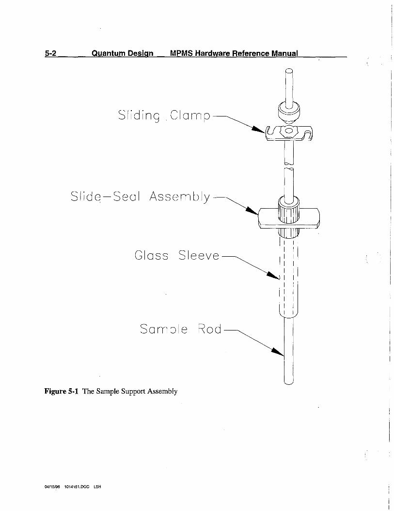
5-2 Quantum Design MPMS Hardware Reference Manual
Sliding .Clamp~
Slide-Seal Assembly
Gloss Sleeve
Sample Rod
Figure 5-1 The Sample Support Assembly
04/15/96 1014151.DOC LSH
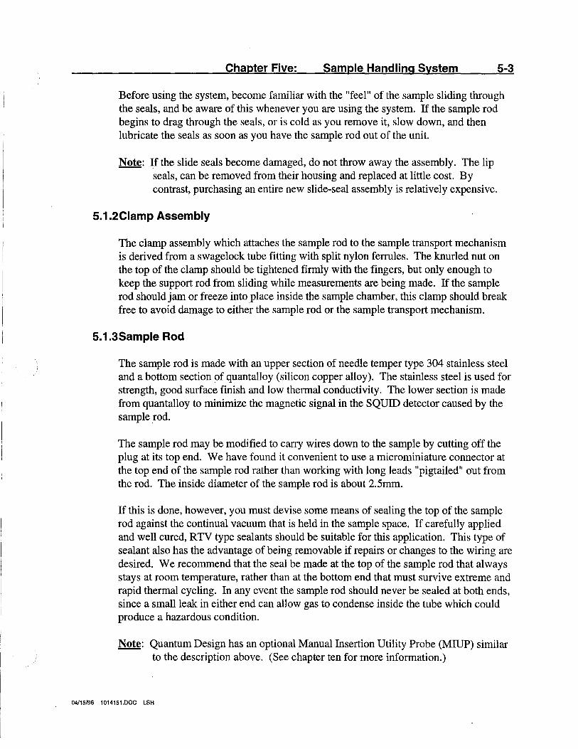
Chapter Five: Sample Handling System 5-3
Before using the system, become familiar with the "feel" of the sample sliding through the seals, and be aware of this whenever you are using the system. If the sample rod begins to drag through the seals, or is cold as you remove it, slow down, and then lubricate the seals as soon as you have the sample rod out of the unit.
Note: If the slide seals become damaged, do not throw away the assembly. The lip seals, can be removed from their housing and replaced at little cost. By contrast, purchasing an entire new slide-seal assembly is relatively expensive.
5.1.2Clamp Assembly
The clamp assembly which attaches the sample rod to the sample transport mechanism is derived from a swagelock tube fitting with split nylon ferrules. The knurled nut on the top of the clamp should be tightened firmly with the fingers, but only enough to keep the support rod from sliding while measurements are being made. If the sample rod should jam or freeze into place inside the sample chamber, this clamp should break free to avoid damage to either the sample rod or the sample transport mechanism.
5.1.3Sample Rod
The sample rod is made with an upper section of needle temper type 304 stainless steel and a bottom section of quantalloy (silicon copper alloy). The stainless steel is used for strength, good surface finish and low thermal conductivity. The lower section is made from quantalloy to minimize the magnetic signal in the SQUID detector caused by the sample.rod.
The sample rod may be modified to carry wires down to the sample by cutting off the plug at its top end. We have found it convenient to use a microminiature connector at the top end of the sample rod rather than working with long leads "pigtailed" out from the rod. The inside diameter of the sample rod is about 2.5mm.
If this is done, however, you must devise some means of sealing the top of the sample rod against the continual vacuum that is held in the sample space. If carefully applied and well cured, RTV type sealants should be suitable for this application. This type of sealant also has the advantage of being removable if repairs or changes to the wiring are desired. We recommend that the seal be made at the top of the sample rod that always stays at room temperature, rather than at the bottom end that must survive extreme and rapid thermal cycling. In any event the sample rod should never be sealed at both ends, since a small leak in either end can allow gas to condense inside the tube which could produce a hazardous condition.
Note: Quantum Design has an optional Manual Insertion Utility Probe (MIUP) similar to the description above. (See chapter ten for more information.)
04/15/96 1014151.DOC LSH
5-4 · Quantum Design MPMS Hardware Reference Manual
When the unit is first unpacked, the sample rods, slide-seal assemblies, and clip assemblies are packaged separately. Handle the sample rods carefully as their entire length must pass through the slide-seal assembly. If the sample rod is bent or dented, it must be replaced. To assemble the mechanism, lightly lubricate several inches of the sample tube at its rounded end, insert this end of the sample tube into the glass sleeve and gently push it through the lip-seals. Slide the sample rod up until a few inches of the sample rod protrude from the glass sleeve. Slip the clip assembly several inches past the rounded end of the sample rod and secure it by tightening the knurled stainless steel nut. Now lightly lubricate the sample rod between the slide-seal and the clip assembly.
CAUTION
The sample rods are made of a very thin-walled tube to limit thermal conduction down the rod. Consequently these rods are easily bent, particularly the quantalloy extension at the lower end of the rod. If the rod is damaged, it must be replaced. It will not seal properly when the damaged portion passes through the lip seal. Please handle rods with great care.
5.1.4Mounting Samples
Samples may be mounted on the end of the sample rod using a variety of techniques. Because of the wide variations in the types, sizes, and geometries of samples from customer to customer; we do not supply a standard sample holder. There are several techniques that previous customers have found useful.
One particularly useful sample holder is a thin-walled quartz tube. This can be attached by mounting a nonmagnetic coupling on the end of the sample rod to mate the quantalloy portion of the rod and quartz tube together. The sample can then be held in place by inserting it into the quartz tube, and stuffing quartz wool in beneath it. (Quartz wool is comprised of tiny quartz fibers.) A similar sample mounting can be accomplished with something as simple as a soda straw. ·
Another technique that can be used with tiny samples is to attach them to the side of a small quartz rod with a dot of vacuum grease. If this is done, centering rings should be
04/15/96 1014151.DOC LSH
Chapter Five: Sample Handling System
attached to the top and bottom of the rod to ensure that the sample does not get scrapped off the rod as it is inserted into the sample chamber.
5-5
If either of these techniques is used, the sample should be mounted about 7 to 10 cm from the end of the sample holder so that the end of the sample holder does not move through the detection coils during the measurement. The end of the sample holder will also produce a signal in the SQUID detector; and if it approaches the coils closely enough.to be detected, the signal will be distorted, and the magnetic moment calculation for the sample will be in error.
Larger samples can be suspended from the end of the sample tube with white cotton thread. However, this allows the sample to swing back and forth in the sample chamber, causing corresponding oscillations in the SQUID detection system. This can cause measurement errors much larger than when using rigidly mounted samples. Generally, we have found it much more desirable to use a rigid mounting rather than suspending samples from a thread.
04/15/96 1014151.DOC LSH

5-6 Quantum Design MPMS Hardware Reference Manual
5.2 Taking A Measurement
Once the sample is mounted on the sample rod, the following procedure describes the progression necessary to take a measurement: ·
5.2.1 Installing the Sample Rod Assembly into the Sample Chamber
WARNING!
Care must be taken about the length of the sample rod and sample holder so that when the transport is initialized, the sample holder will not hit the bottom of the sample chamber. This may destroy the sample tube and possibly damage the sample transport unit. If the sample holder is longer than 23.6 cm, do not continue.
1. Tighted the knurled nut on the slide seal assembly so that it is positioned approximately 122 cm away from the center of your sample.
2. Pull the sample rod up through the slide-seal so that the sample holder is drawn into the protective glass sleeve (the shroud). Make sure the sample holder is flush against the blue plug.
3. Vent the sample chamber.
a. If there is no sample present in the sample chamber and the READY LED is on, vent the system by closing the airlock valve. This automatically vents the sample chamber. Close the airlock by rotating the handle counter clockwise so that it points horizontally to the indicated CLOSED position. Wait for the VENTING LED to turn off.
b. If there is no sample present in the sample chamber, the airlock is already in the CLOSED position, and the green READY LED is on; toggle the handle to OPEN then back to CLOSED. Wait for the VENTING LED to turn off.
c. If there is a sample present in the sample chamber, proceed to the next step.
4. Open the slide seal clamps on the sample transport socket block so the blue plug may be released or in the case of a sample rod present, the slide-seal.
04/15/96 1014151.DOC LSH

Chapter Five: Sample Handling System 5-7
5. Remove the blue plug or the sample rod.
6. Before proceeding, verify that the three o-rings in the blue plug socket block are in place, free of debris, and not dry. Do not put too much grease on the o-rings, but if necessary, apply Apiezon M-Grease so the surface of the o-rings are wet.
7. Insert the sample rod into the sample chamber until the point where the slide-seal housing can be secured into the socket in the sample transport.
Note: Ensure that the white "dot" is facing forward. This ensures proper gas flow through the slide-seal. It may be secured by rotating the two rectangular handles on the socket block so that the slide-seal is forced down agains~ the three o-rings in the block by cam action.
8. The blue plug of the slide seal assembly should be flush to the top of the socket block.
9. Close the slide seal clamps on the sample transport so the slide-seal assembly may be fastened.
10. Press the button on the front of the MPMS probe labeled PURGE AIRLOCK to initiate automatic purging of the airlock. When the green LED labeled READY comes on, open the airlock valve by rotating the handle clockwise so that it points vertically to the indicated OPEN position.
Note: If the READY LED does not light within a few seconds after the purging sequence ends, there may be a leak in the sample handling system or check the annulus pressure gauge for a negative pressure. (Negative pressure is characteristic of acquiring low temperatures. The temperature must first become stable before the READY LED will light.)
11. Lower the sample slowly and slowly turn the rod during the insertion process.
Note: If the rod appears to be dry or not moving smoothly through the lip seals, add some Apiezon M-Grease.
12. Lock the clip assembly into the actuator shoe by tightening the thumb nuts.
04/15/96 1014151.DOC LSH
5-8 Quantum Design MPMS Hardware Reference Manual
5.2.2Center the Sample
1. Access the Register Sample menu (F2) and perform the following action~:
a. Tum Autosample Tracking on. If it is already on, toggle it on. b. Initialize Sample Transport in order to calibrate the transport to 0.27 cm
from the bottom of the transport.
2. Perform the center sample process, in which it may be necessary to apply a magnetic field. Briefly, the sample centering process includes performing a full length DC scan, adjusting the sample position, and then performing DC centering scan. (See the MPMS software manual for more information.)
5.2.3Take Measurements
Collect data by opening the Measure menu (F3), then moving the cursor to Immediate and press ENTER. Data may also be collected through a sequence.
04/15/96 1014151.DOC LSH
Chapter Five: Sample Handling System 5-9
5.3 Retrieving Samples And Cleaning The Sample Chamber
If a sample falls off the sample holder or the sample chamber becomes contaminated, the MPMS is designed to allow the sample chamber to be opened to room temperature without danger of plugging small gas tubes or otherwise degrading the operation of the system. Simply set the system temperature to room temperature or slightly higher (about 310 Kelvin), and when the system becomes stable at that temperature, the airlock can be opened to the room.
Note that wh~n the airlock is vented after closing the airlock valve, the airlock flushing valve is left closed, which is its energized state. For this reason, when there is no sample in the unit we recommend that the airlock plug provided with the system be installed in place of the slide-seal assembly, and then purge the airlock. When the system is left in this condition, simply open the airlock valve slightly, then close it again to vent the airlock. The airlock can now be opened to the room. The airlock flushing and venting valves can also be controlled from the Diagnostic Gas Controls menu under Flush Valve and Vent Valve, respectively (access the Diagnostic Menus (F7), move cursor to Gas Controls, and then press Enter).
Once the airlock is open and the temperature is set to 310 Kelvin, a rod with an appropriate hook or spiral wire can be inserted to the bottom of the sample chamber to retrieve lost samples, or a Kimwipe with a mild solvent can be used to swab out the sample chamber. If a solvent is needed, use it sparingly since the o-ring seals at the top of the sample chamber around the airlock valve may be damaged by strong solvents.
After the lost sample has been retrieved or the sample chamber cleaned out, replace the airlock plug in the top of the sample transport mechanism, and with the airlock open press the PURGE AIRLOCK button. This will purge the entire sample chamber of air and any vapors remaining from the solvent, and it will restore the static helium pressure of a few millimeters. You may wish to repeat this process again after a few minutes, allowing time for any residual liquid or water moisture to vaporize. When this process is finished, close the airlock valve, and the system is ready to accept another sample.
04/15/96 1014151.DOC LSH


6-1
Chapter Six: MPMS Magnetic Field Control
Since the MPMS uses no superconducting shield to trap a magnetic field over the sample volume, the magnetic field on the sample is sustained by trapping a persistent current in the five tesla superconducting magnet. The control system for the magnet is shown in Figure 6-1. The field is changed automatically by the MPMS control system when you specify a new magnetic field.
6.1 Changing t.he Field
The automatic sequence engaged when changing the field is as follows:
1. Turn on the power supply and heater for the SQUID flux transformer heater. Turning on the flux transformer will prevent large standing currents from being trapped in the SQUID sensing circuit as a result of the field change.
2. Set the current switching relays for the correct polarity. Set the power supply output to the current presently stored in the magnet.
3. Turn on the persistent switch heater, and wait a few seconds to ensure that the switch has been driven nmmal.
4. Change the current to give the next desired field. When this current is reached, the 1822 MPMS controller will overshoot the desired value, then approach it through a series of decreasing amplitude oscillations. This procedure dramatically reduces relaxation in the magnet following a field change.
5. When t~e correct value of current is reached, the 1822 MPMS controller reads the voltage across a reference resistor in series with the magnet power supply to ensure that the desired current has been set. If the proper current is not flowing, it is adjusted to be within acceptable limits. In the low resolution mode, the acceptable limit corresponds to 1 gauss; in the high resolution mode the limit is 0.1 gauss.
6. After the final value of current has been reached, turn off the persistent switch heater. Wait a few seconds to ensure that the switch has returned to its persistent mode.
7. Set the power supply current to zero, turn the power supply off, and reset the polarity relays to shunt the persistent switch. This is denoted as "Off" in the MPMS control software.
04/15/96 1014151.DOC LSH
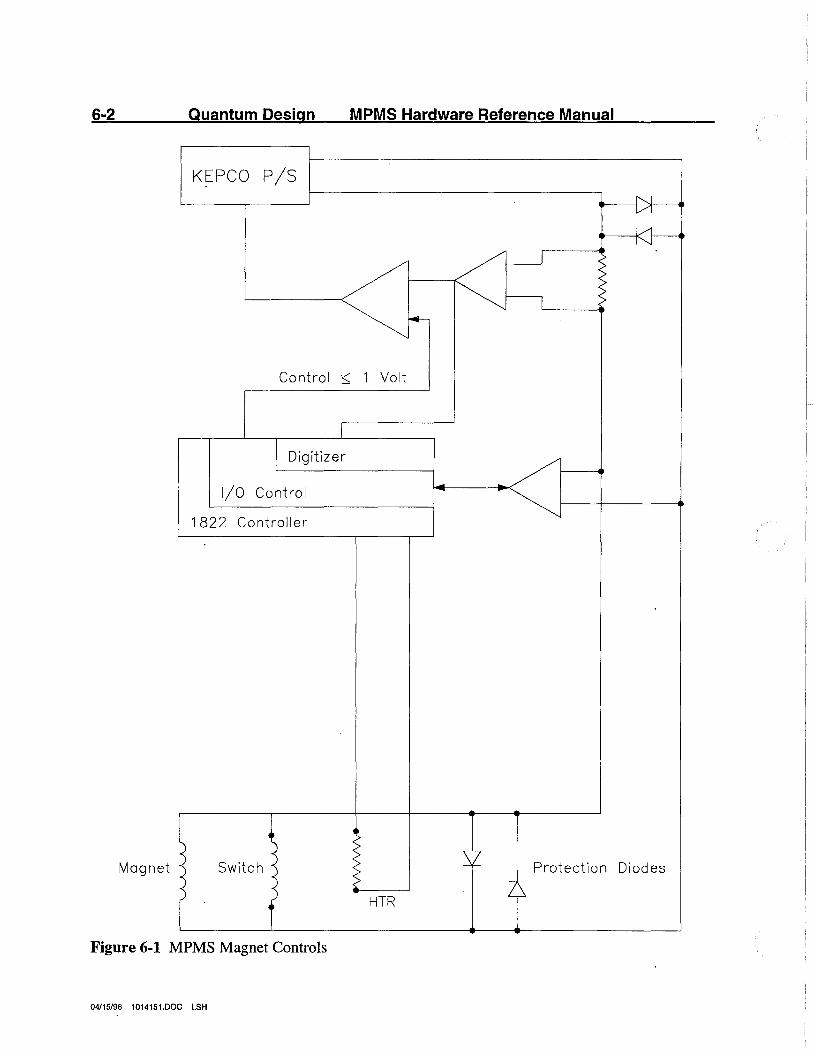
6-2 Quantum Design MPMS Hardware Reference Manual
KEPCO P/S
Control ·::;: 1 Volt
Digitizer
1/0 Control
1822 Controller
Magnet Switch Protection Diodes
HTR
Figure 6-1 MPMS Magnet Controls
04/15/96 1014151.DOC LSH

Chapter Six: Magnetic Field Control 6-3
After this automatic sequence is initiated by the MPMS control software with a single command to the 1822 MPMS controller, the entire sequence of events is processed entirely by the 1822 controller without further attention from the HP computer. When the sequence is finished, the word Stable will appear next to the field value on the HP computer screen. There are two modes available for making field changes which may be selected from the MPMS Executive menu. These are Oscillate and No Overshoot.
04/15/96 1014151.DOC LSH
6-4 Quantum Design MPMS Hardware Reference Manual
6.2 Oscillate Mode
Since the MPMS uses no superconducting shield around the SQUID pickup coils, the magnetic field applied to the sample is just that trapped in the magnet in its persistent mode. However, when a superconducting magnet is put back into the persistent mode immediately after changing the field, the magnetic field will gradually relax due to the magnetic field lines slowly creeping through the superconducting windings. Although the SQUID sensi~g coils are balanced to reject signals from the magnet to a level of about 0.1 percent (due to the extreme sensitivity of the SQUID detector) any relaxation in the magnet will still produce a substantial drift in the SQUID detector output for several minutes after changing the field in the magnet.
This type of relaxation can be minimized by first going past the intended magnetic field, then oscillating the current in the magnet back and forth about the target field with a decreasing amplitude of oscillation. The MPMS control system uses this technique when changing the field to minimize drift in the SQUID detector immediately following a magnetic field change. The initial overshoot in the MPMS is approximately 30 percent of the total field change, and the amplitude of each oscillation is 70 percent of the preceding one. The oscillations continue until the field is within approximately 100 gauss of the desired value, at which time the magnet is set to the precise field value requested.
04/15/96 1014151.DOC LSH
Chapter Six: Magnetic Field Control 6-5
6.3 No Overshoot Mode
If hysteresis measurements are being made, it will be important that the sample not be exposed to these field oscillations. The oscillations can be suppressed by selecting the No Overshoot mode for the magnet under Magnet Charging Mode in the Set Parameters menu (F4) in the MPMS software control system. When the No Overshoot mode is used, the magnet will require a longer settling time.
Even when the No Overshoot mode is used, measurements can normally still be made immediately following a field change because the MPMS control system can compensate for rather large background drifts in the SQUID detector. Magnetic field drift will normally appear in the data as a linear background which can be subtracted when the magnetic moment of the sample is calculated. Hence, when the SQUID "Autoranging" is enabled in the MPMS software control system, the SQUID detector will automatically switch to a less sensitive range to accommodate the background drift.
Note: If the autoranging function is turned off, be sure that the SQUID detector range is sufficiently insensitive to accommodate the background drift. If it is not, the ·data will be invalid because the SQUID detector will saturate during the measurement in which clipping the data occurs.
04/15/96 1014151.DOC LSH
6-6 Quantum Design MPMS Hardware Reference Manual
6.4 High and Low Resolution Mode
When setting fields below 5000 gauss, the control system will automatically switch the current sense resistor to a larger value (if the high resolution is enabled), providing field resolution of .approximately 0.1 gauss, compared to the system's normal field resolution of 1.0 gauss. When enabled, the system will automatically select the high resolution mode whenever possible. Note, however, that the relay that selects the high or low resolution mode cannot be switched unless the current from the power supply is set to zero. When the high resolution mode is enabled, it will be selected as follows:
1. When the magnitudes of both the original field and the newly specified field are less than 5000 gauss.
2. When the magnitude of the new field to be set is less than 5000 gauss and the Oscillate mode is selected. In this case, when the oscillations become small enough to be accommodated with the high resolution mode selected, the current will be momentarily set to zero, the magnet control system will be switched to the high resolution mode, and the oscillations continued.
3. When the "No Overshoot" mode is selected and the original field in the magnet is greater than 5000 gauss, the high resolution mode will not be selected, since this would require that the field be set to zero at some point during the field change - possibly in violation of the "No Overshoot" requirement.
04/15/96 1014151.DOC LSH
Chapter Six: Magnetic Field Control 6-7
6.5 Updating the Last Magnetic Field Stored in the Magnet
Another feature available in the MPMS magnet control system allows you to update the information in the 1822 MPMS controller and the MPMS HP operating system regarding the last field stored in the magnet. From the magnet charging sequence described in section 6.1, it is clear that the MPMS control system must "remember" the current that was last stored in the magnet so the correct current from the power supply can be preset before energizing the persistent switch heater. If the power supply is set to the wrong current when the persistent switch is driven normal, the voltage across the switch will exceed the trigger voltage of the protective diodes, and current will begin to flow through the diodes. When this occurs, the cmTent which was stored in the magnet will be dissipated in the diodes as the magnet is rapidly discharged.
Under normal operating conditions, the 1822 MPMS controller stores the value of current presently stored in the magnet and uses this value when the next field request is received. However, if a power outage occurs while the magnet is charged, the system will experience a Power-On reset, and the information in the 1822 MPMS controller will be lost. When the HP control system is restarted, the data read from the system status file will be inconsistent with the information received from the 1822 MPMS controller, and you will be informed of the problem during the reinitialization of the HP control system.
WARNING!
Be sure that the value of field you specify has the same polarity as the last-field stored in the magnet. If you specify the field with the incorrect sign, you may physically damage the magnet control system. Also, the field update operation should be performed immediately on restarting the system after the power outage has been corrected.
The field information can also be restored using the Update Field in the Utilities (F6) menu. (See the MPMS Software User's Manual for details of the use of this function.) Note that neither field update operation at initialization nor in the Utilities menu initiates a change in the field stored in the magnet- it only informs the 1822 MPMS controller and the MPMS software control system that the field currently stored is as specified.
04/15/96 1014151.DOC LSH
6-8 Quantum Design MPMS Hardware Reference Manual
6.6 Direct Control over the Magnet Sequence
CAUTION
As a final reminder, we want to again caution you against careless manipulation of the magnet control system via the Magnet Controls menu under the Diagnostic Menus (F7). These operations should only be exercised by someone thoroughly familiar with the MPMS system and its operation.
In addition to the normal automatic MPMS magnet controls, we have also included the necessary command structure to allow direct control over the magnet sequence from the MPMS system control computer. While the individual MPMS controller commands are delineated in the Model 1822 MPMS Controller User's Manual, most of the specific functions are available from the Magnet Controls menu in the MPMS control system as described in the MPMS Software User's Manual.
6. 7 Magnetic Field Limitations as a Function of the Helium Level
If the liquid helium level becomes too low, it is possible that the superconducting magnet may quench. To prevent this from happening the liquid helium should be maintained above the top of the magnet. This corresponds to a liquid helium level of approximately 50% (see Figure 2-1). ·
If the helium level drops below the top of the magnet the magnet field used should be limited. Between 40-50%, the maximum field should be limited to 10,000 gauss. Between 30-40%, the maximum field should be limited to 1,000 gauss. Below 30%, the magnet should not be charged with a magnetic field.
04/15/96 1014151.DOC LSH
7-1
Chapter Seven: Gas Control System
The MPMS gas system controls the gas flow through the cooling annulus to provide cooling for the MPMS, plays a key role in the active temperature control below the crossover point of about 4.4 Kelvin, and provides the valving and controls for purging the airlock when loading samples. Figure 7-1 shows a schematic view of the gas control system.
7.1 Description
Cold helium gas or liquid is drawn into the cooling annulus via the variable impedance. When the system is maintaining a stable temperature, the incoming gas is heated to the temperature of the sample chamber as it enters the cooling annulus. It then passes up the cooling annulus, through the larger vacuum line connecting the cooling annulus to the MPMS control console, and through the metering valve (shown as the bias needle valve in Figure 7-1) to the vacuum pump.
During a high speed cooldown, the proportional flow control valve will be opened, providing a large gas flow through the cooling annulus. This valve is in parallel with the metering needle valve which is simply bypassed during this operation.
The proportional valve also is used to fill the helium reservoir (the lower portion of the cooling annulus) with liquid for thermal control below the crossover temperature. The reservoir is filled by adjusting the pumping speed to the proper rate using the proportional valve and by holding that rate constant for an appropriate length of time. When properly adjusted, this will draw liquid through the variable impedance and into the cooling annulus. After the reservoir has been filled, the variable impedance is closed. The pumping rate can then be adjusted to control the temperature of the reservoir. Again, the proportional valve fulfills this function.
04/15/96 1014151.DOC LSH
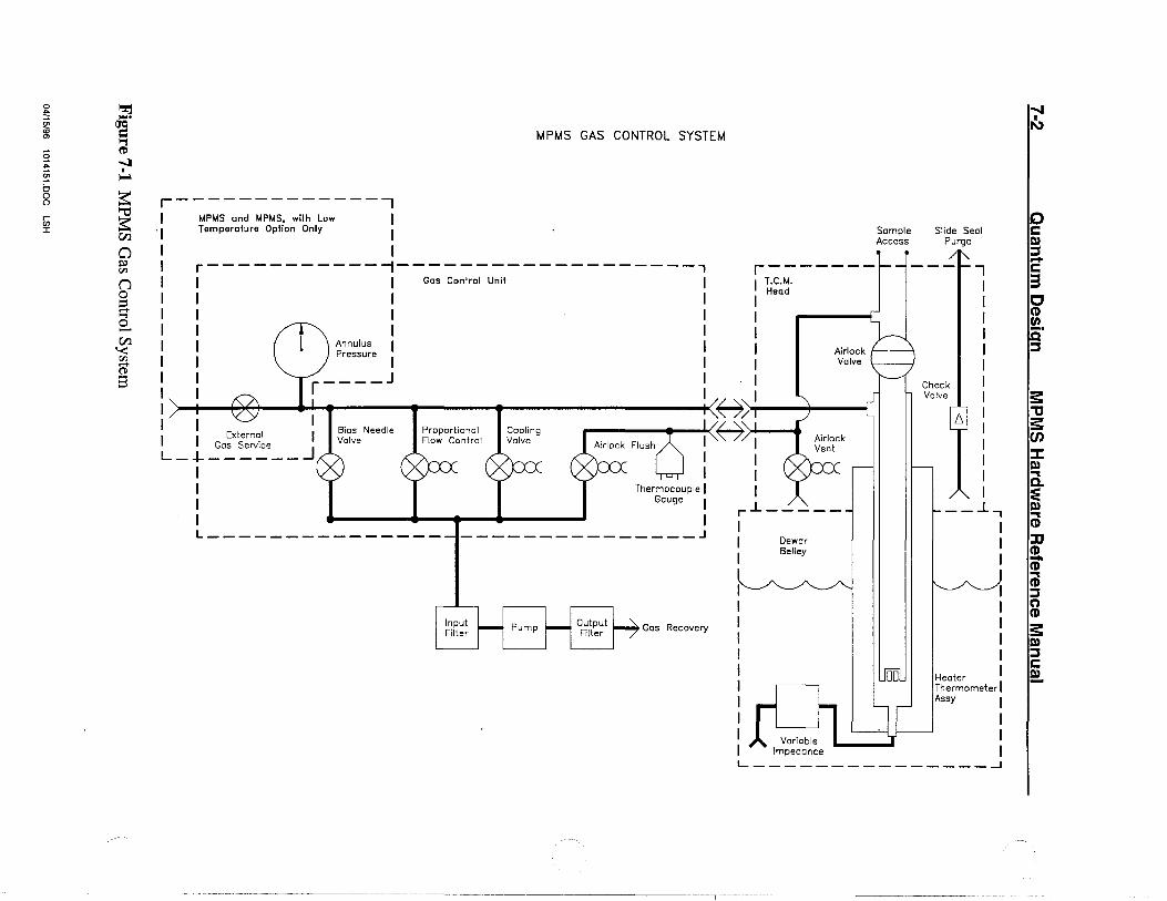
0 ~ ~ .... $ IJc:i O> = ,., § ~
... ...:I § I
~ b
~ 0 ()
r- ""C en ~ ::c
(/.)
0 ~
"' n 0 ::i q 0 -(/.) '< "' ...... (1)
3
MPMS GAS CONTROL SYSTEM
r--------------, I MPMS and MPMS, with Low I
. 1 Temperature Option Only I
I I I r-----------~-------------------, I I I Gas Control Unit I I I I I I I I I I I I I
r-------T.c.M. Head
Sample Access
I I Annulus I I I I Pressure I I I Airlock ,______,.
Valve
I I r ____ J I I I I I f-7) ) I I I I I I External I Bias Needle
Valve Proportional Flow Control
Cooling Valve
,..-----.1.!'L.:::::.." r 0:"7, Gos Service _J
L-+------1 I I I
Thermocouple I Gauge
L---------------~---------------~
Output Filter Gos Recovery
rJ_ __ _
I --
1 I
Dewar Selley
Slide Seal Purge
Check Valve
[.,_
.., I I
__.l.-,
I I I
Heater Thermometer I Assy I
I I I
..... i\>
" c § -c 3 c CD en
:::s
s: .,, s en :I: m ""'I a. ~ ; ::c ~ ; :::s ~ s: m :::s c ~

Chapter Seven: Gas Control System 7-3
7.2 Purging the Airlock
The other primary function of the gas system is to purge the airlock prior to opening the airlock valve and inserting a sample into the sample chamber. The airlock flush valve, the airlock vent valve, and the thermocouple gauge provide this capability. Pressing the PURGE AIRLOCK switch on the front of the MPMS probe, initiates an automatic process in which the two valves are sequentially opened and closed to purge air from the airlock. The flush valve is opened first to evacuate the air from the airlock chamber, then the vent valve is opened allowing helium gas from the dewar to enter the airlock. After a few seconds, the vent valve is again closed, and the flush valve is reopened to purge the airlock. The process is repeated three times providing a thorough cleansing of the airlock.
At the compl~tion of the purge sequence, the vent valve is left closed and the flush valve open, while the 1822 MPMS controller monitors the thermocouple gauge to ensure that the sample chamber pressure is pumped down to the correct pressure. When a pressure of a few millimeters is reached, the green LED on the front of the MPMS probe labeled READY will light up indicating that the airlock can now be opened. ·
If the READY LED does not come on after 5 or 10 seconds, there is probably a leak in the sample chamber. There are three o-ring seals beneath the slide-seal assembly that seal the sample chamber when a sample is in the unit. (The slide-seal assembly is the unit that contains the sliding seals around the sample rod, and is clamped into the top of the sample transport mechanism when a sample is inserted into the airlock.) If the READY LED does not light after the valve sequence is completed, open the airlock slightly, then close it again to initiate the venting operation. After the VENTING LED on the MPMS probe goes out, remove the slide-seal assembly and check to see if the three o-rings are in place. This is the most likely problem, as the o-rings will occasionally stick to the underside of the slide-seal assembly when it is removed.
After the airlock purging operation has been completed and the READY LED is on, the airlock flush valve will be left open so that the vacuum pump will be pumping continuously on the sample chamber. This will maintain a few millimeters pressure of static helium gas in the chamber to provide thermal contact between the sample and the walls of the sample chamber.
When the sample is to be removed from the sample chamber, it is lifted into the airlock and the airlock valve is closed. The valve closure is automatically detected by the 1822 MPMS controller. The airlock flush valve is closed, and the vent valve is opened for several seconds, allowing helium from the dewar to vent the airlock up to atmospheric pressure. After the VENTING LED on the front of the MPMS probe goes off, the sample can be removed from the airlock.
04/15196 1014151.DOC LSH

7-4 · Quantum Design MPMS Hardware Reference Manual
When there is no sample in the airlock, the airlock plug should be placed in the slide-seal seat, and the airlock purged. This will keep dust and dirt from contaminating the o-ring seals, and keep any small objects from dropping into the airlock. It will also leave the flush valve open, which is its deenergized state.
7.3 Attaching an External Helium Source
The toggle valve and access port labeled EXTERNAL GAS SERVICE are located· on the MPMS gas unit on the front of its control console. Together the toggle valve and gas port can be used for attaching an external helium source to the system.
7.4 The Check Valve
The check valve shown in Figure 7-1 provides a steady flow of helium gas from the dewar to the top of the sample transport mechanism. This flow will continuously purge the volume between the two lip seals in the slide-seal assembly. (The construction of the slide-seal assembly is discussed in more detail in chapter 5.) The helium gas which leaves the dewar via this check valve is exhausted from the gas nozzle located on the rear of the sample transport mechanism. Since the check valve is set for 1/3 psi, compared to the 1 psi setting for the dewar relief valve on the top plate of the MPMS probe, the nozzle on the sample transport will be the primary path for helium being vented from the dewar.
7.5 Attaching~ Helium Recovery System
If the system is to be attached to a helium recovery system, two connections are required during normal operation. The vacuum pump outlet passes through an air filter mounted just inside the rear door of the console. The outlet of the air filter is a gas nozzle to which a recovery line can be attached. An additional recovery line must be attached to the gas nozzle on the rear of the sample transport mechanism. During helium transfers you may also wish to connect a third recovery line to the exhaust port of the helium transfer fitting.
04/15/96 1014151.DOC LSH
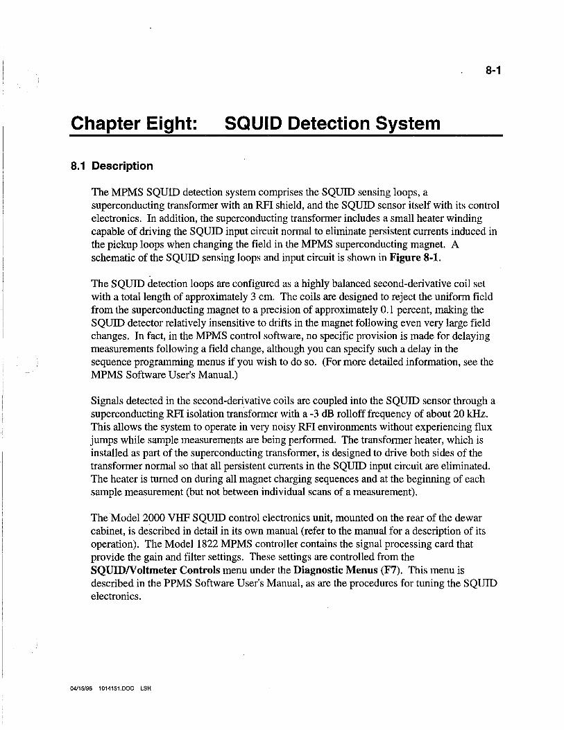
8-1
Chapter Eight: SQUID Detection System
8.1 Description
The MPMS SQUID detection system comprises the SQUID sensing loops, a superconducting transformer with an RFI shield, and the SQUID sensor itself with its control electronics. In addition, the superconducting transformer includes a small heater winding capable of driving the SQUID input circuit normal to eliminate persistent currents induced in the pickup loops when changing the field in the MPMS superconducting magnet. A schematic of the SQUID sensing loops and input circuit is shown in Figure 8-1.
The SQUID detection loops are configured as a highly balanced second-derivative coil set with a total length of approximately 3 cm. The coils are designed to reject the uniform field from the superconducting magnet to a precision of approximately 0.1 percent, making the SQUID detector relatively insensitive to drifts in the magnet following even very large field changes. In fact, in the MPMS control software, no specific provision is made for delaying measurements following a field change, although you can specify such a delay in the sequence programming menus if you wish to do so. (For more detailed information, see the MPMS Software User's Manual.)
Signals detected in the second-derivative coils are coupled into the SQUID sensor through a superconducting RFI isolation transformer with a -3 dB rolloff frequency of about 20 kHz. This allows the system to operate in very noisy RFI environments without experiencing flux jumps while sample measurements are being performed. The transformer heater, which is installed as part of the superconducting transformer, is designed to drive both sides of the transformer normal so that all persistent currents in the SQUID input circuit are eliminated. The heater is turned on during all magnet charging sequences and at the beginning of each sample measurement (but not between individual scans of a measurement).
The Model 2000 VHF SQUID control electronics unit, mounted on the rear of the dewar cabinet, is described in detail in its own manual (refer to the manual for a description of its operation). The Model 1822 MPMS controller contains the signal processing card that provide the gain and filter settings. These settings are controlled from the SQUIDN oltmeter Controls menu under the Diagnostic Menus (F7). This menu is described in the PPMS Software User's Manual, as are the procedures for tuning the SQUID electronics.
04/15/96 1014151.DOC LSH
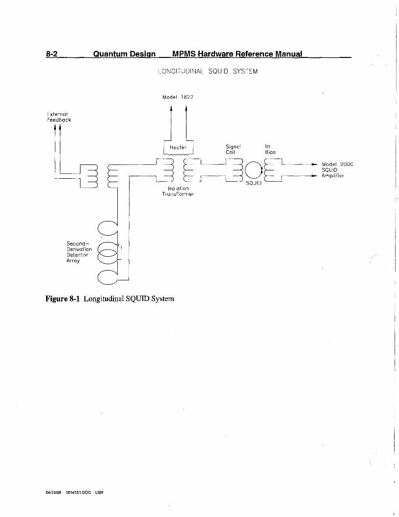
8-2
External Feedback
SecondDerivatian Detector Array
Quantum Design MPMS Hardware Reference Manual
LONGITUDINAL SQUID SYSTEM
Model 1822
Isolation TronsFormer
Signal RF Coil Bias
Figure 8-1 Longitudinal SQUID System
04/15/96 1014151.DOC LSH
Model 2000 SQUID Amplifier
Chapter Eight: SQUID Detection System 8-3
8.2 Transverse Coil Set
The components of the transverse superconducting coil set are almost identical to that of the Longitudinal. The main difference is the configuration of the pickup loop.
The transverse pickup loop is wound orthogonal to the longitudinal pickup in an array. This is illustrated in Figure 8-2. As shown, both the longitudinal and transverse pickup loops share a common center position. This allows for measurement with both axes, without having to recenter the sample. Measurements for both axes are taken in the same manner, by moving the sample up through the pickup loop.
Because the transverse pickup loop does contain some longitudinal components, samples with small transverse moments will give a longitudinal signal when taking a transverse measurement. Therefore it is recommended that when measuring a sample with the transverse axis, the sample should have a transverse moment that is 80 percent larger than its longitudinal signal.
If the sample to be measured does not have a large transverse signal, the measurement can still be taken. Once the data has been collected, the longitudinal portion of the signal must be subtracted from the transverse. This can be accomplished using a Fourier Transform technique.
The transverse option is complete with its own SQUID sensor and associated electronics. The only difference between the longitudinal and transverse electronics is the address setting on the associated Model 2000 amplifier. For the longitudinal the address is "O". For the transverse the address is "1 ".
04/15/96 1014151.DOC LSH
8-4
External Feedback
Quantum Design MPMS Hardware Reference Manual
TRANSVERSE SQUID SYSTEM
Model 1822
Signal RF Coil Bias
Isolation Transformer
Figure 8-2 Transverse SQUID System
04/15/96 1014151.DOC LSH
Model 2000 SQUID Amplifier
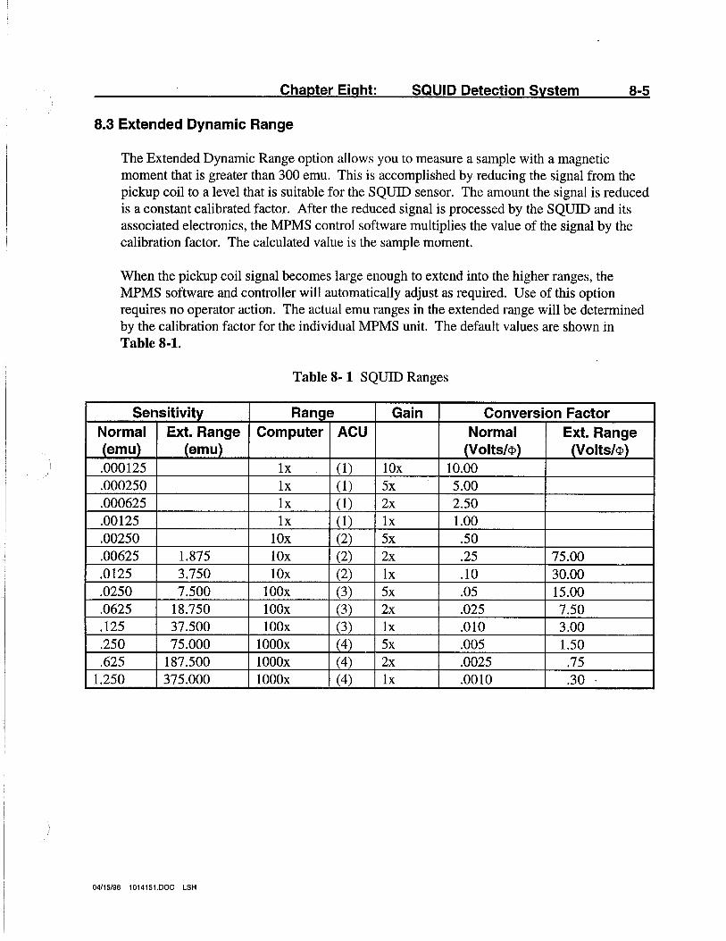
Chapter Eight: SQUID Detection System 8-5
8.3 Extended Dynamic Range
The Extended Dynamic Range option allows you to measure a sample with a magnetic moment that is greater than 300 emu. This is accomplished by reducing the signal from the pickup coil to a level that is suitable for the SQUID sensor. The amount the signal is reduced is a constant calibrated factor. After the reduced signal is processed by the SQUID and its associated electronics, the MPMS control software multiplies the value of the signal by the calibration factor. The calculated value is the sample moment.
When the pickup coil signal becomes large enough to extend into the higher ranges, the MPMS software and controller will automatically adjust as required. Use of this option requires no operator action. The actual emu ranges in the extended range will be determined by the calibration factor for the individual MPMS unit. The default values are shown in Table 8-1.
Table 8- 1 SQUID Ranges
Sensitivi!Y Ran_ge Gain Conversion Factor Normal Ext. Range Computer ACU Normal Ext. Range (emu) (emaj_ J..Volts/<Pj J..Volts/<P) .000125 lx (1) lOx 10.00 .000250 lx (1) 5x 5.00 .000625 lx (1) 2x 2.50 .00125 lx (1) lx 1.00 .00250 lOx (2) 5x .50 .00625 1.875 lOx (2) 2x .25 75.00 .0125 3.750 lOx (2) lx .10 30.00 .0250 7.500 lOOx (3) 5x .05 15.00 .0625 18.750 lOOx (3) 2x .025 7.50 .125 37.500 lOOx (3) lx .010 3.00 .250 75.000 lOOOx (4) 5x .005 1.50 .625 187.500 lOOOx (4) 2x .0025 .75
1.250 375.000 lOOOx (4) lx .0010 .30
04/15/96 1014151.DOC LSH

9-1
Chapter Nine: Magnet Reset Option
9.1 Description
The Magnet Reset Option allows you to reduce the residual or remnant field that is left in the superconducting magnet. Because the MPMS measures the current to the magnet and not the actual magnetic field, there may be some amount of field left in the magnet after operating at high fields, even though the field indicated is zero.
To reduce the amount of field left in the magnet, the Magnet Reset Option heats a small portion of the magnet above its superconducting temperature. A chain reaction occurs and the adjoining portions of the magnet are driven normal. This continues until the entire magnet has been driven normal and quenches. This will reduce the remnant field to typically less than 2 gauss.
In order for this option to function, two criteria must first be met as follows:
1. The helium level in the dewar must be greater than 50 percent. This is to ensure that the magnet is completely covered by the liquid helium.
2. The magnetic field must be set between 25000 and 35000 gauss.
A single reset of the magnet will use approximately 1 liter of liquid helium. The entire reset, including initiation, reset, and recooling of the magnet will take approximately 3.5 minutes.
It is not recommended that the magnet be reset often. The recommended technique is to perform a series of high field experiments, then reset the magnet to perform low field experiments. By lumping the high and low field experiments together, the number of resets can be minimized.
04/15/96 1014151.DOC LSH

10-1
Chapter Ten: Manual Insertion Utility Probe
Description
The Manual Insertion Utility Probe (MIUP) is a multifunction sample mounting platform. The sample mount is constructed of copper to provide a good thermal connection of the sample to the sample space. A microconnector at the top of the MIUP is connected by 5 sets of phosphor-bronze wire to the 10 terminal board at the bottom. Each wire can carry a maximum of 100 mamps. Pin #1 is designated by an arrow on the microconnector, and is connected to the uppermost terminal on the terminal board. Pin #2 is the pin across the microconnector from pin #1 and connects to the net terminal on the terminal board.
10/30/96 10141518.DOC LSH
1802 Bridge; 1-1, 1-5, 3-1, 4-10, 4-12, 4-14, 4-15
1822 Controller; 1-1, 1-5, 2-1, 4-10, 4-12, 4-14, 6-1, 6-3, 6-7, 6-8, 7-3, 8-1
A airlock; 5-6, 5-7, 5-9, 7-1, 7-3, 7-4 amplifier, Model 2000 rf; 1-6, 1-13, 1-14,
8-1, 8-3
c clamp assembly; 5-3 computer; 1-1, 1-5, 1-6, 1-8, 1-10, 2-3, 3-1,
3-2,3-4,4-1,4-5,4-ll,4-12,6-3 control console cabinet; 1-1, 1-5, 1-8, 1-10, 1-11,
1-15, 3-1, 4-3, 7-1, 7-4 cooldown, high speed; 4-8 cooling annulus; 4-1, 4-7, 7-1
D dewar
E
helium; 1-1, 1-11, 2-1, 2-3, 2-4, 3-1 to 3-4, 4-10, 5-1, 7-3, 7-4
nitrogen-shielded; 1-15
Extended Dynamic Range Option (EDR); 8-5
G gas handling system; 1-6
H heaters; 4-7, 4-10, 4-13, 4-15
chamber;4-1,4-14 gas; 4-1, 4-3, 4-7, 4-14
helium consumption; 1-8 level; 2-1 to 2-3 safety; 2-4, 2-5 transfering; 1-8, 3-1 to 3-4, 7-4
helium recovery systems; 1-8, 3-2, 3-4, 5-1, 7-4
I impedance; 4-10, 4-12, 7-1 impedance tube; 3-2
Index
L level meter; 2-1 lip seal; 5-1, 5-3, 5-4, 5-7, 7-4
M magnet; 1-1, 1-6, 2-1, 2-3, 3-2, 3-3, 6-1 to 6-8, 8-1
current; 6-1 high resolution; 6-1, 6-6 low resolution; 6-1, 6-6 mode
no overshoot mode; 6-5 oscillate mode; 6-4
operation; 6-1 to 6-3 persistent mode; 6-1, 6-4 reset; 6-1, 6-7 safety; 1-15 to 1-17 voltage; 6-7
Magnet Reset Option; 9-1 magnetic field; 1-9, 1-17, 3-3, 5-8, 6-1, 6-4, 6-8, 9-1
setting; 6-3, 6-8 Manual Insertion Utility Probe (MIUP); 5-3, 10-1,
10-2
0 o-ring; 5-1
p
location; 1-13, 3-1, 3-3, 5-7, 7-3 maintenance; 5-9, 7-4
persistent switch; 6-1, 6-7 pickup coil; 8-5 Power Distrubution Unit (PDU); 1-13, 3-1 probe; 1-1, 1-5, 1-8, 1-14, 2-1, 2-3, 3-2, 5-7, 7-3, 7-4
handling; 1-10, 1-13, 1-16 installation; 3-1
pumping lines; 3-1
R reservoir; 4-1, 4-4, 4-8, 4-10 to 4-13, 7-1
s safety; 1-10, 1-15 to 1-17, 2-4, 2-5 sample chamber; 4-1, 4-3, 4-4, 4-7 to 4-9, 4-14, 5-1,
5-3, 5-5 to 5-7, 5-9, 7-1, 7-3 sample holder; 5-4 to 5-6, 5-9 sample rod; 1-1, 1-8, 5-1, 5-3, 5-4, 5-6, 5-7, 7-3 sample space; 4-10, 5-3, 10-1 sample support assembly; 5-1, 5-2 sample translator; 1-6