Embed Size (px)
DESCRIPTION
Feasibility on Industrial
Citation preview
FEASIBILITY STUDY
FOR
LAUGHLIN 400 ACRES
CLARK COUNTY, NEVADA
W.O. # 7180
August 4, 2009
Prepared for: Submitted to: JACQUELYNE BRADY CLARK COUNTY LAUGHLIN TOWN MANAGER REAL PROPERTY MANAGEMENT
i
TABLE OF CONTENTS
Page 1. INTRODUCTION................................................................................................................... 1 2. 400+ ACRE INDUSTRIAL PARK ....................................................................................... 1
2.1 Site A Location and Description................................................................................................................ 2 2.2 Site B Location and Description ................................................................................................................ 2 2.3 Site C Location and Description................................................................................................................ 2
3. PLANNING AND LANDUSE ............................................................................................... 3 3.1 Zoning Information .................................................................................................................................... 3 3.2 Master Planning Information .................................................................................................................... 3
4. SITE CHARACTERISTICS.................................................................................................. 4 5. SOILS....................................................................................................................................... 4 6. TRAFFIC................................................................................................................................. 5
6.1 Project Description ..................................................................................................................................... 5 6.2 Trip Generation .......................................................................................................................................... 5 6.3 Trip Distribution......................................................................................................................................... 6 6.4 Area Roadways ........................................................................................................................................... 6 6.5 Mitigation Measures ................................................................................................................................... 7
7. DRAINAGE............................................................................................................................. 7 7.1 Site A............................................................................................................................................................ 7 7.1.1 Flood Zone Information ............................................................................................................................. 7 7.1.2 Drainage Basins .......................................................................................................................................... 7 7.1.3 CCRFCD Master Plan Facilities ............................................................................................................... 8 7.1.4 Existing Local Drainage Facilities............................................................................................................. 8 7.1.5 Proposed Drainage Facilities Cost Estimate............................................................................................. 9 7.2 Site B .......................................................................................................................................................... 10 7.2.1 Flood Zone Information ........................................................................................................................... 10 7.2.2 Drainage Basins ........................................................................................................................................ 10 7.2.3 CCRFCD Master Plan Facilities ............................................................................................................. 10 7.2.4 Existing Local Drainage Facilities........................................................................................................... 11 7.2.5 Proposed Drainage Facilities Cost Estimate........................................................................................... 12 7.3 Site C.......................................................................................................................................................... 12 7.3.1 Flood Zone Information ........................................................................................................................... 12 7.3.2 Drainage Basins ........................................................................................................................................ 13 7.3.3 CCRFCD Master Planned Facilities ....................................................................................................... 13 7.3.4 Existing Local Drainage Facilities........................................................................................................... 13 7.3.5 Proposed Drainage Facilities ................................................................................................................... 14 7.3.6 Proposed Drainage Facilities Cost Estimate........................................................................................... 15
8. WET UTILITIES.................................................................................................................. 15 8.1 Potable Water ........................................................................................................................................... 15 8.1.1 Site A.......................................................................................................................................................... 16 8.1.1.1 Option 1 – Ground Water Well with Package Treatment Plant (600 GPM) ...................................... 16 8.1.1.2 Option 2 – Pipeline Extension.................................................................................................................. 17 8.1.1.3 Option 3 – Water Treatment Plant (600 GPM) ..................................................................................... 18 8.1.2 Site B .......................................................................................................................................................... 20 8.1.2.1 Option 1 – Ground Water Well with Package Treatment Plant (600 GPM) ...................................... 20 8.1.2.2 Option 2 – Pipeline Extension.................................................................................................................. 21 8.1.2.3 Option 3 – Water Treatment Plant (600 GPM) ..................................................................................... 22 8.1.3 Site C.......................................................................................................................................................... 23 8.1.3.1 Option 1 – Ground Water Well with Package Treatment Plant (600 GPM) ...................................... 23
ii
8.1.3.2 Option 2 – Pipeline Extension.................................................................................................................. 24 8.1.3.3 Option 3 – Water Treatment Plant (600 GPM) ..................................................................................... 25 8.2 Sanitary Sewer .......................................................................................................................................... 25
9. DRY UTILITIES .................................................................................................................. 27 9.1 Power ......................................................................................................................................................... 27 9.2 Natural Gas ............................................................................................................................................... 27 9.3 Telephone .................................................................................................................................................. 27
10. SURVEY ................................................................................................................................ 28 10.1 Site A Location – Legal Description of the Approximate Area ............................................................ 28 10.2 Site B Location – Legal Description of the Approximate Area............................................................. 28 10.3 Site C Location – Legal Description of the Approximate Area ............................................................ 28
11. COST ESTIMATE SUMMARY ......................................................................................... 29 11.1 Site A Cost Estimate ................................................................................................................................. 29 11.2 Site B Cost Estimate ................................................................................................................................. 30 11.3 Site C Cost Estimate ................................................................................................................................. 30
12. CONCLUSIONS ................................................................................................................... 31
iii
LIST OF TABLES
Page
Table 1 - Zoning Classification & Land Use by APN ...........................................................................3 Table 2 - Phase Breakdown Summary ...................................................................................................5 Table 3 - Project Trip Generation Summary..........................................................................................6 Table 4 - Tributary Offsite Basin Summary (Site A).............................................................................8 Table 5 - Existing Local Drainage Facilities Summary (Site A) ...........................................................9 Table 6 - Proposed Drainage Facilities Summary (Site A) ....................................................................9 Table 7 - Tributary Offsite Basin Summary (Site B) ...........................................................................10 Table 8 - Existing Local Drainage Facilities Summary (Site B)..........................................................11 Table 9 - Proposed Drainage Facilities Summary (Site B) ..................................................................12 Table 10 - Tributary Offsite Basin Summary (Site C) .........................................................................13 Table 11 - Existing Local Drainage Facilities Summary (Site C)........................................................14 Table 12 - Proposed Drainage Facilities Summary (Site C) ................................................................14 Table 13 - Proposed Drainage Facilities Cost Estimate Summary (Site C).........................................15 Table 14 - Proposed Potable Water Facility and Cost Estimate Summary (Option 1-Site A).............17 Table 15 - Proposed Potable Water Facility and Cost Estimate Summary (Option 2-Site A).............18 Table 16 - Proposed Potable Water Facility and Cost Estimate Summary (Option 3– Site A) ...........19 Table 17 - Proposed Potable Water Facility and Cost Estimate Summary (Option 1-Site B) .............20 Table 18 - Proposed Potable Water Facility and Cost Estimate Summary (Option 2-Site B) .............21 Table 19 - Proposed Potable Water Facility and Cost Estimate Summary (Option 3-Site B) .............22 Table 20 - Proposed Potable Water Facility and Cost Estimate Summary (Option 1-Site C) .............23 Table 21 - Proposed Potable Water Facility and Cost Estimate Summary (Option 2-Site C) .............24 Table 22 - Proposed Potable Water Facility and Cost Estimate Summary (Option 3-Site C) .............25 Table 23 - Cost Summary Table for Site A..........................................................................................29 Table 24 - Cost Summary Table for Site B..........................................................................................30 Table 25 - Cost Summary Table for Site C..........................................................................................30
iv
LIST OF APPENDICES
APPENDIX A:... PROJECT SITE VICINITY MAP APPENDIX B: ... PLANNING AND LANDUSE DOCUMENTATION
• Referenced Commercial Business Design/Research Park Description • Referenced Major Projects Description • Referenced Land Use • Referenced Comprehensive Planning Laughlin Planned Land Use Exhibit
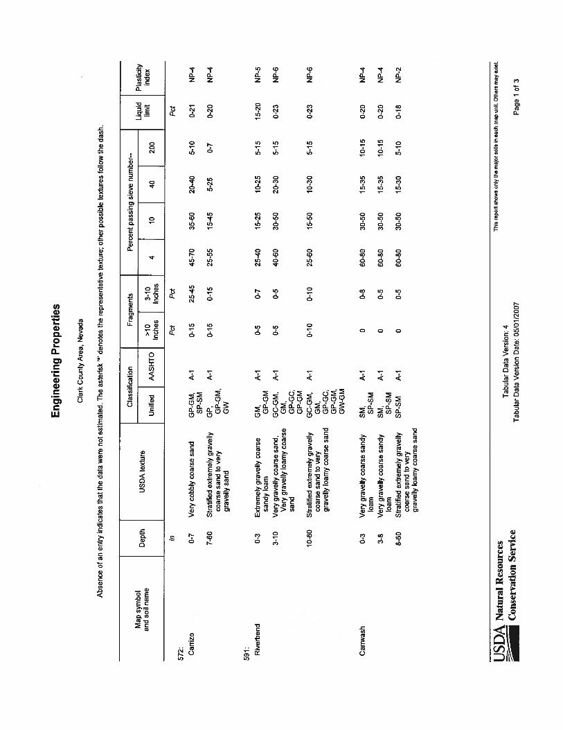
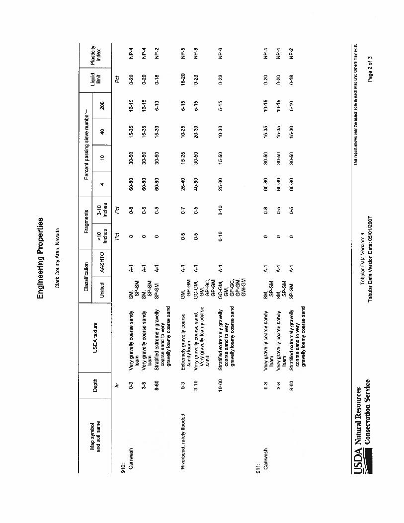
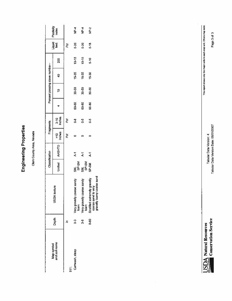
APPENDIX C: ... SOILS • Soil Exhibit • Soil Engineering Properties
APPENDIX D:... TRAFFIC
• Estimated Peak Hour Generated Traffic Volumes Exhibit APPENDIX E: ... DRAINAGE AND HYDRAULICS
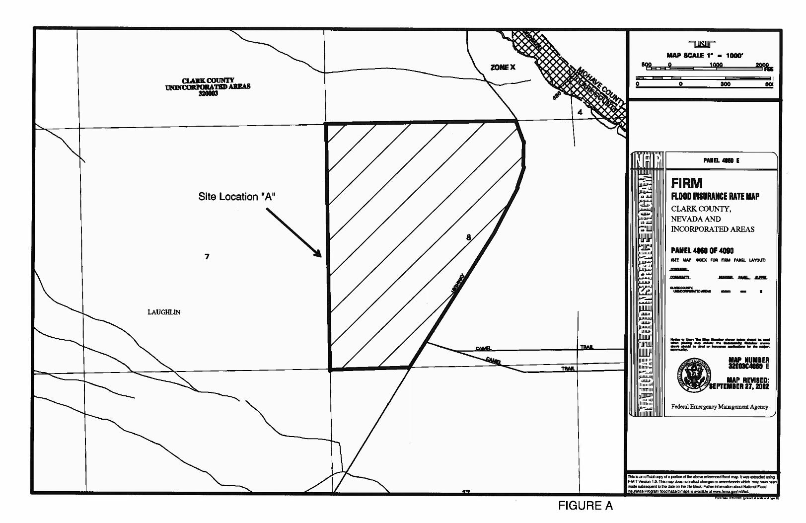
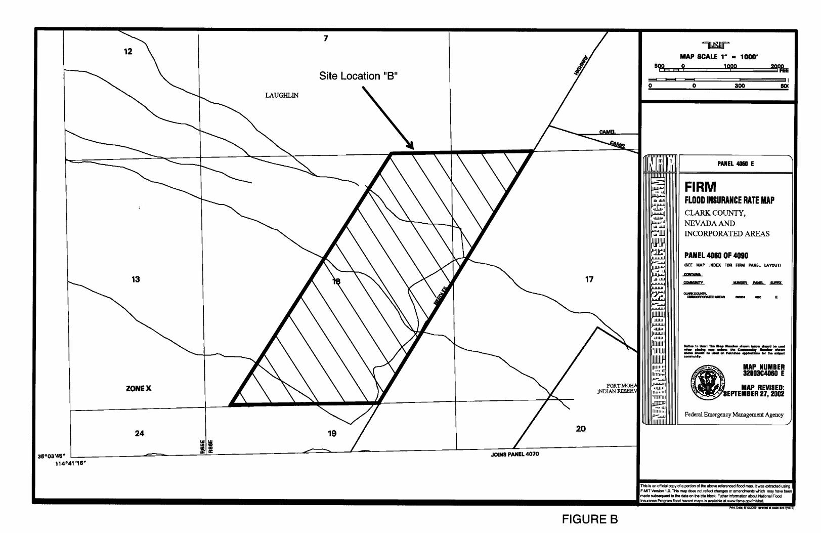
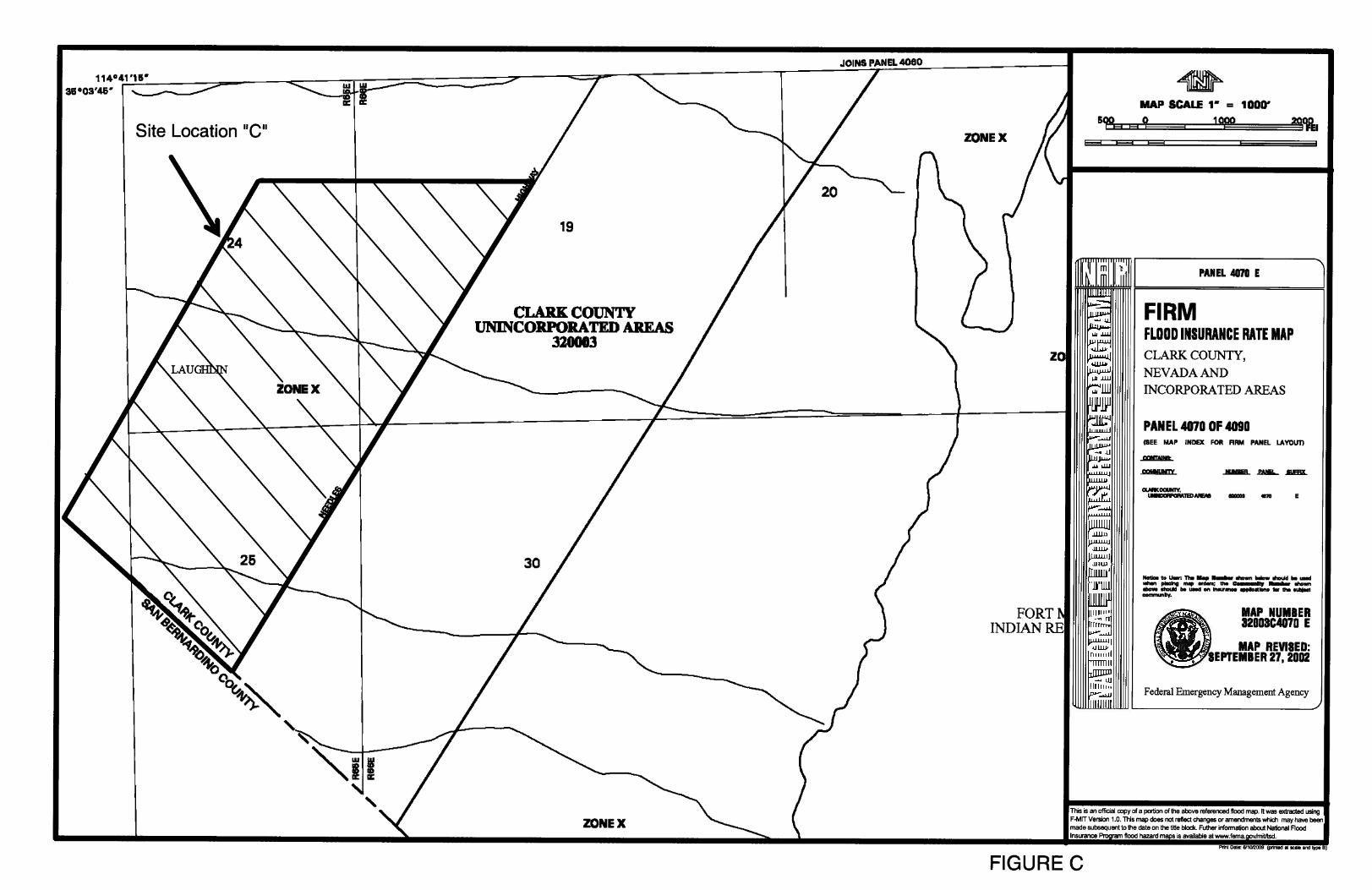
• Figure A: FEMA FIRM (Flood Zone Map)– Site A • Figure B: FEMA FIRM (Flood Zone Map) – Site B • Figure C: FEMA FIRM (Flood Zone Map) – Site C • Figure E-2B: CCRFCD 2009 Outlying Area Flood Control Master Plan Update • Figure 5B: CCRFCD 2009 Outlying Area Flood Control Master Plan Update • Needles Highway Existing Culvert Crossings Exhibit • Referenced Hydrologic Analysis from CCRFCD 2009 Outlying Area Flood Control
Master Plan Update • Culvert Capacity Calculations Based on Head-Water Criteria • Culvert Capacity Calculations Based on Roadway Elevations • Culvert Capacity Summary Table • Referenced Needles Highway Culvert Profile Plans by CH2M Hill • Proposed Facilities (000-1 through 000-3) Hydraulic Calculations
APPENDIX F: ... POTABLE WATER
• Las Vegas Valley Water District - Potable Water Facilities and Estimated Costs – Site Location A
• Las Vegas Valley Water District - Potable Water Facilities and Estimated Costs – Site Location B
• Las Vegas Valley Water District - Potable Water Facilities and Estimated Costs – Site Location C
• Water Facilities Exhibit – Site A • Water Facilities Exhibit – Site B • Water Facilities Exhibit – Site C
v
• Water Demand Calculations • Referenced Table 1: LVVWD Water Consumption for Various Types of Development • Referenced Table A-III-A-1: 2005 Clark County Fire Code Minimum Required Fire Flow
For Buildings APPENDIX G:... SANITARY SEWER
• Clark County Water Reclamation District – Laughlin Wastewater Reclamation Facility (LWRF) Treatment Process Information
• Sanitary Sewer Facilities Exhibit – Site A • Sanitary Sewer Facilities Exhibit – Site B • Sanitary Sewer Facilities Exhibit – Site C • Sanitary Sewer Demand Calculations • Sewer Interceptor Line (Capacity) Calculations
APPENDIX H:... DRY UTILITIES • NV Energy – Distribution Planning Department (Planning Memo) • Substation Location Exhibit • Southwest Gas Corporation – Copies of As-Built Civil Plans
APPENDIX I: .... SURVEY
• Encumbrance Map Exhibit APPENDIX J: .... COST ANALYSIS
• Site A Cost Analysis • Site B Cost Analysis • Site C Cost Analysis
APPENDIX K:... PRELIMINARY SITE PLAN
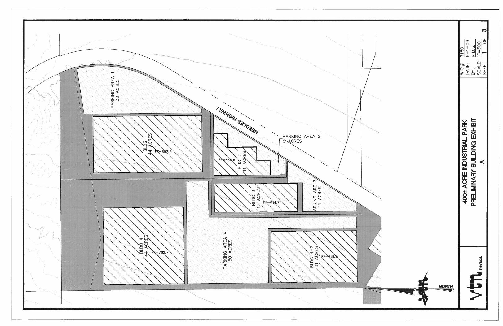
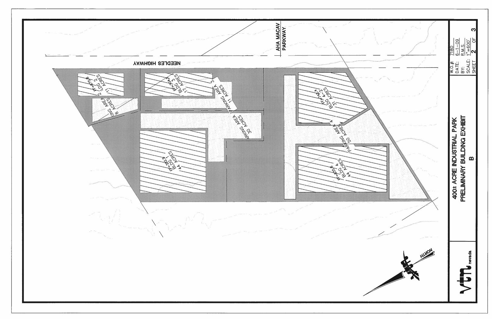
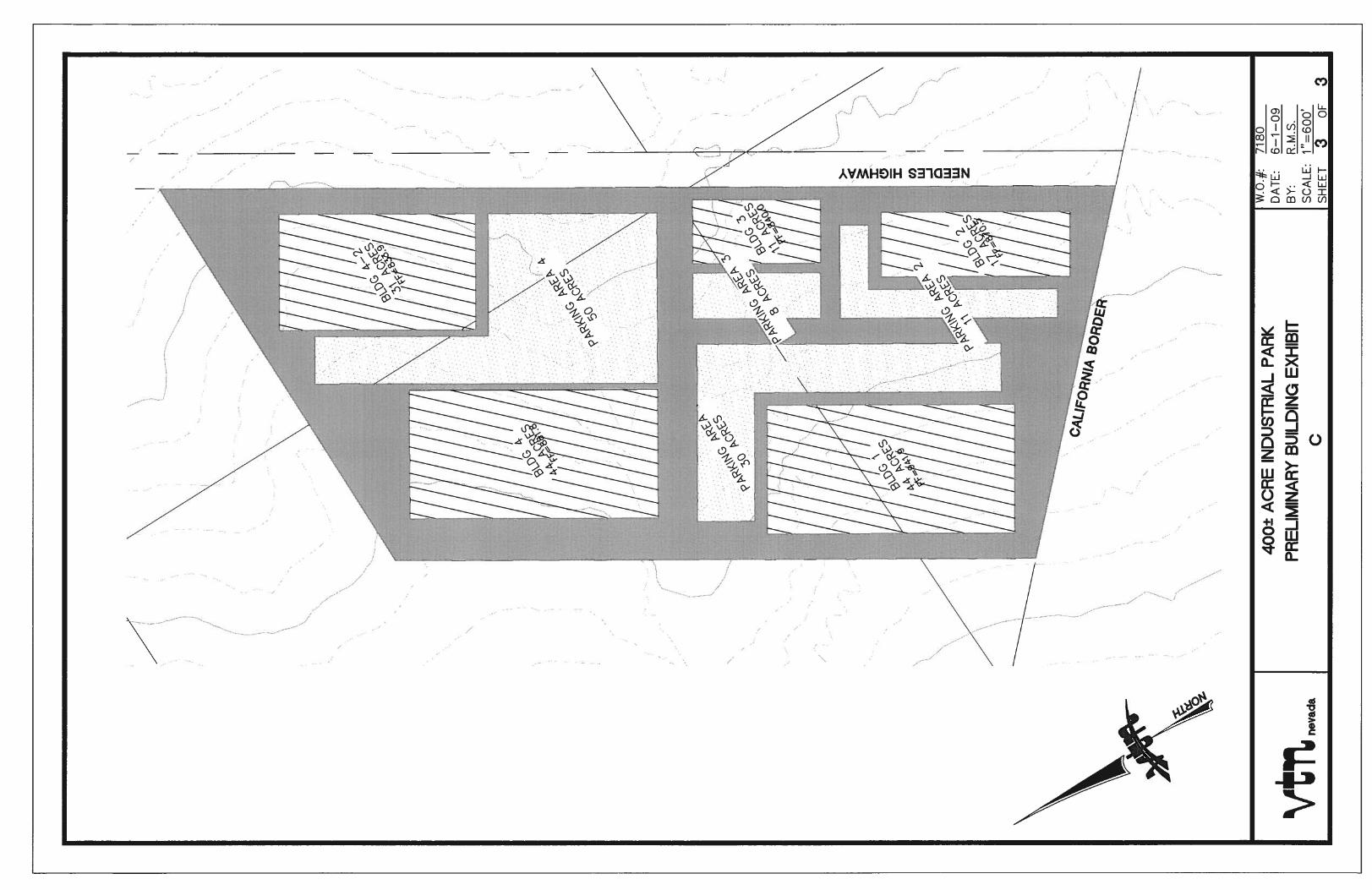
• Preliminary Building Exhibit Site A • Preliminary Building Exhibit Site B • Preliminary Building Exhibit Site C
1
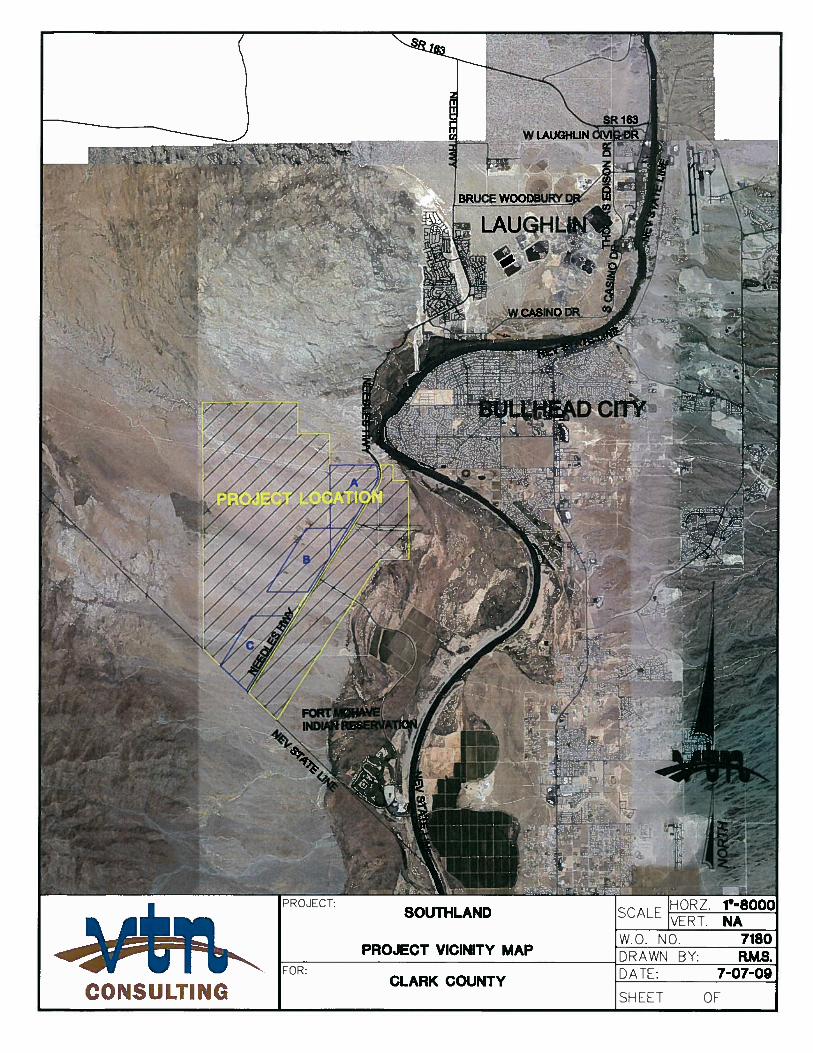
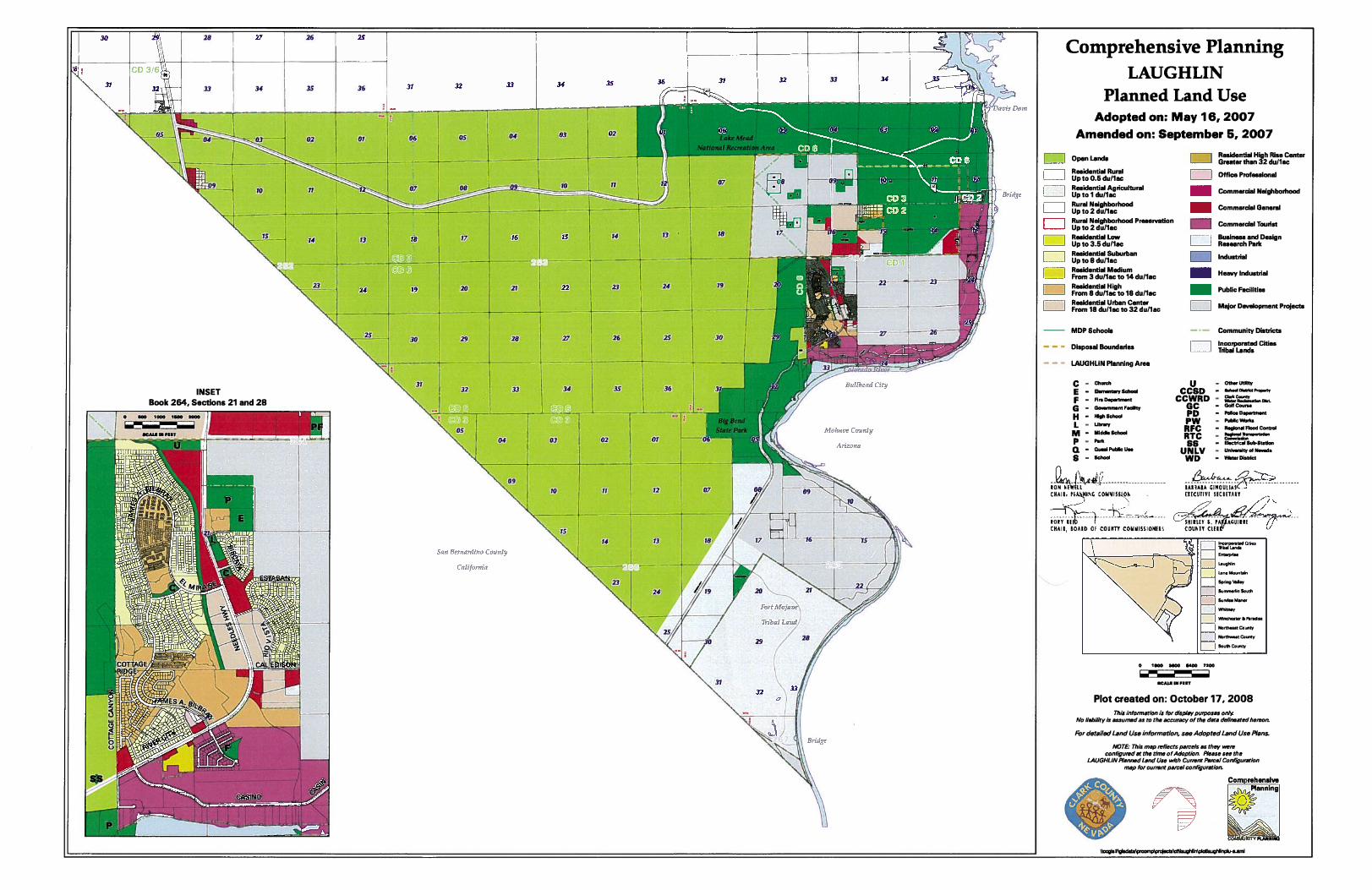
1. INTRODUCTION This feasibility study was commissioned to evaluate three alternative 400+ acre site locations for a proposed industrial park within the Southland proposed master plan development. Southland is a 9,000 acre site acquired by Clark County from the Colorado River Commission. The property came out of 15,000 acres of federal land sold to Colorado River Commission for the purpose as stated in the Fort Mohave Valley Development Act of 1960, as amended. The Town of Laughlin has received control of the property and intends to continue the purposes of the act. Presently the majority of the Southland site is vacant undeveloped land encumbered by a NV Energy power line and Southwest Gas natural gas transmission lines. Southland is located in the most southern tip of the State of Nevada. Southland is bordered by the state of California on the southwest, the Colorado River and the state of Arizona to the east, Nevada BLM land to the west, and the township of Laughlin to the north. The Needles Highway traverses Southland diagonally, in the southwest/northeast direction. The Fort Mohave Indian Reservation is the only adjacent development. Located on the reservation is the AVI Resort and Casino, a golf course with single family residences surrounding the course, and agricultural farming. As directed by Clark County and the Town of Laughlin, three alternative 400+ acre site locations were evaluated for the proposed industrial park. This Feasibility Study will evaluate the alternative site locations for an Industrial Park development. One objective is to determine the anticipated off-site costs for each location. All 3 sites are located directly west of the Needles Highway. The site locations are labeled A, B, and C (see Project Vicinity Map in Appendix A). Site A is closest to the township of Laughlin with an approximate distance of 3 miles from the southern edge of the developed Laughlin area. Site B is adjacently located to the southwest of Site A with some acreage overlapping. Site C is located east of the California border. All 3 sites are in undeveloped natural terrain with minimal land disturbance from the before mentioned transmission lines. As directed by the County, this study utilizes a typical 120 acre manufacturing plant site with a 1.9 million square footage building and 4,000 employees for service demands. This will be referenced as Phase 1 of the 400 acre industrial park. The demands for the remaining 280 acres will be proportional to the Phase 1 demands. Through out this report these demands will be used for the analysis of all dry and wet utilities. The traffic analysis will also be based on typical demands of these parameters. 2. 400+ ACRE INDUSTRIAL PARK
The 400+ acre site plan for Site A and B were determined by utilizing the existing assessor’s section lines in the Southland area. Site C was established by the Needles Highway and the California border. It is anticipated that the industrial park is will be built out in 4 phases over an estimated 5 year period. The phases may range in size from 40 to 200 acres. The first proposed phase is approximately 120 acres based on industrial development for light manufacturing purposes.
2
2.1 Site A Location and Description
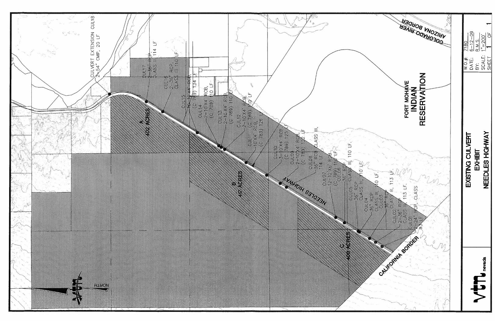
Site A has the closest proximity to the developed Laughlin area. Site A will have lower off site utility development costs due to the shorter distance to the existing dry utilities and the Laughlin Wastewater Reclamation Facility (LWRF) if utilized. Site A is a 402+ acre site with approximately 240 feet of elevation fall at the longest distance of the site in the west to east direction. The site is within APN #’s 265-00-001-014 and 265-00-001-041, and is located northwest of the Needles Highway and Camel Trail intersection, in Laughlin, Clark County, Nevada. Site A is impacted by the existing Southwest Gas transmission line. The gas line transverses the site within a 50-foot wide easement. The easement is in the east-west direction, located in the northern portion of the site. The topography is at a consistent 5% grade with no major washes. The site is adjacent to a mountain range located along the northern site boundary. There are 3 storm drain culvert crossings along the Needles Highway frontage within the proposed frontage of the site.
2.2 Site B Location and Description
Site B is located between Sites A and C. Site B was evaluated for slope analysis to determine if the site’s topography would be better suited for large box industrial buildings. Site B is a 417+ acre site, with a portion that overlaps Site A fronting the Needles Highway. The site is within APN #’s 265-00-001-043 and 265-00-001-041, and is located north of the Needles Highway and Camel Trail intersection, in Laughlin, Clark County, Nevada. The topography is at a consistent 5% grade and has approximately 160 feet of elevation fall in the west-east direction with many minor washes. There are 6 storm drain culvert crossings along the Needles highway, within the proposed frontage of the site. Four of the crossings are located in the over lapping portion of Site A. 2.3 Site C Location and Description Site C was evaluated for its proximity to the California border and Highway 40, a major transportation corridor to the Los Angeles area. Site C is a 408+ acre site similar in shape to Site B. The site is within APN #’s 265-00-002-001, 266-00-002-002, 266-00-002-003, and is located northwest of the Needles Highway adjacent to the California/Nevada border, in Laughlin, Clark County, Nevada. A 40-foot wide power easement impacts Site C. The easement traverses the site in a north-south direction within the western portion of the site. The topography is at a consistent 5% grade and has approximately 120 feet of elevation fall in the west-east direction with a major wash dissecting the center of the site. There are 7 storm drain culvert crossings along the Needles Highway site frontage.
3
3. PLANNING AND LANDUSE The subject properties consist of the following APN #’s:
265-00-001-014 265-00-002-012 265-00-001-041 266-00-002-002 265-00-001-043 266-00-002-003 265-00-002-001
3.1 Zoning Information
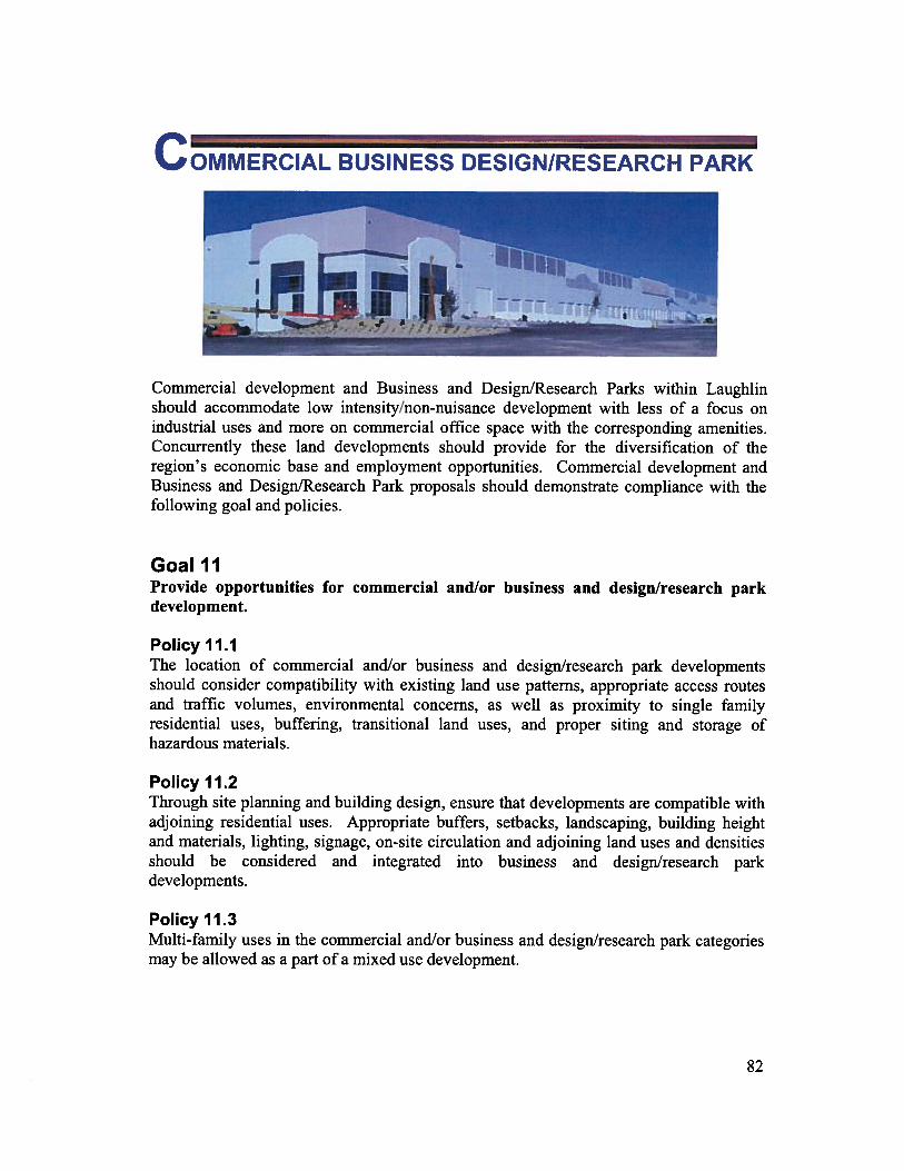
The subject properties are currently zoned RU (Rural Open Lands) per Clark County Records. Zone RU is defined as a district established to provide very low density residential use and appropriate use of vast areas of rural land, including dwellings which do not conform to the design restrictions for single family dwellings. 3.2 Master Planning Information The subject properties are currently master planned BDRP (Business and Design/Research Park) and OL (Open Lands) per the Laughlin Land Use Plan. BDRP is defined as an area where commercial, professional or manufacturing developments are designed to assure minimal impact on surrounding areas. OL is defined as an area designated to provide for permanent open space in the community; to prevent irreversible damage to sensitive areas; and to deter development in areas with highly limited availability of public services and facilities.
Table 1 - Zoning Classification & Land Use by APN
APN Number Zoning Classification Land Use Classification 265-00-001-014 RU BDRP 265-00-001-041 RU BDRP 265-00-001-043 RU BDRP 265-00-002-001 RU BDRP 265-00-002-012 RU BDRP 266-00-002-002 RU OL 266-00-002-003 RU OL
4
The surrounding land uses are as follows:
North Public Facilities (Big Ben State Park) South Business Design / Research Park East Major Development Projects / Business Design/Research Park West Open Lands
Development of the entire property will require APN #’s 266-00-002-003 and 266-00-002-002 to be amended to change the land use designation from OL to BDRP. A rezoning application will be required to one of the approved zones allowed within the land use category.
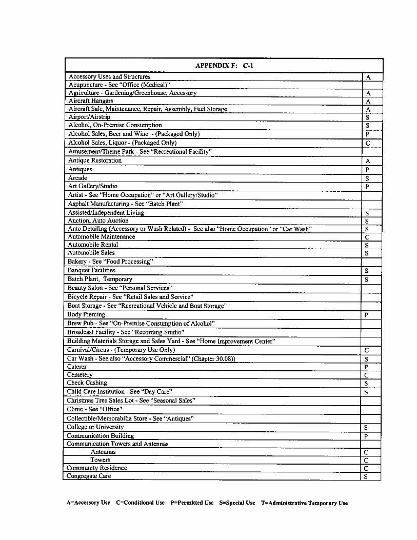
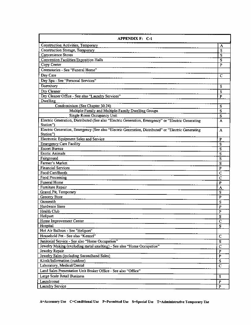
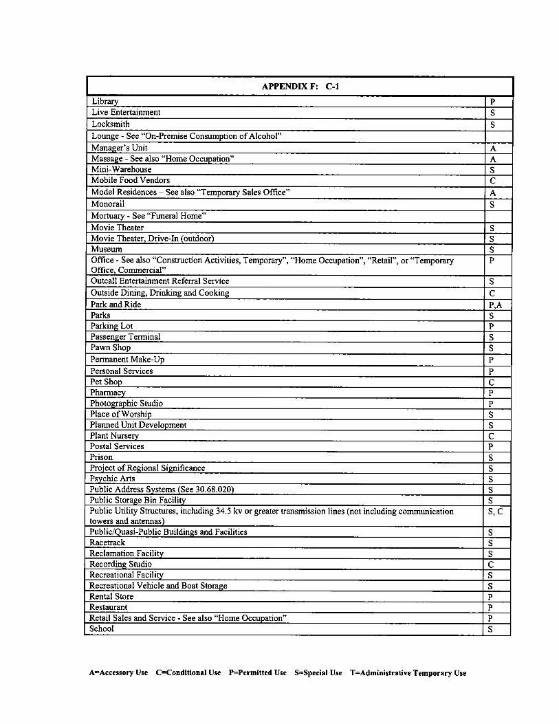
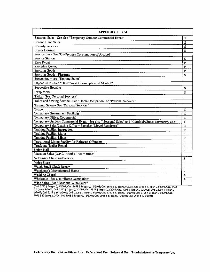
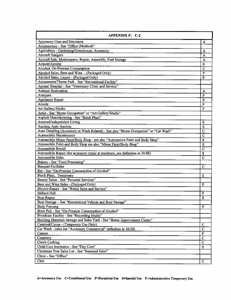
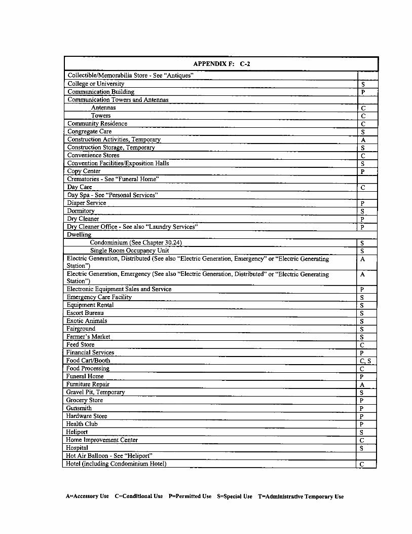
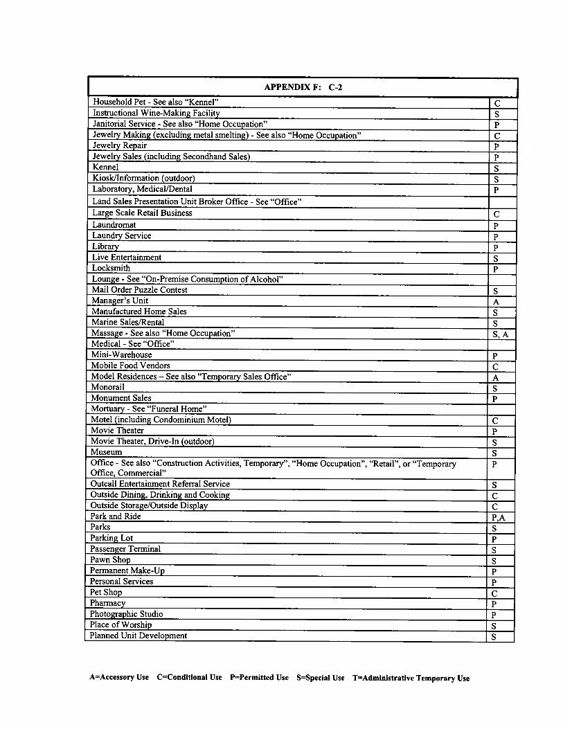
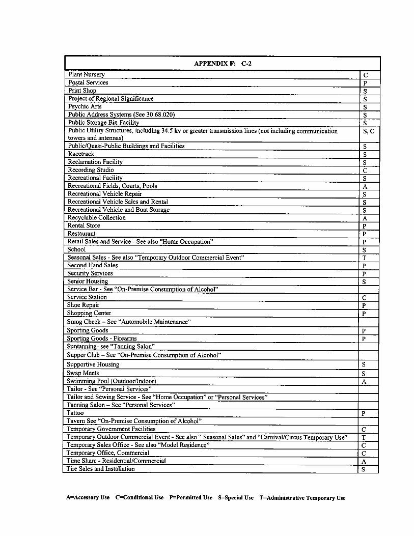
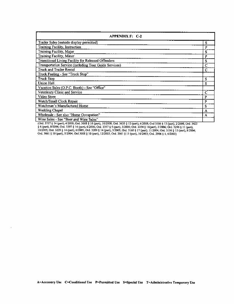
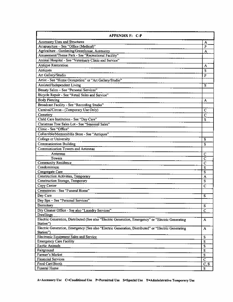
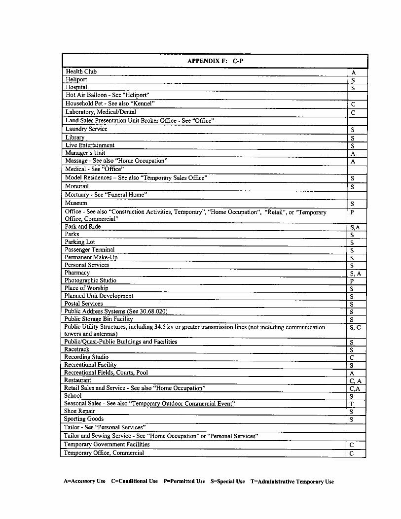
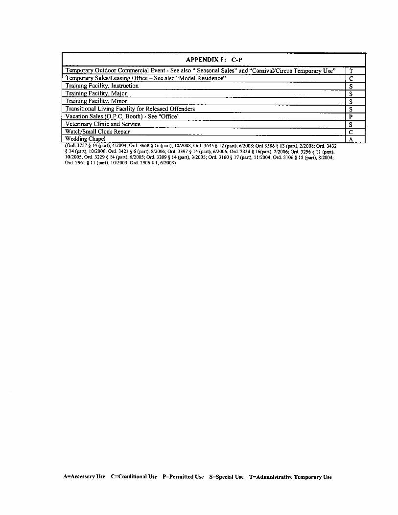
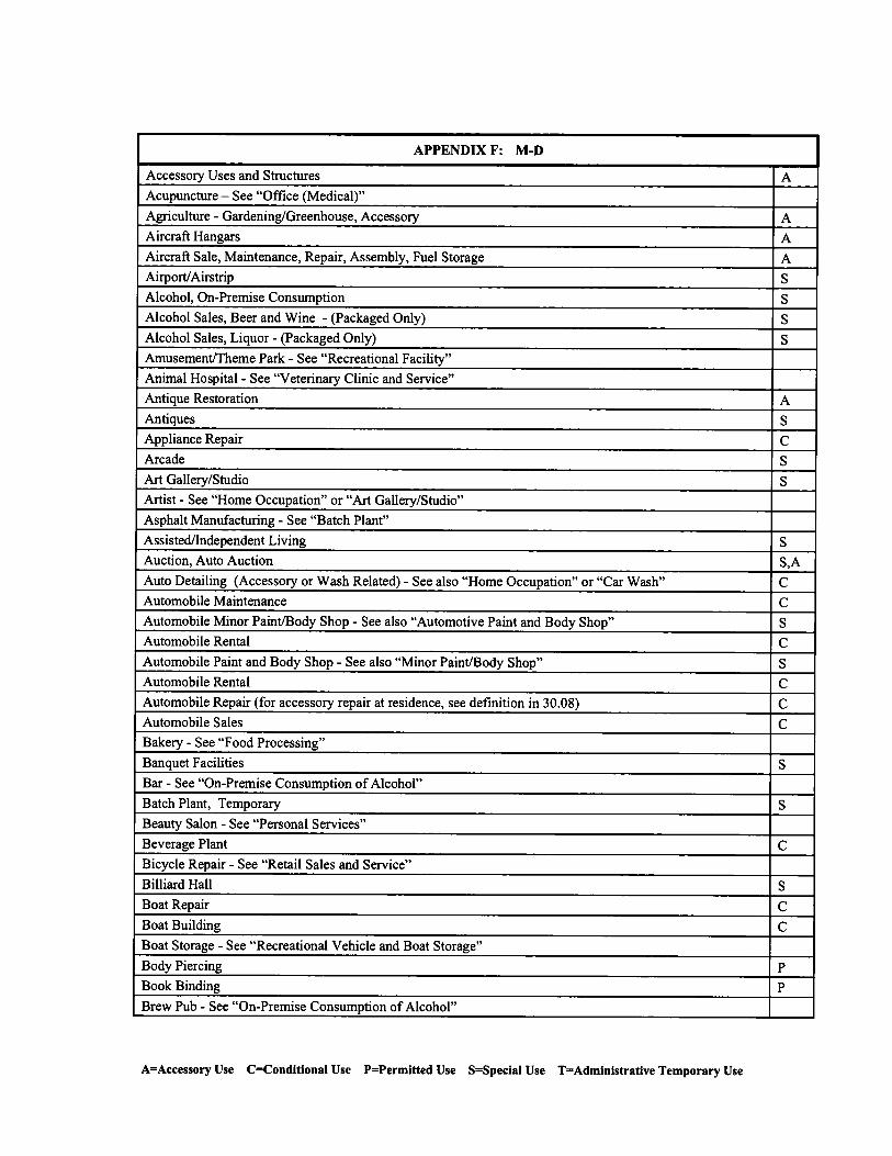
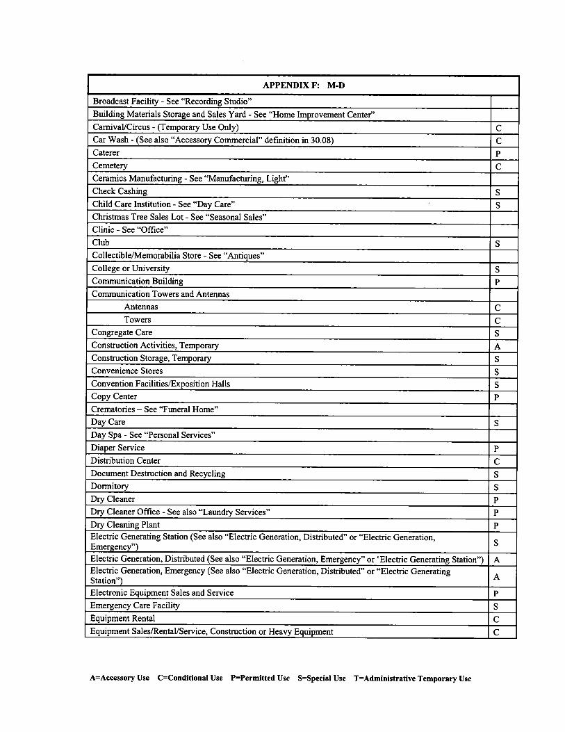
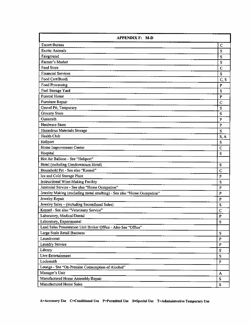
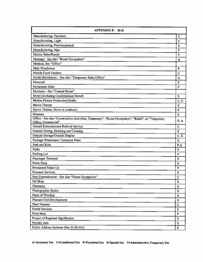
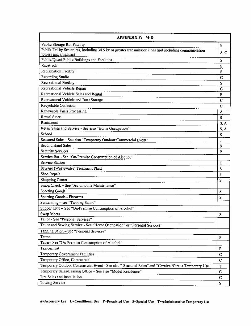
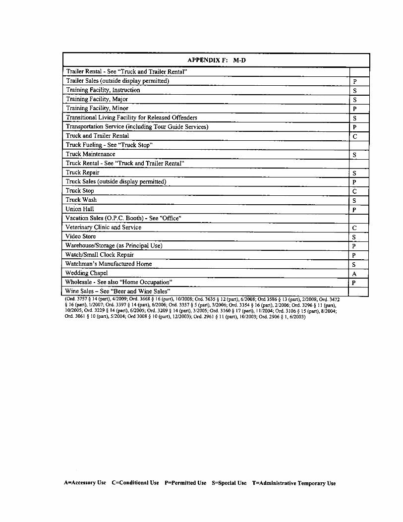
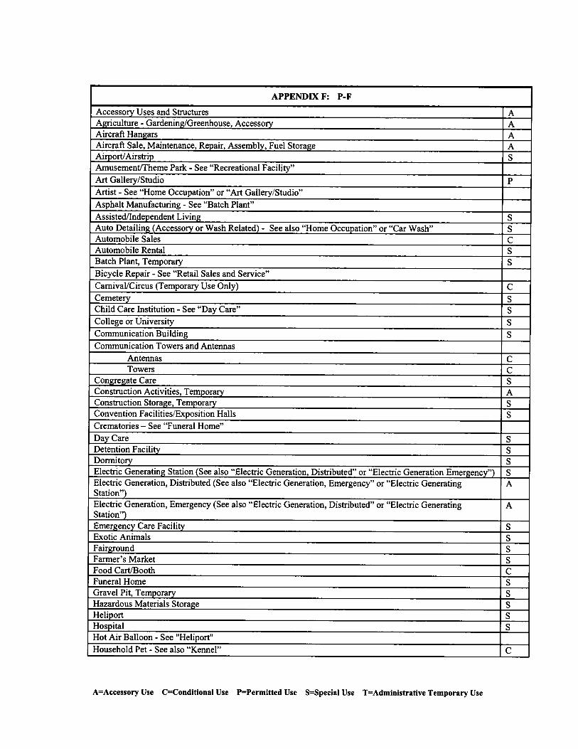
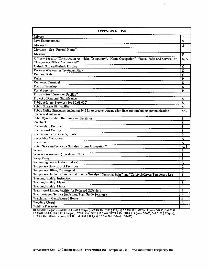
As defined by the Clark County Code, the allowed uses within the BDRP (Business Design/Research Park) category are as follows:
• C-P (Office and professional) • C-1 (Local Business) • C-2 (General Commercial) • M-D (Designed Manufacturing) • P-F (Public Facilities)
See Appendix B for specific details.
4. SITE CHARACTERISTICS
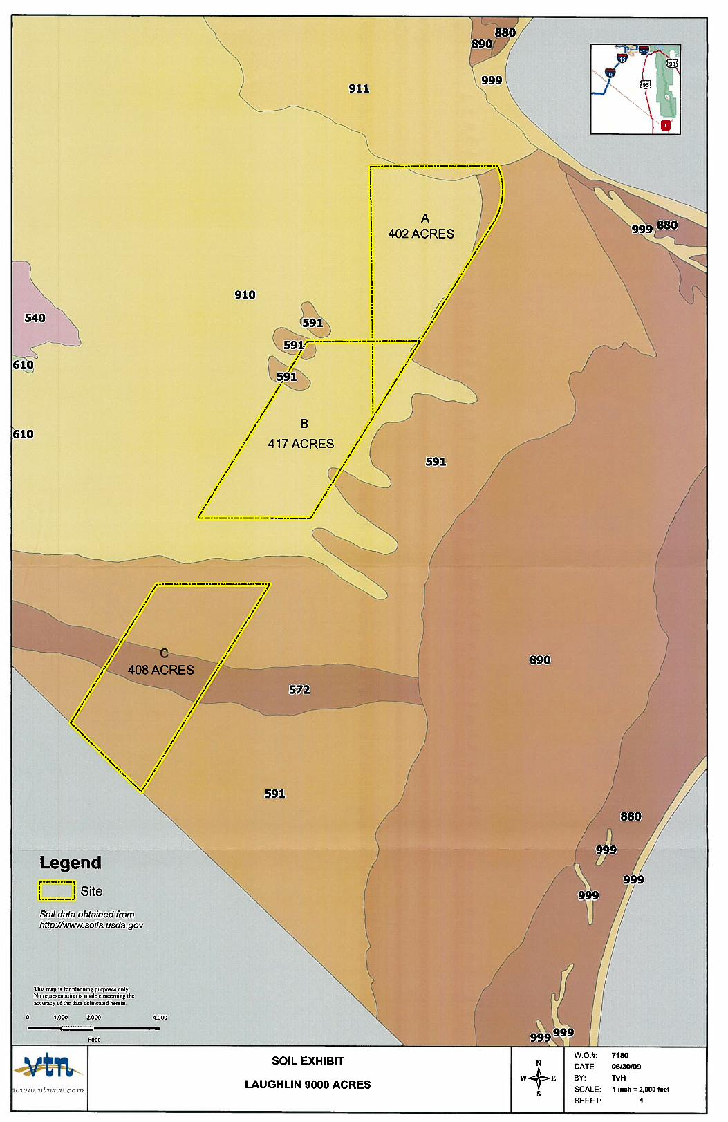
The Southland site consists mostly of desert rangeland sloping in the southeast direction at approximately 4 to 6 percent. The offsite basins impacting the 3 potential Southland project sites includes mountainous and desert rangeland areas to the north and west of the site. Offsite runoff from the mountainous area is collected in numerous washes that create a typical alluvial fan pattern as they spread into the flatter desert rangeland downstream. Flows reach the site within numerous small braided washes and as sheet flow from the offsite tributary area. Storm runoff generated from onsite and offsite basins travel through the Southland areas in a southeast direction and discharge to the Needles Highway a several culvert crossings. 5. SOILS Based on the Soil Exhibit and Soils Engineering Properties from the U.S. Department of Agriculture Natural Resources Conservation Service (USDA) included in Appendix C, the soil classification for Sites A and B is Carrwash type that consists of extremely gravelly course sand to very gravelly loamy coarse sand. Site C soil classification is Riverbend for the majority of the site. Riverbend soil consists of stratified extremely gravelly coarse sand to very gravelly loamy coarse sand. Site C has a large wash that dissects the site. The soil type in the wash is Carrizo soil which is the same as Riverbend with the upper soil layer being very cobbly coarse sand. See Appendix C for a soils exhibit encompassing the possible site locations.
5
6. TRAFFIC
6.1 Project Description
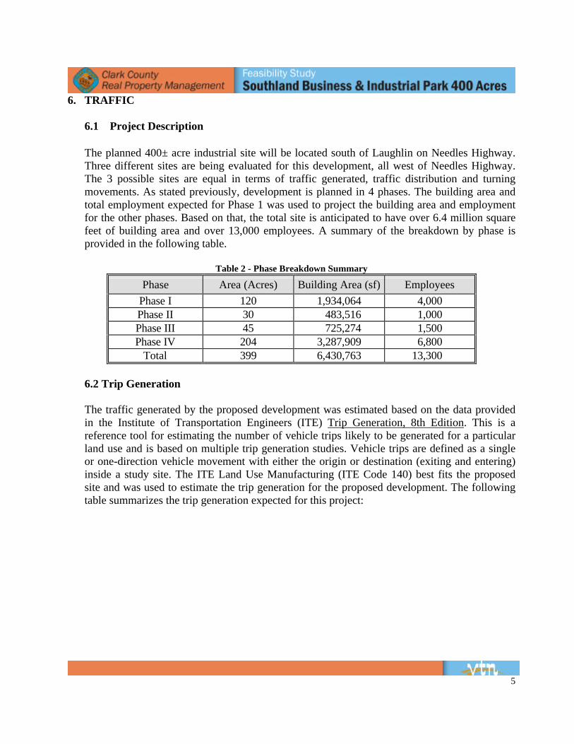
The planned 400± acre industrial site will be located south of Laughlin on Needles Highway. Three different sites are being evaluated for this development, all west of Needles Highway. The 3 possible sites are equal in terms of traffic generated, traffic distribution and turning movements. As stated previously, development is planned in 4 phases. The building area and total employment expected for Phase 1 was used to project the building area and employment for the other phases. Based on that, the total site is anticipated to have over 6.4 million square feet of building area and over 13,000 employees. A summary of the breakdown by phase is provided in the following table.
Table 2 - Phase Breakdown Summary
Phase Area (Acres) Building Area (sf) Employees Phase I 120 1,934,064 4,000 Phase II 30 483,516 1,000 Phase III 45 725,274 1,500 Phase IV 204 3,287,909 6,800
Total 399 6,430,763 13,300
6.2 Trip Generation
The traffic generated by the proposed development was estimated based on the data provided in the Institute of Transportation Engineers (ITE) Trip Generation, 8th Edition. This is a reference tool for estimating the number of vehicle trips likely to be generated for a particular land use and is based on multiple trip generation studies. Vehicle trips are defined as a single or one-direction vehicle movement with either the origin or destination (exiting and entering) inside a study site. The ITE Land Use Manufacturing (ITE Code 140) best fits the proposed site and was used to estimate the trip generation for the proposed development. The following table summarizes the trip generation expected for this project:
6
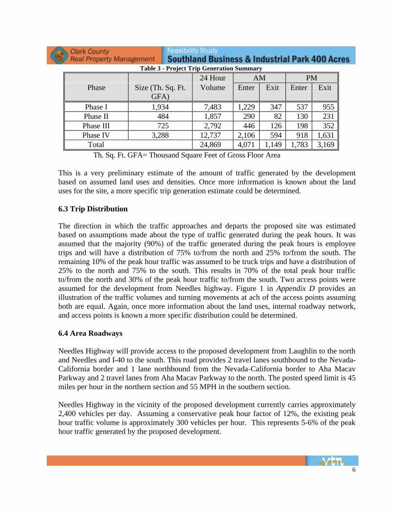
Table 3 - Project Trip Generation Summary
24 Hour AM PM Phase Size (Th. Sq. Ft.
GFA) Volume Enter Exit Enter Exit
Phase I 1,934 7,483 1,229 347 537 955 Phase II 484 1,857 290 82 130 231 Phase III 725 2,792 446 126 198 352 Phase IV 3,288 12,737 2,106 594 918 1,631
Total 24,869 4,071 1,149 1,783 3,169 Th. Sq. Ft. GFA= Thousand Square Feet of Gross Floor Area
This is a very preliminary estimate of the amount of traffic generated by the development based on assumed land uses and densities. Once more information is known about the land uses for the site, a more specific trip generation estimate could be determined.
6.3 Trip Distribution
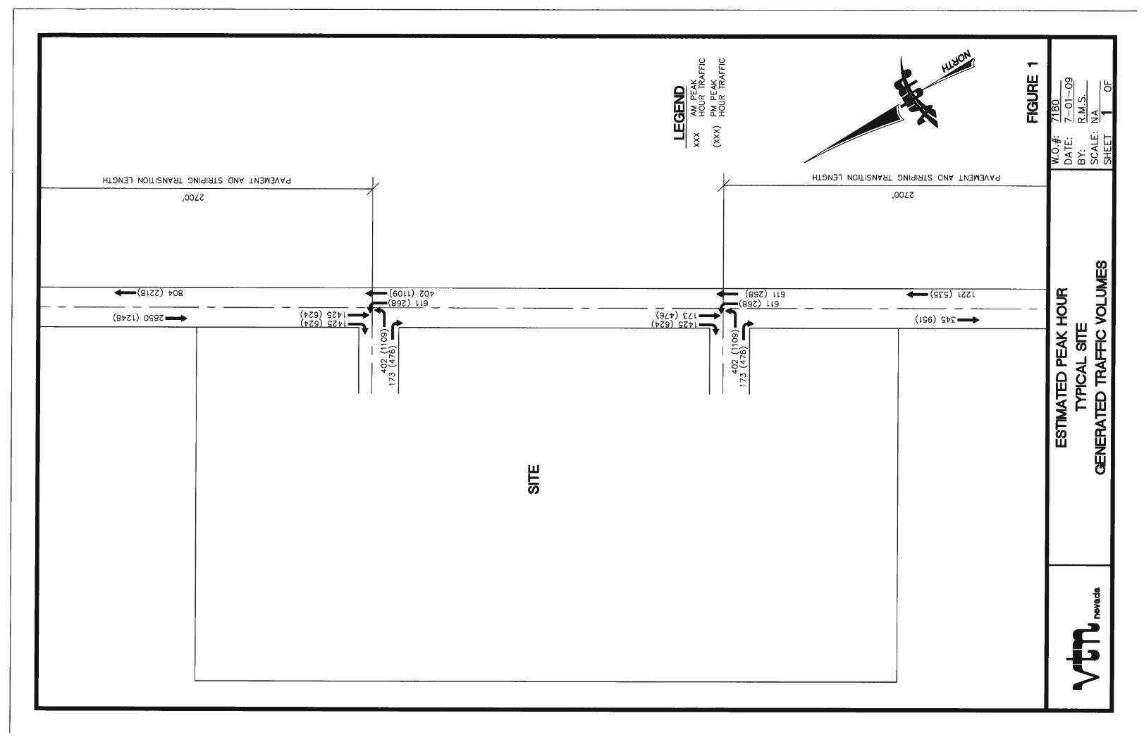
The direction in which the traffic approaches and departs the proposed site was estimated based on assumptions made about the type of traffic generated during the peak hours. It was assumed that the majority (90%) of the traffic generated during the peak hours is employee trips and will have a distribution of 75% to/from the north and 25% to/from the south. The remaining 10% of the peak hour traffic was assumed to be truck trips and have a distribution of 25% to the north and 75% to the south. This results in 70% of the total peak hour traffic to/from the north and 30% of the peak hour traffic to/from the south. Two access points were assumed for the development from Needles highway. Figure 1 in Appendix D provides an illustration of the traffic volumes and turning movements at ach of the access points assuming both are equal. Again, once more information about the land uses, internal roadway network, and access points is known a more specific distribution could be determined.
6.4 Area Roadways
Needles Highway will provide access to the proposed development from Laughlin to the north and Needles and I-40 to the south. This road provides 2 travel lanes southbound to the Nevada-California border and 1 lane northbound from the Nevada-California border to Aha Macav Parkway and 2 travel lanes from Aha Macav Parkway to the north. The posted speed limit is 45 miles per hour in the northern section and 55 MPH in the southern section. Needles Highway in the vicinity of the proposed development currently carries approximately 2,400 vehicles per day. Assuming a conservative peak hour factor of 12%, the existing peak hour traffic volume is approximately 300 vehicles per hour. This represents 5-6% of the peak hour traffic generated by the proposed development.
7
The Nevada Department of Transportation (NDOT) and the Regional Transportation Commission of Southern Nevada (RTC) are studying the Colorado River Bridge Crossings in the vicinity of the proposed development. Three alternatives are being evaluated in the Environmental Assessment (EA). A draft EA is expected to be complete in the fall of 2009 with construction completion in 2013 or later depending on funding. Any of these crossings will be beneficial to the regional access to the proposed development as they tie into Needles Highway in the vicinity of the development area. Since a significant number of employees may come from Bullhead City. A bridge crossing in this vicinity will provide a more direct connection between these proposed employment centers and employees, which would also reduce the amount of traffic added to the roadways within Laughlin.
6.5 Mitigation Measures
Based on the estimated trip generation and turning movements, it is expected that left and right turn deceleration and storage lanes will be needed on Needles Highway. These are expected to be similar to what is provided at Aha Macav Parkway and approximately 1,000 feet long for the right turn lane and 2,000 feet for the left turn lane including transition, taper, deceleration, and storage. In addition, an acceleration lane may be needed on northbound Needles Highway based on the projected turning movements. This lane would be approximately 2,700 feet including transition, taper and acceleration lane.
7. DRAINAGE
Three site locations within the proposed Southland master plan were analyzed for off-site drainage impact and required drainage facilities. The sites are labeled A, B, and C and are consistent in shape, size, and location as referenced within this report.
7.1 Site A
7.1.1 Flood Zone Information
The site is located within the FEMA Flood Insurance Rate Map (FIRM) Panel # 4060 on Map # 32003C4060E, with an effective date of September 27, 2002. According to the FIRM, the site is located within Zone “X.” A Zone “X” is an area which outside of the 0.2% annual chance floodplain. See Figure A: Flood Zone Map in Appendix E.
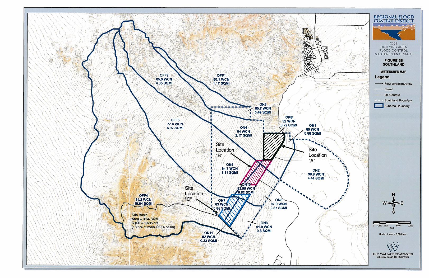
7.1.2 Drainage Basins
In general the area tributary to the site, as well as the site itself, drains in a south east direction. Figure 5B, Watershed Map, shows the location of the site and the corresponding upstream drainage basins based on the 2009 Outlying Area Master Plan Update. According to the MPU, the site is situated within basin ON9, which drains in a southeast direction towards Needles Highway. The existing condition flows impacting the site
8
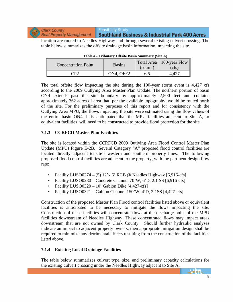
location are routed to Needles Highway and through several existing culvert crossing. The table below summarizes the offsite drainage basin information impacting the site.
Table 4 - Tributary Offsite Basin Summary (Site A)
Concentration Point Basins Total Area (sq.mi.)
100-year Flow (cfs)
CP2 ON4, OFF2 6.5 4,427
The total offsite flow impacting the site during the 100-year storm event is 4,427 cfs according to the 2009 Outlying Area Master Plan Update. The northern portion of basin ON4 extends past the site boundary by approximately 2,500 feet and contains approximately 362 acres of area that, per the available topography, would be routed north of the site. For the preliminary purposes of this report and for consistency with the Outlying Area MPU, the flows impacting the site were estimated using the flow values of the entire basin ON4. It is anticipated that the MPU facilities adjacent to Site A, or equivalent facilities, will need to be constructed to provide flood protection for the site.
7.1.3 CCRFCD Master Plan Facilities
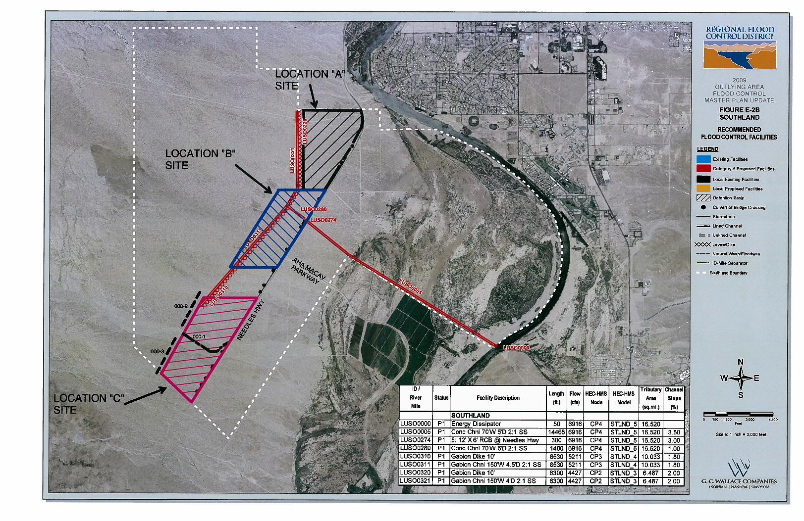
The site is located within the CCRFCD 2009 Outlying Area Flood Control Master Plan Update (MPU) Figure E-2B. Several Category “A” proposed flood control facilities are located directly adjacent to site’s western and southern property lines. The following proposed flood control facilities are adjacent to the property, with the pertinent design flow rate:
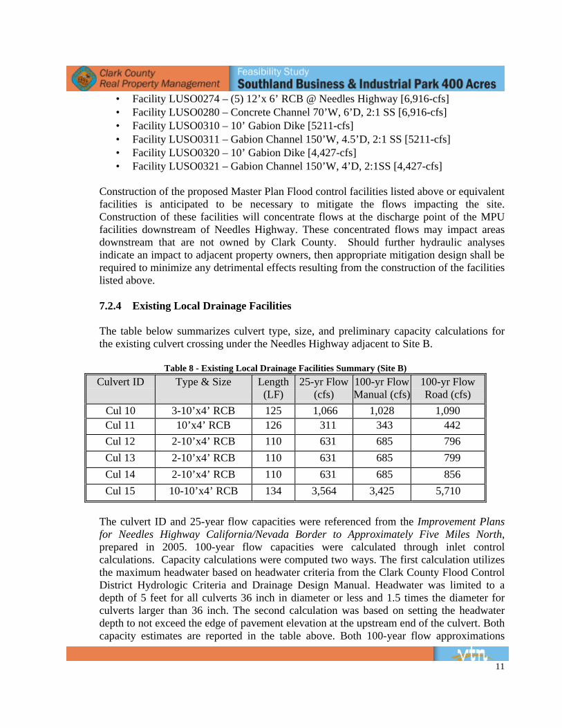
• Facility LUSO0274 – (5) 12’x 6’ RCB @ Needles Highway [6,916-cfs] • Facility LUSO0280 – Concrete Channel 70’W, 6’D, 2:1 SS [6,916-cfs] • Facility LUSO0320 – 10’ Gabion Dike [4,427-cfs] • Facility LUSO0321 – Gabion Channel 150’W, 4’D, 2:1SS [4,427-cfs]
Construction of the proposed Master Plan Flood control facilities listed above or equivalent facilities is anticipated to be necessary to mitigate the flows impacting the site. Construction of these facilities will concentrate flows at the discharge point of the MPU facilities downstream of Needles Highway. These concentrated flows may impact areas downstream that are not owned by Clark County. Should further hydraulic analyses indicate an impact to adjacent property owners, then appropriate mitigation design shall be required to minimize any detrimental effects resulting from the construction of the facilities listed above.
7.1.4 Existing Local Drainage Facilities
The table below summarizes culvert type, size, and preliminary capacity calculations for the existing culvert crossing under the Needles Highway adjacent to Site A.
9
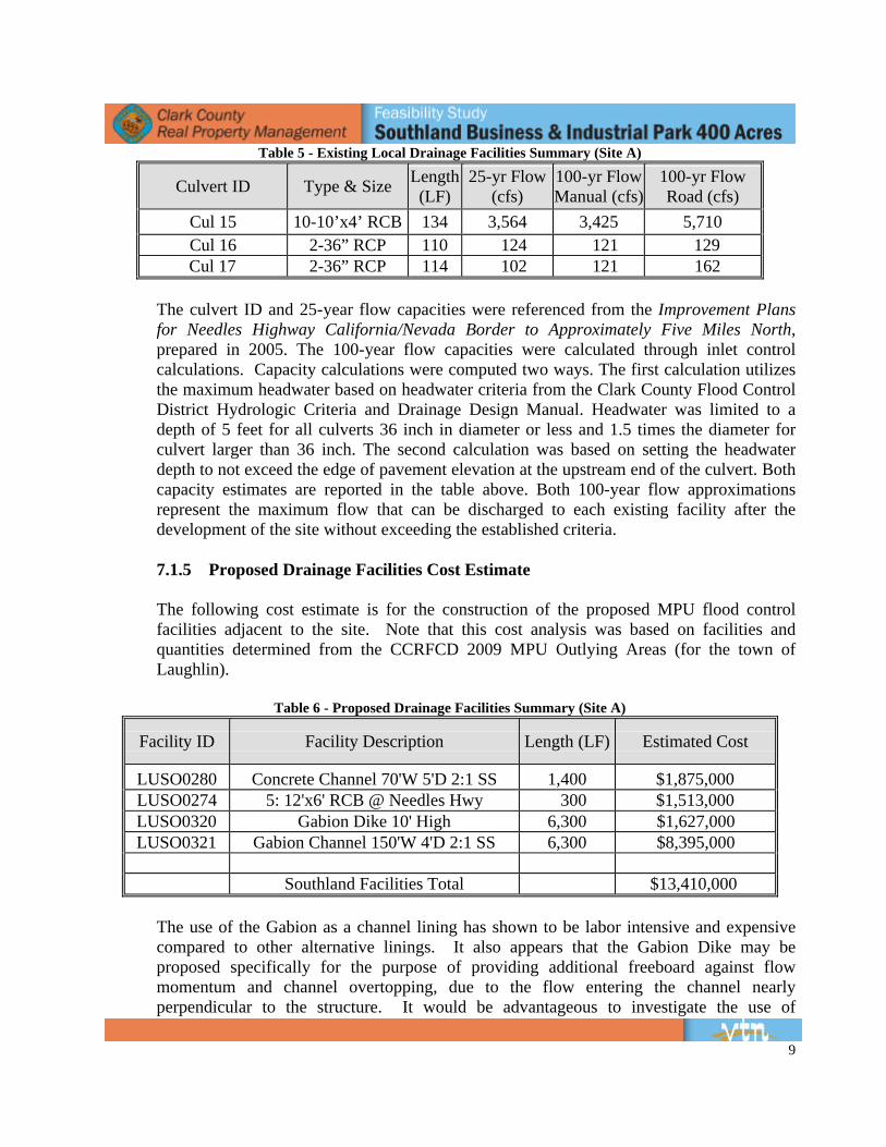
Table 5 - Existing Local Drainage Facilities Summary (Site A)
Culvert ID Type & Size Length (LF)
25-yr Flow (cfs)
100-yr Flow Manual (cfs)
100-yr Flow Road (cfs)
Cul 15 10-10’x4’ RCB 134 3,564 3,425 5,710 Cul 16 2-36” RCP 110 124 121 129 Cul 17 2-36” RCP 114 102 121 162
The culvert ID and 25-year flow capacities were referenced from the Improvement Plans for Needles Highway California/Nevada Border to Approximately Five Miles North, prepared in 2005. The 100-year flow capacities were calculated through inlet control calculations. Capacity calculations were computed two ways. The first calculation utilizes the maximum headwater based on headwater criteria from the Clark County Flood Control District Hydrologic Criteria and Drainage Design Manual. Headwater was limited to a depth of 5 feet for all culverts 36 inch in diameter or less and 1.5 times the diameter for culvert larger than 36 inch. The second calculation was based on setting the headwater depth to not exceed the edge of pavement elevation at the upstream end of the culvert. Both capacity estimates are reported in the table above. Both 100-year flow approximations represent the maximum flow that can be discharged to each existing facility after the development of the site without exceeding the established criteria.
7.1.5 Proposed Drainage Facilities Cost Estimate
The following cost estimate is for the construction of the proposed MPU flood control facilities adjacent to the site. Note that this cost analysis was based on facilities and quantities determined from the CCRFCD 2009 MPU Outlying Areas (for the town of Laughlin).
Table 6 - Proposed Drainage Facilities Summary (Site A)
Facility ID Facility Description Length (LF) Estimated Cost
LUSO0280 Concrete Channel 70'W 5'D 2:1 SS 1,400 $1,875,000 LUSO0274 5: 12'x6' RCB @ Needles Hwy 300 $1,513,000 LUSO0320 Gabion Dike 10' High 6,300 $1,627,000 LUSO0321 Gabion Channel 150'W 4'D 2:1 SS 6,300 $8,395,000
Southland Facilities Total $13,410,000
The use of the Gabion as a channel lining has shown to be labor intensive and expensive compared to other alternative linings. It also appears that the Gabion Dike may be proposed specifically for the purpose of providing additional freeboard against flow momentum and channel overtopping, due to the flow entering the channel nearly perpendicular to the structure. It would be advantageous to investigate the use of
10
alternative linings such as articulated block, grouted rip-rap, and roller compacted concrete for these facilities to provide equivalent structures at a more economical cost.
7.2 Site B
7.2.1 Flood Zone Information
The site is located within the FEMA Flood Insurance Rate Map (FIRM) Panel 4060 Map number 32003C4060E, with an effective date of September 27, 2002. According to the FIRM, the site is located within Zone “X.” A Zone “X” is an area which outside of the 0.2% annual chance floodplain. See Figure B: Flood Zone Map in Appendix E.
7.2.2 Drainage Basins
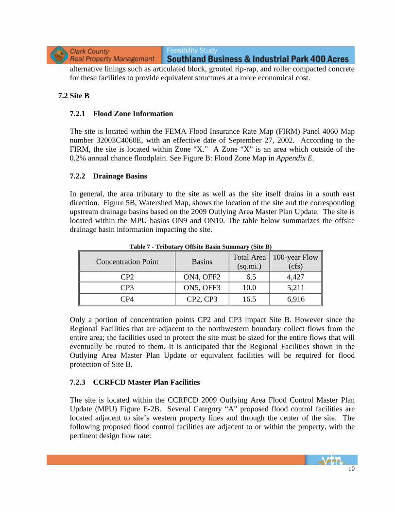
In general, the area tributary to the site as well as the site itself drains in a south east direction. Figure 5B, Watershed Map, shows the location of the site and the corresponding upstream drainage basins based on the 2009 Outlying Area Master Plan Update. The site is located within the MPU basins ON9 and ON10. The table below summarizes the offsite drainage basin information impacting the site.
Table 7 - Tributary Offsite Basin Summary (Site B)
Concentration Point Basins Total Area (sq.mi.)
100-year Flow (cfs)
CP2 ON4, OFF2 6.5 4,427 CP3 ON5, OFF3 10.0 5,211 CP4 CP2, CP3 16.5 6,916
Only a portion of concentration points CP2 and CP3 impact Site B. However since the Regional Facilities that are adjacent to the northwestern boundary collect flows from the entire area; the facilities used to protect the site must be sized for the entire flows that will eventually be routed to them. It is anticipated that the Regional Facilities shown in the Outlying Area Master Plan Update or equivalent facilities will be required for flood protection of Site B.
7.2.3 CCRFCD Master Plan Facilities
The site is located within the CCRFCD 2009 Outlying Area Flood Control Master Plan Update (MPU) Figure E-2B. Several Category “A” proposed flood control facilities are located adjacent to site’s western property lines and through the center of the site. The following proposed flood control facilities are adjacent to or within the property, with the pertinent design flow rate:
11
• Facility LUSO0274 – (5) 12’x 6’ RCB @ Needles Highway [6,916-cfs] • Facility LUSO0280 – Concrete Channel 70’W, 6’D, 2:1 SS [6,916-cfs] • Facility LUSO0310 – 10’ Gabion Dike [5211-cfs] • Facility LUSO0311 – Gabion Channel 150’W, 4.5’D, 2:1 SS [5211-cfs] • Facility LUSO0320 – 10’ Gabion Dike [4,427-cfs] • Facility LUSO0321 – Gabion Channel 150’W, 4’D, 2:1SS [4,427-cfs]
Construction of the proposed Master Plan Flood control facilities listed above or equivalent facilities is anticipated to be necessary to mitigate the flows impacting the site. Construction of these facilities will concentrate flows at the discharge point of the MPU facilities downstream of Needles Highway. These concentrated flows may impact areas downstream that are not owned by Clark County. Should further hydraulic analyses indicate an impact to adjacent property owners, then appropriate mitigation design shall be required to minimize any detrimental effects resulting from the construction of the facilities listed above.
7.2.4 Existing Local Drainage Facilities
The table below summarizes culvert type, size, and preliminary capacity calculations for the existing culvert crossing under the Needles Highway adjacent to Site B.
Table 8 - Existing Local Drainage Facilities Summary (Site B)
Culvert ID Type & Size Length (LF)
25-yr Flow (cfs)
100-yr Flow Manual (cfs)
100-yr Flow Road (cfs)
Cul 10 3-10’x4’ RCB 125 1,066 1,028 1,090 Cul 11 10’x4’ RCB 126 311 343 442 Cul 12 2-10’x4’ RCB 110 631 685 796 Cul 13 2-10’x4’ RCB 110 631 685 799 Cul 14 2-10’x4’ RCB 110 631 685 856 Cul 15 10-10’x4’ RCB 134 3,564 3,425 5,710
The culvert ID and 25-year flow capacities were referenced from the Improvement Plans for Needles Highway California/Nevada Border to Approximately Five Miles North, prepared in 2005. 100-year flow capacities were calculated through inlet control calculations. Capacity calculations were computed two ways. The first calculation utilizes the maximum headwater based on headwater criteria from the Clark County Flood Control District Hydrologic Criteria and Drainage Design Manual. Headwater was limited to a depth of 5 feet for all culverts 36 inch in diameter or less and 1.5 times the diameter for culverts larger than 36 inch. The second calculation was based on setting the headwater depth to not exceed the edge of pavement elevation at the upstream end of the culvert. Both capacity estimates are reported in the table above. Both 100-year flow approximations
12
represent the maximum flow that can be discharged to each existing facility after the development of the site without exceeding the established criteria.
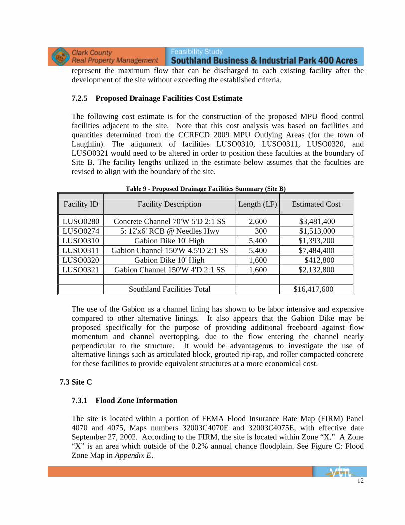
7.2.5 Proposed Drainage Facilities Cost Estimate
The following cost estimate is for the construction of the proposed MPU flood control facilities adjacent to the site. Note that this cost analysis was based on facilities and quantities determined from the CCRFCD 2009 MPU Outlying Areas (for the town of Laughlin). The alignment of facilities LUSO0310, LUSO0311, LUSO0320, and LUSO0321 would need to be altered in order to position these faculties at the boundary of Site B. The facility lengths utilized in the estimate below assumes that the faculties are revised to align with the boundary of the site.
Table 9 - Proposed Drainage Facilities Summary (Site B)
Facility ID Facility Description Length (LF) Estimated Cost
LUSO0280 Concrete Channel 70'W 5'D 2:1 SS 2,600 $3,481,400 LUSO0274 5: 12'x6' RCB @ Needles Hwy 300 $1,513,000 LUSO0310 Gabion Dike 10' High 5,400 $1,393,200 LUSO0311 Gabion Channel 150'W 4.5'D 2:1 SS 5,400 $7,484,400 LUSO0320 Gabion Dike 10' High 1,600 $412,800 LUSO0321 Gabion Channel 150'W 4'D 2:1 SS 1,600 $2,132,800
Southland Facilities Total $16,417,600
The use of the Gabion as a channel lining has shown to be labor intensive and expensive compared to other alternative linings. It also appears that the Gabion Dike may be proposed specifically for the purpose of providing additional freeboard against flow momentum and channel overtopping, due to the flow entering the channel nearly perpendicular to the structure. It would be advantageous to investigate the use of alternative linings such as articulated block, grouted rip-rap, and roller compacted concrete for these facilities to provide equivalent structures at a more economical cost.
7.3 Site C
7.3.1 Flood Zone Information
The site is located within a portion of FEMA Flood Insurance Rate Map (FIRM) Panel 4070 and 4075, Maps numbers 32003C4070E and 32003C4075E, with effective date September 27, 2002. According to the FIRM, the site is located within Zone “X.” A Zone “X” is an area which outside of the 0.2% annual chance floodplain. See Figure C: Flood Zone Map in Appendix E.
13
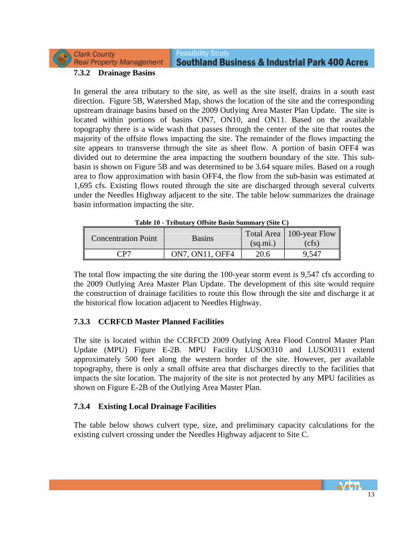
7.3.2 Drainage Basins
In general the area tributary to the site, as well as the site itself, drains in a south east direction. Figure 5B, Watershed Map, shows the location of the site and the corresponding upstream drainage basins based on the 2009 Outlying Area Master Plan Update. The site is located within portions of basins ON7, ON10, and ON11. Based on the available topography there is a wide wash that passes through the center of the site that routes the majority of the offsite flows impacting the site. The remainder of the flows impacting the site appears to transverse through the site as sheet flow. A portion of basin OFF4 was divided out to determine the area impacting the southern boundary of the site. This sub-basin is shown on Figure 5B and was determined to be 3.64 square miles. Based on a rough area to flow approximation with basin OFF4, the flow from the sub-basin was estimated at 1,695 cfs. Existing flows routed through the site are discharged through several culverts under the Needles Highway adjacent to the site. The table below summarizes the drainage basin information impacting the site.
Table 10 - Tributary Offsite Basin Summary (Site C)
Concentration Point Basins Total Area (sq.mi.)
100-year Flow (cfs)
CP7 ON7, ON11, OFF4 20.6 9,547
The total flow impacting the site during the 100-year storm event is 9,547 cfs according to the 2009 Outlying Area Master Plan Update. The development of this site would require the construction of drainage facilities to route this flow through the site and discharge it at the historical flow location adjacent to Needles Highway.
7.3.3 CCRFCD Master Planned Facilities
The site is located within the CCRFCD 2009 Outlying Area Flood Control Master Plan Update (MPU) Figure E-2B. MPU Facility LUSO0310 and LUSO0311 extend approximately 500 feet along the western border of the site. However, per available topography, there is only a small offsite area that discharges directly to the facilities that impacts the site location. The majority of the site is not protected by any MPU facilities as shown on Figure E-2B of the Outlying Area Master Plan.
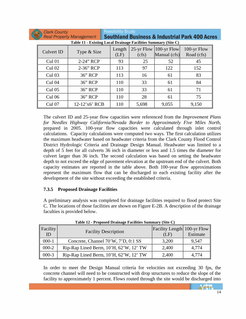
7.3.4 Existing Local Drainage Facilities
The table below shows culvert type, size, and preliminary capacity calculations for the existing culvert crossing under the Needles Highway adjacent to Site C.
14
Table 11 - Existing Local Drainage Facilities Summary (Site C)
Culvert ID Type & Size Length (LF)
25-yr Flow (cfs)
100-yr Flow Manual (cfs)
100-yr Flow Road (cfs)
Cul 01 2-24” RCP 93 25 52 45 Cul 02 2-36” RCP 113 97 122 152 Cul 03 36” RCP 113 16 61 83 Cul 04 36” RCP 110 33 61 84 Cul 05 36” RCP 110 33 61 71 Cul 06 36” RCP 110 28 61 75 Cul 07 12-12’x6’ RCB 110 5,698 9,055 9,150
The culvert ID and 25-year flow capacities were referenced from the Improvement Plans for Needles Highway California/Nevada Border to Approximately Five Miles North, prepared in 2005. 100-year flow capacities were calculated through inlet control calculations. Capacity calculations were computed two ways. The first calculation utilizes the maximum headwater based on headwater criteria from the Clark County Flood Control District Hydrologic Criteria and Drainage Design Manual. Headwater was limited to a depth of 5 feet for all culverts 36 inch in diameter or less and 1.5 times the diameter for culvert larger than 36 inch. The second calculation was based on setting the headwater depth to not exceed the edge of pavement elevation at the upstream end of the culvert. Both capacity estimates are reported in the table above. Both 100-year flow approximations represent the maximum flow that can be discharged to each existing facility after the development of the site without exceeding the established criteria.
7.3.5 Proposed Drainage Facilities
A preliminary analysis was completed for drainage facilities required to flood protect Site C. The locations of those facilities are shown on Figure E-2B. A description of the drainage faculties is provided below.
Table 12 - Proposed Drainage Facilities Summary (Site C)
Facility ID Facility Description Facility Length
(LF) 100-yr Flow
Estimate 000-1 Concrete, Channel 70’W, 7’D, 0:1 SS 3,200 9,547 000-2 Rip-Rap Lined Berm, 10’H, 62’W, 12’ TW 2,400 4,774 000-3 Rip-Rap Lined Berm, 10’H, 62’W, 12’ TW 2,400 4,774
In order to meet the Design Manual criteria for velocities not exceeding 30 fps, the concrete channel will need to be constructed with drop structures to reduce the slope of the facility to approximately 1 percent. Flows routed through the site would be discharged into
15
Existing Culvert 07. Preliminary estimates show that the culvert is close to having enough capacity to handle the anticipated flows. More in depth analysis will be required to determine if any additional cells will need to be added to the existing culvert.
7.3.6 Proposed Drainage Facilities Cost Estimate
The following cost estimate is for the construction of the proposed flood control facilities adjacent to the site. The cost analysis utilizes pricing from the CCRFCD 2009 MPU Outlying Areas to try and be as consistent as possible with that document. For facilities that did not associate well with the cost tools available with the MPU Outlying Area, cost estimates were based off of Clark County Bond Estimate.
Table 13 - Proposed Drainage Facilities Cost Estimate Summary (Site C)
Facility ID Facility Description Length (LF) Estimated Cost
000-1 Concrete Channel 70’W 7’D 0:1 SS 3,200 $5,650,136 000-2 Rip-Rap Lined Berm 10’H 62’W 12’TW 2,400 $633,353 000-3 Rip-Rap Lined Berm 10’H 62’W 12’TW 2,400 $633,353
10% Contingency $691,685 Southland Facilities Total $7,608,527
8. WET UTILITIES
8.1 Potable Water All the proposed 400+ acre Southland Business and Industrial Park sites are located 3 to 5 miles from the existing Big Bend Water District facilities. The study has evaluated the use of a private well system versus public water district improvements. To utilize a private well system, groundwater rights need to be obtained from the same basin/aquifer. If groundwater rights are available, a transfer of the matter of use, place of use, and point of diversion will be required to the proposed site locations. Research has determined that groundwater rights in the Laughlin area basin to service the proposed site are not available. The groundwater rights that do exist are presently being utilized and there is no access water available for purchase or lease. A private well system to service the proposed sites is not a feasible option. This study will concentrate on the evaluated public water service to the proposed sites. The three proposed sites will be served by the Big Bend Water District. The Laughlin Water System is currently composed of five established Pressure Zones: 750, 780, 890, 1000, and 1130 and two future Pressure Zones: 1250 and 1370. The Big Bend Water District provides potable water to the community via a Raw Water Pumping Station Intake at the Colorado River
16
and the Big Bend Water District Water Treatment Facility. Several pump stations and reservoir tanks route the treated water through a network of main transmission lines.
The proposed site water demands and required fire flow were calculated using the provided information of a 1.9 million square foot light manufacturing plant on the first phase 120 acre piece (see Appendix F for calculations and assumptions). The remaining phases used this baseline guide for determining the potable water and fire flow demand assuming a similar development and building square footage based upon the phase area. Several meetings were held with the Las Vegas Valley Water District, which operates and maintains the Big Bend Water District, to discuss the capacity of the existing facilities and the availability of potable water to service the Southland Business and Industrial Park based upon the calculated demands of the site for Fire Flow and Domestic Water as shown in Appendix F. Three options were analyzed to provide potable water to the proposed 400+ acre sites (site’s A, B, and C). The three options include: 1) Ground Water Well with Package Treatment Plant, 2) Pipeline Extension, and 3) New Water Treatment Plant utilizing underground power to service the plant. Estimated costs are feasibility level and may vary depending on specifics of project, including project demands and timing of system facilities. Estimates do not include onsite infrastructure requirements. Also, estimates do not include building permits, licenses, environmental, rights-of-way, or other costs. Project estimates are as of July 6, 2009.
8.1.1 Site A
8.1.1.1 Option 1 – Ground Water Well with Package Treatment Plant (600 GPM) The acquisition and transfer of groundwater rights will be required for each of the proposed project sites. Big Bend Water District has the ability to acquire ground water rights and transfer the rights to the treatment plant location. The water quality and quantity available will need to be explored and researched further to determine if a well system can provide the adequate flow and demand for the proposed development, along with determining the ground water basin and aquifer limits. The preliminary findings of the Big Bend Water District include the following infrastructure improvements for the groundwater well with a package treatment plant option at Site A:
17
Table 14 - Proposed Potable Water Facility and Cost Estimate Summary (Option 1-Site A)
Description Total Cost
Water Treatment Improvements Package Treatment Plant $5,300,000 Construct Underground Power $2,952,000 Groundwater Well Improvements Drill and equip well (2 wells) $3,000,000 Reservoir Improvements 2 MG Storage $2,000,000 Pumping Station Improvements Construct pumping station downstream of Package Treatment Plant (to serve 890 Pressure Zone) $2,300,000
Pipeline Improvements 1,000 LF of 20-inch diameter raw water pipeline $243,600 4,900 LF of 20-inch diameter inlet/outlet pipeline $1,193,400
Estimated Costs for Groundwater Well with Package Water Treatment Plant Option, Site A $16,989,000
(Note: Feasibility level estimates, does not include on-site facilities or permitting costs) 8.1.1.2 Option 2 – Pipeline Extension
There is available capacity at the existing Laughlin Water Treatment Facility to serve the anticipated demands for the Southland Industrial Business Park. To convey the additional capacity, upgrades to the existing facilities and additional infrastructure will need to be constructed. The preliminary findings of the Big Bend Water District include the following infrastructure improvements for the pipeline extension option at Site A (see Appendix F for Pipeline Exhibits).
18
Table 15 - Proposed Potable Water Facility and Cost Estimate Summary (Option 2-Site A)
Description Total Cost
Reservoir Improvements 2 MG Storage $2,000,000 Pumping Station Improvements Add unit to existing Casino Drive Pumping Station $345,000 Construct pumping station in South (to serve 890 Pressure Zone) $2,300,000 Construct Underground Power $2,952,000 Pipeline Improvements 500 LF of 42-inch diameter pipeline along Casino Drive $324,200 14,760 LF of 12-inch (oversized to 24-inch) diameter pipeline along Needles Highway $4,462,100
4,900 LF of 20-inch diameter inlet/outlet pipeline $1,193,400
Sub-Total $13,576,700 Oversizing Estimate $2,042,800 Estimated Costs for Pipeline Extension Option, Site A $15,619,500
(Note: Feasibility level estimates, does not include on-site facilities or permitting costs)
The above infrastructure will be required at a minimum to service the site at the present time. Additional facilities may be needed if additional development in the Laughlin area occurs prior to the construction of the Southland project. Oversizing of the 12 inch main transmission line in Needles Highway is recommended for the future development of the overall 9,000 acres.
Sites B and C will require the above facilities and additional infrastructure due to the distance from existing facilities and the site topography. The topography for Sites B and C will require that each site be split into two different pressure zones, thus requiring an additional Pump Station or a Pressure Reducing Valve to supply adequate water pressure. Sites B and C will result in a higher development cost than Site A for potable water.
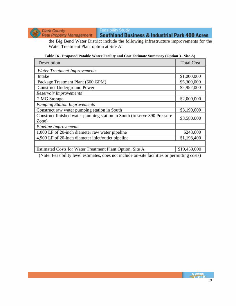
8.1.1.3 Option 3 – Water Treatment Plant (600 GPM) The construction of a Water Treatment Plant will require that a raw Water Intake at the Colorado River be constructed along with the pipelines needed to convey the raw water to the plant. This system would be independent of the current Big Bend Water System but may be connected in the future for redundancy, depending on the future need for such a system. The location of the raw Water Intake and package Treatment Plant will need to be further analyzed; however this study assumes that it can be generally located at the north end of the 9,000 acre boundary. This location requires the least amount of pipeline and is the most convenient for the Site A option. The preliminary findings of
19
the Big Bend Water District include the following infrastructure improvements for the Water Treatment Plant option at Site A:
Table 16 - Proposed Potable Water Facility and Cost Estimate Summary (Option 3– Site A)
Description Total Cost
Water Treatment Improvements Intake $1,000,000 Package Treatment Plant (600 GPM) $5,300,000 Construct Underground Power $2,952,000 Reservoir Improvements 2 MG Storage $2,000,000 Pumping Station Improvements Construct raw water pumping station in South $3,190,000 Construct finished water pumping station in South (to serve 890 Pressure Zone) $3,580,000
Pipeline Improvements 1,000 LF of 20-inch diameter raw water pipeline $243,600 4,900 LF of 20-inch diameter inlet/outlet pipeline $1,193,400
Estimated Costs for Water Treatment Plant Option, Site A $19,459,000 (Note: Feasibility level estimates, does not include on-site facilities or permitting costs)
20
8.1.2 Site B
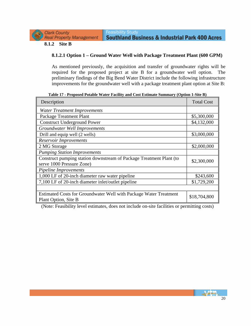
8.1.2.1 Option 1 – Ground Water Well with Package Treatment Plant (600 GPM) As mentioned previously, the acquisition and transfer of groundwater rights will be required for the proposed project at site B for a groundwater well option. The preliminary findings of the Big Bend Water District include the following infrastructure improvements for the groundwater well with a package treatment plant option at Site B:
Table 17 - Proposed Potable Water Facility and Cost Estimate Summary (Option 1-Site B)
Description Total Cost
Water Treatment Improvements Package Treatment Plant $5,300,000 Construct Underground Power $4,132,000 Groundwater Well Improvements Drill and equip well (2 wells) $3,000,000 Reservoir Improvements 2 MG Storage $2,000,000 Pumping Station Improvements Construct pumping station downstream of Package Treatment Plant (to serve 1000 Pressure Zone) $2,300,000
Pipeline Improvements 1,000 LF of 20-inch diameter raw water pipeline $243,600 7,100 LF of 20-inch diameter inlet/outlet pipeline $1,729,200
Estimated Costs for Groundwater Well with Package Water Treatment Plant Option, Site B $18,704,800
(Note: Feasibility level estimates, does not include on-site facilities or permitting costs)
21
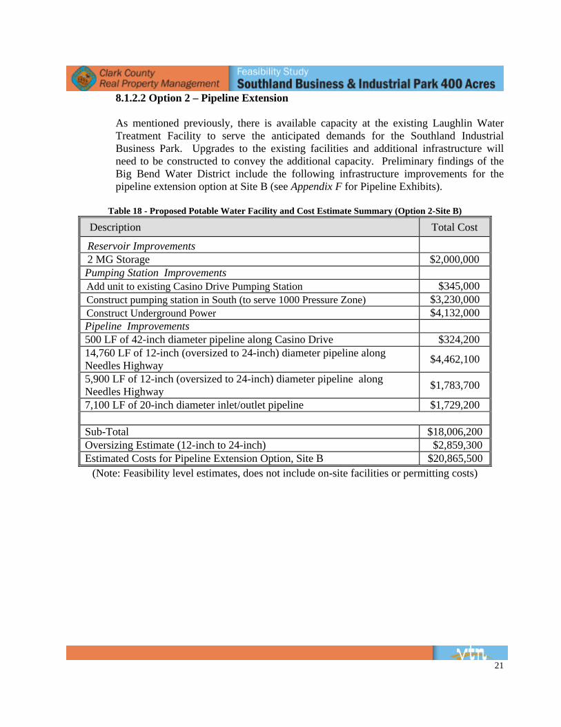
8.1.2.2 Option 2 – Pipeline Extension As mentioned previously, there is available capacity at the existing Laughlin Water Treatment Facility to serve the anticipated demands for the Southland Industrial Business Park. Upgrades to the existing facilities and additional infrastructure will need to be constructed to convey the additional capacity. Preliminary findings of the Big Bend Water District include the following infrastructure improvements for the pipeline extension option at Site B (see Appendix F for Pipeline Exhibits).
Table 18 - Proposed Potable Water Facility and Cost Estimate Summary (Option 2-Site B)
Description Total Cost
Reservoir Improvements 2 MG Storage $2,000,000 Pumping Station Improvements Add unit to existing Casino Drive Pumping Station $345,000 Construct pumping station in South (to serve 1000 Pressure Zone) $3,230,000 Construct Underground Power $4,132,000 Pipeline Improvements 500 LF of 42-inch diameter pipeline along Casino Drive $324,200 14,760 LF of 12-inch (oversized to 24-inch) diameter pipeline along Needles Highway $4,462,100
5,900 LF of 12-inch (oversized to 24-inch) diameter pipeline along Needles Highway $1,783,700
7,100 LF of 20-inch diameter inlet/outlet pipeline $1,729,200
Sub-Total $18,006,200 Oversizing Estimate (12-inch to 24-inch) $2,859,300 Estimated Costs for Pipeline Extension Option, Site B $20,865,500
(Note: Feasibility level estimates, does not include on-site facilities or permitting costs)
22
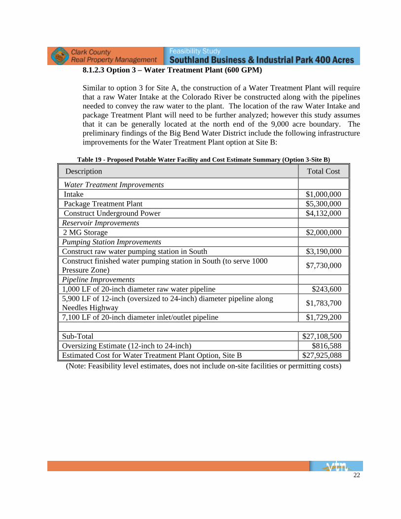
8.1.2.3 Option 3 – Water Treatment Plant (600 GPM)
Similar to option 3 for Site A, the construction of a Water Treatment Plant will require that a raw Water Intake at the Colorado River be constructed along with the pipelines needed to convey the raw water to the plant. The location of the raw Water Intake and package Treatment Plant will need to be further analyzed; however this study assumes that it can be generally located at the north end of the 9,000 acre boundary. The preliminary findings of the Big Bend Water District include the following infrastructure improvements for the Water Treatment Plant option at Site B:
Table 19 - Proposed Potable Water Facility and Cost Estimate Summary (Option 3-Site B)
Description Total Cost
Water Treatment Improvements Intake $1,000,000 Package Treatment Plant $5,300,000 Construct Underground Power $4,132,000 Reservoir Improvements 2 MG Storage $2,000,000 Pumping Station Improvements Construct raw water pumping station in South $3,190,000 Construct finished water pumping station in South (to serve 1000 Pressure Zone) $7,730,000
Pipeline Improvements 1,000 LF of 20-inch diameter raw water pipeline $243,600 5,900 LF of 12-inch (oversized to 24-inch) diameter pipeline along Needles Highway $1,783,700
7,100 LF of 20-inch diameter inlet/outlet pipeline $1,729,200
Sub-Total $27,108,500 Oversizing Estimate (12-inch to 24-inch) $816,588 Estimated Cost for Water Treatment Plant Option, Site B $27,925,088 (Note: Feasibility level estimates, does not include on-site facilities or permitting costs)

23
8.1.3 Site C
8.1.3.1 Option 1 – Ground Water Well with Package Treatment Plant (600 GPM) As mentioned previously, the acquisition and transfer of groundwater rights will be required for the proposed project at site C for a groundwater well option. The preliminary findings of the Big Bend Water District include the following infrastructure improvements for the groundwater well with a package treatment plant option at Site C:
Table 20 - Proposed Potable Water Facility and Cost Estimate Summary (Option 1-Site C)
Description Total Cost
Water Treatment Improvements Package Treatment Plant $5,300,000 Construct Underground Power $5,792,000 Groundwater Well Improvements Drill and equip well (2 wells) $3,000,000 Reservoir Improvements 2 MG Storage $2,000,000 Pumping Station Improvements Construct pumping station downstream of Package Treatment Plant (to serve 1130 Pressure Zone) $2,300,000
Pipeline Improvements 1,000 LF of 20-inch diameter raw water pipeline $243,600 9,000 LF of 20-inch diameter inlet/outlet pipeline $2,191,900
Estimated Cost for Groundwater Well with Package Water Treatment Plant Option, Site C $20,827,500
(Note: Feasibility level estimates, does not include on-site facilities or permitting costs)
24
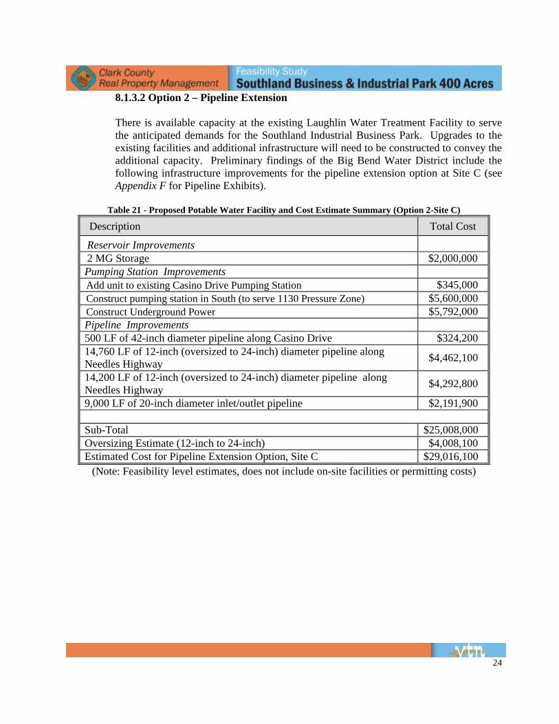
8.1.3.2 Option 2 – Pipeline Extension
There is available capacity at the existing Laughlin Water Treatment Facility to serve the anticipated demands for the Southland Industrial Business Park. Upgrades to the existing facilities and additional infrastructure will need to be constructed to convey the additional capacity. Preliminary findings of the Big Bend Water District include the following infrastructure improvements for the pipeline extension option at Site C (see Appendix F for Pipeline Exhibits).
Table 21 - Proposed Potable Water Facility and Cost Estimate Summary (Option 2-Site C)
Description Total Cost
Reservoir Improvements 2 MG Storage $2,000,000 Pumping Station Improvements Add unit to existing Casino Drive Pumping Station $345,000 Construct pumping station in South (to serve 1130 Pressure Zone) $5,600,000 Construct Underground Power $5,792,000 Pipeline Improvements 500 LF of 42-inch diameter pipeline along Casino Drive $324,200 14,760 LF of 12-inch (oversized to 24-inch) diameter pipeline along Needles Highway $4,462,100
14,200 LF of 12-inch (oversized to 24-inch) diameter pipeline along Needles Highway $4,292,800
9,000 LF of 20-inch diameter inlet/outlet pipeline $2,191,900
Sub-Total $25,008,000 Oversizing Estimate (12-inch to 24-inch) $4,008,100 Estimated Cost for Pipeline Extension Option, Site C $29,016,100
(Note: Feasibility level estimates, does not include on-site facilities or permitting costs)
25
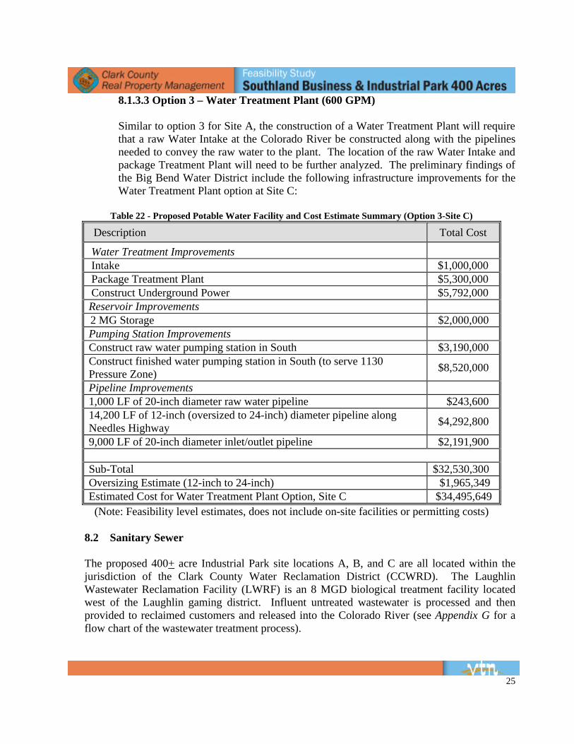
8.1.3.3 Option 3 – Water Treatment Plant (600 GPM) Similar to option 3 for Site A, the construction of a Water Treatment Plant will require that a raw Water Intake at the Colorado River be constructed along with the pipelines needed to convey the raw water to the plant. The location of the raw Water Intake and package Treatment Plant will need to be further analyzed. The preliminary findings of the Big Bend Water District include the following infrastructure improvements for the Water Treatment Plant option at Site C:
Table 22 - Proposed Potable Water Facility and Cost Estimate Summary (Option 3-Site C)
Description Total Cost
Water Treatment Improvements Intake $1,000,000 Package Treatment Plant $5,300,000 Construct Underground Power $5,792,000 Reservoir Improvements 2 MG Storage $2,000,000 Pumping Station Improvements Construct raw water pumping station in South $3,190,000 Construct finished water pumping station in South (to serve 1130 Pressure Zone) $8,520,000
Pipeline Improvements 1,000 LF of 20-inch diameter raw water pipeline $243,600 14,200 LF of 12-inch (oversized to 24-inch) diameter pipeline along Needles Highway $4,292,800
9,000 LF of 20-inch diameter inlet/outlet pipeline $2,191,900
Sub-Total $32,530,300 Oversizing Estimate (12-inch to 24-inch) $1,965,349 Estimated Cost for Water Treatment Plant Option, Site C $34,495,649 (Note: Feasibility level estimates, does not include on-site facilities or permitting costs)
8.2 Sanitary Sewer The proposed 400+ acre Industrial Park site locations A, B, and C are all located within the jurisdiction of the Clark County Water Reclamation District (CCWRD). The Laughlin Wastewater Reclamation Facility (LWRF) is an 8 MGD biological treatment facility located west of the Laughlin gaming district. Influent untreated wastewater is processed and then provided to reclaimed customers and released into the Colorado River (see Appendix G for a flow chart of the wastewater treatment process).
26
CCWRD determined that a new treatment plant will be required to service the entire 9,000 acre Southland Master Plan area, independent of which Industrial Park site location is chosen. In addition, CCWRD concluded that discharging sewage to the existing LWRF would not be feasible due to the need for numerous new lift stations, as well as additional upgrades to existing stations. Based on the 120 acre Phase 1 demand, a 1.3 Million Gallon per Day (MGD) plant would be required for the 400 acre industrial park. The optimal location for the proposed wastewater treatment plant location would be in the northeast portion of the Southland site east of the Needles Highway. This location would be able to service the majority of the future development within the Southland Master Plan by use of gravity lines, while avoiding lift stations. The CCWRD requires that the 400 acre industrial park development be serviced by a publicly owned and operated modular waste water treatment plant (MWWTP) with expansion capabilities to accommodate future development of the remaining 9,000 acres. Design of the plant shall comply with all CCWRD, County, State, and Federal standards. The design of the MWWTP will include sufficient area to accommodate green technology such as solar power generation facilities and re-use water storage basins. A 20-acre site is required to accommodate the MWWTP to service the 400 acre development, as well remaining portion of the 9,000 acre site. A re-use water distribution system would also be required to accommodate re-use water storage. The re-use water distribution lines can be located within Needles Highway to serve future golf course or landscape irrigation needs. The CCWRD’s preferred method of effluent discharge from the MWWTP would be by pipe outfall directly to the Colorado River. Adequate outfall pipe easements will be required along the pipeline alignment from the MWWTP to the actual point of discharge at the Colorado River. Adequate odor control and remediation measures will need to be incorporated within the design of the MWWTP to meet not only aesthetics purposes but also County air quality standards. Design of the MWWTP will be privately funded by the developer and coordinated with the CCWRD design / engineering division. The final design of the MWWTP must go through a formal review process and must be approved by CCWRD prior to applying for a discharge permit from the Nevada Department of Environmental Protection (NDEP). The application process for an NDEP discharge permit will be applied for by the developer with the permit applicant being the CCWRD. As mentioned previously, based on the 120 acre Phase 1 demand, a 1.3 Million Gallon per Day (MGD) plant would be required for the 400 acre industrial park. A similar treatment plant (Coyote Springs treatment plant) had a total cost of 40 million dollars after it was converted to a public facility. The cost of the permitting is not included in the 40 million dollar construction cost.
27
9. DRY UTILITIES
9.1 Power NV Energy is the electrical power provider for the Southland area. Presently there is a 69kV Transmission line the traverses the Southland site. The line has limited additional capacity and may be required to be upgraded depending on the demands of the industrial park and other future developments. NV Energy has a first come, first served policy and will not reserve power capacity for proposed future developments. The cost to upgrade the transmission line is approximately 1 million dollars per mile. A 44.8 MVA Distribution Substation will be required independent of which site is chosen. The substation will require 5 gross acres to be acquired. The substation footprint is approximately 3.2 acres with typical perimeter dimensions of 255-ft x 540-ft. The remaining acreage is utilized for access to the substation, maintenance of the perimeter walls, landscaping if required, and for slope transition. The grading criteria for the 3.2 acre portion are level in the long direction and 1% maximum gradient in the short direction. The location of the substation has been suggested by NV Energy to be located on the industrial park site. This will save off-site distribution infrastructure costs. If an on-site substation location is not feasible the proposed substation will located adjacent to the existing NV Energy transmission line that traverses the Southlands site at the north end. The cost of a substation is approximately 3 million dollars. Refer to Appendix H for pertinent material.
9.2 Natural Gas
Southwest Gas Corporation (SWG) is the provider of natural gas for the Southland area. There are two existing 16-inch steel high pressure gas transmission lines within a 50-foot wide easement that traverses Site A in the northern portion of the site in the east-west direction. The transmission lines terminate at a gas regulation station located on the east side of Needles Highway across from the north boundary of Southland. At the time of this report, SWG states that there was adequate capacity for industrial and manufacturing use. Based on the limited gas demand information, SWG could only estimate what the required line sizes and associated costs. SWG estimates that a 6-inch steel transmission line will be required in the Needles Highway along with 4-inch stubs into 2 regulatory stations for redundancy. These improvements will service the entire 400 acre industrial park. The preliminary cost estimate for the 120 acre Phase I site gas line infrastructure is $500,000, which applies to all 3 sites (A, B, and C). The development of the remaining 280 acres will be an additional $500,000.
9.3 Telephone
Embarq is the provider of phone service for the Southland area. Their facilities are approximately 200 feet to the north of Site A along the Needles Highway. There is capacity in
28
both fiber optic and copper. The developer will be responsible for extending conduits to the site. The carrier will provide the service facilities on site.
10. SURVEY
10.1 Site A Location – Legal Description of the Approximate Area BEING THOSE PORTIONS OF SECTION 8, AND SECTION 17, TOWNSHIP 33 SOUTH, RANGE 66 EAST, M.D.M., CLARK COUNTY, NEVADA, LYING WESTERLY OF THE WESTERLY RIGHT-OF-WAY OF NEEDLES HIGHWAY (270 FEET WIDE). 10.2 Site B Location – Legal Description of the Approximate Area BEING THOSE PORTIONS OF SECTION 17, AND SECTION 18, TOWNSHIP 33 SOUTH, RANGE 66 EAST, M.D.M., CLARK COUNTY, NEVADA, LYING WESTERLY OF THE WESTERLY RIGHT-OF-WAY OF NEEDLES HIGHWAY (270 FEET WIDE), AND EASTERLY OF A LINE LYING 2895.00 FEET WESTERLY OF THE WESTERLY RIGHT-OF-WAY OF NEEDLES HIGHWAY (270 FEET WIDE). 10.3 Site C Location – Legal Description of the Approximate Area BEING THOSE PORTIONS OF SECTION 19, AND SECTION 30, TOWNSHIP 33 SOUTH, RANGE 66 EAST, AND SECTION 24, AND SECTION 25, TOWNSHIP 33 SOUTH, RANGE 65 EAST, M.D.M., CLARK COUNTY, NEVADA, LYING WESTERLY OF THE WESTERLY RIGHT-OF-WAY OF NEEDLES HIGHWAY (270 FEET WIDE), EASTERLY OF A LINE LYING 2895 FEET WESTERLY OF THE WESTERLY RIGHT-OF-WAY OF NEEDLES HIGHWAY (270 FEET WIDE), NORTHERLY OF THE CALIFORNIA / NEVADA STATE LINE, AND SOUTHERLY OF A LINE LYING 1990 FEET SOUTH OF THE NORTH SECTION LINE OF SAID SECTION 19 AND SAID SECTION 24.
29
11. COST ESTIMATE SUMMARY
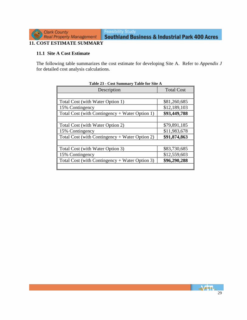
11.1 Site A Cost Estimate The following table summarizes the cost estimate for developing Site A. Refer to Appendix J for detailed cost analysis calculations.
Table 23 - Cost Summary Table for Site A
Description Total Cost
Total Cost (with Water Option 1) $81,260,685 15% Contingency $12,189,103 Total Cost (with Contingency + Water Option 1) $93,449,788 Total Cost (with Water Option 2) $79,891,185 15% Contingency $11,983,678 Total Cost (with Contingency + Water Option 2) $91,874,863
Total Cost (with Water Option 3) $83,730,685 15% Contingency $12,559,603 Total Cost (with Contingency + Water Option 3) $96,290,288
30
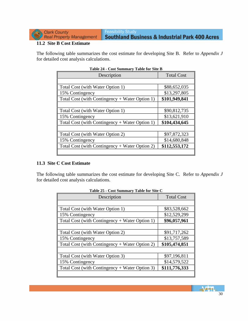
11.2 Site B Cost Estimate The following table summarizes the cost estimate for developing Site B. Refer to Appendix J for detailed cost analysis calculations.
Table 24 - Cost Summary Table for Site B
Description Total Cost
Total Cost (with Water Option 1) $88,652,035 15% Contingency $13,297,805 Total Cost (with Contingency + Water Option 1) $101,949,841 Total Cost (with Water Option 1) $90,812,735 15% Contingency $13,621,910 Total Cost (with Contingency + Water Option 1) $104,434,645
Total Cost (with Water Option 2) $97,872,323 15% Contingency $14,680,848 Total Cost (with Contingency + Water Option 2) $112,553,172
11.3 Site C Cost Estimate The following table summarizes the cost estimate for developing Site C. Refer to Appendix J for detailed cost analysis calculations.
Table 25 - Cost Summary Table for Site C Description Total Cost
Total Cost (with Water Option 1) $83,528,662 15% Contingency $12,529,299 Total Cost (with Contingency + Water Option 1) $96,057,961 Total Cost (with Water Option 2) $91,717,262 15% Contingency $13,757,589 Total Cost (with Contingency + Water Option 2) $105,474,851
Total Cost (with Water Option 3) $97,196,811 15% Contingency $14,579,522 Total Cost (with Contingency + Water Option 3) $111,776,333
31
12. CONCLUSIONS Based on the findings of this report, Site A would be the most feasible location for the proposed 400 acre Industrial Park due to the proximity to the developed Laughlin area and the least off-site cost to develop. Site A, utilizing water option 2, provides the lowest off-site development costs. Water option 2 utilizes an accepted standard method of water main extensions and does not include contingencies, such as acquiring groundwater rights. The gradient slope of all three sites is basically the same so no one site has a benefit over the other concerning the grading of the site. In conclusion Site A is best suited for the development of a 400 acre Industrial Park.
REFERENCES
Drainage 1. Flood Insurance Rate Map, Community Panel Number 32003C4060E, Clark County,
Nevada and Incorporated Areas, effective date of September 27, 2002. 2. Flood Insurance Rate Map, Community Panel Number 32003C4070E, Clark County,
Nevada and Incorporated Areas, effective date of September 27, 2002. 3. Flood Insurance Rate Map, Community Panel Number 32003C4075E, Clark County,
Nevada and Incorporated Areas, effective date September 27, 2002. 4. Clark County Regional Flood Control District (CCRFCD) Master Plan Update 2009 –
Outlying Areas (Laughlin). 5. Clark County Nevada Department of Public Works – Improvement Plans for Needles
Highway California/Nevada Border 2005, by CH2M Hill Stamped by Michael S. Lasko (NV# 10302).
6. Hydrologic Criteria and Drainage Design Manual, Clark County Regional Flood Control
District, 1990. Traffic 7. Trip Generation, 8th Edition, Institute of Transportation Engineers Water 8. Uniform Design and Construction Standards for Potable Water Systems, Las Vegas Valley
Water District, 2nd Edition 2003. 9. Clark County Fire Code – Table A-III-A-1, Clark County Fire Department 2005 Edition. Wastewater / Sanitary Sewer 10. Design and Construction Standards for Wastewater Collection Systems – Southern Nevada,
Clark County Water Reclamation District, 3rd Draft dated May 21, 2009. Cost Analysis 11. Clark County Department of Development Services-Civil Engineering Division Off-Site
Improvement Bond Estimate Tabulations, dated May 20, 2009. 12. Laughlin 400 Acres Industrial Feasibility Study Potable Water Facilities Estimated Costs,
Las Vegas Valley Water District Planning Division, dated July 7, 2009.

APPENDIX A PROJECT SITE VICINITY MAP
APPENDIX B PLANNING AND
LANDUSE DOCUMENTATION

APPENDIX C SOILS

APPENDIX D TRAFFIC

APPENDIX E DRAINAGE AND HYDRAULICS
DRAINAGE AND HYDRAULICS
FIGURES
DRAINAGE AND HYDRAULICS
REFERENCED HYDROLOGIC ANALYSIS FROM
CCRFCD 2009 OUTLYING AREA FLOOD CONTROL MASTER PLAN UPDATE
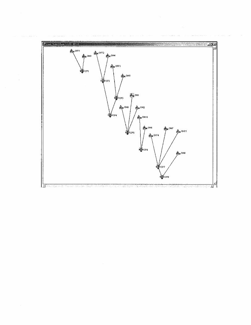
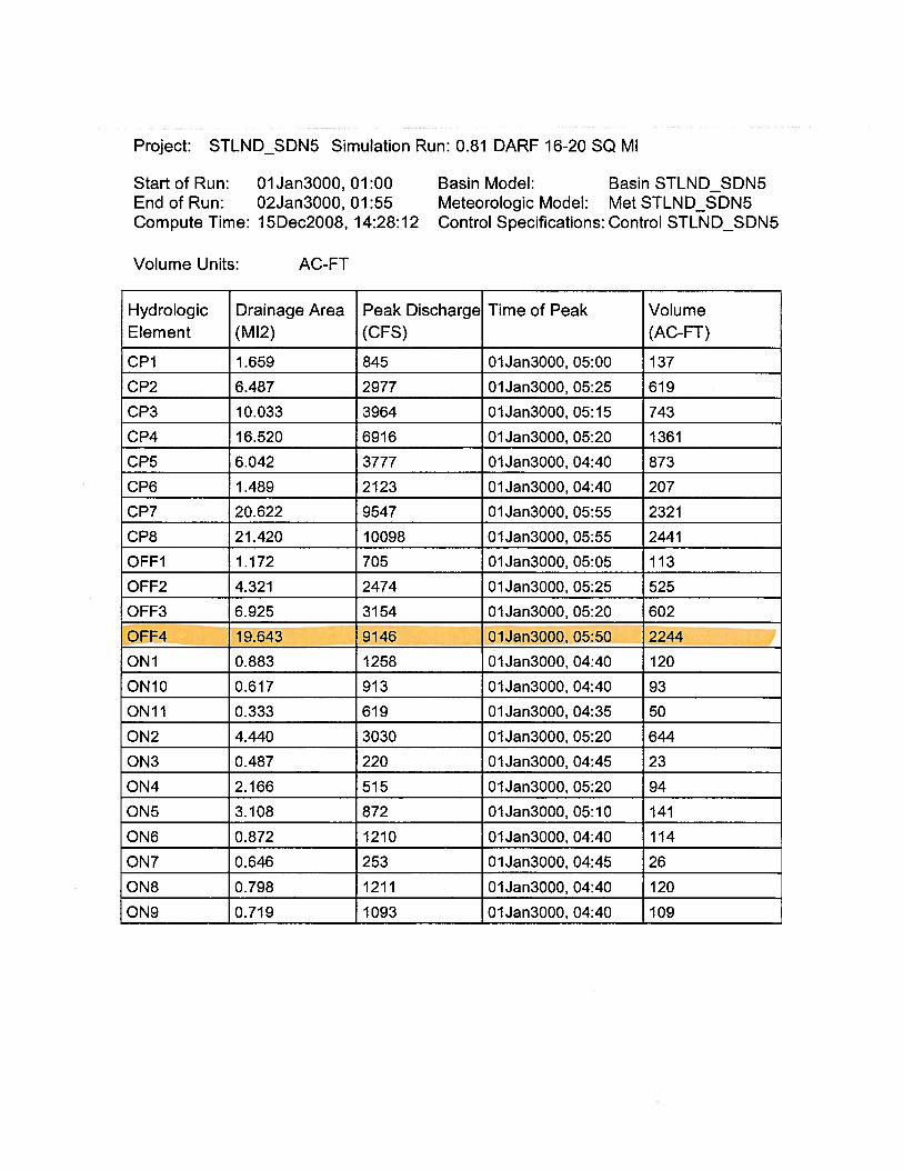
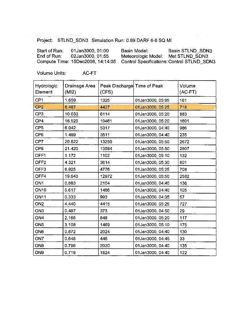
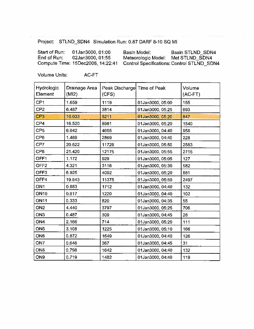
DRAINAGE AND HYDRAULICS
CULVERT CAPACITY CALCULATIONS BASED ON HEADWATER CRITERIA
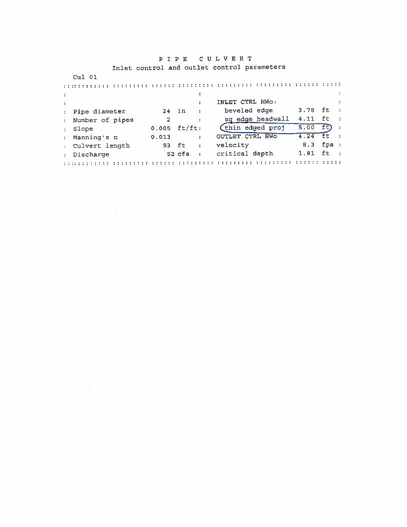


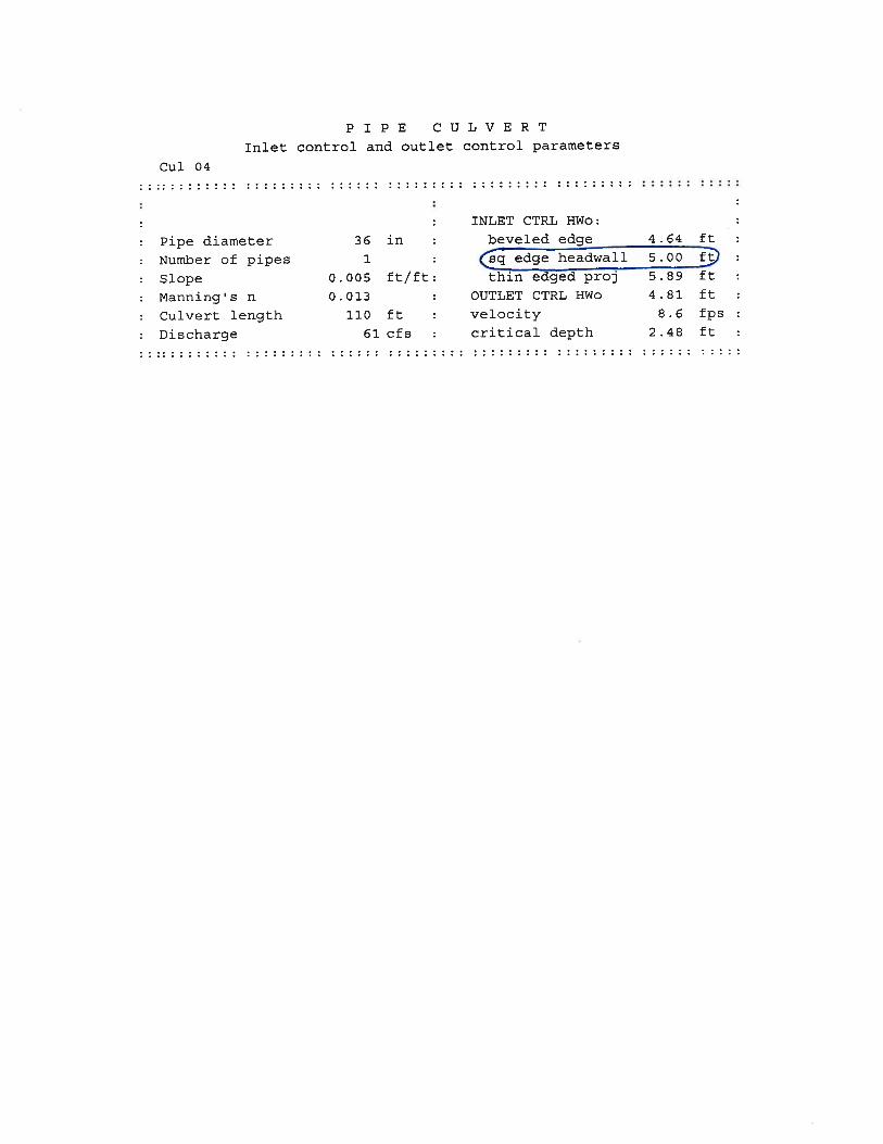
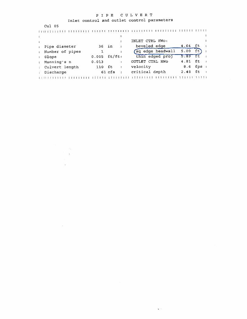

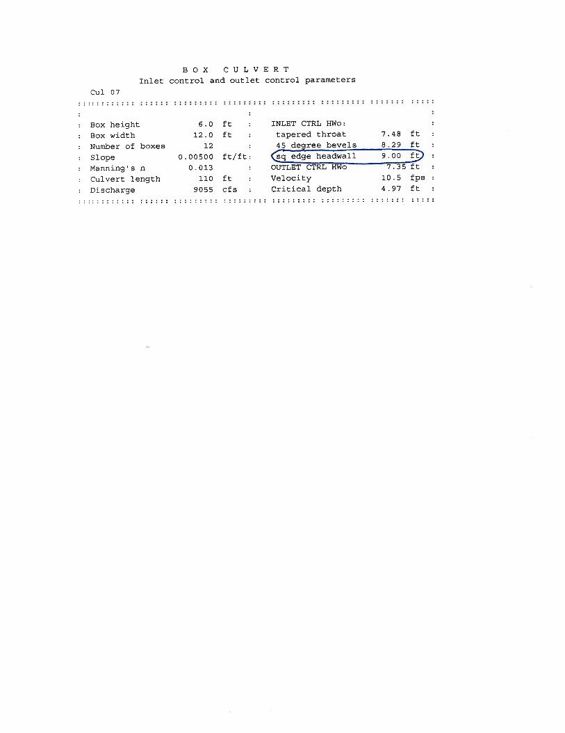

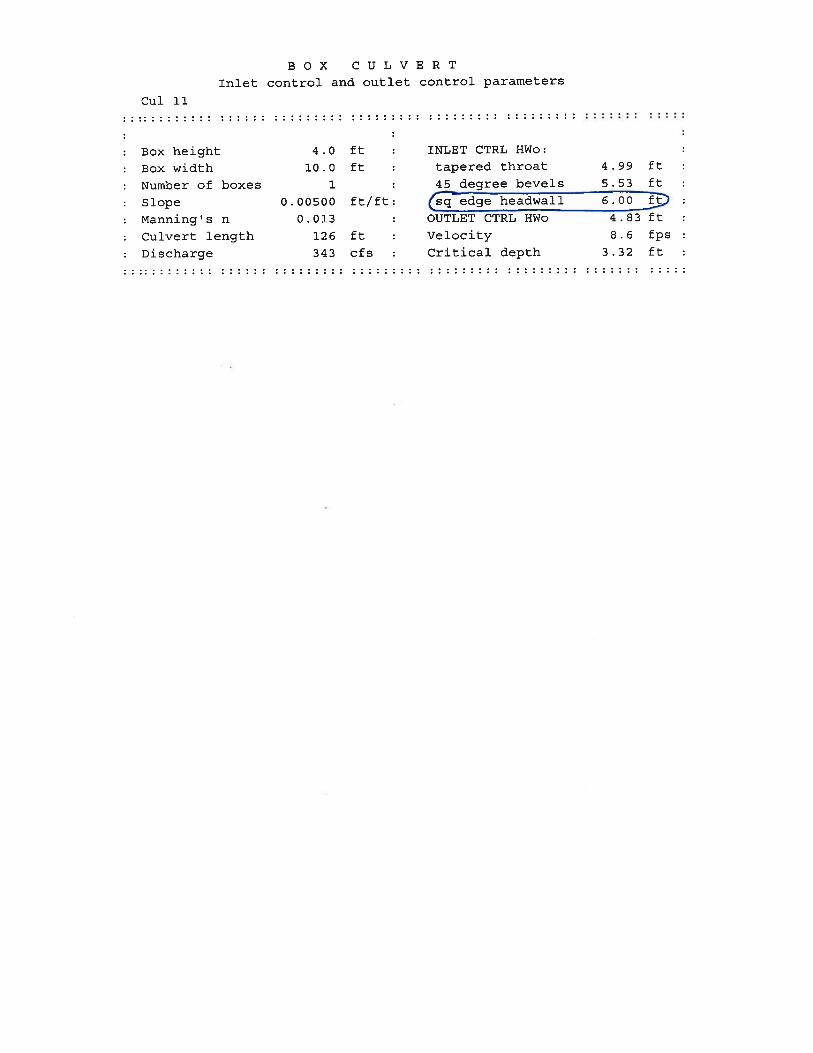
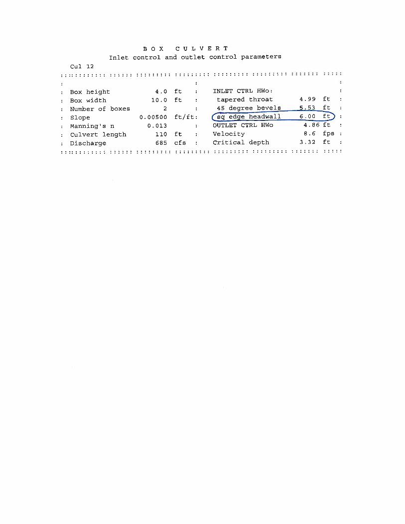
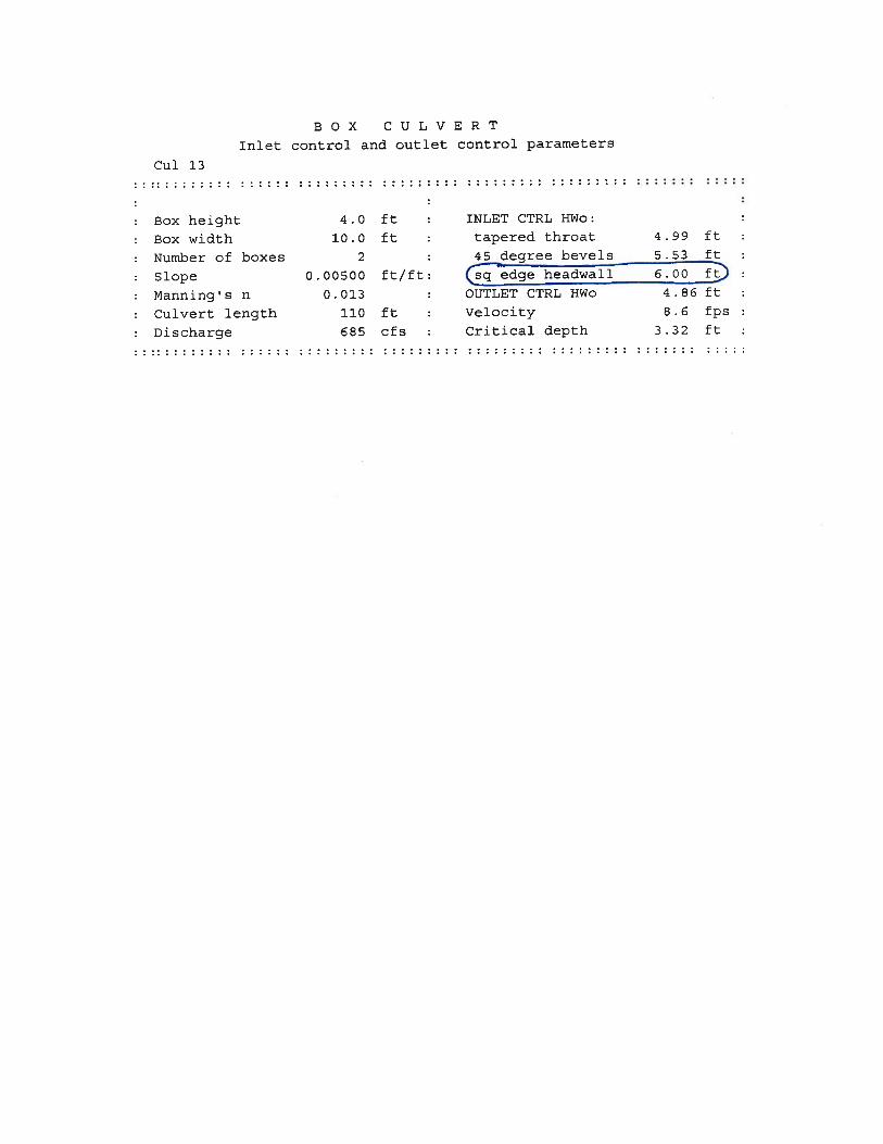


DRAINAGE AND HYDRAULICS
CULVERT CAPACITY CALCULATIONS BASED ON ROADWAY ELEVATIONS

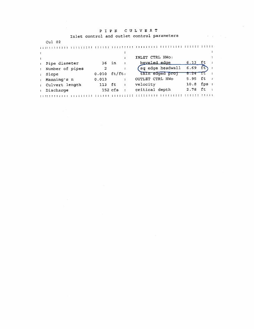

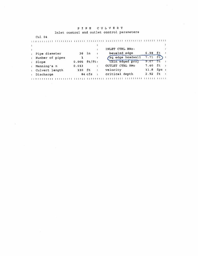
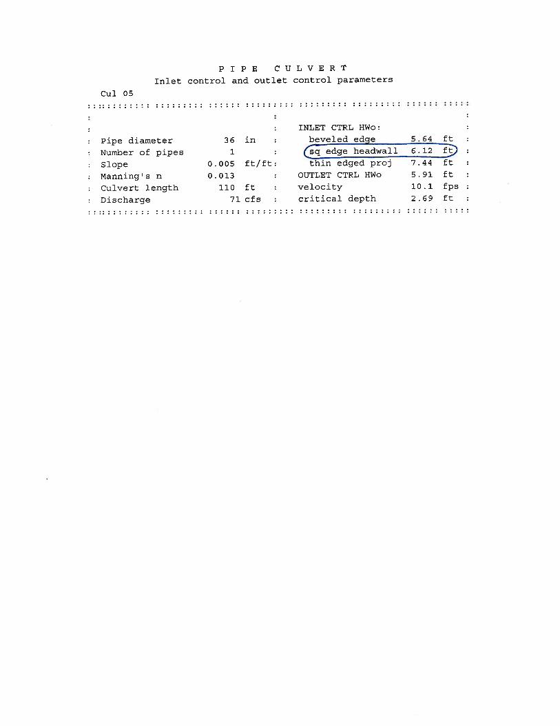

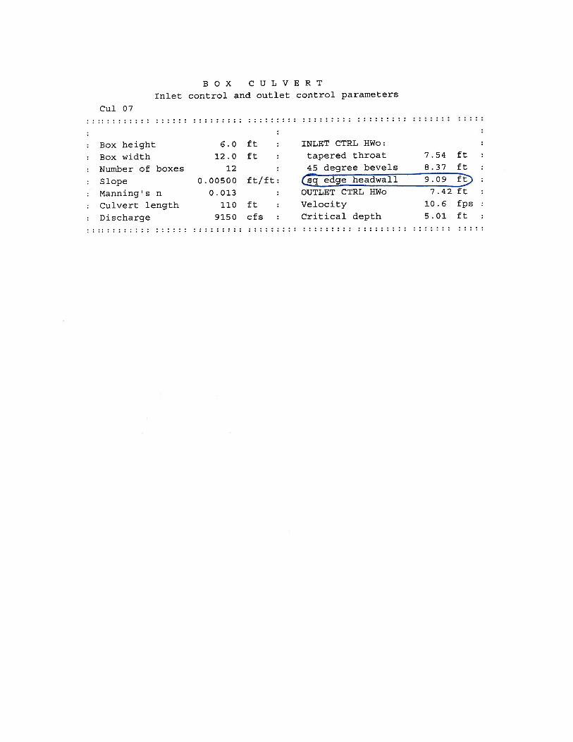

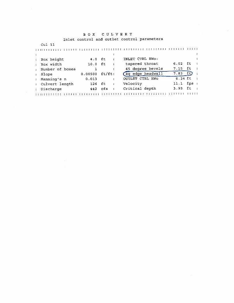
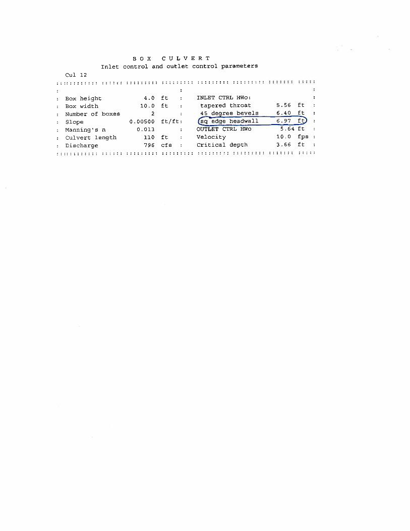

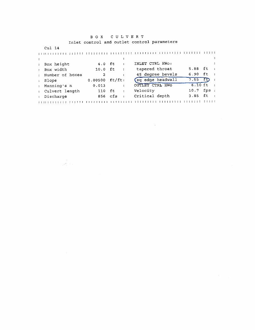


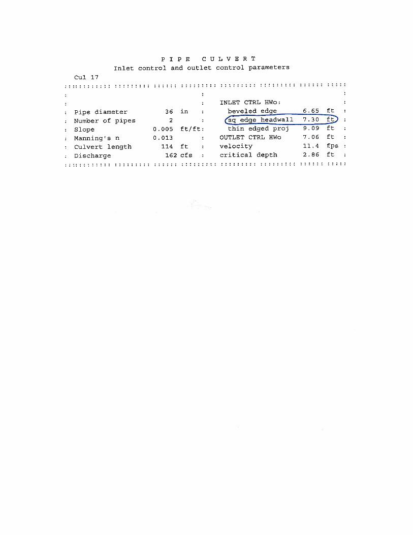
DRAINAGE AND HYDRAULICS
CULVERT CAPACITY CALCULATIONS SUMMARY TABLE
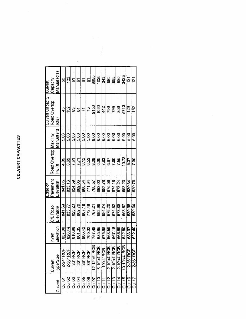
DRAINAGE AND HYDRAULICS
REFERENCE NEEDLES HIGHWAY PLANS
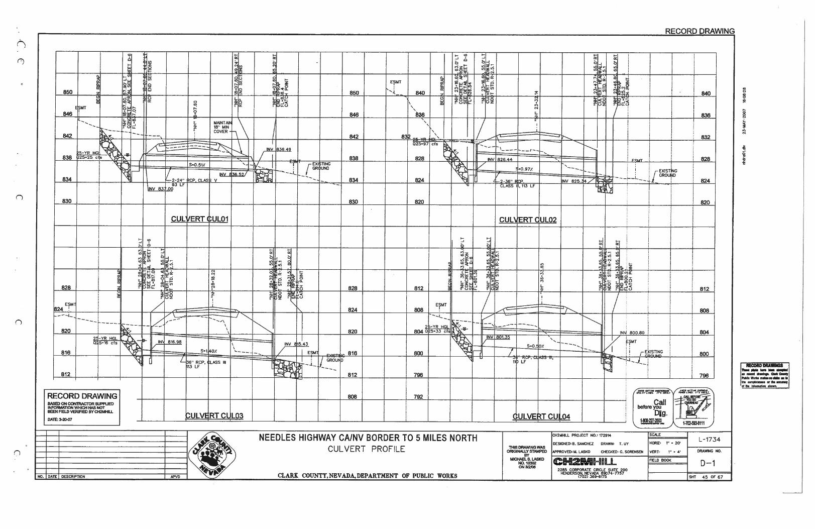
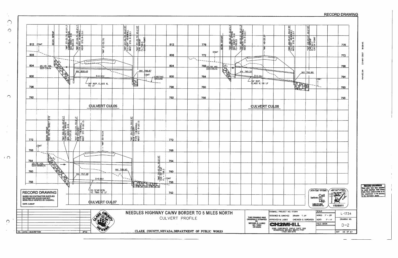
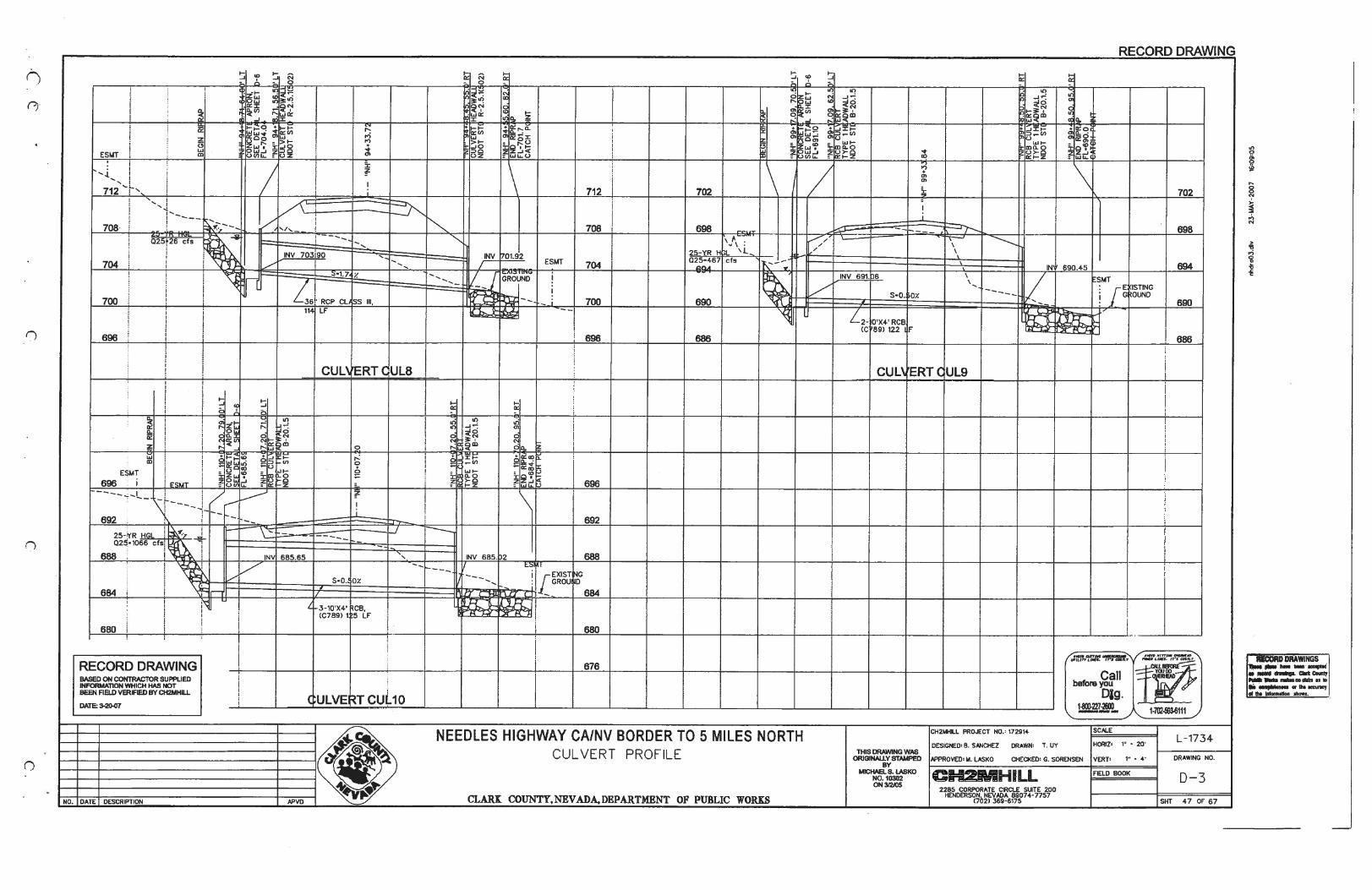
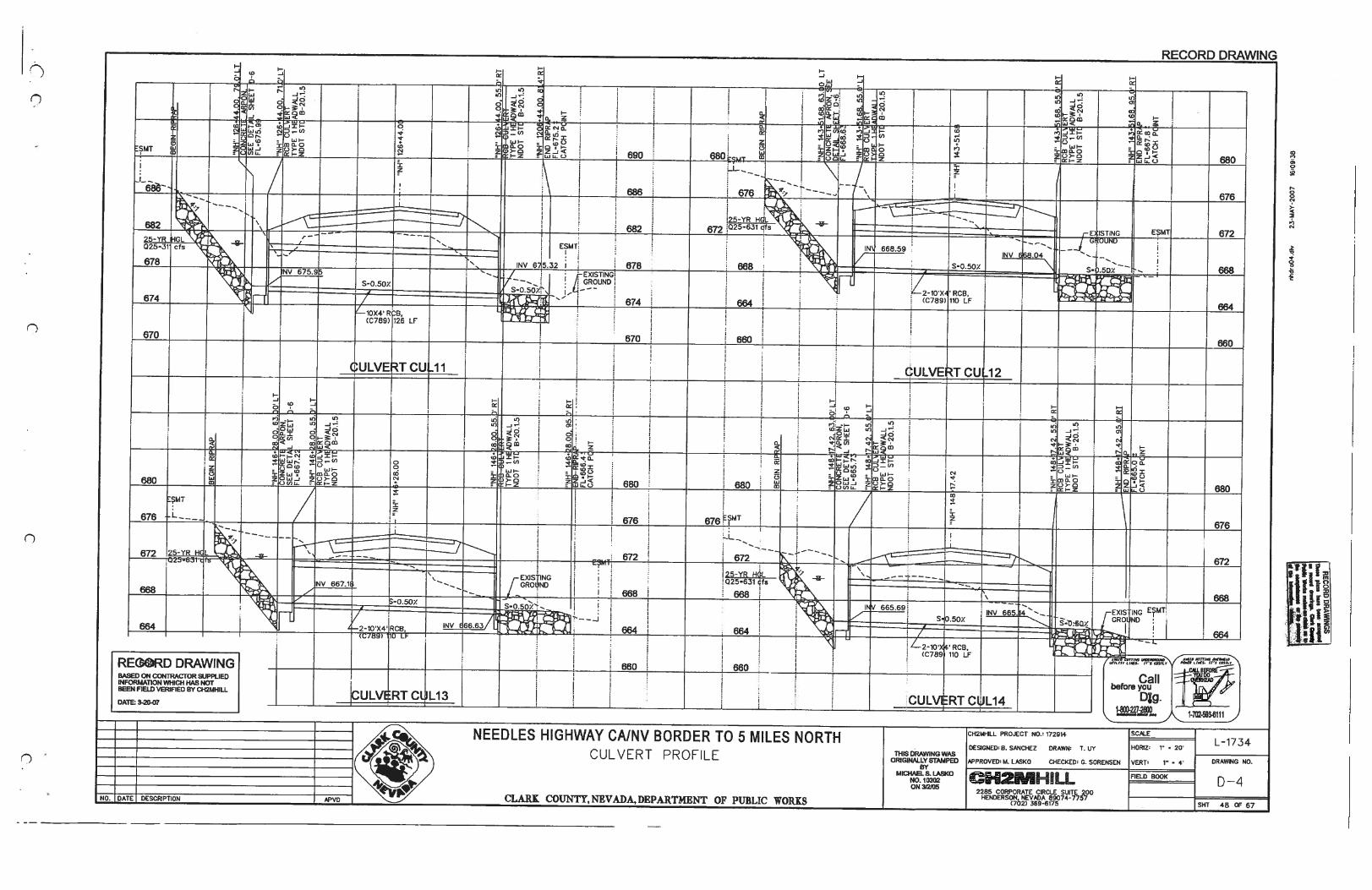
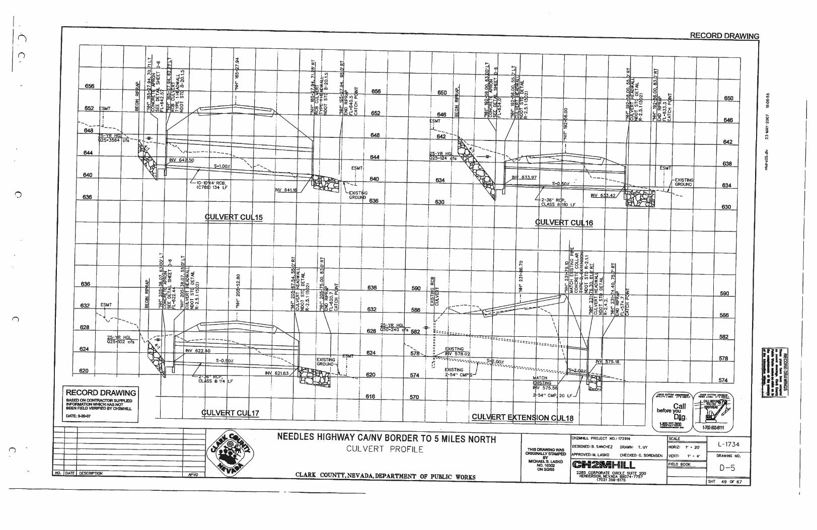
DRAINAGE AND HYDRAULICS
PRELIMINARY FACILITY HYDRAULIC CALCULATIONS
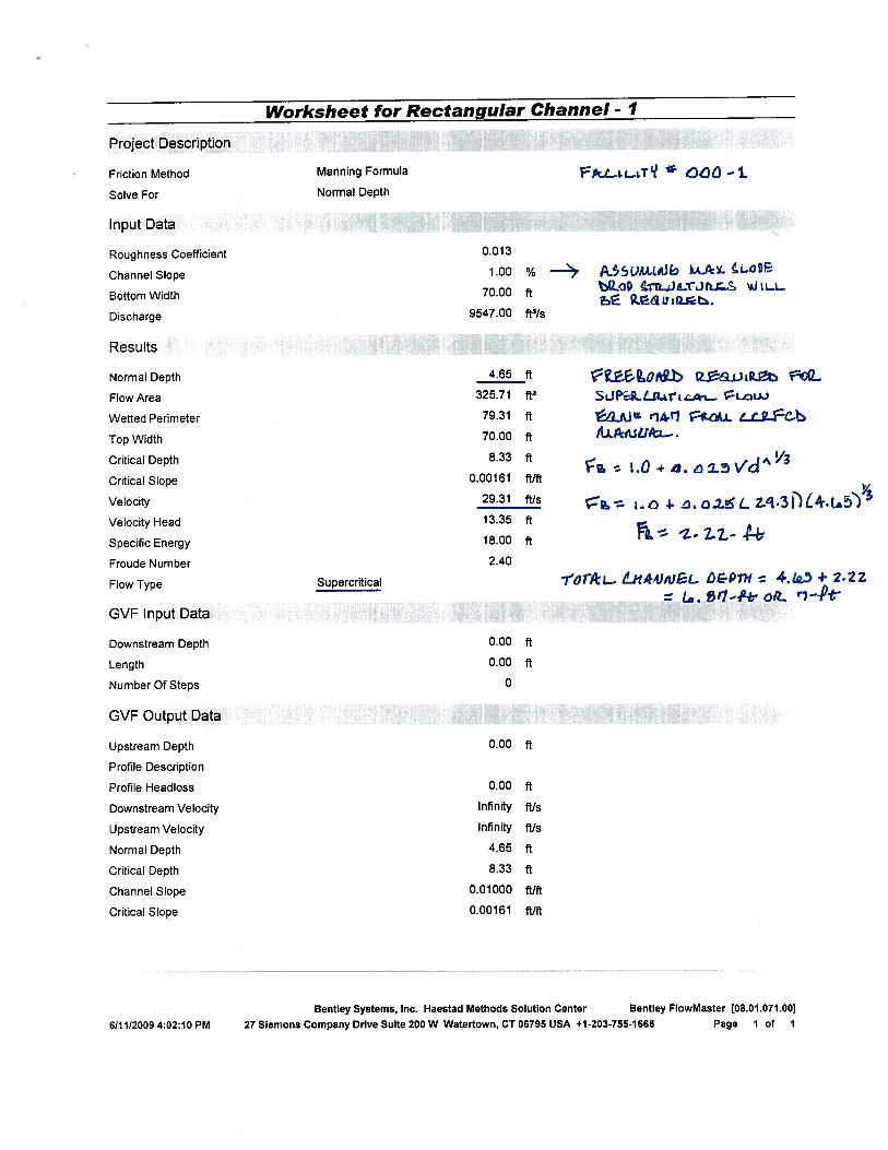
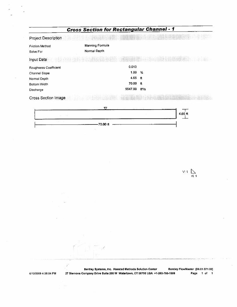
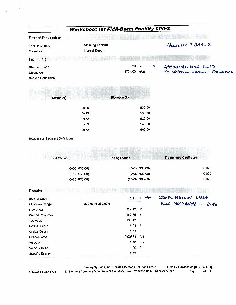
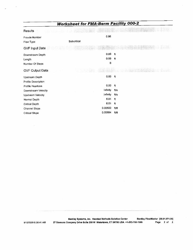
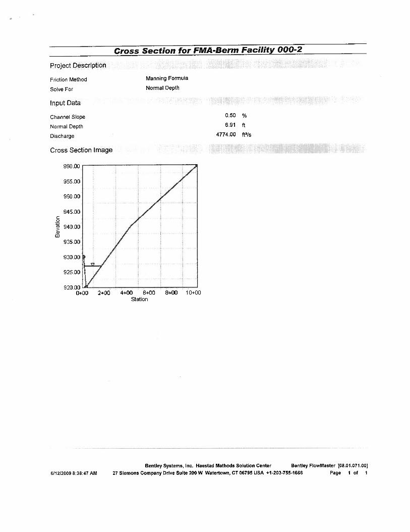
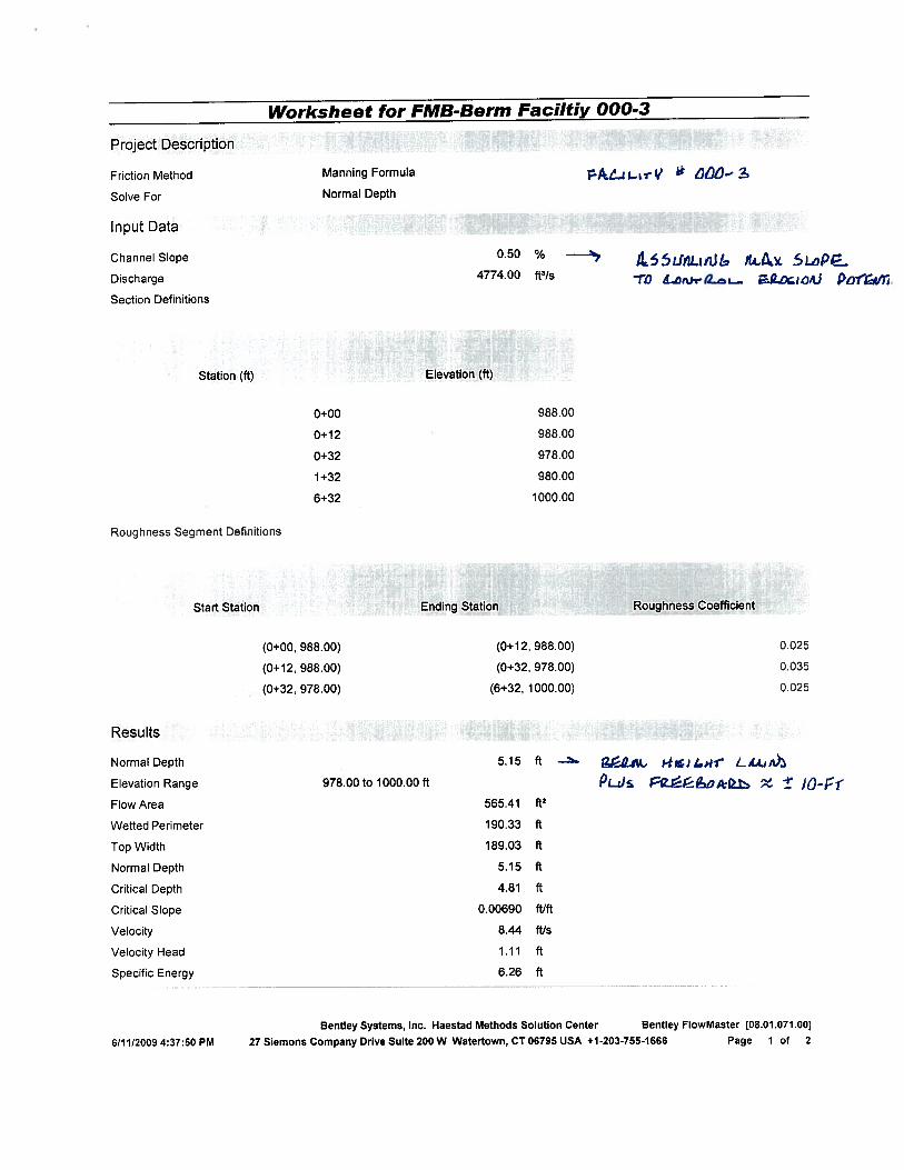
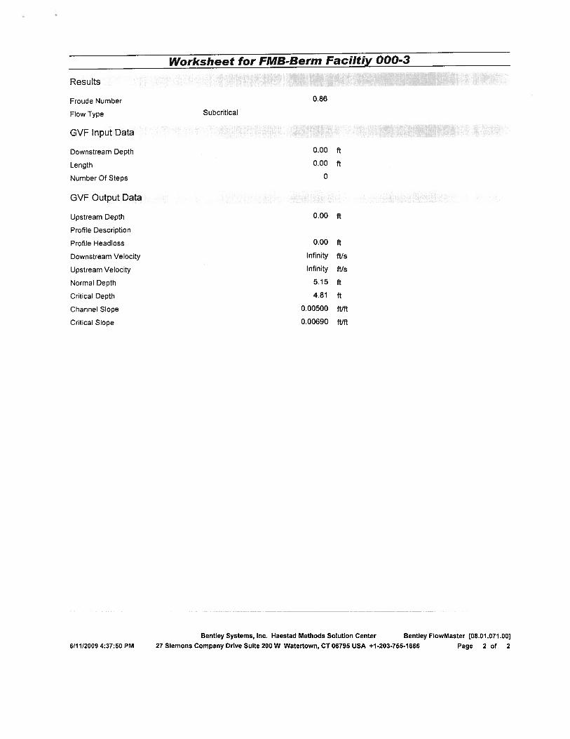
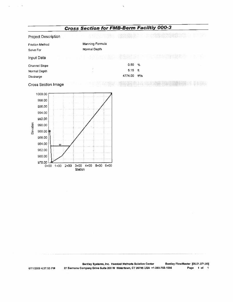

APPENDIX F POTABLE WATER
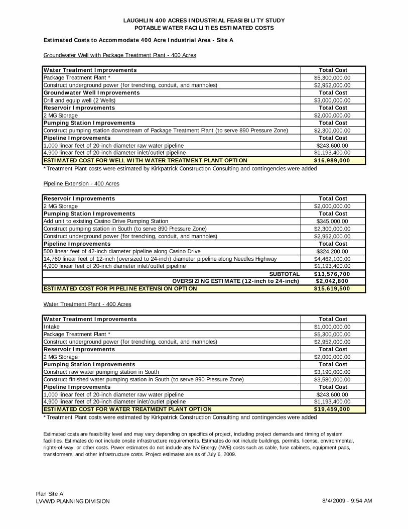
LAUGHLIN 400 ACRES INDUSTRIAL FEASIBILITY STUDYPOTABLE WATER FACILITIES ESTIMATED COSTS
Estimated Costs to Accommodate 400 Acre Industrial Area - Site A
Groundwater Well with Package Treatment Plant - 400 Acres
Water Treatment Improvements Total CostPackage Treatment Plant * $5,300,000.00Construct underground power (for trenching, conduit, and manholes) $2,952,000.00Groundwater Well Improvements Total CostDrill and equip well (2 Wells) $3,000,000.00Reservoir Improvements Total Cost2 MG Storage $2,000,000.00Pumping Station Improvements Total CostConstruct pumping station downstream of Package Treatment Plant (to serve 890 Pressure Zone) $2,300,000.00Pipeline Improvements Total Cost1,000 linear feet of 20-inch diameter raw water pipeline $243,600.004,900 linear feet of 20-inch diameter inlet/outlet pipeline $1,193,400.00ESTIMATED COST FOR WELL WITH WATER TREATMENT PLANT OPTION $16,989,000
Pipeline Extension - 400 Acres
Reservoir Improvements Total Cost2 MG Storage $2,000,000.00Pumping Station Improvements Total CostAdd unit to existing Casino Drive Pumping Station $345,000.00Construct pumping station in South (to serve 890 Pressure Zone) $2,300,000.00Construct underground power (for trenching, conduit, and manholes) $2,952,000.00Pipeline Improvements Total Cost500 linear feet of 42-inch diameter pipeline along Casino Drive $324,200.0014,760 linear feet of 12-inch (oversized to 24-inch) diameter pipeline along Needles Highway $4,462,100.004,900 linear feet of 20-inch diameter inlet/outlet pipeline $1,193,400.00
SUBTOTAL $13,576,700OVERSIZING ESTIMATE (12-inch to 24-inch) $2,042,800
ESTIMATED COST FOR PIPELINE EXTENSION OPTION $15,619,500
Water Treatment Plant - 400 Acres
Water Treatment Improvements Total CostIntake $1,000,000.00Package Treatment Plant * $5,300,000.00Construct underground power (for trenching, conduit, and manholes) $2,952,000.00Reservoir Improvements Total Cost2 MG Storage $2,000,000.00Pumping Station Improvements Total CostConstruct raw water pumping station in South $3,190,000.00Construct finished water pumping station in South (to serve 890 Pressure Zone) $3,580,000.00Pipeline Improvements Total Cost1,000 linear feet of 20-inch diameter raw water pipeline $243,600.004,900 linear feet of 20-inch diameter inlet/outlet pipeline $1,193,400.00ESTIMATED COST FOR WATER TREATMENT PLANT OPTION $19,459,000
*Treatment Plant costs were estimated by Kirkpatrick Construction Consulting and contingencies were added
*Treatment Plant costs were estimated by Kirkpatrick Construction Consulting and contingencies were added
Estimated costs are feasibility level and may vary depending on specifics of project, including project demands and timing of system facilities. Estimates do not include onsite infrastructure requirements. Estimates do not include buildings, permits, license, environmental, rights-of-way, or other costs. Power estimates do not include any NV Energy (NVE) costs such as cable, fuse cabinets, equipment pads, transformers, and other infrastructure costs. Project estimates are as of July 6, 2009.
Plan Site ALVVWD PLANNING DIVISION 8/4/2009 - 9:54 AM
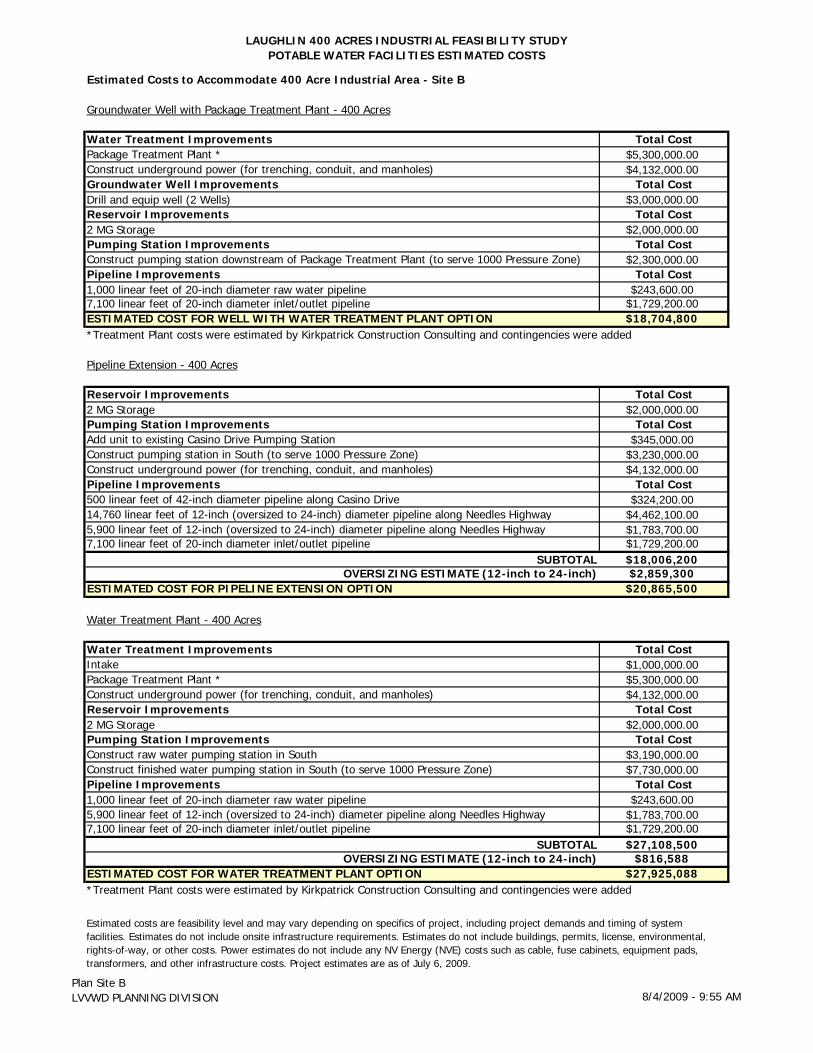
LAUGHLIN 400 ACRES INDUSTRIAL FEASIBILITY STUDYPOTABLE WATER FACILITIES ESTIMATED COSTS
Estimated Costs to Accommodate 400 Acre Industrial Area - Site B
Groundwater Well with Package Treatment Plant - 400 Acres
Water Treatment Improvements Total CostPackage Treatment Plant * $5,300,000.00Construct underground power (for trenching, conduit, and manholes) $4,132,000.00Groundwater Well Improvements Total CostDrill and equip well (2 Wells) $3,000,000.00Reservoir Improvements Total Cost2 MG Storage $2,000,000.00Pumping Station Improvements Total CostConstruct pumping station downstream of Package Treatment Plant (to serve 1000 Pressure Zone) $2,300,000.00Pipeline Improvements Total Cost1,000 linear feet of 20-inch diameter raw water pipeline $243,600.007,100 linear feet of 20-inch diameter inlet/outlet pipeline $1,729,200.00ESTIMATED COST FOR WELL WITH WATER TREATMENT PLANT OPTION $18,704,800
Pipeline Extension - 400 Acres
Reservoir Improvements Total Cost2 MG Storage $2,000,000.00Pumping Station Improvements Total CostAdd unit to existing Casino Drive Pumping Station $345,000.00Construct pumping station in South (to serve 1000 Pressure Zone) $3,230,000.00Construct underground power (for trenching, conduit, and manholes) $4,132,000.00Pipeline Improvements Total Cost500 linear feet of 42-inch diameter pipeline along Casino Drive $324,200.0014,760 linear feet of 12-inch (oversized to 24-inch) diameter pipeline along Needles Highway $4,462,100.005,900 linear feet of 12-inch (oversized to 24-inch) diameter pipeline along Needles Highway $1,783,700.007,100 linear feet of 20-inch diameter inlet/outlet pipeline $1,729,200.00
SUBTOTAL $18,006,200OVERSIZING ESTIMATE (12-inch to 24-inch) $2,859,300
ESTIMATED COST FOR PIPELINE EXTENSION OPTION $20,865,500
Water Treatment Plant - 400 Acres
Water Treatment Improvements Total CostIntake $1,000,000.00Package Treatment Plant * $5,300,000.00Construct underground power (for trenching, conduit, and manholes) $4,132,000.00Reservoir Improvements Total Cost2 MG Storage $2,000,000.00Pumping Station Improvements Total CostConstruct raw water pumping station in South $3,190,000.00Construct finished water pumping station in South (to serve 1000 Pressure Zone) $7,730,000.00Pipeline Improvements Total Cost1,000 linear feet of 20-inch diameter raw water pipeline $243,600.005,900 linear feet of 12-inch (oversized to 24-inch) diameter pipeline along Needles Highway $1,783,700.007,100 linear feet of 20-inch diameter inlet/outlet pipeline $1,729,200.00
SUBTOTAL $27,108,500OVERSIZING ESTIMATE (12-inch to 24-inch) $816,588
ESTIMATED COST FOR WATER TREATMENT PLANT OPTION $27,925,088
Estimated costs are feasibility level and may vary depending on specifics of project, including project demands and timing of system facilities. Estimates do not include onsite infrastructure requirements. Estimates do not include buildings, permits, license, environmental, rights-of-way, or other costs. Power estimates do not include any NV Energy (NVE) costs such as cable, fuse cabinets, equipment pads, transformers, and other infrastructure costs. Project estimates are as of July 6, 2009.
*Treatment Plant costs were estimated by Kirkpatrick Construction Consulting and contingencies were added
*Treatment Plant costs were estimated by Kirkpatrick Construction Consulting and contingencies were added
Plan Site BLVVWD PLANNING DIVISION 8/4/2009 - 9:55 AM
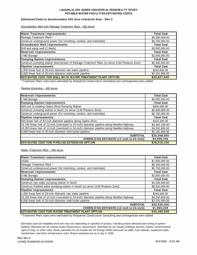
LAUGHLIN 400 ACRES INDUSTRIAL FEASIBILITY STUDYPOTABLE WATER FACILITIES ESTIMATED COSTS
Estimated Costs to Accommodate 400 Acre Industrial Area - Site C
Groundwater Well with Package Treatment Plant - 400 Acres
Water Treatment Improvements Total CostPackage Treatment Plant * $5,300,000.00Construct underground power (for trenching, conduit, and manholes) $5,792,000.00Groundwater Well Improvements Total CostDrill and equip well (2 Wells) $3,000,000.00Reservoir Improvements Total Cost2 MG Storage $2,000,000.00Pumping Station Improvements Total CostConstruct pumping station downstream of Package Treatment Plant (to serve 1130 Pressure Zone) $2,300,000.00Pipeline Improvements Total Cost1,000 linear feet of 20-inch diameter raw water pipeline $243,600.009,000 linear feet of 20-inch diameter inlet/outlet pipeline $2,191,900.00ESTIMATED COST FOR WELL WITH WATER TREATMENT PLANT OPTION $20,827,500
Pipeline Extension - 400 Acres
Reservoir Improvements Total Cost2 MG Storage $2,000,000.00Pumping Station Improvements Total CostAdd unit to existing Casino Drive Pumping Station $345,000.00Construct pumping station in South (to serve 1130 Pressure Zone) $5,600,000.00Construct underground power (for trenching, conduit, and manholes) $5,792,000.00Pipeline Improvements Total Cost500 linear feet of 42-inch diameter pipeline along Casino Drive $324,200.0014,760 linear feet of 12-inch (oversized to 24-inch) diameter pipeline along Needles Highway $4,462,100.0014,200 linear feet of 12-inch (oversized to 24-inch) diameter pipeline along Needles Highway $4,292,800.009,000 linear feet of 20-inch diameter inlet/outlet pipeline $2,191,900.00
SUBTOTAL $25,008,000OVERSIZING ESTIMATE (12-inch to 24-inch) $4,008,100
ESTIMATED COST FOR PIPELINE EXTENSION OPTION $29,016,100
Water Treatment Plant - 400 Acres
Water Treatment Improvements Total CostIntake $1,000,000.00Package Treatment Plant * $5,300,000.00Construct underground power (for trenching, conduit, and manholes) $5,792,000.00Reservoir Improvements Total Cost2 MG Storage $2,000,000.00Pumping Station Improvements Total CostConstruct raw water pumping station in South $3,190,000.00Construct finished water pumping station in South (to serve 1130 Pressure Zone) $8,520,000.00Pipeline Improvements Total Cost1,000 linear feet of 20-inch diameter raw water pipeline $243,600.0014,200 linear feet of 12-inch (oversized to 24-inch) diameter pipeline along Needles Highway $4,292,800.009,000 linear feet of 20-inch diameter inlet/outlet pipeline $2,191,900.00
SUBTOTAL $32,530,300OVERSIZING ESTIMATE (12-inch to 24-inch) $1,965,349
ESTIMATED COST FOR WATER TREATMENT PLANT OPTION $34,495,649*Treatment Plant costs were estimated by Kirkpatrick Construction Consulting and contingencies were added
*Treatment Plant costs were estimated by Kirkpatrick Construction Consulting and contingencies were added
Estimated costs are feasibility level and may vary depending on specifics of project, including project demands and timing of system facilities. Estimates do not include onsite infrastructure requirements. Estimates do not include buildings, permits, license, environmental, rights-of-way, or other costs. Power estimates do not include any NV Energy (NVE) costs such as cable, fuse cabinets, equipment pads, transformers, and other infrastructure costs. Project estimates are as of July 6, 2009.
Plan Site CLVVWD PLANNING DIVISION 8/4/2009 - 9:55 AM
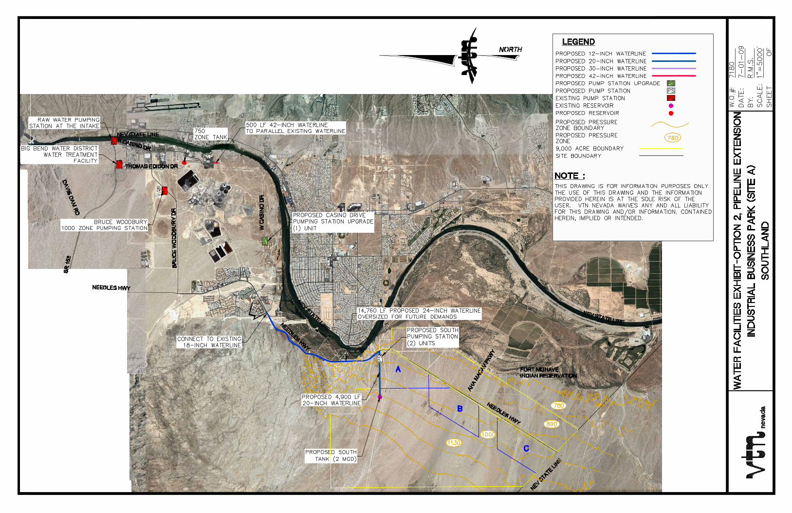
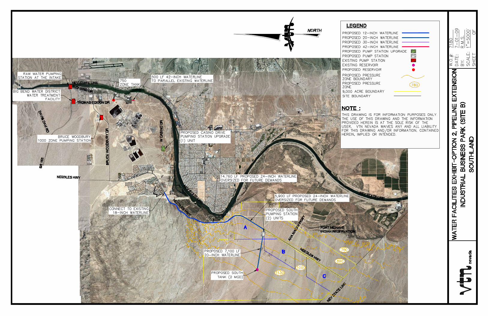
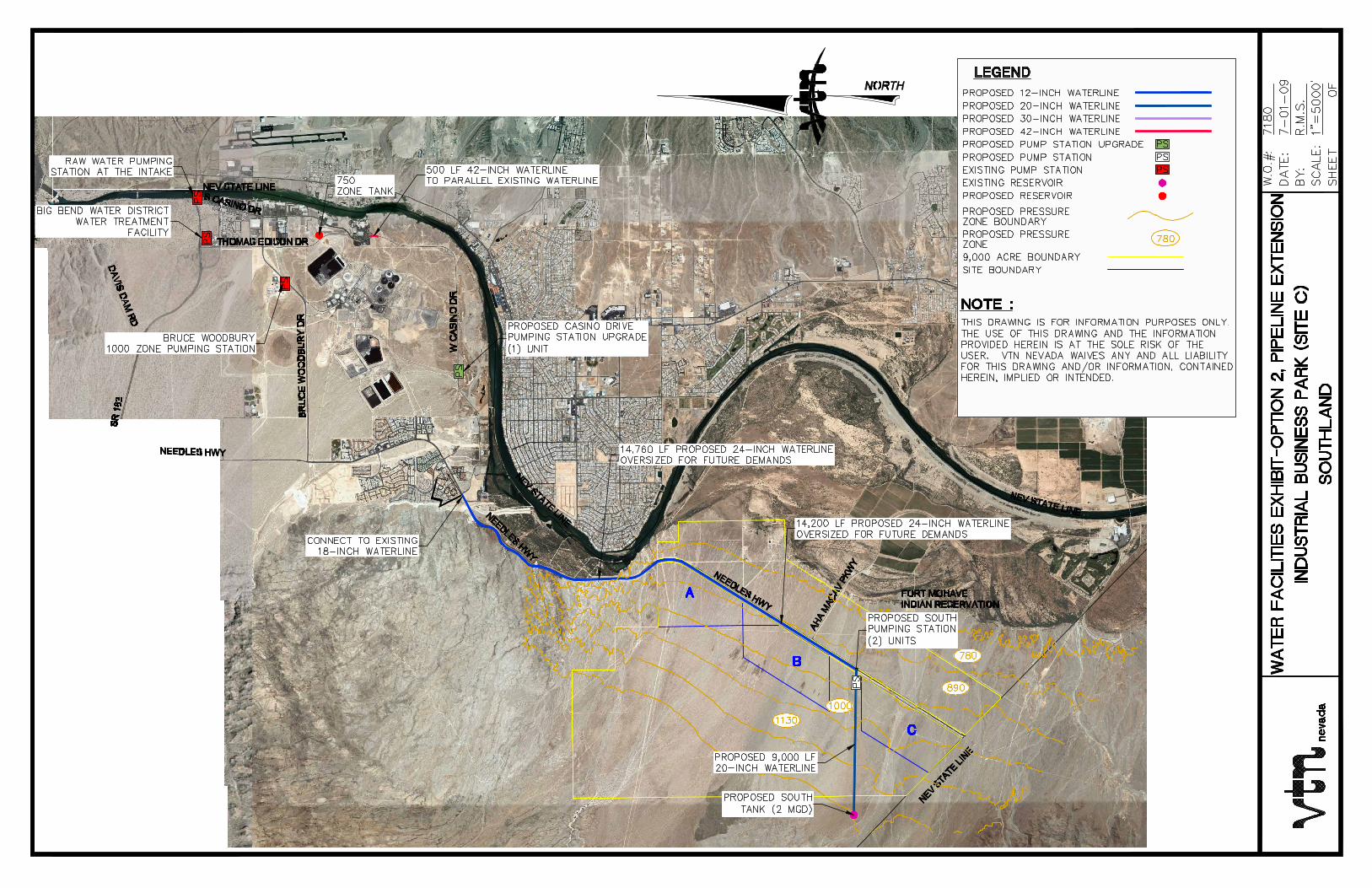
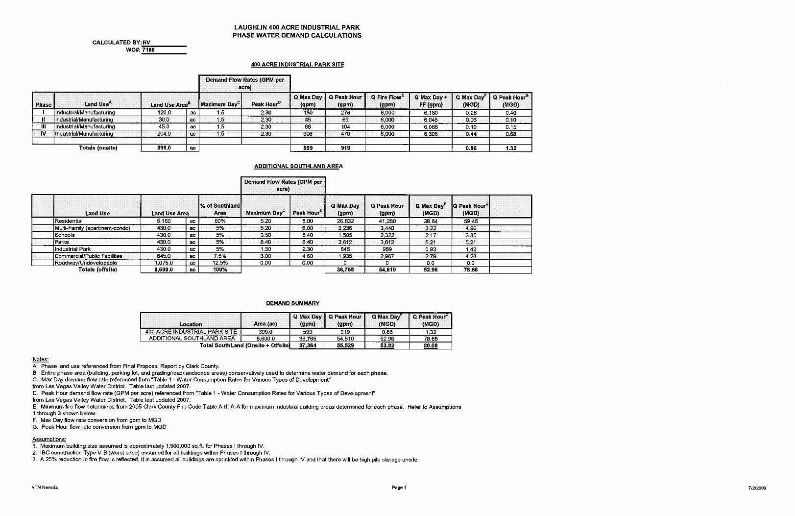
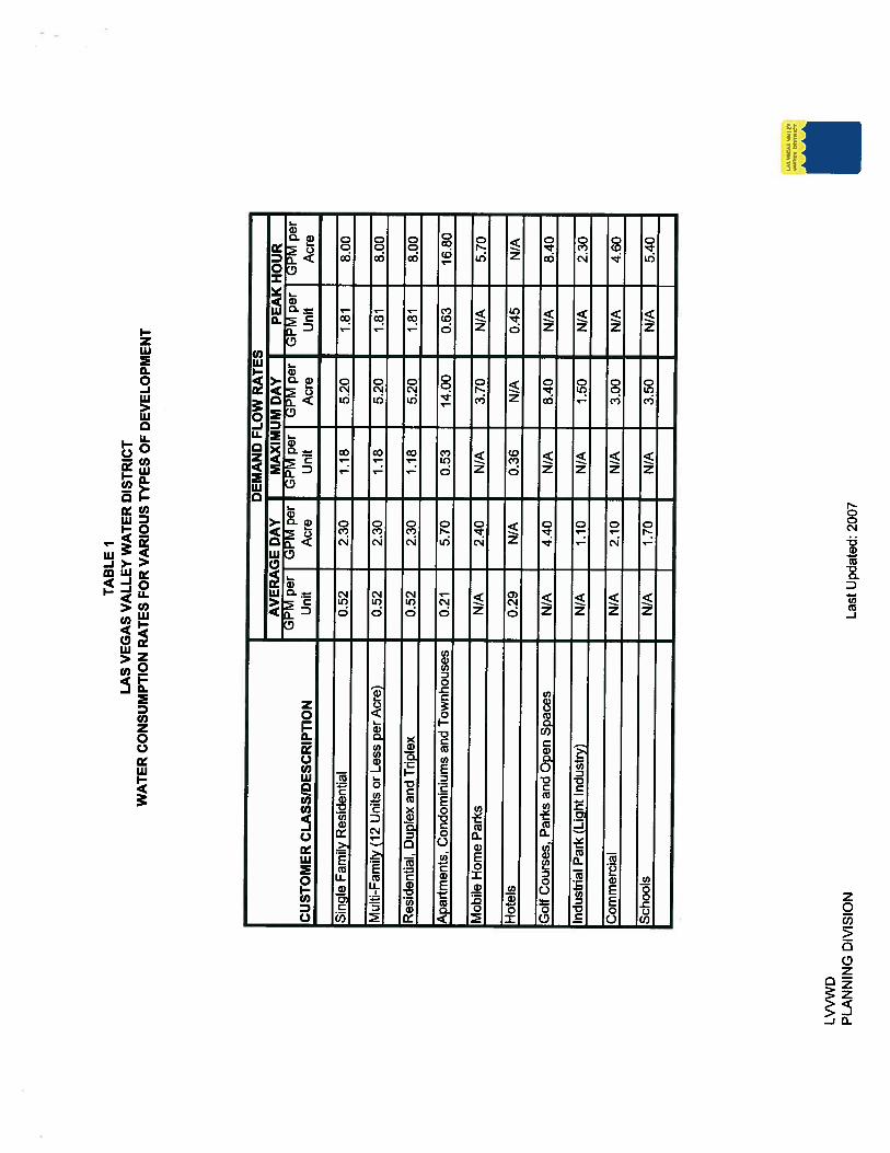
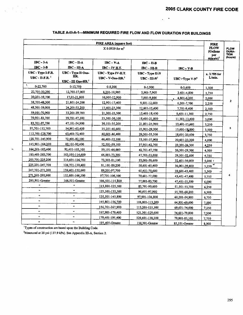

APPENDIX G SANITARY SEWER
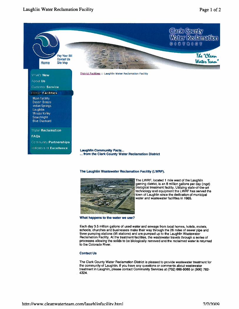
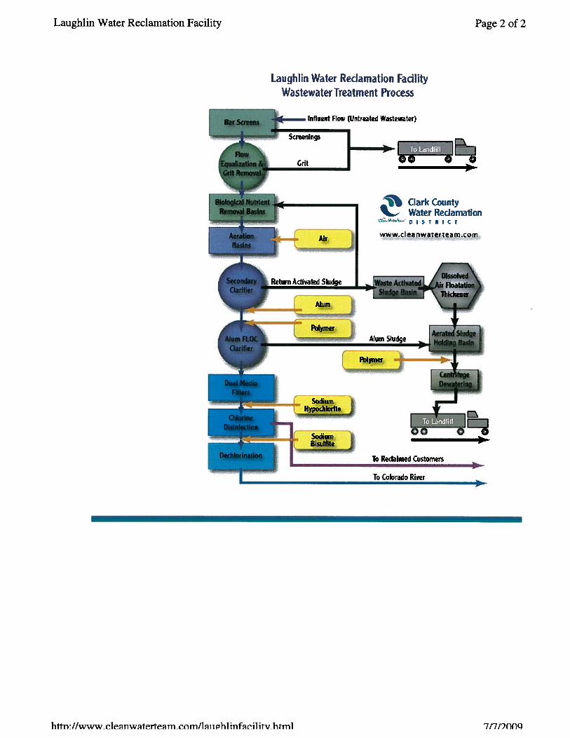
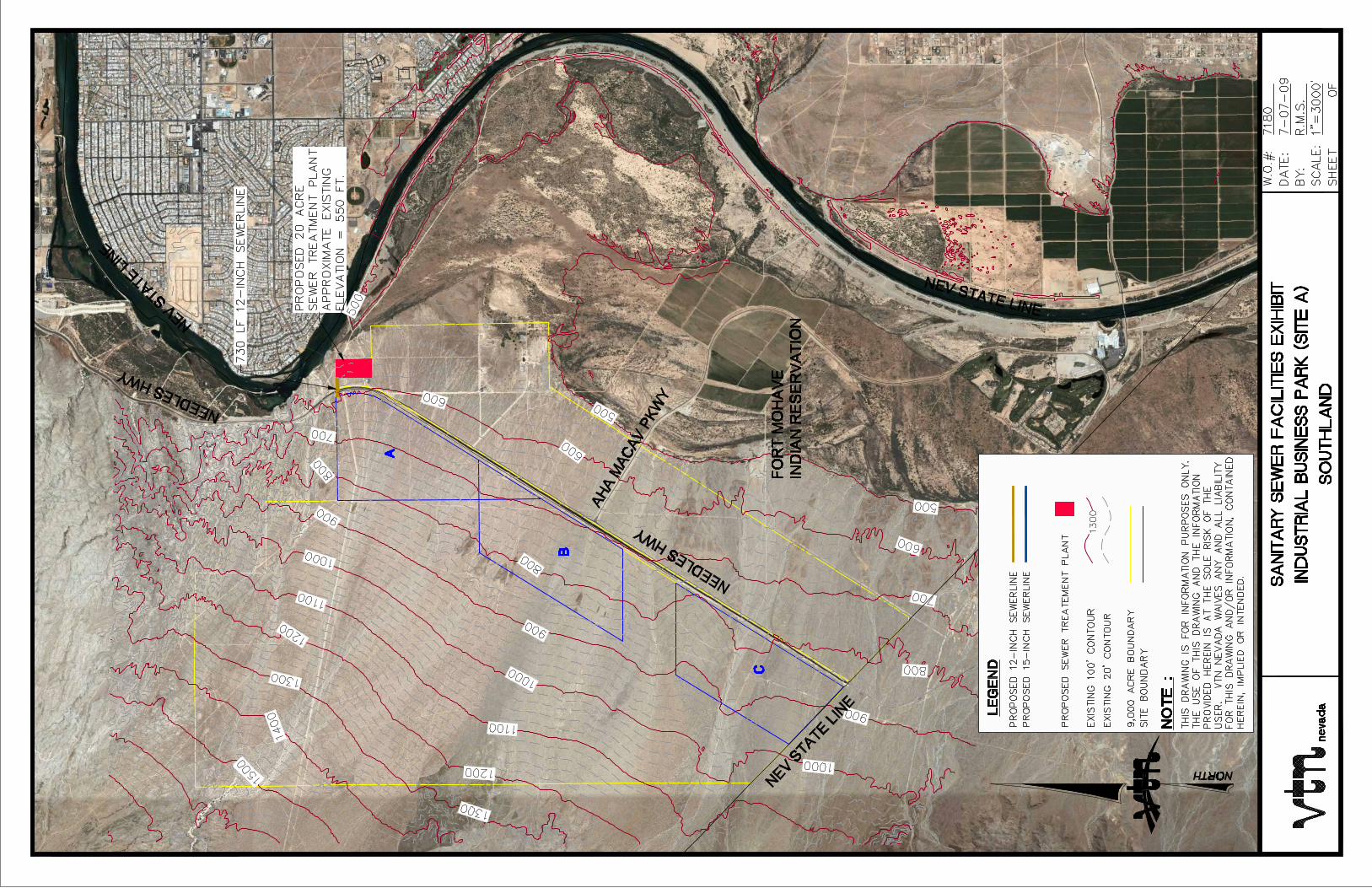

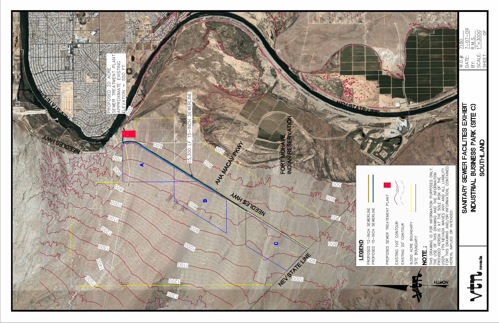
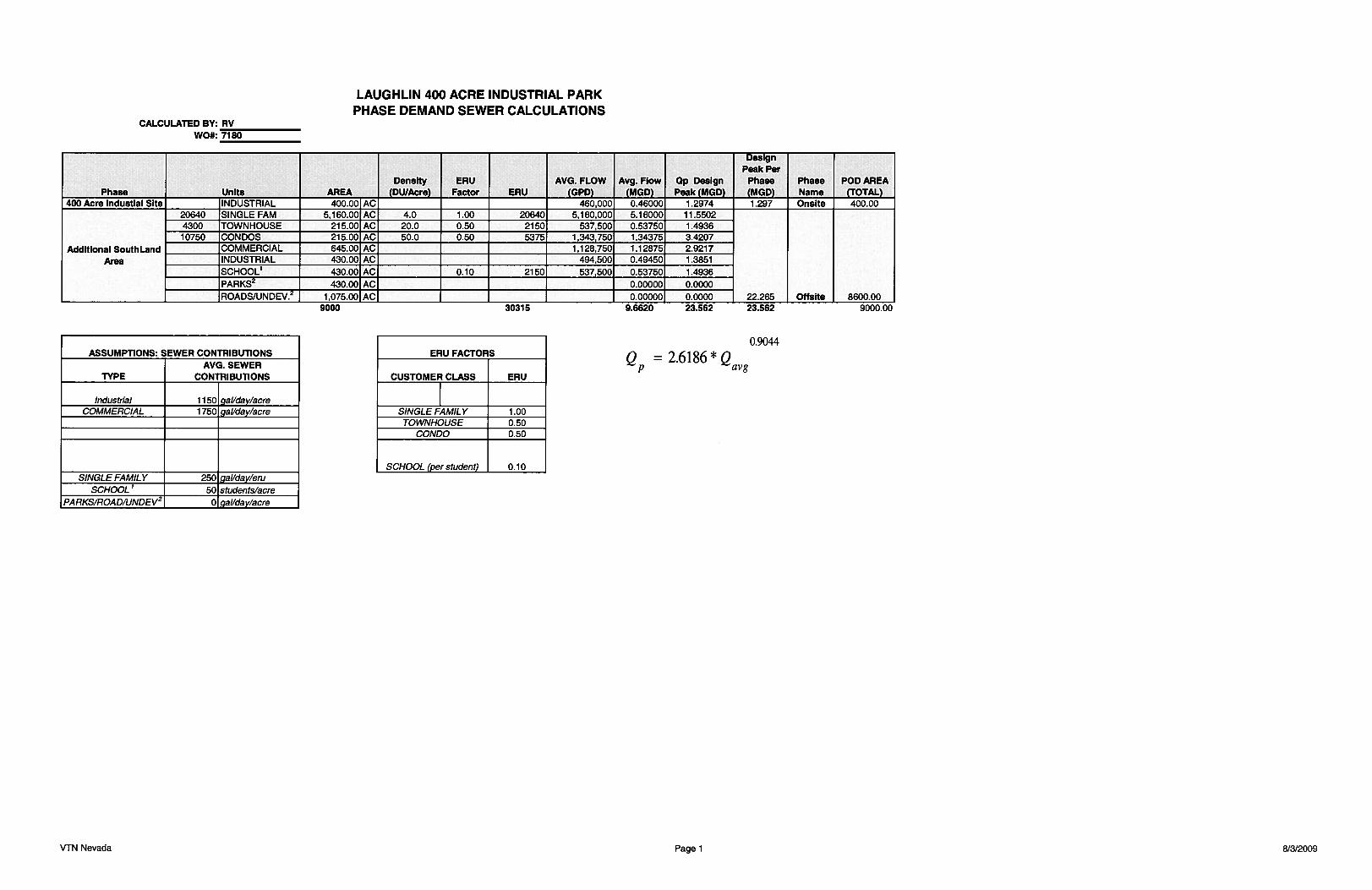
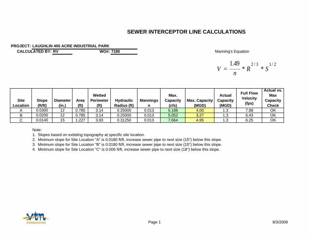
PROJECT: LAUGHLIN 400 ACRE INDUSTRIAL PARKCALCULATED BY: RV WO#: 7180 Manning's Equation
Site Location
Slope (ft/ft)
Diameter (in.)
Area (ft)
Wetted Perimeter
(ft)Hydraulic Radius (ft)
Mannings n
Max. Capacity
(cfs)Max. Capacity
(MGD)
Actual Capacity
(MGD)
Full Flow Velocity
(fps)
Actual vs. Max
Capacity Check
A 0.0300 12 0.785 3.14 0.25000 0.013 6.188 4.00 1.3 7.88 OKB 0.0200 12 0.785 3.14 0.25000 0.013 5.052 3.27 1.3 6.43 OKC 0.0140 15 1.227 3.93 0.31250 0.013 7.664 4.95 1.3 6.25 OK
Note:1. Slopes based on extisting topography at specific site location. 2. Minimum slope for Site Location "A" is 0.0180 ft/ft, increase sewer pipe to next size (15") below this slope.3. Minimum slope for Site Location "B" is 0.0180 ft/ft, increase sewer pipe to next size (15") below this slope.4. Minimum slope for Site Location "C" is 0.006 ft/ft, increase sewer pipe to next size (18") below this slope.
SEWER INTERCEPTOR LINE CALCULATIONS
2/13/2**
49.1SR
nV =
Page 1 8/3/2009

APPENDIX H DRY UTILITIES
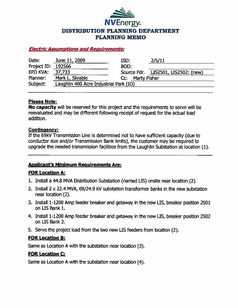
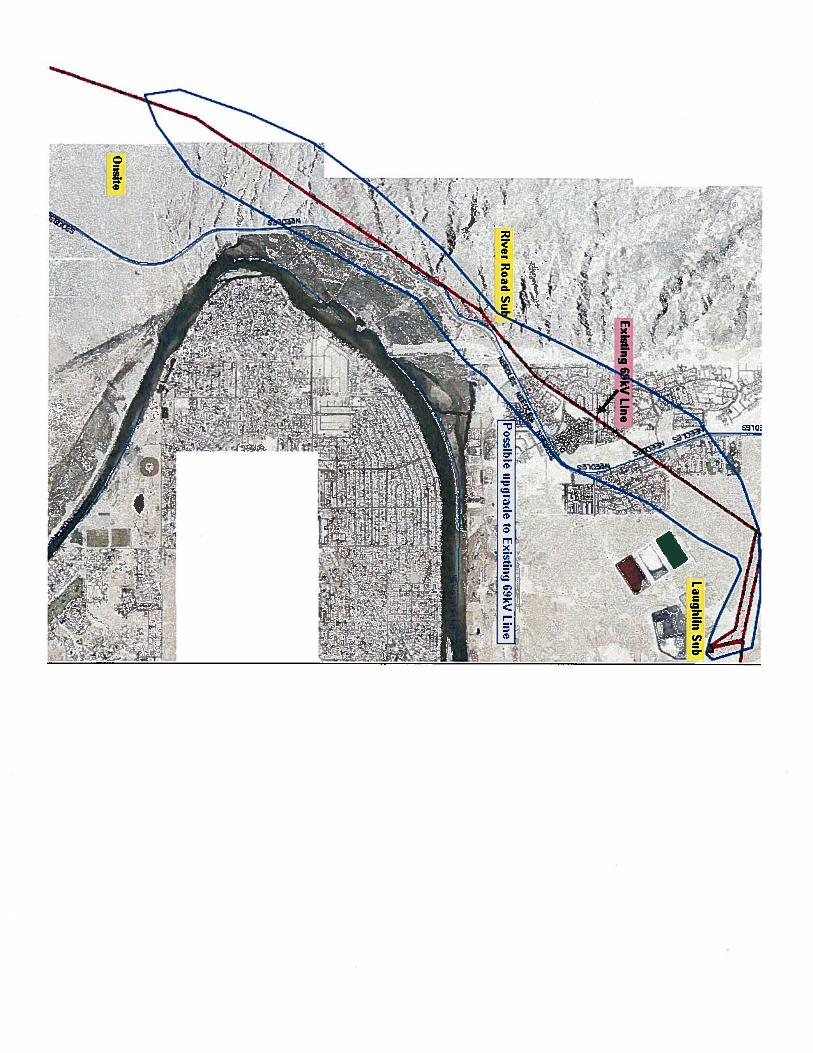
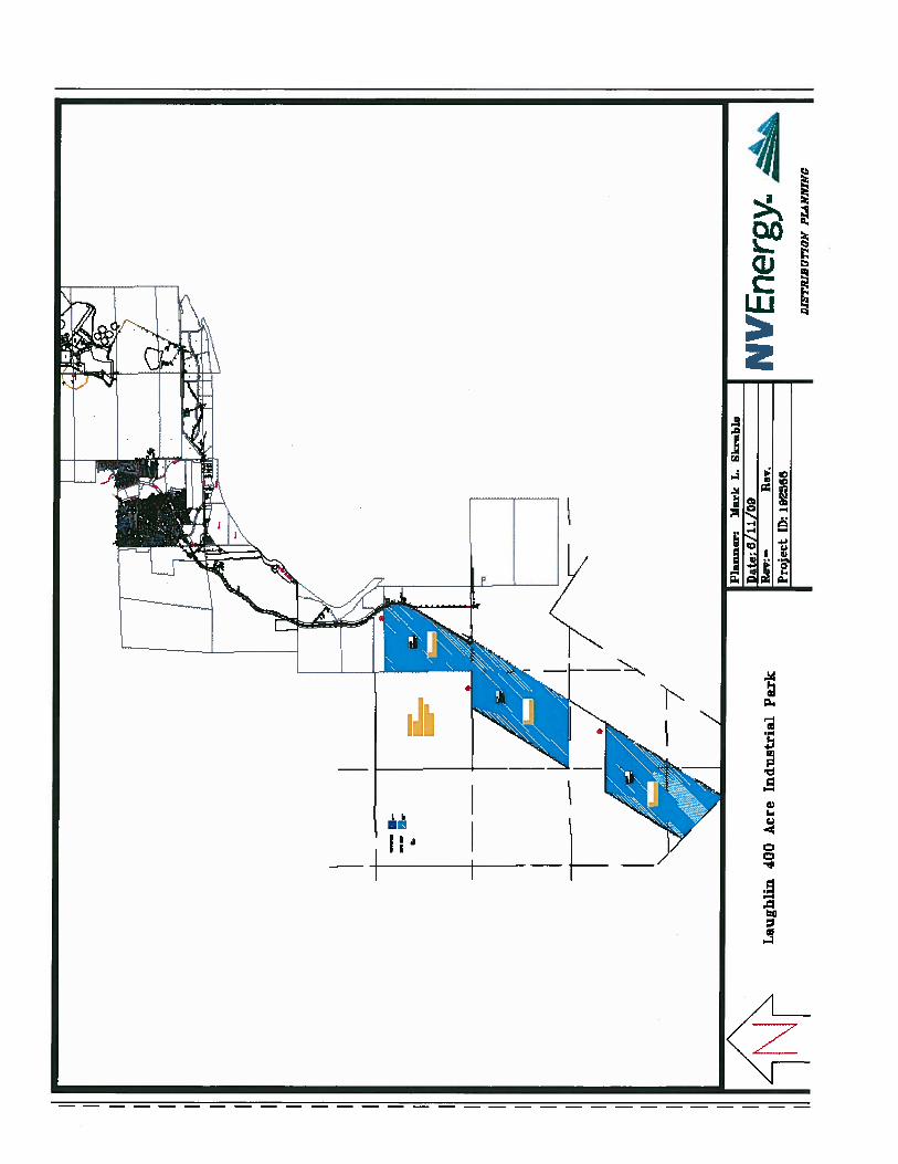
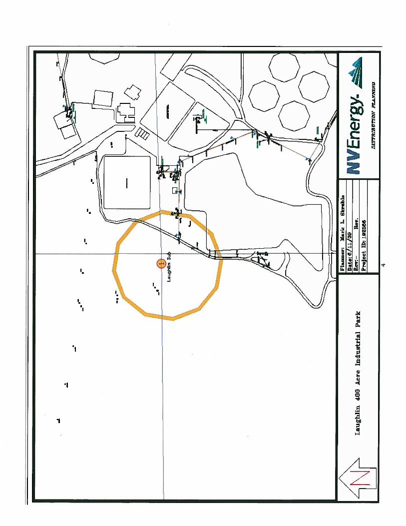
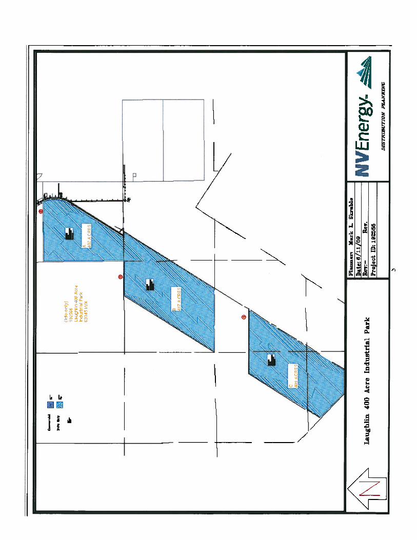
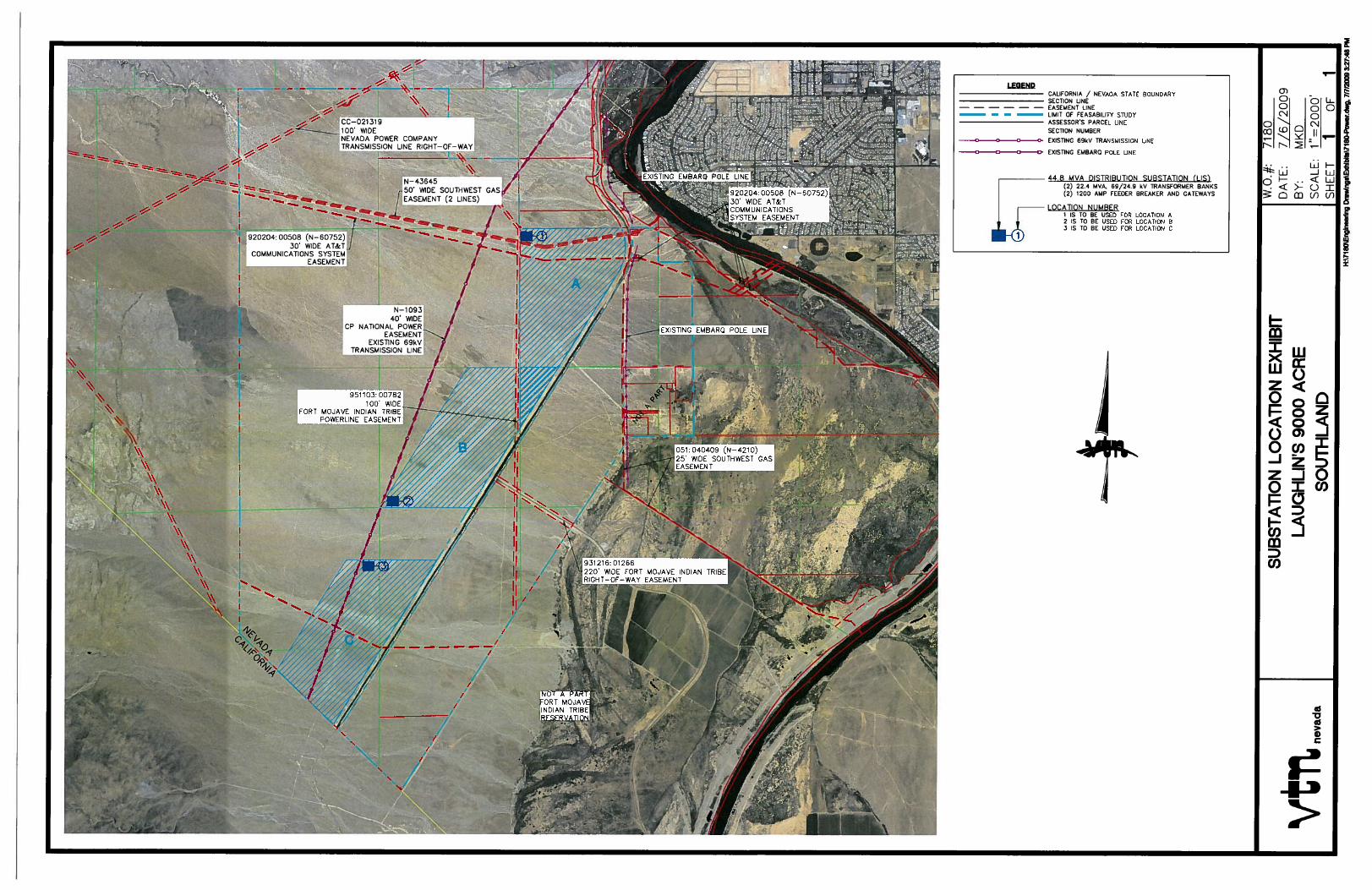
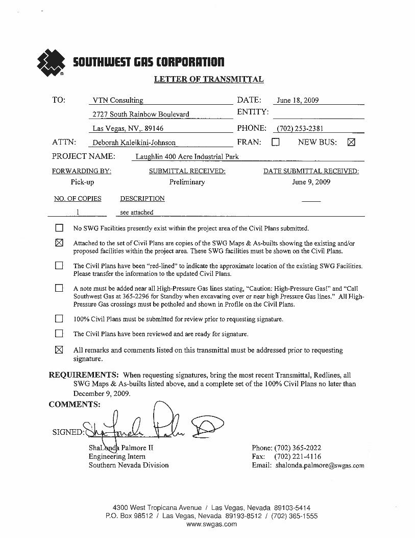
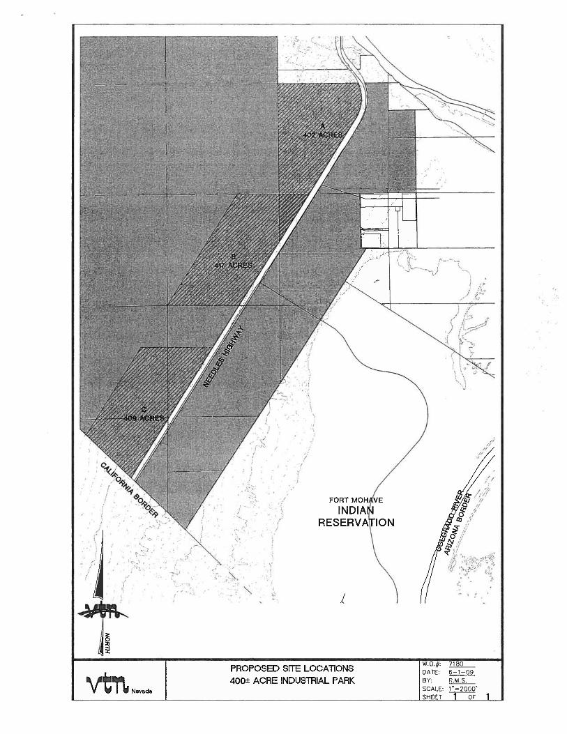
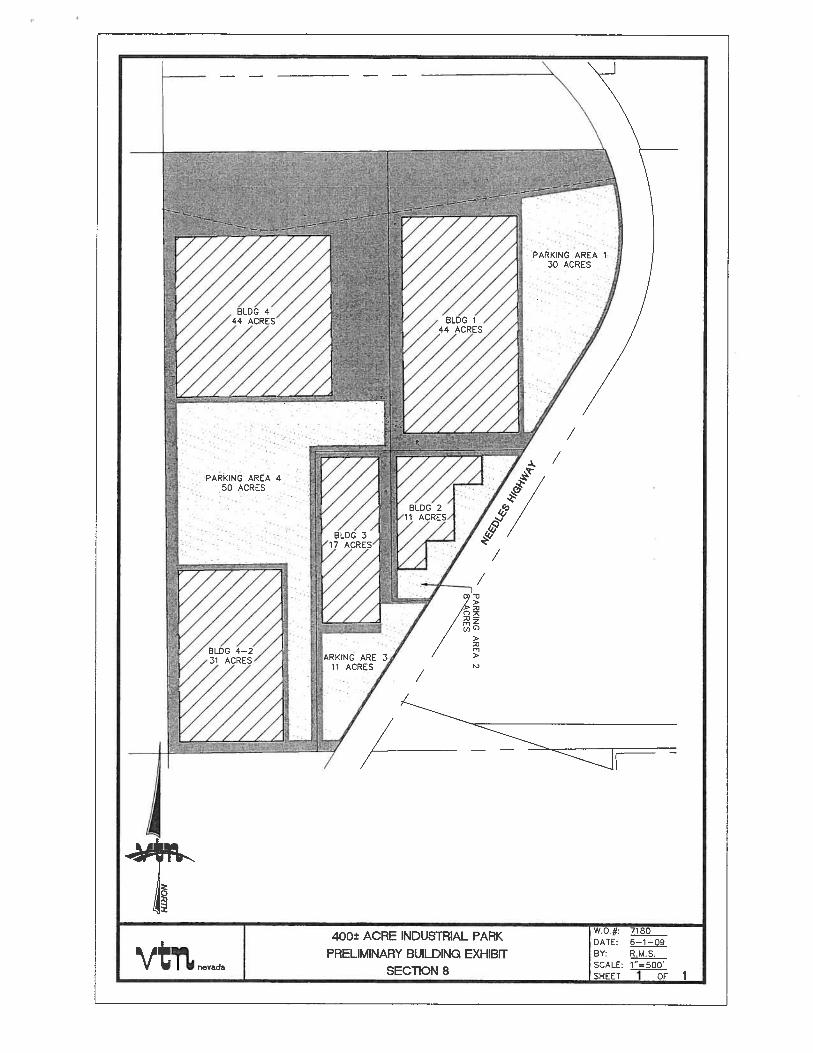
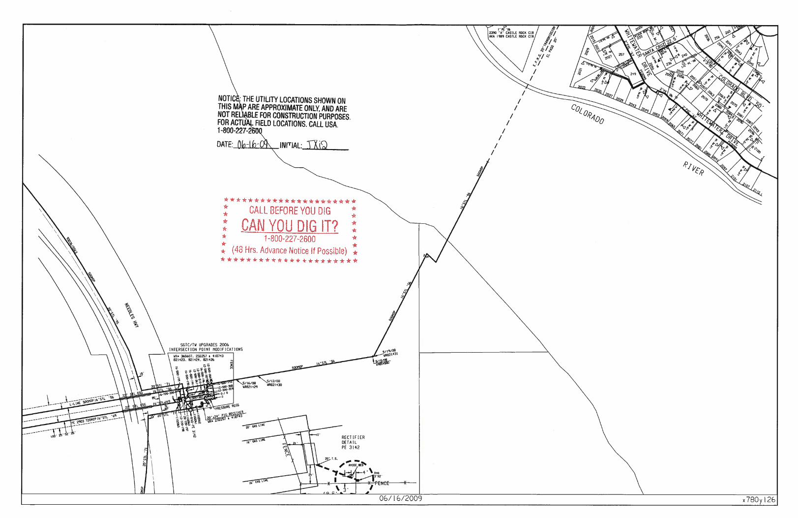
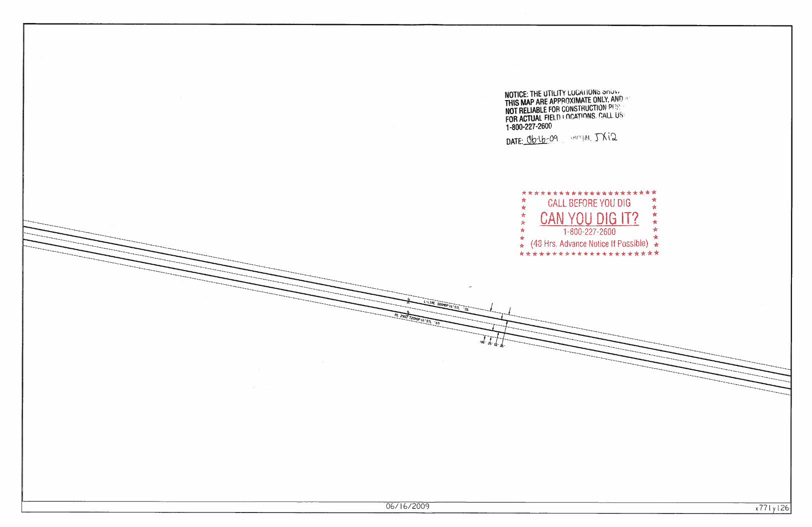
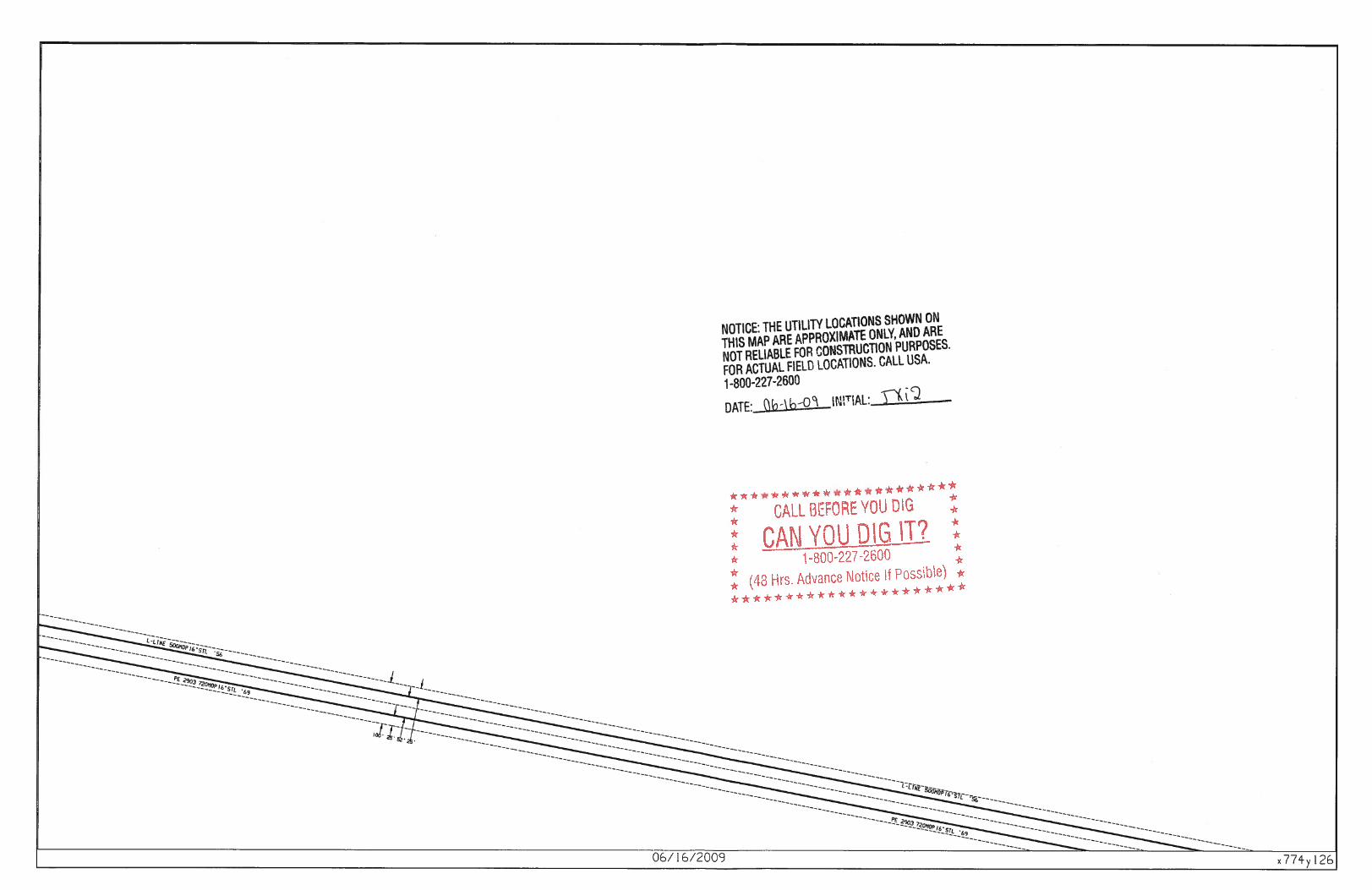
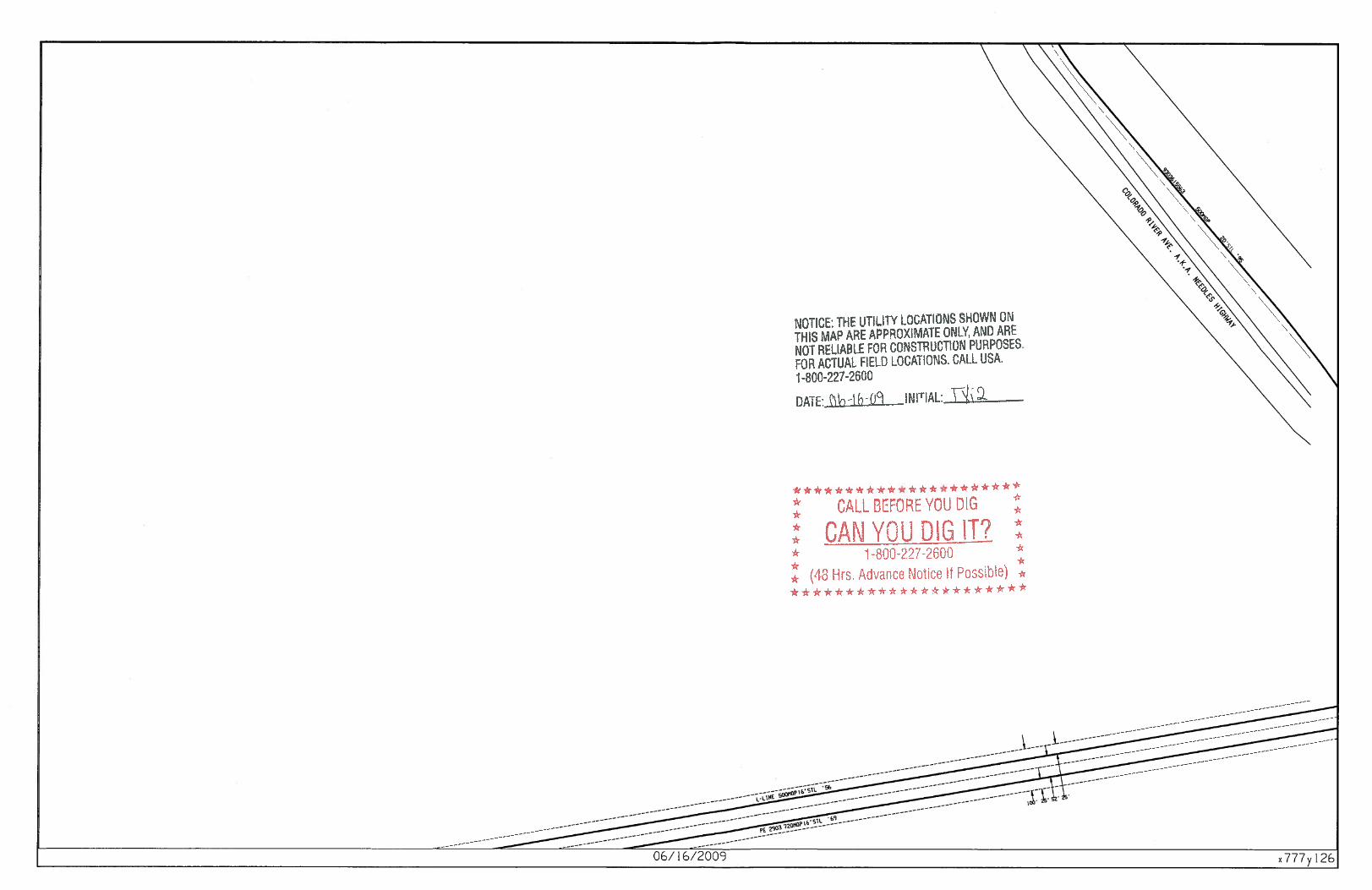
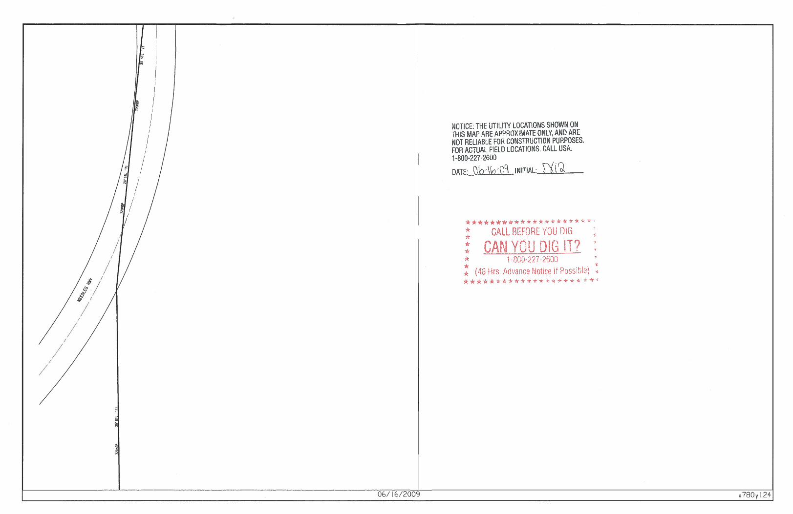

APPENDIX I SURVEY
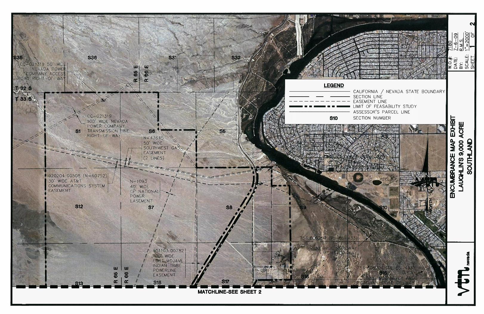
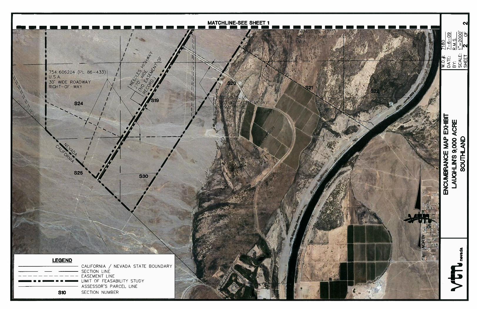

APPENDIX J COST ANALYSIS
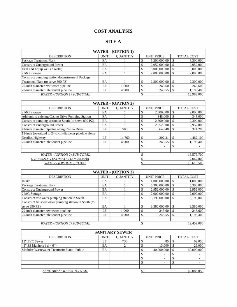
DESCRIPTION UNIT QUANTITY UNIT PRICE TOTAL COSTPackage Treatment Plant EA 1 5,300,000.00$ 5,300,000$ Construct Underground Power EA 1 2,952,000.00$ 2,952,000$ Drill and Equip well (2 wells) EA 1 3,000,000.00$ 3,000,000$ 2 MG Storage EA 1 2,000,000.00$ 2,000,000$ Construct pumping station downstream of Package Treatment Plant (to serve 890 PZ) EA 1 2,300,000.00$ 2,300,000$ 20-inch diameter raw water pipeline LF 1,000 243.60$ 243,600$ 20-inch diameter inlet/outlet pipeline LF 4,900 243.55$ 1,193,400$
DESCRIPTION UNIT QUANTITY UNIT PRICE TOTAL COST2 MG Storage EA 1 2,000,000$ 2,000,000$ Add unit to existing Casino Drive Pumping Station EA 1 345,000$ 345,000$ Construct pumping station in South (to serve 890 PZ) EA 1 2,300,000$ 2,300,000$ Construct Underground Power EA 1 2,952,000$ 2,952,000$ 42-inch diameter pipeline along Casino Drive LF 500 648.40$ 324,200$ 12-inch (oversized to 24-inch) diameter pipeline along Needles Highway LF 14,760 302.31$ 4,462,100$ 20-inch diameter inlet/outlet pipeline LF 4,900 243.55$ 1,193,400$
-$ -$
OVER SIZING ESTIMATE (12 to 24-inch)
DESCRIPTION UNIT QUANTITY UNIT PRICE TOTAL COSTIntake EA 1 1,000,000.00$ 1,000,000$ Package Treatment Plant EA 1 5,300,000.00$ 5,300,000$ Construct Underground Power EA 1 2,952,000.00$ 2,952,000$ 2 MG Storage EA 1 2,000,000.00$ 2,000,000$ Construct raw water pumping station in South EA 1 3,190,000.00$ 3,190,000$ Construct finished water pumping station in South (to serve 890 PZ) EA 1 3,580,000.00$ 3,580,000$ 20-inch diameter raw water pipeline LF 1,000 243.60$ 243,600$ 20-inch diameter inlet/outlet pipeline LF 4,900 243.55$ 1,193,400$
DESCRIPTION UNIT QUANTITY UNIT PRICE TOTAL COST12" PVC Sewer LF 730 85$ 62,050$ 48" SS Manhole ( d > 6' ) EA 2 13,000$ 26,000$ Modular Wastewater Treatment Plant - Public EA 1 40,000,000$ 40,000,000$
-$ -$ -$ -$ -$ -$
SANITARY SEWER SUB-TOTAL 40,088,050$
WATER - (OPTION 2)
WATER - (OPTION 2) SUB-TOTAL 13,576,700$
WATER - (OPTION 3)
15,619,500$
COST ANALYSIS
WATER - (OPTION 1)
SANITARY SEWER
WATER - (OPTION 1) SUB-TOTAL
WATER - (OPTION 3) SUB-TOTAL
2,042,800$ WATER - (OPTION 2) TOTAL
SITE A
19,459,000$
16,989,000$
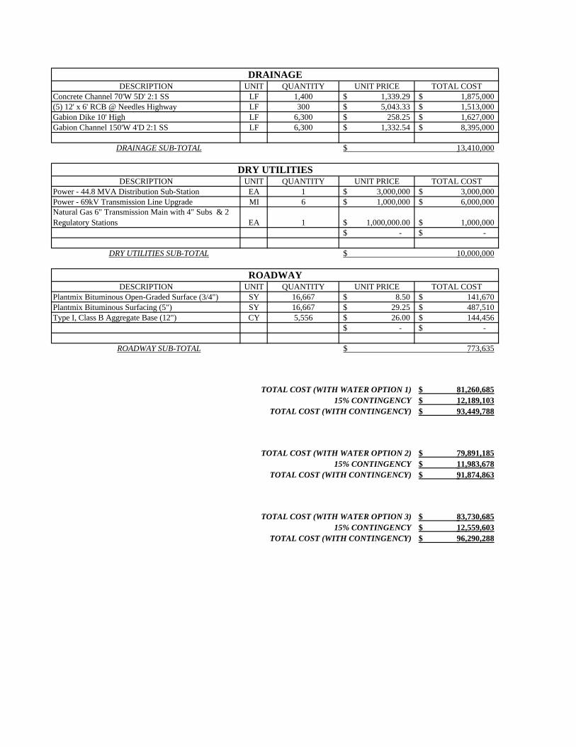
DESCRIPTION UNIT QUANTITY UNIT PRICE TOTAL COSTConcrete Channel 70'W 5D' 2:1 SS LF 1,400 1,339.29$ 1,875,000$ (5) 12' x 6' RCB @ Needles Highway LF 300 5,043.33$ 1,513,000$ Gabion Dike 10' High LF 6,300 258.25$ 1,627,000$ Gabion Channel 150'W 4'D 2:1 SS LF 6,300 1,332.54$ 8,395,000$
DESCRIPTION UNIT QUANTITY UNIT PRICE TOTAL COSTPower - 44.8 MVA Distribution Sub-Station EA 1 3,000,000$ 3,000,000$ Power - 69kV Transmission Line Upgrade MI 6 1,000,000$ 6,000,000$ Natural Gas 6" Transmission Main with 4" Subs & 2 Regulatory Stations EA 1 1,000,000.00$ 1,000,000$
-$ -$
DESCRIPTION UNIT QUANTITY UNIT PRICE TOTAL COSTPlantmix Bituminous Open-Graded Surface (3/4") SY 16,667 8.50$ 141,670$ Plantmix Bituminous Surfacing (5") SY 16,667 29.25$ 487,510$ Type I, Class B Aggregate Base (12") CY 5,556 26.00$ 144,456$
-$ -$
TOTAL COST (WITH WATER OPTION 1) 81,260,685$ 15% CONTINGENCY 12,189,103$
TOTAL COST (WITH CONTINGENCY) 93,449,788$
TOTAL COST (WITH WATER OPTION 2) 79,891,185$ 15% CONTINGENCY 11,983,678$
TOTAL COST (WITH CONTINGENCY) 91,874,863$
TOTAL COST (WITH WATER OPTION 3) 83,730,685$ 15% CONTINGENCY 12,559,603$
TOTAL COST (WITH CONTINGENCY) 96,290,288$
DRAINAGE SUB-TOTAL 13,410,000$
DRY UTILITIES
DRAINAGE
ROADWAY
ROADWAY SUB-TOTAL 773,635$
DRY UTILITIES SUB-TOTAL 10,000,000$
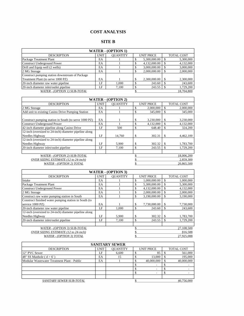
DESCRIPTION UNIT QUANTITY UNIT PRICE TOTAL COSTPackage Treatment Plant EA 1 5,300,000.00$ 5,300,000$ Construct Underground Power EA 1 4,132,000.00$ 4,132,000$ Drill and Equip well (2 wells) EA 1 3,000,000.00$ 3,000,000$ 2 MG Storage EA 1 2,000,000.00$ 2,000,000$ Construct pumping station downstream of Package Treatment Plant (to serve 1000 PZ) EA 1 2,300,000.00$ 2,300,000$ 20-inch diameter raw water pipeline LF 1,000 243.60$ 243,600$ 20-inch diameter inlet/outlet pipeline LF 7,100 243.55$ 1,729,200$
DESCRIPTION UNIT QUANTITY UNIT PRICE TOTAL COST2 MG Storage EA 1 2,000,000$ 2,000,000$ Add unit to existing Casino Drive Pumping Station EA 1 345,000$ 345,000$
Construct pumping station in South (to serve 1000 PZ) EA 1 3,230,000$ 3,230,000$ Construct Underground Power EA 1 4,132,000$ 4,132,000$ 42-inch diameter pipeline along Casino Drive LF 500 648.40$ 324,200$ 12-inch (oversized to 24-inch) diameter pipeline along Needles Highway LF 14,760 302.31$ 4,462,100$ 12-inch (oversized to 24-inch) diameter pipeline along Needles Highway LF 5,900 302.32$ 1,783,700$ 20-inch diameter inlet/outlet pipeline LF 7,100 243.55$ 1,729,200$
OVER SIZING ESTIMATE (12 to 24-inch)
DESCRIPTION UNIT QUANTITY UNIT PRICE TOTAL COSTIntake EA 1 1,000,000.00$ 1,000,000$ Package Treatment Plant EA 1 5,300,000.00$ 5,300,000$ Construct Underground Power EA 1 4,132,000.00$ 4,132,000$ 2 MG Storage EA 1 2,000,000.00$ 2,000,000$ Construct raw water pumping station in South EA 1 3,190,000.00$ 3,190,000$ Construct finished water pumping station in South (to service 1000 PZ) EA 1 7,730,000.00$ 7,730,000$ 20-inch diameter raw water pipeline LF 1,000 243.60$ 243,600$ 12-inch (oversized to 24-inch) diameter pipeline along Needles Highway LF 5,900 302.32$ 1,783,700$ 20-inch diameter inlet/outlet pipeline LF 7,100 243.55$ 1,729,200$
OVER SIZING ESTIMATE (12 to 24-inch)
DESCRIPTION UNIT QUANTITY UNIT PRICE TOTAL COST12" PVC Sewer LF 6,600 85$ 561,000$ 48" SS Manhole ( d > 6' ) EA 15 13,000$ 195,000$ Modular Wastewater Treatment Plant - Public EA 1 40,000,000$ 40,000,000$
-$ -$ -$ -$ -$ -$
COST ANALYSIS
WATER - (OPTION 1)
SANITARY SEWER
WATER - (OPTION 1) SUB-TOTAL
WATER - (OPTION 3) SUB-TOTAL
2,859,300$ WATER - (OPTION 2) TOTAL
816,588$ 27,925,088$ WATER - (OPTION 3) TOTAL
SITE B
27,108,500$
SANITARY SEWER SUB-TOTAL 40,756,000$
WATER - (OPTION 2)
WATER - (OPTION 2) SUB-TOTAL 18,006,200$
WATER - (OPTION 3)
18,704,800$
20,865,500$
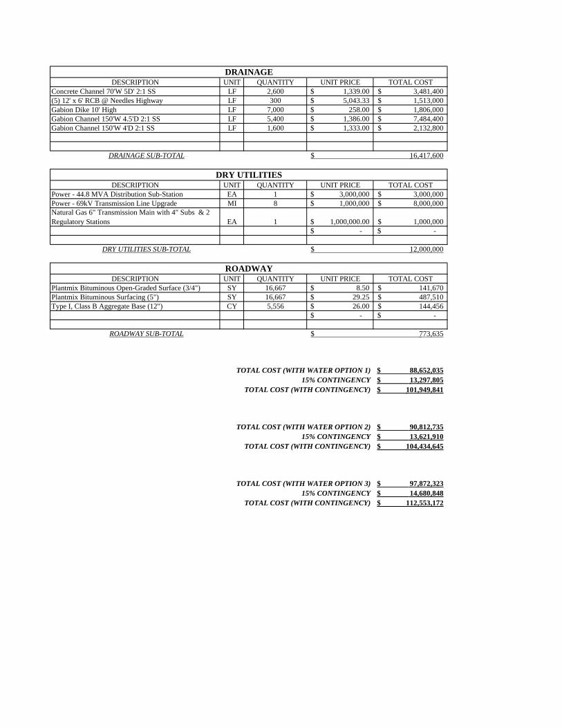
DESCRIPTION UNIT QUANTITY UNIT PRICE TOTAL COSTConcrete Channel 70'W 5D' 2:1 SS LF 2,600 1,339.00$ 3,481,400$ (5) 12' x 6' RCB @ Needles Highway LF 300 5,043.33$ 1,513,000$ Gabion Dike 10' High LF 7,000 258.00$ 1,806,000$ Gabion Channel 150'W 4.5'D 2:1 SS LF 5,400 1,386.00$ 7,484,400$ Gabion Channel 150'W 4'D 2:1 SS LF 1,600 1,333.00$ 2,132,800$
DESCRIPTION UNIT QUANTITY UNIT PRICE TOTAL COSTPower - 44.8 MVA Distribution Sub-Station EA 1 3,000,000$ 3,000,000$ Power - 69kV Transmission Line Upgrade MI 8 1,000,000$ 8,000,000$ Natural Gas 6" Transmission Main with 4" Subs & 2 Regulatory Stations EA 1 1,000,000.00$ 1,000,000$
-$ -$
DESCRIPTION UNIT QUANTITY UNIT PRICE TOTAL COSTPlantmix Bituminous Open-Graded Surface (3/4") SY 16,667 8.50$ 141,670$ Plantmix Bituminous Surfacing (5") SY 16,667 29.25$ 487,510$ Type I, Class B Aggregate Base (12") CY 5,556 26.00$ 144,456$
-$ -$
TOTAL COST (WITH WATER OPTION 1) 88,652,035$ 15% CONTINGENCY 13,297,805$
TOTAL COST (WITH CONTINGENCY) 101,949,841$
TOTAL COST (WITH WATER OPTION 2) 90,812,735$ 15% CONTINGENCY 13,621,910$
TOTAL COST (WITH CONTINGENCY) 104,434,645$
TOTAL COST (WITH WATER OPTION 3) 97,872,323$ 15% CONTINGENCY 14,680,848$
TOTAL COST (WITH CONTINGENCY) 112,553,172$
ROADWAY
ROADWAY SUB-TOTAL 773,635$
DRY UTILITIES SUB-TOTAL 12,000,000$
DRAINAGE SUB-TOTAL 16,417,600$
DRY UTILITIES
DRAINAGE
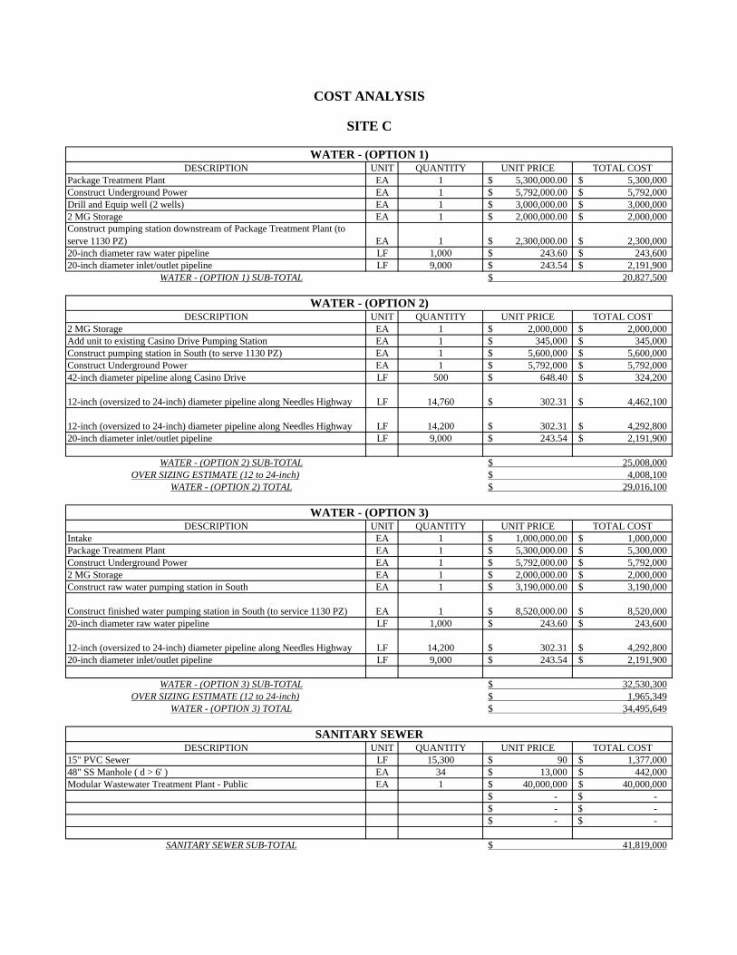
DESCRIPTION UNIT QUANTITY UNIT PRICE TOTAL COSTPackage Treatment Plant EA 1 5,300,000.00$ 5,300,000$ Construct Underground Power EA 1 5,792,000.00$ 5,792,000$ Drill and Equip well (2 wells) EA 1 3,000,000.00$ 3,000,000$ 2 MG Storage EA 1 2,000,000.00$ 2,000,000$ Construct pumping station downstream of Package Treatment Plant (to serve 1130 PZ) EA 1 2,300,000.00$ 2,300,000$ 20-inch diameter raw water pipeline LF 1,000 243.60$ 243,600$ 20-inch diameter inlet/outlet pipeline LF 9,000 243.54$ 2,191,900$
DESCRIPTION UNIT QUANTITY UNIT PRICE TOTAL COST2 MG Storage EA 1 2,000,000$ 2,000,000$ Add unit to existing Casino Drive Pumping Station EA 1 345,000$ 345,000$ Construct pumping station in South (to serve 1130 PZ) EA 1 5,600,000$ 5,600,000$ Construct Underground Power EA 1 5,792,000$ 5,792,000$ 42-inch diameter pipeline along Casino Drive LF 500 648.40$ 324,200$
12-inch (oversized to 24-inch) diameter pipeline along Needles Highway LF 14,760 302.31$ 4,462,100$
12-inch (oversized to 24-inch) diameter pipeline along Needles Highway LF 14,200 302.31$ 4,292,800$ 20-inch diameter inlet/outlet pipeline LF 9,000 243.54$ 2,191,900$
OVER SIZING ESTIMATE (12 to 24-inch)
DESCRIPTION UNIT QUANTITY UNIT PRICE TOTAL COSTIntake EA 1 1,000,000.00$ 1,000,000$ Package Treatment Plant EA 1 5,300,000.00$ 5,300,000$ Construct Underground Power EA 1 5,792,000.00$ 5,792,000$ 2 MG Storage EA 1 2,000,000.00$ 2,000,000$ Construct raw water pumping station in South EA 1 3,190,000.00$ 3,190,000$
Construct finished water pumping station in South (to service 1130 PZ) EA 1 8,520,000.00$ 8,520,000$ 20-inch diameter raw water pipeline LF 1,000 243.60$ 243,600$
12-inch (oversized to 24-inch) diameter pipeline along Needles Highway LF 14,200 302.31$ 4,292,800$ 20-inch diameter inlet/outlet pipeline LF 9,000 243.54$ 2,191,900$
OVER SIZING ESTIMATE (12 to 24-inch)
DESCRIPTION UNIT QUANTITY UNIT PRICE TOTAL COST15" PVC Sewer LF 15,300 90$ 1,377,000$ 48" SS Manhole ( d > 6' ) EA 34 13,000$ 442,000$ Modular Wastewater Treatment Plant - Public EA 1 40,000,000$ 40,000,000$
-$ -$ -$ -$ -$ -$
SITE C
32,530,300$
SANITARY SEWER SUB-TOTAL 41,819,000$
WATER - (OPTION 2)
WATER - (OPTION 2) SUB-TOTAL 25,008,000$
WATER - (OPTION 3)
20,827,500$
29,016,100$
COST ANALYSIS
WATER - (OPTION 1)
SANITARY SEWER
WATER - (OPTION 1) SUB-TOTAL
WATER - (OPTION 3) SUB-TOTAL
4,008,100$ WATER - (OPTION 2) TOTAL
1,965,349$ 34,495,649$ WATER - (OPTION 3) TOTAL
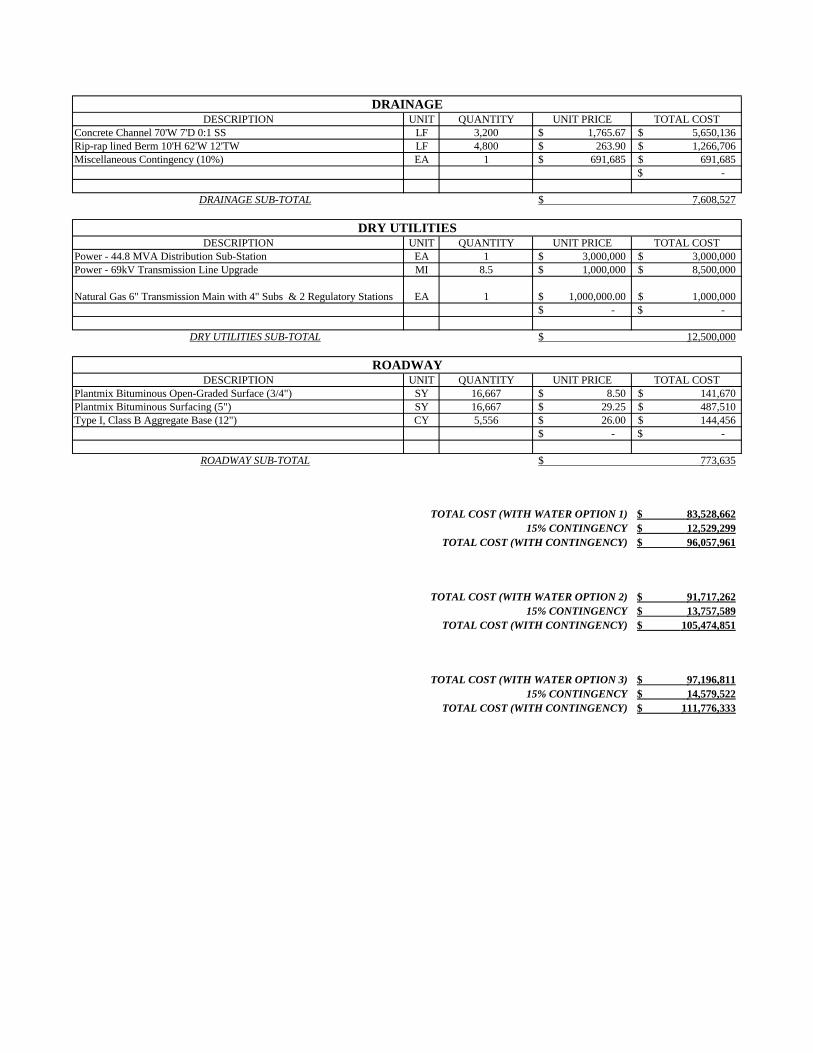
DESCRIPTION UNIT QUANTITY UNIT PRICE TOTAL COSTConcrete Channel 70'W 7'D 0:1 SS LF 3,200 1,765.67$ 5,650,136$ Rip-rap lined Berm 10'H 62'W 12'TW LF 4,800 263.90$ 1,266,706$ Miscellaneous Contingency (10%) EA 1 691,685$ 691,685$
-$
DESCRIPTION UNIT QUANTITY UNIT PRICE TOTAL COSTPower - 44.8 MVA Distribution Sub-Station EA 1 3,000,000$ 3,000,000$ Power - 69kV Transmission Line Upgrade MI 8.5 1,000,000$ 8,500,000$
Natural Gas 6" Transmission Main with 4" Subs & 2 Regulatory Stations EA 1 1,000,000.00$ 1,000,000$ -$ -$
DESCRIPTION UNIT QUANTITY UNIT PRICE TOTAL COSTPlantmix Bituminous Open-Graded Surface (3/4") SY 16,667 8.50$ 141,670$ Plantmix Bituminous Surfacing (5") SY 16,667 29.25$ 487,510$ Type I, Class B Aggregate Base (12") CY 5,556 26.00$ 144,456$
-$ -$
TOTAL COST (WITH WATER OPTION 1) 83,528,662$ 15% CONTINGENCY 12,529,299$
TOTAL COST (WITH CONTINGENCY) 96,057,961$
TOTAL COST (WITH WATER OPTION 2) 91,717,262$ 15% CONTINGENCY 13,757,589$
TOTAL COST (WITH CONTINGENCY) 105,474,851$
TOTAL COST (WITH WATER OPTION 3) 97,196,811$ 15% CONTINGENCY 14,579,522$
TOTAL COST (WITH CONTINGENCY) 111,776,333$
DRAINAGE SUB-TOTAL 7,608,527$
DRY UTILITIES
DRAINAGE
ROADWAY
ROADWAY SUB-TOTAL 773,635$
DRY UTILITIES SUB-TOTAL 12,500,000$

APPENDIX K PRELIMINARY SITE PLAN