Embed Size (px)
Citation preview

1
Interim Action Work Plan February 2015
SOUTH TRANSFER STATION PHASE II PROJECT (STSII)

2
Interim Action Work Plan
AGENDA
Current Site Status
Purpose and Objectives
Site Background
Interim Action Work Plan
Capping Control Elements
LFG Control Technologies
Existing LFG Control Systems and Conditions
Proposed Interim Action Approach

3
Current Site Status

4
Purpose and Objectives
SPU proposes to re-purpose the 11 acre site
Demolish existing structures and pavement
Cover system elements
LFG controls
Future use to accommodate several SPU services and functions.

5

6
Section D-D’

7
Site Cross Section
Refuse thickness approx. 15 feet thick

8
Perimeter Probes
Methane in easterly probes has not been detected (since 1999)

9
Interim Action Work Plan
Cap to mitigate exposure, infiltration, and LFG migration
LFG Control System to mitigate lateral (offsite) and vertical migration
Integrate with SPPD, KIP, and adjacent control systems
Separate occupied building control systems
Mitigate preferential pathways (utilities)

10
Potential Capping Systems
Warning/Identifier layer and soil cover
Geomembrane and Soil cover
Asphalt/Concrete barriers
Geotextiles with spray on barriers
Buildings Foundations/slabs
Landscape areas allowing venting

11
LFG Control
Active – blower vacuum control
Passive – atmospheric venting
Combined
Passive System
Sized for active vacuum flows
Manifolded for zone control
Valved to easily allow passive-to-active conversion

12
Typical LFG Collection
Wells Trenches
Localized extraction/venting
control (limited ROI)
Continuous extraction/venting control
Can fully penetrate refuse Can be installed with and without liners
Can add, as needed Not affected by groundwater table
More effective in landfills with
deeper refuse
No specialized certification for contractor
installation
Commonly used with active
collection systems
Used for active and passive perimeter
control and interior collection

13
Typical LFG Treatment
Direct venting
Dispersion
Bioberm (odor control and degradation)
GAC (odor control)
Flare (>20% methane – utility or enclosed flares) – Not applicable at this site

14
Existing Systems (SPPD and KIP)
High flow active system on SPPD
KIP has had ACP cover since approx. 1968

15
SPPD – High Flow Active Collection
Gridded well system
Perimeter wells
Shallow collector trenches
Buildings connected to site system

16
Proposed Interim Action Approach

17

18
KIP
SPPD
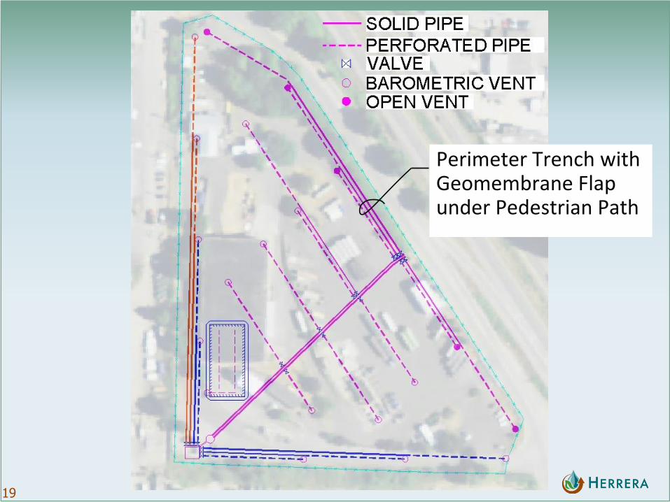
19
Perimeter Trench with Geomembrane Flap under Pedestrian Path

20
Perimeter Trench with Membrane Flap

21
Example Liner Construction
Pedestrian Trail – West Seattle

22
Perimeter Trench with Asphalt Cover

23
Perimeter Trench with Asphalt Cover

24
Shallow Trench

25
Shallow Trench
With Asphalt Cover With Membrane

26
Active/Passive Valve Box

27
Active/Passive Valve Box

28
Open Vent

29
Open Vent
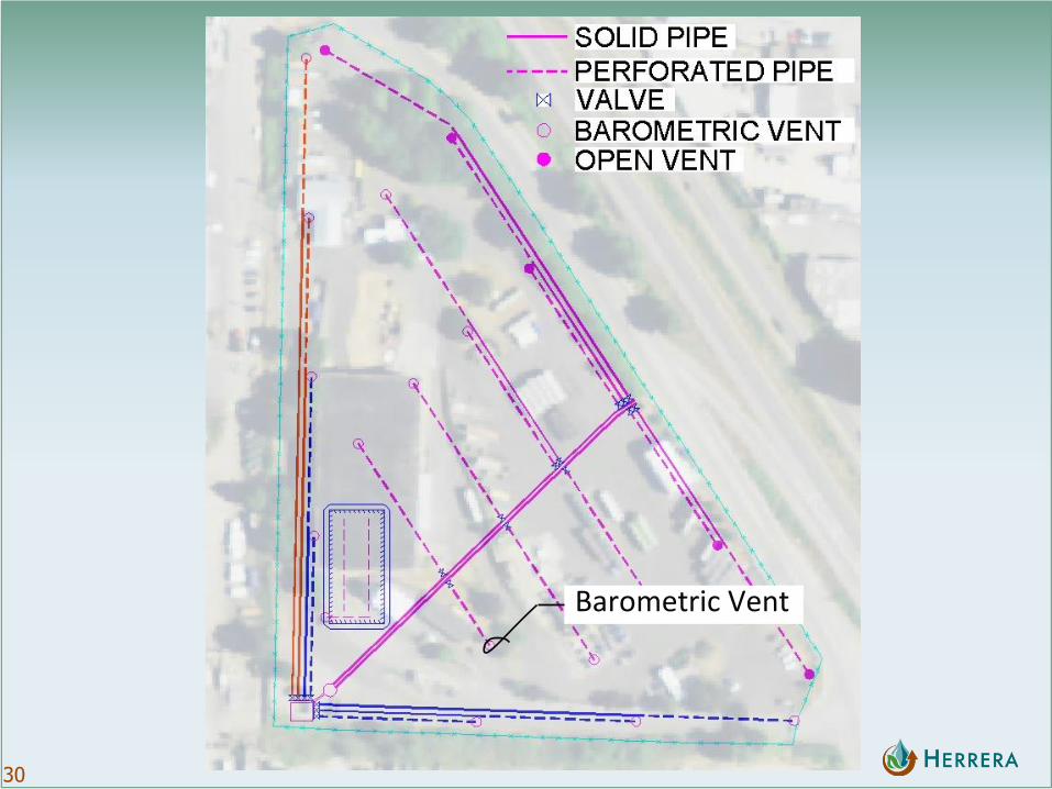
30
Barometric Vent

31
Barometric Vent

32
Example Building

33
Building – Under Slab Collection Piping and Liners

34
Building - Under Slab Collection Piping

35
Building – Liner Under Pile Caps

36
Building - Membrane
Liquid Boot, PVC, HDPE

37
Building – Example Methane Detector and Alarms

38
Building – Example Methane Detectors
39
Utilities
Utilities to be constructed in pre-excavated corridors to allow future maintenance without exposure.
Identifier layer in trenches for cover system separation
Trench plugs to mitigate migration
Conduit seal-offs
Utility pipe flex-Joints

40
Utility Corridor
WITH ASPHALT COVER WITH SOIL COVER

41
Utility Trench Seal