Embed Size (px)
Citation preview

South Shore Testing & Hnvironmental23811 Washington Ave, Suite C110, #112, Murrieta, CA 92562Phone: (951) 239-3008 FAX: (951) 239-3122
February 24, 2020
M. Rich WilsonTrademark Construction Co., Inc.15916 Bemardo Center IhiveSan Diego, CA 92127
E-mail: ss.testing@,aol.coin
SUBJHCT: ONSITE STORM\VATER INFILTRATION SYSTEM INVESTIGATIONProposed Multi-Family Residential DevelopmentAPN: 339-200-080, 9.92-AcresNE Comer of Berea and Normandy RoadsCity of Menifee, RIverside County, CaliforniaWork Order No. 4722002.01
Dear M. Wilson:
In accordance with your authorization, we have conducted percolation testing for the infiltrationaystem for the proposed multi-family residential development. The purpose of our investigationwas to provide infiltration rates for proposed infiltration systems. The proposed infiltration testareas were designated on a 40-scale Conceptual Site Plan (Summa Architecture, 2019) by theproject civil engineer, Kolibrien Civil, Structural, and Surveying of Temecula, California.
Site Description
The subject site is a nearly square-shaped, 9.92-acre parcel of land located the northeast comer ofBrea and Nomandy Roads in the city of Menifee, RIverside County, California. The site isbordered on the north by a flood control channel and an existing single-finily residential tract, onthe west by Berea Road and a mini-storage facility, on the south by Normandy Road and a park, andon the east by vacant undeveloped land.
Topographically on the subject site, for the most part, consists of low rolling gently slopingterrain with natural gradients of less than 5 percent. The southeast comer of the site consists of asmall hill with numerous large unweathered granitic boulders up to 20-ft in diameter. Naturalgradients on the hill are approximately 15 percent. Drainage is accomplished by sheet flow to thenorthwest toward Berea Road and the flood control channel. Vegetation onsite generallyconsists of a sparse to moderate low dried growth of annual weeds and grasses.
South Shore Testing & Environmental W.O. NO. 4722002.01

M. Rich WilsonTrademark Construction Co., Inc.February 24, 2020Page 2
Proposed Development
TThe proposed development consists of the construction of a multi-family residential developmentwith interior parking and driveways, a 3-story commercial building, a fitness building, aclubhouse, a recreation area, and landscape area. The Conceptual Site Plan (Summa, 2019)depicts the extreme southeast comer of the site, which is underlain by numerous graniticboulders, is to remain vacant and in a relatively natural condition.
Percolation Investigation-,
Percolation testing was conducted on January 31, 2020 at locations designated by the project civilengineer. Six (6) tests were performed within the ousite late to middle Pleistocene-nee Old alluvialfan deposits (Morton, 2003) on the northerly portion of the subject site. Six (6) exploratory trencheswere advanced to a depth of 3-ft below the ground surface @gs) with an infiltration test performedat the bottom of each trench. The Old alluvial fan deposits, for the most part, consisted of silty Sand(Unified Soil Classification - SM) that can generally be described as red to orange brown, fine tocoarse grained, minor gravel size, abundant fines, dry (top 1-ft) to slightly moist, loose(top 2-ft) tomedium dense to very dense and excavated with slight difficulty. Approximately 0.5 to 1-ft ofundocumented fills were observed overlying the Old alluvial fan deposits in most areas. Infiltrationtest pits were advanced to a depth of 36-ft bgs utilizing a Case No. 590 extenda-backhoe equippedwith a 18-inch bucket. Our field personnel logged the exploratory trenches and a copies of ourExploratory Trench Logs are presented in Appendix 8.
GROUNDWATER
Groundwater was not encountered to the maximum depth explored of 16.2-ft below the groundsurface (bgs) previously excavated on the northerly portion of the subject site (T.H.E., 2003).Based on historic regional groundwater information (DWR,1978), regional high groundwater isat least 100-ft bgs on the lower elevations of the subject site. Minor fluctuations can and willlikely occur in moisture or free water content of the soil owing to rainfall and irrigation overtime.
SUMMARY OF TEST PROCEDURES
The testing procedure was perfomed in accordance with Riverside County Department ofEnvironmental Health's "Local Management Program for Onsite Wastewater Treatment Systems",which became effective October 5, 2016 and the resulting perc rates were converted to infiltrationrates utilizing the Porchet Method as outlined in the RIverside County Flood Control and WaterConservation District, "Design Handbook for Low Impact Development Best ManagementPractices" dated September 2011. The percolation tests were performed at a depth of 3-ft bgs ®er
South Shore Testing & Environmental W.O. NO:4722002.01 I
Mr. Rich WilsonTrademark Construction Co., Inc.February 24, 2020Page 3
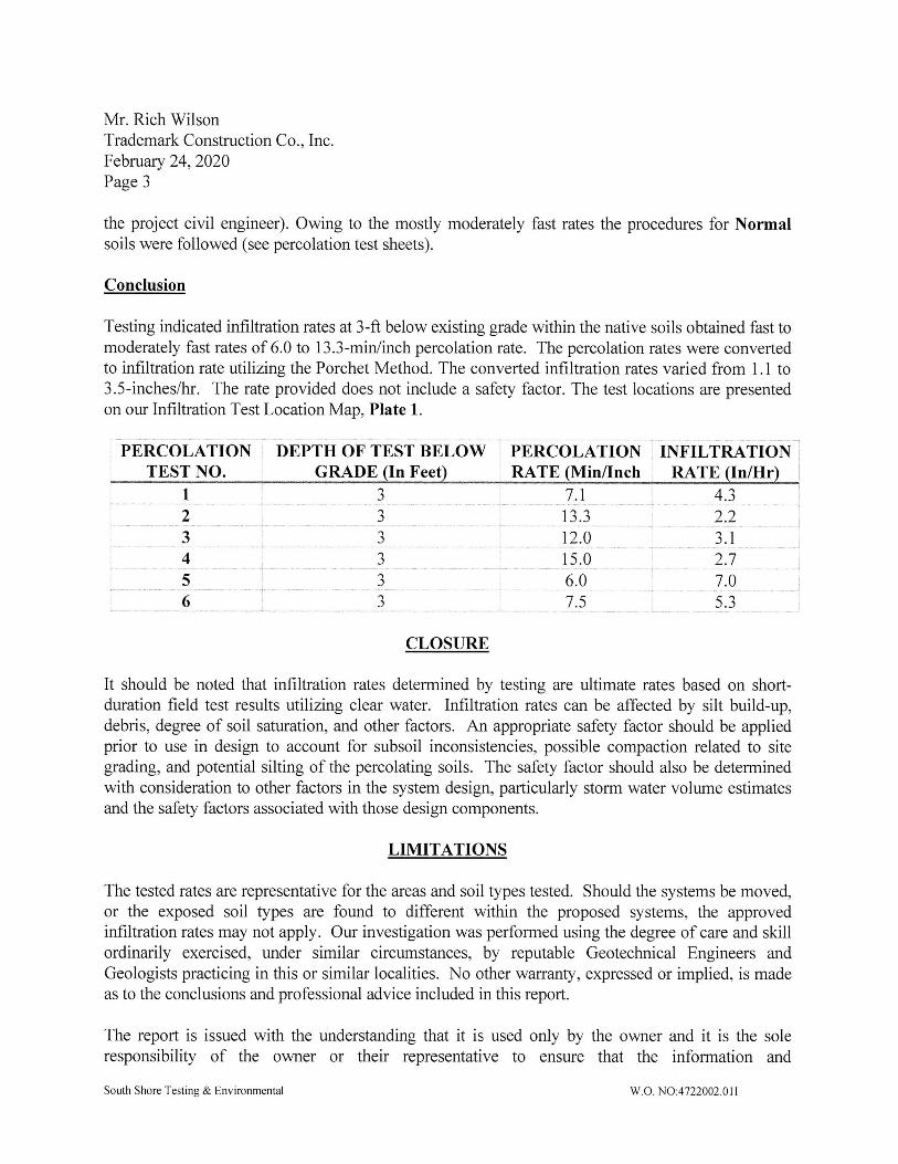
the project civil engineer). Owing to the mostly moderately fast rates the procedures for Normalsoils were followed (see percolation test sheets).
Conclusion
Testing indicated infiltration rates at 3-ft below existing grade within the native soils obtained fast tomoderately fast rates of 6.0 to 13.3-min/inch percolation rate. The percolation rates were convertedto infiltration rate utilizing the Porchet Method. The converted infiltration rates varied from 1.1 to3.5-inches/hr. The rate provided does not include a safety factor. The test locations are presentedon our Infiltration Test Location Map, Plate 1.
inn_piH _6_i: PERCOLATION ;TEST NO.i---I_-i-`TT
i---------------------rf--
TEST BELOW i PERCOLATION ; INFILTRATIONGRADE (In Feet` ; RATE (MinITnch i RATE /InAlr
7.1,-------------- + ------
13.3
i2_.b
CLOSURE
It should be noted that infiltration rates determined by testing are ultimate rates based on short-duration field test results utilizing clear water. Infiltration rates can be affected by silt build-up,debris, degree of soil saturation, and other factors. An appropriate safety factor should be appliedprior to use in design to account for subsoil inconsistencies, possible compaction related to sitegrading, and potential silting of the percolating soils. The safety factor should also be determinedwith consideration to other factors in the system design, particularly storm water volume estimatesand the safety factors associated with those design components.
LIMITATIONS
The tested rates are representative for the areas and soil types tested. Should the systems be moved,or the exposed soil types are found to different within the proposed systems, the approvedinflltration rates may not apply. Our investigation was performed using the degree of care and skillordinarily exercised, under similar circumstances, by reputable Geotechnical Engineers andGeologists practicing in this or similar localities. No other warranty, expressed or implied, is madeas to the conclusions and professional advice included in this report.
The report is issued with the understanding that it is used only by the owner and it is the soleresponsibility of the owner or their representative to ensure that the information and
South Shore Testing & Environmental W.O. NO:4722002.01 I

EI-EHEEioE.1-
EE-<?`+
•uctts"#!
i=E
=EH-i`
R&i=Z*s3Z*J\i.a.EE3B
- \itEEEEEi!D=EEiEEEiEEiE:E~EE=DE.Eon-oEo=D=
;I1!
"'roal
OEIE
i-d`.;t
LJE=E=
DEE]-iEi.iEi.EE
++r`
E
\'iBEiE=-
r,
`\#.¥
I
BiEED
EEEen
i±EEEEE!E]illoEEBi=EBIiEBDEB
E=-EEOD
DEB
-E5n^`
EBEEHEEEB¥ti=
BB=BE=|
`B0'5'
•E=
EEEETEVan3IN
E 'ffiilHIIith,I,i-IiiBEHiEI||EEEEE11,1:!1,`i`ll',,",,
=E,.H|EFiiiE[EE`=BEBIDOEE¥Ei=EEEEEillEEEEOEiE.i=EiiDiiEE=iEFREEEE
'-+-.+-t+-,-iy`?i?.??Si
!1/'-..',..''''.."`',
!ETEiEEJ`
--.E
-EO0E
EEEEEEDi-Elm
ogJZoz
/\,!!!/;-1`,I.
!1,±a
;i;; ',.;,,
tt
::I;:iaa
^sOJS€±sOOoutivDuwro3
qEI.]|
EEEriE==]EE~=:a:`E:EEBI=EEEEH1111111111111-
EEEiyEE]EE`;r
1Er,,i(-,
IE
\•
VZ"
illlllE
:[i,i,=g-li--P-,.g
_,.I.-.`.-....®£H_--,,.:--`..)`:.1,
I
.EEE',t!a`E`B-§`§%
iEt{
!|!t±,.BE,EOEiEE°E
.--_JT_T_--
DDiEE=EEEBEI_:
EEII`=E_-E|E`L=_=--¥!FHE|EERE]
J
:Hat,
"E`++
i'OoEE1'iui
=
E`
St
I8-I
Lj:I,=.=.-:
SZ
11\i
'1=\
ce-EL,,,,|ri
ap,RE..=±ipe-,:._--
..BE
I.ElilEDO.IEEEII
EEoE'EE
EoE]EH
o. .I,HE!El1EoJtaE
'L\f..`--,
•,A'.---:Pf--,---`.*`--r
--==Ji
I.I---.....
.,
.EoE|BEIIdiEIBEEIiEIll
DEB:itE.'EtE`(E
.'-
BE
J, `EEE.E
`.`-J::i_=J-.,----`T---*,-~
iEaj``j:F`t;I,rfu.jLT```[EEE=-aDIEE±,€-iB
--i/ulri+
+,-.I,-
`C
-,?-F,-jLi

M. RIch WilsonTrademark Construction Co. , Inc.February 24, 2020Page 4
recommendations contained herein are brought to the attention of the architect, engineer, andappropriate jurisdictional agency for the project and incorporated into the plans; and the necessarysteps are taken to see that the contractor and subcontractors cany out such recommendationscontained herein during construction and in the field.
The samples taken and used for testing and the observations made are believed representative;however, soil and geologic conditions can vary significantly between test locations. The evaluationor identification of the potential presence of hazardous or corrosive materials was not part of thescope of services provided by South Shore Testing & Environmental, or its assigns.
The findings of this report are valid as of the present date. However, changes in the condition of aproperty can occur with the passage of time, whether due to natural processes or the works of manon this or adjacent properties. In addition, changes in applicable or appropriate standards mayoccur, whether they result from legislation or the broadening of knowledge. Accordingly, thefindings of this report may be invalidated wholly or partially by changes outside our control.Therefore, this report is subject to review and revision as changed conditions are identified. Thefirm that performed the geotechnical investigation for this project should be retained to providetesting observation services during construction to maintain continuity of geotechnical interpretationand to check that the recommendations presented herein are implemented during construction ofimprovements.
If another geotechnical firm is selected to perform the testing and observation services duringconstruction operations, that firm should prepare a letter indicating their intent to assume theresponsibilities of project geotechnical engineer of record. Selection of another firm to perform anyof the recommended activities or failure to retain the undersigned to perform the recommendedactivities wholly absolves South Shore Testing & Environmental, the undersigned, and its assignsfrom any and all liability arising directly or indirectly from any aspects of this project.
South Shore Testing & Environmental W.O. NO:4722002.01 I

Mr. Rich WilsonTrademark Construction Co., Inc.Februay 24, 2020Page 5
We appreciate the opportunity to be of service. Limitations and conditions contained in referencedocuments are considered in full force and applicable. If you have any questions, please do nothesitate to call our office.
Respectfully Submitted,
South Shore Testing & Hnvironmental
ATTACHRENTSPlate 1 -hfiltration Test Location MapAppendix A -ReferencesAppendix 8 -Exploratory Trench LogsAppendix C - Percolation Test Data
South Shore Testing & Environmental
. n 1 Hl
William C. Hobbs, RCE 42265Civil Engineer
W.O. NO:4722002.0lI

APPENDIX A
References
South Shore Testing & Environmental W.O. NO:4722002.01 I
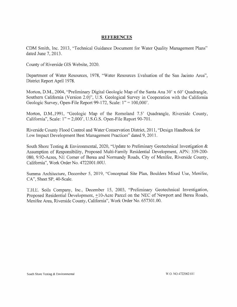
REFERENCES
CDM Smith, Inc. 2013, "Technical Guidance Document for Water Quality Management Plans"dated June 7, 2013.
County of RIverside GIS Website, 2020.
Department of Water Resources, 1978, "Water Resources Evaluation of the San Jacinto Area",District Report April 1978.
Morton, D.M., 2004, "Preliminary Digital Geologic Map of the Santa Ana 30' x 60' Quadrangle,Southern California (Version 2.0)", U.S. Geological Survey in Cooperation with the CaliforniaGeologic Survey, Open-File Report 99-172, Scale: 1" = 100,000'.
Morton, D.M.,1991, "Geologic Map of the Romoland 7.5' Quadrangle, Riverside County,California", Scale: 1" = 2,000', U.S.G.S. OpenlFile Report 90-701.
Riverside County Flood Control and Water Conservation District, 2011, "Design Handbook forLow Impact Development Best Management Practices" dated 9, 201 1.
South Shore Testing & Environmental, 2020, "Update to Preliminary Geotechnical Investigation &Assumption of Responsibility, Proposed Multi-Family Residential Development, APN: 339-200-080, 9.92-Acres, NE Comer of Berea and Normandy Roads, City of Menifee, RIverside County,California", Work Order No. 4722001.00U.
Summa Architecture, December 5, 2019, "Conceptual Site Plan, Boulders Mixed Use, Menifee,CA", Sheet SP, 40-Scale.
T.H.E. Soils Company, Inc., December 15, 2003, "Preliminary Geotechnical Investigation,Proposed Residential Development, ±10-Acre Parcel on the NEC of Newport and Berea Roads,Menifee Area, Riverside County, California", Work Order No. 657301.00.
South Shore Testing & Environmental W.O. NO:4722002.01 I

APPENDIX 8
Exploratory Trench Logs
South Shore Testing & Environmental W.O. NO:4722002.01 I
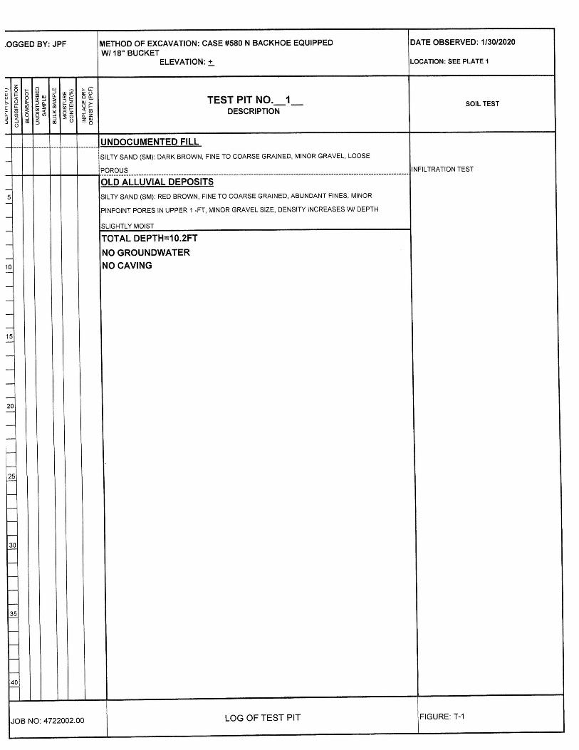
.OGGED BY: JPF METHOD OF EXCAVATION: CASE #580 N BACKHOE EQUIPPED DATE OBSERVED: 1/30/2020OCATI0N:SEEPLATE1W/ 18.' BUCKET
ELEVATION: + L
!i
ii!!
•.-: E§!i TESTPITNO. 1 SOIL TESTIILlIDESCRIPTION
'1
UNDOCUMENTED FILL
NFILTRATION TEST
iI SILTY SAND (SM): DARK BROWN, FINE TO COARSE GRAINED, MINOR GRAVEL, LOOSE
: POROUS IOLDALLUVIALDEPOSITS
5101520I25303540 SILIY SAND (SM): RED BROWN, FINE TO COARSE GRAINED, ABUNDANT FINES, MINOR
PINPOINT PORES IN UPPER 1 -FT, MINOR GRAVEL SIZE, DENSITY `NCREASES W/ DEPTH
SLIGHTLY M0lsT
TOTAL DEPTH=10.2FT
NO GROUNDWATEF`NO CAVING
JOB NO: 4722002.00 LOG OF TEST PIT FIGURE: T-1

OGGED BY: JPF M ETHOD OF EXCAVATION: CASE #580 N BACKHOE EQUIPPED DATE OBSERVED: 1/30/2020W/ 18" BUCKET
OCAT[ON: SEE PLATE 1ELEVATION: + L
iI)
i!!!.-:
:§!! TESTPITNO. 2 SOIL TESTIDESCRIPTION
I
UNDOCUMENTED FILLii SANDY SILT (ML): DARK BROWN, MINOR SAND, LOOSE, POROUSil OLD ALLuVIAL DEPOSITS INFILTRATION TEST-SILTY SAND (SM): REDDISH BROWN, FINE T0 COARSE GRAINED, NUMEROUS PINPOINT
5 PORES AND FINE ROOTS IN TOP 1 FT, MINOR GRAVEL SZ, SLIGHTLY MOIST, INCREASINGil I N DENSITY WITH DEPTH
EI TOTAL DEPTH=10.2FT
EI NO GROUNDWATER
EI NO CAVING
10
5050
15202334
J08 NO: 4722002.00 LOG OF TEST PIT FIGURE: T-2

.OGGED BY: JPF METHOD OF EXCAVATION: CASE #580 N BACKHOE EQUIPPED DATE OBSERVED: 1 /30/2020W/ 18" BUCKET
OCATION: SEE PLATE 1ELEVATION: + L
a5
ii!!
I..: :§!i TESTPITNO. 3 SOIL TESTILuaDESCRIPTION
`1
UNDOCUMENTED FILL
NFILTRATION TEST
I
ALLUVIAL FAN DEPOSITS ISILTYSAND(SM):DARKREDBROWN,FINETOMEDIUMGRAINED,MINORCOARSE,
5'0152025303540 MODERATELY SORTED, SLIGHTLY M0lsT, NUMEROUS PINPOINT PORES IN UPPER 1-2 FT
TOTAL DEPTH=3.OFT
N0 GROUNDWATERNO CAVING
JOB NO: 4722002.00 LOG OF TEST PIT FIGURE: T-3

OGGED BY: JPF METHOD OF EXCAVATION: CASE #580 N BACKHOE EQUIPPED DATE OBSERVED: 1/30/2020
W/ 18" BuCKETOCATION: SEE PLATE 1ELEVATION: + L
;ii ii!ZI!!i
8§!i TESTPITNO. 4 SOIL TESTDESCRIPTION
.UNDOCUMENTED FILL
S lLTY SAND (SM): DARK BROWN, FINE TO MEDIUM GRAINED, MINOR COARSE, LOOSE,oRoUS I
P NFILTRATION TEST
OLD ALLUVIAL FAN DEPOSITS
5 S lLTY SAND (SM): DARK RED BROWN, FINE TO COARSE GRAINED, MODERATELY SORTED,il LOOSE TO MEDIUM DENSE, MINOR GRAVEL SIZE
TOTAL DEPTH 3.OFTil NO GROUNDWATERil NO CAVING
101520233
50540
JOB NO: 4722002.00 LOG OF TEST PIT FIGURE: T4

LOGGED BY: JPF METHOD 0F EXCAVATION: CASE us80 N BACKHOE EQUIPPED DATE OBSERVED: 1/30/2020LOCATION:SEEPLATE1W/ 18" BuCKET
ELEVATloN: +
atLa5
E
aIlli;ZJ IaLi
!gE§i: TEST PIT NO. 5
SOIL TEST
iaLLi
i iIOJ f5 DESCRIPTION
UNDOCUMENTED FILLSANDYSILT(ML)DARKBROWN, DRY, LOOSE. POROUS, MINOR CONSTRUCTION DEBRIS
INFILTRATION TESTPOROUS
5
OLD ALLUVIAL FAN DEPOSITS
SILTY SAND (SM): DARK RED BROWN, FINE TO COARSE GRAINED, MINOR GRAVEL SIZE,
MODERATELY SORTED, SUGHTLY M0lsT, DENSITY INCREASING WITH DEPTH
10152025303540
TOTAL DEPTH 3.OFT
NO GROUNDWATER
NO CAVING
JOB NO: 4722002.00 LOG OF TEST PIT FIGURE: T-5

LOGGED BY: JPF METHOD OF EXCAVATION: CASE #580 N BACKHOE EQUIPPED DATE OBSERVED: 1/30/2020W/ 18" BUCKET
ELEVATION: + LOCATloN: SEE PLATE 1
ai a3§
ai: ±ai!g
8§!i TEST PIT NO. 6SOIL TEST
iC}
u.!a
ia :;Z3 =Ja] !5 DESCRIPTION
UNDOCUIVIENTED FILLGRAVELLYSANDYSILT(ML):DARK BROWN, SANDY IN PART, DRY, LOOSE, MINOR
INFILTRATION TESTCONSTRUCTION DEBRIS
5
OLD ALLUVIAL FAN DEPOSITS
SILTY SAND (SM): DARK RED BROWN, FINE TO COARSE GRAINED. LOOSE IN UPPER 2-FT,
SLIGHTLY M0lsT, INCREASING IN DENSITY WITH DEPTH
10152025303540
TOTAL DEPTH 3.OFT
NO GROUNDWATER
NO CAVING
JOB NO: 4722002.00 LOG OF TEST PIT FiGURE: Tno

APPENDIX C
Percolation Test Results
South Shore Testing & Environmental W.O. NO:4722002.01 I

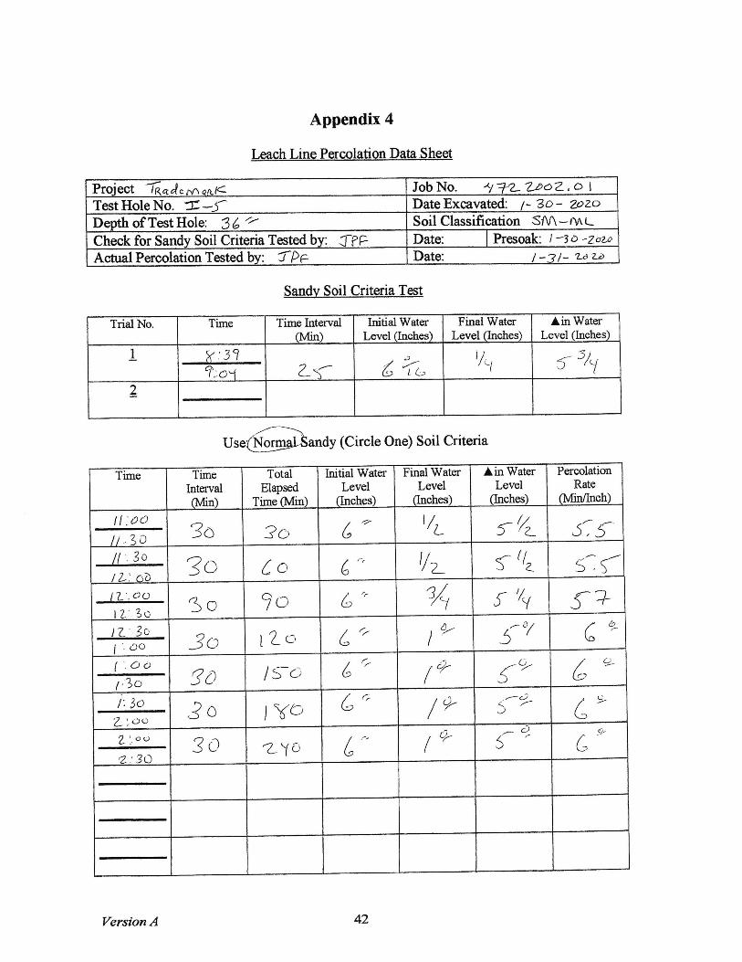
Appendix 4
Leach Line Percolation Data Sheet
Project TQctc£€.rv` 4.QC JobNo. A/72. 2+9o2. o ITestHoleNo. ± -J DateExcavated: /` 3c>~ 2c>2c>Depth ofTestHole: 36.'' Soil classification S/V\-rv\LCheck for Sandy Soil Criteria Tested by: JTPF Date: Presoak: / -3D ~2o2.iD
Actual percolation Tested by: 7PF Date: / -3/~ 2jA, 2.d
Sandv Soil Criteria Test
Trial No. Time Time Interval Initial Water Final Water A in WaterOn) Level (Inches) Level (Inches) Level (hches)
i a.. 3 C,%:.3-5-I--€S C, O,.z S- rJ?{`
2
Normal andy (Circle One) Soil Criteria
Time Time Total hitial Water Find Water A in Water PercolationInterval Elapsed Level Level Level Rate
own) Time Oun) Onches) anches) (Inches) OvfinThch)
?,`1 g10'.Isr 30 3G) •|,r `,a 3-3- a,c,lo:iY1C;``.clfr 3c) CO C,, I//1 `/ //2_
C'a
o..+K11_I.,(fr r=`=C)9C) C,- ` i/7/y y'4 Z,/
I,I/`, I YII:1g-
30 /' ZcJ C,- 13/; f`/4 7,/I I.. L15(IZ-:1& 30 I src) C;=
/,3/yY%7
'Z,/
I i ,' , 8,IZ,`.q.fr3o F5 C:, C-, `3/i 4 `/`/ 1,(
I 2- '` c+ b,I'.(Y 3c) -z .i C cr, ( ?/1` €/¢7 I,/
Version A 42

Appendix 4
Lech Line Per_colation Data .Shect_
Project .7RTctcfe.in eAfc JobNo. ty7Z 2Lz>o2. o ITestHoleNo. tf -2~ DateExcavated: /-3o-2f>2c>Depth ofTestHole: 36 '' Soil classification S/V\ -rv\ LCheck for Sandy Soil Crfueria Tested by: TPF Date: Presock: / -3o ^2o2.p
Actual percolation Tested dy: rpF Date: / -3/-2*p z6
Sandv Soil Criteria Test
Trial No. Time Time hterval hitial Water Final Water ^ in WaterOn) Level thches) Level Onches) Level Ouhes)
i S,. 3 L8..5i 2r a,CT6Ga.y, j3/i
2
Use:@Sandy(Circleone)Soilcriteria
Time Tine Total hitial Water Final Water A in Water PercolationInterval Elapsed Level Level Level Rate
own) Time Odi) thches) thches) anches) Ovfinthch)c7 5- I
3c, 3C) 6,, 2.r 3,i 9,,c/ O..zl
/C) `L II0:3- ( 30 CcJ` C-, `.a I =<J-- 3 //c' Q.-,-_/a .. S|/i-..2,( 3cJ` 9c` 6,, 3e- 39- /c)/ I ,LlI-.s-I `30 I `L C, Cf ?. I `l -L. 2 `/2_ /`L
11-//: i_ '1.i-(
`3c) l..`=`c-` 6,, 3 '-3 /`, 1. )/? )?,'L./?_ ,. L )/a.5-`
30 '81J c.z, 3 3/7/\, ? //`( I 3 , _3_
I t ,. € II'..Z,\ 30 ?i ( i.\ C-,, r3 3/l, z`/y 3,3
Version A 42

Appendix 4
LeachLinepercolationDatash_eat_
project rRciG(cmofuc Job No. ty iJ2. Z+9o2. c> ITestHoleNo.I =3 DateExcavated: /` 3o~ 2ozc>Depth ofTestHole: 36 '' Soil classification S/V\ ~rv\ LCheck for Sandy Soil Criteria Tested by: JTPF Date: Presoak: / ~30 -Za2,p
Actual percolation Tested by: 3-PF Date: / -3/-2+g 2+a
Trial No. Time Time Interval Initial Water Final Water A in WaterOn) Level (Inches) Level (Inches) Level thches)
i 8-.. 3qV:5r7Zc;+ 69, z_,1{ .>?//y
2
-`.:' (Circle One) Soil Criteria
Tine Time Total Initial Water Final Water A in Water PercolationInterval Elapsed Level Level Level Rate
own)fo Time On) (Inches) thches) anches) Owlinthch)
P .. 51 i)a 6% •z_.`, •3'lL 8.aI 0 . . ? ,1/a `. a Z~ 30 Cdo crc 3,C) 3,0 0lD,.€_I_I A ,. SL`LL 30 ?a cZ ?,a 3.a /C,
3 '/`( 234 / c) , q' ( '- I;LII,-SL 30 /Z_a cJ76
3`/y •z, 3/y /09'/ / .. s-1/L.2_i
30 (`F=c:-` 676I L .. cL`1 30 rrLu` 6?c 3 i/``
`=_ I , -` `'L/ 7_ . S-I.1-.`S2-
30 Zyc, C,7G 3 `/ty•-: I `, ,7_ /i
' .. .LL
Version A 42

Appendix 4
_LcachLine__PercolationData_Sheet
Project TRctclcMafuc JobNo. ty:7`2. Z+DoZ. o ITestHoleNo. I-i DateExcavated: /-3o~ 2o2oDepth ofTestHole: 36 '' Soil classification S/\/\~ rv\ LCheck for Sandy Soil Criteria Tested by: JPF Date: presoak: / ~3 c> .-zOz.Li
Actual percolalon Tested by: fp€ Date: / -3/~ zc a,£>
Trial No. Time Time Interval Initial Water Final Water A in WaterOn) Level thches) Level (inches) Level thches)
i €:36q..-c,( `',1-+-62 ?34 3/y
2
use:ngifroandy(circleone)soilcriteria
A in Water PercolationTime Tilne Total hitial Water Fmal WaterInterval Elapsed Level Level Level Rate
own) Time Ovth) thches) .*` anehes) avmch) _9 , s- h- 30 30 6`% 3¢- 3, /010 ,. L<
i ,%,;: 3o CC) 6c, 3 '/2_ i I,z. 'L
i #-s;- 30 cl,C\ c9L- 3 3/c' i//7 /3,3
Il .. L<I`.S-r3CJ l zc; T
Of6
3 3/1, 2, `/1` I --i -i
( : s`s,IL..LS3crL/ /S-a Cs> c/9, 2_c+ S-
11 `. 2,i, 3c) /80 CQ- c/9- zO, /5-I I.I ss,IL`.sS-
31`, ?+0 69, c/,dy 2d, /r1 1 `. -~ r
Versioi. A 42
Appendix 4
_Lca§hLinepercolationData.She_ct
Project TR¢dem afuc Job No. fy72_ Z,oo2. a ITestHoleNo. ±~j~ DateExcavated: /` 3o~ 2pzoDepth ofTestHole: 36 '' Soil classification S/V\ -rv\ LCheck for Sandy Soil Criteria Tested by: TPF Date: Presoak: / -30 -zo2,p
Actual percolation Tested dy: fpF Date: / ~3/~ 2z9 z+2>
Trial No. Time Tilne hterval hitial Water Final Water tin WaterOn) Level ques) Level thches) Level (Inches)
i \: . 3) Q?..,oiZ-i, 6 .`,I `-`
j/i( s- 5/72
Use®andy(Circleone)Soilcriteria
Tine Time Total Initial Water Final Water A in Water PercolationInterval Elapsed Level Level Level Rate
On) Time Odi) Onches) thches) anche§) Owinthch)
/ / .I c) c, 3o 3c) C?I/L 5-//2_ {,5
// . 3 011.. 30Z~'.a) 30 £c, 6r'
`/2_ s- `/a -`:-...({I -L-: 0IL`.C)a12,`.3c
3o 90 6.,, % i- '// 3_+Izj 30''.OC) jo I 2- c, C,, /A, 5-0/ CG+
( `. a aI,3c) 5c, I '`=- c-.` 6,, /di+ 5-a, 69/I, 3c,Z~,,cJ0 30 jYO 6.,, /F7,
.-c)5-C>
a :- a ® 30 1YC) 6.,, / ctz- i- c,J, c.Q`z'30
Version A 42

Appendix 4
I.each Line Percolation Data. Sheet
project .rRCEclc rv` On.c Jo0No. A/iL2. Zj9o2. o ITestHoleNo. I .-6 DateExcavated: /-3o-2o2oDepth ofTestHole: 36 '' Soil classification Srv\ -rv\ LCheck for Sandy Soil Criteria Tested by: GTPF Date: Presoak: / -3D -2o2jlActual percolation Tasted dy: 3-PF Date: / ~3/-2rd a.£>
Sandv Soil Criteria Test
Trial No. Time Tine Interval Initial Water Final Water ^in WaterOu) Level anches) Level (Inches) Level thches)
i 6:|Lc?..01 C¥ c7: tit q,/2-2
use:a:!aLa`sandy(circ,Cone)soilcriteria
Time Time Total hitial Water Final Water A in Water PercolationInterval Elapsed Level Level Level RateOn) Time On) (Inches) thches) (Inehes) Ovrmch)
l I.. o s-il.-3{ 3o 30 6c, \ 3/1\ v`/l` df9 2. `I 1 .. 3C1ZJ-.C,i Jc, CO 6u- \ 7/ey
4t '/y ?,;' 1 I. o`,L~.-3{ ?cl.1 30 6or
'L€-10-
-+:T12`-3f,.,ILaS- 3L| ( '1. ,I 119- I . c:,-
aty, rT'T I
I . . C)iI.-3{ 3C, (3-a cO, 2_c,g, i/a, 1.r/ ,,3(:i`c`,r`(--. 3c) 'tJ 6 c-?- ccj,,-
9Lc/
7.i-•z c) r:3`.::-i 3L` tycl Gc> 7Laz, c7 .i3~ 7,r
Version A 42